
Indian Standard PLAIN AND REINFORCED CONCRETE - Water
347
IS 456 : 2000 Indian Standard PLAIN AND REINFORCED CONCRETE - CODE OF PRACTICE ( Fourth Revision ) ICS 91.100.30 0 BIS 2000 BUREAU OF INDIAN STANDARDS MANAK BHAVAN, 9 BAHADUR SHAH ZAFAR MARG NEW DELHI 110002 July 2000 Price Rs 260.00
-
Upload
khangminh22 -
Category
Documents
-
view
5 -
download
0
Transcript of Indian Standard PLAIN AND REINFORCED CONCRETE - Water

IS 456 : 2000
Indian Standard
PLAIN AND REINFORCED CONCRETE - CODE OF PRACTICE
( Fourth Revision )
ICS 91.100.30
0 BIS 2000
BUREAU OF INDIAN STANDARDS MANAK BHAVAN, 9 BAHADUR SHAH ZAFAR MARG
NEW DELHI 110002
July 2000 Price Rs 260.00

PLAINAND
IS456: 2000
Indian Standard
REINFORCEDCONCRETE- CODEOFPRACTICE
( Fourth Revision ) FOREWORD
This Indian Standard (Fourth Revision) was adopted by the Bureau of Indian Standards, after the draft finalixed by the Cement and Concrete Sectional Committee had been approved by the Civil Engineering Division Council. This standard was first published in 1953 under the title ‘Code of practice for plain and reinforced concrete for general building construction’ and subsequently revised in 1957. The code was further revised in 1964 and published under modified title ‘Code of practice for plain and reinforced concrete’, thus enlarging the scope of use of this code to structures other than general building construction also. The third revision was published in 1978, and it included limit state approach to design. This is the fourth revision of the standard. This revision was taken up with a view to keeping abreast with the rapid development in the field of concrete technology and to bring in further modifications/improvements in the light of experience gained while using the earlier version of the standard.
This revision incorporates a number of important changes. The major thrust in the revision is on the following lines:
a) In recent years, durability of concrete structures have become the cause of concern to all concrete technologists. This has led to the need to codify the durability requirements world over. In this revision of the code, in order to introduce in-built protection from factors affecting a structure, earlier clause on durability has been elaborated and a detailed clause covering different aspects of design of durable structure has been incorporated.
b) Sampling and acceptance criteria for concrete have been revised. With tbis revision acceptance criteria has been simplified in line with the provisions given in BS 5328 (Part 4):1990 ‘Concrete: Part 4 Specification for the procedures to be used in sampling, testing and assessing compliance of concrete’.
Some of the significant changes incorporated in Section 2 are as follows:
a)
b) cl
d) e)
0 8)
h)
j)
k)
All the three grades of ordinary Portland cement, namely 33 grade, 43 grade and 53 grade and sulphate resisting Portland cement have been included in the list of types of cement used (in addition to other types of cement). The permissible limits for solids in water have been modified keeping in view the durability requirements. The clause on admixtures has been modified in view of the availability of new types of admixtures including superplasticixers. In Table 2 ‘Grades of Concrete’, grades higher than M 40 have been included. It has been recommended that minimum grade of concrete shall be not less than M 20 in reinforced concrete work (see also 6.1.3). The formula for estimation of modulus of elasticity of concrete has been revised. In the absenceof proper correlation between compacting factor, vee-bee time and slump, workability has now been specified only in terms of slump in line with the provisions in BS 5328 (Parts 1 to 4). Durability clause has been enlarged to include detailed guidance concerning the factors affecting durability. The table on ‘Environmental Exposure Conditions’ has been modified to include ‘very severe’ and ‘extreme’ exposure conditions. This clause also covers requirements for shape and size of member, depth of concrete cover, concrete quality, requirement against exposure to aggressive chemical and sulphate attack, minimum cement requirement and maximum water cement ratio, limits of chloride content, alkali silica reaction, and importance of compaction, finishing and curing. A clause on ‘Quality Assurance Measures’ has been incorporated to give due emphasis to good practices of concreting. Proper limits have been introduced on the accuracy of measuring equipments to ensure accurate batching of concrete.
1

IS 456 : 2000
m) The clause on ‘Construction Joints’ has been modified.
n) The clause on ‘Inspection’ has been modified to give more emphasis on quality assurance.
The significant changes incorporated in Section 3 are as follows:
a)
b)
cl
4
e)
0
g) h)
j)
Requirements for ‘Fire Resistance’ have been further detailed.
The figure for estimation of modification factor for tension reinforcement used in calculation of basic values of span to effective depth to control the deflection of flexural member has been modified.
Recommendations regarding effective length of cantilever have been added.
Recommendations regarding deflection due to lateral loads have been added.
Recommendations for adjustments of support moments in restrained slabs have been included.
In the detemination of effective length of compression members, stability index has been introduced to determine sway or no sway conditions.
Recommendations have been made for lap length of hooks for bars in direct tension and flexural tension.
Recommendations regarding strength of welds have been modified.
Recommendations regarding cover to reinforcement have been modified. Cover has been specified based~on durability requirements for different exposure conditions. The term ‘nominal cover’ has been introduced. The cover has now been specified based on durability requirement as well as for fite requirements.
The significant change incorporated in Section 4 is the modification-of the clause on Walls. The modified clause includes design of walls against horizontal shear.
In Section 5 on limit state method a new clause has been added for calculation of enhanced shear strength of sections close to supports. Some modifications have also been made in the clause on Torsion. Formula for calculation of crack width has been-added (separately given in Annex P).
Working stress method has now been given in Annex B so as to give greater emphasis to limit state design. In this Annex, modifications regarding torsion and enhanced shear strength on the same lines as in Section 5 have been made.
Whilst the common methods of design and construction have been covered in this code, special systems of design and construction of any plain or reinforced concrete structure not covered by this code may be permitted on production of satisfactory evidence regarding their adequacy and safety by analysis or test or both (see 19).
In this code it has been assumed that the design of plain and reinforced cement concrete work is entrusted to a qualified engineer and that the execution of cement concrete work is carried out under the direction of a qualified and experienced supervisor.
In the formulation of this standard, assistance has been derived from the following publications:
BS 5328-z Part 1 : 1991 Concrete : Part 1 Guide to specifying concrete, British Standards Institution
BS 5328 : Part 2 : 1991 Concrete : Part 2 Methods for specifying concrete mixes, British Standards Institution
BS 5328 : Part 3 : 1990 Concrete : Part 3 Specification for the procedures to be used in producing and transporting concrete, British Standards Institution
BS 5328 : Part 4 : 1990 Concrete : Part 4 Specification for the procedures to be used in sampling, testing and assessing compliance of concrete, British Standards Institution
BS 8110 : Part 1 : 1985 Structural use of concrete : Part 1 Code of practice for design and construction, British Standards Institution
BS 8110 : Part 2 : 1985 Structural use of concrete : Part 2 Code of practice for special circumstances, British Standards Institution
AC1 3 19 : 1989 Building code requirements for reinforced concrete, American Concrete Institute
AS 3600 : 1988 Concrete structures, Standards Association of Australia
2

IS 456 : 2000
DIN 1045 July 1988 Structural use of concrete, design and construction, Deutsches Institut fur Normung E.V.
CEB-FIP Model code 1990, Comite Euro - International Du Belon
The composition of the technical committee responsible for the formulation of this standard is given in Annex H.
For the purpose of deciding whether a particular requirement of this standard is complied with, the final value, observed or calculated, expressing the result of a test or analysis shall be rounded off in accordance with IS 2 : 1960 ‘Rules for rounding off numerical values (revised)‘. The number of significant places retained in the rounded off value should be the same as that of~the specified value in this standard.

As in the Original Standard, this Page is Intentionally Left Blank

IS456:2000
CONTENTS
SECTION 1 GENERAL
1 SCOPE
2 REFERENCES
3 TERMINOLOGY
4 SYMBOLS
SECTION 2 -MATERIALS, WORKMANSHIP, INSPECTION AND TESTING
5 MATERIALS
5.1 Cement
5.2 Mineral Admixtures
5.3 Aggregates
5.4 Water
5 5 Admixtures
5.6 Reinforcement
5.7 Storage of Materials
6 CONCRETE
6.1 Grades
6.2 Properties of Concrete
7 WORKABILITY OF CONCRETE
8 DURABILITY OF CONCRETE
8.1 General
8.2 Requirements for Durability
9
10
11
CONCRETE Mrx PROPORTIONING
9.1 Mix Proportion
9.2 Design Mix Concrete
9.3 Nominal Mix Concrete
PRODUCTION OF CONCRETE
10.1 Quality Assurance Measures
10.2 Batching
10.3 Mixing
FORMWORK
11.1 General
11.2 Cleaning and Treatment of Formwork
1 I .3 Stripping Time
12 ASSEMBLY OF REINFORCEMENT
13 TRANSPORTING, PLACING, COMPACTION AND CURING
13.1 Transporting and Handling
13.2 Placing
13.3 Compaction
PAGE
11
11
11
11
13
13
-13
14
14
15
15
15
15
15
15
17
17
17
18
22
22
22
23
23
23
24
24
25
25
25
25
25
26
26
26
26

IS 456 : 2000
13.4 Construction Joints and Cold Joints
13.5 Curing 13.6 Supervision
14 CONCRERNG UNDER SPECIAL CONDITIONS
14.1 Work in Extreme Weather Conditions
14.2 Under-Water Concreting
15 SAMPLING AND STRENGTH OF DESIGNED CONCRETE Mrx
15.1 General 15.2 Frequency of Sampling 15.3 Test Specimen 15.4 Test Results of Sample
16 ACCEPTANCE CRITERIA
17 INSPECI-ION AND TEFXJNG OF STRWTURE
SECTION 3 GENERAL DESIGN CONSIDERATION
18 BASES FOR DEIGN
18.1 Aim of Design 18.2 Methods of Design 18.3 Durability, Workmanship and Materials 18.4 Design Process
I 9 LOADS AND FORCES
19.1’ General
19.2 Dead Loads 19.3 Imposed Loads, Wind Loads and Snow Loads 19;4 Earthquake Forces
19.5 Shrinkage, Creep and Temperature Effects 19.6 Other Forces and Effects 19.7 Combination of Loads 19.8 Dead Load Counteracting Other Loads and Forces
19.9 Design Load
20 STABILITY OF THE STRUCTURE
20.1 Overturning
20.2 Sliding 20.3 Probable Variation in Dead Load
20.4 Moment Connection 20.5 Lateral Sway
2 1 FIRE RESISTANCE
22 ANALYSIS
22.1 General 22.2 Effective Span
22.3 Stiffness
PAGE
27 27
27
27
27 27
29
29 29 29 29
29
30
32
32 32
32 32
32
32
32 32
32 32
33 33 33 33
33
33 33 33 33 33 33
34
34 - 34 35
6

IS456:2000
PAGE
22.4 Structural Frames
22.5 Moment and Shear Coefficients for Continuous Beams
22.6 Critical Sections for Moment and Shear
22.7 Redistribution of Moments .
23 BEAMS
23.0 Effective Depth
23.1 T-Beams and L-Beams
23.2 Control of Deflection
23.3 Slenderness Limits for Beams to Ensure Lateral Stability
24 SOLID SLABS
24.1 General
24.2 Slabs Continuous Over Supports
24.3 Slabs Monolithic with Supports
24.4 Slabs Spanning in Two Directions~at Right Angles
24.5 Loads on Supporting Beams
25 COMPRESSION MEZMBERS
25.1 Definitions
25.2 Effective Length of Compression Members
25.3 Slenderness Limits for Columns
25.4 Minimum Eccentricity
26 REQUIREMENTS GOVERNING REINFORCEMENT AND DETAILING
26.1 General
26.2 Development of Stress in Reinforcement
26.3 Spacing of Reinforcement
26.4 Nominal Cover to Reinforcement
26.5 Requirements of Reinforcement for Structural Members
27 EXPANSION JOMTS
SECTION 4 SPECIAL DESIGN REQUIREMENTS FOR STRUCTURAL MEMBERS AND SYSTEMS
28 CONCRETE CORBELS
28.1 General
28.2 Design
29 DEEP BEAMS
29.1 General
29.2 Lever Arm
29.3 Reinforcement
30 RIBBED, HOLLOW BLOCK OR VOIDED SLAB
30.1 General
30.2 Analysis of Structure
30.3 Shear
30.4 Deflection
35
35
36
36
36
36
36
37
39
39
39
39
39
41
41
41
41
42
42
42
42
42
42
45
46
46
50
51
51
51
51
51
51
51
52
52
52
52
52

IS 456 : 2000
PAGE
30.5 Size and Position of Ribs 30.6 Hollow Blocks and Formers 30.7 Arrangement of Reinforcement 30.8 Precast Joists and Hollow Filler Blocks
3 1 FLAT SLABS
3 1.1 General 3 1.2 Proportioning 3 1.3 Determination of Bending Moment 3 1.4 Direct Design Method 3 1.5 Equivalent Frame Method 3 1.6 Shear in Flat Slab 3 1.7 Slab Reinforcement 3 1.8 Openings in Flat Slabs
32 WALLS
32.1 General 32.2 Empirical Design Method for Walls Subjected to Inplane Vertical Loads 32.3 Walls Subjected to Combined Horizontal and Vertical Forces 32.4 Design for Horizontal Shear 32.5 Minimum Requirements for Reinforcement in Walls
33 STAIRS
33.1 Effective Span of Stairs 33.2 Distribution of Loading on Stairs 33.3 Depth of Section
34 Foort~~s 34.1 General
34.2 Moments and Forces 34.3 Tensile Reinforcement
34.4 Transfer of Load at the Base of Column
34.5 Nominal Reinforcement
SECTION 5 STRUCTURAL DESIGN (LIMIT STATE METHOD)
35 SAFETY AND SERVKEABlLITY kKNIREMl?N’l’s
35.1 General 35.2 Limit State of Collapse 35.3 Limit States of Serviceability 35.4 Other Limit States
36 CHARACTERISTIC AND DESIGN VALUES AND PARTUL SAFEI”Y FACTORS
36.1 Characteristic Strength of Materials
36.2 Characteristic Loads 36.3 Design Values 36.4 Partial Safety Factors
37 ANALYSIS
37.1 Analysis of Structure
52 52 53 53
53 53 53 53 54 56 57 59 61
61 61 61 62 62 62
63 63 63 63
63 63 64
65 65
66
67
67 67 67 67
67
67 67 68 68
-68
68
8

PAGE
38 LIMIT STATE OF COLLAPSE : FLEXURE
38.1 Assumptions
39 LIMIT STATE OF COLLAPSE: COMPRESSION
39.1 Assumptions 39.2 Minimum Eccentricity 39.3 Short Axially Loaded Members in Compression 39.4 Compression Members with Helical Reinforcement 39.5 Members Subjected to Combined Axial Load and Uniaxial Bending 39.6 Members Subjected to Combined Axial Load and Biaxial Bending 39.7 Slender Compression Members
40 LLWT STATE OF-COLLAPSE : SW
40.1 Nominal Shear Stress 40.2 Design Shear Strength of Concrete 40.3 Minimum Shear Reinforcement 40.4 Design of Shear Reinforcement 40.5 Enhanced Shear Strength of Sections Close to Supports
41 LJMIT STATE OF COLLAPSE : TORSION 41.1 General 4 1.2 Critical Section 4 1.3 Shear and Torsion 4 1.4 Reinforcement in Members Subjected to Torsion
42 LIMIT STATKOF SERVICEABILITY: DEKIZC~ION
42.1 Flexural Members
43 LIMIT STATE OF SERVICEABILITY: CRACKING
43.1 43.2
4NNEXA
ANNEXB
B-l
B-2
B-3
Flexural Members Compression Members
LIST OF REFERRED INDIAN STANDARDS
STRUCTURAL DESIGN (WORKING STRESS METHOD)
GENERAL B-l.1 General Design Requirements B- 1.2 Redistribution of Moments B-l.3 Assumptions for Design of Members
PEaMIsstBLE STrtEssEs
B-2.1 Permissible Stresses in Concrete B-2.2 Permissible Stresses in Steel Reinforcement B-2.3 Increase in Permissible Stresses
I’iuu@ssm~~ Lam IN COMPRESSION MEMBEW
B-3.1 Pedestals and Short Columns with Lateral ‘Des B-3.2 Short Columns with Helical Reinforcement B-3.3 Long Columns B-3.4 Composite Columns
69
69
70
70 71 71 71 71 71 71
72
72 72 72 72 74
74
74 75 75 75
75
75
76
76 76
77
80
80 80 80 80
80 80 80 80
81
81 81 81 81
9

IS 456 : 2ooo
B-4 MYERS SUBJECTED TO COMBINED Axw. LOAD AND BENDING
B-4.1 B-4.2 B-43
B-5 SHEAR
B-5.1 B-5.2 B-5.3 B-5.4 B-5.5
Design Based on Untracked Section Design Based on Cracked Section Members Subjected to Combined Direct Load and Flexure
Nominal Shear Stress Design Shear Strength of Concrete Minimum Shear Reinforcement Design of Shear Reinforcement Enhanced Shear Strength of Sections Close to Supports
B -6 TORSION
B-6.1 General
B-6.2 Critical Section
B-6.3 Shear and Torsion B-6.4 Reinforcement in Members Subjected to Torsion
ANNEX C CALCULATION OF DEFLECTION
C-l TOTAL DEFLECTION
C-2 SHORT-TERM DEFLECTION
C-3 DEFLECI-ION DUE TO SHRINKAGE
C-4 DE-ON DUE TO CREEP
ANNEX D SLABS SPANNING IN TWO DIRECTIONS
D-l RESTRAINED SLAIIS D-2 SIMPLY SIJIWRTED SLABS
ANNEX E EFFECTIVE LENGTH OF COLUMNS
ANNEX F CALCULATION OF CRACK WIDTH
ANNEX G MOMENTS OF RESISTANCE FOR RECTANGULAR AND T-SECTIONS
G- 1 RECTANGULAR SECIIONS
G- 1.1 Sections without Compression Reinforcement G- 1.2 Sections with Compression Reinforcement
G-2 FLANGED SECTION
ANNEX H COMMITTEE COMPOSITION
83
83 83 83
83 83 84 85 85 85
86 86 86 86 86
88
88 88 88 89
90
90
90
92
95
96
96
% 96 96
98
10

SECTION 1 GENERAL
1 SCOPE
k-1 This standard deals with the general structural use of plain and reinforced concrete.
1.1.1 For the purpose of this standard, plain concrete structures are those where reinforcement, if provided is ignored for~determination of strength of the structure. 1.2 Special requirements of structures, such as shells, folded plates, arches, bridges, chimneys, blast resistant structures, hydraulic structures, liquid retaining structures and earthquake resistant structures, covered in respective standards have not been covered in this standard; these standards shall be used in conjunction with this standard.
EL -
Es -
J& -
xx -
2 REFERENCES
fa - fd - fY - 4 - Hive - L - z - c
The Indian Standards listed in Annex A contain provisions which through reference in this text, constitute provisions of this standard. At the time of publication, the editions indicated were valid. All standards are subject to revision and parties to agreements abased on this standard are encouraged to investigate the possibility of applying the most recent editions of the standards indicated in Annex A.
4 - K -
k -
Ld - LL-
Lw -
3 TERMINOLOGY 1 -
For the purpose of this standard, the definitions given in IS 4845 and IS 6461 (Parts 1 to 12) shall generally apply.
4 SYMBOLS
For the purpose of this standard, the following letter symbols shall have the meaning indicated against each, where other symbols are used, they are explained at the appropriate place:
A -
b -
b - ef
bf -
k - D -
Df - DL -
d -
d’ -
EC -
Area Breadth of beam, or shorter dimension of a rectangular column Effective width of slab
Effective width of flange Breadth of web or rib Overall depth of beam or slab or diameter of column; dimension of a rectangular column in the direction under consideration
Thickness of flange
Dead load Effective depth of beam or slab
Depth of compression reinforcement from the highly compressed face ModuIus of elasticity of concrete
11
4 -
lY -
4 -
4 -
12 -
1’ - 2
M -
m -
n -
P -
4,) -
IS456:2000
Earthquake load Modulus of elasticity of steel Eccentricity characteristic cube compressive strength of concrete Modulus of rupture of concrete (flexural tensile strength) Splitting tensile strength of concrete Design strength Characteristic strength of steel Unsupported height of wall Effective height of wall Effective moment of inertia Moment of inertia of the gross section excluding reinforcement Moment of intertia of cracked section Stiffness of member Constant or coefficient or factor Development length Live load or imposed load Horizontal distance between centres of lateral restraint Length of a column or beam between adequate lateral restraints or the unsupported length of a column Effective span of beam or slab or effective length of column Effective length about x-x axis Effective length about y-y axis Clear span, face-to-face of supports I’,, for shorter of the two spans at right angles Length of shorter side of slab Length of longer side of slab Distance between points of zero moments in a beam Span in the direction in which moments are determined, centre to centre of supports Span transverse to I,, centre to centre of supports 1 z for the shorter of the continuous spans Bending moment Modular ratio Number of samples
Axial load on a compression member
Calculated maximum bearing pressure

IS 456 : 2000
Yc, - Calculated maximum bearing pressure of soil
r - Radius
s - Spacing of stirrups or standard deviation
T - Torsional moment
t - Wall thickness
V - Shear force
W - Total load
WL - Wind load
W - Distributed load per unit area
Wd - Distributed dead load per unit area
WI - Distributed imposed load per unit area
X - Depth of neutral axis
z - Modulus of section
Z - Lever arm
OZ, B - Angle or ratio
r, - Partial safety factor for load
xl - Partial safety factor for material
snl - Percentage reduction in moment
E - UC Creep strain of concrete
(T chc - Permissible stress in concrete in
bending compression
OLX - Permissible stress in concrete in direct compression
<T - mc
0% -
% -
0,” -
Permissible stress in metal in direct compression
Permissible stress in steel in compression
Permissible stress in steel in tension
Permissible tensile stress in shear reinforcement
Design bond stress
Shear stress in concrete
Maximum shear stress in concrete with shear reinforcement
Nominal shear stress
Diameter of bar
12

IS456:2000
SECTION 2 MATERIALS, WORKMANSHIP, INSPECTION AND TESTING
5 MATERIALS
5.1 Cement The cement used shall be any of the following and the type selected should be appropriate for the intended use:
a)
b)
c)
d)
e)
f)
g)
h)
j)
k)
33 Grade ordinary Portland cement conforming to IS 269
43 Grade ordinary Portland cement conforming to IS 8 112
53 Grade ordinary Portland cement conforming to IS 12269
Rapid hardening Portland cement conforming to IS 8~041
Portland slag cement conforming to IS 455
Portland pozzolana cement (fly ash based) conforming to IS 1489 (Part 1)
Portland pozzolana cement (calcined clay based) conforming to IS 1489 (Part 2)
Hydrophobic cement conforming to IS 8043
Low heat Portland cement conforming to IS 12600
Sulphate resisting Portland cement conforming to IS 12330
Other combinations of Portland cement with mineral admixtures (see 5.2) of quality conforming with relevant Indian Standards laid down may also be used in the manufacture of concrete provided that there are satisfactory data on their suitability, such as performance test on concrete containing them. 5.1.1 Low heat Portland cement conforming to IS 12600 shall be used with adequate precautions with regard to removal of formwork, etc.
5.1.2 High alumina cement conforming to IS 6452 or supersulphated cement conforming to IS 6909 may be used only under special circumstances with the prior approval of the engineer-in-charge. Specialist literature may be consulted for guidance regarding the use of these types of cements. 5.1.3 The attention of the engineers-in-charge and users of cement is drawn to the fact that quality of various cements mentioned in 5.1 is to be determined on the basis of its conformity to the performance characteristics given in the respective Indian Standard Specification for thatcement. Any trade-mark or any trade name indicating any special features not covered in the standard or any qualification or other special performance characteristics sometimes claimed/ indicated on the bags or containers or in advertisements alongside the ‘Statutory Quality Marking’ or otherwise
have no relation whatsoever with the characteristics guaranteed by the Quality Marking as relevant to that cement. Consumers are, therefore, advised to go by the characteristics as given in the corresponding Indian Standard Specification or seek specialist advise to avoid any problem in concrete making and construction.
5.2 Mineral Admiitures
5.2.1 Poz.zolanas
Pozzolanic materials conforming to relevant Indian Standards may be used with the permission of the engineer-in-charge, provided uniform blending with cement is ensured.
5.2.1.1 Fly ash (pulverizedfuel ash)
FIy ash conforming to Grade 1 of IS 3812 may be use?, as part replacement of ordinary Portland cement provided uniform blending with cement is ensured.
5.2.1.2 Silicafume
Silica fume conforming to a standard approved by the deciding authority may be used as part replacement of cement provided uniform blending with the cement is ensured.
NOTE-The silica fume (very fine non-crystalline silicon dioxide) is a by-product of the manufactme of silicon, kmxilicon or the like, from quartz and carbon in electric arc furnace. It is usually usedinpropoltion of 5’m lOpercentofthecementconbcnt of a mix.
5.2.1.3 Rice husk ash
Rice husk ash giving required performance and uniformity characteristics -may be used with the approval of the deciding authority.
NOTE--Rice husk ash is produced by burning rice husk and contain large propotion of silica. To achieve amorphous state, rice husk may be burnt at controlled temperatum. It is necessary to evaluate the product from a ptuticular source for performnnce and uniformity since it can range from being as dekterious as silt when incorporated in concmte. Water demnnd and drying &i&age should be studied before using ria husk.
5.2.u iuetakaoline
Metakaoline having fineness between 700 to 900 m?/kg may be used as ~pozzolanic material in concrete.
NOTE-Metaknoline is obtained by calcination of pun or r&ledkaolinticclnyatatempexatumbetweea6soVand8xPc followed by grind& to achieve a A of 700 to 900 n?/kg. The resulting material has high pozzolanicity.
5.2.2 Ground Granulated Blast Furnace Slag
Ground granulated blast furnace slag obtained by grinding granulated blast furnace slag conforming to IS 12089 may be used as part replacement of ordinary
13

IS 456 : 2000
Portland cements provided uniform blending with cement is ensured.
5.3 Aggregates
Aggregates shall comply with the requirements of IS 383. As far as possible preference shall be given to natural aggregates. 5.3.1 Other types of aggregates such as slag and crushed overbumt brick or tile, which may be found suitable with regard to strength, durability of concrete and freedom from harmful effects may be used for plain concrete members, but such aggregates should not contain more than 0.5 percent of sulphates as SO, and should not absorb more than 10 percent of their own mass of water.
5.3.2 Heavy weight aggregates or light weight aggregates such as bloated clay aggregates and sintered fly ash aggregates may also be used provided the engineer-in-charge is satisfied with the data on the properties of concrete made with them.
NOTE-Some of the provisions of the code would require moditication when these aggnzgates are used; specialist litemtute may be consulted for guidance.
5.3.3 Size of Aggregate
The nominal maximum size of coarse aggregate should be as large as possible within the limits specified but in no case greater than one-fourth of the minimum thickness of the member, provided that the concrete can be placed without difficulty so as to surround all reinforcement thoroughly and fill the comers of the form. For most work, 20 mm aggregate is suitable. Where there is no restriction to the flow of concrete into sections, 40 mm or larger size may be permitted. In concrete elements with thin sections, closely spaced reinforcement or small cover, consideration should be given to the use of 10 mm nominal maximum size.
Plums above 160 mm and up to any reasonable size may be used in plain concrete work up to a maximum limit of 20 percent by volume of concrete when specifically permitted by the engineer-in-charge. The plums shall be distributed evenly and shall be not closer than 150 mm from the surface. 5.3.3.1 For heavily reinforced concrete members as in the case of ribs of main beams, the nominal maximum size of the aggregate should usually be restricted to 5 mm less than the minimum clear distance between the main bars or 5 mm less than the minimum cover to the reinforcement whichever is smaller. 5.3.4 Coarse and fine aggregate shall be batched separately. All-in-aggregate may be used only where specifically permitted by the engineer-in-charge.
5.4 Water
Water used for mixing and curing shall be clean and
free from injurious amounts of oils, acids, alkalis, salts, sugar, organic materials or other substances that may be deleterious to concrete or steel.
Potable water is generally considered satisfactory for mixing concrete. As a guide the following concentrations represent the maximum permissible values:
a)
b)
cl
5.4.1
To neutralize 100 ml sample of water, using phenolphthalein as an indicator, it should not require more than 5 ml of 0.02 normal NaOH. The details of test are given in 8.1 of IS 3025 (Part 22). To neutralize 100 ml sample of water, using mixed indicator, it should not require more than 25 ml of 0.02 normal H$O,. The details of ‘test shall be as given in 8 of IS 3025 (Part 23). Permissible limits for solids shall be as given in Table 1. In case of doubt regarding development of
strength, the suitability of water for making concrete shall be ascertained by the compressive strength and initial setting time tests specified in 5.4.1.2 and 5.4.1.3. 5.4.1.1 The sample of water taken for testing shall represent the water proposed to be used for concreting, due account being paid to seasonal variation. The sample shall not receive any treatment before testing other than that envisaged in the regular supply of water proposed for use in concrete. The sample shall be stored in a clean container previously rinsed out with similar water. S.4.1.2 Average 28 days compressive strength of at least three 150 mm concrete cubes prepared with water proposed to be used shall not be less than 90 percent of the average of strength of three similar concrete cubes prepared with distilled water. The cubes shall be prepared, curedand tested in accordance with the requirements of IS 5 16. 5.4.1.3 The initial setting time of test block made with theappropriate cement and the water proposed to be used shall not be less than 30 min and shall not differ by& 30min from the initial setting time of control test block prepared with the same cement and distilled water. The test blocks shall be preparedand tested in accordance with the requirements off S 403 1 (Part 5).
5.4.2 The pH value of water shall be not less than 6.
5.4.3 Sea Water
Mixing or curing of concrete with sea water is not recommended because of presence of harmful salts in sea water. Under unavoidable circumstances sea water may be used for mixing or curing in plain concrete with no embedded steel after having given due consideration to possible disadvantages and precautions including use of appropriate cement system.
14

‘lhble 1 Permissible Limit for !Wids (claust? 5.4)
lS456:2000
SI -apu Permb?dbleLImlt, No. Max
i) organic IS 3a25 (Pal-l 18) 2(Jomgll ii) Inorganic IS 3025 (yalt 18) 3ooomo/L iii) Sulphaki (us SOJ IS302s(Part24) amo/l iv) Chlorides (as Cl) IS 3025 (part 32) 2ooompll
for fxmaetc not Containing embcd~sti mdsoomg/l for leInfolced collcntc worlr
v) Suspfmded matter IS 3025 (Palt 17) 2(xJom%l
5.4.4 Water found satisfactory for mixing is also 5.6.1 All reinforcement shall be free from loose mill suitable for curing concrete. However, water used for scales, loose rust and coats of paints, oil, mud or any curing should not produce any objectionable stain or other substances which may destroy or reduce bond. unsightly deposit on the concrete surface. The presence Sand blasting or other treatment is recommended to of tannic acid or iron compounds is objectionable. clean reinforcement.
5.5 Admixtures
5.5.1 Admixture, if used shall comply with IS 9103. Previous experience with and data on such materials should be considered in relation to the likely standa& of supervision and workmanship to the work being specified,
55.2 Admixtures should not impair durability of concrete nor combine with the constituent to form harmful compounds nor increase the risk of corrosion of reinforcement.
5.6.2 Special precautions like coating of reinforcement may be required for reinforced concrete elements in exceptional cases and for~rehabilitation of structutes. Specialist literature may be referred to in such cases. 5.6.3 The modulus of elasticity of steel shall be taken as 200 kN/mm*. The characteristic yield strength of different steel shall be assumed as the minimum yield stress/O.2 percent proof stress specified in the relevant Indian Standard.
55.3 The workability, compressive strength and the slump loss of concrete with and without the use of admixtures shall be established during the trial mixes before use of admixtures.
5.7 Storage of Materials
Storage of materials shall be as described in IS 4082.
6 CONCRETE
5.5.4 The relative density of liquid admixtures shall be checked for each drum containing admixtures and compared with the specified value before acceptance. 5.5.5 The chloride content of admixtures shall be independently tested for each batch before acceptance.
6.1 Grades The concrete shall be in grades designated as per Table 2. 6.1.1 The characteristic strength is defined as the strength of material below which not more than 5 percent of the test results are expectedto fall.
5.5.6 If two or more admixtures are used simultaneously in the same concrete mix, data should be obtained to assess their interaction and to ensure their compatibility.
5.6 -Reinforcement
The reinforcement shall be any of the following:
4
b)
cl
4
6.1.2 The minimum grade of concrete for plain and reinforced concrete shall be as per Table 5.
61.3 Concrete of grades lower than those given in Table-5 may be used for plain concrete constructions, lean concrete, simple foundations, foundation for masonry walls and other simple or temporary reinforced concrete construction.
Mild steel and medium tensile steel bars conforming to IS 432 (Part 1).
High strength deformed steel barsconforming to IS 1786.
6.2 Properties of Concrete
63.1 Increase of Strength with Age
Hard-drawn steel wire fabric conforming to IS 1566.
Structural steel conforming to Grade A of IS 2062.
There is normally a gain of strength beyond 28 days. The quantum of increase depends upon the grade and type of cement, curing and environmental conditions, etc. The design should be based on 28 days charac- teristic strength of concrete unless there is a evidence to
15

IS 456 : 2000
Table 2 Grades cif Concrete (Clau.re6.1,9.2.2, 15.1.1 and36.1)
Group Grade Designation SpecifiedCharacte~tk Compressive Streng$b of
150 mm Cube at 28 Days in N/mmz
(1) (2) (3) Ordinary M 10 10 Concrete M 15 15
M 20 20
Standard M 25 25 Concrete M 30 30
M 35 35 M40 40 M 45 45 M JO 50 M 55 55
High M60 60 Strength M65 65 Concrete M70 70
M75 75 M 80 80
NOTES 1 In the designation of concrete mix M mfm to the mix and the number to the specified compressive strength of 150 mm size cube at 28 days, expressed in N/mn?. 2 For concrete of compressive strength greata than M 55, design parameters given in the stand& may not be applicable and the values may be obtoined from specialized literatures and experimental results.
justify a higher strength for a particular structure due to age. 6.2.1.1 For concrete of grade M 30 and above, the rate of increase of compressive strength with age shall be based on actual investigations. 6.2.1.2 Where members are subjected to lower direct load during construction, they should be checked for stresses resulting from combination of direct load and bending during construction.
6.2.2 Tensile Strength of Concrete
The flexural and splitting tensile strengths shall be obtained as described in IS 516 and IS 5816 respectively. When the designer wishes to use an estimate of the tensile strength from the compressive strength, the following formula may be used:
Flexural strength, f, = 0.7.& N/mm2
wheref& is the characteristic cube compressive strength of concrete in N/mmz.
6.2.3 Elastic Deformation
The modulus of elasticity is primarily influenced by the elastic properties of the aggregate and to a lesser extent by the conditions of curing qd age of the concrete, the mix proportions and the type of cement. The modulus of elasticity is normally related to the compressive strength of concrete. 6.2.3.1 The modulus of elasticity of concrete can be assumed as follows:
where E, is the short term static modulus of elasticity in N/mm*.
Actual measured values may differ by f 20 percent from the values dbtained from the above expression.
6.2.4 Shrinkage
The total shrinkage of concrete depends upon the constituents of concrete, size of the member and environmental conditions. For a given humidity and temperature, the total shrinkage of concrete is most influenced by the total amount of water present in the concrete at the time of mixing and, to a lesser extent, by the cement content.
6.2.4.1 In the absence of test data, the approximate value of the total shrinkage strain for design may be taken as 0.000 3 (for more information, see-IS 1343).
6.2.5 Cmep of Concrete
Creep of concrete depends,in addition to the factors listed in 6.2.4, on the stress in the concrete, age at loading and the duration of loading. As long as the stress in concrete does not exceed one-third of its characteristic compressive strength, creep may be assumed to be proportional to the stress. 6.25.11n the absence of experimental data and detailed information on the effect of the variables, the ultimate creep strain may be estimated from the following values of creep coefficient (that is, ultimate creep strain/ elastic strain at the age of loading); for long span structure, it is advisable to determine actual creep strain, likely to take place:
Age at Loading Creep Coeficient
7 days 2.2 28 days 1.6 1 year 1.1
NOTE-The ultimate creep strain, estimated as described above does not include the elastic strain.
6.2.6 Thermal Expansion
The coefficient df thermal expansion depends on nature of cement, the aggregate, the cement content, the relative humidity and the size of sections-The value of coefficient of thermal expansion for concrete with different aggregates may be taken as below:
npe of Aggregate
Quartzite Sandstone Granite Basalt Limestone
Coeficient of Thermal Expansion for CommtePC
1.2 to 1.3 x 10-S 0.9 to 1.2 x 1cP 0.7 to 0.95 x 10-J O.% to 0.95 x lo5 0.6 [email protected] x 10s
16

IS 456 : 2000
7 WORKABILITY OF CONCRETE
7.1 The concrete mix proportions chosen should be be compacted with the means available. Suggested such that the concrete is of adequate workability for ranges of workability of concrete measured in the placing conditions of the concrete and can properly accordance with IS 1199 are given below:
Placing Conditions Degree of Slump Workability (mm)
(1) (2) (3)
Blinding concrete; Very low See 7.1.1 Shallow sections; Pavements using pavers I Mass concrete; Lightly reinforced sections in slabs, beams, walls, columns; Floors; Hand placed pavements; Canal lining; Strip footings
Low 25-75
Medium Heavily reinforced 50-100 sections in slabs, beams, walls, columns; 75-100 Slipform work; Pumped concrete 1 Trench fill; High 100-150 In-situ piling Tremie concrete I Very high See 7.1.2
NOTE-For most of the placing conditions, internal vibrators (needle vibrators) are suitable. The diameter of tbe needle shall be determined based on the density and spacing of reinforcement bars and thickness of sections. For tremie concrete, vibrators am not
rewired to be used (see &SO 13.3).
7.1.1 In the ‘very low’ category of workability where strict control is necessary, for example pavement quality concrete, measurement of workability by determination of compacting factor will be more appropriate than slump (see IS 1199) and a value of compacting factor of 0.75 to 0.80 is suggested. \
7.1.2 In the ‘very high’ category of workability, measurement of workability by determination of flow will be appropriate (see IS 9103).
8 DURABILITY OF CONCRETE
8.1 General
A durable concrete is one that performs satisfactorily in the working environment during its anticipated exposure conditions during service. The materials and mix proportions specified and used should be such as to maintain its integrity and, if applicable, to protect embedded metal from corrosion. 8.1.1 One of the main characteristics influencing the durability of concrete is its permeability to the ingress of water, oxygen, carbon dioxide, chloride, sulphate and other potentially deleterious substances. Impermeability is governed by the constituents and workmanship used in making the concrete. with normal-weight aggregates
a suitably low permeability is achieved by having an adequate cement content, sufficiently low free water/ cement~ratio,~by ensuring complete compaction of the concrete, and by adequate curing.
The factors influencing durability include:
4
b)
cl
4
d
f)
the environment;
the cover to embedded steel;
the typeand_quality of constituent materials;
the cement content and water/cement ratio of the concrete;
workmanship, to obtain full compaction and efficient curing; and
the shape and size of the member.
The degree of exposure anticipated for the concrete during its service life together with other relevant factors relating to mix composition, workmanship, design and detailing should be considered. The concrete mix to provide adequate durability under these conditions should be chosen taking account of the accuracy of current testing regimes for control and compliance as described in this standard.
17

IS 456 : 2000
8.2 Requirements for Durability
8.2.1 Shape and Size of Member
The shape or design details of exposed structures should be such as to promote good drainage of water and to avoid standing pools and rundown of water. Care should also be taken to minimize any cracks that may collect or transmit water. Adequate curing is essential to avoid the harmful effects of early loss of moisture (see 13S).Member profiles and their intersections with other members shall be designed and detailed in a way to ensure easy flow of concrete and proper compaction during concreting. Concrete is more vulnerable to deterioration due to chemical or climatic attack when it is in thin sections, in sections under hydrostatic pressure from one side only, in partially immersed sections and at corners and edges of elements. The life of the strycture can be lengthened by providing extra cover to steel, by chamfering the corners or by using circular cross- sections or by using surface coatings which prevent or reduce the ingress of water, carbon dioxide or aggressive chemicals. 8.2.2 Exposure Conditions
8.2.2.1 General environment
The general environment tc, which the concrete will be exposed during its working life is classified into five levels of severity, that is, mild, moderate, severe, very severe and extreme as described in Table 3.
Table 3 Environmental Exposure Conditions
(Chwes 8.2.2.1 and 35.3.2)
Sl No. Environment
(1) (2)
i) Mild
ii) Moderate
iii) Severe
iv) Very severe
-4 Extreme
Nominal Maximum Size Entrained Air
Aggregate Percentage
WW
20 5fl
40 4fl
Since air entrainment reduces the strength, suitable adjustments may be made in the mix design for achieving required strength.
8.2.2.4 Exposure to sulphate attack
Table 4 gives recommendations for the type of cement, maximum free water/cement ratio and minimum cement content, which are required at different sulphate concentrations in near-neutral ground water having pHof6to9.
Exposure Conditions
(3)
Concrete surfaces protected against weather or aggressive conditions, except those situated in coastal area. Concrete surfaces sheltered from severe rain or freezing whilst wet Concrete exposed to condensation and rain Concrete continuously under water Concrete in contact or buried under non- aggressive soil/ground water Concrete surfaces sheltered from saturated salt air in coastal area Concrete surfaces exposed to severe rain, alternate wetting and drying or occasional freezing whilst wet or severe condensation.
For the very high sulphate concentrations in Class 5 conditions, some form of lining such as polyethylene or polychloroprene sheet; or surface coating based on asphalt, chlorinated rubber, epoxy; or polyurethane materials should also be used to prevent access by the sulphate solution.
8.2.3 Requirement of Concrete Cover
8.2.3.1 The protection of the steel in concrete against corrosion depends upon an adequate thickness of good quality concrete. 8.2.3.2 The nominal cover to the reinforcement shall be provided as per 26.4.
18
Concletecompletelyimmrsedinseawnter Concrete exposed to coastal environment Concrete surfaces exposed to sea water spray, corrosive fumes or severe freezing conditions whilst wet Concrete in contact with or buried under aggressive sub-soil/ground water Surface of members in tidal zone Members in direct contact with liquid/ solid aggressive chemicals
8.2.2.2 Abrasive
Specialist literatures may be referred to for durability requirementsof concrete surfaces exposed to abrasive action, for example, in case of machinery and metal tyres.
8.2.2.3 Freezing and thawing
Where freezing and thawing actions under wet conditions exist, enhanced durability can be obtained by the use of suitable air entraining admixtures. When concrete lower than grade M 50 is used under these conditions, the mean total air content by volume of the fresh concrete at the time df delivery into the construction should be:
0.2.4 Concrete Mix Proportions
8.2.4.1 General
The free water-cement ratio is an important factor in governing the durability of concrete and should always be the lowest value. Appropriate values for minimum cement content and the maximum free water-cement ratio are given in Table 5 for different exposure conditions. The minimum cement content and maximum water-cement ratio apply to 20 mm nominal maximum size aggregate. For other sizes of aggregate they should be changed as given in Table 6.

IS 456 : 2000
8.2.4.2 Maximum cement content been given in design to the increased risk of cracking Cement content not including fly ash and ground due to drying shrinkage in.thin sections, or to early granulated blast furnace slag in excess of 450 kg/x$ thermal cracking and to the increased risk of damage should not be used unless special consideration has due to alkali silica reactions.
Table 4 Requirements for Concrete Exposed to Sulphate Attack
(Clauses 8.2.2.4 and 9.1.2)
SI No.
ChSS Concentration of Sulphates, Expressed a~ SO,
r .
In Soil Total SO, SO,in In Ground
2:l water: Water Soil Extract
(1) (2) (3)
0 1 TraCeS (< 0.2)
ii) 2 0.2 to 0.5
iii) 3 0.5 to 1.0
&d @
(4) (5)
Less than LesSthan 1.0 0.3
1.oto 0.3 to 1.9 1.2
1.9 to 3.1
iv) 4 1.0to 3.1 to 2.0 5.0
v) 5 More than More than 2.0 5.0
NOTES
1.2 to 2.5
2.5 to 5.0
Type of Cement Dense, Fully Compacted concrete. Made with 20 mm Nominal Maximum Size Aggregates Complying with IS 383
r .
Minimum Maximum Cement Face Water- Content Cement ~kg/m’ Ratio
(6)
Ordinary Portland cement or Portland slag cement or Portland pozzolana cement ’
Ordinary Portland cement or Portland slag cement or Portland pozzolana cement
Supersulphated cement or sulphate resisting Portland cement
Supersulphated cement or sulphate resisting Portland cement Portland pozzolana cement or Podand slag cement
Supersulphated or sulphate resisting Portland cement
More than 5.0
Sulphate resisting Portland cement or superrulphated cement with protective coatings
(7) (8)
280 0.55
330
310
330
350
370
400
0.50
0.50
0.50
0.45
0.45
0.40
1 Cement content given in this table is irrespective of grades of cement. 2 Use of supersulphated cement is generally restricted where the prevailing temperature is above 40 “c. 3 Supersulphated cement gives~an acceptable life provided that the concrete is dense and prepared with a water-cement mtio of 0.4 or
less, in mineral acids, down to pH 3.5. 4 The cement contents given in co1 6 of this table are the minimum recommended. For SO, contents near tbe upper limit of any class,
cement contents above these minimum are advised. 5 For severe conditions, such as thin sections under hydrostatic pressure on one side only and sections partly immersed, considerations
should be given to a further reduction of water-cement ratio. 6 Portland slag cement conforming to IS 455 with slag content more than 50 percent exhibits better sulphate resisting properties. 7 Where chloride is encountered along with sulphates in soil or ground water, ordinary Portland cement with C,A content from 5 to 8
percent shall be desirable to be used in concrete, instead of sulphate resisting cement. Alternatively, Portland slag cement conforming to IS 455 having more than 50 percent slag or a blend of ordinary Portland cement and slag may be used provided sufficient information is available on performance of such blended cements in these conditions.
19

IS 456 : 2000
8.2.5 Mix Constituents
8.2.5.1 General
For concrete to be durable, careful selection of the mix and materials is necessary, so that deleterious constituents do not exceed the limits.
8.2.5.2 Chlorides in concrete
Whenever there is chloride in concrete there is an increased risk of corrosion of embedded metal. The higher the chloride content, or if subsequently exposed to warm moist conditions, the greater the risk of corrosion. All constituents may contain chlorides and concrete may be contaminated by chlorides from the external environment. To minimize the chances of deterioration of concrete from harmful chemical salts, the levels of such harmful salts in concrete coming from concrete materials, that is, cement, aggregates water and admixtures, as well as by diffusion from the environment should be limited. The total amount of chloride content (as Cl) in the concrete at the time of placing shall be as given in Table 7.
The total acid soluble chloride content should be calculated from the mix proportions and the measured chloride contents of each of the constituents. Wherever possible, the total chloride content of the concrete should be determined.
8.2.5.3 Sulphates in concrete
Sulphates are present in most cements and in some aggregates; excessive amounts of water-soluble sulphate from these or other mix constituents can cause
expansion and disruption of concrete. To prevent this, the total water-soluble sulphate content of the concrete mix, expressed as SO,, should not exceed 4 percent by mass of the cement in the mix. The sulphate content should be calculated as the total from the various constituents of the mix.
The 4 percent limit does not apply to concrete made with supersulphated cement complying with IS 6909.
8.2.5.4 Alkali-aggregate reaction
Some aggregates containing particular varieties of silica may be susceptible to attack by alkalis (N%O and %O) originating from cement or other sources, producing an expansive reaction which can cause cracking and disruption of concrete. Damage to concrete from this reaction will normally only occur when .a11 the following are present together:
a) A high moisture level, within the concrete;
b) A cement with high alkali content, or another source of alkali;
c) Aggregate containing an alkali reactive constituent.
Where the service records of particular cement/ aggregate combination are well established, and do not - include any instances of cracking due to alkali- aggregate reaction, no further precautions should be necessary. When the materials are unfamiliar, precautions should take one or more of the following forms:
a) Use of non-reactive aggregate from alternate sources.
Table 5 Minimum CementContent, Maximum Water-Cement Ratio and Minimum Grade of Concrete for Different Exposures with Normal Weight Aggregates of 20 mm Nominal Maximum Size
(Clauses 6.1.2, 8.2.4.1 and9.1.2)
SI No.
1)
0
iii)
iii)
iv)
v)
Exposure Plain Concrete Reinforced Concrete
/ - * - Minimum Maximum Minimum Minimum Maximum Minimum Cement Free Water- Grade of Cement Free Water- Grade of Content Cement Ratio Concrete’ Content Cement Ratio Concrete kg/m’ kg/m’
(2) (3) (4) (5) (6) (7) 0-9
Mild 220 0.60 300 0.55 M 20 Moderate 240 0.60 M 15 300 0.50 M 25 Severe 250 0.50 M 20 ~320 0.45 M 30 Very severe 260 0.45 M 20 340 0.45) M 35 Extreme 280 0.40 M25 360 0.40 M40
NOTES
1 Cement content prescribed in this table is irrespective of the grades of cement and it is inclusive of ad&ons mentioned in 5.2. The additions such as fly ash or ground granulated blast furnace slag may be taken into account in the concrete composition with respect to Ihe cement content and water-cement ratio if the suitability is established and as long as the maximum amounts taken into account do not exceed the limit of pozzolona and slag specified in IS 1489 (Part I) and IS 455 respectively. 2 Minimum gradefor plain concrete under mild exposure condition is not specified.
20

Table 6 Adjustments to Minimum Cement Contents for Aggregates Other Than 20 mm
Nominal Maximum Size (Clause 8.2.4.1)
Sl Nominal Maximum Adjustmenk to Minimum Cement No. Aggregate Size Contents in Table 5
mm Wm’
(1) (2) (3)
i) 10 +40
ii) 20 0
iii) 40 -30
Tabie 7 Limits of Chloride Content of Concrete (Clause 8.2.5.2)
SI No.
(1)
i)
ii)
iii)
Type or Use of Concrete Maximum Total Acid Soluble
Chloride Content Expressed as k&n’ of
concrete
(2) (3)
Concrete containing metal and 0.4 steam cured nt elevated tempe- rnture and pre-stressed concrete Reinforced conctite or plain concrete 0.6 containing embedded metal
Concrete not containing embedded 3.0 metal or any material quiring protection from chloride
b)
c)
d)
Use of low alkali ordinary ‘Portland cement having total alkali content not more than 0.6 percent~(as Na,O equivalent).
Further advantage can be obtained by use of fly ash (Grade 1) conforming to IS 3812 or granulated blastfurnace slag conforming to IS 12089 as part replacement of ordinary Portland cement (having total alkali content as Na,O equivalent not more than 0.6 percent), provided fly ash content is at least 20 percent or slag content is at least 50 percent. Measures to reduce the degree of saturation of the concrete during service such as use of impermeable membranes.
Limitingthe cement content in the concrete mix and thereby limiting total alkali content in the concrete mix. For more guidance specialist literatures may be referred.
8.2.6 Concrete in Aggressive Soils and Water
8.2.6.1 General
The destructive action of aggressive waters on concrete is progressive. The rate of deterioration decreases as the concrete~is made stronger and more impermeable, and increases as the salt content of the water increases. Where structures are only partially immersed or are in contact with aggressive soils or waters on one side only,
IS456: 2000
evaporation may cause serious concentrations of salts with subsequent deterioration, even where the original salt content of the soil or water is not high.
NOTE- Guidance regarding requirements for conctt%c exposed to sulphate nttack is given in 8.2.2.4.
8.2.6.2 Drainage
At sites where alkali concentrations are high or may become very high, the ground water should be lowered by drainageso that it will not come into direct contact with the concrete. Additional protection may be obtained by the use of chemically resistant stone facing or a layer of plaster of Paris covered with suitable fabric, such as jute thoroughly impregnated with bituminous material.
8.2.7 Compaction, Finishing and Curing
Adequate compaction without segregation should be ensured by providing suitable workability and by employing appropriate placing and compacting equipment and procedures. Full compaction is particularly important in the vicinity of construction and movement joints and of embedded water bars and reinforcement.
Good finishing practices are essential for durable concrete. Overworking the surface and the addition of water/ cement to aid in finishing should be avoided; the resulting laitance will have impaired strength and durability and will be particularly vulnerable to freezing and thawing under wet conditions.
It is essential to use proper and adequate curing techniques to reduce the permeability of the concrete and enhance its durability by extending the hydration of the cement, particularly in its surface zone (see 13.5).
8.2.8 Concrete in Sea-water
Concrete in sea-water or exposed directly along the sea-coast shall be at least M 20 Grade in the case of plain concrete and M 30 in case of reinforced concrete. The use of slag or pozzolana cement~is advantageous under such conditions.
8.2.8.1 Special attention shall be. given to the design of the mix to obtain the densest possible concrete; slag, broken brick, soft limestone, soft sandstone, or other porous or weak aggregates shall not be used. 8.2.8.2 As far as possible, preference shall be given to precast members unreinforced, well-cured and hardened, without sharp comers, and having trowel- smooth finished surfaces free from crazing, cracks or other defects; plastering should be avoided. 8.2.8.3 No construction joints shall be allowed within 600 mm below low water-level or within 600 mm of the upper and lower planes of wave action. Where
21

IS 456 : 2000
unusually severe conditions or abrasion’are anticipated, such parts of the work shall be protected by bituminous or silica-fluoride coatings or stone facing bedded with bitumen. 8.2.8.4 In reinforced concrete structures, care shall be taken to protect the reinforcement from exposure to saline atmosphere during storage, fabrication and use. It may be achieved by treating the surface of reinforcement with cement wash or by suitable methods.
9 CONCRETE MIX PROPORTIONING
9.1 Mix Proportion
The mix proportions shall be selected to ensure the workability of the fresh concrete and when concrete is hardened, it shall have the required strength, durability and surface finish.
9.1.1 The determination of the proportions of cement, aggregates and water to attain the required strengths shall be made as follows:
a) By designing the concrete mix; such concrete shall be called ‘Design mix concrete’, or
b) By adopting nominal concrete mix; such concrete shall be called ‘Nominal mix concrete’.
Design mix concrete is preferred to nominal mix. If design mix concrete cannot be used for any reason on the work for grades of M 20 or lower, nominal mixes may be used with the permission of engineer-in-charge, which, however, is likely to involve a higher cement content.
9.1.2 Information Required
In specifying a particular grade of concrete, the following information shall be included:
4
b) cl 4
e)
Type of mix, that is, design mix concrete or nominal mix concrete; Grade designation;
Type of cement; Maximum nominal size of aggregate; Minimum cement content (for design mix concrete);
0
g) h)
9 k)
Maximum water-cement ratio;
Workability; Mix proportion (for nominal mix concrete); Exposure conditions as per Tables 4 and 5; Maximum temperature of concrete at the time of placing;
m> Method of placing; and
n> Degree of supervision.
9.1.2.1 In appropriate circumstances, the following additional information may be specified:
a) b) c)
5pe of wpga% Maximum cement content, and Whether an admixture shall or shall not be used and the type of admixture and the condition of use.
9.2 Design Mix Concrete
9.2.1 As the guarantor of quality of concrete used in the construction, the constructor shall carry out the mix design and the mix so designed (not the method of design) shall be approved by the employer within the limitations of parameters and other stipulations laid down by this standard. 9.2.2 The mix shall be designed to produce the grade of concrete having the required workability and a characteristic strength not less than appropriate values given in Table 2. The target mean strength of concrete mix should be equal to the characteristic strength plus 1.65 times the standard deviation.
9.2.3 Mix design done earlier not prior to one year may be considered adequate for later work provided there is no change in source and the quality of the materials.
9.2.4 Standard Deviation
The standard deviation for each grade of concrete shall be calculated, separately. 9.2.4.1 Standard deviation based on test strength of sample
a)
b)
cl
Number of test results of samples-The total number of test strength of samples required to constitute an acceptable record for calculation of standard deviation shall be not less than 30. Attempts should be made to obtain the 30 samples, as early as possible, when a mix is used for the first time.
In case of si&icant changes in concrete- When significant changes are made in the production of concrete batches (for example changes in the materials used, mix design. equipment Dr technical control), the standard deviation value shall be separately calculated for such batches of concrete. Standard deviation to be btvught up to date- The calculation of the standard deviation shall be brought up to date after every change of mix design.
9.2.4.2 Assumed stanaianl deviation
Where sufficient test results for a particular grade of concrete are not available, the value of standard deviation given in Table 8 may be assumed for design of mix in the first instance. As soon as the results of samples are available, actual calculated standard deviation shall be used and the mix designed properly.
22

However, when adequate past mcords for a similar grade exist and justify to the designer a value of standard deviation d&rent from that shown in Table 8, it shall be pem&ible tOllSthZltValue.
Table 8 Assumed Standard Deviation (Clause 9.2.4.2 and Table 11)
Grade of concrete
AssumedStnndard Deviation
N/IlUlI*
M 10 1
3.5 M 15
M20 I
4.0 M 25
M 30 M 35 M40 1 5.0 M45 MS0 )
NOTE-The above values correspond to the site contrdi having proper storage of cement; weigh batching of all materials; controlled addition of ~water; regular checking of all matials. aggregate gradings and moisture content; and periodical checking of workability and strength. Where there is deviation from the above the values given in the above table shall be increased by lN/inm*.
9.3 Nominal Mix Concrete
Nominal mix concrete may be used for concrete of M 20 or lower. The proportions of materials for nominal mix concrete shall be in accordance with Table 9. 9.3.1 The cement content of the mix specified in Table 9 for any nominal mix shall be proportionately increased if the quantity of water in a mix has to be increase&o overcome the difficulties of placement and compaction, so that the water-cement ratio as specified is not exceeded.
IS 456 : 2000
10 PRODUCTION OF CONCRETE
10.1 Quality Assurance Measures
10.1.1 In order that the properties of the completed structure be consistent with the requirements and the assumptions made during the planning and the design, adequate quality assurance measures shall be taken. The construction should result in satisfactory strength, serviceability and long term durability so as to lower the overall life-cycle cost. Quality assurance in construction activity relates to proper design, use of adequate materials and components to be supplied by the producers, proper workmanship in the execution of works by the contractor and ultimately proper care during the use of structure including timely maintenance and repair by the owner. 10.1.2 Quality assurance measures are both technical and organizational. Some common cases should be specified in a general Quality Assurance Plan which shall identify the key elements necessary to provide fitness of the structure and the means by which they are to be provided and measured with the overall purpose to provide confidence that the realized project will work satisfactorily in service fulfilling intended needs. The job of quality control and quality assurance would involve quality audit of both the inputs as well as the outputs. Inputs are in the form of materials for concrete; workmanship in all stages of batching, mixing, transportation, placing, compaction and curing; and the related plant, machinery and equipments; resulting in the output in the form of concrete in place. To ensure proper performance, it is necessary that each step in concreting which will be covered by the next step is inspected as the work proceeds (see also 17).
Table 9 Proportions for Nominal Mix-Concrete
(Clauses 9.3 and 9.3.1)
Grade of concrete
Total Qua&y of Dry Aggre- gates by hhc-per SO kg of
Cement, to be Taken at? the Sum of the Individual Masses of
F’lne and Coarse Aggregates, kg, Max
Proportion of Fine Quantity of Water per &gregate to Coarse 50 kg of Cement, Mar Aggregate (by Mad 1
(1) (2) (3) (4)
M5 800
1
Generally 1:2 but subject to 60 M 7.5 625 anupperlimitof 1:1*/s anda 45 M 10 480 lower lit of 1:2V, 34 M 15 330 32 M20 250 30
NOTE-The proportion of the fine to coarse aggmgates should be adjusted from upper limit to lower limit~progressively as the grading of fine aggregates becomes finer and the maximum size of coarse aggregate becomes larger. Graded coarse aggregate shall be used.
Exumple For an average grading of tine aggregate (that is. Zone II of Table 4 of IS 383). the proportions shall be 1: 1 I/,, I:2 and 1:2’/, for maximum size of aggregates 10 mm, 20 mm and 40 mm respectively.
23

IS 456 : 2000
10.1.3 Each party involved in the realization of a project should establish and implement a Quality Assurance Plan, for its participation in the project. Supplier’s and subcontractor’s activities shall be covered in the plan. The individual Quality Assurance Plans shall fit into the general Quality Assurance Plan. A Quality Assurance Plan shall define the tasks and responsibilities of all persons involved, adequate control and checking procedures, and the organization and maintaining adequate documentation of the building process and its results. Such documentation should generally include:
4
b)
c)
d) e> f)
test reports and manufacturer’s certificate for materials, concrete mix design details; pour cards for site organization and clearance for concrete placement; record of site inspection of workmanship, field tests; non-conformance reports, change orders; quality control charts; and statistical analysis.
NOTE-Quality control charts are recommended wherever the concrete is in continuous production over considerable period.
10.2 Batching
To avoid confusion and error in batching, consideration should be given to using the smallest practical number of different concrete mixes on any site or in any one plant. In batching concrete, the quantity of both cement and aggregate shall be determined by mass; admixture, if solid, by mass; liquid admixture may however be measured in volume or mass; water shall be weighed or measured by volume in a calibrated tank (see also IS 4925).
Ready-mixed concrete supplied by ready-mixed concrete plant shall be preferred. For large and medium project sites the concrete shall be sourced from ready- mixed concrete plants or from on site or off site batching and mixing plants (see IS 4926).
10.2.1 Except where it can be shown to the satisfaction of the engineer-in-charge that supply of properly graded aggregate of uniform quality can be maintained over a period of work, the grading of aggregate should
. be controlled by obtaining the coarse aggregate in different sizes and blending them in the right proportions when required, the different sizes being stocked in separate stock-piles. The material should be stock-piled for several hours preferably a day before use. The grading of coarse and fine aggregate should be checked as frequently as possible, the frequency for a given job being determined by the engineer-in- charge to ensure that the specified grading is maintained.
10.2.2 The accuracy of the measuring equipment shall Abe within + 2 percent of the quantity of cement being
measured and within + 3 percent of the quantity of aggregate, admixtures and water being measured.
10.2.3 Proportion/Type and grading of aggregates shall be made by trial in such a way so as to obtain densest possible concrete. All ingredients of the concrete should be used by mass only.
10.2.4 Volume batching may be allowed only where weigh-batching is not practical and provided accurate bulk densities of materials to be actually-used in concrete have earlier been established. Allowance for bulking shall be made in accordance with IS 2386 (Part 3). The mass volume relationship should be checked as frequently as necessary, the frequency for the given job being determined by engineer-in-charge to ensure that the specified grading is maintained.
N2.5 It is important to maintain the water-cement ratio constant at its correct value. To this end, determi- nation of moisture contents in both fine and coarse aggregates shall be made as frequently as possible, the frequency for a given job being determined by the engineer-in-charge according to weather conditions. The amount-of the added water shall be adjusted to compensate for any observed variationsin the moisture contents. For the determination of moisture content in the aggregates, IS 2386 (Part 3) may be referred to. To allow for the variation in mass of aggregate due to variation in their moisture content, suitable adjustments in the masses of aggregates shall also be made. In the absence of -exact data, only in the case of nominal mixes, the amount of surface water may be estimated from the values given in Table 10.
Table 10 Surface Water Carried by Aggregate fCZuuse 102.5)
SI Aggregate Approximate Quantity of Surface No. Water
F . Percent by Mass l/m3
(1) (2) (3 (4)
0 Very wet sand 1.5 120
ii) Moderately wet sand 5.0 80
iii) Moist sand 2.5 40
iv) ‘Moist gravel or crashed rock 1.25-2.5 20-40
I) Coarser the aggregate, less the water~it will can-y.
10.2.6 No substitutions in materials used on the work or alterations in the established proportions, except as permitted in 10.2.4 and 10.2.5 shall be made without additional tests to show that the quality and strength of concrete are satisfactory.
10.3 Mixing
Concrete shall be mixed in a mechanical mixer. The mixer should comply with IS 179 1 and IS 12 119. The mixers shall be fitted with water measuring (metering) devices. The mixing shall be continued until there is a uniform distribution of the materials and the mass is
24

uniform in colour and c0nsistenc.y. If there is segregation after unloading from the mixer, the concrete should be remixed. 10.3.1 For guidance, the mixing time shall be at least 2 min. For other types of more efficient mixers, manufacturers recommendations shall be followed; for hydrophobic cement it may be decided by the engineer-in-charge.
10.3.2 Workability should be checked at frequent intervals (see IS 1199).
10.3.3 Dosages of retarders, plasticisers and superplasticisers shall be restricted to 0.5,l .O and 2.0 percent respectively by weight of cementitious materials and unless a higher value is agreed upon between the manufacturer and the constructor based on performance test.
11 FORMWORK
11.1 General
The formwork shall be designed and constructed so as to remain sufficiently rigid during placing and compaction of concrete, and shall be such as to prevent loss of slurry from the concrete. For further details regarding design, detailing, etc. reference may be made to IS 14687. The tolerances on the shapes, lines and dimensions shown in the~drawing shall be within the limits given below:
a) Deviation from specified dimensions of cross-section of columns and beams
b) Deviation from dimensions of footings 1) Dimensions in plan
2) Eccentricity
3) Thickness
+ 12 - 6-
+ 5omm - 12 0.02 times the width of the foot- ing in the direc- tion of deviation but not more than SOmnl f 0.05 times the specified thick- ness
These tolerances apply to concrete dimensions only, and not to positioning of vertical reinforcing steel or dowels. 11.2 Cleaning and ‘lhatment of Formwork
All rubbish, particularly, chippings, shavings and sawdust shall be removed from the interior of the forms before the concrete is placed. The face of formwork in contact with the concrete shall be cleaned and treated with form release agent. Release agents should be applied so as to provide a thin uniform coating to the forms without coating the reinforcement.
IS 456 : 2000
11.3 Stripping Time
Forms shall not be released until the concrete has achieved a strength of at least twice the stress to which the concrete may be subjected at the time of removal of formwork. The strength referred to shall be that of concrete using the same cement and aggregates and admixture, if any, with the same proportions and cured under conditions of temperature and moisture similar to those existing on the work.
11.3.1 -While the above criteria of strength shall be the guiding factor for removal of formwork, in normal circumstances where ambient temperature does not fall below 15°C and where ordinary Portland cement is used and adequate curing is done, following striking period may deem to satisfy the guideline given in 11.3:
Type of Formwork
a)
b)
cl
4
4
Vertical formwork to columns, walls, beams Soffit formwork to slabs (Props to be refixed immediately after removal of formwork) Sofftt formwork to beams (Props to be refixed immediately after removal of formwork) Props to slabs:
1) Spanning up to 4.5 m 2) Spanning over 4.5 m Props to beams and arches: 1) Spanning up to 6 m 2) Spanning over 6 m
Minimum Period Before Striking
Formwork
16-24 h
3 days
7 days
7 days 14 days
14 days 21 days
For other cements and lower temperature, the stripping time recommended above may be suitably modified. 11.3.2 The number of props left under, their sizes and disposition shall be such as to be able to safely carry the full dead load of the slab, beam or arch as the case may be together with any live load likely to occur during curing or further construction. 11.3.3 Where the shape of the element is such that the formwork has re-entrant angles, the formwork shall be removed as soon as possible after the concrete has set, to avoid shrinkage cracking occurring due to the restraint imposed.
12 ASSEMBLY OF REINFORCEMENT
12.1 Reinforcement shall be bent and fixed in accordance with procedure specified in IS 2502. The high strength deformed steel bars should not be re-bent
25

IS 456 : 2000
or straightened without the approval of engineer-in- charge. Bar bending schedules shall Abe prepared for all reinforcement work. 12.2 All reinforcement shall be placed and maintained in the position shown in the drawings by providing proper cover blocks, spacers, supporting bars, etc. 12.2.1 Crossing bars should not be tack-welded for assembly of reinforcement unless permitted by engineer-in-charge.
12.3 Placing of Reinforcement
Rough handling, shock loading (prior to embedment) and the dropping of reinforcement from a height should be avoided. Reinforcement should be secured against displacement outside the specified limits. 12.3.1 Tolerances on Placing of Reinforcement
Unless otherwise specified by engineer-in-charge, the reinforcement shall be placed within the following tolerances:
a) for effective depth 2oO.mm f 1Omm or less
b) for effective depth more than f15mm 200 mm
123.2 Tolerance for Cover
Unless specified ~otherwise, actual concrete cover should not deviate from the required nominal cover
~by +lz mm.
Nominal cover as given in 26.4.1 should be specified to all steel reinforcement including links. Spacers between the links (or the bars where no links exist) and the formwork should be of the same nominal size as the nominal cover. Spacers, chairs and other supports detailed on drawings, together with such other supports as may be necessary, should be used to maintain the specified nominal cover to the steel reinforcement. Spacers or chairs should be placed at a maximum spacing of lm and closer spacing may sometimes be necessary.
Spacers, cover blocks should be of concrete of same strength or PVC.
12.4 Welded JoInta or Mechanical Connections
Welded joints or mechanical connections in reinforcement may be used but in all cases of important connections, tests shall be made to prove that the joints are of the full strength of bars connected. Welding of reinforcements shall be done in accordance with the recommendations of IS 275 1 and IS 9417. 12.5 Where reinforcement bars upto 12 mm for high strength deformed steel bars and up to 16 mm for mild
steel bars are bent aside at construction joints and afterwards bent back into their original positions, care should be taken to ensure that at no time is the radius of the bend less than 4 bar diameters for plain mild steel or 6 bar diameters for deformed bars. Care shall also be taken when bending back bars, to ensure that the concrete around the bar is not damaged beyond the band. 12.6 Reinforcement should be placed and tied in such a way that concrete placement be possible without segregation of the mix. Reinforcement placing should allow compaction by immersion vibrator. Within the concrete mass, different types of metal in contact should be avoided to ensure that bimetal corrosion does not take place.
13 TRANSPORTING, PLACING, COMPACTION AND CURING
13.1 Transporting and Handling
After mixing, concrete shall be transported to the formwork as rapidly as possible by methods which will prevent the segregation or loss of any of the ingredients or ingress of foreign matter or water and maintaining the required workability. 13.1.1 During hot or cold weather, concrete shall be transported in deep containers. Other suitable methods to reduce the loss of water by evaporation in hot weather and heat loss in cold weather may also be adopted.
13.2 Placing
The concrete shall be deposited as nearly as practicable in its final position to avoid rehandling. The concrete shall be placed and compacted before initial setting of concrete commences and should not be subsequently disturbed. Methods of placing should be such as to preclude segregaion. Care should be taken to avoid displacement of reinforcement or movement of formwork. As a general guidance, the maxi- mum permissible free fall of concrete may be taken as 1.5 m.
13.3 Compaction
Concrete should be thoroughly compacted and fully worked around the reinforcement, around embedded fixtures and into comers of the formwork. 13.3.1 Concrete shall be compacted using mechanical vibrators complying with IS 2505, IS 2506, IS 2514 and IS 4656. Over vibration and under vibration of concrete are harmful and should be avoided. Vibration of very wet mixes should also be avoided. Whenever vibration has to be applied externally, the design of formwork and the disposition of vibrators should receive special consideration to ensure efficient compaction and to avoid surface blemishes.
26

13.4 Construction Joints and Cold Joints
Joints are a common source of weakness and, therefore, it is desirable to avoid them. If this is not possible, their number shall be minimized. Concreting shall be carried out continuously up to construction joints, the position and arrangement of which shall be indicated by the designer. Construction joints should comply with IS 11817. Construction joints shall be placed at accessible locations to permit cleaning out of laitance, cement slurry and unsound concrete, in order to create rough/ uneven surface. It is recommended to clean out laitance and cement slurry by using wire brush on the surface of joint immediately after initial setting of concrete and to clean out the same immediately thereafter. The prepared surface should be in a clean saturated surface dry condition when fresh concrete is placed, against it.
In the case of construction joints at locations where the previous pour has been cast against shuttering the recommended method of obtaining a rough surface for the previously poured concrete is to expose the aggregate with a high pressure water jet or any other appropriate means. Fresh concrete should be thoroughly vibrated near construction joints so that mortar from the new concrete flows between large aggregates and develop proper bond with old concrete. Where high shear resistance is required at the construction joints, shear keys may be-provided. Sprayed curing membranes and release agents should be thoroughly removed from joint surfaces.
13.5 Curing
Curing is the process of preventing the loss of moisture from the concrete whilst maintaining a satisfactory temperature regime. The prevention of moisture loss from the concrete is particularly important if the-water- cement ratio is low, if the cement has a high rate of strength development, if the concrete contains granulated blast furnace slag or pulverised fuel ash. The curing regime should also prevent the development of high temperature gradients within the concrete.
The rate of strength development at early ages of concrete made with supersulphated cement is significantly reduced at lower temperatures. Supersulphated cement concrete is seriously affected by inadequate curing and the surface has to be kept moist for at least seven days.
135.1 Moist Curing
Exposed surfaces of concrete shall be kept continuously in a damp or wet condition by ponding or by covering with a layer of sacking, canvas, hessian or similar materials and kept constantly wet for at least seven days from the date of placing concrete in case
IS 456 : 2000
of ordinary Portland Cement-and at least 10 days where mineral admixtures or blended cements are used. The period of curing shall not be less than 10 days for concrete exposed to dry and hot weather conditions. In the case of concrete where mineral admixtures or blended cements are used, it is recommended that above minimumperiods may be extended to 14 days.
13.52 Membrane Curing
Approved curing compounds may Abe used in lieu of moist curing withthe permission of the engineer-in- charge. Such compounds shall be applied to all exposed surfaces of the concrete as soon as possible after the concrete has set. Impermeable~membranes such as polyethylene sheeting covering closely the concrete surface may also be used to provide effective barrier against evaporation.
135.3 For the concrete containing Portland pouolana cement, Portland slag cement or mineral admixture, period of curing may be increased.
13.6 Supervision
It is exceedingly difficult and costly to alter concrete once placed. Hence, constant and strict supervision of all the items of the construction is necessary during the progress of the work, including the proportioning and mixing of the concrete. Supervision is also of extreme importance to check the reinforcement and its placing before being covered.
13.6.1 Before any important operation, such as concreting or stripping of the formwork is started, adequate notice shall be given to the construction supervisor.
14 CONCRETING UNDER SPECIAL CONDITIONS
14.1 Work in Extreme Weather Conditions
During hot or cold weather, the concreting should be done as per the procedure set out in IS 7861 (Part 1) or IS 7861 (Part 2).
14.2 Under-Water Concreting
14.2.1 When it is necessary to deposit concrete under. water, the methods, equipment, materials and proportions of the mix to be used shall be submitted to and approved by the engineer-in-charge before the work is started.
14.2.2 Under-water concrete should have a slump recommended in 7.1. The water-cement ratio shall not exceed 0.6 and may need to be smaller, depending on the grade of concrete or the type of chemical attack. For aggregates of 40 mm maximum particle size, the cement content shall be at least 350 kg/m3 of concrete.
14.23 Coffer-dams or forms shall be sufftciently tight
27

IS 456 : 2000
to ensure still water if practicable, and in any case to reduce the flow of water to less than 3 mAnin through the space into which concrete is to be deposited. Coffer-dams or forms in still water shall be sufficiently tight to prevent loss of mortar through the walls. De-watering by pumping shall not be done while concrete is being placed or until 24 h thereafter.
14.2.4 Concrete cast under water should not fall freely through the water. Otherwise it may be leached and become segregated. Concrete shall be deposited, continuously until it is brought to the required height. While depositing, the top surface shall be kept as nearly level as possible and the formation of seams avoided. The methods to be used for depositing concrete under water shall be one of the following:
a> Tremie-The concrete is placed through vertical pipes the lower end of which is always inserted sufficiently deep into the concrete which has been placed ~previously but has not set. The concrete emerging from the pipe pushes the material that has already been placed to the side and upwards and thus does not come into direct contact with water. When concrete is to be deposited under water by means of tremie, the top section of the tremie shall be a hopper large enough to hold one entire batch of the mix or the entire contents the transporting bucket, if any. The tremie pipe shall be not less than 200 mm in diameter and shall be large enough to allow a free flow of concrete and strong enough to withstand the external pressure of the water in which it~is suspended, even if a partial vacuum develops inside the pipe. Preferably, flanged steel pipe of adequate strength for the job should be used. A separate lifting device shall be provided for each tremie pipe with its hopper at the upper end. Unless the lower end of the pipe is equipped with an approved automatic check valve, the upper end of the pipe shall be plugged with a wadding of the gunny’sacking or other approved material before delivering the concrete to the tremie pipe through the hopper, so that when the concrete is forced down from the hopper to the pipe, it will force the plug (and along with it any water in the pipe) down the pipe and out of the bottom end, thus establishing a continuous stream of concrete. It will be necessary to raise slowly the tremie in order to cause a uniform flow of the concrete, but the tremie shall not be emptied so that water enters the pipe. At all times after the placing of concrete is started and until all the concrete is placed, the lower end of the tremie pipe shall be below the top surface of the plastic concrete. This will cause the concrete to build up from below instead of flowing out over the
b)
surface, and thus avoid formation of laitance layers. If the charge in the tremie is lost while depositing, the tremie shall be raised above the concrete surface, and unless sealed by a check valve, it shall be re-plugged at the top end, as at the beginning, before refilling for depositing concrete.
Direct placement with pumps-As in the case of the tremie method, the vertical end piece of the pipe line is always inserted sufficiently deep into the previously cast concrete and should not move to the side during pumping.
c) Drop bottom bucket -The top of the bucket shall
4
e>
be covered with a canvas flap. The bottom doors shall open freely downward and outward when tripped. The bucket shall be filled completely and lowered slowly to avoid backwash. The bottom doors shall not be opened until the bucket rests on the surface upon which the concrete is to be deposited and when discharged, shall be withdrawn slowly until well above the concrete.
Bags - Bags of at least 0.028 m3 capacity of jute or other coarse cloth shall be filled about two-thirds full of concrete, the spare end turned under so that bag is square ended and securely tied. They shall be placed carefully in header and stretcher courses so that the whole mass is. interlocked. Bags used for this purpose shall be free from deleterious materials. Grouting-A series of round cages made from 50 mm mesh of 6 mm steel and extending over the full height to be concreted shall be prepared and laid vertically over the area to~be concreted so that the distance between centres of the cages and also to the faces of the concrete shall not exceed one metre. Stone aggregate of not less than 50 mm nor more than 200 mm size shall be deposited outside the steel cages over the full area and height to be concreted with due care to prevent displacement of the cages. A stable 1:2 cement-sand grout with a water- cement ratio of not less than 0.6 and not more than 0.8 shall be prepared in a mechanical mixer and sent down under pressure (about 0.2 N/mm*) through 38 to 50 mm diameter pipes terminating into steel cages, about 50 mm above the bottom ,. of the concrete. As the grouting proceeds, the pipe shall be raised gradually up to a height of not more than 6 000 mm above its starting level after which it may be withdrawn and placed into the next cage for further grouting by the same procedure. After grouting the whole area for a height of about 600 mm, the same operation shall be repeated, if necessary, for the next layer of
28

600 mm and so on.
The amount of grout to be sent down shall be sufficient to fill all the voids which may be either ascertained or assumed as 55 percent of the volume to be concreted.
14.2.5 To minimize the formulation of laitance, great care shall be exercised not to disturb the concrete as far as possible while it is being deposited.
15 SAMPLING AND STRENGTH OF DESIGNED CONCRETE MIX
15.1 General
Samples from fresh concrete shall be taken as per IS 1199 and cubes shall be made, cured and tested at 28 days in accordance with IS 516.
15.1.1 In order to get a relatively quicker idea of the quality of concrete, optional tests on beams for modulus of rupture at 72 + 2 h or at 7 days, or compressive strength tests at 7 days may be carried out in addition to 28 days compressive strength test. For this purpose the values should be arrived at based on actual testing. In all cases, the 28 days compressive strength specified in Table 2 shall alone be the criterion for acceptance or rejection of the concrete.
15.2 Frequency of Sampling
15.2.1 Sampling Procedure
A random sampling procedure shall be adopted to ensure that each concrete batch shall have a reasonable chance of being tested that is, the sampling should be spread over the entire period of concreting and cover all mixing units.
15.2.2 Frequency
The minimum frequency of sampling of concrete of each grade shall be in accordance with the following:
Quantity of Concrete in the Number of Samples
Work, m3
I- 5 1 6- 15 2 16- 30 3 31-50 4
5 1 and above 4 plus one additional sample for -each additional 50 m3 or part thereof
NOTE-At least one sample shall be taken from each Shift. Where concrete is produced at continuous production unit, such as ready-mixed concrete plant, frequency of’sampling may be agreed upon mutually by suppliers and purchasers.
15.3 Test Specimen
Three test specimens shall be made for each sample
IS 456 : 2000
for testing at 28 days. Additional samples may be required for various purposes such as to determine the strength of concrete at 7 days or at the time of striking the formwork, or to determine the duration of curing, or to check the testing error. Additional samples may also be required for testing samples cured by accelerated methods as described in IS 9103. The specimen shall be tested as described in IS 516.
15.4 Test Results of Sample
The test results of the sample shall be the average of the strength of three specimens. The individual variation should not be more than +15 percent of the average. If more, the test results of the sample are invalid.
16 ACCEPTANCE CRITERIA
16.1 Compressive Strength
The concrete shall be deemed to comply with the strength requirements when both the following condition are met:
a) The mean strength determined from any group of four consecutive test results compiles with the appropriate limits in co1 2 of Table 11.
b) Any individual test result complies with the appropriate limits in co1 3 of Table 11.
16.2 FIexural Strength
When both the following conditions are met, the concrete complies with the specified flexural strength.
4
b)
The mean strength determined from any group of four consecutive test results exceeds the specified characteristic strength by at least 0.3 N/mm2.
The strength determined from any test result is not less than the specified characteristic strength less 0.3 N/mmz.
16.3 Quantity of Concrete Represented by Strength Test Results
The quantity of concrete represented~by a group of four consecutive test-results shall include the batches from which the first and last samples were taken together with all intervening batches.
For the individual test result requirements given in co1 2 of Table 11 or in item (b) of 16.2, only the particular batch from which the sample was taken shall be at risk.
Where the mean rate of sampling is not specified the maximum quantity of concrete that four consecutive test results represent shall be limited to 60 m3.
16.4 If the concrete is deemed not to comply persuant to 16.3, the structural adequacy of the parts affected shall be investigated (see 17) and any consequential action as needed shall be taken.
29

IS 456 : 2000
16.5 Concrete of each grade shall be assessed separately.
e)
16.6 Concrete is liable to be rejected if it is porous or honey-combed, its placing has been interrupted without providing a proper construction joint, the reinforcement has been displaced beyond the tolerances specified, or construction tolerances have not been met. However, the hardened concrete may be accepted after carrying out suitable remedial measures to the satisfaction of the engineer- in-charge.
17.2
there is a system to verify that the quality is satisfactory in individual parts of the structure, especially the critical ones.
Immediately after stripping the formwork, all concrete shall be carefully inspected and any defective work or small defects either removed or made good before concrete has thoroughly hardened.
17.3 Testing
17 INSPECTION AND TESTING OF STRUCTURES
In case of doubt regarding the grade of concrete used, either due to poor workmanship or based on results of cube strength tests, compressive strength tests of concrete on the basis of 17.4 and/or load test (see 17.6) may be carried out.
17.1 Inspection 17.4 Core Test
To ensure that the construction complies with the design an inspection procedure should be set up covering materials, records, workmanship and construction. 17.1.1 Tests should be made on reinforcement and the constituent materials of concrete in accordance with the relevant standards. Where applicable, use should be made of suitable quality assurance schemes.
17.4.1 The points from which cores are to be taken and the number of cores required shall be at the discretion of the engineer-in-charge and .shall be representative of the whole of concrete concerned. ,In no case, however, shall fewer thau three cores be tested. 17.4.2 Cores shall be prepared and tested as described in IS 516.
17.1,.2 Care should be taken to see that: 17.4.3 Concrete in the member represented by a core test shall be considered acceptable if the average equivalent cube strength of thecores is equal to at least 85 percent of the cube strength of the grade of concrete specified for the corresponding age and no individual core has a strength less than 75 percent.
17.5 In case the core test results do not satisfy the requirements of 17.4.3 or where such tests have not been done, load test (17.6) may be resorted to.
4
b)
c)
4
design and detail are capable of being executed to a suitable standard, with due allowance for dimensional tolerances; there are clear instructions on inspection standards; there are clear instiuctions on permissible deviations; elements critical to workmanship, structural performance, durability and appearance are identified; and
17.6 Loa+ Tests for Flexural Member
17.6.1 Load tests should be carried out as soon as
Table 11 Characteristic Compressive Strength Compliance Requirement
(Clauses 16.1 Md 16.3)
specified Grade
(1)
M 15
Mean of the Group of 4 Non-Overlapping Consecutive Test Results In N/mm’
(2)
2 fa + 0.825 X established stundurd deviation (rounded off to neatest 0.5 N/mm*)
Individual ‘kst Results In Nlmrn’
(3)
2 f,-" N/mm*
M 20 Or
above
f, + 3 N/I&, whichever is greater
2 fe + 0.825 x estublished standard deviation (rounded off to nearest 0.5 N/mm*)
f”’ + 4 N/mm*, whichever iFg*ter
2 f,” Nlmm’
NOTE-In the ubsence of established v&e of standurd deviution, the vulues given in Table 8 may be assumed, and attempt should be made to obtain results of 30 samples us early us possible to estublish the vulue of stundurd deviation.
30

IS 456 : 2000
possible after expiry of 28 days from the time of placing of concrete.
17.6.2 The structure should be subjected to a load equal to full dead load of the structure plus 1.25 times the imposed load for a period of 24 h and then the imposed load shall be removed.
NOTE-Dead load includes self weight of the structural members plus weight of finishes and walls or partitions, if -any, as considered in the design.
17.6.3 The deflection due to imposed load only shall be recorded. If within 24 h of removal of the imposed loa< the structure does not recover at least 75 percent of the deflection under superimposed load, the test may be repeated after a lapse of 72 h. If the recovery is less than 80 percent, the structure shall be deemed to be unacceptable.
17.6.3.1 If the maximum deflection in mm, shown during 24 h under load is less than 4012/D, where 1 is the effective span in m; and D, the overall depth of the section in~mm, it is not necessary for the recovery to be measured and the recovery provisions of 17.6.3 shall
not apply.
17.7 Members Other Than Flexural Members
Members other than flexural members should be preferably investigated by analysis.
17.8 anon-destructive Tests
Non-destructive tests are used to obtain estimation of the properties of concrete in the structure. The methods adopted include ultrasonic pulse velocity [see IS 133 11 (Part l)] and rebound hammer [IS 13311 (Part 2)], probe penetration, pullout and maturity. Non- destructive tests provide alternatives to core tests for estimating the strength of concrete in a structure, or can supplement the data obtained from a limited number of cores. These methods are based on measuring a concrete property that bears some relationship to strength. The accuracy of these methods, in part, is determined by the degree of correlation between strength and the physical quality measured by the non-destructive tests.
Any of these methods may be adopted, in which case the acceptance criteria shall be agreed upon prior to testing.
31

IS 456 : 2000
SECTION 3 GENERAL DESIGN CONSIDERATION
18 BASES FOR DESIGN
18.1 Aim of Design
The aim of design is the achievement of an acceptable probability that structures being designed will perform satisfactorily during their intended life. With an appropriate degree of safety, they should sustain all the loads and deformations of normal construction and use and have adequate durability and adequate resistance to the effects of misuse and fire.
18.2 Methods of Design
18.2.1 Structure and structural elements shall normally be designed by Limit State Method. Account should be taken of accepted theories, experiment and experience and the need to design for durability. Calculations alone do not produce safe, serviceable and durable structures. Suitable materials, quality control, adequate detailing and good supervision are equally important. 18.2.2 Where the Limit State Method can not be conveniently adopted, Working Stress Method (see Annex B) may be used.
18.2.3 Design Based on Experimental Basis
Designs based on experimental investigations on models or full size structure or element may be accepted if they satisfy the primary requirements of 18.1 and subject to experimental details and the analysis connected therewith being approved by the engineer-in-charge.
18.2.3.1 Where the design is based on experimental investigation on full size structure or element, load tests shall be carried out to ensure the following:
a) The structure shall satisfy the requirements for deflection (see 23.2) and cracking (see 35.3.2) when subjected to a load for 24 h equal to the characteristic load multiplied by 1.33 y,, where y, shall be taken from Table 18, for the limit state of serviceability. If within 24 h of the removal of the load, the structure does not show a recovery of at least 75 percent of the maximum deflection shown during the 24 h under,the load, the test loading should be repeated after a lapse of 72 h. The recovery after the second test should be at least 75 percent of the maximum deflection shown during the second test.
NOTE-If the maximum deflection in mm, shown during 24 h under load is less than 40 P/D where 1 is the effective span in m; and D is the overall depth of-the section in mm, it is not necessary for the recovery to be measured.
b) The structure shall have adequate strength to sustain for 24 h, a total load equal to the charac- teristic load multiplied by 1.33 y, where y, shall
be taken from Table 18 for the limit state of collapse.
18.3 Durability, Workmanship and Materials
It is assumed that the quality of concrete, steel and other materials and of the workmanship, as verified by inspections, is adequate for safety, serviceability and durability.
18.4 Design Process
Design, including design for durability, construction and use in service should be considered as a whole. The realization of design objectives requires compliance with clearly defined standards for materials, production, workmanship and also maintenance and use of structure in service.
19 LOADS AND FORCES
19.1 General
In structural design, account shall be taken of the dead, imposed and wind loads and forces such as those caused by earthquake, and effects due to shrinkage, creep, temperature, em, where applicable.
19.2 Dead Loads
Dead loads shall be calculated on the basis of unit weights which shall be established taking into consideration the materials specified for construction.
19.2.1 Alternatively, the dead loads may be calculated on the basis of unit weights of materials given in IS 875 (Part 1). Unless more accurate calculations are warranted, the unit weights of plain concrete and reinforced concrete made with sand and gravel or crushed natural stone aggregate may be taken as 24 kN/m” and 25 kN/m” respectively.
19.3 Imposed Loads, Wind Loads and Snow Loads
Imposed loads, wind loads and snow loads shall be assumed in accordance with IS 875 (Part 2), IS 875 (Part 3) and IS 875 (Part 4) respectively.
19.4 Earthquake Forces
The earthquake forces shall be calculated in accordance with IS 1893.
19.5 Shrinkage, Creep and Temperature Effects
If the effects of shrinkage, creep and temperature are liable to affect materially the safety and serviceability of the structure, these shall be taken into account in the calculations (see 6.2.4, 6.2.5 and 6.2.6) and IS 875 (Part 5). 19.5.1 In ordinary buildings, such as low rise dwellings whose lateral dimension do not exceed 45 m, the
32

effects due to temperature fluctuations and shrinkage and creep can be ignored in &sign calculations.
19.6 Other Forces and Effects
In addition, account shall ‘be taken of the following forces and effects if they are liable to affect materially the safety and serviceability of the structure:
4
b)
cl
4
4
9 g) h)
Foundation movement (see IS 1904),
Elastic axial shortening,
Soil and fluid pressures [see IS 875 (Part S)],
Vibration,
Fatigue,
Impact [see IS 875 (Part 5)],
Erection loads [see IS 875 (Part 2)], and
Stress concentration effect due to point load and the like.
19.7 Combination of Loads
The combination of loads shall be as given in IS 875 (Part 5).
19.8 Dead Load Counteracting Other L,oads and Forces
When dead load counteracts the effects due to other loads and forces in structural member or joint, special care shall be exercised by the designer to ensure adequate safety for possible stress reversal.
19.9 Design Load
Design load is the load to be taken for use in the appropriate method of design; it is the characteristic load in case of working stress method and characteristic load with appropriate partial safety factors for limit state design.
20 STABILITY OF THE STRUCTURE
20.1 Overturning
The stability of a structure as a whole against overturning shall be ensured so that the restoring moment shall be not less than the sum of 1.2 times the maximum overturning moment due to the charac&stic dead load and 1.4 times the maximum overturning moment due to the characteristic imposed loads. In cases where dead load provides the restoring moment, only 0.9 times the characteristic dead load shall be considered. Restoring moment ilue to imposed loads shall be ignored.
20.1.1 The anchorages or counterweights provided for overhanging members (during construction and service) should be such that static equilibrium should remain, even when overturning moment is doubled.
P
IS456:2800
28.2 Sliding
The strucn~e shall have a factor against sliding of not less than 1.4 under the most adverse combination of the applied charact&stic forces. In this case only 0.9 times the characteristic dead load shall be taken into account.
28.3 Probable Variation in Dead Load
To ensure stability at all times, account shall be taken of probable variations in dead load during construction, repair or other temporary measures. Wind and seismic loading shall be treated as imposed loading. 28.4 Moment Connection
In designing the framework of a building provisions shall be made-by adequate moment connections or by a system of bracings to effectively transmit all the horizontal forces to the foundations.
20.5 Lateral Sway
Under transient wind load the lateral sway at the top should not exceed H/500, where H is the total height of the building. For seismic.loading, reference should be made to IS 1893.
21 F’IRBRBSISTANCR
21.1 A structure or structural element required to have fire resistance should be designed to possess an appropriate degree of resistance to flame penetration; heat transmission and failure. The fire resistance of a structural element is expressed in terms of time in hours in accordance with IS 164 1. Fire resistance of concrete elements depends upondetails of member size, cover to steel reinforcement detailing and type of aggregate (normal weight or light weight) used in concrete. General requirements for fue protection are given in IS 1642.
21.2 Minimum requirements of concrete cover and member dimensions for normal-weight aggregate concrete members so as to have the required fire resistance shall be in accordance with 26.4.3 and Fig. 1 respectively.
21.3 The reinforcement detailing should reflect the changing pattern of the structural section and ensure that both individual elements and the structure as a whole contain adequate support, ties, bonds and anchorages for the required fire resistance.
21.3.1 Additional measures such as application of tire resistant finishes, provision of fire resistant false ceilings and sacrificial steel in tensile zone, should be adopted in case the nominal cover required exceeds 40 mm for beams and 35 mm for slabs, to give protection against~spalling.
21.4 Specialist literature may be referred to for determining fire resistance of the structures which have not been covered in Fig. 1 or Table 16A.
33


b)
cl
4
22.3
Continuous Beam or Slab - In the case of continuous beam or slab, if the width of the support is less than l/12 of the clear span, the effective span shall be as in 22.2 (a). If the supports are wider than I/12 of the clear span or 600 mm whichever is less, the effective span shall be taken as under:
1) For end span with one end fixed and the other continuous or for intermediate spans, the effective span shall Abe the clear span between supports;
2) For end span with one end free and the other continuous, the effective span shall be equal to the clear span plus half the effective depth of the beam or slab or the clear span plus half the width of the discontinuous support, whichever is less;
3) In the case of spans with roller or rocket bearings, the effective span shall always be the distance between the centres of bearings.
Cantilever-The effective length of a cantilever shall betaken as its length to the face of the support plus half the effective depth except where it forms the end of a continuous beam where the length to the centre of support shall be taken.
Frames-In the analysis of a continuous frame, centre to centre distance shall be used.
Stiffness
22.3.1 Relative Stlfhess
The relative stiffness of the members may be based on the moment of inertia of the section determined on the basis of any one of the following definitions:.
a)
b)
c)
Gross section - The cross-section of. the member ignoring reinforcement;
Transformed section - The concrete cross- section plus the area of reinforcement transformed on the basis of modular ratio (see B-1.3); or
Cracked section - The area of concrete in compression plus the area of reinforcement transformed on the basis of modular ratio.
The assumptions made shall be consistent for all the members of the structure throughout any analysis.
22.3.2 For deflection calculations, appropriate values of moment of inertia as specified in Annex C should be used.
22.4 Structural Frames
The simplifying assumptions as given in 22.41 to 22.4.3 may be used in the analysis of frames.
IS 456 : 2000
22.4.1 Arrungement of Imposed Load
4
b)
Consideration may be limited to combinations Of:
1)
2)
Design dead load on all spans with full design imposed load on two adjacent spans; and Design dead load on all spans with full design imposed load on alternate spans.
When design imposed load does not exceed three-fourths of the design dead load, the load arrangement may be design dead load and design imposed load on all the spans.
NOTE - For beams and slabs continuous over support 22.4.1(a) may be assumed.
224.2 Substitute Frame
For determining the moments and shears at any floor or roof level due to gravity loads, the beams at that level together with columns above and below with their far ends fixed may be considered to constitute the frame. 22.4.2.1 Where side sway consideration becomes critical due to unsymmetry in geometry or loading, rigorous analysis may be required.
224.3 For lateral loads, simplified methods ~may be used to obtain the moments and shears for structures that are symmetrical. For unsymmetrical or very tall structures, more rigorous methods should be used.
22.5 Moment and Shear Coeffkients for Continuous Beams 22.5.1 Unless more exact estimates are made, for beams of uniform cross-section which support substantially uniformly distributedloads over three or more spans which do not differ by more than 15 percent of the longest, the bending moments and shear forces used in design may be obtained using the coefficients given in Table 12 and Table 13 respectively.
For moments at supports where two unequal spans meet or in case where the spans are not equally loaded, the average of the two values for the negative moment at the support may be taken for design. Where coefficients given in Table 12 are used for calculation of bending moments, redistribution referred to in 22.7 shall not be permitted.
22.5.2 Beams and Slabs Over Free End Supports
Where a member is built into a masonry wall which develops only partial restraint, the member shall be designed to resist a negative moment at the face of the support of WU24 where W is the total design load and I is the effective span, or such other restraining moment as may be shown to be applicable. For such a condition shear coefficient given in Table 13 at the end support may be increased by 0.05.
35

IS 456 : 2000
Table 12 Bending Moment Coeffkients (Cluu&? 22.5.1)
-QPe of Load Span Moments Support Moments
* 4 c \ Near Middle At Middle At Support At Other of End Spnn of Interior Next to the Interior
SPon End Support SUPports
(1) (2) (3) (4) (5)
Dead load and imposed 1 1 .I 1 load (fixed) +i? +iz -?Ti -12
Imposed load (not 1
‘lo 1
+12 I 1
fiXed) -- --
9 9
NOTE -For obtaining the bending moment, the coefficient shall be multiplied by the total design load and effective span.
Table 13 Shear for Coeffkients (Clauses 22.5.1 and 22.52)
TypeofLmd At End At Support Next to the At All Other
SUPport End Support Interior supports c 4
Outer Side Inner Side
(1) (2) (3) (4) (5)
Dead load and imposed 0.4 0.6 0.55 0.5 load (fixed)
Imposed load (not 0.45 0.6 0.6 0.6
fixed)
NOTE -For obtaining the shear force, the coeftkient shall be multiplied by the total design load.
22,6 Critical Sections for Moment and Shear 23 BEAMS
22.6.1 For monolithic construction, the moments computed a% the~face of the supports shall be used in the design of the members at those sections. For non- monolithic construction the design of the member shall be done keeping in view 22.2.
23.0 Effective Depth
22.6.2 Critical Section for Shear
The shears computed at the face of the support shall be used in the design of the member at that section except as in 22.6.2.1.
Effective depth of a beam is the distance between the centroid of the area of tension reinforcement and the maximum compression fibre, excluding the thickness of finishing material not placed monolithically with the member and the thickness of any concrete provided to allow for wear. This will not apply to deep beams.
23.1 T-Beams and L-Beams
23.1.1 Gene&
22.6.2.1 When the reaction in the direction of the applied shear introduces compression into the end region of the member, sections located at a distance less than d from the face of the support may be designed for the same shear as that computed at distance d (see Fig. 2).
36
NOTE-The abwe clauses are applicable for beams general!y car@ing uniformly distributed load or where the principal load is located farther thzut 2d from the face ofthc support.
22.7 Redistribution of Moments
Redistribution of moments may be done in accordance with 37.1.1 for limit state method and in accordance with B-l.2 for working stress method. However, where simplified analysis using coefficients is adopted, redistribution of moments shall not be done.
A slab which is assumed to act as a compression flange of a T-beam or L-beam shall satisfy the following:
a) The slab shall be cast integrally with the web, or the web and the slab shall be effectively bonded together in any other manner; and
b) If the main reinforcement of the slab is parallel to the beam, transverse reinforcement shall be provided as in Fig. 3; such reinforcement shall not be less than 60 percent of the main reinforcement at mid span of the slab.
23.1.2 Effective Width of Flange
In the absence of more accurate determination, the effective width of flange may be taken as the following

IS456:2WO
I I ‘r J; ‘c
I f
Ld_ d
(b)
! I’
llllll1
I (cl
FIG. 2 TYPICAL Sumxc CONDITIONS FOR LOCA~G FACI~RED SHEAR FORCE
but in no case greater than the breadth of the web plus half the sum of the clear distances to the adjacent beams on either side.
a) For T-beams, b, b =-z+bW + 6Df
b) For L-beams, b, b =12+bw+3Df
c) For isolated beams, the effective flange width shahbe obtained as below but in no case greater than the actual width:
T-beam,b,=++b,
0 ” +4 b
L-beam,b,=++b,
where
b, =
I, =
effective width of flange, distance between points of zero moments in the beam,
bw = breadth of the web, D, = thickness of flange, and b = actual width of the flange.
NOTE - For continuous beams nnd frames. ‘I,,’ may be
assumed us 0.7 times the effective span.
23.2 Control of Deflection
The deflection of a structure or part thereof shall not adversely affect the appearance or efficiency of the
structure or finishes or partitions. The deflection shall generally be limited to the following:
a)
b)
The final deflection due to all loads including the effects of temperature, creep and shrinkage and measured from the as-cast level of the , supports of floors, roofs and all other horizontal members, should not normally exceed span/250.
The deflection including the effects of temperahue, creep and shrinkage occurring after erection of partitions and the application of finishes should not normally exceed span/350 or 20 mm whichever is less.
23.2.1 The vertical deflection limits may generally be assumed to be satisfied provided that the span to depth ratios are not greater than the values obtained as below:
a)
b)
c)
4
Basic values of~span to effective depth ratios for spans up to 10 m:
Cantilever 7 Simply supported 20 Continuous 26 For spans above 10 m, the values in (a) may be multiplied by lo/span in metres, except for cantilever in which case deflection calculations should be made. Depending on the area and the stress of steel for tension reinforcement, the values in (a) or(b) shall be modified by multiplying with the modification factor obtained as per Fii. 4. Depending on the’ area of compression reinforcement, the value of span to depth ratio be further modified by multiplying with the modification factor obtained as per Fig. 5.
37

IS 456 : 2ooo
* L I . I
----_ I- ---
A
--a -
t
m-e-
SECTION XX
FIG. 3 TRANSVERSE RJYNWRCEMENT IN FLANGE OF T-BFAM WHEN MAIN REDUOR~EWENT OF SLABISPARALLELTOTHEBJZAM
e) For flanged beams, the values of (a) or (b) be modified as per Fig. 6 and the reinforcement
on area of section equal to b, d,
percentage for use in Fig. 4 and 5 should be based NOTE-When ddlcctiona arc requind to be calculated. the m&odgiveninAnnexCtnaybcwfd.
0 04 04 1.2 l-6 2-O .24 2-B 30 PERCENTAGE TENSION REINFORCEMENT
f,=O.SE f Amlofcross-scctionofsteelrcquired ’ Annofcross-@on of steel provided
FIG. 4 MODIFICATTON FA~I-~R FQR TENSION RHNF~RCEMENT
38

0 040 la00 140 2.00 2-50 MC PERCENTAOE COMPRESSION REINFORCEMENT
FIG. 5 MODIFICATION FACTOR FOR COMPRESSION REINFORCEMEW
RATIO OF WEB WIDTH to FLANOE WIDTH
FIG. 6 REDUCIION FACKIRS FOR RATIOS OP SPAN TO EFPEC~~VB DFPIM FOR FLANOED BUMS
23.3 Slenderness Limits for Beams to9hsure NOTES
Lateral Stability 1 FocsIQkp~panningilrhvodircctions.the shortcrofthehvo spans shpuld be used for calculating the span to effective
A simply supported or continuous beam shall be so depth ratios.
proportioned that the clear distance between thelateral 2 For two-way slabs of shoti spans (up to 3.5 m) with mild
250 b2 steel rcinfonxmcnt, the span to overall depth ratios given
restraints does not exceed 60 b or - whichever below may generally be assumed to satisfy vertical
d deflection limits for loading class up to 3 kN/m’.
is less, where d is the effective depth of the beam and Simply supported slabs 35
b the breadth of the compression face midway between Continuous slabs 40
the lateral restraints. For high stmngth deformed bars of grade Fe 415. the values
For a cantilever, the clear distance from the free end given above should be multiplied by 0.8.
of the cantilever to the lateral restraint shall not 24.2 Slabs Continuous Over Supports
exceed 25 b or w whichever is less. Slabs spanning in one direction and continuous over d supports shall be designed according to the provisions
aDDkabk to continuous beams. 24 SOLID SLABS
24.3 Slabs Monolithic with Suuuorts 24.1 General
__
Bending moments in slabs (except flat slabs)constructed The provisions of 23.2 for beams apply to slabs monolithically with the supports shall be calculated by also. taking such slabs either as continuous over supports and
39

IS 456 : 2000
capable of free rotation, or as members of a continuous framework with the supports, taking into account the stiffness of such supports. If such supports are formed due to beams which justify fixity at the support of slabs, then the effects on the supporting beam, such as, the bending of the web in the transverse direction of the beam and the torsion in thelongitudinal direction of the beam, wherever applicable, shall also be considered in the design of the beam.
24.3.1 For the purpose of calculation of moments in slabs in a monolithic structure, it will generally be sufficiently accurate to assume that members connected to the ends of such slabs are fixed in position and direction at the ends remote from their connections with the slabs.
24.3.2 Slabs Carrying Concentrated Load
24.3.2.1 If a solid slab supported on two opposite edges, carries concentrated loads the maximum bending moment caused by the concentrated loads shall be assumed to be resisted by an effective width of slab (measured parallel to the supporting edges) as follows:
a) For a single concentrated load, the effective width shall be calculated in accordance with the following equation provided that it shall not exceed the actual width of the slab:
b ef=~
b)
re
b = al effective width of slab,
k = constant having the values given in Table 14 depending upon the ratio of the width of the slab (r-) to the effective span fcl,
X = distance of the centroid of the concentrated load from nearer support,
1 ef
= effective span, and
a = width of the contact area of the concentrated load from nearer support measured parallel to the supported edge.
And provided further that in case of a load near the unsupported edge of a slab, the effective width shall not exceed the above value nor half the above value plus the distance of the load from the unsupported edge. For two or more concentrated loads placed in a line in the direction of the span, the bending moment per metre width of slab shall be calculated separately for each load according to its appropriate effective width of slab calculated as in (a) above and added together for design calculations.
c) For two or more loads not in a line in the direction of the span, if the effective width of slab for one load does not overlap the effective width of slab for another load, both calculated as in (a) above, then the slab for each load can be designed separately. If the effective width of slab for one load overlaps the effective width of slab for an adjacent-load, the overlapping portion of the slab shall be designed for the combined effect of the two loads.
mble 14 Valws ofk for Siiply Supported antI continuous slatt6 (C&W X3.2.1)
Old &-for Simply A for conttnuoua supported slaba SlPbS
0.1 0.4 0.4 0.2 0.8 0.8 0.3 1.16 1.16 0.4 1.48 1.44 0.5 1.72 1.68 0.6 l.% 1.84 0.7 2.12 1.96 0.8 2.24 2.08 0.9 2.36 2.16 1 .O and above 2.48 2.24
d) For cantilever solid slabs, the effective width shall be calculated in accordance with the following equation:
b,= 1.2 a1 + a
where
b ef = effective width,
9 = distanceof the concentrated load from the face of the cantilever support, and
a = widthof contact area of the concentrated load measured parallel to the supporting edge.
Provided that the effective width of the cantilever slab shall not exceed one-third the length of the cantilever slab measured parallel to the fixed edge. And provided further that when the concentrated load is placed near the extreme ends of the length of cantilever slab in the direction parallel to the fixed edge, the effective width shall not exceed the above value, nor shall it exceed -half the above value plus the distance of the concentrated load from the extreme end measured in the direction parallel to the fixed edge.
24.3.2.2 For slabs other than solid slabs, the effective width shall depend on the ratio of the transverse and longitudinal flexural rigidities~of the slab. Where this ratio is one, that is, where the transverse and longitudinal flexural rigidities are approximately equal, the value of effective width as found for solid slabs may be used. But as the ratio decreases, proportionately smaller value shall be taken.
40

24.3.2.3 Any other recognized method of analysis for cases of slabs covered by 24.3.2.1 and 24.3.2.2 and for all other cases of slabs may be used with the approval of the engineer-in-charge. 24.3.2.4 The critical section for checking shear shall be as given in 34.2.4.1.
24.4 Slabs Spanning in ‘ho Directions at Right Angles
The slabs spanning in two directions at right angles and carrying uniformly distributed load may be designed by any acceptable theory or by using coefficients given in Annex D. For determining -bending moments in slabs spanning in two directions at right angles and carrying concentrated load, any accepted method approved by the engineer-in-charge may be adopted.
NOTE-The most commonly used elastic methods an based on Pigeaud’s or Wester-guard’s theory and the most commonly used limit state of collupse method is based on Johansen’s yield- line theory.
24.4.~ Restrained Slab with Unequal Conditions at Adjacent Panels
In some cases the support moments calculated from Table 26 for adjacent panels may differ significantly. The following procedure may be adopted to adjust them:
a)
b)
cl
d)
Calculate the sum of moments at midspan and supports (neglecting signs). Treat the values from Table 26 as fixed end moments. According to the relative stiffness of adjacent spans, distribute the fixed end moments across the supports, giving new support moments.
Adjust midspan moment such that, when added to the support moments from (c) (neglecting
I$456 : 2000
signs), the total should be equal to that from (a).
If the resulting support moments are signifi- cantly greater than the value from Table 26, the tension steel over the supports will need to be extended further. The procedure should be as follows:
1)
2)
3)
4)
Take the span moment as parabolic between supports: its maximum value is as found from (d). Determine the points of contraflexure of the new support moments [from (c)] with the span moment [from (l)]. Extend half the support tension steel at each end to at least an effective depth or 12 bar diameters beyond the nearest point of contraflexure. Extend the full area of the support tension steel at each end to half the distance from (3).
24.5 Loads on supporting Beams
The loads on beams supporting solid slabs spanning in two directions at right angles and supporting uniformly distributed loads, may be assumed to be in accordance with Fig. 7.
25 COMPRESSION MEMBERS
25.1 Defdtions
25.1.1 Column or strut is a compression member, the effective length of which exceeds three times the least lateral dimension.
25.1.2 Short and Slender Compression Members
A compression member may be considered as short
1 1 when both the slenderness ratios Cx and x are less
D b than 12:
L LOAD -0
IN THIS SHADED AREA To BE CARRIED &Y BEAM ‘6’
-LOAD IN THIS SHADED AREA TO BE CARRIED By BEAM ‘A’
FIG. 7 LoAD CAxnran BY !bPPGKl7NG BEAMS
41

IS 456 : 2000
where I,, = effective length in respect of the major
axis, D= depth in respect of the major axis, 1 = eY
effective length in respect of the minor axis, and
b = width of the member. It shall otherwise be considered as a slender compression member.
25.1.3 Unsupported Length
The unsupported length, 1, of a compression member shall be taken as the clear distance between end restraints except that:
4 in flat slab construction, it shall be clear distance between the floor and the lower extremity of the capital, the drop panel or slab whichever is the least.
b) in beam and slab construction, it shall be the clear distance between the floor and the underside of the shallower beam framing into the columns in each direction at the next higher floor level.
c> in columns restrained laterally by struts, it shall be the clear distance between consecutive struts in each vertical plane, provided that to be an adequate support, two such struts shall meet the columns at approximately the same level and the angle between vertical planes through the struts shall not vary more than 30” from a right angle. Such struts shall be of adequate dimensions and shall have sufficient anchorage to restrain the member against lateral deflection.
d) in columns restrained laterally by struts or beams, with brackets used at the junction, it shall be the clear distance between the floor and the lower edge of the bracket, provided that the bracket width equals that of the beam strut and is at least half that of the column.
25.2 Effective Length of Compression Members In the absence of more exact analysis, the effective length 1, of columns may be obtained as described in Annex E.
25.3 Slenderness Limits for Columns
25.3.1 The unsupported length between end restraints shall not exceed 60 times the least lateral dimension of a column.
25.3.2 If, in any given plane, one end of a column is unrestrained, its unsupported length, 1, shall not exceed
lOOb* -. D
where b = width.of that cross-section, and D= depth of the cross-section measured in the
plane under consideration.
25.4 Minimum Eccentricity
All columns shall Abe designed for minimum eccentricity, equal to the unsupported length of column/ 500 plus lateral dimensions/30, subject to a minimum of 20 mm. Where bi-axial bending is considered, it is sufficient to ensure that eccentricity exceeds the minimum about one axis at a time.
26 REQUIREMENTS GOVERNING REINFORCEMENT AND DETAILING
26.1 General
Reinforcing steel of same type and grade shall be used as main reinforcement in a structural member. However, simultaneous use of two different types or grades of steel for main and secondary reinforcement respectively is permissible. 26.1.1 Bars may be arranged singly, or in pairs in contact, or in groups of three or four bars bundled in contact. Bundled bars shall be enclosed within stirrups or ties. Bundled bars shall be tied together to ensure the bars remaining together. Bars larger than 32 mm diameter shall not be bundled, except in columns.
26.1.2 The recommendations for detailing for earthquake-resistant construction given in IS 13920 should be taken into consideration, where applicable (see afso IS 4326).
26.2 DCvelopment of Stress in Reinforcement
The calculated tension or compression in any bar at any section shall be devel-oped on peach side -of the section by an appropriate development length or end anchorage or by a combination thereof.
26.2.1 Development Length of Bars
The development length Ld is given by
Ld AL 4%
where
d = nominal diameter of the bar, b, = stress in bar at the section considered at design
load, and
t = design bond stress given in 2.6.2.1.1.
NOTES
1 ‘lie development length includes mchornge values of hooks in tension reinforcement.
2 For bars of sections other than circular, the. development let@ should be sufficient to develop the stress in the bru
by bond.
42

I!3456:2000
26.2.1.1 Design bond stress in limit state method for plain bars in tension shall be as below:
Grade of concrete -M 20 M 25 M 30 M 35 M40 andabove
Design bond stress, 1.2 1.4 1.5 1.7 1.9 zhd, N/mm2
For deformed bars conforming to IS 1786 these values shall be increased by 60 percent.
For bars in compression, the values of bond stress for bars in tension shall be increased-by 25 percent. The values of bond stress in working stress design, are given in B-2.1.
26.2.1.2 Bars bundled in contact
The development length of each bar of bundled bars shall be that for the individual bar, increased by 10 percent for~two bars in contact, 20 percent for three bars in contact and 33 percent for four bars in contact.
26.2.2 Anchoring Reinforcing Bars
26.2.2.1 Anchoring bars in tension
a) Deformed bars may be used without end anchorages provided development length requirement is satisfied. Hooks should normally be provided for plain bars in tension.
lb) Bends and hooks - Bends and hooks shall conform to IS 2502
1) Bends-The anchorage value of bend shall be taken as 4 times the diameter of the bar for each 45” bend subject to a maximum of 16 times~the diameter of the bar.
2) Hooks-The anchorage value of a standard U-type hook shall be equal to 16 times the diameter of the bar.
26.2.2.2 Anchoring bars in compression
The anchorage length of straight bar in compression shall be equal to the development length of bars in compression as specified in 26.2.1. The projected length of hooks, bends and straight lengths beyond bends if provided for a bar in compression, shall only be considered for development length.
26.2.2.3 Mechanical devices for anchorage
Any mechanical or other device capable of developing the strength of the bar without damage to concrete may be used as anchorage withthe approval of the engineer- in-charge.
26.2.2.4 Anchoring shear reinforcement
a) Inclined bars - The development length shall be as for bars in tension; this length shall be measured as under: 1) In tension zone, from the end of the sloping
or inclined portion of the bar, and
2) In the compression zone, from the mid depth ofthe beam.
b) Stirrups-Notwithstanding any of the provisions of this standard, in case of secondary reinforcement, such as stirrups and transverse ties, complete development lengths and anchorage shall be deemed to have been provided when the bar is bent through an angle of at least 90” round a bar of at least its own diameter and is continued beyond the end of the curve for a length of at least eight diameters, or when the bar is bent through an angle of 135” and is continued beyond the end of the curve for a length of at least six bar diameters or when the bar is bent through an angle of 180” and is continued beyond the end of the curve for a length of at least four bar diameters.
26.2.2.5 Bearing stresses at be&s
The bearing stress in concrete for bends and hooks described in IS 2502 need not be checked. The bearing stress inside a bend in tiy other bend shall be calculated as given below:
Bearing stress = !L 4
where
FM = tensile force due to design loads in a bar or group of bars,
r = internal radius of the bend, and
Q = size of the bar or, in bundle, the size of bar of equivalent area.
For limit state method of design, this stress shall not
1.5f,, exceed - 1+2$/a
where fd is the characteristic cube
strength of concrete and a, for a particular bar or group of bars in contact shall be taken as the centre to centre distance between bars or groups of bars perpendicular to the plane of the bend; for a bar or group of bars adjacent to the face of the member a shall be taken as the cover plus size of bar ( 6). For working *stress method of design, the bearing stress shall
not exceed A. f 1+2@/a
26.2.2.6 If a change in direction of tension or compression reinforcement induces a resultant force acting outward tending to split the concrete, such force
43

IS 456 : 2000
should be taken up by additional links or stirrups. Bent tension bar at a re-entrant angle should be avoided. 26.2.3 Curtailment of Tension Reinforcement in Flexural Members
26.2.3.1 For curtailment, reinforcement shall extend beyond the point at which it is no longer required to resist flexure for a distance equal to the effective depth of the member or 12 times the bar diameter, whichever is greater except at simple support or end of cantilever. In addition 26,2.3.2 to 26.2.3.5 shall also be satisfied.
NOTE-A point ut which reinforcement is no longer required to resist flexure is where the resistance moment of the section, considering only the continuing burs. is equal to the design
moment.
26.2.3.2 Flexural reinforcement shall not be terminated in a tension zone unless any one of the following conditions is satisfied:
4
b)
cl
The shear at the cut-off point does not exceed two-thirds that permitted, including the shear strength of web reinforcement provided.
Stirrup area in excess of that required for shear and torsion is provided along each terminated bar over a distance from the cut-off point equal to three-fourths the effective depth of the member. The excess stirrup area shall be not less than 0.4 bs/fy’ where b is the breadth of beam, s is the spacing andfy is the characteristic strength of reinforcement in N/mm*. The resulting spacing shall not exceed d/8 j$, where p, is the ratio of the area of bars cut-off to the total area of bars at the section, and d is the effective depth.
For 36 mm and smaller bars, the continuing bars provide double the area required for flexure at the cut-off point and the shear does not exceed three-fourths that permitted.
26.2.3.3 Positive moment reinforcement
4
b)
cl
At least one-third the positive moment reinforcement in simple members and one- fourth the positive moment reinforcement in continuous members shall extend along the same face of the member into the support, to a length equal to L,/3.
When a flexural member is part of the primary lateral load resisting system, the positive reinforcement required to be extended into the support as described in (a) shall be anchored to develop its design stress in tension at the face of the support. At simple supports and at points of inflection, positive moment tension reinforcement shall be limited to a diameter such that Ld computed for f, by 26.2.1 does not exceed
4 -+Lo V
where M, = moment of resistance of the section
assuming all reinforcement at the section to be stressed to fd;
fJ =
v=
L, =
# =
0.87 f, in the case of limit state design and the permissible stress on in the case of working stress design; shear force at the section due to design loads;
sum of the anchorage beyond the centre of the support and the equivalent anchorage value of any hook or mechanical anchorage at simple support; and at a point of inflection, L,, is limited to the effective depth of the members or 124t, whichever is greater; and
diameter of bar. The value of M, /V in the above expression may be
increased by 30 percent when the ends of the reinforcement are confined by a compressive reaction.
26.2.3.4 Negative moment reinforcement
At least one-third of the total reinforcement provided for negative moment at the support shall extend beyond the point of inflection for a distance not less than the effective depth of the member of 129 or one-sixteenth of the clear span whichever is greater.
26.2.3.5 Curtailment of bundled bars
Bars in a bundle shall terminate at different points spaced apart by not less than 40 times the bar diameter except for bundles stopping at a support.
26.2.4 Special Members
Adequate end anchorage shall be provided for tension reinforcement in flexural members where reinforce- ment stress is not directly proportional to moment, such as sloped, stepped, or tapered footings; brackets; deep beams; and members in which the tension reinforcement is not parallel to the compression face,
26.2.5 Reinforcement Splicing
Where splices are provided in the-reinforcing bars, they , shall as far as possible be away from the sections of maximum stress and be staggered. It is recommended that splices in flexural members should not be at sections where the bending moment is more than 50 percent of the moment of resistance; and not more than half the bars shall be spliced at a section. Where more than one-half of the bars are spliced at a section or where splices are made at points of maximum stress, special precautions shall be taken,

such as increasing the length of lap and/or using spirals or closely-spaced stirrups around the length of the splice.
26.2.5.1 Lap splices
a)
W
cl
1)
2)
Lap splices shall not be used for bars larger than 36 mm; for larger diameters, bars ~may be welded (see 12.4); in cases where welding-is not practicable, lapping of bars larger than 36 mm may be permitted, in which case additional spirals should be provided around the lapped bars.
Lap splices shall be considered as staggered if the centre to centre distance of the splices is not less than 1.3 times the lap length calculated as described in (c). Lap length including anchorage value of hooks for bars in flexural tension shall be Ld (see 26.2.1) or 309 whichever is greater and for direct tension shall be 2L, or 309 whichever is greater. The straight length of the lap shall not be less than lS$ or 200 mm. The following provis’mns shall also apply: Where lap occurs for a tension bar located at:
top of a section as cast and theminimum cover is less than twice the diameter of the lapped bar, the lap length shall be increased by a factor of 1.4.
comer of a section and the minimum cover to either face is less than twice the diameter of the lapped bar or where the clear distance between adjacent laps is less than 75 mm or 6 times the diameter of lapped bar, whichever is greater, the lap length should be increased by a factor of 1.4.
NOTE-Splices in tension members shall be enclosed in
Where both condition (1) and (2) apply, the lap
spirals made of bus not less than 6 mm diameter with pitch not more than 100 mm.
length should be increased by a factor of 2.0.
4
e)
f)
la
The lap length in compression shall be equal to the development length in compression, calculated as described in 26.21, but not less than 24 +
When bars of two different diameters are to be spliced, the lap length shall be calculated on the basis of diameter of the smaller bar.
When splicing of welded wire fabric is to be carried out, lap splices of wires shall be made so that overlap measured between the extreme cross wires shall be not less than the spacing of cross wires plus 100 mm.
In case of bundled bars, lapped splices of bundled bars shall be made by splicing one bar
lS456:2MlO
at a time; such individual splices within a bundle shall be staggered.
26.252 #retigth of w&k
The following values may be used where the strength of the weld has been proved by tests to be at least as great as that of the parent bar.
a) Splices in compassion - For welded splices and mechanical connection, 100 percent of the design strength of joined bars.
b) Splices in tension
1) 80 percent of the &sign strength of welded
2)
bars (100 percent if welding is strictly supervised and if at any cross-section of the member not more than 20 percent of the tensile reinforcement is welded). 100 percent of design strength of mecha- nical connection.
26.2.5.3 End-bearing splices
End-bearing splices shall be used only for bars in compression. The ends of the bars shall be square cut and concentric bearing ensured by suitable devices.
26.3 Spacing of Reinforcement
26.3.1 For the purpose of this clause, the diameter of a round bar shall be its nominal diameter, and in the case of bars which are not round or in the case of deformed bars or crimped bars, the diameter shall be taken as the diameter of a circle giving an equivalent effective area. Where spacing limitations and minimum concrete cover (see 26.4) are based on bar diameter, a group of bars bundled in contact shall be treated as a single bar of diameter derived from the total equivalent area.
The horizontal distance between two parallel
26.3.2 Minimum Distance Between Individual Bars
main reinforcing bars shall usually be not-less than the greatest of the following:
The following shall apply for spacing of bars:
a)
1)
2)
3)
W
Thediameterofthebarifthediatneteraare equal, The diameter of the larger bar if the diameters are unequaI, and 5 mm more than the nominal maximum size of coarse aggregate.
NOTE4ldsdwrnutprccludethcuscoflaqex heof aggregates beyond the congested teinforcemt in tb same mcmk, the size of -gates m8y be rsduced around congested reinforcement to comply with thir provi8ioll.
Greater horizontal .&&ance than the minimum specified in (a) should be provided wherever possible. However when needle vibrators are
4s

IS 456 : 2000
cl
used the horizontal distance between bars of a group may be reduced to two-thirds the nominal maximum size of the coarse aggregate, provided that sufficient space is left between groups of bars to enable the vibrator to be immersed.
Where there are two or more rows of bars, the bars shall be vertically in line and the minimum vertical distance between the bars shall be 15 mm, two-thirds the nominal maximum size of aggregate or the maximum size of bars, whichever is greater.
26.3.3 Maximum Distance Between Bars in Tension
Unless the calculation of crack widths shows that a greater spacing is acceptable, thefollowing rules shall be applied to flexural members in normal internal or external conditions of exposure.
a) Beams - The horizontal distance between parallel reinforcement bars, or groups, near the tension face of a beam shall not be greater than the value given in Table 15 depending on the amount of redistribution carried out in analysis and the characteristic strength of the reinforcement.
b) Slabs
1)
2)
The horizontal distance between parallel main reinforcement bars shall not be more than three times thl effective depth of solid slab or 300 mm whichever is smaller.
The horizontal distance between parallel reinforcement bars provided against shrinkage and temperature shall not be more than five times the effective depth of a solid slab or 450 mm whichever is smaller.
26.4 Nominal Cover to Reinforcement
26.4.1 Nominal Cover
Nominal cover is the design depth of concrete cover to all steel reinforcements, ,including links. It is the dimension used in design and indicated in the drawings. It shall be not less than the diameter of the bar.
26.4.2 Nominal Cover to Meet Durability Requirwnent
Minimum values for the nominal cover of normal- weight aggregate concrete which should be provided to all reinforcement, including links depending.on the condition of exposure described in 8.2.3 shall be as given in Table 16.
26.4.2.1 However for a longitudinal reinforcing bar in a column nominal cover shall in any case not be less than 40 mm, or less than the diameter df such bar. In the case of columns of minimum dimension of 200 mm or under, whose reinforcing bars do not exceed 12 mm, a nominal cover of 25 mm may be used.
26.4.2.2 For footings_minirnum cover shall be 50 mm.
26.4.3 Nominal Cover to Meet S’cified Period of Fire Resistance
Minimum values of nominal cover of normal-weight aggregate concrete to be provided to all reinforcement including links to meet specified period of fire resistance shall be given in Table %A.
265 Requirements of Reinforcement for Structural Members
26.5.1 Beams
26.5.1.1 Tension reinforcement
a) Minimum reinfoKement-Theminimum area of tension reinforcement shall be not less than-that
Table 15 Clear Distance Between Bars (Clause 26.3.3)
f, mtage ikedIstributIon to or tram Section Gmtddered
- 30 I - 15 I 0 I + 15 I +30
Clew D&awe Behveen Bars
Nhl? mm mm mm
250 215 260 350
415 125 155 180
500 105 130 150
NOTE -The spacings given in the tuble nre not applicable to members subjected to particularly~nggrcssivc environment8 unless in the calcuhtion of the moment of rtsistunce. f, has been limited to 300 Nhnn? in limit state design und u, limited to 165 N/mm’ in wo&ii stress design.
46

IS 456 : 2000
Table 16 Nominal Cover to Meet Durability Requirements (Clause 26.4.2)
Exposure Nominal Concrete Cover in mm not Less Than
Mild 20
Moderate 30
Severe 45
Very severe 50
Extreme 75
NOTES
1 For main reinforcement up to 12 mm diameter bar for mild exposure the nominal cover may be reduced by 5 mm.
2 Unless specified otherwise, actual concrete cover should not deviate from the required nominal cover by +I0 mm 0
3 For exposure condition ‘severe’ and ‘very severe’, reduction of 5 mm may be made, where cpncrete grade is M35 and above.
Table 16A Nominal Cover to Meet Specified Period of Fire Resistance
(Clauses 21.4-and 26.4.3 and Fig. 1)
Fire Nominal Cover ReSiS- tance Beams Slabs Ribs Columns
Simply Continuous Simply Continuous Simply Continuous supported supported supported
h mm mm mm mm mm mm mm
0.5 20 20 20 20 20 20 40
1 20 20 20 20 20 20 40
1.5 20 20 25 20 3 20 40
2 40 30 P 25 45 ;tz 40
3 60 40 45 X 55 *5 40
4 70 50 55 45 65 55 40
NOTES 1 The nominal covers given relate specifically to the minimum member dimensions given in Fig. 1.
2 Cases that lie below the bold line require attention to the additional measures necessary to reduce the risks of spalling (see 213.1).
given by the following:
A, 0.85 bd=fy
where
AS =
b =
d =
f, =
minimum area of tension reinforcement,
breadth of beam or the breadth of the web of T-beam,
effective depth, and
characteristic strength of reinforcement in N/mmz.
b) Maximum reinfonzement-lhe maximum area of tension reinforcement shalI not exceed 0.04 bD.
26.5.1.2 Compression reinforcement
The maximum area of compression reinforcement shall not exceed 0.04 bD. Compression reinforcement in beams shall be enclosed by stirrups for effective lateral restraint. The arrangement of stirrups shall be as specified in 26.5.3.2.
26.5.1.3 Side face reinforcement
Where the depth of the web in a beam exceeds 750 mm, side face reinforcement shall be provided along the two faces. The total area ofsuch reinforcement shall be not less than 0.1 percent of the web area and shall be distributed equally on two faces at a spacing not exceeding 300 mm or web thickness whichever is less.
26.5.1.4 Transverse reinforcement in beams for shear and torsion
The transverse reinforcement in beams shall be taken around the outer-most tension and compression bars. In T-beams and I-beams, such reinforcement shall pass around longitudinal bars located close to the outer face of the flange.
26.5.1.5 Maximum spacing of shear reinfomement
The maximum spacing of shear reinforcement measured along the axis of the member shall not exceed 0.75 d for vertical stirrups and d for inclined sti?rups at 45”, where d is the effective depth of the section
47

IS 456 : 2ooo
under consideration. In no case shall the spacing exceed 300 mm.
26.5.1.6 Minimum shear reinforcement
Minimum shear reinforcement in the form of stirrups shall be provided such that:
4 0.4 vz- bs, 0.87 fy
where
AS” =
s = ”
b =
f, =
total cross-sectional area of stirrup legs effective in shear,
stirrup spacing along the length of the member,
breadth of the beam or breadth of the web of flanged beam, and
characteristic strength of the stirrup reinforcement in N/mm* which shall not be taken greater than 415 N/mn?.
Where the maximum shear stress calculated is less than half the permissible value and in members of minor structural importance such as lintels, this provision need not be complied with.
26.5.1.7 Distribution-of torsion reinforcement
When a member is designed for torsion (see 41 or B-6) torsion reinforcement shall be provided as below:
a)
b)
The transverse reinforcement for torsion shall be rectangular closed stirrups placed perpen- dicular to the axis of the member. The spacing of the stirrups shall not exceed the least of
-5 Xl +Yl - and 300 mm, where xi and y, are
4 respectively the short and long dimensions of the stirrup.
Longitudinal reinforcement shall be placed as close as is practicable to the comers of the cross- section and in all cases, there shall be at least one longitudinal bar in each comer of the ties. When the cross-sectional dimension of the member exceeds 450 mm, additional longitudinal bats&all he provided to satisfy the requirements of minimum reinforcement and spacing given in 26.5.13.
26.5.1.8 Reinforcement in flanges of T-and L-beams shall satisfy the requirements in 23.1.1(b). Where flanges are in tension, a part of the main tension reinforcement shall be distributed over the effective flange width or a width equal to one-tenth of the span, whichever is smaller. If the effective flange width exceeds one-tenth of the span, nominal longitudinal reinforcement shall be provided in the outer portions of the flange.
26.52 sklbs
The rules given in 26.5.2.1 and 26.5.2.2 shall apply to slabs in addition to those given in the appropriate clauses.
26.5.2.1 Minimum reinforcement
The mild steel reinforcement in either direction in slabs shall not be less than 0.15 percent of the total cross- sectional area. However, this value can be reduced to 0.12 percent when high strength deformed bars or welded wire fabric are used.
26.5.22 Maximum diameter
The diameter of reinforcing bars shall not exceed one- eight of the total thickness of the slab.
26.5.3 columns
26.5.3.1 Longitudinal reinforcement
a)
b)
cl
4
e)
f)
8)
h)
The cross-sectional area of longitudinal reinforcement, shall be not less than 0.8 percent nor more than 6 percent of the gross cross- sectional area of the column. NOTE - The use of 6 percent reinforcement may involve practical diffkulties in placing and compacting of concrete; hence lower percentage is recommended. Where bars from the columns below have to be lapped with those in the column under consideration, the percentage of steel shall usually not exceed 4 percent.
In any column that has a larger cross-sectional area than that required to support the load, the minimum percentage of steel shall be based upon the area of concrete required to resist the~direct stress and not upon the actual area. The minimum number of longitudinal bars providedinacolumnshallbefourinrectangular columns and six in circular columns. The bars shall not be less than 12 mm in diameter. A reinforced concrete column having helical reinforcement shall have at least six bars of longitudinal reinforcement within the helical reinforwment. In a helically reinforced column, the longitudinal bars shall be in contact with the helical reinforcement and equidistant around its inner circumference. Spacing of longitudinal bars measured along the periphery of the column shall not exceed 300 mm. In case of pedestals in which the longitudinal reinforcement is not taken in account in strength calculations, nominal longitudinal reinforcement not less than 0.15 percent of the cross-sexonal area shall be provided.
48

NOTE - Pedestal is a compression member, the effective length of which does not exceed three times the least lateral
dimension.
26.5.3.2 Transverse reinforcement
a> General-A reinforced concrete compression member shall have transverse or helical reinforcement so disposed that every longitu- dinal -bar nearest to the compression face has effective lateral support against buckling subject to provisions in (b). The effective lateral support is given by transverse reinforcement either in the form of circular rings capable of taking up circumferential tension or by polygonal links (lateral ties) with internal angles not exceeding 135’. The ends of the transverse reinforcement shall be properly anchored [see 26.2.2.4 (b)].
b) Arrangement of transverse reinforcement
1)
2)
3)
4)
If the longitudinal bars are not spaced more than 75 mm on either side, transverse reinforcement need only to go round comer and alternate bars for the purpose of providing effective lateral supports (see Fig. 8). If the longitudinal bars spaced at a distance of not exceeding 48 times the diameter of the tie are effectively tied in two directions, additional longitudinal bars in between these bars need to be tied in one direction by open ties (see Fig. 9).
Where the longitudinal reinforcing bars in a compression member are placed in more than one row, effective lateral support to the longitudinal bars in the inner rows may be assumed to have been provided if:
i>
ii)
transverse reinforcement is provided for the outer-most row in accordance with 26.5.3.2, and
no bar of the inner row is closer to the nearest compression face than three times the diameter of the largest bar in the inner row (see Fig. 10).
IS 456 : 2000
reinforcement need not, however, exceed 20 mm (see Fig. 11).
c) Pitch and diameter of lateral ties
1) Pitch-The pitch of transverse reinforce- ment shall be not more than the least of the following distances:
i) The least lateral dimension of the compression members;
ii) Sixteen times the smallest diameter of the longitudinalreinforcement bar to be tied; and
iii) 300 mm.
2) Diameter-The diameter of the polygonal links or lateral ties shall be not less than one- fourth of the diameter of the largest longitudinal bar, and in no case less than 16 mm.
d) Helical reinforcement
1) Pitch-Helical reinforcement shall be of regular formation with the turns of the helix spaced evenly and its ends shall be anchored properly by providing one and a half extra turns of the spiral bar. Where an increased load on the column on the strength of the helical reinforcement is allowed for, the pitch of helical turns shall be not more than 7.5 mm, nor more than one-sixth of the core diameter of the column, nor less than 25 mm, nor less than three times the diameter of the steel bar forming the helix. In other cases, the requirements of 26.5.3.2 shall be complied with.
2)
26.5.3.3
The diameter of the helical reinforcement shall be in accordance with 26.5.3.2 (c) (2).
ln columns where longitudinal bars are offset
Where the longitudinal bars in a com- pression member are grouped (not in contact) and each group adequately tied with transverse reinforcement in accordance with 26.5.3.2, the transverse reinforcement for the compression member as a whole may be provided on the assumption that each group is a single longitudinal bar for purpose of determining the pitch and diameter of the transverse reinforcement in accordance with 26.5.3.2. The diameter of such transverse in 26.2.5.1.
at a splice, the slope of the inclined portion of the bar with the axis of the column shall not exceed 1 in 6, and the portions of~the bar above and below the offset shall be parallel to the axis of the column. Adequate horizontal support at the offset bends shall be treated as a matter of design, and shall be provided by metal ties, spirals, or parts of the floor construction. Metal ties or spirals so designed shall be placed near (not more than eight-bar diameters from) the point of bend. The horizontal thrust to be resisted shall be assumed as one and half times the horizontal components of the nominal stress in the inclined portion of the bar. Offset bars shall be bent before they are placed in the forms. Where column faces are offset 75 mm or more, splices of vertical bars adjacent to the offset face shall be made by separate dowels overlapped as specified
49

IS 456 : 2000
27 EXPANSION JOINTS
27.1 Structures in which marked changes in plan dimensions take~place abruptly shall be provided with expansion on joints at the section where such changes occur. Expansion joints shall be so provided that the necessary movement occurs with a minimum resistance at the joint. The structures adjacent to the joint should preferably be supported on separate columns or walls but not necessarily on separate foundations. Reinforcement shall not extend across an expansion joint and the break between the sections shall be complete.
All dimensions in millimetres.
FIG. ~8
b-1 /DIAMETER (I
All dimensions in millimetms.
FIG. 10
27.2 The details as to the length of a structure where expansion joints have to be provided can be determined after taking into consideration various factors, such as temperature, exposure to weather, the time and season of the laying of the concrete, etc. Normally structures exceeding 45 m in length are designed with one nor more expansion joints. However in view of the large number of factors involved in deciding the location, spacing and nature of expansion joints, the provision of expansion joint in reinforced cement concrete structures should be left to the discretion of the designer. IS 3414 gives the design considerations, which need to be examined and provided for.
All dimensions in millimetres.
FIG. 9
TTRANSVERSE REINFORCEMENT
\ I u INDIVIDUAL GROUPS
FIG. 11
50

IS 456 : 2000
SECTION 4 SPECIAL DESIGN -REQUIREMENTS FOR STRUCTURAL MEMBERS~AND. SYSTEMS
28 CONCRETE CORBELS
28.1 General
A corbel is a short cantilever projection which supports a load bearing member and where:
a>
b)
the distance aV between the line of the reaction to the supported load and the root of the corbel is less than d (the effective depth of the root of the corbel); and
the depth af the outer edge of the contact area of the supported load is not less than one-half of the depth at the root of the corbel.
The depth of the corbel at the face of the support is determined in accordance with 4O;S.l. PD
28.2 Design
28.2.1 SimplijjGng Assumptions
The concrete and reinforcement may be assumed to act as elements of a simple strut-and-tie system, with the following guidelines:
4
b)
The magnitude of the resistance provided to horizontal force should be not less than one-half of the design vertical load on the corbel (see also 28.2.4).
Compatibility of strains between the strut-and- tie at the corbel root should be ensured.
It should be noted that the horizontal link requirement described in 28.2.3 will ensure satisfactory service- ability performance.
28.2.2 Reinforcement Anchorage
At the front face of the corbel, the reinforcement should be anchored either by:
a>
b)
welding to a transverse bar of equal strength - in this case the bearing area of the load should stop short of the face of the support by a distance equal to the cover of the tie reinforcement, or
bending back the bars to form a loop - in this case the bearing area of the load should not project beyond the straight ~portion of the bars forming the main tension reinforcement.
28.2.3 Shear Reinforcement
Shear reinforcement should be provided in the form of horizontal links distributed in the upper two-third of the effective depth of root of the corbel; this reinforcement should be not less than one-half of the area of the main tension reinforcement and should be adequately anchored.
28.2.4 Resistance to Applied Horizontal Force
Additional reinforcement connected to the supported member should be provided to transmit this force in its entirety.
29 DEEP BEAMS
29.1
a)
General
A beam shall be deemed to be a deep beam when
the ratio of effective span to overall depth, i
is less than:
b)
1) 2.0 for a simply supported beam; and 2) 2.5 for a continuous beam.
A deep beam complying with the requirements of 29.2 and 29.3 shall be deemed to satisfy the provisions for shear.
29.2 Lever Arm
The lever arm z for a deep beam shall be detemined as below:
b)
For simply supported beams:
z = 0.2 (1+ 20) whenlS$<2
or
z = 0.6 1 1
when - < 1 D
For continuous beams:
z = 0.2(1+1.5D)
or
when 1 I iS2.5
z = 0.5 1 1
when - < 1 D
where 1 is the effective span taken as centm to centre distance between supports or 1.15 times the clear span, whichever is smaller, and D is the overall depth.
29.3 Reinforcement
29.3.1 Positive Reinforcement
The tensile reinforcement required to resist positive bending moment in any span of a deep beam~shall:
a) extend without curtailment between supports; b) be embedded beyond the face of each support,
so that at the face of the support it shall have a development length not less than 0.8 L,,; where LJ is the development length (see 26.2.1), for the design stress in the reinforcement; and
51

IS 456 : 2000
c) be placed within a zone of depth equal to 0.25 D - 0~05 1 adjacent to the tension face of the beam where D is the overall depth and 1 is the effective span.
29.3.2 Negative Reinforcement
4
b)
Termination of reinforcement - For tensile reinforcement required to resist negative bending moment over~a support of a deep beam:
1)
2)
It shall be permissible to terminate not more than half of the reinforcement at a distance of 0.5 D from the face of the support where D is as defined in 29.2; and The remainder shall extend over the full span.
Distribution-When ratio of clear span to overall depth is in the range 1.0 to 2.5, tensile reinforcement over a support of a deep beam shall be placed in two zones comprising:
1) a zone of depth 0.2 D, adjacent to the tension face, which shall contain a proportion of the tension steel given by
0.5 ; - 0.5 ( 1 where
1 = clear span, and
D = overall depth.
2) a zone measuring 0.3 D on either side of the mid-depth of the beam, which shall contain the remainder of the tension steel, evenly distributed.
For span to depth ratios less than unity, the steel shall be evenly distributed over a depth of 0.8 D measured from the tension face.
29.3.3 Vertical Reinforcement
If forces are applied to a deep beam in such a way that hanging action is required, bars or suspension stirrups shall be provided to carry all the forces concerned.
29.3.4 Side Face Reinforcement
Side face reinforcement shall comply with require- ments of minimum reinforcement of walls (see 32.4).
30 RIBBED, HOLLOW BLOCK ORVOIDED SLAB
30.1 General
This covers the slabs constructed in one of the ways described below:
a) As a series of concrete ribs with topping cast on forms which may be removed after the concrete has set;
~b) As a series of concrete ribs between precast blocks which remain part of the completed
c)
structure; the top of the ribs may be connected by a topping of concrete of the same strength as that used in the ribs; and
With a continuous top and bottom face but containing voids of rectangular, oval or other shape.
30.2 Analysis of Structure
The moments and forces due to design loads on continuous slabs may he obtained by the methods given in Section 3 for solid slabs. Alternatively, the slabs may be designed as a series of simply supported spans provided they are not exposed to weather or corrosive conditions; wide cracks may develop at the supports and the engineer shall satisfy himself that these will not impair finishes or lead to corrosion of the reinforcement.
30.3 Shear
Where hollow blocks are used, for the purpose of calculating shear stress, the rib width may be increased to take account of the wall thickness of the block on one side of the rib; with narrow precast units, the width of the jointing mortar or concrete may be included.
30.4 Deflection
The recommendations for deflection in respect of solid slabs may be applied to ribbed, hollow block or voided construction. The span to effective depth ratios given in 23.2 for a flanged beam are applicable but when calculating the final reduction factor for web width, the rib width for hollow block slabs may be assumed to include the walls of the blocks on both sides of the rib. For voided slabs and slabs constructed of box or I-section units, an effective rib widthshall be calculated assuming all material below the upper flange of the unit to be concentrated in a rectangular rib having the same cross-sectional area and depth.
30.5 Size and Position of Ribs
In-situ ribs shall be not less~than 65 mm wide. They shall be spaced at centres not greater than 1.5 m apart and their depth, excluding any topping, shall be not more than four times their width. Generally ribs shall be formed along each edge parallel to the spanof one way slabs. When the edge is built into a wall or rests on a beam, a rib at least as wide as~the bearing shall be formed along the edge.
30.6 Hollow Blocks and Formers
Blocks and formers may be of any suitable material. Hollow clay tiles for the filler~type shall conform to IS 3951 (Part 1). When required to contribute to the
52

.
structural strength of a slab they shall:
a) be~made of concrete or burnt clay; and
b) have a crushing strength of at least 14 N/mm* measured on the net section when axially loaded in the direction of compressive stress in the slab.
30.7 Arrangement of Reinforcement
The recommendations given in 26.3 regarding maximum distance between bars apply to areas of solid concrete in this form of construction. The curtailment, anchorage and cover to reinforcement shall be as described below:
4
b)
c)
At least 50 percent of the total main reinforcement shall be carried through at the bottom on to the bearing and anchored in accordance with 26.2.3.3. Where a slab, which is continuous over supports, has been designed as simply supported, reinforcement shall be provided over the support to control cracking. This reinforcement shall have a cross-sectional area of not less than one- quarter that required in the middle of the adjoining spans and shall extend at least one- tenth of the clear span into adjoining spans.
In slabs with permanent blocks, the side cover to the reinforcement shall not be less than 10 mm. In all other cases, cover shall be provided according to 26.4.
30.8 Precasts Joists and Hollow Filler Blocks
The construction with precast joists and hollow concrete filler blocks shall conform to IS 6061 (Part 1) and precast joist and hollow clay filler blocks shall conform to IS 6061 (Part 2).
31 FLAT SLABS
-31.1 General
The term flat slab means a reinforced concrete slab with or without drops, supported generally without beams, by columns with or without flared column heads (see Fig. 12). A flat slab~may be solid slab or may have recesses formed on the soffit so that the soflit comprises a series of ribs in two directions. The recesses may be formed~by removable or permanent filler blocks.
31.1.1 For the purpose of this clause, the following definitions shall apply:
a) Column strip -Column strip means a design strip having a width of 0.25 I,, but not greater than 0.25 1, on each side of the column centre- line, where I, is the span in the direction moments are being determined, measured centre to centre of supports and 1, is the-span transverse
b)
to 1,, measured centre to centre of supports.
Middle strip -Middle strip means a design strip bounded on each of its opposite sides by the column strip.
cl Panel-Panel means that part of a slab bounded on-each of its four sides by the centre-line of a column or centre-lines of adjacent-spans.
31.2 Proportioning
31.2.1 Thickness of Flat Slab
IS 456 : 2000
The thickness of the flat slab shall be generally controlled by considerations of span to effective depth ratios given in 23.2. For slabs with drops conforming to 31.2.2, span to effective depth ratios given in 23.2 shall be applied directly; otherwise the span to effective depth ratios obtained in accordance with provisions in 23.2 shall be multiplied by 0.9. For this purpose, the longer span shall be considered. The minimum thickness of slab shall be 125 mm.
31.2.2 Drop
The drops when provided shall be rectangular in plan, and have a length in each direction not less than one- third of the panel length in that direction. For exterior panels, the width of drops at right angles to the non- continuous edge and measured from the centre-line of the columns shall be equal to one-half the width of drop for interior panels.
31.2.3 Column Heads
Where column heads are provided, that portion of a column head which lies within the largest right circular cone or pyramid that has a vertex angle of 90”and can be included entirely within the outlines of the column and the column head, shall be considered for design purposes (see Fig. 12).
31.3 Determination of Bending Moment
31.3.1. Methods of Analysis and Design
It shall be permissible to design the slab system by one of the following methods:
a) The direct design method as specified in 31.4, and
b) The equivalent frame method as specified in 31.5.
In each case the applicable limitations given in 31.4 and 31.5 shall be met.
31.3.2 Bending Moments in Panels with Marginal Beams or Walls
Where the slab is supported by a marginal beam with a depth greater than 1.5 times the thickness of the slab, or by a wall, then:
53

IS 456 : 2000 .
CRlTlCAL~SECflON CRITICAL SECTION
12A SLAB WITHOUT DROP A COLUMN WITHOUT COLUMN HEAD
CRITICAL SECTION FOR SHEAR
12 B SLAB WITH DROP L COLUMN WITH COLUMN HEAD
ANY CONCRETE IN THIS ARIA TO BE NEGLECTED IN THE CALCULATIONS
SLAB WITHOUT DROP & COLUMN WITH COLUMN HEAD
NOTE - D, is the diameter of column or column head to be considered for design and d is effective depth of slab or drop as
appropriate.
FIG. 12 CRITICAL SUJI~ONS FOR SHEAR IN FLAT SLABS
a) the total load to be carried by the beam or wall shall comprise those loads directly on the wall or beam plus a uniformly distributed load-equal to one-quarter of the total load on the slab, and
b) the bending moments on the~half-column strip adjacent to the beam or wall shall be one-quarter of the bending moments for the first interior column strip.
31.3.3 Transfer of Bending Moments to Columns
When unbalanced gravity load, wind, earthquake, or other lateral loads cause transfer of bending moment between slab and column, the flexural stresses shall be investigated using a fraction, CL of the moment given by:
a=.&7 Ql a2
where
5 = overall dimension of the critical section for shear in the direction in which moment acts, and
a2 = overall dimension of the critical section for shear transverse to the direction in which moment acts.
A slab width between lines that are one and one-half slab or drop panel thickness; 1.5 D, on each side of the column or capital may be considered effective, D being the size of the column.
Concentration of reinforcement over column head by closer spacing or additional reinforcement may be used to resist the moment on this section:
31.4 Direct Design Method
31.4.1 Limitations
Slab system designed by the direct design method shall fulfil the following conditions:
4
b)
c)
d)
There shall be minimum of three continuous spans in each direction,
The panels shall be rectangular, and the ratio of the longer span to the shorter span within a panel shall not be greater than 2.0, It shall be permissible to offset columns to a maximum of 10 ~percent of the span in the direction of the offset notwithstanding the provision in (b), The successive span lengths in each direction shall not differ by more than one-third of the longer span. The end spans may be shorter but not longer than the interior spans, and
54
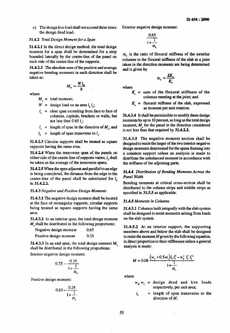
I!S456:2000
Exterior negative design moment:
0.65
l+L cr,
a, is the ratio of flexural stiffness of the exterior columns to the flexural stiffness of the slab at a joint taken in the direction moments are being determined and is given by
e) The design live load shall not exceed three times the design dead load.
31.4.2 Total Design Moment for a Span
31.4.2.1 In the direct design method, the total design moment for a span shall be determined for a strip bounded laterally by the centre-line of the panel on each side of the centre-line of the supports. 31.4.2.2 The absolute sum of the positive and average negative bending moments in each direction shall be taken as:
4, = w= 1. =
1, =
1, =
total moment; design load on an area 1, 1";
clear span extending from face to face of columns, capitals, brackets or walls, but not less than 0.65 1,;
length of span in the direction of M,,; and length of span transverse to 1,.
31.4.2.3 Circular supports shall be treated as square supports having the same area.
3X4.2.4 When the transverse span of the panels on either side of the centre-line of supports varies, I, shall be taken as the average of the transverse spans.
31.4.2.5 When the span adjacent and parallel to attedge is being considered, the distance from the edge to the centre-line of the panel shall be substituted for 1, ifi 31.4.2.2.
31.4.3 Negative and Positive Design Moments
31.4.3.1 The negative design moment shall be located at the face of rectangular supports, circular supports being treated as square supports having the same area.
31.4.3.2 In an interior span, the total design moment M,, shall be distributed in the following proportions:
Negative design moment 0.65 Positive design moment 0.35
31.4.3.3 In an end span, the total design moment MO shall be distributed in the following proportions:
Interior negative design moment:
Positive design moment:
0.28 0.63--
l+’ a,
where K, =
_K, =
sum of the flexural stiffness of the columns meeting at the joint; and flexural stiffness of the slab, expressed as moment per.unit rotation.
31.4.3.4 It shall be permissible to modify these design moments by up to 10 percent, so long as the total design moment, M,, for the panel in the direction considered is not less than that required by 31.4.2.2.
31.4.3.5 The negative moment section shall be designed to resist~the larger of the two interior negative design momenta determined for the spans framing into a common support unless an analysis is made to distribute the unbalanced moment in accordance with the stiffness of the adjoining parts.
31.4.4 Distribution of Bending Moments Across the Panel Wdth
Bending moments at critical cross-section shall -be distributed to the column strips and middle strips as specified in 31.55 as applicable.
31.4.5 Moments in Columns
31.4.5.1 Columns built integrally with the slab system shall be designed to-resist moments arising from loads on the slab system.
31.4.5.2 At an interior support, the supporting members above and below the-slab shall be designed to resist the moment M given by the following equation, in direct proportion to their stiffnesses unless a general analysis is made:
M = 0.08 (W” +0.5w,)1,1.’ -w: 1: 1:’
1
where
Wd,~W, = design dead and live loads respectively, per unit area;
1, = length of span transverse to the direction of M,
55

IS 456 : 2000
1, = length of the clear span in the direction of M, measured face to face of supports;
XK a, = C where K, and KS are as defined
=KS in 31.4.3.3; and
w:, l’, and li, refer to the shorter span.
31.4.6 Effects of Pattern-Loading
In the direct design method, when the ratio of live load to dead load exceeds 0.5 :
4
b)
the sum of the flexural stiffnesses of the columns above and below the slab, mC, shall be such that CL, is not less than the appropriate minimum value aC min specified in Table 17, or if the sum of the flexural stiffnesses of the columns, XC, does not satisfy (a), the positive design moments for the panel shall be multiplied by the coefficient /I, given by the following equation:
01, is the ratio of flexural stiffness of the columns above and below the slab to the flexural stiffness of the slabs at a joint taken in the direction moments are being determined and is given by:
where K, and KS are flexural stiffnesses of column and slab respectively.
31.5 Equivalent Frame Method
31.5.1 Assumptions
The bending moments and shear forces may be determined by an analysis of the structure as a continuous frame and the following assumptions may be made:
a) The structure shall be considered to be made up of equivalent frames on column lines taken longitudinally and transversely through the building. Each frame consists of a row of equivalent columns or supports, bounded laterally by the centre-line of the panel on each side of the centre-line of the columns or supports. Frames adjacent’and parallel to an edge shall be bounded by the edge and the centre- line of the adjacent panel.
b)
cl
4
Each such frame may be analyzed in its entirety, or, for vertical loading, each floor thereof and the roof may be analyzed separately with its columns being assumed fixed at their remote ends. Where slabs are thus analyzed separately, it may be assumed in determining the bending moment at a given support that the slab is fixed at any support two panels distant therefrom provided the slab continues beyond the point. For the purpose of determining relative stiffness of members, the moment of inertia of any slab or column may be assumed to be that of the gross cross-section of the concrete alone. Variations of moment of inertia along theaxis of the slab on account of provision of drops shall be taken into account. In the case of recessed
or coffered slab which is made solid in the region of the columns, the stiffening effect may be ignored provided the solid part of the slab does not extend more than 0.15 Zti, into the span measured from the centre-line of the columns. ‘Ihe stiffening effect of flared column heads may be ignored.
31.52 Loading Pattern
31.5.2.1 When the loading pattern is known, the structure shall be analyzed for the load~concerned,
Table 17 Minimum Permissible Values of c1, (Chue 3 1.4.6)
Imposed Load/Dead Load Ratio + Value of a= II.
(1) (2) ’ (3)
0.5 0.5 to 2.0 0
1.0 0.5 0.6
1.0 0.8 0.7
1.0 1.0 0.7
1.0 1.25 0.8
1.0 2.0 1.2
2.0 0.5 1.3
2.0 0.8 1.5
2.0 1.0 1.6
2.0 1.25 1.9
2.0 2.0 4.9
3.0 0.5 1.8
3.0 0:8 2.0
3.0 1.0 2.3 3.0 1.25 2.8
3.0 2.0 13.0
31.5.2.2 When the live load is variable but does not exceed three-quarters of the dead load, or the nature of the live load is such that all panels will be loaded simultaneously, the maximum moments may be assumed to occur at all sections when full design live load is on the entire slab system.
56

IS456:2000
greater than three-quarters of the value of 1,. the length of span transverse to the direction moments are being determined, the exterior negative moment shall be considered to be uniformly distributed across the length I,.
31.5.5.3 Column strip : Positive momentfor each span
For each span, the column strip shall be designed to resist 60 percent of the total positive moment in the panel.
31.5.5.4 Moments in the middle strip
The middle strip shall be designed on the following bases:
31.5.2.3 For other conditions of live load/dead load ratio and when all panels are not loaded simultaneously:
4
b)
maximum positive moment near midspan of a panel may be assumed to occur when three- quarters of the full design live load is on the panel and on alternate panels; and maximum negative moment in the slab at a support may be assumed to occur when three- quarters of the full design live load is on the adjacent panels only.
3-1.5.2.4 In no case shall design moments be taken to be less than those occurring with full design live load on all panels.
31.53 Negative Design Moment
31.5.3.1 At interior supports, the critical section for negative moment, in both the column strip and middle strip, shall be taken at the face of rectilinear supports, but in no case at a distance greater than 0.175 1, from the centre of the column where 1, is the length of the span in the direction moments are being determined, measured centre-to-centre of supports.
31.5.3.2 At exterior supports provided with brackets or capitals, the critical section for negative moment in the direction perpendicular to the edge shall be taken at a distance from the face of the supporting element not greater than one-half the projection of the bracket or capital beyond the face of the supporting element.
31.5.3.3 Circular or regular polygon shaped supports shall be treated as square supports having the same area.
31.54 Modification of Maximum Moment
Moments determined by means of the equivalent frame method, for slabs which fulfil the limitations of 31.4 may be reduced in such proportion that the numerical sum of the positive and average negative moments is not less than the value of total design moment M,, specified in 31.4.2.2.
31.55 Distribution of Bending Moment Across the Panel Width
31.5.5.1 Column strip : Negative moment at an interior support
At an interior support, the column strip shall be designed to resist 75 percent of the total negative moment in the panel at that support. 31.5.5.2 Column strip : Negative moment at an exterior support
4
b)
At an exterior support, the column strip shall be designed to resist the total negative moment in the panel at that support. Where the exterior support consists of a column or a wall extending for a distance equal to or
4
b)
That portion of-the design moment not resisted by the column strip shall be assigned to the adjacent middle strips. Each middle strip shall be proportioned to resist the sum of the moments assigned to its two half middle strips.
cl The middle strip adjacent and parallel to an edge supported by a wall shall be proportioned, to resist twice the moment assigned to half the middle strip corresponding to the first row of interior columns.
31.6 Shear in Nat Slab
31.6.1 ‘Ike critical section for shear shall be at a distance d/2 from the periphery of the column/capital/ drop panel, perpendicular to the plane of the slab where d is the effective depth of the section (see Fig. 12). The shape in plan is geometrically similar to the support immediately below the slab (see Fig. 13A and 13B).
NOTE -For column sections with reentrant angles, the critical section shall be taken ils indicated in Fig. 13C and 13D.
31.6.1.1 In the case of columns near the free edge of a slab, the critical section shall be taken as shown in Fig. 14.
31.6.1.2 When openings in flat slabs are located at a distance less than ten times the thickness of the slab from a concentrated reaction or when the openings are located within the column strips, the critical sections specified in 31.6.1 shall be modified so that the part of the periphery of the critical section which is enclosed by radial projections of the openings to the centroid of the reaction area shall be considered ineffective (see Fig. 15), and openings shall not encroach upon column head.
31.6.2 Calculation of Shear Stress
The shear stress 2, shali be the sum of the values calculated according to 31.6.2.1 and 31.6.2.2.
31.6.2.1 The nominal shear stress in flat slabs shall be taken as VI b,,d where Vis the shear force due to design load, b,, is the periphery of the critical section and d is the effective depth.
57

IS 456 : 2000
r--------i r CRITICAL
LSUPPORT SEbTlbN COLUMN I COLUMN HEAD
13A
SECT
CRITICAL SECTION-J K%FIT
‘ION
SUPPORT SECTION
L-- --_-_I df2 13D , 7-
NOTE-d is the effective depth of the flat slab/drop.
FIG. 13 CR~TKAL SECTIONS IN PLAN FOR SHIZAR IN FLAT SLABS
14 A
FREE CORNER
FIG. 14 Errzcr OF FREE EDGES ON CRITICAL SK~ION FOR SHEAR
31.6.2.2 When unbalanced gravity load, wind, value of a shall be obtained from the equation given earthquake or other forces cause transfer of bending in 31.3.3. moment between slab and column, a fraction (1 - o!j of the moment shall be considered transferred by 31.6.3 Pemissible Shear Stress
eccentricity of the shear about the centroid of the 31.6.3.1 When shear reinforcement is not provided, critical section. Shear stresses shall be taken as varying the calculated shear stress at the critical section shall linearly about the centroid of the critical section. The not exceed $T~,
58

IS 456 : 2000
SUBTRACT FROM OPENING -$--j-- PERIPHERY
15c
LARGE OPENNG+ \
i i
Y REGARD OPENING AS FREE EDGE
15D
FIG. 15 EFFKT OF OPENINGS ON CRITICAL SECTION FOR SHEAR
where k, = (0.5 + &) but not greater than 1, PC being the
ratio of short side to long side of the column/ capital; and
r, = 0.25 & in limit state method of design,
and 0.16 & in working stress method of design.
31.6.3.2 When the shear stress at the critical section exceeds the value given in 31.6.3.1, but less than 1.5 2, shear reinforcement shall be provided. If the shear stress exceeds 1.5 T,, the flat slab shall be redesigned. Shear stresses shall be investigated at successive sections more distant from the support and shear reinforcement shall be provided up to a section where the shear stress does not exceed 0.5 z,. While designing the shear reinforcement, the shear stress carried by the concrete shall be assumed to be 0.5 2, and reinforcement shall carry the remaining shear.
31.7 Slab Reinforcement
31.7.1 Spacing
The spacing of bars in a flat slab, shall not exceed
2 times the slab thickness, except where a slab is of cellular or ribbed construction.
31.7.2 Area of Reinforcement
When drop panels are used, the thickness of drop panel for determination of area of~reinforcement shall be the lesser of the following:
a) Thickness of drop, and b) Thickness of slab plus one quarter the distance
between edge of drop and edge of capital. 31.7.3 Minimum Length of Reinforcement
a)
b)
cl
Reinforcement in flat slabs shall have the minimum lengths specified in Fig.16. Larger lengths of reinforcement shall be provided when required by analysis. Where adjacent spans are unequal, the extension of negative reinforcement beyond each face of the common column shall be based on the longer span. The length of reinforcement for slabs in frames not braced against sideways and for slabs resisting lateral loads shall be determined by analysis but shall not be less than those prescribed in Fig. 16.
59

IS456:
REMAINOER
REMAINMR
REMAINDER
REMAINDER
(NO S&A8 CONTINUIIYI ICON1INUITY l ROVlOEOb INO sLA8 CONTlNUtl
Bar Lengthfrom Face of Support
Mininwn Length Maximum Length
Mark a b C d E f g
Length 0.14 lD 0.20 1, 0.22 1. 0.30 1. 0.33 1. 0.20 la 0.24 l,, 1
* Bent bars at exterior supports may be used if u general analysis is made. NOTE - D is the diameter of the column and the dimension of the rectangular column in the direction under consideration.
FIG. 16 MINIMUM BEND JOINT LOCATIONS AND EXTENSIONS FOR RENWRCEMEN
IN FLAT SLABS
60

31.7.4 Anchoring Reinforcement
a) All slab reinforcement perpendicular to a discontinuous edge shall have an anchorage (straight, bent or otherwise anchored) past the internal face of the spandrel beam, wall or column, of an amount:
1)
2)
For positive reinforcement - not less than 150 mm except that with fabric reinforce- ment having a fully welded transverse wire directly over the support, it shall be permissible to reduce this length to one-half of the width of the support or 50 mm, whichever is greater; and
For negative reinforcement - such that the design stress is developed at the internal face, in accordance with Section 3.
b) Where the slab is not supported by a spandrel beam or wall, or where the slab cantilevers beyond the support, the anchorage shall be obtained within the slab.
31.8 Openings in Flat Slabs
Openings of any size may be provided in the flat slab if it is shown by analysis that the requirements of strength and serviceability are met. However, for openings conforming to the following, no special analysis is required.
4 Openings of any size may be placed within the middle half of the span in each direction, provided the total amount of reinforcement required for the panel without the opening is maintained.
b)
c>
In the area common to two column strips, not more than one-eighth of the width of strip in either span shall be interrupted by the openings. The equivalent of reinforcement interrupted shall be added on all sides of~the openings.
In the area common to one column strip and one middle strip, not more than one-quarter of the rebforcement in either strip shall be interrupted by the openings. The equivalent of rein- forcement interrupted shall be added on all sides of the openings.
4 The shear requirements of 31.6shall be satisfied.
32 WALLS
32.1 General
Reinforced concrete walls subjected to direct compression or combined flexure and direct compression should be designed in accordance with Section 5 or Annex B provided the vertical reinforcement is provided in each face. Braced walls subjected to only vertical compression may be designed
IS 456 : 2000
as per empirical procedure given in 32.2. The minimum thickness of walls shall be 100 mm.
32.1.1 Guidelines or design -of walls subjected to horizontal and vertical loads are given in 32.3.
32.2 Empirical Design Method for Walls Subjected to Inplane Vertical Loads
32.2.1 Braced Walls
Walls shall be assumed to be braced if they are laterally supported by a structure in which all the following
apply:
a>
b)
c>
4
Walls or vertical braced elements are arranged in two directions so as to provide lateralstability to the structure as a whole.
Lateral forces are resisted by shear in the planes of these walls or by braced elements.
Floor and roof systems are designed to transfer lateral forces.
Connections between the wall and the lateral supports are designed to resist a horizontal force not less than
1) the simple static reactions to the total applied horizontal forces at the level of lateral support; and
2) 2.5 percent of the total vertical load that the wall is designed to carry at the level of lateral support.
32.2.2 Eccentricityof Vertical Load
The design of a wall shall take account of the actual eccentricity of the vertical force subject to a minimum value of 0.05 t.
The vertical load transmitted to a wall by a discontinuous concrete floor or roof shall be assumed to act at one-third the depth of the bearing area measured from the span face of the wall. Where there is an in-situ concrete floor continuous over the wall, the load shall be assumed to act at the centre of the wall.
The resultant eccentricity of the total vertical load on a braced wall at any level between horizontal lateral supports, shall be calculated on the assumption that the resultant eccentricity of all the vertical loads above the upper support is zero.
32.2.3 Maximum Effective Height to Thickness Ratio
The ratio of effective height to thickness, H,.Jt shall not exceed 30.
32.2.4 Effective Height
The effective height of a braced wall shall be taken as follows:
a) Where restrained against rotation at both ends
by
61

IS 456 : 2000
1) floors
2) intersecting walls or similar members
0.15 H, or
0.75 L,
whichever is the lesser.
b) Where not restrained against rotation at both ends by
1) floors 1.0 H, or
2) intersecting~walls or 1.0 L, similar-members whichever is the lesser.
where
H, = the unsupported height of the wall.
L, = the horizontal distance between centres of lateral restraint.
32.2.5 Design Axial Strength of Wall
The design axial strength Puw per unit length of a braced wall in compression may be calculated from the following equation:
Puw = 0.3 (t - 1.2 e - 2e,)f,,
where
t = thickness of the wall,
e = eccentricity of load measured at right angles to the plane of the wall determined in accordance with 32.2.2, and
e a = additional eccentricity due to slen- derness effect taken as H,,l2 500 t.
32.3 Walls Subjected to Combined Horizontal and Vertical Forces
32.3.1 When horizontal forces are in the plane of the wall, it may be designed for vertical forces in accordance with 32.2 and for horizontal shear in accordance with 32.3. In plane bending may be neglected in case a horizontal cross-section of the wall is always under compression due to combined effect of horizontal and vertical loads.
32.3.2 Walls subjected to horizontal forces perpendicular to the wall and for which the design axial load does not exceed 0.04~“~ As, shall~be designed as slabs in accordance with the appropriate provisions under 24, where Ac is gross area of the section.
32.4 Design for Horizontal Shear
32.4.1 Critical Section for Shear
The critical section for maximum shear shall be taken at a distance from the base of 0.5 Lw or 0.5 H, whichever is less,
32.4.2 Nominal Shear Stress
The nominal shear stress znu in walls shall be obtained as follows:
zVw = Vu I t.d
where
V” = shear force due to design loads.
t = wall thickness.
d = 0.8 x L, where L, is the length of the wall.
32.4.2.1 Under no circumstances shall the nominal shear stress 7Vw in walls exceed 0.17 fck in limit state method and 0.12 fck in working stress method.
32.4.3 Design Shear Strength of Concrete
The design shear strength of concrete in walls, z CW’ without shear reinforcement shall be taken as below:
a) For H, IL,+ 1
z,, = (3.0 - &/ LJ K, K
where K, is 0.2 in limit state method and 0.13 in working stress method.
b) For HJLw > 1
Lesser of the values calculated from (a) above and from
where K, is 0.045 in limit state method and 0.03 in working stress method, but shall be
not less than K3 Jfck in any case, where K,
is 0.15 in limit state method and 0.10 in working stress method.
32.4.4. Design of Shear Reinforcement
Shear reinforcement shall be provided to carry a shear equal to Vu - Tcw.t (0.8 LJ. In case of working stress method Vu is replaced by V. The strength of shear reinforcement shall be calculated as per 40.4 or B-5.4 with All” defined as below:
AN = P, (0.8 LJ t
where P, is determined as follows:
a)
b)
For walls where H, / Lw I 1, P, shall be the lesser of the ratios of either the vertical reinforcement area or the horizontal reinforcement area to the cross-sectional area of wall in the respective direction.
For walls where H,l Lw> 1, P, shall be the ratio of the horizontal reinforcement area to the cross-sectional area of wall per vertical metre.
32.5 Minimum Requirements for Reinforcement in Walls
The reinforcement for walls shall be provided as below:
62

b)
cl
4
the minimum ratio of vertical reinforcement to gross concrete area shall be: 1) 0.001 2 for deformed bars not larger than
16 mm in diameter and with a characteristic strength of 4 15 N/mm* or greater.
2) 0.001 5 for other types of bars. 3) 0.0012 for welded wire fabric not larger than
16 mm in diameter. Vertical reinforcement shall be spaced not farther apart than three times the wall thickness nor 450 mm. The minimum ratio of horizontal reinforcement to gross concrete area shall be:
1)
2) 3)
0.002 0 for deformed bars not larger than 16 mm in diameter and with a characteristic strength of 4 15 N/mm* or greater.
0.002 5 for other types of bars.
0.002 0 for welded wire fabric not larger than 16 mm in diameter.
Horizontal reinforcement shall be spaced not farther apart than three times the wall thickness nor 450 mm.
NOTE -The minimum reinforcement mny not slwnys be sufficient to provide adequate resistance to the effects of shrinkage and tempemture.
32.5.1 For walls having thickness more than 200 mm, the vertical and horizontal reinforcement shall be provided in two grids, one near each face of the wall.
32.5.2 Vertical reinforcement need not be enclosed by transverse reinforcement as given in 26.5.3.2 for column, if the vertical reinforcement is not greater than 0.01 times the gross sectional area or~where the vertical reinforcement is not required for compression.
33 STAIRS
33.1 Effective Span of Stairs
The effective span of stairs without stringer beams shall
IS 456 : 2000
be taken as the following horizontal distances:
a) Where supported at top and bottom risers by beams spanning parallel with the risers, the distance centre-to-centre of beams;
b)
c>
Where spanning on to the edge of a landing slab, which spans parallel, ~with the risers (see Fig. 17), a distance equal to the going of the stairs plus at each end either half the width of the landing or one metre, whichever is smaller; and Where the landing slab spans in the same direction as the stairs, they shall be considered as acting together to form a single slab and the span determined as the distance centre-to-centre of the supporting beams or walls, the going being measured horizontally.
33.2 Distribution of Loading on Stairs
In the case ofstairs with open wells, where spans partly crossing at right angles occur, the load on areas common to any two such spans may be taken as one- half in each direction as shown in Fig. 18. Where flights or landings are embedded into walls for a length of not less than 110 mm and are designed to span in the direction of the flight, a 150 mm strip may be deducted from the loaded area and the effective breadth of the sectionincreased by75 mm for purposes of design (see Fig. 19).
33.3 Depth of Section
The depth of section shall be taken as the minimum thickness perpendicular to the soffit of the staircase.
34 FOOTINGS
34.1 General
Footings shall be designed to sustain the applied loads, moments and forces and the induced reactions and to ensure that any settlement which may occur shall be as nearly uniform as possible, and the safe bearing capacity of the soil is not exceeded (see IS 1904).
34.1.1 In sloped or stepped footings the effective
FIG. 17 EFFEC~~V E SPAN FOR STAIRS SUPPORTED AT EACH END BY
LANDINGS SPANNING PARALLEL WITH THE RISERS
63
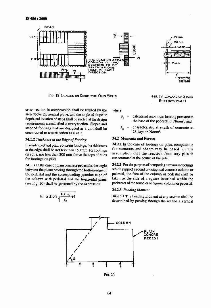
IS 456 : 2000
/-BEAM
UPa
00 THE LOAD ON AREAS COMMON TO TWO SYSTEMS TO BE TAKEN AS ONE HALF IN EACH DIRECTION
BREADTH
FIG. 18 LOADING ON STAIRS wrrn OPW WELLS FIG. 19 LOADING ON STAIRS BUILT INTO WALLS
cross-section in compression shall be limited by the area above the neutral plane, and the angle of slope or depth and location of steps shall be such that the design requirements are satisfied at every section. Sloped and stepped footings that are designed as a unit shall be constructed to assure action as a unit.
34.1.2 Thickness at the Edge of Footing
In reinforced and plain concrete footings, the thickness at the edge shall be not less than 150 mm for footings on soils, nor less than 300 mm above the tops of piles for footings on piles.
34.1.3 In the case of plain concrete pedestals, the angle between the plane passing through the bottom edge of the pedestal and the corresponding junction edge of the column with pedestal and the horizontal plane (see Fig. 20) shall be governed by the expression:
lo@ tanae0.9 A+1 i f,
where
40 = calculated maximum bearing pressure at the base of the pedestal in N/mmz, and
f-,k = characteristic strength of concrete at 28 days in N/mmz.
34.2 Moments and Forces
34.2.1 In the case of footings on piles, computation for moments and shears may be based on the assumption that the reaction from any pile is concentrated at the centre of the pile.
34.22 For the purpose of computing stresses in footings which support a round or octagonal concrete column or pedestal, the face of the column or pedestal shall be taken as the side of a square inscribed within the perimeter of the round or octagonal column or pedestal.
34.2.3 Bending Moment
34.2.3.1 The bending moment at any section shall be determined by passing through the section a vertical
A
1’ --coLUMN , / ? / PLAIN
1’
CONCRE PEDEST
/
1’
1’ \e
t ? t t 1L
FIG. 20
64

plane which extends completely across the footing, and computing the moment of the forces acting over the entire area of the footing on one side ofthe said plane.
34.2.3.2 The greatest bending moment to be used in the design of an isolated concrete footing which supports a column, pedestal or wall, shall be the moment computed in the manner prescribed in 34.2.3.1 at sections located as follows:
b)
cl
At the face of the column, pedestal or wall, for. footings supporting a concrete column, pedestal or wall;
Halfway between the centre-line and the edge of the wall, for footings under masonry walls; and
Halfway between the face of the column or pedestal and the edge of the gussetted base, for footings under gussetted bases.
34.2.4 Shear and Bond
34.2.4.1 The shear strength of footings is governed by the more severe of the following two conditions:
a)
b)
The footing acting essentially as a wide beam, with a potential diagonal crack extending in a plane across the entire width; the critical section for this condition shall be assumed as a vertical section located from the face of the column, pedestal or wall at a distance equal to the effective depth of footing for footings on piles.
Wo-way action of the footing, with potential diagonal cracking along the surface of truncated cone or pyramid araund the concentrated load; in this case, the footing shall be designed for shear in accordance with appropriate provisions specified in 31.6.
34.2.4.2 In computing the external shear or any section through a footing supported on piles, the entire reaction from any pile of diameter DP whose centre is located DP/2 or more outside the section shall be assumed as producing shear on the section; the reaction from any pile whose centre is located Dr/2 or more inside the section shall be assumed as producing no shear on the section, For intermediate positions of the pile centre, the portion of the pile reaction to be assumed as producing shear on the section shall be based on straight line interpolation between full value at D,,/2 outside the section and zero value at D,,/2 inside the section.
34.2.4.3 The critical section for checking the development length in a footing shall be assumed at the same planes as those described for bending moment in 34.2.3 and also at all other vertical planes where abrupt changes of section occur. If reinforcement is curtailed, the anchorage requirements shall be checked in accordance with 262.3.
IS 456 : 2000
34.3 Tensile Reinforcement
The total tensile reinforcement at any section shall provide a moment of resistance at least equal to the bending moment on the section calculated in accordance with 34.2.3.
34.3.1 Total tensile reinforcement shall be distributed across the corresponding resisting section as given below:
a)
b)
cl
In one-way reinforced footing, the-reinforcement extending in each direction shall be distributed uniformly across the full width of the footing;
In two-way reinforced square footing, the reinforcement extending in each direction shall be distributed uniformly across the full width of the footing; and
In two-way reinforced rectangular footing, the reinforcement in the long direction shall be distributed uniformly across the full width of the footing. For reinforcement in the short direction, a central band equal to the width of the footing shall be marked along the length of the footing and portion of the reinforcement determined in accordance with the equation given below shall be uniformly distributed across the central band:
Reinforcement in central band width 2 =- Total reinforcement in short direction p + 1
where /3 is the ratio of the long side to the short side of the footing. The remainder of the reinforcement shall be-uniformly distributed in the outer portions of the footing.
34.4 ‘Ihnsfer of Load at the Base of Column
The compressive stress in concrete at the base of a column or pedestal shdl be considered as being transferred by bearing to the top of the supporting Redestal or footing. The bearing pressure on the loaded area shall not exceed the permissible bearing stress in direct compression multiplied by a value equal to
d A A2
but not greater than 2;
where A, =
A* =
supporting area for bearing of footing, which in sloped or stepped footing may be taken as the area of the lower base of the largest frustum of a pyramid or cone contained wholly within the footing and having for its upper base, the area actually loaded and having side slope of one vertical to two horizontal; and
loaded area at the column base.
65
IS 456 : 2000
For working stress method of design the permissible bearing stress on full area of concrete shall be taken as 0.25tk; for limit state method of design the permissible bearing stress shall be 0.45 f,.
34.4.1 Where the permissible bearing stress on the concrete in the supporting or supported member would be exceeded, reinforcement shall be provided for developing the excess force, either by extending the longitudinal bars into the supporting member, or by dowels (see 34.4.3).
34.4.2 Where transfer of force is accomplished by , reinforcement, the development length of the
reinforcement shall be sufficient to transfer the compression or tension to the supporting member in accordance with 26.2.
34.4.3 Extended longitudinal reinforcement or dowels of at least 0.5 percent of the cross-sectional area of the supported column or pedestal and a minimum of four bars shall be provided. Where dowels are used, their
diameter shall no exceed the diameter of the column ~bars by more than 3 mm.
34.4.4 Column bars of diameters larger than 36 mm, in compression only can be dowelled at the footings with bars of smaller size of the necessary area. The dowel shall extend into the column, a distance equal to the development length of the column bar and into the footing, a distance equal to the development length of the dowel.
34.5 Nominal Reinforcement
34.51 Minimum reinforcement and spacing shall be as per the requirements of solid slab.
34.52 The nominal reinforcement for concrete sections of thickness greater than 1 m shall be 360 mm* per metre length in each direction on each face. This provision does not supersede the requirement of minimum tensile reinforcement based on the depth of the section.
66

IS 456 : 2000
SECTION 5 STRUCTURAL DESIGN (LIMIT STATE METHOD)
35 SAFETY AND SERVICEABILITY REQUIREMENTS
35.1 General
In the method of design based on limit state concept, the structure shall be designed~to withstand safely all loads liable to act on it throughout its life; it shall also satisfy the serviceability requirements, such as limitations on deflection and cracking. The acceptable limit for the safety and serviceability requirements before failure occurs is called a ‘limit state’. The aim of design is td achieve acceptable probabilities that the structure will not become unfit for the use for which it isintended, that is, that it will not reach a limit state. 351.1 All relevant limit states shall be considered in design to ensure an adequate degree of safety and serviceability. In general, the structure shall be designed on the basis of the most critical limit state and shall be checked for other limit states.
35.1.2 For ensuring the above objective, the design should be based on characteristic values for material strengths and applied loads, which take into account the variations in the material strengths and in the loads to be supported. The characteristic values should be based on statistical data if available; where such data are not available they should be based on experience. The ‘design values’ are derived from the characteristic values through the use of partial safety factors, one for material strengths and the other for loads. In the absence of special considerations these factors should have the values given in 36 according to the material, the type of loading and the limit state being considered.
35.2 Limit State of Collapse
The limit state of collapse of the structure or part of the structure could be assessed from rupture of one or more critical sections and from buckling due to elastic or plastic instability (including the effects of sway where appropriate) or overturning. The resistance to bending, shear, torsion and axial loads at every section shall not be less than the appropriate value at that section produced by the probable most unfavourable combination of loads an the structure using the appropriate partial safety factors.
35.3 Limit States of Serviceability
35.3.1 Deflection
Limiting values of deflections are given in 23.2.
35.3.2 Cracking
Cracking of concrete should not adversely affect the appearance or durability of the structure; the acceptable
limits of cracking would vary with the type of structure and environment. Where specific attention is required to limit the designed crack width to a particular value, crack width calculation may be done using formula given in Annex F. The practical objective of calculating crack width is merely to give guidance to the designer in making appropriate structural arrangements and in avoiding gross errors in design, which might result in concentration and excessive width of flexural crack.
The surface width of the cracks should not, in general, ~exceed 0.3 mm in members where cracking is not harmful and does not have any serious adverse effects upon the preservation of reinforcing steel nor upon the durability of the structures. In members where cracking in the tensile zone is harmful either because they are exposed to the effects of the weather or continuously exposed to moisture or in contact soil or ground water, an upper limit of 0.2 mm is suggested for the maximum width of cracks. For particularly aggressive environment, such as the ‘severe’ category in Table 3, the assessed surface width of cracks should not in general, exceed 0.1 mm.
35.4 Other Limit States
Structures designed for unusual or special functions shall comply with any relevant additional limit state considered appropriate to that structure.
36 CHARACTERISTIC AND DESIGN VALUES AND PARTIAL SAFETY FACTORS
36.1 Characteristic Strength of Materials
The term ‘characteristic strength’ means that value of the strength of the material below which not more than 5 percent of the test results are expected to fall. The characteristic strength for concrete shall be in accordance with Table 2. Until the relevant Indian Standard Specifications for reinforcing steel are modified to include the concept of characteristic strength, the characteristic value shall be assumed as the minimum yield stress/O.2 ~percent proof stress specified in the relevant Indian Standard Specifications.
36.2 Characteristic Loads
The term ‘characteristic load’ means that value of load which has a 95 percent probability of not being exceeded during the life of the structure. Since data are not available to express loads in statistical terms, for the purpose of this standard, dead loads given in IS 875 (Part l), imposea loads given in IS 875 (Part 2), wind loads given in IS 875 (Part 3), snow load as given in IS 875 (Part 4) and seismic forces given in IS 1893 shall be assumed as the characteristic loads.
67

IS 456 : 2000
36.3 Design Values
36.3.1 Materials
The design strength of-the materials,& is given by
f ii=-;;-
where
f =
Ym =
lm
characteristic strength of the material (see 36.1), and
partial safety factor appropriate to the material and the limit state being considered.
36.3.2 Loadr
The design load, F, is given by
Fd=FYf
where
F=
Yf =
characteristic load (see 36.2). and
partial safety factor appropriate to the nature of loading and the limit state being considered.
36.3.3 Consequences of Attaining Limit State
Where the consequences of a structure attaining a limit state are of a serious nature such as huge loss of life and disruption of the economy, higher values for yf and ym than those given under 36.4.1 and 36.4.2 may be applied.
36.4 Partial Safety Factors
36.4.1 Partial Safety Factor y f for Loads
The values of yf given in Table 18 shall normally be used.
36.4.2 Partial Safety Factor y,,, for Mateiral Strength
36.4.2.1 When assessing the strength of a structure or structural member for the limit state of collapse, the values of partial safety factor, us should be taken as 1.5 for concrete and 1.15 for steel.
NOTE - 1~ values are already incorporated in the equations and tables given in this standard for limit state design.
36.4.2.2 When assessing the deflection, the material properties such as modulus of elasticity should be taken as those associated with the characteristic strength of the material.
37ANALYsIs
37.1 Analysis of Structure
Methods of analysis as in 22 shall be used, The material strength to be assumed shall be characteristic values in the determination of elastic ~properties , of members irrespective of the limit state being considered. Redistribution of the calculated moments may be made as given in 37.1.1.
37.1.1. Redistribution of Moments in Continuous Beams and Frames
The redistribution of moments may be carried out satisfying the following conditions:
a) Equilibirum between the interal forces and the external loads is maintained.
b) The ultimate moment of resistance provided at any section of a member is not less than 70 percent of the moment at that section obtained from an elastic maximum moment diagram covering all appropriate combinations of loads.
c) The elastic moment at any section in a member due to a particular combination of loads shall
Table 18 Values of Partial Safe@ Factor y, for Loads
(Ckwe~ 18.2.3.1.36.4.1 umf B4.3)
Load Combination Limit State ef Collapse Limit stated of
c 4. Serviceability
DL IL WL DL IL WL
(1) (2) (3) (4) (5) (6) (7) e w
DL+IL 1.5 I.0 1.0 1.0
DL+WL 1.5 or 1.5 1.0 1.0
$J”
DL+IL+ WL 1.2 1.0 0.8 0.8
NOTES
1 While considering earthquake effects, substitute EL for WL
2 For the limit states of serviceability, the values of 7r given in this table m applicable for short tern effects. While assessing the long term effects due to creep the dead load and that pat of the live load likely to be permanent may only be consided.
I) This value is to be considered when stability against overturning or stress reversal is critical.
68

4
not be reduced by more than 30 percent of the numerically largest moment given anywhere by the elastic maximum moments diagram for the particular member, covering all appropriate combination of loads.
At sections where the moment capacity after redistribution is less than that from the elastic maximum moment diagram, the following relationship shall be satisfied:
s+s SO.6 d 100
where
e)
X
d”
= depth of neutral axis, = effective depth, and
6M = percentage reduction in moment.
In structures in which the structural frame provides the lateral stability, the reductions in moment allowed by condition 37.1.1 (c) shall be restricted to 10 percent for structures over 4 storeys in height.
37.1.2 Analysis of Slabs Spanning in Two Directions at Right Angles
Yield line theory or any other acceptable method may be used. Alternatively the provisions given in Annex D may be followed.
38 LIMIT STATE OF COLLAPSE : FLEXURE
38.1 Assumptions
Design for the limit state of collapse in flexure shall be based on the assumptions given below:
a) Plane sections normal to the axis remain plane after bending.
b)
cl
4 e)
f)
IS 456 : 2000
The maximum strain in concrete at the outermost compression fibre is taken as 0.003 5 in bending. The relationship between the compressive stress distribution in concrete and the strain in concrete may be assumed to be rectangle, trapezoid, parabola or any other shape which results in prediction of strength in substantial agreement with the results of test. An acceptable stress- strain curve is given in Fig. 21. For design purposes, the compressive strength of concrete in the structure shall be assumed to be 0.67 times the characteristic strength. The partial safety factor y, = 1.5 shall be applied in addition to this. NOTE - For the stress-stin curve in Fig. 21 the design stress block pnrnmeters are as follows (see Fig. 22):
Aren of stress block = 0.36.f,.xU
Depth of centre of compressive force = 0.425
from the extreme fibre in compression
Where
& = characteristic compressive strength of concrete, nnd
zU = depth of neutrnl exis.
The tensile strength of the concrete is ignored. The stresses in the reinforcement are derived from representative stress-strain curve for the type of steel used. Qpical curves are given in Fig. 23. For design purposes the partial safety factor Ym, equal to 1.15 shall be applied.
The maximum strain in the tension reinforce- ment in the section at failure shall not be less than:
where
f, = characteristic strength of steel, and
E, = modulus of elasticity of steel.
I%67fc,,
T
0.002 0.0035
STRAIN -
FIG. 21 STRESS-STRAIN CURVE FOR CONCRETE FIG. 22 STRESS I~LOCK PARAMETERS
69
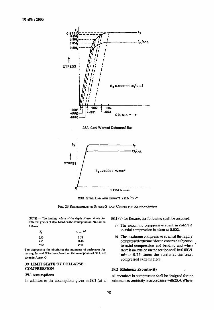
IS 456 : 2000
ES 8 200000 N/mm2
fY
fy /I.15
23A Cold Worked Deformed Bar
E, =ZOOOOO N/mm2
STRAIN -
238 STEEL BAR WITH DEFINITE YIELD POINT
FIG. 23 REPRESENTATIVE STRESS-STRAIN CURVES FOR REINFORCEMENT
NOTE - The limiting values of the depth of neutral axis for different grades of steel based on the assumptions in 38.1 are. as
follows:
f ‘Y *4nulld
250 0.53 415 0.48 500 0.46
The expression for obtaining the moments of resistance for rectangular nnd T-Sections, based on the assumptions of 38.1, are given in Annex G.
39 LIMIT STATE OF COLLAPSE : COMPRESSION
39.1 Assumptions
In addition to the assumptions given in 38.1 (a) to
38.1 (e) for flexure, the following shall be assumed:
a) The maximum compressive strain in concrete in axial compression is taken as 0.002.
b) The maximum compressive strain at the highly compressed extreme fibre in concrete subjected to axial compression and bending and when * there is no tension on the section shall be 0.003 5 minus 0.75 times the strain at the least compressed extreme fibre.
39.2 Minimurdccentricity
All members in compression shall be designed for the minimum eccentricity in accordance with25.4. Where
70

IS 456 : 2000
39.6 Members Subjected to Combined Axial Load and Biaxial Bending
The resistance of a member subjected to axial force and biaxial bending shall be obtained on the basis of assumptions given in 39.1 and 39.2 with neutral axis so chosen as to satisfy the equilibrium of load and moments about two axes. Alternatively such members may be designed by the following equation:
calculated eccentricity is larger, the minimum eccentricity should be ignored.
39.3 Short Axially Loaded Members in Compression
The member shall be designed by considering the assumptions given in 39.1 and the minimum eccentricity. When the minimum eccentricity as per 25.4 does not exceed 0.05 times the lateral dimension, the members may be designed by the following equation:
P” =
where
?J” =
f& =
AC =
f, =
As =
0.4 fd .Ac + 0.674 .A=
axial load on the member,
characteristic compressive strength of the concrete,
Area of concrete,
characteristic strength of the compression reinforcement, and
area of longitudinal reinforcement for columns.
39.4 Compression Members with Helical Reinforcement
The strength of compression members with helical reinforcement satisfying the requirement of 39.4.1 shall be taken as 1.05 times the strength of similar member with lateral ties. 39.4.1 The ratio of the volume of helical reinforcement to the volume of the core shall not be less than
Al =
A, =
& =
& =
gross area of the section,
area of the core of the helically reinforced cc+Iumn measured to the outside diameter of the helix,
characteristic compressive strength of the concrete, and
characteristic strength of the helical reinforcement but not exceeding 415 N/mm*.
39.5 Members Subjected to Combined Axial Load and Uniaxial Bending
A member subjected to axial force and uniaxiaMxmding shall be designed on the basis of 39.1 and 39.2.
NOTE -The design of member subject to canbii axial load and uniaxial bending will involve lengthy calculation by trial and error. In order to overcome these difficulties interaction diugmms may~be used. These have been prepared and published by BIS in ‘SP : 16 Design uids ~for reinforced concrete to IS 456’.
where
MUX, MU, =
KX,, M”Yl =
moments about x and y axes due to design loads, maximum uniaxial moment capacity for an axial load of P,, bending about x and y axes respectively, and
01” is related to P;/Puz
where Puz = 0.45 f, . AC + 0.75&A,
For values of P,lp., = 0.2 to 0.8, the values of cs,, vary linearly from 1 .O to 2.0. For values less than 0.2, a, is 1 .O; for values greater than 0.8, an is 2.0.
39.7 Slender Compression Members
The design of slender compression members (see 25.1.1) shall be based on the forces and the moments determined from an analysis of the structure, including the effect of deflections on moments and forces. When the effect of deflections are not taken into account in the analysis, additional moment given in 39.7.1 shall be taken into account in the appropriate direction. 39.7.1 The additional moments M, and My, shall be calculated by the following formulae:
Ma%
where P” =
1, =
1 =
o”=
b =
axial load on the member,
effective length in respect of the major axis,
effective length in respect of the minor axis,
depth of the cross-section at right angles to the major axis, and
width of the member. For design of section, 39.5 or 39.6 as appropriate shall apply*
71

IS 456 : 2000
NOTES of the beam. 1 A column may be considered braced in a given plane if lateral
stability to the structure as a whole is provided by walls or bracing or buttressing designed to resist all latexal forces in that plane. It should otherwise be considered as unbmced.
2 In the case of a braced column without any transverse loads occurring in its height, the additional moment shall be added to an initial moment equal to sum of 0.4 My, and 0.6 MB, where Mu, is the larger end moment and Mu, is the smaller end moment (assumed negative if the column is bent in double curvature). In no case shall the initial moment be less than 0.4 Mu, nor the total moment including the initial moment be less than Mm,. For unbraced columns, the additional moment shall be added to the end moments.
The negative sign in the formula applies when the bending moment iU” increases numerically in the same direction as the effective depth d increases, and the positive sign when the moment decreases numerically in this direction.
40.2 Design Shear Strength of Concrete
3 Unbraced compression members, at any given level or storey, subject to lateral load are usually constrained to deflect equally. In suth cases slenderness ratio for each column may be taken as the average for all columns acting in the same direction.
40.2.1 The design shear strength of concrete in beams without shear reinforcement is given in Table 19. 40.2.1.1 For solid slabs, the design shear strength for concrete shall be zck, wheie k has the values given below:
39.7.1.1 The values given by equation 39.7.1 may be multiplied by the following factor:
k =p,,-P,<l pu, - 8
Overall Depth 300 or 275 250 225 200 175 15Oor ofS6ab, mm more less
k 1.00 1.05 1.10 I.15 1.20 1.25 1.30
NOTE -This provision shall not apply to flat slabs for which 31.6 shall apply.
40.2.2 Shear Strength of Members under Axial Compression where
P* =
P*z = _Ph =
axial load on compression member,
as defined in 39.6, and
axial load corresponding to the condition of maximum compressive strain of 0.003 5 in concrete and tensile strain of 0.002 in outer most layer of tension steel.
40 LIMIT STATE OF COLLAPSE : SHEAR
40.1 Nominal Shear Stress
The nominal shear stress in beams of uniform depth shall be obtained by the following equation:
2, = v, ‘d
where
vu = b =
d =
shear force due to design loads;
breadth of the member, which for flanged section shall be taken as the breadth of the web, bw; and
effective depth.
40.1.1 Beams of Varying Depth
In the case of beams of varying depth the equation shall be modified as:
where
z, = v,++tanp
bd
z “, VU, b and d are the same as in 40.1, M,, = bending moment at the section, and
p = angle between the top and the bottom edges
For members subjected to axial compression P,, the design shear strength of concrete, given in Table 19, shall be multiplied by the following factor :
6 = 1 + 2 but-not exceeding 1.5
where
P” = axial compressive force in Newtons,
As = gross area of the concrete section in mm2, and
f,l: = characteristic compressive strength of concrete.
40.2.3 With Shear Reinforcement
Under no circumstances, even with shear reinforcement, shall the nominal shear stress in beams z, execed z,_ given in Table 20.
40.2.3.1 For solid slabs, the nominal shear stress shall not exceed half the appropriate values given in Table 20.
40.3 Minimum Shear Reinforcement
When z, is less than z, given in Table 19, minimum shear reinforcement shall -be provided in accordance with 26.5.1.6.
40.4 Design of Shear Reinforcement
When 7t, ~exceeds ‘5, given in Table 19, shear reinforcement shall be provided in any of the following forms:
a) Vertical stirrups, b) Bent-up bars along with stirrups, and
72

I!3456:2000
Table 19 Design Shear Strength of Concrete, N/mm2 5, ,
(Clauses 40.2.1.40.2.2,40.3,40.4,40.5.3.41.3.2.41.3.3 and41.4.3)
(1)
S0.H
0.25
0.50
0.75
1.00
1.25
1.50
1.75
2.00
2.25
2.50
2.75
3.00 and
above
ConcBte Grade ,
M 15 M20 M25 M30 M35 (2) (3) (4) (5) (6)
0.28 0.28 0.29 0.29 0.29
0.35 0.36 0.36 0.37 0.37
0.46 0.48 0.49 0.50 0.50
0.54 0.56 0.57 0.59 0.59
0.60 0.62 0.64 0.66 0.67
0.64 0.67 0.70 0.71 ~0.73
0.68 0.72 0.74 0.76 0.78
0.71 0.75 0.78 0.80 0.82
0.71 0.79 0.82 0.84 0.86
0.71 0.81 0.85 0.88 0.90
0.71 0.82 0.88 0.91 0193
0.7 1 0.82 0.90 0.94 O.%
0.71 0.82 0.92 0.96 0.99
\
M4Oandabove
(7)
0.30
0.38
0.51
0.60
0.68
0.74
0.79
0.84
0.88
0.92
0.95
0.98
l.Oj
NOTE - The tern A, is the area of longitudii temioa reinforcement which continues at least one effective depth beyond the section being considered except at support whete the full ama of tension reinfotreme nt may be used provided the detailing conforms to 26.23 and X.2.3
able 20 Maximum Shear Stress, ITS _ , N/m&
(C&~es40.2.3.40.2.3.1,40.5.1Md41.3.1)
Concrete ~Grade
T,,,Wmm’
M 15 MU) M 25 M30 M 35
2.5 2.8 3.1 3.5 3.7
M40 aad
above
4.0
c) Inclined stirrups, V, = 0.874 A, sin a
Where bent-up bars are provided, their contribution towards shear resistance shall not be more than half that of the total shear reinforcement.
Shear reinforcement shall be provided to carry a shear equal to Vu - z, bd The strength of shear reinforce- ment Vu, shall be calculated as below:
where
AS” =
s = Y
total cross-sectional area of stirrup legs or bent-up bars within a distance sV. spacing of the stirrups or bent-up bars along the length of the member,
nominal shear stress, a) For vertical stirrups:
0, =
z, =
b =
design shear strength of the concrete,
breadth of the member which for flanged beams, shall be taken as the breadth of the web by,
characteristic strength of the stirrup or bent-up reinforcement which shall not be taken greater than 415 N/mmz, angle between the inclined stirrup or bent- up bar and the axis of the member, not less than 45”, and
effective depth.
v = 0.87 fy q,d
“I S”
b) For inclined stirrups or a series of bars bent-up at different cross-sections:
v = 0.8.7 fy bvd
US S”
(sin 01+ cos a)
c) For single bar or single group of parallel bars, all bent-up at the same cross-section:
f, =
a =
d =
73

IS 456 : 2000
NOTES
1 Where more thaa one type of shear reinforcement is used to reinforce the same portion of the beam, the total shear resistance shall be computed as the sumof the resistance for the various types separately.
2 The area of the stim~ps shall not be less than the miniium specified in 265.1.6.
40.5 Enhanced Shear Strength of Sections Close to supports
40.5.1 General Shear failure at sections of beams and cantilevers without shear reinforcement will normally occur on plane inclined at an angle 30” to the horizontal. If the angle of failure plane is forced to be inclined more steeply than this [because the section considered (X - X) in Fig. 24 is close to a support or for other reasons], the shear force~required to produce failureis increased.
The enhancement of shear strength may be taken into account in the design of sections near a support by increasing design shear strength of concrete to 2d z, /a, provided that design shear stress at the face of the support remains less than the values given in Table 20. Account may be taken of the enhancement in any situation where the section considered is closer to the face of a support or concentrated load than twice the effective depth, d. To be effective, tension reinforcement should extend on each side of the point where it is intersected by a possible failure plane for a distance at least equal to the,effective depth, or be provided with an equiv.dent anchorage.
40.52 Shear Reinforcement for Sections Close to
supports
If shear reinforcement is required, the total area of this
X
is given by:
As=avb(zV-2d’tc/aV)10.87fy20.4a,b/0.87fy
This reinforcement should be provided within the middle three quarters of a,, where aV is less than d, horizontal shear reinforcement will be effective than vertical.
40.5.3 Enhanced Shear Strength Near Supports (Simplified Approach)
The procedure given in 40.51 and 40.5.2 may beused for all beams. However for beams carrying generally uniform load or where the principal load is located farther than 26 from the face of support, the shear stress maybe calculated at a section a distance d from the face of support. The value of 2, is calculated in accordance with Table 19 and appropriate shear reinforcement is provided at sections closer to the support, no further check for shear at such sections is required.
41 LIMlT STATE OF COLLAPSE : TORSION
41.1 General
In structures, where torsion is required to maintain equilibrium, members shall be designed for torsion in accordance with 41.2,41.3 and 41A. However, for such indeterminate structures where torsion can be eliminated by releasing redundant restraints, no specific design for torsion is necessary, provided torsional stiffness is neglected in the calculation of internal forces. Adequate control of any torsional cracking is provided by the shear reinforcement as per 40.
NOTE -The approach to desip in this clause is as follows: Torsional reinforcement is not calculated separately from that required for beading and shear. Instead the total longitudinal reinforcement is determined for a fictitious bending moment which is a function of actual bending moment and torsion;
NOTE -The shear causing failure is that acting on section X-X.
FIG. 24 SHIM FAILURE NEAR SIJFWI~~~
74

similarly web reinforcement is determined for a fictitious shear which is a function of actual shear and torsion.
41.1.1 The design rules laid down in 41.3 and 41.4 shall apply to beams of solid rectangular cross-section. However, these clauses may also be applied to flanged beams, by substituting bw for 6 in which case they are generally conservative; therefore specialist literature may be referred to.
41.2 Critical Section
Sections located less than a distance d, from the face of the support may be designed for the same torsion as computed at a distance d, where d is the effective depth.
41.3 Shear and Torsion
41.3.1 Equivalent Shear
Equivalent shear, V,, shall be calculated from the formula:
v, =V, + 1.6 $
where
Y = equivalent shear, Vu = shear, q = torsional moment, and
b = breadth of beam. The equivalent nominal shear stress, 2, in this case shall be calculated as given in 40.1, except for substituting Vu by V,. The values of zvc shall not exceed the values of z, mur given in Table 20.
41.3.2 If the equivalent nominal shear stress, zve does not exceed zc given in ‘Iable 19, minimum shear reinforcement shall be provided as per 26.5.1.6.
41.3.3 If zVe exceeds zc given in Table 19, both longitudinal and transverse reinforcement shall be provided in accordance with 41.4.
41.4 Reinforcement in Members Subjected to Torsion
41.4.1 Reinforcement for torsion, when required, shall consist of longitudinal and transverse reinforcement.
41.4.2 Longitudinal Reinforcement
The longitudinal reinforcement shall be designed to resist an equivalent bending moment, M,,, given by
Me,=M,,+M,
where Mu = bending moment at the cross-section, and
MI = T, $!+! ( .
Is456:2000
where
x is the torsional moment, D is the overall depth of the beam and b is the breadth of the beam.
41.4.2.1 If the numerical value of M, as defined in 41.4.2 exceeds the numerical value of the moment Mu, longitudinal reinforcement shall be provided on the flexural compression face, such that the beam can also withstand an equivalent Me* given by
Me2 = Mt - Mu, the moment M, being taken as acting in the opposite sense to the moment M,.
41.4.3 Transverse Reinforcement
Two legged closed hoops enclosing the corner longitudinal bars shall have anarea of cross-section Aly, given by
q, = TUG v, sv b, dI (0.87 &,) + 2.5d, (0.87&J ’
but the total transverse reinforcement shall not be less
where
Tu =
V” =
S” =
b, =
d, =
b =
f) =
zw =
fc =
(Ge -Z,)b.S, 0.87 fy
torsional moment,
shear force,
spacing of the stirrup reinforcement,
centre-to-centre distance between corner bars in the direction of the width,
centre-to-centre distance between comer bars,
breadth of the member,
characteristic strength of the stirrup reinforcement,
equivalent shear stress as specified in 41.3.1, and
shear strength of the concrete as per Table 19.
42 LIMIT STATE OF SERVICEABILITY: DEFLECTION
42.1 Flexural Members
In all normal cases, the deflection of a flexural member will not be excessive if the ratio of its span to its effective depth is not greater than appropriate ratios given in 23.2.1. When deflections are calculated according to Annex C, they shall not exceed the permissible values given in .23.2.
75

1s 456 : 2000
43 LIMIT STATE OF SERVICEABILITY: CRACKING
43.1 Flexural Members
In general, compliance with the spacing requirements of reinforcement given in 26.3.2 should be sufficient to control flexural cracking. If greater spacing are required, the expected crack width should be checked by formula given in Annex F.
43.2 Compression Members
Cracks due to bending in a compression member subjected to a design axial load greater than 0.2fc, AC, wheref, is the characteristic compressive strength of concrete and AE is the area of the gross section of the member, need not be checked. A mumber subjected to lesser load than 0.2fckAI: may be considered as flexural member for the purpose of crack control (see 43.1).
7G

IS No.
269 : 1989
383 : 1970
432 (Part 1) : 1982
455 : 1989
516: 1959
875
(Part 1) : 1987
(Part 2) : 1987
(Part 3) : 1987
(Part 4) : 1987
(Part 5) : 1987
1199 : 1959
1343 : 1980
1489
(Part 1) : 1991
(Part 2) : 1991
1566 : 1982
1641 : 1988
ANNEX A (Clal&&? 2)
LIST OF REFERRED INDIAN STANDARDS
Specification for ordinary Portland cement, 33 grade (fourth revision)
IS No.
1642 : 1989
Specification for coarse and fine aggregates from natural sources for concrete (second revision)
Specification for mild steel and medium tensile steel bars and hard-drawn steel wire for concrete reinforcement: Part 1 Mild steel and medium tensile steel bars (third revision)
Specification for Portland slag cement yburth revision)
Method of test for strength of concrete
1786 : 1985
1791 : 1968
1893 : 1984
1904 : 1986
Code of practice for design loads (other than earthquake) for buildings and structures :
Dead loads - Unit weights of building material and stored materials (second revision)
Imposed loads (second revision)
Wind loads (second revision)
Snow loads (second revision)
Special loads and load combinations (second revision)
Methods of sampling and analysis of concrete
2062 : 1992
2386 (Part 3) : 1963
2502 : 1963
2505 : 1980
2506 : 1985
Code of practice for prestressed concrete (first revision)
Specification for Portland pozzolana cement :
Ply ash based (third revision)
Calcined clay based (third revision)
Specification for hard-drawn steel wire fabric for concrete reinforcement (second revision)
Code of practice for fire safety of buildings (general): General principles of fire grading and classification yirst revision)
7
2514 : 1963
2751 : 1979
(Part 17) : 1984
(Part 18) : 1984
‘7
‘litle
Code of practice for fire safety of buildings (general) : DeWs of construction (first revision)
Specification for high strength &formed steel bars and wires for concrete reinforcement (third revision)
Specification for batch type concrete mixers (second revision)
Criteria for earthquake resistant design of structures (fourth revision)
Code of practice for &sign and construction of foundations in soils : General requirements (thin-i Fevision)
Steel for general structural purposes (fourth revision)
Methods of test for aggregates for concrete : Part 3 Specific gravity, density, voids, absorption and bulking
Code of practice for bending and fixing of bars for concrete reinforcement
Concrete vibrators -Immersion type - General requirements
General requirements for screed board concrete vibrators (first revision)
Specification for concrete vibrating tables
Recommended practice for welding of mild steel plain and deformed bars for reinforced construction (first revision)
Methods of sampling and test (physical and chemical) for water and waste water :
Non-filterable residue (total suspended solids) (first revision)
Volatile and fixed residue (total filterable and non-filterable) (first revision)

IS 456 : 2000
IS No.
(Part 22) : 1986
(Part 23) : 1986
(Part 24) : 1986
(Part 32) : 1988
3414: 1968
3812 : 1981
3951 (Part 1) : 1975
4031(Part 5) : 1988
4082 : 1
4326 : 1
996
993
4656 : 1968
4845 : 1968
4925 : 1968
4926 : 1976
5816 : 1999
606 I
(Part 1) : 1971
(Part 2) : 1971
6452 : 1989
646 1
(Part 1) : 1972
(Part 2) : 1972
Title
Acidity (first revision)
Alkalinity (first revision)
Sulphates (first revision)
Chloride (first revision)
Code of practice for design and installation of joints in buildings
Specification for fly ash for use as pozzolana and admixture (first revision)
Specification for hollow clay tiles for floors and roofs : Part 1 Filler type (first revision)
Methods of physical tests for hydraulic cement : Part 5 Determination of initial and final setting times yirst revision)
Recommendations on stacking and storage of construction materials and components at site (second revision)
Code of practice for earthquake resistant design and construction of buildings (second revision)
Specification for form vibrators for concrete
Definitions and terminology relating to hydraulic cement
Specification for concrete batching and mixing plant
Specification for ready-mixed concrete (second revision)
Method of test for splitting tensile strength of concrete (first revision)
Code of practice for construction of floor and roof with joists and filler blocks :
With hollow concrete filler blocks
With hollow clay filler blocks (first revision)
Specification for high alumina cement for structural use
Glossary of terms relating to cement:
Concrete aggregates
Materials
IS No.
(Part 3) : 1972
(Part 4) : 1972
(Part 5) : 1972
(Part 6) : 1972
(Part 7) : 1973
(Part 8) : 1973
(Part 9) : 1973
(Part 10) : 1973
(Part 11) : 1973
(Part 12) : 1973
6909 : 1990
7861
(Part 1) : 1975
(Part 2) : 1975
8041 : 1990
8043: 1991
8112 : 1989
9013 : 1978
9103: 1999
9417 : 1989
11817 : 1986
12089 : 1987
12119 : 1987
Me
Concrete reinforcement
Types of concrete
Formwork for concrete
Equipment, tool and plant
Mixing, laying, compaction, curing and other construction aspect
Properties of concrete
Structural aspects
Tests and testing apparatus
Prestressed concrete
Miscellaneous
Specification for supersulphated cement
Code of practice for extreme weather concreting :
Recommended practice for hot weather concreting
Recommended practice for cold weather concreting
Specification for rapid hardening Portland cement (second revision)
Specification for hydrophobic Portland cement (second revision)
Specification for 43 grade ordinary Portland cement (first revision)
Method of making, curing and determining compressive strength of accelerated cured concrete test specimens
Specification for admixtures for concrete (first revision)
Recommendations for welding cold worked bars for reinforced concrete construction (first revision)
Classification of joints in buildings for accommodation of dimensional deviations during construction
Specification forgranulated slag for manufacture of Portland slag cement
General requirements for pan mixers for concrete
78

IS 456 : 2000
IS No. Title
12269 : 1987
12330: 1988
12600 : 1989
Specification for 53 grade (Part 1) : 1992 Ultrasonic pulse velocity ordinary Portland cement (Part 2) : 1992 Rebound hammer Specification for sulphate 13920 : 1993 resisting Portland cement
Code of practice for ductile detailing of reinforced concrete
Specification for low heat structures subjected to seesmic Portland cement forces
13311 Methods of non-destructive testing of concrete :
14687 : 1999 Guidelines for falsework for concrete structures
IS No. Title
79

IS 456 : 2000
ANNEX B (Clauses 18.2.2,22.3.1,22.7,26.2.1 and 32.1)
STRUCTURAL DESIGN (WORKING STRESS METHOD)
B-l GENERAL
B- 1 .l General Design Requirements
The general design requirements -of Section 3 shall apply to this Annex.
B-l.2 Redistribution of Momenta
Except where the simplified analysis using coefficients (see 22.5) is used, the moments over the supports for any assumed arrangement of loading, including the dead load moments may each be increased or decreased by not more than 15 percent, provided that these modified moments over the supports are used for the calculation of the corresponding moments in the spans.
B-l.3 Assumptions for Design of Members
In the methods based on elastic theory, the following assumptions shall be made:
a) At any cross-section, plane sections before bending remain plain after bending.
b) All tensile stresses are taken up by reinforcement and none by concrete, except as otherwise specifically permitted.
c) The stress-strain relationship of steel and concrete, under working loads, is a straight line.
280 d) The modular ratio m has the value -
30&c where cCchc is permissible compressive stress due to bending in~concrete in N/mm2 as specified in Table 21.
NOTE - The expression given for m partially takes into
account long-term effects such as creep. TherefoE this m is not the same us the modular mtio derived bused on the
value of E, given in 633.1.
B-2 PERMISSIBLE STRESSES
B-2.1 Permissible Stresses in Concrete
Permissible stresses for the various grades of concrete shall be taken as those given in Tables 21 and 23.
NOTE - For increase in strength with age 6.2.1 shall be applicable. The values of permissible stress shall be obtained by interpolation~between the grades of concrete..
B-2.1.1 Direct Tension
For members in direct tension, when full tension is taken by the reinforcement alone, the tensile stress shall be not greater than the values given below:
Grcrde of M 10 M IS M 20 M 25 M 30 M 35 M 40 M45 M 50 Concrerc
Tensile stress, 1.2 2.0 2.8 3.2 3.6 4.0 4.4 4.8 5.2 N/mm2
The tensile stress shall be calculated as F,
AC +m%,
F, =
Ac =
m =
4 =
total tension on the member minus pre- tension in steel, if any, before concreting;
cross-sectional area of concrete excluding any finishing material and reinforcing steel;
modular ratio; and
cross-sectional area of reinforcing steel in tension.
B-2.1.2 Bond Stress for Deformed Bars
In the case of deformed bars conforming to IS 1786, the bond stresses given in Table 21 may be increased by 60 percent.
B-2.2 Permissible Stresses in Steel Reinforcement
Permissible stresses in steel reinforcement shall not exceed the values specified in Table 22.
B-2.2.1 In flexural members the value of (T, given in Table 22 is applicable at the centroid of the tensile reinforeement subject to the condition that when more than one layer of tensile reinforcement is provided, the stress at the centroid of the outermost layer shall not exceed by more than 10 percent the value given in Table 22.
B-2.3 Increase in~permissible Stresses
Where stresses due to wind (or earthquake) temperature and shrinkage effects are combined with those due to dead, live and impact load, the stresses specified in Tables 21,22 and 23 may be exceeded upto a limit of
333 percent. Wind and seismic forces need not be
considered as acting simultaneously.
80

Table 21 Permissible Stresses in Concrete IS 456: 2000
(Clauses B-1.3, B-2.1, B-2.1.2, B-2.3 &B-4.2) All values in N/mm’.
Grade of Permissible Stress in Compression . Permissible Stress Concrete in Bond (Average) for
Bending Direct Plain Bars in Tension
(1) (2) (3) (4)
Q Ck 0, ‘N M 10 3.0 2.5 -
M IS 5.0 4.0 0.6
M 20 7.0 5.0 0.X
M 25 a.5 6.0 0.9
M 30 10.0 8.0 1.0
M 35 11.5 9.0 1.1
M 40 13.0 10.0 1.2
M45 14.5 11.0 1.3
M SO 16.0 12.0 1.4
NOTES ,. 1 The values of permissible shear stress in concrete are given in Table 23.
2 The bond stress given in co1 4 shall be increased by 25 percent for bars in compression.
B-3 PERMISSIBLE LOADS IN COMPRESSION MEMBERS
B-3.1 Pedestals and Short Columns with Lateral Ties
The axial load P permissible on a pedestal or short column reinforced with longitudinal bars and lateral ties shall not exceed that given by the following equation :
where
o,, =
Ac =
ASc =
permissible stress in concrete in direct compression,
cross-sectional area of concrete excluding any finishing material and reinforcing steel,
permissible compressive stress for column bars, and
cross-sectional area of the longitudinal steel.
NOTE -The minimum eccentricity mentioned in 25.4 may be deemed to be incorporated in the above equation.
B-3.2 Short Columns with Helical Reinforcement
The permissible load for columns with helical reinforcement satisfying the requirement of 39.4.1 shall be 1.05 times the permissible load for similar member with lateral ties or rings..
B-3.3 Long Columns
The maximum permissible stress in a reinforced concrete column or part thereof having a ratio of effective column length to least lateral dimension above 12 shall not exceed that which results from the
multiplication of the appropriate maximum permissible stress as specified under B-2.1 and B-2.2 by the coefficient C, given by the following formula:
c, = 1.25 -lef 486
where
cr = reduction coefficient;
le, = effective length of column; and
b = least lateral dimension of column; for column with helical reinforcement, b is the diameter of the core.
For more~exact calculations, the maximum permissible stresses in a reinforced concrete column or part thereof having a ratio of effective column length to least lateral radius of gyration above 40 shall not exceed those which result from the multiplication of the appropriate maximum permissible,stresses specified under B-2.1 and B-2.2 by the coefficient C, given by the following formula:
C,=l.25 -I,f laOi,,
where i,,,, is the least radius of gyration.
B-3.4 Composite Cohunns
a) Allowable load - The allowable axitil load P on a composite column consisting of structural steel or cast-iron column thoroughly encased in concrete reinforced with both Jongitudinal and spiral reinforcement, shall not exceed that given by the following formula:
81

IS 456 : 2000
Table 22 Permissible Stresses in Steel Reinforcement (Clauses B-2.2, B-2.2.1, B-2.3 and B-4.2)
Sl lLpe of Stress in Steel No. Reinforcement
(1)
i) Tension ( a, or CT,)
a) Up to and including 20 mm
b) Over 20 mm
ii)
iii)
Compression in column bars ( q)
Compression in bars in a beam or slab when the com- pressive resistance of the concrete is taken into account
iv) Compression in bars in a beam or slab where the compressive resistance of the concrete is not taken into account:
a) Up to and including 2omm
b) Over 20 mm
Permissible Stresses in N/mm -
Mild Steel Bars Conforming to
Grade 1 of IS 432 (Part 1)
(3)
Medium Tensile Steel Conform- ing to IS 432
(Part 1)
(4)
- High Yield Strength Deformed Bars Con- forming to IS 1786
(Grade Fe 415)
(5)
140
130
130
Half the guaranteed yield stress subject to a maximum of 190
130
230
230
190
The calculated compressive stress in the surrounding concrete multiplied by 1.5 times the modular ratio or a= whichever is lower
Half the guaranteed yield stress subject to a maximum of 190
190
I
190
NOTES
1 For high yield strength deformed bars of Grade Fe 500 the permissible stress in direct tension and flexural tension shall be 0.55,fy. The permissible stresses for shear and compression reinforcement shall be ils for Grade Fe 415.
2 For welded wire fabric conforming to IS 1566, the permissible value in tension 0, is 230 N/mm*.
3 For the purpose of this standard, the yield stress of steels for which there is no clearly defined yield point should be taken to be 0.2 percent proof stress.
4 When mild steel conforming to Grade 11 of IS 432 (Part 1) is used, the permissible stresses shall be 90 percent of the permissible stresses in co1 3, or if the design detaikhave already been worked out on the basis of mild steel conforming to Grade 1 of IS 432 (Part I); the area of reinforcement shall be increased by 10 percent of that required for-Grade 1 steel.
permissible stress in concrete in. direct compression; net area of concrete section; which is equal to the gross area of the concrete section -AS -Am;
permissible compressive stress for column bars; cross-sectional area of longitudinal bar reinforcement; allowable unit stress in metal core, ndt to exceed 125 N/mm* for a steel core, or 70 N/mm* for a cast iron core; and the cross-sectional area of the steel or cast iron core.
b) Metal core and reinforcement - The cross- sectional area of the metal core shall notexceed
c)
20 percent of the gross area of the column. If a hollow metal core is used, it shall be filled with concrete. The amount of longitudinal and spiral reinforcement and the requirements as to spacing of bars, details of splices and thickness of protective shell outside the spiral, shall conform to require- ments of 26.5.3. A clearance of at least 75 mm shall be maintained between the spiral and the metal core at all points, except that when the core consists of a structural steel H-column, the minimum clearance may be reduced to 50 mm.
Splices and connections of metal cores - Metal
cores in composite columns shall be accurately milled at splices and positive provisions shall be made for alignment of one core above another. At the column base, provisions shall be
82

IS 456: 2000
d)
B-4
made to transfer the load to the footing at safe unit stresses in accordance with 34. The base of the metal section shall be designed to transfer the load from the entire composite columns to the footing, or it may be designed to transfer the load from the metal section only, provided it is placed in the pier or pedestal as to leave ample section of concrete above the base for the transfer of load from the reinforced concrete section of the column by means of bond on the vertical reinforcement and by direct compression on the concrete, Transfer of loads to the metal core shall be provided for by the use of bearing members, such as billets, brackets or othir positive connections, these shall be provided at the top of the metal core and at intermediate floor levels where required. The column as a whole shall satisfy the requirements of formula given under (a) at any point; in addition to this, the reinforced concrete portion shall be designed to carry, according to B-3.1 or B-3.2 as the case may be, all floor loads brought into the column at levels between the metal brackets or connections. In applying the formulae under B-3.1 or B-3.2 the gross area of column shall be taken to be the area of the concrete section outside the metal core, and the allowable load on the reinforced concrete section shall be further limited to 0.28 fck times gross sectional area of the column.
Allowable had on Metal Core Only - The metal core of composite columns shall be designed to carry safely any construction or other loads to be placed upon them prior to their encasement in concrete.
MEMBERS SUBJECTED TO COMBINED AXIAL LOAD AND BENDING B-4.1 Design Based on Untracked Section
A member subjected to axial load and bending (due to eccentricity of load, monolithic construction, lateral forces, etc) shall be considered safe provided the following conditions are satisfied:
cr cc
where
o‘..,c;ll =
CT cbc
calculated direct compressive stress in concrete, permissible axial compressive stress in~concrete, calculated bending compressive stress in concrete, and permissible bending compressive stress in concrete.
b) The resultant tension in concrete is not greater than 35 percent and 25 percent of the resultant compression for biaxial and uniaxial bending respectively, or does not exceed three-fourths, the 7 day modulus of rupture of concrete.
NOTES
1 %,4 = P
A, +lSmA, for columns with ties where P. A, and
A_ defined in B-3.1 and m-is the modular ratio.
M 2 %W* = y where M equals the moment and Z equals
modulus of section. In the case. of sections subject to moments in two directions, the stress shall be calculated separately and
added algebraically.
B-4.2 Design Based on Cracked Section
If the requirements specified in B-4.1 are not satisfied, -the stresses in concrete and steel shall be calculated by the theory of cracked section in which the tensile resistance of concrete is ignored. If the calculated stresses are within the permissible stress specified in Tables 21,22 and 23 the section may be assumed to be safe.
NOTE - The maximum saess in concrete and steel may be found from tables and chtis based on the cracked section theory or directly by determining the no-stress line which should satisfy the following requirements:
The direct load should be equal to the algebraic sum of the forces on concrete and steel,
The moment of the external loads about any reference line should be equal to the algebraic sum of the moment of the forces in conc=te (ignoring the tensile force in concrete) and steel about the same line, and
The moment of the external loads about any other reference lines should beequal to the algebraic sum of the moment of the forces in concrete (ignoring the tensile force in concrete) and steel about the same line.
B4.3 Members Subjected to Combined Direct toad and Flexure
Members subjected to combined direct load and flexure and shall be designed by limit state method ti in 39.5 after applying appropriate load factors as given in Table 18.
B-5 SHEAR
B&l Nominal Shear Stress
The nominal shear stress 5 in beams or slabs of uniform depth shall be calculated by the following equation:
z, 2 bd
where
V = shear force due to design loads,
83

IS 456 : 2000
b = breadth of the member, which for flanged B-5.2.1.1 For solid slabs the permissible shear stress sections shall be taken as the breadth of in concrete shall be k’r, where k has the value given the web, and below:
d = effective depth. Ovemlldepth3CMlar 275 250 225 200 175 15Oa
B-5.1.1 Beams of Varying Depth of slab, mm more less
k 1.00 1.05 1.10 1.15 1.20 1.25 1.30 In the case of beams of varying depth, the equation NOTE -This does not apply to flat slab for which 31.6 shall shall be modified as: a@ly.
v * MtanP B-5.2.2 Shear Strength of Members Under Axial
d Compression
7” = bd For members subjected to axial compression P,
where the permissible shear stress in concrete tc given in Table 23, shall be multiplied by the following
zy, V, b and d are the same as in B-5.1, factor:
M = bending moment at the section, and 6=1+5p* but not exceeding 1.5
p = angle between the top and the bottom As fck
edges of the beam. where P = axial compressive force in N, Al = gross area of the concrete section id mm2,
and
f, = characteristic compressive strength of concrete.
The negative sign in the formula applies when the bending moment M increases numerically in the same direction as the effective depth d increases, and the positive sign when the moment decreases numerically in this direction.
B-5.2.3 With Shear Reinforcement B-5.2 Design Shear Strength ofConcrete
When shear reinforcement is provided the nominal 1 B-5.2.1 The permissible shear stress in concrete in
beams without shear reinforcement is given in Table 23. shear stress 7, in beams shall not exceed 7, _ given in Table 24.
Table 23 Permissible Shear Stress in Concrete
(Clauses B-2.1, B-2.3, B-4.2, B-5.2.1, B-5.2.2, B-5.3, B-5.4, B-5.5.1, B.5.5.3, B-6.?.2.B-6.3.3 and B-6.4.3 and Table 21)
1002 Permissible Shear Stress in Concrete, T@, N/mm’
i Grade of Concrete
(1)
< 0.15
025
0.50
0.75
1.00
1.25
1 so
1.75
2.00
2.25
2.50
2.75
3.00 and above
M 15 M20 M 25 M 30 M 35
(2) (3) (4) (5) (6)
0.18 0.18 0.19 0.20 0.20
0.22 0.22 0.23 0.23 0.23
0.29 0.30 0.31 0.31 0.31
0.34 0.35 0.36 0.37 0.37
0.37 0.39 0.40 0.41 0.42
0.40 0.42 0.44 0.45 0.45
0.42 0.45 : 0.46 0.48 0.49
0.44 0.47. 0.49 0.50 0.52
0.44 0.49 0.51 0.53 0.54
0.44 0.51 0.53 0.55 0.56
0.44 0.51 0.55 0.57 0.58
0.44 0.51 0.56 0.58 0.60
0.44 0.51 0.57 . 0.60 0.62
M40 and above
(7)
0.20
0.23
0.32
0.38
0.42
0.46
0.49
0.52
0.55
0.57
0.60
0.62
0.63
NOTE - AS is that am of longitudinal tension reinforcement which continues at least one effective depth beyond the section being considered except at suppotis where the full area of tension reinforcement may be used provided% detailiig confom to 26.23 and 26.2.3. r
84

IS 456:2000
B-5.2.3.1 For slabs, Z, shall not exceed half the value of Z, milx given in Table 24.
B-5.3 Minimum Shear Reinforcement
When zv is less than zC given in Table 23, minimum shear reinforcement shall be provided in accordance with 26.5.1.6.
B-5.4 Design of Shear Reinforcement When zv exceeds zC given in Table 23, shear reinforcement shall be provided in any of the following forms:
a) Vertical stirrups, b) Bent-up bars along with stirrups, and c) Inclined stirrups.
Where bent-up bars are provided, their contribution towards shear resistance shall not be more than half that of the~total shear reinforcement.
Shear reinforcement shall be provided to carry a shear equal to V- zC.bd. The strength of shear reinforcement V, shall be calculated as-below:
a) For vertical stirrups
b) For inclined stirrups or a series of bars bent-up at different cross-sections:
v,= as, 4, d sV
(sin a + cos a)
c) For single bar or single group of parallel-bars, all bent-up at the same cross-section:
V, = 6,” A,, sin 01 where
As” = total cross-sectional area of stirrup legs or bent-up bars within a distance,
spacing of the stirrups or bent-up bars along the length of~the member,
design shear strength of the concrete,
breadth of the member which for flanged beams, shall be taken as the breadth of the web b,
permissible tensile stress in shear reinforcement which shall not be taken
a =
d =
greater than 230 N/mmz,
angle between the inclined stirrup or bent-up bar and the axis of the member, not less than 45”, and
effective depth.
NOTE -Where more than one type of shear reinforcement is used to reinforcethe same portion of the beam, the total shear resistance shall be computed as the sum of the resistance for the ’ various types separately. The nrea of the stirrups shall not be less than the minimum specified in 26.5.1.6.
B-5.5 Enhanced Shear Strength of Sections Close to supports
Be5.5.1 General
Shear failure at sections of beams and cantilevers without shear reinforcement will normally occur on plane inclined at an angle 30” to the horizontal. If the angle of failure plane is forced to be inclined more steeply than this [because the section considered (X - X) in Fig. 24 is close to a support or for other reasons], the shear force required to produce failure is increased. The enhancement of shear strength may be taken into account in the design of sections near a support by increasing design shear strength of concrete, z, to 2d zClav provided that the design shear stress at the face of support remains less than the values given in Table 23. Account may be taken of the enhancement in any situation where the section considered is closer to the face of a support of concentrated load than twice the effective depth, d. To be effective, tension reinforcement should extend on each side of the point where it~is intersected by a possible failure plane for a distance at least equal to the effective depth, or be provided with an equivalent anchorage.
B-5.5.2 Shear Reinforcement for Sections Close to Supports
If shear reinforcement is required, the total area of this is given by:
As = avb ( Z, -2d ze/av )/0.87fy 2 0.4avb/0.87fy
This reinforcement should be provided within the middle three quarters of a”. Where av is less than d, horizontal shear reinforcement will be more effective than vertical.
Table 24 Maximum Shear Stress, z, ,_, N/mm*
(CluusesB-52.3, B-5.2.3.1,B-5.5.1 andB-6.3.1)
Concrete Grade M 15
z Nhnz c ,,,yx, 1.6
M 20
1.8
M 25
1.9
M 30
2.2
M 35
2.3
M40andabove
2.5
85

IS 456: 2OOQ
B-5.5.3 Erihanced Shear Strength Near Supports (Simpl$ed Approach)
The procedure given in B-5.5.1 and B-5.5.2 may be used for all beams. However for beams carrying generally uniform load or where the principal load is located further than 2 d from the face of support, the shear stress may be calculated at a section a~distance d from the face of support. The value of 2, is calculated in accordance with Table 23 -and appropriate shear reinforcement is provided at sections closer to the support, no further check for such section is required.
B-6 TORSION
B-6.1 General
In structures where torsion is required to maintain equilibrium, members shall be designed for torsion in accordance with B-6.2, B-6.3 and B-6.4. However, for such indeterminate structures where torsion can be eliminated by releasing redundent restraints, no specific design for torsion is necessary provided torsional stiffness is neglected in the calculation of internal forces. Adequate control of any torsional. cracking is provided by the shear reinforcement as per B-5.
NOTE -The approach to design in this clause for torsion is as follows:
Torsional reinforcement is not calculated separately from that required~for bending and shear. Instead the total longitudinal reinforcement is determined for a fictitious bending moment which is a function of actual bending moment and torsion; similarly web reinforcement is determined for a fictitious shear which is a function of actual shear and torsion.
B-6.1.1 The design rules laid down in B-6.3 and B-6.4 shall apply to beams of solid rectangular cross-section. However, these clauses may also be applied to flanged beams by substituting b, for b, in which case they are generally conservative; therefore specialist literature may be referred to.
B-6:2 Critical Section
Sections located less than a distance d, from the face of the support may be designed for the same torsion as computed at a distance d, where d is the effective depth.
B-6.3 Shear and Torsion
B-6.3.1 Equivalent Shear
Equivalent shear, V, shall be calculated from the formula:
V, = V+1.6$
where V, = equivalent shear,
V = shear, T = torsional moment, and
b = breadth of beam. The equivalent nominal shear stress, ‘t,, in this case shall be calculated as given in B-5.1, except for substituting V by Ve. The values of rVcshall not exceed the values of T _ given in Table 24. B-6.3.2 If the equivalent nominal shear stress Z, does not exceed z,, given in Table 23, minimum shear reinforcement shall be provided as specified in 26.5.1.6. B-6.3.3 If zy, exceeds 2, given in Table 23, both longitudinal and transverse reinforcement shall be provided in accordance with B-6.4.
B-6.4 Reinforcement in Members Subjected to Torsion
B-6.4.1 Reinforcement for torsion, when required, shall consist of longitudinal and transverse reinforcement.
B-6.4.2 Longitudinal Reinforcement
The longitudinal reinforcement shall be designed to resist an equivalent bending moment, Me,, given by
Me,=M+M, ‘where
M = bending moment at the cross-section, and
(l+ D/b) M,=T 17 , where T is the torsional
moment, D is the overall depth of the beam and b is the breadth of the beam.
B-6.4.2.1 If the numerical value of M, as defined in B-6.4.2 exceeds the numerical value of the moment M, longitudinal reinforcement shall be provided on the flexural compression face, such that the beam can also withstand an equivalent moment M, given by M,= M,- M, the moment Me2 being taken as acting in the opposite sense to the moment M.
B-6.4.3 Transverse Reinforcement
Two legged closed hoops enclosing the corner longitudinal bars shall have an area of cross-section Ali,, given by
4, = T.s, + ‘*” W, Q,, 2.5 d, osv
, but the total
transverse reinforcement shall not be less than
(2, - 2,) b.s,
*.w
where
T = torsional moment, V = shear force,
86

Is 456 : 2000
s =
b: =
spacing of the stirrup reinforcement,
centre-to-centre distance between corner bars in the direction of the width,
d, = centre-to-centre distance between comer bars in the direction of the depth,
b = breadth of the member,
dli” = permissible tensile stress in shear reinforcement,
z = Ye equivalent shear stress as specified in B-6.3.1, and
z = E shear strength of-the concrete as specified in Table 23.
87

IS 456 : 2000
ANNEX C (Ckzuses 22.3.2,23.2.1 and 42.1)
CALCULATION OF DEFLECTION
C-l TOTAL DEFLECTION
C-l.1 The total deflection shall be taken as the sum of the short-term deflection determined in accordance with C-2 and the long-term deflection, in accordance with C-3 and C-4.
C-2 SHORT-TERM DEFLECTION
C-2.1 The short-term deflection may be calculated by the usual methods for elastic deflections using the short-term modulus of elasticity of concrete, E, and an effective moment of inertia 5, given by the following equation:
; but
4
where
I, =
Iv, =
M=
Z =
X
d :
bw = b =
moment of inertia of the cracked section,
cracking moment, equal to fcr Igr - where
Yr f,, is the modulus of rupture of concrete, Zgr is the moment of inertia of the gross section about the centroidal axis, neglecting the reinforcement, and yt is the distance from centroidal axis of gross section, neglecting the reinforcement, -to extreme fibre in tension, maximum moment under service loads, lever arm, depth of neutral axis, effective depth, breadth of web, and breadth of compression face.
For continuous beams, deflection shall be calculated using the values of Z,, ‘,I and M, modified by the following equation:
where x, =
X,*X, =
x, = k, =
x=
X =k c I
modified value of X, values of X at the supports,
value of X at mid span, coefficient given in Table 25, and value of I,, 1, or M, as appropriate.
C-3 DEFLECTION DUE TO SHRINKAGE
C-3.1 The deflection due to shrinkage u_ may be computed from the following equation:
a, = k3 Ya l2 where
k3 is a constant depending upon the support conditions,
0.5 for cantilevers,
0.125 for simply supported members,
0.086 for members continuous at one end, and
0.063 for fully continuous members.
is shrinkage curvature equal to k L ‘D
where E,, is the ultimate shrinkage strain of concrete (see 6.2.4).
k,=O.72x 8 - &s l;OforO.25~<-PC< 1.0 7
= 0.65 x !?j$* l.OforP,-PC> 1.0
Table 25 Values of Coeffkient, k,
(Clause C-2.1)
% 0.5 or less 0.6 0.7 0.8 0.9 1.0 1.1 1.2 1.3 1.4
k, 0 0.03 0.08 0.16 0.30 0.50 0.73 0.91 0.97 ,.!j.? 1.0
NOTE - k2 is given by
where M,, Mz = support moments, and
%,, M, = fixed end moments.
88

IS 456: 2000
where a. WV Mlm) = initial plus creep deflection due to
permanent loads obtained using an elastic analysis with an effective modulus of elasticity,
Ece Ec = - ; 8 being the creep coefficient, 1+e
and a. I +3-m) = short-term deflection due to
permanent load using EC.
where P = - I loo 41 and P - loo& bd ’ bd
and D is the total depth of the section, and 1 is the length of span.
C-4 DEFLECTION DUE TO CREEP
C-4.1 The creep deflection due to permanent loads a ~,perm) may be obtained from the following equation:
aU: @emI) = a. I.CC @cm~) - ‘i @cm)
89

IS 456 : 2000
ANNEX D (Clauses 24.4 and 37.1.2)
SLABS SPANNING IN TWO DIRECTIONS
D-l RESTRAINED SLABS
D-1.0 When the comers of a slab are prevented from lifting, the slab may be designed as specified in D-l.1 to%1.11.
D-l.1 The maximum bending moments per unit width in a slab are given by the following equations:
Mx=axwl~
M,=a,w1,2
where ax and % are coefficients given in Table 26,
w=
Mx,My =
lx and 1 = Y
total design load per unit area,
moments on strips of unit width spanning LX and 1, respectively, and
lengths of the shorter span and longer span respectively.
D-l.2 Slabs are considered as divided in each direction into middle strips and edge strips as shown in Fig. 25 the middle strip being three-quarters of the width and each edge strip one-eight of the width.
D-l.3 The maximum moments calculated as in D-l.1 apply only to the middle strips and no redistribution shall be made.
D-l.4 Tension reinforcement provided at mid-span in the middle strip shall extend in the lower part of the slab to within 0.25 1 of a continuous edge, or 0.15 1 of a discontinuous edge.
D-1.5 Over the continuous edges of a middle strip, the tension reinforcement shall extend in the upper part of the slab a distance of 0.15 1 from the support, and at least 50 perccent shall extend a distance of 0.3 1.
D-l.6 At a discontinuous edge, negative moments may arise. They depend on the degree of fixity at the edge of the slab but, in general, tension reinforcement equal to 50 percent of that provided at mid-span extending 0.1 1 into the span will be sufftcient.
D-l.7 Reinforcement in edge strip, parallel to that edge, shall comply with the minimum given in Section 3 and the requirements for torsion given in D-l.8 to D-1.10.
D-l.8 Torsion reinforcement shall be provided at any corner where the slab is simply supported on both edges meeting at that corner. It shall consist of top and bottom reinforcement, each with layers of bars placed parallel to the sides of the slab and extending from the edges a minimum distance of one-fifth of the shorter span. The area of reinforcement in each of these four layers shall be three-quarters of the area required for the maximum mid-span moment in the slab.
D-l.9 Torsion reinforcement equal to half that described in D-l.8 shall be provided at a corner contained by edges over only one of which the slab is continuous.
D-1.10 Torsion reinforcements need not be provided at any comer contained by edges over both of which the slab is continuous.
D-l.11 Torsion ly / 1, is greater than 2, the slabsshall be designed as spanning one way.
D-2 SIMPLY SUPPORTED SLABS
D-2.1 When simply supported slabs do not have adequate provision to resist torsion at corners and to prevent the corners from lifting, the maximum
l----+1
I--+ ’ I
I
I T- J-L
t
EDGE STRIP _--__-____--__-___ alo
I 2 EDGE1
STRlPl MIDDLE STRIP SEDGE 3 -7
ISTRIP MIDDLE STRIP 3 rrh
I 1, ’ I i ’ i
w---- - ------ -____l EDGE STRIP ,4
-+
25A FOR SPAN I, 25B FOR SPAN ly
FIG. 25 DIVISION OF SLAB INTO MDDLE AND EDGE STRIPS
on

IS 456 : 2000
Table 26 Bending Moment Coeffuzients for Rectangular PaneIs Supported on Four Sides with Provision for Torsion at Comers
(Clauses D-l .l and 24.4.1)
Case Type of Panel and No. Moments Considered
(1)
I
2
3
4
5
6
7
8
9
(2)
1.0 1.1 1.2 1.3
(3) (4) (5) (6)
Interior Punels: Negative moment at continuous edge 0.032 0.037 0.043 0.047 Positive moment at mid-span 0.024 0.028 0.032 0.036
One Short Edge Continuous: Negative moment at continuous edge Positive moment at mid-span
0.037 0.043 0.048 0.051 0.028 0.032 0.036 0.039
One h)ng Edge Discontinuous: Negative moment at continuous edge Positive moment at mid-span
0.037 0.044 0.052 0.057 0.028 0.033 0.039 0.044
7klo Adjucent Edges Discontinuous: Negative moment at continuous edge Positive moment at mid-span
Two Short Edges Discontinuous: Negative moment at continuous edge Positive moment at mid-span
0.047 0.035
0.053 0.040
0.060 0.045
0.065 0.049
0.045 0.049 0.052 0.056 0.035 0.037 0.040 0.043
Two L.ong Edges Discontinuous: Negative moment at continuous edge Positive moment at mid-span
-
0.035
-
0.043
-
0.05 1
-
0.057
Three Edges Discontinuous (One Long Edge Continuous): Negative moment at continuous edge Positive moment at mid-span
0.057 0.064 0.071 0.076 0.080 0.084 0.091 0.097 -
0.043 0.048 0.053 0.057 0.060 0.064 0.069 0.073 0.043
Three Edges Discrmntinunus (One Shor? Edge Continuous) : Negative moment at continuous edge Positive moment at mid-span
-
0.043
Four-Edges Discontinuous: Positive moment at mid-span 0.056
-
0.051
0.064
-
0.059
0.072
-
0.065
0.079
,
Short Span Coeffkients a, (values of I,“,,
1.4
(7)
0.05 1 0.039
0.055 0.041
0.063 0.047
0.071 0.053
0.059 0.044
Long Span Coefficients
ay for All . Valuesof
1.5 1.75 2.0 ‘YK (8) (9) (10) Cl 1)
0.053 0.060 0.065 0.032 0.041 0.045 0.049 0.024
0.057 0.064 0.068 0.037 0.044 0.048 0.052 0.028
0.067 0.077 0.085 0.037 0.051 0.059 0.065 0.028
0.075 0.084 0.091 0.047 0.056 0.063 0.069 0.035
0.045 0.065 0.069 -
0.049 0.052 0.035
0.063
-
0.07 1
0.085
- -
0.068 0.080
- -
0.076 0.087
0~089 0.100 0.107
-
0.088
-
0.096
0.045 0.035
0.057 0.043
0.056
moments per unit width are given by the following equation:
and ax and ay are moment coefficients given in Table 27
M, = a, w 1,2 D-2.1.1 At least 50 percent of the tension
M, =izy wl; reinforcement provided at mid-span should extend to the supports. The remaining 50 percent should
where extend to within 0.1 fX or 0.1 f of the support, as Mx, My, w, lx, I, are same as those in D-1.1, appropriate.
Table 27 Bending Moment Coeffkients for Slabs Spanning in l’ko Directions at Right Angles, Simply Supported on Four Sides
. (Clause D-2.1)
$4 a x
aY
1.0 1.1 1.2 1.3 1.4 1.5 1.75 2.0 2.5 3.0
0.062 0.074 0.084 0.093 0.099 0.104 0.113 0.118 0.122 0.124
0.062 0.061 0.059 0.055 0.05 1 0.046 0.03; 0.02% 0.020 0.014
91

IS 456 : 2000
ANNEX E (Chse 25.2)
EFFECTIVE LENGTH OF COLUMNS
E-l In the absence of more exact analysis, the effective length of columns in framed structures may be obtained from the ratio of effective length to unsupported length 1,/f given in Fig. 26 when relative displacement of the ends of the column is prevented and in Fig. 26 when relative lateral displacement of the -ends is not prevented. In the latter case, it is recommendded that the effective length ratio Id/l may not be taken to be less than 1.2.
NOTES
1 Figures 26 and 27 nre reproduced from ‘The Structural Engineer’ No. 7, Volume 52, July 1974 by the permission of the Council of the Institution of Structural Engineers, U.K.
2 In Figs. 26 and 27, p, and p, a~ equal to xc I;K,+=b
where the summation is to be done for the members fmming into n joint st top nnd bottom respectively; nnd Kc und K, being the flexural stiffness for column and benm respectively.
H INGED
FIXED
E-2 To determine whether a column is a no sway or a sway column, stability index Q may be computed as given below :
where
VU =
Au =
Hu =
h, =
sum of axial loads on all column in the storey, elastically computed fust order lateral deflection, total lateral force acting within the Storey, and height of the storey.
If Q 5 0.04, then the column in the frame may be taken as no sway column, otherwise the column will be considered as sway columnn. E-3 For normal usage assuming idealizedconditions. the effective length 1, of in a given assessed on the basis of Table 28.
plane may be
FIG. 26 E FFECIWE LENGTH RATIOS FOR A COLUMN IN A FRAME WITH NO SWAY
92
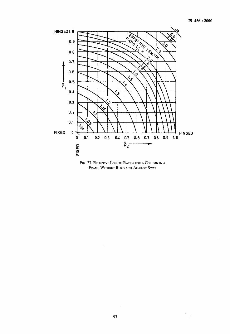
IS 456 : 2000
HINGED1.O
0.8
1
0.7
0.6
P, Oa5 0.4
0.3
0.2
0.1
FIXED 0
0 0.1 0.2 0.3 0.4 0.5 0.6 0.7 0.8 0.9 1.0
FIG. 27 EFFECTIVE LENGTH RATIOS FOR A COLUMN TN A FRAME WITHOUT RESTRAINT AGAINST SWAY
93

IS 456 : 2000
Table 28 Effective Length of Compression Members (Clause E-3)
Degree of End Restraint of Compre- ssion Members
Symbol
Effectively held in position and restrained against rotation in both ends
(2) / 1 I ,
Theoretical Value of Effective Length
Recommended Value of Effective Length
(1) (3) (4)
0.50 1 0.65 1
Effectively held in position at both ends, restrained against rotation at one end
Effectively held in position at both ends, but not restrained against rotation
Effectively held in position and restrained against rotation at one end, and at the other restrained against rotation but not held in position
Effectively held in position and restrained against rotation in one end, and at the other partially restr- ained against rotation but not held in position
Effectively held in position at one end but not restrained against rotation, and at the other end restrained against rotation but not held in position
Effectively held in position and restrained against rotation at one end but not held in position nor restrained against rotation at the
other end
.1 IlIz I t
/
r-1
LI’ L / /
El
L : ,
/’ 4, /
0.70 1 0.80 1
1.001
1.00 1
-
2.00 1
2.00 1
1.00 1
1.20 1
1.50 1
2.00 1
2.00 1
NOTE - 1 is the unsupported length of compression member.
94

IS 456: 2000
ANNEXF (Clauses 35.3.2 and 43.1)
CALCULATION OFCKACK WIDTH
Provided that the strain in the tension reinforcement is limited to 0.8 FYI Es, the design surface crack width, which should not exceed the appropriate value given in 35.3.2 may be calculated from the following equation: Design surface crack width
KY =
where a = SC
Cme m=
E, =
h =
x =
3% Em
1 + 2( a,, - Girl ) h-x
distance from the point considered to the surface of the nearest longitudinal bar,
minimum cover to the longitudinal bar;
average steel strain at the level considered,
overall depth of the member, and
depth of the neutral axis.
The average steel strain E, may be calculated on the basis of the following assumption:
The concrete and the steel are both considered to be fully elastic in tension and in compression. The elastic modulus of the steel may be taken as 200 kN/mm2 and the elastic modulus of the concrete is as derived from the equation given in 6.2.3.1 both in compression and in tension. These assumptions are illustrated in Fig. 28,
where
h = the overall depth of the section,
I- III tl
0 As 0
X= the depth from the compression face to the neutral axis,
f,= the maximum compressive stress in the concrete,
f,= the tensile stress in the reinforcement, and
Es = the modulus of elasticity of the reinforcement
Alternatively, as an approximation, it will normally be satisfactory to calculate the steel stress on the basis of a cracked section and then reduce this by an amount equal to the tensile force generated by the triangular distributions, having a value of zero at the neutral axis and a value at the centroid of the tension steel of 1N/mm2 instantaneously, reducing to 0.55 N/mm2 in the long-term, acting over the tension zone divided by the steel area. For a rectangular tension zone, this gives
b (h-x)(a-x) E, = &I -
3E, A&X)’
where
As =
b =
E, =
a =
d =
area of tension reinforcement,
width of the section at the centroid of the tension steel,
strain at the level considered, calculated ignoring the stiffening of the concrete in the tension zone,
distance from the campression face to the point at which the crack width is being calculated, and
effective depth.
STRESS IN CONCRETE 1 N/mm2 IN SHORT TERM 0.SSNlmm2 IN LONO TERM
SECTION CRACKED STRAIN STRESS
FIG. 28
95

IS 456 : 2000
ANNEX G (Clause 38.1)
MOMENTS OF RESISTANCE FOR RECTANGULAR AM) T-SECTIONS
G-O The moments of resistance of rectangularand T-sections based~on the assumptions of 38.1 are given
exceeds the limiting value, MU ,im compression reinforcement may be obtained from the following
in this annex. equation :
G-l RECTANGULAR SECTIONS
G-l.1 Sections Without Compression Reinforcement
where
Mu - Mu,,h=fJlf (d-d’)
The moment of resistance of rectangular sections without compression reinforcement should be obtained as follows :
Mu, M,, lirn’ d are same as in G-1.1,
f,= ’ design stress in compression reinforce- ment corresponding to a strain of
a)
b)
c>
Determine the depth of netutral axis from the following equation :
xu= 0.87 fY $t d 0.36 f,k~b.d
If the value of x,/d is less than the limiting value (see Note below 3&l), calculate the moment of resistance by the following expression :
M” 4t fy = 0.87 fy bt d 1 --
( 1 bd fck
If the value of xu/d is equal to the limiting value, the moment of resistance of the section is given by the following expression :
Mu *lim = 0.36 F 1 -0.42 y bd2 fct
d) If xU/ d is greater than the limiting value, the section should be redesigned.
In the above equations,
x =
;; =
& =
4 = f& =
b =
Mu. lim =
x = u.-
depth of neutral axis, effective depth,
characteristic strength of reinforce- ment, area of tension reinforcement, .
characteristic compressive strength . of concrete, width of the compression face,
limiting moment of resistance of a section without compression reinforcement, and limiting value of x, from 39.1.
G-l.2 Section with Compression Reinforcement Where the ultimate moment of resistance of section
4 = As,‘ =
Ast* =
where
0.003 5 ( XII, max -6’)
%I, max
x = u. maa the limiting value of xU_from 38.1,
AX = amaof~onreinforcemen~ and
d’ = depth of compression reinforcement from compression face.
The total area of tension reinforcement shall be obtained from the following equation :
Ast=Ast* f42
area of the total tensile reinforcement,
area of the tensile reinforcement for a singly reinforced section for Mu lim,
and
Axfwl 0.87fy.
G-2 FLANGED SECTION
G-2.1 For xU< D, the-moment of resistance may be calculated from the equation given in G-1.1. G-2.2 The limiting value of the moment of resistance of the section may be obtained by the following equation when the ratio D, / d does not exceed 0.2 :
where
M”,x”.~*~ d andf, are same as in G-1.1,
b, = breadth of the compression face/flange,
bw = breadth of the web, and
D, = thickness of the flange.
96

IS 456 : 2000
G-22.1 When the ratio D,/d exceeds 0.2, the moment ~of resistance of the section may be calculated by the
where yr = (0.15 xU + 0.65 DJ, but not greater than
following equation : D, and the other symbols are same as in G-l.1 and G-2.2.
M, ~0.3695 (
l-0.42- 1 fckbwd2
G-2.3 For xU milx > x, > Q,, the moment of resistance may be calculated by the equations given in G-2.2 when D,.lx, does not exceed 0.43 and G-2.2.1 when D/x,, exceeds 0.43; in both cases substituting x,, milx by x;.
97

IS 456 : 2000
ANNEX H ( Foreword )
COMMITTEE COMPOSITION
Cement and Concrete Sectional Committee, CED 2
Chuirman
DR H. C. V~SWSVARYA
‘Chandrika’, at 15th Cross,
63-64, Malleswaram, Bangalore 560 003
Members
DR S. C. AHLUWAL~A
SHRI G. R. BHARTIKAR
SHRI T. N. TIWARI
DR D. GHOSH (Alternute) CHIEF ENGINEER (DESIGN)
SUPERIK~N~ING ENGINEER (S&S) (Alternate) CHIEF ENGINEER, NAVAGAM DAM
SUPERIN~NLNNG ENGINEER @CC) (Alternate)
CHIEF ENGINEER (RE~EAR~WC~M-DIRECTOR)
RESEARCH OFFICER (CONCRETE TECHNOLOGY) (Alternate)
DIRECWR
JOINT DIRECXUR (Alternate)
DIRECTOR (CMDD) (N&W) DEPUTY DIRECWR (CMDD) (NW&S) (Alternate)
SHRI K. H. GANGWAL
SHRI V. PA~ABHI (Altemute)
SHRI V. K. GHANEKAR
SHRI S. GOPMATH
SHRI R. TAMILAKARAN (Alrernu?e)
SHRI S. K. GUHA THAKWRTA
SHRI S. P. SANKARANARAYANAN (Alternate)
Suai N. S. BHAL DR IRSHAD MASOOD (Alremate)
SHRI N. C. JAIN
JOINT DIREWR STANDARDS (B&S) (CB-I) JOINT DIRECTOR STANDARDS (B&S) (CB-II) (Akenrate)
SHRI N. G. JOSHI
SHRI P. D. KELKAR (Altemute)
SHRI D. K. KANIJNOO
SHRI B.R. MEENA (Alternute)
SHRI P. KRISHNAMIJ~
SHRI S. CHAKRAVARTHY (Alternate)
DR A. G. MADHAVA RAO
SHRI K. MANY (Alfemute)
SHRI J. SARUP
SHRI PRAF~LLA KUMAR
SHRI P. P. NAIR (Afternute)
Representing
OCL India, New Delhi
B. G. Shirke & Construction Technology Ltd. Pune The Associated Cement Companies Ltd, Mumbai
Central Public Works Department, New Delhi
Sardar Sarovar Narman Nigam Ltd. Gandhinagar
Irrigation and Power Research Institute, Amritsar
A.P. Engineering Research Laboratories, Hyderabad
Central Water Commission, New Delhi
Hyderabad Industries Ltd. Hyderabad
Structural Engineering Research Centte (CSIR), Ghaziabad
The India Cements Ltd, Chennai
Gannon Dunkerley & Co Ltd. Mumbai
Central Building Research Institute (CSIR), Roorkee
Cement Corporation of India, New Delhi
Research, Designs & Standards Organization (Ministry of Railway), Lucknow
Indian Hume Pipes Co Ltd. Mumbai
National Test House, Calcutta
Larsen and Toubro Limited, Mumbai
Structural Engineering Research Centre (CSIR), Chennai
Hospital Services Consultancy Corporation (India) Ltd, New Delhi
Ministry of Surface Transport, Department of Surface Transport (Roads Wing), New Delhi
. (Continued on page 99)
98

IS 456 : 2000
(Conkwed,from puge 98)
Members
MEMBER SECRETARY
DIRECVLIR (CIVIL) (Alternute)
SHRI S. K. NATHANI, SO I DR A. S. GOEL, EE (A&mute)
SHRI S. S. SEEHRA SHRI SATAN~ERKUMAR (Altemute)
SHRI Y. R. PHULL
SHRI A. K. SHARMA (Alterflute)
DR C. RAJKUMM DR K. MOHAN (Alrernure)
SHRI G. RAMDAS SHRI R. C. SHARMA (Alrernute)
SHRI S. A. REDDI
SHRI J. S. SANGANER~A SHRI L. N. AGARWAL (Alternute)
SHRI VENKATACHALAM SHRI N. CHANDRASEKARAN (Alternute)
SUPERIIWENDING ENGINEER (DESIGN) EXECUTWE ENGINEER (S.M.R.DWISION) (Altemure)
SHRI A. K. CHADHA _SHRI J. R SIL (Alrernule)
DR H. C. VISVESVARAYA SHRI D. C. CHATURVEDI (Alternure)
SHRI VINOD KUMAR Director (Civ Engg)
Convener
DR C. RAJKUMAR
Members
SHRI V. K. GHANEKAR SHRI S. A. REDDI SHRI JOSE KURIAN DR A. K. MITTAL
DR S.C.MAITI
DR ANn KUMAR (Alremute) PROF A.K. JAIN DR V. THIRUVENGDAM
Represenhg
Central Board of Irrigation and Power, New Delhi
Engineer-in-Chief’s Branch, Army Headquarters, New Delhi
Central Road Research Institute (CSIR), New Delhi
Indian Roads Congress, New Delhi
National Council for Cement and Building Materials, New Delhi
Directorate General of Supplies and Disposals, New Delhi
Gammon India Ltd. Mumbai
Geological Survey of India, Calcutta
Central Soil and Materials Research Station, New Delhi
Public Works Department, Government of Tamil Nadu, Chennai
Hindustan Prefab Ltd. New Delhi
The Institution of Engineers (India), Calcutta
Director General, BIS (Ex-@icio Member)
Member-Secreluries
SHRI J. K. PRASAD
Add1 Director (Civ Engg), BIS SHRI SAWAY PANT
Deputy Director (Civ Engg), BIS
Panel for Revision of Design Codes
National Council for Cement and Building Materials, Ballabgarh
Structural Engineering Research Centre, Fhaziabad Gammon India Ltd. Mumbai Central Public Works Department, New Delhi Central Public Works Department, New Delhi National Council for Cement and Building Materials, Ballabgarh
University of Roorkee, Roorkee School of Planning and Architecture, New Delhi
(Continued on puge 100)
99

IS 456 : 2000
Special Ad-Hoc Group for Revision of IS 456
Convener
DR H.C. VISVESVARYA ‘Chandrika’ at 1~5th Cross,
63-64, Malleswamm, Bangalore 560 003
Member.v
SHRI S.A. REDDI
DR C. RAJKUMAR
Gammon India Ltd. Mumbi
National Council for Cement and Buildidg Materials, Ballubgarh
100

Bureau of Indian Standards
BI S is a statutory institution established under the Bureau of Indian Standards Act, 1986 to promote harmonious development of the activities of standardization, marking and quality certification of goods and attending to connected matters in the country.
Copyright
BIS has the copyright of all its publications. No part of these publications may be reproduced in any form without the prior permission in writing of BIS. This does noi. preclude the free use, in the course of implementing the standard, of necessary details, such as symbols and sizes, type or grade designations. Enquiries relating to copyright be addressed to the Director (Publications), BIS.
Review of Indian Standards
Amendmerfts are issued to standards as the need arises on the basis of comments. Standards are also reviewed periodically; a standard along with amendments is reaffirmed when such review indicates that no changes are needed; if the review indicates that changes are needed, it is taken up for revision. Users of Indian Standards should ascertain that they are in possession of the latest amendments~or edition by referring to the latest issue of ‘BIS Catalogue’ and ‘Standards: Monthly Additions’.
This Indian Standard has been developed from Dot: No. CED 2(5525) -
Amendments Issued Since Publication
Amend No. Date of Issue Text Affected
BUREAU OF INDlAN STANDARDS
Headquarters:
Manak Ehavan, 9 Bahadur Shah Zafar Marg, New Delhi 110 002 Telephones : 323 01 3 I, 323 33 75, 323 94 02
Telegrams : Manaksanstha (Common to all offices)
Regional Offices : Telephone
Central : Manak Bhavan, 9 Bahadur Shah Zafar Marg { 323 76 17 NEW DELHI 11’6.002 323 38 41
Eastern : l/l 4 C. I. T. Scheme VII M, V. I. P. Road, Kankurgachi { 337 84 99,337 85 61 CALCUTTA 700 054 337 86 26,337 9120
Northem : SC0 335-336, Sector 34-A, CHANDIGARH 160 022 { 60 38 43 60 20 25
Southerw : C. I. T. Campus, IV Cross’ Road, CHENNAI 600 113 { 235 02 16,235 04 42 235 15 19,23523 15
Western : Manakalaya, E9 MIDC, Marol, Andheri (East) 832 { 832
92 95,832 78 58 MUMBAI 400 093 78 91,832 78 92
Branches : AHMADABAD. BANGALORE. BHOPAL. BHUBANESHWAR. COIMBATORE. FARIDABAD. GHAZIABAD. GUWAHATI. HYDERABAD. JAIPUR. KANPUR. LUCKNOW. NAGPUR. PATNA. PUNE. RAJKOT. THIRUVANANTHAPURAM.
Rhkd at NCW India Rinting Ress, Khurja, India

AMENDMENT NO. 1 JUNE 2001TO
IS 456:2000 PLAIN AND REINFORCED CONCRETE — CODE OF PRACTICE
(Fourth Revision )
(Page 2, Foreword last but one line) — Substitute ‘ACI 318:1995’ for ‘ACI 319:1989’.
(Page 11, clause 4) – Delete the matter ‘L~ – Horizontal distance between centres of lateral restraint’.
(Page 15, clause 5.5, Tide ) — Substitute ‘Chemical Admixtures’ for ‘Admixtures’.
(Page 17, clause 7.1 ) — Substitute the following for the existing informal table:
Placing Conditions Degree of Slump
(1)
Blinding concrete;Shallow sections;Pavements using pavera
Mass concretqLightly reinforcedsections in slabs,beams, walls, columns;Floors;Hand placed pavements;Canal liningStrip footinga
Heavily reinforcedsections in slabs,beams, walls, columns;
Slipfonn worlqPumped concrete
Trench fill;In-situ piling
Tremie concrete
Wo;kabijity (mm)
(2) (3)
}Very low See 7.1.1
I Low
‘1Medium
25-75
50-100
1 Medium 75-1oo
1 High 100-150
Very high See 7.1.2
NOIE — For moat of the placing eonditiona, internal vibrarora (needle vibratota) am suitable. ‘lhe diameter of the oecdle ahatl bedetermined based on the density and apaang of reinformment bara and thickness of aectiona. For tremie eoncret% vibratora are not requiredto be Used(ace ako 13.3).”
(Page 19, Table 4, column 8, sub-heading ) – Substitute %w’ for ‘FMx’ .
(Page 27, clause 13.S.3 ) — Delete.
(Page 29, clause 15.3 ):
a) Substitute ‘specimens’ for ‘samples’ in lines 2,6 and 7.
b) Substitute ‘1S9013’ for ‘IS 9103’.
( Page 29, clause 16.1) — Substitute ‘conditions’ for ‘condition’ in line 3 and the following matter for the existingmatter against ‘a)’ :
‘a) The mean strength determined from any group of four non-overlapping consecutive teat results mmplies with theappropriate limits in column 2 of Table 11.’
(Page 29, clause 16.3,para 2 ) — Substitute ‘cd 3’ for ‘cd 2’.
-(Page 29, clause 16.4, line 2) — Substitute ‘16.1 or 16.2 as the case may be’ for ‘16.3’.
(Page 30, Tablk 11, column 3 ) — Substitute % fek -3’ for ‘a~k-3’ and ‘2A, -4’ for ‘a~k-4’
Price Group 3 1

Amend No. 1 to IS 4S6: 2000
(Page 33, clause 21.3, line 2) — Substitute !action’ )lor ‘section’.
[ Page 37, clause 23.1.2(c)] — Substitute ‘L+‘@r ‘b,’, ‘lO’@ ‘l;, ‘b’ /br ‘b’ and ‘bW’for ‘bW’m the formulak.
(Page 46, clause 26.4.2 ) – Substitute ‘8.2.2’ for ‘8.2.3’.
[Page 49, clause 26.5.3.2 (c) (2), last line ] — Substitute ‘6 mm’ for ’16 mm’.
(Page 62, clause 32.2.5 ) – Substitute ‘H:’ for ‘HW~’in the explamtion of e,.
(Page 62, clause 32.3.1, line 4) – Substitute ‘32.4’ for ‘32.3’.
[ Page 62, clause 32.4.3 (b), line 6 ] — Insert ‘~eW’between the words ‘but’ and ‘shall’.
[ Page 65, clause 34.2.4.l(a), last line] — Insert the following after the words ‘depth of footing’:
‘in case of footings on soils, and at a distsnm equal to half the e~fective depth of footing’.
(Page 68, Tab& 18, CO14 ) — Substitute ‘-’ for ‘1.0’ against the Load Combination DL + IL.
(Page 72, clause 40.1 ) – Substitute ‘bd’ for ‘b~’ in the formula.
(Page 83, clause B-4.3, line 2) —Delete the word ‘and’.
(Page 85, clause B-5.5.l,para 2, line 6 ) – Substitute ‘Table 24’ for ‘Table 23’.
(Page 85, clause B-5.5.2 ) — Substitute the following for the existing formula:
‘A, = avb (tv-2d~c I av) /a,v z 0.4 avb / 0.87 fy’
(Page 90, clause D-1.11, line 1 ) — Substitute ‘Where” for ‘Torsion’.
(Page 93, Fig. 27) — Substitute ‘lJ1’ for ‘U’.
(Page 95, Anncw F ):●
a) The reference to Fig. 28 given in column 1 of the text along with the explanation of the symbols used in the Fig.28 given thereafter maybe read just before the formula given for the rectangular tension zone.
b) Substitute ‘compression’ for ‘compression’ in the explanation of symbol ‘a ‘ .
(Pages 98 to 100, Annex H) – Substitute the following for the existing Annex:
ANNEX H
(Foreword)
COMMTfTEE COMPOSITION
Cement snd Concrete Sectional Committee, CED 2
ChairmanDR H. C. VWESVARAYA
‘Chandnks’. at 15* Cmaa. 63-64 East park Road.
Medurs
DRS. C. AHLUWAUA
SHRIV. BAIASUSrMWUWANSHIUR. P. SINGH(Alternate)
SHFUG. R. BHARtmwtr
SHRIA K CHADHASHIUJ.R. !ML(Ahenrute)
CMrrwENGtmeR(DtmoN)SUFSRNIINDING ENOtNSER&S) (Alternate)
CIMIFENOINSWI@IAVGAMDAMISUFSmmNOINGENoumut(QCC) (Alterrrde)
CHIEFthGINSF!JI(RBswRcH)-cuM-IlttecmRR@sSARCHOFPICaR@ONCREIIi‘kHNOLOGY)
(Akernde)
A4atieawarsmBangalore-560 003 ‘
Reprcssnting
OCL India I& New Delhi
Directorate Geneml of Supplies and Dwpoask New Delhi
B. G. Shirke Construction Technology L@ Puoe
Hindustsn Prefab IJmite4 New Delhi
Central Pubtic WortraDepartment, New Delhi
Sardar Samvar Namrada Nigsm L&t,Gamfhinagar
Irrigation aridPower Research Inatihrte. Amritssr
2(contimdrmpsge3)

( Continuedfiompage 2 )
Amend No. 1 to IS 456:2000
Madera
SHRIJ.P. DESMSHRtB. K JAGETIA(Ahernot.)
DRIX.TORJOINTDItUKTOR@keMOte)
DtREct_OR(CMDD) (N&WDEPrnYDIRtXNIR(CMDD) (NW&S) (Af&rnate)
Stint K H. GANGWAL%ltt V. pATrABHl(Ab7@e)
SHIUV.K Gwuwrmrr
SHRIS. GOPtWITHSttruR. TAMUKAMN (A/krnate)
SHWS.K GUHATHAKURTASHRtS.SANKARANARAYANAN(Akrnate)
SNRIN. S. BNALDRIRSHADM,SGGD(AktwIot.)
PROFA. K JAIN
SHRtN.C. JAIN
JOttWDtRXTOR@TANDARDS)(B&S) (CB-f)JomrrIMF.CTGR(STANOAIUW(B&S) (cB-II)
(Alternote)
SHRJN. G. JosraSmuP. D. IQrumrt (Afterde)
St+trrD.KKANUNooSHRJB.R. Mt?ENA(Akernote)
sHRIP.KRlaHN4MuRlHYSmt S. CHOWDHURY(Akernoti)
DRA. G. MADHAVARAOSmu K MAM (Akermrte)
St+ruJ.SARW
%lltV. [email protected]. SINGH@&?mate)
SW PtwwrA KUMARSHRtp.P. NAIR(AIternate)
MmmtmSF.CRRTARYD(~R(CML)(A/t=ti&)
SHRIS.KN.AMMNIDRA S. Gorz (Akmde)
SHRIS.S. SriEHRASwtt SATANDERKUMAR(Akerwde)
SHRIY. R. PHUUSHRtA K SHARMA(Akrurte)
DRC. RAJKUMARDR K MOHAN(Aft~)
sHRtS. A Rt3DDI
tiR15E!WAllVB
SHRIJ.S. SANO~Smt L N. AOARWAL(A/le/?@e)
suPERtNmmN GBNGtNEER(Dt?stGN)EXKIMVE ENouwER(SMRDtvtsioN)(4ternde)
Stint K K TAPARMSHRIA K JAN(Akd4
SHRIT. N. TIWARIDRD. GHOStI@ternute)
DitK VENKATMXUAMSwuN. CHANDWWXARAN(Alternate)
Jieprcseti”ng
Gujarat Arnbuja Cemenla Ltd, Ahmedabad
AP. EngineeringResearchI.Axxatoris Hyderabad
CentralWater Commission,New Delhi
HyderabadIndustriesLtd, Hyderabad
StructuralEngineeringResrmcb Centre (CSIR), Ghaziabad
Tire IndiaCements Ltd, Chennai
GannonDunkerleyand Companyw Mumtil
Central BuildingResearehInstitute(cSIR), Roorkee
Univemityof Roorkee,Roorkee
Cement Corporation of India Ud, New Delhi
Rese.mcb,Designs& StandardaOrganization(Mlniatryof Railways>Luekmw
The IndianHume Pipe CompanyI@ Mumbai
NationalTest HouaGCalcutts
Larsen& TubroM Mumbai
Structurall?ngineeringReseamhCcntre (CSIR> Cbennai
HospitalServi~ ComsuhsncyGwpmation (hdw) m New Ddbi
Housingand Urbsn DevelopmentCorporationLQ New Delhi
Ministryof SurfaceTrsnapo@Departmentof SurfaceTrsnaport(Rnsds WI@ New Delhi
CentralBoard of Irrigation& Power, New Delhi
Engineer-inChiefs Branch, Army HeaifquartemNew Delhi
Central Road ResearehInstitute(CSIR), New Delhi
IndmnRoadaCm- New Delhi
NationalCouncil for Cement and BuildingMaterials Baflabgsrh
GammonIndw L@ Mumbai
Builder’skoeiition of Indw, Mumbai
GeologicalSurvrYyof Indm,Calcutta
Public Works Departmen$Guvemmentof Tamil Nadq Cbermai
IndmnRayon sod Industries~ Pune
7% Aaociated ~ment Ckmpaniesw Mumbai
Central Soil and MaterialsResearebStatioq New Delhi
3( Continued onpcrge 4 )

Amend No. 1 to IS 456:2000
( Continued fiunpage 3 )
Makers
DRH. C. VtSVESVARAYASmuD. C. CHATUItVEOJ(AkUW@
SHRJVtNODKUMARDkector (Civ Engg)
Com.wser
DRA K MUUJCK
Members
sHRtC. R. AuMcHANOAMSmu S. RANGARAIAN(Altemute)
DR P. C. CHOWDHURYDR C. S. VtSHWANAITM(Alternate)
SHRSJ.P. DESNSrab B. K JAGETIA(Alf.rwt.)
DtIGZTORSNRIN. CHANDRASmCARAN(Akerrrate)
DtRMXOR(C8CMDD)DF,PGTYDrrwcmR (C&MDD) (Alternate)
JOtNTD~RSTANDAttOS @8@CB-HJOSNTDtR@CITIRSTANDARDS(EWS)KB-I
(Alternate)
StJPEWTEHDtNGENGtNEEJt(DI?SIGNS)EmxrmvEENotN@sR(DEsIGNs)-111(Alt.rnok)
StmtV. K. GHANEKArrWirrtD. S. PRAKASHIUO(Allerrrote)
SHRSS. K GGHATHAKURTAsHRrs. P. sANmRmwm YANAN(Alternate)
SHRIJ.S. HINoorwo
stint LKJMN
Smtt M. P. JAtSINGHDR B. KAMISWARARAO(Alternate)
CHIEFENGtNEeR& JOtNTSGCRSTARYsrJP51uNTmmSNOENOSNSSR(Alternate)
PROFS. KstrsHNAMOORIHYSHRIK K. NAYAR(Akernute)
DRS. C. Wvn
MANAGINODtREIXIR.%mtM. KUNDSJ(Alternate)
sHRts. KNNrmNILT-COLK S. fXARAK(Alternate)
Stint B. V. B. PAIStrroM. G. DANDVATB(Alternate)
SHWA. B. PHADKBSHRID. M. SAWR (Alternate)
SHRJY. R PHUUWttt S. S. SSSHRA(A/ternofe I)SW SATANGERKttMAR(Alternate H)
Rep-”ng
llre Institutionof Engineers(India) Calcutta
DirectorGeneral,BtS (Ex-oficio Member)
Member-.%rdark$
SHRIJ. K PRASAOAdditional Dkcctor (Ctv Engg), BIS
SHRISAIWAYPANTDeputy Dkector (Civ Engg), BIS
Concrete Subeomrnittee,CE1322
Representing
National Council for Cement and Building Materials,.Ballabgarh
Stup Consultants Ltd, Mumbai
Torsteel Research Foundation in India, Calcutta
Gujarat Ambuja Cements Ltd, Ahmcrtabad
Central Soil and Materials Research Station, New Delhi
Central Water Commision, New Delhi
Researc~ Designs and Standards Organintion ( Ministry of Railways), Lucknow
Central Public Works Department New Delhi
Structural Engineering Research Centre (CSIR), Gt@abad
Gannon Dunkedey and Co Ltd, Mwnbai
Assoaated Consulting Services, Mumbai
In personal capacity
Central Building Research Institute (CSIR), Roorkec
Public Works Dcpartmenh MumL-A
Indian Institute of Technology, New Delhi
National Counal for Cement and Building Material%Ballabgsrh
HitsdustanPrefab Limited, New Delhi
Engineer-in-Chief’s Branch, Army Headquarters, New Delhi
The Associated Cement Companies L$4Mumtil
llre Hindustsn Construction Co Lt4 Mumbai
Central Road Research Institute (CSIR),-New Delhi
t
4(Carthuedonpsrge5)

Amend No. 1 to IS 4S6: 2000
( Contirtwd frcvnpog. 4 )
Stno A. S. PRASADRAOStlR1K. MAN](Aherrrote)
SHRIK. L PRUrHJSHRIJ. R. GAtSR.JEL(A/terrrufe)
SHrtIB. D. RAHALIWRSHRIU. S. P. VERMA(Alternate)
SHRI HANUMANTHARAOSHRIG. RAMAKRtStlNAN(Alternate)
SHto S. A. REDDIDR N. K. NAYAK (Ahernde)
S}IRI S. C. SAWHNEYStiRl R. P. MEtlR071r,4(Ahernde)
PROFM. S. SHEtTt
SHRIN. K SINHA
SIIRI B. T. UNWAtJA
Convener
DR C. RAJKUMAR
Members
DR ANILKUMAR
SIIRJV. K. GHANEKAR
PROFA. K. JAIN
SHRI L K. JAIN
SHRIJOSE KURtAN
DR S. C. MAtTS
DR A. K MIITAL
S}IR} S. A. REDOI
DR V. THIRWENGDAM
Members
DR C. RAJKUMAR
SIIRI S. A. REDDI
Representing
Structural Engineering Research Centre (cSIR), Chennai
National Building Construction Corporation Ltd. New Delhi
Nuclear Power Corporation Ltd, New Delhi
A.P. Engineering Research Laboratories, Hyderabad
Gammon India Ltd. Mumbai
Engineers India Ltd, New Delhi
Indian Concrete Institute, Cherrnai
Ministry of Surface Transport (Roads Wing), New Delhi
In personal capacity
Panel for Revision of IS 456, CED 2:2/P
Reprwenting
National Council for Cement and Building Materials, Ballabgarh
National Council for Cement and Building Materials, Ballabgarh
Structural Engineering Research Cenire (cSIR), Ghaziabsd
University of Roorkee, Roorkee
In personal capacity
Central Public Works Department, New Delhi
National Council for Cement and Building Materials, Ballabgarh
Central Public Works Department, New Delhi
Gammon India I@ Mumbai
School of Planning and Architecture, New Delhi
Special Ad-Hoc Group for Revision of 1S 456
Chairman
DR H. C. VISVESVARAYA‘Chandrika’, at 15* Cross, 63-64 East Park Road,
Malleswaram, Bangalore-560 003
Representbig
National Council for Cement and Building Materials, Ballabgarh
Gammon India Idd, Mumbai
(CED2)
Printed at New Incha Prmturg Press. KhurJa. India

© BIS 2004
B U R E A U O F I N D I A N S T A N D A R D SMANAK BHAVAN, 9 BAHADUR SHAH ZAFAR MARG
NEW DELHI 110002
IS : 1498 – 1970(Reaffirmed 2002)
Edition 2.2(1987-09)
Price Group 10
Indian StandardCLASSIFICATION AND IDENTIFICATION OF
SOILS FOR GENERAL ENGINEERING PURPOSES
( First Revision )(Incorporating Amendment Nos. 1 & 2)
UDC 624.131.2

IS : 1498 – 1970
B U R E A U O F I N D I A N S T A N D A R D SMANAK BHAVAN, 9 BAHADUR SHAH ZAFAR MARG
NEW DELHI 110002
Indian StandardCLASSIFICATION AND IDENTIFICATION OF
SOILS FOR GENERAL ENGINEERING PURPOSES
( First Revision )Soil Engineering Sectional Committee, BDC 23
ChairmanPROF S. R. MEHRA
Manak, Nehru Road, Ranikhet, Uttar Pradesh
Members RepresentingDR ALAM SINGH University of Jodhpur, JodhpurSHRI B. B. L. BHATNAGAR Land Reclamation, Irrigation & Power Research
Institute, AmritsarSHRI K. N. DADINA In personal capacity ( P-820, New Alipore, Calcutta 53 )SHRI A. G. DASTIDAR Cementation Co Ltd, BombaySHRI J. DATT Concrete Association of India, Bombay
SHRI T. M MENON ( Alternate )SHRI R. L. DEWAN Bihar Institute of Hydraulic and Allied Research,
Khagaul, PatnaPROF DINESH MOHAN Central Building Research Institute (CSIR), Roorkee
SHRI D. R. NARAHARI ( Alternate )DIRECTOR, CENTRAL SOIL MECH-
ANICS RESEARCH STATIONCentral Water & Power Commission, New Delhi
DIRECTOR (DAMS II) ( Alternate )PROF R. N. DOGRA Indian Institute of Technology, New DelhiSHRI B. N. GUPTA Irrigation Research Institute, RoorkeeDR JAGDISH NARAIN University of Roorkee, RoorkeeJOINT DIRECTOR RESEARCH (FL),
RDSORailway Board (Ministry of Railways)
DEPUTY DIRECTOR, RESEARCH(SOIL MECHANICS), RDSO ( Alternate )
SHRI S. S. JOSHI Engineer-in-Chief’s Branch, Army HeadquartersSHRI S. VARADARAJA ( Alternate )
SHRI G. KUECKELMANN Radio Foundation Engineering Ltd; and Hazarat & Co,Bombay
SHRI A. H. DIVANJI ( Alternate )SHRI O. P. MALHOTRA Public Works Department, Government of PunjabSHRI C. B. PATEL M. N. Dasur & Co (Private) Ltd, CalcuttaSHRI RAVINDER LAL National Buildings Organisation, New Delhi
SHRI S. H. BALCHANDANI ( Alternate )( Continued on page 2 )

IS : 1498 – 1970
2
( Continued from page 1 )
Members RepresentingREPRESENTATIVE All India Instruments Manufacturers & Dealers
Association, BombayREPRESENTATIVE Indian National Society of Soil Mechanics &
Foundation Engineering, New DelhiREPRESENTATIVE Public Works (Special Roads) Directorate, Government
of West BengalRESEARCH OFFICER Building and Roads Research Laboratory, Public
Works Department, Government of PunjabRESEARCH OFFICER Engineering Research Laboratories, HyderabadSECRETARY Central Board of Irrigation and Power, New DelhiSHRI S. N. SINHA Roads Wing (Ministry of Transport & Shipping)
SHRI A. S. BISHNOI ( Alternate )SUPERINTENDING E N G I N E E R
(PLANNING & DESIGN CIRCLE)Concrete and Soil Research Laboratory, Public Works
Department, Government of Tamil NaduEXECUTIVE ENGINEER (SOIL
MECHANICS & RESEARCHDIVISION) ( Alternate )
SHRI C. G. SWAMINATHAN Institution of Engineers (India), CalcuttaDR H. L. UPPAL Central Road Research Institute (CSIR), New DelhiSHRI H. G. VERMA Public Works Department, Government of Uttar
PradeshSHRI D. C. CHATURVEDI ( Alternate )
SHRI D. AJITHA SIMHA,Director (Civ Engg)
Director General, BIS ( Ex-officio Member )
SecretarySHRI G. RAMAN
Deputy Director (Civ Engg), BIS
Panel for Classification and Identification of Soils for General Engineering Purposes, BDC 23 : P2
Convener
DR I. C. DOS M. PAIS CUDDOU Central Water & Power Commission, New Delhi
MembersDIRECTOR (DAMS II) ( Alternate to
Dr I. C. Dos M. Pais Cuddou )DR ALAM SINGH University of Jodhpur, JodhpurPROF DINESH MOHAN Central Building Research Institute (CSIR), RoorkeeDIRECTOR Irrigation Research Institute, Roorkee
RESEARCH OFFICER ( Alternate )SHRI S. S. JOSHI Engineer-in-Chief’s Branch, Army HeadquartersDR H. L. UPPAL Central Road Research Institute (CSIR), New Delhi

IS : 1498 – 1970
3
Indian StandardCLASSIFICATION AND IDENTIFICATION OF
SOILS FOR GENERAL ENGINEERING PURPOSES
( First Revision )0. F O R E W O R D
0.1 This Indian Standard (First Revision) was adopted by the IndianStandards Institution on 19 December 1970, after the draft finalized bythe Soil Engineering Sectional Committee had been approved by theCivil Engineering Division Council.0.2 Soil survey and soil classification are at present being done by severalorganizations in this country for different purposes. The engineeringdepartments and research laboratories have done a great deal of work inregard to soil exploration and classification in fields relating to irrigation,buildings, roads, etc. The investigations relating to the field of irrigationhave two objectives namely, the suitability of soil for the construction ofdams and other kinds of hydraulic structures and the effect on thefertility of soil when it is irrigated. With regard to roads and highways,investigations have been undertaken to classify them from the point ofview of their suitability for construction of embankments, sub-grades,and wearing surfaces. In the field of buildings, soil investigation andclassification is done to evaluate the soil as regards its bearing power toa certain extent. Soil survey and soil classification are also done byagriculture departments from the point of view of the suitability of thesoil for crops and its fertility. Each of these agencies was adoptingdifferent systems for soil classification. The adoption of different methodsby various agencies led to difficulties in interpreting the results of soilsinvestigated by one agency by the other and quite often results werefound to be not easily comparable. This Indian standard was, therefore,published in 1959 to provide a common basis for soil classification.0.3 Soils seldom exist in nature separately as sand, gravel or any othersingle component but are usually found as mixture with varyingproportions of particles of different sizes. This revision is essentiallybased on the Unified Soil Classification System with the modificationthat the fine-grained soils have been subdivided into three subdivisionsof low, medium and high compressibility, instead of two subdivisions ofthe original Unified Soil Classification System. The system is based onthose characteristics of the soil which indicate how it will behave as aconstruction material. This system is not limited to a particular use or

IS : 1498 – 1970
4
geographical location. It does not conflict with other systems; in fact,the use of geologic, pedologic, textural or local terms is encouraged as asupplement to, but not as a substitute for, the definitions, terms andphrases established by this system and which are easy to associate withactual soils.0.4 In the formulation of this standard due weightage has been given tointernational co-ordination among the standards and practicesprevailing in different countries in addition to relating it to thepractices in this field in this country.0.5 This edition 2.2 incorporates Amendment No. 1 (August 1982) andAmendment No. 2 (September 1987). Side bar indicates modification ofthe text as the result of incorporation of the amendments.0.6 For the purpose of deciding whether a particular requirement ofthis standard is complied with, the final value, observed or calculated,expressing the result of a test or analysis, shall be rounded off inaccordance with IS : 2-1960*. The number of significant places retainedin the rounded off value should be the same as that of the specifiedvalue in this standard.
1. SCOPE1.1 This standard covers a system for classification and indentificationof soils for general engineering purposes. The information given in thisstandard should be considered as for guidance only for treating the soilfor engineering purposes.
2. TERMINOLOGY2.0 For the purpose of this standard, the definitions given inIS : 2809-1972† and the following shall apply.2.1 Clay — An aggregate of microscopic and sub-microscopic particlesderived from the chemical decomposition and disintegration of rockconstituents. It is plastic within a moderate to wide range of watercontent.2.2 Silt — A fine-grained soil with little or no plasticity. If shaken inthe palm of the hand, a part of saturated inorganic silt expels enoughwater to make its surface appear glossy. If the pat is pressed orsqueezed between the fingers, its surface again becomes dull.2.3 Sand and Gravel — Cohesionless aggregates of angular, sub-angular, sub-rounded, rounded, flaky or flat fragments of more or lessunaltered rocks or minerals.
*Rules for rounding off numerical values ( revised ).†Glossary of terms and symbols relating to soil engineering ( first revision ).

IS : 1498 – 1970
5
According to this system, gravel is a fraction of the soil materialbetween 75 mm and the 4.75-mm IS Sieve size and sand is the materialbetween the 4.75-mm IS Sieve size and the 75-micron IS Sieve size.
3. CLASSIFICATION AND IDENTIFICATION
3.1 Division — Soils shall be broadly divided into three divisions asgiven in 3.1.1 to 3.1.3.3.1.1 Coarse-Grained Soils — In these soils, more than half the totalmaterial by weight is larger than 75-micron IS Sieve size.3.1.2 Fine-Grained Soils — In these soils, more than half of thematerial by weight is smaller than 75-micron IS Sieve size.3.1.3 Highly Organic Soils and Other Miscellaneous Soil Materials —These soils contain large percentages of fibrous organic matter, such aspeat, and particles of decomposed vegetation. In addition, certain soilscontaining shells, concretions, cinders, and other non-soil materials insufficient quantities are also grouped in this division.3.2 Subdivision — The first two divisions ( see 3.1.1 and 3.1.2 ) shallbe further divided as given in 3.2.1 and 3.2.2.3.2.2 Coarse-Grained Soils — The coarse-grained soils shall be dividedinto two subdivisions, namely:
a) Gravels — In these soils, more than half the coarse fraction(+ 75 micron) is larger than 4.75-mm IS Sieve size. This sub-division includes gravels and gravelly soils.
b) Sands — In these soils, more than half the coarse fraction(+ 75 micron) is smaller than 4.75-mm IS Sieve size. This sub-division includes sands and sandy soils.
3.2.2 Fine-Grained Soils — The fine-grained soils shall be furtherdivided into three subdivisions on the basis of the following arbitrarilyselected values of liquid limit:
a) Silts and clays of low compressibility — having a liquid limit lessthan 35 ( represented by symbol L ),
b) Silts and clays of medium compressibility — having a liquid limitgreater than 35 and less than 50 ( represented by symbol I ), and
c) Silts and clays of high compressibility — having a liquid limitgreater than 50 ( represented by symbol H ).
NOTE — In this system the fine-grained soils are not divided according to particlesize but according to plasticity and compressibility. The term ‘compressibility’ hereshall imply volume change, shrinkage during dry periods and swelling during wetperiods, as well as, consolidation under load. Soil particles finer than 2-micron may,however, be designated as clay-size particles and the particles between 75-micronand 2-micron as silt-size particles.

IS : 1498 – 1970
6
3.3 Groups — The coarse-grained soils shall be further divided intoeight basic soil groups. The fine-grained soils shall be further dividedinto nine basic soil groups ( see Table 2 ).3.3.1 Highly organic soils and other miscellaneous soil materials shallbe placed in one group. The groups shall be designated by symbols.
NOTE — These groups are broad, based on basic properties of soil; therefore,supplemental detailed word descriptions are required to point out pecularity of aparticular soil and differentiate it from others in the same group.
3.3.2 The basic soil components are given in Table 1.3.3.3 The various subdivisions, groups and group symbols are given inTable 2.3.4 Field Identification and Classification Procedure — The fieldmethod is used primarily in the field to classify and describe soils.Visual observations are employed in place of precise laboratory tests todefine the basic soil properties. The procedure is, in fact, a process ofelimination beginning on the left side of the classification chart(Table 2) and working to the right until the proper group name isobtained. The group name should be supplemented by detailed worddescriptions, including the description of the in-place conditions forsoils to be used in place as foundations. A representative sample of thesoil is selected which is spread on a flat surface or in the palm of thehand. All particles larger than 75 mm are removed from the sample.Only the fraction of the sample smaller than 75 mm is classified. Thesample is classified as coarse-grained or fine-grained by estimating thepercentage by weight of individual particles which can be seen by theunaided eye. Soils containing more than 50 percent visible particles arecoarse-grained soils, soils containing less than 50 percent visibleparticles are fine-grained soils.
If it has been determined that the soil is coarse grained, it is furtheridentified by estimating and recording the percentage of: (a) gravelsized particle, size range from 75 mm to 4.75-mm IS Sieve size (orapproximately 5 mm size); (b) sand size particles, size range from 4.75to 75-micron IS Sieve size; and (c) silt and clay size particles, size rangesmaller than 75-micron IS Sieve.
NOTE — The fraction of soil smaller than 75-micron IS Sieve, that is, the clay and siltfraction is referred to as fines.
3.4.1 Gravelly Soils — If the percentage of gravel is greater than that ofsand, the soil is a gravel. Gravels are further identified as being clean(containing little or no fines, that is less than 5 percent) or dirty(containing appreciable fines, that is more than 12 percent) dependingupon the percentage of particles not visible to the unaided eye. Gravelscontaining 5 to 12 percent fines are given boundary classification. If thesoil is obviously clean, the classification shall be either: (a) well graded

IS : 1498 – 1970
7
gravel (GW), if there is good representation of all particle sizes; or (b)poorly graded gravel (GP), if there is an excess or absence of intermediateparticle sizes. A well-graded soil has a reasonably large spread betweenthe largest and the finest particles and has no marked deficiency in anysize. If the soil obviously is dirty, the classification will be either (c) siltygravel (GM), if the fines have little or no plasticity; or (d) clayey gravel(GC), if the fines are of low to medium or high plasticity ( see 3.2.2 ).3.4.2 Sandy Soils — If the percentage of sand is greater than gravel, thesoil is a sand. The same procedure is applied as for gravels except that theword sand replaces gravel and the symbol S replaces G. The groupclassification for the clean sands will be either: (a) well-graded sand (SW)or (b) poorly-graded sand (SP), and the dirty sands shall be classified as(c) silty sand (SM), if the fines have little or no plasticity; or (d) clayeysand (SC), if the fines are of low to medium or high plasticity ( see 3.2.2 ).3.4.3 Boundary Classification for Coarse-Grained Soils — When a soilpossesses characteristics of two groups, either in particle sizedistribution or in plasticity, it is designated by combinations of groupsymbols. For example, a well-graded coarse-grained soil with claybinder is designated by GWGC.3.4.3.1 Boundary classifications can occur within the coarse-grained soildivision, between soils within the gravel or sand grouping, and betweengravelly and sandy soils. The procedure is to assume the coarser soil, whenthere is a choice, and complete the classification and assign the propergroup symbol; then, beginning where the choice was made, assume a finersoil and complete the classification, assigning the second group symbol.3.4.3.2 Boundary classifications within gravel or sand groups can occur.Symbols such as GW-GP, GM-GC, GW-GM, GW-GC, SW-SP, SM-SC,SW-SM and SW-SC are common.3.4.3.3 Boundary classifications can occur between the gravel and sandgroups. Symbols such as GW-SW, GP-SP, GM-SM and GC-SC are common.3.4.3.4 Boundary classifications can also occur between coarse and finegrained soils. Classifications such as SM-ML and SC-CL are common.3.4.4 Descriptive Information for Coarse-Grained Soils — The followingdescriptive information shall be recorded for coarse-grained soils:
a) Typical name;b) Maximum size, and fraction larger than 75 mm in the total
material;c) Percentage of gravel, sand and fines in the soil or fraction of soil
smaller than 75 mm;d) Description of average size of sand of gravel;

IS : 1498 – 1970
8
e) Shape of the particles — angular, subangular, subrounded, rounded; f) The surface coatings, cementation and hardness of the particles
and possible breakdown, when compacted;g) The colour and organic content;h) Plasticity of fines;j) Local or geologic name, if known; andk) Group symbol.
3.4.5 Fine-Grained Soils — If it has been determined that the soil isfine-graincd, it is further identified by estimating the percentage ofgravel, sand, silt and clay size particles and performing the manualidentification tests for dry strength, dilatancy, and toughness. Bycomparing the results of these tests with the requirements given for thenine fine-grained soil groups, the appropriate group name and symbol isassigned. The same procedure is used to identify the fine-grained fractionof coarse-grained soil to determine whether they are silty or clayey.3.4.6 Manual Identification Tests — The following tests for identifyingthe fine-grained soils shall be performed on the fraction of the soil finerthan the 425-micron IS Sieve:
a) Dilatancy ( reaction to shaking ) — Take a small representativesample in the form of a soil pat of the size of about 5 cubiccentimetres and add enough water to nearly saturate it. Place thepat in the open palm of one hand and shake horizontally, strikingvigorously against the other hand several times. Squeeze the patbetween the fingers. The appearance and disappearance of thewater with shaking and squeezing is referred to as a reaction. Thisreaction is called quick, if water appears and disappears rapidly;slow, if water appears and disappears slowly; and no reaction, if thewater condition does not appear to change. Observe and record typeof reaction as descriptive information.
b) Toughness ( consistency near plastic limit ) — Dry the pat used inthe dilatancy test by working and moulding, until it has theconsistency of putty. The time required to dry the pat is theindication of its plasticity. Roll the pat on a smooth surface orbetween the palms into a thread about 3 mm in diameter. Foldand reroll the thread repeatedly to 3 mm in diameter so that itsmoisture content is gradually reduced until the 3 mm thread justcrumbles. The moisture content at this time is called the plasticlimit and the resistance to moulding at the plastic limit is calledthe toughness. After the thread crumbles, lump the piecestogether and continue the slight kneading action until the lumpcrumbles. If the lump can still be moulded slightly drier than theplastic limit and if high pressure is required to role the threadbetween the palms of the hand, the soil is described as having

IS : 1498 – 1970
9
high toughness. Medium toughness is indicated by a mediumthread and a lump formed of the threads slightly below the plasticlimit will crumble; while low toughness is indicated by a weakthread that breaks easily and cannot be lumped together whendrier than the plastic limit. Highly organic clays have very weakand spongy feel at the plastic limit. Non-plastic soils cannot berolled into thread of 3 mm in diameter at any moisture content.Observe and record the toughness as descriptive information.
c) Dry strength ( crushing resistance ) — Completely dry theprepared soil pat. Then measure its resistance to crumbling andpowdering between fingers. This resistance, called dry strength, isa measure of the plasticity of the soil and is influenced largely bythe colloidal fraction content. The dry strength is designated aslow, if the dry pat can be easily powdered; medium, if considerablefinger pressure is required and high, if it cannot be powdered atall. Observe and record the dry strength as descriptiveinformation.NOTE — The presence of high-strength water soluble cementing materials, suchas calcium carbonates or iron oxides may cause high dry strength. Non-plasticsoils, such as caliche, coral, crushed lime stone or soils containing carbonaceouscementing agents may have high dry strength, but this can be detected by theeffervescence caused by the application of diluted hydrochloric acid.
d) Organic content and colour — Fresh wet organic soils usually havea distinctive odour of decomposed organic matter. This odour can bemade more noticeable by heating the wet sample. Another indicationof the organic matter is the distinctive dark colour. In tropical soils,the dark colour may be or may not be due to organic matter; whennot due to organic matter, it is associated with poor drainage. Dryorganic clays develop an earthy odour upon moistening, which isdistinctive from that of decomposed organic matter.
e) Other identification tests1) Acid test — Acid test using dilute hydrochloric acid (HCl) is
primarily a test for the presence of calcium carbonate. For soilswith high dry strength, a strong reaction indicates that thestrength may be due to calcium carbonate as cementing agentrather than colloidal clay. The results of this test should beincluded in the soil description, if pertinent.
2) Shine test — This is a quick supplementary procedure fordetermining the presence of clay. The test is performed bycutting a lump of dry or slightly moist soil with a knife. Theshiny surface imparted to the soil indicates highly plastic clay,while a dull surface indicates silt or clay of low plasticity.
3) Miscellaneous test — Other criteria undoubtedly may bedeveloped by the individual as he gains experience in

IS : 1498 – 1970
10
classifying the soils. For example, differentiation between someof the fine-grained soils depends largely upon the experience inthe feel of the soils. Also wet clay sticks to the fingers and driesslowly but silt dries fairly quickly and can be dusted off thefingers leaving only a stain. Frequent checking by laboratorytests is necessary to gain this experience.
3.4.7 Boundary Classification for Fine-Grained Soils — Boundaryclassifications can occur within the fine-grained soil divisions, betweenlow and medium or between medium and high liquid limits andbetween silty and clayey soils. The procedure is comparable to thatgiven for coarse-grained soils ( see 3.4.3 ), that is, first assume a coarsesoil, when there is a choice, and then a finer soil and assign dual groupsymbols. Boundary classifications which are common are as follows:
ML-MI, CL-CI, OL-OI, MI-MH, CI-CH, OI-OH, CL-ML, ML-OL,CL-OL, CI-MI, MI-OI, CI-OI, MH-CH, MH-OH, and CH-OH.
3.4.8 Very Highly Organic Soils — Peat or very highly organic soilsmay be readily identified by colour, sponginess or fibrous texture.3.4.9 Descriptive Information for Fine-Grained Soils — The followingdescriptive information shall be recorded for fine-grained soils:
a) Typical name;b) Percentage of gravel, sand and fines;c) Colour in moist condition and organic content;d) Plasticity characteristics;e) Local or geologic name, if known; andf) Group symbol.
3.4.10 Descripion of Foundation Soils — The following informationshall be recorded to define the in-place condition of soils which are to beutilized as foundation for hydraulic or other structures:
a) For coarse-grained soils:1) Natural moisture content (as dry, moist, wet and saturated);2) Perviousness or drainage properties in the natural condition;3) Structure (as stratified, uniform, uncemented, lensed; and
attitude, that is, strike and dip);4) Type and degree of cementation; and5) Degree of compactness (as loose or dense).
b) For fine-grained soils:1) Natural moisture content (as dry, moist, wet and saturated);2) Perviousness or drainage properties;

IS : 1498 – 1970
11
3) Structures ( as stratified, homogenous, varved, honeycomb,root-holes, blocky, fissured, lensed; and attitude, that is, strikeand dip). The thickness of lenses, fissures, etc, shall be noted;
4) Type and degree of cementation; and5) Consistency (very soft, soft, firm, hard, very hard, sticky,
brittle, friable and spongy).NOTE — The consistency and the compactness of undisturbed soil should bedefined clearly from the consistency of the soil when disturbed and manipulated.For example, a very thick stratum of hard, dense shale or pre-consolidated clay ofhigh bearing capacity, not requiring piling, may be correctly classified as a fat clay(CH) of high plasticity. Obviously the classification without description ofundisturbed condition might cause the interpreter to erroneously conclude that itis soft and plastic in its natural state.
3.5 Laboratory Identification and Classification Procedure —The laboratory method is intended for precise delineation of the soilgroups by using results of laboratory tests, for gradation and moisturelimits, rather than visual estimates. Classification by these tests alonedoes not fulfil the requirements for complete classification, as it doesnot provide an adequate description of the soil. Therefore, thedescriptive information required for the field method should also beincluded in the laboratory classification.3.5.1 Classification Criteria for Coarse-Grained Soils — The laboratoryclassification criteria for classifying the coarse-grained soils are givenin Tables 3 and 4.3.5.2 Boundary Classification for Coarse-Grained Soils — The coarse-grained soils containing between 5 and 12 percent of fines are classifiedas border-line cases between the clean and the dirty gravels or sands asfor example, GW-GC, or SP-SM. Similarly border-line cases might occurin dirty gravels and dirty sands, where the Ip is between 4 and 7 as, forexample, GM-GC or SM-SC. It is possible, therefore, to have a border linecase of a border line case. The rule for correct classification in this caseis to favour the non-plastic classification. For example, a gravel with 10percent fines, a Cu of 20, a Cc of 2.0 and Ip of 6 would be classifiedGW-GM rather than GW-GC ( Ip is the plasticity index of the soil ).3.5.3 Classification Criteria for Fine-Grained Soils — The laboratoryclassification criteria for classifying the fine-grained soils are given inthe plasticity chart shown in Fig. 1 and Table 4. The ‘A’ line has thefollowing linear equation between the liquid limit and the plasticityindex:
Ip = 0.73 ( wL – 20 )where
Ip = plasticity index, andwL = liquid limit.

IS : 1498 – 1970
12
FIG. 1 PLASTICITY CHART
3.5.3.1 Organic silts and clays are usually distinguished from inorganicsilts which have the same position on the plasticity chart, by odour andcolour. However, when the organic content is doubtful, the material canbe oven dried, remixed with water, and retested for liquid limit. Theplasticity of fine-grained organic soils is greatly reduced on ovendrying, owing to irreversible changes in the properties of the organicmaterial. Oven drying also affects the liquid limit of inorganic soils, butonly to a small degree. A reduction in liquid limit after oven drying to avalue less than three-fourth of the liquid limit before oven drying ispositive identification of organic soils.3.5.4 Boundary Classification for Fine-Grained Soils — The fine-grained soils whose plot on the plasticity chart falls on, or practically on:
a) ‘A’ lineb) ‘wL = 35’ linec) ‘wL = 50’ line
shall be assigned the proper boundary classification. Soils which plotabove the ‘A’ line, or practically on it, and which have plasticity indexbetween 4 and 7 are classified ML-CL.3.6 Black Cotton Soils — Black cotton soils are inorganic clays ofmedium to high compressibility and form a major soil group in India.They are predominantly montmorillonitic in structure and black orblackish grey in colour. They are characterized by high shrinkage andswelling properties. The majority of the soils, when plotted on the

IS : 1498 – 1970
13
plasticity chart, lie along a band above the ‘A’ line. The plot of some ofthe black cotton soils is also found to lie below the ‘A’ line. Care shouldtherefore be taken in classifying such soils.3.7 Some other inorganic clays, such as kaolin, behave as inorganic siltsand usually lie below the ‘A’ line and shall be classified as such (ML,MI, MH), although they are clays from mineralogical stand-point.3.8 Relative Suitability for General Engineering Purposes —Table 5 gives the characteristics of the various soil groups pertinent toroads and airfields. Table 6 gives the characteristics pertinent toembankments and foundations. Table 7 gives the characteristicspertinent to suitability for canal sections, compressibility, workabilityas a construction material and shear strength. The information given inthese tables should be considered as a guidance only for treating a soilfor a particular engineering purpose.3.9 Degree of Expansion — Fine grained soils depending upon thepresence of clay mineral exhibit low to very high degree of expansion.Based upon Atterberg’s limits and free swell of the soils the degree ofexpansion and degree of severity for soils is shown in Table 8.

IS : 1498 – 1970
14
TABLE 1 BASIC SOIL COMPONENTS
( Clause 3.3.2 )
SL NO.
SOIL SOIL COMP- ONENT
SYMBOL PARTICLE-SIZE RANGE AND DESCRIPTION
(1) (2) (3) (4) (5)
i) Coarse-grained components
Boulder None Rounded to angular, bulky, hard, rockparticle; average diameter more than300 mm
Cobble None Rounded to angular, bulky, hard, rockparticle; average diameter smaller than300 mm but retained on 75-mm IS Sieve
Gravel G Rounded to angular, bulky, hard, rockparticle; passing 75-mm IS Sieve butretained on 4.75 mm IS Sieve
Coarse : 80-mm to 20-mm IS SieveFine : 20-mm to 4.75-mm IS Sieve
Sand S Rounded to angular, bulky, hard, rockparticle; passing 4.75-mm IS Sieve butretained on 75-micron IS Sieve
Coarse : 4.75-mm to 2.0-mm IS SieveMedium : 2.0-mm to 425-micron IS SieveFine : 425-micron to 75-micron IS Sieve
ii) Fine-grained components
Silt M Particles smaller than 75-micron IS Sieve;identified by behaviour, that is, slightlyplastic or non-plastic regardless ofmoisture and exhibits little or nostrength when air dried
Clay C Particles smaller than 75-micron IS Sieve;identified by behaviour, that is, it can bemade to exhibit plastic properties withina certain range of moisture and exhibitsconsiderable strength when air dried
Organic matter
O Organic matter in various sizes and stagesof decomposition
Coarse : 75-micron to 7.5-micronFine : 7.5-micron to 2-micron
NOTE — A comparison between the size classifications of IS : 1498-1959‘Classification and identification of soils for general engineering purposes’ and thepresent revision is shown in Appendix A.

IS : 1498 - 1970
15
TABLE 2 SOIL CLASSIFICATION (INCLUDING FIELD IDENTIFICATION AND DESCRIPTION) ( Clauses 3.3, 3.3.3 and 3.4 )
DIVISION SUB-DIVISIONGROUP LETTER SYMBOL
HATCHINGMAPPING COLOUR
TYPICAL NAMES
FIELD IDENTIFICATION PROCEDURES (EXCLUDING PARTICLES LARGER THAN
80 mm AND BASING FRACTIONS ON ESTIMATED WEIGHTS)
INFORMATION REQUIRED FOR DESCRIBING SOILS
1 2 3 4 5 6 7 8
CO
AR
SE
-GR
AIN
ED
SO
ILS
Mor
e th
an h
alf
of m
ater
ial i
s la
rger
th
an 7
5-m
icro
n I
S S
ieve
siz
e
Th
e sm
alle
st p
arti
cle
visi
ble
to t
he
nak
ed e
ye Gra
vels
Mor
e th
an h
alf
of c
oars
e fr
acti
on
is l
arge
r th
an 4
.75-
mm
IS
Sie
ve s
ize
(For
vis
ual
cla
ssif
icat
ion
th
e 5-
mm
siz
e m
ay b
e u
sed
as e
quiv
alen
t to
th
e 4.
75-m
m I
S S
ieve
siz
e)
Clean gravels (Little or no fines)
GW Red Well graded gravels,gravel-sand mixtures; littleor no fines
Wide range in grain sizes andsubstantial amounts of allintermediate particle sizes
For undisturbed soils addinformation on strati-fication; degree of comp-actness, cementation,moisture conditions anddrainage characteristics
Give typical name; indicateapproximate percentagesof sand and gravel;maximum size, angularity,surface condition, andhardness of the coarsegrains; local or geologicname and other pertinentdescriptive information;and symbol in parentheses
Example:
Silty sand, gravelly;about 20 percent hardangular gravel particles,10 mm maximum size;rounded and subangularsand grains; about 15percent non-plastic fineswith low dry strength; wellcompacted and moist;inplace; alluvial sand (SM)
GP Red Poorly graded gravels orgravel- sand mixtures; littleor no fines
Predominantly one size or a range ofsizes with some intermediate sizesmissing
Gravels with fines (Appr- eciable amount of fines )
GM Yellow Silty gravels, poorly gradedgravel-sand silt mixtures
Non-plastic fines or fines with lowplasticity (for identification pro-cedures, see ML and MI below)
GC Yellow Clayey gravels, poorly gradedgravel-sand-clay mixtures
Plastic fines (for identificationprocedures, see CL and CI below)
San
ds
Mor
e th
an h
alf
of c
oars
e fr
acti
on
is s
mal
ler
than
4.7
5-m
m I
S S
ieve
siz
e
Clean sands (Little or no fines)
SW Red Well graded sands,gravelly-sands; little or nofines
Wide range in grain size andsubstantial amounts of allintermediate particle sizes
SP Red Poorly graded sands orgravelly sands; little or nofines
Predominantly one size or a range ofsizes with some intermediate sizesmissing
Sands with fines (Appr- eciable amount of fines )
SM Yellow Silty sands, poorly gradedsand-silt mixtures
Non-plastic fines or fines with lowplasticity (for intermediate proc-edures, see ML and MI below)
SC Yellow Clayey sands, poorly gradedsand-clay mixtures
Plastic fines (for identificationprocedures, see CL and CI below)

IS : 1498 - 1970
16
TABLE 2 SOIL CLASSIFICATION (INCLUDING FIELD IDENTIFICATION AND DESCRIPTION) ( Continued )( Clauses 3.3, 3.3.3 and 3.4 )
DIVISION SUB-DIVISIONGROUP LETTER SYMBOL
HATCHINGMAPPING COLOUR
TYPICAL NAMES
IDENTIFICATION PROCEDURES (ON FRACTION SMALLER THAN 425-MICRON IS SIEVE SIZE) INFORMATION REQUIRED FOR
DESCRIBING SOILSDry
Strength Dilatancy Toughness
FIN
E-G
RA
INE
DS
OIL
SM
ore
than
hal
f of
mat
eria
l is
sm
alle
r th
an 7
5-m
icro
n I
S S
ieve
siz
e
Th
e 75
-mic
ron
IS
Sie
ve s
ize
is a
bou
t th
e sm
alle
st p
arti
cle
visi
ble
to t
he
nak
ed e
ye
Silts and clays with lowcompressibility andliquid limit less than 35
ML BlueInorganic silts and very fine
sands rock flour, silty orclayey fine sands or clayeysilts with none to lowplasticity
None tolow
Quick NoneFor undisturbed soils add
information on struc- ture,stratification, con- sistencyin undisturbed andremoulded states,moisture and drainageconditions
Give typical name, indicatedegree and character ofplasticity, amount andmaximum size of coarsegrains; colour in wetcondition; odour, if any,local or geologic name andother pertinent descriptiveinformation and symbol inparentheses
Example:
Clayey silt, brown; slightlyplastic; small percentageof fine sand; numerousvertical root holes; firmand dry in place; loess(ML)
CL GreenInorganic clays, gravelly clays,
sandy clays, silty clays, leanclays of low plasticity
Medium None tovery slow
Medium
OL BrownOrganic silts and organic silty
clays of low plasticityLow Slow Low
Silts and clays withmedium compressibilityand liquid limit greaterthan 35 and less than 50
MI BlueInorganic silts, silty or clayey
fine sands or clayey silts ofmedium plasticity
Low Quick toslow
None
CI GreenInorganic clays, gravelly clays,
sandy clays, silty clays, leanclays of medium plasticity
Medium tohigh
None Medium
OI BrownOrganic silts and organic silty
clays of medium plasticityLow tomedium
Slow Low
Silts and clays with highcompressibility andliquid limit greaterthan 50
MH BlueInorgnic silts of high
compressibility, micaceous ordiatomaceous fine sandy orsilty soils, elastic silts
Low tomedium
Slow tonone
Low tomedium
CH GreenInorganic clays of high
plasticity, fat claysHigh tovery high
None High
OH BrownOrganic clays of medium to
high plasticity Medium tohigh
None tovery slow
Low tomedium
Highly Organic Soils
Pt OrangePeat and other highly organic
soils with very highcompressibility
Readily identified by colour, odour,spongy feel and frequently by fibroustexture
NOTE — Boundary classification : Soil possessing characteristics of two groups are designated by combinations of group symbols, for example, GW-GC, Well-graded,gravel-sand mixture with clay binder.

IS:1498
–1970
17
TABLE 3 CLASSIFICAITON OF COARSE-GRAINED SOILS (LABORATORY CLASSIFICATION CRITERIA)
( Clause 3.5.1 )
GROUP SYMBOLS
LABORATORY CLASSIFICATION CRITERIA
GW Cu Greater than 4Cc Between 1 and 3
Determine percentages of gravel andsand from grain-size curve.Depending on percentage of fines(fraction smaller than 75-micron ISSieve) coarse-grained soils areclassified as follows:
GP Not meeting all gradation requirements for GW
GM Atterberg limits below ‘A’ line or Ip lessthan 4
Limits plotting above ‘A’ linewith Ip between 4 and 7 areborder-line cases requiringuse of dual symbol
Less than 5% GW, GP,, SW, SPMore than 12% GM, GC, SM, SC
GC Atterberg limits below ‘A’ line with Ipgreater than 7
5% to 12% Border-line casesrequiring use ofdual symbols
SW Cu greater than 6Cc between 1 and 3
Uniformity coefficient,
Coefficient of curvature
whereD60 = 60 percent finer than sizeD30 = 30 percent finer than sizeD10 = 10 percent finer than size
SP Not meeting all gradation requirements for SW
SM Atterberg limits below ‘A’ line or Ip lessthan 4
Limits plotting above ‘A’ linewith Ip between 4 and 7 areborder-line cases requiringuse of dual symbolSC Atterberg limits above ‘A’ line with Ip
greater than 7
Ip = plasticity index.
CuD60D10----------=
CcD30( )2
D10 × D60-----------------------------=

As in the Original Standard, this Page is Intentionally Left Blank

IS : 1498 - 1970
19
TABLE 4 AUXILIARY LABORATORY IDENTIFICATION PROCEDURE( Clauses 3.5.1 and 3.5.3 )

IS : 1498 - 1970
20
TABLE 4 AUXILIARY LABORATORY IDENTIFICATION PROCEDURE ( Continued )( Clauses 3.5.1 and 3.5.3 )

IS : 1498 - 1970
21
TABLE 5 CHARACTERISTICS PERTINENT TO ROADS AND AIRFIELDS( Clause 3.8 )
SOIL GROUP
VALUE AS SUB- GRADE WHEN NOT
SUBJECT TO FROST ACTION
VALUE AS SUB- BASE WHEN NOT
SUBJECT TO FROST ACTION
VALUE AS BASE WHEN NOT
SUBJECT TO FROST ACTION
POTENTIAL FROST ACTION
COMPRESSIBILITY AND EXPANSION
DRAINAGE CHARACTERISTICS
COMPACTION EQUIPMENT UNIT DRY WEIGHT
g/cm3
CBR VALUE
PERCENT
SUB-GRADE MODULUS
( k ) kg/cm3
(1) (2) (3) (4) (5) (6) (7) (8) (9) (10) (11)
GW Excellent Excellent Good None to veryslight
Almost none Excellent Crawler-type tractor, rubber- tyred roller, steel- wheeled roller
2.00-2.24 40-80 8.3-13.84
GP Good to excellent Good Fair to good None to veryslight
Almost none Excellent Crawler-type tractor, rubber- tyred roller, steel- wheeled roller
1.76-2.24 30-60 8.3-13.84
GM
Good to excellent Good Fair to good Slight to medium Very slight Fair to poor Rubber-tyred roller, sheeps- foot roller, close control of moisture
2.00-2.32 40-60 8.3-13.84
Good Fair Poor to not suitable
Slight to medium Slight Poor to practically impervious
Rubber-tyred roller, sheeps- foot roller
1.84-2.16 20-30 5.53-8.3
GC Good Fair Poor to not suitable
Slight to medium Slight Poor to practically impervious
Rubber-tyred roller, sheeps- foot roller
2.08-2.32 20-40 5.53-8.3
SW Good Fair to good Poor None to veryslight
Almost none Excellent Crawler-type tractor, rubber- tyred roller
1.76-2.08 20-40 5.53-11.07
SP Fair to good Fair Poor to not suitable
None to veryslight
Almost none Excellent Crawler-type tractor, rubber- tyred roller
1.68-2.16 10-40 4.15-11.07
SM
Fair to good Fair to good Poor Slight to high Very light Fair to poor Rubber-tyred roller, sheeps- foot roller, close control of moisture
1.92-2.16 15-40 4.15-11.07
Fair Poor to fair Not suitable Slight to high Slight to medium Poor to practically impervious
Rubber-tyred roller, sheeps- foot roller
1.60-2.08 10.20 2.77-8.3
SC Poor to fair Poor Not suitable Slight to high Slight to medium Poor to practically impervious
Rubber-tyred roller, sheeps- foot roller
1.60-2.16 5-20 2.77-8.3
ML, MI Poor to fair Not suitable Not suitable Medium to very high
Slight to medium Fair to poor Rubber-tyred roller, sheeps- foot roller, close control of moisture
1.44-2.08 15 or less 2.77-5.53
CL, CI Poor to fair Not suitable Not suitable Medium to high Medium Practically impervious
Rubber-tyred roller, sheeps- foot roller
1.44-2.08 15 or less 1.38-4.15
OL, OI Poor Not suitable Not suitable Medium to high Medium to high Poor Rubber-tyred roller, sheeps- foot roller
1.44-1.68 5 or less 1.38-2.77
MH Poor Not suitable Not suitable Medium to very high
High Fair to poor Sheeps-foot roller, rubber- tyred roller
1.28-1.68 10 or less 1.38-2.77
CH Poor to fair Not suitable Not suitable Medium High Practically impervious
Sheeps-foot roller, rubber- tyred roller
1.44-1.84 15 or less 1.38-4.15
d
u
d
u

IS : 1498 - 1970
22
TABLE 5 CHARACTERISTICS PERTINENT TO ROADS AND AIRFIELDS ( Continued )( Clause 3.8 )
SOIL GROUP
VALUE AS SUB- GRADE WHEN NOT
SUBJECT TO FROST ACTION
VALUE AS SUB- BASE WHEN NOT
SUBJECT TO FROST ACTION
VALUE AS BASE WHEN NOT
SUBJECT TO FROST ACTION
POTENTIAL FROST ACTION
COMPRESSIBILITY AND EXPANSION
DRAINAGE CHARACTERISTICS
COMPACTION EQUIPMENT UNIT DRY WEIGHT
g/cm3
CBR VALUE
PERCENT
SUB-GRADE MODULUS
( k ) kg/cm3
(1) (2) (3) (4) (5) (6) (7) (8) (9) (10) (11)
OH Poor to very poor Not suitable Not suitable Medium High Practically impervious
Sheeps-foot roller, rubber- tyred roller
1.28-1.76 5 or less 0.69-2.77
Pt Not suitable Not suitable Not suitable Slight Very high Fair to poor Compaction not practical — — —
NOTE 1 — Column 1: Division of GM and SM groups into sub-division of d and u are for roads and airfields only; subdivision is on basis of Atterberg limits; suffix d (for exampleGM d) will be used when the liquid limit is 25 or less and the plasticity index is 5 or less; the suffix u will be used otherwise.
NOTE 2 — The equipment listed in col 8, will usually produce the required densities with a reasonable number of passes when moisture condition and thickness of layer areproperly controlled. In some instances, several types of equipment are listed because variable soil characteristics within a given soil group may require different equipment. Insome instances, a combination of two types may be necessary.
a) Processed base materials; other angular materials — Steel-wheeled and rubber-tyred rollers are recommended for hard, angular materials with limited fines or screenings.Rubber-tyred equipment is recommended for softer materials subject to degradation.
b) Finishing — Rubber-tyred equipment is recommended for rolling during final shaping operations for most soils and processed materials.
c) Equipment Size — The following sizes of equipment are necessary to assure the high densities required for airfield construction : Crawler-type tractor: Total weight inexcess of 13 600 kg. Rubber-tyred equipment: Wheel load in excess of 6 800 kg, wheel loads as high as 18 100 kg may be necessary to obtain the required densities for somematerials (based on contact pressure of approximately 4.57 to 10.5 kg/cm2). Sheeps-foot roller: Unit pressure (on 38.7 to 77.4 cm2) to be in excess of 17.5 kg/cm2 and unitpressure as high as 46 kg/cm2 may be necessary to obtain the required densities for some materials. The area of the feet should be at least 5 percent of the total peripheralarea of the drums using the diameter measured to the face of the feet.
NOTE 3 — Unit dry weights in column 9 are for compacted soil at optimum moisture content for Indian Standard heavy compaction effort [ see IS : 2720 (Part 8)-1983* ].
NOTE 4 — Column 10 : The maximum value that can be used in design of airfields, is in some cases, limited by gradation and plasticity requirements. The values arerepresentative of saturated or nearly saturated conditions.
NOTE 5 — In most of the expansive soils, the CBR values after soaking are often found to be less than 2. The thickness of the pavements for such small values turn out toextremely high and impracticable. A minimum CBR value of 2 is recommended for use for design purposes in such soil.
*Method of test for soils : Part 8 Determination of water content — Dry density relation using heavy compaction ( second revision ).

IS : 1498 - 1970
23
TABLE 6 CHARACTERISTICS PERTINENT TO EMBANKMENTS AND FOUNDATIONS( Clause 3.8 )
SOIL GROUP
VALUE OF EMBANKMENT PERMEABILITY
cm/sCOMPACTION CHARACTERISTICS UNIT DRY
WEIGHT
g/cm3
VALUE OF FOUNDATION
REQUIREMENTS FOR SEEPAGE
CONTROL
(1) (2) (3) (4) (5) (6) (7)
GW Very stable; previous shells of dikes anddams
K > 10–2 Good; tractor, rubber tyred,steel-wheeled roller
2.00-2.16 Good bearing value Positive cutoff
GP Reasonably stable, pervious shells of dikesand dams
K > 10–2 do 1.84-2.00 do do
GM Reasonably stable; not particularly suitedto shells, but may be used for imperviouscores or blankets
K = 10–3
to 10–6Good; with close control,
rubber-tyred, sheeps-foot roller1.92-2.16 do Toe trench to none
GC Fairly stable; may be used for imperviouscore
K = 10–6
to 10–8Fair; rubber-tyred, sheeps-foot
roller1.84-2.08 do None
SW Very stable; pervious sections, slopeprotection required
K > 10–3 Good; tractor 1.76-2.08 do Upstream blanket andtoe drainage or wells
SP Reasonably stable; may be used in dikesection with flat slopes
K > 10–3 Good; tractor 1.60-1.92 Good to poor bearingvalue depending ondensity
do
SM Fairly stable; not particularly suited toshells, but may be used for imperviouscores of dikes
K = 10–3
to 10–6Good; with close control,
rubber-tyred, sheeps-foot roller1.76-2.00 do do
SC Fairly stable; use of impervious core forflood control structures
K = 10–6
to 10–8Fair; sheeps-foot roller,
rubber-tyred1.68-2.00 Good to poor bearing
valueNone
ML, MI Poor stability; may be used forembankments with proper control
K = 10–3
to 10–6Good to poor, close control
essential; rubber-tyred roller,sheeps-foot roller
1.52-1.92 Very poor, susceptibleto liquefaction
Toe trench to none
CL, CI Stable; impervious cores and blankets K = 10–6
to 10–8Fair to good; sheeps-foot roller,
rubber-tyred1.52-1.92 Good to poor bearing None
OL, OI Not suitable for embankments K = 10–4
to 10–6Fair to poor; sheeps-foot roller 1.28-1.60 Fair to poor bearing,
may have excessivesettlements
do
MH Poor stability; core of hydraulic fill damsnot desirable in rolled fill construction
K = 10–4
to 10–6Poor to very poor; sheeps-foot roller 1.12-1.52 Poor bearing do
CH Fair stability with flat slopes; thin cores,blankets and dike sections
K = 10–6
to 10–8Fair to poor; sheeps-foot roller 1.20-1.68 Fair to poor bearing do
OH Not suitable for embankments K = 10–6
to 10–8Poor to very poor; sheeps-foot roller 1.04-1.60 Very poor bearing do
Pt Not used for construction — Compaction not practical — Remove fromfoundation
—
NOTE 1 — Values in Column 2 and 6 are for guidance only. Design should be based on test results.
NOTE 2 — The equipment listed in Column 4 will usually produce densities with a reasonable number of passes when moisture conditions and thickness of lift are properlycontrolled.
NOTE 3 — Unit dry weights in column 5 are for compacted soil at optimum moisture content for Indian Standard light compaction effort [ see IS : 2720 (Part VII)-1965* ].
*Methods of test for soils : Part VII Determination of moisture content-dry density relation using light compaction.

IS:1498
–1970
24
TABLE 7 SUITABILITY FOR CANAL SECTIONS, COMPRESSIBILITY, WORKABILITY AS A CONSTRUCTION MATERIAL AND SHEAR STRENGTH
( Clause 3.8 )
SOIL GROUP
RELATIVE SUITABILITY FOR CANAL SECTIONS* COMPRESSIBILITY WHEN COMPACTED
AND SATURATED
WORKABILITY AS A CONSTRUCTION
MATERIAL
SHEARING STRENGTH WHEN COMPACTED
AND SATURATEDErosion Resistance Compacted Earth Lining
GW 1 — Negligible Excellent Excellent
GP 2 — Negligible Good Good
GM 4 4 Negligible Good Good
GC 3 1 Very low Good Good to Fair
SW 6 — Negligible Excellent Excellent
SP 7, if gravelly — Very low Fair Good
SM 8, if gravelly 5 (Erosion critical) Low Fair Good
SC 5 2 Low Good Good to Fair
ML, MI — 6 (Erosion critical) Medium Fair Fair
CL, CI 9 3 Medium Good to Fair Fair
OL, OI — 7 (Erosion critical) Medium Fair Poor
MH — — High Poor Fair to Poor
CH 10 8 (Volume change critical)
High Poor Poor
OH — — High Poor Poor
Pt — — —
*Number 1 is the best.

IS : 1498 – 1970
25
TABLE 8 SHOWING THE DEGREE OF EXPANSION OF FINE GRADED SOILS
( Clause 3.9 )
LIQUID LIMIT
( WL )PLASTICITY
INDEX
( IP )
SHRINKAGE INDEX ( IS )
FREE SWELL (PERCENT)
DEGREE OF EXPANSION
DEGREE OF SEVERITY
20-35 < 12 < 15 < 50 Low Non-critical
35-50 12-23 15-30 50-100 Medium Marginal
50-70 23-32 30-60 100-200 High Critical
70-90 > 32 > 60 > 200 Very High Severe

IS:1498
–1970
26
A P P E N D I X A( Table 1 )
COMPARISION BETWEEN SIZE CLASSIFICATION OF IS : 1498-1959 AND IS : 1498-1970
Particle size in millimetres.

Bureau of Indian StandardsBIS is a statutory institution established under the Bureau of Indian Standards Act, 1986 to promoteharmonious development of the activities of standardization, marking and quality certification ofgoods and attending to connected matters in the country.
CopyrightBIS has the copyright of all its publications. No part of these publications may be reproduced in anyform without the prior permission in writing of BIS. This does not preclude the free use, in the courseof implementing the standard, of necessary details, such as symbols and sizes, type or gradedesignations. Enquiries relating to copyright be addressed to the Director (Publications), BIS.
Review of Indian StandardsAmendments are issued to standards as the need arises on the basis of comments. Standards are alsoreviewed periodically; a standard along with amendments is reaffirmed when such review indicatesthat no changes are needed; if the review indicates that changes are needed, it is taken up forrevision. Users of Indian Standards should ascertain that they are in possession of the latestamendments or edition by referring to the latest issue of ‘BIS Catalogue’ and ‘Standards : MonthlyAdditions’.This Indian Standard has been developed by Technical Committee : BDC 23
Amendments Issued Since Publication
Amend No. Date of Issue
Amd. No. 1 August 1982Amd. No. 2 September 1987
BUREAU OF INDIAN STANDARDSHeadquarters:
Manak Bhavan, 9 Bahadur Shah Zafar Marg, New Delhi 110002.Telephones: 323 01 31, 323 33 75, 323 94 02
Telegrams: Manaksanstha(Common to all offices)
Regional Offices: Telephone
Central : Manak Bhavan, 9 Bahadur Shah Zafar MargNEW DELHI 110002
323 76 17323 38 41
Eastern : 1/14 C. I. T. Scheme VII M, V. I. P. Road, KankurgachiKOLKATA 700054
337 84 99, 337 85 61337 86 26, 337 91 20
Northern : SCO 335-336, Sector 34-A, CHANDIGARH 160022 60 38 4360 20 25
Southern : C. I. T. Campus, IV Cross Road, CHENNAI 600113 235 02 16, 235 04 42235 15 19, 235 23 15
Western : Manakalaya, E9 MIDC, Marol, Andheri (East)MUMBAI 400093
832 92 95, 832 78 58832 78 91, 832 78 92
Branches : AHMEDABAD. BANGALORE. BHOPAL. BHUBANESHWAR. COIMBATORE.FARIDABAD. GHAZIABAD. GUWAHATI. HYDERABAD. JAIPUR. KANPUR. LUCKNOW.NAGPUR. NALAGARH. PATNA. PUNE. RAJKOT. THIRUVANANTHAPURAM.VISHAKHAPATNAM

Indian Standard
1s : 4887 - 1868 ( Reaffirmed 1995 )
CRITERIA FOR DESIGN OF HYDRAULIC JUMP TYPE STlLLING BASINS WlTH HORIZONTAL AND SLOPING APRON
Sixth Reprint JANUARY 1998
( Incorporating Amendment No. 1 )
UDC 627’831 : 624’04
BUREAU OF INDIAN STANDARDS MANAK BHAVAN, 9 BAHADUR SHAH ZAFAR MAR0
NEW DELHI 110002
Cr 5 June 1969

IS:4997-1966
Indian Standard CRITERIA FOR DESIGN OF HYDRAULIC
JUMP TYPE STILLING BASINS WITH HORIZONTAL AND SLOPING APRON
Overflow Sections and Other Spillway Structures Sectional Committee, BDC 54
Chairman Representing
I)R IL C. THOMAS Central Water & Power Commission, New Delhi
Members
DIRECTOR ( CENTRAL WATER & Central Water & Power Commission, New Delhi POWER RESEARCH STATION )
DIRECTOR ( DAMS III ) ( Alternate ) DIRECTOR ( H & S ) Central Water & Power Commission, New Delhi SHRI N. K. DWIVEDI Central Designs Directorate, Irrigation Department,
Uttar Pradesh DR GAJINDER SIN~H Land Reclamation, Irrigation & Power Research
Institute, Punjab; and Public works Department, Government of Punjab
SHRI S. N. GUPTA DR K. T. SUNDARARAJA IYEN~AR
Central Board of Irrigation & Power, New Delhi Indian Institute of Science, Bangalore
SHRI I. M. MA~DUM Public Works Department, Government of Mysore SHRI M. V. A. SEXY ( Alternate )
SRRI V. B. MANERIKAR Public Works Department, Government of Maharashtra SHRI H. B. KULKARNI ( Alternate )
SHRI Y. K. MEHTA Concrete Association of India, Bombay SHRI J. P. MITAL Institution of Engineers ( India ), Calcutta SHRI J. NA~ARAJ National Projects Construction Corporation Ltd.
New Delhi SHRI D.M. SAVUR Hindustan Construction Co Ltd, Bombay DR HARI RAM SEARMA Irrigation Department, Roorkec, Government of
Uttar Pradesh SARI A. M. SINGAL Beas Designs Organization, New Delhi SHRIR. NAGARAJAN, Director General, IS1 ( Ex-ofiio Member)
Director ( Civ Engg )
skretary
SRRI VINOD KUXAR
Assistant Director ( Civ Engg ), IS1
Panel for Criteria for Design of Hydraulic Jump Type Stilling Basins with Horizontal and Sloping Apron, BDC 54: El
Member
Da HARI RAM Snaa~a Irrigation Department, Roorkee, Government of Uttar Pradesh
BtJREAU OF INDIAN STANDARDS MANAK BHAVAN, 9 BAHADUR SHAH ZAFAR MARC
NEW DELHI 110002

IS:4!I97-1968
CRITERIA
Indian Standard FOR DESiGN OF HYDRAULIC
JUMP TYPE STILLING BASINS WITH HORIZONTAL AND SLOPING APRON
0. FOREWORD
0.1 This Indian Standard was adopted by the Indian Standards Institution on-15 December 1968, after the draft finalized by the Overflow Sections and Other Spillway Structures Sectional Committee had been approved by the Civil Engineering Division Council.
0.2 The design of downstream protection works or energy dissipators below hydraulic structures occupies a vital place in the design and construction of dams weirs and barrages. The problem of designing energy dissipators is one- essentially of reducing the high velocity flow to a velocity low enough to minimize erosion of natural river bed. This reduction in velocity may be accomplished by any or a combination of the following, depending upon the head, discharge intensity, tail-water conditions and the type of the bed rock or the bed material:
a) Hydraulic jump type stilling basins:
1) Horizontal apron type 2) Sloping apron type
b) Jet diffusion and free jet stilling basins:
1) Jet diffusion basins 2) Free jet stilling basins 3) Hump stilling basins 4) Impact stilling basins
c) Bucket type dissipators:
1) Solid and slotted roller buckets 2) Trajectory buckets ( ski-jump, flip, etc )
d) Intersecting jets and other special type of stilling basins
0.3 The design criteria recommended in this standard is meant for stilling basins of rectangular cross-section with horizontal and sloping apron. The criteria given in this standard would hold provided that the jet entering the basin is reasonably uniform in regard to both velocity and depth. Though the criteria’are applicable for all cases, yet for falls greater than 15 m, discharge intensities greater than 30 m3/s/m and possible asymmetry of flow, the specific design should be tested on model.
2

0.4 In the formulation of this standard due weightage has been given to international co-ordination among the standards and practices prevailing in different countries in addition to relating it to the practices followed in the field in this country. This has been met by delving assistance from the following publications:
Annual research reports 1951 to 1961, published by Central Water Power Research Station, Poona.
Annual research reports 1957 to 1967, published by U.P. Irrigation Research Institute, Roorkee.
UNITED STATES. DEPARTMENT OF INTERIOR, BUREAU OF RECLAMATION. Engineering Monograph No. 25 Hydraulic design of stilling basins and bucket energy dissipators. Ed. 2. 1963.
1. SCOPE
1.1 This standard lays down the criteria for the design of hydraulic jump type stilling basins of rectangular cross-section with horizontal and sloping apron utilizing various energy dissipators, for example, chute blocks, basin or floor blocks and end sill.
2. NOTATIONS
2.1 For the purpose of this standard, the following notations shall have the meaning indicated against each:
D1 = depth of flow at the beginning of the jump, measured perpendi- cular to the floor
D, = depth conjugate (sequent) to DI for horizontal apron
D’ z s depth conjugate ( sequent ) to D1 for sloping apron (or partly sloping and partly horizontal )
Db = depth of basin
D, = critical water depth
Fl = froude number of the flow at the beginning of the jump
s = acceleration due to gravity
hb = height of basin blocks
h, = height of chute blocks
H, = head loss in hydraulic jump
h, = height of end sill

K = shape factor 1 = length of the inclined portion in basin IV
Lb = length of the basin
Lj = length of hydraulic jump
q, = discharge intensity
sh = spacing of basin blocks
SC = spacing of chute blocks
sd = spacing of dents in dentated sill
Vi = velocity of flow at the beginning of the jump
Vz = velocity of flow at the end ofjump
Wb = width of basin blocks
wC = width of chute blocks
wd = width of dents in dentated sill
0 = angle of the slopin g apron with the horizontal
3. TERMINOLOGY
3.0 (
For the purpose of this standard, the following see Fig. 1, 2A and 2B).
definitions shall apply
FIG. 1 DEFINITION SKETCH BASIN I ANP II
4

ZA DEFINITION SKETCH BASIN m
Lb- I Li -I
28 DEFINITION SKETCH BASIN IV
FIG. 2 DEFINITION SKETCHES OF BASIN III AND IV
3.1 Hydraulic Jump -Hydraulic jump in an open channel is an abrupt transition from the water depth Dr < D, to D, > D,.
3.2 Length of Hydraulic Jump -The distance from the beginning of the jump to a point downstream where either the high velocity jet begins to leave the floor or to a point on the surface immediately downstream of the roller, whichever is the longer. This may be determined from Fig. 3.
3.3 Conjugate Depths-Water depths at the beginning and the end of the hydraulic jump related by the formula:
i/,+BF*“-1] for horizontal apron
D’, 1 -iJ,
=- 2cos e

2 I I I I I 0 2 .!a 6 6 IO 12 14 16 16 2
FI=+
FIG. 3 LENGTH OF JUMP IN TERMS OF CONJUGATE DEPTH D, (BASIN III)
I
where approximate value of X may be determined from Fig. 4. However, D’, may also be determined from Fig. 5 and 6.
3.4 Stilling Basin - A structure in which all or part of the energy dissipat- ing action is confined. In a stilling basin the kinetic energy first causes turbulence and is ultimately lost as heat energy.
3.5 Hydraulic Jump Type Stilling Basin -A basin in which dissipation of energy is accomplished basically by hydraulic jump which may be stabi- lized using chute blocks, basin blocks, end sill, etc.
3.6 Length of Stilling Basin-Dimension of the basin in the direction of flow.
3.7 Width of Stilling Basin -Dimension of the basin perpendicular to the direction of main flow.
3.8 Chute Blocks-Triangular blocks installed at the upstream end of the stifling basin.
3.9 Basin Blocks/Baffle Blocks/Baffle Piers-Blocks installed on the basin floor between chute blocks and end sill.
3.10 End Sill-Solid or dentated wall constructed at the downstream end of the stilling basin.
6

IS:49!I7-1968
K
4
3-
2- \
1
OO O-08 0.16 0.24 0.32
TAN 8
D’s _ 1 D,= 2cos 0
[( ,B_":;;y;$+ 1 *-1
) 1 NOTE - Above curve is based on assumption that K is independent of FI.
FIG. 4 CURVE FOR DETERMINATION OF SHAPE FACTOR

.4997-m%
0*25 045
FICL 5 RATIO OF CONJUGATE DEPTH D', TO D, (BASIN III )

IS: 4997-1968
0.91 I 0 2 4 6 8 10
I -52
FIG. 6 TAIL WATER REQUIREMENT FOR SLOPING APRONS (BASIN IV)
9

18:4997-1968
3.11 Froude Number-A dimensionless inertial and gravitational forces in an open as follows:
number characterizing the channel flow and is defined
where
F = Froude number,
V = velocity of flow, and
D= depth of flow.
3.12 Shape Factor (X)-A dimensionless parameter which varies with the Froude number and the slope of the apron. This has been plotted against slope in Fig. 4 on the assumption that it is independent of Froude number.
4. HYDRAULIC JUMP TYPE STILLING BASIN WITH HORIZONTAL APRON
4.1 General-When the tail-water rating curve approximately follows the hyraulic jump curve or is only slightly above or below it, then hydraulic jump type stilling basin with horizontal apron provides the best solution for energy dissipation. In this case the requisite depth may be obtained on a proper apron near or at the ground level so that it is quite economical. For spillways on weak bed rock conditions and weirs and barrages on sand or loos- gravel, hydraulic jump type stilling basins are recommended.
4.2 Classification - Hydraulic jump type stilling basin with horizontal apron may be classified into the following two categories:
a>
b)
Stilling basins in which the Froude number of the incoming flow is less than 4.5. This case is generally encountered on weirs and barrages. This basin will be hereafter called as Basin I.
NOTE - Data on horizontal stilling basin for some of the existing and propov.2 weirs and barrages is given in Table 1.
Stilling basins in which the Froude number of the incoming flop is greater than 4.5. This case is a general feature for dams. This basin will be hereafter called as Basin II.
KOTE - Data on horizontal stilling basins for some of the existine and proposed dam spillways is given in Table 2.

TABLE 1 DATA ON HORIZONTAL STILLING BASINS BELOW EXISTING AND PROPOSED WEIRS AND BARRAGES
[Clause 4.2(a) ]
NAMEOFTHE STRUCTURE
(1)
1.
32:
:: 6. 7. 8. 9.
10. 11. 12. 13. 14. 15. 16.
(2)
Ahsan Barrage Bhimgoda Under Sluices Bhimgoda Weir Dhela Barrage Gandak Under Sluices Gandak River Sluices Gandak Barrage Mahi Weir Narora Under Sluices Narora Barragt Phika Under Sluices Phika Barrage Sarda Under Sluices Sarda Barrages Yamuna Under Sluices Yamuna Barrage
CUBIC CUBIC D1 Dp Fl Lb Lb/D, Db Db/D, BASIN APPURTENANCE MKTRE METRE PER PER
SECOND SECOND PER
METRE WIDTH
(3) (4) (5) (6) (7) (8) (9) (10) (11)
4500 21.1
l7 270 Z!P 17270 . 821 .
24 070 560.: 24 070 50.4 24 070 48.5 31 150 45.9 14 160 27.9 14 160 18.2
1048 13.0 1048 10.9
16 990 46.5 16 990 39.0 1444G 40.4 14440 31.4
1.55 6.91 3.50 3.13 8.84 2.21 2.53 8.38 2.50 0.98 2.59 2.25 5.27 7.62 1.33 5,27. 7.62 1.33 $18 6.77 1.46 2.78 11.13 3.17 2.68 6.5 2.02 1.89 5.12 2.25 1.22 4.79 3.38 0.96 4% 3.66 344 9.6 2.33 3.11 8.87 2.27 2.80 9.45 2.75 2.35 8.47 2.80
25.39 3.68 5.41 0.79 33.83 ?.96 7.32 0.85 15.06 1.79 7.39 0.88 10.06 3.90 2.44 094 27.7 3.64 12.34 1.62 29.3 3.84 12.80 1.68 28.27 4.18 10.82 1.60 14.94 1.34 13.53 1.22 27.43 4.22 7.32 1.12 18.32 3.58 6.10 1.19 12.80 2.67 4.00 0.83 11.89 2.70 3.70 0.84 30.48 3.17 9.14 0.95 24.38 2.75 5.79 0.65 35.05 3.71 9.60 1.02 30-48 3.60 8.38 0.99
(12) (13) (141
0.97 - 0.26
028 - 0.18
0.15 0.93 1%-5
- o< - - 0.24 - - 0.27
o-34 O$ 0.23
0.48 0.97 0% 1.00 1.25 - 1.11 1.27 - - 079 - - 0.10 - - 0.19 - - 0.18
w __

c
SI. No
:: 3. 4.
;; Z: 7. 8. 9.
IO. 11. 12. 13. 14. 15. 16. 17. 18. 19. 20.
TABLE 2 DAT4 ON HORIZONTAL STILLING BASINS BELOW EXISTING AND v,
PROPOSED DAM SPILLWAYS ;
[ Cimse 4.2 (b) ] 3 I
NAME OF THE STRUCTURE
CUBIC CUBIC D, D, Fl METRE METRE
Lb Lb/D, Db Db/D, BAslN ~!PPUR- ,_ TENANCES 3
PER PER _h____~ s f----
SECOND SECOND &ID, "biQ b/n, PER
METRE WIDTH
(2) (3) (4) (5) (6) (7) (8) (9) (10) (11) (12) (13) (14)
Badua Dam Spillway 2 124 23.2 122 747 3.61 2?43 3.67 lr31 1.51 - - 0.24 Bhadar Dam Spillway 5 663 15.0 0.73 7.53 7.63 24.38 3.24 9.45 1.26 - - 0.16 Baur Spillway 1 303 17.1 1.04 7.04 5.12 27.16 3.86 7.01 1.00 Banas Dam Spillway
1.79 0.26
21240 39.6 1.38 14.57 7.82 48.77 3.34 14.17 0.97 1 - -
Gandhi Sagar Dam Spillway 54.8 1.59 18.84 4.38 53.3 2.83 15.24 0.81 - - Hirakund Subsidiary Dam Spillway 1 133 40.4 1.48 14.23 7.11 1006 0.70 6.10 0.43 - 1.23 0% _Jamni Dam Spillway 2 520 29.5 I.50 10.18 5.12 41.15 0.04 10.67 1.05 0.80 0.81 0.81 Kohira Dam Spillway 736 10.8 0.61 5.90 7.12 16.40 2.78 5.40 0.91 1.63 - 2.26 Kota Dam* 23 360 78.5 3.55 17.10 3.74 11.58 0.68 15.30 0.90 - - 0.14 Matatila Dam Spillway Bay 1 16 990 40.4 1.67 13.56 5.93 37.50 2.76 448 0.33 - - 0.18
do 2 3, >> >> ,I ,, 34.39 2.53 6.31 0.46 - - - do 3 ,z >> >> ,, ,> 31.38 2.31 9.66 0.71 - - - do 4
Manglam Dam Spillway ‘i87 Ii:8 0% $15 ?91 30.48 2-24 11.19 0.82 - - - 24.38 3.75 5.18 0.80
Moosn Khand Dam Spillway 5 097 34.8 l-52 12.01 5.91 32.00 2.66 12.71 1~06 O:O 1 O-20 Obra I)am Spillway Bay 1 to 3 13 590 64.7 2.67 16.64 474 47.10 2.82 21.64 I.30 1.50 1.88 0.24
do 4 to 5 ,, >> >) >> I, 4846 2.90 2012 1.21 1.50 1.71 - do 6 to 15
‘$65 I;:, 1.52 !%4 $72
51.21 3.07 17.07 1.02 1.00 1.37 -
Pilli 1)am Spillway 22.86 3.92 5.64 0.97 Rarnganga Dam Spillway 6 710 55.2 1.34 20.88 11.42 8P.82 4.00 20.42 0.98 174 1:;: :*;t
*‘l‘hpse dams are not having hydraulic jump type stilling basins. the model.
‘The data is based on design proposals finalized on

ISi4997.1968
4.3_ Design Criteria
4.3.1 Factors involved in the design of stilling basins include the deter- mination of the elevation of the basin floor, the basin length and basin appurtenances, if any.
4.3.2 Determining Elevation of the Basin Floor-Knowing Ht and q; DC, D, and D, can be determined either from the following formulae or from Fig. 7:
HL = (D,- D,)3/4 D, D,
1’3
Having obtained D, and D,, the elevation of the basin floor may be calculated by either deducting the specific energy at section l-1 from the total energy line at that section or that at section 2-2 from the downstream total energy line.
4.3.3 To calculate HL from the known upstream and downstream total energy lines, the following procedure may be adopted:
4 Where the basin is directly downstream from the crest or where, the chute is not longer than the hydraulic head, HL may be assu- med equal to the difference in the upstream and downstream total energy lines.
W Where the chute length exceeds the hydraulic head, D, should be first determined by taking HL equal to the difference between the upstream and downstream total energy lines. Next calculate friction losses in the chute by Manning’s formula and determine the more accurate value of HL and consequently that of D,. , The process may be repeated till*he desired accuracy is achieved.
4.3.4 Basin I- Requirements for basin length, depth and appurtenances for Basin I are given in 4.3.4.1 and 4.3.4.2.
4.3.4.1 Basin ‘ength and depth 7 Length of the basin may be determined from the curve given in Fig. 8 A. The basin will be provided with an end sill preferably dentated one. In the boulder reach the sloping face of the end sill will be kept on the upstream side. Generally, the basin floor should not be raised above the level required from sequent depth considera- tion. If the raising of the floor becomes obligatory due to site conditions, the same should not exceed 15 percent of D, and the basin in that case should ‘be further supplemented by chute blocks and basin, blocks. The basin blocks should not be used if the velocity of flow at the location of basin blocks exceeds 15m/s and in that case the floor of the basin should be kept at a depth equal to D, below the tail-water level. The tail-water depth should not generally exceed 10 percent of D,.
13

IS : 4997 - 1966
D2 01
40 0.5
36
32
28
24 h Dc
20 o-3
16
12
o-2
8
4
‘0 T i 4 i i 8 i 1 12 1 1 16 1 1 20 1 1 24 1 1 28 1 1-1 32"
HL
oc
FIG. 7 CURVE FOR DETERMINATION OF SEQUENT DEPTH ( HORIZONTAL APRON )
14

IS : 4997 - 1968
4.3.4.2 Basin appurtenances-Requirements for basin appurtenances, such as chute blocks, basin blocks, end sill are given below (see Fig. 8B):
a) Chute blocks-The chute blocks should be kept at a height equal to 201 on the glasis slope. to 20,.
Their top length should also be equal The width of the chute blocks should be kept equal to
DI and their spacing as 2.5 DI. left along each wall.
A space equal to 0112 should be
FROUDE NUMBER ( F1)
8A RECOMMENDED LENGTH FOR BASIN I
88 APPURTENANCES FOR BASIN t
FIG. 8 DIMENSION SKETCH FOR BASIN I
15

IS : 4997 - 1968
b) Basin blocks- The height of basin blocks in terms of D, may be’ obtained from Fig. 9B. The width and spacing of the basin blocks should be equal to their height. The upstream face of all the basin blocks shall be vertical and in one plane. A half space is recommended adjacent to the walls. The upstream face of the basin blocks should be set at a distance of 0.8 D, from the down- stream face of the chute blocks.
c) End sill-The height of the dentated end sill is recommended as 0.2 D,. The maximum width and spacing of dents shall be according to Fig. 8B. A dent is recommended adjacent to each side wall. In the case of narrow basin, it is advisable to reduce the width and spacing but in the same proportion. It is not necessary to stagger the end sill dents with reference to chute blocks.
4.3.5 Basin II-Requirements for basin length depth and appurtenances for Basin II are given in 4.3.5.1 and 4.3.5.2.
4.3.5.1 Basin length and depth - Length of the basin will be determined from the curve given in Fig. 9A. The basin should be provided with chute blocks and end sill. The maximum raising of the basin floor shall not exceed 15 percent of D, and the basin in that case will be further supplemented by basin blocks. However, when the flow velocity at the location of basin blocks exceeds 15 m/s, no basin blocks are recommended and in that case the floor of the basin should be kept at a depth equal to D, below the tail-water level. The tail-water depth should not generally exceed 10 percent of D,.
4.3.5.2 Basin appurtenances-Requirements for basin appurtenances, such as chute blocks, basin blocks and end sill are given below (see Fig. 9B ) :
a) Chute blocks-The height, width and spacing of the chute blocks should be kept equal to D,. The width and spacing may be varied to eliminate fractional blocks. A space equal to D,/2 is preferable along each wall.
b) Basin blocks -The height of basin blocks in terms of D, can be obtained from Fig. 9B. The width and spacing should be kept three-fourth of the height. These should be placed at distance of 0.8 D, downstream from the chute blocks.
c) End sill-Same as clause 4.3.4.2(c).
16

IS:4997-1968
1. 1
-- ~
I-
a 02 2
I I I I I I I I -4 6 8 10 12
FROUDE NUMBER (Fj)
9A RECOMMENDED LENGTH FOR BASIN If BASIN BLOCK
WLb -I .
1 OO
I I I I I I I 1 J 2 L 6 8 lo 12 14 16 18
9B APPURTENANCES FOR BASIN II
FIG. 9 DIMENSION SKETCH FOR BASIN
17
II

IS : 4997 - 1968
5. HYDRAULIC JUMP TYPE STILLING BASINS WITH SLOPING APRON
5.1 General-When the tail-water is too deep as compared to the sequent depth D,, the jet left at the natural ground level would continue to go as a strong current near the bed forming a drowned jump which is harmful to the river bed. In such a case, a hydraulic jump type stilling basin with sloping apron should be preferred as it would allow an efficient jump to be formed at suitable level on the sloping apron.
5.2 Classification -The hydraulic jump on a sloping apron may occur in four different forms depending on the tail-water conditions (Fig. 10). The action in cases C and D is same if it is assumed that horizontal floor begins at the end of the jump in case D. Case B is virtually case A ope- rating with excessive tail-water depth. Case A has been dealt with previously in 4. ’ In the subsequent paras criteria will be given for the design of stilling basins for cases D and B hereafter known as Basin III and Basin IV respectively.
5.2.1 Basin III is recommended for the case where tail-water curve is higher than the D, curve at all discharges.
5.3.2 Basin IV is suitable for the case where the tail-water depth at maximum discharge exceeds D, considerably but is equal to or slightly greater than D, at lower discharges.
5.3 Design biteria
5.3.1 It is not possible to standardize design criteria for sloping aprons to the same extent as in the case of horizontal apron. In this case, greater individual judgment is required. The slope and overall shape of the apron are determined from economic consideration, the length being jud- ged by the’type and soundness of the river bed downstream. The follow- ing design criteria should serve, only as a guide in proportioning the sloping apron designs.
5.3.2 Basin III- In the design of Basin III, the following procedure may be adopted:
a) Assume a certain level at which the front of jump will form for the maximum tail-water depth and discharge.
b) Determine DI from the known upstream total energy line by applying Bernoulli’s theorem and calculate Fr. Then find out , conjugate depth D1 from equation given in 3.3.
c) Assume a certain slope and determine the con.jugate depth D’, and length of the jump for the above Froude number from Fig. 5 and Fig. 3 respectively. The length of the apron should be kept equal to 60 percent of the jump length.

lS:4997-1968
to c
F1o.
4
e>
t------ Q------d 10 B
0 0
3 .. jE ‘, zjy iz * :.. . *z . :. -r .* . . 24) k .:. ‘.... \ Di .“;
e+:./, \ x- ‘.
“Z....
. ‘..
I=Lj .----Al
100
10 DIPFERINT FORMS OF HYDRAULIC JUMP ON SLOPING APRON
,Test whether the available tail-water depth at the end of the apron matches the conjugate depth D’,. If not, change the slope or the level of the upstream end of the apron or both. Several trials may be required before the slope and the location of the apron are com- patible with the hydraulic requirement.
The apron designed for maximum discharge may then be tested at lower discharges, say f, 4 and 8. If the tail-water depth is sufficient
19

IS : 4997 - 1968
or in excess of the conjugate depth for the intermediate discharges, the design is acceptable. If not, a flatter s!ope at lower apron level should be tried or Basin IV may be adopted.
f) The basin should,be supplemented by a solid or dentated end sill of height equal to 0.05 to 0.2 D, with an upstream slope of 2 : 1 to 3: 1.
5.3.3 Basin IV - In the design of Basin IV, the following procedure may be adopted:
a) Determine the discharge at which the tail-water depth is most deficient.
b) For the above discharge, determine the level and length of the apron on the basis of criteria given in 4.
c) Assume a certain level at which the front of jump will form for the maximum tail-water depth and discharge.
d) Determine Dr from the known upstream total energy line by applying Bernoulli’s theorem and calculate fi. Then’ find out conjugate depth D, from equation given in 3.3.
e) Determine a suitable slope (by trial and error) so that the available tail-water depth matches the required conjugate depth D’, deter- mined from Fig. 6.
f) Determine the length of the jump for the above slope from Fig. 3. If thesum of the lengths of inclined portion and horizontal portion is equal to about 60 percent of the jump length, the design is acceptable. If not, fresh trials may be done by changing the level ’ of the upstream end of the jump formation.
g) The basin should be supplemented by a solid or dentated end sill of height 0.05 to O-2 D, and upstream slope of 2 : 1 to 3 : 1.
20

BUREAU OF INDIAN STANDARDS
Headquarters: Manak Bhavan, 9 Bahadur Shah Zafar Marg, NEW DELHI 110002 Telephones: 323 0131,323 3375,323 9402 Fax : 91 11 3234062,91 11 3239399,91 11 3239382
Telegrams : Manaksanstha (Common to all Offices)
Central Laboratory: Telephone
Plot No. 20/9, Site IV, Sahibabad Industrial Area, Sahibabad 201010 8-77 0032
Regictnal Offices:
Central : Manak Bhavan, 9 Bahadur Shah i’afar Marg, NEW DELHI 110002 32376 17
*Eastern : 1114 CIT Scheme VII M, V.I.P. Road, Maniktola, CALCUTTA 700054 337 86 62
Northern : SC0 335-336, Sector 34-A, CHANDIGARH 160022 60 38 43
Southern : C.I.T. Campus, IV Cross Road, CHENNAI 600113 23523 15
t Western : Manakalaya, E9, Behind Marol Telephone Exchange, Andheri (East), 832 92 95 MUMBAI 400093
Branch bffices:
‘Pushpak’, Nurmohamed Shaikh Marg, Khanpur, AHMEDABAD 380001 5501348
$ Peenya Industrial Area, 1 st Stage, Bangalore-Tumkur Road, 839 49 55 BANGALORE 560058
Gangotri Complex, 5th Floor, Bhadbhada Road, T.T. Nagar, BHOPAL 462003 55 40 21
Plot No. 62-63, Unit VI, Ganga Nagar, BHUBANESHWAR 751001 40 36 27
Kalaikathir Buildings, 670 Avinashi Road, COIMBATCRE 641037 21 01 41
Plot No. 43, Sector 16 A, Mathura Road, FARIDABAD 121001 8-28 88 01
Savitri Complex, 116 G.T. Road, GHAZIABAD 201001 8-71 1996
53/5 Ward No:29, R.G. Barua Road, 5th By-lane, GUWAHATI 781003 541137
5-8-56C, L.N. Gupta Marg, Nampally Station Road, HYDERABAD 500001 20 10 83
E-52, Chitaranjan’ Marg, C-Scheme, JAIPUR 302001 37 29 25
117/418 B, Sarvodaya Nagar, KANPUR 208005 21 68 76
Seth Bhawan, 2nd Floor, Behind Leela Cinema, Naval Kishore Road, 23’89 23 .LUCKNOW 226001
NIT Building, Second Floor, Gokulpat Market, NAGPUR 440010 52 51 71
Patliputra Industrial Estate, PATNA 800013 26 23 05
Institution of Engineers (India) Building 1332 Shivaji Nagar, PUNE 411005 32 36 35
T.C. No. 140421, University P.O. Palayam, THIRUVANANTHAPURAM 695034 621 17
*Sales Office is at 5 Chowringhee Approach, PO. Princep Street, 27 10 85 CALCUTTA 700072
TSales Office is at Novelty Chambers, Grant Road, MUMBAI 400007
*Sales Offlce is at ‘F’ Block, Unity Building, Narashimaraja Square, BANGALORE 560002
309 65 28
222 39 71
Printed at Simco Printing Press, Delhi

IS 5186 : 1994
Indian Standard
DESIGN OF CH~UTE AND SIDE CHANNEL SPILLWAYS - CRITERIA
( First Revision )
WDC 627-83
@ BIS 1994
BUREAU OF INDIAN STANDARDS MANAK BHAVAN, 9 BAHADUR SHAH ZAFAR MARG
NEW DELHI 110002
April I994 Price Group 5

Spillways Including Energy Dissipators Sectional Committee, RVD 10
FOREWORD
: Revision ) was adopted by the Bureau of Indian Standards, after Spillways Including Energy Dissipators Sectional Committee had
been approved by the River Valley Division Council.
This Indian Standard ( First the draft finalized by the
Spillway is an integral part of all river valley projects and is essentially required to pass down to the river or to some other natural drainage, retained upstream of the storage dam.
surplus or flood water which cannot Abe safely Provision of a hydraulically efficient and structurally
strong spillway is very important for the safety of the dam and the life and property along the river down below.
Generally the spillway can be provided directly over the dam in case of concrete or masonry dam. But for dams composed of earth or rock, or for dams over which it is impossible or undesirable, for special reasons, to pass water, some form of spillway adjacent to the dam is to be provided. These may be either closed conduit or open channel spillways. In open channel spillways water is conveyed from the reservoir to the river below the dam or to other natural drainage through an excavated and lined open channel with fairly steep slope and placed either along a dam abutment or through a saddle in the rim of the reservoir. These consist of a low crest and a paved channel on a steep slope on the natural or excavated earth or rock formation. Generally the control structure is placed normal or nearly normal to the centre line of the channel downstream. Such a spillway is termed chute spillway. In narrow canyons, or otherwise, where the site for the control structure is limited in width, the crest is placed almost parallel to the channel and the spillway is then called side channel-spillway. A typical arrangement for chute and side channel spillway is shown in Fig. 1.
Chute and side channel spillways can be constructed on all types of foundation materials ranging from solid rock to soft clays. However, if the foundation material is incapable of passing the water without excessive erosion, it should always be protected by concrete paving. Due to possible use of large amounts of spillway excavation in the dam embankment, these spillways generally result in overall economy in earthfil! dams. These structures are specially suited in situations where sound rocky foundations required for the conventional type of spillways ( vertical drop type ) are not available. Therefore, due to simplicity of their design and construc- tion, adaptability to almost any foundation condition, these spillways are used with earthfill dams more often than any other type.
This standard was first published in 1969. This standard has beenrevised to update its contents based on the experience gained with the use of this standard. The principal modifications are in respect of design requirements of outlet channel, floor lining, drainage system and anchors.
For the purpose of deciding whether a particular requirement of this standard is complied with, the final value, observed or calculated, expressing the result of a test or analysis, should be rounded off in accordance with IS 2 : 1960 ‘Rules for rounding off numerical values ( revised )‘. The number of significant places retained in the rounded off value should be the same as that of the specified value in this standard.

\ ,’ ‘s$
IS 5186 : 1994
Indian Standard
DESIGN OF CHUTE AND SIDE CHANNEL SPILLWAYS - CRITERIA
( First Revision )
1 SCOPE
This standard covers the criteria for hydraulic and structural designs and other general require- ments of chute and side channel spillways.
2 REFERENCES
The following Indian Standards are necessary adjuncts to this st.andard:
IS No. Title
4410 -Glossary of terms relating to (Part 9 ) : 1982 river valley projects : Part 9
Spillways and syphons ( first revision )
11155 : 1984 Code of practice for constru- ction of spillways and similar overflow structure
11527 : 1985 Criteria for structural design of energy dissipators for spillways
11772 : 1986 Guidelines for design of drainage arrangements of energy dissipators and train- ing walls of spillways
3 TERMINOLOGY
For the purpose of this standard the definitions given in IS 4410 ( Part 9 ) : 1982 shall apply.
4 GEOLOGICAL INVESTIGATIONS
Geology of the site will he taken into considera- tion for designing the details of the structure.
5 SPILLWAY LAYOUT
5.1 The outflow characteristics of a spillway depend on the particular device selected to control the discharge. After having selected a spillway control with certain dimensions and crest level, the maximum spillway discharge and the maximum reservoir water level may be determined by flood routing for adopted design- ed flood. Other components of the spillway may then be proportioned to conform to the required capacity, topography and foundation conditions of the site.
5.2 Site conditions generally influence the location, type, and components of a spillway. The steepness of the terrain traversed by the control and discharge channel, the class and amount of excavation and the possibility for its use as embankment material, the chances of scour of the boundi:lg surfaces and the need for lining, the permeabilityand bearing capacity of the foundation, and the stability of the excavated slopes should necessarily be consi- dered in the selection of layout.
6 HYDRAULIC DESIGN
6.1 Chute or side channel spillways in general consist of the following components:
a) An approach channel,
b) Control structure,
c) Side channel trough,
d) Discharge channel,
e) Energy dissipator and/or terminal stru- cture, and
f) Outlet channel.
6.2 Approach Channel
6.2.1 Where the spillway is located through an abutment, saddle or ridge, an approach channel is required to draw water from the reservoir and convey it to the control structure.
6.2.2 Approach velocities should be limited and channel curvatures and transitions should be made gradual, in order to minimize head loss through the channel and to obtain uniformity of flow over the spillway crest. Head loss in the approach channel has the effect of reduc- ing the spillway discharge. High velocity may also necessitate lining of the channel depend- ingupon the rock. Even distribution of flow should be ensured over the spillway crest as far as possible.
6.2.3 The approach velocity and depth below crest level have important influence on the discharge over an ov-rflow crest. Preferably the depth below the crest may be a-bout half of the head lover the crest for good co-eflicient of discharge.
1

IS 5186 : 1994
6.3 Control Structure
6.3.1 The control structure in chute spillways is generally placed normal or nearly normal to the axis of the discharge channel in the head reach and in side channel spillways the control structure is placed along the side or approxi- mately parallel to the upper portion of the spillway discharge channel. Control structure is to limit or prevent outflows below fixed reservoir levels and to regulate releases when the reservoir rises above that level.
6.3.2 Control structure in plan may be straight, semicircular, or U-shaped. The crest may be gated or ungated. The overflow section may be ogee shaped, or broad crested.
6.3.3 The crest profile should be designed to suit the conditions of gate operation. At partial gate openings free flow profiles are likely to develop negative pressures. In low crests which are usually with these types of spillways the negative pressures may be avoided without any appreciable extra cost by adopting a jet flow profile for a small gate opening for the part of the crest downstream of the gate sill. The co-efficient of discharge in this case is reduced and can best be worked out on a hydraulic model.
6.4 Side Channel Trough
6.4.1 In side channel spillcvay the control structure is geneTally placed along the side of or approximately parallel to the upper portion of the spillway discharge channel. Flow over the crest falls into a trough, turns approxi- mately at a right angle and then continues into the main discharge channel. The flow into the trough may enter only on one side in the case of a steep hil&ide location, or on both sides and over the end of the trough if it is located on a knoll or gently sloping abutment.
6.4.2 Reduction in discharge over the crest due to submergence, if it occurs, should be taken into consideration. The submergence may be due to some flow conditions along the reach of the trough under consideration or a control section or a construction in the channel downstream of the trough.
6.4.3 ~The crest structure should be designed was in 6.3.3.
6.4.4 Cross-Section of Trough
The cross-sectional shape of the side channel trough is influenced by the overflow crest on one side and by bank conditions on the oppo- site side. A trapezoidal cross-section with minimum width to depth ratio is recommended for the side channel trough. However, the minimum width should be commensurate with
both practical and structural aspects. If the width to depth ratio is large, the depth of flow in the channel will be shallow, resulting in poor diffusion of increasing flow with the channel flow. Moreover, with width: the excavation will increase.
greater bed
6.4.4.1 Becauce cf turbulences and vibrations inherent in si?e channel ilow, the troligh should be set well into the original formation for safety. The side slopes shnnld be trimmed to the steepest angle at which the malerial will safely stand and lined with concrete n;lchorcd directly to the rocK.
6.4.5 Slope
For the subcritical stage in the trough, the incom- i:lgfl?w wi!l Ilot develophigh transverse velocities becans:, of the low drop before it meets the chan;lel flow, thus effecting a good diffusion with the water bulk in the trough. Since both the incoming velocities and the channel vclo- cities will br- relatively siow, a fairly complete intermingling of the &JWS will take place, thereby producing a comparativelv smooth flow in the side chan~lel. Where the *channel flow is supercri;ical, the channel velocities will be high and the intermixing of the high-energy transverse flow with the channel stream will be rough and turbulent. The tra.nsverse flows will tend to sweep the chanr,el flow to the far side of the channel, producing violent wave action with attendant vibrations. Therefore, for good hydraulic performance the side channel trough should have mild slope or a steep slope with a control section at the downstream end of side channel trough so that the flow is sub- critical in the trough. The slope depends on site conditions and should be so chosen as 10 reduce the excavation to a minimum.
6.4.6 Control Section
The control section is a section downstream of side channel trough where the depth of flow changes from subcritical to supercritical. Control section may be provided by constrict- ing the channel sides or elevating the channel bottom. The best location of a control section is usually at point where bed slope has to be steepened to keep the channel on the ground. Special conditions may require another location. For example, the section may be placed im- mediately downstream of the discharge trough.
6.4.7 Water Surface Projile
The water surface profile on the side channel trough may be determined using the following equation which is based on the law of conserva- tion of linear momentum, assuming that the only forces producing motion in the channel result
2

IS 5186 : 1994
from the fall in the water surface in the direction of the axis and that the entire energy of fls;w over the crest is dissipated through its intermingling with the channel flow and is therefore of no assistance in moving the water along the channel. Axial velocity is produced only after the incoming water particles join the channel stream.
A=r’ v1+w_- c g (Q,+Qa) 1 [W’A +$Qz-Q,,]
where
AY = drop in water surface in a small reach between Section 1 and Section 2 in m;
Q, = discharge at Section 1, in m3/s;
g = accelertion due to gravity in m/s2;
V, = velocity at Section 1, in m/s;
V, = velocity at Section 2, in m/s; and
Q, = discharge at Section 2, in ma/s.
Q, and Q, may be calculated for a particular reach knowing the discharge per unit length of the crest.
6.48 Design Procedure
The following steps are recommended for the design of a side channel trough:
4
b)
c)
4
e>
f >
8
Design the side channel crest controlled or uncontrolied, as required. The length of the cre-st should be determined by the total discharge to be passed and the sur- charge allowed;
Choose a suitable cross-section, bottom profile and location and the datum of the control section;
Calculate the critical depth of flow at the control;
If the control section is not at the down- stream end of trough, calculate the hydraulic properties of the downstream end of the trough using Bernoulli’s theor- rem and by trial and error method;
Determine the water surface profile in the trough using the equation given in 6.4.7;
Fit the channel profile to the crest datum by relating the water surface profile to the reservoir level such that the submer- gence of the overflow is consistent with the condition assumed for evaluating the discharge over the crest; and
Various designs should be made by assuming different bottom widths, diffe- rent channel slopes and varying control
sections. The most economical design thus achieved by comparing several alternatives should be adopted.
6.5 Discharge Channel
6.5.1 Flow released through the control struc- ture is conveyed to the terminal structure Or stream bed below dam in an open channel excavated alo,lg the ground surface. The profile <>f the channel may be variably flat or steep; the cross-szction may be vaGably rectan- gular or trapzoidal. It may be wide or narrow, long or short.
6.5.2 Discharge channel dimensions are gover- ned primarily by hydraulic requirements, but the selection of the profile, cross sectional shape, etc, is influenc,d by the geological and topographical characteristics of the site. In plan the channel tna~y be straight or curved, with sides parallel, convergent, divergent or combination of these. Where the discharge channel is curved, suitable super elevation may be adopted. Discharge channel should always be cut through or lined with material which is resistance to the scouring action of the accelerating velocities, and which is stru- cturally adequate to withstand the forces from backfill, uplift, water loads, etc.
6.5.3 Profile
6.5.3.1 The profile of discharge channel should usually be selected to conform to topographic and geological site conditions and should be provided with uniform slope in reaches joined by vertrical curves. Sharp convex or concave curves should be avoided to prevent unsatis- factory flow in the channel.
6.5.3.2 Convex curve should be sufficiently flat to maintain positive pressures and should, therefore, be flatter than the free flow trajectory at the specific energy at which the flow enters the curve. The curvature should approximate the curve given by the equation:
X* - y = x tan 0 + __-~~~- ____
4 k ( d -t h )cos2 0
where
x, Y = e =
k=
d=
h=
co-ordinate axes;
slope angle of the floor upstream of the curve;
factor of safety to ensure positive pressure on the floor a:ld should be equal to or greater than 1.5;
depth of flow at the beginning of transition; and
velocity head at the beginning of transition.
3

IS 5186 : 1994
6.5.3.3 Concave curve should have a sufficiently long radius of curvature to minimize the dynamic force on the floor due to centrifugal
WC+ force and should not be less than 2 x --’
YS where W is unit weight of water, g is acceleration due to gravity, d is depth of flow, v is velocity and p is permissible intensity of dynamic pressure. In no case the radius should be less than 10 d except at the toe of the crest where it may be 5 d.
6.5.4 Slope
6.5.4.1 Discharge generally passes through the critical stage in the spillway control structure or at the control section downstream of side channel tr?uah, and enters the discharg’, chan- nel as supercyitical or shooting flow. To avoid a hydraulic jump below the control, the flow should necessarily remain at the supercritical stage throughout the length of the channel. The flow in the channel may be uniform, accelerated or decelerated dependitrg on the slopes and dimensions of the channel. Where different slopes are encountered during the length of the channel, it is desirable that the steeper slopes are adopted at the tail of the channel so that likely scour du: to high velo- cities is as far away a.; p3ssiblefrom the control structure.
6.5.4.2 The head losses which occur in the channel are friction, turbulence, impact and transition losses, since in most channels changes are made gradually, ordinarily all losses except those due to friction should be neglected. The velocities along the channel should, therefore, be worked out by applying Bernoulli’s theorem in sections:
AZ + dl + h, = d2 + h, + hf
where
AZ = drop of head from Sections 1 to 2 in m;
d,, d, = depth of flow at Sections 1 and 2 in m;
h,, h, = velocity head at Sections 1 and 2 in m/s; and
hr = total loss of head in the reach AL in m;
= sLA, where s is average friction slope
=i(s, + s,) AL
where
.sl, s, = friction slopes at sections F&X$; slope s may be expressed by
.
1 and 2. Mannings
or
vn 2 s= -- ( ) ye/3
where
V = velocity of flow in m/s;
IZ = coefficient of roughness; and
r = hydraulic mean depth in m.
6.5.4.3 The coefficient of roughness, n, will depend on the nature of the channel surface. The frictio:t lass should be maximized for wc;rking out thy depth oT flow for free board, and minimized for working out net energv at the stilli.lg basin for the design of the basin. For concrete iiiing the value of II may be taken as 0.018 for free board to account for air entrainment and swelling, and 0.008 for the design of stilling basin.
6.5.5 Convergence and Divergence
From economic consirlerations the channel sectio 1 m;~-v b- , c L ;13r:c)w:< or wider than either the crest o; th:, terminal s?ructure thus requir- ing conv:rging or diverging transitions to fit the various components together. Side wall convergence in discharge channel should be made gradual to ‘avoid cross, waves ride ups’ on the walls and uneven distribution of flow across the channel. Similarly the rate of divergence of the side walis should be gradual IO ensure the flow to spread uniformly over the entire width of the ch?n:;el and to avoid unde- sirable flow conditions at the terminal structure and separation of flow at the side walls.
The side transition for convergence or diver- gence should be provided at an angle given by the following equation:
1 tan o< ==
where
o< = angle of convergence or divergence; and
V F = Froude number given by -
VG
where
V = average of the velocities at the ning and end of transition;
g = acceleration due to gravity; and
d = average of the depths of flow beginning and end of transition;
begin-
at the
4

6.5.6 Curves
The centre line of the spillway should be kept straight asfar as possible. However, on place:; where it has to be curved owing to unavoidable circumstances particular attention should be paid to the degree of superelevation to be pro- vided at~the outside of the bend. The super- elevation should be determined by hydraulic model studies. Sloped sides of spillway chan- nel should be avoided on the outside of sharp bends because they cause a higher supereleva- tion of water surface than that by vertical walls.
6.5.7 Free Board
6.5.7.1 The free b:>e:d provided for dischargie channel wh.:re flow is supercritical should be n:>t less than that given by the following formula:
Free board ( in m ) = 0.61 + 0.037 8&/Z
where
v = maximum velocity of flow in m/s, and
d = depth of flow in m.
6.5.7.2 Where side walls of stilling basin are not desired to be overtopped by waves, sxg~s,
splash or spray, the free b>ard f!Jr the side walls in the basin, in the absence of any model tests, should be given by the following formula:
Free board ( in m ) = 0.1 ( v1 + d2 )
where
v, = incoming velocity to the basin in. m/s; and
d2 = conjugate tailwater depth in m.
6.6 Terminal Structure or Energy Dissipator
6.6.1 In order to avoid excessive scour on the downstream of discharge channel, the excessive energy of water should be dissipated before the discharge is returned to the downstream river channel.
6.7 Outlet Channel
6.7.1 Outlet channel conveys spillway flow from the terminal structure to the river channel below the dam. It should be of sufficient size to pass the anticipated flow without forming a control which will affect the tailwater levels for energy dissipators.
6.7.2 The dimension of channel and require- ment of protective measures by lining or rip rap should depend upon the nature of channel bed and the veloci;y achieved after the energy dissipator. The scouring of channel affects the tailwater levels.
IS 5186 : 1994
6.7.3 The tailwater level in the outlet channel may be affected by the scour of channel bed as above, and by retrogression in the river bed due to relatively clear water from the reservoir. In case the outlet channel is only a pilot channel in errodible material, the erroded material may form islands or bars in the channel downstream and raise the tailwater levels. These likely changes in the tailwater level should be taken care of in design of energy dissipators.
6.7.4 Where two or more types of energy dissi- pators have been used for the service or auxiliary spilI~.vay, adequate cart shouid be taken to assess through model studies and taking into consideration the effect s f the eroded material and its deposirion further downstream i? the overali plnnr:ing and func- tioning of energy dissipators and other appurtenant structures such as tail race channels of the power houses so that the eroded material or its deposition does not interfere with energy dissipators or the appurtenant structures.
7 HYDRAULIC MODEL TESTS
7.1 Where necessary the design should be checked by corlducting tests oil geomc:trically similar or distorted models.
7.2 With proper care in hydraulic stud& uhere the shape of the crest and other features are such that precedent +s available, hydraulic model tests may not be necessary. However, for unusual conditiorls and wher~ever there is a bend in channel, appropriate model tests should be made.
8 STRUC7 URAL REQUIREMENTS
8.1 Side Walls
Where retaining walls for sides of entrance channel, discharge channel and stilling basin are used, they should be designed to withstand all possible combinations of various loadings, for example, backfill, earth or rock pressure, water pressure, live load surcharge, uplift pressures and forces due to horizontal or vertical seismic acceleration.
8.2 Floor Lining
Where velocity of 0ow and type of bed rock warrant protection of bed rock against erosion, the bed rock should be lined with some prote- ctive material which genarafly trlkcs the form of concrete lining. The lining may be required in entrance channel, discharge trough or channel and stilling basin.

IS 5186 : 1994
8.2.1 Thickness of Lining During spillway flows the floor lining is sub- jected to hydrostatic forces due to the weight of the water in the channel, to boundary drag forces due to frictional resistance along the surface, to dynamic forces due to Row impinge- ment, to uplift forces due to reduction of pressure along the boundary surface, or to uplift pressure caused by leakage through joints or cracks. When there is no spill, the lining is subject to the action of expansion and contrac- tion due to temperature variations, alternate freezing and thawing, weathering and chemical deterioration, to the effects of settlement and buckling, or to uplift pressures due to under seepage or high ground water condition. Since it is not possible to evaluate the various forces which might occur and also not to make the lining heavy enough to resist them, the thick- ness of the lining is established on a more or less empirical basis, and under drains, anchors, cut offs, etc, are provided to stabilize the lining.
8.2.1.1 The thickness of lining of approach channel will depend upon the velocities, depth of flow and poor rock/soil conditions. The thickness of the order of 15 cm to 30 cm have been found satisfactory for normal circumstances.
8.2.1.2 In the discharge channel, where the velocity of water is usually very high, the design of the floor slab should depend on the foundation ( for example unyielding rock, relatively yielding rock or earth ), velocity and intensity of flow, uplift head and other similar factors including the location of spill- way with respect to dam. Probable hydro- static uplift forces under adverse condition may be considered partially relieved by the drainage system. The forces should be estimated conservatively for particular foundation and drainage system. To provide a relatively water tight functional lining which may with- stand reasonable weathering and abrasion and will hold up against normal experienced forces, a minimum thickness of 20 cm is recommended for small spillways, where the lining is placed directly on rock. When the lining is placed on foundations other than rock and subjected to forces other than normal experienced forces, a detailed design should be carried out and slab thickness arrived at accordingly.
8.2.1.3 Stilling basin floor lining Stilling basin floor lining should be as given in IS 11527 : 198.5 ( under revision ). 8.2.1.4 The reinforcement in slabs should be provided as follows:
a) For slabs on rock, a minimum shrinkage/ temperature reinforcement equal to 0.15
percent of the cross-sectional area may be provided on the top face both ways for thickness LIP to 450 mm. For thick_ ness greater than 450 mm, only 450 mm may be considered. In case of high strength deformed steel bars, this percentage may be reduced to 0.12 percent.
b) For slabs on yielding foundations like earth/poor rock, depending upon the actual site conditions, the reinforcement should be designed suitably.
8.2.2 Waterstops and Joints
The lining should be laid in panels approxi- mately 10 m x 10 m so as to make the entrance channel lining a reasonably watertight upstream apron to reduce uplift on the control structures. Where required, the joints in the lining should be provided wrth waterstops in all the joints. The requirement of waterstops in the lining of discharge channel will depend upon the degree of water tightne~ss required against the exterior water heads. Where a layer of gravel has been provided under the lining, the provision of waterstops may not be necessary, otherwise waterstops should bc provided in the longitudi- nal joints, and in transverse joints at the concave curves. Because of high velocity flow passing across the joint with an offset ( see 8.2.2.2 ) the possibility of water seeping water the transverse joints is very little. The down stops should not be provided in transverse joints unless complete water tightness against exterior water heads is required because these transverse joints should otherwise serve as a relief against built up of high uplift pressure under the lining in case of any possible chocking of under drains. Where the foundations are permeable, waterstops should be provided in the joints of stilling basin floor lining so as to avoid circu- lating flow under the lining due to differential head on the joints in the zone of hydraulic jump.
8.2.2.1 The waterstops should also be provided in the joints of side walls where seepage of flow behind the walls is undesirable.
8.2.2.2 The transverse joints should be provided with 13 mm offset, as shown in Fig. 2 so as to avoid high velocity flow striking against the edge of the lower floor, cause water to seep through the joint under a very high pressure and dislodge or uplift the lining. To further ensure against this, the lifting of upstream edge of lower slab due to ~differential settlements or heaving should be checked by providing cut-off ( see 8.2.3 ), especially when the lining is found- ed on a layer of gravel or earth.
6

IS 5186 : 1994
FIG. 1 TYPICAL SIDE CHANNEL AND CHUTE SPILLWAY ARRANGEMENT
--’ -‘~‘-“ui
ROSS FLOOR TO
i5 mm LEAN COhlCD)Elc _/ - -‘.-‘.- ‘.. ~~
‘$_ oF 150mm SEWER PIPE DRAIN WITH OPEN JOINTS
All dimensions in millimetres.
FIG. 2 TYPICAL DETAILS OF TRANSVERSE JOINTS
7

IS 5186 : 1994
8.2.2.3 The offset in the downstream slab at the transverse joint, as shown in Fig. 2, should also be provided in the joints of side walls ( Fig. 3 ).
JOINT IN VERTICAL WALL
.i ’
l . 75 4.
DIR-LOW
All dimensions in millimetres.
FIG. 3 DETAILS OF JOINTS IN SIDE WALLS
CONTRACTION JOINT
8.2.3 Cut-ofs
Where the lining is placef; earth on a steep gradient or the lining is J’r ,ced on a layer of gravel and not anchored to the foundation, a cut-off should be provided on the upstream end of each panel to check the creeping ( Fig. 2 ). This cut-off should also check the lower slab lifting above the lower edge of the upper slab. These cut-offs should also form barriers against seepage of water in the gravel layer or among the contact of lining and foundations, and divert the seepage water to the transverse drains.
8.2.3.1 Similar small cut-offs should be provided in the longitudinal joints as well, where lining is founded on a layer of gravel as shown in Fig. 4A. Typical joint details for lining on rock are shown in Fig. 4B.
/- RUBBER WATER STOP
75mm LEAN CONCRET SEWER PIPE GRAIN
4A JOlNT DETAILS FOR LINING ON GRAVEL
CONTRACTION JOINT RUBBER WATER STOP
ANCHOR -BAR
125mm SAND
mm LEAN CONCRETE
t OF 150mm SEWER PIPE DRAIN WITH OPEN JOINTS
48 JOINT DETAILS FbR LINING ON ROCK
All dimensions in millimetres.
FIG. 4 DETAILS OF LONGITUDINAL JOINTS
8

IS 5186 : 1994
8.2.3.2 Cut-offs should also be provided at the upstream end of the spillway to reduce seepage of Row along tit .lg, increase path of per- colation, intercept pcrm.cable strata and reduce uplift under the spillway and adjacent struc- tures. Cut-offs should also be provided at the downstream end of spillway to check erosion and undermining of the structures. The depth and thickness of such cut-offs would depend upon the nature of the foundations.
8.2.4 Drainage System
As mentioned in 8.2, the stability of floor lining is increased by providing underdrains. These drains reduce the uplift on the lining. The drainage for floor lii;ing, energy dissipators and training walls of spiliways and the drainage for backfill shouid be according to the provisions given in IS 11772 : 1986.
8.2.4.1 Where the foundation is sufficiently impervious to prevent leakage from draining away nr where it is subject to draw moisture to the underside of the lining by capillary action, ~a continuous gravel blanket should be provided under the lining, especially where the arca is subject to frost action. This blanket should Serve to insulate the foundations against frost penetration. The thickness of gravel layer would depend upon the climate of the area and susceptibility of the foundation to frost heaving.
8.2.4.2 The gravel blanket should be well graded to safeguard against movement of foundation material with the seepage flow.
8.2.4.3 The drains under the lining should consist of a network of pipe drains which should follow the joints in the lining. The drains should either be perforated or non-perforated clay or cement sewer pipes laid with open joints in gravel and bedded on a mortar or porous concrete pad to prevent the foundation material from being leached into the pipe.
8.2.4.4 Where the stratifications in foundation rock are almost parallel to channel bed, vertical drainage holes piercing through the layers of stratifications, backfilled with gravel should be provided to relieve uplift on the layers of foun- dation due to seepage or ground water. These holes should be connected to the pipe drains.
8.2.4.5 The drains under the discharge channel should have their outlets either in the discharge channel itself through the side walls, or into
drainage gallery in case of wide and long spillway. The outlets should be connected to the pipe drains.
8.2.4.6 The drains under the lining below maximum tailwater level and stilling basin should have their outlets into the chute blocks of the basin. The drainage system of stilling basin floor should, however, be kept separate from that of the other floor lining.
8.2.4.7 Sewer pipe drains with open joints should also be provided at the toe of the heel of the side walls to collect seepage water from the backfill and relieve the side walls from water pressure. These pipes should have their outlets in the discharge channel through the side walls or independeat outlets elsewhere.
8.2.5 Anchors The floor of the chute should be anchored to the foundation by anchor bars to increase the effective weight of the slab against displacement due to uplift and other forces.
8.2.5.1 For chute spillways 011 rock foundation, it may be generally sufficient to provide nomi- nal anchors, say 25 mm mild steel rounds 3 m long at the rate of 1.5 m centre to centre ( staggzced ) in the rock with suitable drainage arra’lg>ment, i:l the absence of any analysis. Anchars below aarl around the energy dissipa- tion arrangement should be d=sig;led according to IS 11527 : 1985.
8.2.5.2 The diameter of hole into which the anchor bars should be placed and grouted should not be less than one and a half times the maximum transverse dimension of the bar.
8.2.5.3 Actual pull out tests should be carried out at the site to ~determine the depth and spacing of anchors, diameter of holes and type of anchors to be provided.
8.2.5.4 In soft rocks where bond bewteen rock and grout is very poor, or in earth, bulb anchors as shown in Fig. 5 should be used.
8.2.6 Surface Finish
Because of very high velocity of flow in chute or side channel spillways, the concrete surface finish against which water should flow, is of paramount importance. The abrupt or gradual irregularities for such formed or unformed sur- faces should be reduced to the minimum and should conform to the details given in IS 11155 : 1984.

IS 5186 : 1994
APPROXIMATE EFFECTIVE ADDED WEIGHT OBTAINED BY ANWORAGE
All dimensions in millimetres.
FIG. 5 DETAILS OF BULB ANCHORS

Bnrero of Indian Standards
BlS -is a statutory institution established under the Bureau of Indian Standards Act, 1986 to promote harmonious development of the activities of ~stadardization, marking and quality certification of goods and attending to connected matters in the country.
Copyright
BIS has the copyright of all its publications. No part of these publications may be reproduced in any form without the prior permission in writing of BIS. This does not preclude the free use, in the course of implementing the standard, of necessary details, such as symbols and sizes, type or grade designations. Enquiries relating to copyright be addressed to the Director ( Publications ), BIS.
Revision of Indian Standards
Amendments are issued to standards as the need arises on the basis of comments. Standards are also reviewed periodically; a standard along with amendments is reaffirmed w~hen such review indicates that no changes are needed; if the review indicates that changes are needed, it is taken up for revision. Users of Indian Standards should ascertain that they are in possession of the latest amendments or edition by referring to the latest issue of ‘BIS Handbook’ and 6Standards Monthly Additions’.
This Indian Standard has been developed from Dot : No. RVD 10 ( 57 ).
Amendments Issued Since Publication
Amend No. Date of Issue Text Affected
Headquarters:
BUREAU OF INDIAN -STANDARDS
Manak Bhavan, 9 Bahadur Shah Zafar Marg, New Delhi 110002 Telephones : 331 01 31, 331 13 75 Telegrams : Manaksanstha
( Common to all Officer )
Regional OEEccs :
Central : Manak Bhavan, 9 Bahadur Shah Zafar Marg
NEW DELHI 110002
Eastern : l/14 C. 1. T. Scheme VII M, V. 1. P. Road, Maniktola
CALCUTTA 700054
Telephone
33101 31 {
331 13 75
37 84 99, 37 85 61
37 86 26, 37 86 62
Northern : SC0 415-446, Sector 35-C, CHANDIGARH 160036
Southern : C. I. T. Campus, IV Cross Road, MADRAS 600113
1-53 38 43, 53 16 40
‘b 53 23 84
235 02 16, 235 04 42
235 l-5 19, 235 23 15
Western : Manakalaya, E9 MIDC, Marol, Andheri ( East ) c 632 92 95, 632 78 58
BOMBAY 400093 632 78 91, 632 78 92
Branch : AHMADABAD. BANGALORE. BHOPAL. BHUBANESHWAR. COIMBATORE. FARIDABAD. GHAZIABAD. GUWAHATI. HYDERABAD. JAIPUR. KANPUR LUCKNOW. PATNA. THIRUVANANTHAPURAM.
printed at Printwell Printers, Aligarh. India

Ill Ill II —._—
.
j, L —--—---—-- —.
mAMENDMENT NO. 1 OCTOBER 2008
TOIS 5186:1994 DESIGN OF CHUTE AND SIDE
CHANNEL SPILLWAYS — CRITERIA
(First Revision )
(Page 1, clause 2) — Substitute ‘IS 11155 : 1994 Code of practice forconstruction of spillways and similar overflow structures @st revision)’ for‘IS 11155 : 1984 Code of practice for construction of spillways and similaroverflow structure’.
(Page 9, clause 8.2.6) – Substitute ‘IS 11155 : 1994’ j& ‘IS 11155:1984’.
(WRD 9)
Reprography Uni~ BIS, New Delhi, India
,,, ,, Ill 1’
.- .....-

IS5477 (Part 1):1999
b-Q!*@ Indian Standard
FIXINGTHECAPACITIESOFRESERVOIRS- METHODS
PART 1 GENERAL REQUIREMENTS
( First Revision )
ICS 93.160
0 BIS 1999
BUREAU OF INDIAN STANDARDS MANAK BHAVAN, 9 BAHADUR SHAH ZAFAR MARG
NEW DELHI 110002
June 1999 Price Group 3

Reservoirs Sectional Committee, RVD 4
FOREWORD
This Indian Standard (First Revision) (Part 1) was adopted by Bureau of Indian Standards, after the draft finalized by the Reservoirs Sectional Committee had been approved by the River Valley Division Council.
A dam built across a river creates a reservoir behind it to store a part of the run-off from the catchment upstream of the dam. Run-off is stored when it is in excess of the demand. Demand of water for various purposes like irrigation, power, water supply, etc, is met from the reservoir storage during the lean periods, when demand exceeds the run-off.
Reservoir storage generally consists of three parts as follows:
a) Inactive storage including dead storage,
b) Active or conservation storage, and
c) Flood and surcharge storage.
The standard ‘Fixing the Capacities of Reservoirs’ consists of four parts:
IS 5477 Fixing the capacities of reservoirs - Methods
(Part 1) : 1999 General requirements
(Part 2) : 1994 Dead storage
(Part 3) : 1969 Live storage
(Part 4) : 1971 Flood storage
This standard IS 5477 (Part 1) was first published in 1969. The present revision incorporates the latest knowledge and practices in this field like inclusion of aspects related to engineering, geology, economic analysis, committed and future upstream uses, density currents, location of outlets, etc. Brune’s curve for calculation of trap efficiency has been omitted from this standard and reference has been given to IS 12182 : 1987 ‘Guidelines for determination of effects of sedimentation in planning and performance of reservoirs’ which covers additional details for calculation of trap efficiency.
For the purpose of deciding whether a particular requirement of this standard is complied with, the final value, observed or calculated, expressing the result of a test or analysis, shall be rounded off in accordance with IS 2 : 1960 ‘Rules for rounding off numerical values (revised)‘. The number of significant places retained in the rounded off value should be the same as that of the specified value in this standard.

IS 5477 ( Part 1) : 1999
Indian Standard
FIXINGTHECAPACITIESOFRESERVOIRS- METHODS
PART 1 GENERAL REQUIREMENTS
(First Revision)
1 SCOPE
This standard (Part 1) deals with data and information required for the location and fixing the capacity of reservoirs, and specifies the post-construction data to be collected during the operation of the reservoirs.
2 REFERENCES
The following standard contains provision which through reference in this text, constitutes provisions of this standard. At the time of publication, the edition indicated was valid. All standards are subject to revision, and parties to agreements based on this standard are encouraged to investigate the possibility of applying the most recent editions of the standard indicated below:
IS No. Title
12182: 1987 Guidelines for determination of effects of sedimentation in planning and performance of reservoirs.
3 TERMINOLOGY
3.0 For the purpose of this standard, the definitions given in IS 12182 and the following shall apply.
3.1 Full Reservoir Level
It is the level corresponding to the storage which includes both inactive and active storages as also the flood storage, if provided for.
3.2 Sediment Yield
It is the total quantity of sediment brought in a year to a reservoir as a result of erosion in the watershed. Sediment yield is dependent on the hydro-physical conditions of the watershed. It is expressed in millimetres over unit area of the watershed/catchment per year.
3.3 Trap Efficiency
The trap efficiency of the reservoir is defined as the ratio of the total deposited sediment in the reservoir to the total sediment inflow in a year. It is expressed as a percentage of the annual sediment inflow.
3.4 Buffer Storage
The space located just above the dead storage level (DSL) up to minimum draw down level (MDDL) is termed as buffer storage. As the name implies, this zone is a buffer between the active and dead storage zones and releases from this zone are made in dry situations to cater for essential requirements only. Dead storage and buffer storage together is called inactive storage (see Fig. 1).
3.5 Dead Storage
It is the storage between the dead storage level (DSL) and the ground level. Generally this is occupied by silt/sediment (see Fig. I).
3.6 Surcharge Storage
Surcharge storage is the storage between the full reservoir level (FRL) and the maximum water level (MWL) of a reservoir which may be attained with the spillway surplussing at full capacity the reservoir being at FRL to startwith (see Fig. 1).
3.7 Within-the-Year Storage
This term is used to denote the storage of a reservoir meant for meeting the demands of a specific hydrologic year used for planning the project.
3.8 Carry-Over Storage
When the entire water stored in a reservoir is not used up in a year, the unused water is stored as carry-over storage for use in subsequent years.
3.9 Flood Control Storage
This is the storage capacity provided to attenuate the flood peak depending on its volume and downstream releasing constraints
3.10 Field Storage
The water which is above full reservoir level (FRL) spreading towards the catchment area constitutes field storage.

IS 5477 ( Part 1) : 1999
3.11 SiWSediientation Zones 4 GENERAL ASPECTS OF STORAGE
The space occupied by the sediment in the reservoir 4.1 Inactive Storage Including Dead Storage can be divided into separate zones. A schematic diagram on sedimentation zones of reservoirs is given 4.1.1 Inactive storage including dead storage pertains
in Fig. 2. to storage at the lowest level up to which the reservoir
rSlJRCHARGE STORAGE TOP OF DAM
I MWL _-- ---
TOP OF FLOOD CONTROL POOL--
FRL ( TOP OF CONSERVATION STORAGE )
1 4 _-_- - -_
SPILLWAY CREST LEVEL
MDDL ----__ ----
SILT STORAGE CAPACIT
- INACTIVE STORAGE CAPACITY
FIG. 1 SCHEMATIC DIAGRAM SHOWING STORAGE (CAPACITY) NOMENCLATURE
MWL -_w-
FRL
I A
SPKLWAY
RESERVOIR BED LEVELS
SEDIMENTATION ABOVE F R L
SEDlMENTATlON ABOVE CREST LEVEL
SEDIMENDATION IN ACTIVE STORAGE
%J7& SEDIMENTATION IN LIVE STORAGE k INACTIVE STORAGE
SEDIMENTATION IN DEAD STORAGE
FIG. 2 SCHEMATIC DIAGRAM SHOWING ZONES OF RESERVOIR SEDIMENATION
2

can be depleted. This part of the storage is set apart at the design stage for anticipated filling, partly or fully, by sediment accumulations during the economic life of the reservoir and with sluices/outlets so located that it is not susceptible to full depletion. In case power facility is provided, it is also the storage below the minimum draw down level (MDDL).
4.1.2 Sill level of lowest outlets for any reservoir is fixed from command considerations in case of irrigation purposes and minimum draw down level on considerations of efficient turbine operation in the case of power generation purpose. The lowest sill level should be kept above the new zero elevation expected after the feasible service period according to IS 12182 which is generally taken as 100 years for irrigation projects and 70 years for power projects supplying power to a grid.
4.2 Active or Conservation Storage
4.2.1 Active or conservation storage assures the supply of water from the reservoir to meet the actual demand of the project whether it is for power, irrigation, or any other demand water supply.
4.2.2 The active or conservation storage in a project should be sufficient to ensure success in demand satisfaction, say 75 percent of the simulation period for irrigation projects, whereas for power and water supply projects success rates should be 90 percent and 100 percent respectively. These percentages may be relaxed in case of projects in drought prone areas. The simulation period is the feasible service period as determined in 4.1 but in no case be less than 40 years. Storage is also provided to satisfy demands for maintaining draft for navigation and also maintaining water quality for recreation purpose as envisaged in design.
4.3 J?lood and Surcharge Storage
4.3.1 In case of reservoirs having flood control as one of the purposes, a separate flood control storage is to be set apart above the storage meant for power, irrigation and water supply. Flood control storage is meant for storing flood waters above a particular return period temporarily and to attenuate discharges up to that flood magnitude to minimise effects on downstream areas from flooding. Flood and surcharge storage between the full reservoir level (FRL), and maximum water level (MWL) attainable even with full surplussing by the spillway takes care of high floods and moderates them.
4.3.2 Flood Control Storage
Storage space is provided in the reservoir for storing flood water temporarily in order to reduce peak discharge of a specified return period flood and to minimize flooding of downstream areas for all floods
IS 5477 ( Part 1) : 1999
equal to or lower than the return period flood considered. In the case of reservoirs envisaging flood moderation as a purpose and having separate flood control storage, the flood storage is provided above the top of conservation pool.
4.3.3 Surcharge Storage
Surcharge storage is the storage between the full reservoir level (FRL) and the maximum water level (MWL) of a reservoir which may be attained with capacity exceeding the reservoir at FRL to start with. The spillway capacity has to be adequate to pass the inflow design flood making moderation possible with surcharge storage.
5 DATA AND INFORMATION REQUIRED
5.0 The following factors govern the design storage capacitp of reservoirs:
a)
b)
cl 4 e) f)
g) h) j) k) n-0
Precipitation, run-off and silt records available in the region; Erodibility of catchment upstream of reservoir for estimating sediment yield; Area capacity curves at the proposed location; Trap efficiency; Losses in the reservoir; Water demand from the reservoir for different uses; Committed and future upstream uses; Criteria for assessing the success of the project; Density current aspects and location of outlets; Data required for economic analysis; and Data on engineering and geological aspects.
5.1 Precipitation, Run-Off and Silt Record
The network ofprecipitation and discharge measuring stations in the catchment upstream and near the project needs to be considered to assess the capacity of the same to adequately sample both spatially and temporally the precipitation and the stream flows.
The measurement procedures and gap filling procedures in respect of missing data as also any rating tables or curves need to be critically examined so that they are according to guidelines of World Meteorological Organization (WMO). Long-term data has to be checked for internal consistency between rainfall and discharges, as also between data sets by double mass analysis to highlight any changes in the test data for detection of any long term trends as also for stationarity. It is only after such testing that the data should be used for generating the long term inflows of water (volumes in 10 days, 15 days, monthly or yearly inflow series) into the reservoir.
Sufficiently long term precipitation and run-off records are required for preparing the water inflow series. For working out the catchment average sediment yield, long-term data of silt measurement
3

IS 5477 ( Part 1) : 1999
records from existing reservoirs are essential. These are pre-requisites for fixing the storage capacity of reservoirs.
5.1.1 If long term run-off records are not available, concurrent rainfall and run-off data may be used to convert long term rainfall data (which is generally available in many cases) into long-term run-off series adopting appropriate statistical/conceptual models. In some cases regression analysis may also be resorted to for data extension.
5.1.2 Estimation of Average Sediment Yield from the Catchment Area Above the Reservoir
It is usually attempted using river sediment observation data or more commonly from the experience of sedimentation of existing reservoirs with similar characteristics. Where observations of stage/flow data is available for only short periods, these have to be suitably extended with the help of longer data on rainfall to estimate as far as possible sampling errors due to scanty records. Sediment discharge rating curve may also be prepared from hydrau!ic considerations using any of the standard sediment load formulae, such as, Modified Einstein’s procedure, Young’s stream power, etc. It is also necessary to account for the bed load which may not have been measured. Bed load measurement is preferable and when it is not possible, it is often estimated as a percentage generally ranging from 5 to 20 percent of the suspended sediment load. However, actual measurement of bed load needs to be undertaken particularly in cases where high bed loads are anticipated. To assess the volume of sediment that would deposit in the reservoir, it is further necessary to make estimates of average trap efficiency of the reservoir and the likely unit weight of sediment deposits, along with time average over the period selected. The trap efficiency would depend on the capacity inflow ratio but would also vary with the locations of controlling outlets and reservoir operating procedures. Computations of reservoir trap efficiency may be made using the trap efficiency curves such as those developed by Brune and by Churchill.
5.2 Elevation Area Capacity Curves
Topographic survey of the reservoir area should form the basis for obtaining these curves, which are respectively the plots of elevation of the reservoir versus surface area and elevation of the reservoir versus volume. For preliminary studies, in case suitable topographic map with contours, say at intervals less than 2.5 m is not available, stream profile and valley cross sections taken at suitable intervals may form the basis for computing the volume. Aerial survey may also be adopted when facilities are available.
5.3 Trap Efficiency
Trap efficiency of reservoir, over a period, is the ratio of total deposited sediment to the total sediment inflow. Fig. 1 and 2 given in Annex A of IS 12182 cover re!ationship between sedimentation index of the reservoir and percentage of incoming sediment and these curves may be used for calculation of trap efficiency.
5.4 Losses in Reservoir
Water losses mainly of evaporation and seepage occur under pre-project conditions and are reflected in the stream flow records used for estimating water yield. The construction of new reservoirs and canals is often accompanied by additional evaporation and infiltration. Estimation of these losses may be based on measurements at existing reservoirs and canals. The measured inflows and outflows and the rate of change of storage are balanced by computed total loss rate.
The depth of water evaporated from the reservoir surface may vary from about 400 mm in cool and humid climate to more than 2 500 mm in hot and arid regions. Therefore, evaporation is an important consideration in many projects and deserves careful attention. Various methods like water budget method, energy budget method, etc may be applied for estimating the evaporation from reservoir. However, to be more accurate, evaporation from reservoir is estimated by using data from pan-evaporimeters or pans exposed to atmosphere with or without meshing in or near the reservoir site and suitably adjusted.
Seepage losses from reservoirs and irrigation canals may be significant if these facilities are located in an area underlain by permeable strata. Avoidance in full or in part of seepage losses may be very expensive and technical difficulties involved may render a project unfeasible ,. These are generally covered under the conveyance losses in canals projected on the demand side of simulation studies.
5.5 Demand, Supply and Storage
The demand should be compared with supplies available year by year. If the demand is limited and less than the available run-off, storage may be fixed to cater to that particular demand which is in excess of the run-off. The rough and ready method is the mass curve method for initial sizing.
Even while doing the above exercise, water use data are needed to assess the impact of human activities on the natural hydrological cycle. Sufficient water use information would assist in implementing water supply projects, naniely, evaluating the effectiveness of options for demand management and in resolving problems inherent in competing uses of water,
4

shortages caused by excessive withdrawal, etc. Water demands existing prior to construction of a water resource project should be considered in the design of project as failure to do so may result in losses apart from legal and social problems at the operation stage.
5.6 Committed and Future Upstream Uses
The reservoir to be planned should serve not only the present day requirements but also the anticipated ftiture needs. The social, economic and technological developments may bring in considerable difference in the future needs/growth rate as compared to the present day need/growth rate. Committed and upstream future uses should also be assessed in the same perspective.
5.7 Criteria for Assessing the Success of the Project
Water Resources Projects are to be designed for achieving specified success. Irrigation projects are to be successful for 75 percent period of simulation. Likewise power projects and water supply projects are to he successful for 90 percent and nearly 100 percent period of simulation respectively.
5.8 Density Current Aspects and Location of Outlets
Density current is defined as the gravitational flow of one fluid under another having slightly different density. The water stored in reservoir is generally free from silt but the inflow during floods is generally muddy. There are, thus two layers having different densities resulting in the formation of density currents. The density currents separate the water from the clearer water and make the turbid water flow along the river bottom. The reservoir silting rate can be reduced by venting the density currents hy properly locating and operating the outlets and sluice ways.
5.9 Data Required for Economic Analysis
Economic Analysis is carried out to indicate the economic desirability of the project. ‘benefit cost ratio, Net benefit, interval rate of return are the parameters in this direction. It is desirable to have the benefit cost ratio in the case of irrigation projects and flood mitigation projects to be above 1.5 and 1.1
IS 5477 ( Pakt 1) : 1999
reservoir, water utilisation for irrigation, power, water supply etc, are to be determined. Similarly operation and maintenance cost for projects are to be assessed. Benefit functions for reservoir and water utilisation for irrigation, power, water supply etc, are also to be determined judiciously. Cost benefit functions are obtained as continuous functions using variable cost/benefit against reservoir storage/net utilisation of water and from benefit functions the benefit from unit utilisation of water can be determined. The spillway capacity has to be adequate to pass the inflow design flood using moderation possible with surcharge storage or any other unobstructed capacity in the reservoir without endangering the structural safety as provided elsewhere in the standard. In the event of the inflow design flood passing the reservoir, the design needs to ensure that dam break situation does not develop or induce incremental damage downstream.
5.10 Data on Engineering and Geological Aspects
Under engineering and geological aspects the following items of work shall invariably be carried out:
a) Engineering 1) Preliminary surveys to assess the catchment
and reservoir, 2) Control surveys like topographical surveys, 3) Location of nearest Railway lines/Roads and
possible access, and 4) Detailed survey for making area capacity
curves for use in reservoir flood routing.
b) Geology 1) General formations and foundation suitability; 2) Factors relating to reservoir particularly with
reference to water tightness; 3) Contributory springs; 4) Deleterious mineral and salt deposits; and 5) Location of quarry sites, etc.
6 POST CONSTRUCTION DATA
After the reservoir comes into operation information on inflow, outflow, periodic sedimentation and capacity surveys, seepage losses and wave heights, reservoir levels and e\raporation losses should be collected and recorded as an extension to the available data used for design. The same may be made use of
respectively. For economical analysis cost function of as a basis for improved reservoir operation.

Bureau of Indian Standmds
BIS is a statutory institution established under the Bureau of Indian Standards Act, 1986 to promote harmonious development of the activities ofstandardrzation, marking and quality certification of goods and attending to connected matters in the country.
Copyright
BIS has the copyright of all its publications. No part of these publications may be reproduced in any form without the prior permission in writing of BIS. This does not preclude the free use, in the course ol implementing the standard, of necessary details, such as symbols and sizes, type or grade designations. Enquiries relating to copyright be addressed to the Director (Publication), BIS.
Review of Indian Standards
Amendments are issued to standards as the need arises on the basis of commenrs. Standards are also reviewed periodically; a standard along with amendments is reaffirmed when such review indicates that no changes are
needed; if the review indicates that changes are needed, it is taken up for revision. Users of Indian Standards should ascertain that they are in possession of the latest’amendments or edition by referring to the latest issue of ‘BIS Handbook’ and ‘Standards Monthly Additions’
This Indian Standard has been developed from Dot: No. RVD 4 ( 212 >.
Amend No.
Amendments Issued Since Publication
Date of Issue Text Affected
Headquarters: BUREAU OF INDIAN STANDARDS
Manak Bhavan, 9 Bahadur Shah Zafar Marg; New Delhi 110002 Telegrams: Manaksanstha Telephones: 323 0131,323 33 75,323 94 02 (Common to all offices)
Regional Offices: Telephone
Central : Manak Bhavan, 9 Bahadur Shah i!afar Marg NEW DELHI 110002
Eastern :
Northern :
l/14 C.I.T. Scheme VII M, V.I.P. Road, Maniktola CALCUTTA 700054
SC0 335-336, Sector 34-A, CHANDIGARH 160022
Southern : C.I.T. Campus, IV Cross Road, CHENNAI 600113
Western :
Branches :
Manakalaya, E9 MIX, Marol, Andheri (East) MUMBAI 400093
AHMADAEIAD. BANGALGRE. BHOPAL. BHUBANESHWAR. COIMBATORE. FARIDABAD. GHAZIABAD. GUWAHATI. HYDERABAD. JAIPUR. KANPUR. LUCKNOW. NAGPUR. PATNA. PUNE. THIRUVANANTHAPURAM.
323 76 17,323 38 41
{ 337 84 99,337 85 61 337 86 26,337 9120
{ 60 38 43 602025
{ 235 02 16,235 04 42 235 15 19,235 23 15
1 832 92 95,832 78 58 832 78 91,832 78 92

IS 5477 ( Part 2 ) : 1094
mm JTFra
Indian Standard
FIXING THE CAPACITIES OF RIZSERVOIRS - METHODS
PART 2 DEAD STORAGE
( First Revision )
UBC 627-815-6
BUREAU.O;F INDIAN STANDARDS MANAK BHAVAlk, 9 BAHADUR SHAH ZAFAR MARC3
NEW DELHI 110002
December 1994 Price Group 5

Reservoirs Sectional Committee, RVD 4
FOREWORD
This Indian Standard ( First Revision ) was adopted by the Bureau of Indian Standards, after the draft finalized by the Reservoirs Sectional Committee had been approved by the River Valley Division Council.
By providing extra storage volume in the reservoir for sediment accumulation, in addition to the live storage, it is ensured that the live storage, although it contains sediment, will function at full efficiency for an assigned number of years. This volume of storage ( in the fixation of which the minimum draw down level is also a major criterion m case of power projects ) is referred to as the dead storage and is equivalent to the volume of sediment expected to be deposited in the reservoir during the designed life of the structure.
The distribution pattern of sediments in the entire depth of a reservoir depends on many factors, such as slope of the valley, length of reservoir, sediment and capacity inflow ratio;
constriction in the reservoir, particle size of the suspended but the reservoir operation has an important control over other
factors. However, a knowledge of this pattern is essential, especially, in developing areas, in order to have an idea about the formation of delta and the recreational spots and the consequent increase in back water levels after the reservoir comes into operation.
This standard ( Part 2 ) was first published in 1969. The present revision has been prepared to incorpo- rate the latest knowledge in this field in this revision an additional figure for determining the type of reservoir has been incorporated in addition to modifying Fig. 1 and 2 and some tables.
This standard consists of four parts, Part 1 covers general requirements, Part 3 covers live storage and Part 4 covers flood storage.
For the purpose of deciding whether a particular requirement of this standard is complied with, the final value, observed or calculated, expressing the result of a test or analysis, shall be rounded off in accordance with IS 2 : 1960 ‘Rules for rounding off numerical values ( revised)‘. The number of significant places retained in the rounded off value should be the same as that of the specified value in this standard.

1 SCOPE
This stattdard (Part 2) covers the methods for comput- ing the sedimettt yield and for predicting the probable sedintent distributiou in the reservoir below normal (full) reservoir level (F.R.L.).
2 REFERENCES
The following Indian Standards are ttecessary adjuncts to this standard:
IS No. Title
4410 Glossary of tentts relatittg to river (Part 6) : 1983 valley projects : Part 6 Reser-
voirs (first revision )
4890 : 1968 Methods of measurement of sus- pended sedintenl in open chamtels
121x2 : 19x7 Guidelines for deterntinatiott of effects of sedintentation in platt- ning and perfortttance of reservoirs
For the purpose of this standard, the definitiotts givett in IS 4410 ( Part 6 ) : 1983 shall apply.
4 MEASIJREMENT OF SEDIMENT YIELDS
4.1 The sedintent yield in a reservoir ntay be estimated by atty otte of the following two methods:
a) Sedimentation surveys of reservoirs with sitttilar catchtttent characteristics, or
b) Seditnent load tneasurements of the stream.
4.2 Reservoir Sedimentation Survey
4.2.1 The srditttettt yield liont the catchntent is deter- ntined by nteasuring the accumulated sedintent in a reservoir for a kttowtt period, by ttteans of echo sounders aud other electronic devices since the ttorntal sounding operatiotts give erroneous results in large depths. The volttttte of sedintent accutttulated in a reser- voir is cotttputed as the difference behveeu the presettt reservoir capacity attd the original capacity after the contplrtiott of the dattt. The unit weight of deposit is detenttined in the laboratory front the representative uttdisturbed samples or by field determinatiou usittg a calibrated density probe developed for this purpose. The total sediment voluttte is theu converted to dry- weight of sedintent on the basis of average uttit weight of deposits. The tot61 sediment yield for the period of
record covered by the sutvey will then be equal to the total weight of the sediment deposited in the reservoir plus that which has passed out of the reservoir based ou the trap efficiency. In this way, reliable records may be readily and ecottomically obtained on long-term basis.
4.2.2 The density of deposited sediment varies with the compositiott of the deposits, locatiott of the deposit within the reservoir, the tlocculation characteristics of clay content and water, the age of deposit, etc. For coarse material (0.0625 tnnt and above ) variation of deusity with location and age may be unimportant. Nortnally a tinte and space average dettsity of deposited materials applicable for the period uttder study is required for finding the overall voluttte of deposits. For this purpose the trapped sedimettt for the period tmder study would have to be classified in different fractions. Most of the sedimettt escape front getting deposited into the reservoir should be front the silt attd clay fractions. I:t some special cases local estintates of den- sities at points in the reservoir may be required instead of average dettsity over the whole reservoir.
4.2.3 The trap efficiency ntainly depends upon the capacity-i&low ratio but may vary with location of outlets and reservoir operating procedure. Contputation of reservoir trap efficiettcy may be made using trap effciettcy curves, such as those developed by Brutte attd by Churchill ( see IS 12182 : 1987 ).
4.2.4 The sedimentation rates observed in adjacent reservoirs also serve as guide while designing dead storage capacity for a new reservoir, the rate of sedimetttation observed in similar reservoirs atrd/or adjacettt basin should be suitably modified keeping in view the density of deposited tttaterial, trap efficiency and sedintettt yield front the catchment.
4.3 Sediment Load Measurements
Periodic satnples front the stream should be takett at various discharges along with the streant gauging observations and the suspended sedintettt cottcetttra- tion should be tneasured as detailed in IS 4890 : 196X. A sedimettt rating curve which is a plot of sedintettt coucentratiou against the discharge is then prepared and is used itt conjuttction with stage duratiott curve (or flow duration) based on uniformly spaced daily or shorter time units data in case of sntaller river basins to assess sedintent load. For convenience, the correlatiott between sediment concetttratiott against discharge ntay
IS 5477 ( Part 2 ) : 1994
Indian Standard
FIXING THE CAPACITIES OF RESERVOIRS - METHODS
PART 2 DEAD STORAGE
( First Revision )
1

IS 5477 ( Part 2 ) : 1994
be altered to the relation of sediment load against run-off for calculating sediment yield. Where observed stage/flow data is available for only shorter periods, these have to be suitably extended with the help of longer data on rainfall. The sediment discharge rating curves may also be prepared from hydraulic considera- tions using sediment load formula, that is, modified Einstein’s procedure.
4.3.1 The bed load measurement is preferable. How- ever, where it is not possible, it may be estimated using analytical methods based on sampled data or as a per- centage of suspended load (generally ranging from 10 to 20 percent). This should be added to the suspended load to get the total sediment load.
5 PREDICTING SEDIMENT DISTRIBUTION
5.1 The sediment entering into a storage reservoir gets deposited progressively with the passage of time and thereby reduces the dead as well as live storage capacity of the reservoir. This causes the bed level near the dam to rise and the raised bed level is termed as new zero elevation. It is, therefore, necessary to assess the revised areas and capacities at various reservoir eleva- tions that would be available in future and could be used in simulation studies to test the reservoir performance and also the new zero-elevation.
The following procedure may be adopted for fixing the dead storage level and sill levels of the outlets:
a) The distribution of the estimated sediment load for the feasible service time of the reservoir should be carried out and new zero-elevations should be determined, and
b) The minimum drawdown level is fixed a little above the new zero-elevation computed in (a) above. When other considerations like com- mand area elevation, providing extra head for power generation, etc, prevail, this elevation is fixed higher than one of these.
5.2 Several methods are in use for predicting sediment distribution in reservoirs for design purposes. Either the empirical area reduction method or the area increment method may be used.
52.1 Empirical Area Reduction Method
This method is based on the analysis of data of sediment distribution. In this method, reservoirs are classified into four types, namely, (a) gorge, (b) hill, (c) flood plain-foot hill, and (d) lake, based on the ratio of the reservoir capacity to the reservoir depth plotted on a log-log scale (see Fig. 1). Figures 2 and 3 give the sediment distribution-area design curves for each type of these reservoirs. The equation for the design curve used is:
where
A,, = Cp”‘(1 -p) . . . ...(l)
A, = a non-dimensional relative area at relative distance ‘p’ above the stream bed, and
C, m and = non-dimensional constants which have been n fixed depending on the type of reservoir.
5.2.1.1 These curves are used to work out the probable sediment deposition in the reservoir at different depths. This method is more reliable than the area increment method. An example of the usage of this method is given in Annex A.
CAPACITY (C)
Fto. 1 CLASSIFKATION OF RESERVOIR
DEPTH VERFUS CAPACTTY &LAllONSHIP

2.6
2.4
1.6
1.6
1.4
0.8
0.6
0.4
0.2
on
II AD = 2.487 o o'57 I1 -DI o'4'
_._ 0 0.t 0.2 0.3 0.4 0.5 0.6 0.7 0.8 0.9 1.0
RELATIVE DEPTH JPJ
,( MEASURED FROM BOTTOM)
FIG. 2 SEDIMENT DLSTTUJNTION - ARFA DESIGN CURVES (B&m ONRESJXVOIRSTORAGECURWS )
IS 5477 ( Part 2 ) : 1994
5.2.2 Area Increment Method
The basic assumption in this method is that the sedi- ment deposition in the reservoir may be ap- proximated by reducing the reservoir area at each reservoir elevation by a fixed amount. Successive approximations are made. Average end area (or pris- moidal formula) is used to compute the reservoir capacities on the basis of reduced surface areas until the total reservoir capacity below the full reservoir level is the same as the predetermined capacity ob- tained by subtracting the sediment accumulation with time from the original capacity.
The basic equation in this method is:
V,=A,(H-h,)+V, . . . . . . . . (2)
where
v, = the sediment volume to be distributed in the reservoir in hectare metres,
A 0’ the area correction factor in hectares which is original reservoir area at the new zero elevation of the reservoir,
H= the reservoir depth below full reservoir level (F.R.L.) in metres,
h, = the depth in metres to which the reservoir is completely filled with sediment, and
v, = the sediment volume below new zero elevation in hectare metres.
5.2.2.1 In other words, the equation mathematically expresses that the total sediment volume V, consists of two parts, namely, (a) the protion which is uniformly distributed vertically over the height H - It, with an
60
0 20 40 60 60 100 120
PERCENT SEDIMENT DEPOSITED
FIG. 3 TYPE CURVES OF PERCENT Sm~m DEPOSIED VERSUS PERCENT RESERVOIR DEB B&n, ON Acrua~ OCCURRENCES
3

IS 5477 ( Part 2 ) : 1994
area equal to A,, and (b) the portiou V, below the new zero elevatiou of the reservoir.
5.2.2.2 Au example of the usage of this method is giveu
in Amlex B. NOTE - lhe applicability of this method decreases with . . the increase in the ratio of r~s’~~~~~~~. If the
hundred years sediment, accumulation ex’ceedi 1.5 per- cent of the original capacity, a more exact method should be applied.
5.2.3 Moody k Method to Find New Zero Elevation
This method is used to determine the new zero elevation 0, directly without trial and error process. Two parameters/@) and f’ (p) as explained below are made USC of:
where
f(J)=
0 . . .
s-V@H) f’(P)= HAo
. . 44)
a functiou of the relative depth of reservoir for one of the four types of theoretical design curves,
relative voluine at a given elevation,
relative area at a given elevation,
a function of the relative depth of reservoir
for a particular reservoir and its anticipated sediment storage,
S = total sediment in the reservoir in hectare me&s,
VO= reservoir capacity at a given elevation in hectare metres,
H = the total depth of reservoir for normal water surface in metres, and
A (pH) = reservoir area at a given elevation in hec- tares.
5.2.3.1 Table 1 gives the values of the function/ @) for the four types of reservoirs (see 5.2.1) and Fig. 4 shows the plotting off(v) against relative reservoir depth, p, for the four types of reservoirs of the empirical area method (see 5.2.1) and also for the area increment method (see 5.2.2).
5.2.3.2 To determine the new zero elevation, f(u) should equal f ’ (u). This is done graphically by plotting the values of f’ @) and superposing this over the relevant f@) curve. The intersection gives the relative depth of (PO) reservoir at new zero elevation after sedimentation. New zero-elevation may be computed by adding the product PO. H to the original stream bed elevation. After arriving at the new zero elevation, either empirical area method (see 5.2,1) or the area increment method (see 5.2.2) is used.
5.2.3.3 An example to find out the new zero elevation is given in Annex C.
0.1 o-2 0.3 o-4 REL*T,Y&P;;6(P) @’ O8 0e9 ‘*O
FIG. 4 CURVES TO DETERMW THE DEPTH OF SEDIMENT IN THE RESERVOIR
4

IS 5477 ( Part 2 ) : 1994
Table 1 Values of the Functionf(p) for the Four Types of Reservoirs
(Clause 5.2.3.1)
P 5Pe
(1)
0
0.01
I
(2)
11
(3)
III
(4
IV
(5)
10.568 12.03 0.202 3
0.02
996.7
277.5 3.758 5.544 0.239 0
0.05 51.49 2.233 2.057 0.279 6
0.1 14.53 1.495 1.013 0.291 1
0.15 6.971 1.169 0.682 1 0.293 2
0.2 4.145 0.970 6 0.518 0 0.287 8
0.25, 2.766 0.829 9 0.417 8 0.278 1
0.3 1.900 0.721 2 0.348 6 0.255 6
0.35 1.495 0.632 3 0.296 8 0.2518
0.4 1.109 0.556 5 0.233 3 0.236 5
0.45 0.907 6 0.490 0 0.221 2 0.219 7
0.5 0.726 7 0.430 3 0.191 7 0.201 0
0.55 0.586 0 0.376 8 0.168 7 0.182 6
0.6
0.65
0.473 2 0.325 3
0.380 5 0.278 0
0.!42 2 O.i63 7
0.120 7 0.144 3
0.7 0.302 6 0.233 3 0.1008 0.124 5
0.75 0.235 9 0.190 7 0.082 04 0.104 4
0.8 0.177 7 0.150 0 0.064 28 0.083 97
0.85 0.120 2 0.110 7 0.047 3 1 0.063 30
0.9 0.080 11 0.072 76 0.031 01 0.042 39
0.95 0.058 30 0.026 98 0.015 27 0.021 23
0.98
0.99
I .o
0.014 94
0.007 411
0.00
0.014 25
0.007 109
0.00
0.006 057
0.003 020
0.00
0.008 534
0.002 470
0.00
5

IS 5477 ( Part 2 ) : 1994
ANNEX A ( Clause 5.2.1.1 )
EMPIRICAL AREA REDUCTION METHOD
A-l DAT.4
A-l.1 The data giveu are as follows:
a) Original capacity curve,
b) Amlual sediment inflow = 37.00 hectare metres,
c) Period of sedimentation 100 years (total sedi- ment for the period = 3 700 hectare metres),
d) Bed elevatiou = 1 265.00 m,
e) Normal water surface elevatiou = 1 302.50 m, aud
f) Spillway crest = 1 302.50 m.
A-2 PROCEDURE
A-2.1 Referring to Table 2, the data giveu in col 1, 2 aud 3 are from original area capacity curves. The rela- tive depth ratio for ditferent levels to the total depth from spillway crest (or FRL) to the stream bed is entered in col 4. Reservoir depth is plotted as ordiuate against reservoir capacity as abscissa at different eleva-
tious on a log-log paper. A line is drawn through the plotted points. Reciprocal of the slope of the line will give the value of m by which reservoir type is selected (see Fig. 1). in this case, it is Type II (see Fig. 5). The plot may sometimes indicate a curve having different slopes in different parts. In such cases, the reservoir may be classified into the type in which major portiou of the sediment would deposit.
A-2.2 A, in col 5 is obtained from the relevant curve of Fig. 2. Zero elevation is assumed which in this case is 1 277.00 m. Surface area corresponding to this eleva- tiou is 121.40 hectares. A,, at this elevation is 1.10 (see Fig. 2). Find out K, the ratio of original area at assumed uew zero elevatiou ( col 2 ) to the corresponding A, value ( co15 ).
K 121.40 = -- = 110.36 . . . . .
1.10 ,*(5)
A-2.2.1 Column 6 is K multiplied A, values at each succeeding increment, which is sediment area.
a R 3 8 88 a g HH& Es 8 N s
RESERVOIR CAPACIN IN HECTARE METRES
FIG. 5 CURVE TO DETERMINE VALUE OF ‘m'
6

IS 5477 ( Part 2 ) : 1994
Table 2 Sediment Deposition Computation by Empirical Area Reduction Method
( Clause A-2.1 )
Elevation m
(1)
1302.5
1301.0
1 298.0
1 295.0
1 292.0
1 289.0
1 286.0
1 283.0
1 280x)
1 277.0
1 274.0
1271.0
1 268.0
1 265.0
Original
Area
Hectare
capacity
Hectare Metres
(2) (3) (4) “(5)
1882.00 19 330.00 1.00 0.000
1659.00 L6 460.00 0.96 0.65
1295.00 11 960.00 0.88 0.97
991.50 8 480.00 0.80
700.10 5 889.00 0.72
505.80 4 039.00 0.64
364.20 2 713.00 0.56
263.00 1758.00 0.48
182.10 1079.00
121.40
80.93
40.47
20.23
0
616.70
3wi.30
123.30
30.83
0
0.40
0.32
0.24
0.16
0.08
0
1.13
1.22
1.26
1.28
1.25
1.19
0
Relative Depth
Sediment
Am3 Volume
Hectare Hectare Metres
Accumu- lated
Sediment Volume
HectalE Metres
Hectares Hectare Me&s
(6)
0.00
71.73
107.05
i24.70
(7)
0.0
53.8
268.17
(8) (9) (10)
3 708.16 1882.00 15 621.84
3 654.36 1 587.27 12 805.64
3 386.19 1 187.95 8 173.81
347.63 3 036.54 866.8 5 441.44
134.64 389.01 2 649.55 573.46 3 239.45
139.05 410.54 366.75 1 799.99
141.26 420.47
137.95 418.82
2 239.01
1 818.54
1 399.72
222.94 894.46
125.05 358.28
131.33
121.40
80.93
40.47
20.23
0
403.92 995.8
379.10 616.7
308.4
185.0
92.47
30.83
308.3
123.3
30.83
0
50.67 83.20
0 0
0 0
0 0’
0 0
0 0
Revised Revised fIrea ChpllCity
3 708.16
A-2.2.2 Column 7 is the incxment of sediment volume A-2.2.3 Sum of co1 7 gives the sediment volume of computed by the average end area formula, that is equal to: 3 708.16 which is nearly equal to the computed sedi-
$AI+~+V . . . . . . (6) ment volume of 3 700.00 hectare metres. Hence, the zero elevation assumed is correct, If the values do not tally, further trials have to be made till the sediment
where values differ by not more than one percent. Column 8 h- the height of the segment, gives the sediment accumulation iolume in hectare
Al and A2 = ‘the areas at the end of the segment, and metres. Revised areas in co1 9 are obtained by subtract-
V = the volume of the segment. ing values in co1 6 from co1 2. Revised capacity in co1 10 is obtained by subtracting values in co1 8 from ~013.
7

IS 5477 ( Part 2 ) : 1994
ANNEXB (Clause 5.2.2.2)
AREA INCREMENT METHOD
B-l DATA
B-l.1 Data given are the same as in A-1.1.
B-2 PROCEDURE
B-2.1 Table 3’gives typical calculations of an example for working out the revised capacity. The procedure is as given below:
Step I - Assume ho and corresponding to this ho read A0 and V. from the original area capacity curve. Substitute the values in the basic equation Vs = A0 (H - ho) + VO. In this case h = 12.0 metres, A0 = 121.40 hectares, Vc, = 616.70 hectare metres and V, = 3 712.4 hectare metres which is nearly equal to the 3 700.00 hectare metres of the total sediment load within one percent.
Step 2 - Compute the cumulative volume of sedi-
ment (co1 5) by applying the area correction factor which is in co1 4 of Table 2 and get the vblume by average end area formula. Com- puted volume should then be within one percent of the predetermined sediment value.
Step 3 - Revised areas in co1 6 are obtained by reduc- ing the original area at each increment in co1 2 by the area correction factor in co1 4.
Step4 - The revised capacity is determined by reducing the original capacity at each incre- ment by the sediment accumulation (co1 7 = co1 3 - col 5).
B-2.2 The result obtained should be compared with actual resurvey curve. After verifying, the probable sedirneut depositiou in the reservoir at different depths may be worked out for the sediment volume to be distributed in the period equal to the life of the reservoir.
Table 3 Area Increment Method
(Clause B-2.1)
Elevatlon m
Original Area Original Capacity
Sediment Volume
Hectares Hectare Metres
Hectares Hectare Metws
(1) (2) (3) (4) (5)
1 302.5 1882.00 19 330.00 121.40 3 712.40
1 301.0 1659.00 16 460.00 121.40 3 530.3
1 298.0 1295.00 11 960.00 121.40 3 166.10
1 295.0 991.50 8 480.00 121.40 2 801.90
1 292.0 708.10 5 889.00 121.40 2 437.7
1 289.0 505.80 4 039 .oo 121.40 2 073.5
1 286.0 364.20 2 713.00 121.40 1709.30
I 283.0 263.00 1758.00 121.40 1 345.10
1 280.0 182.10 1 079.00 121.40 980.90
1 277.0 121.40 616.70 121.40 616.70
1 274.0 80.93 308.30 80.93 308.30
1271.0 40.47 123.30 40.47 123.30
1 268.0 20.23 30.83 20.23 30.83
1 265.0 0 0 0 0
Revised
Arm
Hectares
(6)
176.60
1 537.60
1 173.60
870.10
586.70
384.40
242.80
141.40
60.70
0
0
0
0
0
C’apacity
Hectare Metres
(7)
15617.60
12 929.70
8 793.90
5 678.1
3 451.3
I 985.5
1 003.7
412.90
98.10
0
0
0
0
0

IS 5477 ( Part 2 ) : 1994
ANNEX C
( Clause 5.2.3.3 )
MOODY’S METHOD TO FIND NEW ZERO ELEVATION
C-l DATA
C-l.1 The data given are as follows:
a) Reservoir Type 11, b) Bottom elevation = 1 265.00 m,
c) Total depth (H) = 37.5 m, and
d) Total sediment in reservoir (S) = 3 700 hectare metres.
C-l.2 Referring to Table 4, the data given in co1 1 and 3 are taken from the known original capacity versus depth curve. Column 2 is worked out as the result of
division of each depth corresponding to the elevations given in co1 1 by the total depth (H). Column 5 is worked out from the known original area versus depth curve and it is the product of the area at a specified elevation and the total depth. Column 4 is obtained by subtracting co1 3 from ‘S’. Column 6 is obtained from Fig. 4, and column 7 is worked out by equation (4).
C-1.2.1 In Fig. 6, f@) andf’ (p) curves are drawn against relative reservoir depth @) and their intersec- tion corresponds to PO of 0.32. Therefore, PJY = 12.00 m and the new zero elevatiou is 1 265.00 + 12.00 = 1 277.00 m.
Table 4 Moody’s Method for Determination of New Zero Elevation
(ClauseC-1.2)
Elevatiod m
P VCPM S-V@H) HA W) f(p) from f ’ (~1 from Fig. 4 h4
(1) (2)
1 268.00 0.08
1271.00 0.16
1274.00 0.24
1 277.00 0.32
1280.00 0.40
1283.00 0.48
1286.00 0.56
Hectare Hectare Hectare Metres Metres Metres
(3) (4) (5)
30.83 3 669 759
123.30 3 577 1.518
308.30 3 392 3 035
616.70 3083 4 553
1 079.00 2621 6 829
1758.00 1942 9863
2 713.00 987 13650
(6) (7)
1.80 4.83
1.22 2.36
0.85 1.12
0.68 0.68
0.56 0.38
0.46 0.20
0.39 0.07

IS 5477 ( Part 2 ) : 1994
20
1 .o
0.5
0.2 ELEUiTlON OF SEDltiENT DEPOSITiD AT DAM = 1277.GOM
0.1 0 0.1 0.2 0.3 0.4
RELATIVE DEPTH (P)
0.5 0.6 0.7
FIG. 6 EXAMPLE M)R DIRECI DETERMINATION OF NEW ZERO ELEVARON
10


(Part IsI)-
Indian METHODS
IS : w77
Standard FOR FIXING
THE CAPACITIES OF RESERVOIRS
PART Ill LIVE STORAGE
Catchment Area and. Reservoirs Sectional Committee, BDC 48
Chairman Rcgrcsm ting
SHRI N. V. KEURSALE Irrigation Department, Government of Maharasbtrs
MnnbC7S SERI R. D. GUPTP: I Altematc to
Shri N. V. Khu&e) SERI BIJAYANANDA TRIPATHY
DIRECI’OR
DR S. R. SEHOAL ( Alrmate ) DIRECTOR (HYDROLOGY )
SERI S. M. HUCJ ( Altnnatc ) DIRECTOR (INTERSTATE ik DE-
SIQNS)
SHRI P. V. RAO ( Akwnntc) SHRI D. DODDIAH SHnI R. L. GUPTA
SUPERINTENDING ENQIVEER SaRr s’ ;-;; ( A&at8 )
SHRI V. S. KRISRNASWAMY Sax1 A. N. MALHOTRA
SHRI R. N. HOON ( Allnnnlc ) SRRI B. N. MURTMY
SHRI Y. G. PATXL SERI H. R. PRAMANIR
DR S. P. RAYCHAKJDHURI SERI P. SAMPATH
SHRI J. NAOARAJ ( AItcrnat~ ) Da R. V. TAMHANE
SHHI R. NAQAR4JAN.
Director ( Civ Engg )
Irrig;23na & Power Department, Government of
Land Reclamation, Irrigation & Power Research Institute, Amritsar
Central Water & Power Commission, New Delhi
Public Works Department, Government of Andhra Pradesh
Public Works Department, Government of Mysora Public Works Department, Government of Madhya
Pradesh
Central Board of Irrigation & Power, New Delhi Geological Survey of India, Lucknow Bhakra Dams Organization, Nangal Township
Damodar Valley Corporation, Maithon Dam, Dhanbad
Pate1 Engineering Company Ltd, Bombay Irrigation & Waterways Department, Government of
West Bengal Planning Commission, New Delhi NatireTki Projecu Construction Corporation, New
Soil Conservation Division (Ministry of Food, Agriculture, Community Development & Co- operation ), New Delhi
Director General, ISI ( Ex-o&o Member )
SAHI K. RAQIIAVENDRAN Deputy Director (Civ Engg ), ISI
INDIAN STANDARDS INSTITUTION MANAK BHAVAN. 9 BAHADUR SHAH ZAFAR MARE;
NEW DELHI 110002

IS : 5477 ( Part III ) - 1969
Indian Standard METHODS FOR FIXING
TWE CAPACITlES OF RESERVOIRS
PART III LIVE STORAGE
0. FOREWORD
0.1 This Indian Standard (Part III) was adopted by the Indian Standards Institution on 9 December 1969, after the draft finalized by the Catchment Area and Reservoirs Sectional Committee had been approved by the Civil Engineering Division Council.
0.2 Live storage capacity of a reservoir is provided to impound excess waters during periods of high flow, for use during periods of low flow. It helps the usage of water at uniform or nearly uniform rate which is greatel than the minimum flow Live storage has to guarantee a certain quantity of water usually called safe (or firm) yield with a predetermined relia- bility. Though sediment is distributed to some extent in the space for live storage, the capacity of live storage is generally taken as the useful storage between the full reservoir level and the minimum draw-down level in the case of power projects and dead storage in the case of irrigation projects.
0.3 This standard consists of four parts and the other parts are as follows:
IS:5477 (Part I)-1969 Methods for fixing the capacities of reservoirs: Part I General requirements
IS: 5477 (Part II)-1969 Methods for fixing the capacities of reser- voirs: Parr II Dead storage
IS:5477 (Part IV>-1971 Methods for fixing the capacities of reservoirs: Fart IV Flood storage
0.4 For the purpose of deciding whether a particular requirement of this siandard is complied with, the final value, ohserved or calculated, expressing the result of a test or analysis, shall be rounded off in accordance \\.ith IS : 2-1960*. The number of significant places retained in the rounded off value should be the same as that of the specified value in this standard.

- -__-.- _--- - .-.,- ̂ .._ _” .._... -._.._-- ____.__-._ _. __.._ .
ISr!!l117 (Part III)-1969
1. SCOPE
1.1 This standard (Part III) lays down the criteria and methods for fixing the live storage capacity of a reservoir.
2. TERMINOLOGY
2.0 For the purpose of this standard, the following definitions shall apply.
2.1 Irrigation or Power Demand - It is the amokt of run off supplied from the run of the river or from the live storage for meeting the irrigation or power requirements and regeneration.
2.2 Minimum Draw-Down Levcl- It is the level below which t%e reservoir will not be drawn down so as to maintain a minimum head required in power projects.
2.3 Net Annual Draft- It is the total volume of water used for irrigation, power, etc, excluding evaporation losses in reservoir.
3. GENERAL FACTORS FOR DESIGN
3.1 Availability of flow is one of the major criteria in the design as without adequate flow it is not possible to cope up with the demand at all pericds. When adequate flow is available two types of problems are usually met with. In the first, the storage capacity at the site is limited (due to physi- cal considerations) which forms the governing factor and in this case it is possible to cover only limited demand. In the second, there is sufficient capacity for storage but the governing factor for design is the demand.
3.2 For fixing the live storage capacity, the following data should be made use of:
a) Stream Bow data for a sufficiently long period at the site;
b) Evaporation losses from the water-spread area of the reservoir and seepage losses and also recharge into reservoir when the reservoir is depleting;
c) The contemplated irrigation, power or water supply demand; and
d) The storage capacity curve at the site.
3.2.1 Stream flow records are required at proposed reservoir site. In the absence of such records the records from a station located upstream or downstream of the site on the stream or .on a nearby stream should be adjusted to the reservoir site. The run off records are often too short to
3

Is:5477 (Part III)-1969
include a critical drought period. In such a case the records should be extended by comparison with longer stream flow records in the vicinity or by the use of rainfall run off relationship*.
3.2.2 The total evaporation losses during a period are generally worked out roughly as the reduction in the depth of storage multiplied by the mean water-spread area between the full reservoir level and the minimum draw-down level. For accurate estimation, monthly working tables should be prepared and the mean exposed area during the month is found out and the losses should be then worked out on the basis of this mean exposed area, and the evaporation data from pan evapori meter at the reservoir site. The details are expected to be covered in the draft ‘ Indian Standard criteria for determination of seepage and evaporation losses including the code for minimizing them (under pre/mution) t’. In the absence of’ actual data these may be estimated from the records of an existing reser- voir with similar characteristics, like elevation, size, etc, in the neighbourhood. However, for a rough guidance mean monthly evaporation charts are provided in Fig. 1. These charts are to be used with multiplication factors of O-845 for rainy period and 0.6 for dry period.
3.2.3 Seepage losses and ground water recharge cannot be readily estimated. Therefore, until adequate data are obtained no allowance is made.
3.3 The storage provided in an irrigation project should be able to meet the demand for 75 percent of the time whereas in power and water supply projects the storage should meet the demand for 90 percent and 100 percent of the time respectively.
4. METHODS FOR FIXING THE STORAGE GAPMIITY
4.0 Of the various methods available, the working table method should be preferred. However, the mass curve method (see Fig. 2) which permits alternative studies without much labour may be used for fixation of the storage capacity. This should, however, be followed by a detailed working table for a critical period (see Fig. 3).
4.1 Working Tablw - Working tables should be prepared based on immediately preceding long term data on discharge observation, inclusive of at least one drought period and they should include all important factors. They should be used for an accurate analysis for the fixation of the five storage capacity. Typical fioforma for working tables used for irrigation and power studies is shown in Table 1.
*The subject estimation of: run off is proposed to be covered in a separate standard.
tUnti1 this standard is published the details for the determination of evaporation losses are loft to the discretion of the designer.
4

IS : 5477 ( Part IKI ) - 1969
I I ,-
FEBRUARY
NOTE-Values indicated are in centimetres.
FIG. 1 MEAN MONTHLY EVAPORATION CHARTS
5 ( Cmtinued)

_- -.
PS : 5477 (Part III ) - 1969
. \ ,-. 7, 15.0 ;"f&,
4
15.0
8 ._ _ f----
’ -5?0.6 1 0
OCTOBER
NOTE - Values indicated are in centim~~tres.
FIG. 1 MEAN MONTHLY EVAPORATION CHARTS
6


Fro. 2 SEQMENT oi: NET INFLOW MASS CURVE
4.2 Maw Garvc Tecbniquc- This technique is used to fix the storage capacity for a given demand when the net run off data are available.
4.2.1 The mass curve is a graph showing the cumulative net reservoir inflow, exclusive of upstream abstraction, as ordinate against time as abscissa. The ordinate may be denoted by depth in centimetres or in hectare metres or in any other unit of volume. Discharges with units of 10 days or a month may be used for cumulation in the mass curve. A segment of the mass curve is shown in Fig. 2. The difference in the ordinates at the ends of a segment of the mass curve gives the inflow volume during that time interval. Lines parallel to the line of unihorm rate of demand are drawn at the points 6 and c of the mass curve. the line at b cut the mass curve at d.
Let
8

-
IS : 5477 ( Part III ) - 1969
180
160
1401
401
2ot
LIVE STORAGE REQUIRED IS 210000 HECTARE METRES TO MEET THE VEARLV DEMAND OF 200000 HECTARE METRES
SLOPE 200000 HECTARE METRES/ YEAR
200000 HECTARE METRES
1 YEAR
I
1950 1952 1954 1956
YEAR
( Inflow adjusted for evaporation and required releases for downstream uses, if any )
FIG. 3 NET INFLOW MASS CURVE
9

IS : 5477 ( Part III) - 1969
4.2.1.1 The following information about the condition of the reservoir may be had from the mass curve:
Inflow rate between a to b is more than the demand rate and the reservoir is full;
Keservoir is ,just full at b as the inflow rate is equal to the demand rate;
Reservoir storage is being drawn down between h and r since tltc demand rate exceeds the inflow-rate;
Draw-down, S, is maximum at c due to demand rate equal to inflow rate;
Kescrvoir is filling or in other words the dravv-down is decreasing from c to d as the inflow rate is more than the demand rate; and
Reservoir is full at d and from d to 6’ again the reservoir is over- fl owing because the inflow rate exceeds the demand rate. The greatest vertical distance, S, at c is the storage reqtired to make up the proposed demand.
4.2.2 The withdrawals from the reservoir to meet the irrigation demand are generally variable and in such cases the demand line becomes a curve instead of a straight line. The demand mass curve should be super- imposed on the inflow mass curve on the same time scale. When the inflow and demand mass curves intersect, the reservoir may be assumed IO be full. For emptying conditions of the reservoir the demand cttrve would bc above the inflow curve and the maximum ordinate between the two would indicate the live storage capacity required.
4.2.3 Fixation of Lhe Storage Capa& for a Given Dmand- Lines parallel to the demand lines are drawn at ali the peak points of the mass inflow curve exclusive of upstream abstraction obtained from a long run of1 record on IO-day (or monthly ) basis (see Fig. 3 j. VVhen the demand line cuts the mass curve, the reservoir may be assumed to be ft111. Thf?
maximum ordinate between the demand line and the mass ctuvc v\,ill give the live storage to meet the required demand. The vertical distance between the successive lines parallel to the demand line represents the surplus water from the reservoir.
4.2.4 Estimation of a Demurid from a G&n Liiz Sforcqe Capaci(y- ‘I‘)lc net inflow mass curve is plotted from the available records. l‘hlx dcmnnd lines arc ,drawn at peak points of the mass curve in such a way tltat tlrr maximum ordinate between the demand lint and the mass CLI~VC is qua1 to the specified live storage. The demand lines shall intersect the mass curve whrn extended forward. The $lop~ of the fiattest line ittdicates the film demand that could he met by the given live storage rapacity.
10

IS:5477 (Part III)-19ti,
4.3 Before fixing the reservoir capacity, it would be desirable to plot a curve between the net annual drafts and the required live storage capacities for these drafts. This curve will give an indication of the required live storage capacity. However, the economics of the capacity will have to be considered before deciding final capacity.
4.4 Run Off Availability Curve ---When the rainfall data for a longer period are available and the run off data are only available only for a few years, the monsoon rainfall data are converted into monsoon run off with the monsoon run off relationship. The monsoon run off is arranged in ascending order. The percentage availability in a given period is com- puted against the arranged series. The run off is plotted as ordinate against the percentage availability as abscissa and a curve is drawn through the points. This is the run off availability curve and run off available for the requisite percentage of period can be read from the curve.
4.4.1 Live storage equal to the available run off for the requisite percentage of period should be provided and working tables should bc prepared with the run off series in chronological order on monthly or IO-day basis to ensure that live storage is capable of meeting the demand for the contemplated success, that is, 75 percent success in irrigation projects and 90 and 100 percent success in power and water supply projects respectively.
4.42 The evaporation losses should be deducted from the available run off corresponding to the requisite percentage of period, which will give net run off available at the dam site. The demand that could be met with by this run off is calculated.
11


IS : 5477 ( Part IV ) - 1971
Indi& Standard METHODS FOR
FIXING THE CAPACITIES OF RESERVOIRS
PART IV FLOOD STORAGE
Catchment Area and Reservoirs Sectional Committee, BDC 48
ChIliWll~
+RI N. V. KEURSAL~
Members
Reflmmtinf
Irrigation Department, Government of Maharashtra
SEBI R. D. GU~TE ( Alternatr to Shri N. V. Khursale )
DIREO~OR Land Reclamation, Irrigation St Power Research Institute, Amritsar
Da S. R. SEHOAL ( .&mot# )
DIBEOTOR ( HYDFCOLOQY ) Central Water & Power Commission, New Delhi
SERI B. GA~UDACHAR ( Altemotr )
‘Drn~crron (INTERSTATE & Public Works Department, Government of Andhra DESICJN~ ) Pradesh
SHar P. V. RAO ( Afkmata)
Sam D. DODDIAH
SERI R. L. GU~TA
SUPERINTENDINO ENQINEER ( DESIGNS ) ( Akmnti )
SHRI S. N. GUPTA
SHRI V. S. KRISHNASWAMY
SRRI p. N. MALHOTRA ‘@RI R. N. HOON ( Altemte )
SARI B. N. MURTEY
&RI Y. G. PATEL
SHRI H. R. PRAMANIK
Public Works Department, Government of Mysore
PublgraWzhkr Department, Government of Madhya
Central Boards of Irrigation & Power, New Delhi
Geological Survey of India, Lucknow
Bhakra Dams Organization, Nangal Township
Damodh~n~~lley Corporation, Maithon Dam,
Pate1 Engineering Company Ltd, Bombay
Irrigation 8 Waterways Department, Government of West Bengal
c
( Continued on page 2 )
INDIAN STANDARDS INSTITUTXON MANAK. BHAVAN, 9 BAHADUR SHAH ZAFAR MARC
NEW DELHI llooO2

IS: 5477 (Part IV) - 1971
( Conrinusd Jfom pug8 1)
Members Representing
Da S. P. RAYOHAUDHTJRI Planning Commission, New Delhi
SHRI P. SAM~ATH NationnLiProjects Construction Corporation, New
SHRI K. N. TANEJA (Altermats) DR R. V. TAMHANE Soil Conservation Division ( Ministry of Food,
Agriculture, Community Development & Co- operation ) , New Delhi
SERI BIJAYANARDA TIXIPATEY
SHRI D. AJITRA SIYEA, Director ( Civ Engg )
Irriga;y= & Power Department, Government of
Director General, IS1 ( Er-oJi& Mmbcr )
SHRI K. RAQHAVENDRAN
Deputy &actor ( Civ Engg ), IS1
L
2

IS :5477 ( Part IV ) - 1971
Indian Standard METHODS FOR
FIXING THE CAPACITIES OF -RESERVOIRS PART IV FLOOD STORAGE
0. FOREWORD
0.1 This Indian Standard (Part IV ) was adopted by the Indian Standards Institution on 19 February 1971, after the draft finalized by the Catchment Area and Reservoirs Sectional Committee had been approved by the Civi4 Engineering Division Council.
0.2 Flood storage depends on the height at which the maximum water level ( MWL ) is fixed above the normal conservation level ( NCL ). The determination of the MWL involves the routing of the design flood .through the reservoir and spillway. When the spillway capacity provided is low, the flood storage required for moderating a particular tlood will be large and vice versa. A higher MWI involves larger submergence and hence this aspect has also to be kept in view while fixing the MWL and the flood storage capacity of the reservoir.
0.3 This standard consists of four parts and the other parts are as follows:
IS : 5477( Part I )- 1969 Methods for fixing the capacities of reservoirs: Part I General requirements
IS:5477(Part II)-1969 Methods for fixing the capacities of reser- voirs: Part II Dead storage
IS:5477 (Part III)-1969 Methods for fixing the capacities of reser- voirs : Part III Live storage
0.4 For the purpose of deciding whether a particular requirement of this standard is complied with, the final value, observed or calculated, express- ing the result of a test or analyL shall be roundedoff in accordance with IS:2-1960*. The number of sl\rnificant places retained in the rounded off value should be the same as that of the specified value in this standard.
1. SCOPE
1.1 This standard ( Part IV ) iovers the criteria and procedure to be follow- ed in fixing the flood storage capacity of a reservoir consistent with the
*Rules for rounding off numerical values ( revised ;.
c

IS : 54r7 (paXfv ) - i97i
safety of the structure itself and the life and properties downstream of the reservoir.
2. TERMINOLOGY
2.0 For the purpose of this standard, the following definitions shall
apply.
2.1 Normal Conservation. Level (NGL) -The normal conservation level is the highest level of the reservoir at which water’ is intended to be held for various uses other than flood control.
2.2 FUR Reservoir Level (FRL) - Is the highest level of the reservoir at which water is intended to be held for various uses including part or total of the flood storage without allowing any passage of water through the spillway.
2.3 Maximum Water Level ( MWL ) - Is the highest level to which the reservoir waters will rise while passing the design flood with the spillway facilities in full operation.
2.4 Surcharge Storage-The storage between the crest of an uncontroll- ed spillway or the top of the crest gates in normal closed position and the MWL is termed as the surcharge storage.
2.5 Maximum Probable Flood -1s the flood that may be expected from the most severe combination of critical meteorologic and hydrologic conditions that are reasonably possible in the region, and is computed by using the maximum probable storm which is an estimate of the physical upper limit to storm rainfall over the basin. This is obtained from storm studies of all the storms that have occurred over the region and maximizing them for the’ most critical atmospheric conditions (see A-2.1.1 of Appen- dix A also).
2.6 Standard Project Flood- Is the flood that may be expected from the most severe combination of meteorologic and hydrologic conditions consi- dered reasonably characteristic of the legion and is computed from the standard project storm rainfall reasonably capable of occurrence over the basin in question and may be taken as the largest storm which has occurred in ‘the region of the basin during the period of weather record. It is not maximized for most critical atmospheric conditions but it may be transposed from an adjacent region to the water-shed under consideration.
2.7 Design Flood- Is the flood adopted for design purposes. It may be the maximum probable flood or the standard project flood or a flood corresponding to some desired frequency of occurrence depending upon the standard of security that should be provided against possible failure of the structure.
4

IS t 5477 ( Part IV ) - 1Sil
3. GENERAL
3.1 A prerequisite essential to the safety of the Adam is a decision in regard to the standard of security that should be provided against possible failure of the concerned structure during extraordinary floods. In case, failure of the structure is likely to result in loss of life or widespread property damage in addition to the damage of the structure itself as in the case of spillways of large reservoirs, a very high degree of security shall be provided against failure under the most severe flood conditions considered reasonably possible. But when loss of life is not involved, economic considerations would prevail to govern the selection of the design flood.
3.2 It should be assumed that the reservoir would be filled to the full reservoir level at the beginning of the spillway design flood. Even though the contemplated plan of reservoir operation indicates that a portion of the storage capacity below the FRL probably would be available at the beginning of the spillway design flood, the possibility of improper operation of regulating outlets as the result of incorrect flood predictions, mechanical difficulties, plugging of conduits by debris, or negligent attendance may justify the assumption of a full reservoir at the beginning of the design flood. Moreover, future developments may require revisions in the original plan of reservoir operation or changes in the use of the reservoir that would increase the probability of a full reservoir at the beginning of the spillway design flood.
4. ESTIMATION OF DESIGN FLOOD
4.1 The methods in vogue for estimation of design flood are broadly classified as under:
a) Application of a suitable factor of safety to maximum ~observed flood or maximum historical flood,
b) Empirical flood formulae, c) Envelope curves, d) Frequency analysis, and
e) Rational method of derivation of design flood from storm studies and application of unit hydrograph principle.
4.2 Application of a Suitable Factor of Safety to Maximum Observed Flood or Maximum Historical Flood -The design flood is obtained by applying a safety factor which depends upon the judgement of the designer to the observed or estimated maximum historical flood at the project site or nearby site on the same stream. This method is limited by the highly subjective selection of a safety factor and the length ofavailable stream flow record which may give a quite inadequate sample of flood magnitudes likely to occur over a long period.of time.
5

Isi5477 (Part IV ) - 1971
4.3 Pmpirical Flood Formulae -The empirical formulae commonly used in the country are the Dicken’s formula, Ryve’s formula and Inglis’ formula in which the peak flow is given as a fun,ction of the catchment area and a coefficient. The values of the coefficient vary within rather wide, limits and have to be selected on the basis of judgement. They have limited regional application, should be used with caution and only, when a more accurate method cannot be applied for lack of data.
4.4 Envelope Carves -In the envelope curve method maximum flood is obtained from the envelope curve of all the observed maximum floods for a number of catchments in a homogeneous meteorological region plotted against drainage area. This method, although useful for generalizing the limits of floods actually experienced in the region under consideration, cannot be relied upon for estimating maximum probable floods for the determination of spillway capacity except as an aid to judgement.
4.5 Frequency Analysis -The frequency method involves the statistical analysis of observed data of a fairly long (at least 25 years ) period.
4.5.1 A purely statistical approach when applied to derive design floods for long recurrence intervals several times larger than the data has many limitations and hence this method has to be used with caution.
4.6 Rational Method of Derivation of Design Flood from Storm Studies and Application of Unit Bydrograph Principle
4.6.1 The steps involved, in brief, are:
a) analysis of rainfall 7s run-off data for derivation of loss rates under critical conditions;
b) derivation of unit hydrograph by analysis (or by synthesis, in cases where data are not available);
c) derivation of the design storrir; and
d) derivation of design flood from the design storm by the application of the rainfall excess increments to the unit hydrograph.
Appendix A provides the criteria for estimation of design flood. L
4.6.2 Unit Hydrograph -Limitations
a) The unit hydrograph ~principle is not applicable for drainage basins having an area of more than 5 000 km2 where valley storage effects are not reflected and where variation of rainfall in space and time shows a tendency to become too great to be reflected in the unit hydrograph.
b) Application of the unit hydrografih principle is also not recom- mended for catchments having an area less than about 25 kmz.
6

cl
4
IS : 5477 ( Part IV ) - 1971
Large number of raingauges suitably located should be available in. the entire catchment to reflect the true weighted rainfall of the catchment.
Unit hydrograph principle is not applicable when appreciable proportions of the precipitation occurs in the form of snow or when snow covers a significant’part of the catchment.
5. DETgRMINATION OF MAXIMUM WATER LEVEL
5.1 The maximum water level of a reservoir is obtained by routing the design flood through the reservoir and spillway. This process of computing the reservoir stages, storage volumes and outflow rates corresponding to a particular hydrograph of inflow is commonly referred to as flood routing. The routing is determined by the following:
a) Initial reservoir stage; b) The design-flood hydrograph ; c) Rate of outRow including the flow over the crest, through sluices or
outlets and through power units; and d) Incremental storage capacity (each stage ).
5.1.1 Although there are definite relations -between reservoir inflow, storage, and outflow these relations are usually difficult to express algebrai- cally. Therefore, a step-by-step computation procedure is followed whereby the increase in storage and rate of outflow resulting from the volumes of inflow during successive short increments of time are computed. Increments of inflow are computed for periods of time sufficiently short to warrant the assumption that the mean of the inflow rates and the mean of the outflow rates at the beginning and end of the intervals would closely approximate the average rates for the respective periods.
5.2 Appendix B provides an illustration with the details of routing the in- Aow hydrograph through a storage reservoir and fixing the maximum water level, Appendix C gives an example based on graphical ( Sorensen ) method of routing the inflow hydrograph through a reservoir.
APPENDIX A ( Clauses 2.5 and 4.6.1 )
CRITERIA FOR ESTIMATION OF DESIGN FLOODS FOR DAMS AND OTHER HYDRAULIC STRUCTURES
A-l. GENERAL
A-l.1 Each site is causes and effects.
individual in its local conditions, and evaluation of Therefore, only general guidelines are provided and
7

IS : 3477 ( Part IV ) - 1971
the hydrologists and the designer would have the discretion to vary the criteria in special cases, where the same are justifiable on account ofassess- able and acceptable local conditions, which should be recorded and have the acceptance of the competent authority.
A-2. DETERMINATION OF DESIGN FLOOD
A-2.1 Major and Medium Reservoirs
A-2.1.1 Maximum Probable Flood- In the design ofspillwaysfor major and medium reservoirs ( with storages more than 6000 hectare metres ) the maximum probable flood should be used. The maximum probable flood is estimated from the maximum probable storm applying the unit hydro- graph principle. The maximum probable storm is an estimate of the physical upper limit to storm rainfall over a basin. It is obtained from the studies of all the storms that have occurred in the region and maximiz- ing them for possible moisture charge and for storm efficiency.
The method of moisture adjustment commonly used involves the estimation of air moisture content from surface level dew point observa- tions. Maximizing storm efficiency is achieved by storm transposition which assumes that the most effective combination ofstorm efficiency and inflow wind has either occurred or has been closely approached in the outstanding storm on record. Further adjustment of storm precipitation data to the estimated maximum sustained wind to carry this maximum moisture supply into the project basin is not attempted unless very high design safety factors are desired or only very limited storm rainfall data are available.
A-2.1.2 Distribution of Storm Rainfall - The distribution of storm intensi- ties for smalldurations is obtained on the basis of recorded data of self- recording raingauge stations in the catchment or region.
A-2.1.3 Maximization for Unit Hydrograph Peak- It is observed in practice that the unit hydrograph peak obtained from heavier rainfalls is about 25 to 50 percent higher than those obtained from the smaller rainfalls. There- fore, the unit hydrograph from the observed floods may have to be suitably maximized up to a limit of 50 percent depending upon the judgement of the hydrologist. In case the unit hydrograph is derived from very large floods, then the increase may be of a very small order; if it is derived from low floods the increase may have to be substantial.
A-2.1.4 Loss Rate-The loss-rate should be estimated from the volume of observed flood run-off and the corresponding storm that caused the flood. A minimum loss rate should be worked out and adopted for com- puting the design blood.
A-2.2 The probability method, when applied to derive design floods for long recurrence intervals several times larger than the length of data, has
8
L

IS: 5477 ( Part IV ) - 1971
many limitations. In certain case& however, like that of very large catch- ments where unit hydrograph method is not applicable and where sufi- cient long term discharge data is available, the frequency method may be the only course possible. In such cases the design flood to be adopted for major structures should have a frequency of not less than once in 1000 years. Where annual flood values of adequate length are available, ‘they are to be analyzed by Gumbel’s method (see Appendix D ), and where the tata is short, either partial duration method or regional frequency techni-
q,*e is to be adopted as a tentative approach and the results verified and cht-ked by hydrological approaches.
Sometimes when the flood data is inadequate, frequency analysis of recorded storms is made and the storm of a particular frequency applied to the unit hydrograph to derive the flood; this flood usually, has a return period greater than that of the storm. A-2.3 Barrages and Minor Dams -In the case of parmanent barrages and minor dams with less than 6000 hectare metres storage, the standard project flood or a lO0 year flood,’ whichever is higher, is to be adopted.
A-2.3.1 For pick-up weirs a flood 50-100 years frequency should be adopted according to its importance, and level conditions.
A-3. PROVIS’ONS FOR OTHER.FACTORS
A-3.1 The initial reservoir level before the impact of the spillway design flood has to be taken as at, full reservoir level. In regions experiencing prolonged floods where storms in quick succession are experienced, the spillway may also be checked for design flood preceded or succeeded by a flood of once in 25 years frequency. The interval between these two floods ( peak to peak) may be taken as 3 or 5 days according to as the region lies in an annual rainfall zone of more than 100 cm or less than 100 cm respectively. A-3.2 To provide for mechanical and other failures, it is assumed that some gates as inoperative with a maximum of 10 percent and a minimum of one gate. For this purpose the designer may be permitted to increase permis- sible stresses treating it as an extraordinary occurrence, like earthquake.
APPENDIX B ( Clause 5.2 )
STEP-BY-STEP METHOD OF RESERVOIR FLOOD ROUTING FOR FIXING MAXIMUM WATER LEVEL
( MODIFIED PULS’ METHOD )
B-l. BASIC DATA REQUIRED B-l.1 The following is the basic data:
a) Reservoir level MYSUS spillway and storage capacity (see Fig. 1
9
capacity (outflow) (see Fig. 1 ), )i

1s : 5477 ( Part IV ) - 1971
b) Full reservoir level;
c) Inflow hydrograph (see Fig. 2 );
d) Initial outflow; and
e) Initial storage (or initial reservoir level).
394.51’ - 1 I I I J O.&a 0.50 o-60 0-70 040 040
STORAGE ( h8.m xl 8 )
5000 10000 14oeo 2oooo zsow OUTFLOW bf?/s)
FIG. 1 RESERVOIR LEVELS Vs SPILLWAY AND STORAGE CAPACITIES
399-o
2 398-O u-l
28 397.0
5 Q 396.0 9 z 2 395.0
396.0
393.0
TIME IN HOURS
FXG. 2 TNFI.OW AND OUTFLOW HYDROCRAPHS, AND TIME J’s RESERVOIR LEVELS FOR THE DESIGN FLOOD HYDROGRAPH
10

IS-:5477 ( Part IV ) - 1971
B-2. BASIC EQUATION FOR ROUTING FLOOD THROUGH RESERVOIR
B-2.1 Basic equation for routing flood through reservoir is given below:
t(qA)_t(s+2q =s,-s,=*s , I.. (1)
where
t = time interval,
11 = initial inflow in ma/s,
1s = final inflow in ma/s after t h,
Ot = initial outflow in ma/s,
0 s = final outflow in msjs after t h,
S, = final gross storage in cumec h after t h,
S, = initial gross storage in cumec h, and
n.9 = incremental storage in time t h.
Storage capacity is usually given in hectaremetres which should be converted into cumec h or cumec day, if the time interval t is expressed in hours or a part of a day.
B-3. PROCEDURE
w3.1 Taking known values on one side
(A+) + ($2) = (;t+;) ... . . . (2)
1 cumec day = 24 cumec h = 8.64 ha-m ...... (3)
S ha.m =2.771 S cumec h ......... (4)
sha.m ~2.771 S/t cumec h . . . . . . . . . (5)
f
Taking the time interval t as 6 h
S - =0.463 S . . . . . . . . . . . . t
(6)
B-3.2 From Fig. 1, Table 1 is prepared.
B-3.3 By means of Table 1, Fig. 3 is prepared.
1-l

IS : 5477 ( Part IV ) - 1971
TABLE 1 RESERVOIR LEVEL k’s $ + -$
( ROUTING PERIOD - 6 HOURS )
( Clause i-3.2 )
RESERVOIR STORAGE (S) S =Oa463s OuTFLoW o/2
LEVEL m) (ha.a.X106) t (cumec x 1O8) (cumec X lo@)
(cumecx lOa) (cumecX 10’)
(‘1 (2) (3) (4) (5) (6)
394.8 0.480 0 0.222 3 0.005 5 0.002’8 0.225 1
’ 396.3 0.556 5 O-257 7 0007 3 0.003 I 0.261 4
397.8 0,641 3 0.297 0 0.008 9 0.004 5 0.301 5
399.3 0.735 3 0.340 5 0.011 1 0.005 6 0.346 1
B-3.4 Referring to Table 2, co1 1 and 2 are obtained from the given inflow hydrograph (Fig. 2 ). The values given in co1 3 are the average of successive inflows. Column 4 is obtained by subtracting the initial 012 value from the initial S/t value ( which is either known or read out from Fig. 1 knowing the initial reservoir level).
Column 5 is the sum of co1 3 and 4.
Column 6 is obtained by referring to Fig. 3 for the values of co1 5.
Corresponding to the values of co1 6, the values in co1 7 are obtained by referring to Fig. 1.
With the values given in co1 6 and 7, the outflow hydrograph and the curve of reservoir level with time are drawn in Fig. 2.
FIG. 3 $ + -& Vs OUTFLOW CURVE
12

IS : 5477 ( Part IV) - 1971
TABLE 2 ROUTING OF DESIGN FLOOD THROUGH RESERVOIR ( ROUTLNG PERIOD - 6 HOURS )
( Clause B-3.4 )
TIME h
INFLOW
d/s x 1oa
m
(1)
26
32
38
44
50
(3) (4)
52
68
74
80
86
92
(2)
O-007 1
0.012 3
0.017, 1
0.019 3
0.019 6
0’018 2
0.014 9
o-011 0
o-007 4
0.004 1
0.002 3
O*OOl 1
0.009 7 0,252 3
0.014 7 0.254 7
0.018 2 O-261 5
0.019 4 0.271 4
0.018 9 0.282 2
0016 5 0.291 9
0.013 0 o-299 0
0.009 2 O-302 4
0.005 7 0.302 1
0.003 2 0.298 4
0.001 7 0.289 5
0~000 9 0.285 2
(5)
O-261 4
0.262 0
O-269 4
0.279 7
O-290 8
o-301 1
0.308 4
0.312 0
O-311 6
0.307 8
O-301 6
0.291 3
98 OaKI 6 0.286 1
0.000 6 0.277 7
104
110
116
O-000 5
OaO 4
o*oOO 4
o&O 4
O-278 3 o*ooo 5
0.000 4
OaOO 4
0.270 3
01270 8
0~263.0
O-265 4
0’256 4
122 0.256 8
(6) (7)
0.007 1 396.30 FRL
0.007 3 396.42
0.007 6 -39676
0.008 1 397.14
0.008 6 397.59
0.009 1 397.98
0.009 5 398.2 1
O-009 6 398.3 1MWL
0.009 6 398.28
0.009 4 398.19
0.009 1 397.98
0.008 8 397.67
0.008 4 397-43
0.008 0 397.09
0.007 7 396.79
3.007 4 396.58
O-007 1 396.22
L
13

IS : 5477 ( Part IV ) - 1971
APPENDIX C ( C&se 5.2)
GRAPHICAL (SORENSEN’S) METHOD OF RESERVOIR FLOOD ROUTING FOR FIXING MAXIMUM
WATER LEVEL
C-l. BASIC DATA REQUIRED
C-l.1 The following is the basic data:
a) Reservoir level zwsus spillway capacity (outflow) (see Fig. 4), and storage capacity (see Fig. 4 );
b) Full reservoir level; c) Inflow hydrograph (see Fig. 5A); d) Initial outflow; and
e) Initial storage (or initial reservoir level).
C-2. BASIC EQUATION FOR ROUTING FLOOD THROUGH RESERVOIR
C-2.1 Basic equation for routing flood through reservoir is given below:
d,.Y= (Z-O) df . . . . . . . . . . ..(7)
where dS = change in reservoir storage,
Z= rate of inflow,
0 = spillway discharge rate (or outflow rate \, and dt = time interval.
As the inflow is a function of time and outflow is a function of storage, equation (7) may be written as:
s = Sf - sj = [
i _ L!?-tOI)_ 2 1 at . . .
where 7 is the average inflow for the period At and the subscripts ‘i’ and ‘f’ refer to the initial and final conditions of the period at.
C-3. PROCEDURE
C-3.1 For graphical solution, equation (8) is transposed as follows:
( si+ y) + (i-oi ) at=s,+o,-y . ..(9)
14

IS : 5477, ( Part Iv ) - 1971
239.25 I 1 I I I I 4 l-25 2.50 3.75 5.00 6.25 7.50 6.75
(SISTORAGE (1000 ha.m) .~. L
0 0.25 0.50. 0.75 l-00 1.25 l*ko (O)OUTFLOW(lOOO ha.m PER h)
FIG. 4 RESERVOIR LEV-EL Vs STORAGE AND OUTFLOW CURVES
A constant value of A t is selected, depending on the shape of the
inflow hydrograph (here A t = 1 h ). The values of S + OAt - are plotted 2
as a function of (a) reservoir level as shown in Fig. 5B, and (b) spillway discharge (or outflow ) ps shown in Fig. 5C.
NOTE -The scales for the ordinates ofFig. 5A and 5C should be the same.
OAt In Fig. 5C by the side of S + 2 versus outflow curve, a line A is
drawn with the same origin such that its slope is --&- where C is the
ratio Of S + OAt -scale to the 0 scale ( that iqratio of the scale of X-axis
to the Y-axis o?Fig. 5C ).
c
15

IS : 5477 ( Part IV ) - 1971
For this particular example, A t is taken as one hour and the scale
ratio works out to 1 250 250= 5, which determines the slope of the line A.
At 0800 h the reservoir inflow and the outflow are known. To deter- mine the reservoir level one hour later, that is at 0900 h, the following procedure is adopted:
4
b)
c>
4
4
f 1
Draw a horizontal line a from the value of the average inflow 7 for the period 0800 h to 0900 h, towards Fig. 5C.
Draw a line b in Fig. 5C parallel to line A, from the intersection of horizontal (towards Kg. 5C) corresponding to the initial out-
OAt flow at 0800 h and the curve of S + 2 versus 0 in Fig. 5C.
The intersection point of lines a and b is projected vertically in Fig. 5B and 5C to get the points Yand Xrespectively.
The point Y of Fig. 5B is projected horizontally to Fig. 5D to get the reservoir elevation at 0900 h.
The point X of Fig. 5C is projected horizontally to Fig. 5A to get the outflow 0, at 0900 h.
With new reservoir level and outflow values as initial conditions the steps a to e are repeated for the next hourly increment. Thus reservoir stage hydrograph Fig. 5D and the outflow hydrograph Fig. 5A ( superimposed on the inflow hydrograph) are obtained.
The curves of Fig. 4 are not directly involved in the graphical solu- tion but are~the basic data for plotting Fig. 58 and 5C (see Table 3).
TABLE 3 COMPUTATION OF VALUES FOR l&g. 5B AND 5C ( WITH AI AS 1 HOUR )
ELEVATION m
(1) (2) (3) (4) (5)
240.70 I.500 0,032 0.016 1’516
242.25 2*100 0,120 0.060 2.160
243.02 2.500 0.200 0.100 2.600
243.80 3’237 0,302 o-151 3.388
245.35 5.188 O-612 0.306 -5494
246.90 7,500 0.987 0,494 7.994
STORAQE, S 1 000 ha. m
OUTFLOW, O- OAt 1000 ha. m/h - 2
I 000 ha. m
OAt s+ 2-
1 000 ha. m L
16


As in the Original Standard, this Page is Intentionally Left Blank

IS : 5477 ( Part IV ) - 1971
APPENDIX D (Clausi A-2.2 )
ESTIMATION OF PARAMETERS OF GUMBEL’S EXTREME VALUE DISTRIBUTION AND DETERMINATION OF PEAK
FLOW OF LONG TERM RETURN PERIOD
D-l. MAGNITUDE OF PEAK FLOW OF A GIVEN RETURN PERIOD
D-l.1 Gumbel postulated the use of extreme value distribution
-a(%-U) F(x)& = ae-+-u)e-e dx . . . . ..(iO)
where a and u are to be evaluated from n years annual observed peak flow values xl, x2, x3 ,............“......... .‘..........“.......) xn. Peak floy magnitude XT of T years return period is evaluated from
XT = u - (l/a) log, loge T/( T - 1 ) 2.302 6 l-
=u-- - -- u
0.362 3 + logro log10 -T_ , 1 ;..(ll)
D-2. EXAMPLE D-2-1 A worked out example for data of Sabarmati at Dharoi ( 1935 - 52 ), as given in Table 4 illustrates the computational procedure ( 1 ma/s ‘= 1000 l/s ).
Referring to Table 4,
mean flood =z = --g$.= L$? = 98.352 g ... . ..( 12)
Standard deviation s is given by 2x8 - (Z X)”
$= 2‘ (x-ZJB n
n-l 256 002 - 164446.11;6- L 5 ,22.242 650
. . . . ..( 13)
=
:. s = 75.645 50Q6
Computation for ‘a’
As a first approximation to a, take
al =Fr x _+= 0.016955 . . . . ..( 14)
Then co1 5 in Table 4 is completed. For an, as, ar, etc, of co1 6, 7 and 8 of Table 4, a step-by-step method of computing successive approximations ak + 1 from ak is given in Table 5, which is self-explanatory. Successive approximations are continued in Tables 4 and 5 till a negligibly small
‘value approaching 0 of hk is reached in Table 5. .
19

fSr5477(PareIV)-1971
(1)
YEAR
(2) 1935 1936 1937 1938 1939 1940 1941 1942 1943 1944 1945 1946 1947 1948 1949 1951 1952
TABLE 4 VALUE OF c-az
( Clause D-2.1 )
PEAK FLOW
RATE (x)
‘:;y I
(3)
76
ld
2:; 91
:s 193 246 187
z 20 48
102 6
,-V e -a,p ,-v 4
-laoa
(4) (5) (6) (7) (8) 5 776
15 62: 6 241
51 529 8 281 1 764
15 625 37 249 60 516 34 969 2 025 3 249
2% 10 404
36
0.275 7 0.263 1 0262 4 0262 4 0.950 4 0948 6 0.948 6 0.948 6 0.120 1 0.1113 0.110 8 0.110 8 0.262 0 0.249 7 0249 0 0.249 0 0.021 3 0.018 6 0.018 4 0018 4 0,213 7 0.202 2 0.201 6 0.201 5 0.490 6 0.478 2 0.477 4 0.477 4 0.120 1 0.111 3 0.110 8 0.110 8 0.037 9 0033 7 0.033 5 0033 5 o-015 4 0.013 3 0.013 2 @013 2 0.042 0 0.037 5 0.037 2 0.037 2 0466 2 0.453 6 0.452 9 0’452 9 0.380 5 0,367 5 0.366 7 0366 7 0.712 4 0.703 7 0.703 3 0.703 3 0.443 2 0.430 3 0429 6 C.429 6 0.177 4 0.166 6 0.166 1 0.166 I 0.903 3 0.899 9 0,899 7 0899 7
TOTAL 1672 256 002 5.632 2 5489 1 54812 5.481 1
,Computation for ‘IO
From the steady value so reached of ak for k = 4 (in the present case ), compute
u= logslOX -$ C
log10 (n)--loglo (Ze -akzi ) 1
= 64.297 104
. ..( 15)
Putting these values of I( and the steady ok in ( 11 ), expected peak values %r for T = 50; 100; 200; 500, etc, years return periods are evaluated as
~6s = 285.97; xlw = 325.63; xzoo = 365.15; ~500 = 417.30
In order to safeguard against incidental errors of estimation arising from small samples of 29, 30, ..‘.......... _., years observed data available the above best estimates may be increased by I.645 SE(xr ) to warrant 95 percent dependability of the design estimates. The standard error of
. 20
L

IS : 5477 (Part IV ) - 1971
estimation $E( XT ) is given by
SE( XT ) = a :-;;-[I + -$-{ l-O.577216
--log, loger/(z--1) . . . . ..(16)
1 = ___ 1 + 0.607 927 1
a&- [
-log,logeT/(2--1) . . . . ..(17)
Thus
x60-= 2 859 700 l/s ( = 2 859.7 ma/s) + 797.3 ms/s
x100 = 3 256 300 ,, ( = 3 256.3 ma/s) + 916.1 ma/s
xzoo = 3 651 500 ,, ( = 3 651.5 ms/s) + 1035.7 ms/s
xsoo = 4 173 000 ,, ( = 4 173.0 ma/s) + 1 194.6 ma/s
Values of A = --log, loge T/( T- 1 ) for the most commonly used values of T like 20, 50, 100, 200,50@,.and 1000 years are reproduced below for convenience of users:
l-=20 50 100 200 500 1000
A ~2-9702 3.9020, 4.6002 5.2958 6.2137 6.9073
D-2.2 It is advisable to procure always at least 20-25 years observed records and not to compute estimates for return periods longer than about 20n or 2% years.
D-2.3 The steps remain very much the same irrespective of the value of n, the number of years. Though the computational steps by successive approximation method appear very arduous, their schematically outlined procedure as in D-2.1, even with recorded data of around 50 years should not take a person equipped with an ordinary calculating machine and a book of logarithm tables more than 6-7 hours. With electronic fast computers the stabilized expression can be secured in two to three minutes for which programme is given in D-3. L
D-2.4 The calculation of a 500 years ’ flood, for example does not tell when the flood is coming; it might occur in any year within that period or not until 500 years have elapsed.
D-2.5 The choice of a suitable return period on which to base the ‘design flood’ is the engineer’s responsibility, and rests ultimately on his judgement and experience. The size and cost of the dam, the design freeboard, the amount of water stored, and the likely consequences of failure are factors which influence the selection.
21

STEP QVANRTY k=l k-2 k=3
6
7
8
9
10
11
12
- =tic z Xi6
- wd z 2‘8
f (0,) = (7) - (5) (6)
f’ bk) = (8) + (5) (7) - (4) (6)
01: + , = ok + hk I
TAlriLE 5 FOR VALUES OF @k + I &?koht #k
k=4
0.016 955 0.017 565 0.017 602
0.007 363 0’007 628 0+07 644
58.979 6 56.931 4 56.811 7
3 478.593 2 3 241.184 3 3 227.569 3
39.373 3 41.421 5 41.541 2
0.017 602 58 b
0*007 645 2
56.809 9
3 227.364 7
41.543 0
5.632 2 5489 1 54812 54811
240.075 2 228.368 4 227.711 1 227.702 0
19 898.861 8 18 563.741 2 18 488.027 9 18 487.199 8
18.316 900 lflOl644 oa15 475 Of@0 663
-30 038++15 -26 895.564 3 -26 719588 4 -26 717.284 3
0.000 610 omo 037
0.017 602
Of)00 000 58 0.000 000 02
0.017 565 0.017 602 58 0.176 026 0
( Clause D-2.1 )
c

IS : 5477 (Part IV) - 1971
D-3. COMPUTER PROGRAMME FOR PEAK FLOOD ESTIMA- TION BY MAXIMUM LIKELIHOOD METHOD
FIRST DATA CARD IS NO. OF OBSERVATION 4COLS, NAMES OF RIVER, SITE, UNIT OF OBSERVATION 8COLS EACH FOLLOWED BY DATA CARDS 4COLS EACH OBSERVATION. ~;~E~;ION X( 100 ), EX( 100 )
SQS&O. READ 2, N, RVR, SITE, UNIT
2 FORMAT ( 14,3A8) READ3, ( X (I), I=l, N )
3 FORMAT (20F4.2) D05I=I,N SUM=SUM+X(I)
5 ;QS$M=SQSUM+X(I)**2
SQSUM=(SQSUM-SUM*SUM/B)/(B-1.) SUM=SUM/B T=3.141592654 &%;/SQRTF(6.*SQSUM)
DO i.j=l, 20 SIG=O. XSIG=O. XZSIG=O. A=A-H -tiO-8 I=l, N
EX( I ) =EXPF(-A*X(I)) SIG=SIG+EX(I) XSIG = XSIG + X( I )*EXf I 1 XZSIG = X2SIG + Xc’1 )*X( f)*EX( I ) FA = XSlG - ( SUM - 1./A )*SIG FH = ( SUM - 1,/A )fXSIG - XZSIG - SIG/A**2 H = FA/FH IF(ABSF(H)- l.E - 06 ) 30, 30, 1 CONTINUE
30 ;I: T ;A/( T**2 )
U= T*LoGF( B/sxG ) X20 = U + T*2.970186 X50 = U + T*3.901953 xl00 = U‘+ T*4.600150 X2nO = U + T*5.295775 X500 = U + T*6.213675 t’ c l./( A*SQRTF ( B ) ) SEX20 = P*SQRTF ( 1. + PIE*( 0.422784 + 2.970186)**2 ) SEX50 = P*SQRTF ( 1. + PIE*( 0.422784 + 3.901953 )**2 ) SEX100 = P*SQRTF ( 1. + PIE*( 0.422784 + 4.600150)**2) SEX200 = P*SQRTF ( 1. + PIE*( 0.422784 + 5.295775 )**2 ) SEX500 = P*SQRTF ( 1. + PIE*( 0.422784 + 6.213675 )**2 ) PRINT 310, UNIT, RVR, SITE
23

IS:%77 (Part IV)-1971
310 1
309 1
311
312
FORMAT(IH1/////30X 43HEXPECTEDVALUES WITH VARIOUS RETURN Pm101 46X, IH*, A8, 4X, lH*//4OX, A8,3X,2HAT,A8) PRlNT !-4W _ _--_. _ __I
FORMAT( //29X. 8H20 YEARS, 12X, 8H50 YEARS, 11X, 9HlOO YEARS, IIX, 9H2( EARS, 11X, 9H500 YEARS) PRINT 311, X20, X50, X100, X200, X500 FORMAT( 8X. SHESTIMATE -, 5 ( 4X. F16.9 ) ) PRINT 312, SEXBO, SEX50, SEXlOO, SEX200. SEX500 FORMAT( /9X, 8HSTD ERR =, 5 ( 4-X, F16.9 ) ) STOP END
24


IS:6512-1984 (Reaffirmed 1990)
Indian Standard
CRITERIA FOR DESIGN OF SOLID GRAVITY DAMS
( First Revision )
First Reprint SEPTEMBER 1998
UDC 627.824.7.04
0 Copyrigllt 19S5
BUREAU OF INDIAN STANDARD‘S MANAK BIIAVA-N. 9 BAHADUR SliAH ZAFAR hlARG
NEW DELHI 110003
Gr- 6

IS : 6512 - 1984
Indian Standard
CRITERIA FOR
DESIGN OF SOLID GRAVITY DAMS
( First Revision )
Dams ( Overflow and Non-overflow ) Sectional Committee, BDC 53
Chairman
SHRI V. B. PATEL
Members
SHRI R. K. BHASIN
Representing
Irrigation Department, Government of Gujarat, Gandhinagar
Bhakra Beas Management Board, Nangal Townshin
SHRI J. S. KHURANA ( Allenrate ) PROF M. C. CHATURVEDI Indian Institute of Technology, New Delhi CHIEF ENQINEER ( IRRICJATION ) Public Works Department, Government of Tamil
Nadu. Madras SENIOR DEPUTY CHIEF ENQINEER ( Alternaie )
CHIEF ENQINEER ( MID ) Irrigation Department, Government of Andhra Pradesh, Hyderabad
DR J. PURUSI~OTTAM ( Alternate ) CHIEF ENGINEER, TDO Irrigation Department, Government of Punjab,
Chandigarh DIRECTOR, DAM ( Alternate )
SHRI C. ETTY DARWIN In personal capacity ( Malabar Cements Ltd, Trivandrum )
DIRECTOR Central Water + Power Research Station, Pune SHRI S. L. MOKHASHI ( Alternate )
DIRECTUR ( C & MDD-I ) Central Water Commission, New Delhi DIRECTOR ( E & RDD-I ) Central Water Commission, New Delhi
DEPUTY DIRECTOR ( E & RDD-I ) (Alternate ) SHRI N. C. DUQQAL Concrete Association of India, Bombay
SHRI J. N. SUKHADWALLA ( Alternate ) SHRI RA~ABHADRAN NAIR Kerala State Electricity Board, Trivandrum SHRI T. RANGANNA Karnataka Power Corporation Ltd, Bangalore SECRETARY Central Board of Irrigation & Power, New Delhi
DIRECTOR ( CIVIL ) ( Alternate ) SUPERINTENDINQ ENQINEER, CD0 Irrigation Department, Government of Gujarat,
Gandhinagar UNIT LEADER (C) ( Alternate )
0 Copyright 1985
BUREAU OF INDIAN STANDARDS
This publication is protected under the Zndian Copyright Act ( XIV of 1957 ) and
reproduction in whole or in part by any means except with written permission of the
publisher shall be deemed to be an infringement of copyright under the said Act.

IS:6512 - 1984
( Continued from page 1 )
Members Represenfing
SUP~;~TENDIN~ ENGINEER (MD), Irrigation Department, Government of Maharash-
SHRI R. M. VIDWANS tra, Bombay
Hindustan Construction Co Ltd, Bombay SERI D. M. SAVUR ,( ~~~8faU~s )
SHRI M. R. VINAYAKA The Associated Cement Companies Ltd, Bombay SHRI G. RAXAN, Director General, IS1 ( Ex-o$cio Member )
Director ( Civ Engg )
SHRI K. K. SHARMA Deputy Director ( Civ Engg ), IS1
Masonry and Concrete Dams Subcommittee, BDC 53 : 1
Convener
DR B. PANT Water Resources Development Training Centre, University of Roorkee, Roorkee
Members
DR B. M. AHUJA SHRI R. K. BHASIN
Tndian Institute of Technology, New Delhi Bhakra Beas Management Board, Nangal
Townshio SHRI K. K. KHOSGA ( Alternate )
CHIEF ENQINE~R ( MID ) Irrigation Department, Government of Andhra Pradesh, Hyderabad
Da J. PURUSHOTTAM ( Alternate ) SHRI C. ETTY DARWIN In personal capacity ( Malabar Cements Ltd,
%ivandrum ) DIRECTOR ( C & MDD-I ) Central Water Commission, New Delhi
DEPVT_Y DIRIXTOR ( C & MDD-I ) ( Alternate ) DIRECTOR ( IRRIQATION ) Planning Commission, Government of India. New
Delhi DIRECTOR (TUNNEL & Irrigation Department, Government of Punjab,
SPILLWAYS ‘r. TDO Chandiearh DIRECTOR/ 1’P ( Alternate )
DR A. K. MULLICE Cement Research Institute of India, New Delhi SHRI N. K. JAIN ( Alternate )
SHRI RAMABHADRAN NAIR Kerala State Electricity Board, Trivandrum 4.
SHRI M. P. BHARATHAN ( Alternate ) SHRI G. K. PATIL Modern Construction Co Ltd, Bombay
Karnataka Power Corporation Ltd, Bangalore Irrigation Denartment. Government of IJttar
SRRI T. RANQANNA REPRESENTATIVE
SUPERINTENDING ENQINEER, CD0
UNIT LEADER (C) ( Alternate ) SUPEXINTENDINQ ENGINEER (MD),
CD0
“Pradesh, Licknow ’ Irrigation Department, Government of Gujarat,
Gandhinagar
Irrigation Department, Government of Maharasi - tra, Bombay
SHRI P. R. TONQAONKAR
SHRI M. R. VINAYAEA
In personal capacity ( Shirish Co-operative Housing Society,. Veer Savarkar Marg, Bombay )
The Assocrated Cement Companies Ltd, Bombay

IS : 6512 - 1984
Indian Standard
CRITERIA FOR DESIGN OF SOLID GRAVITY DAMS
( First Revision j
0. FORE-WORD
0.1 This Indian Standard ( First Revision ) was adopted by the Indian Standards Institution un 10 September 1984, after the draft finalized by Dams (-Overflow and Non-overflow ) Sectional Committee, had been approved by the Civil Engineering Division Council.
0.2 Designs are made more rational by utilizing fully the available data from analytical procedures, laboratory and field investigations and mea- surements of the behaviour of structures in service. It is essential that all design loads are carefully chosen to represent, as nearly as can be deter- mined, the actual loads that will act on the structure and that all the resistive forces used in design represent as accurate an evaluation as possible. It is, in addition, necessary that dams be frequently inspected ( as in all cases, uncertainties exist regarding such factors as loads, resistive forces or characteristics of the foundation ) and adequate observations and measurements be made of the structural behaviour of the dam and the foundation to ensure that the structure is safe at all times.
0.3 As no criterion may be applicable under all conditions, the criteria laid down in this standard are preceded by a discussion of the underlying considerations to explain the basis for the criterion specified and to serve as a guide in appraising the applicability of the criteroin to any special condition or to the appropriateness of any deviation. This also helps in the frequent examination of design practices essential to ensure that the practices remain consistent with the best existing knowledge and concepts, by allowing revisions needed in the light of fresh data. At any time, the criteria are meant to be supplemented with the latest available knowledge.
0.4 This standard was first published in 1972. Since then more dams have been designed and constructed in the country and more experience has been gained. The standard is, therefore, proposed to be revised to reflect the latest practices. Important changes affected in the standard include the following:
a) Methods and formula for computing wave height and free board have been modified;
3

IS:6512 - 1984
b) Requirement for min;mllm free bonrtl Ilns brcn moclificd; and
c) Permissible factor 0T safety leas bcc:ll rel;ltcd to the concept of partial factor of safety concerning friction and cohesion, and their values specified.
0.5 For the purpose of deciding whether a particular requirement of this standard is complied with, the final v&~e, observed or calculated, express- ing the results of a test, shall be rounded off in accordance with IS : 2- 1960*. The number of significant places rctainrd in the rounded off value should be the same as that of the specified value in this standard.
1. SCOPE
1.1 This standard lays down criteria for design of solid gravity dams made of masonry or concrete or both.
2. REQUIREMENTS FOR STABILITY
2.1 The design shall satisfy the hollowing requirements of stability:
a)
b)
C>
The dam shall be safe against sliding on any plane or combination of planes within the dam, at the foundation or within the foundation;
The dam shall be safe against overturning at any plane within the dam, at the base, or at any plane below the base; and
The safe unit stresses in the concrete or masonry of the dam or in the foundation material shall not be exceeded.
3. FORCES CONSIDERED IN THE ANALYSIS OF STABILITY
3.1 The following forces may be considered as affecting the design:
4 Dead load,
b) Reservoir and tailwater loads,
C> Uplift pressure,
4 Earthquake forces,
e) Earth and silt pressures,
f > Ice pressure,
d Wind pressure,
4 Wave pressure, and
j> Thermal loads.
*Rules for rounding off numerical values ( revised )
4

IS t 6512 - 1984
3.2 The forces to be resisted by a gravity dam fall into two categories as given below:
a) Forces, such as weight of the dam and water pressure, which are directly calculable from the unit weights of the materials and properties of fluid pressures; and
b) Forces, such as uplift, earthquake loads, silt pressure and ice pressure, which can only be assumed on the basis of assumption of varying degree of reliability.
NOTE - It is in the estimating of the second category of the forces that special care has to be taken and reliance placed on availabic data, experience, and judge- ment.
3.3 For consideration of stability the following assumptions are made:
a)
b)
That the dam is composed of individual transverse vertical elements each of which carries its load to the foundation without transfer of load from or to adjacent elements ( .sEe 7.1.3 ).
NOTE - However. in the stability analvsis of a wavitv dam. it becomes frequently necessary tb make an an’alysis’ of the %hole bloci, wherever special features of foundation and large openings so indicate,
That the vertical stress varies-linearly- from upstream face to downstream face on any horizontal section.
4. LOAD COMBINATIONS
4.1 Criteria -- Gravity dam design should be based on the most adverse load combination A, B, C, D, E, F or G given below using the safety factors prescribed. Depending on the scope and details of the various project components, site conditions and construction programme one or more of the following loading combinations may not be applicable @so-
facto and may need suitable modifications:
a> b)
4
4 4 f 1
d
Load Combination A ( Construction Condition) - Dam completed but no water in reservoir and no tailwater. Load Combination B ( Normal Operating Condition ) - Full reservoir elevation normal dry weather tailwater, normal uplift; ice and silt ( if applicable )_ Load Combination C ( Flood Discharge Condition) - Reservoir at maximum flood pool elevation, all gates open, tailwater at flood elevation, nor-ma1 uplift, and silt ( if applicable ). Load Combination D - Combination A, with earthquake. Load Combination E - Combination B, with earthquake but no ice.
Load Combination F - Combination C, but with extreme uplift ( drains inoperative ). Load Combinaiion G - Combination E, but with extreme uplift ( drains inoperative ).
5

1$:6512-19&J
5. DESIGN CRITERIA
5.1 Dead Load
5.1.X General - The dead load to be considered comprises the weight of the concrete or masonry or both plus the weight of such appurtenances as piers, gates and bridges. The unit weight of concrete and masonry varies considerably depending upon the various materials that go t,o make them. It is essential to make certain that the assumed unit weight for concrete/masonry or both can be obtained with the available aggregates/ stones.
5.1.2 Criteria for Design
5.1.2.1 The magnitude of dead load is considered as the mass of concrete or masonry or both plus that of the appurtenances, such as gates and bridges.
5.1.2.2 For preliminary designs, the unit mass of concrete and masonry may be taken as 2 400 kg/m3 and 2 300 kg/ma, respectively. For final designs the unit mass shall be based on actual test data.
5.2 Reservoir and Tailwater Loads
5.2.1 Cotcrul - Although the weight of water varies slightly with temperature, the variation is usually ignored. In case of low overflow dams, the: dynamic effect of the velocity of approach may be significant and will dcscrve consideration. The mass of the water flowing over the top of the spillway is not considered in the analysis since the water usually approaches spouting velocity and exerts little pressure on the spillway crest. If gates or other control features are used on the crest they are treated as part of- the dam SO far as application of water pressure is concerned.
52.2 Criteria for Design - The mass of water is taken as 1 000 kg/ms. Linear distribution of the static water pressure acting normal to the face of the dam is assumed. Tailwater pressure adjusted for any retrogression should be taken at full value for non-overflow sections and at a reduced value for overflow sections depending on the type of energy dissipation arrangement adopted and anticipated water surface profile downstream. The full value of correspondin, g tailwater should, however, be used in the case of uplift.
5.3 Uplift Pressures
5.3.1 Uplift forces occur as internal pressures in pores, cracks and seams within the body of the dam, at the contact between the dam and its foundation and within the foundation. It is recognized that there are
6

IS : 6512 - 1984
two constituent elements in uplift pressure; the area factor or the per- centage of the area on which uplift acts and the intensity factor or the ratio which the actual intensity of uplift pressure bears to the intensity gradient extending from head water to tailwater at various points.
5.3.1.1 Effective downstream drainage, whether natural or artificial, will generally limit the uplift at the toe of the dam to tailwater pressure. Formed drains in the body of the dam and drainage holes drilled sub- sequent to grouting in the foundation , where maintained in good repair, are effective in giving a partial relief to the uplift pressure intensities under and in the body of the dam. The degree of effectiveness of the system will depend upon the character of the foundation and the dependabiiity of the effective maintenance of the drainage system. In case observations of the behaviour of the dam will indicate the uplift pressures actually acting on the structure and when the uplift pressures are seen to approach or exceed design pressures, prompt remedial measures should necessarily be taken to reduce the uplift pressures to values below the design pressures.
5.3.2 Criteria for Design - The following criteria arc recommcndcd for calculating uplift forces:
a) Uplift pressure distribution in the body of the dam shall IX assumed, in case of both preliminary and final designs, to have an intensity which at the line of the formed drains exceeds the tailwater head by one-third the differential bctwrcn rcscrvoir level and tailwater level. Th e pressure gradient shall then be extended linearly to heads corresponding to reservoir lcvcl and tailwater level. The uplift shall be assumed to act over 100 percent of the area.
b) UpliftIpressure distribution at the contact rplane between the dam and its foundation, and within the foundation shall be assumed for preliminary designs to have an intensity which at the line of drains/drainage holes exceeds the tailwater head by one-third the differential between the reservoir and tailwater heads. The pressure gradient shall then be extended linearly to heads corresponding to reservoir level and tailwater level, The uplift shall be assumed to act-over 100 percent of the area ( Fig. 1 ). For final designs, the uplift criteria in case of dams founded on compact and unfissured rock shall be as specified above. In case of highly jointed and broken foundation, however, the pressure distribution may be required to be based on special methods of analysis taking into consideration the ~foundation condition after the treatment proposed. The uplift shall be assumed to act over 100 percent of the area.
7

IS t 6512 -1984
c) For the loading conditions F and-G ( see 4.1 ) the uplift shall be taken as varying linearly from the appropriate reservoir water pressure at the upstream face to the appropriate tailwater pressure at the downstream face. The uplift is assumed to act over 100 percent of the area ( Fig. 2 ).
f- FULL RESERVOIR LEVEL
FOUNDATION GALLERY
LINE OF DRAINS
GROUT CURTAIN
uw OF ORAINS
Fxa. 1 UPLIFT DIAGRAM

4
e>
1s : 65ii - 1984
No reduction in uplift is assumed at the downstream too of spillways on account of the reduced water surface elevation ( relative to normal tailwater elevation ) immediately downstream of the structure.
that may be expected
It is assumed that uplifit pressures are not affected by earthquakes.
RESERVOIR RESERVOIR LEVEL
WI4 Kl VERTICAL STRESS ON FOUNDATtON {WITHOUT CONSlDfRlNG UPLIFT)
UPLIFT PRESSURE
DIAGRAM BEFORE:
CRACKING
CRACK ASSUMED TO EXTEND A WIDTH OF b FROM UPSTREAM FACE
--I :t-
L/3
COMBINED BASE
PRESSURE DIAGRAM FOR THE CRACKED
SECTION
FINAL UPLIFT PRESSURE
DIAGRAM FOR THE
SECTION
CRACKED
FIG. 2 PRESSURE DIAQRAM
9

is : 6512 - 1984
5.4 Earthquake Forces - The criteria for seismic design shall be in accordance \vith IS : 1893-1984*.
5.5 Earth and Silt Pressures
5.5.1 GUMTU~ -~- Gravity dams arc subjcctcd to earth pressures on the downstream and LlpStlTiHn faces wbcre the foundation trench is to he backlillcd. Except in the abutment sections in spccilic casts and in the junctions of the dam with an earth or rock611 embankment, earth pressures have usually a minor effect on the stability of the structure and may be ignored.
5.5.1.1 The prcscnt proccdurc is to treat silt as a saturated cohcsion- less soil having full uplift and whose value of internal friction is not materially changed on account of submergence.
5.5.1.2 Experiments indicate that silt pressure and water pressure exist together in a submerged fill and that the silt pressure on the dam is reduced in the proportion that the weight of the fill is reduced by submergence.
5.5.2 Criteria for Design - The following criteria is rccommcnded for calculating forces due to silt:
a) Horizontal ‘ silt and water pressure ’ is assumed to be equivalent to that of a fluid with a mass of 1 360 kg/ms, and
b) Vertical ‘ silt and water pressure ’ is determined” as if silt and water together have a density of 1 925 kg/ms.
5.6 Ice Pressure
5.6.1 The problem of ice pressure in the design of dam is not encountered in India except, perhaps, in a few localities.
5.6.1.1 Ice expands and contracts with changes in temperature. In a reservoir completely frozen over, a drop in the air temperature or in the level of the reservoir water may cause the opening up of cracks which subsequently fill with water and freezed solid. When the next rise in temperature occurs, the ice expands and, if restrained, it exerts pressure on the dam. In some cases the ice exerts pressure on the dam when the c water level rises. For ice sheets of wide extent this pressure is moderate but in smaller ice sheets the pressure may be of the same order of magni- tude as in the case of extreme temperature variation.
5.6.1.2 Ice is plastic and flows under sustained pressure. The duration of rise in temperature is, therefore, as important as the magnitude of the rise in temperature in the determination of the pressure exerted by
*Criteria for earthquake resistant design of structures (fiurth ravision ),
10

ice on the dam. Wind drag also contributes to the pressure exerted by ice to some extent. Wind drag is dependent on the size and shape ofthe exposed area, the roughness of the surface area and the direction of wind.
5.6.1.3 Existing design information on ice pressure is inadequate and somewhat approximate. Good analytical procedures exist for computing ice pressures, but the accuracy of results is dependent upon certain physical data which have not been adequately determined. These data should come from field and laboratory.
5.6.1.4 Till specific reliable procedures become available for the assessment of ice pressure it may be provided for at the rate of 250 kPa applied to the face of dam over the anticipated area of contact of ice with the face of dam.
5.7 Wind Pressure - Wind pressure does exist but is seldom a signiti- cant factor in the design of a dam. Wind loads may, therefore, be ignored.
5.8 Wave Pressure
5.8.1 In addition to the static water loads the upper portions of dams are subject to the impact of waves. Wave pressure against massive dams of appreciable height is usually of little consequence. The force and dimensions of waves depend mainly on the extent and configuration of the water surface, the velocity of wind and the depth of reservoir water. The height of wave is generally more important in the determination of the free board requirements of dams to prevent overtopping by wave splash. An empirical method based upon research studies on specific cases has been recommended by T. Saville for computation of wave height. It takes into account the effect of the shape of reservoir and also wind velocity over water surface rather than on land by applying necessary correction. It gives the value of different wave heights and the percentage of waves exceeding these heights so that design wave height for required exceedance can be selected.
5.8.2 Criteria for Design - The following formulae are made use of in determining wave height, wave,pressure and wave force:
a) For ‘determining the height of waves the method recommended by T. Saville sh-uld be adopted. Details ofthe procedure are given in Appendix A.
b) The maximum unit pressure fiw in kPa occurs at O-125 h, above the still water level and is given by the equation:
&, = 24 h,
where
h = height of wave in m.
11

fS I 6512 - 1984
c) The wave pressure diagrams can be approximately~represented by the triangle l-2-3 in Fig. 3. The total wave force P, ( in kN ) is given by the area of the triangle, or
P, = 20 h:
d) The centre of application is at a height of 0.375 h, above the still water level.
OBSTRUCTED CREST
Cc-2h”w ---/ IN kPa
Fro. 3 WAVE DATA
5.8.3 Free Board - Free board is the vertical distance between the top of the dam and still water level. The free board shall be wind set-up plus 14 times wave height above normal pool elevation or above maximum reservoir level corresponding to the design flood, whichever gives higher crest elevation for the dam. The free board shall not, however, be less than I.0 m above mean water level ( MWL ) corresponding to the design + flood. If design flood is not same as probable maximum flood ( PMF ) than the top of dam shall not be lower than MWL corresponding to PIMF. Notwithstanding the above requirement, I.0 m high solid parapet shall be provided on the upstream side above the top of the dam in all cases.
5.8.3.1 The wave height and wind set up should be calculated accor- ding to the method recommended by T. Saville. The details of the procedure to be followed for computation of free board are given in Appendix A.
12

18 t 6512 - 1994
5.8.3.2 Wind velocity of 120 km/h over water in case of normal pool condition and of 80 km/h over water in case of maximum reservoir condi- tion should generally be assumed for calculation of wave height if meteorological data is not available. When maximum wind velocity is known, the same shall be used for full reservoir level ( FRL ) condition and 213 times that for MWL condition.
5.9 Thermal Loads - Measures for temperature control of concrete in solid gravity dams are adopted during construction. Yet it is noticed that stresses in the dam are affected due to temperature variation in the dam on the basis of data recorded from the thermometer embedded in the body of the dam. The cyclic variation of air temperature and the solar radia- tion on the downstream side and the reservoir temperature on the upstream side also affect the stresses in the dam. Even the deflection of the dam is maximum in the morning and it goes on reducing toga minimum value in the evening. The magnitude of deflection is also affected depending on whether the spillway is running or not. It is generally less when spillway is working than when it is not working. While considering the thermal load, temperature gradients are assumed depending on location, orienta- tion, surrounding topography, etc.
5.10 Reaction of ‘Foundations - The determination by statics of the reaction of the foundations of dams is covered in various texts. In general, the resultant of all horizontal and vertical forces including uplift should be balanced by an equal and opposite reaction at the foundation consisting of the total vertical reaction and the total horizontal shear and friction at the base and the resisting shear and friction of the passive wedge, if any. For the dam to be in static equilibrium the location of this force is such that the summation of moments is equal to zero. The distribution of the vertical reaction is assumed as trapezoidal for conve- nience only, with a knowledge that the elastic and plastic properties of both the foundation. material and the concrete do affect the actual distribution.
5.10.1 The problem of determining the actual distribution is complicated by the horizontal reaction, internal stress relations and other theoretical considerations. Moreover, variation of foundation materials with depth, cracks, and fissures which affect the resistance of the foundation also make the problem more complex.
5.10.2 _For overflow sections, the base width is generally determined by projecting the spillway slope to the foundation line and all concrete downstream from this line is disregarded. If a vertical longitudinal joint is not provided at this point, the mass of concrete downstream from the theoretical toe must be investigated for internal stresses.
5.10.3 Internal stresses and foundation pressures should be computed both with and without uplift to determine the worst condition.
13

IS:6512-1984
5.11 Resistance Against Overturning - Before a gravity dam over- turns bodily, other types of failures may occur, such as cracking of the upstream material due to tension, increase in uplift, crushing of toe material and sliding. A gravity dam is, therefore, considered safe against overturning if the criteria of no tension on the upstream face, the resistance against sliding as well as the quality and strength of concrete/masonry of the dam and its foundation is satisfied assuming the dam and foundation as a continuous body.
5.12 Sliding Resistance
5.12.1 General - Many of the loads on the dam are harizontal or have horizontal components which are resisted by frictional or shearing forces along horizontal or nearly horizontal planes in the body of ,the dam, on the foundation or on horizontal or nearly horizontal seams in the founda- tion. The stability of a dam against sliding is evaluated by comparing the minimum total available resistance along the critical path of sliding ( that is, along that plane or combination of planes which mobilizes the least resistance to sliding ) to the total magnitude of the forces tending to induce sliding.
5.12.1.1 Sliding resistance is a function of the cohesion inherent in the materials and at their contact and the angle of internal friction of the material at the surface of sliding. The junction plane between the dam and rock is rarely smooth. In fact, special efforts are made to avoid this condition. There may, however, be some lower plane in the foundation where sliding is resisted by friction alone especially if the rock is markedly stratified and horizontally bedded.
5.12.2 Criteria for Design - The factorfof safety against sliding may be calculated as indicated in 5.12.2.1 on the basis of partial factor of safety in respect of friction ( F 4 ) and partial factor of safety in respect of cohesion ( F, ) as given in Table 1.
TABLE 1 PARTIAL FACTORS OF SAFETY AGAINST SLIDING
l&. LO ADINO F+ FO CONDITION r- W-L -----.
For Dams and For Foundation the Contact , L I Plane with Thoroughly Others Foundation Investigated
i) A, B, C 1’5 3.6 4’0 4.5
ii) _D, E 1.2 2’4 2’7 3’0
iii) F, G 1’0 1.2 1’35 1’5
14

fis I 6512 - is84
5.12.2.1 The factor -of safety against sliding shall be computed from the following equation and shall not be less than 1.0.
F=
(w- ;itanQ , CA FO
P
where
F = factor of safety against sliding,
IU = total mass of the dam,
u = total uplift force,
tan rj = coefficient of internal friction of the material,
C = cohesion of the material at the plane considered.
A - area under consideration for cohesion,.
F# = partial factor of safety in respect of friction,
F D = partia! factor of safety in respect of cohesion, and
P - total horizontal force.
5.12.2.2 The value of cohesion and internal friction may be estimated for the purpose of preliminary designs on the basis of available data on similar or comparable- materials. For final designs, however, the value of cohesion and internal friction shall be determined by actual~laboratory and field tests ( see IS : 7746-1975* ).
5.13 Quality and Strength of Concrete/Masonry
5.13.1 General - The strength of concrete/masonry shall exceed the stresses anticipated in the structure by a safe margin. The maximum compressive stresses occur at the heel or toe and on planes normal to the faces of the dam. The strength of concrete and masonry ,varies with age, the kind of cement and other ingredients and their proportions in the work can be determined only by experiment.
5.13.2 Criteria for Design
5.13.2.1 General - Mix proportions are determined from the results of laboratory tests made with the materials that will be used in the structures. The proportions are selected to produce concrete/masonry of sufi&ent strengtb _to meet the design requirements multiplied by an appropriate safety factor. In addition to meeting the requirements of strength described in 5.13.2.2 and 5.13.2.3, the concrete/masonry/mortar should be adequate in regard to placing characteristics, weathering res& tarme, impermeability and resistance to alkali-aggregate attack.
Wbde of practice for in-situ shear tea on rocka
15

1s : 6512 - 1984
5.13.2.2 Cump7essive strength - The comprcssivc strength of concrctc and masonry shall conform to the following requirements:
4
b)
Concrete - Concrete strength is detcrmincd by comprrssing to failure 150 mm cubes. The strength of concrctc sirould satisfy early load and construction requirements arrd at tllc age of one year it should be four times the maximum computed stress in the dam or 14 N/mmz, whichever is more. The allownblc working stress in any part of the structure shall not also exceed 7 N/mm2.
hfa~onry - The comprcssivc strength of masonry is determined by compressing to failure 75-cm cubes of the masonry fabricated and cured at temperatures approximating to those cxpectcd in the structures ( or 45 x 9 O-cm cylinders cored out of the structures or I~locks mad<: for the purpose ). This strength should satisfy early load and construction requircmcnts and at one year it should bc Gvc times the maximum computed stress on the dam or 12.5 N/mm2 whichever is more.
~\;OYE - For the purpose of quality control, correlation bctwccn the atrvngth of mortar and that of masonry may be established in suitable smaller size specimen.
5.13.2.3 Tensile strength
a) 1\To tensile stress shall be permitted at the upstream face of the clam for load combination B ( spe 4.1 ). Nominal tensile stresses, however, may be permitted in other load combinations and their permissible values shall not exceed the values given in Table 2.
T’ABLE 2 VALUES OF PERMISSIBLE TENSILE STRESS IN CONCRETE AND MASONRY
LoAn PERMISSIBLE TENSILE SW,ESS COXUIN~TION r---- --- x--_--.--~
Concrete Masonry
C 0’01 fc 0.005 fc E 0'02fc 0‘01 fc F O’OZJC 0’01 ,fc G 0’04fc 0’02 fc
where f c is the cube compressive strength of concrete/mortar for masonry.
b) Small values of tension on the downstream face may be permitted since it is very improbable that a fully constructed dam is kept empty and downstream cracks which are not extensive and for limited depths from the surface may not be detrimental to the safety of the structure.
6, CONFIGURATION OF DAM AND FOUNDATION
6,l The shape.of a dam and curvature in its layout are pertinent in regard to the stability and more favourable stress conditions. Wherever possible
16

IS : 6512 - 1984
7. CONTRACTION JOINTS
7.1 Longitudinal and Transverse Contraction Joints- A contraction joint is formed vertical or inclined surface between masses of concrete/ masonry placed at different times. They divide the dam into convenient sized monoliths to permit convcnicnt and systematic construction and to prevent the formation, owing to volume changes that cannot be prevented, of haphazard ragged cracks.
7.1.1 Longitudinal Contraction Joints - One of the measures used to control cracks parallel to the length of the dam in the case of relatively high dams is to subdivide the monolith into several blocks by longitudinal contraction joints and subsequently grout these joints to ensure monolithic action. The spacing of the joints is largely dtctated by convenience of construction and the foundation conditions. A spacing of 20-30 m is generally adopted. There is also now a school of thought which believes that the longitudinal joints need to be at very close spacing ( about 15 m ) if they are to achieve their purpose.
7.1.1.1 However, it is recognized that the practice of dividing a monolith into two or more blocks buy introducing joints parallel to the axis is basically unsound unless a high degree of perfection is accomplished in ensuring monolithicity by provision of suitable shear keys and successfully grouting at the appropriate time. It is now being increasingly accepted that better alternative is to achieve necessary temperature control by precooling of the concrete supplemented where necessary, by post-cooling and avoid longitudinal contraction joints altogether, :even in case of high dams. No longitudinal joints are considered necessary in dams built of rubble masonry with the construction methods in vogue in India, as of now.
7.1.2 Transverse Contraction Joints - The spacing of transverse contrac- tion joints shall be such as to suit the methods of construction materials of the dam, the foundation conditions and the convenience of the location of control gates outlet, etc. A spacing of -15 to 25 m may be adopted for concrete dams; larger spacing may be adopted for masonry dams. The general requirement is that each joint extends entirely through the structure.
7.1.3 Grouting Transverse Contraction Joints - The characteristics of a dam and its profile determine the magnitude :of the load transferred horizontally through the joints to the abutments. If the stream bed is wide and flat, the vertical cantilever blocks from the centre of the dam towards end canyon walls are approximately of the same length. Under
L
17

load each will deflect downstream very nearly the same amount and the load transferred horizontally across the joints ( provided it is capable of transferring the load ) to the abutments will, therefore, be negligible except near the abutment. In a narrow canyon with steep sloping walls, each cantilever block from the centre of the dam towards the canyon wall will be shorter than the preceding one. In this case the load will cause each succeeding block to deflect less than the preceding one and more than the succeeding one. If the transverse joints are keyed and grouted, or keyed and ungrouted the intervening cantilever block will be affected by adjacent ones. This interaction between blocks causes torsional moments, or twist in the blocks, which materially affect the way in which the loads are distributed to the foundation and abutments. If the joints are keyed and grouted, part of the load will be transferred horizon- tally to the abutments by both bending and shear in the horizontal beam ~elements. If the joints are keyed but ungrouted, the load will be trans- ferred horizontally to the abutments by shear across the keys. If the joints are neither keyed nor grouted, the -entire load on the dam is transferred to the foundation independently by each block.
APPENDIX A ( Clauses 5.8.2 and 5.8.3.1 )
PROCEDURE FOR COMPUTING FREE BOARD FOR GRAVITY DAM
A-l. The following procedure shall be followed.
A-l.1 Select design FRL as reference level for which, free board is to be computed and enter at Step 1 in enclosed proforma ( 146.3 m ).
A-162 Use reservoir water spread or submergence contour plan showing dam centreline and FRL contour and work out maximum fetch in km as shown in Fig. 4. Enter at Step 2 in proform ( 11.0 km ). L A-l.3 Select a line AB, with A on dam axis and B on FRL contour in Fig. 4 so as to cover the maximum reservoir water spread area within 42” angle on either side of line AB. If necessary, do two or three trials, so that the computed effective fetch is maximum. Assume maximum wind velocity to act along BA. Draw 7 rays at 6Ointerval on either side of AB and compute effective fetch as shown in Fig. 4. Enter in Step 3 of pro forma ( 5.0 km ).
A-l.4 Find out maximum wind velocity on land at dam site from 50 years return period chart *. Enter in Step 4 of proforma ( 140 km/h ).
*Being included in the revision of IS : 875-1964 Code of practice for structural safety of buildings: Loading standards ( rcnised ).’
18

l$ : 6512 - 1984
A-l.5 Convert wind velocity on land ( UL ) to wind velocity on water ( UW) using table given below:
Eflctive 1 2 4 6 8 10 12 Fetch in km
UW -m
l-10 l-16 1.24 l-27 l-30 1.31 l-31
Enter wind velocity on water ( VW) in Step 5 of pro forma ( 175 km/h).
A-1.6 Use Fig, 5 and compute significant wave height ( Hs ) for the computed wind velocity on water of 175 km/h and effective fetch of 5 km.
Enter in Step 6 of pro forma ( 2.8 m ).
A-l.7 Using table below, select design wave height ( H ) as that specific height which is exceeded by only 4 percent waves ( 1.27 Us ).
Enter in Step 7 of proforma ( 3.6 m ).
Percentage of waves exceeding speciJk O-4 2 4 8 13 wave height H.
Ratio = Sp. height
S$@$%ih~= 1.67 1.40 1.27 l-12 l-00
NOTE -Higher percentages of wave exceeding H may be considered for small dams, not likely ,to cause damage to life and property in case of breach. Lower percentage may be considered in case of large dams.
A-l.% Compute wind set up from formula:
Wind set up = a:%-
where Y = wind velocity over water in km/h;
F = maximum fetch in km; and
D = average~depth of reservoir in m along maximum fetch, computed as shown in Fig. 4 ( 18.3 m )+
Enter in Step 8 ofpro forma ( 0.30 m ).
19

IS : 6512 - 1984
A-l.9 Work out computed free board as sum of 1 i times the value in Step 7 and value in Step 8 and enter in Step 9 ofproforrna ( 5.1 m ).
A-1.10 hforma for computation of free board for gravity dams is given below: -
Step 1
Step 2
Step 3
Step 4
step 5
Full reservoir level ( FRL )
Reservoir maximum fetch
Reservoir effective fetch ( from Fig. 4 )
Maximum wind velocity over land
= 146.3 m
= ll*Okm
= 5-O km
= 140 km/h
Wind velocity over water = Velocity over land x Wind ( refer table under A-l.5 ) ratio
= 140 x 1.27
= 175 km/h
Step 6 Significant wave height (H,) = 2.8 m ( from Fig. 5 )
Step 7 Design wave height (H) = 1.27-x H, ( refer table under A-l.7 )
= ( 1.27 x 2.8 ) s 3.6 m
Step 8 Wind set up PF (175PXll =0.3m
==SmitiD= 62 000 x 18.3
= 1; (Step7) + (Step8)
= 4.8 + 0.3 = 5.1 m
- 3.60 + 0.30 = 3.9 m
Step 9 Computed free board
Step 10 Similar computation should be done with reference to MWL for Z/3 wind velocity
Step 11 Minimum free board to be - 1-O m provided above MWL
L
Step 12 Top of dam should be highest of
( FRL + Step 9 ), ( MWL + Step 10 ) and
(MWLfStep 11 )
NOTE l- Out of the free board computed 1 m may be provided as solid parapet.
NOTE 2 - If the design flood is different from probable maximum flood (PMF), top of dam shall not be lower than MWL corresponding to PMF.
20

L DAM LINE
GOMPUTATION OF FETCH OF WATER ALONG FEl’CH LINE C-D
l%. m
FRL IN QLXN DEPTH IIU
m m
1 14fi:3 146’3 0
z 146’3 140-o 6’3 146.3 135’0 11’3
4 146’3 130’0 16.3
6” 146.3 125’0 146’3
21.3 120’0
;: 145.3 Z’3” 115’0 -
At the 112’0 dam
34’3
Total 147.1
147.1 Average Depth - 8
- 18’3 m
CALCULATION OF EFFECTIVE FETCH
uo coo OL X, IN km x, co5 o!
s 0’743 Aa = 3’00 0’809
2’23
30 Ab = 4’85
0’866 3.92
24 AC = 3’65
0 914 3.16
18 Ad = 4’80
on951 4’39
Ae = 12
5’50 5.23 0’978
6 Af = 5’90
0.995 5.77
Ag - : 6’00 xz5 5.97 AB II 4’50 4.50
;f * 8%
Ag’ = 4.70 4’68 Af’ = 5.3 5.18
24 Ae’ = +2 3’99
0’914 Ad’ - x1 5.25 0.809 0’866 AC’
Ab’
- - 6’20 ~5.37 4.80
42 6’55
0.743 5.30
Aa’ P 5’10 3’79
CCosa==1~512 tx,Cosa = 68.28
i) Effective Fetch
68’28 -13.512
= 5.00 km
ii) Maximum Fetch ( C-D)
= 11’00 km
FIG. 4 GMPUTATION OF EFFECTIVE FETCH (F) AND AVERAGE DEPTH (D)

109-3
!93:2
177.1
161'0
144.9
126-E
112-7
96.6
48.3
32.2 O-16 O-32 0.46 0.80 l-13 1.61 3.22 4.85 6.05 11.27 16*09 32.19 48-28 64.20
EFFECTiVE FETCH DISTANCE IN KILOMETRES
Fra. 5 CORRELATION OF SIONIFICANT WAVE HEIGHTS (I&,) WITH RELATED FAC~RB
22

BUREAU OF INDIAN STANDARDS
Headquarters Manal; Bhavan, 9 Bahadur Shah Zafar Marg, NEW DELHI 110002 Telephones: 323 0131,323 3375,323 9402 Fax t~91 11 3234062, 61 11 3239399, 91 11 3239362
Telegrams : Manaksanstha (Common to all Offices)
Central Laboratory : Telephone
Plot No. 20/9, Site IV, Sahibabad industrial Area, Sahibabad 201010 0-77 00 32
Regional Offices:
Central : Manak Bhavan, 9 Bahadur Shah Zafar Marg, NEW DELHI 110002 32376 17
*Eastern : l/14 CIT Scheme VII M, V.I.P. Road, Maniktola, CALCUTTA 700054 337 86 62
Northern : SC0 335-336, Sector 34-A, CHANDIGARH 160022 60 38 43
Southern : C.I.T. Campus, IV Cross Road, CHENNAI 600113 23523 15
tWestern : Manakalaya, E9, Behind Mar01 Telephone Exchange, Andheri (East), 832 92 95 MUMBAI 400093
Branch Offices::
‘Pushpak’, Nurmohamed Shaikh Marg, Khanpur, AHMEDABAD 380001
SPeenya Industrial Area, 1 st Stage, Bangalore-Tumkur Road, BANGALORE 560058
550 1348
839 49 55
Gangotri Complex, 5th Floor, Bhadbhada Road, T.T. Nagar, BHOPAL 462003 55 40 21
Plot No. 62-63, Unit VI, Ganga Nagar, BHUBANESHWAR 751001 40 36 27
Kalaikathir Buildings, 670 Avinashi Road, COIMBATORE 641037 21 01 41
Plot No. 43, Sector 16 A, Mathura Road, FARIDABAD 121001 8-28 88 01
Savitri Complex, 1 i 6 G.T. Road, GHAZIABAD 201001 8-71 19 96
53/5 Ward No.29, R.G. Barua Road, 5th By-lane, GUWAHATI 781003 54 11 37
5-8-56C, L.N. Gupta Marg, Nampally Station Road, HYDERABAD 500001 20 1083
E-52, Chitaranjan Marg, C-Scheme, JAIPUR 302001 37 29 25
1171418 B, Sarvodaya Nagar, KANPUR 208005 21 68 76
Seth Bhawan, 2nd Floor, Behind Leela Cinema, Naval Kishore Road, 23 89 23 LUCKNOW 226001
NIT:, Building, Second Floor, Gokulpat Market, NAGPUR 440010 5251 71 +
Patliputra Industrial Estate, PATNA 800013 26 23 05
Institution of Engineers (India) Building 1332 Shivaji Nagar, PUNE 411005 32 36 35
T.C. No. 14/l 421, University P. 0. Palayam, THIRWANANTHAPURAM 695034 621 17
*Sales Office is at 5 Chowringhee Approach, P.O. Princep Street, CALCUTTA 700072
271085
tSales Office is at Novelty Chambers, Grant Road, MUMBAI 400007
$SaleS Office is at ‘F’ Block, Unity Building, Narashimaraja Square, BANGALORE 560002
309 65 28
222 39 71
l%nted at Printopph, New D+i, Ph : 5726847

IS 6531 : 1994
m*9 WFFJ
Indian Standard
CANALHEAD REGULATORS- CRTTERIAFORDESIGN
( First Revision )
UDC 626.112-55
Q BIS 1994
BUREAU OF INDIAN STANDARDS MANAK BHAVAN, 9 BAHADUR SHAH ZAFAR MARG
NEW DELHI 110002
April 1994 Price Group 5

Intake Structures Sectional Committee, RVD 11
FOREWORD
This Indian Standard ( First Revision ) was adopted by the Bureau of Indian Standards, after the draft finalized by the Intake Structures Sectional Committee had been approved by the River Valley Division Council.
Regulator provided at the head of canal offtaking from a river is termed as canal head regulator. It serves the following purposes:
a) To regulate the supplies entering the canal: and
b) To control silt entry into the canal.
This standard was first published in 1972. The present revision has been made in view of the experience gained during the course of these years in the use of this standard. The important modifications made in the revision are given below:
1) Layout for curved channel head regulator in case of head works for spate irrigation system has been added.
2) Determination of value of C has been modified.
3) Design criteria for curved channel sediment excluder for spate irrigation headworks has also been included.
For the purpose of deciding whether a particular requirement of this standard is complied with, the final value, observed or calculated, expressing the result of a test or analysis, shall be rounded off in accordance with IS 2 : 1960 ‘Rules for rounding off numerical values ( revised )‘. The number of significant places retained in the rounded off value should be the same as that of the specified value in this standard.

IS 6531 : 1994
Indian Standard
CANALHEADREGULATOW- CRITBRlAFORDESIGN
/ First Revision ) 1 SCOPE respect to the axis of the diversion work. This
This standard covers the criteria for the design of may, however, be confirmed from model studies,
canal head regulators. if necessary. A typical layout of the canal head regulator is given in Fig. 2.
2 REFERENCES Layout of canal head regulator in case of head-
The Indian Standards listed below are necessary works with sediment excluder is given in Fig. 3. adjuncts to this standard: 4 HYDRAULIC DESIGN
IS No. Title 4.1 General
4997 : 1968 Criteria for design of hydraulic jump type stilling basins with The hydraulic design of canal head regulator
horizontal and sloping apron consists of the following:
10430 : 1982 Criteria for design of lined a)
canals and guidelines for selec- tion type of lining b)
3 LOCATION AND LAYOUT
3.1 Location
The location of canal head regulator is inter- linked with the location of diversion work. The head regulator should be located as close to the diversion structure as possible and preferably at the end of the outer curve ( convex bend ), if available, to minimize the sediment entry into the offtaking canal ( see Fig. 1A ).
3.2 Layout
c)
d)
e)
f )
The canal head regulator should be properly aligned so as to reduce silt entry into the canal
g)
Fixation of pond level ( including losses through structures );
Fixation of sill level, width of sill and shape of sill;
Fixa~tion of waterway, number and width of spans and height of gate openings, requirements of breast wall, etc;
Shape of approaches and other component parts;
Safety of structure -from surface flow consideration;
Safety of structure from sub-surface flow consideration; and
Energy dissipation arrangements; terminal structures.
to ‘; minimum and avoid backflow and formation of stagnant zones in the pocket. To achieve this,
4.2 Pond Level
the a& of canal head regulator may be located at an angle of SO” to 110” ( SM Fig. 1B ) with
Pond level, in the under-sluice pocket, upstream of the camal head regulator should generally be
UPSTREAM
+ CANAL
Fm. 1A CANAL HEAD REGULATOR DOWNSTREAM A CONVEX BEND
1

IS 6531 : 1994
Q OF HEADWORKS
Fra. 1B ALIGNMENTOFHEAD REGULATOR
LOOSE APRON
PERVIOUS FLOOR
L
-
2A Typical Plan of Head Regulator
2

IS6531:1994
SPACE FOR GATE HOISTING PLATFORM
GATE GROOVE
BREAST WALL -AX15 L’ HEAD
BAFFLE BLOCK
IMPERVIOUS FLOOR
2B Typical Section 07 Head Regulator Fro. 2 LAYOUT OF CANAL HEAD REGULATOR
FOM TOT- i\
C.C. BLOCKS
D/S LMMZHnni APRON U/S INVERTED FILTER U/S LAUNCHING APRON
\ 31L-l EXCLUDER TUNNELS Y
I_ s
x= FLOW
3A Typical Plan of Head Regulator with Sediment Excluder
obtained by adding the working head to the designed full supply level in the canal. The work- ing head should include the head required for passing the designed discharge into the canal and the head losses in the regulator. If under certain situations there is a limitation of pond level, the full supply level should be fixed by subtracting the working head from the pond level. In regions of high altitude where there is a possibility of ice formation, a cover of ice of about 0.5 m may be added to the working head.
4.3 SZll Level
Sill level should be fixed by subtracting from pond level the head over the sill required to pass
the full supply discharge in the canal at a speci- fied pond level. To obtain control on entry of silt into the canal it is desirable that the sill of head regulator should be kept higher than the sill of under-sluices, as much as possible, commensurate with the economic waterway and the driving head available. If a silt-excluder is provided, the sill level of head regulator should be determined in conjunction with the design requirements of silt-excluder.
4.3.1 The required head over the sill ff, for pass- ing a discharge Q, with an effective waterway L, should be worked from the following formula:
Q= CL, ffe3’4
3

IS 6531 : 1994
t- AXIS OF HEAD REGULATOR
.- CEMENT CONCRETE LINW TPANSiTlON PORTION
______ -- ______ BOULDER SET FACING i
I I * I
*t *
I * l j/ PRESSWE RELiEF VALVE I
MAX. POND LVL
AAMOURED STEEL PLATE
SECTICW X -X -- ._~ GRANITE STONE
36 Longitudinal Section of Canal Head Regulator with Sediment Excluder
Fra. 3 LAYOUT OF CANAL HEAD RECWLATOR WITH SEDIMENT EXCLUDER
where C = a coefficient;
L, = effective waterway in m; and HI and H, = total heads to the bottom and top
Q = discharge in ms/s;
C = a coefficient ( see 4.3.1.1 );
JS = effective waterway in m; and of the orifice.
LEVEL VAF1IES ~__
He = required head over the crest for passing a discharge Q, in m.
4.3.1.1 In the formula given in 4.3.1 the exact value of C depends on many factors; such as head over the sill, shape and width of the sill (W), upstream slope (51) and downward slope (&) of the sill, height over the upstream floor (P) and roughness of its surface. Some values of C for
H varied % and -G- for ungated flow and for
& = 0, zz = 2 and 3 are shown in Fig. 4. The discharge reduction factor for varied submergence
ratios -zc be obtained from Fig. 5 [H* : depth
of tail wattr level above the crest 1. The values of C be determined by model studies where values based on prototype observations on similar struc- tures are not available.
But when the outflow is controlled by partly open gates, the condition similar to sluice flow deve- lopes, The required head in this case may be computed by the following equation:
Q = 213 6-2g.Le ( H18/a - H,sI= )
where
Q = discharge in ms/s;
4.3.2 Width qf Sill
Width of sill should be kept according to the requirements of the gates, trash and stop logs subject to a minimum of 213 He.
4.3.3 Shape of Sill
The edges of sill should be rounded off with a radius equal to He. The upstream face should generally be kept vertical and the downstream sloped at 2 : 1 or flatter.
4.4 Having decided upon the effective waterway, the total waterway between the abutments includ- ing piers should be worked out from the following formula:
Lt=L,+ 2(.7VKEc, + Ila)&+ W
where
Lt =
L, =
JV=
total waterways,
effective waterways,
number of piers,
K, = pier contraction coefficient ( see 4.4.1 ),
K-, = abutment contraction coefficient ( see 4.4.2 ),
H B = head over crest, and
W = total width of all piers.

IS 6531 : 1994
4.4.1 R .ecommended values of K, are as follows:
1.2
I I I,- HORIZONTAL CREST
I I I
Ha/w
Fro 4 RECOMMENDATION FOR COEFFICIENT OF DISCHARGE FOR VARIED I&, P AND W
a)
b)
c)
For square nose piers with corners rounded with a radius equal to about 0.1 of the pier thickness:
II, = 0.02 For rounded nose piers:
K, = 0.01
For pointed nose piers:
x, = 000
4.4.2 Recommended values of K, are as follows:
a) For square abutments with head walls at 90” to the direction of flow:
b) For rounded abutments with head walls a.t 90” to the direction of flow for
O-5 He > T > O-15 H,
K, = 0.1
c) For rounded abutments where r > 0.5 He, and head wall is placed not more than 45O to the direction of flow:
where
r= abutment rounding radius.
L_ r
--- 3 4.5 Shape of Approaches and Other Compo- nent Parts
The shape of approaches and other component parts should preferably be fixed by means of model studies. However, for works of medium


size the criteria given in 4.5.1 and 4.5.2 may be adopted.
4.5.1 At the upstream inlet a smooth entry should be ensured by providing circular, elliptical or hyperbolic transitions as shown in Fig. IA and Fig. 2. The splay may be of the order of 1 : I to 3 : 1. These transitions should be confirmed by model studies, where necessary.
4.5.2 At the downstream side, straight, parabolic or hyperbolic transitions should be provided as shown in Fig. 1A and Fig. 2. The splay may be of the order of 3 : 1 to 5 : 1. These transitions should be confirmed by model studies, where necessary.
4.5.3 Wing walls should normally be kept vertical up to the end of the impervious floor beyond which they should be flared from vertical to the actual slope of the canal section. However, in order to obtain greater economy the wing walls may be kept vertical up to the toe of glacis beyond which they may be flared gradually to l/2 : 1 at the end of irnpervious floor. In the remaining length, wing walls may be flared from l/2 : 1 to the actual slope of the canal section,
4.6 Safety of Structure on Permeable Foundations from Surface Flow Considera- tions
In the case of regulators on permeable founda- tions, the factors enumerated in 4.6.1 to 4.6.4 should be determined. In case of downstream non-erodible beds protective measures may not be necessary.
4i6.1 Depth of UpJtream Cut-Off in Relation to Scour
On the upstream side of the head regulator, cut- off should be provided and taken to the same depth as the cut-off stream of diversion work.
4.6.2 Basin Dimensions and Appurtenances
These should be provided IS 4997 : 1968.
4.6.3 Thickness of Floor on Reference to Hydraulic Jump
in accordance with
Sloping Glacis with
The hvdraulic jump profile should be plotted under different conditions of flow. Average height of the jump trough should then be obtained by deducting the levels of the jump profile from corresponding hydraulic gradient line. This will be taken as the unbalanced head for which safety of glacis floor should be ensured. As a rough guide the unbalanced head may be assumed to be l/2 ( d, - dl ) where dl and d2 are conjugate depths at the beginning and end of the hydraulic jump.
IS 6531 : 1994
4.6.4 Length and Thickness of Upstream and Down- &earn Loose Aprons
Just at the end of concrete floor on the down- stream an inverted filter I.5~to 2 D long ( D being the depth of scour below bed ), consisting of 600 to 900 mm deep concrete blocks with open gaps ( 100 - 150 mm to be suitably filled with coarse material ) laid over 500 to 800 mm graded filter, should be provided. The graded inverted filter should conform to -the following design criteria:
D 15 of filter >4>
D 15 of filter D 15 01 foundation D 85 ot foundation
The subscript to D ( 15 or 85 ) means the grain size than which the percentage indicated by the subscript is finer.
4.6.4.1 Downstream of the inverted filter, loose apron 1.5 D long cmsisting of either boulders of not less than 40 kg or wire boulder cratrs should be provided so as to ensure a minimum thickness of 1 m in launched position.
4,6.4.2 Upstream of the impervious floor, blocks and loose apron should be provided which should be similar to that provided in the corresponding weir or barrage.
4.7 Safety of Structure on Permeable Foundation from Sub surface Flow Consi- derations
For this, the factors enumerated from 4.7.1 to 4.7.3 should be considered.
4.7.1 Exit Gradient at the End of Impervious Floor
It should be determined from accepted formulae and curves. The factors of safety for exit gradient for different types of soils should be as follows:
Shingle 4 to 5
Coarse sand 5 to 6
Fine sand 6 to 7
4.7.2 Total Floor .Lenpth of Impervious Floor and Depth of Downstream Cut-Off
These two parameters are inter-related. Total floor length can be decreased by increasing the depth of downstream cut-off and vice ver.ca, but increase in the depth of downstream cut-off should result in increase in the concentration of uplift pressures, specially in the lower half of the floor. A balance between the two should have to be arrived on the basis of economic studies and other requirements, if any.
4.7.2.1 Minimum of total floor length required should be the sum of:
a) horizontal floor in the downstream from surface flow considerations ( see 4.6 ),
7

IS 6531 : 1994
b) length required to accommodate sloping glacis and crest; and
c) about 3 m extra, upstream of the crest or length required from other considerations.
4.7.2.2 Depth of downstream cut-off should be worked out for this floor length to ensure safe exit gradient. If depth of downstream cut-off so calculated is excessive, it can be reduced in increasing upstream floorlength. As a rough guide depth of downstream cut-off should not be less than ( d/2 + 0.5 ), where d is the water depth in metres corresponding to full supply discharge.
4.7.3 Thickness of Downstream Floor with Reference to Uplift Pressure
Uplift pressures at key points on the floor should be determined from the accepted curves and formulae, corresponding to the condition that there is high flood level in the river upstream of head regulator and no water in the canal down- stream of head regulator. Upstream of sill, only nominal floor thickness of about 1 m should be provided.
5 OPERATION
5.1 Provision for Breast Wall
If the maximum flood level to be attained after construction of the weir is not very high as com- pared to the full supply level of canal, that is, if the difference is up to 1 m, gates may be carried right above the high flood level. But when the difference is considerable, economy may be achieved by limiting the height of gates and providing a breast wall to stop the floods.
5.2 Working Platform
A bridge and working platform should be pro- vided for the operation of gates. The height of working platform depends upon the travel of gates. When there is a breast wall, the gate has to rise up to its bottom whereas in other case it has to go above hiqh flood level. Working platform should be such that counter-weights are clear of water in the canal.
5.3 The canal head regulator may have to be operated under partially open conditions during high flood which may have to be taken under con- siderations while designing the height of gates.
6 SEDIMENT EXCLUSION DEVICES
6.1 Sediment excluder is a device constructed in the river bed in front of a canal head regulator to prevent, as far as possible, sediment entering into the offtaking canal. This sediment exclusion becomes necessary, where excessive sediment entry into the canal causes silting-up and gradu- ally reduces its capacity. Such devices are neces- sary, if sediment entering the canal is harmful.
8
5.2 Fundamental Principle
Streams carry most of sediment load of coarser grade near the bottom. If these bottom layers are intercepted and removed before the water enters the canal, most of the sediment load causing rilting up would be withdrawn. This is generally achieved by constructing:
a) tunnel type sediment excluders suitablv located in front of different bays of the head regulators, and
b) a curved channel with skimming weir towards the canal as shown in Fig. 3. It is recommended that hydraulic model tests be carried out to check the performance of the proposed design.
6.3 Design Criteria for Sediment Excluder
6.3.1 &poach
The river approach plays an important part and it should be kept straight to the mouth of the tunnels as far as possible.
63.2 Design of Tunnels
a>
b)
c)
Location and number of tunnels - The exclu- der tunnels are located in front of the canal head regulator and their alignment is generally kept parallel to the regulator. The number of tunnels is determined by the available discharge for escapages, approach conditions and length of the canal regulator; usually four to six tunnels are provided. Any change in the alignment, if found necessary, should be on smooth curves.
Spacing and bell mouthing rfi tunnels - The tunnel nearest to the head regulator has to be of the same length as that of the regu- lator. The consecutive tunnels should be spaced at distances such that the mouth of the one nearer to the head regulator comes within the suction zone of the succeeding tunnel so that no dead zone is left between the two to permit sediment to deposit. The extent of suction and distance between the mouth of two tunnels should normally be determined by model. Generally a distance of about 12 m may be adequate. The tunnels should be suitably bell mouthed at the inlet to minimize entry losses and improve suction. Bell mouthing should be done within the thickness of divide wall and may be done on any suitable elliptical curve.
Size of tunnels - Size of tunnels depends upon the number of tunnels, self-clearing velocity of flow required to be provided which may be kept 3 m/s for the alluvial and 4.0 to 4.5 m/s for the boulder stage

e)
f)
g)
river and the discharge available for escap age. Besides, the convenience of a man for inspection and repairs should also be kept in view.
Roof and bed of tunnels - The roof slab of the tunnels should be kept flush with sill of the canal regulators and the bed kept at the upstream floor level of weir/anicut/ barrage.
Exit - All the tunnels outfall into the stilling basin through one or two under- sluice bays of the weir or anicut next to the canal regulator. It is usually one in case of sandy reaches and two in the case of rivers in shingle or bouhler stage. The tunnels should be suitably throttled later- ally or vertically or both as the conditions may be to produce accelerating velocities in the tunnels; maximum being at the exit end so that sediment material once extrac- ted does not deposit anywhere in the tunnels.
Bend radius - Straight tunnels should be preferred for the sediment excluders; how- ever, if a bend becomes inevitable. Its radius may vary from 5 to 10 times the tunnel’s width.
Tranjitions - All transitions to piers, in bellmouthing at top or sides should pre- ferably be elliptical, the major axis being in the direction of flow and two to three times the minor axis.
6.3.3 Control Structure
The excluder tunnels are operated-by the under- sluice gates. These should be regulated either for the tunnels to run full bore or to remain comple- tely closed.
6.3.4 Outfall Channels
No separate outfall channel is required for the sediment excluders. As already mentioned above, these outfall into the river downstream of the weir or anicut through under-sluice bays. In the case of shingle or boulder bed rivers a provision of some additional contrivance, that is, a sort of guide wall in the stilling basin may become necessary to eliminate formation of big deposits there.
6.3.5 Escapage Discharge and Minimum M’orking Head
The seepage discharge is generally governed by sediment size and load. Escapage discharge of 15 to 20 percent of the canal discharge is generally required. A minimum of 0.5 to 0.75 m of working head is required for sediment excluders on sandy rivers and minimum of 1.0 to 1~25 m is required for excluders on shingle or boulder beds.
IS 6531 : X994
6.3.6 Losses in Tunnels
These should comprise friction losses and losses at the bends and transitions and should be com- puted by the following formulae:
a) Friction loss
where
hi = head loss in m,
V = velocity in m/s,
L = length of tunnel in m,
N I- rugosity coefficient values of rugosity coefficient ( .N ) for various surfaces should be taken as gi.ven in IS 10430 : 1982, and
R c hydraulic mean depth.
b) Loss due to bend
hb = f ( V2/2g ). ( 8/180 )
where
hb = loss Jue to bend,
f = 0.124 + 3.134 ( S/2r )lP,
g - acceleration due to gravity,
0 = angle of deviation in degrees,
S = width of tunnel in m, and
r = radius of bend along centre line of tunnel in m.
c) Transitional loss due to change of velocity in expansion
ho-K(+) - (9)
where
X = coefficient which may vary from 0.1 to 0.5 from gradual to abrupt tran-
sitions,
he 0 transitional loss due to change of velocity in expansion,
V, and Vz = velocities before and after the transition, and
g = acceleration due to gravity.
6.4 Design Criteria for Curved Channel Sediment Excluder for Spate Irrigation Headworks
The layout of curved channel sediment excluder is shown in Fig. 3. Some factors relevant to such a design are:
a) river flow variability,
b) sediment transport rates in the river,
c) availability of water for sluicing purposes*
9

IS 6531:1994
d) availability of head for sluicing purposes, 6.4.2 Water Requirement for Sluice Flow
and A sluice flow of about 10 to 20 percent of the canal flow be provided for sediment exclusion.
e) river mobility. 6.4.3 Tail Water Level
6.4.1 Principle of Design
Water surface in curved channel flow becomes super elevated ( higher on the outside ) and a spiral flow develops. The bottom current moves towards the inside of bend, and in this region the sediment will be moved away ~from the outside of the bend provided the current is sufficiently strong. For spate irrigation systems, the principle can be used by constructing a suitably curved local sluice and approach channel.
The efficiency of the curved channel sediment excluder is strongly dependent upon tail water level. For variation of tail water depths from 84 to 116 percent ( of weir crest height from down- stream floor ) the efficiency varies from 75 to 30 percent. To preserve the curvature effect of the sluice channel velocities should not be too low and hence depths of flow should not be too large.
6.4.4 It is desirable to verify the hydraulic design of curved channel sediment excluder through model studies.
10
Bureau of Indian Standards
BIS is a statutory institution established under the Bureau of Indian Standards Act, 1986 to promote harmonious development of the activities of standardization, marking and quality certification of goods and tittending to connected matters in the country.
Copyright
BIS has the copyright of all its publications. No part of these publications may be reproduced in any form without the prior permission in writing of BIS. This does not preclude the free use, in the course of implementing the standard, of necessary details, such as symbols and sizes, type or grade designations. Enquiries relating to copyright be addressed to the Director ( Publications ), BIS.
Review of Indian Standards
Amendments are issued to standards as the need arises on the basis of comments. Standards are also reviewed oeriodicallv: a standard along with amendments IS reaffirmed when such review indicates that no changes are neehkd; if the review-indicates that changes are needed, Users of Indian Standards should ascertain that they are in possession of edition.
it is taken up for revision. the latest amendments or
This Indian Standard has been developed from Dot : No. RVD 11 ( 30 ).
Amendments Issued Since Publication
Amend No. Date of Issue Text Affected
BUREAU OF INDIAN STANDARDS
Headquarters:
Manak Bhavan, 9 Bahadur Shah Zafar Marg, New Delhi 110002 Telephones : 331 01 31, 331 13 75
Telegrams : Manaksaastha ( Common to all offices )
Regional Offices : Telephone
Central : Manak Bhavan, 9 Bahadur Shah Zafar Marg NEW DELHI 110002
Eastern : l/14 C. I. T. Scheme VII M, V. I. P. Road, Maniktola CALCUTTA 700054
Northern : SC0 445-446, Sector 35-C, CHANDIGARH 160036
Southern : C. I. T. Campus, IV Cross Road, MADRAS 600113
331 01 31 331 13 75
37 84 99, 37 85 61
37 86 26, 37 86 62
t
53 38 43, 53 16 4~ 53 23 84
235 02 16, 235 04 42 235 15 19, 235 23 15
Western : Manakalaya, E9 MIDC, Marol, Andheri ( East ) 632 92 95, 632 78 58
BOMBAY 400093 632 78 91, 632 78 92
Branches : AHMADABAD. BANGALORE. BHOPAL. BHUBANESHWAR. COIMBATORE. FARIDABAD. GHAZIABAD. GUWAHATI. HYDERABAD.
JAIPUR. KANPUR. LUCKNOW. PATNA. THIRUVANANTHAPURAM.
* ?

1s 6934 : 1998
Indian Standard
HYDRAULIC DESIGN OF HIGH OGEE OVERFLOW SPILLWAYS -
RECOMMENDATIONS
( First Revision )
ICS 27.140
0 BIS 1998
December 1998
BUREAU OF INDIAN STANDARDS MANAK BHAVAN, 9 BAHADUR SHAH ZAFAR MARG (
NEW DELHI 110002
Price Group 5

Spillways Including Energy Dissipators Sectional Committee, RVD 10
FOREWORD
This Indian Standard (First Revision) was adopted by the Bureau of Indian Standards, after the draft finalized by the Spillways Including Energy Dissipators Sectional Committee had been approved by the River Valley Division Council.
Spillways arc devices provided in conjunction with dams to pass surplus water for reservoir regulation and safety. Various types of spillways include overflow, shaft or morning glory, siphon, chute, side channel, tunnel spillway, etc. The overtlow type is by far the most common one. The usual form of overflow spillway has a rounded crest with an ogee profile. d
This standard was first published in 1973. In this revision principle of hydraulic design of high ogee spillway have heen modified based on the latest technology and practice being followed in this field.
For the purpose of deciding whether a particular requirement of this standard is complied with, the final value, observed or calculated, expressing the result of a test or analysis, shall be rounded off in accordance with IS 2 : I960 ‘Rules for rounding off numerical values (revised)‘. The number of significant places retained in the rounded off value should be the same as that of the specified value in this standard.

IS 6934 : 1998
hzdian Standard
HYDRAULIC DESIGN OF HIGH OGEE OVERFLOW SPILLWAYS -
RECOMMENDATIONS
( First Revision )
1 SCOPE
This standard recommends criteria to be adopted for hydraulic design of high ogee overflow spillway, appiicable to spillways without gates, with gates and with breast walls.
2 LETTER SYMBOLS
For the purpose of this standard, the following letter notations shall have the meaning indicated against each (see nlso Fig. I).
A,, A,, etc =
B,, El,, etc =
c;, =
c,, =
=
c, =
c,, =
c, =
1) =
Go =
s =
H =
Ha =
H< =
Hd =
Horizontal dimension defining upstream quadrant of the crest,
Vertical dimension defining upstream quadrant of the crest,
Non-dimensional discharge coefficient,
Discharge coefficient as affected by downstream apron,
Discharge coeflicient forspillways with breast wall,
Discharge coefficient for design head,
2l3 6 c,
Discharge coefficient for flow under the gate,
Discharge coefficient for head H (other than -design head),
Discharge coefficient as affected by submergence of the crest,
Net opening for the spillway with breast wall,
Gate opening
Acceleration due to gravity,
Head of overflow,
Head due to velocity of approach,
Head from reservoir level up to the centreline of the opening of the gate,
Design head,
K,, K,, etc =
K, =
K, =
L =
L’ =
A4 =
N =
n,, n2, etc =
P =
Q=
4 =
R=
RI! =
v, =
x x,, x*7 = Y, Y,, Y,, etc
P =
Variable parameters,
Abutmegt contraction co- efficient,
Pier contraction co-efficient,
Effective length of overflow crest,
Net length of overflow crest (excluding thickness of pier),
Riser of the crest,
Number of piers,
variable parameters,
Height of the spillway crest measured from the river bed,
Discharge,
Discharge per unit length of the spillway,
~Radius of abutment,
Radius of crest gate,
Approach velocity,
Co-ordinates of the profile.
Angle formed by the tangent to the gate lip and the tangent to the crest curve at the nearest point of the crest curve.
3 TEBMINOLOG‘?
3.1 For the purpose of this standard, the following definitions shall apply.
3.1.1 Ogee Spillway
Spillway which has its overflow profile conforming, as nearly as possible, to the profile of the lower nappe of a ventilated jet of water issuing over a sharp crested weir (free ovefflov4) or through an orifice (spillway with breast wall).
3.1.2 High Overflow Spillwuy
Overflow spillways are classified
I
as high and low

IS 6934 : 1998
depending on whether the ratio of the height of the spillway crest measured from the river bed to the design head is greater~than and equal to or less than 1.33 respectively. In the case of hi_gh overflow spillways the velocity of approach head may be considered negligible.
3.1.3 Head
The head is the distance measured vertically from the water surface (upstream of the commencement of drawdown) to the crest elevation. It also includes head due to velocity of approach.
3.1.4 Design Head
The design head is that value of head for which the ogee profile is designed.
3.1.5 Breast Wuli
A suspended wall on top of the spillway, spanning between the piers, so as tocreate a rectangular opening above the crest level to pass the flow of water stored behind the wall.
4 OGEE PROFILE FOR FREE OVERFLOW
4.1 Shape of The Profile
4.1.1 The ogee profile consists of two quadrants, the upstream quadrant and the downstream quadrant. Once the design head t,, of the spillway is fixed, the crest geometry may eastly be evaluated. The recommended shape is based on detailed observations of the lower nappe profile of a fully ventilated thin-plate weir. Such a profile would generally result in atmospheric pressure along the entire spillway surface at design head H,,. For head lower than H,, the pressure would be higher than atmospheric and for higher heads, sub-atmospheric pressure would result.
reference to the. parameter P/H‘, from the graphs, given in Fig. 2.
4.1.3.2 Downstreum profile
The downstream profile of the crest may conform to the equation :
The magnitude of K, is determined with reference to
the parameter P/H, from the graphs given in Fig. 2.
4.1.4 Spillwuy with Sloping Upstream Face
In the case of sloping upstream face, the desired inclination of the face is fitted tangential to the elliptical profile described in 4.1.3.1, with the appropriate tangent point worked out from the equation. The profile of the downstream quadrant remains unchanged.
4.1.5 Spillwuys with Crest Offsets and Risers
Whenever structural requirements permit, removal of some mass from the upstream face leading to offsets and risers as shown in Fig. 1, results in economy. The ratio of riser M to the design head H, that is M/H4 should be at least 0.6 or larger, for the flow conditions to be stable. The crest shapes defined in 4.1.3.1 and 4.1.3.2 are applicable to overhanging crests also, for the ratio M/H, > 0.6.
4.2 Discharge Computations
4.2.1 Coefficient of Discharge
The charge over the spillway may be computed from the basic equation:
Q = + x&- C. L’ H712
4.1.2 The ogee profile is divided into three groups 4.2.2 The non-dimensional coefficient of discharge
as follows: has a theoretical minimum value of nl (n + 2) = 0.61 I and a practical upper limit of about 0.75. The
a) Spillways with vertical upstream face, parameter $ 6 C is often called C,, which,
h) Spillways with sloping upstream face, and however, is a dimensional quantity. The value of
c) Spillways with crest offsets and risers. C, generally varies from 1.80 to 2.21 (SI units).
However, the same general equation for the upstream and downstream quadrants are applicable to all the three cases as described in 4.1.3 to 4.1.5.
4.1.3 Spillwqs with Vertical Upstream Fuce
4.1.3.1 Upstream quadrurlt
The upstream quadrant of the crest may conform to the ellipse:
x,? Y’ -..-+-L= 1
A,’ B,’
4.2.3 The valui of the coefficient of discharge depends on the following:
a) shape of the crest,
b) depth of overflow in relation to design head,
c) depth of approach,
d) extent of submergence due to tail water, and
e) inclination of the upstream face.
4.2.4 Figure 3 gives the coefficient of discharge C for the design head as a function of approach depth and inclination of upstream face of the spillway. These curves may be used for preliminary design purpose.
The magnitudes of A, and B, are determined with 4.2.5 Figure 4 gives the variation of coefficient of
2

IS 6934 : 1998
discharge as a function of ratio of the actual head to the design head ( H / H,,). This curve may be used to estimate C, for heads other than design head H,,.
4.2.6 The coefficient of discharge is reduced due to submergence by the tail water. The position of the downstream apron relative to the crest level also has an effect on the discharge coefficient. Figures 5A and 5B give the variation of C, with the above parameters.
4.3 Effective Length of Overflow Crest
4.3.1 The net length of overflow crest is reduced due to contractions caused by the abutments and crest piers. The effective length L of the crest may be calculated as follows:
L = L' - 2 H (N. Kr, + Ku)
4.3.2 The pier contraction coefficient, K is affected by the shape and location of the pier no&, thickness of the pier, the head in relation to the design head and the approach velocity. Average pier contraction coefficients may be taken as follows:
For square-nosed piers with rounded corners on a radius ol‘ about 0.1 times the pier thickness
0.02
For round-nosed piers 0.01
For pointed-nosed piers 0
4.3.3 The ahutment contraction coeff&ient is affected by the shape of the abutment, the angle between the upstream approach wall and the axis of flow, the head in relation to design head and the approach velocity.
Average ahulment contraction coefficient may be taken as follows:
For square abutments with head wall at 90’ to direction 01‘ t1ow
For rounded abutments with head wall at 90° to direction of flow, when 0.5 H, > R > 0. IS H,
For rounded abutments where R > 0.5 H,, and head wall is placed not more than 45’ to the direction of flow
4.4 Determination of Design Head
KU 0.20
0.10
0
Designing the crest profile for a particular head H,, results in a profile conforming to the lower nappe of a fully ventilated sharp crested weir and hence the pressures on the profile for the head H,, are atmospheric. Operating the spillway for heads lower than H,, would give pressures higher than atmospheric and for heads higher than H,,, the pressure would be
sub-atmospheric. At the same time the coefficient of discharge would be reduced or increased (relative to that for the design head) for the heads lower or higher than the design head. Generally, designing the profile for a head lower than the highest anticipated head results in a steeper profile provided the sub- atmospheric pressures could be kept within acceptable limits so as not to induce cavitation. The ratio of actual head to design head (H/H,), for ensuring cavitation-free performance of the spillway crest _is a function of design head H,. The extent of suh- atmospheric pressure for an underdesigned spillway profile shall be ascertained from hydraulic model studies for the specific case. Generally design head is kept as 80 to 90 percent of the maximum head.
5 OGEE PROFILE FOR GATES SPILLWAY
5.1. Shape of the Profile
51.1 When spillways are equipped with gates (the most common type of gate is radial gate), discharges for partial gate openings will occur as orifice flow. With full head on the gate and with the gate partially opened the jet emerging from the gate will be in the form of a trajectory conforming to a parabola
X’ = 4HY
If sub-atmospheric pressures are to be avoided along the crest, the shape of ogee downstream from the gate sill should conform to the trajectory profile. The adoption of a trajectory profile rather than a nappe profile will result in a flatter profile and reduced discharge efficiency under full gate opening. Where the discharge efficiency is not important and a flatter profile is needed from consideration of structural stability, the trajectory profile may be adopted to avoid sub-atmospheric pressures along the crest. When the ogee is shaped to the ideal nappe profile for the maximum head (see 4.1.3.1 and 4.1.3.2), sub-atmos- pheric pressures would occur in the region immediately downstream of the gate for small gate openings. The magnitude and area of sub-atmospheric pressures may be minimized by placing the gate sill 0.3 m to 0.5 m below the crest level, downstream of the crest axis. Experiments have shown that under such a condition the minimum crest pressures may range from about 0.1 H, for upstream water level at design head to
about 0.2 H, for heads about 1.3 H,. The ogee profile
may thus be designFd considering the magnitude of the minimum presbures.
5.2 Discharge Computation
5.2.1 The discharge for a gates ogee crest at partial gate opening is similar to flow through a low-head orifice and may be computed by the equation:
The coefficient C differs with different gate and crest arrangementsFand is influenced by the approach and downstream conditions. Figure 6 shows coefficient of discharge for flow under the gate for various ratios of gate opening to total head. The curve presents average determined for various approach and

IS 6934 : 1998
downstream conditions and may he used for preliminary design purpose.
6 OGEE PROFILE FOR SPILLWAYS WITH BREAST WALL
6.1 Spillways are sometimes provided with breast wall from various considerations such as increasing the regulating storage of flood discharge, reducing the height of gate, minimizing the cost of gate operating mechanism, etc.
For the spillways with breast wall, the following parameters are required to be determined:
a) Profile of the spillway crest including the upstream and downstream quadrants,
b) Profile of the bottom surface of the bceast wall, and
c) Estimation of discharge efficiency of the spillway.
6.2 The flow through a spillway with breast wall has been idealised as two-dimensional flow through a sharp edged orifice in a large tank. The following guidelines for determining the parameters mentioned above may be used for preparing preliminary designs and studies on hydraulic model may be conducted for confirming or improving on the preliminary design. Figure 7 shows pertinent details of various profiles of the spillway with a breast wall.
6.3 Ogee Profile
6.3.1 Upstream Quudrunt ’
The upstream quadrant may conform to an ellipse with the equation:
x$ Yj’ ----+- = 1
A,’ B,’
where
A; = 0.541 D (H,lD)““, and
B; = 0.369 3 D (H,,/D,““*
6.3.2 Dorvr~streun~ Profile
6.3.2.1 The downstream profile may conform to the equation:
n -1 X:‘l = K, . H, 4 . Y,
where
H,, K, = 0.44 - 0.025 -
D ’ and
II, = I .7X2 - 0.009 9
4
6.4 Bottom Profile of the Breast Wall
6.4.1 The bottom profile of the breast wall may
conform to the equation:
4 x, = A . q2.4
ns2.4
where
K5 = 0.541 D (HJD)“.32, and
iIs = 0.4 $
6.4.2 The upstream edge of the breast wall is in line with the upstream edge of the spillway and the downstream edge is in line with the spillway crest axis, as shown in Fig. 7.
6.5 Discharge Computation
6.51 The discharge through the breast wall spillway may be estimated by the equation:
Q=C, . L . D [ 2g (Hc + Va2/2g) 10.’
The following equation relates Ch with the para
meter (HIH,) in the range of H/H,, = 0.8 to 1.33.
C, = 0.148 631 + 0.945 305 (H/H,) - 0.326 238 (HIHJ2
Typical value of C, are:
H’H,, ctl
0.80 0.696
1 .oo 0.769
1.15 0.797
1.33 0.829
6.6 Provisio$ of Stoplog Groove
6.6.1 The configuration shown in Fig. 7 includes provision of stoplog gate groove upstream of the crest axis through the breast wall. If in a specific case, structural requirement does not permit a stoplog gate groove through the body of the breast wall, a breast wall with a section thinner than A, or KS permitting location of the stoplog groove in the available space (between the upstream face of the spillway and uptstream face of the breast wall) could be developed. The entire configuration wohld then need studies on a hydraulic model for discharging capacity, pressures on spillway surface and breast wall, etc.

. ‘--Ha
H U/S QUADARANT UPPER NAPPE
D/S PROFILE
IS 6934 : 1998
1A OVERFLOW SPILLWAY
RES. W. L.
QUADRANT 9 h
18 SPI ILLWAY WITH BREAST WALL
FIG. 1 NOTATIONS

f
0.21 0 *23 0’25 0.27 0.29 0.12 0.14 0.16 0.10
“It Hd ORIGIN FOR
U/S OUADkAN T I
FIG. 2 OVERFLOW SPILLWAY CREST - DESIGN PARAMETERS

IS 6934 : 1998
O-l o-2 O-L 0.6 0.8 1.0 2.0 3.0 5.0 10.0 P/Hd-
FIG. 3 DISCHARGE COEFFICIENT FOR DESIGN HEAD
.’
0.4 0.6 0.8 1-o 1.2 1'A 1.6
FIG. 4 RATIO OF HEAD ON CREST TO DESIGN HEAD (H/H,)
7

IS 6934
)-
I k0
___-
--
c ,
DEGREE OF SUBMERGENCE “l,,,
5A EFFECT OF TAIL WATER ON DISCHARGE COEFFICIENTS
/
---
-___-
/
l-4 i-6
POSITION OF DOWNSTREAM APPON ++---
58 EFFECT OF APRON ELEVATION ON DISCHARGE COEFFICIENTS
FIG. 5 COEFFICIENT OF DISCHARGE
8

IS 6934 : 1998
B ( DEGREE 1 -
R.W. L. _-- _
( x, 7 Ye, ) TRUNN ION
-GATE LIP ( X2, Y2 )
I i GATE SEAT
FIG. 6 COEFFICIENT OF DISCHARGE FOR FLOW UNDER GATE 1
9

$SY \ \ \ 1
\
\
\’
\\
KS k \
I -- I
t
_--- -7 /
J.
\
\ ---
_---
c -T ‘A /
/
/
STOPLOG GROOVE
DEiAIL-‘A’
/ /
/
ORIGIN
-_.CREST AXIS
K5
* X5
/ x5 = KS
$.4
DETAIL-‘A’
B3 -CREST
I
R5
4- 2.4
y5
I DETAIL-‘B’
AXI S

Bureau of Indian Standards
BIS is a statutory institufion established under the Bureuu of Indian Standards Act, 1986 to promote harmonious development of the activities of standardization, marking and quality certification of goods and attending to connected matters in the country.
Copyrigbt
BIS has the copyright of all its publications. No part of these publications may be reproduced in any form without the prior permis’sion in writing of BIS. This does not preclude the free use, in the course of implementing the standard, of necessary details, such as symbols and sizes, type or grade dcsignalions. Enquiries relating to copyright be addressed to the Director (Publication), BIS.
Review of Indian Standards
Amendments are issued to standards as the need arises on the basis of comments. Standards are also reviewed periodically; a standard along with amendments is reaffirmed when such review indicates that no changes are needed; if the review indicates that changes are needed, it is taken up for revision. Users of Indian Standards should ascertain that they are in possession of the latest amendments or edition by referring to the latest issue of ‘BIS Handbook’ and ‘Standards Monthly Additions’
This Indian Standard has been developed from Dot: No.: RvD lo (135) )
Amendments Issued Since Ptiblication
Amend No. Date of Issue Text Affected
BUREAU OF INDIAN STANDARDS Headquarters:
Manak Bhavan, 9 Bahadur Shah. Zafar Marg, New Delhi 110002 Telephones: 323 0131,323 33 75,323 94 02
Regional Offices:
Central : Manak Bhavan, 9 Bahadur Shah Zafar Marg NEW DELHI 110002
Eastern : l/14 C.I.T. Scheme VII M, V.I.P. Road, Maniktola CALCUlTA 700054
Northern : SC0 335336, Sector 34-A, CHANDIGARH 160022
Scuthern * : C.I.T. Campus, IV Cross Road, CHENNAI 600113
Western : Manakalaya, E9 MIDC, Marol, Andheri (East) MUMBAI 400093
Branches : AHMADABAD. BANGALORE. BHOPAL. BHUBANESHWAR. COIMBATORE. FARIDABAD. GHAZIABAD, GUWAHATI. HYDERABAD. JAIPUR. KANPUR. LUCKNOW. NAGPUR. PATNA. PUNE. THIRUVANANTHAPURAM.
Telegrams: Manaksanstha (Common to all offices)
Telephone
323 76 17,323 38 41
337 84 99,337 85 61 337 86 26,337 9120
‘# 60 1 60 38 43 20 25
235 02 16,235 04 42 235 15 19,235 23 15.
{ 832 832 92 78 95,832 91,832 78 78 58 92
Printed at Dee -Kay Printers, New Delhi, India

+~_AFFIR~ED i996” IS 6966 ( Part 1 ) : 1989
Indian Standard
HYDRAULIC DESIGN OF BARRAGES AND WEIRS - GUIDELINES
PART 1 ALLUVIAL REACHES
( First Revision )
_- UDC 627.82 + 627.43 : 624.04 ( 026 )
(0 BIS 1989
BUREAU OF INDIAN STANDARDS MANAK BHAVAN, 9 BAHADUR SHAH ZAFAR MARG
NEW DELHI 110002
December 1989 Price Group 5

Barrages and Weirs Sectional Committee, BDC 65
FOREWORD
This Indian Standard ( Part 1 ) ( First Revision ) was adopted by the Bureau of Indian Standards on 24 January 1989, after the draft finalized by the Barrages and Weirs Sectional Committee had been approved by the Civil Engineering Division Council.
Agriculture plays an important role in the economy of our country. For proper development of agriculture, we need to ensure irrigation facilities by tapping the river water and taking it to fields through cardk.
Diversion of water from rivers is achieved by construction of barrages and weirs across them. With increa- sed emphasis on agriculture in our planning, these diversion structures are also becoming important in terms of their use and money spent on them. h need has thus been felt to lay down the guidelines for hydraulic design of barrages and weirs. may be referred.
For detailed design, CBIP Publication ( No. 12, 179, Volumes I and II )
Foundations on which barrages and weirs have to be constructed may be permeable or impermeable. The criteria for hydraulic design will be different for different reaches. This standard has been formulated for alluvial reaches which is a permeable foundation. For other types of reaches, namely, clayee reaches, bouldery reaches and rocky reaches, separate parts of this standard are under preparation,
This standard was first published in 1973. Th e committee in view of the suggestions received from users during the course of these years decided to revise this standard into parts based on the type of reaches on which barrages and weirs are constructed. The contents of the standards have been updated and provisions applicable to alluvial reaches have only been specified. This revision also incorporates a curve for determin- ing the coefficient of discharge. Provisions for model studies have also been incorporated.
Attention is drawn to IS : 10751-1983 ‘Criteria for design of guide banks for alluvial rivers’ which is very relevant while referring to this standard.
Salient design parameters of some important barrages in India are given in Annex A for guidance.
For the purpose of deciding whether a particular requirement of this standard is complied with, the final value, obselved or calculated shall be rounded off in accordance with IS 2 : 1960 ‘Rules t’or rounding off numerical values ( revised )‘. The number of significant places retained in the rounded off value should be the same as that of the specified value in this standard,

1 SCOPE
This standard lays down guidelines for hydraulic design of barrages and weirs in alluvial founda- tions.
2 REFERENCES
The Indian Standards listed in Annex B are necessary adjuncts to this standard.
3 TERMINOLOGY
For the purpose of this standard, the following definitions and those given in IS 1191 : 1971, IS 4410 ( Part 3 ) : 1967 and IS 4410 ( Part 5 ) : 1982 shall apply.
3.1 Afflux
The difference in water level at any point up- stream of barrage before and after the construc- tion of a barrage/weir, maximum afflux occurs just upstream of the barrage/weir.
3.2 Barrage
A barrier with low crest provided with a series of gates across the river to regulate water surface level and pattern of flow upstream and other purposes, distinguished from a weir in that it is gated over its entire length and may or may not have a raised sill.
3.3 Concentration Factor
It is the slope ( or gradient ) of the hydraulic grade line for subsoil seepage flow, at the exit end of the structure where the seepage water comes out from subsoil.
3.4 Exit Gradient
IS 6966 ( Part 1 ) : 1989
Indian Standard
HYDRAULIC DESIGN OF BARRAGES AND WEIRS - GUIDELINES
PART 1 ALLUVIAL REACHES
( First Revision )
submerged weight of the soil. It may be expressed mathematically as
GEC = ( 5’ - 1 ) ( 1 - n ) where S is the specific gravity of the soil and n is its porosity.
3.4.2 Safe Exit Gradient ( GES )
Critical exit gradient divided by factor of safety ( see 17.3 ) gives the safe exit gradient. For exam- ple, for ordinary alluvial type soil, S = 2.6 and n = 0.4,
the; ;;a:,: ;f;;fe;; lJ4( 1 - 0.4 ) = 1.0 ,
GES = l/4 = 0.25.
3.4.3 Piping/Sand Boil
When the actual exit gradient ( GE ) exceeds the critical gradient ( GEC ), boiling of sand starts from the exit end. Uncontrolled seepage and sand boiling leads to formation of hollow ‘pipe’ like structure leading to undermining of the struc- ture.
3.5 Looseness Factor
The ratio of overall length of the weir/barrage proposed or provided to the theoretically com- puted minimum stable width of river at the design flood obtained by using Lacey’s equation.
3.6 Pond Level
The level of water, immediately upstream of the barrage/weir, required to facilitate withdrawal into the canal or for any other purpose.
3.7 Weir
It is the slope ( or gradient ) of hydraulic grade line for subsoil seepage flow, at the exit end of the structure where the seepage water comes out from subsoil.
3.4.1 Critical Exit Gradient ( GEC )
It is the exit gradient at the critical stage when the upward seepage force acting on soil at the exit end of the structure is exactly balanced by the
Barrier across a water course to raise the water level in the course with or without low shutters.
3.8 Silt Factor
Silt factor may be calculated by knowing the average particle size m, in mm of the soil from relationship (f = 1*762/;r;r) [f may be checked
from Lacey’s relationshipf = 290 ( RB S* )%I
1

IS 6966 ( Part 1 ) I 1989
4 DATA REQUIRED
The following data is essential for hydraulic design of a barrage or weir:
4
b)
C)
4
e)
f 1
An index map showing catchment of the entire river valley upstream of the proposed site of work with position of important irrigation works and power projects, road and railway network and gauge and dis- charge observation sites on the river, if any. A contour plan of the area around the proposed site of the weir or barrage with contour intervals of not more than 0 5 m, up to an elevation of at least 2.5 m above the high flood level. The contour plan shall extend up to 5 km on the upstream and downstream on the proposed site and up to an adequate distance on both flanks up to which the effect of back-water is likely to extend under all exigencies. Cross-sections of the river at the proposed site and at intervals of 200 m both on upstream and downstream up to at least 1 km from the proposed site. Besides these, cross-sections of the river at 2 km intervals shall be taken up to the distance, the back- water effect of ponding is likely to extend on the upstream of the site. At the detailed design stage, if the topography indicates appreciable fall in the river slope, cross- sections may be taken at closer intervals depending on site conditions. Longitudinal section of the river with observed water levels along the deep cur- rent for a distance from 5 km downstream of the site up to 15 km or the distance up to which the backwater effect is likely to extend upstream of the site, whichever is more. Log charts of initial bore holes normally drilled 100 m apart along the axis of the weir or barrage and along divide walls and under abutments to a depth of 20 m or in accordance with design requirements below the deepest river bed level. For barrages on rivers with more than 3 000 cumecs dis- charge, the spacing and depth of bore holes may be decided based on the requirements of individual cases and site requirements. Such log charts of holes along the upstream and downstream cutoff lines may be taken to decide the bottom level of cutoff and drainage arrangements in case imperme- able strata are met with. Permeability tests may be conducted in these bore holes for assessing seepage flow below the struo ture.
Soil samples shall be obtained at suitable intervals of depth and the property of soils determined by sieve analysis and other laboratory tests.
2
Id
4
3
k)
ml
4
P)
4)
r)
s)
Standard penetration values at intervals of about 30 m and up to a depth of at least 10 m below the proposed foundation level under the piers and abutments should also be collected at the initial stage itself. Daily rainfall data of all rainfall gauging stations in and around the catchment, for as many years as possible, shall be collec- ted. Where no discharge data is available rainfall data may be collected for calcula- tion of discharge in river. Information regarding maximum flood discharge and high flood level from flood marks and local enquiry at the site of the work. Daily river stage and discharge data at the river at or near the site of the proposed work, with stages and observed discharges during hoods, for as many years as possi- ble shall be collected. A gauging station at or near the proposed site of work should be established as soon as the proposal for the work is first initiated and the stage discharge data should be collected ( see IS 2914 : 1964 ) for computing design floods. Two gauges should be established upstream of the axis of the proposed work, one at the axis and two downstream of the axis. More gauges may be installed when necessary. All the gauges should be connected to the common GTS bench mark. If discharge data is available at a distant downstream or upstream established gaug- ing site over a number of years, the flows at the proposed site may be estimated by developing a statistical test fit for correla- tion between a few years’ data at site and the data available at the distant site or by correlating the flows. Observations in regard to suspended silt shall be made at periodic intervals. The frequency should be increased during mon- soon months to prepare sediment rating curve for finding the average annual sedi- ment load incoming into the pond.
Navigability of the river before and after the construction of barrage/weir. Expected numbers of vessels to be crossed per hour through locks, Fishiculture and existing fisheries. Types of irrigating fish for which fishways to be provided.
Other materials, such as logs, bamboos, etc, which are transported by the river for which longways to be provided. Electrical load including seasonal load due to crushing of fruits, jute washing, etc, for determining required capacity of hydel units to be provided in the head “regulators ( for firm power ) and the barrage ( for seasonal/secondary power ).

t) Aerial map of the flood plain indicating dominant river course for the past years for deciding the location of barrage, guide bundhs, approach embankments and off- take points, etc.
u) Existing structure upstream may be studied for their effects.
5 DESIGN FLOOD DISCHARGE
For purposes of design of items other than free board, a design flood of 50 year frequency may normally suffice. In such cases where risks and hazards are involved, a review of this criteria based on site conditions may be necessary. For designing the free board, a minimum of 500 year frequency flood or the standard project flood [ see IS 5477 ( Part 4 ) : 1971 ] may be desirable.
6 RATING CURVE
6.1 In the absence of detailed data, preliminary rating curve may be prepared by computing the discharges at different water levels using the fol- lowing formula:
where
Q = rate of flow, n = rugosity co-efficient ( see IS 2912 :
1964) A = area of cross-section of flow, R = hydraulic mean radius in m, and S1 = friction slope.
6.2 The rating curve obtained from 6.1 is for the existing unretrograded condition of the river. This rating curve will have to be modified to account for possible retrogression in the river after the construction of a weir or a barrage. This may be done by suitable reduction of the stages at high and low discharges as in 9.3 and 9.4 with proportionate reduction of stages at intermediate discharges and by redrawing the curve through these points.
7 POND LEVEL
Pond level, in the under-sluice pocket, upstream of the canal head regulator shall generally be obtained by adding the working head to the designed full supply level in the canal. The work- ing head shall include the head required for passing the design discharge into the canal and the head losses in the regulator. If under certain situations, there is a limitation of pond level, the full supply level shall be fixed by subtracting the working head from the pond level. While deter- mining pond level, losses through trash-rack ( if provided ), shall also be taken into account in addition to losses through head regulator.
IS 6966 ( Part 1 ) : 1989
8 AFFLUX
8.1 The width of the barrage/weir is governed by the value of afllux ( at the design flood ) to be permitted and the proposed crest levels. It is also important for the design of downstream cistern, flood protection and river training works, up stream and downstream loose protections and up- stream and downstream cutoffs. The maximum permissible value of afflux has to be carefully evaluated depending upon the river conditions upstream and after considering the extent of back- water effect, the area being submerged and its importance.
8.2 In the case of barrages or weirs, an afIlux of 1 m is found satisfactory in the upper and middle reaches of the river. In lower reaches with flat gradients, the afllux may have to be limited to about 0.3 m.
9 RETROGRESSION
9.1 Progressive retrogression or degradation of the downstream river and levels as a result of cons- truction of a weir or barrage causes lowering of the downstream river stages which has to be suit- ably provided for in the design of downstream cisterns. The lowering of river water level due to retrogression on the downstream causes increased exit gradients,
9.2 Retrogression of water levels is more pro- nounced in alluvial rivers carrying more silt having finer bed material and having steep slope. A value of I.25 to 2.25 m may be adopted as retro- gression for alluvial rivers at lower river stages depending upon the amount of silt in the river, type of bed material and slope. Whenever a proposed barrage/ weir is situated downstream of a dam, the possibility of heavier retrogression than normal shall be considered for the design of downstream floor level and downstream protec- tion works.
9.3 As a result of retrogression, low stages of the river are generally affected more compared to the maximum flood levels. Reduction of river gauge at low stage which governs the design, should be carefully evaluated.
9.4 At the design flood, the reduction of gauges due to retrogression may be considered to vary from 0.3 to 0.5 m depending upon whether the river is shallow or confined during floods. For in- termediate discharges, the effect of retrogression may be obtained by plotting the retrogressed high flood levels on log - log graph.
10 WATERWAY
10.1 In deep and confined rivers with stable banks, the overall waterway ( between abutments including thickness of piers ) should be approxi- mately equal to the actual width of the river at the design flood.
3 l

IS 6966 ( Part 1 ) : 1989
10.2 For meandering alluvial rivers for minimizing shoal formations, the following looseness factor shall be applied to Lacey’s waterway for deter- mining the primary value of the waterway.
Silt Factor Looseness Factor
Less than 1 1.2 to 1 1 to 1.5 1 to 0.6
Lacey’s waterway is given by the following formula:
P = 4.83 Q*
where Q = design flood discharge in cumecs for
50 year frequency flood.
10.2.1 For deciding the final waterway, the follow- ing additional considerations may also be taken into account:
a) Cost of protection works and cutoffs, b) Repairable damages for floods of higher
magnitudes, and c) Afflux constraints as determined by model
studies.
11 DISCHARGE
11.1 The discharge shall be obtained from the following formula:
Q = CLH;
where
Q = discharge in cumecs, C - coefficient of discharge ( in free flow
condition ), L = clear waterway of the barrage or weir
in m, and H = total head causing the flow in m.
11.1.1 In the formula given in 11.1, the exact value of C depends on many factors including the head over the sill, shape and width of the sill, its height over the upstream floor, and roughness of its surface. It is, therefore; recommended that the value of C be determined by model studies where values based on prototype observations on similar structures are not available. In the past, some studies were made for the value of C by the Pun- jab Irrigation Research Institute ( Malikpur ). Based on these studies, a curve indicating coeffi- cient of discharge ( C) us drowning ratio has been developed and shown in Fig. 1. This curve may be used for determining the value of C subject to modifications by model studies.
11.2 Uplift Pressure
The uplift pressure at any point shall be calcula- ted by any accepted practice taking into account the depth of permeable strata below floor, the effect of the upstream and downstream cutoffs, intermediate cutoffs ( if any ), interference of cut- offs, thickness of floor and slope of the glacis. In
general, the uplift pressure at any point of floor of barrage/weir is computed on the basis of Khosla’s theory for permeable foundation of infinite depth. The uplift pressure for a limited depth of previous strata below barrage floor may be computed either by mathematical or electrical models or by the method given in CBIP technical report No. 17.
12 LEVELS OF CREST AND UPSTREAM FLOOR
12.1 It would bedesirable to keep the crest and upstream floor level in the pocket upstream of undersluices at the normal low bed level of the deep current of the rivers, as far as practicable. The provision of such a low level for the crest and the upstream floor may not be necessary where a high pond level has to be maintained. The limits imposed by the consideration of cost of foundations and gates and hoists and their operation, the difficulty of dewatering during cons- truction, the permissible afflux upstream of the work and the silt charge of river should be kept in view.
12.2 Sill levels of the canal head regulator shall be decided according to IS 6531 : 1972,
12.3 In the river bays portion, the upstream floor level should be fixed at the general river bed level at or below the level of the crest. The crest levels should be fixed according to 12.3.1 to 12.3.3.
12.3.1 For weirs without shutters, the crest level shall be at the required pond level.
12.3.2 For weirs with falling shutters, the crest level shall not be lower than 2 m below the ele- vation of the pond as the maximum height of the falling shutters is normally limited to 2 m. It may be suitably raised if possible, from consideration of passing the design flood discharge at the desired afllux and with the waterway provided. If the lowest crest level fixed in the above manner causes too much of afflux, the waterway of weir may be suitably increased.
12.3.3 For barrages, the head required to pass the design flood at the desired afllux directly determines the crest level. The level of crest in this portion should be fixed by adjustment of the waterway. It should, in any case, be kept higher than the undersluice crest level.
13 SHAPE OF BARRAGE/WEIR PROFILE
13.1 Where the upstream floor level and the crest level are not the same, the crest may be provided flat at the top with a width of about 2 m. An upstream slope of 2 : 1 to 3 : 1 shall be given depending on site conditions. The downstream slope shall be as required for the glacis of stilling basin ( see 14.3 ). For major projects, it is advis- able to undertake model studies for obtaining the best shape for the crest.
4

IS 6966 ( Part 1 ) : 1989
I.70 -
-O 1.60 - Y
K
% 1.50 -
z !c 0 l.LO - LL 0
+ 1.30 -
ifi u z
1.20 - LL W
E 1.10
t 1~00
0.90 L. ’ ’ ’ ’ ’ ’ ’ ’ ’ ’ 35 LO L5 50 55 60 65 70 75 60 85 90 95 1
DROWNING RATIO (“/,a)
W/S WATER LEVEL
_I - - --_-. --m-m FLOW
-- _--_ =y---~z*z?$.!q
Q= CLH
WHERE
a= DISCHARGE IN CUMECS
C = COEFFICIENT OF DISCHARGE IN FREE CONDITIONS
L = CLEAR WATER WAY IN METRE
H = HEAD OF WATER OVER CREST IN METRE’
DROWNING RATIO = D/S WATER LEVEL- CREST LEVEL
U/S WATER LEVEL - CREST LEVEL
FIG. 1 DROWNING RATIO vs COEFFICIENT OF DISCHARGE CURVE ( IN MKS UNITS ) ( BASED ON MALIKPUR CURVE ) APPLICABLE IN BROAD CRESTED BARRAGES
5

___....~ _.
IS 6966 ( Part 1 ) : 1989
13.2 For weirs with falling shutters, top width of the crest shall be limited to that required for accommodating the shutter in fallen position.
14 ENERGY DISSIPATION
14.1 For barrages/weirs on alluvial foundations, hydraulic jump type stilling basins designed in accordance with IS 4997 : 1968 would normally be required for dissipation of energy.
14.2 The concentration of flow will depend on upstream and downstream river conditions in- cluding formation of islands, obliquity of flow and river stage. Normally provision for 20 percent concentration for the governing conditions may be found adequate.
14.3 Downstream Glacis - A slope of 3 : 1 is recommended for the downstream glacis.
114.4 Downstream Floor - The hydraulic design of the downstream floor shall conform to IS 4997 : 1968.
15 UNDERSLUICES *
15.1 A weir or barrage normally requires deep pockets of undersluices portions in front of the head regulator of offtaking canal and long divide walls to separate the remaining river bays portion from the undersluices portion. The arrangement is aimed at keeping the approach channel to the canal head regulator comparativeIy clear of the silt and to minimize the effect of main river current on the flow conditions in the regulator. Provision of intermediate divide wall to produce favourable flow condition may be decided on the basis of model studies and proposed operation of gates.
15.1.1 A layout of a typical barrage showing the various components is given in Fig. 2.
15.2 The width of the undersluice portion shall be determined on the basis of the following con- siderations:
a)
b!
C>
d)
It should be capable of passing at least double the canal discharge to ensure good scouring capacity. It should be capable of passing about 10 to 20 percent of the maximum flood discharge at high floods. It should be wide enough to keep the approach velocities suficiently lower than critical velocities to ensure maximum settling of suspended silt load. In case of weirs, it should be capable of passing fair weather freshets and low mon- soon floods for obviating overtopping and/or
operation of crest gates.
Where silt excluders are provided, the width of the pocket should be determined
by the velocity required in the pocket to induce siltation. Where the width of barr- age is appreciable, river sluices adjoining the pockets can be provided to take care of low floods and freshets thereby econo- mizing on the cost.
152.1 The section of the river sluice bay, wher- ever provided, will be similar to that of under- sluice bay without silt excluder.
16 DIVIDE WALLS
16.1 On all important works, the width of under- sluice portion and the length of divide walls shall be fixed on the basis of model experiments.
16.2 If indicated by model studies, long submer- ged spurs ( Ionger than the bed protection ) shall be provided to keep any parellel flows far away from the protection works.
16.3 The following guidelines shall be adopted in fixing the length of divide walls for barrages of lesser importance and before referring the model experiments:
a) It shall not extend beyond the upstream end of the head regulator.
b) Generallv. satisfactorv results are obtained if it cove& two-thirds’the width of the head regulator.
Cl
4
Downstream divide wall shall extend up to the end of the downstream apron or as required by model studies. If the pocket is at the outer curvature of the river, the length and alignment of divide walls is to be decided by model studies.
17 CUTOFFS
17.1 The upstream and downstream cutoffs should generally be provided to cater for scours up to 1 R and 1.25 A, respectively where R is the depth of scour as defined in 17.1. The concen- tration factor shall be taken into account in fixing depth of cutoffs. These should be suitably exten- ded into the banks on both sides up to at least twice their depth from top of the floors.
17.1.1 In case the substratum continuous layer of clay in the neighbourhood ,,of downstream cutoffs, a judicious adjustment in the depths of upstream and downstream cutoffs shall be made to avoid build up of pressure under the floor.
17.2 The depth of downstream cutoffs along with the total length of impervious floor should also be sufficient to reduce the exit gredient to within safe limits, for the governing design condition.
6

CC BLOCKS
CC BLOCKS WITH JHARRIES OVER CC BLOCKS WITH INVERTED FILTER JHARRIES OVER STONE
‘~ SLOPE 3 1
l.,,llllll,,l 11,,‘111~~,,’
L CREST !,,,‘l~lll,,’
BLOCKS
‘,‘1111, ~1)1111, ~,;11,111
ROAD BRIDGE LOOSE STONE PROTECTION
,,,,,I =lcy LAnDER OFF TAKING
CANAL !
-PITCHED SLOPE 21
FIG. 2 TYPICAL LAYOUT OF A BARRAGE

IS 6966 ( Part 1 ) : 1989
17.3 Exit Gradient at the End of Impervious Table 1 Likely Extent of Scour at Different Floor Places Along a Barrage/Weir
The exit gradient shall be determined from accep- ted formulae and curves. The factors of safety for exit gradient for different types of soils shall be as follows:
( C2uuse 19.2 )
Sl No.
Location Range Mean
a) Shingle : 4 to 5, b) Coarse sand : 5 to 6, and
c) Fine sand : 6 to 7.
17.4 The cutoffs may be of masonry, concrete or sheet piles depending upon the type of the soil and the depth of the cutoffs to suit construction convenience.
(1) 3
ii)
iii)
iv)
v)
(2) (3) (4) Ur;;~rn of impervious 1’25 to 1’75 R 1’5R
Downstream of imper- 1.75 to 2’25 R 2’0 R vious floor
Noses of guide banks 2.00 to 2’50 R 2’25 R Noses of divide wall 2’00 to 2’50 R 2.25 R Transition from nose to 1’25 to 1’75 R 1’50 R
straight
Straight reaches of guide 1’00 to 1’50 R 1’25 R banks 18 TOTAL FLOOR LENGTH
18.1 The total length of impervious floor which consists of upstream floor, upstream glacis, crest, downstream glacis, downstream basin and end sill required from consideration of safety against sliding shall be fixed in conjunction with the depth of downstream cutoff to satisfy the require- ments of exit gradient, scours and economy.
19 SCOUR
19.1 River scour is likely to occur in erodible soils, such as clay, silt, sand and shingle, In non- cohesive soils, the depth of scour may be calcula- ted from the Lacey’s formula which is as follows:
R = 0.473 Q.+ 0 f
when looseness factor is
more than 1, or
R = I.35 QS a ( > J
when looseness factor is
less than 1
where
R = depth of scour below the highest flood level in m;
Q = hi$ flood discharge in the river in ;
f = silt factor which may be calculated by knowing the average particle size m,, in mm, of the soil from the relation- ship: f = 1.76 q/m, [f may be checked
from Lacey’s relationship f = 290
(R’S)‘]; and
4 = intensity of flood discharge in rnsjs per m width.
19.2 The extent of scour in a river with erodible bed material varies at different places along a weir or barrage. The likely extent of scour at various points are given in Table I.
vi)
20 PROTECTION WORKS
20.1 Upstream Block Protection
20.1.1 Just beyond the upstream end of the im- pervious floor, pervious protection comprising of cement concrete blocks of adequate size laid over loose stone shall be provided. The cement concrete blocks shall be of adequate size so as not to get dislodged, and shall generally be of 1 500 x 1 500 x 900 mm size for barrages in alluvium reaches of rivers.
20.1.2 The length. of upstream block protection shall be approximately equal to D, the design depth of scour below the floor level.
20.2 Downstream Block Protection
20.2.1 Pervious block protection shall be provided just beyond the downstream end of impervious floor as well. It shall comprise of cement concrete blocks of adequate size laid over a suitably desig- ned inverted filter for the grade of material in the river bed. The cement concrete blocks shall generally be not smaller than 1 500 x 1 500 x 900 mm size to be laid with gaps of 75 mm width, packed with gravel.
20.2.2 The length of downstream block protection shall be approximately equal to 1.5 D. Where this length is substantial, block protection with in- verted filter may be provided in part of the length and block protection only with loose stone spawls in remaining length.
20.2.3 A toe wall of masonry or concrete extend- ing up to about 500 m below the bottom of filter shall be provided at the end of the inverted filter to prevent it from getting disturbed.
20.2.4 The graded inverted filter should roughly conform to the following design criteria:
8

-..-_
NOTE - 45 and 085 denote grain sizes. 45 is the size such that 15 percent ofthe soil grains are smaller than that particular size. DSS is the size such that 85 percent of the soil grains are smaller than that particular size.
b) The filter may be provided in two or more layers The grain size curves of the filter layers and the base material shall be roug- hly parallel.
20.3 Loose Stone Protection
20.3.1 Beyond the block protection on the up- stream and downstream of a weir or a barrage located on permeable foundation, launching apron of loose boulder or stones shall be provided to spread uniformly over scoured slopes. The stone or boulder used shall not be less than 300 mm size and no stone shall weigh less than 40 kg. Where the stone is likely to be swept away due to high velocities or where somewhat smaller stones are to be used due to non-availability of stones of speci- fied size, the loose stone apron shall be provided in the form of cement concrete blocks or wire sausages of suitable size depending on the econo- mics.
20.3.2 The quantity of stone provided at various locations of the barrage shall be adequate to cover the slopes of scour holes corresponding to the factors given in Table 1 for value of R calculated from Lacey’s formula given in 17.1. No allowance for concentration shall be made in the discharge per unit length in computing the normal scour R for the upstream and downstream protection works.
20.3.3 Slope of Launched Apron
The slopes of the launched apron is primarily dependent on the grade and the size of the mate- rial in the river bed. For rivers in alluvium sandy reaches, the slope shall not be assumed steeper than 2 : 1 nor flatter than 3 : 1. The latter figure should be adopted for river with very fine sand or silty bed.
IS 6966 ( Part 1 ) : 1989
20.3.4 Thickness of Material on Launched Slopes
The requirement of thickness of material on laun- ched slope can be connected to grade of river bed material and river slope. The thickness of loose stone required for covering the launched slope shall be kept I.25 7, where r is the value of thickness obtained from Table 2.
Table 2 Thickness of Pitching ( 7 for Loose Stone Protection in mm )
Type of River Bed Material
r-- 0’05
(1) (2) Very coarse 400
Coarse 550
Medium 700
Fine 850
Very fine 1 000
River Slope in m/km .-_--,_--A---
0’15 0’20 0’30
(3) (4) (5) 500 550 650
650 700 800
800 850 950
950 1000 1 100
1 100 1 150 1 250
-GF? (6) 700
850
1 000
1 150 1 300
20.3.5 Length and Thickness of Laid Apron
20.3.5.1 The total quantity of loose stone worked out according to 20.3.2, 20.353 and 20.3.4 shall be laid in a length of about l-5 to 2.5 D. The higher figure shall be adopted for flatter launched slope.
20.3.5.2 The thickness of stone at the inner edge shall correspond to the quantity required for a thickness 7. The material required for extra thick- ness of 0.25 7 on launched slope shall be distributed in the length of laid apron in the form of a wedge with increasing thickness towards outer edge.
21 MODEL STUDIES
21.1 For important barrages, model studies should be carried out to get an idea of hydraulic con- ditions vis-a-vis layout of guide bunds, location and axis to barrage/weir and also to determine distribution of flows.
9

IS 6966 ( Part 1 ) : 1989
ANNEX A ( Foreword )
SALIENT DESIGN PARAMETERS OF SOME IMPORTANT BARRAGES IN INDIA
SL NAMEOF. DES~UN DESIQNFLOOD SILT RIVEBRED OVERALL ALIQNMENT OF No. BARRAGE DISCHARGE FREQUENCY FACTOR, SLOPE, s WATERWAY HEAD
Cu mec8 YEARS f m REGULATOR (ANQLE WITH THE LINE PERPENDICU- LAR TO BARRAGE)
i) Dakpathar 14 580 4’00 - 517 20”
_ii) Durgaput 15600 1 in30600 1’00 692 -
iii) Gandak 24 100 1 in 220 3’00 1 in 833 742 0”
iv) Godavari 99 100 1 in 200 1’10 I in 2 450 3 550 -
Y) Harike 18400 1’00 - 635 11’10
vi) Kosi 27 000 1 in 600 1’30 1 in 513 1 150 12’5”
vii) Madhopur 17 700 1’00 513 O0
viii) Narora 14 180 0’85 922 17”
ix) Ramganga 5 950 1’28 13”
x) Sons 41 000 1 in 70 1’40 1 in 2 347 1 260 20”
xi ) Yamuna 8 500 1’00 1 in 5 000 553 No head regulator
IS .No.
IS 1191 : 1971
IS 2912 : 1964
IS 2914 : 1964
IS 4410 ( Part 3 ) : 1967
IS 4410 ( Part 5 ) : 1982
IS 4497 : 1968
IS 5477 ( Part 4 ) : 1971
IS 6531 : 1972
ANNEX B ( Clause 2 )
LIST OF REFERRED INDIAN STANDARDS
Title
Glossary of terms and symbols used in connection with the measurement of liquid flow with a free surface (first revision )
Recommendation for liquid flow measurement in open channels by slope-area method ( approximate method )
Recommendations for estimation of discharges by establishing stage-discharge relation in open channels
Glossary of terms relating to river valley projects: Part 3 River and river training
Glossary of terms relating to river valley projects: Part 5 ’ . Canals (first revision )
Criteria for design of hydraulic jump type stilling basins with horizontal and sloping apron
Methods for fixing the capacities of reservoirs: Part 4 Flood storage
Criteria for design of canal head regulators
10

Standard Mark
The use of the Standard Mark is governed by the provisions of the Bureau of Indian Standards Act, 1986 and the Rules and Regulations made thereunder. The Standard Mark on products covered by an Indian Standard conveys the assurance that they have been produced to comply with the requirements of that standard under a well defined system of inspection, testing and quality control which is devised and supervised by BIS and operated by the producer. Standard marked products are also continuously checked by l3IS for conformity to that standard as a further safeguard. Details of conditions under which a licence for the use of the Standard Mark may be granted to manufacturers or producers may be obtained from the Bureau of Indian Standards.

B<ureau of Indian Standards
BIS is a statutory institution established under the Bureau of Indian Standards Act, 1986 to promote harmonious development of the activities of standardization, marking and quality certification of goods and attending to connected matters in the country.
Copyright
BLS has the copyright of all its publications. No part of these publications may be reproduced in any form without the prior permission in writing of BIS. This does not preclude the free use, in the course of implementing the standard, of necessary details, such as symbols and sizes, type or grade designations. Enquiries relating to copyright be adressed to the Director ( Publications ), BIS.
Revision of Indian Standards
Indian Standards are reviewed periodically and revised, when necessary and amendments, if any, are issued from time to time. Users of Indian Standards should ascertain that they are in possession of the latest amendments or edition. following reference:
Comments on this Indian Standard may be sent to BIS giving the
Dot : No. BDC 65 (4429)
Amendments Issued Since Publication
Amend No. Date of Issue Text Affected
BUREAU OF INDIAN STANDARDS
Headquarters :
Manak Bhavan, 9 Bahadur Shah Zafar Marg, New Delhi 110002 Telephones : 331 01 31,331 13 75
Regional Offices :
Central : Manak Bhavan, 9 Bahadur Shah Zafar Marg NEW DELHI 110002
Eastern : l/14 C. I. T. Scheme VII M, V. I. P. Road, Maniktola CALCUTTA 700054
Northern : SC0 445-446, Sector 35-C, CHANDIGARH 160036
Southern : C. I. T. Campus, IV Cross Road, MADRAS 600113
Western : Manakalaya, E9 MIDC, Marol, Andheri East ) BOMBAY 400093
Branches : AHMADABAD. BANGALORE. BHOPAL. BHUBANESHWAR. GUWAHATI. HYDERABAD. JAIPUR. KANPUR. PATNA. TRIVANDRUM.
Telegrams : Manaksanstha ( Common to all Offices )
Telephone
I 331 01 31 ( 331 13 75
36 24 99
{ 2 3 1843 1641
1 41 41 41 24 25 29 42 19 16
6 32 92 95
.
Printed at New India Printing Press. Khuria, India

AMENl)MEN’l’ NO. 1 SEI’TEM~EK 1991 ‘I’0
IS 6966 ( Part 1) : 1Y8Y HYDRAULIC DESIGN OF BARRAGES AND WEIRS - GUIDELINES
PAR-l- 1 ALLUVIAL REACHES
( Firti Kevision )
( Puge 1, cfuuse 3.3 ) - Substitute the following for the existing clause :
‘3.3 Conreatmtion Fuctor
The factor by which the discharge per unit length of a barrage or weir assuming
uniform distribution, is required to be multiplied to get the design discharge per
unit length for designing its various elements.
(RVD20)
Reprography Unit, BIS, New Delhi, India

AMENDMENT NO. 2 NOVEMBER 1996 TO
IS 6966 ( Part 1) : 1989 HYDRAULIC DESIGN OF BARRAGES AND WEIRS - GUIDELINES
PART 1 ALLUVIAL REACHES
(First Revision )
(Page 6, clause 17.1, line 4 ) - Substitute ‘19.1’for ‘17.1’.
( Page 8, Table 1) - Put ‘*’ mark against 1.5 R and 2.0 R in column 4 of Sl No. (i) and (ii) and incorporate the following foot-note below the table:
‘*These are to be considered for designing the flexible protection only. For depths of cut-offs
provisions given in 17.1 should be adopted.’
(RVD20) Reprography Unit, BE, New Delhi, India


fS : 7365 - I985
Indian Stundard
CRITERIA FOR HYDRAULIC DESIGN OF BUCKET TYPE ENERGY DISSIPATORS
( First Revision )
Spillways Including Energy Dissipators Sectional Committee, BDC 54
Chairman
SHE1 J. F. MISERY
Representing
Irrigation Department, Government of Gujarat, Gandhinagar
Members
DR A. S. CHAWLA University of Roorkee ( WRDTC ), Roorkee CHIIF ENGIINEEB (DAM DESIGNS) Irrigation Department, Government of Uttar
Pradesh, Lucknow Snn~ LA~MI NAI~AIN ( Alternate )
CHIEF ENQINEIH, CD0 Irrigation Department, Government of Andhra Pradesh, Hyderabad
SUP~RINT~~UIN~ Exarxrsxn ( DAMS ) ( Alternate )
CEIE~ EN~INI~EI~ & DIRECTOR Maharashtra Engineering Research Institute, Nasik
SHBI K. A. GRAMPUR~IIIT ( Alternate ) CHIEF ENGINEER ( PWD ) Irrigation Department, Government of Karna-
taka, Mysore SUPERINTENDING ENQINBER
( DESIQNB ) ( Alternate ) CHIEF EN~INEER/R-CUM-DII~ECTOR Irrigation & Power Research Institute, Amritsar CHIEF ENGINEER, TIIEIN DAM Irrigation Department, Government of Punjab,
DESIGN Chandigarh DIRECTOR ( SPILLWAYS & POWER %ANT ) ( Ah7,2Qt8 )
CHIEF ENOINEER & DIRECTOR, Irrigation Departmem, Government of Tamil INSTITUTE OB HYDRAULICS & Nadu, Madras HYDROLOGY, POONDI
DEPUTP DIRECTOR ( HYDRAULICS ) ( Alternatc )
( Continued on page 2 )
0 CoPyright 1987
INDIAN STANDARDS INSTITUTION “2
This pnblicati~?%. protected under the Indian Copyright Act ( XIV of 1957) and reproduction in whole or in part by any means except with written permission of the oubliher shall be deemed to be an infringement of copyright under the said Act.

IS : 7365 - 1985
( Continued from page 1 )
Members
SHRI M. L. DAS
SI~RI B. DASS
D~REGTOR
Representing
Irrigation & Power Department, Government of Orissa, Bhubaneshwar
Irrigation & Waterways Directorate, Government of West Bengal, Calcutta
Central Water and Power Research Station, Pune
SHRX R. M. KEATSURIA ( Alternate ) DIRECTOR ( CMDD-I ) Central Water Commission, New Delhi KUXABI E. DIVATIA National Hydroelectric Power Corporation Ltd,
New Delhi DR K. K. FRAMJI Consulting Engineering Services ( India ) Pvt
Ltd, New Delhi PROF HARI KRISENA ( Alternate )
DR JAUDISH NARAIN Institution of Engineers ( India ), Calcutta SHRI S. P. JAIN Bhakra Beas Management Board, Nangal
Township SHRI J, C. BASUR ( Alternate )
SHRI D. G. KADKADE Jaiprakash Associates Pvt Ltd, New Delhi SHRI A. B. ODAE ( Alternate )
SH~I~H. K. KROSLA Irrigation Department, Government of Haryana, Chandigarh
SHRI M. L. GUPTA ( Alternate ) SlIRI M. U. PUROHIT Irrigation Department, Government of Gujarat,
Gandhinagar SHRI N. B. DESAI (Alternate )
SHRI M.S. RAMX RAO Karnataka Power Corporation Ltd, Bangalore SHRI D. M. SAVC-R Hindustan Construction Co Ltd, Bombay
SJIRI M. V. S. IYENGAR (Alternate ) SUPEILINTENDING EEGINEER ( MD ) Irrigation Department, Government of Maha-
rashtra, Bombay Srrnr V. N. PENDSE ( Alternate I ) KUMARI PRATIXA NAIDU ( Alternate II )
SHRI C. D. THATTE Gujarat Engineering Research Institute, Vadodara
SHRI B. K. RAO ( Alternate ) DR R. S. VARSBN~Y
SHRI G. RAXA~, Director ( Civ Engg )
Irrigation Department, Government of Uttar Pradesh, Lucknow
Director General, ISI ( Ex-ojicio Member )
Secretary
SHRI K. K. SHARMA Joint Director ( Civ Engg ), IS1
2

IS:7365 - 1985
Indian Standard
CRITERIA FOR HYDRAULIC DESIGN OF BUCKET TY-PE ENERGY DISSIPATORS
( First Revision )
0. FOREWORD
0.1 This Indian Standard ( First Revision ) was adopted by the Indian Standards Institution on 31 December 1985, after the draft finalized by $_lae Spillways Including Energy Dissipators Sectional Committee had been approved by the Civil Engineering Division Council.
0.2 This Indian Standard was first published in 1974. Since then more energy dissipators at the toe of spillway have been designed and more experience has been gained and hence to reflect the latest practice the standard has been revised.
0.3 Energy dissipator at the toe of spillway of a hydraulic structure is necessary to minimize erosion of strata on the downstream side of the structure. For this purpose there are different types of energy dissipators in vogue, such as hydraulic jump, bucket, impact, jet diffusion, interacting jets, hollow jet and multiple ski-jump. In our country, generally bucket type energy dissipators are being used for energy dissipation in medium and high dams.
0.4 Hydraulic behaviour of bucket type energy dissipator depends on dissipation of energy through:
a)
b)
interaction of two rollers formed, one in the bucket, rolling anti- clockwise ( if the flow is from the left to the right ) and the other -downstream of the bucket, rolling. clockwise; or
interaction of the jet of water, shooting out from the bucket lip, with the surrounding air and its impact on the channel bed downstream.
0.5 Bucket type energy dissipators can be either:
a) roller bucket type energy dissipator; or
b) trajectory bucket type energy dissipator.
3

IS:7365 -1985
0.5.1 The following two types of roller buckets are adopted on the basis of tailwater conditions and importance of the structure:
a) Solid roller bucket, and
b) Slotted roller bucket.
0.5.1.1 Roller bucket type energy dissipator is preferred when:
4
b) 0.5.2
a)
b)
c)
tailwater depth is high ( greater than 1.1 times sequent depth preferably 1.2 -times sequent depth ), and river bed rock is sound.
Trajectory bucket type energy dissipator is generally used when:
tailwater depth is much lower than the sequent depth of hydrau- lic jump, thus preventing formation of the jump;
by locating at higher level it may be used in case of higher tail- water depths also, if economy permits; and
bed of the river channel downstream is composed of sound rock.
NOTE 1 - Slotted trajectory buckets have also been tried in some cases with success.
NOTE 2 - Sometimes, pairs of trajectory type energy dissipators are so oriented that their jets impinge against each other before they fall into downstream pool below.
0.6 In preparing this standard, due weightage has been given to Indian and foreign practices in this field.
1. SCOPE
1.1 This standard lays down criteria for hydraulic design of bucket type energy dissipators.
2. TERMINOLOGY
2.0 For the purpose of this standard the following ~definitions shall apply.
2.1 Solid Roller Bucket - An upturn solid bucket ( see Fig. 1A ) used when the tailwater depth is much in excess of sequent depth and in which dissipation of considerable portion of energy occurs as a result of forma- tion of two complementary elliptical rollers, one in bucket proper, called the surface roller, which is anticlockwise ( if the flow is to the right ) and the other downstream of the bucket, called the ground roller, which is clockwise.
4

fS : 7365 - 1985
2.2 Slotted Roller Bucket - An upturned bucket with teeth in it ( see Fig. IB and 12 ) used when the tailwater depth is much in excess of sequent depth and in which the dissipation of energy occurs by lateral spreading of jet passing through bucket slots in addition to the formation of two complementary rollers as in the solid bucket.
2.3 Trajectory Bucket - An upturn solid bucket ( see Fig. IC ) used when the tailwater depth is insufficient for the formation of the hydraulic jump, the bed of the river channel downstream comprises sound rock and is capable of withstanding, without excessive scour, the impact of the high velocity jet. The flow coming down the spillway is thrown away from toe ofthe dam to a considerable distance downstream as a free discharging upturned jet which falls into the channel directly, thereby avoiding exces- sive scour immediately downstream of the spillway. There is hardly any energy dissipation within the bucket itself. The device is used mainly to increase the distance from the structure to the place where high velocity jet hits the channel bed, thus avoiding the danger of excessive scour immediately downstream of the spillway. Due to the throw of the jet in the shape of a trajectory, energy dissipation takes place by:
a) internal friction within the jet,
b) the interaction between the jet and surrounding air,
c) the diffusion of the jet in the tailwater, and
d) the impact on the channel bed.
3. SYMBOLS
3.1 The symbols used in the standard are given below:
a CC=
d, =
d, =
D, =
vertical distance from the lip level to the highest point of the centre of jet in m;
critical depth in m;
depth of scour below tailwater level in m;
horizontal distance from spillway crest axis to the point of maximum probable scour in m;
dl = depth of flow entering bucket in m;
ds = sequent depth; d3 = height of tailwater above bucket invert in m;
d4 = tailwater level minus bucket lip elevation in m;
Fl - Froude number of jet entering bucket
V&% = l/gdl ;
5

fs : 7365 - 1985
FD = discharge parameter
g = acceleration due to gravity in m/s%;
hb = height of roller above bucket invert in m;
h, = height of surge above bucket invert in m;
H = depth of overflow over spillway in m;
HI = reservoir pool elevation minus bucket invert elevation in m;
Hs - spillway crest elevation minus bucket invert elevation in m;
H3 - reservoir pool elevation minus tailwater elevation in m;
H4 = reservoir pool elevation minus bucket lip elevation in m;
Hs = reservoir pool elevation minus jet surface elevation on bucket;
H, = velocity head ofjet at bucket lip in m;
P = pressure on the bucket in t/ma;
q = discharge intensity per metre of bucket width in ma/s/m;
Q = total discharge in m3/s;
R = radius of bucket in m;
sd = Horizontal distance from spillway crest axis of the point of maximum probable surge in m;
T max = maximum tailwater depth, above bucket invert, for good per- formance of slotted roller bucket in m;
T min = minimum tailwater depth, above bucket invert, for good per- formance of slotted roller bucket in m;
2- 8’ tailwater sweep out depth in m;
v, = actual velocity of flow entering bucket in m/s;
vt = theoretical velocity of flow entering bucket in m/s;
X = horizontal throw distance from bucket lip to the centre point of impact with tailwater in m;
Y = difference between the lip level and tailwater, sign taken as positive for tailwater below the lip level and negative for tail- water above the lip level in m;
Y = specific weight of water in t/ms; and
+ = bucket lip angle with horizontal in degree.
3.1.1 Some symbols are shown in Fig. 1.

-7
:7365 - 1985
r--SURFACE ROLLER
POOL
SOL10 ROLLER BUCKET =-CHANNEL BED
POOL
SLOTTED ROLLER BUCKET [CHANNEL BED
TRAJECTORY ‘BUCKET
FIG. 1 SKETCHES FOR BUCKET TYPE ENERGY DISSIPATORS
4. HYDRAULIC DESIGN OF ROLLER BUCKET TYPE ENERGY DISSIPATORS ( SOLID AN-D SLOTTED ROLLER BUCKETS )
4.1 General
4.1.1 Tyfle - The following adopted:
a) Solid roller bucket, and b) Slotted roller bucket.
types of roller bucket are commonly
7

IS : 7365 - 1985
4.1.1.1 In the case of solid roller bucket the ground roller is more pronounced and picks up material from downstream bend and carried it towards the bucket where it is partly deposited and partly carried away downstream by the residual jet from the lip. The deposition in roller buc- ket is more likely when the spillway spans are not operated equally, setting up horizontal eddies downstream of the bucket. The picked up material which is drawn into the bucket can cause abrasive damage to the bucket by churning action.
4.1.1.2 In the case of slotted roller bucket a part of the flow passes through the slots, spreads laterally and is lifted away from the channel bottom by a short apron at the downstream end of the bucket. Thus the flow is dispersed and distributed over a greater area resulting in a less violent ground roller. The height of boil is also reduced in case of slotted roller bucket. The slotted bucket -provides a self-cleaning action to reduce abrasion in the bucket.
4.1.1.3 In general the slotted roller bucket is a improvement over the solid roller bucket for the range of tailwater depths under which it can operate without sweepout or diving. However, it is necessary that specific model experiments should be conducted to verify pressure on the teeth so as to avoid cavitation conditions. In case of hydraulic structures in boulder stages slotted roller buckets need not be provided. Heavy boulders rolling down the spillway face can cause heavy damage to the dents thereby mak- ing them ineffective and on the contrary, increasing the chances of damage by impact, cavitation and erosion.
4.1.2 Drawal of Bed Materials - A major problem with the solid roller bucket would be the damage due to churning action, caused to the bucket because of the downstream bed material brought into the bucket by the pronounced ground roller, Even in a slotted roller bucket downstream material might get drawn due to unequal operation of gates. The channel bed immediately downstream of the bucket shall be set at 1 to 1.5 m below the lip level to minimize the possibility of this condition. Where the invert of the bucket is required to be set below the channel general bed level the channel should be dressed down in one level to about 1 to 1.5 m below the lip level in about 15 m length downstream and then a recovery slope of about 3 ( horizontal ) to 1 ( vertical ) should be given to meet the gene- ral bed level as shown in Fig. 2. Careful model studies should be done to check this tendency. If possible, even provision of solid apron or cement concrete blocks may be considered tq avoid trapping of river bed material in the bucket as it may cause heavy erosion on the spillway face, bucket and side training wall.
8

IS : 7365 - 1985
4.13 In the case where the bucket invert is substantially higher than the general channel bed level and the channel bed is erodible, the cascad- ing flow over the lip for small discharges may cause deep scour very close to the bucket lip. A concrete apron of about 15 m width minimum or more if required and parallel to the end sill may be provided downstream as shown in Fig. 3 to minimize the possible scour in the bed near the bucket lip. The apron should be keyed into good rock.
%z; FIG. 2 RECOVERY SLOPE DOWNSTREAM OF SOLID ROLLER BUCKET
!1 .I
FIG. 3 CONCRETE APRON LAID ON FRESH ROCK
4.1.4 Precautions in Operation - It is necessary to operate all the spillways gates equally ( under partial operation condition ) to achieve satisfactory performance of the bucket. Unsymmetrical operation of gates or operation of only a few gates at a time may set up horizontal eddies in the channel downstream which may bring debris into the bucket. All loose debris inside and just beyond the bucket should be removed after construction and before the bucket is put to use.
4.1.4.1 Divide walls to separate flows would be necessary if unequal spillway operations can not be avoided. Also when the invert levels of the buckets in adjacent bays are provided at different elevations, divide walls may be required depending upon the flow conditions. Model studies may
9

IS: 7365 - 1985
be conducted for such cases. The divide walls shall be designed for unequal operation condition of the spillway spans and also for differential pressure due to adjoining gates closed on one side and all gates open on the other side.
4.2 Hydraulic Design of Solid Roller Bucket
4‘2.1 General - For effective energy dissipation in a solid roller bucket both the surface or dissipating roller and the ground or stabilizing roller should be well formed. Otherwise, hydraulic phenomenon of sweep out or heavy submergence occurs depending upon which of the rollers is inhibi- ted.
4.2.2 Design Criteria - The principal features of hydraulic design of solid roller bucket consists of determining:
a) the bucket invert elevation,
b) the radius of the bucket, and
c) the slope of the bucket lip or the bucket lip angle.
4.2.2.1 Bucket invert elevation - Normally the invert level of a roller bucket is so fixed that the difference in the design maximum tailwater level and the invert level ( ds ) is between 1.1 to 1.4 times the sequent depth ( dz ). Thus d3 = l-l to 1.4 times da. The design charts given in Fig. 4 and 5 and sample calculations given in Appendix A may be used to determine the bucket invert elevation and probable roller and surge height for the expected range of spillway discharges. Satisfactory energy dissipation is obtained when the roller height ( hb ) is between 75 and 90 percent of the tailwater depth ( ds). If the aforesaid two criteria are satisfied, then the surge height ( h, ) measured above the invert level is 105 to 130 percent of the tailwater d3, that is, h,/ds = 1.05 to l-3. When the invert elevation arrived at to get the h,/d, ratio between 0.75 and 0.90, is considerably below the channel bed level, substantial excavation would be involved for dressing downstream channel bed down to 1-O to l-5 m below the endsill level in minimum 15.0 m length or more in the downstream depending upon the discharge intensity and the head. It would therefore be prefera- ble if the invert can be brought near to the channel bed level with the hb/da ratio still remaining within the prescribed limits, and d3 being about 1.2 to l-4 times dz. The charts are applicable for the ranges of variables shown in Fig. 4 and 5. The channel bed elevationis believed to have negligible effect on roller and surge heights.
10


As in the Original Standard, this Page is Intentionally Left Blank

Its : 7365 - 1985
VALUES OF DISCHARGE
hs/Hl LF~REE JET
BUCKET lNVERT ELEVATION
Range of variables: Spillway slope ( S: 1 ) 1 : 1 to 1’67 : 1
Lip angle ( $ ) 45” [The curves may also be used
Hal&
for other lip angles ( SM 4.2.2.3 ) ] 0’68 to 0’93
FIG. 5 DESIGN OF SOLID ROLLER BUCKET - SURGE HEIGHT
13

IS :7365 - 1985
The discharge parameter ( F,, ) of the design curves in Fig. 4 and 5, namely:
4 --- 4 g H13’=
x 103
has been related to Froude number of the incoming jet as follows:
The full range of a spillway discharge should be investigated. When hb is less than 0.2 d3 in the case of falling tailwater and 0.3 d3 in the case of rising tailwater, free jet condition may be expected ( Fig. 4 ).
4.2.2.2 Radius of bucket - The values given inFig. 4 show the ranges of HI/R for which good roller action can be expected. The maximum values of HI/R recommended in Fig. 4 indicate commencement of a pulsating surge downstream of the bucket or commencement of a sloping channel type jump apparently uninfluenced by the presence of the bucket. The mir;imum values of HI/R may indicate commencement of eddies in the buc- ket region and also results in increase of bucket cost. The bucket, therefore, should not be too deep to set up vortices within the bucket nor too shallow to allow eddies being formed at the junction of the overflow with the up- stream end of the bucket circle. The decrease in radius within the range of good roller action increases scour; the rate of increase, however, dimini- , shes with higher value of Froude number. The bucket radius should be chosen to fall within the~recommended ranges consistent with economical and structural considerations. There are different formulae for calculating the radius of the bucket. One such formula which has been found to be widely applicable is given below. When the bucket lip angle is 45”, this formula may be used for calculating the bucket radius:
R - = 8.26 x 10⁻³ + 2.07 x lO-3F, + 1.4 x lo-5F9 HI
where FD = discharge parameter
= 2/ +&,,I ’ lo9
Table 1 shows the radius of the bucket as actually provided and as calculated by the formula given above for various existing spillways. Following other formulae are also often used:
1) R = Bucket radius in metre
= 0.305 x lop
14

IS : 7365 - 1985
where p = vt + 6.4 H + 4.88
3.6 H + 19.5
2) JF, = o-09 % + 1.96
where Fl = Froude number of jet entering bucket, and
dl = Depth of flow entering bucket in metre.
3) F1 = 13.0 R’l4 - 19.50
where F1 = Froude number of jet entering bucket.
A sample calculation is given in Appendix A. It should, however, be seen that the value of radius worked out should satisfy the specified range of HI/R in Fig. 4. Also it should not be less than the minimum allowable radius worked out as in 4.362.1.
4.2.2.3 Bucket Ii’
a) Shape and width - A flat topped lip tends to lower the jet after it leaves the lip and the size and strength of the ground roller would reduce. This is not desirable from the point of view of prevention of erosion near the lip. Therefore, a downstream slope of 1 in 10 or slightly steeper than that may be given to the top of lip. The width of the lip should not be more than one tenth of the radius of the bucket. However, the minimum width may be kept as one metre ( Fig. 6A ). In order to avoid the tendency of the down- stream debris riding over the downstream face of the lip, the down- stream face may be kept vertical in about 1 .O m depth fromtop of the lip. A key may be provided below the bucket endsill to protect
min.
6A Shape and Width
FIG. 6 BUCKET LIP - Contd
15
-

z . . 2 0, ul I
5; 8
ET INVERT ELEVATION ---
EITHER SIDE
DETAILS AT A DETAILS AT 8
6B Lip Elevation
FIG. 6 BUCKET LIP

fS : 7365 - $985
the bucket against the scour. The depth of scour predicted by Fig. 18 in absence of model studies. In order to protect the edges of the lip, steel plates and angles may be fixed at the edges of the lip ( see Fig. 6B ). .
b) Lip angle - A -45” bucket lip angle with the horizontal will be generally satisfactory for most cases where the discharge para- meter lies between 30 and 80. But in other cases a smaller lip angle up to 35’ would be economical and needs less depth of tailwater for roller action to begin but may be adopted if found satisfactory as a result of model tests.
c) Lip height - The height of the lip from the invert level depends on the radius of the bucket and the lip angle. Thelip level should be kept slightly higher than the bed level downstream so as to avoid entry of bed material in the bucket. If possible, the height of the bucket lip above the invert level may be kept approximately equal to one-sixth of the maximum tailwater depth. Reference to 4.1.2 should be made in this connection.
4.2.2.4 The pressures on the solid roller bucket would be nearly equal to the hydrostatic head measured as the difference in tailwater ele- vation and the elevation of the point, in the bucket.
4.2.3 Model Studies - The design criteria given in 4.2.2.1 to 4.2.2.3 will evolve a more or less satisfactory design of solid roller bucket. However, confirmatory model tests are desirable when any one of the following con- ditions exists:
a) sustained operation near limiting conditions is expected,
b) discharge per metre width of bucket exceeds 45 ms/s,
c) velocities entering the bucket exceed 20 m/s,
d) eddies appear to be possible downstream of spillway, and
e) waves in the downstream channel would cause problems like unstable flow and flow disturbances.
4.2.4 Protoope Examples - A few typical examples of solid roller bucket prototype dimensions for some installations are given in Appendix B. These may be used for guidance in the design.
4.3 Hydraulic Design of Slotted Roller Bucket
4.3.1 General - In the slotted roller bucket, a part of the flow passes through the slots, spreads laterally and is lifted away from the channel bottom by a short apron at the downstream end of the bucket. Thus the flow is dispersed and distributed over a greater area providing less violent
17

IS t 7365 - 1985
flow concentrations compared to those in a solid roller bucket. The velocity distribution just downstream of the bucket is more akin to that in a natural stream, that is, higher velocities at the surface and lower velocities at the bottom. While designin g a slotted roller bucket, for high head spillway exceeding the total head (HI) of 50 m or so, specific care should be taken especially for design of the teeth, to ensure that the teeth will perform cavitation free. Specific model tests should therefore be conducted to verify pressures on the teeth and the bucket invert should accordingly be fixed at such an elevation as to restrict the subatmospheric pressures to the permissible magnitude. The provisions of 4.1.2 and 4.1.4 would also apply in case of the slotted roller bucket.
4.3.2 Design Criteria - The principal features of hydraulic design of the slotted roller bucket consists of determining in sequence:
a) bucket radius;
b) bucket invert elevation;
c) bucket lip angle; and
d) bucket and tooth dimensions, teeth spacing and dimensions and profile of short apron.
The procedures given in 4.3.2.1 to 4.3.2.4 shall be followed in designing the slotted roller bucket.
4.3i2.1 Bucket radius - Determine Q ( the spillway routed discharge ( obtained by flood routing calculations ) and calculate g the routed
discharge per metre of bucket width. Calculate t’t, the theoretical velocity
of flow entering bucket, using the formula Ut = J 2g ff,. Using Fig. 7 find ua, the actual velocity of flow entering the bucket.
Find dl = 4 * ua
Compute Froude number from F, = La -
d gdl for maximum flow and intermediate flows. Enter Fig. 8 with minimum
F1 to find bucket radius parameter R
-- from which minimum dl + va212g
allowable bucket radius may be computed.
4.3.2.2 Bucket invert elevation - Figure 9 with R (used)
dl + ua2/2%? and F1 to
find K!:T from which minimum tailwater depth, Tmln may be computed.
Repeat the step in Fig. 10 to compute maxitnum tailwater depth Imax* Set such bucket invert elevation for which the tailwater elevations are between tailwater depth limits determined by Trnin and Trnax allowing possible retrogression in the bed of the downstream channel. For best
18

ISI 7365 - 1985
performance set such bucket invert elevation for which tailwater depth is nearer Imln. Check setting and determine factor of safety against sweep out by computing tailwater sweep out depth, T,, from Fig. II. Check the setting for the entire range of discharge.
9
8
1
6
E 5 2 m =4
Or
\ \
0
o-
o-
IO -
O-
IO -
ro -
IO -
o_ 0.1
7f-l IN m,
I 0.6 0.8
-_ .
q- f
_
1 1.0
,f RESERYOIR POOL ELEVATION
Curves for determination of velocity entering bucket for steep slopes 0’8 : 1 to 0’6 : 1
FIG. 7 DESIGN OP SLOTTED ROLLER BUCKET - VELOCITY OF JET ENTERING BUCKET
19

IS : 7365 - 1985
R MINiMUM ALLOWABLF -- 2
d., t L*_.aj’2g
FIG. 8 DESIGN OF SLOTTED ROLLER BUCKET - MINIMUM ALLDWABLE BUCKET RADIUS
4.3.2.3 Bucket lip angle - Fix the bucket lip angle in accordance with 4.2.2.3 which is also applicable in the case of slotted roller bucket.
4.3.2.4 Bucket and tooth dimensions, teeth sjacing and dimensions and jwo- jile of short apron - Use Fig. 12A and 12B to obtain tooth size, spacing, bucket dimensions and dimensions and profile of short apron. Occur- rence of negative pressures on bucket teeth should be checked on model and possible cavitation damage should be kept in view. If necessary the clear spacing between the teeth can be reduced consistant with minimum working space considerations to reduce subatmospheric pres- sures on the teeth.
20
-

I I
IS:7365 - 1985
R
6
FIG. 9 DESIGN OF SLOTTED ROLLER BUCKET - MINIMUM TAIL WATER LI~WIT
21

IS: 7365 - 1985
BED APPROX 0.05 R BELOW LIP7
0 0.1 0.2 0.3 0.4 0.5 0.6 0.7
BED APPROX 0.05 R BELOW LIP 0.1 0.2 0.3 0.4 0.5 0*6 0.7 0.8
BED SLOPES UP FROM APRON R
NOTE 1 - For channel bed elevation 0.05 R below apron lip or lower, use coordinates for bed approx 0.05 R below lip.
NOTE 2 - For channel bed elevation higher coordinates for bed sloping up from apron.
than 0.05 R below apron lip, use
FIG. 10 DESIGN OF SLOTTED ROLLERBUCKET - MAXIMUM TAIL WATEK LIMIT
22

IS :7365 - 1985
0 0.1 O-2 O-3 O-4 O-5 096
R
FIG. 1 I DESIGN OF SLOTTED ROLLER BUCKET -
‘TAIL WATER SWEEPOUT DEPTH
23

IS : 7365 - 1985
4.3.2.5 A sample calculation given in Appendix C may prove help- ful in designing a slotted roller bucket.
4.3.3 Model Studies - In the case of slotted roller bucket also, hydrau- lic model studies shall be done to confirm the design under conditions given in 4.2.3 and 4.3.1. It shall be ensured that the teeth perform cavita- tion free.
4.3.4 Protoo$e Examples - A few typical examples of slotted roller buc- ket prototype dimensions for some installations are given in Appendix D. These may be used as a guide in the design.
5. HYDRAULIC DESIGN OF TRAJECTORY BUCKET TYPE ENERGY DISSIPATOR
5.1 General - When the tailwater depth is insufficient for the formation of the hydraulic jump and the bed of the channel downstream comprises sound rock which is capable of withstanding the impact of the high velo- city jet, the provision of a trajectory bucket is considered more suitable as provision of conventional hydraulic jump type apron or a roller bucket involves considerable excavation in hard strata forming the bed. It is also necessary to have sufficient straight reach in the downstream of a skijump bucket. The flow coming down the spillway is thrown away in air from the toe of the structure to a considerable distance as a free discharging uptur- ned jet which falls on the channel bed d/s. The hard bed can tolerate the spray from the jet and erosion by the plunging jet would not be a signifi- cant problem for the safety of the structure. Thus, although there is very little energy dissipation within the bucket itself, possible channel bed erosion close to the downstream toe of the dam is minimized. In the trajectory bucket, only part of the energy is dissipated through interaction of the jet with the surrounding air. The remaining energy is imparted to the channel bed below. The channel bed should consist of sound, hard strata and should be free from laminations, joints and weak pockets to withstand the impact of jet. The design of the trajectory bucket presupposes the forma- tion of large craters or scour holes at the zone of impact of the jet during the initial years of operation and, therefore, the design shall be restricted to sites where generally sound rock is available in the river bed. Special care shall be taken to cancrete weak pockets in the bed located in a length of about 15 m d/s of the bucket.
5.2 Design Criteria - The principal features of hydraulic design of tra- jectory bucket consist of determining:
bucket shape, bucket invert elevation, radius or principal geometrical parameters of the bucket, lip elevation and exit angle, trajectory length, and estimation of scour downstream of the spillway.
24

IS:7365.1985
The procedure given in 5.2.1 to 5.2.6 shall be followed in designing the trajectory bucket.
5.2.1 Bucket Shape -The performance of the trajectory buckets is judged by the trajectory height~and the length of throw in the flip action, Gene- rally a circular shape is preformed from practical consideration. Hence, the design criteria for a circular trajectory bucket has been discussed in this standard.
5.2.2 Bucket Invert Elevation - The fixation of bucket invert elevation depends on the site and tail water conditions. For a clear flip action, the lip shall have to be kept above the maximum tailwater level. When the bucket is placed near the natural bed level it will not only be economical but also there will be a beneficial ground roller just below the endsill which would help in piling up material against the endsill. Under these condi- tions there is less possibility of erosion immediately downstream of the bucket. Therefore with the considerations of economy and beneficial ground roller action, an attempt should be made to fix the bucket invert as close the ground level as possible, In such cases the bucket invert is deci- ded so as to provide a minimum concrete cover of 1.5 m over the bed rock. Also beyond certain submergence, the lip may turn the skiaction into roller
12A Dimensions of Slotted Roller Bucket
FIG. 12 SLOTTED ROLLER BUCKET - Contd
25

L2- ENLARGED TOOTH PLAN
\ \
\ \ ____------~
1
I
c
b
126 Tooth Details
FIG. 12 SLOTTEDROLLER BUCKET

action, Fig. 13 gives the submergence ( d4 ) at which ski action would turn in roller action. The tailwater interference inthe performance of the tra- jectory bucket will change the flow conditions and may result in heavy subatmospheric pressures at the lip. A submergence of more than 70 percent of the depth required for formation of hydraulic jump may adversely affect proper performance of the trajectory bucket. The safe maximum submer- gence may be assumed to be equal to the critical depth ( do ) over the lip elevation. Sometimes the trajectory buckets are located at higher level on the spillway glacis to facilitate the construction of power house at the toe of spillway and also from high level trajectory buckets it is necessary to con- sider the effect of scour downstream which may cause the sliding of abut- ment slopes if the geological conditions are not favourable. Alsothe sprays from the water jet may spoil the nearby electrical installations,
*L = (TWL - LIP LEVEL)
FIG. 13 SUBMERGENCE d4 AT WHICH SKI ACTION WOULD TURN INTO ROLLER
5.2.2.1 Hydraulic forces acting on a trajectory bucket are of interest in the structural design of the bucket. Theoretical studies, and model and prototype data indicate that bottom pressures change continuously through- out the bucket and are a function of the entering velocity and depth of flow, radius of curvature of the bucket and angle of deflection of the flow. The concept of centrifugal force gives an indication of the effects of independent variables. The centrifugal force together with the correspond- ing water depth in the bucket would indicate the pressure on the bucket. The equation in terms applicable to trajectory bucket pressures can be written as:
p= (s+ l)ydl
27

where
P = bucket pressure in t/ma, Y- = weight of water in t/ms, ua = actual velocity of flow entering bucket in m/s, g = acceleration due to gravity in m/s*, R = radius of bucket in m, and dl = depth of flow entering bucket in m.
5.2.2.2 Figure 14 presents maximum theoretical bucket pressures for velocities of 10 to 45 m/s and radius/depth ratios of 4 to 10. Actual pressu- res vary considerably over the bucket. However, the curves shown in Fig. 14 shall be used to estimate the hydraulic load per square metre of the bucket surface. The design of training walls adjacent to the bucket should also allow for these pressures. For actual variation of pressure along bucket profile and along the retaining walls model studies are necessary.
PRESSURE p’ IN t/m’
FIG. 14 DESIGN OF TRAJECTORY BUCKET - THEORETICAL BUCKET PRESSURES
28

IS:7365 - 1985
5.2.3 Radius of Bucket - The pressure distribution on the bucket and the trajectory length are affected by the radius. To maintain the concen- tric flow and to avoid the tendency for the water to spring away from the bucket, the radius has to be substantially large so that the streamline dis- tribution of the flow is not altered by the floor pressure. The radius of the bucket (R) should not be less than 3 times the maximum depth of flow (d,) entering the bucket to avoid separation tendencies in the bucket. Another criterion for the radius of bucket obtained by experience and satisfactorily used for several designs is that the radius can be taken to be equal to 0.6 to 0.8 times the geometric mean of the depth over the spillway and the total fall between upstream reservoir pool elevation and the jet surface on the bucket, R = (0.6 to O-8) dH*Hs. These guide rules shall be used for preliminary design. The higher value of 0.8 should preferably be used for preliminary design. A closer estimate of the radius to-be actually used shall, however, be made by model tests by finding the actual pressure con- ditions existing and avoiding hurdling conditions on the bucket.
5.2.4 Lip Elevation and Lip Angle - The lip angle affects the horizontal throw distance. The factors affecting the horizontal throw distance also include the initial velocity of the jet and the difference in elevation between the lip and the tailwater. Normally adopted lip ang!e is between 30” and 40”, as greater the exit angle within this range greater will be the distance of throw, but the jet impinges on the tailwater at a steeper angle which results in deeper scour, the final choice depending upon the minimum throw permissible under the loca.1 rock conditions. For submerged lips the lower lip angle of 3G” may be adopted to minimize subatmospheric pres- sures on the lip.
5.2.4.1 The lip shall be made flat in case tailwater level is lower than the lip level. However, if the tailwater level is higher than the buc- ket lip level, the lip shall slope-downstream about 1 in 10. In .some cases necessity of aeration may ~arise which may be finalized after model studies.
5.2.5 Trajectory Length
5.2.5.1 The following expression may be used for calculating the throw distance:
X - = Sin 2 4 + 2 cos + d Sins d + Y/Hv HV
where X E= horizontal throw distance from bucket lip to the centre point
of impact with tailwater in m; Y = difference between the lip level and tailwater level, sign taken
as positive for tailwater below the lip level and negative for tailwater level above the lip level in m;
29

IS: 7365 - 1985
Hv = velocity head of jet at the bucket lip in m; and + = bucket lip angle with the horizontal in degrees. For the
conditions when Y is negative, model studies may be carried out to confirm the values of horizontal throw distance (X) and vertical distance (a).
5.2.5.2 Vertical distance of throw above the lip level may be calcu- lated from the following formula:
where
C.Z= vBs Sina 4
2g
a = vertical distance from the lip level to the highest point of the centre of jet in m,
va = actual velocity of flow entering the bucket in m/s,
9 = bucket lip angle with the horizontal in degrees, and s = acceleration due to gravity in miss.
5.2.5.3 Figure 15 presents throw distance curve for lip angles of 0 to 45” based on the expression in 5.2.5.1. This shall be used for judging the point of impact of the jet The actual throw distance may be less than in- dicated depending uwn spillway energy loss, air entrainment in the jet, etc.
5.2.6 Estimation of Erosion at the Point of Impact 5.2.6.1 The factors governing scour below trajectory buckets are the
discharge intensity, height of fall, water level, lip angle, mode of opera- tion of spillway, degree of homogeneity of rock, type of rock time factor involved in the process of scour, etc. An evaluation of the extent of scour has to consider the combined effect of all these factors which is very diffi- cult in practice. However, restricting the analysis to the correlation of the scour depth with the two dominant factors, namely, discharge intensity (q) and the total head (HJ, the depth of scour (d,) can be worked out by the following equation:
d8 = m ( q H4 )0’5 where
ds = depth of scour in metre, m =I constant ( 0.36 for minimum expected scour )
( 0.54 for probable scour under sustained spillway operation )
( 0.65 for ultimate scour ), q = discharge intensity per metre, and
H4 = reservoir pool elevation-bucket endsill elevation in m. NOTE 1 - Ultimate scour means the final stabilized scour. NOTE 2 - Probable scour means the scour which may reasonably be expected
in any individual case of sustained spillway operation. NOTE 3 -- h4inimum scour means the minimum scour in any case.
30

O-6
0 0.6 1.0 2.2 2.6 3.0
X
H,,
FIG. 15 DESIGN OF TRAJECTORY BUCKET - THROW DISTANCE
Another formulae to work out the probable scour is also given below for guidance:
ds = 1.9 &0.225 go.54
5.2.6.2 Figure 16 presents scour depth curve for minimum excepted scour, probable scour under sustained spillway operation and uhimate scour based on the expression ~given in 5.2.6.1. This shall be used for estimating the scour depth ( dS ).
5.2.6.3 During construction stages, the temporary spill levels are at much lower elevation than the final crest level thus reducing the height of fall. Therefore, the trajectory will have a shorter range and may, in certain circumstances lead to overfall conditions causing scour closer to the bucket. In order to protect the endsills from undermmmg a cut-off may be provi- ded and the excavated trench should immediately be backfilled with
31

concrete, flush with the original ground level. The provision of a concrete apron of about 10 to 15 m length downstream may also be considered to prevent the scour near the bucket lip where the condition of rock is such that it is likely to be eroded.
RESERVOIR LEVEL
d,=0~65(qH,)05”LTI~~TE SCOUR
PROBABLE SCOUR UNDER SUSTAINED
4 = 0-36(qHb)0’5~,~~~~~ EXP
30
,” a 20 t t ds10 65(qH4)
z GANDHI SAGA/
2 10 9 8 7 PANCHET HILL
6
5
L 0 OBSERVATION ON MODEL
A OBSERVATION PROTOTYPE I I I,,,,,, I I ,I,
50 60 80 100 200 300 500 700 1000 2000 3000 5000
FIG. 16 DESIGN OF TRAJECTORY BUCKET - ESTIMATION OF SCOUR DOWNSTREAM OF BUCKET
5.2.7 Model Studies - The trajectory bucket shall be model tested to ensure satisfactory hydraulic performance of the bucket which is judged by the trajectory height and the throw distance and also the depth and extent of scour. Also it shall be ensured that subatmospheric pressures do not exist on the bucket profile and on the bucket lip.
32

IS : 7365 - 1985
5.3 Prototype Examples - Appendix E gives a few typical examples of trajectory bucket prototype dimensions for some installations, These may be used as a guide in the design.
6. TRAINING AND DIVIDE WALLS
6;l With the provision of a solid or slotted roller bucket or trajectory buc- ket at the toe of the spillway, the design of the end training walls and in- termediate divide walls on the spillway in respect of their lengths, top levels, foundation levels, etc, assume importance.
6.1.1 Where the model studies are not carried out the height length and foundation of training wall in the case where a roller bucket has been adopted may be worked out as follows.
6.1.1.1 Height of training wall - In the bucket portion the top of the wall may be kept higher by 1.5 m above the maximum water level in the bucket or as required according to the earth dam profile adjacent to it. The height of the wall in the surge portion should rise at least to an elevation h, + l-5 m, where h, is the maximum surge height. The surge height may be worked out as shown in Appendix A. be obtained from Fig.
The distance of surge (Cc,) can 18. The wall can be given a trapezoidal shape for
economy as indicated in Fig. 17. The top of the wall beyond the surge portion should be kept at least l-5 m above the maximum tailwater level or higher, if required, according to the earth dam profile adjoining to the wall depending upon the layout of the dam. The following empirical rela- tionship has been found to be generally suitable in working out the free board and may be adopted for preliminary designs ( later to be confirmed by hydraulic model studies and detailed calculations ) 4F. B. ( in metres ) = O-030 5 ( V, + D, ) where V, = actual velocity of flow enter- ing the bucket in m/set, and Ds = subcritical depth of flow in bucket in- cluding the boil height, etc, in metre.
6.1.1.2 Length of training wall - The length ofthe training wall may generally be fixed as per the following criteria:
a)
b)
Cl
The wall should be extended downstream beyond the surge por- tion by about 3 m or as dictated by the downstream toe of the envelope of the earth dam, powerhouse, etc. If the toe of the envelope is resting on erodible alluvium bed the training wall should be extended beyond the toe at least by 15.0.
If the bed strata are erodible the wall should be extended be- yond the location of the deepest scour by about 5.0 m.
33

LlNlNG
FIG. 17 DEFINITION SKETCH FOR TOP PROFILE OF TRAINING WALL AND SCOUR AND SURGE DISTANCES

200 300 500 700 11
----
t: . . -I
0 3000 2000 5000 7000 10000 20 000
q H3 -
g
I r
FIG. 18 TRAINING AND DIVIDE WALLS SCOUR DEPTH AKD DISTANCE AND SURGE DISTANCE z u*

tS : 7365 - i985
A splay wall connecting the bank may be provided, if required, at the end of the training wall to avoid erosion behind the wall. In some in- stallations the spillway flow is required to be separated from an adjoining structure like an earth dam toe, power house tail channel, canal or any other structure. In such cases the optimum lengths and top levels shall be decided on the basis of the water and scour profiles obtained from the model studies. In some cases intermediate divide walls are also provided to separate the flow from adjoining buckets at different elevations. Their top levels and lengths shall also be decided on the basis of model studies.
6.1.1.3 Foundation of the training wall - The wall should be founded about 2.0 m, lower than the maximum scour level as worked out from Fig. 18 if competent foundation rock is not available above the scour level. In order that foundation rocks may not get exposed and under- mined, it is necessary to provide the foundation of the wall either down to the scour levels observed on the model or to a higher level if competent foundation rocks are available at that level. In the latter case, a concrete 7
lining of about 1 *O to I.5 m thickness should be provided below the found- ation level of the wall down to the anticipated scour level if the wall has been extended beyond the bucket. For the spillways where the model studies are carried out, the scour enovelope should be adopted for the purpose of founding the wall or protective lining below it. In cases where model studies are not conducted and where a roller bucket is provided, the maximum probable scour depth (d,) and the distance (D,) from the spillway crest axis and the maximum probable distance of the surge (Sd) from spillway crest axis ( Fig, 17 ) may be calculated with the use of the curves given in Fig.. 18 and a sample calculations given in Appendix A. The graph shown in Fig. 18 indicates probable parameters and may be adopted for guidance only.
6.1.2 In case of a trajectory bucket, the training wall should normally be extended by about 10 metres beyond the endsill as per requirement to overcome the formation of returnflow eddies, etc, and thereby avoiding the entry of the downstream bed material into the bucket in the event of one or two of the end crest gates not getting opened. It may be preferable to flare the training walls beyond the lip so as to provide aeration to the ski-jump trajectory. It has also been observed in the case of the prototype trajectory bucket that the normal depth of the air-water mixture would be as high as 2.5 times the normal depth of clear water. As it is not possible to represent the air-entrainment in the hydraulic model test it is advisable to provide the freeboard of the wall considering the following empirical relation which is found to be generally suitable for preliminary design ( later to be confirmed by hydraulic model studies and detailed calculations ) .
Freeboard = 0.61 + O-037 1 v, dp ( in m )
36

IS: 7365 - 1985
where
ug T actual velocity of flow entrybucket in m/set, and
dl = depth of flow entering bucket.
The foundation of the training wall and/or lining below it may be taken down to the scour level worked out as indicated in 5.2.6.
7. REGULATION
7.1 All the spans of a spillway having a roller bucket at the toe have to be operated equally and simultaneously. In case of trajectory bucket this condition is not necessary unless objectionable flow conditions and return eddies are formed downstream of the bucket.
8. RETROGRESSION OF DOWNSTREAM CHANNEL
8.1 The design of a roller or trajectory bucket is primarily based on the tailwater rating curve observed or assumed. Leviation of these tailwater rating curves and their accuracy shall be thoroughly checked before finaliz- ing the designs. Allowance shall also be made for the retrogression of the downstream channel bed and consequent lowering of the tailwater levels. Consequently a 10 percent variation in tailwater depth may be taken into account in design calculations. The actual observations of tailwater levels downstream of the spillway shall be taken every year and shall be com- pared with the tailwater rating curve adopted for the design to evaluate the percentage retrogression in the tailwater level.
9. MAINTENANCE AND INSPECTIO-N
9.1 It is preferable to make bucket starting from tangential point on spillway face to bucket lip in granite stones or to provide an overlay with special wear-resistant material.
9.2 In order to avoid the danger of loose material downstream of the roller bucket being picked up and carried into the bucket and consequent possible abrasion damage to the bucket it is desirable to clear an area up to about 50 to 100 m downstream of bucket of all loose material every year before monsoon. It is also desirable to inspect every year the spillway to assess the damage to bucket surface, bucket teeth lip, training walls and erosion downstream. Damage to any surface shall be immediately repaired. Weak pockets of river bed downstream which might have been eroded should be filled with concrete. Damage to the foundations of bucket lip, training walls, etc, shall also be immediately repaired.
31

f$ : 7365 - 1985
APPENDIX A ( Clauses 4.2.2.1, 4.2.2.2 and 6.1 )
DESIGN OF SOLID ROLLER BUCKET - SAMPLE CALCULATIONS
Given
Discharge per metre width of spillway (q) = 55.30 ms/s
Reservoir pool elevation = 1280.2 m
Tailwater elevation = 99.67 m
Spillway crest elevation = 116.74 m
Assume
Bucket invert elevation
Compute,
= 79.25 m
H1 = Reservoir pool elevation minus bucket invert elevation
= 128.02 -- 79.25
= 48.77 m
H = Reservoir pool elevation - Crest elevation
= 128.02 - 116.74
in- 11.28 m
Hz = Reservoir pool elevation - Tailwater elevation
= 128.02 -- 99.67 = 28.35 m
ds = Tailwater elevation - Bucket invert elevation = 99.67 -- 79.25
= 20.42 m
& 20.42
‘*’ -H; = 2_ - 48.7 7 = 0.42
Discharge parameter,
dc3.81 x ( 48.77 )3/‘i x 103
= 51.84, Say 52.00
38

From Fig. 4 for,
t$ : 7365 - 1985
F,=- 4 4 g HP
X 10s = 52 and $- = 0.42 1
hb read ---- = O-315 HI
:. hb = 0.315 x H, = 9.315 x 48.77 = 15.36 m
hb :. __ E 15.36 ds -20x
- 0.752 2
Good energy dissipation is obtained when -$- is between
0.75 and O-90.
Now, vt = J 2 gH,
= 4 2 x 9.81 x 28.35 = 23.58 m/s
From Fig. 7
forH= 11*28mandHs=28*35m
read >= 0.95
:. v, = 0.95 x vt
= 0.95 x 23.58
= 22.40 m/s
:. dl =- 4 Va 55.30
-z%0-
= 2.47 m
Now Fl = -$jT
22.40 =- 2/ 9.81 x 2.47
= 4.55
39

1s : 7365 - 1985
d, = + I
---_ ,/-i + 8 F12 - 1
_ 2;7 [ d~--+--8x-~------~2 (455) --I
= 14.70 m
. 4 20.42 . . -=-
da 14-70
= 1.39
Good energy dissipation is obtained when -$- is between 2
1.1 and 1.4.
Setting of bucket invert elevation is therefore acceptable.
From Fig. 5 for,
4 q? H,3P
x 103 = 52 and -fib; = 0.315
read h
--K = 0.53 HI
:. k+ = 0.53 x 48.77
= 25.85 m
Compute /lb and h, for the full range of spillway flows.
Determine maximum elevation of bucket roller and surge.
Compute N3 = Reservoir pool elevation minus tail water elevation
0 128.02 - 99.67 = 28.35 m
:. qH, = 55.30 x 28.35
=I 1 564.99 say 1 565 ms/s.
From Fig. 18 for
qH3 = 1 565
Read d, = 27.7 m and D, = 106.00 m
Compute d, and D, for the full range of spillway flows.
Determine maximum probable scour depth and corresponding distance from the spillway crest axis.
NOTE - As the discharge per metre width of bucket exceeds 45 ma/s confirma- tory tests are desirable ( see i.2.3 ).
40

IS:7365 -1985
APPENDIX B
( Clause 4.2.4 )
SOLID ROLLER BUCKET PROTOTYPE DIMENSIONS
Sl .NO.
Structure Country Maxi- Maxi- Head But- Buc- Tail mum mum From ket ket Water Dis- Dis- Maxi- Ra- Lip Depth
char- charge mum dius An- For ge per m Reser- R gle Maxi-
with mum Ho- Dis-
rip charge
(1) (2) (3)
9
ii)
iii)
iv)
V)
vi)
vii) viii)
ix)
x) xi)
xii)
xiii) xiv)
xv)
Banas Gujarat
Damanganga p+,)
( India) Dharoi Gujarat
Kadana ( India )
Gujarat
Yeldari ( India ) Mahara- shtra
Sidheswer &li;a)
a - shtra ( India )
Buggs Islands USA Centre Hill USA Clark Hill USA Davis USA Grand Coulee USA Head Gate USA
Rock Sterwarts Ferry USA Wolf Greek USA Sakuma Japan
*Spillway crest to bucket invert -
(4) ms/ s
6 655
22 048 115.37 50.0 17.00 40 24.0
16 230 74.0 44.68 15.24 45 18.3
31 064 84.5 57.0 21.34 40 26.5
10 478 53.6 40.5 21.34 35 19.2
9 911 26.6 31.9 15.24 40 15.7
21 804 65.5 50.9 12.19 45 21.3 12 914 90.4 68.9 15.24 45 26.3 29 959 89.6 56.4 15.24 45 21.1 5 437 72.6 54.0 22.86 45 21.3
28 317 56.3 128.5 15.24, 45 49.2 5 663 46.5 25.3 12.19 45 10.1
5 642 15 150 9 798
Hz.
- 4 tion to ontal Bucket 4 Invert Hl
(5) (6) (7) (8) (9) ms/s/m m m degree m
40.4 45.7 35 16.8
56.4 37.2 12.19 45 18.4 84.3 69.2 15.24 45 31.3
122.2 118.6” 19.23 45 27.4
41

IS: 7365 - 1985
APPEdDI ( Clause 4 3.2
DESIGN OF SLOTTED ROLLER
x c 5) BUCKET - SAMPLE
COMPUTATION
Given
Total discharge, Q Width of bucket,
= 1 815 ms/s = 4167 m
Maximum reservoir pool level - el 464.5 m Crest level of spillway - el 454.9 m Maximum tailwater level = el 446.0 m H = Maximum depth of overflow over the spillway
= 464.5 - 454.9 = 9.6 m
Hs = Maximum reservoir pool level maximum tailwater level = 464.5 - 446.0 = 18.5 m
Ut = +f 2 g x H, = 4 2 x 9.81 x 18.5 == 19.05 m/s From Fig. 7 for H= 9.6 m and Hs = 18.5 m
;- -_ 998
vg = 0.98 x 19.03 = 18.67 m/s
V2 18.67s -= 2g 2 x 9.81
= 17.77 m
9 = discharge per metre width of bucket I 815.0 =
41.67 = 43.56 ms/s/m
d,+-=$$= 2.33 m
F1 = -$k= 18.67
2/ 9.81 x 2.33 = 3.91
vet& - = 2.33 + 17.77 = 20~10 m 2.f Enter Fig. 8 with F, to find minimum allowable bucket radius
Ii
For F1 = 3.91, dl + %a2 rr: 0.53 2g
42

fS : 7365 - 1963
R = 0.53 dl +Ufa ?c >
= 0.53 x 20.10
= 10.65 m
R used = 10.67 m
R used
dl +A = 0.53
2.C R
Enter Fig. ~9 with dl+*
= 0.53 and
?z
to find zrns - 5.9 dl
:. T min = 5.9 x 2.33 = 13.75 m
Enter Fig. 10 to find Tmax/dl = 14.0
T msx = 14 x 2.33 = 32.62 m
Bucket invert is set at el 430.4 m giving T actual
= 446.0 - 430.4 = 15.6 m
As against Tmin = 13.75 m, and
T max = 32.62 m
From %ig. 12 adopt tooth spacing = 0.05 Ii
= 0.05 x 10.67
= 0*534 m
Tooth width = 0.125 R
= 0.125 x lo-67
= 1.334 m
Length of short apron = 0.5 R
= 0.5 x 10.67
= 5.335 m
Investigate entire range of discharge.
43

APPENDIX D
( Clause 4.3.4 )
SLOTTED ROLLER BUCKET - PROTOTYPE DIMENSIONS
s1 NO.
(1)
1. < L
3.
4.
5.
6.
7.
8.
9.
10.
11.
12.
13.
14.
Structure
(2)
Ichari
Jawahar Sagar
Jayak Wadi
Poochnmpad
Hasdeo Bango
Rajghat
Bansagar
Angostura
Manheri
Itiadoh
Karanjawan
Pench
Ujjani
Majalgaon
Country Maxi- Maxi- Head Buc- Buc- Tail mum mum From ket Dis- Dis- Maxi- Radi-
ket Lip Water Angle Depth
charge charge mum us with for Q_ per m of Reser- R Hori- Maxi-
Bucket voir zontal mum Width Pool 4 Dis-
4 Eleva- chagre tion to Bucket Invert HI
(3) (4) (51 (6) (7) (8) (9) ms/s ms/s/m m m degree m
India 10 600 160-O 42.50 12.00 45 25.0
India 21 238 95.2 45.4 15.24 45 22.3
India 18 151 43.4 32.5 10.67 45 16.8
India 45 310 59.2 35-97 12.19 45 18.3
India 21 660 108.3 82.2 21.0 45 37-28
India 33 892.9 99.10 48.82 16.5 45 26.95
India 43 380 106.92 68.93 17.6 45 28.10
USA 7 844 95.5 48.2 12.19 45 22.6
India 5 000 78-l 33.5 12.0 52 18.0
India 196.7 7.02 33.22 9.14 45 12.19
India 1 620-O 21.24 40.58 6.00 45 12.3
India 12 000 50.63 37.00 13.0 45 21.6
India 18 010 29.92 43.74 9.14 45 20.35
India 15 040 62.92 31.30 9.0 45 17.87
44

IS : 7365 - 1985
APPENDIX E ( Clause 5.3 )
TRAJECTORY BUCKET - PROTOTYPE DIMENSIONS
Sl .A%.
Structure
(1) (2) (3)
1. Banas India 2. Gandhi India
Sagar 3. Girna India 4. Hirakud India 5. Maithan India 6. Mandira India 7. Panchet Hill India
Country
8. Rangpartap Sagar
9. Rihand 10. Salandi
11. Sukhi 12. Tilaiya 13. Ukai
14. Vaitarna 15. Radhana-
gari 16. Bhatsai 17. Dimbhe 18. Surya
India
8 750 41.3 33 626 64.8 15 971 85.7
8 496 42.7 17 840 81.8 21 238 61-l
India 11 805 55.7 India 5 239 29.3
India 5 912 44.0 India 3 851 24.7 India 35 963 97.6
India 5 663 27.9 India 1 180 28.4
India 3 737 47.9 India 3 348 46.5 India 3 180 44.2
Maximum Maxi- Head Bucket Discharge mum From Radius
Q Dis- Pool E/e- R vation to Bucket Invert
HI
(4) ms/s
6 909 15 705
charge Per m
of Bucket Width
4 ms/s/ m
42.7 53.9
(6) (7) m m
36.3 21.95 32.4 30.48
32.3 15.24 39.7 15.24 38.1 IO.67 19.8 7.62 34.1 18.29 31.4 16.76
78.3 3.29 34.1 13.72
24-8 13.70 29.0 6.1 47.9 27.43
70.7 24.38 29.5 15.0
85.6 18.3 66.5 17.0 48.2 13.5
45
Bucket Lip
Angle with
Hori- zontal
4
(8) degree
35 30
35 40 43 NA 43 40
30 30
40 30 40
35 40
40 38 45

IS:2365 - 1985
Sl NO.
Structure
(1) (2)
19. Srirama Sagar
20. Anchor
2 1. Ark port
22. Chilhowee
23. Conowingo
24. Hartwell
25. Pineflat
Country
(3)
India
USA
USA
USA
USA
USA
usI\
26. Safe Harbor USA
27. Dnieprostroy Russia
28. Bort France
29. Chastang France
30. Genissiat France
31. L’Aigle France
32. Maregos France
33. St. Etiernna France Centales
34. Castelodo Portugal Bode
35. Pictoe Portugal
36. Clereland British Columbia
37. Kamishiiba Japan
Maximum Maxi- Discharge mum
Head Bucket Bucket From Radius Lib
Q- Dis- Pool Ele- R vation to Bucket Invert
HI
(4) ms/s
45 310
charge Per m
of Bucket Width
(5”, ms/s/m
59-4
(6) (7) m m
27.7 12.9
382 18-O 3 1-O Parabolic
824 32.0 -NA 3.11
6 513 80.4 21.6 9.75
24 919 36.3 27.9 12.19
15 999 90.6 49-l 9.14
11 185 125.4 113.4 15.24
27 467 34-o 17-8 12.80
23 645 31-o NA 11.55
1 195 90 8 114.9 NA
3 987 146-8 71-O NA
2 690 179-8 64.0 NA
3 987 124-7 89.9 NA
1 393 26.9 77.1 NA
714 70.0 71.1 NA
13 998 249.9 112.8 NA
NA
1 226
NA
50.2
90.8 NA
91.4 NA
2 152 55.7 110-O NA
An&e with
Hori- zontal
#
(8) degree
37
NA
45
20
12.5
36.0
20.0
27.0
NA
NA
NA
NA
NA
NA
NA
NA
NA
NA
NA
46

SL No.
(1)
i)
P ii) Q
iii)
iv)
v)
vi)
vii)
viii)
ix)
x)
TABLE 1 SOLID ROLLER BUCKETS ( PROTOTYPE STRUCTURES )
( Clause 4.2.2.2 )
STRUCTURE HEAD DIS- DIS- MOPEER- RANGEOF
HI CHARGE CHARGE SON RADIUS (m) PERUNIT PARA- AND
LENGTH M&TER pAyi; (4) FD =
ma/s/m qx 10s OB HJR - d 8 H13@
(2) (3)
Banas ( Gujarat ) 45.7
Yeldari 40.5 ( Maharashtra )
Siddeswar 31’9 ( Maharashtra )
Kadana ( Gujarat ) 58’2
Linganamakki 58 ( Karnataka )
Panam ( Gujarat ) 55
Wolf Creek, 69.2 Kenbucky ( USA)
Bugg? Island, 50’9 Virgmia ( USA)
Centrehill, Fennessee 68’9 (USA)
(4)
40’4
53.6
26’6
118 83’7 2 to 5
42.7 31’1 3 to 6
76’ 1
84’3
65’5
90.44
(5) (6)
41’1 2 to6
65’3 2 to6
49.6 2 to6
58’8 2 to 6
45’74 2 to 6
57’58 2 to 6
50’48 2 to 6
Charkhill, Georgia 56’4 89’60 67’51 2 to 6 (USA)
(7)
8’662 to 22’86
6’77 to 20,77
5.33 to 16’00
11’64 to 29’11
9’65 to 19’3
9’2 to 27.58
11’58 to 34’44
8.53 to 25.45
11’49 to 3444
9’45 to 28’19
ACTUAL ASPER RIH, LIP R PRO- FORMULA ASPRO- ANQLE VIDED ,!%JCXJES-
TED IN (m) IS
03) (9)
21.95 10.06
21’34 10.36
15’14 7’01
21.34 19’81
18’29 9.75
12 12.19
15.14 15’14
12’19 11.28
15.24 15.24 0'221 45"
15.24 14.32
VIDED
(10) (11)
0.48 35"
0.526 35'
0.475 40"
0.364 45"
0'316 30"
0'218 45"
0.222 45"
0'239 45O
0.27 45"
( Continued )

TABLE 1 SOLID ROLLER BUCKETS ( PROTOTYPE STRUCTURES ) - Contd
(1) (2) (3) (4) (5)
46.48
12’73
116’5 2 to 5 5’06 to 12’65
xi) Greensboro, Carolina 17.15
Headgate rock, 25.3 Arizona ( USA )
(USA)
Stewarts Ferry, 37.3 Tennessee ( USA )
Sakuma (Japan ) 118.5
Grand Coulee, 128.4 Washington ( USA )
Pennforest, Pennsyl- 40’4 vania ( USA )
Murdock ( USA ) 6.4
Malaprabha 38’86 ( Karnataka )
Vaitarna 72’4 ( Maharashtra )
Rihand ( UP ) 77’7
Nagarjunasagar (AP) 107.9
Gandhisagar 56’7 ( Rajasthan )
Hirakund ( Orissa ) 39.4
Guayabo ( Central 54’6 America )
54.6
6 2 to 6
(7)
3.66 to 10’97
(8)
5’18
12’ 19
(9) (10) (11)
3'96 0’219 45” tf:
12’50 0.480 45” : w
12’50 0.388 45’ ‘f
19’81 g
16’15
0’163 45” g
0’119 45”
56’42 79’38 2 to 5 7.44 to 18’59 12’19
122’3 30’21 5 to 6 19’8 to 39.62 19’23
56’33 12’32 6 to 7 18’29 to 22’34 15’24
27439 81’1 2 to 5 8’08 to 20’19 5’18
46.48 91’7 2 to 5 1’28 to 3’20 1’52
69’13 91’16 2 to 5 7’77 to 19’43 18’29
55’77 29’7 3 to 6 12’10 to 24’17 24’38
55’7 30’8 3 to 6 13’26 to 26.52 18.29
92 17,7 6 to 7 4.69 to 5.49 21.34
53.52 40’5 2 to 6 9’45 to 28’34 30’4
1041 135 2 to 5 7’92 to 19’69 150
119’9 68’02 2 to5 10’36 to 27’43 10.95
xii)
xiii)
xiv)
xv)
13’41 0’1285 45”
0.91 0.238 37”
19’20 0.47 47”
12’07 0’345 35”
12’93 0’239 30”
13’49 0.197 5 34”
12’40 0.538 30”
19’7 0’387 40”
15.23 0’20 59O
xvi)
xvii)
xviii)
xix)
% xx) xxi)
xxii)
xxiii)
xxiv)