Design Of Reinforced Concrete - Icivil-hu.com
213
-
Upload
khangminh22 -
Category
Documents
-
view
4 -
download
0
Transcript of Design Of Reinforced Concrete - Icivil-hu.com

Design Of
Reinforced Concrete ACI 318-11 Code Edition
Anas G. Dawas
Hashemite University
ANAS
uploaded by icivil-hu.com
All Rights Reserved to Icivil-Hu

1
ANAS DAWAS
This textbook presents an introduction to reinforced concrete design. I hope the material is written in such a manner as to interest students in the subject and to encourage them to continue its study in the years to come.
This textbook covers the following topics :
Design One Way Ribbed Slab
Design Two Way Slabs
Serviceability Design For Torsion
Design Footings
Design Columns
Sample Exams : Examples of sample exams are included for most topics in
the text. Problems in the back of each chapter are also suitable for exam questions
About the Author
I am currently a third year student in the CIVIL ENGINEERING at Hashemite University
Preface
uploaded by icivil-hu.com
All Rights Reserved to Icivil-Hu

2
ANAS DAWAS
كلمةبسى هللا انشد انشدى خش كالو أبذأ ف سسانخ , انذذ هللا انزي
نعه سم انكثش انضع انخاضع فق قذس نا اكال زا
عهى انضيالء األفاضم أسأل هللا أ ك عها افعا نج خانصا .
يا أد انخأكذ عه أ زا انعم ي صع بشش خطئ
صب , أ انشاجع راحا انخ اعخذث عها ف جع انضع
فا اخطاء دسابت يخخهفت ز عهى أذي كباس انعهاء
, نزنك أحى ي صيالئ أ خذشا انعهيت أا كاج انغشب
فانخطأ اسد يا كاج دسجت انخشكض أ سايذ ا أخطأث ف
.أيش يا أ كا عا ن عهى حذقق زا انطشح قذس االيكا
أخشا , أحى ي هللا أ غفش نضيالئ انز افخى انت خالل
داح انجايعت انز كاا با طذ نا طخ ان ذ
ا ش ف أفسى يسخقبال يششقا نك هلل عاقبت األيس , أحى
ي كم شخص اخفع بزا انضع أ ذعا نى نجع انسه
انشدت , فذ صائش نا صاسا بانغفشة
فقكى هللا أدبخ
uploaded by icivil-hu.com
All Rights Reserved to Icivil-Hu
3
ANAS DAWAS
ONE WAY JOIST
SLAB
uploaded by icivil-hu.com
All Rights Reserved to Icivil-Hu

4
ANAS DAWAS
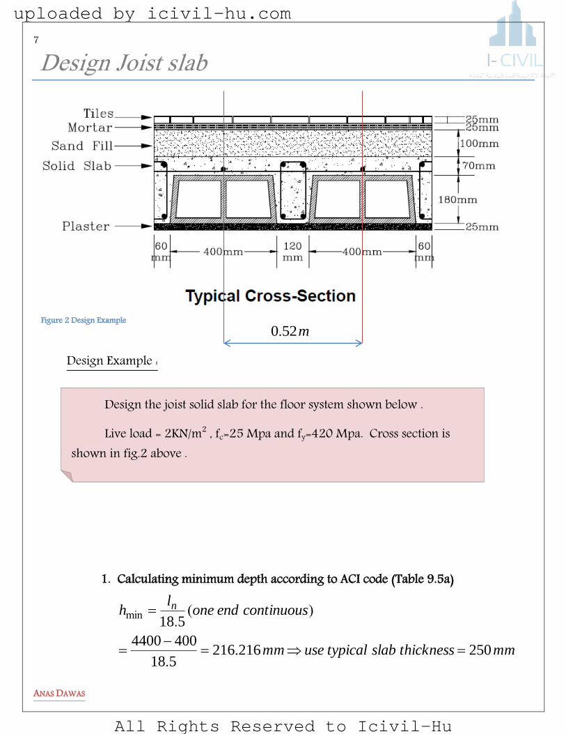
One-Way Joist Floor System :
Long-span floors for relatively light live loads can be constructed as a series of closely
spaced, cast-in-place T-beams (or joists) with a cross section as shown in Fig. The
joists span one way between beams. Most often, removable metal forms referred to as
fillers or pans are used to form the joists. Occasionally, joist floors are built by using clay-tile
fillers, which serve as forms for the concrete in the ribs that are left in place to serve as the
ceiling (ACI Code Section 8.13.5).
When the dimensions of the joists conform to ACI Code Sections 8.13.1 to 8.13.3,
they are eligible for less cover to the reinforcement than for beams (ACI Code Section
7.7.2(c)) and for a 10 percent increase in the shear, carried by the concrete (ACI
Figure 1 Types of slabs
uploaded by icivil-hu.com
All Rights Reserved to Icivil-Hu

5
ANAS DAWAS
Code Section 8.13.8). The principal requirements are that the floor be a monolithic combination
of regularly spaced ribs and a top slab with
1. ribs not less than 100 mm. in width,
2. depth of ribs not more than 3.5 times the minimum web width, and
3. clear spacing between ribs not greater than 750 mm.
S
mm
fillerwith
mmfillerwithout
h f
12
1
50
40
Ribbed slabs not meeting these requirements are designed as slabs and beams.
Although not required by the ACI Code, load-distributing ribs perpendicular to the
joists are provided at the midspan or at the third points of long spans. These have at least
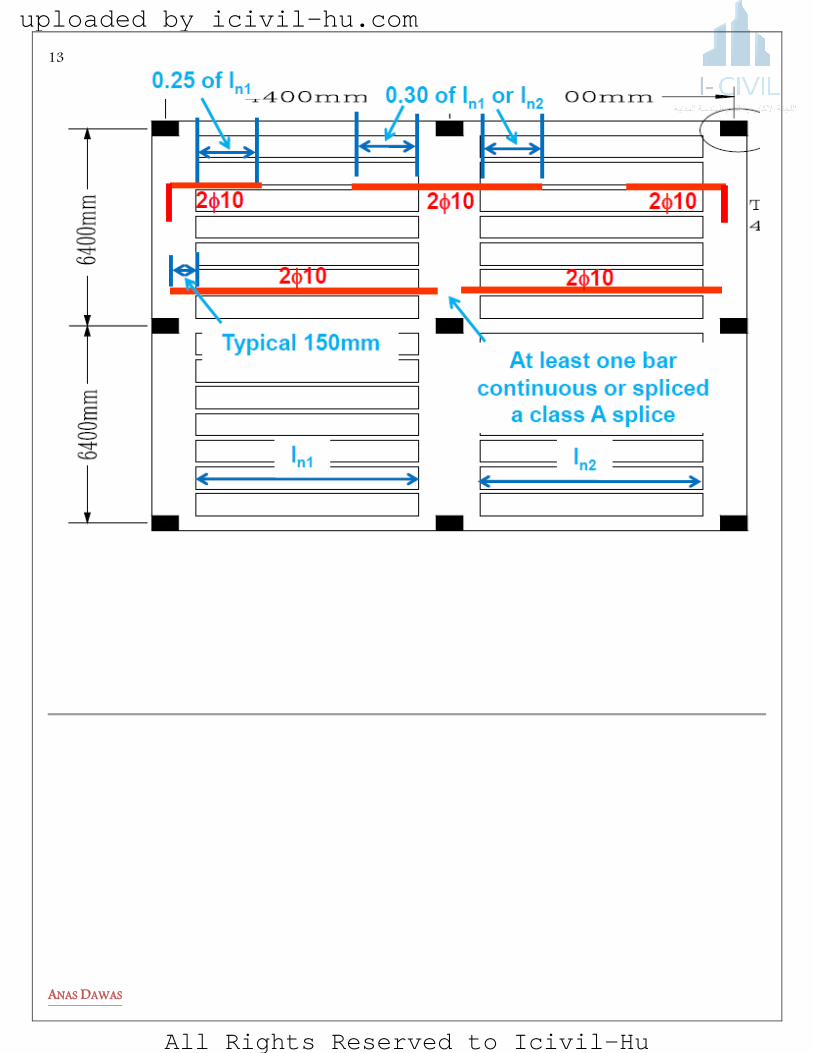
one continuous No. 4 (13 mm) bar at the top and the bottom. The CRSI Handbook [10-4] suggests
no load-distributing ribs in spans of up to 6 m, one at midspan for spans of 6 to 9 m , and
two at the third points for spans over 9 m .
For joist floors meeting the requirements of ACI Code Section 8.3.3, the ACI moment
and shear coefficients can be used in design, taking (Ln) as the clear span of the joists
themselves. For uneven spans, it is necessary to analyze the floor.
The negative moments in the ends of the joists will be underestimated if this is not done.
S
uploaded by icivil-hu.com
All Rights Reserved to Icivil-Hu
6
ANAS DAWAS
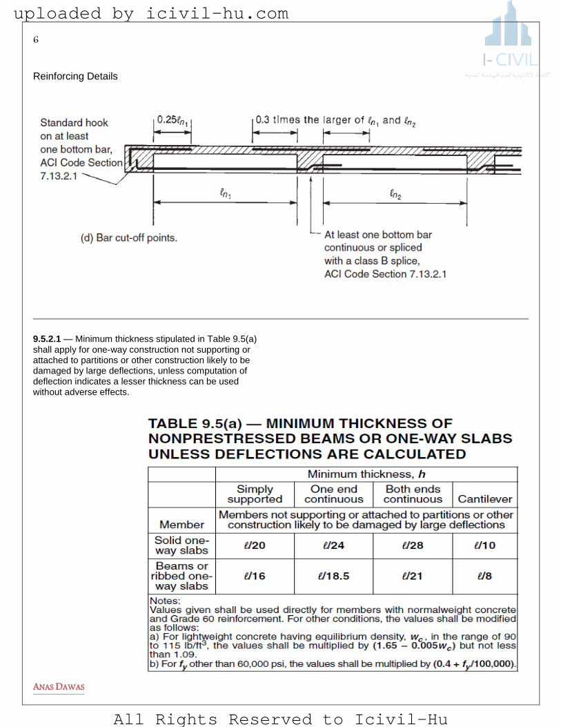
Reinforcing Details
9.5.2.1 — Minimum thickness stipulated in Table 9.5(a) shall apply for one-way construction not supporting or attached to partitions or other construction likely to be damaged by large deflections, unless computation of deflection indicates a lesser thickness can be used without adverse effects.
uploaded by icivil-hu.com
All Rights Reserved to Icivil-Hu
7
ANAS DAWAS
baiJ tgioJingiseDg
Design Example :
1. Calculating minimum depth according to ACI code (Table 9.5a)
mmthicknessslabtypicalusemm
continuousendonel
h n
250216216518
4004400
518
..
)(.
min
Design the joist solid slab for the floor system shown below .
Live load = 2KN/m2 , fc=25 Mpa and fy=420 Mpa. Cross section is shown in fig.2 above .
Figure 2 Design Example m520.
uploaded by icivil-hu.com
All Rights Reserved to Icivil-Hu
8
ANAS DAWAS
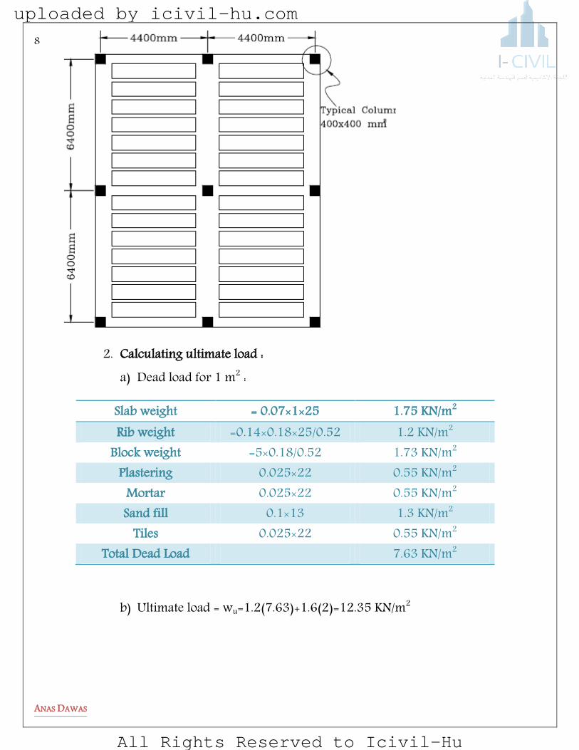
2. Calculating ultimate load : a) Dead load for 1 m2 :
Slab weight = 0.07×1×25 1.75 KN/m2 Rib weight =0.14×0.18×25/0.52 1.2 KN/m2
Block weight =5×0.18/0.52 1.73 KN/m2 Plastering 0.025×22 0.55 KN/m2
Mortar 0.025×22 0.55 KN/m2 Sand fill 0.1×13 1.3 KN/m2
Tiles 0.025×22 0.55 KN/m2 Total Dead Load 7.63 KN/m2
b) Ultimate load = wu=1.2(7.63)+1.6(2)=12.35 KN/m2
uploaded by icivil-hu.com
All Rights Reserved to Icivil-Hu
9
ANAS DAWAS
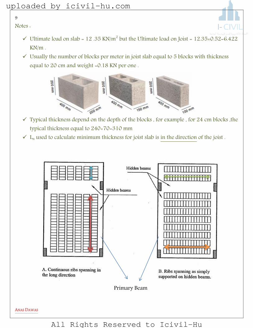
Notes :
Ultimate load on slab = 12 .35 KN/m2 but the Ultimate load on Joist = 12.35×0.52=6.422 KN/m .
Usually the number of blocks per meter in joist slab equal to 5 blocks with thickness equal to 20 cm and weight =0.18 KN per one .
Typical thickness depend on the depth of the blocks , for example , for 24 cm blocks ,the typical thickness equal to 240+70=310 mm
Ln used to calculate minimum thickness for joist slab is in the direction of the joist .
Primary Beam
uploaded by icivil-hu.com
All Rights Reserved to Icivil-Hu
10
ANAS DAWAS
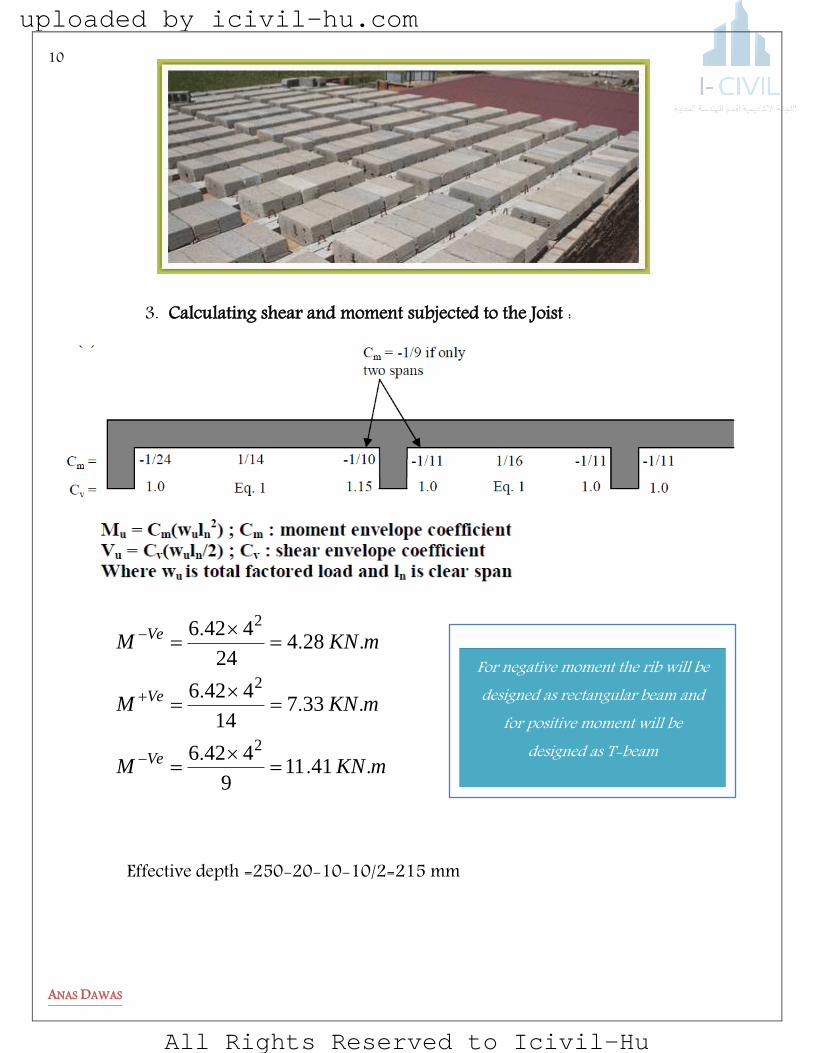
3. Calculating shear and moment subjected to the Joist :
mKNM
mKNM
mKNM
Ve
Ve
Ve
...
...
...
41119
4426
33714
4426
28424
4426
2
2
2
Effective depth =250-20-10-10/2=215 mm
For negative moment the rib will be designed as rectangular beam and
for positive moment will be designed as T-beam
uploaded by icivil-hu.com
All Rights Reserved to Icivil-Hu
11
ANAS DAWAS
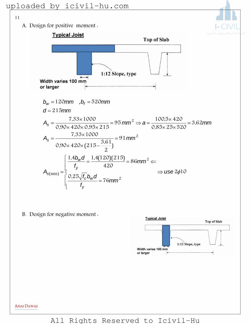
A. Design for positive moment :
10276250
86420
2151204141
91
2613215420900
1000337
62352025850
420510095215950420900
1000337215
520120
2
2
2
2
use
mmf
dbf
mmf
db
A
mmA
mmammA
mmd
mmbmmb
y
wc
y
w
s
s
s
fw
.
))((..
).
(.
.
..
.
..
.
,
(min)
B. Design for negative moment :
uploaded by icivil-hu.com
All Rights Reserved to Icivil-Hu

12
ANAS DAWAS
102276250
2864202151204141
22149
2825215420900
10004411
4241202585042015722148215950420900
10004411
use
mmyf
dwbcf
mmyf
dwb
sA
mmsA
mmammsA
.
))((..
(min)
.)
.(.
.
..
...
.
4. Shear Design:
OKVV
KNdbf
V
KNlW
V
uc
wc
c
nuu
73172151206
2575011
611
76142
151
....
.)(.
5. Solid Slab Design :
blockormeshUse
mmA
mm
A
mKN
lwM
beamsimpleasitdesigncanwealsobut
beamfixefixeaspartthisdesigncanwe
s
s
nuu
/
))((.
..
.
..
..
.
(min)
10
12670100000180
15
4595042090
100024680
24680
8
403412
8
2
2
22
40cm
uploaded by icivil-hu.com
All Rights Reserved to Icivil-Hu
13
ANAS DAWAS
uploaded by icivil-hu.com
All Rights Reserved to Icivil-Hu

14
ANAS DAWAS
Problems:
1-1 The one way joist slab shown below consists of 011 mm wide joists spaced at 510 mm , the web width of the spandrel beams is 400 mm and 500 for interior beams . Column dimension (400×400 mm).
A B C D
1
2
3
4
uploaded by icivil-hu.com
All Rights Reserved to Icivil-Hu

15
ANAS DAWAS
The minimum required depth of the slab upon the ACI code requirement is most nearly
………… Calculate the Ultimate load /rib assuming that the Live load = 3 KN/m2,
25 mm Covering material with unit weight is 20 KN/m3 . blocks are 40×25×17 cm in dimension , each 17 Kg in weight . Use
fc =30 Mpa , fy=420 Mpa and 25 mm plaster with unit weight = 21 KN/m3.
The maximum ultimate negative moment in the joist ……… The maximum ultimate shear in the joist ……… The ultimate distributed load /m on the beam between column A and B is most nearly
………. The ultimate load carried by column A is most nearly…….. For the overhang slab , The minimum required depth of the slab upon the ACI code
requirement is………… The minimum required depth of the exterior beam upon the ACI code requirement is
……. The maximum ultimate negative moment in the overhang joist is most nearly …………. The maximum ultimate positive moment in the joist is most nearly ………. The largest ultimate load carried by the intermediate column is most ……… The minimum area of steel required to resist the maximum ultimate positive moment in
beam between column C2 and D2 upon ACI code is most nearly (assume the depth of the beam is 600 mm ) …………
Show by suitable sketch the reinforcements required to resist the maximum ultimate positive moment for any interior joist.
The minimum area of steel must be provided to solid slab part upon ACI code requirements is most nearly ……..
uploaded by icivil-hu.com
All Rights Reserved to Icivil-Hu

16
ANAS DAWAS
1-2 For Simple supported square slab shown below is apart of a floor in a typical residential building and the live load = 2 KN/m2,fc=28 Mpa and fy=420 Mpa .use 12mm bars
The minimum required depth of the slab upon the ACI code requirement is most nearly………..
Calculate the Ultimate load /rib based on the typical section shown above……. Draw shear and moment diagram for the simple supported Joist …… Calculate the shear strength capacity for the joist upon ACI code……… Design the reinforcement in the joist to carry the positive moment, show suitable
sketch ……….. The minimum required depth of the primary beam upon the ACI code
requirement is most nearly………..
uploaded by icivil-hu.com
All Rights Reserved to Icivil-Hu

17
ANAS DAWAS
Draw shear and moment diagram for the primary beam based on the minimum depth calculated above ………
1-3 The one way joist slab shown below consists of 150 mm wide joists spaced at 550 mm , the web width of the spandrel beams is 400 mm and 500 for interior beams . Column dimension (400×400 mm).
Assume that the dead load and live load on the slab is 7KN/m2 and 3 KN/m2:
m7
m6
m6
m7 m4 m7
uploaded by icivil-hu.com
All Rights Reserved to Icivil-Hu

18
ANAS DAWAS
The minimum required depth of the slab upon the ACI code requirement is most nearly …………
The maximum ultimate negative moment in the joist ……… The maximum ultimate shear in the joist ……… The ultimate distributed load /m on the beam between column A3 and B3 is most nearly
………. ( neglect self weight of beam )
The minimum required depth of the exterior beam upon the ACI code requirement is …….
The maximum ultimate positive moment in the joist is most nearly ………. Show by suitable sketch the reinforcements required to resist the maximum ultimate
positive moment for any interior joist. The minimum area of steel must be provided to solid slab part upon ACI code
requirements is most nearly …….. Determine the design ultimate bending moment , ultimate shear force at the most
critical section for each for the simple supported joist ………..
uploaded by icivil-hu.com
All Rights Reserved to Icivil-Hu
19
ANAS DAWAS
TWO WAY SLAB
uploaded by icivil-hu.com
All Rights Reserved to Icivil-Hu

20
ANAS DAWAS
Two Way Slabs
Behavior , Analysis and Design
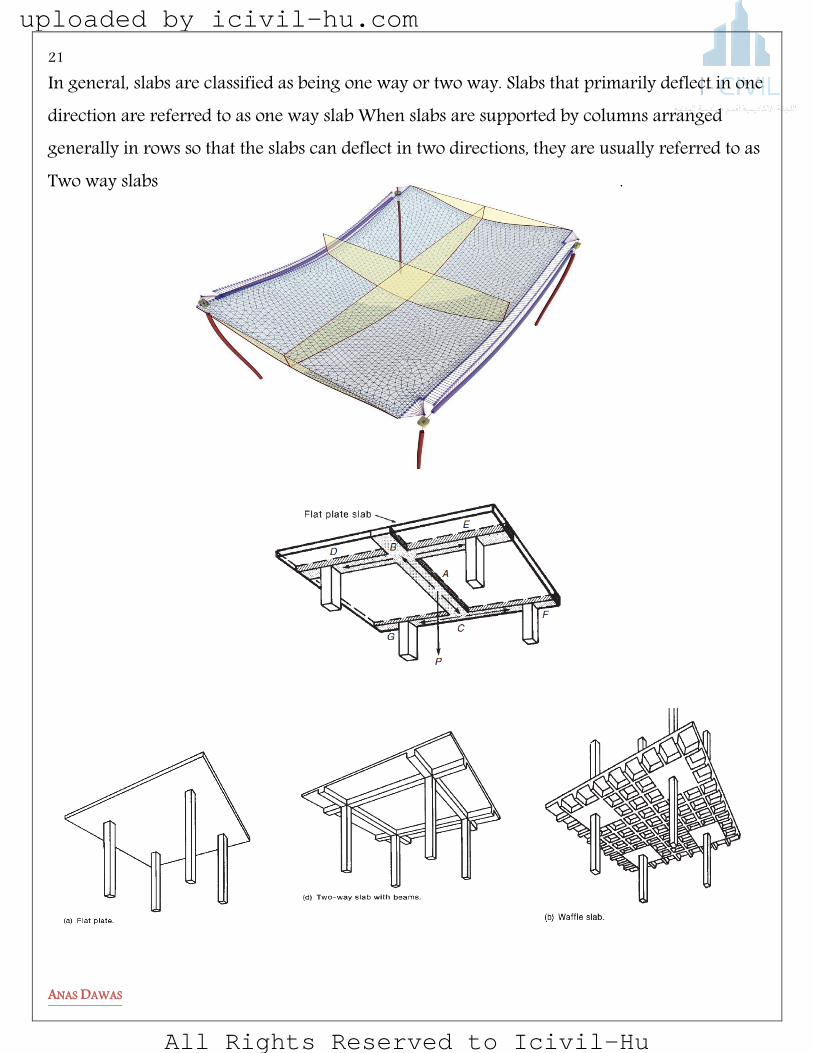
Two-way slabs are a form of construction unique to reinforced concrete among the major structural materials. It is an efficient, economical, and widely used structural system. In practice, two-way slabs take various forms. For relatively light loads, as experienced in apartments or similar buildings, flat plates are used. such a plate is simply a slab of uniform thickness supported on columns. In an apartment building, the top of the slab would be carpeted, and the bottom of the slab would be finished as the ceiling for the story below. Flat plates are most economical for spans from 4.5 to 6 m .
uploaded by icivil-hu.com
All Rights Reserved to Icivil-Hu
21
ANAS DAWAS
In general, slabs are classified as being one way or two way. Slabs that primarily deflect in one direction are referred to as one way slab When slabs are supported by columns arranged generally in rows so that the slabs can deflect in two directions, they are usually referred to as Two way slabs .
uploaded by icivil-hu.com
All Rights Reserved to Icivil-Hu

22
ANAS DAWAS
Two-way slabs can be strengthened by the addition of beams between the columns, by thickening the slabs around the columns (drop
panels), and by flaring the columns under the slabs (column capitals). These situations are shown in Figure 16.1 and discussed in the next several paragraphs. Flat plates present a possible problem in transferring the shear at the perimeter of the columns. In other words, there is a danger that the columns may punch through the slabs. As a result, it is frequently necessary to increase column sizes or slab thicknesses or to use Shearheads .
Analysis of Two-Way Slabs:
A theoretical elastic analysis for such slabs is a very complex problem because of their highly indeterminate nature. Numerical techniques such as finite difference and finite elements are required, but such methods require sophisticated software to be practical in design. The methods described in this chapter can be done by hand or with simple spreadsheets, and are sufficiently accurate for most design problems. the design of two-way slabs is generally based on empirical moment coefficients, which, although they
might not accurately predict stress variations, result in slabs with satisfactory overall safety
factors. In other words, if too much reinforcing is placed in one part of a slab and too little
somewhere else, the resulting slab behavior will probably still be satisfactory. The total amount
of reinforcement in a slab seems more important than its exact placement.
uploaded by icivil-hu.com
All Rights Reserved to Icivil-Hu

23
ANAS DAWAS
DESIGN OF SLABS: Two procedures for the flexural analysis and design of two-way floor systems are presented in detail in the ACI Code:
Direct-design method—considered in the following section:
The calculation of moments in the direct-design method is based on the total statical moment
Equivalent-frame design method:
Here, the slab is divided into a series of two-dimensional frames (in each direction), and the positive and negative
moments are computed via an elastic-frame analysis.
THE DIRECT-DESIGN METHOD
Limitations on the Use of the Direct-Design Method:
The direct design method was developed from theoretical procedures for
determination of moments in slabs, requirements for simple design,
construction procedures, and performance of existing slabs. Therefore, the
slab system, to be designed using the direct design method, should conform
to the following limitations as given by ACI Code 13.6.1:
1. There must be three or more spans in each direction.
2. Slab panels must be rectangular with a ratio of longer to shorter span,
center-to-center of supports, not greater than 2.0.
3. Successive span lengths, center-to-center of supports, in each direction
must not differ by more than one-third of the longer span.
4. Columns must not be offset more than 10 % of the span in the direction
of offset from either axis between centerlines of successive columns.
5. Loads must be due to gravity only and uniformly distributed over the
entire panel. The live load must not exceed 2 times the dead load.
6. For a panel with beams between supports on all sides, the relative
stiffness of beams in two perpendicular directions is not
less than 0.20 and not greater than 5.0.
52002
12
221
l
l
f
f
.
uploaded by icivil-hu.com
All Rights Reserved to Icivil-Hu
24
ANAS DAWAS
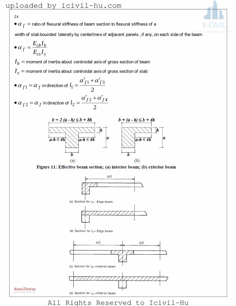
2
2
4222
3111
ffff
ffff
s
b
scs
bcbf
f
l
l
I
I
IE
IE
of direction in
of direction in
slab of section gross of axis centroidalabout inertia ofmoment
beam of section gross of axis centroidalabout inertia ofmoment
beam the of side each on any, if , panelsadjacent of scenterlineby laterally bounded slab of width
a of stiffness flexuralto section beam of stiffness flexuralof ratio
uploaded by icivil-hu.com
All Rights Reserved to Icivil-Hu

25
ANAS DAWAS
Design Procedure:
1) Determination of the total factored static moment: Total factored static moment for a span is determined in a strip bounded laterally by centerline of panel
on each side of centerline of supports, as shown in Figure.
columnsbetweenspanclearl
striptheofwidthtransversel
areaunitperloadfactoredw
wherellw
M
n
u
nuo
2
22
8
:than less be tonot is direction each in moments factorednegative average and positive of sum Absolute
2) Distribution of the total factored static moment to negative and positive moments:
uploaded by icivil-hu.com
All Rights Reserved to Icivil-Hu
26
ANAS DAWAS
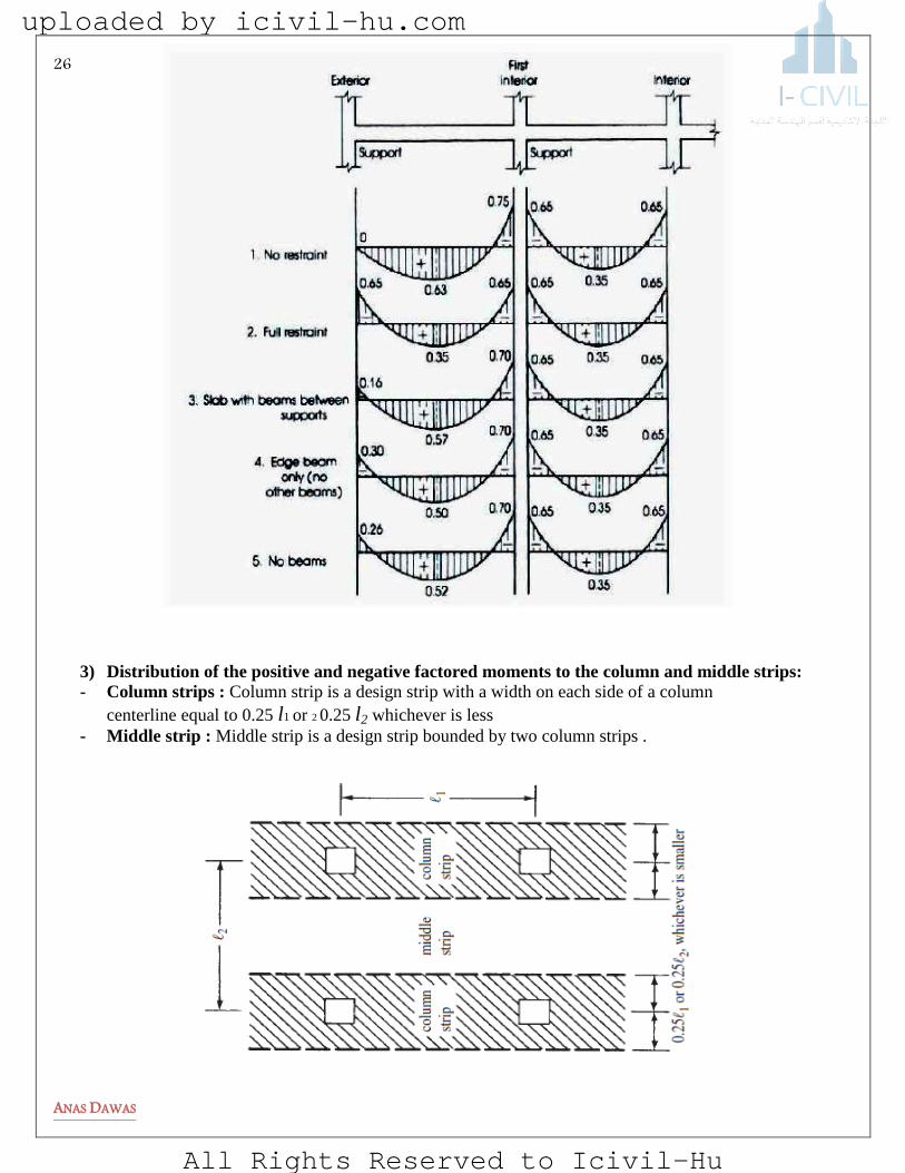
3) Distribution of the positive and negative factored moments to the column and middle strips:
- Column strips : Column strip is a design strip with a width on each side of a column
centerline equal to 0.25 l1 or 2 0.25 l2 whichever is less
- Middle strip : Middle strip is a design strip bounded by two column strips .
uploaded by icivil-hu.com
All Rights Reserved to Icivil-Hu
27
ANAS DAWAS
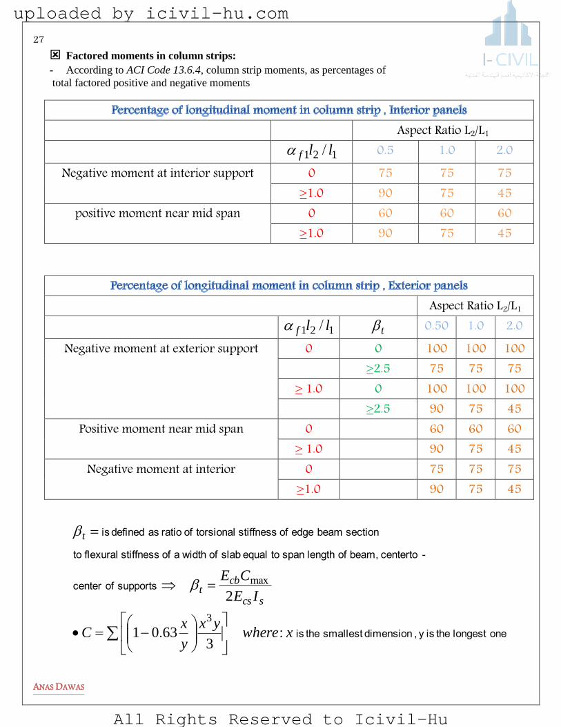
Factored moments in column strips: - According to ACI Code 13.6.4, column strip moments, as percentages of
total factored positive and negative moments
Aspect Ratio L2/L1
121 llf / 0.5 1.0 2.0 Negative moment at interior support 0 75 75 75
≥1.0 90 75 45 positive moment near mid span 0 60 60 60
≥1.0 90 75 45
Aspect Ratio L2/L1 121 llf / t 0.50 1.0 2.0
Negative moment at exterior support 0 0 100 100 100 ≥2.5 75 75 75
≥ 1.0 0 100 100 100 ≥2.5 90 75 45
Positive moment near mid span 0 60 60 60 ≥ 1.0 90 75 45
Negative moment at interior 0 75 75 75 ≥1.0 90 75 45
onelongest the isy , dimensionsmallest the is
supports of center
-centerto beam, of length span to equal slab of widtha of stiffness flexuralto
section beam edge of stiffness torsional of ratio as defined is
xwhereyx
y
xC
IE
CE
scs
cbt
t
:.
max
36301
2
3
uploaded by icivil-hu.com
All Rights Reserved to Icivil-Hu

28
ANAS DAWAS
Factored moments in beams caused by slab loads
Depth Limitations and Stiffness Requirements
It is obviously very important to keep the various panels of a two-way slab relatively level (i.e.,
with reasonably small deflections). Thin reinforced two-way slabs have quite a bit of moment
resistance, but deflections are often large. As a consequence, their depths are very carefully
controlled by the ACI Code so as to limit these deflections. This is accomplished by requiring
the designer to either (a) compute deflections and make sure they are within certain limitations
or (b) use certain minimum thicknesses as specified in Section 9.5.3 of the code. Deflection
computations for two-way slabs are rather complicated, so the average designer usually uses
the minimum ACI thickness values, presented in the next few paragraphs of this chapter.
uploaded by icivil-hu.com
All Rights Reserved to Icivil-Hu

29
ANAS DAWAS
1) Slabs without Interior Beams
For a slab without interior beams spanning between its supports and with a ratio of its long
span to short span not greater than 2.0, the minimum thickness can be taken from [Table 9.5(c) in the code]. The
values selected from the table, however, must
not be less than the following values (ACI 9.5.3.2):
Slabs without drop panels 125 mm .
Thickness of those slabs with drop panels outside the panels 100 mm
.
Very often slabs are built without interior beams between the columns but with edge beams running around the perimeter
of the building. These beams are very helpful in stiffening the slabs and reducing the deflections in the exterior slab
panels. The stiffness of slabs with edge beams is expressed as a function of αf , which follows.
uploaded by icivil-hu.com
All Rights Reserved to Icivil-Hu

30
ANAS DAWAS
2) Slabs with Interior Beams
To determine the minimum thickness of slabs with beams spanning between their supports on
all sides, Section 9.5.3.3 of the code must be followed. Involved in the expressions presented
there are span lengths, panel shapes, flexural stiffness of beams if they are used, steel yield
stresses, and so on. In these equations, the following terms are used:
panel a of sides all on stiffness slab-to-beam of ratios the of value average the
span clear short the to long the of ratio the
beams withslab for beams (b) and beams withoutslabs for columns (a) of
face, to face measured direction, long the in span clear the
fm
nl
mm
fl
h
For
mm
fl
h
For
For
yn
fm
fm
yn
fm
fm
909361400
80
02
125200536
140080
2002
20
).(
,.
).(
).(
,.
,.
) 16.1 tablesupports.( their between spanning beams interior
withoutslabs for they were as obtained are sthicknesse minimum the
uploaded by icivil-hu.com
All Rights Reserved to Icivil-Hu

31
ANAS DAWAS
SHEAR STRENGTH OF TWO-WAY SLABS A shear failure in a beam results from an inclined crack caused by flexural and shearing
stresses. This crack starts at the tensile face of the beam and extends diagonally to the compression zone .
One-way shear or beam-action shear (Fig. 4) involves an inclined crack extending across the entire width of the
structure. Two-way shear or punching shear involves a truncated cone or pyramid-shaped surface
around the column, as shown schematically in Fig. 3.
Once a punching-shear failure has occurred at a slab–column joint, the shear capacity of that particular joint is almost
completely lost. In the case of a two-way slab, as the slab slides down, the column load is transferred to adjacent column-
slab connections, thereby possibly overloading them and causing them to fail. Thus, although a two-way slab possesses
great ductility if it fails in flexure, it has very little ductility if it fails in shear
One Way Shear :
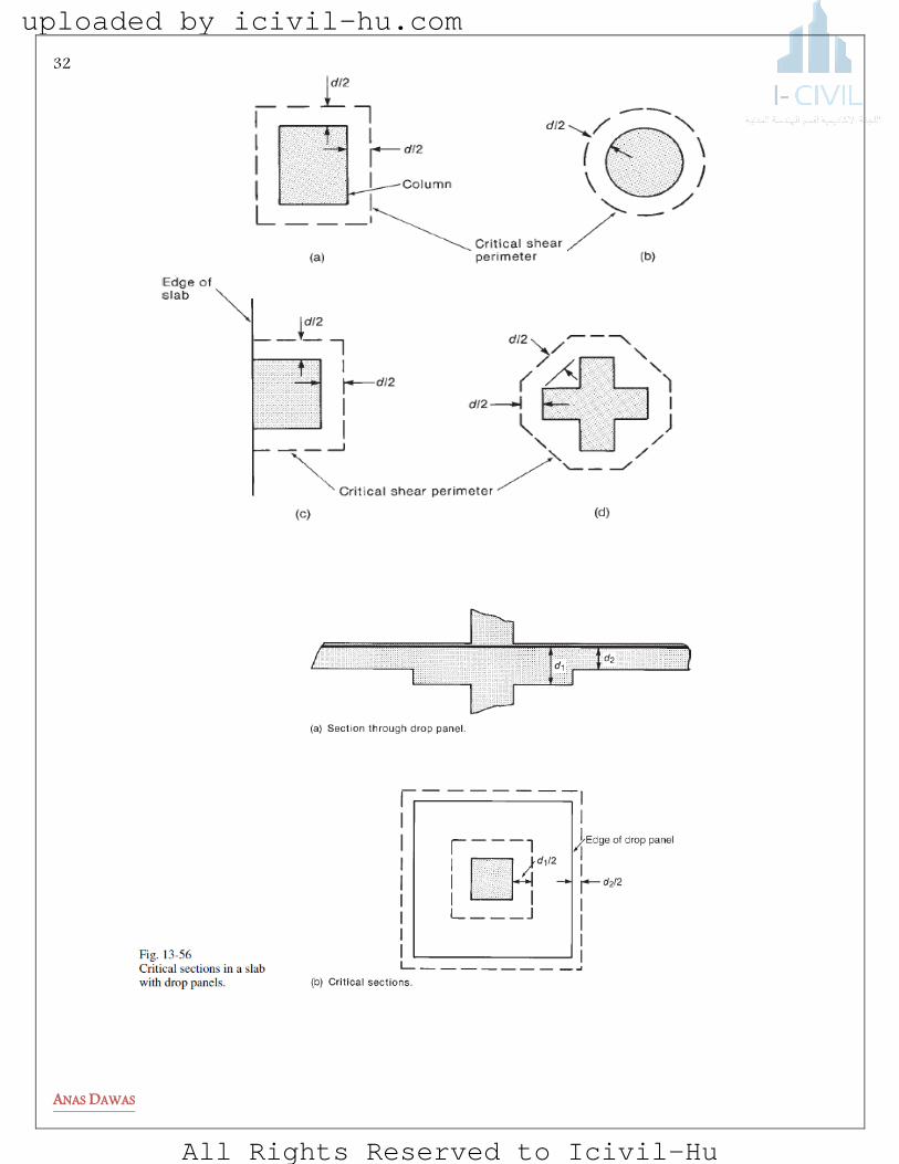
The critical section for one way shear is located at “d” from the face of the support or at “d” from the face of the drop panel or other change in thickness . The shear strength on the critical section is computed as for beams .
""datVbeshoulddbfV uwcc 6
1
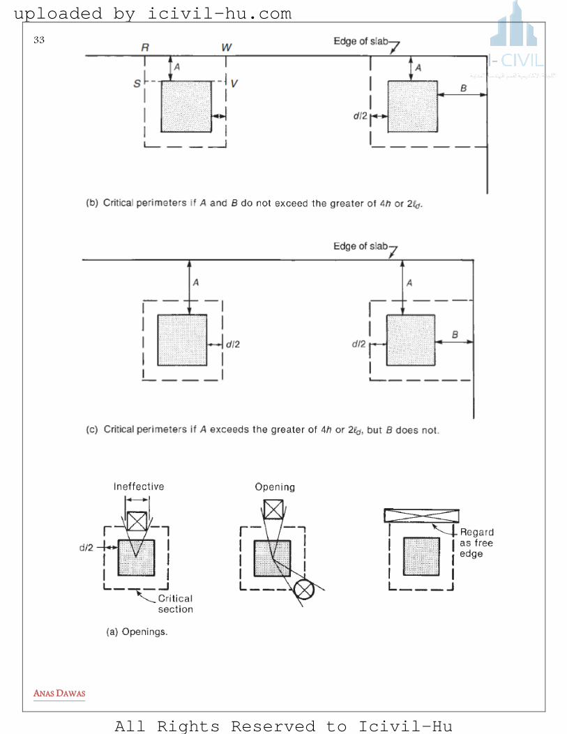
Two Way Shear:
Location of the Critical Perimeter:
Two-way shear is assumed to be critical on a vertical section through the slab or footing
extending around the column. According to ACI Code Section 11.11.1.2, this section is
chosen so that it is never less than d/2 from the face of the column and so that its length ,bo ,
is a minimum.
Figure 4 Beam shear / one way Figure 3 Two way shear / punching shear
uploaded by icivil-hu.com
All Rights Reserved to Icivil-Hu
32
ANAS DAWAS
uploaded by icivil-hu.com
All Rights Reserved to Icivil-Hu
33
ANAS DAWAS
uploaded by icivil-hu.com
All Rights Reserved to Icivil-Hu

34
ANAS DAWAS
Tributary Areas for Shear in Two-Way Slabs
column corner for20
column edge for30
column interior for40
section critical the of perimeter the is
sideshort the to column of side long of ratio
s
o
c
b
dbfVc
dbf
b
dVb
dbfVa
wherecandbaofsmallesttheastakenisV
VslabmostIn
occ
oc
o
sc
oc
cc
c
s
3
1
122
12
42
0
)(
)(
)(
:)()(),(
uploaded by icivil-hu.com
All Rights Reserved to Icivil-Hu
35
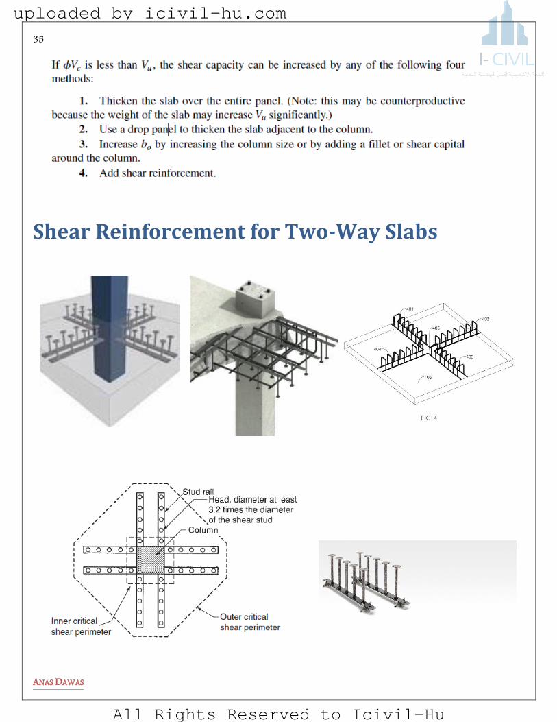
ANAS DAWAS
Shear Reinforcement for Two-Way Slabs
uploaded by icivil-hu.com
All Rights Reserved to Icivil-Hu
36
ANAS DAWAS
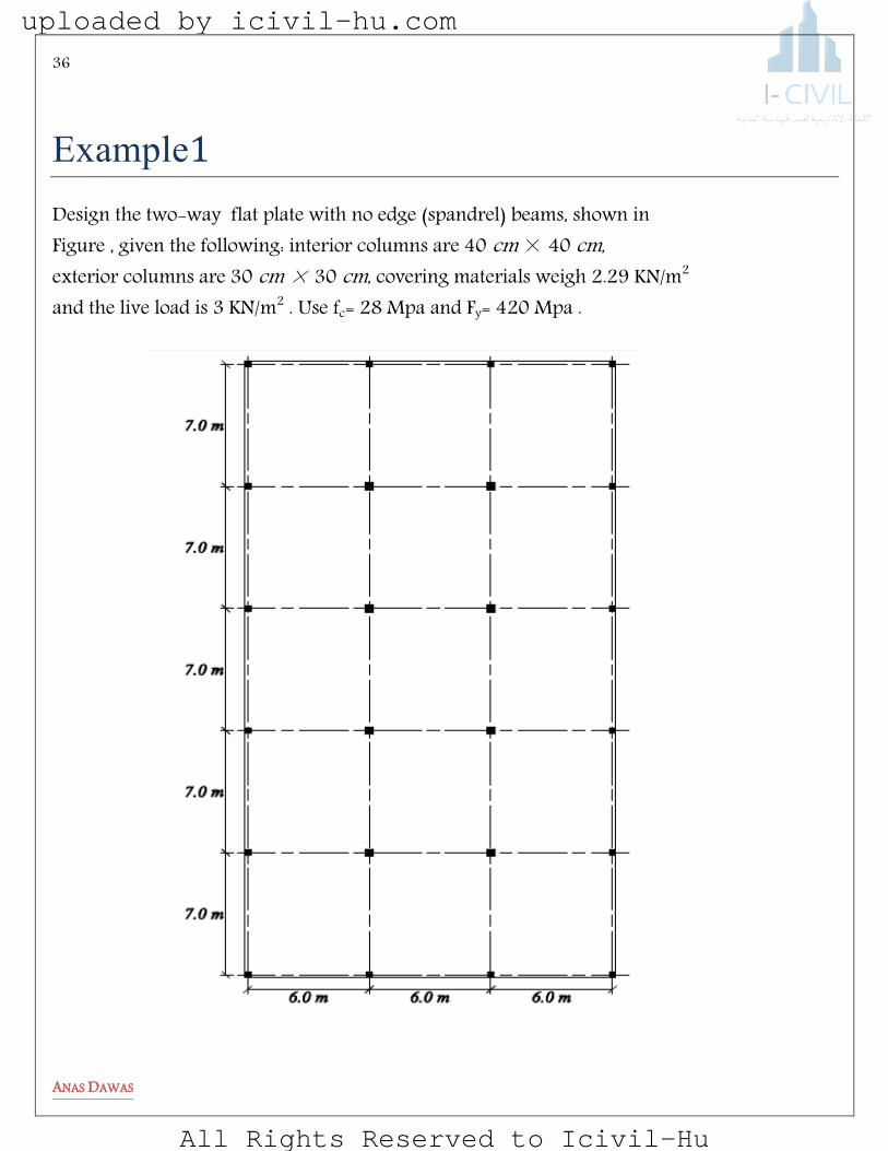
elemasa1
Design the two-way flat plate with no edge (spandrel) beams, shown in Figure , given the following: interior columns are 40 cm × 40 cm, exterior columns are 30 cm × 30 cm, covering materials weigh 2.29 KN/m2
and the live load is 3 KN/m2 . Use fc= 28 Mpa and Fy= 420 Mpa .
uploaded by icivil-hu.com
All Rights Reserved to Icivil-Hu

37
ANAS DAWAS
Solution:
1) Evaluate slab thickness For corner panel Ln=7-0.3=6.7 m For Edge panel Ln=7-0.15-0.2=6.65 m For interior panel Ln=7-0.40=6.6 m For flat plates with no edge beams, minimum slab thickness = Ln/30 = 6700/30 = 223.33 mm
Take it as 30 cm .
2) Check limitations for slab analysis by the direct design method:
The first five conditions are satisfied, while the sixth condition does not apply due to the nonexistence of
beams.
3) Calculate the factored load on the slab:
Wu= 1.2 ( 0.3×25+2.29)+1.6(3)=16.55 4) Check slab thickness for shear:
a) Interior column :
davg = 300 – 20 -20 (use ø20 bar ) = 26 cm
x
y
uploaded by icivil-hu.com
All Rights Reserved to Icivil-Hu

38
ANAS DAWAS
- Punching shear
OKVVKNV
KN
KN
KN
ofsmallerV
KNV
mmb
ucc
c
u
o
3894750351192
7121026026402831
35119212
2602640282640
26040
181612
260264028142
01896876600765516
264040026042
...
.
.
.
.).)((.
)(
- Beam shear For section 1-1 :
OKKNV
KNV
mmx
c
u
810312606000286
1750
871301604035516
30402602
400
2
7000
..
.).(.
For section 2-2:
OK
KNV
KNV
mmy
c
u
12032607000286
1750
329454275516
25402602
400
2
6000
.
.).(.
uploaded by icivil-hu.com
All Rights Reserved to Icivil-Hu
39
ANAS DAWAS
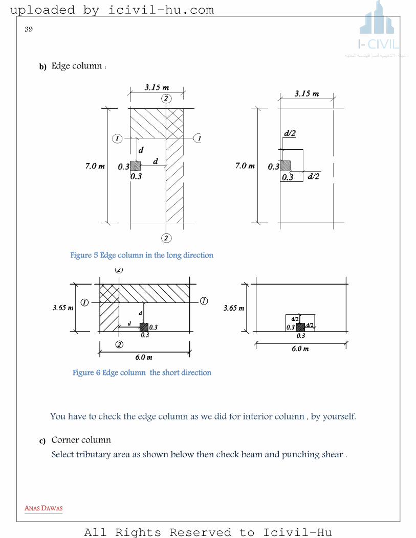
b) Edge column :
You have to check the edge column as we did for interior column , by yourself.
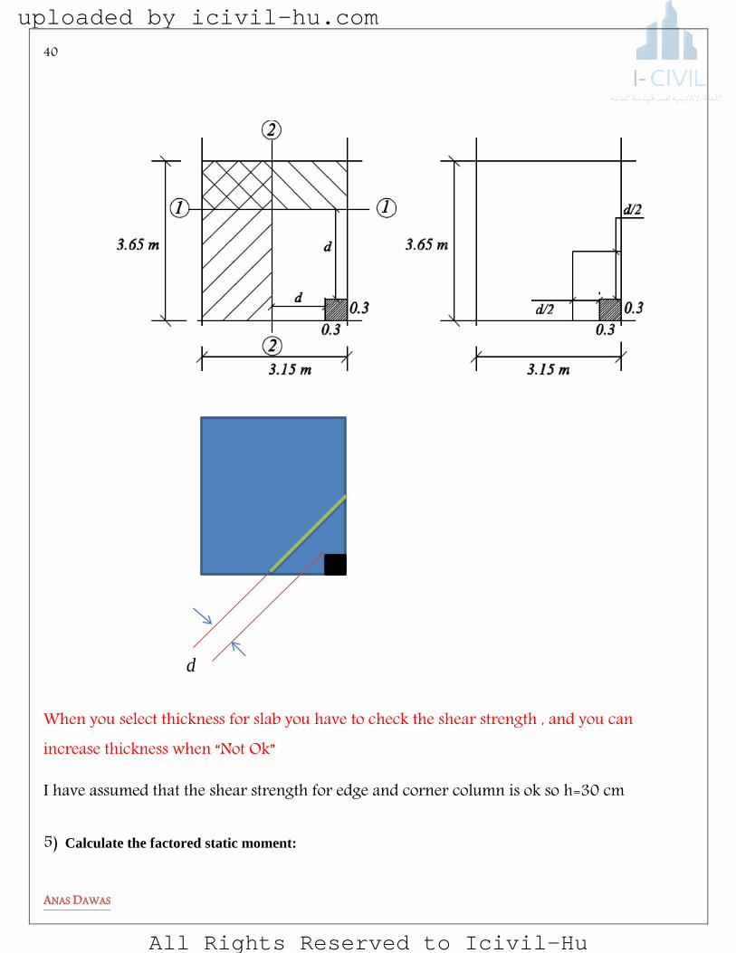
c) Corner column Select tributary area as shown below then check beam and punching shear .
Figure 6 Edge column the short direction
Figure 5 Edge column in the long direction
uploaded by icivil-hu.com
All Rights Reserved to Icivil-Hu
40
ANAS DAWAS
When you select thickness for slab you have to check the shear strength , and you can increase thickness when “Not Ok”
I have assumed that the shear strength for edge and corner column is ok so h=30 cm 5) Calculate the factored static moment:
d
uploaded by icivil-hu.com
All Rights Reserved to Icivil-Hu
41
ANAS DAWAS
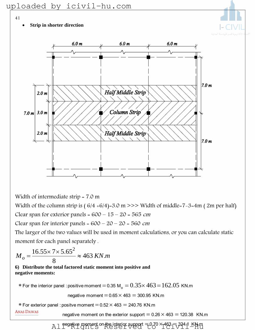
Strip in shorter direction
Width of intermediate strip = 7.0 m Width of the column strip is ( 6/4 +6/4)=3.0 m >>> Width of middle=7-3=4m ( 2m per half) Clear span for exterior panels = 600 – 15 – 20 = 565 cm Clear span for interior panels = 600 – 20 – 20 = 560 cm The larger of the two values will be used in moment calculations, or you can calculate static moment for each panel separately .
mKNMo ...
4638
65575516 2
6) Distribute the total factored static moment into positive and
negative moments:
KN.m 324.14630.70 support interior the onmoment negative
KN.m 120.384630.26support exterior the onmoment negative
KN.m 240.764630.52 moment positve : panel exterior For
KN.m 300.95463 0.65 moment negative
KN.m M 0.35 moment positive : panel interior the For o
05162463350 ..
uploaded by icivil-hu.com
All Rights Reserved to Icivil-Hu

42
ANAS DAWAS
05162.
95300. 95300.38120.
76240.
1324. 1324. 38120.
76240.
38120.
96
144
243
38120.243
14497
864.
81
Figure 7 Total Static moment
Figure 8 Column strip moment
Figure 9 Middle Strip moment
uploaded by icivil-hu.com
All Rights Reserved to Icivil-Hu

43
ANAS DAWAS
7) Distribute the positive and negative moments to the column and middle strips:
8) Design the reinforcement: Column strip reinforcement and Half middle strip reinforcement:
Design sections at maximum positive and negative moments as rectangular section :
Column Strip Half Middle Strip
Negative Positive Negative Positive
Moment(KN.m) 243 144 81/2= 40.5 96/2= 48
b (mm) 3000 3000 2000 2000
d (mm) 260 260 260 260
h (mm) 300 300 300 300
Fy ( Mpa) 420 420 420 420
Fc (Mpa) 28 28 28 28
As (mm2)
As-min (mm2) 0.0018bh 0.0018bh 0.0018bh 0.0018bh
Bar Dim Ø12 Ø12 Ø12 Ø12
No of bar
As Provided
øMn (KN.m)
Sample Of Calculation To Design Column Strip :
For Positive Moment
Slab Moment End span Interior span
Exterior
negative
Positive Interior
negative
Positive Negative
Total moment 120.38
240.76 324.1 162.05 300.95
Column
moment
120.38 0.6×240.76=
144.45
0.75×324.1=
243.075
0.6×162.05=
97.23
0.75×300.95=
225.7
Middle strip
moment
0 240.76-144.45=
96.31
324.1-243.075=
81.025
162.05-
97.23=64.82
300.95-225.7=
75.25
uploaded by icivil-hu.com
All Rights Reserved to Icivil-Hu

44
ANAS DAWAS
)(.).
(.
..
)(
)(
)(.
)(
.
)()()(.
.
).
(.
..
.
...
max
(min)
OKM
mmaa
dfAM
ScheckmmA
AbS
mmbarsuseBarNo
thisusemmA
mmA
mma
mmA
n
ysn
s
b
s
s
s
14451632
9792604201696900
979300028850
4201696
2
2001696
124
3000
16961215314
124
1620
1620300300000180
31491
2
1926042090
1000144
19300028850
42031542
3154226095042090
1000144
2
2
2
2
2
2
Strip in the long direction Width of intermediate strip = 600 cm and width of column strip is the smaller of (L1 / 2) and (L2 / 2), taken as (600/2) = 300 cm. Total factored static moment: Clear span for exterior panels = 700 – 15 – 20 = 665 cm Clear span for interior panels = 700 – 20 – 20 = 660 cm The larger of the two values will be used in moment calculations.
mKNM o ...
5498
65665516 2
uploaded by icivil-hu.com
All Rights Reserved to Icivil-Hu

45
ANAS DAWAS
You can design this strip by yourself now
elemasagE
For the two-way solid slab with beams on all column lines, shown in Figure , evaluate the moments acting on any of the internal beams, using the direct design method. All columns are 30 cm × 30 cm in cross section, all beams are 30 cm × 60 cm in cross section, slab thickness is equal to 14 cm, covering materials weigh 1.83 KN/m2 and the live load is 4 kN/m2. Use Use fc= 28 Mpa and Fy= 420 Mpa .
uploaded by icivil-hu.com
All Rights Reserved to Icivil-Hu

46
ANAS DAWAS
1) Evaluate the slab thickness For internal beams :
uploaded by icivil-hu.com
All Rights Reserved to Icivil-Hu
47
ANAS DAWAS
49923
23
1058910236353120437046030012
460300
2
14012041401220
12
1401220
12044603001401220
1402
460460300
2
1401401220
mm
I
mmy
b
...).)(())((
).)(())((
.)()(
))(())((
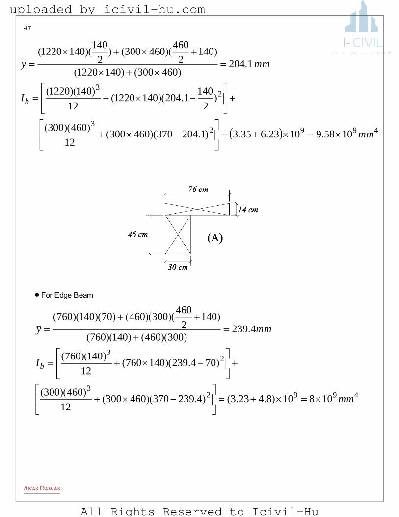
49923
23
1081084233423937046030012
460300
70423914076012
140760
4239300460140760
1402
46030046070140760
mm
I
mmy
b
)..().)(())((
).)(())((
.))(())((
))()(())()((
Beam Edge For
uploaded by icivil-hu.com
All Rights Reserved to Icivil-Hu
48
ANAS DAWAS
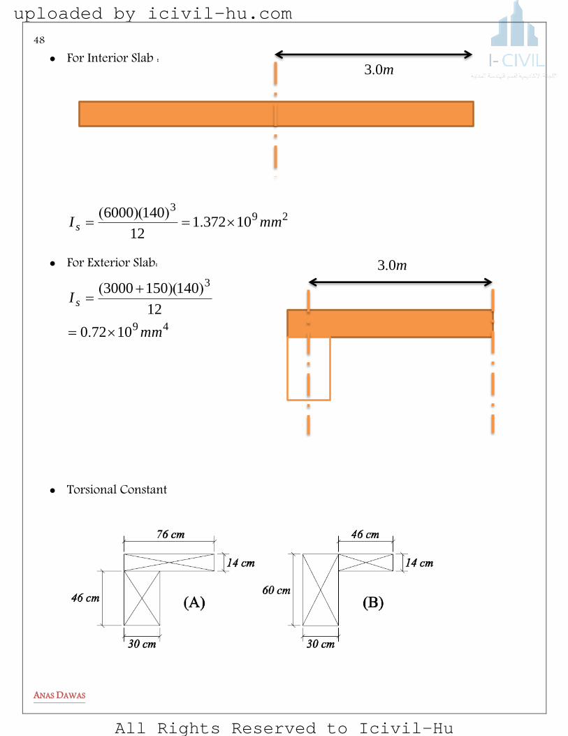
For Interior Slab :
293
10372112
1406000mmI s .
))((
For Exterior Slab:
49
3
10720
12
1401503000
mm
I s
.
))((
Torsional Constant
m03.
m03.
uploaded by icivil-hu.com
All Rights Reserved to Icivil-Hu

49
ANAS DAWAS
)(./))((
.
.
.
.
max
cminunits
cmC
cmC
cmC
t
B
A
472112146002
3403907
3403907
3403907
3305347
3
4
4
4
Calculating α :
Generally , you have to calculate αm for each span then calculate thickness for each one to
determine which values will control ……
Figure 10 Alpha Values
Okmmh
mm
fl
h
valuesall
cm
cm
yn
mf
mf
f
f
).(.)(
).(.
..
..
).(
.
.....
...
(.
(.
33139140331391936
1400
4208075
013006
3006
90936
140080
02
964
96969696
9584
96961111
1111720
8000
9861372
9850
2
1
2
4
4
1
beams) exterior For
beams) interior For
uploaded by icivil-hu.com
All Rights Reserved to Icivil-Hu

50
ANAS DAWAS
2) Factored load on the slab Wu=1.2 ( 0.14×25+1.83)+1.6(4)=12.8 KN/m2
3) Check slab thickness for shear Note : No need to check two way shear for two way slabs with beam , and you should check one way shear for interior and exterior beams but in this example they are the same so we will check for the interior one. x
OkVKNV
KNV
mm x
mmd
uc
u
64281086000286
750
521067422812
27421082
300
2
6000
1081220140
..
.).(.
section critical of Width
uploaded by icivil-hu.com
All Rights Reserved to Icivil-Hu

51
ANAS DAWAS
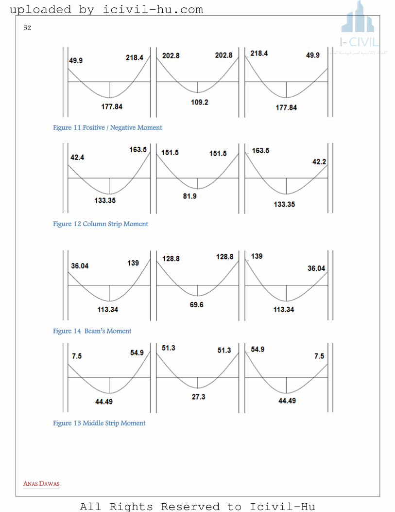
4) Total factored static moment
)(.
.)(.
.).(.
beforcalculated
l
l
mKNM
t
f
o
4721
9066
696
3128
756812
1
21
2
uploaded by icivil-hu.com
All Rights Reserved to Icivil-Hu
52
ANAS DAWAS
Figure 11 Positive / Negative Moment
Figure 12 Column Strip Moment
Figure 14 Beam’s Moment
Figure 13 Middle Strip Moment
uploaded by icivil-hu.com
All Rights Reserved to Icivil-Hu
53
ANAS DAWAS
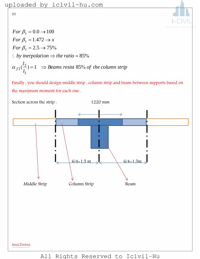
stripcolumntheofresistBeamsl
l
ratiotheoninerpolatiby
For
xFor
For
f
t
t
t
%)(
%
%.
.
.
851
85
7552
4721
10000
1
21
Finally , you should design middle strip , column strip and beam between supports based on the maximum moment for each one .
Section across the strip : 1220 mm
6/4=1.5 m 6/4=1.5m
Middle Strip Column Strip Beam
uploaded by icivil-hu.com
All Rights Reserved to Icivil-Hu
54
ANAS DAWAS
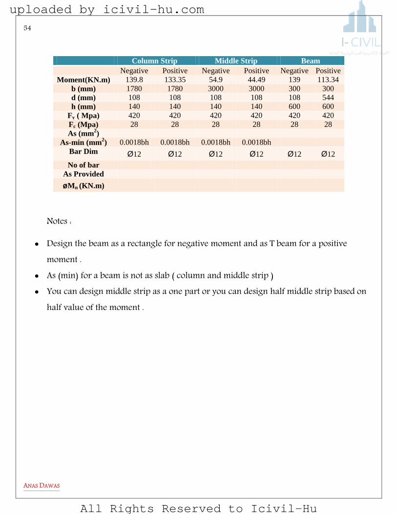
Column Strip Middle Strip Beam
Negative Positive Negative Positive Negative Positive
Moment(KN.m) 139.8 133.35 54.9 44.49 139 113.34
b (mm) 1780 1780 3000 3000 300 300
d (mm) 108 108 108 108 108 544
h (mm) 140 140 140 140 600 600
Fy ( Mpa) 420 420 420 420 420 420
Fc (Mpa) 28 28 28 28 28 28
As (mm2)
As-min (mm2) 0.0018bh 0.0018bh 0.0018bh 0.0018bh
Bar Dim Ø12 Ø12 Ø12 Ø12 Ø12 Ø12
No of bar
As Provided
øMn (KN.m)
Notes :
Design the beam as a rectangle for negative moment and as T beam for a positive moment .
As (min) for a beam is not as slab ( column and middle strip ) You can design middle strip as a one part or you can design half middle strip based on
half value of the moment .
uploaded by icivil-hu.com
All Rights Reserved to Icivil-Hu

55
ANAS DAWAS
beoag etasg
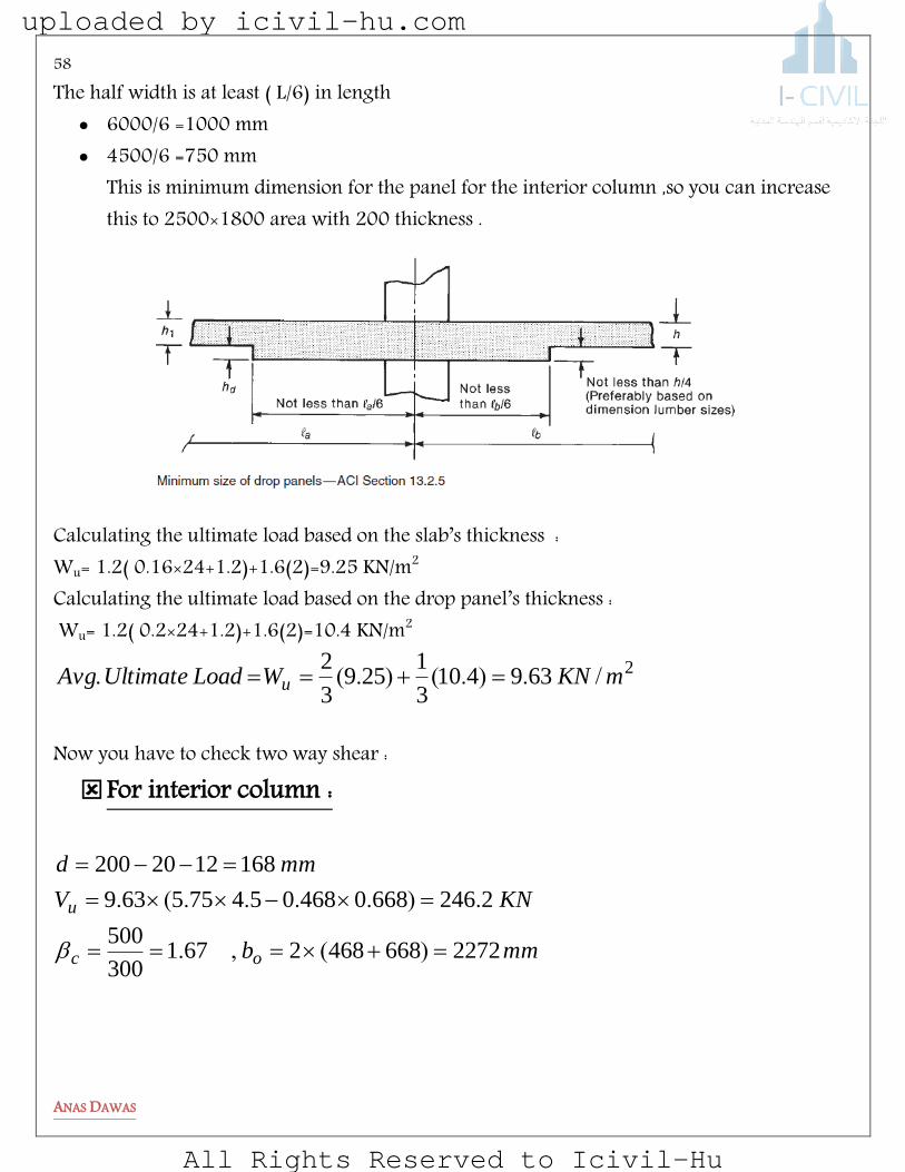
Drop panels are thicker portions of the slab adjacent to the columns, as shown in Fig.
1. The minimum thickness of slab required to limit deflections may be reduced by 10 percent if the slab has drop panels conforming to ACI Code Section 13.2.5. The drop panel stiffens the slab in the region of highest moments and hence reduces the deflection.
uploaded by icivil-hu.com
All Rights Reserved to Icivil-Hu

56
ANAS DAWAS
2. A drop panel with dimensions conforming to ACI Code Section 13.2.5 can be used to reduce the amount of negative-moment reinforcement required over a column in a flat slab. By increasing the overall depth of the slab, the lever arm, jd, used in computing the area of steel is increased, resulting in less required reinforcement in this region.
3. A drop panel gives additional slab depth at the column, thereby increasing the area of the critical shear perimeter.
Example : Design a drop panel according to the ACI code requirements for the floor system shown below in the fig. Check two way shear . Interior columns are ( 500×300 mm) and exterior columns are (300×300 mm ), Live load = 2 KN/m2 and super imposed Dead load = 1.2 KN/m2.
uploaded by icivil-hu.com
All Rights Reserved to Icivil-Hu
57
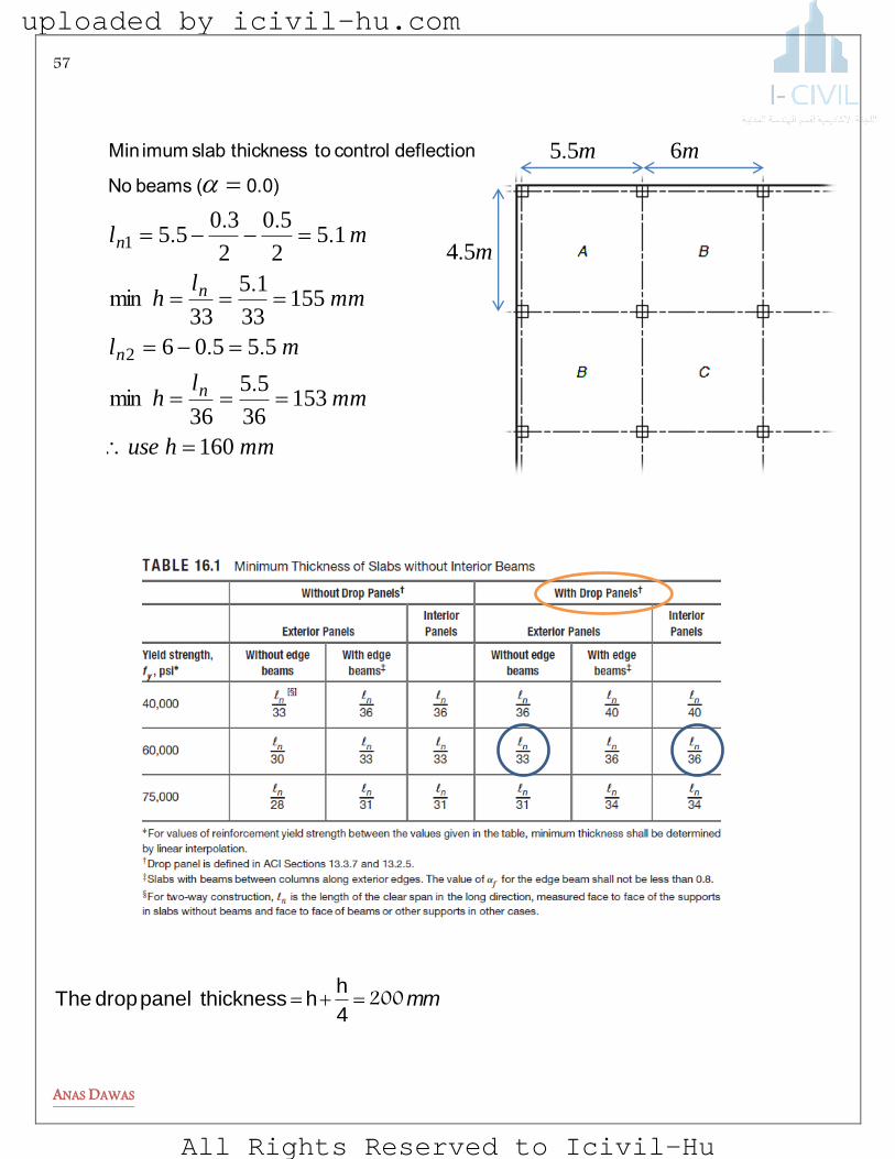
ANAS DAWAS
mm2004
hh thickness panel drop The
m55. m6
mmhuse
mml
h
ml
mml
h
ml
n
n
n
n
160
15336
55
36
55506
15533
15
33
152
50
2
3055
2
1
.min
..
.min
...
.
0.0)( beams No
deflection control to thickness slab imum Min
m54.
uploaded by icivil-hu.com
All Rights Reserved to Icivil-Hu
58
ANAS DAWAS
The half width is at least ( L/6) in length 6000/6 =1000 mm 4500/6 =750 mm
This is minimum dimension for the panel for the interior column ,so you can increase this to 2500×1800 area with 200 thickness .
Calculating the ultimate load based on the slab’s thickness : Wu= 1.2( 0.16×24+1.2)+1.6(2)=9.25 KN/m2
Calculating the ultimate load based on the drop panel’s thickness : Wu= 1.2( 0.2×24+1.2)+1.6(2)=10.4 KN/m2
26394103
1259
3
2mKNWLoadUltimateAvg u /.).().(.
Now you have to check two way shear : For interior column :
mmb
KNV
mmd
oc
u
22726684682671300
500
22466680468054755639
1681220200
)(,.
.)....(.
uploaded by icivil-hu.com
All Rights Reserved to Icivil-Hu

59
ANAS DAWAS
OKVKNV
KNVc
KNVb
KNVa
uc
c
c
c
505248673750
2486731000
168227228
3
1
48341000
168
12
2272282
2272
16840
87391000
168
12
227228
671
42
..
.)(
.)()(
.).
()(
uploaded by icivil-hu.com
All Rights Reserved to Icivil-Hu
60
ANAS DAWAS
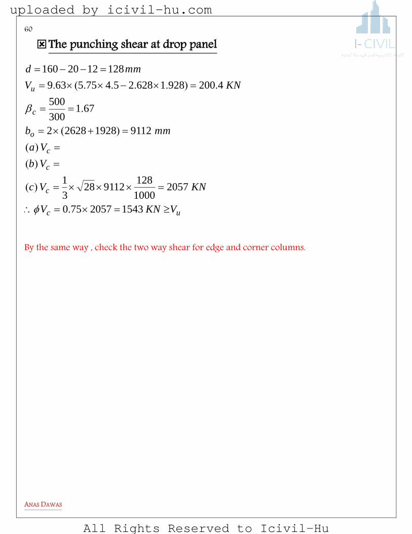
The punching shear at drop panel
uc
c
c
c
o
c
u
VKNV
KNVc
Vb
Va
mmb
KNV
mmd
15432057750
20571000
128911228
3
1
9112192826282
671300
500
42009281628254755639
1281220160
.
)(
)(
)(
)(
.
.)....(.
By the same way , check the two way shear for edge and corner columns.
uploaded by icivil-hu.com
All Rights Reserved to Icivil-Hu
61
ANAS DAWAS
MELBeReg
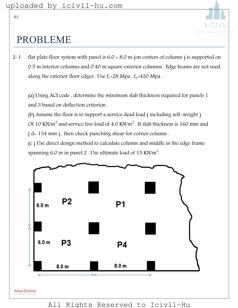
2-1 flat plate floor system with panel is 6.0 × 8.0 m (on centers of column ) is supported on 0.5 m interior columns and 0.40 m square exterior columns . Edge beams are not used along the exterior floor edges . Use fc=28 Mpa , fy=420 Mpa . (a) Using ACI code , determine the minimum slab thickness required for panels 1 and 3 based on deflection criterion . (b) Assume the floor is to support a service dead load ( including self-weight ) Of 10 KN/m2 and service live load of 4.0 KN/m2 . If slab thickness is 160 mm and ( d= 134 mm ) , then check punching shear for corner column . (c ) Use direct design method to calculate column and middle in the edge frame spanning 6.0 m in panel 2 . Use ultimate load of 15 KN/m2.
uploaded by icivil-hu.com
All Rights Reserved to Icivil-Hu
62
ANAS DAWAS
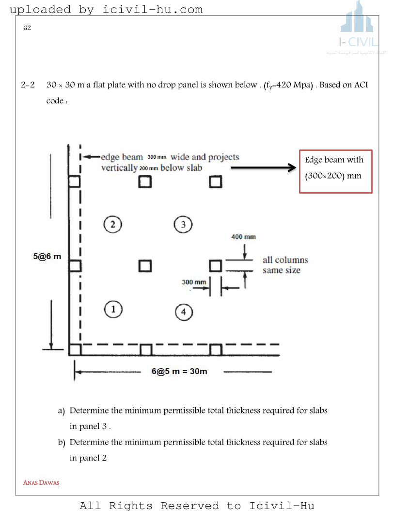
2-2 30 × 30 m a flat plate with no drop panel is shown below . (fy=420 Mpa) . Based on ACI code :
a) Determine the minimum permissible total thickness required for slabs
in panel 3 . b) Determine the minimum permissible total thickness required for slabs
in panel 2
Edge beam with (311×211) mm
uploaded by icivil-hu.com
All Rights Reserved to Icivil-Hu
63
ANAS DAWAS
c) The ACI code states that for slabs with beams between column along exterior
edges , the value αf for the edge beam shall not less than 0.8 . Determine αf if the slab is 200 mm in thickness and show if the provision is satisfied .
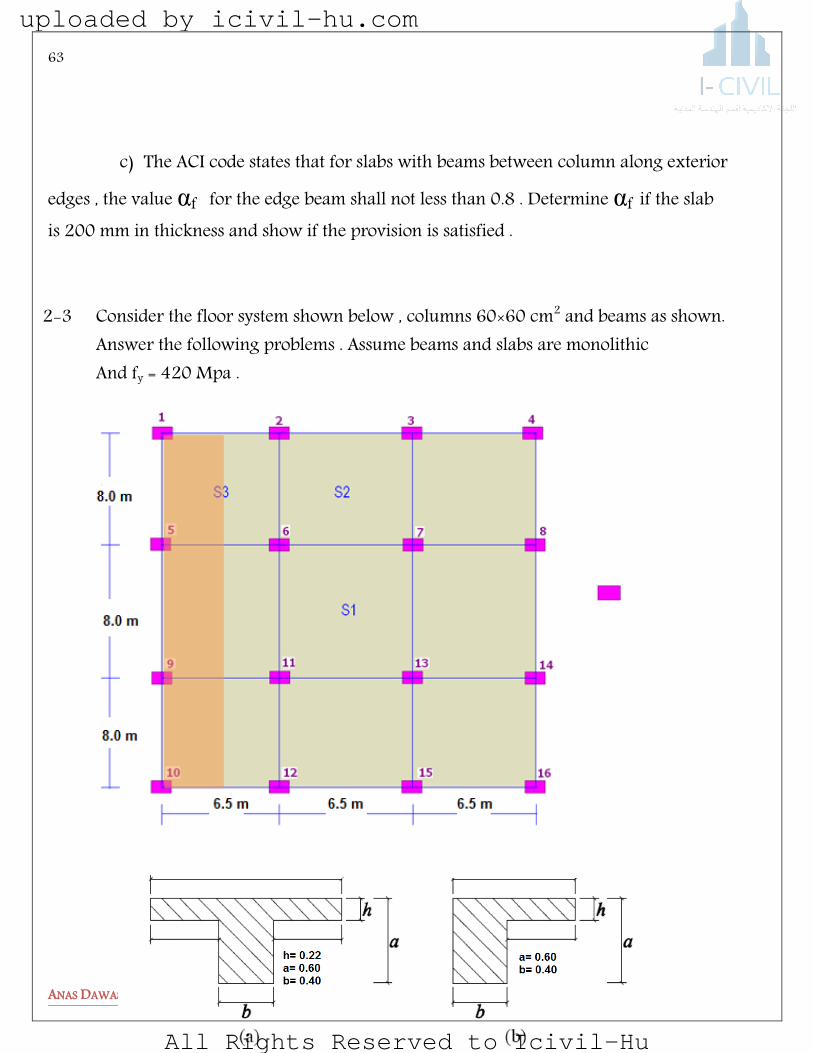
2-3 Consider the floor system shown below , columns 60×60 cm2 and beams as shown. Answer the following problems . Assume beams and slabs are monolithic And fy = 420 Mpa .
uploaded by icivil-hu.com
All Rights Reserved to Icivil-Hu
64
ANAS DAWAS
a) Compute α for interior beam in the short direction b) Compute α for exterior beam in the short direction c) Compute α for exterior beam in the long direction d) Compute βt for the exterior beam . e) Use the direct design method to calculate column and middle strip moments at the shaded
edge frame spanning . Use the ultimate load of 15 KN/m2.
f) Check one way shear for the beam between columns 6 and 7 .
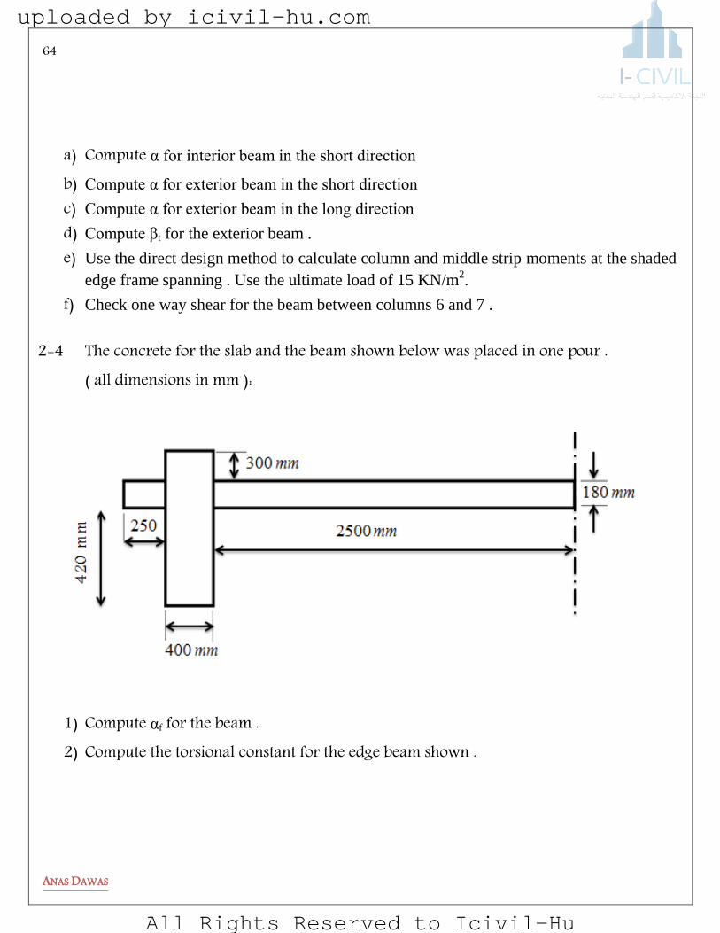
2-4 The concrete for the slab and the beam shown below was placed in one pour . ( all dimensions in mm ):
1) Compute αf for the beam . 2) Compute the torsional constant for the edge beam shown .
uploaded by icivil-hu.com
All Rights Reserved to Icivil-Hu

65
ANAS DAWAS
2-5 For the flat plate shown in the figure below ( edge beam are not used ). Answer the following questions . The columns dimensions are (40×40 cm ) , fc=28 Mpa and fy=420 Mpa .
5 m
5 m
6 m
6 m 6 m 5.5 m
41×41 cm
A2
W3
uploaded by icivil-hu.com
All Rights Reserved to Icivil-Hu

66
ANAS DAWAS
a) The minimum required depth of the slab based upon ACI code requirement Is most nearly: If the ultimate load on the slab is Wu= 15 KN/m2 , slab thickness h= 15 cm and effective depth d = 12 cm :
b) The maximum one way shear Vu in the area around column A2 ……… c) The Ultimate punching shear Vu for the corner column W3. ……… d) The Ultimate punching shear Vu for the interior column A2. ………
For the shaded area ( column and middle strip) shown in the figure
e) The Total static moment in the W-E direction (hatched frame ) is ……… If the total static moment in W-E direction is 300 KN.m :
f) The positive moment in the frame ( hatched frame ) is : ……… g) The column strip positive moment in the frame (hatched frame ) is : ……… h) Design a drop panel for the interior column A2 ….. i) The ultimate punching shear Vu for the 2000 by 2000 mm interior drop panel ( use
ø12 bars and 20 mm cover ) .
uploaded by icivil-hu.com
All Rights Reserved to Icivil-Hu
67
ANAS DAWAS
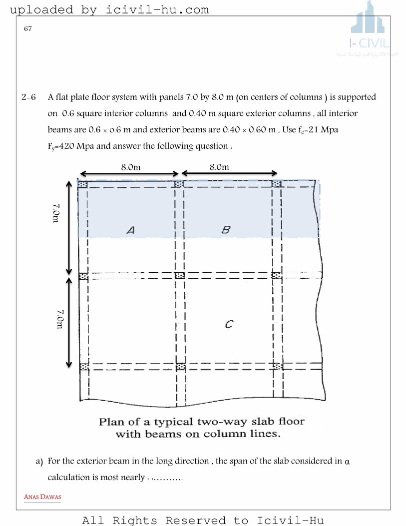
2-6 A flat plate floor system with panels 7.0 by 8.0 m (on centers of columns ) is supported on 0.6 square interior columns and 0.40 m square exterior columns , all interior beams are 0.6 × o.6 m and exterior beams are 0.40 × 0.60 m , Use fc=21 Mpa Fy=420 Mpa and answer the following question :
a) For the exterior beam in the long direction , the span of the slab considered in α calculation is most nearly : :……….
7.0m
7.0m
8.0m 8.0m
uploaded by icivil-hu.com
All Rights Reserved to Icivil-Hu
68
ANAS DAWAS
b) For interior panel C if the average α is equal to 2.3 , then the minimum depth of the slab is most nearly : :……….
c) For the corner panel (A) , if the floor system is assumed to be without beams , then the minimum depth of slab is most nearly : :……….
d) If the ultimate slab load is 20 KN/m2, and effective depth d =190 mm , the one way shear in panel C is most nearly : :……….
e) For the exterior frame spanning in the long direction (hatched frame ) , the clear span Ln of the of the frame in panel A is most nearly : :……….
f) For the exterior frame spanning in the long direction (hatched frame ) , the transvers length L2 of the of the frame in panel A is most nearly: :……….
g) If the total static moment in panel (A) for the exterior frame spanning in the long direction (hatched frame ) is 300 KN.m , the exterior negative moment in the frame is most nearly : :……….
h) If the total static moment in panel (A) for the exterior frame spanning in the long direction (hatched frame ) is 300 KN.m , the exterior positive moment in the frame is most nearly : :……….
i) Assume the floor has no beams and the ultimate load is 20 KN/m2 , if d=190 mm then the ultimate punching shear Vu for an interior column is most nearly :……….
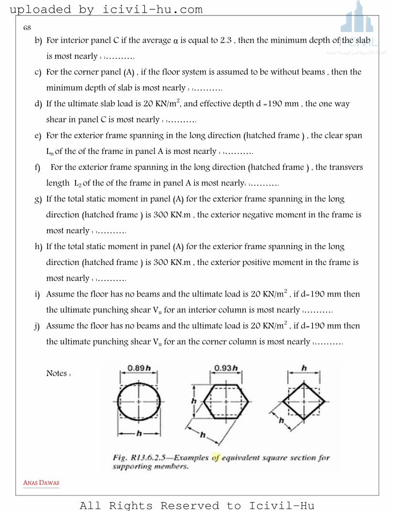
j) Assume the floor has no beams and the ultimate load is 20 KN/m2 , if d=190 mm then the ultimate punching shear Vu for an the corner column is most nearly :………. Notes :
uploaded by icivil-hu.com
All Rights Reserved to Icivil-Hu

69
ANAS DAWAS
Serviceability
uploaded by icivil-hu.com
All Rights Reserved to Icivil-Hu

70
ANAS DAWAS
yaelJbaeDJsJnS
Today the structural design profession is concerned with a limit states philosophy. The term limit state is used to describe a condition at which a structure or some part of a structure ceases to perform its intended function. There are two categories of limit states: strength and serviceability. Strength limit states are based on the safety or load-carrying capacity of structures and include buckling, fracture, fatigue, overturning, and so on. with the bending limit state of various members. Serviceability limit states refer to the performance of structures under normal service loads and are concerned with the uses and/or occupancy of structures. Serviceability is measured by considering the magnitudes of deflections, cracks, and vibrations of structures, as well as by considering the amounts of surface deterioration of the concrete and corrosion of the reinforcing. You will note that these items may disrupt the use of structures but do not usually involve collapse.
CRACKING This section presents a few introductory comments concerning some of the several types of cracks that occur in reinforced concrete beams. The remainder of this chapter is concerned with the estimated widths of flexural cracks and recommended maximum spacing of flexural bars to control cracks. Flexural cracks are vertical cracks that extend from the tension sides of beams up to the region of their neutral axes. Cracking starts when the tensile stress in the concrete reaches the tensile strength of the concrete at some point in the bar. When this occurs, the prism cracks.
uploaded by icivil-hu.com
All Rights Reserved to Icivil-Hu

71
ANAS DAWAS
Figure 15 types of cracks
uploaded by icivil-hu.com
All Rights Reserved to Icivil-Hu
72
ANAS DAWAS
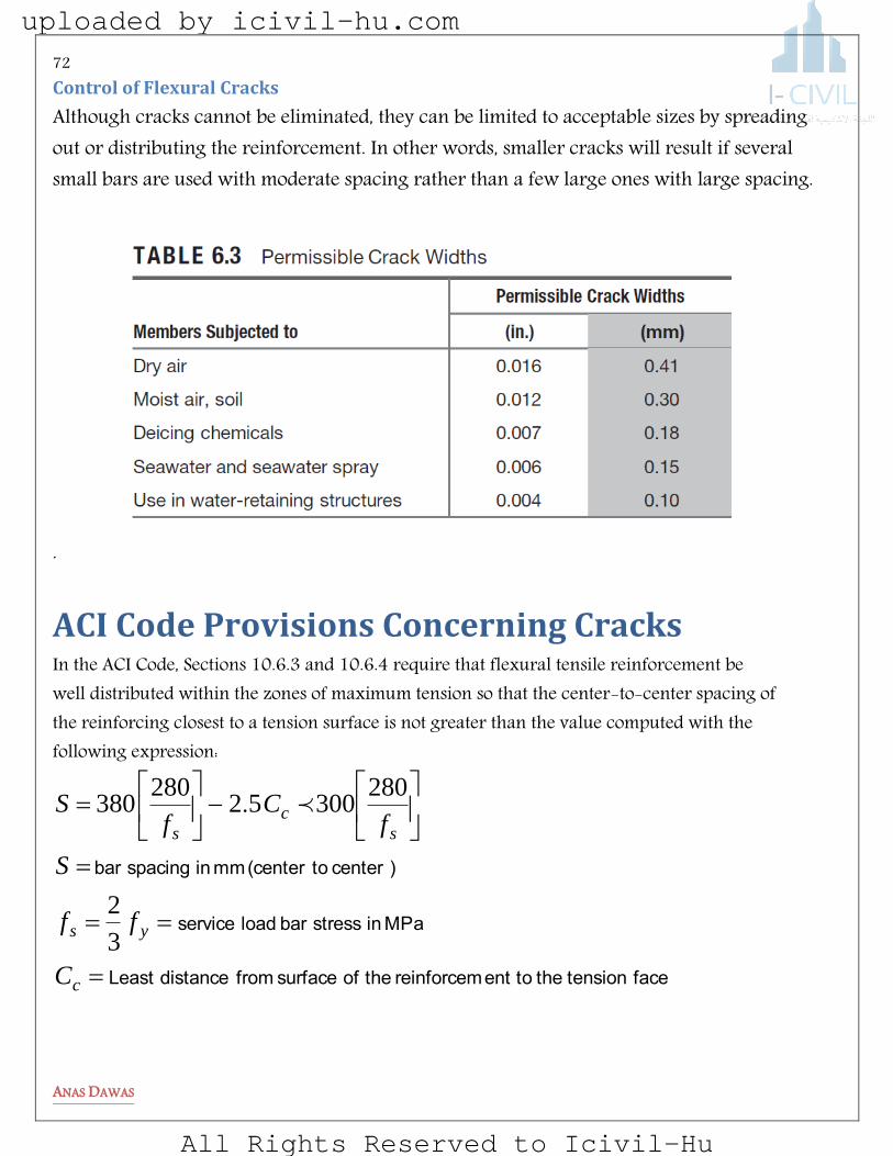
Control of Flexural Cracks
Although cracks cannot be eliminated, they can be limited to acceptable sizes by spreading out or distributing the reinforcement. In other words, smaller cracks will result if several small bars are used with moderate spacing rather than a few large ones with large spacing.
.
ACI Code Provisions Concerning Cracks In the ACI Code, Sections 10.6.3 and 10.6.4 require that flexural tensile reinforcement be well distributed within the zones of maximum tension so that the center-to-center spacing of the reinforcing closest to a tension surface is not greater than the value computed with the following expression:
facetension the toent reinforcem the of surface fromdistanceLeast
MPa in stress bar load service
) center to (center mm in spacing bar
c
ys
s
c
s
C
ff
S
fC
fS
3
2
28030052
280380 .
uploaded by icivil-hu.com
All Rights Reserved to Icivil-Hu

73
ANAS DAWAS
elpmaxE
Is the spacing of the bars shown in the figures within the requirements of the ACI code from the standpoint of the cracking ? If fy= 420 Mpa.
e. acceptablspacing is mm, this less than
mm is f spacing oactual barSince the
mmmm
S
mmd
C bc
228
75
300228
4203
2
280300656052
4203
2
280380
65602
72875
275
)().(.)(
..
uploaded by icivil-hu.com
All Rights Reserved to Icivil-Hu
74
ANAS DAWAS
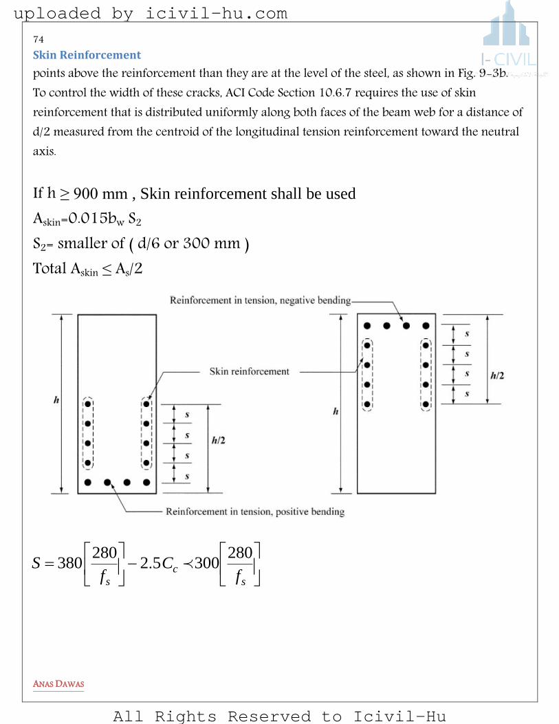
Skin Reinforcement
points above the reinforcement than they are at the level of the steel, as shown in Fig. 9-3b. To control the width of these cracks, ACI Code Section 10.6.7 requires the use of skin reinforcement that is distributed uniformly along both faces of the beam web for a distance of d/2 measured from the centroid of the longitudinal tension reinforcement toward the neutral axis. If h ≥ 900 mm , Skin reinforcement shall be used Askin=0.015bw S2 S2= smaller of ( d/6 or 300 mm ) Total Askin ≤ As/2
s
c
s fC
fS
28030052
280380 .
uploaded by icivil-hu.com
All Rights Reserved to Icivil-Hu

75
ANAS DAWAS
Deflections
Control of Deflections
One of the best ways to reduce deflections is by increasing member depths—but designers are always under pressure to keep members as shallow as possible. (As you can see, shallower members mean thinner floors, and thinner floors mean buildings with less height, with consequent reductions in many costs, such as plumbing, wiring, elevators, outside materials on buildings, and so on.) Reinforced concrete specifications usually limit deflections by specifying certain minimum depths or maximum permissible computed deflections.
Minimum Thicknesses
Table 9.5(a) of the ACI Code, provides a set of minimum thicknesses for beams and one-way slabs to be used, unless actual deflection calculations indicate that lesser thicknesses are permissible. These minimum thickness values, which were developed primarily on the basis of experience over many years, should be used only for beams and slabs that are not supporting or attached to partitions or other members likely to be damaged by deflections.
Maximum Deflections
If the designer chooses not to meet the minimum thicknesses given in Table 9.5(a) , he or she must compute deflections. If this is done, the values determined may not exceed the values specified in Table 6.1, which is Table 9.5(b) of the ACI Code.
Camber
The deflection of reinforced concrete members may also be controlled by cambering.
uploaded by icivil-hu.com
All Rights Reserved to Icivil-Hu

76
ANAS DAWAS
Common cases
uploaded by icivil-hu.com
All Rights Reserved to Icivil-Hu

77
ANAS DAWAS
Effective Moments of Inertia
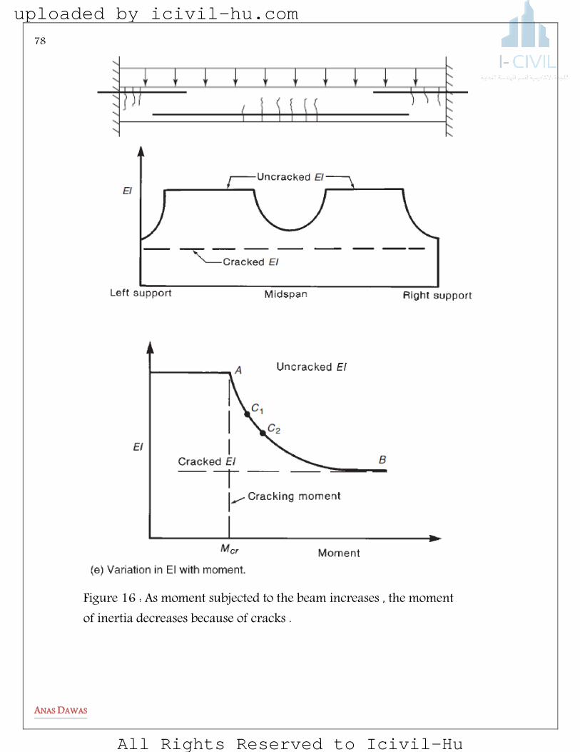
Regardless of the method used for calculating deflections, there is a problem in determining the moment of inertia to be used. The trouble lies in the amount of cracking that has occurred.
uploaded by icivil-hu.com
All Rights Reserved to Icivil-Hu
78
ANAS DAWAS
Figure 16 : As moment subjected to the beam increases , the moment of inertia decreases because of cracks .
uploaded by icivil-hu.com
All Rights Reserved to Icivil-Hu

79
ANAS DAWAS
cr
cc
t
gr
cr
ff
fE
y
IfM
700
4700
.
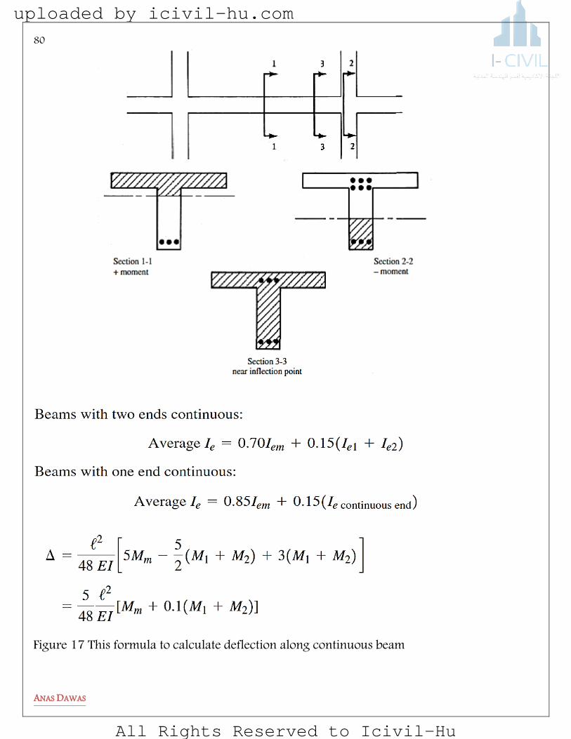
Continuous-Beam Deflections
The following discussion considers a continuous T beam subjected to both positive and negative moments. As shown in Figure below , the effective moment of inertia used for calculating deflections varies a great deal throughout the member.
cr
a
crg
a
cre
ecra
gcra
IM
MI
M
MI
IIUseMM
IIUseMMfor
33 1 )()(
ng stageious loadit any prevputed or a being cominertia is
tof the momen for whichding stageat the loa
member nt in the imum momeM
fibertensionextremethetocentroidfromy
ruptureoff
inertiaofmomentgrossI
momentcracking M
a
t
r
g
cr
max
distance
Modulus
uploaded by icivil-hu.com
All Rights Reserved to Icivil-Hu
80
ANAS DAWAS
Figure 17 This formula to calculate deflection along continuous beam
uploaded by icivil-hu.com
All Rights Reserved to Icivil-Hu

81
ANAS DAWAS
Critical section shall be permitted to obtain deflection in ACI code :
Mid span for simple supported beam At support for cantilever Critical positive and negative moment sections for continuous beam
ACI code :( Ig )is the moment of inertia of the gross concrete section neglecting area of tension steel .
Transformed Section
uploaded by icivil-hu.com
All Rights Reserved to Icivil-Hu

82
ANAS DAWAS
Elastic Theory For Flexure
This theory helps us to calculate deflection with several assumptions must be taken in considered :
1) Plan sections remain plane after bending . 2) Linear stress – strain curves for steel and concrete . 3) Perfect bond between steel and concrete . 4) Concrete tension capacity is neglected .
This theory cannot be used when concrete stress are higher than cf60. .
elpmaxE
For the beam shown below , check if we can use Theory of elasticity or not at the given moments :
1- 28 KN.m 2- 113 KN.m
Transform section (un-cracked ) 2270003000110110 mmAnn s )()(,
Determine the centroid
mmyt 132627000300600
500270002
600300600
.)()(
)()()()(
As=3000 mm2, n=10
uploaded by icivil-hu.com
All Rights Reserved to Icivil-Hu
83
ANAS DAWAS
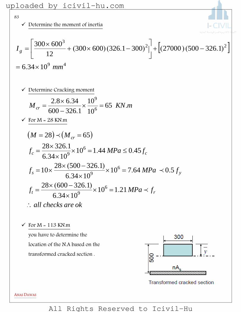
Determine the moment of inertia
Determine Cracking moment
mKNM cr ..
..65
10
10
1326600
346826
9
For M = 28 KN.m
For M = 113 KN.m you have to determine the location of the N.A based on the transformed cracked section .
49
223
10346
132650027000300132660030012
600300
mm
I g
.
).()().()(
okarechecksall
fMPaf
fMPaf
fMPaf
MM
rt
ys
cc
cr
2111010346
132660028
506471010346
13265002810
4504411010346
132628
6528
6
9
6
9
6
9
..
).(
...
).(
...
.
uploaded by icivil-hu.com
All Rights Reserved to Icivil-Hu

84
ANAS DAWAS
TheoryElasticusecanyou
okarechecksall
ff
fMPaf
mmI
mmyyy
y
ANaboutyA
ys
cc
cr
ii
501789101043
723150011310
5077101043
7231113
10437231500300003
7231300
72315003000102
300
00
6
9
6
9
4923
...
).(
...
.
.).(.
.)()(
..
Calculate The Deflection
Instantaneous Deflection : When a concrete beam is loaded, it undergoes a deflection referred to as an instantaneous deflection.
uploaded by icivil-hu.com
All Rights Reserved to Icivil-Hu

85
ANAS DAWAS
Sustained Load Deflection Under sustained loads, concrete undergoes creep strains and the curvature of a cross section increases.
If compression steel is present, the increased compressive strains will cause an increase in stress in the compression reinforcement, thereby shifting some of the compressive force from the concrete to the compression steel. As a result, the compressive stress in the concrete decreases, resulting in reduced creep strains.
.
,
creepinreductiongreaterthe
db
AsteelncompressioofratiogreaterThe s
The Total Long Time Deflection
duration load limited for factorTime
load sustained of duration infinite for factorTime
deflection load live Sustained
deflection load dead Immediate
deflection load live Immediate
t
SL
D
L
SLtDLLT
501
uploaded by icivil-hu.com
All Rights Reserved to Icivil-Hu

86
ANAS DAWAS
elpmaxE : Simple Supported Beam
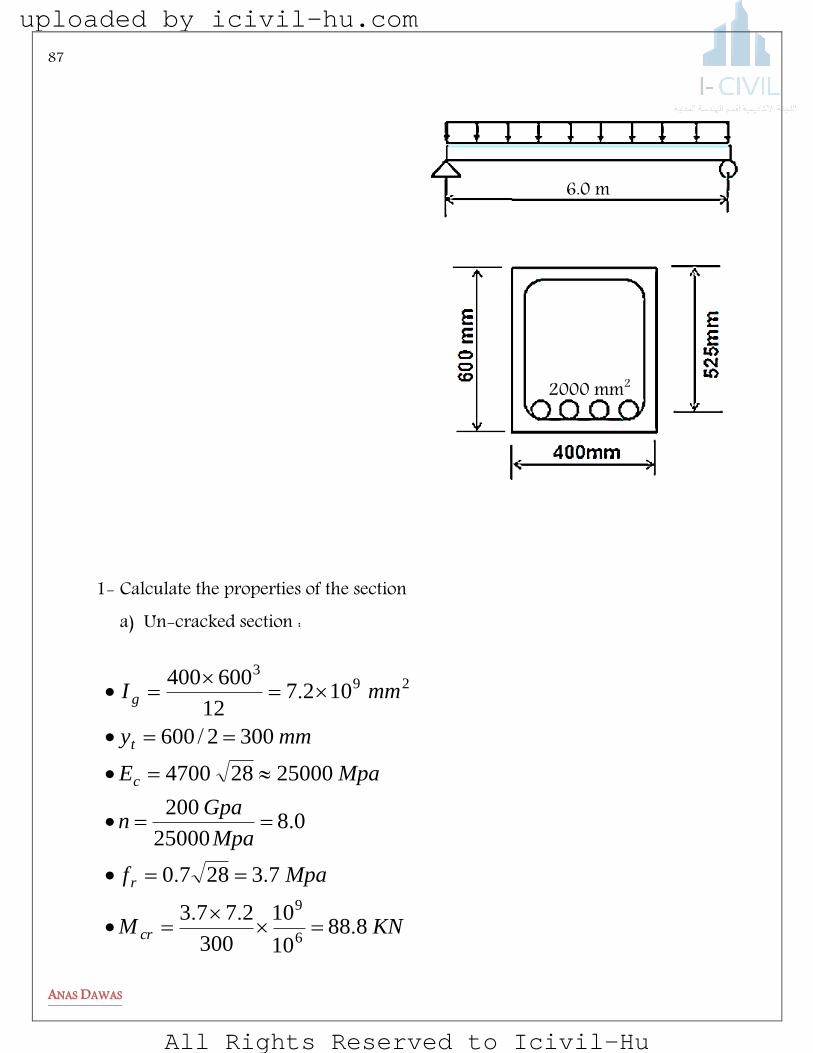
A simple supported beam with the cross section shown in the figure , has a span of 6 m
And supports un-factored dead load of 30 KN/m2 including its self-weight plus an un-factored live load of 20 KN/m2 .
22000
20
30
420
28
mmA
mKNLL
mKNDL
MPaf
MPaf
s
y
c
/
/
uploaded by icivil-hu.com
All Rights Reserved to Icivil-Hu
87
ANAS DAWAS
1- Calculate the properties of the section a) Un-cracked section :
2000 mm2
6.0 m
KNM
Mpaf
Mpa
Gpan
MpaE
mmy
mmI
cr
r
c
t
g
88810
10
300
2773
732870
0825000
200
25000284700
3002600
102712
600400
6
9
293
...
..
.
/
.
uploaded by icivil-hu.com
All Rights Reserved to Icivil-Hu
88
ANAS DAWAS
b) Cracked section
2- Calculate ultimate moment at the critical section (mid span )
ecrLLDL
ecrDL
IIMmKNM
IIMmKNM
.)(
.
2258
62030
1358
630
2
2
3- Calculate effective moment of inertia
4- Calculate instantaneous deflection :
mmIE
wl
DLec
DL 12651095325000384
6000305
384
59
44
..
Section properties
Y before crack
Y after crack (Transformed)
gI
CrI
crM
At mid span 300 mm 168.8 mm 491027 mm. 4910672 mm. 88.8 KN.M
4923
2
106728168525200083
8168400
8168525200082
400
mmI
mmyyy
cr
.).()(.
.)()(
4933
4933
10952672225
888127
225
888
10953672135
888127
135
888
mmMonBasedI
mmMonBasedI
LLDLe
DLe
...
..
)(
...
..
)(
uploaded by icivil-hu.com
All Rights Reserved to Icivil-Hu
89
ANAS DAWAS
mm
mmIE
wl
DLLLDLLL
DLec
LLDL
314612654411
44111095225000384
6000505
384
59
44
...
..
5- Calculate long term deflection
mmLT 561600126523146
20501
2
....
)(
6- Compare with ACI code limits :
soandsospan
OKmmmmspan
exampleanjustthis
LT
LLi
480
316716360
6000
360
..
7- Summary
Load (KN)
Mm (KN.m) mid
I 4910 mm
( mm)
DL 30 135 3.95 5.126 DL+LL 50 225 2.95 11.44 DL+SL 30+0 No sus.L ---------- -------
uploaded by icivil-hu.com
All Rights Reserved to Icivil-Hu

90
ANAS DAWAS
elpmaxE : Continuous Beam
Determine the long term deflection at the mid span of the continues T beam shown above , The member supports a dead load including its self-weight of 16 KN/m and live load of 14 KN/m , Fc=28 Mpa , Fy = 420 Mpa . The beam cross section is shown below . Assume that 30% of the live load is sustained .
Duration LL
DL
SLt
LT
5 YEARS 2 2 11.44-5.126= 6.314 mm
(2)(5.126)= 10.252
________ 16.566 mm
3ø25
3ø25
6ø25
9.0 m
uploaded by icivil-hu.com
All Rights Reserved to Icivil-Hu

91
ANAS DAWAS
Notes : Firstly , you can check minimum thickness according to Table 9.5 (a) in ACI code Then , you can fill the following tables to get perfect solution : 1) You should calculate the properties for the sections at support and at mid span .
2) Calculate the moment caused by DL , (DL+LL) at the two edges of the member and at the mid span .
Section properties
Y before crack
Y after crack (Transformed)
gI
CrI
crM
At mid span At supports
uploaded by icivil-hu.com
All Rights Reserved to Icivil-Hu
92
ANAS DAWAS
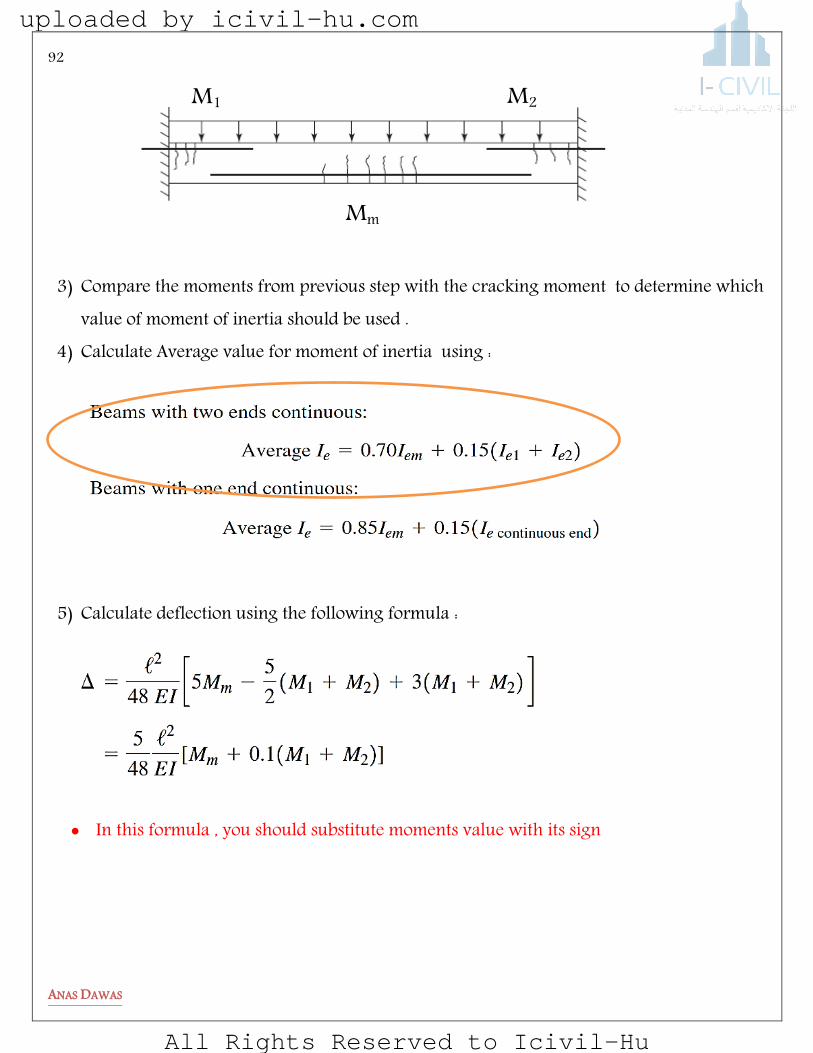
3) Compare the moments from previous step with the cracking moment to determine which value of moment of inertia should be used .
4) Calculate Average value for moment of inertia using :
5) Calculate deflection using the following formula :
In this formula , you should substitute moments value with its sign
M1
Mm
M2
uploaded by icivil-hu.com
All Rights Reserved to Icivil-Hu

93
ANAS DAWAS
You can use these tables :
Note : In case of negative moment , consider the section as a rectangular beam and all calculation based on this consideration as shown below :
Load (KN)
M1 (KN.m)
Mm (KN.m)
M2 (KN.m)
I1 Imid
I2 Iavg
( mm)
DL DL+LL DL+SL
Duration LL DL
SLt LT
uploaded by icivil-hu.com
All Rights Reserved to Icivil-Hu
94
ANAS DAWAS
PROBLEMS
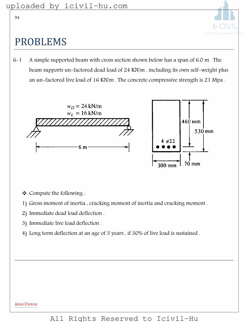
6-1 A simple supported beam with cross section shown below has a span of 6.0 m . The beam supports un-factored dead load of 24 KN/m , including its own self-weight plus an un-factored live load of 16 KN/m . The concrete compressive strength is 21 Mpa .
Compute the following : 1) Gross moment of inertia , cracking moment of inertia and cracking moment . 2) Immediate dead load deflection . 3) Immediate live load deflection . 4) Long term deflection at an age of 3 years , if 30% of live load is sustained .
uploaded by icivil-hu.com
All Rights Reserved to Icivil-Hu

95
ANAS DAWAS
6-2 A Cantilever beam with cross section shown below has a span of 5.0 m . The beam
supports an un-factored concentrated live load of 60 KN and un-factored dead load of 15 KN/m . The concrete compressive strength is 28 Mpa and effective depth = 800 mm
Compute the following : 1) Gross moment of inertia , cracking moment of inertia and cracking moment . 2) Immediate dead load deflection . 3) Immediate live load deflection . 4) Long term deflection at an age of 5 years , if 30% of live load is sustained .
uploaded by icivil-hu.com
All Rights Reserved to Icivil-Hu

96
ANAS DAWAS
6-3 A simple supported beam with cross section shown below has a span of 6.0 m . The
beam supports un-factored dead load of 20 KN/m , including its own self-weight plus an un-factored concentrated live load of 40 KN. The concrete compressive strength is 28 Mpa.
Compute the following : 1) Gross moment of inertia , cracking moment of inertia and cracking moment . 2) Immediate dead load deflection . 3) Immediate live load deflection . 4) Long term deflection at an age of 5 years , if 30% of live load is sustained .
6-4 For the cross sections shown below , determine whether the reinforcement satisfies the ACI code requirements for crack width control .
For section C design skein reinforcement Upon ACI code requirements .
uploaded by icivil-hu.com
All Rights Reserved to Icivil-Hu

97
ANAS DAWAS
A B
C D
uploaded by icivil-hu.com
All Rights Reserved to Icivil-Hu

98
ANAS DAWAS
6-5 For 3.6 m span cantilever beam shown in the figure below , (Ignore weight in your calculation ) : 1) Determine instantaneous live load deflection at the free end of the beam due to the
load condition shown below . 2) Determine the Total long term deflection . Assume that only dead load is
Sustained. What code deflection criteria it meets and what limitations, if any , have to be placed on its use ?
uploaded by icivil-hu.com
All Rights Reserved to Icivil-Hu

99
ANAS DAWAS
6-6 The beam cross section shown is on a 8000 mm simple span and carries uniformly distributed service dead load of wD=15 kN/m and concentrated service live load of PL=30 kN. Use fc’ = 28 MPa, fy = 420 MPa and assume n = 9 (Ignore beam self-weight). Compute : 1. Cracked moment of inertia, 2. Cracking Moment, 3. Immediate deflection due to live load only, 4. Ultimate long-term deflection due to dead load
6-7 Continues beam with cross section shown below has a span of 9.0 m. The beam
supports un-factored dead load of 22 KN/m , including its own self weight , plus un-factored live load of 36 KN/m . The concrete compressive strength is 21 Mpa . Compute the following : 1) Gross moment of inertia for positive moment section . 2) Cracking moment for positive moment moment section . 3) Cracked moment of inertia for positive moment section
uploaded by icivil-hu.com
All Rights Reserved to Icivil-Hu

100
ANAS DAWAS
4) Using the following assumption , Answers the followings :
Section properties
Y before crack
Y after crack (Transformed)
gI
CrI
crM
At mid span - - 2×1010 mm4 8×109 mm4 106 KN.m At supports - - 3×1010 mm4 7.4×109 mm4 76 KN.m
uploaded by icivil-hu.com
All Rights Reserved to Icivil-Hu

101
ANAS DAWAS
A. Immediate dead load deflection B. Immediate live load deflection . C. Ultimate long term deflection of 30 % live load sustained .
uploaded by icivil-hu.com
All Rights Reserved to Icivil-Hu

102
ANAS DAWAS
Torsion
uploaded by icivil-hu.com
All Rights Reserved to Icivil-Hu

103
ANAS DAWAS
noeiJotg
The average designer probably does not worry about torsion very much. He or she thinks almost exclusively of axial forces, shears, and bending moments, and yet most reinforced concrete structures are subject to some degree of torsion. Until recent years, the safety factors required by codes for the design of reinforced concrete members for shear, moment, and so forth were so large that the effects of torsion could be safely neglected in all but the most extreme cases. Today, however, overall safety factors are less than they used to be and members are smaller, with the result that torsion is a more common problem. Appreciable torsion does occur in many structures, such as:
1) In the main girders of bridges, which are twisted by transverse beams or slabs. 2) In buildings where the edge of a floor slab and its beams are supported by a spandrel
beam running between the exterior columns. 3) Earthquakes can cause dangerous torsional forces in all buildings. 4) In curved bridge girders, spiral stairways, and balcony girders
uploaded by icivil-hu.com
All Rights Reserved to Icivil-Hu
104
ANAS DAWAS
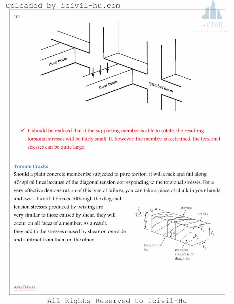
It should be realized that if the supporting member is able to rotate, the resulting
torsional stresses will be fairly small. If, however, the member is restrained, the torsional stresses can be quite large.
Torsion Cracks
Should a plain concrete member be subjected to pure torsion, it will crack and fail along 45o
spiral lines because of the diagonal tension corresponding to the torsional stresses. For a very effective demonstration of this type of failure, you can take a piece of chalk in your hands and twist it until it breaks. Although the diagonal tension stresses produced by twisting are very similar to those caused by shear, they will occur on all faces of a member. As a result, they add to the stresses caused by shear on one side and subtract from them on the other.
uploaded by icivil-hu.com
All Rights Reserved to Icivil-Hu

105
ANAS DAWAS
Strength of Material Review
In a bar with a rectangular cross section, however, the torsional stresses vary from a maximum at the middle of the long sides of the rectangle to zero at the corners.
Torsional Reinforcing
Tests have shown that both longitudinal bars and closed stirrups (or spirals) are necessary to intercept the numerous diagonal tension cracks that occur on all surfaces of members subject to appreciable torsional forces.
uploaded by icivil-hu.com
All Rights Reserved to Icivil-Hu

106
ANAS DAWAS
The normal -shaped stirrups are not satisfactory. They must be closed either by welding their ends together to form a continuous loop, as illustrated in Figure (a), or by bending their ends around a longitudinal bar, as shown in part (b) of the same figure.
uploaded by icivil-hu.com
All Rights Reserved to Icivil-Hu

107
ANAS DAWAS
ACI Code Section 11.5.4.3 requires that longitudinal reinforcement for torsion be developed at both ends of a beam. Because the maximum torsions generally act at the ends of a beam, it is generally necessary to anchor the longitudinal torsional reinforcement for its yield strength at the face of the support. This may require hooks or horizontal U-shaped bars lap spliced with the longitudinal torsion reinforcement.
uploaded by icivil-hu.com
All Rights Reserved to Icivil-Hu
108
ANAS DAWAS
The strength of closed stirrups cannot be developed unless additional longitudinal reinforcing is supplied. Longitudinal bars should be spaced uniformly around the insides of the stirrups, not more than 300 mm apart. There must be at least one bar in each corner of the stirrups to provide anchorage for the stirrup legs (Code 11.6.6.2); otherwise, if the concrete inside the corners were to be crushed, the stirrups would slip and the result would be even larger torsional cracks. These longitudinal bars must have diameters at least equal to 0.042 times the stirrup spacing. Their size may not be less than 10 mm .
DESIGN METHODS FOR TORSION
Skew bending theory developed: This theory assumes that some shear and torsion is resisted by the concrete, the rest by shear and torsion reinforcement.
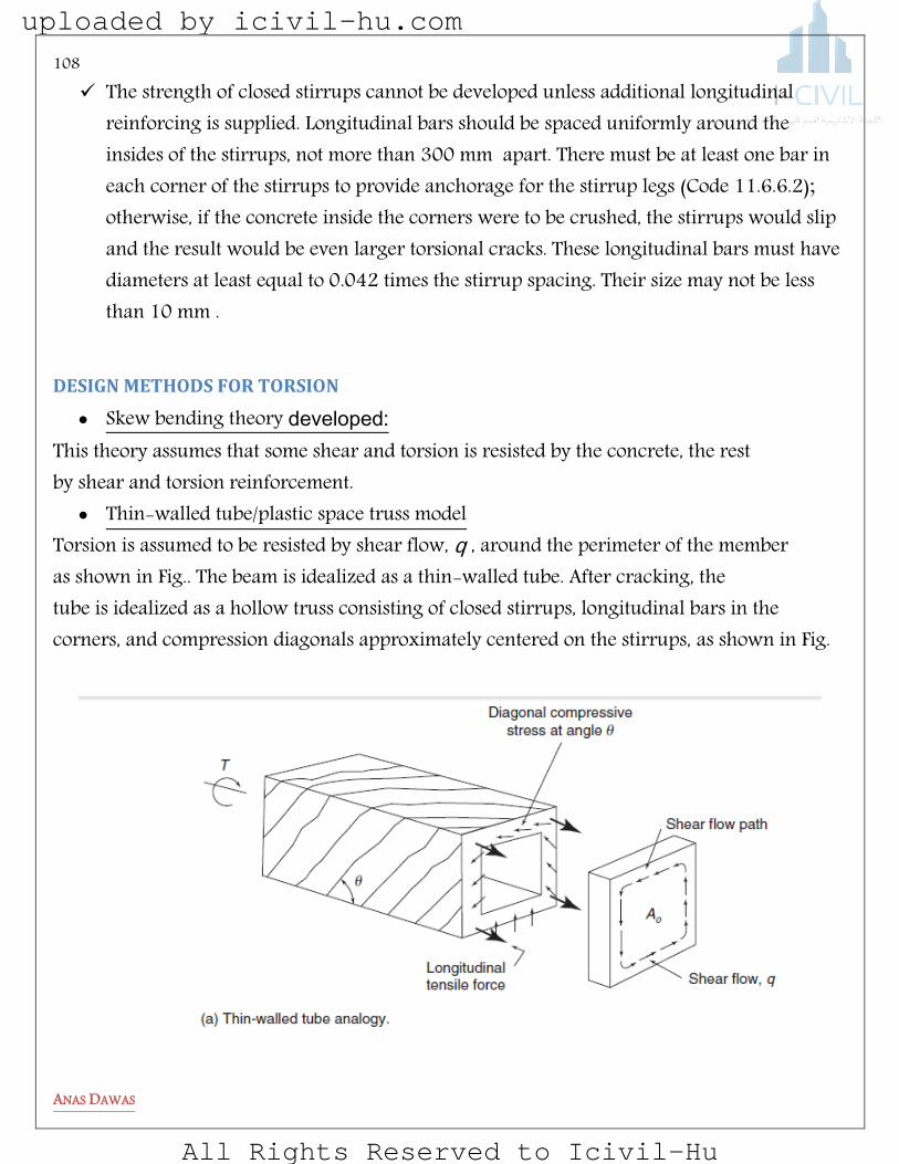
Thin-walled tube/plastic space truss model Torsion is assumed to be resisted by shear flow, q , around the perimeter of the member as shown in Fig.. The beam is idealized as a thin-walled tube. After cracking, the tube is idealized as a hollow truss consisting of closed stirrups, longitudinal bars in the corners, and compression diagonals approximately centered on the stirrups, as shown in Fig.
uploaded by icivil-hu.com
All Rights Reserved to Icivil-Hu
109
ANAS DAWAS
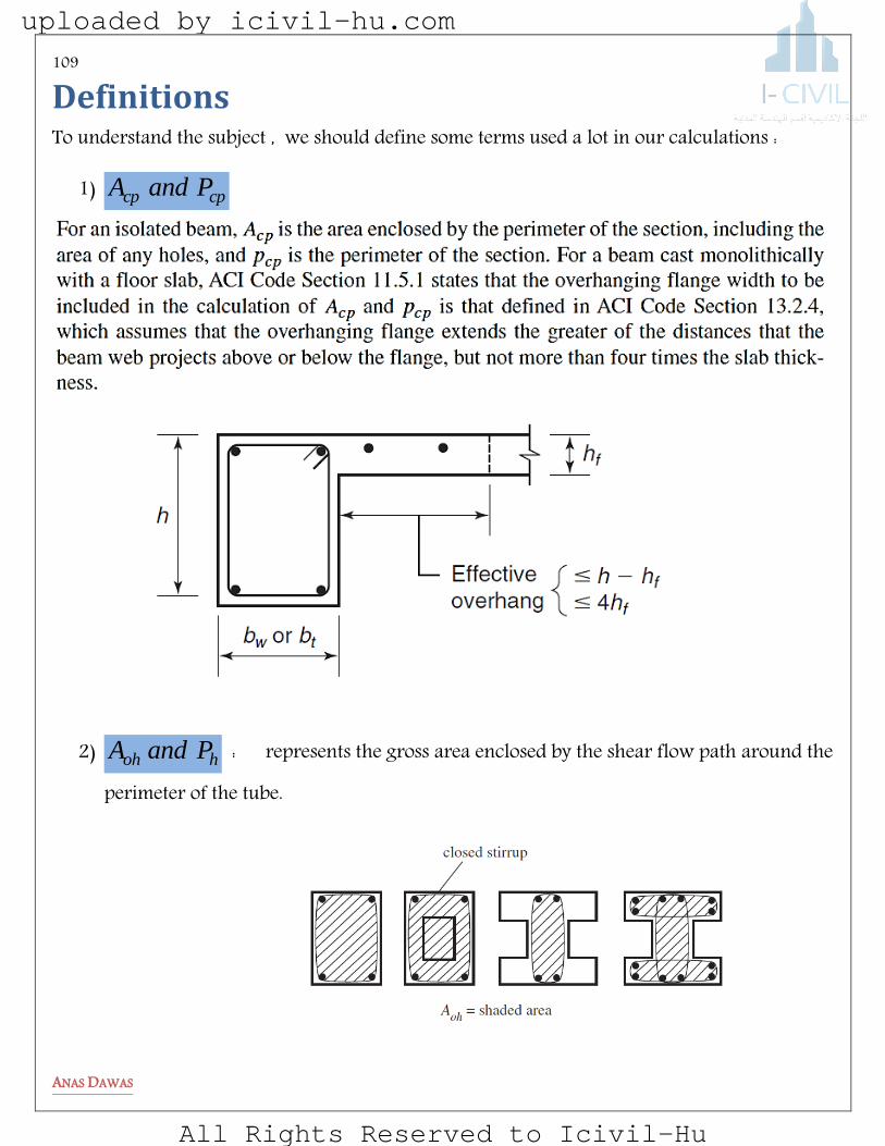
Definitions To understand the subject , we should define some terms used a lot in our calculations :
1) cpcp PandA
2) hoh PandA : represents the gross area enclosed by the shear flow path around the
perimeter of the tube.
uploaded by icivil-hu.com
All Rights Reserved to Icivil-Hu
110
ANAS DAWAS
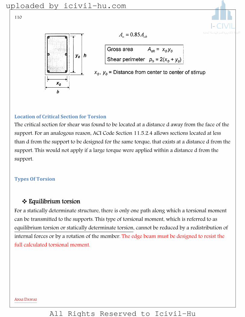
Location of Critical Section for Torsion
The critical section for shear was found to be located at a distance d away from the face of the support. For an analogous reason, ACI Code Section 11.5.2.4 allows sections located at less than d from the support to be designed for the same torque, that exists at a distance d from the support. This would not apply if a large torque were applied within a distance d from the support.
Types Of Torsion
Equilibrium torsion For a statically determinate structure, there is only one path along which a torsional moment can be transmitted to the supports. This type of torsional moment, which is referred to as equilibrium torsion or statically determinate torsion, cannot be reduced by a redistribution of internal forces or by a rotation of the member. The edge beam must be designed to resist the full calculated torsional moment.
uploaded by icivil-hu.com
All Rights Reserved to Icivil-Hu
111
ANAS DAWAS
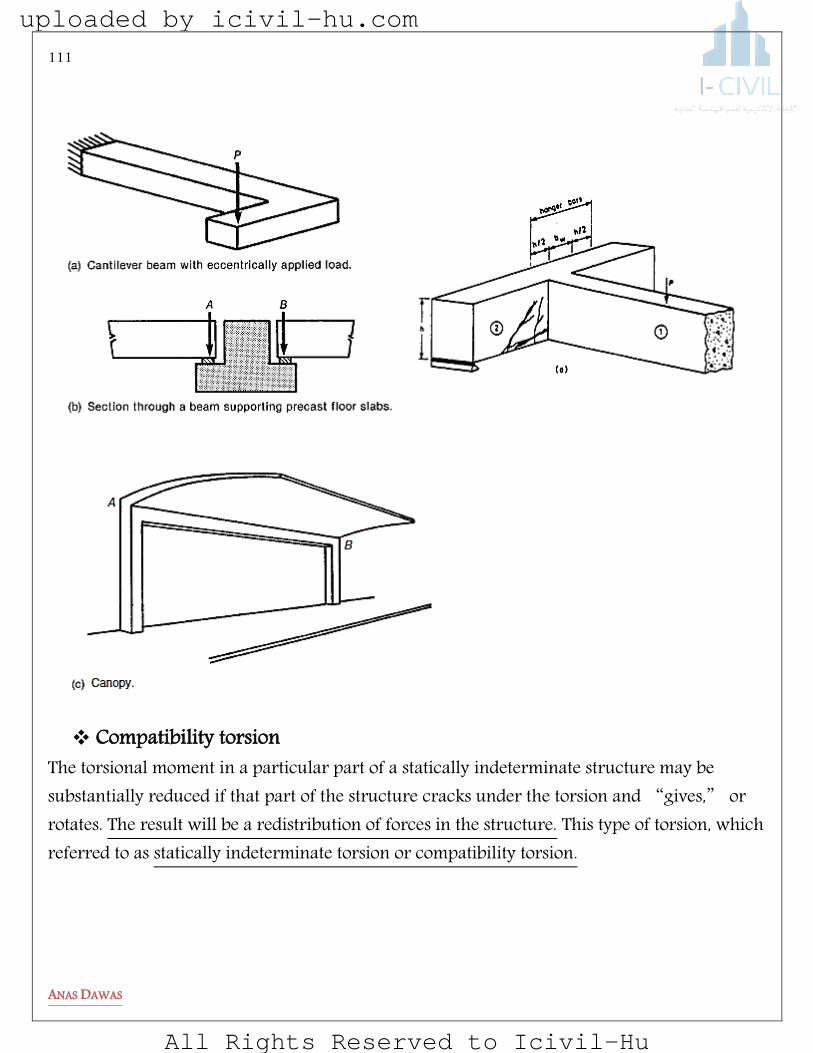
Compatibility torsion The torsional moment in a particular part of a statically indeterminate structure may be substantially reduced if that part of the structure cracks under the torsion and “gives,” or rotates. The result will be a redistribution of forces in the structure. This type of torsion, which referred to as statically indeterminate torsion or compatibility torsion.
uploaded by icivil-hu.com
All Rights Reserved to Icivil-Hu

112
ANAS DAWAS
uploaded by icivil-hu.com
All Rights Reserved to Icivil-Hu

113
ANAS DAWAS
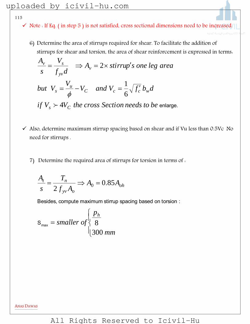
Design Procedure For Members Subjected to Bending Moment , Shear and Torsion
1) . Draw the shear force, bending moment, and torque diagrams. 2) Select cross-sectional dimensions “b” and “h” based on factored bending moment,
and determine the required area of reinforcement.
)(.
)/(
).(
.,
Economic
ff
fK
K
Mdb
cy
cn
n
u
010
5901
9002
3) Check if torsion may be neglected. Torsion may be neglected if the torsion less than :
forceaxialWithfA
N
P
Af
forceaxialWithoutP
Af
cg
U
cp
cp
c
cp
cp
c
).
)((.
)(.
33010830
0830
2
2
If this is the case, proceed on with shear design and choose flexural and shear reinforcement.
Note : The critical section for torsion is located at distance d from the face of the
support if no torques are applied within this distance. If torques are applied within distance d from face of support, critical torsion is located at face of the support.
dbf
fA
c
dc
c
cd
y
cs
s
s
3190
0030
0030
.
)(.
)(.
(max)
uploaded by icivil-hu.com
All Rights Reserved to Icivil-Hu
114
ANAS DAWAS
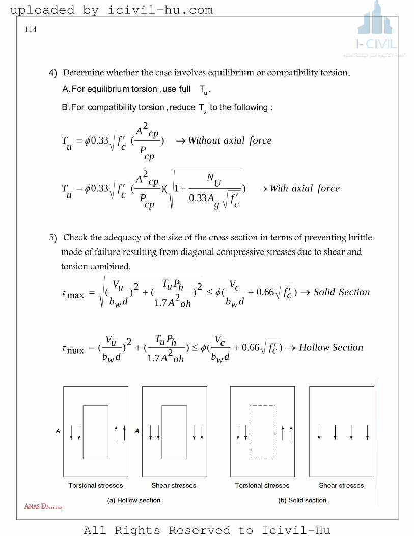
4) .Determine whether the case involves equilibrium or compatibility torsion.
forceaxialWith
cf
gA
UN
cpP
cpA
cf
uT
forceaxialWithout
cpP
cpA
cf
uT
).
)((.
)(.
.
3301
2
330
2
330
: followingthe to T reduce , torsionity compatibilFor B.
T fulluse , torsion mequilibriu For A.
u
u
5) Check the adequacy of the size of the cross section in terms of preventing brittle mode of failure resulting from diagonal compressive stresses due to shear and torsion combined.
SectionHollowcfdwb
cV
ohA
hPuT
dwb
uV
SectionSolidcfdwb
cV
ohA
hPuT
dwb
uV
).().
()(max
).().
()(max
6602
71
2
6602
271
2
uploaded by icivil-hu.com
All Rights Reserved to Icivil-Hu
115
ANAS DAWAS
Note : If Eq. ( in step 5 ) is not satisfied, cross sectional dimensions need to be increased.
6) Determine the area of stirrups required for shear. To facilitate the addition of stirrups for shear and torsion, the area of shear reinforcement is expressed in terms:
enlarge.betoneedsSectioncrosstheVVif
dbfVandVV
Vbut
arealegonespstirruAdf
V
s
A
Cs
wccCu
s
v
yv
sv
4
6
1
2
Also, determine maximum stirrup spacing based on shear and if Vu less than 0.5Vc No need for stirrups .
7) Determine the required area of stirrups for torsion in terms of :
mm
p
ofsmaller
AAAf
T
s
A
h
oh
oyv
nt
300
8
8502
0
maxS
:torsion on based spacing stirrup maximum compute Besides,
.
uploaded by icivil-hu.com
All Rights Reserved to Icivil-Hu

116
ANAS DAWAS
yv
w
y
yv
ht
y
cpc
l
h
y
yvtl
f
b
f
fP
s
A
f
AfA
Pf
f
s
AA
1750420
2
.)(.
cot
min
s
A Where
t
8) Determine combined area of stirrups required for shear and torsion:
9) Select stirrup size, and compute stirrup spacing based on the amount determined in step 7.
calculated s
A(
size spstirru selected for
tv )
vA
S
NOTE Maximum stirrup spacing must not exceed the smaller of the two values
evaluated in steps 5 and 6.
10) Calculate the longitudinal reinforcement required for torsion.
yvf
wbcf
yvf
wb
ofs
tvABut
s
tA
s
vA
s
tvA
0620
350
2
.
.
maxmin)(
uploaded by icivil-hu.com
All Rights Reserved to Icivil-Hu
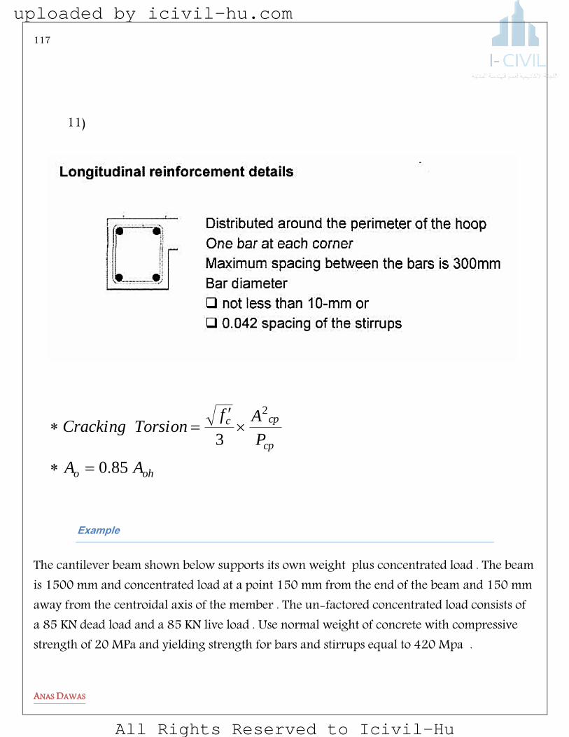
117
ANAS DAWAS
11)
oho
cp
cpc
AA
P
AfTorsionCracking
850
3
2
.
elpmaxE
The cantilever beam shown below supports its own weight plus concentrated load . The beam is 1500 mm and concentrated load at a point 150 mm from the end of the beam and 150 mm away from the centroidal axis of the member . The un-factored concentrated load consists of a 85 KN dead load and a 85 KN live load . Use normal weight of concrete with compressive strength of 20 MPa and yielding strength for bars and stirrups equal to 420 Mpa .
uploaded by icivil-hu.com
All Rights Reserved to Icivil-Hu

118
ANAS DAWAS
1) Assume a dimension for the section to calculate own weight ( d = 535 mm )
KNP
mKNwt
partmmforwt
beammajorforwt
ult
factored
23885618521
912676521
765246040150
765246040
2
)(.)(.
/...
...
...
2) Draw Shear , Moment and Torsion Diagram
400 mm
600
mm
mKN
mKNu
M
KNuV
uT ....
)..
....
..)..(
.....
( 8351502382
150150916
53303512382
251916351150916
424951916238150916
uploaded by icivil-hu.com
All Rights Reserved to Icivil-Hu
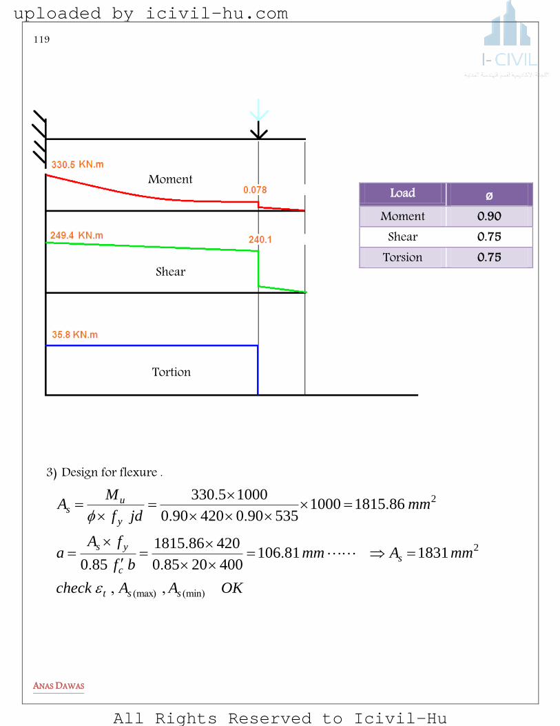
119
ANAS DAWAS
3) Design for flexure .
ø Load 0.90 Moment 0.75 Shear 0.75 Torsion
Moment
Shear
Tortion
OKAAcheck
mmAmmbf
fAa
mmjdf
MA
sst
s
c
ys
y
us
(min)(max) ,,
..
.
.
...
.
2
2
18318110640020850
420861815
850
8618151000535900420900
10005330
uploaded by icivil-hu.com
All Rights Reserved to Icivil-Hu

120
ANAS DAWAS
4) Check if torsion may be neglected:
5) The Torsion is needed for equilibrium , so design for full of 35 .8 KN.m
6) Check the adequacy of the size of the cross section (assume 40 mm cover and ø10 stirrups )
consideredbemustT
mKNP
AfT
mmhbP
mmhbA
u
cp
cp
cth
cp
cp
18835
18102000
2400002008307500830
200060040022
240000600400
622
2
..
..)(..)(.
)()(
Ok
Mpacfc
f
cfdwb
cV
MPa
ohA
hPuT
dwb
uV
mmyxP
mmyxA
mmy
mmx
ooh
oooh
o
o
77281
7726606
660
81
2
215810071
16406108352
535400
1000724522
71
2
164051031022
158100510310
51010402600
31010402400
2
..
.).().(
.max
.
..)
.()(max
)()(
)(
)(
uploaded by icivil-hu.com
All Rights Reserved to Icivil-Hu

121
ANAS DAWAS
Note : Vu used above to check section size is at “d” distance from the support KNdV u 724553509164249 .).(..@
7) Determine the area of stirrups required for shear
mmmmdf
V
s
A
KNVV
V
KNdbfV
yv
sv
cu
s
wcc
/..
...
.
.
2
3
7480535420
10001168
11685159750
7245
515910535400206
1
6
1
8) Determine the required area of stirrups
mmmmAf
T
s
A
oyv
nt /.).(
.
.
23
3
4220101581008504202
750
10835
2
9) Determine combined area of stirrups required for shear and torsion:
22640
0620
23330
350
2591422027480
2
mm
yvf
wbcf
mm
yvf
wb
ofs
tvA
mmmms
tA
s
vA
s
tvA
..
..
maxmin)(
/.).(.
uploaded by icivil-hu.com
All Rights Reserved to Icivil-Hu

122
ANAS DAWAS
10) Calculate the longitudinal reinforcement required for torsion
11) Spacing between stirrups :
mm
mmp
ofsmallerS
mmA
S
h
v
300
2058
1640
8
99591
104
2 2
max
.
)(
)
calculated s
A(
size spstirru selected for
tv
You can increase the diameter of the stirrups to increase the spacing (s).
12) Provide 3ø10 at the top , 3ø10 at the middle and the rest to the flexure steel:
.bottomatusemm
mmmm
25520522211831
221471692471106
2
22
2
22
381116404220420
24000020420
167017504220420
6921164014220
mmA
f
b
f
fP
s
A
f
AfA
mmPf
f
s
AA
l
yv
w
y
yvh
t
y
cpcl
h
y
yvtl
..
...)(.
.cot
min
mins
A Where
t
uploaded by icivil-hu.com
All Rights Reserved to Icivil-Hu
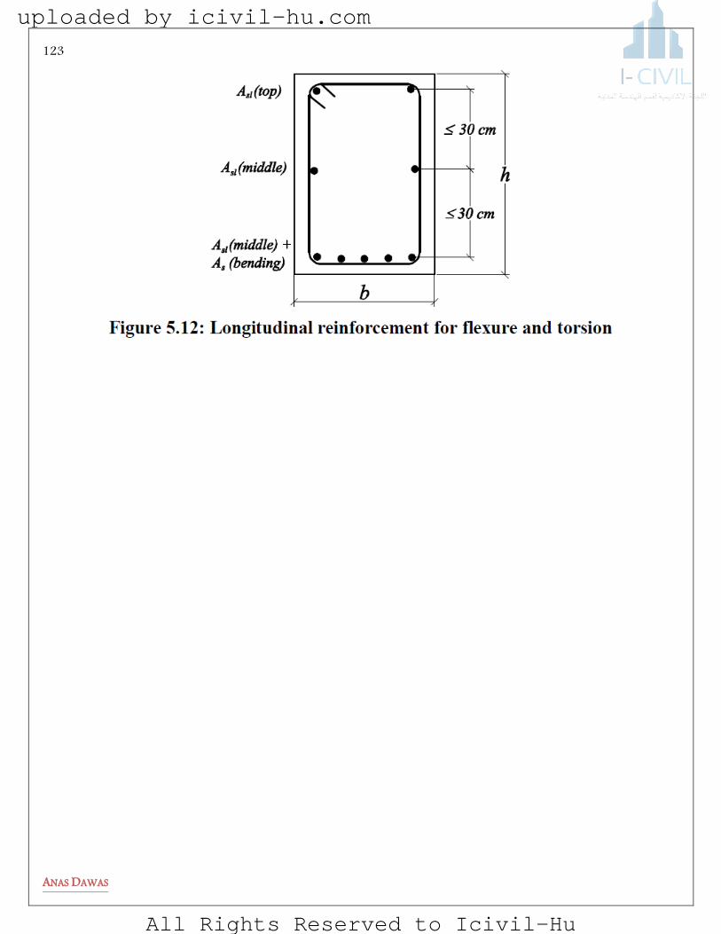
123
ANAS DAWAS
uploaded by icivil-hu.com
All Rights Reserved to Icivil-Hu
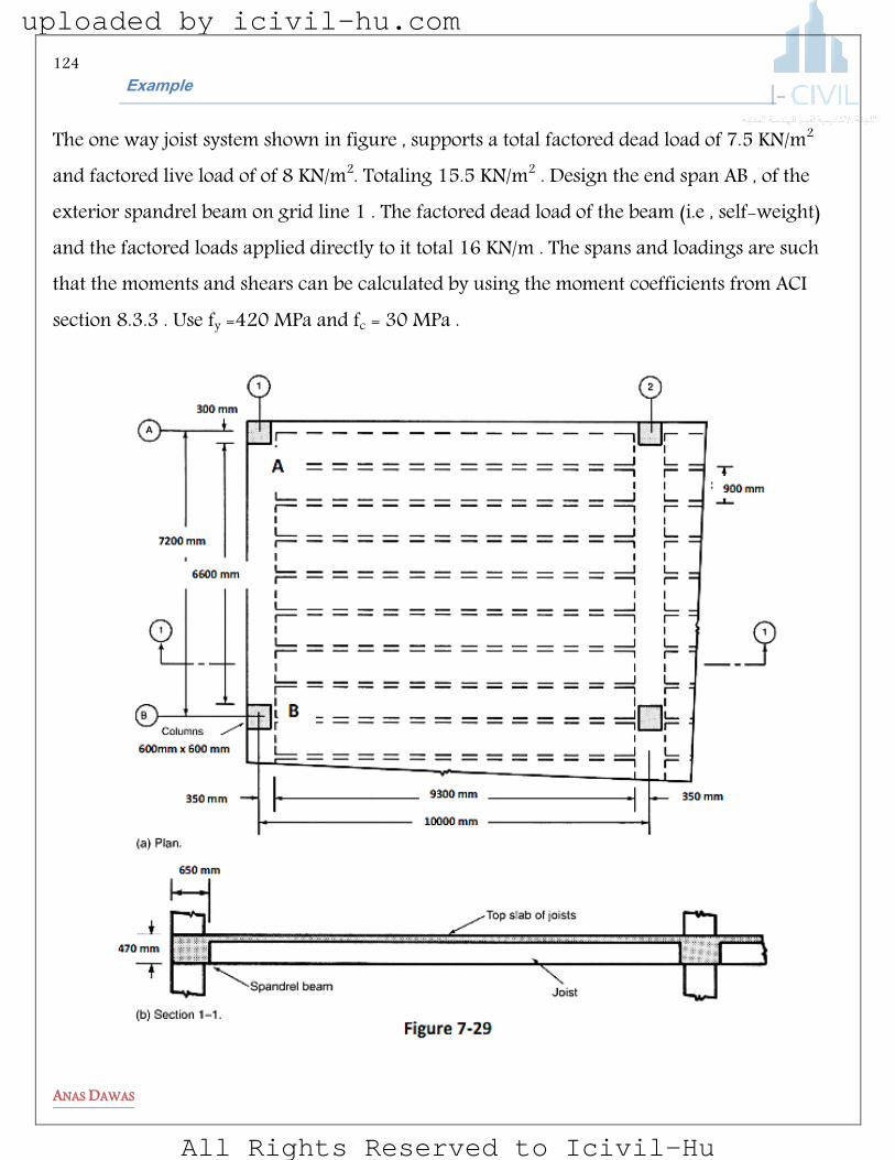
124
ANAS DAWAS
elpmaxE
The one way joist system shown in figure , supports a total factored dead load of 7.5 KN/m2 and factored live load of of 8 KN/m2. Totaling 15.5 KN/m2 . Design the end span AB , of the exterior spandrel beam on grid line 1 . The factored dead load of the beam (i.e , self-weight) and the factored loads applied directly to it total 16 KN/m . The spans and loadings are such that the moments and shears can be calculated by using the moment coefficients from ACI section 8.3.3 . Use fy =420 MPa and fc = 30 MPa .
uploaded by icivil-hu.com
All Rights Reserved to Icivil-Hu

125
ANAS DAWAS
1) Initial choice of beam size . The beam overhangs the inside face of the columns by 50 mm. Effective length 405 mm and slab thickness is 110 mm .
2) Assume that the joists behave as a one unit with uniform load for simplicity , calculate the loads now :
Total load on the beam =load from the slab + load on it self
KNlw n 18816
2
3951516
2.
..
Compute the moment along the edge beam .
650 mm 47
0 m
m
600 mm
Spandrel beam Column
110 mm
uploaded by icivil-hu.com
All Rights Reserved to Icivil-Hu

126
ANAS DAWAS
KNlw
MnegativeendInterior
KNlw
MpositivespanMid
KNlw
MnegativeendExterior
nu
nu
nu
838310
66188
10
127414
66188
14
923916
66188
16
22
22
22
...
:
...
:
...
:
3) Check adequacy of the section size based on the maximum moment subjected to the edge beam. The section has adequate size for flexure .
4) Calculate area of steel for flexure :
uploaded by icivil-hu.com
All Rights Reserved to Icivil-Hu

127
ANAS DAWAS
Area of steel required (mm2)
Exterior end negative 1791 Mid-span positive 2046
First interior negative 2865
5) Draw final Shear and Torsion diagram for the edge beam .
KNVedgeatB
KNVedgeexterioratAForceShear
u
u
33347290151
72902
66188
....int)
...
):
uploaded by icivil-hu.com
All Rights Reserved to Icivil-Hu
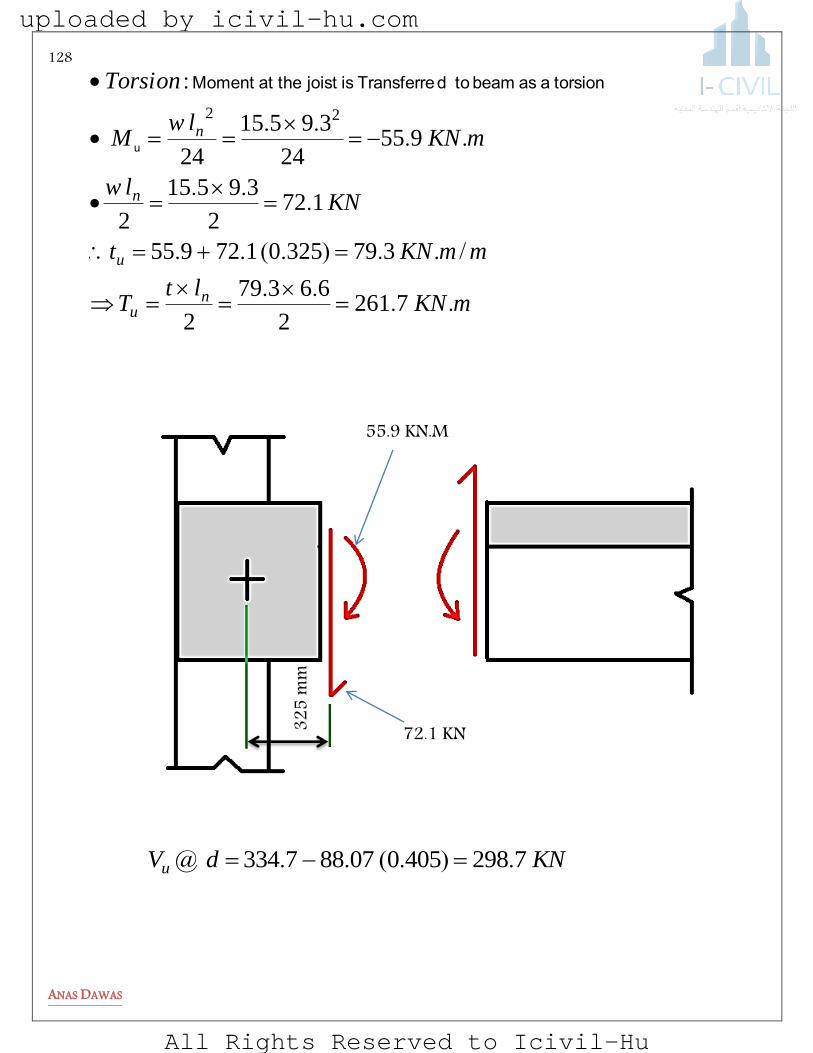
128
ANAS DAWAS
mKNlt
T
mmKNt
KNlw
mKNlw
M
Torsion
nu
u
n
n
....
/..).(..
...
....
:
72612
66379
2
3793250172955
1722
39515
2
95524
39515
24
22
u
torsion a as beam to dTransferre isjoist theat Moment
KNdVu 7298405007887334 .).(..@
72.1 KN
55.9 KN.M
325
mm
uploaded by icivil-hu.com
All Rights Reserved to Icivil-Hu
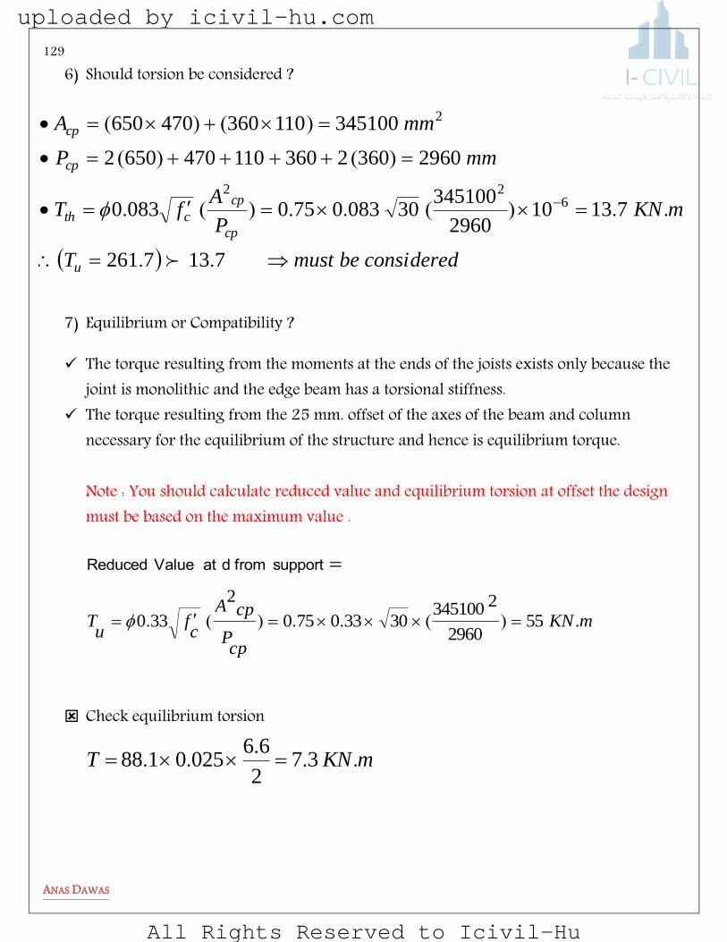
129
ANAS DAWAS
6) Should torsion be considered ?
7) Equilibrium or Compatibility ?
The torque resulting from the moments at the ends of the joists exists only because the joint is monolithic and the edge beam has a torsional stiffness.
The torque resulting from the 25 mm. offset of the axes of the beam and column necessary for the equilibrium of the structure and hence is equilibrium torque. Note : You should calculate reduced value and equilibrium torsion at offset the design must be based on the maximum value .
Check equilibrium torsion
mKNT ...
.. 372
660250188
consideredbemustT
mKNP
AfT
mmP
mmA
u
cp
cp
cth
cp
cp
7137261
713102960
3451003008307500830
296036023601104706502
345100110360470650
622
2
..
..)(..)(.
)()(
)()(
mKN
cpP
cpA
cf
uT .)(..)(. 55
2960
234510030330750
2
330
support fromdat ValueReduced
uploaded by icivil-hu.com
All Rights Reserved to Icivil-Hu

130
ANAS DAWAS
Design should be based on T=55.1 KN
8) Check the adequacy of the section >>>>> OK
hP ohA nT oA 1868 mm 209989 mm2 73.5 KN.m 45 0.85 Aoh
88.1 KN
88.1 KN
25 mm
uploaded by icivil-hu.com
All Rights Reserved to Icivil-Hu
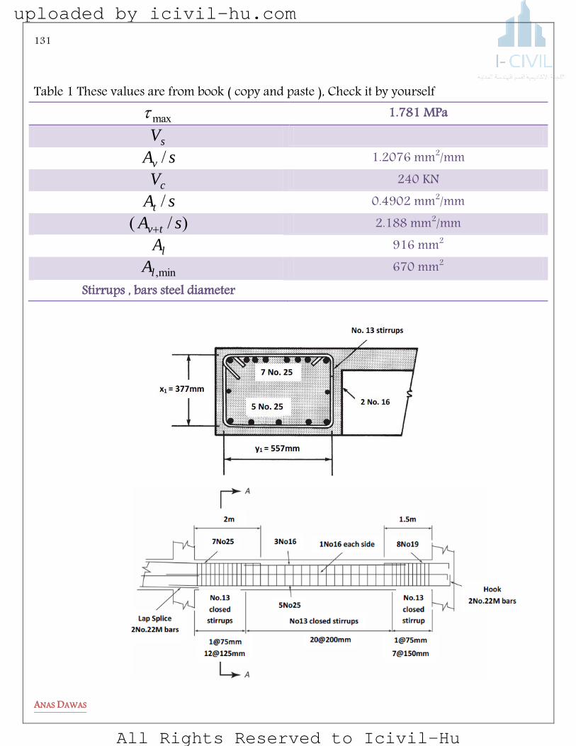
131
ANAS DAWAS
Table 1 These values are from book ( copy and paste ), Check it by yourself
max 1.781 MPa
sV sAv / 1.2076 mm2/mm
cV 240 KN sAt / 0.4902 mm2/mm )/( sA tv 2.188 mm2/mm
lA 916 mm2
min,lA 670 mm2 Stirrups , bars steel diameter
uploaded by icivil-hu.com
All Rights Reserved to Icivil-Hu
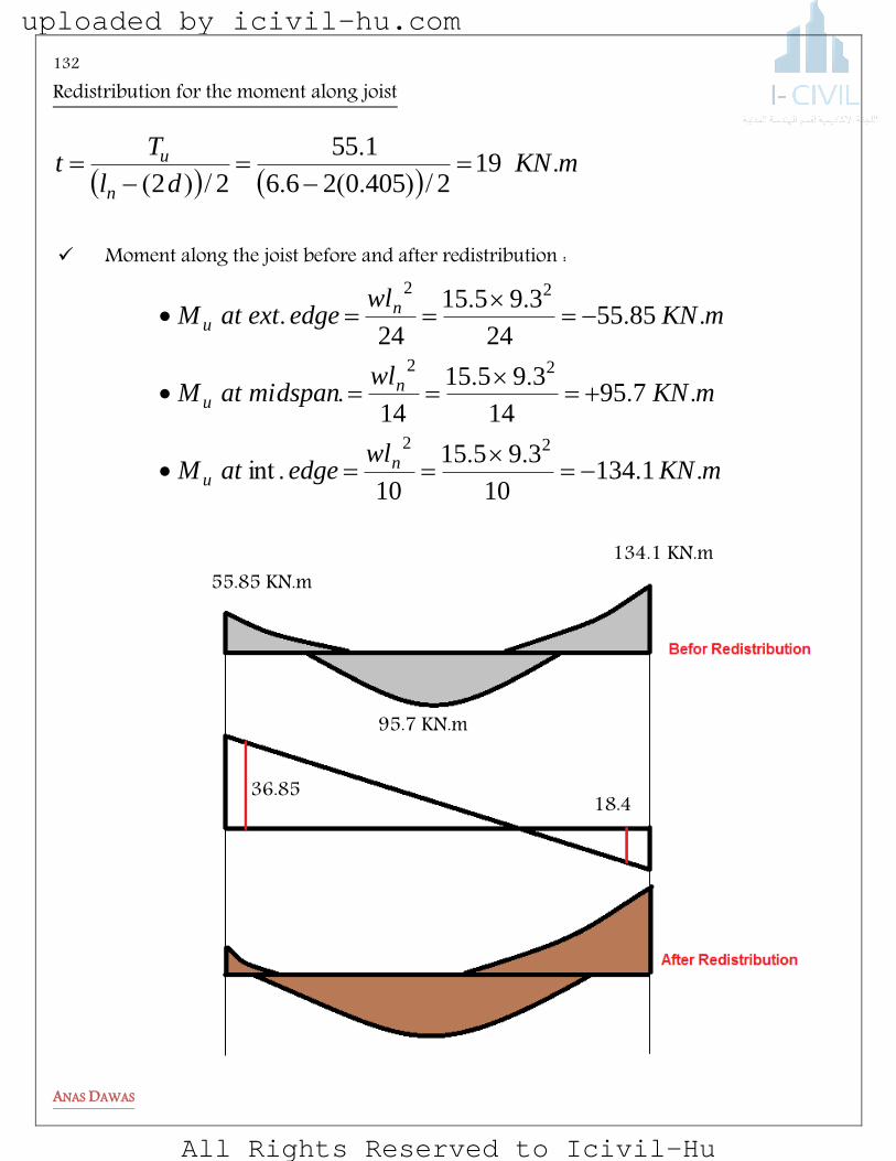
132
ANAS DAWAS
Redistribution for the moment along joist
Moment along the joist before and after redistribution :
mKNwl
edgeatM
mKNwl
midspanatM
mKNwl
edgeextatM
nu
nu
nu
....
.int
....
.
....
.
113410
39515
10
79514
39515
14
855524
39515
24
22
22
22
mKN
dl
Tt
n
u ./).(.
.
/)(19
24050266
155
22
55.85 KN.m 134.1 KN.m
95.7 KN.m
36.85 18.4
uploaded by icivil-hu.com
All Rights Reserved to Icivil-Hu
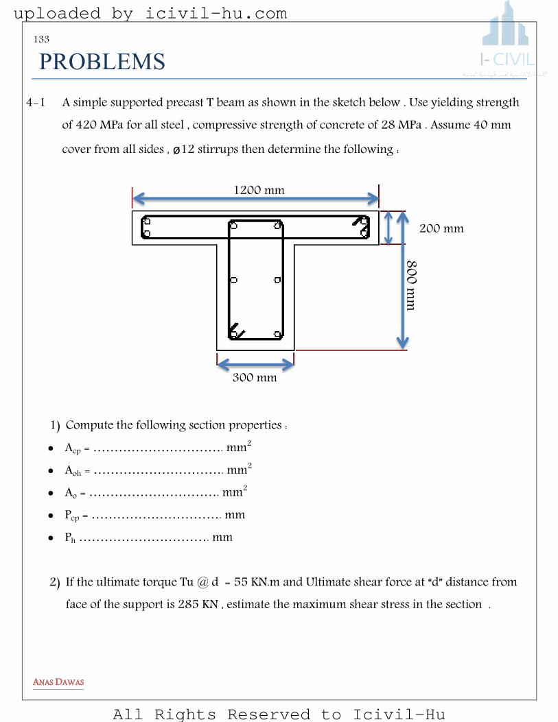
133
ANAS DAWAS
MELBeRyg
4-1 A simple supported precast T beam as shown in the sketch below . Use yielding strength of 420 MPa for all steel , compressive strength of concrete of 28 MPa . Assume 40 mm cover from all sides , ø12 stirrups then determine the following :
1) Compute the following section properties : Acp = …………………………. mm2 Aoh = …………………………. mm2 Ao = …………………………. mm2 Pcp = …………………………. mm Ph …………………………. mm
2) If the ultimate torque Tu @ d = 55 KN.m and Ultimate shear force at “d” distance from
face of the support is 285 KN , estimate the maximum shear stress in the section .
1200 mm
300 mm
800 mm
200 mm
uploaded by icivil-hu.com
All Rights Reserved to Icivil-Hu
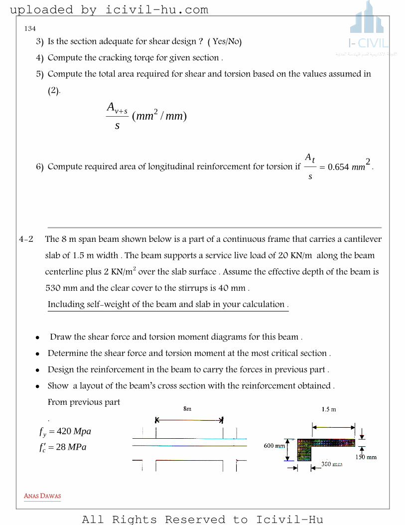
134
ANAS DAWAS
3) Is the section adequate for shear design ? ( Yes/No) 4) Compute the cracking torqe for given section . 5) Compute the total area required for shear and torsion based on the values assumed in
(2).
)/( mmmms
A sv 2
6) Compute required area of longitudinal reinforcement for torsion if 26540 mm
s
tA. .
4-2 The 8 m span beam shown below is a part of a continuous frame that carries a cantilever
slab of 1.5 m width . The beam supports a service live load of 20 KN/m along the beam centerline plus 2 KN/m2 over the slab surface . Assume the effective depth of the beam is 530 mm and the clear cover to the stirrups is 40 mm . Including self-weight of the beam and slab in your calculation .
Draw the shear force and torsion moment diagrams for this beam . Determine the shear force and torsion moment at the most critical section . Design the reinforcement in the beam to carry the forces in previous part . Show a layout of the beam’s cross section with the reinforcement obtained .
From previous part .
MPaf
Mpaf
c
y
28
420
uploaded by icivil-hu.com
All Rights Reserved to Icivil-Hu
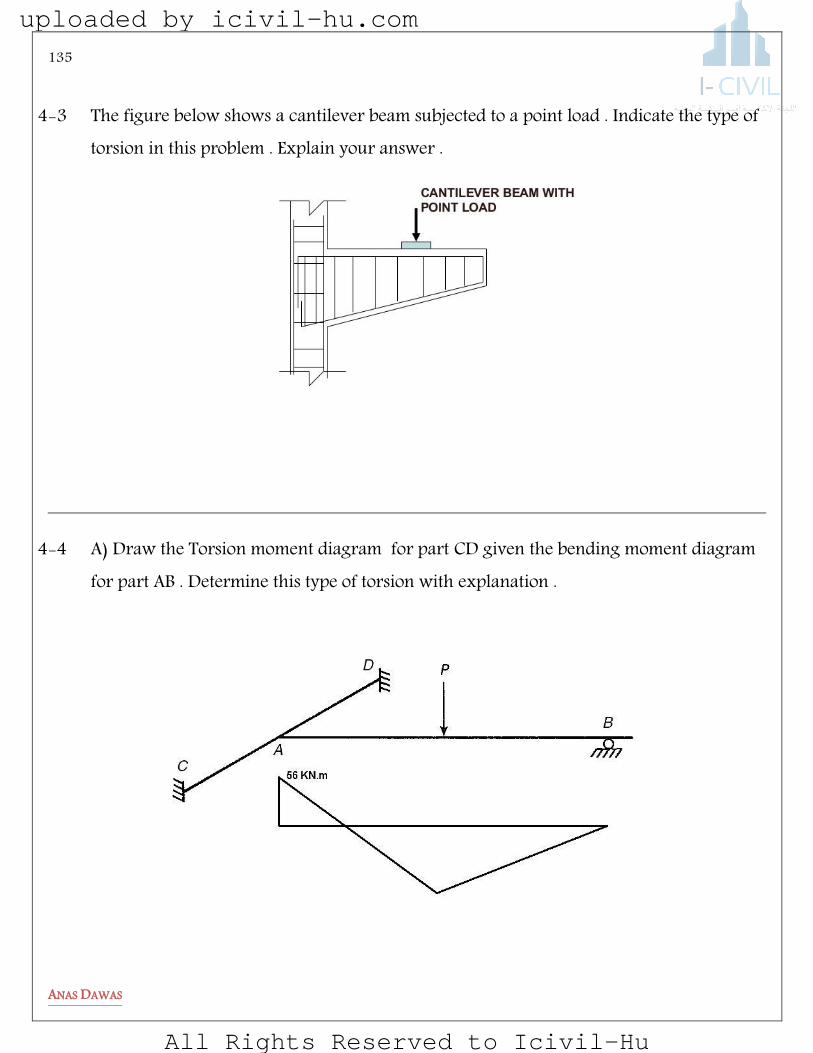
135
ANAS DAWAS
4-3 The figure below shows a cantilever beam subjected to a point load . Indicate the type of
torsion in this problem . Explain your answer .
4-4 A) Draw the Torsion moment diagram for part CD given the bending moment diagram for part AB . Determine this type of torsion with explanation .
uploaded by icivil-hu.com
All Rights Reserved to Icivil-Hu

136
ANAS DAWAS
B) Draw torsion moment diagrams for following cantilever .
4-5 The following figure shows a partial plan of precast roof system . Roof members are double tee units simple supported on precast beams .Continuity of spandrel beams is not provided . The roof is supporting a service live load of 1.5 KN/m2 and service dead load of 3.0 KN/m2 . Assume effective depth d =730 mm and ignore the self-weight in your calculation . a) Determine the factored load that will carried by the spandrel beam . b) Draw bending moment , shear force and torsion diagrams for the spandrel beam . c) Determine the design ultimate bending moment , ultimate shear and ultimate torsion
at most critical sections . d) Design shear reinforcement for the beam based on values from ( c ) .
uploaded by icivil-hu.com
All Rights Reserved to Icivil-Hu

137
ANAS DAWAS
4-6 Design the T beam shown in the figure below ,considering the contribution of the flanges for torsion if its subjected to a ultimate torsional moment of 18 KN.m . compressive strength of concrete is 30 MPa and yf =360 MPa for all steel .Assume
concrete cover of 40 mm to the centerline of the stirrups al around the cross section .
uploaded by icivil-hu.com
All Rights Reserved to Icivil-Hu
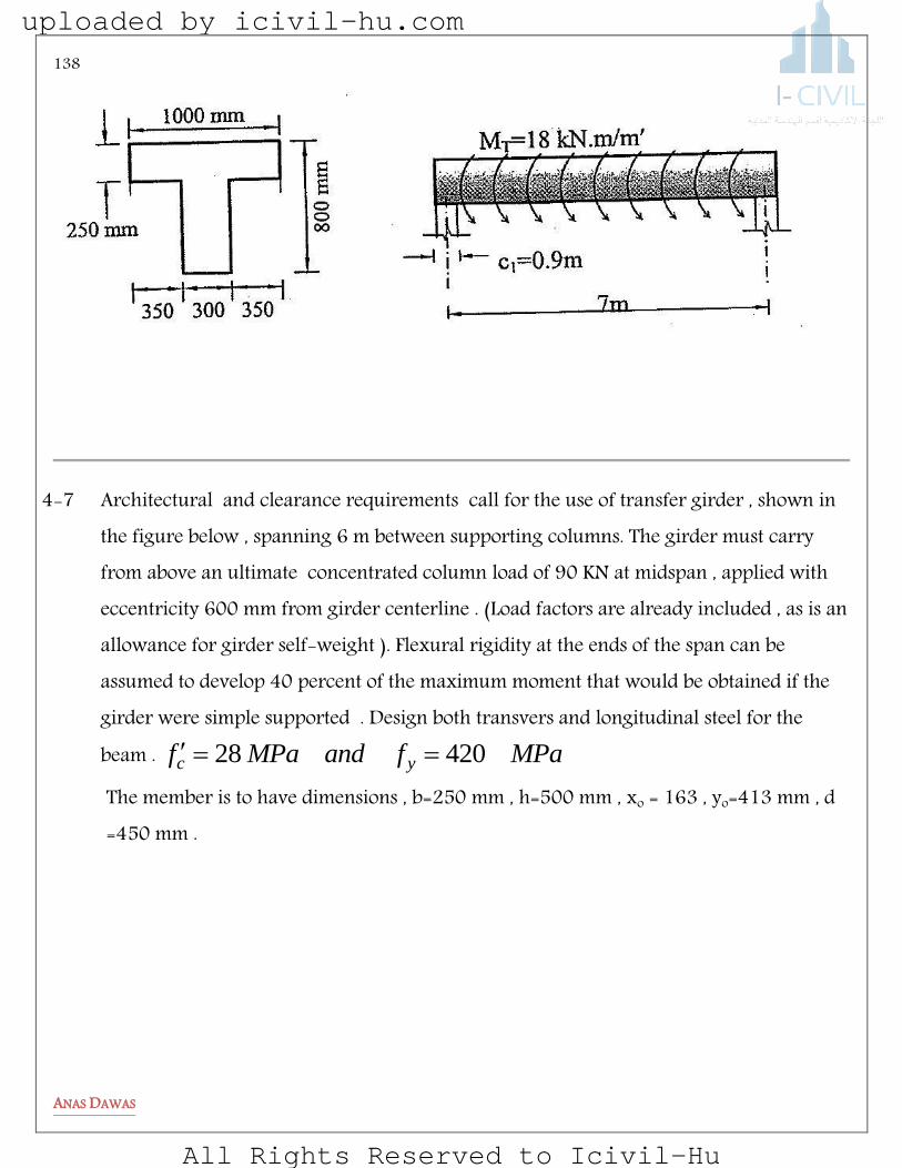
138
ANAS DAWAS
4-7 Architectural and clearance requirements call for the use of transfer girder , shown in the figure below , spanning 6 m between supporting columns. The girder must carry from above an ultimate concentrated column load of 90 KN at midspan , applied with eccentricity 600 mm from girder centerline . (Load factors are already included , as is an allowance for girder self-weight ). Flexural rigidity at the ends of the span can be assumed to develop 40 percent of the maximum moment that would be obtained if the girder were simple supported . Design both transvers and longitudinal steel for the beam . MPafandMPaf yc 42028
The member is to have dimensions , b=250 mm , h=500 mm , xo = 163 , yo=413 mm , d =450 mm .
uploaded by icivil-hu.com
All Rights Reserved to Icivil-Hu

139
ANAS DAWAS
4-8 Joint A is monolithically built with cross beam C-D. Beam A-B spans 8.0 meters between supports A and B while beam C-D spans 6.0 meters between supports C and D. Beam A-B carries a factored load of 120 kN/m and beam C-D carries a factored load of 85 kN/m (both are including self-weights). Use fy = 420 MPa for all steel and fc’ = 26 MPa and calculate the following:
uploaded by icivil-hu.com
All Rights Reserved to Icivil-Hu
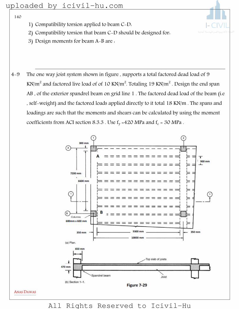
140
ANAS DAWAS
1) Compatibility torsion applied to beam C-D: 2) Compatibility torsion that beam C-D should be designed for: 3) Design moments for beam A-B are :
4-9 The one way joist system shown in figure , supports a total factored dead load of 9
KN/m2 and factored live load of of 10 KN/m2. Totaling 19 KN/m2 . Design the end span AB , of the exterior spandrel beam on grid line 1 . The factored dead load of the beam (i.e , self-weight) and the factored loads applied directly to it total 18 KN/m . The spans and loadings are such that the moments and shears can be calculated by using the moment coefficients from ACI section 8.3.3 . Use fy =420 MPa and fc = 30 MPa .
uploaded by icivil-hu.com
All Rights Reserved to Icivil-Hu

141
ANAS DAWAS
it was found that joists with overall depth of 470 mm would be required .The slab thickness is 110 mm . The spandrel beam was made the same depth . The column supporting the beam are 600 mm square , the beam overhangs the inside face of the columns by 50 mm .Beam size is h= 470 mm , b=650 mm and d= 405 mm.
Answer the following : 1) Draw bending moment and shear forces diagrams for the beam. 2) Draw bending moment and shear forces diagrams for joist before
redistribution. 3) Calculate the torque resulting from the moments at the ends of the joist if the
joint is monolithic .Indicate this type of torsion and explain your answer. 4) Calculate the torque resulting from the 25 mm offset of the axis of the beam
and column . Indicate this type of torsion and explain your answer . 5) Calculate the design ultimate torsion at most critical section 6) Calculate all section properties :
ohcpohcp APPAA ,,,,
For the hollow section shown below , calculate the following : Assume the cover = 40 mm
1) Gross moment if inertia 2) Cracking moment of inertia 3) cpA
4) cpP
5) ohA 6) hP 7) oA
uploaded by icivil-hu.com
All Rights Reserved to Icivil-Hu

142
ANAS DAWAS
Footings
uploaded by icivil-hu.com
All Rights Reserved to Icivil-Hu

143
ANAS DAWAS
FOOTINGS
Footings are structural members used to support columns and walls and transmit their loads to the underlying soils. Reinforced concrete is a material admirably suited for footings and is used as such for both reinforced concrete and structural steel buildings, bridges, towers, and other structures.
Types of Footings
Among the several types of reinforced concrete footings in common use are the wall, isolated, combined, raft, and pile-cap types. These are briefly introduced in this section; the remainder of the chapter is used to provide more detailed information about the simpler types of this group.
uploaded by icivil-hu.com
All Rights Reserved to Icivil-Hu
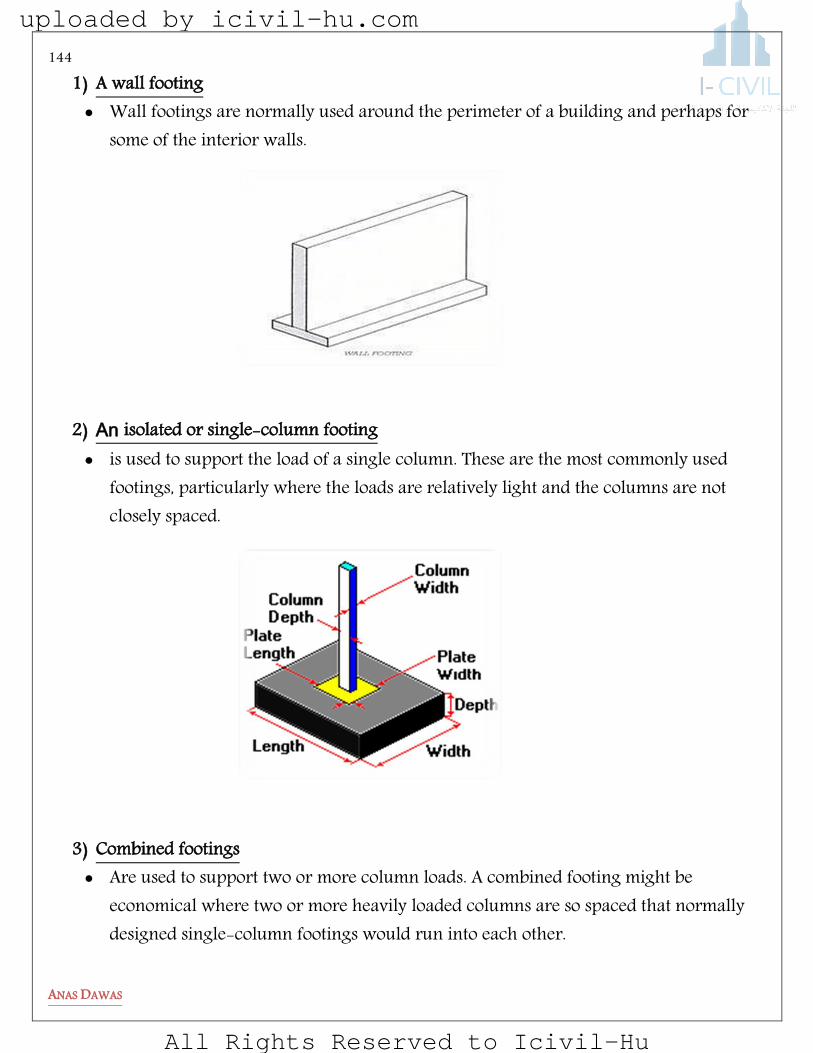
144
ANAS DAWAS
1) A wall footing Wall footings are normally used around the perimeter of a building and perhaps for
some of the interior walls.
2) An isolated or single-column footing is used to support the load of a single column. These are the most commonly used
footings, particularly where the loads are relatively light and the columns are not closely spaced.
3) Combined footings Are used to support two or more column loads. A combined footing might be
economical where two or more heavily loaded columns are so spaced that normally designed single-column footings would run into each other.
uploaded by icivil-hu.com
All Rights Reserved to Icivil-Hu
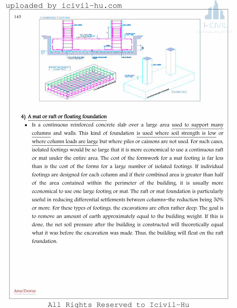
145
ANAS DAWAS
4) A mat or raft or floating foundation Is a continuous reinforced concrete slab over a large area used to support many
columns and walls. This kind of foundation is used where soil strength is low or where column loads are large but where piles or caissons are not used. For such cases, isolated footings would be so large that it is more economical to use a continuous raft or mat under the entire area. The cost of the formwork for a mat footing is far less than is the cost of the forms for a large number of isolated footings. If individual footings are designed for each column and if their combined area is greater than half of the area contained within the perimeter of the building, it is usually more economical to use one large footing or mat. The raft or mat foundation is particularly useful in reducing differential settlements between columns—the reduction being 50% or more. For these types of footings, the excavations are often rather deep. The goal is to remove an amount of earth approximately equal to the building weight. If this is done, the net soil pressure after the building is constructed will theoretically equal what it was before the excavation was made. Thus, the building will float on the raft foundation.
uploaded by icivil-hu.com
All Rights Reserved to Icivil-Hu

146
ANAS DAWAS
SOIL PRESSURE UNDER FOOTINGS
The soil pressure at the surface of contact between a footing and the soil is assumed to be uniformly distributed as long as the load above is applied at the center of gravity of the footing. The distribution of soil pressure under a footing is a function of the type of soil and the relative rigidity of the soil and the foundation pad.
uploaded by icivil-hu.com
All Rights Reserved to Icivil-Hu
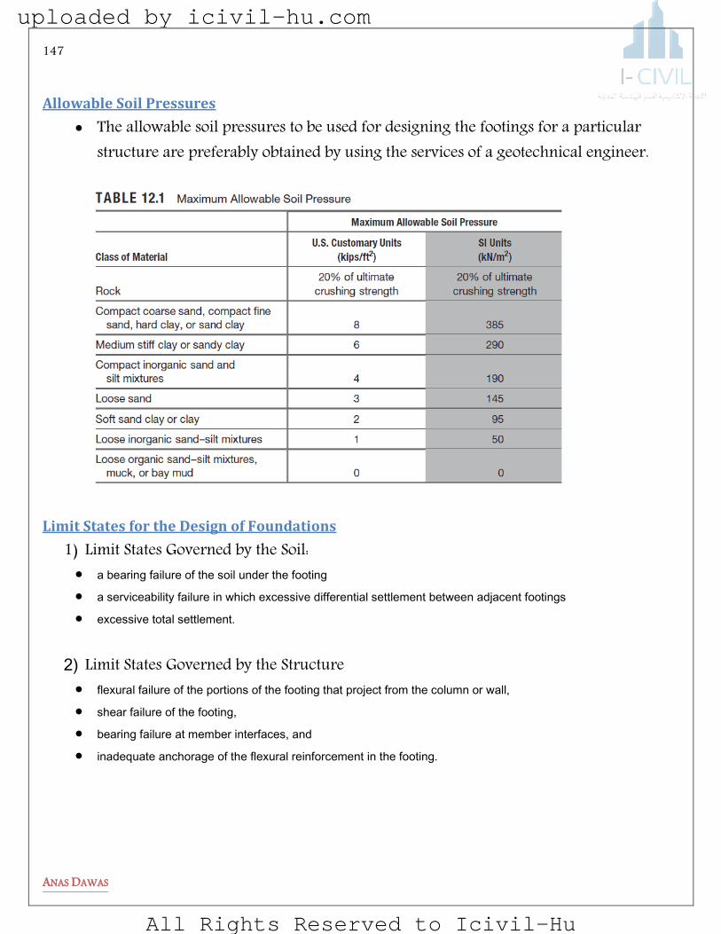
147
ANAS DAWAS
Allowable Soil Pressures
The allowable soil pressures to be used for designing the footings for a particular structure are preferably obtained by using the services of a geotechnical engineer.
Limit States for the Design of Foundations
1) Limit States Governed by the Soil: a bearing failure of the soil under the footing a serviceability failure in which excessive differential settlement between adjacent footings
excessive total settlement.
2) Limit States Governed by the Structure
flexural failure of the portions of the footing that project from the column or wall,
shear failure of the footing,
bearing failure at member interfaces, and
inadequate anchorage of the flexural reinforcement in the footing.
uploaded by icivil-hu.com
All Rights Reserved to Icivil-Hu
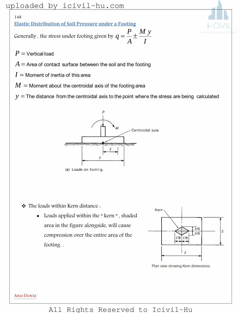
148
ANAS DAWAS
Elastic Distribution of Soil Pressure under a Footing
Generally , the stress under footing given by I
yM
A
Pq
calculated being are stress the epoint wher the to axis centroidal the fromdistance The
area footingthe of axis centroidal theabout Moment
area this of inertia ofMoment
footingthe and soil the between surfacecontact of Area
load Vertical
y
M
I
A
P
The loads within Kern distance : Loads applied within the “ kern “ , shaded
area in the figure alongside, will cause compression over the entire area of the footing .
uploaded by icivil-hu.com
All Rights Reserved to Icivil-Hu
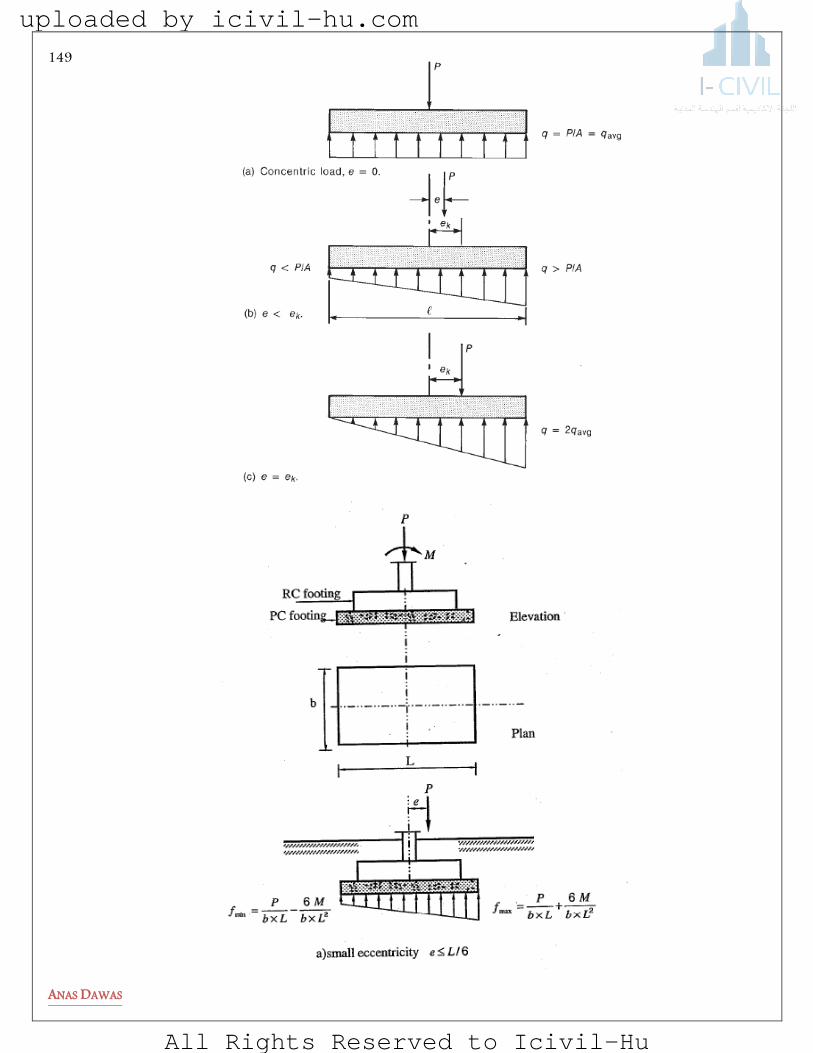
149
ANAS DAWAS
uploaded by icivil-hu.com
All Rights Reserved to Icivil-Hu
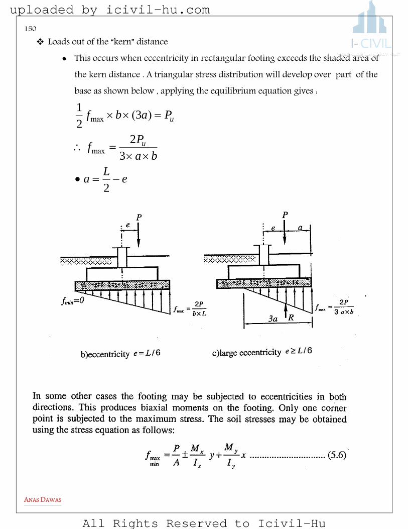
150
ANAS DAWAS
Loads out of the “kern” distance This occurs when eccentricity in rectangular footing exceeds the shaded area of
the kern distance . A triangular stress distribution will develop over part of the base as shown below , applying the equilibrium equation gives :
eL
a
ba
Pf
Pabf
u
u
2
3
2
32
1
max
max )(
uploaded by icivil-hu.com
All Rights Reserved to Icivil-Hu
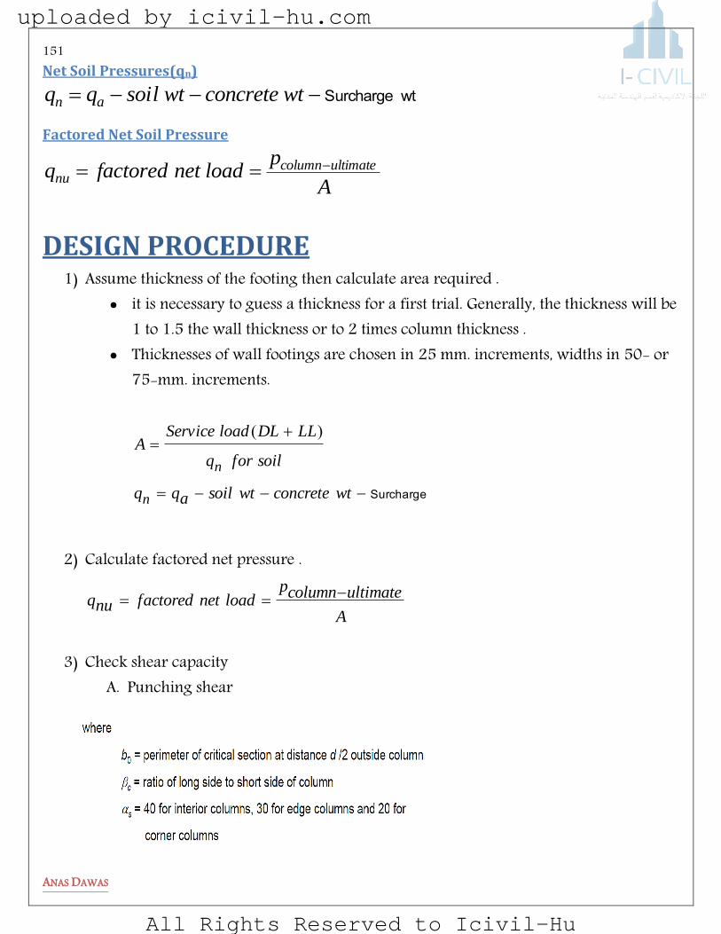
151
ANAS DAWAS
Net Soil Pressures(qn)
wtSurcharge wtconcretewtsoilqq an
Factored Net Soil Pressure
A
ploadnetfactoredq ultimatecolumn
nu
DESIGN PROCEDURE 1) Assume thickness of the footing then calculate area required .
it is necessary to guess a thickness for a first trial. Generally, the thickness will be 1 to 1.5 the wall thickness or to 2 times column thickness .
Thicknesses of wall footings are chosen in 25 mm. increments, widths in 50- or 75-mm. increments.
Surcharge
wtconcretewtsoilaqq
soilforq
LLDLloadServiceA
n
n
)(
2) Calculate factored net pressure .
A
ultimatecolumnploadnetfactorednuq
3) Check shear capacity
A. Punching shear
uploaded by icivil-hu.com
All Rights Reserved to Icivil-Hu

152
ANAS DAWAS
B. One way shear Calculate avarege effective length in the two directions
SHEARCHECKA
changenqchangeshouldyoudepthchangeyouif
depthincreasetoneednouVcVif
dobcf
dobcf
ob
ds
dobcf
c
ofsmallercV
,
)(
)(
3
1
122
12
42
uploaded by icivil-hu.com
All Rights Reserved to Icivil-Hu

153
ANAS DAWAS
thicknesschangeotherwiseOKuVcVif
dwbcfcV
bdhddeptheffective
)(.6
1750
-mm) (75 cover
4) Design flexural reinforcement The deflection for the spread footing
shown is in two directions , so the reinforcement should be provided in both the short and long directions .
uploaded by icivil-hu.com
All Rights Reserved to Icivil-Hu
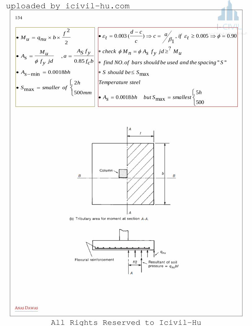
154
ANAS DAWAS
mm
hofsmallerS
bhsA
bcf
yfSAa
jdyf
uMsA
fbnuquM
500
2
00180
850
2
2
max
.min
.,
500
500180
90000501
0030
hsmallestSbutbhsA
steeleTemperatur
SbeshouldS
SspacingtheandusedbeshouldbarsofNOfind
uMjdyfsAnMcheck
tifacc
cdt
max.
max
"".
?
..,)(.
uploaded by icivil-hu.com
All Rights Reserved to Icivil-Hu

155
ANAS DAWAS
5) Design column footing joint
uploaded by icivil-hu.com
All Rights Reserved to Icivil-Hu

156
ANAS DAWAS
6) Area Of dowels The purpose of the dowels is the same as the keyway. But dowels provide stronger
connection . You should place dowels in the
footing while the concrete is still wet .
The number of dowel bars needed is four these may be placed at the four corners of the column. The dowel bars are usually extended into the footing, bent at the ends, and tied to the main footing reinforcement. The dowel diameter shall not exceed the diameter of the longitudinal bars in the column .
650.
uploaded by icivil-hu.com
All Rights Reserved to Icivil-Hu
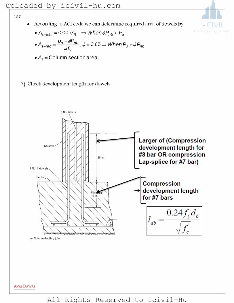
157
ANAS DAWAS
According to ACI code we can determine required area of dowels by
area section Column
1
1
650
0050
A
PPWhenf
PpA
PPWhenAA
nbuy
nbureqs
unbs
.;
.min
7) Check development length for dowels
uploaded by icivil-hu.com
All Rights Reserved to Icivil-Hu

158
ANAS DAWAS
uploaded by icivil-hu.com
All Rights Reserved to Icivil-Hu
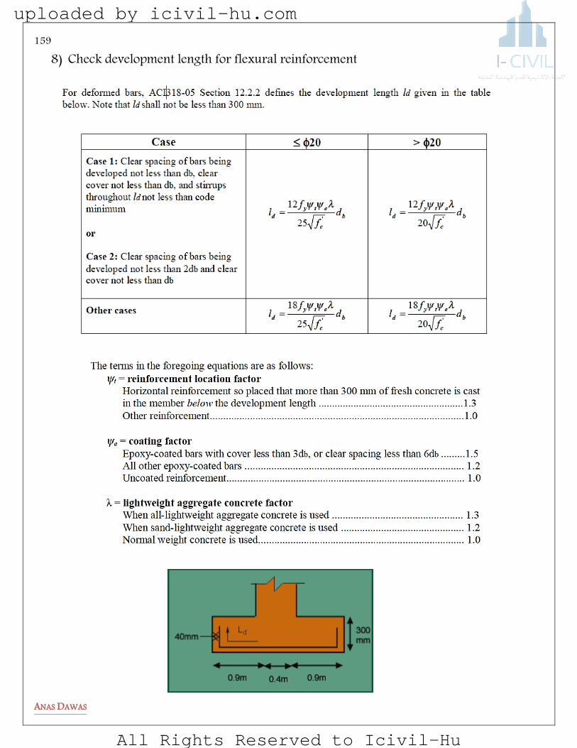
159
ANAS DAWAS
8) Check development length for flexural reinforcement
uploaded by icivil-hu.com
All Rights Reserved to Icivil-Hu
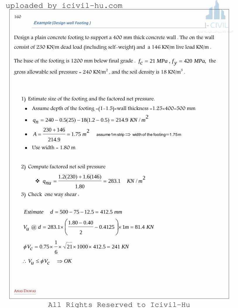
160
ANAS DAWAS
elpmaxE (Design wall Footing )
Design a plain concrete footing to support a 400 mm thick concrete wall . The on the wall consist of 230 KN/m dead load (including self-weight) and a 146 KN/m live load KN/m .
The base of the footing is 1200 mm below final grade . ,, MPayfMPacf 42021 the
gross allowable soil pressure = 240 KN/m2 , and the soil density is 18 KN/m3 .
1) Estimate size of the footing and the factored net pressure. Assume depth of the footing =(1-1.5)×wall thickness =1.25×400=500 mm
2
92145021182550240 mKNnq /.)..()(.
m 1.75 footingthe of width strip m 1 assume
2
7519214
146230mA .
.
Use width = 1.80 m
2) Compute factored net soil pressure
2
1283801
1466123021mKNnuq /.
.
)(.)(.
3) Check one way shear :
OKcVuV
KNcV
KNmduV
mmdEstimate
24154121000216
1750
4811412502
4008011283
541251275500
..
....
.@
..
uploaded by icivil-hu.com
All Rights Reserved to Icivil-Hu
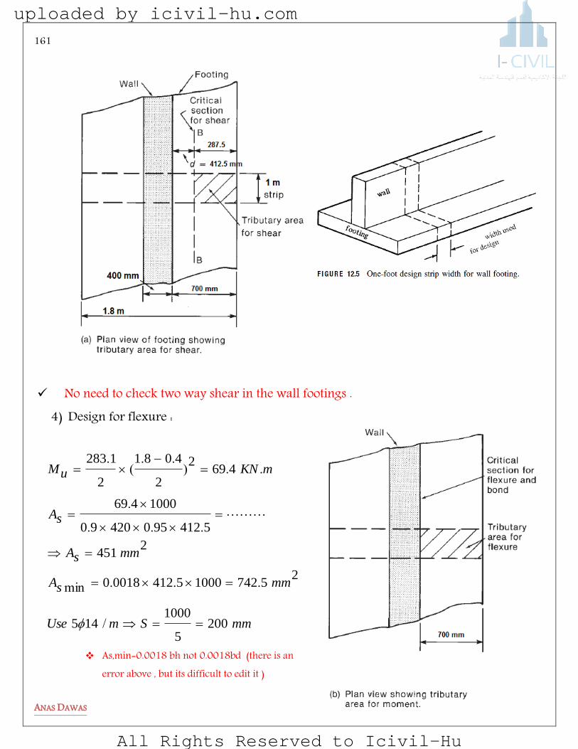
161
ANAS DAWAS
No need to check two way shear in the wall footings .
4) Design for flexure :
As,min=0.0018 bh not 0.0018bd (there is an error above , but its difficult to edit it )
mmSmUse
mmsA
mmsA
sA
mKNuM
2005
1000145
257421000541200180
2451
541295042090
1000469
4692
2
4081
2
1283
/
...min
...
.
..)..
(.
uploaded by icivil-hu.com
All Rights Reserved to Icivil-Hu

162
ANAS DAWAS
5) Check development length
6)
You should check this length
mm
cf
bd
yf
dhl
mml
mm
cf
bd
yf
dl
30821
14420240
240
625752
4001800
11552110
144209
10
9
.
.
hook 90 Use
uploaded by icivil-hu.com
All Rights Reserved to Icivil-Hu
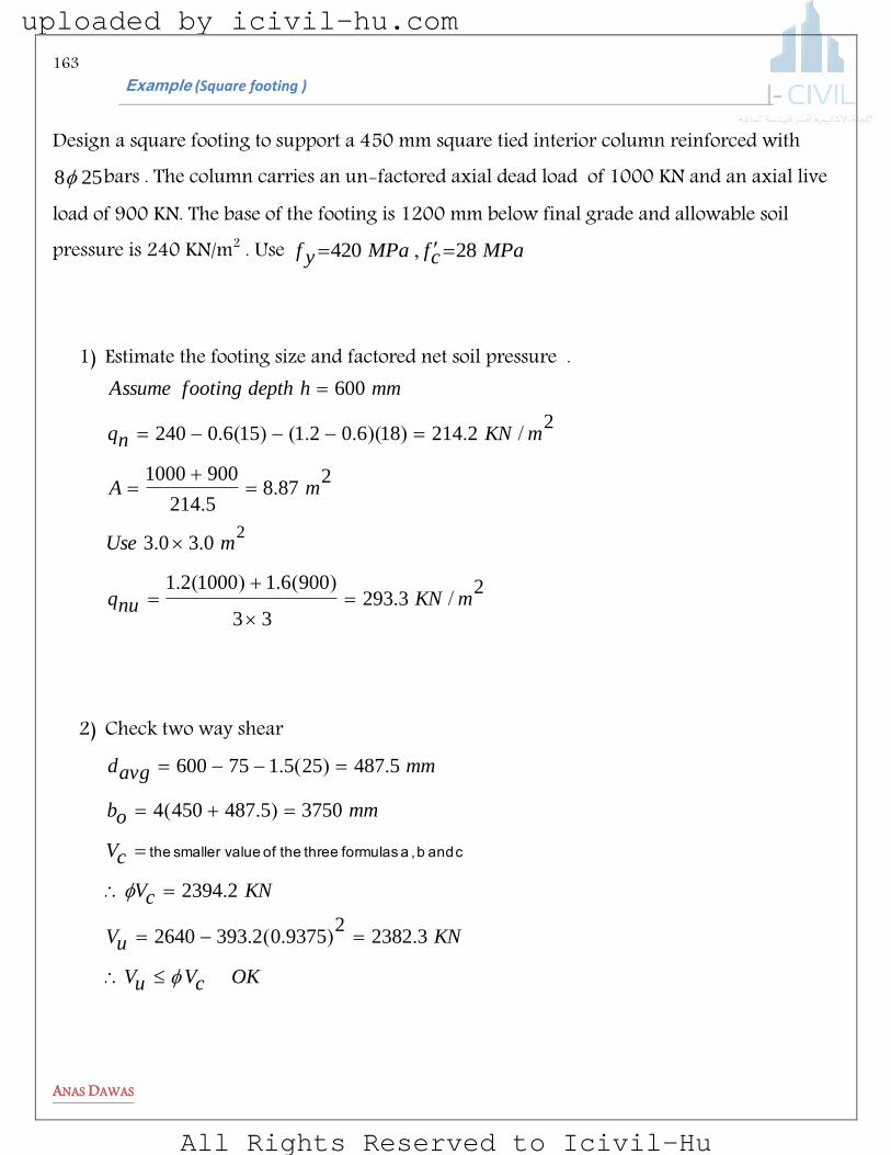
163
ANAS DAWAS
elpmaxE (Square footing )
Design a square footing to support a 450 mm square tied interior column reinforced with 258 bars . The column carries an un-factored axial dead load of 1000 KN and an axial live
load of 900 KN. The base of the footing is 1200 mm below final grade and allowable soil pressure is 240 KN/m2 . Use MPacfMPayf 28420 ,
1) Estimate the footing size and factored net soil pressure .
23293
33
90061100021
0303
2878
5214
9001000
222141860211560240
600
2
mKNnuq
mUse
mA
mKNnq
mmhdepthfootingAssume
/.)(.)(.
..
..
/.))(..()(.
2) Check two way shear
OKcVuV
KNuV
KNcV
cV
mmob
mmavgd
323822
9375023932640
22394
375054874504
5487255175600
.).(.
.
).(
.)(.
c and b , a formulasthree the of value smaller the
uploaded by icivil-hu.com
All Rights Reserved to Icivil-Hu
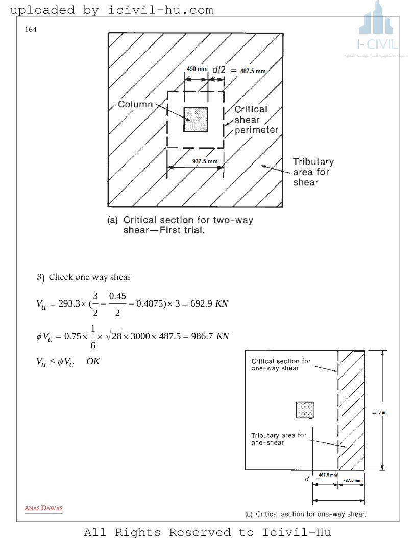
164
ANAS DAWAS
3) Check one way shear
OKcVuV
KNcV
KNuV
798654873000286
1750
96923487502
450
2
33293
...
.)..
(.
uploaded by icivil-hu.com
All Rights Reserved to Icivil-Hu

165
ANAS DAWAS
4) Design for flexure
mmSmmUse
mmsA
mmsA
mKNuM
5237113
7523000263702513
23240600300000180
26325
112232
45033293
.)(
.min
.).
(.
uploaded by icivil-hu.com
All Rights Reserved to Icivil-Hu
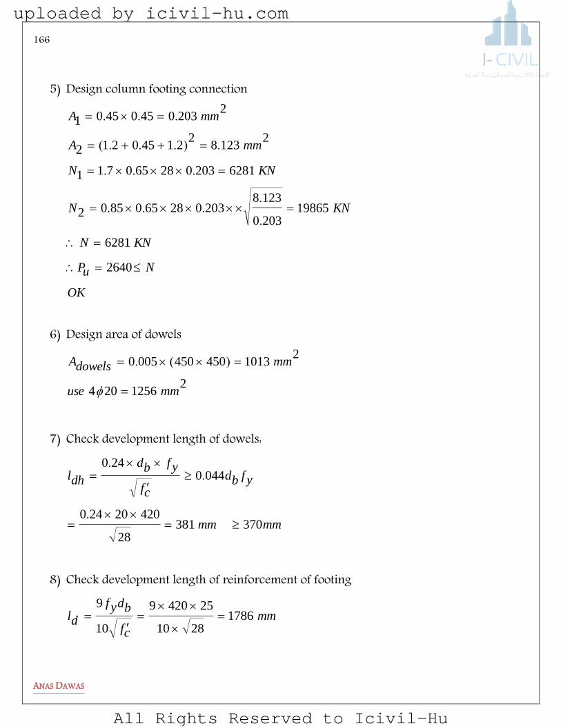
166
ANAS DAWAS
5) Design column footing connection
OK
NuP
KNN
KNN
KNN
mmA
mmA
2640
6281
198652030
12382030286508502
6281203028650711
21238
221450212
220304504501
.
....
...
.)...(
...
6) Design area of dowels
21256204
210134504500050
mmuse
mmdowelsA
)(.
7) Check development length of dowels:
mmmm
yfbd
cf
yfbd
dhl
37038128
42020240
0440240
.
..
8) Check development length of reinforcement of footing
mm
cf
bdyf
dl 17862810
254209
10
9
uploaded by icivil-hu.com
All Rights Reserved to Icivil-Hu

167
ANAS DAWAS
mmmmdhlhookuse
mmlAvailable
120047628
4202524090
17861200752
4503000
.
13ø25
4ø20
3000 mm
600-75 mm
450 mm
75 mm
uploaded by icivil-hu.com
All Rights Reserved to Icivil-Hu
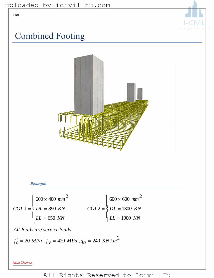
168
ANAS DAWAS
gomDJta geoonJt g
elpmaxE
224042020
1000
1300
2600600
2
650
890
2400600
1
mKNaqMPayfMPacf
loadsserviceareloadsAll
KNLL
KNDL
mm
COL
KNLL
KNDL
mm
COL
/,,
uploaded by icivil-hu.com
All Rights Reserved to Icivil-Hu
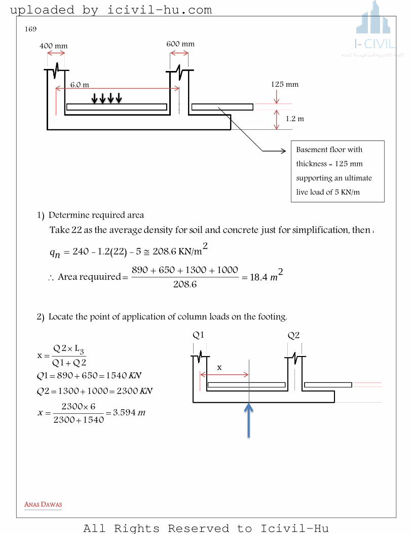
169
ANAS DAWAS
1) Determine required area
2418 m
nq
.
208.610001300650890requuired Area
2KN/m 208.65-1.2(22)-240
: thention,simplifica for just concreteand soil fordensity average the as 22 Take
2) Locate the point of application of column loads on the footing.
125 mm
600 mm 400 mm
6.0 m
Basement floor with thickness = 125 mm supporting an ultimate live load of 5 KN/m
1.2 m
x
Q1 Q2
mx
KNQKNQ
594.315402300
623002300100013002
154065089012Q1Q
L2Qx 3
uploaded by icivil-hu.com
All Rights Reserved to Icivil-Hu

170
ANAS DAWAS
3) Determine the dimension of the footing
mLAB
mmLxL
5.26.74.18
6.7588.7)2.0594.3(2)(2 2
4) Factored net pressure and factored loads
KNQKNQ
mKNq
uu
nu
3160)1000(6.1)1300(2.12108)650(6.1)890(2.1
/3.2775.26.7
)1000650(6.1)1300890(2.1
21
2
L/2
L3 L1 L2
Q1+Q2
Q1+Q2
uploaded by icivil-hu.com
All Rights Reserved to Icivil-Hu
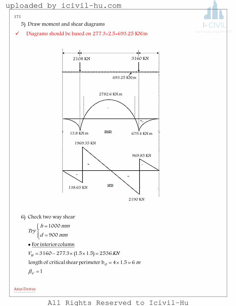
171
ANAS DAWAS
5) Draw moment and shear diagrams Diagrams should be based on 277.3×2.5=693.25 KN/m
6) Check two way shear
165.14b perimeter shear critical of length
2536)5.15.1(3.2773160column interior For
9001000
o
c
um
KNV
mmdmmh
Try
2108 KN 3160 KN
13.8 KN.m
2782.6 KN.m
679.4 KN.m
138.65 KN
1969.35 KN
2190 KN
969.85 KN
693.25 KN/m
uploaded by icivil-hu.com
All Rights Reserved to Icivil-Hu

172
ANAS DAWAS
3220)8402)
6.3756)
5.1400600
2.35.1)85.0(24.1754)85.05.1(3.2772108
column interior For
4.603731)
1207412
)2()
905612
)42()
OKVVKNcKNb
KNaofsmallesV
mbKNV
OKVV
KNdbfc
KNdbf
bdb
KNdbf
a
ofsmallestV
uc
c
c
ou
uc
oc
oco
s
occ
c
7) Check one way shear
OKKNV
KNVmmdmmh
Try
thicknesstheincreaseKNdbfV
KN
c
u
wcc
5.139710002500206175.0
8.1288)0.13.0(25.693219010001100
7.12579002500206175.0
61
1.1358)9.03.0(25.6932190V ) column the of
center from mm 300d ( column interior the of face the fromd at critical is shearway One
u
uploaded by icivil-hu.com
All Rights Reserved to Icivil-Hu
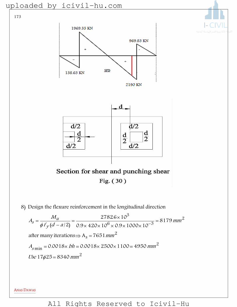
173
ANAS DAWAS
8) Design the flexure reinforcement in the longitudinal direction
2
2min
2s
236
3
83402517
4950110025000018.00018.0
7651A iterationsmany after
81791010009.0104209.0
106.2782)2/(
mmUsemmbhA
mm
mmadfMA
s
yus
uploaded by icivil-hu.com
All Rights Reserved to Icivil-Hu

174
ANAS DAWAS
2min
2s
54012511
9.199510009.04209.0
1000679A
moment positive tosubjected column interior For
mmUse
Amm s
9) Design for transverse beam
2
2min
2
22
4418259
4158110021000018.0
mm 1588.4As iterationsmany after10009.04209.0
10004.570
/4.5702
95.012642
mmUsemmA
A
mKNwlM
s
s
u
B+1.5 d =2.1 m
B
0.75 d
0.95 m
3160 KN
uploaded by icivil-hu.com
All Rights Reserved to Icivil-Hu

175
ANAS DAWAS
2
2min
2
4.2454255
2277110011500018.0
/4.3802
95.02.843
:
mmUsemmA
mKNM
beamedgeFor
s
u
Check development length for all reinforcements required
2108 KN
2018/2.5=843.2 KN/m
uploaded by icivil-hu.com
All Rights Reserved to Icivil-Hu
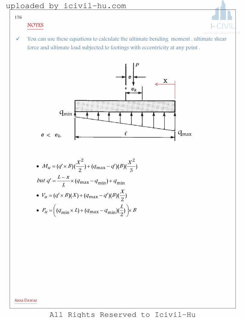
176
ANAS DAWAS
NOTES
You can use these equations to calculate the ultimate bending moment , ultimate shear force and ultimate load subjected to footings with eccentricity at any point .
x
qmax
qmin
BLqqLqP
XBqqXBqV
qqqLxLqbut
XBqqXBqM
u
u
u
)2
)(()(
)2
)()(())((
)(
)3
)()(()2
()(
minmaxmin
max
minminmax
2max
2
uploaded by icivil-hu.com
All Rights Reserved to Icivil-Hu
177
ANAS DAWAS
Moment transfer from columns to footings depends on how the column–footing connection is constructed. Many designers treat the connection between columns and footings as a pinned connection. Others treat it as fixed, and still others treat it as somewhere in between. If it is truly pinned, no moment is transferred to the footing, and this section of the text is not applicable. If, however, it is treated as fixed or partially fixed, this section is applicable. If a column–footing joint is to behave as a pin or hinge, it would have to be constructed accordingly. The reinforcing in the column might be terminated at the column base instead of continuing into the footing. Dowels would be provided, but these would not be adequate to provide a moment connection. To provide continuity at the column–footing interface, the reinforcing steel would have to be continued into the footing. This is normally accomplished by embedding hooked bars into the footing and having them extend into the air where the columns will be located. The length they extend into the air must be at least the lap splice length; sometimes this can be a significant length. These bars are then lap spliced or mechanically spliced with the column bars, providing continuity of tension force in the reinforcing steel.
uploaded by icivil-hu.com
All Rights Reserved to Icivil-Hu

178
ANAS DAWAS
SMELBeRP
5-1 Design a square footing to support a 500 x 500 mm-square tied interior column reinforced with 825 bars. The column carries unfactored axial dead load of 1100 kN and unfactored axial live load of 750 kN. The base of the footing is 1200 mm below final grade and allowable NET soil pressure is 195 kN/m2. Use fc’ = 28 MPa and fy = 420 MPa. Assume d = h – 100mm.
5-2 A 4.0 x 4.0 m-square footing is
subjected to an ultimate (factored) axial load Pu = 2400 kN due to eccentric column as shown below (ignore footing self-weight). Assume effective depth d = 0.535 m.
Calculate maximum and minimum ultimate soil pressure. Calculate maximum ultimate flexural moment in the footing Calculate maximum one-way shear in the footing (Vu) Calculate the punching shear exerted by the 400 mm-square column on the footing (Vu).
uploaded by icivil-hu.com
All Rights Reserved to Icivil-Hu
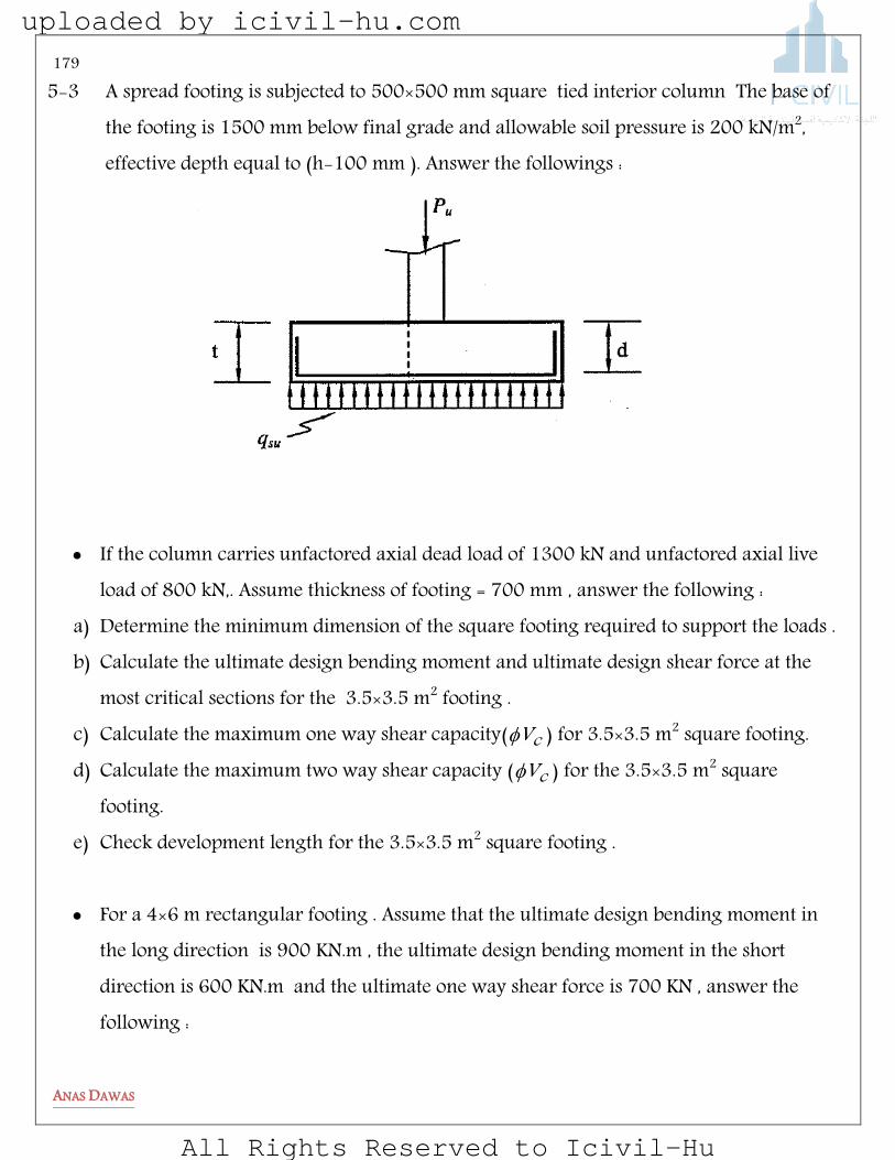
179
ANAS DAWAS
5-3 A spread footing is subjected to 500×500 mm square tied interior column The base of the footing is 1500 mm below final grade and allowable soil pressure is 200 kN/m2, effective depth equal to (h-100 mm ). Answer the followings :
If the column carries unfactored axial dead load of 1300 kN and unfactored axial live load of 800 kN,. Assume thickness of footing = 700 mm , answer the following :
a) Determine the minimum dimension of the square footing required to support the loads . b) Calculate the ultimate design bending moment and ultimate design shear force at the
most critical sections for the 3.5×3.5 m2 footing . c) Calculate the maximum one way shear capacity( cV ) for 3.5×3.5 m2 square footing. d) Calculate the maximum two way shear capacity ( cV ) for the 3.5×3.5 m2 square
footing. e) Check development length for the 3.5×3.5 m2 square footing .
For a 4×6 m rectangular footing . Assume that the ultimate design bending moment in
the long direction is 900 KN.m , the ultimate design bending moment in the short direction is 600 KN.m and the ultimate one way shear force is 700 KN , answer the following :
uploaded by icivil-hu.com
All Rights Reserved to Icivil-Hu

180
ANAS DAWAS
f) Calculate the area of steel required in the long direction . g) Calculate the area of steel required in the long direction . h) Calculate the minimum area of steel in the long direction.
i) If we have to use 30ø12in the short direction , make a simple sketch showing the distribution of the bars in this direction .
5-4 The rectangular footing shown below is subjected to a concentrated factored column
load Pu=3000 KN and having an area 3.00×4.00 m2. Given the column size is 350×450 mm2 and effective depth of the footing is 610 mm :
a) Determine the value of the moment at the critical section(s) . b) Check the adequacy of the footing depth for one way shear . c) Check the adequacy of the footing depth for punching shear . d) Assume that the main reinforcement in the footing consists of 18-mm diameter bars
at 150 mm O.C and the dowels in the footing are 14- mm bars . Sketch the distribution of the reinforcement in the short direction .
uploaded by icivil-hu.com
All Rights Reserved to Icivil-Hu
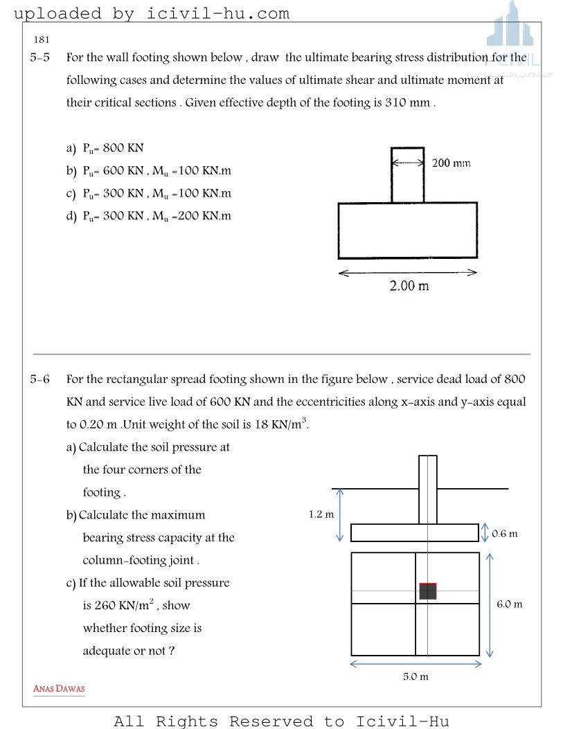
181
ANAS DAWAS
5-5 For the wall footing shown below , draw the ultimate bearing stress distribution for the following cases and determine the values of ultimate shear and ultimate moment at their critical sections . Given effective depth of the footing is 310 mm . a) Pu= 800 KN b) Pu= 600 KN , Mu =100 KN.m c) Pu= 300 KN , Mu =100 KN.m d) Pu= 300 KN , Mu =200 KN.m
5-6 For the rectangular spread footing shown in the figure below , service dead load of 800 KN and service live load of 600 KN and the eccentricities along x-axis and y-axis equal to 0.20 m .Unit weight of the soil is 18 KN/m3. a) Calculate the soil pressure at
the four corners of the footing .
b) Calculate the maximum bearing stress capacity at the column-footing joint .
c) If the allowable soil pressure is 260 KN/m2 , show whether footing size is adequate or not ?
1.2 m
6.0 m
5.0 m
0.6 m
uploaded by icivil-hu.com
All Rights Reserved to Icivil-Hu
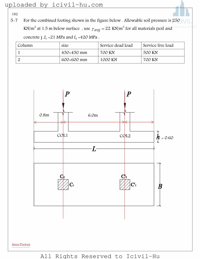
182
ANAS DAWAS
5-7 For the combined footing shown in the figure below . Allowable soil pressure is 250 KN/m2 at 1.5 m below surface , use 22avg KN/m3 for all materials (soil and concrete ) ,fc =21 MPa and fy =420 MPa .
Column size Service dead load Service live load 1 450×450 mm 700 KN 500 KN 2 600×600 mm 1000 KN 700 KN
COL2 COL1
6.0m 0.8m
= 0.60 m
uploaded by icivil-hu.com
All Rights Reserved to Icivil-Hu
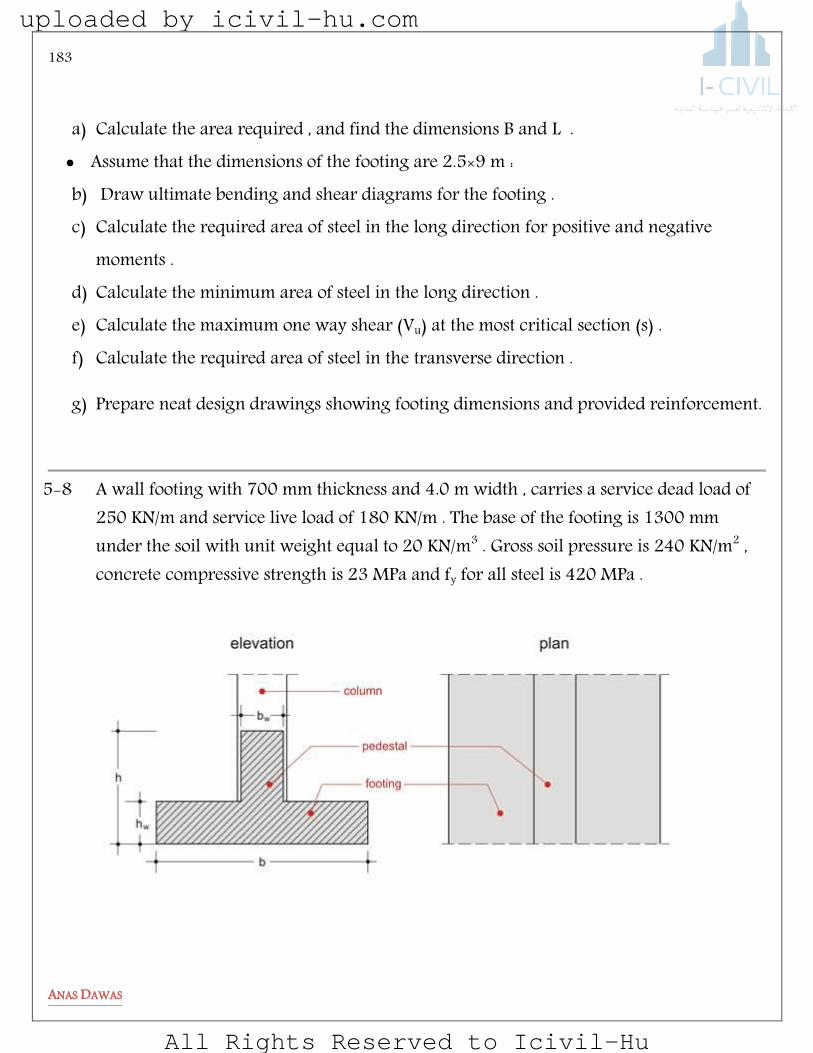
183
ANAS DAWAS
a) Calculate the area required , and find the dimensions B and L . Assume that the dimensions of the footing are 2.5×9 m : b) Draw ultimate bending and shear diagrams for the footing . c) Calculate the required area of steel in the long direction for positive and negative
moments . d) Calculate the minimum area of steel in the long direction . e) Calculate the maximum one way shear (Vu) at the most critical section (s) . f) Calculate the required area of steel in the transverse direction .
g) Prepare neat design drawings showing footing dimensions and provided reinforcement.
5-8 A wall footing with 700 mm thickness and 4.0 m width , carries a service dead load of
250 KN/m and service live load of 180 KN/m . The base of the footing is 1300 mm under the soil with unit weight equal to 20 KN/m3 . Gross soil pressure is 240 KN/m2 , concrete compressive strength is 23 MPa and fy for all steel is 420 MPa .
uploaded by icivil-hu.com
All Rights Reserved to Icivil-Hu
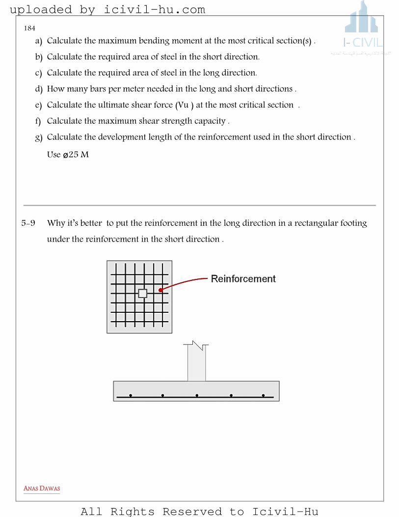
184
ANAS DAWAS
a) Calculate the maximum bending moment at the most critical section(s) . b) Calculate the required area of steel in the short direction. c) Calculate the required area of steel in the long direction. d) How many bars per meter needed in the long and short directions . e) Calculate the ultimate shear force (Vu ) at the most critical section . f) Calculate the maximum shear strength capacity . g) Calculate the development length of the reinforcement used in the short direction .
Use ø25 M
5-9 Why it’s better to put the reinforcement in the long direction in a rectangular footing under the reinforcement in the short direction .
uploaded by icivil-hu.com
All Rights Reserved to Icivil-Hu

185
ANAS DAWAS
Biaxial Columns
uploaded by icivil-hu.com
All Rights Reserved to Icivil-Hu
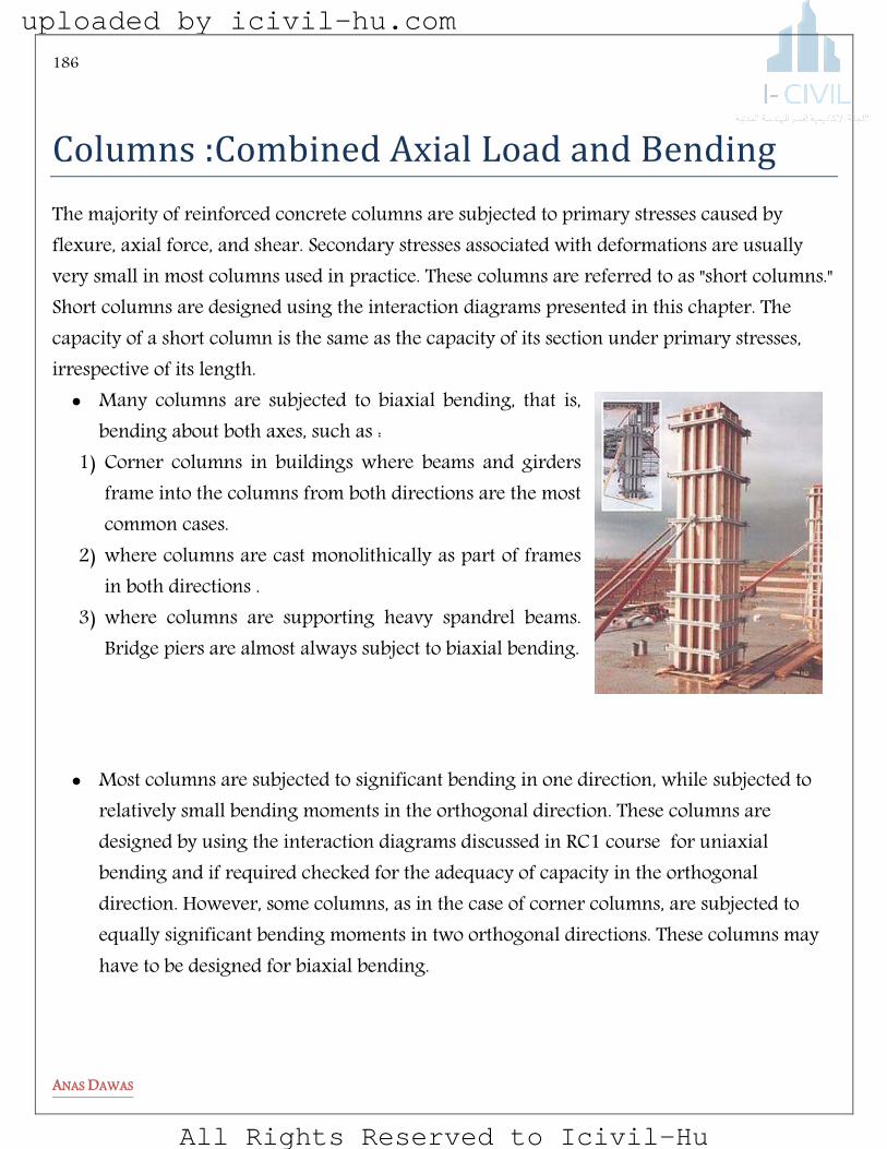
186
ANAS DAWAS
Columns :Combined Axial Load and Bending
The majority of reinforced concrete columns are subjected to primary stresses caused by flexure, axial force, and shear. Secondary stresses associated with deformations are usually very small in most columns used in practice. These columns are referred to as "short columns." Short columns are designed using the interaction diagrams presented in this chapter. The capacity of a short column is the same as the capacity of its section under primary stresses, irrespective of its length. Many columns are subjected to biaxial bending, that is,
bending about both axes, such as : 1) Corner columns in buildings where beams and girders
frame into the columns from both directions are the most common cases.
2) where columns are cast monolithically as part of frames in both directions .
3) where columns are supporting heavy spandrel beams. Bridge piers are almost always subject to biaxial bending.
Most columns are subjected to significant bending in one direction, while subjected to relatively small bending moments in the orthogonal direction. These columns are designed by using the interaction diagrams discussed in RC1 course for uniaxial bending and if required checked for the adequacy of capacity in the orthogonal direction. However, some columns, as in the case of corner columns, are subjected to equally significant bending moments in two orthogonal directions. These columns may have to be designed for biaxial bending.
uploaded by icivil-hu.com
All Rights Reserved to Icivil-Hu
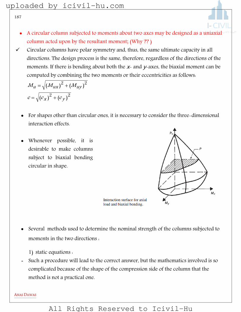
187
ANAS DAWAS
A circular column subjected to moments about two axes may be designed as a uniaxial
column acted upon by the resultant moment; (Why ?? ) Circular columns have polar symmetry and, thus, the same ultimate capacity in all
directions. The design process is the same, therefore, regardless of the directions of the moments. If there is bending about both the x- and y-axes, the biaxial moment can be computed by combining the two moments or their eccentricities as follows:
22
22
)()(
)()(
yx
uyuxu
eee
MMM
For shapes other than circular ones, it is necessary to consider the three-dimensional
interaction effects.
Whenever possible, it is desirable to make columns subject to biaxial bending circular in shape.
Several methods used to determine the nominal strength of the columns subjected to moments in the two directions :
1) static equations : - Such a procedure will lead to the correct answer, but the mathematics involved is so
complicated because of the shape of the compression side of the column that the method is not a practical one.
uploaded by icivil-hu.com
All Rights Reserved to Icivil-Hu
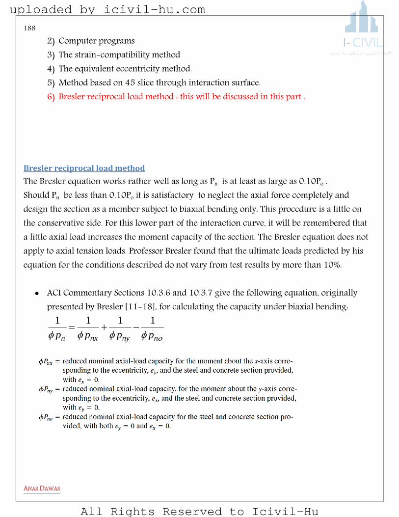
188
ANAS DAWAS
2) Computer programs 3) The strain-compatibility method 4) The equivalent eccentricity method. 5) Method based on 45 slice through interaction surface. 6) Bresler reciprocal load method : this will be discussed in this part .
Bresler reciprocal load method
The Bresler equation works rather well as long as Pn is at least as large as 0.10Po . Should Pn be less than 0.10Po it is satisfactory to neglect the axial force completely and design the section as a member subject to biaxial bending only. This procedure is a little on the conservative side. For this lower part of the interaction curve, it will be remembered that a little axial load increases the moment capacity of the section. The Bresler equation does not apply to axial tension loads. Professor Bresler found that the ultimate loads predicted by his equation for the conditions described do not vary from test results by more than 10%.
ACI Commentary Sections 10.3.6 and 10.3.7 give the following equation, originally presented by Bresler [11-18], for calculating the capacity under biaxial bending:
nnynxn pppp
1111
uploaded by icivil-hu.com
All Rights Reserved to Icivil-Hu

189
ANAS DAWAS
Procedure Used To Design Biaxial Columns
1) Select a trial section:
2) Select appropriate number of bars to be subjected to the column : A bar is adequately supported against lateral movement if its located at a corner of a tie and if the dimension “x” shown in the figure below is less than 15 cm .
. spiral for mm 300and mm 250 columntied a for dimension Min.)(5.0
)(4.0)(
%)55.2(%)21(
Columnspiralforgyfcf
up
ColumnTiedforgyfcf
up
trialgA
ColumnspiralforColumnTiedfor
gthatassume
uploaded by icivil-hu.com
All Rights Reserved to Icivil-Hu
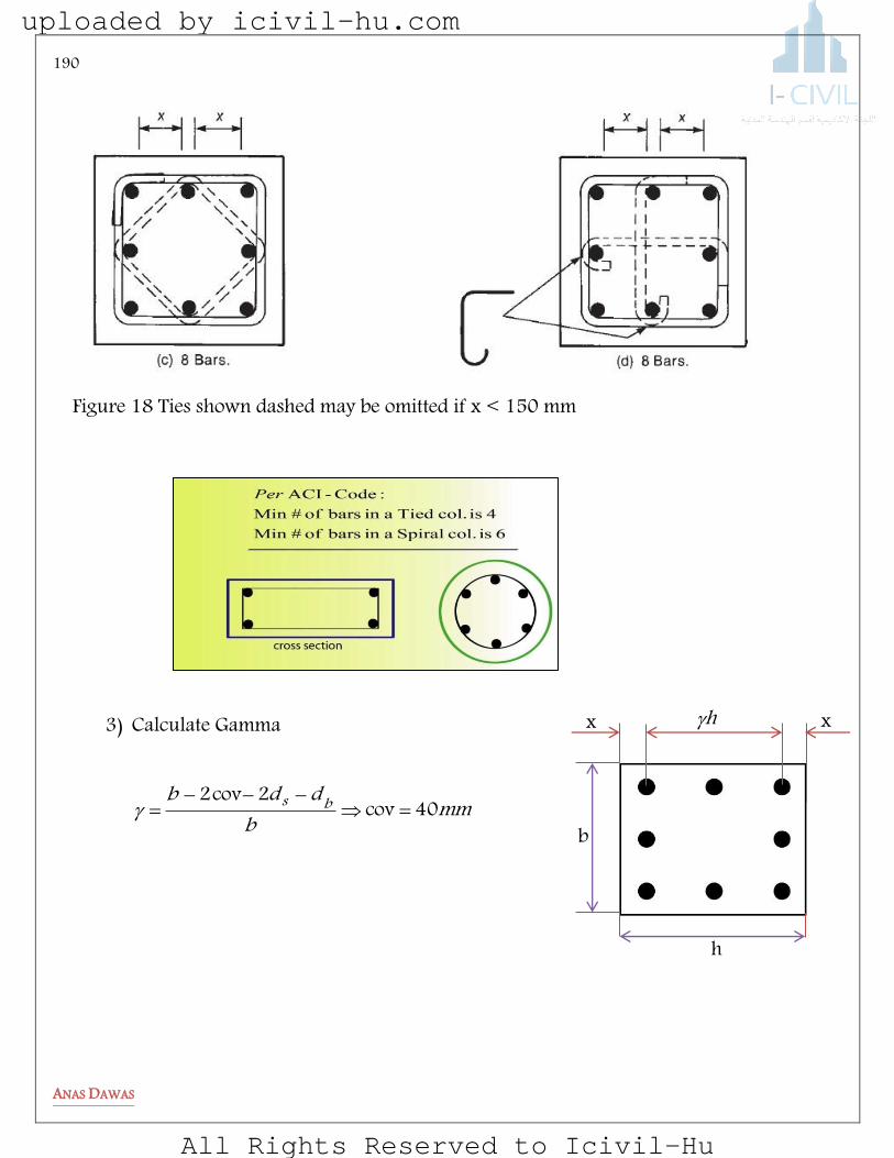
190
ANAS DAWAS
3) Calculate Gamma
mmbddb bs 40cov2cov2
Figure 18 Ties shown dashed may be omitted if x < 150 mm
h
b
x x h
uploaded by icivil-hu.com
All Rights Reserved to Icivil-Hu

191
ANAS DAWAS
nxgy
y
nygxx
ny
nxuux
yu
uyx
oyx
Ple
Ple
ondependingPand
PfindtodiagramtheusethenPMeP
Me
eandeeCompute
,
,:
,
:,
spiralforP
TiedforPloadaxialMax
and
fAAAfP
PCompute
n
n
Ts
yssgcn
n
850
80
650750
850
.
..
..
))(.(
:
un
nnynxnpbeshouldp
pppp
1111
4) Compute ex , ey and eo
5) Compute oP
6) Solve for nP
uploaded by icivil-hu.com
All Rights Reserved to Icivil-Hu
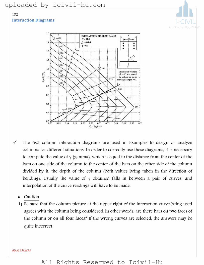
192
ANAS DAWAS
Interaction Diagrams
The ACI column interaction diagrams are used in Examples to design or analyze columns for different situations. In order to correctly use these diagrams, it is necessary to compute the value of γ (gamma), which is equal to the distance from the center of the bars on one side of the column to the center of the bars on the other side of the column divided by h, the depth of the column (both values being taken in the direction of bending). Usually the value of γ obtained falls in between a pair of curves, and interpolation of the curve readings will have to be made.
Caution 1) Be sure that the column picture at the upper right of the interaction curve being used
agrees with the column being considered. In other words, are there bars on two faces of the column or on all four faces? If the wrong curves are selected, the answers may be quite incorrect.
uploaded by icivil-hu.com
All Rights Reserved to Icivil-Hu

193
ANAS DAWAS
elpmaxE
Select column section size and reinforcement for a rectangular tied column with bars distributed along four faces, subject to biaxial bending. Given :
Pu Mux Muy fc fy 1900 KN 100 KN.m 190 KN.m 28 MPa 420 MPa
1) Estimate column size
sizesmallerselectcanYoummmmTry
ffPA
ygcu
g
222
g
200000400500mm 96.138483)420015.028(4.0
10001900A0.015 ratio steel gross assume )(4.0
2) Select appropriate number of ø25 bars
uploaded by icivil-hu.com
All Rights Reserved to Icivil-Hu
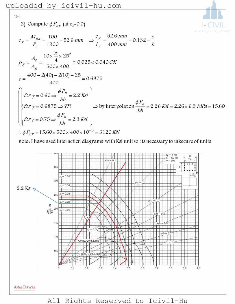
194
ANAS DAWAS
3) Compute nxP (at ex=0.0)
units of takecare tonecessary its so unit Ksi with diagrams ninteractioused have I : note31201040050060.15
60.159.626.226.2 ioninterpolatby
3.275.0
???6875.0
2.260.0
6875.0400
25)10(2)40(2400
040.0025.0400500
254
10
132.0400
6.526.52
1900100
3
2
KNP
MPaKsibhP
KsibhP
for
forKsibh
Pfor
OKAA
he
mmmm
lemmP
Me
nx
n
n
n
gS
g
y
y
uux
y
2.2 Ksi
uploaded by icivil-hu.com
All Rights Reserved to Icivil-Hu

195
ANAS DAWAS
4) Compute nyP ( at ey =0.0)
5) Compute noP You can calculate it by equation or by interaction diagrams ( independent of Gamma
value )
. diagrams using ofaccuracy less to due or units of because bemay ,P of values in difference largea is there , that note
4357420254
10254
104005002885.065.0
Equation Using34501040050025.17
25.175.20.0
025.0Diagrams Using
n
22
3
KNP
KNP
MPaKsibhP
he
on
on
ng
units of takecare tonecessary its so unit Ksi with diagrams ninteractioused have I : note26221040050011.13
11.139.69.1
9.175.0
75.0500
25)10(2)40(2500
040.0025.0400500
254
10
2.0500100
1001900190
3
2
KNP
MPaMPabhP
KsibhP
for
OKAA
he
mmmm
lemmP
Me
ny
n
n
gS
g
xx
u
uyx
uploaded by icivil-hu.com
All Rights Reserved to Icivil-Hu
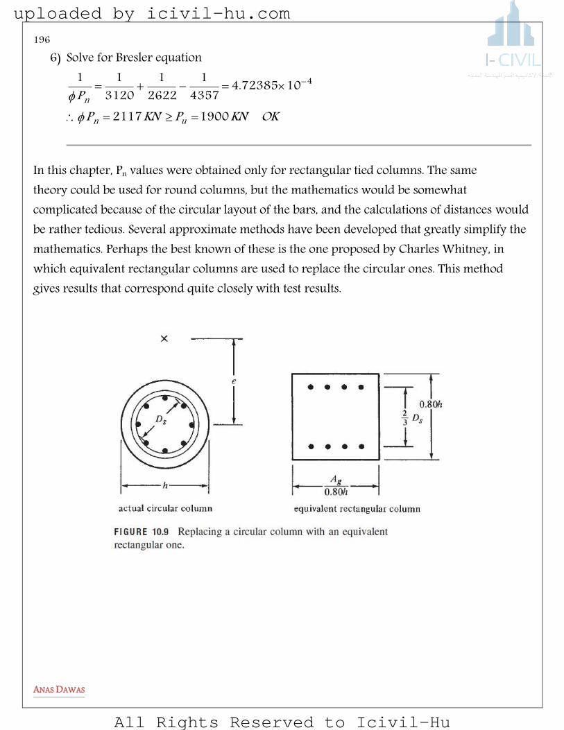
196
ANAS DAWAS
6) Solve for Bresler equation
OKKNPKNPP
un
n19002117
1072385.44357
12622
13120
11 4
In this chapter, Pn values were obtained only for rectangular tied columns. The same theory could be used for round columns, but the mathematics would be somewhat complicated because of the circular layout of the bars, and the calculations of distances would be rather tedious. Several approximate methods have been developed that greatly simplify the mathematics. Perhaps the best known of these is the one proposed by Charles Whitney, in which equivalent rectangular columns are used to replace the circular ones. This method gives results that correspond quite closely with test results.
uploaded by icivil-hu.com
All Rights Reserved to Icivil-Hu

197
ANAS DAWAS
SMELBeRP
For all problems :
Cover Bars diameter Ties diameter cf yf 40 mm 25 mm 10 mm 28 MPa 420 MPa
6-1 The column shown below is to carry a factored load , Pu ,of 800 KN with eccentricities of ey = 90 mm and ex = 300 mm . Check the adequacy of the trial design by using Bresler method .
6-2 Check the adequacy of the circular column for the following axial load and biaxial bending moments. Use and procedure you feel is most suitable .
Pu Mux Muy 2200 KN 100 KN.m 175 KN.m
uploaded by icivil-hu.com
All Rights Reserved to Icivil-Hu

198
ANAS DAWAS
6-3 For square column shown in the figure below , determine the maximum ultimate biaxial bending moment ( Mux and Muy ) that can be applied simultaneously with a load Pu = 3000 KN to column section . Assume ex = ey and =0.80
6-4 The section of a short tied column is 400×400 mm and is reinforced with 8ø25 bars as shown. Determine the allowable ultimate load on the section nP if its acts at ex = 108 mm and ey = 270 mm. Use Reciprocal Load Method: Bresler’s Formula and the interaction diagram given on Design Aids . Fill the table below .
noP
nxP
nyP
nP
uploaded by icivil-hu.com
All Rights Reserved to Icivil-Hu

199
ANAS DAWAS
uploaded by icivil-hu.com
All Rights Reserved to Icivil-Hu

200
ANAS DAWAS
Slender Columns
uploaded by icivil-hu.com
All Rights Reserved to Icivil-Hu
Slender
Columns
Reference
Chapter12: Reinforced Concrete MECHANICS AND
DESIGN 6th edition
Maher Fakhoury
uploaded by icivil-hu.com
All Rights Reserved to Icivil-Hu

Definition: A slender column is defined as a column that has a significant reduction in its axial-load capacity due to moments resulting from lateral deflections of the column. In the derivation of the ACI Code, “a significant reduction” was arbitrarily taken as anything greater than about 5 percent.
Most building columns fall in the short-column category. Exceptions occur in industrial buildings and in buildings that have a high first-floor story for architectural or functional reasons. An extreme example is shown in Fig. 12-7. The left corner column has a height of 50 times its least thickness. Some bridge piers and the decks of cable stayed bridges fall into the slender-column category.
Less than 10 % of columns in “braced” or “nonsway” frames and less than half of columns in “unbraced” or “sway” frames would be classified as “slender” following ACI Code Procedure.
Fig. 12-7
Bank of Brazil building,
Porto Alegre, Brazil. Each
Floor extends out over the
Floor below it. (Photograph
Courtesy of J. G. MacGregor.)
uploaded by icivil-hu.com
All Rights Reserved to Icivil-Hu

Concept of Slenderness Effect
An eccentrically loaded, pin-ended column is shown in Fig the
moments at the ends of the column are when the loads P are
applied, the column deflects laterally by an amount as shown.
Me = Pe
For equilibrium, the internal moment at mid height
Mc = P(e + δ)
The deflection increases the moments for which the column
must be designed. In the symmetrical column shown here, the
maximum moment occurs at mid height.
The slenderness of columns is based on their geometry and on
their lateral bracing. As their slenderness increases, their
bending stresses increase, and thus buckling may occur. If
they are “slender,” the moment for which the column must be designed is increased or magnified. Once
the moment is magnified, it’s very simple the column is then designed as a short column using the
increased moment.
The line O–A is referred to as a load–moment curve
for the end moment, while the line O–B is the load–
moment curve for the maximum column moment.
Failure occurs when the load–moment curve O–B for
the point of maximum moment intersects the
interaction diagram for the cross section. Thus the
load and moment at failure are denoted by point B in
Fig. Because of the increase in maximum moment
due to deflections, the axial-load capacity is reduced
from A to B. This reduction in axial-load capacity
results from what are referred to as slenderness
effects.
uploaded by icivil-hu.com
All Rights Reserved to Icivil-Hu
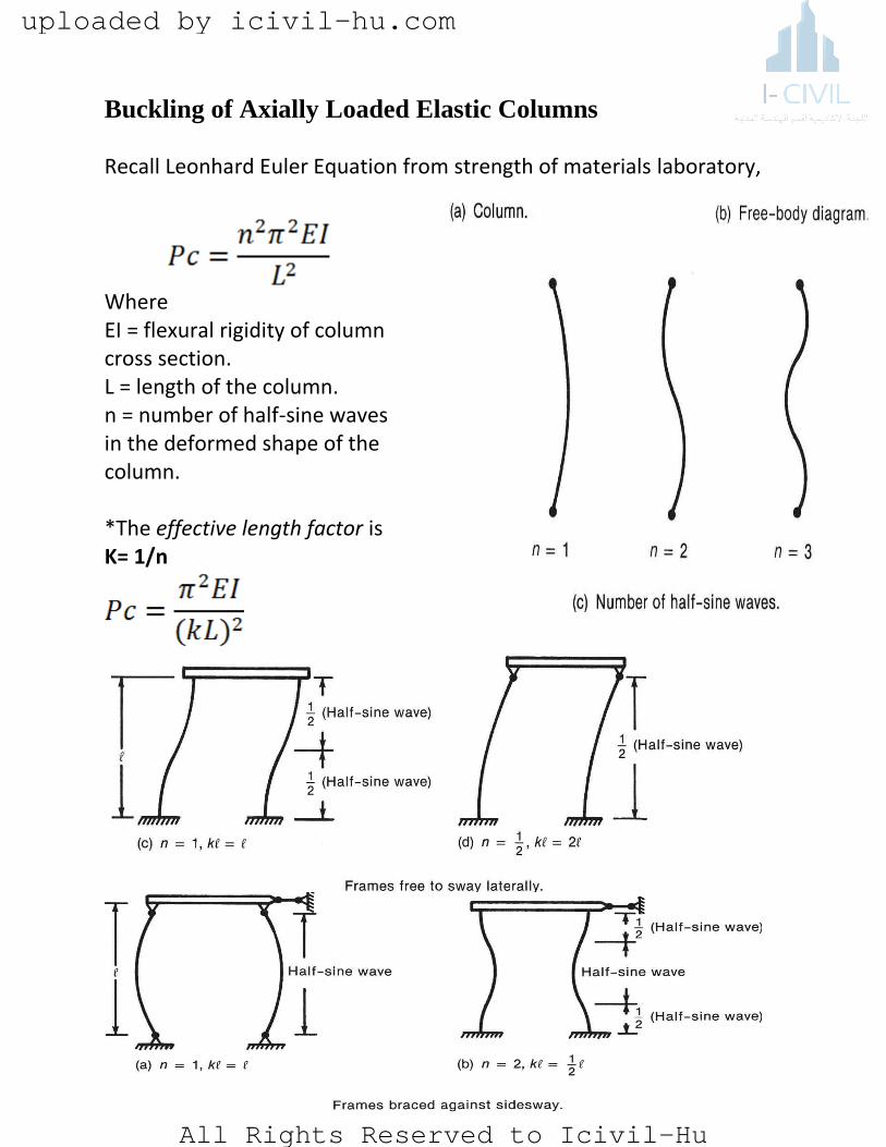
Buckling of Axially Loaded Elastic Columns Recall Leonhard Euler Equation from strength of materials laboratory,
Where EI = flexural rigidity of column cross section. L = length of the column. n = number of half-sine waves in the deformed shape of the column. *The effective length factor is K= 1/n
uploaded by icivil-hu.com
All Rights Reserved to Icivil-Hu
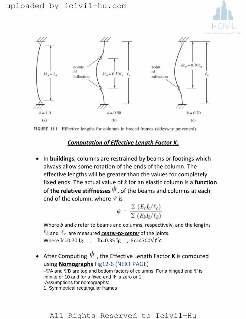
Computation of Effective Length Factor K:
In buildings, columns are restrained by beams or footings which always allow some rotation of the ends of the column. The effective lengths will be greater than the values for completely fixed ends. The actual value of k for an elastic column is a function
of the relative stiffnesses , of the beams and columns at each end of the column, where is
Where b and c refer to beams and columns, respectively, and the lengths
and are measured center-to-center of the joints.
Where Ic=0.70 Ig , Ib=0.35 Ig , Ec=4700
After Computing , the Effective Length Factor K is computed using Nomographs Fig12-6 (NEXT PAGE) A and B are top and bottom factors of columns. For a hinged end is
infinite or 10 and for a fixed end is zero or 1. -Assumptions for nomographs: 1. Symmetrical rectangular frames
uploaded by icivil-hu.com
All Rights Reserved to Icivil-Hu
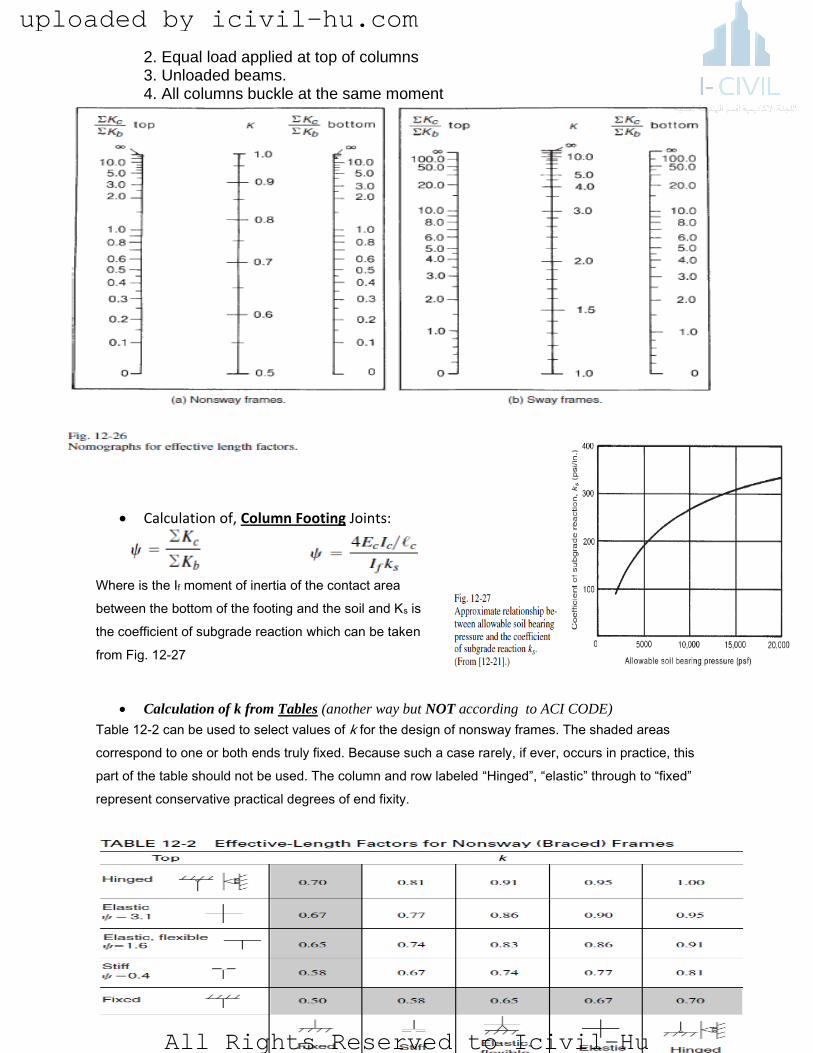
2. Equal load applied at top of columns 3. Unloaded beams. 4. All columns buckle at the same moment
Calculation of, Column Footing Joints:
Where is the If moment of inertia of the contact area
between the bottom of the footing and the soil and Ks is
the coefficient of subgrade reaction which can be taken
from Fig. 12-27
Calculation of k from Tables (another way but NOT according to ACI CODE)
Table 12-2 can be used to select values of k for the design of nonsway frames. The shaded areas
correspond to one or both ends truly fixed. Because such a case rarely, if ever, occurs in practice, this
part of the table should not be used. The column and row labeled “Hinged”, “elastic” through to “fixed”
represent conservative practical degrees of end fixity.
uploaded by icivil-hu.com
All Rights Reserved to Icivil-Hu
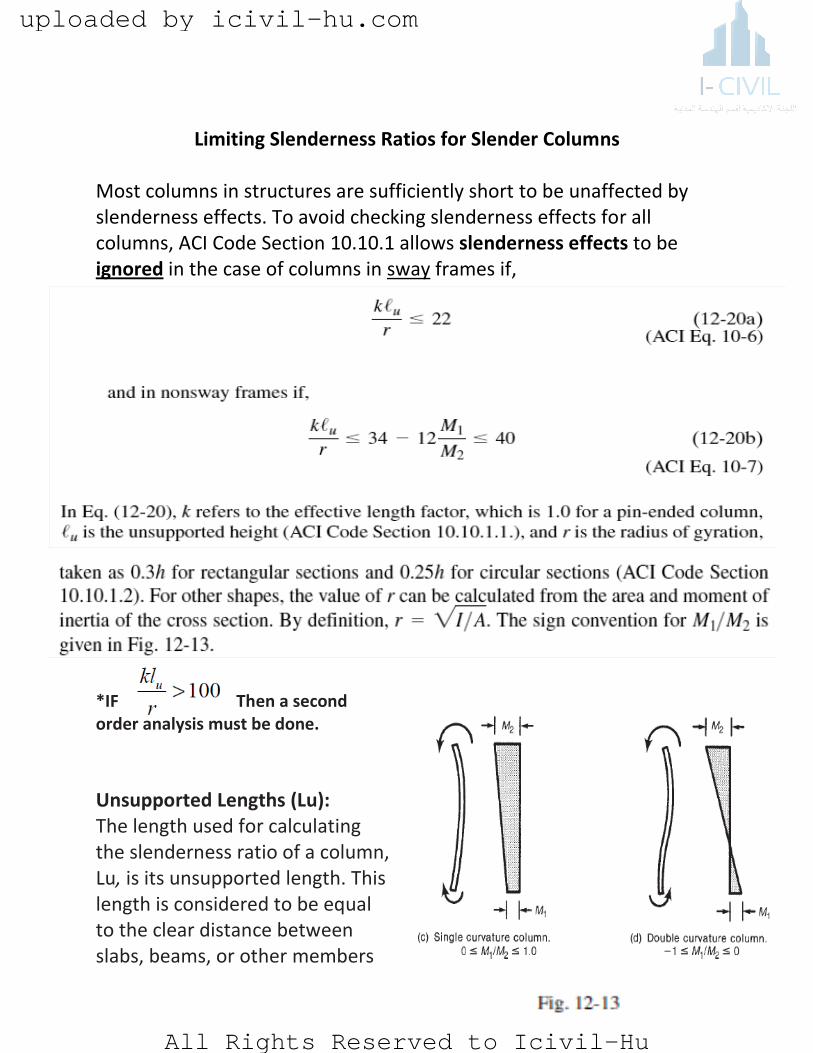
Limiting Slenderness Ratios for Slender Columns Most columns in structures are sufficiently short to be unaffected by slenderness effects. To avoid checking slenderness effects for all columns, ACI Code Section 10.10.1 allows slenderness effects to be ignored in the case of columns in sway frames if,
*IF Then a second order analysis must be done.
Unsupported Lengths (Lu): The length used for calculating the slenderness ratio of a column, Lu, is its unsupported length. This length is considered to be equal to the clear distance between slabs, beams, or other members
uploaded by icivil-hu.com
All Rights Reserved to Icivil-Hu
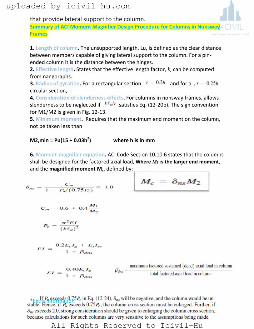
that provide lateral support to the column. Summary of ACI Moment Magnifier Design Procedure for Columns in Nonsway Frames 1. Length of column. The unsupported length, Lu, is defined as the clear distance between members capable of giving lateral support to the column. For a pin-ended column it is the distance between the hinges. 2. Effective length. States that the effective length factor, k, can be computed from nangoraphs. 3. Radius of gyration. For a rectangular section and for a circular section, 4. Consideration of slenderness effects. For columns in nonsway frames, allows slenderness to be neglected if satisfies Eq. (12-20b). The sign convention for M1/M2 is given in Fig. 12-13. 5. Minimum moment. Requires that the maximum end moment on the column, not be taken less than M2,min = Pu(15 + 0.03h2) where h is in mm 6. Moment-magnifier equation. ACI Code Section 10.10.6 states that the columns shall be designed for the factored axial load, Where M2 is the larger end moment, and the magnified moment Mc, defined by:
*Extra Information
uploaded by icivil-hu.com
All Rights Reserved to Icivil-Hu

Example 1: Design of a Slender Pin-Ended Column (Nonsway)
Design a 6m-tall column to support an unfactored dead load of
400 KN and an unfactored live load of 334 KN. The loads act at
an eccentricity of 76 mm. at the top and 50 mm. at the bottom,
as shown in Fig. Use f’c= 28 MPa and Fy=420 MPa
1. Compute the factored loads Pu and moments M1/M2 and
Pu= 1.2 DL+1.6LL = 1.2 X 400+1.6 X 334 = 1014.4 KN
The Moment at the top = 1014.4 X 0.076 = 77.1 KN-m
The Moment at the bottom = 1014.4*0.05= 50.72 KN-m
By definition, M2 is the larger end moment in the column. Therefore,
M2= 77 KN-m and M1= 51.7 KN-m the ratio M1/M2 is taken to be
positive, because the column is bent in single curvature Thus
M1/M2=0.658
2. Estimate the column size. Use ρ=1.5%
= = 73935.86mm2
use bXh = 300 X 300 mm2
3. Is the column slender? a column in a nonsway frame is short if
K=1 because the column is pin ended, where r=0.3*300= 90 mm
=
For M1/M2=0.658
34 - 12 = 34-12 X 0.658= 26
uploaded by icivil-hu.com
All Rights Reserved to Icivil-Hu

Because 66.7 exceeds 26, the column is quite slender. This suggests that the Section 300mm by 300mm
probably is inadequate.
We shall select a 400mm-by-400mm.-section for the first trial.
4. Check whether the moments are less than the minimum. a braced column be designed for a
minimum eccentricity of 15+0.03 X 350 = 25.5 Because the maximum end eccentricity exceeds this,
design for the moments from step 1.
5. Compute EI.
Ec=4700 f’c= 4700 28=24870 MPa
Ig= bh3 /12 = 2.13X 109 mm4
The term Bdnsis the ratio of the factored sustained (dead) load to the total factored axial load:
Bdns = 1.2 X 400 / 1014.4 = 0.473
EI = = 1.44 X 10¹³ N-mm2
6. Compute the magnified moment.
= 0.6 + 0.4 x 0.658 =0.8632
= KN
1.3
uploaded by icivil-hu.com
All Rights Reserved to Icivil-Hu

Magnified moment (Mc) =1.3 X 77= 100.1 KN-m
7. Select the column reinforcement. We will use the tied-column interaction diagrams assuming an
equal distribution of longitudinal bars in two opposite faces of the column. The parameters required for
entering the interaction diagrams are:
Cover 50 mm and assume Ø25
From both and the required value for is less than ρ= 0.01. Therefore, to satisfy the
minimum column longitudinal-reinforcement ratio from ACI Code Section 10.9.1, use ρ= 0.01Thus,
As’ rqd = Ag * 0.015 = 400*400 * 0.01 = 1600 mm2
Use 8Ø16 with As= 1609mm2 for the 400x400 mm2 section. This section design would be very
conservative if we were designing a short column, but the slenderness of the column has required the use
of this larger section.
uploaded by icivil-hu.com
All Rights Reserved to Icivil-Hu