MATH: Reinforced Concrete Design 02
14
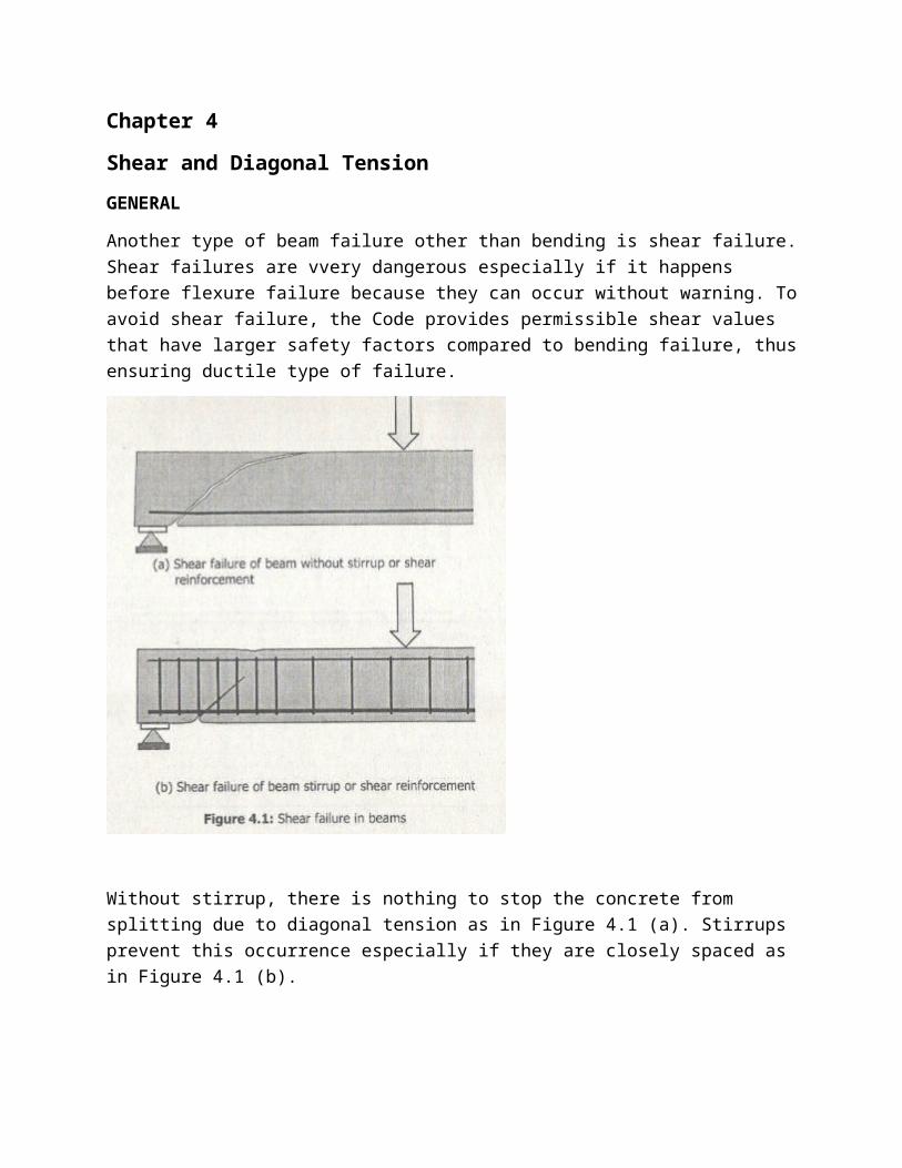
Chapter 4 Shear and Diagonal Tension GENERAL Another type of beam failure other than bending is shear failure. Shear failures are vvery dangerous especially if it happens before flexure failure because they can occur without warning. To avoid shear failure, the Code provides permissible shear values that have larger safety factors compared to bending failure, thus ensuring ductile type of failure. Without stirrup, there is nothing to stop the concrete from splitting due to diagonal tension as in Figure 4.1 (a). Stirrups prevent this occurrence especially if they are closely spaced as in Figure 4.1 (b).
Transcript of MATH: Reinforced Concrete Design 02
Chapter 4
Shear and Diagonal TensionGENERAL
Another type of beam failure other than bending is shear failure.Shear failures are vvery dangerous especially if it happens before flexure failure because they can occur without warning. Toavoid shear failure, the Code provides permissible shear values that have larger safety factors compared to bending failure, thusensuring ductile type of failure.
Without stirrup, there is nothing to stop the concrete from splitting due to diagonal tension as in Figure 4.1 (a). Stirrups prevent this occurrence especially if they are closely spaced as in Figure 4.1 (b).
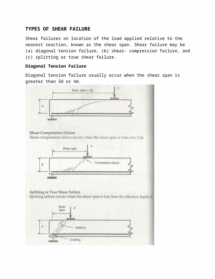
TYPES OF SHEAR FAILUREShear failures on location of the load applied relative to the nearest reaction, known as the shear span. Shear failure may be (a) diagonal tension failure, (b) shear- compression failure, and(c) splitting or true shear failure.
Diagonal Tension Failure
Diagonal tension failure usually occur when the shear span is greater than 3d or 4d.

BASIC CODE REQUIREMENTS
The basic Code requirement (Sec. 5.11.1) on shear strength is that the factored shear force Vu shall be equal or less than the design shear ø Vnρ or
Vu ≤ ø Vn Eq. 4 - 1
Where ø = 0.85 and
Vn = Vc + Vs Eq. 4 - 2For a beam with no web reinforcement, the shearing force that causes the first diagonal cracking can be taken as the shear capacity of the beam. For a beam that does contain web reinforcement, the concrete is assumed to carry a constant amount of shear force Vcρ and the web reinforcement need only be designed for the shear force Vs in excess ofthat carried by the concrete, or
Vs = Vn - Vc Eq. 4 - 3
The amount of shear Vc that can be carried by concrete at ultimate is at least equal to the amount of shear that would cause diagonal cracking. The amount of shear provided by the reinforcement Vs is calculated using the truss analogy with a 45° inclination of the diagonal members.
SHEAR STRENGTH PROVIDED BY CONCRETE, VC FOR NON PRESTRESSING MEMBERS
5.11.3.1 Shear strength Vc shall be computed by provisons of Sec. 5.11.3.1.1 through 5.11.3.1.4, unless a more detailed calculation is made in accordance with Sec. 5.11.3.2.
5.11.3.1.1 For members subject to shear and flexure only.
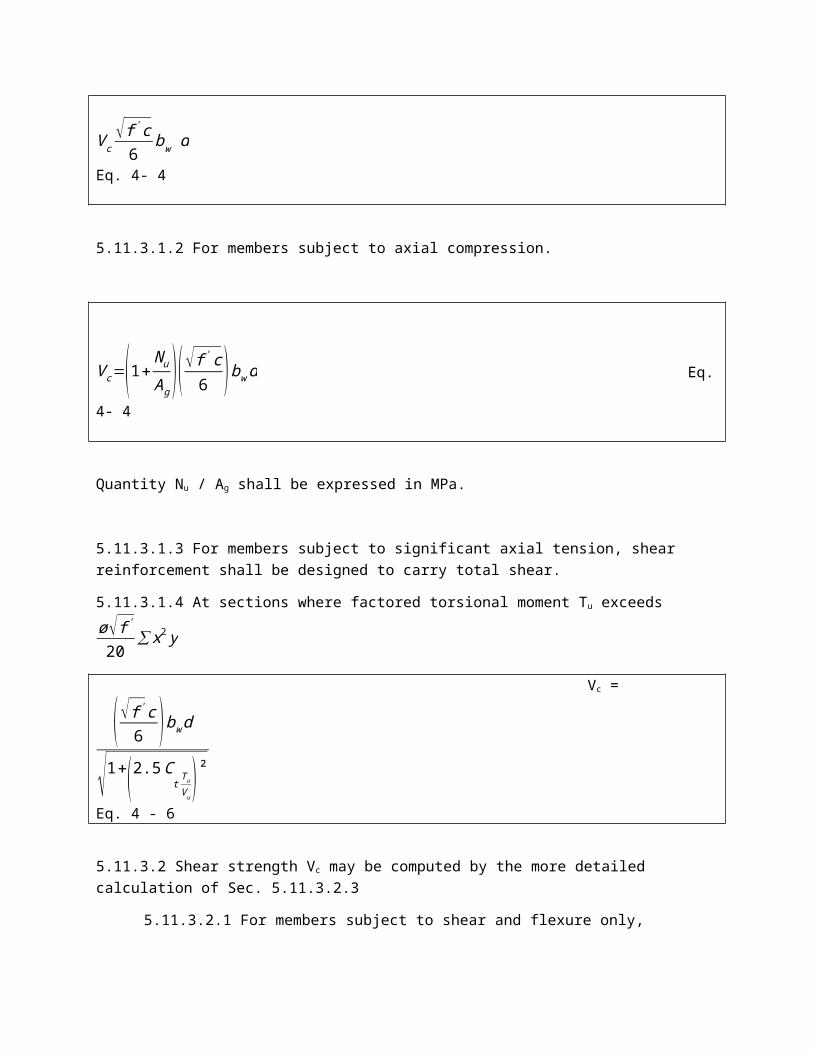
Vc√f'c6
bw d
Eq. 4- 4
5.11.3.1.2 For members subject to axial compression.
Vc=(1+NuAg )(√f
'c6 )bwd Eq.
4- 4
Quantity Nu / Ag shall be expressed in MPa.
5.11.3.1.3 For members subject to significant axial tension, shear reinforcement shall be designed to carry total shear.
5.11.3.1.4 At sections where factored torsional moment Tu exceedsø√f'
20∑x2y
Vc =
(√f'c6 )bwd
√1+(2.5Ct Tu
Vu)²
Eq. 4 - 6
5.11.3.2 Shear strength Vc may be computed by the more detailed calculation of Sec. 5.11.3.2.3
5.11.3.2.1 For members subject to shear and flexure only,

Vc [(√f'c+120ρwTu
Mu )÷7 ]= bwd
Eq. 4 - 7
But not greater than 0.3 √f'c bw d. Quantity Vu d/Mu shall not be taken greater than 1.0 in computing Vc by Eq. 4 – 7, where Mu is factored moment occurring simultaneously with Vu at section considered.
5.11.3.2.2 For members subject to axial compression, Eq. 4 – 7 may be used to compute Vc with Mm substituted for Mu and Vu d/Mu not then limited to 1.0, where
Mm = Mu – Nu
4h−d8
Eq. 4 - 8
However, Vc shall not be taken greater than
Vc =
0.3 √f'cbwd√1+0.3Nu
Ag
Eq. 4 - 9
Quantity Nu/Ag shall be expressed in MPa. When Mm as computed by Eq. 4 –8 is negative, Vcρ shall be computed by Eq. 4 – 9.
5.11.3.2.3 For members subject to significant axial tension,
Vc =
(1+0.3NuAg ) √f'c
6bwd Eq. 4
- 10
Where Nu is negative for tension. Quantity Nu/Ag shall be expressed in MPa.

In the foregoing √f'c is in MPa and shall not exceed 0.7 MPa except asprovided by Section 5.11.1.2.1, bw is the width of th web in mm, d is the effective depth in mm, and ρw= As/bwd.
SHEAR STRENGTH PROVIDED BY REINFORCEMENT
When factored shear force Vu exceeds strength øVcρ shear reinforcement shall be provided to satisfy Eq. 4 – 1 and Eq. 4 – 2. The shear strength provided by the stirrups is given by the following but shall not be taken greater than 0.3 √f'c bw d
(a) When shear reinforcement perpendicular to axis of member is used,
Vs = Avfyds
Eq. 4 - 11
Where Av is the area of shear reinforcement within a distance s.
Av = 2Ab for U stirrup (see figure 4.2)
(b) When inclined stirrups used as shear reinforcement,
Vs =Avfy (sinαcosα )d
s Eq.
4 - 12
Where α is the angle between inclined stirrups and longitudinal axis of member.
(c) When shear reinforcement consist of a single bar or a singlegroup of parallel bars, all bent up at the same distance from the support,
Vs =
Avfysinα≤14 √f'c bwd Eq. 4 -
13
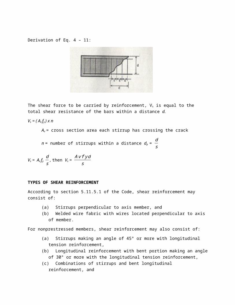
Derivation of Eq. 4 – 11:
The shear force to be carried by reinforcement, Vs is equal to the total shear resistance of the bars within a distance d.
Vs = ( Av fy ) x n
Av = cross section area each stirrup has crossing the crack
n = number of stirrups within a distance dρ = ds
Vs = Av fy ds , then Vs =
Avfyds
TYPES OF SHEAR REINFORCEMENT
According to section 5.11.5.1 of the Code, shear reinforcement may consist of:
(a) Stirrups perpendicular to axis member, and(b) Welded wire fabric with wires located perpendicular to axis
of member.
For nonprestressed members, shear reinforcement may also consist of:
(a) Stirrups making an angle of 45° or more with longitudinal tension reinforcement,
(b) Longitudinal reinforcement with bent portion making an angleof 30° or more with the longitudinal tension reinforcement,
(c) Combinations of stirrups and bent longitudinal reinforcement, and

(d) Spirals.
DESIGN YIELD STRENGTH OF STIRRUPS
According the Section 5.11.5.2 the design yield strength of shear reinforcement shall not exceed 415 MPa. Stirrups and other bars or wires used as shear reinforcement shall extend to a distance d from extreme compression fiber and shall be anchored at both ends to develop the design yield strength of reinforcement.
SPACING LIMITS OF SHEAR REINFORCEMENT, S
According to Section 5.11.5.4 of the Code, the spacing s of shear reinforcement placed perpendicular to axis of members shall not exceedd/2 in nonprestressed members and (3/4)h in prestressed members, nor 600 mm. Inclined stirrups and bent longitudinal reinforcement shall beso spaced that every 45 ° line, extending toward the reaction from middepth of member d/2 to longitudinal tension reinforcement, shall becrossed by at least one line of shear reinforcement.
When Vs exceed 0.3 √f'c bw d maximum spacing given by the above limits shall be reduced by one-half.
MINIMUM SHEAR REINFORCEMENT

According to Section 5.11.5.5 of the code, a minimum area of shear reinforcement shall be provided in all reinforced concrete flexural members (prestressed and nonprestressed) where factored shear force Vu exceeds one-half the shear strength provided by concrete øVc , except:
(a) Slabs and footings(b) Concrete joist construction defined by Sec 5.8.11(c) Beams with total depth not greater than 250 mm, 2-1/2 timmes
thickness of flange, or ½ the width of the web, whichever is the greatest.
This minimum shear reinforcement requirement may not be required if shown by test that required nominal flexural and shear strengths can be developed when shear reinforcement is omitted. Such tests shall simulate effects of different settlement, creep, shrinkage, and temperature change, based on a realistic assessment of such effects occurring in service.
Where shear reinforcement is required, the minimum area of shear reinforcement shall be computed by
Av = bws3fy
Eq. 4 - 14
Where bw and s are in millimetres.
CRITICAL SECTION FOR BEAM SHEAR
According to section 5.11.1.3 of NSCP, the maximum factored shear force Vu at supports may be computed in accordance with the following conditions provided that:
(a) The support reaction, in direction of the applied shear, introduces compression into the end regions of member, and
(b) No concentrated load occurs between the face of the support and the location of the critical section.
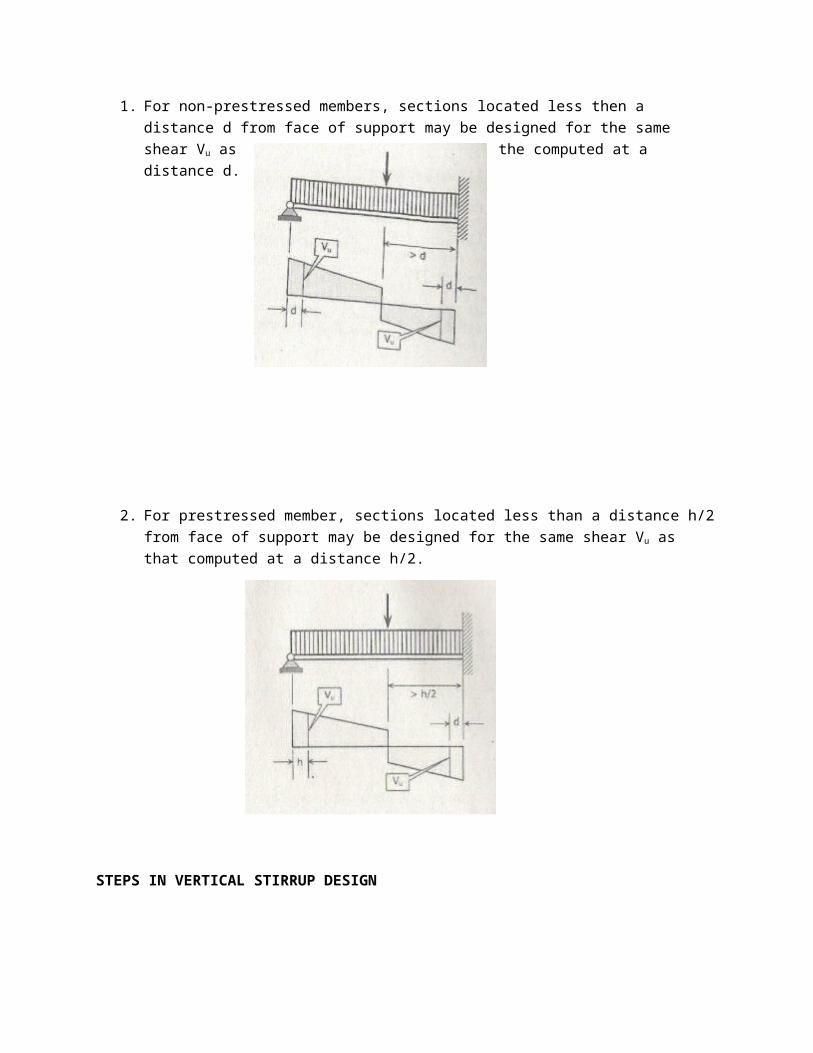
1. For non-prestressed members, sections located less then a distance d from face of support may be designed for the same shear Vu as the computed at a distance d.
2. For prestressed member, sections located less than a distance h/2from face of support may be designed for the same shear Vu as that computed at a distance h/2.
STEPS IN VERTICAL STIRRUP DESIGN

I. Calculate the factored shear force Vu at critical sections defined in Page 132, or at any section you want the spacing tobe determined.
II. Calculate the shear strength provided by concrete, Vcρ IV. Calculate the shear strength Vs to be provided by the stirrup.
1. Vn = Vu / ø2. Vs = Vn – Vc = Vu / ø - Vc
If Vs ≤ 23 √f
'c bw d, proceed to step V
If Vs > 23 √f
'c bw d, adjust the size of the beam
V. Spacing of stirrups:
Spacing, s = Avfyd
Vs ; See figure 4.2 in Page 131 for the value
of Av.If s < 25mm, increase the value of Av by either using a bigger bar size or adding more shear area.
Maximum spacing s:
(a) When Vs ≤ 13 √f
'c bw d, smax= d/2 or 600 mm
(b) When Vs > 13 √f
'c bw d, smax= d/4 or 300 mm
VI. If Vu < ø Vc but Vu > ½ øVc:
Minimum area of stirrup, Av = bws3fy
(Sect. 5.11.5.5.3)Where s = d/2 or 600mm (whichever is smaller)
Problem 4.4
A simply supported reinforced concrete beam with a width B of 230 mm and an effective depth d of 500 mm has a span of 6 m. The beam carries
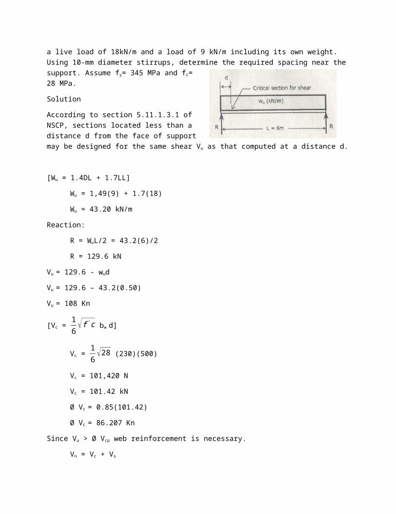
a live load of 18kN/m and a load of 9 kN/m including its own weight. Using 10-mm diameter stirrups, determine the required spacing near thesupport. Assume fy= 345 MPa and fc=28 MPa.
Solution
According to section 5.11.1.3.1 ofNSCP, sections located less than adistance d from the face of supportmay be designed for the same shear Vu as that computed at a distance d.
[Wu = 1.4DL + 1.7LL]
Wu = 1,49(9) + 1.7(18)
Wu = 43.20 kN/m
Reaction:
R = WuL/2 = 43.2(6)/2
R = 129.6 kN
Vu = 129.6 - wud
Vu = 129.6 – 43.2(0.50)
Vu = 108 Kn
[Vc = 16 √f'c bw d]
Vc = 16 √28 (230)(500)
Vc = 101,420 N
Vc = 101.42 kN
Ø Vc = 0.85(101.42)
Ø Vc = 86.207 Kn
Since Vu > Ø Vcρ web reinforcement is necessary.
Vn = Vc + Vs
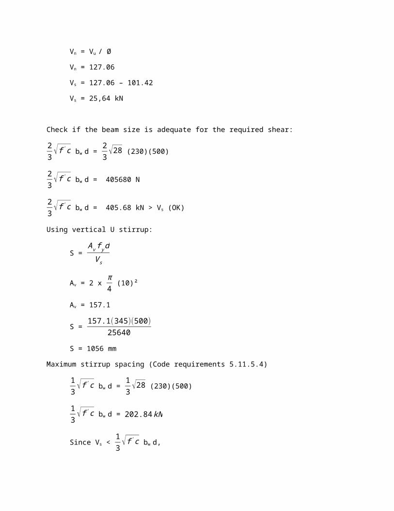
Vn = Vu / Ø
Vn = 127.06
Vs = 127.06 – 101.42
Vs = 25,64 kN
Check if the beam size is adequate for the required shear:
23 √f'c bw d =
23 √28 (230)(500)
23 √f'c bw d = 405680 N
23 √f'c bw d = 405.68 kN > Vs (OK)
Using vertical U stirrup:
S = AvfydVs
Av = 2 x π4 (10)²
Av = 157.1
S = 157.1(345)(500)25640
S = 1056 mm
Maximum stirrup spacing (Code requirements 5.11.5.4)
13 √f'c bw d =
13 √28 (230)(500)
13 √f'c bw d = 202.84kN
Since Vs < 13 √f'c bw d,

Smax = d/2 = 500/2 = 250 mm or
Smax = 600 mm
Therefore; use s = 250 mm