REGLO Analog - Betriebsanleitung - Wie-Tec
32
FRANÇAIS ENGLISH DEUTSCH Schlauchpumpe REGLO Analog 2 Kanäle ISM830 6 Rollen ISM829 8 Rollen ISM795 12 Rollen 4 Kanäle ISM828 6 Rollen ISM827 8 Rollen ISM796 12 Rollen Tubing pump REGLO Analog 2 channels ISM830 6 rollers ISM829 8 rollers ISM795 12 rollers 4 channels ISM828 6 rollers ISM827 8 rollers ISM796 12 rollers Pompe péristaltique REGLO Analog 2 canaux ISM830 6 galets ISM829 8 galets ISM795 12 galets 4 canaux ISM828 6 galets ISM827 8 galets ISM796 12 galets Operating Manual Mode d‘emploi Betriebsanleitung
-
Upload
khangminh22 -
Category
Documents
-
view
1 -
download
0
Transcript of REGLO Analog - Betriebsanleitung - Wie-Tec

FRANÇAISENGLISHDEUTSCH
Schlauchpumpe
REGLO Analog
2 KanäleISM830 6 RollenISM829 8 RollenISM795 12 Rollen
4 KanäleISM828 6 RollenISM827 8 RollenISM796 12 Rollen
Tubing pump
REGLO Analog
2 channelsISM830 6 rollersISM829 8 rollersISM795 12 rollers
4 channelsISM828 6 rollersISM827 8 rollersISM796 12 rollers
Pompe péristaltique
REGLO Analog
2 canauxISM830 6 galetsISM829 8 galetsISM795 12 galets
4 canauxISM828 6 galetsISM827 8 galetsISM796 12 galets
Operating Manual Mode d‘emploiBetriebsanleitung

Contents
Safety precautions 4
Warranty terms 7
Product 8
Rear panel 10
Mains voltage 10 Voltage setting 11 Changing the fuses 11
Inserting the tubing 12
Starting the pump 13
Overload protector 15 Pumping against pressure 16
When the pump is not in use 17
Run-in period for tubing 17 Tubing life 18
Sommaire
Mesures de précaution 4
Conditions de garantie 7
Produit 8
Panneau arrière 10
Tension d’alimentation 10 Commutation de la tension 11 Remplacement des fusibles 11
Insertion des tubes 12
Mise en service 13
Protection en cas de surcharge 15 Pompage sous pression 16
Durant les tempes d‘arrêt 17
Durée de rodage des tubes 17 Durée de vie des tubes 18
Inhaltsverzeichnis
Sicherheitsvorkehrungen 4
Garantiebestimmungen 7
Produkt 8
Geräterückwand 10
Netzspannung 10 Spannungswechsel 11 Sicherungswechsel 11
Schläuche einlegen 12
Inbetriebnahme 13
Überlastschutz 15 Pumpen gegen Druck 16
Wenn die Pumpe ruht 17
Einlaufzeit der Schläuche 17 Lebensdauer der Schläuche 18
REGLO ANALOG, 14-026, REV. C 2 of 32

Contents
Analog interface 19
Accessories 23
Flow rates per channel 25
Maintenance 28
Replacement parts 28 Repairs 29 Disposal 29
Technical specifications 30
Sommaire
Interface analogique 19
Accessoires 23
Débits par canal 25
Entretien 28
Pièces détachées 28 Réparation 29 Mise en rebut 29
Spécifications techniques 30
Inhaltsverzeichnis
Analogschnittstelle 19
Zubehör 23
Fließraten pro Kanal 25
Unterhalt 28
Ersatzteile 28 Reparaturen 29 Entsorgung 29
Technische Daten 30
REGLO ANALOG, 14-026, REV. C 3 of 32
Safety precautions
ISMATEC® Pumps are designed for pumping applications in laboratories and industry. As such, it is assumed that Good Laboratory Practice (GLP) and our following recommendations will be observed:
XX The circuit between mains supply and pump has to be connected to earth ground.
XX The pump must not be operated outside the designed operating and environmental conditions.
XX The pump must not be used:
– for medical applications on human beings
– in explosion proof chambers or in the presence of flammable gases or fumes
XX The pump must be switched OFF when pump-heads, cassettes or tubing are inserted or changed.
Mesures de précaution
Les pompes ISMATEC® sont prévues pour l’usage en laboratoire et dans l’industrie. Dès lors, nous présumons que les utilisateurs emploient nos appareils selon les règles de l’art (normes GLP) et conformément à nos recommandations:
XX Le circuit électrique entre le réseau et la pompe doit être mis à la terre.
XX La pompe ne doit être mise en opération que dans le cadre des conditions de fonctionnement et d’environnement prescrites.
XX La pompe ne doit pas être utilisée:
– pour des applications médicales sur des êtres humains,
– dans des locaux protégés contre les explosions ou en présence de gaz et vapeurs inflammables.
XX Ne procéder au montage ou à l’échange de têtes de pompes, tubes ou cassettes que lorsque la pompe est éteinte.
Sicherheitsvorkehrungen
Die ISMATEC® Pumpen sind für För-derzwecke in Labors und der Industrie vorgesehen. Wir setzen voraus, dass die GLP-Richtlinien (Gute Laborpraxis) sowie die nachstehenden Empfehlungen befolgt werden:
XX Der Stromkreis zwischen Netz und Pumpe muss geerdet sein.
XX Die Pumpe darf nur innerhalb der vorgegebenen Betriebs- und Umgebungsbedingungen betrieben werden.
XX Die Pumpe darf nicht eingesetzt werden:
– für medizinische Anwendungen am Menschen
– in ex-geschützten Räumen oder in Gegenwart von entflamm-baren Gasen und Dämpfen.
XX Ein Pumpenkopf-, Schlauch- oder Kassettenwechsel darf nur bei ausgeschalteter Pumpe durchgeführt werden.
HinweisWir empfehlen, diese Betriebsanleitung genau durchzulesen.
Beim Betrieb einer Pumpe sind gewisse Gefahren nicht auszu-schliessen.
ISMATEC® haftet nicht für Schäden, die durch den Einsatz einer ISMATEC® -Pumpe entstehen.
Der Umgang mit Chemikalien liegt nicht im Verantwortungsbereich der ISMATEC®.
Please noteWe recommend that you read this operating manual carefully.
When operating a pump, certain hazards cannot be excluded.
ISMATEC® does not take liability for any damage resulting from the use of an ISMATEC® pump.
ISMATEC® does not admit responsibility for the handling of chemicals.
REGLO ANALOG, 14-026, REV. C 4 of 32

Sicherheitsvorkehrungen
XX Je nach Material und Druckbe-dingungen haben Schläuche eine gewisse Gasdurchlässigkeit und können sich statisch aufladen. Wir warnen vor möglichen Gefahren, falls Schläuche in ex-geschützten Räume verlegt werden.
XX Pumpenköpfe haben rotierende Teile. Sie dürfen nur mit komplett eingeklinkten Kassetten betrieben werden.
XX Manipulieren Sie nicht am Pumpenkopf, bevor die Pumpe ausgeschaltet und vom Netz getrennt ist.
XX Achten Sie besonders darauf, dass keine Körperteile wie Finger, Haare, usw. oder Schmuck sowie lose Gegenstände wie Kabel, Schläuche, usw. in den rotierenden Pumpenkopf gelangen.
Safety precautions
XX The permeability of tubing depends on the material used and pressure conditions. Tubing can also become electrostatically charged. Please be aware of possible hazards when routing tubing in explosion- proof chambers.
XX Pump-heads consist of rotating parts. Therefore, the pump must not be operated before the cassettes are fully snapped-in.
XX Do not manipulate the pump-head before the pump is switched OFF and disconnected from the mains supply.
XX Be particularly cautious that no parts of your body such as fingers, long hair, etc. or jewellery, or loose objects such as cables or tubing, etc. can be trapped by the rotating pump head.
Mesures de précaution
XX La perméabilité des tubes dépend des matériaux utilisés et des conditions de pression. Les tubes peuvent également se charger d’électricité statique. Soyez bien conscients des risques inhérents à l’installation de tubes dans des locaux protégés contre les explosions.
XX Les têtes de pompes sont constituées de pièces rotatives. La pompe ne doit donc pas être mise en service avant que les cassettes ne soient entièrement introduites.
XX Ne manipulez jamais la tête de pompe avant que la pompe n’ait été mise hors service et déconnectée du réseau électrique.
XX Veillez tout particulièrement à ce qu’aucune partie de votre corps comme des doigts, des cheveux longs, etc. ou encore des bijoux ou des objets isolés tels que des câbles ou des tubes ne puissent être entraînés par le rotor rotatif.
RemarqueNous recommandons de lire attentivement le présent mode d’emploi.
Il n’est pas possible d’exclure certains risques en cas d’utilisation d’une pompe.
ISMATEC® décline toute responsabilité pour tout dommage résultant de l’utilisation d’une pompe ISMATEC®.
ISMATEC® décline toute responsabilité pour tout dommage résultant de l’emploi de produits chimiques.
Achtung Bei beruhrung des rotierenden pumpenkopfes besteht quetsch/verletzungsgefahr.
Caution Rotating pumphead creates a pinch and crush hazard.
Attention Un risque de pincement ou de blessure existe lors du contact arec la téte de pompe.
REGLO ANALOG, 14-026, REV. C 5 of 32
Sicherheitsvorkehrungen
XX Falls wegen Schlauchbruchs durch auslaufende Medien Schäden verursacht werden können, sind vor Inbetriebnahme die notwendigen Sicherheitsvorkehrungen zu treffen.
XX Es dürfen nur neue Sicherungen, die den Angaben auf Seite 10 entspre-chen, verwendet werden.
XX Der Sicherungshalter darf nicht überbrückt werden.
XX Das Gehäuse darf während des Betriebes nicht geöffnet bzw. abge-nommen werden.
XX Reparaturen dürfen nur von einer Fachkraft ausgeführt werden, die sich der möglichen Gefahren bewusst ist.
XX Durch Kunden bzw. Drittpersonen ausgeführte Arbeiten am und im Gerät erfolgen auf eigene Verant-wortung.
Safety precautions
XX Tubing can tear and burst during operation. If this could cause damage, the necessary safety measures based on the specific situation must be taken.
XX Only new fuses, according to the specifications stated on Page 10 in this manual, must be used.
XX The fuse-holder must not be short-circuited.
XX Do not open or remove the housing while the pump is operating.
XX Repairs may only be carried out by a skilled person who is aware of the hazard involved.
XX For service and repairs carried out by the customer or by third-party companies, ISMATEC® denies any responsibility.
Mesures de précaution
XX En cours d’exploitation, les tubes peuvent se déchirer ou même éclater. Si cela pouvait causer des dommages, il faut prendre les mesures de sécurité adaptées à la situation spécifique.
XX N’utilisez que des fusibles neufs correspondant aux spécifications indiquées en Page 10 du présent manuel.
XX Le porte-fusible ne doit pas être court-circuité.
XX N’ouvrez pas et n’enlevez pas le boîtier pendant que la pompe fonctionne.
XX Les réparations ne doivent être effectuées que par une personne connaissant parfaitement les risques liés à de tels travaux.
XX ISMATEC® décline toute responsa-bilité pour les dommages découlant de travaux d’entretien et de répara-tion assurés par le client ou par de tierces personnes.
Achtung Gefahr durch elektrischen schlag.
CautionRisk of electrical shock.
Attention Risque de choc electrique.
Protective RedeMasse.
Protective Earth Ground.
Terre de protectionTerre.
REGLO ANALOG, 14-026, REV. C 6 of 32

Garantiebestimmungen
Wir garantieren eine einwandfreie Funktion unserer Geräte, sofern diese sachgemäß und nach den Richtlinien unserer Betriebsanleitung angeschlossen und bedient werden. Sofern nachweislich Herstell- oder Material-fehler vorliegen, werden die fehlerhaften Teile nach unserer Wahl kostenlos in Stand gesetzt oder ersetzt.
Die Rücksendung hat in der Original- oder einer gleichwertigen Verpackung zu erfolgen. Durch Inanspruchnahme einer Garantieleistung wird die Garantiezeit nicht beeinflusst. Weitergehende Forderungen sind ausgeschlossen. Frachtkosten gehen zu Lasten des Kunden.
Unsere Garantie erlischt, wenn:XX das Gerät unsachgemäß bedient oder zweck-entfremdet wird
XX am Gerät Eingriffe oder Veränderungen vorgenommen werden
XX ein für das Gerät unangemessener Standort gewählt wird
XX das Gerät umwelt- und elektrospezifisch unter Bedingungen eingesetzt wird, für die es nicht vorgesehen ist
XX Software, Hardware, Zubehör oder Ver-brauchsmaterial eingesetzt wird, welches nicht unseren Angaben entspricht.
Warranty terms
ISMATEC® warrants the perfect functioning of our products, provided they have been installed and operated correctly, according to our operating instructions. If production or material faults can be proved, the defective parts will be repaired or replaced free of charge at our discretion.
A pump must be returned in the original ISMATEC® packaging or in packaging of equal quality. The duration of the warranty is not affected by making a claim for warranty service. Further claims are excluded. Shipping costs are charged to the customer.
Our warranty becomes invalid in the case of:XX improper operation by the user, or if the pump is diverted from its proper use
XX unauthorized modification or misuse by the user or by a third party
XX improper site preparation and maintenance
XX operation outside of the environmental and electrical specifications for the product
XX use of third-party software, hardware, accessories or consumables purchased by the user and which do not comply with our specifications.
Conditions de garantie
Nous garantissons un fonctionnement irréprochable de nos appareils sous conditions d’une mise en service compétente et correspondant à nos normes et notices d’emploi. Si un défaut de fabrication ou de matériau peut être prouvé, les pièces défectueuses seront réparées ou remplacées gratuitement.
Le renvoi doit être effectué dans l’emballage d’origine ou similaire. La durée de la garantie n’est pas touchée par le fait que le client demande une prestation de garantie. Toute autre prétention est exclue. Les frais d’expédition sont facturés au client.
Notre garantie perd sa validité dans les cas suivants:XX manipulation inadéquate par l’utilisateur ou utilisation de l’appareil à des fins auxquelles il n’est pas destinéXX modifications non autorisées ou mauvais emploi par l’utilisateur ou un tiersXX préparation et entretien inadéquats de l’emplacement de l’appareilXX utilisation de la pompe en dehors de l’environnement et des spécifications élec-triques définies pour le produitXX utilisation de matériel, de logiciels, d’interfaces ou de produits de consomma-tion tiers achetés par l’utilisateur et qui ne satisfont pas à nos spécifications.
GarantieAuf allen von ISMATEC® hergestellten Erzeugnissen ab Lieferdatum: 2 Jahre
Übrige Teile, ohne Verschleißmaterial: 1 Jahr
Wir garantieren eine einwandfreie Funktion unserer Geräte, sofern diese sachgemäß und nach den Richtlinien unserer Betriebsanleitung angeschlossen und bedient werden.
WarrantyFor all parts manufactured by ISMATEC® from date of delivery: 2 years
All other parts, excluding consumables: 1 year
We warrant the perfect functioning of our products, provided they have been installed and operated correctly according to our operating instructions.
GarantiePour toutes les pièces fabriquées par ISMATEC® à partir de la date de livraison 2 ans
Autres pièces, sauf les pièces d’usure 1 an
Nous garantissons un fonctionnement impeccable de nos appareils sous conditions d’une mise en service compétente et correspondant à nos normes et notices d’emploi.
REGLO ANALOG, 14-026, REV. C 7 of 32

Produkt
Die Schlauchpumpe REGLO Analog ist mit 2 oder 4 Schlauchkanälen und 6, 8 oder 12 Pumpenrollen erhältlich.
REGLO Analog 2 Kanal(Drehzahl 3.2–160 min–1) Bestell- Typ Fließraten Nummer ml/min
ISM830 MS-2/06 0.005–68 ISM829 MS-2/08 0.004–57 ISM795 MS-2/12 0.003–38
REGLO Analog 4 Kanal (Drehzahl 2.0–100 min–1) Bestell- Typ Fließraten Nummer ml/min
ISM828 MS-4/06 0.003–43 ISM827 MS-4/08 0.003–35 ISM796 MS-4/12 0.002–24
Product
The REGLO Analog tubing pump is available with 2 or 4 tube channels and 6, 8 or 12 pump rollers.
REGLO Analog 2 channels(Speed 3.2–160 rpm) Order Type Flow Rates Number ml/min
ISM830 MS-2/06 0.005–68 ISM829 MS-2/08 0.004–57 ISM795 MS-2/12 0.003–38
REGLO Analog 4 channels(Speed 2.0–100 rpm) Order Type Flow rates Number ml/min
ISM828 MS-4/06 0.003–43 ISM827 MS-4/08 0.003–35 ISM796 MS-4/12 0.002–24
Produit
La pompe péristaltique REGLO Analog comporte 2 ou 4 canaux et 6, 8 ou 12 galets.
REGLO Analog 2 canaux(3.2–160 tours/min) No. de Type Débits commande ml/min
ISM830 MS-2/06 0.005–68 ISM829 MS-2/08 0.004–57 ISM795 MS-2/12 0.003–38
REGLO Analog 4 canaux(2.0–100 tours/min) No. de Type Débits commande ml/min
ISM828 MS-4/06 0.003–43 ISM827 MS-4/08 0.003–3 ISM796 MS-4/12 0.002–24
REGLO ANALOG, 14-026, REV. C 8 of 32
Produkt
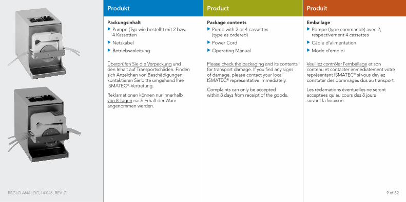
PackungsinhaltXX Pumpe (Typ wie bestellt) mit 2 bzw. 4 Kassetten
XX Netzkabel
XX Betriebsanleitung
Überprüfen Sie die Verpackung und den Inhalt auf Transportschäden. Finden sich Anzeichen von Beschädigungen, kontaktieren Sie bitte umgehend Ihre ISMATEC®-Vertretung.
Reklamationen können nur innerhalb von 8 Tagen nach Erhalt der Ware angenommen werden.
Product
Package contentsXX Pump with 2 or 4 cassettes (type as ordered)
XX Power Cord
XX Operating Manual
Please check the packaging and its contents for transport damage. If you find any signs of damage, please contact your local ISMATEC® representative immediately.
Complaints can only be accepted within 8 days from receipt of the goods.
Produit
EmballageXX Pompe (type commandé) avec 2, respectivement 4 cassettes
XX Câble d’alimentation
XX Mode d’emploi
Veuillez contrôler l’emballage et son contenu et contacter immédiatement votre représentant ISMATEC® si vous deviez constater des dommages dus au transport.
Les réclamations éventuelles ne seront acceptées qu’au cours des 8 jours suivant la livraison.
REGLO ANALOG, 14-026, REV. C 9 of 32

Fenster für Spannungswahlanzeige Window for voltage setting Fenêtre de réglage de la tension
1 3 2
Geräterückwand
1. Analogschnittstelle
2. Netzbuchse
3. Sicherungshalter mit Spannungs-wähler 115/230V
Rear panel
1. Analog Interface
2. Mains Socket
3. Fuse-Holder with Voltage Selector 115/230V
Panneau arrière
1. Interface analogique
2. Prise d‘alimentation
3. Porte-fusibles avec sélecteur de tension 115/230V
Netzanschluss Sicherung
220–240 VAC 110–120 VAC
2 x T500mA/250V 2 x T500mA/250V
Mains voltage Fuse rating
220–240 VAC 110–120 VAC
2 x T500mA/250V 2 x T500mA/250V
Tension d‘alimentation Fusibles de sécurité
220–240 VCA 110–120 VCA
2 x T500mA/250V 2 x T500mA/250V
! Steckdose/NetzkabelVerwenden Sie ausschließlich das mitgelieferte Originalkabel.
Die Steckdose muss geerdet sein. (Schutzleiterkontakt).
! Vor der InbetriebnahmePrüfen Sie, ob die Spannungswahl-anzeige im Fenster des Sicherungshalters der Netzspannung Ihres Landes entspricht. Wenn nötig, muss die Einstellung geändert und die 2 Sicherungen müssen ausgetauscht werden.
! Socket/Power cordUse exclusively the originally supplied power cord.
The socket must be connected to earth ground.
! Before starting-upCheck that the voltage setting visible in the window of the fuse-holder complies with the local mains voltage. If necessary, the voltage setting must be changed and the 2 fuses must be replaced.
! Prise/câble d’alimentationN’employer que le câble d’alimentation d’origine.
La prise doit être raccordée à la terre (contact conducteur de protection).
! Avant la mise en serviceContrôlez si la tension indiquée dans la fenêtre du porte-fusibles correspond à la tension de votre réseau local. Si nécessaire, modifiez la tension et remplacez les deux fusibles correspondants.
Netzspannung Mains voltage Tension d‘alimentation
REGLO ANALOG, 14-026, REV. C 10 of 32
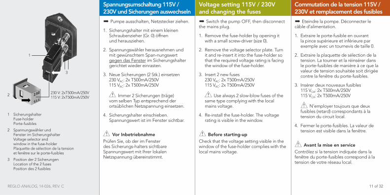
1 Sicherungshalter Fuse-holder Porte-fusibles
2 Spannungswähler und Fenster im Sicherungshalter Voltage selector and window in the fuse-holder Plaquette de sélection de la tension et fenêtre sur le porte-fusibles
3 Position der 2 Sicherungen Location of the 2 fuses Position des 2 fusibles
Voltage setting 115V / 230V and changing the fuses
X� Switch the pump OFF, then disconnect the mains plug.
1. Remove the fuse-holder by opening it with a small screw-driver (size 0).
2. Remove the voltage selector plate. Turn it and re-insert it into the fuse-holder so that the required voltage rating is facing the window of the fuse-holder.
3. Insert 2 new fuses 230 VAC: 2x T500mA/250V 115 VAC: 2x T500mA/250V
! Use always 2 slow-blow fuses of the same type complying with the local mains voltage.
4. Re-install the fuse-holder. The voltage rating is visible in the window.
! Before starting-upCheck that the voltage setting visible in the window of the fuse-holder complies with the local mains voltage.
Commutation de la tension 115V / 230V et remplacement des fusibles
X� Eteindre la pompe. Déconnecter le câble d’alimentation.
1. Extraire le porte-fusible en ouvrant la pince supérieure et inférieure par exemple avec un tournevis de taille 0.
2. Extraire la plaquette de sélection de la tension. La tourner et la réinsérer dans le porte-fusibles de manière à ce que la valeur de tension souhaitée soit dirigée contre la fenêtre du porte-fusibles.
3. Insérer deux nouveaux fusibles 115 VCA: 2x T500mA/250V 115 VCA: 2x T500mA/250V
! N’employer toujours que deux fusibles (retard) correspondants à la tension du circuit local.
4. Fermer le porte-fusibles. La valeur de tension est visible dans la fenêtre.
! Avant la mise en serviceContrôlez si la tension indiquée dans la fenêtre du porte-fusibles correspond à la tension de votre réseau local.
Spannungsumschaltung 115V / 230V und Sicherungen auswechseln
X� Pumpe ausschalten, Netzstecker ziehen.
1. Sicherungshalter mit einem kleinen Schraubenzieher (Gr. 0) öffnen und herausziehen.
2. Spannungswähler herausnehmen und mit gewünschtem Span-nungswert gegen das Fenster im Sicherungshalter gerichtet wieder einrasten.
3. Neue Sicherungen (2 Stk.) einsetzen 230 VAC: 2x T500mA/250V 115 VAC: 2x T500mA/250V
! Immer 2 Sicherungen (träge) vom selben Typ entsprechend der ortsüblichen Netzspannung einsetzen.
4. Sicherungshalter einschieben. Spannungswert ist im Fenster sichtbar.
! Vor InbetriebnahmePrüfen Sie, ob der im Fenster des Sicherungs-halters sichtbare Spannungswert mit Ihrer lokalen Netzspannung übereinstimmt.
230 V: 2xT500mA/250V 115 V: 2xT500mA/250V
1
2
3
REGLO ANALOG, 14-026, REV. C 11 of 32
3
4 5
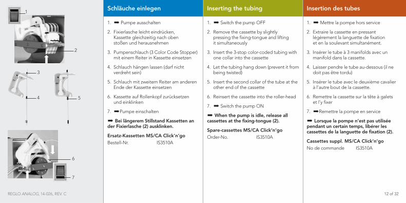
Schläuche einlegen
1. � Pumpe ausschalten
2. Fixierlasche leicht eindrücken, Kassette gleichzeitig nach oben stoßen und herausnehmen
3. Pumpenschlauch (3 Color Code Stopper) mit einem Reiter in Kassette einsetzen
4. Schlauch hängen lassen (darf nicht verdreht sein)
5. Schlauch mit zweitem Reiter am anderen Ende der Kassette einsetzen
6. Kassette auf Rollenkopf zurücksetzen und einklinken
7. �Pumpe einschalten
X� Bei längerem Stillstand Kassetten an der Fixierlasche (2) ausklinken.
Ersatz-Kassetten MS/CA Click‘n‘go Bestell-Nr. IS3510A
Inserting the tubing
1. � Switch the pump OFF
2. Remove the cassette by slightly pressing the fixing-tongue and lifting it simultaneously
3. Insert the 3-stop color-coded tubing with one collar into the cassette
4. Let the tubing hang down (prevent it from being twisted)
5. Insert the second collar of the tube at the other end of the cassette
6. Reinsert the cassette into the roller-head
7. � Switch the pump ON
X� When the pump is idle, release all cassettes at the fixing-tongue (2).
Spare-cassettes MS/CA Click‘n‘go Order-No. IS3510A
Insertion des tubes
1. � Mettre la pompe hors service
2. Extraire la cassette en pressant légèrement la languette de fixation et en la soulevant simultanément.
3. Insérer le tube à 3 manifolds avec un manifold dans la cassette.
4. Laisser pendre le tube au-dessous (il ne doit pas être tordu)
5. Insérer le tube avec le deuxième cavalier à l’autre bout de la cassette.
6. Remettre la cassette sur la tête à galets et l’y fixer
7. �Remettre la pompe en service
X� Lorsque la pompe n’est pas utilisée pendant un certain temps, libérer les cassettes de la languette de fixation (2).
Cassettes suppl. MS/CA Click‘n‘goNo de commande IS3510A
2
1
6
7
REGLO ANALOG, 14-026, REV. C 12 of 32

Inbetriebnahme
XX Netzspannung im Fenster des Sicherungshalters (Geräterückseite) kontrollieren. Allenfalls anpassen, wie auf Seite 10–11 beschrieben.
XX Pumpenschlauch am System anschließen.
XX Pumpe am Netz anschließen.
! Beim Einsatz von neuen Schläu-
chen kann es vorkommen, dass je nach verwendetem Schlauch (Härte und Durchmesser) die Pumpe anfänglich nicht fördert. Trifft dies zu, so empfeh-len wir, die Schläuche zu benetzen und die Pumpe zuerst mit eingesetztem Schlauch ca. 15 – 30 Minuten laufen zu lassen.
X� Bei Applikationen mit hohem Differenzdruck (>1 bar) empfehlen wir, die Kassette mit Anpresshebel einzusetzen.
Starting the pump
XX Check the voltage rating in the window of the fuse-holder (on rear panel). If necessary, change the rating as indicated on Page 10–11.
XX Connect the pump tubing to the system.
XX Connect the pump to the mains.
! When using new tubing for the first
time, it may occur that, depending on the tubing used (hardness and diameter), the pump cannot be primed and, hence, does not deliver the liquid. If that is the case it is recommended that the tubing be wet and run in the pump for 15 to 30 minutes.
X� For applications with a high differen-tial pressure (>1 bar), use of pressure lever cassettes are recommended.
Mise en service
XX Contrôler la tension indiquée dans la fenêtre du porte-fusibles (derrière l’appareil). Si nécessaire, modifier la tension (voir Page 10-11).
XX Connecter le tube de la pompe au système.
XX Raccorder la pompe au réseau et la mettre en service.
! Lors de la première utilisation de
nouveaux tubes, il se peut, suivant le tube utilisé (dureté et diamètre), que l’amorçage du tube ne se fasse pas correctement et que de ce fait aucun liquide ne soit délivré. Si tel est le cas, nous conseillons de remplir les tubes et de faire fonctionner la pompe avec tube inséré pendant 15 à 30 minutes.
X� Pour des applications avec de fortes pressions différentielles (>1 bar), il est conseillé d’utiliser les cassettes avec levier de pression.
REGLO ANALOG, 14-026, REV. C 13 of 32
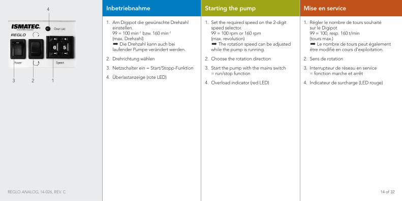
Inbetriebnahme
1. Am Digipot die gewünschte Drehzahl einstellen. 99 = 100 min–1 bzw. 160 min–1 (max. Drehzahl) � Die Drehzahl kann auch bei laufender Pumpe verändert werden.
2. Drehrichtung wählen
3. Netzschalter ein = Start/Stopp-Funktion
4. Überlastanzeige (rote LED)
Starting the pump
1. Set the required speed on the 2-digit speed selector. 99 = 100 rpm or 160 rpm (max. revolution) � The rotation speed can be adjusted while the pump is running.
2. Choose the rotation direction
3. Start the pump with the mains switch = run/stop function
4. Overload indicator (red LED)
Mise en service
1. Régler le nombre de tours souhaité sur le Digipot 99 = 100, resp. 160 t/min (tours max.) � Le nombre de tours peut également être modifié en cours d’exploitation.
2. Sens de rotation
3. Interrupteur de réseau en service = fonction marche et arrêt
4. Indicateur de surcharge (LED rouge)3 2 1
4
REGLO ANALOG, 14-026, REV. C 14 of 32
Overcurrent protector
The REGLO Analog tubing pump features an overload protector.
When an overload condition occurs, an activated overcurrent protector is indicated by the red LED (4) and the pump is stopped.
Whenever this situation occurs, the pump must be switched OFF immediately.
X� Let the pump cool down (it takes about 2 minutes until the pump is ready again). Before the pump is re-started, it is most important to check the reason for the overload (eg. too high differential pressure).
X� Only when the cause of the overload has been detected and the failure corrected accordingly may the pump be started again.
Überlastschutz
Die Pumpe REGLO Analog besitzt eine Überlast-Sicherung.
Bei aktiviertem Überlastschutz leuchtet die rote LED-Anzeige (4) auf und die Pumpe stoppt.
In einer solchen Situation ist die Pumpe sofort mit dem Netzschalter auszuschalten.
X� Abkühlen lassen (es dauert ca. 2 Min., bis die Pumpe wieder betriebsbereit ist). Bevor die Pumpe wieder gestartet wird, ist unbedingt zu prüfen, was die Überlastung der Pumpe verursacht hat (z.B. zu hoher Differenzdruck).
X� Erst nachdem die Ursache für die Überlast behoben worden ist, darf die Pumpe neu gestartet werden.
Protection en cas de surcharge
La pompe REGLO Analog possède une protection de surcharge.
Lors-que le dispositif de protection contre les surcharges est activé, la diode lumi-neuse rouge (4) s’allume et la pompe s‘arrête automatiquement.
Dans une telle situation, la pompe doit étre immédiatement déclenchée.
X� Laisser refroidir (la pompe est à nouveau prête à fonctionner après environ 2 min). Avant d’enclencher à nouveau la pompe, il est indispensable de contrôler ce qui a pu provoquer la surcharge (p. ex. pression différentielle trop élevée).
X� La pompe ne doit être remise en service qu‘après l‘identification et la réparation de la cause de la surcharge.
REGLO ANALOG, 14-026, REV. C 15 of 32

Pumpen gegen Druck
Die REGLO Analog kann im Dauer-betrieb bis max. 1.0 bar Differenzdruck eingesetzt werden (kleine Schlauch-größen und/ oder Kassetten mit Anpresshebel erlauben höhere Drücke).
Im Zweifelsfalle wenden Sie sich bitte an Ihre ISMATEC®-Vertretung.
Pumping against pressure
The REGLO Analog can be used for continuous duty at a differential pressure of 1.0 bar max. for the smaller tube sizes. Pressure lever type cassettes allow operating at higher pressures.
In case of any doubts please contact your ISMATEC® agent.
Pompage sous pression
En exploitation continue, la pompe REGLO Analog peut être employée jusqu’à 1.0 bar de pression différentielle au maximum. Avec de petits diamètres de tube et/ou des cassettes avec levier de pression, il est possible de pomper contre des pressions plus fortes.
En cas de doute, veuillez vous adresser à votre représentant ISMATEC®.
REGLO ANALOG, 14-026, REV. C 16 of 32

When the pump is not in use
When the pump is idle, pressure on the tubing should be released. Releasing the cassette on the right side is sufficient.
This helps to protect the tubing from unnecessary strain and prolongs its service-life.
! Syphoning effectWhen pressure on the tubing is released, the fluid can flow back to the reservoir.
Durant les temps d‘arrêt
En cas d’interruption de l’exploitation, nous recommandons de détendre les tubes. Il suffit de relâcher la cassette sur le côté droit.
Vous ménagez ainsi les tubes et en prolongez la durée de vie.
! Danger de refluxSi le tube n’est plus pincé, le liquide refoulé peut refluer.
Wenn die Pumpe ruht
Wir empfehlen, bei Betriebsunter-brüchen die Schläuche zu entspannen. Es genügt, wenn die Kassette rechts ausgeklinkt wird.
Sie schonen damit die Schläuche und verlängern ihre Lebensdauer.
! RückflussgefahrWird der Schlauch nicht mehr gequetscht, kann das Medium zurück-fließen (Syphon-Effekt).
Running-in period for tubing
Every new tube requires a running-in period. If constant and reproducible flow rates are required, new tubing should be run-in with water or the medium to be pumped for 1 to 3 hours before the application is started.
Durée de rodage des tubes
Chaque nouveau tube a besoin d’un temps de rodage. Pour obtenir des débits constants et reproductibles, il est absolument nécessaire de roder de nouveaux tubes avant leur utilisation pendant 1 à 3 heures au minimum avec de l’eau ou avec le liquide à refouler.
Einlaufzeit der Schläuche
Jeder neue Schlauch braucht eine Ein-laufzeit. Für konstante und reproduzierbare Fließraten ist es unbedingt nötig, neue Schläuche vor ihrem Einsatz mind. 1–3 Stunden mit Wasser oder dem zu fördernden Medium einlaufen zu lassen.
REGLO ANALOG, 14-026, REV. C 17 of 32
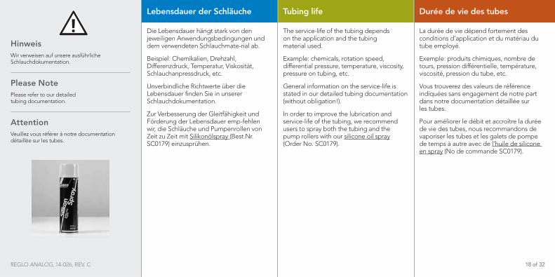
Lebensdauer der Schläuche
Die Lebensdauer hängt stark von den jeweiligen Anwendungsbedingungen und dem verwendeten Schlauchmate-rial ab.
Beispiel: Chemikalien, Drehzahl, Differenzdruck, Temperatur, Viskosität, Schlauchanpressdruck, etc.
Unverbindliche Richtwerte über die Lebensdauer finden Sie in unserer Schlauchdokumentation.
Zur Verbesserung der Gleitfähigkeit und Förderung der Lebensdauer emp-fehlen wir, die Schläuche und Pumpenrollen von Zeit zu Zeit mit Silikonölspray (Best.Nr. SC0179) einzusprühen.
Tubing life
The service-life of the tubing depends on the application and the tubing material used.
Example: chemicals, rotation speed, differential pressure, temperature, viscosity, pressure on tubing, etc.
General information on the service-life is stated in our detailed tubing documentation (without obligation!).
In order to improve the lubrication and service-life of the tubing, we recommend users to spray both the tubing and the pump rollers with our silicone oil spray (Order No. SC0179).
Durée de vie des tubes
La durée de vie dépend fortement des conditions d’application et du matériau du tube employé.
Exemple: produits chimiques, nombre de tours, pression différentielle, température, viscosité, pression du tube, etc.
Vous trouverez des valeurs de référence indiquées sans engagement de notre part dans notre documentation détaillée sur les tubes.
Pour améliorer le débit et accroître la durée de vie des tubes, nous recommandons de vaporiser les tubes et les galets de pompe de temps à autre avec de l’huile de silicone en spray (No de commande SC0179).
Hinweis Wir verweisen auf unsere ausführliche Schlauchdokumentation.
Please NotePlease refer to our detailed tubing documentation.
Attention Veuillez vous référer à notre documentation détaillée sur les tubes.
REGLO ANALOG, 14-026, REV. C 18 of 32

Analogschnittstelle
Pin 1, GND (Masse)Bezugspotential für alle anderen Eingänge.
Pin 2, remoteFür Umschaltung zwischen manueller Bedienung und der Analogschnittstelle. Zur Aktivierung der Analog-Schnittstelle muss Pin 2 mit Pin 1 (GND) verbunden werden.
Pin 3, startIm Remote-Betrieb (Pin 2 auf GND) startet die Pumpe bei Verbindung mit Pin 1 (GND).
Pin 4, directionWenn offen, dreht die Pumpe im Gegenuhrzeigersinn; wenn mit Pin 1 (GND) verbunden, dreht sie im Uhr-zeigersinn.
Analog interface
Pin 1, GND (ground)Reference potential for all other inputs.
Pin 2, remoteFor changing between manual control and analog interface. For activating the analog interface, Pin 2 must be connected with Pin 1 (GND).
Pin 3, startIn remote operation (Pin 2 to GND) the pump starts when connected to Pin 1 (GND).
Pin 4, directionIn the open position, the pump turns counter-clockwise; when connected to Pin 1 (GND) it turns clockwise.
Interface analogique
Pin 1, GND (masse)Potentiel de référence pour toutes les autres entrées.
Pin 2, remotePour commuter du service manuel à l’interface analogique. Pour activer l‘interface analogique, le Pin 2 doit être connecté au Pin 1 (GND).
Pin 3, startEn exploitation à distance (Pin 2 sur GND), la pompe se met en route dès qu’elle est connectée au Pin 1 (GND).
Pin 4, direction Si ouvert, le sens de rotation de la pompe est celui contraire des aiguilles d’une montre.; si relié avec le Pin 1 (GND), elle tourne dans le sens des aiguilles d’une montre.
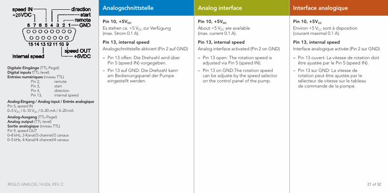
Digitale Eingänge (TTL-Pegel) Digital inputs (TTL-level) Entrées numériques (niveau TTL) Pin 2, remote Pin 3, start Pin 4, direction Pin 13, internal speed
Analog-Eingang / Analog input / Entrée analogique Pin 5, speed IN 0–5 VDC / 0–10 VDC / 0–20 mA / 4–20 mA
Analog-Ausgang (TTL-Pegel) Analog output (TTL-level) Sortie analogique (niveau TTL) Pin 9, speed OUT 0–8 kHz, 2-Kanal/2-channel/2 canaux 0–5 kHz, 4-Kanal/4-channel/4 canaux
REGLO ANALOG, 14-026, REV. C 19 of 32

Analog interface
Pin 5, speed INExternal speed control (0–5VDC, 0–10VDC, 0–20mA, 4–20mA) Input impedance and input range can be selected via a dip-switch inside the pump (see P. 22).
Input impedance0–5 V 18 kΩ 0–10 V 38 kΩ 0–20 mA 270 Ω 4–20 mA 270 Ω
Pin 7, +20VDC
About +20 VDC are available (max. current 0.2 A).
Pin 9, speed OUTFrequency proportional to the rotation speed: 2 channels: 0–8 kHz, 3.2–160 rpm 4 channels: 0–5 kHz, 2.0–100 rpm
Interface analogique
Pin 5, speed INRéglage externe du nombre de tours (0–5VCC, 0–10VCC, 0–20mA, 4–20mA ) Impédance d‘entrée et réglage de zone au moyen de l’interrupteur DIP à l’intérieur de l’appareil (voir P. 22).
Impédance d‘entrée0–5 V 18 kΩ 0–10 V 38 kΩ 0–20 mA 270 Ω 4–20 mA 270 Ω
Pin 7, +20VCC
Environ +20 VCC sont à disposition (courant maximal 0.2 A).
Pin 9, speed OUTFréquence proportionelle au nombre de tours: 2 canaux: 0–8 kHz, 3.2–160 t/min 4 canaux: 0–5 kHz, 2.0–100 t/min
Analogschnittstelle
Pin 5, speed INExterne Drehzahlsteuerung (0–5VDC, 0–10VDC, 0–20mA, 4–20mA) Eingangsimpedanz und Wahlmöglichkeiten mittels DIP-Switch im Geräteinnern (siehe Seite 22).
Eingangs-Impedanzen0–5 V 18 kΩ 0–10 V 38 kΩ 0–20 mA 270 Ω 4–20 mA 270 Ω
Pin 7, +20VDC
Es stehen ca. +20 VDC zur Verfügung (max. Strom 0.2 A).
Pin 9, speed OUTFrequenz proportional zur Drehzahl: 2 Kanal: 0–8 kHz, 3.2–160 min–1 4 Kanal: 0–5 kHz, 2.0–100 min–1
Digitale Eingänge (TTL-Pegel) Digital inputs (TTL-level) Entrées numériques (niveau TTL) Pin 2, remote Pin 3, start Pin 4, direction Pin 13, internal speed
Analog-Eingang / Analog input / Entrée analogique Pin 5, speed IN 0–5 VDC / 0–10 VDC / 0–20 mA / 4–20 mA
Analog-Ausgang (TTL-Pegel) Analog output (TTL-level) Sortie analogique (niveau TTL) Pin 9, speed OUT 0–8 kHz, 2-Kanal/2-channel/2 canaux 0–5 kHz, 4-Kanal/4-channel/4 canaux
REGLO ANALOG, 14-026, REV. C 20 of 32
Digitale Eingänge (TTL-Pegel) Digital inputs (TTL-level) Entrées numériques (niveau TTL) Pin 2, remote Pin 3, start Pin 4, direction Pin 13, internal speed
Analog-Eingang / Analog input / Entrée analogique Pin 5, speed IN 0–5 VDC / 0–10 VDC / 0–20 mA / 4–20 mA
Analog-Ausgang (TTL-Pegel) Analog output (TTL-level) Sortie analogique (niveau TTL) Pin 9, speed OUT 0–8 kHz, 2-Kanal/2-channel/2 canaux 0–5 kHz, 4-Kanal/4-channel/4 canaux
Analog interface
Pin 10, +5VDC
About +5 VDC are available (max. current 0.1 A).
Pin 13, internal speedAnalog interface activated (Pin 2 on GND)
– Pin 13 open: The rotation speed is adjusted via Pin 5 (speed IN).
– Pin 13 on GND:The rotation speed can be adjuste by the speed selector on the control panel of the pump.
Interface analogique
Pin 10, +5VCC
Environ +5 VCC sont à disposition (courant maximal 0.1 A).
Pin 13, internal speedInterface analogique activée (Pin 2 sur GND)
– Pin 13 ouvert: La vitesse de rotation doit être ajustée par le Pin 5 (speed IN).
– Pin 13 sur GND: La vitesse de rotation peut être ajustée par le sélecteur de vitesse sur le tableau de commande de la pompe.
Analogschnittstelle
Pin 10, +5VDC
Es stehen ca. +5 VDC zur Verfügung (max. Strom 0.1 A).
Pin 13, internal speedAnalogschnittstelle aktiviert (Pin 2 auf GND)
– Pin 13 offen: Die Drehzahl wird über Pin 5 (speed IN) vorgegeben.
– Pin 13 auf GND: Die Drehzahl kann am Bedienungspanel der Pumpe eingestellt werden.
REGLO ANALOG, 14-026, REV. C 21 of 32
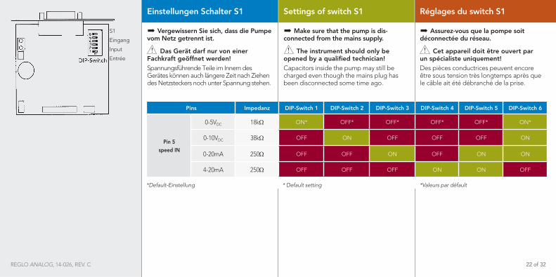
Einstellungen Schalter S1
X� Vergewissern Sie sich, dass die Pumpe vom Netz getrennt ist.
! Das Gerät darf nur von einer Fachkraft geöffnet werden!Spannungsführende Teile im Innern des Gerätes können auch längere Zeit nach Ziehen des Netzsteckers noch unter Spannung stehen.
Settings of switch S1
X� Make sure that the pump is dis-connected from the mains supply.
! The instrument should only be opened by a qualified technician! Capacitors inside the pump may still be charged even though the mains plug has been disconnected some time ago.
Réglages du switch S1
X� Assurez-vous que la pompe soit déconnectée du réseau.
! Cet appareil doit être ouvert par un spécialiste uniquement!Des pièces conductrices peuvent encore être sous tension très longtemps après que le câble ait été débranché de la prise.
S1
Eingang
Input
Entrée
REGLO ANALOG, 14-026, REV. C 22 of 32
Pins Impedanz DIP-Switch 1 DIP-Switch 2 DIP-Switch 3 DIP-Switch 4 DIP-Switch 5 DIP-Switch 6
Pin 5speed IN
0-5VDC 18kΩ ON* OFF* OFF* OFF* OFF* ON*
0-10VDC 38kΩ OFF ON OFF OFF OFF ON
0-20mA 250Ω OFF OFF ON OFF ON ON
4-20mA 250Ω OFF OFF OFF ON ON OFF
*Default-Einstellung * Default setting *Valeurs par défault

Zubehör
Fußschalter Bestell-Nr. ISM891
Dieser Fußschalter dient als Impuls-geber zum Starten bzw. Anhalten der Pumpe. Er ist sehr nützlich, wenn die Pumpe als Dosiergerät zum Abfüllen von Röhrchen, Gläsern, Flaschen usw. eingesetzt wird. Beide Hände bleiben für das Arbeiten mit Flaschen usw. frei.
3-Stopper-SchläucheFür die passenden Pumpenschläuche verweisen wir auf unsere aus-führliche Schlauch-Dokumentation.
X� Beim Einsatz von neuen Pumpenschläuchen kann es vorkommen, dass je nach verwendetem Schlauch (Härte und Durchmesser) die Pumpe anfänglich nicht fördert. Trifft dies zu, so emp-fehlen wir, die Schläuche zu benetzen und die Pumpe zuerst mit eingesetztem Schlauch ca. 15 - 30 Minuten laufen zu lassen. Bei Applikationen mit hohem Differenzdruck (> 1 bar) empfehlen wir, die Kassette mit Anpresshebel einzusetzen.
Accessories
Footswitch Order No. ISM891
This footswitch serves as a start/stop device. It is very useful when using the pump as a dispenser for filling tubes, bottles, etc. Both hands are free for handling the bottles and tubing.
3-stop tubingFor selecting the correct tubing, please refer to our detailed tubing documentation.
X� When using new tubing for the first time, it may occur that, depending on the tubing used (hardness and diameter), the pump cannot be primed and, hence, does not deliver the liquid. If that is the case, the tubing should be primed and run for 15 to 30 minutes. For applications with a high differential pressure (> 1 bar), pressure lever cassettes should be used.
Accessoires
Pédale de commandeNo de commande ISM891
Cette pédale de commande est utilisée pour enclencher et déclencher la pompe. Elle est très utile lorsque la pompe est utilisée comme appareil de dosage pour remplir des tubes, des flacons, etc. Les deux mains sont ainsi libres pour travailler.
Tubes à 3 arrêtsPour le choix de tubes adéquats, veuil-lez vous référer à notre documentation détaillée sur les tubes de pompe.
X� Lors de la premiére utilisation de nouveaux tubes, il se peut, suivantes le tube utilisé (dureté et diamètre), que l‘amorçage du tube ne se fasse pas correctement et que de ce fait aucun liquide ne soit délivré. Si tel est le cas, nous conseillons de remplir les tubes et de faire fonctionner la pompe avec tube inséré pendant 15 à 30 minutes. Pour des applications avec de fortes pressions différentielles (> 1 bar), il est conseillé d‘utiliser les cassettes avec levier de pression.
3-Stopper-Schläuche 3-stop tubing Tubes à 3 arrêts
REGLO ANALOG, 14-026, REV. C 23 of 32
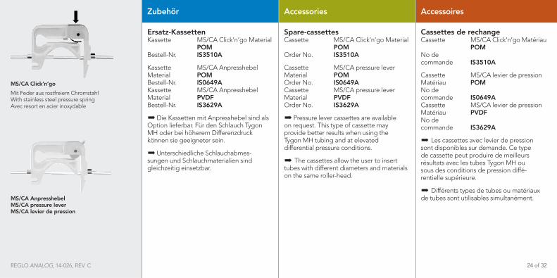
MS/CA Anpresshebel MS/CA pressure lever MS/CA levier de pression
MS/CA Click‘n‘go
Mit Feder aus rostfreiem Chromstahl With stainless steel pressure spring Avec resort en acier inoxydable
Zubehör
Ersatz-Kassetten Kassette MS/CA Click‘n‘go Material POM Bestell-Nr. IS3510A
Kassette MS/CA Anpresshebel Material POM Bestell-Nr. IS0649A Kassette MS/CA Anpresshebel Material PVDF Bestell-Nr. IS3629A
X�Die Kassetten mit Anpresshebel sind als Option lieferbar. Für den Schlauch Tygon MH oder bei höherem Differenzdruck können sie geeigneter sein.
X�Unterschiedliche Schlauchabmes- sungen und Schlauchmaterialien sind gleichzeitig einsetzbar.
Accessories
Spare-cassettesCassette MS/CA Click‘n‘go Material POM Order No. IS3510A
Cassette MS/CA pressure lever Material POM Order No. IS0649A Cassette MS/CA pressure lever Material PVDF Order No. IS3629A
X�Pressure lever cassettes are available on request. This type of cassette may provide better results when using the Tygon MH tubing and at elevated differential pressure conditions.
X� The cassettes allow the user to insert tubes with different diameters and materials on the same roller-head.
Accessoires
Cassettes de rechange Cassette MS/CA Click‘n‘go Matériau POM No de commande IS3510A
Cassette MS/CA levier de pression Matériau POM No de commande IS0649A Cassette MS/CA levier de pression Matériau PVDF No de commande IS3629A
X� Les cassettes avec levier de pression sont disponibles sur demande. Ce type de cassette peut produire de meilleurs résultats avec les tubes Tygon MH ou sous des conditions de pression diffé- rentielle supérieure.
X� Différents types de tubes ou matériaux de tubes sont utilisables simultanément.
REGLO ANALOG, 14-026, REV. C 24 of 32
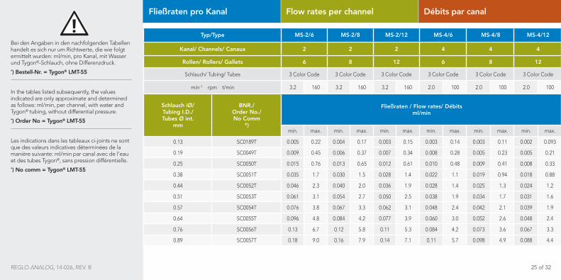
Bei den Angaben in den nachfolgenden Tabellen handelt es sich nur um Richtwerte, die wie folgt ermittelt wurden: ml/min, pro Kanal, mit Wasser und Tygon®-Schlauch, ohne Differenzdruck.*) Bestell-Nr. = Tygon® LMT-55 In the tables listed subsequently, the values indicated are only approximate and determined as follows: ml/min, per channel, with water and Tygon® tubing, without differential pressure.*) Order No = Tygon® LMT-55 Les indications dans les tableaux ci-joints ne sont que des valeurs indicatives déterminées de la manière suivante: ml/min par canal avec de l’eau et des tubes Tygon®, sans pression différentielle.*) No comm = Tygon® LMT-55
Typ/Type MS-2/6 MS-2/8 MS-2/12 MS-4/6 MS-4/8 MS-4/12
Kanal/ Channels/ Canaux 2 2 2 4 4 4
Rollen/ Rollers/ Gallets 6 8 12 6 8 12
Schlauch/ Tubing/ Tubes 3 Color Code 3 Color Code 3 Color Code 3 Color Code 3 Color Code 3 Color Code
min–1 rpm t/min 3.2 160 3.2 160 3.2 160 2.0 100 2.0 100 2.0 100
Schlauch iØ/ Tubing I.D./ Tubes Ø int.
mm
BNR./ Order No./ No Comm
*)
Fließraten / Flow rates/ Débits ml/min
min. max. min. max. min. max. min. max. min. max. min. max.
0.13 SC0189T 0.005 0.22 0.004 0.17 0.003 0.15 0.003 0.14 0.003 0.11 0.002 0.093
0.19 SC0049T 0.009 0.45 0.006 0.37 0.007 0.34 0.008 0.28 0.005 0.23 0.005 0.21
0.25 SC0050T 0.015 0.76 0.013 0.65 0.012 0.61 0.010 0.48 0.009 0.41 0.008 0.33
0.38 SC0051T 0.035 1.7 0.030 1.5 0.028 1.4 0.022 1.1 0.019 0.94 0.018 0.88
0.44 SC0052T 0.046 2.3 0.040 2.0 0.036 1.9 0.028 1.4 0.025 1.3 0.024 1.2
0.51 SC0053T 0.061 3.1 0.054 2.7 0.050 2.5 0.038 1.9 0.034 1.7 0.031 1.6
0.57 SC0054T 0.076 3.8 0.067 3.3 0.062 3.1 0.048 2.4 0.042 2.1 0.039 1.9
0.64 SC0055T 0.096 4.8 0.084 4.2 0.077 3.9 0.060 3.0 0.052 2.6 0.048 2.4
0.76 SC0056T 0.13 6.7 0.12 5.8 0.11 5.3 0.084 4.2 0.073 3.6 0.067 3.3
0.89 SC0057T 0.18 9.0 0.16 7.9 0.14 7.1 0.11 5.7 0.098 4.9 0.088 4.4
Fließraten pro Kanal Flow rates per channel Débits par canal
REGLO ANALOG, 14-026, REV. B 25 of 32

Bei den Angaben in den nachfolgenden Tabellen handelt es sich nur um Richtwerte, die wie folgt ermittelt wurden: ml/min, pro Kanal, mit Wasser und Tygon®-Schlauch, ohne Differenzdruck.
*) Bestell-Nr. = Tygon® LMT-55
In the tables listed subsequently, the values indicated are only approximate and determined as follows: ml/min, per channel, with water and Tygon® tubing, without differential pressure.
*) Order No = Tygon® LMT-55
Les indications dans les tableaux ci-joints ne sont que des valeurs indicatives déterminées de la manière suivante: ml/min par canal avec de l’eau et des tubes Tygon®, sans pression différentielle.
*) No comm = Tygon® LMT-55
Typ/Type MS-2/6 MS-2/8 MS-2/12 MS-4/6 MS-4/8 MS-4/12
Kanal/ Channels/ Canaux 2 2 2 4 4 4
Rollen/ Rollers/ Gallets 6 8 12 6 8 12
Schlauch/ Tubing/ Tubes 3 Color Code 3 Color Code 3 Color Code 3 Color Code 3 Color Code 3 Color Code
min–1 rpm t/min 3.2 160 3.2 160 3.2 160 2.0 100 2.0 100 2.0 100
Schlauch iØ/ Tubing I.D./ Tubes Ø int.
mm
BNR./ Order No./ No Comm
*)
Fließraten / Flow rates/ Débits ml/min
min. max. min. max. min. max. min. max. min. max. min. max.
0.95 SC0058T 0.20 10 0.18 6.9 0.16 7.9 0.13 6.4 0.11 5.6 0.99 5.0
1.02 SC0059T 0.23 12 0.20 10 0.18 9.0 0.15 7.3 0.13 6.3 0.11 5.6
1.09 SC0060T 0.27 13 0.23 11 0.20 10 0.17 8.3 0.14 7.2 0.13 6.3
1.14 SC0061T 0.29 14 0.25 12 0.22 11 0.18 9.0 0.16 7.8 0.13 6.7
1.22 SC0062T 0.33 15 0.28 14 0.24 12 0.20 10 0.16 8.8 0.15 7.5
1.30 SC0063T 0.37 16 0.31 16 0.26 13 0.23 11 0.20 10 0.17 8.3
1.42 SC0064T 0.43 21 0.37 16 0.30 15 0.27 13 0.23 11 0.19 8.4
1.52 SC0065T 0.48 24 0.41 20 0.33 17 0.30 15 0.26 13 0.21 10
1.65 SC0066T 0.56 28 0.47 23 0.37 19 0.35 17 0.29 15 0.23 12
1.75 SC0067T 0.61 31 0.51 28 0.40 20 0.38 19 0.32 18 0.25 13
Fließraten pro Kanal Flow rates per channel Débits par canal
REGLO ANALOG, 14-026, REV. B 26 of 32

*) = Tygon® LMT-55
HinweisFür die Auswahl des Schlauchmaterials sind wir gerne behilflich. Die Verantwortung für die richtige Wahl liegt jedoch beim Benutzer.
Reproduzierbare Werte erhalten Sie mit den Pumpenschläuchen von ISMATEC®.
Please noteWe will be pleased to help the user to select the tubing material. However, the user himself has the final responsibility for the selection of the correct tubing material.
For reproducible results we recommend you to use tubing from ISMATEC®.
RemarqueLe choix correct du tube adéquat relève de la seule responsabilité de l‘utilisateur.
Pour des valeurs reproductibles nous vous recommandons l‘utilisation des tubes ISMATEC®.
Typ/Type MS-2/6 MS-2/8 MS-2/12 MS-4/6 MS-4/8 MS-4/12
Kanal/ Channels/ Canaux 2 2 2 4 4 4
Rollen/ Rollers/ Gallets 6 8 12 6 8 12
Schlauch/ Tubing/ Tubes 3 Color Code 3 Color Code 3 Color Code 3 Color Code 3 Color Code 3 Color Code
min–1 rpm t/min 3.2 160 3.2 160 3.2 160 2.0 100 2.0 100 2.0 100
Schlauch iØ/ Tubing I.D./ Tubes Ø int.
mm
BNR./ Order No./ No Comm
*)
Fließraten / Flow rates/ Débits ml/min
min. max. min. max. min. max. min. max. min. max. min. max.
1.85 SC0068T 0.67 34 0.56 26 0.43 21 0.42 21 0.35 17 0.27 13
2.06 SC0069T 0.79 40 0.66 33 0.49 24 0.50 25 0.41 20 0.30 15
2.29 SC0070T 0.92 46 0.76 35 0.55 27 0.58 29 0.48 24 0.34 17
2.54 SC0071T 1.1 53 0.88 44 0.62 31 0.68 33 0.55 27 0.39 19
2.79 SC0072T 1.2 55 0.89 50 0.69 34 0.74 37 0.62 31 0.43 21
3.17 SC0224T 1.4 65 1.1 57 0.75 36 0.65 43 0.71 35 0.47 24
Typ/Type MS-2/6 MS-2/8 MS-2/12 MS-4/6 MS-4/8 MS-4/12
Kanal/ Channels/ Canaux 2 2 2 4 4 4
Rollen/ Rollers/ Gallets 6 8 12 6 8 12
Schlauch/ Tubing/ Tubes 3 Color Code 3 Color Code 3 Color Code 3 Color Code 3 Color Code 3 Color Code
min–1 rpm t/min 3.2 160 3.2 160 3.2 160 2.0 100 2.0 100 2.0 100
Schlauch iØ/ Tubing I.D./ Tubes Ø int.
mm
BNR./ Order No./ No Comm
*)
Fließraten / Flow rates/ Débits ml/min
min. max. min. max. min. max. min. max. min. max. min. max.
0.95 SC0058T 0.20 10 0.18 6.9 0.16 7.9 0.13 6.4 0.11 5.6 0.99 5.0
1.02 SC0059T 0.23 12 0.20 10 0.18 9.0 0.15 7.3 0.13 6.3 0.11 5.6
1.09 SC0060T 0.27 13 0.23 11 0.20 10 0.17 8.3 0.14 7.2 0.13 6.3
1.14 SC0061T 0.29 14 0.25 12 0.22 11 0.18 9.0 0.16 7.8 0.13 6.7
1.22 SC0062T 0.33 15 0.28 14 0.24 12 0.20 10 0.16 8.8 0.15 7.5
1.30 SC0063T 0.37 16 0.31 16 0.26 13 0.23 11 0.20 10 0.17 8.3
1.42 SC0064T 0.43 21 0.37 16 0.30 15 0.27 13 0.23 11 0.19 8.4
1.52 SC0065T 0.48 24 0.41 20 0.33 17 0.30 15 0.26 13 0.21 10
1.65 SC0066T 0.56 28 0.47 23 0.37 19 0.35 17 0.29 15 0.23 12
1.75 SC0067T 0.61 31 0.51 28 0.40 20 0.38 19 0.32 18 0.25 13
Fließraten pro Kanal Flow rates per channel Débits par canal
REGLO ANALOG, 14-026, REV. B 27 of 32

Unterhalt
Sofern die REGLO Analog bestim-mungsgemäß und mit der nötigen Sorgfalt eingesetzt wird, unterliegt lediglich das Schlauchmaterial einem gewissen Verschleiß.
Maintenance
Provided the REGLO Analog tubing pump is operated properly and in compliance with this manual, the tubing is the only part that is subject to wear and tear.
Entretien
Pour autant que la pompe REGLO Analog soit utilisé avec tout le soin nécessaire et conformément aux in-structions d’utilisation, seuls les tubes feront l’objet d’une certaine usure.
Ersatzteile
Für Reparaturen, die Sie selbstän-dig ausführen wollen (außerhalb der Garantiezeit) erhalten Sie von Ihrer ISMATEC®-Vertretung:
XX Stücklisten
XX Ersatzteile Pumpenantrieb
XX Verdrahtungspläne
Bitte geben Sie Defekt, Kaufdatum, Serien-Nr. und Typ an.
Replacement parts
For repairs performed by the owner (out of the warranty period), ask your ISMATEC® distributor for:
XX parts lists
XX replacement parts for pump drive
XX wiring diagrams
Please give information on defect, date of purchase, serial-no., and model.
Pièces détachées
Pour les travaux de réparation que vous désirez effectuer vous-même (en dehors de la période de garantie), vous pouvez demander à votre revendeur ISMATEC®:
XX des pièces détachées
XX des listes de pièces
XX des schémas de connexion
Veuillez fournir des informations concernant la panne, la date de l’achat, le numéro de série et le modèle.
REGLO ANALOG, 14-026, REV. C 28 of 32
Service and repairs
Like all pumps, the REGLO Analog contains components that will wear over a period of time.
For repairs, send the complete pump with a detailed description of the failure to your ISMATEC® distributor. Please use the original ISMATEC® packaging or packaging of equal quality.
Service technique et réparations
Comme toutes les pompes, la pompe REGLO Analog contient des composan-tes qui s’useront au cours du temps.
Pour tout travail de réparation, envoyer la pompe complète avec une description détaillée du défaut constaté à votre revendeur ISMATEC®. Veuillez employ-ez l‘emballage d‘origine ou similaire.
Service und Reparaturen
Wie jedes Gerät besitzt auch die REGLO Analog Komponenten, die sich innerhalb einer gewissen Zeit abnutzen.
Für Reparaturen senden Sie die komplette Pumpe mit umfassender Beschreibung des Defekts an Ihre ISMATEC®-Vertretung. Bitte verwenden Sie die Original- oder eine gleichwertige Verpackung.
EntsorgungBewahren Sie bitte das Verpackungsmaterial bis zum Ablauf der Garantiezeit auf. Danach entsorgen Sie es bitte umweltgerecht und Ihren gesetzlichen Vorschriften entsprechend. Hat Ihr Gerät eines Tages ausgedient, führen Sie es dem Gesetz entsprechend einer geordneten Entsorgung zu. Kunststoffe und Elektronikteile müssen einer Wiederverwertung zugeführt werden. Erkundigen Sie sich bei ihrer zuständigen Entsorgungsstelle.
DisposalPlease retain packaging materials until the product warranty ends. Afterwards please discard packaging materials in an environmentally-friendly manner according to local regulations. Once the useful life of the product has ended, please ensure proper disposal according to local laws. Paper, cardboard, plastic, and electronic components should be disposed of at a recycling facility. Please refer to local regulations regarding proper disposal.
Mise au rebutConserver le matériel d‘emballage jusqu‘à expiration de la garantie du produit. Par la suite, jeter le matériel d‘emballage en respectant l‘environnement et les réglementations locales en vigueur. Lorsque la durée de vie utile du produit est dépassée, s‘assurer que l‘élimination se fait conformément aux lois locales. Déposer les composants électroniques et les plastiques dans un centre de recyclage spécialisé. Respecter les réglementations locales applicables à l‘élimination.
REGLO ANALOG, 14-026, REV. C 29 of 32

Technische Daten
AntriebMotortyp DC-Motor Drehzahlbereich 2 Kanal 3.2 – 160 min–1 4 Kanal 2.0 – 100 min–1 einstellbar in 1 % Schritten
Differenzdruckmax. 1.0 bar, siehe Seite 16
Extern ansteuerbarüber Analogschnittstelle (siehe Seite 19–22)
Netzanschluss/Absicherung230 VAC/50 Hz 2x T500mA/250V 115 VAC/60 Hz 2x T500mA/250V
Leistungsaufnahme Max. 20 W
Technical Specifications
DriveMotor type DC-Motor Speed range 2 channels 3.2 – 160 rpm 4 channels 2.0 – 100 rpm adjustable in 1 % steps
Differential pressuremax. 1.0 bar (14.5 psi) see Page 16
Remote controlvia analog interface (see Page 19–22)
Mains connection/Fuse rating230 VAC/50 Hz 2x T500mA/250V 115 VAC/60 Hz 2x T500mA/250V
Power consumption Max. 20 W
Spécifications techniques
MoteurType de moteur moteur DC Vitesse 2 canaux 3.2 – 160 t/min 4 canaux 2.0 – 100 t/min réglable par pas de 1 %
Pression différentiellemax. 1.0 bar, voir Page 16
Télécommandevia interface analogique (voir Page 19–22)
Connexion au réseau/type de fusibles230 VCA/50 Hz 2x T500mA/250V 115 VCA/60 Hz 2x T500mA/250V
Consommation de courantMax. 20 W
REGLO ANALOG, 14-026, REV. C 30 of 32
HinweisBeachten Sie ebenfalls unsere Garantie- und allgemeinen Verkaufs- und Lieferbedingungen.
Bitte setzen Sie sich bei Fragen oder Unklarheiten mit Ihrer lokalen ISMATEC®-Vertretung in Verbindung.
Please noteWe also recommend you observe our Warranty Terms as well as our Terms and Conditions of Sale.
In case of any queries, please contact your local ISMATEC® representative.
RemarqueVeuillez lire également nos conditions de garantie, nos conditions générales de vente ainsi que nos conditions de livraison.
Pour toute demande, veuillez prendre contact avec votre représentant ISMATEC®.
Technische Daten
Betriebsbedingungen Temperatur +5 bis +40°C Rel. Feuchtigkeit max. 80%
– nicht kondensierend, normale Labor-bedingungen
Maße/Gewicht (TxBxH) 2 Kanal 178x100x143 mm 4 Kanal 190x100x143 mm
Gewicht 2 Kanal 2.0 kg 4 Kanal 2.1 kg
CE-KonformitätDieses Gerät entspricht den Normen: EN 61326-1, EN 61010-1
Technical Specifications
Operating conditionsTemperature +5 to +40°C, Rel. humidity max. 80%
– not condensing, at normal environmental conditions
Dimensions/Weight(DxWxH) 2 channels 178x100x143 mm (7“x4“x5 2/3“) 4 channels 190x100x143 mm (7 ½“x4“x5 2/3“)
Weight 2 channels 2.0 kg (5 lb) 4 channels 2.1 kg (5 lb)
CE-compatibility according to: EN 61326-1, EN 61010-1
Spécifications techniques
Conditions d’utilisationTempérature de +5 à +40°C Humidité relative au max. 80 %
– sans condensation, sous des conditions de laboratoire normales
Dimensions/PoidsPxLaxH 2 canaux 178x100x143 mm 4 canaux 190x100x143 mm
Poids 2 canaux 2.0 kg 4 canaux 2.1 kg
Compatibilité CE conformément à: EN 61326-1, EN 61010-1
REGLO ANALOG, 14-026, REV. C 31 of 32

©2015 COLE-PARMER INSTRUMENT COMPANY, LLC. 14-026, REV. C
For ordering and technical support, please contact:North America [email protected] | 1-800-323-4340 | 1-847-549-7600
Europe [email protected] | +49 (0) 9377 9203-0
Learn more about the Ismatec® product line by visiting: www.ismatec.com