
Region-based video coding using mathematical morphology
14
Transcript of Region-based video coding using mathematical morphology

PROCEEDING OF THE IEEE, VOL. 83, NO. 6, JUNE 1995 843Region-Based Video Coding UsingMathematical MorphologyPhilippe Salembier , Luis Torres, Fernand Meyer, Chuang GuInvited PaperAbstract| This paper presents a region-based coding al-gorithm for video sequences. The coding approach invol-ves a time-recursive segmentation relying on the pixels ho-mogeneity, a region-based motion estimation, and motioncompensated contour and texture coding. This algorithm ismainly devoted to very low bit rate video coding applicati-ons. One of the important features of the approach is that noassumption is made about the sequence content. Moreover,the algorithm structure leads to a scalable coding processgiving various levels of quality and bit rates. The coding aswell as the segmentation are controlled to regulate the bitstream. Finally, the interest of morphological tools in thecontext of region-based coding is extensively reviewed.Keywords|Video coding, mathematical morphology, seg-mentation, motion estimation and compensation, contourcoding, texture coding.I. IntroductionIN the framework of very low bit rate video coding, thereis an increasing interest in second generation image com-pression techniques [4]. These techniques eliminate the re-dundant information within and between frames, takingadvantage of the properties of the human visual system.In particular, region-based compression methods describethe images in terms of a set of regions, that is a partition,and of some information for each region to be used by thereceiver to reconstruct the image. These techniques havebeen successfully applied to the coding of still images [4].For sequences, region-based schemes have been developedin particular in [10], [12], [23].The main di�erence between the techniques proposed in[10], [12], [23] can be described by the relative importancethey assign to the spatial or the motion information. Re-ference [10] proposes a coding scheme where motion playsthe central role and the image is restored on the receiverside by motion compensation of past restored frames. Apartition of each frame is used mainly to de�ne the regionsManuscript received July 1, 1994; revised January 17, 1995. thiswork was supported by the MORPHECO project under the EuropeanRACE program.P. Salembier and L. Torres are with the Department of Signal The-ory and Communications of the Polytechnic University of Catalonia(UPC), Barcelona, Spain.F. Meyer is with the Center for Mathematical Morphology of ParisSchool of Mines (CMM), Fontainebleau, France.C. Gu is with the Signal Processing Laboratory of the Swiss FederalInstitute of Technology (EPFL), Lausanne, Switzerland.IEEE Log number 9410572.
that should be compensated. This approach leads to goodresults if the sequence can actually be compensated. Thatis, if no new objects are allowed to be introduced in thescene and if scene changes are prohibited. As a result thistechnique is mainly dedicated to very speci�c applicationssuch as "head & shoulders" sequences. The approachesdescribed in [12], [23] are more general in the sense thatthey mainly deal with the spatial information of the scene.The sequence is considered as a 3D signal (2 spatial plusone temporal dimensions) and 3D blocks are segmented onthe basis of the gray-level information. Finally, the 3Dpartition is coded as well as the texture of each region.Note that the system can a priori code any sequence andno assumptions have to be made about the introduction ofnew objects or about scene changes. However, in this case,motion information is not used and the coding e�ciencyremains moderate because the temporal redundancy is notreally exploited.In this paper, we propose a coding algorithm which com-bines a spatial analysis of the sequence with a motioncompensation of the transmitted information. On the onehand, the spatial analysis is used to get a general schemeable to deal with any kind of sequences and scene changes.On the other hand, motion information is used to increasethe coding e�ciency by compensation of the spatial infor-mation that has to be transmitted (partition and texture).From the information theory viewpoint, coding generallyrelies on the statistical properties of signals. However, ina region-based approach, the geometrical information is ofprime importance and should be used as much as possible.Classical linear signal processing tools are not well suitedfor a geometrical approach and other tools coming fromnonlinear signal processing or from computer vision maybe attractive for this purpose. Mathematical morphology[19], [20] has been developed as a geometrical approach tosignal processing. Our objective in this paper is twofold:�rst to describe a region-based video coding algorithm and,second, to discuss the usefulness of morphological tools inthis context.The organization of this paper is as follows: section 2describes the general codec structure and its strategy. Foursteps are highlighted: segmentation, motion estimation,contour coding and texture coding. These steps are res-pectively discussed in sections 3 to 6. Finally section 7 isdevoted to the presentation of some results of very low bitrate video coding. Through out the paper, the interest of

844 PROCEEDING OF THE IEEE, VOL. 83, NO. 6, JUNE 1995using nonlinear signal processing tools such as mathemati-cal morphology is discussed. The appendix brie y de�nesand comments on the major morphological tools that arementioned in the paper.II. Structure of the algorithmIn order to de�ne the algorithm structure, let us startwith a review of the basic system requirements:� The codec is mainly devoted to very low video bit ra-tes, that is below 64 kbits.� It should be generic with respect to the input sequen-ces. In particular, no assumption about the scene con-tent should be made.� It should be exible with respect to the coded sequencequality. The coding strategy should provide an easyway to de�ne various levels of quality.� The system is principally devoted to �xed rate trans-mission. As a consequence, the bit stream should beregulated.� It should be suitable for interactive applications. The-refore, large processing delays should be avoided.To design such a system, we will follow one of the second-generation coding ideas which states that, as the compres-sion ratio increases (as for very low bit rates), the mostvital part of the image information is represented by con-tours [4]. This point of view leads to a two-componentimage representation: contour / texture. As a result, theencoder involves a segmentation step, which de�nes a par-tition of the image, followed by a coding step, which codesthe contour of the partition and the gray-level or color in-formation of each region (called texture in the following).As mentioned in the introduction, motion compensationis one of the best available techniques to take bene�t ofthe temporal redundancy. Therefore, motion informationwill be used for contour as well as for texture coding. Thesegmentation criterion will not deal with the motion �eldbut with the pixels' homogeneity in the spatial domain.Motion will not be used as segmentation criterion, becausewe are interested in a spatial analysis of the signal to beable to deal with any kind of sequence.This analysis leads to the general coding structure descri-bed in Fig. 1. It involves four steps: segmentation, motionestimation, coding of contours and coding of texture. Thesegmentation de�nes the partition of the sequence. Themotion estimation is performed after the segmentation andcan therefore be region-based. Finally, contour and tex-ture are coded by motion compensation techniques. Notethat the texture coding makes use of the partition. It is aregion-based texture coding approach.III. SegmentationWith the assumptions made in the previous section, agood segmentation should extract the visually importantregions of the scene, be coherent in time, avoid as muchas possible random uctuations of the contours and solvethe region correspondence problem. This last requirementmeans that one should be able to follow the time evolutionof a given region (a given object). With these requirements,
Original sequence
Partition
SEGMENTATION
MOTIONESTIMATION
CONTOURCODING
TEXTURECODINGFig. 1. General structure of the encoderit is very di�cult to obtain a good segmentation if theprocessing is only 2D or intra-frame. Indeed, if framesare segmented independently, both the time coherence andthe region correspondence problems are di�cult to solve.Somehow, the temporal relationship between frames mustbe exploited.In this direction, a �rst solution consists in dealing withthe sequence as a 3D (2D plus time) signal and in perfor-ming a 3D segmentation. This approach implies to split thesequence into 3D blocks of a given number of frames and tosegment these 3D blocks. Examples of this approach canbe found in [17], [12], [23]. However, these techniques havesome drawbacks. Indeed, if the temporal size of the 3Dblocks is large, the approach implies huge memory requi-rements, a high computational load and the introductionof a large processing delay disallowing any interactive ap-plication. Besides, if the temporal size of the 3D blocksis small, the temporal correlation between frames will beignored at each block transition, that is, very often.However, most of the information contained in a frameis already present in the previous frame. The changes aremainly due to object motion and the appearance of new ob-jects. This point of view leads to a segmentation processthat can be called time-recursive [11]. The segmentationapproach involves two modes of operation: intra-frame andinter-frame segmentation. During the intra-frame mode, aframe is segmented. It is a purely 2D process. Then, duringthe inter-frame mode, each frame is recursively segmentedusing the segmentation of the previous frame. Note thatin the following, the segmentation is assumed to be perfor-med on the luminance signal because most of the visuallyimportant transitions are de�ned by the luminance signal.A. intra-frame modeThe intra-frame segmentation relies on the hierarchicalmethod proposed for still images in [14]. The algorithm�rst produces a simpli�ed segmentation in the sense thatit involves a reduced number of regions. Then, the seg-mentation is progressively improved by introducing moreregions. Typically four segmentation levels are used. Each
SALEMBIER ET AL.: REGION-BASED VIDEO CODING USING MATHEMATICAL MORPHOLOGY 845Segmentation
Segmentation
Segmentation
Originalframe
Partition (n)
MODELING
MARKER EXTRACTION
DECISION
Partition (n-1)
SIMPLIFICATIONPartition (n-1)
Partition (n)
Level 2
Level 1Segmentation
Level n
Level n+1
Segmentation(Level n)
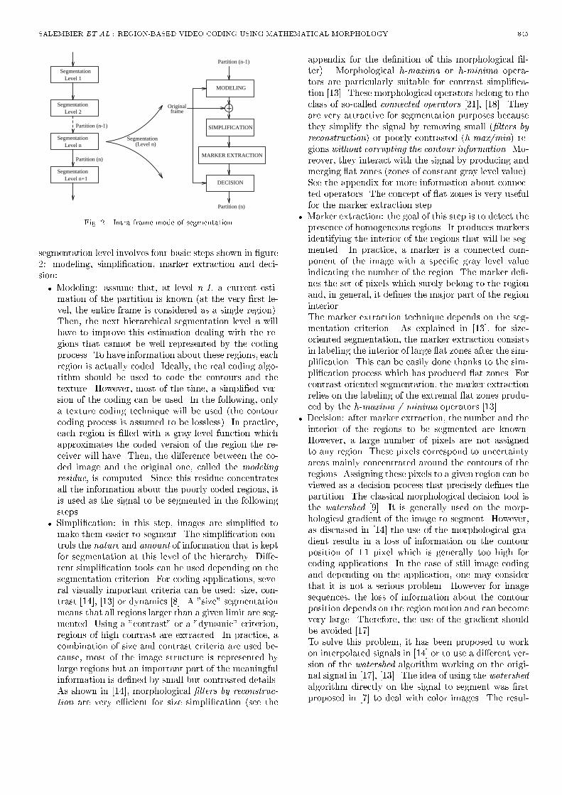
Fig. 2. Intra-frame mode of segmentationsegmentation level involves four basic steps shown in �gure2: modeling, simpli�cation, marker extraction and deci-sion:� Modeling: assume that, at level n-1, a current esti-mation of the partition is known (at the very �rst le-vel, the entire frame is considered as a single region).Then, the next hierarchical segmentation level n willhave to improve this estimation dealing with the re-gions that cannot be well represented by the codingprocess. To have information about these regions, eachregion is actually coded. Ideally, the real coding algo-rithm should be used to code the contours and thetexture. However, most of the time, a simpli�ed ver-sion of the coding can be used. In the following, onlya texture coding technique will be used (the contourcoding process is assumed to be lossless). In practice,each region is �lled with a gray-level function whichapproximates the coded version of the region the re-ceiver will have. Then, the di�erence between the co-ded image and the original one, called the modelingresidue, is computed. Since this residue concentratesall the information about the poorly coded regions, itis used as the signal to be segmented in the followingsteps.� Simpli�cation: in this step, images are simpli�ed tomake them easier to segment. The simpli�cation con-trols the nature and amount of information that is keptfor segmentation at this level of the hierarchy. Di�e-rent simpli�cation tools can be used depending on thesegmentation criterion. For coding applications, seve-ral visually important criteria can be used: size, con-trast [14], [13] or dynamics [8]. A "size" segmentationmeans that all regions larger than a given limit are seg-mented. Using a "contrast" or a "dynamic" criterion,regions of high contrast are extracted. In practice, acombination of size and contrast criteria are used be-cause, most of the image structure is represented bylarge regions but an important part of the meaningfulinformation is de�ned by small but contrasted details.As shown in [14], morphological �lters by reconstruc-tion are very e�cient for size simpli�cation (see the
appendix for the de�nition of this morphological �l-ter). Morphological h-maxima or h-minima opera-tors are particularly suitable for contrast simpli�ca-tion [13]. These morphological operators belong to theclass of so-called connected operators [21], [18]. Theyare very attractive for segmentation purposes becausethey simplify the signal by removing small (�lters byreconstruction) or poorly contrasted (h-max/min) re-gions without corrupting the contour information. Mo-reover, they interact with the signal by producing andmerging at zones (zones of constant gray level value).See the appendix for more information about connec-ted operators. The concept of at zones is very usefulfor the marker extraction step.� Marker extraction: the goal of this step is to detect thepresence of homogeneous regions. It produces markersidentifying the interior of the regions that will be seg-mented. In practice, a marker is a connected com-ponent of the image with a speci�c gray level valueindicating the number of the region. The marker de�-nes the set of pixels which surely belong to the regionand, in general, it de�nes the major part of the regioninterior.The marker extraction technique depends on the seg-mentation criterion. As explained in [13], for size-oriented segmentation, the marker extraction consistsin labeling the interior of large at zones after the sim-pli�cation. This can be easily done thanks to the sim-pli�cation process which has produced at zones. Forcontrast-oriented segmentation, the marker extractionrelies on the labeling of the extremal at zones produ-ced by the h-maxima / minima operators [13].� Decision: after marker extraction, the number and theinterior of the regions to be segmented are known.However, a large number of pixels are not assignedto any region. These pixels correspond to uncertaintyareas mainly concentrated around the contours of theregions. Assigning these pixels to a given region can beviewed as a decision process that precisely de�nes thepartition. The classical morphological decision tool isthe watershed [9]. It is generally used on the morp-hological gradient of the image to segment. However,as discussed in [14] the use of the morphological gra-dient results in a loss of information on the contourposition of �1 pixel which is generally too high forcoding applications. In the case of still image codingand depending on the application, one may considerthat it is not a serious problem. However for imagesequences, the loss of information about the contourposition depends on the region motion and can becomevery large. Therefore, the use of the gradient shouldbe avoided [17].To solve this problem, it has been proposed to workon interpolated signals in [14] or to use a di�erent ver-sion of the watershed algorithm working on the origi-nal signal in [17], [13]. The idea of using the watershedalgorithm directly on the signal to segment was �rstproposed in [7] to deal with color images. The resul-

846 PROCEEDING OF THE IEEE, VOL. 83, NO. 6, JUNE 1995
Fig. 3. Example of intra-frame segmentation. Each row represents a given segmentation step with a size criterion for the three �rst rows(size: 671, 219, 94 pixels) and a contrast criterion for the last one (contrast: 25). The four columns give respectively the modeled image,the residue, the simpli�ed error and the partition.ting algorithm is a region growing process: the set ofmarkers is extended until they occupy all the availablespace. During the extension, pixels of the uncertaintyareas are assigned to a given marker. A point is as-signed to a speci�c region because it is in the neigh-borhood of at least one marker and it is more similar(in the sense de�ned by a speci�c criterion) to thismarker than to any other marker of its neighborhood.A detailed description of this modi�ed version of thewatershed can be found in [17].A possible similarity criterion is the gray tone di�e-rence between the pixel under consideration and themean of the pixels that have already been assigned tothe region. This basic similarity measure has to bemodi�ed to take into account the complexity of thecontours. Indeed, for coding, if the gray level transi-tion between two regions is not very strong, it is usefulto have simple contours, even if some precision on theposition is lost. For this aim, the similarity criterion isde�ned as the weighted sum of the gray-level di�erencebetween the pixel and the mean of the region plus apenalty term corresponding to the contour complexity:
Simil. = � Di�. in gray-tone+(1��) Contour compl.(1)The measure of contour complexity is made by coun-ting the number of contour points that are added ifthe pixel is assigned to that region. The weightingfactor � allows more importance to be given to thegray level measure or to the contour complexity. Thedecision produces the new partition n which can beused as input to a new segmentation level. In prac-tice, the partition is represented by a gray-level imagewhere the gray-level values de�ne the region number.This kind of image is also called a label image.Typically four hierarchical levels of segmentation areused for the intra-frame processing. The �rst three dealwith a size criterion and the last with a contrast crite-rion. At each level, the same procedure is repeated andthe only di�erence is the simpli�cation parameter which isdecreased to allow the progressive introduction of small orlow-contrasted regions. This hierarchical procedure has thefollowing main advantages: it produces a good segmenta-

SALEMBIER ET AL.: REGION-BASED VIDEO CODING USING MATHEMATICAL MORPHOLOGY 847tion of the image taking into account the possibilities of thetexture coding (it segments the coding residue). It allowsthe progressive estimation of the segmentation parameters,size and contrast, to get a segmentation result compatiblewith the coding objective (appropriate number of regionsor of contour points, etc.).Four segmentation levels are illustrated in Fig. 3. Foreach level the modeled image, the residue, the simpli�edresidue and the segmentation are shown. This exampleillustrates how the information is progressively extractedfrom the original frame and introduced in the segmenta-tion. Note in particular the evolution of the modeling er-ror which becomes simpler at each level. Ideally, this errorshould tend towards zero. Comparison between the mo-deling error and its simpli�cation illustrates the usefulnessof using connected operators such as �lters by reconstruc-tion. For example, in the �rst level, the simpli�ed imageis really a coarse approximation of the original. Only largeobjects are present. However, the contours of the remai-ning objects are well de�ned. This simpli�ed image is an"easy" image to segment. The simpli�ed image involves alarge number of at zones which are very useful for markerextraction. The marker extraction step assigns a label tothese at zones. Finally, the segmentation is representedby the corresponding label image. The number of segmen-ted regions is respectively 12, 28, 53 and 71 for each level.B. inter-frame modeTwo di�erent steps can be distinguished in the inter-frame mode: �rst, to de�ne the time evolution of the re-gions that are present in the segmentation of the previousframe and, second, to detect the possible appearance ofnew regions [11].The �rst problem is basically a projection problem. De-note Ft�1 and Ft the original frames at time t � 1 andt. Assume that the segmentation at time t � 1, St�1, isknown. Our goal is to �nd the segmentation, St, at time twithout introducing new regions. For this purpose, two 3Dsignals are constructed. As illustrated by Fig. 4, FramesFt�1 and Ft are grouped together to form a temporal blockF of size 2 in the time direction. Similarly, the frame St�1is grouped with an empty frame So representing an entireframe of uncertainty. The resulting 3D signal denoted Sis considered as the set of markers that should be used tosegment the signal F . The marker extension itself is achie-ved by the same decision algorithm used in the intra-framesegmentation, that is the watershed. The only di�erenceis the nature of the signals that are now 3D signals. Thewatershed extends the markers de�ned by St�1 into theempty frame So. Each pixel of the uncertainty area (thatis of frame So) is assigned to a region of frame St�1 basedon a similarity criterion.As in the inter-frame mode, the similarity criterion com-bines a gray tone distance with a contour complexity me-asure. The contour complexity is assessed by counting thenumber of contour points that are added if the pixel is assig-ned to a particular region. A 6 connected-neighborhood isassumed for this purpose, 4 pixels in the spatial dimension
WATERSHED
Frame Frame
S
F S
S
t-1F St-1t
t-1 t
area
Uncertainty
New segmentation
F S
o
Fig. 4. Projection of markers of frame n� 1 into frame nand 2 for the temporal. The similarity in the time dimen-sion plays an important role with respect to the temporalstability of the contours.Once the labels of the previously segmented regions havebeen propagated into the current frame, new regions haveto be extracted. From now on, the process is purely intra-frame. First of all, the residue image is computed. Asfor the intra-frame segmentation discussed previously, theresidue image is obtained by texture-coding of the segmen-tation obtained from the extension of the past regions. Asimpli�ed version of the texture coding is used. In the fo-llowing, the texture coding used in intra-frame mode (seesection VI) for luminance is assumed to be used for thesegmentation. Then, the di�erence with the original imagegives the residue, where new regions can be detected. Thesegmentation of new regions is performed with the methodused for the intra-frame segmentation. That is, it consistsof the basic segmentation steps: simpli�cation, marker ex-traction and decision. The segmentation can be performedaccording to a size or a contrast criterion. Our experiencehas lead us to use a contrast segmentation only since, mostof the time, large and non contrasted regions of the residueare not visually important. Note that the inter-frame modeof segmentation is very similar to the intra-frame mode.The main di�erence is in the projection step which doesnot exist in the intra-frame mode. In intra-frame mode, itcan be considered that the algorithm segments a sequenceof still images and that the segmentation parameters aremodi�ed to increase the number of regions. In inter-framemode, the hierarchy is not on the spatial space but onthe temporal space. The sequence is moving and the seg-mentation parameters are mainly updated to maintain thepartition characteristics.The inter-frame mode of segmentation is illustrated inFig. 5. The �rst row presents the segmentation of framen � 1 and its projection at time n. The second row gi-ves the modeled projection and the corresponding residue.

848 PROCEEDING OF THE IEEE, VOL. 83, NO. 6, JUNE 1995
Fig. 5. Example of inter-frame segmentation. First row: segmen-tation of frame n-1 and its projection in frame n. Second row:modeled projection and the residue. Third row: new regions and�nal segmentation of frame n.Finally, the last row shows the new regions and the �nalsegmentation of frame n. As can be seen, three new regionshave been extracted.C. regulation of the segmentationThe regulation of the segmentation is done both in theintra- and inter-frame modes to control the �nal bit stream.In the intra-frame mode, the number of segmentation levelsand the segmentation parameters, size or contrast, can beeasily controlled to produce a segmentation with given cha-racteristics such as number of regions or number of contourpoints [15]. Controlling the number of contour points of thesegmentation does not precisely regulate the bit stream.However, in practice, it gives a reasonable stability of thebit stream produced by the contour coding. It can be con-sidered as an approximate regulation. Texture coding isused afterwards to absorb the deviation in number of bits.Moreover, thanks to the segmentation criteria used inthe scheme, the segmentation parameter estimation can besimply done. Assuming that we only want to regulate thebit rate for the contour information and that this bit rate isdirectly proportional to the number of contour points CPproduced by the segmentation [15], then the parametersestimation can be done as follows:� Estimation of the size parameter: For a very largenumber of shapes, it can be assumed that the peri-meter P is proportional to the square root of the areaS (size): P = �1pS. Moreover, the number N of sha-pes of size S that �ts within a �xed area (that is the
frame) is generally inversely proportional to the sizeS: N = �2=S. Finally, the number of contour points(and therefore the number of bits for contour) can beapproximated by: CP = �pS (2)In the hierarchical segmentation procedure describedpreviously, the � parameter can easily be estimated byaveraging the size parameters S and the actual numberof contour points obtained for the previous segmenta-tion level.� Estimation of the contrast parameter: The contrastparameter can be estimated by using two thresholdsat c and �c on the residue image. The number of newcontour points, �CP , created by the contrast-orientedsegmentation with c as parameter is assumed to beproportional to the number of points where the residueimage crosses level c and �c. As in the case of sizesegmentation, the proportionality factor is estimatedby taking into account the previous segmentation level.Once the intra-frame segmentation has been performed,the inter-frame mode should mainly preserve the characte-ristics of the segmentation, that is the number of regionsand of contour points. Assume that we want to work witha constant number of contour points CP . If the numberof contour points of the current segmentation is below thisthreshold CP , then the contrast parameter (only contrastoriented is performed in the inter-frame mode) should bedecreased to allow the introduction of a few new regions.On the contrary, if the number of contour points of thecurrent segmentation is above CP , then the contrast pa-rameter can be progressively increased in order to preventthe introduction of new regions and wait for possible disap-pearance of regions. Note however, than depending on thesequence, this procedure does not guarantee the actual de-crease of the number of contour points. Therefore, if thenumber of contour points is really too high, and reaches forexample 1:2CP , regions are merged together on the basis oftheir mean gray-level. In practice, this merging procedureis very seldom used.IV. Region-based Motion EstimationWithin the framework of region-based coding techniques,contour coding represents a bottleneck in terms of compres-sion rate. In the 2D case, the modi�ed chain code methodproposed in [6] needs in practice 1.3 bits per contour point.In the 3D case, the spatial-temporal contours make the si-tuation even worse. For sequences, motion estimation andcompensation is generally used to exploit the temporal re-dundancy of gray-level pixels. Motion estimation analyzesthe pixels'motion in the sequence, and the interframe dis-placement information allows the prediction of the currentpixel value. In order to achieve a high compression ratio,the temporal redundancy of the contour image sequence,that is of the segmentation, should be exploited.The segmentation algorithm described previously solvesthe region correspondence problem: we know exactly how

SALEMBIER ET AL.: REGION-BASED VIDEO CODING USING MATHEMATICAL MORPHOLOGY 849the past regions are transformed into current regions andwhere the new regions are. Motion estimation is introdu-ced to code the current partition by prediction from theprevious coded partition. Furthermore, the resulting mo-tion information can also be used for texture compensation.However, it has to be noticed that, for a given region, themotion of its contours may not coincide with the motion ofits texture. This is in particular the case for backgroundregions. Indeed, the contour modi�cations of a backgroundregion are due to the motion of the surrounding foregroundregions and not to its own motion. In the following, themotion information, that is estimated and used for com-pensation, is the motion of the contours because contoursrepresent very sensitive information and contour errors re-sult in a rapid increase of the bit stream. On the contrary,texture information is less sensitive and graceful degrada-tion of the texture quality can more easily be achieved.Therefore, the goal of the motion estimation is to assignto each region a set of motion parameters allowing the pre-diction of its shape. A translational motion model is usedhere for simplicity and to reduce the cost associated to thecoding of the motion parameters.Assume that A, B, v respectively denote a region in theprevious frame n� 1, the corresponding region in the cur-rent frame n and a translation vector. The goal of themotion estimation is to minimize the following predictionerror: minf(Av [ B)� (Av \B)g (3)where Av denotes the compensated version of A. Notethat the motion estimation is performed from frame n� 1towards frame n. This does not correspond to the classicalapproach of motion estimation for compensation. However,in a region-based approach, the receiver has to compensateregions (by translation). The only regions that are knownat time n before contour decoding are the previously re-constructed regions, that is, the regions corresponding toframe n� 1.For each region, the prediction error is calculated as thetotal number of pixels of the frame n which are not assig-ned to their correct region by motion compensation. Sincean accurate estimation of the region motion considerablyreduces the prediction error, a full-search motion estima-tion algorithm is used. A fast full-search region matchingalgorithm has been developed to minimize the predictionerror within reasonable time. This fast algorithm avoidsthe estimation of the motion of each region separately, butdeals with them all together.For a given motion vector v, the whole partition at timen� 1 is translated. Then, the compensation error for eachregion is calculated by scanning the image once. The errorcomputation is done by comparing the current partitionwith the translation of the previous partition. Let us de-note by pn(x; y) the region number of a pixel at position(x; y) in the current partition and by pn�1;v(x; y) the regionnumber at the same position after translation of the previ-ous partition. For each pn(x; y), one of the three followingsituations may occur:
1. pn(x; y) = pn�1;v(x; y): the compensation gives thecorrect result and the pixel does not contribute to theerror.2. pn(x; y) has no corresponding pixel because the trans-lation of the previous partition would have taken pixelsoutside the frame limits. The error corresponding tothe region number pn(x; y) is incremented by one.3. pn(x; y) 6= pn�1;v(x; y): the two errors correspondingto the region numbers pn(x; y) and pn�1;v(x; y) areincremented by one.By using this method, the compensation error of all re-gions for a speci�c translation v can be obtained by a sin-gle scanning of the image. Comparing with a full-searchmotion estimation algorithm for each region, there is a sig-ni�cant decrease of complexity which can be estimated bya factor k given by:k = O(old)O(new) = 2 � Sx � Sy � Lx � Ly �RSx � Sy � (Lx � Ly +R) � 2 �R (4)where R is the total number of regions, Sx; Sy are thelengths of the searching window, Lx; Ly are the sizes ofthe current image. Finally, once the error produced by allpossible translations for all regions has been computed, thetranslation creating the minimum error is assigned to eachregion of the previous partition. This motion informationis used in the following for both contour and texture com-pensation.V. Motion Compensated Contour CodingThe transmission of the contour information follows theclassical motion predictive technique illustrated in Fig. 6:based on the previous partition image stored in the con-tour memory and on the motion information, a compensa-ted partition image is created by the contour compensationblock and its di�erence with the current partition de�nedby the segmentation is computed. Since we are dealingwith partition, the di�erence operator has to be conside-red as a set di�erence. The di�erence, called contour error,is simpli�ed, coded and transmitted to the receiver [3].A. Contour compensationA.1 Separation of foreground and background regionsSince a forward motion estimation is used, adjacent regi-ons in the previous frame may overlap after compensationin the current frame. Moreover, two adjacent regions sharea common contour segment. If a contour segment has al-ready been considered in one of the two adjacent regions,it should not be taken into account again in the compen-sation of the other region. Furthermore, if all the contoursegments de�ning a region have already been considered,we only need to send a region number to code that region.Such regions are de�ned as background regions, while theothers are de�ned as foreground regions.In order to distinguish between background and fore-ground regions, a region adjacency graph (RAG) repre-senting the adjacency relation between the regions of the

850 PROCEEDING OF THE IEEE, VOL. 83, NO. 6, JUNE 1995COMPENSATIONMEMORY
DECODING CODING
Motion
CONTOUR CONTOUR
CONTOURCONTOUR
segmentationCurrent
Dif.Add.
Fig. 6. Structure of the contour encodingcurrent frame is constructed. Depending on the predictionerror, an order list is built to indicate the translation orderof each region. A region associated with a small predic-tion error should be translated before a region producinga large prediction error. An example is shown in Fig. 7.Suppose that the order list is R1R4R3R2R5 where R1 hasthe minimal prediction error and R5 has the maximal pre-diction error. Based on the RAG and this order list, theregions in the current frame can be easily classi�ed into fo-reground and background regions. Following the list order,each region is examined. If all of its surrounding regionshave already been de�ned as foreground regions, this re-gion is de�ned as a background region. If not, it is de�nedas a foreground region. According to this procedure, in thecase of Fig. 7, R1R4R3 are de�ned as foreground regionsand R2R5 as background regions.Only the prediction errors for the foreground regionsneed to be transmitted. This is the reason why the regionscreating a low error should be processed �rst. The boun-daries of background regions are naturally de�ned by thereconstructed foreground regions. Eliminating the back-ground regions greatly reduces the prediction error compo-nents and leads to an e�cient representation.A.2 Morphological �ltering of prediction errorAfter motion compensation, the resulting prediction er-ror may be noisy. If the prediction error is coded losslessly,the resulting number of bits is very high. To achieve ahigh compression ratio, a lossy method should be used.Since small prediction errors of one pixel width representa large part of the bit stream and have little visual im-portance, they may be removed. Morphological �lters areshape-oriented and are particularly suitable for removingobjects that are smaller than a speci�c size. They are in-troduced to purge the prediction error of each foregroundregion.A morphological opening can remove objects of size sma-ller than the size of the structuring element. But it willalso cause contour degradation of the remaining large ob-jects [16]. Openings by reconstruction (see appendix) donot have this drawback. A structuring element of size 2*2is used. It results in a maximal error of one pixel for thecontour location. This simpli�cation ensures the preser-
R2R1
R3R4R5
R1R2
R4
R5 R3(a) (b)Fig. 7. (a) Labeled image in current frame; (b) Region AdjacencyGraph (RAG)Region in current frame
Motion compensation
R
R R1 R2
Region in previous frame
R1: region to be deleted
R2: region to be added
Prediction Error to be coded by Chain Code(a) (b)Fig. 8. (a) Region-based motion compensation; (b) Prediction errorcodingvation of the boundaries for large prediction error whileerasing the very small error components.To further reduce the prediction errors of the foregroundregions, a mask is incrementally constructed in the currentframe to indicate the areas where regions have already beensettled. Any prediction fragment falling into this mask isnot considered.B. Contour error codingB.1 Prediction Error CodingAfter motion compensation of the foreground regions,the prediction error is obtained for each foreground region.An e�cient coding method has to be found to code thisprediction error. From Fig. 8(a), it can be seen that theboundaries of the prediction error are composed of motioncompensated boundaries and of the new boundaries in thecurrent frame. Only the new boundaries need to be coded.These new boundaries are divided into two groups: boun-daries de�ning areas to be added and boundaries de�ningareas to be deleted.From Fig. 8(b), it can be seen that actually only thethick curves need to be coded. For the coding of a singlecontinuous digital curve, a derivative chain code is used[1], [6]. The curve coding needs three symbols to indicatethe movement of the continuous boundary and the startingpoints of the prediction error segments are coded di�eren-tially.Finally, it should be mentioned that the new appearedregions in the current frame are directly coded by chaincode since there are no corresponding regions in the pre-vious frame that can be used to predict them. Note that,in the intra-frame mode all regions are processed as newregions and are coded by chain code. At the end, the in-formation to transmit is composed of the motion vectors,

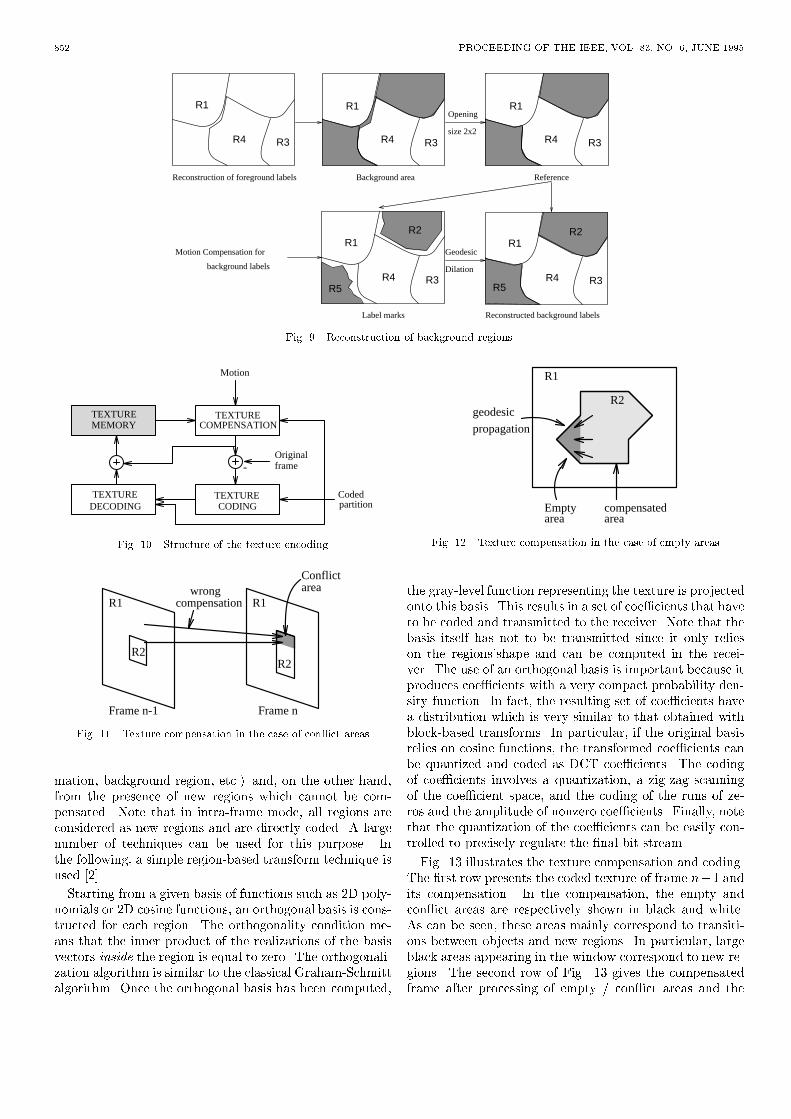
SALEMBIER ET AL.: REGION-BASED VIDEO CODING USING MATHEMATICAL MORPHOLOGY 851the prediction error and the order of the foreground regi-ons. All this information is entropy coded by a �rst orderadaptive arithmetic coder.B.2 Reconstruction of foreground and background regionsAt the decoder side, the foreground regions are recons-tructed �rst. The reconstruction is based on the previousreceived partition, the motion vectors, the prediction errorand the order of translation of foreground regions. Thissimple procedure consists in translating the regions accor-ding to the list order and their motion. As in the encoderside, a mask is incrementally constructed to indicate thearea where regions have already been settled. Any motioncompensated part falling into this area is neglected. Then,the prediction error which has not been removed by themorphological �lter will be either added to or deleted fromthe motion compensated regions.After the reconstruction of the foreground regions, thebackground regions should be restored with the correct re-gion number. First, a reference mask in the current frameis built to indicate all the background areas where the re-gion number has to be de�ned, see Fig 9. Because of theopening by reconstruction of size 2*2 used to simplify theprediction error for foreground regions, small cracks mayappear between foreground regions. The number of the re-gion in these crack areas are uncertain. Moreover, thesecracks may join together background regions that were ori-ginally disconnected. To keep the correct topological rela-tion in the current image, a morphological opening of size2*2 is applied to the background area to obtain the correctreference mask.Once the shapes of the background regions have beende�ned on the receiver side, a region number should be as-signed to each of them. Each region of the previous framewhich does not correspond to a foreground region is motioncompensated. The biggest connected component de�nesthe region number. In fact, the resulting image might beconsidered as a partially reconstructed background parti-tion. Afterwards, a reconstruction by geodesic dilation le-ads to a complete reconstruction of the whole backgroundregions, see Fig. 9.Finally, the reconstructed foreground and backgroundregions image are put together to form the current parti-tion. A post-processing procedure is carried out to removesmall isolated connected components of one pixel width.VI. Motion compensated Texture codingOnce the partition has been transmitted to the recei-ver, the texture or color information has to be coded. Thestrategy follows the classical motion predictive techniqueillustrated in Fig. 10: based on the previous texture imagestored in the texture memory and on the motion informa-tion, a compensated texture image is created by the tex-ture compensation block and its di�erence with the originaltexture frame is computed. The di�erence, called textureerror, is coded and transmitted to the receiver. The tex-ture image is created by adding the compensated textureand the coded error. As can be seen in Fig. 10, all coding
steps can be region-based since the partition has alreadybeen coded and the receiver knows the di�erent regions.For color sequences, the coding process is achieved sepa-rately on the luminance (Y) and the chrominance (U andV) signals. The only di�erence is the quality of the textureerror coding which has a much higher accuracy in the caseof luminance.A. Texture compensationAs discussed in the previous section, the motion informa-tion estimated on the contours is used to compensate boththe contours and the texture. This approach may produceerrors and inaccuracies in the compensated image, in par-ticular, for background regions. However, with a simplemodel, like the translational model that is used here, thesetexture compensation errors are not very annoying.The texture compensation is more complicated than the"classical" compensation because the motion estimationhas been performed from frame n � 1 towards frame n.Therefore, the projection of frame n� 1 into frame n crea-tes some empty areas, where no values have been assignedto the pixels, and some con ict areas, where more thanone value is assigned. To assign a value to these pixels, thecoded partition information can be used.Fig. 11 illustrates a case of con ict area. Several pixelsof frame n� 1 are projected to the same location of framen. As a result several gray-level values may be assigned tothe pixel of frame n. However, since each region of framen� 1 can only be translated, each possible gray-level valuecorresponds to a speci�c region of frame n�1. Most of thetime, one of these regions in frame n�1 corresponds to theactual region of the pixel in frame n. In Fig. 11, regions R1and R2 of frame n� 1 are in con ict but the pixels of thecon ict area belong to region R2 in frame n. The con ictcan be naturally solved by taking the gray-level value of thepixels of frame n � 1 coming from the same region as thecon ict pixel in frame n. In the example of Fig. 11, onlypixels coming from region R2 are taken into considerationin the con ict area. If none of the possible regions of framen�1 corresponds to the region of the con ict area, the areawill be processed as an empty area. Finally, note that thesecon ict areas were also present during the compensation ofcontours. However, the coding of the contour error hassolved these con icts and the coded partition is used nowas a reference to solve the texture con icts.Empty areas cannot be solved by the preceding techniquebecause no gray-level candidates in frame n � 1 can befound. In this case, the safest gray-level value to take isthe value of the closest pixel of the same region in frame n.As illustrated by Fig. 12, this procedure can be seen as apropagation of the pixels gray-level values of the region intoits empty areas. This is a geodesic dilation of the bordersof the empty area in the empty area itself.B. Texture error codingAfter motion compensation, texture errors are coded.Texture errors come, on the one hand, from inaccuracies ofthe compensation (non translational motion, region defor-
852 PROCEEDING OF THE IEEE, VOL. 83, NO. 6, JUNE 1995R1
R3R4
R1
R3R4
R1
R3R4
R1
R3R4
R2
R5
Label marks
Geodesic
Dilation
Reconstruction of foreground labels
background labels
Motion Compensation forR1
R3R4R5
R2
Reconstructed background labels
Background area Reference
Opening
size 2x2
Fig. 9. Reconstruction of background regionsCOMPENSATION
-
MEMORYTEXTURE
DECODINGTEXTURE
CODINGTEXTURE
TEXTURE
Motion
Codedpartition
OriginalframeFig. 10. Structure of the texture encoding
R1 R1
R2R2
Conflictareawrong
compensation
Frame n-1 Frame nFig. 11. Texture compensation in the case of con ict areasmation, background region, etc.) and, on the other hand,from the presence of new regions which cannot be com-pensated. Note that in intra-frame mode, all regions areconsidered as new regions and are directly coded. A largenumber of techniques can be used for this purpose. Inthe following, a simple region-based transform technique isused [2].Starting from a given basis of functions such as 2D poly-nomials or 2D cosine functions, an orthogonal basis is cons-tructed for each region. The orthogonality condition me-ans that the inner product of the realizations of the basisvectors inside the region is equal to zero. The orthogonali-zation algorithm is similar to the classical Graham-Schmittalgorithm. Once the orthogonal basis has been computed,
R1
R2
areaEmpty
areacompensated
propagation
geodesic
Fig. 12. Texture compensation in the case of empty areasthe gray-level function representing the texture is projectedonto this basis. This results in a set of coe�cients that haveto be coded and transmitted to the receiver. Note that thebasis itself has not to be transmitted since it only relieson the regions'shape and can be computed in the recei-ver. The use of an orthogonal basis is important because itproduces coe�cients with a very compact probability den-sity function. In fact, the resulting set of coe�cients havea distribution which is very similar to that obtained withblock-based transforms. In particular, if the original basisrelies on cosine functions, the transformed coe�cients canbe quantized and coded as DCT coe�cients. The codingof coe�cients involves a quantization, a zig-zag scanningof the coe�cient space, and the coding of the runs of ze-ros and the amplitude of nonzero coe�cients. Finally, notethat the quantization of the coe�cients can be easily con-trolled to precisely regulate the �nal bit stream.Fig. 13 illustrates the texture compensation and coding.The �rst row presents the coded texture of frame n�1 andits compensation. In the compensation, the empty andcon ict areas are respectively shown in black and white.As can be seen, these areas mainly correspond to transiti-ons between objects and new regions. In particular, largeblack areas appearing in the window correspond to new re-gions. The second row of Fig. 13 gives the compensatedframe after processing of empty / con ict areas and the

SALEMBIER ET AL.: REGION-BASED VIDEO CODING USING MATHEMATICAL MORPHOLOGY 853
Fig. 13. Example of texture compensation. First row: coded textureof frame n � 1, compensated frame with empty areas in blackand con ict areas in white. Second row: compensated frame withnew and unresolved areas in white, compensation error. Thirdrow: coded compensation error, reconstructed frame n.compensation error. The major part of the error is relatedto new regions which cannot be predicted from frame n�1.Finally, the last row gives the coded error and the codedframe n. VII. ResultsTo illustrate the approach described in this paper, thewell-known Miss America, Carphone and Foreman sequen-ces in QCIF format have been selected.The Miss America sequence is segmented with a targetnumber of contour points CP of 2500, whereas a value ofCP of 4250 is used for the two remaining sequences. Inintra-frame mode, the four segmentation levels respectivelyproduce approximately CP/4, 2CP/4, 3CP/4, CP contourpoints. These parameters lead to an average number ofregions of 60 for Miss America, 80 for Carphone and 90 forForeman. The segmentation is performed recursively at 25Hz. This means that all frames are segmented. This pointis important because, if the segmentation rate is decreased,small moving objects may be disconnected. They result inregions which are always processed as new regions and mayhave an in uence on the overall bit stream.Motion estimation, contour and texture coding are per-formed at 5 Hz. The search range for the motion estimationis �xed at �15 pixels. Finally, the texture coding relies ondecomposition on a orthogonal basis of cosine functions.The number of basis vectors, that is of coe�cients to code,for each region is equal to 25 for the luminance signal (Y)
and to 4 for chrominance signals (U and V). The quantiza-tion of the coe�cients is stronger in inter-frame mode thanin intra-frame.Table I gives some details about the bit stream compo-sition after entropy coding by a �rst order adaptive arith-metic coder. In all cases, 150 frames have been coded. The�gures are averages.Finally, Fig. 14 shows the original frames correspondingto frame numbers 10, 60 and 110 of each sequence. Fig.15 presents the luminance of the coded sequences. Theseexamples show that the approach described in this paperis appropriate for very low bit rate video coding. Bit rateslower than 32 kbits can be obtained with reasonable qua-lity. Moreover, no assumptions have been made about thesequence content. VIII. ConclusionsA region-based coding algorithm for video sequences hasbeen presented in this paper. This algorithm is mainlydevoted to very low bit rate video coding applications. Noassumption is made about the sequence content and, thealgorithm structure leads to a scalable coding process ableto give various levels of quality and bit rates. Several stepsof the algorithm are controlled to regulate the bit stream.The coding approach involves a time-recursive segmen-tation relying on the pixels'homogeneity, a region-basedmotion estimation, and motion compensated contour andtexture coding. The segmentation process relies on morp-hological tools such as connected operators and waters-heds. It deals with two possible criteria: size and con-trast, which are appropriate to extract the visually mostimportant image components. Motion estimation is doneafter segmentation and is used for the coding of contourand texture. Finally, both contour and texture are codedby motion compensation predictive techniques. Morpholo-gical techniques have proved to be very useful for speci�csteps of contour coding and for texture compensation. Asshown by several examples, this approach gives very in-teresting results for very low bit rate video coding.AppendixThe goal of this section is to de�ne the basic morpholo-gical tools discussed in the paper. A complete descriptionof Mathematical Morphology can be found in [19], [20]..1 Morphological operators and �ltersA large number of morphological tools relies on two basicsets of transformations known as erosions and dilations. Inthis paper, two sets of erosions and dilations are used. The�rst one deals with erosion and dilation with at structu-ring element. If f(x) denotes an input signal and Mn awindow (or at structuring element) of size n, the erosionand dilation by Mn are given by:Erosion: �n(f)(x) = Minff(x+ y); y 2Mng (5)Dilation: �n(f)(x) = Maxff(x� y); y 2Mng (6)The second set of erosions and dilations involves geode-sic transforms [5]. They are always de�ned with respect

854 PROCEEDING OF THE IEEE, VOL. 83, NO. 6, JUNE 1995
Fig. 14. Original frames (number 10, 60 and 110) of the sequences Miss America, Carphone and Foreman
Fig. 15. Coded frames (number 10, 60 and 110) of the sequences Miss America, Carphone and Foremanto a reference function r. The geodesic dilation of size one(that is the smallest size on the discrete space) is de�nedas the minimum between the dilation of size one of the ori-ginal function f and the reference function r. The geodesicerosion is de�ned by duality: Geodesic dilation of size 1:�1(f; r) = Minf�1(f); rg (7)

SALEMBIER ET AL.: REGION-BASED VIDEO CODING USING MATHEMATICAL MORPHOLOGY 855Sequence Mode Motion Contour Texture Total bit rate at 5Hzbits bits bits bits kbit/sMiss America Intra-frame 0 4879 3950 8829Miss America Inter-frame 220 2167 1238 3625 18Carphone Intra-frame 0 6528 3950 10478Carphone Inter-frame 641 3228 1348 5217 26Foreman Intra-frame 0 6740 4052 10792Foreman Inter-frame 529 3950 1941 6420 32TABLE IGeodesic erosion of size 1:�1(f; r) = ��1(�f;�r) (8)Geodesic dilations and erosions of arbitrary size are de�-ned by iterations. For example, the geodesic dilation (ero-sion) of in�nite size, also called reconstruction by dilation(by erosion) is given by:Reconstruction by dilation: rec(f; r) = �1(f; r) = :::�1(:::�1(f; r):::; r) (9)Reconstruction by erosion:'rec(f; r) = �1(f; r) = :::�1(:::�1(f; r):::; r) (10)It has to mentioned that reconstruction processes can beimplemented very e�ciently by using queues which avoidany iterating process and lead to extremely fast algorithms[22].Elementary erosions and dilations allow the de�nition ofmorphological �lters such as the morphological opening andclosing:Morphological opening: n(f) = �n(�n(f)) (11)Morphological closing: 'n(f) = �n(�n(f)) (12)A morphological opening (resp. closing) simpli�es the ori-ginal signal by removing the bright (resp. dark) compo-nents that do not �t within the structuring element. Itis a size-oriented simpli�cation. If the simpli�cation hasto deal with both bright and dark elements, an open close n('n(f)) or a close open 'n( n(f)) has to be used. Noneof these �lters are self-dual, but in practice they approxi-mately remove the same kind of information. These �lterscan be used as simpli�cation tools before segmentation,but they do not allow a perfect preservation of the contourinformation [16]. In order to improve the contour preser-vation properties, �lters by reconstruction should be used.The most popular �lter by reconstruction is the openingby reconstruction of erosion rec(�n(f); f). Of course, byduality, a closing can be de�ned: 'rec(�n(f); f). These�lters have a size-oriented simpli�cation e�ect on the signalbut preserve the contour information.
Finally, the h-maxima and h-minima operators are usedfor contrast-oriented simpli�cation. They can also be de�-ned in terms of reconstruction. If h is a constant,h�max(f) = rec(f � h; f) (13)h�min(f) = 'rec(f + h; f) (14)Filters by reconstruction belong to the class of connectedoperators that have been introduced in [21], [18]. Amongthe set of theoretical results given in [21], let us focus onthe following ones: connected operators fundamentally havethe property of interacting with the signal by producing atzones. A at zone is a connected component of the imagewhere the gray-level value is constant. Note that a atzone may be reduced to a single point. Moreover, consi-der a family of connected operators f �g depending on aparameter � (for example, a family of open close by recons-truction depending on the size of the structuring element).Assume that the family has the following property, calledpyramidal property in [21], [18]:for any � � �; 9� such that � = �( �)that is, for anyf; �(f) = �( �(f))Intuitively, this property means that, the knowledge of �(f) is su�cient to compute all �(f) for � � �. Withthese assumptions, it can be shown that the set of at zo-nes produced by � are either preserved or merged when �increases. In other words, the contours of the at regionsare either conserved or removed by the �lter. This verystrong property explains the simpli�cation e�ect as well asthe contour preservation feature of these �lters. As a result,connected �lters are extremely useful for segmentation..2 Morphological gradientsIn morphology, three gradients are generally used:Morphological gradient: g(f) = �1(f)� �1(f) (15)Gradient by erosion: g�(f) = f � �1(f) (16)Gradient by dilation: g+(f) = �1(f)� f (17)All gradients are positive, but the �rst one is symmetri-cal with respect to the contour position whereas the tworemaining ones are not. In [14], it was mentioned that theuse of the gradient results in a loss of information. In parti-cular, if the original signal involves transitions, its gradient
856 PROCEEDING OF THE IEEE, VOL. 83, NO. 6, JUNE 1995is either biased (gradient by erosion or dilation) or thick (2pixels). In the case of still images, this phenomenon is notextremely annoying. In the case of moving images, the useof the gradient results in a much larger loss of information[17] because its thickness depends on the objects'motion.I. AcknowledgmentsThis work has been performed within the frameworkof the MORPHECO project supported by the EuropeanRACE programme. Beside the authors, the main partici-pants of theMORPHECO project are L. Bouchard (PhilipsResearch Lab., Paris, texture coding), P. Brigger (EPFL,contour coding), J.R. Casas (UPC, texture coding), T. Ga-sull (UPC, contour coding), B. Marcotegui (CMM, seg-mentation), F. Marques (UPC, contour coding), M. Pardas(UPC, segmentation), O. Ribes (CMM, contour coding).References[1] M. Eden and M. Kocher. On the performance of contour co-ding algorithm in the context of image coding. Part 1: Contoursegment coding. EURASIP, Signal Processing, 8:381{386, 1985.[2] M. Gilge, T. Engelhardt, and Mehlan R. Coding of arbitra-rely shaped image segments based on a generalized orthogonaltransform. EURASIP, Image Communications, 1(2):153{180,October 1989.[3] C. Gu and M. Kunt. Contour simpli�cation and motion com-pensated coding. Accepted for publication in EURASIP, SignalProcessing: Image Communication, Special issue for very lowbitrate coding, 1995.[4] M. Kunt, A. Ikonomopoulos, and M. Kocher. Second generationimage coding techniques. Proceedings of the IEEE, 73(4):549{575, April 1985.[5] C. Lantuejoul and F. Maisonneuve. Geodesic methods in imageanalysis. Pattern Recognition, 17(2):117{187, 1984.[6] F. Marqu�es, J. Sauleda, and T. Gasull. Shape and locationcoding for contour images. In Picture Coding Symposium, pages18.6.1{18.6.2, Lausanne, Switzerland, March 1993.[7] F. Meyer. Color image segmentation. In 4th International Con-ference on Image Processing and its Applications, pages 303{304, Maastricht, The Netherlands, May 1992.[8] F. Meyer. Morphological image segmentation for coding. InJ. Serra and P. Salembier, editors, First Workshop on Mathe-matical Morphology and its Applications to Signal Processing,pages 46{51, Barcelona, Spain, May 1993. UPC.[9] F. Meyer and S. Beucher. Morphological segmentation. Journalof Visual Communication and Image Representation, 1(1):21{46, September 1990.[10] H.G. Musmann, M. Hotter, and J. Ostermann. Object-orientedanalysis-synthesis coding of moving images. Signal Processing,Image Communications, 1(2):117{138, October 1989.[11] M. Pard�as and P. Salembier. Time-recursive segmentation ofimage sequences. In EURASIP, editor, EUSIPCO 94, VII Eu-ropean Signal Processing Conference, pages 18{21, Edinburgh,U.K., September 13-16 1994.[12] S. Rajala, M. Civanlar, and W. Lee. Video data compressionusing three-dimensional segmentation based on HVS properties.In IEEE, editor, International Conference on Acoustics, Speechand Signal Processing, pages 1092{1095, New York (NY), USA,1988.[13] P. Salembier. Multi-criterion segmentation for image coding. InJ. Serra and P. Salembier, editors, First Workshop on Mathe-matical Morphology and its Applications to Signal Processing,pages 40{45, Barcelona, Spain, May 1993. UPC.[14] P. Salembier. Morphological multiscale segmentation for imagecoding. EURASIP Signal Processing, 38(3):359{386, September1994.[15] P. Salembier, C. Gu, M. Pard�as, and M. Kunt. Very low bitrate video coding using morphological segmentation and con-tour/texture motion compensation. In IEEE, editor, The 12thInternational Conference on Pattern Recognition, Jerusalem, Is-rael, October 9-13 1994.
[16] P. Salembier and M. Kunt. Size-sensitive multiresolution de-composition of images with rank order based �lters. EURASIP,Signal Processing, 27(2):205{241, May 1992.[17] P. Salembier and M. Pard�as. Hierarchical morphological segmen-tation for image sequence coding. IEEE Transactions on ImageProcessing, 3(5):639{651, September 1994.[18] P. Salembier and J. Serra. Flat zones �ltering, connected opera-tors and �lters by reconstruction. IEEE Transactions on ImageProcessing, 3(8), August 1995.[19] J. Serra. Image Analysis and Mathematical Morphology. Aca-demic Press, 1982.[20] J. Serra. Image Analysis and Mathematical Morphology, Vol II:Theoretical advances. Academic Press, 1988.[21] J. Serra and P. Salembier. Connected operators and pyramids.In SPIE, editor, Image Algebra and Mathematical Morphology,volume 2030, pages 65{76, San Diego (CA), USA, July 1993.[22] L. Vincent and P. Soille. Watersheds in digital spaces: an e�ci-ent algorithm based on immersion simulations. IEEE, Transacti-ons on Pattern Analyis and Machine Intelligence, 39(12):1845{1855, December 1991.[23] P. Willemin, T. Reed, and M. Kunt. Image sequence codingby split and merge. IEEE Transactions on Communications,39(12):1845{1855, 1991.