
REFERENCE MANUAL - Thomann
263
1 6 - V O I C E R E A L A N A L O G S Y N T H E S I Z E R REFERENCE MANUAL February 2001
-
Upload
khangminh22 -
Category
Documents
-
view
0 -
download
0
Transcript of REFERENCE MANUAL - Thomann

1 6 - V O I C E R E A L A N A L O G S Y N T H E S I Z E R
REFERENCEMANUAL
February 2001


A6 REFERENCE MANUAL 1
Your shipping carton should contain thefollowing items:
1. Andromeda A6 synthesizer2. AC power cable3. Warranty Registration card4. Reference Manual5. A list of the Preset and User Bank Mixes and Programs
If anything is missing, please contact your dealer or Alesis immediately.
NOTE: Completing and returning the Warranty Registration card is important.
Alesis contact information:Alesis Studio Electronics, Inc.1633 26th StreetSanta Monica, CA 90404USA
Telephone: 800-5-ALESIS (800-525-3747)E-Mail: [email protected]: http://www.alesis.com
Alesis Andromeda A6TM Reference ManualRevision 1.0by Dave Bertovic
© Copyright 2001, Alesis Studio Electronics, Inc. All rights reserved. Reproduction in whole orin part is prohibited. “A6”, “QCard” and “FreeLoader” are trademarks of Alesis StudioElectronics, Inc.

2 A6 REFERENCE MANUAL

Contents
ANDROMEDA A6 REFERENCE MANUAL 3
CONTENTS
Important Safety Instructions ....................................................................................7Instructions to the User (FCC Notice) ............................................................................................11CE Declaration of Conformity .........................................................................................................13
Introduction ................................................................................................................15How to Use this Manual....................................................................................................................16
Typographic Conventions..................................................................................................17Key Terminology ................................................................................................................................18
Chapter 1: Getting Started ........................................................................................21What You’ll Need, Unpacking, Set Up, Power .............................................................................21Audio Connections and Pedals........................................................................................................22MIDI Connections...............................................................................................................................23 Quick Start............................................................................................................................................26
Chapter 2: Playing the A6 .........................................................................................29A Brief Tour of the Front Panel ........................................................................................................30
How Functions are Grouped.............................................................................................30Interacting with the Display .............................................................................................................32Selecting Programs and Mixes .........................................................................................................38
PROGRAM Mode Parameters...........................................................................................39MIX Mode Parameters ........................................................................................................39
Storing Edited Programs and Mixes ...............................................................................................43Setting Up Splits and Layers ............................................................................................................47Using Global Mode.............................................................................................................................49
GLOBAL Mode Parameters...............................................................................................49Master Controls...................................................................................................................................52
Volume...................................................................................................................................52Tune........................................................................................................................................52
The Keyboard and Keyboard Modes ..............................................................................................54Performance Features (KBD MODE, UNISON X, DETUNE) .....................................55Portamento............................................................................................................................59
The Performance Wheels and Ribbon Controller.........................................................................65Programming the Wheels and Ribbon.............................................................................66Pedals and Footswitches ....................................................................................................68
The CLOCK Section............................................................................................................................69Clock Parameters .................................................................................................................70Sequencer ..............................................................................................................................71Arpeggiator...........................................................................................................................79
Chapter 3: Basics of Analog Synthesis ...................................................................81An Overview of Synthesis.................................................................................................................81
Analog and Digital Technologies .....................................................................................81A Little History ....................................................................................................................81
A Little Theory ...................................................................................................................................82Waveforms............................................................................................................................82Fundamentals and Harmonics ..........................................................................................83
Sound Dynamics .................................................................................................................................84LFOs .......................................................................................................................................87
Components of an Analog Synthesizer ..........................................................................................88

Contents
4 ANDROMEDA A6 REFERENCE MANUAL
Chapter 4: Overview of the Andromeda A6 ..........................................................93A Few Basic Concepts........................................................................................................................93A6 Function List..................................................................................................................................95A6 Functions At-a-Glance .................................................................................................................97MIDI Overview .................................................................................................................................102
Chapter 5: Oscillators and Filters...........................................................................103Oscillators...........................................................................................................................................103
Oscillator Parameter Descriptions..................................................................................104VCO Modulation ...............................................................................................................107
Filters...................................................................................................................................................116What Filters Do ..................................................................................................................116How Filters Are Designed................................................................................................117How Filters Work ..............................................................................................................122Filter Parameter Descriptions..........................................................................................127
Chapter 6: Modulation and Envelopes ................................................................. 131Modulation.........................................................................................................................................131
Background.........................................................................................................................131Modulation Principles ......................................................................................................131Hardware and Software Modulation, Default Mod Paths ........................................133
Envelopes ...........................................................................................................................................134Envelope Properties ..........................................................................................................134Envelope Parameter Descriptions ..................................................................................135TIME Page Parameters......................................................................................................137SHAPE: Selecting the Stage Slope .................................................................................139LEVEL Page Parameters ..................................................................................................141TRIG Page Parameters .....................................................................................................142Envelope Modes (Norm 1 & 2, Freerun, Susrel) ..........................................................144Envelope Modulation Triggering (MODTRG).............................................................153How Modulation Triggering Works .............................................................................155DYN Page Parameters ......................................................................................................158LOOP Page Parameters ....................................................................................................160MOD Pages .........................................................................................................................164Envelope Examples ...........................................................................................................165
Chapter 7: LFOs, Sample & Hold and Process..................................................... 171Low Frequency Oscillators .............................................................................................................171
LFO Parameter Descriptions ...........................................................................................171WAVE Page ........................................................................................................................172TRIG Page ...........................................................................................................................175SYNC Page ..........................................................................................................................176MOD Page...........................................................................................................................176Using LFOs as a Trigger Source......................................................................................176
Sample and Hold ..............................................................................................................................177PROCESS Module.............................................................................................................................179
Tracking Generator (TGEN) ............................................................................................179Track Gen Level and Track Gen Step.............................................................................179Tracking Generator Parameter Descriptions................................................................180
Chapter 8: The A6 Mixing System ........................................................................183Pre Filter Mix/Post Filter Mix ........................................................................................................183Pre Filter Mix Overview ..................................................................................................................183Pre Filter Mix Operation..................................................................................................................184
OSC and SUB OSC Controls............................................................................................184RING MOD Control ..........................................................................................................184NOISE/EXTERNAL Control...........................................................................................185Signal Routing through the Filters .................................................................................187

Contents
ANDROMEDA A6 REFERENCE MANUAL 5
Post Filter Mix Overview ................................................................................................................189Post Filter Mix Operation................................................................................................................189
Voice Mix.............................................................................................................................190MAIN and AUX outputs ..................................................................................................190Setting Levels in Mix Mode .............................................................................................190Individual VOICE OUTPUT............................................................................................190
Chapter 9: Custom Modulations .............................................................................191MOD Functions Overview..............................................................................................................191
Avoid duplication with hard-wired mods....................................................................191Performance control of mods ..........................................................................................192Using the Modulation Matrix..........................................................................................192A Few Ground Rules.........................................................................................................197
The Control Routes Section.............................................................................................................198To change modulation amounts using the CROUTES page: ....................................198To change the source of a Control Route: .....................................................................199
About Signal Flow in a MOD Path................................................................................................200About Modulation Sources .............................................................................................................201
Chapter 10: Using Effects ....................................................................................... 203Introduction .......................................................................................................................................203
Signal Flow..........................................................................................................................203Basic Controls .....................................................................................................................203Analog Distortion ..............................................................................................................204
Editing Digital Effects ......................................................................................................................205To select a Digital Effects Configuration Type:............................................................205
Editing Effect Parameters................................................................................................................206Choosing a Parameter Page .............................................................................................206Changing an Individual Parameter................................................................................206MOD: Modulating Effects Send/Output ......................................................................207
Tutorial: How to Edit a Reverb .....................................................................................................208Set the Type and Audio Levels .......................................................................................208Set the Reverb's Decay and Tone....................................................................................208Set the Reverb Predelay....................................................................................................209Change the Tone of the Reverb Decay...........................................................................209Adjust the Mix....................................................................................................................210
Digital Effects Architecture.............................................................................................................211The Signal Flow Through the Effects Section...............................................................211Single....................................................................................................................................211Dual Effects: Parallel .........................................................................................................212Dual Effects: Mono ............................................................................................................213Multi Chain .........................................................................................................................214
Configurations & Parameter Descriptions...................................................................................215Reverbs ................................................................................................................................215Delays...................................................................................................................................220Pitch Effects.........................................................................................................................222
Table of Digital Effects Parameters ...............................................................................................227
Chapter 11: Mix Mode ..............................................................................................243What is a Mix? ...................................................................................................................................243
Mix Channels vs. MIDI Channels...................................................................................243Common Mix Settings for MIDI Sequencers...............................................................................244
To make a custom multitimbral Mix:.............................................................................244MIDI Program Change Messages...................................................................................245
Editing Programs from Mix Mode ................................................................................................245

Contents
6 ANDROMEDA A6 REFERENCE MANUAL
Mix SOLO............................................................................................................................245To copy a Mix Channel from another Mix:...................................................................245
Effects in Mix Mode..........................................................................................................................246To set effect send levels for different Mix Channels: ..................................................246To copy an effect from another Program or Mix: ........................................................246
Chapter 12: MIDI Functions .....................................................................................247MIDI Basics ........................................................................................................................................247
MIDI Hardware..................................................................................................................247MIDI Messages...................................................................................................................248To send an individual Program or Mix out as a MIDI System Exclusivedump:...................................................................................................................................253To send an entire Program or Mix Bank out as a MIDI System Exclusivedump:...................................................................................................................................254About receiving SysEx dumps: .......................................................................................254
MIDI and the A6 Andromeda ........................................................................................................255A6 Channel Messages: Multitimbral Sequencing.......................................................255Setting MIDI Parameters in Global Mode.....................................................................256
Appendix A: Glossary ..............................................................................................259
Appendix B: Table of Mod Sources .......................................................................261
Appendix C: Troubleshooting.................................................................................265The Auto Tune Display ...................................................................................................................265How to Use the Tune Display ........................................................................................................266Upgrading the Operating System..................................................................................................268Troubleshooting Chart.....................................................................................................................270Cleaning and Maintenance .............................................................................................................272
Appendix D: Specifications .....................................................................................273MIDI Implementation Chart...........................................................................................................273Specifications .....................................................................................................................................274
Appendix E: Warranty .............................................................................................275

Important Safety Instructions
A6 REFERENCE MANUAL 7
IMPORTANT SAFETYINSTRUCTIONS
SAFETY SYMBOLS USED IN THISPRODUCT
This symbol alerts the user that there are important operating andmaintenance instructions in the literature accompanying this unit.
This symbol warns the user of uninsulated voltage within the unitthat can cause dangerous electric shocks.
PLEASE FOLLOW THESE PRECAUTIONSWHEN USING THIS PRODUCT:
1. Read these instructions.
2. Keep these instructions.
3. Heed all warnings.
4. Follow all instructions.
5. Do not use this apparatus near water.
6. Clean only with a damp cloth. Do not spray any liquid cleaner onto thefaceplate, as this may damage the front panel controls or cause a dangerouscondition.
7. Install in accordance with the manufacturer’s instructions.
8. Do not install near any heat sources such as radiators, heat registers, stoves,or other apparatus (including amplifiers) that produce heat.
9. Do not defeat the safety purpose of the polarized plug on the AC poweradapter. A polarized plug has two blades with one wider than the other. Thewide blade is provided for your safety. When the provided plug does not fitinto your outlet, consult an electrician for replacement of the obsolete outlet.
10. Protect the power cord from being walked on or pinched, particularly atplugs, convenience receptacles, and the point where they exit from theapparatus.
11. Use only attachments or accessories specified by the manufacturer.

Important Safety Instructions
8 A6 REFERENCE MANUAL
12. Use only with a cart, stand, bracket, or table designed for use withprofessional audio or music equipment. In any installation, make sure thatinjury or damage will not result from cables pulling on the apparatus and itsmounting. If a cart is used, use caution when moving the cart/apparatuscombination to avoid injury from tip-over.
13. Unplug this apparatus during lightning storms or when unused for longperiods of time.
14. Refer all servicing to qualified service personnel. Servicing is required whenthe apparatus has been damaged in any way, such as when the power-supply cord or plug is damaged, liquid has been spilled or objects havefallen into the apparatus, the apparatus has been exposed to rain or moisture,does not operate normally, or has been dropped.
15. This unit produces heat when operated normally. Operate in a well-ventilated area.
16. This product, in combination with an amplifier and headphones or speakers,may be capable of producing sound levels that could cause permanenthearing loss. Do not operate for a long period of time at a high volume levelor at a level that is uncomfortable. If you experience any hearing loss orringing in the ears, you should consult an audiologist.
17. WARNING: To reduce the risk of fire or electric shock, do not expose this apparatus to rain or moisture.

Important Safety Instructions
A6 REFERENCE MANUAL 9
INSTRUCTIONS DE SÉCURITÉ IMPORTANTES(FRENCH)
SYMBOLES UTILISÉS DANS CE PRODUIT
Ce symbole alèrte l’utilisateur qu’il existe des instructions defonctionnement et de maintenance dans la documentation jointeavec ce produit.
Ce symbole avertit l’utilisateur de la présence d’une tension nonisolée à l’intérieur de l’appareil pouvant engendrer des chocsélectriques.
VEUILLEZ SUIVRE CES PRÉCAUTIONS LORS DEL’UTILISATION DE L’APPAREIL:
1. Lisez ces instructions.
2. Gardez ces instructions.
3. Tenez compte de tous les avertissements.
4. Suivez toutes les instructions.
5. N’utilisez pas cet allareil à proximité de l’eau.
6. Ne nettoyez qu’avec un chiffon humide. Ne pas vaporiser de liquide nettoyantsur l’appareil, cela pourrait abîmer les contrôles de la face avant ou engendrerdes conditions dangeureuses.
7. Installez selon les recommandations du constructeur.
8. Ne pas installer à proximilé de sources de chaleur comme radiateurs, cuisinièreou autre appareils (don’t les amplificateurs) produisant de la chaleur.
9. Ne pas enlever la prise de terre du cordon secteur. Une prise murale avec terredeux broches et une troisièrme reliée à la terre. Cette dernière est présente pourvotre sécurité. Si le cordon secteur ne rentre pas dans la prise de courant,demandez à un électricien qualifié de remplacer la prise.
10. Evitez de marcher sur le cordon secteur ou de le pincer, en particulier au niveaude la prise, et aux endroits où il sor de l’appareil.
11. N’utilisez que des accessoires spécifiés par le constructeur.
12. N’utilisez qu’avec un stand, ou table conçus pour l’utilisation d’audioprofessionnel ou instruments de musique. Dans toute installation, veillez de nerien endommager à cause de câbles qui tirent sur des appareils et leur support.
13. Débranchez l’appareil lors d’un orage ou lorsqu’il n’est pas utilisé pendantlongtemps.

Important Safety Instructions
10 A6 REFERENCE MANUAL
14. Faites réparer par un personnel qualifié. Une réparation est nécessaire lorsquel’appareil a été endommagé de quelque sorte que ce soit, par exemple losrque lecordon secteur ou la prise sont endommagés, si du liquide a coulé ou des objetsse sont introduits dans l’appareil, si celui-ci a été exposé à la pluie ou àl’humidité, ne fonctionne pas normalement ou est tombé.
15. Cet appareil produit de la chaleur en fonctionnement normal.
16. Ce produit, utilisé avec un amplificateur et un casque ou des enceintes, estcapable de produite des niveaux sonores pouvant engendrer une pertepermanente de l’ouïe. Ne l’utilisez pas pendant longtemps à un niveau sonoreélevé ou à un niveau non confortable. Si vous remarquez une perte de l’ouïe ouun bourdonnement dans les oreilles, consultez un spécialiste.

Important Safety Instructions
A6 REFERENCE MANUAL 11
BEIM BENUTZEN DIESES PRODUKTES BEACHTENSIE BITTE DIE FOLGENDEN SICHERHEITSHINWEISE:(GERMAN)
1. Lesen Sie die Hinweise.
2. Halten Sie sich an die Anleitung.
3. Beachten Sie alle Warnungen.
4. Beachten Sie alle Hinweise.
5. Bringen Sie das Gerät nie mit Wasser in Berührung.
6. Verwenden Sie zur Reinigung nur ein weiches Tuch. Sprühen Sie keine flüssigerReiniger auf die Oberfläche, dies könnte zur Beschädigung der Vorderseiteführen und auch weitere Schäden verursachen.
7. Halten Sie sich beim Aufbau des Gerätes an die Angaben des Herstellers.
8. Stellen Sie das Gerät nich in der Nähe von Heizkörpern, Heizungsklappen oderanderen Wärmequellen (einschließlich Verstärkern) auf.
9. Verlegen Sie das Netzkabel des Gerätes niemals so, daß man darüber stolpernkann oder daß es gequetscht wird.
10. Benutzen Sie nur das vom Hersteller empfohlene Zubehör.
11. Verwenden Sie ausschließlich Wagen, Ständer, oder Tische, die speziell fürprofessionelle Audio- und Musikinstrumente geeignet sind. Achten Sie immerdarauf, daß die jeweiligen Geräte sicher installiert sind, um Schäden undVerletzungen zu vermeiden. Wenn Sie einen Rollwagen benutzen, achten Siedarauf, das dieser nicht umkippt, um Verletzungen auszuschließen.
12. Ziehen Sie während eines Gewitters oder wenn Sie das Gerät über einenlängeren Zeitraum nicht benutzen den Netzstecher aus der Steckdose.
13. Die Wartung sollte nur durch qualifiziertes Fachpersonal erfolgen. Die Wartungwird notwendig, wenn das Gerät beschädigt wurde oder aber das Stromkabeloder der Stecker, Gegenstände oder Flüssigkeit in das Gerät gelangt sind, dasGerät dem Regen oder Feuchtigkeit ausgesetzt war und deshalb nicht mehrnormal arbeitet oder heruntergefallen ist.
14. Bei normalem Betrieb des Gerätes kommt es zu Wärmeentwicklungen.
15. Dieses Produkt kann in Verbindung mit einem Verstärker und Kopfhörern oderLautsprechern Lautstärkepegel erzeugen, die anhaltende Gehörschädenverursachen. Betreiben Sie es nicht über längere Zeit mit hoher Lautstärke odereinem Pegel, der Ihnen unangenehm is. Wenn Sie ein Nachlassen des Gehörsoder ein Klingeln in den Ohren feststellen, sollten Sie einen Ohrenarzt aufsuchen.

Important Safety Instructions
12 A6 REFERENCE MANUAL
INSTRUCTIONS TO THE USERThis equipment has been tested and found to comply with the limits for a class Bdigital device, pursuant to Part 15 of the FCC Rules. These limits are designed toprovide reasonable protection against harmful interference in a residentialinstallation. This equipment generates, uses, and can radiate radio frequency energyand, if not installed and used in accordance with the instructions, may cause harmfulinterference to radio communications. However, there is no guarantee thatinterference will not occur in a particular installation. If this equipment does causeharmful interference to radio or television reception, which can be determined byturning the equipment off and on, the user is encouraged to try and correct theinterference by one or more of the following measures:
• Reorient or relocate the receiving antenna.• Increase the separation between the equipment and receiver.• Connect the equipment into an outlet on a circuit different from that to which
the receiver is connected.• Consult the dealer or an experienced radio/TV technician for help.
This equipment has been verified to comply with the limits for a class B computingdevice, pursuant to FCC Rules. In order to maintain compliance with FCCregulations, shielded cables must be used with this equipment. Operation with non-approved equipment or unshielded cables is likely to result in interference to radioand TV reception. The user is cautioned that changes and modifications made to theequipment without the approval of manufacturer could void the user’s authority tooperate this equipment.

Important Safety Instructions
A6 REFERENCE MANUAL 13
CE DECLARATION OF CONFORMITY
PRELIMINARY FOR INFORMATION ONLYOCTOBER PRODUCTION AND ALPHA UNITS ARE NOT YET CERTIFIEDFOR EXPORT OUTSIDE THE UNITED STATES AS OF THIS WRITING
Manufacturer’s Name: Alesis Corporation
Manufacturer’s Address: 1633 26th StreetSanta Monica, CA 90404USA
declares, that the product:
Product Name: A6Model Type: Analog Synthesizer
conforms to the following Standards:
EMC: EN 55022:1995 Class BIEC 801-2:1984 2nd Edition, 4kVdirect, 8kV air; IEC 801-3:1984 2;3V/m 150MHz-1GHz, IEC 801-4:1988 1st Edition 2; 1kV, 0.5kV
Safety: EN 60065
European Contact: Sound Technology17 Letchworth Point, Lechworth,Hertfordshire, SG6 1ND, England.Phone: +44.1462.480000Fax: +44.1462.480800
May, 2000

Important Safety Instructions
14 A6 REFERENCE MANUAL

Introduction
A6 REFERENCE MANUAL 15
INTRODUCTIONThere was a time when most of us thought that analog synthesis was dead. Yeah,there were a few new analog instruments – and rather decent ones, at that – that havecome and gone over the past few years. They were glimmers of hope that the robust,full and rich sounds of the analogs could peacefully co-exist with the digitals. I wasexcited that a handful of manufacturers were still “carrying the ball” and believedthat there will always be a place in the music world for a great analog synth. But forsome reason, these instruments – as good as they are – seem to be a little lacking inmany respects.
Then I was introduced to the Andromeda A6. Simply stated, this box has morefeatures and music power per square inch than any other synthesizer I’ve owned.And I’ve owned a bunch of them, starting with an obscure little monophonicinstrument called the MiniMoog® in 1973. To me, the A6 represents the nextsignificant step in the development of musical instruments that celebrate thistechnology.
The Andromeda A6 starts out with 16 of the most elaborate synthesizer voices todate, and these voices sound absolutely wonderful. The attention to detail applied asAlesis Engineering researched the great analog synths of the past has paid off inproducing an instrument that has the world-class analog sound, complete with everynuance. There’s nothing “virtual” about the A6: it is a real analog synthesizer.
This synthesizer has more modulation and control functionality than most playerscan fully use in a lifetime. It has an studio-quality effects system, an elaborate MIDIsystem and one of the most logical and useful displays on the market. Add to that anArpeggiator, a classic 16-event Sequencer, a Ribbon controller and CV inputs, andyou have an analog powerhouse with all of the tools — and all of the toys.
Last, but certainly not least, the A6 is gorgeous. And its striking layout and frontpanel artwork is every bit as functional as it is beautiful.
We’ve just touched on the some of the highlights of this product; there’s much moreto be explored. After you’ve read through this Reference, and experienced the soundand feel of the A6, I’m confident that you will be every bit as excited about it as I am.
There will always be a place in the music world for a great analog synth.
Dave BertovicWinter 2001

Introduction
16 A6 REFERENCE MANUAL
HOW TO USE THIS MANUAL
STRUCTURE
This manual was designed to take you through the A6 in a logical order of topics.This way, anyone who is new to this type of instrument can read through the bookfrom front to back and get the most basic information first. The manual progressivelydeals with more complex topics as you read through to the end. Experienced userscan simply use this manual as a reference resource, browsing through the topics asneeded. An Index is provided at the end of the manual for quick referrals to specificsubjects or problems. The Appendices provide technical information about the A6.
The Chapters can be grouped into five categories of information:
Overview – Chapters 1 and 2Chapter 1 is your basic introduction to the A6, from getting it out of the box, setting itup and plugging it in to making simple audio and MIDI connections, and hookingup pedals and footswitches.
Once you get everything connected, Chapter 2 takes you on a detailed tour of the A6.This Chapter runs you through the most commonly used performance features of theunit, including a discussion of how the display works and how to select sounds.We’ll also take a good look at Master Volume and Tune, the keyboard and its modes,Portamento, the Sequencer and Arpeggiator, the two performance Wheels and theRibbon Controller.
Synthesis and the A6 – Chapters 3 and 4This section of the manual starts out with Chapter 3 giving you a broad backgroundof analog synthesis, including some history and acoustic theory. All of this is thenapplied to a generic analog synthesizer to illustrate the electronic counterparts of asound’s components.
If you are new to analog synthesis, we strongly recommend that you read thisChapter in its entirety. What you will learn here will help the rest of the manualmake sense.
Where Chapter 3 provides you with concepts, Chapter 4 brings it all home to the A6.Here, you’ll learn how the A6’s sounds are organized, and how the front and backpanels are laid out. A complete list of the A6’s functions are presented along withconcise descriptions.
Program Functions – Chapters 5, 6, 7, 8, and 9These five Chapters take you through every function that makes up a Program.Here’s where the theory we covered in Chapter 3 meets reality: what the knobs andswitches do to affect each aspect of the sound.
Sound Applications – Chapters 10, 11 and 12Chapter 10 covers all the bases when it comes to using the Andromeda’s powerfulinternal effects. Chapter 11 deals with Mix mode: the A6’s memory functions forcombining two or more Programs. Mix mode is where you create splits and layers,multiple splits and layers and other multitimbral configurations. We’ll also exploreincorporating external Programs with the A6’s internal sounds.
Chapter 12 takes a good, long look at MIDI: an introductory tutorial on MIDIfunctions followed by MIDI operations specific to the A6.

Introduction
A6 REFERENCE MANUAL 17
Technical – The AppendicesThe appendices at the end of the A6 Reference Manual provide concise informationabout the instrument from a technical perspective:
Appendix A is a complete reference that documents every function in the unit.
Appendix B is glossary of common terms we use throughout the manual.
Appendix C covers all warranty, servicing and maintenance issues.
Appendix D provides troubleshooting assistance and covers the majority ofcommon problems you might incur while using the A6.
Appendix E provides a list of the A6’s technical and design specificationsincluding the instrument’s MIDI Implementation Chart.
The Index is a comprehensive cross-reference to all of the topics and terminologyin the manual.
TYPOGRAPHIC CONVENTIONS
Knob, button and back panel jack labels are printed in SMALL BOLD CAPITALS.
Words or phrases that appear in the display are printed using type thatresembles the DISPLAY characters.
A new or important term is in italics followed by its definition or contextual meaning.
Paragraphs in italics provide additional information on a topic that might be helpful inunderstanding certain important concepts.
Tip: A hint or special example called a Tip is set off from the main text by a box witha light-gray fill.
Important instructions or emphasis on a word or phrase are printed in boldfacetype.
When something extremely important appears in the manual, anicon like the one on the left will appear in the left margin. Thisindicates that this information is vital when operating the A6.

Introduction
18 A6 REFERENCE MANUAL
KEY TERMINOLOGY
While we define terms throughout this manual, and also provide a Glossary at theend, we’d like to list a few terms now that will help you get a head start on some ofthe technical expressions used in this document:
VoiceA synthesizer voice is the most basic component of a synthesizer that producessound. A voice is all of the hardware and software that is necessary to produce onenote of sound.
The A6 has 16 voices: 16 independent “sound-producing components” that playwhen a key or keys are played on its keyboard, or when MIDI Notes are received.This also means that 16 voices is the limit: if you play more than 16 keys at a time (orthe A6 receives more than 16 MIDI Notes), only 16 will play.
Program and MixWhere a voice is the instrument’s sound-producing component, a Program is all thesettings that cause the voices to produce a particular sound. This is where many ofthe front panel controls come in. They are used to create the individual sounds of theA6 and their values (settings) are stored as a Program.
A Mix is two or more Programs that can be played at the same time. Mix mode iswhere you make settings for splits and layers plus numerous combinations ofPrograms, and keyboard/MIDI control.
RAM and ROMRelated to Programs and Mixes, these two terms refer to the physical circuit chipsinside the A6 where data is stored. RAM stands for Random Access Memory and is atype of memory that you can change. This manual refers to RAM as user memory.
In addition to Programs and Mixes, Global setings are also stored in RAM (see thedefinition of Global mode later in this topic).
ROM stands for Read Only Memory and is a type of memory that is, for the mostpart, permanent. The A6 uses a type of ROM called Flash ROM which can bemodified but only under special circumstances. So, for all intents and purposes,consider ROM to be read-only. This manual refers to ROM as preset memory.
ParameterVirtually all of the main functions of the A6 are comprised of smaller elements orparts. These elements are all related in some way to the overall operation of thefunction they constitute. Each of these elements or parts is referred to as a parameter.
Using an Envelope as an example, it is comprised of no less than 47 parameters: sixadjustments for time, five adjustments for level, eight trigger settings, six dynamicssettings, eight loop parameters, plus settings for slope (with nine options), 12modulation parameters and clock-synchronization settings.
PageThe display will group a function’s parameters together on the screen called adisplay page. Some A6 functions have more than one page because they have moreparameters than can be displayed in the available screen area. This is called a multi-page display and each page’s title is printed on a page tab which resembles a tab in anotebook.
EditingWhen you make a change to a parameter in a Program or Mix, or to a Global function– by adjusting its numeric value, turning it on or off and so forth – this is calledediting.

Introduction
A6 REFERENCE MANUAL 19
OffsetMany of the Andromeda A6’s parameters have an additional adjustment called offset.This is simply an adjustment of the parameter by a fixed amount
DefaultWhen the A6 is shipped from the factory, each of its parameters has a pre-assignedvalue called a default. This is so that when a parameter is selected, it displays somesetting – on or off status, positive or negative status, a number or anotherappropriate entry – that is either a neutral setting, or one that's a good starting pointfor editing.
AmplitudeThe most common use of this word is using it to describe loudness or volume. Butstrictly speaking, amplitude refers to the level of a signal, its “intensity” (or lack of it)or the “signal strength”. And this includes any signal: the sound coming from theoscillators, vibrato from an LFO, an envelope and so forth.
So care must be taken not to associate amplitude with volume exclusively; it can be(and most often is) used to generically describe a signal’s level whether it’s volumeor not. When we cover envelopes in the next chapter, for example, amplitude controlis one of an envelope’s main characteristics, but it doesn’t always mean volume.We’ll simply use the term amplitude when referring to any kind of level.
FrequencyThe most common use of this word is to describe musical pitch or notes. Althoughthis is accurate, there are other things that have frequency even though you mightnot be able to hear them directly. Frequency is defined as rate or speed, usuallyexpressed in “cycles-per-second” which indicates how many times a wave or patternis repeated in one second. Cycles-per-second is most often referred to as “Hertz” –abbreviated “Hz” – named after the German physicist who established this unit ofmeasurement, Heinrich Hertz. Many of our examples will involve frequencies in thethousands of cycles per second, referred to as “kilo-Hertz” and abbreviated “kHz”.
We’ll use the term frequency to refer to the rate of repetition of any component of theA6: the pitch of the VCOs, the speed of the LFOs, the harmonic characteristics of theFILTERs and the CLOCK rate, among others.
Note On and Note OffThe A6 can be played from four sources. The two primary ones are its own built-inkeyboard, or a MIDI device such as another MIDI keyboard. It also can be played bya sequencer (including software sequencers running on a computer), or a drummachine – anything capable of sending MIDI Note On commands and a MIDI NoteOff commands. In addition, the A6 can be “played” by its own Sequencer andArpeggiator.
To simplify our discussions in the manual, we’ll use the term Note On to refer to akey being pressed on the A6’s keyboard, a MIDI Note On message being received bythe A6, or notes being played from the A6’s Arpeggiator and Sequencer, since theyall essentially accomplish the same thing.
We’ll use the term Note Off when referring to a pressed key being let go on the A6’skeyboard, a received MIDI Note Off message or the end of the Gate Time from theSequencer and Arpeggiator.
Trigger and GateThe concept of triggers and gates is often a confusing one for many synthesizer users.They are similar in that they both instruct a modulation source to begin, but that’swhere the similarity ends.
A trigger is best described as a “go” signal that is routed from a source (such as thekeyboard) to a modulation function. A trigger has no significant duration as it is

Introduction
20 A6 REFERENCE MANUAL
simply an electronic pulse. Translating our definition of trigger to MIDI, a trigger isthe equivalent of a Note On command.
By contrast, a gate not only performs a “go” instruction but also carries with it aduration characteristic. Using the keyboard as in the above example, a gate signal isactive for the time that a key is held down; a trigger is generated only at the instantthe key is first played. Translating our definition of gate to MIDI, the duration of agate is the time that elapses between the Note On and the Note Off commands.
LEDThis acronym stands for Light Emitting Diode, a technical name for a simple feature.It refers to the small panel lights on the A6’s front panel. When an LED next to aknob or button is on, this indicates that the function is active.
GlobalThe term global, used often in this manual, refers to any function that affects the A6no matter what play mode it’s in: global functions affect all Programs and Mixes. Youcan think of global functions as “master” functions. Master Tune is a perfect exampleof this – it tunes the whole instrument. Other global functions, described in detaillater in the manual, include Master Volume, Pitch and Mod Wheel assignments, theClock’s tempo and certain MIDI functions. While not programmable in the sense ofbeing stored with Programs and Mixes, global settings are kept in a section of RAMdedicated to global functions and are retained when the A6 is turned off.
Linear, Exponential and LogarithmicThese are mathematical terms that are used in A6 to describe the way certainfunctions perform, most notably Envelope stages and Portamento. When a functionis said to have a “linear response”, we mean that it produces an even rate of changethat, when depicted by a graph, resembles a straight line (hence the term “linear”).
Functions that have exponential and logarithmic responses produce rates of changethat accelerate (speed up) or decelerate (slow down) rather than stay even. Instead ofa straight line which represents simple ratios, expo and log functions are a little morecomplex and are graphed by curves.

Chapter 1: Getting Started
A6 REFERENCE MANUAL 21
CHAPTER 1
GETTING STARTEDWHAT YOU’LL NEED
The A6’s basic requirements include:1. an AC electrical outlet
2. a stand or table to put it on
3. audio cables and a sound system or amplifier, or a pair of headphones
USING THE A6 WITH OTHER INSTRUMENTS
If you plan to use the A6 with other MIDI devices, you’ll need standard MIDI cablesthat connect your A6 to other MIDI devices in your system. See the topic Hook It Upbelow for more information. It would also help if you have basic working knowledgeof MIDI. If you’re new to MIDI, read our MIDI tutorial in Chapter 10.
UNPACK ITThe A6 is packaged in a cardboard box with molded styrofoam inserts. After youremove your A6, its AC power cord, the Warranty card and this manual, we suggestyou keep all packing materials in a safe place. You’ll need the box and styrofoam incase the unit needs to be transported or shipped.
SET IT UPYou can place the A6 just about anywhere that’s convenient. Before placing the A6on a stand or table, be certain that is capable of securely holding an object thatweighs 40 lbs. (18.15kg). You should also consider any pounding that you might begiving it. If the stand collapses under the A6’s weight (or your playing), the unitcould suffer permanent damage and you could be injured. Take the time right now tomake sure that your stand is adequate.
HOOK IT UP
POWER
Use the AC power cord (or equivalent) that is included with the A6. Make sure thatthe unit is turned off before you plug the power cord into the rear panel receptacleand the wall outlet. The unit has a universal power supply that should work withlocal AC power in most countries. If in doubt, check with your power companybefore plugging it in. In the U.S., the A6 must be plugged into a standard 117 VAC,50 - 60 Hz outlet.
Do not attempt to use another type of power cable and do notattempt to modify this receptacle or the cable itself. Doing so maycause serious injury or death. Please refer to the section ImportantSafety Instructions at the beginning of this manual.

Chapter 1: Getting Started
22 A6 REFERENCE MANUAL
AUDIO CONNECTIONS
After you’ve set up the A6 and plugged it into an AC outlet, connect your A6 to asound system. Since the A6 does not contain an amplifier or speakers, you’ll need toconnect it to some kind of a sound system in order to hear it. An amp with a full-range speaker will also suffice, as will a stereo music system with external audioinputs. You can also use a pair of standard stereo headphones with a 1/4” TRS pluginserted into the back panel.
For stereo, connect two 1/4” 2-conductor (unbalanced) audio cables from the unit’sLEFT and RIGHT jacks on the rear panel to two inputs on your sound system. For amonophonic output, use an audio cable from the A6’s LEFT jack. The four AUX OUTjacks plus the eight stereo VOICE OUTPUTS will be covered in Chapter 4.
For use with stereo headphones, the A6 sports a 1/4” stereo HEADPHONE jack on therear panel.
In any case, turn your A6 on first, then your sound system or amplifier. Use theMASTER VOLUME control located near the front panel’s upper left-hand corner to setthe overall output level of the synthesizer.
PEDALS AND FOOTSWITCHES
Momentary, 2-conductor foot switches are used for the SWITCH and SUSTAIN inputson the A6’s back panel. “Momentary” means that it is a spring-loaded switch thatoperates by “pressing and releasing” for ON (press) or OFF (release) signals.
A potentiometer, 2-conductor foot pedal is used for the PEDAL/CV back panel input.This input is typically used for volume or modulation (typically vibrato, but you canuse it for other types of modulation). “Potentiometer” means that the pedalmechanically operates an internal knob giving you “more” or “less” rather than ONor OFF like a switch. These pedals are often referred to as “rocker pedals”.

Chapter 1: Getting Started
A6 REFERENCE MANUAL 23
MIDI CONNECTIONS
If you plan to use the A6 with other MIDI instruments and devices in a music system,use the following guide to connect it to your rig.
As a Master: If you intend to use the A6 as the master controller in your MIDIrig, plug a standard MIDI cable into the A6’s MIDI OUT port. Theother end of this cable should plug into the MIDI IN of the firstslave in the system. If there are several MIDI instruments in yoursetup, connect MIDI THRU from the first slave to the MIDI IN of thesecond device and so forth to create a “chain”.
POWEREDIT MODE
PHONES VOLUME
PLAY MODE
BANK SELECT
64 VOICE EXPANDABLE SYNTHESIZER MODULE
PCMCIA EXPANSION CARDS
B
A
VALUE
PROGMIXEDIT
DOWN UPSTOREMIDI CH
CURSOR
GLOBALCOMPAREMIDI CHANNEL

Chapter 1: Getting Started
24 A6 REFERENCE MANUAL
As a Slave: If you plan to control the A6 from another MIDI device, you’llneed a MIDI cable connected to its MIDI IN port.
You will also need a MIDI cable connected to the A6’s MIDI THRUif you plan to pass MIDI data from the master through the A6 toother MIDI devices in your rig. Connect one end of the MIDIcable to the A6’s MIDI THRU port and the other end of the cable tothe MIDI IN of the first device in the chain.
POWEREDIT MODE
PHONES VOLUME
PLAY MODE
BANK SELECT
64 VOICE EXPANDABLE SYNTHESIZER MODULE
PCMCIA EXPANSION CARDS
B
A
VALUE
PROGMIXEDIT
DOWN UPSTOREMIDI CH
CURSOR
GLOBALCOMPAREMIDI CHANNEL

Chapter 1: Getting Started
A6 REFERENCE MANUAL 25
With a MIDI Patchbay: If you’re using a MIDI patchbay or “patcher” to connect all ofyour MIDI devices centrally, the patcher will have a pair of MIDIconnectors for each MIDI device. The patcher’s back panel willhave a series of paired MIDI OUT and MIDI IN ports for each devicein your rig (the A6 being one of them).
Connect the A6’s MIDI OUT to the MIDI IN of one of the pairs. Thesame pair’s MIDI OUT connects to the MIDI IN of the A6. Consult thepatcher’s Owner’s Manual to find out how it routes MIDI dataamong the devices connected to it.
POWEREDIT MODE
PHONES VOLUME
PLAY MODE
BANK SELECT
64 VOICE EXPANDABLE SYNTHESIZER MODULE
PCMCIA EXPANSION CARDS
B
A
VALUE
PROGMIXEDIT
DOWN UPSTOREMIDI CH
CURSOR
GLOBALCOMPAREMIDI CHANNEL
This covers the basics of setting up the A6.

Chapter 1: Getting Started
26 A6 REFERENCE MANUAL
QUICK START: PLAYING YOUR FIRST PROGRAM
AUTO TUNE
Now that it's all hooked up, there's one more thing you have to do. If you've jumpedthe gun and played a few chords, you probably heard that the unit was way out oftune. Because the Andromeda is a true analog synthesizer, and analog circuitry issensitive to temperature and other factors, each one of the sixteen voices (and theoscillators and filters within each voice) must be tuned before playing. Luckily, theAndromeda has a software routine that will do this for you.
To tune the Andromeda's voices automatically:
On the left side of the control panel above the Mod Wheel, find the MASTER section,with a Volume and a Tune knob. Press the AUTO TUNE button beneath these, whichwill bring up the Auto Tune display. Press AUTO TUNE again to start the tuningprocess.
On the display, you will see each individual oscillator, pulse width, and filter tuned inturn. This takes about three and a half minutes, during which you won't be able to playthe unit. (Later, you can save time by tuning only the oscillators if you wish, by pressingthe button under OSCFRQ in the display.)
Once the unit is tuned, you'll see a screen with lists of multiple TUNEOK columns.After the unit has warmed up some more, if you hear something off-key, you maypress AUTO TUNE again.
In addition, the A6 has a feature called background tuning. This automatically tunesvoices in the background without interrupting playing. (More about turning this onand off can be found in later sections of the manual.)

Chapter 1: Getting Started
A6 REFERENCE MANUAL 27
SELECTING PROGRAMS
You don't have to know what all the knobs do to enjoy the A6; it comes pre-programmed with hundreds of sounds. You can simply listen to these sounds andfind out more about them later. When playing the A6, the instrument operates inone of two play modes: Program mode and Mix mode. In Program mode, thekeyboard plays a single sound across the entire keyboard. Program mode has 3banks: User, Preset 1, and Preset 2. Each bank has 128 different Programs, so youhave a total of 384 Programs to audition. In Mix mode, it may play different soundsin different ranges (a split), a stack of sounds on top of each other, or combination ofsplits and stacks. There are two banks in Mix mode (one User and one Preset) for atotal of 256 Mixes. Between the two modes, you have 640 "patches" to select from.
To select Programs and Mixes:
1. To select a Program, make sure that the A6 is in Program mode: the LED next tothe PROGRAM button should be on. If not, press the PROGRAM button.
The easiest method of selecting Programs or Mixes to use the row of direct-selectbuttons just above the Ribbon Controller. Pressing a 2-digit PROGRAM GROUP buttonselects the “tens group”...
and pressing a single-digit PROGRAM NUMBER button selects the specific Program:
OR
To select a Mix, make sure that the A6 is in Mix mode: the LED next to theMIX button should be on. If not, press the MIX button.
2. To select a specific Program, press a PROGRAM GROUP button then a PROGRAMNUMBER button. Pressing the “50” button, for example, plus the “8” buttonselects Program 58, Mix 58, or PROG 58 in a Mix Channel.
3. You can move among Banks by pressing the < BANK or BANK > button:
For example, when the Andromeda is in PROGRAMmode, you have three Program Banks from which tochoose Programs: two factory Preset Banks and theUser Bank (where you store Programs that you create).Use the BANK buttons to switch among these threeBanks. Mix Mode works the same: when MIX Mode isactive, use the BANK buttons to switch among the twoMix Banks (one Preset and one User).
As you change programs, you'll notice various lights on the top panel will change.Disregard this for now.

Chapter 1: Getting Started
28 A6 REFERENCE MANUAL
MASTER VOLUME
And finally, adjust the level using the MASTER VOLUME on the left side of the controlpanel. The VOICE MIX LEVEL on the right side is a programmable control—it may seemto do the same thing, but avoid using it for now.
The MASTER VOLUME knob is aglobal (affects the A6 in allmodes) volume control thatdetermines the final outputlevel of the unit’s MAIN LEFT andRIGHT stereo outs, theHEADPHONE output and the twoAUX OUTs. It does not affect theeight stereo VOICE OUTPUTS. Touse an audio term, MASTERVOLUME is post (comes after) thePRE and POST FILTER mixes andthe VOICE MIX. This means thatany relative level settings youmake within the Programs andMixes are preserved.
You operate this control by simply turning it: fully counter-clockwise shuts the audiooutputs off, fully clockwise is maximum.
The next Chapter covers the basics of playing the A6: more detail about how to selectPrograms and Mixes, understanding the various keyboard modes including settingup splits and layers and using portamento, using the performance wheels and theribbon controller, using pedals and footswitches, and understanding the CLOCKsection in using the sequencer and arpeggiator.
Chapter 2 will also devote much attention to the display, as it is the central focus ofthe A6 when operating its controls.

Chapter 2: Playing the A6
A6 REFERENCE MANUAL 29
CHAPTER 2:
PLAYING THE A6Possibly the best way to get acquainted with the A6 is to dig in and start playing.Feel free to skip around this Chapter if you need to get specific information quickly.This Chapter deals specifically with functions you’re most likely to use when playingthe instrument:
• getting around the front panel• understanding and using the display• selecting Programs and Mixes• setting up splits and layers• using the Master controls• exploring the various keyboard modes• using the performance wheels and ribbon controller• using pedals and footswitches• the Clock section: using the sequencer and arpeggiator
Quite possibly the most fundamental skill you’ll need to acquire in using the A6successfully is understanding the display. The essentials of operating the display arecovered in this Chapter, and as you use the display on a regular basis, its operationwill become much clearer. Once you get a hold of the concepts and procedures laidout in this section, you’ll be ready to undertake the remaining tutorials in this book.
The one glaring omission of this Chapter – which is intentional, by the way – is atutorial on MIDI. If you need an explanation of this technology now, go to Chapter12. The first half of Chapter 12 is devoted to the MIDI Specification, which serves as agood starting point for those new to this system. Real-world applications withnumerous examples in connecting the A6 to other MIDI devices were covered in theprevious Chapter.

Chapter 2: Playing the A6
30 A6 REFERENCE MANUAL
A BRIEF TOUR OF THE FRONT PANELThe A6’s front panel contains a fairly large number of buttons and knobs, which isprobably a lot more than most players are used to seeing on a synthesizer these days.The A6 is designed to make editing as easy and as quick as possible: the majority ofProgram voice parameters exist on the front panel with a knob or button dedicatedexclusively to that function. Having dedicated knobs and buttons achieves the speedgoal by not forcing you to dig through layers and layers of functions on the displayjust to make a simple or routine edit.
The speed of Program editing is enhanced further by the functionality of the display.As we’ll discover in the next topic INTERACTING WITH THE DISPLAY, the A6’s LCDscreen employs a set of soft controls – controls that change function depending on thecurrent screen. These eight buttons and eight knobs are used to edit whatever isbeing displayed. Therefore, the display area provides a second location whereProgram editing can happen.
So you have a choice: you can make Program edits directly from any front panelcontrol, or you can do it in the display area. In either case, the display will change toreflect the current edit you’re making. You can even lock the display so that itdoesn’t switch every time an edit is attempted. More on that later.
HOW FUNCTIONS ARE GROUPED
Understanding how the A6’s functions are grouped will greatly enhance your abilityto learn and use the instrument. The following topics describe these function groups– called modules – of the A6.
Program-Specific FunctionsThere are numerous functions within the A6 that deal only with the creating orediting of Programs. In fact, most of the controls on the front panel that are in thearea above the keyboard (not including the display area) are Program functions.The front panel is laid out such that each Module and its related parameters arevisually grouped by the artwork:
LFOs Display and Soft Controls* FILTER 1PROCESS FILTER 2OSC 1 EFFECTS* POST FILTER MIXOSC 2 EXTERNAL INPUTS* ENV 1 (PITCH)PRE FILTER MIX ENV 2 (FILTER)
* also available for Mixes. ENV 3 (AMP)VOICE MIX
These functions will be covered in detail in Chapter 4: A6 Overview and Chapter5: Program Functions. But of particular importance to note now, especially forseasoned analog synthesists who are familiar with earlier modular products, is thateach of the above function groups can be thought of as a “physical module minus thepatch cords”. In fact, you can “disconnect” some of these modules from the audioand control paths by setting their values to zero, in effect turning them off. That’swhy they’re called “modules”.
Mix-Specific FunctionsMix mode, because of its nature in simply organizing existing Programs into splits,layers and other Voice arrangements, has far fewer controls than those forconstructing the Programs themselves. Notice that Mix controls are conspicuouslyabsent from the A6’s front panel – you access these functions from the display. Thebasics of layering and splitting are covered later in this chapter on page 47.

Chapter 2: Playing the A6
A6 REFERENCE MANUAL 31
Mix mode is also used when the A6 is connected to a MIDI sequencer formultitimbral recording and playback. Each Mix channel, the set of parameters that areused to control a Program in the Mix, can be assigned to a specific MIDI Channelwith unique MIDI controller assignments.
Especially noteworthy of Mix mode is that it has its own set of programmable effects.All of the effects available for enhancing Programs are included in this mode and arefully independent and programmable per Mix. This is particularly useful whenconstructing complex Mixes that use many different Programs. These functions arecovered in detail later in this manual in Chapter 11: Mix Mode.
Global FunctionsGlobal functions are those that affect the A6 no matter what mode it’s in. You canthink of global functions as “master” controls such as MASTER VOLUME or MASTERTUNE.
Also, there are certain MIDI functions that are global as well. Every MIDI instrumentor device has a setting called the Basic MIDI Channel. This sets the Channel on whichthe instrument will normally transmit MIDI data, although the “upper” and “lower”components of splits and layers can be set to transmit and receive on Channels otherthan the Basic. Global Mode is covered later in this Chapter on page 50, UsingGlobal Mode. But first, let's become familiar with the Andromeda's display andsoft controls.

Chapter 2: Playing the A6
32 A6 REFERENCE MANUAL
INTERACTING WITH THE DISPLAYAlthough the A6 has numerous knobs and buttons across its front panel, the display(and its associated controls) is the central area to use when operating the A6. Thisconcept holds true in all modes: with few exceptions, virtually every front panelknob and button are duplicated on-screen, and most of them will show their currentsettings if appropriate.
DISPLAY FEATURES
As a general principle, the display will group a function’s parameters together on thescreen. This makes creating and editing Programs and Mixes much easier, as isgetting around in Global mode.
A group of parameters on the screen is called a display page. Some A6 functions havemore than one page because they have more parameters than can be displayed in theavailable screen area. This is called a multi-page display and the active page’s title isdisplayed on a page tab which resembles a tab in a notebook. The active parameter’stitle is displayed in white characters with a black-highlighted tab. This way, you willalways know which page and which parameter on that page is active.
In addition, the display’s usefulness is enhanced by depicting certain functions witha graphic. Furthermore, the picture changes as you make adjustments to its para-meters. Envelope shapes, LFO waves and Velocity curves are displayed in graphform, just to name a few. A visual representation of the item(s) you’re changing notonly makes the editing process faster, it will (in many cases) assist you inunderstanding the functionality of the parameters you’re working with.

Chapter 2: Playing the A6
A6 REFERENCE MANUAL 33
BASIC DISPLAY FUNCTIONS
In its normal operating mode, the display will react to virtually any change youmake to any of the front panel controls. When you turn a knob or press a button, thedisplay will recall that parameter’s page and select the parameter for editing. Thisfeature of the A6 will save you an enormous amount of time and frustration whenmaking changes and minimizes the risk of “getting lost” when editing manyparameters at the same time.
While this feature of the A6 is quite useful when working with individualparameters, you may want to display a particular module. In this case, press its VIEWbutton. This will display the selected module – OSC 1, OSC 2, FILTER 1, FILTER 2, ENV 1,ENV 2 or ENV 3, etc. – and the last parameter that was used in that module will be theactive one. You can then proceed to make your edits from either the screen’s controlsor the module’s dedicated front panel controls.
The advantage of the VIEW button is that you can select a module and view itscurrent settings without changing any of its parameters. If you turn one of the frontpanel knobs, its value will change. So if you just want to see the module’s currentsettings without making changes, use the VIEW button.
On the other hand, the advantage of a module’s dedicated front panel controls is thatyou can make edits to its most commonly used parameters quickly just by turninga knob. The choice is yours.
Soft ControlsDirectly beneath the display is a series of eight untitled knobs and buttons numbered1 through 8. These are soft controls – controls that change function depending on thecurrent screen. Soft controls, therefore, obtain their functional identity or“personality” from the pages and parameters being displayed: the current function ofany knob or button is determined by what is on the display directly above thecontrol. There are three rows in most displays:
• the bottom row of the display is called the Page Row. It shows the names ofdisplay pages that can be called up by pressing the button beneath the pagetab.
• the second row of text shows the function of each knob. We’ll refer to thisrow of text as the Parameter Row.
• the third row of text (in reversed text like this) shows the current value ofeach parameter. We’ll refer to this row of text as the Value Row.
Tip: Although you can select any parameter simply by turning its corresponding softknob, this action also changes the parameter’s value which isn’t alwaysdesirable. Sometimes you just want to review the current settings of theparameters on a page without changing anything. On many pages, you canselect a parameter without changing its value by pressing its page’s soft button.

Chapter 2: Playing the A6
34 A6 REFERENCE MANUAL
Modes of OperationLet’s start at the beginning and discuss the three basic operating modes of the A6 andhow the display keeps you informed of what’s going on.
All of the operations of the A6 are grouped into three operating modes: Programmode, Mix mode and Global mode. You can access only one of these modes at a time,but switching among the three is as easy as pressing a button.
Use the three buttons on the lower left-hand corner of the display area to initiate thedesired mode. When pressed, a mode button’s associated LED will light:
• pressing PROGRAM initiates Program mode where the A6’s single programsare played via the keyboard or MIDI, and where you edit existing Programsor create new ones from scratch. This is one of the A6’s two Play modes; theother one is Mix mode, described next.
• pressing MIX initiates Mix mode where the A6’s Mix programs are played viathe keyboard or MIDI, and where you edit existing Mixes or create new onesfrom scratch. A Mix is made up of existing single Programs and is the modeyou use for creating layers, splits or complex sound combinations, and forMIDI control.
• pressing GLOBAL initiates Global mode where you control the A6’s globalfunctions and master settings. These functions affect the A6 regardless ofwhat Play mode the A6 is in. Included in this mode are items such as settingthe MIDI Basic Channel and MIDI Controller Numbers, monitoring voiceactivity, and so forth.
Data Banks: How the A6’s Sounds Are OrganizedThe following block diagram illustrates how the A6’s memory is organized amongthe three operating modes we just discussed.
GlobalMixProgram
EXTERNAL INPUTSCV/Audio/Hardware Routing
EFFECTSAnalog Distrotions Configurations & Parameters
Digital Effects Configurations & Parameters
EXTERNAL INPUTSCV/Audio/Hardware Routing
EFFECTSAnalog Distrotions Configurations & Parameters
Digital Effects Configurations & Parameters
PRO
GRA
M S
ETTI
NG
S
Sequencer & Arpeggiator
Keyboard Modes
Portamento/LFOs/S & H
Tracking Generator
Voltage Controlled Oscillators
Pre Filter Mix
Filters
Post Filter Mix
Envelopes
Voice Outputs & Mix
Effects Send Outputs & Mix
Modulation Matrix
Mix ChannelParameters
ProgramSettings
MIX CHANNEL 1
Mix ChannelParameters
ProgramSettings
MIX CHANNEL 2
Mix ChannelParameters
ProgramSettings
MIX CHANNEL 3
Mix ChannelParameters
ProgramSettings
MIX CHANNEL 14
Mix ChannelParameters
ProgramSettings
MIX CHANNEL 15
Mix ChannelParameters
ProgramSettings
MIX CHANNEL 16
Global Tune & Transpose
Global MIDI Filtering & Assign
Wheel, Pedal, Ribbon andMIDI Continuous Controllers
Assignments
Edit Preferences
MASTER CLOCK SETTINGS MASTER CLOCK SETTINGS

Chapter 2: Playing the A6
A6 REFERENCE MANUAL 35
Throughout this manual, we’ll be using the following terms to describe the memorycapabilities of the A6:
• A Program bank refers to an entire bank of Programs.
• A Mix bank refers to an entire bank of Mixes.
• A User bank (there’s one for Programs and one for Mixes) refers to a databank that uses RAM for storage and can be edited. You can think of this ofbank as your “work space”: individual Programs and Mixes can be edited andstored, replaced, copied and so forth.
• A Preset bank refers to a data bank – either Program or Mix – in Flash ROM.The A6’s Preset banks (there are three of them) are commonly called “factorypresets” on many other instruments. These banks – two Preset Program banksand one Preset Mix bank – contain Programs and Mixes developed for the A6by the Alesis Sound Design team.
Unlike Preset banks in many other synths, the A6's Preset banks can becustomized by the user, but only as an Entire Bank copy operation. Thismeans that, unlike the User banks, you cannot selectively copy just oneProgram or Mix to this bank. The entire bank must be over-written at once.
• A Card bank refers to a data bank of memory provided by a PCMCIA card inthe A6's back-panel card slot. An SRAM card allows the same options forstorage as found for the User bank. The card may allow for a Program Bankonly, several Mix banks, or a combination, depending on its size.
The A6’s memory capacity is arranged as follows:
Program mode:
• 2 Preset Program banks of 128 Programs (256 total)• 1 User Program bank of 128 Programs
Mix mode:
• 1 Preset Mix banks of 128 Mixes each• 1 User Mix bank of 128 Mixes
Memory FunctionsEach of the two play modes – Program and Mix – contain two memory functions thatare used when editing existing Programs or Mixes, or creating new ones. Whenpressed, a memory button’s associated LED will light:
• the STORE button allows you to save a Program or Mix that you’ve edited orcreated into the current program number, or copy it to another memorylocation. The procedure for saving edited Programs and Mixes is detailed onpage 43.
• pressing COMPARE recalls the stored version of the Program or Mix you’reediting so that you can compare the edited version with the original. Thisbutton is inactive if the current program hasn’t been edited (there’s nothingdifferent to compare).
Program mode contains a third memory-related function called MANUAL that’s usedwhen creating new Programs and is only active in Program mode. Pressing thisbutton causes the A6 to exit the current Program and create a new Program based onthe current settings of all front panel controls. While this new program may notsound like anything useful – the knobs could be positioned in strange settings – itprovides a good starting point for a new program.

Chapter 2: Playing the A6
36 A6 REFERENCE MANUAL
LOCK FunctionWhile many of the A6’s pages make use of all eight knobs and buttons, many do not.You may notice that sometimes knobs and buttons will become inactive because thedisplay doesn’t need them. But there are two soft buttons – 7 and 8 – that are alwaysactive. They are used to lock the display.
As mentioned at the beginning of this topic, the display will react to virtually anychange you make to any of the front panel controls. This causes a lot of displayswitching and can be distracting. If you want to prevent the display from switchingscreens when performing numerous edits, press soft buttons 7 and 8 together. Thiswill lock the display in its current screen, and DISPLAY LOCKED will flash over softknobs 4 and 5. You can continue to make adjustments to any parameter, but thedisplay stays put. Press 7 and 8 again (or any VIEW button) to turn this function off.
▲ and ▼ ArrowsFor the majority of parameters in the A6, numeric values are displayed withfractional amounts, represented by the digits to the right of the decimal point. Thisallows for very precise adjustments to be made to parameters that support fractionalvalues. The ▲ (increment) and ▼ (decrement) arrows are used to make fineadjustments to any parameter that is displayed with a fractional value.
Holding an arrow down scrolls the values. You’ll notice that the changing values willaccelerate the longer you hold the arrow button down.
Double-Arrow ResetPressing both arrow buttons together will either set the selected parameter to zeroor to a useful default or neutral value. For example, if the SQR wave’s WIDTHparameter is selected, pressing both arrows together sets its value to 50%. If FILTER 2KEY TRACK is selected, pressing both arrows together sets its value to 50. Generally,most parameters with a 0 to 100 or a -100 to +100range will reset to 0.
CONTRAST ControlThe CONTRAST knob above the ▼ and ▲ arrows is used to adjust the contrast of thedisplay.
The MIX SELECT Button GroupThe row of rectangular buttons just below the display area are used to select thePrograms within a Mix. When a Mix Channel is ON, its associated LED will light.When a Mix Channel is currently selected for editing in the display, its LED willblink.
When the A6 is in Mix mode, pressing one the 1/9 through 8/16 buttons selectsa specific Mix Channel – the group of settings that affect each Program in a Mix (theProgram number, its transpose value, its individual MIDI Channel, etc.). Pressing anumbered button alone selects Mix Channels 1 through 8. Pressing and holding SHIFTwhile pressing a numbered button selects Mix Channels 9 through 16.

Chapter 2: Playing the A6
A6 REFERENCE MANUAL 37
Table of Display FunctionsThe following table summarizes the functions of the display’s knobs and buttons:
NAME FUNCTION
GLOBAL button Enters Global mode, displays Global screen.
PROGRAM button Enters Program mode, displays Program screen.
MIX button Enters Mix mode, displays Mix screen.
STORE buttonEnters Store mode, Copy mode for Programs, Banks, and Effects, SysEx mode, and the INIT
function used to reset the A6 User banks; displays the screens associated with each of theabove functions.
COMPARE buttonEnters Compare mode: when editing, the stored versions of the current Program or Mix (including
Distortion and Effects) are recalled permitting a comparison to be made with the editedversions.
MANUAL button Enters Manual mode: every knob position on the front panel is read by the A6 and made current.This mode is exited when another Program or Mix is selected.
MIX button group Group of buttons for selecting the current Mix Channel within a Mix:
SHIFT button Toggles between the Mix Channels 1-8 and 9-16.
1/9 – 8/16 buttonsPressing once selects the desired Mix Channel. For the current Mix Channel, pressing againtoggles the Mix Channel on or off. When a Mix Channel is on, its button’s LED will blink whenthat Mix Channel is selected.
“Soft Buttons” Eight buttons below the display that select the page shown on the Page row (the lowest row oftext in the display).
“Soft Knobs” Eight knobs below the display whose functions are determined by what is currently beingdisplayed on the second row of text from the bottom (the Parameter row).
▲ and ▼ buttons Step adjusts the highlighted value for the current parameter. Pressing both arrows together resetsthe current parameter to zero, a midpoint or a useful default value
LOCK DISPLAYbutton combination
Soft Buttons 7 and 8 pressed together will lock the current display screen. The wordsDISPLAY LOCKED will flash in the display.

Chapter 2: Playing the A6
38 A6 REFERENCE MANUAL
SELECTING PROGRAMS AND MIXESWhen playing the A6, the instrument operates in one of two play modes: Programmode or Mix mode. One method of selecting Programs or Mixes is using the row ofdirect-select buttons just above the Ribbon Controller. Pressing a 2-digit PROGRAMGROUP button selects the “tens group”...
... and pressing a single-digit PROGRAM NUMBER button selects the specific Program orMix:
1. To select a Program, make sure that the A6 is in Program mode: the LED nextto the PROGRAM button should be on. If not, press the PROGRAM button.
OR
To select a Mix, make sure that the A6 is in Mix mode: the LED next to the MIXbutton should be on. If not, press the MIX button. Also, in Mix mode you canwork with the individual Programs that are contained within a Mix (theindividual Programs that comprise a Mix are referred to as Mix Channels).
2. To select a specific Program, Mix or assign a Program to a Mix Channel, pressa PROGRAM GROUP button then a PROGRAM NUMBER button. Pressing the “50”button, for example, plus the “8” button selects Program 58 when the A6 is inProgram mode, Mix 58 when in Mix mode or assigns Program 58 to theselected Mix Channel when Mix mode’s PROG page is displayed. See the nextparagraph for details:
3. To assign a specific Program to a specific Mix Channel within a Mix, press MIXto enter Mix mode, then press one of the SELECT buttons to select a MixChannel. Press soft button 6 to display Mix mode’s PROG page. While thePROG page is being displayed, pressing a PROGRAM GROUP and/or aPROGRAM NUMBER assigns that Program to the current Mix Channel. Don’tforget to turn the Mix Channel on (press the Channel’s SELECT button if itsLED is off).
4. You can move among Banks by pressing the < BANK or BANK > button:
When the Andromeda is in Program mode, you have three Program Banksfrom which to choose: two factory Preset Banks and one User Bank (whereyou store Programs that you create). Use the BANK buttons to switch betweenthese Banks. Mix Mode works the same: when MIX Mode is active, use theBANK buttons to switch among the two Mix Banks (one Preset and one User).
The second method of selecting a Program, Mix or Mix Channel involves the displayand soft knobs and is covered in the next topic.

Chapter 2: Playing the A6
A6 REFERENCE MANUAL 39
PROGRAM MODE PARAMETERS
Pressing the PROGRAM button displays the Program mode display screen. As with allother A6 functions, the page and parameter that was last selected will be recalled.The following table summarizes the Program mode parameters:
SOFT KNOB ✿
✿ PAGE TAB
1 2 3 4 5 6 7 8
PROG BANK NUMBER
DIR BANK NUMBER
PROG and DIR Page ParametersThe PROG (Program) page provides another method to select Programs in addition tothe Direct Select buttons. When this page is being displayed, use soft knob 1 to selectthe bank and soft knob 2 to select the specific Program number.
The DIR (Directory) page soft knobs operate the same as in the PROG page. Thedifference is that the DIR page provides a directory-style listing of all Programs in thesynthesizer, and shows ten names at a time.
Tip: While either of these two pages are being displayed, you can still use the DirectSelect buttons as well as the soft knobs to select sounds.
MIX MODE PARAMETERS
Pressing the MIX button displays the Mix mode display screen. As with all other A6functions, the page and parameter that was last selected will be recalled. Thefollowing table summarizes the Mix mode parameters:
SOFT KNOB ✿
✿ PAGE TAB
1 2 3 4 5 6 7 8
MIX BANK NUMBER ENABLE
DIR BANK NUMBER
KBD KBD LO KBD HI ENABLE
PROG LEVEL PAN OUTPUT SEMI CENTS MIDI CH
PCHWHL MODWHL AFTCH SUSPDL EXTSW EXTPDL RIBBON - KBD -CNTL
MID IN MIDOUT MID CC MIDVOL MIDPGM MIDAFT
SOLO
The DIR page in Mix mode operates exactly the same as the parameters in Programmode. For descriptions of this parameter, see above.

Chapter 2: Playing the A6
40 A6 REFERENCE MANUAL
The pages unique to Mix mode are MIX, KBD, PROG, CNTL and SOLO, described asfollows:
MIX Page Parameters
PAGE PARAMETEROPTIONS
or RANGE DESCRIPTION
MIX BANK - USER -
PRESET 1
This parameter displays the current Mix Bank.Use soft knob 1 or the BANK select buttons tochange Banks.
NUMBER 000 ··· 127 This parameter displays the number of thecurrent Mix in the current Mix Bank. Use softknob 2 or the PROGRAM GROUP and PROGRAMNUMBER buttons to change Mixes.
ENABLE ON, OFF Use soft knob 8 to turn the currently selectedMix Channel on or off.
KBD Page ParametersThe abbreviation for “Keyboard,” this Mix page contains parameters that determinethe keyboard range of the current Mix Channel and allow you to turn the keyboard’scontrol of the Mix Channel on or off.
PAGE PARAMETEROPTIONS
or RANGE DESCRIPTION
KBD KBD LO
Low note limit *
C0 ··· G10 The lowest note on the keyboard that this MixChannel will play on.
KBD HI
High note limit *
C0 ··· G10 The highest note on the keyboard that this MixChannel will play on.
ENABLE ON, OFF Turns keyboard control of this Mix Channel onor off. This is useful for setting up a Mix Channelto be played by MIDI In only and not to beaffected by the A6’s keyboard.
* The KBD LO and KBD HI settings define the keyboard range or zone of the Mix Channel. Theseare the parameters you use when setting up splits and layers, as well as other specialtykeyboard configurations. See page 47 later in this Chapter for the full story.

Chapter 2: Playing the A6
A6 REFERENCE MANUAL 41
PROG Page ParametersThe abbreviation for “Program,” this page is where you set the level, pan and outputjacks, transpose and fine tuning amounts, and MIDI Channel settings for the selectedMix Channel.
This is also where you can select a Program for the Mix Channel using the PROGRAMGROUP and PROGRAM NUMBER buttons.
PAGE PARAMETEROPTIONS
or RANGE DESCRIPTION
PROG LEVEL 0 ··· 100 Sets the output level of the current Mix Channel.
PAN -100 ··· +100 Sets the “placement” of the Mix Channel’soutput in the left-to-right stereo panorama. -100is full left, +100 is full right and 0 is center.
OUTPUT - OFF -
MAIN
AUX
Routes the audio output of the current MixChannel to either the rear panel MAIN outputjacks, the AUX jacks or off. Note that theheadphones will be active only when MAIN isselected in the display.
SEMI -60 ··· +60 Sets the transpose amount of the current MixChannel in semi-tones, ± 5 octaves.
CENTS -100 ··· +100 Sets the transpose amount of the current MixChannel in semi-tones, ± 5 octaves.
MIDI CH 1 ··· 16 Sets the MIDI Channel that the current MixChannel will use to send and receive.

Chapter 2: Playing the A6
42 A6 REFERENCE MANUAL
CNTL Page ParametersThe abbreviation for “Controllers”, this page permits you to enable/disable local andMIDI controllers for the selected Mix Channel.
The parameters on this page determine whether or not the displayed controllersaffect the currently selected Mix Channel. Use the parameter’s corresponding softknob to turn the function on or off.
PAGE PARAMETEROPTIONS
or RANGE DESCRIPTION
PCHWHL ON, OFF Enables, disables the A6’s Pitch Wheel.CNTL
Page 1MODWHL ON, OFF Enables, disables the A6’s Modulation Wheel.
AFTCH ON, OFF Enables, disables keyboard Aftertouch. MIDI Inaftertouch is turned off or on in Page 2, below.
SUSPDL ON, OFF Enables, disables the rear panel SUSTAIN jack andMIDI In sustain pedal control.
EXTSW ON, OFF Enables, disables the rear panel SWITCH jack.
EXTPDL ON, OFF Enables, disables the rear panel CC PEDAL jack.
RIBBON ON, OFF Enables, disables the A6’s Ribbon Controller.
- KBD - ON, OFF Enables, disables the A6’s keyboard.
The CNTL parameter group contains 16 parameters, displayed eight at a time. Press soft button7 to toggle between the two display sub-pages.
MID IN ON, OFF Enables, disables MIDI In control of the currentMix Channel.
CNTL
Page 2
MIDOUT ON, OFF Enables, disables MIDI Out control from thecurrent Mix Channel.
MIDCC ON, OFF Enables, disables MIDI continuous controllercommands such as sliders and knobs on anotherMIDI device.
MIDVOL ON, OFF Enables, disables MIDI volume control.
MIDPGM ON, OFF Enables, disables MIDI program changecommands.
MIDAFT ON, OFF Enables, disables MIDI Aftertouch.
SOLO functionThis is not a “page”, actually; you can press Soft Button 8 to solo a Mix Channelwhen you’re on any of the pages of Mix mode. This “solos” the currently selectedMix Channel (indicated by the green blinking LED over the SELECT button) so youcan concentrate on one layer of a Mix without hearing the others.

Chapter 2: Playing the A6
A6 REFERENCE MANUAL 43
STORING EDITED PROGRAMS AND MIXESChapters 5 through 8 explore the details of editing existing Programs and Mixes, andprovide all the information for creating completely new ones. When a Program orMix has been edited or a new one is created, you’ll need to save your work. This iswhere STORE mode comes in.
STORE mode allows you to save into the current Program or Mix number (alsoreferred to as a memory location), or copy it to another memory location in the User orCard bank. Note that you cannot store to a memory location in any Preset bank.
STORE MODE PARAMETERS
SOFT KNOB ✿
✿ PAGE TAB
1 2 3 4 5 6 7 8
PROG1 BANK NUMBER
DIR BANK NUMBER
COPY TYPE SRCBNK SRCNUM MIXCHN* DSTBUF* DSTBNK* MIXCHN*
INIT PROGS MIXES
SYSEX BANK NUMBER RCV-TO ALL
CARD INIT
NAME BANK NUMBER 0 - 9 UPPER LOWER OTHER NAMES <- ->
1 The first tab, displayed here as PROG, shows that the A6 is in STORE mode for Programs.When the A6 is in STORE mode for Mixes, this tab will display MIX.
* These parameters appear in the COPY page depending on the TYPE chosen.
TO STORE A PROGRAM OR MIX TO MEMORY:
1. Press STORE. For Programs (Mixes), the screen will display the message:
SELECT PROGRAM (MIX) AND BANK AND HIT STORE TO SAVE
2. To store the current edited version of a Program or Mix to the same memorylocation, press STORE again. This will overwrite the old version of theProgram or Mix that is currently in this (User or Card) memory location.
3. To store an edited Program or Mix to a different memory location, use softknob 1 (or the BANK buttons) to change Banks and use soft knob 2 (or thePROGRAM GROUP and PROGRAM NUMBER buttons) to change the Program orMix number. The press STORE again. This will overwrite the Program or Mixthat is currently in this User or Card memory location.
To abort the store, press either the PROGRAM or the MIX button.
If you want to re-arrange the order of Programs and Mixes, you can use thisprocedure to copy Programs and Mixes that you just want to move around – theydon’t have to be edited to be copied. On the other hand, the STORE function has a DIRpage and a COPY page that are designed to make these operations easier as describedbelow.

Chapter 2: Playing the A6
44 A6 REFERENCE MANUAL
DIR Store ProcedureWhen you press the STORE button the first time to initiate a store, you can press softbutton 2 to enter the DIR (“Directory”) page. Here you can view the entire list of 128Programs or Mixes by name. This way, if you want to store a Program or Mix toanother memory location, you can see in advance which Program or Mix will beoverwritten.
Use soft knob 2 to select the destination Program (or Mix). Press STORE again tocomplete the store. To abort the store, press either the PROGRAM or the MIX button.
COPY Page Parameters
PAGE PARAMETEROPTIONS
or RANGE DESCRIPTION
TYPE PRG BANK
MIX BANK
Copy the entire Program/Mix Bank to theDestination Bank. This is the only way to change aPreset Bank.
COPY
PRG DFX
MIX DFX
Copy the Digital Effects parameters of theselected Program or Mix to the selected EditBuffer.
PRG AFX
MIX AFX
Copy the Analog Distortion parameters of theselected Program or Mix to the selected EditBuffer.
MIX CHAN Copy a Mix Channel to a different Mix Channelin the Edit Buffer.
SRCBNK
Source BankUSER
PRESET 1
PRESET 2*
CARD*
Selects the Bank you want to copy from.
SRCNUM
Source NumberO-127 Selects the number of the Program or Mix you
want to copy from. This has no effect in Programor Mix Bank copy mode.
DSTBNK
Destination BankUSER
PRESET 1
PRESET 2*
CARD*
Selects the Bank you want to copy to, that will beoverwritten by pressing COPY then STORE.
Appears only in Program or Mix Bank copy mode.
DSTBUF
Destination BufferMIXBUF
PRGBUF
Selects the Edit Buffer you want to copy to, thatwill be overwritten by pressing COPY thenSTORE.Appears only in Program or Mix DFX or AFX copymode.
MIXCHN
Mix Channel
1-16 In MIX CHAN COPY mode, this appears in twoplaces. Turn Soft Knob 4 to select the source,and Soft Knob 8 to select the destination MixChannel.
* There is no Preset 2 option when a Mix is the source, and no Card unless an initialized card is in thememory slot.

Chapter 2: Playing the A6
A6 REFERENCE MANUAL 45
INIT ProcedureYou can initialize, or reset, all Programs in the User Bank to the - A6 DefaultProgram -, a program that returns all program settings to their default valuesresulting in a basic, rather “plain” sounding Program. By the same token, you canreset all Mixes to their default values as well.
To accomplish this, press STORE then press soft button 4. To initialize all Programs,turn soft knob 1; to initialize all Mixes, turn soft knob 2. In either case, the displaywill prompt you to press STORE again to complete the reset. To abort theinitialization, press either the PROGRAM or the MIX button.
Be careful: initialization cannot be reversed. There is no “Undo” like there is onpersonal computers.
Storing Programs and Mixes using the SYSEX PageTo store Programs and Mixes to an external MIDI device such as a sequencer or MIDIdata storage device, use a System Exclusive dump. You can set the kind of SysExdump you want to send by pressing Soft Button 5, the SYSEX page of Store mode.This page is also where you set how SysEx messages will be received. For details onusing System Exclusive messages for storing to an external MIDI device, see Chapter12: MIDI.
CARD PageYou can expand the Program/Mix memory of your Andromeda by plugging in PCCard Type 1 SRAM cards, available from your Alesis dealer. The CARD page willshow you the size and type of card currently in the memory slot on the rear panel.The only other function of the page is INIT, used primarily when a card is brandnew and needs to be initialized to the A6's card format, but also to erase all Programsor Mixes on a card.
TO INITIALIZE A CARD:
1. Insert a PCMCIA Type 1 SRAM memory card of at least 256k size into the cardslot on the back of the unit.
2. Press STORE. Press Soft Button 6, CARD.3. Turn Soft Knob 1 (INIT) all the way around until "HIT STORE TO INIT RAM
CARD" shows in the display.4. Press STORE. Follow the prompts for whether you want the card to store only
Programs, Mixes, or both. (These may not be available if the card is less than512k in size.)

Chapter 2: Playing the A6
46 A6 REFERENCE MANUAL
NAME Page ParametersThe NAME page contains parameters that allow you to quickly and easily change thename of the selected Program or Mix. In addition, you can also change thedestination Bank and Program/Mix number like you can in the PROG page.
PAGE PARAMETEROPTIONS
or RANGE DESCRIPTION
NAME BANK - USER -
PRESET 1
This parameter displays the current Program orMix Bank. Use soft knob 1 or the BANK selectbuttons to change Banks.
NUMBER 000 ··· 127 This parameter displays the number of thecurrent Program or Mix in the current Bank. Usesoft knob 2 or the PROGRAM GROUP and PROGRAMNUMBER buttons to save to a different Program orMix number.
0 ··· 9 0 ··· 9 Use soft knob 3 to select numerals 0 through 9for the selected character.
UPPER A ··· Z Use soft knob 4 to select upper-case letters Athrough Z for the selected character.
LOWER a ··· z Use soft knob 5 to select lower-case letters athrough z for the selected character.
OTHER ! @ # $ % &
* ( ) etc.
Use soft knob 6 to select special charactersincluding punctuation, dashes, and so forth.
NAMES* Various (seebelow)
Soft knob 7 allows you to select from among alist of 89 preset Program/Mix names to save youtime.
<- -> Use soft knob 8 to select the character you wantto change.
* The names available for selection are:
Alien Boomy Dark Fretless Lonely Oboe Reverse String Trash
Analog Brass Decay FM Mod Loose Pad RingMod Stupid Twisted
Angry Bright Deep Guitar Lost Phat Sax Sync Unison
Another Chromatic Delayed Horns Low Plucked Sequence Synth Velocity
Awesome City Dingy Hammer MIDI Piano Simple Technox Violin
Arpeg Crash Dual Hard Monster Piercing Sloppy Timed Watery
Attack Crispy Edge Harp Moon Porta Slow Thick Whirling
Bass Crying Fast Harmonic Morph PW Mod Solo Thunder Whistle
Bell Cutting Fat Junky Octave Random Soft Tight Zither
Blues Cymbal Flute Leslie Organ Retro Sparkle Toy Blank

Chapter 2: Playing the A6
A6 REFERENCE MANUAL 47
SETTING UP SPLITS AND LAYERSSplits and layers are constructed from Mix Channels in Mix mode. So make sure thatthe A6 is in Mix mode: the LED next to the MIX button should be on. If not, press theMIX button.
TO SET UP LAYERS OF PROGRAMS IN MIX MODE:
To create a layer, we’ll “stack” one Mix Channel on top of another. This isaccomplished by assigning the same keyboard range to both Mix Channels. Thiseffectively creates two note commands for every one key that is played on the A6’skeyboard:
1. Press the 1/9 button. The display will show you the STATUS of Mix Channel 1on the right side of the screen. If OFF, press the 1/9 button again or use softknob 8 to turn Mix Channel 1 ON. The LED above the 1/9 button will blink.
2. Do the same for Mix Channel 2: press the 2/10 button. If the the status of MixChannel 2 is OFF, press the 2/10 button again or use soft knob 8 to turn MixChannel 2 ON. The LED above the 2/10 button will blink; the LED above the 1/9button will light steady.
3. We only want to use two Mix Channels, so make sure that the LEDs above theremaining MIX SELECT buttons are off. Also, press the SHIFT button to makesure that Mix Channels 9 - 16 are off as well.
4. Next, we will assign a different Program to each Mix Channel and adjust theperformance parameters. Press the 1/9 button to select Mix Channel 1. Presssoft button 6 to enter the PROG page:
a. Use the PROGRAM GROUP and PROGRAM NUMBER buttons to assign aProgram to this Mix Channel.
b. Use soft knob 1 to set the Mix Channel’s output level and soft knob 2 to setits panning position. For our purposes in this example, set PAN to -100 (allthe way left).
c. Use soft knob 3 to set the OUTPUT to MAIN. Mix Channels normally defaultto MAIN, so just make sure that MAIN is selected. Settings for SEMI, CENTS,and MIDICH are optional for this example.
d. Press soft button 5 to display the KBD page. Make sure that KBD LO is set toC-1 and KBD HI is set to G9. These are the default settings for a MixChannel’s keyboard range which spans the entire MIDI note range of 0 -127. Last, make sure that ENABLE is set to - ON -.
e. Settings on the CNTL page for MIDIIN and MIDOUT are optional for thisexample.
5. Press the 2/10 button to select Mix Channel 2 and soft button 6 to re-enter thePROG page. Follow sub-steps a. through e. above in setting up Mix Channel 2with the exception of step b. where you want to set the panning to +100instead of -100. By panning Mix Channel 1 hard left and Mix Channel 2 hardright, it’s easier to hear the layer.
6. Play the A6’s keyboard. For every key you play, you should hear twoPrograms at the same time. Note that the A6’s 16 voices are divided betweenthe two Mix Channels. Each Mix Channel plays eight voices.

Chapter 2: Playing the A6
48 A6 REFERENCE MANUAL
SPLITS
The major difference between a split and a layer is in the KBD settings. The KBD LOand KBD HI settings define the limits of the keyboard range or “zone” of the MixChannel. In a layer, the settings overlap; but in a split, the settings separate (“split”)the keyboard.
TO SPLIT THE KEYBOARD IN MIX MODE:
Start from the Mix we setup in layers on the previous page.
1. Press MIX SELECT button 1/9 to select Mix Channel 1.
2. Press soft button 5 (KBD) and use soft knob 2 to set Mix Channel 1’s KBD HI notedown to B3, the B below Middle C. This effectively makes Mix Channel 1 the“lower” or left-hand keyboard zone.
3. Next, we’ll set up Mix Channel 2 to be the “upper” or right-hand keyboard zone.Press MIX SELECT button 2/10, and use soft knob 1 to set Mix Channel 2’s KBD LOnote up to C4, Middle C.
The A6’s keyboard is now “split” between Middle C and the B below it with MixChannel 1 playing notes up to and including the B key and Mix Channel 2 playing allnotes from Middle C and above.
Tip: To set the Hi and Lo values using the keyboard instead of the knobs, turn softknob 3 (USEKBD) to set this feature to -ON-. When either KBD LO or KBD HI ishighlighted (by turning their soft knobs or by pressing soft button 5 (KBD), playany note on the keyboard to set the value. Make sure to turn this off to avoidinadvertently changing split points.
Another neat trick: To get a "hole in the middle", so one mix channel will play at thelow end and high end of the keyboard but NOT in the middle, simply set KBDLO so it's higher than KBD HI. The channel will play all notes except betweenthose two points, creating a "hole" where no notes play for that Mix Channel,while notes on either side will play (up and down to the limits of the MIDI noterange). So a Mix Channel with a KBD LO limit of C6 and a KBD HI limit of C5would be playable from the range of C-1 to C5 (inclusive) and from C6 to G9.
BEYOND SPLITS AND LAYERS
As you can see by our previous examples of creating a split or a layer, this is only thebeginning. The key point here is that we used only two Mix Channels. What happenswhen we use three? Or more? By activating a third Mix Channel with a layer, a three-level layer is created. Activating a fourth Mix Channel adds a fourth layer.
Just keep in mind that each new Mix Channel, if ENABLE is - ON - in the KBD page,divides the available 16 voices among the active Mix Channels. 16 voices ÷ 4 MixChannels = 4 voices per Mix Channel. But if ENABLE is - OFF - in the KBD page, theMix Channel can be used to play a MIDI instrument from the A6’s keyboard anddoesn’t take A6 voices away from the other active Mix Channels.
For splits, adding another Mix Channel and resetting KBD LO and KBD HI zonelimits for each Mix Channel to avoid overlap creates a three-way split. Add anotherMix Channel for a four-way split and so on. If the KBD LO and KBD HI zone limitsfor two Mix Channels do overlap, the result is a split keyboard with a layer.

Chapter 2: Playing the A6
A6 REFERENCE MANUAL 49
USING GLOBAL MODE
GLOBAL MODE PARAMETERS
SOFT KNOB ✿
✿ PAGE TAB
1 2 3 4 5 6 7 8
KEYBD TRANSP VELCRV SENS MODE MIDICH AFTCH STEAL
PEDAL PEDMOD FSWMOD
MIDI MIXSEL PRGSEL BNKSEL CC TX CC RX SYXRX
CC MAP PED CC FSW CC RIBVCC RIBLCC RIBRCC CTLNUM CC IN
PANEL PTHRU1 PTHRU2
VOXMON
KEYBD Page Parameters
PAGE PARAMETEROPTIONS
or RANGE DESCRIPTION
KEYBD TRANSP
Transpose
-24 ··· +24
semitones
DEFAULT:
00
This parameter adjusts the keyboardtransposition ± one octave in semitoneincrements.
This does not affect the tuning of the A6, ratherthe Note Number output from the keyboard istransposed. The MIDI Note Number transmittedfrom the A6 via the MIDI OUT port is alsotransposed.
VELCRV WEIGHTED
PLASTIC
1 ··· 127
DEFAULT:
WEIGHTED
Sets the "feel" of the dynamics of the keyboard.Weighted and Plastic emulate those responsecurves for the A6's semi-weighted 61-noteKeyboard. Settings 1 through 127 select a fixedvelocity value that the keyboard transmits. Thissetting affects Keyboard velocities both to the A6itself and the MIDI Out.
SENS
Sensitivity
0 ··· 127 This parameter adjusts the velocity sensitivity ofthe keyboard. When set to 0, only the hardestplaying will result in velocity values of 127.When set to 99, it's hard to get low velocityoutput even with very soft playing.

Chapter 2: Playing the A6
50 A6 REFERENCE MANUAL
PAGE PARAMETEROPTIONS
or RANGE DESCRIPTION
MODE Sets the control output of the A6 keyboard:KEYBDcontinued
LOCAL + MIDI The keyboard will play the A6’s voices andtransmit MIDI Notes.
MIDI ONLY The keyboard will transmit MIDI Notes only –the A6’s voices will not be played by itskeyboard. This setting is the same as “Local Off”on other instruments.
LOCAL ONLY The keyboard will play the A6’s voices only –the A6 will not transmit MIDI Notes played onits keyboard. This setting is the same as “MIDIOff” on other instruments.
MIDICH 1 ··· 16 When the keyboard MODE is set to MIDI ONLY,this parameter sets the MIDI Channel that thekeyboard will use to transmit. This parameter isonly displayed when MODE is set to MIDI ONLY.
AFTCH
STEAL ON, OFF Sets whether voice stealing will take place undercertain conditions.
PEDAL Page ParametersUse the parameters on this page when setting up your pedals that are plugged intothe A6’s rear panel. You can refer to page 68 for the physical and electricalspecifications of the types of pedals that are compatible with the A6.
PAGE PARAMETEROPTIONS
or RANGE DESCRIPTION
PEDAL PEDMOD These settings affect PEDAL/CV input on the A6’srear panel.
CC Use this setting if the pedal plugged into thePEDAL/CV jack is a continuous (“rocker” type)pedal.
CC REV This setting causes a continuous pedal to act inreverse: pushing the pedal forward causes lessinstead of more.
SW Use this setting if the pedal plugged into thePEDAL/CV jack is a footswitch (“on-off” type).
SW REV This setting causes a footswitch to act in reverse:stepping on the pedal is off rather than on. Thisalso means that the footswitch is always on untilyou step on it. Be careful.
FSWMOD Identical to PEDMOD except that the settingsaffect the SWITCH input on the A6’s rear panel.

Chapter 2: Playing the A6
A6 REFERENCE MANUAL 51
MIDI Page ParametersThis page controls how the Andromeda responds to incoming MIDI messages suchas Program Change commands, and whether it will transmit MIDI ContinuousController messages. For details on setting these parameters, see Chapter 12: MIDI.
CC MAP Page ParametersThis page assigns particular MIDI Continuous Controller numbers to theAndromeda’s footswitches and ribbon. It also sets the MIDI CC numbers that will beused for the Modulation sources MIDI CC A-H. For details on setting theseparameters, see Chapter 12: MIDI.
PANEL Page ParametersThis page sets how the top panel will respond when you're editing. It's purely amatter of personal preference…there's no right or wrong way to set these controls.
PAGE PARAMETEROPTIONS
or RANGE DESCRIPTION
PANEL PTHRU1
Top panel knobpass-thru mode
OFF, ON When set to OFF, moving any top panel controlwill make the parameter jump to the value of theknob immediately. When set to ON, the knobmust pass through the current value before thevalue will change, allowing smoothertransitions.
PTHRU2
Mod list pass-thru mode
OFF, ON This is a pass-through mode for the ModSOURCE lists only; when set to ON, the sourcewon't change until the knob passes through thecurrent source in the list of 79 possiblemodulators.
VOXMON PageThis page has no soft knob or soft button control. Also designed for advanced users,it is a voice activity monitor, showing which of the Andromeda's 16 voices arecurrently in use. In addition to its usefulness as a troubleshooting tool to identifywhich voices are being used by which Mix Channels (for example), it allows users tosee how a mix might be (unexpectedly) using polyphony, e.g. if an ENV3 release is toolong.
Another voice activity monitor is displayed on the main Program and Mix display.A series of dashes will appear above the BANK and NUMBER legends showingwhich voices are being used as you play.

Chapter 2: Playing the A6
52 A6 REFERENCE MANUAL
MASTER CONTROLS
VOLUME
The MASTER VOLUME knob is aglobal (affects the A6 in allmodes) volume control thatdetermines the final outputlevel of the unit. To use anaudio term, MASTER VOLUME ispost (comes after) the PRE andPOST FILTER mixes and theVOICE MIX. This means that anyrelative level settings you makewithin the Programs and Mixesare preserved. The MASTERVOLUME is routed to the unit’sMAIN LEFT and RIGHT stereo outs,the HEADPHONE output and thetwo AUX OUTs. It does not affect the eight stereo VOICE OUTPUTS.
You operate this control by simply turning it: fully counter-clockwise shuts the audiooutputs off, fully clockwise is maximum.
TUNE
MASTER TUNE is also global andis used to tune the A6 toanother instrument or tuningdevice. This control is post (or“after”) the frequency of theVCOs and Filters, Transposeand Detune. So any relativefrequency settings you makewithin the Programs and Mixes,or global pitch changes suchtranspose or pitch bend, arepreserved.
You operate this control by turning it to the left or right of center. Setting this knobnear the 12 o’clock center position tunes the A6 to standard pitch. You will know thatthe knob is at 0 when the associated LED lights. Turning the knob to the left causesthe A6 to tune flat; turning the knob to the right causes it to tune sharp.
Adjusting this control displays the global TUNE page where more precise and customcontrol over the global tuning can be made. When displayed, the global TUNE pageshows the precise tuning frequency in hundredths of Hz. In addition to using theMASTER TUNE knob to adjust tuning, you can also use soft knob 1 when global TUNE isdisplayed as well as the ▲ and ▼ buttons. And remember, when the MASTERparameter is selected in global TUNE, pressing both arrows together resets MASTERTUNE to precisely 440.00.
Also included on the global TUNE page is the BKTUNE or “background tuning”option. Use soft knob 2 to turn it on or off. After you perform an AUTO TUNE (nexttopic), background tuning will continuously monitor the VCOs and makeadjustments as they are needed. (The VCFs are not tuned in the background.)

Chapter 2: Playing the A6
A6 REFERENCE MANUAL 53
AUTO TUNE ButtonPressing AUTO TUNE displays the auto tune page. Pressing it again initiates a routinethat fine tunes or calibrates a number of A6 functions to an internal tuning reference.
Tip: You need to auto-tune the A6 after you first turn it on and should do it againafter it warms up (about 15 minutes). After that, background tuning (if turnedon) will keep your A6 in tune as long as it is powered on.
During the Auto Tune process both VCO’s frequencies and pulse widths, and bothVCF’s frequencies and resonances are calibrated along with a number of otherparameters. If you want to tune only one type of module (only oscillators, or onlyfilters), you may select that using the soft buttons.
While Auto Tune is in process, the display shows a progress/status box and the LEDnext the button blinks. At all other times the Auto Tune LED is off.
For more detail on Auto Tune, see Troubleshooting on page 265.

Chapter 2: Playing the A6
54 A6 REFERENCE MANUAL
THE KEYBOARD AND KEYBOARD MODESThis might be a big assumption, but we get the impression that some players may beinterested in learning about the keyboard since the A6 is a keyboard instrument. Alljoking aside, the A6’s keyboard makes the unit a particularly versatile instrument,especially when you take into consideration the varied performance modes plus theaddition of portamento.
KEYBOARD SPECS
The A6’s keyboard is a 5-ocatve C-to-C semi-weighted keyboard. This means that ithas a similar design to an organ as opposed to a piano, which has heavier keys due toits mechanical hammer action. But small weights under each key provide mass sothe action is a little heavier than typical synthesizers.
PropertiesThe A6’s keyboard is sensitive to Velocity (how hard the keys are struck) and ReleaseVelocity (how fast the keys are let go). Velocity and Release Velocity information fromthe keyboard is sent to the A6’s internal Voices and to MIDI OUT so that receivinginstruments connected to the A6 can respond to these performance dynamics.
The A6’s keyboard also responds to monophonic pressure – known in the MIDI worldas Channel Pressure or Aftertouch – which means that if you play a chord and pressinto the keys, the A6 averages the amount of pressure you’re applying and sends thatinformation to the Voices and MIDI OUT.
There is another kind of key pressure called polyphonic key pressure which reads theamount of pressure on each key and sends the individual amounts to the Voices andMIDI OUT. Although the A6’s keyboard does not respond to this type of pressure, theA6’s Voices will respond to poly pressure received from another MIDI devicecapable of transmitting this type of pressure.
Note RangeAlthough the range of the keyboard is limited to 61 physical keys, the entire MIDINote Range of 128 notes (numbered 0 to 127) are available. Each key of the A6’skeyboard as well as any received MIDI Note is given a number. This number is usedby the A6 to determine what musical note or notes to play.
Assuming that the Transpose function (see below) is not being used, Middle C is“Note Number 60” as far as the A6 is concerned. With that in mind, you can easilyfind the Note Number of any key just by adding or subtracting the number of keysup or down from Middle C.
Using the TRANSPOSE function, the range of the keyboard can be shifted up or downusing Middle C on the A6 as your reference. See page 58.

Chapter 2: Playing the A6
A6 REFERENCE MANUAL 55
PERFORMANCE FEATURES
KBD MODE ControlsThe KBD MODE(“keyboard mode”)functions allow for quickand easy access to threeof the most commonperformancecharacteristics of thekeyboard: UNISON Xwhich provides severalunison playing modes,DETUNE which allowsyou to set an amount ofdetuning among thevoices when in unison,and switching betweenPOLY and MONO playing.
UNISON X ButtonIn the classic sense of the word, unison is a performance mode which slaves allvoices to one key or one received MIDI Note. In the A6, unison is a set of keyboardmodes in which “all-voices-play-with-one-key” is just one of the options.
Pressing this button enables the UNSN-X parameter on the KBMODE page, and lightsthe UNISON X LED. This parameter allows you to select the number of voices that willplay with one key or one MIDI In note. Minimum is two voices, maximum is 16. InSTACK mode, the maximum number of voices are played, automatically allocated tomaintain polyphony. For example, if you play 1 note, all 16 voices will stack on it; ifyou play 4 notes, each note will be a stack of 4 voices.
DETUNE KnobTurning this knob also displays the KBMODE screen, selecting the DETUNE parameteron the KBMODE page. This parameter allows you to adjust the unison DETUNEparameter. Turning this control clockwise adds detune amounts to voices playing inunison.
POLY/MONO ButtonPressing this button toggles the Keyboard Mode between POLY (polyphonic) or MONO(monophonic) type. Pressing this button also initiates the KBMODE screen, selectingthe POLY parameter on the KBMODE page to show which Keyboard Mode is currentlyactive. This parameter interacts with the UNISON X mode, permitting a polyphonicversion of unison.

Chapter 2: Playing the A6
56 A6 REFERENCE MANUAL
Keyboard Mode ParametersPressing the UNISON X, POLY or MONO buttons, or turning the DETUNE knob willdisplay the KBMODE page. Note that the display shows PROG MODE or MIX MODE(depending on the mode selected). Separate keyboard settings are available for eachmode.
SOFT KNOB ✿
✿ PAGE TAB1 2 3 4 5 6 7 8
KBMODE DETUNE UNSN-X POLY MONOVX or
MIXMVX
*Mix mode only
ASSIGN
KBMODE Page Parameters
PAGE PARAMETEROPTIONS
or RANGE DESCRIPTION
KBMODE
KeyboardMode
DETUNE
Unison Detune
0 ··· 100
± cents
Only effective if UNSN-X mode is active.
This parameter controls the “width” of the voicetuning in Unison mode: the pitch of each voicewill be staggered up and down towards theselected tuning offset.* Being able to detunevoices in unison mode provides a very “fat”and rich unison sound.
UNSN-X - OFF -
STACK
2 ··· 16
Sets the number of voices that will be played byone note from a minimum of 2 to a maximum of16, or off. If it is set to STACK, all availablevoices will be stacked up automatically on thekeys being played.
POLY POLY The keyboard/MIDI In plays voices poly-phonically. One voice is used for each noteplayed (or received). If UNSN-X is on, thenumber of voices used per note is determinedby the setting of the Unison-X parameter.
MONO This setting allows only one note to be played,even you’re playing a chord. Each new note thatis played/received while the note is held willsimply change the pitch of the playing voice.The characteristics of MONO mode aredetermined by the MIXMVX and ASSIGNparameters described next.
*See About DETUNE on the next page.

Chapter 2: Playing the A6
A6 REFERENCE MANUAL 57
PAGE PARAMETEROPTIONS
or RANGE DESCRIPTION
KBMODE
Continued
MONOVX
Mono Voice
1 ··· 16
± cents
Only available if MONO mode is selected in thePOLY parameter, MONOVX selects a specific voiceto be played. This effectively turns the A6 into a2-oscillator, single-voiced instrument.
This feature is useful when the individual VOICEOUTPUTS on the back panel are used. If you needto isolate voice 8, for example, set thisparameter to 8.
ASSIGN This parameter selects which voices of the A6will be assigned to incoming notes.
LOWEST This will always play the lowest availablevoices.
ROTARY This assigns new notes to the 16 voices so thatall voices are used in turn.
About DETUNEAs an example of how voices are staggered-tuned, we’ll use the extreme setting of100 which gives the greatest width or amount of detune among the voices.
Mode: maximum UNSN-X set to 16 (16 voices are used for one note)
If DETUNE is set to 100 (100 cents, which is equal to a semitone), the followingformula is used to calculate the “spread”:
Spread = DETUNE setting / (# of voices – 1)= 100/(16-1)= 100/15= 6.67
Voice 1 pitch = no changeVoice 2 pitch = + 06.67 centsVoice 3 pitch = – 13.33 centsVoice 4 pitch = + 20.00 centsVoice 5 pitch = – 26.67 centsVoice 6 pitch = + 33.33 centsVoice 7 pitch = – 40.00 centsVoice 8 pitch = + 46.67 centsVoice 9 pitch = – 53.33 centsVoice 10 pitch = + 60.00 centsVoice 11 pitch = – 66.67 centsVoice 12 pitch = + 73.33 centsVoice 13 pitch = – 80.00 centsVoice 14 pitch = + 86.67 centsVoice 15 pitch = – 93.33 centsVoice 16 pitch = + 100.00 cents
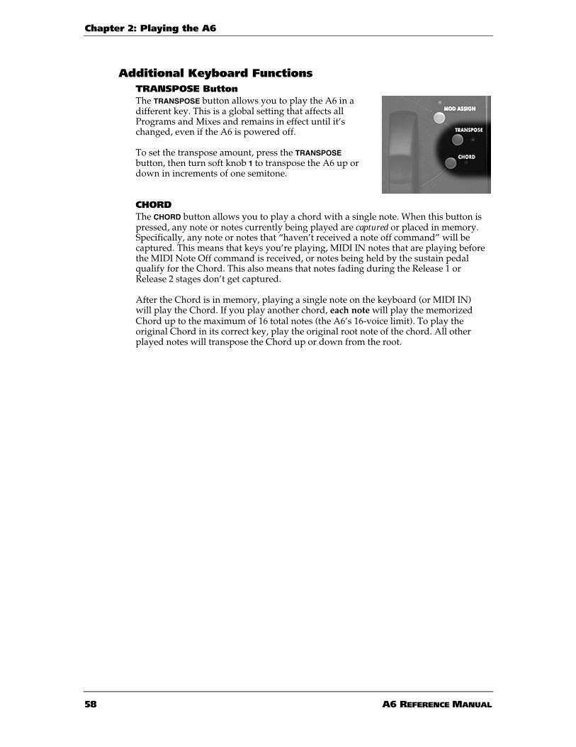
Chapter 2: Playing the A6
58 A6 REFERENCE MANUAL
Additional Keyboard FunctionsTRANSPOSE ButtonThe TRANSPOSE button allows you to play the A6 in adifferent key. This is a global setting that affects allPrograms and Mixes and remains in effect until it’schanged, even if the A6 is powered off.
To set the transpose amount, press the TRANSPOSEbutton, then turn soft knob 1 to transpose the A6 up ordown in increments of one semitone.
CHORDThe CHORD button allows you to play a chord with a single note. When this button ispressed, any note or notes currently being played are captured or placed in memory.Specifically, any note or notes that “haven’t received a note off command” will becaptured. This means that keys you’re playing, MIDI IN notes that are playing beforethe MIDI Note Off command is received, or notes being held by the sustain pedalqualify for the Chord. This also means that notes fading during the Release 1 orRelease 2 stages don’t get captured.
After the Chord is in memory, playing a single note on the keyboard (or MIDI IN)will play the Chord. If you play another chord, each note will play the memorizedChord up to the maximum of 16 total notes (the A6’s 16-voice limit). To play theoriginal Chord in its correct key, play the original root note of the chord. All otherplayed notes will transpose the Chord up or down from the root.

Chapter 2: Playing the A6
A6 REFERENCE MANUAL 59
PORTAMENTOA Italian term (from a Latin root) that means sliding, portamento causes the A6’sVoices to “slide” (sometimes called “glide”) to the notes being played. When you areplaying the A6 normally, played keys or MIDI Note On messages activate the Voiceswith the appropriate notes instantly. With portamento active, it takes a period oftime – set by the TIME knob – for the Voices to reach the played notes by “sliding intothem”.
The first important concept to understand here is that the sliding direction isdetermined by the notes that were previously played. For example, if you play keysin the lowest octave, turn PORTA on and then play keys in the upper range of thekeyboard, the Voices will slide up to the higher notes. If you then play lower notes,the Voices will slide down to the new lower keys being played.
The second concept to understand is the distance between played notes. Musicallyspeaking, we’re referring to the interval between successive notes. In contrast to theabove example, if you play notes in a certain octave then continue to play in that keyrange, there’s a good chance that portamento may not be that distinct since thedistance (interval) between the old notes and new notes is not that great.
The third concept to understand when using portamento is that it is the voices thatare doing the sliding, not the keys. The A6 keeps track of all notes played andwhich voices played them so that it knows the most current note values of each of its16 voices. Therefore, depending on what voices were played before portamento isturned on, you may get sliding from all directions or not much at all. The distanceand direction of the glide depends on which voice is getting the new note relative towhat note this voice played before.
PORTAMENTO CONTROLS
Portamento is fully programmableper Program.
TIME KnobThis control varies the portamentorate, or the amount of time it takes toslide from previously played notes tothe target notes. Portamento time isadjusted in either seconds orseconds-per-octave depending on theselected portamento mode. Turningthis knob selects the TIME parameteron the PORTA page.
MOD ButtonPressing the MOD button displays the MOD page of modulation parameters forportamento. This page provides parameters for creating a mod route to theportamento’s TIME parameter (displayed on the MOD page as PORTA RATE),providing variations in the portamento speed. If a mod route has been created byturning the ENABLE parameter to - ON -, the MOD LED will be illuminated. Using amodulation on TIME, you can affect the rate of sliding in countless ways.

Chapter 2: Playing the A6
60 A6 REFERENCE MANUAL
ON/OFF ButtonThis button simply turns the portamento function on or off. When on, the LED willlight. Pressing this button selects the ENABLE parameter on the PORTA page.
Portamento Parameters
SOFT KNOB
PAGE TAB
1 2 3 4 5 6 7 8
PORTA TIME SPEED MODE CURVE ENABLE OSC EN FLT EN
STMODE MODE OFFSET
MOD SOURCE LEVEL OFFSET ENABLE
PORTA Parameters
PAGE PARAMETEROPTIONS
or RANGE DESCRIPTION
PORTA TIME OFF
2 M ···
32.77 S
Sets the speed of the glide between notes.Minimum is 2M or 2 milliseconds; maximum isabout 33 seconds. The actual time it takes toslide between two notes is dependent upon theSPEED setting, described next.
SPEED This parameter determines the method used tocalculate the rate of portamento between notes:
OCTAVE When set to OCTAVE, the TIME setting isdetermined by the interval between notes andis expressed in “seconds per octave.” If TIME isset to 5.00 seconds, for example, the time ittakes to slide one octave is 5 seconds. The timeit takes to glide the entire length of thekeyboard (five octaves) is 25 seconds.
1SPEED When set to 1SPEED, the TIME setting doesn’tcare about the interval in its calculations. Therate of sliding is the same between semitones asit is between octaves. Using the previousexample of 5.00 seconds, it takes five secondsto glide from the E key to the F key just above it,just one semitone. It also takes five seconds toslide from the same E key to the E three octavesabove it.

Chapter 2: Playing the A6
A6 REFERENCE MANUAL 61
PAGE PARAMETEROPTIONS
or RANGE DESCRIPTION
PORTA
Continued
MODE This parameter is used to select from amongthree portamento actions:
NORMAL Each new voice that is played will havePortamento. The portamento will glide from thelast note played by this voice to the new note.
LEGATO Voices played staccato will not glide. Whileholding the first voice of a program, subsequentvoices will glide, starting from the last keypressed.
LEGATO2 Operates like NORMAL for each first voice of aprogram. While holding the original note(voice), subsequent notes will not glide.
CURVE This parameter allows you to select the slopeused to glide between notes. Refer to thediscussionand the graphs on the followingpages for a complete description of these slopes.
LINEAR standard linear slope
EXP 1 Exponential 1: less steep version of Exponential 2
EXP 2 Exponential 2: standard ln curve
EXP 3 Exponential 3: steeper verion of Exponential 2
LOG 1 Logarithmic 1: less steep version of Logarthmic 2
LOG 2 Logarithmic 2: standard ex curve
LOG 3 Logarithmic 3: steeper verion of Logarthmic 2
SCURV1 S-Curve 1: forward “S-Curve”, created bymerging EXPO2 into LOG2
SCURV2 S-Curve 2: reverse progression of SCURVE1
ENABLE OFF, ON Enables portamento. The ON/OFF LED reflectsthe status.

Chapter 2: Playing the A6
62 A6 REFERENCE MANUAL
CURVE: Selecting the Portamento’s SlopeIdentical to the stages of an envelope, Portamento has a user-selectable propertycalled slope. This term refers to how gliding notes accelerate (speed up) or decelerate(slow down) as each voice approaches its target note:
• A LINEAR slope means that gliding notes do not accelerate (or decelerate) asthey progress towards their target (destination) notes. In the illustration on thenext page, notice that the linear slope is depicted as a straight line (from wherewe get the term “linear”). The glide doesn’t speed up or slow down but keepsan even rate of change.
• An EXP (exponential) slope, however, accelerates towards the target notes: itstarts out slow then speeds up as it gets closer to its destination. Rather than astraight line, it is represented by a curve. One of three exponential curves canbe selected.
• In contrast, the LOG (logarithmic) slope decelerates towards the target notes: itstarts out fast then slows down as it reaches its destination. It is represented bya curve that is the opposite of the exponent. One of three logarithmic curvescan be selected.
• The SCURV (“S” Curve) combines the slopes of EXP 2 and LOG 2. One of twoS-Curves can be selected:
SCURV1: The rising-amplitude of S-Curve 1 is characterized by accelerationduring the first half of its stage using EXP 2, then decelerates during the lasthalf using LOG 2. This is commonly known as a forward progression s-curve.
The falling-amplitude of S-Curve 1 is the opposite of its rising-amp: the stagedecelerates during the first half using LOG 2, then accelerates during the lasthalf using EXP 2.
SCURV2: The opposite of S-Curve 1 – commonly referred to as a reverseprogression s-curve – the rising-amplitude of S-Curve 2 decelerates during thefirst half using LOG 2, then accelerates during the last half using EXP 2.
The falling-amplitude of S-Curve 2 accelerates during the first half using EXP2, then decelerates during the last half using LOG 2.

Chapter 2: Playing the A6
A6 REFERENCE MANUAL 63
PORTAMENTO SLOPES
Rising LINEAR Falling
Rising EXPONENTIAL 1 Falling Rising LOGARITHMIC 1 Falling
Rising EXPONENTIAL 2 Falling Rising LOGARITHMIC 2 Falling
Rising EXPONENTIAL 3 Falling Rising LOGARITHMIC 3 Falling
Rising S-CURVE 1 Falling Rising S-CURVE 2 Falling

Chapter 2: Playing the A6
64 A6 REFERENCE MANUAL
STMODE Parameters
PAGE PARAMETEROPTIONS
or RANGE DESCRIPTION
STMODE
Start Mode
MODE This page determines where the portamento issliding from—its start point.
LSTKEY When a new note is played, it will “slide” fromthe last key played.
OFFSET When a new note is played, it will slide from afixed number of semitones above or below thenote, as set by the OFFSET variable set by SoftKnob 2.
CHORD Each voice slides from its previous value. Forexample, whatever note Voice 8 last played,that’s where it will slide from when called uponagain. The voice order is set in the KBD MODEsection (Unison X, Poly, and Mono).
OLDEST Each voice slides from the oldest note that isbeing held.
OFFSET -127 ··· + 127 Sets the number of notes above or below thepresent note where the slide will start, when theMODE is set to OFFSET. For example, a setting of-12 will always start sliding from an octavebelow the note played.
Portamento MOD ParametersThe Portamento Modulation parameters permit you to create a mod route tomodulate the RATE parameter. Please note that, unlike most of the other MOD pages,RATE is the only Portamento parameter that can be modulated.
PAGE PARAMETEROPTIONS
or RANGE DESCRIPTION
MOD
PortamentoSpeedModulation
SOURCE NONE
or any modsource
Selects one of the A6’s mod sources to modulatethe Portamento’s RATE. The default is OFFSETONLY.
LEVEL -100 ··· 100 Sets the level or intensity of the mod source.
OFFSET -100 ··· + 100 Standard mod route offset.
ENABLE OFF, ON Turns the modulation OFF or ON.
The status of the parameter is also shown by theLED next to the MOD button.

Chapter 2: Playing the A6
A6 REFERENCE MANUAL 65
THE PERFORMANCE WHEELS ANDRIBBON CONTROLLER
BACKGROUND
The A6 utilizes two performance wheels that are used mainly for pitch bend (PITCH)and vibrato (MOD). The Pitch wheel on the left is a spring-loaded wheel that snapsback to its center or neutral position when released, and is normally used for pitchbend. The Mod wheel on the right is not spring loaded and must be manuallyreturned to its off position. It is normally used for vibrato.
But note that you can assign each one to a different destination – you are notconfined to using them for strictly pitch bend and vibrato. In fact, you can make bothpitch bend or both vibrato, if you so desire.
Better yet, they can be neither pitch bend nor vibrato, as you can assign these wheelsto modulate any parameter of the sound that is designated as a mod destination. Butbest of all, you can assign the wheels to perform multiple modulations at the sametime. Imagine a wheel causing vibrato, increasing the reverb amount, fading in thesub-oscillators and triggering the sequencer all at once. See Chapter 9: CustomModulations for an in-depth look at Andromeda’s “modulation matrix” thatallows you to customize mod routes or mod paths to achieve out-of-the-ordinaryresults.
In any case, the purpose and range of these wheels are programmable per Program,which makes them incredibly flexible. Consider the possibility of a wheel being usedto control the brightness of the sound instead of pitch, or to control the amount ofreverb or chorus, or to alter the pulse width of one (or both) VCOs... The possibilitiesare virtually limitless.
Typically, the pitch wheel is set up so that pushing it away from you bends playednotes up in pitch and pulling bends them down. The A6’s pitch wheel however, canhave its polarity – the positive/negative attributes – reversed so that pushing pitch-bends down and pulling bends up.
The pitch wheel can also be programmed so that it can have a different type ofmodulation on either side of the center stop. You can set the wheel to pitch bendwhen pushed (up or down, your choice) and change the portamento time whenpulled, as just one of many, many examples.
You can think of the Ribbon Controller as a wheel that’s been stretched across theA6’s front panel. It can be assigned to any of the A6’s mod destinations and isprogrammable per Program like the wheels. It operates simply by touching it with afinger and sliding it along the ribbon’s surface.
One of its attributes that distinguishes it from the wheels is that it may be divided inhalf—the left and right sides (from the center line mark on the top panel) may act asseparate controllers aimed at separate destinations. And because the RibbonController has a much longer travel than the wheels, it typically has a more accurateresponse since you have more physical space across the ribbon’s surface within agiven range.
In all cases – for both wheels and the ribbon – the MIDI Controller Number is user-selectable and programmable per Program so you can determine how the wheels willaffect other instruments via MIDI for each Program.

Chapter 2: Playing the A6
66 A6 REFERENCE MANUAL
PROGRAMMING THE WHEELS AND RIBBON
All of the Programs that ship with the A6 havedefault wheel and ribbon modulations stored withthem. In most cases (but not all), the left wheel andribbon are preset for pitch bend and the right wheelis vibrato. Some factory Programs, on the otherhand, have the wheels and ribbon preset to othertypes of modulation depending on what isappropriate for the Program.
For MIDI purposes, the right wheel defaults toMIDI Controller 1 (vibrato) and the left wheel andribbon are assigned to Channel Pitch Bend. Theseassignments can be changed, however, and storedfor each Program.
To make changes to either wheel, press the PITCH(“Pitch Wheel”) ASSIGN or the MOD (“Mod Wheel”)ASSIGN button. The parameters for that wheel willbe displayed. Likewise, pressing the RIBBON buttonto the left of the ribbon controller displays itsparameters.
PITCH ASSIGN Parameters
SOFT KNOB
PAGE TAB
1 2 3 4 5 6 7 8
PWHEEL BOTRNG TOPRNG BOTCRV TOPCRV OSC 1 OSC 2
CROUTE SOURCE LEVEL ENABLE ROUTE
PAGE PARAMETEROPTIONS
or RANGE DESCRIPTION
PWHEEL The A6 permits you to adjust the range of theupper travel of the Pitch Wheel independent ofits lower travel:
BOTRNG
Bottom Range
- 0 ··· 48 This parameter adjusts the bottom range of thePitch Wheel from 0 to 48 semitones (4 octaves).The default value is two semitones (one Wholetone).
TOPRNG
Top Range
+ 0 ··· 48 This parameter adjusts the top range of thePitch Wheel from 0 to 48 semitones. The defaultvalue is two semitones (one Whole tone).
BOTCRV
Bottom Curve
LINEAR ···
SCURV2
This parameter selects one of nine responsecurves for the wheel’s lower travel. See thediscussion on curves starting on page 62.

Chapter 2: Playing the A6
A6 REFERENCE MANUAL 67
PAGE PARAMETEROPTIONS
or RANGE DESCRIPTION
PWHEEL
Continued
TOPCRV
Top Curve
LINEAR ···
SCURV2
This parameter selects one of nine responsecurves for the wheel’s upper travel. See thediscussion on curves starting on page 62.
OSC 1 OFF, ON Turn the effect of the Pitch Wheel on OSC 1 on oroff.
OSC 2 OFF, ON Turn the effect of the Pitch Wheel on OSC 2 on oroff.
MOD ASSIGN Parameters
SOFT KNOB
PAGE TAB
1 2 3 4 5 6 7 8
MODWHL SCALE CURVE
CROUTE SOURCE LEVEL ENABLE ROUTE
PAGE PARAMETEROPTIONS
or RANGE DESCRIPTION
MODWHL SCALE 0 ··· 100 Adjusts the modulation amount from the wheel.Higher values = more modulation.
CURVE LINEAR ···
SCURV2
This parameter selects one of nine responsecurves for the wheel’s travel. See the discussionon curves starting on page 62.
CROUTES (Control Routes)A second press of either the PITCH ASSIGN or the MOD ASSIGN button will bring up theCROUTES page. This allows you to see and change the internal routings of thecontrollers. By turning the ROUTE knob, you can see the source routed to thatdestination. You’ll need to enter this page whenever you want to create customcontrol setups that are different from the defaults. For more information, seeChapter 9: Custom Modulations.

Chapter 2: Playing the A6
68 A6 REFERENCE MANUAL
Pedals and FootswitchesIts seems as if anything plugged into an instrument that you step on is called a pedal.Well, not exactly. There are actually two types of “foot-actuated controllers” in thecontext of an electronic instrument. Although it’s politically correct to called them“pedals” generically, one is accurately called a switch, and one is accurately called apedal. We’ll define both of them:
A foot switch is a momentary device – it is a spring-loaded switch that operates by“pressing and releasing” for ON (press: foot down) or OFF (release: foot off) signals.The A6 uses footswitches with a 2-conductor 1/4” connector and are plugged intothe SWITCH and SUSTAIN functions of the A6.
A foot pedal is a potentiometer device – the pedal mechanically operates an internalknob (technically known as a potentiometer) giving you “more” or “less” rather than“on” or “off” like a switch. These pedals are often referred to as “rocker pedals”. TheA6 uses a footpedal with a 2-conductor 1/4” connector typically used for volumeand modulation and is connected to the PEDAL/CV jack.
The diagram below shows what the right kind of connector looks if you want topurchase a pedal or switch.
Footswitch and pedal functions are defined (set up) in the PEDAL page of GLOBALmode. This set of parameters in the A6 are particularly interesting (and useful) asthey permit you to reverse a pedal’s action or make its MIDI function different fromits local function. For example, a rocker-type pedal that is used as a volume pedal onthe A6 can be sending modulation messages out MIDI at the same time. For detailson the PEDAL parameters, see page 50.

Chapter 2: Playing the A6
A6 REFERENCE MANUAL 69
THE CLOCK SECTIONThe A6’s Clock is aglobal function thatprovides globalsynchronization as amodulation source toall voices in Programsor Mixes. By global syncwe mean that any A6function that relies ontempo can get itstiming from the Clock.The timing can besteady or variable.
Some examples of A6functions that rely ontempo are theSequencer and theArpeggiator. You canalso slave modulation sources such as LFO rates and Envelope stages to the Clockwhen their timing needs to coincide with a song’s tempo. Normally, the A6’s LFOsrun independently of the Clock as they have their own generators for RATE. The sameapplies to Envelopes whose stages are normally timed by their own circuitry. Butwhen the need arises to synchronize one or more LFOs or Envelope stages to acommon tempo, this is accomplished by slaving the desired destination to the Clock.
Conversely, you can modulate the Clock’s tempo by an LFO or Envelope or any ofthe A6’s 71 modulation sources. This is accomplished using SYNC/MOD as describedbelow.
How the A6’s clock is integrated with the Sequencer and Arpeggiator is covered inthe following topics. Slaving an LFO to the Clock is covered in Chapter 7. Slaving anEnvelope stage is discussed in Chapter 6.

Chapter 2: Playing the A6
70 A6 REFERENCE MANUAL
CLOCK PARAMETERS
DISPLAYPAGE PANEL LABEL
PARAMETERDISPLAY
OPTIONSor RANGE DESCRIPTION
CLOCK TEMPO
Knob
TEMPO 0.4578 ···500.0000
Beats Per Minute
The knob adjusts the tempo of the Clock from.46 bpm to 500 bpm, adjusted in increments of1/10000th of a bpm (.0001 on the display) forslower settings. To fine-adjust fractions athigher rates, use the ▲ and ▼ buttons.
— SYNSRC
Sync Source
This parameter selects the source from whichthe Clock’s tempo is generated:
LOCAL the A6’s internal dedicated clock
MIDI incoming MIDI clock from an external MIDIMaster
LFO 1, 2 or 3 the clock that controls LFO 1, 2 or 3.
— MODVOX
TempoModulation byVoice
This parameter is used to select the amount ofmodulation triggered by a voice. Use the softknob below this parameter in the display toselect one of three options, described below.
FIRST The first voice to modulate the clock willdetermine the modulation source amount. Ifthis first voice is released while other voicesare held, the last modulation source for thefirst voice is held and used.
OLDEST The oldest voice playing this sequence willdetermine the modulation source amount.
NEWEST The newest voice playing this sequence willdetermine the modulation source amount.

Chapter 2: Playing the A6
A6 REFERENCE MANUAL 71
SYNC/MOD ButtonPressing the SYNC/MOD button that is located directly below the TEMPO knob displaysthe parameters for modulating the tempo of the Clock by any of the A6’s 71modulation sources. Use SYNC/MOD to modulate the tempo of the Clock by theselected mod source.
SYNC/MOD Parameters
If the SYNC/MOD button is pressed, the following parameters will be shown on thedisplay. Unlike other MOD pages, there's no DEST parameter controlled by SoftKnob 6 because there is only one destination, the CLOCK RATE.
DISPLAYPAGE PANEL LABEL
PARAMETERDISPLAY
OPTIONSor RANGE DESCRIPTION
MOD — SOURCE Any of the A6’s 71modulation sources.
See Appendix B.
Use soft knob 1 to scroll through the list ofpossible modulation sources.
— LEVEL -100 ··· +100 This parameter sets the amount of modulationthat will affect the tempo. Keep in mind thatnegative values invert the action of the selectedsource. For example, if Velocity is the source anda negative value for LEVEL is used, playingharder will reduce the level and thus slowingthe tempo of the Clcok.
— OFFSET -100 ··· +100 This parameter sets the offset or fine adjustmentfor the selected modulation level.
SYNC/MOD
Button + LED
ENABLE ON, OFF This parameter is used to turn the selectedmodulation on or off. Use soft knob 5 or thepanel button.
SEQUENCER
A sequence is a series of two or more “events” (usually musical notes) that play oneafter another – or “in sequence.” The A6 Sequencer is a simple 16-step, 3-levelmodulation source/note triggering module. It follows the functionality offered bythe early analog sequencers found in the Moog and Buchla modular synthesizers, aswell as many others.
The Sequencer is a per Program function: each of the 128 user Programs can have itsown sequence that is saved in memory along with all of its other settings. This meansthat each program within a Mix can have its own sequence, so if you construct a Mixwith 16 different Programs – each with its own sequence – the Mix will have 16different sequences at the same time.

Chapter 2: Playing the A6
72 A6 REFERENCE MANUAL
LayoutEach of the sequencer’s 16 “steps” or “events” consists of four components or Levels:a Note, the note’s Velocity amount, the note’s duration called Gate time, and whethera note will play or the step will be a rest, called the Type.
It is important to note here that the A6’s Sequencer, unlike many other sequencersthat play their recorded notes when you press START, can be triggered by numeroussources. By default, the A6’s Sequencer runs when you play a note, and will play thesequence in a key signature using that note as a reference. Likewise, if a chord isplayed, the sequencer will sequence the chord according to its note settings.
Note that the values for the NOTE Level can have either a positive value or a negativevalue. This means that the sequence can play notes above and below the root note ofthe sequence. For example, a sequence is often constructed such that it starts playingwhen one note is played and held down. That’s the root note of the sequence which isnormally set to 0, the equivalent of “no transpose.” The NOTE setting for any Step canthen be “tuned” up or down from the root. This flexibility in allowing note valuesbelow the root provides a way to create interesting and useful melodic patterns.
Of course you can play chords, and the sequencer will play the pattern for every notein the chord.
When an event “plays,” Note, Velocity and Gate are output to the sequencer’sassigned destination—most often the voices—simultaneously. The most common useof the Sequencer is to play musical notes, so each event will generate a Note On (plusits associated Velocity), then output a corresponding Note Off when the Gate Timehas expired. Of course, if TYPE is set to REST, the Step will rest (the NOTE and VELsettings are bypassed) for the amount of time that the GATE is set to.
But also note that the Sequencer can be used as a source in a modulation route. Inthis case, Note, Velocity and Gate are listed in the MOD SRC LIST as SEQ LEVEL A,B and C respectively.
The table below shows the Sequencer Graph. The Graph can be thought of as beingin any time signature or combination of time signatures. For example, common 4/4usage would yield four bars of quarter notes with downbeats at Steps 1, 5, 9 and 13.Depending on how you set the RATE setting and Gate times to fit into the song, youcan also consider a sequence as two bars of 8th notes, one bar of 16th notes, and soforth. And since you can select the number of Steps, five steps of quarter notes canplay a bar of 5/4 and ten steps of quarter notes can play two bars in 5/4 with downbeats on steps 1 and 6. Six steps of eighth notes can play a bar of 6/8 and 12 steps ofeighth notes can play a two bars of 6/8 with down beats on steps 1 and 7.
STEP (or “EVENT”) A B C D E F G H I J K L M N O P
NOTE • • • • • • • • • • • • • • • •
VEL (Velocity) • • • • • • • • • • • • • • • •
GATE • • • • • • • • • • • • • • • •
TYPE • • • • • • • • • • • • • • • •

Chapter 2: Playing the A6
A6 REFERENCE MANUAL 73
START/STOP ButtonPressing this button starts orstops the Sequencer. This is aprogrammable function: if yousave the Program with thesequencer running, thesequencer will run as soon asyou select this program frommemory. But remember: youmay not hear anything until thesequence receives a trigger,normally the keyboard. Thedefault trigger source is thekeyboard, but you can changethat if you want.
SYNC/MOD ButtonPressing this button displays theSequencer’s MOD page on the
screen. The Sync/Mod page of parameters allows you to modulate the tempo of thesequence. The Sync/Mod parameters table that describes their functions can befound on page 78.
VIEW ButtonPressing this button recalls the page of Sequencer parameters that was last used (itdefaults to the GRAPH page). Using this button to enter the Sequencer edit modeallows you to examine the current settings without making any changes. You can, ofcourse, change any setting but you don’t have to when using a VIEW button.
Sequencer ParametersThis section describes the parameters of the Sequencer. The summary table belowshows the Sequencer’s parameter names – listed in the rows under under the SOFTKNOB numbers – with their associated page (parameter group) in the PAGE TABcolumn. The tables on the following pages provide operational details of eachdisplay page.
SOFT KNOB
PAGE TAB
1 2 3 4 5 6 7 8
NOTE
VELA B C D E F G H
GATE
GRAPH
TYPEI J K L M N O P
CONFIG BPM KYMODE LENGTH LPTYPE LPCNT USEKBD ZOOM
TRIG SOURCE LEVEL TYPE RETRIG ENABLE TRGVOX MODE
PROGRS PRGRSR MIN MIX
SYNC SYNSRC TIXSTP
MOD SOURCE LEVEL OFFSET ENABLE
RUN Pressing this button turns the sequencer on or off. This is the same as pressing the START/STOPbutton in the SEQUENCER section on the front panel.
1-16 Use soft button 8 to select a Step (A – P) on the GRAPH page for editing.

Chapter 2: Playing the A6
74 A6 REFERENCE MANUAL
GRAPH and 1 - 8 Parameters
The GRAPH page is used to set the Note, Velocity, Gate and Type values for the 16steps:
• Pressing soft button 1 (GRAPH) repeatedly cycles through the NOTE, VEL, GATEand TYPE parameters for the selected Step.
• Soft knobs 1 through 8 are used to select and adjust the values in each Step.
• The graph on top shows the settings for all Steps at once. The Parameter andValue rows of the display show the settings for eight Steps at a time (Steps A -H or Steps I – P). Repeatedly press soft button 8 to tab between the two groupsof Steps.
PAGE PARAMETEROPTIONS
or RANGE DESCRIPTION
GRAPH NOTE E-11 ··· G+10
Semitones
This parameter sets the note value of the Step. Asetting of C0 indicates that the sequencer willplay the note being played on the A6’skeyboard or the incoming MIDI Note.
VEL
Velocity
0 ··· 127 This parameter sets the velocity amount of thenote set in the NOTE parameter, above. 64 is thedefault setting.
GATE 0 ··· 100 This parameter sets the gate time or duration ofthe note set in the NOTE parameter, above.
TYPE NOTE, REST This parameter selects the type of Step, whetherit plays a note or a rest.
If NOTE is selected, the Step outputs the note setin the NOTE parameter along with its associatedVEL and GATE settings.
If REST is selected, the Step outputs the GATEtime only, effectively playing a musical rest.

Chapter 2: Playing the A6
A6 REFERENCE MANUAL 75
Sequencer CONFIG Parameters
PAGE PARAMETEROPTIONS
or RANGE DESCRIPTION
CONFIG
SequencerConfiguration
BPM .01HZ ···
50.00 HZ
The tempo of the Sequencer displayed in “Hz”(cycles per second).
Under normal conditions, the sequencer willuse its own clock for the the tempo. This is thesituation when LOCAL is selected on the SYNCpage. If CLOCK or MIDI is selected on the SYNCpage, this parameter has no effect.
KYMODE OFF, ON When ON, the sequencer will play a the A6’svoice(s) when a note or chord is played. This isthe most common usage of the sequencer. TheNOTE, VEL and GATE values are also available asmod sources.
When OFF, the sequencer will not play a theA6’s voice(s) when a note or chord is played.The A6 behaves as if the sequencer isn’trunning, but NOTE, VEL and GATE values arestill available as mod sources.
LENGTH 1 ··· 16 Selects the number of Steps that the sequencerwill play from 1 to 16 (Steps A through P).
LPTYPE
Loop Type
This parameter determines how the sequence“loops” or cycles.
FORWRD The sequence plays forward through theselected Steps.
REVERSE The sequencer cycles backward through theselected Steps.
ROKROL Rock-n-Roll: The sequence cycles backward and forwardthrough the Steps.
LPCNT
Loop Count
When the sequencer is running, this parameterdetermines the number of times the sequencewill loop through the Steps, or turns it OFF:
1 ··· 240 sets a finite number of loops from 1 to 240repititions.
SUSTN the loop will continue to cycle as long as notesare being played or the Sustain Pedal is down.
INFINT the sequence will continue to cycle infinitely oncestarted. The sequence can still be stopped by using theSTART/STOP button.
MONLEG
Mono Legato
OFF, ON When ON, this parameter allows the sequence tobe transposed in the middle of its cycle whenyou play legato.

Chapter 2: Playing the A6
76 A6 REFERENCE MANUAL
TRIG Parameters
PAGE PARAMETEROPTIONS
or RANGE DESCRIPTION
TRIG SOURCE Many of the MODsources such as
Mod Wheel,Ribbon, Footswitch,
etc.
This parameter allows you to select an inputthat will trigger the sequencer. Unlike otherMOD source menus, nothing involved with avoice is on the list, since the voicesthemselves are being triggered by thisfunction.
The selected trigger source is activated whencertain conditions exist. Specifically, when theselected trigger’s LEVEL and TYPE (describedbelow) are detected, the trigger is activated.
The A6 gets its signal to generate a trigger when the SOURCE reaches a certainLEVEL that you set (next page) and when the source is “moving” in a positive ornegative direction, or both (next page under TYPE - polarity type).
LEVEL -100 ··· +100 This sets the level of the SOURCE (selectedabove) where triggering will take place.
Note that if the POLAR setting (below) is set toone of the absolute (ABS) options, negativesettings are treated as is they were positive.
TYPE NEGATIVE The trigger will occur only when the source is“moving in a negative direction.” This meansthat a trigger is generated when the LEVELsetting is reached, but only if the source isdecreasing in amplitude.
BIPOLAR The trigger occurs when the LEVEL is reachedbut the source can be either increasing ordecreasing in amplitude.
POSITIVE The trigger will occur only when the source is“moving in a positive direction.” This meansthat a trigger is generated when the LEVELsetting is reached, but only if the source isincreasing in amplitude.
ABS: Absolute – the following polarities treat positive andnegative LEVEL settings as if they were all positive.
ABS NEGATIVE Absolute Negative: a trigger is generated whenthe source is moving in a negative directionand reaches the absolute value of the LEVEL.
ABS BIPOLAR Absolute Bi-Polar: a trigger is generated whenthe source is moving in a either direction andreaches the absolute value of the LEVEL.
ABS POSITIVE Absolute Positive: a trigger is generated whenthe source is moving in a positive directionand reaches the absolute value of the LEVEL.

Chapter 2: Playing the A6
A6 REFERENCE MANUAL 77
PAGE PARAMETEROPTIONS
or RANGE DESCRIPTION
TRIG
Continued
RETRIG OFF, ON Turns re-triggering on or off. When off, thetrig source acts as a one-shot trigger. Whenon, the trigger acts repeatedly, restarting thesequence from the beginning.
ENABLE OFF, ON Turns the trigger on or off.
MODE This parameter determines how voices are played once a triggeror multiple triggers occur.
NORMAL One trigger plays the sequence according tothe CONFIG page settings.
STAGE Requires multiple triggers: each Step (“stage”)in the sequence plays in order if each newtrigger has a different level.
ADVANC Requires multiple triggers: each Step plays inorder with each new trigger.
RANDOM Requires multiple triggers: each Step plays atrandom with each new trigger.
PROGRS Parameters
The Progressor allows for automatic transposing of the sequence within the limits setby the MIN and MAX parameters. Although the PRGRSR is the first parameter on thescreen, you should set the MIN and MAX limits first, then adjust the PRGRSR value.
Using 0 as the base note (the key that’s being played) value, the MIN value sets the lowend of the note range where transposing takes place. Conversely, MAX sets the upperlimit of the note range where transposing takes place. Although both of theseparameters have a -127 to +127 range, the most useful limits will be within a fewoctaves (-24 to +24 settings).
The PRGRSR value determines the transpose amount. A setting of 1 means that thesequence will transpose up one semitone starting at the MIN note with eachrepetition of the sequence until the MAX note limit is reached. A PRGRSR setting of -1means that the sequence will start playing at the MAX key and transpose down onesemitone with each repetition until the MIN note limit is reached.

Chapter 2: Playing the A6
78 A6 REFERENCE MANUAL
SYNC Parameters
PAGE PARAMETEROPTIONS
or RANGE DESCRIPTION
SYNC SYNSRC
Sync Source
This parameter allows you to select the clocksource that will drive the sequencer.
LOCAL Uses the sequencer’s dedicated clock for itstempo.
CLOCK Uses the A6’s global Clock for tempo.
MIDI Uses an external MIDI device for tempo.
TIXSTP
Clock Ticks perStep
2 ··· 65535 In order to compensate for significantdifferences in clocks, especially external clocksources, TIXSTP allows you to designate thenumber of clock ticks per step. The default is 2and each increase occurs in 3-tick increments.
About Tempos and TIXSTP
The SYNC page features a tempo display that can help you match the speed of theclock to musical values. This display calculator assumes that 24 ticks equals aquarter note, and that the music is in 4/4 time. If SYNSRC is set to CLOCK, andTIXSTP is set to 24, the display will read:
0:0:Qtr Note
and the sequencer will advance one Step per beat. If you want the sequencer to playtwice as fast relative to the beat of the clock, set TIXSTP to 12 and the display willread 0:0:8th Note. The format of the tempo display is:
Phrase (4 bars):Bars (4 beats):Note/tick value
So, if you want the Sequencer to advance one Step per 4-beat bar, set TIXSTP to 96and the display will read 0:1:0 Ticks. If you want to slow it down so that itadvances only one Step every 4 measures (assuming 4/4 time), set TIXSTP to 384and the display will read 1:0:0 Ticks.
MOD Parameters
The modulation page for the sequencer is identical to the SYNC/MOD page for theClock. See page 71.

Chapter 2: Playing the A6
A6 REFERENCE MANUAL 79
ARPEGGIATOR
Similar to a sequence, an arpeggio is musical term that refers to the playing of notes ofa chord one after another instead of playing them simultaneously. The A6’sArpeggiator is used to create programmable arpeggios – Arpeggiator settings aremade per Program and stored in memory with each Program. An arpeggiator isextremely versatile in that intricate patterns of notes can be constructed that wouldotherwise be extremely difficult, if not impossible, to play manually. Also, arpeggioscan be played faster than is humanly possible, or span octaves above or below thephysical limits of the keyboard.
The A6 Arpeggiator is nearly identical to the Sequencer in its basic design. The maindifference lies in the display layout and what you’re playing on the keyboard (orwhat the A6 is receiving via MIDI In).
Also, unlike the Sequencer, the Arpeggiator is a per Voice function rather than a perProgram function. This means that each playing voice is linked to its ownarpeggiator. This results in 16 arpeggiators – one per Voice – each with their ownstatus, position, and voice variables.
The Arpeggiator TRIG, PROGRS, SYN and MOD parameter pages are identical to thoseof the Sequencer (refer to pages 76 through 78 for the information). The only differentset of parameters exist on the CONFIG page which is covered on the next page.
START/STOP ButtonStarts and stops the Arpeggiator.This is a programmable functionfor all voices in Programs orMixes.
SYNC/MOD ButtonPressing this button displays theArpeggiator’s SYNC page on thescreen. This page of parametersallows you to set the source of theArpeggiator’s tempo.
VIEW ButtonPressing this button recalls thepage of Arpeggiator parametersthat was last used (it defaults tothe CONFIG page). Using thisbutton to enter the Arpeggiatoredit mode allows you to examine
the current settings without making any changes. You can, of course, change anysetting but you don’t have to when using a VIEW button.

Chapter 2: Playing the A6
80 A6 REFERENCE MANUAL
Arpeggiator CONFIG Parameters
PAGE PARAMETEROPTIONS
or RANGE DESCRIPTION
CNFG
ArpeggiatorConfiguration
BPM
Beats per Minute
.46 ··· 600 The speed or rate of the Arpeggiator displayedin “bpm” or beats per minute. This setting isindependent of any TEMPO setting for the Clockor Sequencer, and is only effective when theArpeggiator is set to LOCAL in the SYNC menu.
LENGTH 0 ··· 100 Modifies the Release 2 times of the envelopes.
OCTAVE -10 ··· +1`0 Sets the number of octaves the arpeggio willplay. 0 indicates that a held chord will onlyarpeggiate the notes actually held. Positivevalues transpose the arpeggio up that numberof octaves; negative values transpose thearpeggio down that number of octaves.
CENTER OFF, ON Places the held notes in the “center” of thearpeggio: if the OCTAVE parameter above is setto 3, the arpeggio will play three octaves aboveand below the chord played.
TYPE Determines the direction the Arpeggiator will play notes:
FORWRD The arpeggio will play notes in order from thelowest to the highest, and additional octaves (asset in the OCTAVE parameter, above) fromlowest to highest.
REVERS The arpeggio will play notes in reverse orderfrom the highest to the lowest, and additionaloctaves (as set in the OCTAVE parameter, above)from highest to lowest.
RNRINC Rock-n-Roll Inclusive – the sequence will play thearpeggio forward then in reverse, including theend notes twice: once when completing theforward direction and once when starting thereverse direction.
RNRCIR Rock-n-Roll Circle – the sequence will play thearpeggio forward then in reverse, but will notplay the end notes twice as in RNRINC.
CHORD OFF, ON When off, a held chord arpeggiates as singlenotes. When on, a held chord is heard as achord along with its arpeggiated notes.
LATCH OFF, ON Latch keeps the arpeggio playing after you letgo of the keys. This function uses soft button 7and is available when any Arpeggio page isdisplayed.
RUN OFF, ON Turns the arpeggio on or off. This function usessoft button 8 and is available when anyArpeggio page is displayed.

Chapter 3: Basics of Analog Synthesis
ANDROMEDA A6 REFERENCE MANUAL 81
CHAPTER 3
BASICS OF ANALOGSYNTHESIS
AN OVERVIEW OF SYNTHESISThe concept of a synthesizer is an instrument that is capable of producing a verywide range of sounds electronically. The huge popularity and continueddevelopment of synths since the late 60s is due, in great part, to this ability to offer somany different types of sound textures in one box.
A synthesizer’s ability to produce such an incredible variety of sound comes from itsbasic design: it electronically simulates the fundamental components of sound andgives you control over each part. The term synthesize means to “to combine parts into awhole”. And that’s exactly what a synthesizer does: the essential ingredients of soundare presented on the front panel as separate parts which are then “re-assembled” as anaudible sound.
ANALOG AND DIGITAL TECHNOLOGIES
In today’s world, the majority of electronic keyboards are digital. Although the firstsynthesizers were analog, the demand for digital products led the market away fromanalog designs. But because analog instruments have a sound quality all their own,and because they operate somewhat differently than their digital cousins, there’sbeen sort of a revival of interest in this technology.
So if this is your first analog synthesizer, or your first synthesizer ever, you might bewondering what the difference is. Briefly, a digital instrument is completelydependent on its microprocessor(s) and memory for the sounds it makes and anycontrol and sound-modifying functions.
An analog instrument uses electronic circuitry for sound creation and filtering that isnot dependent on its computer chip. While the instrument’s processor providesmany control and memory functions, the basic sound path is in the hardware that isseparate from the microprocessor. In the early days of synthesizers, everything inthe unit was analog, which involved many transistors, resistors, capacitors, diodesand coils of wire, and often meant no program memory, frequent manual tuning,limited sound-modifying abilities and relatively high cost.
But where did all this start?
A LITTLE HISTORYElectronic music as we know it today began years ago with musicians and physicistsanalyzing and experimenting with sound. Sound, as we might remember from highschool physics, is created by an object vibrating the air causing sound waves – minorfluctuations or changes in air pressure that we perceive or experience with our earsas audible sound. The people who studied this natural phenomenon from a musicalperspective put audible sound into two categories: sound that has a musical pitchand sound that doesn’t.

Chapter 3: Basics of Analog Synthesis
82 ANDROMEDA A6 REFERENCE MANUAL
For both pitched and non-pitched sounds, there are two keyelements of sound that we will be working with whencreating or editing Programs on the A6. First, we need toconsider what makes up a sound wave: what are thecomponents of a sound wave and how do they relate to theA6? Second, we need to know that sound changes over aperiod of time, which can be a mere fraction of a second toseveral minutes (or longer). Let’s take a few moments tocover these two elements.
A LITTLE THEORY
WAVEFORMS
All audible sound consists of waveforms or waveshapes. Theseare the vibrating air waves our ears perceive as sound, andcan be described by their “form” (or the “shape” of thewave) when depicted by a graph. Waveforms can beillustrated by simple graphs that show how they wouldappear on the display screen of an oscilloscope, an electronicdevice used to analyze sound waves. The graphs in the leftcolumn illustrate what the basic waveforms look like.
Waveforms are the primary components of the “raw” soundin a synthesizer. But instead of a “vibrating object”, thesewaveforms are generated electronically. This is the functionof an analog synthesizer that we mentioned just a momentago: the electronic approximation of sound waves that occurin nature.
The A6 uses 32 oscillators – electronic circuits that produceraw waveforms – to simulate naturally occurring soundwaves. For our purposes in operating the A6, we’ll classifywaveforms into two types based on their shape:
• Cyclical or periodic waves repeat a particular pattern overand over. The main property of a periodic wave is that ithas a musical pitch or tone. Periodic waves, therefore,are especially useful when attempting to synthesizetraditional instruments such as violins and other stringedinstruments, brass and horns, reed instruments and soforth. By the same token, periodic waveforms are usefulwhen synthesizing entirely new sounds that don’t soundanything like a violin or a clarinet.
The A6 provides four periodic waveforms which aredescribed by the shape of the sound wave they create:Sine, Triangle, Pulse and Sawtooth. These four basicwaveforms have distinct sound personalities and lendthemselves to producing certain kinds of sounds as wewill discover later.
• Non-cyclical or aperiodic waves are irregular and do nothave any particular pattern that is repeated. The mainproperty of an non-cyclical wave is that it does not have amusical tone. Aperiodic waves, therefore, are especiallyuseful when synthesizing wind, thunder, explosions or

Chapter 3: Basics of Analog Synthesis
ANDROMEDA A6 REFERENCE MANUAL 83
mechanical sounds. Clever use of aperiodic waves, often in combination withperiodic waveforms, have resulted in sounds that closely resemble drums, cymbalsand helicopters. The A6 provides two of these non-cyclical sound sources calledRandom and Noise.
Central to all sounds are two properties frequency and amplitude. Frequency is anotherword for pitch. Low notes on a musical instrument, for example, are said to have alow frequency; high pitched notes have a high frequency. Amplitude is commonlyassociated with “amount” and often (but not always) refers to the volume level of asound: high amplitude means loud, low amplitude means soft or quiet. Frequencyand amplitude are also used to describe the properties of control signals that are notaudible themselves – you can’t actually hear a vibrato signal, but you can hear theeffects of it when applied to a sound. More on that later.
FUNDAMENTALS AND HARMONICS
Periodic waveforms, when analyzed further, reveal that they actually are composedof numerous waves that combine to make up the sound that we hear. The primarywave, called the fundamental, establishes the pitch or note value of the wave. It is alsothe loudest of all the waves that comprise a sound.
In addition to the fundamental wave, a series of waves are present in each sound thatare related to the fundamental. Called harmonics or overtones, these waves areresponsible for the waveform’s timbre (pronounced TAM-ber) or tonal identity. Forexample, Sine and Triangle waves sound “flute-like” with the Triangle wavesounding a little brighter due to its harmonics (a Sine wave is simply a fundamentalwave without harmonics). A Sawtooth wave, which has a certain harmonic structure,sound “raspy” while the Square wave, having another set of harmonics, sounds“hollow”. Variations on the Square wave, accomplished by varying the width of thepulse, sound less hollow as the pulse width becomes narrower, to “nasally” at thenarrowest setting.

Chapter 3: Basics of Analog Synthesis
84 ANDROMEDA A6 REFERENCE MANUAL
Harmonics, like other periodic waves, have frequency and amplitude. Theirfrequencies are musical intervals above the fundamental which can be thought of asthe “root”. Their amplitudes are also based on the loudness of the fundamental: eachharmonic diminishes in amplitude as you get further away from the fundamental.
1 kHz 2 kHz 5 kHz 10 kHz 20 kHz
FREQUENCY
AM
PLIT
UD
E
FUNDAMENTAL HARMONICPARTIALS
Harmonics also determine if the waveform is perceived to be “bright” or “muted”:the more harmonics present in the waveform, the brighter the sound appears to ourears. This is where filters come in.
In an analog synthesizer, the harmonic content of the sound is controlled by thefilters: circuitry that controls the amount of harmonics present in the Program. By itsvery name, it’s implied that these circuits “filter out” harmonics. This is true: thefilters provide a range or bandwidth of harmonics, sometimes called the spectrum, thatthe sound will contain by filtering out or removing the harmonics of a waveformgenerated by the oscillators. It is also possible to set the filter “wide open” (atmaximum) so that all of the harmonics are present.
SOUND DYNAMICS
Most of us aren’t conscious of this, but virtually every sound we hear every day isdynamic: audible sounds make subtle yet significant changes as we are listening tothem. Take a piano note, for example. When a key is played and held down, thesound the vibrating strings make goes through numerous fluctuations as the notefades out. When the hammer first strikes the strings, this initial “hit” is the loudestand the brightest part of the sound. As the note fades, notice that not only is there agradual decrease in loudness but also in brightness as well.
Consider the differences in loudness and tonal quality that different playing styleshave on just about any acoustic instrument. Think about how staccato playing soundsdifferent than playing legato on the same instrument.
EnvelopesA synthesizer provides a number of electronic controls that are used to shape orcontour the overall sound as it plays out over the duration of the note. We’re notreferring to Velocity, Aftertouch or Pressure here but the synthesizer’s envelopes:electronic circuits that you can set to shape the loudness and the brightness (or lackof it) of the sound as it plays out.

Chapter 3: Basics of Analog Synthesis
ANDROMEDA A6 REFERENCE MANUAL 85
Here’s a graphical representation of a typical envelope. We’ll be covering the detailsof how an envelope works, what you can do with it and what all those labels mean ina later chapter. For now, we just want to show you how an envelope is graphed(especially since the A6’s screen will display something like this when you’re editingan envelope in a Program).
Since sound waves have polarity – both positive and negative properties (a kind of“pushing and pulling”) when moving air – a sound’s envelope also has polarity.Using the envelope above to shape a sound wave’s volume, the wave as we mighthear it could look like this:

Chapter 3: Basics of Analog Synthesis
86 ANDROMEDA A6 REFERENCE MANUAL
In the real world, sound waves are three dimensional, radiating from a central pointof origin. So our example here really looks something like this:

Chapter 3: Basics of Analog Synthesis
ANDROMEDA A6 REFERENCE MANUAL 87
LFOsIn addition to loudness and brightness dynamics, everyday sounds are oftenenhanced with repeating, patterned fluctuations we recognize as vibrato. In one of itsmore expressive applications, a singer often adds vibrato at the end of a sustainednote. As an extreme example, you can think of the high rise and fall of a police sirenas vibrato on steroids.
A synthesizer uses Low Frequency Oscillators (LFOs) to introduce vibrato to thesound. Designed much like the oscillators that produce raw waveforms as the synth’sprimary sound source, LFOs are not heard but are used to modulate, or change, manycomponents of the sound that you can hear: the oscillators, filters, overall loudnessand many others.
LFOs use the same waveform types as the oscillators, but their frequency range ismuch lower (hence the term “low frequency”) because the typical speed of LFOmodulation is below the range of an audio oscillator. Using our original graph of asine wave on page 82, the following illustration shows how this wave affects asustained note.
Middle C

Chapter 3: Basics of Analog Synthesis
88 ANDROMEDA A6 REFERENCE MANUAL
COMPONENTS OF AN ANALOG SYNTHESIZERWith the preceding information as background, let’s take a look at how ourdiscoveries about sound relate to a physical electronic instrument. Here’s a series offlowcharts illustrating this concept that we will build upon over the next few pages:
1. In its most rudimentary form, the heart of synthesizer is really nothing morethan a group of oscillators (to provide the raw sound), feeding the filters (tocontrol the harmonic content of the sound), feeding the output of theinstrument (where the final volume level is set).
2. Now we start adding controllers – hardware that gives the instrumentplayability and expression – and modulation – circuitry and/or software thatis used to shape or vary the sound.
First up is the keyboard controlling the pitch of the oscillators:

Chapter 3: Basics of Analog Synthesis
ANDROMEDA A6 REFERENCE MANUAL 89
3. As the keyboard is played, low notes output low frequencies from theoscillators and high notes play high frequencies. Similarly, the filters can bescaled as well. So it makes sense that the keyboard control be routed to thefilters so that low notes played on the keyboard cause the filter to “close” andoutput fewer harmonics; high notes on the keyboard cause the filters to“open” and output more harmonics. This type of scaling causes notes acrossthe keyboard to have an even amount of brightness:
4. Envelope modulation is introduced into the signal flow so that the harmoniccontent (the envelope modulating the filters) and the overall loudness (theenvelope modulating the output section) of the sound can be shaped. Thisshaping is controlled by you as you set the envelopes’ time and amountparameters.

Chapter 3: Basics of Analog Synthesis
90 ANDROMEDA A6 REFERENCE MANUAL
5. The keyboard is also responsible for gating the envelopes. In essence, this isreally what causes the synthesizer to make a sound. When the envelopes start,they “open” and allow the filters and the output section to pass sound fromthe oscillators:
6. But what about pitch bend and vibrato controllers? Pitch bend routes a wheeldirectly to the oscillators so as to allow you to manually vary their pitch.Vibrato uses a wheel that sends a variable amplitude (amount) to an LFO thatin turn varies the pitch of the oscillators up and down slightly:

Chapter 3: Basics of Analog Synthesis
ANDROMEDA A6 REFERENCE MANUAL 91
7. Last, but not least, we’ll add controller inputs for volume pedal and sustainpedal. Typically, a volume pedal varies the amplitude (again the “amount”)of the synth’s output section.
Sustain pedal control is typically routed to the Release portion of theenvelopes: the stage of the envelopes that controls the time it takes for thefundamental and harmonics to fade out.
Note: The keyboard, pitch bend and vibrato wheels, plus sustain and volume pedalspictured here as physical controllers can also be incoming MIDI information.
This covers the material for our starting point in introducing the concept of analogsynthesis. In the next Chapter, we’ll apply all of this wonderful knowledge to thedesign and operation of the A6, including a comprehensive feature list.

Chapter 3: Basics of Analog Synthesis
92 ANDROMEDA A6 REFERENCE MANUAL

Chapter 4: Andromeda A6 Overview
ANDROMEDA A6 REFERENCE MANUAL 93
CHAPTER 4
OVERVIEW OF THEANDROMEDA A6
MAKING SENSE OF ALL THIS THEORY:AN OVERVIEW OF THE A6
Now that we’ve covered the bare-bones basics of analog synthesis, we can move onto see how all this theory applies to the A6.
As analog synthesizer technology developed over the years, it became more feasibleto not only add more sound-modifying features (additional oscillators, two filters pervoice rather than just one, more envelopes, more LFOs, etc.) but add morefunctionality as well. For example, early analog synthesizers had simpler envelopeswith just Attack, Decay, Sustain Level and Release parameters. Advances intechnology allowed the addition of a Delay portion as well as a second Decay stageand a second Release stage for more precise articulation of envelope shaping.
In addition, further refinement of analog synthesis allows the routing of standardsound modifiers to more elements of the sound than ever before. In fact, “modifyinga modifier” is not only possible but commonplace. Consider modulating an LFO’sspeed by an envelope or another LFO, or the keyboard, or the sustain pedal, ordozens of other sources you wouldn’t normally think of using. Later in this manual,we’ll explore how the A6’s audio mixing capabilities provide ways to combinefiltered and unfiltered sounds, creating an incredible wealth of new textures. Theseare just a few highlights of how synthesis has grown and matured.
The A6 represents the latest and most comprehensive set of sound creation tools yetin an analog synthesizer. You’ll find all of the necessary ingredients we just coveredplus countless more, including a full complement of studio-quality stereo effects andexternal inputs.
A FEW BASIC CONCEPTS
The design of the A6 follows conventional wisdom in the way many of its functionsare organized. But that’s where many synth players, especially those who are new tothese instruments, get confused. Here, then, are a few fundamental principles thatwill help you understand how the A6 is laid out.
Essentially, the A6 operates in one of two play modes: Program mode or Mix mode.The third mode, Global, is not a play mode but a operating mode where the A6’smaster settings are made. There will be more said about Global functions later in thisChapter.
Program ModeIn Chapter 3, we defined a Voice as the most basic component of a synthesizer thatproduces sound: the physical circuitry (the “hardware”) that generates audio.
A Program is the basic group of sound settings for a Voice – the pitch or tuning,harmonic content and shape, loudness, etc. – that are used to create the Voice’s tonalidentity: does it sound like a flute, a trumpet, a violin, a truck, a helicopter, or a dogbark?

Chapter 4: Andromeda A6 Overview
94 ANDROMEDA A6 REFERENCE MANUAL
In the A6, all of a Voice’s settings are stored in memory for instant recall. So, all of thesettings that you use to create a sound are “programmed” into the A6’s memory,hence the term Program for referring to a sound stored in memory.
In PROGRAM mode, all 16 of the A6’s Voices get the same Program information andtherefore play the same sound. Playing keys on the keyboard or receiving MIDI notesall play the same sound. Things start to get interesting when you put the A6 into MIXmode where you take existing Programs and combine them in a wide variety of waysas described in the next topic.
Mix ModeAs the name implies, a Mix is comprised of two or more Programs. Using the A6’sMIX mode, existing Programs are combined to create multi-textured sounds. In itsmost extreme application, each of the 16 voices can be set to play a different Program.Although rarely used, this can be accomplished quite easily.
But what about standard splits and layers? Mix mode is where splits and layers areset up and programmed for instant recall using existing Programs. The proceduresfor setting up splits and multi-splits, layers and multi-layers, and splits-with-layersare covered in detail in Chapter 6. Mix mode is also commonly used for multitimbraloperation with an external MIDI sequencer.
External MemoryThe A6’s RAM EXPANSION CARD port on the back panel is ideally suited for use withthe Alesis 512k PCMCIA Type I RAM card (PC Card). This is a credit-card-sizedmemory module that adds additional Program and Mix memory for you to storeyour own creations in addition to the User bank. These cards are available from yourAlesis dealer. Note, however, that Alesis QCards™, which are ROM cards withsample memory designed for use with the Alesis QS series, will not work in your A6.
Using a PCMCIA RAM card provides additional storage space for you to store bothPrograms and Mixes that you create. A RAM card also makes an excellent backupdevice that is both convenient and fast. Refer to Chapter X for the procedure toformat and store sounds on the external RAM card.
External sounds from an Alesis RAM card can be used for single Programs andMixes. They can also be combined with internal sounds, both Programs and Mixes.This opens up new possibilities when creating layers and splits.

Chapter 4: Andromeda A6 Overview
ANDROMEDA A6 REFERENCE MANUAL 95
A6 FUNCTION LIST
We continue with a list of A6 functions. Each function will be explained in the sectionfollowing this list. Detailed descriptions will be covered throughout this manual.
Memory256 factory Programs (in Flash ROM memory)128 user-programmable Programs128 factory Mixes (in Flash ROM memory)128 user-programmable Mixes
Tone Sources32 true analog Voltage-Controlled Oscillators (2 per voice) w/ hard and soft sync
and sub-oscillation3 external audio inputs (-10dB):
one input to Voice 15 Filters, one input to Voice 16 Filters and one MonoInput to All filters
1 full-spectrum Noise Generator, capable of producing White, Pink and Red noise
Tone Modifiers32 true analog Voltage-Controlled Filters w/ resonance (2 per voice)
Filter 1: dynamic 2-pole low-pass, high-pass, band-pass and notchFilter 2: dynamic 4-pole low-pass
16 Ring Modulators (1 per Voice)
Modulation Sources (per Voice)3 Low Frequency Oscillators1 Sample-and-Hold generator3 multi-stage, multi-mode Envelopes1 multi-stage Tracking Generator
Audio Mixing3 in-line signal level controls: Pre-Filter Mix, Post-Filter Mix and Voice Mix to
final out through true analog Voltage-Controlled Amplifiers
Controllers5-octave (C-to-C) velocity, aftertouch and pressure-sensitive semi-weighted
keyboardModes: full, layer and split w/ polyphonic, monophonic and unison voicingsassignable Pitch and Modulation wheelsassignable, splittable Ribbon controllerrear-panel Volume and Sustain pedal inputsrear-panel Oscillator and Filter control voltage inputsReal-time Arpeggiator16-event, programmable Step Sequencer, 1 per ProgramMaster Clock control

Chapter 4: Andromeda A6 Overview
96 ANDROMEDA A6 REFERENCE MANUAL
EffectsAnalog distortionStereo reverb (Large Hall, Hall, Stereo Hall, Room, Chamber, Ambience,
Large Plate, Plate, Hall/Room, Plate/Room, Hall/Plate, Nonlinear)Delays (Mono, Ping-Pong, Multi-tap, Dual)
Chorus (Stereo Chorus/Flanger, Quad Chorus, Dual)FlangeQuad pitch shifterMultieffects (Rotary/Room, Delay/Room, Chorus/Room, Room/Flange,
Flange/Delay/Room, Delay/Room, Chorus/Room, Flange/Room, PassThru)
Display240 x 64 multi-function back-lighted LCD
Master ControlsMaster VolumeMaster Tune w/ AutoTune functionGlobal Transpose
Rear Panel Inputs & OutputsRAM Expansion Card slot PCMCIA Type I card slotMIDI In, Out and ThruPedals Sustain pedal, footswitch, pedal CVControl Voltage inputs Oscillator, FilterFilter audio inputs Mono to all, Voice 15 filter, Voice 16 filterAudioIndividual Voice outputs eight stereo 1/4” jacksAuxiliary audio outputs two mono 1/4” jacksMain outputs Left and Right 1/4” jacksHeadphones stereo 1/4” jackPowerAC receptacle standard 3-prong recessed male receptacle

Chapter 4: Andromeda A6 Overview
ANDROMEDA A6 REFERENCE MANUAL 97
A6 FUNCTIONS AT-A-GLANCE
MemoryThe A6 contains enough memory for three banks of 128 Programs and two banks of128 Mixes. The Preset banks contain the 256 Preset Programs and 128 Preset Mixeswe created for the A6 and are stored in semipermanent memory called Flash ROM(Read-Only Memory). The User bank contains 128 Programs in programmablememory that you can modify to your liking, or use to store your own Programs (128memory locations) and Mixes (128 of those, too).
Mixes are memory locations that take existing single Programs and allow you tocombine them. Examples of this combining of Programs in a Mix would includelayering (two Programs played by one note), and keyboard splitting (the lower rangeof the keyboard plays one Program such as a bass sound, and the upper range of thekeyboard plays another Program such as a solo or accompaniment). It is possible tomake any combination of layers and splits, with up to 16 programs playing at once.Mix mode is also used when you want to have multitimbral control from asequencer, or use the A6 as a MIDI master keyboard controlling other synthesizersand modules.
Programs are selected by using the row of buttons just above the Ribbon Controller.The 2-digit buttons select the group of 10 and the single-digit buttons select thespecific Sound or Mix.
Audio SourcesReferring back to Chapter 3, we covered the basic ingredients of sound and thecorresponding components of a synthesizer. Using our first flowchart as an example,the oscillators are the primary sources for raw sound in the A6. To be more specific,the oscillators provide the periodic waveforms used to create sounds with musicalpitch.
The A6’s oscillators are true analog Voltage-Controlled Oscillators, hereinafterreferred to as the VCOs or by their panel labels OSC 1 and OSC 2. As in the early daysof analog synthesis, the frequency of an oscillator – what musical note it plays – isdetermined by the voltage it is sent by the keyboard (or other controller such as thePitch Bend wheel, Vibrato wheel, etc.). Low voltages produce low notes and highvoltages result in high notes. Although the A6 has a digital keyboard and alsoresponds to incoming MIDI data, its processor’s data stream that controls the VCOsis converted to an analog voltage first, then is sent to the VCOs. In addition, each ofAndromeda’s VCOs produce sub-oscillation: each VCO outputs a sine wave oneoctave below its SEMITONE tuning.
Aperiodic waves are provided by the A6’s Noise Generator, a full-spectrum(containing the full range of frequencies) noise source for creating Programssimulating wind, thunder, earthquakes and various mechanical sounds.
The A6 also provides three 1/4” input jacks on the rear panel that allow you toconnect, for example, another synth, electric piano or guitar and process these signalsthrough the A6’s Filters and Output stages. Through these inputs, you can connectyour external audio to the Filters of either Voice 15 or Voice 16 (or both for stereo), ora mono signal to all Voices.

Chapter 4: Andromeda A6 Overview
98 ANDROMEDA A6 REFERENCE MANUAL
Tone ModifiersFiltersReferring back to Chapter 3 again, the second component in the signal flow is thesynthesizer’s Filters – the circuitry that controls the harmonic content of the soundwave. Like the A6’s VCOs, its filters are true analog Voltage-Controlled Filters. We’llrefer to them throughout the rest of this manual as VCFs or by their panel labelsFILTER 1 and FILTER 2.
The A6’s VCFs operate by removing unwanted frequencies from the sound wavesgenerated by the VCOs, the Noise Generator or audio signals input to the A6 via theEXT FILTER INPUTS on the unit’s rear panel. This is commonly referred to as subtractivesynthesis whereby the VCOs, for example, generate a full spectrum of harmonics, andthe VCFs are used to “filter out” unwanted overtones. If the sound you are creatingcalls for the full range of harmonics to be heard, you can either “open up” the VCFsby turning their FREQ controls fully clockwise or press the FILTER BYPASS button.
Although both VCFs appear to have identical controls, they are quite different.FILTER 1 is a multi-mode filter – it filters harmonics in several ways. FILTER 2 is a singlemode filter – only one type of harmonic filtering is accomplished by this circuit. We’llcover these modes in detail in Chapter 5.
Last, the A6’s VCFs are designed such that the output of FILTER 1 can be routed intoFILTER 2. This allows additional control over the harmonic content of the sound waveby providing a means of “filtering a filter”.
Ring ModulatorThe A6’s Ring Modulator, labeled on the front panel as RING MOD, is another classicanalog tone modifier. It generates a series of sum-and-difference overtones from theinput signals, resulting often in a metallic, distorted character that is frequency-dependent. For more on Ring Modulation, see Chapter 8.
Modulation SourcesThe term modulation means “to change”. Musically, we use the term modulationwhen referring to a key change in a composition. In the world of synthesis, theconcept of change applies to any control that causes variation to the original soundwave over a period of time.
The A6 offers the common sources of modulation in a synthesizer: Low-FrequencyOscillators, Envelopes, and the Tracking Generator. (Strictly speaking, however, anychange to the sound wave’s components would be considered a mod source. Thekeyboard, for example – and for that matter incoming MIDI notes – would beconsidered a modulation source because it changes the frequency of the VCOs.)
The A6’s Low-Frequency Oscillators – hereinafter referred to as LFOs – are similar tothe A6’s VCOs in that they produce periodic waveforms. The difference is in the“low-frequency” designation: LFOs produce waveforms whose frequency or pitch isusually below our threshold of hearing. Because of this, LFOs aren’t considered asource of sound in the A6 and are not part of the audio path. They’re only used formodulation.
Because of their low-frequency nature, LFOs are not only perfect for the familiarvibrato and trills, they provide a virtually unlimited source of special effects. Inaddition to the periodic waves, a fourth LFO in the A6 provides Sample-and-Holdmodulation – S & H on the front panel – a classic analog mod that produces a randommodulation wave.
The A6’s Envelopes are the time-dependent modulators we introduced in Chapter 2.Commonly used to shape the harmonics (ENV 2 (FILTER)) and overall loudness (ENV 3

Chapter 4: Andromeda A6 Overview
ANDROMEDA A6 REFERENCE MANUAL 99
(AMP)) of the sound wave, an Envelope can also be routed to a VCO for pitch changes.For this purpose, ENV 1 is routed to the frequency of OSC 2. via a rotary front-panelcontrol; it can also be routed to OSC 1.
The Tracking Generator, found on the A6’s front panel under the PROCESS label andas a MOD source in many display windows, is a circuit that is used to “reshape” amodulation source. A good example of this is using the Track Gen to reshape thekeyboard control. The A6 uses a standard equally-tempered keyboard, but itslinearity – a term that refers to how its musical intervals are even from octave tooctave and resemble “straight line”– can be significantly changed by the Track Gensuch that all five octaves can be squeezed, expanded or even inverted. The Track Gencan be applied to many other modulators in order to modify their normal behavior.
Audio MixingThe A6 provides several points in the sound path where audio levels are mixed. Theyare arranged on the front panel into three function groups: PRE FILTER MIX, POSTFILTER MIX and VOICE MIX. The knobs in each group are used to set the level of aparticular element of the sound indicated by their labels. For example, the FILT 1 BPknob in POST FILTER MIX controls the level of the band pass (“BP”) output of FILTER 1.
To set levels, each knob controls the action of a VCA or Voltage Controlled Amplifier– a circuit that provides internal signal amplification. Much like the level knobs andfaders on an audio mixer, you use a VCA’s knob to control “how much” of aparticular component of the Program. In most cases, the “how much” will be anaudio level, but not always. VCAs provide signal amplification – also known as“amplitude level” or “more-or-less” control – to things like modulation amounts. TheENV 1 AMNT knob on OSC 2 and the ENV 2 AMOUNT knobs in the VCFs are goodexamples of this.
The PRE FILTER MIX provides controls for blending both VCOs, the RING MOD, theNOISE generator and the three external Audio Inputs. As the name implies, thesesignal sources are mixed prior to being processed by the VCFs. On the A6’s rearpanel are 1/4” jacks labeled FILTER AUDIO INPUTS. These three jacks are used to inputexternal audio signals for processing by the A6’s filters.
The POST FILTER MIX controls the outputs of the two VCFs plus the unfiltered outputsof the VCOs’ Sine waves and the Ring Modulator. This is the final mix that is sent tothe output section (via the VCA controlled by Envelope 3).
Referring to our first flowchart in Chapter 3, the VOICE MIX is the unit’s OutputSection. Although the A6’s main mixes are set in PRE FILTER MIX and POST FILTER MIX,this section controls the final output levels sent to the rear panel audio out jacks. Atthe bottom of the section the LEVEL knob regulates the output of everything in theProgram currently being edited: the stereo LEFT and RIGHT and AUX 1-2 jacks plus theeight stereo VOICE OUTPUTS and the stereo HEADPHONES. A switch controls whetherthe output of a program will go to the Main or Aux outputs (or to neither); but avoice is always output to its individual output as long as the LEVEL knob is up and theVOICE MIX switch is ON.
Last, the MASTER VOLUME knob on the left side of the front panel controls the overalloutput of the Main outs, Aux outs, and headphones, but not the individual VoiceOuts. Unlike the LEVEL control, the position of the Volume control is not saved inmemory as part of a Program or Mix.

Chapter 4: Andromeda A6 Overview
100 ANDROMEDA A6 REFERENCE MANUAL
ControllersThe A6 provides all the standard hardware controllers you’d expect in a keyboardsynthesizer plus a few more. Most obvious is its 5-octave (C-to-C) semi-weightedkeyboard that responds to velocity and aftertouch. It can be played normally withone Program across all keys, or can be split so that one Program plays from the lowerrange of keys and a second Program plays from the upper range. In fact, three-wayand four-way (or more) splits are easy. In all cases, split points are user-assignableand programmable. Also, two or more Programs can be layered, and the balance ofthe Programs as well as any transposing are user-assignable and programmable.
The A6 features several keyboard performance modes under the KBD MODE heading.In addition to the A6’s polyphonic (POLY) play mode, monophonic (MONO) andunison (UNISON X) voicings are also available along with a wide range of Portamento(PORTA) modes.
And where would we be without assignable Pitch and Modulation wheels? Noticethat the controller wheels are not specifically labeled Pitch Bend and Vibrato. That’sbecause you can define each wheel as you like it using the ASSIGN buttons. Some ofus like the Mod wheel to be the one on the right, because in the days of hard-wiringcontrollers, most manufacturers just did it that way, and we got used to it. But youcan assign Vibrato to be the one on the left, if you so desire. In fact, you can makeboth wheels Pitch or both Vibrato. Or make them do something else, likeadd/remove brightness, control volume level, you name it.
There are also back panel inputs for FOOTSWITCHES AND PEDALS. The A6’s PEDAL/CV(commonly used for volume) and SUSTAIN pedal inputs allow the use of footcontrollers for master volume control and sustain. A third input jack labeled SWITCHis ideally suited for footswitch control of patch changes. The electrical specificationsfor these switches and pedals are listed in Appendix C: Specifications.
That long strip of fabric along the top of the keyboard is the A6’s Ribbon Controller.Normally assigned to the VCOs’ frequency to create a pitch bend device, it can beassigned to countless other parts of the sound.
The rear-panel CONTROL VOLTAGE INPUTS labeled OSCILLATOR and FILTER are theclassic control inputs from the early analog era. These inputs make controlling theVCOs and VCFs possible from external analog devices like an analog sequencer,guitar synth or wind controller.
The A6’s Real-time ARPEGGIATOR takes held chords from the keyboard and/orincoming MIDI Notes and creates an arpeggio from the original chord. You canarpeggiate “up” (from the lowest note being played to the highest note), “down”(high to low), or up and down. You can also extend the range of the held notes to upto five octaves above the actual notes being played.
Another classic analog controller is the A6’s 16-event, programmable SEQUENCER – astep sequencer that takes its design right out of the pages of analog genesis. Thenotes and filter settings are programmed by hand – not recorded like you’d expectfrom a digital or MIDI sequencer. There’s a programmable sequence for each of the128 Programs.
The MASTER CLOCK control sets the tempo for both the Arpeggiator and eachSequence, and can be slaved to received MIDI Timing Clock.

Chapter 4: Andromeda A6 Overview
ANDROMEDA A6 REFERENCE MANUAL 101
EffectsThe digital effects built into the A6 employ the same state-of-the-art technology asthe studio products Alesis is known for. The extensive list of effects is programmablenot only for each Program but for each Mix as well. This gives you the freedom to setup effects sets that work well for a single Programs, then create other effects sets thatare appropriate for split or layered Mixes. This design provides enormous flexibilitywhen applying effects to the wide variety of sound textures possible with the A6.
An analog distortion section provides several levels of the classic "overdrive" soundessential to many synth sounds, with extensive control over how much distortion isadded to a given Program or Mix.
DisplayThe 240 x 64 backlighted display – and its associated knobs and buttons – is yourcontrol panel for operating virtually all functions on the A6. It is both a text-basedwindow where titled and numerical values are entered and a graphical workspacewhere A6 functions such as LFOs and Envelopes are pictured when edited.
The display area is where you edit programs and store them. It is where youassemble Mixes from the existing single Programs, and where you make your MIDIsettings.
Master ControlsMASTER VOLUME: controls the final audio output level of the A6. Any pre- or post-
mixing in a Program or relative levels set among the component SoundPrograms in a Mix are not affected when adjusting the MASTER VOLUME.
MASTER TUNE: controls the overall tuning reference of the A6. This knob is used totune the A6 to another instrument. Any VCO tunings, transpose amounts orrelative tunings among the component Programs in a Mix are preserved whenadjusting the MASTER TUNE.
AUTO TUNE: as a true analog synthesizer, the 32 VCOs and VCFs of the A6 are subjectto slight amounts of tuning drift. Pressing this button twice retunes the VCOsand VCFs to standard pitch. A background tuning feature can be turned on or offas desired; normally it is left on.
TRANSPOSE: this button transposes the A6 up or down over a two octave range.Using Middle C as your reference, press this button and use soft knob 1 to set thetranspose amount. The A6 will be globally transposed by the new interval. Aswith MASTER TUNE and AUTO TUNE, any VCO tunings, transpose amounts orrelative tunings among the component Programs in a Mix are preserved whentransposing.
Rear Panel Inputs & OutputsRAM EXPANSION CARD slot: accepts an Alesis PCMCIA Type I SRAM card for
additional storage of both Programs and Mixes. A compatible RAM card can beformatted for storing several additional banks of your own Programs and Mixes,and can be used for data backup.
MIDI IN, OUT and THRU ports: these standard MIDI ports are used for communicationbetween the A6 and other MIDI-compatible devices. A thorough discussion ofthe MIDI functions of the A6 can be found in Chapter 8.
FOOTSWITCHES AND PEDALS: see the discussion under the heading “Controllers”earlier in this section on page100.
CONTROL VOLTAGE INPUTS: see the discussion under the heading “Controllers” earlier

Chapter 4: Andromeda A6 Overview
102 ANDROMEDA A6 REFERENCE MANUAL
in this section on page 95.FILTER AUDIO INPUTS: see the discussion under the heading “Audio Mixing” earlier in
this section on page 95.
AudioMAIN outputs: the LEFT and RIGHT 1/4” jacks provide the main stereo output signal for
the A6. They are fed by the MASTER VOLUME control after the final voice mix is setby the LEVEL control in the VOICE MIX section.
AUX OUT: these two auxiliary audio outputs are mono 1/4” jacks that supplement theMAIN stereo outs. They are fed by the MASTER VOLUME control after the auxiliaryvoice mix is set by the MAIN/AUX SWITCH and LEVEL controls in the VOICE MIXsection.
VOICE OUTPUTS: these eight stereo 1/4” jacks provide the means to mix each of theA6’s 16 Voices on its own mixer channel. These outputs are not affected by theMASTER VOLUME controls.
HEADPHONES: this stereo 1/4” jack is used with standard stereo headphones forprivate listening and/or monitoring of the A6. It is fed by the MASTER VOLUMEcontrol after the final mix is set by the LEVEL control in the VOICE MIX section.
PowerAC RECEPTACLE and POWER switch: the standard 3-prong recessed male receptacle
accepts the standard grounded AC line cord. A suitable cable for using the A6in your geographical region was included in the carton. Longer or shortercables may be purchased at electronics or computer stores. Do not attempt to useanother type of power cable and do not attempt to modify this receptacle or thecable itself. Doing so may cause serious injury or death. Please refer to thechapter at the beginning of this manual entitled Important SafetyInstructions.
The POWER switch is used to turn the A6 on or off. As a precautionary measure, itis advised that you power on your A6 before you power on your audio system.This prevents any audio spikes that may be output from the A6 from damagingyour amplifier or speaker system. By the same token, when shutting down yourrig, turn off your amplifier first then the A6. This is a good practice to followwith all of your instruments and devices.
MIDI OVERVIEW
The A6 employs a comprehensive MIDI system for communicating with a widevariety of MIDI instruments and devices. Unlike many keyboard instruments, the A6offers MIDI control that you wouldn’t normally expect from an instrument of itstype. Of particular note, the A6 sends and receives MIDI Timing Clock. This SystemReal-Time Message is usually found only on time-based devices like a sequencer or adrum machine. Since the A6 has step sequencing and an arpeggiator, these clock-based features can control other rhythm-type units or be controlled from an externalMIDI source.
The Andromeda is capable of sending and receiving on up to 16 MIDI channelssimultaneously (but keep in mind that only 16 voices can sound at any one moment).Mix Mode is used for this kind of MIDI application. In Program Mode, the A6 sendsand receives on a single MIDI channel at a time.

Chapter 5: Oscillators and Filters
ANDROMEDA A6 REFERENCE MANUAL 103
CHAPTER 5
PROGRAM FUNCTIONS PART 1:OSCILLATORS AND FILTERS
Up to this point in the manual, what we’ve covered so far will serve mainly asbackground material for the rest of the manual. But it is important backgroundmaterial, especially for A6 owners new to analog synthesis or analog veteranswho’ve been away for awhile. For the rest of the manual, we’ll be cross-referencingportions of the previous four Chapters as appropriate.
Before we dive into Program editing and creation, let’s take a moment to reviewwhat progress we’ve made so far:
• Chapter 1 provides the info for setting up the A6.• Chapter 2 is an expanded QuickStart guide: a working overview of the
performance functions of the A6.• Chapter 3 explains the roots of analog synthesis: what it is, how it works and
how all of this began.• Chapter 4 takes the info we provided in Chapter 3 and applies it to the A6.
This Chapter also provides a list of A6 functions and brief descriptions.
Now we’re ready to tackle programming the A6. The most intricate operations of theA6 lie in the area of creating new Programs or modifying existing ones. As aprerequisite to actually creating Programs on the A6, we need to understand howthe functions of the A6 operate. Let’s start by detailing the A6’s primary soundsources, the Voltage Controlled Oscillators. We’ll then cover the Filters, and the twoprimary modulation engines, the Envelopes and the Low Frequency Oscillators.
OSCILLATORSThe A6’s Voltage Controlled Oscillators(VCOs), labeled on the front panel as OSC1 and OSC 2, are the primary soundsources in the A6. Although the A6 has aNoise Generator and inputs for externalaudio sources, you’ll most likely be usingthe VCOs for the majority of sounds youcreate.
We’ve already covered much of thebackground and primary functions of theVoltage Controlled Oscillator in Chapters3 and 4. In Chapter 3, we covered VCOwaveforms – what they look like, whatthey sound like and how they aretypically used to approximate familiarsounds. We also discussed thecomposition of a sound wave: thefundamental and its related harmonicsand how filtering and envelope dynamicsshape the sound.
Chapter 4 provided a brief functionaloverview of the oscillators. It alsodiscussed how the VCOs (as well as other

Chapter 5: Oscillators and Filters
104 ANDROMEDA A6 REFERENCE MANUAL
A6 components) fit into the Program/Mix concept. With this as a foundation, we’renow ready to explore the VCOs from a hands-on functional perspective.
OSCILLATOR PARAMETER DESCRIPTIONS
The following two tables summarize the Pages of parameters for the Andromeda’stwo oscillators. Notice that most of the parameters are present in both VCOs. Wherethere are differences, the manual will specify “OSC 1 Only” (FMMOD parameters) or“OSC 2 Only” (SYNC parameters) in the sub-title.
OSC 1 Parameters
SOFT KNOB ✿
✿ PAGE TAB
1 2 3 4 5 6 7 8
TUNE SEMI CENTS FINE 1PITCH
WAVE SQUARE WIDTH LEVEL SAW TRI SINE FILTFM
ENV1 ENABLE OFFSET LEVEL LIVE Parameters for OSC 2. See next table.
OSC2FM LINFM EXPFM PWM ASSIGN OSC2FM
NZEXT* SOURCE LINFM1 EXPFM1 PWM1 EXPFM2 PWM2
MODS When this page is selected, the screen displays a summary table listing the fivemodulations for OSC 1. and shows different page tabs allowing access to any of themodulations. A press of soft button 1 (<<BACK) from the MODS page will return to theTUNE page and parameters shown above. See page 111 for details.
OSC 2 Parameters
SOFT KNOB ✿
✿ PAGE TAB
1 2 3 4 5 6 7 8
TUNE SEMI CENTS FINE 1PITCH SYNC
WAVE SQUARE WIDTH LEVEL SAW TRI SINE FILTFM
ENV1 Parameters for OSC 1. See table above. LIVE LEVEL OFFSET ENABLE
NZEXT* SOURCE LINFM1 EXPFM1 PWM1 EXPFM2 PWM2
MODS When this page is selected, the screen displays a table listing the four modulations forOSC 2 just like OSC 1 above. See page 111 for details.
* NOTE: the NZEXT page is shared between the two oscillators—there aren't twoexternal/noise sources.

Chapter 5: Oscillators and Filters
ANDROMEDA A6 REFERENCE MANUAL 105
TUNE Page Parameters: OSC 1 and OSC 2Each oscillator has tuning knobs for coarse, fine and ultra-fine tuning control. Thesethree controls have their neutral positions (where A-440 or Standard Pitch isachieved) at 12 o’clock. For each knob, its lowest frequency position is fully counter-clockwise. As you turn a knob clockwise, its frequency increases. As you turn theknob counter-clockwise, its pitch is lowered.
DISPLAYPAGE PANEL LABEL
PARAMETERDISPLAY
OPTIONSor RANGE DESCRIPTION
TUNE OCT Panel LED The OCT LED will light at each octave intervalas the SEMITONE knob, described next, is used.
SEMITONE SEMI - 60 ··· 60 Coarse tuning is accomplished with theSEMITONE knob. Turning this knob changesthe VCO’s frequency in precise semitoneincrements over a ten octave range: fiveoctaves up or five octaves down from the 12o’clock center position (A-440).
CENTS CENTS - 100 ··· 100
± 1 semitone
For more precise tuning, use the CENTS knobor soft knob 2 below the display. Thefrequency set by the SEMITONE knob can befine tuned in cents. One cent is 1/100th of asemitone.
FINE FINE - 100 ··· 100
± 1/10 semitone
Fine tuning is accomplished with the FINEknob or soft knob 3 below the display. TheFINE parameter changes the oscillators’frequency in millicents. A millicent is 1/10th ofa cent, or 1/1000th of a semitone.
····· 1PITCH OFF, ON If a VCO is being used as a modulationsource, it may be necessary to keep its pitch atone particular frequency no matter what noteor notes are being played. Turning thisparameter ON will disable “keyboardtracking” of the selected VCO so that the samenote is produced regardless of what keys (orMIDI notes) are played. More on this functionin the next topic OSC 1 FM Parameters.
SYNC
(OSC 2 only)
SYNC OFF, SOFT,
HARD
An OSC 2 function only. See the expandeddiscussion of this parameter beginning onpage 115.
When the TUNE page is selected for either oscillator, note that the screen displays “A4equals XXX.XX Hz.” Key “A4” is the third “A” key counting up from the bottom(left side) of the keyboard. When the frequency shows 440.00 Hz, the A6 is tuned tostandard pitch.

Chapter 5: Oscillators and Filters
106 ANDROMEDA A6 REFERENCE MANUAL
WAVE Page Parameters
DISPLAYPAGE PANEL LABEL
PARAMETERDISPLAY
OPTIONSor RANGE DESCRIPTION
WAVE SQRButton + LED
SQUARE OFF, ON Turns the Square Wave on or off.
PULSE WIDTH WIDTH 0 ··· 100 This parameter sets the width of the Square Wave.When the SQR parameter above is on, the graphicdisplay depicting the Pulse Width will changewhen you turn the PULSE WIDTH control or softknob 2.
— LEVEL 0 ··· 100 Sets the output level of the SQR wave. Note thatthis is the only waveform that has a level control.The others are either on (full output) or off.
SAWButton + LED
SAW
Sawtooth
OFF, POS,
NEGThis parameter turns the Sawtooth wave outputof the selected VCO to POS (positive), NEG(negative) or off.
TRIButton + LED
TRI
Triangle
OFF, ON This parameter turns the Triangle wave output ofthe selected VCO on or off.
SINEButton + LED
SINE OFF, ON This parameter turns the Sine wave output of theselected VCO on or off.
— FILTFM
Filter FrequencyModulationOutput
OFF, ON This parameter turns the oscillator's send to theFM modulation of the filter section on or off. ThisFilter FM output goes to the Filter section's CVSRC parameter as the FILTFM source (see page129). This is used if you want to use FM tomodulate the filter with the oscillator output.
Selecting WaveformsWhen editing an existing Program or creating a new one, one of the key issues indetermining what the final program will sound like is what waveform is selected ineach VCO. Both OSC 1 and OSC 2 have identical functions for producing waveformsso our discussion here covers both VCOs.
Selecting a waveform is as simple as pressing the button next to its panel label. EachVCO can have a different waveform and more than one waveform can be activatedon each VCO. You can have all four waves on at the same time, for example.
The SAW and SQR (square wave, which is the pulse wave set to 50%) waveforms havea few controls not found on the SINE or TRI (triangle wave). Pressing the SAW buttonrepeatedly toggles between POS (positive) and NEG (negative) sawtooth waves.Referring again to Chapter 3, a positive sawtooth corresponds to the Up Saw waveand a negative sawtooth corresponds to the Down Saw.
The SQR wave employs a PULSE WIDTH knob (duplicated on soft knob 2 when thispage is being displayed) that varies its duty cycle. At its fully counter-clockwiseposition, the duty cycle is 0% producing that “nasal” sound we described in Chapter3 on page 83. Turning the knob clockwise, the midpoint is 50%, producing atraditional square wave that we described as “hollow” sounding. As the knob isturned clockwise from the midpoint, the duty cycle begins to narrow again until theknob reaches its full clockwise position, producing a 100% pulse width, also “nasal”sounding but with different harmonics than the pulse widths below 50%.

Chapter 5: Oscillators and Filters
ANDROMEDA A6 REFERENCE MANUAL 107
VCO MODULATION
ENV 1 AMOUNT, OSC 2 FM and NZEXTOf major importance in many synthesizer sounds is the ability to modulate theVCOs. The A6 provides each oscillator with several pre-routed and three custommodulations. We’ll cover the pre-routed mods accessible from the VIEW page first:ENV1 AMOUNT, OSC 2 FM (found in Osc 1 only) and NZEXT (Noise/External).
DISPLAYPAGE PANEL LABEL
PARAMETERDISPLAY
OPTIONSor RANGE DESCRIPTION
ENV1 OSC 1, OSC 2
Button + 2 LEDs
ENABLE OFF, ON This parameter is used to turn the selectedmodulation on or off.
OFFSET -100 ··· +100 This parameter sets the offset for the selectedmodulation level.
ENV 1 AMOUNT LEVEL -100 ··· +100 This parameter sets the amount of modulationthat will affect the selected VCO’s frequency.Keep in mind that negative values invert theaction of the selected source. For example, ifVelocity is the source and a negative value forLEVEL is used, playing harder will lower theVCO’s pitch.
LIVE OFF, ON This makes the front panel control ENV 1AMOUNT active (“live”) for either oscillator.The soft knobs still work but the LIVEparameter allows control from the single frontpanel knob.
Using the ENV 1 AMOUNT PageThis page is displayed when you turn the ENV 1 AMOUNT knob on OSC 2 or enter thepage by pressing soft button 3 (ENV 1 tab) from either VCO’s main display page.This may appear to be a little confusing a first, but just keep in mind that there’s oneENV1 page that applies to both oscillators and three ways to get there: turn the ENV 1AMOUNT knob, press soft button 3 from OSC 1’s main display page or press soft button3 from OSC 2’s main display page.
So the first thing that you’ll notice about this page is that it contains ENV 1 AMOUNTparameters for both VCOs. Because each VCO has its own set of parameters (the fouron the left of the display are for OSC 1, four on the right are for OSC 2), you can setthem independently.
The ENV 1 AMOUNT knob – shown on the ENV1 Page as the LEVEL parameter on thedisplay – controls the amplitude of ENV 1 (PITCH) as a mod source modulating thefrequency of OSC 1, OSC 2 or both as destinations.
Pressing the button adjacent to the ENV 1 AMOUNT knob rotates among fourpossibilities: the first press routes ENV 1 to OSC 1 only, a second press routes ENV 1 toOSC 2 only, a third press activates both VCOs as ENV 1 mod destinations, and a fourthpress turns ENV 1 off as a mod source to the VCOs. The LEDs indicate which VCO isselected as a destination.

Chapter 5: Oscillators and Filters
108 ANDROMEDA A6 REFERENCE MANUAL
Since there is only one front panel knob for ENV 1 control, the LIVE parameter allowsthe selection of which oscillators were affected by turning the ENV1 AMOUNT knob.This way you can have one oscillator set to a constant value while the other would becontrolled by the ENV1 AMOUNT knob. Or you can have the ENV1 AMOUNT knob controlboth oscillators. The soft knobs control the ENV1 AMOUNT settings regardless of theLIVE settings. The LIVE setting is only for the ENV1 AMOUNT knob on the front panel.
Once you have selected which VCO(s) to modulate by ENV 1, use the ENV 1 (PITCH)controls on the upper right-hand area of the front panel to adjust the characteristicsof this envelope as it affects the frequency of OSC 1, OSC 2 or both VCOs. The basics ofenvelope operation are provided in Chapter 6.

Chapter 5: Oscillators and Filters
ANDROMEDA A6 REFERENCE MANUAL 109
OSC 2 FM ParametersUsing a VCO as a Mod SourceThe frequency of OSC 1 can be modulated by OSC 2, hence the term “OSC 2 FM”, or“frequency modulation by Oscillator 2”. Using this modulation is a bit moreinvolved than simply turning the OSC 2 FM knob clockwise to increase the amount ofOSC 2 modulating OSC 1 although amount is the main parameter of FM.
What is “FM”?The abbreviation for frequency modulation, FM can be easily confused with otherforms of frequency modulation such as an LFO providing vibrato or trills bymodulating the frequency of the VCOs. “FM”, however, has become synonymouswith modulating an oscillator by another using one of several technologies thatemerged during the 1930s.
As a modulation source, a VCO oscillates at a rate that puts its frequency in theaudible range, as opposed to an LFO which typically oscillates at a slower rate that isbelow the range of pitched audio. Since a VCO can cover the entire audiblefrequency range (and then some: 20Hz to 22Khz), its effect as a modulation sourcefor another oscillator is much different than of an LFO.
When you modulate a VCO by another VCO, the modulation rate is high enough toproduce an entirely new set of harmonics called sidebands. The result of this type ofmodulation is often described as “buzzing” or “metallic”. Also significant in themodulating process is VCO tracking by the keyboard. When tracked by thekeyboard, the frequency of the source VCO changes with each new key played,changing the characteristics of the sound.
There are two types of oscillator-generated FM in the A6, linear and exponential. OSC1 features both linear and exponential FM, OSC 2 features exponential FM only.
DISPLAYPAGE PANEL LABEL
PARAMETERDISPLAY
OPTIONSor RANGE DESCRIPTION
OSC2FM OSC 2 FM — This knob controls the amount of the FM typecurrently selected. There are three type of FM:Linear, Exponential and Pulse WidthModulation, described next.
— LINFM 0 ··· 100 Linear FM causes the source VCO to modulatethe destination VCO such that harmonics areadded without shifting the pitch of the notesexcept at extreme amount settings.
— EXPFM 0 ··· 100 Exponential FM, the type found on mostsynthesizers that have FM, causes OSC 1 tomodulate OSC 2 such that harmonics areadded by shifting the pitch of the notes. Theaudible result is clangorous, inharmonic tones.
— PWM 0 ··· 100 PW Mod by FM causes the pulse width ofOSC 1 to be modulated by OSC 2.
— ASSIGN LINFM
EXPFM
PWID
Turning this soft knob selects the type of FMto be controlled by the OSC 2 FM knob: Linear,Exponential, Pulse Width or combinations:Linear + Expo, Linear + PW, Expo + PW, allthree together or none.

Chapter 5: Oscillators and Filters
110 ANDROMEDA A6 REFERENCE MANUAL
DISPLAYPAGE PANEL LABEL
PARAMETERDISPLAY
OPTIONSor RANGE DESCRIPTION
OSC2FM
Continued
— OSC2FM 0 ··· 100 This soft knob sets the amount of FM for thetype(s) selected in the ASSIGN parameterabove. If a combination of two or more typesare assigned, notice that the amounts changetogether and by the same amount. Also noticethat this soft knob has the same function asthe OSC 2 FM knob in the OSC 1 section.
Basic OperationTo get started, it’s best if OSC 2 is not heard. You can always mix it in later, but fornow you should turn the OSC 2 knob in the PRE FILTER MIX all the way counter-clockwise. Also, be sure that SYNC is set of off.
Next, press the VIEW button for OSC 1, then press soft button 4 to select the OSC2FMpage. Using soft knob 4 ASSIGN, select LINEAR as the FM type. If EXPFM and PWMaren't set to 0.00 already, zero them out using soft knobs 2 and 3 (or by pressing the▲ and ▼ buttons simultaneously).
As mentioned earlier, the OSC 2 FM knob adjusts the amplitude (amount) of OSC 2modulating OSC 1. You can also use soft knob 5 for this purpose, or the individualsoft knobs for each type of FM.
Play a key on the A6’s keyboard. As you vary the amount, you will notice significantchanges to the timbre of the sound.
Next, try experimenting with the frequency of OSC 2. First, vary the SEMITONE knobwhile playing the same key repeatedly and note the difference in timbre. When youarrive at a setting that sounds desirable, remember that you can fine-tune thisfrequency with the CENTS and FINE knobs.
While you’re working with OSC 2’s tuning, try experimenting with the 1PITCHparameter. Press OSC 2’s VIEW button, then press soft knob 1 to select the TUNE page ifit’s not already active. Use soft knob 4 to turn 1PITCH on and off. Experiment withvarying the amount of FM as well the tuning controls for OSC 2.
Notice that there’s a MOD button adjacent to the OSC 2 FM knob. This indicates that theamount of OSC 2 modulating OSC 1 can itself be modulated by any of 79 modulationsources, which provides for some interesting possibilities.
To FM Modulate OSC 2 by OSC 1To route OSC 1 to FM OSC 2, press one of OSC 2’s MOD buttons and select OFFSETONLY (the first parameter in the list) as the mod SOURCE with soft knob 1. Asdescribed on the next page, select OSC 1 as the NZEXT source. Select EXT -> EXP FM(the last parameter in the list) as the DEST with soft knob 7 and experiment withdifferent OFFSET levels.
To FM Modulate a Filter by an OscillatorThe filters can be modulated by the oscillators. In the WAVE page, use soft knob 8 toset FILTFM to ON for either or both Osc 1 and Osc 2. These sources will appear inthe Filters' CV SOURCE parameters as FILTFM. If Filter 1's CV IN control is up, andeither filter has FILTFM as its CV source, the filter will be modulated.

Chapter 5: Oscillators and Filters
ANDROMEDA A6 REFERENCE MANUAL 111
NZEXT Oscillator Modulation ParametersSimilar in principle to OSC 2 FM, NZEXT modulation allows you to use four ofAndromeda’s audio sources and use them as modulation sources. By incorporatingthese mod routes into the A6’s modulation system, you now have the ability to useone of the synthesizer’s three noise sources or Oscillator 1, which produce very highrates of modulation, as mod sources.
Note that, similar to the ENV1 modulation, the NZEXT modulation parameters forboth VCOs are shown on a single page, with OSC 1's parameters on the left andOSC 2's on the right. There is a single SOURCE selection that applies to both OSC 1and OSC 2.
DISPLAYPAGE PANEL LABEL
PARAMETERDISPLAY
OPTIONSor RANGE DESCRIPTION
NZEXT
Noise/External
SOURCE WHT NZ
PNK NZ
RED NZ
OSC 1
Selects the mod source: white (high frequency)noise, pink (mid frequency) noise, red (lowfrequency) noise or OSC 1.
Note that all five of the available destinations,described next, can be modulated at the sametime by the selected source.
LINFM1 0 ··· 100 This parameter sets the amount of linearmodulation to the frequency of OSC 1.
EXPFM1 0 ··· 100 This parameter sets the amount of exponentialmodulation to the frequency of OSC 1.
PWM1 0 ··· 100 This parameter sets the amount of linearmodulation to the Pulse Width of OSC 1. Thismodulation will only be heard if SQR is turnedon in OSC 1.
EXPFM2 0 ··· 100 This parameter sets the amount of exponentialmodulation to the frequency of OSC 2.
PWM2 0 ··· 100 This parameter sets the amount of linearmodulation to the Pulse Width of OSC 2. Thismodulation will only be heard if SQR is turnedon in OSC 2.
MOD 1, MOD 2 and MOD 3 Buttons and MODS PageThe MOD 1, 2 and 3 buttons in the VCOs are used to display and edit the three custommod routes for each VCO. A lighted LED adjacent to a MOD button indicates that acustom mod has been created for that VCO. Pressing a mod button shows its currentmodulation route in the display (if any) and displays the parameters that will allowyou to create a custom modulation route.
The display also allows you access these three MODs at once, as well as PWM and FM.When any of a VCO’s parameter pages are being displayed, pressing the MODS (softbutton 8) button displays a summary table of the current modulation routes for thecurrently selected VCO. (This grid, however, does not display the settings for ENV 1AMOUNT modulation to the oscillators.) Reading from left to right, the table lists themodulation’s name, the source, the amount, the offset and the destination. This is justa summary table so none of the soft knobs are active.

Chapter 5: Oscillators and Filters
112 ANDROMEDA A6 REFERENCE MANUAL
Soft buttons 3 through 7, however, are active and allow you to display theirrespective modulations. Soft buttons 3, 4 and 5 correspond to the MOD 1, MOD 2 andMOD 3 buttons in the VCO sections and display their respective pages when pressed.
Soft button 6 PWMOD corresponds to the PWM buttons in the VCO sections and softbutton 7 FMMOD corresponds to the MOD button on the OSC 2 FM knob on OSC 1.
Tip: When using any of these buttons—either the dedicated buttons on the frontpanel or the soft buttons (mod tabs) under the display—pressing once displaysthe function’s page and a second press turns the function on (if it’s presently off)or turns it off (if it’s currently on).
DISPLAYPAGE PANEL LABEL
PARAMETERDISPLAY
OPTIONSor RANGE DESCRIPTION
MOD1
MOD2
MOD3
—
—
—
— SOURCE Any of the A6’s79 modulation
sources. SeeAppendix B.
Use soft knob 1 to scroll through the list ofpossible modulation sources.
— LEVEL -100 ··· +100 This parameter sets the amount of modulationthat will affect the selected destination usingsoft knob 3. Keep in mind that negative valuesinvert the action of the selected source. Forexample, if Velocity is the source and anegative value for LEVEL is used, playingharder will reduce the level of the destination.
— OFFSET -100 ··· +100 Using soft knob 4, this parameter sets theoffset for the selected modulation level.
MOD 1, 2 or 3
Button + LED
ENABLE OFF, ON This parameter is used to turn the selectedmodulation on or off. Use soft knob 5 or thepanel buttons on the right side of the OSC 1and OSC 2 sections.
— DEST
Mod Destination
See table on nextpage.
Use soft knob 7 to scroll through the list ofpossible modulation destinations. Thedestinations are nine of the oscillatorparameters described earlier in this Chapter.
PWMOD PWM
Button + LED
Uses same parameters as above with the exception of DEST which is, of course,the selected VCO’s Pulse Width as the only destination. See the following pagefor more information on PWMOD.
FMMOD MOD
Button + LED
Uses same parameters as above with the exception of DEST which providesthree destinations only. See the following page for more information on FMMOD.

Chapter 5: Oscillators and Filters
ANDROMEDA A6 REFERENCE MANUAL 113
MODULATION DESTINATIONS: VCOs
PARAMETER DISPLAYED AS DEFINITION
1. FREQUENCY The frequency of OSC 1 or OSC 2.
2. SQR WAVE LEVEL The output level of the selected VCO’ssquare wave.
3. PULSE WIDTH The pulse width of the selected VCO’ssquare wave.
4. OSC2 -> PWM (Oscillator 1 only) The output of OSC 2 feeding into thepulse width modulation of OSC 1 .
5. OSC2 -> LIN FM (Oscillator 1 only) The output of OSC 2 feeding into thelinear frequency modulation of OSC 1 .
6. OSC2 -> EXP FM (Oscillator 1 only) The output of OSC 2 feeding into theexponential frequency modulation ofOSC 1 .
7. EXT -> PWIDTH The output of NZEXT (white, pink, red, orOSC 1) feeding into the pulse width of theselected VCO.
8. EXT -> LINFM (Oscillator 1 only) The output of NZEXT (white, pink, red, orOSC 1) feeding into the linear frequencymodulation of the selected VCO.
9. EXT -> EXPFM The output of NZEXT (white, pink, red, orOSC 1) feeding into the exponentialfrequency modulation of the selectedVCO.
PWMOD/PWM ParametersBoth VCOs provide for PWM or Pulse Width Modulation, shown as PWMOD on thedisplay. This means that the width setting of the pulse wave set by the PULSE WIDTHknob can be varied by a modulation source. This mod has been popular for years andhas been used to re-create many well-known sounds ranging from lush stringensembles to thick synth pads.
When the PWM button is pressed on either VCO, the display shows the pulse widthmodulation parameters for that VCO. A VCO’s pulse width is most often modulatedby an LFO, but it can easily be modulated by an envelope, the keyboard (velocity,aftertouch or key track), the pitch bend and modulation wheels, pedals and ribboncontroller, just to name a few of the 79 possible sources in the A6. See Appendix B fora complete list.

Chapter 5: Oscillators and Filters
114 ANDROMEDA A6 REFERENCE MANUAL
FMMOD ParametersThis is the page where the OSC 2 FM function (see page 109) is modulated. In otherwords, you can modulate the amount of OSC 2 modulating OSC 1 with theparameters on this page. Referring to the table on the previous page, you have thesame SOURCE, LEVEL, OFFSET and ENABLE parameters as the other mods. Thedifference is that FMMOD has the following three destinations:
MODULATION DESTINATIONS: FM MOD
PARAMETER DISPLAYED AS DEFINITION
1. OSC 2 -> LIN FM The amount of OSC 2’s linear FMmodulating OSC 1.
2. OSC 2 -> EXP FM The amount of OSC 2’s exponential FMmodulating OSC 1.
3. OSC 2 -> PWIDTH The amount of OSC 2’s linear FMmodulating the Pulse Width of OSC 1.

Chapter 5: Oscillators and Filters
ANDROMEDA A6 REFERENCE MANUAL 115
SYNC Parameter: OSC 2 OnlySynchronizing OSC 1 with OSC 2Even with the VCOs’ fine tuning and ultra-fine tuning controls, it is impossible totune the VCOs to perfect unison, especially across the entire range of the A6’skeyboard or the wider range of MIDI Notes. There may be times when you need thetuning of two VCOs to be locked to each other. This is where SYNC is used.
SYNC forces the frequency of OSC 2 to match the frequency of OSC 1 by locking theirwaves’ phase – when the waves begin their rise and fall during their periodic cycles.When two sound waves have their phases synchronized, their cycles begin at exactlythe same instant and stay locked throughout the cycle.
DISPLAYPAGE PANEL LABEL
PARAMETERDISPLAY
OPTIONSor RANGE DESCRIPTION
TUNE SYNC
Button +Two LEDs
SYNC OFF Turns the synchronization of OSC 2 to OSC 1off. Both VCOs oscillate independently.
HARD Turns HARD SYNC on. See description below.
SOFT Turns SOFT SYNC on. See description below.
Pressing the SYNC button rotates among three synchronizing possibilities: the firstpress activates HARD sync, the second press activates SOFT sync, and the third pressturns SYNC off. You can also use soft knob 7 when OSC 2’s TUNE page is displayed.The choices, in order, are - OFF -, SOFT and HARD.
HARD sync locks the phase relationship of OSC 2’s fundamental wave with that of OSC1. SOFT sync locks the phase relationships of OSC 2’s harmonics with the harmonics ofOSC 1. The audible difference between these two methods depends on the frequenciesof the VCOs before sync is activated.
When tuned to approximately the same frequency, there’s not much (if any) audibledifference between hard and soft sync. What you’ll experience is two VCOs tuned toperfect (well, for all intents and purposes) unison. There may be a noticeable increasein loudness – depending on which waveforms are selected – resulting from twowaves being “right on top of each other” (more accurately called “in phase” witheach other), and any beating from two oscillators in close frequency will disappear.
As the oscillators are tuned to wider intervals, the difference between HARD and SOFTsync (or no sync, for that matter) becomes more obvious. If you tune OSC 2 up a fifthfrom OSC 1 then turn HARD sync on, for example, a new set of harmonics are createdresulting from two fundamental waves – with significantly different frequencies –being locked in phase: the waveforms start their cycles at the same time. Another setof harmonics is created when SOFT sync is used.
Since OSC 1 is the reference, try tuning OSC 1 up from OSC 2 and listen to the result ofthe slaved oscillator (OSC 2) being tuned below the reference oscillator (OSC 1). Listento the difference between hard and soft sync in this situation. You might also want toexperiment with octave intervals and dissonant intervals as well.

Chapter 5: Oscillators and Filters
130 ANDROMEDA A6 REFERENCE MANUAL
MOD Parameters
DISPLAYPAGE PANEL LABEL
PARAMETERDISPLAY
OPTIONSor RANGE DESCRIPTION
MOD1
MOD2
MOD3
MOD 1
MOD 2
MOD 3
— SOURCE Any of the A6’s79 modulation
sources.
Use soft knob 1 to scroll through the list ofpossible modulation sources.
— LEVEL -100 ··· +100 This parameter sets the amount of modulationthat will affect the selected destination. Keepin mind that negative values invert the actionof the selected source. For example, if Velocityis the source and a negative value for LEVEL isused, playing harder will reduce the level ofthe destination.
— OFFSET -100 ··· +100 This parameter sets the offset for the selectedmodulation.
— ENABLE OFF, ON This parameter is used to turn the selectedMOD on or off.
— DEST FREQUENCY,
RESONANCE
Use soft knob 7 to select either FREQUENCY orRESONANCE as the modulation destination.

Chapter 6: Modulation and Envelopes
ANDROMEDA A6 REFERENCE MANUAL 131
CHAPTER 6
PROGRAM FUNCTIONS PART 2:MODULATION AND ENVELOPES
MODULATIONModulation is quite possibly the most-used operation in a synthesizer. It involvesmore of the routine day-to-day synth functions than most people are aware of. Infact, even the simplest of Programs has some kind of modulation programmed intoit. Otherwise, you wouldn’t be able to hear it.
This section will cover modulation principles and define a number of terms.Understanding the basics as they are laid out here will make a world of differencewhen you get to other topics that deal with specific modulations. Refer back to thesepages if you need a review.
Also, the A6 incorporates what is called a Modulation Matrix. This technology allowsyou to route virtually any source to any destination, with few exceptions. Becausethis functionality is fairly wide in scope, we’ve devoted an entire Chapter to it,Chapter 9. The basics of modulation are covered right here.
BACKGROUND
What It IsThe simplest definition of modulation is “to change something by something else”. Itis modifying one component of a Program by another. Having said that, why wouldwe want to use modulation?
Why We Use ItAs we discovered in Chapter 3, natural sounds go through many subtle butsignificant changes as we are listening to them. Referring back to our example ofvibrating piano strings, all kinds of modulation is going on. A synthesizer providesnumerous types modulation to simulate the changes that an acoustic sound goesthrough. Therefore, it is essential that a synthesizer provide modulation capabilitiesif we are to approximate the subtleties and nuances of sounds we’re familiar with.
But a synth is also capable of producing modulations above and beyond what isnormally experienced with acoustically-produced sounds. Synthesizers have becomefamous for their ability to emit sounds that have never been heard before.Modulation has a whole lot to do with that.
MODULATION PRINCIPLES
Referring back to our definition of modulation as “changing something by somethingelse”, let’s take a look at what this means.
When a musical sound is played, it can start out loud and fade out. It can also fade inand, at the peak of its loudness, end abruptly. It can fade in and then fade out, or juststart loud and end loud. This is volume modulation or, more precisely, amplitudemodulation. The loudness of the sound (“something”) can be changed by a pedal, anenvelope, an LFO, velocity or other sources (“something else”).
Still using this example, as a sound is being played, it can start out bright and fulland while it’s fading out in volume it’s also becoming less bright. Or as it fades in, it

Chapter 6: Modulation and Envelopes
132 ANDROMEDA A6 REFERENCE MANUAL
gets brighter as it gets louder. This is harmonic modulation or, more precisely, filterfrequency modulation. The brightness of the sound (“something”) can be changed bya pedal, an envelope, an LFO, velocity or other sources (“something else”).
The principle of “something/something else” is the key concept in understandingmodulation. The “something” is called the modulation destination (or simply thedestination). It is “what’s being modulated”.
The “something else” is called the modulation source (or simply the source). It is“what’s doing the modulating”.
Throughout the rest of this manual, we’ll be discussing modulation in terms ofsources modulating destinations. This is called a modulation path or simply mod pathand we’ll use this term in the documentation as well.
Common ModulationsTo further illustrate the source/destination concept, this is a good time to take a lookat some everyday modulations. Everything that is mentioned here will be covered indetail throughout the manual.
Keyboard, Mod Wheels and PedalsUsed as often as any modulation source, but rarely perceived as one, the keyboard isa legitimate source of modulation. Because a note played on the keyboard changesthe frequency of the VCOs (the key word here is “changes”), the keyboard (andreceived MIDI Notes for that matter) can be counted among the mod sources in theA6. Another common keyboard mod destination is the Filters, since we often wantthe Filter to be more open on higher ranges of the keyboard, or even to track thekeyboard exactly because it's in self-oscillation.
However, the keyboard is most commonly recognized as a controller – a mechanicalcomponent that affects the sound, rather than a mod source that’s electronic orderived in the synth’s operating system. So we will refer to the keyboard in thismanual as a controller rather than a modulation source per se as well as the modwheels, pedals and ribbon controller.
EnvelopesLoudness and harmonic shaping, plus the amplitude-shaping of other soundelements, make the envelopes indispensable modulation sources for every Programin the A6.
Aside from the essential envelope-to-filter (ENV 2) and envelope-to-loudness (ENV 3)routings, envelopes are often used to affect VCO frequency (ENV 1), shape theamplitude of an LFO, or alter the shape of a VCO’s waveform.
LFOsLow Frequency Oscillators are similar in design to the VCOs that are used as theprimary sound source of an analog synthesizer. They utilize periodic waveforms likethe VCOs (sine, triangle, sawtooth and pulse) and aperiodic waves (random andnoise) but that’s where the similarity ends. An LFO is not intended to be used as anaudio source but a modulation source and, as such, its output is not routed to any ofthe A6’s audio paths. Rather, an LFO is routed to other elements of the sound as amod source, so while you can’t hear it directly, you can hear the effect of it on otherelements of the sound.
The most common use of an LFO is for vibrato. In fact, the modulation wheel on theA6 controls the amplitude (amount) of an LFO that is routed to the frequency of theVCOs and often to the VCFs. Similarly, one or more LFOs are typically used in stringensemble Programs to simulate the animation of many stringed instruments playing

Chapter 6: Modulation and Envelopes
ANDROMEDA A6 REFERENCE MANUAL 133
together.
The LFO section of the A6 also contains an aperiodic mod source called sample-and-hold (S & H on the front panel). This classic analog mod, discussed in detail later,provides yet another random modulation typically based on a noise source ratherthan a periodic waveform.
Hardware and Software ModulationWhat goes on under the A6’s hood may not be of much interest or importance tomost users, but we’d like to take a moment to talk about modulations that arehardware-based and mods that are generated by the A6’s operating system, thesoftware mods.
Hardware ModsSome of the A6’s modulation sources and modulation destinations exist as physicalcircuitry and are physically connected. These are called hardware or hard wired modulations. For example, Envelope 3 is connected to the output Voltage ControlledAmplifier; you don't have to program that.
Software ModsIn contrast to the hardware modulations, the remaining modulation sources andmodulation destinations are generated by the A6’s operating system. By nature, thismakes them... digital. But not to worry: these mods in their raw form are output to adigital-to-analog converter so, in essence, they are analog modulations at the timethey are put to use.
Appendix B: Table of Software Modulation Sources summarizes the softwaremod sources in the A6. The software mod destinations in the A6 are listed perfunction throughout this manual, as they are different for each type of function. Forexample, the mod destinations for the oscillators are completely different than thosefor the envelopes. We will provide destination lists wherever appropriate.
Default Modulation PathsA key concept to understand when using modulation in the A6 is that many of themodulation paths in the A6 are already routed in the instrument’s design. These arecalled default modulation paths. One of the reasons for including default mod paths isbecause these particular mods are used so often, pre-routing makes setting them upmuch easier: they’re already “connected” so all you need to do is adjust values.Those of you familiar with mixing consoles and patchbays can think of default modpaths as being “normalled”.
But you don’t have to use them if you don’t want to, and you can route any of thedefault modulation sources to a whole slew of other destinations. By the same token,default modulation destinations can be modulation by a host of other sources.

Chapter 6: Modulation and Envelopes
134 ANDROMEDA A6 REFERENCE MANUAL
ENVELOPESAn envelope is used when you want to make changes in the level or the frequency ofa destination over a period of time which can be mere fractions of a second – .001seconds (or one thousandth of a second) – to several minutes or longer.
For level modulation, the changes an envelope makes to the destination is bymodifying its amplitude (its amount or signal level) during a time period that youcan set. ENV 3, which defaults to the A6’s audio output amplitude (AMP), is a goodexample of this.*
For frequency modulation, an envelope’s varying output levels can be used tochange the current pitch of the VCOs (ENV 1 defaults to the frequency of OSC 1 andOSC 2) or the Program’s harmonic content, also referred to as the “frequency” of thefilters (ENV 2 defaults to FILTER 1 FREQ and FILTER 2 FREQ).
ENVELOPE PROPERTIES
An envelope’s output is often described as a contour or shape. The envelope’s shape isdetermined by its level settings and time it takes to go from one level to the next. Therising and falling of an envelope’s output levels during the time the envelope isrunning forms a “shape” so to speak which is then applied to a destination. Thedestination modulated by the envelope conforms to this shape: the envelope instructsit when to increase or decrease in level or frequency, by how much and for how long.
In Chapter 3 when we introduced the concept of the envelope, we used the exampleof sound dynamics when we described how an envelope shapes its destination. Inour example, we used a synthesized sound’s loudness (the destination) as the thingto be shaped by the envelope.
Using a sound’s loudness again as our example, the envelope controlling it takes acertain amount of time for the sound to achieve maximum volume (or amplitude,which is set in the ATTACK time parameter), a certain amount of time for the sound tobegin its initial fade (decreasing amplitude, set in the DECAY 1 time parameter) to asecond loudness level (DECAY 2 level) and so forth until the sound has completelyfaded to silence.
On the other hand, the very same envelope can be used to shape an LFO: theamplitude in this case is the intensity of the LFO, where the envelope is used to fadethe LFO in and out of the sound. Also, the very same envelope can be used to shapethe waveforms in the VCOs: applied to a pulse wave, it can vary the wave’s widthfrom wide to narrow or narrow to wide, providing some interesting textures. Theflexibility of the A6 becomes obvious when you know you can route an envelope to along list of destinations. And also keep in mind that an envelope – or any of itsparameters, for that matter – can be a destination: try modulating an envelope by anLFO, for example._________________________* Please note that ENV 3 is hardwired (physically connected) to the voice’s output stage and
cannot be disconnected. While you can use ENV 3 to modulate many other destinations, it isalways routed to its voice’s output.

Chapter 6: Modulation and Envelopes
ANDROMEDA A6 REFERENCE MANUAL 135
ENVELOPE PARAMETER DESCRIPTIONS
The A6 has three 7-stage loop-able envelope generators per voice. The parameters ofthe envelopes are described on the following pages. Pressing a button or turning aknob on any of the three envelope areas displays that parameter. You can also pressthe VIEW button on the desired envelope and then use any of the display’s soft knobsand buttons to work with a specific parameter as well as its dedicated panel controls.
SOFT KNOB
PAGE TAB
1 2 3 4 5 6 7 8
TIME DELAY ATTACK D1TIME D2TIME R1TIME R2TIME SHAPE
LEVEL OFFSET LEVEL D2LEVL SUSTAIN R2LEVL POLAR1
TRIG and SOURCE LEVEL POLAR ENABLE MODE
RETRIG2 SOURCE LEVEL POLAR STAGE ENABLE MODE<PAGE>
DYN RESET SUSPDL KEYTRK KTBASE LVLTRK VELMOD RELMOD
LOOP START END COUNT TYPE SMOOTH SSHAPE BEAT
MOD1 SOURCE LEVEL OFFSET ENABLE DEST
MOD2 SOURCE LEVEL OFFSET ENABLE DEST
MOD3 SOURCE LEVEL OFFSET ENABLE DEST
1 The POLAR parameter does not appear for ENV3.2 The TRIG and RETRIG parameters (except MODE) are only effective if MODE is set to MOD TRIG
or MOD TRIG/GATE.
Normally, each of the A6’s three envelope generators has a start level of 0, an endlevel of 0 and four target levels in between. Each target level is achieved by a timeparameter as depicted in the illustration below.
Note the stages in the envelope’s cycle that are marked KEY PRESSED, KEY HELD DOWN,and KEY LET GO. Normally, these actions “cue” the envelope: Key Pressed tells theenvelope that a “Note On” has occurred: a key on the A6’s keyboard has beenplayed, a note has been played from the A6’s Sequencer or Arpeggiator, or a MIDI
Note has been received. This message starts the Delay, Attack, Decay1 and Decay2stages will complete in succession as long as a Key is Held Down. Since in this

Chapter 6: Modulation and Envelopes
136 ANDROMEDA A6 REFERENCE MANUAL
example the Trigger Mode is set to NORM, the envelope’s Sustain Level will also bemaintained as long as the Key is Held Down. As soon as the Key is Let Go – a “NoteOff” – the envelope continues according to the settings of the Release1 and Release2parameters. This “normal” envelope cycle can be modified extensively, but we’ll usethis basic example as a good place to start.
ENV1 and ENV2 are bi-polar envelopes meaning that each stage level setting has a userrange of - 100 through +100. ENV3 is positive only because it is hardwired to thefinal output of the voice. Its stage level ranges, therefore, are 0 through +100.
ENV1 and ENV2 being bi-polar can create unusual envelope shapes as shown in thefollowing graphs. Note that the stage times are identical; only the levels have beenchanged.
Decay 1, Decay 2, and Release 1 TIME stages can be bypassed by setting their TIMEpage parameters – D1TIME, D2TIME and R1TIME – to 0. Sustain Level is bypassed bysetting its level on the LEVEL page to 0.
There are other ways to bypass stages, or go from one to another depending on whenthe note or sustain pedal is released using the TRIG MODE which we’ll coverstarting on page 144. But for now, let’s continue with envelope basics assumingthat the envelope mode is set to NORM1.

Chapter 6: Modulation and Envelopes
ANDROMEDA A6 REFERENCE MANUAL 137
TIME Page ParametersThe TIME page is where the selected envelope’s stage duration (TIME) and stageslope (SHAPE) parameters are adjusted.
Tip: Although you can select any parameter simply by turning its corresponding softknob, this action also changes the parameter’s value which isn’t alwaysdesirable. Sometimes you just want to review the current settings of theparameters on a page without changing anything.
On Envelope pages, you can select a parameter without changing its value bypressing its page’s soft button. For these pages pressing a soft button onceselects the page, pressing it again selects the parameter to the right of the activeparameter in the Parameter Row. Repeated pressings cycle though allparameters from left to right. We call this handy little feature tabbing.
Parameters in the table below marked with a ➟ are also mod destinations – they canbe modulated by another source.
DISPLAYPAGE PANEL LABEL
PARAMETERDISPLAY
OPTIONSor RANGE DESCRIPTION
TIME ➟ DELAY DELAY
Delay Time
OFF ···
131.05 S
From the moment a Note On occurs, thisparameters sets the amount of time that elapsesbefore the envelope begins its ATTACK stage.
➟ ATTACK ATTACK
Attack Time
2 M ···
131.05 S
The amount of time it takes the envelope to risefrom minimum to maximum amplitude, from 2milliseconds to 131.05 seconds. Note that Attack(and Release 2, next page) differs from the otherenvelope times in that a 2ms time minimum isrequired.
➟ DECAY 1 D1TIME
Decay 1 Time
OFF ···
131.05 SThe amount of time it takes the envelope todecrease from its maximum amplitude to the D2LEVEL.
➟ DECAY 2 D2TIME
Decay 2 Time
OFF ···
131.05 SThe amount of time it takes the envelope todecrease from the D2 LEVEL to SUSTAIN level. TheSUSTAIN level is the target level whether a note isbeing held or not.

Chapter 6: Modulation and Envelopes
138 ANDROMEDA A6 REFERENCE MANUAL
DISPLAYPAGE PANEL LABEL
PARAMETERDISPLAY
OPTIONSor RANGE DESCRIPTION
TIME
TIMEParameters(continued)
— SHAPE LINEAR
EXP 1, 2 & 3
LOG 1, 2 & 3
SCURV1 & 2
Designed after the CURVE function of the PORTAfunction, SHAPE refers to the slope (accelerationor deceleration attributes) of the envelope’sAttack, Decay 1, Decay 2, Release 1 and Release2 stages.
This parameter is active at all times for all timeparameters except DELAY. To select a particularslope for a time parameter, select the parameterby tabbing with soft button 1, then use soft knob5 to select the desired slope. The display willshow an envelope graphic that will depict theslope selected for each stage.
See the SHAPE topic on the following page for adetailed description of the A6’s stage slopes.
➟ RELEASE 1 R1TIME
Release 1 Time
OFF ···
131.05 S
The amount of time it takes the envelope todecrease from the SUSTAIN LEVEL to the RELEASE2 LEVEL; this is the envelope stage entered whena Note Off occurs.
➟ RELEASE 2 R2TIME
Release 2 Time
2 M ···
131.05 S
The amount of time it takes the envelope todecrease from the RELEASE 2 LEVEL to zero, from2 milliseconds to 131.05 seconds. Note thatRelease 2 (and also Attack, previous page)differs from the other envelope times in that a2ms time minimum is required.
Important Note: If R2TIME is set to its maximumvalue, the envelope will enter into “infiniterelease”. This means that when the envelopereaches this stage, it will hold at its R2LEVL (seepage 141) indefinitely until you change toanother Program or Mix, or turn the A6 off.
To alert you that R2TIME has been set to itsmaximum, the HOLD LED on the front panel forthat envelope will light.

Chapter 6: Modulation and Envelopes
ANDROMEDA A6 REFERENCE MANUAL 139
SHAPE: Selecting the Stage SlopeEach time parameter of an envelope (except Delay) has a user-selectable propertycalled slope. This term refers to how the attack, decay and release stages accelerate(speed up) or decelerate (slow down) as each stage approaches its target level.
When a time stage parameter is selected, its current slope appears in the far right sideof the display. Use Soft Knob 7 to make your selection:
• A LINEAR slope means that the time settings do not accelerate (or decelerate)as the stage progresses towards its target level. In the illustration above, noticethat the linear slope is depicted as a straight line (from where we get the term“linear”). The stage doesn’t speed up or slow down in its duration but keepsan even rate of change.

Chapter 6: Modulation and Envelopes
140 ANDROMEDA A6 REFERENCE MANUAL
• An EXP (exponential) slope, however, accelerates towards the target level: itstarts out slow then speeds up as it gets closer to its target level. Rather than astraight line, it is represented by a curve. One of three exponential curves canbe selected:
EXP 1 less steep than EXP 2EXP 2 standard exponential curveEXP 3 steeper than EXP 2
• In contrast, the LOG (logarithmic) slope decelerates towards the target level: itstarts out fast then slows down as it reaches its target level. It is represented bya curve that is the opposite of the exponent. One of three logarithmic curvescan be selected:
LOG 1 less steep than LOG 2LOG 2 standard logarithmic curve, pictured aboveLOG 3 steeper than LOG 2
• The SCURV (“S”-Curve) combines the slopes of EXP 2 and LOG 2. One of two S-curves can be selected:
SCURV1 The rising-amplitude of S-Curve 1 is characterized by acceleration during the first half of its stage using EXP 2, then decelerates during the last half using LOG 2. This is commonly known as a forward progression s-curve.
The falling-amplitude of S-Curve 1 is the opposite of its rising-amp: the stage decelerates during the first half using LOG 2, then accelerates during the last half using EXP 2.
SCURV2 The opposite of S-Curve 1 – commonly referred to as a reverse progression s-curve – the rising-amplitude of S-Curve 2 decelerates during the first half using LOG 2, then accelerates during the last half using EXP 2.
The falling-amplitude of S-Curve 2 accelerates during the first half using EXP 2, then decelerates during the last half using LOG 2.
Tip: The Attack, Decay and Release stages can have different slopes. You can mixand match slopes any way you want within the same envelope.

Chapter 6: Modulation and Envelopes
ANDROMEDA A6 REFERENCE MANUAL 141
LEVEL Page ParametersThis page of parameters is where the four levels of the envelope are set. Notice thatyou can use a negative value for any or all of the levels in Envelopes 1 and 2.
DISPLAYPAGE PANEL LABEL
PARAMETERDISPLAY
OPTIONSor RANGE DESCRIPTION
LEVEL — OFFSET -100 ··· +100 This parameter sets the fine adjustment of theoutput LEVEL parameter, described next.
— LEVEL
Output Level
0 ··· 100 This parameter sets the overall output level ofthe envelope. This is also the target level of theATTACK stage.
D2 LEVEL D2LEVL
Decay 2 Level
-100 ··· +100
ENV1 & ENV2only
0 ··· 100
ENV3 only
The target level for the DECAY 1 slope; at thispoint the DECAY 2 time begins.
SUSTAIN SUSTAIN
Sustain Level
-100 ··· +100
ENV1 & ENV2only
0 ··· 100
ENV3 only
The target level for the DECAY 2 slope; intypical cases this is the “hold” level during asustain situation: a key on the A6’s keyboard isbeing held down, the A6 is waiting for a MIDINote Off command or the end of the GATEfrom the built-in Sequencer or Arpeggiator.
R2 LEVEL R2LEVL
Release 2 Level
-100 ··· +100
ENV1 & ENV2only
0 ··· 100
ENV3 only
The target level for the RELEASE 1 slope; at thispoint the RELEASE 2 time begins.
— POLAR POSWAV
NEGWAV
This parameter allows you to select between anormal or “positive” (POSWAV) or inverted(NEGWAV) envelope. When inverted, theenvelope is turned “upside down”: theenvelope begins at maximum level and theAttack stage transitions to zero. The Release 2stage transitions the level back to maximum.
This parameter is available for Envelopes 1and 2 only. Envelope 3 is positive only:inverting ENV 3 would cause it to releaseindefinitely at maximum level, with nothingto stop it.

Chapter 6: Modulation and Envelopes
142 ANDROMEDA A6 REFERENCE MANUAL
TRIG and RETRIG Pages ParametersThe envelope’s Time and Level parameters determine its shape or contour. Asimportant as an envelope’s shape is when it begins its cycle and how it playsthrough the cycle. This is where the TRIG and RETRIG pages come in.
An envelope starts its cycle when it receives a trigger. The most typical and often-used trigger source is the keyboard: a key or keys played on the keyboard instructthe envelopes to start their cycles. By the same token, incoming MIDI notes are alsoused to trigger the envelopes, the A6’s Sequencer and Arpeggiator, and a slew ofother trig sources we’ll get into shortly.
The TRIG and RETRIG pages let you determine:
• where the trigger comes from – the keyboard/MIDI, another envelope, anLFO, the Sequencer and so forth
• under what conditions an envelope responds to a received trigger• how an envelope proceeds through its cycle once a trigger is received• if an envelope is re-triggered and how responds
So this page not only lets you determine if and when an envelope gets a trigger butalso what is does after the trigger starts the envelope. Looping would normally fallinto this category but because it has a rather large set of parameters, LOOP has itsown page of parameters described on page 160.
The following table provides a summary overview of the TRIG page parameters. Adetailed discussion of the MODE types starts right after the table.
DISPLAYPAGE PANEL LABEL
PARAMETERDISPLAY
OPTIONSor RANGE DESCRIPTION
TRIG TRIGGER ENABLE OFF, ON The TRIGGER button on each envelope, or softknob 6 under each envelope page display,turns the trigger for the selected envelope onor off.
— SOURCE Any of the A6’s 71modulationsources. See
Appendix B.
This parameter allows you to select an “input”that triggers the envelope. Any of the A6’s 71modulation sources can be used to trigger theenvelope.
The selected trigger source is activated whencertain conditions exist. Specifically, when theselected trigger’s Input Level and Polaritycharacteristics (described below) are detected,the trigger is activated.
Note that this is a one shot input: once theenvelope starts its cycle, subsequent triggersare ignored until the envelope stops.
The A6 gets its signal to generate a trigger when the SOURCE reaches a certainLEVEL that you set (next) and when the source “moving” in a positive ornegative direction, or both (next page under POLAR - polarity).
— LEVEL -100 ··· +100 This sets the level of the SOURCE (selectedabove) where triggering will take place.
Note that if the POLAR setting (below) is set toone of the absolute (ABS) options, negativesettings are treated as is they were positive.

Chapter 6: Modulation and Envelopes
ANDROMEDA A6 REFERENCE MANUAL 143
DISPLAYPAGE PANEL
LABEL
PARAMETERDISPLAY
OPTIONSor RANGE DESCRIPTION
TRIG
Continued
— POLAR* NEGATIVE The trigger will occur only when the source is“moving in a negative direction.” This meansthat a trigger is generated when the LEVELsetting is reached, but only if the source isdecreasing in amplitude.
BIPOLAR The trigger occurs when the LEVEL is reachedbut the source can be either increasing ordecreasing in amplitude.
POSITIVE The trigger will occur only when the source is“moving in a positive direction.” This meansthat a trigger is generated when the LEVELsetting is reached, but only if the source isincreasing in amplitude.
ABS: Absolute – the following polarities treat positive andnegative LEVEL settings as if they were all positive.
ABS NEGATIVE Absolute Negative: a trigger is generated whenthe source is moving in a negative directionand reaches the absolute value of the LEVEL.
ABS BIPOLAR Absolute Bi-Polar: a trigger is generated whenthe source is moving in a either direction andreaches the absolute value of the LEVEL.
ABS POSITIVE Absolute Positive: a trigger is generated whenthe source is moving in a positive directionand reaches the absolute value of the LEVEL.
— MODE NORM 1
NORM 2
FRERUN
FR-SUS
SUSREL
MODTRG
MOD-TG
Once the envelope is triggered or re-triggered,this parameter instructs the envelope how toexecute its Attack, Decay, Sustain and Releasestages.
These seven modes are fairly elaborate, so anextended discussion with examples arepresented starting on the next page.
— <PAGE> TRIG
RETRIG
Not only are envelopes triggered, they canalso be configured to be re-triggered. Use softknob 8 to toggle between the TRIG page andthe RETRIG pages of parameters.
* For an in-depth study of these polarities, see our discussion on How Modulation Triggering Worksusing an LFO source as the example. This topic starts on page 155.
An interesting attribute of the envelopes is that while they rely on a trigger source tostart (an envelope is a trigger destination), they themselves can also be triggersources. One of the more interesting properties of envelopes is the triggeringcapabilities of the envelopes’ parameters. As an example, an envelope can beconfigured so that a trigger is generated by an envelope when its attack stage reachesa certain level. This trigger can be used to start another envelope or an LFO as just afew possibilities.

Chapter 6: Modulation and Envelopes
144 ANDROMEDA A6 REFERENCE MANUAL
Envelope ModesThe envelope MODE parameter on the TRIG page determines how an envelope istriggered (started) and how it progresses through its stages under variouscircumstances. There are seven envelope modes: Normal 1, Normal 2, Freerun,Freerun-Sustain, Sustain-Release 1, Mod-Trigger, Mod-Trig/Gate.
Here are some terms used in the following descriptions of the envelope modes. Thedescriptions get a little technical in breaking down the modes into their basic parts,but this will be valuable in understanding the intricate functions of the envelopes.
Note On A note is played from the A6’s keyboard, Arpeggiator, orSequencer, or a received MIDI Note. This term alsoincludes the amount of time (the “duration”) from themoment a note is played – a Note On event – until the keyis let go – the Note Off event.
The manual will sometimes refer to a Note On as a “keybeing played” or words to that effect. For simplicity, we’lluse this phrase to mean any note played, whether it comesfrom the keyboard, the Sequencer or Arpeggiator, or areceived MIDI Note.
Note Off The corresponding Note Off event for a previous Note On.Like the Note On term, the manual will sometimes refer toa Note Off as a “key being let go” or words to that effect.We’ll use this phrase to mean any note off message,whether it comes from the keyboard, the Sequencer orArpeggiator, or a received MIDI Note.
Sustain Pedal On the SUSPDL envelope parameter is ON (DYN parameterpage) and the actual sustain pedal is depressed.
Sustain Pedal Off the SUSPDL envelope parameter is OFF or the actualsustain pedal is not depressed or has been released.
Modulation Source On when using the MOD-TRIG or MOD-TRIG/GATE modes, thisphrase indicates any amount of time (duration) from theKey Note On event to the Key Note Off event .
The following pages detail the behavior of the six envelope modes. Keep in mind thatduring any stage of an envelope, the envelope may also be affected by anymodulation, re-triggering, looping, etc.

Chapter 6: Modulation and Envelopes
ANDROMEDA A6 REFERENCE MANUAL 145
NORM 1A NORM 1 envelope will proceed through its cycle to the Sustain stage as long as akey is being held down (Note On). The Release 1 stage starts when the key is let go(Note Off). But if the key is let go before the Sustain stage is reached, the envelope“jumps” to the Release 1 stage. Also, if the key is let go then immediately playedagain, the envelope will resume from its current level.
Start: The envelope is started by the beginning of a Note On event.
Progress: During the Note On, the envelope proceeds normally through Delay,Attack, Decay 1, and Decay 2 stages to the Sustain stage.
Sustain: 1. If the Note On is held until the Sustain stage is reached, the Note On or a Sustain Pedal On will hold the envelope at the Sustain level until a Key Off and a Sustain Pedal off occur. The envelope will then proceed to Release 1 and continue through to the end of the envelope. See EXAMPLE 1.
2. If the Note Off occurs before the Sustain stage is reached, a Sustain Pedal On will “jump” and hold the envelope in the Sustain stage at the current level until a Sustain Pedal Off occurs. The envelope will then proceed to Release 1 and continue through to the end of the envelope. See EXAMPLE 2b.
Key Release: 1. If a Note Off event (assuming the Sustain Pedal is off) occurs whilethe envelope is in the Sustain stage, the envelope will proceed to Release 1 stage and progress normally through the envelope to the end. See EXAMPLE 1 again.
2. If a Note Off event (assuming Sustain Pedal is off) occurs beforethe envelope reaches the Sustain stage, the envelope will jumpimmediately to the Release 1 stage, at the current level, and proceedto the Release 2 level according to the time setting of the Release 1 stage. When the Release 2 stage is reached the envelope will proceed normally through to the end. See EXAMPLE 2a.
NORM 1, EXAMPLE 1
This is a NORM 1 envelope with theNote Off occurring after the SUSTAINstage was reached.
Note that a Sustain Pedal On will alsohold the envelope at the SUSTAIN level.
When a Note Off or Sustain Pedal Offoccurs, the envelope will proceed intothe RELEASE 1 stage.

Chapter 6: Modulation and Envelopes
146 ANDROMEDA A6 REFERENCE MANUAL
NORM 1, EXAMPLE 2
EXAMPLE 2a
This is a NORM 1 envelope with theNote Off occurring during the ATTACKstage.
The envelope “jumps” to the RELEASE1 stage and proceeds into the RELEASE2 level.
The gray lines in the illustration aboveindicate the envelope stages that arebypassed when a Note Off occursbefore the ATTACK stage is complete.After removing the bypassed stagesfrom the graph, the envelope shapelooks more like the one here on theright.
EXAMPLE 2b
When a sustain pedal is used, aSustain Pedal On will “jump” to theSUSTAIN stage and hold at the Note Offlevel. When the Sustain Pedal is let go,the envelope will proceed intoRELEASE 1.
As with Example 2a, the gray lines inthe illustration above indicate theenvelope stages that are bypassed.After removing the bypassed stagesfrom the graph, the envelope shapelooks more like the one here on theleft.
The duration of the SUSTAIN stage is aslong as the sustain pedal is down.

Chapter 6: Modulation and Envelopes
ANDROMEDA A6 REFERENCE MANUAL 147
NORM 2A NORM 2 envelope is very similar to a NORM 1. The main difference is that a NORM 2envelope jumps to the Release 2 stage (instead of the Release 1 stage in NORM 1) if thekey is let go before the Sustain stage is reached.
Start: The envelope is started by the beginning of a Note On event.
Progress: During the Note On, the envelope proceeds normally through Delay,Attack, Decay 1, and Decay 2 stages to the Sustain stage.
Sustain: 1. If the Note On is held until the Sustain stage is reached, the Note On or a Sustain Pedal On will hold the envelope at the Sustain level until a Key Off and a Sustain Pedal off occur. The envelope will then proceed to Release 1 and continue through to the end of the envelope. (This is the same as NORM1 mode.) See EXAMPLE 1.
2. If the Note Off occurs before the Sustain stage is reached, a Sustain Pedal On will “jump” and hold the envelope in the Sustain stage at the current level until a Sustain Pedal Off occurs. The envelope will then proceed to Release 2 and continue through to the end of the envelope. See EXAMPLE 2b (Note Off during ATTACK) and 3b (Note Off during the D1TIME).
Key Release: 1. If a Note Off event (assuming the Sustain Pedal is off) occurs whilethe envelope is in the Sustain stage, the envelope will proceed to Release 1 stage and progress normally through the envelope to the end. See EXAMPLE 1 again.
2. If a Note Off event (assuming Sustain Pedal is off) occurs beforethe envelope reaches the Sustain stage, the envelope will jump immediately to the Release 2 stage, at the current level, and proceedto 0 according to the its time setting.See EXAMPLE 2a (Note Off during ATTACK) and 3a (Note Off during D1TIME).
NORM 2, EXAMPLE 1
This is a NORM 2 envelope with theNote Off occurring after the SUSTAINstage was reached.
Note that a Sustain Pedal On will alsohold the envelope at the SUSTAIN level.
When a Note Off or Sustain Pedal Offoccurs, the envelope will proceed intothe RELEASE 1 stage.

Chapter 6: Modulation and Envelopes
148 ANDROMEDA A6 REFERENCE MANUAL
NORM 2, EXAMPLE 2
EXAMPLE 2a
This is a NORM 2 envelope with theNote Off occurring during the ATTACKstage.
The envelope “jumps” directly to theRELEASE 2 stage and proceeds to 0.
The gray lines in the illustration aboveindicate the envelope stages that arebypassed when a Note Off occursbefore the ATTACK stage is complete.After removing the bypassed stagesfrom the graph, the envelope shapelooks more like the one here on theright.
EXAMPLE 2b
When a sustain pedal is used, aSustain Pedal On will “jump” to theSUSTAIN stage and hold at the Note Offlevel. When the Sustain Pedal is let go,the envelope will proceed into theRELEASE 2 stage and proceed to 0.
As with Example 2a, the gray lines inthe illustration above indicate theenvelope stages that are bypassed.After removing the bypassed stagesfrom the graph, the envelope shapelooks more like the one here on theleft.
The duration of the Sustain stage is aslong as the sustain pedal is down.

Chapter 6: Modulation and Envelopes
ANDROMEDA A6 REFERENCE MANUAL 149
NORM 2, EXAMPLE 3
EXAMPLE 3a
This is a NORM 2 envelope with theNote Off occurring during the DECAY 1stage.
The envelope “jumps” directly to theRELEASE 2 stage and proceeds to 0.
The gray lines in the illustration aboveindicate the envelope stages that arebypassed when a Note Off occursbefore the DECAY 1 stage is complete.After removing the bypassed stagesfrom the graph, the envelope shapelooks more like the one here on theright.
EXAMPLE 3b
When a sustain pedal is used, aSustain Pedal On will “jump” to theSUSTAIN stage and hold at the Note Offlevel. When the Sustain Pedal is let go,the envelope will proceed into theRELEASE 2 stage and proceed to 0.
As with Example 3a, the gray lines inthe illustration above indicate theenvelope stages that are bypassed.After removing the bypassed stagesfrom the graph, the envelope shapelooks more like the one here on theleft.
The duration of the Sustain stage is aslong as the sustain pedal is down.

Chapter 6: Modulation and Envelopes
150 ANDROMEDA A6 REFERENCE MANUAL
FRERUNThe FRERUN (“free-run”) envelope plays through its cycle even if the key or pedal isreleased before reaching the Sustain stage.
Start: The envelope is started by the beginning of a Note On event.
Progress: Once the envelope has started, regardless of Note On or Sustain status,the envelope proceeds normally through Delay, Attack, Decay 1, andDecay 2 stages to the Sustain stage.
Sustain: If a Note On and/or a Sustain Pedal On is held when the Sustain stageis reached, the Note On and/or the Sustain Pedal On will hold at theSustain level until a Note Off and a Sustain Pedal Off occurs.The envelope will then proceed to Release 1 and continue through tothe end of the envelope.
Key Release: 1. If a Note Off event (assuming the Sustain Pedal is Off) occurs whilethe envelope is in the Sustain stage, the envelope will proceed to Release1 stage and progress normally through the envelope to the end.
2. If a Note Off event occurs before the envelope reaches the Sustain stage (and the Sustain Pedal is off), the envelope will proceed through all remaining stages just as if the key was still being pressed. The only difference in this situation is that the envelope will pass through the Sustain stage without stopping.
FRERUN EXAMPLE
In a FRERUN envelope, the envelopewill proceed through all stages nomatter when the Note Off occurs.
A Sustain Pedal On will hold theenvelope at the SUSTAIN level as longas the pedal is down.
When a Sustain Pedal Off occurs, theenvelope will proceed into theRELEASE 1 stage.
SUSRELThe SUSREL (Sustain-Release) envelope mode merges Sustain and Release 1 stages.
Start: The envelope is started by the beginning of a Note On event.
Progress: During the Note On, the envelope proceeds normally through Delay,Attack, Decay 1, and Decay 2 stages to the Sustain stage.
Sustain: While the envelope is “sustaining”, it will actually be transitioningfrom the Sustain level to the Release 2 level – the Sustain stage iseffectively bypassed. When the Release 2 level is reached, the envelopewill hold (“sustain”) at the Release 2 level if the Note On and/orSustain Pedal are still On. When a Note Off or Sustain Pedal Off occur,the envelope will then proceed to the Release 2 stage through to theend of the envelope.
1. If the Note On is held until the Sustain level is reached, the Note Onor Sustain Pedal On will allow the envelope to transition to the

Chapter 6: Modulation and Envelopes
ANDROMEDA A6 REFERENCE MANUAL 151
Release 2 level via the Sustain/Release 1 stage:
a. if the Note On or Sustain Pedal On are held until the Release 2 Level is reached, the envelope will hold at that level until a Note Off and/or a Sustain Pedal Off occur. The envelope will then proceed to the Release 2 stage and continue through to the end.See EXAMPLE 1.
b. if the Note On and Sustain Pedal On are released before the Release 2 Level is reached, the envelope will jump to the Release 2 stage (at the current level) and proceed to 0 within the time of the Release 2 Stage. See EXAMPLE 2.
2. If a Note Off occurs before the Sustain stage is reached, a Sustain Pedal On will cause the envelope to jump to the Sustain/Release 1 Stage and begin the transition to the Release 2 level until a Sustain Pedal Off occurs. The envelope will then transition to (if not alreadyat) the Release 2 stage time (at the current level) and proceed to 0 within the time of the Release 2 Stage. See EXAMPLE 3b (Note Off/Pedal On during D2TIME) and EXAMPLE 4 (Note Off/Pedal On during D1TIME, Pedal Off during SUSREL).
Key Release: 1. If a Note Off event (assuming that Sustain Pedal is Off) occurs while the envelope is in the Sustain/Release 1 stage, the envelope will jump to the Release 2 stage and continue through to the end.See EXAMPLE 2 again.
2. If a Note Off event (assuming that Sustain Pedal is Off) occurs before the envelope reaches the Sustain/Release1 stage, the envelope will jump immediately to the Release 2 stage (at current level) and proceed to 0 according to the time setting of the Release 2Stage. See EXAMPLE 3a (Note Off during D2TIME).
SUSREL, EXAMPLE 1
This is a SUSREL envelope with theNote Off occurring after the RELEASE 2stage was reached.
Note that a Sustain Pedal On will alsomaintain the transition through theSUSREL stage and remain at theRELEASE 2 level until a Note Off orPedal Off occurs.

Chapter 6: Modulation and Envelopes
152 ANDROMEDA A6 REFERENCE MANUAL
SUSREL, EXAMPLE 2
This is a SUSREL envelope with theNote Off occurring during the SUSRELstage, but before the RELEASE 2 stagewas reached.
The key concept to note here is that aNote Off or Pedal Off occurringduring the SUSREL stage causes theenvelope to jump directly to theRELEASE 2 stage.
SUSREL, EXAMPLE 3
EXAMPLE 3a
This is a SUSREL envelope with theNote Off occurring during the DECAY 2stage. The envelope jumps directly tothe RELEASE 2 stage and proceeds to 0.
The gray lines in the illustration aboveindicate the envelope stages that arebypassed when a Note Off occursbefore the DECAY 2 stage is complete.After removing the bypassed stagesfrom the graph, the envelope shapelooks more like the one here on theright.
EXAMPLE 3b
If a Sustain Pedal On occurs duringDECAY 2, the envelope will jump to theSUSREL stage and begin the transitioninto the RELEASE 2 stage.

Chapter 6: Modulation and Envelopes
ANDROMEDA A6 REFERENCE MANUAL 153
SUSREL, EXAMPLE 4
This is a SUSREL envelope with theNote Off occurring during the DECAY 1stage.
If a Sustain Pedal On occurs, theenvelope “jumps” to the SUSREL stageand proceeds into RELEASE 2. If theSustain Pedal Off occurs during theSUSREL stage, the envelope will jumpto RELEASE 2 for its final decay to 0.
The gray lines in the illustration aboveindicate the envelope stages that arebypassed when a Note Off occursbefore the DECAY 1 stage is complete.After removing the bypassed stagesfrom the graph, the envelope shapelooks more like the one here on theright.
MODTRGThe MODTRG (“modulation trigger”) envelope mode is very similar in function toFRERUN, except that the envelope is triggered by a user selectable modulationsource instead of the keyboard or other “note source” (the A6’s Sequencer,Arpeggiator, or a received MIDI Note).
Start: The envelope is started by an On level from the selected modulationsource.
Progress: once the envelope is started, regardless of Modulation Input or Sustainstatus (key held down or the Sustain Pedal is down), the envelope willproceed normally through Delay, Attack, Decay 1, and Decay 2 stages(subject to modulation, Retriggering, Looping, etc… ) to the SUSTAINStage.
Sustain: If the Sustain Pedal is down when the SUSTAIN Stage is reached, thepedal will hold at the SUSTAIN Level until the pedal is let go.Afterwards, the envelope will proceed to RELEASE 1 and continuethrough to the end of the envelope.

Chapter 6: Modulation and Envelopes
154 ANDROMEDA A6 REFERENCE MANUAL
MOD-TGThe MOD-TG (“modulation trigger-gate”) envelope mode is very similar in function tothe NORM 1 mode, except that the envelope is triggered by a user selectablemodulation input instead of the keyboard.
Start: The envelope is started by an On level from the selected modulationsource.
Progress: During the Modulation Source On, the envelope proceeds normallythrough Delay, Attack, Decay1, and Decay2 stages to the Sustainstage.
Sustain: 1. If the Modulation Source On signal continues until the Sustain stage is reached, the Modulation Source On or SUSTAIN PEDAL ON will HOLD at the SUSTAIN Level until Modulation Input OFF and SUSTAIN PEDAL OFF, afterwards, the envelope willproceed to RELEASE1 and continue through to the end of the envelope.
2. If Modulation Input OFF occurs before the SUSTAIN Stage is reached, SUSTAIN PEDAL ON will "jump" and HOLD the envelope in the Sustain Stage at the Current Level until SUSTAINPEDAL OFF, afterwards, the envelope will proceed to RELEASE1and continue through to the end.
Gate (Release): 1. If a Modulation Input OFF (assuming Sustain Pedal is OFF) event occurs while the envelope is in the SUSTAIN stage, the envelope will proceed to RELEASE1 Stage and progress normally through the envelope to the end.
2. If a Modulation Input OFF (assuming Sustain Pedal is OFF) event occurs before the envelope reaches the SUSTAIN stage, the envelope will "jump" immediately to the RELEASE1 stage time(at current level) and proceed to the Release2 Level within the time of the Release1 Stage. When the RELEASE2 stage is reached the envelope will proceed normally through to the end.
Envelope Trigger ExamplesWhen a MOD-TRIG or MOD-TRIG/GATE is selected in the MODE parameter, the threeTrigger and four Re-Trigger parameters become available. These parameters are usedto configure the triggering (and re-triggering) of the envelope.
In the following seven examples, we illustrate the interaction among the triggerSOURCE, LEVEL, and POLAR parameters. When using the Re-Trigger function, knowthat these parameters are identical to their Trigger counterparts. The Re-Triggerfunction contains a fourth parameter, STAGE (Re-Trigger Stage) which simply tellsthe envelope at what stage to start when re-triggered.
For simplicity, we’ll use a TRIGGER/SOURCE of LFO1 for all seven examples. LFO1will be producing a simple sine wave with a frequency of about 20Hz. We’ll also usea LEVEL value of +75 for the examples, with the exception of EXAMPLE 4 that assignsa LEVEL value of -45, just so you can see how a negative Level value affects thepoint at which a trigger is generated.
The main differences among the examples exist in the TRIGGER/POLAR setting sothat you can see the effect of the six Polarity types. Each of the examples has adifferent Polarity selected, with the exception of EXAMPLE 4 that has a positivepolarity like EXAMPLE 1 but has a negative Level setting.

Chapter 6: Modulation and Envelopes
ANDROMEDA A6 REFERENCE MANUAL 155
How Modulation Triggering WorksWhen a modulation source is selected to trigger an envelope, the envelope ignoresNote On messages (the keyboard, MIDI Notes, and so forth) and instead looks at theselected mod source for its trigger signal. In the examples below, we chose LFO 1 butthe trig source can be another envelope, the Pitch Wheel, a foot switch and so on.
Before triggering takes place, the envelope “looks” at the mod source – in this caseLFO 1 – for certain conditions that generate the trigger. When these conditions havebeen met, the trigger occurs and the envelope plays.
In EXAMPLE 1, the “conditions to be met” are: 1. the LFO must reach a level on itscycle of 75 (LEVEL value of 75) and 2. when this level of 75 is reached, the LFO mustbe “moving in a positive direction” or rising in level (POLAR setting of POSITIVE).Notice that the trigger is generated on the LFO’s “up slope” when it reaches a level of75.
In EXAMPLE 2, the same LFO and level setting of 75 are used but this time theenvelope will look for the LFO to be “moving in a negative direction” or falling inlevel (POLAR setting of NEGATIVE). The trigger is generated on the LFO’s “downslope” when it reaches a level of 75.
In EXAMPLE 3, polarity is set to BIPOLAR or bi-directional. This means that triggersare generated whenever the LFO’s level = 75 no matter what direction the slope isgoing.
In the examples, take particular note of the shaded areas of the graphs. The lightareas indicate that the trigger is on and the dark areas indicate that the trigger is off.
EXAMPLE 1
User Parameters:
Trigger In Level = 75
Trigger Polarity = POSITIVE

Chapter 6: Modulation and Envelopes
156 ANDROMEDA A6 REFERENCE MANUAL
EXAMPLE 2
User Parameters:
Trigger In Level = 75
Trigger Polarity = NEGATIVE
EXAMPLE 3
User Parameters:
Trigger In Level = 75
Trigger Polarity = BIPOLAR
EXAMPLE 4
User Parameters:
Trigger In Level = -45
Trigger Polarity = POSITIVE

Chapter 6: Modulation and Envelopes
ANDROMEDA A6 REFERENCE MANUAL 157
In EXAMPLEs 5, 6 and 7, the envelope looks at the LFO for absolute values: positive ornegative attributes are ignored – just the level of 75 is used.
EXAMPLE 5
User Parameters:
Trigger In Level = 75
Trigger Polarity = ABSBIPOLAR
EXAMPLE 6
User Parameters:
Trigger In Level = 75
Trigger Polarity = ABS
POSITIVE
EXAMPLE 7
User Parameters:
Trigger In Level = 75
Trigger Polarity = ABS
NEGATIVE
RETRIG PageThe parameters of the RETRIG page are identical to those of the TRIG page. RETRIG,however, adds an additional parameter called STAGE.
When re-triggering an envelope, you have the added ability to determine at whatstage in the envelope’s cycle where re-triggering takes place. By contrast, the firsttrigger that an envelope receives (TRIG parameters) always starts at the DELAY stage.You use soft knob 5 to select the desired stage. When re-triggered, the envelope willstart at the beginning of the selected stage:
DEL DELAY stageATK ATTACK stageD1 D1TIME (DECAY 1) stageD2 D2TIME (DECAY 2) stageSUS SUSTAIN level; note that sustain will be by-passed if the key or sustain
pedal is not down.R1 R1TIME (RELEASE 1) stage

Chapter 6: Modulation and Envelopes
158 ANDROMEDA A6 REFERENCE MANUAL
DYN Page ParametersThe DYN or Dynamics functions permit you to modulate certain parameters of anenvelope “live” or as you are playing the A6. To use a current computer phrase, wecould say that dynamics are performance parameters that happen “in real time.”
Parameters in this page deal with how the envelope is affected by the way notes areplayed or if a sustain pedal is used. When a parameter is modulated dynamically, wemean that the modulations occur as you are playing and depend, to a large degree,on how you are playing. For example, if the RESET parameter is set to LEGATO,legato playing will affect the envelope behavior differently than staccato playing.Employing the VELMOD parameter allows you to control the output level of theenvelope by velocity – how hard or soft you’re playing.
DISPLAYPAGE PANEL LABEL
PARAMETERDISPLAY
OPTIONSor RANGE DESCRIPTION
DYN DYNAMICS
Button
RESET Each envelope is assigned to a particularvoice. Once an envelope begins its cycle, thisparameter determines what the envelopeshould do if its voice plays a new note beforethe cycle is completed.
If the voice plays a new note while theenvelope is in progress...
NORMAL ... the envelope will always restart its cyclefrom the beginning. In other words, theenvelope is “reset”.
LEGATO ... the envelope will continue from its presentstage and level with the new note. Legatoplaying is the most common way for this tooccur. If, however, you begin playing staccato,the envelope will reset as in NORMAL mode.
RE-ASSIGN …the envelope will behave as in Legato mode,with the exception that if the voice is beingreassigned from a different Program in a Mix,it will continue on from the present stageaccording to the new Program's envelope.
ANALOG …the envelope will retrigger if it's a newnote, but won't retrigger if it's the same note.
SUSPDL
Sustain PedalControl
OFF, ON Turns Sustain Pedal control on and off for theenvelope. If the envelope reaches the SUSTAINstage and this parameter is ON, holding thesustain pedal down will hold the envelope inits Sustain stage. When the pedal is let go, theenvelope proceeds to the Release stages.

Chapter 6: Modulation and Envelopes
ANDROMEDA A6 REFERENCE MANUAL 159
DISPLAYPAGE PANEL LABEL
PARAMETERDISPLAY
OPTIONSor RANGE DESCRIPTION
DYN
Continued
KEYTRK
Key Tracking
-100 ··· +100 Key Tracking allows you to dynamically alterthe time settings of the selected envelope’sstages (except Delay and Attack) by the NoteNumber that triggered this envelope.
When positive settings are used, the highnotes add time to D1, D2, R1 and R2 timesettings, making the envelope take longer tocomplete. Low notes subtract from these timesettings. The note that determines the mid-point is the KTBASE parameter, next.
— KTBASE
Key TrackingBase Note
C0 ··· G10 This parameter sets the midpoint between therange of notes where adding time to theenvelope and subtracting time occurs.
This parameter spans the entire range of MIDInotes from C0 to G10.
— LVLTRK
Level Tracking
-100 ··· +100 This parameter allows you to dynamicallyalter the LEVEL setting – the overall outputlevel – of the selected envelope by the NoteNumber that triggered this envelope.
A setting of 0% means no modulation.
— VELMOD
Level VelocityModulation
-100 ··· +100 This parameter allows you to dynamicallyalter the LEVEL setting – the overall outputlevel – of the selected envelope by the Velocityof the key that triggered this envelope.
A setting of 0% means no modulation.
— RELMOD
Release 2Modulation
-100 ··· +100 This parameter allows you to dynamicallyalter the Release2 TIME setting of the selectedenvelope by the Note Number that triggeredthis envelope. See examples below.
Key Tracking and RELMOD Release 2 ModulationThe TIME and RELMOD parameters modulate the stage time settings (as set in theTIME page) by the Note Number that triggered the envelope. If you refer back topage 54 when we covered Keyboard Properties, each key of the A6’s keyboard aswell as any received MIDI Note is assigned a number. This number is used by the A6to determine what musical note or notes to play.
The KEYTRK Key Tracking setting affects Decay 1, Decay 2, Release 1 and Release 2stage times. The RELMOD Release 2 Mod setting affects Release 2 only. For ourdiscussion, let’s use Middle C (C5) as the KTBASE note.
At Middle C, the selected envelope’s stages are not affected and will proceedaccording to the times as set in the TIME page. Consider Middle C (or any other noteselected as the KTBASE) as the “neutral note”.

Chapter 6: Modulation and Envelopes
160 ANDROMEDA A6 REFERENCE MANUAL
Positive Values: If KEYTRK and RELMOD are set to 100, the envelope stage times willdouble in speed with each octave above Middle C, and halve in speed with eachoctave below Middle C.Negative Values: If KEYTRK and RELMOD are set to -100, the envelope will double inspeed with each octave below Middle C, and halve in speed with each octave aboveMiddle C. Negative values have reverse effect of positive settings.
LOOP Page ParametersEach of the three envelopes has the ability to loop – repeat selected stages over andover. The parameters in the Loop page allow you specify how the loop behaves:
• When it starts: as the envelope proceeds through its stages – according to thesettings in the TIME, LEVEL, TRIG and DYN pages – you select the stage of theenvelope when looping starts. As an example, you can set the envelope tostart looping when the DECAY 2 stage is complete, as shown in the illustrationbelow.
• Where it starts looping: once the loop is instructed to start, you specify thestage of the envelope where the loop begins. As an example, you can set theloop’s start point to be the ATTACK stage, as shown in the illustration below.
• How the looping continues: you can instruct the loop to repeat a specificnumber of times (from 1 to 240), repeat until you release the key (or a MIDINote Off is received), repeat as long as the Sustain Pedal is down, or cycleinfinitely.
MINIMUMLEVEL
DELAYTIME
DECAY 1TIME SUSTAIN STAGE RELEASE 1 TIME RELEASE 2 TIME
DECAY 2TIME
AM
PLIT
UD
E
TIME
ATTACKTIME
SUSTAIN LEVEL
LOOPSMOOTH
TIME
LOOPSTART
LOOPEND
LOOP
This example shows the loop path for the following parameters:
Loop END = DECAY 2
Loop START = ATTACK
SMOOTH Time = user selectable, shown above as about 2/3 of the Attack time.SSHAPE = LINEAR
Envelope looping simply instructs an envelope to repeat a certain stage or stages.You can set up a loop to repeat only one stage – for example DECAY 1 – or up to allavailable stages – DELAY through RELEASE 1. The keywords here are available stages:RELEASE 2 cannot be selected as a loop end stage.
In the following table of loop parameter descriptions, it’s important to understand

Chapter 6: Modulation and Envelopes
ANDROMEDA A6 REFERENCE MANUAL 161
how we use the the term stage. It refers to the same envelope parameters as before,but when describing the loop start function, the loop starts at the beginning of theselected stage only. For example, you cannot start a loop during the Attack stage’srise time, only at the point where the Attack stage starts.By the same token, for a loop’s end functions, the loop finishes at the completion ofthe last stage before the loop end stage. For example, you cannot end a loop at somepoint during the Decay 2 stage’s fall time, only at the point where the Decay 2 stageis completed.
DISPLAYPAGE PANEL LABEL
PARAMETERDISPLAY
OPTIONSor RANGE DESCRIPTION
LOOP LOOP
button
As you select and adjust the Loop parameters below, note how the displaychanges to reflect your settings. The box will change size and position withnew START and END points and will display a representation of the selectedcurve.
— START DEL Delay
ATK Attack
D1 Decay 1
D2 Decay 2
SUS Sustain
This parameter is used to select the stage in theenvelope where the loop begins.
The loop will cycle through the envelope’sstages that are between what you select as theSTART and END stages. For example, if you setthe START stage to be ATK and the END stage tobe D2, the envelope will repeat
ATK → D1 → D2
The number times the loop cycles or repeats isselected by the COUNT parameter, described onthe next page.
— END ATK Attack
D1 Decay 1
D2 Decay 2
SUS Sustain
R1 Release 1
This parameter actually performs twofunctions:
1. As its name implies, this is the stage in theenvelope where the loop ends. If the looprepeats, this is also the stage where theloop returns to the loop’s START stage.
2. This is also the stage in the envelopewhere the loop gets its initial instructionto start looping and begins a smoothedtransition to the Loop Start stage. Thetransition is an amount of time that is setby the SMOOTH and SSHAPE parameters.
So when setting this parameter, keep in mindthat this is the stage in the envelope where theloop receives both its command to start and itscommand to return to the first stage in theloop after each loop cycle.
— COUNT This parameter determines how many times the selectedenvelope will loop.
1 ··· 240 This selects a specific number of loop cyclesup to 240. After the last cycle is completed, theenvelope is released.

Chapter 6: Modulation and Envelopes
162 ANDROMEDA A6 REFERENCE MANUAL
DISPLAYPAGE PANEL LABEL
PARAMETERDISPLAY
OPTIONSor RANGE DESCRIPTION
LOOP
Continued
— COUNT
Continued
SUSTAIN The loop will continue to cycle until the key islet go (or the A6 receives a MIDI Note Off). Ifyou’re using a sustain pedal, the loop willcycle as long as the pedal is down.
INFINITE The loop will cycle infinitely. There are,however, differences between infinite loopingof ENV 3 and ENVs 1 and 2. ENV 3, which isdedicated to the amplitude of the voice, willliterally loop forever or until you change toanother Program or power the A6 off.
If ENV 1 and ENV 2 are set to an infinite loop,they will loop until the Release 2 time of ENV 3reaches its 0 level.
— TYPE This parameter determines how the loopcycles.
FORWARD The loop cycles normally in a forwarddirection. Smoothing and Count settings willbe in effect.
REVERSE The loop cycles backward through the stages.Smoothing and Count settings will be in effect.
ROKROL “Rock-n-Roll”: The loop cycles backward andforward through the stages. Count settingswill be in effect but Smoothing is ignored as itis not needed.
— SMOOTH
Smooth Time
2 M ···
131.05 S
When a loop repeats, it is quite possible thatthe level of the start stage will be different thanthe level of end stage. This may cause theenvelope to sound uneven or choppy eachtime the loop cycle starts over.
While this may be desirable in some cases (justset SMOOTH to 0), you can adjust the transitioninto the level of the start stage to be gradual,accomplished by a function called smoothing.
This parameter sets the amount of timesmoothing will take where 0 is instantly and65535 is maximum, approximately 32seconds.
SSHAPE
Smooth Shape
LINEAR
EXP 1, 2 & 3
LOG 1, 2 & 3
SCURV1 & 2
Selects the slope that the Smooth Time willfollow during the smoothing transition.
These curves are the same as the envelopes’Stage Slopes – see page 139.

Chapter 6: Modulation and Envelopes
ANDROMEDA A6 REFERENCE MANUAL 163
Some Important Notes About Envelope Looping• You can think of the Smooth parameter as another envelope “stage”. It has Time
(the SMOOTH parameter) and Slope (the SSHAPE parameter) properties just like theother stages. Just keep in mind that smoothing is used strictly for the purpose oflinking two of the standard stages in order to form a loop. If SMOOTH is set to 2 M,the Smoothing “stage” executes so quickly, it has the effect of linking the selectedSTART and END stages to each other directly.
But you should keep in mind that if the levels of the START and END stages aredifferent – as they are likely to be – you may hear a jump in levels every time theloop cycles back to the START stage.
• When adjusting loop points, if a loop END value is selected that would be equal toor before the loop START, the loop START will continue to step back toaccommodate the new loop end. The same would be true of adjusting the loopSTART to be equal or greater than the END point.
• An envelope will start looping at the beginning of the stage you select for the ENDparameter. As an example, if D2 is selected in the END parameter, the envelopestarts looping the moment D2 starts. Another way of looking at this is that theenvelope starts looping the moment D1 ends. Either way, once the envelope startslooping, the remaining stages will not be available until looping is completed as setby the COUNT parameter.
So when selecting START and END stages, the setting of the envelope’s MODE on theTRIG page (see the description on page 144) must be taken into consideration.Using the example above, if NORM 1 is the mode, the envelope will transition toRELEASE 1 when the loop ends, bypassing the D2 and SUSTAIN. This is identical tothe response of NORM 1 mode when playing the keyboard: if a key is released priorto the SUSTAIN stage, the envelope transitions immediately to R1.
If the mode is set to FRERUN, the envelope proceeds through the remaining stageswhen looping ends. This is identical to the response of FRERUN mode when playingthe keyboard: if a key is released prior to the SUSTAIN stage, the envelopeproceeds through the remaining stages.
• If you select R1 to be the Loop END stage, the envelope will not begin loopinguntil the Sustain portion of the envelope is complete. Since an envelope’s Sustainstage ends when a Note Off occurs, the envelope will not start looping until it getsa Note Off.

Chapter 6: Modulation and Envelopes
164 ANDROMEDA A6 REFERENCE MANUAL
MOD PagesIn addition to the modifications offered by the TRIG and DYN pages, each envelopecan be modulated by any of the A6’s 71 mod sources. In fact, three separate modpaths can be created per envelope from the three MOD 1, MOD 2 and MOD 3 pages. Thisprovides outstanding versatility in customizing the envelopes to a particular need.
MOD 1, MOD 2 and MOD 3 are identical, so the following table applies to all three:
PAGE PARAMETEROPTIONS
or RANGE DESCRIPTION
MOD 1
MOD 2
MOD 3
SOURCE Any of the A6’s 71modulation sources.
See Appendix B.
Use soft knob 1 to scroll through the list ofpossible modulation sources.
LEVEL -100 ··· +100 This parameter sets the amount of modulationthat will affect the selected destination. Keep inmind that negative values invert the action of theselected source. For example, if Velocity is thesource and a negative value for LEVEL is used,playing harder will reduce the level of thedestination.
OFFSET -100 ··· +100 This parameter sets the offset or fine adjustmentfor the selected modulation level.
ENABLE OFF, ON This parameter is used to turn the selectedmodulation on or off. Use soft knob 5 or thepanel buttons along the upper edge of the ENV 1,ENV 2 and ENV 3 sections.
DEST
Destination
DELAY TIME
ATTACK TIME
DECAY 1 TIME
DECAY 2 TIME
REL 1 TIME
REL 2 TIME
ENV LEVEL
SUS LEVEL
Use soft knob 2 to scroll through the list ofpossible modulation destinations. Thesedestinations are eight envelope parametersdescribed earlier in this Chapter.

Chapter 6: Modulation and Envelopes
ANDROMEDA A6 REFERENCE MANUAL 165
ENVELOPE EXAMPLES
Now that we’ve covered envelope functions in detail, let’s take a look at a fewenvelopes that can be created in the A6. The envelope depicted on page 135represents the most basic envelope contour: all stages are used, they’re all linear andall levels have positive values.
The following five examples are just a few of the endless variations that can beaccomplished on the A6, but illustrate the flexibility of these powerful modulations.
EXAMPLE 1: BI-POLAR
DELAY Time 5.99 S
ATTACK Time 16.50 S
Attack SHAPE EXP `1
D1TIME 15.90 S
Decay1 SHAPE LINEAR
D2LEVL -45
D2TIME 7.95 S
Decay2 SHAPE LOG 2
SUSTAIN Level 25
R1TIME 12.50 S
Release1 SHAPE LINEAR
R2LEVL 9
R2TIME 16.06 S
Release2 SHAPE EXP 1
Envelope OFFSET 0
Envelope LEVEL 100
Envelope POLAR POSWAV
Bi-Polar envelopes like this one are only available for ENV1 and ENV2. Also, thisenvelope can be inverted by switching POLAR from POSWAV to NEGWAV.

Chapter 6: Modulation and Envelopes
166 ANDROMEDA A6 REFERENCE MANUAL
EXAMPLE 2: BI-POLAR with OFFSET plus LEVEL Changes
DELAY Time OFF (no Delay stage)ATTACK Time 4.82 S
Attack SHAPE LOG 1
D1TIME 2.34 S
Decay1 SHAPE EXP 2
D2LEVL Set to 79 but is effectively 60 after adjusting for OffsetD2TIME 4.50 S
Decay2 SHAPE EXP 1
SUSTAIN Level 23
R1TIME 2.92 S
Release1 SHAPE LINEAR
R2LEVL Set to 72 but is effectively 50 after adjusting for OffsetR2TIME 3.92 S
Release2 SHAPE LOG 1
Envelope OFFSET -35
Envelope LEVEL 100
Envelope POLAR POSWAV
This example shows the relationship between the Offset and the envelope’s Attackand Release2 stages. Notice that the envelope will always begin from the “0-plus-Offset” level. Likewise, Release 2 will always end at the same level where theenvelope started. In this example, Offset is -35, shifting the envelope downward.Thus the envelope starts below 0 and rises from there during Attack.
This example also shows how the envelope’s Level is used to increase the amplitudeof the envelope when Offset is used. Since the Offset is set to -35 and the envelopeLevel is set to 100, the Attack Stage actually reaches its maximum point at +65, andno stages above the 0 line can exceed that value.
The stage Levels do not behave exactly as they appear in the illustration. This isbecause the envelope Level is set to 100 and the Offset to -35. For example, Decay 2Level is set to 79 (more than 3/4 between 0 and the maximum). But because it isOffset by -35 and amplified by 100 the the resulting level (internally calculated) isabout 60 where it appears in the illustration.

Chapter 6: Modulation and Envelopes
ANDROMEDA A6 REFERENCE MANUAL 167
EXAMPLE 3: BI-POLAR with Output LEVEL Clipping and RELEASE HOLD
DELAY Time OFF (no Delay stage)ATTACK Time 8.67 S
Attack SHAPE LINEAR
D1TIME 7.58 S
Decay1 SHAPE LOG 1
D2LEVL Set to 0 but is effectively 60 after adjusting for OffsetD2TIME 3.70 S
Decay2 SHAPE LINEAR
SUSTAIN Level Set to -59 but is effectively -9 after adjusting for OffsetR1TIME 2.92 S
Release1 SHAPE EXPO 2
R2LEVL Set to -100 but is effectively -50 after adjusting for OffsetR2TIME 131.07 S (Maximum, causing the HOLD LED to light.)Release2 SHAPE Can be set to anything but is ignored
Envelope OFFSET +50
Envelope LEVEL 100
Envelope POLAR POSWAV
This example shows another relationship between the Offset and the envelope Level.Since the envelope Level is set to 100, the level from the start of the envelope to themaximum Output Level is 100. After the Offset is adjusted to +50, this pushes thetop half of the Attack segment beyond the maximum Output Level. The envelopelevels are calculated beyond the maximum, but are clipped at the maximum.
The HOLD function for the Release stage is also shown here. When the R2TIME is setto its maximum value, it is set to HOLD mode. In this mode, when the envelopereaches the Release2 Level, it holds at that Level infinitely until the Voice is released.

Chapter 6: Modulation and Envelopes
168 ANDROMEDA A6 REFERENCE MANUAL
EXAMPLE 4: Classic “ADSR” – Positive Amplitude Envelope with Bypassed Stages
DELAY Time OFF (no Delay stage)ATTACK Time 2.60 S
Attack SHAPE LOG 3
D1TIME Set to 0 which bypasses this stageDecay1 SHAPE Bypassed: can be set to anything but is ignoredD2LEVL Bypassed: can be set to anything but is ignoredD2TIME 1.46 S
Decay2 SHAPE LOG 1
SUSTAIN Level Set to 75 but is effectively -9 after scalingR1TIME Set to 0 which bypasses this stageRelease1 SHAPE Bypassed: can be set to anything but is ignoredR2LEVL Bypassed: can be set to anything but is ignoredR2TIME 3.29 S
Release2 SHAPE LOG 2
Envelope OFFSET 0
Envelope LEVEL 100
Envelope POLAR POSWAV
This example illustrates bypassing stages to create new envelope functionality.Notice that Decay2 Level and Release2 Level are ignored. This is because Attackalways rises to the maximum Output Level – set by the LEVEL parameter in theLEVEL page – at which time the envelope decays (via Decay2 Time) to the next stagelevel Sustain.

Chapter 6: Modulation and Envelopes
ANDROMEDA A6 REFERENCE MANUAL 169
EXAMPLE 5: A(S)R – Positive Amplitude Envelope with Additional Bypassed Stages
DELAY Time OFF (no Delay stage)ATTACK Time 3.20 S
Attack SHAPE LOG 3
D1TIME Set to 0 which bypasses this stageDecay1 SHAPE Bypassed: can be set to anything but is ignoredD2LEVL Bypassed: can be set to anything but is ignoredD2TIME Set to 0 which bypasses this stageDecay2 SHAPE Bypassed: can be set to anything but is ignoredSUSTAIN Level Bypassed: superceded by the ATTACK stageR1TIME Set to 0 which bypasses this stageRelease1 SHAPE Bypassed: can be set to anything but is ignoredR2LEVL Bypassed: can be set to anything but is ignoredR2TIME 2.50 S
Release2 SHAPE LOG 2
Envelope OFFSET 0
Envelope LEVEL 100
Envelope POLAR POSWAV
This example shows the functionality of an A(S)R envelope. As always, the Attackstage rises to maximum, and proceeds to the next available Decay stage. In this case,since D1TIME and D2TIME are set to 0, the “next available Decay stage” does notexist, and the envelope proceeds to the Sustain stage.
As the Sustain stage is encountered, maximum level is held if a key is being helddown or a sustain pedal is depressed. When the key or pedal is let go, the envelopeproceeds from its current level (maximum, in this case) to Release2. Because Release2is our exit stage and always decays to zero (plus Offset, if any), this functions exactlyas an A(S)R envelope.
With this same method, a simple Attack/HOLD envelope could be created by settingthe Release2 Time to HOLD (maximum).

Chapter 6: Modulation and Envelopes
170 ANDROMEDA A6 REFERENCE MANUAL

Chapter 7: LFOs, S&H and Process
ANDROMEDA A6 REFERENCE MANUAL 171
CHAPTER 7
PROGRAM FUNCTIONS PART 3:LFOS, SAMPLE & HOLD AND PROCESS
LOW FREQUENCY OSCILLATORSAs mentioned earlier in this manual, a Low FrequencyOscillator (LFO) primarily provides periodic (repeatingpattern) modulation to its assigned destination. But anLFO can also produce aperiodic (non-repeating)modulation based on a randomly-generated waveformand a noise source.
Although they are somewhat similar in design to theVCOs, LFOs are not intended to be used as audio sources.Therefore, their outputs are not routed to any of the A6’saudio paths. Instead, LFOs are routed to other elements ofthe sound as a mod source, so while you can’t hear themdirectly, you can hear their effect on other elements of thesound in a modulation path.
In addition, the description of LFO waves bear a strikingresemblance to VCO waves. So you may notice that you’veseen many of this chapter's diagrams in previous parts ofthe manual. This is not a deja vú, and we’ll try to keep theconfusion to a minimum.
The most common use of an LFO is for vibrato (VCOfrequency or pitch modulation). The mod wheel on the A6is a perfect example of this as it controls the amplitude(amount) of an LFO that is routed to the frequency of theVCOs. An LFO is often routed to modulate the filterfrequency (harmonic modulation) or the any of theamplifiers in the audio path (amplitude modulation, ortremolo): the PRE FILTER MIX, POST FILTER MIX or the VOICEMIX stages.
The LFO section of the A6 also contains a special aperiodicmod source called sample-and-hold – S & H on the frontpanel – which we’ll get into shortly.
LFO PARAMETER DESCRIPTIONS
The parameters of the LFOs are described below.Parameters marked with a ✿ are also mod destinations –they can be modulated by another source. You canexperiment with any of the parameters by pressing theVIEW button or turning the RATE knob on any of the threeLFOs. Then use the soft knobs and buttons below thedisplay to select a specific parameter.

Chapter 7: LFOs, S&H and Process
172 ANDROMEDA A6 REFERENCE MANUAL
Tip: Tabbing feature: You can select any parameter simply by turning its correspond-ing soft knob, but this action also changes the parameter’s value which isn’talways desirable. If you just want to review the current settings of the LFOparameters without changing anything, you can select a parameter withoutchanging its value by pressing its page’s soft button. For LFO pages (like theEnvelopes) pressing a soft button once selects the page, pressing it again selectsthe parameter to the right of the active parameter in the Parameter Row.Repeated pressings cycle though all parameters from left to right.
WAVE Page➠ RATE Frequency Select
The speed of the LFO is set with this parameter. This is another LFO parameterthat you will use often.
Range: .0076Hz – 25 Hz (131.6 seconds per cycle – 40 milliseconds per cycle)
SHAPE Shape SelectOf the nine LFO parameters, the Shape select is one of the parametersyou’ll use most often when editing an LFO. You have the option ofselecting from among four periodic waves (sine, triangle, square/pulseand sawtooth) and two aperiodic waves (random and noise).
When depicted graphically, these waveforms appear very much liketheir names imply, and you select a particular waveform based on thetype of modulation required.
SINE and TRIThe sine wave produces a smooth rise and fall which is well-suited formost vibrato applications. The triangle has a similar smooth rise andfall but with a sharp ”peak” (on the positive side of the wave) andsharp “trough” (on the negative side). Triangle waves are alsoadequate for vibrato, especially at low amplitude settings where theeffect of sharp peaks and troughs aren’t as noticeable.
SAW
The sawtooth wave combines the characteristics of the triangle andpulse waves. An "up" or positive sawtooth wave has a smooth risewith a sharp peak that immediately drops and starts its rise cycleagain. A "down" or negative sawtooth falls, then immediately rises upto the start level. Unlike the oscillators which have positive/negativesawtooth waves to select from, in the LFOs the up/down character-istic of the wave is set by the PWIDTH parameter explained on the nextpage.
PULSE
In contrast, the pulse wave is characterized by abrupt or instantaneousrise and fall, producing a “push-pull” or “high-low” effect. When itswidth is set to a square wave (50%) and routed to the VCOs, forexample, it is well-suited for trills. Careful adjustments to itsamplitude actually allow you to “tune” the wave’s high-lowmovement to specific musical intervals.
RANDOM or NOISEThe random wave can be characterized as a wave that sounds like it’sjumping all over the place, especially at high amplitude levels. Thenoise wave is an “ultra-random” wave that has a much higherfrequency than the random wave, sounding like hiss.
BASIC LFO WAVESHAPES

Chapter 7: LFOs, S&H and Process
ANDROMEDA A6 REFERENCE MANUAL 173
➠ DELAY Delay TimeThis parameter sets time that elapses before the LFO begins its oscillation. Duringthis time delay, the LFO is inactive.
Range: 0 – 131.075 seconds, adjustable in increments of 2 to 10 milliseconds.
➠ PHASE Initial PhaseThis parameter sets the initial phase portion where the LFO waveform starts. Here’show an LFO’s wave phase is described and adjusted:
One cycle of an LFO’s wave equals a 360º “phase” (cycle). Under normalcircumstances, an LFO’s wave will rise at the start of its oscillation (the initialphase) at the neutral point of 0º. This parameter allows you to instruct the A6 tostart the LFO – its initial phase – at later points of the waveform. For example, ifyou wanted to start at the peak of the wave, set this to 90 degrees.
Range: 0.00 – 360.00 degrees in increments of .01.SINE WAVE
Initial Phase = 0º
0º
45º90º
180º
270º
359º
Initial Phase = 60º Initial Phase = 90º Initial Phase = 270º
➠ PWIDTH Wave WidthYou can alter the width of the triangle and pulse waves which allows forvariations in the way these waveshape rise and fall. A width adjustment alters theduty cycle – the positive portion of the wave – relative to the negative side andgives the wave a significantly different property when modulating a destination.
Range: 0.00 – 100.00% in increments of .01%
Pulse wave with adjustment range:50% duty cycle (square wave) to 5% (narrow pulse)
Triangle wave width adjustment range:
100% duty cycle produces an UpSaw wave, 50% duty cycle produces asymmetric or triangle wave, 0% duty cycle produces an DownSaw wave.
If the wave type is SAW, below 50% produces a DownSaw, above 50% an UpSaw.

Chapter 7: LFOs, S&H and Process
174 ANDROMEDA A6 REFERENCE MANUAL
➠ OFFSET DC OffsetThis parameter allows you to shift (“offset”) the zero amplitude reference for theLFO wave. This means that, as depicted in the graphs below, you can move thezero line – the point of a wave where it is neither positive or negative – up ordown. This is the equivalent of adding a fixed direct current voltage to analternating wave.
This parameter gives you the ability to add a pitch bend to a vibrato (if the LFO ismodulating an oscillator) or add a volume increase to a tremolo (if the LFO ismodulating a VCA).
Range: -100.00 – +100.00 in increments of .01
➠ LEVEL Amplitude SelectThis is the initial amplitude of the LFO. The terminitial is used because this parameter can bemodulated by another mod source. Therefore,this parameter sets the LFO’s amplitude beforemodulation occurs, if any. If no mod source isrouted to this parameter, its initial level is also itsfinal level. (Note in the illustration at right thatlevels above 50 produce clipping.)
Range: 0 – 100.00 in increments of .01.
Note that the LEVEL of the LFO itself and the LEVEL on a receiver's MOD page areseparate, and interact with each other. Think of this as the "send" and the levelon the oscillator or filter as the "receive".
➠ POLAR PolarityWhere the DC Offset parameter (OFFSET, above) allows you to shift the zeroamplitude reference for the LFO wave, this parameter defines which side of zerothe wave will stay on. It simply sets the LFO's polarity – does it produce a positivevoltage, a negative one or both?
BI-POL = center zero: this is a standard “bi-polar” wave – the LFO’s voltage oscillates both positively and negatively around the zero reference
-POS- = positive: LFO voltage oscillates above the zero reference only
-NEG- = negative: LFO voltage oscillates below the zero reference only

Chapter 7: LFOs, S&H and Process
ANDROMEDA A6 REFERENCE MANUAL 175
TRIG PageAs important as how an LFO operates is when it begins to oscillate. It is usuallyassumed that an LFO starts when a key is played or MIDI Note is received, or atthe end of the Delay stage. All three of these scenarios are correct, but moreaccurately, it is the trigger that originates from the keyboard or MIDI that startsthe LFOs’ oscillation. This page allows you to do more than that.
The TRIG page in the LFO section is mostly about allowing you to start theLFO's oscillation from something other than a key hit. None of the variables onthis page will take effect until the VOXTRG parameter is set to ON TRIG. Itsdefault setting is ON VOX which initiates the LFO when a voice is activated fromthe keyboard or MIDI, as is customary.
SOURCE Trigger SourceThis menu is probably familiar to you by now—it contains the 79 Mod Sourcescovered in Appendix B.
Depending on the source, you may set an LFO to start only above or below certainkey ranges, or when a particular envelope stage is set, or in response to a MIDImessage. The possibilities are huge.
LEVEL Trigger Input LevelThis sets the threshold level for the trigger, up or down. A setting of zero is in themiddle. For many trigger sources, the level must be positive to achieve a trigger.But for others, you may need to reduce it so that the LFO is triggered only whenyou want it to be.
Range: ±100.00 in increments of .01.
TYPE Trigger TypeThis sets the conditions or rules under which a trigger will occur as the inputsource crosses the threshold level. See page 143, the POLAR parameter, forexplanations of the values for Trigger Type. The illustrations on pages 155-157 inthe Modulation section will also help you understand the meaning of NEGATIVE,POSITIVE, BIPOLAR, ABS NEGATIVE, ABS BIPOLAR, and ABSPOSITIVE.
ENABLE Trigger Enable (ON or OFF)Soft Knob #6 of this page turns the whole Trigger source for the LFO on or off.When it is ON, the TRIG LED on the top panel (next to the LFO's VIEW button) willlight.
Even if TRIG ENABLE is ON, the LFO will not be triggered from the selected triggerSOURCE unless VOXTRG is set to ON TRG. The TRIG LED doesn't have to be onfor the LFO to be triggered by the standard voice/key on trigger path.
VOXTRG LFO Trigger from Voice (ON VOX or ON TRG)Soft Knob #7 of this page determines whether the LFO will start from its defaultsource (ON VOX, meaning when a key or MIDI input triggers the voice) or fromthe trigger source chosen by Soft Knob #1 on this page.
FREERN LFO Freerun (ON or OFF)Soft Knob #8 of this page determines whether the LFO will always start at thebeginning of its cycle when it receives a trigger (Freerun OFF), or simply keeposcillating and not restart when it receives a trigger.

Chapter 7: LFOs, S&H and Process
176 ANDROMEDA A6 REFERENCE MANUAL
SYNC PageThis page allows you to synchronize the LFO’s frequency with the A6’s MasterClock, or with an external MIDI clock. This is a very useful function when youneed the LFO to be in sync with the arpeggiator, the sequencer or received MIDITiming Clock signals.
SYNSRC Synchronization Source
LOCAL the selected LFO runs independently of the Master Clock at aspeed determined by its RATE control.
CLOCK the selected LFO is slaved to the A6’s Master Clock, at amultiple determined by the TIXPRD parameter (see below)
MIDI the selected LFO is slaved to the incoming MIDI Clock, also at amultiple determined by the TIXPRD parameter
TIXPRD Clock Ticks per PeriodIn order to compensate for significant differences in clocks, especially externalclock sources, and allow different LFOs to run at different multiples of theincoming clock, TIXPRD allows you to designate the number of clock ticks perperiod of the LFO. Higher values of this will make the LFO run slower (to thepoint where you may not notice the LFO moving at all); low values are commonfor most applications.
Note: The A6’s internal clock and MIDI are both based on a 24 ticks-per-beatcycle. So, if you select 24 TIXPRD, the LFO will repeat once per cycle.
Range: 2 – 65535.
MOD PageThis page and its parameters should be very familiar to you by now. You choosea SOURCE from the list of 71 possibilities, set its LEVEL and OFFSET if desired,ENABLE it (which can be done from the LFO's top-panel MOD button or from SoftKnob # 5) and send it to its destination:
FREQUENCY if you want to change the LFO's speed or rateDELAY if you want to change the delay before the LFO startsAMPLITUDE if you want to change the LFO's levelPHASE if you want to change the place in the wave where the LFO
will startPULSE WIDTH if the LFO's WAVE is a square or triangle want to change its
width (this variable will do nothing if the WAVE is set to Sine,Sawtooth, Random or Noise).
OFFSET if you want to change the DC offset of the LFO.
Tip: To have an LFO send controlled by the Mod Wheel, note that it's usually betterto assign the Mod Wheel to the receiver (for example, MOD 1 of OSC 1) than itis to assign it to control the AMPLITUDE of the LFO on this MOD page. This isbecause the CROUTES section pre-routes certain controllers to certainmodulation destinations. See Chapter 9 for more details.
USING LFOS AS A TRIGGER SOURCE
While LFOs rely on a trigger source to start (unless they're in Freerun mode), theythemselves can also be trigger sources. Chapter 6 on envelopes covered some ofthe triggering capabilities of the LFOs’ parameters. As an example, an LFO can beconfigured so that a trigger is generated every time its wave reaches a certain

Chapter 7: LFOs, S&H and Process
ANDROMEDA A6 REFERENCE MANUAL 177
level. This can be used to trigger an envelope, another LFO, the sequencer orarpeggiator, and many more. We’ll cover more about this in Chapter 9, The A6Modulation Matrix.
SAMPLE AND HOLD
Sample and Hold is a specialty mod sourcethat generates its modulation by “sampling aninput”. This means that a sine wave, as anexample of the input, is sampled – a reading ofthe sine wave’s current amplitude is taken atregular intervals, the amplitude is held for aperiod of time – and the result is output as amod source. So, the output of the S & Hmodule, instead of a sine wave, would be aseries of "steps". The amplitude of those stepsat any given time depends on the relationshipbetween the sampling clock speed and the rateof change of the wave being sampled.
The sampling is usually accomplished by anLFO whose speed is controlled by the S & HRATE knob. This LFO only produces a pulsethat is used to sample the waveform or otherinput you select as a source in the display.
Each sample represents an amplitude value that the RATE LFO will hold until thenext sample is taken. Depending on the RATE setting, this “hold time” could be just afew milliseconds to several seconds in duration.
In the following illustrations, the same sample rate is used to sample two differentinputs, a periodic sine wave and an aperiodic noise source. Notice that the resultingoutput from the sine wave is symmetrical: it has an even or regular rise and fallpattern that imitates the uniform shape of the sine wave. The noise input, on theother hand, is a random input and produces a corresponding random output. Thelatter is what most people think of as a classic sample and hold modulation source.

Chapter 7: LFOs, S&H and Process
178 ANDROMEDA A6 REFERENCE MANUAL
In both examples, the RESULT is the output of the Sample and Hold generator and willmodulate the selected destination when S & H LEVEL is used as a mod source.

Chapter 7: LFOs, S&H and Process
ANDROMEDA A6 REFERENCE MANUAL 179
PROCESS MODULEThe PROCESS module contains advanced specialtyfunctions of the A6 that are used to process an input invery specific, mathematically-defined ways. Since thismodule is software-based, features may be added in thefuture. Check our website at:
http://www.alesis.com/downloads
to see if features have been added since your unit'ssoftware version.
TRACKING GENERATOR (TGEN)The Tracking Generator is used to scale a modulation source. It allows you to"redraw" any modulation source to your own custom curves. For example, normallyyou could modulate the level of a sound using velocity; the harder you play, thelouder the sound gets. If the amount of change in volume is equal to the change invelocity, this would be called linear control (and you wouldn't need the TrackingGenerator). However, if you set the Tracking Generator's input to VOX KEY ONVELOCITY, and then routed the output of the Tracking generator to Envelope 3'sLEVEL, you can make your own customized "map" of the control velocity has overthe sound level. You could even make it turn back on itself—for example, make itloud at both very high and very low velocities, and softest at average velocities.
When you look at the TGEN display, you're looking at a classic "X-Y" axis. The inputis on the X axis, from left to right, low values to high values. The output of TGEN willbe according to the Y axis, from up to down. The Tracking Generator divides therange of the input into a maximum of 16 points or stages, each of which can be set to avalue between +120 and –120. If you boost the value of one of the lower points, youcan make the input more sensitive in its lower register. By creating a non-linearcurve, or using one of the preset curves available in the Tracking Generator, you canscale the velocity's control over the sound's volume just the way you want.
Track Gen Level and Track Gen StepTRACK GEN LEVEL appears as one of the modulation sources in every MOD menu.As the input to the tracking generator rises and falls, it scales its output linearlybetween stages according to the level you set for each stage. For example, if the PitchBend wheel is the TrackGen source, and stage 15 is set to +90 and stage 16 is set to+120, at the top 1/16th of the Pitch Bend range the output of the Tracking Generatorwill rise smoothly, from 90 to 120.
When TRACK GEN STEP is chosen as a mod source, the Tracking Generator's outputis stepped. This means that instead of scaling the input linearly from stage to stage,the input is kept at each stage's value setting until it goes beyond the followingstage's value setting, at which point it jumps to that setting. In the example above, asyou raise the Pitch Bend wheel to the top, it would jump suddenly from 90 to 120with no interpolations in-between as it would with TRACK GEN LEVEL. This featureis useful in creating "mini-sequences" if the modulation destination is an oscillatorfrequency and the Tracking Generator's input is an LFO using an "up sawtooth" as itswaveform.

Chapter 7: LFOs, S&H and Process
180 ANDROMEDA A6 REFERENCE MANUAL
Tip: The Tracking Generator can be used to turn a variable control, such as the ModWheel or velocity, into a switch by setting all of the points to 0 except thehighest one. Only near the maximum input will anything other than 0 come outof the Tracking Generator. Note that this doesn't keep you from using the ModWheel directly at the same time for more gradual functions. For example, theMod Wheel could be used to gradually bring in vibrato from an LFO, and at thevery top of its travel the Analog Distortion could suddenly be switched on.
TRACKING GENERATOR PARAMETER DESCRIPTIONS
The A6 has a 16-stage (maximum) Tracking Generator for each voice. The parametersare described in detail below.
SOFT KNOB
PAGE TAB
1 2 3 4 5 6 7 8
OUTPUT INLVL STAGE QUANTZ SIZE ENABLE CURVE OUTLVL --
INPUT SOURCE LEVEL OFFSET ENABLE
DISPLAYPAGE
PARAMETERDISPLAY
OPTIONSor RANGE DESCRIPTION
OUTPUT INLVL
Input Level
-100 ···
+100
This "sets the X point" of the Tracking Generator. It defineswhat input level will be affected by the current STAGE (seebelow). Note that the bar in the display moves from left toright as this is changed, but an Input Level of a stage cannotbe moved lower than the stage below it or higher than thestage above.
STAGE
Stage selection
1 ··· 16 This is effectively the "cursor" of the display, allowing youto select any of the 16 stages for editing. The number of thecurrently-selected stage will be shown above STAGE and itsbar will blink on and off.
QUANTZ
Quantize
OFF ··· ON This determines whether the output of the trackinggenerator will be quantized to a specific multiple or fractionof the input (-120 S to +120 S), or output a particular value(–100.00 to +100.00)
SIZE
TGen Size
2 ··· 16 Sets the number of stages in the Tracking Generator. Morestages give more detail, but are also more complex toprogram.
ENABLE OFF ··· ON Turns the output of TGEN on or off.
CURVE LINEAR
EXP 1,2,3
LOG 1,2,3
SCURV1,2
This recalls several preset curves for you to use as startingpoints for editing.
OUTLVL
TGen OutputLevel
-120S -
+120S(if quantized)
-100 ···+100(if not)
Sets the output level of the currently-selected stage of thetracking generator.

Chapter 7: LFOs, S&H and Process
ANDROMEDA A6 REFERENCE MANUAL 181
DISPLAYPAGE PANEL LABEL
PARAMETERDISPLAY
OPTIONSor RANGE DESCRIPTION
INPUT — MOD SOURCE
LIST
Any of the A6’s79 modulation
sources.
Use soft knob 1 to scroll through the list ofpossible sources as input for the TrackingGenerator.
— LEVEL -100 ··· +100 This parameter sets the amount of input thatwill go into the Tracking Generator. Keep inmind that negative values invert the action ofthe selected source. For example, if Velocity isthe source and a negative value for LEVEL isused, playing harder will send to lower stagesof the Tracking Generator.
— OFFSET -100 ··· +100 This parameter sets the offset for the selectedmodulation.
— ENABLE OFF, ON This parameter is used to turn the TrackingGenerator outputs on or off.

Chapter 7: LFOs, S&H and Process
182 ANDROMEDA A6 REFERENCE MANUAL

Chapter 8: Pre Filter, Post Filter and Voice Mixes
ANDROMEDA A6 REFERENCE MANUAL 183
CHAPTER 8
PROGRAM FUNCTIONS PART 4:THE ANDROMEDA’S MIXING SYSTEM
One of the most useful and exciting features of the A6 is its ability to mix soundsignals in a multitude of ways. Having a wide choice of audio paths – routes that theoscillators and other sound sources can take as they make their way through the A6 –provides another set of power tools that you can use to create sounds.
The PRE FILTER MIX, POST FILTER MIX and VOICE MIX are modules used to blend the A6’ssound for the Programs. VOICE MIX is also important when setting the levels ofdifferent Mix Channels in Mix Mode. But for now, we’ll focus our efforts on Programfunctions.
PRE FILTER MIX/POST FILTER MIXThe PRE FILTER MIX and POST FILTER MIX modules are used in conjunction to mix thelevels of the A6’s sound sources, the Ring Modulator of each voice, and the twoFilters. PRE FILTER MIX controls the A6’s sound sources going into the Filters and POSTFILTER MIX handles the Filter outputs plus several unfiltered signals going into theVCA controlled by Envelope 3.
PRE FILTER MIX OVERVIEW
The PRE FILTER MIX module contains six knobs that control the initial output levels oftheir respective sound sources before they are processed by the Filters and then havetheir final output levels set in VOICE MIX. It is the PRE FILTER MIX module that you useto mix the relative output levels of the VCOs (and add in their sub-oscillators ifdesired), select and mix in a noise source or external audio (but not both), mix inFilter Feedback, and set the level of the Ring Modulator. All of these sound elementscan be mixed into a Program at the same time.
You can route the “output” of PRE FILTER MIX – any combination of the VCOs (OSC 1and OSC 2) plus their sub-oscillators (SUB OSC), the Ring Modulator (RING MOD),Noise/External Audio (NOISE EXT) and FILTER FEEDBACK from the POST FILTER MIX –in a number of different ways:
• into FILTER 1 only• into FILTER 2 only• into both Filters in parallel – each Filter processes the PRE FILTER MIX signal
independently and at the same time• into both Filters in series – the output of PRE FILTER MIX goes first into FILTER 1,
then into FILTER 2, effectively permitting the “filtering of a filter”
The Ring Modulator is especially interesting in that you can route it into the Filters asabove, bypass the Filters altogether (it has a direct route into POST FILTER MIX) or haveboth the Filtered and unfiltered signals at once. See the topic on the following pagefor the complete story.
Note that all audio sources are available at the same time, with the exception ofNoise or External audio – you must select one or the other.
In addition, each level control in the PRE FILTER MIX has its own MOD button forcontrolling levels from any of the modulation sources. You can modulate the levelsof the VCOs and their sub-oscillators, the level of the Ring Modulator and the level ofthe Noise Generator/External Inputs.

Chapter 8: Pre Filter, Post Filter and Voice Mixes
184 ANDROMEDA A6 REFERENCE MANUAL
PRE FILTER MIX OPERATION
OSC and SUB OSC ControlsThe output levels of both VCOs going to the Filters are controlled by their respectiveOSC 1 and OSC 2 knobs. Each VCO also provides a sub-oscillator output and its levelis controlled by the SUB OSC knob. Each sub-oscillator outputs a square wave from itsrespective VCO, tuned one octave below its SEMITONE setting.
RING MOD ControlEach voice’s Ring Modulator is simple in its operationbut provides a wealth of new timbres and textures thatcan be used on their own or mixed in with the VCOs’unmodified waves.
The RING MOD knob controls the output level of theRing Modulator into FILTER 1, FILTER 2 or both. TheRing Modulator’s output is also routed directly to thePOST FILTER MIX, bypassing the Filters. This dual audiopath allows you to filter the Ring Modulator’s output,feed it directly to the outputs with no filtering, or both.We’ll detail how to use this feature of the A6 on thefollowing page.
RING MOD OperationThe A6’s Ring Modulator takes the waveforms of thetwo VCOs and multiplies them by each other. Thekeyword here is multiplies: notice that we didn’t saymodulate. The A6 does allow you to FM-modulate oneVCO by the other – covered on page 109 – whichproduces different results.
When two waveforms are multiplied together, theresult is a new waveform that is composed of twofrequencies: the sum of the two original waveforms’frequencies and the difference of their frequencies. Inthe following illustration, we start with two sine waves,one at 300Hz and one at 1,200Hz. When multiplied, theresultant waveform is composed of a 1,500Hz wave(300 + 1,200) and a 900Hz wave (1,200 - 300).

Chapter 8: Pre Filter, Post Filter and Voice Mixes
ANDROMEDA A6 REFERENCE MANUAL 185
Note that this example uses two sine waves. When experimenting with the RingModulator, using the sine waves of OSC 1 and OSC 2 is a good place to start becausesine waves have no harmonics. This will allow you to hear the Ring Modulatorproduce a waveform with the least complexity.
Different results are obtained by using two square waves or two sawtooth waves asthese waveforms contain numerous harmonics which are also multiplied together.Next try multiple waveforms in each VCO: SAW plus TRI, SQR plus TRI, SQR plus SAWor two square waves with different pulse widths. While you’re testing out differentpulse widths, you may also want to add pulse width modulation (press the PWMbutton and make changes to the assigned LFO’s square wave) to hear what happens.
You may also want to experiment with different VCO tunings – experiment with theSEMITONE, CENTS and FINE knobs. Try modulating the frequency of a VCO (or both ofthem) with a slow LFO or ENV 1 (PITCH).
NOISE/EXTERNAL ControlThe NOISE/EXTERNAL knob controls the initial level of three varieties of NOISE, thelevel of the external FILTER AUDIO INPUTS and the internal FILTER FEEDBACK. Each ofthe four audio sources are selected in turn (or turned off) by repeatedly pressing theinput button; the current Noise/External source is shown by LEDs on the top paneland in the display. Only one source can be selected at a time. But Filter Feedback ison its own switch, and when this switch is on Feedback is added at a fixed amount tothe NOISE/EXTERNAL input amplifier controlled by the NOISE/EXT knob.
NOISEThe A6 provides a single noise generator that is available to all voices. Noise isproduced by circuit that outputs nearly all audible frequencies at once, calledwideband audio. The result is an unpitched signal that sounds similar to the “static”you hear on a radio when it’s tuned between two stations.
Noise is often used to simulate wind, thunder and explosions. When used subtly,noise can embellish musical sounds created with the VCOs by adding breath effectsto brass and woodwinds, for example.
Noise is generated in three “colors”: white, pink and red. These are names that referto the frequency range of the noise signal. White noise (indicated by the W LED onthe front panel) selects the entire range of noise at identical levels regardless offrequency. White noise sounds the brightest and fullest of the three. Pink noise(indicated by the P LED) reduces the high frequencies and sounds less bright thanwhite noise. Red noise (the R LED) has even more high end removed and sounds theleast bright of the three noise sources.
Pressing the button to the left of these LEDs switches among the three noise sourcesplus AUDIO EXT IN, described next.

Chapter 8: Pre Filter, Post Filter and Voice Mixes
186 ANDROMEDA A6 REFERENCE MANUAL
AUDIO EXT INYou can process external audio sources through the A6.Examples of audio sources you can use include an electricguitar, a high-impedance microphone, a digital sampler,an audio CD player or cassette player, just to name a few.
You may want to process your external audio by the A6’sFilters. And since the Filters can be modulated, you canalso shape the external source by an envelope and add ahost of other mod sources if needed.
EXT FILTER INPUTS/ V 1-16 JackV 1-16 Button
The V 1-16 jack on the Andromeda’s back panel is a high-impedance input thatroutes a mono or single-channel external audio source to all 16 of the A6’s Voices.This means that you can process a mono signal polyphonically through the A6’sfilters, complete with all of the modulation normally available to the Filters:envelope shaping, LFOs and the rest of the A6’s 79 mod sources.
To activate this function, press the V 1-16 button on the EXTERNAL INPUTS moduleand make sure that AUDIO EXT IN is selected in PRE FILTER MIX. Use theNOISE/EXTERNAL knob to adjust the level of this signal.
EXT FILTER INPUTS/VOICE 15 and VOICE 16 JacksVOICE 15 and VOICE 16 Buttons
The VOICE 15 and VOICE 16 jacks are high-impedance inputs that route a stereo ortwo single-channel external audio sources to Voice 15 and Voice 16. These inputsdiffer from the V 1–16 jack in that, when activated, the Voice 15 and Voice 16circuitry inside the A6 are reserved for external audio processing and are notaffected by the keyboard, received MIDI Notes or any other trigger sources.
To activate this function press the VOICE 15 and/or the VOICE 16 buttons on theEXTERNAL INPUTS module and make sure that the AUDIO EXT IN LED is lit in PREFILTER MIX (shown in the display as EXTERNL noise source). Use theNOISE/EXTERNAL knob to adjust the level of these signals.
FILTER FEEDBACKA little trick that was used in the days of modular synthesizers to achieve a gritty,nasty sound was to connect the output of the filter module back into the mix module.Since the mix module is normally routed to the filters to begin with, a feedback loopwas created. (MiniMoog users might remember this capability by connecting theMini’s headphone output to the auxiliary audio input).
The A6 pre-wires this circuit for you internally: no patch cords required. Press theFILTER FEEDBACK button to enable this function and use the NOISE EXT knob to controlthe feedback level. Please note that the level settings of the Filters – FILT1 LP, FILT1 HP,FILT1 BP and FILT2 LP – also affect the feedback. Use these five knobs in conjunction toobtain the feedback you want.

Chapter 8: Pre Filter, Post Filter and Voice Mixes
ANDROMEDA A6 REFERENCE MANUAL 187
Signal Routing through the FiltersThe PRE FILTER MIX outputs of OSC 1 and OSC 2 (along with their respective SUB OSCsignals), the RING MOD and NOISE EXT can be routed through the A6 using thefollowing procedures.
Please note that the PRE FILTER MIX output always goes to FILTER 1 unless, of course,FILTER BYPASS is on. The following procedures will inform you how to turn theFilters on or off using their respective level knobs, as well as other Filter “mixing”methods you’ll find useful.
Tip: For these examples, you can experiment with any of the components in PREFILTER MIX: the procedures are applicable for any of them or all of them, shouldyou need to mix in levels of all four knobs.
For the component you select, turn its knob to its 2 o’clock position. This willgive you a moderate output level to work with. If you are trying out the VCOs,you can also mix in their SUB OSCs if you like by turning the knobs clockwise.
Check that the LEVEL knob in VOICE MIX is turned up and adjusted to provide acomfortable listening level.
Last, turn down all the knobs in POST FILTER MIX as a starting point. Theexamples that follow will tell you what knob to use when appropriate.
• To process external audio through FILTER 1 only, turn up the FILT1 LP knob.This causes FILTER 1 to output its lowpass-filtered signal. To have the Filteroutput other filtered signals – highpass, bandpass or notch – turn up theirrespective knobs. (We’ll provide details on these controls under the FilterOutput Controls topic on the following page.)
To be certain that you’re only hearing FILTER 1, make sure that the FILT2 LPknob is turned fully counter-clockwise. This shuts off the output of FILTER 2.
• To process external audio through FILTER 2 only, press the F2 INPUT buttonlocated on the front panel between the two Filters until the MIX LED lights.This routes the output of PRE FILTER MIX into FILTER 2. Then turn up the FILT2LP knob and make sure that all the other knobs in this module are turneddown.
• To process external audio through filters in parallel, use the first two methodstogether: when the MIX function is active, the output of PRE FILTER MIX flowsinto FILTER 2 independently of FILTER 1. Use the FILT2 LP knob to control thelevel. And since the output of PRE FILTER MIX is normally routed to FILTER 1,use any (or all) of the FILT1 knobs to mix in the output of FILTER 1.
This functionality of the A6 mixing system provides enormous flexibility: youcan independently mix the levels of two Filters complete with their ownRESONANCE levels, KEY TRACK amounts and modulation. You can even assigna different envelope to one of the Filters for independent harmonic shaping.
• To process external audio through filters in series, press the F2 INPUT buttonuntil either the NOTCH LED lights or the BP (bandpass) LED lights. Wheneither of these two LEDs are on, that means that the respective output ofFILTER 1 will flow into FILTER 2. Here are the details:
- When using NOTCH as the input, remember from Chapter 5 that the notchin the FILTER 1’s harmonic spectrum is created by using both lowpass andhighpass filtering together (page 118). The input to Filter 2 is post-fader,meaning that you can turn up the FILT1 LP and turn down the FILT1 HP knobwhich effectively gives you a “LOWPASS” input instead of NOTCH as it islabeled on the front panel. Conversely, you can turn down FILT1 LP and

Chapter 8: Pre Filter, Post Filter and Voice Mixes
188 ANDROMEDA A6 REFERENCE MANUAL
turn up FILT 1 HP, effectively giving you a “HIGHPASS” input to FILTER 2instead of a notch.
- When using BP as the input to FILTER 2, you can invert the bandpassfiltering by pressing the BP INVERT button in the POST FILTER MIX module.
RING MOD Signal RoutingThe signal routing of the Ring Modulator has a unique feature that allows you tobypass the Filters while still routing the RING MOD signal as in the above examples.This allows you to hear the filtered and unfiltered Ring Modulator simultaneously.You can’t do that with the other components of PRE FILTER MIX.
• To hear the Ring Modulator in its purest form, turn all four knobs in PREFILTER MIX fully counter-clockwise. This turns off all of the PRE FILTER MIXcomponents going to the Filters.
In POST FILTER MIX, press the RING MOD button located near the bottom of thismodule until the LED is off. (If the OSC 1 SINE or OSC 2 SINE LEDs are lit, pressthose buttons to turn them off.) This connects the Ring Modulator’s output tothe PRE FILTER knob, bypassing the Filters. Use this knob to control the level ofthe unfiltered Ring Modulator signal.
Try pressing the MOD button and assigning ENV 1 (PITCH) to shape the loudnessof the Ring Modulator’s signal, especially if the Filter Envelope is being usedto control the other signals.
• To hear this unfiltered Ring Modulator signal along with filtering, raise theRING MOD control in the PRE FILTER MIX. Then follow one of the procedures onthe previous page to route the RING MOD signal, in parallel, through one orboth of the Filters.

Chapter 8: Pre Filter, Post Filter and Voice Mixes
ANDROMEDA A6 REFERENCE MANUAL 189
POST FILTER MIX OVERVIEW
The POST FILTER MIX module contains five knobs that control the output of the Filtersgoing to the VOICE MIX plus the unfiltered signal levels of OSC 1 and OSC 2 SINE wavesand the RING MOD signal.
POST FILTER MIX , like the PRE FILTER MIX module, includes a number of MOD buttonsthat are used to route mod sources to their respective destinations. You can modulatethe levels of the FILTER 1’s lowpass, highpass and bandpass (as well as the invertedbandpass) outputs, and the level of FILTER 2’s lowpass output. The PRE FILTER knob,which controls the unfiltered levels of OSC 1/OSC 2 SINE waves and RING MOD outputs,can also be modulated.
POST FILTER MIX OPERATION
The first four knobs in POST FILTER MIX are all levelcontrols for the Filters’ outputs routed to the VOICE MIXas shaped by ENV 3 (AMP). We’ve already covered theprinciples of these Filter functions earlier in Chapter 5under the topics How Filters Are Designed (refer to page117 if you need a review) and Signal Routing (see theprevious page). We’re providing a summary here.
FILTER 1 ControlsThe FILT1 LP knob controls the level of FILTER 1’s lowpass filtered signal while the FILT2 HP knob controls thelevel of FILTER 1’s high pass filtered signal. Both of theseknobs can be used at the same time. When they are, aNOTCH filter is produced.
The FILT1 BP knob controls the level of FILTER 1’s bandpass filtered signal. The band of frequencies can beinverted by pressing the BP INVERT button.
FILTER 2 ControlThe FILT2 LP knob controls the level of FILTER 2’s lowpass filtered signal.
PRE FILTER Output ControlThis knob controls the level of three signals – OSC 1 SINE(the sine wave output of OSC 1), OSC 2 SINE (the sine wave output of OSC 2) and RINGMOD (the output of the Ring Modulator) – that are routed directly from the sources tothe POST FILTER MIX, bypassing the Filters. This direct signal flow provides severaldistinct advantages when editing Programs, covered in detail earlier in this manualon page 126.
To select any or all of these signals, press the respective button or buttons – all threesignals can be selected at the same time. Use the PRE FILTER knob to set the initiallevel. If you want independent envelope shaping of the loudness of these PRE FILTERsignals, press the MOD button and assign an envelope at this point in the mix.
FILTER BYPASS ButtonNormally, all audio flowing through the A6 is routed to FILTER 1. And depending onthe settings of the LP INPUT button and the POST FILTER MIX level knobs, FILTER 2becomes part of the mix as well. You can, however, bypass both Filters if necessary.Pressing the FILTER BYPASS button disconnects both Filters from the audio path: anysound going through the A6 is untouched. You must, however, shape the signal’sloudness by ENV 3 (AMP) as all audio is hardwired to this envelope.

Chapter 8: Pre Filter, Post Filter and Voice Mixes
190 ANDROMEDA A6 REFERENCE MANUAL
VOICE MIX
The VOICE MIX module contains the final mixing stages of the A6. The mixed output ofthis module feeds the instrument’s MASTER VOLUME knob on the left of the instrumentthat controls the final output of the A6.
VOICE MIX is where the relative levels and panning – the placement of voicesleft-to-right in the stereo image – are set as part of a Program or Mix. Youhave a LEVEL knob and a PAN knob for the back panel outputs: MAIN (LEFTand RIGHT stereo pair), and alternatively an AUX 1-2 pair. The importantconcept to understand here is that you are panning the final outputs of theA6’s 16 voices.
MAIN and AUX outputsThe LEVEL knob controls the level of the A6’s stereo mix sent to either theMAIN RIGHT and LEFT (via the Master Volume control) or AUX back paneljacks. An OUTPUT switch toggles the output of the current Program or MixChannel between the MAIN and AUX jacks. The most important differencebetween the Main and Aux jacks is that the EFFECTS outputs are onlyrouted to the MAIN outputs, and the headphones only monitor the MAINoutputs. Aux jacks can serve as a separate "dry" stereo output in case youneed them. Examples include a send to a stereo monitor mix, a stereo sendto an external effects device (EQ, compressor and so forth) or outputs toadditional tape tracks, just to name a few.
Note that you can pan the voices hard left or hard right in MAIN, AUX or OFFand use the corresponding jack for a mono signal output.
These settings are programmable for each Program and Mix. Justremember that the MASTER VOLUME control (on the far left side of the frontpanel) affects only the Main Output, and it is NOT programmable.
Last, the MOD button is used to route a mod source to modulate the PANof the Main and Aux outputs. Any of the A6’s 79 modulation sources can
be assigned.
Setting Levels in Mix ModeThe ability to set different output assignments, pans, and levels is most useful whenthe Andromeda is in Mix Mode. For example, you can send Mix Channels with bassprograms to the AUX outputs, and layer different Mix Channels’ outputs in stereo fordramatic effects.
The settings for each Mix Channel’s VOICE MIX can be set either directly on the VoiceMix controls, or on the PROG page in Mix Edit mode using the soft knobs. Level, Pan,and Main/Aux selections made on either display will be shown automatically on theother.
To set the Voice Mix parameters for different Mix Channels, simply use the MIXCHANNEL SELECT 1/9-8/16 buttons to select the channels you want.
Individual VOICE OUTPUTThe VOICE OUTPUT button at the top of the module turns the feed to the individualVOICE OUTPUT jacks on and off. It has no effect on the feed to the Main or Auxoutputs. Although it may not be obvious from the display, the VOICE OUTPUT jacksare affected by the LEVEL knob, though not by the PAN, since they are monophonic.They are the direct outputs of each of the sixteen hardware voices.

Chapter 9: The A6 Modulation Matrix
ANDROMEDA A6 REFERENCE MANUAL 191
CHAPTER 9:
CUSTOM MODULATIONSChapter 5: Program Functions just presented us with a detailed look at the mainprogrammable functions of the A6’s modules that comprise a Program: OSC 1 andOSC 2, FILTER 1 and FILTER 2, the PRE FILTER MIX, POST FILTER MIX and VOICE MIX audiomixing modules, plus the modulation source modules of the LFOs, ENV 1, ENV 2 andENV 3.
Referring back to Chapter 2: Playing the A6, we also covered the performancefunctions of the A6: how to use the Display, the CLOCK module (SEQUENCER andARPEGGIATOR), the MASTER module (VOLUME and TUNE), the KBD MODE and PORTAmodules, and the performance wheels, ribbon controller and pedals.
As far as modulation is concerned, Chapter 6: Modulation and Envelopes, andChapter 7: LFOs, Sample and Hold and Process covered the most importantmodulation sources.
So looking at the A6’s front panel, it would be easy to conclude that we’ve coveredjust about all there is to know about the A6.
Well, not quite. Now we’ll explain how the modulation sources can be routed andcontrolled within a program.
MOD FUNCTIONS OVERVIEWWe’ve already covered much in the way of modulation when we presented the LFOsand Envelopes topics in Chapter 6. There were also many instances where a MODbutton was mentioned, if only briefly, as a way to route additional mod sources tothe function being discussed. In this Chapter, we’ll detail one of the most flexiblefeatures of the A6 called the Modulation Matrix. This technology expands themodulation capabilities of the A6 by leaps and bounds.
Where the default and hardwired modulations in the A6 provide the standard, most-used modulations, you can think of the Mod Matrix as a “system of custom modpaths”. There will be times that the default mod paths won’t be able to offer the kindof modulation you really need to do the job. The Modulation Matrix, which is theengine underneath the MOD buttons, permits taking any one of the A6’s 79modulation sources and routing it to any one of 175 destinations. That’s 13,825possible new mod paths. In addition to the standard “hardwired” modulations,there’s almost no route you can imagine that can’t be implemented if you’re creativeabout it.
Between the many “hardwired” and the 45 custom mod paths available, you havethousands of potential modulations per Program – and they’re all programmable.
AVOID DUPLICATION WITH HARD-WIRED MODS
The MOD functions are so flexible, they may fool you into using them when one of thepre-wired modulations would be a wiser choice. For example, in Oscillator 1’s MODbuttons, you can choose PITCH WHEEL as the source and FREQUENCY as thedestination…but you don’t need to do that to get pitch bend, because that’s alreadyhandled by the PITCH ASSIGN system above the wheel itself. Similarly, the Mod

Chapter 9: The A6 Modulation Matrix
192 ANDROMEDA A6 REFERENCE MANUAL
Wheel is assigned by default to control the level of MOD 1 in each oscillator; you don’thave to program that. In both cases, you can turn the hard-wired routes off if youwish, but why use up a custom MOD for something that’s already there?
PERFORMANCE CONTROL OF MODS
Once you’ve set up a modulation, you have two options:
1. Have the modulation exist constantly (for example, if you always wantvibrato on) or
2. Control the modulation from a performance controller, such as the ModWheel, the Ribbon, or a footswitch.
You need to know which option you will use in order to set the parameters correctly.If you choose Option 2, you’ll need to learn about the Control Routes section, onpage 198.
USING THE MODULATION MATRIX
Conceptually, you can think of the Mod Matrix as a rather large table with thesources listed down the left-hand column and the destinations listed across the toprow. This table forms a “matrix” (sometimes called an array) of the available sourcesand destinations. Any source can be paired with any destination, or with multipledestinations. The following illustration shows just a small representation of the entiretable of sources and destinations:
Env 1 Level
The bullets indicate the intersection of the source/destination pairs that form themod paths:
• LFO 1 modulates the OSC 2 Linear FM of OSC 1• LFO 2 modulates the Frequency of OSC 1• LFO 3 modulates the Level of OSC 1’s Square Wave• Envelope 1 modulates the Pulse Width of OSC 1
Note that this Matrix doesn’t appear directly in the display; instead, you have atarget-based system that shows an individual matrix element when you press a MODbutton within a module. The MOD displays are all similar to this:

Chapter 9: The A6 Modulation Matrix
ANDROMEDA A6 REFERENCE MANUAL 193
What the MOD display meansThe upper right hand corner shows that this is a mod page for Filter 1. By looking atthe page tabs and the legend above it, we know we’re looking at Mod 1 of that filter.Moving from left to right, we can see:
• the SOURCE is VOX KEY NUMBER, which means the modulation will rise andfall as you play higher and lower on the keyboard.
• the LEVEL is +46.00. If it were 0.00, there would be no modulation unlesssome other modulator has this level as its target. If LEVEL were a negativevalue, it would invert the modulation (in this case, higher key values wouldgive LESS modulation).
• OFFSET is -31.06. The programmer wanted the “home value” of themodulation to start lower on the keyboard in this case.
• the MOD path is ON; you can enable and disable this path by pressing the MODkey in the module, or by turning soft knob 5.
• the destination (DEST) is RESONANCE.
Looking at these elements, you can see that in this program, Mod 1 of Filter 1 isdesigned to increase the resonance of the filter the higher you play on the keyboard,and decrease it on lower notes. Since the level is positive, this mod path is probablyintended to be on constantly…but it’s still possible that the amount of resonancecould be increased or decreased by still another modulator via MOD2 or MOD 3. You’llfind out when you check them. The flexibility of the Modulation Matrix may lead tosome confusion when you’re editing a complicated program, but when you’rewriting your own program you’ll be very glad it’s there.

Chapter 9: The A6 Modulation Matrix
194 ANDROMEDA A6 REFERENCE MANUAL
The different ways to modulate a parameterThere are four “levels” of operation that are used to control mod paths in the A6’sMod Matrix system:
Hardware Mods: The first level uses dedicated front panel controls to control thelevel of a particular modulation source and is the most visible of the three. First levelmods such as PWM and OSC2 FM are commonly used and are easily accessed fromthe front panel. Other “hardwired” mods include:
ENV 1 AMOUNT which can modulate the frequency of either or both oscillators,PITCH WHEEL , also sending to the frequency of either or both oscillators, andENV 2 AMOUNT which can modulate the frequency of either or both filters.
While hardware modulators can be turned off or changed at any time, you don’thave to use a custom mod path for these functions.
Custom Mods (Mod Matrix): Second-level mod paths are the custom paths found inthe display only after a MOD button is pressed and are not related to a particularsource. Instead they can draw on up to 79 Mod Sources which are listed in AppendixB. These “hidden” mod paths involve a large number of sources and destinationsthat are not that common but are quite useful nonetheless. Examples include usingthe parameters of a mod source as a mod destination. You can modulate an envelope– typically a mod source – by selecting many of its parameters as destinations:LEVEL, DELAY time, ATTACK time, DECAY 1 time, and so on. Another example wouldbe EFFECTS parameters: Distortion SEND or reverb SEND.
Fixed software Mods: Third-level mod paths are also found in the display only.These mods involve triggers that are generated by a wide variety of sourcesincluding the keyboard, sequencer, arpeggiator and MIDI triggers. Certain othermod sources, such as CV IN in the Filter displays, go from a fixed source to a fixeddestination, and have no top-panel control.
Control of Custom Mods: “Control Routes” (CROUTES) In addition, control ofcertain modulation paths can be established in the background using the CROUTES(control routes) screen, which essentially “reaches in” to the mod path to modulateits level from a controller or another modulation source. For example, you cancontrol the amount of MOD 1 modulating Oscillator 2 from the Mod Wheel and/or theRibbon simultaneously. But if the Ribbon was in the mod route and the Wheel was inthe control route, the Wheel would control how much the Ribbon controlled themodulation of VCO 2.
About the custom MOD pathsA quick look at the A6’s front panel reveals 45 MOD buttons strategically placedaround the modules. The important concept to understand here is that the functionthat each MOD button is linked to is a destination. So when you press a MOD button,the function or module where the button is located will be the destination (“what’sbeing modulated”).
Pressing a MOD button causes the screen to display the current mod path along withits current values, as shown on the previous page. If a modulation has not beenassigned to this destination, the display will inform you of that (the SOURCE will sayOFFSET ONLY). Either way, use the soft controls to edit the source and adjust themodulation level.
The MOD buttons fall into two categories: those linked to a single parameter and thoselinked to a particular module with several destination parameters to choose from.The following tables will clarify this distinction:

Chapter 9: The A6 Modulation Matrix
ANDROMEDA A6 REFERENCE MANUAL 195
MOD BUTTONS WITH SINGLE DESTINATIONS
MODULE BUTTON TITLEDESTINATIONPARAMETER DESCRIPTION
ARPEGGIATOR SYNC/MOD TEMPO modulates the clock rate of the arpeggiatorSEQUENCER SYNC/MOD TEMPO modulates the clock rate of the sequencerPORTA MOD PORTA RATE modulates the portamento rateS&H MOD SAMPHOLD
RATEmodulates the RATE of the Sample & Hold
OSC 1 PWM (PulseWidthModulation)
OSC 1 PulseWidth
modulates the pulse width of OSC 1’s square wave
OSC 2 PWM (PulseWidthModulation)
OSC 2 PulseWidth
modulates the pulse width of OSC 2’s square wave
PRE FILTER MOD OSC 1 LVL modulates the output level of OSC 1MIX MOD SUB OSC 1 LVL modulates the output level of OSC 1’s sub oscillator
MOD RING MOD LVL modulates the output level of the Ring ModulatorMOD NOISE/EXT LVL modulates the output level of the noise module
and external inputMOD OSC 2 LVL modulates the output level of OSC 2MOD SUB OSC 2 LVL modulates the output level of OSC 2’s sub oscillator
EFFECTS MOD (AnalogDistortion)
DISTORT SEND modulates the level of the Analog Distortion SENDcontrol
POST FILTER MOD FILT1 LP LVL modulates the level of FILTER 1’s low pass outputMIX MOD FILT1 HP LVL modulates the level of FILTER 1’s high pass output
MOD FILT1 BP LVL modulates the level of FILTER 1’s band pass orinverted band pass output
MOD FILT2 LP LVL modulates the level of FILTER 2’s low pass outputMOD SIN/RING VOL modulates the level of the unfiltered signals from
OSC 1 and OSC 2’s sine waves plus the RIng Mod
MOD BUTTONS WITH MULTIPLE DESTINATIONS
MODULE BUTTON TITLEDESTINATIONPARAMETER DESCRIPTION
LFO1 MOD PHASEPULSE WIDTHOFFSET
modulates the PHASE, PULSE WIDTH or OFFSET of LFO1
LFO2 and 3 MOD FREQUENCYDELAYAMPLITUDEPHASEPULSE WIDTHOFFSET
modulates the FREQUENCY, DELAY, AMPLITUDE,PHASE, PULSE WIDTH or OFFSET of each LFO
EFFECTS DFX SEND LEFT,RIGHT, L&R,
modulates the level of the Sends to the left andright side of the Digital Effects module
MOD (DigitalEffects)
PAN modulates the input pan of any Digital Effect thathas a Pan control (parallel configurations)
OSC 1 MOD 1, 2 and 3 FREQUENCY modulates the frequency of the oscillatorSQR WAVE LVL modulates the level of the square wave output
from the oscillatorPULSE WIDTH modulates the pulse width of the oscillatorOSC2->PWM modulates the amount of pulse width modulation
from Oscillator 2

Chapter 9: The A6 Modulation Matrix
196 ANDROMEDA A6 REFERENCE MANUAL
MOD BUTTONS WITH MULTIPLE DESTINATIONS (continued)
OSC 1 (cont.) OSC2->LIN FM modulates the amount of linear FM modulationfrom Oscillator 2
OSC2->EXP FM modulates the amount of exponential FMmodulation from Oscillator 2
EXT->PWIDTH modulates the amount of pulse width modulationfrom the Noise/External module
EXT->LIN FM modulates the amount of linear FM modulationfrom the Noise/External module
EXT->EXP FM modulates the amount of exponential FMmodulation from the Noise/External module
LIN FM
EXP FM
MOD(OSC 2 FM)
Pulse Width
modulates the level of OSC 2 modulating OSC 1’sfrequency in two different ways
modulates the level of OSC 2 modulating OSC 1’ssquare wave pulse width
OSC 2 MOD 1, 2 and 3 FREQUENCY modulates the frequency of the oscillatorSQR WAVE LVL modulates the level of the square wave output
from the oscillatorPULSE WIDTH modulates the pulse width of the oscillatorEXT->PWIDTH modulates the amount of pulse width modulation
from the Noise/External moduleEXT->EXP FM modulates the amount of exponential FM
modulation from the Noise/External moduleFREQUENCY modulates the frequency of the filterFILTER 1 and
FILTER 2MOD 1, 2 and 3
RESONANCE modulates the resonance of the filter
DELAY,ATTACK, DECAY1, DECAY 2,RELEASE 1,RELEASE 2
modulates the time of these filter segmentsMOD 1, 2 and 3
ENVELOPELEVEL, SUSTAINLEVEL
modulates the level of the entire envelope, or thesustain segment
ENV 1ENV 2 andENV 3
TRIGGER TRIGGER andRETRIGGER
triggers the envelope in response to the modulationsource
VOICE MIX MOD MAIN OUT PANAUX OUT PAN
modulates the pan of the Main or Aux stereooutputs

Chapter 9: The A6 Modulation Matrix
ANDROMEDA A6 REFERENCE MANUAL 197
A FEW GROUND RULES
• The mod paths created from the Mod Matrix are programmable per Program.This means that each of the A6’s 128 Programs can have a unique set ofcustom mod paths, or none at all.
• Therefore, all Mod Routes routings must be written into memory with theSTORE button, just like any other Program or Mix parameter.
• When there are multiple MOD buttons in a module, you can actually assignmultiple sources to the same destination. You can also take the same sourceand route it to different destinations simultaneously.When a destination is being modulated by two or more sources, their effectson the destination are summed together. This means that the effect of onesource used alone may be added to, subtracted from or even interfered withby the introduction of another source. This situation may be further enhanced(or aggravated) when positive amounts are used on some of the sources andnegative amounts are used on the others. Keep experimenting!
• The range of a modulation may not be enough to do the job in some cases. Noproblem. Since mod sources assigned to the same destination are summed,just add the same Source again in another Mod path and adjust LEVEL untilthe required range is achieved. If you still need more just do it again. Also,since the same Source can be used several times, each LEVEL can be used for“fine tuning”: a Source can be used to provide very fine increments of changeif necessary. Try it.
• When modulating a destination that already has a high initial value (above 50or so) by a positive source value, it is recommended that the initial value beset to a lower amount. This is suggested so that the modulation has enough“headroom” to be effective.If, for example, the destination’s initial setting is near its maximum, in manycases the effect of positive modulation may not be heard because thedestination’s amount is already near maximum to begin with. Envelope 3Level is a good example of this—if the VCA is already wide open, addingpositive modulation from another source will have no effect. Someexperimentation is required depending greatly on the nature of theModulation Page you’ve created.
• Conversely, when modulating a Destination that has an initial setting of alower (below 20 or so) value by a negative LEVEL value, it is recommendedthat this initial setting be set to a higher amount. If, for example, theDestination’s initial LEVEL is 10, in many cases the effect of negativemodulation may not be heard because the Destination’s amount is alreadynear its minimum to begin with. Again, some experimentation is required.
• As you audition new MODs you’ve created, you may experience some resultsthat you didn’t expect. This may be due to the fact that many of themodulations are inter-related and editing one parameter could possibly affectanother indirectly.
Infinite feedback loops: It is possible to program sources and destinations thatresult in infinite loops. For example, the frequency of LFO 1 can be modulatedby LFO 1 itself. Sometimes this is useful, other times you may need to turn theMOD off to get the program to work correctly.

Chapter 9: The A6 Modulation Matrix
198 ANDROMEDA A6 REFERENCE MANUAL
THE CONTROL ROUTES SECTIONAs we said earlier in this chapter, modulators can be constant at the level set on theMod page, or they can be controlled from still more modulation sources. This“modulating the modulator” control panel is called the Control Routes display. TheCRoutes are Mod Route scaling control assignments. Think of them asa sort of “behind the scenes” modulation route. For example, if you’ve everwondered why the MW appears to be hardwired to control LFO 1 modulation forboth Osc 1 and 2 when you enable their respective Mod 1’s, the CRoutes arethe reason why. And the CRoutes are what you would use to undo that, as well.
You reach the Control Routes display by pressing the MOD ASSIGN, PITCH WHEEL orRIBBON buttons twice. The first press of the button shows you the variables of thecontroller itself, but a second displays the Control Routes section, or CROUTES forshort. There are two pages in the Control Routes display: CROUTE and GRID.
Unlike the custom modulators, in the CRoutes display a Mod Route can be assignedonly one controller at any time (in the CRoutes screen, mod sources are assigned toMod Routes). Also, only 35 of the Mod Routes can be controlled from here.
TO CHANGE MODULATION AMOUNTS USING THE CROUTES PAGE:
The easiest way to understand this section is to use it to change the most commonmodulation route in a program.
1. Call up a program for which the Mod Wheel brings in vibrato.
2. Double-press the Mod Assign button. This will take you to the Control Routessection and call up the Grid page showing a list of the mods that are beingcontrolled by the Mod Wheel.Note that the Mod Wheel is highlighted in the box to the left of the LCD. That means thedestinations listed in the Grid to the right belong to the Mod Wheel.
3. Turn soft knob 1 (SOURCE) and watch the list in the box on the left. If it lookssuspiciously like the Source list for every other modulation path on the A6,you’re right! That’s because it is the same list. Any modulation source can beused as a source for a Control Route.As you change sources, you’ll see what destinations they control, if any. Any destinationsthat aren’t controlled by a modulator will be displayed when the source is set to OFFSET.
4. Double-press the Mod Assign button again to return to the Mod Wheel’s Gridpage. Notice the list in the Grid on the right. Depending on the program, itprobably has Osc 1 Mod 1 and Osc 2 Mod 1 listed in the farthest column on theright. The next column over to the left has the words ON or OFF, and the leftmostcolumn shows numbers. These numbers show the amount of control the ModWheel currently exerts over the Mod 1 paths of each oscillator.
5. Move the Mod Wheel up and down while playing a note. You should hearvibrato on the note. Now turn soft knob 4, which is directly under the wordENABLE in the display. You should see the word ON change to OFF in the firstrow of the Grid.
6. Carefully turn soft knob 6, the one under the word SCROLL, until you haveselected the next row of the Grid and highlighted the words Osc 2 Mod 1. Nowturn soft knob 4 again until you see the word ON change to OFF in the second rowof the Grid.

Chapter 9: The A6 Modulation Matrix
ANDROMEDA A6 REFERENCE MANUAL 199
If you’ve done this, try the Mod Wheel again. You’ll notice that it didn’t bring in thevibrato this time. But notice that the LEDs for each Oscillator’s Mod 1 are still on.This means the mod route itself is still active; it’s just that the Mod Wheel is no longeravailable to increase the level of the mod.
Note that Control Sources only affect mod routes which are linked to hardwaredestinations such as Oscillators, Pulse Width, Filters, Pre Filter Mix, Post FilterMix, FX sends, and the Voice Mix Pan mod. They do not control software-generated destinations like Envelope stages or LFOs.
TO CHANGE THE SOURCE OF A CONTROL ROUTE:
The next thing to do might be to assign some other Control Source (like Aftertouch)to control vibrato via Osc 1 Mod 1 and Osc 2 Mod 1. Or we could add some othermods to be controlled by the Mod Wheel.
1. Press the MOD ASSIGN button next to the Mod Wheel twice.
2. Press soft button 1 (CROUTE).You’ll now see a list of SOURCES on the left, going through a LEVEL and ENABLEcontrol, to a list of ROUTEs.
3. Turn soft knob 5 (ROUTE), (or press the up or down keys when ROUTE ishighlighted), to display the destination OSC1 MOD1.As you go through the list, the SOURCE being aimed at that destination will show in thedisplay, as will its level and whether it’s enabled. If the ENABLE parameter reads HARDinstead of ON or OFF, that particular pathway is hard-wired and cannot be disabled.
4. Turn soft knob 1 (SOURCE) to select the source you want (for example, KEYAFTERTOUCH).Note that the Mod Wheel no longer controls OSC1’s vibrato; aftertouch will. Since therecan be only one Control Route per destination, aftertouch has replaced the mod wheel.
Sometimes when programming, you may hear a modulation you want to eliminate,but you’re not sure of the source. The CROUTE page offers you a way to find outwhat’s going where and eliminate or change the level of these modulators. Simplygo through steps 1-3 above to display the route you think you want to eliminate oredit.

Chapter 9: The A6 Modulation Matrix
200 ANDROMEDA A6 REFERENCE MANUAL
ABOUT SIGNAL FLOW IN A MOD PATHWhen you’re programming a modulation, keep in mind that there are many possiblelevel controls between the mod source and its destination. As in a mixing console,there are many places in the MOD signal path where the signal may be turned up,turned down, or switched off. In the Andromeda, this flexibility allows you to dothings that are difficult or impossible on other synths.
There is no “right” way to control the levels; they simply have differentconsequences depending on what you want to achieve.
Below is a sample drawing/flow chart of the controls typical in the path from LFO 1to Osc 1. At any one of these points, the amount of modulation can be affected.
The top part of this diagram represents the basic modulation path: LFO through MOD1 of Oscillator 1, aimed at its frequency. To get a basic, constant vibrato, the level ofthe LFO module itself must be up, LFO 1 must be the source of MOD 1, the level ofMOD 1 must be up, MOD 1 must be enabled, and Frequency must be the mod’sdestination.
The lower blocks of the diagram show the “modulators of the modulators”: LFO 1has its own MOD button, which may be set to control the amplitude of the LFO itselffrom any of the 79 Modulation Sources. If this is enabled (the LED next to the buttonis on), the output of LFO 1 (to all destinations, not just Oscillator 1) will be affected.Another potential level control comes from the Control Route section, which affectshow much of Mod 1 will be sent on to the frequency of the oscillator. In manyprograms, the source of this route is the Mod Wheel; other programs may not enablethis route at all.
So why have two different ways of doing the same thing? What’s the differencebetween controlling the level of the source and controlling the level at thedestination? The difference is that the diagram above doesn’t show the many otherpossible modules that may be using LFO 1 for some purpose. It’s perfectly OK to useLFO 1’s MOD button to raise and lower the output level, but if you do, keep in mindthat every other MOD in the Andromeda that may be using LFO 1 for some purposewill be affected at the same time.
ENABLE
FREQUENCY
ENABLE
LFO 1
WAVE/LEVEL
MOD of LFO
DEST =
AMPLITUDE
MOD
OSC 1
MOD 1/LEVEL
ENABLE
CROUTE = OSC1MOD1
LEVEL
MOD 1

Chapter 9: The A6 Modulation Matrix
ANDROMEDA A6 REFERENCE MANUAL 201
ABOUT MODULATION SOURCESThe Mod Sources list in Appendix B near the end of the manual carries a descriptionof each source, although they’re fairly self-explanatory. But there are three categoriesthat you should consider:
• Sources with a VOX prefix are per Voice, and are per-note functions.
• Sources with a PGM prefix, later in the list, are per Program, or are ‘global’ andwill affect all voices at once in the same way.
• At the end of the list are Clock and Gate Sources. The clocks should be self-explanatory in name; they can be used to fire or reset modules which accomodatesuch (Envelopes, Seq/Arp, S/H, LFOs, etc.) The Envelope stage names at the endof the list are Gates that go high when the indicated stage is reached during theassociated Envelope’s cycle. You can start the Sequencer when Envelope 2reaches Release 2, for example, or start the S/H running upon reaching theSustain of Env 3. The End stage is provided to allow cascading Envelopes or tofire modules when an Envelope reaches zero at the end of its cycle.
Obviously, certain modulation sources are more appropriate for some destinationsthan others. In most cases, you won’t assign a gate source to control the frequency ofthe oscillator. But you may get some interesting results by going beyond the standardconcepts.

Chapter 9: The A6 Modulation Matrix
202 ANDROMEDA A6 REFERENCE MANUAL

Chapter 10: Using Effects
ANDROMEDA A6 REFERENCE MANUAL 203
CHAPTER 10:
USING EFFECTS
INTRODUCTIONThe A6 features two complete systems of effects: one that produces a variety ofanalog-generated distortions (overdrive, classic fuzz box and more) and the other forproducing an array of studio-quality digital effects (reverbs, delays, chorus, flanging,pitch-shifting and rotating speaker). This entire arsenal is fully programmable foreach Program and Mix.
The digital effects contain a number of single effects plus some very useful multi-effects where two or more single effect generators are linked. In addition, the outputof the analog system can be input to the digital effects for further processing, or feddirectly to the VOICE MIX (in parallel to the digital effects) for a “dry” distorted output.
SIGNAL FLOW
In the Andromeda, the effects processors receive signal from the VOICE MIX LEVELcontrol (on the far right hand side of the unit). This is after the post-filter mix and theVCA controlled by ENV 3. The Digital Effects section can also receive signal from theAnalog Distortion section if desired. The effects processors send their output directlyto the MAIN OUT jacks only—not to the AUX OUTS or the individual VOICE OUTS.
Think of the effects section as a dedicated signal processor attached in stereo to themain stereo outputs, whose effects program changes every time you select anotherProgram or Mix. You set the balance between the “wet” (effected) and “dry”(uneffected) sounds using the output levels of the effects pages in thedisplay—unlike most other controls in the A6 there are no dedicated top-panelcontrols for effects besides the buttons shown above.
BASIC CONTROLS
The EFFECTS area above the display is a simple set of five buttons. The LED beloweach button informs you of that function’s current status. When selecting Programsor Mixes, if an LED in this section is lighted, you know that the current Program hasthat function enabled. By the same token, if any one of these LEDs is off, you knowthat its associated function is not part of the current program.
EFFECTS ON/OFF – Both the Analog Distortion and the Digital Effects systems areturned on or off by pressing this button. Although fully programmable for each

Chapter 10: Using Effects
204 ANDROMEDA A6 REFERENCE MANUAL
Program and each Mix, any and all distortions/effects stored with a Program or Mixcan be disabled with this button. The on/off status is programmable.
CONFIG – There are two Configuration buttons, one for the Analog Distortion systemand one for the Digital Effects system. A configuration is an arrangement of one ormore effects. Each Analog Distortion and each Digital Effect in the A6 use oneconfiguration at a time. Pressing either CONFIG button enters either Analog DistortionEdit or Digital Effects Edit mode and displays the current Distortion or Effectssettings for the selected Program or Mix.
MOD – Like many other functions in the A6, several parameters in the Distortion andEffects systems may be modulated by envelopes, LFO’s and many other sources.Pressing either MOD button enters Modulation Edit mode for that system. The A6displays the available mod destinations and allows the user to select any of the 79modulation sources.
ANALOG DISTORTION
Analog Distortion has one simple configuration, with four different types ofdistortion available: EASY, LIGHT, HEAVY, and KILLER. It has three outputs, any orall of which can be switched on or off: MAIN, DFX1 and DFX2. The latter are twoseparate inputs to the digital effects section, which are useful in multieffect (stereo-input) configurations only. For example, you can have the left side of a chorusdistorted, while the right side is clean.
There’s only one page when you press Analog Distortion’s CONFIG button: the ANAFXpage which allows you to set the SEND (input) level, select the TYPE of effect, theOUTPUT level, and turn the three outputs on and off.
Digital EffectsThe CONFIG pageSoft button 1 is always the CONFIG page, which is the “home page” of the digitaleffect in use. Here’s where you set the input and output levels, and if it’s amultieffect of any kind, the mix between them. But most importantly, this page letsyou select the Digital Effects Type. There are 28 different configuration typesavailable, each of which fall into one of four categories: Single, Dual Stereo, DualMono and Multi Chain.
The Configuration page displays a graphic of the effect block or blocks being used. Ifa multi-effect is used, the display will also show you the order of the multi-effectsthat the audio will pass through and whether this is a Stereo or Dual configuration(more about specific configurations later in this Chapter).
Parameter pagesSoft buttons 2 through 6 are reserved for selecting the current configuration’s EditPages: each configuration can have up to five pages of editable parameters. Here’swhere you make the effects sound different—long or short decays, fast or slowspeed, etc. The parameter pages are labeled differently depending on the type ofeffect.
To Main output
To Digital Effects 1
To Digital Effects 2

Chapter 10: Using Effects
ANDROMEDA A6 REFERENCE MANUAL 205
MOD pageSoft button 8 brings you to the MOD page. As with any of the other modulationoptions on the A6, you can use any of the 79 modulation sources to increase ordecrease the level of the destinations, which are the inputs to the digital effects:
DFX SEND LEFT
DFX SEND RIGHT
DFX SEND L&R
DFX PAN
Note that modulating these will have no effect if that parameter doesn’t exist in theparticular configuration. For example, there is no PAN in the Large Hallconfiguration. Single Configurations are fed by a mix of the Left and Right digitaleffects busses, so their input level may be controlled by modulating DFX SEND L&R;there will be little effect if you modulate only the Left or Right send.
Note that if you’ve edited an effect, changing to a new Program or Mix without firstpressing the STORE button will result in the loss of changes. If you want to hear whatthe effect sounded like before your changes, the COMPARE button will work forDistortions and Effects as well.
EDITING DIGITAL EFFECTSA Configuration is made up of one or more effects. Each of the Programs and Mixesof the Andromeda contains it own Digital Effects Configuration. When you want tocreate your own effect from scratch, the first thing you must decide is whichConfiguration Type you wish to use.
TO SELECT A DIGITAL EFFECTS CONFIGURATION TYPE:
1. Enter Digital Effects Edit mode by pressing the DIGITAL EFFECTS CONFIG button onthe top panel. The CONFIG page will be displayed.
2. Turn soft knob 8 to select one of the 28 types with the TYPE parameter.The abbreviated name of the effects will show in the display above the knob; whenyou stop on one for a moment, the entire configuration will be displayed with its fullname.
After you’ve adjusted the send and output levels of the effect, you can then changethe parameters of each effect block, just as you can on any external effect processor.That’s all there is to it. Now you can start editing the effect’s parameters, and havingsome real fun!
For information on the individual configurations, see page 211.
Remember: If you decide you want to select a different Program, you can always doso by pressing one of the Program keys. However, if you select another Programafter making changes and without storing the Program back into memory, thechanges you have made will be lost.

Chapter 10: Using Effects
206 ANDROMEDA A6 REFERENCE MANUAL
EDITING EFFECT PARAMETERS
CHOOSING A PARAMETER PAGE
To select an effects edit page, press a soft button under the page “tab” on the bottomrow of the display. In single effects, these pages are named PARAM1, PARAM2, etc.In a multieffect each parameter page is named after the effect “block” it controls:PLATE1 PLATE2 etc. The total number of Parameter pages depends on which EffectType the Program uses. The currently-selected page tab will have a box around it likethis:
PARAM1
Once you’ve entered a parameter page, the display shows up to six parameters atonce. Each parameter is displayed as a bar graph of its current value, relative to itsminimum and maximum values. The current value of a parameter is shownnumerically just under the bar graph. If the parameter is turned off, OFF will displayin that section instead. Below the Parameter Value Row is the Parameter Name Row,with the abbreviated names of the parameter (which are explained individually laterin this chapter). The complete name of the currently-selected parameter is shown onthe right side of the display, under the effect type.
CHANGING AN INDIVIDUAL PARAMETER
Selection of a parameter (such as DECAY, BOOST or LPF on the middle row of thedisplay) happens automatically when you touch the soft knob for that parameter. Asyou adjust a parameter, both its numerical value and bargraph will change inrelation to the slider’s position.
Tip: To make a small change to a parameter, you can repeatedly press the page’s softbutton, and each parameter on the page will be selected in turn. Its name willbe displayed in reverse type like this:
DECAY
Then, you can use the ▲ or ▼ buttons to change the value by small amounts.

Chapter 10: Using Effects
ANDROMEDA A6 REFERENCE MANUAL 207
MOD: MODULATING EFFECTS SEND/OUTPUT
Pressing an effect’s MOD button on the top panel, or pressing soft button 8 (MOD) whileon any Effects Edit page displays a Modulation page for the Analog Distortion orDigital Effects systems. Here you are able to select up to two sources that can be usedto modulate output levels of the Analog Distortion or Digital Effects sections.
The Modulation page will display the modulation destination(s) and its sources,along with LEVEL, OFFSET and ENABLE controls. Pressing the MOD key on the toppanel of the Analog Distortion or Digital Effects section has the same effect asturning ENABLE on and off on the display. Turn soft knob 1 to set the SOURCE for themod from among the 79 possible choices.
When a mod source is selected, its effect on the destination is heard instantly whilescrolling through the list. Any changes made will remain active so long as you do notswitch Programs or Mixes. They will only be saved when you press the STORE buttonand save the entire Program or Mix.

Chapter 10: Using Effects
208 ANDROMEDA A6 REFERENCE MANUAL
TUTORIAL: HOW TO EDIT A REVERBThe best way to learn a new piece of gear is to start using it in your studio. Thissection is designed to teach you how to edit your own effects using normal day-to-day examples. Remember that programs are subjective and these are just guidelines.If the program sounds weird when you’re all done, change it - that’s what the softknobs are for!
You can use the following section to edit any Program or Mix in the Andromeda.But to get started, use a basic bass or pad patch that doesn’t have many effects tobegin with. Whatever its effect type is, we’re going to change it to a simple reverb.This will be a typical large, warm hall program, with a lot of space to swim around.
SET THE TYPE AND AUDIO LEVELS
1. If it’s not on already, press the EFFECTS ON/OFF switch to turn the LED on.
2. Enter Digital Effects Edit mode by pressing the DIGITAL EFFECTS CONFIG button onthe top panel. The CONFIG page will be displayed.
3. Turn soft knob 8 (the TYPE parameter) fully counter-clockwise to select LG HALL(Large Hall).
4. Increase the SEND level to about 80 using soft knob 1, and the OUT level to 80using soft knob 7.At this point, you will probably be able to hear reverb when you play the keyboard.
5. Press soft button 2 (PARAM1).You’ll now see six different parameters in the display.
SET THE REVERB’S DECAY AND TONE
The quickest way to change the sound of any reverb program is to change the Decayand LPF (Low Pass Filter) parameters. The Decay time (soft knob 1 on this page)dictates the size of the room, and the LPF (soft knob 4) emulates the wall surfaces. Tosimulate a large castle chamber with a few tapestries and other soft surfaces, we’ll setthe decay fairly long and the LPF relatively low. Don’t worry if the decay time seemslong, we can do other things to trim it down later.
6. Set the DECAY to around 4.638 (seconds) using soft knob 1.
7. Set the LPF to 5.650 (kHz) using soft knob 4.
Our next step is editing the Density (DENS) and Diffusion (DIFF) parameters. Theseare less obvious to hear, but can make a big difference on your sound. Density (softknob 5) affects how smooth the attack will be, and can approximate different surfacetextures. A very high density would be good for simulating a polished marble room,for example, and lower densities would simulate a rougher surface with morediscrete echoes. A Program with a very fast Attack and Decay can be a big help whenprogramming Density and Diffusion; it’s much easier to hear than on a sustainedsound—but don’t change Programs now or you’ll lose your changes so far! Play thekeyboard while moving the Density up and down with soft knob 5 to hear its effecton the hall.
8. Set the Density (DENS) to 74% for this room - not too rough, but not too glassyeither.

Chapter 10: Using Effects
ANDROMEDA A6 REFERENCE MANUAL 209
The Diffusion parameter (soft knob 6) sets how smooth the decay will be. Used inconjunction with the Density parameter, it can be used to approximate hundreds ofroom textures. Again, use the keyboard to check if the room is getting too ripply ortoo glassy.
9. Set the Diffusion (DIFF) to 78%.
SET THE REVERB PREDELAY
Our next step is editing the Pre-delay parameters on PARAM2. (We’ll come back to theBass Boost parameters once the program is structured better.)
10. Press soft button 3 (PARAM2)
Pre-delay was originally used to simulate the delay before hearing reverberation in alarge hall. However, in modern reverb program it is used more for effect. You canuse predelay on a bass sound to make the initial attack clearer. You can also leaksome non-predelayed reverb using the Pre-delay Mix (PDMIX) if you want. For thisprogram, let’s try a Pre-delay Time (PDTIME) of 32ms with 100% mix for a splash ofreverb.
11. Turn soft knob 1 until the value of PDTIME is 32.
12. Turn soft knob 2 (PDMIX) all the way up (100).
CHANGE THE TONE OF THE REVERB DECAY
The Low and High Frequency Damping parameters are controlled by soft knobs 4and 5 on this page (LDAMP and HDAMP). The damping parameters interact with theDecay time according to frequency. In a hall with no high frequency damping, thehigh frequencies will “sizzle” with a long decay. With no low frequency damping,the low frequencies will boom with a long decay, as in a large cement parkinggarage. Raising the frequency of the Low damping will cut the decays below thatfrequency (like adding bass traps to the hall), and lowering the frequency of the HighDamping will cut the decays above the frequency (like adding drapes and couches tothe hall).
For this room, leave Low Damping off and set High Damping for 2.14kHz as follows:
13. Turn soft knob 4 all the way off (LDAMP = OFF).
14. Turn soft knob 5 to set the High Frequency Damping (HDAMP = 2.140).
Remember that if you set the High Damping higher than the input LPF, it will doalmost nothing. Notice how the apparent decay drops off when you do this, and thatthe room starts to sound more natural.
Press soft button 4 (PARAM3) to see the last parameters of the Large Hall Reverbprogram. Swirl (soft knob 1 of this page) is an effect which simulates moving walls.Set to a low value, it can add subtle movement to your reverb sound. Set high, itadds chorusing to the room. we’ll leave it off in this example. We’re not looking for agated reverb sound, so we’ll leave Gate set to zero (otherwise, it will “chop off” thereverb sound once it reaches a certain point).
0 60% 0 0 0
SWIRL DEPTH GATE HOLD RELEAS

Chapter 10: Using Effects
210 ANDROMEDA A6 REFERENCE MANUAL
Now we’re ready to go back to the PARAM1 page, parameters 2 and 3. Bass Boost canbe useful for adding a little warmth to a hall program. By setting the frequency to237Hz and the Level to 100, we can add a touch of warmth to our hall program.
15. Press soft button 2 (PARAM1) to return to that page.
16. Using the soft knobs, set BOOST to 100 and BASSF to 0.237.
ADJUST THE MIX
Now, you can go back to the CONFIG page and adjust the SEND and OUTPUT levelsfor whatever balance of “wet and dry” you want.
Setting Input LevelsFor quietest operation, it’s best in most cases to leave the input level high, and if youwant less reverb, to turn the output level down. The input level should be highenough to be well above the noise floor to get the best dynamic range, but not sohigh that it clips the digital effects engine itself. If you see the word CLIP appear inthe lower right side of an effects page, lower the SEND level on the CONFIG page.
Setting Output LevelsOn the other hand, it is possible to set the Output so high that it can clip the finalsumming amps of the Andromeda. If this happens, you’ll hear it. Turn off theEFFECTS ON/OFF switch to make sure it’s the effect, and not something in the program.If it’s the effect, restructure your gain. Sometimes this means going all the way backto the levels of the PRE FILTER MIX.
To “SOLO” the EffectsTo hear the reverb and only the reverb while you’re listening to the Main Outputs,simply press the OUTPUT switch on the far right of the top panel to remove theprogram audio from the Main Output. The effects will still be feeding the output,without any “dry” signal mixed in.

Chapter 10: Using Effects
ANDROMEDA A6 REFERENCE MANUAL 211
DIGITAL EFFECTS ARCHITECTURE
This section describes the 28 configurationcategories for the Digital Effects system.
THE SIGNAL FLOW THROUGH THE EFFECTS SECTION
As you can see in the flow chart above, the effects section gets its input from theVoice Mix Level pot. At this point, the signal is mono. This signal appears at theSEND controls of both effects units. The Digital Effects unit can receive signal from itsown SEND control, but even if this is all the way down, it can still receive signal fromthe Analog Distortion section's output. Now that you understand where the input tothe Digital Effects comes from, let's look at what goes on inside the Digital Effectssystem:
SINGLE
A Single configuration consists of one effect. These configurations utilize complex,processor-intensive effect algorithms providing the best quality possible for eacheffect type supported.
Effects that use this configuration:Large Hall Chamber Large Plate
Hall Reverb Ambience Mono Delay
Room Reverb Plate Reverb Nonlinear Reverb
Ping Pong Delay
VCA(ENV 3)
VOICE MIXLEVEL
VOICE MIXPAN
OUTPUTAUX/MAINSWITCH
MAIN
DFX1
DFX2
MAIN OUTDIGITALEFFECTS
SEND OUT
ANALOGDISTORTION
SEND OUTPUT
MAIN OUT
PAN/BLEND*(in some configurations)

Chapter 10: Using Effects
212 ANDROMEDA A6 REFERENCE MANUAL
STEREO
The Stereo Room, Quad Pitch Shifter and Quad Chorus configurations are specialsingle algorithms that treat the incoming left and right signals differently, but stillcreate a synthesized stereo image from each side, depending on the setting of theWidth control. If the width is set to 99%, a signal appearing at the left input (as setby the PAN control inside the effect display—NOT the control on the Voice Mixoutput section) will be processed and sent to only the left output; if the width is set to00%, the processed signal will appear in stereo at both outputs. StereoChorus/Flanger has two separate mono signal paths that are controlled bysynchronized parameters to give a total stereo effect.
Stereo Chorus/Flanger is not always a Stereo Effect, because each side of the chorusfeeds only one side of the output. Depending on its input PAN setting, it can assignthe chorus to either or both channels. Unlike the Dual Mono configurations,however, it doesn't have independent control of the parameters for each side, or leftand right output level controls.
Effects that use this configuration:Stereo Room
Quad Chorus
Quad Pitch Shifter
Stereo Chorus/Flanger
PAN

Chapter 10: Using Effects
ANDROMEDA A6 REFERENCE MANUAL 213
DUAL EFFECTS: PARALLEL
Parallel configurations consist of two discrete “side-by-side” mono-in/stereo-outeffects. These configurations are identified by the presence of a “+” in their name,and by a BLEND control between the input and the effect. In each case, the left outputof the Blend control is routed to one effect, while the right output is routed to theother. The stereo outputs of both effects are then summed together to the outputs.
Effects that use this configuration:Room+Hall Room+Plate
Plate+Hall Room+Delay
Room+Chorus Room+Flange
DUAL EFFECTS: MONO
Dual Mono configurations consist of two discrete “side-by-side” mono-in/mono-outeffects. These configurations are identified by the presence of a “:” in their name, andby separate left and right output controls, one for each effect. In each case, a PANcontrol allows you to set how much of each effect you want on each side. left input isrouted to one effect, while the right input is routed to the other. Unlike the paralleleffects, in these mono effects the left signal only feeds the left output, and the rightsignal only feeds the right output. Chorus:Chorus and Delay:Delay haveindependent control of the two effects.
Effects that use this configuration:Chorus:Chorus
Delay:Delay
BLEND
PAN

Chapter 10: Using Effects
214 ANDROMEDA A6 REFERENCE MANUAL
MULTI CHAIN
The Multi Chain configurations provide two or three stereo effects, which areconnected in series: one feeding the next in the chain. These configurations areidentified by a “>” symbol in their name, for example CHRS > RM (Chorus->Room).
These individual effect types provide excellent sound quality but are less processor-intensive than their Single configuration equivalents, since the Digital SignalProcessor is accommodating more than one effect at a time. In other words, thereverb effect in the “Delay → Room” configuration is not as “dense” as the Singleconfiguration called “Room Reverb”.
Effects that use this configuration:Lezlie → Room Delay → RoomChorus → Room Room → Flange
Effects that use this configuration:MULTI 3 (Flange>Delay>Room)
In the case of Multi Chain configurations, the MIX parameter of each effectdetermines what the following effect receives at its input(s). For example, it ispossible to use the “Delay → Room” configuration (where Effect 1 is a mono delayand Effect 2 is a reverb), and have only the dry, undelayed signal going to the reverb.This is done by setting the first effect’s MIX parameter to 0.00. This means that theprevious effect chain is bypassed and all the signal is coming directly from the effectsSEND control. A setting of 100.00 (full up) means that the input comes entirely fromthe previous effect block—in this case, that the entire signal to the reverb is delayed.

Chapter 10: Using Effects
ANDROMEDA A6 REFERENCE MANUAL 215
CONFIGURATIONS & PARAMETER DESCRIPTIONSThis section provides detailed descriptions of the available Digital Effects and theirrelated parameters. A comprehensive Table of Parameters is provided at the end ofthis section.
REVERBS
Reverb ConfigurationsReverb is made up of a large number of distinct echoes, called reflections. In anatural acoustic space, each reflection’s amplitude and brightness decays over time.This decaying action is influenced by the room size, the location of the sound sourcein the room, the hardness of the walls, and other factors. The A6’s Digital Effectssystem offers the following types of reverberation:
Large HallThis is a simulation of a large concert hall. Halls tend to be large rooms with lots ofreflective surfaces, where sounds can swim around, changing timbre over time. Thisis a classic reverb which sounds good on just about anything.
Hall ReverbThis algorithm is similar to the one above, but the sound is not as “thick” and thereare programmable early reflections. You might use this configuration instead of theLarge Hall to get different hall characters or shapes. This configuration also has twicethe predelay time of the Large Hall, 500ms instead of 250ms.
Room ReverbRoom Reverb gives you the sound of a medium-size studio room. It has a quickattack and programmable reflections. It's a good, tight, instrumental sound.
ChamberSimilar to the Room Reverb, this algorithm simulates a polished live reverb chamber.It differs from the Room in character; the chamber is smoother and more transparent.It sounds great on many programs, especially if you’re looking for a non-obtrusivesound.
AmbienceThis algorithm simulates a very small room. It can be used when just a slight amountof ambient character is needed to augment a sound. This works great for percussiveprograms or anywhere you want to add space without a lot of long reverb.
Stereo RoomThis algorithm is a true stereo room for use with stereo sources. The width isprogrammable and simulates the space between two microphones in a large room.The higher the width value gets, the closer the room gets to being two mono roomswith no bleed to each other.
Large PlateThis is a simulation of a classic echo plate, a 4’ by 8’ suspended sheet of metal withtransducers at either end used to produce reverb. Popular in the 1970’s, it still prizedfor its transparent sound. This algorithm uses the most processing available for atruly realistic reverb plate simulation. It works well for a lush , classic rock and rollsound.
PlatePlate is a variation on Large Plate. This version is not as “thick” and can sound betteron shorter, more percussive patches.

Chapter 10: Using Effects
216 ANDROMEDA A6 REFERENCE MANUAL
NonlinearThis reverb effect’s direction can be set either forwards or backwards. Selecting theforward direction provides a classic “Gated” digital reverb sound. Selecting thereverse direction gives you a backwards reverb sound. A popular trick in the 80’swas to record the reverb with the tape flipped over, so it would play backwards inthe mix. The reverse reverb is a useful effect for percussive sounds -adding spacewithout washing out the instrument.
Reverb ParametersMost of the reverb effects in the A6 operate under the same set of control parameters,which are listed and described in this section. However, reverbs which use moreprocessing power (i.e. the Single configuration reverbs) provide more parameterswhich take advantage of their extra processing power; parameters which are notfound in the other, smaller reverb algorithms. For example, Reverberation Swirl is aparameter found only in the Single configuration reverb types. Here is a list of allreverb parameters found in the Digital Effects system:
DecayThe Reverb Decay determines how long the Reverb will sound before it dies away.When using the Reverse Reverb effect type, the Reverb Decay parameter controls theReverse Time. This parameter dictates the size of the space you are emulating: smallrooms have a short decay (500ms-2 Sec) while large halls have a long decay (2-6 Sec).
Low Pass Filter (LPF)The lowpass filter can be set between 029 Hz and 41.3 kHz, and attenuates allfrequencies above this value by 6dB per octave. The lower the setting, the less highfrequencies are allowed to pass thru to the reverb effect.
The LPF simulates the reflectivity of the space you’re emulating. A tiled room mayroll off around 12kHz, where a living room or a warm church might roll off at 6kHz.An instrument may also dictate how “bright” the reverb should be. If you want toadd sustain to a program without cluttering up the mix with reverb from the initialfilter attack and initial transients, set the LPF around 2 or 4kHz.
High Pass Filter/Low Shelf (LSHELF/HPF--Plates only)Classic plate reverbs often have a midrangy twang to them. Since this frequencybump is part of the character of a plate reverb, the A6 allows you to roll off the highs(see above) and low frequencies on Plate reverbs. The High Pass Filter (HPF)parameter controls the frequency where the low end will begin to roll off (at a rate of6dB per octave). The Low Shelf controls how deep the cut will be - from barelynoticable (high value) to completely cut (low value).

Chapter 10: Using Effects
ANDROMEDA A6 REFERENCE MANUAL 217
Bass Boost (Halls only)The Hall reverb type allows you to add bass to the input signal before processing.This can make the halls sound “warmer”, or even add rumble at extreme settings.The BASSF parameter selects the highest frequency which will be boosted, and theBOOST parameter sets the amount of boost, up to 6 dB.
Pre-delay (PDTIME)All the reverb effects have pre-delay parameters. Pre-delay slightly delays the reverbitself up to 500 ms, so that the dry signal more easily stands out from the reverb. Abit of pre-delay can make certain instruments sound bigger. It is also useful whensimulating big spaces, where the echoes may take a moment to build up. You canalso use predelay in conjunction with early reflections to dictate various roomshapes.
Pre-delay Mix (PDMIX)This allows you to balance the amount of Pre-delay to Direct Signal as a percentageof each. This gives you the ability to hear a bit of the Reverb before the Pre-DelayedReverb sounds, making the delay less apparent.
Density (DENS)Density controls how smooth the reverb decay and early reflections sound. When setfor very low values, the decay is “bumpier” and simulates a large room with lots ofdistinct echoes. If the density is set high, the reverb will be very smooth, like achamber or tiled room. Try using lower density settings on sustained sounds, andhigher density for percussive sounds.

Chapter 10: Using Effects
218 ANDROMEDA A6 REFERENCE MANUAL
Diffusion (DIFF)Diffusion determines the “thickness” of the reverb sound by adding more reflectionsto the reverb’s decay. With lower diffusion settings, you may be able to hear theindividual echoes that make up the overall reverb sound. With higher diffusionsettings, the echoes increase in number and blend together, washing out the reverb’sdecay.
Frequency Damping - Low & High (LDAMP and HDAMP)These two parameters allow you to control the equalization of the reverb’s decayseparately for both the low and high frequencies. This means that you have controlover the tonal shape of the Reverb itself over time, being able to cut the highfrequencies if the effect is too bright, and being able to cut the lows if the effect is tooboomy. These parameters allow you to simulate different surfaces of a room or hall,with softer surfaces absorbing high frequencies and harder rooms (parking garages,tiled rooms) diffusing low frequencies. Example: If a room has lots of hangingdrapes, the high frequencies will decay faster than the lower frequencies.
Note that the Low Pass Frequency and High Damping parameters are related. If yourLPF is set for 8kHz, and the High Damping parameter is set above 8kHz, you won’thear much of a change from this parameter. This is because the high frequencies havealready been rolled off, so there’s nothing left to dampen. In most cases, make surethat the LPF is set above the high damping frequency to get the most out of thiseffect. However, since reverb is a random function, some high frequencies can begenerated over the course of a long decay which are higher than the LPF. In thesecases, setting the High Damping at the same frequency or higher than the LPF willattain audible results. In either case, by using the LPF and High Damping inconjunction, you can yield a more authentic room sound.
ER: Early Reflections – SPREAD, SHAPE and ELEVELThe Early Reflections of a reverb add attack to the room and dictate the room’s size.

Chapter 10: Using Effects
ANDROMEDA A6 REFERENCE MANUAL 219
The Shape parameter controls how the reflections fade out over time. Differentshapes will dictate the shape of the room and the intensity of the attack. The EarlyReflection shapes are diagramed below:
These shapes range from 0, which fades immediately and is good for small rooms, to2, which builds and then falls to approximate a hall, to 4, which builds up slowly fora long “bloom” reverb. These shapes can then be scaled using the Spread parameter,explained below, to better emulate various spaces.
The ELevel parameter controls how loud the early reflections will be compared to thereverb’s “body”. The Spread parameter scales how close the reflections are to eachother. If Spread is set for 500ms, the last reflection will be 500ms away from the firstand the room will seem larger. Use Spread in conjunction with Shape to define thecharacter of your reverberant spaces.
DepthThe Depth parameter makes the reverb sound wider and deeper. At 0%, the reverbsounds like its coming from the speakers and slightly behind. At settings of 60% andabove, the reverb sounds like it’s around you and farther behind the speakers. Use alow setting for better mono or surround encoding compatibility and higher valuesfor a huge stereo sound.
Width (Stereo Room only)This setting simulates the distance between two microphones in a stereo room. Whenset to 100%, you get two mono rooms. When set to 0%, you get a mono in, stereo outroom. When set anywhere between these values, a sound which starts on one sidereverberates there then bleeds over to the other side.
SwirlThis parameter is very useful for adding randomness to the decay of a reverb whenset to a low value. When set to a high value, it creates a more dramatic chorusingeffect as the reverb decays.
TIME and DIRECTION (Nonlinear only)Gating is the process which abruptly cuts off the reverb’s decay for a more “choppy”sound. This effect was very popular on drums in the ‘80s because it makes themsound HUGE. It is achieved by dropping the level of the signal very rapidly after theinitial attack making a short, sharp sound. The Nonlinear configuration ispermanently in a gated mode, with the TIME parameter in place of the more typicalDECAY time; other reverbs may be gated using the GATE parameter (typically onthe last parameter page).
The DIR parameter (soft knob 1 of the PARAM2 page) can be set to FORWARD orREVERSE. In Forward, it's a classic gated sound; in Reverse, it's reversed as if thereverb were coming from a backwards tape of the input. The Hold Time determines

Chapter 10: Using Effects
220 ANDROMEDA A6 REFERENCE MANUAL
how long the gate will be held open before it begins to turn off; this can be set from100 to 600 ms.
GATE (Reverb Gate Level Damping)This parameter creates the effect of plugging an expander/gate on the output of areverb, giving the famous gated reverb effect. GATE essentially sets the threshold ofthe expander. When set to zero, there is no cutoff by the gate and the reverb decaysnormally; higher values of GATE will "chop off" the reverb at earlier and earlierpoints. The GATE parameter interacts with the following two parameters:
HOLD (Gate Hold Time)This sets the amount of time the signal will be "held open" after the gate threshold iscrossed. If the signal remains below the threshold level and the hold time iscompleted, the release segment will begin:
RELEAS (Gate Release Time)When the gate closes, this sets the curve of how abruptly the effect will be closeddown: almost immediately, or fading away gradually.
DELAYS
Delay ConfigurationsDelay provides a discrete repetition of a signal. By adding feedback within the effect,the delayed signal can repeat many times, with each successive decay softer than itspredecessor. Each of the Delay types allow you to adjust their delay time inmilliseconds (1/1000 of a second). The A6 offers the following types of delay:
Mono DelayThis Single configuration provides delay of signal up to 5499 ms (5 1/2 seconds). Thedelay time can be adjusted separately by 100ms, 10ms and 1 ms increments.Feedback is also available to increase the complexity of the signal. You also have highand low frequency cutting, which gives you the ability to equalize the effect’s decay.This can help emulate an old tape-style echo where each succesive echo is darkerthan the previous one. Also available are Density, Modulation (chorusing), Tremoloand Autopan.
Delay:DelayThis Single configuration provides two separate right and left channel delays whichcan be individually adjusted for delay time, feedback and high and low cutting. Thedelay time can be adjusted separately by 100ms, 10ms and 1 ms increments.
Ping Pong DelaySo called because the output bounces from left to right in stereo with the speeddetermined by the delay time. Again, low and high frequency cut is available. Thedelay time can be adjusted separately by 100ms, 10ms and 1 ms increments.
MultiTap DelayThis is like having five delays at once. Each of the “taps” have individual delay, level,panning and feedback controls. By adjusting the delay time of each tap, you cancreate sophisticated rhythms.

Chapter 10: Using Effects
ANDROMEDA A6 REFERENCE MANUAL 221
Delay ParametersSome of these parameters (Feedback, etc.) are found in all of the Delayconfigurations, where others are found only on the single delays. Following is a listof all Delay parameters found in the A6:
Delay Time (100MS, 10MS, and 1MS)In most cases, the delay time is separated into three parameters for fine-tuning thetime: 100mS (milliseconds), 10mS, and 1mS. Maximum delay time depends on theconfiguration; the Mono Delay offers up to 5499mS of delay while the Ping Pongdelay offers only 2499mS.
Feedback (FDBK)The Feedback parameter controls the regeneration of the delay. If feedback is set for0, you will only hear one delay. If it is set for 99, the delay will continue to repeat fordays. The feedback can also be set for negative values (-1 to -99). Negative valuesproduce out-of-phase delays for a thinner sound.
Low Cut/High Cut (LOCUT/HICUT)These parameters filter the input and feedback of the delay. They can be used tomake a “warmer” or “thinner” delay sound. The filters can each be set for Off or29Hz to 41.3kHz and they roll off at 6dB per octave.
Density (DENS)Similar to the Density parameter on the reverb programs, this adds several quickdelays to the initial delay time. This effect “smears” the delayed sound, so the resultis more like a small room than a discrete echo.
Rate/DepthThese parameters work like the pitch modulation parameters on the Chorus/Flangeconfigurations (see next section). This allows you to add chorusing to a delay for aricher effect. Used in conjunction to the tremolo and autopan parameters, you caneven create unique panning chorus effects. To bypass this effect, simply set the Depthto 000.
Tremolo Rate/Depth (TREMR, TREMD)This effect adds a tremolo effect to the delay return. You can use it as a simpletremolo by setting the delay time to 000mS and the Tremolo depth and Delay Mix to100%. Or, you can use it in conjunction with the delay to produce delays which fadein and out. Rate controls the speed and Depth controls the intensity of the effect.
Pan Rate/Depth (PANR, PAND)These parameters control an autopanner which effects the delayed signal. Like theTremolo effect, you can set the delay time to 000mS for a simple autopan effect or useit with the delay for panning delays. Rate controls the speed and Depth controls theintensity of the effect. Make sure you have the OUT level set high enough to hear theeffect of the pan or tremolo.
Tip: Note that all of the modulation effects have similar Rate scales. By setting therates to the same values (or multiples of each other; double, quadruple, ...) you can“sync” them to each other. Use this trick to create swirling, panning choruses, flangeswhich fade in and out every cycle, or anything else you can come up with.

Chapter 10: Using Effects
222 ANDROMEDA A6 REFERENCE MANUAL
PITCH EFFECTS
Pitch ConfigurationsThe Pitch effects alter the pitch of a signal in various ways to produce “layered”timbres that are more complex than the original signal. Although some of theseeffects can sound similar to one another depending on the parameter settings, each isachieved differently and can be quite dramatic under the right circumstances. Pitcheffects are achieved by splitting the signal into at least two parts, affecting the pitchof one of the parts, then mixing them back together. This eventual mixing is essentialsince the overall sound of the effect is achieved by the actual difference between thedry, uneffected signal and the effects signal. The various types of Pitch change are:
Chorus/FlangeChorus and Flange are combined into one configuration, since the only differencebetween these effects is the time range of delay the effect "scans", so they soundslightly different. A predelay of 0-14 will produce a flanger, and a delay of 15 ormore will chorus. Note that on Choruses and Flangers, the “Wet” and “Dry” signalsneed to be mixed in order to hear the effect—in other words, if the Program/Mix isnot assigned to the MAIN OUTPUT, you'll hear a vibrato instead of a chorus or flange.
The Chorus/Flange effect is achieved by splitting the signal into three parts with adry signal and a separate Detuning section for both left and right channels, offsetfrom one another. The detuning is further effected by being modulated by an LFO(low frequency oscillator) which causes the detuning to vary. Many variables areavailable in this scheme: the Predelay can be varied, the LFO depth can be varied, theLFO speed can be varied, and a portion of the detuned signal can be fed back to theinput to increase the effect. Finally, the waveform shape of the LFO can be changedfrom a smooth sinewave, to a more abrupt triangle wave to make the pitch detuningmore pronounced.
Flanging is similar to chorusing , but modulates the delayed signal over a muchshorter delay range (typically 0-12 ms). This produces a “jet airplane”-like soundbecause of the high-frequency comb filtering that sweeps across the frequency rangeas the delay varies. The flange modulation sweep can be triggered by the audio inputin order to sync up with the rhythm of your playing. You can adjust the attack andrelease threshold of this audio triggering function.
The A6 has filters on the input and the feedback loop to tailor the frequency sweep ofthe effect.

Chapter 10: Using Effects
ANDROMEDA A6 REFERENCE MANUAL 223
Quad ChorusQuad Chorus modulates four delayed signals, each with independent rate and depthcontrols. Each of the four signals has a separate Predelay variable, allowing you tochange the “rhythm” of the phasing.
Quad Pitch Shifter (4 PITCH)The Pitch Shifter effect transposes the pitch of the incoming signal by a fixed amount.It is useful for creating parallel harmonies, detuning, chorusing, and special effects.The Semi parameter shifts the pitch in increments of one half step, with a range of upor down one octave. The Fine parameter detunes the signal in very fine increments,with a range of up or down one half step. Also available are Delay and Feedbackparameters. The Delay parameter delays the shifted signal up to 250 ms, or can beused with the Feedback parameter to produce decaying arpeggio effects. There arealso Low Cut and High Cut filters in the feedback loop which can be used to alter thetimbre of the sound as it repeats. The Quad Pitch Shift configuration provides twodiscrete pitch shifters, each with their own Pan and Level control.
Both the Quad Chorus and Quad Pitch Shifter have stereo Input and stereo Outputrouting. The Left Input feeds Voice 1 and the Right Input feeds Voice 4. Voices 2 and3 are fed by a mix of the Left and Right Input. These Voices are similarly panned inthe Outputs: Voices 1,2,3 and 4 are panned from hard Left to Hard Right.
Chorus:ChorusThis is a dual mono configuration with two independent mono Chorus/Flangers.Even though the configuration is called Chorus:Chorus, you can use it as a dualFlanger, or even a Chorus and a Flange. Both the controls and the I/O are separate,so stereo imaging will be maintained. By setting the left and right sides to slightlydifferent settings, you can achieve a wide stereo image.
ChorusThis is a mono, less processor-intensive version of the Stereo Chorus effect, used inMulti Chain configurations (Chorus → Room, Room → Flange,Flange → Delay → Room) and Dual configurations (Room+Chorus).
LezlieWith the Lezlie effect (found in the Lezlie → Room configuration), the pitch changeblock becomes a rotating speaker simulator. This effect was extremely popularduring the 1960’s and was achieved by mechanically rotating the speakers to producecomplex timbral changes. The Lezlie speaker system is most often used with rockorgans, but is occasionally used on other kinds of programs as well. Parametersinclude: Motor on/off, Speed, which can be slow or fast; and High Rotor Level,which lets you attenuate the volume of the high frequencies. When switching theLezlie effect on and off, or when changing the speed between fast and slow, the effectwill ramp rather than change abruptly, just as a true Lezlie speaker system would do.By raising the High Rotor Level, you can really make this effect scream.

Chapter 10: Using Effects
224 ANDROMEDA A6 REFERENCE MANUAL
Pitch ParametersRateThis is the rate that the delay time is modulated. It is adjustable from 0.00 to 6.47Hz.
DepthThis controls how deep the flange or chorusing will be. It affects how wide a range ofdelay time is swept, and is adjustable from 0-250.
Feedback (FDBK)This is the amount of regeneration (output fed back to the input) in theChorus/Flanger, from -99 to 99%. Negative values produce out-of-phase feedback,which has a thinner, hollow sound.
Rate, Depth and Feedback are always related, and you will probably find yourselfadjusting all of them at the same time. In general, slower rates sound better withhigh depth settings than faster ones, and lots of feedback will sound better withlower depth settings.
THRU0 ("Thru Zero")This control delays the input signal to better simulate tape flanging. When flangingwas done using two tape machines, it was possible for one to be behind the other,catch up and then go past the other. This is called passing “through zero”. The“zero” point is when both signals were in perfect synchronization.
Since the A6 is digitally simulating the flanging effect, it normally cannot provide thethrough zero effect. The “Thru0” parameter found in the A6’s flanging effects letsyou create the appearance of the effected signal passing through the zero point. Itdoes this by actually delaying the uneffected signal by as much as 12 milliseconds(an amount virtually undetectable to the human ear). This allows the wet signal tomove “behind” the dry signal as it cycles. To hear this effect properly, the MAIN OUTof the program must be off.
Low Pass Filter (LPF)This filter allows you to roll off any high frequencies going into the Chorus/Flanger.This allows you to get a “warmer” flanger sound, or to simulate vintage effects.
Feedback Highpass and Lowpass Filters (FBHPF and FBLPF)These controls filter out the high and low frequencies in the feedback loop only. Byrolling off the lowest and highest frequencies, you can add lots of feedback withoutgetting a metallic ring or low frequency thump to the sound.
PredelayDepending on the type of effect, predelays may appear on the Parameter Strip as1PDTIM (first predelay time of the 4-element Quad Chorus), LPDLY or RPDLY (leftand right predelay in a stereo chorus), and similar variables. In any case, this controlsthe amount of delay before the modulation effect. If you set it below 15mS, you get aFlanger. If you set it for 15 mS or more, you get a Chorus. The Predelay range istypically up to 250mS.

Chapter 10: Using Effects
ANDROMEDA A6 REFERENCE MANUAL 225
WaveThe Wave parameter sets the waveform of the Chorus/Flanger’s sweep, either Sineor Triangle.
Triggered FlangeThe Flanger effects can be Triggered by the input audio signal. This allows you tostart the flanger at the top of the measure and other rhythmic effects. It starts the“sweep” of a flanger from the same point whenever it is triggered, and then runsuntil the next time you trigger it.
TRIGGER TRIGGER
FLANGER SHAPE
INPUT SIGNAL
ATTACK THRESHOLD
RELEASE THRESHOLD
This function is controlled by three parameters:

Chapter 10: Using Effects
226 ANDROMEDA A6 REFERENCE MANUAL
TRIG This selects which input to monitor to begin triggering. The choices areOFF, Left, Right, or L&R.
ATTACK This parameter sets the level where the flange will “trigger” or reset.When the audio goes above this level, the flanger will begin its sweep.
RELEAS This is the level where the flanger stops listening to the input. When theflanger is triggered, it won’t trigger again until the input signal fallsbelow the Release level then goes above the Attack level.
Width (Quad Chorus only)The Width parameter adjusts the stereo width of the Quad Chorus output. A settingof 99% is full stereo, 0% is mono, and -99% is reverse stereo (The left input feedingvoice 1 will be panned right).
Level (2LEVEL and 3LEVEL, Quad Chorus only)The level of Voices 2 and 3. 1 and 4 are always set to 100%.
Motor, Speed, High Rotor Level (Lezlie only)These three parameters control the sound of the rotary speaker simulation. Motorturns the spinning effect on or off, but does not bypass the effect - it will still bephased and filtered with the rotor on, frozen in its pan position. Speed togglesbetween Fast and Slow. On true rotary speakers, an organ player often switchesbetween these speeds during a performance. High Rotor Level affects the tone of theeffect. A rotary speaker usually has two segments: a spinning horn for highfrequencies and a woofer firing into a spinning “scoop” for low frequencies. Thisparameter simulates moving a microphone closer to the high rotor.

Chapter 10: Using Effects
ANDROMEDA A6 REFERENCE MANUAL 227
TABLE OF DIGITAL EFFECTS PARAMETERSThe following chart lists the parameters found on each page of each configuration.Use this as a road map to locate a specific parameter you want to edit.
CONFIG DISPLAY PARAMETERNAME MOD PAGE
DISPLAY PARAMETER NAME RANGE
Large Hall ➟ CONFIG SEND Send (Input Level from Voice) 0.00-100.00
OUT Effects Output Level 0 - 100%
PARAM1 DECAY Reverb Decay Time 1.33 - 229 sec
BOOST Bass Boost 0 - 255
BASSF Bass Boost Frequency off, 29Hz - 41.3KHz
LPF Input Low Pass Filter off, 29Hz - 41.3KHz
DENS Reverb Density 0 - 100%
DIFF Reverb Diffusion 0 - 100%
PARAM2 PDTIME Pre-Delay Time 0 - 250 msec
PDMIX Pre-Delay Mix 0 - 100%
LDAMP Low Frequency Damping off, 29Hz - 41.3KHz
HDAMP High Frequency Damping off, 29 Hz - 41.3KHz
PARAM3 SWIRL Reverb Swirl 0 - 50
DEPTH Reverb Depth 0 - 100%
GATE Gate Level 0 - 100
HOLD Gate Hold Time 0 - 500 msec
RELEAS Gate Release Time 0 - 500 msec
Hall Reverb ➟ CONFIG SEND Send (Input Level from Voice) 0.00-100.00
OUT Effects Output Level 0 - 100%
PARAM1 DECAY Reverb Decay Time 1.33 - 229 sec
BOOST Bass Boost 0 - 255
BASSF Bass Boost Frequency off, 29Hz - 41.3KHz
LPF Input Low Pass Filter off, 29Hz - 41.3KHz
DENS Reverb Density 0 - 100%
DIFF Reverb Diffusion 0 - 100%
PARAM2 PDTIME Pre-Delay Time 0 - 250 msec
PDMIX Pre-Delay Mix 0 - 100%
LDAMP Low Frequency Damping off, 29Hz - 41.3KHz
HDAMP High Frequency Damping off, 29 Hz - 41.3KHz
SWIRL Reverb Swirl 0 - 50
DEPTH Reverb Depth 0 - 100%
PARAM3 SPREAD Early Reflection Spread 0 - 500 msec
SHAPE Early Reflection Shape 0 - 4
ELEVEL Early Reflection Level 0 - 99
GATE Gate Level 0 - 100
HOLD Gate Hold Time 0 - 500 msec
RELEAS Gate Release Time 0 - 500 msec

Chapter 10: Using Effects
228 ANDROMEDA A6 REFERENCE MANUAL
Table of Digital Effects Parameters (continued)
CONFIG DISPLAY PARAMETERNAME MOD PAGE
DISPLAY PARAMETER NAME RANGE
Stereo Room ➟ CONFIG SEND Send (Input Level from Voice) 0.00-100.00
PAN Input Pan -100.0- +100.00
OUT Effects Output Level 0 - 100%
PARAM1 DECAY Reverb Decay Time 1.33 - 229 sec
LPF Input Low Pass Filter off, 29Hz - 41.3KHz
PDTIME Pre-Delay Time 0 - 250 msec
PDMIX Pre-Delay Mix 0 - 100%
PARAM2 DENS Reverb Density 0 - 100%
DIFF Reverb Diffusion 0 - 100%
LDAMP Low Frequency Damping off, 29Hz - 41.3KHz
HDAMP High Frequency Damping off, 29Hz - 41.3KHz
PARAM3 SWIRL Reverb Swirl 0 - 50
WIDTH Stereo Image Width 0 - 99%
GATE Gate Level 0 - 100
HOLD Gate Hold Time 0 - 500 msec
RELEAS Gate Release Time 0 - 500 msec
Room Reverb ➟ CONFIG SEND Send (Input Level from Voice) 0.00-100.00
OUT Effects Output Level 0 - 100%
PARAM1 DECAY Reverb Decay Time 1.33 - 229 sec
LPF Input Low Pass Filter off, 29Hz - 41.3KHz
PDTIME Pre-Delay Time 0 - 250 msec
PDMIX Pre-Delay Mix 0 - 100%
DENS Reverb Density 0 - 100%
DIFF Reverb Diffusion 0 - 100%
PARAM2 LDAMP Low Frequency Damping off, 29Hz - 41.3KHz
HDAMP High Frequency Damping off, 29Hz - 41.3KHz
SPREAD Early Reflection Spread 0 - 500 msec
SHAPE Early Reflection Shape 0 - 4
ELEVEL Early Reflection Level 0 - 99
PARAM3 SWIRL Reverb Swirl 0 - 50
DEPTH Reverb Depth 0 - 100%
GATE Gate Level 0 - 100
HOLD Gate Hold Time 0 - 500 msec
RELEAS Gate Release Time 0 - 500 msec

Chapter 10: Using Effects
ANDROMEDA A6 REFERENCE MANUAL 229
CONFIG DISPLAY PARAMETERNAME MOD PAGE
DISPLAY PARAMETER NAME RANGE
Chamber ➟ CONFIG SEND Send (Input Level from Voice) 0.00-100.00
AND Ambience OUT Effects Output Level 0 - 100%
PARAM1 DECAY Reverb Decay Time 1.33 - 229 sec
LPF Input Low Pass Filter off, 29Hz - 41.3KHz
PDTIME Pre-Delay Time 0 - 250 msec
PDMIX Pre-Delay Mix 0 - 100%
DENS Reverb Density 0 - 100%
DIFF Reverb Diffusion 0 - 100%
PARAM2 LDAMP Low Frequency Damping off, 29Hz - 41.3KHz
HDAMP High Frequency Damping off, 29Hz - 41.3KHz
SPREAD Early Reflection Spread 0 - 500 msec
SHAPE Early Reflection Shape 0 - 4
ELEVEL Early Reflection Level 0 - 99
PARAM3 SWIRL Reverb Swirl 0 - 50
DEPTH Reverb Depth 0 - 100%
GATE Gate Level 0 - 100
HOLD Gate Hold Time 0 - 500 msec
RELEAS Gate Release Time 0 - 500 msec
Large Plate ➟ CONFIG SEND Send (Input Level from Voice) 0.00-100.00
AND Plate OUT Effects Output Level 0 - 100%
PARAM1 DECAY Reverb Decay Time 567 msec - 61.6 sec
LSHELF Low Frequency Shelf 0 - 255
HPF Input High-Pass Filter off, 29Hz - 41.3KHz
LPF Input Low-Pass Filter off, 29Hz - 41.3KHz
DENS Reverb Density 0 - 100%
DIFF Reverb Diffusion 0 - 100%
PARAM2 PDTIME Pre-Delay Time 0 - 250 msec
PDMIX Pre-Delay Mix 0 - 100%
LDAMP Low Frequency Damping off, 29Hz - 41.3KHz
HDAMP High Frequency Damping off, 29Hz - 41.3KHz
PARAM3 SWIRL Reverb Swirl 0 - 50
DEPTH Reverb Depth 0 - 100%
GATE Reverb Gate off, 1 - 100%
HOLD Reverb Gate Hold Time 0 - 500 msec
RELEAS Reverb Gate Release Time 0 - 500 msec

Chapter 10: Using Effects
230 ANDROMEDA A6 REFERENCE MANUAL
Table of Digital Effects Parameters (continued)
CONFIG DISPLAY PARAMETERNAME MOD PAGE
DISPLAY PARAMETER NAME RANGE
Room + Hall ➟ CONFIG SEND Send (Input Level from Voice) 0.00-100.00
BLEND Input Blend ±100.00
RM OUT Room Output Level 0 - 100%
HL OUT Hall Output Level 0 - 100%
ROOM1 DECAY Room Reverb Decay Time 1.00 - 75.8 sec
LPF Room Input Low-Pass Filter off, 29Hz - 41.3KHz
PDTIME Room Pre-Delay Time 0 - 250 msec
PDMIX Room Pre-Delay Mix 0 - 100%
ROOM2 DENS Room Reverb Density 0 - 100%
DIFF Room Reverb Diffusion 0 - 100%
LDAMP Room Low FrequencyDamping
off, 29Hz - 41.3KHz
HDAMP Room High FrequencyDamping
off, 29Hz - 41.3KHz
HALL1 DECAY Hall Reverb Decay Time 1.97 - 135 sec
BOOST Hall Bass Boost 0 - 255
BASSF Hall Bass Boost Frequency off, 29Hz - 41.3KHz
LPF Hall Input Low-Pass Filter off, 29Hz - 41.3KHz
HALL2 DENS Reverb Density 0 - 100%
DIFF Reverb Diffusion 0 - 100%
PDTIME Pre-Delay Time 0 - 250 msec
PDMIX Pre-Delay Mix 0 - 100%

Chapter 10: Using Effects
ANDROMEDA A6 REFERENCE MANUAL 231
Table of Digital Effects Parameters (continued)
CONFIG DISPLAY PARAMETERNAME MOD PAGE
DISPLAY PARAMETER NAME RANGE
Room + Plate ➟ CONFIG SEND Send (Input Level from Voice) 0.00-100.00
BLEND Input Blend ±100.00
RM OUT Room Output Level 0 - 100%
PL OUT Hall Output Level 0 - 100%
ROOM1 DECAY Room Reverb Decay Time 1.00 - 75.8 sec
LPF Room Input Low-Pass Filter off, 29Hz - 41.3KHz
PDTIME Room Pre-Delay Time 0 - 250 msec
PDMIX Room Pre-Delay Mix 0 - 100%
ROOM2 DENS Room Reverb Density 0 - 100%
DIFF Room Reverb Diffusion 0 - 100%
LDAMP Room Low FrequencyDamping
off, 29Hz - 41.3KHz
HDAMP Room High FrequencyDamping
off, 29Hz - 41.3KHz
PLATE1 DECAY Plate Reverb Decay Time 567 msec - 61.6 sec
LSHELF Low Frequency Shelf 0 - 255
HPF Input High-Pass Filter off, 29Hz - 41.3KHz
LPF Input Low-Pass Filter off, 29Hz - 41.3KHz
DENS Reverb Density 0 - 100%
DIFF Reverb Diffusion 0 - 100%
PLATE2 PDTIME Pre-Delay Time 0 - 250 msec
PDMIX Pre-Delay Mix 0 - 100%
LDAMP Low Frequency Damping off, 29Hz - 41.3KHz
HDAMP High Frequency Damping off, 29Hz - 41.3KHz

Chapter 10: Using Effects
232 ANDROMEDA A6 REFERENCE MANUAL
Table of Digital Effects Parameters (continued)
CONFIG DISPLAY PARAMETERNAME MOD PAGE
DISPLAY PARAMETER NAME RANGE
Plate + Hall ➟ CONFIG SEND Send (Input Level from Voice) 0.00-100.00
BLEND Input Blend ±100.00
PL OUT Room Output Level 0 - 100%
HL OUT Hall Output Level 0 - 100%
PLATE1 DECAY Plate Reverb Decay Time 567 msec - 61.6 sec
LSHELF Low Frequency Shelf 0 - 255
HPF Input High-Pass Filter off, 29Hz - 41.3KHz
LPF Input Low-Pass Filter off, 29Hz - 41.3KHz
DENS Reverb Density 0 - 100%
DIFF Reverb Diffusion 0 - 100%
PLATE2 PDTIME Pre-Delay Time 0 - 250 msec
PDMIX Pre-Delay Mix 0 - 100%
LDAMP Low Frequency Damping off, 29Hz - 41.3KHz
HDAMP High Frequency Damping off, 29Hz - 41.3KHz
HALL1 DECAY Hall Reverb Decay Time 1.97 - 135 sec
BOOST Hall Bass Boost 0 - 255
BFREQ Hall Bass Boost Frequency off, 29Hz - 41.3KHz
LPF Hall Input Low-Pass Filter off, 29Hz - 41.3KHz
HALL2 DENS Reverb Density 0 - 100%
DIFF Reverb Diffusion 0 - 100%
PDTIME Pre-Delay Time 0 - 250 msec
PDMIX Pre-Delay Mix 0 - 100%
Nonlinear ➟ CONFIG SEND Send (Input Level from Voice) 0.00-100.00
OUT Effects Output Level 0 - 100%
PARAM1 TIME Nonlinear Reverb Time 100 - 600 msec
LPF Input Low Pass Filter off, 29Hz - 41.3KHz
PDTIME Pre-Delay Time 0 - 250 msec
PDMIX Pre-Delay Mix 0 - 100%
PARAM2 DIR Reverb Direction FORWARD, REVERSE
DENS Reverb Density 0 – 100%
DIFF Reverb Diffusion 0 – 100%

Chapter 10: Using Effects
ANDROMEDA A6 REFERENCE MANUAL 233
Table of Digital Effects Parameters (continued)
CONFIG DISPLAY PARAMETERNAME MOD PAGE
DISPLAY PARAMETER NAME RANGE
Mono Delay ➟ CONFIG SEND Send (Input Level from Voice) 0.00-100.00
OUT Effects Output Level 0 - 100%
PARAM1 100MS Delay Time Hundreds ofmilliseconds
0 - 54
10MS Delay Time Tens Digit 0 - 9
1MS Delay Time Ones Digit 0 - 9
FDBK Deay Feedback – 99% to + 99%
LOCUT Low Frequency Cutoff off, 29Hz - 41.3KHz
HICUT Hi Frequency Cutoff off, 29Hz - 41.3KHz
PARAM2 DENS Reflection Density 0 - 100%
RATE Delay Modulation Rate 0 - 6.47Hz
DEPTH Delay Modulation Depth 0 - 250 msec
PARAM3 TREMR Tremelo Rate 0 - 6.47Hz
TREMD Tremelo Depth 0 - 100%
PANR Pan Rate 0 - 6.47Hz
PAND Pan Depth 0 - 100%
Ping Pong Delay ➟ CONFIG SEND Send (Input Level from Voice) 0.00-100.00
OUT Effects Output Level 0 - 100%
PARAM1 100MS Delay Time Hundreds ofmilliseconds
0 - 54
10MS Delay Time Tens Digit 0 - 9
1MS Delay Time Ones Digit 0 - 9
FDBK Deay Feedback – 99% to + 99%
LDAMP Low Frequency Damping off, 29Hz - 41.3KHz
HDAMP High Frequency Damping off, 29Hz - 41.3KHz
PARAM2 DENS Reflection Density 0 - 100%

Chapter 10: Using Effects
234 ANDROMEDA A6 REFERENCE MANUAL
Table of Digital Effects Parameters (continued)
CONFIG DISPLAY PARAMETERNAME MOD PAGE
DISPLAY PARAMETER NAME RANGE
Multi Tap Delay ➟ CONFIG SEND Send (Input Level from Voice) 0.00-100.00
OUT Effects Output Level 0 - 100%
PARAM1 1TIME Delay Time (First tap) 0 – 250 ms
1LEVEL Delay Tap Output Level 0 - 99
1PAN Tap Pan ± 50
1FDBK Delay Feedback – 99% to + 99%
PARAM2 2TIME Delay Time (2nd tap) 0 – 250 ms
2LEVEL Delay Tap Output Level 0 - 99
2PAN Tap Pan ± 50
2FDBK Delay Feedback – 99% to + 99%
PARAM3 3TIME Delay Time (3rd tap) 0 – 250 ms
3LEVEL Delay Tap Output Level 0 - 99
3PAN Tap Pan ± 50
3FDBK Delay Feedback – 99% to + 99%
MFDBK Master Feedback Scaler(controls all)
0 - 100
PARAM4 4TIME Delay Time (4th tap) 0 – 250 ms
4LEVEL Delay Tap Output Level 0 - 99
4PAN Tap Pan ± 50
4FDBK Delay Feedback – 99% to + 99%
LOCUT Low Frequency Cutoff off, 29Hz - 41.3KHz
PARAM5 5TIME Delay Time (4th tap) 0 – 250 ms
5LEVEL Delay Tap Output Level 0 - 99
5PAN Tap Pan ± 50
5FDBK Delay Feedback – 99% to + 99%
HICUT Hi Frequency Cutoff off, 29Hz - 41.3KHz

Chapter 10: Using Effects
ANDROMEDA A6 REFERENCE MANUAL 235
Table of Digital Effects Parameters (continued)
CONFIG DISPLAY PARAMETERNAME MOD PAGE
DISPLAY PARAMETER NAME RANGE
Delay:Delay ➟ CONFIG SEND Send (Input Level from Voice) 0.00-100.00
PAN Input Pan -100.0- +100.00
OUT L Left Delay Output Level 0 - 100%
OUT R Right Delay Output Level 0 - 100%
L-DLY1 100MS Delay Time Hundreds (LEFT)milliseconds
0 - 24
10MS Delay Time Tens Digit 0 - 9
1MS Delay Time Ones Digit 0 - 9
FDBK Delay Feedback – 99% to + 99%
L-DLY2 LOCUT Low Frequency Cutoff off, 29Hz - 41.3KHz
HICUT Hi Frequency Cutoff off, 29Hz - 41.3KHz
RATE Delay Modulation Rate 0 - 6.47Hz
DEPTH Delay Modulation Depth 0 - 250 msec
WAVE Left Modulation LFO type TRIANGLE or SINE
R-DLY1 100MS Delay Time Hundreds (RIGHT) 0 - 24
10MS Delay Time Tens Digit 0 - 9
10MS Delay Time Ones Digit 0 - 9
FDBK Delay Feedback – 99% to + 99%
R-DLY2 LOCUT Low Frequency Cutoff off, 29Hz - 41.3KHz
HICUT Hi Frequency Cutoff off, 29Hz - 41.3KHz
RATE Delay Modulation Rate 0 - 6.47Hz
DEPTH Delay Modulation Depth 0 - 250 msec
WAVE Right Modulation LFO type TRIANGLE or SINE
➟ CONFIG SEND Send (Input Level from Voice) 0.00-100.00StereoChorus/Flanger PAN Input Pan -100.0- +100.00
OUT Effects Output Level 0 - 100%
PARAM1 RATE Chorus/Flange Rate 0 – 6.477 Hz
DEPTH Chorus/Flange Depth 0 - 250
FDBK Chorus/Flange Feedback – 99% to + 99%
THRU0 Through Zero ON/OFF
LPF Input Low Pass Filter off, 29Hz - 41.3KHz
PARAM2 FBHPF Feedback High-Pass Filter off, 29Hz - 41.3KHz
FBLPF Feedback Low-Pass Filter off, 29Hz - 41.3KHz
PDLYL Pre-Delay Time LEFT 0 - 250 msec
PDLYR Pre-Delay Time RIGHT 0 - 250 msec
PARAM3 TRIG Triggered Flange Input Monitor Off, Left, Right, L&R
ATTACK Trigger Attack Threshold (start) 0 - 255
RELEAS Trigger Release Threshold 0 - 255

Chapter 10: Using Effects
236 ANDROMEDA A6 REFERENCE MANUAL
Table of Digital Effects Parameters (continued)
CONFIG DISPLAY PARAMETERNAME MOD PAGE
DISPLAY PARAMETER NAME RANGE
Quad Chorus ➟ CONFIG SEND Send (Input Level from Voice) 0.00-100.00
PAN Input Pan -100.0- +100.00
OUT Effects Output Level 0 - 100%
PARAM1 1RATE Chorus/Flange Rate (1st tap) 0 – 6.477 Hz
1DEPTH Chorus/Flange Depth 0 - 250
1FDBK Chorus/Flange Feedback – 99% to + 99%
1WAVE Modulation LFO type TRIANGLE or SINE
1PDTIM Pre-Delay Time 0 - 250 msec
PARAM2 2RATE Chorus/Flange Rate (2nd tap) 0 – 6.477 Hz
2DEPTH Chorus/Flange Depth 0 - 250
2FDBK Chorus/Flange Feedback – 99% to + 99%
2WAVE Modulation LFO type TRIANGLE or SINE
2PDTIM Pre-Delay Time 0 - 250 msec
PARAM3 3RATE Chorus/Flange Rate (3rd tap) 0 – 6.477 Hz
3DEPTH Chorus/Flange Depth 0 - 250
3FDBK Chorus/Flange Feedback – 99% to + 99%
3WAVE Modulation LFO type TRIANGLE or SINE
3PDTIM Pre-Delay Time 0 - 250 msec
PARAM4 4RATE Chorus/Flange Rate (4th tap) 0 – 6.477 Hz
4DEPTH Chorus/Flange Depth 0 - 250
4FDBK Chorus/Flange Feedback – 99% to + 99%
4WAVE Modulation LFO type TRIANGLE or SINE
4PDTIM Pre-Delay Time 0 - 250 msec
PARAM5 WIDTH Quad Chorus Stereo Width ± 99
2LEVEL Out Level of 2nd Chorus 0 - 99
3LEVEL Out Level of 3rd Chorus 0 - 99
Chorus:Chorus ➟ CONFIG SEND Send (Input Level from Voice) 0.00-100.00
PAN Input Pan -100.0- +100.00
OUT L Left Chorus Output Level 0 - 100%
OUT R Right Chorus Output Level 0 - 100%
L-CHRS1 RATE Chorus/Flange Rate (Left) 0 – 6.477 Hz
DEPTH Chorus/Flange Depth 0 - 250
FDBK Chorus/Flange Feedback – 99% to + 99%
PDTIM Pre-Delay Time 0 - 250 msec
L-CHRS2 LPF Input Low Pass Filter off, 29Hz - 41.3KHz
FBHPF Feedback High-Pass Filter off, 29Hz - 41.3KHz
FBLPF Feedback Low-Pass Filter off, 29Hz - 41.3KHz
WAVE Modulation LFO type TRIANGLE or SINE
THRU0 Through Zero ON/OFF
R-CHRS1 RATE Chorus/Flange Rate (Left) 0 – 6.477 Hz
DEPTH Chorus/Flange Depth 0 - 250
FDBK Chorus/Flange Feedback – 99% to + 99%
PDTIM Pre-Delay Time 0 - 250 msec
R-CHRS2 LPF Input Low Pass Filter off, 29Hz - 41.3KHz
FBHPF Feedback High-Pass Filter off, 29Hz - 41.3KHz
FBLPF Feedback Low-Pass Filter off, 29Hz - 41.3KHz
WAVE Modulation LFO type TRIANGLE or SINE
THRU0 Through Zero ON/OFF

Chapter 10: Using Effects
ANDROMEDA A6 REFERENCE MANUAL 237
Table of Digital Effects Parameters (continued)
CONFIG DISPLAY PARAMETERNAME MOD PAGE
DISPLAY PARAMETER NAME RANGE
➟ CONFIG SEND Send (Input Level from Voice) 0.00-100.00Quad PitchShifter PAN Input Pan -100.0- +100.00
OUT Effects Output Level 0 - 100%
PARAM1 1SEMI Pitch Shift, Semitones ± 12 semitones (2octave range)
1FINE Pitch Shift, Fine ± 50 cents (1semitone range)
1LEVEL Output Level of this element 0 - 100%
1PAN Output Pan " " " ± 50
1PDTIM Pre-Delay Time 0 - 250 msec
PARAM2 2SEMI Pitch Shift, Semitones ± 12 semitones (2octave range)
2FINE Pitch Shift, Fine ± 50 cents (1semitone range)
2LEVEL Output Level of this element 0 - 100%
2PAN Output Pan " " " ± 50
2PDTIM Pre-Delay Time 0 - 250 msec
PARAM3 3SEMI Pitch Shift, Semitones ± 12 semitones (2octave range)
3FINE Pitch Shift, Fine ± 50 cents (1semitone range)
3LEVEL Output Level of this element 0 - 100%
3PAN Output Pan " " " ± 50
3PDTIM Pre-Delay Time 0 - 250 msec
PARAM4 4SEMI Pitch Shift, Semitones ± 12 semitones (2octave range)
4FINE Pitch Shift, Fine ± 50 cents (1semitone range)
4LEVEL Output Level of this element 0 - 100%
4PAN Output Pan " " " ± 50
4PDTIM Pre-Delay Time 0 - 250 msec
PARAM5 1FDBK Pitch Feedback, 1st element – 99% to + 99%
2FDBK Pitch Feedback,2nd element
– 99% to + 99% HiCut HiFrequency Cutoff off, 29Hz -41.3KHz
Table of Digital EffectsParameters (continued)
CONFIG DISPLAY PARAMETERNAME MOD PAGEDISPLAY PARAMETER
NAME RANGE Lezlie >Room fl CONFIG SEND Send(Input Level from Voice)
0.00-100.00
MIX Input Mix of Room 0.00-100.00
OUT Effect Chain Output Level 0 - 100%
LEZLE1 MOTOR Rotary Motor On/Off ON - OFF
SPEED Motor Speed FAST or SLOW
HIROT High Rotor Level 0 - 250
ROOM1 DECAY Room Reverb Decay Time 100 -8153
LPF Room Input Low-Pass Filter off, 29Hz - 41.3KHz

Chapter 10: Using Effects
238 ANDROMEDA A6 REFERENCE MANUAL
PDTIME Room Pre-Delay Time 0 - 250 msec
PDMIX Room Pre-Delay Mix 0 - 100%
ROOM2 DENS Room Reverb Density 0 - 100%
DIFF Room Reverb Diffusion 0 - 100%
LDAMP Room Low FrequencyDamping
off, 29Hz - 41.3KHz
HDAMP Room High FrequencyDamping
off, 29Hz - 41.3KHz
GATE Room Gate Hold Time 0 - 500 msec
Delay > Room ➟ CONFIG SEND Send (Input Level from Voice) 0.00-100.00
MIX Input Mix of Room 0.00-100.00
OUT Effect Chain Output Level 0 - 100%
DELAY1 100MS Delay Time Hundreds ofmilliseconds
0 - 24
10MS Delay Time Tens Digit 0 - 9
1MS Delay Time Ones Digit 0 - 9
FDBK Delay Feedback – 99% to + 99%
DELAY2 LOCUT Low Frequency Cutoff off, 29Hz - 41.3KHz
HICUT Hi Frequency Cutoff off, 29Hz - 41.3KHz
DENS Reflection Density 0 - 100%
RATE Delay Modulation Rate 0 - 6.47Hz
DEPTH Delay Modulation Depth 0 - 250 msec
DELAY3 TREMR Tremelo Rate 0 - 6.47Hz
TREMD Tremelo Depth 0 - 100%
PANR Pan Rate 0 - 6.47Hz
PAND Pan Depth 0 - 100%
ROOM1 DECAY Room Reverb Decay Time 1.00 - 75.8 sec
LPF Room Input Low-Pass Filter off, 29Hz - 41.3KHz
DENS Room Reverb Density 0 - 100%
DIFF Room Reverb Diffusion 0 - 100%
ROOM2 GATE Room Gate Level 0 - 100
HOLD Room Gate Hold Time 0 - 500 msec
RELEAS Room Gate Release Time 0 - 500 msec

Chapter 10: Using Effects
ANDROMEDA A6 REFERENCE MANUAL 239
Table of Digital Effects Parameters (continued)
CONFIG DISPLAY PARAMETERNAME MOD PAGE
DISPLAY PARAMETER NAME RANGE
Chorus > Room ➟ CONFIG SEND Send (Input Level from Voice) 0.00-100.00
MIX Input Mix of Room 0.00-100.00
OUT Effect Chain Output Level 0 - 100%
CHORS1 LRATE Chorus/Flange Rate (Left) 0 – 6.477 Hz
LDEPTH Chorus/Flange Depth 0 - 250
LFDBK Chorus/Flange Feedback – 99% to + 99%
LPDLY Pre-Delay Time 0 - 250 msec
CHORS2 RRATE Chorus/Flange Rate (Right) 0 – 6.477 Hz
RDEPTH Chorus/Flange Depth 0 - 250
RFDBK Chorus/Flange Feedback – 99% to + 99%
RPDLY Pre-Delay Time 0 - 250 msec
CHORS3 CLPF Chorus Input Low Pass Filter off, 29Hz - 41.3KHz
CFBHPF Chorus Feedback High-PassFilter
off, 29Hz - 41.3KHz
CFBLPF Chorus Feedback Low-PassFilter
off, 29Hz - 41.3KHz
ROOM1 DECAY Room Reverb Decay Time 100 -8153
RLPF Room Input Low-Pass Filter off, 29Hz - 41.3KHz
PDTIME Room Pre-Delay Time 0 - 250 msec
PDMIX Room Pre-Delay Mix 0 - 100%
ROOM2 DENS Room Reverb Density 0 - 100%
DIFF Room Reverb Diffusion 0 - 100%
GATE Room Gate Hold Time 0 - 500 msec
Room > Flange ➟ CONFIG SEND Send (Input Level from Voice) 0.00-100.00
MIX Input Mix of Room 0.00-100.00
OUT Effect Chain Output Level 0 - 100%
ROOM1 DECAY Room Reverb Decay Time 100 -8153
LPF Room Input Low-Pass Filter off, 29Hz - 41.3KHz
PDTIME Room Pre-Delay Time 0 - 250 msec
PDMIX Room Pre-Delay Mix 0 - 100%
ROOM2 DENS Room Reverb Density 0 - 100%
DIFF Room Reverb Diffusion 0 - 100%
FLANG1 RATE Chorus/Flange Rate (Left) 0 – 6.477 Hz
DEPTH Chorus/Flange Depth 0 - 250
FDBK Chorus/Flange Feedback – 99% to + 99%
FLANG2 PDTIME Pre-Delay Time 0 - 250 msec
THRU0 Through Zero ON/OFF
LPF Flange Input Low Pass Filter off, 29Hz - 41.3KHz
FBHPF Flange Feedback High-PassFilter
off, 29Hz - 41.3KHz
FBLPF Chorus Feedback Low-PassFilter
off, 29Hz - 41.3KHz
FLANG3 TRIG Triggered Flange Input Monitor Off, Left, Right, L&R
ATTACK Trigger Attack Threshold (start) 0 - 255
RELEAS Trigger Release Threshold 0 - 255

Chapter 10: Using Effects
240 ANDROMEDA A6 REFERENCE MANUAL
Table of Digital Effects Parameters (continued)
CONFIG DISPLAY PARAMETERNAME MOD PAGE
DISPLAY PARAMETER NAME RANGE
➟ CONFIG SEND Send (Input Level from Voice) 0.00-100.00Flange > Delay >Room (MULTI 3) MIX 1 Input Mix of Delay 0.00-100.00
MIX 2 Input Mix of Room 0.00-100.00
OUT Effect Chain Output Level 0 - 100%
FLANG1 RATE Chorus/Flange Rate (Left) 0 – 6.477 Hz
DEPTH Chorus/Flange Depth 0 - 250
FDBK Chorus/Flange Feedback – 99% to + 99%
PDTIME Pre-Delay Time 0 - 250 msec
THRU0 Through Zero ON/OFF
LPF Flange Input Low Pass Filter off, 29Hz - 41.3KHz
FLANG2 FBHPF Flange Feedback High-PassFilter
off, 29Hz - 41.3KHz
FBLPF Flange Feedback Low-PassFilter
off, 29Hz - 41.3KHz
TRIG Triggered Flange Input Monitor Off, Left, Right, L&R
ATTACK Trigger Attack Threshold (start) 0 - 255
RELEAS Trigger Release Threshold 0 - 255
DELAY DELAY Delay Time 0 – 500 ms
FDBK Delay Feedback – 99% to + 99%
HICUT Hi Frequency Cutoff off, 29Hz - 41.3KHz
ROOM1 DECAY Room Reverb Decay Time 1.00 –81.53 secs.
LPF Room Input Low-Pass Filter off, 29Hz - 41.3KHz
PDTIME Room Pre-Delay Time 0 - 250 msec
PDMIX Room Pre-Delay Mix 0 - 100%
ROOM2 DENS Room Reverb Density 0 - 100%
DIFF Room Reverb Diffusion 0 - 100%
GATE Room Gate Hold Time 0 - 500 msec

Chapter 10: Using Effects
ANDROMEDA A6 REFERENCE MANUAL 241
Table of Digital Effects Parameters (continued)
CONFIG DISPLAY PARAMETERNAME MOD PAGE
DISPLAY PARAMETER NAME RANGE
Room + Delay ➟ CONFIG SEND Send (Input Level from Voice) 0.00-100.00
BLEND Input Blend ±100.00
RM OUT Room Output Level 0 - 100%
DL OUT Delay Output Level 0 - 100%
ROOM1 DECAY Room Reverb Decay Time 1.00 –81.53 secs.
LPF Room Input Low-Pass Filter off, 29Hz - 41.3KHz
DENS Room Reverb Density 0 - 100%
DIFF Room Reverb Diffusion 0 - 100%
ROOM2 GATE Room Gate Level 0 - 100
HOLD Room Gate Hold Time 0 - 500 msec
RELEAS Room Gate Release Time 0 - 500 msec
DELAY1 100MS Delay Time Hundreds 0 - 24
10MS Delay Time Tens Digit 0 - 9
1MS Delay Time Ones Digit 0 - 9
FDBK Delay Feedback – 99% to + 99%
DELAY2 LOCUT Low Frequency Cutoff off, 29Hz - 41.3KHz
HICUT Hi Frequency Cutoff off, 29Hz - 41.3KHz
DENS Reflection Density 0 - 100%
RATE Delay Modulation Rate 0 - 6.47Hz
DEPTH Delay Modulation Depth 0 - 250 msec
DELAY3 TREMR Tremelo Rate 0 - 6.47Hz
TREMD Tremelo Depth 0 - 100%
PANR Pan Rate 0 - 6.47Hz
PAND Pan Depth 0 - 100%

Chapter 10: Using Effects
242 ANDROMEDA A6 REFERENCE MANUAL
Table of Digital Effects Parameters (continued)
CONFIG DISPLAY PARAMETERNAME MOD PAGE
DISPLAY PARAMETER NAME RANGE
Room + Chorus ➟ CONFIG SEND Send (Input Level from Voice) 0.00-100.00
BLEND Input Blend ±100.00
RM OUT Room Output Level 0 - 100%
CH OUT Chorus Output Level 0 - 100%
ROOM1 DECAY Room Reverb Decay Time 1.00 –81.53 secs.
LPF Room Input Low-Pass Filter off, 29Hz - 41.3KHz
PDTIME Room Pre-Delay Time 0 - 250 msec
PDMIX Room Pre-Delay Mix 0 - 100%
ROOM2 DENS Room Reverb Density 0 - 100%
DIFF Room Reverb Diffusion 0 - 100%
HOLD Room Gate Hold Time 0 - 500 msec
CHORS1 LRATE Chorus/Flange Rate (1st tap) 0 – 6.477 Hz
LDEPTH Chorus/Flange Depth 0 - 250
LFDBK Chorus/Flange Feedback – 99% to + 99%
LPDTIM Pre-Delay Time 0 - 250 msec
CHORS2 RRATE Chorus/Flange Rate (2nd tap) 0 – 6.477 Hz
RDEPTH Chorus/Flange Depth 0 - 250
RFDBK Chorus/Flange Feedback – 99% to + 99%
RPDTIM Pre-Delay Time 0 - 250 msec
CHORS3 LPF Chorus Input Low Pass Filter off, 29Hz - 41.3KHz
FBHPF Chorus Feedback High-PassFilter
off, 29Hz - 41.3KHz
FBLPF Chorus Feedback Low-PassFilter
off, 29Hz - 41.3KHz
Room + Flange ➟ CONFIG SEND Send (Input Level from Voice) 0.00-100.00
BLEND Input Blend ±100.00
RM OUT Room Output Level 0 - 100%
FL OUT Flange Output Level 0 - 100%
ROOM1 DECAY Room Reverb Decay Time 1.00 –81.53 secs.
LPF Room Input Low-Pass Filter off, 29Hz - 41.3KHz
PDTIME Room Pre-Delay Time 0 - 250 msec
PDMIX Room Pre-Delay Mix 0 - 100%
ROOM2 DENS Room Reverb Density 0 - 100%
DIFF Room Reverb Diffusion 0 - 100%
HOLD Room Gate Hold Time 0 - 500 msec
FLANG1 RATE Chorus/Flange Rate (1st tap) 0 – 6.477 Hz
DEPTH Chorus/Flange Depth 0 - 250
FDBK Chorus/Flange Feedback – 99% to + 99%
PDTIM Pre-Delay Time 0 - 250 msec
THRU0 Through Zero ON/OFF
LPF Flange Input Low Pass Filter off, 29Hz - 41.3KHz
FLANG2 FBHPF Flange Feedback High-PassFilter
off, 29Hz - 41.3KHz
FBLPF Flange Feedback Low-PassFilter
off, 29Hz - 41.3KHz
TRIG Triggered Flange Input Monitor Off, Left, Right, L&R
ATTACK Trigger Attack Threshold (start) 0 - 255
RELEAS Trigger Release Threshold 0 - 255

Chapter 11: Mix Mode
ANDROMEDA A6 REFERENCE MANUAL 243
CHAPTER 11:
MIX MODEThe basics of Mix Mode operation including how to select a Mix, change a
Program within a Mix, and the complete list of Mix Parameters canbe found in Chapter 2, pages 39 through 42. Setting up Splits andLayers is covered on pages 47 and 48.
WHAT IS A MIX?Mix Mode is one of the most powerful features of the Andromeda. Although inProgram Mode you can play only one Program at a time, in Mix Mode you can playup to 16 Programs at once, either from the keyboard (as layers or splits) or from anexternal sequencer (via 16 MIDI channels) or a combination of both. Keep in mind,however, that since the Andromeda has a total of 16 voices, a full 16-channel Mixwould have only one voice per channel.
Having said that, with Mix Mode, you can do the following:
• Combine (“stack” or “layer”) different Programs so they can be playedsimultaneously from the keyboard. For example, stack a stabbing synth soundon top of a warm pad, adjusting the volume of each to get the mix you want.
• Split the keyboard into different zones—for example, the classic bass synth onthe left-hand side of the keyboard, and a brass program on the right. You cansplit the keyboard into as many as 16 zones, which may overlap.
• Transmit on as many as 16 different MIDI channels simultaneously.• Receive up to 16 MIDI channels from an external sequencer, with each channel
representing a different instrument.
Or, you can have several different programs on different Mix Channels respondingto the same MIDI channel. More on this below.
• Set the level, panning, transposition, and output assignment of each Program in aMix.
• Enable and disable the major controllers such as Pitch Bend, Mod Wheel, RibbonController, etc. individually per Channel.
MIX CHANNELS VS. MIDI CHANNELS
Most digital synthesizers (including the Alesis QS Series) assign one Program perMIDI channel in a multitimbral Mix. But while the Andromeda has 16 MixChannels, that is not the same as the 16 conventional MIDI channels. Several A6 MixChannels may be “played” by only one MIDI channel if desired. This means that ifyou want to play a layer of several Programs, you don’t have to clog the MIDIsequencer with duplicate tracks and messages.
For example, you could have Mix Channels 1, 2 and 3 layered together, playing toand responding to MIDI channel 8. Mix Channels 4 and 5 could be a bass layerresponding to MIDI channel 9.

Chapter 11: Mix Mode
244 A6 REFERENCE MANUAL
COMMON MIX SETTINGS FOR MIDI SEQUENCERSThe easiest way to use the A6 with a MIDI sequencer is to use one of the pre-programmed Mixes in the Preset or User banks. See the Program/Mix chart for theMix set up for multitimbral use that’s appropriate for your situation.
But if you want to start from scratch or edit an existing Mix, here are the steps:
TO MAKE A CUSTOM MULTITIMBRAL MIX:
1. Press the MIX button.2. Select a Mix to start with using the PROGRAM GROUP/NUMBER, and BANK keys.
Select a Mix Channel3. Select Mix Channel 1 by pressing the black MIX SELECT 1/9 key.
Make sure the right side of the display window has a box that says MIX CHAN 1. If itsays MIX CHN 9, press the SHIFT key and press MIX SELECT 1/9 again.
4. If the green LED above the MIX SELECT key isn’t flashing, press it again to enablethe channel.A small box in the display should say ON and an arrow appear pointing to the currentMix Channel. The flashing LED above the switch means the Mix Channel is currentlyselected for editing and is ON.
Set the Keyboard parameters5. Press soft button 5 (KBD).6. If you want to play this mix channel from the keyboard*, make sure that ENABLE
is set to ON using soft knob 4. Set the high and low ranges using soft knobs 1and 2.
Set the MIDI parameters7. Press soft button 6 (PROG).8. Set the MIDI channel for this Mix Channel by turning soft knob 6 (MIDICH).9. Press soft button 7 (CNTL). If the first parameter isn’t MID IN , press it again. Set
MID IN to ON using soft knob 1.10. If you’re going to be using this Mix Channel to send note messages to the
sequencer*, set MIDOUT (soft knob 2) to ON.
* In most MIDI sequencer applications, you’ll want to send only one MIDIchannel from the keyboard, and the sequencer will be set to “echo” the MIDInotes back to the synthesizers. The sequencer will also be able to re-route aMIDI channel as you’re recording. (For example, most people send only MIDIChannel 1 messages from their keyboard, and allow the computer to record thedata onto other MIDI channels.) The Andromeda’s GLOBAL mode can also affecthow MIDI is handled; either generating MIDI messages without making asound until a MIDI message is “echoed” back (local mode) or if it will notgenerate MIDI messages at all, regardless of the Mix settings. See pages 49 and50, Using Global Mode/KEYBD Page Parameters.
Select a Program for the Mix Channel11. When you’re on Mix Mode’s PROG page, the PROGRAM GROUP/NUMBER, and BANK
keys may be used to change programs. You can also select a different Programby pressing soft button 2, DIR (for “Directory”) and scrolling through it. But besure the currently-selected page is not MIX, or you will lose all your edits!

Chapter 11: Mix Mode
ANDROMEDA A6 REFERENCE MANUAL 245
Set Controller parametersAt this point, it should be self-explanatory to go on to the CNTL page and decidewhether you want this program to respond to various controller messages. Forexample, you can have a lead synth part affected by the pitch bend, while the basspatch on another Mix Channel stays steady.
Repeat on other Mix ChannelsTo add other Mix Channels, simply repeat steps 3-11 above, selecting differentchannels in step 3. Don’t forget to press STORE along the way… a careless punch of aprogram button at the wrong time could take you to another Mix altogether, losingthe edits you’ve made.
MIDI PROGRAM CHANGE MESSAGES
Note that if several different Mix Channels are on the same MIDI Channel, aProgram Change message received via MIDI will make all the Mix Channels on thatMIDI Channel go to the same Program…not usually a useful result. To avoid this, ifyou’re using PgmCh messages, go to the CNTL page where MIDPGM is and turn softknob 6 so that Mix Channel will ignore the messages.
EDITING PROGRAMS FROM MIX MODEEspecially when you’re combining Programs in a stack to make a single combinedsound, you may find that an individual Program needs to be “tweaked” a bit to makeit sound right. You don’t need to leave Mix Mode to do that. Programs are live onthe front panel upon Mix Channel selection, and can be edited while the otherChannels play. You may edit all Programs in a Mix as there are (of course) 16 editbuffers. You may Store an edited Program back to its Program User Bank location bysimply pressing Store twice. Or, you can Store a Mix Channel Program to anylocation so that the original Program may be preserved.
If you have done editing of Programs in Mix Mode, you must store each Programindividually, as well as storing the Mix that calls on them. If you’re not sure whichparameters are part of the Mix and which are part of the Programs, see pages 34 -35,Data Banks: How the A6’s Sounds Are Organized.
MIX SOLOYou may solo a Mix Channel by pressing SOLO (soft button 8) on any screen of MixMode. SOLO mode is indicated by a text box on the screen, and the SOLO logo willflash. In this mode, all other Mix Channels are muted, both audio and MIDI Out.
TO COPY A MIX CHANNEL FROM ANOTHER MIX:
Mix Channel complete with its effect sends and MIDI channel assignments may becopied to the Mix Edit buffer from any Mix in memory. The procedure is similar tothat for copying an effect.
1. Start with the Mix you’re editing (of course). Press STORE.2. Press COPY (soft button 3).3. Using TYPE (soft knob 1), select MIX CHAN.4. Select the specific Mix you want to copy from using the SRCBNK and SRCNUM
knobs (soft knobs 2 and 3).The name of the Mix will be shown in the display.

Chapter 11: Mix Mode
246 A6 REFERENCE MANUAL
5. Select the source Mix Channel (1–16) using soft knob 4 (MIXCHN).6. Select the destination Mix Channel (1–16) using soft knob 8 (MIXCHN).
MIX EDIT MIXCHAN: XX will be shown in the display.7. Press soft button 3 (COPY).
A window will pop up asking you to press STORE to copy the effect.8. Press STORE.
EFFECTS IN MIX MODEEffects, both Digital and Analog Distortion, are stored per Mix, and can be copiedfrom Programs or other Mixes. Note that while each individual Program has its ownEffects parameters in Program Mode, these aren’t brought into the Mix since therearen’t 16 separate Digital Effects and Analog Distortion sections. However, you canvary the Effect Send and Pan levels from each Mix Channel.
Effects are selected and created in a Mix in the same manner as in Program, by usingthe Effects buttons and pages (see Chapter 10).
TO SET EFFECT SEND LEVELS FOR DIFFERENT MIX CHANNELS:
1. Select different Channels using the MIX SELECT and SHIFT keys.2. Press the ANALOG DISTORTION CONFIG OR DIGITAL EFFECTS CONFIG buttons on the
top panel.3. Notice that soft knob 1’s parameter title is SEND X, where X is the number of the
current Mix Channel. If the Digital Effect has a PAN control, it will also show thenumber of the Channel.
4. Use the soft knobs to get the values you want. Note that any other changes youmake besides SEND and PAN will be to the effect for the entire Mix, not just thecurrent Channel.
TO COPY AN EFFECT FROM ANOTHER PROGRAM OR MIX:
A Digital Effects and/or Analog Distortion configuration may be copied from anyProgram or Mix in memory. These are copied to the Mix Edit Buffer, so you cancustomize them before storing them along with the current Mix.
1. Start with the Mix you’re editing (of course). Press STORE.2. Press COPY (soft button 3).3. Select the type of effect you want to copy to the current mix using TYPE (soft
knob 1):• PRG DFX to copy a Digital Effect from a Program.• PRG AFX to copy an Analog Distortion from a Program.• MIX DFX to copy a Digital Effect from a Mix.• MIX AFX to copy an Analog Distortion from a Mix.
4. Select the specific Program or Mix you want to copy from using the SRCBNK andSRCNUM knobs (soft knobs 2 and 3).The name of the Program or Mix will be shown on the screen.
5. The display should show MIX EDIT BUFFER. If not, turn soft knob 6 (DSTBUF)until it does.
6. Press soft button 3 (COPY).A window will pop up asking you to press STORE to copy the effect.
7. Press STORE.Remember—even though you pressed STORE, the effect is only in the Mix Edit Bufferuntil you store the Mix itself to either the User Bank or a Card.

Chapter 12: MIDI Functions
A6 REFERENCE MANUAL 247
CHAPTER 12:
MIDI FUNCTIONS
MIDI BASICSBefore we delve into the specific MIDI functions of the A6, we’d like to provide abrief background on MIDI for those who may not be familiar with this technology.
MIDI (pronounced “MID-ee”) is the acronym for Musical Instrument DigitalInterface. It was developed and adopted by electronic musical instrumentmanufacturers in the early 1980s as a common system of connecting electronicmusical instruments and devices so that they could share music data as well as otherdigital information.
Just about any device that has a microprocessor (synthesizers, samplers, sequencersand drum machines, analog and digital recorders and mixers, effects devices andcomputers) can share music data (notes and chords) and various digital informationsuch as pitch bend and vibrato, sustain and volume pedal, keyboard velocity,pressure and aftertouch, patch change commands, timing data (called “MIDI Clock”)and a wide variety other types of data.
Thus, virtually any musical expression that is generated by an electronic musicaldevice could be shared in a system of MIDI devices. But we are not limited tomusical applications alone. With the addition of MIDI Time Code for example, theability to interface a music system with video production was realized. There areeven stage lighting systems that use MIDI for programming light control and datastorage.
A document called the MIDI Specification describes all possible MIDI functions andhow they should work. Manufacturers use this spec when designing products so thata fairly high level of compatibility among different brands can be reasonablyexpected.
Generally, a manufacturer will also include a MIDI Implementation chart with eachproduct so that you can know how MIDI was designed into that particular model.This is usually helpful to know because not every MIDI function needs to beincluded in every musical product. For example, certain MIDI functions that areunique to keyboard instruments are unnecessary on, say, digital effects devices.Manufacturers have the option of including whatever MIDI functions areappropriate to the product. You can find the MIDI Implementation chart for the A6in Appendix C.
MIDI HARDWARE
MIDI instruments and devices are connected by a fairly simple system of cables. TheMIDI OUT port transmits data from one device one-way through the cable to thereceiving instrument’s MIDI IN. You can setup each device in the system to send andrespond to MIDI commands in a certain way. For example, you can tell yourkeyboard or guitar synth to send everything in MIDI except for Program Changecommands. By the same token, you can tell your sound module to respond to anyMIDI command sent to it but ignore Velocity data.
MIDI THRU simply passes data received by MIDI IN right back out to another deviceconnected to it. This makes “chaining” possible in a MIDI system.

Chapter 12: MIDI Functions
248 A6 REFERENCE MANUAL
For some examples in connecting MIDI devices together, see our illustrations in MIDIConnections starting on page 23. This MIDI Chapter will take these basicconnections and provide many examples of using your A6 to control otherinstruments in a MIDI system, and playing your A6 from another MIDI device.
MIDI MESSAGES
The are two types of MIDI messages that are communicated through your networkof MIDI cables: Channel and System.
Channel Messages are typically the messages you’ll be most concerned with forroutine MIDI operations and can originate (be transmitted) from virtually any devicein the system. MIDI provides 16 “Channels” through which certain MIDI data isshared among devices in the system. The communication of certain messages alongChannels makes it possible to connect many devices together but allows you tospecify which devices communicate directly with each other. For example, youcould have seven MIDI devices that are all connected to each other. Two of thedevices can be communicating on Channel 2, two others on Channel 9 and theremaining three on Channel 4, as one possible setup.
Channel messages are further divided into two groups: Voice messages and Modemessages. Because these messages are channelized (they are communicated on adesignated Channel number), they are only recognized by instruments that havebeen set to receive on that Channel (or Omni On mode which tells the receivingdevice to respond to data from all Channels – see Mode Messages on page 251).
System Messages, on the other hand, do not have a channel number and can bereceived by any device in a system. This permits devices in a MIDI system to sharecertain data without having to be set to a particular Channel. System messages, likeChannel messages, can originate from just about any MIDI device in the system. Thethree types of System messages are called Real Time messages, Common messages andExclusive messages.
Channel Messages: Voice MessagesEach MIDI device is assigned a Basic MIDI Channel. This is the MIDI Channel that theinstrument will use to transmit MIDI data and can be set to any Channel number 1 -16. If OMNI Mode is set to OFF, this is also the MIDI Channel that the instrument willreceive on.
This principle is not set in concrete, however. For many MIDI instruments, the abilityto communicate – both transmit and receive – on several Channels at once is quitecommon. For example, certain instruments are designed such that you can set aVoice or group of voices to MIDI Channels other than the Basic Channel. Thisprovides enormous flexibility in the way that the instrument can control otherinstruments in the system, or be controlled by another MIDI device. You might wantto think of a device’s Basic Channel as the one that other Channel settings can bebased – hence the word “basic”. A good place to start is a setup that instructs the unitto transmit and receive on the Basic Channel, then build from there if you need to.
The A6 is a prime example of a multiple MIDI Channel instrument in that its MixChannels – ranges of MIDI notes used to define splits and layers – may be assigned aspecific MIDI Channel to play from. Each of the A6’s 16 Mix Channels transmit andreceive on a selected MIDI Channel and allow you to specify which of its 16 voices toplay. For an in-depth look at how this is implemented on the A6, see page 47, andChapter 11: Mix Mode.

Chapter 12: MIDI Functions
A6 REFERENCE MANUAL 249
MIDI messages that affect your instrument’s voices include:
Note On. This message communicates that a particular note is being played andcorresponds to a key being pressed down; values range from 000 (the lowest possiblenote) to 127 (the highest possible note). Middle C is MIDI Note #60.
Note Off. Where a Note On message communicates when a note is to be played, thismessage tells when the key has been released. This may appear a little like overkill,but remember that we’re dealing with computers here: every action requires acorresponding message to be communicated.
Velocity. A Velocity message corresponds to the dynamics of your playing by tellingthe receiving device how quickly (or slowly) a note was played. Typically, Velocityaffects the loudness and brightness of the sound – playing harder makes the soundlouder and brighter; playing softly makes the sound quieter and less bright. In themore elaborate products, this data can be routed to other aspects of the sound as wellfor some very interesting results. Velocity values range from 001 (minimum velocity)to 127 (maximum velocity). A velocity of 000 is equivalent to a Note Off message.
“Channel Pressure” and “Polyphonic Key Pressure”. These messages communicatethe physical pressure applied to the keyboard after a key is played. Channel Pressure(commonly known as Aftertouch or Mono Pressure) represents the average amount ofpressure applied by all keys. Polyphonic Key Pressure produces individual pressuremessages for each key. As with Velocity, these functions typically affect the loudnessand brightness of the sound – pressing harder can be used to make the sound louderand brighter. Also like Velocity messages, this data can be routed to affect otheraspects of the sound: pressure can be used, for example, to add vibrato.
Program Change. Sending a Program Change command from a sequencer or anotherMIDI keyboard can change synth patches automatically. There are 128 ProgramChange command numbers.
Also note that not all instruments and devices number programs consistently. Somenumber them as 000-127, others as 001-128, and still others arrange programs inbanks of 8 programs (such as A1-A8, B1-B8, C1-C8, etc.).
Pitch Bend. This “bends” a note from its standard pitch.
Continuous Controllers. This term is sometimes abbreviated “CC” and is followedby a number sign and a number, as in “CC #7”. If you look at the chart on the nextpage, you’ll see that “Continuous Controller # 7” controls MIDI (or Main) Volume.What we mean by “continuous” is that the controller is able “to go from 0 to 127 inincrements of 1”. Although this might first appear as a rough stepping from onevalue to the next, the resolution of 128 increments is small enough to provide asmooth transition through this range. If this resolution is not fine enough, themanufacturer can opt to add more resolution by using a second byte to define therange. Controller #’s 32 through 63 are used for this purpose.
Footpedals, breath controllers, and modulation wheels can vary sounds as you play,thus adding expressiveness. MIDI allows for 32 continuous controllers and 58continuous/switch controllers (which can act like continuous controllers, but someare assumed to choose between two possible states, such as on and off).

Chapter 12: MIDI Functions
250 A6 REFERENCE MANUAL
Each type of controller is stamped with its own controller identification number. Notall controller numbers have been standardized for specific functions, but thefollowing table lists the current list of assigned controllers.
CONTROLLER # FUNCTION DATA RANGE
0 Bank Select 0 - 1271 Modulation Wheel 0 - 127
2 Breath Controller 0 - 127
3 Early DX7 Aftertouch 0 - 127
4 Foot Controller 0 - 127
5 Portamento Time 0 - 127
6 Data Slider 0 - 127
7 Main Volume 0 - 127
8 Balance 0 - 127
10 Pan 0 - 127
11 Expression 0 - 127
16 General Purpose #1 0 - 127
17 General Purpose #2 0 - 127
18 General Purpose #3 0 - 127
19 General Purpose #4 0 - 127
32-63 Least Significant Bytes (LSB), Controllers 0-31 0 - 127
64 Sustain Pedal 0 or 127
65 Portamento On/Off 0 or 127
66 Sostenuto Pedal 0 or 127
67 Soft Pedal 0 or 127
69 Hold 2 0 or 127
80 General Purpose #5 0 or 127
81 General Purpose #6 0 or 127
82 General Purpose #7 0 or 127
83 General Purpose #8 0 or 127
91 Reverb Depth 0 - 127
92 Tremolo Depth 0 - 127
93 Chorus Depth 0 - 127
94 Celeste Depth 0 - 127
95 Phase Depth 0 - 127
96 Data Increment 0 or 127
97 Data Decrement 0 or 127
98 Non-Registered Parameter MSB 0 - 127
99 Non-Registered Parameter LSB 0 - 127
100 Registered Parameter MSB 0 - 127
101 Registered Parameter LSB 0 - 127
121 Reset All Controllers 0
122 Local Control On/Off 0 or 127
123 All Notes Off 0
124 Omni Off 0
125 Omni On 0
126 Mono On 0-16; 0 = Omni Off
127 Poly On 0

Chapter 12: MIDI Functions
A6 REFERENCE MANUAL 251
Channel Messages: Mode MessagesThere are four types of messages that determine the MIDI Mode of the instrument.The “mode” of a device refers to how it will respond to incoming MIDI data.
The four possible modes are defined by the instrument’s Receive Status – Omni On orOmni Off – and by it’s Voice Assignment – Poly or Mono.
The Omni On or Omni Off messages determine how many channels will berecognized when the instrument or device is receiving MIDI data. Omni On meansthat data from all channels will be received; Omni Off tells the receiving instrumentto respond to MIDI data on one channel only.
The Poly and Mono messages determine the voice assignment of the instrument. Aninstrument’s voice is the most basic unit of sound generation. It can be an integratedcircuit chip (or chips) like the A6, or can be a sampled sound in the instrument’smemory.
Each voice plays one note at a time, so the number of notes you can play at one timewill be limited by the number of voices. The A6 is a 16-voice instrument so you canplay up to 16 keys on its keyboard, receive up to 16 MIDI Notes, or a combination of16 keyboard and MIDI Notes at one time.
So in Poly mode, the receiving instrument plays incoming MIDI notespolyphonically up to the number of voices it has (16 maximum for the A6). In Monomode, the receiving instrument plays incoming MIDI notes monophonically: onlyone voice at a time plays in response to incoming MIDI notes.
The MIDI Specification combines the two Receive Status modes with the VoiceAssignment modes and describes each as follows:
Mode 1: Omni On/PolyThe instrument responds to notes from all Channels and plays them polyphonically.This is a popular mode for many musicians in that it makes the unit play via MIDIregardless of what Channel other units in the MIDI system are set to. Most productsship from the factory with this mode enabled so that they will respond to MIDIpolyphonically right out of the box.
Mode 2: Omni On/MonoThe instrument responds to notes from all Channels and plays them monophonicallyon one voice. This mode causes the receiving instrument to be monophonic and is theleast used mode of the four.
Mode 3: Omni Off/PolyThe instrument responds to notes from one Channel only (which is set by the user)and plays them polyphonically. This is possibly the most-used mode for the majorityof musicians. In most MIDI systems, each instrument is set to play polyphonically ona specific MIDI Channel.
Mode 4: Omni Off/MonoIn this mode, the receiving device is, in essence, divided into a number ofmonophonic instruments: each voice is assigned its own MIDI Channel and will playonly one note at a time when incoming MIDI Notes are recognized.

Chapter 12: MIDI Functions
252 A6 REFERENCE MANUAL
System Messages: Real-Time MessagesTiming Clock. A tempo source (such as a sequencer) emits 24 timing messages(clocks) per quarter note. Each device synchronized to the sequencer advances by1/24th of a quarter note when it receives the clock message, thus keeping units insync after they’ve both started at the same time. Many devices subdivide this clocksignal internally for higher resolution (e.g., 96 pulses per quarter note).
Start. Signals all rhythmically-based units when to start playing.
Stop. Signals all rhythmically-based units when to stop playing.
Continue. Unlike a Start command which re-starts a sequencer or drum machinefrom the beginning of a song each time it occurs, sending a Continue message after aStop command will re-start units from where they were when they stopped.
Active Sensing. Active Sensing is a precautionary measure in MIDI that allows allinstruments in a MIDI system to turn off any playing voices in the event that one ormore MIDI cables become unplugged. Because receiving instruments wait for a NoteOff command to know when a note or chord has stopped playing, yanking a MIDIcable out while notes are being played will cause receiving instruments to have anysustaining notes get “stuck on”.
With Active Sensing, a message is sent from the transmitting device to all receivingdevices about three times a second. Once receiving devices recognize this message,they will expect to continue to receive it. If this message stops – using our example ofa MIDI cable being accidentally pulled out – the receiving instruments will performan All Notes Off to stop any voices that might be playing at the time. When theoffending cable is found and replaced, the system returns to normal.
System Reset. Every MIDI instrument and device has a default set of parameters (allthe factory settings the unit had when you first took it out of the box). These defaultscan be restored if you manually initialize the instrument (see Troubleshootingsection). System Reset is the command used to accomplish this via MIDI.
System Messages: Common MessagesSong Position Pointer. This indicates how many “MIDI beats” (normally a 16th note)have elapsed since a piece started (up to 16,384 total beats or 1,024 measures in 4/4).It is primarily used to allow different sequencers and drum machines to auto-locateto each other. If you start your sequencer for example, the other devices willautomatically jump to the same place in the song, whereupon all continue ontogether. The sequencer in the A6 does not respond to SPP.
Song Select. Intended for clock-based devices (such as drum machines andsequencers), this message tells all units in the system which Song Number to select.This handy function allows you to instruct all clock-based units in your MIDI rig toload the appropiate song data from their own internal memory remotely.
You can think of Song Select as a kind of a Program Change command for drummachines and sequencers, although Song Select commands are not channelized. Infact, drum machines and sequencers do have the ability to respond to ProgramChange commands transmitted on a specific Channel. When they do, they recall anindividual drum pattern or sequence. Song Select is used to recall a Song which istypically composed of many patterns or sequences in the form of a finished song.
Tune Request. Primarily intended for analog synthesizers which need to have theiroscillators tuned periodically, this command instructs all units in the system toinitiate an autotune routine.

Chapter 12: MIDI Functions
A6 REFERENCE MANUAL 253
End-of-System-Exclusive Message. This byte is sent at the completion of a SystemExclusive message and that tells all units in a MIDI rig that a Program or Sampledump in progress has completed.
System Messages: Exclusive MessagesSystem Exclusive. This message (called SysEx for short) is considered “exclusive”because different manufacturers send and receive data over MIDI which is intendedonly for that manufacturer’s equipment. For example, sending a A6 SysEx messageto an Alesis DM Pro drum module won’t do anything, but the message will beunderstood by another A6.
System Exclusive messages most often contain the data of individual instrumentprograms: when synthesizer patches are transferred via SysEx, it is called a ProgramDump; sound samples transferred between two like devices via the MIDI SampleDump standard.
The System Exclusive message function of MIDI makes it possible for two or moresynthesizers that are the same make and model to exchange program data. Twodrum machines of the same make and model can exchange pattern and song data,much the same as two identical sequencers to exchange sequence and song data.
SysEx also makes it possible for MIDI editing using personal computers. It is oftenthe case with complex synthesizers, drum machines and sequencers to have theirfunctions buried in layers of display pages – a group of related functions that areshown together in the display. Often, a group of related functions is so large that allof them can’t be displayed at the same time, so they are broken up into many sub-groups and hence displayed on many pages. This requires you to make numerousbutton presses and knob turns just to get to the page you want. This scenario iscompounded by the fact that certain buttons and knobs have multiple functions andit is easy to get lost or confused in making even the simplest of edits, such as naminga program.
While this not as much of an issue on the A6 due to its large display, this synthesizerliterally has thousands of parameters. SysEx editing software running on a personalcomputer displays most (if not all) of a device’s functions on-screen simultaneously.The frustration level drops dramatically when you can move from page to page witha mouse click, or give a program a name by just typing it on your computer’skeyboard.
SysEx also makes it possible for personal computers and other hardware devices tostore program, sample, pattern, sequence or song data to a hard disk, floppy disk orother storage media.
TO SEND AN INDIVIDUAL PROGRAM OR MIX OUT AS A MIDI SYSTEMEXCLUSIVE DUMP:
1. Set your sequencer or data recorder to RECORD mode. Make sure SystemExclusive filtering, if any, is OFF.
2. From Program or Mix mode, press STORE. Press Soft Button 5, SYSEX.3. If you're not already on the Program or Mix you want to send, select it using the
BANK and NUMBER variables on Soft Knobs 1 and 2.4. Make sure that the ALL variable is set to OFF using Soft Knob 4.5. A box in the display will read, HIT STORE TO SEND THIS PROGRAM (MIX)
OUT AS A SYSEX DUMP. Do that.

Chapter 12: MIDI Functions
254 A6 REFERENCE MANUAL
TO SEND AN ENTIRE PROGRAM OR MIX BANK OUT AS A MIDI SYSTEMEXCLUSIVE DUMP:
Follow the steps above, except in step 4, set the ALL variable to ON using SoftKnob 4.
ABOUT RECEIVING SYSEX DUMPS:
In most cases, simply playing the MIDI sequence with the System Exclusive dumpback into the Andromeda will put the SysEx data into the same User or Card bank itwas saved from. Preset banks can not be written via System Exclusive dumps: youmust burn them into the User bank and use the COPY function (explained onprevious pages) to burn a new Preset bank.
Before the A6 can receive a SysEx dump, press the GLOBAL button, go to the MIDIpage, and set SYXRX (Sysex Receive) to -ON-.
The SYSEX page of Store mode contains a useful feature under Soft Knob 3 labeledRCV TO (Receive To). This gives more flexibility in receiving SysEx messages:
NORMAL means that the incoming SysEx Program or Mix will be written to theoriginal number location. If it was a Preset Program or Mix, it will go to theUser bank. If it was a Card bank and a card is present, it will write to theCard.
->HERE means that the incoming SysEx Program or Mix will overwrite theProgram or Mix currently shown in the display, regardless of its originalbank or number.
BANK allows you to write to either the User bank or the Card bank as chosen bySoft Knob 1; it does not allow you to write over a Preset bank.
Portions of this appendix are abridged versions of material from Power Sequencing with Master TracksPro/Pro 4 and The Complete Guide to the Alesis HR-16 and MMT-8, copyright 1990 and 1989 respectively byAMSCO Publications, and are adapted with permission.

Chapter 12: MIDI Functions
A6 REFERENCE MANUAL 255
MIDI AND THE A6 ANDROMEDAWith the previous description of MIDI basics in mind, let’s continue with a few moredetails concerning the MIDI functions that are present in the A6. A MIDIImplementation Chart is provided in Appendix C that lists the MIDI functionssupported by the A6.
A6 CHANNEL MESSAGES: MULTITIMBRAL SEQUENCING
As we mentioned on page 248, certain instruments are designed such that you can seta voice or group of voices to MIDI Channels other than the Basic Channel theinstrument has been set to. This is an important concept to understand when settingup the A6 as a master (transmitting MIDI to other instruments) or as a slave(receiving MIDI from other instruments) in a MIDI music system.
While the Andromeda's Mix Mode and MIDI both have 16 channels, it is possible for theA6 to assign any Mix Channel to any MIDI channel if desired. TheAndromeda can send and receive on up to 16 channels at once.
For complete information on multitimbral MIDI operation, see Chapter 11: MixMode.

Chapter 12: MIDI Functions
256 A6 REFERENCE MANUAL
SETTING MIDI PARAMETERS IN GLOBAL MODE
The most common MIDI transmission and reception variables are under theGLOBAL button, on the MIDI page (Soft Button 3).
MIDI Page Parameters
PAGE PARAMETEROPTIONS
or RANGE DESCRIPTION
MIDI MIXSEL
Mix Select
OFF
1 ··· 16
This parameter determines on which MIDIChannel a Program Change command will selecta new Mix.
When set to OFF, a MIDI Program Change willselect a Program Mix Channel from within aMix. In this case, MIDI Channel numbers and A6Mix Channel numbers are matched.
For example, if a MIDI Program Changecommand is received on MIDI Channel 5, MixChannel 5 responds to the command.
PRGSEL
Program Select
1 ··· 16 This parameter determines on which MIDIChannel a Program Change command will selecta new Program.
BNKSEL
Bank Select
This parameter is used to enable the A6 to workwith the various Bank Select methods used byvarious controllers, modules and computersoftware (sequencers, etc.)
If you are controlling the A6 from another MIDIinstrument, device or computer, refer to itsOwner’s Manual to see how it sends MIDI BankSelect messages.
NORMAL This setting uses the LSB/MSB combination ofCC32/CC0. This method is the one recom-mended by the MIDI Manufacturers Association.
CC0 Controller 0 only selects a bank, CC32 is ignored.
CC32 Controller 32 only selects a bank, CC0 is ignored.
CC TX
ContinuousControllerTransmit
OFF, ON Allows the A6 to send Continuous Controllermessages (mod wheel, pitch wheel, aftertouch,volume, etc.), or for them to be turned off.
CC RX
ContinuousControllerReceive
OFF, ON Allows the A6 to receive Continuous Controllermessages.
SYX RX
System ExclusiveReceive
OFF, ON Allows the A6 to receive A6-specific SystemExclusive messages. This is to protect patchesfrom becoming unintentionally overwritten.

Chapter 12: MIDI Functions
A6 REFERENCE MANUAL 257
CC MAP Page ParametersThe fourth page of the GLOBAL menu allows you to set which of the 120 MIDIContinuous Controller messages will be transmitted by the Andromeda's controllers.
PAGE PARAMETEROPTIONS
or RANGE DESCRIPTION
CC MAP PED CC
Pedal
OFF
1 ··· 120
This parameter determines what type of MIDIContinuous Controller message will betransmitted by a pedal plugged into theCV/PEDAL jack on the rear panel.
FSW CC
Footswitch
OFF
1 ··· 120
Sets what type of MIDI Continuous Controllermessage will be transmitted by a pedal pluggedinto the SWITCH jack on the rear panel.
RIBVCC
Ribbon Value
OFF
1 ··· 120
Sets what type of MIDI Continuous Controllermessage will be transmitted by the entireRibbon.
RIBLCC
Ribbon Left
OFF
1 ··· 120
Sets what type of MIDI Continuous Controllermessage will be transmitted by the left part ofthe Ribbon when it is split in the middle.
RIBRCC
Ribbon Right
OFF
1 ··· 120
Sets what type of MIDI Continuous Controllermessage will be transmitted by the right part ofthe Ribbon when it is split in the middle.
CTL NUM
ContinuousControllerNumber
CC A-H Selects which letter (A through H) of the A6'sModulation sources will be mapped to aparticular incoming Continuous Controllermessage. CC A etc. appear as Sources in MODmenus all over the Andromeda, allowing MIDIcontrol of individual synth settings in real time.
CC IN
ContinuousController Input
0··· 127 Sets what number CC will be used to control theMod source currently selected by CTL NUMabove.

Chapter 12: MIDI Functions
258 A6 REFERENCE MANUAL

Appendix A: Glossary
ANDROMEDA A6 REFERENCE MANUAL 259
GLOSSARY All Notes Off a command that is transmitted to all devices in a MIDI system
that prevents notes from becoming stuck on.
Amplitude the level of a signal, its “intensity” (or lack of it) or the “signalstrength”.
Channel one of sixteen separate “paths” that Voice and Mode data cantravel on.
Channel Messages data that communicates Voice and Mode messages on a specific,user-selected Channel.
Controllers commands that are used for musical expression (volume,sustain, vibrato, etc.) or remote control of other devices in theMIDI system (reverb depth, bank select, etc.).
Default a parameter’s pre-assigned value or factory setting.
Edit, Editing changes made to a parameter in a Program or Mix, or to a Globalfunction by adjusting its numeric value, turning it on or off andso forth.
Exponential a function that produces a decelerated rate of change (it “slowsdown”) as it approaches its destination value.
Frequency rate or speed, usually expressed in “cycles-per-second” whichindicates how many times a wave or pattern is repeated in onesecond. Cycles-per-second is most often referred to as “Hertz” –abbreviated “Hz”.
Gate similar to a trigger, a gate not only performs a “go” instructionbut also carries with it a duration characteristic. Using thekeyboard as an example, a gate signal is active for the time thata key is held down; a trigger is generated only at the instant thekey is first played. Translating our definition of gate to MIDI, theduration of a gate is the time that elapses between the Note Onand the Note Off commands. See also “Trigger”.
Global any function that affects the A6 no matter what play mode it’s in:global functions affect all Programs and Mixes. You can think ofglobal functions as “master” functions.
LED Light Emitting Diode: the small panel lights on the A6’s frontpanel. When an LED next to a knob or button is on, this indicatesthat the function is active.
Linear a function that produces an even rate of change that, whendepicted by a graph, resembles a straight line.
Local any function that is physically present on the A6.
Logarithmic a function that produces an accelerated rate of change (it “speedsup”) as it approaches its destination value.
MIDI “Musical Instrument Digital Interface”; refers to the system ofconnecting microprocessor-controlled instruments and devicesfor sharing information.
MIDI IN the port on a device that receives MIDI data

Appendix A: Glossary
260 ANDROMEDA A6 REFERENCE MANUAL
MIDI OUT the port on a device that transmits the MIDI data generated bythe device.
MIDI THRU the port on a device that passes received MIDI data to the nextdevice in the chain.
Mix a performance mode where two or more Programs are played atthe same time. Mix mode is where you make settings for splitsand layers plus numerous combinations of Programs, andkeyboard/MIDI control.
Mode a particular state that an instrument or device is currently in;in MIDI, “mode” refers to the unit’s receive state that determines1. how MIDI messages are received, and 2. how voices will beassigned to handle MIDI notes.
Note Off a general term that indicates that a pressed key on the localkeyboard has been let go, a MIDI Note Off message has beenreceived, or the end of the Gate Time from the Sequencer orArpeggiator has been reached.
Note On a general term that indicates that a key has been pressed on theA6’s keyboard, a MIDI Note On message has been received, ornotes are being played from the A6’s Arpeggiator or Sequencer.
Omni Off a receive function that instructs the device to respond tocommands on a specific, user-selected Channel.
Omni On a receive function that instructs the device to respond tocommands on any Channel.
Page a group of related parameters on the display.
Parameter a basic element of an A6 function.
Program the settings that cause the voices to produce a particular sound.
Program Change a command that instructs the receiving instrument to recall aspecific sound program from memory.
RAM “Random Access Memory”: the physical circuit chips inside theA6 where data is stored. RAM is a type of memory that you canchange and is also referred to as user memory.
ROM “Read Only Memory”: the physical circuit chips inside the A6where data is stored. ROM is a type of memory that ispermanent and is also referred to as preset memory.
SysEx “System Exclusive”; data that is unique to a particular MIDIdevice.
System Messages data that is transmitted to all devices in a MIDI system; this datais not Channel-specific.
Timing Clock a data stream that synchronizes MIDI devices, such as asequencer or drum machine.
Trigger a “go” signal that is routed from a source (such as the keyboard)to a modulation function. A trigger has no significant durationas it is simply an electronic pulse. Translating our definition oftrigger to MIDI, a trigger is the equivalent of a Note Oncommand. See also “Gate”.
Voice the most basic component of a synthesizer that produces sound.A voice is all of the hardware and software that is necessary toproduce one note of sound.

Appendix B: Table of Software Modulation Sources
ANDROMEDA A6 REFERENCE MANUAL 261
MOD SOURCES
TABLE OF SOFTWARE MODULATION SOURCES
DISPLAYED AS MEANING
1. OFFSET ONLY Fine adjustment amount by the onscreen fader only: noother modulation is present.
2. VOX KEY NUMBER The key or MIDI Note Number for the voice being played.
3. VOX KEY ON VEL The key or MIDI Note Velocity amount for the voice beingplayed.
4. VOX KEY OFF VEL The key or MIDI Note Release Velocity amount for thevoice being played.
5. KEY AFTERTOUCH The amount of Aftertouch from the A6’s keyboard.
6. MIDI AFTERTOUCH The amount of Aftertouch from MIDI In.
7. MOD WHEEL Modulation wheel amount.
8. PITCH WHEEL Pitch wheel amount.
9. RIBBON VALUE Ribbon controller amount from anywhere on its entirelength.
10. RIBBON LEFT Ribbon controller amount from its left side only.
11. RIBBON RIGHT Ribbon controller amount from its right side only.
12. LFO 1 The current waveform of LFO 1.
13. LFO 2 The current waveform of LFO 2.
14. LFO 3 The current waveform of LFO 3.
15. SAMPLE AND HOLD LVL The output level of the Sample and Hold generator.
16. ENVELOPE 1 Envelope 1.
17. ENVELOPE 2 Envelope 2.
18. ENVELOPE 3 Envelope 3.
19. TRACK GEN STEP The quantized output of the Tracking Generator (QUANTparameter must be on).
20. TRACK GEN LEVEL The output level of the Tracking Generator.
21. SEQ LEVEL A The output of the Sequencer’s Note level.
22. SEQ LEVEL B The output of the Sequencer’s Velocity level.
23. SEQ LEVEL C The output of the Sequencer’s Gate level.
24. ARP KEY NUMBER The Arpeggiator’s generated note values as set by itsLENGTH, OCTAVE, CENTER and TYPE parameters.
25. ARP VELOCITY The velocity amounts of the Arpeggiator’s generatednotes.
26. PORTA LEVEL
27. PORTA RAW LEVEL

Appendix B: Table of Software Modulation Sources
262 ANDROMEDA A6 REFERENCE MANUAL
28. VOICE RANDOM A note value picked at random from the notes currentlybeing played.
29. SUSTAIN PEDAL The output level of an on/off sustain pedal.
30. FOOT SWITCH The output level of an on/off foot switch.
31. CONTROL PEDAL The output level of continuous control pedal, e.g. volumepedal.
32. MIDI VOLUME The current MIDI volume level.
33. PGM KEY NUMBER
34. KEY TRIG RATE
35. PGM KEY ON VEL
36. PGM KEY OFF VEL
37. PGM KEY DOWN
38. PGM NUMKEYS ON
39. TEMPO
40. MASTER CLOCK The rate of the A6’s Master Clock.
41. MIDI CLOCK The clock rate of an external MIDI device.
42. MIDI START A MIDI Start signal from an external MIDI device.
43. MIDI STOP A MIDI Stop signal from an external MIDI device.
44. MIDI FIRST CLK
45. MIDI START/CONT A MIDI Stop/Continue signal from an external MIDIdevice.
46. SAMPHOLD CLOCK The clock rate of the Sample and Hold Generator.
47. PGM KEY TRIGGER
48. EXT TRIGGER 1
49. EXT TRIGGER 2
50. GLOBAL RANDOM
51. ENV 1 ATTACK The Attack stage of Envelope 1.
52. ENV 1 DECAY 1 The Decay 1 stage of Envelope 1.
53. ENV 1 DECAY 2 The Decay 2 stage of Envelope 1.
54. ENV 1 SUSTAIN The Sustain level of Envelope 1.
55. ENV 1 RELEASE 1 The Release 1 stage of Envelope 1.
56. ENV 1 RELEASE 2 The Release 2 stage of Envelope 1.
57. ENV 1 END The final Level of Envelope 1 at the end of its Release 2stage.
58. ENV 2 ATTACK The Attack stage of Envelope 2.
59. ENV 2 DECAY 1 The Decay 1 stage of Envelope 2.
60. ENV 2 DECAY 2 The Decay 2 stage of Envelope 2.
61. ENV 2 SUSTAIN The Sustain level of Envelope 2.
62. ENV 2 RELEASE 1 The Release 1 stage of Envelope 2.

Appendix B: Table of Software Modulation Sources
ANDROMEDA A6 REFERENCE MANUAL 263
63. ENV 2 RELEASE 2 The Release 2 stage of Envelope 2.
64. ENV 2 END The final Level of Envelope 2 at the end of its Release 2stage.
65. ENV 3 ATTACK The Attack stage of Envelope 3.
66. ENV 3 DECAY 1 The Decay 1 stage of Envelope 3.
67. ENV 3 DECAY 2 The Decay 2 stage of Envelope 3.
68. ENV 3 SUSTAIN The Sustain level of Envelope 3.
69. ENV 3 RELEASE 1 The Release 1 stage of Envelope 3.
70. ENV 3 RELEASE 2 The Release 2 stage of Envelope 3.
71. ENV 3 END The final Level of Envelope 3 at the end of its Release 2stage.
72. MIDI CC A
73. MIDI CC B
74. MIDI CC C
75. MIDI CC D
76. MIDI CC E
77. MIDI CC F
78. MIDI CC G
79. MIDI CC H
A MIDI Continuous Controller, selected for A-H inGLOBAL mode, on the CC MAP page. Any of the 128different MIDI Controller numbers may be selected forany of the eight letters and used to modulate the A6 viaMIDI. See page 257.

Appendix B: Table of Software Modulation Sources
264 ANDROMEDA A6 REFERENCE MANUAL

Appendix C: Troubleshooting
ANDROMEDA A6 REFERENCE MANUAL 265
TROUBLESHOOTINGTHE AUTO-TUNE DISPLAY
The basics of AUTO TUNE were covered in Chapter 1: pressing the button twiceinitiates a software routine that will automatically tune every circuit in theAndromeda that is subject to thermal drift. Ideally, you won't have to worry aboutthe details of Auto Tune… simply press it twice every time you turn on the unit.
But if something still sounds out of tune on several different Programs afterperforming a complete Auto Tune, the Auto Tune display may be able to show youwhat's wrong so you can temporarily overcome the problem by turning off amalfunctioning voice.
TIPS AND TRICKS ABOUT TUNING
If AUTO TUNE was last pressed when the A6 was warmed up, in most cases the unitwon't fall out of tune from a short power on-off. Even if it does drift a bit, it willlikely drift back into tune when the temperature returns to the old level, withouthaving to press AUTO TUNE again.
If you don't have enough time to wait through an entire Auto Tune, you may be ableto get most of the benefits of a complete Auto Tune routine by tuning the oscillatorsonly. Press soft button 4 (OSCFRQ) twice. (See below.)
Background tuning constantly monitors the analog circuitry and adjusts it. The onlyreason to turn it off is if you like the slight drift in tuning that analog synths arefamous (and infamous) for; but in most cases leaving background tuning on is a goodidea. Background tuning on/off is the second parameter of the TUNE menu.
If you plan on making a Program or Mix that will be used on a different Andromeda,it's particularly important to make sure the unit is in tune before you make finaladjustments and store the Program; otherwise it may sound very different onanother unit.
Auto Tune ParametersThe Auto Tune display is different from other displays in that soft buttons 2 - 6 pullup the page with the first press, and start the specific tuning process with the secondpress.
SOFT KNOB
PAGE TAB1 2 3 4 5 6 7 8
TUNE MASTER BKTUNE
AUTO VOICE BAND
VCACAL VOICE BAND
OSCFRQ VOICE BAND
OSCPW VOICE BAND
FILFRQ VOICE BAND

Appendix C: Troubleshooting
266 ANDROMEDA A6 REFERENCE MANUAL
AUTO TUNE Parameters
PAGE PARAMETEROPTIONS
or RANGE DESCRIPTION
TUNE MASTER 354.35 Hz ···
546.42 Hz
Sets the basic tuning reference of theAndromeda for A4 (the A above middle C).The default is 440.00 Hz, which is the modernconcert reference. You can set it to A=440 bypressing the INC/DEC keys.
BKTUNE ON/OFF Background tuning: when ON, the Andromedawill constantly check the oscillators for each ofthe 16 voices and adjust them to the tuningreference.
VOICE 1-16 Selects which of the A6's sixteen voices iscurrently shown in the TUNE display.
AUTO
BAND 1-16 Selects which oscillator tuning band is shown inthe top line of the display.
VCACAL Press twice to initiate a calibration of each VCA's base levels.
OSCFRQ Press twice to tune the oscillators only.
OSC-PW Press twice to tune the pulse width of the oscillators only.
FILFRQ Press twice to tune the filter frequencies only.
HOW TO USE THE TUNE DISPLAY
In any of the Auto Tune pages except TUNE itself, the upper window shows the resultof the latest tuning procedure. Usually, this will be of no concern, but in case there'ssome problem, you can track it down using the display. There are a lot of things totune in an analog synthesizer. Each of the Andromeda's 16 voice chips contains twooscillators. Each one of those oscillators can operate over many octaves, and needs tobe tuned in 17 different bands so it will play in tune in any register. In addition, thepulse width, filter frequencies, and the VCAs may be calibrated.
With so many different variables, there's not room to monitor them on a singlescreen. So, you need to scroll through the displays using the VOICE and BANDcontrols to see them all. Here's an example of what a screen may look like:
1: TUNEOK TUNEOK NOTUNE NOTUNE TUNEOK TUNEOK
2: TUNEOK TUNEOK NOTUNE NOTUNE TUNEOK TUNEOK
3: TUNEOK TUNEOK TUNEOK TUNEOK
4: TUNEOK TUNEOK TUNEOK TUNEOK
5: TUNEOK TUNEOK TUNEOK TOOHI
6: TUNEOK TUNEOK
OSC1 OSC2 OSC1PW OSC2PW FILT1 FILT2 12 1
VOICE BAND
The TUNEOK in the Oscillator columns means that the first six bands (which representthe lower octaves of the range) of this voice (12, in this case) went through an AutoTune process and were OK. The NOTUNE in the Oscillator Pulse Width columnshows that the Pulse Width has not gone through an Auto Tune process. The TOOHIin the 6th band of Filter 2 shows that Auto Tune was not able to bring this band into

Appendix C: Troubleshooting
ANDROMEDA A6 REFERENCE MANUAL 267
range. (Unless you're using Filter 2 as an oscillator, and playing it in the highestoctaves, this won't be noticable.)
It isn't unusual for the very highest bands of the oscillators to be out-of-range after anAuto Tune procedure, especially if the unit is cold. Try again after the unit haswarmed up. Even when the tuning is not exact enough to "win" an "OK" from thecomputer, it may still sound OK. But if a voice won't show "OK" in its lower bands,after several attempts, the unit may require servicing.
TO CHECK FOR AN OUT-OF-TUNE VOICE:
1. Press AUTO TUNE once.2. Turn the VOICE knob (soft knob 7) to show Voice 1 in the display.3. Note any voice bands that do NOT say TUNEOK.4. Turn the BAND knob (soft knob 8) to show band 7 at the top of the display.5. Again, note any voices that say TOOHI or TOOLO.6. Turn the BAND knob (soft knob 8) to show band 13 at the top of the display.7. Again, note any voices that say TOOHI or TOOLO.8. Turn the VOICE knob (soft knob 7) to show the next voice in the display, and
repeat steps 3–8 until all bands of all sixteen voices are checked.
If a band isn't in tune, let the instrument warm up for a while, and perform acomplete Auto Tune again before proceeding to the next step.
TO TURN OFF AN UNTUNED VOICE:
If the Auto Tune procedure doesn't fix a voice and it's noticeably out of tune, theremay be a physical problem with the instrument. In this case, Auto Tune willautomatically turn the voice off. All other voices may be in tune… it's only when thisuntuned voice is called on that you could hear a pitch problem. But the Andromedadoes allow you to turn off individual voices using its Voice Monitor feature. You'lllose a voice of polyphony, but the voices that remain will be in tune.
After you know which voice can't be tuned using the procedure above:
1. Press GLOBAL.2. Press VOXMON (soft button 8).3. To turn a voice off, press any of the SELECT buttons (1/9 through 8/16). Press SHIFT
to access voices 9–16.
If a voice was already OFF, the reason it showed NOTUNE in the display is thatAuto Tune was initiated while the voice was off. Turn the voice onand try Auto Tune again.
Another way to check quickly for "problem" voices is to watch the VOXMON displaywhile playing. An "X" appears above the voice number as it's played. When youhear the voice that's out of tune, note which voice has an "X" above it.

Appendix C: Troubleshooting
268 ANDROMEDA A6 REFERENCE MANUAL
UPGRADING THE OPERATING SYSTEMWhile the Andromeda's sound-generating electronics are all analog, they arecontrolled by a digital microprocessor with software, just like a computer. Thissoftware resides in flash RAM memory, and is upgradable via a MIDI SystemExclusive dump from a computer sequencer capable of reading Standard MIDI Files.Each operating system has a version number, such as "1.10". Over the course of time,Alesis may make improvements to the operating system and make a new operatingsystem available to registered Andromeda owners. Any improved operating systemwill have a higher number, such as "1.11" or "2.00". Check www.alesis.com or yourAlesis dealer for information about the latest version of A6 software. If you have asequencer capable of sending System Exclusive dumps, you can upgrade thesoftware yourself. Upgrading the software will not affect, in most cases, yourPrograms and Mixes, but check the documentation to be sure, and make a backupcopy (to card or a SysEx file) of your User banks before proceeding.
TO DISPLAY THE VERSION OF SOFTWARE IN YOUR A6:
Turn on the A6 while holding down soft button 6. The display will show twodifferent parts of the operating system: the OS burner or bootloader, and on thebottom line something like this:
PRESS STORE TO SEND A6 OS VERSION: X.XX OUT AS SYSEX
The "X.XX" is your current operating system. The bootloader, which is the basic codeallowing you to upgrade the operating system itself, will probably never needupgrading.
Tip: Before upgrading to a new version of software, connect the MIDI OUT of the A6to the MIDI IN of a sequencer, set it to record a SysEx dump, and press STOREfrom this page. This will give you a backup copy of the old operating system incase there is a problem with transmitting the new one.
TO UPGRADE THE SYSTEM SOFTWARE OF YOUR A6:
The following instructions are a guideline only. Check Alesis.com for the mostrecent software upgrade procedures.
1. Obtain the new operating system (OS), on a disc or via the Internet.If the file is compressed (such as a .zip file), it will need to be decompressed via ashareware utility such as Unzip or Stuffit before using. The file will have the extension".mid" (for MIDI files) or ".syx" (for System Exclusive only files). Check Alesis.com fordetailed, up-to-date information about the operating system.
2. Start your sequencer program and open the file with the new OS on it.Make sure the program is capable of playing back long SysEx files without interruption.You may need to open a blank sequence and import the SysEx file. It's a good idea to tryplaying the file to see how it's handled, before trying to send it to the A6. It is normal formany sequencers to "freeze" the display while sending a SysEx message, so it may seemthat nothing is happening, but wait several minutes for the transmission to complete.
3. Connect the sequencer's MIDI OUT to the MIDI IN of the Andromeda.
4. Turn on the Andromeda while holding down soft button 7. A screen will appearshowing the current "bootloader" version (which is NOT the same version

Appendix C: Troubleshooting
ANDROMEDA A6 REFERENCE MANUAL 269
number as the operating software itself). It will also display, "IF RAM CARD ISIN PLEASE REMOVE IT AND PRESS ANY SWITCH." Do that.
5. The display will now say, "Press STORE to upgrade OS—any other switch toexit." Press STORE.
6. A window will now appear showing the blocks of memory that will be received.Press PLAY on your sequencer. You should see the count of blocks increment,and the progress bar will slowly fill in. This takes several minutes for a completeoperating system.
7. Eventually, after all blocks have been received, the screen will display a message"GOOD DOWNLOAD–PRESS STORE TO BURN FLASH". For several minutes,messages of "Erasing Block XX" and "Writing Block XX" will appear.
Do not interrupt this process for any reason, or you will have to restart thewhole procedure again. At worst, your memory may be corruptedrequiring service.
8. At the end of the process, the Andromeda will display a message indicating thatthe new OS has been burned to memory. It will automatically restart, and returnthe unit to Program mode.

Appendix C: Troubleshooting
270 ANDROMEDA A6 REFERENCE MANUAL
TROUBLESHOOTING CHARTIf you experience problems while operating your Andromeda A6, please use thefollowing table to check for possible causes and solutions before contacting Alesiscustomer service for assistance. Some of them may seem rather obvious, but you’d beamazed at how easy it can be to overlook the basics.
SYMPTOM CAUSE SOLUTION
The display does not lightup when the ON/OFF switchis turned on.
No power. Check that the power cableis plugged in properly.
Volume is turned down. Raise the VOLUME pot,LEVEL pot or volume pedalif one is being used.
MIDI Volume on mastercontroller is set to 0.
Check MIDI Volume levelon master MIDI device.
Output has beenswitched to AUX or OFF.
Press OUTPUT switch onright side until MAIN LEDis lit.
Set to MIDI (localkeyboard off) mode inthe Global menu.
Set to LOCAL or LOCMIDon the GLOBAL/MIDIpage, MODE parameter.
No sound.
Voices are turned off. Press GLOBAL, go to theVOXMON page, and turnthe voices back on usingthe Mix Channel Selectkeys.
Voices are out of tune witheach other.
Temperature changesafter power-up affectinganalog circuits.
Press AUTO TUNE twice.Then, enable BackgroundTuning (see "The AutoTune Display" above).
Unit responding strangelyon all programs.
Software glitch inmemory.
Reinitialize Globalparameters by turning uniton while holding SoftButton 4.
Wrong MIDI channelbeing received.
Set MIDI channel usingGLOBAL/KEYBD page.Or, if a Mix, make sure theChannel is enabled (greenLED on) and is set to theright MIDI channel on theMIX/PROG page.
Reception of MIDIProgram Change, CC,SysEx, or other types ofmessages turned off.
Turn them on using theGLOBAL/MIDI and CCMAP pages.
Unit not responding toMIDI input.
Set to LOCAL mode. Set to MIDI or LOCMID onthe GLOBAL/MIDI page,MODE parameter.

Appendix C: Troubleshooting
ANDROMEDA A6 REFERENCE MANUAL 271
SYMPTOM CAUSE SOLUTION
Unit "hangs" (won'trespond to top panel)whenever a particularProgram, Mix, or Bank isaccessed
Corrupted data inmemory.
Replace an individualProgram or Mix by a SysExdump or the COPY featurein STORE mode.If the entire User bank iscorrupted, turn the unit onwhile pressing soft button3. This erases the contentsof the User bank andreinitializes the Globalparameters as well.If a Preset bank iscorrupted, press STOREand use the COPY featureto overwrite the entirebank with a non-corruptedbank. Banks are alsoavailable on the Alesis website.
Mod wheel doesn't work asexpected.
Mod wheel wasn't inlowest position when theunit was reinitialized.
Reinitialize the unit (turnon while holding downsoft button 4) with the modwheel in its full downposition.

Appendix C: Troubleshooting
272 ANDROMEDA A6 REFERENCE MANUAL
CLEANING AND MAINTENANCEWhile your Andromeda A6 should not need much attention, here are some tips forpreventive maintenance:
• Disconnect the AC power Adapter, then use a damp cloth to clean the A6’smetal and plastic surfaces. For heavy dirt, use a non-abrasive householdcleaner such as Formula 409® or Fantastik®. DO NOT SPRAY THECLEANER DIRECTLY ONTO THE FRONT OR BACK OF THE UNIT AS ITMAY CONTAMINATE THE INTERNAL CARD SLOT CONTACTS, THEDISPLAY OR THE FRONT PANEL BUTTONS! Spray onto a cloth, then usethe cloth to clean the unit.
• Periodically check the power adapter for signs of fraying or damage.
• Unplug the Andromeda’s AC power adapter when not in use for extendedperiods of time.
• Place a dust cover over the unit when it is not in use.
• Vacuum around the RAM card slot to keep dust from falling into it. DO NOTSPRAY ANY KIND OF CLEANER OR LUBRICANT into the card slot.
• The one place where contact cleaner may be useful is on the three 1/4” backpanel jacks and cables. Periodically disconnect the A6 from AC power andall cables, and clean the 1/4” cable ends with rubbing alcohol or electroniccontact cleaner, then work the plug into the jack repeatedly. DO NOT SPRAYCONTACT CLEANER DIRECTLY INTO THE JACKS. It’s better to use adamp plug to clean the jacks, or use a cotton or foam swab (but be careful notto get cotton or foam stuck in the unit). While Alesis does not endorse theuse of any specific product, certain contact enhancers (such as Cramolin™)may be used to keep the connections from corroding in the future.

Appendix D: Specifications
ANDROMEDA A6 REFERENCE MANUAL 273
SPECIFICATIONSMIDI IMPLEMENTATION CHART
Function Transmitted Recognized RemarksBasicChannel
DefaultChanged
1 - 161 - 16 each
1 - 161 - 16 each Memorized
ModeDefaultMessagesAltered
Mode 3
X* * * * * * * *
Mode 3
X
NoteNumber True Voice
33-96* * * * * * * *
33-9633-96
Velocity Note OnNote Off
O
O
O
XAfterTouch
KeysCh’s
X
X
X
X
Pitch Bender X O
ControlChange
0 - 120 O O Transmittedfrom CV pedals
ProgChange True #
O1 0 - 127* * * * * * * *
O1 0 - 1270 - 127
SystemExclusive
O O
SystemCommon
Song PositionSong SelectTune Request
X
O
X
X
O
XSystemRealtime
ClockCommands
O
O
O
OAuxMessages
Local On/OffAll Notes OffActive SenseSystem Reset
X
X
X
X
O
O
X
O
CC #122CC #123
CC #121
Notes1 O, X is selectable
Mode 1: OMNI ON, POLY Mode 3: OMNI OFF, POLY O : Yes
Mode 2: OMNI ON, MONO Mode 4: OMNI OFF, MONO X : No

Appendix D: Specifications
274 ANDROMEDA A6 REFERENCE MANUAL
SPECIFICATIONS
Polyphony16-voice, 16-channel multitimbral
Synthesis MethodTrue analog subtractive
Oscillators2 oscillators (with sub-oscillation) per voice, 5 waveforms available (sine, triangle,square, up saw, down saw)
Filters2-pole multimode resonating filter per voice, 4-pole lowpass resonating filter pervoice
Program Memory256 preset and 128 user-defined
Mix Memory128 user-defined
Audio Outputs16 mono outputs, one for each of 16 voices (eight 1/4" TRS jacks)Stereo main outputs (two 1/4" jacks)2 mono aux outputs (two 1/4" jacks)Stereo headphone output (1/4" TRS jack)
Audio InputsTwo 1/4" jacks
External Audio Filter InputsThree 1/4" jacks – one each for Voices 1-16, Voice 15, and Voice 16
Pedal JacksPedal/CV, Switch and Sustain – each with dedicated 1/4" jack
MIDI ConnectionsMIDI In, Out, Thru
Memory Card SlotPCMCIA-format
Power100-230 VAC, 50/60 Hz 30W
Dimensions (WxHxD)40.1" x 4.8" x 16.1"1019mm x 122mm x 409mm
Weight47lbs.21 kg

Appendix E: Warranty
ANDROMEDA A6 REFERENCE MANUAL 275
WARRANTYThis product is warranted by Alesis to the original purchaser against defects inmaterial and workmanship for a period of 1 year for parts and labor from the date ofpurchase. Complete terms of the Limited Warranty are stated on the Warranty Cardpacked with the product. Please retain a copy of your dated sales receipt for proof ofwarranty status should repairs be necessary.
REFER ALL SERVICING TO ALESISWe believe that your Andromeda A6 should provide years of trouble-free use.However, should problems occur, DO NOT attempt to service the unit yourself.Service on this product should be performed only by qualified technicians. THEREARE NO USER-SERVICEABLE PARTS INSIDE.
OBTAINING REPAIR SERVICEBefore contacting Alesis, check over all your connections, and make sure you’ve readthe manual. Your Alesis dealer may be able to offer further assistance.
Customers in the USA:If the problem persists, copy down the serial number of your Andromeda A6 and callAlesis USA at 1-800-5-ALESIS and request the Technical Support Department. Talkthe problem over with one of our technicians; if necessary, you will be given a returnauthorization (RA) number and instructions on how to return the unit to Alesis orthe nearest authorized service center. All units must be shipped prepaid and C.O.D.shipments will not be accepted.
You must indicate the RA number on the shipping label or the shipment will not beaccepted. If you do not have the original packing, ship the A6 in a sturdy carton withshock-absorbing materials such as foam or “bubble-pack” surrounding the unit.Shipping damage caused by inadequate packing is not covered by the Alesiswarranty. Ship the unit with insurance via a carrier that provides a tracking system.
Tape a note to the top of the unit describing the problem, include your name and aphone number where Alesis can contact you if necessary, as well as instructions onwhere you want the product returned. Alesis will pay for standard one-way shippingback to you on any repair covered under the terms of this warranty.
Field repairs are not authorized during the warranty period, and repair attempts byunqualified personnel may invalidate the warranty.
Customers outside the USA:Contact your local Alesis dealer for warranty assistance. Do not return products tothe factory unless you have been given specific instructions to do so. Your warrantyis valid only in the country of purchase.
Internet Addresses:Important information and advice is available on our web site:http://www.alesis.com
E-mail may be addressed to: [email protected]