KMC Connect Reference Manual
712
KMC Connect™ Reference Includes installation instructions Revision L
-
Upload
khangminh22 -
Category
Documents
-
view
3 -
download
0
Transcript of KMC Connect Reference Manual

KMC Connect™ ReferenceIncludes installation instructions
Revision L

©2021, KMC Controls, Inc.
NetSensor, WinControl, and the KMC logo are registered trademarks of KMC Controls, Inc.
AppStat, BACstage, FlexStat, FullBAC, KMC Connect, TotalControl, SimplyVAV, and theSimplyVAV logo are trademarks of KMC Controls, Inc.
ActiveX, Silverlight, Internet Explorer, and Microsoft Excel, Windows, and Windows Vistaare registered trademarks of Microsoft, Inc.
BACnet and ASHRAE are registered trademarks of the American Society of Heating,Refrigerating and Air-Conditioning Engineers.
Adobe Flash Player, Acrobat and Acrobat Reader are trademarks of Adobe Systems, Inc.
Cimetrics and BACstac are trademarks of Cimetrics, Inc.
Java is a registered trademark of Oracle, Inc.
Firefox is a registered trademark of the Mozilla Foundation.
Google Chrome is a registered trademark of Google LLC.
All rights reserved. No part of this publication may be reproduced, transmitted,transcribed, stored in a retrieval system, or translated into any language in any form byany means without the written permission of KMC Controls, Inc.
Printed in U.S.A.
The material in this manual is for information purposes only. The contents and theproduct they describe are subject to change without notice. KMC Controls, Inc. makes norepresentations or warranties with respect to this manual. In no event shall KMC Controls,Inc. be liable for any damages, direct or incidental, arising out of or related to the use ofthis manual.
KMC Controls, Inc.19476 Industrial DriveNew Paris, IN 46553U.S.A.TEL: 1.574.831.5250FAX: [email protected]
KMC Controls, Inc.
2 Revision L

C o n t e n t s
Contents 3
About this manual 13What you need to know 13Conventions used 13If you encounter difficulty 14
Part I: Setting up KMC Connect 15Section 1: About KMC Connect 17
Computer requirements 18Setting up computers 20
Computer names 20Passwords and privileges 20Sleep and hibernation modes 20
Installing KMC Connect 20Uninstalling KMC Connect 21
Section 2: Getting started 23Starting KMC Connect 24Adding a new site 25Open an existing site 27Closing a site 28Working offline 28
Part II: Working with KMC Connect 29Section 3: The KMC Connect workspace 31
Customizing the workspace 33Options for KMC Connect 36Object Locate 37
Section 4: Using the Network Manager 39Opening and closing the Network Manager pane 40Network Manager toolbar commands 40Discovering devices 41Setting discovery options 41Adding a service 42Configuring an existing service 44Removing a service 45Changing the Network Manager options 46Naming BACnet networks 47Restarting BACstac from the Network Manager 48Enable and disable NFC 48
Section 5: The Output Window 51Opening and closing the Output Window 52Sorting and clearing the Output Window 52Output Window options 52
KMC Connect Reference Guide Contents
Revision L 3

Section 6: About the Resource Manager 55Opening and closing the Resource Manager pane 56Editing items in the Resource Manager list 56Restoring a configuration 57Creating backup files 60Managing the Resource Manager list 60Adding files to the Resource Manager folder 61
Section 7: Viewing objects with Table View 63Viewing groups of similar objects 64Custom Table Views 67
Section 8: Backing up and restoring a site 71Backing up a site 71Restoring site data 72
Section 9: Security and passwords 75KMC Connect Basic Security 75KMC Connect advanced security 78
Group roles for security 79Adding and modifying groups 81Adding TotalControl users to a KMC Connect site 84
Section 10: The KMC Connect Audit Log 89
Section 11: Upgrading firmware 91
Part III: Trend logs 95Section 12: About trend logs 97
Section 13: Viewing trend logs in KMC Connect 99Viewing with the Trend Viewer 100
Starting a live trend log 100Starting from the Network Manager 101Viewing trend logs in the Trend Manager 101Parts of the Trend Viewer 102
Viewing controller trend logs 104Archiving trend logs 105
Section 14: Configuring BACnet trend logs and groups 107Trend Configuration Wizard 108
Start the wizard 108Add objects by searching 110
Configuring BACnet controller trend logs 111Configuring BACnet device trend logs 112Configuring a BACnet PC trend log 115Adding BACnet trend logs to trend groups 117
Section 15: Configuring KMD trend logs and groups 119Configuring KMD controller Trend Logs 119Configuring KMD device trend logs 121Configuring KMD PC trend logs 123
Contents KMC Controls, Inc.
4 Revision L

Adding KMD trend logs to a trend group 124
Section 16: Configuring the Trend Service 127
Part IV: Alarms, notifications, and events 129Section 17: An overview of notifications, alarms, and events 131
Section 18: Configuring BACnet controllers for alarms 133Using the Alarm Wizard for BACnet alarms 134
Start the wizard 134Add by searching 136
About intrinsic BACnet alarms and events 137An example of intrinsic notification 138Notifications in analog objects 138Notifications in binary objects 140
Configuring BACnet devices for intrinsic alarms 141About algorithmic reporting in BACnet devices 142Configuring event enrollment objects 144Configuring a notification class object 146
Section 19: Configuring KMD controllers for alarms 149Control Basic alarm statements 149
ALARM statement 149DALARM statement 150
Alarm classes for KMD controllers 151Setting up KMD alarms 152
Section 20: Change Of Value (COV) notifications 153The parts of COV 153
COV server 153COV client 154
Subscribing to an object on a configuration page 155Subscribing to a property on a configuration page 156Unsubscribing from COV subscriptions 157Subscribing trend logs to a COV server device 158Viewing all event enrollment subscriptions 158
Section 21: Viewing, acknowledging, and archiving alarms and events 161Viewing alarms 161Acknowledging alarms 163Archiving alarms in KMC Connect 164Viewing a summary of BACnet notifications 164Using the Alarm Monitor bar 165Filtering alarms 166Disabling alarms by network 167
Section 22: Emailing operator alarms 169Setting up alarm emails 169
The components of the Alarm Routing Manager 169Changing the listing view 170
Configuring email notifications 170
KMC Connect Reference Guide Contents
Revision L 5

Setting up emails for alarms and events 170The components of the Alarm Routing Manager 172Changing the listing view 172
Section 23: Filtering alarms by security groups 173
Section 24: Configuring the Notification Service 175
Part V: Schedule management 177Section 25: About BACnet schedules 179
Configuring BACnet Schedule objects 180Entering time-value pairs 180Configuring an Exception schedule 181
Configuring BACnet Calendar objects 182
Section 26: About KMD Schedules 185Configuring KMD Weekly Schedule points 186Configuring KMD Annual Schedule points 187
Part VI: Control Basic and the Code Editor 189Section 27: Programming with the Code Editor 191
Writing Control Basic programs in controllers 192Writing programs offline 194Automatically numbering program lines 196Keyword prompting 196Using keyboard shortcuts 197Finding and replacing text 198Changing Code Editor options 202Reading live values 206Locking Control Basic programs 207Adding objects by dragging 210
Section 28: About Control Basic programs 213Line vs. block programming 214About Control Basic scans 214Writing Control Basic statements 215
Statements 215Multiple statements 215Functions 215Expressions 216
Labels and line numbers 216Line numbers–Standard Control Basic only 217Labels in Next Generation Control Basic 217
Programming format and notation 218Real numbers 218Hierarchy of operators 219Relational operators 220Using arithmetic operators 221Using Boolean logic 221
Contents KMC Controls, Inc.
6 Revision L

Programming with variables 222Variables in KMD controllers 222BACnet value objects as variables 222Local variables 222
Reading and writing BACnet objects 223Mnemonics for BACnet controllers 223
Name/Mnemonic switching 225Reading and writing the priority array 227
Transferring values between BACnet controllers 228Limits on transferring off-panel BACnet properties 228Using WAIT statements to transfer values 229Using NETPOINT and NETPOINTCACHE to transfer values 230Reading and writing off-panel points with COV 231Using WAIT statements to transfer values 233Using INTERVAL for reading off-panel points 233
Reading and writing KMD points 235Mnemonics for KMD controllers 235Transferring values with KMD want-points 236KMD want-point limitations 237
User-defined functions and procedures 240BACnet arrays and dynamic access 242BACnet data types 243Generation 5 data types 243
Section 29: Keywords for Control Basic 245Using example programs from help 245Syntax for commands and functions 245
Section 30: Writing block programs 333Applicable controllers 333Starting the Block Editor 335A tour of the Block Editor 337
The parts of the editor 337The Block Editor toolbar 338
Get and Set blocks 338Get blocks 338Set blocks 339
Defining and using local variables 339Adding and editing routines 340Macro blocks 341Limitations and importing line programs 344
Section 31: Reference to Control Basic blocks 347
Part VII: BACnet objects 393Section 32: BACnet overview 395
BACnet objects and properties 395An example BACnet object 395BACnet properties 395
KMC Connect Reference Guide Contents
Revision L 7
BACnet services 396Priority arrays 396
An example priority array 397Standard BACnet priority levels 399
Section 33: Configuring and connecting to BACnet devices and networks 401Adding BACnet devices to the Network Manager list 402Configuring BACnet devices and objects 403Converting input and output objects 406Configuring a BACnet service 407Regenerating networks and devices 409Reinitializing a BACnet device 410Setting BACnet system time 410Automatic MAC Addressing commands 412Scanning BACnet configuration files 413Creating and deleting BACnet objects 414Configuring the IP connection 415Comparing BACnet objects 416
Section 34: Backing up and restoring BACnet and KMDigital devices 419Backing up with .bnd files 419BACnet backup and restore 420Importing and exporting BACstage files 422Scheduling BACnet and KMDigital devices for backup 423
Section 35: Reference to BACnet objects 427Access Door objects 427Averaging objects 432Calendar objects 433Command object 434Device objects 435Event enrollment objects 442Event Log objects 446File objects 449Group objects 449Input objects–accumulator 450Input objects–analog 453Input objects–binary 458Input objects–multistate 461Life Safety Point objects 464Life Safety Zone objects 468Load Control objects 472Loop objects 476Notification objects 482Output objects–analog 483Output objects–binary 486Output objects–multistate 490Program objects 493Schedule objects 496Structured View objects 500Trend Log objects 501
Contents KMC Controls, Inc.
8 Revision L

Trend Log Multiple objects 506Value objects–analog 510Value objects–binary 513Value objects–multistate 517
Section 36: Configuring Sensor Port objects 521Configuring KMD series NetSensors for BACnet 521Configuring the STE-9000 series NetSensor 527Configuring the HPO-9007 wireless gateway 532
Section 37: BACnet tables 541Input tables 541CB tables 542
Section 38: Supported engineering units 545
Section 39: Reference to KMC Controls BACnet controllers 547
Part VIII: KMDigital networks and points 551Section 40: Configuring and connecting to KMDigital controllers and networks 553
Before connecting to a KMDigital network 553Adding a KMDigital Tier 1 network 554
Adding a Tier 1 network connection 554Adding a Tier 1 serial connection 556
Adding a KMDigital Tier 2 network 559Configuring KMD controllers and points 561Updating the Network Manager list 563Configuring a KMD service 564Configuring a KMD network 566Setting time for KMD networks 567
Section 41: Reference to KMD points 569Annual Schedule points 569Array points 571Device points 572Input points-analog 574Input points-binary 575InterProtocol points 576Configuring a NetSensor for KMDigital controllers 579Output points-analog 585Output points-binary 587PID loop controllers 588Control Basic programs 590Runtime Log points 591System Groups 593Tables 594Trend Log points 595Variable points-analog 596Variable points-binary 597Weekly Schedule points 598
KMC Connect Reference Guide Contents
Revision L 9

Section 42: Supported KMD controller engineering units 601
Section 43: Reference to KMD controllers 603
Section 44: KMD Tier 1 alarm messages 605
Part IX: Working with OPC objects 609Section 45: An introduction to OPC 611
Section 46: Setting up an OPC service 613Connecting to an OPC server 613Configuring an OPC service 614
Section 47: Reference to OPC objects and tags 617
Part X: Protocol Gateway Service and Protocol Gateway Manager 621Section 48: Overview of the Protocol Gateway 623
Section 49: Setting up Protocol Gateway processes 625Using the Protocol Gateway Manager 625Managing Protocol Gateway processes 627
Section 50: Configuring the Protocol Gateway service 631
Part XI: Applications and wizards 633Section 51: Application selection, configuration, and deployment 635
Step 1—Selection 635Step 2—Configuration 636Step 3—Deployment 637
Section 52: Audit application 639
Section 53: VAV Balancing application 643The VAV Balancing sequence 643VAV flow monitoring 646Commanding VAV airflow 646
Section 54: Custom Applications Wizard 649
Section 55: Input and output object wizards 653Analog input object wizard 653Binary input object wizard 656Analog output object wizard 657
Appendices 659Appendix A: Communication ports and BAS networks 661
Firewalls and ports 661Remote access 663BACnet controllers and networks 664
BACnet networks, broadcast domains and tunneling 664
Contents KMC Controls, Inc.
10 Revision L

Bandwidth and traffic loading 665Other applications and KMC Connect on a single computer 665
KMD controllers and networks 665Bandwidth issues 666Summary of KMD network use 666Network protocols supported 667Broadcasting on KMD networks 667
Appendix B: Configuring the Cimetrics BACstac driver 669Before you begin 669Configuring BACstac for BACnet IP 670
Configure the computer as a BACnet IP device 670Register as a foreign device 672Configure BACstac as a BBMD 673
Configure BACstac for Ethernet 8802.3 674Remove previous versions of the BACstac driver 675
Appendix C: Versions of Control Basic 677Control Basic versions in controllers 677Deprecated keywords 678Changes to IF THEN 680File compatibility 680
TotalControl and KMC Connect compatibility 680BACstage file compatibility 680
New keywords 681Next Generation 681Generation 5 682
Line numbers and labels 685Line numbers 685Labels 685
Local variables 686References to objects in remote devices 686References to properties 686
Appendix D: KMC Conquest-compliant controllers 689
Appendix E: Glossary 691
Index 697
KMC Connect Reference Guide Contents
Revision L 11

Contents KMC Controls, Inc.
12 Revision L

About this manual
This publication is an installation and operation manual for KMC Connect. Review thismaterial in its entirety before installing the KMC Connect program.
This manual covers installation for KMC Connect. Sections in this manual include thefollowing topics:
l Information you need to gather before you begin installing KMC Connect.l Requirements and specifications for the computer to run KMC Connect.l Installing KMC Connect.l Customizing the installation of KMC Connect.l Uninstalling KMC Connect.
What you need to knowThis manual assumes your familiarity with the following:
l Your computer and the Windows operating system.l The principles of the building automation systems that will be managed with KMC
Connect.
In addition to the material presented in this user’s guide, review and have available thefollowing reference material.
l The user’s guides for each device in the system.l A sequence of operation for each piece of equipment in the site.l Detailed plans and drawings for the building automation system.l Information about the Local Area Network (LAN) including routers, switches, and
network firewalls.
Conventions usedSome of the text in this publication uses special formatting to indicate emphasis orkeystrokes. The text conventions are as follows:
Menu and dialog items Highlights items in the KMC Connectinterface, including buttons, dialog names,menus, and commands in menus.
File names Highlights names of files and extensions.
Italics Indicates a book or section title.
KEY NAMES Indicates a specific key on the keyboard suchas SHIFT or ENTER .
KMC Connect Reference Guide About this manual
Revision L 13

If you encounter difficultyIf you experience difficulty with KMC Connect, KMC Controls, Inc. provides the followingassistance.
Printed version of help An Adobe Acrobat version of KMC Connect help is available fromthe KMC Controls website. The PDF document is identical to the online help, but it isformatted to print as a reference manual.
The KMC Controls web site Navigate to the support section on the KMC controls web sitefor the latest information for KMC Connect and other KMC Controls products.
www.kmccontrols.com
KMC technical support Our distribution partners have unlimited and free access to ourteam of Technical Support representatives. We provide coast-to-coast and toll-freesupport from 8:00 AM Eastern Time to 5:00 PM Pacific Time.
Toll-Free Technical Support: (866) 303-4562
About this manual KMC Controls, Inc.
14 Revision L

KMC Connect
Part I: Setting up KMC Connect
KMC Connect Reference Guide
Revision L 15

KMC Controls, Inc.
16 Revision L

Section 1: About KMC Connect
KMC Connect is a master operator workstation with which you can program BACnet andKMDigital controllers for a building automation system. This section covers choosingand setting up computers and installing KMC Connect.
To install KMC Connect you will need the following items and information:
l Detailed plans and drawings for the building automation system.l Information about the LAN including routers, switches and firewalls.l Installation files available from the Software downloads area in the Partner Portal
on the KMC Controls web site.l A hardware license key that includes a KMC Connect license.l A password to establish for KMC Connect administrator for the computer on which
KMC Connect will be installed.
Topics covered in this sectionl Computer requirements on page 18l Setting up computers on page 20l Installing KMC Connect on page 20l Uninstalling KMC Connect on page 21
KMC Connect Reference Guide Section 1: About KMC Connect
Revision L 17
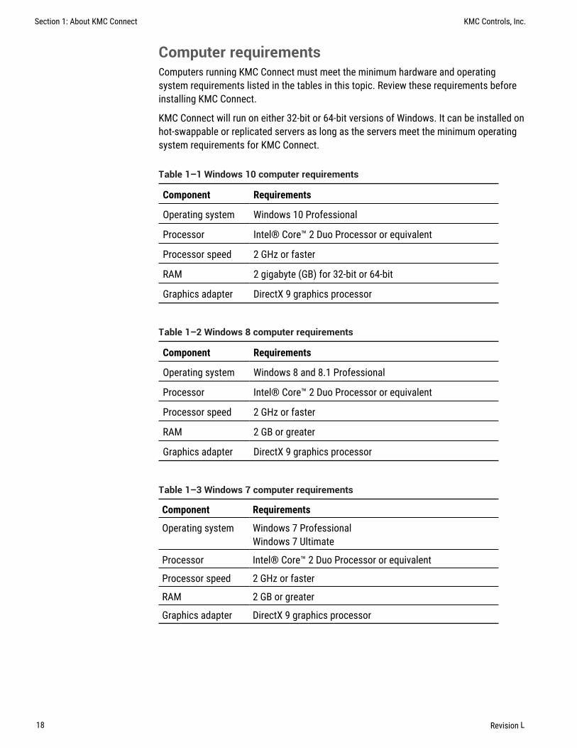
Computer requirementsComputers running KMC Connect must meet the minimum hardware and operatingsystem requirements listed in the tables in this topic. Review these requirements beforeinstalling KMC Connect.
KMC Connect will run on either 32-bit or 64-bit versions of Windows. It can be installed onhot-swappable or replicated servers as long as the servers meet the minimum operatingsystem requirements for KMC Connect.
Component Requirements
Operating system Windows 10 Professional
Processor Intel® Core™ 2 Duo Processor or equivalent
Processor speed 2 GHz or faster
RAM 2 gigabyte (GB) for 32-bit or 64-bit
Graphics adapter DirectX 9 graphics processor
Table 1–1 Windows 10 computer requirements
Component Requirements
Operating system Windows 8 and 8.1 Professional
Processor Intel® Core™ 2 Duo Processor or equivalent
Processor speed 2 GHz or faster
RAM 2 GB or greater
Graphics adapter DirectX 9 graphics processor
Table 1–2 Windows 8 computer requirements
Component Requirements
Operating system Windows 7 ProfessionalWindows 7 Ultimate
Processor Intel® Core™ 2 Duo Processor or equivalent
Processor speed 2 GHz or faster
RAM 2 GB or greater
Graphics adapter DirectX 9 graphics processor
Table 1–3 Windows 7 computer requirements
Section 1: About KMC Connect KMC Controls, Inc.
18 Revision L

Component Requirements
Operating system Windows Server 2008 R2Windows Server 2012 R2Windows Server 2016Windows Server 2019
Processor Dual-core minimum
Processor speed 2 GHz or faster
RAM 2 GB or greater
Table 1–4 Windows Server computer requirements
Component Recommended Minimum
Hard disk space 160 GB60 GB free
80 GB60 GB free
Monitor SVGA 1280 x 1024, 1920 x 768 SVGA 1024 x 768
Network connection Ethernet 100BaseT Ethernet 10BaseT
USB USB port dedicated to hardwarekey
Table 1–5 Computer platform requirements
KMC Connect Reference Guide Section 1: About KMC Connect
Revision L 19

Setting up computersComputers hosting KMC Connect must meet the requirements listed in the sectionComputer requirements on page 18. Before installing KMC Connect, verify thecomputer name, passwords and privileges, and sleep and hibernation modes.
Computer namesAssign a name to the computer that consists of only numbers and letters.
Passwords and privilegesHave available an administrator's user password for the computer on which KMC Connectwill be installed. The installing technician must have Windows administrator privileges.
Sleep and hibernation modesTo avoid corrupting the hardware license key, change the power settings for thecomputer. To change the power settings for your version of Windows, do the following:
1 Use the Help function in Windows to search for “power” or “power management”.
2 Choose the Help topic for changing or setting up a power scheme.
3 In the power scheme, change the computer power settings to disable hibernationand set the sleep mode to “never”.
Installing KMC ConnectKMC Connect installation files are distributed in a .zip file available from theDownloads section of our web site at partners.kmccontrols.com. All of the files for KMCConnect are included in the .zip file.
Note: A hardware license key is not required to install KMC Connect.However, you will need a key to start KMC Connect after installation.
To install KMC Connect, do the following.
1 In the Downloads folder, right-click the .zip folder containing KMC Connect.
2 Temporarily disable any security features that might block the installation. Forexample, in Windows: > Right-click the .zip folder. > In the shortcut menu, clickProperties. > In the Security section, select Unblock. > Click Apply.
3 Right-click the KMC Connect .zip folder.
4 Select Extract All.
5 When prompted, choose a location for the program and record this information.KMC Controls recommends the default location.
Once KMC Connect is installed, see the topic Getting started on page 23.
Section 1: About KMC Connect KMC Controls, Inc.
20 Revision L

Uninstalling KMC ConnectThis topic covers the removal of KMC Connect when it is no longer needed.
To uninstall KMC Connect, do the following:
1 Click Start, Settings, Control Panel and then choose Add or Remove Programs.
2 Scroll to programs in the Currently installed programs list. See the illustrationInstalled programs on page 21 for a list of the programs.
3 Choose KMC Connect and then click Remove.
4 The following programs should also be uninstalled unless other programs, such asTotalControl, are installed on the same computer.
l Choose KMC License Service and then click Remove.l Choose BACstac Router and then click Remove.
5 When the procedure is complete, restart the computer.
Illustration 1–1 Installed programs
KMC Connect Reference Guide Section 1: About KMC Connect
Revision L 21

Section 1: About KMC Connect KMC Controls, Inc.
22 Revision L

Section 2: Getting star ted
KMC Connect is a master operator workstation with which you can program BACnet andKMD controllers for a building automation system. This section covers the first stepstoward using the program.
With KMC Connect you can:
l View or change controller operationl Set up alarms and notificationsl Set up and view historical trend datal Set schedulesl Edit Control Basic programs
To use KMC Connect as a BACnet operator workstation you will need the following items:
l A hardware license key.l For existing sites—the user name and password established for the sitel For new sites—a new password for the site administrator
The following topics are covered in this section.
l Starting KMC Connect on page 24l Adding a new site on page 25l Open an existing site on page 27l Closing a site on page 28l Working offline on page 28
KMC Connect Reference Guide Section 2: Getting started
Revision L 23

Starting KMC ConnectKMC Connect starts the same as other Windows applications.
Note: The first time a hardware key is plugged into a computer,Windows will notify you that new hardware has been found. In thefollowing procedure, step 2 may not be required after the key isinserted for the first time.
To start KMC Connect, do the following:
1 Insert a valid hardware key or verify that a hardware key is inserted into a USB port.The key must remain in the USB port at all times KMC Connect is operating.
2 If the Found New Hardware Wizard opens, do the following.
l Choose the Install the software automatically option. This may take severalminutes to complete.
l When the wizard finishes installing the software for the hardware key,installation is complete.
3 For Windows 7, click Start > Programs > KMC Controls > KMC Connect. For Windows10, click Start > KMC Controls > KMC Connect .
4 Once KMC Connect starts, you can choose a site to open. If a site has not been setup on the computer, you can choose to run KMC Connect without connecting to asite or set up a new site.
Related topicsl Adding a new site on page 25l Open an existing site on page 27l Closing a site on page 28l Working offline on page 28
Section 2: Getting started KMC Controls, Inc.
24 Revision L

Adding a new siteAdding a new site sets up KMC Connect with all of the files, user names, and passwordsfor a specific building automation system. Typically, every building automation systemthat a control technician manages will have its own site on the technician's computer.
Note: The following procedure sets up a new site but does notconfigure BACstac for a connection to the BACnet internetwork.Verify or set Cimetrics BACstac to match the BACnet routingprotocol, network, and port established by a BACnet router. See thetopic Configuring the Cimetrics BACstac driver on page 669.
To start a new site in KMC Connect, do the following:
1 On the Site tab click New. The Site Name and Password dialog opens.
2 Enter the site name and a password for the site administrator.
3 Click Next to continue. When the Complete dialog opens, click Finish.
4 When the KMC Connect Sites dialog opens, select the site and then click Open.
KMC Connect Reference Guide Section 2: Getting started
Revision L 25

5 In Log on to Site, enter the user name admin and the password entered in Step 2.
6 When the site opens, change the Device Instance number of the BACnet service if itdoes not match system plans or if there is a conflict with another device. To changethe Device Instance, right click the BACnet service icon and choose ConfigureService from the shortcut menu. See Configuring a BACnet service on page 407
Related topicsl Open an existing site on page 27l Closing a site on page 28l Working offline on page 28
Section 2: Getting started KMC Controls, Inc.
26 Revision L

Open an existing siteTo open an existing site, you will need the following items:
l A hardware license key.l The user name and password established for the site.
Note: The following procedure opens an existing site but does notconfigure BACstac for a connection to the BACnet internetwork.Verify or set Cimetrics BACstac to match the BACnet routingprotocol, network, and port established by a BACnet router. See thetopic Configuring the Cimetrics BACstac driver on page 669.
To open an existing KMC Connect, do the following:
1 On the Site tab click Open.
2 When the KMC Connect Sites dialog opens, select the site by name and then clickOpen.
3 In the Log on to Site text box, enter the user name and the password.
4 If necessary, configure BACstac as described in the topic Configuring theCimetrics BACstac driver on page 669.
Related topicsl Adding a new site on page 25l Closing a site on page 28l Working offline on page 28
KMC Connect Reference Guide Section 2: Getting started
Revision L 27

Closing a siteClose an open KMC Connect site from the ribbon. On the Site tab click Close. With the siteis closed, you can continue to work offline.
l See About the Resource Manager on page 55 to program and configure a deviceor object file in the Resource Manager.
l See Application selection, configuration, and deployment on page 635 toconfigure a job for Conquest compliant controller.
Related topics
l Adding a new site on page 25l Open an existing site on page 27l Working offline on page 28
Working offlineKMC Connect supports offline programming at any time even if a site is open.
l See About the Resource Manager on page 55 to program and configure a deviceor object file in the Resource Manager.
l See Application selection, configuration, and deployment on page 635 toconfigure a job for Conquest compliant controllers.
Related topicsl Adding a new site on page 25l Open an existing site on page 27l Closing a site on page 28
Section 2: Getting started KMC Controls, Inc.
28 Revision L

KMC Connect
Part II: Working with KMC Connect
KMC Connect Reference Guide
Revision L 29

KMC Controls, Inc.
30 Revision L

Section 3: The KMC Connect workspace
KMC Connect is a master operator workstation for building automation systems. Topicsin this section explain the basic components of the KMC Connect.
KMC Connect is a collection of software modules with which you can configurecontrollers, and set up security, trends, schedules, and alarms.
Illustration 3–1 KMC Connect workspace
Site management tools The most frequently used components of KMC Connect are thedockable site management tools. Each tool opens in a separate pane in the KMC Connectworkspace.
l The The Output Window on page 51 displays recent actions and messages aboutissues that may need operator attention.
l The Network Manager is an expandable list of all controllers, networks, and servicesin a KMC Connect-managed building automation system. See the topic Using theNetwork Manager on page 39 for all of the features of the Network Manager.
l The Resource Manager is a tool for managing templates and working offline tocreate controller configuration files, and Control Basic programs. See About theResource Manager on page 55 for details on working offline.
KMC Connect Reference Guide Section 3: The KMC Connect workspace
Revision L 31

Alarm Monitor Bar The alarm window is a scrolling list of alarms and notifications thathave yet to be acknowledged and archived. See the topic Using the Alarm Monitor baron page 165 for details on alarm management.
Illustration 3–2 Alarm Monitor Bar
Configuration tabs Components in a KMC Connect-managed building automation site areset up and configured from configuration tabs. The tabs may be opened from the KMCConnect ribbon or from one of the site management tools.
l To configure a service, network, device or object, see Using the NetworkManager on page 39.
l To set up and view data trends, see About trend logs on page 97.l To write Control Basic programs, see Control Basic and the Code Editor on page
189.l To set up alarms and notifications, see Alarms, notifications, and events on page
129.
Configuration tabs may also include toolbar commands that are specific to the tabs. Thecommands are explained in the sections for that configuration tab.
Illustration 3–3 Parts of a configuration tab
To locate a hidden tab
A tabbed page may be open but, because of space available, its tab may not be visible inthe workspace. Click the downward arrow ( ) to open the tabs menu.
Section 3: The KMC Connect workspace KMC Controls, Inc.
32 Revision L

To close the active configuration page
l Click in the upper right corner of the page.l Right-click the tab and choose Close.
Related topics
l Customizing the workspace on page 33l Options for KMC Connect on page 36l Object Locate on page 37
Customizing the workspaceWhen first installed, KMC Connect opens with the panes for the site management tools —Network Manager, Output Window, and Resource Manager — docked and visible.Configuration tabs are opened in the remaining workspace. The available workspace canbe controlled by docking, floating, or hiding the panes for the site management tools.
Illustration 3–4 Docking arrows
Docked panes When a pane is docked, it is stationary and visible against a side of theKMC Connect window. Network Manager, Resource Manager, and Output Window are alldocked when KMC Connect opens. When docked, any of these management tool panescan be hidden or changed to floating panes.
KMC Connect Reference Guide Section 3: The KMC Connect workspace
Revision L 33

Hidden panes Docked panes may be hidden from view and kept ready to use whenneeded. A hidden pane’s location is indicated by a tab along the edge of the window.
Illustration 3–5 Tab for pinned management tool pane
Floating panes A floating pane is detached from the KMC Connect window and can bemoved to any location on the desktop.
To change a docked management tool pane to a floating pane.
l Drag the title bar of the pane to a new location.l Double click the title bar. The pane moves into the workspace.
To set a management tool pane to Auto-Hide
Setting a site management tool pane to Auto-Hide pins the pane against the edge of theworkspace. Only a docked pane may be set to Auto-Hide. A tab marks the location of thehidden tab.
1 If the pane is floating, dock the pane.
2 Do one of the following:
l Click in the title bar. The pane is pinned against the edge of the workspace towhich it is docked.
l Right-click the title bar and choose Auto-Hide.
Viewing a management tool pane in Auto-Hide
To display a pinned pane, hover the pointer over the tab of the pinned pane. The paneremains visible until you click outside of the pane or reveal another pane.
Section 3: The KMC Connect workspace KMC Controls, Inc.
34 Revision L

To change a hidden pinned pane to a docked pane
1 Display the pane.
2 Do one of the following:
l Click in the title bar. The pane docks along the edge of the workspace.l Right-click the title bar and choose Dockable.
To change a floating page to a docked pane
1 Click the title bar of the pane. The docking arrows appear in the KMC Connectwindow.
2 Drag the pane to one of the docking arrows.
l Pane docking arrows–When released over the pane arrows, KMC Connect splitsthe stationary pane and docks the floating pane in the position indicted by thearrow.
l Window arrow–KMC Connect docks the floating pane against the entire edge ofthe KMC Connect window.
To close a management tool pane
To close a pane that is floating, docked, or pinned, from the View tab on the ribbon, clickthe name of the management tool.
To open a management tool pane
To open a pane that is not docked, pinned or floating, do one of the following:
l On the KMC Connect toolbar, click the icon for the pane.l From the View tab on the ribbon, choose the site management tool by name. Its
pane will become active in the same location in which it was closed.
KMC Connect Reference Guide Section 3: The KMC Connect workspace
Revision L 35

Options for KMC ConnectWith the General Applications Options dialog, you can:
l Choose to save the position of the site management tools when KMC Connectcloses.
l Control the way KMC Connect displays the Alarm Monitor Bar.l Choose when KMC Connect starts an audible alarm after receiving an alarm or event
notification.l Set KMC Connect to lock after a period of inactivity.l Set the display precision for floating point numbers.
Illustration 3–6 General Application options dialog
To open the General Applications option dialog, do the following:
1 On the ribbon click the File tab and then click Options.
2 From the Component list choose General Applications.
3 Change settings or selections.
4 Click Apply or OK when finished.
Save My Window Settings The Save My Windows Settings check box saves theconfiguring of the site management tools when KMC Connect opens.
l Select the Save My Windows Settings Upon Exit check box to set KMC Connect tosave the present configuration of site management tools.
l Clear the Save My Windows Settings Upon Exit check box to set KMC Connect toalways open with the present configuration of site management tools.
Section 3: The KMC Connect workspace KMC Controls, Inc.
36 Revision L

Alarm Notification Settings KMC Connect will open an alarm popup and sound an audiblealarm when it receives a notification from a device on a building automation systemnetwork. Enable or disable the popup or audible alarm with the check boxes in this sectionof the General Application options dialog.
l Select the Hide Alarm Popup check box to disable the alarm popup from openingwhen KMC Connect processes an alarm.
l Select the Mute Audio Alert check box to disable the audible alarm when KMCConnect processes an alarm.
l Select the Disable Alarm Monitor Bar Popup check box to prevent the Alarm MonitorBar from opening when a new alarm is received.
Lock application when inactive Locks KMC Connect after the specified time. Enter a username and password to unlock the application.
Floating point numbers displayed precision Change the precision of displayed floatingpoint numbers. The default is two decimal places.
Object LocateWhen working with sidebar panes, the sources of some files, objects and devices maybecome hidden due to scrolling or repositioning.
To bring the source of an open object, file or device back into focus in the NetworkManager or Resource Manager, use the Object Locate feature.
Clicking Locate in the active item's toolbar will scroll to and highlight the item in itssource pane.
Illustration 3–7 The Locate command in an open configuration tab
Related topics
l Using the Network Manager on page 39l About the Resource Manager on page 55l Customizing the workspace on page 33
KMC Connect Reference Guide Section 3: The KMC Connect workspace
Revision L 37

Section 3: The KMC Connect workspace KMC Controls, Inc.
38 Revision L

Section 4: Using the Network Manager
The Network Manager is the site management tool with which you can view andconfigure networks, devices, objects and points.
Networks, devices, objects, points and properties are displayed and configured throughthe Network Manager. The Network Manager list is a display of the actual buildingautomation system job site to which KMC Connect is connected. The list can be expandedto manipulate a specific point or property or collapsed to view only networks, devices orcontrollers. Use the Network Manager for the following:
l Display the structure of KMC Connect services, networks, and devices in the buildingautomation system job site.
l As a source for dragging objects into Control Basic programs.l To locate and configure objects, properties, and points in the BAS controllers.
Illustration 4–1 Typical Network Manager
KMC Connect Reference Guide Section 4: Using the Network Manager
Revision L 39

Configuring controllers
l Configuring and connecting to BACnet devices and networks on page 401l Configuring and connecting to KMDigital controllers and networks on page
553l Setting up an OPC service on page 613
Related topics
l Network Manager toolbar commands on page 40l Opening and closing the Network Manager pane on page 40l Changing the Network Manager options on page 46
Opening and closing the Network Manager paneTo open or close the Network Manager pane, on the View group click Network Manager.
Illustration 4–2 View tab on the ribbon
Network Manager toolbar commandsUse one of the following methods to choose a Network Manager command.
l Click the icons on the Network Manager toolbar.l Right-click an icon in the Network Manager list and then choose a command from
the shortcut menu.
Illustration 4–3 Network manager toolbar
Find Device Locates the devices connected to the building automation system. Oncelocated, the devices are displayed in the Network Manager list. See Changing theNetwork Manager options on page 46.
Add Service Connect a KMC Connect Building Service to the site database.
Restore Device Configure a device with the contents of a backup file.
Backup Device Save the configuration of a device in a backup file.
Delete selected item Remove the selected item from the Network Manager list.
Section 4: Using the Network Manager KMC Controls, Inc.
40 Revision L

Discovering devicesDiscovery is the process of populating the Network Manager list with the devices on thenetwork. KMC Connect supports two types of discovery.
Limited discovery KMC Connect will read only the device object properties. Thisdiscovery is faster but may limit other functions. Devices are discovered under limiteddiscovery are represented by a limited discovery icon .
Full discovery KMC Connect reads all objects and properties in every device. Devicesdiscovered under full discovery are represented by a full discovery icon .
To change the discovery method, see the topic Setting discovery options on page 41.
Initial discovery
1 Start KMC Connect.
2 In the Network Manager list, locate the service icon .
3 Right-click the icon.
4 From the shortcut menu, choose Regenerate All Networks.
Updating a network
1 In the Network Manager list, locate a network icon .
2 Right-click the icon and choose one of the following from the shortcut menu.
l Regenerate Network—Deletes all current devices in the network and repopulatesthe network list with only the devices currently on the network.
l Find Devices—Leaves the existing devices unchanged and adds new devices tothe network list.
Complete discovery
When the site is set for Limited discovery, use complete discovery to fully discover allobjects in selected devices.
1 Locate the service icon , network icon , or the device icon .
2 Right-click the icon and choose Complete Discovery from the shortcut menu. Whendiscovery is complete, device icons change to .
See the related topic Adding BACnet devices to the Network Manager list on page402.
Setting discovery optionsDiscovery is the process of populating the Network Manager list with the devices on thenetwork. KMC Connect supports two methods of discovery.
Limited discovery KMC Connect will read only the device object properties. This methodis faster but may limit other functions. Devices are discovered by limited discovery arerepresented by the limited discovery icon .
KMC Connect Reference Guide Section 4: Using the Network Manager
Revision L 41

Full discovery KMC Connect reads all objects and properties in every device. Devicesdiscovered by full discovery are represented by the full discovery icon .
To change the discovery method, do the following:
1 On the ribbon, click the File tab.
2 Click Options.
3 From the Component list, choose Current Site.
4 Choose either Limited Discovery or Full Discovery.
5 Click Apply.
6 Click OK.
Illustration 4–4 Current Site Settings dialog
See the related topic Discovering devices on page 41.
Adding a serviceAdding a service connects one of the previously installed components of services to thesite. Typically, the services are added and configured at the time they were installed. If aservice was not connected to the site at the time of installation, add it with NetworkManager.
To add a service to the Network Manager list, do the following:
1 On the Network Manager toolbar, click the Add Service icon . The Add Servicedialog opens.
2 Choose a service from the Service Type list.
3 Enter a descriptive name in the Service Name text box.
4 Enter either the IP address or the name of the computer hosting the SQL database.
Section 4: Using the Network Manager KMC Controls, Inc.
42 Revision L

5 If required, change the default number in Port.
6 When complete, click OK. The icon for the service is added to the Network Managerlist.
Illustration 4–5 Add Service dialog
Details of the Add Service dialogService Name A descriptive name to display in the Network Manager list.
Service Type Choose a service to add from the Service Type list.
IP Address/Computer Name Enter the name or IP address of the computer hosting thesite database.
Port Change the default port number only if required. For a listing of UDP ports used byKMC Connect, see Communication ports and BAS networks on page 661.
Automatic Service ID Select the Automatic Service ID check box when adding a newservice. Clear the check box to change the Service ID number that was automaticallyassigned by KMC Connect.
Service ID Use only to change the Service ID number that was automatically assigned byKMC Connect.
Related topics
l Using the Network Manager on page 39l Network Manager toolbar commands on page 40l Opening and closing the Network Manager pane on page 40
l Configuring the Trend Service on page 127l Configuring the Notification Service on page 175l Configuring and connecting to BACnet devices and networks on page 401l Configuring and connecting to KMDigital controllers and networks on page
553l Configuring the Protocol Gateway service on page 631
l Configuring an existing service on page 44l Removing a service on page 45
KMC Connect Reference Guide Section 4: Using the Network Manager
Revision L 43

Configuring an existing serviceThe installed KMC Connect services are at the top of the Network Manager list. If aservice is in the Network Manager list, use the following procedure to make changes. Theexact changes that can be made will depend upon the service.
To configure an installed service, do the following:
1 Open the Network Manager.
2 Locate and select the service.
3 Right-click the service and then choose Configure Service from the shortcut menu. Aconfiguration tab opens in the workspace.
4 Make the changes to the service.
5 When changes are complete, click Save Changes to Service in configuration tab.
Illustration 4–6 Services in the Network Manager list
Related topics
l Using the Network Manager on page 39l Network Manager toolbar commands on page 40l Opening and closing the Network Manager pane on page 40
l Configuring and connecting to KMDigital controllers and networks on page553
l Configuring the Protocol Gateway service on page 631
Section 4: Using the Network Manager KMC Controls, Inc.
44 Revision L

Removing a serviceTo remove the site connection to a KMC Connect Building Service, select the service inthe Network Manager list and then do one of the following:
l On the Network Manager toolbar, click the Delete icon .
l Right-click the service and choose Remove Service from the shortcut menu.
Note: Removing a service only removes the service connection to thesite database. It does not uninstall it from the computer hosting theservice.
Related topics
l Using the Network Manager on page 39l Network Manager toolbar commands on page 40l Opening and closing the Network Manager pane on page 40
l Adding a service on page 42l Configuring an existing service on page 44
KMC Connect Reference Guide Section 4: Using the Network Manager
Revision L 45

Changing the Network Manager optionsUse the Network Manger Settings dialog to change any of the following settings.
l How objects, points, and tooltips are displayed in the Network Manager listl Options for trend logsl Configuration, deployment, and balancing options
To make changes to Network Manager settings, do the following:
1 On the ribbon, click the File tab.
2 Click Options.
3 From the Component list, choose Network Manager and then change any of theproperties in the dialog.
Illustration 4–7 Network Manager Settings dialog
Display Mnemonics first Select or clear this check box to change the listing of a point orobject in the Network Manager list.
l When selected, the mnemonic identifier for a point or object is displayed first in theNetwork Manager list.
l When cleared, the name or label for a point or object is displayed first in theNetwork Manager list.
Minimum Display Time for Device Node Warnings (seconds) Sets the minimum period—in seconds—that warning icons and tooltips remain in place when hovering over icons inthe Network Manager list.
Include Trend Log Data in Exported Files When this check box is selected, the trend logdata is included with a trend log object or point when the point or object is moved to theResource Manager list.
Default PC Trend Log Interval (seconds) Sets the default logging interval value in theTrend Manager when setting up PC trends. See Configuring a BACnet PC trend log onpage 115 and Configuring KMD PC trend logs on page 123.
Use First Matching VAV Application on VAV Configuration Form When the check box isselected, the application in the newest version of the application library is used. If the
Section 4: Using the Network Manager KMC Controls, Inc.
46 Revision L

check box is cleared, a list of versions is opened for selection. See the topic Applicationselection, configuration, and deployment on page 635.
Use First Matching VAV Application on VAV Balancing Form When the check box isselected, the application in the newest version of the application library is used. If thecheck box is cleared, a list of versions is opened for selection. See the topic Applicationselection, configuration, and deployment on page 635.
Limit Deployment Parallel Tasks When the check box is selected, the number ofcontrollers that KMC Connect is actively deploying to is limited by the entered value. Thisprevents overloading the network. See the topic Application selection, configuration,and deployment on page 635.
Related topics
l Using the Network Manager on page 39l Network Manager toolbar commands on page 40l Opening and closing the Network Manager pane on page 40
Naming BACnet networksBACnet networks are identified by a network number assigned by a BACnet router. In KMCConnect, networks can be assigned a name for easy identification.
To rename a network, do the following:
1 Right-click the network icon and choose Rename from the shortcut menu.
2 Enter a descriptive name for the network.
3 Click Okay when finished.
Illustration 4–8 Network Manager with network names
Related topics
l Using the Network Manager on page 39l Network Manager toolbar commands on page 40l Opening and closing the Network Manager pane on page 40
KMC Connect Reference Guide Section 4: Using the Network Manager
Revision L 47

Restarting BACstac from the Network ManagerFor various reasons, the BACstac BACnet driver may need to be restarted after computermaintenance or upgrade. The driver can be restarted from the BACnet service in theNetwork Manager.
To restart the BACstac driver from the Network Manager, do the following:
1 In the Network manager, locate the BACnet service icon .
2 Right-click the icon.
3 From the shortcut menu, choose Restart BACstac.
Related topics
l Using the Network Manager on page 39l Network Manager toolbar commands on page 40l Opening and closing the Network Manager pane on page 40
Enable and disable NFCThe Near Field Communications (NFC) for KMC Conquest controllers on a network orservice can be disabled from either a BACnet network or service in the Network Managerlist. This applies only to KMC controllers with the NFC icon and firmware E1.0.0.31 orlater.
To enable or disable NFC in a single controller, see the topic Device objects on page435.
Illustration 4–9 The NFC icon
NFC is used with the smartphone app KMC Connect Lite to configure Conquest seriescontrollers.
To disable NFC for controllers on a service or network, do the following:
1 Do one of the following:
l In the Network Manager list, locate the service icon .l Expand the Network Manager list, and locate a network icon .
2 Right-click the icon.
3 Choose the NFC shortcut menu.
4 From the NFC shortcut menu, choose Disable All.
The NFC on the selected service or network will be disabled.
Section 4: Using the Network Manager KMC Controls, Inc.
48 Revision L

To enable NFC for controllers on a service or network, do the following:
1 Do one of the following:
l In the Network Manager list, locate the service icon .l Expand the Network Manager list, and locate a network icon .
2 Right-click the icon.
3 Choose the NFC shortcut menu.
4 From the NFC shortcut menu, choose Enable All .
The NFC on all controllers on the selected service or network will be enabled.
KMC Connect Reference Guide Section 4: Using the Network Manager
Revision L 49

Section 4: Using the Network Manager KMC Controls, Inc.
50 Revision L

Section 5: The Output Window
The Output Window is a continuously updated list of significant actions that have takenplace in a KMC Connect managed site.
As components of KMC Connect perform tasks, the success or failure of the function isindicated by an entry in the Output Window. Every entry is tagged with an icon as an error,warning, or message.
Icon Condition Description
Error A severe condition that could be either system or userrelated.
Warning Less severe than an error; operation may proceed.
Message For information purposes.
Table 5–1 Output Window icons
At the top of the Output Window are three buttons. Clicking a button hides or reveals all ofthe entries associated with that button.
Illustration 5–1 Output Window
Entries listed in the Output Window are saved as the file KMCConnectOutput.log inthe Resource Manger Logs folder.
To conserve memory, the Output Window list is limited to 5000 entries. If there are morethan 5000 entries, the oldest entries are deleted. KMC Connect adds a message to the listthat older entries are in the KMCConnectOutput.log file.
Related topics
l Opening and closing the Output Window on page 52l Sorting and clearing the Output Window on page 52l Output Window options on page 52
KMC Connect Reference Guide Section 5: The Output Window
Revision L 51

Opening and closing the Output WindowTo open or close the Output Window, on the ribbon click the View tab and then clickOutput Window.
See also the related topics Sorting and clearing the Output Window on page 52 andOutput Window options on page 52.
Illustration 5–2 View tab on the ribbon
Sorting and clearing the Output WindowTo change the order of entries in the Output Window list, right-click on the list and selectone of the following commands from the shortcut menu.
Illustration 5–3 Output Window with shortcut menu
Clear Removes all entries from the list.
Sort By Sorts and displays the entries based on either the entry number, time of the entryor the KMC Connect component from which the entry originated.
Show By Hides or reveals the entries by the component from which the entry originated.
Save Output To Log File When selected, entries added to the list are also added to a.log text file in the Logs folder in the Resource Manager.
Copy To Clipboard Ctrl+C Selects and copies all of the entries in the list to the Clipboard.
See also the topics Related topics Opening and closing the Output Window on page52 and Output Window options on page 52.
Output Window optionsPermanently change the sorting or contents of the Output Window list with settings in theOutput Window Settings dialog.
To change the Output Window settings, do the following:
1 On the ribbon click the File tab and click Options.
2 Click Output Window.
Section 5: The Output Window KMC Controls, Inc.
52 Revision L

3 Change any of the settings.
4 Click Apply or OK when finished.
Illustration 5–4 Output Window Settings dialog
Output Logging When Save Output to File is selected, entries added to the Output Windoware also added to a .log text file in the Logs folder of the Resource Manager.
Sort By This property sets the default sort order for the entries in the Output Window.
Output Window Display Behavior When selected, the Output Window automatically openswhen error or warning entries are added.
Show By Selects the entries that are visible based on the origin of the message.
Restore to Default Returns the Output Window display to the default settings.
See also the topics Opening and closing the Output Window on page 52 and Sortingand clearing the Output Window on page 52.
KMC Connect Reference Guide Section 5: The Output Window
Revision L 53

Section 5: The Output Window KMC Controls, Inc.
54 Revision L

Section 6: About the Resource Manager
The Resource Manager is a tool with which operators can manage local files for backingup the building automation system and editing files offline to prepare templates. Thefollowing topics include procedures to use the Resource Manager to create backup files,restore the configuration of controllers with backup files, and edit files offline.
The Resource Manager displays and manages a list of files stored on the computer that isrunning KMC Connect. Through the Resource Manager, these local files can be editedwithout connecting to a site. By opening an item in the Resource Manager list, you can:
l Create backup files of properties, points, devices, or the entire building automationsystem
l Restore device configurations with backup filesl Write Control Basic programsl Drag objects into Control Basic programsl Open other files with their associated Windows applicationl Import and export files from other programs
Illustration 6–1 Resource Manager
Related topics
l Opening and closing the Resource Manager pane on page 56l Editing items in the Resource Manager list on page 56l Restoring a configuration on page 57l Creating backup files on page 60
KMC Connect Reference Guide Section 6: About the Resource Manager
Revision L 55

l Managing the Resource Manager list on page 60l Adding files to the Resource Manager folder on page 61l Backing up and restoring BACnet and KMDigital devices on page 419
Opening and closing the Resource Manager paneTo open or close the Resource Manager, on the ribbon click the View tab and then clickResource Manager.
Illustration 6–2 View tab on the ribbon
Related topics
l About the Resource Manager on page 55l Editing items in the Resource Manager list on page 56l Restoring a configuration on page 57l Creating backup files on page 60l Managing the Resource Manager list on page 60l Adding files to the Resource Manager folder on page 61l Importing and exporting BACstage files on page 422
Editing items in the Resource Manager listYou may edit offline any item in the Resource Manager list. To edit an item in the list:
1 Click or to expand or collapse the Resource Manager list to locate a device,object, point, or diagram file.
2 Use one of the following methods to open the item:
l Right-click and choose Configure.l Double-click the item.
3 The configuration tool associated with the item opens in the workspace.
l For Control Basic programs, the Code Editor opens.l For BACnet objects and devices, a BACnet configuration tab opens.l For items that are not part of KMC Connect, the Windows program associated
with the file type opens.
4 Make changes and then save the configuration page.
Related topics
l About the Resource Manager on page 55l Opening and closing the Resource Manager pane on page 56
Section 6: About the Resource Manager KMC Controls, Inc.
56 Revision L

l Restoring a configuration on page 57l Creating backup files on page 60l Managing the Resource Manager list on page 60l Adding files to the Resource Manager folder on page 61l Importing and exporting BACstage files on page 422
Restoring a configurationDragging an object from a backup file in the Resource Manager list to a compatible itemin the Network Manager list is a restorative process.
Illustration 6–3 Devices and objects in a .bnd file
When dragging a file to an item in Network Manager, the following actions are permitted:
Dragging objects to objects, devices or networks
l Drag an object from a backup file onto an object of similar type in the NetworkManager list. For example, drag only input objects onto input objects.
l Drag an object from a backup file onto a device that contains objects of similar type.A dialog opens with which you can select the objects to restore.
l Drag an object from a backup file onto a network that includes devices with similarobjects.
l Drag a group of objects, such as the input objects folder, onto a similar group. Theobjects in the backup file are matched by object instance number to the objects inthe Network Manager list.
KMC Connect Reference Guide Section 6: About the Resource Manager
Revision L 57

Dragging devices to devices or networks
l Drag a device from a backup file onto a device of the same model andmanufacturer. For example, only BAC-5801 files may be dropped onto BAC-5801devices in the Network Manager list. A dialog opens with which you can choose theobjects within the device to restore.
l Drag a device onto a network that includes similar devices. A dialog opens withwhich you can select the devices to restore.
Dragging a folder to another folder or device
When dragging a folder to another folder or device, Resource Manager restores objects onan instance-matching basis. For example:
l If the source folder contains input objects numbers 1-4, then objects 1-4 in thetarget folder or devices are restored.
l If the source item has 16 objects and the target item has eight objects, only eighttarget objects are restored with objects 1-8.
When the folder is dropped, the Select Objects dialog opens. Select or clear the checkboxes next to the object names to designate the objects to restore.
Illustration 6–4 Select Objects dialog
Tip: You may also right-click anywhere in the dialog and then selectCheck All or Clear All from the shortcut menu.
Section 6: About the Resource Manager KMC Controls, Inc.
58 Revision L
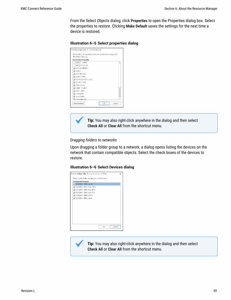
From the Select Objects dialog, click Properties to open the Properties dialog box. Selectthe properties to restore. Clicking Make Default saves the settings for the next time adevice is restored.
Illustration 6–5 Select properties dialog
Tip: You may also right-click anywhere in the dialog and then selectCheck All or Clear All from the shortcut menu.
Dragging folders to networks
Upon dragging a folder group to a network, a dialog opens listing the devices on thenetwork that contain compatible objects. Select the check boxes of the devices torestore.
Illustration 6–6 Select Devices dialog
Tip: You may also right-click anywhere in the dialog and then selectCheck All or Clear All from the shortcut menu.
KMC Connect Reference Guide Section 6: About the Resource Manager
Revision L 59

Related topics
l About the Resource Manager on page 55l Opening and closing the Resource Manager pane on page 56l Editing items in the Resource Manager list on page 56l Restoring a configuration on page 57l Managing the Resource Manager list on page 60l Adding files to the Resource Manager folder on page 61l Importing and exporting BACstage files on page 422
Creating backup filesDragging an item from the Network Manager list to the Resource Manager creates abackup file.
l For BACnet devices and objects, a .bnd file is placed in the Resource Manager list.l For KMD controllers and points, a .kmd file is placed in the Resource Manager list.
Related topics
l About the Resource Manager on page 55l Opening and closing the Resource Manager pane on page 56l Editing items in the Resource Manager list on page 56l Restoring a configuration on page 57l Managing the Resource Manager list on page 60l Adding files to the Resource Manager folder on page 61l Backing up and restoring BACnet and KMDigital devices on page 419
Managing the Resource Manager listThe Resource Manager list displays the hierarchical structure of folders, files, and devicesin the Resource folder. You can delete, copy, move, and rename any item in the list. Forexample, you can open a folder that contains a file you want to copy or move, and thendrag the file to another folder.
Creating a new folder
Creating a new folder in the Resource Manager list creates also a new folder in theResource folder on the computer hard drive. For details about folders, see Adding files tothe Resource Manager folder on page 61.
1 Click the new folder icon in the Resource Manager toolbar.
2 Enter a name for the new folder.
3 Once the folder is in the list, you may drag it to new location.
Section 6: About the Resource Manager KMC Controls, Inc.
60 Revision L

Removing an item from the Resource Manager list
1 Right-click the item.
2 Choose Delete from the shortcut menu.
Changing the name of an item in the Resource Manager list
1 Right-click the item.
2 Choose Rename from the shortcut menu.
3 Enter the new name.
Duplicating an item in the Resource Manager list
1 Right-click the item.
2 Choose Clone from the shortcut menu.
3 Enter a new name for the duplicated item.
If the cloned item is a BACnet device, you may choose also to select the Auto IncrementDevice Instance check box. This increases the device instance number to preventduplicate instance numbers.
Related topics
l About the Resource Manager on page 55l Opening and closing the Resource Manager pane on page 56l Editing items in the Resource Manager list on page 56l Restoring a configuration on page 57l Creating backup files on page 60l Adding files to the Resource Manager folder on page 61l Importing and exporting BACstage files on page 422
Adding files to the Resource Manager folderAll files and folders in the Resource Manager list are stored in the Resource folder. Thefolder is located on the same computer on which KMC Connect is running. Use WindowsExplorer to move files to the Resource folder.
To open the Resource folder, do one of the following:
l Click the Open Location icon to open the Resource folder in Windows Explorer.
l Use Windows Explorer to locate the file at C:\ProgramData\KMCControls\KMC Connect\Resource.
Once the Resource folder is open in Windows Explorer, you may move files into or out of itas you would any other folder.
KMC Connect Reference Guide Section 6: About the Resource Manager
Revision L 61

Related topics
l About the Resource Manager on page 55l Opening and closing the Resource Manager pane on page 56l Editing items in the Resource Manager list on page 56l Restoring a configuration on page 57l Creating backup files on page 60l Managing the Resource Manager list on page 60l Importing and exporting BACstage files on page 422
Section 6: About the Resource Manager KMC Controls, Inc.
62 Revision L

Section 7: V iewing objects with Table V iew
Table Views are a method to view all of the properties of a group of objects. Thissection describes the methods and procedures to use Table Views.
To view all or some of the properties of a group of objects use the Table View feature ofDesign Studio. Table View can be used in two different ways.
l To view all of the objects in a group folder. See the topic Viewing groups ofsimilar objects on page 64.
l A custom view with a mix of objects from one or more controllers. See the topicCustom Table Views on page 67.
Illustration 7–1 Table View of input points
Illustration 7–2 Custom Table View
KMC Connect Reference Guide Section 7: Viewing objects with Table View
Revision L 63

Viewing groups of similar objectsOpening a group of objects in the Table View is an alternative to using a deviceconfiguration tab. The Table View is opened from the Network Manager list and displaysall of the properties for a group of objects in one Table. The view can be customized byrearranging properties, hiding or revealing properties, and adding other objects to thetable.
To open the Table View, do the following:
1 In the Network Manager list, click or to expand or collapse the list of devicesand objects to locate a folder of objects such as input objects.
2 To open the Table Viewer, do one of the following:
l Double-click on the folder of objects. The Table Viewer opens.l Right-click the folder of points of objects and choose Configure Objects from the
shortcut menu.
Illustration 7–3 Table View of input objects
Objects, located in the rows of the tables, and properties, located in the columns of thetable, can be moved or hidden to customize the view.
l To close the Table View, click the close button in the upper right corner of thepage.
l To change the order of the columns, drag a column heading across the top of thetable.
l To hide or reveal rows and columns, see the following procedures.l Objects and properties with the refresh icon are selected for automatic update if
Auto Refresh is selected.
Copying table data
The data in a Table View can be copied to the Clipboard and then pasted into otherprograms such as a spreadsheet, text editor, or word processor. The columns areseparated with tabs.
1 Drag across the rows and columns.
2 Right-click the selected area and choose Copy Selection to Clipboard.
Section 7: Viewing objects with Table View KMC Controls, Inc.
64 Revision L

3 Open a document in an application such as spreadsheet, text editor, or wordprocessor.
4 Paste the data into the document.
Hiding and revealing the objects and properties in the table
Use one of the following methods to hide or reveal rows or columns.
l To hide a row, right-click the first column in the row and select Hide Object from theshortcut menu.
l To hide a column, right-click the top of the column and select Hide from the shortcutmenu.
l Choose one of the Select Visible commands from the View menu.
Hiding and revealing rows To hide or reveal hidden rows with the Select Visible Rowscommand, do the following.
1 From the View menu, choose Select Visible Rows.
2 When the Select Visible Object Rows dialog opens, do either of the following.
l To hide a visible object, clear the check box next to the name of the object.l To reveal a hidden object, select the check box next to the name of the object.
3 Click OK when finished.
4 To make the change permanent, choose Save from the View menu.
Hiding and revealing columns To hide visible or reveal hidden columns with the SelectVisible Columns command, do the following.
1 From the View menu, choose Select Visible Columns.
2 When the Select Visible Columns dialog opens, do either of the following.
l To hide a visible property, clear the check box next to the name of the object.l To reveal a hidden property, select the check box next to the name of the object.
3 Click OK when finished.
4 To make the change permanent, from the View menu choose Save.
Refreshing the table data
Data in the table can be refreshed by clicking Refresh at the top of the tab. Objects andproperties selected for automatically refresh are marked with the refresh icon .
To automatically refresh the data, do the following:
1 Select the Auto Refresh check box.
2 Enter a time value in the Auto Refresh Interval text box. Time is entered in seconds;the minimum refresh interval is 1 second.
KMC Connect Reference Guide Section 7: Viewing objects with Table View
Revision L 65

3 To choose specific objects (rows) and properties (columns) to refresh, do one orboth of the following procedures.
l From the View menu, choose Select Auto Refresh Rows. When the auto refreshdialog opens, select or clear the check boxes next to the name of the row.
l From the View menu, choose Select Auto Refresh Columns. When the autorefresh dialog opens, select or clear the check boxes next to the name of theproperties. After the dialog is closed, the column header turns to blue.
4 Click Save Changes when finished.
To add object types or properties from other devices
In addition to the objects from a single group of objects, objects from either the samedevice or other devices can be included in the Table View.
To add objects from the same device or other devices, do the following.
1 Open a Table View for a group of objects.
2 Locate the additional object types in the same device or the other device andobjects in the Network Manager list.
3 Drag the additional objects or properties to the table.
Note: Other object types or objects from other devices are not savedin the Table View for a group of objects. To save a Table View with amix of objects, see Custom Table Views on page 67.
Editing property configurations in the table viewer
Any properties that can be changed by KMC Connect can be changed in the table viewer.
1 In an open Table View, locate the property in the viewer.
2 Change the value of the property. For complex properties such as for editing ControlBasic programs, a dialog will open. The value background changes to green toindicate unsaved changes.
3 When all changes have been made, click Save Changes at the top of the tab.
Click Refresh at the top of the table to undo changes that have not been saved.
Related topics
l Viewing objects with Table View on page 63l Custom Table Views on page 67l Using the Network Manager on page 39
Section 7: Viewing objects with Table View KMC Controls, Inc.
66 Revision L

Custom Table ViewsUse a custom Table View to place a mix of object types from one or more controllers intoa single Table View. The custom view can then be saved as a .tbvx file in the ResourceManager for future use.
Illustration 7–4 Custom Table View
Objects, located in the rows of the tables, and properties, located in the columns of thetable, can be moved or hidden to customize the view.
l To close the Table View, click the close button in the upper right corner of thepage.
l To change the order of the columns, drag a column heading across the top of thetable.
l To hide or reveal rows and columns, see the following procedures.l Objects and properties with the refresh icon are selected for automatic update if
Auto Refresh is selected.
Starting a new custom view
1 On the View tab, click New Table View.
Option: On the ribbon, click the File tab and then click New and then New Table View.
2 Locate objects or folders of objects in the Network Manager list.
3 Drag the objects or folders to the Table View workspace.
4 When all objects are in the new table, click Save or Save As to save the view as a.tbvx file in the Resource Manager.
Starting custom views from a group of objects
A custom Table View can also be started from a group of objects in the Network Managerlist.
To start a custom Table View from a group of objects, do the following:
KMC Connect Reference Guide Section 7: Viewing objects with Table View
Revision L 67

1 In the Network Manager list, click or to expand or collapse the list of devicesand objects to locate a folder of objects such as input objects.
2 To open the Table Viewer, do one of the following:
l Double-click on the folder of objects. The Table Viewer opens.l Right-click a folder of objects or points and choose Configure Objects from the
shortcut menu.
3 As needed, drag other objects to the viewing area.
4 Click Save As to save the view as a .tbvx file in the Resource Manager.
Adding objects by path name
Objects can be added to a Table View by entering the path of objects that are located ineither the Resource Manager or the Network Manager list. By using this method, severalsimilar objects can be added at one time without dragging individual objects to the TableView.
1 From an open Table View, choose View and then Edit Object Paths. The paths dialogopens.
2 Click Add or Edit from the Object Paths dialog.
3 In the New Objects Path dialog, enter the path to the objects to place in the table.
l The parts of the path are separated by a backslash (\).l Use NM if the objects are in the Network Manager list and RM for objects in the
Resource Manager.l A wildcard character (*) may be substituted for some of the characters in some
parts of the path.l BACnet and KMD paths are slightly different. See the following illustration for
path names.
Management tool
Service ID
Device instance
Object ID
NM\1\331\AI1 NM\1\9\M1\IN1Management tool
Service ID
KMD network
Controller
Point ID
Path for BACnet protocol Path for KMD protocol
4 When the path is complete, click OK to close and save the New Object Paths dialog.
5 When all paths are added or edited, click OK to close the Object Paths dialog.
Section 7: Viewing objects with Table View KMC Controls, Inc.
68 Revision L

Copying table data
The data in a Table View can be copied to the Clipboard and then pasted into otherprograms such as a spreadsheet, text editor, or word processor. The columns areseparated with tabs.
1 Drag across the rows and columns.
2 Right-click the selected area and choose Copy Selection to Clipboard.
3 Open a document in an application such as spreadsheet, text editor, or wordprocessor.
4 Paste the data into the document.
Hiding and revealing the objects and properties in the table
Use one of the following methods to hide or reveal rows or columns.
l To hide a row, right-click the first column in the row and select Hide Object from theshortcut menu.
l To hide a column, right-click the top of the column and select Hide from the shortcutmenu.
l Choose one of the Select Visible commands from the View menu.
Hiding and revealing rows To hide or reveal hidden rows with the Select Visible Rowscommand, do the following.
1 From the View menu, choose Select Visible Rows.
2 When the Select Visible Object Rows dialog opens, do either of the following.
l To hide a visible object, clear the check box next to the name of the object.l To reveal a hidden object, select the check box next to the name of the object.
3 Click OK when finished.
4 To make the change permanent, choose Save from the View menu.
Hiding and revealing columns To hide visible or reveal hidden columns with the SelectVisible Columns command, do the following.
1 From the View menu, choose Select Visible Columns.
2 When the Select Visible Columns dialog opens, do either of the following.
l To hide a visible property, clear the check box next to the name of the object.l To reveal a hidden property, select the check box next to the name of the object.
3 Click OK when finished.
4 To make the change permanent, from the View menu choose Save.
KMC Connect Reference Guide Section 7: Viewing objects with Table View
Revision L 69

Refreshing the table data
Data in the table can be refreshed by clicking Refresh at the top of the tab. Objects andproperties selected for automatically refresh are marked with the refresh icon .
To automatically refresh the data, do the following:
1 Select the Auto Refresh check box.
2 Enter a time value in the Auto Refresh Interval text box. Time is entered in seconds;the minimum refresh interval is 1 second.
3 To choose specific objects (rows) and properties (columns) to refresh, do one orboth of the following procedures.
l From the View menu, choose Select Auto Refresh Rows. When the auto refreshdialog opens, select or clear the check boxes next to the name of the row.
l From the View menu, choose Select Auto Refresh Columns. When the autorefresh dialog opens, select or clear the check boxes next to the name of theproperties. After the dialog is closed, the column header turns to blue.
4 Click Save Changes when finished.
Related topics
l Viewing objects with Table View on page 63l Viewing groups of similar objects on page 64l Using the Network Manager on page 39
Section 7: Viewing objects with Table View KMC Controls, Inc.
70 Revision L

Section 8: Backing up and restor ing a site
Use the Backup Site and Restore Site tools to save a site configuration and data storedon a computer running KMC Connect. This section describes procedures to back up theentire site and to restore the site with the backup files.
With KMC Connect you can back up site configuration and data files into one compressedfile. A site backup file may then be taken to another computer. This type of site backup isoften used to initially set up a site on one computer and then deploy the site onto asecond computer.
Related topicsl Backing up a site on page 71l Restoring site data on page 72
Backing up a siteA site backup copies all of the configuration and data files and stores them in a singlecompressed .zip file. Any of the following items may be saved during a site backup.
l Data from the site databasel Files stored in the Resource Managerl Configuration job files
Even though .zip files are compressed, the backup file can take up several gigabytesof disk space. The file name is a combination of the site name and the date and time ofthe backup. Backing up a site may take several minutes to complete.
To perform a site backup, do the following:
1 On the Site tab click Backup.
2 Choose the items to be save in the backup file. To save time and make a smaller file,consider the following:
l Alarm and trend data may not be relevant if the backup file will be used to movethe site to a new computer.
l The files under Resource Manager Files are not part of actual site operation.They can be copied anytime with Windows Explorer.
l KMC Connect lists items in the Job folder separately but the folder is locatedinside the Resource folder.
3 Click Backup to start the backup process.
KMC Connect Reference Guide Section 8: Backing up and restoring a site
Revision L 71

Site Backup properties
Illustration 8–1 Site backup settings
Select Backup Path The location in which KMC Connect will save the backup file. Thedefault location is the My Documents folder for the current Windows user.
ConfigurationKMC Connect saves the items selected in the Configuration list in thebackup file.
Resource The items in the Resource list are the folders and files in the Resource Manager.These files are not part of the site but may have been used to create the site.
Jobs Select the configuration jobs to save with the backup file.
Email Backup Send a previously saved backup file attached to an email message. Themessage is sent with the default email program running on the same computer as KMCConnect. The From: part of the message will have to be added before sending.
See the related topic Restoring site data on page 72.
Restoring site dataRestore data from either KMC Connect backup file with the KMC Connect restore site tool.
Note: When restoring a site, KMC Connect will not overwrite existingfiles.
To restore the data from a backup file, do the following:
1 On the Site tab click Restore.
Section 8: Backing up and restoring a site KMC Controls, Inc.
72 Revision L

2 Choose the backup file from the Select Restore File list. If the file is not in list, clickthe browse button and locate the backup file.
3 Choose the items to restore from the backup file.
4 Click Restore when ready.
See the related topic Backing up a site on page 71.
KMC Connect Reference Guide Section 8: Backing up and restoring a site
Revision L 73

Section 8: Backing up and restoring a site KMC Controls, Inc.
74 Revision L

Section 9: Secur ity and passwords
This section covers procedures to manage user access to KMC Connect-managed sites.
Control technicians and engineers use the KMC Connect Security Manager to set up usernames, passwords, and TotalControl security groups.
Basic Security With KMC Connect basic security, users are added as site administrators.Most users will use basic security with KMC Connect. For details on managing users withbasic security, see the topic KMC Connect Basic Security on page 75.
Advanced Security With the advanced security features, users are added to TotalControlsecurity groups. This is useful if the KMC Connect site will be used to build a TotalControlsite. See the topic KMC Connect advanced security on page 78 for details.
Illustration 9–1 KMC Connect basic security dialog
KMC Connect Basic SecurityWith KMC Connect Basic Security, users are added as site administrators. Most users willuse Basic Security with KMC Connect.
Note: Basic Security is the same level of security required for accessto TotalControl Design Studio. See KMC Connect advancedsecurity on page 78.
Adding a user
To add a new user, do the following:
1 On the ribbon, choose Security Manager from the Site. The Design StudioAdministrators dialog opens.
KMC Connect Reference Guide Section 9: Security and passwords
Revision L 75

2 Click Add.
.
3 In the Add User dialog, enter the following information:
l First and Last Namel User Namel Password and confirmation passwordl Password expiration date
Section 9: Security and passwords KMC Controls, Inc.
76 Revision L

4 Do the following to add an optional security question:
a. Select the Enable Security Question check box.
b. Choose a question from the Security Question list.
c. Enter the required response in Answer.
5 Click OK when finished.
Changing a password
To change a user password, do the following:
1 On the ribbon, choose Security Manager from the Site. The Design StudioAdministrators dialog opens.
2 Select a user from the users list.
3 Click Edit.
4 Enter a new password in Password and Confirm Password.
5 Click OK when finished.
Deleting a user
To delete a user, do the following:
1 On the ribbon, choose Security Manager from the Site. The Design StudioAdministrators dialog opens.
2 Select a user from the users list.
3 Click Remove.
4 Click OK when finished.
KMC Connect Reference Guide Section 9: Security and passwords
Revision L 77

KMC Connect Basic Security features
The properties in the Edit User dialog control a user's access to a site.
First and Last Name Not required but helps to identify specific individuals with similaruser names or to associate individuals with obscure user names.
Username The name by which a user will be identified for security purposes in KMCConnect.
Password A password is a secret word or string of characters that is used to authenticatethe user.
Confirm Password The confirming password must match the entry in Password.
Password Expiration Passwords can be set to expire after a set period. When a passwordexpires the user must enter the old password and establish a new password. The newpassword must be different than the old password. The default value is to never expire.
Expiration Date Sets the date the password will expire.
Initial Group Not applicable to KMC Connect.
User's Home Page Not applicable to KMC Connect.
Security Question A security question helps to verify a user's identity when a password islost. If the security question is answered correctly, the user can then establish a newpassword.
To enable a security question, select the Enable Security Question check box.
Question Select from one of the several types of security questions in the question list.
Answer Enter the word or phrase a user must correctly enter to the security question.
Advanced Click to open the Advanced security dialog.
KMC Connect advanced securityIn KMC Connect Advanced Security, users are added to TotalControl security groups. Usethe features in Advanced Security if the KMC Connect site will be used to build aTotalControl site.
l Group roles for security on page 79l Adding TotalControl users to a KMC Connect site on page 84l Adding and modifying groups on page 81
Section 9: Security and passwords KMC Controls, Inc.
78 Revision L

Group roles for securityKMC Connect security is based on permissions granted to security groups. Users are thenassigned to a group based on the level of permission that they need to operate the site.The group is assigned one of the following security roles:
l Adminl Administratorl Web Administratorl Contributorl Reader
Admin A group with the Admin role is automatically established during installation andthe user Admin is automatically added to the group. No other users can be added to thisgroup. The Admin user has complete access to the KMC Connect site.
Tip: KMC Controls recommends that only the highest level sitemanagers have access to the Admin user name and password. TheAdmin user should establish an Administrator group and sitemanagement users should be added to that group.
Administrator User groups in the Administrator role are the only users with access toDesign Studio. Operators are granted Administrator status by the Admin user in the Admingroup or by other users in the Administrator group. In addition to having access to allfunctions in Design Studio, a user in the Administrator group can do the following in theWeb Portal:
l Add new users to groups.l Add or move existing users to groups.l Change the password of existing users.l View pages except pages that have been denied to the group.l View graphic elements on a page except those that have been denied to the group.l Use interactive controls and navigation buttons except those controls that are
denied to the group.l Use all web modules.
Note: Users added with KMC Connect Basic Security areautomatically added to the Administrator group.
KMC Connect Reference Guide Section 9: Security and passwords
Revision L 79

Web Administrator User groups in the Web Administrator role typically given access to allor major portions of the site, but only through the Web Portal. A user assigned to a WebAdministrator group may do the following in the Web Portal:
l Add new users to groups to which the Web Administrator belongs except groupswith the Administrator role.
l Add existing users to groups to which the Web Administrator belongs.l Change the password of existing users except users assigned to an Administrator
group and the user logged in as a Web Administrator.l View pages except pages that have been denied to the group.l View graphic elements on a page except those that have been denied to the group.l Use interactive controls and navigation buttons on a page except those controls that
are denied to the group.l Use the web modules assigned to the group including the Web Administer module.
Contributor Users in a Contributor role have limited access to the site through the WebPortal. A user assigned to a contributor group may do the following:
l View pages except pages that have been denied to the group.l View graphic elements on a page except those that have been denied to the group.l Use interactive controls and navigation buttons except those controls that are
denied to the group.l Use only the web modules assigned to the group.
Reader The Reader role is the most restrictive security role. A user assigned to a Readergroup may do the following in the Web Portal:
l View pages except those that have been denied to the group.l View graphic objects on a page except those that have been denied to the group.l Use navigation buttons except those that have been denied to the group.l Use only the web modules assigned to the group.
Section 9: Security and passwords KMC Controls, Inc.
80 Revision L

Illustration 9–2 Permission roles for groups
www
w
w
De
sig
n S
tud
io
We
b a
cce
ss
Vie
w w
eb
pa
ge
s
Vie
w/c
ha
ng
e c
on
trols
Web modules
We
b A
dm
in
Tre
nd
Vie
w
Tre
nd
Mg
mt
Sch
ed
ule
Vie
w
Re
po
rt Vie
w
Administrator
Web Administrator
Contributor
Reader
41 2 2
1 3
By group permission only
Ala
rm V
iew
Tim
ed
Ove
rride
s
w
w
w
w w w w w w w w w
w w w
1Users must be in a Contributor or Reader group to view graphic pages in a browser.2Users in Contributor groups can view all pages and elements except those denied to agroup to which they are assigned.3Users in Reader groups can view all pages except those denied to a group to which theyare assigned.4Groups can be denied access to specific trend logs, alarms and schedules.
Related topics
l For an overview of security, see Security and passwords on page 75.l For setting up security for KMC Connect only, see the topic KMC Connect BasicSecurity on page 75.
l For setting up security to use with a TotalControl site, see the topic KMC Connectadvanced security on page 78.
Adding and modifying groupsCreate new security user groups and configure existing groups from the Security ManagerGroups tab. Use the Groups tab to do the following:
l Add a user to or delete a user from security groups.l Grant or change permissions to an existing security group.l Add new security groups.
KMC Connect Reference Guide Section 9: Security and passwords
Revision L 81

Only operators assigned to a group with the role of Admin or TC Admin can connect to asite with Design Studio.
l A security user group consists of one or more users.l Security roles are assigned to groups.l Users are assigned to one or more groups.l Users can perform tasks based upon the groups to which they belong.l A user’s permissions is the combined permissions granted to all of the groups to
which the user is a member.
Note: KMC Connect does not use Security Groups. Set up Groupsonly in KMC Connect sites that will used as a basis for aTotalControl site.
Note: All KMC Connect users must be assigned to a Design StudioAdministrator group. All other roles and permissions apply only toTotalControl Web Portal users.
To add a new group, do the following.
1 On the ribbon, choose Security Manager from the Site group.
2 Click Advanced. The Security Manager dialog opens.
Section 9: Security and passwords KMC Controls, Inc.
82 Revision L
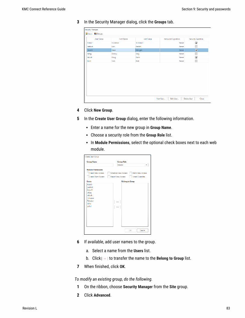
3 In the Security Manager dialog, click the Groups tab.
4 Click New Group.
5 In the Create User Group dialog, enter the following information.
l Enter a name for the new group in Group Name.l Choose a security role from the Group Role list.l In Module Permissions, select the optional check boxes next to each web
module.
6 If available, add user names to the group.
a. Select a name from the Users list.
b. Click to transfer the name to the Belong to Group list.
7 When finished, click OK.
To modify an existing group, do the following.
1 On the ribbon, choose Security Manager from the Site group.
2 Click Advanced.
KMC Connect Reference Guide Section 9: Security and passwords
Revision L 83
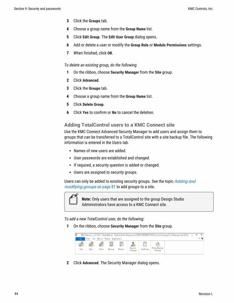
3 Click the Groups tab.
4 Choose a group name from the Group Name list.
5 Click Edit Group. The Edit User Group dialog opens.
6 Add or delete a user or modify the Group Role or Module Permissions settings.
7 When finished, click OK.
To delete an existing group, do the following.
1 On the ribbon, choose Security Manager from the Site group.
2 Click Advanced.
3 Click the Groups tab.
4 Choose a group name from the Group Name list.
5 Click Delete Group.
6 Click Yes to confirm or No to cancel the deletion.
Adding TotalControl users to a KMC Connect siteUse the KMC Connect Advanced Security Manager to add users and assign them togroups that can be transferred to a TotalControl site with a site backup file. The followinginformation is entered in the Users tab.
l Names of new users are added.l User passwords are established and changed.l If required, a security question is added or changed.l Users are assigned to security groups.
Users can only be added to existing security groups. See the topic Adding andmodifying groups on page 81 to add groups to a site.
Note: Only users that are assigned to the group Design StudioAdministrators have access to a KMC Connect site.
To add a new TotalControl user, do the following:
1 On the ribbon, choose Security Manager from the Site group.
2 Click Advanced. The Security Manager dialog opens.
Section 9: Security and passwords KMC Controls, Inc.
84 Revision L

3 In the Security Manager dialog, click the Users tab.
4 Click New User.
KMC Connect Reference Guide Section 9: Security and passwords
Revision L 85

5 In the Add User dialog, enter the following information:
l First and Last Namel User Namel Password and confirmation passwordl Password expiration date
6 Do the following to add an optional security question.
a. Select the Enable Security Question check box.
b. Choose a question from the Security Question list.
c. Enter the required response in Answer.
7 Click OK when finished.
Deleting a user
To delete a user, do the following:
1 On the ribbon, choose Security Manager from the Site.
2 Click Advanced.
3 Select a user from the users list.
4 Click Remove.
5 Click OK when finished.
Section 9: Security and passwords KMC Controls, Inc.
86 Revision L
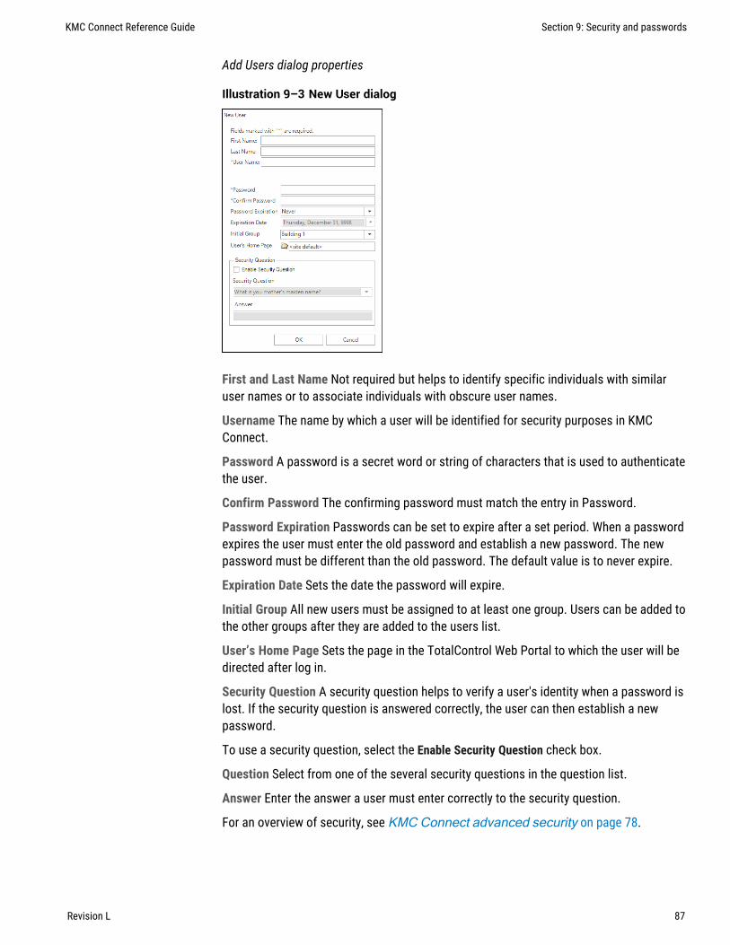
Add Users dialog properties
Illustration 9–3 New User dialog
First and Last Name Not required but helps to identify specific individuals with similaruser names or to associate individuals with obscure user names.
Username The name by which a user will be identified for security purposes in KMCConnect.
Password A password is a secret word or string of characters that is used to authenticatethe user.
Confirm Password The confirming password must match the entry in Password.
Password Expiration Passwords can be set to expire after a set period. When a passwordexpires the user must enter the old password and establish a new password. The newpassword must be different than the old password. The default value is to never expire.
Expiration Date Sets the date the password will expire.
Initial Group All new users must be assigned to at least one group. Users can be added tothe other groups after they are added to the users list.
User’s Home Page Sets the page in the TotalControl Web Portal to which the user will bedirected after log in.
Security Question A security question helps to verify a user's identity when a password islost. If the security question is answered correctly, the user can then establish a newpassword.
To use a security question, select the Enable Security Question check box.
Question Select from one of the several security questions in the question list.
Answer Enter the answer a user must enter correctly to the security question.
For an overview of security, see KMC Connect advanced security on page 78.
KMC Connect Reference Guide Section 9: Security and passwords
Revision L 87

Section 9: Security and passwords KMC Controls, Inc.
88 Revision L

Section 10: The KMC Connect Audit Log
KMC Connect includes an Audit Log that tracks changes to the site.
The Audit Log viewer lists operational changes to the system in a list that can be filteredby any of the following criteria.
l User Name—Select from the list of authorized users.l Service Type—Changes made to controllers, either BACnet or KMD, or any of the
building services.l Start and End Dates—The time and date when the change was made.l Phrase—A simple text search.
Note: Changes made to controllers by operator workstations otherthan the current instance of KMC Connect are not recorded.
Illustration 10–1 KMC Connect Audit Log
Viewing the Audit Log
To view the Audit log, do the following:
1 On the Site tab, click Audit Log. The Audit Log viewer opens.
2 Enter criteria—dates, User Name, Phrase, Service Type—to filter the data listed in theAudit Log.
3 Click Refresh.
KMC Connect Reference Guide Section 10: The KMC Connect Audit Log
Revision L 89

Exporting the Audit log
The visible data in the Audit Log can be saved in a comma separated values (.csv) file.
To export the Audit Log, do the following:
1 Open the Audit Log for viewing.
2 Enter criteria—dates, User Name, Phrase, Service Type—to filter the data listed in theAudit Log.
3 At the top of the log click Export.
4 Browse to a location to save the data.
5 Click Save. KMC Connect saves the log with the site name as the file name and.csv as the file extension.
Purging old records
To remove records that are no longer useful, purge the Audit Log of old records.
To purge old records, do the following:
1 Open the Audit Log for viewing.
2 At the top of the log click Purge.
3 In the Purge Audit Log dialog, set the time and date of the oldest record to beretained.
4 Click OK and then YES to confirm the purge. Clicking NO leaves the log untouched.
Section 10: The KMC Connect Audit Log KMC Controls, Inc.
90 Revision L

Section 11: Upgrading f irmware
This section covers upgrading controller firmware over the network with KMC Connect.
Firmware in later model Conquest series devices can be upgraded—or FLASHed—over thenetwork. Refer to the release notes and specifications for each device to verifycompatibility.
Illustration 11–1 Firmware Upgrade Manager
Downloading firmware
Before the firmware can upgraded, you will need a firmware file. Firmware files areavailable from the download section of our website at kmccontrols.com. You will need auser name and password to log in. Each model for upgrade will require a firmware file.
1 Download the firmware file from the KMC Controls web site. The firmware ispackaged in a .zip file.
2 In the .zip file are two folders. Extract the file from the For over the networkfolder. The extracted file is a self-running file that will install the firmware.
KMC Connect Reference Guide Section 11: Upgrading firmware
Revision L 91

3 Double-click the extracted file. The installer will place the firmware atC:\ProgramData\KMC Controls\Firmware UpgradeManager\BACnet Family. The file is placed in a folder with the model namefor the firmware.
Program Data
KMC Controls
BACnet Family
Firmware Upgrade Manager
BAC-5901CE
BAC-9001CE
BAC-9311CE
Upgrading firmware
1 Locate the device , network , or service icon in the Network Manager list.
2 Right-click the icon and choose Upgrade Firmware from the shortcut menu.
3 Once the Firmware Upgrade Manager opens, drag any additional devices, networks,or services to the device list of the Firmware Upgrade Manager.
4 In the Firmware Upgrade Manager, click Browse and locate the new firmware file.The default location for the firmware is C:\ProgramData\KMCControls\Firmware Upgrade Manager\BACnet Family. Thefirmware is stored in a folder with the model name for the controller.
5 If the controllers can restart immediately after the upgrade, select Auto Commit andRestart.
Caution: Do not select Auto Commit and Restart if equipment connected to acontroller cannot be shut down and restarted when the upgrade is finished.
6 Click Upgrade. KMC Connect will begin loading the new firmware into the selectedcontrollers.
7 Once the new firmware is loaded, the Firmware Update Confirmation dialog opens.
l To finish upgrading, select the devices and click Commit.l Click Abort to cancel the upgrade and leave the devices with the original
firmware intact.
Reducing errors
To reduce problems with upgrading device firmware over a network, reduce the volume ofnetwork traffic that is competing for bandwidth with the upgrade traffic by doing thefollowing:
Section 11: Upgrading firmware KMC Controls, Inc.
92 Revision L

l Reduce the Payload value to reduce the number of rejected packets.l Temporarily disable or remove devices such as J.A.C.E. controllers that
continuously poll the network.l Reduce the number of controllers that are selected for update at the same time.l Temporarily isolate MS/TP networks and connect directly to the network with a
BAC-5051E router.l Verify that Control Basic is correctly managing the interval for reading from and
writing to off-panel objects with WAIT, ALIAS, or NETPOINT functions.
The values at the bottom of the Firmware Upgrade Manager can be adjusted to increasethe efficiency of the software upgrade.
Auto Commit and Restart When selected, the Firmware Upgrade Manager will commit theupgrade to the controller and immediately reinitialize the controller with a cold start.Select this feature only if controller operation can be interrupted during reinitialization.
Broadcast Interval The interval at which KMC Connect sends data. This can be set as lowas 50 ms but at the expense of other network traffic. The default is 250 ms. Increasingthis value will slow down the firmware upgrade but, it will keep the firmware upgrade frominterfering with traffic on busy networks.
Payload Size This property approximately corresponds to the BACnet network’s maximumAPDU size. For MS/TP networks, set this property to 450 or less depending on equipmentconstraints. For Ethernet and BACnet IP without MS/TP networks this can be set as highas 1400 but may still result in rejected packets.
Wait Timeout Typically changing this value is not required. The default value is 30seconds. If there are numerous timeout messages in the Output Window, increase thisvalue to give busy devices additional time to handle and respond to firmware upgraderequests.
Retries The number of times KMC Connect will attempt to send any one packet before thetarget device is dropped from the upgrade session. Retries slow down the upgradesession for the entire network.
KMC Connect Reference Guide Section 11: Upgrading firmware
Revision L 93

Section 11: Upgrading firmware KMC Controls, Inc.
94 Revision L

KMC Connect
Part III: Trend logs
KMC Connect Reference Guide
Revision L 95

KMC Controls, Inc.
96 Revision L

Section 12: About trend logs
Collecting data from a building automation system and saving it as a historical trend logis part of any building automation system. Topics in this section are an overview oftrend logs in KMC Connect.
Trend logs are a record of the value of a point or property as measured by a buildingautomation device or controller. KMC Connect collects data with one of three types oftrends.
Controller trends Controller trend logs are sets of historical data collected and storedonly within the memory of an individual controller. Each controller has only a finiteamount of allocated memory—also referred to as a buffer—in which it can store trenddata. As the buffer nears capacity, one of three actions can take place:
l The controller continues to collect data until the buffer is full. It then stopscollecting data.
l The controller continues to collect data by replacing the oldest data in the bufferwith the newest collected data. This is often referred to as a circular buffer.
l The controller continues to collect data and—at a predetermined point—notifies atrend handling service to store the existing data. This makes room in the controllerfor newer data. In KMC Connect, this is referred to as a device based trend log.
Device trends Device trend logs are controller trend logs that have been retrieved from adevice—either BACnet or KMD—and then stored by KMC Connect. As a controller trend logreaches a preset threshold, KMC Connect retrieves the data from the controller and thenappends it to previously stored data. Threshold criteria depends upon the type ofcontroller, but it is based upon one of the following:
l A preset time of day such as 1:00 AM.l A preset interval such as every 15 minutes or every 3 hours.l The number of samples in the log buffer.
PC trends A PC trend log is a polling process that is performed by KMC Connect. Onregular intervals, the value of a property or point is sampled by KMC Connect and thenstored on the local computer.
Setting up trend logs
To set up trend logs, see the following topics.
l Trend Configuration Wizard on page 108l Configuring BACnet controller trend logs on page 111l Configuring KMD trend logs and groups on page 119
KMC Connect Reference Guide Section 12: About trend logs
Revision L 97

Viewing trend logs
To view trend logs, see the following topics.
l Viewing controller trend logs on page 104l Viewing with the Trend Viewer on page 100
Section 12: About trend logs KMC Controls, Inc.
98 Revision L

Section 13: V iewing trend logs in KMC Connect
Topics in this section cover various methods by which you can view trend logs. Thissection also covers exporting trend log data.
The data collected by KMC Connect as trend logs can be viewed by one of three methods.
l To view data in the BACnet trend log object, see Viewing controller trend logs onpage 104.
l To view temporary data from one or more points or objects, see the topic Viewingwith the Trend Viewer on page 100 and set up a live trend log.
l To view device or PC trend logs, see the Trend Log viewer and then follow theprocedure for Viewing trend logs in the Trend Manager.
KMC Connect Reference Guide Section 13: Viewing trend logs in KMC Connect
Revision L 99

Viewing with the Trend ViewerThe Trend Viewer is a tool to view historical trend data from within KMC Connect. Theviewer can be used for two types of data.
l To view temporary data from one or more points or objects, see the procedureStarting a live trend log on page 100.
l To view device trend logs, PC trend logs, or trend groups, see Viewing trend logsin the Trend Manager on page 101.
Illustration 13–1 Trend Viewer
Starting a live trend logA live trend log view will start collecting trend data as soon as an object is added to theTrend Viewer. The data in the Trend Viewer is temporary and is not stored by KMCConnect.
1 On the ribbon choose Viewer from the Trends group.
2 Locate an object to collect data from in the Network Manager list.
3 Drag the object from Network Manager list to the Trend Viewer.
Section 13: Viewing trend logs in KMC Connect KMC Controls, Inc.
100 Revision L

4 As needed, drag additional objects from the Network Manager list to the TrendViewer.
l The number of analog objects is limited only by viewing clarity.l If a mix of analog, binary or multistate objects is added to the same window,
only 20 objects can be present.
Starting from the Network ManagerTo start a live log from the Network Manager, do the following.
1 Locate an object from which to collect data in the Network Manager list.
2 Right-click the object and select New Live Trend from the shortcut menu.
3 As needed, drag additional objects from the Network Manager list to the TrendViewer.
Viewing trend logs in the Trend ManagerYou can use the Trend Viewer to view either PC trends, device trends or trend groups inthe Trend Manager.
Illustration 13–2 KMC Connect Trend Manager
1 On the ribbon, choose Manager from the Trends group. The Trend Manager opens.
2 Do one of the following:
l In the Database Trend Configurations list or Trends Group list, right-click on a PCtrend object icon or Device Log icon and choose Open Trend Viewer from
the shortcut menu.l In the Trend Groups list, right-click on a Trend Group icon and choose Open
Trend Viewer from the shortcut menu.
KMC Connect Reference Guide Section 13: Viewing trend logs in KMC Connect
Revision L 101

Parts of the Trend ViewerValues in the viewer can be displayed as either a chart or table.
l To change the view, click the Chart View or Table View tab.l To hide an individual graph, clear the check box next to the name of the graph.
Illustration 13–3 Trend Viewer
Update Click to manually refresh the chart or table with the newest data in the objects.
View Timeframe Choose a time span for the display from the Quick View list or set a StartDate and End Date for a custom time frame.
Illustration 13–4 The View Timeframe dialog
Clear Click to remove all trend data from the viewer.
Export Click to export the data in the viewer to a comma separated value (.csv) file.
Max Records per Trend Sets the maximum number of data points held in the buffer of theTrend Viewer.
Section 13: Viewing trend logs in KMC Connect KMC Controls, Inc.
102 Revision L

Stop when Full When selected and the number of data points of the trend exceeds thevalue of Max Records per Trend, the Trend Viewer will stop collecting data. If Stop whenFull is not selected, the oldest data in the buffer will be deleted.
Auto Update When selected, the data in the Trend Viewer is automatically updated at theinterval specified in Update Interval.
Update Interval Enter a value to automatically refresh the data in the Trend Viewer.
Apply Click to apply the settings for Stop when Full, Max Records per Trend, Auto Update,Update Interval.
Records lumping interval (seconds) When exporting multiple trend logs to a .csv file,selecting Records lumping interval lines up the records to the nearest specified time value.
Show Values Larger Than Select this check box to display the actual recorded values inthe text of the trend log. Enter a threshold for the minimum value to show as text.
Zoom in/Zoom out In the Chart view, only a limited amount of trend data is displayed onthe chart.
l To zoom in, drag from left to right across an area of the chart.l To zoom out, drag from right to left across an area of the chart.
Reset Zoom Restores the display to the original view.
Related topics
l Configuring BACnet trend logs and groups on page 107l Viewing controller trend logs on page 104
KMC Connect Reference Guide Section 13: Viewing trend logs in KMC Connect
Revision L 103

Viewing controller trend logsKMC Connect includes a controller trend log object viewer for examining data collected byBACnet controller trend objects or KMD trend logs.
To view controller trend data from a point or object, do the following.
1 Open Network Manager.
2 In the Network Manager list locate the BACnet or KMD controller.
3 Within the controller, locate and click on the trend log folder to reveal the list oftrend object or point icons .
4 Double-click a trend icon and then scroll to View Trend to open the trend log.
Device and PC trend logs are viewed with the Trend Viewer. See the topic Viewing withthe Trend Viewer on page 100.
BACnet controller trend logs can be displayed as either a chart or table. To change theview, click the Chart View or Table View tab.
Illustration 13–5 BACnet controller trend with text displayed
Update Click to retrieve new data not already on the chart and add it to the viewer data.
Refresh Clears data from the chart, retrieves the controller trend and plots it on theviewer.
Custom Refresh Enter a specific number of records beginning at a designated time.
Auto Load When selected, new trend data in the controller is added to the existing data inthe trend viewer.
Show Values Select to display the actual recorded text values of the data.
Export Click to export the data in the viewer to a comma separated value (.csv) file.
Section 13: Viewing trend logs in KMC Connect KMC Controls, Inc.
104 Revision L
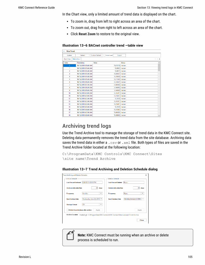
In the Chart view, only a limited amount of trend data is displayed on the chart.
l To zoom in, drag from left to right across an area of the chart.l To zoom out, drag from right to left across an area of the chart.l Click Reset Zoom to restore to the original view.
Illustration 13–6 BACnet controller trend —table view
Archiving trend logsUse the Trend Archive tool to manage the storage of trend data in the KMC Connect site.Deleting data permanently removes the trend data from the site database. Archiving datasaves the trend data in either a .csv or .xml file. Both types of files are saved in theTrend Archive folder located at the following location:
C:\ProgramData\KMC Controls\KMC Connect\Sites\site name\Trend Archive
Illustration 13–7 Trend Archiving and Deletion Schedule dialog
Note: KMC Connect must be running when an archive or deleteprocess is scheduled to run.
KMC Connect Reference Guide Section 13: Viewing trend logs in KMC Connect
Revision L 105

To archive and optionally delete trend data, do the following:
1 On the ribbon, choose Archive Tool from the Trends group. The Trend Archiving andDeletion Schedule dialog opens.
2 Under Archive Schedule, set the age of the data to archive (and optionally delete) inthe Archive data older than text box.
3 Select an option from Frequency.
l Choose IMMEDIATE to archive or delete data as soon as Apply is clicked.l Choose from the other options to repeat the action on a regular schedule.
Frequency selection ranges from daily to yearly.
4 In Next Archive Date, enter a date when the archiving process will next run.
5 Choose either CSV or XML from Storage Format.
6 To permanently remove the data from the site after the data is archived, selectDelete from database after archive.
7 Click Apply when ready.
To delete trend data, do the following:
1 On the ribbon, choose Archive Tool from the Trends group. The Trend Archiving andDeletion Schedule dialog opens.
2 Under Delete Schedule, set the age of the data to delete in the Delete data older thantext box.
3 Select an option from Frequency.
l Choose IMMEDIATE to delete data as soon as Apply is clicked.l Choose from the other options to repeat the action on a regular schedule.
Frequency selection ranges from daily to yearly.
4 In Next Deletion Date, enter a date when the deletion process will next run.
5 Click Apply when ready.
Section 13: Viewing trend logs in KMC Connect KMC Controls, Inc.
106 Revision L

Section 14: Conf igur ing BACnet trend logs andgroups
Each of the supported BACnet trend logs in KMC Connect have specific configurationrequirements for proper operation. Topics in this section cover detailed procedures forconfiguring KMC Connect trend logs in BACnet controllers.
The easiest method for setting up device and controller trend logs is to use the Trendwizard. See Trend Configuration Wizard on page 108.
Trend logs can also be set up manually with any of the following procedures.
l Configuring BACnet controller trend logs on page 111l Configuring BACnet device trend logs on page 112l Configuring a BACnet PC trend log on page 115
To view trend data see, Viewing trend logs in KMC Connect on page 99.
Illustration 14–1 Trend Manager
KMC Connect Reference Guide Section 14: Configuring BACnet trend logs and groups
Revision L 107

Trend Configuration WizardThe Trend Configuration Wizard is an easy method to configure trend logs for BACnetcontrollers. Using the wizard is an alternative to manually setting up the properties fortrend log, notification class, and event enrollment objects.
l Use the wizard to configure trends for input, accumulator, output, or value objects.l For controllers that support Change Of Value subscriptions, the wizard can set up
COV trends.l If the object is in a controller without a Trend Log object, the wizard will set up a PC
trend.l The wizard is an easy way to configure BACnet controller trend logs and use them
as a device logs in the Trend Manager.
Start the wizard1 Start the Trend Configuration Wizard by doing one of the following:
l On the ribbon, choose Configuration Wizard from the Trends group.l Right-click an object in the Network Manager list and choose Trend Configuration
Wizard from the shortcut menu. This starts the wizard and adds the object to theObject Selection list.
2 Add objects to the Object Selection list by doing the following:
l Drag input, output, or value objects from the Network Manager list to the ObjectSelection list.
l Right-click an object in the Network Manager list and choose Trend ConfigurationWizard.
l Click Add and then search for objects. See the procedure Add objects bysearching on page 110.
Note: If an object has been previously assigned, the number of previous trend logs isshown in the Number of Database Trends column.
3 When ready, click Next.
Section 14: Configuring BACnet trend logs and groups KMC Controls, Inc.
108 Revision L

4 Change or accept the Trend Parameter Configuration properties.
l Sample Interval sets the time between samples.l Start and End Time sets the time span for logging data.l Select the BACnet Change of Value Notifications check box to set up a COV
subscription. COV subscriptions are not supported in all devices. For additionalinformation, see the topic Change Of Value (COV) notifications on page153.
5 Click Next when ready.
6 The Trend Configuration list shows the assignments of the Trend Log, NotificationClass, and where applicable, Event Enrollment objects.
l Right-click on a cell to change assignments.l The name of the trend in the first column can be changed.l If a Trend Log object is not available, a PC trend is set up.
Tip: If unconfigured Trend Log and Trend Log Multiple objects areboth available in the controller, the Wizard chooses a Trend LogMultiple object. To change to a Trend Log object, right-click on theTrend Log object cell and choose another Trend Log object.
KMC Connect Reference Guide Section 14: Configuring BACnet trend logs and groups
Revision L 109

7 Click Save when finished.
l All information in the list is written to the objectsl For viewing, the trend logs are also added to the Trend Configuration Manager.
Add objects by searchingObjects in the Network Manager list can be added to the Trend Wizard Object Selectionlist by using the Search and Add functions.
To add objects by searching, do the following:
1 Start the wizard.
2 In the Object Select list, click Add. The Find BACnet Objects Dialog opens.
3 Enter the instance number of a device in the Network Manager list.
4 Enter the mnemonics for the object followed by the object number.
l Use AI for Analog Input, BO for Binary Output objects, MSV for Multistate Valueobjects, etc.
l Use an asterisk (*) for all objects of the same type. For example AI* for allanalog input objects.
l To search for all devices, use an asterisk (*) in the Device box.l Use a question mark (?) to substitute for characters when searching by name.
For example SENSOR? will find both SENSOR1 and SENSOR2 but notSENSOR10.
5 Click Search.
6 Select or clear the check boxes next to each object found by the search.
7 Click OK to add the selected objects to the list.
Section 14: Configuring BACnet trend logs and groups KMC Controls, Inc.
110 Revision L

For details on the BACnet objects related to trends, see the following topics.
l Trend Log objects on page 501l Notification objects on page 482l Event enrollment objects on page 442
To manually configure BACnet trend logs, see the following topics.
l Configuring BACnet controller trend logs on page 111l Configuring BACnet device trend logs on page 112l Configuring a BACnet PC trend log on page 115
Configuring BACnet controller trend logsA controller trend log is data that is stored in a BACnet trend log object.
l To view the data in the trend log object, see Viewing controller trend logs on page104.
l To view the data with the Trend Log viewer, add the controller trend to a trendgroup. See Adding BACnet trend logs to trend groups on page 117
l To set up trend logs with a wizards, see Trend Configuration Wizard on page108.
To set up a BACnet controller trend log, do the following:
1 In the Network Manager list, locate the device and then select the trend objectthat will collect the trend data.
2 Expand General Properties.
3 Enter a name for the trend log in Object Name.
4 Enter additional information in Description.
5 Enter the start and stop dates and time in Start Time and Stop Time. The start andstop times are based on the time and date maintained within the controller.
6 Enter the frequency to sample the data in Log Interval. This is entered in hundredthsof a second.
7 For Buffer Size, enter 256 for KMC BACnet controllers. Entering zero (0) clears thebuffer.
Enter the number of samples that will trigger the notification recipient that there isdata in the buffer available for transfer. For device trend logs, a value of 10 providesa good trade-off between responsiveness and excessive network traffic.
8 Under Device in Log Object Property Reference, do one of the following:
l In the Device list, choose an object to log.l Drag an object from the Network Manager list to Device.
KMC Connect Reference Guide Section 14: Configuring BACnet trend logs and groups
Revision L 111

9 Under Property in Log Object Property Reference, if the property to log is not PresentValue, choose the correct property.
10 Select the Log Enable check box.
l Clear the Stop When Full check box to continuously collect data for device trendlogs.
l Select the Stop When Full check box to halt data collection when the buffer isfull.
11 Select or clear the Stop When Full check box.
12 If a notification class object will be used with this trend log, expand Event/AlarmProperties and do the following:
13 In Notification Class, enter the object number of the notification class object.
14 Under Event Enable, do the following.
l Select the To Normal and To Off Normal check boxes.l Clear the To Fault check box.
15 In Notification Type, select Event.
16 When all selections and entries are correct, click Save Changes at the top of the tab.
Related topics
l About trend logs on page 97l Viewing trend logs in KMC Connect on page 99l Configuring BACnet device trend logs on page 112l Configuring a BACnet PC trend log on page 115l Adding BACnet trend logs to trend groups on page 117
Configuring BACnet device trend logsA device trend log is a controller trend log that is periodically retrieved from a controllerand then stored by KMC Connect.
l To view the data with the Trend Log viewer, see Adding BACnet trend logs totrend groups on page 117
l To set up trend logs with a wizards, see Trend Configuration Wizard on page108.
Configuring BACnet trend objects for a device trend log
To configure a device trend log for a BACnet controller, do the following:
1 Follow the procedure in the topic Configuring BACnet controller trend logs onpage 111 to set up a controller trend log.
Section 14: Configuring BACnet trend logs and groups KMC Controls, Inc.
112 Revision L

2 In the configuration tab for the trend log object that was configured for thecontroller trend, do the following:
a. Expand Event/Alarm Properties.
b. In Notification Class, enter the number of the notification class object.
c. Under Event Enable do the following.l Select the To Normal and To Off Normal check boxes.l Clear the To Fault check box.
d. In Notification Type, select Event.
e. Save the changes.
3 In the same device in which you are configuring the trend log object, open anotification class object.
4 Add to Recipient List the device instance number of the notification handling device.For KMC Connect, enter the device instance of the BACnet service. The KMCConnect device instance is found in the BACnet node the Network Manager list. Doone of the following to add a notification handling device.
l Drag the icon of the notification handling device from the Network Manager listto the Recipient List text box.
l Click Add and then enter the device instance in the Recipient Identifier dialog.l Holding CTRL and then dragging a device icon will also open the Recipient
Identifier dialog.
5 Under Ack. Required, clear all check boxes.
6 Select or clear the check boxes for the applicable days of the week and then set thetime of day.
l The days of the week and time of notification are based upon the clock in thecontroller.
l For 24-hour notification, set the time from 12:00:00 AM to 11:59:00 PM.
7 In Transitions enter the following settings:
l Select the To Normal and To Off Normal check boxes.l Clear the To Fault check box.
8 Enter any non-zero number for Process ID.
9 Select the Send Confirmed Notifications check box.
10 When selection and entries are correct, click Save Changes at the top of the tab.
11 Continue the setup by adding the trend log to the trend group.
Add the trend log to a trend group
1 Set up a BACnet object, trend object and notification class object as described bythe previous steps.
2 On the ribbon,. choose Trend Manager from the Trends group.
KMC Connect Reference Guide Section 14: Configuring BACnet trend logs and groups
Revision L 113

3 Locate the trend object in the Network Manager list.
4 Drag the trend log object from the Network Manager list to the Database TrendConfiguration list in the Trend Manager. The Device Based Trends dialog opens. SeeUsing the Device Based Trend dialog on page 114.
5 Enter the trend configuration settings in the dialog.
6 Click Submit when finished.
7 Drag the trend object from the Database Trend Configurations list to a trend group inthe Trend Groups list.
Using the Device Based Trend dialog
Use the Device Based Trend dialog to configure a BACnet device-based trend. The dialogopens automatically when a BACnet object is dropped into the Database TrendsConfiguration list.
Illustration 14–2 BACnet Device Based Trend dialog
To open the dialog after the trend object is placed in the list, do the following:
1 Right-click an object in either the Database Trend Configurations or Trend Groups list.
2 Choose Edit from the shortcut menu.
3 Make changes in the open dialog.
4 Click Save when done.
Enable Clear the check box to stop adding recorded data from this trend object to KMCConnect. Select the check box to add data from the trend object by KMC Connect.
Trend Name Enter the name of the trend as you want it to appear in the trend viewer. Thedefault value for Trend Name is the object name. Changing the Trend Name does notchange the object name.
Section 14: Configuring BACnet trend logs and groups KMC Controls, Inc.
114 Revision L
Configuring a BACnet PC trend logA PC trend log is a polling process performed by KMC Connect. For a detailed overview onPC trends, see About trend logs on page 97.
l Any object except trend objects may be selected for a PC trend.l An object may be placed in more than one trend group.l To view the data with the Trend Log viewer, see Adding BACnet trend logs totrend groups on page 117
l To set up trend logs with a wizard, see Trend Configuration Wizard on page 108.
To set up a PC trend log for a BACnet object, do the following:
1 On the ribbon, choose Trend Manager from the Trends group.
2 In the Network Manager list, locate the object to trend.
3 Drag the object from the Network Manager list to the Device Trend Configurations listin the Trend Manager. The PC Based Trends dialog opens. See Using the PCBased Trends dialog on page 115.
4 Enter the trend configuration in the dialog.
5 Click Submit when finished.
6 Drag the object from the Device Trend Configurations list to a trend group in theTrend Groups list.
Using the PC Based Trends dialog
Use the PC Based Trend dialog to set up a PC based trend for a BACnet object. The dialogopens automatically when a BACnet object is dropped into the Database TrendsConfiguration list.
To open the dialog, do the following:
1 Right-click a PC trend icon in either the Device Trend Configurations or TrendGroups list.
2 Choose Edit from the shortcut menu.
KMC Connect Reference Guide Section 14: Configuring BACnet trend logs and groups
Revision L 115

3 Make changes in the open dialog and then click Save when done.
Illustration 14–3 PC Based Trends dialog
Enabled Select the check box to add the records for an individual point from a BACnettrend log to the Device Trend Configurations list; clear the check box to disable theindividual point.
Trend Name Enter the name of the trend as you want it to appear in the trend viewer. Thedefault value for Trend Name is the object name.
Start and Stop Date Enter the date and times to start and end data collection. The dateand times are based on the clock in the computer hosting KMC Connect.
Property (Available only when dragging the object to the Device Trend Configurationslist.) Select from the properties in the object. Typically the property is Present Value.
Property Index (Available only when dragging the object to the Device TrendConfigurations list.) Usually left blank.
Log Interval Enter the frequency to sample data in Log Interval. See Changing theNetwork Manager options on page 46 to change the default value.
Use BACnet COV Event (Available only when dragging objects that support change ofvalue to the Device Trend Configuration list.) Select the check box to record the value ofthe property only when an COV notification takes place. See Change Of Value (COV)notifications on page 153.
COV Increment (Available only when dragging objects that support change of value to theDevice Trend Configuration list.) Enter the value by which Property must change to initiatea COV notification.
Section 14: Configuring BACnet trend logs and groups KMC Controls, Inc.
116 Revision L

Adding BACnet trend logs to trend groupsTrend logs are organized in the KMC Connect trend viewer with trend categories andgroups.
l Trend groups can be placed only in trend categories.l To set up trend logs with a wizard, see Trend Configuration Wizard on page 108.l To view the data with the Trend Log viewer, see Adding BACnet trend logs totrend groups on page 117.
Illustration 14–4 Trend Manager
Add a trend category
To add a trend category, do either of the following:
l Click the new category icon above the Trend Groups list.
l Right-click in the Trend Groups list and choose New Category from the shortcutmenu.
Add a trend group
To be visible in the KMC ConnectTrend Viewer, a trend log—either a PC or device trendlog— must be in a trend group. Trend groups can be placed only in trend categories.
1 If there is no trend category in the Trend Groups list, add a new category.
2 Select a trend category in the Trend Groups list and then add a new group by doingone of the following:
l Click the new group icon above the Trend Groups list.
l Right-click in the Trend Groups list and choose New Group from the shortcutmenu.
KMC Connect Reference Guide Section 14: Configuring BACnet trend logs and groups
Revision L 117

3 In the Custom Trend Group dialog, enter the following data:
l Under Group Name, enter the name to appear in the Trend Selector list in theTrend Viewer.
l In the Y Title text box, enter a label for the value (y) axis chart that will display inthe Trend Viewer.
l Set the top and bottom values of the value axis chart with Max Y and Min Y.
4 Click Submit when finished.
Delete a trend, group, or category
1 In the Trend Groups list, select the trend, group, or category to delete.
2 Right-click the item and then choose Remove from the shortcut list.
Rename a trend group
1 In the Trend Groups list, select the trend group to rename.
2 In the Trend Group Configuration area, enter a new name in Group Name.
3 Click Save when finished.
Rename a trend category
1 In the Trend Groups list, select the category to rename.
2 Right-click the category and choose Rename from the shortcut list.
The parts of the Trend Manager
Use the Trend Manager to set up trends and trend groups to display in the Trend Viewer.
Group Name The entry in Group Name is the name under which the group will appear in theTrend Selector list in the Trend Viewer.
Y Title Enter a label for the value (y) axis of the chart that will display in the Trend Viewer.
Y Min and Y Max Set the top and bottom values of the value axis chart with Max Y andMin Y.
Database Trend Configuration list A list of all the devices with objects that are the sourcefor a trend log.
Trend Groups list A list of the individual trends, trend groups, and trend categories thatare available for viewing with the Trend Viewer.
Trend Name list A list of all of the individual trends within the trend group.
Section 14: Configuring BACnet trend logs and groups KMC Controls, Inc.
118 Revision L

Section 15: Conf igur ing KMD trend logs andgroups
Each of the KMC Connect supported trend logs for KMD controllers have specificconfiguration requirements for proper operation. Topics in this section cover detailedprocedures for configuring KMC Connect trend logs in KMD controllers.
Set up and manage trend logs with the Trend Manager.
l About trend logs on page 97l Configuring KMD controller Trend Logs on page 119l Configuring KMD device trend logs on page 121l Configuring KMD PC trend logs on page 123l Viewing trend logs in KMC Connect on page 99l Configuring BACnet trend logs and groups on page 107
Illustration 15–1 Trend Manager
Configuring KMD controller Trend LogsA controller Trend Log is the mechanism that KMC Connect uses to collect the data for adevice Trend Log.
A controller Trend Log can be set up two different ways.
l To log data at regular intervals, see the procedure Automatic logging on page 120.l To use Control Basic to log a single record at a time, see the procedureOn-demand logging on page 120
See also the topic Trend Log points on page 595 for a detailed description of theproperties in the Trend Log point.
KMC Connect Reference Guide
Revision L 119

Automatic logging
A controller Trend Log can be set up to log one or more points at regular intervals. To setup a Trend Log for automatic logging, do the following:
1 In the Network Manager list, locate the KMD controller and then select the Trend Logicon that will collect the data.
2 Expand General Properties.
3 Under Name, enter a name for the Trend Log.
4 Under Log Interval, enter the frequency to sample data. This is entered as hours:minutes: seconds.
5 Under Trended Points, enter the points to be recorded in the formatcontroller.mnemonic.
l Mnemonics are listed in the topic Mnemonics for KMD controllers on page235.
l The recorded points can be from points within the controller or from othercontrollers on the network.
l The exact number of points placed in the list depends on the type of controller.
6 When all selections and entries are correct, click Save Changes at the top of the tab.
On-demand logging
A Trend Log can be set up to log data only when triggered by a statement in a ControlBasic program. To set up a KMD controller Trend Log for on-demand logging, do thefollowing:
1 In the Network Manager list, locate the KMD controller and then select the Trend Togicon that will collect the trend data.
2 Expand General Properties.
3 Under Name, enter a name for the Trend Log.
4 Under Log Interval, enter 00:00:00.
5 Under Trended Points, enter the points to be recorded in the formatcontroller.mnemonic.
l Mnemonics are listed in the topic Mnemonics for KMD controllers on page235.
l The recorded points can be from points within the controller or from othercontrollers on the network.
l The exact number of points placed in the list depends on the type of controller.
6 When all selections and entries are correct, click Save Changes at the top of the tab.
Section 15: Configuring KMD trend logs and groups KMC Controls, Inc.
120 Revision L

7 Add a Control Basic statement TLx = -1 to one of the Control Basic programs.See the following example for the details.
Control Basic example The following example adds one record to Trend Log TL1 on thefirst day of each month.
IF+ DOM < 2 THEN TL1 = -1
The exact data add to the Trend Log is determined by the Trended Points entry in theTrend Log point.
See also the topic Programming with the Code Editor on page 191.
Related topics
l Trend Log points on page 595l About trend logs on page 97l Configuring KMD device trend logs on page 121l Adding KMD trend logs to a trend group on page 124
Configuring KMD device trend logsKMD device trend logs are controller trend logs that have been retrieved periodically froma controller and then stored in the site database. A device trend reduces network trafficand is the preferred method to capture trend log data.
To configure a device trend log for KMD controllers, do the following:
1 Follow the procedure in the topic Configuring KMD controller Trend Logs onpage 119 to set up a controller trend log.
2 On the ribbon, choose Manager from the Trends group.
3 Locate the Trend Log icon in the Network Manager list.
4 Drag the trend log from the Network Manager list to the Database TrendConfigurations list in the Trend Manager. The Device Based Trends dialog opens.
5 In the Device Based Trends dialog, set the following:
l Clear the check box for any trend in the trend log that you do not want to add tothe trend group.
l Set dates for the trend to collect data with Start Time and Stop Time.
6 Click Save when finished.
7 Drag the trend object from the Device Trend Configuration list to a trend group in theTrend Groups list.
KMC Connect Reference Guide Section 15: Configuring KMD trend logs and groups
Revision L 121

Using the Device Based Trend dialog
Use the Device Based Trend dialog to configure a KMD device based trend. The dialogopens automatically when a BACnet object is dropped into the Database TrendConfigurations list.
Illustration 15–2 KMD Device Trend dialog
To open the dialog after the trend object is in the list, do the following:
1 Right-click a device trend icon in either the Device Trend Configurations or TrendGroups list.
2 Choose Edit from the shortcut menu.
3 Make changes in the open dialog and then click Save when done.
Properties of the Device Based Trend dialog
Enabled Select the Enabled check box to add the records for an individual point from aKMD trend log to the Device Trend Configurations list; clear the check box to disable theindividual point.
Trend Name Enter a name for the point trend log as it should appear in the trend group.
Start Time and Stop Time Set the beginning and ending period of the trend log. Bydefault, the beginning date is the day the trend log is added to the Database TrendConfiguration list; the end date is the start date with 5 years added.
Control Basic Override When True, the trend log is collecting data under command fromControl Basic instead of performing automatic sampling based on the period set by LogInterval. See the procedure On-demand logging on page 120.
Log Interval Displays time interval between readings in the Trend Log point in thecontroller. See the topic Trend Log points on page 595 for additional information.
Max Samples Displays the number of samples in the buffer. See the topic Trend Logpoints on page 595 for additional information.
Polling Interval The polling interval must be short enough to collect controller trendbefore new data replaces old data. The default value is calculated from the maximumnumber of samples in a controller and the interval in the KMD trend log.
Polling Interval = (Max Samples-10) * Log Interval
Section 15: Configuring KMD trend logs and groups KMC Controls, Inc.
122 Revision L

Related topics
l About trend logs on page 97l Configuring KMD controller Trend Logs on page 119l Adding KMD trend logs to a trend group on page 124
Configuring KMD PC trend logsA PC trend log is a polling process performed by the KMC Connect trend service. For adetailed overview on PC trends, see About trend logs on page 97.
l Any KMD point except trend logs may be selected for a PC trend.l A point must be added to a trend group to be visible in the trend group.l A point may be placed in more than one trend group.
To set up a PC trend log for a KMD point, do the following:
1 On the ribbon, choose Manager from the Trends group.
2 In the Network Manager list locate the point to trend.
3 Drag the point from the Network Manager list to the Device Trend Configurations listin the Trend Manager. The KMD PC Based Trends dialog opens. .
4 Enter the trend configuration to the dialog. Click Submit when finished.
5 Drag the object from the Device Trend Configurations list to a trend group in theTrend Groups list.
Using the PC Based Trends dialog
Edit the setting for PC trends from KMD controllers with the PC Based Trend dialog.
Illustration 15–3 KMD PC Based Trends dialog
To open the dialog:
1 Right-click a PC trend log icon in either the Device Trend Configuration or TrendGroups list.
KMC Connect Reference Guide Section 15: Configuring KMD trend logs and groups
Revision L 123
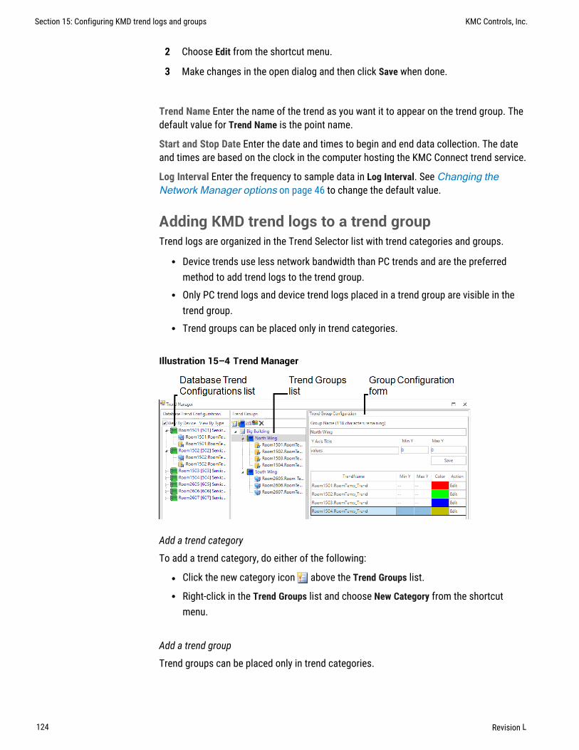
2 Choose Edit from the shortcut menu.
3 Make changes in the open dialog and then click Save when done.
Trend Name Enter the name of the trend as you want it to appear on the trend group. Thedefault value for Trend Name is the point name.
Start and Stop Date Enter the date and times to begin and end data collection. The dateand times are based on the clock in the computer hosting the KMC Connect trend service.
Log Interval Enter the frequency to sample data in Log Interval. See Changing theNetwork Manager options on page 46 to change the default value.
Adding KMD trend logs to a trend groupTrend logs are organized in the Trend Selector list with trend categories and groups.
l Device trends use less network bandwidth than PC trends and are the preferredmethod to add trend logs to the trend group.
l Only PC trend logs and device trend logs placed in a trend group are visible in thetrend group.
l Trend groups can be placed only in trend categories.
Illustration 15–4 Trend Manager
Add a trend category
To add a trend category, do either of the following:
l Click the new category icon above the Trend Groups list.
l Right-click in the Trend Groups list and choose New Category from the shortcutmenu.
Add a trend group
Trend groups can be placed only in trend categories.
Section 15: Configuring KMD trend logs and groups KMC Controls, Inc.
124 Revision L

1 If there is no trend category in the Trend Groups list, add a new category.
2 Select a trend category in the Trend Groups list and then add a new group by doingone of the following:
l Click the new group icon above the Trend Groups list.
l Right-click in the Trend Groups list and choose New Group from the shortcutmenu.
3 In the Custom Trend Group dialog, enter the following data:
l Under Group Name, enter the name to appear in the Trend Selector list in thetrend group.
l In the Y Title text box, enter a label for the value (y) axis chart that will display inthe trend group.
l Set the top and bottom values of the value axis chart with Max Y and Min Y.
4 Click Submit when finished.
Delete a trend, group, or category
1 In the Trend Groups list, select the trend, group, or category to delete.
2 Right-click the item and then choose Remove from the shortcut list.
Rename a trend group
1 In the Trend Groups list, select the trend group to rename.
2 In the Trend Group Configuration area, enter a new name in Group Name.
3 Click Save when finished.
Rename a trend category
1 In the Trend Groups list, select the category to rename.
2 Right-click the category and choose Rename from the shortcut list.
The parts of the Trend Manager
Use the Trend Manager to set up trends and trend groups to display in the Trend Viewer.
Group Name The entry in Group Name is the name under which the group will appear in theTrend Selector list in the Trend Viewer.
Y Title Enter a label for the value (y) axis of the chart that will display in the Trend Viewer.
Y Min and Y Max Set the top and bottom values of the value axis chart with Max Y andMin Y.
Database Trend Configuration list A list of all the devices with objects that are the sourcefor a trend log.
Trend Groups list A list of the individual trends, trend groups, and trend categories thatare available for viewing with the Trend Viewer.
KMC Connect Reference Guide Section 15: Configuring KMD trend logs and groups
Revision L 125

Trend Name list A list of all of the individual trends within the trend group.
Related topics
l About trend logs on page 97l Configuring KMD controller Trend Logs on page 119l Configuring KMD device trend logs on page 121
Section 15: Configuring KMD trend logs and groups KMC Controls, Inc.
126 Revision L

Section 16: Conf igur ing the T rend Service
The KMC Connect Trend Service is the link between a BACnet building automationsystem and other KMC Connect services.
To gather historical trend data from a KMC Connect managed building automationsystem, a Trend Service must be installed and running on the computer hosting theprotocol driver service. Typically, a Trend Service is installed and configured at the timeKMC Connect building services are installed.
l Configuring an existing service on page 44l Removing a service on page 45
Illustration 16–1 Trend Service dialog
To configure the Trend Service, do the following:
1 Locate the Trend Service icon in the Network Manager list.
2 Right-click the icon and choose Configure Service from the shortcut menu.
3 Make the changes to the service.
4 When changes are complete, click Save Changes to Service at the top of theconfiguration page.
Trend Service properties
Service Name A descriptive label of the service. Service Name is the name that identifiesthe service in the Network Manager list. The set of characters used in Service Name isrestricted to printable characters.
Service ID A Service ID number is assigned by KMC Connect and cannot be changed.
Service Host Address This is the address of the computer on which the SQL service isrunning. The preferred entry is the name of the computer; the IP address may also beused.
Service Host TCP Port This port is used by KMC Connect building services.
KMC Connect Reference Guide
Revision L 127

Section 16: Configuring the Trend Service KMC Controls, Inc.
128 Revision L

KMC Connect
Part IV: Alarms, notifications, and events
KMC Connect Reference Guide
Revision L 129

KMC Controls, Inc.
130 Revision L

Section 17: An overview of notif ications, alarms,and events
KMC Connect includes alarm functions to automatically notify operators that criticalsystem values have changed. This section describes how operator notifications areinitiated and how KMC Connect receives, processes, and displays events and alarms.
The alarm process centers around the KMC Connect Notification Service but includes alsothe controllers.
l A notification is initiated when the value of a point or property within a controllermoves outside of predetermined limits.
l The notification is received by KMC Connect for display in the Alarm Viewer.l KMC Connect takes action based upon the configuration parameters that created
the notification. Actions include alerting key operators, sounding audible alarms andstoring the event.
l An operator uses the Alarm Viewer in KMC Connect to view and acknowledgealarms.
Illustration 17–1 KMC Connect alarm process
Viewed and acknowledged
with Alarm Viewer
Sends email to key operatorNotification starts in
a controller
Origination of notifications Programs within devices monitor conditions. When a valuemoves outside of normal parameter, a notification is sent that KMC Connect can thenprocess.
Programming within the controller determines if the notification should be processed asan alarm or event by KMC Connect. The exact method by which an event is createddepends upon the type of controller.
l For BACnet controllers, see Configuring BACnet controllers for alarms on page133.
l For KMD controllers, see Configuring KMD controllers for alarms on page 149.
KMC Connect Reference Guide Section 17: An overview of notifications, alarms, and events
Revision L 131

Notification processingKMC Connect processes events for display and operatornotification.
l Processes the notification based upon the conditions from which it was generated.l Stores the event on the computer running KMC Connect.l Places the event in the alarm viewing list.l If the event is associated with an alarm class, notifies an operator.
Operator notification KMC Connect alarm classes are the method that designate alarmand event routing to one or more key recipient operators. The recipient operators receivethe notifications by email.
Event and alarm viewing Operators view and acknowledge alarms and events with theAlarm Viewer:
Related topics
l Viewing, acknowledging, and archiving alarms and events on page 161l Emailing operator alarms on page 169
Section 17: An overview of notifications, alarms, and events KMC Controls, Inc.
132 Revision L

Section 18: Conf igur ing BACnet control le rs foralarms
Topics in this section provide an overview of intrinsic and algorithmic BACnetnotifications as well as methods to configure BACnet devices to generate alarms andevents from algorithmic and intrinsic notifications.
Alarm and event notifications are set up within the objects in a BACnet controller.Typically, the notifications are initiated with either of the following methods:
l Intrinsic This method of generating alarm and event notification is configured usingonly standard BACnet properties within the objects that support events and alarms.
l Algorithmic Algorithmic reporting initiates alarm and event notifications based oncriteria maintained in an event enrollment object.
A third method, change of value reporting, is discussed in the topic Change Of Value(COV) notifications on page 153.
The following topics provide information about the intrinsic and algorithmic notificationprocesses and the methods to set up the notifications.
l About intrinsic BACnet alarms and events on page 137l Configuring BACnet devices for intrinsic alarms on page 141l About algorithmic reporting in BACnet devices on page 142l Configuring event enrollment objects on page 144l Configuring a notification class object on page 146l Change Of Value (COV) notifications on page 153
Tip: The Alarm wizard is a quick method to set up intrinsic oralgorithmic alarms. See the topic Using the AlarmWizard forBACnet alarms on page 134 for the procedure.
KMC Connect Reference Guide Section 18: Configuring BACnet controllers for alarms
Revision L 133

Using the Alarm Wizard for BACnet alarmsThe Alarm Wizard is an easy way to configure alarms and notifications in BACnetcontrollers. Using the wizard is an alternative to setting up properties in monitoredobjects and the associated notification class and event enrollment objects.
l The wizard can configure input, accumulator, output, or value objects.l Only one type of object can be configured at one time.l The objects can be from a mix of controllers that support either algorithmic or
intrinsic alarms.
Start the wizard1 On the ribbon, choose Configuration Wizard from the Alarms group.
2 Add objects to the Object Selection list.
l Drag the objects from Network Manager list to the Objects list.l Click Add and then search for objects. See the procedure Add by searching on
page 136.l All of the objects must be of the same type. For example all analog input objects
or all binary value objects.
3 Click Next to advance.
Section 18: Configuring BACnet controllers for alarms KMC Controls, Inc.
134 Revision L

4 Enter the alarm parameters. The exact properties will be depend upon the type ofobject.
5 Click Next to advance.
6 Enter custom messages and select the operators that will receive the alarm routing.
l Custom messages display in the Alarm viewer.l Routing classes are groups of recipient operators that will receive the same
alarm by email. See Emailing operator alarms on page 169.
7 Click Next to advance.
KMC Connect Reference Guide Section 18: Configuring BACnet controllers for alarms
Revision L 135

8 The Alarm Configurations list shows the Notification Class assignments, and whereapplicable, Event Enrollment objects. Right-click on a cell to change assignments.
9 To finish, click Write to Devices. KMC Connect updates the alarm properties in theselected objects.
Add by searchingObjects in the Network Manager list can be added to the Alarm Wizard Object Selectionlist by using the Add function.
To add objects by searching, do the following:
1 Start the Alarm wizard.
2 In the Object Select list, click Add. The Find BACnet Objects Dialog opens.
3 Enter the instance number of a device in the Network Manager list.
Section 18: Configuring BACnet controllers for alarms KMC Controls, Inc.
136 Revision L

4 Enter the mnemonics for the object followed by the object number.
l Use AI for Analog Input, BO for Binary Output objects, MSV for Multistate Valueobjects, etc.
l Use an asterisk (*) for all objects of the same type. For example AI* for allanalog input objects.
l To search for all devices, use an asterisk (*) in the Device box.l Use a question mark (?) to substitute for characters when searching by name.
For example SENSOR? will find both SENSOR1 and SENSOR2 but notSENSOR10.
5 Click Search.
6 Select or clear the check boxes next to each object found by the search.
7 Click OK to add the selected objects to the list.
Additional information on BACnet alarms:
l Emailing operator alarms on page 169l About intrinsic BACnet alarms and events on page 137l About algorithmic reporting in BACnet devices on page 142l Reference to BACnet objects on page 427
About intrinsic BACnet alarms and eventsIntrinsic notification reporting is a method of monitoring the value of a property andissuing notifications from within a BACnet object. A notification can be classified aseither an alarm or an event based on the significance of the condition generating thenotification.
Notification takes place when a monitored value moves outside of predefined limits. Theobject then sends a notification to a notification class object. Within notification classobjects are one or more recipient lists that include the designated notification handlingdevice such as KMC Connect.
KMC Connect Reference Guide Section 18: Configuring BACnet controllers for alarms
Revision L 137

An example of intrinsic notificationIn the example shown in the diagram The intrinsic alarm and event notification flowon page 138, a thermistor is connected to an analog input object. The object is configuredto generate notifications when the temperature input moves outside of a predefinedtemperature range. When the temperature makes the transition outside of the normalrange, the following actions take place:
l The input object sends the notification to the designated notification class objectfor further handling.
l On weekdays, Recipient List 1 directs the notification to the computer with aworkstation configured as device instance #100.
l On weekends, Recipient List 2 sends the notification to the computer with aworkstation configured as device instance #200.
l The operator workstation processes the notification. The exact actions that takeplace at the operator workstation depend upon the capabilities of the workstationand the type and priority of the notification.
Illustration 18–1 The intrinsic alarm and event notification flow
Device Instance
200
Device Instance
100
Recipient List 1
Device Instance: 100MondayTuesdayWednesdayThursdayFriday
Recipient List 2
Device Instance: 200SaturdaySunday
Notification class object
Analoginput object
Notifications in analog objectsEach BACnet object that supports notifications contains properties that define theconditions that initiate a notification.
l When the monitored value makes a transition from normal conditions to a valueoutside of normal conditions, the object sends a To Off Normal event to anotification class object.
l To Normal events are generated when present value makes the transition fromoutside the defined range to normal conditions.
Section 18: Configuring BACnet controllers for alarms KMC Controls, Inc.
138 Revision L

The following illustration is an example of an analog object configured to generate eventswhen the present value falls outside of predefined limits.
Illustration 18–2 Example of Off Normal and Normal events in analog objects
Off Normal NormalOff Normal
High Limit
Low Limit
Deadband
Delay
Present value
Time
DelayDelay
All of the following conditions are required to generate a To Off Normal event whenPresent Value exceeds normal limits:
l Present Value must be either greater than High Limit or less than Low Limit forthe period specified by Time Delay.
l Low/High must be selected in Limit Enable.l The selection in Event Enable must include Off Normal.
All of the following conditions are required to generate a To Normal event whenPresent Value returns to a normal value:
l Present Value must return to a level that is less than High Limit minusDeadband and greater than Low Limit plus Deadband for the period specified byDelay.
l Low/High must be selected in Limit Enable.l The selection in Event Enable must include NORMAL.l Delay and Deadband provide a buffer that ignores minor fluctuations inPresent Value.
KMC Connect Reference Guide Section 18: Configuring BACnet controllers for alarms
Revision L 139

Notifications in binary objectsThe following illustration is an example of a binary object configured to generatenotifications when the present value falls outside of predefined limits.
Illustration 18–3 Example of Off Normal and To Normal notifications
Time
Alarm value
Present
value
To NormalDelay
Off Normal
All of the following conditions are required to generate To Off Normal notifications in abinary object.
l Present Value must maintain the value specified by Alarm Value for the periodspecified by Time Delay.
l The selection in Event Enable must include To Off Normal.
All of the following conditions are required to generate a To Normal notification in binaryobjects:
l Present Value must remain unequal to the value specified by Alarm Value for theperiod specified by Time Delay.
l The selection in Event Enable must include To Normal.
Section 18: Configuring BACnet controllers for alarms KMC Controls, Inc.
140 Revision L

Configuring BACnet devices for intrinsic alarmsConfiguring a BACnet device to send a notification to KMC Connect is a two-part process.
1 Configure the alarm limits within an object. Use one of the following procedures toconfigure the limits.
l For analog inputs, output or value objects, see Notifications in analog objectson page 141.
l For loop objects or binary input, output or value objects, see Notifications inbinary objects on page 142.
2 Configure a notification class object to send the notification to a handler. SeeConfiguring a notification class object on page 146.
Tip: An alternative to using the procedures in this topic is to use theAlarm wizard. See the topic Using the AlarmWizard for BACnetalarms on page 134.
Notifications in analog objects
To configure an object to detect an out-of-range value in an analog property maintainedwithin a BACnet object, do the following:
1 Locate and open the device and object in the Network Manager list.
2 Expand the section Event/Alarm Properties.
3 Choose the state that will initiate the notification by selecting the Event Enable checkbox. Selections are To Normal, To Fault, or To Off Normal. This selection must matchthe selection of the Transitions in the recipient list of the notification class objectthat routes the notification.
4 Select the notification class object that will receive the event.
5 Under Notification Type, select either Alarm or Event. The manner in which KMCConnect displays events and alarms is described in the topic Viewing,acknowledging, and archiving alarms and events on page 161.
6 Enter values for the following alarm limits:
l Low Limitl High Limitl Deadbandl Time Delay
7 Expand the section Alarm Routing Properties and then select the Class Routing fromthe list.
8 When done, click Save Changes at the top of the object tab.
9 Configure the notification class object referenced in step 4. See the topicConfiguring a notification class object on page 146.
KMC Connect Reference Guide Section 18: Configuring BACnet controllers for alarms
Revision L 141

Notifications in binary objects
To configure an object to detect a binary value that changes state in a propertymaintained within a BACnet object, do the following:
1 Locate and open the device and object in the Network Manager list.
2 Expand the section Event/Alarm Properties.
3 Choose the state that will initiate the notification by selecting the Event Enable checkbox. Selections are To Normal, To Fault, or To Off Normal. This selection must matchthe selection of the Transitions in the recipient list of the notification class objectthat routes the notification.
4 Select the notification class object that will receive the event.
5 Under Notification Type, select either Alarm or Event. The manner in which KMCConnect displays events and alarms is described in the topic Viewing,acknowledging, and archiving alarms and events on page 161.
6 Under Alarm Value, select either Active or Inactive.
7 Expand the section Alarm Routing Properties and then select the Class Routing fromthe list.
8 When done, click Save Changes at the top of the object tab.
9 Configure the notification class object referenced in step 4. See the topicConfiguring a notification class object on page 146.
Related topics
l About intrinsic BACnet alarms and events on page 137l Notification objects on page 482
About algorithmic reporting in BACnet devicesAlgorithmic reporting initiates alarm and event notifications based on criteria maintainedin an event enrollment object. Event enrollment objects are standard BACnet objects thatmonitor the value of properties in other BACnet objects for alarm or event conditions.When the condition is detected, the event enrollment object sends the notification to anotification class object for routing to the notification handling device. Within notificationclass objects are one or more recipient lists that include the designated BACnetnotification handling device.
Section 18: Configuring BACnet controllers for alarms KMC Controls, Inc.
142 Revision L

In the example shown in the diagram Algorithmic notification flow on page 143, athermistor is connected to an analog input object. The input object is monitored by anevent enrollment object that will generate events when the temperature input movesoutside of a predefined temperature range. When the temperature makes the transitionoutside of the normal range, the following actions take place:
l The event enrollment object sends the event to the designated notification classobject for further handling.
l On weekdays, Recipient List 1 directs the event to the computer with workstationconfigured as device instance #100.
l On weekends, Recipient List 2 sends the event to the computer with workstationconfigured as device instance #200.
l The operator workstation processes the event. The exact actions that take place atthe operator workstation depend upon the capabilities of the workstation and thetype and priority of the notification.
Illustration 18–4 Algorithmic notification flow
Device Instance
100
Device Instance
200
Recipient List 1
Device Instance: 100MondayTuesdayWednesdayThursdayFriday
Recipient List 2
Device Instance: 200SaturdaySunday
Notification Class object
Event Enrollment
object
AnalogInput object
Related topics
l Configuring event enrollment objects on page 144l Event enrollment objects on page 442l Notification objects on page 482l About intrinsic BACnet alarms and events on page 137
KMC Connect Reference Guide Section 18: Configuring BACnet controllers for alarms
Revision L 143

Configuring event enrollment objectsConfiguring algorithmic notification reporting in KMC Connect is a two-part process.
1 First, configure the alarm limits within an event enrollment object. Use one of thefollowing procedures to configure the limits.
l For analog inputs, output or value objects, see Configuring an eventenrollment object for analog values on page 144.
l For loop objects or binary input, output or value objects, see Configuring anevent enrollment object for binary values on page 145.
2 Next, configure the notification class object to send the notification to a handler.See Configuring a notification class object on page 146.
Tip: An alternative to using the procedures in this topic is to use theAlarm wizard. See the topic Using the AlarmWizard for BACnetalarms on page 134.
Tip: The following procedures describe methods similar toconfiguring intrinsic notification for analog and binary objects. Thereare, however, methods for configuring an event enrollment objectother than the ones described here.
Configuring an event enrollment object for analog values
The following procedure describes configuring an event enrollment object to detect anout-of-range analog value. This procedure is similar to notifications initiated by intrinsicnotifications as described in the topic Notifications in analog objects on page 138.
1 Locate and open the event enrollment object in the Network Manager list.
2 Expand the section General Properties.
3 Under Event Type, select Out of Range.
4 Enter values for the following alarm limits:
l Low Limitl High Limitl Deadbandl Time Delay
5 Under Device, Object and Property, enter the following:
l Choose Local or enter the device instance of a remote controller.l The object to monitorl The analog property to monitor
6 Expand the section Event/AlarmProperties.
Section 18: Configuring BACnet controllers for alarms KMC Controls, Inc.
144 Revision L

7 Choose the state that will initiate the notification by selecting the Event Enable checkbox. Selections are To Normal, To Fault, or To Off Normal. This selection must matchthe selection of the Transitions in the recipient list of the notification class objectthat routes the notification.
8 Select the notification class object that will receive the event.
9 Under Notification Type, select either Alarm or Event. The manner in which KMCConnect displays events and alarms is described in the topic Viewing,acknowledging, and archiving alarms and events on page 161.
10 Expand the section Alarm Routing Properties and then select the Class Routing fromthe list.
11 When done, click Save Changes at the top of the object tab.
12 Configure the notification class object referenced in step 8. See Configuring anotification class object on page 146.
Configuring an event enrollment object for binary values
The following procedure describes configuring an event enrollment object to detect whena binary value changes state. This procedure is similar to notifications initiated byintrinsic notifications as described in the topic Notifications in binary objects on page140.
1 Locate and open the event enrollment object in the Network Manager list.
2 Expand the section General Properties.
3 Under Event Type, select Change Of State.
4 Under Property Type, choose Binary.
5 Under List of Values, do the following:
a. Click Add.
b. Select either Active or Inactive. This is the state that initiates a To Off Normalnotification.
6 Under Device, Object and Property, enter the following:
l Choose Local or enter the device instance of a remote controller.l The object to monitorl The binary property to monitor
7 Expand the section Event/AlarmProperties.
8 Choose the state that will initiate the notification by selecting the Event Enable checkbox. Selections are To Normal, To Fault, or To Off Normal. This selection must matchthe selection of the Transitions in the recipient list of the notification class objectthat routes the notification.
9 Select the notification class object that will receive the event.
KMC Connect Reference Guide Section 18: Configuring BACnet controllers for alarms
Revision L 145

10 Under Notification Type, select either Alarm or Event. The manner in which KMCConnect displays events and alarms is described in the topic Viewing,acknowledging, and archiving alarms and events on page 161.
11 Expand the section Alarm Routing Properties.
12 Select the Class Routing from the list.
13 When done, click Save Changes at the top of the object tab.
14 Configure the notification class object referenced in step 9. See Configuring anotification class object on page 146.
Related topics
l About algorithmic reporting in BACnet devices on page 142l Event enrollment objects on page 442l Notification objects on page 482l Viewing all event enrollment subscriptions on page 158
Configuring a notification class objectNotification class objects receive event notification from other objects and then routethem to an alarm handling device such as KMC Connect. A notification class object doesthe following:
l Designates the priority for the handling device to process the notification as eitheran alarm or event.
l Maintains one or more recipient lists that designate—by device instance—thedevices that will handle the event. Each recipient list includes also a day of the weekand a time span. By configuring multiple recipient lists for different days of the weekor periods of time, notifications can be sent to the workstations or devices whereoperators can take appropriate action.
l Designates that an acknowledgment is required from an operator at a BACnetOperator Workstation such as KMC Connect.
To configure a notification class object, do the following:
1 Locate and open the notification class object in the Network Manager list.
2 Add or edit the following in the Recipient List:
l Enter the device instance number of the BACnet operator workstation that willreceive the notification. For KMC Connect, the device instance is displayed inNetwork Manager under Network 0 for the BACnet service.
l Under Days, select the day of the week and time for notification.l Under Transitions, select the state that triggers the event. This must match the
selection under Event Enable in the properties of the object-in-alarm.l Select Send Confirmed Notifications. This is a required selection for KMC
Connect.
Section 18: Configuring BACnet controllers for alarms KMC Controls, Inc.
146 Revision L

3 For transitions that require an acknowledgment by an operator, select the conditionsin ACK Required.
4 Set the process identifier to any non-zero value.
5 When done, click Save Changes at the top of the object tab.
Related topics
l Notification objects on page 482l Configuring BACnet devices for intrinsic alarms on page 141l Configuring event enrollment objects on page 144l Configuring email notifications on page 170
KMC Connect Reference Guide Section 18: Configuring BACnet controllers for alarms
Revision L 147

Section 18: Configuring BACnet controllers for alarms KMC Controls, Inc.
148 Revision L

Section 19: Conf igur ing KMD control le rs foralarms
Topics in this section describe the process of creating alarm notifications within KMDseries controllers.
KMD series controllers initiate alarm notifications within Control Basic programs.
l Control Basic alarm statements on page 149l Alarm classes for KMD controllers on page 151l Setting up KMD alarms on page 152
For BACnet devices and controllers, see the topic Configuring BACnet controllers foralarms on page 133.
Control Basic alarm statementsAlarm notifications for KMD controllers are initiated with either of the two Control Basicalarm statements.
l ALARM on page 246l DALARM on page 262
When one of the alarm statements initiates an alarm notification, the notification is heldin a Tier 1 controller until KMC Connect retrieves and processes it. The Tier 1 controllerholding the notification is either the controller in which the notification was created or theTier 1 controller to which the Tier 2 network is connected.
ALARM statementThe ALARM Control Basic statement initiates a notification based on the value of a pointin a controller. If the value of the point exceeds the limit, an alarm notification is sent tothe network. The alarm status for that point does not return to normal until the value ofthe point is outside of the alarm dead band. The dead band is set by a combination of thecondition limit and a differential value.
The following Control Basic statement initiates an alarm when Input Point IN1 dropsbelow 34 degrees. The alarms status returns to normal after the input rises above 37degrees.
ALARM IN1 < 34 , 3 , Air temperature is close tofreezing.
KMC Connect Reference Guide Section 19: Configuring KMD controllers for alarms
Revision L 149

The diagram Example alarm statement on page 150 is a diagram of the alarm process.
Illustration 19–1 Example alarm statement
Condition limit
Differential
Time
NormalAlarm
Point value
Dead band
DALARM statementThe DALARM Control Basic statement initiates a notification only after the point isoutside of the limit for a specific period. This prevents multiple alarms from being issuedwhen the state exceeds the conditions for a brief period that can be ignored. DALARM istypically the best alarm statement to use for digital points.
The following Control Basic statement initiates an alarm when the value at input IN1 isTrue (1) for longer than 5 seconds. As soon as the point returns to False (0), the state ofthe alarm changes to normal.
DALARM IN1 <> False , 5 , Door is open!
The diagram Example delay alarm statement on page 150 shows how delay works inan alarm statement.
Illustration 19–2 Example delay alarm statement
Condition limit
Time
Normal
Alarm
Point value
Delay
Related topics
l An overview of notifications, alarms, and events on page 131l Viewing, acknowledging, and archiving alarms and events on page 161l Setting up KMD alarms on page 152l Alarm classes for KMD controllers on page 151l The Control Basic statements ALARM on page 246 and DALARM on page 262
Section 19: Configuring KMD controllers for alarms KMC Controls, Inc.
150 Revision L

Alarm classes for KMD controllersThere are three unique alarm classes for KMD alarms.
l KMD Default Classl KMD Offline Alarml WinControl email notifications
KMD Default Class This is a default class for the KMD protocol. The KMD Default Classreceives notifications that originate automatically within a KMD controller. The KMD PDSperiodically polls all Tier 1 controllers for these notifications. Notifications include thefollowing conditions:
l A Control Basic program did not run correctly.l A Tier 2 device is offline.l A Tier 1 device is offline.l BACnet issues in BACnet licensed Tier 1 controllers.l Changes to Ethernet connections.l Internal memory problems.
The alarms generated for KMD Default Class are listed in the topic KMD Tier 1 alarmmessages on page 605.
KMD Offline Alarm Class This is a default alarm class for the KMD protocol. The KMDPDS periodically polls any attached KMD networks for the presence of KMD Tier 1controllers. If a previously discovered controller is not online, its status is changed in theNetwork Manager list. All Tier 2 controllers connected to the Tier 1 controller are thenalso set to offline. There are four notifications generated by the KMD PDS for this alarmclass:
l KMD Network Offlinel KMD Network Onlinel KMD Device Offlinel KMD Device Online
WinControl email alarms KMC Connect receives and processes WinControl email alarms.Email alarm classes respond to the E1-E8 parameter in the Control Basic statementsALARM on page 246 and DALARM on page 262. These email classes have to be addedto the Classes Of Alarms list in the Alarm Routing Manager tool.
l The alarm classes are E1 to E8.l They do not require set up other than operator notification.l The alarm classes E1 to E8 may be bound to other incoming notifications.
Related topics
l An overview of notifications, alarms, and events on page 131l Viewing, acknowledging, and archiving alarms and events on page 161
KMC Connect Reference Guide Section 19: Configuring KMD controllers for alarms
Revision L 151

l Control Basic alarm statements on page 149l Control Basic alarm statements on page 149, ALARM on page 246 andDALARM on page 262
Setting up KMD alarmsConfiguring an alarm for a KMD point is a two-part process.
1 Write a Control Basic statement to initiate the alarm notification for a monitoredpoint. The Control Basic statement is added to one of the Control Basic programswithin the controller that contains the monitored point.
2 Select the Alarm Class Routing for the point monitored for alarm.
To set up an alarm in a KMD controller, do the following.
1 Locate the controller in the Network Manager list.
2 Open the Control Basic program in which the alarm statement will run. Alarms arebest added to a higher numbered program, preferably the highest numbered programwithin the controller.
3 Add a program line that includes either an ALARM or DALARM statement.
4 Save and close the program.
5 Locate and open the monitored point in the Network Manager list.
6 Expand the section Alarm Routing Properties and then select the Class Routing fromthe list.
7 When done, click Save Changes at the top of the object tab.
Related topics
l An overview of notifications, alarms, and events on page 131l Viewing, acknowledging, and archiving alarms and events on page 161l Alarm classes for KMD controllers on page 151l Control Basic alarm statements on page 149l Control Basic keywords ALARM on page 246 and DALARM on page 262
Section 19: Configuring KMD controllers for alarms KMC Controls, Inc.
152 Revision L
Section 20: Change Of Value (COV) notif ications
The BACnet Change Of Value notification services are an alternative to polling methodsof monitoring values in a BACnet system. Topics in the section cover information aboutthe COV services and procedures to implement them.
BACnet Change Of Value (COV) services send notifications when a monitored value withina device changes by a specified increment. These services are a subset of the alarm andnotification services.
BACnet COV notifications have two advantages over the algorithmic or intrinsicnotifications polling methods:
l Bandwidth is reduced because only changes of value create notifications.l Short duration changes that occur between polling intervals are captured.
The following topics describe the COV services and set up procedures:
l The parts of COV on page 153l Subscribing to an object on a configuration page on page 155l Subscribing to a property on a configuration page on page 156l Subscribing trend logs to a COV server device on page 158l Unsubscribing from COV subscriptions on page 157
The parts of COVThere are two key components of change of value notification.
l The COV server is part of a standard BACnet device that detects and reports thechanges in value of a monitored property.
l The COV client is the notification handler for COV servers.
COV serverA COV server is a BACnet device that supports COV subscriptions and sends COVnotification messages to a COV client. The COV server device monitors the value of theobject property and compares it with criteria in a subscription list. When the criteriamatches the criteria in the subscription list, the COV server device sends notifications ofthe new value to the COV clients in its subscription lists.
KMC Connect Reference Guide Section 20: Change Of Value (COV) notifications
Revision L 153

A COV server device supports two types of COV subscriptions.
Subscribe to the object When the COV subscription is to an object, only the present valueand the status flags are monitored. Either of the following will trigger a COV notification.
l When the status flags change for any reason.l When the present value in the object changes by the value specified by the value in
the increment property.
Subscribe to a property When the COV subscription is to a specific property in an object,either of the following will trigger a notification.
l When the status flags change for any reason.l When the value of the specified property changes by the value specified by the value
in the subscription list.
Subscription list Each COV server device maintains a subscription list with space for atleast one subscription. The subscription list describes a relationship between the COVserver and the COV client. The list includes the following information:
l Subscription type—BACnet provides two services for subscription. One subscribesto an object and the other subscribes to a specific property of an object.
l COV client identity—The client processes COV notifications sent by the COV server.l Monitored object identity— Identifies the monitored BACnet object.l Subscription period—A subscription can be for an indefinite period or for a specific
number of seconds. For subscriptions that are not indefinite, the maximum period is4,294,967,295 seconds.
l Notification type—Notifications can be either confirmed or unconfirmed. Aconfirmed notification is sent until the client acknowledges the notification. Anunconfirmed notification is sent only once without requiring acknowledgment fromthe client.
l COV increment—This parameter is only used in subscriptions when subscribing to aspecific property. If the subscription is to an object, the increment used is theincrement property in the object.
COV clientA COV client, referred to also as a subscriber, is a service in a BACnet device thatsubscribes to COV servers and receives COV notifications. Upon receipt of thenotifications, the COV client processes notification messages. KMC Connect is a clientthat receives notifications with new values and then caches the new values for use by thefollowing:
l Subscribed BACnet PC trendsl Open configuration pages
Section 20: Change Of Value (COV) notifications KMC Controls, Inc.
154 Revision L

BACnet COV servers are not required to maintain subscription lists during a power loss.To prevent loss of data, KMC Connect maintains a list of subscriptions that have beenestablished between KMC Connect and COV server devices. KMC Connect automaticallyrenews unexpired subscriptions under the following conditions.
l Every eight hoursl When the PDS detects that the device has restarted
Subscribing to an object on a configuration pageOpen configuration pages for BACnet objects may receive COV notifications from theobject to which KMC Connect has subscribed. By subscribing to an object, the PresentValue property in a configuration page automatically updates without an operator clickingRefresh at the top of the tab. When subscribing to an object, only a change in presentvalue or the status flags will create a notification.
Use one of the following procedures to subscribe a configuration page to an object:
In the Network Manager list
1 Locate the object in the Network Manager list.
2 Right-click the object and then choose COV from the shortcut menu.
3 In the COV shortcut menu, choose one of the following:
l Subscribe Confirmedl Subscribe COV Unconfirmed
From the object configuration tab
1 Locate the object in the Network Manager list.
2 Open the configuration tab for the object.
3 Right-click the Present Value text box and then choose COV from the shortcut menu.
4 In the COV shortcut menu, choose one of the following:
l Subscribe Confirmedl Subscribe COV Unconfirmed
5 Enter the increment in COV Increment.
6 When done, click Save Changes at the top of the object tab.
Related topics
l The parts of COV on page 153l Subscribing to a property on a configuration page on page 156l Unsubscribing from COV subscriptions on page 157
KMC Connect Reference Guide Section 20: Change Of Value (COV) notifications
Revision L 155

Subscribing to a property on a configuration pageOpen configuration pages for BACnet objects may receive COV notifications from aspecific property in an object to which KMC Connect has subscribed. By subscribing to aproperty, the monitored property in a configuration page automatically updates withoutclicking Refresh at the top of the tab. Subscribing to a property offers more choices forCOV notifications than does subscribing to an object.
Use one of the following procedures to subscribe KMC Connect to a specific property inan object.
In the Network Manager list
1 Locate the object in the Network Manager list.
2 Right-click the object and then choose COV from the shortcut menu.
3 In the COV shortcut menu, choose Subscribe COV Property.
4 Enter settings in the Subscribe COV Property dialog.
5 When done, click OK.
From the object configuration tab
1 Locate the object in the Network Manager list.
2 Open the configuration tab for the object.
3 Right-click over the Present Value text box and then choose COV from the shortcutmenu.
4 In the COV shortcut menu, choose Subscribe COV Property.
5 Enter settings in the Subscribe COV Property dialog.
6 Click OK to save the changes in the dialog.
7 When done, click Save Changes at the top of the object tab.
The COV Property dialog
Use the COV Property dialog to set up subscribing to a COV property in an object.
Illustration 20–1 Subscribe COV Property dialog
Property ID— The property within the object to monitor. Typically this is set to PresentValue.
Property Index— Used only for properties that are arrays.
Section 20: Change Of Value (COV) notifications KMC Controls, Inc.
156 Revision L

Increment — This entry specifies the minimum change of the value specified in PropertyID that will send a COV notification to subscriber notification clients.
Lifetime— Sets the duration of the subscription.
Confirmed COV Notification— Sets the requirement for confirmed or unconfirmednotification.
l When this check box is clear, the COV notification is sent to the client—KMCConnect—without a confirmation.
l When the check box is selected, the notification is sent until the client—KMCConnect—returns a confirmation.
Unsubscribing from COV subscriptionsWhen a COV client no longer needs the subscription, it unsubscribes from the COV serverdevice. If it is necessary to maintain the subscription, then the client should periodicallyre-subscribe.
l Subscriptions for a KMC Connect configuration page are automatically canceledwhen KMC Connect closes.
l Subscription periods for trend logs are specified when an PC trend log is created fora BACnet object. If a value is not specified, the subscription is indefinite.
To cancel a subscription, do one of the following:
From the object configuration tab
1 Locate the object in the Network Manager list.
2 Open the configuration tab for the object.
3 Right-click the Present Value text box and then choose COV from the shortcut menu.
4 In the COV shortcut menu, choose Unsubscribe COV.
5 Enter settings in the Unsubscribe COV Property dialog.
6 Click OK to save the changes in the dialog.
7 When done, click Save Changes at the top of the object tab.
In the Network Manager list
1 Locate the object in the Network Manager list.
2 Right-click the object and then choose COV from the shortcut menu.
3 In the COV shortcut menu, choose Unsubscribe COV.
4 Enter settings in the Unsubscribe COV Property dialog.
5 Click OK to save the changes in the dialog.
From the device object configuration page
1 Locate the object in the Network Manager list.
KMC Connect Reference Guide Section 20: Change Of Value (COV) notifications
Revision L 157

2 Expand the section Active COV Subscription Properties.
3 Right-click the subscription in the Active Change of Value Subscriptions list andchoose one of the following options:
l Unsubscribe COVl Unsubscribe All COVs
4 When done, click Save Changes at the top of the object tab.
From the BACnet service icon
1 Locate the BACnet service icon in the Network Manager list. Double-click theicon to open the configuration tab.
2 Expand the COV Subscriptions area.
3 Scroll through the list to locate the subscription.
4 Right-click the subscription and then choose one of the following from the shortcutmenu:
l Unsubscribe COVl Unsubscribe All COVs
5 When changes are complete, click Save Changes to Service at the top of theconfiguration page.
Subscribing trend logs to a COV server deviceA PC trend log may be set to subscribe to a device that supports COV subscriptions whenit is set up.
KMC Connect automatically renews the subscription for a PC trend under the followingconditions.
l Every eight hours unexpired subscriptions are automatically reestablished.l When KMC Connect detects that the device has restarted.
Trend logs with COV subscriptions can also be set up with the Trend configuration wizard.See the topic Trend Configuration Wizard on page 108.
Viewing all event enrollment subscriptionsTo view all event enrollment subscriptions in a device, do the following:
1 Locate the device in the Network Manager list.
2 Right-click the device icon, and then choose Get Enrollment Summary from theshortcut menu.
Section 20: Change Of Value (COV) notifications KMC Controls, Inc.
158 Revision L

3 A new tab opens in the KMC Connect workspace.
4 If needed, click Refresh to retrieve the latest enrollment information from the device.
Illustration 20–2 Summary of event enrollment subscriptions
Related topics
l Change Of Value (COV) notifications on page 153l Event enrollment objects on page 442l Configuring event enrollment objects on page 144
KMC Connect Reference Guide Section 20: Change Of Value (COV) notifications
Revision L 159

Section 20: Change Of Value (COV) notifications KMC Controls, Inc.
160 Revision L
Section 21: V iewing, acknowledging, andarchiving alarms and events
Topics in this section describe how to view, acknowledge and clear alarm and eventnotifications within KMC Connect.
Notifications from controllers in a KMC Connect monitored site are displayed as eitheralarms or events. Either can be viewed, acknowledged and cleared from the Alarm Viewer.
l An overview of notifications, alarms, and events on page 131l Viewing alarms on page 161l Acknowledging alarms on page 163l Archiving alarms in KMC Connect on page 164l Filtering alarms on page 166l Disabling alarms by network on page 167l Viewing a summary of BACnet notifications on page 164l Using the Alarm Monitor bar on page 165
Viewing alarmsYou can view, acknowledge, and archive alarm and event notifications from the AlarmViewer.
To open the Alarm Viewer, on the ribbon choose Viewer from the Alarms group.
KMC Connect Reference Guide Section 21: Viewing, acknowledging, and archiving alarms and events
Revision L 161

The Alarm Viewer tab opens a list of points and objects that triggered alarms or eventsthat have not been archived.
l The icons in the first column indicate the type of notification. See the tableNotification type icons on page 162.
l The icons in the second column indicate the status of the notification. See the tableAcknowledgment status icons on page 162.
l The background color of each row indicates the type of notification.l Red—Notification of an alarm condition in a BACnet or KMD controller.l Green—Notification that an alarm condition in a BACnet or KMD controller has
returned to normal.l Yellow—Alarms that do not require acknowledgment.l White—Notification of a BACnet event.
Illustration 21–1 The Alarm Viewer
Icon Description
Notification of a BACnet event
Notification of a BACnet or KMD To Off Normal alarm
Notification of a BACnet or KMD To Normal alarm
Table 21–1 Notification type icons
Icon Description
A notification in the database is waiting for an acknowledgment from anoperator.
A notification that does not require an operator acknowledgment.
KMC Connect is updating the status.
An operator has acknowledged the notification.
Table 21–2 Acknowledgment status icons
Section 21: Viewing, acknowledging, and archiving alarms and events KMC Controls, Inc.
162 Revision L

To view notification details
1 Right-click an alarm in the Alarm Viewer list.
2 Choose Show Details from the shortcut menu. The Alarm Details tab opens.
Illustration 21–2 Alarm Details tab
Related topics
l An overview of notifications, alarms, and events on page 131l Acknowledging alarms on page 163l Archiving alarms in KMC Connect on page 164l Using the Alarm Monitor bar on page 165l Filtering alarms on page 166l Disabling alarms by network on page 167
Acknowledging alarmsNotifications that require an operator acknowledgment are identified with the icon inthe Ack column of the notification list. Alarms that are acknowledged remain in thenotification list of the Alarm Viewer.
Do the following to acknowledge an alarm in KMC Connect:
1 On the ribbon, choose Viewer from the Alarms group.
2 Do one of the following:
l To acknowledge a single alarm, click the Ack icon in the alarm status column ofthe notification list.
l To acknowledge all alarms, click Acknowledge/Dismiss All at the top of the tab.
Related topics
l An overview of notifications, alarms, and events on page 131l Viewing alarms on page 161l Archiving alarms in KMC Connect on page 164
KMC Connect Reference Guide Section 21: Viewing, acknowledging, and archiving alarms and events
Revision L 163

l Using the Alarm Monitor bar on page 165l Filtering alarms on page 166l Disabling alarms by network on page 167
Archiving alarms in KMC ConnectArchive alarms to remove them from the Alarm Viewer list. This removes the alarm orevent from the notification list but leaves it in the database.
1 On the ribbon, choose Viewer from the Alarms group.
2 Do one of the following:
l To archive a single alarm, right-click an alarm in the Alarm Viewer tab andchoose Archive from the shortcut menu.
l To archive all alarms, click Archive All at the top of the tab.
Related topics
l An overview of notifications, alarms, and events on page 131l Viewing alarms on page 161l Acknowledging alarms on page 163l Using the Alarm Monitor bar on page 165l Filtering alarms on page 166l Disabling alarms by network on page 167
Viewing a summary of BACnet notificationsTo view a summary of current alarms or events in a BACnet device, do the following:
1 Locate the device in the Network Manager list.
2 Right-click the device icon and then choose one of the following from the shortcutmenu.
l Get Event Informationl Get Alarm Summary
3 A new tab opens in the KMC Connect workspace with a list of current alarms orevents.
4 If needed, click Refresh to retrieve the latest information from the device.
Related topics
l An overview of notifications, alarms, and events on page 131l Viewing alarms on page 161
Section 21: Viewing, acknowledging, and archiving alarms and events KMC Controls, Inc.
164 Revision L

l Acknowledging alarms on page 163l Archiving alarms in KMC Connect on page 164l Using the Alarm Monitor bar on page 165l Filtering alarms on page 166l Disabling alarms by network on page 167
Using the Alarm Monitor barThe Alarm Monitor bar opens when a new notification, either an alarm or event, is receivedby KMC Connect. It remains in the workspace until it is closed by an operator. To changewhen the Alarm Monitor Bar opens, see the topic Options for KMC Connect on page 36.
The Alarm Monitor bar can also be opened from the ribbon by choosing Alarm Monitor Barfrom the View group.
Illustration 21–3 Alarm Viewer and Alarm Monitor bar
The background of the Alarm Monitor bar changes color depending on the type and stateof the notification. See the following table for background color codes.
Ack required Acked Ack Error Ack in progress
To Off Normal,Ack Required
Red Green Red Green
To Normal,Ack Required
Green Green Green Green
To Off Normal,Ack Not Required
Yellow Green Yellow Green
To Normal,Ack Not Required
Green Green Green Green
Event White White White White
Table 21–3 Alarm Monitor colors
KMC Connect Reference Guide Section 21: Viewing, acknowledging, and archiving alarms and events
Revision L 165

The operator can perform the following actions from the Alarm Monitor bar.
Mute Enables and disables the audible alarm.
Ack or Dismiss Alarm Click to acknowledge an alarm or to dismiss an alarm that does notrequire acknowledgment.
Archive Alarm Click to remove the alarm from the list. The alarm remains in the database.
Alarm Viewer Opens the KMC Connect alarm viewer. See Viewing alarms on page 161.
Filtering alarmsIn the Alarm Viewer, alarms and events can be filtered by the following criteria.
l Protocol typel Device instance numberl Network numberl Contents of the message textl System default alarms.
To filter alarms, do the following:
1 At the top of the Alarm Viewer, click Filter Alarms.
2 In the Filter Alarms dialog, choose the criteria for filtering.
3 Click Filter when finished.
Related topics
l An overview of notifications, alarms, and events on page 131l Viewing alarms on page 161l Acknowledging alarms on page 163l Archiving alarms in KMC Connect on page 164l Disabling alarms by network on page 167l Viewing a summary of BACnet notifications on page 164l Using the Alarm Monitor bar on page 165
Section 21: Viewing, acknowledging, and archiving alarms and events KMC Controls, Inc.
166 Revision L

Disabling alarms by networkAlarms can be disabled by the network from where they originate. This is useful duringinitial installation and testing to avoid nuisance or invalid alarms.
Alarms from disabled networks are not handled or stored by KMC Connect. They cannotbe retrieved at a later date.
To disable alarms by network, do the following:
1 At the top of the Alarm Viewer, click Disable Alarms by Network.
2 Choose the networks to excluded. Network 0 is the network to which KMC Connectis connected.
3 Click OK when finished.
Related topics
l An overview of notifications, alarms, and events on page 131l Viewing alarms on page 161l Acknowledging alarms on page 163l Archiving alarms in KMC Connect on page 164l Filtering alarms on page 166l Viewing a summary of BACnet notifications on page 164l Using the Alarm Monitor bar on page 165
KMC Connect Reference Guide Section 21: Viewing, acknowledging, and archiving alarms and events
Revision L 167

Section 21: Viewing, acknowledging, and archiving alarms and events KMC Controls, Inc.
168 Revision L

Section 22: Email ing operator alarms
Topics in this section cover how to configure KMC Connect to process notifications andalert key operators to alarm conditions.
In addition to adding alarms and events to the alarm viewer list, alarms and events can berouted to specific users by email.
l Configuring email notifications on page 170l Filtering alarms by security groups on page 173l Configuring the Notification Service on page 175
Setting up alarm emailsUse the Alarm Routing Manager to configure KMC Connect to alert key operators when itprocesses an event or alarm.
l The notification process is explained in the topic An overview of notifications,alarms, and events on page 131.
l To set up operator notifications see Configuring email notifications on page 170.
To open the routing manager, on the ribbon choose Routing Manager from the Alarmsgroup.
Illustration 22–1 Alarm Routing Manager
The components of the Alarm Routing ManagerPeople Receiving Alarms This is a list of operators that will receive alarms and eventmessages by email.
Alarm Message Delivery Details This property sets the schedule and email address oraddresses for each person.
Classes Of Alarms To Include in Message Delivered An Alarm Class is a group ofoperators that need to receive an alarm notification in email messages. When an alarm orevent is received by the KMC Connect Notification Service for an alarm class, emailmessages are sent to recipient operators based on the configuration in Alarm RoutingManager. The alarm or event is assigned to an alarm class in the device that initiates thealarm or event.
KMC Connect Reference Guide Section 22: Emailing operator alarms
Revision L 169

Changing the listing viewClick Show by Person or Show by Class to change the display listing. By setting the displayto show the alarm classes and then choosing a class, you can quickly choose theoperators to add to or delete from a class.
Illustration 22–2 Changing the display listing
Related topics
l Configuring BACnet controllers for alarms on page 133l Configuring KMD controllers for alarms on page 149l Configuring email notifications on page 170l Viewing, acknowledging, and archiving alarms and events on page 161
Configuring email notificationsIn addition to displaying a list of alarms and events in the KMC Connect Alarm Viewer,KMC Connect will send the same notification by email to individual operators. Use theAlarm Routing Manager to configure the operator notifications.
The notification process is explained in the topic An overview of notifications, alarms,and events on page 131.
To open the Alarm Routing Manager, on the ribbon choose Routing Manager from theAlarms group.
Illustration 22–3 Alarm Routing Manager
Setting up emails for alarms and eventsSetting up email notification is a three-step process.
1 Adding operator names.
Section 22: Emailing operator alarms KMC Controls, Inc.
170 Revision L

2 Assigning one or more email addresses to each name.
3 Assigning names to one or more Alarm Classes.
To add a name, do the following:
1 Right-click the Person list and choose Add Person from the shortcut menu.
2 Enter the first and last name of the person.
3 Choose Close when finished.
To assign an email address to a person, do the following:
1 Choose a name from the Person list.
2 Under the Alarm Message Delivery Details list, right-click and then select Add Emailfrom the shortcut menu.
3 In the Add Email/Phone dialog, do the following:
a. Enter the email address.
b. Enter a description for the delivery detail.
c. Click OK when the entry is complete.
4 Click the Schedule button and select the times of day for the entry.
5 Click Close when finished.
To assign a person to one or more alarm classes, do the following:
1 Choose a name from the Person list.
2 Choose the delivery method from the Delivery Details list.
3 Select one or more alarm classes in the Alarm Class list.
4 Click Close when finished.
Tip: The alarm class must also be enabled in every object or pointthat originates an event for which this operator must be notified. SeeConfiguring BACnet controllers for alarms on page 133 fordetails about configuring devices and objects for event notification.
KMC Connect Reference Guide Section 22: Emailing operator alarms
Revision L 171

To add a new alarm class, do the following:
1 Right-click under the Alarm Class list, and then choose Add Class from the shortcutmenu.
2 Enter the new Class Name.
3 Click OK when finished.
The components of the Alarm Routing ManagerPeople Receiving Alarms This is a list of operators that will receive alarms and eventmessages by email.
Alarm Message Delivery Details This property sets the schedule and email address oraddresses for each person.
Classes Of Alarms To Include in Message Delivered An Alarm Class is a group ofoperators that need to receive an alarm notification in email messages. When an alarm orevent is received by the KMC Connect Notification Service for an alarm class, emailmessages are sent to recipient operators based on the configuration in the Alarm RoutingManager. The alarm or event is assigned to an alarm class in the device that initiates thealarm or event.
Changing the listing viewClick Show by Person or Show by Class to change the display listing. By setting the displayto show the alarm classes and then choosing a class, you can quickly select the operatorsto add to or delete from a class.
Illustration 22–4 Changing the display listing
Section 22: Emailing operator alarms KMC Controls, Inc.
172 Revision L

Section 23: Fi l te r ing alarms by secur ity groups
Alarms in KMC Connect can be excluded from viewing by designated security usergroups. This topic covers setting up alarm groups with the Alarm Group Manager.
Users in security groups can be included or excluded from seeing, archiving andacknowledging alarms.
l Use the Alarm Group Manager tool to set up filtering of alarms.l When filtering is applied, specific security user groups are excluded from seeing
alarms from designated devices, networks, or services.l The procedure for setting up security user groups is described in the topic Securityand passwords on page 75.
Before beginning the setup procedure, determine which devices, networks or services willrequire filtering.
l In BACnet internetworks the source of notification are devices that contain thenotification class object that designates KMC Connect as the alarm handling device.
l In KMD networks the source of alarms are controllers that initiate alarms fromControl Basic programs.
To set up alarm filtering do the following:
1 On the Alarms tab click Group Manager.
2 Use existing alarm exclusion category or add a new category by doing one of thefollowing:
l Click the category icon at the top of the page and enter a unique name for thecategory.
l Right-click anywhere in the list and choose New Category from the shortcutmenu. Enter a unique name for the group.
3 Select the alarm exclusion category and add a new exclusion group by doing oneof the following:
l Click the group icon at the top of the list and enter a unique name for thegroup. Enter a new name for the group. A group icon is added to the list.
l Right-click anywhere in the list and choose New Group from the shortcut menu.Enter a new name for the group. A group icon is added to the list.
KMC Connect Reference Guide Section 23: Filtering alarms by security groups
Revision L 173

4 Drag a service, network or device from the Network Manager list to the exclusiongroup icon .
5 In the Alarm Group Manager list, right-click a group icon and choose Exclude UserGroup from the shortcut menu. The Alarm Group Manager dialog opens.
6 Select an exclusion group icon from the All Alarm Group list.
7 Select a user group from the Include User Group list.
8 Click to move the group to the Exclude User Group list.
Illustration 23–1 Alarm Group Manager dialog
Section 23: Filtering alarms by security groups KMC Controls, Inc.
174 Revision L
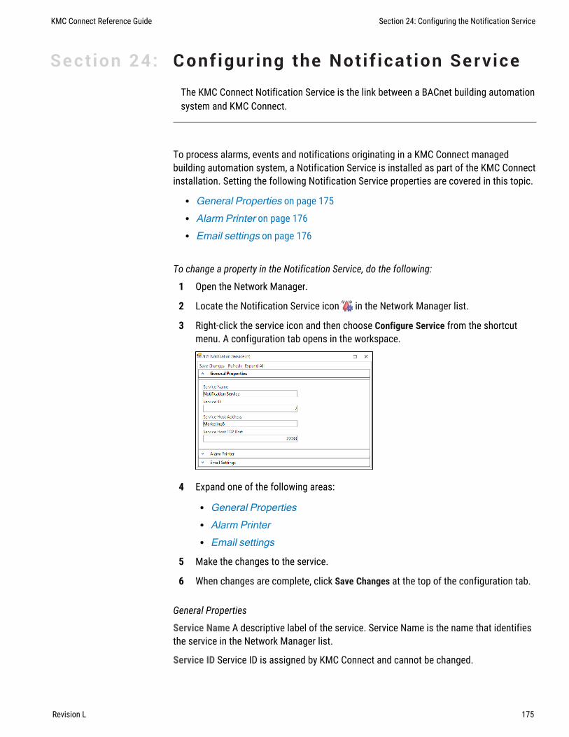
Section 24: Conf igur ing the Notif ication Service
The KMC Connect Notification Service is the link between a BACnet building automationsystem and KMC Connect.
To process alarms, events and notifications originating in a KMC Connect managedbuilding automation system, a Notification Service is installed as part of the KMC Connectinstallation. Setting the following Notification Service properties are covered in this topic.
l General Properties on page 175l Alarm Printer on page 176l Email settings on page 176
To change a property in the Notification Service, do the following:
1 Open the Network Manager.
2 Locate the Notification Service icon in the Network Manager list.
3 Right-click the service icon and then choose Configure Service from the shortcutmenu. A configuration tab opens in the workspace.
4 Expand one of the following areas:
l General Propertiesl Alarm Printerl Email settings
5 Make the changes to the service.
6 When changes are complete, click Save Changes at the top of the configuration tab.
General Properties
Service Name A descriptive label of the service. Service Name is the name that identifiesthe service in the Network Manager list.
Service ID Service ID is assigned by KMC Connect and cannot be changed.
KMC Connect Reference Guide Section 24: Configuring the Notification Service
Revision L 175

Service Host Address Not applicable to KMC Connect.
Service Host TCP Port Not applicable to KMC Connect.
Alarm Printer
As each alarm is received, it is printed on the selected printer. The printer must beinstalled as a Windows printer.
Email settings
The account credentials supplied by the server administrator include the following:
Outgoing Mail Server The address of an SMTP email server. The address may take theform of a URL (bigbuilding.com) or an IP address (192.0.2.0).
Username A user account name (TCalarms).
Password The password for the user account.
Domain The domain name of the server.
Port Typically, this is TCP port 25. The IT department can verify this or supply the correctvalue.
Return Address The reply address that is included as part of the message([email protected]).
To Address Enter the recipient address ([email protected]) for an outgoingtest message. This address is used only to test the connection to the email server.
Test Connection Click Test Connection to send a test message to the email recipient in ToAddress.
Related topics
l Configuring an existing service on page 44l Removing a service on page 45l Opening and closing the Network Manager pane on page 40
Section 24: Configuring the Notification Service KMC Controls, Inc.
176 Revision L

KMC Connect
Part V: Schedule management
KMC Connect Reference Guide
Revision L 177

KMC Controls, Inc.
178 Revision L

Section 25: About BACnet schedules
In a KMC Connect managed building automation system, BACnet schedules are aconvenient method for controlling recurring or future events without extensiveprogramming. Topics in this section describe the Schedule and Calender objects andcover setting up schedules with KMC Connect.
BACnet controllers contain three types of schedules that are maintained within two typesof BACnet objects.
l Weekly schedules are a list of daily events that are maintained within Scheduleobjects.
l Exception schedules override special days in the Weekly schedule and aremaintained also within Schedule objects.
l Calendar objects maintain common Exception schedules that can be shared amongSchedule objects.
In a Schedule object, the Present Value property changes state depending on thetime-of-day and the day-of-the-week in the controller that maintains the object. Theschedule for each day is a list of time-value pairs. Each time-value pair includes atime-of-day and a state or value. As the time in the controller matches the time and day-of-the-week in a time-value pair, the Present Value of the object changes to the state orvalue defined by the time-value pair. The state or value of objects referenced by theSchedule object also change state or value.
Unless the current day is an Exception day, Schedule objects follow the Monday-Sundaydaily schedules in the Weekly Schedules area. Exception days take place when the date inthe controller's Exception schedule matches the date in the controller. Then, the state ofthe Weekly schedule is controlled by the time-value pairs in the Exception schedule. Daysfor the Exception schedule can be designated from within the Schedule object or aCalendar object.
In a Calendar object, the Present Value property changes state for the entire day. Whenthe calendar maintained in the controller reaches one of the Exception days, the objectchanges to True, otherwise the Present Value property is False. The entries for Exceptiondays maintained in a Calendar object can be for individual days, the days between twodates, or a day of the week or day of the month. Schedule management is simplified byusing Calendar objects because several Schedule objects can use the same Calendarobject for common Exception days.
Related topicsl Configuring BACnet Schedule objects on page 180l Configuring BACnet Calendar objects on page 182l Schedule objects on page 496l Calendar objects on page 433
KMC Connect Reference Guide Section 25: About BACnet schedules
Revision L 179

Configuring BACnet Schedule objectsBACnet Schedule objects directly control the value of properties of one or more BACnetobjects designated in the Object Reference List. The control is based on the times andvalues entered into the Weekly Schedule property.
To configure a BACnet Schedule object, do the following.
1 Open the Network Manager.
2 Expand the Network Manager list to reveal the controller, the Schedule Objectsfolder, and the Schedule object icons in the folder.
3 Double-click an icon to open the Schedule object configuration tab.
4 In the General Properties area, enter the following:
l Enter a name and description for the object.l In the Present Value area, choose a Data Type.l Drag one or more BACnet objects to the Object Reference List. All objects must
be of the same data type and must match Data Type in Present Value.l In Start Date and End Date in Effective Period, set the dates to make the schedule
active.l In the Schedule Default area, choose a Data Type. Data Type must match Data
Type in Present Value.l Enter a value in Schedule Default.l Enter a value in Priority for Writing.
5 Expand Weekly Schedules and add time-value pairs. See the following procedureEntering time-value pairs on page 180.
6 For special days such as holidays, special events or maintenance days, expandExceptions Schedule and add dates and time-value pairs.
7 Click Save Changes at the top of the configuration tab.
Entering time-value pairsEvery time-value pair includes a time-of-day and a state or value. When the day and time ina controller matches the day and time in a time-value pair, the Schedule object updatesthe Present Value property to the value in the time-value pair. It updates also theproperties of the objects in the Objects Reference List to the value in the time-value pair.
To add a time-value pair, do either of the following:
1 Click the add button at the bottom of the list of time-value pairs. The new pair isadded to the bottom of the list.
2 Drag the remove button next to a time-value to any day in the schedule.
Section 25: About BACnet schedules KMC Controls, Inc.
180 Revision L

To duplicate a time-value pair
1 Right-click a time value-pair and choose Copy from the shortcut menu.
2 Select a time-value pair for another day. Right-click and choose Paste from theshortcut menu.
To change time in a time-value pair
1 To change time, select the hours, minute or seconds value.
2 Next to the time value, click the up or down arrows .
To remove a time-value pair
Click the remove button to delete a time-value pair.
Configuring an Exception scheduleOn special days, an Exception schedule overrides the time-value pairs of the Weeklyschedule. Typically, the special days are holidays, special events, or other days thatchange the normal schedule in a Schedule object. For special days that are common totwo or more schedule objects, use a Calendar object to designate special days.
To add an exception schedule to a schedule object, do the following:
1 In the Schedule object tab, expand Exceptions Schedule.
2 Click Add and then choose Date, Date Range or Week and Day from the shortcutmenu.
3 Choose an Event priority for the Exception schedule.
4 Add time-value pairs as described in the procedure Entering time-value pairs onpage 180.
To add a Calendar object to the Exception schedule
For details on the Calendar object see the topic Calendar objects on page 433.
1 In the Schedule object tab, expand Exceptions Schedule.
2 In Period Selection choose Calendar Object.
3 Choose and Event priority for the Exception schedule.
4 Add time-value pairs as described in the procedure Entering time-value pairs onpage 180.
Add a day to the Exception schedule
Use either of the following methods to add a day to the Exception schedule list.
l Click Add and then choose Date, Date Range or Week and Day from the shortcutmenu.
l Right-click the list and then choose Date, Date Range or Week and Day from theshortcut menu.
KMC Connect Reference Guide Section 25: About BACnet schedules
Revision L 181

Change an entry in the list
Use any of the following methods to change an entry in the list of days.
l Right-click an entry and then make a selection from the shortcut menu.l Select the entry and then click Edit.l Select the entry and then click Remove.
Related topics
l About BACnet schedules on page 179l Configuring BACnet Calendar objects on page 182l Schedule objects on page 496.
Configuring BACnet Calendar objectsA BACnet Calendar object is a standard BACnet object that contains a list of calendardates. Typically, the dates are holidays, special events, or other special days that need tobe added to the Exception schedule in a Schedule object. Schedule management is madeeasier with Calendar objects because several Schedule objects can use the sameCalendar object for common Exception days.
To configure a Calendar object, do the following:
1 In the Network Manager list, locate the device, the folder of Calendar objects, andthe Calendar object icon.
2 Double-click the object icon to open it.
3 Add or delete dates as needed.
4 For each date entry, add time-value pairs as described in the procedure Enteringtime-value pairs on page 180.
5 When finished, click Save.
Adding a calendar entry
Use either of the following methods to add a calendar to the calendar list.
l Click Add and then choose Date, Date Range or Week and Day from the shortcutmenu.
l Right-click the list and then choose Date, Date Range or Week and Day from theshortcut menu.
Changing an entry
Use any of the following methods to change a calendar entry in the list.
l Right-click an entry and then make a selection from the shortcut menu.l Select the entry and then click Edit.l Select the entry and then click Remove.
Section 25: About BACnet schedules KMC Controls, Inc.
182 Revision L

Related topics
l About BACnet schedules on page 179l Configuring BACnet Schedule objects on page 180l Calendar objects on page 433
KMC Connect Reference Guide Section 25: About BACnet schedules
Revision L 183

Section 25: About BACnet schedules KMC Controls, Inc.
184 Revision L

Section 26: About KMD Schedules
In a KMC Connect managed building automation system, schedules points in KMDigitalcontrollers are a convenient method for controlling recurring or future events withoutextensive programming. Topics in this section cover setting up schedules in KMDigitalcontrollers.
Every KMDigital controller contains three types of schedules within two different types ofschedule points.
l Weekly schedules for recurring daily events are maintained within Weekly Schedulepoints.
l Override schedules for special days are included also in Weekly Schedule points.l Schedules for special days of the year are maintained within Annual Schedule
points.
Weekly Schedule points change state depending on the time-of-day and the day-of-the-week in the controller that maintains the schedule. As the time in the schedule falls withina time range in a daily schedule, the schedule changes state to match the block it is in.For example, if 08:00 is entered in the first On block, the schedule changes to Activewhen the clock in the controller reaches 0800 hours (8:00 A.M.). Because Weekly Schedulepoints do not directly control any other points, use Control Basic to set the value ofanother point or local variable to the state of the schedule.
Unless an override is active, Weekly Schedule points follow the Monday-Sunday dailyschedules in the Weekly Schedules area. Overrides are applied by adding a KMDigitalpoint to either the Override Object 1 or Override Object 2 text boxes. Then, when either ofthe override points change to True, the Weekly Schedule follows the schedule in theWeekly Schedule area under Override1 or Override2. The point in Override Object 1 takesprecedence. For instance, if Override Object 1 is Active, the schedule for Override Object2 is ignored even if Override Object 2 is also Active.
Annual Schedule points change state for the entire day. When the calendar maintained inthe controller reaches one of the days designated by the override point, the AnnualSchedule point changes to Active. Typically, Annual Schedule points designate holidays,maintenance or other special days. Use an Annual Schedule point to override a WeeklySchedule point by adding its mnemonic to either Override Object 1 or Override Object 2 inthe Weekly Schedule object.
Related topicsl Configuring KMDWeekly Schedule points on page 186l Configuring KMD Annual Schedule points on page 187l Weekly Schedule points on page 598l Annual Schedule points on page 569
KMC Connect Reference Guide
Revision L 185

Configuring KMD Weekly Schedule pointsUse Weekly Schedule points for events that take place at the same time, every day onnormal days. A scheduled time in a Weekly Schedule point sets the state of the point toActive when the time in the controller matches the scheduled time. Occupancy andlighting are two examples of events that are typically scheduled with Weekly Schedulepoints.
To enter weekly schedules, do the following:
1 Open the Network Manager.
2 Expand the Network Manager list to reveal the controller, the Weekly Schedulesfolder, and the Weekly Schedules icons in the folder.
3 Double-click an icon to open the Weekly Schedule configuration tab.
4 Under General Properties, enter the following:
l Namel Description
5 Optional: In Override Object 1 and Override Object 2, enter the points that will controlthe overrides. Typically, the override points are Annual schedules. Use mnemonics(AS1, AS2, etc.) to designate the Annual schedule point.
6 Expand the Weekly Schedules area.
7 Enter the time values for each day, including Override 1 and Override 2.
8 When finished, click Save Changes at the top of the configuration tab.
Follow these rules when entering Weekly Schedule values.
l Enter time using the 24-hour clock format.l When more than one On and Off time is entered for the same day, times must be
entered in ascending order.l Enter 00:01 (1 minute after midnight) to designate midnight.l Do not leave empty days. If an On or Off state is to continue from a previous day,
enter 00:01 in the first On or Off row for that day.l Override1 and Override2 schedule times are used when the value controlled by the
point entered in the Override Object 1 or Override Object 2 becomes True (1) or On.
Related topics
l About KMD Schedules on page 185l Configuring KMD Annual Schedule points on page 187l Weekly Schedule points on page 598
Section 26: About KMD Schedules KMC Controls, Inc.
186 Revision L

Configuring KMD Annual Schedule pointsUse Annual Schedule points to designate special days of the year. Typically, these daysare holidays, maintenance days, special occupancy days, or any other day that requires aschedule different than a weekly schedule. The state of an Annual Schedule Point is set toTrue when the date in the controller matches a scheduled date in the point. Usually,Annual Schedule points control the override schedule in a Weekly Schedule point.
To configure an Annual Schedule point, do the following:
1 Open the Network Manager.
2 Expand the Network Manager list to reveal the controller, the Annual Schedulesfolder, and the Annual Schedule icons in the folder.
3 Double-click the icon.
4 Under General Properties, enter the following:
l Namel Description.
5 Expand the Annual Schedule Dates area.
6 Click a date on the calendar to designate it as a scheduled day. Click the date againto clear the selection.
7 Click Save Changes at the top of the configuration tab.
Related topics
l About KMD Schedules on page 185l Configuring KMDWeekly Schedule points on page 186l Annual Schedule points on page 569
KMC Connect Reference Guide Section 26: About KMD Schedules
Revision L 187

Section 26: About KMD Schedules KMC Controls, Inc.
188 Revision L
KMC Connect
Part VI: Control Basic and the Code Editor
KMC Connect Reference Guide
Revision L 189

KMC Controls, Inc.
190 Revision L

Section 27: Programming with the Code Editor
Topics in this section describe the Code Editor and using it to write Control Basicprograms for KMC controllers.
The Code Editor is the programming tool with which Control Basic programs are enteredand edited in the program objects in KMC controllers. Key features of the Code Editorinclude the following items.
l Editing programs within KMD or BACnet controllers from KMC Controlsl Writing and editing programs while offlinel Automatic Control Basic line numberingl Color-coded textl Automatic keyword display
Illustration 27–1 The KMC Connect Code Editor
Related topics
l About Control Basic programs on page 213l Writing Control Basic programs in controllers on page 192l Writing programs offline on page 194l Automatically numbering program lines on page 196l Keyword prompting on page 196l Using keyboard shortcuts on page 197l Finding and replacing text on page 198l Name/Mnemonic switching on page 225l Changing Code Editor options on page 202l Reading live values on page 206
KMC Connect Reference Guide
Revision L 191

Writing Control Basic programs in controllersEvery KMC BACnet and KMD controller includes Control Basic programs. The programsare written and edited with the KMC Connect Code Editor.
Note: Converting between block programming and line programmingwithin the same program object is not recommended and usually isnot possible. See the following topic, Line vs. block programmingon page 214.
Open an existing program for editing with the Code Editor by doing the following:
1 Locate a program icon in the Network Manager list.
2 Click the icon to open the program.
3 When editing is complete, save the work in the controller by doing one of thefollowing:
l Press Ctrl+s .l Right-click in the editor window and choose Save from the shortcut menu.l From the Code Editor toolbar, choose File menu and then Save.
Tip: After compiling or saving a program, check the output windowfor errors in the program . The message or messages will include aline number and the cause of the error.
Illustration 27–2 Control Basic objects within controllers
Section 27: Programming with the Code Editor KMC Controls, Inc.
192 Revision L

To save a save a Control Basic program as a local file
Local files have the extension of .cb. Save the program as a local program file by doingthe following:
1 From the Code Editor toolbar, choose File and then Save As.
2 Specify the new file name and location.
Code Editor toolbar items
Use the menus and buttons on the Code Editor toolbar to compile, save, start and haltControl Basic programs. Button functions are listed in the table Code Editor toolbaritems on page 193.
Note: The Advanced Options are for special circumstances. Do notchange unless directed by the KMC Controls Technical Supportdepartment.
Illustration 27–3 Code Editor toolbar
Action Icon Description
Compile Tests the program for proper syntax but does notsend it to the controller.
Run(BACnet only)
Compiles the program, saves it in the controller, andruns the program in the controller.
Halt(BACnet only)
Stops the controller from running the program.
Unload(BACnet only)
Removes a Control Basic program from the queue inthe controller.
Comment Adds the REM keyword to the beginning of selectedlines.
Uncomment Removes the REM keyword from the beginning ofselected lines.
Name/Mnemonicswitching
Switches object references between names andmnemonics in the Code Editor. See the topicName/Mnemonic switching on page 225.
Clear(BACnet only)
Erases the Control Basic program from thecontroller.
Block Editor Opens the Block Programming Editor
Table 27–1 Code Editor toolbar items
KMC Connect Reference Guide Section 27: Programming with the Code Editor
Revision L 193

Action Icon Description
Enable Line Editor Unlocks the Block Editor generated Control Basic forcopying or editing with the line editor.
Live Values See the topic Reading live values on page 206.
Table 27–1 Code Editor toolbar items (continued)
Related topics
l About Control Basic programs on page 213l Writing programs offline on page 194l Automatically numbering program lines on page 196l Keyword prompting on page 196l Adding objects by dragging on page 210l Using keyboard shortcuts on page 197l Finding and replacing text on page 198l Changing Code Editor options on page 202l Writing block programs on page 333l Name/Mnemonic switching on page 225l Reading live values on page 206
Writing programs offlineWith the Code Editor, you can write Control Basic programs without connecting to a site orcontroller. The Code Editor can open two types of offline Control Basic programs.
l Program objects that are part of .bnd and .kmd files that are located in theResource Manager list. The program object or point is indicated with the programicon( ).
l Control Basic .cb files that are typically stored in the Resource Manager list but maybe located on any disk of the computer running Design Studio
Start a new program
Start a new Control Basic program by doing the following:
1 Do either of the following to open the Code Editor workspace:l On the File menu, click New and then Program File.l Click on the toolbar and then choose New Program File.
An empty Code Editor window opens in the workspace.
Section 27: Programming with the Code Editor KMC Controls, Inc.
194 Revision L

2 Choose the following from the text boxes at the top of the Code Editor tab:l Modell Firmware versionl Device ID
3 Add program statements and lines as required to operate the equipment connectedto the controller.
4 Test the program for proper syntax by compiling the program. Make corrections asnecessary.
5 Save the program by doing one of the following:l Choose Save from either File menu.l To save the file in a different folder or with a different name, choose File and
then Save As. Using Save As always saves the file as a .cb file.
Note: Saving the file overwrites an existing file with the same nameat the same location.
Illustration 27–4 A local file in the Code Editor
Edit an existing program
To use the Code Editor to modify local files — files with a .cb, .bnd, or .kmdextensions — do the following:
1 Open an existing Control Basic program by doing either of the following:l On the File menu, click Open and then Program File. Locate a .CB file.l In the Resource Manager, locate a .BND or .KMDfile and then double-click a
program object or point icon .
2 When the program is open, add program statements and lines as required to operatethe equipment connected to the controller.
3 Test the program for proper syntax by compiling the program. Make corrections asnecessary.
KMC Connect Reference Guide Section 27: Programming with the Code Editor
Revision L 195

4 Save the program by doing one of the following:l Choose Save from the File menu.l To save the file in a different folder or with a different name, choose File and
then Save As. Using Save As saves the file as a .CB file.
Note: Saving the file overwrites an existing file with the same nameat the same location.
Related topics
l About Control Basic programsl Writing Control Basic programs in controllers on page 192l Automatically numbering program lines on page 196l Keyword prompting on page 196l Using keyboard shortcuts on page 197l Finding and replacing text on page 198l Changing Code Editor options on page 202l Reading live values on page 206
Automatically numbering program linesThe Code Editor will automatically add numbers to program lines.
To turn automatic line numbering on or off, do one of the following:
l From the Code Editor View menu, select or clear the Auto Line Number check box.l Right-click in the editor work space, and then select or clear Auto Line Number.
Related topics
l About Control Basic programsl Writing Control Basic programs in controllers on page 192l Writing programs offline on page 194l Keyword prompting on page 196l Using keyboard shortcuts on page 197l Finding and replacing text on page 198l Changing Code Editor options on page 202l Reading live values on page 206
Keyword promptingThe Intellisense keyword filter speeds the writing of Control Basic programs. As you typeprogram lines, a shortcut menu opens a list of keywords. The list starts at a keyword thatmatches the letters that you have already typed. For example, if you have typed GO, then
Section 27: Programming with the Code Editor KMC Controls, Inc.
196 Revision L

the list opens at the keyword GOSUB. You can then choose either GOSUB or GOTOfrom the list.
To turn keyword prompting on or off, do either of the following:
l From the View menu select or clear Keyword Prompt.l Right-click in the editor work space and then select or clear Keyword Prompt from
the shortcut menu.
Tip: To change settings for keyword prompting, see ChangingCode Editor options on page 202.
Illustration 27–5 Keyword prompting list
Related topics
l About Control Basic programs on page 213l Writing Control Basic programs in controllers on page 192l Writing programs offline on page 194l Automatically numbering program lines on page 196l Using keyboard shortcuts on page 197l Finding and replacing text on page 198l Changing Code Editor options on page 202l Reading live values on page 206
Using keyboard shortcutsUse the shortcuts listed in the table File menu shortcuts in Code Editor when enteringprograms with the Code Editor.
l All of the shortcuts in the table are available by right-clicking in the Code Editorprogram listing.
l Some are available also through keyboard shortcuts.
KMC Connect Reference Guide Section 27: Programming with the Code Editor
Revision L 197

Shortcut Keyboard Action
Renumber Ctrl+r Renumbers all lines in the program. Active only whenautomatic numbering is not enabled.
Undo Ctrl+z Reverses the last action.
Redo Ctrl+y Repeats the last action.
Cut Ctrl+x Removes the selected text and places it on theclipboard for pasting into another location.
Copy Ctrl+c Copies the selected text to the clipboard for pastinginto another location.
Paste Ctrl+v Moves text from the clipboard to the selectedlocation.
Select All Ctrl+a Selects all text in the program.
Find/Replace Ctrl+f Opens the Find and Replace dialog.
Go To Ctrl+g Moves the insertion point to the specified line number.
Table 27–2 File menu shortcuts in Code Editor
Related topics
l About Control Basic programs on page 213l Writing Control Basic programs in controllers on page 192l Writing programs offline on page 194l Automatically numbering program lines on page 196l Keyword prompting on page 196l Finding and replacing text on page 198l Changing Code Editor options on page 202l Reading live values on page 206
Finding and replacing textUse Find and Replace in the Code Editor to locate and replace text and words in a ControlBasic program. The search can be extended by using wildcards and regular expressions.
Illustration 27–6 Find/Replace dialog
Section 27: Programming with the Code Editor KMC Controls, Inc.
198 Revision L

Finding text and words
To quickly locate every occurrence of a specific word or phrase do the following:
1 From the Edit menu, choose Find And Replace.
2 In the Find what text box, enter the text for which to search.
3 Select the check boxes for any other options.
4 Click Find Next.
Replacing text
You can automatically replace text— for example, you can replace GOTO with GOSUB.
1 From the Edit menu, choose Find And Replace.
2 In the Find what box, enter the text for which to search.
3 In the Replace with box, enter the replacement text.
4 Select the check boxes for any other options.
5 Click Find Next, Replace, or Replace All.
Placing bookmarks
Bookmarks are temporary visual markers placed in Control Basic listings to help locatespecific blocks of text. For example, when modifying a long program it may be helpful tobookmark a program lines that contain a reference to a specific object.
1 From the Edit menu, choose Find And Replace.
2 In the Find what box, enter the text for which to search.
3 Click Bookmark All.
4 At the end of the search, each program line with the found text will have a bookmarkicon in the left margin.
5 Once bookmarks are placed, use the Bookmark commands in the Edit menu tonavigate to lines with bookmarks or manage bookmarks placed in program listings.
Illustration 27–7 Control Basic with bookmarks
KMC Connect Reference Guide Section 27: Programming with the Code Editor
Revision L 199

Searching with wildcards
Use wildcards to find character patterns.
1 On the Edit menu, click Find And Replace.
2 Select the Use check box and then select Wildcards.
3 Enter a wildcard character in the Find What box by doing one of the following:l Click the wildcard menu icon , click a wildcard character, and then type any
additional text in the Find what box.l Type a wildcard character directly in the Find what box. Wildcard characters are
described in the table Wildcard characters on page 200.
4 If you want to replace the item, enter the replacement text in the Replace with box.
5 Click Find Next, Replace, or Replace All.
When the Use Wildcards check box is selected, use the following wildcards to findcharacter patterns.
To find Do this Example
Zero or more characters,excluding spaces andpunctuation
Enter an asterisk (*). f*t finds words such as fitand feet.
Any single character,excluding spaces andpunctuation
Enter a question mark (?). f??t finds four-letterwords that begin with fand end with t, forexample, foot and feet.
Any string of numbers Enter a (#) AV2# finds AV21 andAV23.
Table 27–3 Wildcard characters
Searching with regular expressions
Use regular expressions to create sophisticated search patterns not possible withwildcards.
1 From the Edit menu, choose Find And Replace.
2 Select the Use check box and then select Regular Expressions.
3 Enter a regular expression in the Find What box by doing one of the following:l Click the regular expression menu icon , click a regular expression, and then
type any additional text in the Find what box.l Type a regular expression directly in the Find what box. Regular expression
codes are listed in the table Regular expression codes on page 201.
Section 27: Programming with the Code Editor KMC Controls, Inc.
200 Revision L

4 To replace the item, enter the replacement text in the Replace with box.
5 Click Find Next, Replace, or Replace All.
When the Use Regular Expressions check box is selected, use the following codes tofind character patterns.
To find Do this Example
Any single characterexcept line breakcharacters
Enter a period (.) a.cd finds abcda..d finds abcd[a.cd] finds a, c, d or a period (.)
Zero or more copies ofthe previous expression
Enter an asterisk(*).
go*gol finds ggol, gogol, googol orgooogol.
At least one copy of theprevious expression.
Enter a plus sign(+).
go+gol finds gogol, googol, gooogo,but not ggol.
The beginning of a line Enter a caret (^). ^f finds any word that starts with f at thebeginning of a line.
One or more charactersat the end of a line
Enter a dollarsign ($).
f$ finds any word that ends with f at theend of a line.
To find one or morecharacters at thebeginning or end of aword
Enter \b \bsub finds any word that starts withsub such as subroutinesub\b finds words that end in sub suchas GOSUB
To find one or morecharacters preceded orfollowed by white space
Enter \s \ssub finds any word that has whitespace before subsub\s finds words thatare followed by white space.
The end of a line Enter \n Finds the end of program lines.
Any one of severalcharacters
Type thecharacters withinbrackets ( [ and ] ).
[rml]ate finds rate, mate, and late, butnot gate.
Any one character not ina specified group ofcharacters
Precede thecharacters inbrackets with acaret (^).
[^rml]ate finds fate, gate, and date, butnot rate or late.
Either of two or moregroups of characters
Enter a verticalbar (|) betweencharacter groups
AV10|BV10 finds both AV10 andBV10
Table 27–4 Regular expression codes
Related topics
l About Control Basic programs on page 213
KMC Connect Reference Guide Section 27: Programming with the Code Editor
Revision L 201

l Writing Control Basic programs in controllers on page 192l Writing programs offline on page 194l Automatically numbering program lines on page 196l Keyword prompting on page 196l Using keyboard shortcuts on page 197l Changing Code Editor options on page 202l Reading live values on page 206
Changing Code Editor optionsThe Code Editor options are located under three separate tabs.
l The General Options tab controls Object Reference Detection, IntelliSense typingand line numbering options.
l The Fonts & Colors tab includes settings for the color and other text properties inthe Code Editor window.
l Settings under Tabs tab control program formatting to enhance the readability ofControl Basic.
To change the Code Editor appearance or options, do the following:
1 On the ribbon, click the File tab.
2 Click Options.
3 From the Component list, choose Code Editor.
4 Choose a tab to which to make changes in the Code Editor Settings dialog.
5 Click Apply or OK when finished.
General Options tab
Illustration 27–8 Code Editor Options dialog - General tab
Settings under the General Options tab control Object Reference Detection, IntelliSensetyping and line numbering options.
Compile with Object Names When selected, object names may be used instead ofmnemonics in Control Basic.
Detect Object References When selected, enables Name/Mnemonic object referenceswitching. The Detect Object References check box is selected automatically when theCompile with Object Names check box is selected. See Name/Mnemonic switching onpage 225
Section 27: Programming with the Code Editor KMC Controls, Inc.
202 Revision L

Enable IntelliSense When selected, keywords are verified as they are entered from thekeyboard.
Enable Automatic Line Numbering When selected, automatically adds a line number atthe start of a new line. The new line number is incremented by the value set in IncrementBy.
Start With Number When new pages open, the first line number is automatically set to thevalue in Start With Number.
Increment By When Turn Auto Line Number On is selected, the Code Editor adds a linenumber every time a new line is started. The value of the line number is the previous linenumber plus the value of Increment By.
Auto Fix When selected, references to lines by a GOTO, GOSUB, or ON-ERROR areautomatically updated when new line numbers are inserted.
Restore Defaults Returns all Code Editor options to the original settings.
KMC Connect Reference Guide Section 27: Programming with the Code Editor
Revision L 203

Fonts & Colors tab
Illustration 27–9 Code Editor Options dialog - Fonts & Colors tab
Font, colors, and styles for text in the Code Editor window can be changed under the Fonts& Colors tab. Options are typical choices for text appearance in Windows programs.
Font Selects the typeface for the entire program.
Size Selects the point size for the entire program.
Code Element Selects the category of code element to modify.
Style Selects the style (e.g., regular, italic, bold) of the selected code element.
Item Foreground Color Selects the text color of the selected code element.
Item Background Color Selects the background color of the selected code element.
Restore Defaults Returns all text elements to their default settings.
Default text colors are listed in the table Code Editor default text colors.
Text function Default color
Plain text Black
Object references Black
Comments Green
Keywords Blue
Strings Maroon
Table 27–5 Code Editor default text colors
Note: When entering text into the Code Editor, there is a 0.5 seconddelay before an object reference text changes color. This is part ofthe Control Basic scan that determines if the object reference isvalid.
Section 27: Programming with the Code Editor KMC Controls, Inc.
204 Revision L

Tabs tab
Illustration 27–10 Code Editor Options dialog - Tabs tab
Settings under Tabs changes the way Code Editor adds tabs at the beginning of a newline. Tabs are invisible divisions that span five character spaces. Using tabs enhances thereadability of Control Basic but does not change the way a program compiles or runs.
Indenting When Smart is selected, the number of tab characters in Tab Size areautomatically added to the beginning of a new line when ENTER is pressed.
Tab Size Specifies the number of tab characters to add to the beginning of a new programline. The minimum number of tabs is 4; the maximum is 80.
Related topics
l About Control Basic programs on page 213l Writing Control Basic programs in controllers on page 192l Writing programs offline on page 194l Automatically numbering program lines on page 196l Keyword prompting on page 196l Using keyboard shortcuts on page 197l Finding and replacing text on page 198l Reading live values on page 206
KMC Connect Reference Guide Section 27: Programming with the Code Editor
Revision L 205

Reading live valuesTo view the actual present values of objects referenced from within a Control Basicprogram, use the Live Values option in the Code Editor.
l To display a list of objects used in the code and their most recent values, select theLive Values check box.
l To change the refresh rate, change the value in Refresh time (seconds) box.l Clear the check box next to an individual object to prevent it from updating
automatically.l Right-click the object list to Enable or Disable automatic value updates for all
objects.l To change the order in the list, drag an object or group of objects to a new location.
Illustration 27–11 Code editor live values
Section 27: Programming with the Code Editor KMC Controls, Inc.
206 Revision L

Hovering over an object displays additional information.
l Hovering over an object in the object list displays the line number(s) where theobject is used in the program.
l When Live Values is enabled, hovering over an object in the code displays theobject's mnemonic and name, its most recent value, and the time at which the valuewas read.
l When Live Values is disabled, hovering over an object in the code displays itsmnemonic and name.
Illustration 27–12 Hovering for live values (when enabled) or location
Related topics
l About Control Basic programs on page 213l Writing Control Basic programs in controllers on page 192l Writing programs offline on page 194l Automatically numbering program lines on page 196l Keyword prompting on page 196l Using keyboard shortcuts on page 197l Finding and replacing text on page 198l Changing Code Editor options on page 202
Locking Control Basic programsThe Control Basic program in a BACnet Program object may be locked and hidden toprevent tampering. Locked files cannot be viewed, edited, or compiled with the CodeEditor, but properties in the Program object are still accessible.
Caution: Locking a program requires a password. The passworddoes not have a backdoor or recovery method. If it is unknown orforgotten, the program cannot be changed. The only recovery is toflash the controller firmware with the Firmware Upgrade Tool.
KMC Connect Reference Guide Section 27: Programming with the Code Editor
Revision L 207

Locking a Control Basic program
To lock a Control Basic program, do the following:
1 In the Network Manager list, click or to expand or collapse the list to locate theBACnet device containing the program.
2 Double-click the device icon to open the Device Object configuration page in theworkspace.
3 Expand the Object Locking area.
4 In the Network Manager list, click to expand the device and locate the Files folder.
5 Click the next to the Files folder.
6 In the Files folder, locate the Control Basic file. The file name format is similar to[129005]prog5.cg5cb. The number following "prog" in the extension is thesame number as the Program object that contains the Control Basic program.
7 Drag the file icon to the Locked Objects list.
8 Enter a password. Do not lose this password; it cannot be recovered.
9 Click Save Changes at the top of the tab.
Unlocking a locked program
To unlock a Control Basic program, do the following:
1 In the Network Manager list, click or to expand or collapse the list to locate theBACnet device containing the program.
2 Double-click the device icon to open the Device Object configuration page in theworkspace.
Section 27: Programming with the Code Editor KMC Controls, Inc.
208 Revision L

3 Expand the Object Locking area.
4 Enter the password.
5 Click the delete button next to one or more file names.
6 Click Save Changes at the top of the tab.
7 Reenter the password.
8 Click Save Changes at the top of the tab.
See also the topic, Device objects on page 435.
KMC Connect Reference Guide Section 27: Programming with the Code Editor
Revision L 209

Adding objects by draggingSome types of BACnet objects may be dragged directly from the Network Manager orResource Manager to the Code Editor for use in programs written for BACnet devices.This option can quickly add an object to or replace an existing object in a program.
Available object types are:
l Variables (Analog, Binary, Multistate)l Inputs (Analog, Binary, Accumulator)l Loopsl Outputs (Analog, Binary)
The following rules apply when dragging objects to the Code Editor.
l Objects may only be dragged to code written for the same device instance.l Any text selected in the Code Editor must be cleared before dragging an object into
a program.l An object may be dragged to either:
l A blank space in the code. This adds the object to the program.l An existing element in the code. The element is highlighted when a replacement
is available. The user can choose whether this replaces a single instance or allinstances of the object in the program.
l An object dragged into the Code Editor displays in Mnemonic format by default. Toconvert an object to Name format when dragging, press and hold the Alt key whilereleasing the mouse button at the desired position in the code.
l When dragging an object over text in the Code Editor, the pointer changes to a . An
instance of the same object is highlighted as the pointer contacts it.l Information about objects that have been replaced appears in the Output Window.
To add a new object to the code:
1 Open the program in the Code Editor.
2 Drag the object from the Network Manager or Resource Manager to the desiredposition in the program. If there is no text on the line, the object is inserted at thebeginning of the line.
To replace a single instance of an object in the code:
1 Open the program in the Code Editor.
2 Drag the object from the Network Manager or Resource Manager to the desiredposition in the program.
3 In the dialog box, click No.
Section 27: Programming with the Code Editor KMC Controls, Inc.
210 Revision L

To replace all instances of an object in the code:
1 Open the program in the Code Editor.
2 Drag the object from the Network Manager or Resource Manager to the desiredposition in the program and press Ctrl .
3 In the dialog box, click Yes.
Related topics
l Using the Network Manager on page 39l About the Resource Manager on page 55l Reference to BACnet objects on page 427l About Control Basic programs on page 213l Writing Control Basic programs in controllers on page 192l Writing programs offline on page 194l Automatically numbering program lines on page 196l Keyword prompting on page 196l Finding and replacing text on page 198l Changing Code Editor options on page 202l Reading live values on page 206
KMC Connect Reference Guide Section 27: Programming with the Code Editor
Revision L 211

Section 27: Programming with the Code Editor KMC Controls, Inc.
212 Revision L

Section 28: About Control Basic programs
Control Basic is the process that creates the automation in KMC controllers. Topics inthis section cover the rules for writing Control Basic programs.
Every KMC controller includes space for Control Basic programs. Within each controller aprogram continuously evaluates input data from the building automation system. Then,based upon the instructions in the program, the controller takes action to keep one ormore pieces of equipment operating within required parameters.
The instructions within the program object are written in Control Basic, a programminglanguage that is similar to BASIC (Beginner's All-purpose Symbolic Instruction Code). Inaddition to standard BASIC programming functions, it includes specialized functionsspecific for the building automation controls industry.
Each of the following topics cover a key aspect of Control Basic.
l Line vs. block programming on page 214l About Control Basic scans on page 214l Programming format and notation on page 218l Labels and line numbers on page 216l Real numbers on page 218l Hierarchy of operators on page 219l Relational operators on page 220l Using arithmetic operators on page 221l Using Boolean logic on page 221l Programming with variables on page 222l Reading and writing BACnet objects on page 223l Transferring values between BACnet controllers on page 228l Reading and writing KMD points on page 235l BACnet data types on page 243l Generation 5 data types on page 243l BACnet arrays and dynamic access on page 242l User-defined functions and procedures on page 240
KMC Connect Reference Guide
Revision L 213

Line vs. block programmingThe recommend best practice for programming is to use either line or block programmingand not attempt to switch between the two methods within the same program object. If ablock program requires a function that is available only in line programming, do one of thefollowing:
l In another program object, write the function using line programming and then sharedata between programs with value objects.
l Write the function inside of a Macro block. See the topic Macro blocks on page341.
See the topic Limitations and importing line programs on page 344.
About Control Basic scansControl Basic is the process that creates the automation in a KMC controller. Eachcontroller has several program areas or program objects for storing and executingControl Basic instructions. When running Control Basic programs, the microprocessor inthe controller does the following:
1 Evaluates the state of each object.
2 Executes the Control Basic programs.
3 Changes the state of all outputs when all programs have been executed.
This process—referred to as a scan—is normally performed several times a second. Seethe illustration The scan process on page 214 for an example of the scanning process.
Illustration 28–1 The scan process
Start scan
End scan
Evaluate objects and run program 1
Evaluate objects and run program 2
Evaluate objects and run last program.
Change outputs
Section 28: About Control Basic programs KMC Controls, Inc.
214 Revision L

The processor evaluates all program objects before making changes. For example, ifprograms 1, 3, and the last program includes instructions for Lights ON, and programs 2and 4 have instructions for Lights OFF, the lights will not flash and they will be set to ONonly at the end of the scan.
Tip: Program the most important events in the highest numberedprogram area. This prevents programs with less importance fromoverriding critical actions.
Writing Control Basic statementsControl Basic programs are added to program objects and program points with theControl Basic editor.
StatementsA statement is the simplest instruction in a Control Basic program. Keywords such asINTERVAL, START, or GOTO are examples of statements. Expressions and functions arespecific types of statements.
Multiple statementsMultiple statements can be used on the same program line, but must be separated by acolon.
ExampleA = B : GOTO 80 : START S
FunctionsA function is a keyword that—when evaluated by Control Basic—returns a value. Thisreturned value is the result computed by the function. Functions save time for complexcalculations such as calculating square roots or averaging a set of values. They may alsobe used to retrieve common system data such as using TIME to retrieve the time of day.
Functions are defined by either a keyword or by a user-defined function as described inthe topic User-defined functions and procedures on page 240.
KMC Connect Reference Guide Section 28: About Control Basic programs
Revision L 215
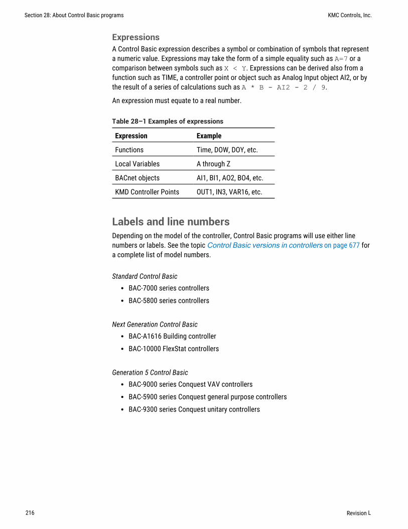
ExpressionsA Control Basic expression describes a symbol or combination of symbols that representa numeric value. Expressions may take the form of a simple equality such as A=7 or acomparison between symbols such as X < Y. Expressions can be derived also from afunction such as TIME, a controller point or object such as Analog Input object AI2, or bythe result of a series of calculations such as A * B - AI2 - 2 / 9.
An expression must equate to a real number.
Expression Example
Functions Time, DOW, DOY, etc.
Local Variables A through Z
BACnet objects AI1, BI1, AO2, BO4, etc.
KMD Controller Points OUT1, IN3, VAR16, etc.
Table 28–1 Examples of expressions
Labels and line numbersDepending on the model of the controller, Control Basic programs will use either linenumbers or labels. See the topic Control Basic versions in controllers on page 677 fora complete list of model numbers.
Standard Control Basicl BAC-7000 series controllersl BAC-5800 series controllers
Next Generation Control Basicl BAC-A1616 Building controllerl BAC-10000 FlexStat controllers
Generation 5 Control Basicl BAC-9000 series Conquest VAV controllersl BAC-5900 series Conquest general purpose controllersl BAC-9300 series Conquest unitary controllers
Section 28: About Control Basic programs KMC Controls, Inc.
216 Revision L

Line numbers–Standard Control Basic onlyWhen writing programs for controllers that support Standard Control Basic, enter a linenumber at the beginning of each line. Each Control Basic program line must include a linenumber and at least one function or statement.
10 A = 2 + 320 P = PI30 REM Program starts here
Programs written for controllers with Next Generation and Generation 5 Control Basic donot use line numbers.
Labels in Next Generation Control BasicLabels are used instead of line numbers with Next Generation Control Basic. Use labelswhen redirecting program flow with the following statements:
l GOSUB on page 275l GOTO on page 276l ONERROR on page 298l ON GOSUB on page 295l ON GOTO on page 296
Declare a label by typing a name followed immediately by a colon (:).
l A label must start with a letter.l A label can be any combination of letters (A-Z or a-z), numbers (0-9) or the
underscore (_).l Labels are not case sensitive.l Labels are unique to the program in which they are declared.l A label cannot duplicate a keyword, constant, local variable, or alias.
In the following program example, CoolMode and HeatMode are program labels.
IF T > 55 THEN GOTO CoolModeIF T <= 55 THEN GOTO HeatModeENDCoolMode:REM Cooling sequence runs hereENDHeatMode:REM Heating sequence runs hereEND
KMC Connect Reference Guide Section 28: About Control Basic programs
Revision L 217

Programming format and notationControl Basic programs consist of a series of program lines. On each line there are one ormore statements.
Throughout these instructions the following notations are used to describe formats:
CAPS Words in capital letters are keywords and must be entered as shown.
lowercase Items in lowercase letters represent information such as expressionsthat you supply.
... An ellipsis (...) indicates that an item may be repeated as many times asnecessary.
spaces (_) Required spaces in syntax are illustrated with an underline (_).
: A colon (:) separates statements on the same line.
[ ] Optional items are shown in brackets [ ].
Table 28–2 Typographic conventions
All other punctuation, including commas(,), are part of the syntax and must be included asshown in each example.
Real numbersReal numbers are any logical number between -3.4 * 1038 and 3.4 * 1038. Notation of anumber is recognized in any of the following formats:
l Whole numbers (100)l Decimal format (.0000123)l Engineering notation (7.879 E-12)
Section 28: About Control Basic programs KMC Controls, Inc.
218 Revision L

Hierarchy of operatorsControl Basic arithmetic operators have an order of precedence. When several operationstake place in the same program statement, some operations are performed before others.Control Basic uses the operator precedence shown in the illustration Order of operatorprecedence on page 219 when performing operations on an expression. Operations atthe same level of precedence are evaluated from left to right.
Illustration 28–2 Order of operator precedence
Operator Type Precedence
( ) Expression in parenthesis Highest (performed first)
NOT Logical NOT
^ Exponentiation
*, / Multiplication and division
\ Integer division
MOD Modulus (remainder)
+, -
<, >, <=, >= Relational
=, <>
AND Logical
OR
XOR Lowest (performed last)
Related topics
l Using arithmetic operators on page 221l Relational operators on page 220l Using Boolean logic on page 221
KMC Connect Reference Guide Section 28: About Control Basic programs
Revision L 219

Relational operatorsRelational operators are used to compare two values. The result is TRUE if thecomparison is TRUE; otherwise, the result equals FALSE. The result can then be usedto direct program flow. All relational operators have the same level of precedence.
Operator Relation Tested Example Result
= Equality 5 = 2 False
<> Inequality 5 <> 2 True
< Less than 5 < 2 False
> Greater than 5 > 2 True
<= Less than or equal to 5 <= 2 False
>= Greater than or equal to 5 >= 2 True
Table 28–3 Relational operators
Related topics
l Using arithmetic operators on page 221l Using Boolean logic on page 221l Hierarchy of operators on page 219
Section 28: About Control Basic programs KMC Controls, Inc.
220 Revision L

Using arithmetic operatorsOperators are listed in their order of priority. The formats for using operators are listed inthe table Arithmetic order of precedence on page 221.
Symbol Operation Example
* Multiplication 2*4=8
/ Division 10/4 =2.5
\ The integer portion of a division 13\5= 2
MOD The remainder of a division 13 MOD 5=3
+ Addition 2+2=4
- Subtraction 4-3=1
^ ExponentiationRaises a value to a power
A = AI1 ^ AV1
Table 28–4 Arithmetic order of precedence
Related topics
l Relational operators on page 220l Using Boolean logic on page 221l Hierarchy of operators on page 219
Using Boolean logicControl Basic recognizes four Boolean operators. The operators are listed in their order ofprecedence.
NOT NOT is a Boolean operator that performs a logical NOT operation on an expression. Ifthe expression is 0, the result is 1. If the expression is non-zero, the result is 0.
For additional details on this operator, see the keyword NOT on page 294.
AND AND performs the logical AND of the two expressions. The result is TRUE if bothexpressions are non-zero; otherwise, the result is FALSE .
For additional details on this operator, see the keyword AND on page 251.
OR OR performs the logical OR of the two expressions. The result is TRUE if eitherexpression is TRUE. The result is FALSE if both expressions are FALSE.
For additional details on this operator, see the keyword OR on page 300.
KMC Connect Reference Guide Section 28: About Control Basic programs
Revision L 221

XOR XOR performs the logical exclusive or of the two expressions. The result is TRUEif the two expressions are different; otherwise, the result is FALSE.
For additional details on this operator, see the keyword XOR on page 331.
Related topics
l Using arithmetic operators on page 221l Relational operators on page 220l Hierarchy of operators on page 219
Programming with variablesVariables are placeholders for information such as setpoints, time delays, and operatingmodes. Control Basic uses two types of variables—local variables and value objects inBACnet controllers and variable points in KMD controllers.
Variables in KMD controllersVariable points in KMD controllers are place holders for information such as setpoints,time delays, and modes. See the topic Mnemonics for KMD controllers on page 235 forusing a variable point in Control Basic.
BACnet value objects as variablesAnalog, binary, and multi-state value objects are used as program variables in BACnetcontrollers.
Local variablesLocal variables can only be used within the Control Basic program that refers to them. Thevalues they represent cannot be directly transferred to other Control Basic programs.Local variables are useful as counters or to store the results of local calculations.
Standard Control Basic local variables Within each Control Basic program, there are 26local variables. These variables are assigned the letters of the alphabet (A-Z).
Next Generation and Generation 5 Local variables in controllers that use Next Generationor Generation 5 Control Basic can be either a single-letter variable (A-Z) or a declaredlocal variable. Variables are declared with the commands INTEGER, LOCALS, REAL, orSTRING and must be declared within each Control Basic program. All single-letter localvariables are automatically declared unless a local variable is declared. If a local variableis declared, single-letter variables must also be declared.
For details on using and declaring local variables, see the following keywords.
l LOCALS on page 286l INTEGER on page 282l REAL on page 307l STRING on page 320
Section 28: About Control Basic programs KMC Controls, Inc.
222 Revision L

Reading and writing BACnet objectsControl Basic programs read from input objects and write to output objects by usingmnemonics or—depending on the editor used to write the program—the name ordescription of the object. The programs can also read and write other objects such asschedule, value, and PID loop objects. In addition, Control Basic programs can read valuesfrom and write values to objects in other BACnet controllers on the same internetwork.
l For reference to the list of mnemonics, see Mnemonics for BACnet controllerson page 223.
l To read and write values in other controllers, see Transferring values betweenBACnet controllers on page 228.
l To read and write to the priority array and relinquish default, see Reading andwriting the priority array on page 227.
Mnemonics for BACnet controllersMnemonics are short, easy-to-remember abbreviations in Control Basic that refer toBACnet objects. For example, a physical input is entered as AI1 or BI1 in BACnetcontrollers instead of typing Input1.
Note: The mnemonic codes are different between KMD and BACnetcontrollers. For KMD mnemonics see the topic Mnemonics forKMD controllers on page 235.
Object mnemonics Control Basic mnemonics for BACnet objects are listed in the tableBACnet object mnemonics on page 224. The following line of Control Basic is anexample of using mnemonics to refer to an analog input object and a binary output object.
IF AI08 > 10 THEN START BO2
l Mnemonics listed as Read Only can read a value—such as its value or status—from that object.
l Mnemonics listed as Read and Write describe a property—such as its value orstatus—that may be changed through programming or by direct access.
l Mnemonics are reserved words and cannot be used for object names ordescriptions.
l Mnemonics are not case sensitive.
Caution: If a Control Basic program uses a mnemonic to refer to aninvalid local object or property within an object, the program willcompile but it will halt execution. The reason for the halt is listed inthe Program Object's Description of Halt property.
KMC Connect Reference Guide Section 28: About Control Basic programs
Revision L 223
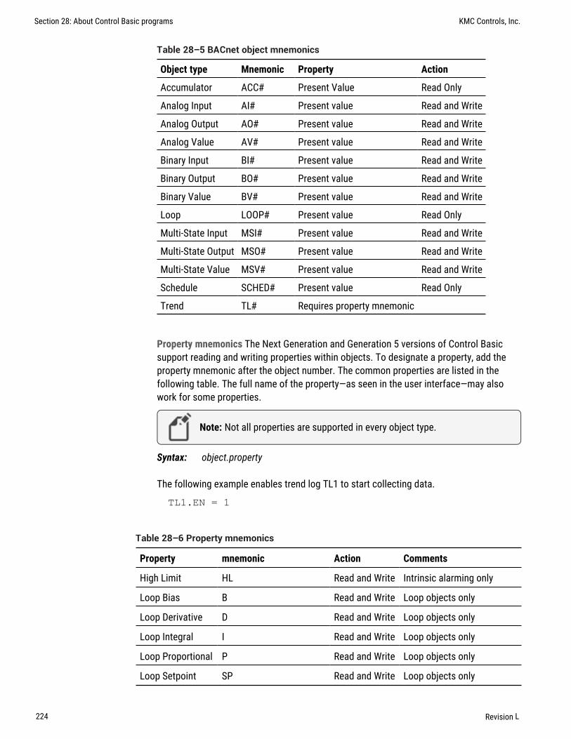
Object type Mnemonic Property Action
Accumulator ACC# Present Value Read Only
Analog Input AI# Present value Read and Write
Analog Output AO# Present value Read and Write
Analog Value AV# Present value Read and Write
Binary Input BI# Present value Read and Write
Binary Output BO# Present value Read and Write
Binary Value BV# Present value Read and Write
Loop LOOP# Present value Read Only
Multi-State Input MSI# Present value Read and Write
Multi-State Output MSO# Present value Read and Write
Multi-State Value MSV# Present value Read and Write
Schedule SCHED# Present value Read Only
Trend TL# Requires property mnemonic
Table 28–5 BACnet object mnemonics
Property mnemonics The Next Generation and Generation 5 versions of Control Basicsupport reading and writing properties within objects. To designate a property, add theproperty mnemonic after the object number. The common properties are listed in thefollowing table. The full name of the property—as seen in the user interface—may alsowork for some properties.
Note: Not all properties are supported in every object type.
Syntax: object.property
The following example enables trend log TL1 to start collecting data.
TL1.EN = 1
Property mnemonic Action Comments
High Limit HL Read and Write Intrinsic alarming only
Loop Bias B Read and Write Loop objects only
Loop Derivative D Read and Write Loop objects only
Loop Integral I Read and Write Loop objects only
Loop Proportional P Read and Write Loop objects only
Loop Setpoint SP Read and Write Loop objects only
Table 28–6 Property mnemonics
Section 28: About Control Basic programs KMC Controls, Inc.
224 Revision L

Property mnemonic Action Comments
Low Limit LL Read and Write Intrinsic alarming only
Present Value PV Read and Write Default
Pulse Rate PR Read Only Accumulator objects only
Relinquish Default RDRELINQUISH_DEFAULT
Read and Write Limit writes to changes only
Trend Log Enable EN Read and Write Trend Log objects only
Table 28–6 Property mnemonics (continued)
Name/Mnemonic switchingThe Name/Mnemonic switching icon button ( ) in the Control Basic Code Editor toolbar isused to toggle between name and mnemonic object references when writing, modifyingand inspecting code. In order to use Name/Mnemonic switching, the Detect ObjectReferences option must be selected in Code Editor Settings. See Changing Code Editoroptions on page 202.
Name/Mnemonic switching is available in Generation 5, Next Generation and Standardversions of Control Basic.
Note: The Name/Mnemonic switching icon button is unavailable inthe Code Editor when the Detect Object References option is notselected in Code Editor Settings or when using devices that areunsupported by Control Basic compilers.
Note: When Name/Mnemonic switching is active, moving the pointerover the same object in the Code Editor as the one selected in theResource Manager or Network Manager highlights its background toaid in location.
Tip: Remember to click Save in order to update the program in thecontroller.
KMC Connect Reference Guide Section 28: About Control Basic programs
Revision L 225

Generation 5 and Next Generation Control Basic implementation
Name/Mnemonic switching in Generation 5 Control Basic (KMC Conquest devices) andNext Generation Control Basic (FlexStat devices) can be applied to either a section of aprogram or to an entire program.
To convert a section of a program to the opposite object reference format:
1 Open the program in Code Editor.
2 Select the section of code including the complete object reference.
Note: A complete object reference must be selected in order to useName/Mnemonic switching in Generation 5 and Next GenerationControl Basic. A partially selected object reference will not beconverted.
3 In the Control Editor toolbar, click the Name/Mnemonic icon button .
To convert an entire program to the opposite object reference:
1 Open the program in Code Editor.
2 Click anywhere in the Code Editor workspace.
3 In the Control Editor toolbar, click the Name/Mnemonic icon button .
Standard Control Basic implementation
Name/Mnemonic switching in the Standard Control Basic used in Tier 2 BACnet (legacyKMC BACnet) and KMD (KMDigital) devices applies to the entire code. This means thatone section of the program cannot be converted to the opposite object reference displayformat while the remainder of the program retains the original format.
To use Name/Mnemonic switching in Standard Control Basic:
1 Open the program in Code Editor.
2 Click anywhere in the workspace.
3 In the Control Editor toolbar, click the Name/Mnemonic icon button .
Related topics
l Control Basic versions in controllers on page 677l Mnemonics for BACnet controllersl Mnemonics for KMD controllersl About Control Basic programsl Writing Control Basic statements on page 215l Writing Control Basic programs in controllers on page 192l Programming with the Code Editor on page 191l Writing programs offline on page 194
Section 28: About Control Basic programs KMC Controls, Inc.
226 Revision L
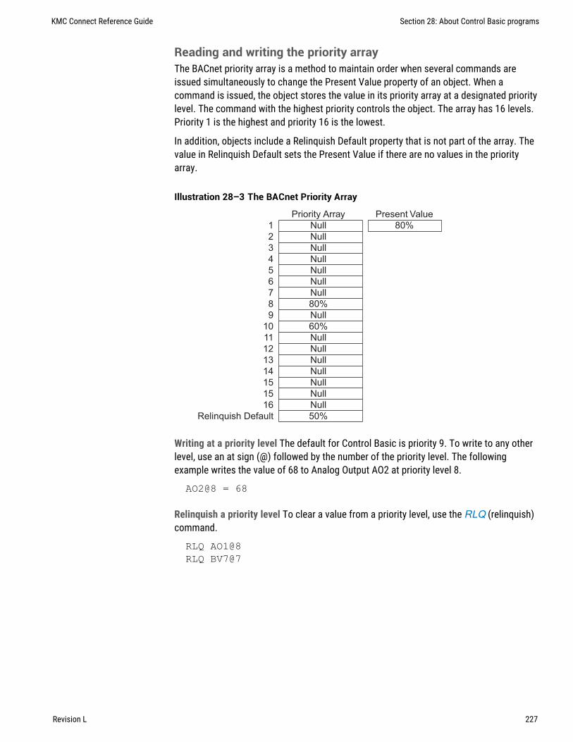
Reading and writing the priority arrayThe BACnet priority array is a method to maintain order when several commands areissued simultaneously to change the Present Value property of an object. When acommand is issued, the object stores the value in its priority array at a designated prioritylevel. The command with the highest priority controls the object. The array has 16 levels.Priority 1 is the highest and priority 16 is the lowest.
In addition, objects include a Relinquish Default property that is not part of the array. Thevalue in Relinquish Default sets the Present Value if there are no values in the priorityarray.
Illustration 28–3 The BACnet Priority Array
Priority Array Present Value
1 Null 80%
2 Null
3 Null
4 Null
5 Null
6 Null
7 Null
8 80%
9 Null
10 60%
11 Null
12 Null
13 Null
14 Null
15 Null
15 Null
16 Null
Relinquish Default 50%
Writing at a priority level The default for Control Basic is priority 9. To write to any otherlevel, use an at sign (@) followed by the number of the priority level. The followingexample writes the value of 68 to Analog Output AO2 at priority level 8.
AO2@8 = 68
Relinquish a priority level To clear a value from a priority level, use the RLQ (relinquish)command.
RLQ AO1@8RLQ BV7@7
KMC Connect Reference Guide Section 28: About Control Basic programs
Revision L 227

Relinquish Default The value in the Relinquish Default property sets the value of thePresent Value property if there are no values in the priority array. The value in RelinquishDefault is persistent through a coldstart in the controller. Add the RELINQUISH_DEFAULT or RD mnemonic to an object mnemonic to read or write to the property.
The following example reads Relinquish Default in Analog Output object AO8.
AV14 = AO8.RD
To conserve the life of the FLASH memory in the controller, do not write to RelinquishDefault on every scan. The following example writes to the Relinquish Default propertyonly when the value at AI1 changes.
IF AI1 <> AV7 THEN AV7.RD = AI1
Transferring values between BACnet controllersIn a BACnet internetwork, controllers rarely operate without communicating with eachother. In controllers from KMC Controls, Control Basic is used for this communication byreading from and writing to off-panel points. However, the rate of reading and writingoff-panel points must be controlled to prevent flooding the network with unnecessarytraffic. The method of controlling the rate of transfer will depend on the version of ControlBasic that the controller supports.
The table Versions of Control Basic lists the version of Control Basic supported byeach model of controller.
Topics in this section
Limits on transferring off-panel BACnet properties 228Using WAIT statements to transfer values 229Using NETPOINT and NETPOINTCACHE to transfer values 230Reading and writing off-panel points with COV 231Using WAIT statements to transfer values 233Using INTERVAL for reading off-panel points 233
Limits on transferring off-panel BACnet propertiesWith Control Basic, a BACnet controller can request a property value from any othercontroller on the BACnet internetwork. The limit on the number of requests varies witheach family of controllers.
BAC-5800 and BAC-7000 series controllers Each BAC-5800 or BAC-7000 seriescontroller can request 128 values from no more than 32 devices.
Section 28: About Control Basic programs KMC Controls, Inc.
228 Revision L

Example: A single controller can make requests for off-panel values as shown in one ofthe following examples:
l Four values each from controllers 1-32l Eight values each from controllers 1-16l Sixteen values from controllers 1,5,6,8 and thirty-two values from controllers 9 and
10.
Note: In firmware earlier than R1.7.0.7 released September 2008, thenumber of requests is limited to 64 requests and 32 devices.
BAC-A1616BC, Flex Stat, and Conquest controllers Program no more than 256 requestsfor off-panel values in BAC-A1616BC, Flex Stat, and Conquest controllers.
See the following related topics for programming examples to read and write off-panelvalues.
l Using WAIT statements to transfer values on page 233l Using NETPOINT and NETPOINTCACHE to transfer values on page 230l The keyword ALIAS on page 248.
Using WAIT statements to transfer valuesIn controllers that support Standard Control Basic, use a WAIT statement to control therate of reading and writing values between controllers Controlling the rate of reading andwriting off-panel points prevents flooding the network with unnecessary traffic.
See also the keyword WAIT on page 329.
Reading properties from other BACnet devices To read a value from another panel, youmust know the panel’s device instance and the object mnemonic. The instance isseparated from the value by a period (.). See the topic Limits on transferring off-panelBACnet properties on page 228 for the number of requests that can be programmed foreach type of controller.
Syntax: device instance.object
Caution: In the following examples, the WAIT statements arerequired. Do not delete them or the program will not run correctly.
REM * Reading from Device 1213, AI7AV24 = 1213.AI7 : REM Reading an off-panel valueWAIT 0:05:00END
KMC Connect Reference Guide Section 28: About Control Basic programs
Revision L 229

Writing values to other controllers To change the value in another BACnet device, youmust know the instance number for the device. The device instance is separated from theobject mnemonic by a period(.).
Syntax: device instance.object[@priority]
REM * Writing a value to Device 201, AV1201.AV1 = AV1 : REM Writing an off-panel valueWAIT 0:05:00END
Using NETPOINT and NETPOINTCACHE to transfer valuesIn controllers that support Generation 5 Control Basic, statements with NETPOINTCACHEand NETPOINT are an efficient method to limit the rate of reading from and writing tooff-panel points. Controlling the rate of reading and writing off-panel points preventsflooding the network with unnecessary traffic.
Follow these basic rules when using NETPOINT and NETPOINTCACHE for off-panelpoints. Additional information can be found by looking in Help topics for the keywords.
l Always use NETPOINT and NETPOINTCACHE together.l NETPOINT sets the interval for reading and writing off-panel points.l NETPOINTCACHE enables a cache of values within a program from off-panel
objects that are referenced with NETPOINT.
See also the keywords NETPOINT on page 291 and NETPOINTCACHE on page 292.
Syntax: NETPOINT(device instance.object.property,read interval,write interval)
l The intervals for reading and writing are expressed in seconds.l If the point is read only then use a NAN in the write interval field.l Within a controller, execute the NETPOINT command only once for each off-panel
object.
Syntax: NETPOINTCACHE(expression)
l Enter one (1) for expression to enable NETPOINTCACHE and COV caching.l Enter zero (0) for expression to disable NETPOINTCACHE and COV caching. This is
the default state in controllers that support Generation 5 Control Basic.l Add NETPOINTCACHE(1) to every program in the controller that uses an off-panel
object that is referenced by the NETPOINT command.
Section 28: About Control Basic programs KMC Controls, Inc.
230 Revision L

The following examples include Control Basic programs that use NETPOINT andNETPOINTCACHE in a single program and a second example that uses NETPOINT in oneprogram and NETPOINTCACHE in a second program.
Example 1: This program is an example of reading one off-panel point.
NETPOINTCACHE(1):REM REM This Turns on the point cachingfor points in this program.IF POWERLOSS=0 THEN
NETPOINT(5.AV1.PV,300,NAN) : REM Cache is updatedevery 300 seconds (5 MINUTES).
ENDIFIF 5.AV1 > 50 THEN START BV1 : REM The value of 5.AV1will be 0 to 300sec oldEND
Example 2: This is an example of retrieving off-panel points in Program 1 and referencingthem in Program 2.
Program 1
IF POWERLOSS=0 THENNETPOINT(5.AV1.PV,300,NAN)NETPOINT(6.AV1.PV,200,NAN)
ENDIFEND
Program 2
NETPOINTCACHE(1)IF 5.AV1 > 50 THEN START BV1 : REM The value of 5.AV1will be 0 to 300sec oldEND
Reading and writing off-panel points with COVIn controllers that support Generation 5 Control Basic, a COV (Change Of Value)subscription transfers data between controllers only when there is a predeterminedchange to a remote value. It is a quick method to receive an update and still limitunnecessary network traffic. Controlling the rate of reading and writing off-panel objectsprevents flooding the network with unnecessary traffic.
Follow these basic rules when using COV for off-panel points. Additional information canbe found by looking in Help for the keyword COV on page 260.
l Within a controller, execute the COV command only once for each off-panel object.l Add NETPOINTCACHE to every program in the controller that uses the off-panel
object that is referenced by the COV command.l For redundancy, combine COV with NETPOINT to periodically update the off-panel
value regardless of change.l Use ERRORLEVEL to detect when a COV subscription is not returning a valid value
from the off-panel point.
KMC Connect Reference Guide Section 28: About Control Basic programs
Revision L 231

See also the keywords NETPOINT on page 291, NETPOINTCACHE on page 292, andERRORLEVEL.
Syntax: COV(device.object.property, lifetime, confirmed, increment )
Two Control Basic examples follow: Example 1 is a single program that sets up the COVsubscription and references the off-panel object in a single program. Example 2 sets upthe subscription in one program and references the object in a second program.
Example 1: In this example, a COV subscription is set up in the same program that usesthe the remote value. When Binary Value object 1 in Device Instance 1 (the remote device)changes from TRUE(1) to FALSE(0) or FALSE(0) to TRUE(1), the value istransferred to the local controller. Then, the local controller uses that value to start orstop the BV1. To provide redundancy, NETPOINT automatically reads BV1 every 300seconds (5 minutes). The statements with COV and NETPOINT run only during the firstscan after a restart.
When using the Control Basic COV method, add error detection with ERRORLEVEL. Whenthe program runs the first time and there is reference to off-panel object BV1, the value isreturned as NAN (Not A Number). The value will continue to be returned as NAN until avalid subscription is established. In addition, NAN is returned if the program requests theoff-panel value and, after three attempts, does not receive a reply. When a valid number isreturned, ERRORLEVEL is FALSE(0) and the COV value for the off-panel BV1 is used.
NETPOINTCACHE(1)IF POWERLOSS THEN
NETPOINT(5.BV1.PV,300,NAN)COV(5.BV1.PV,300,0,1)
ENDIF
IF 5.BV1=1 AND ERRORLEVEL=0 THEN START BV1 ELSE BV1=0END
Example 2: This is an example of initializing a COV subscription to an off-panel point inProgram 1 and referencing the point in Program 2. The logic is similar to Example 1except that Analog Value Object 2 in Device Instance 605 is subscribed for a Change ofValue of 3.0.
Program 1
NETPOINTCACHE(1)IF POWERLOSS THEN
NETPOINT(605.AV2.PV,300,NAN)COV(605.AV2.PV,300,0,3.0)
ENDIF
Program 2
NETPOINTCACHE(1)IF ERRORLEVEL=0 THEN av7=605.AV2
Section 28: About Control Basic programs KMC Controls, Inc.
232 Revision L

Using WAIT statements to transfer valuesIn controllers that support Standard Control Basic, use a WAIT statement to control therate of reading and writing values between controllers Controlling the rate of reading andwriting off-panel points prevents flooding the network with unnecessary traffic.
See also the keyword WAIT on page 329.
Reading properties from other BACnet devices To read a value from another panel, youmust know the panel’s device instance and the object mnemonic. The instance isseparated from the value by a period (.). See the topic Limits on transferring off-panelBACnet properties on page 228 for the number of requests that can be programmed foreach type of controller.
Syntax: device instance.object
Caution: In the following examples, the WAIT statements arerequired. Do not delete them or the program will not run correctly.
REM * Reading from Device 1213, AI7AV24 = 1213.AI7 : REM Reading an off-panel valueWAIT 0:05:00END
Writing values to other controllers To change the value in another BACnet device, youmust know the instance number for the device. The device instance is separated from theobject mnemonic by a period(.).
Syntax: device instance.object[@priority]
REM * Writing a value to Device 201, AV1201.AV1 = AV1 : REM Writing an off-panel valueWAIT 0:05:00END
Using INTERVAL for reading off-panel pointsIn Standard Control Basic, use INTERVAL with an IF THEN statement to control the rate ofreading off-panel points. Controlling the rate of reading and writing off-panel objectsprevents flooding the network with unnecessary traffic.
Example 1: Without error checking
This example is the simplest form of using INTERVAL and assumes that the controller willalways respond correctly. It reads, at one minute intervals, the value of Analog Input AI4 incontroller Device Instance 4410. The value of AI4 is then assigned to Analog Value objectAV24 in the controller running the program.
IF INTERVAL ( 00:01:00 ) THEN AV24 = 4410.AI4
KMC Connect Reference Guide Section 28: About Control Basic programs
Revision L 233

Example 2: Error checking
The program in Example 1 assumes that the controller will always respond correctly to arequest for a value. However, if a controller is off-line or the controller’s Device Instancechanges, an error will result when using INTERVAL.
The program in this example begins by reading, at one minute intervals, the value ofAnalog Input object AI4 in controller Device Instance 4410.
If the program does not detect an error reading the off-panel point, it uses the value from4410.AI4 and jumps to label NO_ERROR to continue evaluation.
If an error is detected, the program jumps to the label FOUND_ERROR and assigns thefixed value “70” to AV24. It then continues to run the program as if no error took place.
Next Generation and Generation 5 Control BasicIF INTERVAL ( 00:01:00 ) THEN AV24 = 4410.AI4ONERROR FOUND_ERRORGOTO NO_ERROR : REM Jump around error recoveryFOUND_ERROR:REM Error recoveryAV24 = 70NO_ERROR: REM Continue program
Standard Control Basic10 IF INTERVAL( 0:01:00 ) THEN AV_24 = 4410.AI420 ONERROR 4030 GOTO 50 : REM Jump around error recovery40 AV_24 = 70 : REM Error recovery50 REM Continue program
Example 3: Validating the value
This example is similar to Example 2 except that it tests to see if the received value is alegitimate BACnet number. The keyword ISNAN tests 4410.AV4 and if it is not valid,substitutes the value of “55”. If 4410.AV4 is valid, the program continues at ELSE and theoff-panel value is used. This example is not supported for Standard Control Basic.
IF INTERVAL ( 00:01:00 ) THENREM Verify that the value is good
IF ISNAN( 4410.AI4 ) THENREM Set a default valueAV24 = 55
ELSEREM Use the received valueAV24 = 4410.AI4
ENDIFENDIF
Section 28: About Control Basic programs KMC Controls, Inc.
234 Revision L

Reading and writing KMD pointsControl Basic programs read from and write to points by using mnemonics or—dependingon the editor used to write the program—the name or description of the point. The typesof points include input and output points as well as points such as variables, schedules,or PID loops. In addition, Control Basic programs can read the value of points in otherKMD controllers on the same network.
l For reference to the list of mnemonics for KMD controllers, see Mnemonics forKMD controllers on page 235.
l To read values from other controllers, see Transferring values with KMDwant-points on page 236.
Mnemonics for KMD controllersMnemonics are short, easy-to-remember abbreviations in Control Basic that refer topoints. For example, a physical input is entered as IN1 in KMD controllers.
Note: The mnemonic codes are different between KMD and BACnetcontrollers.
Control Basic mnemonics for KMD points are listed in the table Control BasicMnemonics for KMD points on page 236. The following line of Control Basic is anexample of using mnemonics to refer to an analog input point and a digital output point.
10 If IN1 < 70 then start out2
l Mnemonics are reserved words and cannot be used for point labels or descriptions.l The column Read Field describes attributes that can be read from that point type,
such as its value or status.l The column Write Field describes attributes that may be changed on a point type
through programming or by direct access, such as its value or status.l The total time in a Runtime Log point is automatically rounded to whole hours.
KMC Connect Reference Guide Section 28: About Control Basic programs
Revision L 235
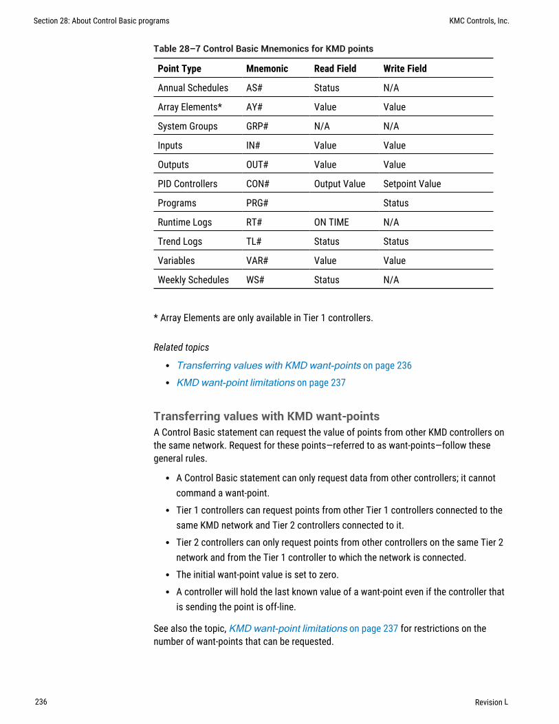
Point Type Mnemonic Read Field Write Field
Annual Schedules AS# Status N/A
Array Elements* AY# Value Value
System Groups GRP# N/A N/A
Inputs IN# Value Value
Outputs OUT# Value Value
PID Controllers CON# Output Value Setpoint Value
Programs PRG# Status
Runtime Logs RT# ON TIME N/A
Trend Logs TL# Status Status
Variables VAR# Value Value
Weekly Schedules WS# Status N/A
Table 28–7 Control Basic Mnemonics for KMD points
* Array Elements are only available in Tier 1 controllers.
Related topics
l Transferring values with KMD want-points on page 236l KMD want-point limitations on page 237
Transferring values with KMD want-pointsA Control Basic statement can request the value of points from other KMD controllers onthe same network. Request for these points—referred to as want-points—follow thesegeneral rules.
l A Control Basic statement can only request data from other controllers; it cannotcommand a want-point.
l Tier 1 controllers can request points from other Tier 1 controllers connected to thesame KMD network and Tier 2 controllers connected to it.
l Tier 2 controllers can only request points from other controllers on the same Tier 2network and from the Tier 1 controller to which the network is connected.
l The initial want-point value is set to zero.l A controller will hold the last known value of a want-point even if the controller that
is sending the point is off-line.
See also the topic, KMD want-point limitations on page 237 for restrictions on thenumber of want-points that can be requested.
Section 28: About Control Basic programs KMC Controls, Inc.
236 Revision L

Syntax for want-pointsTo designate a want-point, add the controller panel number to the front of the mnemonic.Use the same Control Basic mnemonics that designate local points to designatewant-points. The exact format will depend on whether the want-point request comes fromwithin a Tier 1 or Tier 2 controller. See Mnemonics for KMD controllers on page 235.
Control Basic want-point examplesThe format for Tier-1 and Tier 2 want-points is slightly different. Examples are shown foreach type of controller.
Tier 1 examples In Tier 1 controllers, refer to Tier 2 controllers by their network letter andpanel number. Model KMD-5210, the Lan Controller, has both A and B networks. KMD-5205 and KMD-5270 have only an A network but, the letter A must be used.
10 VAR3 = A4OUT320 VAR4 = B4IN4
Refer to points in other Tier 1 controllers by their panel number.
10 VAR5 = 4IN6
Tier 2 examples In the Control Basic running in a Tier 2 controller, use address 0 (zero)for the Tier 1 controller regardless of the controller’s panel number.
10 VAR1 = 0IN1
For Tier 2 controllers on the same Tier 2 network, use the remote controller’s panelnumber.
10 VAR2 = 1OUT2
KMD want-point limitationsKMC direct digital controllers read values from points in controllers across a network byrequesting want-points. These requests create a want-point list that is filled and refreshedas each controller puts data on the network. However, there are restrictions on thenumber of points that can be transferred.
l Tier-to-Tier transfer limitationsl Total want-points transferredl Tier 2 extended pointsl Transfer time
KMC Connect Reference Guide Section 28: About Control Basic programs
Revision L 237
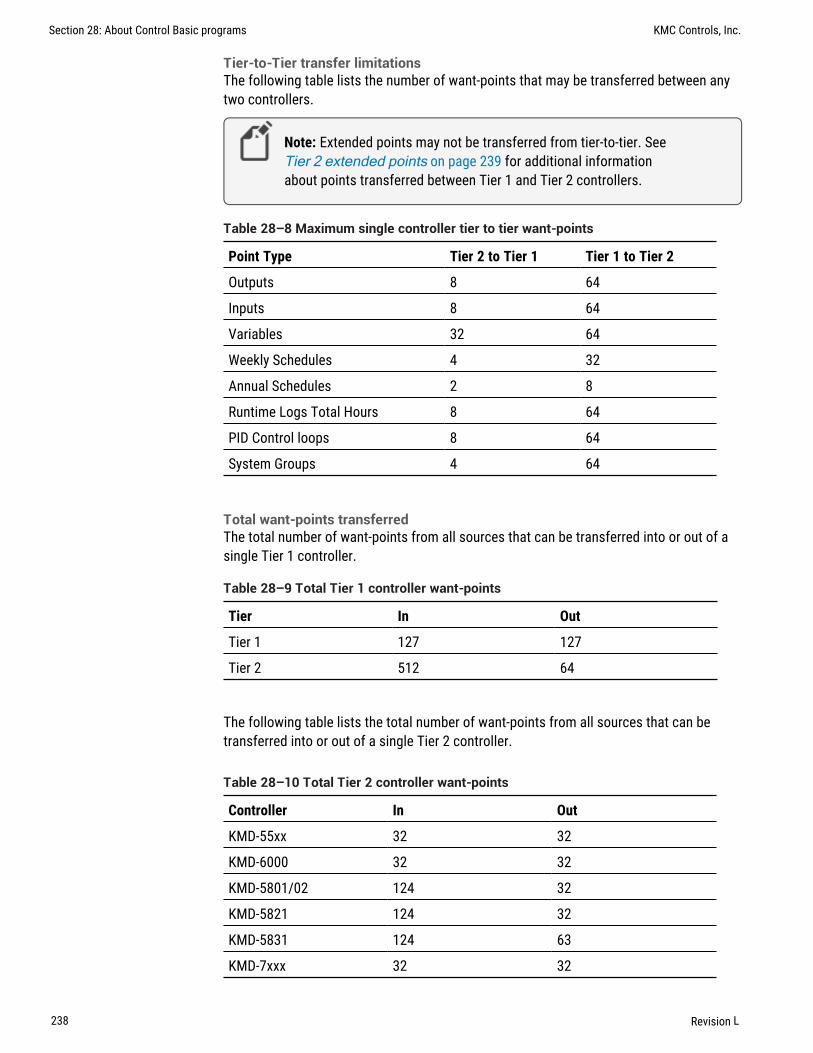
Tier-to-Tier transfer limitationsThe following table lists the number of want-points that may be transferred between anytwo controllers.
Note: Extended points may not be transferred from tier-to-tier. SeeTier 2 extended points on page 239 for additional informationabout points transferred between Tier 1 and Tier 2 controllers.
Point Type Tier 2 to Tier 1 Tier 1 to Tier 2
Outputs 8 64
Inputs 8 64
Variables 32 64
Weekly Schedules 4 32
Annual Schedules 2 8
Runtime Logs Total Hours 8 64
PID Control loops 8 64
System Groups 4 64
Table 28–8 Maximum single controller tier to tier want-points
Total want-points transferredThe total number of want-points from all sources that can be transferred into or out of asingle Tier 1 controller.
Tier In Out
Tier 1 127 127
Tier 2 512 64
Table 28–9 Total Tier 1 controller want-points
The following table lists the total number of want-points from all sources that can betransferred into or out of a single Tier 2 controller.
Controller In Out
KMD-55xx 32 32
KMD-6000 32 32
KMD-5801/02 124 32
KMD-5821 124 32
KMD-5831 124 63
KMD-7xxx 32 32
Table 28–10 Total Tier 2 controller want-points
Section 28: About Control Basic programs KMC Controls, Inc.
238 Revision L

Tier 2 extended pointsThe KMD-5800 series of controllers have points not found in the original generation ofKMD controllers. These additional points are referred to as extended points and canonly be transferred as follows:
l Extended points can be shared across the network with other KMD-5800 or KMD-7000 series controllers.
l Extended points cannot be shared with KMD-5500 or KMD-6000 series controllers.l Extended points cannot be shared with attached Tier 1 controllers.
The table KMD–5800 Series extended points on page 239 summarizes the extendedpoints found in the KMD–5800 series controllers.
Tip: To transfer an extended point to a Tier 1 controller (either aKMD-5100 or KMD-5200 series controller), assign the value to avariable within the source controller and then share the variable withthe Tier 1 controller.
Controller Input Output Variables PID ControlLoops
System Groups WeeklySchedules
AnnualSchedules
KMD-5801 33-64
KMD-5802 33-64
KMD-5821 33-64
KMD-5831 9-16 9-12 33-128 9-16 5-8 5-8 3-4
Table 28–11 KMD–5800 Series extended points
Transfer timeThe time to transfer want-points depends on the type of controller and firmware version.
Tier 1 Tier 1 controllers send want-points at regular intervals. The interval depends uponthe version of firmware in the controller.
Firmware build 1.213 and later want-points are transferred every 20-25 seconds.
Prior to firmware build 1.213 want-point transfer time is calculated as follows:
want-points = Number of controllers x 3
Tier 2 A Tier 2 want-point list is not immediately filled or refreshed. Each time the token ispassed to a controller, the protocol permits the controller to transmit up to eight points. Afull controller, with 32 points to put onto the network, will have all of its informationpassed only every fourth time the token passes by.
KMC Connect Reference Guide Section 28: About Control Basic programs
Revision L 239

User-defined functions and proceduresUser-defined functions and procedures are programming techniques that can improveprograms in the following ways.
l They divide long and complicated programs into smaller, more manageablemodules.
l They are a method to avoid repeated programming steps within a Control Basicprogram.
Note: Applies only to controllers with Generation 5 Control Basic.
See the related keywords PROCEDURE on page 305 and FUNCTION on page 274.
Rules for functions and procedures.
l All functions and procedures must have unique names. The names cannot duplicateControl Basic keywords, object names, or descriptions.
l If you use a function or procedure, then all Control Basic statements in that programobject must be part of a function or procedure.
l If a program object includes a function or procedure it must also include oneprocedure named main. The main procedure represents the starting point of theprogram.
l Function and procedure declarations cannot be nested inside other functions orprocedures.
l Functions and procedures can call other functions and procedures.l A function or procedure cannot use a GOTO, ON GOTO, GOSUB, or ON GOSUB that
branches to a location outside of the function or procedure.l A function or procedure cannot have an IF or FOR that crosses the boundaries of a
function or procedure.l Local variables declared inside of a procedure or function are not accessible outside
of the procedure.l The number of procedures and functions in a program object is limited only by
available memory.
Functions A function is a self-contained block of statements that return a single value tothe point from where it was called or referenced.
Functions are called from within an expression in place of a variable or constant byspecifying the keyword FUNCTION followed by a list of arguments. The arguments areenclosed in parentheses and separated by commas. When a function is called, the valuesof the arguments are passed to the local variables in the function in the same order thatthey occupy in the list. The names of the arguments in the function reference need not bethe same as those in the function definition. The arguments can be expressed asconstants, variables, or expressions. However, the number of arguments must be thesame and the data types of the arguments must match.
Section 28: About Control Basic programs KMC Controls, Inc.
240 Revision L

When all of the statements have been executed, control is returned to the statementimmediately following the point from where the function was called.
Example of a function In the following example, local variable DialSp will always fallwithin the range set by constants LoCoolingSp and HiHeatingSp.
CONST LoCoolingSp = 68CONST HiHeatingSp = 75REM AI1 is the septoint on a sensor dial.
FUNCTION validateSp(s, l, h) s = MAX(s, l) s = MIN(s, h) FRETURN sENDFUNC
PROCEDURE main() LOCALS DialSp DialSP = validateSp(AI1, LoCoolingSP, HiHeatingSP)ENDPROC
Procedures A procedure is a self-contained block of statements that performs a task. Aprocedure is called by name from any location except from within an expression.
Procedures are defined with the keyword PROCEDURE, followed by a name for theprocedure. The procedure definition may also include one or more arguments that areenclosed in parentheses and separated by commas. When a procedure is called, thevalues of the arguments are passed to the local variables in the procedure in the sameorder that they occupy in the list. The names of the arguments in the procedure referenceneed not be the same as those in the procedure definition. The arguments can beexpressed as constants, variables, or expressions. However, the number of argumentsmust be the same and the data types of the arguments must match.
When all of the statements have been executed, control is returned to the statementimmediately following the point from where the procedure was called.
Example of a procedure In the following example, the lowest of two temperatures issaved in Analog Value object AV1 to use as the outside air temperature.
LOCALS oat1, oat2PROCEDURE lowOAT(a,b) AV1 = MIN(a,b)ENDPROC
PROCEDURE main() oat1 = AI1 oat2 = AI2 lowOAT(oat1,oat2)ENDPROC
KMC Connect Reference Guide Section 28: About Control Basic programs
Revision L 241

BACnet arrays and dynamic accessControllers that support Generation 5 Control Basic support arrays and dynamic access.For a list of controllers, see the topic Control Basic versions in controllers on page677.
Arrays An array is a set of values—such as the highest daily temperature—that arelogically related to each other. The individual values are called the elements of the array.You can then refer to individual elements by the array name and a number—the index—totell them apart. The elements are numbered starting at zero (0) up to the size of the array.
Dynamic access Dynamic access is similar to using an array but uses an index to point toeither a BACnet object or device instead of pointing to an array element.
In the following example, Control Basic stores the last seven readings of Analog Inputobject AI3 in a seven-element array and in Analog Value objects 1-7. The oldest reading isstored in array element zero (0); the newest is in array element 6.
l A seven-element array (seventemps) and a local variable (x) are declared.l A FOR TO NEXT loop moves array elements 1-6 to elements 0-5.l The newest temperature reading from Analog Input object AI3 is stored in element
6.l A second FOR TO NEXT loop moves the values from array elements 0-6 to Analog
Value objects 1-7.l Finally, the program waits for 30 seconds before repeating the process.
REAL seventemps[7]INTEGER x
FOR x = 0 TO 5 seventemps[x] = seventemps[x + 1]NEXT x
seventemps[6] = AI3
FOR x = 0 TO 6 AV[x+1] = seventemps[x]NEXT x
WAIT(00:00:30)
To declare arrays, see the following topics.
l LOCALS on page 286l INTEGER on page 282l REAL on page 307l STRING on page 320
Section 28: About Control Basic programs KMC Controls, Inc.
242 Revision L

BACnet data typesA data type is a classification identifying a type of data, such as integer, real, or string thatdetermines the possible values for that type. It also defines the operations that can beperformed on values of that type, the meaning of the data, and the way values of that typecan be stored and used by properties in controllers.
Integer Holds a signed 32-bit (4-byte) integer in value from -2,147,483,648 through2,147,483,647.
Real Holds a signed IEEE 32-bit (4-byte) single-precision floating-point number ranging invalue from -3.4028235E+38 through -1.401298E-45 for negative values and from1.401298E-45 through 3.4028235E+38 for positive values.
String Holds sequences of the ASCII letters and symbols on a standard U.S. keyboard.
See the following topics for a complete description and the procedure to declare variablesas the following data types.
l INTEGER on page 282l STRING on page 320l REAL on page 307l Generation 5 data types on page 243
Generation 5 data typesTo maintain compatibility with current and future BACnet standards, the Generation 5version of Control Basic expands the use of data types. This includes support for String,Signed Integer, and Unsigned Integer data types. This expansion also changes the wayControl Basic uses data type Real. This results in some issues with division and lone-value variable assignment.
Division issues When performing division, if either the dividend or the divisor is data typeReal, the result—the quotient—is also data type Real. However, if both parts of the divisioncalculation are data type Integer, the result is data type Integer. This results in an errorwhen the division is used with a BACnet property that is data type Real, for example thePresent Value property in an Analog Value object. The following statement producesunexpected results because the Present Value in AV1 is expecting data type Real, but thedivision operation quotient is data type Integer.
AV1=1/2
To correct the calculation, add a decimal point to one or both of the values.
AV1=1.0/2 AV1=1/2.0 AV1=1.0/2.0
Lone-value variables The data type issue is found also with the assignment of lone-valuevariables. Lone-value variables are the variables in an equation whose only purpose isassigning a value to the variable. The following example produces the same errorpreviously shown for division.
KMC Connect Reference Guide Section 28: About Control Basic programs
Revision L 243

A=1B=2AV1=A/B
The correction is the same as with the division error. Add a decimal point to one of thevariables.
A=1.0B=2AV1=A/B
A=1B=2.0AV1=A/B
A=1.0B=2.0AV1=A/B
Complex equations For complex equations—equations that include several operations—some parts of the equations may be calculated as data type Integer and other parts asdata type Real. When the equation is evaluated, the data type for the result is determinedby the order that the equation is evaluated. In the following example, 1/2 is evaluated firstand sets the data type as Integer. Then, the result is divided by 4.0, but because the datatype is already set as data type Integer, the result is also data type Integer even throughthere is a decimal point in the number.
AV1=1/2/4.0
Correct the problem by adding a decimal to the part of the equation that is evaluated firstby Control Basic.
AV1=1/2.0/4
Summary of the rules
l Division results in a data type of Integer unless a decimal point is added to a numberin the equation.
l Lone-value variable assignment (a=1) is data type Integer.l In complex equations, the data type established first is the data type for the entire
result. The hierarchy of evaluation is parentheses, exponents, division,multiplication, addition, subtraction.
l If either part of a calculation is data type String, then the other side is converted todata type String.
l If either part of a calculation is data type Real, then the other side is converted todata type Real.
l If either part of a calculation is data type Integer, then the other side is converted todata type Integer.
See also the topic BACnet data types on page 243 and Hierarchy of operators onpage 219.
Section 28: About Control Basic programs KMC Controls, Inc.
244 Revision L

Section 29: Keywords for Control Basic
This section covers the keywords for the Control Basic programming language.
Control Basic reserves keywords for operators, commands, and functions. Thesekeywords may not be used for descriptors, labels or names of points, objects, variables, orprocedures.
To refer to KMC points in Control Basic programs, see the topic Mnemonics for KMDcontrollers on page 235.
To refer to BACnet objects in Control Basic programs, see the topic Mnemonics forBACnet controllers on page 223.
Using example programs from helpYou can use example programs listed in this document. Highlight the example and thencopy the example and paste it into a Control Basic program.
Syntax for commands and functionsRequired spaces are shown with underscore marks ( _ ) and indicate that a space must beincluded for proper syntax. Optional items are shown in brackets [ ].
ABSThis function returns the absolute value of the expression. The expression can be a singlenumber or the result of a calculation.
Syntax: ABS(_expression_)
Standard Control Basic example
Returns 2.3, the absolute value of -2.3.
A = ABS( -2.3 )
Returns the absolute value from the result of the calculation.
C = ABS( AV1 - AI1 )
Next Generation Control Basic example
Returns 2.3, the absolute value of -2.3.
A=ABS(-2.3)
Returns the absolute value from the result of the calculation.
C=ABS(AV1 - AI1)
KMC Connect Reference Guide
Revision L 245

KMD example
Returns 2.3, the absolute value of -2.3.
A = ABS( -2.3 )
Returns the absolute value of the result of the calculation.
C = ABS( SETPOINT - SPACETMP )
ALARMThe ALARM statement initiates an alarm notification from a KMD controller. It may alsoinitiate a dialing sequence in a modem connected directly to the controller in which thealarm notification is created.
Syntax: ALARM_expression_,_differential_,_string
Note: For KMDigital controllers only.
Expression The expression parameter defines a condition that triggers the alarm. It isexpressed as a conditional such as X_<_Y or X_>_Y or X_=_Y. The values for X and Y canbe any number, variable, input, or output in any controller. Spaces within the expressionare required and are indicated by the underscore (_).
Differential The differential parameter defines a dead band. The alarm returns to normalafter the condition is outside of the dead band. Using differential minimizes multiplealarms when conditions change rapidly between alarm conditions.
String This is the text message that is added to the alarm viewer list. The message maybe up to 69 characters long.
The following examples sets up alarms when the temperature measured at Input IN1drops below 34 degrees. Once triggered, the alarm will not clear until the air temperaturerises to or above 37 (34+3) degrees. The differential value eliminates multiple alarms ifthe temperature cycles rapidly between 33.9 and 34.0 degrees.
ALARM IN1 < 34 , 3 , Air temperature is close tofreezing.
Use the following alarm message for TotalControl alarms. The text immediately following$$D indicates the address of the controller that generated the alarm. This is explained indetail under Setting up routing for TotalControl alarms on page 246.
ALARM IN1 < 34 , 3 , $$D5/A/13/IN1 Air temperature isclose to freezing.
Setting up routing for TotalControl alarms
Without TotalControl alarm routing, the text defined by string will be added to the alarmviewer but not the point of the alarms origin. To use TotalControl alarm routing, you mustadd to string information about the point that originated the alarm. The format is shownin the illustration, ALARM on page 246.
Section 29: Keywords for Control Basic KMC Controls, Inc.
246 Revision L

Illustration 29–1 Alarm routing message string for KMD controllers
Escape stringTier 1 controller number
Tier 2 network A or BTier 2 controller number
PointText message
$$D5/A/13/VAR15 Message
ALARM VAR15 < 68 , 0 , $$D1/A/13/VAR15 Gym belowsetpoint!
For WinControl XL email routing
To duplicate the WinControl XL Plus email feature, create one or more alarm classesnamed E1-E8.
Add the alarm class to the alarm message string as shown in the following example:
ALARM IN4 > 85 , 3 , E1 Area temp too high
For pager notification
By adding the CALL, NPAGE, or TPAGE options to the ALARM text string, the controller willinitiate a modem dialing sequence for pagers or another computer running WinControl XL.The KMD Tier 1 controller that initiates the alarm must have a modem connected to it forpager notification.
Alarm device String option
Numeric pager NPAGE(_1234567_)_5555555
Text pager TPAGE(_1234567-1234_)_Message
Table 29–1 Pager message string options
ALARM AIR/TP < 34 , 3 , NPAGE( 1234567 ) 5555555ALARM AIR/TP < 34 , 3 , TPAGE( 1234567 1234 ) Message
Related topics
l DALARM on page 262l NPAGE on page 294l PHONE on page 302l TPAGE on page 328
KMC Connect Reference Guide Section 29: Keywords for Control Basic
Revision L 247

ALIASUse ALIAS to read from and write to off-panel objects. ALIAS declares a local variable anddynamically binds the value of a property to that variable. The syntax for ALIAS is slightlydifferent between Next Generation and Generation 5 Control Basic.
l For the KMC Controls Building Controller and FlexStat, see ALIAS for NextGeneration Control Basic.
l For Conquest controllers, see ALIAS for Generation 5 Control Basic on page250.
See also the related topic FLUSH on page 273.
ALIAS for Next Generation Control Basic
ALIAS declares a local variable and dynamically binds the value of a property to thatvariable. It also sets two intervals at which Control Basic will read from or write to theproperty bound to the variable.
Syntax: ALIAS(device, object, property[priority], local, read interval, write interval)
Note: Applies only to controllers with Next Generation Control Basic.
The same point may be bound to an ALIAS statement in more than one program. However,the shortest read or write interval of all ALIAS statements within the device is used in allprograms.
Parameter Description Comments
device The device instance number orname.
Enclose the name of a devicewith quotation marks (" ").Names are case sensitive.
object A valid mnemonic See Mnemonics forBACnet controllers on page223.
property The property of the off-panel object.
priority The priority for writing. If no priority is designated,the default value is @9.Priority is ignored for objectswithout a priority array suchas inputs.
local The local variable to use within theprogram
Use as a local variable withinthe Control Basic program inwhich ALIAS is declared.
Table 29–2 Parameter for Next Generation ALIAS
Section 29: Keywords for Control Basic KMC Controls, Inc.
248 Revision L

Parameter Description Comments
read interval The interval, in seconds, at whichControl Basic will read the property
To never read from theobject, use NONE. Thedefault value is 60 seconds.
write interval The interval, in seconds, at whichControl Basic will write to theproperty
To never write to the object,use NONE. The default valueis NONE.
Table 29–2 Parameter for Next Generation ALIAS (continued)
Reading off-panel objects The following Control Basic example binds the present value ofAnalog Input object 1 in device 1212 to the local name LocalOAT. Control Basic readsthe value of off-panel object AI1 every 10 minutes. The value of LocalOAT is then usedto set the value of local object AV1.
ALIAS(1212, AI1, PV, LocalOAT, 00:10:00, NONE)AV1=LocalOAT
Writing to off-panel objects The following Control Basic example binds the present valueof Binary Value object BV1 in the device named "RTU" to the local nameGlobalOccupied. Control Basic writes the state of the local Binary Value object BV1 tothe off-panel BV1 every four minutes.
ALIAS("RTU", BV1, PV@8, GlobalOccupied, NONE, 00:04:00)GlobalOccupied=BV1
The last example binds the value of the Analog Input object AI2 to the local variableOutsideAirTemp. When the device name is omitted, Control Basic binds the localvariable to the device with the lowest device instance that contains an Analog Input objectAI2.
ALIAS("", AI2, PV, OutsideAirTemp, 100, NONE)AV1=OutsideAirTemp
KMC Connect Reference Guide Section 29: Keywords for Control Basic
Revision L 249

ALIAS for Generation 5 Control Basic
This statement declares a local variable and dynamically binds the value of a property tothat variable.
Syntax: ALIAS(device, object, property[priority], local)
Note: Generation 5 Control Basic only.
Note: For accessing off-panel points with Generation 5 Control Basiccompatible controllers, use either NETPOINT or COV on page260.
The same point may be bound to an ALIAS in more than one program. See also the relatedtopic FLUSH on page 273.
Parameter Description Comments
device The device instance number Enclose the name of a devicewith quotation marks (" ").Names are case sensitive.
object A valid mnemonic See Mnemonics forBACnet controllers on page223.
property The property of the off-panel object.
priority The priority for writing. If no priority is designated,the default value is @9.Priority is ignored for objectswithout a priority array suchas inputs.
local The local name to use within theprogram
Use as a local variable withinthe Control Basic program inwhich the alias is declared.
Table 29–3 Parameters for Generation 5 ALIAS
In the following example, Control Basic binds the present value of Binary Output objectBO1 in device 1212 to the local name Lights.
ALIAS(1212, BO1, PV@4, Lights)
The last example binds the value of the Analog Input object AI2 to the local variableOutsideAirTemp. When the device argument is omitted, Control Basic binds the localvariable to the device with the lowest device instance that contains an Analog Input objectAI2.
ALIAS("", AI2, PV, OutsideAirTemp)
Section 29: Keywords for Control Basic KMC Controls, Inc.
250 Revision L

ANDAND is a Boolean operator that performs the logical AND of two expressions. The resultis true if both expressions are non-zero; otherwise, the result is false.
Syntax: result = expression1 AND expression2
In the following example, local variable C will always equal 1 as long as both localvariables A and B = 1
A = 1 : B = 1 : C = A AND B
See the related topic Using Boolean logic on page 221.
ARCCOSReturns the arccosine of the specified angle. Angle is expressed in radians.
Syntax: ARCCOS( angle )
Note: For BACnet controllers only. See COS-1 on page 260 for KMDcontrollers.
A = ARCCOS( AV1 )
See the related topic COS on page 260.
ARCSINReturns the arcsine of the specified angle. Angle is expressed in radians.
Syntax: ARCSIN( angle )
Note: For BACnet controllers only. See SIN-1 on page 316 for KMDcontrollers.
A = ARCSIN( AI8 )
See the related topic SIN on page 317.
KMC Connect Reference Guide Section 29: Keywords for Control Basic
Revision L 251

ARCTANReturns the arctangent of the specified angle. Angle is expressed in radians.
Syntax: ARCTAN( angle )
Note: For BACnet controllers only. See TAN-1 on page 321 for KMDcontrollers.
A = ARCTAN( AV12 )
See the related topic TAN on page 321.
AVGThis statement returns the average value of the items enclosed in parenthesis. In thefollowing example, local variable D equals the average of analog inputs 1, 3 and 6.
Syntax: AVG(_expression_,_expression_...)
Standard BACnet Control Basic exampleD = AVG( AI1 , AI3 , AI6 )
Next Generation Control Basic exampleD=AVG(AI1, AI3, AI6)
KMD exampleD = AVG( IN1 , IN3 , IN6 )
Section 29: Keywords for Control Basic KMC Controls, Inc.
252 Revision L

BAC-GETReturns the present value from an object in a BACnet device. The BACnetdevice instance number must be in the range from 1 to 4,194,303. The BACnet object iscomposed of the object type and the object number.
Syntax: BAC-GET (_device number_,_object_)
Note: BACnet licensed KMD Tier 1 controllers only.
Object type Mnemonic to use
Analog Input AI
Analog Output AO
Binary Input BI
Binary Output BO
Analog Value AV
Binary Value BV
Table 29–4 Supported BACnet object types
In the following example, ON-ERROR redirects the program if a BACnet error occurs.WAIT on line 40 halts program execution while the BACnet device responds to theprogram.
A = BAC-GET( 1 , AV01 )ON-ERROR 40VAR10 = AWAIT 0:00:30 : REM Line 40
KMC Connect Reference Guide Section 29: Keywords for Control Basic
Revision L 253

BAC-RLQBAC-RLQ relinquishes control to the specified priority to the object in the BACnetdevice. The BACnet device instance number must be in the range from 1 to 4,194,303.The BACnet object is composed of the object type (see the table Supported BACnetobject types on page 253 ) and the object number. The priority number must be in therange of P1 to P16. See the table Standard BACnet priorities on page 254 for theBACnet standard priority levels.
Syntax: BAC-RLQ( device instance , object , priority )
Note: For BACnet licensed KMD Tier 1 controllers only.
Priority Level BACnet Standard Priority
P1 Manual-Life Safety
P2 Automatic -Life Safety
P3
P4
P5 Critical Equipment Control
P6 Reserved for minimum On/Off time
P7
P8 Manual Operator
P9 Default for Control Basic
P10–P16
Table 29–5 Standard BACnet priorities
In the following example, ON-ERROR redirects the program if a BACnet error occurs. TheWAIT statement halts program execution while waiting on a response from the BACnetdevice.
BAC-RLQ( 54321 , AO14 , P12 )ON-ERROR 40WAIT 0:00:30REM Program continues at Line 40
Section 29: Keywords for Control Basic KMC Controls, Inc.
254 Revision L

BAC-SETThis command sends a value at the specified priority, to a point in a BACnet device. TheBACnet device instance number must be in the range from 1 to 4,194,303. The BACnetobject is composed of the object type (see the table Supported BACnet object typeson page 253) and the object number.
Syntax: BAC-SET ( device instance , object , priority , value )
Note: BACnet licensed KMD Tier 1 controllers only.
In the following example, ON-ERROR redirects the program if a BACnet error occurs. WAITon line 30 halts program execution while the BACnet device responds to the program.
BAC-SET( 5 , BO14 , P9 , VAR10 )ON-ERROR 40WAIT 0:00:30REM Continue program here at Line 40
BINDBinds a BACnet device instance to a physical network address. This is typically used tobind an MS/TP slave device to a master device.
Syntax: BIND (device, network, mac, option)
Note: For Next Generation Control Basic only.
Parameter Description Comments
device The instance number of thedevice.
network The number of the BACnetnetwork on which the deviceresides.
May be expressed as decimal orhexadecimal notation. Use zero (0) as thelocal network.
mac The MAC address of thedevice.
Table 29–6 BIND parameters
KMC Connect Reference Guide Section 29: Keywords for Control Basic
Revision L 255

Option Description
Hint Sets the default address but uses whatever can be found by the controller.This is the default state.
Locked Forces the default address back to this every time it changes.
Table 29–7 BIND options
Examples:BIND (550013,1,13)BIND(123456, 678, 0x24 )BIND(123456, 0x44, 09:88:77:55:44:55 )BIND(123456, 0x4, 10.1.2.3:678 )Bind(123456, 0x4, 10.1.2.3:678 , LOCKED)BIND(123456, 0, 10.1.2.3:678 , HINT )
BUILD-NUMBERThis function returns the firmware version number stored in the controller.
Note: For KMD controllers only.
VAR10 = BUILD-NUMBER
CLEARResets the value of all local variables—variables labeled A-Z and declared variables—tozero.
CLEAR
CLEAR-COUNTResets the error count in a KMD Tier 2 controller to zero.
Note: For KMD Tier 2 controllers only.
A = CLEAR-COUNT
See the related topic ERROR-COUNT on page 272.
Section 29: Keywords for Control Basic KMC Controls, Inc.
256 Revision L

CLOSESets the value of a named point, KMD variable, binary output or value object to off.
Syntax: CLOSE_point
Standard BACnet Control Basic exampleCLOSE BO2CLOSE A
Next Generation Control Basic exampleCLOSE BO2CLOSE A
KMD exampleCLOSE VAR1CLOSE A
Related topics
l OPEN on page 299l START on page 318l STOP on page 319
CONBIASCONBIAS sets the bias property of a PID control loop. PIDcontroller is the number ofthe PID control loop within the controller. Expression is the new bias value within therange of 0–100. The value for Expression can also be a variable or a computation.
Note: For KMD controllers only. For BACnet controllers, see the topicMnemonics for BACnet controllers on page 223.
Syntax: CONBIAS(_PIDcontroller_,_Expression_)
CONBIAS( 1 , 1.1 )
Related topics
l CONPROP on page 258l CONRATE on page 258l CONRESET on page 259
KMC Connect Reference Guide Section 29: Keywords for Control Basic
Revision L 257

CONPROPCONPROP sets the proportional band of a PID control loop. PIDcontroller is the PIDcontrol loop number. Expression is the new proportional band value within the range of0-4000. The expression can also be a variable or a computation.
Note: For KMD controllers only. For BACnet controllers, see the topicMnemonics for BACnet controllers on page 223.
Syntax: CONPROP(_PIDcontroller_,_Expression_)
In the following example, if VAR1 is less than 3, the proportional band on controller #1 willbe set to 10, otherwise the proportional band will be set to 50.
IF VAR1 < 3 THEN CONPROP( 1 , 10 ) ELSE CONPROP( 1 , 50 )
Related topics
l CONBIAS on page 257l CONRATE on page 258l CONRESET on page 259
CONRATEUsed to change the rate (derivative component) of a PID control loop. PIDcontroller isany controller in the network. Expression is the new rate to set within the range of 0–2.00. The value for Expression can also be a variable or a computation.
Note: For KMD controllers only. For BACnet controllers, see the topicMnemonics for BACnet controllers on page 223.
Syntax: CONRATE(_PIDcontroller_,_Expression_)
IF VAR1 < 3 THEN CONRATE( 1 , 1.3 ) ELSE CONRATE( 1 , 0.7)
Related topics
l CONBIAS on page 257l CONPROP on page 258l CONRESET on page 259
Section 29: Keywords for Control Basic KMC Controls, Inc.
258 Revision L

CONRESETUse CONRESET to change the reset rate (integral term) of a PID control loop in a KMDcontroller. Controller# is any PID control loop in the network. Expression is the numberof allowable resets per hour within the range of 0–255. The value for Expression canalso be a variable or a computation.
Note: KMD controllers only. For BACnet controllers, see the topicMnemonics for BACnet controllers on page 223.
Syntax: CONRESET(_controller#_,_Expression_)
IF VAR1 < 3 THEN CONRESET( 1 , 25 ) ELSE CONRESET( 1 , 20)
Reset for controller #1 is 20 unless variable VAR1 is less than 3; then reset will be set to25.
Related topics
l CONBIAS on page 257l CONPROP on page 258l CONRATE on page 258
CONSTUse to declare a variable and assign to it a fixed value. Do not use with variables thatchange with subsequent steps in the program.
Syntax: CONST, variable[, variable, ...]
Note: For Next Generation Control Basic only.
Rules for using constants:
l Constants must be declared before they are used in a program. A constant may bedeclared anywhere in the program, but typically it is at the beginning of the program.
l Must start with a letter A-Z, a-z, or an underscore (_). Constants are not casesensitive.
l Can be any combination of letters (A-Z or a-z), numbers (0-9), or the underscore (_).l A constant may be used only within the program in which it is declared.l A constant cannot duplicate a keyword, local variable, label, or alias.
CONST Freeze = 32CONST Boiling = 212
KMC Connect Reference Guide Section 29: Keywords for Control Basic
Revision L 259

To declare local variables or arrays, see the following topics:
l INTEGER on page 282l LOCALS on page 286l REAL on page 307l STRING on page 320
COSReturns the cosine value of a specified angle. Angle is expressed in radians.
Syntax: COS(_angle_)
BACnet examples
Standard BACnet Control Basic example10 A = COS( AV1 )
Next Generation Control Basic exampleA = COS(AV1)
KMD exampleA = COS( VAR10 )
COS-1Returns the arccosine of the specified angle. Angle is expressed in radians.
Syntax: COS-1(_angle_)
Note: Deprecated for BACnet controllers. See the keywordARCCOS on page 251.
A = COS-1( VAR10 )
COVThe COV command sets up an off-panel object for a COV (Change of Value) subscription.The object must be in a device that supports COV subscriptions. It applies to all readaccesses in a program regardless of location.
Syntax: COV(device.object.property, lifetime, confirmed, increment )
Note: Applies only to controllers with Generation 5 Control Basic.
l Within a controller, execute the COV command only once for each off-panel object.l Add NETPOINTCACHE to every program in the controller that uses the off-panel
object that is referenced by the COV command.l Combine COV with NETPOINT to periodically update the off-panel value
Section 29: Keywords for Control Basic KMC Controls, Inc.
260 Revision L

regardless of change.l Use ERRORLEVEL to detect when a COV subscription is not returning a valid
value from the off-panel point.
Parameter Description Comments
device The device instance number of thedevice that contains the subscribedobject.
object A valid Control Basic objectmnemonic.
See Mnemonics forBACnet controllers onpage 223.
property Present value (PV) is typically theproperty.
Priority is ignored for readonly objects such as inputs.
lifetime The time, in seconds, for the lifetimeof the COV subscription.
confirmed Enter 1 (one) for a confirmedsubscription and 0 (zero) for anunconfirmed subscription.
increment The increment for the change ofvalue that the subscribed object willreport.
Table 29–8 COV parameters
In the following example, the COV statement sets up a subscription to Binary Value objectBV1 in controller Device Instance 5. It also sets up NETPOINT to read the value of BV1every 300 seconds (5 minutes). The statements with COV and NETPOINT run only duringthe first scan after a restart.
Error detection is added with ERRORLEVEL. When the program executes the first time andthere is reference to off-panel object BV1, the value is returned as NAN (Not A Number).The value may continue to be returned as NAN until a valid subscription is established. Inaddition, NAN is returned if the program requests the off-panel value and after threeattempts does not receive a reply. When a valid number is returned, ERRORLEVEL isFALSE(0) and the COV value for the off-panel BV1 is used.
NETPOINTCACHE(1)IF POWERLOSS THEN
NETPOINT(5.BV1.PV,300,NAN)COV(5.BV1.PV,300,0,1)
ENDIF
IF 5.BV1=1 AND ERRORLEVEL=0 THEN START BV1 ELSE BV1=0END
KMC Connect Reference Guide Section 29: Keywords for Control Basic
Revision L 261

To use 5.BV1 in other programs within the same controller, add only theNETPOINTCACHE(1) command to the program.
NETPOINTCACHE(1)IF 5.BV1=1 AND ERRORLEVEL=0 THEN START BV1 ELSE BV1=0END
Related topics
l ERRORLEVEL on page 272l NAN on page 290l NETPOINT on page 291l NETPOINTCACHE on page 292l POWERLOSS on page 304l Transferring values between BACnet controllers on page 228
DALARMThe DALARM statement initiates an alarm notification from a KMD controller. It may alsoinitiate a dialing sequence in a modem connected directly to the controller in which thealarm notification is created.
Syntax: DALARM_expression_,_delay_,string
Note: For KMDigital controllers only.
Expression The expression parameter defines the condition that triggers the alarm. It isexpressed as a conditional such as X_<_Y or X_>_Y or X_=_Y. The values for X and Y canbe any number, variable, input, or output in any controller. Spaces within the expressionare required and are indicated by the underscore (_).
Delay The value for delay is time expressed in whole seconds. Using delay minimizesmultiple alarms when conditions change rapidly between alarm conditions. The value fordelay may be up to 32,000 seconds.
String This is the text message that is added to the alarm viewer list. The message maybe up to 69 characters long.
The following example sets up an alarm condition if the Input IN1 is greater than 72degrees for 7 seconds or longer. The delay parameter eliminates unnecessary alarms ifinput IN1 briefly exceeds 72 degrees.
DALARM IN1 > 72 , 7 , Room temperature is above 72degrees!
Use the following alarm message for TotalControl alarms. The text after $$D indicatesthe address of the controller that generated the alarm. This is explained in detail underSetting up routing for TotalControl alarms on page 263.
DALARM IN1 > 72 , 7 , $$D5/A/13/IN1 Room temperature isabove 72
Section 29: Keywords for Control Basic KMC Controls, Inc.
262 Revision L

Setting up routing for TotalControl alarms
Without TotalControl alarm routing, the text defined by string will be added to the alarmviewer but not the point of the alarms origin. To use TotalControl alarm routing, you mustadd to string information about the point that originated the alarm. The format is shownin the illustration Routing message string for DALARM on page 263.
Illustration 29–2 Routing message string for DALARM
Escape stringTier 1 controller number
Tier 2 network A or BTier 2 controller number
PointText message
$$D5/A/13/VAR15 Message
DALARM IN1 > 72 , 7 , $$D5/A/13/VAR15 Room temperature isabove 72 degrees!
For WinControl XL email routing
To duplicate the WinControl XL Plus email feature, create one or more alarm classesnamed E1-E8.
Add the alarm class to the alarm message string as shown in the following example:
ALARM IN4 > 85 , 3 , E1 Area temp too high
For pager notification
By adding CALL, NPAGE, or TPAGE options to the text string, the controller initiates adialing sequence to either pagers or a computer running WinControl XL. The KMD Tier 1controller that initiates the alarm must have a modem connected to it for pagernotification.
Alarm device String option
Numeric pager NPAGE(_1234567_)_5555555
Text pager TPAGE(_1234567-1234_)_Message
Table 29–9 Pager message string options
DALARM IN1 > 72 , 7 , NPAGE( 1234567 ) 5555555DALARM IN1 > 72 , 7 , TPAGE( 1234567 1234 ) Message
Related keywords
l ALARM on page 246l NPAGE on page 294l TPAGE on page 328
KMC Connect Reference Guide Section 29: Keywords for Control Basic
Revision L 263

l PHONE on page 302
DECDecrements the value of point by the value of step. If step is omitted, the step value is 1.
Syntax: DEC(_point_,_step_) DEC(_point_)
See the related topic INC on page 280.
Standard BACnet Control Basic example10 DEC( AV1 , A + B )20 DEC( AV2 )
Next Generation Control Basic exampleDEC( AV1 , A + B )DEC( AV2 )
KMD exampleDEC( VAR1 , A + B )DEC( VAR2 )
DECOMReturns true if the decommission flag for a point is set and false if not.
Syntax: DECOM(_point_)
Note: KMD Tier 2 controllers only.
A = DECOM( IN1 )
DEWPOINTReturns the dew point in degrees Fahrenheit based on Outside Air Humidity (OAH) andOutside Air Temperature (OAT). OAT is in degrees Fahrenheit.
Syntax: DEWPOINT(_OAH_,_OAT_)
Note: For KMD controllers, see DEW-POINT on page 265.
See the related topic DEWPOINTSI on page 265 to express temperature in degreesCelsius.
Standard Control Basic exampleD = DEWPOINT( AI1 , AI2 )
Next Generation Control Basic exampleD=DEWPOINT(AI1, AI2)
Section 29: Keywords for Control Basic KMC Controls, Inc.
264 Revision L

DEW-POINTReturns the dew point in degrees Fahrenheit based on Outside Air Humidity (OAH) andOutside Air Temperature (OAT). OAT is in degrees Fahrenheit.
Syntax: DEW-POINT(_OAH_,_OAT_)
Note: Deprecated for BACnet controllers. See the keywordDEWPOINT on page 264.
D = DEW-POINT( VAR1 , VAR2 )
DEWPOINTSIReturns the dew point in degrees Celsius based on Outside Air Humidity (OAH) andTemperature (OAT). OAT is in degrees Celsius.
Syntax: DEWPOINTSI( OAH , OAT )
See the related topic DEWPOINT on page 264 to express temperature in degreesFahrenheit.
Note: For KMD controllers see DEW-POINT-SI on page 265.
D=DEWPOINT(AI1, AI2)
DEW-POINT-SIReturns the dew point in degrees Celsius based on Outside Air Humidity (OAH) andTemperature (OAT). OAT is in degrees Celsius.
Syntax: DEW-POINT-SI(_OAH_,_OAT_)
Note: Deprecated for BACnet controllers. See the keywordDEWPOINTSI on page 265.
D = DEW-POINT-SI( VAR1 , VAR2 )
DISABLEDISABLE sets the value of a point, which can be the present value of an input, output, orvalue object, to off.
Syntax: DISABLE_point
Standard BACnet Control Basic exampleDISABLE AO1DISABLE A
Next Generation Control Basic exampleDISABLE AO1
KMC Connect Reference Guide Section 29: Keywords for Control Basic
Revision L 265

DISABLE A
KMD exampleDISABLE OUT1DISABLE ADISABLE PRG1
Related topics
l ENABLE on page 269l START on page 318l STOP on page 319
DOMReturns the current day of the month.
Tip: For the most accurate results, use DOM only once in a programand then assign the value to a local variable.
D = DOMIF D = 5 THEN START X ELSE STOP X
DOWA function that returns a numerical value for the day of the week.
Tip: For the most accurate results, use DOW only once in a programand then assign the value to a local variable.
D = DOWIF D = MON THEN START X ELSE STOP X
Section 29: Keywords for Control Basic KMC Controls, Inc.
266 Revision L

DOYReturns the day of the year.
l The year always begins on January 1.l December 31st is day 366.l February is always counted as having 29 days, which means March 1 is always day
61.l On non-leap years, February 29 (day 60) is skipped.
Tip: For the most accurate results, use DOY only once in a programand then assign the value to a local variable.
The day of the year may be expressed as either a number or the first three letters of themonth and the day of the month.
D = DOYIF D = DEC 25 THEN START X ELSE STOP X
EMAILDSends an email message with the value of system points as the contents of the message.Data from up to eight points may be included in one message.
Note: KMDigital web enabled products only.
Syntax: EMAILD_to address_,_reply address_,_subject_,_data points
In the following example the 15 second WAIT statement at line 20 halts programexecution until the message is sent.
EMAILD [email protected] , [email protected] , AirHandler Data , IN1 VAR2 OUT2WAIT 0:00:15 : REM Line 20
Related topics
l EMAILL on page 268l EMAILM on page 268l EMAILR on page 269
KMC Connect Reference Guide Section 29: Keywords for Control Basic
Revision L 267

EMAILLSends an email message with data from either a trend log or runtime log as the contentsof the message. Only one log may be sent in the same message. The log data in the bodyof the message is separated by commas (,).
Note: KMDigital web enabled products only.
Syntax: EMAILL_to address_,_reply address_,_subject_,_log
In the following example, the 15 second WAIT statement at line 20 halts programexecution until the message is sent.
EMAILL [email protected] , [email protected] , Rooftop unit , TL1WAIT 0:00:15 : REM Line 20
Related topics
l EMAILD on page 267l EMAILM on page 268l EMAILR on page 269
EMAILMSends predefined text as the email message contents.
Note: KMDigital web enabled products only.
Syntax: EMAILM_to address_,_reply address_,_subject_,_text
In the following example, the 15 second WAIT statement at line 20 halts programexecution until the message is sent.
EMAILM [email protected] , [email protected] ,Refrigeration Alarm , Temperature in cooler is high!WAIT 0:00:15 : REM Line 20
Related topics
l EMAILD on page 267l EMAILL on page 268l EMAILR on page 269
Section 29: Keywords for Control Basic KMC Controls, Inc.
268 Revision L
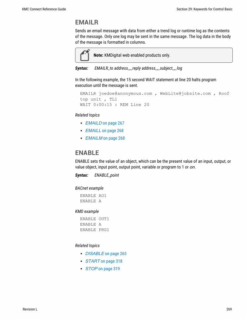
EMAILRSends an email message with data from either a trend log or runtime log as the contentsof the message. Only one log may be sent in the same message. The log data in the bodyof the message is formatted in columns.
Note: KMDigital web enabled products only.
Syntax: EMAILR_to address_,_reply address_,_subject_,_log
In the following example, the 15 second WAIT statement at line 20 halts programexecution until the message is sent.
EMAILR [email protected] , [email protected] , Rooftop unit , TL1WAIT 0:00:15 : REM Line 20
Related topics
l EMAILD on page 267l EMAILL on page 268l EMAILM on page 268
ENABLEENABLE sets the value of an object, which can be the present value of an input, output, orvalue object, input point, output point, variable or program to 1 or on.
Syntax: ENABLE_point
BACnet exampleENABLE AO1ENABLE A
KMD exampleENABLE OUT1ENABLE AENABLE PRG1
Related topics
l DISABLE on page 265l START on page 318l STOP on page 319
KMC Connect Reference Guide Section 29: Keywords for Control Basic
Revision L 269

ENDTerminates the execution of a program. When the END statement is encountered, thecontroller stops reading lines and exits the program. All program lines that follow anencountered END statement are not executed.
In the following examples, the last line is ignored and the analog output will always equal10.
BACnet exampleAO1 = 10ENDAO1 = 7
KMD exampleOUT1 = 10ENDOUT1 = 7
ENDFUNCUse ENDFUNC to mark the end of the definition of a Control Basic function.
Note: Applies only to controllers with Generation 5 Control Basic.
FUNCTION validateSp(s, l, h) s = MAX(s, l) s = MIN(s, h) FRETURN sENDFUNC
See also the topics FUNCTION on page 274 and User-defined functions andprocedures on page 240.
ENDPROCUse ENDPROC to mark the end of the definition of a Control Basic user defined procedure.
Note: Applies only to controllers with Generation 5 Control Basic.
PROCEDURE lowOAT(a,b) AV1 = MIN(a,b)ENDPROC
See also the topics PROCEDURE on page 305 and User-defined functions andprocedures on page 240.
Section 29: Keywords for Control Basic KMC Controls, Inc.
270 Revision L

ENTHALPYCalculates enthalpy based on Outside Air Temperature (OAT) and Outside Air Humidity(OAH). The value returned is expressed as BTUs per pound of air. OAT is in degreesFahrenheit.
Syntax: ENTHALPY(_OAH_,_OAT_)
For BACnet controllers, see the topic ENTHALPYSI on page 271 to enter OAT in degreesCelsius.
For KMD controllers, see the topic ENTHALPY-SI on page 272 to enter OAT in degreesCelsius.
BACnet exampleE = ENTHALPY( AI1 , AI2 )
KMD exampleE = ENTHALPY( VAR10 , VAR20 )OAE = ENTHALPY-SI( OAH, OAT )
ENTHALPYSIThis function calculates enthalpy based on Outside Air Temperature (OAT) and OutsideAir Humidity (OAH). The value returned is expressed as kilojoules per kilogram of air. OATis in degrees Celsius.
Syntax: ENTHALPYSI(_OAH_,_OAT_)
Note: For KMD controllers see ENTHALPY-SI on page 272.
See the topic ENTHALPY on page 271 to enter OAT in degrees Fahrenheit.
Standard Control Basic example10 E = ENTHALPY-SI( AI1 , AI2 )
Next Generation Control Basic exampleE=ENTHALPYSI(AI1, AI2)
KMC Connect Reference Guide Section 29: Keywords for Control Basic
Revision L 271

ENTHALPY-SIThis function calculates enthalpy based on Outside Air Temperature (OAT) and OutsideAir Humidity (OAH). The value returned is expressed as kilojoules per kilogram of air. OATis in degrees Celsius.
Syntax: ENTHALPY-SI(_OAH_,_OAT_)
Note: Deprecated for BACnet controllers. See ENTHALPYSI onpage 271.
E = ENTHALPY-SI( VAR10 , VAR20 )E = ENTHALPY-SI( OAH , OAT )
ERROR-COUNTReturns the number of network errors detected by the controller since the last start-upcycle or executed a CLEAR-COUNT statement.
Note: KMDigital Tier 1 controllers only.
VAR1 = ERROR-COUNT
The following statements return a count of the errors detected for a specific network onconnections in Tier 1 controllers:
ERROR-COUNT-SUBAERROR-COUNT-SUBBERROR-COUNT-MAINERROR-COUNT-ETHERNETERROR-COUNT-PCAERROR-COUNT-PCB
See the related topic CLEAR-COUNT on page 256.
ERRORLEVELThe ERRORLEVEL function returns a non zero (0) value when an error is detected in theprevious statement.
Syntax: ERRORLEVEL
Note: This keyword is for Next Gen and Gen 5 controllers only.
Section 29: Keywords for Control Basic KMC Controls, Inc.
272 Revision L

FLUSHWhen a FLUSH statement runs, Control Basic immediately reads from or writes to theproperty bound to the local variable declared by ALIAS.
Syntax: Flush (LocalAlias1)
Note: Next Generation Control Basic only.
ALIAS(1212, BO1, PV@4, Lights, 1:00:00, 60)FLUSH(Lights)
See the related topic ALIAS on page 248.
FOR TO NEXTThe FOR TO NEXT loop repeats a set of instructions a specific number of times.
Syntax: FOR_ControlVariable_=_StartValue_to_EndValue(_Step_Increment_)
l ControlVariable is the variable that FOR increments each time the loop repeats. Itcontrols whether Control Basic repeats the loop. ControlVariable must be local tothe controller in which the Control Basic program is running.
l StartValue is the initial value that Control Basic assigns to ControlVariable.l EndValue is the value that the ControlVariable must equal before the loop ends.l Increment is the amount that Control Basic adds to ControlVariable with each
iteration of the loop. Increment can be a positive or negative value. If STEP andIncrement are omitted, the default value is 1.
l NEXT ends FOR TO statements. It directs Control Basic to incrementControlVariable and to test whether it is greater than EndValue. If it is not, theloop continues at the first statement within the loop. If it is, the program continuesat the first statement following NEXT.
KMC Connect Reference Guide Section 29: Keywords for Control Basic
Revision L 273

In the following examples, the value of A increases from 0 to the value of AV2 or CON1in 0.1 increments, pausing 10 seconds between steps.
Standard Control Basic exampleFOR A = 0 TO AV2 STEP .1AO1 = AWAIT 0:00:10NEXT AEND
Next Generation Control Basic exampleFOR A = 0 TO AV2 STEP .1 AO1 = A WAIT 0:00:10NEXT AEND
KMD exampleFOR A = 0 TO CON1 STEP 0.1OUT1 = AWAIT 0:00:10NEXT A
FRETURNUse FRETURN to designate the value that is returned by the function. A function caninclude multiple FRETURN statements, bu, the result is returned from only the firstFRETURN executed.
Note: Applies only to controllers with Generation 5 Control Basic.
FUNCTION validateSp(s, l, h) s = MAX(s, l) s = MIN(s, h) FRETURN sENDFUNC
See also the topics FUNCTION on page 274 and User-defined functions andprocedures on page 240.
FUNCTIONUse FUNCTION to mark the beginning of a user-defined function. A function is aself-contained block of statements that returns a single value.
Note: Applies only to controllers with Generation 5 Control Basic.
Syntax: FUNCTION name ( argument[, argument, ...] )
Section 29: Keywords for Control Basic KMC Controls, Inc.
274 Revision L

Rules specific to functions:
l All procedures must have unique names. The names cannot duplicate Control Basickeywords, object names or descriptions, or mnemonics.
l A function must be called from an expression.l Functions are declared with the keyword FUNCTION( ).l Arguments passed to the function are enclosed in parentheses ( ) and separated by
commas. The parenthesis ( ) are required even if no arguments are passed.l The body of a function must end with the keyword ENDFUNC.l The keyword FRETURN must be used to return from a function and must be followed
by a value to return.l All branches created by an IF statement must end with a FRETURN statement.
FUNCTION validateSp(s, l, h) s = MAX(s, l) s = MIN(s, h) FRETURN sENDFUNC
Related topics
l User-defined functions and procedures on page 240l FRETURN on page 274l ENDFUNC on page 270l PROCEDURE on page 305
GOSUBGOSUB is the preferred way of branching to a subroutine in a program and then returningto the original point and continuing execution. When Control Basic encounters a GOSUBstatement, the program jumps to the location specified and continues reading programlines until it encounters a RETURN statement. At that point, the program returns to the linefollowing the GOSUB statement.
Syntax: GOSUB_line#
In the following examples, the program reads the first line, jumps to the third line, andthen to the fourth line. The RETURN statement on the fourth line sends the program backto the second line and the program ends.
KMC Connect Reference Guide Section 29: Keywords for Control Basic
Revision L 275

See the related topics GOTO on page 276 and RETURN on page 308.
BACnet exampleGOSUB 30ENDREM Line 30 subroutine starts hereRETURN
Next generation Control Basic GOSUB DoSubRoutine ENDDoSubRoutine: RETURN
KMD exampleGOSUB 30ENDREM Line 30 subroutine start hereRETURN
GOTOThis statement redirects the program to a new location in the program.
In the following examples, the program does not run the second line and output 1 is neverchanged.
See the related topic GOSUB on page 275.
Syntax: GOTO_line#
BACnet exampleGOTO 30START BO1REM Line 30 Program continues hereEND
Next generation Control Basic GOTO JumpToEnd START BO1JumpToEnd: END
KMD exampleGOTO 30START OUT1REM Line 30END
Section 29: Keywords for Control Basic KMC Controls, Inc.
276 Revision L
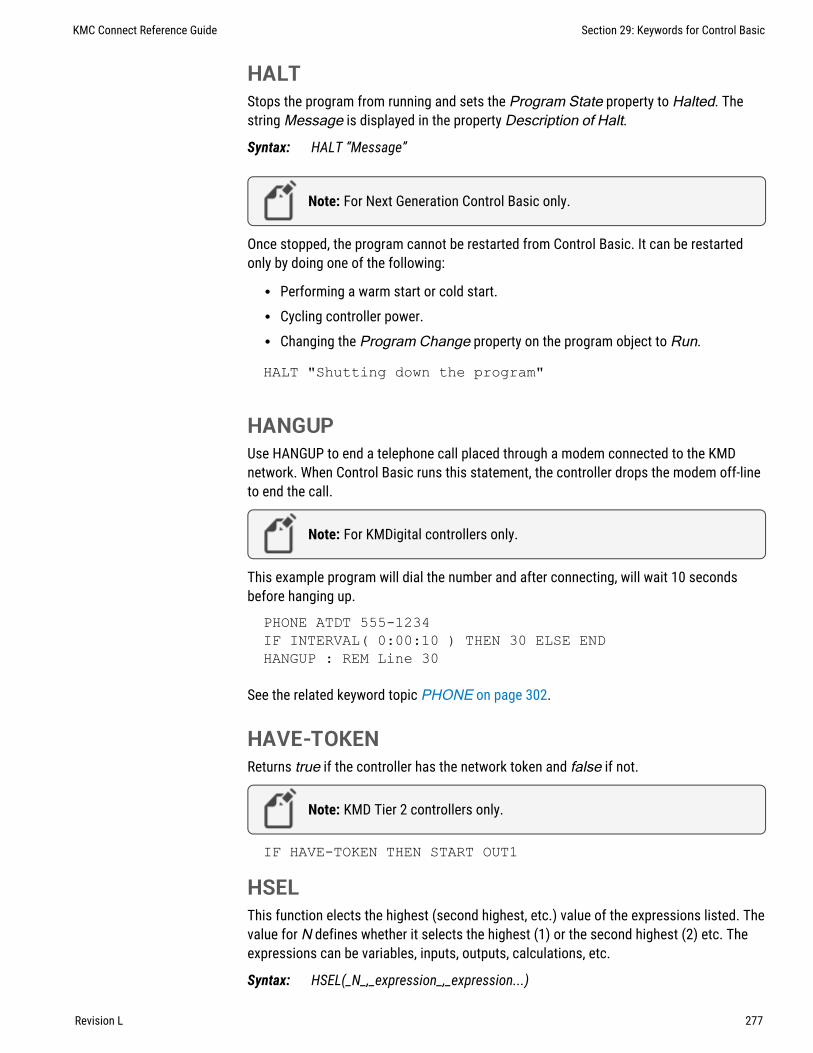
HALTStops the program from running and sets the Program State property to Halted. Thestring Message is displayed in the property Description of Halt.
Syntax: HALT “Message”
Note: For Next Generation Control Basic only.
Once stopped, the program cannot be restarted from Control Basic. It can be restartedonly by doing one of the following:
l Performing a warm start or cold start.l Cycling controller power.l Changing the Program Change property on the program object to Run.
HALT "Shutting down the program"
HANGUPUse HANGUP to end a telephone call placed through a modem connected to the KMDnetwork. When Control Basic runs this statement, the controller drops the modem off-lineto end the call.
Note: For KMDigital controllers only.
This example program will dial the number and after connecting, will wait 10 secondsbefore hanging up.
PHONE ATDT 555-1234IF INTERVAL( 0:00:10 ) THEN 30 ELSE ENDHANGUP : REM Line 30
See the related keyword topic PHONE on page 302.
HAVE-TOKENReturns true if the controller has the network token and false if not.
Note: KMD Tier 2 controllers only.
IF HAVE-TOKEN THEN START OUT1
HSELThis function elects the highest (second highest, etc.) value of the expressions listed. Thevalue for N defines whether it selects the highest (1) or the second highest (2) etc. Theexpressions can be variables, inputs, outputs, calculations, etc.
Syntax: HSEL(_N_,_expression_,_expression...)
KMC Connect Reference Guide Section 29: Keywords for Control Basic
Revision L 277

This example returns the local variable A equal to the second highest value of the itemslisted.
BACnet Control Basic example10 A = HSEL( 2 , AI1 , AI2 , AI3 , AV1 )
Next Generation Control Basic exampleA=HSEL(2, AI1, AI2, AI3, AV1)
KMD exampleA = HSEL( 2 , IN1 , IN2 , IN3 , VAR1 )
IF THEN (ELSE)IF THEN is a decision making statement. The expression parameter can be anyexpression capable of being true or false (high or low, on or off, etc.) If expression isTRUE, the THEN statement will be executed. If the expression is FALSE (not true), theELSE statement will be executed. The ELSE statement and associated clause are optional.If they are not included, the program reads and executes the next program line.
Syntax: IF_expression_THEN_clause(_ELSE_clause)
Standard BACnet Control Basic example
In this example, the program stops Analog Output AO5 if Analog Input AI1 is less thanAnalog Input AI2. If AI1 is not less than AI2, Analog Output AO5 will be turned on(started). If the ELSE START AO5 statement was not included, the program will stopAO5 if AI1 is less than AI2. Otherwise, it will do nothing and end the program.
IF AI1 < AI2 THEN STOP AO5 ELSE START AO5
Note: Use commas to separate multiple commands in an IFstatement.
IF T > S THEN START BO1, STOP BO2IF T > S THEN START BO1, STOP BO2 ELSE STOP BO1
Section 29: Keywords for Control Basic KMC Controls, Inc.
278 Revision L

Next generation Control Basic
By using ENDIF, Next Generation Basic supports block and nested IF THEN statements.
IF TIME > 7:00:00 THENa=b
ENDIF
Locals ChilledWaterSetpointAV24 = ChilledWaterSetpointIF BV258 THEN
ChilledWaterSetpoint=52ELSE
Chilledwatersetpoint=48ENDIF
IF TIME > 7:00:00 THENIF TIME < 9:00:00 THEN
B=CENDIF
ENDIF
KMD exampleIF IN1 < IN2 THEN STOP OUT5 ELSE START OUT5END
In this example, the program stops output OUT5 if input IN1 is less than input IN2. If IN1is not less than IN2, OUT5 will be turned on (started). If the ELSE START OUT5statement was not included, the program will stop OUT5 if IN1 is less than IN2. Otherwise,it will do nothing and end the program.
Note: Use commas to separate multiple commands in an IFstatement.
IF IN1 > VAR1 THEN START OUT2 , STOP OUT1IF IN1 > VAR1 THEN START OUT2 , STOP OUT1 , OUT3 = 0 ELSESTOP OUT1 , OUT3 = CON1
IF+ THENIF+ THEN is similar to IF THEN, except that it detects the first time a condition changesfrom false to true. If the expression is true and on the previous scan it was not true, theTHEN clause will be executed.
Syntax: IF+_expression_THEN_clause(_ELSE_clause)
The ELSE statement and associated clause are optional. If they are not included, theprogram reads and executes the next program line.
When a button closes the circuit in the sensor Analog Input 1 to which it is connected, theprogram will branch down to line 30 or label ADD1, which increases the setpoint (AV13 orVAR13) by one degree. This will happen only once for each time the button is pressed and
KMC Connect Reference Guide Section 29: Keywords for Control Basic
Revision L 279

released. Even if the button is held for several minutes, it will only increment the setpointby one degree.
See the related topic IF THEN (ELSE) on page 278 and IF- THEN on page 280.
BACnet exampleIF+ SENSOR-ON( AI1 ) THEN GOSUB 30ENDAV13 = AV13 + 1 : REM Line 30 starts hereRETURN
Next generation Control BasicIF+ SENSORON( AI1 ) THEN GOSUB ADD1ENDADD1:AV13 = AV13 + 1RETURN
KMD exampleIF+ SENSOR-ON( IN1 ) THEN GOSUB 30ENDVAR13 = VAR13 + 1 : REM Line 30 start hereRETURN
IF- THENIF- THEN is similar to IF THEN except that it detects the first time a condition changesfrom true to false. In this case, the THEN clause would only be executed if the expressionis false and on the previous scan it was true.
Syntax: IF-_expression_THEN_clause(_ELSE_clause)
Note: The ELSE and associated clause is optional.
See the related topic IF THEN (ELSE) on page 278 and IF+ THEN on page 279.
INCUse INC to increment the value of the argument point by the value of the argument step.If step is omitted, the step value is 1. Point may be the present value of any analogobject.
Syntax: INC(_point_, step_) INC(_point_)
Section 29: Keywords for Control Basic KMC Controls, Inc.
280 Revision L

See the related topic DEC on page 264.
Standard BACnet Control Basic exampleINC( AV1 , A + B )INC( AV2 )
Next Generation Control Basic exampleINC( AV1 , A + B )Inc( AV2 )
KMD exampleINC( VAR1 , A + B )INC( VAR2 )
INTINT returns the integer portion of the numeric value expression. The value returned is thegreatest integer that is less than or equal to the value of expression.
Syntax: INT(_expression_)
The following examples calculate the hour of the day (0-23) without minutes or seconds.The result is stored in Analog Value Object AV1 or variable VaR1.
Standard BACnet Control Basic exampleAV1 = INT( TIME / 3600 )
Next Generation Control Basic exampleAV1=INT(TIME/3600)
KMD exampleVAR1 = INT( TIME / 100 )
KMC Connect Reference Guide Section 29: Keywords for Control Basic
Revision L 281
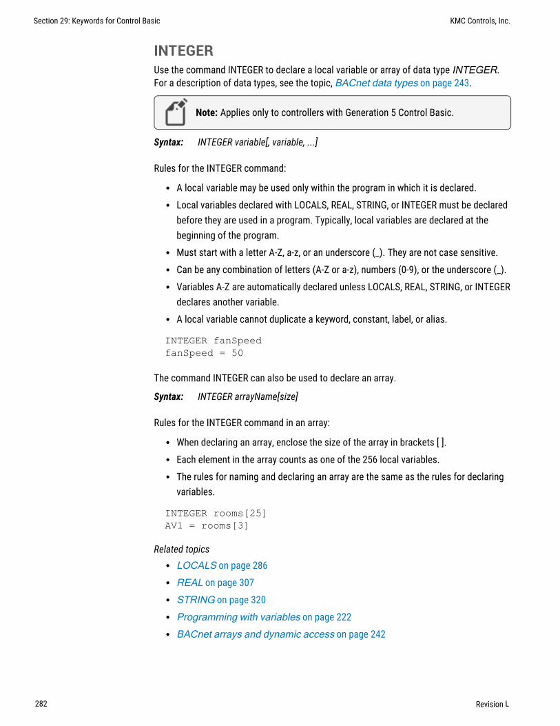
INTEGERUse the command INTEGER to declare a local variable or array of data type INTEGER.For a description of data types, see the topic, BACnet data types on page 243.
Note: Applies only to controllers with Generation 5 Control Basic.
Syntax: INTEGER variable[, variable, ...]
Rules for the INTEGER command:
l A local variable may be used only within the program in which it is declared.l Local variables declared with LOCALS, REAL, STRING, or INTEGER must be declared
before they are used in a program. Typically, local variables are declared at thebeginning of the program.
l Must start with a letter A-Z, a-z, or an underscore (_). They are not case sensitive.l Can be any combination of letters (A-Z or a-z), numbers (0-9), or the underscore (_).l Variables A-Z are automatically declared unless LOCALS, REAL, STRING, or INTEGER
declares another variable.l A local variable cannot duplicate a keyword, constant, label, or alias.
INTEGER fanSpeedfanSpeed = 50
The command INTEGER can also be used to declare an array.
Syntax: INTEGER arrayName[size]
Rules for the INTEGER command in an array:
l When declaring an array, enclose the size of the array in brackets [ ].l Each element in the array counts as one of the 256 local variables.l The rules for naming and declaring an array are the same as the rules for declaring
variables.
INTEGER rooms[25]AV1 = rooms[3]
Related topicsl LOCALS on page 286l REAL on page 307l STRING on page 320l Programming with variables on page 222l BACnet arrays and dynamic access on page 242
Section 29: Keywords for Control Basic KMC Controls, Inc.
282 Revision L
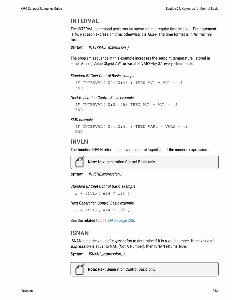
INTERVALThe INTERVAL command performs an operation at a regular time interval. The statementis true at each expression time; otherwise it is false. The time format is in hh:mm:ssformat.
Syntax: INTERVAL(_expression_)
The program sequence in this example increases the setpoint temperature—stored ineither Analog Value Object AV1 or variable VAR2—by 0.1 every 45 seconds.
Standard BACnet Control Basic exampleIF INTERVAL( 00:00:45 ) THEN AV1 = AV1 + .1END
Next Generation Control Basic exampleIF INTERVAL(00:00:45) THEN AV1 = AV1 + .1END
KMD exampleIF INTERVAL( 00:00:45 ) THEN VAR2 = VAR2 + .1END
INVLNThe function INVLN returns the inverse natural logarithm of the numeric expression.
Note: Next generation Control Basic only.
Syntax: INVLN(_expression_)
Standard BACnet Control Basic exampleB = INVLN( AI4 * 125 )
Next Generation Control Basic exampleB = INVLN( AI4 * 125 )
See the related topics LN on page 285.
ISNANISNAN tests the value of expression to determine if it is a valid number. If the value ofexpression is equal to NAN (Not A Number), then ISNAN returns true.
Syntax: ISNAN( _expression_ )
Note: Next Generation Control Basic only.
KMC Connect Reference Guide Section 29: Keywords for Control Basic
Revision L 283

A typical use of ISNAN is to test the present value property of an object in a remotedevice.
Note: If the remote device goes offline, the last good value is helduntil the controller is reset with a cold start, warm start, or powercycle. After the reset, the value in the remote property becomes NANuntil it is read by another controller.
In the following example, the program tests the present value of Analog Input AI4 indevice instance 4410 once every minute. If the value is a usable number, then the remotevalue is stored in value object AV503. If the remote value is not valid, the value object isset equal to 55, the default value.
IF INTERVAL ( 00:01:00 ) THEN REM Verify that the value is good IF ISNAN( 4410.AI4 ) THEN REM Set a default value AV503 = 55 ELSE REM Use the received value AV503 = 4410.AI4 ENDIFENDIF
ISSTRINGISSTRING tests the value of expression to determine if it is of data type character string.
Syntax: ISSTRING( expression )
Note: Applies only to controllers with Generation 5 Control Basic.
LETThe LET function assigns expression1 to equal expression2. Use this function toassign values to inputs, outputs, variables, PID control loops, or schedule.
Syntax: LET_expression1_=_expression2
LET OUT1 = CON1LET A = OUT1
The LET function is optional. Both of the following examples will produce the sameresults.
VAR3 = IN2 - 23LET VAR3 = IN2 - 23
Section 29: Keywords for Control Basic KMC Controls, Inc.
284 Revision L

LN-1LN-1 returns the inverse natural logarithm of the numeric expression.
Syntax: LN-1(_expression_)
Note: Deprecated for BACnet controllers. See the keyword INVLNon page 283.
B = LN-1( IN4 * 125 )
LNThe function LN( ) returns the natural logarithm of the numeric expression.
Syntax: LN(_expression_)
Standard BACnet Control Basic exampleB = INVLN( AI4 * 125 )
Next Generation Control Basic exampleB = INVLN( AI4 * 125 )
KMD exampleA = LN( IN1 )
KMC Connect Reference Guide Section 29: Keywords for Control Basic
Revision L 285

LOCALSUse to declare local variables or arrays of data type REAL.
Note: Next Generation Control Basic only.
Syntax: LOCALS variable[, variable, ...]
LOCALS chilledWaterSetpoint, a, b
Rules for LOCALS declaration:
l A local variable may be used only within the program in which it is declared.l Local variables declared with LOCALS, REAL, STRING, or INTEGER must be declared
before they are used in a program. Typically, local variables are declared at thebeginning of the program.
l Must start with a letter A-Z, a-z, or an underscore (_). They are not case sensitive.l Can be any combination of letters (A-Z or a-z), numbers (0-9), or the underscore (_).l Variables A-Z are automatically declared unless LOCALS, REAL, STRING, or INTEGER
declares another variable.l A local variable cannot duplicate a keyword, constant, label, or alias.
The command LOCALS can also be used to declare an array of data type REAL.
Syntax: LOCALS arrayName[size]
l When declaring an array, enclose the size of the array in brackets [ ].l Each element in the array counts as one of the 256 local variables.l The rules for naming and declaring an array are the same as the rules for declaring
variables.
LOCALS roomTemps[10]
Related topicsl INTEGER on page 282l REAL on page 307l STRING on page 320l Programming with variables on page 222l BACnet arrays and dynamic access on page 242
Section 29: Keywords for Control Basic KMC Controls, Inc.
286 Revision L

LSELLSEL returns the lowest, second lowest, etc. value of the expression listed. The value Ndefines whether it selects the lowest (1) or second lowest (2) etc. Expressions can bevariables, inputs, outputs, calculations, etc.
Syntax: LSEL(_N_,_expression_,_expression_...)
In the examples, local variable A will be set equal the second lowest value of the itemslisted.
Standard BACnet Control Basic exampleA = LSEL( 2 , BI1 , BI2 , BI3 , BV1 )
Next Generation Control Basic exampleA=LSEL(2, BI1, BI2, BI3, BV1)
KMD exampleA = LSEL( 2 , IN1 , IN2 , IN3 , VAR1 )
MAXMAX returns the maximum value of the expression listed. Expressions can be one of thefollowing items.
l Input, output, or value objectsl Input, output, or variable pointsl The result of a calculation
Syntax: MAX(_expression_,_expression_...)
Standard BACnet Control Basic exampleA = MAX( AI1 , AI2 , AI3 , AV1 )
Next Generation Control Basic exampleA=MAX(AI1, AI2, AI3, AV1)
KMD exampleA = MAX( IN1 , IN2 , IN3 , VAR1 )
KMC Connect Reference Guide Section 29: Keywords for Control Basic
Revision L 287

MINMIN returns the minimum value of those expression listed. Expressions can be one of thefollowing items.
l Input, output, or value objectsl Input, output, or variable pointsl The result of a calculation
Syntax: MIN(_expression_,_expression_...)
Standard BACnet Control Basic exampleB = MIN( AI1 , AI2 , AI3 )
Next Generation Control Basic exampleB = MIN( AI1 , AI2 , AI3 )
KMD exampleB = MIN( IN1 , IN2 , IN3 , VAR1 )
MODMOD is an arithmetic operator function that returns the remainder (or modulus) of adivision operation.
Syntax: Dividend MOD Divisor
Standard BACnet Control Basic exampleIF AV1 MOD 5 = 0 THEN START BO2 ELSE STOP BO2
Next Generation Control Basic exampleIF AV1 MOD 5=0 THEN START BO2 ELSE STOP BO2
KMD exampleIF VAR1 MOD 5 = 0 THEN START OUT1 ELSE STOP OUT1
The following example uses MOD to calculate leap year. If the year in the controller’sinternal clock is a leap year, local variable L is set to true. For other years the variable L isset to false.
IF YEAR MOD 4 = 0 AND YEAR MOD 100 <> 0 OR YEAR MOD 400 =0 THEN L = 1 ELSE L = 0
See the related topic Using arithmetic operators on page 221.
Section 29: Keywords for Control Basic KMC Controls, Inc.
288 Revision L

MODBUSTRANSFERUse MODBUSTRANSFER to control the transfer of data between pairs of points andregisters set up with interprotocol points.
Syntax: MODBUSTRANSFER( point , action )
l Point designates the interprotocol point.l Action controls the transfer. See the following table for a list of permissible
actions.
Note: Only for KMDigital models with a Modbus license.
MODBUSTRANSFER( 1 , DISABLED )MODBUSTRANSFER( 2 , ONCE )MODBUSTRANSFER( 3 , ALWAYS )
Action Description
DISABLED Disables the transfer of data from the read point to the write point.
ONCE Initiates a one-time transfer of data between the read point and thewrite point. When the transfer is complete, the mode of the pointpair is set to DISABLED.
ALWAYS Initiates a continuous transfer of data between the read point andthe write point.
Table 29–10 Actions
MODELNUMBERMODELNUMBER returns the numerical portion of the model number of the controller.
Syntax: MODELNUMBER
Note: For KMD controllers see MODEL-NUMBER on page 289.
AV1=MODELNUMBER
MODEL-NUMBERMODEL-NUMBER returns the numerical portion of the model number of the controller.
Note: Deprecated for BACnet controllers. See the keywordMODELNUMBER on page 289.
VAR1 = MODEL-NUMBER
KMC Connect Reference Guide Section 29: Keywords for Control Basic
Revision L 289

MONTHMONTH returns the current month of the year.
Standard BACnet Control Basic exampleM = MONTH
Next Generation Control Basic exampleM=MONTH
KMD exampleM = MONTH
NANUse NAN to set a variable or property to a Not A Number constant or to test if thevariable or property is equal to Not A Number.
Note: Next generation Control Basic only.
IF A <> NAN THEN GOTO CONTINUEB = 55CONTINUE:B = A
See the related topic ISNAN on page 283.
NEG_INFINITYUse the NEG-INFINITY command to set a variable or property to a very large negativenumber.
Note: Applies only to controllers with Next Generation orGeneration 5 Control Basic.
Note: The underscore (_) is required for this keyword.
a = NEG-INFINITYAV21.LL = NEG-INFINITY
See also the topic POS_INFINITY on page 303.
Section 29: Keywords for Control Basic KMC Controls, Inc.
290 Revision L

NETPOINTUse the NETPOINT command to set the interval for reading from and writing to BACnetoff-panel objects. NETPOINT and COV are the preferred methods to read from or write tooff-panel points in Generation 5 controllers.
Syntax: NETPOINT(device instance.object.property, read interval, write interval)
Note: Applies only to controllers with Generation 5 Control Basic.
Rules for the NETPOINT command:
l Within a controller, execute the NETPOINT command only once for each off-panelobject.
l Add NETPOINTCACHE to every program in the controller that uses the off-panelobject that is referenced by the NETPOINT command.
l Only the shortest read or write interval for the same object in all NETPOINTstatements within the controller will be used.
Parameter Description Comments
device The device instance number.
object A valid Control Basic objectmnemonic.
See Mnemonics forBACnet controllers onpage 223.
property The property for reading or writing. Present Value is the defaultproperty.
read interval The interval, in seconds, at whichControl Basic will read the property.
The default value is 60seconds. Enter NONE for awrite-only function.
write interval The interval, in seconds, at whichControl Basic will write to theproperty.
The default value is NONEwhich sets the function toread-only.
NETPOINT parameters
KMC Connect Reference Guide Section 29: Keywords for Control Basic
Revision L 291

In the following example, the statement with NETPOINT runs only during the first scanafter a restart. The NETPOINT function sets up reading Analog Value object AV1 incontroller Device Instance 5 every 180 seconds (3 minutes) and writing to AV1 every 60seconds. Then, local variable A is updated every 180 seconds (3 minutes) and the valueof local variable B writes to AV1 in device 5 every 60 seconds.
NETPOINTCACHE(1)IF POWERLOSS THEN
NETPOINT(5.AV1.PV,180,60)ENDIFA=5.AV15.AV1@8=B
To use 5.AV1 in other programs within the same controller, add only theNETPOINTCACHE(1) command to the program.
NETPOINTCACHE(1)IF 5.AV1 < 51 THEN STOP BV1
See also the topics POWERLOSS on page 304 and NETPOINTCACHE on page 292.
NETPOINTCACHEUse NETPOINTCACHE to enable a cache of values within a program from off-panelobjects that are referenced with the COV and NETPOINT functions. UsingNETPOINTCACHE with NETPOINT or COV reduces network traffic by sharing valuesamong all programs within the same controller. This is the preferred method to read fromor write to off-panel points in Generation 5 controllers.
Syntax: NETPOINTCACHE(expression)
Note: Applies only to controllers with Generation 5 Control Basic.
Rules for the NETPOINTCACHE command:
l Add NETPOINTCACHE to every program in a controller that is referencing anoff-panel object by using NETPOINT or COV.
l Enter one (1) for expression to enable NETPOINTCACHE and COV caching.l Enter zero (0) for expression to disable NETPOINTCACHE and COV caching. This is
the default state in controllers that support Generation 5 Control Basic.
Section 29: Keywords for Control Basic KMC Controls, Inc.
292 Revision L

In the following example, the statement with NETPOINT runs only during the first scanafter a restart. The NETPOINT function sets up reading Analog Value object AV1 incontroller Device Instance 5 every 180 seconds (3 minutes) and writing to AV1 every 60seconds. Then, local variable A is updated every 180 seconds (3 minutes) and the valueof local variable B writes to AV1 in device 5 every 60 seconds.
NETPOINTCACHE(1)IF POWERLOSS=0 THEN
NETPOINT(5.AV1.PV,180,60)ENDIFA=5.AV15.AV1@8=B
To use 5.AV1 in other programs within the same controller, add NETPOINTCACHE(1)to the program.
NETPOINTCACHE(1)IF 5.AV1 < 51 THEN STOP BV1
Related topics
l COV on page 260l NETPOINT on page 291l POWERLOSS on page 304l Transferring values between BACnet controllers on page 228
NETSENSORSTATUSNETSENSORSTATUS returns the connection status of a NetSensor with which the programcan take appropriate action. The function returns true if a functional NetSensor isconnected to the controller and false if the controller does not detect a NetSensor.
Note: For KMD controllers see NETSENSOR-STATUS on page294.
Standard Control Basic exampleF NOT NETSENSORSTATUS THEN STOP BV1
Next Generation Control Basic exampleIF NOT NETSENSORSTATUS THEN STOP BV1
KMC Connect Reference Guide Section 29: Keywords for Control Basic
Revision L 293

NETSENSOR-STATUSNETSENSOR-STATUS returns the connection status of a NetSensor so the program cantake appropriate action. The function returns true if a functional NetSensor is connectedto the controller and false if the controller does not detect a NetSensor.
Note: Deprecated for BACnet controllers. See the keywordNETSENSORSTATUS on page 293.
DALARM NETSENSOR-STATUS = 0 , 10 , NetSensor in lobby notresponding!
NOTNOT is a Boolean operator that performs a logical negation operation on an expression. Ifthe expression is 0, the result is 1. If the expression is non-zero, the result is 0.
Syntax: result = NOT expression
IF NOT BV1 THEN STOP BO210 IF NOT OUT1 THEN STOP OUT2
See the related topic Using Boolean logic on page 221.
NPAGEUse the NPAGE command to initiate a telephone call to a numeric pager.
Syntax: NPAGE telephone number , numeric message
Note: For KMDigital controllers only.
l Use NPAGE only in programs running in Tier 1 controllers that are connected to amodem.
l Telephone number cannot contain spaces, hyphens, or punctuation other thancommas (,). Each comma adds a two second pause.
DALARM VAR51 , 1 , VAR 51 is in alarm!ON-ALARM 40GOTO 60NPAGE 18005551212,,,,51 : REM line 40WAIT 0:00:15END : Rem Line 60
See the related topics TPAGE on page 328 and PHONE on page 302.
Section 29: Keywords for Control Basic KMC Controls, Inc.
294 Revision L

ON GOSUBON GOSUB is a control statement. The program branches to the location from the listpassed by the statement. The value of expression determines the location in the list towhich Control Basic will continue. For example, if expression equals 2 the program willbranch to the second location in the list; if expression equals 5 the program will branchto the fifth location in the list. Expression is rounded to an integer. If the value ofexpression is greater than the number of locations listed or if expression is less than 1,no branch will occur.
Syntax: ON_expression_GOSUB_location1[_location2_location3_...]
See the related topic RETURN on page 308.
Standard BACnet Control Basic example
In this example, Value Object AV1 is equal to 3, which will cause the program to branchto Line 80. If AV1 were equal to 2, the program would branch to Line 60, etc.
AV1 = 3ON AV1 GOSUB 40 , 60 , 80ENDRETURN : REM Line 40RETURN : REM Line 40RETURN : REM Line 40
Next Generation Control Basic
In this example, Value Object AV1 is equal to 3, which will cause the program to branchto label Third. If AV1 equals 2, the program will branch to label Second, etc.
AV1 = 3ON AV1 GOSUB First , Second , ThirdENDFirst:RETURNSecond:RETURNThird:RETURN
KMD example
In this example, Variable VAR1 is equal to 3, which will cause the program to branch toLine 80. If VAR1 equals 2, the program will branch to Line 60, etc.
VAR1 = 3ON VAR1 GOSUB 40 , 50 , 60ENDRETURN : REM Line 40RETURN : REM Line 50RETURN : REM Line 60
KMC Connect Reference Guide Section 29: Keywords for Control Basic
Revision L 295

ON GOTOON GOTO is a control statement. The program branches to the locations from the listpassed by the statement. The value of expression determines the location in the list towhich the program will branch. For example, if expression equals 2, the program willbranch to the second location in the list; if expression equals 5, the program will branchto the fifth location in the list. Expression is rounded to an integer. If the value ofexpression is greater than the number of locations listed, or if expression is less than1, no branch will occur.
Syntax: ON_expression_GOTO_location1[_location2_location3_...]
Standard BACnet Control Basic example
In this example, Value Object AV1 is equal to 3, which will cause the program to branchto Line 60. If AV1 were equal to 2, the program would branch to Line 60, etc.
AV1 = 3ON AV1 GOTO 40 , 50 , 60ENDREM Line 40 Program continues hereREM Line 50 Program continues hereREM Line 60 Program continues here
Next generation Control Basic
In this example, Value Object AV1 is equal to 3, which will cause the program to branch tolabel 60. If AV1 equals 2, the program will branch to label 50, etc.
AV1 = 3ON AV1 GOTO Forty, Fifty, SixtyENDForty:Fifty:Sixty:
KMD example
In this example, VAR1 is equal to 3, which will cause the program to branch to line 60. IfVAR1 were equal to 2, the program would branch to line 50, etc.
VAR1 = 3ON VAR1 GOTO 40 , 50 , 60ENDREM Line 40 Program continues hereREM Line 50 Program continues hereREM Line 60 Program continues here
Section 29: Keywords for Control Basic KMC Controls, Inc.
296 Revision L

ON-ALARMON-ALARM is a control statement that redirects the program when alarms are detected ina KMD controller. When an alarm condition is detected, ON-ALARM redirects the programto the line number listed. This redirection occurs only once when the alarm is firstdetected. This statement only evaluates the ALARM statement immediately prior to it.
Syntax: ON-ALARM_line#
Note: KMD controllers only.
The following program runs the first three lines if alarms are not detected. However, if thealarm is activated on the first line, when ON-ALARM runs, the program jumps to the fourthline (Line 40). In this example, if no alarm is detected the program does nothing. If analarm is detected Output OUT1 is turned on.
ALARM IN1 < 34 , 1 , Temp is near freezingON-ALARM 40ENDSTART OUT1 : REM Line 40-Activates warning deviceEND
KMC Connect Reference Guide Section 29: Keywords for Control Basic
Revision L 297

ONERRORONERROR is a control statement that redirects the program to the line specified bylocation when an error is detected in the previous line.
Syntax: ONERROR location
Note: For KMD Controllers see ON-ERROR on page 298.
In the following examples, the program attempts to read an off-panel object. If the objectis not found, the program substitutes the value 55.
Standard BACnet Control Basic exampleIF INTERVAL ( 00:01:00 ) THEN AV24 = 4410.AI4ONERROR 40GOTO 60 : REM Jump around error recoveryREM Line 40-Error recoveryAV16 = 55REM Line 60-Continue program
Next Generation Control BasicIF INTERVAL ( 00:01:00 ) THEN
REM Verify that the value is goodIF ISNAN( 4410.AI4 ) THEN
REM Set a default valueAV24 = 55
ELSEREM Use the received valueAV24 = 4410.AI4
ENDIFENDIF
ON-ERRORON-ERROR is a control statement that redirects the program to the line specified bylocation when an error is detected in the previous line.
Syntax: ON-ERROR location
Note: Deprecated for BACnet controllers. See the keywordONERROR on page 298.
Section 29: Keywords for Control Basic KMC Controls, Inc.
298 Revision L

The example prints an error message if line 10 is unsuccessful while executing thePHONE statement. ON-ERROR may also be used to branch to a subroutine where asecond telephone phone number is called when an error may be received on the firstattempt. Use ON-ERROR with the following commands.
l BAC-GETl BAC-SETl BAC-RLQl NPAGEl PHONEl REMOTE-GETl REMOTE-SETl RUN-MACROl TPAGE
PHONE 555-1234ON-ERROR 40ENDREM Line 40 handles the errorEND
OPENThe OPEN command sets the present value of an object or point to on or true.
Syntax: OPEN_point
Standard BACnet Control Basic exampleOPEN V20 OPEN A30 OPEN BO1
Next Generation Control Basic exampleOPEN VOPEN AOPEN BO1
KMD exampleOPEN OUT1OPEN AOPEN VAR1
Related topics
l CLOSE on page 257l START on page 318l STOP on page 319
KMC Connect Reference Guide Section 29: Keywords for Control Basic
Revision L 299

OROR is a Boolean operator that performs the logical OR of the two expressions. The resultis true if either expression is true. The result is false if both expressions are false.
Syntax: result = expression1 OR expression2
In the following example, local variable C will equal 1 if either of the variables A and B areequal to 1.
A = 1 : B = 0 : C = A OR B
See the related topic Using Boolean logic on page 221.
OUTPUTOVERRIDEThe OUTPUTOVERRIDE function returns the switch position of an optional HPO-6700series output board installed in the controller in which Control Basic is running.
Syntax: OUTPUTOVERRIDE( output )
Note: For BACnet controllers only. For KMD controllers see thekeyword OUTPUT-OVERRIDE.
The function returns FALSE (0) if the switch is set to A (Auto) and TRUE (1) if theswitch is set to either the O (Off) or H (Hand controlled On) position. The argumentoutput can be expressed as either of the following:
l The instance number of the output.l A local variable whose value represents the number of an output object.
Standard BACnet Control Basic example BV20 = OUTPUTOVERRIDE( 2 )
Next Generation Control Basic exampleBV20=OUTPUTOVERRIDE(2)
Section 29: Keywords for Control Basic KMC Controls, Inc.
300 Revision L

OUTPUT-OVERRIDEThe OUTPUT-OVERRIDE function returns the switch position of an optional HPO-6700series output board installed in the controller in which Control Basic is running.
Syntax: OUTPUT-OVERRIDE(_output_)
Note: Deprecated for BACnet controllers. See the keywordOUTPUTOVERRIDE on page 300.
The function returns FALSE (0) if the switch is set to A (Auto) and TRUE (1) if theswitch is set to either the O (Off) or H (Hand controlled On) position. The argumentoutput can be expressed as either of the following:
l The point number of the output.l A local variable whose value represents the number of an output object.
DALARM OUTPUT-OVERRIDE( 1 ) , 300 , OUTPUT1 1 SWITCH ISNOT IN AUTOIF OUTPUT-OVERRIDE( 2 ) THEN STOP OUT2
PANELADDRESSPANELADDRESS returns the device instance number of the controller on which the ControlBasic program is running.
Note: For KMD controllers see PANEL-ADDRESS on page 301.
Standard Control Basic exampleP = PANELADDRESS
Next Generation Control Basic exampleP=PANELADDRESS
PANEL-ADDRESSPANEL-ADDRESS returns the KMD network address of the controller on which ControlBasic is running.
Note: Deprecated for BACnet controllers. For BACnet controllers seePANELADDRESS on page 301
P = PANEL-ADDRESS
KMC Connect Reference Guide Section 29: Keywords for Control Basic
Revision L 301

PHONEUse PHONE to establish a modem connection from a controller to a remote computerrunning WinControlXL Plus. Use PHONE in Control Basic programs only in Tier 1controllers with an attached modem.
Syntax: PHONE_ATDT_telephone number
l The ATDT option is a standard modem structure clause to configure the modem todial out in a tone format.
l Telephone number cannot contain spaces, hyphens or punctuation other thancommas (,). Each comma adds a two second pause.
When Control Basic runs the Phone statement, the processor suspends operation for upto 45 seconds as it waits for the modem to return a connection string.
Caution: The WAIT statements in the following examples are criticalto reliable program execution. Do not delete them.
Example—Tier 1 controller
The sequence in the following example dials the number, waits up to 45 seconds for theremote modem to answer, and then after connecting to it, waits 1 minute before hangingup. The HANGUP command is required at the end of the sequence.
DALARM VAR51 , 1 , VAR 51 is in alarm!ON-ALARM 40GOTO 80PHONE 18005551212,,,,51WAIT 0:00:45 : ON-ERROR 40HANGUPWAIT 0:01:00END10 DALARM 1-VAR51 , 1 , VAR 51 is in alarm!20 ON-ALARM 4030 GOTO 8040 PHONE 18005551212,,,,5150 WAIT 0:00:45 : ON-ERROR 4060 HANGUP70 WAIT 0:01:0080 END
Example–Tier 2 controller
In the following example, a Tier 2 controller dials a pager and leaves the message 1234.Each comma adds a 1 second pause.
10 IF+ IN1 THEN 20 ELSE END20 PHONE ATDT 5551212,,,,,,123430 HANGUP
Section 29: Keywords for Control Basic KMC Controls, Inc.
302 Revision L
Related topics
l NPAGE on page 294l TPAGE on page 328l HANGUP on page 277
PIThis function PI inserts the mathematical value of pi(π). The following examples convertangle D from degrees to radians.
Standard Control Basic exampleA = PI * ( D / 180 )
Next Generation Control Basic exampleA=PI*(D/180)
KMC exampleA = PI * ( D / 180 )
POS_INFINITYUse the POS-INFINITY command to set a variable or property to a very large positivenumber.
Note: Applies only to controllers with Next Generation orGeneration 5 Control Basic.
Note: The underscore(_) is required for this keyword.
a = POS_INFINITYAV21.HL = POS_INFINITY
See also the topic NEG_INFINITY on page 290.
KMC Connect Reference Guide Section 29: Keywords for Control Basic
Revision L 303

POWERLOSSUse POWERLOSS to detect loss of power to the controller. It will also detect any othercondition that causes the controller to run its restart sequence. This function returnsTRUE on the first scan of all Control Basic programs after power is restored. After thefirst scan, it returns as FALSE.
Note: For KMD controllers see POWER-LOSS on page 304.
The following examples are useful for monitoring intermittent power failures at acontroller. The Analog Value object AV32 increments by 1 each time power is restored.
Standard Control Basic exampleIF POWERLOSS THEN AV32 = AV32 + 1END
Next Generation Control Basic exampleIF POWERLOSS THEN AV32 = AV32+1END
POWER-LOSSUse POWER-LOSS to detect loss of power to the controller or any condition that forced thecontroller to reset. This function returns TRUE on the first scan of all Control Basicprograms after power is restored. After the first scan, it returns as FALSE.
Note: Deprecated for BACnet controllers. See POWERLOSS onpage 304.
The following example is useful for monitoring intermittent power failures at a controller.The KMD Variable Point VAR32 increments by 1 each time power is restored.POWER-LOSS may also be used to detect any other condition that causes thecontroller to perform its restart sequence.
IF POWER-LOSS THEN VAR32 = VAR32 + 1END
PRETURNUse PRETURN to return from a procedure before reaching ENDPROC. Control Basicreturns program control to the next statement that called the procedure. PRETURN isoptional.
Note: Applies only to controllers with Generation 5 Control Basic.
See also, PROCEDURE on page 305 and User-defined functions and procedures onpage 240.
Section 29: Keywords for Control Basic KMC Controls, Inc.
304 Revision L

PROCEDUREUse PROCEDURE to mark the beginning of a user-defined procedure. A procedure is aself-contained block of Control Basic statements that performs a task.
Note: Applies only to controllers with Generation 5 Control Basic.
Syntax: PROCEDURE name([argument, argument, argument...])
Rules specific to procedures:
l All procedures must have unique names. The names cannot duplicate Control Basickeywords, object names or descriptions, or mnemonics.
l A procedure cannot be called from an expression.l Procedures are declared with the keyword PROCEDURE( ). The parentheses ( ) are
required even if no arguments are passed.l The body of a procedure must end with the keyword ENDPROC.l The keyword PRETURN is optional and can be used to return from a procedure
before the ENDPROC statement is reached.
PROCEDURE lowOAT(a,b) AV1 = MIN(a,b)ENDPROC
Related topics
l User-defined functions and procedures on page 240l PRETURN on page 304l FUNCTION on page 274
READ-CONBIASREAD-CONBIAS returns the bias value of a PID control loop. The value range is 0–100.
Syntax: READ-CONBIAS(_expression_)
Note: KMD controllers only.
B = READ-CONBIAS( 1 )
KMC Connect Reference Guide Section 29: Keywords for Control Basic
Revision L 305

READ-CONPROPREAD-CONPROP returns the proportional band value of PID control loop. The value rangeis 0–4000.
Syntax: READ-CONPROP(_expression_)
Note: KMD controllers only.
P = READ-CONPROP( 1 )
READ-CONRATEREAD-CONRATE returns the rate (derivative) value of PID controller. The value range is 0–2.00.
Syntax: READ-CONRATE(_expression_)
Note: KMD controllers only.
10 R = READ-CONRATE( 1 )
READ-CONRESETREAD-CONRESET returns the reset (integral) value of a PID control loop. The value rangeis 0–255.
Syntax: READ-CONRESET(_expression_)
Note: KMD controllers only.
S = READ-CONRESET( 1 )
Section 29: Keywords for Control Basic KMC Controls, Inc.
306 Revision L

REALUse the command REAL to declare a local variable or array of data type REAL. For adescription of data types, see the topic, BACnet data types on page 243.
Note: Applies only to controllers with Generation 5 Control Basic.
Syntax: REAL variable[, variable, ...]
Rules for the REAL command:
l A local variable may be used only within the program in which it is declared.l Local variables declared with LOCALS, REAL, STRING, or INTEGER must be declared
before they are used in a program. Typically, local variables are declared at thebeginning of the program.
l Must start with a letter A-Z, a-z, or an underscore (_). They are not case sensitive.l Can be any combination of letters (A-Z or a-z), numbers (0-9), or the underscore (_).l Variables A-Z are automatically declared unless LOCALS, REAL, STRING, or INTEGER
declares another variable.l A local variable cannot duplicate a keyword, constant, label, or alias.
REAL hotWaterSetpoint, outsideAirTemp
The command REAL can also be used to declare an array.
Syntax: REAL arrayName[size]
l When declaring an array, enclose the size of the array in brackets [ ].l Each element in the array counts as one of the 256 local variables.l The rules for naming and declaring an array are the same as the rules for declaring
variables.
REAL roomTemps[10]AV1 = roomTemps[5]
Related topicsl INTEGER on page 282l LOCALS on page 286l STRING on page 320l Programming with variables on page 222.l BACnet arrays and dynamic access on page 242
KMC Connect Reference Guide Section 29: Keywords for Control Basic
Revision L 307

REMPlace a REM statement at the beginning of a program line to insert explanatory commentsor remarks. REM is a method to document the use of a subroutine or to explain a formulaused in a calculation.
Syntax: REM_string
Standard BACnet Control Basic exampleREM ** Step temperature every minute by 1 degree **IF INTERVAL( 0:01:00 ) THEN AV1 = AV1 + 1REM **calculation for velocity (FPM)**AV1 = 4004.4 * SQR( AI1 )END
Next Generation Control Basic exampleREM ** Step temperature every minute by 1 degree **IF INTERVAL(0:01:00) THEN AV1=AV1+1REM **calculation for velocity (FPM)**AV1=4004.4*SQR(AI1)END
KMD exampleREM ** Step temperature every minute by 1 degree **IF INTERVAL( 0:01:00 ) THEN VAR1 = VAR1 + 1REM **calculation for velocity (FPM)**VAR1 = 4004.4 * SQR( IN1 )END
RETURNThe RETURN command returns control from a subroutine that was called with a GOSUB orON GOSUB statement.
See the related topics GOSUB on page 275 and ON GOSUB on page 295.
RLQRelinquishes the priority level of a BACnet object.
Note: For BACnet controllers only.
Syntax: RLQ_object@priority
Standard Control Basic exampleRLQ AO1@7
Next Generation Control Basic exampleRLQ AO1@7
Section 29: Keywords for Control Basic KMC Controls, Inc.
308 Revision L

RNDRND is a numeric function that returns a random number between 0 and expression-1. Itis useful for applications such as security lighting.
Syntax: RND(_expression_)
Standard BACnet Control Basic exampleIF TIME = 20:00:00 + RND( 10:00:00 ) THEN START AO1
Next Generation Control Basic exampleIF TIME=20:00:00+RND(10:00:00) THEN START AO1
KMD exampleIF TIME = 20:00:00 + RND( 10:00:00 ) THEN START OUT1
SCANSSCANS returns the rate a controller is processing all Control Basic programs. The valuereturned is expressed in scans per second. As the complexity or length of a programincreases, it takes the program longer to process and the number of scans per seconddecreases.
One application for SCANS is to create a time-based counter. By programming a counterbased on SCANS, the smallest time increment can range between 1/5 of a second to 1/50of a second depending on how busy the controller is. If you use the INTERVAL or WAITstatements, you are limited to a time division no smaller than one second.
See the related topic About Control Basic scans on page 214.
Standard BACnet Control Basic exampleA = 1 / SCANSB = A + B : REM B Will increment by 1 every second (basedon scan rate)IF B > 10 THEN B = 0 : REM B counts 0-10 in 10 secondsEND
Next Generation Control Basic exampleA=1/SCANSB=A+B:REM B Will increment by 1 every second (based onscan rate)IF B>10 THEN B=0: REM B counts 0-10 in 10 secondsEND
KMD exampleA = 1 / SCANSB = A + B : REM B Will inc. by 1 every sec.(based on scanrate)IF B > 10 THEN B = 0 : REM B counts 0-10 in 10 secondsEND
KMC Connect Reference Guide Section 29: Keywords for Control Basic
Revision L 309

SCHEDOFFUse the SCHEDOFF function to find when a schedule object will next set the present valueof the reference object to INACTIVE or a value of zero (0). The schedule object must bewithin the same controller as the controller running the program. The value returned is forthe current day, as maintained in the controller, of the weekly schedule in a scheduleobject.
Syntax: SCHEDOFF(_schedule object #_,_time_)
Rules for the SCHEDOFF command:
l The value for time may be specified with a fixed value, local variable, anotherobject, or the keyword TIME. If TIME is used, the time maintained in the controllerrunning the program is the time value used.
l A fixed value for time is entered in the 24-hour format (hh:mm:ss).l The returned value is the difference—in seconds—between the value specified bytime and the next scheduled time that the schedule's present value will change toINACTIVE (0).
l A returned value of 0 indicates that the schedule is already set to INACTIVE.l A return of 86,400 indicates that there are no more scheduled INACTIVE times for
the current day.
Note: For BACnet controllers only. See WS-OFF on page 330 for anequivalent Control Basic function in KMD Controllers.
Note: KMC Controls recommends that, because it is computationallyintensive, Control Basic should not continuously run the SCHEDOFFfunction.
In the following example, the SCHEDOFFF functions are evaluated once every fiveminutes. For a schedule that changes to OFF at 6:00 P.M., the values for local variablesA, C, and D will equal 3600. The value for variable E will change with the time of day asmaintained in the controller.
Standard Control Basic exampleB = 61200 : REM 5:00 P.M.AV30 = BIF INTERVAL( 0:05:00 ) THEN A = SCHEDOFF( 1 , B )IF INTERVAL( 0:05:00 ) THEN C = SCHEDOFF( 1 , AV30 )IF INTERVAL( 0:05:00 ) THEN D = SCHEDOFF( 1 , 61200 )IF INTERVAL( 0:05:00 ) THEN E = SCHEDOFF( 1 , TIME )
Section 29: Keywords for Control Basic KMC Controls, Inc.
310 Revision L

Next Generation and Generation 5 Control Basic exampleB = 61200 : REM 5:00 P.M.AV30 = BIF INTERVAL( 0:05:00 ) THEN A = SCHEDOFF( 1 , B )IF INTERVAL( 0:05:00 ) THEN C = SCHEDOFF( 1 , AV30 )IF INTERVAL( 0:05:00 ) THEN D = SCHEDOFF( 1 , 61200 )IF INTERVAL( 0:05:00 ) THEN E = SCHEDOFF( 1 , TIME )
See SCHEDON on page 311 for calculating the time when a schedule becomes active.
SCHED-OFFDeprecated for BACnet controllers. See SCHEDOFF on page 310.
SCHEDONUse the SCHEDON function to find when a schedule object will next set the present valueof the reference object to ACTIVE or a non-zero value. The schedule object must bewithin the same controller as the controller running the program. The value returned is forthe current day, as maintained in the controller, of the weekly schedule in a scheduleobject.
Syntax: SCHEDON(_schedule object #_,_time_)
Rules for the SCHEDON function:
l The value for time may be specified with a fixed value, local variable, anotherobject, or the keyword TIME. If TIME is used, the time maintained in the controllerrunning the program is the time value used.
l A fixed value for time is entered in the 24-hour format (hh:mm:ss).l The returned value is the difference—in seconds—between the value specified bytime and the next scheduled time that the schedule's present value will change toActive or a non-zero(0) value.
l A returned value of 0 indicates that the schedule is already set to ACTIVE or a non-zero(0) value.
l A return of 86,400 indicates that there are no more ACTIVE or a non-zero(0) valuesscheduled for the current day.
Note: For BACnet controllers only. See WS-ON on page 331 for anequivalent Control Basic function in KMD controllers.
Note: KMC Controls recommends that, because it is computationallyintensive, Control Basic should not continuously run the SCHEDONfunction.
KMC Connect Reference Guide Section 29: Keywords for Control Basic
Revision L 311

In the following example, the SCHEDON functions are evaluated once every five minutes.For a schedule that changes to ON at 6:00 A.M., the values for local variables A, C, and Dwill equal 1800. The value for variable E will change with the time of day as maintained inthe controller.
Standard Control Basic exampleB = 19800 : REM 5:30 A.M.AV30 = BIF INTERVAL( 0:05:00 ) THEN A = SCHEDON( 1 , B )IF INTERVAL( 0:05:00 ) THEN C = SCHEDON( 1 , AV30 )IF INTERVAL( 0:05:00 ) THEN D = SCHEDON( 1 , 19800 )IF INTERVAL( 0:05:00 ) THEN E = SCHEDON( 1 , TIME )
Next Generation and Generation 5 Control Basic exampleB = 19800 : REM 5:30 A.M.AV30 = BIF INTERVAL( 0:05:00 ) THEN A = SCHEDON( 1 , B )IF INTERVAL( 0:05:00 ) THEN C = SCHEDON( 1 , AV30 )IF INTERVAL( 0:05:00 ) THEN D = SCHEDON( 1 , 19800 )IF INTERVAL( 0:05:00 ) THEN E = SCHEDON( 1 , TIME )
See SCHEDOFF on page 310 for calculating the time when a schedule becomesinactive.
SCHED-ONDeprecated for BACnet controllers. See the keyword SCHEDON on page 311.
SENSOROFFUse SENSOROFF to detect an open-circuit condition on an input that is configured as ananalog input. A typical application is to detect momentary conditions such as a pressedbutton. If the opened contact condition lasts longer than two minutes, the function will bedisabled. After three minutes, the object will change Out Of Service to true but thecommands will still execute.
Syntax: SENSOROFF(_IN#_)
Note: For BACnet controllers only. For KMD controllers see the topicSENSOR-OFF on page 313.
When SENSOROFF is used with SENSORON on page 314 and IF THEN (ELSE) onpage 278, IF+ THEN on page 279, or IF- THEN on page 280, you can determine threeseparate conditions from one input:
l A temperature or other analog reading.l A sensor with open contacts (SENSOROFF).l A sensor with closed contacts (SENSORON).
Section 29: Keywords for Control Basic KMC Controls, Inc.
312 Revision L

SENSOROFF can also be used with inputs using a table if the minimum value in the tableis set to a value greater than zero and its maximum value is less than 5.00 volts.
Input Voltage Detected condition
0 Closed circuit
0.4 Temperature-55 degrees
4.9 Temperature-95 degrees
5.0 or greater Open circuit
Table 29–11 Example table for SENSOROFF in BACnet controllers
In the table Example table for SENSOROFF in BACnet controllers on page 313, theinput voltage under normal temperature conditions will never fall below 0.4 volts. When asensor is shorted to ground, the input voltage will fall to zero, which is a conditionSENSORON can detect. Similarly, if the circuit is opened, the controller will read the opencircuit voltage, which is higher than the maximum 4.9 volts in the table that will bedetected by SENSOROFF.
Standard Control Basic exampleIF- SENSOROFF( AI1 ) THEN AV11 = 02:00:00
Next Generation Control Basic exampleIF- SENSOROFF(AI) THEN AV11=02:00:0
SENSOR-OFFUse SENSOR-OFF to detect an open-circuit condition on an input that is configured as ananalog input. A typical application is a two-wire thermistor sensor with Up and Downpushbuttons. SENSOR-ON detects 0 volts (closed contact) while SENSOR-OFF detects 5volts (open-circuit) condition.
Syntax: SENSOR-OFF(_IN#_)
Note: Deprecated in BACnet controllers. See the keywordSENSOROFF on page 312.
When SENSOR-OFF is used with SENSOR-ON on page 315 and IF THEN (ELSE) onpage 2780, IF+ THEN on page 279, or IF- THEN on page 280, you can determine threeseparate conditions from one input:
l A temperature or other analog reading.l A sensor with open contacts (Sensor-Off).l A sensor with closed contacts (Sensor-On).
KMC Connect Reference Guide Section 29: Keywords for Control Basic
Revision L 313

These statements can also be used with inputs using a table if the minimum value in thetable is set to a value greater than zero and its maximum value is less than 5.00 volts.
Input Voltage Detected condition
0 Closed circuit
0.1 Temperature-55 degrees
4.9 Temperature-95 degrees
5.0 or greater Open circuit
Table 29–12 Input conditions for SENSOR-OFF in KMDControllers
In the example table, under normal temperature conditions, the input voltage would neverfall below 0.1 volts. When a sensor is shorted to ground, the input voltage will fall to zero,which is a condition SENSOR-ON can detect. Similarly, if the circuit is opened, thecontroller will read 5.00 volts, which is higher than the maximum 4.9 volts in the table thatwill be detected by SENSOR-OFF.
See the keyword topic DECOM on page 264 for additional information aboutdecommissioned inputs.
10 IF- SENSOR-OFF( IN1 ) THEN GOSUB 3020 END30 VAR13 = VAR13 + 140 RETURN
SENSORONUse SENSORON to detect 0 volts (closed-circuit) condition on an input that is configuredas an analog input. A typical application is to detect momentary conditions such as apressed button. If the opened contact condition lasts longer than two minutes, thefunction will be disabled. After three minutes, the object will change Out Of Service totrue but the commands will still execute.
Syntax: SENSORON(_IN#_)
Note: For BACnet controllers only. For KMD controllers seeSENSOR-ON on page 315.
When SENSORON is used with SENSOROFF on page 312 and IF THEN (ELSE) onpage 278, IF+ THEN on page 279, or IF- THEN on page 280, you can determine threeseparate conditions from one input:
l A temperature or other analog reading.l A sensor with open contacts (SENSOROFF).l A sensor with closed contacts (SENSORON).
Section 29: Keywords for Control Basic KMC Controls, Inc.
314 Revision L

SENSORON can also be used with analog inputs using a table if the minimum value in thetable is set to a value greater than zero and its maximum value is less than 5.00 volts.
Input Voltage Detected condition
0 Closed circuit
0.4 Temperature-55 degrees
4.9 Temperature-95 degrees
5.0 or greater Open circuit
Table 29–13 Input conditions for SENSORON for BACnetcontrollers
In the table Input conditions for SENSORON for BACnet controllers on page 315,the input voltage under normal temperature conditions would never fall below 0.4 volts.When a sensor is shorted to ground, the input voltage will fall to zero, which is a conditionSENSORON can detect. Similarly, if the circuit is opened, the controller will read 5.00 volts,which is higher than the maximum 4.9 volts in the table that will be detected bySENSOROFF.
Standard Control Basic exampleIF+ SENSORON( AI1 ) THEN AV11 = 02:00:00
Next Generation Control Basic exampleIF+ SENSORON(AI1) THEN AV1=02:00:00
SENSOR-ONUse SENSOR-ON to detect 0 volts (closed-circuit) condition on an input that is configuredas an analog input. A typical application is to detect momentary conditions such as apressed button. If the opened contact condition lasts longer than two minutes, thefunction will be disabled. After three minutes, the object will change Out Of Service totrue but the commands will still execute.
Syntax: SENSOR-ON(_IN#_)
Note: Deprecated for BACnet controllers. See SENSORON onpage 314.
When SENSOR-ON is used with SENSOR-OFF on page 313 and IF THEN (ELSE) onpage 278, IF+ THEN on page 279, or IF- THEN on page 280, you can determine threeseparate conditions from one input:
l A temperature or other analog reading.l A sensor with open contacts (Sensor-Off).l A sensor with closed contacts (Sensor-On).
KMC Connect Reference Guide Section 29: Keywords for Control Basic
Revision L 315

These statements can also be used with inputs using a table if the minimum value in thetable is set to a value greater than zero and its maximum value is less than 5.00 volts.
Input Voltage Detected condition
0 Closed circuit
0.1 Temperature-55 degrees
4.9 Temperature-95 degrees
5.0 Open circuit
Table 29–14 Example table for SENSOR-ON for KMDcontrollers
In the table, Example table for SENSOR-ON for KMD controllers, the input voltageunder normal temperature conditions would never fall below 0.1 volts. When a sensor isshorted to ground, the input voltage will fall to zero, which is a condition that SENSOR-ONcan detect. Similarly, if the circuit is opened, the controller will read 5.00 volts, which ishigher than the maximum 4.9 volts in the table that will be detected by SENSOR-OFF.
IF+ SENSOR-ON( IN1 ) THEN VAR11 = 02:00:00
Note: Use SENSOR-ON to detect momentary, unusual conditionssuch as a pressed button. The opened or closed contact conditionshould last no longer than two minutes or the functions will bedisabled. After three minutes the inputs will change to adecommissioned status but the commands will still execute.
See the keyword topic DECOM on page 264 for additional information aboutdecommissioned inputs.
SIN-1The function SIN-1 returns the arcsine of the specified angle. The value of angle isexpressed in radians.
Syntax: SIN-1(_angle_)
Note: Deprecated for BACnet controllers. See the keyword ARCSINon page 251.
A = SIN-1( VAR1 )
Section 29: Keywords for Control Basic KMC Controls, Inc.
316 Revision L

SINThe SIN function returns the sine of the specified angle. The value of angle is expressedin radians.
Syntax: SIN(_angle_)
Standard Control Basic exampleA = SIN( AI1 )
Next Generation Control Basic exampleA=SIN(AI1)
KMD exampleA = SIN( VAR10 )
SQRThe SQR function returns a value equal to the square-root of the value expression.
Syntax: SQR(_expression_)
Standard BACnet Control Basic exampleA = SQR( AI1 )
Next Generation Control Basic exampleA=SQR(AI1)
KMD exampleA = SQR( IN1 )
KMC Connect Reference Guide Section 29: Keywords for Control Basic
Revision L 317

STARTSTART sets the value of a point to on.
Syntax: START_point
Standard BACnet Control Basic exampleSTART AO1START FSTART A
Next Generation Control Basic exampleSTART AO1START FSTART A
KMD exampleSTART OUT1START VAR5START ASTART PRG1
Related topics
l STOP on page 319l DISABLE on page 265l ENABLE on page 269
Section 29: Keywords for Control Basic KMC Controls, Inc.
318 Revision L

STATUSThis function returns the network status of a KMD controller. The status codes are listedin the table Status conditions on page 319.
Syntax: STATUS(_expression_)
Note: For KMDigital controllers only.
Value Status
0 Loss of communication; Not on-line
1 Controller is functioning properly
2 Controller has no program but is communicating
Table 29–15 Status conditions
REM Take special action if controller is not functioningIF STATUS( 2 ) = 0 THEN GOSUB 40ENDREM Line 40START OUT1 : STOP OUT2 : RETURN
STOPSTOP sets the value of a point to Off.
Syntax: STOP_point
Standard BACnet Control Basic exampleSTOP AO1STOP F
Next Generation Control Basic exampleSTOP AO1STOP F
KMD exampleSTOP OUT1STOP VAR10STOP PRG7STOP RT1
Related topics
l START on page 318l DISABLE on page 265l ENABLE on page 269
KMC Connect Reference Guide Section 29: Keywords for Control Basic
Revision L 319

STRINGUse the command STRING to declare a local variable or array of data type STRING. For adescription of data types, see the topic, BACnet data types on page 243.
Note: Applies only to controllers with Generation 5 Control Basic.
Syntax: STRING variable[, variable, ...]
When using strings:
l A string is limited to 64 characters and consists of the ASCII letters and symbols ona standard U.S. keyboard.
l Strings can be assigned to controller properties that are of data type string or toother variables of data type string.
l Strings can be joined with the plus(+) sign.l Strings can be compared to each other with arithmetic comparison.
Rules for declaring local variables:
l A local variable may be used only within the program in which it is declared.l Local variables declared with LOCALS, REAL, STRING, or INTEGER must be declared
before they are used in a program. Typically, local variables are declared at thebeginning of the program.
l Must start with a letter A-Z, a-z, or an underscore (_). They are not case sensitive.l Can be any combination of letters (A-Z or a-z), numbers (0-9), or the underscore (_).l Variables A-Z are automatically declared unless LOCALS, REAL, STRING, or INTEGER
declares another variable.l A local variable cannot duplicate a keyword, constant, label, or alias.
STRING alarmMessageHi, alarmMessageLo
Section 29: Keywords for Control Basic KMC Controls, Inc.
320 Revision L

The command STRING can also be used to declare an array.
Syntax: STRING arrayName[size]
Rules for using the STRING command to declare declare an array:
l When declaring an array, enclose the size of the array in brackets [ ].l Each element in the array counts as one of the 256 local variables.l The rules for naming and declaring an array are the same as the rules for declaring
variables.
STRING messages[5]
Related topicsl INTEGER on page 282l LOCALS on page 286l REAL on page 307l Programming with variables on page 222l BACnet arrays and dynamic access on page 242
TAN-1The TAN-1 function returns the arctangent of the specified angle. The value of angle isexpressed in radians.
Syntax: TAN-1(_angle_)
Note: Deprecated for BACnet controllers. See the keywordARCTAN on page 252.
A = TAN-1( VAR12 )
TANThe TAN function returns the tangent of the specified angle. The value angle isexpressed in radians.
Syntax: TAN(_angle_)
Standard Control Basic exampleA = TAN( AV10 )
Next Generation Control Basic exampleA=TAN(AV10)
KMD exampleA = TAN( VAR10 )
KMC Connect Reference Guide Section 29: Keywords for Control Basic
Revision L 321

TBLUse the TBL function to calculate the value of an expression in a custom created table.Use the function when the value of the expression is nonlinear or requires a complicatedcalculation to arrive at the proper value.
Syntax: TBL(_expression_,_table_)
Rules for using the TBL function:
l Expression is an analog input, value object, or variable.l The value for table must be a whole number.l In BACnet controllers, use a Control Basic (Cbasic) table, not an input table. KMD
controllers have only one type of table.
Standard Control Basic exampleAV1 = TBL( AI3 , 2 )
Next Generation Control BasicAV1 = TBL( AI3 , 2 )
KMD exampleVAR1 = TBL( IN3 , 2 )VAR2 = TBL( VAR7 , 1 )
Example for TBL
The following example uses a table to calculate the value for a boiler hot water resetfunction as shown in the following graph.
1 Enter values into a table.
l For BACnet controllers use Cbasic table 1.l For KMD controllers use Table 1
1 Enter values into Cbasic table 1.
2 Set up an analog object or variable for the outside air temperature and with thename "OAT".
3 Set up a second analog object or variable with the name "boilerReset".
Section 29: Keywords for Control Basic KMC Controls, Inc.
322 Revision L

4 Add the following line to a Control Basic program.
boilerReset = TBL(OAT,1)
Illustration 29–3 Graph for boiler reset function
180
160
140
30 40 50 60Outside air temperature
Bo
iler re
se
t tem
pe
ratu
re
Outside air temperatureX Value
Reset temperatureY Value
32 180
40 160
60 140
Table 29–16 Table values for boiler reset
As Control Basic runs the program, the value of the object boilerReset automaticallyupdates as the outside air temperature changes.
l For any OAT value less than 32, the reset temperature is 180.l For any OAT value greater than 60, the reset temperature is 140.l For an OAT value between 32 and 60, the reset temperature is calculated as shown
in Graph for boiler reset function on page 323.
TIMEThe TIME function that returns a value based on the time of day as maintained in thecontroller running Control Basic. The exact format for TIME varies between BACnet andKMD controllers.
Tip: For the most accurate results, read the time only once in aprogram. If time is required in more than one place, read the timeand then assign the value to a local variable.
BACnet time format In BACnet controllers, the function returns the value for system timeas the number of seconds after midnight.
KMD time format In KMD controllers , the function returns a number in a 24-hour format.
KMC Connect Reference Guide Section 29: Keywords for Control Basic
Revision L 323

BACnet example
The following program returns hours, minutes, and seconds in local variables H, M, and S.
T = TIMEH = T \ 3600 : REM HoursM = ( T - H * 3600 ) \ 60 : REM MinutesS = T - 60 * M - 3600 * H : REM Seconds
KMD example
The TIME function in KMD controllers returns a number in the 24-hour format. Forexample 7:15:50 is returned by TIME as 725.30.
Illustration 29–4 TIME function format in KMD controllers
0000.00
Hours
Minutes expressed aspercent of hours
Seconds
TIME can also be entered in the traditional hours:minutes:seconds format.
IF TIME = 12:30:00 THEN GOTO 20 ELSE ENDREM it is after lunchtime
Time in the traditional hours:minutes:seconds format can be converted to a format to usein KMD controllers by using the following formula:
TIME = hour * 100 + ( 60 * min + sec ) / 36
The following example calculates time from a KMD controller and breaks it down intohours, minutes, and seconds and stores the results in local variables.
10 T = TIME20 H = T \ 100 : REM Hours30 M = INT( ( T - H * 100 ) * 0.6 ) : REM Minutes40 S = INT( 60 * ( T - INT( T ) ) ) : REM Seconds
Section 29: Keywords for Control Basic KMC Controls, Inc.
324 Revision L

TIMEOFFUse the TIMEOFF function to determine if the present value of an object has been in theOff state for a specific period of time.
Syntax: TIMEOFF(_point_)
Note: For BACnet controllers only. For KMD controllers, see thekeyword TIME-OFF on page 325.
Caution: TIMEOff responds to the time a point was Off as seen bythe controller executing the program. This time may not be the sameas the actual time if the point is from another controller.
The time used in the conditional can be expressed with any of the following formats:
hh:mm:ss 00:20:00hh:mm 00:20seconds 120
In the following example, binary output BO2 will be set to Off if output BO1 has been setto Off for more than 10 minutes.
IF TIMEOFF( BO1 )>0:10 THEN STOP BO2
See the related keyword topic TIMEON on page 326.
TIME-OFFUse the TIME-OFF function to determine if a point has been in an Off state for a specificperiod of time.
Syntax: TIME-OFF(_point_)
l If point is a variable, Units must be configured as "Time".l If point is a local variable, it will be returned as a number in the 24-hour format.
Note: Deprecated for BACnet controllers. See the topic TIMEOFFon page 325.
Caution: TIME-OFF responds to the time a point was Off as seen bythe controller executing the program. This time may not be the sameas the actual time if the point is from another controller.
KMC Connect Reference Guide Section 29: Keywords for Control Basic
Revision L 325

The time used in the conditional can be expressed with either of the following formats:
hh:mm:ss 00:10:00hh:mm 00:10
IF TIME-OFF( OUT1 ) > 0:10 THEN STOP OUT2
See the related topic TIME-ON on page 327 and Programming with variables on page222.
TIMEONUse the TIMEON function to determine if the present value of object has been in the Onstate for a specific period of time.
Syntax: TIMEON(_point_)
Note: For BACnet controllers only. For KMD controllers, see thekeyword TIME-ON on page 327.
Caution: TIMEON responds to the time a BACnet property is set toOn as maintained by the controller running the program. This timemay not be the same as the actual time if the object containing theproperty is in a different controller.
The time used in the conditional can be expressed with any of the following formats:
hh:mm:ss 00:20:00hh:mm 00:20seconds 120
In the following example, binary output BO2 will be set to On if output BO1 has been setto On for more than 10 minutes.
IF TIMEON( BO1 ) > 0:10 THEN START BO2
See the related keyword topic TIMEOFF on page 325.
Section 29: Keywords for Control Basic KMC Controls, Inc.
326 Revision L

TIME-ONUse the TIME-ON function to determine if the present value in a point has been On for aspecific period of time.
Syntax: TIME-ON(_point_)
l If point is a variable, Units must be configured as "Time".l If point is a local variable, it will be returned as a number in the 24-hour format.
Note: Deprecated for BACnet controllers. See the keyword TIMEONon page 326.
Caution: TIME-ON responds to the time a point was On as seen bythe controller executing the program. This time may not be the sameas the actual time if the point is from another controller.
The time used in the conditional can be expressed with either of the following formats:
hh:mm:ss 00:10:00hh:mm 00:10
IF TIME-ON( OUT1 ) > 0:10 THEN START OUT2
See the related topic TIME-OFF on page 325.
TOSTRINGUse TOSTRING to convert a numerical value to a string.
Syntax: TOSTRING(argument1, argument2)
See also the topic STRING on page 320.
KMC Connect Reference Guide Section 29: Keywords for Control Basic
Revision L 327

TPAGEUse the TPAGE command to initiate a telephone call to a text pager. Telephone numbercannot contain spaces, hyphens, or other punctuation except commas. Each comma addsa two second pause.
Syntax: TPAGE telephone number , text message
Note: For KMDigital controllers only.
Note: KMC controllers do not support older TAPI protocols orspeeds below 1200 baud.
DALARM VAR51 , 1 , VAR51 is in alarm!ON-ALARM 40GOTO 60TPAGE 18005551212-5551212 , VAR 51 is in alarm! : REMLine 40WAIT 0:00:15 : ON-ERROR 40END : REM Line 60
Note: Use TPAGE only in programs running in KMD Tier 1 controllersor stand-alone Tier 2 networks with a KMD-5559.
See the related topics NPAGE on page 294 and PHONE on page 302.
UNACKUse UNACK to determine if there are alarms in the system which have not beenacknowledged. The function returns true when an unacknowledged alarm exists or falseif alarms have been acknowledged.
Note: For KMDigital controllers only.
IF UNACK THEN START VAR31 ELSE STOP VAR31
USER-A and USER-BThe USER-A and USER-B functions return the user number of any user logged on at localserial Port A. The functions return as false if an operator is not logged on.
Note: KMDigital Tier 1 controllers only.
IF+ USER-A > 0 THEN GOSUB 30ENDREM Line 30-Handles a user on Port ARETURN
Section 29: Keywords for Control Basic KMC Controls, Inc.
328 Revision L

WAITUse WAIT to suspend execution in a Control Basic program for a specified time.
Syntax: WAIT_period
When Control Basic encounters a WAIT command, the following takes place:
l Program execution is suspended at the line with the WAIT command.l A WAIT timer is started. The time is set to the value of period in the WAIT
command.l Control Basic moves to the next Control Basic program in the controller and no other
lines in the program are evaluated.l On the next scan, if the WAIT timer has not expired, Control Basic skips the entire
program. The program with the WAIT command will continue to be skipped until theWAIT timer expires.
l When the WAIT timer expires, program execution will continue at the line followingthe WAIT statement.
Other programs in the controller will not be affected as WAIT applies only to the programin which it is listed.
Note: Plan carefully when using WAIT before a conditional branchsuch as with IF-THEN. Conditions within a controller may change thevalue of points or properties during the waiting period. For bestresults, place WAIT commands only at the end of a program.
Note: Do not use WAIT commands in programs that includeINTERVAL, TIME-ON, or TIME-OFF statements. These statementsrequire that the program runs on every scan to function properly.
Tip: The value for period can be expressed in 24-hour format(14:15) or converted to decimal format (1425). See the related topicTIME on page 323.
Standard BACnet Control Basic exampleSTART AO2REM Program continues hereWAIT 00:00:10 : REM ** Waits 10 seconds **END
Next Generation Control Basic exampleSTART AO2REM Program continues hereWAIT 00:00:10 : REM ** Waits 10 seconds **END
KMC Connect Reference Guide Section 29: Keywords for Control Basic
Revision L 329

KMD exampleSTART OUT2REM Program continues hereWAIT 00:00:10 : REM ** Waits 10 seconds **END
WRITE-TO-FLASHWrites data to the non-volatile flash memory in the controller.
Note: For KMDigital controllers only.
Note: Firmware in the controller limits WRITE-TO-FLASHexecution to once every 15 minutes. This limitation preventsWRITE-TO-FLASH commands from superseding otherprogramming in the controller.
IF+ TIME > 17:00:00 THEN WRITE-TO-FLASHIF ABS( VAR1 - VAR2 ) = 100 THEN WRITE-TO-FLASH
WS-OFFUse the WS-OFF function to determine the time of day that a weekly schedule will changeto Off. The parameter schedule# designates the weekly schedule and time#slot is theselected Off time, in earlier-to-later sequence.
Note: For KMDigital controllers only. See SCHED-OFF on page311 for an equivalent Control Basic function in BACnet controllers.
Syntax: WS-OFF(_schedule#_,_time#slot_)
The following example sets variable VAR2 equal to the time that the schedule changes toOff for the third time on the day that Control Basic runs the statement.
VAR2 = WS-OFF( 1 , 3 )
Section 29: Keywords for Control Basic KMC Controls, Inc.
330 Revision L

WS-ONUse the WS-ON function to determine the time of day that a weekly schedule will changeto On . The parameter schedule# designates the weekly schedule and time#slot is theselected On time, in earlier-to-later sequence.
Note: For KMDigital controllers only. See SCHEDON on page 311for an equivalent Control Basic function in BACnet controllers.
Syntax: WS-ON(_schedule#_,_time#slot_)
The following example sets variable VAR1 equal to the time that the schedule changes toOn for the third time on the day that Control Basic runs the statement.
VAR1 = WS-ON( 1 , 3 )
XORXOR performs a logical exclusion on two Boolean expressions. The result is true if thetwo expressions are different; otherwise, the result is false.
Syntax: result_=_expression1_XOR_expression2
In the following example, local variable C will equal 1 as long as variables A and B are notequal to each other.
A = 1 : B = 0 : C = A XOR B
See the related topic Using Boolean logic on page 221.
YEARReturns the four-place value of the current year.
Y = YEAR
KMC Connect Reference Guide Section 29: Keywords for Control Basic
Revision L 331

Section 29: Keywords for Control Basic KMC Controls, Inc.
332 Revision L

Section 30: Wr it ing block programs
This section is an overview of block programming in KMC Controls BACnet controllers.
The topics in this section describe the parts of the Control Basic Block Editor and how touse it to build programs for KMC Controls BACnet Controllers.
Topics in this sectionl Applicable controllers on page 333l Starting the Block Editor on page 335l A tour of the Block Editor on page 337l Get and Set blocks on page 338l Adding and editing routines on page 340l Defining and using local variables on page 339l Macro blocks on page 341l Limitations and importing line programs on page 344
Applicable controllersBlock programming is available only in the KMC Conquest series of controllers. Thisincludes the models from the following list.
l BAC-5901l BAC-9001l BAC-9021l BAC-9301l BAC-9311
KMC Connect Reference Guide
Revision L 333

Section 30: Writing block programs KMC Controls, Inc.
334 Revision L

Starting the Block EditorTo start block programing do one of the following:
l In the Network Manager list, right-click a program object icon and then choose BlockEditor from the shortcut menu.
l Open a program object and then choose Block Editor from the Control BasicProgram group.
The Block Editor always includes a red Program Start block. The Start block is addedautomatically and cannot be deleted.
Add program blocks to the stage by dragging them from the variables and objects list orfrom one of the block library groups.
l Blocks in the library are programming functions and commands.l The Get and Set blocks in the Variables/Functions list transfer values to a program
step.
KMC Connect Reference Guide
Revision L 335

To build a program, connect the blocks together to create the program logic. In thefollowing illustration, the Get and Set block are connected to create the operationAV14="SPACE_SENSOR".
Once all blocks are in place and connected, click the Compile icon on the tool bar.
Section 30: Writing block programs KMC Controls, Inc.
336 Revision L
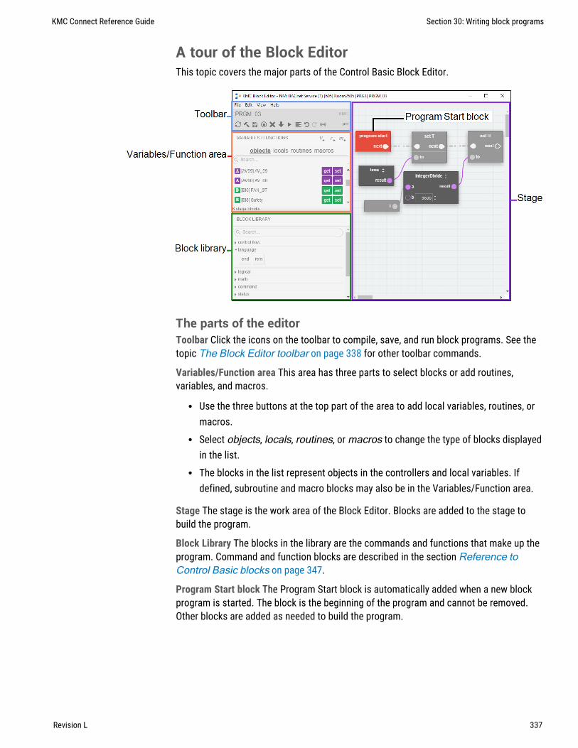
A tour of the Block EditorThis topic covers the major parts of the Control Basic Block Editor.
The parts of the editorToolbar Click the icons on the toolbar to compile, save, and run block programs. See thetopic The Block Editor toolbar on page 338 for other toolbar commands.
Variables/Function area This area has three parts to select blocks or add routines,variables, and macros.
l Use the three buttons at the top part of the area to add local variables, routines, ormacros.
l Select objects, locals, routines, or macros to change the type of blocks displayedin the list.
l The blocks in the list represent objects in the controllers and local variables. Ifdefined, subroutine and macro blocks may also be in the Variables/Function area.
Stage The stage is the work area of the Block Editor. Blocks are added to the stage tobuild the program.
Block Library The blocks in the library are the commands and functions that make up theprogram. Command and function blocks are described in the section Reference toControl Basic blocks on page 347.
Program Start block The Program Start block is automatically added when a new blockprogram is started. The block is the beginning of the program and cannot be removed.Other blocks are added as needed to build the program.
KMC Connect Reference Guide Section 30: Writing block programs
Revision L 337

The Block Editor toolbarThe icons on the toolbar compile, save, clear, and run the block programs in the programobject.
Compile and Save Converts the block program into Control Basic line code and saves it inthe program object.
Compile Converts the block program into Control Basic line code but does not save it inthe program object.
Refresh Refreshes the Block Editor workspace.
Halt Stops the program from running in the program object.
Clear Deletes the program from the program object.
Unload Deletes the program from the program object. In KMC Controls controllers this issimilar to Clear.
Run Compiles the program, saves it to memory, and runs the program in the programobject.
Align blocks Select two or more blocks to align the tops, left sides, right sides or bottomsof the selected blocks.
Undo Undo the last action.
Redo Redo the last action.
Display live values Displays the actual value of the block's selected property. If theproperty type changes, compile the program to display the value of the new property.
Get and Set blocksGet and Set blocks represent objects and local variables within the controller. Theytransfer values between the program and local variables or objects in the controller.
Get blocksA Get block transfers a value to a program statement from local variables or objects in thecontroller.
Comments Save notes or remarks for the block in the comments area.
Select property Selects the Present Value or Out Of Service property value.
Section 30: Writing block programs KMC Controls, Inc.
338 Revision L

Connection point The connection point connects to a Set block to connector or to aninput on other types of blocks.
Set blocksA Set block transfers a value to local variables or objects from a program statement.
Comments Save notes or remarks for the block in the Comments area.
Select property Selects the Present Value or Out Of Service property value.
Select priority Selects the BACnet priority for writing to the priority array. The default levelis priority 9.
Connection point Connect this point to Set blocks or the input on other types of blocks.
From previous block Connects to the Program Start block or the previous block in theprogram flow.
To next block Connects to the next block in the program flow.
value Enter a constant in the value field to set the object or variable to a fixed number.
to Connects to a Get block or the result from another block such as a Math block. The toconnector is disabled when there is an entry in value.
Defining and using local variablesLocal variables are place holders for information. They can only be used within theProgram object that defines them and cannot be directly transferred to other ControlBasic programs. Local variables are often used for counters or to store the results of localcalculations.
Adding new variables To add a new local variable, do the following:
1 Click the variable button in the Variables/Function area. The Variables/Functionlist automatically changes to Variables. New Set and Get blocks are added to thebottom of the variables list.
2 Give the variable a unique, descriptive name.
3 Use the variable Get and Set blocks the same as you would use other Get and Setblocks.
KMC Connect Reference Guide Section 30: Writing block programs
Revision L 339

Using an existing variable To use the Get or Set block of an existing local variable, do thefollowing:
1 Click locals to change the Variables/Function list to display local variables.
2 Drag the Get or Set blocks to the Stage.
Adding and editing routinesA routine—often referred to as a subroutine— is a packaged unit of program blocks thatperforms a specific task that is repeated within the same program. The unit can then beadded to a program wherever that particular task is required. Routines are added as Callblocks in the Block Editor.
To add a routine, do the following:
1 Click the routine button in the Variables/Function area. A Call block is added tothe routines list and the list automatically changes to the routines list.
2 Give this block a unique, descriptive name.
3 Drag the Call block to the stage.
4 Connect the Call block to other blocks as required by program logic.
Section 30: Writing block programs KMC Controls, Inc.
340 Revision L

To add a Call block to a program, do the following:
1 Click routines to change the Variables/Function list to display the list of Call blocks.
2 Drag a Call block to the Stage.
To edit a routine, do the following:
1 On a Call block, click the r next to the program name.
2 On the return stage, add blocks as needed between the Routine Start block and theReturn block. The Routine Start and Return blocks are added automatically andcannot be removed.
3 When finished, click Program in the upper right corner to return to the main programstage.
Macro blocksA Macro block represents a set of Control Basic instructions that are inserted into aprogram with a single block. That single block can be reused in the program or otherprograms without rewriting complicated or long sequences.
Tip: A properly written Macro block can be moved to anotherprogram without rewriting it because it does not directly refer tocontroller objects. All references to objects are made through theMacro block ports.
Macro block ports are the inputs and outputs to the set of instructions. The portsrepresent the arguments or parameters used within the macro.
l Input ports transfer values into the macro.l Output ports transfer results from the macro to variables.l The ports appear as the connector points on the Macro block.l Ports are optional and can be added, deleted, or renamed as needed when setting up
the macro.l When the Macro block is compiled, the reference to the port is replaced by the
actual parameter, such as the results from a previous block, local variable, orconstant.
KMC Connect Reference Guide Section 30: Writing block programs
Revision L 341

Macro blocks can be saved on the local computer and reused in other programs, either inthe same controller or in other controllers in the Network Manager list.
Adding a new Macro block
To add a new Macro block to the program, do the following:
1 Click the Macro button in the Variables/Function area. A Macro block is addedto the Macros list and the list automatically changes to show the Macro blocks.
2 Give the new block a unique, descriptive name.
3 Drag the Macro block to the stage.
4 Connect the Macro block to other blocks as required by program logic.
Adding existing Macro blocks to the stage
To add an existing Macro block to the stage, do the following:
1 Click macros to change the Variables/Function list to display the Macro blocks.
2 Drag the Macro block to the stage.
3 Connect the Macro block to other blocks as required by program logic.
Editing and saving Macro blocks
Macro blocks can only be edited on the stage. To edit an existing Macro block, do thefollowing:
1 On a Macro block, click the m next to the macro name.
2 In the Macro Block Editor, add or delete ports as needed.
l Input ports add input connectors to the macro block and transfer parametersinto the line code.
l Output ports add a variable selector to the macro block and transfer results fromthe line code to a variable or object.
l Change the port name to be descriptive of the port function.
Section 30: Writing block programs KMC Controls, Inc.
342 Revision L

3 Add the Control Basic line code using the names of the ports instead of mnemonicsor object names. Control Basic can be entered directly in the editor or copied andpasted from another program text file.
Note: To write to an output port at a BACnet priority level other than 9, add an atsign (@) followed by the priority number after the name of the output port. Forexample result@8.
4 To save the Macro block for reuse in other programs, click Save macro to server.
5 When finished, click the close editor button .
KMC Connect Reference Guide Section 30: Writing block programs
Revision L 343

Reusing Macro blocks
Saved Macro blocks can be reused in other programs in either the same controller orprograms in other controllers.
To reuse a saved Macro, drag it from the Macros group in the Block Library to the stage.
To move a Macro block to another computer, copy the file in Windows Explorer. Macroblock files are located atC:\ProgramData\KMC Controls\Block Program Blocks.
Limitations and importing line programsThe Block editor will attempt to import programs from existing line code. However, someprograms may be too complex and will require revision before they can be imported.
Note: Because of the limitations of importing line programs,switching between line programing and block programming in thesame program object is not recommended.
Capitalization All keywords in the line program must be capitalized before importing.
REM Remark statements are not imported. They can be added in the Block Editor once theprogram is imported.
Multiple statements on one line Statements on the same line that are separated by acolon (:) are not supported.
Section 30: Writing block programs KMC Controls, Inc.
344 Revision L

Off-panel points Reading from and writing to objects that are not in the same controllermust be done with line programming. KMC Controls recommends using just one programfor all off-panel reading and writing and then storing the results in value objects. See thetopics Transferring values between BACnet controllers on page 228.
Unsuported keywordsThe following keywords are not supported with blocks in blockprogramming.
l ALIASl FUNCTION and the associated keywords ENDFUNC and FRETURNl GOTOl HALTl NETPOINTl NETPOINTCACHEl ON GOTOl ON GOSUBl ONERRORl PROCEDURE and the associated keywords ENDPROC and PRETURN keywordsl STRING
KMC Connect Reference Guide Section 30: Writing block programs
Revision L 345

Section 30: Writing block programs KMC Controls, Inc.
346 Revision L

Section 31: Refe rence to Control Basic blocks
This section covers the blocks for the Control Basic block programming.
Abs blockBlock type: Math
The Abs block returns the absolute value of the input. The input at a can be a Get block orthe output of a Math block. Connect the result connector to another Math block or a Setblock.
Add blockBlock type: Math
The Add block performs addition on all of the input values. The inputs at the valueconnectors can be from a constant, a Get block, or the result of a Math block. Connect theresult connector to the input of another logical block or a Set block.
The Add block can be changed to any of the following types of blocks by clicking on thedouble-arrows and choosing a new function.
l Multiply block on page 374l Divide block on page 360l IntegerDivide block on page 368l Mod block on page 373l Subtract block on page 387l Power block on page 377
Add additional inputs to the block by clicking + Add Input.
KMC Connect Reference Guide
Revision L 347

And blockBlock type: Logical
The And block performs the logical AND of two expressions. The result is TRUE if bothexpressions are non-zero; otherwise, the result is FALSE. The inputs at the valueconnectors can be from constants or other blocks.
The And block can be changed to an Or or an Xor block by clicking on the double-arrowsand choosing the new function.
Add additional inputs to the block by clicking + Add Input.
See also the topics Or block on page 376 and Xor block on page 391.
AntiCycle blockBlock type: Command
Use the AntiCycle macro block to prevent an output from rapidly cycling. A typical use forthis block is a timed lockout for compressors or motors.
l The value at MinOnTime sets the minium time that output will be TRUE (1) afterinput1 is FALSE (0).
l The value at MinOffTime sets the maximum time that output must be FALSE (1)after input1 is TRUE (0).
l The values for MinOnTime and MinOffTime can be from blocks or constants.l The variable for output must be a binary object or a local variable.
If the time value at MinOffTime is a constant, it can be expressed with any of thefollowing formats:
hh:mm:ss 00:20:00hh:mm 00:20seconds 120
Section 31: Reference to Control Basic blocks KMC Controls, Inc.
348 Revision L

Arccos blockBlock type: Trigonometry
The Arccos block calculates the arccosine of the value at a. The value at result isexpressed in radians. The value at a can be from a constant, a Get block, or the result of aMath block. The block is typically used with a Math block or connected to a Set block.
The Arccos block can be changed to any of the following types of blocks by clicking onthe double-arrows and choosing a new function.
l Arcsin block on page 349l Arctan block on page 350l Cos block on page 355l Sin block on page 385l Tan block on page 388
Arcsin blockBlock type: Trigonometry
The Arcsin block calculates the arcsine of the value at a. The value at result is expressedin radians. The value at a can be from a constant, a Get block, or the result of a Mathblock. The block is typically used with a Math block or connected to a Set block.
The Arcsin block can be changed to any of the following types of by clicking on thedouble-arrows and choosing a new function.
l Arccos block on page 349l Arctan block on page 350l Cos block on page 355l Sin block on page 385l Tan block on page 388
KMC Connect Reference Guide Section 31: Reference to Control Basic blocks
Revision L 349

Arctan blockBlock type: Trigonometry
The Arctan block calculates the arctangent of the value at a. The value at result isexpressed in radians. The value at a can be from a constant, a Get block, or the result of aMath block. The block is typically used with a Math block or connected to a Set block.
The Arctan block can be changed to any of the following types of by clicking on thedouble-arrows and choosing a new function.
l Arccos block on page 349l Arcsin block on page 349l Cos block on page 355l Sin block on page 385l Tan block on page 388
Avg blockBlock type: Math
The Avg block returns the average value of the values connected to the inputs. Connectthe result connector to another Math block or a Set block.
The block can be changed to a Max or Min block by clicking on the double-arrows andchoosing a new function.
Add additional inputs to the block by clicking + Add Input.
An average can also be calculated with the MinMaxAvg block on page 372.
Clear blockBlock type: Command
The Clear block resets the value of all local variables to zero.
Section 31: Reference to Control Basic blocks KMC Controls, Inc.
350 Revision L

Close blockBlock type: Command
The Close block sets the value of the input block to zero (0) for analog objects andvariables and inactive for binary objects and variables.
The Close block can be changed to any of the following types of blocks by clicking on thedouble-arrows and choosing a new command.
l Open block on page 376l Start block on page 386l Stop block on page 387l Enable block on page 362l Disable block on page 359
Compare blockBlock type: Logical
The Compare block is a macro block that includes an optional deadband. The input anddeadband (HI-DB, LO-DB) values can be from Get blocks, Math blocks, or constants.
l If input1 is greater than input2 plus the value at HI-DB, the output variable isTRUE.
l If input1 is less than input2 minus the value at LO-DB, the output variable isFALSE.
l Values for HI-DB and LO-DB are required. Enter zero (0) if no value is required.l Only binary objects or local variables can be selected for output.
KMC Connect Reference Guide Section 31: Reference to Control Basic blocks
Revision L 351

See the following topics for additional comparison blocks.
l CompareEqual block on page 352l CompareGreater block on page 352l CompareGreaterEqual block on page 353l CompareLess block on page 353l CompareLessEqual block on page 354l CompareNotEqual block on page 355
CompareEqual blockBlock type: Logical
The CompareEqual block tests whether one value is equal to a second value. The block istypically used as the condition for an If block or connected to a Set block.
If the value at a is equal to the value at b, the result is logically true. The values at a and bcan be from a Get block, the result of a Math block, or a constant entered in value.
The CompareEqual block can be changed to any of the following types of blocks byclicking on the double-arrows and choosing a new function.
l CompareGreater block on page 352l CompareGreaterEqual block on page 353l CompareLess block on page 353l CompareLessEqual block on page 354l CompareNotEqual block on page 355
See also the topic Compare block on page 351.
CompareGreater blockBlock type: Logical
The CompareGreater block tests if one value is greater than a second value. The block istypically used as the condition for an If block or connected to a Set block.
If the value at a is greater than the value at b, the result is logically true. The values at aand b can be from a Get block, the result of a Math block, or a constant entered in value.
Section 31: Reference to Control Basic blocks KMC Controls, Inc.
352 Revision L

The CompareGreater block can be changed to any of the following types of blocks byclicking on the double-arrows and choosing a new function.
l CompareEqual block on page 352l CompareGreaterEqual block on page 353l CompareLess block on page 353l CompareLessEqual block on page 354l CompareNotEqual block on page 355
See also the topic Compare block on page 351.
CompareGreaterEqual blockBlock type: Logical
The CompareGreaterEqual block is a logical block that tests if one value is greater than orequal to a second value. The block is typically used as the condition for an If block orconnected to a Set block.
If the value at a is greater than or equal to the value at b, the result is logically true. Thevalues at a and b can be from a Get block, the result of a Math block, or a constantentered in value.
The CompareGreaterEqual block can be changed to any of the following types of blocksby clicking on the double-arrows and choosing a new function.
l CompareEqual block on page 352l CompareGreater block on page 352l CompareLess block on page 353l CompareLessEqual block on page 354l CompareNotEqual block on page 355
See also the topic Compare block on page 351.
CompareLess blockBlock type: Logical
The CompareLess block tests if one value is less than a second value. The block istypically used as the condition for an If block or connected to a Set block.
KMC Connect Reference Guide Section 31: Reference to Control Basic blocks
Revision L 353

If the value at a is less than the value at b, the result is logically true. The values at a andb can be from a Get block, the result of a Math block, or a constant entered in value.
The CompareLess block can be changed to any of the following types of blocks byclicking on the double-arrows and choosing a new function.
l CompareLess block on page 353l CompareGreater block on page 352l CompareGreaterEqual block on page 353l CompareLessEqual block on page 354l CompareNotEqual block on page 355
See also the topic Compare block on page 351.
CompareLessEqual blockBlock type: Logical
The CompareLessEqual block tests if one value is less than or equal to a second value.The block is typically used as the condition for an If block or connected to a Set block.
If the value at a is less than or equal to the value at b, the result is logically true. Thevalues at a and b can be from a Get block, the result of a Math block, or a constantentered in value.
The CompareLessEqual block can be changed to any of the following types of blocks byclicking on the double-arrows and choosing a new function.
l CompareEqual block on page 352l CompareGreater block on page 352l CompareGreaterEqual block on page 353l CompareLess block on page 353l CompareNotEqual block on page 355
See also the topic Compare block on page 351.
Section 31: Reference to Control Basic blocks KMC Controls, Inc.
354 Revision L

CompareNotEqual blockBlock type: Logical
The CompareNotEqual blocks tests whether one value is not equal to a second value. Thevalues at a and b can be from a Get block, the result of a Math block, or a constantentered in value.
The block is typically used as the condition for an If block or connected to a Set block. Ifthe values at a and b are not equal, the result is logically true.
The CompareNotEqual block can be changed to any of the following types of blocks byclicking on the double-arrows and choosing a new function.
l CompareEqual block on page 352l CompareGreater block on page 352l CompareGreaterEqual block on page 353l CompareLess block on page 353l CompareLessEqual block on page 354
See also the topic Compare block on page 351.
Cos blockBlock type: Trigonometry
The Cos block calculates the cosine of the value at a. The value at result is expressed inradians. The block is typically used with a Math block or connected to a Set block. Thevalue at a can be from a constant, a Get block, or the result of a Math block.
The Cos block can be changed to any of the following types of by clicking on thedouble-arrows and choosing a new function.
l Arccos block on page 349l Arcsin block on page 349l Arctan block on page 350l Sin block on page 385l Tan block on page 388
KMC Connect Reference Guide Section 31: Reference to Control Basic blocks
Revision L 355

Counter blockBlock type: Math
Use the Counter macro Math block to change the value of the output by a fixed amountevery time an input is triggered. This can be useful for installations such as ramping asupply fan frequency drive during start up by triggering INC trigger once a minute until anoperational static pressure is reached. After start up, a PID loop would then be used tomodulate the frequency drive.
l A transition from FALSE (0) to TRUE (1) at INC trigger or DEC trigger willincrease or decrease the value at output by the amount in INC amount orDEC amount.
l The HI Limit and LOW Limit input sets the minimum and maximum value foroutput. These inputs are optional and can be from other blocks or constants.
l Setting clear to TRUE (1) resets and holds the output value to zero (0).l The variable for output must be an analog object or local variable.
DelayOnMake blockBlock type: Time
The DelayOnMake macro block sets output to TRUE when input changes to TRUE afterthe period set by delay. The values for delay and input can be from Get blocks, otherblocks, or constants. The variable for output must be a binary object or a local variable.
Section 31: Reference to Control Basic blocks KMC Controls, Inc.
356 Revision L

If the time value at delay is a constant, it can be expressed with any of the followingformats:
hh:mm:ss 00:20:00hh:mm 00:20seconds 120
See also the topic DelayOnBreak block on page 357.
Dec blockBlock type: Math
The Dec block decrements the value at point by the value at step. The values at step andpoint can be from constants, Get blocks, or the results from Math blocks.
The Dec block can be changed to an Inc block by clicking on the double-arrows andchoosing the new function.
DelayOnBreak blockBlock type: Time
The DelayOnBreak macro block extends the time that output is TRUE for the period setby delay after the input condition changes to FALSE. The values for delay and inputcan be from Get blocks, other blocks, or constants. The variable for output must be abinary object or a local variable.
KMC Connect Reference Guide Section 31: Reference to Control Basic blocks
Revision L 357

If the time value at delay is a constant, it can be expressed with any of the followingformats:
hh:mm:ss 00:20:00hh:mm 00:20seconds 120
See also the topic DelayOnMake block on page 356.
Dewpoint blockBlock type: Value
The Dewpoint block calculates the dew point in degrees Fahrenheit based on airtemperature–in degrees Fahrenheit–and humidity. Humidity at hum and temperature attemp can be from constants, Get blocks, or the results of Math blocks. The block istypically used with a Math block or connected to a Set block.
The Dewpoint block can be changed to any of the following types of blocks by clicking onthe double-arrows and choosing a new function.
l Enthalpy block on page 362l Enthalpysi block on page 363l Dewpointsi block on page 359
To calculate dew point in degrees Celsius, see the topic Dewpointsi block on page 359.
Section 31: Reference to Control Basic blocks KMC Controls, Inc.
358 Revision L

Dewpointsi blockBlock type: Value
The Dewpointsi block returns the dew point in degrees Celsius based on outside airtemperature, in degrees Celsius, and the outside humidity. Humidity at hum andtemperature at temp can be from constants, Get blocks, or the results of Math blocks.The block is typically used with a Math block or connected to a Set block.
The Dewpointsi block can be changed to any of the following types of blocks by clickingon the double-arrows and choosing a new function.
l Dewpoint block on page 358l Enthalpy block on page 362l Enthalpysi block on page 363
To calculate dew point in degrees Fahrenheit, see the topic Dewpoint block on page 358.
Disable blockBlock type: Command
The Disable block is a command block that sets the value of the input block to zero (0) foranalog objects and variables and inactive for binary objects and variables.
The Disable block can be changed to any of the following types of blocks by clicking onthe double-arrows and choosing a new command.
l Close block on page 351l Open block on page 376l Start block on page 386l Stop block on page 387l Enable block on page 362
KMC Connect Reference Guide Section 31: Reference to Control Basic blocks
Revision L 359

Divide blockBlock type: Math
The Divide block divides the value of a by the value of b. The values at a and b can befrom constants, Get blocks, or the results from Math blocks. Connect the resultconnector to the input of another Math block or a Set block.
The Divide block can be changed to any of the following types of blocks by clicking on thedouble-arrows and choosing a new function.
l Multiply block on page 374l IntegerDivide block on page 368l Mod block on page 373l Add block on page 347l Subtract block on page 387l Power block on page 377
See the related topics IntegerDivide block on page 368 and Mod block on page 373.
Dom blockBlock type: Time
The Dom block returns the current day of the month. The block is typically used with alogical block, or connected to a Set block.
The Dom block can be changed to any of the following types of blocks by clicking on thedouble-arrows and choosing a new function.
l Dow block on page 361l Doy block on page 361l Month block on page 373l Time block on page 389l Year block on page 392
Section 31: Reference to Control Basic blocks KMC Controls, Inc.
360 Revision L

Dow blockBlock type: Time
The Dow block returns a numerical value for the day of the week. In BACnet controllers,Monday is day 1 and Sunday is day 7. The block is typically used with a logical block, orconnected to a Set block.
The Dow block can be changed to any of the following types of blocks by clicking on thedouble-arrows and choosing a new function.
l Dom block on page 360l Doy block on page 361l Month block on page 373l Time block on page 389l Year block on page 392
Doy blockBlock type: Time
The Doy block returns the current day of the year. The block is typically used with a logicalblock or connected to a Set block.
l The year always begins on January 1.l December 31st is day 366.l February is always counted as having 29 days. This means March 1 is always day
61.l On non-leap years, February 29 (day 60) is skipped.
The Doy block can be changed to any of the following types of blocks by clicking on thedouble-arrows and choosing a new function.
l Dom block on page 360l Dow block on page 361l Month block on page 373l Time block on page 389l Year block on page 392
KMC Connect Reference Guide Section 31: Reference to Control Basic blocks
Revision L 361

Enable blockBlock type: Command
The Enable block sets the value of the input block to one (1) for analog objects andvariables and active for binary objects and variables.
The Enable block can be changed to any of the following types of blocks by clicking onthe double-arrows and choosing a new command.
l Close block on page 351l Open block on page 376l Start block on page 386l Stop block on page 387l Disable block on page 359
End blockBlock type: Language
The End block terminates the execution of a program. When the block is encountered, theprogram stops reading blocks and exits the program.
The block programming editor automatically adds an End block. Other End blocks may berequired by program design.
Enthalpy blockBlock type: Value
The Enthalpy block calculates enthalpy based on air temperature–in degrees Fahrenheit–and humidity. The value of result is expressed as BTUs per pound of air. Humidity at humand temperature at temp can be from constants, Get blocks, or the results of Mathblocks. The block is typically used with a Math block or connected to a Set block.
Section 31: Reference to Control Basic blocks KMC Controls, Inc.
362 Revision L

The Enthalpy block can be changed to any of the following types of blocks by clicking onthe double-arrows and choosing a new function.
l Enthalpysi block on page 363l Dewpoint block on page 358l Dewpointsi block on page 359
To calculate enthalpy as kilojoules per kilogram of air, see the topic Enthalpysi block onpage 363.
Enthalpysi blockBlock type: Value
The Enthalpysi block calculates enthalpy based on air temperature–in degrees Celsius–and humidity. The value at result is expressed as kilojoules per kilogram of air. Humidityat hum and temperature at temp can be from constants, Get blocks, or the results ofMath blocks. The block is typically used with a Math block or connected to a Set block.
The Enthalpysi block can be changed to any of the following types of blocks by clicking onthe double-arrow and choosing a new function.
l Enthalpy block on page 362l Dewpoint block on page 358l Dewpointsi block on page 359
To calculate enthalpy as BTUs per pound of air, see the topic Enthalpy block on page362.
KMC Connect Reference Guide Section 31: Reference to Control Basic blocks
Revision L 363

EqualToDiff blockBlock type: Logical
The EqualToDiff block is a comparison macro block. The values for input1, input2, anddiff can be from Get blocks, Math blocks, or constants.
l If input1 is equal to input2, the output variable is TRUE.l If input1 is greater than input2 plus the value at diff, the output variable is FALSE.l If input1 is less than input2 minus the value at diff, the output variable is FALSE.l An entry for diff is required. Enter zero (0) if no value is required.l Only binary objects or local variables can be selected for output.
The EqualToDiff block can be changed to a LessThanDiff block on page 370or aGreaterThanDiff block on page 365 by clicking on the double-arrows and choosing anew function.
For blockBlock type: Control flow
The For block adds a For To Next loop to the program. The loop repeats a set ofinstructions a specific number of times.
Section 31: Reference to Control Basic blocks KMC Controls, Inc.
364 Revision L

index is the variable or value that increments each time the loop repeats. It controlswhether Control Basic repeats the loop. The value at index must be local to the controllerin which the Control Basic program is running.
startingValue is the initial value that Control Basic assigns to index value.
endingValue is the value that the index value must equal before the loop ends.
stepIncrement is the amount that Control Basic adds to index with each iteration of theloop. The value at stepIncrement can be a positive or negative value.
body connects to the program blocks that are executed inside of the loop.
GreaterThanDiff blockBlock type: Logical
The GreaterThanDiff block is a comparison macro block. The values for input1, input2,and diff can be from Get blocks, other blocks, or constants.
l If input1 is greater than or equal to input2, the output variable is TRUE.l If input1 is less than input2 minus the value at diff, the output variable is FALSE.l An entry for diff is required. Enter zero (0) if no value is needed.l Only binary objects or local variables can be selected for output.
The GreaterThanDiff block can be changed to an EqualToDiff block on page 364 or aLessThanDiff block on page 370 by clicking on the double-arrows and choosing a newfunction.
Hsel blockBlock type: Logical
The Hsel block selects the highest, second highest, etc. value of blocks connected to theinput. The value at N defines whether it selects the highest (1) or the second highest (2)etc. An input block can be a Get block, the result of a Math block, or a constant entered invalue.
KMC Connect Reference Guide Section 31: Reference to Control Basic blocks
Revision L 365

The Hsel block can be changed to an Lsel block by clicking on the double-arrows andchoosing the new function.
Add additional inputs to the block by clicking + Add Input.
See also the topic Lsel block on page 371.
If blockBlock type: Control flow
The If block is a decision making block based on the state of the input at the conditionconnector. The condition input can be from a Get block or the results of another blockwith a value that is either true or false (high or low, on or off, etc.)
l If condition is true the block connected to the true connector is executed.l If the condition is false (not true) the block connected to the false connector is
executed.l A block connected to the next connector is the next block executed in the program
flow after the blocks connected to either the true or false connectors are executed.
The If block can be changed to an IfPlus or IfMinus block by clicking on the double-arrowsand choosing the new function.
See also the topics IfMinus block on page 366 and IfPlus block on page 367.
IfMinus blockBlock type: Control flow
The IfMinus block is a decision making block that detects the first time a conditionchanges from true to false. If the condition is false and on the previous scan it was true,the block connected to the true connector will be executed; otherwise, the blockconnected to the false connecter will be executed.
A block connected to the next connector is the next block executed in the program flow.
Section 31: Reference to Control Basic blocks KMC Controls, Inc.
366 Revision L

The IfPlus block can be changed to an If or IfPlus block by clicking on the double-arrowsand choosing the new function.
See also the topics If block on page 366 and IfPlus block on page 367.
IfPlus blockBlock type: Control flow
The IfPlus block is a decision making block that detects the first time a condition changesfrom false to true. If the condition is true and on the previous scan it was not true, theblock connected to the true connector will be executed; otherwise, the block connected tothe false connecter will be executed.
A block connected to the next connector is the next block executed in the program flow.
The IfPlus block can be changed to an If or IfMinus block by clicking on the double-arrowsand choosing the new function.
See also the topics If block on page 366 and IfMinus block on page 366.
Inc blockBlock type: Math
The Inc block increments the value at point by the value at step. The values at step andpoint can be from constants, Get blocks, or the results from Math blocks.
The Inc block can be changed to a Dec block by clicking on the double-arrows andchoosing the new function.
KMC Connect Reference Guide Section 31: Reference to Control Basic blocks
Revision L 367

Int blockBlock type: Math
The Int block returns the integer portion of the block connected to a. The value returned isthe greatest integer that is less than or equal to the value of expression. The value at acan be a constant, a Get block, or the result of a Math block. Connect the resultconnector to another Math block or a Set block.
IntegerDivide blockBlock type: Math
The IntergerDivide block divides the value of a by the value of b and returns only theinteger portion. The values at a and b can be from constants, Get blocks, or the results ofMath blocks. Connect the result connector to the input of another Math block or a Setblock.
The IntegerDivide block can be changed to any of the following types of blocks by clickingon the double-arrows and choosing a new function.
l Multiply block on page 374l Divide block on page 360l Add block on page 347l Mod block on page 373l Subtract block on page 387l Power block on page 377
Section 31: Reference to Control Basic blocks KMC Controls, Inc.
368 Revision L

Interval blockBlock type: Time
The Interval block is a repeating count-up timer. When the timer reaches the value at a,result is true otherwise result is false. The Interval block is typically used with Compareand If blocks. If the time value at a is a constant, it can be expressed with any of thefollowing formats:
hh:mm:ss 00:20:00hh:mm 00:20seconds 120
Invln blockBlock type: Math
The Invln block returns the inverse natural logarithm of the value at a. The value at a canbe a constant, a Get block, or the result of a Math block. Connect the result connector toanother Math block or a Set block.
KMC Connect Reference Guide Section 31: Reference to Control Basic blocks
Revision L 369

LessThanDiff blockBlock type: Logical
The LessThanDiff block is a comparison macro block. The values for input1, input2, anddiff can be from Get blocks, Math blocks, or constants.
l If input1 is less than or equal to input2, the output variable is TRUE.l If input1 is greater than input2 plus the value at diff, the output variable is FALSE.l An entry for diff is required. Enter zero (0) if no value is required.l Only binary objects or local variables can be selected for output.
The LessThanDiff block can be changed to aGreaterThanDiff block on page 365 or anEqualToDiff block on page 364 by clicking on the double-arrows and choosing a newfunction.
Limiter blockBlock type: Logical
The Limiter block is a macro block that limits the input at value to the range defined bylow and hi. The values at value, low, and hi can be from constants, Get blocks, or theresults of other blocks. Connect the result connector to the input of another Math blockor a Set block.
Tip: Connecting a Get block to value and a Set block to result fromthe same object tests and limits the object's value.
Section 31: Reference to Control Basic blocks KMC Controls, Inc.
370 Revision L

Ln blockBlock type: Math
The Ln block returns the natural logarithm of the value at a. The value at a can be aconstant, a Get block, or the result of a Math block. Connect the result connector toanother Math block or a Set block.
Lsel blockBlock type: Logical
The Lsel block selects the lowest, second lowest, etc. value of blocks connected to theinput. The value at N defines whether it selects the lowest (1) or the second lowest (2)etc. An input block can be a Get block, the result of a Math block, or a constant entered invalue.
The Lsel block can be changed to an Hsel block by clicking on the double-arrows andchoosing the new function.
Add additional inputs to the block by clicking + Add Input.
See also the topic Hsel block on page 365.
Max blockBlock type: Math
The Max block returns the maximum value of the blocks connected to the inputs. An inputblock can be a Get block, the result of a Math block, or a constant entered in value.
The Max block can be changed to an Avg block on page 350 or Min block on page 372by clicking on the double-arrows and choosing the new function.
Add additional inputs to the block by clicking + Add Input.
KMC Connect Reference Guide Section 31: Reference to Control Basic blocks
Revision L 371

Min blockBlock type: Math
The Min block returns the minimum value of the blocks connected to the inputs. An inputblock can be a Get block, the result of a Math block, or a constant entered in value.
The Min block can be changed to an Avg block on page 350 Avg or Max block on page371 by clicking on the double-arrows and choosing the new function.
Add additional inputs to the block by clicking + Add Input.
MinMaxAvg blockBlock type: Math
The MinMaxAvg block is a macro block that returns the minimum, maximum, and averagevalues of the values connected to the inputs. The values at the inputs can be fromconstants, Get blocks, or the results of Math blocks. The min, max, and avg variablescan be analog objects or local variables.
Add additional inputs to the block by clicking + Add Input.
See also the following topics.
l Avg block on page 350l Max block on page 371l Min block on page 372
Section 31: Reference to Control Basic blocks KMC Controls, Inc.
372 Revision L

Mod blockBlock type: Math
The Mod block returns the remainder (or modulus) of a divided by b. The values at a andb can be from constants, Get blocks, or the result from a Math block. Connect the resultconnector to the input of another Math block or a Set block.
The Mod block can be changed to any of the following types of blocks by clicking on thedouble-arrows and choosing a new function.
l Multiply block on page 374l Divide block on page 360l IntegerDivide block on page 368l Add block on page 347l Subtract block on page 387l Power block on page 377
See the related topics Divide block on page 360 and IntegerDivide block on page 368.
Modelnumber blockBlock type: Status
Use the Modelnumber block to set a variable or property to the numerical portion of themodel number of the controller. The block is typically used with an IF block, a Logicalblock, or connected to a Set block.
Month blockBlock type: Time
The Month block returns the current month of the year. The block is typically used with aLogical block or connected to a Set block.
KMC Connect Reference Guide Section 31: Reference to Control Basic blocks
Revision L 373

The Month block can be changed to any of the following types of blocks by clicking on thedouble-arrows and choosing a new function.
l Dow block on page 361l Doy block on page 361l Doy block on page 361l Time block on page 389l Year block on page 392
Multiply blockBlock type: Math
The Multiply block multiplies the input values. The input values can be from constants,Get blocks, or the results from Math blocks. Connect the result connector to the input ofanother Math block or a Set block.
The Multiply block can be changed to any of the following types of blocks by clicking onthe double-arrows and choosing a new function.
l Divide block on page 360l IntegerDivide block on page 368l Mod block on page 373l Add block on page 347l Subtract block on page 387l Power block on page 377
Add additional inputs to the block by clicking + Add Input.
Nan blockBlock type: Math
Use the Nan block to set a variable or property to a Not A Number constant or to test ifthe variable or property is equal to Not A Number. The block is typically used as thecondition for an If block or connected to a Set block.
Section 31: Reference to Control Basic blocks KMC Controls, Inc.
374 Revision L

Netsensorstatus blockBlock type: Status
The Netsensorstatus block returns TRUE if a functional NetSensor is connected to thecontroller and FALSE if the controller does not detect a NetSensor. The block is typicallyused with an IF block, a Logical block, or connected to a Set block.
Not blockThe Not block performs a logical negation operation on the input. If the input is 0, theresult is 1. If the input is non-zero, the result is 0. The block at a can be from a Get blockor the result of a Math block.
OneShot blockBlock type: Time
The OneShot block sets the variable at output to TRUE the first time input changes fromFALSE to TRUE. The output variable remains TRUE for the period set by duration andthen changes to FALSE. The values for duration and input can be from Get blocks,other blocks, or constants. The variable for output must be a binary object or a localvariable.
If the time value at duration is a constant, it can be expressed with any of the followingformats:
hh:mm:ss 00:20:00hh:mm 00:20seconds 120
See also the topic IfPlus block on page 367.
KMC Connect Reference Guide Section 31: Reference to Control Basic blocks
Revision L 375

Open blockBlock type: Command
The Open block is a command block that sets the value of analog objects and variables toone (1) and binary objects and variables to active.
The Open block can be changed to any of the following types of blocks by clicking on thedouble-arrows and choosing a new command.
l Close block on page 351l Start block on page 386l Stop block on page 387l Enable block on page 362l Disable block on page 359
Or blockBlock type: Logical
The Or block performs a logical OR of the values of the input blocks. The result is true ifany of the inputs are true. The result is false if all inputs are false. The values at a and bcan be from constants or other blocks.
The Or block can be changed to an And block on page 348 or Xor block on page 391 byclicking on the double-arrows and choosing the new function.
Add additional inputs to the block by clicking + Add Input.
Section 31: Reference to Control Basic blocks KMC Controls, Inc.
376 Revision L

Outputoverride blockBlock type: Status
The Outputoverride block returns the switch position of an optional HPO-6700 seriesoutput board installed in the controller in which Control Basic is running. The blockreturns FALSE if the switch is in AUTO and TRUE if the switch is set to either the OFFor HAND position. The output object instance can be a numerical constant entered at aor a Get block.
Paneladdress blockBlock type: Status
Use the Paneladdress block to set a variable or property to the device instance of thecontroller. The block is typically used with an IF block, a logical block, or connected to aSet block.
Pi blockBlock type: Math
Use the Pi block to set a variable or property to the value of the constant pi. The block istypically used with a Math block or connected to a Set block.
Power blockBlock type: Math
The Power block raises the value of a by the value of b. The values at a and b can befrom constants, Get blocks, or the results from Math blocks. Connect the resultconnector to the input of another Math block or a Set block.
KMC Connect Reference Guide Section 31: Reference to Control Basic blocks
Revision L 377

The Power block can be changed to any of the following types of blocks by clicking on thedouble-arrows and choosing a new function.
l Multiply block on page 374l Divide block on page 360l IntegerDivide block on page 368l Mod block on page 373l Add block on page 347l Subtract block on page 387
Powerloss blockBlock type: Status
The Powerloss block returns TRUE on the first scan of all Control Basic programs afterpower is restored. After the first scan, it returns as FALSE. The block is typically usedwith an If block, a logical block, or connected to a Set block.
Program Start blockThe Program Start block is automatically added when a new block program is started. Theblock marks the beginning of the program and cannot be removed. Other blocks areadded as needed to build the program.
Rem blockBlock type: Language
A Rem block inserts explanatory comments or remarks into the program. Use Rem blocksto document the use of a subroutine or to explain a calculation.
Section 31: Reference to Control Basic blocks KMC Controls, Inc.
378 Revision L

Reset blockBlock type: Math
The Reset block is a macro block that calculates an output in one unit of measure—forexample, a boiler hot water setpoint—from an input in another unit of measure such asoutside air temperature in degrees Fahrenheit.
l Input values—OUT_MAX, OUT_MIN, IN_MAX, IN_MIN, and input—can be fromGet blocks, the results of other blocks, constants, or local variables.
l The variables for slope and y-intercept are required and are usually local variables.l The output variable can be an object within the controller or a local variable.l The output value is limited to the range set by OUT_MIN and OUT_MAX.
The Reset block can be changed to a Slope block by clicking on the double-arrows andchoosing the new function.
Rlq blockBlock type: Command
The Rlq bloc relinquishes the priority level of the BACnet output or value object connectedto a.
To set the priority level, do the following:
1 Select the block. A selected block has a yellow border.
2 Click the priority arrow above the box.
3 Click the up and down arrows in the priority list to choose the new priority value.
KMC Connect Reference Guide Section 31: Reference to Control Basic blocks
Revision L 379

Rnd blockBlock type: Math
The Rnd block calculates a random number between 0 and the value at a-1. The value at acan be a constant, a Get block, or the result of a Math block. Connect the resultconnector to another Math block or a Set block.
Routine Start blockThe Routine Start block is automatically added to new routines. The block is the beginningof the routine and cannot be removed. See the topic Adding and editing routines onpage 340.
Scans blockBlock type: Time
The Scan block returns the rate a controller is processing all Control Basic programs. Asthe complexity or length of a program increases, it takes the program longer to processand the scan rate decreases. The value at result is expressed in scans per second.
Section 31: Reference to Control Basic blocks KMC Controls, Inc.
380 Revision L
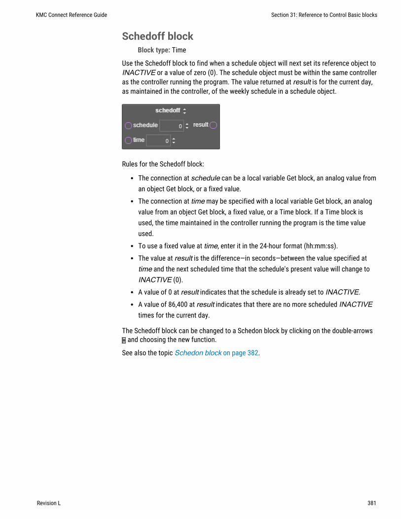
Schedoff blockBlock type: Time
Use the Schedoff block to find when a schedule object will next set its reference object toINACTIVE or a value of zero (0). The schedule object must be within the same controlleras the controller running the program. The value returned at result is for the current day,as maintained in the controller, of the weekly schedule in a schedule object.
Rules for the Schedoff block:
l The connection at schedule can be a local variable Get block, an analog value froman object Get block, or a fixed value.
l The connection at time may be specified with a local variable Get block, an analogvalue from an object Get block, a fixed value, or a Time block. If a Time block isused, the time maintained in the controller running the program is the time valueused.
l To use a fixed value at time, enter it in the 24-hour format (hh:mm:ss).l The value at result is the difference—in seconds—between the value specified attime and the next scheduled time that the schedule's present value will change toINACTIVE (0).
l A value of 0 at result indicates that the schedule is already set to INACTIVE.l A value of 86,400 at result indicates that there are no more scheduled INACTIVE
times for the current day.
The Schedoff block can be changed to a Schedon block by clicking on the double-arrowsand choosing the new function.
See also the topic Schedon block on page 382.
KMC Connect Reference Guide Section 31: Reference to Control Basic blocks
Revision L 381
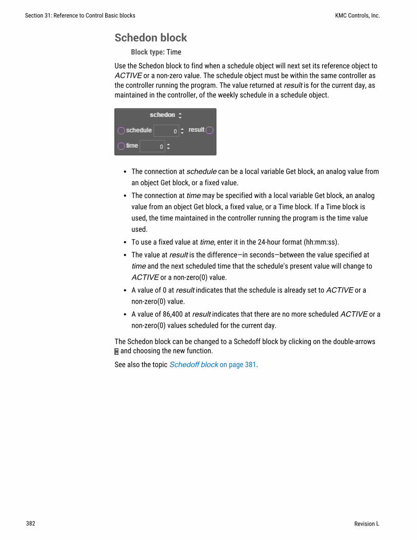
Schedon blockBlock type: Time
Use the Schedon block to find when a schedule object will next set its reference object toACTIVE or a non-zero value. The schedule object must be within the same controller asthe controller running the program. The value returned at result is for the current day, asmaintained in the controller, of the weekly schedule in a schedule object.
l The connection at schedule can be a local variable Get block, an analog value froman object Get block, or a fixed value.
l The connection at time may be specified with a local variable Get block, an analogvalue from an object Get block, a fixed value, or a Time block. If a Time block isused, the time maintained in the controller running the program is the time valueused.
l To use a fixed value at time, enter it in the 24-hour format (hh:mm:ss).l The value at result is the difference—in seconds—between the value specified attime and the next scheduled time that the schedule's present value will change toACTIVE or a non-zero(0) value.
l A value of 0 at result indicates that the schedule is already set to ACTIVE or anon-zero(0) value.
l A value of 86,400 at result indicates that there are no more scheduled ACTIVE or anon-zero(0) values scheduled for the current day.
The Schedon block can be changed to a Schedoff block by clicking on the double-arrowsand choosing the new function.
See also the topic Schedoff block on page 381.
Section 31: Reference to Control Basic blocks KMC Controls, Inc.
382 Revision L

Select blockBlock type: Command
Use the Select macro block to choose a value from a list of values. This block is useful tochoose a setpoint based on a system mode.
l The value at N points to the position in the list of input values to use as the outputvalue.
l N must be an integer. Non-integer values will not change the output value.l The value inputs can be from blocks or constants.l The variable for output must be an analog object or a local variable.
Add additional inputs to the block by clicking + Add Input.
Sensoroff blockBlock type: Value
Use the Sensoroff block to detect an open-circuit condition at an analog input. The inputat a is typically a Get block for an analog input. The result is usually connected to an if,ifMinus, or ifPlus block.
The Sensoroff block can be changed to a Sensoron block on page 384 by clicking on thedouble-arrows and choosing the new function.
A typical application is to detect momentary conditions such as a pressed button. If theopened contact condition lasts longer than two minutes, the function will be disabled.After three minutes, the object will change Out Of Service to true, but the commandswill still execute.
When used with Sensoroff block on page 383 and If block on page 366, IfMinus blockon page 366, or IfPlus block on page 367, you can determine three separate conditionsfrom one input:
l A temperature or other analog reading.l A sensor with open contacts (Sensoroff).l A sensor with closed contacts (Sensoron).
KMC Connect Reference Guide Section 31: Reference to Control Basic blocks
Revision L 383

A Sensoroff block can also be used with inputs using a table if the minimum value in thetable is set to a value greater than zero and its maximum value is less than 5.00 volts.
Input Voltage Detected condition
0 Closed circuit
0.4 Temperature-55 degrees
4.9 Temperature-95 degrees
5.0 or greater Open circuit
Table 31–1 Example table for Sensoroff blocks
In the table Example table for Sensoroff blocks on page 384, the input voltage undernormal temperature conditions will never fall below 0.4 volts. When a sensor is shorted toground, the input voltage will fall to zero, which is a condition the block can detect.Similarly, if the circuit is opened, the controller will read the open circuit voltage, which ishigher than the maximum 4.9 volts in the table that will be detected by a Sensoroff block.
Sensoron blockBlock type: Status
Use a Sensoron block to detect 0 volts (closed-circuit) condition on an analog input. Theinput at a is typically a Get block for an analog input. The result is usually connected to anif, ifMinus, or ifPlus block.
The Sensoron block can be changed to a Sensoroff block on page 383 by clicking on thedouble-arrows and choosing the new function.
A typical application is to detect momentary conditions such as a pressed button. If theopened contact condition lasts longer than two minutes, the function will be disabled.After three minutes, the object will change Out Of Service to true, but the commandswill still execute.
When used with the Sensoroff block on page 383and If block on page 366, IfPlus blockon page 367, or IfMinus block on page 366, you can determine three separate conditionsfrom one input:
l A temperature or other analog reading.l A sensor with open contacts (SENSOROFF).l A sensor with closed contacts (SENSORON).
Section 31: Reference to Control Basic blocks KMC Controls, Inc.
384 Revision L

The Sensoron block can also be used with analog inputs using a table if the minimumvalue in the table is set to a value greater than zero and its maximum value is less than5.00 volts.
Input Voltage Detected condition
0 Closed circuit
0.4 Temperature-55 degrees
4.9 Temperature-95 degrees
5.0 or greater Open circuit
Table 31–2 Input conditions for Sensoron blocks
In the table Input conditions for Sensoron blocks, the input voltage under normaltemperature conditions would never fall below 0.4 volts. When a sensor is shorted toground, the input voltage will fall to zero (0), which is a condition the block can detect.Similarly, if the circuit is opened, the controller will read 5.00 volts, which is higher thanthe maximum 4.9 volts in the table that will be detected with a Sensoroff block.
Sin blockBlock type: Trigonometry
The Sin block calculates the sine of the value at a. The value at result is expressed inradians. The block is typically used with a Math block or connected to a Set block. Thevalue at a can be from a constant, a Get block, or the result of a Math block.
The Sin block can be changed to any of the following types of by clicking on thedouble-arrows and choosing a new function.
l Arccos block on page 349l Arcsin block on page 349l Arctan block on page 350l Cos block on page 355l Tan block on page 388
KMC Connect Reference Guide Section 31: Reference to Control Basic blocks
Revision L 385

Slope blockBlock type: Logical
The Slope block is a macro block that calculates an output in one unit of measure—forexample, a boiler hot water setpoint—from an input in another unit of measure such asoutside air temperature in degrees Fahrenheit.
l Input values—OUT_MAX, OUT_MIN, IN_MAX, IN_MIN, and input—can be fromGet blocks, the results of other blocks, constants, or local variables.
l The variables for slope and y-intercept are required and are usually local variables.l The output variable can be an object within the controller or a local variable.
The Slope block can be changed to a Reset block by clicking on the double-arrows andchoosing the new function.
Sqr blockBlock type: Math
The Sqr block calculates the square root of the value at a. The block is typically used witha Math block or connected to a Set block. The value at a can be from a constant, a Getblock, or the result of a Math block.
Start blockBlock type: Command
The Start block is a command block that sets the value of the input block to one (1) foranalog objects and variables and active for binary objects and variables.
Section 31: Reference to Control Basic blocks KMC Controls, Inc.
386 Revision L

The Start block can be changed to any of the following types of blocks by clicking on thedouble-arrows and choosing a new command.
l Close block on page 351l Open block on page 376l Stop block on page 387l Enable block on page 362l Disable block on page 359
Stop blockBlock type: Command
The Stop block is a command block that sets the value of the input block to zero (0) foranalog objects and variables and inactive for binary objects and variables.
The Stop block can be changed to any of the following types of blocks by clicking on thedouble-arrows and choosing a new command.
l Close block on page 351l Open block on page 376l Start block on page 386l Disable block on page 359l Enable block on page 362
Subtract blockBlock type: Math
The Subtract block subtracts the value at b from the values at a. The values at a and bcan be from constants, Get blocks, or the results from Math blocks. Connect the resultconnector to the input of another Math block or a Set block.
KMC Connect Reference Guide Section 31: Reference to Control Basic blocks
Revision L 387

The Subtract block can be changed to any of the following types of blocks by clicking onthe double-arrows and choosing a new function.
l Multiply block on page 374l Divide block on page 360l IntegerDivide block on page 368l Mod block on page 373l Add block on page 347l Power block on page 377
Switch blockBlock type: Command
The Switch macro block switches the output between TrueValue when SelectingValueis TRUE, and the FalseValue when SelectingValue is FALSE. The values forSelectingValue, TrueValue, and FalseValue can be from Get blocks, other blocks, orconstants. The variable for output can be any object within the controller or a localvariable.
Tan blockBlock type: Trigonometer
The Tan block calculates the tangent of the value at a. The value at result is expressed inradians. The block is typically used with a Math block or connected to a Set block. Thevalue at a can be from a constant, a Get block, or the result of a Math block.
The Tan block can be changed to any of the following types of by clicking on thedouble-arrows and choosing a new function.
l Arccos block on page 349l Arcsin block on page 349l Arctan block on page 350l Cos block on page 355l Sin block on page 385
Section 31: Reference to Control Basic blocks KMC Controls, Inc.
388 Revision L

Tbl blockBlock type: Value
Use the Tbl block to calculate a value based on the input at a and a Control Basic table.The input at a can be from a Get block for an analog object and must be an integer. Thevalue at b designates the Control Basic table object within the controller.
Use the Tbl block when the value of the input is nonlinear or requires a complicatedcalculation to arrive at the proper value.
Time blockBlock type: Time
The Time block returns the time of day—as the number of seconds after midnight—asmaintained in the controller running Control Basic. The block is typically used with aLogical block or connected to a Set block.
The Time block can be changed to any of the following types of blocks by clicking on thedouble-arrows and choosing a new function.
l Dow block on page 361l Doy block on page 361l Dom block on page 360l Month block on page 373l Year block on page 392
Timeoff blockBlock type: Time
Use the Timeoff block to determine if the present value of the object at point has been inthe Off state for a specific period of time. The value returned at result is connected toone port of a Compare block and then compared to a time value.
KMC Connect Reference Guide Section 31: Reference to Control Basic blocks
Revision L 389

The Timeoff block can be changed to a Timeon block by clicking on the double-arrowsand choosing the new function.
See also the topic Timeon block on page 390.
Timeon blockBlock type: Time
Use the Timeon block to determine if the present value of an object has been in the Onstate for a specific period of time. The value returned at result is connected to one port ofa Compare block and then compared to a time value.
The Timeon block can be changed to a Timeoff block by clicking on the double-arrowsand choosing the new function.
See also the topic Timeoff block on page 389.
Wait blockBlock type: Time
Use a WAIT block to suspend execution in a Control Basic program for a specified time.The time at period can be a Get block, the output of a Math block, or a constant. If thetime value at period is a constant, it can be expressed with any of the following formats:
hh:mm:ss 00:20:00hh:mm 00:20seconds 120
When Control Basic encounters a WAIT block, the following takes place:
l Program execution is suspended at the WAIT block.l A WAIT timer is started. The time is set to the value of period in the WAIT block.l Control Basic moves to the next Control Basic program in the controller and no other
blocks in the program are evaluated.l On the next scan, if the WAIT timer has not expired, Control Basic skips the entire
program. The program with the WAIT block will continue to be skipped until theWAIT timer expires.
l When the WAIT timer expires, program execution will continue at the next block.
Section 31: Reference to Control Basic blocks KMC Controls, Inc.
390 Revision L

Other programs in the controller will not be affected as WAIT applies only to the programin which it is listed.
Note: Plan carefully when using WAIT before a conditional branchsuch as with IF-THEN. Conditions within a controller may change thevalue of points or properties during the waiting period. For bestresults, place WAIT statements only at the end of a program.
Note: Do not use WAIT statements in programs that includeINTERVAL, TIME-ON, or TIME-OFF blocks. These blocks require thatthe program runs on every scan to function properly.
Within blockBlock type: Logical
The Within block is a macro block that sets the output to ACTIVE (1) if the input atvalue is within the range set by HI and LO. If value is not within the range, the output isset to INACTIVE (0). The inputs at variable, HI, and LO can be from constants, a Getblock, or the results from another block. The object selected by output is limited to binaryobjects or local variables.
Xor blockBlock type: Math
The Xor block performs a logical exclusion on the two Boolean expressions at a and b.The result is true if the two expressions are different; otherwise, the result is false. Thevalues at a and b can be from constants or other blocks.
The Xor block can be changed to an And block on page 348 or an Or block on page 376by clicking on the double-arrows and choosing the new function.
KMC Connect Reference Guide Section 31: Reference to Control Basic blocks
Revision L 391

Year blockBlock type: Time
The Year block returns the four-place value of the current year. The block is typically usedwith a Logical block or connected to a Set block.
The Year block can be changed to any of the following types of blocks by clicking on thedouble-arrows and choosing a new function.
l Dow block on page 361l Doy block on page 361l Dom block on page 360l Month block on page 373l Time block on page 389
Section 31: Reference to Control Basic blocks KMC Controls, Inc.
392 Revision L

KMC Connect
Part VII: BACnet objects
KMC Connect Reference Guide
Revision L 393

KMC Controls, Inc.
394 Revision L

Section 32: BACnet overview
The topics in this section are an overview of the BACnet objects, properties andservices. It discusses also priority arrays and alarm basics.
The ASHRAE BACnet standard defines a controller or other BACnet device by describingthe key characteristics of objects and properties within the device. The standard requiresthat objects and properties respond the same way regardless of the manufacturer. Whenconnected to the same BACnet internetwork, devices from various manufactures canshare data because of this standardized operation.
l BACnet objects and properties on page 395l BACnet services on page 396l Priority arrays on page 396l Configuring BACnet controllers for alarms on page 133l Reference to BACnet objects on page 427
BACnet objects and propertiesObjects are the means by which a BACnet device represents information that can beobserved or changed. An object may represent a physical point such as an input or outputor a logical grouping of data such as a PID loop, schedule, or variable. Objects are amethod of organizing and accessing data in a way that corresponds to real-world inputsand values.
An example BACnet objectThe example object in the illustration Object model on page 395.
Illustration 32–1 Object model
Present value: 72.1
Description: Outside air temperature
Name: OAT
Device type: Type II 10K
Out of service: False
Units: oF
Analog Input Object
Device
72.1What is the present value?
Network
Present value is 72.1
BACnet propertiesThe BACnet standard strictly defines available objects, their properties, and theacceptable values for each property. Because each type of object has the same set ofrequired properties, and the properties follow the same rules about what values they canbe, the data that the property represents is generally accessible to any BACnet processthat requests it.
KMC Connect Reference Guide
Revision L 395

BACnet servicesBACnet devices use services to acquire information from another device, commandanother device to perform certain actions, or announces to one or more devices that someevent has taken place. Examples of services include scheduled commands and alarmsbetween BACnet devices. Some services read or write properties of objects in thereceiving device. Other services convey notification of alarms or other special events. Stillothers read and write files. The services provided by a BACnet device are described by thedevice's PIC statement.
In the object model shown in the illustration Object model on page 395 , a read propertyservice is shown as the question “What is the present value?” The analog input objectresponds with “Present value is 72.1”.
Priority arraysBACnet devices use the priority array to control the Present Value property in output andvalue objects. The priority array property maintains order when several commands aresimultaneously issued to change the Present Value property. For example, an operatormay enter a command to stop a fan when a schedule is commanding it to run. Byprogramming the command from the operator at a higher priority, the priority arrayproperty permits the operator command to take precedence over the schedule.
Priority array properties have 16 levels associated with them. Priority 1 is the highest;priority 16 is the lowest. When a command is issued for a present value property of anoutput or value object, rather than directly affecting the present value, the object storesthe value in its priority array property at the appropriate priority level. The command withthe highest priority sets the present value of the object.
Section 32: BACnet overview KMC Controls, Inc.
396 Revision L

An example priority arrayInitially, all levels of a priority array are filled with a NULL value. The default value isentered in Relinquish Default in the object menu. In this example, Relinquish Defaultequals 50%.
Illustration 32–2 Initial state
Priority Array Present Value 1 Null 50% 2 Null 3 Null 4 Null 5 Null 6 Null 7 Null 8 Null 9 Null 10 Null 11 Null 12 Null 13 Null 14 Null 15 Null 15 Null 16 Null Default 50%
Then, a write property command with a value of 80% at a priority level of 10 is sent to theobject. Because this new priority is a higher priority than the default level, the presentvalue changes to 80%. Note that the array default value remains in the array.
Illustration 32–3 First write property command
Priority Array Present Value 1 Null 80% 2 Null 3 Null 4 Null 5 Null 6 Null 7 Null 8 Null 9 Null 10 80% 11 Null 12 Null 13 Null 14 Null 15 Null 15 Null 16 Null Default 50%
Write Property
Present Value 80Priority 10
KMC Connect Reference Guide Section 32: BACnet overview
Revision L 397

Next, a write property command with a value of 65% at a priority level 7 is sent to theobject. Since this new command has a higher priority than the previous level 10 priority,the present value becomes 65%. As before, the previous values remain in the priorityarray.
Illustration 32–4 Second write property command
Priority Array Present Value 1 Null 65% 2 Null 3 Null 4 Null 5 Null 6 Null 7 65% 8 Null 9 Null 10 80% 11 Null 12 Null 13 Null 14 Null 15 Null 15 Null 16 Null Default 50%
Write Property
Present Value 65Priority 7
At this point, if a write property command is sent to the object with a NULL value atpriority 7, this relinquishes the priority 7 control at that priority. The output reverts to thenext highest priority, which in this example is the 80% value at level 10.
The same principles for controlling analog objects hold true for binary objects. The onlydifference is that the values for binary objects are INACTIVE (0) or ACTIVE (1) and arereferred to as numerical values.
To manipulate the write priority of an object with Control Basic, see the keyword RLQ onpage 308.
Section 32: BACnet overview KMC Controls, Inc.
398 Revision L

Standard BACnet priority levelsSome priorities are designated by the BACnet standard. For example, Priority 1 is reservedfor use by life/safety systems and Priority 8 is reserved for manual operator commands.By standardizing the priority levels, the levels are applied consistently across variousvendors, types of facilities, and applications.
Priority Level BACnet Standard Priority
P1 Manual-Life Safety
P2 Automatic-Life Safety
P3
P4
P5 Critical Equipment Control
P6 Reserved for minimum on and off time
P7
P8 Manual Operator
P9 Default Control Basic
P10–P16
Table 32–1 BACnet standard priorities
Even with these designations, the standard meanings are subject to interpretation and theresult of a local decision as to how priority levels are applied. The assignment of specificmeanings to the priorities are site dependent and represent the objectives of thebuilding’s owner and management. To maintain interoperability, system programmersshould apply priorities consistently across all controllers within the same facility.
Related topics
l BACnet objects and properties on page 395l BACnet services on page 396
KMC Connect Reference Guide Section 32: BACnet overview
Revision L 399

Section 32: BACnet overview KMC Controls, Inc.
400 Revision L

Section 33: Conf igur ing and connecting toBACnet devices and networks
The topics in this section cover connecting to BACnet networks as well as configuringBACnet objects and the BACnet service.
The following topics are basic procedures for working with BACnet networks, devices andobjects in the Network Manager and configuration pages.
Illustration 33–1 Network Manager and Input Configuration tab
l Adding BACnet devices to the Network Manager list on page 402l Configuring BACnet devices and objects on page 403l Regenerating networks and devices on page 409l Reinitializing a BACnet device on page 410l Setting BACnet system time on page 410l Automatic MAC Addressing commands on page 412
These additional topics cover more advanced procedures for working with BACnetdevices and objects:
l Reference to BACnet objects on page 427l Configuring BACnet controllers for alarms on page 133
KMC Connect Reference Guide
Revision L 401

Adding BACnet devices to the Network Manager listTo add BACnet devices and networks to the Network Manager list, use the Find Devicescommand.
l Use Find Devices rather than Regenerate Networks to initially populate the NetworkManager list.
l When new devices or networks are added, select only the device or network to addto the Network Manager list. Choosing the All Devices or All Networks options maytake several minutes and will unnecessarily increase network traffic.
To add BACnet devices to the Network Manager list, do the following:
1 From the Network Manager list, open the Find Devices dialog box by doing one ofthe following:
l On the Network Manager toolbar, click the Find Device icon .
l In the Network Manager list, right-click a BACnet service icon or network icon and then choose Find Devices from the shortcut menu.
2 Choose an option from the Network and Devices properties.
l From Network choose a specific network, the local network or all of thenetworks.
l From Devices choose All Devices, a specific device or a range of BACnet devicesspecified by the BACnet instance numbers.
3 Click Find. The Network Manager list will fill with BACnet networks and devices. Seethe table Network Manager BACnet device icons on page 402 for a descriptionof the BACnet icons.
Icon Status Action
All objects in the deviceare known to KMCConnect.
No action required. The device is operatingnormally.
A BACnet device that hasone or more GPL compliantprograms.
No action required. The device is operatingnormally.
The device has beendiscovered under limiteddiscovery.
No action required. The device is operatingnormally.
Table 33–1 Network Manager BACnet device icons
Section 33: Configuring and connecting to BACnet devices and networks KMC Controls, Inc.
402 Revision L

Icon Status Action
The device has beendetected but not all objectshave been placed in thedatabase.
If the device icon does not change to green, anexception for a port in a firewall may be required.
KMC Connect has locatedthe device and is in theprocess of detectingobjects.
No action required. This icon will change to greenonce all objects are detected.
The device is known toKMC Connect but is nolonger available.
The device may be disconnected, device power isturned off or there is a network problem. UseRegenerate Networks when the problem iscorrected.
Changes have been madeto this device that requiresa cold start.
See Reinitializing a BACnet device on page410.
Table 33–1 Network Manager BACnet device icons (continued)
Related topics
l Configuring BACnet devices and objects on page 403l Configuring a BACnet service on page 407l Regenerating networks and devices on page 409l Reinitializing a BACnet device on page 410l Setting BACnet system time on page 410l Automatic MAC Addressing commands on page 412
l Using the Network Manager on page 39l Network Manager toolbar commands on page 40l Opening and closing the Network Manager pane on page 40l Reference to BACnet objects on page 427
Configuring BACnet devices and objectsTo configure a BACnet device or an object, the device must be in the Network Managerlist. If a device is not in the Network manager list, see Adding BACnet devices to theNetwork Manager list on page 402. For devices in the Network Manager list you mayuse either of the following methods to configure a device or object.
l By opening, changing and saving the configuration page for the device or object.l By copying a configuration from a backup file.l By copying the configuration from a similar device or object that is in the Network
Manager list.
KMC Connect Reference Guide Section 33: Configuring and connecting to BACnet devices and networks
Revision L 403

To open a configuration tab for a BACnet device or object, do the following:
1 In the Network Manager list, click or to expand or collapse the list to locate aspecific BACnet device or object.
l The device icon will always be in the list under a BACnet service icon andnetwork icon .
l A BACnet object is in a folder under a device. Each type of object has a uniqueicon.
2 Once the device or object is located, double-click the object or device icon to open aconfiguration page in the workspace.
3 Make changes in the configuration page.
l When complete, click Save Changes at the top of the configuration page.l Click Refresh to discard changes and reload data from the system into the
configuration page.l To close the configuration page, right-click the tab and choose Close or click the
close button in the upper right corner of the page.
Illustration 33–2 Tab in configuration page
Copying configurationsThe configuration of a device or object may be copied from either of two sources:
l Directly from another connected device or object in the Network Manager list.l From a backup file in the Resource Manager list. For details on copying a
configuration from a backup file, see Configuring BACnet devices and objectson page 403.
To copy a configuration from an item in the Network Manager list, do the following:
1 In the Network Manager list, click or , to expand or collapse the network list tolocate a specific device, object or point.
2 Hold ALT and drag the configuration to the object, folder of objects or device.
Section 33: Configuring and connecting to BACnet devices and networks KMC Controls, Inc.
404 Revision L

When dragging a configuration from the Network Manager list, the following actions arepermitted:
l Drag an object configuration to a single object of similar type. For example, dragonly input object configurations onto input objects.
l Drag an object configuration to a device icon that contains objects of similartype. A dialog opens with which you can select the specific objects to restore.
l Drag an object to a network icon that includes devices with similar objects.
l Drag a group of objects—such as a folder of input objects—onto a similar group. Theobjects are matched by their object instance number to the objects in the NetworkManager list.
Related topics
l Adding BACnet devices to the Network Manager list on page 402l Configuring BACnet devices and objects on page 403l Regenerating networks and devices on page 409l Reinitializing a BACnet device on page 410l Setting BACnet system time on page 410l Automatic MAC Addressing commands on page 412
l Using the Network Manager on page 39l Network Manager toolbar commands on page 40l Opening and closing the Network Manager pane on page 40l Reference to BACnet objects on page 427l Input and output object wizards on page 653
KMC Connect Reference Guide Section 33: Configuring and connecting to BACnet devices and networks
Revision L 405

Converting input and output objectsDepending upon the model of the device, physical device inputs and outputs can beconfigured as different types of BACnet objects by using one of the following methods.
l By right-clicking the object in the Network Manager list.l By choosing a new object type in the object configuration page.l By adding or removing objects as describe in the topic Creating and deletingBACnet objects on page 414.
To convert input and output types, use one of the following procedures.
Convert an object from the Network Manager list
1 In the Network Manager list, click or to expand or collapse the list of devicesand objects to locate the input or output object icon.
2 Right-click the icon and choose a new object type from the Convert to short-cutmenu.
3 When prompted, reinitialize the controller.
Convert object in the object configuration page
1 In the Network Manager list, click or to expand or collapse the list of devicesand objects to locate the input or output object icon.
2 Double-click the object icon to open a configuration page in the workspace.
3 At the top of the page, choose Convert To and then choose the type of object.
4 When prompted, reinitialize the controller.
Related topics
l Adding BACnet devices to the Network Manager list on page 402l Regenerating networks and devices on page 409l Reinitializing a BACnet device on page 410l Setting BACnet system time on page 410l Input and output object wizards on page 653
l Automatic MAC Addressing commands on page 412l Input and output object wizards on page 653l Using the Network Manager on page 39l Reference to BACnet objects on page 427
Section 33: Configuring and connecting to BACnet devices and networks KMC Controls, Inc.
406 Revision L

Configuring a BACnet serviceThe BACnet service is the link between a BACnet building automation system and otherKMC Connect services. Use the BACnet Service configuration tab to view or changeparameters of the BACnet service .
To open the configuration tab, do the following:
1 Locate the BACnet service icon in the Network Manager list.
2 Right-click the BACnet service icon and choose Configure Service from the shortcutmenu.
3 Make the changes to the service.
4 When changes are complete, click Save Changes to Service at the top of theconfiguration page.
General Properties
Items under General Properties are usually set up when KMC Connect is installed.
Service Name A descriptive label of the service. This property must be unique among allBACnet devices on the internetwork. The set of characters used in Service Name isrestricted to printable characters. Service Name is a BACnet property that is accessible toother BACnet devices and workstations.
Service ID Service ID is assigned by KMC Connect and cannot be changed.
Service Host Address Not used by KMC Connect.
Service Host TCP Port Not used by KMC Connect.
Settings and Statistics
Server BACnet Device Instance A number that uniquely identifies the BAnet service onthe internetwork. The device instance number is assigned by the BACnet system designer.Valid instance number’s range from 0 to 4,194,303. It is by reference to the deviceinstance number that data is exchanged between BACnet devices.
When a site is first set up, Server BACnet Device Instance is assigned a random value.
Maximum Requests Per Network Sets the maximum number of unanswered requestssent to a BACnet MS/TP network. Once the maximum number of requests is reached, theservice stores requests in a buffer. As a request is answered, the service sends to thenetwork the next request in the buffer.
The KMC Connect default entry is 20.
Maximum Response Staleness To reduce redundant network traffic, the BACnet servicecaches data that is likely to be requested by other KMC Connect services. If a request forthe same data from a building automation is received by the service and the data hasbeen in the cache less than the period set by Maximum Response Staleness, the datain the cache is used. If the data has been in the cache longer than the period set byMaximum Response Staleness, new data is retrieved from the building system.
Status Request Heartbeat Interval Sets an interval for maintaining communication witheach controller. If the BACnet service does not receive some type communication from
KMC Connect Reference Guide Section 33: Configuring and connecting to BACnet devices and networks
Revision L 407

each controller in the Network Manager list within the heartbeat interval, it will attempt tocontact the controller.
The default value is two minutes.
Time Synchronization Interval KMC Connect can be set to function as a BACnet timemaster device. The value in Time Synchronization Interval sets the interval at which theBACnet service will send a time message. All controllers on the internetwork can thensynchronize their internal clocks to the KMC Connect time message. KMC Connect usescomputer time for the time message. The interval can be set to hourly, daily, weekly, ormonthly. To disable the time message, choose Never. To send a single time update, seeSetting BACnet system time on page 410.
Monitor Statistics Select to enable statistic gathering for diagnostics.
Incoming Requests Not applicable to KMC Connect.
Pending Requests Not applicable to KMC Connect.
Completed Requests Not applicable to KMC Connect.
Licensing
License Status KMC Connect displays the license information contained in the licensekey.
License Address and Port The address and UDP port of the computer with the licensekey.
COV Subscriptions
Use the COV subscription list to view or delete COV subscriptions from an object.
To delete COV subscriptions, do the following:
l Scroll through the list to locate the object and COV subscription.l Right-click the subscription and then choose either Unsubscribe COV or Unsubscribe
All COVs.l When changes are complete, click Save Changes to Service at the top of the
configuration page.
See also the related topic Unsubscribing from COV subscriptions on page 157.
Related topics
l Opening and closing the Network Manager pane on page 40l Adding BACnet devices to the Network Manager list on page 402
Section 33: Configuring and connecting to BACnet devices and networks KMC Controls, Inc.
408 Revision L

Regenerating networks and devicesUse the regenerate commands to refresh the database with device and network data.
l After choosing a regenerate command networks and devices are not available untilregeneration is complete.
l Choosing a regenerate command may—depending upon the size of the network—substantially increase traffic on the building automation system network. Use aregenerate command at the lowest level possible on the Network Manager list.
To regenerate a single device
1 Expand the Network Manager list to locate the device icon .
2 Right-click the device and choose Regenerate Device from the shortcut menu.
3 The device icons will change color as KMC Connect updates the information for thedevices. See the table Network Manager BACnet device icons on page 402 for adescription of icons.
To regenerate a single network
1 Expand the Network Manager list to locate the network icon .
2 Right-click the network and choose Regenerate Network from the shortcut menu.
3 The device icons in the network will change color as KMC Connect updates theinformation for the devices. See the table Network Manager BACnet deviceicons on page 402 for a description of icons.
To regenerate all networks
1 In the Network Manager list right-click a BACnet service icon and then chooseRegenerate All Networks from the shortcut menu.
2 The device icons will change color asKMC Connect refreshes the information for thedevices. See the table Network Manager BACnet device icons on page 402 for adescription of icons.
Related topics
l Adding BACnet devices to the Network Manager list on page 402l Configuring BACnet devices and objects on page 403l Configuring a BACnet service on page 407l Reinitializing a BACnet device on page 410l Setting BACnet system time on page 410l Automatic MAC Addressing commands on page 412l Using the Network Manager on page 39l Network Manager toolbar commands on page 40
KMC Connect Reference Guide Section 33: Configuring and connecting to BACnet devices and networks
Revision L 409

l Opening and closing the Network Manager pane on page 40l Reference to BACnet objects on page 427
Reinitializing a BACnet deviceUse the Reinitialize Device command to perform either a BACnet warm start or cold startin a BACnet device. Changes made to the device are not effective until the deviceundergoes a warm start, an update notification, a cold start or the device power is cycled.
To restart a BACnet device from KMC Connect do the following:
1 In the Network Manager list, click or to expand or collapse the list to locate aspecific device.
2 Once the device is located, right-click the device icon and choose Reinitialize Devicefrom the shortcut menu.
3 Choose either Warm Start or Cold Start.
4 If required, enter the password and then click Reinitialize.
Illustration 33–3 Reinitialize BACnet device dialog
Properties of the Reinitialize dialog
Warm Start Restarts the processor in the controller. In KMC BACnet controllers, allControl Basic programs suspend operation and present values are held at their conditionprior to the warm start. Devices from other manufactures restart differently.
Cold Start Restarts the processor in the controller and sets it to its power-up state. InKMC BACnet controllers, controllers, all outputs and values are set to default levels untilControl Basic programs return the outputs to operational levels. Devices from othermanufactures restart differently.
Password If required, enter the password supplied from the manufacturer of the device.For KMC BACnet controllers the password is snowman.
Setting BACnet system timeUse the BACnet Time Synchronization dialog to immediately set the time in a singledevice, all of the devices on a single BACnet network or all devices on all of the networksconnected to a BACnet service.
1 Expand or collapse the Network Manager list to reveal a BACnet service, network ordevice.
2 Right-click the service, network or device and choose Time Synchronization from theshortcut menu.
Section 33: Configuring and connecting to BACnet devices and networks KMC Controls, Inc.
410 Revision L

3 Do any of the following:
l To set the time in the item to the time maintained in the computer hosting thesite database, click Use Server Time and then click OK.
l To set a time and date different than the time and date in the computer hostingthe site database, click Specify Time, enter time and date values and then clickOK.
l To send the time in UTC, click the UTC check box.
Note: UTC (Universal Coordinated Time) is calculated from the timeand time zone settings in the computer on which the server isrunning.
See Configuring a BACnet service on page 407 to set up the BACnet service toautomatically update system time.
Illustration 33–4 Time Synchronization dialog
Related topics
l Regenerating networks and devices on page 409l Adding BACnet devices to the Network Manager list on page 402l Configuring BACnet devices and objects on page 403l Regenerating networks and devices on page 409l Reinitializing a BACnet device on page 410l Automatic MAC Addressing commands on page 412
l Using the Network Manager on page 39l Network Manager toolbar commands on page 40l Opening and closing the Network Manager pane on page 40l Reference to BACnet objects on page 427
KMC Connect Reference Guide Section 33: Configuring and connecting to BACnet devices and networks
Revision L 411

Automatic MAC Addressing commandsUse the Auto MAC Addressing commands to control and manage MS/TP automatic MACaddressing in some BACnet controllers from KMC Controls. Automatic addressing isavailable on controllers with firmware version 2.0.0.0 and later. Using MS/TP automaticaddressing is fully described in the manual Installation Instructions for MS/TPAutomatic MAC Addressing available from the KMC Controls web site.
To use the Automatic MAC Addressing commands do the following:
1 In the Network Manager list, click or to expand or collapse the list to locate aspecific device with automatic MAC addressing.
2 Right-click the device.
3 Once the device is located, right-click the device icon and choose AutomaticMAC Addressing and then one of the following commands from the shortcut menu.
Request Status Displays the status of automatic addressing in the controller in the outputwindow.
Restart Anchor (Anchor controller only) Restarts the auto addressing process withoutsending a warm start or cold start command to the anchor controller.
Lock MAC Addresses (Anchor controller only) Locks the temporary MAC addresses innomad controllers and makes the MAC addresses permanent.
MAMA Report This command generates a report that shows the status of all controllerson the network with MS/TP Automatic MAC Addressing. The report can be exported to a.csv file.
Illustration 33–5 MAMA report
Related topics
l Adding BACnet devices to the Network Manager list on page 402
Section 33: Configuring and connecting to BACnet devices and networks KMC Controls, Inc.
412 Revision L

l Configuring BACnet devices and objects on page 403l Regenerating networks and devices on page 409l Reinitializing a BACnet device on page 410l Setting BACnet system time on page 410
l Using the Network Manager on page 39l Network Manager toolbar commands on page 40l Opening and closing the Network Manager pane on page 40l Reference to BACnet objects on page 427
Scanning BACnet configuration filesThe Scan Devices for Uninitialized Configuration Files command checks BACnetcontrollers from KMC Controls for valid BACnet configuration files. If uninitialized filesare detected, the operator can choose to initialize the files. A controller with uninitializedfiles will not retain configuration changes after controller power is cycled.
To scan for uninitialized files, do the following:
1 Open Network Manager.
2 Locate and select a BACnet service or network to scan.
3 Right-click the service or network icon and then choose Scan Devices forUninitialized Configuration Files from the shortcut menu.
4 If devices with uninitialized files are found, do one of the following:
l Click Yes to initialize files. This will take several minutes per controller.l Click No to cancel. This will mark each controller with uninitialized files as
unavailable.
KMC Connect Reference Guide Section 33: Configuring and connecting to BACnet devices and networks
Revision L 413
Creating and deleting BACnet objectsSome BACnet devices support adding and deleting objects. The rules controlling theaddition or deletion of objects will vary with the type of device being modified.
l Creating or deleting an input or output object may require restarting the controller.l Not all devices support all types of objects. Refer to the specifications supplied with
the device.l Only one type of object can be associated with a physical input or output.l The input or output object instance number will always correspond to the physical
input number.l Some controllers, BAC-5800 and BAC-7000 series controllers, change input and
output types from the configuration page. See the topic Converting input andoutput objects on page 406.
Tip: Use these procedures to add input and output objects to theCAN-A168EIO or CAN-5901 IO expansion modules.
Creating objects
1 In the Network Manager, click or to expand or collapse the list to locate aBACnet device icon .
2 Click to expand the device and locate the icon for a group of objects.
3 Right-click the folder and choose Create Objects from the shortcut menu. The CreateObject(s) dialog opens.
4 Enter the objects to create.
5 When ready, click OK.
6 If prompted, restart the controller.
Deleting objects
1 In the Network Manager, click or to expand or collapse the list to locate aBACnet device icon .
2 Click to expand the device and locate the icon for a group of objects.
3 Once the group folder is located, do one of the following:
l Right-click the group icon and enter the objects to delete in the Delete Object
(s) dialog.l Right-click an individual object and choose Delete Object(s) from the shortcut
menu.
4 When ready, click OK.
5 If prompted, restart the controller.
Section 33: Configuring and connecting to BACnet devices and networks KMC Controls, Inc.
414 Revision L

Related topics
l Adding BACnet devices to the Network Manager list on page 402l Regenerating networks and devices on page 409l Reinitializing a BACnet device on page 410l Setting BACnet system time on page 410
l Automatic MAC Addressing commands on page 412l Input and output object wizards on page 653l Using the Network Manager on page 39l Reference to BACnet objects on page 427
Configuring the IP connectionConquest series controllers that include an Ethernet port may require configuration forproper network operation.
l Ethernet is the default configuration for Conquest series controllers. No additionalconfiguration is required.
l To connect the controller as an IP device, change the address and configuration asdescribed in this topic. IP network configuration properties should be part of thesystem plans and must be coordinated with the IT department.
Tip: These properties can also be changed with the KMC ConnectLite mobile app.
To change the addressing and configuration, do the following:
1 Locate the device object in the Network Manager list and open it .
2 Expand the IP Configuration Properties section.
3 Make changes to the settings and click Save at the top of the tab.
4 Click Refresh.
5 Verify that the settings are valid.
l If IP Configuration Good is True then proceed.l If IP Configuration Good is False, check IP Configuration Status for possible
causes.
6 From the list in IP Configuration Command choose Commit.
7 Click Save at the top.
8 Restart the device. See the topic Reinitializing a BACnet device on page 410.
KMC Connect Reference Guide Section 33: Configuring and connecting to BACnet devices and networks
Revision L 415

Comm Type Choose from either IP or Ethernet.
l Ethernet requires no further configuration.l IP requires additional configuration for the address, subnet mask, default gateway,
and UDP Port.
IP Address The network address of the controller. The address must be unique on the ITnetwork and is supplied or coordinated with the IT department.
Default Gateway The address of the network gateway router. The address of the gatewayis supplied by the IT department.
Subnet Mask Subnet Mask Mask determines which part of the IP address is used for anetwork identifier and which part is used for a device identifier. The mask must match themask for the network gateway router and other devices on the subnet.
UDP Port Must match the UDP port of the BACnet network to which it is connected. Portnumbers are designated by BACnet routers. The default port number is 47808.
BACnet IP Mode Controller supports normal IP and Foreign device connections to aBBMD (BACnet Broadcast Management Device).
l Normal—Only the IP Address, Default Gateway, and Subnet mask properties arerequired.
l Foreign device—The BBMD Address and BBMD Port must also be configured.
BBMD Address Enter the address of the remote BBMD. If network address translation(NAT) is used between the computer and the BBMD, contact the network systemadministrator for the correct public IP address.
BBMD Port Enter the port number of the remote BBMD. If port address translation (PAT)is used between the computer and the BBMD, contact the network system administratorfor the correct public UDP port.
IP Configuration Good If the address information is valid, this will display TRUE.
IP Configuration Status Displays OKAY if the address information is valid; lists probablecause if the address information is not valid.
IP Configuration Command Use to commit or discard pending changes. Choose Commitor Discard and then choose Save.
l Idle—Waiting on next command.l Commit—Save the pending changes in the device.l Discard—Discard pending changes.
Comparing BACnet objectsBACnet objects in either the Resource Manager or Network Manager can be comparedwith each other.
1 Open the Network Manager, Resource Manager, or both.
2 Reveal the objects for comparison.
3 Press and hold Shift .
Section 33: Configuring and connecting to BACnet devices and networks KMC Controls, Inc.
416 Revision L

4 Drag one object and drop it on a second object.
Once an object is dropped onto another object, KMC Connect compares theproperties in the two objects and generates a report.
5 Do either of the following:
l Click the triangle next to the object name to reveal the report.l Click Save Report to save the report as .csv file.
Illustration 33–6 Report from comparing two objects
KMC Connect Reference Guide Section 33: Configuring and connecting to BACnet devices and networks
Revision L 417

Section 33: Configuring and connecting to BACnet devices and networks KMC Controls, Inc.
418 Revision L

Section 34: Backing up and restor ing BACnet andKMDigital devices
This section describes the methods to back up BACnet and KMDigital devices with KMCConnect.
KMC Connect supports several methods to back up BACnet devices.
l Backing up with .bnd files on page 419 describes saving a .bnd file. A .bnd fileis the only file type that can be edited with Design Studio.
l BACnet backup and restore on page 420 covers the procedures to archive deviceconfigurations from other manufacturers.
l Importing and exporting BACstage files on page 422 describes opening andsaving .bac files that are compatible with the BACstage operator workstation.
l Scheduling BACnet and KMDigital devices for backup on page 423 details theprocedures to back up BACnet and KMDigital devices on a regular basis.
Backing up with .bnd filesTo create .bnd backup files, drag items from the Network Manager list to the ResourceManager pane. A .bnd file is the only file type that can be edited with Design Studio.KMC Connect will back up any of the following items with this method.
l A single devicel All or some of the devices from a network or servicel A single objectl All of the objects in a group folder within a device
To restore devices or objects with a .bnd file, see the topic Restoring a configurationon page 57.
Note: A .bnd file is the only file type that can be edited with KMCConnect.
To save device configurations to .bnd files, do the following:
1 Open the Network Manager.
2 Expand or collapse the Network Manage list to locate a BACnet device , network, or service icon.
3 Drag the icon to the Resource Manager pane.
4 For BACnet networks or services, the Export Devices dialog opens. To delete adevice from the backup process, clear the check box next to the device name.
KMC Connect Reference Guide
Revision L 419

5 Click OK to continue.
To save object configurations to .bnd files, do the following:
1 Open the Network Manager.
2 Expand or collapse the Network Manage list to locate the BACnet device .
3 Expand the device to locate the object folders .
4 Do either of the following:
l Expand a folder and drag a single object to the Resource Manager.l Drag the folder to the resource manager.
To export a .bnd file, do the following:
Exporting to a .bnd file is the same as dragging an item to the Resource Manager exceptthat the backup files can be saved to any location available to the computer running KMCConnect.
1 Open the Network Manager.
2 Expand or collapse the Network Manage list to locate a BACnet device , network, or service icon.
3 Do one of the following:
l Right-click a device icon and choose Export Configuration from the shortcutmenu.
l Right-click a network or service icon and choose Export Device Configurationsfrom the shortcut menu.
4 For BACnet networks or services, the Export Devices dialog opens. To delete adevice from the backup process, clear the check box next to the device name.
5 Select a location to store the backup files.
6 Click Okay to start the export.
Related topics
l Restoring a configuration on page 57l BACnet backup and restore on page 420l Importing and exporting BACstage files on page 422l Scheduling BACnet and KMDigital devices for backup on page 423l About the Resource Manager on page 55
BACnet backup and restoreBACnet Backup is a standard BACnet procedure for saving the configuration from devicesthat support this feature. It is a method to archive a device configuration that includesproprietary objects or properties without using a manufacturer's proprietary software. In
Section 34: Backing up and restoring BACnet and KMDigital devices KMC Controls, Inc.
420 Revision L

KMC Connect, the BACnet backup is saved as a .bbk file. The .bbk file can be then bestored on a computer drive and used to restore the saved configuration at a later date.
A .bbk file is unique to KMC Controls, Inc. and cannot be used by programs from othermanufacturers. It cannot be edited by KMC Connect.
Preparation Time The Preparation Time is a delay built into KMC Connect that gives adevice time to prepare to send the backup files. It is not used in devices that support theBackup Preparation Time property. If a device reaches a time limit when starting a backupprocedure, increasing this value may result in a successful backup.
Password For KMC BACnet controllers, the password is snowman. Other manufacturersuse different passwords.
To save a configuration to a .bbk file, do the following:
1 Open the Network Manager.
2 Expand or collapse the Network Manage list to locate a BACnet device , network, or service icon.
3 Right-click the icon and choose BACnet Backup from the shortcut menu.
4 Select or clear the check boxes next to the name of each device.
5 Select a location to store the backup file. The default location is the BACnetBackupfolder in the Resource Manager. KMC Connect will automatically create the folder ifit is not present.
6 Click Save to start the export.
To restore a device from a .bbk file, do the following:
1 Open the Network Manager.
2 Expand or collapse the Network Manage list to locate a BACnet device icon.
3 Right-click the device icon and choose BACnet Restore from the shortcut menu.
4 If required, enter a password and then click Restore.
5 Locate the .bbk file.
6 Click Open to start the import.
Related topics
l Backing up with .bnd files on page 419l Importing and exporting BACstage files on page 422l Scheduling BACnet and KMDigital devices for backup on page 423l About the Resource Manager on page 55
KMC Connect Reference Guide Section 34: Backing up and restoring BACnet and KMDigital devices
Revision L 421

Importing and exporting BACstage filesUse the Resource Manager to import BACstage .bac configuration files. Once a .bacfile is converted to a .bnd file, it can be configured or used the same as any other .bndfile. For example, you may drag an input object from the .bnd file to a BACnet inputobject in the Network Manager list.
KMC Connect will also convert .bnd files into .bac files.
To import a BACstage .bac file
1 Use Windows Explorer to move a .bac file to the Resource Manager folder.
2 In Design Studio locate the .bac file in the Resource Manager list.
3 Right-click the .bac file and choose Save as .bnd from the shortcut menu.
To export a BACstage .bac file
1 Locate a .bnd file in the Resource Manager list.
2 Right-click the file and choose Save as .bac from the shortcut menu.
3 Select the file type and then click OK.
Related topics
l BACnet backup and restore on page 420l Backing up with .bnd files on page 419l Scheduling BACnet and KMDigital devices for backup on page 423l About the Resource Manager on page 55
Section 34: Backing up and restoring BACnet and KMDigital devices KMC Controls, Inc.
422 Revision L

Scheduling BACnet and KMDigital devices for backupUse the Device Backup Manager to back up specific devices on a regular schedule. TheDevice Backup Manager operates with the following rules:
l Scheduled backups run on the date and time as maintained in the computer runningKMC Connect.
l Devices can be added to more than one schedule.l If the same devices are in overlapping schedules of the same type, files are saved
for the first schedule and then copies are saved for each additional schedule.l If the same devices are in overlapping schedules of different types, files for each
device are saved only for the first schedule.l A failed backup will not be retried.l Disabling or deleting a backup in progress will stop the backup for all remaining
devices. Existing device files will not be deleted or modified.l If a backup is scheduled for a day of the month that does not exist, the backup will
take place on the last day of the month.
Illustration 34–1 Device Backup Manager dialog
Opening the Device Backup Manager
The Device Backup Manager can be opened from either the ribbon or the NetworkManager.
From the Ribbon On the ribbon, choose Device Backup Manager from the Site group.
From the Network Manager From the Network Manager, do the following:
1 Open the Network Manager.
2 Locate the System Monitor icon .
3 Right-click the icon and choose Device Backup Manager from the shortcut list.
KMC Connect Reference Guide Section 34: Backing up and restoring BACnet and KMDigital devices
Revision L 423

Creating new schedules
To set up a new schedule, do the following:
1 Open the Device Backup Manager.
2 Do one of the following:
l In the Device Backup Manager dialog, click Create Schedule.l Right-click over the Schedule List and choose Create from shortcut list.
3 Set the schedule properties.
l In Frequency, set how often the scheduled backup will take place.l In Time, Day of Week and Time, Day of Month and Time, or Date and Time, set the
time of day the backup will take place.l In Start Date and End Date set the dates for the backups to take place.l In Backup Type, choose the type of backup (Bnd, Bacnet, or Kmd).
4 Add devices to the Device list by doing one of the following:
l Drag a single device icon from the Network Manager.
l Drag a network icon or service icon to add all devices from a network orservice.
l Click Add Device and search for devices as described in Searching fordevices.
Note: BACnet devices (.bnd and .bbk backup file types) and KMDdevices (.kmd backup file type) cannot be used in the sameschedule.
5 Click Save Configuration when finished.
Changing existing schedules
To modify an existing schedule, do the following:
1 Open the Device Backup Manager.
2 Choose a schedule from the Schedules list.
3 As required, make changes to the Schedule properties or the Device list.
4 Click Save Configuration when finished.
Searching for devices
Objects in the Network Manager list can be added to the Device list by searching for adevice instance, a device name, or a series of devices with a pattern to their names.
To add devices by searching, do the following:
1 Create a new schedule or select an existing schedule.
2 Under the Device list, click Add Device. The Search dialog opens.
Section 34: Backing up and restoring BACnet and KMDigital devices KMC Controls, Inc.
424 Revision L

3 In Device, enter the instance number or name of a device.
For devices with a pattern to their names, use an asterisk (*) or question mark (?) toreplace characters.
l Use an asterisk (*) to replace a group of characters. Room1* will find Room10and Room111 but not Room20.
l Use a question mark (?) to replace a single character. Room150? will findRoom1501and Room1502 but not Room15 or Room150.
4 Click Search.
5 Select or clear the check boxes next to each device found by the search.
6 Click OK to add the selected devices to the Device list.
Properties in the Schedules tab
Status Icons The Status Icons in the Schedule List indicatethe state or progress of each schedule. Additionalinformation about the schedule may be listed in the OutputWindow.
Backup scheduled and waiting to start
Backup running as scheduled
Backup complete
Backup canceled
Table 34–1 Backup Status Icons
Backup Location This is the path to the storage location for the device backup files. Thelocation is always on the computer running KMC Connect and cannot be changed.
Browse Click to open the folder containing the backup files.
Frequency This property sets the interval for scheduled backups.
l Custom—The scheduled backup runs at an interval of one or more hours betweenbackups. The interval is set in Custom Period Hours.
l Every Midnight—The backup runs daily at midnight.l Daily—The backup runs once a day as designated in Time.l Weekly—The backup runs once a week as designated in Day of Week and Time.l Biweekly—The backup runs every two weeks as designated in Day of Week and Time.l Monthly—The backup runs once a month as designated in Day of Month and Time.l One Time—Runs a single backup as designated in Date and Time.
KMC Connect Reference Guide Section 34: Backing up and restoring BACnet and KMDigital devices
Revision L 425

Only one of the properties in the following group are active at one time. The activeproperty depends on the setting of Frequency.
Time Sets the time of day for a Daily schedule. It is active only when Frequency isset to Daily.
Date and Time Sets the date and time for a One Time backup. It is active only whenFrequency is set to One Time.
Day of Week and Time Sets the day of the week and time of day for a Weekly orBiweekly schedule. It is active only when Frequency is set to Weekly or Biweekly.
Day of Month and Time Sets the day of the month and time of day for a Monthlyschedule. It is active only when Frequency is set to Monthly.
Custom Period Hours Sets the interval for a Custom backup interval. It is activeonly when Frequency is set to Custom.
Start Date and Stop Date A scheduled backup starts only between midnight on the StartDate and midnight on the Stop Date.
Backup type The Device Backup Manager can save the following types of backup files.
l BACnet—This is a standard BACnet backup file. The file extension is .bbk.l BND—A KMC Connect BACnet .bnd file that can be edited in the Resource
Manager.l KMDigital—A .kmd file that can be edited in the Resource Manager.
Section 34: Backing up and restoring BACnet and KMDigital devices KMC Controls, Inc.
426 Revision L

Section 35: Refe rence to BACnet objects
The following topics are a reference to the features and characteristics of BACnetobjects and properties.
KMC Connect supports standard BACnet objects and properties within BACnet devices.
l To locate a BACnet device on the internetwork, see Using the Network Manageron page 39.
l To configure the objects and properties in a BACnet device see ConfiguringBACnet devices and objects on page 403.
l For an introduction to BACnet see BACnet overview on page 395.
This section describes the following BACnet objects:
l Access Door objects on page 427l Averaging objects on page 432l Calendar objects on page 433l Command object on page 434l Device objects on page 435l Event enrollment objects on page 442l Event Log objects on page 446l File objects on page 449l Group objects on page 449l Input objects–accumulator on page 450l Input objects–analog on page 453l Input objects–binary on page 458l Input objects–multistate on page 461
l Life Safety Point objects on page 464l Life Safety Zone objects on page 468l Loop objects on page 476l Notification objects on page 482l Output objects–analog on page 483l Output objects–binary on page 486l Output objects–multistate on page 490l Schedule objects on page 496l Trend Log objects on page 501l Trend Log Multiple objects on page 506l Value objects–analog on page 510l Value objects–binary on page 513l Value objects–multistate on page 517
Access Door objectsThe Access Door object represents the physical characteristics of an access–controlleddoor and its associated physical hardware and devices. Typically, this includes doorcontacts, door locks, and card readers or other request-for-access devices.
See the related topic BACnet objects and properties on page 395.
General Properties
Object Instance The Access Door object number. The objects are numbered sequentiallywithin a BACnet device.
KMC Connect Reference Guide
Revision L 427

Object Name A text label of the object. The exact length will depend upon the controllerthat contains the object. The Name property must be unique within the BACnet device thatmaintains it. Printable characters must be used for the Name property.
Present Value The present value of an Access Door objects represents the current, activecommand of the object. The command may be one of the following standard BACnetcommands for this object type.
l LOCKl UNLOCKl PULSE_UNLOCKl EXTENDED_PULSE_UNLOCK
Write Priority When saving the object, this property sets priority for the Present Valueproperty. See the topic Priority arrays on page 396.
Profile Name The name of the vendor’s object profile to which this object conforms. Aprofile name defines a set of additional properties, behaviors and requirements for thisobject. The definition of the profile is unique to the vendor and not part of the BACnetstandard.
Description A text label of the object. The exact length of the Description property willdepend upon the controller that contains the object.
Door Status This property represents the opened or closed status of the door. Thestandard BACnet states for this property are:
l CLOSEDl OPENl UNKNOWN
Lock Status The Lock Status property represents the monitored status of the physicaldoor lock. The standard BACnet states for this property are:
l LOCKEDl UNLOCKEDl FAULTl UNKNOWN
Secured Status This property indicates if the door is in a SECURED, UNSECURED, orUNKNOWN status. The door is considered secure only if all of the following conditions aremet:
l There are no alarm status flags.l The Masked Alarms Values list is empty.l The Door Status property is CLOSED.l The Present Value property is LOCKED.l The Locked Status property is LOCKED or UNKNOWN.
Section 35: Reference to BACnet objects KMC Controls, Inc.
428 Revision L

Out of Service When the Out Of Service check box is selected, the object is not trackingchanges to the physical door.
Relinquish Default Sets the status or value that will take effect when all levels of thepriority array are NULL. See Priority arrays on page 396.
Door Members This property is a list of input or output devices, authentication devices,schedules, programs, or other objects that are associated with the physical door. Theobjects in the list and they way they interact with the door depends on the controller thatcontains the object.
To add an object to the list, do either of the following:
l Locate the object in the Network Manager list and drag it to the list.l Choose the object number from the Object ID list.
To remove an object from list, click the remove button .
Door Pulse Time Indicates the maximum time — in tenths of seconds — that the door willremain unlocked when the Present Value property is set to PULSE_UNLOCK.
Door Extended Pulse Time Indicates the maximum time—in tenths of seconds—that thedoor will remain unlocked when the Present Value property is set to EXTENDED_PULSE_UNLOCK.
Door Unlock Delay Time Indicates the maximum time — in tenths of seconds — that thedoor will delay unlocking when the Present Value property is set to PULSE_UNLOCK orEXTENDED_PULSE_UNLOCK.
Maintenance Required An indication of required maintenance for the door device that isrepresented by the Access Door object. The exact method for determining thatmaintenance is required depends upon the controller that contains the object.
Event/Alarm Properties
Related topicsl Configuring BACnet devices for intrinsic alarms on page 141l About intrinsic BACnet alarms and events on page 137l Notification objects on page 482
Notification Class Specifies the notification class object to be used when handling andgenerating event notifications for this object. See Notification objects on page 482 fordetails about the notification class object.
Notification Type This property specifies whether the notifications generated by theobject are events or alarms. Alarm and event notifications are handled differently by thedevice — usually a workstation — that receives the notification.
Time Delay The Time Delay property defines a minimum period, in seconds, for a set ofconditions to exist before a TO OFF NORMAL or TO NORMAL event occurs. UseTime Delay with the Alarm Value property to define conditions that indicate Present Valuehas changed states.
KMC Connect Reference Guide Section 35: Reference to BACnet objects
Revision L 429

Alarm Values When the state of the Door Alarm State property matches any of the itemsselected in the Alarm Values property list, a notification event is generated.
l Normall Alarml Door Open Too Longl Forced Openl Tamperl Door Fault
Fault Values The Door Alarm State property must equal one of the selected items in theAlarm Values property list before a To Fault event is generated.
l Normall Alarml Door Open Too Longl Forced Openl Tamperl Door Fault
Event Enable Use Event Enable to enable notifications for To Off Normal, To Normal andTo Fault conditions.
Door Open Too Long Time This property delays changing the Door Alarm State propertyby the time entered in the Door Open Too Long property. The time is in tenths of seconds.
Door Alarm State This is the current alarm property for the physical door.
Masked Alarm Values A list of alarm states that are not used for the Door Alarm state.
Status Properties
Status Flags The four BACnet status flags are an indication of the general condition of theobject.
Flag Description
IN ALARM False (0) if the event state property is Normal; otherwise, True(1)
FAULT True (1) if Reliability is present and the value for Reliability is notNO FAULT DETECTED; otherwise, False (0)
OVERRIDDEN True (1) if the point has been overridden by some mechanismlocal to the BACnet device. When this flag is True, Present Valueand Reliability are no longer tracking changes to the physicalinput. Otherwise, the flag is False (0).
OUT OFSERVICE
True (1) if Out Of Service is selected; otherwise, False (0)
Table 35–1 Access Door object status flags
Section 35: Reference to BACnet objects KMC Controls, Inc.
430 Revision L

Reliability This property is an indication that the Present Value property or the operationof the physical input may be not be reliable as defined by the device or an operator.Reliability can have any of the following values:
l NO_FAULT_DETECTEDl MULTISTATE_FAULTl CONFIGURATION _ERRORl COMMUNICATION_FAILUREl UNRELIABLE_OTHER
Event State Use Event State to determine that this object has an active event stateassociated with it.
l If the object supports intrinsic reporting, then Event State indicates the state of theobject.
l If the object does not support intrinsic reporting, then the value of this property isNormal.
Event Time Stamps This property holds the times of the last event notifications ofTO OFF NORMAL, TO FAULT, and TO NORMAL events.
Priority Array Properties
The Priority Array property holds a priority list for writing values for the object.
To relinquish a priority value, select the check box and then click Relinquish.
For an explanation, see the topic Priority arrays on page 396.
Illustration 35–1 Priority Array Properties
Alarm Routing Properties
Alarm classes designate a group of operators who receive notifications of alarms andevents originating from this object. See the topics An overview of notifications,alarms, and events on page 131 and Emailing operator alarms on page 169.
KMC Connect Reference Guide Section 35: Reference to BACnet objects
Revision L 431
Averaging objectsAn Averaging object represents the results of regularly sampling the value of a property,storing the samples, and then calculating the minimum, maximum and average values ofthe samples. The object stores the minimum, maximum, and average values of thesamples as properties of the object. The sample can be from any Boolean, integer,unsigned integer, enumerated, or real property of any object of the BACnet device in whichthe object is found. The sampled object property may also be found in another BACnetdevice on the internetwork.
The Averaging object uses a buffer to hold a number of samples. At preset intervals, anew sample is taken which then replaces the oldest sample in the memory. When the newsample is added to the buffer, the minimum, maximum, and average values arerecalculated.
To configure the properties in a BACnet device see Configuring BACnet devices andobjects on page 403.
Object Instance The Averaging object number. The objects are numbered sequentiallywithin a BACnet device.
Object Name A text label of the object. The exact length will depend upon the controllerthat contains the object. The Name property must be unique within the BACnet device thatmaintains it. Printable characters must be used for the Name property.
Profile Name The name of the vendor’s object profile to which this object conforms. Aprofile name defines a set of additional properties, behaviors and requirements for thisobject. The definition of the profile is unique to the vendor and not part of the BACnetstandard.
Description A text label of the object. The exact length of the Description property willdepend upon the controller that contains the object.
Minimum Value This property holds the lowest value of all the samples in the buffer.
Minimum Value Time Stamp This property indicates the date and time at which thevalued stored by the Minimum Value property was sampled.
Maximum Value This property holds the highest value of all the samples in the buffer.
Maximum Value Time Stamp This property indicates the date and time at which thevalued stored by the Maximum Value property was sampled.
Device, Object and Property Designates the device, object, and property as the source ofdata for the Averaging object.
l Device—An object within a BACnet device on the internetwork. Choose Local toselect the device within which the Averaging object is located.
l Device—An object within a BACnet device on the internetwork. Choose Local toselect the device within which the Averaging object is located.
l Property–Choose the property within the designated object. Typically, the propertyis Present Value.
Section 35: Reference to BACnet objects KMC Controls, Inc.
432 Revision L

Window Interval The time interval — in seconds — over which the minimum, maximum,and average values are calculated. The time between samples can be calculated bydividing the values in Window Samples by Window Interval.
Window Samples Sets the number of samples to be taken over the period of time enteredin the Window Interval property. The minimum value is 15.
Average Value This property holds the average value of all the samples in the buffer.
Variance Value This property holds the variance of all the values in the buffer. Thevariance is calculated after the most recent sample. After a reset, the Variance Valueproperty will equal NAN (Not a Number) until a sample is added to the buffer.
Attempted Samples Indicates the number of samples the Averaging object has attemptedto collect over the period set by the Window Interval property. This property can be usedwith the value in Window Samples to determine if the buffer is full. After a device restart,this property will remain at zero until a valid sample is added to the buffer.
Valid Samples Indicates the number of samples that have been successfully collected forthe current window.
Calendar objectsA calendar object is a standard BACnet object that contains a list of calendar dates. Usethe calendar object to enter and manage a list of special dates. These special dates maybe holidays, special events or other days that require special attention on a calendar.
l See Schedule objects on page 496 for more information about setting upschedules.
l To configure the properties in a BACnet device, see Configuring BACnet devicesand objects on page 403.
Object Instance The calendar object number. Calendar objects are numbered sequentiallywithin the BACnet device.
Object Name A text label of the object. The exact length will depend upon the controllerthat contains the object. The Name property must be unique within the BACnet device thatmaintains it. Printable characters must be used for the Name property.
Present Value This property indicates the current value of the calender object. If thecurrent system date and time is in the calendar entries list, Present Value is True. If thecurrent date and time do not have a match in the calendar entries list, Present Value isFalse.
Profile Name The name of the vendor’s object profile to which this object conforms. Aprofile name defines a set of additional properties, behaviors and requirements for thisobject. The definition of the profile is unique to the vendor and not part of the BACnetstandard.
Description A text label of the object. The exact length of the Description property willdepend upon the controller that contains the object.
KMC Connect Reference Guide Section 35: Reference to BACnet objects
Revision L 433
Calendar Entries Each entry in the calendar entries date list can include any of the of thefollowing:
l Date—A single date. If the date matches the current system time and date,PRESENT VALUE of the calendar object is TRUE.
l Date Range—If the current system date falls with the range of dates specified byRANGE, then PRESENT VALUE of the calender object is TRUE. If END DATEis empty, then all dates beginning with START DATE are considered valid dates inthe range of dates. If START DATE is empty, then all dates from the currentsystem date up to END DATE are considered to be valid dates in the range ofdates.
l Week & Day—If the current system time and date match the day of the week andmonth, then PRESENT VALUE is True. If no month is selected, thenPresent Value is TRUE on that day of the week for every month of the year.
To add a calendar entry to the list.
Use either of the following methods to add a calendar to the calendar list.
l Click Add and then choose Date, Date Range or Week and Day from the shortcutmenu.
l Right-click the list and then choose Date, Date Range or Week and Day from theshortcut menu.
To change an entry in the list.
Use any of the following methods to change a calendar entry in the list.
l Right-click an entry and then make a selection from the shortcut menu.l Select the entry and then click Edit.l Select the entry and then click Remove.
Command objectThe Command object defines an object that represents one or more multi-actioncommand procedures. The procedures are stored in the object as action lists. Writing thelist number to the Present Value property commands the object to run the commandsequence in the action list.
To configure the properties in a BACnet device, see Configuring BACnet devices andobjects on page 403.
Object Instance The number of the object. Command objects are numbered sequentiallywithin a BACnet device.
Object Name A text label of the object. The exact length will depend upon the controllerthat contains the object. The Name property must be unique within the BACnet device thatmaintains it. Printable characters must be used for the Name property.
Section 35: Reference to BACnet objects KMC Controls, Inc.
434 Revision L

Present Value The Present Value property commands which of the action lists the objectshould run. For example, writing the value 5 to Present Value will command the object torun the fifth action list.
Profile Name The name of the vendor’s object profile to which this object conforms. Aprofile name defines a set of additional properties, behaviors and requirements for thisobject. The definition of the profile is unique to the vendor and not part of the BACnetstandard.
Description A text label of the object. The exact length of the Description property willdepend upon the controller that contains the object.
In Process This property changes to True (1) when a value is written to Present Value.This indicates the object is running the sequence in one of the action lists. The In Processproperty is then set to False (0) when the sequence is complete.
All Writes Successful Indicates the successful completion of a sequence in an action list.
Action The Action property is a number of lists of command sequences. The object runsthe sequence in the list by writing the list number to the Present Value property.
Action Text A text list of descriptions for each of the possible values for the PresentValue property.
Device objectsThe properties in the Device object represent the general characteristics of the userinterface in a KMC BACnet controller. In each device, there is only one Device object. Usethe Device Objects configuration page to set the Device object properties in aKMC BACnet controller.
To configure the objects and properties in a KMC BACnet controller, see the topicConfiguring BACnet devices and objects on page 403.
General Properties
Device Instance The device instance uniquely identifies the device on the internetworkand is assigned by the BACnet system designer. Valid instance number’s range from 0 to4,194,302 and must be unique on the BACnet internetwork. It is by reference to the deviceinstance number that data is exchanged between BACnet devices.
Pending Device Instance(For KMC Conquest controllers only) Enter the new DeviceInstance, save the change, and then reinitialize the controller. Valid instance number’srange from 0 to 4,194,302.
Device Network The number of the local network to which the device is connected. Thenetwork number is zero (0) if the device is connected to the same network as KMCConnect. The network number is displayed for information only and cannot be changedfrom KMC Connect.
KMC Connect Reference Guide Section 35: Reference to BACnet objects
Revision L 435

Device MAC Address The MAC address is a number assigned to the device that indicatesthe node number on the network to which it is connected.
l For devices that connect directly to a LAN, the MAC address is entered by themanufacturer and cannot be changed.
l The address must be unique on the local network but may be duplicated on otherMS/TP networks.
l MAC addresses for MS/TP networks start at 0 and are assigned sequentially.l Valid MS/TP addresses are 0-127 for master devices.
Pending MAC Address(For KMC Conquest controllers only) Enter the new MS/TP MACAddress, save the change, and then reinitialize the controller. Valid address number’srange from 0 to 127.
Device Name A 63-character label of the device. This property must be unique among alldevices on the internetwork. The default entry for Device Name in KMC BACnet controllersis the model number of the controller followed by the serial number.
Location An optional 32-character description of the object’s physical location.
Profile Name The name of the vendor’s object profile to which this object conforms. Aprofile name defines a set of additional properties, behaviors and requirements for thisobject. The definition of the profile is unique to the vendor and not part of the BACnetstandard.
Description A text label of the object. The exact length of the Description property willdepend upon the controller that contains the object.
Vendor Identifier This is a unique vendor identification code, assigned by ASHRAE, whichis used to distinguish proprietary extensions to the protocol.
Vendor Name This property identifies the manufacturer of the BACnet Device.
Model Name The model name property is assigned by the vendor to represent the modelof the BACnet device.
Firmware Version Displays the firmware version number stored in the device. Check theKMC Controls website for the current version of firmware. When calling for technicalsupport, have the firmware release number available.
Application Software Version This property identifies the version of application softwareinstalled in the device. The content of this property string is a local matter. Typicalcontent of the property could be a date-and-time stamp, a programmer's name or a hostfile version number.
System Status This property reflects the current physical and logical status of the BACnetdevice. The System Status property can have any of the following values:
l OPERATIONALl OPERATIONAL READ ONLYl DOWNLOAD REQUIREDl DOWNLOAD IN PROGRESSl NON OPERATIONAL
Section 35: Reference to BACnet objects KMC Controls, Inc.
436 Revision L

Local Time The Local Time property indicates the time of day as maintained in the device.If the BACnet device does not have any knowledge of time or date, then the Local Timeproperty is omitted.
Local Date The Local Date property indicates the date as maintained in the device. If theBACnet device does not have any knowledge of time or date, then the Local Date propertyis omitted
UTC Offset The UTC Offset property indicates the time offset — in minutes — betweenlocal standard time and Universal Time Coordinated. The value of the property rangesfrom -780 to +780 minutes. The time zones to the west of the zero degree meridian arepositive values; those to the east are negative values. The value of the UTC Offsetproperty is subtracted from the UTC received in a UTC Time Synchronization servicerequest to calculate the correct local standard time.
Daylight Saving Status The Daylight Saving Status property indicates TRUE whendaylight saving time is in effect and FALSE when it is not in effect at the device'slocation.
Protocol Version Protocol Version represents the version of the BACnet protocolsupported by the BACnet device.
Protocol Revision This property indicates the minor revision level of the BACnet standard.
KMC Hardware Info Additional information about the controller — such as the electronicserial number — that is not in the description or other properties.
IP Configuration Properties
See the topic Configuring the IP connection on page 415.
Communication Properties
MAX APDU Size This property is the maximum number of octets that may be contained ina single, indivisible APDU (Application Layer protocol Data Unit)1.
APDU Timeout Indicates the period — in milliseconds — between retransmissions of anAPDU that requires an acknowledgment for which no acknowledgment has been received.
APDU Retries Indicates the maximum number of retries that an APDU shall beretransmitted.
Segmentation Supported BACnet segmentation indicates whether the device supportssegmentation of messages and, if so, whether it supports segmented transmission,segmented reception, or both.
Baud Rate Set Baud Rate to match the speed of the MS/TP network to which the device isconnected. All devices on the same network must be set to the same speed.
Conquest MS/TP Baud Rate (For KMC Conquest controllers only) Set Baud Rate to matchthe speed of the MS/TP network to which the Conquest device is connected. All deviceson the same network must be set to the same speed. See KMC Conquest-compliantcontrollers on page 689.
1Application Layer Protocol Data Unit. An APDU is the significant data in a network packet.
KMC Connect Reference Guide Section 35: Reference to BACnet objects
Revision L 437

APDU Segment Timeout The Segment Timeout property indicates the amount of time—inmilliseconds—between retransmission of an APDU segment. The default value for thisproperty is 2000 milliseconds. To maintain reliable communication, set the values of theSegment Timeout properties of all device objects of all intercommunicating devices to thesame value.
Max Master Indicates the highest MAC address the device will attempt to locate whilepolling for master devices on the local MS/TP network.
l Setting Max Master to allow an additional five controllers beyond the number ofcontrollers connected to the local network will not significantly decrease responsetime.
l Setting Max Master significantly higher than the highest numbered device couldresult in increased polling and slower response times.
l In KMC Connect, Max Master cannot be set lower than the MAC address of thecontroller.
Caution: Setting Max Master lower than the highest addressedcontroller will result in controllers that are not polled and data fromthose controllers that is not shared.
Max Info Frames Sets the maximum number of packets that are sent before passing thetoken.
Max Segments This property indicates the maximum number of APDU segments acceptedby the device.
GEST (Gated Event State Transitions) When selected, prevents the in-alarm bit in thestatus flags property from indicating an alarm condition when Event Enable within anobject is set to Disabled. This prevents some BACnet operator workstations fromdetecting an alarm condition when the Event Enable property is set to Disabled.
When the Gated Event State Transactions check box is clear, the in-alarm bit indicatesan alarm when the present value of an object meets alarm conditions regardless of theEvent Enable property value.
The Event Enable property is set for alarm or event conditions within input, output,value, loop and trend objects.
Device Database and Restart Properties
Database Revision A number under control of the device’s firmware that displays therevision of the device’s internal database. The revision number is incremented when anobject is created, an object is deleted, the name of an object changes, an object identifiernumber changes or a restore is performed.
Last Restore Time This is an optional property that holds the time at which the device'sfirmware image was last restored. This property is supported if the device supports theBACnet backup and restore procedures.
Section 35: Reference to BACnet objects KMC Controls, Inc.
438 Revision L

Backup Failure Timeout This is an optional property that indicates the time—in seconds—that the device being backed up or restored must wait before unilaterally ending thebackup or restore procedure.
Configuration Files This optional property is a BACnet array that identifies the files withinthe device that define the device's image that can be backed up. The contents of thisproperty is required to be valid only during the backup procedure. This property must besupported if the device supports the BACnet backup and restore procedure.
Last Restore Reason This optional property indicates the reason for the last devicerestart. The possible reasons for the restart are listed in the following table.
Reason Description
UNKNOWN The device cannot determine the cause of the last restart.
COLDSTART The device was restarted because of a request toreinitialize the device from an operator workstation orsome other coldstart request.
WARMSTART The device was restarted because of a request toreinitialize the device from an operator workstation orsome other warmstart request.
DETECTED POWER LOST The device detected that incoming power was lost.
DETECTED POWERED OFF The device detected that its power switch was turned off.
HARDWARE WATCHDOG The hardware watchdog timer reset the device.
SOFTWARE WATCHDOG The software watchdog timer reset the device.
SUSPENDED The device operation was suspended. How or whyoperation was suspended will vary by the manufacturer ofthe device.
Table 35–2 Reasons for restart
Time of Device Restart This property holds the time at which the device was lastrestarted.
Restart Notification Recipients This property is a list of devices or addresses that willreceive a notification that the device has restarted.
Time Synchronization and Daylight Saving Time Properties
Daylight Saving Time End Enter the day and time that is the end of Daylight Saving Time.
Daylight Saving Time Start Enter the day and time that is the start of Daylight SavingTime. This is property is unique to some BACnet controllers from KMC Controls, Inc.
Enable Daylight Saving Time Enables the controller to change its time to Day Light Savingtime based either on the dates entered in Daylight Saving Time End and Start or toautomatically calculate Daylight Saving Time.
KMC Connect Reference Guide Section 35: Reference to BACnet objects
Revision L 439

Automatically Calculate Daylight Saving Time Enables a rules-based calculation ofDaylight Saving Time in selected controllers. The Daylight Saving Time rules are entereddirectly in the user interface of the controllers and are not available in KMC Connect.
Time Synchronization Interval This property specifies the periodic interval at which timeand UTC synchronization request messages are sent by KMC Connect.
Align Intervals If selected and a Time Synchronization Interval is specified, the timesynchronization messages are sent at the start of the hour or day.
Interval Offset If Align Intervals is selected, the time synchronization messages areoffset, in minutes, from the beginning of the hour or day.
Time Synchronization Recipients This property is a list of recipient devices or addressesthat will receive time synchronization messages from the device. If the list is empty, timesynchronization is not sent.
UTC Time Synchronization Recipients This property is a list of recipient devices that willreceive a UTC synchronization message from the device. If the list is empty, UTCsynchronization is not sent.
Active COV Subscription Properties
Active Change of Value Subscriptions This property provides a network-visible indicationof active COV subscriptions. The list consists of a Recipient, a Monitored PropertyReference, an Issue Confirmed Notifications flag, a Time Remaining value and an optionalCOVIncrement.
Service and Object Type Properties
Supported Protocol Service Types This property is a list of the standard BACnet servicesthat are supported by the device.
Supported Protocol Object Types This property is a list of the standard BACnet objecttypes that are supported by the device.
Address Binding Properties
Device Address Bindings The Device Address Bindings property is a list of BACnetAddress Binding each of which consists of a BACnet Object Identifier of a BACnet Deviceobject and a BACnet device address in the form of a BACnetAddress. Entries in the listidentify the actual device addresses that will be used when the remote device must beaccessed with a BACnet service request. A value of zero shall be used for the network-number portion of BACnetAddress entries for other devices residing on the same networkas this device. The list may be empty if no device identifier-device address bindings arecurrently known to the device.
Slave Proxy Enable This property indicates True if the device will perform Slave-Proxyfunctions for each of the MS/TP ports represented by each array element. It indicatesFalse if it will not perform the Slave-Proxy functions.
Auto Slave Discovery This property indicates True if the device will perform automaticslave detection functions for each of the MS/TP ports represented by each array element.
Section 35: Reference to BACnet objects KMC Controls, Inc.
440 Revision L

Manual Slave Address Binding This property is a list of the manually configured set ofslave devices for which this device is acting as a Slave Proxy.
Slave Address Binding This property is a list of slave devices for which this device isacting as a Slave-Proxy.
VT Class and Session Properties
Supported VT Classes This property is a network-visible list of terminal sessions (VTSessions) that are supported within the device. The property is a list that consists of alocal VT Session identifier, a Remote VT Session identifier, and remote VT Sessionaddress.
Active VT Sessions This property is a network-visible list of the active VT-Sessions withinthe device.
Structured Object List Property
This property is a hierarchical list of Life Safety Zone and Structured View objects withinthe device.
l To add a new object, click to add an object and then choose the object from the
drop down list.
l To delete an object, click .
Application Properties
Applies to Conquest controllers only. For list of applicable models see the topic KMCConquest-compliant controllers on page 689.
Base Application Index Changes the base application index to change the units used in aConquest application. A restart is required after making a change.
Base Application Name The name of the current enabled application.
Deployed Application Name The name of the deployed application. This is empty if anapplication has not been deployed.
Deployed Application ID The identification number assigned to the deployed application.This is empty if an application has not been deployed.
NFC Properties
NFC (Near Field Communication) properties are unique to the Conquest series ofcontrollers. Near Field Communication for an individual controller can be disabled orenabled with the NFC commands.
Note: Use only the Enable NFC and Disable NFC commands. Othercommands should be used only under the direction of technicalsupport from KMC Controls, Inc.
KMC Connect Reference Guide Section 35: Reference to BACnet objects
Revision L 441

To enable or disable the NFC in a controller, do the following:
1 From the Network Manager list, locate a Device object icon .
2 Double-click the icon to open the configuration pane.
3 Expand the NFC Properties area.
4 From the Direct Command list, choose either Enable NFC or Disable NFC.
5 At the top of the pane, click Save Changes.
To disable all of the controllers on a BACnet service or network, see the topic Enableand disable NFC on page 48.
Object Locking
The properties in Object Locking hide and lock the Control Basic programs in a BACnetProgram object. Locked files cannot be viewed or edited with the Code Editor, butproperties in the Program object are still accessible.
Password The password required to lock and unlock a program.
Locked Objects A list of programs that are locked and hidden from view in Programobjects. See the topic Locking Control Basic programs on page 207.
Niagara Compatibility Mode
Event State Override No longer supported.
Priority NULL Override When selected, the controller is set to respond to the Niagara Setcommand. In this mode, when the controller receives a BACnet write with a non-NULLvalue and no priority level is designated, it will write the value only to the relinquish defaultproperty. It will not write to priority level 16 as would take place for a normal BACnetwrite.
Also in this mode, a write with a value of NULL and no priority will be acknowledged with aSimple ACK and the controller will drop the write, relinquish default will remainunchanged, and nothing will happen with priority 16.
To write a value at priority level 16 in compatibility mode, priority level 16 must bespecified for the write.
Event enrollment objectsAn event enrollment object is a standard BACnet object that monitors a property inanother BACnet object for alarm or event conditions. When the condition is detected, anotification is sent to a notification class object for further handling. The supportedBACnet algorithms are listed in the table Event Types, Event States, and EventParameters.
General Properties
Object Instance
Section 35: Reference to BACnet objects KMC Controls, Inc.
442 Revision L

The number of the object. Event enrollment objects are numbered sequentially within theKMC Controls BACnet device.
Object Name A text label of the object. The exact length will depend upon the controllerthat contains the object. The Name property must be unique within the BACnet device thatmaintains it. Printable characters must be used for the Name property.
Profile Name The name of the vendor’s object profile to which this object conforms. Aprofile name defines a set of additional properties, behaviors and/or requirements for thisobject. The definition of the profile is vendor unique and not part of the BACnet standard.
Description A text label of the object. The exact length of the Description property willdepend upon the controller that contains the object.
Device, Object and Property These parameters designate the referenced property. Enterthe device instance number, the object number and the property to monitor.
l Device–an object within a BACnet device on the internetwork. Choose Local toselect the device within which the trend log is located.
l Object–Choose the object from the Object list or drag the object from the NetworkManager list. For KMC BACnet controllers the object must be within the BACnetdevice as the event enrollment object.
l Property–Choose the property within the designated object. Typically the property isPresent Value.
Event Type The Event Type property specifies which of the standard algorithms should beapplied when monitoring the referenced object as entered under Device, Object andProperty. The selection of the Event Type changes the display of the parameter valuesneeded for each algorithm. Each of the parameters are described in the following topics.
Event Type Event State Event Parameters
CHANGE OF BITSTRING NORMALOFFNORMAL
Time DelayBitmaskList Of Bitstring Values
CHANGE OF STATE NORMALOFFNORMAL
Time DelayList Of Values
CHANGE OF VALUE NORMALOFFNORMAL
Time DelayBitmaskReferenced Property Increment
COMMAND FAILURE NORMALOFFNORMAL
Time DelayFeedback Property Reference
Table 35–3 Event Types, Event States, and Event Parameters
KMC Connect Reference Guide Section 35: Reference to BACnet objects
Revision L 443
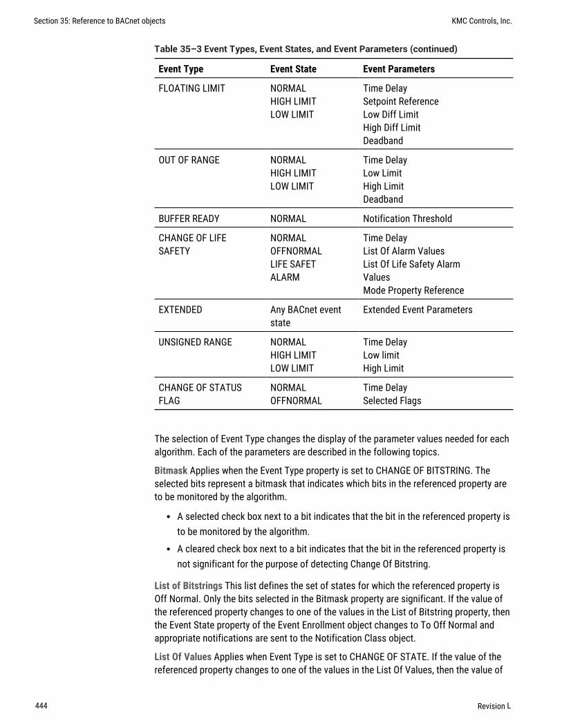
Event Type Event State Event Parameters
FLOATING LIMIT NORMALHIGH LIMITLOW LIMIT
Time DelaySetpoint ReferenceLow Diff LimitHigh Diff LimitDeadband
OUT OF RANGE NORMALHIGH LIMITLOW LIMIT
Time DelayLow LimitHigh LimitDeadband
BUFFER READY NORMAL Notification Threshold
CHANGE OF LIFESAFETY
NORMALOFFNORMALLIFE SAFETALARM
Time DelayList Of Alarm ValuesList Of Life Safety AlarmValuesMode Property Reference
EXTENDED Any BACnet eventstate
Extended Event Parameters
UNSIGNED RANGE NORMALHIGH LIMITLOW LIMIT
Time DelayLow limitHigh Limit
CHANGE OF STATUSFLAG
NORMALOFFNORMAL
Time DelaySelected Flags
Table 35–3 Event Types, Event States, and Event Parameters (continued)
The selection of Event Type changes the display of the parameter values needed for eachalgorithm. Each of the parameters are described in the following topics.
Bitmask Applies when the Event Type property is set to CHANGE OF BITSTRING. Theselected bits represent a bitmask that indicates which bits in the referenced property areto be monitored by the algorithm.
l A selected check box next to a bit indicates that the bit in the referenced property isto be monitored by the algorithm.
l A cleared check box next to a bit indicates that the bit in the referenced property isnot significant for the purpose of detecting Change Of Bitstring.
List of Bitstrings This list defines the set of states for which the referenced property isOff Normal. Only the bits selected in the Bitmask property are significant. If the value ofthe referenced property changes to one of the values in the List of Bitstring property, thenthe Event State property of the Event Enrollment object changes to To Off Normal andappropriate notifications are sent to the Notification Class object.
List Of Values Applies when Event Type is set to CHANGE OF STATE. If the value of thereferenced property changes to one of the values in the List Of Values, then the value of
Section 35: Reference to BACnet objects KMC Controls, Inc.
444 Revision L

Event State changes to To Off Normal and notifications are sent to the Notification Classobject.
Referenced Property Increment This parameter represents the increment by which thereferenced property must change to initiate an event.
Time Delay This parameter represents the time—in seconds—that the conditionsmonitored by the event algorithm must persist before an event notification is issued.
Feedback Property Reference This parameter applies when Event Type is set toCOMMAND FAILURE. It identifies the object and property that provides the feedback toensure that the commanded property has changed value. This property may referenceonly object properties that have enumerated values or are of type BOOLEAN.
Setpoint Reference This parameter applies when Event Type is set to FLOATING LIMIT. Itindicates the setpoint reference for the reference property interval.
High Limit This parameter applies when Event Type is set to OUT OF RANGE. It definesthe upper limit for a normal operating range of the monitored property in the referencedobject.
Low Limit This parameter applies when Event Type is set to OUT OF RANGE. It defines thelower limit for a normal operating range of the monitored property in the referencedobject.
Deadband This parameter applies when Event Type is set to FLOATING LIMIT andOUT OF RANGE. It specifies a range between the high limit and low limit properties inwhich the monitored property in the referenced object must remain before the objectgenerates a notification.
High Diff Limit This parameter applies when Event Type is set to FLOATING LIMIT. Whenadded to Setpoint Reference it defines an upper limit for a normal operating range of themonitored property in the referenced object.
Low Diff Limit This parameter applies when Event Type is set to OUT OF RANGE. Whenadded to Setpoint Reference it defines an lower limit for a normal operating range of themonitored property in the referenced object.
Notification Threshold This parameter applies when Event Type is set to BUFFER READY.It specifies the value of Records Since Notification at which notification occurs.
List Of Life Safety Alarm Values This parameter applies when Event Type is set toCHANGE OF LIFE SAFETY. If the value of the referenced property changes to one of thevalues in the list of Life Safety Alarm Values, then the value of Event State changes toTo Off Normal and appropriate notifications are sent to the Notification Class object.
Alarm Values This parameter applies when Event Type is set to CHANGE OF LIFE SAFETY.It is a list of states that apply to the CHANGE OF LIFE SAFETY algorithm. If the value ofthe referenced property changes to one of the values in the Alarm Values, then the valueof Event State changes to To Off Normal and appropriate notifications are sent to theNotification Class object.
Mode Property Reference This parameter applies when Event Type is set to CHANGE OFLIFE SAFETY. It identifies the object and property that provides the operating mode of thereferenced object providing life safety functionality (normally the Mode property). Thisparameter may reference only object properties for BACnet Life Safety.
KMC Connect Reference Guide Section 35: Reference to BACnet objects
Revision L 445

Extended Event Parameters The interpretation of Extended Event Parameters isdetermined by the vendor of the device.
Event/Alarm Properties
Related topics
l Notification objects on page 482l Configuring BACnet controllers for alarms on page 133
Notification Class Specifies the notification class object to be used when handling andgenerating event notifications for this object. See Notification objects on page 482 fordetails about the notification class object.
Notification Type This property specifies whether the notifications generated by theobject are events or alarms. Alarm and event notifications are handled differently by thedevice — usually a workstation — that receives the notification.
Event Enable Use Event Enable to enable notifications for To Off Normal, and To Fault.
Status Properties
Event Type Displays the value of Event Type as selected under General Properties.
Event State Use Event State to determine that this object has an active event stateassociated with it.
l If the object supports intrinsic reporting, then Event State indicates the state of theobject.
l If the object does not support intrinsic reporting, then the value of this property isNormal.
Acked Transitions This property controls three flags that separately indicate the receiptof acknowledgments for To Off Normal, To Fault, and To Normal events.
Event Time Stamps This property holds the times of the last event notifications ofTO OFF NORMAL, TO FAULT, and TO NORMAL events.
Alarm Routing Properties
Alarm classes designate a group of operators who receive notifications of alarms andevents originating from this object. See the topics An overview of notifications,alarms, and events on page 131 and Emailing operator alarms on page 169.
Event Log objectsThe Event Log object records alarm and event notifications and then saves them with timestamps and other pertinent data. The data is stored as records in an internal buffer forsubsequent retrieval.
To configure the properties in a BACnet device see Configuring BACnet devices andobjects on page 403.
Section 35: Reference to BACnet objects KMC Controls, Inc.
446 Revision L

General Properties
Object Instance The number of the object. Event Log objects are numbered sequentiallywithin a BACnet device.
Object Name A text label of the object. The exact length will depend upon the controllerthat contains the object. The Name property must be unique within the BACnet device thatmaintains it. Printable characters must be used for the Name property.
Profile Name The name of the vendor’s object profile to which this object conforms. Aprofile name defines a set of additional properties, behaviors and requirements for thisobject. The definition of the profile is unique to the vendor and not part of the BACnetstandard.
Description A text label of the object. The exact length of the Description property willdepend upon the controller that contains the object.
Start and Stop Date and Time Set the period for logging data with the Start Time and StopTime properties.
Buffer Size Holds the value of the maximum number of records that the Event Log buffermay hold.
Notification Threshold When the number of records in the buffer reaches the value of theNotification Threshold property, a notification is sent to the Notification Class objectspecified by this Event Log object.
Log Enable If this check box is clear, the Event Log object does not log data. If the LogEnable check box is selected and the current time and date are within the range of timeand dates specified by Start Time/Date and Stop Time/Date the object will lognotifications.
Stop When Full When selected, the object stops adding new records to the log bufferwhen the buffer is full. If the check box is clear, the oldest data record is replaced with anew record when the buffer is full.
Event/Alarm Properties
Notification Class Specifies the notification class object to be used when handling andgenerating event notifications for this object. See Notification objects on page 482 fordetails about the notification class object.
Notification Type This property specifies whether the notifications generated by theobject are events or alarms. Alarm and event notifications are handled differently by thedevice — usually a workstation — that receives the notification.
Event Enable Use the Event Enable property to enable notifications for To Off Normal,To Normal, or To Fault conditions.
Status Properties
Record Count This property displays the number of records currently resident in the logbuffer. Writing a value of zero to this property will delete all records in the log buffer andthe Records Since Notification property will change to zero. Upon completion, this event isadded to the log as the initial entry.
KMC Connect Reference Guide Section 35: Reference to BACnet objects
Revision L 447

Total Record Count This property represents the total number of records collected by theEvent Log object since creation. When the value of property reaches its maximum value of4,294,967,295, the next value is 1.
Records Since Last Notification This property represents the number of records collectedsince the previous notification or since the beginning of logging if no previous notificationhas occurred. This property is required if intrinsic reporting is supported by this object.
Last Notify Record This property represents the sequence number associated with themost recently collected record whose collection triggered a notification. If no notificationhas occurred since logging began the value of this property is zero. This property isrequired if intrinsic reporting is supported by this object.
Status Flags The four BACnet status flags are an indication of the general condition of theobject.
Flag Description
IN ALARM False (0) if the event state property is Normal, otherwiseTrue (1)
FAULT True (1) if Reliability is present and the value forReliability is not NO FAULT DETECTED, otherwise False(0)
OVERRIDDEN True (1) if the point has been overridden by somemechanism local to the BACnet device. When this flag isTrue, Present Value and Reliability are no longer trackingchanges to the physical output. Otherwise, the flag isFalse (0).
OUT OF SERVICE True (1) if Out Of Service is selected. Otherwise False(0).
Table 35–4 Event log object status flags
Event State Use Event State to determine that this object has an active event stateassociated with it.
l If the object supports intrinsic reporting, then Event State indicates the state of theobject.
l If the object does not support intrinsic reporting, then the value of this property isNormal.
Acked Transitions This property controls three flags that separately indicate the receiptof acknowledgments for To Off Normal, To Fault, and To Normal events.
Event Time Stamps This property holds the times of the last event notifications ofTO OFF NORMAL, TO FAULT, and TO NORMAL events.
Reliability This property is an indication that the Present Value property or the operationof the physical input may be not be reliable as defined by the device or an operator.Reliability can have any of the following values:
Section 35: Reference to BACnet objects KMC Controls, Inc.
448 Revision L

l No Fault Detectedl Configuration Errorl Communication Failurel Unreliable Other
Alarm Routing Properties
Alarm classes designate a group of operators who receive notifications of alarms andevents originating from this object. See the topics An overview of notifications,alarms, and events on page 131 and Emailing operator alarms on page 169.
Log Buffer Records
A list of all of the time stamped records of notifications or status change in the event log.Selecting any individual record will display its contents in the lower half of the pane.
File objectsWorking with file objects is an advanced topic and not covered here. Do not makechanges to file objects unless specifically directed by the Technical Support Departmentat KMC Controls, Inc.
Group objectsThe Group object defines a collection of properties from other objects and one or more oftheir properties. Use the object to simplify the simultaneous collection of informationfrom several objects. The group of objects can consist of any combination of objects thatreside within the same device as the Group object.
To configure the properties in a BACnet device, see Configuring BACnet devices andobjects on page 403.
Object Instance The number of the object. Group objects are numbered sequentiallywithin a BACnet device.
Object Name A text label of the object. The exact length will depend upon the controllerthat contains the object. The Name property must be unique within the BACnet device thatmaintains it. Printable characters must be used for the Name property.
Profile Name The name of the vendor’s object profile to which this object conforms. Aprofile name defines a set of additional properties, behaviors and requirements for thisobject. The definition of the profile is unique to the vendor and not part of the BACnetstandard.
Description A text label of the object. The exact length of the Description property willdepend upon the controller that contains the object.
Group Members This is a list of all objects and properties that are members of the group.All objects in the list must be within the device that contains the Group object.
Present Value A list of all the values of each property specified by the Group Membersproperty. The Present Value property is read-only in a Group object.
KMC Connect Reference Guide Section 35: Reference to BACnet objects
Revision L 449

Input objects–accumulatorAn accumulator input is a standard BACnet object whose properties represent thecharacteristics of a pulse signal at the input of a controller. Use the input object tool toconfigure each of the controllers inputs with one of the three input object types.
To configure a property, see the topic Configuring BACnet devices and objects onpage 403.
Related topics
l BACnet objects and properties on page 395l Input objects–analog on page 453l Input objects–binary on page 458l Input objects–multistate on page 461
General Properties
Object Instance The number of the object. Input objects are numbered sequentially withinthe BACnet device; the object instance number directly correspond to the controller’sinput terminal.
Object Name A text label of the object. The exact length will depend upon the controllerthat contains the object. The Name property must be unique within the BACnet device thatmaintains it. Printable characters must be used for the Name property.
Present Value This property indicates the current value of the number of input pulsesacquired by the object since the value was set with the Value Set property. If the objectincludes a Prescale property, Present Value is expressed in the prescaled number ofpulses.
Profile Name The name of the vendor’s object profile to which this object conforms. Aprofile name defines a set of additional properties, behaviors and requirements for thisobject. The definition of the profile is unique to the vendor and not part of the BACnetstandard.
Description A text label of the object. The exact length of the Description property willdepend upon the controller that contains the object.
Device Type This property is a description of the physical device connected to the input.Choose an available type from the drop-down list.
Logging Object This property indicates an object in the same device as the accumulatorobject which, when it acquires data from Logging Record in the accumulator object,causes the accumulator object to acquire, present and store the data from the underlyingsystem.
Logging Record This read-only property is a list of values that must be acquired andreturned for proper interpretation of the data.
Out Of Service Out Of Service indicates that the physical input is internally disconnectedfrom the input object. KMC Connect sets this property to True (1) when selected andFalse (0) when unselected. When Out Of Service is selected, and sent to the controller,Present Value does not respond to changes at the physical input of the device.
Section 35: Reference to BACnet objects KMC Controls, Inc.
450 Revision L

Max Present Value This property indicates the maximum value of Present Value.
Units Select a unit of measure to associate with the input signal. See Supportedengineering units on page 545 for a list of the available units.
Pulse Rate Pulse Rate indicates the number of input pulses received during the mostrecent period specified by the value in Limit Monitoring Interval.
Limit Monitoring Interval This property specifies the monitoring period—in seconds—fordetermining the value of Pulse Rate.
Value Change Time This property holds the date and time of the most recent occurrenceof a write operation to Value Before Change or Value Set properties. If a write has not yetoccurred, this property consists of wildcard values for all date and time fields.
Value Before Change Value Before Change indicates the value of the Present Valueproperty just prior to the most recent write to the Value Set or Value Before Changeproperties. If a write has not yet occurred, the value of this property is zero (0). If thisproperty is writable, Value Set is read-only.
Value Set This property indicates the value of Present Value after the most recent write toValue Set or Value Before Change. If a write has not yet occurred, the value of thisproperty is zero (0). If this property is writable, Value Before Change is read-only.
Scale Multiply Present Value by Scale to provide a value in the units indicated by Units.
Prescale This property presents the coefficients that are used for converting the pulsesignals generated by the measuring instrument into the value displayed by Present Value.
Event/Alarm Properties
Notification Class Specifies the notification class object to be used when handling andgenerating event notifications for this object. See Notification objects on page 482 fordetails about the notification class object.
Notification Type This property specifies whether the notifications generated by theobject are events or alarms. Alarm and event notifications are handled differently by thedevice — usually a workstation — that receives the notification.
High Limit This property is used with intrinsic reporting to define a limit that Pulse Ratemust exceed before an event is generated. Use with Limit Enable and Time Delay to defineconditions that indicate Pulse Rate is out of a normal operating range.
Low Limit This property is used with intrinsic reporting to define a limit that Pulse Ratemust fall below before an event is generated. Use with Limit Enable and Time Delay todefine events that indicate Pulse Rate is out of a normal operating range.
Time Delay Time Delay defines a minimum period for a set of conditions to exist before aTo Off Normal or To Normal notification event occurs. Use Time Delay with High Limit andLow Limit to define conditions that indicate Pulse Rate is out of an expected, predefinedoperating range. Time Delay is expressed in seconds.
Limit Enable This property separately enables and disables reporting of high limit and lowlimit Off Normal events and their return to normal.
Event Enable Use Event Enable to enable notifications for To Off Normal, To Normal andTo Fault.
KMC Connect Reference Guide Section 35: Reference to BACnet objects
Revision L 451

Status Properties
Status Flags The four BACnet status flags are an indication of the general condition of theobject.
Flag Description
IN ALARM False (0) if the event state property is Normal, otherwise True (1)
FAULT True (1) if Reliability is present and the value for Reliability is not NOFAULT DETECTED, otherwise False (0)
OVERRIDDEN True (1) if the point has been overridden by some mechanism local tothe BACnet device. When this flag is True, Present Value andReliability are no longer tracking changes to the physical input.Otherwise, the flag is False (0).
OUT OFSERVICE
True (1) if Out Of Service is selected. Otherwise False(0).
Table 35–5 Input object status flags
Reliability This property is an indication that the Present Value property or the operationof the physical input may be not be reliable as defined by the device or an operator.Reliability can have any of the following values:
l NO_FAULT_DETECTEDl UNDER_RANGEl UNRELIABLE_OTHERl NO_SENSORl OPEN_LOOPl OVER_RANGEl SHORTED_LOOP
Event State Use Event State to determine that this object has an active event stateassociated with it.
l If the object supports intrinsic reporting, then Event State indicates the state of theobject.
l If the object does not support intrinsic reporting, then the value of this property isNormal.
If Reliability is present and does not have a value of No_fault_detected, then the value ofEvent_State is Fault. Changes in the Event State to the value tem">Fault are considered tobe fault events.
Section 35: Reference to BACnet objects KMC Controls, Inc.
452 Revision L

Acked Transitions This property controls three flags that separately indicate the receiptof acknowledgments for To Off Normal, To Fault, and To Normal events. For analog inputobjects, the transition of High Limit and Low Limit are considered to be Off Normalevents. These flags are cleared upon the occurrence of the corresponding event and setunder any of the following conditions.
l Upon receipt of the corresponding acknowledgmentl Upon the occurrence of the event, if the corresponding flag is not set in the Event
Enable property. Under this condition, event notifications are not generated for thiscondition and therefore no acknowledgments are expected.
l Upon the occurrence of the event, if the corresponding flag is set in the Event Enableproperty and the corresponding flag in the Ack Required property of the notificationclass object implicitly referenced by the notification class property of this object isnot set (meaning no acknowledgment is expected).
Event Time Stamps Holds the times of the last event notifications of To Off Normal,To Fault and To Normal events.
Alarm Routing Properties
Alarm classes designate a group of operators who receive notifications of alarms andevents originating from this object. See the topics An overview of notifications,alarms, and events on page 131 and Emailing operator alarms on page 169.
Input objects–analogAn analog input is a standard BACnet object. The properties in the object represent thecharacteristics of an analog signal at the input of a controller. Use the input object tool toconfigure each of the controllers inputs with one of the three input object types.
To configure a property, see the following topics:
l Analog input object wizard on page 653l Configuring BACnet devices and objects on page 403l Calibration on page 455
Related topics
l BACnet objects and properties on page 395l Input objects–accumulator on page 450l Input objects–binary on page 458l Input objects–multistate on page 461
General Properties
Object Instance The input object number. Input objects are numbered sequentially withinthe BACnet device and directly correspond to the controller’s input terminal.
KMC Connect Reference Guide Section 35: Reference to BACnet objects
Revision L 453

Object Name A text label of the object. The exact length will depend upon the controllerthat contains the object. The Name property must be unique within the BACnet device thatmaintains it. Printable characters must be used for the Name property.
Present Value This numerical property indicates the current value of the input beingmeasured. To manually change the present value property, first select Out-Of-Service andthen change Present Value.
Profile Name The name of the vendor’s object profile to which this object conforms. Aprofile name defines a set of additional properties, behaviors and requirements for thisobject. The definition of the profile is unique to the vendor and not part of the BACnetstandard.
Description A text label of the object. The exact length of the Description property willdepend upon the controller that contains the object.
Device Type This property is a description of the physical device connected to the input.Choose an available type from the drop-down list.
Termination For Conquest compliant controllers, this selects and indicates the inputtermination. For other controllers, this is an indication of how the termination should beset.
Out Of Service Out Of service indicates that the physical input is internally disconnectedfrom the input object. KMC Connect sets this property to True (1) when selected andFalse (0) when unselected. When Out Of Service is selected, and sent to the controller,Present Value does not respond to changes at the physical input of the device.
Units Select a unit of measure to associate with the input signal. See Supportedengineering units on page 545 for a list of the available units.
Minimum Present Value This property indicates the smallest input value—expressed inengineering units—that can reliably be obtained for the input object Present Value.
Maximum Present Value This property indicates the largest input value—expressed inengineering units—that can reliably be obtained for the input object Present Value.
COV Increment This property specifies the minimum change of Present Value that willsend a COV notification to subscriber notification clients.
Resolution This property indicates the smallest recognizable change—expressed inengineering units— in the present value of this object.
Update Interval This property sets the maximum period—in hundredths of a second—between updates to Present Value.
Filter Weight Sets the number of samples that are averaged together to calculate thedisplayed value. A sample is taken on each scan.
Filter Weight Scans to average
0 1
1 2
Table 35–6 Filter weight values
Section 35: Reference to BACnet objects KMC Controls, Inc.
454 Revision L

Filter Weight Scans to average
2 4
3 8
4 16
5 32
6 64
7 128
Table 35–6 Filter weight values (continued)
Calibration
1 To add a calibration factor to a BACnet analog input object, do the following:
2 Open the configuration tab for the object.
3 Right-click over Present Value.
4 Choose Calibrate Present Value from the shortcut menu.
5 Enter a calibration factor to adjust the input for sensor inaccuracies.
l For a low reading, enter a positive correction value.l For a high reading, enter a negative correction value.l The valid range for a calibration factor is from -30 to 30.l The default value is 0 (no calibration).
Custom Device Calibration For objects that have Device Type set to CUSTOM, additionalcalibration factors can be added. The Custom Device Calibration function converts theinput voltage—such as the voltage from a temperature transmitter—to a calculatedPresent Value. The calculation is based on an input voltage that falls between 0 and 5volts.
To set the values for Custom Device Calibration do the following:
1 Open the configuration tab for the object.
2 Right-click over Present Value.
3 Choose Custom Device Calibration from the shortcut menu.
4 On a BAC-A1616BC or CAN-A168EIO, if the 0-12 VOLT jumper is in place, select theJumpered (12 volt) check box.
5 Enter values in either From Range and To Range or Offset and Multiplier.
KMC Connect Reference Guide Section 35: Reference to BACnet objects
Revision L 455

Range Enter values in Desired Range text boxes when two points are known thatcorrespond to 0 and 5 volts at the input.
l In Desired Range To enter the value to display in Present Value when the inputvoltage equals 5 volts.
l In Desired Range From enter the value to display in Present Value when the inputvoltage equals 0 volts.
Offset and multiplier Use offset and multiplier when a calibration factor and offset for theinput device are known; for example, if a transducer output is calibrated for degreesCentigrade and Present Value needs to display in degrees Fahrenheit.
Event/Alarm Properties
Notification Class Specifies the notification class object to be used when handling andgenerating event notifications for this object. See Notification objects on page 482 fordetails about the notification class object.
Notification Type This property specifies whether the notifications generated by theobject are events or alarms. Alarm and event notifications are handled differently by thedevice — usually a workstation — that receives the notification.
High Limit This property is used with intrinsic reporting to define an upper limit for anormal operating range of Present Value. Use with Limit Enable, Deadband and TimeDelay to define conditions that indicate Present Value is out of a normal operating range.
Low Limit This property is used with intrinsic reporting to define a lower limit for a normaloperating range of Present Value. Use with Limit Enable, Deadband and Delay to defineevents that indicate Present Value is out of a normal operating range.
Deadband This property specifies a range between the high limit and low limit propertiesin which Present Value must remain before the device generates a To Normal notificationevent.
Time Delay Time Delay defines a minimum period for a set of conditions to exist before aTo Off Normal or To Normal notification event occurs. Use Time Delay with High Limit,Low Limit and Deadband to define conditions that indicate Present Value is out of anexpected, predefined operating range. Time Delay is expressed in seconds.
Limit Enable This property separately enables and disables reporting of high limit and lowlimit Off Normal events and their return to normal.
Event Enable Use the Event Enable property to enable notifications for To Off Normal,To Normal, or To Fault conditions.
Status Properties
Status Flags
The four BACnet status flags are an indication of the general condition of the analoginput.
Section 35: Reference to BACnet objects KMC Controls, Inc.
456 Revision L

Flag Description
IN ALARM False (0) if the event state property is Normal, otherwiseTrue (1)
FAULT True (1) if Reliability is present and the value forReliability is not NO FAULT DETECTED, otherwise False(0)
OVERRIDDEN True (1) if the point has been overridden by somemechanism local to the BACnet device. When this flag isTrue, Present Value and Reliability are no longer trackingchanges to the physical input. Otherwise, the flag is False(0).
OUT OF SERVICE True (1) if Out Of Service is selected. Otherwise False(0).
Table 35–7 Input object status flags
Reliability This property is an indication that the Present Value property or the operationof the physical input may be not be reliable as defined by the device or an operator.Reliability can have any of the following values:
l NO_FAULT_DETECTEDl UNDER_RANGEl UNRELIABLE_OTHERl NO_SENSORl OPEN_LOOPl OVER_RANGEl SHORTED_LOOP
Event State Use Event State to determine that this object has an active event stateassociated with it.
l If the object supports intrinsic reporting, then Event State indicates the state of theobject.
l If the object does not support intrinsic reporting, then the value of this property isNormal.
If Reliability is present and does not have a value of No_fault_detected, then the value ofEvent_State is Fault. Changes in the Event State to the value Fault are considered to befault events.
KMC Connect Reference Guide Section 35: Reference to BACnet objects
Revision L 457

Acked Transitions This property controls three flags that separately indicate the receiptof acknowledgments for To Off Normal, To Fault, and To Normal events. For analog inputobjects, the transition of High Limit and Low Limit are considered to be Off Normalevents. These flags are cleared upon the occurrence of the corresponding event and setunder any of the following conditions:
l Upon receipt of the corresponding acknowledgmentl Upon the occurrence of the event, if the corresponding flag is not set in the Event
Enable property. Under this condition, event notifications are not generated for thiscondition and therefore no acknowledgments are expected.
l Upon the occurrence of the event, if the corresponding flag is set in the Event Enableproperty and the corresponding flag in the Ack Required property of the notificationclass object implicitly referenced by the notification class property of this object isnot set (meaning no acknowledgment is expected).
Event Time Stamps This property holds the times of the last event notifications ofTO OFF NORMAL, TO FAULT, and TO NORMAL events.
Alarm Routing Properties
Alarm classes designate a group of operators who receive notifications of alarms andevents originating from this object. See the topics An overview of notifications,alarms, and events on page 131 and Emailing operator alarms on page 169.
Input objects–binaryA binary input is a standard BACnet object. The properties in the object represent thecharacteristics of a binary signal at the input of a controller. Use the input object tool toconfigure each of the controllers inputs with one of the input object types.
To configure a property, see the topics Input and output object wizards on page 653and Configuring BACnet devices and objects on page 403.
Related topics
l BACnet objects and properties on page 395l Input objects–accumulator on page 450l Input objects–analog on page 453l Input objects–multistate on page 461
General Properties
Object Instance The input object number. Input objects are numbered sequentially withinthe BACnet device and directly correspond to the controller’s input terminal.
Object Name A text label of the object. The exact length will depend upon the controllerthat contains the object. The Name property must be unique within the BACnet device thatmaintains it. Printable characters must be used for the Name property.
Section 35: Reference to BACnet objects KMC Controls, Inc.
458 Revision L

Present Value This numerical property indicates the logical state of the input. A binaryinput will be in one of two states such as Start/Stop, On/Off or True/False.
To manually change Present Value, first select Out-Of-Service and then changePresent Value.
Profile Name The name of the vendor’s object profile to which this object conforms. Aprofile name defines a set of additional properties, behaviors and requirements for thisobject. The definition of the profile is unique to the vendor and not part of the BACnetstandard.
Description A text label of the object. The exact length of the Description property willdepend upon the controller that contains the object.
Termination For Conquest compliant controllers, this selects and indicates the inputtermination. For other controllers, this is an indication of how the termination should beset.
Device Type This property is a description of the physical device connected to the input.
Out Of Service Out Of service indicates that the physical input is internally disconnectedfrom the input object. KMC Connect sets this property to True when selected and Falsewhen not selected. When Out Of Service is selected and then sent to the controller,Present Value does not respond to changes at the physical input of the device.
PolarityThe polarity property sets the relationship between the physical state of the inputand the logical state represented by Present Value. KMC Connect displays Present valueas either Active or Inactive Text.
Passive inputwith pull-up
Polarity Present Value Text example
Normal Active Off, Stop
Normal Inactive On, Start
Reverse Inactive On, Start
Reverse Active Off, Stop
Table 35–8 Input object polarity relationships
Active Text Text to display when Present Value is in the active state.
Inactive Text Text to display when Present Value is in the inactive state.
Event/Alarm Properties
Notification Class Specifies the notification class object to be used when handling andgenerating event notifications for this object. See Notification objects on page 482 fordetails about the notification class object.
KMC Connect Reference Guide Section 35: Reference to BACnet objects
Revision L 459

Notification Type This property specifies whether the notifications generated by theobject are events or alarms. Alarm and event notifications are handled differently by thedevice — usually a workstation — that receives the notification.
Alarm Value When the object’s present value changes to the value in Alarm Value, anotification event is generated.
Time Delay Time Delay defines a minimum period for a set of conditions to exist before aTo Off Normal or To Normal event occurs. Use Time Delay with Alarm Value to defineconditions that indicate Present Value has changed states.
Event Enable Use Event Enable to enable notifications for To Off Normal, TO NORMAL andTo Fault.
Status Properties
Status Flags The four BACnet status flags are an indication of the general condition of theobject.
Flag Description
IN ALARM False (0) if the event state property is Normal, otherwiseTrue (1)
FAULT True (1) if Reliability is present and the value forReliability is not NO FAULT DETECTED, otherwise False(0)
OVERRIDDEN True (1) if the point has been overridden by somemechanism local to the BACnet device. When this flag isTrue, Present Value and Reliability are no longer trackingchanges to the physical input. Otherwise, the flag is False(0).
OUT OF SERVICE True (1) if Out Of Service is selected. Otherwise False(0).
Table 35–9 Input object status flags
Reliability This property is an indication that the Present Value property or the operationof the physical input may be not be reliable as defined by the device or an operator.Reliability can have any of the following values:
l NO_FAULT_DETECTEDl SHORTED_LOOPl UNRELIABLE_OTHERl NO_SENSORl OPEN_LOOP
Time of Active Time Reset This property holds the date and time when Elapsed ActiveTime was most recently set to zero.
Elapsed Active Time This property holds the accumulated number of seconds thatPresent Value has been in the active state since Elapsed Active Time was set to zero.
Section 35: Reference to BACnet objects KMC Controls, Inc.
460 Revision L

Event State Use the Event State property to determine that this input object has an activeevent state associated with it.
l If the input supports intrinsic reporting, then Event State indicates the state of theobject.
l If the input does not support intrinsic reporting, then the value of this property isNormal.
l If Reliability is present and does not have a value of No Fault Detected, then thevalue of Event State is Fault. Changes in Event State to the value Fault areconsidered to be fault events.
Acked Transitions This property controls three flags that separately indicate the receiptof acknowledgments for To Off Normal, To Fault, and To Normal events. These flags arecleared upon the occurrence of the corresponding event and set under any of thefollowing conditions:
l Upon receipt of the corresponding acknowledgmentl Upon the occurrence of the event, if the corresponding flag is not set in the Event
Enable property. Under this condition, event notifications are not generated for thiscondition and therefore no acknowledgments are expected.
l Upon the occurrence of the event, if the corresponding flag is set in the Event Enableproperty and the corresponding flag in the Ack Required property of the NotificationClass object implicitly referenced by the Notification Class property of this object isnot set (meaning no acknowledgment is expected).
Event Time Stamps This property holds the times of the last event notifications ofTO OFF NORMAL, TO FAULT, and TO NORMAL events.
Change of State Time This property holds the date and time that Present Value mostrecently changed state.
Change of State Count This property holds the number of times that Present Value haschanged state since Change of State Count was most recently set to zero (0).
Time of State Count Reset This property holds the date and time that Change of StateCount was most recently set to zero.
Alarm Routing Properties
Alarm classes designate a group of operators who receive notifications of alarms andevents originating from this object. See the topics An overview of notifications,alarms, and events on page 131 and Emailing operator alarms on page 169.
Input objects–multistateThe Multistate Input object is a standard BACnet object whose Present Value propertyrepresents the result of a calculation performed within the device. Present Value may bethe result of a logical combination of multiple binary inputs, the threshold of one or moreanalog inputs, or the result of a mathematical computation. The result of the calculationis a single number that represents the state of the object.
KMC Connect Reference Guide Section 35: Reference to BACnet objects
Revision L 461

To configure a property, see the topic Configuring BACnet devices and objects onpage 403.
Related topicsl BACnet objects and properties on page 395l Input objects–accumulator on page 450l Input objects–analog on page 453l Input objects–binary on page 458
General Properties
Object Instance The number of the object. Input objects are numbered sequentially withina BACnet device.
Object Name A text label of the object. The exact length will depend upon the controllerthat contains the object. The Name property must be unique within the BACnet device thatmaintains it. Printable characters must be used for the Name property.
Present Value
This numerical property indicates the current state of the Mulitstate Input object. Thenumber of states for this property is defined by the value of the Number Of Statesproperty.
Profile Name The name of the vendor’s object profile to which this object conforms. Aprofile name defines a set of additional properties, behaviors and requirements for thisobject. The definition of the profile is unique to the vendor and not part of the BACnetstandard.
Description A text label of the object. The exact length of the Description property willdepend upon the controller that contains the object.
Device Type A text description that is typically used to describe the type of deviceattached to the Multistate Input object.
Termination For Conquest compliant controllers, this selects and indicates the inputtermination. For other controllers, this is an indication of how the termination should beset.
Out Of Service Out Of Service indicates that the physical input is internally disconnectedfrom the input object. KMC Connect sets this property to True (1) when selected andFalse (0) when unselected. When Out Of Service is selected, and sent to the controller,Present Value does not respond to changes at the physical input of the device.
Number of States The Number of States property defines the number of states thatPresent Value may have. It is always greater than zero. The value of Number Of States willautomatically change as entries are added or removed from the State Text list.
State Text Each entry in the State Text list corresponds to a value of Present Value. Forexample, if Present Value equals 1, then the value of State Text is the first entry in the list.
l To start a new entry in State Text, right-click and choose Add String from theshortcut menu.
l To change the text of an entry in State Text, right-click an entry and choose Edit
Section 35: Reference to BACnet objects KMC Controls, Inc.
462 Revision L

String from the shortcut menu.l To delete an entry from State Text, right-click an entry and choose Remove String
from the shortcut menu.l To change the order of the list in State Text, right-click an entry and choose Move Up
or Move Down from the shortcut menu.
Event/Alarm Properties
Notification Class Specifies the notification class object to be used when handling andgenerating event notifications for this object. See Notification objects on page 482 fordetails about the notification class object.
Notification Type This property specifies whether the notifications generated by theobject are events or alarms. Alarm and event notifications are handled differently by thedevice — usually a workstation — that receives the notification.
Time Delay Time Delay defines a minimum period for a set of conditions to exist before aTo Off Normal or To Normal notification occurs. Use Time Delay with the Alarm Valuesproperty to define conditions that indicate Present Value has changed state. Time Delay isexpressed in seconds.
Event Enable Use the Event Enable property to enable notifications for To Off Normal,To Normal, or To Fault conditions.
Alarm Values This property is used with intrinsic reporting to define a change of thePresent Value property that will generate an alarm event.
Fault Values This property list any states that the Present Value property must equal for aTo Fault notification to be generated.
Status Properties
Status Flags The four BACnet status flags are an indication of the general condition of theobject.
Flag Description
IN ALARM False (0) if the event state property is Normal, otherwiseTrue (1)
FAULT True (1) if Reliability is present and the value forReliability is not NO FAULT DETECTED, otherwise False(0)
OVERRIDDEN True (1) if the point has been overridden by somemechanism local to the BACnet device. When this flag isTrue, Present Value and Reliability are no longer trackingchanges to the physical input. Otherwise, the flag is False(0).
OUT OF SERVICE True (1) if Out Of Service is selected. Otherwise False(0).
Table 35–10 Multistate input object status flags
KMC Connect Reference Guide Section 35: Reference to BACnet objects
Revision L 463

Reliability This property is an indication that the Present Value property or the operationof the physical input may be not be reliable as defined by the device or an operator.Reliability can have any of the following values:
l No Fault Detectedl No Sensorl Over Rangel Under Rangel Open Loopl Shorted Loopl Multistate Faultl Communication Failurel Unreliable Other
Event State Use Event State to determine that this object has an active event stateassociated with it.
l If the object supports intrinsic reporting, then Event State indicates the state of theobject.
l If the object does not support intrinsic reporting, then the value of this property isNormal.
Acked Transitions This property controls three flags that separately indicate the receiptof acknowledgments for To Off Normal, To Fault, and To Normal events.
Event Time Stamps This property holds the times of the last event notifications ofTO OFF NORMAL, TO FAULT, and TO NORMAL events.
Alarm Routing Properties
Alarm classes designate a group of operators who receive notifications of alarms andevents originating from this object. See the topics An overview of notifications,alarms, and events on page 131 and Emailing operator alarms on page 169.
Life Safety Point objectsA Life Safety Point object is a standard BACnet object that represents the characteristicsof an indicating or initiating device. The device is typically used for fire, life safety, orsecurity applications. The condition of the Life Safety Point object is determined by themode and state of the object.
l The mode of the object mode is usually under the control of the device operator.l The state of the object indicates the controller condition depending on the internal
logic of the device.
Section 35: Reference to BACnet objects KMC Controls, Inc.
464 Revision L

Life Safety Point object applications can include the following safety-related devices:
l Automatic fire detectorsl Sirensl Pull stations
See also Life Safety Zone objects on page 468.
General Properties
Object Instance The Life Safety Point object number. The objects are numberedsequentially within a BACnet device.
Object Name A text label of the object. The exact length will depend upon the controllerthat contains the object. The Name property must be unique within the BACnet device thatmaintains it. Printable characters must be used for the Name property.
Present Value This property represents the state of the object. The state will be one ofthe 24 BACnet states for Life Safety Point objects. The internal logic of controller sets thestate of present value. Present value may remain latched in a non-normal state until reset.
Profile Name The name of the vendor’s object profile to which this object conforms. Aprofile name defines a set of additional properties, behaviors and requirements for thisobject. The definition of the profile is unique to the vendor and not part of the BACnetstandard.
Description A text label of the object. The exact length of the Description property willdepend upon the controller that contains the object.
Device Type A text description of the physical device that the Life Safety Point objectrepresents.
Silenced Indicates that the most recent transition that produced an audible or visualalarm has been silenced by an operator.
Operation Expected Indicates the next operation expected for the object to handle.
Accepted Modes A read-only list of the modes that can be written to the mode property bya BACnet service.
Mode This property sets the object to one of 15 BACnet-defined operating states.Changing the mode property may also trigger an alarm. Mode can be changed only to avalue in the Accepted Modes list.
Out Of Service The Out Of service property indicates that the physical input is internallydisconnected from the Life Safety Point object. KMC Connect sets this property to True(1) when selected and False (0) when unselected. When Out Of Service is selected, andsent to the controller, Present Value does not respond to changes at the physical input ofthe device.
Units Select a unit of measure to associate with the direct reading property.
Tracking Value This property represents the unlatched state of the object. Unlike thePresent Value property, the Tracking Value property will not latch. The state will be one ofthe 24 BACnet states for Life Safety Point objects. The internal logic of controller sets thestate of the Tracking Value property.
KMC Connect Reference Guide Section 35: Reference to BACnet objects
Revision L 465

Setting Sets a threshold that determines the logical state of the Present Value property.The Setting property is a range from 0 (least sensitive) to 100 (most sensitive). The actualmeaning to the setting value is determined and is unique to the controller that containsthe Life Safety Point object.
Maintenance Required An indication of required maintenance for the device that isrepresented by the Life Safety Point object.
Direct Reading The analog value of the measured or calculated reading from the devicethat is represented by the Life Safety Point object.
Member Of Life Safety Zones A list of the Life Safety Zone objects that include the LifeSafety Point object as a member.
To add an object to the Member Of list, do either of the following:
l Locate the Life Safety Zone object in the Network Manager list and drag it to theMember list.
l Choose the object number from the Object ID list.
To remove an object from the Member Of list, click the remove button .
Event/Alarm Properties
Notification Class Specifies the notification class object to be used when handling andgenerating event notifications for this object. See Notification objects on page 482 fordetails about the Notification Class object.
Notify Type This property specifies whether the notifications generated by the object areevents or alarms. Alarm and event notifications are handled differently by the device—usually a workstation—that receives the notification.
Life Safety Alarm Values
To add a value, do the following:
1 Right-click in the Life Safety Alarm Values list and choose Add Value from theshortcut menu.
2 Choose an alarm value from the New Value list.
To delete a value, do the following:
1 Right-click a value in the list.
2 Choose Remove Value from the shortcut menu.
Time Delay Time Delay defines a minimum period, in seconds, for a set of conditions toexist before a To Off Normal or To Normal event occurs. Use Time Delay with Alarm Valueto define conditions that indicate Present Value has changed states.
Event Enable
Use Event Enable to enable notifications for To Off Normal, To Normal and To Fault.
Section 35: Reference to BACnet objects KMC Controls, Inc.
466 Revision L

Alarm Values When the Present Value property equals one of the items in the AlarmValues property, a notification event is generated. Items are added or deleted from the listby right-clicking and choosing either Add or Remove from the shortcut menu.
Fault Values When the Present Value property equals one of the items in the Fault Valuesproperty, a fault event is generated. Items are added or deleted from the list by right-clicking and choosing either Add or Remove from the shortcut menu.
Status Properties
Status Flags The four BACnet status flags are an indication of the general condition of theobject.
Flag Description
IN ALARM False (0) if the event state property is Normal, otherwise True(1)
FAULT True (1) if Reliability is present and the value for Reliability is notNO FAULT DETECTED, otherwise False (0)
OVERRIDDEN True (1) if the point has been overridden by some mechanismlocal to the BACnet device. When this flag is True, Present Valueand Reliability are no longer tracking changes to the physicalinput. Otherwise, the flag is False (0).
OUT OFSERVICE
True (1) if Out Of Service is selected. Otherwise False(0).
Table 35–11 Life Safety Point object status flags
Reliability This property is an indication that Present Value or the operation of thephysical input may be not be reliable as defined by the device or an operator. Reliabilitycan have any of the following values:
l NO_FAULT_DETECTEDl SHORTED_LOOPl UNRELIABLE_OTHERl NO_SENSORl OPEN_LOOP
KMC Connect Reference Guide Section 35: Reference to BACnet objects
Revision L 467

Event State Use Event State to determine that this input object has an active event stateassociated with it.
l If the input supports intrinsic reporting, then Event State indicates the state of theobject.
l If the input does not support intrinsic reporting, then the value of this property isNormal.
l If Reliability is present and does not have a value of No Fault Detected, then the valueof Event State is Fault. Changes in Event State to the value Fault are considered to befault events.
Acked Transitions This property controls three flags that separately indicate the receiptof acknowledgments for To Off Normal, To Fault, and To Normal events. These flags arecleared upon the occurrence of the corresponding event and set under any of thefollowing conditions:
l Upon receipt of the corresponding acknowledgmentl Upon the occurrence of the event, if the corresponding flag is not set in the Event
Enable property. Under this condition, event notifications are not generated for thiscondition and therefore no acknowledgments are expected.
l Upon the occurrence of the event, if the corresponding flag is set in the Event Enableproperty and the corresponding flag in the Ack Required property of the NotificationClass object implicitly referenced by the Notification Class property of this object isnot set (meaning no acknowledgment is expected).
Event Time Stamps Holds the times of the last event notifications of To Off Normal,To Fault and To Normal events.
Life Safety Zone objectsA Life Safety Zone object is a standard BACnet object that represents the characteristicsof an arbitrary group of Life Safety Point and Life Safety Zone objects that are typicallyused for fire, life safety, or security applications. The condition of the Life Safety Zoneobject is determined by the mode and state of the object.
l The mode of the object mode is usually under the control of the device operator.l The state of the object indicates the controller condition depending on the internal
logic of the device.
See also Life Safety Point objects on page 464.
General Properties
Object Instance The Life Safety Zone object number. The objects are numberedsequentially within a BACnet device.
Object Name A text label of the object. The exact length will depend upon the controllerthat contains the object. The Name property must be unique within the BACnet device thatmaintains it. Printable characters must be used for the Name property.
Section 35: Reference to BACnet objects KMC Controls, Inc.
468 Revision L

Present Value This property represents the state of the object. The state will be one ofthe 24 BACnet states for Life Safety objects. The internal logic of controller sets the stateof present value. Present value may remain latched in a non-normal state until reset.
Profile Name The name of the vendor’s object profile to which this object conforms. Aprofile name defines a set of additional properties, behaviors and requirements for thisobject. The definition of the profile is unique to the vendor and not part of the BACnetstandard.
Description A text label of the object. The exact length of the Description property willdepend upon the controller that contains the object.
Silenced Indicates that the most recent transition that produced an audible or visualalarm has been silenced by an operator.
Operation Expected Indicates the next operation expected for the object to handle.
Accepted Modes A read-only list of the modes that can be written to the mode property bya BACnet service.
Mode This property sets the object to one of 15 BACnet defined operating states.Changing the mode property may also trigger an alarm. Mode can be changed only to avalue in the Accepted Modes list.
Out Of Service The Out Of Service property indicates that the physical input is internallydisconnected from the Life Safety Point object. KMC Connect sets this property to True(1) when selected and False (0) when unselected. When Out Of Service is selected, andsent to the controller, Present Value does not respond to changes at the physical input ofthe device.
Tracking Value This property represents the unlatched state of the object. Unlike thePresent Value property, the Tracking Value property will not latch. The state will be one ofthe 24 BACnet states for Life Safety Point objects. The internal logic of controller sets thestate of the Tracking Value property.
Maintenance Required An indication of required maintenance for the device that isrepresented by the Life Safety Point object.
Zone Members A list of the Life Safety Point and other Life Safety Zone objects that are amember of this Life Safety Zone object.
To add an object to the Member Of list do either of the following:
l Locate the Life Safety Zone object in the Network Manager list and drag it to theZone Member list.
l Choose the object number from the Object ID list
To remove an object from the Member Of list, click the remove button .
Member of Life Safety Zone A list of the Life Safety Zone objects that include this LifeSafety Zone object as a member.
To add an object to the Member Of list do either of the following:
l Locate the Life Safety Zone object in the Network Manager list and drag it to theMember Of list.
KMC Connect Reference Guide Section 35: Reference to BACnet objects
Revision L 469

l Choose the object number from the Object ID list
To remove an object from Member Of list, click the remove button .
Event/Alarm Properties
Notification Class Specifies the notification class object to be used when handling andgenerating event notifications for this object. See Notification objects on page 482 fordetails about the notification class object.
Notify Type This property specifies whether the notifications generated by the object areEvents or Alarms. Alarm and event notifications are handled differently by the device—usually a workstation—that receives the notification.
Life Safety Alarm Values
To add a value, do the following:
1 Right-click in the Life Safety Alarm Values list and choose Add Value from theshortcut menu.
2 Choose an alarm value from the New Value list.
To delete a value, do the following:
1 Right-click a value in the list.
2 Choose Remove Value from the shortcut menu.
Time Delay Time Delay defines a minimum period, in seconds, for a set of conditions toexist before a To Off Normal or To Normal event occurs. Use Time Delay with Alarm Valueto define conditions that indicate Present Value has changed states.
Event Enable Use Event Enable to enable notifications for To Off Normal, To Normal andTo Fault.
Alarm Values When the Present Value property equals one of the items in the AlarmValues property, a notification event is generated. Items are added or deleted from the listby right-clicking and choosing either Add or Remove from the shortcut menu.
Fault Values When the Present Value property equals one of the items in the Fault Valuesproperty, a fault event is generated. Items are added or deleted from the list by right-clicking and choosing either Add or Remove from the shortcut menu.
Status Properties
Status Flags The four BACnet status flags are an indication of the general condition of theobject.
Section 35: Reference to BACnet objects KMC Controls, Inc.
470 Revision L

Flag Description
IN ALARM False (0) if the event state property is Normal, otherwise True(1)
FAULT True (1) if Reliability is present and the value for Reliability is notNO FAULT DETECTED, otherwise False (0)
OVERRIDDEN True (1) if the point has been overridden by some mechanismlocal to the BACnet device. When this flag is True, Present Valueand Reliability are no longer tracking changes to the physicalinput. Otherwise, the flag is False (0).
OUT OFSERVICE
True (1) if Out Of Service is selected. Otherwise False(0).
Table 35–12 Life Safety Point object status flags
Reliability This property is an indication that Present Value or the operation of thephysical input may be not be reliable as defined by the device or an operator. Reliabilitycan have any of the following values:
l NO_FAULT_DETECTEDl SHORTED_LOOPl UNRELIABLE_OTHERl NO_SENSORl OPEN_LOOP
Event State Use Event State to determine that this input object has an active event stateassociated with it.
l If the input supports intrinsic reporting, then Event State indicates the state of theobject.
l If the input does not support intrinsic reporting, then the value of this property isNormal.
l If Reliability is present and does not have a value of No Fault Detected, then the valueof Event State is Fault. Changes in Event State to the value Fault are considered to befault events.
KMC Connect Reference Guide Section 35: Reference to BACnet objects
Revision L 471

Acked Transitions This property controls three flags that separately indicate the receiptof acknowledgments for To Off Normal, To Fault, and To Normal events. These flags arecleared upon the occurrence of the corresponding event and set under any of thefollowing conditions:
l Upon receipt of the corresponding acknowledgmentl Upon the occurrence of the event, if the corresponding flag is not set in the Event
Enable property. Under this condition, event notifications are not generated for thiscondition and therefore no acknowledgments are expected.
l Upon the occurrence of the event, if the corresponding flag is set in the Event Enableproperty and the corresponding flag in the Ack Required property of the NotificationClass object implicitly referenced by the Notification Class property of this object isnot set (meaning no acknowledgment is expected).
Event Time Stamps Holds the times of the last event notifications of To Off Normal,To Fault and To Normal events.
Load Control objectsA load control object represents a mechanism for controlling load requirements throughload shedding. One or more objects may be used in the device to allow independentcontrol over different sub-loads. The Load Control object may also be used in ahierarchical fashion to control other Load Control objects in other BACnet devices.
Note: Much of the actions in a Load Control object are defined by thedevice that contains the Load Control object and are not describedhere.
General Properties
Object Instance The Load Control object number. The objects are numbered sequentiallywithin a BACnet device.
Object Name A text label of the object. The exact length will depend upon the controllerthat contains the object. The Name property must be unique within the BACnet device thatmaintains it. Printable characters must be used for the Name property.
Section 35: Reference to BACnet objects KMC Controls, Inc.
472 Revision L

Present Value The present value of a load control object indicates the current loadshedding state of the object. The states for the property are:
l Shed Inactive—The Load Control object is waiting for a shed request.l Shed Request Pending— The object is determining, based on newly written shed
request parameters, whether a shed request needs to be executed immediately or atsome time in the future.
l Shed Non Compliant—The object is attempting to meet a shed request and will doso until the shed request is achieved, the object is reconfigured, or the request hascompleted unsuccessfully.
l Shed Compliant—The object is continuing to meet a shed request until the shedrequest is either reconfigured, finished, or the conditions change and the object isno longer able to maintain the requested shed level.
Profile Name The name of the vendor’s object profile to which this object conforms. Aprofile name defines a set of additional properties, behaviors and requirements for thisobject. The definition of the profile is unique to the vendor and not part of the BACnetstandard.
Description A text label of the object. The exact length of the Description property willdepend upon the controller that contains the object.
Shed Levels This property represents the shed levels when the Requested Shed Levelproperty is set to Level. When commanded with the Level choice, the Load Control objectstarts the shedding action described by the corresponding element in theShed Level Descriptions list.
Requested Shed Level This property indicates the desired load shedding. The followingtable describes the default values and power targets for the different choices ofRequested Shed Level.
Choice Default RequestedLevel
Power load target in kW
PERCENT 100 (Current baseline) * Requested Shed Level/ 100
LEVEL 0 Locally pre-specified shed target for the givenlevel
AMOUNT 0.0 (Current baseline) - Requested Shed Level
Table 35–13 Requested Shed Level Default Values
Enable If the Enabled check box is selected, the Load Control object can respond to loadshed requests. If the Enable check box is clear, the object is set to Shed Inactive and willnot respond to requests to shed a load.
Start Time Enter the time of the duty window in which the load controlled by the objectmust be compliant with the shed request. If no shed request is pending or active, the StartTime property will contain all wildcard values. Setting Start Time earlier than the timemaintained in the controller will start an immediate shed request.
KMC Connect Reference Guide Section 35: Reference to BACnet objects
Revision L 473

State Description A text description that provides additional information for humanoperators about the shed state of the Load Control object. The exact length of the StateDescription property will depend upon the controller that contains the object. The set ofcharacters entered for the property must be printable characters.
Shed Duration (minutes) The Shed Duration property indicates the duration of the loadshedding action. The action will begin at the time specified in the Start Time property. Theunits for the Shed Duration property is in minutes. If no shed request is pending or active,or if the device has run a load control command to completion, the value for this propertyis zero.
Duty Window (Minutes) The Duty Window property indicates the time window—inminutes—for performance measurement or compliance purposes. The average powerconsumption across a duty window must be less than or equal to the requested reducedconsumption.
Full Duty Baseline Indicates the baseline power consumption value for the load controlledby this Load Control object. Requests are made with reference to this baseline; forexample, as a percent of baseline or amount of baseline.
Shed Level Descriptions This property is a list of text descriptions for each of the shedlevels that the Load Control object can take on. This allows a local configuration tool toprovide to a user an understanding of what each shed level in this object’s load sheddingalgorithm will do. The level at which each shed action will occur can then be configured bywriting to the Shed Levels property.
Expected Shed Level This property indicates the amount of power that the object expectsto be able to shed in response to a load shed request.
Actual Shed Level This property indicates the actual amount of power being shed inresponse to a load shed request. The units for the Actual Shed Level property are thesame as the units for the Requested Shed Level.
Event/Alarm Properties
Notification Class Specifies the notification class object to be used when handling andgenerating event notifications for this object. See Notification objects on page 482 fordetails about the notification class object.
Notification Type This property specifies whether the notifications generated by theobject are events or alarms. Alarm and event notifications are handled differently by thedevice — usually a workstation — that receives the notification.
Time Delay This property specifies the minimum period—in seconds—hat the PresentValue property must remain equal to Shed Non Compliant when the current time is laterthan Start Time and before a To Off Normal event is generated, or not equal to Shed NonCompliant before a To Normal event is generated. This property is required if intrinsicreporting is supported by this object.
Event Enable Use the Event Enable property to enable notifications for To Off Normal,To Normal, or To Fault conditions.
Section 35: Reference to BACnet objects KMC Controls, Inc.
474 Revision L

Status Properties
Status Flags The four BACnet status flags are an indication of the general condition of theobject.
Flag Description
IN ALARM False (0) if the event state property is Normal, otherwiseTrue (1)
FAULT True (1) if Reliability is present and the value forReliability is not NO FAULT DETECTED, otherwise False(0)
OVERRIDDEN True (1) if the point has been overridden by somemechanism local to the BACnet device. When this flag isTrue, Present Value and Reliability are no longer trackingchanges to the physical input. Otherwise, the flag is False(0).
OUT OF SERVICE This flag is always False(0) in a Load Control Object.
Load Control object status flags
Reliability This property is an indication that the Load Control object is reliably reportingits compliance with load shed requests. Reliability can have either of the following values:
l No Fault Detectedl Unreliable other
Event State Use Event State to determine that this object has an active event stateassociated with it.
l If the object supports intrinsic reporting, then Event State indicates the state of theobject.
l If the object does not support intrinsic reporting, then the value of this property isNormal.
Acked Transitions This property controls three flags that separately indicate the receiptof acknowledgments for To Off Normal, To Fault, and To Normal events.
Event Time Stamps This property holds the times of the last event notifications ofTO OFF NORMAL, TO FAULT, and TO NORMAL events.
Alarm Routing Properties
Alarm classes designate a group of operators who receive notifications of alarms andevents originating from this object. See the topics An overview of notifications,alarms, and events on page 131 and Emailing operator alarms on page 169.
KMC Connect Reference Guide Section 35: Reference to BACnet objects
Revision L 475

Loop objectsUse the Loop objects dialog to configure a PID loop. A PID loop is a mathematicalfunction that calculates an analog output required to maintain a process at or near asetpoint. The output of the loop object directly controls a property—usually the presentvalue property—of an object.
To program the properties of a loop object with Control Basic, see Mnemonics forBACnet controllers on page 223.
To use Autotune, see Autotune Properties on page 480.
General Properties
Object Instance The loop object number. Loop objects are numbered sequentially withinthe BACnet device.
Object Name A text label of the object. The exact length will depend upon the controllerthat contains the object. The Name property must be unique within the BACnet device thatmaintains it. Printable characters must be used for the Name property.
Present Value A numerical property that indicates the current value—in engineeringunits—of the output of the loop object.
Profile Name The name of the vendor’s object profile to which this object conforms. Aprofile name defines a set of additional properties, behaviors and requirements for thisobject. The definition of the profile is unique to the vendor and not part of the BACnetstandard.
Description A text label of the object. The exact length of the Description property willdepend upon the controller that contains the object.
Out Of Service When the Out Of Service check box is selected, the output of the loopobject is not updating the object selected by the Manipulated property. Select the Out OfService check box to manually change Present Value.
Output Units Use Output Units to select the unit of measure for the output signal. KMCConnect supports several units of measure for loop objects. The available units are listedin the section Supported engineering units on page 545.
Reference Properties
Action The action of the loop. Action can be either direct acting or reverse acting.
l A Direct acting loop object increases the value of the Manipulated VariableReference property as the value of the Controlled Variable Reference property risesabove the value of the Setpoint property. Typically, direct action loops are used forcooling systems.
l A Reverse acting loop objects decreases the value of the Manipulated VariableReference property as the value of the Controlled Variable Reference property risesabove the value of the Setpoint property. Typically, reverse action loops are used forheating systems.
Section 35: Reference to BACnet objects KMC Controls, Inc.
476 Revision L

Controlled Variable Reference (Input) The controlled variable is usually the present valueof an object that is measuring a process variable such as a temperature, airflow, orpressure. In a typical application, an analog input or analog value object represents aspace temperature that is to be to maintained at a setpoint.
l Object selects the object that represents the controlled process variable. Select theobject from the Object list or drag the object from the Network Manager list.
l Property selects the property—usually Present Value–within the referenced object.
Controlled Variable This property holds the value of the object in Controlled VariableReference.
l Value is the value of the designated object Controlled Variable Unitsl Units holds the engineering units of the selected property in Controlled Variable
Reference.
Setpoint Reference (Setpoint Object) Use Setpoint Reference to designate where thesetpoint for the loop is stored.
l If None is selected from the Object list, the loop setpoint is the fixed value that isentered in the Setpoint property text box.
l If an object is selected from the Object list, the loop’s setpoint is held in a propertyof the selected object.
l The setpoint property is typically the Present Value of the selected object but otherproperties can be selected from the Property list.
Setpoint A fixed value for Setpoint Reference when Setpoint Reference is set to None.
Manipulated Variable Reference (Output) The Manipulated Variable Reference propertydirects the output of the loop to a property within an object.
l Object selects the object to receive the output of the loop. Select the object from theObject list or drag the object from the Network Manager list.
l Property selects the property—usually the Present Value property–within thereferenced object.
Priority For Writing Sets the priority for writing to the object in Manipulated VariableReference. See the topic Priority arrays on page 396.
Minimum Output This property sets the minimum allowable value of the loop’s presentvalue property. It is normally used to prevent the loop algorithm from controlling beyondthe range of the controlled device.
Maximum Output This property sets the maximum allowable value of the loop’s presentvalue property. It is normally used to prevent the loop algorithm from controlling beyondthe range of the controlled device.
KMC Connect Reference Guide Section 35: Reference to BACnet objects
Revision L 477

Update Interval Indicates the interval—expressed in milliseconds—that the loop algorithmupdates the Present Value property of the loop object.
Note: For BACnet controllers from KMC Connect, the Update Intervalproperty is fixed at 1,000 milliseconds and cannot be changed. The1,000 millisecond interval is also the calculation rate in controllersfrom KMC Connect.
COV Increment This property specifies the minimum change of Present Value that willsend a COV notification to subscriber notification clients.
Constant Properties
Proportional Constant and Units Proportional Constant is the value of the proportionalgain parameter used by the loop algorithm. It represents the amount of sensed change—expressed in the value selected in Proportional Units—that will cause the output to movefrom 0 to 100%.
Integral Constant and Units Integral Constant is the value of the integral parameter—expressed in hours or minutes as selected in Integral Units— used by the loop algorithm.Integral adds a correction factor to the control loop based on how long the condition hasbeen outside the setpoint. It specifies the number of times the magnitude of the error isadded or subtracted to the output signal, over time, to eliminate the offset.
Derivative Constants and Units Derivative—specified in minutes—slows the rate ofchange of the error. Use Derivative to reduce overshoot. If the error is changing at 1.0 persecond (60/min) and the rate was 0.25 minutes, then the derivative component wouldequal 60 /Min X 0.25 Min =15%. This additonal 15% would be applied over the couse of 1minute in a direction to reduce the rate of change, regardless of whether the input isabove or below the setpoint.
Caution: Use the Derivative property only in systems without timelags. The input must start responding immediately to an outputchange. If there is a time delay, the control loop will be unstable andwill perform better without rate correction.
Bias Sets the output value at setpoint. The bias is the value the controller will reach atequilibrium when a derivative is not used.
Event/Alarm Properties
Notification Class Specifies the notification class object to be used when handling andgenerating event notifications for this object. See Notification objects on page 482 fordetails about the notification class object.
Notification Type This property specifies whether the notifications generated by theobject are events or alarms. Alarm and event notifications are handled differently by thedevice — usually a workstation — that receives the notification.
Section 35: Reference to BACnet objects KMC Controls, Inc.
478 Revision L

Error Limit This property sets the absolute magnitude that the difference between thevalues of Setpoint and Controlled Variable must exceed before a To Off Normalnotification event is generated.
Deadband This property specifies a range between the high limit and low limit propertiesin which the Present Value must remain before the device generates a To Normalnotification event.
Time Delay Time Delay defines a minimum period for a set of conditions to exist before aTo Off Normal or To Normal notification event occurs. Use Time Delay with Error Limit toindicate that the difference between Setpoint and Controlled is out of an expected,predefined operating range. Time Delay is expressed in seconds.
Event Enable Use the Event Enable property to enable notifications for To Off Normal,To Normal, or To Fault conditions.
Status Properties
Status Flags The four BACnet status flags are an indication of the general condition of theobject.
Flag Description
IN ALARM False (0) if the event state property is Normal, otherwise True (1)
FAULT True (1) if Reliability is present and the value for Reliability is notNO FAULT DETECTED, otherwise False (0)
OVERRIDDEN True (1) if the point has been overridden by some mechanismlocal to the BACnet device. When this flag is True, Present Valueand Reliability are no longer tracking changes to the physicalinput. Otherwise, the flag is False (0).
OUT OF SERVICE True (1) if Out Of Service is selected. Otherwise False(0).
Table 35–14 Loop object status flags
Reliability This property is an indication that the Present Value property or the operationof the physical input may be not be reliable as defined by the device or an operator.Reliability can have any of the following values:
l NO FAULT DETECTEDl NO SENSORl OPEN LOOPl SHORTED LOOPl UNRELIABLE OTHER
KMC Connect Reference Guide Section 35: Reference to BACnet objects
Revision L 479

Event State Use Event State to determine that this object has an active event stateassociated with it.
l If the object supports intrinsic reporting, then Event State indicates the state of theobject.
l If the object does not support intrinsic reporting, then the value of this property isNormal.
If Reliability is present and does not have a value of No_fault_detected, then the value ofthe Event State property is Fault. Changes in the Event State to the value Fault areconsidered to be fault events.
Acked Transitions This property controls three flags that separately indicate the receiptof acknowledgments for To Off Normal, To Fault, and To Normal events.
Event Time Stamps This property holds the times of the last event notifications ofTO OFF NORMAL, TO FAULT, and TO NORMAL events.
Autotune Properties
When active, the Autotune algorithm calculates values for the loop's proportional, integral,and derivative constants. The algorithm calculates the constants by operating the loop inan installed and configured controller and then measuring the response. The Autotunealgorithm uses the Ziegler-Nichols method to calculate the constants and is unique toBACnet controllers from KMC Controls.
Note: Autotune is available only in Conquest controllers withfirmware R1.2.0.9 or later.
The Autotune process The algorithm starts by setting the Proportional constant to a highvalue and setting the Derivative and Integral constants to zero. This purposely makes theloop unresponsive. Then, the Proportional constant is slowly decreased until the loop'spresent value begins oscillating–or hunting–around the setpoint. Once oscillation isdetected, the algorithm measures the period of oscillation. When a valid measurement isacquired, the algorithm stops monitoring and saves the Proportional constant value fromthe time that the oscillation measurement was acquired. It then calculates and saves newDerivative and Integral constants based on the period of the oscillation.
Conditions to consider for using the Autotune algorithm:
l The Controlled Variable Reference property must be able to reach setpoint. If not,tuning will never finish.
l The loop must be actively controlling the output and the environment it is controllingmust be left relatively undisturbed during the Autotune process.
l The Autotune algorithm has a built-in restart. If tuning is greatly disturbed, theprocesswill start over.
l If the controller is restarted, tuning will start over.
Section 35: Reference to BACnet objects KMC Controls, Inc.
480 Revision L

To use Autotune, do the following:
1 Configure the loop properties. The properties are describe in the sections GeneralProperties on page 476, Constant Properties on page 478, and ReferenceProperties on page 476.
2 Choose a Tuning Type.
3 Optional: Monitor progress in a Trend Viewer window by doing the following:
a. Open a Trend Viewer window.
b. Add the Controlled Variable Reference and Setpoint Reference properties to theviewer.
4 Select the Enable Autotune check box.
5 Click Save Changes at the top of the tab.
Autotune Properties The following properties control the Autotune algorithm.
Enable Autotune When selected, the Autotune algorithm runs in the controller.
Autotune State This property displays the progress of the Autotune algorithm.
l Idle The Autotune algorithm is monitoring the loop output for oscillation around thesetpoint.
l Achieving Oscillation The algorithm has detected an oscillation in the output of theloop.
l Measure Oscillation The algorithm is measuring the period of oscillation.l Calculating Constants The algorithm is calculating the Derivative and Integral
constants based on the oscillation time and saving the Proportional constant fromthe time when the oscillation was measured.
Tuning Type This property determines which of the PID constants are calculated by theAutotune algorithm:
l Proportional Onlyl Proportional and Integrall Proportional, Integral and Derivative
Alarm Routing Properties
Alarm classes designate a group of operators who receive notifications of alarms andevents originating from this object. See the topics An overview of notifications,alarms, and events on page 131 and Emailing operator alarms on page 169.
KMC Connect Reference Guide Section 35: Reference to BACnet objects
Revision L 481

Notification objectsUse the notification class object to manage the distribution and processing of alarms andevents originating within a device. The notification object:
l Maintains a list of destination devices which are usually BACnet operatorworkstations
l Sets the prioritization of To Off Normal and To Normal events by the destinationdevice
l Designates if the event notification requires an acknowledgmentl Designates the process a recipient device should perform upon the receipt of an
event.
Object Instance The notification class object number. Notification class objects arenumbered sequentially within the BACnet device.
Object Name A text label of the object. The exact length will depend upon the controllerthat contains the object. The Name property must be unique within the BACnet device thatmaintains it. Printable characters must be used for the Name property.
Profile Name The name of the vendor’s object profile to which this object conforms. Aprofile name defines a set of additional properties, behaviors and requirements for thisobject. The definition of the profile is unique to the vendor and not part of the BACnetstandard.
Description A text label of the object. The exact length of the Description property willdepend upon the controller that contains the object.
Recipient List The notification object recipient list may include up to four devices—eachwith a specific day and time—may be designated as recipients of the event.
l Valid Days—The days of the week on which this destination may be used betweenFrom Time and To Time.
l From Time/To Time—The window of time (inclusive) during which the destination isviable on the days of the week checked in Valid Days.
l Transitions—A set of flags that indicate To Off Normal, To Fault or To Normal forwhich the recipient is suitable.
l Send Confirmed Notifications—Check when confirmed notifications are to be sent.Leave unchecked if confirmed notifications are not required.
l Process Identifier—The handle of a process within the recipient device that is toreceive the event notification.
Add and Remove To add a device to the recipient list, use the Add and Remove buttons.Devices can be added either by their device instance number or their network and MACaddress.
Notification Class This property indicates the numeric value of this notification class andis equal to the instance number of the notification class object. Event-initiating objectsuse this number to indirectly refer to this notification class object.
Ack. Required Select the condition or conditions for which acknowledgment is required.
Section 35: Reference to BACnet objects KMC Controls, Inc.
482 Revision L

Notification Priorities Choose the priority for To Off Normal, To Fault, or To Normal eventnotifications. The highest priority is 0; the lowest is 255.
Alarm and event priority Network priority
00-63 Life safety message
64-127 Critical equipment message
128-191 Urgent message
192-255 Normal message
Table 35–15 Alarm and event priority
Output objects–analogAn analog output is a standard BACnet object. The properties in the object set thecharacteristics of an analog signal at the output of a controller. Use the output object toolto configure each of the controller’s outputs for either of the two output object types.
Related topicsl BACnet objects and properties on page 395l Priority arrays on page 396l Output objects–binary on page 486l Analog output object wizard on page 657
General Properties
Output Instance
The output object number. Output objects are numbered sequentially within the BACnetdevice and directly correspond to the controller’s output terminal.
Object Name A 16-character label of the object. Name must be unique within the BACnetdevice that maintains it. The set of characters entered for Name must be printablecharacters.
Present Value This is a numerical property that indicates the current value—in engineeringunits—of the output terminal of the device.
Write Priority When saving the object, this property sets priority for the Present Valueproperty. See the topic Priority arrays on page 396.
Profile Name The name of the vendor’s object profile to which this object conforms. Aprofile name defines a set of additional properties, behaviors and requirements for thisobject. The definition of the profile is unique to the vendor and not part of the BACnetstandard.
Description A text label of the object. The exact length of the Description property willdepend upon the controller that contains the object.
Device Type This property is a description of the physical device connected to the output.Choose from an available type in the drop-down list.
KMC Connect Reference Guide Section 35: Reference to BACnet objects
Revision L 483

Out Of Service Out Of Service indicates that the physical output is internally disconnectedfrom the output object. This property will be True when selected or False when notselected. When Out Of Service is selected, Present Value does not change the value at theoutput terminal of the controller.
Relinquish Default Sets the status or value that will take effect when all levels of thepriority array are NULL. See Priority arrays on page 396.
Units Select a unit of measure to associate with the output signal. The available units arelisted in the section Supported engineering units on page 545. KMC Connect supportsseveral units of measure for both analog and binary outputs. For binary outputs, the firstunit in the pair of units is the Normal Inactive state of the output. See Output objects–binary on page 486 for the relationship between Units and Polarity property.
Minimum Present Value This property indicates the smallest value—expressed inengineering units—to which the output can reliably be set.
Maximum Present Value This property indicates the largest value—expressed inengineering units—to which the output can reliably be set.
COV Increment This property specifies the minimum change of Present Value that willsend a COV notification to subscriber notification clients.
Resolution This property indicates the smallest recognizable change—expressed inengineering units—in the present value of this object.
Event/Alarm Properties
Notification Class Specifies the notification class object to be used when handling andgenerating event notifications for this object. See Notification objects on page 482 fordetails about the notification class object.
Notification Type This property specifies whether the notifications generated by theobject are events or alarms. Alarm and event notifications are handled differently by thedevice — usually a workstation — that receives the notification.
High Limit This property is used with intrinsic reporting to define an upper limit for anormal operating range of Present Value. Use with Limit Enable, Deadband and TimeDelay to define conditions that indicate Present Value is out of a normal operating range.
Low Limit This property is used with intrinsic reporting to define a lower limit for a normaloperating range of Present Value. Use with Limit Enable, Deadband and Delay to defineevents that indicate Present Value is out of a normal operating range.
Deadband
This property specifies a range between the high limit and low limit properties in whichPresent Value must remain before the device generates a To Normal notification event.
Time Delay The Time Delay property defines a minimum period for a set of conditions toexist before a To Off Normal or To Normal notification event occurs. Use Time Delay withHigh Limit, Low Limit and Deadband to define conditions that indicate Present Value isout of an expected, predefined operating range. Time Delay is expressed in seconds.
Limit Enable This property separately enables and disables reporting of high limit and lowlimit Off Normal events and their return to normal.
Section 35: Reference to BACnet objects KMC Controls, Inc.
484 Revision L

Event Enable Use the Event Enable property to enable notifications for To Off Normal,To Normal, or To Fault conditions.
Status Properties
Status Flags The four BACnet status flags are an indication of the general condition of theobject.
Flag Description
IN ALARM False (0) if the event state property is Normal, otherwise True(1)
FAULT True (1) if Reliability is present and the value for Reliability isnot NO FAULT DETECTED, otherwise False (0)
OVERRIDDEN True (1) if the point has been overridden by some mechanismlocal to the BACnet device. When this flag is True, PresentValue and Reliability are no longer tracking changes to thephysical output. Otherwise, the flag is False (0).
OUT OF SERVICE True (1) if Out Of Service is selected. Otherwise False(0).
Table 35–16 Output object status flags
Reliability This property is an indication that the Present Value property or the operationof the physical input may be not be reliable as defined by the device or an operator.Reliability can have any of the following values:
l NO_FAULT_DETECTEDl UNDER_RANGEl UNRELIABLE_OTHERl NO_SENSORl OPEN_LOOPl OVER_RANGEl SHORTED_LOOP
Event State Use Event State to determine that this object has an active event stateassociated with it.
l If the object supports intrinsic reporting, then Event State indicates the state of theobject.
l If the object does not support intrinsic reporting, then the value of this property isNormal.
If Reliability is present and does not have a value of No_fault_detected, then the value ofEvent_State is Fault. Changes in the Event State to the value Fault are considered to befault events.
KMC Connect Reference Guide Section 35: Reference to BACnet objects
Revision L 485

Acked Transitions This property controls three flags that separately indicate the receiptof acknowledgments for To Off Normal, To Fault, and To Normal events.
Event Time Stamps This property holds the times of the last event notifications ofTO OFF NORMAL, TO FAULT, and TO NORMAL events.
Priority Array Properties
The Priority Array property holds a priority list for writing values for the object.
To relinquish a priority value, select the check box and then click Relinquish.
For an explanation, see the topic Priority arrays on page 396.
Illustration 35–2 Priority Array Properties
Alarm Routing Properties
Alarm classes designate a group of operators who receive notifications of alarms andevents originating from this object. See the topics An overview of notifications,alarms, and events on page 131 and Emailing operator alarms on page 169.
Output objects–binaryA binary output is a standard BACnet object. The properties in the object set thecharacteristics of a binary signal at the output of a controller. Use the output object toolto configure each of the controller’s outputs for either of the two output object types.
Related topicsl BACnet objects and properties on page 395l Output objects–analog on page 483.l Priority arrays on page 396
General Properties
Object Instance The output object number. Output objects are numbered sequentiallywithin the BACnet device and directly correspond to the controller’s output terminal.
Object Name A text label of the object. The exact length will depend upon the controllerthat contains the object. The Name property must be unique within the BACnet device thatmaintains it. Printable characters must be used for the Name property.
Section 35: Reference to BACnet objects KMC Controls, Inc.
486 Revision L

Present Value This property reflects the logical state of an output that is either Inactive orActive. The relationship between Present Value and the physical state of the output isdetermined by the polarity property. The possible states are summarized in the tableOutput object polarity relationships on page 487.
To manually change the present value property, enter the new value and then press theenter key or click another property. A dialog opens in which the write priority level isselected. See Priority arrays on page 396.
Write Priority When saving the object, this property sets priority for the Present Valueproperty. See the topic Priority arrays on page 396.
Profile Name The name of the vendor’s object profile to which this object conforms. Aprofile name defines a set of additional properties, behaviors and requirements for thisobject. The definition of the profile is unique to the vendor and not part of the BACnetstandard.
Description A text label of the object. The exact length of the Description property willdepend upon the controller that contains the object.
Device Type This property is a description of the physical device connected to the output.Choose from an available type in the drop-down list.
Out Of Service The Out Of Service property indicates that the physical output is internallydisconnected from the output object. This property will be True when selected or Falsewhen not selected. When Out Of Service is selected, Present Value does not change thevalue at the output terminal of the controller.
Relinquish Default Sets the status or value that will take effect when all levels of thepriority array are NULL. See Priority arrays on page 396.
Polarity The polarity property sets the relationship between the physical state of theoutput and the logical state represented by Present Value. KMC Connect displays Presentvalue as either Active Text or Inactive Text.
Polarity Voltage at output Text displayed Example
Normal 0 Inactive Text Off, Stop
Normal 10 Active Text On, Start
Reverse 0 Active Text On, Start
Reverse 10 Inactive Text Off, Stop
Table 35–17 Output object polarity relationships
Active Text Text to display when the output is in the active state.
Inactive Text Text to display when the output is in the inactive state.
Minimum On Time Sets the minimum time—expressed in seconds—that Present Valuemust remain in the active state after changing to the active state.
Minimum Off Time Sets the minimum time—expressed in seconds—that Present Valuemust remain in the inactive state after changing to the inactive state.
KMC Connect Reference Guide Section 35: Reference to BACnet objects
Revision L 487

Event/Alarm Properties
Notification Class Specifies the notification class object to be used when handling andgenerating event notifications for this object. See Notification objects on page 482 fordetails about the notification class object.
Notification Type This property specifies whether the notifications generated by theobject are events or alarms. Alarm and event notifications are handled differently by thedevice — usually a workstation — that receives the notification.
Feedback Value This property is used with intrinsic reporting to indicate the value fromwhich Present Value must differ to generate a notification.
Time Delay Time Delay defines a minimum period for a set of conditions to exist before aTo Off Normal or To Normal event occurs. Use Time Delay with Feedback Value to defineconditions that indicate Present Value has changed states. Time Delay is expressed inseconds.
Event Enable Use the Event Enable property to enable notifications for To Off Normal,To Normal, or To Fault conditions.
Relinquish Default Sets the status or value that will take effect when all levels of thepriority array are NULL. See Priority arrays on page 396.
Status Properties
Status Flags The four BACnet status flags are an indication of the general condition of theobject.
Flag Description
IN ALARM False (0) if the event state property is Normal, otherwise True (1)
FAULT True (1) if Reliability is present and the value for Reliability is notNO FAULT DETECTED, otherwise False (0)
OVERRIDDEN True (1) if the point has been overridden by some mechanismlocal to the BACnet device. When this flag is True, Present Valueand Reliability are no longer tracking changes to the physicaloutput. Otherwise, the flag is False (0).
OUT OF SERVICE True (1) if Out Of Service is selected. Otherwise False(0).
Table 35–18 Binary output object status flags
Section 35: Reference to BACnet objects KMC Controls, Inc.
488 Revision L

Reliability This property is an indication that the Present Value property or the operationof the physical input may be not be reliable as defined by the device or an operator.Reliability can have any of the following values:
l NO_FAULT_DETECTEDl SHORTED_LOOPl NO_SENSORl UNRELIABLE_OTHERl OPEN_LOOP
Time of Active Time Reset This property holds the date and time that Elapsed ActiveTime was most recent set to zero.
Elapsed Active Time This proper holds the accumulated number of seconds that PresentValue has been in the active state since Elapsed Active Time was set to zero.
Event State Use Event State to determine that this object has an active event stateassociated with it.
l If the object supports intrinsic reporting, then Event State indicates the state of theobject.
l If the object does not support intrinsic reporting, then the value of this property isNormal.
If Reliability is present and does not have a value of No Fault Detected, then the value ofEvent State is Fault. Changes in the Event State to the value Fault are considered to befault events.
Acked Transitions This property controls three flags that separately indicate the receiptof acknowledgments for To Off Normal, To Fault, and To Normal events.
Event Time Stamps This property holds the times of the last event notifications ofTO OFF NORMAL, TO FAULT, and TO NORMAL events.
Change of State Time This property holds the date and time that Present Value mostrecently changed state.
Change of State Count This property holds the number of times that Present Value haschanged state since Change of State Count was most recently set to zero (0).
Time of State Count Reset This property holds the date and time thatChange of Sate Count was most recent set to zero (0).
Priority Array Properties
The Priority Array property holds a priority list for writing values for the object.
KMC Connect Reference Guide Section 35: Reference to BACnet objects
Revision L 489

To relinquish a priority value, select the check box and then click Relinquish.
For an explanation, see the topic Priority arrays on page 396.
Illustration 35–3 Priority Array Properties
Alarm Routing Properties
Alarm classes designate a group of operators who receive notifications of alarms andevents originating from this object. See the topics An overview of notifications,alarms, and events on page 131 and Emailing operator alarms on page 169.
Output objects–multistateThe Multistate Output object is a standard object whose properties represent the state ofone or more physical outputs or processes within the BACnet Device in which the objectresides. For example, a particular state may represent the active or inactive condition ofseveral physical outputs or the value of an analog output. The result of the calculation is asingle number that represents the state of the object.
Related topicsl BACnet objects and properties on page 395l Priority arrays on page 396l Output objects–analog on page 483l Output objects–binary on page 486
General Properties
Object Instance The number of the object. Output objects are numbered sequentiallywithin a BACnet device.
Object Name A text label of the object. The exact length will depend upon the controllerthat contains the object. The Name property must be unique within the BACnet device thatmaintains it. Printable characters must be used for the Name property.
Present Value This numerical property indicates the current state of the Mulitstate Outputobject. The number of states for this property is defined by the value of theNumber Of States property.
Section 35: Reference to BACnet objects KMC Controls, Inc.
490 Revision L

Write Priority When saving the object, this property sets priority for the Present Valueproperty. See the topic Priority arrays on page 396.
Profile Name The name of the vendor’s object profile to which this object conforms. Aprofile name defines a set of additional properties, behaviors and requirements for thisobject. The definition of the profile is unique to the vendor and not part of the BACnetstandard.
Description A text label of the object. The exact length of the Description property willdepend upon the controller that contains the object.
Device Type A text description that is typically used to describe the type of deviceattached to the Multistate Output object.
Out Of Service Out Of Service indicates that the physical output is internally disconnectedfrom the output object. This property will be True(1) when selected or False(0) when notselected. When Out Of Service is selected, Present Value does not change the value at theoutput terminal of the controller.
Relinquish Default Sets the status or value that will take effect when all levels of thepriority array are NULL. See Priority arrays on page 396.
Number of States The Number of States property defines the number of states thatPresent Value may have. It is always greater than zero. The value of Number of States willautomatically change as entries are added or removed from the State Text list.
State Text Each entry in the State Text list corresponds to a value of Present Value. Forexample, if Present Value equals 1, then the value of State Text is the first entry in the list.
l To start a new entry in State Text, right-click and choose Add String from theshortcut menu.
l To change the text of an entry in State Text, right-click an entry and choose EditString from the shortcut menu.
l To delete an entry from State Text, right-click an entry and choose Remove Stringfrom the shortcut menu.
l To change the order of the list in State Text, right-click an entry and choose Move Upor Move Down from the shortcut menu.
Event/Alarm Properties
Notification Class Specifies the notification class object to be used when handling andgenerating event notifications for this object. See Notification objects on page 482 fordetails about the notification class object.
Notification Type This property specifies whether the notifications generated by theobject are events or alarms. Alarm and event notifications are handled differently by thedevice — usually a workstation — that receives the notification.
Feedback Value This property is used with intrinsic reporting to indicate the value fromwhich Present Value must differ before a To Off Normal notification is generated.
Time Delay Time Delay defines a minimum period for a set of conditions to exist before aTo Off Normal or To Normal event occurs. Use Time Delay with Alarm Value to define
KMC Connect Reference Guide Section 35: Reference to BACnet objects
Revision L 491

conditions that indicate Present Value has changed state. Time Delay is expressed inseconds.
Event Enable Use the Event Enable property to enable notifications for To Off Normal,To Normal, or To Fault conditions.
Status Properties
Status Flags The four BACnet status flags are an indication of the general condition of theobject.
Flag Description
IN ALARM False (0) if the event state property is Normal, otherwiseTrue (1)
FAULT True (1) if Reliability is present and the value forReliability is not NO FAULT DETECTED, otherwise False(0)
OVERRIDDEN True (1) if the point has been overridden by somemechanism local to the BACnet device. When this flag isTrue, Present Value and Reliability are no longer trackingchanges to the physical input. Otherwise, the flag is False (0).
OUT OF SERVICE True (1) if Out Of Service is selected. Otherwise False(0).
Table 35–19 Multistate output object status flags
Reliability This property is an indication that the Present Value property or the operationof the physical input may be not be reliable as defined by the device or an operator.Reliability can have any of the following values:
l No Fault Detectedl Open Loopl Shorted Loopl No Outputl Communication Failurel Unreliable Other
Event State Use Event State to determine that this object has an active event stateassociated with it.
l If the object supports intrinsic reporting, then Event State indicates the state of theobject.
l If the object does not support intrinsic reporting, then the value of this property isNormal.
Acked Transitions This property controls three flags that separately indicate the receiptof acknowledgments for To Off Normal, To Fault, and To Normal events.
Section 35: Reference to BACnet objects KMC Controls, Inc.
492 Revision L

Event Time Stamps This property holds the times of the last event notifications ofTO OFF NORMAL, TO FAULT, and TO NORMAL events.
Priority Array Properties
The Priority Array property holds a priority list for writing values for the object.
To relinquish a priority value, select the check box and then click Relinquish.
For an explanation, see the topic Priority arrays on page 396.
Illustration 35–4 Priority Array Properties
Alarm Routing Properties
Alarm classes designate a group of operators who receive notifications of alarms andevents originating from this object. See the topics An overview of notifications,alarms, and events on page 131 and Emailing operator alarms on page 169.
Program objectsThe Program object provides a network-visible view of selected parameters of anapplication program in the form of properties. The form and content of the applicationprogram is unique to each BACnet vendor. In KMC BACnet controllers, the program withina program object is Control Basic. Control Basic programs are edited with the KMCConnect code editor.
Related topicsl About Control Basic programs on page 213l Programming with the Code Editor on page 191
Object Instance The number of the program object within the device.
Object Name A text label of the object. The exact length will depend upon the controllerthat contains the object. The Name property must be unique within the BACnet device thatmaintains it. Printable characters must be used for the Name property.
Profile Name The name of the vendor’s object profile to which this object conforms. Aprofile name defines a set of additional properties, behaviors and requirements for thisobject. The definition of the profile is unique to the vendor and not part of the BACnetstandard.
KMC Connect Reference Guide Section 35: Reference to BACnet objects
Revision L 493

Description A text label of the object. The exact length of the Description property willdepend upon the controller that contains the object.
Instance Of This property is the local name of the program in the Program object.
Program Location This property is used by the application program to indicate its locationwithin the program code. The exact method is determined by the vendor.
Reliability The Reliability property is an indication of whether the program is valid asevaluated by the device in which the program is running. The Reliability property forprogram objects may have any of the following values:
l NO FAULT DETECTEDl PROCESS ERRORl UNRELIABLE OTHER
Out Of Service Out Of Service indicates that the program is properly loaded andinitialized, although the process may or may not be actually executing. This property willbe True when selected or False when not selected. When Out Of Service is selected, Stateis Idle.
Run On Coldstart When selected, Control Basic in the program object will automaticallystart after either a warm start or cold start.
Program State This property reflects the current state of the program within the device.
State Description of state
IDLE The program is not executing
LOADING The program is being loaded.
RUNNING The program is currently executing.
WAITING The program is waiting for some external event.
HALTED The program is halted because of some error condition.
UNLOADING The program has been requested to terminate.
Table 35–20 Control Basic program states
Section 35: Reference to BACnet objects KMC Controls, Inc.
494 Revision L

Program Change Use Program Change to alter the operational state of a program. Thedevice may also change the state of Program Change as a result of program execution.
Change Description of change
READY The program is ready for a change request. This is thenormal state of the object.
LOAD Requests that the program be loaded, if it is notalready loaded
RUN Request that the program begin executing, if notalready running
HALT Request that the program halt execution.
RESTART Request that the process restart at its initializationpoint
UNLOAD Request that execution halts and the programunloads.
Table 35–21 Program object program changes
Reason For Halt If the program is stopped for any reason, Reason For Halt displays anexplanation of the halt.
State Description of state
NORMAL The Control Basic program has not stopped becauseof any error condition.
LOAD_FAILED The Control Basic program could not completeloading.
INTERNAL The Control Basic program halted because of someinternal mechanism.
PROGRAM The Control Basic program was halted by a programchange request.
OTHER The Control Basic program is halted for some otherreason.
Table 35–22 Control Basic reason for halt
Description For Halt This property is a character string that may be used to describe thereason why a program stopped running. If implemented in a device, this property providesa more detailed description than found in Reason For Halt property
KMC Connect Reference Guide Section 35: Reference to BACnet objects
Revision L 495

Status Flags These flags are associated with values of other properties within theprogram object. A more detailed status can be determined by reading the properties thatare linked to these flags.
Flag Description
In Alarm Unselected in a program object
Fault Not selected when the reliability property is present and does nothave a value of No Fault Detected. Selected when the reliabilityproperty has any other value.
Overridden Selected when the program has been overridden by somemechanism within the BACnet device. When Overridden is selected,neither Program Change,Program State nor any other program-specific property may bechanged through BACnet services. Otherwise, the value is notselected.
Out Of Service Selected if Out Of Service is selected, otherwise it is notselected.
Table 35–23 Program status flags
Schedule objectsBACnet schedule objects directly control the state of one or more BACnet objects basedon the times and values entered into either a weekly schedule or an exception schedule.
General Properties
Object Instance The schedule object number within the device. Schedules are numberedsequentially within BACnet devices.
Object Name A text label of the object. The exact length will depend upon the controllerthat contains the object. The Name property must be unique within the BACnet device thatmaintains it. Printable characters must be used for the Name property.
Present Value This property indicates the value most recently written to an objectproperty of the objects in the Object Reference List. The value may be from either aWeekly Schedule on page 498 or one of the Exception Schedules.
Profile Name The name of the vendor’s object profile to which this object conforms. Aprofile name defines a set of additional properties, behaviors and requirements for thisobject. The definition of the profile is unique to the vendor and not part of the BACnetstandard.
Description A text label of the object. The exact length of the Description property willdepend upon the controller that contains the object.
Effective Period Set the active period of the schedule with Start Time and End Time.Create seasonal schedules by defining several schedules with non-overlapping Start andEnd Time periods to control the same assigned objects.
Section 35: Reference to BACnet objects KMC Controls, Inc.
496 Revision L

Out Of Service When Out Of Service is selected and sent to the controller, Present Valuedoes not respond when a weekly schedule changes state.
Priority for Writing Sets the BACnet priority for writing of assigned objects. See Priorityarrays on page 396.
Schedule Default Each day in a weekly schedule covers a 24–hour period. ScheduleDefault defines the value and data type of the schedule's present value between 12:00A.M. (midnight) and the first time slot in the weekly schedule. The present value of theschedule remains at the value of the last time slot until 12:00 A.M.
Object Reference List This is a list of the objects to be controlled by the schedule. Asingle schedule controls only one type of object.
l Device Instance—The instance number and mnemonic of the device that containsthe controlled object. An entry of zero indicates the object is in the same device asthe schedule.
l Object ID—The object that will be controlled by the schedule.l Property ID—The property that is under control of the schedule. Present value is the
default.
To add an object to the Object Reference list, do either of the following:
l Locate object in the Network Manager list and drag it to the Object Reference List.l Enter the Object ID in the Object Reference List
To remove an object from Object Reference List, click the remove button .
Status Properties
Status Flags The four BACnet status flags are an indication of the general condition of theobject.
Flag Description
In Alarm FALSE (0) if the event state property is NORMAL,otherwise TRUE (1)
Fault True (1) if Reliability is present and the value for Reliability isnot No Fault Detected, otherwise False (0)
OVERRIDDEN TRUE (1) if the point has been overridden by somemechanism local to the BACnet device. When this flag isTRUE, PRESENT VALUE, and RELIABILITY are nolonger tracking changes to the physical schedule. Otherwise,the flag is FALSE (0).
Out Of Service TRUE (1) if OUT OF SERVICE is selected. OtherwiseFALSE (0).
Table 35–24 Schedule object status flags
KMC Connect Reference Guide Section 35: Reference to BACnet objects
Revision L 497

Reliability This property is an indication that the Present Value property or the operationof the physical input may be not be reliable as defined by the device or an operator.Reliability can have any of the following values:
l NO FAULT DETECTEDl UNRELIABLE OTHERl CONFIGURATION ERROR
Weekly Schedule
The weekly schedule consists of several sets of time-value pairs for each day of the week.As the day and time maintained within the controller becomes equal to a time and day inthe schedule, the present value of the objects in the Object Reference List is set to thevalue of the time-value pair. When the current time and date are within the date range ofthe schedule and the day and time of the weekly schedule, the value associated with theday of the week and time in Weekly Schedule is assigned to Present Value in the assignedobject.
l The schedule for the days in a normal week are defined by the weekly schedule.l Days on the schedule that require a schedule different from the normal days are
defined by exception schedules.l A single schedule typically controls either analog, binary, or multistate objects but
not a mix of objects.l For KMC Controls BACnet devices, reference objects must be within the same
device as the schedule object.
Data Type Choose from one of the four data types to set the default data type for theschedule default data type, weekly schedules and exception schedules.
Caution: Changing the data type deletes all schedule times from theSchedule object. Set the data type — either in the Weekly Schedulearea or at the top of the tab — before entering times and values intoa schedule.
The available data types are available for weekly schedules.
l Booleanl Reall Enumeratedl Unsigned
Section 35: Reference to BACnet objects KMC Controls, Inc.
498 Revision L

The default data type can also be set by choosing a new Change Schedule Data Type list atthe top of the Schedule object tab.
l Default defines the state of the schedule’s present value and data type for theperiod between 12:00 midnight and the first time-value pair each day.
l The present value of the schedule will remain at the value of the last time-value pairuntil 12:00 midnight.
l Time-value pairs with Null as the value are ignored.l Duplicate times are not permitted in the same day.
To add a time-value pairTo add a time value pair, do either of the following:
l Click the add button at the bottom of the list of time-value pairs. The new pair is
added to the bottom of the list.
l Drag the remove button next to a time-value to any day in the schedule.
To change time in a time-value pair1 To change time, select the hours, minute or seconds value.
2 Click the up or down arrows next to the time value.
To remove a time-value pair
To remove any time-value pair click the remove button .
Exception Schedules
Use an exception schedule to override the values in the weekly schedule.
To add an exception schedule to the object, click the Add button and then choose the datatype and type of type of exception.
The Exception Schedule dialog includes the following choices for setting dates.
Data Type Choose from one of the four data types to set the data type for the exceptionschedule. The available data types for available for exception schedules.
l Booleanl Reall Enumeratedl Unsigned.
Date A single date on which the values and times listed in the exception schedule willoverride the values of the weekly schedule.
KMC Connect Reference Guide Section 35: Reference to BACnet objects
Revision L 499

Date Range A range of dates on which the values and times listed in the exceptionschedule will override the values of the weekly schedule.
l If End Date is empty, then all dates beginning with Start Date are considered validdates in the range of dates.
l If Start Date is empty, then all dates from the current system date up to End Date areconsidered to be valid dates in the range of dates.
Week and Day A day of the week and month on which the values and times listed in theexception schedule will override the values in the weekly schedule.
Calendar Object Use a calendar object for special days such as holidays or other datesthat require special attention on a schedule. If the date in the calendar object is true, thenthe exception schedule will override the weekly schedule. To configure a Calendar Object,see the topic Calendar objects on page 433.
Event priority Sets the order of precedence for conflicting exceptions schedules. Forexample, if Exception Schedule 2 has an event priority of 18 and Exception Schedule 4 hasan event priority of 10, then Exception Schedule 2 will override Exception Schedule 4 whenthere is a conflict in the values for the reference object.
Time and Value Set the time and values for the exception schedule the same way they areentered in the weekly schedule. See Weekly Schedule on page 498.
Calendar View
The Calendar view displays all scheduled times in daily, weekly, or monthly graphicalformat. The Month view starts on the calendar month that includes the date in Start Time.
Structured View objectsThe Structured View object defines a standard object that holds references to subordinateobjects. Subordinate objects may reside either in the same device as the Structured Viewobject or in other devices on the network. A multilevel hierarchy of objects may be createdby including other Structured View objects as subordinate objects.
Object Instance The Structured View object number within the device. The objects arenumbered sequentially within the device.
Object Name A text label of the object. The exact length will depend upon the controllerthat contains the object. The Name property must be unique within the BACnet device thatmaintains it. Printable characters must be used for the Name property.
Profile Name The name of the vendor’s object profile to which this object conforms. Aprofile name defines a set of additional properties, behaviors and requirements for thisobject. The definition of the profile is unique to the vendor and not part of the BACnetstandard.
Description A text label of the object. The exact length of the Description property willdepend upon the controller that contains the object.
Section 35: Reference to BACnet objects KMC Controls, Inc.
500 Revision L

Node Type This property provides a general classification of the object in the hierarchy ofobjects. The allowable values for this property are:
l UNKNOWNl SYSTEMl NETWORKl DEVICEl ORGANIZATIONALl AREAl EQUIPMENTl POINTl COLLECTIONl PROPERTYl FUNCTIONALl OTHER
Node Subtype This property is a short text description of the item represented by thenode. It provides a more specific classification of the object in the hierarchy of objects.
Subordinate List This property is a list of the subordinate objects in Structured Viewobject.
To add a subordinate objectTo add an object to the Subordinate List property, do either of the following:
l Click the add button and then enter a Device Instance and Object ID to the line
added to the list.l Drag an object from the Network Manager list to the Subordinate List.
To remove a subordinate object
To remove any object, click the remove button next to the object's Device Instance.
Subordinate Annotations This optional property is text description for each member ofthe Subordinate List.
Trend Log objectsUse Trend Log objects to monitor and record the value of a property. Each trend logperiodically saves the data record along with a time stamp and relevant statusinformation at the time the controller saved the record to a trend log.
Related topicsl Configuring BACnet trend logs and groups on page 107l Trend Log Multiple objects on page 506
KMC Connect Reference Guide Section 35: Reference to BACnet objects
Revision L 501

General Properties
Object Instance The Trend Log object number within the device. The objects arenumbered sequentially within the device.
Object Name A text label of the object. The exact length will depend upon the controllerthat contains the object. The Name property must be unique within the BACnet device thatmaintains it. Printable characters must be used for the Name property.
Profile Name The name of the vendor’s object profile to which this object conforms. Aprofile name defines a set of additional properties, behaviors and requirements for thisobject. The definition of the profile is unique to the vendor and not part of the BACnetstandard.
Description A text label of the object. The exact length of the Description property willdepend upon the controller that contains the object.
Start and Stop Date and Time Set the period for logging data with Start and Stop Timeand Date.
Log Enable If the Log Enable check box is clear, the object does not log data. If the LogEnable check box is selected and the current time and date are within the range of timeand dates specified by Start Time/Date and Stop Time/Date, the Trend Log object logsdata.
Stop When Full When selected, once the buffer is full the Trend Log object stops addingnew records to the log buffer. If the check box is clear, the oldest data record is replacedwith a new record.
Trigger When the Logging Type property is set to Triggered and the Trigger propertychanges from False to True, the object will log a record from the monitored property. Thisproperty will remain True until all recording is complete. The object will then change thisproperty to False.
Log Interval This property, specifies the periodic interval — in hundredths of a second —for which the data from the monitored property is to be logged.
Buffer Size Holds the value of the maximum number of records the trend buffer may hold.
COV Resubscription Interval If the trend log is acquiring data from a remote device byCOV subscription and COV subscription is in effect, this property specifies the number ofseconds between COV resubscriptions.
If COV subscriptions are in effect, the first COV subscription is issued when the trend logobject begins operation or when Log Enable becomes True. If present, the value of thisproperty must be non-zero. If this property is not present, then COV subscription cannotbe attempted.
Client COV Increment If the Trend Log object is acquiring COV data, this propertyspecifies the increment to be used in determining that a change of value has occurred.
Notification Threshold When the number of records reaches the value of NotificationThreshold, a notification is sent to the notification class object specified for this TrendLog object.
Log Object Property Reference Designate the device, object and property as the source ofdata for the trend log.
Section 35: Reference to BACnet objects KMC Controls, Inc.
502 Revision L

l Device–an object within a BACnet device on the internetwork. Choose Local toselect the device within which the trend log is located.
l Object–Choose the object from the Object list or drag the object from the NetworkManager list. The object may be an input, output, value or accumulator object. ForKMC BACnet controllers, the object must be within the BACnet device as the trendlog.
l Property–Choose the property within the designated object. Typically the property isPresent Value.
Align Intervals If this check box is selected, clock-aligned periodic logging is enabled.When periodic logging is enabled and the value of Log Interval is a factor of (that is, itdivides without remainder) a second, minute, hour, or day, then the beginning of the periodspecified for logging is aligned to the second, minute, hour, or day, respectively.
Interval Offset This value specifies an interval, in hundredths of a second, between thebeginning of the period specified for logging until the actual acquisition of the datarecord.
Logging Type Select whether the Trend Log object will collect records using polling ortriggered acquisition.
Event/Alarm Properties
Notification Class Specifies the notification class object to be used when handling andgenerating event notifications for this object. See Notification objects on page 482 fordetails about the notification class object.
Notification Type This property specifies whether the notifications generated by theobject are events or alarms. Alarm and event notifications are handled differently by thedevice — usually a workstation — that receives the notification.
Event Enable Use the Event Enable property to enable notifications for To Off Normal,To Normal, or To Fault conditions.
Status Properties
Status Flags The four BACnet status flags are an indication of the general condition of theobject.
Flag Description
IN ALARM False (0) if the event state property is Normal, otherwiseTrue (1).
FAULT True (1) if Reliability is present and the value forReliability is not NO FAULT DETECTED, otherwise False(0).
OVERRIDDEN This flag is always False(0) in a Trend Log object.
OUT OF SERVICE This flag is always False(0) in a Trend Log object.
Table 35–25 Trend Log object status flags
KMC Connect Reference Guide Section 35: Reference to BACnet objects
Revision L 503

Reliability This property is an indication that the Present Value property or the operationof the physical input may be not be reliable as defined by the device or an operator.Reliability can have any of the following values:
l No Fault Detectedl Configuration Errorl Communication Failurel Unreliable Other
Record Count This property displays the number of records currently resident in the logbuffer. Writing a value zero to this property will delete all records in the log buffer andreset the Records Since Notification property to zero. Upon completion, this event will beentered in the log as the initial entry.
Total Record Count This property represents the total number of records collected by theTrend Log object since creation. When the value of property reaches its maximum valueof 4,294,967,295, the next value is 1.
Records Since Last Notification This property represents the number of records collectedsince the previous notification, or since the beginning of logging if no previousnotification has occurred. This property is required if intrinsic reporting is supported bythis object.
Last Notify Record This property represents the sequence number associated with themost recently collected record whose collection triggered a notification. If no notificationhas occurred since logging began, the value of this property is zero. This property isrequired if intrinsic reporting is supported by this object.
Previous Notify Time This property represents the value that the property Current NotifyTime had at the time of the previous notification. At the beginning of a notificationoperation, this property is set to the value of Current Notify Time, when the propertyCurrent Notify Time is updated. If no previous notification has occurred, this propertycontains all wildcard values.
Current Notify Time This property represents the timestamp associated with the mostrecently collected record whose collection triggered a notification. If no notification hasoccurred since logging began, this property contains all wildcard values.
Event State Use Event State to determine that this object has an active event stateassociated with it.
l If the object supports intrinsic reporting, then Event State indicates the state of theobject.
l If the object does not support intrinsic reporting, then the value of this property isNormal.
If Reliability is present and does not have a value of No Fault Detected, then the value ofEvent State is Fault. Changes in the Event State to the value Fault are considered to befault events.
Section 35: Reference to BACnet objects KMC Controls, Inc.
504 Revision L

Acked Transitions This property controls three flags that separately indicate the receiptof acknowledgments for To Off Normal, To Fault, and To Normal events. For analogobjects, the transition of High Limit and Low Limit are considered to be Off Normalevents. These flags are cleared upon the occurrence of the corresponding event and setunder any of the following conditions:
l Upon receipt of the corresponding acknowledgmentl Upon the occurrence of the event, if the corresponding flag is not set in Event
Enable. Under this condition, event notifications are not generated for this conditionand therefore no acknowledgments are expected.
l Upon the occurrence of the event, if the corresponding flag is set in Event Enableand the corresponding flag in the Ack Required property of the notification classobject implicitly referenced by the notification class property of this object is not set(meaning no acknowledgment is expected.).
Event Time Stamps This property holds the times of the last event notifications ofTO OFF NORMAL, TO FAULT, and TO NORMAL events.
Alarm Routing Properties
Alarm classes designate a group of operators who receive notifications of alarms andevents originating from this object. See the topics An overview of notifications,alarms, and events on page 131 and Emailing operator alarms on page 169.
View Trend
Choose View Trend to display the trend data stored in a controller.
Autoload When selected, new controller trend data is added to the data in the trendviewer.
Update Click to retrieve new data not already on the screen and then add it to the screendata.
Refresh Clears data from the screen, retrieves records from the device and then plots thenew data on the screen.
Custom Refresh Set the trend log to refresh on a specific date or when a specific numberof records has been collected.
Export To export log data as comma separated values, click Export. Each data value isexported with a timestamp.
KMC Connect Reference Guide Section 35: Reference to BACnet objects
Revision L 505
Trend Log Multiple objectsUse Trend Log Multiple objects to monitor one or more properties in one or morereference objects. The Trend Log Multiple object periodically saves the value of themonitored properties along with a timestamp and relevant status information at the timethe object saved the data The monitored properties may either be in the same device asthe Trend Log Multiple object or a different device.
Related topicsl Configuring BACnet trend logs and groups on page 107l Trend Log objects on page 501
General Properties
Object Instance The Trend Log Multiple object number within the device. The objects arenumbered sequentially within the device.
Object Name A text label of the object. The exact length will depend upon the controllerthat contains the object. The Name property must be unique within the BACnet device thatmaintains it. Printable characters must be used for the Name property.
Profile Name The name of the vendor’s object profile to which this object conforms. Aprofile name defines a set of additional properties, behaviors and requirements for thisobject. The definition of the profile is unique to the vendor and not part of the BACnetstandard.
Description A text label of the object. The exact length of the Description property willdepend upon the controller that contains the object.
Start and Stop Date and Time Set the period for logging data with Start and Stop Timeand Date.
Log Enable If the Log Enable check box is clear, the object does not log data. If the LogEnable check box is selected and the current time and date are within the range of timeand dates specified by Start Time/Date and Stop Time/Date the Trend Log Multiple objectlogs data.
Stop When Full When selected, once the buffer is full the Trend Log Multiple object stopsadding new records to the log buffer. If the check box is clear, the oldest data record isreplaced with a new record.
Trigger When the Logging Type property is set to Triggered and the Trigger propertychanges from False to True, the object will log a record from each of the monitoredproperties. The property will remain True until all recording is complete. The object willthen change this property to False.
Log Interval This property, specifies the periodic interval—in hundredths of seconds—forwhich the data from Object to Log is to be logged.
Buffer Size Holds the value of the maximum number of records the trend buffer may hold.
COV Resubscription Interval If the trend log is acquiring data from a remote device byCOV subscription and COV subscription is in effect, this property specifies the number ofseconds between COV resubscriptions.
Section 35: Reference to BACnet objects KMC Controls, Inc.
506 Revision L
If COV subscriptions are in effect, the first COV subscription is issued when the trend logobject begins operation or when Log Enable becomes True. If present, the value of thisproperty must be non-zero. If this property is not present, then COV subscription cannotbe attempted.
Client COV Increment If the trend log object is acquiring COV data, this property specifiesthe increment to be used in determining that a change of value has occurred.
Notification Threshold When the number of records reaches the value of NotificationThreshold, a notification is sent to the Notification Class object specified for this trend.
Log Object Property Reference Designate the device, object, property, and data type asthe source of data for the log object.
l Device Instance–Enter the device instance number for a BACnet device on theinternetwork. Enter zero (0) to select the device within which the trend log islocated.
l Object ID–Choose the object from the Object list or drag the object from theNetwork Manager list. For KMC BACnet controllers, the object must be within thesame BACnet device as the log object.
l Property ID–Choose the property within the designated object. Typically the propertyis Present Value.
l Data Type—Choose from one of the four data types to set the data type for themonitored property. The available data types are:l Booleanl Reall Enumeratedl Unsigned.
To add a monitored object and propertyTo add an object and property to the Log Object Property List, do either of the following:
l Click the add button and then and then enter a Device Instance, Object ID,
Property ID, and Data Type to the line added to the list.l Drag an object from the Network Manager list to the Log Object Property List.
To remove a monitored object and property
To remove any object, click the remove button next to the object's Device Instance.
Align Intervals If this check box is selected, clock-aligned periodic logging is enabled.When periodic logging is enabled and the value of Log Interval is a factor of (that is, itdivides without remainder) a second, minute, hour, or day, then the beginning of the periodspecified for logging is aligned to the second, minute, hour, or day, respectively.
KMC Connect Reference Guide Section 35: Reference to BACnet objects
Revision L 507

Interval Offset This value specifies an interval, in hundredths of a second, between thebeginning of the period specified for logging until the actual acquisition of the datarecord.
Logging Type Select whether the Trend Log Multiple object will collect records usingpolling or triggered acquisition.
Event/Alarm Properties
Notification Type This property specifies whether the notifications generated by theobject are events or alarms. Alarm and event notifications are handled differently by thedevice — usually a workstation — that receives the notification.
Notification Class Specifies the notification class object to be used when handling andgenerating event notifications for this object. See Notification objects on page 482 fordetails about the notification class object.
Event Enable Use the Event Enable property to enable notifications for To Off Normal,To Normal, or To Fault conditions.
Status Properties
Status Flags The four BACnet status flags are an indication of the general condition of theobject.
Flag Description
IN ALARM False (0) if the event state property is Normal, otherwise True(1)
FAULT True (1) if Reliability is present and the value for Reliability isnot NO FAULT DETECTED, otherwise False (0)
OVERRIDDEN This flag is always False(0) in a Trend Log Multiple object.
OUT OF SERVICE This flag is always False(0) in a Trend Log Multiple object.
Table 35–26 Trend Log Multiple object status flags
Reliability This property is an indication that the Present Value property or the operationof the physical input may be not be reliable as defined by the device or an operator.Reliability can have any of the following values:
l No Fault Detectedl Configuration Errorl Communication Failurel Unreliable Other
Record Count This property displays the number of records currently resident in the logbuffer. Writing a value zero to this property will delete all records in the log buffer andreset the Records Since Notification property to zero. Upon completion, this event will beentered in the log as the initial entry.
Section 35: Reference to BACnet objects KMC Controls, Inc.
508 Revision L

Total Record Count This property represents the total number of records collected by theTrend Log Multiple object since creation. When the value of property reaches itsmaximum value of 4,294,967,295, the next value is 1.
Records Since Last Notification This property represents the number of records collectedsince the previous notification, or since the beginning of logging if no previousnotification has occurred. This property is required if intrinsic reporting is supported bythis object.
Last Notify Record This property represents the sequence number associated with themost recently collected record whose collection triggered a notification. If no notificationhas occurred since logging began the value of this property is zero. This property isrequired if intrinsic reporting is supported by this object.
Previous Notify Time This property represents the value that the property Current NotifyTime had at the time of the previous notification. At the beginning of a notificationoperation this property is set to the value of Current Notify Time, when the propertyCurrent Notify Time is updated. If no previous notification has occurred this property shallcontain all wildcard values.
Current Notify Time This property represents the timestamp associated with the mostrecently collected record whose collection triggered a notification. If no notification hasoccurred since logging began this property contains all wildcard values.
Event State Use Event State to determine that this object has an active event stateassociated with it.
l If the object supports intrinsic reporting, then Event State indicates the state of theobject.
l If the object does not support intrinsic reporting, then the value of this property isNormal.
If Reliability is present and does not have a value of No Fault Detected, then the value ofEvent State is Fault. Changes in the Event State to the value Fault are considered to befault events.
Acked Transitions This property controls three flags that separately indicate the receiptof acknowledgments for To Off Normal, To Fault, and To Normal events.
Event Time Stamps This property holds the times of the last event notifications ofTO OFF NORMAL, TO FAULT, and TO NORMAL events.
Alarm Routing Properties
Alarm classes designate a group of operators who receive notifications of alarms andevents originating from this object. See the topics An overview of notifications,alarms, and events on page 131 and Emailing operator alarms on page 169.
View Trend
Choose View Trend to display the trend data stored in a controller.
Chart View and Table View Select one of these tabs to view the data in the device aseither a line graph or a table.
KMC Connect Reference Guide Section 35: Reference to BACnet objects
Revision L 509

Autoload When selected, new controller trend data is added to the data in the trendviewer.
Update Click to retrieve new data not already on the screen and then add it to the screendata.
Refresh Clears data from the screen, retrieves records from the device and then and plotsthe new data on the screen.
Custom Refresh Set the trend log to refresh on a specific date or when a specific numberof records have been collected.
Export To export log data as comma separated values, click Export. Each set of datavalues are exported with a time stamp.
Value objects–analogAn analog value object is a standard BACnet object whose properties represent an analogvalue residing in memory. Use a value object to define program variables in Control Basic.Variables are place holders for information such as setpoints, time delays and modes.
Related topicsl BACnet objects and properties on page 395l Value objects–binary on page 513l Value objects–multistate on page 517
General Properties
Object Instance The value object number. Value objects are numbered sequentially withinthe BACnet device.
Object Name A text label of the object. The exact length will depend upon the controllerthat contains the object. The Name property must be unique within the BACnet device thatmaintains it. Printable characters must be used for the Name property.
Present Value This numerical property indicates the current value — in engineering units— of the value object. To manually change the present value property, enter the new valueand then press the Enter key or click another property. A dialog opens in which the WritePriority Level is selected.
Write Priority When saving the object, this property sets priority for the Present Valueproperty. See the topic Priority arrays on page 396.
Profile Name The name of the vendor’s object profile to which this object conforms. Aprofile name defines a set of additional properties, behaviors and requirements for thisobject. The definition of the profile is unique to the vendor and not part of the BACnetstandard.
Description A text label of the object. The exact length of the Description property willdepend upon the controller that contains the object.
Out Of Service When Out Of Service is checked, the present value cannot be updated byprograms running on the controller. This property will be True when selected or Falsewhen not selected. Changes can still be made to the object’s priority array.
Section 35: Reference to BACnet objects KMC Controls, Inc.
510 Revision L

Relinquish Default Sets the status or value that will take effect when all levels of thepriority array are NULL. See Priority arrays on page 396.
Units Use Units to select the unit of measure for the value object. The available units arelisted in the section Supported engineering units on page 545.
COV Increment This property specifies the minimum change of Present Value that willsend a COV notification to subscriber notification clients.
Event/Alarm Properties
Notification Class Specifies the notification class object to be used when handling andgenerating event notifications for this object. See Notification objects on page 482 fordetails about the notification class object.
Notification Type This property specifies whether the notifications generated by theobject are events or alarms. Alarm and event notifications are handled differently by thedevice — usually a workstation — that receives the notification.
High Limit This property is used with intrinsic reporting to define an upper limit for anormal operating range of Present Value. Use with Limit Enable, Deadband and Delay todefine conditions that indicate Present Value is out of a normal operating range.
Low Limit This property is used with intrinsic reporting to define a lower limit for a normaloperating range of Present Value. Use with Limit Enable, Deadband and Delay to defineevents that indicate Present Value is out of a normal operating range.
Deadband This property specifies a range between the high limit and low limit propertiesin which Present Value must remain before the device generates a To Normal notificationevent.
Time Delay Time Delay defines a minimum period for a set of conditions to exist before aTo Off Normal or To Normal notification event occurs. Use Time Delay with High Limit,Low Limit and Deadband to define conditions that indicate Present Value is out of anexpected, predefined operating range. Time Delay is expressed in seconds.
Limit Enable This property separately enables and disables reporting of high limit and lowlimit Off Normal events and their return to normal.
Event Enable Use the Event Enable property to enable notifications for To Off Normal,To Normal, or To Fault conditions.
KMC Connect Reference Guide Section 35: Reference to BACnet objects
Revision L 511

Status Properties
Status Flags The four BACnet status flags are an indication of the general condition of theobject.
Flag Description
IN ALARM False (0) if the event state property is Normal, otherwiseTrue (1)
FAULT True (1) if Reliability is present and the value for Reliabilityis not No Fault Detected, otherwise False (0)
OVERRIDDEN True (1) if the point has been overridden by somemechanism local to the BACnet device. Otherwise, the flagis False (0). When this flag is True, Present Value cannotbe changed through BACnet services.
OUT OF SERVICE True (1) if Out Of Service is selected. Otherwise False(0).
Analog value object status flags
Reliability This property is an indication that Present Value or the operation of the objectmay be not be reliable as defined by the device or an operator. Reliability can have any ofthe following values:
l NO FAULT DETECTEDl UNDER RANGEl UNRELIABLE OTHERl OPEN LOOPl NO SENSORl OVER RANGEl SHORTED LOOP
Event State Use Event State to determine that this object has an active event stateassociated with it.
l If the object supports intrinsic reporting, then Event State indicates the state of theobject.
l If the object does not support intrinsic reporting, then the value of this property isNormal.
If Reliability is present and does not have a value of No Fault Detected, then the value ofEvent State is Fault. Changes in the Event State property to the value Fault are consideredto be fault events.
Section 35: Reference to BACnet objects KMC Controls, Inc.
512 Revision L

Acked Transitions This property controls three flags that separately indicate the receiptof acknowledgments for To Off Normal, To Fault, and To Normal events. For analogobjects, the transition of High Limit and Low Limit are considered to be Off Normalevents. These flags are cleared upon the occurrence of the corresponding event and setunder any of the following conditions:
l Upon receipt of the corresponding acknowledgmentl Upon the occurrence of the event if the corresponding flag is not set in the Event
Enable property. Under this condition, event notifications are not generated for thiscondition and therefore no acknowledgments are expected.
Event Time Stamps This property holds the times of the last event notifications ofTO OFF NORMAL, TO FAULT, and TO NORMAL events.
Priority Array Properties
The Priority Array property holds a priority list for writing values for the object.
To relinquish a priority value, select the check box and then click Relinquish.
For an explanation, see the topic Priority arrays on page 396.
Illustration 35–5 Priority Array Properties
Alarm Routing Properties
Alarm classes designate a group of operators who receive notifications of alarms andevents originating from this object. See the topics An overview of notifications,alarms, and events on page 131 and Emailing operator alarms on page 169.
Value objects–binaryA binary value object is a standard BACnet object whose properties represent a binaryvalue residing in memory. Use value objects to define program variables in Control Basic.Variables are placeholders for information such as flags and conditions.
Related topicsl BACnet objects and properties on page 395l Value objects–analog on page 510
KMC Connect Reference Guide Section 35: Reference to BACnet objects
Revision L 513

l Value objects–multistate on page 517
General Properties
Object Instance The value object number. Value objects are numbered sequentially withinthe BACnet device.
Object Name A text label of the object. The exact length will depend upon the controllerthat contains the object. The Name property must be unique within the BACnet device thatmaintains it. Printable characters must be used for the Name property.
Present Value This numerical property indicates the current state — in engineering units— of the value object. To manually change the present value property, enter the new valueand then press the Enter key or click another property. A dialog opens in which the writepriority level is selected.
Write Priority When saving the object, this property sets priority for the Present Valueproperty. See the topic Priority arrays on page 396.
Profile Name The name of the vendor’s object profile to which this object conforms. Aprofile name defines a set of additional properties, behaviors and requirements for thisobject. The definition of the profile is unique to the vendor and not part of the BACnetstandard.
Description A text label of the object. The exact length of the Description property willdepend upon the controller that contains the object.
Out Of Service When Out Of Service is checked, the present value cannot be updated byprograms running on the controller. This property will be True when checked or Falsewhen unchecked. Changes can still be made to the object’s priority array.
Relinquish Default Sets the status or value that will take effect when all levels of thepriority array are NULL. See Priority arrays on page 396.
Minimum Off Time Sets the minimum time — expressed in seconds— that Present Valuemust remain in the inactive state after changing to the inactive state.
Minimum On Time Sets the minimum time — expressed in seconds — that Present Valuemust remain in the active state after changing to the active state.
Active Text Text to display when the value object is in the active state.
Inactive Text Text to display when the value object is in the inactive state.
Event/Alarm Properties
Notification Class Specifies the notification class object to be used when handling andgenerating event notifications for this object. See Notification objects on page 482 fordetails about the notification class object.
Notification Type This property specifies whether the notifications generated by theobject are events or alarms. Alarm and event notifications are handled differently by thedevice — usually a workstation — that receives the notification.
Alarm Value This property is used with intrinsic reporting to define a change ofPresent Value that will generate an alarm event.
Section 35: Reference to BACnet objects KMC Controls, Inc.
514 Revision L

Time Delay The property Time Delay defines a minimum period for a set of conditions toexist before a To Off Normal or To Normal event occurs. Use Time Delay with Alarm Valueto define conditions that indicate Present Value has changed state. Time Delay isexpressed in seconds.
Event Enable Use the Event Enable property to enable notifications for To Off Normal,To Normal, or To Fault conditions.
Status Properties
Status Flags The four BACnet status flags are an indication of the general condition of theobject.
Flag Description
IN ALARM False (0) if the event state property is Normal, otherwiseTrue (1)
FAULT True (1) if Reliability is present and the value forReliability is not No Fault Detected, otherwise False (0)
OVERRIDDEN True (1) if the point has been overridden by somemechanism local to the BACnet device. Otherwise, theflag is False (0). When this flag is True, Present Valuecannot be changed through BACnet services.
OUT OF SERVICE True (1) if Out Of Service is selected. Otherwise False(0).
Table 35–27 Binary value object status flags
Reliability This property is an indication that Present Value or the operation of the objectmay be not be reliable as defined by the device or an operator. Reliability can have any ofthe following values:
l NO FAULT DETECTEDl UNRELIABLE OTHER
Time of Active Time Reset This property holds the date and time that Elapsed ActiveTime was most recently set to zero.
Elapsed Active Time This property holds the accumulated number of seconds thatPresent Value has been in the active state since Elapsed Active Time was set to zero.
KMC Connect Reference Guide Section 35: Reference to BACnet objects
Revision L 515

Event State Use Event State to determine that this value object has an active event stateassociated with it.
l If the object supports intrinsic reporting, then Event State indicates the state of theobject.
l If the object does not support intrinsic reporting, then the value of this property isNormal.
l If Reliability is present and does not have a value of No Fault Detected, then thevalue of Event State is Fault. Changes in Event State to the value Fault areconsidered to be fault events.
Acked Transitions This property controls three flags that separately indicate the receiptof acknowledgments for To Off Normal, To Fault, and To Normal events. These flags arecleared upon the occurrence of the corresponding event and set under any of thefollowing conditions:
l Upon receipt of the corresponding acknowledgmentl Upon the occurrence of the event, if the corresponding flag is not set in Event
Enable. Under this condition, event notifications are not generated for this conditionand therefore no acknowledgments are expected.
l Upon the occurrence of the event, if the corresponding flag is set in Event Enableand the corresponding flag in Ack Required of the notification class object implicitlyreferenced by the notification class property of this object is not set (meaning noacknowledgment is expected).
Event Time Stamps This property holds the times of the last event notifications ofTO OFF NORMAL, TO FAULT, and TO NORMAL events.
Change of State Time This property holds the date and time that Present Value mostrecently changed state.
Change of State Count This property holds the number of times that Present Value haschanged state since Change of State Count was most recently set to zero.
Time of State Count Reset This property holds the date and time that Change of StateCount was most recent set to zero.
Priority Array Properties
The Priority Array property holds a priority list for writing values for the object.
Section 35: Reference to BACnet objects KMC Controls, Inc.
516 Revision L

To relinquish a priority value, select the check box and then click Relinquish.
For an explanation, see the topic Priority arrays on page 396.
Illustration 35–6 Priority Array Properties
Alarm Routing Properties
Alarm classes designate a group of operators who receive notifications of alarms andevents originating from this object. See the topics An overview of notifications,alarms, and events on page 131 and Emailing operator alarms on page 169.
Value objects–multistateA Multistate Value object is a standard BACnet object whose properties represent theresult of a calculation performed within the device. For Multistate Value objects in BACnetdevices from KMC Controls, the calculation is performed with Control Basic.
Related topicsl BACnet objects and properties on page 395l Value objects–analog on page 510l Value objects–binary on page 513
General Properties
Object Instance The Multistate Value object number. Multistate Value objects arenumbered sequentially within the BACnet device.
Object Name A text label of the object. The exact length will depend upon the controllerthat contains the object. The Name property must be unique within the BACnet device thatmaintains it. Printable characters must be used for the Name property.
Present Value This numerical property indicates the current state — in engineering units— of the value object. To manually change the present value property, enter the new valueand then press ENTER or click another property.
Write Priority When saving the object, this property sets priority for the Present Valueproperty. See the topic Priority arrays on page 396.
Profile Name The name of the vendor’s object profile to which this object conforms. Aprofile name defines a set of additional properties, behaviors and requirements for this
KMC Connect Reference Guide Section 35: Reference to BACnet objects
Revision L 517

object. The definition of the profile is unique to the vendor and not part of the BACnetstandard.
Description A text label of the object. The exact length of the Description property willdepend upon the controller that contains the object.
Out Of Service When Out Of Service is selected, the present value cannot be updated byprograms running on the controller. This property will be True (1) when selected or False(0) when cleared. Changes can still be made to the object’s priority array.
Relinquish Default Sets the status or value that will take effect when all levels of thepriority array are NULL. See Priority arrays on page 396.
Number of States The Number of States property defines the number of states thatPresent Value may have. It is always greater than zero. The value of Number of States willautomatically change as entries are added or removed from State Text.
State Text Each entry in the State Text list corresponds to a value of Present Value. Forexample, if Present Value equals 1, then the value of State Text is the first entry in the list.
l To start a new entry in State Text, right-click and choose Add String from theshortcut menu.
l To change the text of an entry in State Text, right-click an entry and choose EditString from the shortcut menu.
l To delete an entry from State Text, right-click an entry and choose Remove Stringfrom the shortcut menu.
l To change the order of the list in State Text, right-click an entry and choose MoveUp or Move Down from the shortcut menu.
Event/Alarm Properties
Notification Class Specifies the notification class object to be used when handling andgenerating event notifications for this object. See Notification objects on page 482 fordetails about the notification class object.
Notification Type This property specifies whether the notifications generated by theobject are events or alarms. Alarm and event notifications are handled differently by thedevice — usually a workstation — that receives the notification.
Time Delay Time Delay represents the time, in seconds, that the Off Normal conditionsmust exist before an Off Normal event state is indicated.
Time Delay Normal Time Delay Normal represents the time, in seconds, that the Normalconditions must exist before a Normal event state is indicated.
Event Enable Use the Event Enable property to enable notifications for To Off Normal,To Normal, or To Fault conditions.
Alarm Value This property is used with intrinsic reporting to define a change ofPresent Value that will generate an alarm event.
Fault Values This property indicates any states that the Present Value property mustequal before a To Fault notification is generated.
Section 35: Reference to BACnet objects KMC Controls, Inc.
518 Revision L

Status Properties
Status Flags The four BACnet status flags are an indication of the general condition of theobject.
Flag Description
IN ALARM False (0) if the event state property is Normal, otherwiseTrue (1)
FAULT True (1) if Reliability is present and the value forReliability is not No Fault Detected, otherwise False (0)
OVERRIDDEN True (1) if the point has been overridden by somemechanism local to the BACnet device. Otherwise, theflag is False (0). When this flag is True, Present Valuecannot be changed through BACnet services.
OUT OF SERVICE True (1) if Out Of Service is selected; otherwise, False(0).
Table 35–28 Multistate Value object status flags
Reliability This property is an indication that the Present Value property or the operationof the physical input may be not be reliable as defined by the device or an operator.Reliability can have any of the following values:
l NO FAULT DETECTEDl MULTI STATE FAULTl UNRELIABLE OTHER
Event State Use the Event State property to determine that this value object has an activeevent state associated with it.
l If the object supports intrinsic reporting, then Event State indicates the state of theobject.
l If the object does not support intrinsic reporting, then the value of this property isNormal.
l If Reliability is present and does not have a value of No Fault Detected, then thevalue of Event State is Fault. Changes in Event State to the value Fault areconsidered to be fault events.
KMC Connect Reference Guide Section 35: Reference to BACnet objects
Revision L 519
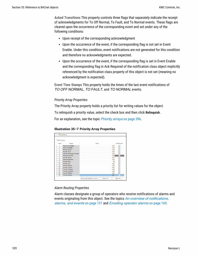
Acked Transitions This property controls three flags that separately indicate the receiptof acknowledgments for To Off Normal, To Fault, and To Normal events. These flags arecleared upon the occurrence of the corresponding event and set under any of thefollowing conditions:
l Upon receipt of the corresponding acknowledgmentl Upon the occurrence of the event, if the corresponding flag is not set in Event
Enable. Under this condition, event notifications are not generated for this conditionand therefore no acknowledgments are expected.
l Upon the occurrence of the event, if the corresponding flag is set in Event Enableand the corresponding flag in Ack Required of the notification class object implicitlyreferenced by the notification class property of this object is not set (meaning noacknowledgment is expected).
Event Time Stamps This property holds the times of the last event notifications ofTO OFF NORMAL, TO FAULT, and TO NORMAL events.
Priority Array Properties
The Priority Array property holds a priority list for writing values for the object.
To relinquish a priority value, select the check box and then click Relinquish.
For an explanation, see the topic Priority arrays on page 396.
Illustration 35–7 Priority Array Properties
Alarm Routing Properties
Alarm classes designate a group of operators who receive notifications of alarms andevents originating from this object. See the topics An overview of notifications,alarms, and events on page 131 and Emailing operator alarms on page 169.
Section 35: Reference to BACnet objects KMC Controls, Inc.
520 Revision L

Section 36: Conf igur ing Sensor Port objects
This section covers the configuration of NetSensors and the HPO-9007 wirelessgateway.
Sensor Port Objects are active devices that plug directly into a KMC Controls BACnetcontroller. Use one of the following configuration procedures to configure Sensor PortObjects.
l KMD-1100 and KMD-1200 series NetSensors are used with the BAC-5800 andBAC-7000 series controllers. Configuration is described in the topic ConfiguringKMD series NetSensors for BACnet on page 521.
l STE-9000 series NetSensors are used with the BAC-5900 and BAC-9000 series ofcontrollers. Configuration is described in the topic Configuring the STE-9000series NetSensor on page 527.
l Wireless gateway Configuring the HPO-9007 wireless gateway on page 532.
See also the topic Configuring a NetSensor for KMDigital controllers on page 579.
Configuring KMD series NetSensors for BACnetThe KMD-1160, KMD-1180, KMD-1260, and KMD-1280 series NetSensors connect directlyto any of the following KMC BACnet controllers:
l BAC-5800 seriesl BAC-7000 seriesl BAC-7400 series
NetSensors are wall-mounted display and sensor units that consist of an LCD display, athermistor, up to seven buttons, and optional humidity and motion sensors. Additionalinformation for the NetSensor can be found in the following documents.
l The NetSensor installation guide.l The Control Basic topic NETSENSORSTATUS on page 293.
KMC Connect Reference Guide
Revision L 521

To configure a NetSensor object, do the following:
1 In the Network Manager list, click or to expand or collapse the list to open theSensor Port Objects folder.
2 Double-click the NetSensor icon to open the NetSensor object. The NetSensortab opens.
3 As required, configure each of the buttons. See Button configuration exampleson page 522 for suggestions on configuration.
4 When finished, click Save Changes.
Button configuration examples
Configuring a KMD series NetSensor consists of assigning an object—typically a valueobject—to one of the buttons on the NetSensor. The value of the object is then displayedby the NetSensor and controlled with the assigned button. For a description of theNetSensor button functions, see NetSensor button functions on page 524.
Illustration 36–1 NetSensor button layouts
Section 36: Configuring Sensor Port objects KMC Controls, Inc.
522 Revision L
Button 1–internal temperature sensor Button 1 and the space temperature sensor insideof the NetSensor are usually associated with Analog Value object AV1.
1 In Assignment, select an Analog Value object to associate with the temperaturebutton or drag an object from the Network Manager list to Assignment.
2 Set Display Format to °F or °C.
3 Set Permission to Read Only. Operators can then view the room temperature bytouching Button 1 but cannot change the value.
If input calibration is required, see Calibration on page 525.
Button 1–controller points To manage or display an object value from Button 1, configureas follows:
1 In Assignment, select an input, output or value object to associate with thetemperature button or drag an object from the Network Manager list to Assignment.
2 Set Display Format to 0, 0.0 or 0.00.
3 Set Permission to Read Only or Read/Write.
l If set to Read Only, operators can view the value associated with Button 1 butcannot change it.
l Is set to Read/Write operators can change the value of the object by firsttouching Button 1 and then pressing the up or down arrow buttons.
Setpoint Button 2 is usually associated with Analog Value object AV2.
1 In Assignment, select an Analog Value object to associate with the setpoint buttonor drag an object from the Network Manager list to Assignment.
2 Set Display Format to 0, 0.0 or 0.00.
3 Set Permission to Read/Write. Operators can view and change the setpoint by firsttouching Button 2 and then pressing an up or down arrow button.
4 In a Program object, add a Control Basic statement to start equipment based on theconditions of the setpoint.
IF AV2 < AV1 THEN START BO6
Humidity (Humidity equipped models only) Button 7—the humidity sensor— is usuallyassociated with Analog Value object AV7.
1 In Assignment, select an Analog Value object to associate with the humidity buttonor drag an object from the Network Manager list to Assignment.
2 Set Display Format to 0.
3 Set Permission to Read/Write. Operators can view the room humidity by touchingButton 7 but cannot change the value.
KMC Connect Reference Guide Section 36: Configuring Sensor Port objects
Revision L 523

Time Typically Button 5 is assigned to display system time and is associated with AnalogValue object AV5.
1 Set Display Format to Time which will automatically format the display with a colon (:).
2 In Assignment, select an Analog Value object to associate with the time button ordrag an object from the Network Manager list to Assignment.
3 In a Program object, add a Control Basic line as follows:
AV5 = TIME
Verifying a functioning NetSensor To check if a functioning NetSensor is present, use theControl Basic function NETSENSORSTATUS on page 293.
IF NOT NETSENSORSTATUS THEN STOP BV1
Motion sensing (Motion sensing models only) Detects movement in the room andchanges the value of the Auxiliary function.
1 Under Assignment, select an Analog Value object to associate with the motionsensor. Typically this is Analog Value object AV8.
2 Set Display Format to 0.
3 Set Permission to Read/Write.
4 In a Program object, add Control Basic to test the state of the object assigned toAuxiliary.
l A value of -1 indicates motionl A value of -2 indicates no motionl A value of 0 or 1 indicates the auxiliary function is active.
The following Control Basic example detects motion and changes the state of BinaryValue object BV9.
IF+ AV8 = -1 THEN START BV9 , STOP AIF AV8 = -2 < 1 THEN START AIF TIMEON( A ) > 0:02:00 THEN STOP BV9
NetSensor button functions
The functions of the NetSensor buttons are listed in the following table.
Button Function
Up arrow Increases displayed analog values and toggles binary values
Down arrow Decreases displayed analog values and toggles binary values
Button 1 The default display value. Only Button 1 may be assigned to theinternal temperature sensor.
Table 36–1 NetSensor button functions
Section 36: Configuring Sensor Port objects KMC Controls, Inc.
524 Revision L

Button Function
Button 2 Labeled as Setpoint but can be defined as an input, output or valueobject within the controller.
Buttons 3–6 Can be defined as an input, output or value object within the controller.
Button 7 On applicable models, assigned as the humidity sensor physicallyincluded on the NetSensor.
Aux Press buttons 5 and 7 together and then press the up arrow ordown arrow button to change Aux from Off to On.
Table 36–1 NetSensor button functions (continued)
NetSensor tab properties
The properties in the NetSensor tab define how each of the buttons function.
Assignment Points to the value object that stores the button value. The value object canbe either an analog or binary object. The object can be selected from the Assignment listor by dragging an object from the Network Manager list to Assignment.
Current Value This numerical property indicates the current value—in engineering units—of the input being measured.
Calibration (Button 1 only) Enter a value to correct the temperatures reading as comparedto a calibrated test instrument.
l For a low temperature reading, enter a positive correction value.l For a high temperature reading, enter a negative correction value.l The maximum calibration is 3.2 degrees Fahrenheit above or below the displayed
value.
Display Format Use Display Format to select one of the units from the drop-down list.
l Units in the table NetSensor analog display formats are active when the objectunder Assignment is an analog input, output or value object.
l Units in the table NetSensor binary display formats are active when a binaryinput, output or value object is selected under Assignment.
Unit Action and display
°C Displays temperature in degrees Celsius. Available only on Button 1.If °C is selected, Button 1 is assigned to the internal temperaturesensor and must be associated with a value object.
°F Displays temperature in degrees Fahrenheit. Available only onButton 1. If °F is selected, Button 1 is assigned to the internaltemperature sensor and must be associated with a value object.
Table 36–2 NetSensor analog display formats
KMC Connect Reference Guide Section 36: Configuring Sensor Port objects
Revision L 525

Unit Action and display
0 Sets the precision of the display to nearest whole number.
0.0 Sets the precision of the display to one place to the right of thedecimal point.
0.00 Sets the precision of display to two places to the right of the decimalpoint.
Time Sets the NetSensor to display a time format.
Off/Low/High The NetSensor cycles through each word as arrow buttons arepressed and released. The Analog Value object cycles from 0 to 2.
Off/On1/2/3 The NetSensor display cycles through each word as arrow buttonsare pressed and released. The Analog Value object cycles from0 to 3.
System Time Use to set time in a stand-alone controller when an operatorworkstation or other time master device is not available.
Day Of Week Use to set the day of week in a stand-alone controller when anoperator workstation or other time master device is not available.
Table 36–2 NetSensor analog display formats (continued)
Label Action and display
On/Off The NetSensor toggles between words as arrow buttons are pressedand released. The binary object toggles between 0 and 1.
Low/High The NetSensor toggles between words as arrow buttons are pressedand released. The binary object toggles between 0 and 1.
Cool/Heat The NetSensor toggles between words as arrow buttons are pressedand released. The binary object toggles between 0 and 1.
Table 36–3 NetSensor binary display formats
Permission The permission property sets the button to be either a display-only button or abutton that an operator can use to change a value in the building automation system.
l Read Only indicates an operator may only view the data displayed on the NetSensor.l Read/Write indicates an operator may use the arrow buttons to change the data.
Retain Changes When selected, the present value of the object associated with a button iswritten to the flash memory in a KMC BACnet controller and retrieved from the controllerafter a cold start.
Auto Blanking When this check box is selected, the NetSensor display will go darkapproximately 15 seconds after the last button is pushed.
Section 36: Configuring Sensor Port objects KMC Controls, Inc.
526 Revision L

Configuring the STE-9000 series NetSensorThe STE-9000 series NetSensor is a wall-mounted display and sensor unit that connectsdirectly to any of the following Conquest controllers.
l BAC-5900 seriesl BAC-9000 seriesl BAC-9300 series
The sensor consists of an LCD display, a thermistor, control buttons and optionalhumidity, motion sensor, and CO2 sensors. By installing an HPO-9001 NetSensorDistribution board, up to eight NetSensors can be configured for each controller.Additional information for the NetSensor can be found in the following documents.
l The installation guide for the NetSensor.l The installation guide for the HPO-9001 distribution module.
Caution: BAC-9000 and BAC-9300 series controllers areprogrammed for specific display functions with an STE-9000 sensor.Changing the sensor configuration may disrupt controller operation.Refer to the controller application guide before changing NetSensorconfiguration.
To configure a NetSensor, do the following:
1 In the Network Manager list, locate and open a device that includes a NetSensor.
2 Locate and open the Sensor Port Objects folder.
KMC Connect Reference Guide Section 36: Configuring Sensor Port objects
Revision L 527

3 Double-click the NetSensor icon . The NetSensor configuration tab opens.
4 Make changes as needed.
5 When changes are complete, click Save Changes at the top of the page.
6 Right-click the device icon and choose Reinitialize Device.
Section 36: Configuring Sensor Port objects KMC Controls, Inc.
528 Revision L

General tab
The General tab displays information about the sensor and sets overall operatingproperties.
Illustration 36–2 Conquest NetSensor General tab
Sensor model Properties in this area list basic properties for the sensor.
Configured Sensor Selects the default configuration for each sensor model.
Detected Sensor Shows the model of the sensor connected to the controller.
Firmware Version Shows the firmware version.
Settings The properties in the Settings area set up security and basic display information.
Object Name Enter the name of the sensor to be shown in the Network Managerlist.
Level One Password Enter the numerical Password One for the user accessiblesetpoints.
Level Two Password Enter the numerical Password Two for the configurationfunctions used by a controls technician.
Screen Blanking When selected, the screen automatically darkens after a fewseconds.
Enabled By default, this check box is selected for NetSensor 1 in each controller. Ifadditional NetSensors are connected with an HPO-9001 NetSensor distributionmodule, select the Enabled check box.
Temperature Units Select the temperature display units as either degreesFahrenheit or Celsius.
Flow Units Select the flow units as either CFM (Cubic Feet per Minute) or LPS(Liters Per Second).
Sensor Parameters The properties in the Sensor Parameters list associate a sensorfunction with a value object in the controller.
KMC Connect Reference Guide Section 36: Configuring Sensor Port objects
Revision L 529

Note: When the NetSensor is connected to a controller, the internalsensors for temperature, humidity, CO2, and motion areautomatically associated with the default objects for Temperature,Humidity, CO2, and Motion Sensor. Changing these assignments willdisrupt the sequence of the factory supplied programs.
Internal Sensor The type of physical internal sensor. Not all sensor types areincluded in every NetSensor.
Object and Property The object and property within the NetSensor to associate withan internal sensor.
Priority The level in the object's priority where the internal value will be stored.
Calibration Enter a calibration value for the temperature sensor. The range is +/- 20degrees.
Home Display tab
Items in the Home Display tab associate the properties in the controller to display on thevarious parts of the sensor LCD screen.
Illustration 36–3 Conquest NetSensor Home Display tab
Icon Control The properties in the Icon Control list associate a screen icon with a BinaryValue object. The icon is displayed when the object is active.
Home Screen Upper Display Values This a list of objects whose Present Value propertiesare displayed in the upper display of the home screen. The time of display for each objectis set by the value in the column Display Time.
Home Screen Lower Display Values This a list of objects whose Present Value propertiesare displayed in the lower display of the home screen. Set the time of display for eachobject in the column Display Time.
Section 36: Configuring Sensor Port objects KMC Controls, Inc.
530 Revision L

User Setpoints tab
The User Setpoints tab sets the scale, icons, and limits for the setpoints available with aLevel 1 password.
Illustration 36–4 Conquest NetSensor User Setpoints tab
Advanced tab
Items under the Advanced tab associate a sensor Configuration or Setpoint menu itemwith an object in the controller. See the documentation for the NetSensor and controllerfor the details on each menu item.
Illustration 36–5 Conquest NetSensor Advanced tab
System Configuration Items in this list associate a value object with a systemconfiguration function such as fan or reheat type.
Setpoint Configuration This list designates the value objects and values for setpointlimits.
KMC Connect Reference Guide Section 36: Configuring Sensor Port objects
Revision L 531

Optional Menus tab
The properties under the Optional Menus tab enables or disables the CNFG(Configuration), COMM (Communication), or BLNC (Balancing) menus in the sensor. Whena menu is not enabled, users are prevented from changing properties from the sensor inthe disabled menus. See the documentation supplied with the sensors and controllers forthe properties that are included in each type of menu.
Note: The BLNC (Balancing) menu is available only for VAVcontrollers.
Illustration 36–6 Conquest NetSensor Optional Menus tab
Configuring the HPO-9007 wireless gatewayThe HPO-9007 gateway is a receiver for STW-6000 and THW-6000 series of wirelesssensors. It is compatible also with EnOcean sensors from other manufacturers. Connectthe gateway directly to a Room Sensor port or to an HPO-9001 distribution module. TheHPO-9007 is compatible with any of the following Conquest controllers:
l BAC-5900 seriesl BAC-9000 seriesl BAC-9300 series
Before you begin, review the information provided with the HPO-9007 gateway, thesensors, and, if used, the HPO-9001 distribution module.
You will also need the following items and information:
l Access to the Learn button inside of the sensors.l The sensor identification number located inside of the sensors.l An unassigned Analog Value object for each sensor parameter to be used by the
controller or site.
Configuring sensors is a two-part process:
1 Converting a sensor object in the Sensor Port Object list to a gateway object. This isonly done once for each gateway.
2 Adding individual sensors to the gateway.
Section 36: Configuring Sensor Port objects KMC Controls, Inc.
532 Revision L

Converting a sensor object
A NetSensor object in the Sensor Port Objects folder must be converted to a gatewayobject before sensors can be added to it.
To convert a sensor object to a gateway object, do the following:
1 In the Network Manager list, click or to expand or collapse the network list tolocate the Sensor Port Objects folder.
2 Right-click a NetSensor icon and choose Convert To and then EnOcean Gatewayfrom the shortcut menu.
3 The NetSensor icon changes to a gateway icon .
Once a gateway is in the Network Manager list, add compatible sensors to it.
Adding sensors by discovery
1 In the Network Manager list, click or to expand or collapse the network list tolocate the Sensor Port Objects folder.
KMC Connect Reference Guide Section 36: Configuring Sensor Port objects
Revision L 533

2 Locate the gateway icon in the Sensor Port Objects list. If the gateway object isnot in the Sensor Port Objects list, see Converting a sensor object on page 533.
3 Double-click the icon to open the gateway configuration tab.
4 Expand the Gateway Sensor List Properties.
5 Inside of a sensor, press and release the Learn button.
When the gateway has detected the sensor, the sensor ID and other data will beadded to the Gateway Sensor List in normal type.
6 Expand the Sensor Mapping Properties area.
7 From the Gateway Sensor List area, drag the sensor icon to any area of the SensorMapping Properties area.Once the sensor is in the Sensor Mapping properties area, the sensor text in theGateway Sensor List Properties turns gray.
Section 36: Configuring Sensor Port objects KMC Controls, Inc.
534 Revision L

8 From the text list in the Object column, choose an Analog Value object to associatewith each sensor property. At least one property must be paired with an AnalogValue object.
9 In Location, enter the physical location of the sensor.
10 Click Save Changes at the top of the tab.
Adding sensors by Sensor ID
Use the manual method to add sensors that may not be available or are currently out-of-range of the gateway. This includes adding compatible EnOcean devices from othermanufacturers.
1 Locate the gateway icon in the Sensor Port Objects list. If the gateway object isnot in the Sensor Port Objects list, see Converting a sensor object on page 533.
2 Double-click the icon to open the object.
3 Expand Sensor Mapping Properties.
4 At the bottom of the list, click the plus button to add a new sensor.
5 In SensorID, enter the numerical portion of the sensor identification number.
KMC Connect Reference Guide Section 36: Configuring Sensor Port objects
Revision L 535

6 From the text list in the EEP column, choose the EnOcean Equipment Profile for thesensor.
l Models from KMC Controls, Inc. are listed by their model number.l For other EnOcean sensors, choose the EEP provided by the manufacturer.
7 In Location, enter the physical location of the sensor.
8 From the the Object column text list, choose an Analog Value object to associatewith each sensor parameter. At least one parameter must be paired with an AnalogValue object.
9 Click Save Changes at the top of the tab.
Deleting sensors
1 Locate the gateway icon in the Sensor Port Objects list.
2 Double-click the icon to open the object.
3 Expand Sensor Mapping Properties.
Section 36: Configuring Sensor Port objects KMC Controls, Inc.
536 Revision L

4 Click the minus button next to the sensor. The sensor will be deleted from SensorMapping Properties but will remain in Gateway Sensor List.
5 Click Save Changes at the top of the tab.
Control Basic conversion examples
To convert sensor temperature to degrees Fahrenheit or dial position data to a setpointoffset, use the following examples.
Celsius to Fahrenheit Conquest wireless sensors send temperature data to a gatewayonly in degrees Celsius. In the following example, Analog Value object AV6 holds thesensor temperature data in degrees Celsius. The calculation converts the value in AV1 todegrees Fahrenheit and stores the result in AV1.
REM AV6 Degrees C from sensorAV1 = AV6 * 1.8 + 32
Dial position The dial position for the Conquest sensor is stored as a value that rangesfrom 0-255. This value is proportional to a dial position that ranges from 0-270 degrees. Inthe following example, Analog Value object AV5 holds the sensor temperature offset spanin degrees. For example, enter 4 for an offset of ± 2 degrees. The calculation converts theposition stored in AV3 to an offset that is stored in AV2.
REM AV5 = The offsetREM AV3 = The sensor dial value (0 thru 255)REM AV2 = Resulting offsetAV2 = AV5 / (255 / AV3) - AV5 / 2
General Properties
The General Properties display and configure the gateway as an object within the BACnetcontroller to which it is connected.
Object Instance The number of the object. Gateway objects are numbered sequentiallywithin a BACnet device.
Object Name A text label of the object. The Name property must be unique within theBACnet device that maintains it. The set of characters entered for the Name propertymust be printable characters.
Profile Name The name of the vendor’s object profile to which this object conforms. Aprofile name defines a set of additional properties, behaviors and requirements for this
KMC Connect Reference Guide Section 36: Configuring Sensor Port objects
Revision L 537
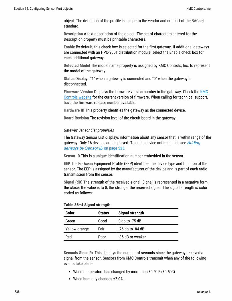
object. The definition of the profile is unique to the vendor and not part of the BACnetstandard.
Description A text description of the object. The set of characters entered for theDescription property must be printable characters.
Enable By default, this check box is selected for the first gateway. If additional gatewaysare connected with an HPO-9001 distribution module, select the Enable check box foreach additional gateway.
Detected Model The model name property is assigned by KMC Controls, Inc. to representthe model of the gateway.
Status Displays "1" when a gateway is connected and "0" when the gateway isdisconnected.
Firmware Version Displays the firmware version number in the gateway. Check the KMCControls website for the current version of firmware. When calling for technical support,have the firmware release number available.
Hardware ID This property identifies the gateway as the connected device.
Board Revision The revision level of the circuit board in the gateway.
Gateway Sensor List properties
The Gateway Sensor List displays information about any sensor that is within range of thegateway. Only 16 devices are displayed. To add a device not in the list, see Addingsensors by Sensor ID on page 535.
Sensor ID This is a unique identification number embedded in the sensor.
EEP The EnOcean Equipment Profile (EEP) identifies the device type and function of thesensor. The EEP is assigned by the manufacturer of the device and is part of each radiotransmission from the sensor.
Signal (dB) The strength of the received signal. Signal is represented in a negative form;the closer the value is to 0, the stronger the received signal. The signal strength is colorcoded as follows:
Color Status Signal strength
Green Good 0 db to -75 dB
Yellow-orange Fair -76 db to -84 dB
Red Poor -85 dB or weaker
Table 36–4 Signal strength
Seconds Since Rx This displays the number of seconds since the gateway received asignal from the sensor. Sensors from KMC Controls transmit when any of the followingevents take place:
l When temperature has changed by more than ±0.9° F (±0.5°C).l When humidity changes ±2.0%.
Section 36: Configuring Sensor Port objects KMC Controls, Inc.
538 Revision L

l When the dial changes by ±10.5° of the 270° dial rotation.l When the Learn button in the sensor is pushed.l After 15-25 minutes of inactivity.
For more detailed information about when sensors transmit data, see the instructionssupplied with the sensors.
Sensor Mapping properties
Sensor Mapping properties display information about a sensor. It is used also toassociate a sensor property with an Analog Value object.
Sensor ID This is a unique identification number embedded in the sensor.
EEP The EnOcean Equipment Profile (EEP) identifies the device type and function of thesensor. The EEP is assigned by the manufacturer of the device and is part of each radiotransmission from the sensor.
Location The physical location of the sensor. This is entered during configuration.
Property The Property is the raw data transmitted by the sensor. Sensors from KMCControls, Inc. will include one or more of the following properties.
Set Point In sensors from KMC Controls, this is the position of the dial. Set Pointranges from a value of 0-255 which is proportional to 0-270° of rotation. SeeControl Basic conversion examples on page 537.
Temperature The space temperature in Celsius. See Control Basic conversionexamples on page 537.
Humidity The relative humidity, in percent, of the space.
RSSI Signal strength in dB and corresponds to Signal (dB) in the GatewaySensor List area.
Last Update This displays the number of seconds since the gateway received asignal from the sensor.
Object The Object text list pairs the Property with an Analog Value object. When newsensor data is received, the Analog Value object is updated at Priority 8.
Value This is the latest received value from the sensor.
Description This is the Description property of the Analog Value object that is paired withthe sensor Property. This can only be changed by editing the Analog Value object. SeeConfiguring BACnet devices and objects on page 403.
KMC Connect Reference Guide Section 36: Configuring Sensor Port objects
Revision L 539

Section 36: Configuring Sensor Port objects KMC Controls, Inc.
540 Revision L

Section 37: BACnet tables
The topics in this section cover for using look-up tables with analog inputs or fromwithin a Control Basic program.
KMC Connect supports look-up tables for both analog inputs and Control Basic. Thefundamental operation of the tables is similar, but the tables are not interchangeable andeach has its own rules.
CBasic A CBasic (Control Basic) table performs a look-up function within a Control Basicprogram. It is based on 32 pairs of data that are interpreted in a Control Basic function.See the topic CB tables on page 542 and the Control Basic keyword TBL on page 322.
Input or device tables An input table, also referred to as a device table, is used with ananalog input object to convert an input—such as a voltage from a temperaturetransmitter—to an output such as temperature in degrees. See the topic Input tables onpage 541.
Input tablesAn input table converts a non-linear input — such as the voltage across a thermistor — toan output such as temperature in degrees. KMC Controls BACnet controllers include twotypes of input tables.
l Built-in tables for Type II and Type III thermistors and airflow sensorsl Custom tables for special applications from third party devices
Device in table Description
KMD 10K Type II KMC Type II thermistors
KMD 10K Type III KMC Type III thermistors
Airflow Sensor Table BAC–7000 series VAV controllers
Table 37–1 Device table descriptions
To open a BACnet Input table, see the topic Configuring BACnet devices and objectson page 403.
See the related topic CB tables on page 542 to use a look-up table in Control Basic.
KMC Connect Reference Guide
Revision L 541

To set up a custom input table, calculate a set of conversion factors based on 128 samplepoints spread over the voltage range of the input. Enter the output value that correspondsto the input voltage in the Index column.
Illustration 37–1 Input table
Generate Defaults Restores the default values for the KMD thermistors or the airflowsensor.
Erase Clears the table of all data.
Import Tables Import a simple text file of values. The text file must contain exactly 128items.
CB tablesA CB(Control Basic) table is used by the Control Basic function TBL on page 322 toperform a look-up function. This may be useful for the following reasons:
l To create special functions within Control Basic.l When the value of an expression is nonlinear or requires a complicated calculation.
A table consists of 32 data pairs stored in two columns. Entries in the X Value columncorrespond to an input value, which is usually an analog input or value object. TheY Value entries are the result of the look-up function and are also stored in an analogobject or variable.
l Values in the X Value column must be entered in ascending order.l The range of the input value is limited by the range of values in the X Value column.l Control Basic performs a linear interpolation between data pairs.
To open a CB table, see the topic Configuring BACnet devices and objects on page403.
Section 37: BACnet tables KMC Controls, Inc.
542 Revision L

See also the keyword TBL on page 322 to use the table data in Control Basic.
Illustration 37–2 CB table
KMC Connect Reference Guide Section 37: BACnet tables
Revision L 543

Section 37: BACnet tables KMC Controls, Inc.
544 Revision L

Section 38: Supported engineer ing units
KMC Connect supports the engineering units listed in this section.
Illustration 38–1 Analog units
%%/sec%Obscuration/ft%Obscuration/m2%RH/hr/min /secamperesamps/mamps/m2amps-sq-mbarsBTUBTU/hrBTU/lbBTU/lb-dry-aircandelascandelas/m2cm2cm2cm-mercurycm-watercurrency1currency10currency2currency3currency4currency5currency6currency7currency8currency9cycles/hrcycles/minDeg-AngularDegCDegC/hrDegC/min
deg-days-Cdeg-days-FDegFDegF/hrDegF/minDegKDegK/hrDegK/mindegrees-phasedelta-deg-Fdelta-deg-Kfaradsfoot-canbdlesftft/minft/secft2ft3ft3/minft3/secgrams/mingrams/secgr-water/kg-dry-airhectoPahenryshertzhorsepowerhoursIgal/minImperial-Galinin2in-mercuryinwjoulesjoules/DegKjoules/kg-DegKjoules/kg-dry-airjoules/sec
KBTUKBTU/hrkgkg/hrkg/m3kg/minkg/secKhertzKJ/kgKJoulesKjoules/DegKKjoules/kg-dry-airKMHKOhmsKpaKVKVAKVARKWHKWHKWH/ft2KWH/m2L/hrL/minL/seclbf/in2lb-masslb-mass/hrlb-mass/minlb-mass/secliterslixeslumensm/hrm/minm/secm2m2/newtonm3
m3/hrm3/minm3/secmAMBTUmetersMeters/s/sMhertzmillibarsminutesMjoulesMjoules/DegKMjoules/ft2MJoules/kg-dry-airMjoules/m2mmmm/minmm/secmm-mercuryMOhmsmOhmsmonthsMPHmsecMVMVAMVARmVoltsMWmwattsMWHnewtonnewton-mnewtons/mnewton-secno-unitsohm-metersohmsPa
PFppbppmpsi/DegFradiansradians/secRPMsdayssec/100secondssiemenssiemens/mteslasthermston-hourstonstons/hrTons-RUS-GalUS-Gal/minV/DegKV/mVAVARVoltswatt-hourswattswatts/ft2watts/m/DegKwatts/m2watts/m2/DegKwebersweeksyears
Normal Inactive Normal Active
OFF ON
Stop Start
Normal Alarm
Closed Open
Table 38–1 Binary unit pairs
KMC Connect Reference Guide
Revision L 545

Normal Inactive Normal Active
Cool Heat
Unocc Occupied
Disable Enable
Normal High
Normal Low
No Yes
Low High
Inactive Active
Table 38–1 Binary unit pairs (continued)
Section 38: Supported engineering units KMC Controls, Inc.
546 Revision L

Section 39: Refe rence to KMC Controls BACnetcontrol le rsThe information in the following table lists characteristics of the BACnet objects in KMCControls BACnet controllers.
l For detailed specifications for each controller, see the installation and operationguide supplied with the controller.
l For information about connecting controllers to a building automation system, seethe installation and operation guide supplied with the controller.
l For configuring the properties in an object, see the topic Reference to BACnetobjects on page 427.
Notes:
l Model BAC–5802 and models ending with C do not have a hardware-based real-timeclock.
l All VAV models include one input dedicated to the airflow sensor and one outputdedicated to the damper motor.
BAC-5801BAC-5802
BAC-5831 BAC-7301BAC-7301C
BAC-7302BAC-7302C
BAC-7303BAC-7303C
BAC-7401BAC-7401C
Function and type GeneralAAC
GeneralAAC
AHUAAC
RTUAAC
FCUAAC
HPUAAC
Universal inputsAnalog,accumulator orbinary
8 16 4 4 4 4
OutputsAnalog or binary
8 12 3 1 2 4
Outputs, singlestage triac
1 1 1
Outputs, dual-stage triac
2 1
Outputs, relay
Binary valueobjects
40 40 40 40 40 40
Analog valueobjects
40 40 40 40 40 40
PID loop objects 8 12 4 4 4 4
Table 39–1 KMC BACnet advanced application controllers
KMC Connect Reference Guide
Revision L 547
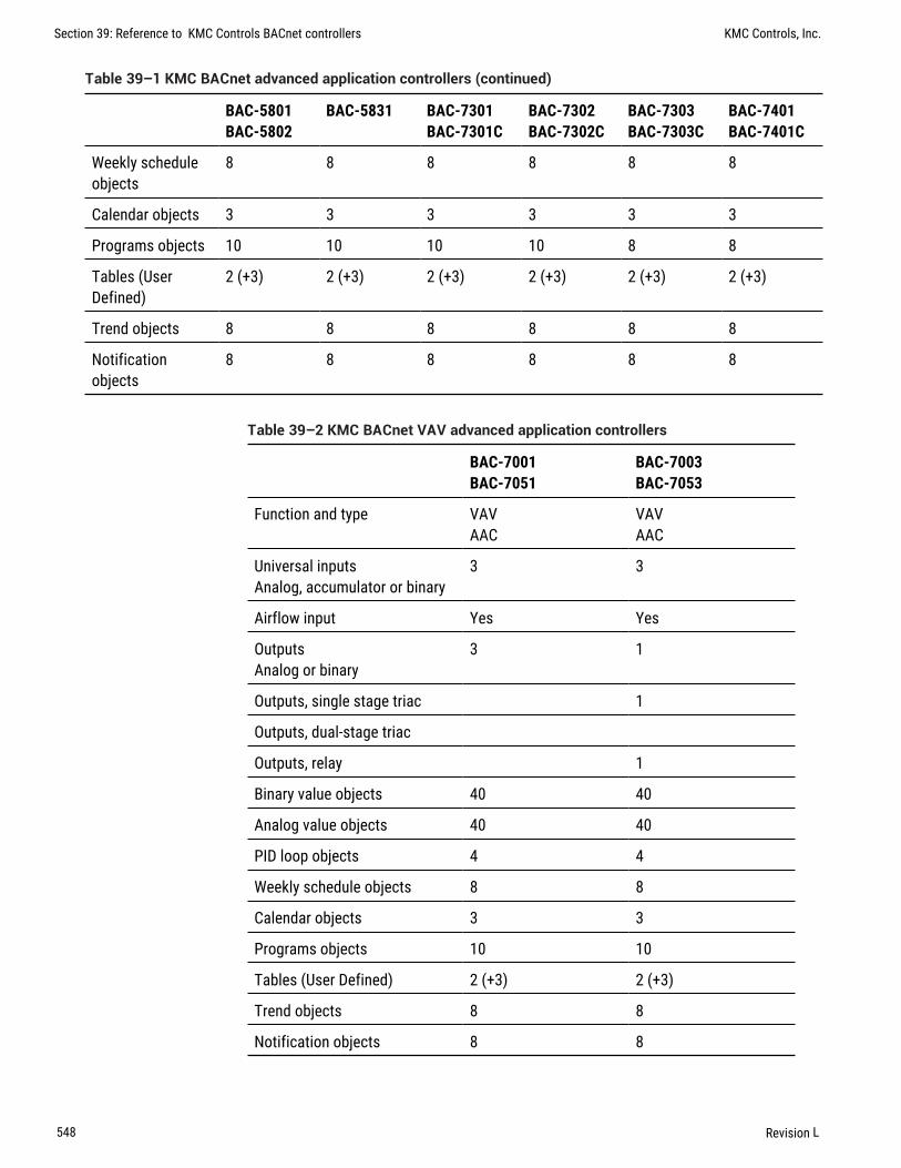
BAC-5801BAC-5802
BAC-5831 BAC-7301BAC-7301C
BAC-7302BAC-7302C
BAC-7303BAC-7303C
BAC-7401BAC-7401C
Weekly scheduleobjects
8 8 8 8 8 8
Calendar objects 3 3 3 3 3 3
Programs objects 10 10 10 10 8 8
Tables (UserDefined)
2 (+3) 2 (+3) 2 (+3) 2 (+3) 2 (+3) 2 (+3)
Trend objects 8 8 8 8 8 8
Notificationobjects
8 8 8 8 8 8
Table 39–1 KMC BACnet advanced application controllers (continued)
BAC-7001BAC-7051
BAC-7003BAC-7053
Function and type VAVAAC
VAVAAC
Universal inputsAnalog, accumulator or binary
3 3
Airflow input Yes Yes
OutputsAnalog or binary
3 1
Outputs, single stage triac 1
Outputs, dual-stage triac
Outputs, relay 1
Binary value objects 40 40
Analog value objects 40 40
PID loop objects 4 4
Weekly schedule objects 8 8
Calendar objects 3 3
Programs objects 10 10
Tables (User Defined) 2 (+3) 2 (+3)
Trend objects 8 8
Notification objects 8 8
Table 39–2 KMC BACnet VAV advanced application controllers
Section 39: Reference to KMC Controls BACnet controllers KMC Controls, Inc.
548 Revision L

BAC-A1616BC CAN-168EIO
Function and type B-BC I/O Expansion
Universal inputsAnalog, accumulator orbinary
16 16
OutputsAnalog or binary
16 8
Binary value objects 100 40
Analog value objects 100 40
Multistate value objects 10
PID loop objects 16 12
Weekly schedule objects 10 8
Calendar objects 10
Programs objects 32
Tables (User Defined) 16 (+8)
Trend objects 32
Notification objects 10
Event Enrollment objects 10
Table 39–3 KMC BACnet Building Controller
KMC Connect Reference Guide Section 39: Reference to KMC Controls BACnet controllers
Revision L 549

Section 39: Reference to KMC Controls BACnet controllers KMC Controls, Inc.
550 Revision L

KMC Connect
Part VIII: KMDigital networks and points
KMC Connect Reference Guide
Revision L 551

KMC Controls, Inc.
552 Revision L

Section 40: Conf igur ing and connecting toKMDigital control le rs and networks
The topics in this section cover connecting to a KMD network as well as configuringKMD points and a KMD network.
The following topics are basic procedures for working with KMDigital1 networks,controllers and points in the Network Manager and configuration pages.
l Before connecting to a KMDigital network on page 553l Adding a KMDigital Tier 1 network on page 554l Adding a KMDigital Tier 2 network on page 559l Configuring KMD controllers and points on page 561l Updating the Network Manager list on page 563l Configuring a KMD service on page 564l Configuring a KMD network on page 566l Setting time for KMD networks on page 567
These additional topics cover more advanced procedures for working with KMDcontrollers and points:
l Reference to KMD points on page 569l Configuring KMD controllers for alarms on page 149
Before connecting to a KMDigital networkBefore KMC Connect can configure KMD controllers, the KMD service must be running andthe KMD network added to the KMD service. The service was automatically installed whenKMC Connect was installed.
Before connecting to a KMD network, verify and have available the following items:
l The KMD service icon is present in the Network Manager list and that the icon isblue.
l Firewalls are open to network traffic used by the KMD ports listed in the topicFirewalls and ports on page 661.
1KMDigital is a proprietary line of digital building automation controllers manufactured by KMCControls, Inc. The controllers are either Tier 1 or Tier 2 controllers. Tier 1 controllers connectdirectly to a LAN through Ethernet; Tier 2 controllers connect to each other and Tier 1 controllerson an EIA-485 network. KMDigital is often abbreviated as KMD.
KMC Connect Reference Guide
Revision L 553

Use one of the following procedures to add a KMDigital network to a KMC Connect site.
l Adding a KMDigital Tier 1 network on page 554l Adding a KMDigital Tier 2 network on page 559
Related topics
l Configuring KMD controllers and points on page 561l Configuring a KMD service on page 564l Configuring a KMD network on page 566l Setting time for KMD networks on page 567l Updating the Network Manager list on page 563
Adding a KMDigital Tier 1 networkTo connect KMC Connect to a KMD Tier 1 network, add a KMD network to the KMD servicein the Network Manager list.
l For details on opening the Network Manager list, see Using the Network Manageron page 39.
l If a KMD service icon is not present and active in the Network Manager list, seeAdding a service on page 42.
l Adding a Tier 1 network adds all KMD controllers in the KMD system to the NetworkManager list.
Note: Before connecting a KMD controller to a network, useHardware Configuration Manager to configure the controller with anaddress. Hardware Configuration Manager is available in thedownloads area of the KMC Controls partners web site.
For a Tier 2 network, see the topic Adding a KMDigital Tier 2 network on page 559.
Adding a Tier 1 network connectionUse the following procedure to add a KMD network and Tier 1 controller to the KMDservice. See also the procedure Adding a Tier 1 serial connection to connect to a Tier1 controller with a serial connection.
Tip: You will need the network IP address of at least one of the Tier1 KMD controllers in the KMDigital network for the followingprocedure.
To add a KMD Tier 1 network with a network connection, do the following:
1 In the Network Manager list, right-click the KMD Service icon and choose ADDNew KMD Network from the shortcut menu. The Add KMD Network dialog opens.
Section 40: Configuring and connecting to KMDigital controllers and networks KMC Controls, Inc.
554 Revision L

2 To change the network name from the original KMDigital system name, do thefollowing:
a. Clear the Use System Name check box.
b. In Network Name, enter a new name for the network.
3 Under System, choose Tier 1.
4 Under Connection, choose Lan Ethernet.
5 Under IP Address, enter the address for one of the KMD Tier 1 controllers. Use oneof the following methods:
l If KMC Connect and the KMD controllers are on the same LAN, enter only the IPaddress of one of the Tier 1 controllers.
l If a network address translation (NAT) router is connected between KMCConnectand the KMD network, add the characters F: or R: to the front of thepublic IP address. See the table Network address translation prefixes for adescription of the prefixes.
l If the IT department set up a URL name for one of the controllers, add thecharacters F: to the front of the URL. For example, enterF:kmdnetwork.bigbuilding.com for the IP address.
6 Click OK when finished.
The Network Manager list will add a network icon and then the list will fill with deviceicons . See the table Network Manager KMD controller icons on page 557 for adescription of the KMD device icons.
Prefix Description
F Full access—All Tier 1 controllers in the network status list are accessible.This is the typical method for connecting to a KMD network over theInternet when only one of the controllers has a public IP address.
R Restricted access—Only the controller with the IP address in thetranslating router is accessible in the network status list.
Table 40–1 Network address translation prefixes
KMC Connect Reference Guide Section 40: Configuring and connecting to KMDigital controllers and networks
Revision L 555

Adding a Tier 1 serial connectionSee the illustration KMD Tier 1 serial connection on page 557 for connection details.Each type of controller requires a specific serial cable.
Tip: Before you begin, verify the port number (COM1, COM2, etc.) ofthe serial port that the KMC Connect computer will use for theconnection. Use the Windows Device Manager to find the portnumber.
To add a Tier 1 network with a direct serial connection, do the following:
1 In the Network Manager list, right-click the KMD Service icon and choose ADDNew KMD Network from the shortcut menu. The Add KMD Network dialog opens.
2 To change the network name from the original KMD system name, do the following:
a. Clear the Use System Name check box.
b. In Network Name, enter a new name for the network.
3 Under System, choose Tier 1.
4 Under Connection, choose Direct.
5 Under Port, choose the port number for the serial connection (COM1, COM2, etc.).
6 Under Baud Rate, choose the same baud as the controller. Typically, this is 38,400for Tier 1 controllers.
7 Click OK when finished.
KMC Connect will add a new network icon under the KMD Service icon and then the listwill fill with device icons. For a description of the KMD controller icons, see Icons forKMD controllers on page 557.
Section 40: Configuring and connecting to KMDigital controllers and networks KMC Controls, Inc.
556 Revision L

Illustration 40–1 KMD Tier 1 serial connection
KMD-5672
Serial cable
KMD-5673
Serial cable
KMD-5210
LAN Controller
KMD-5205
LAN Lite
KMD-5270
Web Lite
Icons for KMD controllersIcons in the following table are added to a KMD network in the Network Manager list.
Tier 1 Tier 2 Status Action
All points in the controllerare known to KMC Connect.
No action required. The controller isoperating normally.
KMC Connect has locatedthe controller and is in theprocess of detecting points.
No action required. This icon willchange to green once all points aredetected.
The controller has beendetected but not all objectshave been placed in thedatabase.
Typically, no action is required. Theicon will change to the icon with agear.
The controller is known toKMC Connect but is nolonger available.
The device may be disconnected,device power is turned off or there is anetwork problem. Use Refresh Devicewhen the problem is corrected.
Device is not availablebecause of a systemproblem.
Verify that the KMD service isoperating and licensed correctly.
Table 40–2 Network Manager KMD controller icons
Properties of the Add KMD Network dialog
Properties in the Add KMD Network dialog set the connection method between aKMDigital network and the KMD service.
KMC Connect Reference Guide Section 40: Configuring and connecting to KMDigital controllers and networks
Revision L 557

Illustration 40–2 Add KMD Network dialog
Use System Name When selected, KMC Connect will automatically assign the originalKMDigital system name as the KMC Connect network name. To use a different name,clear the Use System Name check box.
Network Name A descriptive label of the network.
System Selects the type of KMD network that KMC Connect will connect to. The choicesare Tier 1 or Tier 2.
Connection Depending on the type of network, the Connection list will have the followingchoices:
Tier 1 Lan Ethernet, Direct, or Modem.
Tier 2 has only Direct as a choice.
Port Selects the serial port (Com 1, Com 2, etc.) on the computer running KMC Connect.
Baud Rate Sets the speed of the serial connection. Set Baud Rate to the same speed asthe controllers on the network.
IP Address The IP address of a KMD Tier 1 controller on the network. The address maytake one of the following forms.
l If KMC Connect and the KMD controllers are on the same LAN, enter the IP addressfor one of the Tier 1 controllers.
l If a network address translation (NAT) router is connected between KMCConnectand the KMD network, add the characters F: or R: to the front of the publicIP address. See the table Network address translation prefixes for a descriptionof the prefixes.
l The IT department may set up a URL name for one of the controllers. To use a URL,add the characters F: to the front of the URL. For example, enterF:kmdnetwork.bigbuilding.com for the IP address.
Automatic Network ID Select the Automatic Network ID check box when adding a newKMD network. Clear the check box to change the network number that was automaticallyassigned by KMC Connect.
Network ID Use only to change the Network ID number that was automatically assigned byKMC Connect.
Section 40: Configuring and connecting to KMDigital controllers and networks KMC Controls, Inc.
558 Revision L

Related topics
l Before connecting to a KMDigital network on page 553l Adding a KMDigital Tier 2 network on page 559l Configuring KMD controllers and points on page 561l Updating the Network Manager list on page 563l Configuring a KMD service on page 564l Configuring a KMD network on page 566l Setting time for KMD networks on page 567
Adding a KMDigital Tier 2 networkTo connect a KMC Connect site to KMD Tier 2 controllers, add a new KMD network to theKMD service in the Network Manager list.
Note: Before connecting a KMD controller to a network, useHardware Configuration Manager to configure the controller with anaddress. Hardware Configuration Manager is available in thedownloads area of the KMC Controls partners web site.
Connect to the computer running KMC Connect with one of the methods shown in thediagrams Connecting with a KMD-5559 on page 560 and Connecting with aKMD-5576 on page 561. Either method requires specific cables for the connection.Additional cable details are available in the instructions supplied with the KMD-5559 andKMD-5576. When connecting with a KMD-5559, use a third-party USB-to-serial adapter ifthe computer running KMC Connect does not have a 9-pin serial connector.
Note: KMC Connect does not process KMDigital alarms stored in aKMD-5559.
When KMC Connect is connected directly to a Tier 2 network, only the controllers on thatnetwork are added to the Network Manager list.
Tip: Before you begin, verify the port number (COM1, COM2, etc.) ofthe serial port that the KMC Connect computer will use for theconnection. Use the Windows Device Manager to find the portnumber.
KMC Connect Reference Guide Section 40: Configuring and connecting to KMDigital controllers and networks
Revision L 559

To add a Tier 2 network with a serial port connection, do the following:
1 In the Network Manager list, right-click the KMD Service icon and choose ADDNew KMD Network from the shortcut menu. The Add KMD Network dialog opens.
2 To change the network name from the KMD system name, do the following:
a. Clear the Use System Name check box.
b. In Network Name, enter a new name for the network.
3 Under System, choose Tier 2.
4 Under Port, choose the port for the serial connection (COM1, COM2, etc.).
5 Under Baud Rate, choose the baud of the network.
l For a KMD-5559 connection use 19,200.l For a KMD-5559-2 use 9,600.l For other connections, enter the same baud as the controllers on the network.
6 Click OK when finished.
KMC Connect will add a new network icon and device icons to the Network Manager list.This process may take several minutes. Only the controllers connected to the Tier 2network are added to the Network manager list. For a description of the KMD deviceicons, see Network Manager KMD controller icons on page 557.
Illustration 40–3 Connecting with a KMD-5559
KMD-5615
KMD-5628-1
KMD-5614
Tie
r 2 N
etw
ork
KMD-5624
KMD-5628-1
KMD-5615
KMD-5559
KMD-5559
Section 40: Configuring and connecting to KMDigital controllers and networks KMC Controls, Inc.
560 Revision L

Illustration 40–4 Connecting with a KMD-5576
USB
KMD-5614USB
KMD-5624
Tie
r 2 N
etw
ork
KMD-5576
KMD-5576
Configuring KMD controllers and pointsTo configure a KMD controller or point, the controller must have a device icon in theNetwork Manager list. If a device icon is not in the Network manager list, seeConfiguring a KMD network on page 566. For controllers in the Network Manager listyou may use any of the following methods to configure a device or object.
l By opening, changing and saving the configuration page for the device or object.l By copying a configuration from a backup file from the Resource Manager.l By copying the configuration from a similar controller or point that is in the Network
Manager list.
To open a configuration tab for a KMD controller or object, do the following:
1 In the Network Manager list, click or to expand or collapse the list to locate aspecific KMD controller or point.
l The controller device icon will always be in the list under a KMD service icon and network icon .
l A KMD point is in a folder under a device icon. Each type of point has a uniqueicon.
2 Once the device or point is located, double-click the object or point icon to open aconfiguration page in the workspace.
KMC Connect Reference Guide Section 40: Configuring and connecting to KMDigital controllers and networks
Revision L 561

3 Make changes in the configuration page.
l When complete, click Save Changes at the top of the configuration page.l Click Refresh to discard changes and reload data from the system into the
configuration page.l To close the configuration page, right-click the tab and choose Close or click the
close button in the upper right corner of the page.
Illustration 40–5 Tab in KMD configuration page
Copying configurationsThe configuration of a device or object may be copied from either of two sources:
l Directly from another connected controller in the Network Manager.l From a backup file in the Resource Manager.
To copy a configuration from an item in the Network Manager list, do the following:
1 In the Network Manager list, click or to expand or collapse the network list tolocate a specific controller or point.
2 Hold ALT and drag the configuration to the object, folder of points or device.
When dragging a configuration file from the Network Manager list, the following actionsare supported:
l Dragging a point configuration file onto a single point of similar type. For example,drag only input point configurations onto other input points.
l Dragging a controller configuration file onto another controller that contains pointsof similar type. A dialog opens with which you can select the specific points torestore.
l Dragging a point onto a network that includes devices with similar objects.l Dragging a folder of points onto a similar folder. The points are matched by their
point instance number to the points in the Network Manager list.
Related topics
l Before connecting to a KMDigital network on page 553l Adding a KMDigital Tier 1 network on page 554l Adding a KMDigital Tier 2 network on page 559l Updating the Network Manager list on page 563
Section 40: Configuring and connecting to KMDigital controllers and networks KMC Controls, Inc.
562 Revision L

l Configuring a KMD service on page 564l Configuring a KMD network on page 566l Setting time for KMD networks on page 567
Updating the Network Manager listTo update the KMD controller and network information in the Network Manager list, useRegenerate KMD Device, Regenerate Device List or Refresh Device List.
l Refreshing the device list updates the database with information from existingcontrollers and adds any new controllers that have been connected to the network.
l Regenerating either a device or the entire Network Manager list removes devicesfrom both the database and the Network Manager list. KMC Connect then restoresonly the devices connected to the network.
To refresh the Network Manager list:
1 In the Network Manager list, click or to expand or collapse the list to locate thenetwork icon for a specific KMD network.
2 Right-click the icon and then choose Refresh Device list. As new controllers arediscovered, the are added to the list.
To regenerate a single device:
1 In the Network Manager list, click or to expand or collapse the list to locate thedevice icon for a specific KMD controller.
2 Right-click the icon and then choose Regenerate KMD Device.
3 The icon will be removed from the list and then return as a yellow icon. Regenerationis complete when the icons change to green.
To regenerate the network:
1 In the Network Manager list, click or to expand or collapse the list to locate thenetwork icon for a specific KMD network.
2 Right-click the icon and then choose Regenerate Device List.
3 All network icons are removed and then return as yellow icons. Regeneration iscomplete when the icons change to green.
Related topics
l Before connecting to a KMDigital network on page 553l Adding a KMDigital Tier 1 network on page 554l Adding a KMDigital Tier 2 network on page 559l Configuring KMD controllers and points on page 561l Configuring a KMD service on page 564
KMC Connect Reference Guide Section 40: Configuring and connecting to KMDigital controllers and networks
Revision L 563

l Configuring a KMD network on page 566l Setting time for KMD networks on page 567
Configuring a KMD serviceUse the KMD Service configuration tab to view or change settings for the KMD service.
1 Locate the KMD Service icon in the Network Manager list.
2 Right-click the KMD Service icon and choose Configure Service from the shortcutmenu.
3 Make the changes to the service.
4 When changes are complete, click Save Changes in the tab of the configurationpage.
General Properties
Items under General Properties are usually set up when the KMD service was added to theNetwork Manager list.
Service Name A descriptive name of the service to display in the Network Manager list.
Service ID The Service ID number that was automatically assigned by KMC Connect.
Service Host Address Not applicable to KMC Connect.
Service Host TCP Port Not applicable to KMC Connect.
Update System Group File The KMD service maintains a list of all the System Groups ineach controller in the system. Selecting the Update System Group File check box enablesKMC Connect to update the list as changes are made. Clearing the check box preventschanges to the list.
See also the related topic System Groups on page 593.
Settings and Statistics
The entries in the Settings and Statistics area either set or display operational informationabout the KMD service.
Maximum Response Staleness Sets the age of the data. If—at the time data is requestedfrom a point—the data in the database is older than the value of Maximum ResponseStaleness, KMC Connect will retrieve new data from the controller. If the data is newerthan the value in Maximum Response Staleness, KMC Connect displays the valuestored in the database.
Time Synchronization Interval Sets the interval at which KMC Connect will updated thetime on the connected network. The time sent to the network is the time maintained in thecomputer on which the KMD service is running.
Monitor Statistics Select to automatically refresh data in the Incoming Requests, PendingRequests and Completed Requests fields.
Incoming Requests The number of requests the service has received from KMC Connect.During device discovery, activity will peak and then subside as discovery is completed.
Section 40: Configuring and connecting to KMDigital controllers and networks KMC Controls, Inc.
564 Revision L

Pending Requests The number of unanswered requests that the service has sent to thenetworks. During discovery the rise and fall of this value will somewhat lag the incomingrequests rise and fall.
Completed Requests The number of requests sent to networks for which the servicereceived a response. This is a cumulative value since the service was last started.Selecting the Monitor Statistics check box will periodically initiate requests of theservice, which increases the Completed Requests by one(1) each time a request ismade.
Licensing
This area contains settings and information about licensing for the service.
License Status This is a list of the features for the service that are authorized by thelicense key. This includes also the number of devices or controllers that are authorized bythe license.
License Address This is the location of the license key. If the key is plugged into thecomputer on which the service is running, the entry is (local). To use a license key onanother computer on the network, enter either the computer name or IP address of thecomputer.
License Port This is the UDP network port for communications between the service andthe KMC License Service. Do not change this unless instructed by KMC Controls TechnicalSupport. The default entry is 27605.
Related topics
l Before connecting to a KMDigital network on page 553l Adding a KMDigital Tier 1 network on page 554l Adding a KMDigital Tier 2 network on page 559l Configuring KMD controllers and points on page 561l Updating the Network Manager list on page 563l Configuring a KMD network on page 566l Setting time for KMD networks on page 567
KMC Connect Reference Guide Section 40: Configuring and connecting to KMDigital controllers and networks
Revision L 565

Configuring a KMD networkA KMD network is configured at the time it is added to the Network Manager list. Onceadded to the list only the network name can be changed. To change other properties ofthe network, see Adding a KMDigital Tier 1 network on page 554 or Adding aKMDigital Tier 2 network on page 559.
l If a KMD network is not present, see Adding a KMDigital Tier 1 network on page554 or Adding a KMDigital Tier 2 network on page 559.
l To change the properties of a KMD service, see Configuring a KMD service onpage 564
l If a KMD service is not in the Network Manager list, see Adding a service on page42.
To change the name of an existing KMD network, do the following:
1 Expand or collapse the Network Manager list to locate the network name.
2 Right-click the network icon and choose Configure KMD Network.
3 In the configuration page, make the changes to the network.
4 When changes are complete, click Save in the tab at the top of the configurationpage.
General Properties
Network Name A descriptive label of the network.
Network ID The Network ID is assigned by KMC Connect and cannot be changed.
IP Address The IP address of a KMD Tier 1 controller on the network. This can only bechanged with Hardware Configuration Manager. It cannot be changed in KMC Connect.
Tier 1 Network Status
The status properties apply to the Tier 1 network to which the controller is assigned.
To see the Tier 2 Network Status, see the topic Device points on page 572.
Online Indicates TRUE if the controller is currently on-line.
Running Program Indicates TRUE if one or more Control Basic programs are running inthe controller. See also the topic About Control Basic scans on page 214.
Version The revision level of the firmware in the controller.
Scan Rate This is the rate that all Control Basic programs in the controller are running.Typical scan rates range from 5 to 50 scans per second. See also the topic AboutControl Basic scans on page 214.
Network Input Point The total number of want-points a controller is requesting from othercontrollers. See also the topic Transferring values with KMD want-points on page236.
Section 40: Configuring and connecting to KMDigital controllers and networks KMC Controls, Inc.
566 Revision L

Network Output Point The total number of want-points a controller is making available toother controllers.
Remaining memory The amount of free memory, in bytes, available for programs, trendlogs, runtime logs, etc.
Advanced right-click commands
The following commands are available only by right-clicking the network icon in theNetwork Manager list.
Read System Groups Refreshes the points in all of the System Groups in all controllers onthe network. See also the procedure Reading the System Group list on page 594.
Clear Want Points Clears all want-points from the controllers on the network. Clear thewant-points when a controller has exceeded its maximum number of points. SeeTransferring values with KMD want-points on page 236 for detail.
Related topics
l Before connecting to a KMDigital network on page 553l Adding a KMDigital Tier 1 network on page 554l Adding a KMDigital Tier 2 network on page 559l Configuring KMD controllers and points on page 561l Updating the Network Manager list on page 563l Configuring a KMD service on page 564l Setting time for KMD networks on page 567
Setting time for KMD networksUse the KMD Service configuration tab to set the interval at which KMC Connect willupdate the time in the controllers connected to the KMD networks. The time sent to thenetworks is the time of the computer on which the KMC Connect is running.
1 Locate the KMD Service icon in the Network Manager list.
2 Right-click the KMD Service icon and choose Configure Service from the shortcutmenu.
3 Under Time Synchronization Interval, choose an update interval:
l Neverl Hourlyl Dailyl Weeklyl Monthly
KMC Connect Reference Guide Section 40: Configuring and connecting to KMDigital controllers and networks
Revision L 567

4 Click Save Changes to Service at the top of the page.
Note: The actual KMDigital network time is maintained in thecontroller with the lowest Tier 1 panel number conneted to thenetwork. See the topic Device points on page 572 to set the time ina KMDigital device.
Related topics
l Before connecting to a KMDigital network on page 553l Adding a KMDigital Tier 1 network on page 554l Adding a KMDigital Tier 2 network on page 559l Configuring KMD controllers and points on page 561l Updating the Network Manager list on page 563l Configuring a KMD service on page 564l Configuring a KMD network on page 566
Section 40: Configuring and connecting to KMDigital controllers and networks KMC Controls, Inc.
568 Revision L

Section 41: Refe rence to KMD points
The following topics are a reference to the features and characteristics of points in KMDseries controllers.
KMC Connect supports standard points in KMD series controllers.
l To locate a KMD controller or point on a KMD network, see Using the NetworkManager on page 39.
l To configure the points in a KMD controller, see Configuring and connecting toKMDigital controllers and networks on page 553.
This section describes the following objects:
l Annual Schedule points on page 569l Array points on page 571l Device points on page 572l Input points-analog on page 574l Input points-binary on page 575l InterProtocol points on page 576l Configuring a NetSensor for KMDigital controllers on page 579l Output points-analog on page 585l Output points-binary on page 587l PID loop controllers on page 588l Control Basic programs on page 590l Runtime Log points on page 591l System Groups on page 593l Tables on page 594l Trend Log points on page 595l Variable points-analog on page 596l Variable points-binary on page 597l Weekly Schedule points on page 598
Annual Schedule pointsUse Annual Schedule points to override the normal schedule in a Weekly Schedule pointon special days during a year. When the calendar maintained in the controller reaches oneof the days designate by the Annual Schedule point, the point changes to Active (On, 1,etc.).
KMC Connect Reference Guide
Revision L 569

An Annual Schedule point can be used to override a normal daily schedule in a WeeklySchedule point. The state of a schedule can also be tested with Control Basic as shown inthe following example.
A = AS1Override = AS2
General Properties
Name The 8-character description of the point. Name must be unique within the KMDcontroller that maintains it. The set of characters entered for Name must be printablecharacters.
Description A 20-character description of the annual schedule. Description must beunique within the KMD controller that maintains it. The set of characters entered forDescription must be printable characters.
Present Value Indicates whether the schedule is Active (On) or Inactive (Off).
Manual When the Manual check box is selected, the present value will remain asdisplayed until changed by a user. When the check box is clear, the value of the schedulewill change based on the days selected.
Annual Schedule Dates
To add to or remove days from an Annual Schedule point, click the day on the calendar.Enabled dates appear highlighted. When the highlighted day begins, the present state ofthe Annual Schedule changes to Active (On).
Alarm Routing Properties
Alarm classes designate a group of operators that receive notifications of alarms andevents originating from this point. Select the KMC Connect alarm class routing from thelist. See the topics An overview of notifications, alarms, and events on page 131,Emailing operator alarms on page 169, and Alarm classes for KMD controllers onpage 151.
Related topics
l Configuring KMDWeekly Schedule points on page 186l Configuring KMD Annual Schedule points on page 187l Weekly Schedule points on page 598l About KMD Schedules on page 185
Section 41: Reference to KMD points KMC Controls, Inc.
570 Revision L

Array pointsAn array is a special kind of table. It contains only one column and up to 128 rows whichare also referred to as elements. The elements of the array can take on any numericalvalue and each element value can be recalled or updated at any time using Control Basic.An example of an array would be the storing of the highest temperature every day of themonth.
Note: Available only in KMD Tier 1 controllers.
See the related topic Configuring KMD controllers and points on page 561.
Array Name The 8-character description of the point. the Array Name must be uniquewithin the KMD controller that maintains it. The set of entered characters must beprintable characters.
Array Length The total number of elements the array can contain. The array can be set tohold up to 128 elements. The elements of the array can be assigned either manually orfrom a Control Basic program.
Index The first column displays the element number of the array. This number is used toreference data in the value column. The number of elements in an array is set in ArrayLength.
Value The actual data can be manually entered in the Value column or a Control Basicprogram can read or write the data. When specifying an element within an array, use theform AYN [x].
l N is the array numberl x is the element number within the array
Both N and x must be whole numbers.
The following example shows how to set the value of a variable from an array element:
REM Set Variable 6 to the value of Array 2, element 11VAR6=AY2[11]
This example shows how to set the values of array AY1:
IF+ 1.VAR1 < 55 THEN GOSUB 30ENDIF X > 127 THEN X = 0 : REM Line 30X = X + 11.AY1[ X ] = 1.VAR2X = X + 11.AY1[ X ] = 1.VAR1RETURN
This program records the position value of the mixed air damper (variable VAR2) and thetime of day when the mixed air temperature (variable VAR1) falls below 55 degrees. Localvariable X selects the element where the data is to be stored. Time values are recorded inhours (12:30 PM =1250). The array should be configured for 128 elements. Once the arrayis full, new data will be written over the oldest data.
KMC Connect Reference Guide Section 41: Reference to KMD points
Revision L 571

Device pointsTo configure a KMD device, do the following:
1 In the Network Manager list, locate a Tier 1 device or Tier 2 device icon.
2 Do one of the following:
l Double-click the icon.l Right-click the device icon and choose Configure KMD Device from the shortcut
menu. The device configuration tab opens.
3 Make changes and then click Save Changes at the top of the tab.
General Properties
Panel Name Enter an 8-character description of the device.
Plus Mode Select the Plus Mode check box to set the PID control loop calculationfrequency. This is not available on all models.
DayLight Saving Time Use to set start and end dates to observe daylight savings time.Select Disable in locations where daylight saving time is not observed.
Device Status A view only property.
Firmware Version The firmware series.
Note: Firmware Version is not the same as the firmware buildnumber.
Date and Time (Tier 1 controllers only) Use to directly enter the time and date in thecontroller.
The Tier 1 controller with the lowest controller number maintains the time for the entireKMD network.
Build Number A view only property. The build number is the released version number ofthe firmware.
KMD Model Number A view only property.
Build Time and Date View only properties. Does not apply to all models.
MAC Address The MAC address uniquely identifies the controller on the network. It isassigned by KMC Controls and cannot be changed.
Tier 2 Network Status
Properties for Tier 2 Network Status apply only to the Tier 2 networks directly connect tothe Tier 1 controller
To see the Tier 1 Network Status, see the topic Configuring a KMD network on page566.
Online Indicates TRUE if the controller is currently on-line.
Section 41: Reference to KMD points KMC Controls, Inc.
572 Revision L

Running Program Indicates TRUE if one or more Control Basic programs are running inthe controller.
Version The revision level of the firmware in the controller.
Scan Rate This is the rate that all Control Basic programs in the controller are running.Typical scan rates range from 5 to 50 scans per second. See also the topic AboutControl Basic scans on page 214.
Network Input Point The total number of want-points a controller is requesting from othercontrollers. See also the topic Transferring values with KMD want-points on page236.
Network Output Point The total number of want-points a controller is making available toother controllers.
Custom Units
Custom Units are user defined units of measure for use with inputs, outputs, variables,arrays and tables. A Custom Unit defined in one controller is automatically distributed to,and stored in all controllers on the same network.
Analog Use Analog Custom Units with analog output and variable points. Analog CustomUnits are limited to five characters.
Digital On Use the Binary On Custom Unit with binary points that are in the Active state.Digital On Custom Units are limited to eleven characters.
Digital Off Use the Binary Off Custom Unit with binary points that are in the Inactive state.Digital Off Custom Units are limited to eleven characters.
Alarm Routing Properties
Alarm classes designate a group of operators that receive notifications of alarms andevents originating from this point. Select the KMC Connect alarm class routing from thelist. See the topics An overview of notifications, alarms, and events on page 131,Emailing operator alarms on page 169, and Alarm classes for KMD controllers onpage 151.
Additional right-click commands
The following commands are available only by right-clicking a Tier 1 device or Tier 2device icon in the Network Manager list.
Erase Master Password Removes the master KMDigital password from all controllers onthe same KMDigital network.
Caution: The master password cannot be restored unless allprogramming is erased from the controller with the HCMconfiguration program. Before disabling the master password, verifythat all user defined passwords are known and recorded and that atleast one user defined password has level 6 access.
KMC Connect Reference Guide Section 41: Reference to KMD points
Revision L 573

Initialize Print Buffer Deletes all print jobs in the KMD–5210 print buffer.
Note: For KMD–5110 MultiNet controllers only.
Read System Groups Refreshes the points in the System Groups. See also the procedureReading the System Group list on page 594.
Clear Panel Erases all programming, point configuration, labels, and descriptions from thecontroller. Using Clear Panel does not change settings made with HCM. The configurationfor panel number, baud, and last panel remain unchanged.
Clear Want Points Clears all want-points from the controllers on the network. Clear thewant-points when a controller has exceeded its maximum number of points. SeeTransferring values with KMD want-points on page 236 for detail.
Input points-analogAn analog input point represents the characteristics of an analog signal at the input of acontroller.
General Properties
Name The 8-character description of the point. Name must be unique within the KMDcontroller that maintains it. The set of characters entered for Name must be printablecharacters.
Description A 20-character description of the device connected to the point. Descriptionmust be unique within the KMD controller that maintains it. The set of characters enteredfor Description must be printable characters.
Binary State When the Binary State check box is clear, the input is set as an analog input.When the check box is selected, the input is a binary input.
Value The current level, quantity, or state of the point.
Units Choose the unit of measure and scale factor for the input signal. For a list of units,see Supported KMD controller engineering units on page 601.
Manual Override Indicates the input is either in automatic or manual mode. When ManualOverride is selected, the input value will remain as displayed until changed by an operator.When the check box is clear, the point will display the value at the input of the controller.
Decommissioned Indicates the input value has been out of range for more than twominutes. If the point is functioning normally, this check box is clear. Decommissioned isvalid only for inputs configured for a KMC thermistor or table.
See the keyword DECOM on page 264 to detect the state of Decommissioned in a ControlBasic program.
Average Sets the number of samples that are averaged together to calculate thedisplayed value. A sample is taken on each scan.
Section 41: Reference to KMD points KMC Controls, Inc.
574 Revision L

Calibration (Analog Inputs points only) Enter a calibration factor to adjust the input forsensor inaccuracies.
l For a low reading, enter a positive correction value.l For a high reading, enter a negative correction value.l The valid range for a calibration factor is from -30 to 30.l The default value is 0 (no calibration).
Alarm Routing Properties
Alarm classes designate a group of operators that receive notifications of alarms andevents originating from this point. Select the KMC Connect alarm class routing from thelist. See the topics An overview of notifications, alarms, and events on page 131,Emailing operator alarms on page 169, and Alarm classes for KMD controllers onpage 151.
Related topics
l Configuring KMD controllers and points on page 561l Input points-binary on page 575 to change an analog input to a binary input
Input points-binaryA binary input point represents the characteristics of a binary signal at the input of acontroller.
General Properties
Name The 8-character description of the point. Name must be unique within the KMDcontroller that maintains it. The set of characters entered for Name must be printablecharacters.
Description A 20-character description of the device connected to the point. Descriptionmust be unique within the KMD controller that maintains it. The set of characters enteredfor Description must be printable characters.
Binary State When selected, the input is a binary input. When the Binary State check boxis clear, the input is set as an analog input.
Value The current state of the point.
Units Select the unit of measure to match the input device. In the scroll box, the digitalunits of measure are shown as a pairs. The first unit is the normal state. When referencingdigital inputs in Control Basic, the left hand state is False (0) and the right hand state isTrue (1). To reverse the action, select the Invert Polarity check box.
For a list of available units, see Reference to KMD points on page 569.
KMC Connect Reference Guide Section 41: Reference to KMD points
Revision L 575
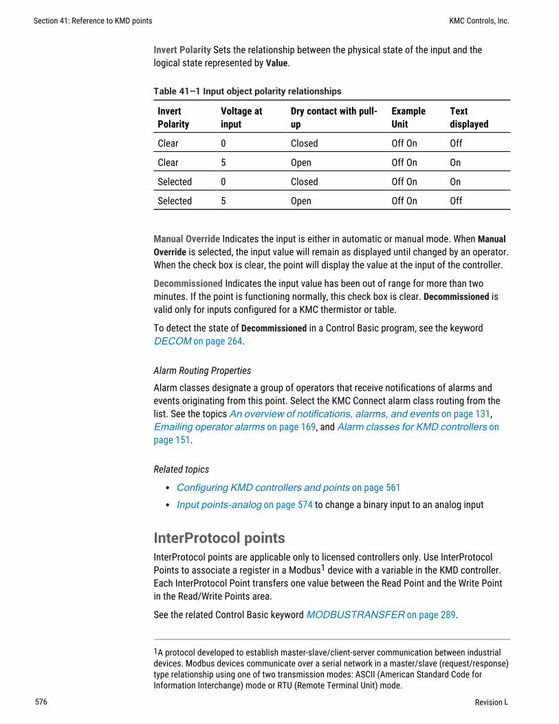
Invert Polarity Sets the relationship between the physical state of the input and thelogical state represented by Value.
InvertPolarity
Voltage atinput
Dry contact with pull-up
ExampleUnit
Textdisplayed
Clear 0 Closed Off On Off
Clear 5 Open Off On On
Selected 0 Closed Off On On
Selected 5 Open Off On Off
Table 41–1 Input object polarity relationships
Manual Override Indicates the input is either in automatic or manual mode. When ManualOverride is selected, the input value will remain as displayed until changed by an operator.When the check box is clear, the point will display the value at the input of the controller.
Decommissioned Indicates the input value has been out of range for more than twominutes. If the point is functioning normally, this check box is clear. Decommissioned isvalid only for inputs configured for a KMC thermistor or table.
To detect the state of Decommissioned in a Control Basic program, see the keywordDECOM on page 264.
Alarm Routing Properties
Alarm classes designate a group of operators that receive notifications of alarms andevents originating from this point. Select the KMC Connect alarm class routing from thelist. See the topics An overview of notifications, alarms, and events on page 131,Emailing operator alarms on page 169, and Alarm classes for KMD controllers onpage 151.
Related topics
l Configuring KMD controllers and points on page 561l Input points-analog on page 574 to change a binary input to an analog input
InterProtocol pointsInterProtocol points are applicable only to licensed controllers only. Use InterProtocolPoints to associate a register in a Modbus1 device with a variable in the KMD controller.Each InterProtocol Point transfers one value between the Read Point and the Write Pointin the Read/Write Points area.
See the related Control Basic keyword MODBUSTRANSFER on page 289.
1A protocol developed to establish master-slave/client-server communication between industrialdevices. Modbus devices communicate over a serial network in a master/slave (request/response)type relationship using one of two transmission modes: ASCII (American Standard Code forInformation Interchange) mode or RTU (Remote Terminal Unit) mode.
Section 41: Reference to KMD points KMC Controls, Inc.
576 Revision L

General Properties
Description Enter a description of the data passed between a KMD controller and theModbus controller. Description is for notation only and is not required for operation.
Mode Sets the update mode for each read point and write point pair.
l Disabled–The pair will not be processed.l One Time–The controller will update the pair only when Save Changes is clicked.
The value for the pair will not be processed after that.l Continuous–The pair is processed approximately once every 10 seconds.
Value The current level, quantity, or state of the point.
Read/Write Points
Read Point Read Point sets the KMD point or Modbus register whose value will betransferred to Write Point. Read Point can be also set to a fixed value. The timing of thetransfer is set by Mode.
Set Read Point to either KMD, Modbus or Fixed Point.
l If Read Point is set to KMD, enter the mnemonic for a KMD point. Use standardControl Basic mnemonics as described in the topic Mnemonics for KMDcontrollers on page 235.
l If Read Point is set to Modbus, see Modbus Point for details on specifying a Modbusregister.
l If Read Point is set to Fixed Value, enter any valid number.
Read Status Reports the success or failure of reading the value in Read Point.
Write Point Write Point is the KMD Point or Modbus register that will receive the transferfrom Read Point.
l If Write Point is set to KMD, enter the mnemonic for a KMD point. Use standardControl Basic mnemonics as described in the topic Mnemonics for KMDcontrollers on page 235.
l If Write Point is set to Modbus, see Modbus Point for details on specifying aModbus register.
Writes Status Reports the success or failure of updating the KMD point or Modbusregister in Write Point.
KMC Connect Reference Guide Section 41: Reference to KMD points
Revision L 577

Modbus Point Modbus Point is active only when Read Point or Write Point is set toModbus.
Point String Enter Modbus registers as shown in the illustration Modbus register formaton page 578. Function codes are listed in the table Supported Modbus functionnumbers and prefix codes on page 578.
Note: Modbus manufacturers typically list the prefix code with theregister number in equipment guides. Verify in the equipment guideexactly how the register number is formatted.
Illustration 41–1 Modbus register format
x-yzzzz
Address of Modbus devicePrefix code
Modbus register
Function Prefix code Action Description
0 00 hex 0 Read Discrete output coil
1 01 hex 1 Read Discrete output coils
3 03 hex 4 Read Analog output holdingregisters
4 04 hex 3 Read Analog input registers
6 06 hex 4 Write Single Analog output holding register
15 0F hex 0 Write multiple Discrete output coils
Supported Modbus function numbers and prefix codes
Data Type Data Type sets the type of data stored in the register.
l Unsigned Integer–For whole numbers between 0 and 65535.l Signed Integer–For whole numbers between -32768 and 32767l Bit String–Use for digital points and status registers.l Float–Must use for 32-bit registers.
Data Format Data Format sets the order in which the parts of the data are sent first. Thisis also referred to as byte ordering and word ordering.
Integer data types have only byte ordering (LSB and MSB) to select. To set up DataFormat for integers choose one of the following:
l Choose MSB,LSB to send the most significant or high byte first.l Choose LSB,MSB to send and store the least significant or low byte first.
Section 41: Reference to KMD points KMC Controls, Inc.
578 Revision L

Float data types have both word ordering (MSW and LSW) and byte ordering (MSB andLSB) to set up. To set up Data Format for floating point values, choose one of thefollowing:
l Choose MSW, LSB or MSW, MSB to send the most significant data word firstfollowed by either the least significant (LSB) or most significant byte (MSB).
l Choose LSW, LSB or LSW, MSB to send the least significant data word first followedby either the least significant (LSB) or most significant byte (MSB).
Multiplier and Offset Values for Multiplier and Offset are used for scaling. Both areprovided by the manufacturer of the Modbus equipment.
Number of Registers Choose 16 bit or 32 bit. If Float is selected in Data Type, set Numberof Registers to 32 bits.
Configuring a NetSensor for KMDigital controllersThe KMD-1160, KMD-1180, KMD-1260, and KMD-1280 series NetSensors connect directlyto any of the following KMDigital controllers:
l KMD-5800 seriesl KMD-7000 seriesl KMD-7400 series
The NetSensors are wall mounted display and sensor units that consist of an LCD display,a thermistor, up to seven buttons, and optional humidity and motion sensors. Additionalinformation for the NetSensor can be found in the following documents.
l In the installation guide for the NetSensor.l In the Control Basic topic NETSENSOR-STATUS on page 294.
To configure a KMD series NetSensor object, do the following:
1 In the Network Manager list, click or to expand or collapse the list to open theNetSensor & Table folder.
KMC Connect Reference Guide Section 41: Reference to KMD points
Revision L 579

2 Double-click the NetSensor icon to open the NetSensor object. The NetSensortab opens.
3 As required, configure each of the buttons. See Button configuration exampleson page 580 for suggestions on configuration.
4 When finished, click Save Changes.
Button configuration examples
Programming a KMD series NetSensor consists of assigning an object—typically a KMDvariable point—to one of the buttons on the NetSensor. The value of the point is thendisplayed by the NetSensor and controlled with the assigned button. See NetSensorbuttons for a description of the available button functions.
Illustration 41–2 NetSensor models and button layouts
Use the following examples to set up and program a NetSensor to display roomtemperature, humidity, a setpoint and time.
Caution: When displaying the value from the internal temperaturesensor, always associate Button 1 only with a variable. AssociatingButton 1 with an input or output will result in improper operation.
Section 41: Reference to KMD points KMC Controls, Inc.
580 Revision L

Button 1—internal temperature sensor Button 1 and the space temperature sensor insideof the NetSensor is usually associated with variable VAR1.
1 Under Point Mnemonic, choose the mnemonic of the variable that will storetemperature data.
2 Set Type to Analog.
3 Set Range to F or C.
4 Set Display to Read Only. Operators can then view the room temperature by pressingButton 1 but cannot change the value.
Button 1—controller points To manage or display a point value from Button 1, configureas follows:
1 Under Point Mnemonic, choose the mnemonic of the point to associate with Button1.
2 Set Type to Analog or Decimal.
3 Set Range to 0, 1 or 2 Decimal. Do not set range to F or C unless controlling theinternal temperature sensor.
4 Set Display to Read or Read/Write.
l If set to Read, operators can view the value associated with the Button butcannot change it.
l If set to Read/Write, operators can change the value of the point by first pressingButton 1 and then pressing the up or down arrow buttons.
Setpoint Button 2 is usually associated with Variable VAR2.
1 Under Point Mnemonic, choose the mnemonic of the variable that will store thesetpoint value.
2 Set Type to Analog.
3 Set Range to 0, 1 or 2 Decimal.
4 Set Display to Read/Write.
Operators can view and change the setpoint by first pressing Button 2 and thenpressing an up or down arrow button.
5 Write a Control Basic to control equipment based on the conditions of the setpoint.
IF VAR2 < VAR1 THEN START OUT6
Humidity (Humidity equipped models only) Button 7—the humidity sensor— is usuallyassociated with variable VAR7.
1 Under Point Mnemonic enter the mnemonic of the variable that will store thehumidity value.
2 Set Type to Analog.
KMC Connect Reference Guide Section 41: Reference to KMD points
Revision L 581
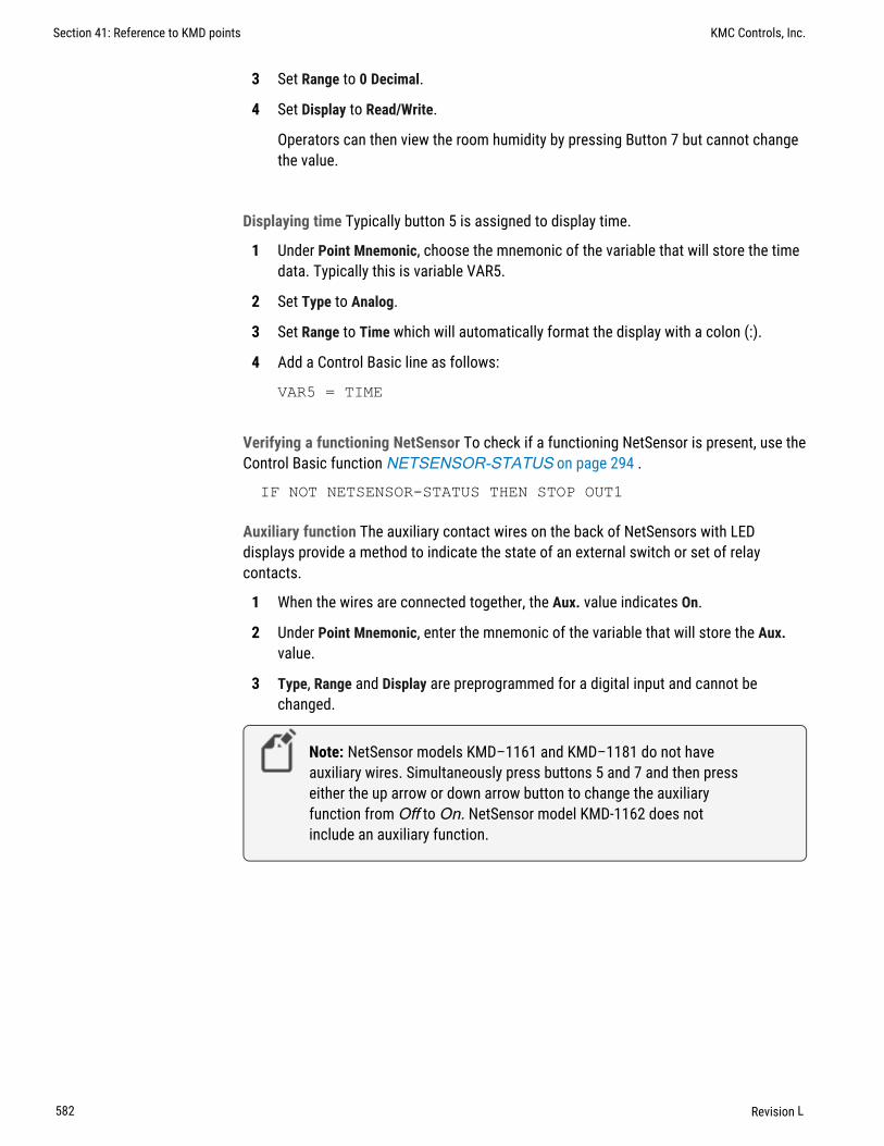
3 Set Range to 0 Decimal.
4 Set Display to Read/Write.
Operators can then view the room humidity by pressing Button 7 but cannot changethe value.
Displaying time Typically button 5 is assigned to display time.
1 Under Point Mnemonic, choose the mnemonic of the variable that will store the timedata. Typically this is variable VAR5.
2 Set Type to Analog.
3 Set Range to Time which will automatically format the display with a colon (:).
4 Add a Control Basic line as follows:
VAR5 = TIME
Verifying a functioning NetSensor To check if a functioning NetSensor is present, use theControl Basic function NETSENSOR-STATUS on page 294 .
IF NOT NETSENSOR-STATUS THEN STOP OUT1
Auxiliary function The auxiliary contact wires on the back of NetSensors with LEDdisplays provide a method to indicate the state of an external switch or set of relaycontacts.
1 When the wires are connected together, the Aux. value indicates On.
2 Under Point Mnemonic, enter the mnemonic of the variable that will store the Aux.value.
3 Type, Range and Display are preprogrammed for a digital input and cannot bechanged.
Note: NetSensor models KMD–1161 and KMD–1181 do not haveauxiliary wires. Simultaneously press buttons 5 and 7 and then presseither the up arrow or down arrow button to change the auxiliaryfunction from Off to On. NetSensor model KMD-1162 does notinclude an auxiliary function.
Section 41: Reference to KMD points KMC Controls, Inc.
582 Revision L

Motion sensing (Motion sensing models only) Detects movement in the room.
1 Under Point Mnemonic, choose the mnemonic of the variable that will store the stateof Aux. Typically this is Variable VAR8 configured as an analog variable.
2 Set Type to Analog. Range is automatically set to 0 Decimal.
3 Set Display to Read/Write.
4 Use Control Basic to test the state of the variable assigned to Aux.
l A value of -1 indicates motion.l A value of -2 indicates no motion.l A value of 0 or 1 indicates the auxiliary function is active.
The following Control Basic program detects motion and changes the state of VariableVAR9.
IF+ VAR8 = -1 THEN START VAR9 , STOP AIF VAR8 = -2 THEN START AIF TIME-ON( A ) > 0:02:00 THEN STOP VAR9
NetSensor button functions
The functions of the NetSensor buttons are listed in the following table.
Button Function
Up arrow Increases analog values and toggles digital values
Down arrow Decreases displayed values; toggles digital values
Button 1 The default display value. Only Button 1 may be assigned to theinternal temperature sensor.
Button 2 Labeled as Setpoint but can be defined as an input, output, or variablewithin the controller.
Buttons 3-6 Can be defined as any point available on the Tier 2 network.
Button 7 On applicable models, assigned as the humidity sensor physicallyincluded on the NetSensor.
Auxiliary For use with auxiliary two-wire input on the back. Use with dry contactssuch as a switch.NetSensors KMD–1161 and KMD–1181 do not have auxiliary wires.Press buttons 5 and 7 together and then press an up or down arrowbutton to change Auxillary from Off to On.
Table 41–2 NetSensor button functions
KMC Connect Reference Guide Section 41: Reference to KMD points
Revision L 583

NetSensor tab properties
The properties in the NetSensor tab define how each of the buttons function.
Calibration Enter a calibration value that is added Button 1.
l For a low temperature reading enter a positive correction value.l For a high temperature reading enter a negative correction value.l The maximum calibration is 3.2° Fahrenheit above or below the displayed value.
Auto Blanking When this check box is selected, the NetSensor display will go darkapproximately 15 seconds after the last button is pushed.
Point Mnemonic The mnemonic for the variable that stores the button value. Thedescription can be a mnemonic from either the connected controller or any othercontroller on the Tier 2 network.
Value Displays the value, in engineering units, of the point listed in Description.
Type Sets the button as either an analog or digital function.
Range Select a unit of measure from the Range list.
l Units listed in the table NetSensor analog display formats on page 584 areactive when Type is set to Analog
l Units listed in the table NetSensor binary display formats on page 585 are activewhen Type is set to Digital.
Display Read/write status of the button.
l Read Only indicates the operator may only view the data displayed on theNetSensor.
l Read/Write indicates an operator may use the buttons to change the data.
Range unit Action and display
C Displays temperature in degrees Celsius. Available only on Button 1. IfC is selected, Button 1 is assigned to the internal temperature sensorand must be associated with a variable.
F Displays temperature in degrees Fahrenheit. Available only onButton 1. If F is selected, Button 1 is assigned to the internaltemperature sensor and must be associated with a variable.
Decimal_0 Sets the precision of the display to the nearest whole number.
Decimal_1 Sets the precision of the display to one place to the right of thedecimal point.
Decimal_2 Sets the precision of display to two places to the right of the decimalpoint.
Time Sets the NetSensor to display a time format.
Table 41–3 NetSensor analog display formats
Section 41: Reference to KMD points KMC Controls, Inc.
584 Revision L

Range unit Action and display
RTC_Time Use to set time in a stand-alone controller when an operatorworkstation or other time master device is not available.
Day_Of_Week Use to set the day of week in a stand-alone controller when anoperator workstation or other time master device is not available.
Table 41–3 NetSensor analog display formats (continued)
Range unit Action and display
Off_On The NetSensor toggles between words as arrow buttons arepressed and released. The digital point toggles between 0 and1.
Low_High The NetSensor toggles between words as arrow buttons arepressed and released. The digital point toggles between 0 and1.
Cool_Heat The NetSensor toggles between words as arrow buttons arepressed and released. The digital point toggles between 0 and1.
Off_Low_High The NetSensor cycles through each word as arrow buttons arepressed and released. The analog point cycles from 0 to 2.
Off_On1_On2_On3 The NetSensor cycles through each word as arrow buttons arepressed and released. The analog point cycles from 0 to 3.
Table 41–4 NetSensor binary display formats
Output points-analogAn analog output point sets the characteristics of an analog signal at the output of acontroller.
General Properties
Name The 8-character description of the point. Name must be unique within the KMDcontroller that maintains it. The set of characters entered for Name must be printablecharacters.
Description A 20-character description of the device connected to the point. Descriptionmust be unique within the KMD controller that maintains it. The set of characters enteredfor Description must be printable characters.
Binary State When selected, the output is a binary output. When the Binary State checkbox is clear, the output is set as an analog output.
Value The current state of the point.
Units Choose the unit of measure and scale factor for the output signal. Outputs can beset up for one of several standard or custom units. For a list of units, see SupportedKMD controller engineering units on page 601.
KMC Connect Reference Guide Section 41: Reference to KMD points
Revision L 585

Manual Override Indicates the output is either in automatic or manual mode. WhenManual Override is selected, the value will remain as displayed until changed by anoperator. When the check box is clear, the value of the output signal can be set by eitheran operator or a calculation in a Control Basic program.
Switch If the controller is set to WinControl Compatible mode, Switch displays the state ofthe output override card. The position of the switch can be evaluated with Control Basic.See the keyword topic OUTPUT-OVERRIDE on page 301.
Switch position on override card State of switch
Hand Manual
Off Manual
Automatic Auto
Table 41–5 Switch settings for KMD binary outputpoints
Security Level Choose an output security level to assign to the point. A user must have asecurity level at or above this value to make changes to the point.
Note: The Security Level property applies only when connecting tothe controller with WinControl XL Plus. It does not apply to KMCConnect.
Delay Not available in analog input points.
Voltage Low Sets the voltage at the output which corresponds to 0% output. Applicableonly when Units is set to Percent or Percent Open.
Voltage High Sets the voltage at the output which corresponds to 100% output.Applicable only when Units is set to Percent or Percent Open.
Alarm Routing Properties
Alarm classes designate a group of operators that receive notifications of alarms andevents originating from this point. Select the KMC Connect alarm class routing from thelist. See the topics An overview of notifications, alarms, and events on page 131,Emailing operator alarms on page 169, and Alarm classes for KMD controllers onpage 151.
Related topics
l Configuring KMD controllers and points on page 561l Output points-binary on page 587 to change an analog output to a binary output
Section 41: Reference to KMD points KMC Controls, Inc.
586 Revision L

Output points-binaryA binary output point sets the characteristics of an binary signal at the output of acontroller.
General Properties
Name The 8-character description of the point. Name must be unique within the KMDcontroller that maintains it. The set of characters entered for Name must be printablecharacters.
Description A 20-character description of the device connected to the point. Descriptionmust be unique within the KMD controller that maintains it. The set of characters enteredfor Description must be printable characters.
Binary State When selected, the output is a binary output. When Binary State is clear, theoutput is set as an analog output.
Value The current state of the point.
Units Choose the unit of measure and scale factor for the output signal. Outputs can beset up for one of several standard or custom units. For a list of units, see SupportedKMD controller engineering units on page 601.
The units of measure are shown as pairs. The first unit is the normal (not inverted) state.When referencing digital points in Control Basic, the left hand state is False (0) and theright hand state is True (1). Custom Units do not have an inverted range. If an invertedcustom range is required you must reverse the setup on the custom unit or create areversed custom unit.
Invert Polarity Sets the relationship between the physical state of the output and thelogical state represented by Value.
InvertPolarity
Voltage atoutput
Textdisplayed
Example
Clear 0 Off Off On
Clear 10 On Off On
Selected 0 On Off On
Selected 10 Off Off On
Table 41–6 Output point polarity relationships
Manual Override Indicates the output is either in automatic or manual mode. WhenManual Override is selected, the state of the output will remain as displayed until changedby an operator. When the check box is clear, the state of the output signal can be set byeither an operator or a calculation in a Control Basic program.
KMC Connect Reference Guide Section 41: Reference to KMD points
Revision L 587

Switch If the controller is set to WinControl compatible mode, Switch displays the state ofthe output override card. The position of the switch can be evaluated with Control Basic.See the keyword topic OUTPUT-OVERRIDE on page 301.
Switch position on override card State of switch
Hand Manual
Off Manual
Automatic Auto
Table 41–7 Switch settings for KMD binary output points
Security Level Choose an output security level to assign to the point. A user must have asecurity level at or above this value to make changes to the point.
Note: The Security Level property applies only when connecting tothe controller with WinControl XL Plus. It does not apply to KMCConnect.
Delay Specifies a delay, in hours, minutes and seconds, which sets a period before theoutput changes to ON after being OFF. This timer takes precedence over any ControlBasic program.
l Delay is entered in hours:minutes:seconds.l The maximum start delay is 1:39:50.
Alarm Routing Properties
Alarm classes designate a group of operators that receive notifications of alarms andevents originating from this point. Select the KMC Connect alarm class routing from thelist. See the topics An overview of notifications, alarms, and events on page 131,Emailing operator alarms on page 169, and Alarm classes for KMD controllers onpage 151.
Related topics
l Configuring KMD controllers and points on page 561l Output points-analog on page 585 to change a binary output to an analog output
PID loop controllersA PID controller point manages the PID loops in the connected controller. A PID loop is amathematical function that calculates the analog output required to maintain a process ator near a setpoint.
See the related topic Configuring KMD controllers and points on page 561.
Section 41: Reference to KMD points KMC Controls, Inc.
588 Revision L

To use the output of a PID loop, assign the output of the PID loop controller to an outputor variable point in a Control Basic program.
OUT1 = CON1
Controlled Point The mnemonic of the input measuring the condition under control. Thecontrolled point is the sensed value that is to be maintained at the setpoint value.
Controlled Point Value (In Value) Displays the value of Controlled Point.
Controlled Point Units Choose the unit of measure and scale factor for the controlledpoint signal. For a list of available units, see Supported KMD controller engineeringunits on page 601.
Manual Override Indicates the PID loop is either in automatic or manual mode. WhenManual Override is selected, the value of the loop output will remain as displayed untilchanged by an operator. When the check box is clear, the value of the loop output signalis controlled by the PID algorithm.
Output Displays, in percent, the current output value of the controller. The value of theoutput is the mathematical sum of the four functions (PROP +RESET +RATE +BIAS).
Setpoint Enter the target value of Controlled Point. Use a mnemonic, label or descriptionto define Setpoint.
Setpoint Value Displays the value of the setpoint.
Action The action of the controller. Action can either be direct-acting or reverse-acting.
For direct-acting loops, select Positive. Direct-acting controllers increase the outputas the input rises above the setpoint.
For reverse-acting loops, select Negative. Reverse-acting controllers decrease theoutput as the input rises above the setpoint.
Proportional Value The proportional value is the value of the proportional gain parameterused by the loop algorithm. It represents the amount of sensed change—expressed in thevalue selected Proportional Units—that will cause the output to move from 0 to 100%.
The proportional parameter is the P in PID.
To program Proportional with Control Basic, see CONPROP on page 258.
Reset and Repeats Reset adds a correction factor to the control loop based on how longthe condition has been outside the setpoint. It specifies the number of times themagnitude of the error is added or subtracted to the output signal, over time, to eliminatethe offset. Reset rate is specified in a repeats per hour (H) or per minute (M).
For example, a system maintaining a continuous error of two units and a reset of five perhour were specified, the output of the controller will change by ten units per hour in adirection to reduce the error.
Reset can also be thought of as the time integral of the error. Integral is the I in PID.
KMC Connect Reference Guide Section 41: Reference to KMD points
Revision L 589
The KMD PID controllers have an anti-windup feature when using Reset. In typical loopsthe integral will continue to increase as long as there is a positive error. For most HVACapplications, such as space temperature control, integral windup is undesirable. To avoidwindup, KMC PID controller algorithms are programmed with an integral capping feature.This limits the integral portion of the output to the percentage below 100% not used byproportional correction. If the proportional value is 60%, the integral can only increase to40%. As the error increases, the rate that the integral adds into the output will increase butthe integral will actually decrease because it has less room. The proportional amount willcontinue to squeeze out integral until the input value is outside the proportional band atwhich point integral value is 0. Integral windup can only happen within the proportionalband and is eliminated as the error increases.
To program Reset with Control Basic, see the Control Basic keyword CONRESET onpage 259.
Rate Rate slows the rate of change of the error. Rate is specified in minutes.
Use rate to reduce overshoot. If the error is changing at 1.0 per second (60/min) and therate was 0.25 minutes, then the derivative component would equal 60 /Min X .25 Min=15%. This 15% would be added in over the 1 minute in a direction to reduce the rate ofchange regardless of whether the input is above or below the setpoint.
Caution: Use Rate only in systems without time lags. The inputmust start responding immediately to an output change. If there is atime delay, the control loop will be unstable and will perform betterwithout rate correction.
Rate is the D (derivative) in PID.
To program Rate with Control Basic, see the Control Basic keyword CONRATE on page258.
Bias Sets the output value at setpoint. The bias is the value the controller will reach atequilibrium when derivative is not used.
To program Bias with Control Basic, see the Control Basic keyword CONBIAS on page257.
Control Basic programsA program point provides a network-visible view of the state of a Control Basic programwithin a KMD controller. It is also a method to open Control Basic programs that areedited with the KMC Connect code editor.
Name Short name of the program. Also referred to as the label.
Description Long name of the program
On Select to enable the program.
Manual When selected, the program cannot be executed by another Control Basicprogram.
Section 41: Reference to KMD points KMC Controls, Inc.
590 Revision L

Timer State (Tier 1 only) Check to run the program at the interval specified in RepeatMinutes.
Note: Do not select Timer State if the program includes ControlBasic NPAGE, TPAGE, or WAIT statements.
Repeat Minutes (Tier 1 only) Sets the interval timer.
Remaining Minutes (Tier 1 only) Time left before program will execute.
Program Size (Tier 1 only) Amount of memory the program is using.
Exit Flag Control Basic forced an exit from the program area.
Related topics
l Configuring KMD controllers and points on page 561l About Control Basic programs on page 213l Programming with the Code Editor on page 191
Runtime Log pointsUse Runtime Log points to record the number of cycles on a digital point and save thecumulative total of runtime hours for that point.
Note: Use a Runtime Log only to record events that are longer thanone-second. Recording shorter events will result in missed orerroneous data.
General Properties
Trend Point Enter the mnemonic for the point to log. Points can be inputs, outputs, orvariables. The point can be from the controller that contains the log or from othercontrollers on the network.
Total On Time Displays the total amount of time the point has been on since the startdate. On Time is displayed in hours: minutes. Clear the data in the log by clickingReset Runtime Log at the top of the tab.
Start Date The date the log began accumulating data.
Total Starts Displays the total number of starts since the log started.
Starts Today Displays the number of starts for the current calendar day.
Head Index The next location for storing data in the data buffer.
Wrap Flag This property is set to True when the data buffer is filled and newer data iswriting over older data.
Reset Flag When this property is True an operator has sent a new configuration.
Log Buffer Size Displays the maximum number of samples that can be recorded in theruntime log. The buffer size depends on the type of controller.
KMC Connect Reference Guide Section 41: Reference to KMD points
Revision L 591
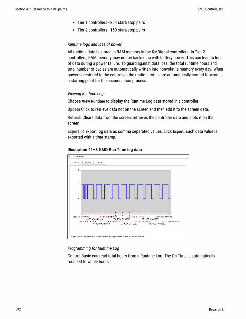
l Tier 1 controllers—254 start/stop pairsl Tier 2 controllers—150 start/stop pairs
Runtime logs and loss of power
All runtime data is stored in RAM memory in the KMDigital controllers. In Tier 2controllers, RAM memory may not be backed up with battery power. This can lead to lossof data during a power failure. To guard against data loss, the total runtime hours andtotal number of cycles are automatically written into nonvolatile memory every day. Whenpower is restored to the controller, the runtime totals are automatically carried forward asa starting point for the accumulation process.
Viewing Runtime Logs
Choose View Runtime to display the Runtime Log data stored in a controller.
Update Click to retrieve data not on the screen and then add it to the screen data.
Refresh Clears data from the screen, retrieves the controller data and plots it on thescreen.
Export To export log data as comma separated values, click Export. Each data value isexported with a time stamp.
Illustration 41–3 KMD Run Time log data
Programming for Runtime Log
Control Basic can read total hours from a Runtime Log. The On Time is automaticallyrounded to whole hours.
Section 41: Reference to KMD points KMC Controls, Inc.
592 Revision L

Using a Runtime Log in Control Basic:
IF+ TIME > 9:00:00 AND DOW = TUE THEN GOTO 20 ELSE GOTO30IF RT1 > RT2 then START OUT2 ELSE START OUT1 : REM Line20END : REM Line 30
In this example pumps are controlled by outputs OUT1 and OUT2. The output OUT1 islogged in runtime log RT1, and the output OUT2 is logged in the runtime log RT2. Thepump with the lowest runtime will be chosen to run at 9:00 AM each Tuesday.
ALARM RT1 > 299 , 1 , CHANGE AHU#1 FILTER. PRESSPUSHBUTTON ON UNIT TO RESET TIME COUNTERIF+ IN1 THEN START RT1
Starting a Runtime Log with the Control Basic command START resets the accumulatedOn time and total number of cycle counts to zero. This is equivalent to manually changingStart Date on a Runtime Log setup worksheet, except Start Date remains the same asbefore.
System GroupsUse Sytem Groups points to improve performance of TotalControl web pages with KMDpoints on a graphics page. Every time a point is added to a System Group, that point isadded to the System Group list to be used by the KMD PDS and Web POrtal. Add thepoints for a page to a System Group and then bind the points to elements on the page.Points in a system group are then retrieved with a single network request rather than witha request for each individual point.
To add a point to a System Group, do the following:
1 In the Network Manager list, locate the network icon , Tier 1 device or Tier 2device that contains the system group.
2 Locate and double-click the system group icon to open the configuration tab.
3 In the Network Manager list, locate a point to add to the system group.
4 Drag the point from the Network Manager list to the KMD Points list in the SystemGroup tab.
Adding points from a graphics page
To add all of the points on a graphics page to a System Group, do the following:
1 Expand the Network Manager list until you locate the System Group icon to whichyou will add the points.
2 Drag a page from the Site Explorer list to the system group icon in the NetworkManager list.
KMC Connect Reference Guide Section 41: Reference to KMD points
Revision L 593

Reading the System Group list
The System Group list is automatically updated every time a change is made to a SystemGroup from within KMC Connect. If a change to a system group from outside of KMCConnect—for example with WinControl XL Plus or KMC Connect—the list is not updated.Use the Update System Group List command to refresh the list at either the network ordevice level.
To read the system group list, do the following:
1 In the Network Manager list locate the network icon , Tier 1 device or Tier 2device from which the system group list will be updated.
2 Right-click on the device or network icon and then choose Read System Groups fromthe shortcut menu.
TablesA table performs a look-up function based on the actual input voltage of an analog input.The table converts the input voltage to a present value that is displayed in engineeringunits.
A table consists of up to 15 data pairs stored in two columns.
l Values in the X column correspond to an input voltage.l Values in the Y column are the corresponding present values expressed in
engineering units.
X Value The input voltage that will correspond to a specific present value in engineeringunits. Values in the X Values column must be entered in ascending order.
Y Value The present value–in engineering units–that corresponds to the X Value inputvoltage. The table function performs a linear interpolation between data pairs to calculatea Y value.
Units Select a unit of measure from the Units list. For a list of units, see SupportedKMD controller engineering units on page 601.
Related topics
l Configuring KMD controllers and points on page 561l The keyword TBL on page 322 for using tables in Control Basic
Section 41: Reference to KMD points KMC Controls, Inc.
594 Revision L

Trend Log pointsUse Trend Log points to periodically collect and store data from key points in the system.
When the log becomes full, the oldest data is deleted and replaced with the latestreadings. This creates a moving window of the most recent information.
Note: Use a trend log to record events that are longer than two orthree seconds. Recording shorter events will result in missed orerroneous data.
For the procedures to set up Trend Logs, see the topics Configuring KMD trend logsand groups on page 119 and Configuring KMD controllers and points on page 561.
General Properties
Name The 8-character description of the Trend Log. Name must be unique within the KMDcontroller that maintains it. The set of characters entered for Name must be printablecharacters.
Log Interval Specify the time interval between readings. The interval is entered ashours:minutes:seconds. Enter a Log Interval value of zero (0) to log data under controlof a Control Basic program.
Note: Once a value is entered in Log Interval, the Trend Logimmediately changes to automatic sampling , all previous data iserased, and new data is recorded.
Trended Points Enter the mnemonic of the points to be recorded in the trend log. Thelogged points can be from within the controller or from other controllers on the network.The exact number of points placed in the list depends on the type of controller. See thetopic Mnemonics for KMD controllers on page 235.
Control Basic Override (Tier 1 only) This check box is selected when the Trend Log isrecording data on-demand instead of automatic sampling based on the period set by LogInterval. On-demand recording is under control of a Control Basic program. SeeConfiguring KMD controller Trend Logs on page 119.
Trend Buffer Size Each log can store a limited number of records based on the type ofcontroller.
Tier 1 255 samplesTier 2 400 samples
View Trend
Choose View Trend to display the trend data stored in a controller.
Update Click to retrieve new data not on the screen and then add it to the screen data.
Refresh Clears data from the screen, retrieves the controller data and plots it on thescreen.
KMC Connect Reference Guide Section 41: Reference to KMD points
Revision L 595

Export To export log data as comma separated values, click Export. Each data value isexported with a time stamp.
Illustration 41–4 KMD Trend point
Variable points-analogAnalog variable points are place holders for information such as setpoints temperature,time delays or other analog values. Use variable points as global program variables inControl Basic.
General Properties
Name The 8-character description of the point. Name must be unique within the KMDcontroller that maintains it. The set of characters entered for Name must be printablecharacters.
Description A 20-character description of the device connected to the point. Descriptionmust be unique within the KMD controller that maintains it. The set of characters enteredfor Description must be printable characters.
Binary State When the Binary State box is clear, the variable is an analog variable. Whenthe Binary State check box is selected, the variable is set as a binary variable.
Value The current level, quantity, or state of the point.
Units Choose the unit of measure and scale factor for the input signal. See SupportedKMD controller engineering units on page 601.
Manual Override Indicates the variable is either in automatic or manual mode. WhenManual Override is selected, the value of the variable will remain as displayed untilchanged by an operator. When the check box is clear, the value of the variable can be setby either an operator or a calculation in a Control Basic program.
Alarm Routing Properties
Alarm classes designate a group of operators that receive notifications of alarms andevents originating from this point. Select the KMC Connect alarm class routing from the
Section 41: Reference to KMD points KMC Controls, Inc.
596 Revision L

list. See the topics An overview of notifications, alarms, and events on page 131,Emailing operator alarms on page 169, and Alarm classes for KMD controllers onpage 151.
Related topics
l Configuring KMD controllers and points on page 561l Variable points-binary on page 597
Variable points-binaryBinary variables are place holders for the state of binary data. Use variables as globalprogram variables in Control Basic.
General Properties
Name The 8-character description of the point. Name must be unique within the KMDcontroller that maintains it. The set of characters entered for Name must be printablecharacters.
Description A 20-character description of the device connected to the point. Descriptionmust be unique within the KMD controller that maintains it. The set of characters enteredfor Description must be printable characters.
Binary State When selected, the variable is a binary variable. When the Binary State checkbox is clear, the variable is set as an analog variable.
Value The current state of the point.f
Units Choose the unit of measure and scale factor for the variable. See Supported KMDcontroller engineering units on page 601.
The units of measure are shown as a pairs. The first unit is the normal state. Whenreferencing binary points in Control Basic, the left hand state is False (0) and the righthand state is True (1).
Manual Override Indicates the variable is either in automatic or manual mode. WhenManual Override is selected, the state of the variable will remain as displayed untilchanged by an operator. When the check box is clear, the state of the variable can be setby either an operator or a calculation in a Control Basic program.
Alarm Routing Properties
Alarm classes designate a group of operators that receive notifications of alarms andevents originating from this point. Select the KMC Connect alarm class routing from thelist. See the topics An overview of notifications, alarms, and events on page 131,Emailing operator alarms on page 169, and Alarm classes for KMD controllers onpage 151.
Related topics
l Configuring KMD controllers and points on page 561l Variable points-analog on page 596
KMC Connect Reference Guide Section 41: Reference to KMD points
Revision L 597

Weekly Schedule pointsUse Weekly Schedule points to schedule recurring daily events. A scheduled time in aWeekly Schedule point sets the state of the point to Active when the time in the controllermatches the scheduled time. Occupancy and lighting are two types of events that aretypically scheduled with Weekly Schedule points. Weekly Schedule points include thefollowing properties:
l Daily schedules for a seven-day week.l Two override schedules for holidays or other special days.l Both the daily and override schedules have several pairs of On and Off times that
control the state of the schedule depending on the time of the day.
Once a schedule is entered, use Control Basic to test the state of the schedule todetermine if it is Active (1, True, On, etc.) or Inactive ( 0, False, Off, etc.). To control apoint with a weekly schedule, write a Control Basic line similar to the following example:
VAR1 = WS1A = WS2
Annual Schedule points are usual points that control the overrides. However, a Variable orInput point can be used also to activate an override schedule. For example, a switchconnected to an Input point or a Variable point can be used to activate one of the overridedaily schedules.
General Properties
Name The 8-character description of the point. Name must be unique within the KMDcontroller that maintains it. The set of characters entered for Name must be printablecharacters.
Description A 20-character description of the point. Description must be unique within theKMD controller that maintains it. The set of characters entered for Description must beprintable characters.
Manual Select the check box to put the schedule in manual mode; clear the check box toput the schedule in automatic mode.
Present Value Indicates whether the schedule is Active (On) or Inactive (Off).
Override Object 1 and Override Object 2 Enter the mnemonic of the point that will enablethe override. See the topic, Mnemonics for KMD controllers on page 235.
l If an override is True, the state of the weekly schedule uses the scheduled times inthe Override1 or Override2 columns.
l If Override Object 1 is True then Override Object 2 is disregarded.l Override days are typically controlled by Annual Schedule points. See the topicAnnual Schedule points on page 569.
Section 41: Reference to KMD points KMC Controls, Inc.
598 Revision L

Rules for Weekly Schedule points
Follow these rules when entering Weekly Schedule values.
l Enter times using the 24-hour clock format.l Entering 00:00 clears the field.l When more than one On and Off time is entered for the same day, times must be
entered in ascending order.l Enter 00:01 (1 minute after midnight) to designate midnight.l Do not leave empty days. If the On or Off state is to continue from a previous day,
enter 00:01 in the first On or Off row for that day.l Override 1 and Override 2 schedule times are used when the value controlled by the
point entered in the Override 1 or Override 2 column becomes True (1) or On.
Alarm Routing Properties
Alarm classes designate a group of operators that receive notifications of alarms andevents originating from this point. Select the KMC Connect alarm class routing from thelist. See the topics An overview of notifications, alarms, and events on page 131,Emailing operator alarms on page 169, and Alarm classes for KMD controllers onpage 151.
Related topics
l Configuring KMDWeekly Schedule points on page 186l Configuring KMD Annual Schedule points on page 187l Annual Schedule points on page 569l About KMD Schedules on page 185
KMC Connect Reference Guide Section 41: Reference to KMD points
Revision L 599

Section 41: Reference to KMD points KMC Controls, Inc.
600 Revision L

Section 42: Supported KMD control le rengineer ing units
KMC Connect supports the engineering units for KMD controllers listed in this section.
Amperes 0 to 100C KMC10k Type IIC KMC10k Type IIICounts 2x32F KMC10k Type IIF KMC10k Type IIIFPM 0 to 3000mA 0 to 20 Input
Percent 0 to 100 ORmA 4 to 20Percent 0 to 100 ORV 0 to 5Pulses Per Min 0 to255CCMHcounts
Table1Table2Table3Table4Table5Table6UnusedV 0 to 5
Table 42–1 Units for KMD analog inputs
mA 0 to 20PercentPercent OpenPSI 0 to 20V 0 to 10
Table 42–2 Units for KMD analog outputs
AmperesBTUCCFCFHCFMCountsCustom1Custom2Custom3Custom4Custom5Custom6
Custom7Custom8DaysFFPMGPMHoursIn WKPaKVoltsKWattsKWHmA
MinutesOhmsPaPercentPercent OpenPercent RHPSIPulses per minSecondsTimeUnusedVoltsWatts
Table 42–3 Units for KMD analog outputs
KMC Connect Reference Guide
Revision L 601

Closed OpenCool HeatCustom1Custom2Custom3Custom4Custom5
Custom6Custom7Custom8Custom_digital8Disabled EnabledLow HighNo Yes
Normal AlarmNormal HighNormal LowOn OffStop StartUnoccupiedOccupied
Table 42–4 Units for KMD digital inputs, outputs and variables
Section 42: Supported KMD controller engineering units KMC Controls, Inc.
602 Revision L

Section 43: Refe rence to KMD control le rs
This appendix list total of each type of point for each KMC controller family.
The information in the following table lists the number of points in KMD controllers.
l For detailed specifications for each controller, see the installation and operationguide packed with the controller.
l For information about connecting controllers to a building automation system, seethe installation and operation guide packed with the controller.
l For configuring the properties of a point, see Reference to KMD points on page569.
Notes:
l Model KMD–5802 and models ending with C do not have a hardware basedreal-time clock.
l All VAV models include one input dedicated to the airflow sensor and one outputdedicated to the damper motor.
Type 5205 5210 5270
Alarms 192 192 192
Annual Schedule 4 16 4
Arrays 8 48 8
Control Basic 10 128 10
Inputs 8 128 8
Outputs 8 128 8
Passwords 256 256 256
PID Control loops 8 64 8
Runtime Logs 16 128 16
Sign On log 32 32 32
System groups 32 64 32
Tables 5 5 5
Trend Logs 16 96 16
Variables 128 256 128
Weekly Schedules 8 32 8
Table 43–1 Tier 1 controllers
KMC Connect Reference Guide
Revision L 603

Type 5801 5821 5831 6000 7000 7300
Alarms 10 10 10 1 10 10
Annual Schedule 2 2 4 - 0 0
Arrays n/a n/a n/a n/a n/a n/a
Control Basic 5 5 10 4/1 5 5
Inputs 8 8 12 4 4 4
Outputs 8 8 16 4 4 4
Passwords 27 27 27 2 27 27
PID Control loops 8 8 16 4 4 4
Runtime Logs 8 8 12 2 2 2
Sign On log n/a n/a n/a n/a n/a n/a
System groups 4 4 8 1/1 2 2
Tables 3 3 6 2/1 3 3
Trend Logs 8 8 12 2 2 2
Variables 64 64 128 32 32 32
Weekly Schedules 4 4 8 1 1 1
Table 43–2 Tier 2 controllers
Section 43: Reference to KMD controllers KMC Controls, Inc.
604 Revision L

Section 44: KMD T ie r 1 alarm messages
KMD Tier 1 controllers issue alarm notifications when an internal error is detected. Thissection is a list of the error messages.
Module Alarm Text Cause Restorable
Cbasic Program Error: Prog WS-ON:WS-OFF: An illegal routine#FOR TO NEXT: An off-panel pointis used as value to incrementINC: sub-opcode other than RD_A-RD_Z, or RD_PNTDEC: sub-opcode other than RD_A-RD_Z, or RD_PNT
No
Cbasic Off Panel Write : Prog #, Line # , OpCode #! STOP, DISABLE, CLOSE, LET:Argument is an off panel point.
No
Cbasic Invalid Table: Prog #, Line # , OpCode #! TBL: Invalid table#. No
Cbasic Array Table Invalid: Prog #, Line # , OpCode #! Invalid array index used anywherean array point is read or isassigned a value.
No
Cbasic Invalid OpCode: Prog #, Line # , OpCode #! Can be tested by using an emailcommand on a LAN Controller
No
Cbasic BACnet Not Licensed: Prog # These errors arenít currentlyimplemented in Control Basic.
No
Cbasic BACnet Application Layer Not Configured: Prog # These errors arenít currentlyimplemented in Control Basic.
No
Cbasic BACnet: Ethernet is not Running: Prog # These errors arenít currentlyimplemented in Control Basic.
No
Cbasic Main Panel Does not Exist: Prog #, Line # ,OpCode #!
STATUS: Illegal panel# No
Cbasic User Name not found: Prog #, Line # , OpCode #! PRINT USER-A/B: There isnít auser logged-on on port A/B.
No
Cbasic LSEL too many values: Prog #, Line # , OpCode #! LSEL: The number of expressionsare less than 2 or greater than 30
No
Cbasic HSEL too many values: Prog #, Line # , OpCode #! HSEL: The number of expressionsare less than 2 or greater than 30
No
Table 44–1 Tier 1 alarm messages
KMC Connect Reference Guide
Revision L 605

Module Alarm Text Cause Restorable
Cbasic Probable Infinite Loop: Prog #, Line # , OpCode #! More than 25,000 opcodes havebeen executed for one pass of theprogram
No
BACnet BACnet Service Request Timeout on Device #,Object #
A BACnet read or write propertyrequest has timed out.
No
BACnet BACnet Who-Is Timeout on Device # A BACnet who-is request hastimed out.
No
BACnet BACnet MS/TP Sole Master No other panels accepting thetoken
Yes
MainNet Too Many MainNet In Want Points! Point notadded:
More than 64 In Want Points No
MainNet Too Many MainNet Out Want Points! Point notadded:
More than 64 In Want Points No
MainNet MAIN PANEL IS OFFLINE-# 5 minutes has passed since thispanel was heard from
Yes
SubNetA Too Many SubNetA In Want Points! Point notadded:
More than 512 In Want Points No
SubNetA Too Many SubNet A Out Want Points! Point notadded:
More than 64 In Want Points No
SubNetA SUB-PANEL IS OFFLINE M#-SUBA-# 5 minutes has passed since thispanel was heard from
Yes
SubNetB Too Many SubNetB In Want Points! Point notadded:
More than 512 In Want Points No
SubNetB Too Many SubNet B Out Want Points! Point notadded:
More than 64 In Want Points No
SubNetB SUB-PANEL IS OFFLINE-SUBB-# 5 minutes has passed since thispanel was heard from
Yes
Ethernet Trying to send more packets than allowed byprotocol!
User response message lengthgreater than 255 bytes.Broadcast message lengthgreater than 1500 bytes.
No
Ethernet Panel to Panel message from unknown panel : #port #
MSG_TOPANELS received from apanel not in the Netlist.
No
Ethernet Broadcast message from unknown panel : # port#
MSG_TOBEHOST received by apanel thatís not a broadcastserver.MSG_TOBEHOST received from apanel not in the Netlist.
No
Table 44–1 Tier 1 alarm messages (continued)
Section 44: KMD Tier 1 alarm messages KMC Controls, Inc.
606 Revision L
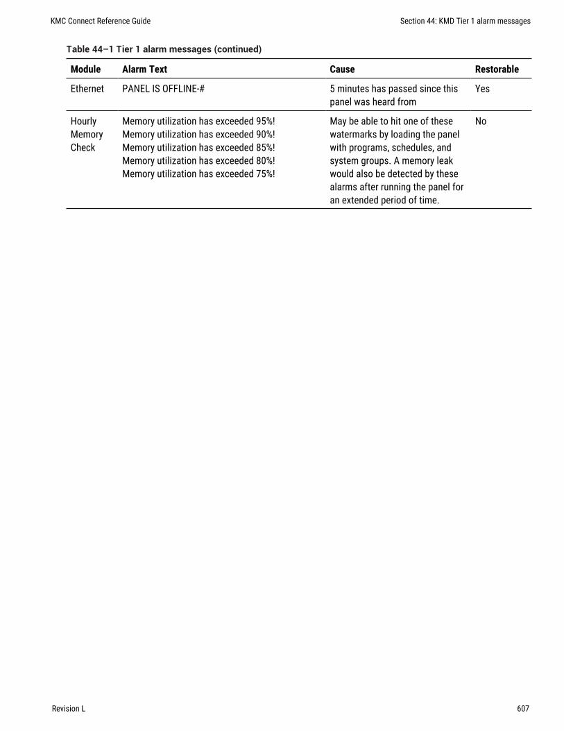
Module Alarm Text Cause Restorable
Ethernet PANEL IS OFFLINE-# 5 minutes has passed since thispanel was heard from
Yes
HourlyMemoryCheck
Memory utilization has exceeded 95%!Memory utilization has exceeded 90%!Memory utilization has exceeded 85%!Memory utilization has exceeded 80%!Memory utilization has exceeded 75%!
May be able to hit one of thesewatermarks by loading the panelwith programs, schedules, andsystem groups. A memory leakwould also be detected by thesealarms after running the panel foran extended period of time.
No
Table 44–1 Tier 1 alarm messages (continued)
KMC Connect Reference Guide Section 44: KMD Tier 1 alarm messages
Revision L 607

Section 44: KMD Tier 1 alarm messages KMC Controls, Inc.
608 Revision L

KMC Connect
Part IX: Working with OPC objects
KMC Connect Reference Guide
Revision L 609

KMC Controls, Inc.
610 Revision L

Section 45: An introduction to OPC
The topics in this section are an overview of the OPC process.
OPC is a non-proprietary standard that specifies the communication of real-time databetween control devices from different manufacturers. It is a standard that defines a setof interfaces, based upon Microsoft's OLE/COM technology, that is often used inindustrial automation and enterprise systems. The application of the OPC standardinterface makes possible interoperability between building automation, manufacturingcontrol applications, field systems, devices, business, and office applications.
OPC is the original name for OLE for Process Control, an open standards specificationdeveloped in 1996 by an industrial automation industry task force.
OPC has two parts: a client and a server.
Client A client program connects to and obtains data from an OPC server. The OPC clientcan be on the same computer or on another computer. The client makes a request to theserver for data and the server then fulfills the request. For a KMC Connect managed site,the OPC PDS is the client application that connects the OPC sever to the components ofKMC Connect.
Server An OPC Sever is a software application that acts as a protocol converter. The OPCserver connects to devices or systems and translates the data into a standard OPCformat. Each supported protocol will have a server application written specifically toobtain data from a source in the protocol and then convert it to the OPC standard format.OPC client applications— the KMC Connect PDS for example—can then connect to theOPC server and use it to read and write device data.
Illustration 45–1 Typical OPC network with KMC Connect
OPC
Server B
OPC
Server A
Client X
OPC Interface
Client Y
OPC Interface
TotalControl
OPC PDS
Modbus Interface LON Interface
Modbus
devices
LON
devices
KMC Connect Reference Guide Section 45: An introduction to OPC
Revision L 611

Section 45: An introduction to OPC KMC Controls, Inc.
612 Revision L

Section 46: Setting up an OPC service
The OPC service is the link between a third-party OPC server and other KMC Connectservices. The following topics are a reference for setting parameters in the OPC service.
The OPC service is distributed as part of KMC Connect. Typically, it is installed when KMCConnect is installed.
Topics covered in this section:
l Configuring an OPC service on page 614l Connecting to an OPC server on page 613
Related topics:l An introduction to OPC on page 611l Reference to OPC objects and tags on page 617
Connecting to an OPC serverThe KMC Connect OPC service can connect to either a local or remote OPC server.
l A local OPC server runs on the same computer on which the KMC Connect OPCservice is running.
l A remote OPC server runs on a computer separate from the computer on which theKMC Connect OPC service runs. The computer on which the OPC server runs mustalso have DCOM enabled or is running a DCOM tunneling program.
Connect to a local OPC server
1 In the Network Manager list, right-click the OPC Service icon .
2 In the shortcut menu choose Find/Regenerate Objects.
3 The OPC service will connect to the local server and then add OPC groups and itemsto the Network Manager list.
Connect to a remote OPC server
1 In the Network Manager list, right-click the OPC Service icon .
2 In the shortcut menu choose Find/Regenerate Remote Objects. The New OPC ServerURL dialog opens.
3 Enter the name of the computer on which the OPC server is running.
4 The PDS will connect to the remote server and then add OPC groups and items tothe Network Manager list.
KMC Connect Reference Guide Section 46: Setting up an OPC service
Revision L 613

Configuring an OPC serviceUse the OPC Service configuration tab to view or change parameters of the OPC service.
1 Locate the OPC Service icon in the Network Manager list.
2 Right-click the OPC Service icon and choose Configure Service from the shortcutmenu.
3 Make the changes to the service.
4 When changes are complete, click Save Changes to Service in the tab of theconfiguration page.
General Properties
Items under General Properties are usually set up when the OPC service was added to theNetwork Manager list.
Service Name A descriptive name of the service to display in the Network Manager list.
Service ID The Service ID number that was automatically assigned by KMC Connect at thetime the service was added to the site database.
Service Host Address This is the address of the computer on which the SQL service isrunning. The preferred entry is the name of the computer; the IP address may also beused.
Service Host TCP Port This port is used by KMC Connect building services. For KMDnetworks the default TCP Port is 27031.
Settings and Statistics
Maximum Response Staleness Sets the age of the data. If—at the time data is requestedfrom an OPC server—the data in the database is older than the value of MaximumResponse Staleness, KMC Connect will retrieve new data from the server. If the data isnewer than the value in Maximum Response Staleness, KMC Connect displays thevalue stored in the database.
Monitor Statistics Select to enable the service to save statistical data for diagnostics.
Incoming Requests The number of requests the service has received from KMC Connect.During device discovery, this will peak and then subside as discovery is completed.
Pending Requests The number of unanswered requests that the PDS has sent to thenetworks. During discovery the rise and fall of this value will somewhat lag the incomingrequests rise and fall.
Completed Requests The number of requests sent to networks for which the servicereceived a response. This is a cumulative value since the service was last started.Selecting the Monitor Statistics check box will periodically initiate requests of theservice, which increases the Completed Requests by one each time a request is made.
Related topics
l Connecting to an OPC server on page 613
Section 46: Setting up an OPC service KMC Controls, Inc.
614 Revision L

l Adding a service on page 42l Opening and closing the Network Manager pane on page 40
KMC Connect Reference Guide Section 46: Setting up an OPC service
Revision L 615

Section 46: Setting up an OPC service KMC Controls, Inc.
616 Revision L

Section 47: Refe rence to OPC objects and tags
Topics in this section are a reference to the features and characteristics of OPCobjects.
OPC objects in the Network Manager list represent the groups, items and tags as providedby the OPC server to which the OPC PDS is connected.
l To connect a KMC Connect site to an OPC server, see Connecting to an OPCserver on page 613.
l To locate an OPC object on an OPC server that is connected to a KMC Connectmanaged site, see Using the Network Manager on page 39.
l For an overview of OPC, see An introduction to OPC on page 611.
Object Name A description of the OPC tag.
Present Value The current level, quantity, or state of the OPC tag.
Data Type Present Value can be any of the following data types. Data types define a set ofvalues and the allowable operations on those values. OPC data types are listed in thetable Standard OPC data types.
Description
Default/Empty (nothing)
2-byte signed integer
4-byte signed integer
4-byte (single-precision) real
8-byte (double-precision) real
Currency
Date
Text (UNICODE)
Error code
Boolean (TRUE = -1, FALSE = 0)
1-byte signed integer
1-byte unsigned integer
2-byte unsigned integer
4-byte unsigned integer
Table 47–1 Standard OPC data types
KMC Connect Reference Guide Section 47: Reference to OPC objects and tags
Revision L 617

Description
Array of 2-byte signed integers
Array of 4-byte signed integer
Array of 4-byte (single-precision) real
Array of 8-byte (double-precision) real
Array of currency values
Array of dates
Array of text values
Array of error codes
Array of Boolean values
Array of 1-byte signed integers
Array of 1-byte unsigned integers
Array of 2-byte unsigned integers
Array of 4-byte unsigned integers
Table 47–1 Standard OPC data types (continued)
Timestamp The date and time of the most recent reading of Present Value. Timestamp istypically the time of the Present Value reading in the device. However, if the device thedoes not provide a time stamp, it is added by the OPC server to which the PDS isconnected.
Quality An indication of the quality state of the tag’s present value. Quality is based on amajor quality value, a substatus for that major quality value, and a limit status indicatinghow the value is limited.
Flag Description
NotSet The quality is not set
Good
GoodLocalOverride Overridden. Usually input disconnected and manualvalue forced.
Bad Bad but no reason available
BadLastKnown Communication failed - last known value
BadCommFailure Communication failed - no last known value
BadWaitingOnInit No error - default for items added to subscription untilread
Table 47–2 Supported OPC quality flags
Section 47: Reference to OPC objects and tags KMC Controls, Inc.
618 Revision L

Flag Description
BadConfigError There is a server-specific problem with theconfiguration.
BadInputDisconnected The input appears to be disconnected
BadDeviceFailure Device failure detected
BadSensorFailure Sensor failure detected
BadOutOfService Block is off scan or locked
Uncertain Uncertain with no reason available
UncertainLastUsable Providing last usuable value
UncertainSensorCalibration Sensor pegged at a limit or out of calibration.
UncertainEUExceeded Value outside defined limits
UncertainSubnormal Value derived from less than required number ofsources.
Table 47–2 Supported OPC quality flags (continued)
KMC Connect Reference Guide Section 47: Reference to OPC objects and tags
Revision L 619

Section 47: Reference to OPC objects and tags KMC Controls, Inc.
620 Revision L

KMC Connect
Part X: Protocol Gateway Service and Protocol GatewayManager
KMC Connect Reference Guide
Revision L 621

KMC Controls, Inc.
622 Revision L

Section 48: Overview of the Protocol Gateway
The Protocol Gateway is a KMC Connect service that transfers values betweencontrollers of different protocols. This section is an overview of Protocol GatewayManager and the Protocol Gateway service.
Two components of KMC Connect are required to transfer values between dissimilarprotocols.
l The Protocol Gateway service is a component of KMC Connect.l The Protocol Gateway Manager is a programing tool within KMC Connect.
Protocol Gateway service The KMC Connect Protocol Gateway service monitors data inone or more points or objects and then transfers that value to another point or object. Thetransfer takes place at regular intervals that range from every few seconds to once amonth. For example, the present value of a BACnet object can be transferred to a variablepoint in a KMD controller.
The Protocol Gateway service runs only as long as KMC Connect is running on thecomputer.
Protocol Gateway Manager The Protocol Gateway Manager is the tool that techniciansuse to set up a transfer process for points or objects between controllers of differentprotocols. It also sets an interval between transfers.
Related topics Setting up Protocol Gateway processes on page 625.
KMC Connect Reference Guide Section 48: Overview of the Protocol Gateway
Revision L 623

Section 48: Overview of the Protocol Gateway KMC Controls, Inc.
624 Revision L

Section 49: Setting up Protocol Gatewayprocesses
Topics in this section cover setting up Protocol Gateway processes with the ProtocolGateway Manager.
The Protocol Gateway service transfers values between different types of KMC Connectsupported BAS protocols with one or more defined processes. The processes are set upwith the Protocol Gateway Manager in KMC Connect.
l A process input transfers values to a process output.l The input can be a user defined value or a point or property in the Network Manager
list.l The process output is a point or property in the Network Manager list.l A process runs at designated intervals that can range from a few seconds to
monthly.
Related topics
l Using the Protocol Gateway Manager on page 625l Managing Protocol Gateway processes on page 627l Overview of the Protocol Gateway on page 623
Using the Protocol Gateway ManagerThe Protocol Gateway Manager is the KMC Connect tool that technicians use to set up agateway process.
To open the Protocol Gateway Manager, do the following:
1 In the Network Manager list, locate the Protocol Gateway service icon .
2 Right-click the icon and then choose Protocol Gateway Manager from the shortcutmenu. The Protocol Gateway Manager tab opens.
3 Add, delete, test, or restart processes as described in the topic Managing ProtocolGateway processes on page 627.
KMC Connect Reference Guide Section 49: Setting up Protocol Gateway processes
Revision L 625

4 At the top of the tab, click Save Changes when all settings are complete.
Illustration 49–1 Protocol Gateway Manager
Toolbar commands
Save Changes Saves the changes to all processes in the site database.
Refresh For the selected process, the parameters in the Protocol Gateway Manager arediscarded and the parameters from the site database are loaded.
Restart Restarts all processes that have stopped.
The components of Protocol Gateway Manager
Test The selected process runs once and then stops until the next interval. The intervalfor transferring a value is specified in Period Type.
Update Stores the selected process in the site database.
Add Places a new process in the List of Processes.
Delete Removes a process.
Process ID A unique number assigned by the Protocol Gateway service. It cannot bechanged.
Process Name A unique label that identifies the process. Use only letters, numbers andthe underscore (_) symbol for the process name.
Input Assigns a point or property in the Network Manager list, or a fixed-value to theprocess input.
Input Retry Count Sets the number of times the Protocol Gateway service will attempt toread the value of the input process.
Output Assigns either a point or property in the Network Manager list as the processoutput.
Output Retry Count Sets the number of times the Protocol Gateway service will attempt tochange the value of the point or property assigned to the process output .
Section 49: Setting up Protocol Gateway processes KMC Controls, Inc.
626 Revision L

Enable Select the check box to enable the process; clear the check box to disable theprocess.
Trigger Alarm When selected, a message will be placed in the Output Window list if theProtocol Gateway service cannot read a process input or change a process output.
Start Date and Stop Date Sets the effective period in which the process will run.
Process Type The process type designates the type of input for a process.
l Integration Point sets the process input as a point or property in the buildingautomation system.
l Fixed Value sets the process to a user-defined value or constant entered in Input.
Period Type Sets the interval for running the process.
l Custom—Sets the interval to the value in Custom Period.l Every Noon—The process runs once a day at noon.l Daily—The process runs at the time specified in Date Time Format.l Weekly—The process runs on the day of the week and at the time specified in Date
Time Format.l Every Two Weeks—The process runs every two weeks on the first day of the week
and at the time specified in Date Time Format.l Monthly—The process runs monthly on the day of the month and at the time
specified in Date Time Format.l One Time—The process runs once at the time in Date Time Format.
Custom Period Sets the interval—in seconds—at which a process will run.
Date Time Format Sets the time and day or date on which a process will run. The date andtime for the process schedule is controlled by the clock in the computer on which thegateway service is running.
Related topics
l Overview of the Protocol Gateway on page 623l Managing Protocol Gateway processes on page 627
Managing Protocol Gateway processesA process transfers the value of a point or property from one controller to another.Usually, the controllers are of different protocols such as KMDigital and BACnet. Aprocess can also write a fixed value to a point or property. The transfer takes place atdesignated intervals.
See the topic Using the Protocol Gateway Manager on page 625 for details on theProtocol Gateway Manager tab.
Create a new process
1 Open the Protocol Gateway Manager.
KMC Connect Reference Guide Section 49: Setting up Protocol Gateway processes
Revision L 627

2 Do one of the following:
l Click Add.l Right-click in the List of Processes area and then select Add Process from the
shortcut menu.
3 In Process Name, enter a unique name for the process. Use only letters, numbers andthe underscore (_) symbol for the process name.
4 Designate an input for the process by doing one of the following:
l In the Process Type list, choose Integration Point and then drag a point orproperty from the Network Manager list to Input.
l In the Process Type list click Fixed Value and then enter a fixed value in Input.
5 Drag a point or property from the Network Manager list to Output.
6 Select the Enable check box.
7 Set the following interval properties:
l Period Type
l Custom Period, Start Date, Stop Date and Date Time Format as required by PeriodType.
8 When all settings are complete, click Save Changes at the top of the tab.
Delete a process
1 Open the Protocol Gateway Manager.
2 Locate the process to delete in List of Processes.
3 Do one of the following:
l Select the process and then click Delete.l Right-click the process and then choose Delete Process from the shortcut menu.
4 Choose Yes to delete and No to cancel.
Restarting processesThis procedure restarts all processes that have stopped.
1 Open the Protocol Gateway Manager.
2 At the top of Protocol Gateway Manager configuration tab, click Restart AllProcesses.
Section 49: Setting up Protocol Gateway processes KMC Controls, Inc.
628 Revision L

Testing a process
When a process is tested, it runs once and then stops until the next interval as specifiedby Period Type.
1 Open the Protocol Gateway Manager.
2 In List of Processes, select the process to test.
3 Click Test.
KMC Connect Reference Guide Section 49: Setting up Protocol Gateway processes
Revision L 629

Section 49: Setting up Protocol Gateway processes KMC Controls, Inc.
630 Revision L

Section 50: Conf igur ing the Protocol Gatewayservice
The KMC Connect Protocol Gateway service transfers values between different types ofKMC Connect supported BAS protocols with one or more defined gateway processes.
To run gateway process from a KMC Connect managed building automation system, aProtocol Gateway service must be running on the computer that is running KMC Connect.Typically the Protocol Gateway service is installed at the same time that KMC Connect isinstalled.
To open the Protocol Gateway service, do the following:
1 In the Network Manager, locate the Protocol Gateway service icon .
2 Right-click the Protocol Gateway service icon and choose Configure Service from theshortcut menu.
3 Make the changes to the service.
4 When changes are complete, click Save Changes to Service in the tab of theconfiguration page.
Properties of the Protocol Gateway service
Service Name A descriptive label of the service. Service Name is the name that identifiesthe service in the Network Manager list. The set of characters used in Service Name isrestricted to printable characters.
Service ID Service ID is assigned by KMC Connect and cannot be changed.
Service Host Address Not applicable for KMC Connect.
Service Host TCP Port Not applicable for KMC Connect.
KMC Connect Reference Guide Section 50: Configuring the Protocol Gateway service
Revision L 631

Section 50: Configuring the Protocol Gateway service KMC Controls, Inc.
632 Revision L

KMC Connect
Part XI: Applications and wizards
KMC Connect Reference Guide
Revision L 633

KMC Controls, Inc.
634 Revision L

Section 51: Appl ication se lection, conf iguration,and deployment
The Selection, Configuration, and Deployment tools with which a technician canconfigure controllers from the KMC Controls applications library.
Use the Selection, Configuration, and Deployment applications to manage the options inprograms supplied by KMC Controls in KMC Conquest-compliant controllers on page689. In addition to configuring controllers, it also contains a selection of documents thatcan be used to plan and commission a job.
Using the applications is a three step process.
Selection This is the start of the process. By selecting from a list of features in thesupplied application library, the possibilities are narrowed to the set of features that bestfit the job requirements. The selections are saved in an application job file.
Configuration This application customizes and fine tunes the default settings for achosen controller application. The settings are saved as templates in the selectedapplication job.
Deployment For deployment, templates are matched to, and then written to, individualcontrollers.
Details of the applications.
l The Selection and Configuration applications can be used without connecting to asite.
l For easiest configuration, plan the site with sequential device instance numbers forcontrollers with identical applications.
l More than one type of application template (VAV, FCU, RTU, etc.) can be developedfor a job.
Step 1—SelectionThe Selection page sets up application jobs.
1 On the ribbon, choose Selection from the Applications group.
KMC Connect Reference Guide Section 51: Application selection, configuration, and deployment
Revision L 635

2 Under Job Selection, choose an existing job or click New Job and enter a name forthe new job.
3 Under Feature Selection Filter, select the features for the job.
As features are selected, the features that are not applicable are removed.
Example: Choosing VAV Single Duct from Unit Type will remove all features thatdo not apply to VAV single duct applications.
4 Under Documentation Selection, select or clear the check boxes next to each type ofdocument available for the job.
Note: Documents must be selected before the next step. Changing documentselection after the next step does not add documents to the job.
5 Under Matching Applications, select the model or models that are the best fit for theapplication. Click Add to save them to the job. More than one type of application canbe added to each job.
6 Click Next to advance to the Application Configuration tab.
Step 2—ConfigurationThis step sets the values for the actual points of interest in the application. Setpoints, fanoperation, and VAV terminal unit parameters are all examples of points of interest.
1 Select a job and application from the Job and Application Selection drop downboxes. The application is added to the template list.
2 Make any required changes to the template such as changing a default setpoint.
Section 51: Application selection, configuration, and deployment KMC Controls, Inc.
636 Revision L

3 Make a clone of the template for each target controller.
Example: A job may use the same model VAV controller but, the controllers may bemounted on VAV units with different K-factors. Make a duplicate template for eachsize of VAV terminal unit and enter the correct K-factor for each template.
Note: The device instance for each clone is automatically incremented. For example,if you start with device instance 10 and make nine clones, the clones will benumbered 11-19.
4 When finished, click Next. The templates are stored in the job file and the applicationadvances to Deployment.
Step 3—DeploymentThis step matches device templates to actual controllers in the Network Manager list.
1 Select a job and application from the Job and Application Selection drop downboxes. The templates for the application are added to the Device Template list
2 The application attempts to match the templates to the actual controllers in theNetwork Manager list. The match is either by device instance or device name.
3 When finished, click Write to Devices. The application begins the process ofdeploying the templates matched to each controller. This may take several minutes.
KMC Connect Reference Guide Section 51: Application selection, configuration, and deployment
Revision L 637

Section 51: Application selection, configuration, and deployment KMC Controls, Inc.
638 Revision L

Section 52: Audit appl ication
The Audit application is a tool to detect changes to the configuration of controllers onthe building automation system.
Use the Audit application to establish a baseline of performance and then, in the future,compare current settings to the stored baseline.
Using the Audit application is a two part process.
l After controllers are set up and commissioned, the values of the points-of-interestare saved as a baseline.
l To verify performance, baseline values are compared to current values.
For a list of controllers compatible with the application, see KMC Conquest-compliantcontrollers on page 689.
Establishing the baseline
Before establishing an audit baseline, set up the controllers. Once the baseline isestablished, it can be used at any time to detect changes to the system.
1 On the ribbon, choose Audit from the Applications group.
2 Open the Network Manager list and drag a device, network with devices, or theBACnet service icon to the Devices area. Only devices that are Conquest compliantare available for audit. All others are marked with a yellow triangle .
KMC Connect Reference Guide Section 52: Audit application
Revision L 639

3 Do one of the following:
l Click Evaluate All devices.l In the devices list, right-click a device name and choose Evaluate from the
shortcut menu.
The Audit application reads the points-of-interest and then lists them in the CurrentApplication column.
4 Save the baseline by clicking Store All or Store Selected. This adds the values to astored baseline for future reference.
Comparing controllers to a baseline
For controllers with an established baseline, the current values in the controllers can beevaluated at any time against the baseline values.
1 On the Applications tab, click Audit.
2 Open the Network Manager list and locate the objects to evaluate against the storedbaseline. Drag the devices, network icon or the BACnet service icon to the Devicesarea.
3 Click Evaluate or Evaluate All.
Section 52: Audit application KMC Controls, Inc.
640 Revision L

4 Devices and object that do not match the values in the baseline are flagged with thechanged icon .
l To use the current values in the controller as a new baseline, click Store Selectedor Store All.
l To restore the device to the original configuration, click Restore All DeviceDifferences.
KMC Connect Reference Guide Section 52: Audit application
Revision L 641

Section 52: Audit application KMC Controls, Inc.
642 Revision L

Section 53: VAV Balancing appl ication
Topics in this section are for control technicians or engineers who will be balancing theairflow in VAV controllers.
The VAV Balancing application includes the following features for balancing, configuring,and commanding airflow in compatible VAV controllers.
l The VAV Balancing sequence on page 643 is a tool that control technicians canuse to balance the airflow in a VAV unit.
l VAV flow monitoring on page 646 can be used to monitor airflow through a VAVunit without starting the balancing sequence in a controller.
l Commanding VAV airflow on page 646 temporarily sets a specific airflow withoutchanging the permanent VAV properties.
For a list of controllers compatible with the VAV Balancing application, see the topicKMC Conquest-compliant controllers on page 689.
The VAV Balancing sequenceBalancing airflow is the process of calibrating the internal airflow sensor of a VAVcontroller to a known standard. In the field, airflow is measured with an airflow hood orother measuring instrument and then compared to the controller's internal airflowmeasurements.
When the balancing sequence starts, all other functions of the controller are locked out.
The airflow balancing procedure described in this section requires the following items:
l A flow hood or other accurate method to measure airflow.l The engineering design specifications for the VAV airflow setpoints.
For a list of controllers compatible with the wizard, see KMC Conquest-compliantcontrollers on page 689.
Note: The procedures in this section are for pressure independentsystems only.
Tip: Once balancing has started, all steps must be finished in order.If the procedure is interrupted, unpredictable VAV operation willresult.
KMC Connect Reference Guide Section 53: VAV Balancing application
Revision L 643

To run the VAV Balancing sequence, do the following:
1 On the ribbon, choose VAV Balancing from the Applications group.
2 Open the Network Manager list and drag a device, a network with devices, or theBACnet service icon to the To Balance area.
3 Select an individual device and then click Start Balancing. The applicationcommands the VAV controller to position the damper for maximum airflow.
4 Monitor the airflow graph and the value in Primary Actual Airflow until the airflowstabilizes at or near the maximum airflow value.
5 At the VAV terminal unit outlet, measure the airflow with an airflow hood or otheraccurate instrument. Make note of the value.
Section 53: VAV Balancing application KMC Controls, Inc.
644 Revision L

6 Enter the actual measured airflow value in the Primary Actual Maximum Flow text boxand then click Save. The controller immediately starts moving the damper forminimum air flow.
7 Again, monitor the airflow graph and the value in Primary Actual Flow and wait forthe airflow to stabilize at or near the minimum airflow value.
8 At the VAV terminal unit outlet, measure the airflow with an airflow hood or otheraccurate instrument. Make note of the value.
9 Enter the actual measured airflow value in the Primary Actual Minimum Flow text boxand then click Save. The program calculates new airflow constants and returns theVAV controller to normal operation.
Note: For dual-duct VAV systems, both the primary and secondary airflow values aredisplayed by the application. Both airflow values must be balanced before thecontroller is considered balanced.
KMC Connect Reference Guide Section 53: VAV Balancing application
Revision L 645

VAV flow monitoringUsing the flow monitoring function in the VAV application is a way to monitor airflowthrough a VAV unit without starting the balancing sequence in a controller.
To balance the airflow for a VAV unit, see the topic The VAV Balancing sequence onpage 643.
To monitor airflow through a VAV unit, do the following:
1 On the ribbon, choose VAV Balancing from the Applications group.
2 Open the Network Manager list and drag a device, a network with devices, or theBACnet service icon to the To Balance area.
3 Select an individual device and then click Start Monitoring. The application beginsgraphing the airflow through the VAV unit.
4 When finished, click Stop Monitoring.
Commanding VAV airflowUse the VAV airflow manual override function to command airflow to a specific airflowvalue. When a controller is in manual override, the calculated airflow setpoint is replacedwith a temporary fixed setpoint. This function is used to make adjustments ormeasurements that require a steady, specific airflow.
Section 53: VAV Balancing application KMC Controls, Inc.
646 Revision L

To command a specific airflow through a VAV unit, do the following:
1 On the ribbon, choose VAV Balancing from the Applications group.
2 Open the Network Manager list and drag a device, a network with devices, or theBACnet service icon to the To Balance area.
3 Select an individual device and then click Start Monitoring.
4 Click Manual Override.
5 In the Enter Manual Airflow dialog, enter an airflow setpoint and then click OK.
6 When finished, click Cancel Manual Override.
KMC Connect Reference Guide Section 53: VAV Balancing application
Revision L 647

Section 53: VAV Balancing application KMC Controls, Inc.
648 Revision L

Section 54: Custom Appl ications Wizard
This section describes how to build unique applications with the Custom ApplicationWizard to use with the Selection, Configuration, and Deployment applications.
Use the Applications Custom Wizard to save a custom application based on theconfiguration in a controller that contains a standard KMC application. The applicationcan then be used with the Selection, Configure and Deployment applications. It can alsobe used to define points-of-interest for the Application Audit Tool for older KMC BACnetcontrollers. Custom applications are saved in the Resource Manager Custom ApplicationLibrary folder.
Conquest and SimplyVAV controllers—For Conquest and SimplyVAV controllers, use theCustom Applications Wizard to do the following:
l Build a unique application based on a standard application that is configured in acontroller.
l Define a custom set of points-of-interest that can be used with the AuditApplications Tool.
l Add documents relevant to the application.l Save all modifications, object assignments, Control Basic programs, sensor
configurations, etc. in a .bnd file that can be deployed to other controllers.
Non-Conquest and third-party controllers—Define a set of points-of-interest for the Auditapplication.
Note: Before starting the wizard, complete the configuration of thecontroller that will be the template for the custom application.
Setting up the application
This procedure starts building a custom application. It sets up the application name,features, and supported models. If needed, it also sets up a new custom applicationlibrary in the Resource Manager.
To start the custom application, do the following:
1 On the ribbon, choose Custom Wizard from the Applications group.
KMC Connect Reference Guide Section 54: Custom Applications Wizard
Revision L 649
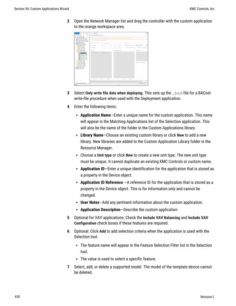
2 Open the Network Manager list and drag the controller with the custom applicationto the orange workspace area.
3 Select Only write file data when deploying. This sets up the .bnd file for a BACnetwrite-file procedure when used with the Deployment application.
4 Enter the following items:
l Application Name—Enter a unique name for the custom application. This namewill appear in the Matching Applications list of the Selection application. Thiswill also be the name of the folder in the Custom Applications library.
l Library Name—Choose an existing custom library or click New to add a newlibrary. New libraries are added to the Custom Application Library folder in theResource Manager.
l Choose a Unit type or click New to create a new unit type. The new unit typemust be unique. It cannot duplicate an existing KMC Controls or custom name.
l Application ID—Enter a unique identification for the application that is stored asa property in the Device object.
l Application ID Reference —A reference ID for the application that is stored as aproperty in the Device object. This is for information only and cannot bechanged.
l User Notes—Add any pertinent information about the custom application.l Application Description—Describe the custom application.
5 Optional for VAV applications: Check the Include VAV Balancing and Include VAVConfiguration check boxes if these features are required.
6 Optional: Click Add to add selection criteria when the application is used with theSelection tool.
l The feature name will appear in the Feature Selection Filter list in the Selectiontool.
l The value is used to select a specific feature.
7 Select, add, or delete a supported model. The model of the template device cannotbe deleted.
Section 54: Custom Applications Wizard KMC Controls, Inc.
650 Revision L

8 To add documents to the custom application library, select the Include Documentscheck box. Document selection will take place after the Points selection step.
9 When ready, click Next to advance to Points selection procedure.
Points selection
This procedure selects points that will be used by the Selection and Audit tools.
1 Select points to include in the custom application.
l Configuration—These are the points that are visible and can be changed in theConfiguration tool.
l RD (Relinquish Default)—Select to make the Relinquish Default property part ofthe Audit tool process.
l PV (Present Value)—Select to make the Present Value property part of the Audittool process.
l Points of Interest—Adds points to the application for TotalControl graphics.l Graphical points—Adds points to the application for Niagara graphics.
2 To add objects not in the points list, click Add and then choose an object andproperty to add to the list.
3 Click Next to advance to the document selection procedure.
l If the Include Documents check box was selected in the first screen, the wizardadvances to Document Selection.
l If Include Documents check box was not selected, the wizard saves the customapplication in the Custom Affliction Library folder in the Resource Manager.
KMC Connect Reference Guide Section 54: Custom Applications Wizard
Revision L 651

Document Selection (optional)
If the Include Documents check box was selected in the first screen, you can now selectdocuments to add to the custom application. In this procedure, selected documents arecopied from their original location and then stored with the job in the Custom AfflictionLibrary folder in the Resource Manager.
1 For each document type that will have a document added, click the ellipsis (...)under Browse.
2 When the Windows dialog opens, browse to the document to include in theapplication.
3 Optional: Click Add to create a new document category and then add documents tothe category.
4 When all documents are added, click Save to save the custom application in theCustom Affliction Library folder in the Resource Manager.
Section 54: Custom Applications Wizard KMC Controls, Inc.
652 Revision L

Section 55: Input and output object wizards
Topics in this section cover the BACnet input and output object wizards.
Use the BACnet input and output wizards to configure the most common properties ininput and output objects.
Each of the wizards are explained in one of the following topics.
l Analog input object wizard on page 653l Binary input object wizard on page 656l Analog output object wizard on page 657
Analog input object wizardUse the Analog Input Wizard to match the BACnet Analog Input object and Input devicetable properties to the input device connected to the controller. These properties are fullydescribed in the topics Input objects–analog on page 453 and Input tables on page541.
To open an Analog Input Wizard, do the following:
1 In the Network Manager list, locate the controller and then open the Inputs folder.
2 Locate an analog input icon .
3 Right-click the icon and choose Analog Input Wizard from the shortcut menu.
Additional information is in the Application Guide AG160516A, KMC Input Wizards.
Illustration 55–1 BACnet Analog Input Wizard
KMC Connect Reference Guide Section 55: Input and output object wizards
Revision L 653

The properties in the wizard are those properties required to match the signal from theinput device to the input of the controller.
Standard device types
Choosing an item from the Device Type list automatically configures most of the inputobject properties.
To configure a standard device type, do the following:
1 In the Device Type list, select the entry that matches the type of device connected tothe controller. Passive temperature sensor inputs (thermistors) are listed as KMCType II or Type III in degrees Centigrade or Fahrenheit.
2 For non-Conquest controllers, set the correct physical input termination as noted inTermination and Termination Note. The exact method of termination will bedescribed in the instructions for the controller.
3 Enter a name and description for the input.
4 If required, change Filter Weight.
5 Click Save when finished.
Active Custom device types
For active input devices, devices with a voltage or current output that are not in the DeviceType list, set up a custom device type. Setting up a custom device requires informationsupplied by the manufacturer of the device. This information is either a voltage or currentrange and a monitored range. For example, a CO2 sensor output signal may be specified500–2,000 PPM and an output current of 4–20 mA.
1 In Device Type, choose Custom.
2 From Termination, choose the type of voltage or current signal connected to thecontroller. This setting must cover the range of the signal from the active deviceconnected to the input.
l If the controller is a Conquestseries controller, the termination is set by thewizard.
l If the controller is not a Conquest series controller, set the termination asindicated in Termination Note. The exact method of termination will depend onthe model and manufacture of the controller.
3 In Input Span, enter the Low and High range of the input signal as specified by thedevice connected to the controller.
4 In Output Span, enter the Low and High monitored range of the connected device.
5 Typically, the output from an active device is linear and does not require a table tocorrect nonlinear signals.
l If a table is not required, in Input Table select None.l If a table is required, choose a table from Input Table. Either directly enter values
or import the values by clicking Import Table. See Input tables on page 541 fordetails on building and importing tables.
Section 55: Input and output object wizards KMC Controls, Inc.
654 Revision L

6 Select Units to match the type of input signal.
7 Enter a name and description for the input.
8 If required, change Filter Weight.
9 Click Save when finished.
Passive Custom device types
For passive input devices (thermistors, potentiometers, RTC, etc.) that are not in theDevice Type list, set up a custom device type. A passive device is powered from a pull-upresistor that is typically switched with a jumper or DIP switch at the input. The exactmethod will depend on the model and manufacturer of the controller.
1 In Device Type, choose Custom.
2 From Termination, choose either 1K Ohm or 10K Ohm pullup.
l The 1K Ohm pullup resistor is for the RTC platinum sensor and is not supportedin all controllers.
l If the controller is a Conquest series controller, the termination is set by thewizard.
l If the controller is not a Conquest series controller, set the termination asindicated in Termination Note. The exact method of termination will depend onthe model and manufacture of the controller.
3 In Input Span, enter the Low and High range of the resistance of the device asspecified by the device connected to the controller.
4 In Output Span, enter the Low and High monitored range of the connected device.
5 Typically, passive devices have some points of nonlinearity that are corrected withan input table.
l If a table is required, choose a table from Input Table. Either directly enter valuesor import the values by clicking Import Table. See Input tables on page 541 fordetails on building and importing tables.
l If a table is not required, in Input Table select None.
6 Select Units to match the type of input signal.
7 Enter a name and description for the input.
8 If required, change the Filter Weight.
9 Click Save when finished.
Related topics
l Binary input object wizard on page 656l Input objects–analog on page 453l Input tables on page 541
KMC Connect Reference Guide Section 55: Input and output object wizards
Revision L 655

Binary input object wizardUse the Binary Input wizard to match the BACnet Binary Input object properties to theinput device connected to the controller. These properties are fully described in the topicInput objects–binary on page 458.
To open a Binary Input wizard, do the following:
1 In the Network Manager list, locate the controller and then open the Inputs folder.
2 Locate the binary input icon .
3 Right-click the icon and choose Binary Input Wizard from the shortcut menu.
Additional information is in Application Guide AG160516A, KMC Input Wizards.
Illustration 55–2 BACnet Binary Input Wizard
The properties in the wizard are those properties required to match the signal from theinput device to the input of the controller. The typical application is a switch contact thatis powered through a pull-up resistor in the controller. The Present Value property of theobject will depend on the setting of the Polarity property and the position of the switch.This interaction is shown in the following table.
Passive inputwith pull-up
Polarity Present Value Text example
Normal Active Off, Stop
Normal Inactive On, Start
Reverse Inactive On, Start
Reverse Active Off, Stop
Table 55–1 Input object polarity relationships
Section 55: Input and output object wizards KMC Controls, Inc.
656 Revision L

To configure a Binary Input object, do the following:
1 Set the termination.
l For Conquest controllers, choose 10k Ohm Pullup. This is the default setting andis automatically set by the wizard.
l If the controller is not a Conquest series controller, terminate the input with a10k Ohm pullup resistor. The exact method of termination will depend on themodel and manufacture of the controller.
2 Choose the polarity. See the table Input object polarity relationships on page 656.
3 Enter descriptive names Active and Inactive Text.
4 Enter a name and description for the input.
5 Click Save when finished.
See also the related topics Analog input object wizard on page 653 and Input objects–binary on page 458.
Analog output object wizardUse the Analog Output Wizard to match the BACnet Analog Output object to the outputdevice connected to the controller. Properties for the object are fully described in thetopic Output objects–analog on page 483.
To open the Analog Output Wizard, do the following:
1 In the Network Manager list, locate the controller and then open the Outputs folder.
2 Locate an analog output icon .
3 Right-click the icon and choose Analog Output Wizard from the shortcut menu.
Illustration 55–3 BACnet Analog output wizard
The properties in the wizard are those properties required to match the signal from theoutput of the controller to the input of the device connected to it.
KMC Connect Reference Guide Section 55: Input and output object wizards
Revision L 657

Standard device types
Choosing an item from the Device Type list automatically configures most of the outputobject properties.
To configure a standard device type, do the following:
1 From the Device Type list, select the entry that matches the type of device connectedto the controller.
2 Select Units to match the type of output signal.
3 Enter a priority for writing in Relinquish Default.
4 Enter a name and description for the output.
5 Click Save when finished.
Custom device types
For output devices that are not in the Device Type list, set up a custom device type.Setting up a custom device requires information supplied by the manufacturer of thedevice connected to the controller. This information is either a voltage or current range.
1 From the Device Type list, choose Custom.
2 In Output Voltage Range, enter the Low and High range of the signal as specified bythe device connected to the controller.
3 In Present Value Range, enter the Low and High values that will correspond to theLow and High values in Output Voltage Range.
4 Select Units to match the type of output signal.
5 Enter a priority for writing in Relinquish Default.
6 Enter a name and description for the output signal.
7 Click Save when finished.
Section 55: Input and output object wizards KMC Controls, Inc.
658 Revision L

Appendices
KMC Connect Reference Guide
Revision L 659

KMC Controls, Inc.
660 Revision L

Appendix A : Communication ports and BASnetworks
This topic focuses on Information Technology issues related to your BuildingAutomation System (BAS).
A Building Automation System (BAS) consists of a network of hardware devices thatcommunicate using one or more KMC Connect supported protocols. Softwareapplications provide an interface between the user and these devices for monitor andcontrol of the building environment. The devices and software perform most functionswithout manual intervention. They also collect trends of monitored sensor and equipmentstatus, and will send alarm messages as needed.
Topics in the remainder of this section cover the following information:
l Firewalls and ports on page 661l Remote access on page 663l BACnet controllers and networks on page 664l KMD controllers and networks on page 665
Firewalls and portsBecause a Microsoft Windows or Microsoft Server operating system has an inherentfirewall, exceptions must be added to the firewall to allow communication through thefirewall ports. The KMC Connect installer adds exceptions to the Windows firewall for itsown services. Other ports, such as those for IIS, SQL and BACnet traffic, must be manuallyadded to the firewall. If other firewalls—such as with network IP routers— are in the pathbetween elements, exceptions for the ports must also be added to the firewall. Client-server communications between Building Services are not shown in the following tableand diagram.
KMC Connect Reference Guide
Revision L 661

Device / Application Purpose Port Location
KMC License service Active licensed components TCP 27065 Anywhere
Building Controller Site Manager Technician configuration tool TCP 21 Anywhere
KMD Protocol Driver Service (PDS) KMD BAS server TCP 27042 Site
KMD Tier 1 controllers KMD traffic router UDP 21068 Site
KMD Tier 1 controllers KMD traffic router betweenTier 1 controllers
UDP 21069 Site
OPC Protocol Driver Service (PDS) OPC server TCP 27031 Site
BACnet Protocol Driver Service(PDS)
BACnet BAS server TCP 27011 Site
BACnet routers BACnet traffic router Typical range is47808-47812
Site
BAC-5050 & BAC-1616 Router configuration TCP 21070 Site
System Monitor Engine BAS server TCP 27050 Site
Notification service BAS server TCP 27033 Site
Trend Service BAS server TCP 27021 Site
Protocol Gateway service BAS server TCP 27055 Site
MS IIS Web Server TCP 80 Site
MS SQL Dbase server TCP 1433, 1434 Site
Design Studio Client (Technicianconfiguration tool)
Communicates withservices, IIS & SQL
Anywhere
Web browser Client (End User) Communicates with IIS Anywhere
Table A–1 TCP/UDP Ports
Appendix A: Communication ports and BAS networks KMC Controls, Inc.
662 Revision L

Illustration A–1 Communication ports for KMC Connect
KMDTier 2
Controllers
TCP 27065License
Service
ProtocolGatewayService
KMC License Service
*DCOM tunneling
recommended for
remote OPC servers.
KMDTier 2
Controllers
BACnetMS/TP
Controllers
OPCDevices
BACnetRouter
UDP 47808-47817
or
Ethernet 8802.3
OPCPDS
Remote accessIf remote access to the building automation system is required, we recommend setting upa VPN account for your authorized installer. This provides a secure, remote access forKMC Connect. We also recommend that remote connectivity—either by Microsoft's remoteconsole or Virtual Network Computing (VNC)—be set up temporarily on the computer untilinstallation of KMC Connect and communication with devices has been verified. This willenable technical service personnel to identify problems.
KMC Connect Reference Guide Appendix A: Communication ports and BAS networks
Revision L 663

BACnet controllers and networksThe KMC Controls BACnet products in a Building Automation System (BAS) conform tothe BACnet communications standard (www.bacnet.org) for monitor and controlfunctions, services, devices, and software applications. The issues discussed are:
l Broadcast domains and traffic tunneling schemes in BACnetl Network traffic loading
BACnet controllers are installed throughout the building to control building equipment andmonitor environmental and system status. The controllers from KMC Controls use BACnetMS/TP (EIA-485 physical layer) for communication. Gateways, called BACnet routers inthe standard, transfer traffic along EIA-485 and Ethernet cabling between DDCs and theBACnet Protocol Driver Service.
BACnet networks, broadcast domains and tunnelingThe BACnet standard specifies networking schemes that may be used at OSI Layers 1-4.Several physical layers are supported, mainly EIA-485 and IEEE 802.3. For IEEE 802.3,BACnet traffic is transported either at the Link layer, called “BACnet over Ethernet”, or atthe Network/Transport layers, called “BACnet over IP”, as follows:
l BACnet/Ethernet uses an LSAP of 0x82 in the LLC sub layer to identify BACnettraffic.
l BACnet/IP uses UDP ports to identify BACnet service traffic The default port is47808 (0xBAC0).
Every device within the system has peer-to-peer communications with all other devices,routed through BACnet routers. BACnet networks are defined as follows:
l An Ethernet segmentl An IP broadcast domain, defined by a UDP portl An EIA-485 networkl A one-to-one unicast tunnel between two routers, defined by a UDP port. This is
referred to as the PAD method.l A many-to-one unicast tunnel between routers and a single router configured as a
broadcast manager, defined by a UDP port. This is the BACnet BroadcastManagement Device (BBMD) and foreign device method.
BBMDs and Packet Assembler and Disassembler (PAD) routers are used to cross ITsubnetwork boundaries. PAD routers carry broadcast and unicast messages betweendevices. In the BBMD method, only broadcast messages are tunneled between the manyforeign devices and the BBMD. The BBMD informs all of its registered foreign devices ofthe entire set of foreign devices so that foreign devices will route unicast messagesdirectly to other foreign devices. Thus, if a BBMD fails, this will stop the flow ofbroadcast—and eventually all—BACnet traffic within the BBMD's registered foreigndevices.
Appendix A: Communication ports and BAS networks KMC Controls, Inc.
664 Revision L

The following are some defining features of BACnet routers:
l BACnet routers are really gateways.l BACnet routers do not route Layer 3 (IP) traffic; they route BACnet traffic at all
appropriate layers. .l BBMD traffic passing through a firewall to the Internet requires a public IP address.
Network address translation is supported for BACnet routers that comply withAddendum O to BACnet Standard 135-2010 or Annex J of BACnet Standard 135-2012.
The Cimetrics BACstac driver—part of the BACnet Protocol Driver Service for KMCConnect—may be configured to route traffic as a either a BBMD or foreign device.Typically, a BBMD is used for permanent installations. A foreign device connection is onlyrecommended for a temporary connection such as a technician's service tool.
Bandwidth and traffic loadingBACnet traffic mainly consists of periodic requests for sensor and equipment status. Theperiodicity can be minutes, even hours, and messages are very small. A site of 100,000sq. ft. may typically have system-wide traffic on the LAN on the order of a few tens ofpackets a second to a few kilobytes a second.
Web traffic per client is also minimal. Typically, only a few hundred kilobytes arenecessary to present a page in the Web Portal and to initialize a Flash movie or HTML 5animation, and then a few kilobytes every 30 seconds thereafter.
Other applications and KMC Connect on a single computerFor a system in which BACnet traffic is transported over BACnet/IP, BACstage and KMCConnect may not operate through the same Ethernet network interface card (NIC) whileusing the same UDP port. To simultaneously use other applications, each applicationmust be assigned its on network and UDP port and a matching UDP port and networkmust be configured on the internetwork within a BACnet router.
KMD controllers and networksOnly the Tier 1 KMD series1 of controllers are directly connected to the Ethernet LAN. Tier2 controllers are connected to Tier 1 controllers with EIA-485 networking. All controllersuse points of data (such as an input from a sensor) to perform their control function(s).
1KMDigital is a proprietary line of digital building automation controllers manufactured by KMCControls, Inc. The controllers are either Tier 1 or Tier 2 controllers. Tier 1 controllers connectdirectly to a LAN through Ethernet; Tier 2 controllers connect to each other and Tier 1 controllerson an EIA-485 network. KMDigital is often abbreviated as KMD.
KMC Connect Reference Guide Appendix A: Communication ports and BAS networks
Revision L 665

Bandwidth issuesIn general terms, KMD controllers take only a minutely small portion of available Ethernetbandwidth. Some bandwidth usage is fixed, other usage is dynamic, and still other usageis user-defined.
Fixed bandwidth Each controller is set to send and receive data only every 20 to 30seconds. This traffic probably accounts for no more than 6 kilobytes at peak while atmost times it is idle.
Dynamic Dynamic usage refers to alarm conditions. These exceptions occur rarely, evenin large and complex automation systems. In addition, each alarm will account for only upto several hundred bytes or so of bandwidth.
User defined User-defined traffic is more unpredictable. Users can set up KMC Connect toaccess controllers and perform any number of tasks. Again, even at peak, this trafficaccounts for only a small percentage of available Ethernet traffic bandwidth.
While not meant to be definitive or comprehensive, the following formula can provide ageneral calculation for controller-to-controller bandwidth.
max. bandwidth per controller =
3000 bytes X (number of Tier 1 controllers in system – 1) every 25 seconds
This formula does not account for dynamic or user-defined traffic.
Summary of KMD network usel A Network Status UDP packet—UDP datagrams of 40 bytes—is sent every 23
seconds to each Ethernet connected controller in the system.l A Network Points packet—a UDP datagram from 0 to 528 bytes—is sent every 24
seconds to each Ethernet connected controller in the system.l Alarms—UDP datagrams of up to 1400 bytes—are sent to each Ethernet connected
controller as they occur. Multiple alarms will be concatenated into one message.These same packets are then directed to the KMD PDS or operator workstation thatis both logged in and set up to receive such alarms.
l Operator requests—UDP datagrams of 24 bytes—are directed to specific controllers.Replies can be up to 1400 bytes.
l Operator sends can be a UDP datagram of up to 1400 bytes; controllersacknowledge with a 15-byte UDP datagram.
l The building operator determines and controls the frequency of activity. Operatorworkstation refresh rates can be set as often as once per second, In addition,multiple windows may be open simultaneously. Only those windows that are inUpdate mode (as opposed to View mode), generate network traffic. However,workstations can also be programmed to maintain historical files known as trendlogs. Workstation settings determine the number of trend logs and the frequency ofupdates. Trend log packets (UDP datagrams) are 1400 bytes.
l Packets transmitted on the same Ethernet sub-network are fragmented at theMaximum Transmission Unit (MTU) size set at the controller level not related to the
Appendix A: Communication ports and BAS networks KMC Controls, Inc.
666 Revision L

LAN MTU size. Default size is 1500 bytes.l Routers and gateways have a tendency to drop KMD controllers from routing tables.
To keep the controllers in the tables, Tier 1 controllers ping routers and gatewaysevery 2 minutes.
Network protocols supportedl Internet Protocol (IP) over Ethernetl Internet Control Message Protocol (ICMP)l Universal Datagram Protocol (UDP)l Address Resolution Protocol (ARP)l BACnet-licensed KMD models (MS/TP, Ethernet 802.3)l Proprietary protocol (encapsulated in UDP)
Broadcasting on KMD networksl In the traditional sense of the word, KMC controllers do not perform any
broadcasting functions.l Address Resolution Protocol (ARP) messages are used whenever a given Tier 1
controller needs to determine the MAC address of other controllers. This broadcastARP is of no consequence to the other devices on the Ethernet LAN.
l We generally recommend that Tier 1 controllers are designated as broadcast serversin our facility management software. However, this traffic exists only from controllerto controller.
l All UDP transmissions are directed (no broadcasts).
KMC Connect Reference Guide Appendix A: Communication ports and BAS networks
Revision L 667

Appendix A: Communication ports and BAS networks KMC Controls, Inc.
668 Revision L
Appendix B: Conf igur ing the Cimetr ics BACstacdr ive r
The Cimetrics BACstac driver connects the computer running KMC Connect to a BACnetinternetwork.Topics in this section cover the configuration of BACstac for BACnet IP orBACnet Ethernet networks.
The Cimetrics BACstac driver is an automatic part of installing KMC Connect. TheBACstac driver is a software service that connects the local BACnet network to the KMCConnect BACnet service.
l Prerequisite system information and requirements are covered in the topic Beforeyou begin on page 669.
l Configuring the driver for the correct BACnet protocoll Configuring BACstac for BACnet IP on page 670.l Configure BACstac for Ethernet 8802.3 on page 674.
l If needed, removal procedures are covered in the topic Remove previousversions of the BACstac driver on page 675.
Before you beginThe Cimetrics BACstac driver is included in the installation of KMC Connect is installed.To configure the BACstac driver for connection to a BACnet internetwork, you will needthe following information.
l For BACnet IP networks—a local BACnet network number and UDP port number forthe local network.
l For foreign device registration—the IP address and UDP port number of a remoteBBMD.
l For BACnet Ethernet 8802.3—the local BACnet Ethernet network number.
Network number Network numbers are assigned by BACnet routers or devices with arouting function. The network number in BACstac must match the network number set bythe router.
KMC Connect Reference Guide
Revision L 669

Routing protocol The routing protocol is established by a router or a device with a routingfunction. By using Cimetrics BACstac as a driver, KMC Connect supports the followingBACnet routing protocols.
l BACnet IP (Internet protocol)l BACnet IP foreign devicel BACnet IP BACnet Broadcast Management Device (BBMD)l BACnet Ethernet-8802.3
The routing protocol must match the BACnet protocol of the local BACnet network.
UDP Port The UDP Port number is assigned by a BACnet router or a device with a routingfunction. Each BACnet IP network must be assigned a UDP Port. The port number inBACstac must match the port number set by the router.
Related topicsl Configuring BACstac for BACnet IP on page 670l Configure BACstac for Ethernet 8802.3 on page 674l Remove previous versions of the BACstac driver on page 675
Configuring BACstac for BACnet IPThe BACstac driver is automatically installed when KMC Connect is installed. However,the driver must be configured to match the type of BACnet network to which the computeris connected.
Caution: If the computer running BACstac includes a firewall, theport selected in UDP Port must be opened in the firewall. If the portis not opened, BACnet devices cannot be seen in the NetworkManager list and data cannot be transferred from the device to thecomputer running KMC Connect.
Configure the computer as a BACnet IP deviceTo configure the computer as a BACnet IP device, the computer must meet one of thefollowing conditions:
l It must be connected to the same IP subnetwork as one of the BACnet IP networks.l It must be configured as a BACnet Broadcast Management Device (BBMD) that is
part of the BACnet internetwork. This is the recommended practice if no othermeans to send and receive BACnet broadcast messages is available.
l It must be registered as a foreign device to a BBMD. This is not recommend forpermanent installations.
All three types of IP routing protocols require entries under the Port tab. To configure thecomputer as an IP device, do the following:
1 Choose Start, Cimetrics, and then Configure BACstac. The Port Table dialog opens.
Appendix B: Configuring the Cimetrics BACstac driver KMC Controls, Inc.
670 Revision L

2 If there are any unneeded entries in the port table, select them and then clickRemove.
3 Click Add and then choose BACnet/IP.
4 Enter the configuration for the following in the BACnet/IP dialog:
l Port IDl Network numberl UDP Port
5 From Adapter, select the physical network adapter that will connect to a LAN.
6 If required, perform either of the following additional configurations:
l Configure BACstac as a BBMD on page 673l Register as a foreign device on page 672
7 Click OK to finish and save the configuration.
Port ID Enter any non-zero number.
Network number Enter the BACnet IP network number from the BACnet system plans. Thenetwork number must match the network number for the BACnet IP network to which thecomputer is connected. BACnet IP network numbers are configured in routers or deviceswith routing functions.
IP Address This lists the IP addresses of the Network Interface Cards (NIC) installed inthe computer. Select the address for the NIC in use.
KMC Connect Reference Guide Appendix B: Configuring the Cimetrics BACstac driver
Revision L 671

Subnet Mask The IP subnetwork to which the computer hosting the PDS is connected.
UDP Port Enter the UDP port number from the BACnet system plans. The UDP port numbermust match the port number for the BACnet IP network to which the computer connected.UDP port numbers are typically 47808 to 47817 (0xBAC0 to 0xBAC9 in hexadecimalnotation).
Register as a foreign deviceThe computer can register as a foreign device to a BACnet Broadcast Management device(BBMD). Foreign device registration to a BBMD is a technique for crossing IP subnetworkboundaries with BACnet broadcast messages.
Note: Registering as a foreign device is not recommended forpermanent connections. Instead, configure BACstac as a BBMD.
To configure the KMC Connect computer as a foreign device, do the following:
1 Configure the computer as a BACnet IP device on page 670
2 Click the Foreign Device tab.
3 Enter the configuration for the following properties:
l IP Address of the remote BBMDl UDP Port of the remote BBMDl A value for Time To Live
4 Close all dialog boxes when finished.
IP Address Enter the IP address of the remote BBMD. If network address translation(NAT) is used between the PDS computer and the BBMD, contact the network systemadministrator for the correct public IP address.
UDP Port Enter the UDP Port of the BBMD to which BACstac is registering as a foreigndevice.
Appendix B: Configuring the Cimetrics BACstac driver KMC Controls, Inc.
672 Revision L

Time To Live Sets the interval at which the driver sends a registration message to theBBMD with which it is registered.
If the BBMD does not receive a registration message within the Time To Live period plus30 seconds, the BBMD removes the device from its foreign device table and will not sendbroadcast messages to the device.
l The valid time range is 1 to 65535 seconds.l If the entry is zero (0), the registration is forever.l The default value is 1880 seconds.
Configure BACstac as a BBMDA BACnet Broadcast Management Device (BBMD) facilitates BACnet broadcast messagesacross IP subnetworks. When configuring the driver as a BBMD, observe the followingrules.
l Configure only one BBMD with the same port number for a single IP subnetwork.l Assign the same BACnet network number to all BBMDs on the internetwork.l The BBMD can accept registration from foreign devices or perform BBMD-to-BBMD
routing.
Note: To use BACstac as a permanent BBMD, the computer mustremain connected to the internetwork and running at all times.Typically, a BBMD is not used on a computer that is used only as aservice tool.
To configure the PDS computer as a BBMD, do the following:
1 Start with the procedure Configure the computer as a BACnet IP device onpage 670.
2 Click the BBMD tab.
3 Select the BACnet Broadcast Management Device check box.
KMC Connect Reference Guide Appendix B: Configuring the Cimetrics BACstac driver
Revision L 673

4 Enter the configuration for the following:
l Broadcast Distribution Tablel Two-Hop Forwardingl Foreign Device Tablel Max FDT Entries
5 Close all dialog boxes when finished.
Broadcast Distribution Table The broadcast distribution table is a list of all BBMDs in theinternetwork. The table includes the IP address, UDP port number, and IP subnet mask ofeach BBMD. Use Add or Remove to edit the table.
Two-Hop Forwarding Always select the Two-Hop Forwarding check box.
Foreign Device Table Select the Enable check box to enable foreign devices to registerwith the BBMD. The maximum number of devices is limited by the value in Max FDTEntries.
Max FDT Entries Sets the maximum number of foreign devices that can register at onetime. The value for MAX FDT Entries is 1 to 128.
NAT Global Address When using network address translation and port addresstranslation (NAT and PAT), enter the public IP and port number. NAT and PAT are usedwhen the BBMD needs to be accessible from the Internet. The IT department provides theIP address and UDP Port number.
Configure BACstac for Ethernet 8802.3The BACstac driver is automatically installed when KMC Connect is installed. However,the driver must be configured to match the type of BACnet network to which the computeris connected.
1 Choose Start, Cimetrics, and then Configure BACstac. The Cimetrics Port Table dialogopens.
2 If there are any unneeded entries in the port table, select them and then clickRemove.
3 Choose Add and then select Ethernet.
Appendix B: Configuring the Cimetrics BACstac driver KMC Controls, Inc.
674 Revision L
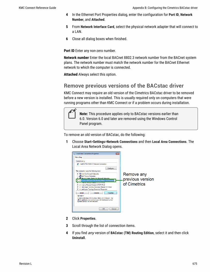
4 In the Ethernet Port Properties dialog, enter the configuration for Port ID, NetworkNumber, and Attached.
5 From Network Interface Card, select the physical network adapter that will connect toa LAN.
6 Close all dialog boxes when finished.
Port ID Enter any non-zero number.
Network number Enter the local BACnet 8802.3 network number from the BACnet systemplans. The network number must match the network number for the BACnet Ethernetnetwork to which the computer is connected.
Attached Always select this option.
Remove previous versions of the BACstac driverKMC Connect may require an old version of the Cimetrics BACstac driver to be removedbefore a new version is installed. This is usually required only on computers that wererunning programs other than KMC Connect or if a problem occurs during installation.
Note: This procedure applies only to BACstac versions earlier than6.0. Version 6.0 and later are removed using the Windows ControlPanel program.
To remove an old version of BACstac, do the following:
1 Choose Start>Settings>Network Connections and then Local Area Connections. TheLocal Area Network Dialog opens.
2 Click Properties.
3 Scroll through the list of connection items.
4 If you find any version of BACstac (TM) Routing Edition, select it and then clickUninstall.
KMC Connect Reference Guide Appendix B: Configuring the Cimetrics BACstac driver
Revision L 675

Appendix B: Configuring the Cimetrics BACstac driver KMC Controls, Inc.
676 Revision L

Appendix C : Versions of Control Basic
Next Generation and Generation 5 Control Basic are advanced versions of Control Basicthat are supported in newer BACnet controllers. The following information explains thevariations of Control Basic and the differences among Standard, Next Generation, andGeneration 5 Control Basic.
With the 2015 release of KMC Connect and the Conquest series of controllers, there arenow three versions of Control Basic for BACnet controllers.
Standard Control Basic This is the version of Control Basic that was part of the release ofthe original KMC BACnet controllers. It is very similar to the version of Control Basicfound in the KMD series of controllers. Controllers with Standard Control Basic areprogrammed with little change. However, when existing programs are loaded from acontroller you will see some changes to the keywords and references to remote points.
Next Generation Control Basic With the release of BACstage 2.3 (June 2008) andTotalControl Design Studio 1.5, KMC Controls added Next Generation Control Basic. Thenew version includes additional commands and functions, new syntax, labels, and theelimination of line numbers.
Generation 5 Control Basic This version of Control Basic includes all of theenhancements of Next Generation Control Basic and adds several new functions andcommands.
Review the following topics to become familiar with the new features of Control Basic:
l Control Basic versions in controllers on page 677l Changes to IF THEN on page 680l Deprecated keywords on page 678l File compatibility on page 680l New keywords on page 681l Line numbers and labels on page 685l Local variables on page 686l References to objects in remote devices on page 686l References to properties on page 686
Control Basic versions in controllersThe following table lists the versions of Control Basic that are supported in the BACnetcontrollers from KMC Controls.
KMC Connect Reference Guide
Revision L 677

Control Basic Version
Model number Standard Next Gen Gen 5
BAC-A1616BC ■
BAC-5801BAC-5802
■
BAC-5831 ■
BAC-5841BAC-5842
■
BAC-7001BAC-7051
■
BAC-7003BAC-7053
■
BAC-7301BAC-7301C
■
BAC-7302BAC-7302C
■
BAC-7303BAC-7303C
■
BAC-7401BAC-7401C
■
BAC-5900 ■
BAC-9000 ■
BAC-9100 ■
BAC-9300 ■
FlexStatBAC-10000BAC-11000BAC-120000BAC-130000BAC-140000
■
Table C–1 Versions of Control Basic
Deprecated keywordsKeywords in the table Control Basic deprecated keywords on page 679 changed inBACstage version 2.3. Only the keywords are changed; the functions and commands theyrepresent remain the same.
l When writing programs for controllers with Standard Control Basic (see ControlBasic versions in controllers on page 677), BACstage will accept and compile
Appendix C: Versions of Control Basic KMC Controls, Inc.
678 Revision L

either the deprecated keywords or the replacement versions of the keywords. Forexample either DEW-POINT or DEWPOINT may be used when writing a program.
l When BACstage or TotalControl retrieves a Control Basic program from a controllerand decompiles it, the deprecated keywords are replaced with the new keywords.For example DEW-POINT becomes DEWPOINT and TIME-ON becomes TIMEON.
l For controllers with Next Generation or Generation 5 Control Basic, BACstage orTotalControl will not accept or compile the deprecated keywords.
Deprecated keyword Replacement keyword
COS-1 ARCCOS
DEW-POINT DEWPOINT
DEW-POINT-SI DEWPOINTSI
ENTHALPY-SI ENTHALPYSI
LN-1 INVLN
MODEL-NUMBER MODELNUMBER
NETSENSOR-STATUS NETSENSORSTATUS
ON-ERROR ONERROR
OUTPUT-OVERRIDE OUTPUTOVERRIDE
PANEL-ADDRESS PANELADDRESS
SCHED-ON SCHEDON
SCHED-OFF SCHEDOFF
SENSOR-OFF SENSOROFF
SENSOR-ON SENSORON
SIN-1 ARCSIN
TAN-1 ARCTAN
TIME-ON TIMEON
TIME-OFF TIMEOFF
Table C–2 Control Basic deprecated keywords
KMC Connect Reference Guide Appendix C: Versions of Control Basic
Revision L 679

Changes to IF THENBoth Next Generation and Generation 5 Control Basic support block and nested IF THENstatements.
Locals ChilledWaterSetpointAV24 = ChilledWaterSetpointIF BV258 THEN
ChilledWaterSetpoint=52ELSE
Chilledwatersetpoint=48ENDIF
t=TIMEIF t> 00:07:00 THEN
IF t < 00:09:00 THENSTART BO1
ENDIFENDIF
File compatibilityNot all versions of BACstage and TotalControl are compatible with the versions of ControlBasic.
TotalControl and KMC Connect compatibilityAll versions of KMC Connect and versions of TotalControl released after June 2015 arecompatible with all versions of Control Basic.
BACstage file compatibilityWhen saving and opening files with versions of BACstage other than BACstage 2.3, beaware of the following compatibility issues.
Note: TotalControl Design Studio and KMC Connect will not directlyimport BACstage .bas or .ng Control Basic files. However,programs can be pasted into a Control Basic editor window and thenmodified.
l No version of BACstage is compatible with the Generation 5 keywords.l Programs saved in a controller with BACstage 2.3 can be loaded from a controller
with earlier versions of BACstage. BACstage 2.2 and earlier will list the programsusing the deprecated keywords and original syntax for remote points.
l If a .BAS file includes any of the new or deprecated keywords, BACstage versionsearlier than 2.3 will open but not compile the program. The new keywords andsyntax must be changed to the original format.
l When transferring a .BAS file to a controller with Next Generation basic, linenumbers will have to be deleted. Labels will have to be added to lines that are
Appendix C: Versions of Control Basic KMC Controls, Inc.
680 Revision L
referenced by a GOSUB or GOTO control statement. See Line numbers and labelson page 685.
l Files created with Backup Device (.BAC files) in BACstage 2.3 are backwardscompatible with BACstage 2.2 and earlier.
New keywordsThis topic includes only a brief description of the keywords not in the original version ofControl Basic. Details for each keyword are included in the help for each program thatuses Control Basic.
Next GenerationThe following keywords are added to Next Generation Control Basic and are alsorecognized by Generation 5 Control Basic.
l ALIASl BINDl CONSTl ERRORLEVELl FLUSHl HALTl ISNANl LOCALSl NAN
ALIASALIAS declares a local variable and dynamically binds the value of a property to thevariable. It also sets two intervals at which Control Basic will read from or write to theproperty bound to the variable.
Syntax: ALIAS(device, object, property, local, read interval, write interval)
See ALIAS on page 248 for a more detailed description.
BINDThe BIND command binds a device instance to a physical network address. This istypically used to bind an MS/TP slave to a master device. BIND is required in only oneprogram within the device.
Syntax: BIND (device, network, mac, option)
See the keyword BIND on page 255 for a more detailed description.
CONSTUse CONST to declare one or more variables and assign to them a fixed value. Do not usewith variables that change with subsequent steps in the program.
Syntax: CONST, variable[, variable, ...]
KMC Connect Reference Guide Appendix C: Versions of Control Basic
Revision L 681

See CONST on page 259 for a more detailed description.
FLUSHWhen a FLUSH statement runs, Control Basic immediately reads from or writes to theproperty bound to the local variable declared by ALIAS.
Syntax: Flush (LocalAlias1)
See the topics FLUSH on page 273 and ALIAS on page 248 for more detaileddescriptions.
HALTHALT stops the program from running and sets the Program State property in theprogram object to Halted. The string Message is displayed in the property Descriptionof Halt.
Syntax: HALT “Message”
See the keyword HALT on page 277 for a more detailed description.
ISNANISNAN tests the value of expression to determine if it is a valid number. If the value ofexpression is equal to NAN (Not A Number), then ISNAN returns true. A typical use ofISNAN is to test the present value property of an object in a remote device.
Syntax: ISNAN( _expression_ )
See ISNAN on page 283 for a more detailed description.
LOCALSUse LOCALS to declare local variables or arrays of data type REAL. A local variable maybe used only within the program in which it is declared.
Syntax: LOCALS variable[, variable, ...]
Syntax: LOCALS arrayName[size]
See the keyword LOCALS on page 286 for a more detailed description.
NANUse NAN to set a variable or property to a Not A Number constant or to test if thevariable or property is equal to Not A Number. NAN can be used in both Standard andNext Generation Control Basic.
See NAN on page 290 for a more detailed description.
Generation 5The following keywords are now recognized by Generation 5 Control Basic.
l COVl ENDFUNCl ENDPROCl FRETURN
Appendix C: Versions of Control Basic KMC Controls, Inc.
682 Revision L

l FUNCTIONl INTEGERl NETPOINTl NETPOINTCACHEl PRETURNl PROCEDUREl REALl STRINGl TOSTRING
COVThe COV command sets up an object and property for a COV (Change of Value)subscription. The object must be in a device that supports COV subscriptions. It appliesto all read accesses in a program regardless of location.
Syntax: COV( device.object.property, increment , confirmed, lifetime )
See the keyword COV on page 260 for details and examples.
ENDFUNCENDFUNC the end of a user defined Control Basic function.
See the keyword ENDFUNC on page 270 and for details and the topic User-definedfunctions and procedures on page 240 for an overview of functions.
ENDPROCMarks the end of a user defined Control Basic procedure.
See the keyword ENDPROC on page 270 for details and the topic User-definedfunctions and procedures on page 240 for an overview of procedures.
FRETURNUse FRETURN to designate the value that is returned by the function. A function caninclude multiple FRETURN statements but only the first statement executed designatesthe returned value.
See the keyword FRETURN on page 274 and for details and the topic User-definedfunctions and procedures on page 240 for an overview of functions.
FUNCTIONUse FUNCTION to mark the beginning of a user defined function. A function is a self-contained block of statements that return a single value.
See the keyword FUNCTION on page 274 for an example and the topic User-definedfunctions and procedures on page 240 for an overview of functions.
INTEGERUse the command INTEGER to declare a local variable or array of data type INTEGER.
Syntax: INTEGER variable[, variable, ...]
Syntax: INTEGER arrayName[size]
KMC Connect Reference Guide Appendix C: Versions of Control Basic
Revision L 683

See the keyword INTEGER on page 282 for details and an example. For a description ofdata types, see the topic, BACnet data types on page 243.
NETPOINTUse the NETPOINT function to set the interval for reading from and writing to BACnet off-panel objects.
Syntax: NETPOINT(device.object.property, read interval, write interval)
See the keyword NETPOINT on page 291 for details and an example.
NETPOINTCACHEUse NETPOINTCACHE to enable and disable the NETPOINT and COV functions.
Syntax: NETPOINTCACHE(expression)
See the keyword NETPOINTCACHE on page 292 for details and an example.
PRETURNUse PRETURN to return from a procedure before reaching ENDPROC. PRETURN isoptional.
See the keywords PRETURN on page 304 and PROCEDURE on page 305 for detailsand examples.
PROCEDUREThe PROCEDURE keyword marks the beginning of a user defined procedure. A procedureis a self-contained block of Control Basic statements that perform a task.
Syntax: PROCEDURE name([argument, argument, argument...])
See the keyword PROCEDURE on page 305 for an example and the topic User-defined functions and procedures on page 240 for an overview of procedures.
REALUse the command REAL to declare a local variable or array of data type REAL. For adescription of data types, see the topic, BACnet data types on page 243.
Syntax: REAL variable[, variable, ...]
See the keyword REAL on page 307 for details and an example.
STRINGUse the command STRING to declare a local variable or array of data type STRING. For adescription of data types, see the topic, BACnet data types on page 243.
Syntax: STRING variable[, variable, ...]
See the keyword STRING on page 320 for details and an example.
TOSTRINGUse TOSTRING to convert a numerical value to a string.
Syntax: TOSTRING(argument1, argument2)
See the keyword TOSTRING on page 327 for details and an example.
Appendix C: Versions of Control Basic KMC Controls, Inc.
684 Revision L

Line numbers and labelsWhen using Next Generation or Generation 5 Control Basic, the line numbers found inStandard Control Basic are not used. For branching commands that require a destination,such as GOSUB or GOTO, a label is used instead.
Line numbersLine numbers are not used in Next Generation or Generation 5 Control Basic programs.However, a line number is displayed in the Control Basic editors for BACstage,TotalControl Design Studio, and KMC Connect. The line numbers displayed are only foridentifying problems when a program is compiled.
Line numbers continue to be used in controllers with Standard Control Basic.
l In BACstage, enter line numbers as the programs are written.l In TotalControl Design Studio and KMC Connect, the line numbers are generated
automatically.
LabelsIn both Next Generation and Generation 5 Control Basic, labels are used instead of linenumbers when program flow is redirected by any of the following statements.
l GOSUBl GOTOl ONERRORl ON GOSUBl ON GOTO
In the following program example, CoolMode and HeatMode are examples ofdestinations for a program redirection.
IF T > 55 THEN GOTO CoolMode IF T <= 55 THEN GOTO HeatMode ENDCoolMode: REM Cooling sequence runs here ENDHeatMode: REM Heating sequence runs here END
KMC Connect Reference Guide Appendix C: Versions of Control Basic
Revision L 685
Declare labels by typing a name followed immediately by a colon (:).
l A label can be any combination of letters (A-Z or a-z), numbers (0-9) or theunderscore (_).
l A label must start with a letter.l Labels are not case sensitive.l Labels are unique to the program in which they are declared.l Labels cannot be a Control Basic keyword.
Local variablesThe single-letter local variables a-z and A-Z may still be used without programmodification. In addition to single letters, more descriptive variables may be used bydeclaring variables with the following statements.
l INTEGER on page 282l LOCALS on page 286l REAL on page 307l STRING on page 320
References to objects in remote devicesWhen referring to an object in a remote device, the device name or instance is nowseparated from the object reference by a period (.). In previous versions, the instance andname were separated with a dash (-).
A = 1214.AI1
In BACstage, the name of the device or object can be used in place of an instancenumber.
A = MechanicalRoom.TempMechRoomA = 1214.TempMechRoomA = MechanicalRoom.AI1
Place a WAIT statement after the expression that reads the point. Place both the WAITstatement and the expression for the remote point at the end of the program.
REM * POINTS TRANSFERRED FROM DEVICE 1213REM * OUTSIDE AIR TEMPERATURE *AV24 = 1213.AI7WAIT 0:05:00END
References to propertiesThe Next Generation and Generation 5 versions of Control Basic support reading andwriting some properties within objects. The common mnemonics are listed in thefollowing table.
Appendix C: Versions of Control Basic KMC Controls, Inc.
686 Revision L

See the topic Mnemonics for BACnet controllers on page 223 for details on bothproperty and object mnemonics.
Property mnemonic Action Comments
High Limit HL Read and Write Intrinsic alarming only
Loop Bias B Read and Write Loop objects only
Loop Derivative D Read and Write Loop objects only
Loop Integral I Read and Write Loop objects only
Loop Proportional P Read and Write Loop objects only
Loop Setpoint SP Read and Write Loop objects only
Low Limit LL Read and Write Intrinsic alarming only
Present Value PV Read and Write Default
Pulse Rate PR Read Only Accumulator objects only
Trend Log Enable EN Read and Write Trend Log objects only
Relinquish Default RELINQUISH_DEFAULT Read and Write Limit writes to changes only
Table C–3 Property mnemonics
KMC Connect Reference Guide Appendix C: Versions of Control Basic
Revision L 687

Appendix C: Versions of Control Basic KMC Controls, Inc.
688 Revision L

Appendix D: KMC Conquest-compliant control le rs
This appendix lists controllers that are compliant and compatible with applications inKMC Connect.
The following KMC Connect applications support controllers listed in this section.
l Application selection, configuration, and deployment on page 635l Audit application on page 639l VAV Balancing application on page 643
BAC-4001BAC-4002BAC-4003BAC-4007BAC-4008
BAC-4021BAC-4022BAC-4023BAC-4027BAC-4028
BAC-4201BAC-4202BAC-4203BAC-4207BAC-4208
BAC-4221BAC-4222BAC-4223BAC-4227BAC-4228
BAC-8001BAC-8005BAC-8007BAC-8205
BAC-5901
BAC-9001BAC-9021BAC-9301BAC-9311
KMC Connect Reference Guide
Revision L 689

Appendix D: KMC Conquest-compliant controllers KMC Controls, Inc.
690 Revision L

Appendix E: G lossary
AAPDUApplication Layer Protocol Data Unit. An APDU is the significant data in a networkpacket.
BBACnetBuilding Automation Control Network. A data communications protocol for buildingautomation systems. Developed and maintained by ASHRAE, it is an AmericanNational Standards Institute standard designated ASHRAE/ANSI 135. BACnet defineshow information is exchanged between vendors.
BACnet broadcastA message that is intended to be received by a group of devices on an internetwork.There are three types of BACnet broadcasts: Global Broadcast - All devices on theinternetwork get the message. Remote Broadcast - All the devices on a remotenetwork get the message. Local Broadcast - All of the devices on the local networkreceive the message.
BACnet broadcast management device (BBMD)A special type of routing device that is used in BACnet/IP networks to distributebroadcast messages across multiple IP subnetworks.
BACnet deviceAny device, real or virtual, that supports digital communication using the BACnetprotocol. Examples of devices are operator terminals, routers, unitary controllers, etc.
Cconformance classConformance classes describe the capabilities of a BACnet device for communicatingdata and interoperating with other BACnet devices. A device's ProtocolImplementation Conformance Statement (PICS) details its conformance class.
DDCOMDistributed Component Object Model (DCOM) is a set of Microsoft program interfacesin which client program objects can request services from server program objects onother computers in a network.
device instanceA number that uniquely identifies the device on the internetwork. The device instancenumber is determined by the BACnet system designer. Valid instance numbers rangefrom 0 to 4,194,303 and are assigned to the device during configuration. It is by
KMC Connect Reference Guide
Revision L 691

reference to the device instance number that data is exchanged between BACnetdevices.
directly connected networkA BACnet network that is accessible from a router without messages being relayedthrough an intervening router. A PTP connection is to a directly connected network ifthe PTP connection is currently active and no intervening router is used.
Hhalf-routerIn BACnet, a device that can participate as one partner in a point-to-point (PTP)connection. Two half-routers form an active PTP connection and act as a singlerouter.
II-Am serviceThe I-Am service is used to respond to Who-Is service requests. However, the I-Amservice request may be issued at any time. It does not need to be preceded by thereceipt of a Who-Is service request. A device may be programmed to broadcast an I-Am service request when it powers up. The network address is derived either from theMAC address associated with the I-Am service request, if the device issuing therequest is on the local network, or from the BACnet network header (NPCI) if thedevice is on a remote network.
internetworkA BACnet internetwork can be as simple as a single network but is usually two or moreBACnet networks connected by routers. The BACnet protocol permits up to 65,534interconnected networks in an internetwork. Internetworks may contain similar ordissimilar physical types such an Ethernet, IP or MS/TP.
KKMDigitalKMDigital is a proprietary line of digital building automation controllers manufacturedby KMC Controls, Inc. The controllers are either Tier 1 or Tier 2 controllers. Tier 1controllers connect directly to a LAN through Ethernet; Tier 2 controllers connect toeach other and Tier 1 controllers on an EIA-485 network. KMDigital is oftenabbreviated as KMD.
Llast panelThe highest numbered panel on a KMD network. A controller assigned as the lastpanel will pass the token back to the lowest numbered panel when it is done talking onthe network. Last Panel is not the same as end-of-line termination.
local networkThe network to which a BACnet device is directly connected.
Appendix E: Glossary KMC Controls, Inc.
692 Revision L

Mmain panelSee Tier 1 controller.
master and slave devicesMS/TP devices come in two varieties: Slave devices are suited for the lowest-costimplementations but they lack the capability to initiate requests; they can only reply tomessages from other devices. Master devices are able to initiate requests, but theymust also be able to negotiate for a time slot in which to make their requests. Thisadds some processing and memory requirements to the Master device which canresult in higher cost than the slave.
Microsoft.NET FrameworkThe Microsoft .NET Framework is a component of the Microsoft Windows operatingsystem. It provides a large body of pre-coded solutions to common programrequirements, and manages the execution of programs written specifically for theframework. The framework is intended to make it easier to develop computerapplications and to reduce the vulnerability of applications and computers to securitythreats.
ModbusA protocol developed to establish master-slave/client-server communication betweenindustrial devices. Modbus devices communicate over a serial network in amaster/slave (request/response) type relationship using one of two transmissionmodes: ASCII (American Standard Code for Information Interchange) mode or RTU(Remote Terminal Unit) mode.
MS/TPThe MS/TP (master slave/token passing) protocol is unique to BACnet and isimplemented using the EIA–485 signaling standard. This is a shielded, twisted-pairLAN operating at speeds from 9600 to 115,200 baud.
NNetwork ManagerNetwork Manager is the user interface for navigating through the control system. Itdisplays a hierarchical view of the physical layout of the control system includingnetworks, devices, controllers, objects, and properties.
network numberA number from 1 to 65,534 that identifies specific BACnet network. It is assigned bythe BACnet system designer at the time a router is initialized for network operation.
OobjectObjects are the means by which a BACnet device represents information that can beobserved or changed. The object may represent a physical point such as an input or
KMC Connect Reference Guide Appendix E: Glossary
Revision L 693

output or a logical grouping of data such as a PID loop, schedule, or variable. Objectshave a set of properties and a group of functions that can be applied to them.
OPCOPC is the original name for OLE for Process Control , an open standards specificationdeveloped in 1996 by an industrial automation industry task force. The standardspecifies the communication of real-time plant data among control devices fromdifferent manufacturers. OPC servers provide a method for many different softwarepackages to access data from a process control device, such as a PLC or DCS.
PPAD routerA BACnet IP PAD (Packet Assembler and Disassembler) is a special type of router thatconnects two BACnet IP network segments that are separated by at least one IP-onlyrouter. The PAD router monitors network traffic for BACnet messages addressed tothe other subnet and repackages the message so that it can pass through IP routers,in effect forming a “tunnel” between the two network segments. A companion PADrouter unpacks and retransmits the message on the remote BACnet network.
point-to-pointIn BACnet, point-to-point is a method of data transmission to provide serialcommunications between two BACnet devices. Typically, it is used for remote androaming access to BACnet systems, dial-up communications over modems, or aportable computer connection to a controller. PTP is based on the EIA-232 directpoint-to-point connection or via dial-up telephone modems.
priority arrayBACnet devices use the priority array to control Present Value in certain objects. Thearray consists of a table with 16 slots arranged in descending priority order. Valueswritten to higher priority slots in the table override those of lower priority. The value inthe highest priority slot transfers to the present value property.
Protocol Driver ServiceA Protocol Driver Service (PDS) is the link between a building automation system andother services. When data is required from a controller, the PDS retrieves the data,forwards it to the requesting service and, depending upon the type of data, caches itfor future use. Each supported protocol requires a corresponding PDS and networkconnection. The PDS is one of the licensed components of Building Services.
Protocol Implementation Conformance StatementA Protocol Implementation Conformance Statement (PICS) is a document issued by amanufacturer that specifies exactly which portions of the BACnet Standard a deviceactually implements.
Rrouters, BACnetBACnet routers connect different types of BACnet networks. The KMC Controls BAC–5050 or BAC-5051E routers link BACnet 8802-3, BACnet IP, and MS/TP networks.
Appendix E: Glossary KMC Controls, Inc.
694 Revision L

SservicesBACnet services control the transfer of information between BACnet devices.Examples of services include scheduled commands and alarms between BACnetdevices. BACnet defines 26 standard services. Some services read or write propertiesof objects in the receiving device. Others convey notification of alarms or other specialevents, others read and write files, and so on. The services provided by a BACnetdevice are generally described by the device's PIC statement.
TTier 1 controllerAn upper level controller in the KMC digital network hierarchy. The Tier 1 controllercan have one or more Tier 2 networks connected to it. A Tier 1 controller may alsohave ports for connection to computers, a network, buffered modem communications,a dedicated system printer and an OEM equipment interface. The Tier 1 controller hasmany other advantages for large networks such as large areas of memory for systemgroups, Control Basic programs, schedules, and passwords. Tier 1 controllers haveadditional commands and statements available to allow complex programs to beeasily written. Also referred to as a LAN controller, MultiNet or main panel.
Tier 2 controllerA KMC controller with built-in peer-to-peer, EIA–485 network communications. Alsoreferred to as a Subnet controller or sub-panel.
VvariablesVirtual points in the KMD protocal that can represent temperatures, setpoints, offsets,multipliers, or digital values.
WWho-Is serviceThe Who-Is service message is sent by a BACnet device to determine the device objectidentifiers and network addresses for all devices on the network, or to determine thenetwork address of a specific device whose device object identifier is known, butwhose address is not.
KMC Connect Reference Guide Appendix E: Glossary
Revision L 695

Appendix E: Glossary KMC Controls, Inc.
696 Revision L

Index
.
.bac files 422
.bbk files 420
.bnd files 419
.csv filesarchived trend logs 105audit log report 89Automatic MAC Addressing report 412comparing objects 416KMD runtime log data 591trend log
BACnet 501KMD 595
trend log multiple 506.tbvx files 67.xml files
archived trend logs 105
Aabout
alarms 131BACnet algorithmic 142BACnet intrinsic 137KMD Control Basic 149KMD offline controller 151
BACnet services 395change of value notifications 153Code Editor 191Control Basic 213KMC Connect 31Network Manager 39objects 395OPC 611Output Window 51properties 395Protocol Gateway manager 623Protocol Gateway service 623Resource Manager 55schedules 179table view 63trend logs 97
ABS 245abs block 347ACC 223access door object 427accumulator object 450action
BACnet PID loop object 476
KMD PID controller 588add
inputs and outputs to expansion panels 414objects to device 414service to Network Manager list 42users to a group
in Security Manager 81add block 347adding 210address
IP 415KMD Tier 1 554
administrator permissions 79AI 223ALARM 246alarms
Alarm Monitor bar 165archiving 164audible 36BACnet
algorithmic 142intrinsic 137
clearing 164configuration wizard 134configuring BACnet 133configuring KMD 151disable by network 167email server 175filtering 166filtering by user group 173GEST 435icons 161KMD classes 151KMD messages 605muting 36notification settings 36operator notifications 170options 36overview 131printer 175summary in BACnet device 164viewing 161wizards 134
algorithmic alarmsabout 142configuring 144
ALIAS 248analog
BACnet input objects 453BACnet output object 483BACnet value objects 510
KMC Connect Reference Guide
Revision L 697

KMD input point 574KMD output point 585KMD variable point 596
AND 251and block 348annual schedules
in KMD controllers 569See BACnet calendar object 433
antiCycle block 348AO 223applicable controllers
block programming 333application
audit 639commanding VAV airflow 646configuration 635custom application wizard 649deployment 635selection 635VAV balancing 643VAV flow monitoring 646
ARCCOS 251arccos block 349arccosine for KMD contollers 260archiving
alarms 164trend logs 105
ARCSIN 251arcsin block 349arcsine for KMD controllers 316ARCTAN 252arctan block 350arctangent for KMD controllers 321arithmetic operators 221array
Control Basic example 571in KMD controllers 571length 571
arraysdeclaring with
INTEGER 282LOCALS 286REAL 307STRING 320
programming with 242AS 235audit
application 639log 89log report 89
Auto-Hide 34automatic
autotune in BACnet PID loops 476blanking NetSensor for BACnet 521blanking NetSensor for KMD 584line numbering 196MAC addressing 412
automatic log off 36autotune in BACnet loops 476AV 223average
BACnet inputs 454KMD analog inputs 574
averaging objects 432AVG 252avg block 350AY 235
BBAC-GET 253BAC-RLQ 254BAC-SET 255backup
BACnet backup 420BACstage .bac files 422entire site 71files for devices and controllers 60scheduled device 423to .bnd file 419
BACnet 664about services 395BAC-GET 253BAC-RLQ 254BAC-SET 255backup procedure 420broadcast management device 670controllers 547Ethernet 674foreign device 670IP 670network number 670objects 427overview 395Priority 254restore 420
BACnet objects 210, 416BACstac driver
configuring 669removing 675
BACstage.bac files 422
KMC Controls, Inc.
698 Revision L

importing and exporting files 422balancing application 643bandwidth
for BACnet networks 664for KMD networks 665
baudin devices 435
BBMD configuration 415BI 223bias
BACnet PID loop object 476in BACnet Control Basic 223in KMD Control Basic 257KMD PID controller 588
binaryBACnet input objects 458BACnet output objects 486BACnet value objects 513KMD input 575KMD output 587KMD variable 597
BIND 255block programming 333
applicable controllers 333importing 344limitations 344line vs. block 214local variables 339macros 341reference to blocks 347routines 340starting the editor 335subroutines 340unsupported keywords 344
blocksabs 347add 347and 348antiCycle 348arccos 349arcsin 349arctan 350avg 350call 340clear 350close 351compare 351compareEqual 352compareGreater 352compareGreaterEqual 353compareLess 353
compareLessEqual 354compareNotEqual 355cos 355counter 356dec 357delayOnBreak 357delayOnMake 356dewpoint 358dewpointsi 359disable 359divide 360dom 360-361enable 362end 362enthalpy 362enthalpysi 363equalToDiff 364for 364Get 338greaterThanDiff 365hsel 365if 366ifMinus 366ifPlus 367inc 367int 368integerDivide 368interval 369invln 369lessThanDiff 370limiter 370ln 371lsel 371macro 341max 371min 372minMaxAvg 372mod 373modelnumber 375month 373multiply 374nan 374netsensorstatus 373oneShot 375open 376or 376outputoverride 377paneladdress 377pi 377power 377powerloss 378program start 378
KMC Connect Reference Guide
Revision L 699

rem 378reset 379rlq 379rnd 380scans 380schedoff 381schedon 382select 383sensoroff 383sensoron 384Set 338sin 385slope 386sqr 386start 386stop 387subtract 387switch 388tan 388tbl 389time 389timeoff 389timeon 390wait 390xor 391year 392
bnd backup files 60BO 223bookmarks 198Boolean logic 221BUILD-NUMBER 256building services
deleting 45buttons
NetSensor-BAC controllers 521NetSensor-KMD controllers 579
BV 223byte ordering in Modus 576
Ccached values
COV client 154calendar object 433Calendar object 182calibration
BACnet analog input objects 453BACnet custom device types 453inputs in KMD controllers 574NetSensor-BAC controllers 521NetSensor-KMD controllers 584STE-9000 NetSensor 527
call block 340Cbasic table 542change of value 153
about 153COV client 153COV server 153subscribe configuration pages to object 155subscribe configuration pages to property 156subscribe to object 153subscribe to property 153subscribe to trend logs 158subscription list 153unsubscribing 157
CLEAR 256CLEAR-COUNT 256clear block 350clearing
alarms 164Control Basic programs 193Output Window messages 52
clearing want-pointsin Tier 1 networks 566in Tier 2 networks 572
CLOSE 257close block 351Code Editor
about 191adding objects by dragging 210automatic line numbering 196changing text font and color 202live values 206name/mnemonic button operation 225options 202programming 191select all 197writing code 192
cold start 410color
alarm list 161in Code Editor 202signal strenght color code 532
combining graphic elements 435command object 434commanding airflow 646communication ports 661compareEqual block 352compareGreater block 352compareGreaterEqual block 353compareLess block 353compareLessEqual block 354
KMC Controls, Inc.
700 Revision L

compareNotEqual block 355comparing BACnet objects 416comparison operators 220compatibly mode, Niagara 435compile
Control Basic programs 193options 193
computernames 20requirements and specifications 18
CON 235CONBIAS 257configuration application 635configuration files, scanning 413configuring
alarmsin BACnet devices 133in KMD controllers 151operator notifications 170
BACnet objects 403BACnet service 407BACstac for Ethernet 674BACstac for IP, BBMD and foreign device 670building services 44Cimetrics BACnet driver 669COV notifications
for configuration pages 155-156for trend logs 158
Design Studio workspace 33devices 403KMD network 566KMD service 564notification service 175OPC PDS 614Protocol Gateway service 631sensor port objects 521trend logs
BACnet controller 111BACnet device 112BACnet PC 115KMD controller 119KMD device 121KMD PC trends 123
trend service 127connecting
a Building Service 42to an OPC server 613to KMDigital
over the Internet 554Tier 1 network 554Tier 1 serial 554
Tier 2 controllers 559CONPROP 258CONRATE 258CONRESET 259CONST 259constants in Control Basic 259contributor permissions 79Control Basic
alarms in KMD controllers 149automatic line numbering 196BACnet tables 542editing 192expressions 215find and replace 198for KMD arrays 571functions 215Generation 5 677keywords 245KMD runtime logs 591KMD weekly schedules 598labels 216line numbers 216line vs. block 214live values
block editor 337live values in Code Editor 206locking programs 207mnemonics
BACnet 223KMD 235
Next Generation 677procedures and functions 240scans 214statements 215undo 197using NETPOINT and NETPOINTCACHE 230using WAIT statements 229, 233variables 222version in controllers 677want-points 236writing offline 194
controllers 689converting input and output objects 406copy
Code Editor 197device configuration 403
COS 260COS-1 260cos block 355counter block 356
KMC Connect Reference Guide
Revision L 701

COV 260about 153reading and writing off-panel 231
createBACnet objects 414
customBACnet device type 453KMD units 572
custom application wizard 649custom table view 67cut in Code Editor 197
DDALARM 262data format in Modbus 576data type in Modbus 576data types in OPC tags 617date
date and time in KMD controllers 572start date in runtime log 591
dayof month 266of week 266of year 267
daylight saving timein BACnet devices 435in KMD controllers 572
DEC 264dec block 357declaring
arraysINTEGER 282LOCALS 286REAL 307STRING 320
constants with CONST 259variables
INTEGER 282LOCALS 286REAL 307STRING 320
DECOM 264decommissioned 574default values
PC trend log interval 46delayOnBreak block 357delayOnMake block 356delete
building services 45inputs and outputs from expansion panels 414objects from device 414
deployment application 635deprecated keywords 678derivative
BACnet PID loops 476in BACnet Control Basic 223in KMDigital Control Basic 258KMD PID controller 588
deviceBACnet object 435instance 435KMD controllers 572scheduled backup 423
Device Backup Manager 423device tables 541DEW-POINT 265DEWPOINT 264dewpoint block 358DEWPOINTSI 265dewpointsi block 359DISABLE 265disable block 359discovering devices 41discovering devices, See Find Devices 402discovery
discovering devices 41full 41limited 41options 41
divide block 360docked panes 33DOM 266dom block 360DOW 266dow block 361DOY 267doy block 361dragging 210DST
in BACnet devices 435in KMD controllers 572
dynamic access 242
Eediting Control Basic 192ELSE 278email
alarm notification 170backup files 71data points with EMAILD 267
KMC Controls, Inc.
702 Revision L

KMD alarm messagesALARM 246DALARM 262
messages with EMAILM 268runtime logs with EMAILR 269server configuration 175trend logs with EMAILL 268
EMAILD 267EMAILL 268EMAILM 268EMAILR 269ENABLE 269enable block 362END 270end block 362ENDFUNC 270ENDIF 278ENDPROC 270engineering units
BACnet analog 545BACnet binary 545KMD analog 601
ENTHALPY 271ENTHALPY-SI 272enthalpy block 362ENTHALPYSI 271enthalpysi block 363equalToDiff block 364ERROR-COUNT 272ERRORLEVEL 272errors messages 51Ethernet
connection in devices 415in BACstac 674
eventacknowledgment 482enrollment object 442enrollment summary 158processing 482summary in BACnet device 164
event log objects 446example programs 245
reqlinquish default 227exception schedules 496expansion modules 414exporting
archived trend logs 105audit log 89BACstage .bac files 422from trend viewer 100
KMD runtime logs 591scheduled backup records 423trend log multiple 506trend logs
BACnet 501KMD 595
expressions in Control Basic 215
Ffile objects 449file types
.bac 422
.bbk 420
.bnd 419
.csvAutomatic MAC Addressing 412of audit log 89of compared objects 416
.tbvx 67filter weight in BACnet inputs 454filtering
alarms 166alarms by user group 173BACnet analog inputs 454KMD analog inputs 574Output Window messages 52
finddevices 402text in Control Basic 198
firewall 661firewall exceptions 661firmware
file location 91upgrades 91
FLASH 330FLASH over the network 91floating panes 34FLUSH 273for block 364FOR TO NEXT 273foreign device configuration 415FRETURN 274full discovery 41FUNCTION 274function codes in Modbus 576functions and procedures 240functions in Control Basic 215
GGated Event State Transitions 435Generation 5 Control Basic 677
KMC Connect Reference Guide
Revision L 703

GEST 435get block 338GOSUB 275GOTO 276goto in Code Editor 197greaterThanDiff block 365group
BACnet group object 449user groups in Security Manager 81
group roles for security 79GRP 235
Hhalt 193HALT 277HANGUP 277HAVE-TOKEN 277heartbeat 407help examples 245hibernation mode 20hidden panes 34hierarchy of operators 219holiday schedule
BACnet controllers 433KMD controllers 569
HPO-9007 532HSEL 277hsel block 365humidity programing
NetSensor-BAC controllers 521NetSensor-KMD controllers 581
Iicons
alarms 161BACnet devices 402KMD controllers 554Network Manager 40Output Window 51STE-9000 NetSensor 527
IF- THEN 280if block 366IF THEN (ELSE) 278IF THEN ELSE 280IF+ THEN 279ifMinus block 366ifPlus block 367importing
BACstage .bac files 422importing block programming 344
IN 235inactivity timer 36INC 280inc block 367index in array 571input objects
accumulator 450analog 453BACnet pulse 450binary 458changing type 406creating and deleting 414multistate 461
input tables 541installing
computers 20KMC Connect 20
INT 281int block 368INTEGER 282integerDivide block 368integral
BACnet PID loops 476in BACnet Control Basic 223in KMDigital Control Basic 259KMD PID controller 588
Intellisense filter 196interprotocol mapping 576INTERVAL 283interval block 369INVLN 283invln block 369IP address 415ISNAN 283ISSTRING 284
Kkeyboard shortcuts
Code Editor 197keywords 245
deprecated 678Intellisense filter 202prompting 196
KMC Connect 31KMD
backup files 60system name 554
KMD-5559 for KMD Tier 2 559KMD-5576 for KMD Tier 2 559
KMC Controls, Inc.
704 Revision L

Llabels 216leap year 288length 571
array 571runtime log 591
lessThanDiff block 370LET 284license
for KMD service 564life safety objects
point 464zone 468
limitations of block programming 344limited discovery 41limiter block 370limits
KMD want-points 237off-panel points 228
line numbers 216live values
block editor 337Code Editor 206
LN 285LN-1 285ln block 371load control objects 472local variables 222, 339LOCALS 286locking programs
how to 207properties 435
lockout application 36logarithm
invln (inverse natural) block 369ln (natural) block 371
loggingKMD 119Ouput Window 52
logs, runtime 591loop
BACnet PID loop object 476PID loops in KMD controllers 588
LOOP 223LSEL 287lsel block 371
MMAC address
in BACnet 412
in devices 435macro blocks
antiCycle 348delayOnBreak 357delayOnMake 356equalToDiff 364greaterThanDiff 365limiter 370minMaxAvg 372reset 379reusing 341saving 341select 383slope 386switch 388user defined 341
MAMA report 412manual change
analog value 510binary value 513, 517output 486weekly schedule 598
MAX 287max block 371max master 435messages in Output Window 51MIN 288min block 372minMaxAvg block 372mnemonics
BACnet object 223BACnet properties 223KMD 235
MOD 288mod block 373Modbus
data format 576data type 576function codes 576Multiplier 576offset 576register 576
MODBUSTRANSFER 289MODELNUMBER 289modelnumber block 375modulus
block 373keyword 288
MONTH 290month block 373
KMC Connect Reference Guide
Revision L 705

motion sensingNetSensor-BAC controllers 521NetSensor-KMD controllers 583
MSI 223MSO 223MSV 223Multiplier in Modbus 576multiply block 374multistate objects
input 461output 490value 517
mute alarms 36
Nnames
alarm recipient operators 170names for computers 20NAN 290nan block 374Near Field Communication (NFC)
for service and network 48for single devices 435
NEG_INFINITY 290NETPOINT 291NETPOINTCACHE 292NetSensor
Conquest 527STE-9000 527
NetSensor-BAC controllersauto-blanking 521buttons 521calibration 521humidity 521motion sensing 521programming 521setpoint 521temperature 521time 521verifying status 521
NetSensor-KMD controllersauto-blanking 584buttons 579calibration 584humidity 581motion sensing 583programming 580setpoint 581temperature 581time 582verifying status 582
NETSENSOR-STATUS 294NETSENSORSTATUS 293netsensorstatus block 373network
FLASHing controllers 91ports 661
network address translation 554Network Manager 39
display settings 46icons 40opening 40options 46scanning for uninitialized files 413
network number 670network status
KMD Tier 1 566KMD Tier 2 572
networks 47new
security group in Security Manager 81Next Generation Control Basic 677NFC
for service and network 48for single devices 435
Niagara compatibility mode 435NOT 294not block 375notification class object 482notifications
BACnet algorithmic 142BACnet change of value 153BACnet intrinsic 137KMD controllers 149
NPAGEin Tier 1 controllers 294message strings in alarms 246, 262
Oobject locate 37objects
about 395access door 427accumulator 450analog input 453analog output 483analog value 510averaging 432binary input 458binary output 486binary value 513calendar 182, 433
KMC Controls, Inc.
706 Revision L

command 434creating and deleting 414device 435event enrollment 442event log 446file 449group 449life safety point 464life safety zone 468load control 472loop 476multistate input 461multistate output 490multistate value 517notification class 482program 493schedule 496sensor port 521structured view 500trend 501trend log multiple 506
off-panel pointsBACnet limits 228reading 228using COV 231using NETPOINT and NETPOINTCACHE 230with INTERVAL 233with WAIT 229, 233writing 228
offline programming 28Offset in Modbus 576ON-ALARM 297ON-ERROR 298ON GOSUB 295ON GOTO 296ONERROR 298oneShot block 375OPC 611
connecting to servers 613objects 617quality 617tags 617timestamp 617
OPEN 299open block 376opening
Control Basic programs 192Network Manager 40Output Window 52Resource folder 61Resource Manager 56
operatorsarithmetic 221Boolean 221comparison 220precedence 219relational 220
optionsalarm popup 36audible alarm 36Code Editor 202discovery 41for the workspace 36Network Manager 46Output Window 52
OR 300or block 376OUT 235output
KMD PID control loop 588weekly schedule 598
OUTPUT-OVERRIDE 301output objects
analog 483binary 486changing type 406creating and deleting 414multistate 490
Output Window 51icons 51
OUTPUTOVERRIDE 300outputoverride block 377override of weekly schedule 598
PPANEL-ADDRESS 301PANELADDRESS 301paneladdress block 377panes
docked 33floating 34hidden 34
password 75in KMD controllers 572STE-9000 NetSenSensor 527to reinitialize BACnet device 410
paste in Code Editor 197peer-to-peer transfer
BACnet 228KMD 236
permissionschanging for a group 81
KMC Connect Reference Guide
Revision L 707

contributor 79reader 79web administrator 79
PHONE 302PI 303pi block 377PID loops
BACnet PID loop object 476KMD controllers 588
pinned 34plus mode in KMD controllers 572point-passing
BACnet 228KMD 236
pointsKMD analog input 574KMD analog output 585KMD analog variable 596KMD annual schedule 569KMD binary input 575KMD binary output 587KMD binary variable 597KMD interprotocol 576KMD PID controllers 588KMD PID loops 588KMD runtime log 591KMD system groups 593KMD tables 594KMD trend logs 595
portscommunications 661for BACnet 664for KMD networks 665in firewalls 661
POS-INFINITY 303POWER-LOSS 304power block 377power settings 20POWERLOSS 304powerloss block 378precedence of operators 219PRETURN 304PRG 235printer, alarm 175priority array 396priority for writing
Control Basic syntax 227macro block 341set block 338syntax 227
priority levels
BACnet standard levels 396Control Basic default 396
PROCEDURE 305procedures and functions 240process identifier 482program start block 378programming examples
array in KMD controller 571NetSensor-BAC controllers 521NetSensor-KMD controllers 580PID loop in KMD controller 588runtime logs in KMD controllers 591weekly schedules in KMD controllers 598
programming notation 218programs 590properties
about 395proportional
BACnet PID loops 476in BACnet Control Basic 223in KMD Control Basic 258KMD PID controller 588
Protocol Gatewayabout 623configuring 631create a process 627delete a process 627opening Protocol Gateway Manager 625restart processes 627test a process 627
public IP address 554pulse input 450
Rradians 303random numbers 309rate in KMD PID control loops 588RD 223READ-CONBIAS 305READ-CONPROP 306READ-CONRATE 306READ-CONRESET 306reader permissions 79reading
system groups from a device 572system groups from device, network or service 593
reading properties from other devices 228REAL 307redo in Code Editor 197regenerate networks 409
KMC Controls, Inc.
708 Revision L

regular expressions 198reinitialize device 410relational operators 220relinquish
default 227priority 227priority level keyword 308
REM 308rem block 378remote access 663renumber Control Basic lines 197repeats in PID loops 588replace
text in Control Basic 198reports
audit log 89MS/TP Automatic MAC Addressing 412
requirementscomputers 18
reset block 379reset in PID control loops 588Resource folder 61Resource Manager 55restart
BACnet device 410BACstac driver
from Network Manager 48restoring
BACnet restore 420controller configuration 57site from backup file 72
RETURN 308reusing macro blocks 341RLQ 308rlq block 379RND 309rnd block 380routine start block 380routines 340RT 235run
Control Basic programs 193set to Control Basic to run in KMD controllers 590
runtime logsprogramming 591start date 591starts today 591total starts 591
Ssaving
trend logsfrom trend viewer 100
saving macro blocks 341scanning for uninitialized files 413scans 214SCANS 309scans block 380SCHED 223SCHED-OFF 311SCHED-ON 312SCHEDOFF 310schedoff block 381SCHEDON 311schedon block 382schedules
about 179annual in KMD controllers 569annual, See calendar object 433BACnet schedule object 496device backup 423exception 496holiday 433KMD
weekly schedule point 598object 496override 496SCHED-OFF 311SCHEDON 311weekly point 598
security 75contributor 79group roles 79groups 81reader 79web admin administrator 79
Security Manager 75select all 197select block 383selection application 635SENSOR-OFF 313SENSOR-ON 315sensor objects
NetSensorBACnet 521Conquest 527
wireless gateway 532SENSOROFF 312sensoroff block 383
KMC Connect Reference Guide
Revision L 709
SENSORON 314sensoron block 384services
adding to Network Manager 42configuring 44
set block 338setpoint
in KMD PID control loop 588NetSensor-BAC controllers 521NetSensor-KMD controllers 581
shedding load with load control object 472shortcut keys
Code Editor 197Show By in Output Window 52side panes 37SIN 317SIN-1 316sin block 385site
add new 25back up 71close 28management tools 31offline programming 28open existing 27restoring from backup file 72
sleep mode 20slope block 386Sort By in Output Window 52sorting
Output Window messages 52Output Window options 52
specificationscomputers 18
SQR 317sqr block 386START 318start block 386start date in runtime log 591starts
today in runtime logs 591total in runtime log 591
startup 24statements in Control Basic 215STATUS 319STEP 273STOP 319stop block 387STRING 320structured view objects 500
subscribe to object 153subscribe to property 153subscription list 153subtract block 387summary,event enrollment 158switch block 388system groups 593
reading from device 572system name for KMD networks 554
Ttable view
about 63custom views 67group of objects 64
tables 541BACnet Control Basic 542BACnet device 541BACnet input 541Cbasic 542KMD controllers 594TBL in Control Basic 322
tags in OPC servers 617TAN 321TAN-1 321tan block 388TBL 322tbl block 389temperature
NetSensor-BAC controllers 521NetSensor-KMD controllers 581
testinggateway processes 627
textfont and color in Code Editor 202
timeBACnet
DST in devices 435setting in devices 410synchronization 410synchronization interval 407UTC in systems 410
KMD networks 564, 567NetSensor-BAC controllers 521NetSensor-KMD controllers 582OPC timestamp 617want-point transfer 237
TIME 323TIME-OFF 325TIME-ON 327time block 389
KMC Controls, Inc.
710 Revision L
TIMEOFF 325timeoff block 389TIMEON 326timeon block 390timeout 36TL 223, 235toolbar
Network Manager 40tools
site management 31TOSTRING 327total on time, runtime log 591TPAGE
in Tier 1 controllers 328message strings in alarms 246, 262
trend logsarchiving 105change of value 115configuration wizard 108configuring
BACnet controller 111BACnet device trend logs 112BACnet PC trend logs 115KMD controller 119KMD device trend logs 121KMD PC trend logs 123
creating with trend log multiple object 506creating with trend object 501in KMD controllers 595trend log multiple object 506viewing
BACnet controller trends 501KMD controller trends 595
viewing controller 104wizard 108
trend object 501types 243
UUNACK 328undo 197uninstall 21units
standard analog units 545standard binary units 545
unsubscribing from COV subscriptions 157upgrading firmware 91USER-A 328user groups in Security Manager 81user name 75UTC (Universal Coordinated Time) 410, 435
Vvalue in array 571value objects
analog 510binary 513multistate 517
VAR 235variable point
KMD analog 596KMD binary point 597
variables 222declaring with
INTEGER 282LOCALS 286REAL 307STRING 320
variables, local 339VAV
balancing application 643commanding airflow 646flow monitoring 646
viewingalarms 161COV subscriptions 158event enrollment summary 158from trend viewer 100groups of objects 63notification summary in BACnet 164trend logs
controller logs 104
WWAIT 329wait block 390want-points
clearing 572initial value 237KMD mnemonics 235limitations 237requesting 236total 237transfer time 237using COV 231using INTERVAL 233using NETPOINT and NETPOINTCACHE 230using WAIT 229, 233
warm start 410web administrator 79weekly schedules 598
in BACnet schedule objects 496
KMC Connect Reference Guide
Revision L 711

KMD weekly schedules 598programming example 598
wirelesscolor code 532Control Basic 537gateway 532sensors 532
within block 391wizards
alarm configuration 134analog input object 653analog output object 657Bacnet input objects 653Bacnet output objects 653binary input object 656custom application 649trend configuration 108
word ordering in Modbus 576workspace 37workspace in Design Studio 33WRITE-TO-FLASH 330writing
programs 215properties to other devices 228
WS 235WS-OFF 330WS-ON 331
XXOR 331xor block 391
YYEAR 331year block 392
Zzero-length files 413zoom in and out
trend logs 104
KMC Controls, Inc.
712 Revision L