AGENDA - C&S Connect
100
AGENDA SUBCOMMITTEE ON SAFETY VALVE REQUIREMENTS of the ASME Boiler and Pressure Vessel Committee Le Centre Sheraton Montreal Hotel 1201 Rene-Levesque Boulevard West Montreal, QC H3B 2L7 Tuesday, August 13, 2013 1:00PM – 5:00PM tel 1.212.591.8500 fax 1.212.591.8501 www.asme.org Three Park Avenue New York, NY 10016-5990 U.S.A. 1
-
Upload
khangminh22 -
Category
Documents
-
view
6 -
download
0
Transcript of AGENDA - C&S Connect

AGENDA
SUBCOMMITTEE ON SAFETY VALVE REQUIREMENTS of the
ASME Boiler and Pressure Vessel Committee
Le Centre Sheraton Montreal Hotel 1201 Rene-Levesque Boulevard West
Montreal, QC H3B 2L7
Tuesday, August 13, 2013 1:00PM – 5:00PM
t e l 1 . 212 .591 .8500 f ax 1 .21 2 .591 .850 1 w w w . a s me . o r g
Three Park Avenue New York, NY 10016-5990 U.S.A.
1

BPV SC-SVR Agenda August 13, 2013
13-17 Call to Order and Introductions 13-18 Announcements
The US TAG to ISO TC 185 will not be holding a face-to-face meeting this week The ASME BPV SC-SVR thanks Alan West for his service as Chairman and Denis DeMichael
for his service as Vice Chairman and welcomes Denis DeMichael as the new Chair and Joe Ball as the new Vice Chair.
13-19 Adoption of Agenda
13-20 Approval of Minutes – February 12, 2013 13-21 Membership Report
See pages 8-9 for a copy of the ballot voting report and page 10 for an attendance history. New Appointments Reappointments
Terminations / Resignations Membership Summary Subcommittee
General Interest (AF) 4 Manufacturer (AK) 6 User (AW) 2 Insurance/Inspection (AH) 1 Testing Services (AQ) 1 Total 14
A membership history of all past and present SC-SVR members, the SC-SVR and Subgroup membership list and complete rosters are shown on pages 11-17.
2

BPV SC-SVR Agenda August 13, 2013
13-22 Ballots Below is a list of the ballots issued since the last meeting of SC-SVR, please see the corresponding pages for a copy of the comments which were submitted on them, if any.
Record # SG Title Pages
10-1776 T BPV I; PRV and PARV Capacity Certification……………….. 18-20 Background………………………………………………. 21 Proposal…………………………………………………… 22-31 Subcommittee Ballot #12-2144RC1……………………… 32
11-2106 T BPV VIII; Correct Overpressure Protection Subsections……… 33-35 Background………………………………………………… 36-37 Proposal ………………………………………………… 38-51 Subcommittee Ballot #13-334…………………………… 52-53 Subcommittee Ballot #13-334RC1……………………… 54-55
13-495 D CC to Delay Implementation of #01-061…………………… 56-57 Proposal………………………………………………… 58 Subcommittee Ballot #13-738…………………………. 59-60 13-23 Items Awaiting Publication Review
Items in this section have been Board Approved and are scheduled for publication in the next edition of their respective code. Items will remain on this list until their publication is verified as correct by the assigned reviewer as listed. The reviewer is asked to not only verify that the item was published correctly but also to determine whether that new language affects other open items.
Item Subject Subgroup Reviewer Pub. Yr. 01-061 Rupture Disk Devices, Section VIII-3 D Nutter On hold 08-487 Section VIII-1; Capacity Certification D Patel 2013 08-488 Section VIII-1; Changing Set Pressure D Danzy 2013 of Pressure Relief 09-1236 Section IV: HG-402.5 Opening Tests of T Nutter 2013 Temperature and Pressure Safety Relief Valves 09-1325 Section I, Hydrostatic Test Requirements D Tuttle 2013 09-2013 Section VIII-1; Marking Requirements for GR Ball 2013 Rupture Discs 10-1407 BPV XII: Correction of Definitions GR DeMichael 2013 10-1409 BPV XII: General Revisions to TR-400 GR Glaspie 2013 11-452 BPV I; Two Safety Valves of Different D Danzy 2013 Sizes 11-453 BPV I; PG-110 (e) new sub-item (4) and T Cox 2013 PVG-12.5 11-1155 BPV I; New Certification Mark GR Ball 2013 11-1911 BPV I; Review of PG-69.2.3 D Danzy 2013 12-400 BPV IV; New Certification Mark GR Ball 2013 12-401 BPV VIII; New Certification Mark GR Ball 2013
3

BPV SC-SVR Agenda August 13, 2013
13-24 Status of Items Referred Item SG Subject Page(s)
08-1594 D BPV VIII-1; Revision to para UG-136(D)(2), UG-137(D)(2), And UG-138 (D)(2) Hydrostatic Pressure Test ..….................... 61-63 Background……………………………………………….... 64-65
Proposal………………………… …………………………. 66-68
10-1412 GR BPV XII: Use of the "TV’ and "TD" Designators in accordance with CSP-53…………………………………………………….. 69-71
Proposal…………………………………………………….. 72-78
10-1784 GR BPV VIII-1; Code Case regarding Multiple Marking of Certified Capacities for Pressure Relief Valves……………… 79-81 Proposal…………………………………………………… 82
10-1877 T BPV VIII-1: UG-131(d)(2)(b) and UG-131(e)(2) Liquid Capacity Certification………………………………….. 83-85 Proposal……………………………………………………. 86-91
11-311 GR Section XII, TR-100 through TR-140 – General Requirements…………………………………………………. 92-93 Proposal…………………………………………………… 94-96
11-312 GR Section XII, TR-200, TR-210.3, TR-300, TR-310, TR-310.3, TR-310.4, TR-310.6, TR-320, TR-310.3, TR-310.4, TR-320.6, TR-510, TR-520, TR-530, TR-540……………………………………………………….. 97-99 Proposal………………………………………………….. 100-116
11-313 D Section XII, TR-210.1, TR-210.2, TR-310.1, TR-310.2, TR-320.1, TR-320.2…………………………………………. 117-119 Proposal…………………………………………………. 120-124
11-314 T Section XII, TR-210.4, TR-310.5, TR-400, TR-410………… 125-127 Proposal….………………………………………………. 128-140
11-1459 D BPV I; Intent Interpretation; Nameplate Capacity for Power Actuated Pressure Relieving Valves………………………… 141-142 Background………………………………………………… 143 Proposal…………………………………………………… 144
11-2104 D Revision to Code Case 1750…………………………………… 145-146 Proposal…………………………………………………….. 147-149
12-402 GR BPV XII; New Certification Mark…………………………… 150-151 Proposal……………………………………………………. 152-153
12-697 D Section VIII; UG-131(e)(2), Metrication unit conversion for 1500 psig………………………………………………….. 154-155 Background……………………………………………….. 156-157 Proposal………………………………………………….. 158
12-942 GR BPV VIII-3; New Certification Mark…………………………. 159-160 Proposal…………………………………………………… 161-164
4

BPV SC-SVR Agenda August 13, 2013
13-25 Items For Action The following items are ready for ballot once the committee has reviewed them
Item SG Subject Page(s) 13-26 Items In Progress
Item SG Subject Page(s)
03-1392 GR Section XII, TR-520 - Marking and Certification of Rupture Disk Devices; Incorporation of CC2367…………… 165-166
Background……………………………………………........ 167
09-209 D Section VIII-1 2007 Ed.; UG-136(b)(3), UG-137(b)(3) and UG-138(b)(3) Low Temperature Applications………………… 168-170 Background………………………………………………… 171 Proposal……………………………………………………. 172-174
09-270 GR Section VIII-1; Incorporation of CC 2367…………………….. 175-177 Background………………………………………………… 178 Proposal…………………………………………………….. 179-182
09-1324 D Section I; Changing Set Pressure of Pressure Relief Valves…. 183-186 Proposal……………………………………………………. 187-188
10-1411 GR BPV XII: Valve Performance Requirements in Modal Appendix 3, paragraph 1-7 (a)…………………………………. 189-191 Background………………………………………………… 192-296 Proposal……………………………………………………. 197-298
10-1435 D Revise CC 1750 to include BPV II as well as review the need to put an upper limit on allowable pressures………………… 199-201
11-819 GR BPV I; Pressure Relief Valves for liquid service……………. 202-203 Proposal………………………………………………….. 205-209
11-1071 GR BPV I; Draft of PL-54 Safety Relief Valves…………………. 210-212 Background………………………………………………. 213 Proposal………………………………………………….. 214
11-2105 T BPV I; Supercritical Capacity Calculation for applications outside of Tables PG- 69.2.3 and PG-69.2.3M…………….. 215-216
12-253 BPV VIII-1 CC 1750-23 Material Addition of SA-675 Grades 50, 55, 60, 65, 70……………………………………… 217-218 Background……………………………………………….. 219-220 Proposal…………………………………………………… 221-223
12-450 Section I, Revision of PG-73.7.1, PEB-18.5.1, and A-360 - Certified Individual to Meet QAI-1 Requirements……. 224-225 Proposal………………………………………………………226-228
12-897 GR BPV I-2; Overpressure Protection……………………………. 229-230 Proposal……………………………………………………. 231-245
12-1151 GR BPV I; review of PTFH-12…………………………………… 246-247 Background……………………………………………….. 248-250 Proposal………………………………………………….. 251 5

BPV SC-SVR Agenda August 13, 2013
12-1472 D Section VIII; Revision to the requirements of UG-126(c)……… 252-253 Proposal…………………………………………………….. 254-255 13-78 D BPV VIII-3; Move Cautionary Elements From the Current Manufacturing Range Definition…………………………….. 256-257
13-661 Conformity Assessment Revisions…………………………. 258-259 13-663 New BPVC Section on Overpressure Protection…………… 260-261 13-27 New Business The following items were opened since the last meeting of the BPV SC-SVR. Item SG Subject Page(s) 13-729 T HG-402.3(a) Maximum Allowable Coefficient………….. 262-263 Background…………………………………………… 264 Proposal……………………………………………….. 265-267 13-28 New Items The following is a list of items requested at the meeting:
Item SG Subject Page(s)
13-29 Items of Interest
Record #09-885: New BPV XII requirement for maintenance of PRVs by uncertified personnel
August 9, 2011: Currently in Section XII industry, they are taking valves off of tanks, cleaning them, replacing parts, not modifying the spring that controls the pressure, but replacing different components for continuous maintenance. There are no rules for this and no rules for who should do this. They want some rules to be written, but they do not want to impose anything new and to keep it very open ended. This was put to a vote a while ago and SVR voted against it. BPV XII wants to go forward with something and the handout is very preliminary. They are looking for feedback from us, NBIC, or whoever is the most appropriate party to give them guidance on the rules, the latest proposal can be found on page 363 of the August 9, 2011 Meeting Minutes. This is going to remain as an item of interest at this committee.
November 8, 2011: Mr. Pittel reported that this was discussed in Section XII. Monte plans to have something for review by mid-next year.
February 7, 2012: Mr. Pittel reported that this is still being worked on. Mr. Ball said that the need in the train industry is that they have tanks which they sometimes want to take the valve off and clean it and put it back together. The proposal from BPV XII was that there could be a valve that could be designated that anyone could repair.
May 15, 2012: Mr. Pittel reported that he talked with Mr. Ball on this. A joint task group will likely need to be created between BPV XII and SVR. Mr. Ball reported that first they were going to propose a type of design with limited adjustment and then mandate that the manufacturer provide information so that these adjustments could be made.
August 14, 2012: Mr. Pittel noted that they are accepting the fact that there are issues with not having certificated individuals doing this maintenance; they are working with the NBIC to develop a resolution. Mr. Ball noted that when this was balloted to BPV XII they got a number
6

BPV SC-SVR Agenda August 13, 2013
of negatives and comments and were going to send it back to whoever was originally working on it.
November 6, 2012: Mr. Pittel reported that there has been no progress on this.
February 12, 2013: Mr. Pittel reported that this is being worked on and discussions are being held with the NBIC; they are trying to definite the problem and get consensus on how to approach this.
August 13, 2013: Project Plan for new UD-3 Certification The publication of Record #01-061 one for the UD-3 certification has been put on administrative
hold until the project plan for the new conformity assessment program has been approved. For a copy of the memo issued by Gerry Eisenberg, Director of Pressure Technology Codes and Standards see pages 268-271 and for a copy of the latest draft of the project plan, see pages 272-273.
BPV IV Interpretation regarding Size of boiler connection and connecting piping between boiler and Safety or Safety Relief Valve (Record #13-871).
For a copy of the record information, see page 274. On page 275 please find a picture of the aluminum Isothermic heat exchanger with undersized safety relief valve connection. The connections on the heat exchanger accept tubing with an inside diameter of approximately 0.669 (one of which is shown in the attached photo). Also on pages 276-279 is a copy of some typical European style wall hung copper fin tube boiler sales literature indicating improper placement of a relief valve. There are several manufacturer's selling similar products based upon this heat exchanger with such mounting. Mr. Bedeaux from the ASME BPV IV Committee will discuss.
13-14 Errata
None 13-15 Next Meeting See page 280 for the list of the future Boiler Code Meetings.
Date Location Hotel October 29, 2013 Atlanta, GA Westin Peachtree Plaza February 11, 2014 San Diego, CA Sheraton S.D. Hotel & Marina August 19, 2014 Washington, D.C. Hyatt Regency Washington November 18, 2014 Orlando, FL Orlando World Center Marriott 13-16 Adjournment Respectfully Submitted,
Colleen O’Brien Secretary, SC-SVR 212-591-7881 [email protected] 7

BPV
SC
-SVR
Bal
lot P
artic
ipat
ion
Bal
lots
Ope
ned
betw
een
7/1/
2012
and
7/2
5/20
13
12-1
603
12-1
604
12-1
604R
C12
-160
512
-160
5RC
12-1
605R
C12
-160
712
-163
512
-163
612
-163
712
-163
7RC
12-1
802
12-1
802R
C12
-199
612
-204
112
-204
1RC
Bal
lJB
urge
ssJ
Cam
mer
esiS
Cox
JD
anzy
RD
emic
hael
DX
Doe
llin
gRX
XX
XG
lasp
ieJ
XH
arri
sonS
XX
XX
XX
XX
XX
XX
XH
artW
XM
ille
rDPar
rish
DX
XX
Pat
elT
XT
arba
yTX
XX
XX
XX
XW
angZ
XW
estJ
8
obrienc
Text Box
X - Indicates not returned vote

Bal
lJB
urge
ssJ
Cam
mer
esiS
Cox
JD
anzy
RD
emic
hael
D
Doe
llin
gRG
lasp
ieJ
Har
riso
nSH
artW
Mille
rDPar
rish
DPat
elT
Tar
bayT
Wan
gZW
estJ
12-2
144
12-2
144R
C12
-214
712
-236
312
-244
912
-260
712
-288
512
-536
RC
112
-80R
C1
13-1
1813
-269
13-3
3413
-334
RC
113
-738
X
XX
XX
X
XX
XX
XX
XX
XX
X
XX
XX
XX
XX
X
9

SC-S
VR a
ttend
ance
reco
rd
Apr
-11
Aug
-11
Nov
-11
Feb
-12
May
-12
Aug
-12
Nov
-12
Feb
-13
Bal
lX
XX
XX
XB
urge
ss--
---
---
---
---
---
---
-X
Cam
mer
esi
XX
XX
Cox
XR
RX
XX
XD
anzy
R
XX
XX
XX
DeM
icha
elX
XX
XX
XD
oelli
ngX
XX
XX
XX
Gla
spie
XX
XX
RX
RX
Har
rison
XX
XX
XX
XH
art
XX
XX
XX
XM
iller
XX
XX
XX
XP
arris
hR
RX
RX
RX
Pat
el
XX
XX
XW
ang
XX
XX
RX
XW
est
XX
XX
XX
X
X =
Pre
sent
R =
Rep
rese
ntat
ive
blan
k =
Abs
ent
10

N20160000 Subcommittee on Safety Valve Requirements (SC-SVR) Date Printed: 7/25/2013As of: 07/25/2013
Page 1 of 2
Denis DeMichael, AW
Chair
Senior Consultant
DuPont
DuPont Engineering Technology
12 Tims Lane
Hockessin, DE 19707-9190(302)999-2582Phone #
(302)999-6273Fax #
Com. Exp. Date - 06/30/2016
Joseph Ball, AQ
Vice Chair
Director Pressure Relief Department
NBBI
7437 Pingue Dr
Worthington, OH 43085-17151(614)888-8320Phone #
1(614)848-3474Fax #
Com. Exp. Date - 06/30/2016
Ms. Colleen E. O'Brien
Staff Secretary
Engineering Administrator
ASME
MS: 6-2B
2 Park Ave
New York, NY 10016-5902(212)591-7881Phone #
(212)591-8501Fax #
Com. Exp. Date - 06/30/2049
Mr. Joey Burgess, AH
Member
Operations Chief Inspector
FM Global - Dallas Operations
5700 Granite Parkway, Suite 700
Plano, TX 750241(972)731-1647Phone #
1(972)731-1800Fax #
Com. Exp. Date - 06/30/2017
Sidney Cammeresi, AF
Member
Manager
Furmanite America
1513 23rd Ave N
Texas City, TX 77590-5250(409)392-0271Phone #
(713)869-5290Fax #
Com. Exp. Date - 06/30/2018
J. Alton Cox, AF
Member
Quality Manager
JAC Consulting, Inc.
213 Park View Drive
Belmont, NC 280121(704)301-8532Phone #
1(704)820-8408Fax #
Com. Exp. Date - 06/30/2014
Roger Danzy, AK
Member
Engineering Manager
GE Oil & Gas
PO Box 1430
Alexandria, LA 71309-1430(318)640-6001Phone #
(318)640-6096Fax #
Com. Exp. Date - 06/30/2015
Robert Doelling, AK
Member
Continental Disc Corporation
13404 Rinehart Lane
Parkville, MO 641521(816)891-6493Phone #
Com. Exp. Date - 06/30/2018
11

N20160000 Subcommittee on Safety Valve Requirements (SC-SVR) Date Printed: 7/25/2013As of: 07/25/2013
Page 2 of 2
John P. Glaspie, AW
Member
Technology Manager - Stress Analysis
Alstom Power Inc.
175 Addison Rd
9350-A1S10
Windsor, CT 06095-2176(860)285-2556Phone #
(860)285-2579Fax #
Com. Exp. Date - 06/30/2014
Fred Harrison, AF
Member
Consultant
251 Alumwood Dr
Westerville, OH 43081-14011(614)361-8982Phone #
Com. Exp. Date - 06/30/2017
Waring F. Hart, AF
Member
Director, Global Technical Support, Valve Products & Services
Furmanite Worldwide
6330 Dixie Drive
Houston, TX [email protected]
Com. Exp. Date - 06/30/2018
Dean Miller, AK
Member
Director Product Development
Fike Corp
704 S. 10th Street
Blue Springs, MO 64015-42861(816)655-4729Phone #
(816)229-5082Fax #
Com. Exp. Date - 06/30/2016
Thakor Patel, AK
Member
Senior Project Engineer
Farris Engineering
10195 Brecksville Rd
Brecksville, OH 44141-3205(440)838-5090Phone #
(440)838-5194Fax #
Com. Exp. Date - 06/30/2018
Zhenggang Wang , PE, AK
Member
Consultant
BS&B Safety Systems
7910 Ashbrook Dr
Haslett, MI 48840-8855(517)339-7468Phone #
Com. Exp. Date - 06/30/2017
Alan West, AK
Member
Director of Global Engineering
Pentair Valves & Controls
3950 Greenbriar Drive
Stafford, TX 77477-3998(281)274-4550Phone #
(281)274-4534Fax #
Com. Exp. Date - 06/30/2018
Total Number of Members: 15
12

N20160200 Subgroup on Testing (SC-SVR) Date Printed: 7/25/2013As of: 07/25/2013
Page 1 of 2
J. Alton Cox
Chair
Quality Manager
JAC Consulting, Inc.
213 Park View Drive
Belmont, NC 280121(704)301-8532Phone #
1(704)820-8408Fax #
Com. Exp. Date - 06/30/2015
Jonathan Britt
Member
Manager, Mechanical Engineering
Fike Corporation
704 S 10th Street
Blue Springs, MO 64015(816)655-4770Phone #
1(816)229-5082Fax #
Com. Exp. Date - 06/30/2014
Sidney Cammeresi
Member
Manager
Furmanite America
1513 23rd Ave N
Texas City, TX 77590-5250(409)392-0271Phone #
(713)869-5290Fax #
Com. Exp. Date - 06/30/2015
Jeramy W. Dickson
Member
Engineering Manager
GE Oil & Gas
8011 Shreveport Hwy
Pineville, LA 71360-27411(318)640-6078Phone #
1(318)640-6175Fax #
Com. Exp. Date - 06/30/2016
Gregory D. Goodson
Member
Manager Of Product Engineering
Conbraco Industries
1418 S Pearl Street
PO Box 125
Pageland, SC 29728(843)672-1624Phone #
(843)672-1648Fax #
Com. Exp. Date - 06/30/2016
Waring F. Hart
Member
Director, Global Technical Support, Valve Products & Services
Furmanite Worldwide
6330 Dixie Drive
Houston, TX [email protected]
Com. Exp. Date - 06/30/2018
Brandon Nutter
Member
Pressure Relief Consultant
E I Dupont De Nemours & Co Inc
5401 Jefferson Davis Hwy
Spot 611- Relief Valve Shop
Richmond, VA 23234-2257(804)383-3835Phone #
(804)383-4206Fax #
Com. Exp. Date - 06/30/2016
Curtis Sharpe
Member
Manager - Global Engineering Brass and Bronze & Black Mountain
Tyco Valves and Controls
953 Old US Hwy 70 W
Black Mountain, NC 28711-82011(828)669-3719Phone #
Com. Exp. Date - 06/30/2014
13
N20160200 Subgroup on Testing (SC-SVR) Date Printed: 7/25/2013As of: 07/25/2013
Page 2 of 2
Zhenggang Wang , PE
Member
Consultant
BS&B Safety Systems
7910 Ashbrook Dr
Haslett, MI 48840-8855(517)339-7468Phone #
Com. Exp. Date - 06/30/2018
Alan Wilson
Member
R&d Manager
Oseco Inc.
1701 W Tacoma
Broken Arrow, OK 74012-14491(918)259-7150Phone #
1(918)251-2809Fax #
Com. Exp. Date - 06/30/2017
Total Number of Members: 10
14

N20160100 Subgroup on General Requirements (SC-SVR) Date Printed: 7/25/2013As of: 07/25/2013
Page 1 of 1
Denis DeMichael
Chair
Senior Consultant
DuPont
DuPont Engineering Technology
12 Tims Lane
Hockessin, DE 19707-9190(302)999-2582Phone #
(302)999-6273Fax #
Com. Exp. Date - 06/30/2015
Joseph Ball
Member
Director Pressure Relief Department
NBBI
7437 Pingue Dr
Worthington, OH 43085-17151(614)888-8320Phone #
1(614)848-3474Fax #
Com. Exp. Date - 06/30/2015
Geoffrey Brazier
Member
BS&B Safety Systems, LLC
3557 Bailey Ridge Drive
Woodbury, MN 55125-8463(918)671-3144Phone #
(651)734-1591Fax #
Com. Exp. Date - 06/30/2017
Mr. Joey Burgess
Member
Operations Chief Inspector
FM Global - Dallas Operations
5700 Granite Parkway, Suite 700
Plano, TX 750241(972)731-1647Phone #
1(972)731-1800Fax #
Com. Exp. Date - 06/30/2016
Samuel T. French, PE
Member
Principal Technical Advisor
Savannah River Nuclear Solutions
Bldg. 730-1B-2130
Aiken, SC 29808(803)952-9111Phone #
(803)952-9220Fax #
Com. Exp. Date - 06/30/2016
John P. Glaspie
Member
Technology Manager - Stress Analysis
Alstom Power Inc.
175 Addison Rd
9350-A1S10
Windsor, CT 06095-2176(860)285-2556Phone #
(860)285-2579Fax #
Com. Exp. Date - 06/30/2018
John W Richardson
Member
980 Richardson Rd
Colfax, LA 71417-5609(318)627-5504Phone #
Com. Exp. Date - 06/30/2016
David Tuttle
Member
QA Manager
Anderson Greenwood Crosby
55 Cabot Boulevard
Mansfield, RI 02048(508)594-4430Phone #
(508)594-4249Fax #
Com. Exp. Date - 06/30/2016
Total Number of Members: 8
15

N20160300 Subgroup on Design (SC-SVR) Date Printed: 7/25/2013As of: 07/25/2013
Page 1 of 1
Roger Danzy
Chair
Engineering Manager
GE Oil & Gas
PO Box 1430
Alexandria, LA 71309-1430(318)640-6001Phone #
(318)640-6096Fax #
Com. Exp. Date - 06/30/2014
Charles Beair
Member
Engineering Manager
BS&B Safety Systems, LLC
7455 E 46th St
Tulsa, OK 74145-6301(918)664-3764Phone #
(918)664-3776Fax #
Com. Exp. Date - 06/30/2018
Jeff A. Conley
Member
Engineering Project Manager
Pentair
3950 Greenbriar Dr
Stafford, TX 77477-39191(281)274-4567Phone #
Com. Exp. Date - 06/30/2018
Robert Doelling
Member
Continental Disc Corporation
13404 Rinehart Lane
Parkville, MO 641521(816)891-6493Phone #
Com. Exp. Date - 06/30/2015
Dean Miller
Member
Director Product Development
Fike Corp
704 S. 10th Street
Blue Springs, MO 64015-42861(816)655-4729Phone #
(816)229-5082Fax #
Com. Exp. Date - 06/30/2015
Thakor Patel
Member
Senior Project Engineer
Farris Engineering
10195 Brecksville Rd
Brecksville, OH 44141-3205(440)838-5090Phone #
(440)838-5194Fax #
Com. Exp. Date - 06/30/2018
Alan West
Member
Director of Global Engineering
Pentair Valves & Controls
3950 Greenbriar Drive
Stafford, TX 77477-3998(281)274-4550Phone #
(281)274-4534Fax #
Com. Exp. Date - 06/30/2018
Total Number of Members: 7
16

N20160400 US Technical Advisory Group ISO/TC 185 Safety Relief Valves Date Printed: 7/26/2013As of: 07/26/2013
Page 1 of 1
Thomas J. Bevilacqua, AW
Chair
Loss Prevention Engineer
Exxonmobil Development Company
12450 Greenspoint Drive
DEV-GP6-312
Houston, TX 77060-19051(832)624-0888Phone #
(281)654-4244Fax #
Com. Exp. Date - 06/30/2015
Ms. Colleen E. O'Brien
Staff Secretary
Engineering Administrator
ASME
MS: 6-2B
2 Park Ave
New York, NY 10016-5902(212)591-7881Phone #
(212)591-8501Fax #
Com. Exp. Date - 06/30/2049
Joseph Ball, AQ
Member
Director Pressure Relief Department
NBBI
7437 Pingue Dr
Worthington, OH 43085-17151(614)888-8320Phone #
1(614)848-3474Fax #
Com. Exp. Date - 06/30/2017
Geoffrey Brazier, AK
Member
BS&B Safety Systems, LLC
3557 Bailey Ridge Drive
Woodbury, MN 55125-8463(918)671-3144Phone #
(651)734-1591Fax #
Com. Exp. Date - 06/30/2018
Denis DeMichael, AW
Member
Senior Consultant
DuPont
DuPont Engineering Technology
12 Tims Lane
Hockessin, DE 19707-9190(302)999-2582Phone #
(302)999-6273Fax #
Com. Exp. Date - 06/30/2016
Dean Miller, AK
Member
Director Product Development
Fike Corp
704 S. 10th Street
Blue Springs, MO 64015-42861(816)655-4729Phone #
(816)229-5082Fax #
Com. Exp. Date - 06/30/2016
Brandon Nutter, AW
Member
Pressure Relief Consultant
E I Dupont De Nemours & Co Inc
5401 Jefferson Davis Hwy
Spot 611- Relief Valve Shop
Richmond, VA 23234-2257(804)383-3835Phone #
(804)383-4206Fax #
Com. Exp. Date - 06/30/2018
Alan West, AK
Member
Director of Global Engineering
Pentair Valves & Controls
3950 Greenbriar Drive
Stafford, TX 77477-3998(281)274-4550Phone #
(281)274-4534Fax #
Com. Exp. Date - 06/30/2014
Total Number of Members: 8
17

Record Level
SC Approved
Record
10-1776
PagesRecord Sub-Type
Revision
Project Manager
Curtis Sharpe
Subject
BPV I; PRV and PARV Capacity Certification and Nameplate Stamping
Proposal
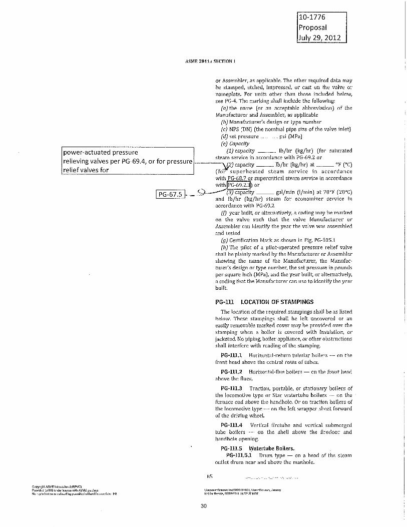
Revise paragraph PG-67.5, PG-69.2, PG-69.2.3, PG-69.4, and PG-110, by clarifying
requirements for power actuated relief valves, by adding information regarding capacity
correction factors, and by clarifying marking requirements.
This proposal standardizes application of the supercritical correction factor, the Napier
correction factor, capacity certification methods and marking for both pressure relief valves and
power-actuated pressure relieving valves. It also moves the supercritical correction factor to
PG-67 Boiler.
Explanation
Summary of ChangesPG-67.5 Revised and added supercritical reference from PG-69.2.3
PG-68.7 Added table reference.
PG-69.2 Added correction factor from PG-69.2.3
PG-69.2.3 Deleted correction factors and revised table numbers.
PG-69.3 Deleted redundant certification method information.
PG-69.4 Deleted formula reference.
PG-110(e)(2) Added clarification for superheated steam service and revised reference from
PG-69.2.3 to PG-67.5
Table A-356 (17) Revised reference from PG-69.2.3 to PG-67.5
Item History
BPV SC-SVR
BPV SC-SVR SGT
Sub-Tier Committees Involved
Ballot: 12-2144
Ballot Level: Subcommittee
Date Opened: 09/13/2012
Date Closed: 10/15/2012
Final Record Status :Disapproved
Latest Ballot Information
18

Item 10-1776: Section I PRV and PARV Capacity Certification
SC-SVR History October 26, 2010 – This item was opened between meetings by request of the Project Manager. November 30, 2010 – Curtis Sharpe will be the PM and the task group will consist of Jeramy Dickson and David Scallan. February 1, 2011 – Mr. Sharpe reported that there are changes to 67.5 that need to be reviewed. There are a few editorial changes that need to be made. A task group was formed and they plan to develop a proposal and ballot to the SG-T before the next meeting. April 28, 2011 – Mr. Sharpe reported that the TG is working on a revised proposal. The scope of this item is broader than the title suggests. This item will be broken into three items, one of which is #11-453. The main changes will still be under #10-1776. Mr. Dickson will flow chart the circular reference for this item. Record #11-453 will get a new proposal and another new item may be established for the economizer portion of this item. Mr. Tuttle noted that this item started because super critical steam capacities were added. Mr. Tuttle also noted that he would like to be a part of the working group for this item. August 9, 2011 - Mr. Sharpe reported that they have a new proposal, which is shown on pages 249-259 of the August 9, 2011 Meeting Minutes, for the committee to review. The PM will be uploading the proposal and will notify the Secretary when they have done so and this will be sent for ballot. Mr. Danzy noted that there is some urgency for this revision because of the way power actuated valves are affected by it. Alan West noted that the next edition of the code will not be until July 2013 so the power actuated portion may need to be issued as a Code Case/or Intent Interpretation. Mr. Danzy and Mr., Tuttle will create the intent interpretation request and separate out of the proposal the remaining changes which will not be included with the Intent Interpretation. – Record #11-1459 was opened for this. November 8, 2011 – Mr. Hart reported that this item is on hold pending the outcome of the intent interpretation that is being processed in SG-D. February 7, 2012 – Mr. Sharpe reported that this item is on hold pending intent interpretation #11-1459. May 15, 2012 – This item is loosely linked to #11-1459. As soon as #11-1459 is complete, this proposal will be modified accordingly and will be sent for ballot. August 14, 2012 – Mr. Cox reported that there were minor changes made to the proposal by the subgroup. The proposal was uploaded to the record on CS Connect and the explanation
19

Item 10-1776: Section I PRV and PARV Capacity Certification [Continued]
and summary of changes were updated as well. This item is now ready for ballot to Subcommittee Safety Valve Requirements. November 6, 2012 – This item will be sent for a recirculation ballot; the PM will post the necessary responses and then ballot will be issued before the next meeting. February 12, 2013 – Mr. Sharpe reported that this item was balloted and was disapproved with one negative. Mr. Sharpe will be modifying the proposal accordingly and the proposal will be sent for a recirculation ballot. August 13, 2013 -
20

2. Proposal Revise paragraph PG-67.5 by moving information from PG-69.2.3 and adding information regarding economizer pressure relief valves Rename Table PG-68.7 to Table PG-67.5A Rename Table PG-68.7M to Table PG-67.5AM Rename Table PG-69.2.3 to Table PG-67.5B Rename Table PG-69.2.3M to Table PG-67.5BM Delete the last two paragraphs of PG-69.2.3 Revise paragraph PG-69.3 replacing all text after “PG-67.4.1” with “the power actuated pressure relieving valve or valves may be certified either per PG-69.2.2 or PG-69.2.3”. Revise PG-110(e)(1) by changing reference to PG-69.2 to PG-67.5 Revise PG-110(e)(2) by changing reference to PG-68.7 and PG-69.2.3 to PG-67.5 Revise PG-110(e)(3) by changing reference to PG-69.2 to PG-67.5 Revise PG-110(e) by adding paragraph (4)
3. Explanation * Allow utilization of the Supercritical Correction factor added to the Code per 07-1148 for both pressure relief valves and power actuated pressure relieving valves. Add the requirement to use the Napier, Superheat and Supercritical correction factors to valves certified by the three valve and slope method. Allow a Manufacturer of Power Actuated Pressure Relieving Valves the option of using either the slope or coefficient method of capacity certification. Allow the capacity of power actuated pressure relieving valves to be calculated per the requirements of PG-110. Add requirement for capacity stamping of pressure relief valves per Section PVG.
4. Summary of Changes PG-67.5 – Revised per 10-1776 PG-69.2 – Revised per 10-1776 PG-69.3 – Revised per 10-1776 PG-69.4 – Revised per 10-1776 PG-110 – Revised per 10-1776
21

22
csharpe
Text Box
Item 10-1776 Proposal File Recirculation Ballot (The only change is the addition in red text on page 1) May 15, 2013 Page 1 of 10
csharpe
Sticky Note
Completed set by csharpe
csharpe
Sticky Note
None set by csharpe
csharpe
Text Box
be tested in accordance with the requirements of PG-69, and shall
csharpe
Line

23
csharpe
Text Box
Item 10-1776 Proposal File Recirculation Ballot (The only change is the addition in red text on page 1) May 15, 2013 Page 2 of 10

24
csharpe
Text Box
Item 10-1776 Proposal File Recirculation Ballot (The only change is the addition in red text on page 1) May 15, 2013 Page 3 of 10

25
csharpe
Text Box
the power-actuated pressure relieving valve or valves shall be certified in accordance with PG-69.2.2 or PG-69.2.3.
csharpe
Text Box
Item 10-1776 Proposal File Recirculation Ballot (The only change is the addition in red text on page 1) May 15, 2013 Page 4 of 10

26
csharpe
Text Box
Item 10-1776 Proposal File Recirculation Ballot (The only change is the addition in red text on page 1) May 15, 2013 Page 5 of 10

27
csharpe
Text Box
Item 10-1776 Proposal File Recirculation Ballot (The only change is the addition in red text on page 1) May 15, 2013 Page 6 of 10

28
csharpe
Text Box
Item 10-1776 Proposal File Recirculation Ballot (The only change is the addition in red text on page 1) May 15, 2013 Page 7 of 10

29
csharpe
Text Box
Item 10-1776 Proposal File Recirculation Ballot (The only change is the addition in red text on page 1) May 15, 2013 Page 8 of 10
30
csharpe
Text Box
power-actuated pressure relieving valves in accordance with PG-69.4, or for pressure relief valves for
csharpe
Text Box
Item 10-1776 Proposal File Recirculation Ballot (The only change is the addition in red text on page 1) May 15, 2013 Page 9 of 10

31
csharpe
Text Box
Item 10-1776 Proposal File Recirculation Ballot (The only change is the addition in red text on page 1) May 15, 2013 Page 10 of 10

Ballot#:
Closed Date: 07/17/2013
Opened Date: 07/02/2013 Record(s) Included: 10-1776
Committee Responsible:
BPV SC-SVR
Committees Balloted:
BPV SC-SVR
12-2144RC1
Ballot Level:
Subcommittee
BPV SC-SVR Recirculation Ballot for BPV I revision item #10-1776, PRV and PARV Capacity Certification and Nameplate StampingDescription:
Explanation:
This is a recirculation ballot to the BPV SC-SVR for BPV I revision item #10-1776, PRV and PARV Capacity Certification and Nameplate
Stamping.
The first consideration ballot received one negative. The PM reviewed the negative, posted a response and revised the proposal
accordingly as shown in red in the proposal.
Please note that this is a reciruclation ballot and disapproved votes shall be limited to:
1) support of first consideration disapproved votes
2) disagreement with any changes introduced to the proposal
Please see the record for details on this proposal.
Record# 10-1776 Committee Responsible: BPV SC-SVR
Subject: BPV I; PRV and PARV Capacity Certification and Nameplate Stamping
Commenter, Vote, and Comment Response
GlaspieJ (Approved)
Passed on the revisions relative to my comments I
approve this action.
Date Posted: 07/12/2013
Committee Balloted: BPV SC-SVR
Approved Disapproved Abstained Not Voting Not ReturnedDisapproved w/out
Comment
BallJ, BurgessJ,
CammeresiS, CoxJ,
DanzyR,
DemichaelD,
DoellingR, GlaspieJ,
HartW, MillerD,
WestJ
WangZ HarrisonS; PatelT
11 0 1 0 2 0
Page 1 of 1
Date Printed:7/26/2013
32

Record Level
SC Proposal
Record
11-2106
PagesRecord Sub-Type
Revision
Project Manager
Frank Richter
Subject
Section VIII, Division 1; Correction of reference paragraphs for Ovepressure Protection in the
Scope and Subsections.
Proposal
Revise paragraph U-1(f) to indicate the correct paragraph references for overpressure
protection (UG-125 through UG-140 and Appendix 11).
Revise all subsections to have similar sentence structure and reference paragraph U-1(f). By
doing so, all subsections will be consistent and if the Overpressure Protection section is
modified, only one paragraph reference, U-1(f), would need to be revised.
Section U-1(f) referenced overpressure sections UG-125 through UG-137. Paragraph was
revised to include all overpressure protection sections (UG-125 through UG-140).
In addition, the following subsections were revised to make reference to U-1(f) rather than the
individual subsections for overpressure protection. Subsections: UW-65, UB-60, UCS-125,
UNF-125, UHA-65, UCI-125, UCL-60, UCD-125, UHT-125, ULW-125.
UF-125, ULT-125 and UIG-125 were revised to change references as noted above as well as
the sentence structure was changed to make them the same as UW-65, UB-60, UCS-125,
UNF-125, UHA-65, UCI-125, UCL-60, UCD-125, UHT-125 and ULW-125.
The terminology "Pressure Relief Device" was replaced with "Overpressure Protection"
throughout the affected paragraphs commensurate with the incorporation of overpressure
protection by system design in UG-140.
Explanation
Summary of ChangesU-1(f): Revised paragraph references
UW-65: Retitled and revised paragraph reference
UF-125: Retitled, revised paragraph reference and incorporated common language
UB-60: Retitled and revised paragraph reference
UCS-125: Retitled and revised paragraph reference
UNF-125: Retitled and revised paragraph reference
UHA-65: Retitled and revised paragraph reference
UCI-125: Retitled and revised paragraph reference
UCL-60: Retiteld and revised paragraph reference
UCD-125: Retitled and revised paragraph reference
UHT-125: Retitled and revised paragraph reference
ULW-125: Retitled and revised paragraph reference
ULT-125: Retitled, revised paragraph reference and incorporated common language
UIG-125: Retitled, revised paragraph reference and incorporated common language
Item History
BPV SC-SVR SGT
BPV SC-VIII SGGR
Sub-Tier Committees Involved
33

Ballot: 12-2363
Ballot Level: Subcommittee
Date Opened: 10/15/2012
Date Closed: 11/29/2012
Final Record Status :Disapproved
Latest Ballot Information
34

Item 11-2106; BPV VIII; Correct Overpressure Protection Subsections
SC-SVR History
November 8, 2011 – This item was initiated at the meeting and was assigned to Subgroup Testing. Alton Cox will be the temporary PM until someone else is assigned. This item will affect sections UW-65, UF-125, UB-60, UCS-125, UNF-125, UHA-65, UCI-125, UCL-60, UCB-125, UHT-125, ULT-125. February 7, 2012 – Mr. Cox reported that the PM needs to be changed to Mr. Dickson. Mr. Dickson then reported that this item was submitted to SC-SVR for review. There are 16 sections within BPV VIII and at the end of each there is a paragraph that refers you to the relevant UG Section. There have been additions to the UG paragraphs and these references have not been accordingly revised. The PM will be reviewing each of these and will determine what the appropriate references are. May 15, 2012 – Mr. Cox reported that there is a proposal drafted for this item which is ready for ballot to the BPV SC-SVR SG-Testing. Mr. Dickson will contact the Secretary to initiate the ballot when the item is ready. August 14, 2012 – Mr. Cox reported that this item is ready for ballot to SC-SVR, the secretary will initiate the ballot. November 6, 2012 – The PM noted that this item received a comment on the latest ballot indicating that there is a typo in the last two items. He agrees with the commenter and will be revising the proposal accordingly and will send it for a recirculation ballot. February 12, 2013 – Mr. Hart reported that this item was disapproved by SC-SVR. Mr. Nutter provided a handout to the committee which was reviewed at the meeting. Mr. DeMichael suggested that UG-125 be added to the record as background material. The Secretary reminded Mr. Nutter that responses need to be posted on C&S Connect before this item can move forward. Once this is done Mr. Nutter will send a note to the secretary and a new first consideration ballot will be issued. August 13, 2013 -
35

(a)
2011a SECTION VIII — DIVISION 1
complied with shall be indicated on the Data Reports.(e) Pressure retaining covers and their attaching bolting
and nuts shall be listed in the Remarks section of theManufacturer’s Data Report or on an attached Form U-4when required. The minimum information shall includethe material specification, material grade, size, and threaddesignation.
(f) For sample forms and guidance in their preparation,see Appendix W.
OVERPRESSURE PROTECTION
UG-125 GENERAL
(a) Other than unfired steam boilers, all pressure vesselswithin the scope of this Division, irrespective of size orpressure, shall be provided with overpressure protectionin accordance with the requirements of UG-125 throughUG-138 and/or overpressure protection by system designper UG-140. Unfired steam boilers shall be provided withoverpressure protection in accordance with the require-ments of UG-125 through UG-138. In addition, the follow-ing shall apply:
(1) It is the user’s or his/her designated agent’sresponsibility to identify all potential overpressure scenar-ios and the method of overpressure protection used tomitigate each scenario.
(2) It is the responsibility of the user to ensure thatthe required overpressure protection system is properlyinstalled prior to initial operation.
(3) If a pressure relief device(s) is to be installed, itis the responsibility of the user or his/her designated agentto size and select the pressure relief device(s) based onits intended service. Intended service considerations shallinclude, but not necessarily be limited to, the following:
(a) normal operating and upset conditions(b) fluids(c) fluid phases
(4) The overpressure protection system need not besupplied by the vessel Manufacturer.
(5) Unless otherwise defined in this Division, thedefinitions relating to pressure relief devices in Section 2of ASME PTC 25 shall apply.
(b) An unfired steam boiler shall be equipped with pres-sure relief devices required by Section I insofar as theyare applicable to the service of the particular installation.
(c) Other than unfired steam boilers, when a pressurerelief device is provided, it shall prevent the pressure fromrising more than 10% or 3 psi (20 kPa), whichever isgreater, above the maximum allowable working pressureexcept as permitted in (1) and (2) below and UG-127(d)(3).(See UG-134 for pressure settings.)
(1) When multiple pressure relief devices are pro-vided and set in accordance with UG-134(a), they shall
90
prevent the pressure from rising more than 16% or 4 psi(30 kPa), whichever is greater, above the maximum allow-able working pressure.
(2) When a pressure vessel can be exposed to fire orother unexpected sources of external heat, the pressurerelief device(s) shall be capable of preventing the pressurefrom rising more than 21% above the maximum allowableworking pressure. Supplemental pressure relief devicesshall be installed to protect against this source of excessivepressure if the pressure relief devices used to satisfy thecapacity requirements of UG-125(c) and UG-125(c)(1)have insufficient capacity to provide the required protec-tion. See Nonmandatory Appendix M, para. M-13 for caseswhere the metal temperature due to fire or other sourcesof external heat can cause vessel failure prior to reachingthe MAWP.
(3) Pressure relief devices, intended primarily forprotection against exposure of a pressure vessel to fire orother unexpected sources of external heat installed on ves-sels having no permanent supply connection and used forstorage at ambient temperatures of nonrefrigerated lique-fied compressed gases,42 are excluded from the require-ments of (c)(1) and (c)(2) above, provided:
(a) the pressure relief devices are capable of pre-venting the pressure from rising more than 20% above themaximum allowable working pressure of the vessels;
(b) the set pressure marked on these devices shallnot exceed the maximum allowable working pressure ofthe vessels;
(c) the vessels have sufficient ullage to avoid aliquid full condition;
(d) the maximum allowable working pressure ofthe vessels on which these pressure relief devices areinstalled is greater than the vapor pressure of the storedliquefied compressed gas at the maximum anticipated tem-perature43 that the gas will reach under atmospheric condi-tions; and
(e) pressure relief valves used to satisfy these pro-visions also comply with the requirements ofUG-129(a)(5), UG-131(c)(2), and UG-134(d)(2).
(d) Pressure relief devices shall be constructed, located,and installed so that they are readily accessible for testing,inspection, replacement, and repair and so that they cannotbe readily rendered inoperative (see Appendix M).
(e) Pressure relief valves or nonreclosing pressure reliefdevices44 may be used to protect against overpressure.
42 For the purpose of these rules, gases are considered to be substanceshaving a vapor pressure greater than 40 psia (300 kPa absolute) at100°F (40°C).
43 Normally this temperature should not be less than 115°F (45°C).44 A pressure relief valve is a pressure relief device which is designed
to reclose and prevent the further flow of fluid after normal conditionshave been restored. A nonreclosing pressure relief device is a pressurerelief device designed to remain open after operation.
36
OM3475
Highlight
OM3475
Highlight

8011 Shreveport Hwy., Pineville, LA 71360 U.S.A. Office: +1 318 640 2250 Fax: +1 318 640 6041 www.ge.com
Page 1 of 1
TO: SG-T
FROM: Mr. Jeramy W. Dickson
SUBJECT: Background File for Item 11-2106
DATE: February 28, 2012 Team: This item was referred to our committee for review on the discrepancy that each of the sub-sections of ASME Section VIII-1 referenced the incorrect paragraph ranges that are applicable to pressure relief devices. In efforts to keep future revisions of the Standard consistent, I am proposing that each sub-section be revised to the same sentence structure and refer back to Section U where only one paragraph has to be revised. Section VIII-1 has the following sections:
Section Paragraph referencing PRDs Comment
U U-1(f) Provided revision proposal
UG N/A No paragraph refers back to the relevant sections as the other sub-sections
UW UW-65 Provided revision proposal
UF UF-125 Provided revision proposal
UB UB-60 Provided revision proposal
UCS UCS-125 Provided revision proposal
UNF UNF-125 Provided revision proposal
UHA UHA-65 Provided revision proposal
UCI UCI-125 Provided revision proposal
UCL UCL-60 Provided revision proposal
UCD UCD-125 Provided revision proposal
UHT UHT-125 Provided revision proposal
ULW ULW-125 Provided revision proposal
ULT ULT-125 Provided revision proposal
UHX No Reference This section is on heat exchangers. No proposal provided. This section does not revision
UIG UIG-125 Provided revision proposal
37
2011a SECTION VIII — DIVISION 1
(f) a vessel for containing water1 under pressure,including those containing air the compression of whichserves only as a cushion, when none of the followinglimitations are exceeded:
(1) a design pressure of 300 psi (2 MPa);(2) a design temperature of 210°F (99°C);
(g) a hot water supply storage tank heated by steamor any other indirect means when none of the followinglimitations is exceeded:
(1) a heat input of 200,000 Btu/hr (58.6 kW);(2) a water temperature of 210°F (99°C);(3) a nominal water containing capacity of
120 gal (450 L);(h) vessels not exceeding the design pressure (see
3-2), at the top of the vessel, limitations below, with nolimitation on size [see UG-28(f), 9-1(c)]:
(1) vessels having an internal or external pres-sure not exceeding 15 psi (100 kPa);
(2) combination units having an internal orexternal pressure in each chamber not exceeding 15 psi(100 kPa) and differential pressure on the common ele-ments not exceeding 15 psi (100 kPa) [see UG-19(a)];
(i) vessels having an inside diameter, width, height,or cross section diagonal not exceeding 6 in. (152 mm),with no limitation on length of vessel or pressure;
(j) pressure vessels for human occupancy.2
U-1(d) The rules of this Division have been formulatedon the basis of design principles and construction practicesapplicable to vessels designed for pressures not exceeding3000 psi (20MPa). For pressures above 3000 psi (20MPa),deviations from and additions to these rules usually arenecessary to meet the requirements of design principlesand construction practices for these higher pressures. Onlyin the event that after having applied these additional designprinciples and construction practices the vessel still com-plies with all of the requirements of this Division may itbe stamped with the applicable Certification Mark with theDesignator.
U-1(e) In relation to the geometry of pressure con-taining parts, the scope of this Division shall include thefollowing:
U-1(e)(1) where external piping; other pressure ves-sels including heat exchangers; ormechanical devices, suchas pumps, mixers, or compressors, are to be connected tothe vessel:
(a) the welding end connection for the first circum-ferential joint for welded connections [see UW-13(h)];
(b) the first threaded joint for screwed connections;
1 The water may contain additives provided the flash point of theaqueous solution at atmospheric pressure is 185°F or higher. The flashpoint shall be determined by the methods specified in ASTM D 93 or inASTM D 56, whichever is appropriate.
2 Requirements for pressure vessels for human occupancy are coveredby ASME PVHO-1.
2
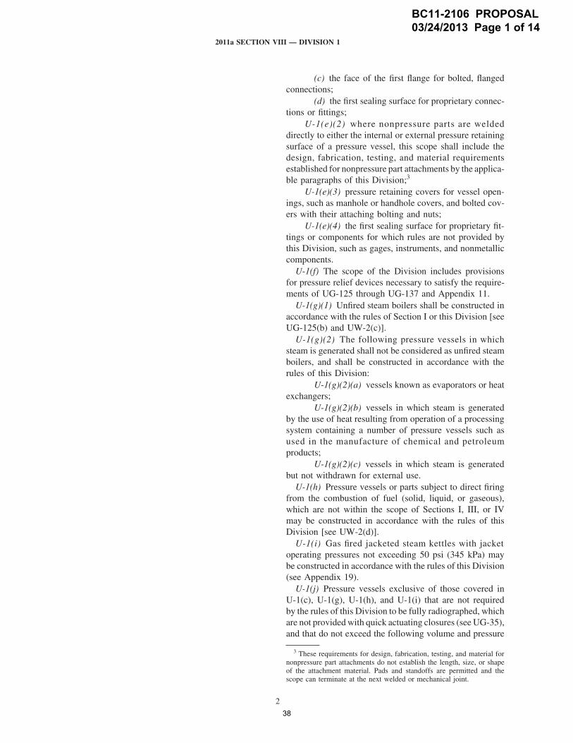
(c) the face of the first flange for bolted, flangedconnections;
(d) the first sealing surface for proprietary connec-tions or fittings;
U-1(e)(2) where nonpressure parts are weldeddirectly to either the internal or external pressure retainingsurface of a pressure vessel, this scope shall include thedesign, fabrication, testing, and material requirementsestablished for nonpressure part attachments by the applica-ble paragraphs of this Division;3
U-1(e)(3) pressure retaining covers for vessel open-ings, such as manhole or handhole covers, and bolted cov-ers with their attaching bolting and nuts;
U-1(e)(4) the first sealing surface for proprietary fit-tings or components for which rules are not provided bythis Division, such as gages, instruments, and nonmetalliccomponents.
U-1(f) The scope of the Division includes provisionsfor pressure relief devices necessary to satisfy the require-ments of UG-125 through UG-137 and Appendix 11.
U-1(g)(1) Unfired steam boilers shall be constructed inaccordance with the rules of Section I or this Division [seeUG-125(b) and UW-2(c)].
U-1(g)(2) The following pressure vessels in whichsteam is generated shall not be considered as unfired steamboilers, and shall be constructed in accordance with therules of this Division:
U-1(g)(2)(a) vessels known as evaporators or heatexchangers;
U-1(g)(2)(b) vessels in which steam is generatedby the use of heat resulting from operation of a processingsystem containing a number of pressure vessels such asused in the manufacture of chemical and petroleumproducts;
U-1(g)(2)(c) vessels in which steam is generatedbut not withdrawn for external use.
U-1(h) Pressure vessels or parts subject to direct firingfrom the combustion of fuel (solid, liquid, or gaseous),which are not within the scope of Sections I, III, or IVmay be constructed in accordance with the rules of thisDivision [see UW-2(d)].
U-1(i) Gas fired jacketed steam kettles with jacketoperating pressures not exceeding 50 psi (345 kPa) maybe constructed in accordance with the rules of this Division(see Appendix 19).
U-1(j) Pressure vessels exclusive of those covered inU-1(c), U-1(g), U-1(h), and U-1(i) that are not requiredby the rules of this Division to be fully radiographed, whichare not provided with quick actuating closures (see UG-35),and that do not exceed the following volume and pressure
3 These requirements for design, fabrication, testing, and material fornonpressure part attachments do not establish the length, size, or shapeof the attachment material. Pads and standoffs are permitted and thescope can terminate at the next welded or mechanical joint.
BC11-2106 PROPOSAL 03/24/2013 Page 1 of 14
38
NUTTERBK
Pencil
NUTTERBK
Line
NUTTERBK
Text Box
requirements for overpressure protection in UG-125 through UG-140 and Appendix 11.
NUTTERBK
Line
OM3475
Line
NUTTERBK
Pencil
OM3475
Line
NUTTERBK
Pencil

2011a SECTION VIII — DIVISION 1
spot. The locations of these additional spots shall be deter-mined by the Inspector or fabricator as provided for theoriginal spot examination in (b)(3) above.
(a) If the two additional spots examined showwelding which meets the minimum quality requirementsof (c)(1) and (c)(2) above, the entire weld increment repre-sented by the three radiographs is acceptable provided thedefects disclosed by the first of the three radiographs areremoved and the area repaired by welding. The weldrepaired area shall be radiographically examined in accor-dance with the foregoing requirements of UW-52.
(b) If either of the two additional spots examinedshows welding which does not comply with the minimumquality requirements of (c)(1) or (c)(2) above, the entireincrement of weld represented shall be rejected. The entirerejected weld shall be removed and the joint shall berewelded or, at the fabricator’s option, the entire incrementof weld represented shall be completely radiographed andonly defects need be corrected.
(c) Repair welding shall be performed using a qual-ified procedure and in a manner acceptable to the Inspector.The rewelded joint, or the weld repaired areas, shall bespot radiographically examined at one location in accor-dance with the foregoing requirements of UW-52.
UW-53 TECHNIQUE FOR ULTRASONICEXAMINATION OF WELDED JOINTS
Ultrasonic examination of welded joints when requiredor permitted by other paragraphs of this Division shall beperformed in accordance with Appendix 12 and shall beevaluated to the acceptance standards specified in Appen-dix 12. The written examination procedure shall be avail-able to the Inspector and shall be proven by actualdemonstration to the satisfaction of the Inspector to becapable of detecting and locating imperfections describedin this Division.
UW-54 QUALIFICATION OFNONDESTRUCTIVE EXAMINATIONPERSONNEL
(a) The Manufacturer shall be responsible for assuringthat nondestructive examination (NDE) personnel havebeen qualified and certified in accordance with theiremployer’s written practice prior to performing or evaluat-ing radiographic or ultrasonic examinations required by
151
this Division. SNT-TC-1A11 or CP-18911 shall be used asa guideline for employers to establish their written practice.National or international Central Certification Programs,such as the ASNTCentral Certification Program (ACCP),11
may be used to fulfill the examination and demonstrationrequirements of the employer’s written practice. Provisionsfor training, experience, qualification, and certification ofNDE personnel shall be described in the Manufacturer’squality control system.
(b) NDE personnel shall be qualified by examination.Qualification of NDE Level III personnel certified priorto the 2004 Edition of this Division may be based ondemonstrated ability, achievement, education, and experi-ence. Such qualification shall be specifically addressedin the written practice. When NDE personnel have beencertified in accordance with a written practice based on anedition of SNT TC-1A or CP-189 referenced in Table U-3,their certification shall be valid until their next scheduledrecertification.
(c) Recertification shall be in accordance with theemployer’s written practice based on the edition ofSNT-TC-1A or CP-189 referenced in Table U-3. Recerti-fication may be based on evidence of continued satisfactoryperformance or by reexamination(s) deemed necessary bythe employer.
MARKING AND REPORTS
UW-60 GENERAL
The provisions for marking and reports, UG-115 throughUG-120, shall apply without supplement to welded pres-sure vessels.
PRESSURE RELIEF DEVICES
UW-65 GENERAL
The provisions for pressure relief devices, UG-125through UG-136, shall apply without supplement to weldedpressure vessels.
11 Recommended Practice No. SNT-TC-1A, Personnel Qualificationand Certification in Nondestructive Testing, ACCP, ASNT Central Certi-fication Program, and CP-189 are published by the American Societyfor Nondestructive Testing, Inc., 1711 Arlingate Plaza, Caller #28518,Columbus, Ohio 43228-0518.
BC11-2106 PROPOSAL 03/24/2013 Page 2 of 14
39
OM3475
Line
NUTTERBK
Pencil
OM3475
Line
OM3475
Line
NUTTERBK
Pencil
NUTTERBK
Pencil
NUTTERBK
Text Box
overpressure protection in U-1(f)
NUTTERBK
Line
NUTTERBK
Text Box
OVERPRESSURE PROTECTION
NUTTERBK
Line

2011a SECTION VIII — DIVISION 1
UF-53 TEST SPECIMENS
When test specimens are to be taken under the applicablespecification, the Inspector shall be allowed to witnessthe selection, place the identifying stamping on them, andwitness the testing of these specimens.
UF-54 TESTS AND RETESTS
Tests and retests shall be made in accordance with therequirements of the material specification.
UF-55 ULTRASONIC EXAMINATION
(a) For vessels constructed of SA-372 Grade J, Class110 material, the completed vessel after heat treatmentshall be examined ultrasonically in accordance withSA-388. The reference specimen shall have the same nomi-nal thickness, composition, and heat treatment as the vesselit represents. Angle beam examination shall be calibratedwith a notch of a depth equal to 5% of the nominal sectionthickness, a length of approximately 1 in. (25 mm), and awidth not greater than twice its depth.
(b) A vessel is unacceptable if examination results showone or more imperfections which produce indications
157
exceeding in amplitude the indication from the calibratednotch. Round bottom surface imperfections, such as pits,scores, and conditioned areas, producing indicationsexceeding the amplitude of the calibrated notch shall beacceptable if the thickness below the indication is not lessthan the design wall thickness of the vessel, and its sidesare faired to a ratio of not less than three to one.
MARKING AND REPORTS
UF-115 GENERAL
The rules of UG-115 through UG-120 shall apply toforged vessels as far as practicable. Vessels constructed ofliquid quenched and tempered material, other than austen-itic steels, shall be marked on the thickened head, unlessa nameplate is used.
PRESSURE RELIEF DEVICES
UF-125 GENERAL
The provisions for pressure relief devices of UG-125through UG-136 shall apply without supplement.
BC11-2106 PROPOSAL 03/24/2013 Page 3 of 14
40
NUTTERBK
Line
NUTTERBK
Text Box
OVERPRESSURE PROTECTION
NUTTERBK
Text Box
overpressure protection in U-1(f)
NUTTERBK
Line
NUTTERBK
Pencil
OM3475
Line
OM3475
Line
NUTTERBK
Pencil
OM3475
Line
NUTTERBK
Pencil
OM3475
Line
OM3475
Line
OM3475
Line
OM3475
Line
NUTTERBK
Text Box
to forged pressure vessels

2011a SECTION VIII — DIVISION 1
and Tests in Subsection A and with the specific require-ments for Inspection and Tests in Subsection C that pertainto the class of material used.
UB-41 INSPECTION DURINGFABRICATION
The Manufacturer shall submit the vessel or other pres-sure parts for inspection at such stages of the work as maybe designated by the Inspector.
UB-42 PROCEDURE
The Inspector shall assure himself that the brazing proce-dure for each type of joint being produced is qualified inaccordance with the requirements of Section IX and whennecessary the additional requirements of this Section. Heshall satisfy himself that each joint has been fabricated inaccordance with the procedure. Where there is evidenceof consistent poor quality, the Inspector shall have the rightat any time to call for and witness tests of the brazingprocedure.
UB-43 BRAZER AND BRAZING OPERATOR
(a) The manufacturer shall certify that the brazing ona vessel or part thereof has been done by brazers or brazingoperators who are qualified under the requirements of Sec-tion IX and the Inspector shall assure himself that onlyqualified brazers or brazing operators have been used.
(b) Themanufacturer shall make available to the Inspec-tor the record of the qualification tests of each brazer andbrazing operator. The Inspector shall have the right at anytime to call for and witness tests of the ability of a brazeror brazing operator.
UB-44 VISUAL EXAMINATION
(a) Where possible, the Inspector shall visually inspectboth sides of each brazed joint after flux residue removal.Where it is not possible to inspect one side of a brazedjoint (blind joint), the Inspector shall check the design todetermine that the proper joint factor has been employed,unless he can assure himself that the brazing filler metal
164
has been preplaced in such a manner that it satisfiesUB-15(b) and (c).
(b) There shall be evidence that the brazing filler metalhas penetrated the joint. In a butt braze there shall be noconcavity. The braze may be repaired or rebrazed.
(c) The presence of a crack in the brazing filler metalshall be cause for rejection. Dye penetrant inspection maybe used if desired. The braze may be repaired or rebrazed.See UB-37.
(d) The presence of a crack in the base metal adjacentto a braze shall be cause for rejection even if the crackis filled with brazing alloy. Such cracking shall not berepaired.
(e) Pinholes or open defects in the braze shall be causefor rejection. The joint may be rebrazed.
(f) Rough fillets, particularly those with a convexappearance, are cause for rejection. Such joints may berepaired or rebrazed.
UB-50 EXEMPTIONS
Certain brazed joints regardless of their service tempera-tures may be exempt from the additional mechanical testingof this Section providing that the design application doesnot assume any benefit from the brazed joint strength. Itshall, however, meet the requirements of those qualificationtests required by Section IX of the Code.
MARKING AND REPORTS
UB-55 GENERAL
The provisions for marking and reports given in UG-115through UG-120 shall apply without supplement to brazedpressure vessels and parts thereof.
PRESSURE RELIEF DEVICES
UB-60 GENERAL
The provisions for pressure relieving devices given inUG-125 through UG-136 shall apply without supplementto brazed pressure vessels.
BC11-2106 PROPOSAL 03/24/2013 Page 4 of 14
41
NUTTERBK
Line
NUTTERBK
Text Box
OVERPRESSURE PROTECTION
NUTTERBK
Text Box
overpressure protection in U-1(f)
NUTTERBK
Line
NUTTERBK
Pencil
OM3475
Line
OM3475
Line
NUTTERBK
Pencil
OM3475
Line
NUTTERBK
Pencil

2011a SECTION VIII — DIVISION 1
number of tests and test results shall be as required bythe material specification. The vessel Manufacturer shallspecify the temperature, time, and cooling rates to whichthe material will be subjected during fabrication, exceptas permitted in (h) below. Material from which the speci-mens are prepared shall be heated at the specified tempera-ture within reasonable tolerances such as are normal inactual fabrication. The total time at temperature shall beat least 80% of the total time at temperature during actualheat treatment of the product and may be performed in asingle cycle.
UCS-85(d) Thermal treatment of material is notintended to include such local heating as thermal cutting,preheating, welding, or heating below the lower transfor-mation temperature of tubing and pipe for bending orsizing.
UCS-85(e) An exception to the requirements of (c)above and UG-85 shall apply to standard items such asdescribed in UG-11(a). These may be subject to postweldheat treatment with the vessel or vessel part without thesame treatment being required of the test specimens. Thisexception shall not apply to specially designed cast orwrought fittings.
UCS-85(f) Materials conforming to one of the specifi-cations listed in P-No. 1 Group Nos. 1 and 2 of QW-422and all carbon and low alloy steels used in the annealedcondition as permitted by the material specification areexempt from the requirements of (c) above when the heattreatment during fabrication is limited to postweld heattreatment at temperatures below the lower transformationtemperature of the steel. This exemption does not applyto SA-841.
UCS-85(g) Materials listed in QW-422 as P-No. 1Group No. 3 and P-No. 3 Group Nos. 1 and 2 that arecertified in accordance with (c) above from test specimenssubjected to the PWHT requirements of Table UCS-56need not be recertified if subjected to the alternate PWHTconditions permitted by Table UCS-56.1.
UCS-85(h) The simulation of cooling rates for test spec-imens from nonimpact tested materials 3 in. and under inthickness is not required for heat treatments below thelower transformation temperature.
UCS-85(i) All thermal treatments which precede a ther-mal treatment that fully austenitizes the material need notbe accounted for by the specimen heat treatments, providedthe austenitizing temperature is at least as high as any ofthe preceding thermal treatments.
INSPECTION AND TESTSUCS-90 GENERAL
The provisions for inspection and testing in SubsectionsA and B shall apply without supplement to vessels con-structed of carbon and low alloy steels.
195
MARKING AND REPORTS
UCS-115 GENERAL
The provisions for marking and reports in UG-115through UG-120 shall apply without supplement to pres-sure vessels constructed of carbon and low alloy steels.
PRESSURE RELIEF DEVICES
UCS-125 GENERAL
The provisions for pressure relief devices in UG-125through UG-136 shall apply without supplement to pres-sure vessels constructed of carbon and low alloy steels.
NONMANDATORY APPENDIX CS
UCS-150 GENERAL
See Appendix A, A-100, of Section II, Part D.
UCS-151 CREEP-RUPTURE PROPERTIES OFCARBON STEELS
See Appendix A, A-200, of Section II, Part D.
UCS-160 VESSELS OPERATING ATTEMPERATURES COLDER THANTHE MDMT STAMPED ON THENAMEPLATE
(a) Vessels or components may be operated at tempera-tures colder than the MDMT stamped on the nameplate,provided the provisions of UCS-66, UCS-67 and UCS-68aremet when using the reduced (colder) operating tempera-ture as the MDMT, but in no case shall the operatingtemperature be colder than −155°F (−105°C).
(b) As an alternative to (a) above, for vessels or compo-nents whose thicknesses are based on pressure loadingonly, the coincident operating temperature may be as coldas the MDMT stamped on the nameplate less the allowabletemperature reduction as determined from Fig. UCS-66.2.The ratio used in Step 3 of Fig. UCS-66.2 shall be theratio of maximum pressure at the coincident operatingtemperature to the MAWP of the vessel at the stampedMDMT, but in no case shall the operating temperature becolder than −155°F (−105°C).
BC11-2106 PROPOSAL 03/24/2013 Page 5 of 14
42
NUTTERBK
Text Box
OVERPRESSURE PROTECTION
NUTTERBK
Line
OM3475
Line
NUTTERBK
Pencil
NUTTERBK
Pencil
OM3475
Line
OM3475
Line
NUTTERBK
Pencil
NUTTERBK
Line
NUTTERBK
Text Box
overpressure protection in U-1(f)
2011a SECTION VIII — DIVISION 1
or
% strain p �tA − tBtA �100
where
R p nominal bending radius to center line of pipe ortube
Rf p mean radius after formingRo p original radius (equal to infinity for a flat plate)
r p nominal outside radius of pipe or tubet p nominal thickness of the plate, pipe, or tube before
formingtA p measured average wall thickness of pipe or tubetB p measured minimumwall thickness of the extrados
of the bend
UNF-79(b) When forming strains cannot be calculatedas shown in (a) above, the Manufacturer shall have theresponsibility to determine the maximum forming strain.For flares, swages, or upsets, heat treatment in accordancewith Table UNF-79 shall apply, regardless of the amountof strain.
INSPECTION AND TESTS
UNF-90 GENERAL
The rules in the following paragraphs apply specificallyto the inspection and testing of pressure vessels and vesselparts that are constructed of nonferrous materials and shallbe used in conjunction with the general requirements forInspection Tests in Subsection A, and with the specificrequirements for Inspection and Tests in Subsection B thatpertain to the method of fabrication used.
UNF-91 REQUIREMENTS FORPENETRAMETER
If the filler metal is radiographically similar1 to the basemetal, the penetrameter may be placed adjacent to the weld;otherwise it shall be placed on the deposited weld metal.
UNF-95 WELDING TEST PLATES
If a vessel of welded titanium or zirconium and theiralloys construction incorporates joints of Category A or Bas described in UW-3, a production test plate of the samespecification, grade, and thickness shall be made of suffi-cient size to provide at least one face and one root bendspecimen or two side bend specimens dependent upon platethickness. Where longitudinal joints are involved, the test
1 This is defined in Section V, SE-142, 4.1.1 and Appendix A1.
204
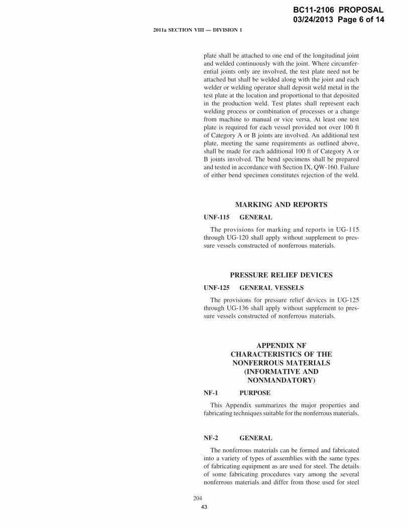
plate shall be attached to one end of the longitudinal jointand welded continuously with the joint. Where circumfer-ential joints only are involved, the test plate need not beattached but shall be welded along with the joint and eachwelder or welding operator shall deposit weld metal in thetest plate at the location and proportional to that depositedin the production weld. Test plates shall represent eachwelding process or combination of processes or a changefrom machine to manual or vice versa. At least one testplate is required for each vessel provided not over 100 ftof Category A or B joints are involved. An additional testplate, meeting the same requirements as outlined above,shall be made for each additional 100 ft of Category A orB joints involved. The bend specimens shall be preparedand tested in accordance with Section IX, QW-160. Failureof either bend specimen constitutes rejection of the weld.
MARKING AND REPORTS
UNF-115 GENERAL
The provisions for marking and reports in UG-115through UG-120 shall apply without supplement to pres-sure vessels constructed of nonferrous materials.
PRESSURE RELIEF DEVICES
UNF-125 GENERAL VESSELS
The provisions for pressure relief devices in UG-125through UG-136 shall apply without supplement to pres-sure vessels constructed of nonferrous materials.
APPENDIX NFCHARACTERISTICS OF THENONFERROUS MATERIALS
(INFORMATIVE ANDNONMANDATORY)
NF-1 PURPOSE
This Appendix summarizes the major properties andfabricating techniques suitable for the nonferrousmaterials.
NF-2 GENERAL
The nonferrous materials can be formed and fabricatedinto a variety of types of assemblies with the same typesof fabricating equipment as are used for steel. The detailsof some fabricating procedures vary among the severalnonferrous materials and differ from those used for steel
BC11-2106 PROPOSAL 03/24/2013 Page 6 of 14
43
NUTTERBK
Text Box
OVERPRESSURE PROTECTION
NUTTERBK
Line
OM3475
Line
NUTTERBK
Pencil
NUTTERBK
Pencil
OM3475
Line
OM3475
Line
NUTTERBK
Pencil
NUTTERBK
Line
NUTTERBK
Text Box
overpressure protection in U-1(f)
2011a SECTION VIII — DIVISION 1
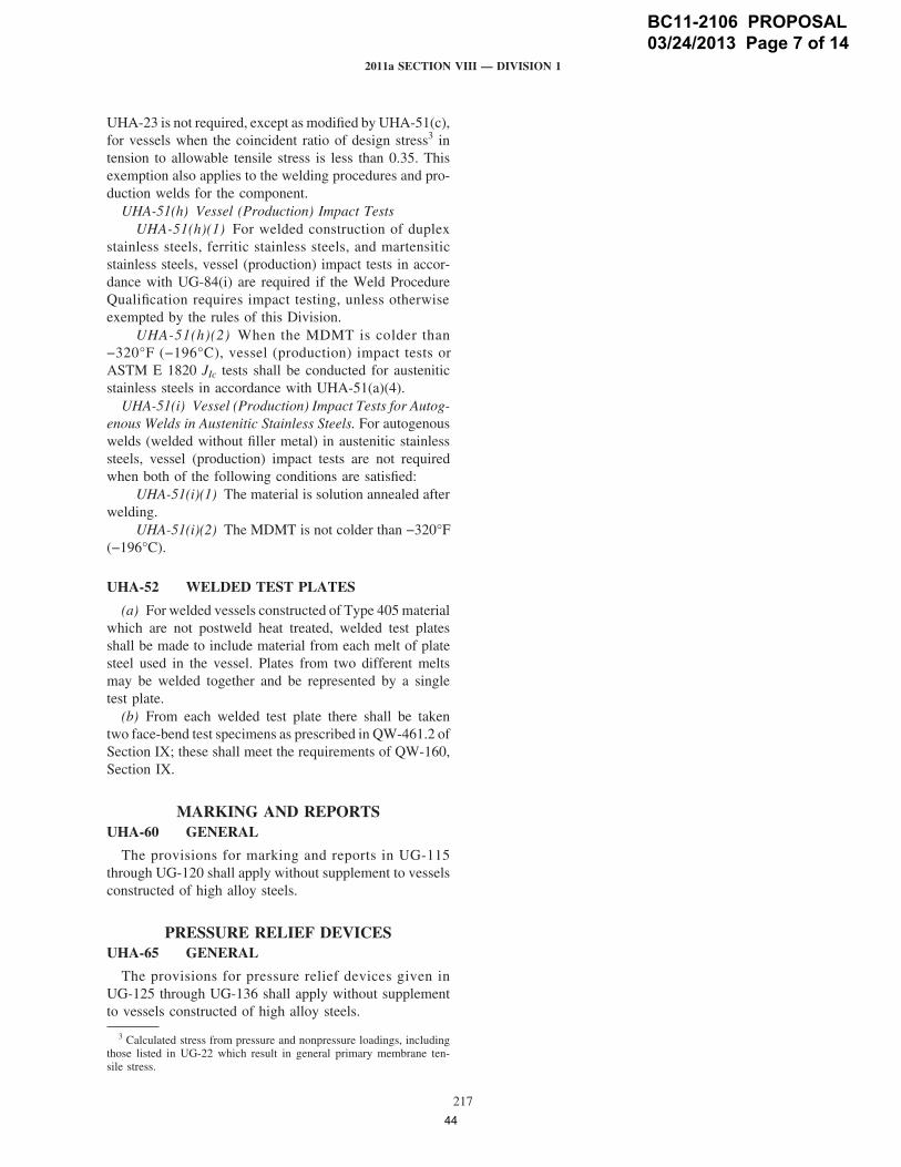
UHA-23 is not required, except as modified by UHA-51(c),for vessels when the coincident ratio of design stress3 intension to allowable tensile stress is less than 0.35. Thisexemption also applies to the welding procedures and pro-duction welds for the component.
UHA-51(h) Vessel (Production) Impact TestsUHA-51(h)(1) For welded construction of duplex
stainless steels, ferritic stainless steels, and martensiticstainless steels, vessel (production) impact tests in accor-dance with UG-84(i) are required if the Weld ProcedureQualification requires impact testing, unless otherwiseexempted by the rules of this Division.
UHA-51(h)(2) When the MDMT is colder than−320°F (−196°C), vessel (production) impact tests orASTM E 1820 JIc tests shall be conducted for austeniticstainless steels in accordance with UHA-51(a)(4).
UHA-51(i) Vessel (Production) Impact Tests for Autog-enous Welds in Austenitic Stainless Steels. For autogenouswelds (welded without filler metal) in austenitic stainlesssteels, vessel (production) impact tests are not requiredwhen both of the following conditions are satisfied:
UHA-51(i)(1) The material is solution annealed afterwelding.
UHA-51(i)(2) The MDMT is not colder than −320°F(−196°C).
UHA-52 WELDED TEST PLATES
(a) For welded vessels constructed of Type 405materialwhich are not postweld heat treated, welded test platesshall be made to include material from each melt of platesteel used in the vessel. Plates from two different meltsmay be welded together and be represented by a singletest plate.
(b) From each welded test plate there shall be takentwo face-bend test specimens as prescribed in QW-461.2 ofSection IX; these shall meet the requirements of QW-160,Section IX.
MARKING AND REPORTSUHA-60 GENERAL
The provisions for marking and reports in UG-115through UG-120 shall apply without supplement to vesselsconstructed of high alloy steels.
PRESSURE RELIEF DEVICESUHA-65 GENERAL
The provisions for pressure relief devices given inUG-125 through UG-136 shall apply without supplementto vessels constructed of high alloy steels.
3 Calculated stress from pressure and nonpressure loadings, includingthose listed in UG-22 which result in general primary membrane ten-sile stress.
217
APPENDIX HASUGGESTIONS ON THE SELECTIONAND TREATMENT OF AUSTENITIC
CHROMIUM–NICKEL AND FERRITICAND MARTENSITIC HIGH CHROMIUM
STEELS (INFORMATIVE ANDNONMANDATORY)
UHA-100 GENERAL
The selection of the proper metal composition to resista given corrosive medium and the choice of the properheat treatment and surface preparation of the materialselected are not within the scope of this Division. AppendixA, A-310 to A-360, of Section II, Part D discusses someof the factors that should be considered in arriving at aproper selection.
UHA-101 STRUCTURE
See Appendix A, A-310, of Section II, Part D.
UHA-102 INTERGRANULAR CORROSION
See Appendix A, A-320, of Section II, Part D.
UHA-103 STRESS CORROSION CRACKING
See Appendix A, A-330, of Section II, Part D.
UHA-104 SIGMA PHASE EMBRITTLEMENT
See Appendix A, A-340, of Section II, Part D.
UHA-105 HEAT TREATMENT OF AUSTENITICCHROMIUM–NICKEL STEELS
See Appendix A, A-350, of Section II, Part D.
UHA-107 DISSIMILAR WELD METAL
The difference between the coefficients of expansionof the base material and the weld should receive carefulconsideration before undertaking the welding of ferritictype stainless steels with austenitic electrodes for servicesinvolving severe temperature conditions, particularly thoseof a cyclic nature.
UHA-108 FABRICATION
It is recommended that the user of austenitic chromium–nickel steel vessels in corrosive service consider the follow-ing additional fabrication test.
BC11-2106 PROPOSAL 03/24/2013 Page 7 of 14
44
NUTTERBK
Text Box
OVERPRESSURE PROTECTION
OM3475
Line
NUTTERBK
Pencil
NUTTERBK
Pencil
OM3475
Line
OM3475
Line
NUTTERBK
Pencil
NUTTERBK
Line
NUTTERBK
Text Box
overpressure protection in U-1(f)
OM3475
Line

2011a SECTION VIII — DIVISION 1
(b) The value of the average tensile strength of testspecimens in the foregoing equation shall be determinedfrom the test results of three test bars from the same ladleof iron as used in the part, or from three test specimenscut from the part.
(c) All vessels or vessel parts of the same material,design, and construction, whosemaximum allowablework-ing pressure is based on a test to destruction of a samplevessel in accordance with (a) above, shall be consideredto have a design pressure equal to the maximum allowableworking pressure thus determined, except as limited bythe rules of UCI-3, and shall be subjected to a hydrostatictest pressure in conformity with the rules of UCI-99.
223
MARKING AND REPORTS
UCI-115 GENERAL
The provisions for marking and reports in UG-115through UG-120 shall apply without supplement to vesselsconstructed of cast iron.
PRESSURE RELIEF DEVICES
UCI-125 GENERAL
The provisions for pressure relief devices in UG-125through UG-136 shall apply without supplement to vesselsconstructed of cast iron.
BC11-2106 PROPOSAL 03/24/2013 Page 8 of 14
45
NUTTERBK
Text Box
OVERPRESSURE PROTECTION
NUTTERBK
Line
OM3475
Line
NUTTERBK
Pencil
NUTTERBK
Pencil
OM3475
Line
OM3475
Line
NUTTERBK
Pencil
NUTTERBK
Line
NUTTERBK
Text Box
overpressure protection in U-1(f)
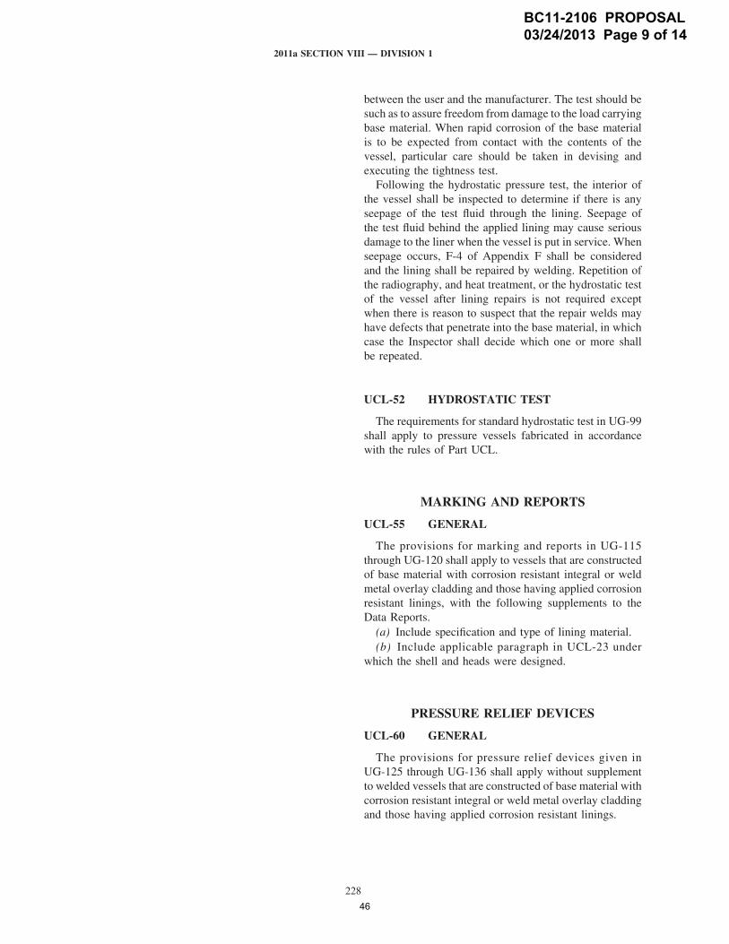
2011a SECTION VIII — DIVISION 1
UCL-40 WELDING PROCEDURES
Welding procedures for corrosion resistant weld overlay,composite (clad) metals, and attachment of applied liningsshall be prepared and qualified in accordance with therequirements of Section IX.
UCL-42 ALLOY WELDS IN BASE METAL
Groove joints in base material and parts may be madewith corrosion resistant alloy-steel filler metal, or groovejoints may be made between corrosion resistant alloy steeland carbon or low alloy steel, provided the welding proce-dure and the welders have been qualified in accordancewith the requirements of Section IX for the combinationof materials used. Some applications of this rule are basemetal welded with alloy-steel electrodes, and alloy nozzleswelded to steel shells.
UCL-46 FILLET WELDS
Fillet welds of corrosion resistant metal deposited incontact with two materials of dissimilar composition maybe used for shell joints under the limitations of UW-12,for connection attachments under the limitations of UW-15and UW-16, and for any other uses permitted by this Divi-sion. The qualification of the welding procedures and weld-ers to be used on fillet welds for a given combination ofmaterials and alloy weld metal shall be made in accordancewith the rules prescribed in Section IX.
INSPECTION AND TESTS
UCL-50 GENERAL
The rules in the following paragraphs apply specificallyto the inspection and testing of pressure vessels and vesselparts constructed of base material with corrosion resistantintegral or weld metal overlay cladding and those havingapplied corrosion resistant linings, and shall be used inconjunction with the general requirements for Inspectionand Tests in Subsection A, and with the specific require-ments for Inspection and Tests in Subsection B that pertainto the method of fabrication used.
UCL-51 TIGHTNESS OF APPLIED LINING
A test for tightness of the applied lining that will beappropriate for the intended service is recommended, butthe details of the test shall be a matter for agreement
228
between the user and the manufacturer. The test should besuch as to assure freedom from damage to the load carryingbase material. When rapid corrosion of the base materialis to be expected from contact with the contents of thevessel, particular care should be taken in devising andexecuting the tightness test.
Following the hydrostatic pressure test, the interior ofthe vessel shall be inspected to determine if there is anyseepage of the test fluid through the lining. Seepage ofthe test fluid behind the applied lining may cause seriousdamage to the liner when the vessel is put in service. Whenseepage occurs, F-4 of Appendix F shall be consideredand the lining shall be repaired by welding. Repetition ofthe radiography, and heat treatment, or the hydrostatic testof the vessel after lining repairs is not required exceptwhen there is reason to suspect that the repair welds mayhave defects that penetrate into the base material, in whichcase the Inspector shall decide which one or more shallbe repeated.
UCL-52 HYDROSTATIC TEST
The requirements for standard hydrostatic test in UG-99shall apply to pressure vessels fabricated in accordancewith the rules of Part UCL.
MARKING AND REPORTS
UCL-55 GENERAL
The provisions for marking and reports in UG-115through UG-120 shall apply to vessels that are constructedof base material with corrosion resistant integral or weldmetal overlay cladding and those having applied corrosionresistant linings, with the following supplements to theData Reports.
(a) Include specification and type of lining material.(b) Include applicable paragraph in UCL-23 under
which the shell and heads were designed.
PRESSURE RELIEF DEVICES
UCL-60 GENERAL
The provisions for pressure relief devices given inUG-125 through UG-136 shall apply without supplementto welded vessels that are constructed of base material withcorrosion resistant integral or weld metal overlay claddingand those having applied corrosion resistant linings.
BC11-2106 PROPOSAL 03/24/2013 Page 9 of 14
46
NUTTERBK
Text Box
OVERPRESSURE PROTECTION
NUTTERBK
Line
OM3475
Line
NUTTERBK
Pencil
NUTTERBK
Pencil
OM3475
Line
OM3475
Line
NUTTERBK
Pencil
NUTTERBK
Line
NUTTERBK
Text Box
overpressure protection in U-1(f)

2011a SECTION VIII — DIVISION 1
(1) the vessel or vessel parts are to operate withinthe limits of UCD-3(a);
(2) no welding is performed;(3) the material from which the plug is manufactured
shall conform in all respects to the material specificationwhich applies to the pressure vessel or pressure vessel part;
(4) the depth of the plug is not greater than 20% ofthe thickness of the section and its diameter is not greaterthan its engaged length;
(5) the pressure vessel or pressure vessel part meetsthe standard hydrostatic test prescribed in UCD-99.
INSPECTION AND TESTS
UCD-90 GENERAL
The rules in the following paragraphs apply specificallyto the inspection and testing of pressure vessels and pres-sure vessel parts of cast ductile iron and shall be used inconjunction with the general requirements of Inspectionand Tests in Subsection A insofar as these requirementsare applicable to cast material.
UCD-99 STANDARD HYDROSTATIC TEST
Cast ductile iron pressure vessels and pressure vesselparts shall be hydrostatically tested by the method pre-scribed in UG-99 except that the test pressure shall be twotimes the maximum allowable working pressure.
UCD-101 HYDROSTATIC TEST TODESTRUCTION
(a) Themaximum allowable working pressure of identi-cal cast ductile iron vessels, based on testing one of themto destruction in accordance with UG-101(m), shall be
PR p �PB f5 ��
specified min.tensile strength
avg. tensile strength oftest specimens
�
232
where
f p casting quality factor as defined in UG-24, whichapplies only to identical cast ductile iron vesselsput into service
PB p destruction test pressurePR p maximum allowable working pressure of identical
cast ductile iron vessels
The principle of UG-101(c) shall be followed.(b) The value of the average tensile strength of test
specimens in the foregoing equation shall be determinedfrom the test results of three test bars from the same ladleof iron as used in the part, or from three test specimenscut from the part.
(c) All pressure vessels or pressure vessel parts of thesame material, design, and construction, whose maximumallowable working pressure is based on the destruction testof a sample vessel or part, shall be subjected to a hydrostatictest pressure of not less than twice the maximum allowableworking pressure determined by the application of the rulesin (a).
MARKING AND REPORTS
UCD-115 GENERAL
The provisions for marking and preparing reports inUG-115 through UG-120 shall apply without supplementto vessels constructed of cast ductile iron.
PRESSURE RELIEF DEVICES
UCD-125 GENERAL
The provisions for the application of pressure reliefdevices in UG-125 through UG-136 shall apply withoutsupplement to vessels constructed of cast ductile iron.
BC11-2106 PROPOSAL 03/24/2013 Page 10 of 14
47
NUTTERBK
Text Box
OVERPRESSURE PROTECTION
NUTTERBK
Line
OM3475
Line
NUTTERBK
Pencil
NUTTERBK
Pencil
OM3475
Line
OM3475
Line
NUTTERBK
Pencil
NUTTERBK
Line
NUTTERBK
Text Box
overpressure protection in U-1(f)

2011a SECTION VIII — DIVISION 1
PRESSURE RELIEF DEVICES
UHT-125 GENERAL
The provisions for pressure relief devices in UG-125through UG-136 shall apply without supplement to pres-sure vessels constructed in whole or in part of steels cov-ered by this Part.
244
BC11-2106 PROPOSAL 03/24/2013 Page 11 of 14
48
OM3475
Line
NUTTERBK
Pencil
OM3475
Line
NUTTERBK
Text Box
OVERPRESSURE PROTECTION
NUTTERBK
Text Box
overpressure protection in U-1(f)
NUTTERBK
Line
NUTTERBK
Pencil
OM3475
Line
OM3475
Line
NUTTERBK
Pencil

(a)
2011a SECTION VIII — DIVISION 1
FIG. ULW-77
t
h
b
0.010 in. (0.25 mm) (nonrelevant gap) 0.010 in. (0.25 mm)
(nonrelevant gap)
AgbhRgt
=====
area of gap (approx.) = 2/3hbarc length of relevant radial gapradial gapradius of vessel at gaplayer thickness
Rg
(a) The circumference shall bemeasured at themidpointbetween adjacent circumferential joints, or between a cir-cumferential joint and any nozzle in a shell course. Mea-surements shall be taken at zero pressure, and followingapplication of hydrostatic test pressure, at the design pres-sure. The difference in measurements shall be averagedfor each course in the vessel and the results recorded asaverage middle circumferential expansion em in inches(millimeters).
(b) The theoretical circumferential expansion of a solidvessel of the same dimensions and materials as the layeredvessel shall be calculated from the following formula:
eth p1.7�P (2R − ts )
2 (2R + ts )8ERts
where
E p modulus of elasticity [use 30 � 106 psi (200 �106 kPa) for carbon steel]
eth p theoretical circumferential expansionP p internal design pressureR p mean radiusp outside radius − ts /2
ts p wall thickness
(c) Acceptance criteria for circumferential expansion atthe design pressure shall be as follows: em shall not be lessthan 0.5 eth.
INSPECTION AND TESTINGULW-90 GENERAL
The inspection and testing of layered pressure vesselsto be marked with the Certification Mark with the U Desig-nator shall be in accordance with UG-90 through UG-103.
267
MARKING AND REPORTS
ULW-115 GENERAL
(a) The rules for marking and reports of layered pressurevessels built under Part ULW shall meet the requirementsgiven in UG-115 through UG-120.
(b) In addition, a description of the layered shell and/orlayered heads shall be given on the Data Report describingthe number of layers, their thickness or thicknesses, andtype of construction. See W-2 and Table W-3 for the useof Form U-4 Manufacturer’s Data Report SupplementarySheet. An example of the use of Form U-4 illustrating theminimum required data for layered construction is givenin Fig. W-3.1.
(c) In addition, the stamping below the CertificationMark and Designator prescribed in UG-116(c) shall be theletters WL to designate layered construction.
PRESSURE RELIEF DEVICES
ULW-125 GENERAL
The provisions for pressure relief devices in UG-125through UG-134 shall apply without supplement to pres-sure vessels fabricated in whole or in part of layered con-struction.
(a)
BC11-2106 PROPOSAL 03/24/2013 Page 12 of 14
49
NUTTERBK
Text Box
OVERPRESSURE PROTECTION
NUTTERBK
Line
OM3475
Line
NUTTERBK
Pencil
NUTTERBK
Pencil
OM3475
Line
OM3475
Line
NUTTERBK
Pencil
NUTTERBK
Line
NUTTERBK
Text Box
overpressure protection in U-1(f)

2011a SECTION VIII — DIVISION 1
(2) the following markings shall be used instead ofthose in UG-116(a)(3) and UG-116(b)(1)(a):Maximum Allowable Working Pressure: psi at 150°FMinimum Allowable Temperature: Minus °FService Restricted to Operating
the Following TemperatureLiquid Minus °FLiquid Minus °FLiquid Minus °FLiquid Minus °F
NOTES APPLICABLE TO MARKINGS:(1) Minimum allowable temperature is the temperature of the coldest
cryogenic liquid which will be admitted to or stored within the vessel.(2) Operating temperature for the cryogenic liquid is its saturation tem-
perature at MAWP. All liquids that may be contained in the vesselshall be listed.
(b) On theManufacturer’s Data Report, under Remarks,show the additional marking notations from (a) above.
(c) Unless the requirements of (c)(1) and (2) below aremet, for 5%, 8%, and 9% nickel steels, the use of name-plates is mandatory for shell thicknesses below 1⁄2 in.
278
(13 mm); nameplates are preferred in all thicknesses.(1) The materials shall be limited to aluminum as
follows: SB-209 Alloys 3003, 5083, 5454, and 6061;SB-241 Alloys 3003, 5083, 5086, 5454, 6061, and 6063;and SB-247 Alloys 3003, 5083, and 6061.
(2) The minimum nominal plate thickness shall be0.249 in. (6.32 mm), or the minimum nominal pipe thick-ness shall be 0.133 in. (3.38 mm).
PRESSURE RELIEF DEVICES
ULT-125 GENERAL
The provisions of UG-125 through UG-136 shall applyto vessels constructed to this Part; the vessel shall beequippedwith a safety relief valve suitable for low tempera-ture service and installed to remain at ambient temperatureexcept when relieving.
BC11-2106 PROPOSAL 03/24/2013 Page 13 of 14
50
NUTTERBK
Text Box
OVERPRESSURE PROTECTION
NUTTERBK
Line
OM3475
Line
NUTTERBK
Pencil
NUTTERBK
Pencil
OM3475
Line
OM3475
Line
NUTTERBK
Pencil
NUTTERBK
Line
NUTTERBK
Text Box
The provisions for overpressure protection in U-1(f) shall apply to vessels constructed to this Part with the additional requirement that the safety relief device be
OM3475
Line
NUTTERBK
Pencil

(a)
(a)
2011a SECTION VIII — DIVISION 1
of all joints and connections shall be made at a pressurenot less than the design pressure.
UIG-112 QUALITY CONTROLREQUIREMENTS
The Manufacturer’s quality control manual shall, inaddition to the provisions of Mandatory Appendix 10,include the following:
(a) The Authorized Inspector may, with cause, call forthe requalification of procedures and personnel.
(b) The Manufacturer shall include sufficient provisionfor material control to ensure that all material is traceableto the manufacturing lot number. The Manufacturer shallmaintain traceability of all materials used in constructionof vessels and vessel parts until such time that theManufac-turer’s Data Report has been completed and the Certifica-tion Mark applied.
UIG-115 MARKINGS AND REPORTS
The provisions of UG-115 through UG-120 shall applyto complete graphite pressure vessels or parts except asmodified in UIG-116 through UIG-121.
UIG-116 REQUIRED MARKINGS
(a) Each graphite pressure vessel and graphite pressurevessel part requiring inspection under this Part shall bemarked in accordance with the requirements of UG-116except as modified herein.
(b) The type of construction shall be indicated directlybelow the Certification Mark by applying the letter “G”,indicating graphite pressure vessel or pressure vessel part.
(c) The stamping may be applied to metallic parts, anameplate, or a permanent impression on the graphite usingcement (see Nonmandatory Appendix MM). Nameplatesmay be attached to either metallic or graphite parts.
(d) For multiple identical items from a single lot, suchas tubes, the Manufacturer shall apply the partial stampingnameplate to the bundle or container. Each piece shall beidentified by permanent marking with the Manufacturer’sname, date, and serial number. (A coded marking systemwith traceability of these data is acceptable.) The subse-quent Manufacturer shall maintain the nameplate until all
361
of the multiple pieces have been used, and shall then oblit-erate the Certification Mark with the U Designator fromthe nameplate. Obliteration of the Certification Mark withthe U Designator stamping shall be witnessed by theAuthorized Inspector.
NOTE: Permanent shall mean any method of marking that will ensurethat the marking is present until the item is incorporated into a completedvessel, and the Authorized Inspector has signed the data report.
UIG-120 DATA REPORTS
(a) Form U-1B, Manufacturer’s Supplementary DataReport for Graphite Pressure Vessels, shall be completedand certified by the Manufacturer, and shall be signed bythe Authorized Inspector for each graphite pressure vesselmarked with the Certification Mark with the U Designator.Form U-1B shall be completed as otherwise required forData Reports as specified in UG-120.
(b) Form U-1B shall be attached to and referenced onthe applicable Data Report specified in UG-120.
UIG-121 RECORDS
The Manufacturer shall maintain records of the proce-dures employed in fabricating vessels and vessel parts andin cementing parts together. The Manufacturer shall alsomaintain records of the tests and their results by whichthe Procedure Specifications were qualified for fabrication.The Manufacturer shall maintain the records of designcalculations, certified material test reports, visual examina-tion, the procedure specifications that detail the materialsused, fabrication procedures and quality control records.All records shall be dated and shall be certified by theManufacturer andmade available to the Authorized Inspec-tor. The Manufacturer shall keep these records on file forat least 5 yr after production has ceased.
UIG-125 PRESSURE RELIEF DEVICES
The provisions of UG-125 through UG-140 shall apply.The user shall make provisions for the reaction forces frompressure relief devices on graphite components.
(a)
(10)
BC11-2106 PROPOSAL 03/24/2013 Page 14 of 14
51
OM3475
Line
NUTTERBK
Pencil
NUTTERBK
Pencil
OM3475
Line
NUTTERBK
Line
NUTTERBK
Text Box
The provisions for overpressure protection in U-1(f) shall apply without supplement for graphite pressure vessels.
NUTTERBK
Text Box
OVERPRESSURE PROTECTION
OM3475
Line
OM3475
Line

Ballot#:
Closed Date: 04/02/2013
Opened Date: 02/21/2013 Record(s) Included: 11-2106
Committee Responsible:
BPV SC-SVR
Committees Balloted:
BPV SC-SVR
Committees for Review and Technical Comment:
BPV SC-SVR SGT
13-334
Ballot Level:
Subcommittee
BPV SC-SVR Ballot for BPV VIII-1 revision item #11-2106, Correction of reference paragraphs for Ovepressure Protection in the Scope
and Subsections
Description:
Explanation:
This is a new first consideration ballot to the BPV SC-SVR for BPV VIII-1 revision item #11-2106, Correction of reference paragraphs
for Ovepressure Protection in the Scope and Subsections
Please see the record for details on this revision.
Record# 11-2106 Committee Responsible: BPV VIII
Subject: Section VIII, Division 1; Correction of reference paragraphs for Ovepressure Protection in the Scope and Subsections.
Commenter, Vote, and Comment Response
Date Posted: 03/24/2013WestJ (Disapproved)
In my opinion, the wording of ULT-125 is confusing. I
suggest the following: "The provisions for overpressure
protection in U-1(f) shall apply to vessels constructed to
this Part with the additional requirement that the safety
relief device be suitable for low temperature service and
installed to remain at ambient temperature except when
relieving."
Thank you for your comment and proposed improvement.
We will incorporate your suggestion and offer the item for
recirculation ballot.
Date Posted: 03/14/2013
Committee Balloted: BPV SC-SVR
Approved Disapproved Abstained Not Voting Not ReturnedDisapproved w/out
Comment
BallJ, BurgessJ,
CammeresiS, CoxJ,
DemichaelD,
DoellingR, GlaspieJ,
HartW, MillerD,
PatelT
WestJ DanzyR; HarrisonS;
WangZ
10 1 0 0 3 0
Page 1 of 2
Date Printed:7/26/2013
52

Committee for Review and Comment: BPV SC-SVR SGT
Comment No Comment
BrittJ, DicksonJ,
NutterB, SharpeC
0 4
Page 2 of 2
Date Printed:7/26/2013
53

Ballot#:
Closed Date: 04/25/2013
Opened Date: 04/03/2013 Record(s) Included: 11-2106
Committee Responsible:
BPV SC-SVR
Committees Balloted:
BPV SC-SVR
Committees for Review and Technical Comment:
BPV SC-SVR SGT
13-334RC1
Ballot Level:
Subcommittee
BPV SC-SVR Recirculation Ballot for BPV VIII-1 revision item #11-2106, Correction of reference paragraphs for Ovepressure Protection
in the Scope and Subsections
Description:
Explanation:
This is a recirculation ballot to the BPV SC-SVR for BPV VIII-1 revision item #11-2106, Correction of reference paragraphs for
Ovepressure Protection in the Scope and Subsections
Since this is a recirculation ballot, your vote from the last ballot will be carried over. Disapproved votes on this ballot shall be limited
to:
1) support of first consideration disapproved votes
2) disagreement with any changes introduced to the proposal
Please see the record for details on this revision.
Record# 11-2106 Committee Responsible: BPV VIII
Subject: Section VIII, Division 1; Correction of reference paragraphs for Ovepressure Protection in the Scope and Subsections.
Commenter, Vote, and Comment Response
()
Date Posted:
Committee Balloted: BPV SC-SVR
Approved Disapproved Abstained Not Voting Not ReturnedDisapproved w/out
Comment
BallJ, BurgessJ,
CammeresiS, CoxJ,
DemichaelD,
DoellingR, GlaspieJ,
HartW, MillerD,
PatelT, WangZ,
WestJ
DanzyR; HarrisonS
12 0 0 0 2 0
Page 1 of 2
Date Printed:7/26/2013
54

Committee for Review and Comment: BPV SC-SVR SGT
Comment No Comment
BrittJ, DicksonJ,
NutterB, SharpeC
0 4
Page 2 of 2
Date Printed:7/26/2013
55

Record Level
SC Approved
Record
13-495
PagesRecord Sub-Type
Code Case
Project Manager
Dean Miller
Subject
Code Case to delay implementation of record #01-061
Proposal
Adopt a new Code Case to postpone the requirement for rupture disk devices to carry the
ASME Certification Mark and applicable Designator as described in KR-200(a) until January
1, 2015
The 2013 Edition of ASME Section VIII, Division 3 will incorporate item 01-061 into the
Code. This change requires all bursting disk devices used on Division 3 vessels to be marked
with the ASME Certification Mark and applicable Designator. By default this requirement will
become mandatory on January 1, 2014. This provides only six months for manufacturers to
identify designs that are used on Division 3 vessels, submit application to the ASME Designated
Organization and get production testing scheduled and performed. With some devices being
manufactured by differing rupture disk and holder manufacturers this process will be even more
time consuming. Since this item also includes the creation of new ASME Scopes of
Authorization and there are many manufacturers of these devices it is very likely that many of the
devices used today will not have completed the certification process by January 1, 2014. The
objective of the Code Case is to delay the mandatory implementation of these requirements to
allow manufacturers sufficient time to pursue the necessary device certifications and prevent
users from being put in the position of having to knowingly violate Code rules by applying
non-certified devices.
Explanation
Summary of Changes
Item History
SG-HPV (11/7/12): Proposal currently being balloted, 13-738, to SC-SVR. Proposal
unanimously approved by SG-HPV.
BPV SC-SVR SGD
Sub-Tier Committees Involved
Ballot: 13-738
Ballot Level: Subcommittee
Date Opened: 04/03/2013
Date Closed: 05/13/2013
Final Record Status :Approved
Latest Ballot Information
56

Item 13-495: Code Case to Delay Implementation of #01-061
SC-SVR History February 12, 2013 – Mr. Miller reported that this item is a byproduct of #01-061. It entails establishment of new scopes of authorization as well as a new process for manufacturers to have time to prepare and implement some of the devices. As written now, the code would require that all devices to be stamped on Jan 1, 2014 and this is to delay that mandate by one year. Mr. West requested that the proposal for this item be developed and balloted prior to the May BCW. August 13, 2013 -
57
Case XXXX Implementation of ASME Certification Mark and Applicable Designator. Section VIII, Division 3 Inquiry: In the 2013 Edition of the ASME Section VIII, Division 3 paragraph KR-200(a) adds a new requirement for rupture disk devices to carry the ASME Certification Mark with the applicable UD or UD3 Designator. May rupture disk devices for use on Division 3 vessels without the ASME Certification Mark continue to be used beyond the six-month period after which revisions to the Code published in the 2013 Edition become mandatory? Reply: It is the opinion of the Committee that the implementation of the requirement for rupture disk devices to carry the ASME Certification Mark and applicable Designator as described in KR-200(a) may be postponed until January 1, 2015.
58

Ballot#:
Closed Date: 05/13/2013
Opened Date: 04/03/2013 Record(s) Included: 13-495
Committee Responsible:
BPV SC-SVR
Committees Balloted:
BPV SC-SVR
Committees for Review and Technical Comment:
BPV SC-SVR SGD
13-738
Ballot Level:
Subcommittee
BPV SC-SVR Ballot for record #13-495 Code Case to delay implementation of record #01-061Description:
Explanation:
This is a first consideration ballot to the BPV SC-SVR for proposed code case item #13-495 to delay the implementation of record
#01-061.
Please see the record for details on this proposal.
Record# 13-495 Committee Responsible: BPV SC-SVR
Subject: Code Case to delay implementation of record #01-061
Commenter, Vote, and Comment Response
Date Posted: 04/24/2013GlaspieJ (Approved)
There needs to be a motion made in the proposal field.
Mr. Glaspie,
I agree. Since this field is locked during balloting I can't
update right now. I will give you an OIU to update the
proposal field as follows once the ballot has been closed:
"Adopt a new Code Case to postpone the requirement for
rupture disk devices to carry the ASME Certification Mark
and applicable Designator as described in KR-200(a) until
January 1, 2015 "
DM 042413
Date Posted: 04/24/2013
Based on your responce I well withdraw my negitive.
Date Posted: 04/24/2013
GlaspieJ (Follow-Up Responses)
Page 1 of 2
Date Printed:7/26/2013
59

Committee Balloted: BPV SC-SVR
Approved Disapproved Abstained Not Voting Not ReturnedDisapproved w/out
Comment
BallJ, BurgessJ,
CammeresiS,
DanzyR,
DemichaelD,
DoellingR, GlaspieJ,
HartW, MillerD,
PatelT, WangZ,
WestJ
CoxJ; HarrisonS
12 0 0 0 2 0
Committee for Review and Comment: BPV SC-SVR SGD
Comment No Comment
BeairC
0 1
Page 2 of 2
Date Printed:7/26/2013
60

Record Level
Stds Comm
Approved
Record
08-1594
PagesRecord Sub-Type
Revision
Project Manager
Frank Richter
Subject
Section VIII, Division 1; Revision to paragraph UG-136(d)(2), UG-137(d)(2), and
UG-38(d)(2) Hydrostatic Pressure Test
Proposal
To revise paragraphs UG-136(d)(2), UG-136(d)(3), UG-137(d)(2), and UG-38(d)(2).
The paragraphs UG-136(d)(2), UG-136(d)(3), UG-137(d)(2),and UG-138(d)(2) Hydrostatic
Pressure Test of Section VIII, Division 1 needs to be revised to clarify: a) clarify that pressure
testing is required and not restricted to hydrostatic testing, b) state what components require
pressure testing; c) the conditions for exempting components from pressure testing; d) the
option of either testing hydrostatically or pneumatically and, e) remove visible as a requirement
for test acceptance.
Explanation
Summary of ChangesRevised paragraphs UG-136(d)(2), UG-137(d)(2), and UG-138(d)(2) changing the subject
from "hydrostatic testing" to "pressure testing", revised content to better define the parts
exempted from testing and deleted the word "visible" with regards to acceptance criteria.
Delete the word "visible" from UG-136(d)(3)
Item History
SC-SVR, November 11, 2008 – MOTION to approve 11/10/08 proposal. Seconded and
approved without any negatives or comments.
SC-SVR, February 3, 2009 - Passed SVR and is now at Section VIII SG-GR
SC-SVR, August 11, 2009 - This item is still at Section VIII.
SC-SVR, November 3, 2009 – This item is currently being worked on within Section VIII-1.
BPV SC-SVR
BPV SC-SVR SGGR
BPV SC-VIII SGGR
Sub-Tier Committees Involved
Ballot: 11-2814
Ballot Level: Subcommittee
Date Opened: 12/05/2011
Date Closed: 01/10/2012
Final Record Status :Pending
Latest Ballot Information
61

Item 08-1594: BPV VIII-1; Revision to para UG-136(D)(2), UG-137(D)(2), and UG-138(D)(2) Hydrostatic Pressure Test
SC-SVR History November 3, 2009 – This item is currently being worked on within Section VIII-1.
February 2, 2010 – Mr. Doelling reported that they are trying to get the requirements in Section I to be the same as those in Section VIII. This item is currently at BPV VIII SG-GR.
August 3, 2010 – This item is still at BPV VIII SG-GR. November 30, 2010 – This item is still at the BPV VIII SG-GR. Mr. Patel is still shown as the Project Manager. He has updated the proposal, approved by this committee, from the 2007 Edition of the Code to the 2010 Edition. As a courtesy Mr. Patel will forward this to BPV VIII SG-GR however, once an item has left SC-SVR we do not have the responsibilities to update the proposal to current Code. February 1, 2011 – Mr. Patel reported that this item is with BPV VIII SG-GR and there is no progress since the last meeting. April 28, 2011 - This item is at BPV VIII SG-GR and there has been no action to date. August 9, 2011 - Mr. Patel reported that this item is currently within BPV VIII SG-GR. It was balloted in July and was approved. There were some negatives because the proposal said 2007 over the 2011 edition. Mr. Patel created a new proposal with the same revisions using the 2011 Edition. There was not much difference between the 2007 and 2011 wording except that para 136(d)(2)(d) was removed in the 2011 edition and there were objections to removing the word “visible” in subparagraph (e). Visible was already removed in Section I and we are trying to match the wording in Section VIII. Mr. Patel will give copies of the new proposal to Mr. DeMichael or Mr. Danzy to provide to the BPV VIII PM. It was also suggested that the word “may” be removed. November 8, 2011 – Mr. Danzy reported that this item is currently in Section VIII. This item was discussed at the August meeting of Section VIII SG-GR and they felt that the wording was confusing. This item will be discussed at the meeting tomorrow, both Mr. West and Mr. Danzy plan to attend. February 7, 2012 – Mr. Danzy reported that this item was approved by the SC-SVR and was referred to BPV VIII. The Standards Committee balloted and revised the proposal, approved it and sent it back to SC-SVR for review. This item will be dropped back down to Items in Progress. There will be a new ballot to SC-SVR regarding this item before the next meeting. May 15, 2012 – This item has been returned to SC-SVR to rework and will be moved back to items in progress on the agenda. The proposal in CS Connect is correct and is ready for ballot to BPC SC-SVR.
62

Item 08-1594: BPV VIII-1; Revision to para UG-136(D)(2), UG-137(D)(2), and UG-138(D)(2) Hydrostatic Pressure Test [Continued]
August 14, 2012 – Mr. Danzy reported that this item was balloted and received some comments which have been resolved. He will post responses to all of the comments on CS Connect and will notify the secretary when this has been completed so that the item can move forward. November 6, 2012 – This item was approved by SC-SVR with comments. The PM will post the final responses and will notify the secretary and the item will be transferred to the Standards Committee. February 12, 2013 – This item has been approved by SC-SVR and has been forwarded to BPV VIII SG-GR for consideration. This item can be moved to items referred. August 13, 2013 -
63

64

65

Section VIII, Div. 1 EXISTING CODE :
UG‐136(d)(2) Hydrostatic Pressure Test
(a) Hydrostatic testing shall be performed on the pressure containing parts of the shell of each valve at a pressure at least 1.5 times the design pressure of the parts. The valve shell is defined as parts, such as the body, bonnet, and cap, which isolates primary or secondary pressure from atmosphere. Parts meeting the following criteria shall be exempt from hydrostatic testing:
(1) the applied stress under hydrostatic test conditions does not exceed 50% of the allowable stress; and
(2) the part is not cast or welded.
(b) Testing may be performed pneumatically at a pressure of 1.25 times the design pressure of the part. Pneumatic testing can be hazardous; it is therefore recommended that special precautions be taken when conducting a pneumatic test.
(c) Testing may be done in the component or assembled condition.
(d) These tests shall be conducted after all machining and welding operations on the parts have been completed.
(e) There shall be no visible sign of leakage.
UG‐136(d)(3) (last sentence)
There shall be no visible sign of leakage.63
PROPOSED CODE REVISION:
UG‐136(d)(2) Pressure Testing (a) The pressure containing parts of
the shell of each valve are subject to pressure testing. The valve shell is defined as parts, such as the body, bonnet, and cap, that isolates primary or secondary pressure from atmosphere.
(b) A valve shell part is exempt from pressure testing if:
(1) the stress that would be applied under hydrostatic test conditions does not exceed 50% of the allowable stress; and
(2) the part is not cast or
welded.
(c) A valve shell part requiring pressure testing shall be tested either:
(1) Hydrostatically at a minimum 1.5 times the design pressure of the part; or
(2) Pneumatically at a minimum 1.25 times the design pressure of the part. Pneumatic testing can be hazardous; it is therefore recommended that special precautions be taken when conducting a pneumatic test.
(d) Pressure testing may be done in the part or assembled condition.
(e) Pressure testing shall be conducted after all machining and welding operations have been completed.
(f) Parts subjected to pressure testing shall not exhibit a sign of leakage.
UG‐136(d)(3) (last sentence)
Parts subjected to pressure testing shall not exhibit a sign of leakage.63
08‐1594
7 November 2012
Page 1 of 3
66
hbad296
Cross-Out
hbad296
Text Box
Proposed Code Revision:
hbad296
Text Box
Super script
hbad296
Line

Section VIII, Div. 1 EXISTING CODE : UG‐137(d)(2) Hydrostatic Pressure Test
(a) The pressure containing parts of each rupture disk holder shall be hydrostatically tested at a pressure at least 1.5 times the design pressure of the parts. Holders meeting the following criteria shall be exempt from hydrostatic testing:
(1) the applied stress under hydrostatic test conditions does not exceed 50% of the allowable stress; and
(2) the holder is not cast or welded.
(b) Testing may be performed pneumatically at a pressure of 1.25 times the design pressure of the part. Pneumatic testing can be hazardous; it is therefore recommended that special precautions be taken when conducting a pneumatic test.
(c) Testing may be done in the component or assembled condition.
(d) When the outlet of the device is not designed to contain pressure, holder components downstream of the rupture disk are exempt from hydrostatic testing.
(e) Holder components fully contained within the holder are exempt from hydrostatic testing.
(f) These tests shall be conducted after all machining and welding operations on the parts have been completed.
(g) There shall be no visible sign of leakage.
PROPOSED CODE REVISION:
UG‐137(d)(2) Pressure Testing
(a) The pressure containing parts of each rupture disk holder are subject to pressure testing.
(b) A rupture disk holder part is exempt from pressure testing if:
(1) the stress that would be applied under hydrostatic test conditions does not exceed 50% of the allowable stress and the part is not cast or welded; or
(2) the part is downstream of the rupture disk when the outlet of the rupture disk device is not designed to contain pressure; or
(3) the part is fully contained within the
holder. (c) A rupture disk holder part requiring pressure
testing shall be tested either:
(1) Hydrostatically at a minimum 1.5 times the design pressure of the part; or
(2) Pneumatically at a minimum 1.25 times the design pressure of the part. Pneumatic testing can be hazardous; it is therefore recommended that special precautions be taken when conducting a pneumatic test.
(d) Pressure testing may be done in the part or assembled condition.
(e) Pressure testing shall be conducted after all machining and welding operations have been completed.
(f) Parts subjected to pressure testing shall not exhibit a sign of leakage.
08‐1594
7 November 2012
Page 2 of 3
67

Section VIII, Div 1
EXISTING CODE :
UG‐138(d)(2) Hydrostatic Pressure Test
(a) The pressure containing parts of each pin device shall be hydrostatically tested at a pressure at least 1.5 times the design pressure of the parts. Parts meeting the following criteria shall be exempt from hydrostatic testing:
(1) the applied stress under hydrostatic test conditions does not exceed 50% of the allowable stress; and
(2) the holder is not cast or welded.
(b) Testing may be performed pneumatically at a pressure of 1.25 times the design pressure of the part. Pneumatic testing can be hazardous; it is therefore recommended that special precautions be taken when conducting a pneumatic test.
(c) Testing may be done in the component or assembled condition.
(d) When the device is designed for discharging directly to atmosphere, the device components downstream of the pressure containing element are exempt from hydrostatic testing.
(e) Device components downstream of the pressure containing element and fully contained within the holder are exempt from hydrostatic testing.
(f) These tests shall be conducted after all machining and welding operations on the parts have been completed.
(g) There shall be no visible sign of leakage.
PROPOSED CODE REVISION:
UG‐138(d)(2) Pressure Testing
(a) The pressure containing parts of each pin device are subject to pressure testing.
(b) A pin device part is exempt from pressure testing if:
(1) the stress that would be applied under hydrostatic test conditions does not exceed 50% of the allowable stress and the part is not cast or welded; or
(2) the part is downstream of the pressure containing element for a device designed for discharging directly to atmosphere; or
(3) the part is downstream of the pressure containing element and fully within the holder.
(c) A pin device part requiring pressure testing
shall be tested either:
(1) Hydrostatically at a minimum 1.5 times the design pressure of the part; or
(2) Pneumatically at a minimum 1.25 times the design pressure of the part. Pneumatic testing can be hazardous; it is therefore recommended that special precautions be taken when conducting a pneumatic test.
(d) Pressure testing may be done in the part or assembled condition.
(e) Pressure testing shall be conducted after all machining and welding operations have been completed.
(f) Parts subjected to pressure testing shall not exhibit a sign of leakage.
08‐1594
7 November 2012
Page 1 of 3
68

Record Level
Out for SC Ballot
Record
10-1412
PagesRecord Sub-Type
Revision
Project Manager
John W Richardson
Subject
BPV XII: Use of the "TV’ and "TD" Designators in accordance with CSP-53
Proposal
Changes are proposed for Section XII article TR-5, adding a new paragraph TR 550 to define
responsibilities, duties and qualifications of the CI for application of the code symbol stamp with
TV or TD designator.
BPV XII record #04-20 consisted of a list of requests to the BPV SC-SVR, this item is
regarding the use of the "TV’ and "TD" Code Symbol Stamps in accordance with CSP-53, in
response to item #12.
Explanation
Summary of Changes
Item History
SC-SVR 8/3/2010: Item requested at meeting
9/2012: SG Approved with additional change of "Division" to "Section" on page 3 of the
proposal.
BPV SC-SVR
BPV SC-SVR SGGR
BPV SC-XII SGGR
Sub-Tier Committees Involved
Ballot: 12-2449
Ballot Level: Subcommittee
Date Opened: 10/24/2012
Date Closed: 11/29/2012
Final Record Status :Approved
Latest Ballot Information
69

Item 10-1412: Section XII; Use of the “TV” and “TD” Designators in accordance with CSP-53
SC-SVR History August 3, 2010 – This item was opened regarding the use of the “TV” and “TD” Code Symbol Stamps, in accordance with CSP-53, in response to item #12 of list of requests to the BPV SC-SVR from BPV XII via record #04-20. November 30, 2010 – No action to report on this item. February 1, 2011 - Mr. DeMichael reported that items 10-1409, 10-1410, 10-1411and 10-1412 will be included in note to BPV XII for clarification with Modal Appendices. April 28, 2011 - This and several other items have to do with comments from Mr. Tanner that came from #04-20. The PM’s of these items sent notice to Mr. DeMichael. Nothing has been received yet. However, Mr. DeMichael is arranging to discuss these items with members of Section XII at the Las Vegas meeting. August 9, 2011 - Mr. DeMichael noted that there is no reason to hold this item up due to the Modal Appendixes and the PM will move forward with a proposal for this. November 8, 2011 – Mr. Richardson reported that this item was generated in response to a comment by Mr. Tanner. They were delayed for a while pending clarification regarding the modal appendices. However, they will now be moving forward and providing general requirements. A proposal was provided to the subgroup for review and the PM plans to have a proposal for action by SG-GR by the next meeting. February 7, 2012 – Mr. Ball reported that John Richardson and Dave Parrish have been working on this item. A proposal was distributed at the SG-GR meeting. Once the PM incorporates the comments from the SG meeting it will be uploaded to CS Connect and a request will be sent to the secretary to initiate a ballot to SG0GR. Mr. Richardson noted that the forms will need to be added to Section XII. May 15, 2012 – Mr. Richardson reported that this item was initiated in response to Mr. Tanners comments. The proposal has been completed and updated on CS Connect. This was discussed at SG-GR and they feel that it is ready for ballot. The secretary will initiate a ballot to SG-GR. August 14, 2012 – Mr. Richardson reported that this item came from Mr. Tanners comments on Section XII. A proposal was put forward and balloted in SG-GR and was approved with a comment. There is one word in the current proposal which needs to be corrected, the PM will do so and will notify the secretary when the record has been updated. This item will then proceed to the SC-SVR for ballot. November 6, 2012 – Mr. Richardson reported that this item is currently out for ballot and has not received any comments so far.
70

Item 10-1412: Section XII; Use of the “TV” and “TD” Designators in accordance with CSP-53 [Continued]
February 12, 2013 – Mr. DeMichael reported that this item has passed BPV SC-SVR and was referred to BPV XII where it is awaiting action. This item can be moved to items referred. August 13, 2013 -
71
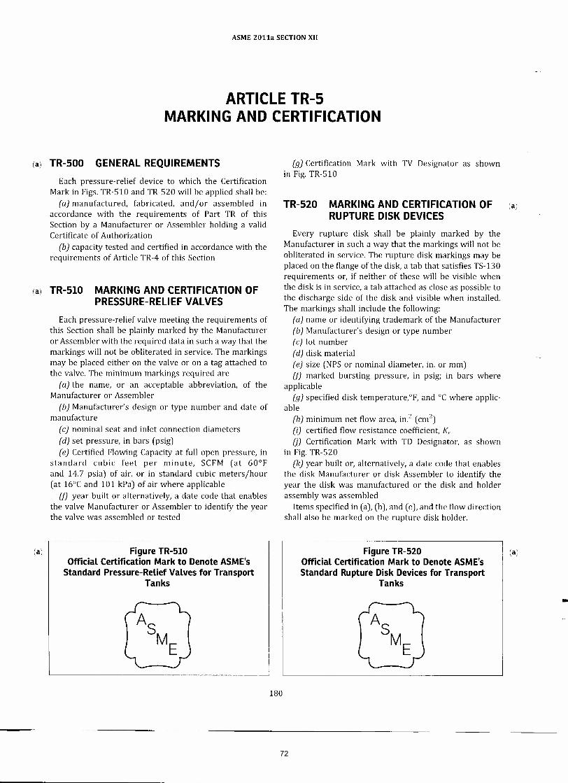
ASME 2011a SECTION XII
ARTICLE TR-5MARKING AND CERTIFICATION
(a) TR-SOO GENERAL REQUIREMENTSEach pressure-relief device to which the Certification
Mark in Figs. TR-S10 and TR-S20 will be applied shall be:(a) manufactured, fabricated, and/or assembled in
accordance with the requirements of Part TR of thisSection by a Manufacturer or Assembler holding a validCertificate of Authorization
(b) capacity tested and certified in accordance with therequirements of Article TR-4 of this Section
(a) TR-SI0 MARKING AND CERTIFICATION OFPRESSURE-RELIEF VALVES
Each pressure-relief valve meeting the requirements ofthis Section shall be plainly marked by the Manufactureror Assembler with the required data in such a way that themarkings will not be obliterated in service. The markingsmay be placed either on the valve or on a tag attached tothe valve. The minimum markings required are
(a) the name, or an acceptable abbreviation, of theManufacturer or Assembler
(b) Manufacturer's design or type number and date ofmanufacture
(c) nominal seat and inlet connection diameters(d) set pressure, in bars (psig)(e) Certified Flowing Capacity at full open pressure, in
standard cubic feet per minute, SCFM (at 60°Fand 14.7 psia) of air, or in standard cubic meters/hour(at 16°C and 101 kPa) of air where applicable
(f) year built or alternatively, a date code that enablesthe valve Manufacturer or Assembler to identify the yearthe valve was assembled or tested
(a) Figure TR-SIOOfficial Certification Mark to Denote ASME's
Standard Pressure-Relief Valves for TransportTanks
(g) Certification Mark with TV Designator as shownin Fig. TR-S10
TR-S20 MARKING AND CERTIFICATION OF (a)
RUPTURE DISK DEVICESEvery rupture disk shall be plainly marked by the
Manufacturer in such a way that the markings will not beobliterated in service. The rupture disk markings may beplaced on the flange of the disk, a tab that satisfies TS-130requirements or, if neither of these will be visible whenthe disk is in service, a tab attached as close as possible tothe discharge side of the disk and visible when installed.The markings shall include the following:
(a) name or identifying trademark of the Manufacturer(b) Manufacturer's design or type number(c) lot number(d) disk material(e) size (NPS or nominal diameter, in. or mm)(f) marked bursting pressure, in psig; in bars where
applicable(g) specified disk ternperature.T, and °C where applic-
able(h) minimum net flow area, in.2 (em")(i) certified flow resistance coefficient, K;(j) Certification Mark with TO Designator, as shown
in Fig. TR-S20(k) year built or, alternatively, a date code that enables
the disk Manufacturer or disk Assembler to identify theyear the disk was manufactured or the disk and holderassembly was assembled
Items specified in (a), (b), and (e), and the flow directionshall also be marked on the rupture disk holder.
-
Figure TR-S20Official Certification Mark to Denote ASME'sStandard Rupture Disk Devices for Transport
Tanks
(a)
)
180
72
parrishd
Rectangle
burgessj
Text Box
Item 10-1412 10-24-2012
burgessj
Sticky Note
MigrationConfirmed set by burgessj
parrishd
Text Box
This Page Reference Only

ASME 2011a SECTION XII
TR-S30 MARKING AND CERTIFICATION OFPRESSURE-RELIEF VALVESINSTALLED IN COMBINATION WITHRUPTURE DISK DEVICES
Pressure relief valves installed in combination withrupture disk devices shall be marked with the capacity orthe combination capacity factor established by testing inaccordance with Article TR-4, in addition to the markingsofTR-S10. The markings may be placed on the valve or ona tag attached to the valve. The markings shall include thefollowing:
(a) name of the Manufacturer of the valve(b) design or type number of the valve(c) name of the Manufacturer of the rupture disk(d) design or type number of the disk
(e) combined capacity, or combination factor(fJ name of organization responsible for this marking
(This may be the tank user, tank Manufacturer, or thepressure-relief valve Manufacturer.)
TR-S40 MARKING AND CERTIFICATION OFPRESSURE-RELIEF VALVESINSTALLED IN COMBINATION WITHBREAKING PIN DEVICES
A pressure-relief valve installed in combination with abreaking pin device shall be marked in accordancewith TR-SI0. In addition, the rated breaking pressureshall be marked on the breaking pin and the breaking pindevice housing.
-
181
73
parrishd
Callout
TR-550 Code Symbol Stamp With TV or TD Designator A Certified Individual (CI) shall provide oversight of the application of the Certification Mark. A CI shall document each application of the Certification Mark with the TV designator on a Form TV-1 Manufacturer's or Assembler's Certificate of Conformance for Pressure Relief Valves or with the TD designator on a Form TD-1 Manufacturer's or Assembler's Certificate of Conformance for Rupture Disks. (1)Requirements for the Certified Individual (CI). The CI shall: (a) be an employee of the Manufacturer or Assembler. (b) be qualified and certified by the Manufacturer or Assembler. Qualifications shall include as a minimum: (1) knowledge of the requirements of this Section for the application of the Certification Mark with the appropriate designator; (2) knowledge of the Manufacturer's or Assembler's quality program; (3) training commensurate with the scope, complexity, or special nature of the activities to which oversight is to be provided. (c) have a record, maintained and certified by the Manufacturer or Assembler, containing objective evidence of the qualifications of the CI and the training program provided. (2) Duties of the Certified Individual (CI). The CI shall: (a) verify that each item to which the Certification Mark is applied meets all applicable requirements of this Section and has a current capacity certification for the TV or TD Designators; (b) for the TV or TD Designators, review documentation for each lot of items to be stamped to verify, for the lot, that requirements of this Section have been completed; (c) sign the appropriate Certificate of Conformance Form TV-1 or TD-1 as appropriate prior to release of control of the item. (3) Certificate of Conformance Forms TV-1 or TD-1. (a) The appropriate Certificate of Conformance shall be filled out by the Manufacturer or Assembler and signed by the CI. Mass produced pressure relief devices may be recorded on a single entry provided the devices are identical and produced in the same lot. (b) The Manufacturer's or Assembler's written quality control program shall include requirements for completion of Certificates of Conformance forms and retention by the Manufacturer or Assembler for a minimum of five years.
burgessj
Sticky Note
MigrationNone set by burgessj
burgessj
Text Box
Item 10-1412 10-24-2012

ASME 2011a SECTION XII
MANDATORY APPENDIX IQUALITY CONTROL SYSTEM
11 GENERALThe Manufacturer, Repair, and Relief Valve Recertifica-
tion Organization shall have and maintain a quality controlsystem that will establish that all Code requirements,including material, design, fabrication, examination (bythe Manufacturer, Repair, and Relief Valve RecertificationOrganization), and for vessels and vessel parts, inspection(by the Inspector), will be met. Provided that Coderequirements are suitably identified, the system mayinclude provisions for satisfying any requirements bythe Manufacturer, or User, which exceed minimum Coderequirements and may include provisions for qualitycontrol of non-Code work. In such systems, the Manufac-turer of vessels or vessel parts may make changes in partsof the system that do not affect the Code requirementswithout securing acceptance by the Inspector. Beforeimplementation, revisions to quality control systems ofManufacturers and Assemblers of pressure-reliefvalves shall have been found acceptable to the ASME-designated organization if such revisions affect Coderequirements.
The system that the Manufacturer uses to meet therequirements of this Section must be one suitable for hisown circumstances. The necessary scope and detail of thesystem shall depend on the complexity of the work/"performed and on the size and complexity of theManufacturer's organization.f ' A written description ofthe system the Manufacturer will use to produce aCode item shall be available for review. Depending uponthe circumstances, the description may be brief orvoluminous.
The written description may contain information of aproprietary nature relating to the Manufacturers orprocesses. Therefore, the Code does not require anydistribution of this information except for the Inspector,ASME Designee, or an ASME-designated organization ascovered by I15(c) and I16(c). It is intended that informa-tion learned about the system in connection with theevaluation will be treated as confidential and that allloaned descriptions will be returned to the Manufacturerupon completion of the evaluation.
12 OUTLINE OF FEATURES TO BE INCLUDEDIN THE WRITTEN DESCRIPTION OF THEQUALITY CONTROL SYSTEM
The following is a guide to some of the features thatshould be covered in the written description of the QualityControl System and that is equally applicable to both shopand field work.
13 AUTHORITY AND RESPONSIBILITYThe authority and responsibility of those in charge of
the Quality Control System shall be clearly established.Persons performing quality control functions shall havesufficient and well-defined responsibility, the authority,and the organizational freedom to identify qualitycontrol problems and initiate, recommend, and providesolutions.
14 ORGANIZATIONAn organization chart showing the relationships among
management and engineering, purchasing, manufacturing,construction, inspection, and quality control is required toreflect the actual organization. The purpose of this chart isto identify and associate the various organizational groupswith the particular function for which they are respon-sible. The Code does not intend to encroach on theManufacturer's right to establish, and from time to time,to alter, whatever form of organization the Manufacturerconsiders appropriate for its Code work.
15 DRAWINGS, DESIGN CALCULATIONS, ANDSPECIFICATION CONTROL
The Manufacturer's or Assembler's Quality ControlSystem shall provide procedures that will ensure thatthe latest applicable drawings, design calculations, speci-fications, and instructions required by the Code, as well asauthorized changes, are used for manufacture, examina-tion, inspection, and testing. -
241
74
parrishd
Callout
The Quality Control Systems of Certificate Holders with TV, or TD Designators shall include duties of a Certified Individual, as required by this Section. The Certified Individual authorized to provide oversight may also serve as the Certificate Holder’s authorized representative responsible for signing data reports or certificates of conformance.
burgessj
Text Box
Item 10-1412 10-24-2012

ASME 2011a SECTIONXII
MANDATORY APPENDIX IIIDEFINITIONS FOR TRANSPORT TANKS
1111 INTRODUCTIONThis Mandatory Appendix defines the terminology used
in this Section. Definitions relating to specific types oftransport tanks may be found in one of the ModalAppendices.
(a) 11I2 DEFINITIONSbar: 1 bar = 100 kPa (14.5 psi).C: Celsius or Centigrade.cargo tank: a bulk packaging that
(a) is a tank intended primarily for the carriage ofliquids or gases and includes appurtenances, reinforce-ments, fittings, and closures.
(b) is permanently attached to or forms a part of amotor vehicle, or is not permanently attached to a motorvehicle but which, by reason of its size, construction, orattachment to a motor vehicle is loaded or unloadedwithout being removed from the motor vehicle.
(c) is not fabricated under a specification for cylinders,portable tanks, tank cars, or multiunit tank car tanks.cargo tank motor vehicle (CTMV): a motor vehicle with oneor more cargo tanks permanently attached to or formingan integral part of the motor vehicle.Certificate of Authorization: a document issued by theSociety that authorizes the use of the ASME CertificationMark and appropriate Designator for a specified time andfor a specified scope of activity.Certification Designator: the symbol used in conjunctionwith the Certification Mark for the scope of activitydescribed in a Manufacturer's Certificate of Authorization.Certification Mark: an ASME symbol identifying a productas meeting Code requirements.Certification Mark Stamp: a stamp issued by the Society foruse in impressing the Certification Mark.Competent Authority (CA): a national agency responsibleunder its national law for the control or regulation of aparticular aspect of the transportation of hazardousmaterials (dangerous goods). The Appropriate Authority,as used in the ICAOTechnical Instructions (see Sec. 171.7),has the same meaning as Competent Authority. Forexample, the U.S. Department of Transportation's Associ-ate Administrator of Hazardous Materials Safety is theCompetent Authority for the United States.dangerous goods: substances or articles classified andsubject to the United Nations Recommendations on theTransport of Dangerous Goods: Model Regulations.
Included in this definition are hazardous materials thatare subject to the requirements of the U.S. Departmentof Transportation.Designator: see Certification Designator.DOT or Department: U.S. Department of Transportation.F: Fahrenheit.fine-grain practice: a steelmaking practice that is intendedto produce a killed steel that is capable of meeting therequirements for fine austenitic grain size.fusible element: a nonreclosing pressure relief device thatis thermally activated and that provides protection againstexcessive pressure buildup in the portable tank developedby exposure to heat, such as from a fire.gas: a material that has a vapor pressure greater than300 kPa (43.5 psia) at 50°C (122°F) or is completelygaseous at 20°C (68°F) at a standard pressure of 101.3 kPa(14.7 psia).hazardous material: a substance or material that has beendetermined by the Secretary of Transportation to becapable of posing an unreasonable risk to health, safety,and property when transported in commerce, and that hasbeen so designated. The term includes but is not limited tohazardous substances, hazardous wastes, marine pollu-tants, and elevated-temperature materials as defined inCFR,Title 49.IMO: International Maritime Organization.intermodal container: a freight container designed andconstructed to permit it to be used interchangeably in twoor more modes of transport.intermodal (1M) portable tank: a specific class of portabletanks designed primarily for international intermodal use.international transportation: transportation
(a) between any place in the United States and any placein a foreign country.
(b) between places in the United States through aforeign country.
(c) between places in one or more foreign countriesthrough the United States.liquid: a material, other than an elevated-temperaturematerial, with a melting point or initial melting pointof 20°C (68°F) or lower at a standard pressure of101.3 kPa (14.7 psia). A viscous material for which aspecific melting point cannot be determined must besubjected to the procedures specified in ASTM D 4359,Standard Test Method for Determining Whether a Materialis Liquid or Solid.mode: any of the following transportation methods: rail,highway, air, or water.
-
245
75
burgessj
Text Box
Item 10-1412 10-24-2012
parrishd
Text Box
This Page Reference Only

,. Q
• - o - , § • • •
• ~ • ~ ~ j !l ! ~c
· , · , ~ ~ · ; ~ . < • n · , 8 ~ · , o • · , · , ~ i § ~ • • ., • • "
<
• • " · . •
0 • • ~ I ~
0: ;;
, t~ , o
!f:1 o • !=
llJ ,r'! , , i
Km'
, II,· , ~ r ... ~ •
• , i
~~~~
~" tq
I
~ ~
~:;!".
, , O!:O:;
n ..
<, .• - :I;
~E
~i
· -,
"
1 1<1
; , ~ II -. li~j;ll"
.r! .0
.
~ ~
.. i
::I;,!! Q
"
0:;
c <
"
= 5!' a " l' I; ~i 11 _I ;§~ , , I.
... n ~ -I • I <
• ~
';l'li "",n ...
1; ~
o ••
" -, '"
~ ~ ~ ~.! •
I" «C
,0('5
<.>
~.~u
• ll' .....
~ '"
· '!' ~
! '
· , !H
iil "ii
~ '"
~ f" ~g~ , -, -,. !!, ,c, <J .~ "' ~~
"' =
11 ~ ; j£:! · -•
• •
0
••• "
1 £h
! ~ , I ) I ! , !
~l i 1 ; , • ! , l
•
!
76
burgessj
Polygon
burgessj
Text Box
SECTION XII
burgessj
Polygon
burgessj
Text Box
TV-1
burgessj
Polygon
burgessj
Text Box
Section XII
burgessj
Text Box
Item 10-1412 10-24-2012
burgessj
Line
burgessj
Line
burgessj
Line
burgessj
Polygon
burgessj
Polygon
burgessj
Line
burgessj
Line
burgessj
Polygon
burgessj
Line
burgessj
Text Box
Section XII
burgessj
Text Box
TV
burgessj
Line
burgessj
Line

201 b SECT IO:\' VII I _ 1JI \'ISIO~ 1
FORM UD· ' MANUFACTURER'S CERTIFICATE OF CONFORMANCE FOR NONRECLOSING PRESSURE REUEF DEVICES lal As R<lq ui,od by tho Provi""", of tho ASME BoOlg, a M p ,g .... ,g V<>SMf Cod<> Rul .... s..ctioo VIII , D;"'ioion 1
1. Mo nuloctu,od by
2A. Tabl . 01 Codg . ymbol .".mpod &C.i.alion oomponOflts:
M.M Min. Ac1ivat"",
""~ ,,, C .... ifiod
,~,
'" ~- .~ S_ifiod ,,- ,~ a a , .. Bui" Cm.1 "'. ~ " ~ Strg P:=i'. I Pi' I R~irg Capacity ~,.
i' S~ , , • • • , • ,
2B Tab!<> 01 Cod<> Symbol SUlmpod Non,,,,,Io"ng P, ... u,g Rgl .. 1 o..vica Hokl<lf or Body
Hokl<lf or Body Pin to Pin Yg., Hllih '" I"I ,~ "" [}eV'=imifi ... ~ ~~ O~Uf~ , • • ,
CERTIFICATE OF SHOP COMPLIANCE By th ... gnaw,. ollho C.nifi. d Indi.idualKII nol<H1 abOY., w. cgnit., thaI tho ota •• monts mado in .hi. ,oport aro COf,oct and ,"" • • 11
dotail. for dooign, ","'",iaf , construc.ion, and wo,km.n..., ip 01 tho ruptu,. di • • or pin ~ico. conform with .h. '<>Qui,. ",.",. of Soc.ion VIII , D;"'i.ion 1 ol.ho ASME BO ILER ANOI'IIESSURE VESSEl COOE.
UD C. M",. ,. 01 Authori,. tion No. ______ -'®OC _______ Expi, •• __ -'®<> __ _
D. t. ____ ,@'-___ Signod ___ ~==~c''''===~----N.m.-----~,,'''==~-----1......,._' ... _ ..... , , .......... "_'
01111 77
burgessj
Line
burgessj
Line
burgessj
Line
burgessj
Line
burgessj
Line
burgessj
Polygon
burgessj
Polygon
burgessj
Polygon
burgessj
Line
burgessj
Line
burgessj
Line
burgessj
Polygon
burgessj
Polygon
burgessj
Polygon
burgessj
Text Box
Section XII
burgessj
Text Box
TD
burgessj
Text Box
Section XII
burgessj
Text Box
SECTION XII
burgessj
Text Box
TD-1
burgessj
Text Box
Item 10-1412 10-24-2012

,., 101la SECTION \ ' 11 1_ I)I VISIO:-" I
TABLE W-3.2 SUPPLEMENTARY INSTRUCTIONS FOR THE PREPARATION OF MAN UFACTURER'S
OR ASSEMBLER'S CERTIFICATE OF CONFORMANCE FORM S UV-l ANO UD·l
'0' No, lost'uctloo
(0 Namt and add"" 0/ Manulactu...,. or A""mb ......
CD P, .. ..,,,, 'rlid dr>iicr Matlulactu",.·, or A, <rmblrr', uniqur iclrntificatioo nurOOrr. <u<h as "';a l num •• work ortJr.r numbrr. or lot numbrr.
CD Thr 1"'" bu ilt or m. or"""'" mid dr>iicr Ma nuiauu.r,·, or A""mbl<.·, dJtr codr.
o Thr NB Crrt ificatioo Numbr •.
o Thr Quanti ty 01 idrmica l dr>iit .. lor th;.; Ii ... it .,..,.
o Thr Manulactu ..... ' n." ign or Twr Numbr. as ma.kN 00 m. "",,",platr ,
o Thr in l'" silt 0/ m. Pf'""IJ'" "' lid dr>iicr.
o Thr II.lrflrIl latr srt II""'lJrr 0/ m. prro;sIJ'" rt lid dr>iicr.
o Thr II.lrflrIl latr ""P'ICity 0/ thr II""'lJrr rt lid <bit •• as awlicab l •.
€l Thr Au id =d lor ttSting thr II""'lJrr rt lid !bier.
@ Thr d.:!tt 01 complrtioo 01 orodoct ioo 01 thr lIf"SSU.r .rl id dr>iier ,
@ Thr namr or un""", ID Stamp 0/ thr Crnifird Ind ividual.
@ Thr ,ignatu", 01 m. CtrtiliN IrKli. idU.ll, Rrqui.N lor r ach Ii"" itrm.
€l IndOOr any """Iicab" rtm",k, (rdrrrflCing thr iclrntificatioo numbr,l that may prrt.1 in. 511Ch as iclrmific",ioo 0/ a Codr C ..... that 'rqlJirrs ma. king on m. dr>iit •.
€l Thr numbr. 0/ thr prrssu.r "'lirl dr>iicr Manulactu...,.·, or A' '''mbl ... ·' Crnific.1tr 0/ AU1horilat ioo ,
€l Expi .atioo datr 01 m. 1I""'lJ'" rt lid dr>iit. M atlulacwrt.·s or Asstmb l ... ·' Crrti ficatr 01 AutilorilatiOO ,
@ Oatr signrd II)' m. or"""'" rt lid dr>iicr Manulactu.r, or A, <rmblr,', autilori l N """ ..... rt.ui ... ,
€l Thr Crnific.1tr 01 Compliancr block is to show thr namr 0/ m. Manulactu...,. or Asstmblr. as shown on h"""'. ASM E Codr Crrti fic"", 01 ALIIhorimion. Th i, w ll br signrd in accorddncr with or!)an il ationa l authority cIrlinrd in thr Quality Control S)'Strm (..,. 1()-41.
e Thr m ...... ia l 01 m. acti .. tion c~m and/or acti .. t ion c~m holclrr or body. as awl icabl< ,
@ Thr ma.kN burst or srt lI""'lJ.r 0/ thr ruptu", disk or pin.
@ Thr l.prC ifird trmpr.aw rt 01 thr ,uptu", disk or pin.
@ Thr minimum nrt flow Mra 01 thr '"ptu", disk or pin dr>iier as applicblr.
@ Thr crrt ifird flow rrsio;t.:1ncr (onr or mort as """Ii<:.lblr ) KIlGo KRL KllfJt 01 m. dr>iio • • as awl icabl< ,
@ Pin-ta-pin dr>i icr iclrnti fitr as app litablr.
GENE RAL HOTE: Any quant ity to which units appl)' w ll br ~ on thr Manulactu...,.·, Oat.:! Rrport with thr """'"" units.
78
burgessj
Line
burgessj
Line
burgessj
Polygon
burgessj
Polygon
burgessj
Text Box
TV-1 AND TD-1
burgessj
Polygon
burgessj
Text Box
SECTION XII
burgessj
Line
burgessj
Text Box
Item 10-1412 10-24-2012
burgessj
Line
burgessj
Line

Record Level
Stds Comm
Proposal
Record
10-1784
PagesRecord Sub-Type
Code Case
Project Manager
Denis DeMichael
Subject
Section VIII, Division 1; Code Case regarding Multiple Marking of Certified Capacities for
Pressure Relief Valves
Proposal
Adopt the Code Case as shown in the Proposal file.
There are many capacity certified direct spring loaded and pilot operated pressure relief valves
that are certified for steam, gas (air) and/or liquid (water) that will perform to all ASME Section
VIII Div 1 requirements when set and tested for one capacity certification and without
adjustments or changes to their parts will perform to all ASME Section VIII, Div 1
requirements for their other capacity certifications. At present even under the performance
capabilities noted, only one of the capacity certifications can be marked on the valve or its
nameplate and the end user can only apply the pressure relief valve to applications related to the
marked capacity certification.
It is noted that rupture disks may be marked for all applicable capacity certifications, see
UG-129(e)(9).
Explanation
Summary of ChangesNew Code Case.
Item History
Code Case updated based on SGGR (BPV VIII) reveiw during May 2013 meeting.
Code Case updated based on SGGR (BPV VIII) ballot 13-1403
BPV SC-SVR
BPV SC-SVR SGGR
BPV SC-VIII SGGR
Sub-Tier Committees Involved
Ballot: 11-2029
Ballot Level: Subcommittee
Date Opened: 09/07/2011
Date Closed: 10/03/2011
Final Record Status :Disapproved
Latest Ballot Information
79

Item 10-1784: Section VIII Code Case regarding Multiple Marking of Certified Capacities for Pressure Relief Valves
SC-SVR History October 27, 2010 – This item was opened between meetings. November 30, 2010 – This item was assigned to Dave Tuttle. Mr. Tuttle reported that he expects to have a proposal for review at the next meeting. February 1, 2011 – Mr. DeMichael provided a progress report. The Subgroup went through each item of the Code Case and provided comments to the Project Manager for consideration. Any comments should be sent to Dave Tuttle for consideration.
April 28, 2011 – Mr. Tuttle reported that this Code Case is to allow marking of multiple capacities on the relief valves. His basis for his proposal comes from what was done on rupture discs for multiple capacities.
Mr. Tuttle’s proposal was reviewed by the subgroup and was revised by them. The proposal was shown to the members as a progress report and was discussed. This item will be revised by the subgroup at their next meeting and will then be brought to SC-SVR for ballot after their review.
Jeramy Dickson noted that something in the code case needs to be added regarding what will be written on the UV-1 form.
Mr. Tuttle requested that everyone with comments or concerns with this proposal send their suggestion to him for consideration of inclusion in the next revision of this case. August 9, 2011 - Mr. Tuttle reported that at the last meeting, the item was held because Roger hadn’t seen the proposal yet. He has reviewed it and the subgroup reaffirmed the proposal. Alan West noted two revisions to the code case request that he would like made before this item proceeds to ballot. At the last meeting, Mr. Dickson also wanted to know where the media was to be included on the stamp. Mr. Tuttle will revise the proposal and this item will then be sent for ballot. November 8, 2011 – Mr. Tuttle reported that this ballot received several disapprovals. The negatives were discussed and Mr. Tuttle noted that he will make revisions to the proposal based on the negatives he received. He will be updating the record and will get it ready for another round of balloting. February 7, 2012 – Mr. Ball reported that ballot #12-80 closed with three negatives. Mr. DeMichael plans to withdraw his negative and the other comments will require editorial revisions; this item will be recirculated when the proposal is revised. May 15, 2012 – Mr. DeMichael reported that this item has been through a first consideration ballot to SC-SVR. It received negatives which have been addressed. The record on CS Connect needs to be cleaned up and will then be sent for a recirculation ballot.
80
Item 10-1784: Section VIII Code Case regarding Multiple Marking of Certified Capacities for Pressure Relief Valves [Continued]
August 14, 2012 – Mr. Tuttle reported that this item is currently out for recirculation ballot and is scheduled to close on August 20, 2012. November 6, 2012 – Mr. Tuttle reported that this item was referred to BPV VIII for action but does not currently appear on the SG-GR agenda. February 12, 2013 – Mr. DeMichael reported for Mr. Tuttle that this item has been forwarded to BPV VIII but is not yet on their agenda; Mr. DeMichael will resolve this at the meeting tomorrow. August 13, 2013 -
81

82

Record Level
SC Proposal
Record
10-1877
PagesRecord Sub-Type
Revision
Project Manager
John P. Glaspie
Subject
Section VIII, Division 1; UG-131(d)(2) and (e)(2) Capacity Certification
Proposal
Approve the Code changes shown in the proposal.
The no longer utilized log-log plotting process in UG-131(d)(2)(b) is replaced with current
industry method of flow factor capacity certification for liquid pressure relief valves.
The format of slope certification in UG-131(d)(2)(a) is revised to mirror the flow factor
incorporation. Redundant equations for rated capacity based on set and overpressure are also
removed from UG-131(d)(2)(a).
A code rule located in a note in UG-131(e)(2) is incorporated into body text of UG-131(e)(2).
>> UG-131(e)(2) capacity formulas proposed by original inquirer will be handled under a
separate item.
Explanation
Summary of ChangesRevised paragraph UG-131(d)(2)(a).
Revised paragraph UG-131(d)(2)(b).
Moved sentence in UG-131(e)(2).
Item History
11/6/12: MOTION was made to add subscript M to the S as shown in the proposal as shown
on pages 66-71 of the November 6, 2012 Meeting Minutes. Motion was seconded and
APPROVED.
11/6/12: SVR approved the revisions to UG-131 and transferred the item to BPV VIII for
action.
BPV SC-SVR
BPV SC-SVR SGD
BPV SC-VIII SGGR
Sub-Tier Committees Involved
Ballot: 12-2041RC1
Ballot Level: Subcommittee
Date Opened: 10/15/2012
Date Closed: 11/06/2012
Final Record Status :Approved
Latest Ballot Information
83

Item 10-1877: Section VIII-1 UG-136(d)(2)(b) and UG-136(e)(2) Liquid Capacity Certification
SC-SVR History November 8, 2010 – This item was opened between meetings. November 30, 2010 – PM was changed to Mr. Wang and the task group will consist of Greg Goodson and Sid Cammerisi. February 1, 2011 – Mr. Cox reported that the PM needs to be changed to Brandon Nutter. Mr. Nutter then reported that this item is a change from what’s required in the code to what’s actually practiced in industry. The subgroup received a proposed revision to the code (Feb. 2011 minutes pages 256-258). Brandon noted that there are a few things that need to be worked on before the item moves forward. The task group will consist of J. Dickson, Z. Wang, J. Goodson and S. Cammerisi. There will be a ballot before then next meeting.
April 28, 2011 – Mr. Nutter provided a handout for the committee to review. Mr. Nutter reviewed the rationale of this revision to bring the code in line with current industry practices.
The proposal provided was a revised draft created by the subgroup on Testing. The committee reviewed the proposal. Mr. Nutter noted that h would like to have Joe Ball review the proposal before it goes out for ballot to the entire committee. After Mr. Ball reviews the proposal, Mr. Nutter will send a request to the secretary to initiate the ballot before the next meeting.
August 9, 2011 - There have been some Task Group meetings and they have requested to bring this item back to the Task Group level. The Task Group plans to revise the scope of this item and do some further work on it before it is presented again to the Subcommittee. Mr. Nutter noted that, during discussions with several of the interested parties, it came to light that the coefficient of discharge method for all device certifications might be something they want to look at. Any members who would like to be a part of the TG should notify Mr. Nutter. November 8, 2011 – There have been a lot of comments received on the latest proposal and has been brought back to the task group for further work. February 7, 2012 – Mr. Nutter reported that this item began with an inquiry from Mr. Danzy. The proposal that he supplied incorporated several things including the log-log plotting method for liquid capacity certification. He proposed that we incorporate the industry standard flow factor certification method. He also proposed that we change the liquid capacity certification to a volumetric certification rather than the mass. The TG will be work on a proposal to correct the rules as they are now and then go back to the additional information on volumetric and coefficient of discharge methods on another item. They plan to have a proposal by the next meeting. May 15, 2012 – There was a task group teleconference and they agreed to revise the scope of record #10-1877 to address UG-136(d)(2)(b) only to eliminate the log-log and to instead
84

Item 10-1877: Section VIII-1 UG-136(d)(2)(b) and UG-136(e)(2) Liquid Capacity Certification [Continued]
describe the actual practice. Mr. Nutter will send a request to the Secretary to open new items for the inquiry as well as new items to address the issues that came up during the review of the proposal. August 14, 2012 – Mr. Nutter reported that he has further revised the proposal, a copy of the revised proposal can be found on pages 292-397 of the August 14, 2012 Meeting Minutes. Mr. Nutter reviewed the proposal with the committee and they agreed to open a new item at the subgroup level to review the other portion of Mr. Danzy’s issues. Mr. Danzy added that this item can go forward for the flow factor portion. Mr. Danzy further noted that the statement being removed about failure to meet the requirements is in the wrong location and that it shouldn’t be deleted all together. Mr. Nutter will revise the proposal to avoid the issue of the failure to meet the requirements. November 6, 2012 – On the first ballot for this item (#12-204), there were a few comments made which were corrected in a recirculation ballot. During the recirculation ballot, Mr. Glaspie noted that there was a missing subscript which is a typographical error.
MOTION was made to add subscript M to the S as shown in the proposal as shown on pages 66-71 of the November 6, 2012 Meeting Minutes. Motion was seconded and APPROVED.
The corrected proposal will be uploaded to CS Connect and this item will be referred to the Standards Committee. February 12, 2013 – This item was approved by the subcommittee and some editorial changes were introduced; it is currently listed as standards committee proposal. August 13, 2013 -
85

2011a SECTION VIII — DIVISION 1
(b)(1) Capacity certification tests for pressure reliefdevices for compressible fluids shall be conducted on drysaturated steam, or air, or gas. When dry saturated steamis used, the limits for test purposes shall be 98% minimumquality and 20°F (10°C) maximum superheat. Correctionfrom within these limits may be made to the dry saturatedcondition. Pressure relief devices for steam service maybe rated as above, but at least one device of each seriesshall be tested on steam to demonstrate the steam capacityand performance.
(2) Capacity certification tests for pressure reliefdevices for incompressible fluids shall be conducted onwater at a temperature between 40°F (5°C) and 125°F(50°C).
(c)(1) Capacity certification tests shall be conducted ata pressure which does not exceed the pressure for whichthe pressure relief device is set to operate by more than10% or 3 psi (20 kPa), whichever is greater, except asprovided in (c)(2) below. For pressure relief valves, mini-mum pressure for capacity certification tests shall be atleast 3 psi (20 kPa) above set pressure. The reseatingpressure shall be noted and recorded.
(2) Capacity certification tests of pressure reliefdevices for use in accordance with UG-125(c)(3) may beconducted at a pressure not to exceed 120% of the stampedset pressure of the device.
(3)(a) Pressure relief valves for compressible fluidshaving an adjustable blowdown construction shall beadjusted prior to testing so that the blowdown does notexceed 5% of the set pressure or 3 psi (20 kPa), whicheveris greater.
(b) The blowdown of pressure relief valves forincompressible fluids and pressure relief valves for com-pressible fluids having nonadjustable blowdown shall benoted and recorded.
(4) Capacity certification of pilot operated pressurerelief devices may be based on tests without the pilotdevices installed, provided prior to capacity tests it has beendemonstrated by test to the satisfaction of the AuthorizedObserver that the pilot device will cause the main deviceto open fully at a pressure which does not exceed the setpressure by more than 10% or 3 psi (20 kPa), whicheveris greater, and that the pilot device in combination withthe main device will meet all the requirements of thisDivision.
(d)(1) A capacity certification test is required on a setof three devices for each combination of size, design, andpressure setting. The stamped capacity rating for each com-bination of design, size, and test pressure shall not exceed90% of the average capacity of the three devices tested.The capacity for each set of three devices shall fall withina range of ±5% of the average capacity. Failure to meetthis requirement shall be cause to refuse certification ofthat particular pressure relief device design.
97
(2) If a Manufacturer wishes to apply the CertificationMark to a design of pressure relief devices, four devicesof each combination of pipe size and orifice size shall betested. These four devices shall be set at pressures whichcover the approximate range of pressures for which thedevice will be used or covering the range available atthe certified test facility that shall conduct the tests. Thecapacities based on these four tests shall be as follows:
(a) For compressible fluids, the slope W/P of theactual measured capacity versus the flow pressure for eachtest point shall be calculated and averaged:
slope pWPp
measured capacityabsolute flow pressure, psia
All values derived from the testing must fall within ±5%of the average value:
minimum slope p 0.95 � average slope
maximum slope p 1.05 � average slope
If the values derived from the testing do not fall betweenthe minimum and maximum slope values, the AuthorizedObserver shall require that additional devices be tested atthe rate of two for each device beyond the maximum andminimum values with a limit of four additional devices.
The relieving capacity to be stamped on the device shallnot exceed 90% of the average slope times the absoluteaccumulation pressure:
rated slope p 0.90 � average slope
(U.S. Customary Units)
stamped capacity ≤ rated slope (1.10 � set pressure
+ 14.7) or (set pressure + 3 psi
+ 14.7), whichever is greater
(SI Units)
stamped capacity ≤ rated slope (1.10 � set pressure
+ 100 kPa) or (set pressure + 20 kPa
+ 101 kPa), whichever is greater
For devices certified in accordance with (c)(2) above,
(U.S. Customary Units)
stamped capacity ≤ rated slope (1.20 � set pressure
+ 14.7) or (set pressure + 3 psi
+ 14.7), whichever is greater
(SI Units)
stamped capacity ≤ rated slope (1.20 � set pressure
+ 100 kPa) or (set pressure + 20 kPa
+ 101 kPa), whichever is greater
BC10-1877 PROPOSAL 10/19/2012 Page 1 of 6
86
OM3475
Rectangle
OM3475
Text Box
NO CHANGES - FOR REFERENCE ONLY

2011a SECTION VIII — DIVISION 1
(b)(1) Capacity certification tests for pressure reliefdevices for compressible fluids shall be conducted on drysaturated steam, or air, or gas. When dry saturated steamis used, the limits for test purposes shall be 98% minimumquality and 20°F (10°C) maximum superheat. Correctionfrom within these limits may be made to the dry saturatedcondition. Pressure relief devices for steam service maybe rated as above, but at least one device of each seriesshall be tested on steam to demonstrate the steam capacityand performance.
(2) Capacity certification tests for pressure reliefdevices for incompressible fluids shall be conducted onwater at a temperature between 40°F (5°C) and 125°F(50°C).
(c)(1) Capacity certification tests shall be conducted ata pressure which does not exceed the pressure for whichthe pressure relief device is set to operate by more than10% or 3 psi (20 kPa), whichever is greater, except asprovided in (c)(2) below. For pressure relief valves, mini-mum pressure for capacity certification tests shall be atleast 3 psi (20 kPa) above set pressure. The reseatingpressure shall be noted and recorded.
(2) Capacity certification tests of pressure reliefdevices for use in accordance with UG-125(c)(3) may beconducted at a pressure not to exceed 120% of the stampedset pressure of the device.
(3)(a) Pressure relief valves for compressible fluidshaving an adjustable blowdown construction shall beadjusted prior to testing so that the blowdown does notexceed 5% of the set pressure or 3 psi (20 kPa), whicheveris greater.
(b) The blowdown of pressure relief valves forincompressible fluids and pressure relief valves for com-pressible fluids having nonadjustable blowdown shall benoted and recorded.
(4) Capacity certification of pilot operated pressurerelief devices may be based on tests without the pilotdevices installed, provided prior to capacity tests it has beendemonstrated by test to the satisfaction of the AuthorizedObserver that the pilot device will cause the main deviceto open fully at a pressure which does not exceed the setpressure by more than 10% or 3 psi (20 kPa), whicheveris greater, and that the pilot device in combination withthe main device will meet all the requirements of thisDivision.
(d)(1) A capacity certification test is required on a setof three devices for each combination of size, design, andpressure setting. The stamped capacity rating for each com-bination of design, size, and test pressure shall not exceed90% of the average capacity of the three devices tested.The capacity for each set of three devices shall fall withina range of ±5% of the average capacity. Failure to meetthis requirement shall be cause to refuse certification ofthat particular pressure relief device design.
97
(2) If a Manufacturer wishes to apply the CertificationMark to a design of pressure relief devices, four devicesof each combination of pipe size and orifice size shall betested. These four devices shall be set at pressures whichcover the approximate range of pressures for which thedevice will be used or covering the range available atthe certified test facility that shall conduct the tests. Thecapacities based on these four tests shall be as follows:
(a) For compressible fluids, the slope W/P of theactual measured capacity versus the flow pressure for eachtest point shall be calculated and averaged:
slope pWPp
measured capacityabsolute flow pressure, psia
All values derived from the testing must fall within ±5%of the average value:
minimum slope p 0.95 � average slope
maximum slope p 1.05 � average slope
If the values derived from the testing do not fall betweenthe minimum and maximum slope values, the AuthorizedObserver shall require that additional devices be tested atthe rate of two for each device beyond the maximum andminimum values with a limit of four additional devices.
The relieving capacity to be stamped on the device shallnot exceed 90% of the average slope times the absoluteaccumulation pressure:
rated slope p 0.90 � average slope
(U.S. Customary Units)
stamped capacity ≤ rated slope (1.10 � set pressure
+ 14.7) or (set pressure + 3 psi
+ 14.7), whichever is greater
(SI Units)
stamped capacity ≤ rated slope (1.10 � set pressure
+ 100 kPa) or (set pressure + 20 kPa
+ 101 kPa), whichever is greater
For devices certified in accordance with (c)(2) above,
(U.S. Customary Units)
stamped capacity ≤ rated slope (1.20 � set pressure
+ 14.7) or (set pressure + 3 psi
+ 14.7), whichever is greater
(SI Units)
stamped capacity ≤ rated slope (1.20 � set pressure
+ 100 kPa) or (set pressure + 20 kPa
+ 101 kPa), whichever is greater
BC10-1877 PROPOSAL 10/19/2012 Page 2 of 6
87
OM3475
Rectangle
OM3475
Rectangle
OM3475
Line
OM3475
Line
OM3475
Text Box
(a) For compressible fluids, the slope Sm of the measured capacity versus the absolute flow-rating pressure shall be determined for each test point as follows: where, Sm = slope, lb/hr/psia (kg/hr/kPa) or SCFM/psia (M3/min/kPa) Pf = absolute flow-rating pressure, psia (kPa) W = measured capacity, lb/hr (kg/hr) or SCFM (M3/min) The average slope Savg shall be the arithmetic mean of all calculated slope values Sm. All experimentally determined slope values Sm shall fall within a range of ±5% of the average slope Savg. If all slope values Sm are not within ±5% of the average slope Savg, two additional devices shall be tested for each device beyond the ±5% range up to a limit of four additional devices. The average slope Savg shall be multiplied by 0.90, and this product shall be taken as the rated slope S for that design and orifice size combination. The relieving capacity to be stamped on the device shall not exceed the rated slope S multiplied by the absolute relieving pressure.
OM3475
Pencil
OM3475
Rectangle
OM3475
Line
OM3475
Line
OM3475
Pencil
OM3475
Line
om3475
Stamp

2011a SECTION VIII — DIVISION 1
For direct spring loaded valves, the results may beextrapolated to valves with set pressures higher than thehighest set pressure used in the capacity certification tests,if the spring in the valve with the higher set pressure meetsthe requirements of UG-136(a)(2).
(b) For incompressible fluids, the capacities shallbe plotted on log–log paper against the differential (inletminus discharge pressure) test pressure and a straight linedrawn through these four points. If the four points do notestablish a straight line, two additional devices shall betested for each unsatisfactory point, with a limit of twounsatisfactory points. Any point that departs from thestraight line by more than 5% should be considered anunsatisfactory point. The relieving capacity shall be deter-mined from this line. The certified capacity shall not exceed90% of the capacity taken from the line.
For direct spring loaded valves, the results may beextrapolated to valves with set pressures higher than thehighest set pressure used in the capacity certification tests,if the spring in the valve with the higher set pressure meetsthe requirements of UG-136(a)(2).
(e) Instead of individual capacity certification as pro-vided in (d) above, a coefficient of discharge K may beestablished for a specific pressure relief device designaccording to the following procedure.
(1) For each design, the pressure relief device Manu-facturer shall submit for test at least three devices for eachof three different sizes (a total of nine devices) togetherwith detailed drawings showing the device construction.Each device of a given size shall be set at a differentpressure.
For each valve design intended to be restricted in lift,the Manufacturer shall have capacity tests conducted onthree valves of different sizes. Each size valve shall betested for capacity at the minimum lift for which certifica-tion is required, and at two intermediate lift points betweenthe full rated lift and minimum lift certification points.Each of the three test valves shall be set at a differentpressure.
For each restricted lift valve tested, it shall be verifiedthat actual measured capacity at restricted lift will equalor exceed the ASME rated capacity at full rated liftmultiplied by the ratio of measured restricted lift to fullrated lift.
(2) Tests shall be made on each pressure relief deviceto determine its capacity-lift (if applicable), set pressureand blow-down pressures (for pressure relief valves), andactual capacity in terms of the fluid used in the test. Acoefficient KD shall be established for each test run asfollows:
KD pactual flow
theoretical flowp coefficient of discharge
98
where actual flow is determined quantitatively by test, andtheoretical flow is calculated by the appropriate formulawhich follows:
For tests with dry saturated steam,
WT p 51.5AP
NOTE: For dry saturated steam pressures over 1500 psig (10.9 MPagage) and up to 3200 psig (22.1 MPa gage), the value of WT, calculatedby the above equation, shall be corrected by being multiplied by thefollowing factors, which shall be used only if it is 1.0 or greater.
(U.S. Customary Units)
� 0.1906P − 10000.2292P − 1061 �
(SI Units)
� 27.6P − 1 00033.2P − 1 061 �
For tests with air,
WT p 356AP�MT
For tests with natural gas,
WT p CAP � MZT
For tests with water,
WT p 2407A� (P − Pd ) w
where
A p actual discharge area through the device at devel-oped lift, sq in.
C p constant for gas or vapor based on the ratio ofspecific heatsk p cp /cv (see Fig. 11-1)
M p molecular weightP p (set pressure � 1.10) plus atmospheric pressure,
psia, or set pressure plus 3 psi (20 kPa) plusatmospheric pressure, whichever is greater
Pd p pressure at discharge from deviceT p absolute temperature at inlet, °F + 460°F (273°C)w p specific weight of water at device inlet conditions
WT p theoretical flowZ p compressibility factor corresponding to P and T
The average of the coefficients KD of the nine tests requiredshall be multiplied by 0.90, and this product shall be takenas the coefficient K of that design. The coefficient of thedesign shall not be greater than 0.878 (the product of 0.9� 0.975).
NOTE: All experimentally determined coefficients KD shall fall withina range of ±5% of the average KD found. Failure to meet this requirementshall be cause to refuse certification of that particular device design.
BC10-1877 PROPOSAL 10/19/2012 Page 3 of 6
88
OM3475
Rectangle
OM3475
Rectangle
OM3475
Line
OM3475
Line
OM3475
Pencil
OM3475
Text Box
(b) For incompressible fluids, the flow factor Fm shall be determined from the ratio of the measured volumetric capacity versus the square root of the differential flow-rating pressure for each test point as follows: where, ___ ___ Fm = flow factor, gal/min/√psid (l/min/√kPa) Pd = absolute discharge pressure, psia (kPa) Pf = absolute flow-rating pressure, psia (kPa) Q = measured volumetric capacity, gal/min (l/min), corrected to 70°F (20°C) The average flow factor Favg shall be the arithmetic mean of all calculated flow factors Fm. All experimentally determined flow factors Fm shall fall within a range of ±5% of the average flow factor Favg. If all the flow factors Fm are not within ±5% of Favg, two additional devices shall be tested for each device beyond the ±5% range up to a limit of four additional devices. The average flow factor Favg shall be multiplied by 0.90, and this product shall be taken as the flow factor F for that design and orifice size combination. The relieving capacity to be stamped on the device shall not exceed the flow factor F multiplied by the square root of the differential relieving pressure.
OM3475
Stamp

2011a SECTION VIII — DIVISION 1
For direct spring loaded valves, the results may beextrapolated to valves with set pressures higher than thehighest set pressure used in the capacity certification tests,if the spring in the valve with the higher set pressure meetsthe requirements of UG-136(a)(2).
(b) For incompressible fluids, the capacities shallbe plotted on log–log paper against the differential (inletminus discharge pressure) test pressure and a straight linedrawn through these four points. If the four points do notestablish a straight line, two additional devices shall betested for each unsatisfactory point, with a limit of twounsatisfactory points. Any point that departs from thestraight line by more than 5% should be considered anunsatisfactory point. The relieving capacity shall be deter-mined from this line. The certified capacity shall not exceed90% of the capacity taken from the line.
For direct spring loaded valves, the results may beextrapolated to valves with set pressures higher than thehighest set pressure used in the capacity certification tests,if the spring in the valve with the higher set pressure meetsthe requirements of UG-136(a)(2).
(e) Instead of individual capacity certification as pro-vided in (d) above, a coefficient of discharge K may beestablished for a specific pressure relief device designaccording to the following procedure.
(1) For each design, the pressure relief device Manu-facturer shall submit for test at least three devices for eachof three different sizes (a total of nine devices) togetherwith detailed drawings showing the device construction.Each device of a given size shall be set at a differentpressure.
For each valve design intended to be restricted in lift,the Manufacturer shall have capacity tests conducted onthree valves of different sizes. Each size valve shall betested for capacity at the minimum lift for which certifica-tion is required, and at two intermediate lift points betweenthe full rated lift and minimum lift certification points.Each of the three test valves shall be set at a differentpressure.
For each restricted lift valve tested, it shall be verifiedthat actual measured capacity at restricted lift will equalor exceed the ASME rated capacity at full rated liftmultiplied by the ratio of measured restricted lift to fullrated lift.
(2) Tests shall be made on each pressure relief deviceto determine its capacity-lift (if applicable), set pressureand blow-down pressures (for pressure relief valves), andactual capacity in terms of the fluid used in the test. Acoefficient KD shall be established for each test run asfollows:
KD pactual flow
theoretical flowp coefficient of discharge
98
where actual flow is determined quantitatively by test, andtheoretical flow is calculated by the appropriate formulawhich follows:
For tests with dry saturated steam,
WT p 51.5AP
NOTE: For dry saturated steam pressures over 1500 psig (10.9 MPagage) and up to 3200 psig (22.1 MPa gage), the value of WT, calculatedby the above equation, shall be corrected by being multiplied by thefollowing factors, which shall be used only if it is 1.0 or greater.
(U.S. Customary Units)
� 0.1906P − 10000.2292P − 1061 �
(SI Units)
� 27.6P − 1 00033.2P − 1 061 �
For tests with air,
WT p 356AP�MT
For tests with natural gas,
WT p CAP � MZT
For tests with water,
WT p 2407A� (P − Pd ) w
where
A p actual discharge area through the device at devel-oped lift, sq in.
C p constant for gas or vapor based on the ratio ofspecific heatsk p cp /cv (see Fig. 11-1)
M p molecular weightP p (set pressure � 1.10) plus atmospheric pressure,
psia, or set pressure plus 3 psi (20 kPa) plusatmospheric pressure, whichever is greater
Pd p pressure at discharge from deviceT p absolute temperature at inlet, °F + 460°F (273°C)w p specific weight of water at device inlet conditions
WT p theoretical flowZ p compressibility factor corresponding to P and T
The average of the coefficients KD of the nine tests requiredshall be multiplied by 0.90, and this product shall be takenas the coefficient K of that design. The coefficient of thedesign shall not be greater than 0.878 (the product of 0.9� 0.975).
NOTE: All experimentally determined coefficients KD shall fall withina range of ±5% of the average KD found. Failure to meet this requirementshall be cause to refuse certification of that particular device design.
BC10-1877 PROPOSAL 10/19/2012 Page 4 of 6
89
OM3475
Rectangle
OM3475
Text Box
All experimentally determined coefficients KD shall fall within a range of ±5% of the average KD found. The
OM3475
Line
OM3475
Pencil
OM3475
Line
OM3475
Line
OM3475
Line
OM3475
Line
OM3475
Pencil

2011a SECTION VIII — DIVISION 1
To convert lb /hr of water to gal /min of water, multiplythe capacity in lb /hr by 1/500.
(3) The official relieving capacity of all sizes andpressures of a given design, for which K has been estab-lished under the provisions of (e)(2) above, that are manu-factured subsequently shall not exceed the value calculatedby the appropriate formula in (e)(2) above multiplied bythe coefficient K (see Appendix 11).
(4) The coefficient shall not be applied to deviceswhose beta ratio (ratio of valve throat to inlet diameter)lies outside the range of 0.15 to 0.75, unless tests havedemonstrated that the individual coefficient of dischargeKD for devices at the extreme ends of a larger range iswithin ±5% of the average coefficient K. For designs wherethe lift is used to determine the flow area, all devices shallhave the same nominal lift-to-seat diameter ratio (L /D).
(5) The coefficient shall not be applied to directspring loaded valves with springs that do not meet therequirements of UG-136(a)(2).
(6) For direct spring loaded valves the results maybe extrapolated to valves with set pressures higher thanthe highest set pressure used in the capacity certificationtests if the spring in the valve with the higher set pressuremeets the requirements of UG-136(a)(2).
(7) For direct spring loaded valves the results maybe extrapolated to valves larger or smaller than the valvesused in the capacity certification tests providing all dimen-sions of the flow path and all dimensions of the parts thatcan affect the overall thrust exercised by the medium onthe moving parts are scaled with the corresponding dimen-sions of the valves used in the capacity certification testing.
(f) Tests shall be conducted at a place where the testingfacilities, methods, procedures, and person supervising thetests (Authorized Observer) meet the applicable require-ments of ASME PTC 25. The tests shall be made underthe supervision of and certified by an Authorized Observer.The testing facilities, methods, procedures, and qualifica-tions of the Authorized Observer shall be subject to theacceptance of the ASME on recommendation of a represen-tative from an ASME designated organization. Acceptanceof the testing facility is subject to review within each 5year period.
(g) Capacity test data reports for each device model,type, and size, signed by the Manufacturer and the Author-ized Observer witnessing the tests shall be submitted tothe ASME designated organization for review and accept-ance.60 Where changes are made in the design, capacitycertification tests shall be repeated.
(h) For absolute pressures up to 1500 psia (10 MPaabsolute), it is permissible to rate safety valves under
60 Pressure relief device capacities and flow resistances are published in“Pressure Relief Device Certifications.” This publication may be obtainedfrom the National Board of Boiler and Pressure Vessel Inspectors, 1055Crupper Avenue, Columbus, Ohio 43229.
99
PG-69.1.2 of Section I with capacity ratings at a flowpressure of 103% of the set pressure, for use on pressurevessels, without further test. In such instances, the capacityrating of the valve may be increased to allow for the flowpressure permitted in (c)(1) and (c)(3) above, namely,110% of the set pressure, by the multiplier,
(U.S. Customary Units)
1.10p + 14.71.03p + 14.7
(SI Units)
1.10p + 1001.03p + 100
where
p p set pressure, psig(kPa gage)
Such valves shall be marked in accordance with UG-129.This multiplier shall not be used as a divisor to transformtest ratings from a higher to a lower flow.
For steam pressures above 1500 psig (10.3 MPa gage),the above multiplier is not applicable. For pressure reliefvalves with relieving pressures between 1500 psig (10.9MPa gage) and 3200 psig (22.1 MPa gage), the capacityshall be determined by using the equation for steam andthe correction factor for high pressure steam in (e)(2) abovewith the permitted absolute relieving pressure (for Custom-ary units, 1.10p + 14.7; for SI units, 1.10p + 101) and thecoefficient K for that valve design.
(i) Rating of nozzle type pressure relief valves, i.e.,coefficient KD, greater than 0.90 and nozzle construction,for saturated water shall be according to 11-2.
(j) When changes are made in the design of a pressurerelief device in such a manner as to affect the flow path,lift, or performance characteristics of the device, new testsin accordance with this Division shall be performed.
(k) The certified flow resistance KR of the nonreclosingpressure relief device used in UG-127(a)(2) or (b)(2) shallbe either KR p 2.4, or as determined in accordance with(l) through (r) below.
(l) Flow resistance certification tests for nonreclosingpressure relief device for air or gas service KRG shall beactivated and flow tested with air or gas. Flow resistancecertification tests for liquid service KRL shall be activatedwith water and flow tested with air or gas. Nonreclosingpressure relief device for air or gas and liquid service KRGL
may be certified with air or gas as above, but at least onedevice of the number required under (o) below for eachsize of each series shall be activated with water and flowtested with air or gas to demonstrate the liquid service flowresistance.
(m) Flow resistance certification tests shall be conductedat an inlet pressure which does not exceed 110% of thedevice set pressure.
BC10-1877 PROPOSAL 10/19/2012 Page 5 of 6
90
OM3475
Text Box
NO CHANGES - FOR REFERENCE ONLY

BC10-1877 PROPOSAL 10/19/2012 Page 6 of 6
91
OM3475
Text Box
FOR REFERENCE ONLY
OM3475
Rectangle

Record Level
Out for SC Ballot
Record
11-311
PagesRecord Sub-Type
Revision
Project Manager
Brian Pittel
Subject
Section XII, TR-100 through TR-140 – General Requirements
Proposal
To harmonize the Section XII general requirements and definitions for pressure relief devices
with those in Section VIII, Division 1 and PTC-25
Item numbers 03-1388 and 03-1389 required that paragraphs TR-310.5, TR-400, and
TR-410 be revised so that the requirements of these paragraphs are harmonized with Section
VIII, Division 1. When performing these revisions, it was determined that the requirements of
other paragraphs of Section XII also required revisions. Due to the scope of the project, all of
Section XII, Part TR was reviewed and revised to harmonize these requirements for pressure
relief devices with the requirements of Section VIII, Division 1 and other applicable sections of
ASME Boiler and Pressure Vessel codes, including PTC-25. Item numbers 03-1388 and
03-1389 will be closed and new item numbers addressing the changes required by 03-1388
and 03-1389 and all necessary changes to TR-1 through TR-5 will be developed.
Explanation
Summary of ChangesThe following changes were made to update ASME Section XII with the applicable information
within the current revision and addenda of ASME Section VIII Division 1:
TR-100(a) - Updated in its entirety
TR-100(d) - Updated in its entirety
TR-130(a) - Added last two sentences to paragraph
TR-130(b) - Updated in its entirety
TR-130(c) - Updated in its entirety
TR-130(d) - Updated in its entirety
TR-130(e) - Updated in its entirety
TR-130(f) - Updated in its entirety
TR-130(g) - Was TR-130(e)
TR-130(h) - Was TR-130(f)
Item History
BPV SC-SVR
BPV SC-SVR SGGR
BPV SC-XII SGGR
Sub-Tier Committees Involved
Ballot: 11-1700
Ballot Level: Subcommittee
Date Opened: 07/25/2011
Date Closed: 08/30/2011
Final Record Status :Disapproved
Latest Ballot Information
92

Item 11-311: Section XII, TR-100 through TR-140 – General Requirements
SC-SVR History February 8, 2011 – This item was opened between meetings. April 28, 2011 – Mr. Pittel noted that the original proposal for this was reviewed and commented on. This will be revised and submitted at the next meeting for voting. August 9, 2011 - Mr. Pittel reported that this item is for general updates for PRV and RD. This item is not a large update and it is currently being voted on. When the ballot closes the PM will take the comments into consideration including how to handle the Modal Appendixes. November 8, 2011 – Mr. Pittel reported that this item was sent for ballot and was reviewed by members of the SC-SVR SG-GR which came back with comments and disapprovals. The item will be revised in response to those comments as well as some additional changes allowing the modal appendices to override the TR sections. He hopes to have this proposal balloted to SG-GR prior to the next meeting. February 7, 2012 – Mr. Ball reported that this item considers some General Requirements fixes in BPV XII. Mr. Pittel reported that he has the SG review his markup and he made some further changes to it. The new mark-up is posted on CS Connect and there is one additional issue that needs to be revised. Once the proposal is ready for ballot the PM will request that the secretary initiate a ballot to SG-GR and then that will hopefully be followed by a ballot to SC-SVR. May 15, 2012 – Mr. Pittel reported that this item was balloted to and APPROVED by SG-GR. This is now ready to be sent for ballot to SC-SVR. August 14, 2012 – Mr. Pittel reported that he has reviewed all of the comments and negatives associated with the ballot and only formatting changes are necessary to the proposal. Mr. Pittel will modify the proposal and upload it to CS Connect. He will then notify the Secretary and the item will move forward. November 6, 2012 – Mr. Tuttle reported that this item has passed SG-GR and has been sent up to the BPC XII Standards Committee for action. February 12, 2013 – Mr. Pittel reported that he will be working with the BPV XII Secretary to get this item out for ballot. August 13, 2013 -
93
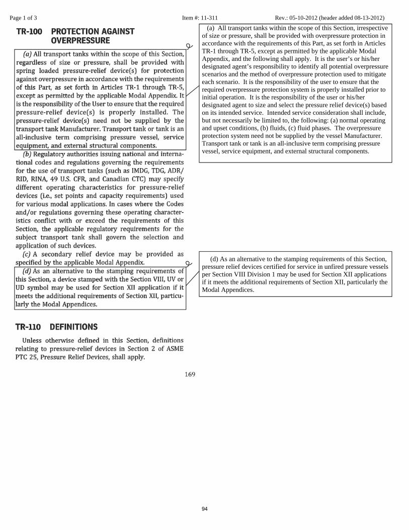
Page 1 of 3 Item #: 11-311 Rev.: 05-10-2012 (header added 08-13-2012)
(a) All transport tanks within the scope of this Section, irrespective of size or pressure, shall be provided with overpressure protection in accordance with the requirements of this Part, as set forth in Articles TR-1 through TR-5, except as permitted by the applicable Modal Appendix, and the following shall apply. It is the user’s or his/her designated agent’s responsibility to identify all potential overpressure scenarios and the method of overpressure protection used to mitigate each scenario. It is the responsibility of the user to ensure that the required overpressure protection system is properly installed prior to initial operation. It is the responsibility of the user or his/her designated agent to size and select the pressure relief device(s) based on its intended service. Intended service consideration shall include, but not necessarily be limited to, the following: (a) normal operating and upset conditions, (b) fluids, (c) fluid phases. The overpressure protection system need not be supplied by the vessel Manufacturer. Transport tank or tank is an all-inclusive term comprising pressure vessel, service equipment, and external structural components. (d) As an alternative to the stamping requirements of this Section, pressure relief devices certified for service in unfired pressure vessels per Section VIII Division 1 may be used for Section XII applications if it meets the additional requirements of Section XII, particularly the Modal Appendices.
94
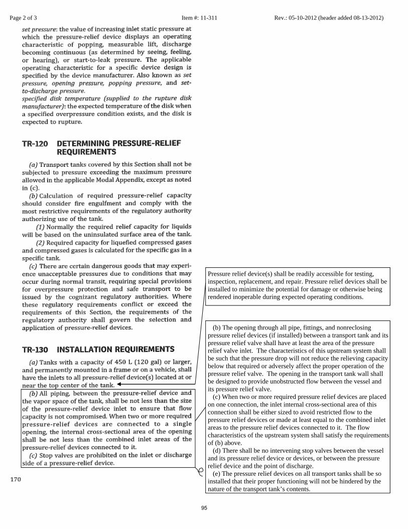
Page 2 of 3 Item #: 11-311 Rev.: 05-10-2012 (header added 08-13-2012)
Pressure relief device(s) shall be readily accessible for testing, inspection, replacement, and repair. Pressure relief devices shall be installed to minimize the potential for damage or otherwise being rendered inoperable during expected operating conditions. (b) The opening through all pipe, fittings, and nonreclosing pressure relief devices (if installed) between a transport tank and its pressure relief valve shall have at least the area of the pressure relief valve inlet. The characteristics of this upstream system shall be such that the pressure drop will not reduce the relieving capacity below that required or adversely affect the proper operation of the pressure relief valve. The opening in the transport tank wall shall be designed to provide unobstructed flow between the vessel and its pressure relief valve. (c) When two or more required pressure relief devices are placed on one connection, the inlet internal cross-sectional area of this connection shall be either sized to avoid restricted flow to the pressure relief devices or made at least equal to the combined inlet areas to the pressure relief devices connected to it. The flow characteristics of the upstream system shall satisfy the requirements of (b) above. (d) There shall be no intervening stop valves between the vessel and its pressure relief device or devices, or between the pressure relief device and the point of discharge. (e) The pressure relief devices on all transport tanks shall be so installed that their proper functioning will not be hindered by the nature of the transport tank’s contents.
95

Page 3 of 3 Item #: 11-311 Rev.: 05-10-2012 (header added 08-13-2012)
(f) Discharge lines from pressure relief devices shall be designed to facilitate drainage or shall be fitted with drains to prevent liquid from lodging in the discharge side of the pressure relief device, and such lines shall lead to a safe place of discharge. The size of the discharge lines shall be such that any pressure that may exist or develop will not reduce the relieving capacity of the pressure relief devices below that required to properly protect the vessel, or adversely affect the proper operation of the pressure relief devices. [See TR-210.1 (g) and the applicable Modal Appendix.] (g) (h)
96

Record Level
Out for SC Ballot
Record
11-312
PagesRecord Sub-Type
Revision
Project Manager
Brian Pittel
Subject
Section XII, TR-200, TR-210.3, TR-300, TR-310, TR-310.3, TR-310.4, TR-310.6,
TR-320, TR-310.3, TR-310.4, TR-320.6, TR-510, TR-520, TR-530, TR-540
Proposal
To harmonize the Section XII general requirements for pressure relief valves with those in
Section VIII, Division 1 and to address Tanner's negative #9 for Item #:04-20.
Item numbers 03-1388 and 03-1389 required that paragraphs TR-310.5, TR-400, and
TR-410 be revised so that the requirements of these paragraphs are harmonized with Section
VIII, Division 1. When performing these revisions, it was determined that the requirements of
other paragraphs of Section XII also required revisions. Due to the scope of the project, all of
Section XII, Part TR was reviewed and revised to harmonize these requirements for pressure
relief devices with the requirements of Section VIII, Division 1 and other applicable sections of
ASME Boiler and Pressure Vessel codes, Item numbers 03-1388 and 03-1389 will be closed
and new item numbers addressing the changes required by 03-1388 and 03-1389 and all
necessary changes to TR-1 through TR-5 will be developed.
Explanation
Summary of ChangesThe following changes were made to update ASME Section XII with the applicable information
within the current revision and addenda of ASME Section VIII Division 1:
TR-200(b) – Updated in its entirety
TR-200(c) – Updated in its entirety
TR-210.3 (a) – Changed “capacity certification testing” to “Capacity Certification”
TR-210.3 (b) – Changed “(including capacity tests)” to “including capacity”
TR-210.3(c) - Updated in its entirety
TR-210.3(c)(1) - Updated in its entirety
TR-210.3(c)(2) - Updated in its entirety
TR-210.3(c)(3) – Added “pressure relief” in front of “valve” in two places
TR-210.3(c)(4) - Updated in its entirety
TR-210.3(c)(4)(d) - Updated in its entirety
TR-300(a) – Added last sentence
TR-300(b) – Updated in its entirety
TR-310.3 – Added “and pressure parts” between “holders” and “shall”
TR-310.4 – Added “the” between “samples and” and “performance of”
TR-310.4(c) – Changed “fifth” to “sixth” and “5” to “6”
TR-310.4(c)(3) – Added “or exceed” between “meet” and “the performance”
TR-300(c)(4) – Updated in its entirety
TR-320 – Updated in its entirety
Added TR-320.1, TR-320.2, TR-320.3, TR-320.4, TR-320.5, TR-320.6
TR-510 - Updated in its entirety
TR-510(a) – Changed “Manufacturer or Assembler” to “ Manufacturer and the Assembler”
TR-510(c) - Updated in its entirety
TR-510(d) - Updated in its entirety
TR-510(e) - Updated in its entirety
TR-510(g) - Updated in its entirety
TR-520(a) - Updated in its entirety
TR-520(e) - Updated in its entirety 97

TR-520(f) - Updated in its entirety
TR-520(g) - Updated in its entirety
TR-520(h) - Updated in its entirety
TR-520(j) - Updated in its entirety
TR-520(k) - Changed “(a),(b), and (e),” to “(a),(b),(e),(j), and (k),”
Added TR-520.1
TR-530 - Updated in its entirety
TR-540 - Updated in its entirety
Item History
12/17/12: Transferred from SC-SVR to BPV XII
BPV SC-SVR
BPV SC-SVR SGGR
BPV SC-XII SGGR
Sub-Tier Committees Involved
Ballot: 12-1802RC1
Ballot Level: Subcommittee
Date Opened: 11/30/2012
Date Closed: 12/17/2012
Final Record Status :Approved
Latest Ballot Information
98

Item 11-312: Section XII, TR-200, TR-210.3, TR-300, TR-310, TR-310.3, TR-310.4, TR-310.6, TR-320, TR-310.3, TR-310.4, TR-320.6, TR-
510, TR-520, TR-530, TR-540
SC-SVR History February 8, 2011 – This item was opened between meetings. April 28, 2011 – A list will be put together of the issues that the group needs to look at. Hopefully a proposal will be able to be formulated for the November meeting. August 9, 2011 - Mr. Pittel reported that this is a work in progress and that they are still working to bring the Section VIII requirements into the proposal. The bulk of the work has already been completed. Hopefully it will be ready for vote at the subgroup level by November. November 8, 2011 – Mr. Pittel reported that this item needs a proposal; some changes to the proposal will need to be made based on the comments received on record #11-311. He hopes to have this ready for ballot to the SG-GR before the next meeting. February 7, 2012 – Mr. Pittel reported that he is continuing to work with this proposal. Based on the discussions in Section XII, he found that he omitted marking for breaking pin devices which will need to be incorporated into this proposal. He will be composing a new proposal and will hopefully have a ballot to SG-GR in the next few weeks. May 15, 2012 – Mr. Pittel reported that the proposal was updated, see pages 246-261 of the May 15 ,2012 Meeting Minutes for the revised proposal provided at the meeting. The PM will update the record on CS Connect and this item will be balloted to SC-SVR. He will send the request to the secretary when they are ready to be balloted. August 14, 2012 – Mr. Pittel reported that this item is currently out for ballot and is scheduled to close on August 17, 2012. November 6, 2012 – Mr. Pittel reported that this item went for ballot and received several negatives. A new version was posted to CS Connect and is ready for a recirculation ballot. February 12, 2013 – Mr. Pittel reported that this item has been approved by SC-SVR and was forwarded to BPV XII. He is working with the BPV XII Secretary to get this item out for ballot. This item can be moved to items referred. August 13, 2013 -
99

(b) The set pressure of a pressure relief device shall not be adjusted outside the range of set pressure specified by the device Manufacturer. The initial adjustment shall be performed by the Manufacturer, his authorized representative, or an Assembler, and a valve data tag shall be provided that identifies the set pressure capacity and date. The valve shall be sealed with a seal identifying the Manufacturer, his authorized representative, or the Assembler performing the adjustment. (c) The set pressure tolerances of pressure relief valves shall not exceed ±15 kPa (±2 psi) for pressures up to and including 500 kPa (70 psi) and ±3% for pressures above 500 kPa (70 psi).
100