2021 - AMI Connect
48
Connect 2021 Catalogue
-
Upload
khangminh22 -
Category
Documents
-
view
2 -
download
0
Transcript of 2021 - AMI Connect

Connect
2021 Catalogue


Contents
Connect
AMI Connect Head Office: 107 Forsyth Street, O’Connor 6163, WAT: (08) 9331 0070 E: [email protected] Support: [email protected]
Branches Australia Wide & InternationalPerth, Adelaide, Sydney, Brisbane, Darwin, Cairns, Melbourne, Singapore & Vietnam
Visit us online: www.amiconnect.com.au A Member of the AMI Group | ABN: 88 569 498 390
Who We Are
Core values 2
Airtime provision and services 3
Cellular Signal Boosters
Cel-Fi GO Stationary 4
Cel-Fi GO Mobile 5
Cel-Fi GO Marine 6
Cel-Fi PRO 8
Portable Satellite Phones
IsatPhone 2 10
Iridium 9555 12
Iridium Extreme® 14
Iridium GO!® 16
Fixed Satellite & Docking Units
IsatDock2 DRIVE 18
IsatDock2 MARINE 20
LT-3100 System 22
VMS, Tracking & GMDSS
LT-3100S GMDSS System 24
SAILOR® 6140 mini-C Maritime 26
SAILOR® 6110 mini-C GMDSS 28
Broadband & VSAT Systems
SAILOR® Fleet One 30
SAILOR® 4300 L-Band 32
Connect v60E 34
Connect v65 36
Connect VSAT Range 38
Bandwidth Management Solutions
Connect RedPort 40
Connect SeaBrowser 42
IP Based Radio
Connect PTT 45

2
Who we areCore Values
AMI Connect (formerly trading as Global Maritime Data and Airtime Solutions) is your solutions partner for satellite communications requirements.
Our product range includes technology from world leading Manufacturers and satellite operators.
AMI Connect is perfectly positioned to provide Australasia with a world-class satellite communications service, with our head office in Fremantle, Western Australia, and branches throughout Australia, Singapore and Vietnam.
Our products are ideal for situations which require communication in remote areas, or where high performance voice and data solutions are needed for commercial and leisure application.
Those working in mining, oil and gas, maritime, offshore, engineering and media, to name a few industries, are sure to benefit from airtime packages tailored by AMI Connect to meet any requirement.
Our clients are as varied as they come: Japanese supertankers and offshore vessels; mining camps and rural farms, super yachts; fast ferries and fishing vessels; St. John ambulances and truck fleets… we have a communications solution for every situation.
Visit us online at www.amiconnect.com.au
Who
We
Are

3
Airtime provision and services
AMI Connect enable our users to access service coverage from market leaders in satellite communications and airtime, through the largest and most reliable satellite networks available across the globe, at a competitive price.
Whether an offshore cruising sailor or working remotely in some of the regions most isolated areas, our partnership with prime networks such as Iridium and Inmarsat ensure stability and coverage.
Contact us about post and pre-paid plans for a variety of technologies, along with genuine hardware and service plans.
Who
We
Are

4
Cel-Fi GO Stationary
Technical Specifications
Features
The evolved smart signal booster that can amplify cellular signals up to 100 dB.
The Cel-Fi GO Stationary Smart Signal Repeater, the first carrier-class indoor/outdoor cellular coverage solution to feature industry leading 100 dB system gain and Nextivity’s unconditionally network safe guarantee. Cel-Fi GO Stationary leverages the award-winning Intelliboost signal processing to deliver the industry’s largest coverage footprint with the best voice and data wireless performance.
Cel-Fi GO Stationary is IP54 rated weather resistant and does not interfere with other wireless devices. This multi-band solution is ideal for use in commercial properties, government buildings, agricultural settings, small manufacturing operations, rural areas, businesses, and large homes.
• 3G / 4G / 4GX Voice and Data
• Up to 15,000 ft2 (1,500 m2) of Coverage
• Multi-Band Support
• Indoor / Outdoor IP54 Rated
• Network Safe
Cel-Fi GO STATIONARY
Configurations Band 3/5/28 3-front end receivers that relay a single band.
Physical Specification 255mm x 87mm x 28mm600g
System Gain Up to 100 dB Gain
Cellu
lar S
igna
l Boo
ster
s

5
Cel-Fi GO MobileThe evolved in-vehicle smart signal booster that’s great for cars, trucks, RVs and marine installations.
The Cel-Fi GO Mobile Smart Signal Repeater, the first carrier-class mobile cellular coverage solution to feature industry-leading 70 dB system gain and Nextivity’s unconditional network safe guarantee. Cel-Fi GO Mobile leverages artificial intelligence and award-winning Intelliboost signal processing to deliver the industry’s best voice and data wireless performance for mobile subscribers on the move.
Cel-Fi GO Mobile is IP54 rated weather resistant and does not interfere with other wireless devices. This multi-band solution is ideal for trucks, vehicles, RVs, and boats.
• 3G / 4G / 4GX Voice and Data
• Multi-User Mobile Coverage
• Multi-Band Support
• Indoor / Outdoor IP54 Rated
• Network Safe
Features
Cellu
lar S
igna
l Boo
ster
s
Technical Specifications
Cel-Fi GO MOBILE
Configurations Band 3/5/28 3-front end receivers that relay a single band.
Physical Specification 255mm x 87mm x 28mm600g
System Gain Up to 70 dB Gain

6
Cellu
lar S
igna
l Boo
ster
s
Cel-Fi GO MarineBoost and distribute a 3G/4G mobile signal on a boat, ship or marine vessel.
Supporting voice and mobile internet for multiple mobile devices, boosting your mobile coverage at sea has never been easier.
• Supports 3G (850) and 4G (700/1800) – only one band at a time
• Designed for marine applications
• 100dB of system gain (latest software update required using WAVE App)
• Includes external and internal antennas
• Carrier approved
• Band Selection Button
• Bluetooth WAVE App for iPhone, Android & Computers
Features:

7
Sample Layout
Cellu
lar S
igna
l Boo
ster
s
Wall Mount
Cel-Fi Marine Pack (Adhesive Mount)
Cel-Fi Marine Pack (Wall Mount)
• Cel-Fi GO Mobile
• Blackhawk Marine Omni High Gain Antenna (7/10 dBi)
• Standard adjustable mount
• Blackhawk Adhesive Mount 700-2700MHz 3.5dBi
• 1 x 10m PT240 LSHF cable
• 1 x 12v Power Supply
• Cel-Fi GO Mobile
• Blackhawk Marine Omni High Gain Antenna (7/10 dBi)
• Standard adjustable mount
• Blackhawk Wall Mount 698-4000MHz 5/7dBi Panel Antenna -150dBc PIM
• 1 x 10m PT240 LSHF cable
• 1 x 6m PT240 LSHF cable
• 240v and 12v Power Supply
Available Marine Packs:

8
Cel-Fi GO PROIndoor Smart Signal Booster for 3G, 4G and 4G LTE networks around the world.
Benefit to Consumers
• Improved Voice Coverage
• Improved Data Throughput
• Improved Battery Life
• Ease of Installation
Benefit to Operators
• Reduced Churn
• Higher Data Service Usage
• Decreased Operational Cost
• Network Safe
• Operator Specific
• Self Adjusting
• Multi Technology Support
• Multi Carrier Support
Cel-Fi PRO improves 3G, 4G, and LTE cellular service by eliminating dead zones and dropped calls. With 100 dB of gain, Cel-Fi PRO will not only improve cellular service across four (4) concurrent bands, it will also reduce your cell phone’s power requirements and extend its battery life. Cel-Fi PRO covers up to 13,000 ft2 (1,200 m2) of indoor space per system.
Cel-Fi PRO systems feature an LCD color interface, are fully self-contained and self-configuring, and require no external antennas or wiring. Simply plug it in to boost indoor cellular coverage.
Cellu
lar S
igna
l Boo
ster
s

9
Technical Specifications
Cel-Fi GO PROConfigurationsAll systems are reconfigured to specific carriers
Bands 1/3, 1/7, 1/8, 1/3/7, 1/3/8, 1/3/7/8, 1/3/8/20, 1/7/8/20, 2/5, 2/4/5/12, 1/3/5/28, or 3/5/28
Power Consumption Full uplink: • 30 WattsIdle: • <20 Watts
Physical Specification
Network Unit:179 x 155 x 110mm (540g)Coverage Unit:160 x 164 x 70mm (450g)
Certifications CE, FEE, RoHS, IC, EAC, R&TTE & EN
Electrical & Environmental Requirements 12 VDC-25 to 60 Celsius
Physical Specification
Network Unit:179 x 155 x 110mm (540g)Coverage Unit:160 x 164 x 70mm (450g)
Sample Layouts
One Level
Two Level
Cellu
lar S
igna
l Boo
ster
s
10
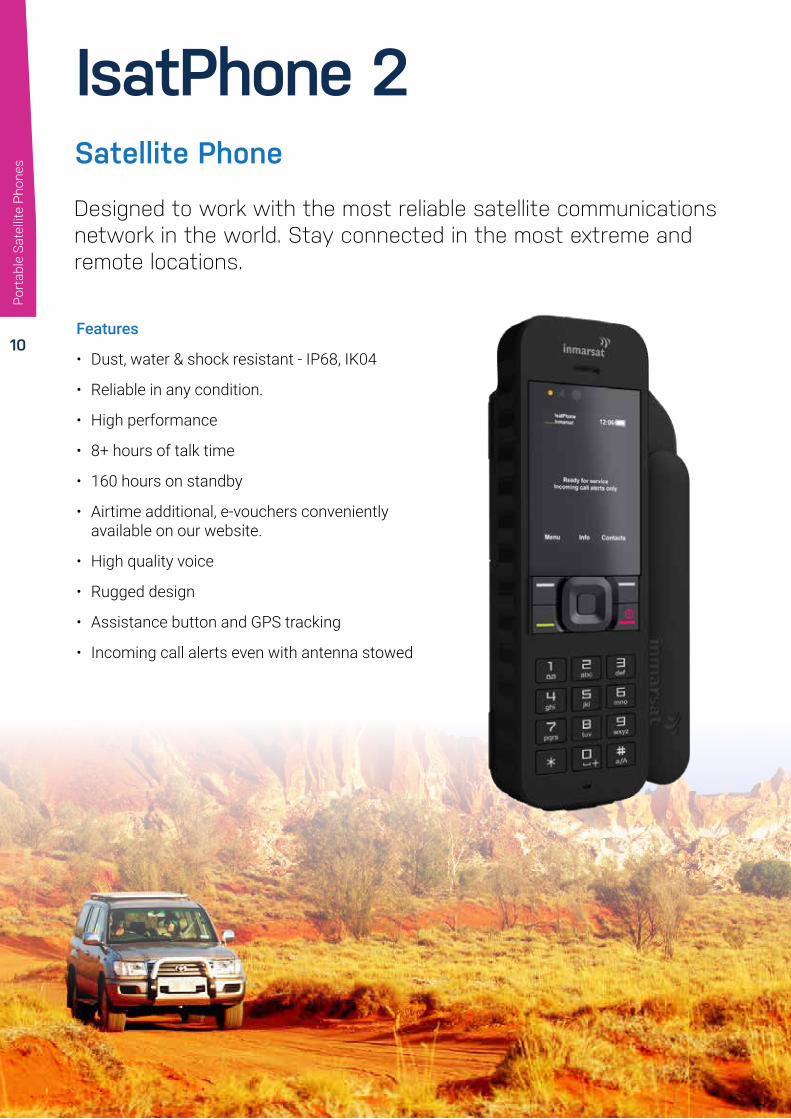
IsatPhone 2
Features
• Dust, water & shock resistant - IP68, IK04
• Reliable in any condition.
• High performance
• 8+ hours of talk time
• 160 hours on standby
• Airtime additional, e-vouchers conveniently available on our website.
• High quality voice
• Rugged design
• Assistance button and GPS tracking
• Incoming call alerts even with antenna stowed
Designed to work with the most reliable satellite communications network in the world. Stay connected in the most extreme and remote locations.
Satellite Phone
Port
able
Sat
ellit
e Ph
ones

11
PhysicalLength: 169mm (6.7”)
Width: 52mm (2”) without antenna 75mm (3”) with antenna
Depth: 29mm (1.1”) in hand 36mm (1.4”) at deepest point
Weight: 318g (11.2oz) – including batteryDisplay: High-contrast colour screen
Interfaces:
Micro USB Audio socket Antenna port Bluetooth 2.0
Durability: IP65 IK04
Operating range: -20°C to +55°C (-4°F to +131°F)Storage range: -20ºC to +70ºC (-4ºF to +158ºF) (with battery)Charging range: 0°C to +45°C (+32°F to +113°F)
Battery
Type: Lithium-ion, 3.7 voltsTalk time: Up to 8 hoursStandby time: Up to 160 hours
Services
Satellite telephony: 2.4kbps voice codecVoicemail: Speed dial 1
Supplementary voice services:
Call history Caller ID Call waiting Call divert Call holding Conferencing Call barring Speed dialling Fixed number dialling
Text-to-text:160 Latin / ~74 non-Latin characters Up to 10 concatenations Standard and predictive text
Text-to-email:160 Latin / ~74 non-Latin characters Up to 10 concatenations Incoming email – 160 Latin characters / ~74 non-Latin characters
Web message-to-IsatPhone 2: Free from message.inmarsat.com
GPS location data: View position Send as text or email
Technical Specifications
This map is illustrative of IsatPhone 2 coverage. It does not provide a guarantee of the extent of service availability. Please note, Alphasat coverage prioritises the region north of 44°S and service may degrade south of this latitude.
Port
able
Sat
ellit
e Ph
ones
12
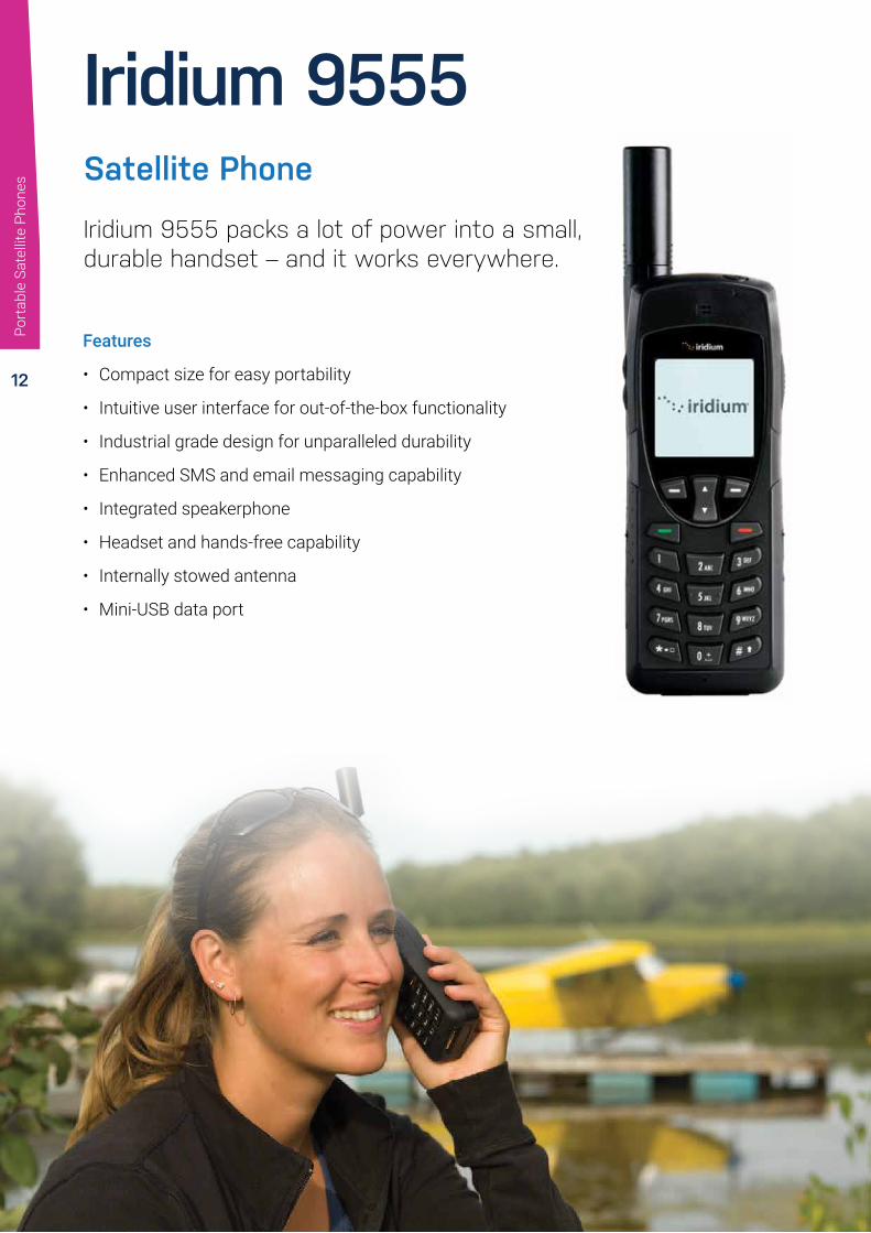
Iridium 9555
Features
• Compact size for easy portability
• Intuitive user interface for out-of-the-box functionality
• Industrial grade design for unparalleled durability
• Enhanced SMS and email messaging capability
• Integrated speakerphone
• Headset and hands-free capability
• Internally stowed antenna
• Mini-USB data port
Iridium 9555 packs a lot of power into a small, durable handset – and it works everywhere.
Satellite Phone
Port
able
Sat
ellit
e Ph
ones

13
PhysicalDimensions 143 mm (L) x 55 mm (W) x 30 mm (D)Weight 266g (9.4 oz)
DurationStandby time Up to 30 hoursTalk time Up to 4 hours
Display200 character illuminated graphic displayVolume, signal and battery strength metersIlluminated weather-resistant keypad
Calling FeaturesIntegrated speakerphoneQuick-connect to Iridium voicemailTwo-way SMS and short email capabilityPre-programmable International AccessCode (00 or +)Mailbox for voice, numeric and text messagesSelectable ring and alert tones (8 choices)
Memory100 entry internal address book, with capacity for multiple phone numbers, email addresses and notesSIM-based address book with 155 entry capacityCall history retains received, missed and dialed callsUsage Control FeaturesUser-configurable call timers to manage costsKeypad lock and PIN lock for additional security
Technical Specifications
Compact Power
Iridium 9555 packs serious power into its small frame. With a significantly reduced footprint from our previous phone, more hand-friendly form factor, and space-saving features such as an internally stowed antenna, this sleek handset is designed to easily go wherever your customers go.
Rugged and Reliable Critical Lifelines
Iridium 9555 is a dependable, ruggedly built tool, not a toy. It won’t play games, take pictures, or play MP3s. What it will do is work. Everywhere. It is engineered to withstand some of the world’s toughest environments, so the world’s toughest customers can depend on it as a critical lifeline whenever and wherever need takes them.
Port
able
Sat
ellit
e Ph
ones

14
Iridium Extreme®
Features
• GPS-enabled location-based services
• Online tracking
• Customized solutions enabled for diverse markets
• Accessories to dramatically enhance personal communications
• Satellite Emergency Notification
• Device (SEND) compliant SOS button design
• Reliable two-way global coverage
• Toughest military-grade designed satellite handset ever built
Unparalleled reach. In hand, everywhere.
Satellite Phone
It’s time to raise expectations of what a satellite phone should be. Iridium Extreme® combines location awareness, a fully integrated SOS button with included emergency response service, and market leading toughness — letting you take durability, reliability and versatility with you in hand, all over the world.
Por
tabl
e Sa
telli
te P
hone
s

15
Technical Specifications
PhysicalDimensions: 140 mm (L) x 60 mm (W) x 27 mm (D)Weight: 247g
DurationStandby time: Up to 30 hoursTalk time: Up to 4 hours
Display200-character, daylight-readable displayIntegrated back-light for nighttime viewingIlluminated weather resistant keypad
Calling FeaturesIntegrated speakerphoneQuick-connect to Iridium voice mailTwo-way SMS and short email21 supported menu languagesPre-programmable International Access Code (00 or +)Mailbox for voice, numeric and text messagesSelectable ring and alert tones (8 choices)
Durability SpecificationsMilitary-grade ruggedness (MIL-STD 810F)Ingress Protection (IP65)
Memory100-entry internal phonebook, with capacity for multiple phone numbers, email addresses and notesCall history retains received, missed and dialed calls
Usage Control FeaturesUser-configurable call timers to manage costsKeypad lock and PIN lock for additional security
Jet Water Resistant
Shock Resistant
Dust Proof
SMSSMS
Data Tethering
Real Global
Real Mobile
Real Reliable
SOS EmergencyButton
Online Tracking
GPS GPS Positioning
VoicePo
rtab
le S
atel
lite
Phon
es

16
Iridium GO!®Your smartphone will work anywhere on the planet.
Iridium GO!® creates the first ever reliable global connection for voice calling and text messaging using your own smartphone or tablet, as well as provides enhanced data capabilities offered through optimized apps to meet your unique needs. No worries. No roaming charges. Just connected and in touch wherever you are, whenever you need, with the devices you rely on every day.
Iridium GO! supports a full range of global communications using optimized apps:
• Voice calls
• Text messaging
• Email access
• Weather updates
• Customized third-party apps
• Emergency alerts (SOS)
• Photo sharing
• GPS tracking
• Posting to Facebook/Twitter
Port
able
Sat
ellit
e Ph
ones

17
PhysicalDimensions: 11.4 x 8.2 x 3.2 cm
DurationStandby time: Up to 15.5 hoursTalk time: Up to 5.5 hours
What’s in the BoxIridium GO! deviceBatteryUniversal AC Travel ChargerUSB Charging/Data CableFour International AdaptersAC Adapter (Car Charger)Protective CoverUser ManualLegal Information BookletGEOS Emergency ServicesBrochure
Easy to Use:
• Stable, lay-flat design
• Flip-up antenna
• Built-in menu/status display
• Durability Specifications:
• Military-grade ruggedness
• (MIL-STD 810F)
• Ingress Protection (IP65)
Flexible:
• Custom app platform for developers (SDK)
• Robust line of accessories
Technical Specifications
Port
able
Sat
ellit
e Ph
ones

18 Features
• Slim line compact installation
• Handsfree
• Privacy Handset option (ISD955)
• Voice, SMS and Circuit Switched Data capable
• Tracking and SOS (Via the ISatPhone 2)
• USB data interface
• Accessory / Ignition sense / Horn Alert
• 10-32V DC power input
• AC Plug pack 110/240 input (optional)
• SMA Connectors – Inmarsat Antenna / GPS Antenna
• Full certified, FCC, Industry Canada, Inmarsat, RoHS, CE, IEC60945, AS/EN60950
• 2 year repair or replacement warranty
The only Inmarsat Certified dock for the IsatPhone 2 A highly featured docking station for the Inmarsat satellite handset that can be used in various maritime and transport applications considerably extending the functionality of the handset.
IsatDock2 DRIVEFi
xed
Sate
llite
& D
ocki
ng U
nits

19
Technical Specifications
Average Power Consumption Current @ 12V Average WattsStandby + Charging 360mA 4.3WTransmit + Charging 875mA 10.5WSleep Mode 5mA 60mWPeak Current 3.5mA 42W
Connectors/ Interfaces
Configuration Port USB MicroAntenna TNC-FemaleGPS Antenna SMA-FemaleMicrophone 2-way microFitSpeaker 2-way microFit10-32 VDC 4-way microFit (AC/DC adaptor, or DC lead)Privacy Handset Port RJ9 connectorLEDs/Buttons Status LED, Track, Mute, Up and Down
CertificationsInmarsat Type ApprovalFCCCE ComplianceElectrical SafetyRoHSIndustry CanadaC-TickEMC Compliance
I/O Alert1 x Beam Alert Loop Bare Wire - Normally Closed loop IN to OUTTrack (Personal Alert*) button In-built - single key press
* NOTE This action is optional, only when the Personal Alert Mode for your IsatPhone 2 is configured
Temperature Degrees °C Degrees °FOperating Range -30°C to +70°C -22°F to +158°FStorage -35°C to +85°C -31°F to +185°FBattery Charging 0°C to +45°C 32°F to +113°FHumidity < =75% RH
Kit ContentsIsatDock2 DRIVE2 x IsatDock2 AdaptorsUniversal Mounting Bracket (RAM)Speaker & Microphone10-32V DC Power Cable/fuse kitUser ManualQuick Start Guide
Fixe
d Sa
telli
te &
Doc
king
Uni
ts

20
Features
• Intelligent POTS/RJ11 interface
• Supports Personal Alert and
• Assistance Alert of the IsatPhone 2
• Active privacy handset
• High quality marine enclosure
• Supports External I/O
• Charges IsatPhone 2
• RJ11/POTS interface
• PABX Integration
• Supports Assistance Alert & Tracking via IsatPhone 2
• 2 year repair/replacement warranty
• Active Privacy Handset
• In-built handsfree speakerphone
• Adjustable in-built ringer
• Mute facility
• Status LED with adjustable brightness
• USB data access
• Includes IsatDock2 adapters (2x)
IP54 rated intelligent docking station for the IsatPhone 2 Specifically designed for maritime application
IsatDock2 MARINEFi
xed
Sate
llite
& D
ocki
ng U
nits

21
Average Power Consumption Current @ 12V Average Watts
Power w/o IsatPhone 2 130mA 1.6WStandby + Charging 360mA 4.3WTransmit + Charging 875mA 10.5WSleep Mode 5mA 60mWPeak Current 3.5A 42W
Physical Specifications
Dimensions "276 x 208 x 100 (mm)" "10.9 x 8.2 x 3.9 (inches)"Weight - Dock 1.67kg 3.67lbsTotal Kit Weight 2.72kg 5.99lbs
Environment Specifications
Operating Range -30°C to +70°C -22°F to +158°Storage -35°C to +85°C -31°F to +185°FBattery Charging Temp# 0°C to +45°C +32°F to +113°FHumidity < =75% RH
Connectors / Interfaces
POTS/RJ11 RJ11/2-wire, 5REN @ 600m, Adjustable dial, ring, busy tone configured frequency and adaptive impedance.
BEAM Antenna TNC-FemaleGPS Antenna SMA-Female10-32 V DC 4-way microFit (AC/DC adator, or DC lead)Privacy Handset Port RJ9 connectorConfiguration/Data USB MicroSpeakerphone In-built speaker and microphone
I/O Alert
1x BEAM Alert Loop Bare wire - ‘‘Normally Closed’’ loop IN to OUT
Personal Alert In-built single key press
Certifications
Inmarsat Type ApprovalFCCCE ComplianceElectrical SafetyRoHSIndustry CanadaC-TickEMC compliance
IP54 Rating 5 = Protected against dust limited ingress (no harmful deposits) 4 = Protection against water sprayed from all directions - limited ingress permitted.
Accessories
ISD710 Maritime Antenna (Active)ISD932 6m SMA/TNC Cable Kit (Active)ISD933 13m SMA/TNC Cable Kit (Active)ISD934 18m SMA/TNC Cable Kit (Active)ISD935 30m SMA/TNC Cable Kit (Active)ISD938 40m SMA/TNC Cable Kit (Active)ISD942 50m SMA/TNC Cable Kit (Active)ISD943 60m SMA/TNC Cable Kit (Active)ISD944 70m SMA/TNC Cable Kit (Active)ISD945 80m SMA/TNC Cable Kit (Active)ISD946 90m SMA/TNC Cable Kit (Active)ISD947 100m SMA/TNC Cable Kit (Active)ISD960 IsatDock2 AdaptorRST055A UPS Battery PackRST410 “Man Down” Pendant Kit
Technical Specifications
KlT CONTENTS
IsatDock2 MARINE2 x IsatDock2 Adapters110-240V AC Plug PackPrivacy Handset10-32V DC Power Cable2m Alert wiring loopWall Mounting PlateUser Manual & Quick Start Guide
Fixe
d Sa
telli
te &
Doc
king
Uni
ts

22
LT-3100 Satellite Communications System Designed and built for the demanding and rough environment at sea.
LT-3100 System
• Voice, SMS, Data, and Vessel tracking
• 2.4 kbps and 9.6 kbps compressed data
• Programmable softkeys for e.g. Emergency Service
• Single antenna cable solution (up to 500 m)
• High-performance GNSS/GPS receiver
• High quality microphone, speaker, and equalizer for improved audio performance
• Bluetooth interface supporting voice, SMS, and data
• Voice prompt audio feedback
• Large 4.3” TFT display supporting day and night modes
• Firewall and user authentication for high level of security
• Webserver for configuration and maintenance
• Support external LAN Wi-Fi Access Points
• Support external SIP PABX and SIP handsets
• Connectivity of Smartphones, Softphones, and Apps
Features
Fixe
d Sa
telli
te &
Doc
king
Uni
ts

23
LT-3100 SATELLITE COMMUNICATIONS SYSTEM
designed and built for the demanding and rough environment at sea
SPECIFICATIONS
Lars Thrane A/S Skovlytoften 33DK-2840 Holte, Denmark Phone: +45 88 30 10 00 Fax: +45 88 30 10 09Email: [email protected] DK-36042443www.thrane.eu
98-1
0071
1 LT
-310
0 R
EV. 1
.03
LT-3
100
Pro
duc
t Sh
eet
Sub
ject
to
cha
nge
wit
hout
fur
ther
no
tice
IC
RoHS
compliant
IN THE BOXLT-3110 Control Unit P/N: 51-100987
LT-3120 Handset P/N: 51-100988
LT-3121 Cradle P/N: 51-101181
LT-3130 Antenna Unit P/N: 51-100989
Bracket Mount, Control Unit P/N: 91-100771
Power Cable, 3m P/N: 91-100767
User & Installation Manual P/N: 95-100765
ACCESSORIESFlush Mount, Control Unit P/N: 91-100772
Bracket Mount (1.5” to 2.5” tube), Antenna Unit P/N: 91-100773
Pole Mount (1.5” tube), Antenna Unit P/N: 91-100774
Aux Cable, 3m P/N: 91-100768
Coaxial Cable Ø4.9mm, 10m and 25m
Coaxial Cable Ø10.3mm, 10m, 25m, and 50m
Crimping Tool for Coaxial Cable Ø4.9mm and Ø10.3mm
LT-3100 SATELLITE COMMUNICATIONS SYSTEMCertification & standards Maritime CE, FCC, IC, RCM, RoHS 2, Iridium®
Vibration, operational IEC 60945 (sine) & proprietary Maritime Random profile
Vibration, survival Proprietary Maritime Random profile
Vibration, shock Proprietary Maritime profile (20 g, 11 ms)
Power consumption: operating mode, max 37 W
Power consumption: standby mode, max 21 W
Power consumption: sleep mode, max 0.08 W
Compass Safe Distance, std. 0.85 m (2.8 ft)
Compass Safe Distance, steer. 0.65 m (2.1 ft)
LT-3110 Control UnitWeight 658 g (1.45 lbs)
Dimensions 224.0 x 120.0 x 70.0 mm (8.82 x 4.72 x 2.76 in)
Temperature, operational -15°C to +55°C (+5°F to +131°F)
IP rating, dust and water IP 32
Interfaces Ethernet, auxiliary, DC input, chassis ground Antenna Unit (N conn.), Handset, Bluetooth, SIM card
Input voltage 10 - 32 VDC
LT-3120 HandsetWeight 290 g (0.64 lbs)
Dimensions 208.8 x 52.8 x 38.2 mm (8.22 x 2.08 x 1.50 in)
Temperature, operational -15°C to +55°C (+5°F to +131°F)
IP rating, dust and water IP32
LT-3130 Antenna UnitWeight 687 g (1.51 lbs)
Dimensions 151.1 x Ø 149.5 mm (5.95 x Ø 5.89 in)
Temperature, operational -25°C to +55°C (-13°F to +131°F)
IP rating, dust and water IP67
Interfaces Control Unit (N conn.)
Antenna communication cable Coaxial cable, up to 500 m (1500 ft)
Warranty 2 year
Maintenance None
LT-3100 Satellite Communications System
Certification & standards Maritime CE, FCC, IC, RCM, RoHS 2, Iridium®
Vibration, operational IEC 60945 (sine) & proprietary Maritime Random profile
Vibration, survival Proprietary Maritime Random profileVibration, shock Proprietary Maritime profile (20 g, 11 ms)Power consumption: operating mode, max 37 W
Power consumption: standby mode, max 21 W
Power consumption: sleep mode, max 0.08 W
Compass Safe Distance, std. 0.85 m (2.8 ft)Compass Safe Distance, steer. 0.65 m (2.1 ft)
LT-3110 Control UnitWeight 658 g (1.45 lbs)
Dimensions 224.0 x 120.0 x 70.0 mm (8.82 x 4.72 x 2.76 in)
Temperature, operational -15°C to +55°C (+5°F to +131°F)
IP rating, dust and water IP 32
Interfaces Ethernet, auxiliary, DC input, chassis ground Antenna Unit (N conn.), Handset, Bluetooth, SIM card
Input voltage 10 - 32 VDC
LT-3120 HandsetWeight 290 g (0.64 lbs)
Dimensions 208.8 x 52.8 x 38.2 mm (8.22 x 2.08 x 1.50 in)
Temperature, operational -15°C to +55°C (+5°F to +131°F)IP rating, dust and water IP32
LT-3130 Antenna UnitWeight 687 g (1.51 lbs)Dimensions 151.1 x Ø 149.5 mm (5.95 x Ø 5.89 in)Temperature, operational -25°C to +55°C (-13°F to +131°F)IP rating, dust and water IP67Interfaces Control Unit (N conn.)Antenna communication cable Coaxial cable, up to 500 m (1500 ft)Warranty 2 yearMaintenance None
In the Box
LT-3110 Control Unit P/N: 51-100987
LT-3120 Handset P/N: 51-100988
LT-3121 Cradle P/N: 51-101181
LT-3130 Antenna Unit P/N: 51-100989
Bracket Mount, Control Unit P/N: 91-100771
Power Cable, 3m P/N: 91-100767
User & Installation Manual P/N: 95-100765
Accessories
Flush Mount, Control Unit P/N: 91-100772
Bracket Mount (1.5” to 2.5” tube), Antenna Unit P/N: 91-100773
Pole Mount (1.5” tube), Antenna Unit P/N: 91-100774
Aux Cable, 3m P/N: 91-100768
Coaxial Cable Ø4.9mm, 10m and 25m
Coaxial Cable Ø10.3mm, 10m, 25m, and 50m
Crimping Tool for Coaxial Cable Ø4.9mm and Ø10.3mm
Technical Specifications
Fixe
d Sa
telli
te &
Doc
king
Uni
ts

24
LT-3100S Satellite Communications SystemDesigned and built for the demanding and rough environment at sea.
LT-3100S GMDSS System
Iridium GMDSS
• 100% global GMDSS coverage
• Distress Alert & Safety Voice
• Maritime Safety Information (MSI)
• BAM & ECDIS interface
• SSAS & LRIT
• Voice, SMS & Data
• Up to 500 m antenna cable
Features:
The LT-3100S GMDSS System is the new solution for GMDSS Distress and Safety communication via satellite. In early 2020, Iridium plans to start its GMDSS services and operation. Being recognized by the IMO and the SOLAS convention, it will be much more than an alternative to Inm-C, offering 100% global coverage and built-in Safety Voice.
VMS,
Tra
ckin
g &
GM
DSS

25
LT-3100S GMDSS System
Certification & standards Maritime CE, FCC, ISED, RCM, RED, MED (Wheel Mark), RoHS 2, Iridium®
LT-3110S Control UnitWeight 658 g (1.45 lbs)Temperature, operational -15°C to +55°C (+5°F to +131°F)IP rating, dust and water IP32
InterfacesEthernet, auxiliary, DC input, chassis ground, Antenna Unit (N conn.), Handset, SIM card
Input voltage 12 – 24 VDC
LT-3120 HandsetWeight 290 g (0.64 lbs)Temperature, operational -15°C to +55°C (+5°F to +131°F)IP rating, dust and water IP32
LT-3130 Antenna UnitWeight 687 g (1.51 lbs)Temperature, operational -40°C to +55°C (-40°F to +131°F)IP rating, dust and water IP67Interfaces Control Unit (N conn.)Antenna communication cable Coaxial cable, up to 500 m (1500 ft)
LT-3140S Interface Unit
Weight 720 g (1.59 lbs)Temperature, operational -15°C to +55°C (+5°F to +131°F)IP rating, dust and water IP10
Interfaces 4 x Ethernet, 2 x RS422, 4 x GPIO, 4 x CAN, DC input, chassis ground
Input voltage 12 – 24 VDC
LT-3150S Alarm PanelWeight 68 g (0.15 lbs)Temperature, operational -15°C to +55°C (+5°F to +131°F)IP rating, dust and water IP32Interface CANWarranty 2 yearMaintenance None
In the Box
LT-3110S Control Unit P/N 51-101812LT-3120 Handset P/N 51-100988LT-3121 Cradle P/N 51-101181
LT-3130 Antenna Unit P/N 51-100989Bracket Mount, Control Unit P/N 91-100771
Power Cable, 3m P/N 91-102118User & Installation Manual P/N 95-101817
Accessories
LT-3140S Interface Unit P/N 51-101814
LT-3150S Alarm Panel P/N 51-101815
LT-3160S Printer Adapter P/N 51-101816
Flush Mount, Control Unit P/N 91-100772
Bracket Mount (1.5” to 2.5” tube), Antenna Unit P/N 91-100773
Pole Mount (1.5” tube), Antenna Unit P/N 91-100774
Aux Cable, 3m P/N 91-100768
Coaxial Cable Ø10mm, 10m, 25m and 50m
8,82224 m
m
4,72120 mm
5,88149
mm
5,93151 mm
8,23209 m
m
19,92506 m
m
1,5038 mm
2,7470 m
m
2,1354 mm
3,2182 mm
2,0352 m
m
8,95227 m
m
7,33186
8,82224 m
m
4,72120 mm
2,6868 mm
1,9549 m
m
Lars Thrane A/S Skovlytoften 33DK-2840 Holte, Denmark Phone: +45 88 30 10 00 Fax: +45 88 30 10 09Email: [email protected] DK-36042443www.thrane.eu
98-1
0205
6 LT
-310
0S G
MD
SS
Pro
duc
t Sh
eet
Rev
1.0
1Su
bje
ct t
o c
hang
e w
itho
ut f
urth
er n
oti
ce
IN THE BOXLT-3110S Control Unit P/N 51-101812
LT-3120 Handset P/N 51-100988
LT-3121 Cradle P/N 51-101181
LT-3130 Antenna Unit P/N 51-100989
Bracket Mount, Control Unit P/N 91-100771
Power Cable, 3m P/N 91-102118
User & Installation Manaul P/N 95-101817
ACCESSORIESLT-3140S Interface Unit P/N 51-101814
LT-3150S Alarm Panel P/N 51-101815
LT-3160S Printer Adapter P/N 51-101816
Flush Mount, Control Unit P/N 91-100772
Bracket Mount (1.5” to 2.5” tube), Antenna Unit P/N 91-100773
Pole Mount (1.5” tube), Antenna Unit P/N 91-100774
Aux Cable, 3m P/N 91-100768
Coaxial Cable Ø10mm, 10m, 25m and 50m
LT-3100S GMDSS SYSTEMCertification & standards Maritime CE, FCC, ISED, RCM, RED, MED (Wheel Mark),
RoHS 2, Iridium®
LT-3110S Control UnitWeight 658 g (1.45 lbs)
Temperature, operational -15°C to +55°C (+5°F to +131°F)
IP rating, dust and water IP32
Interfaces Ethernet, auxiliary, DC input, chassis ground, Antenna Unit (N conn.), Handset, SIM card
Input voltage 12 – 24 VDC
LT-3120 HandsetWeight 290 g (0.64 lbs)
Temperature, operational -15°C to +55°C (+5°F to +131°F)
IP rating, dust and water IP32
LT-3130 Antenna UnitWeight 687 g (1.51 lbs)
Temperature, operational -40°C to +55°C (-40°F to +131°F)
IP rating, dust and water IP67
Interfaces Control Unit (N conn.)
Antenna communication cable Coaxial cable, up to 500 m (1500 ft)
LT-3140S Interface UnitWeight 720 g (1.59 lbs)
Temperature, operational -15°C to +55°C (+5°F to +131°F)
IP rating, dust and water IP10
Interfaces4 x Ethernet, 2 x RS422, 4 x GPIO, 4 x CAN, DC input, chassis ground
Input voltage 12 – 24 VDC
LT-3150S Alarm PanelWeight 68 g (0.15 lbs)
Temperature, operational -15°C to +55°C (+5°F to +131°F)
IP rating, dust and water IP32
Interface CAN
Warranty 2 year
Maintenance None
SPECIFICATIONS
8,82224 mm
4,72
120
mm
5,88149 mm
5,93
151
mm
8,23209 mm
19,92506 mm
1,50
38 m
m
2,7470 mm
2,13
54 m
m
3,21
82 m
m
2,0352 mm
8,95227 mm
7,33
186
8,82224 mm
4,72
120
mm
2,68
68 m
m
1,9549 mm
8,82224 mm
4,72
120
mm
5,88149 mm
5,93
151
mm
8,23209 mm
19,92506 mm
1,50
38 m
m
2,7470 mm
2,13
54 m
m
3,21
82 m
m
2,0352 mm
8,95227 mm
7,33
186
8,82224 mm
4,72
120
mm
2,68
68 m
m
1,9549 mm
Technical Specifications
VMS,
Tra
ckin
g &
GM
DSS
26
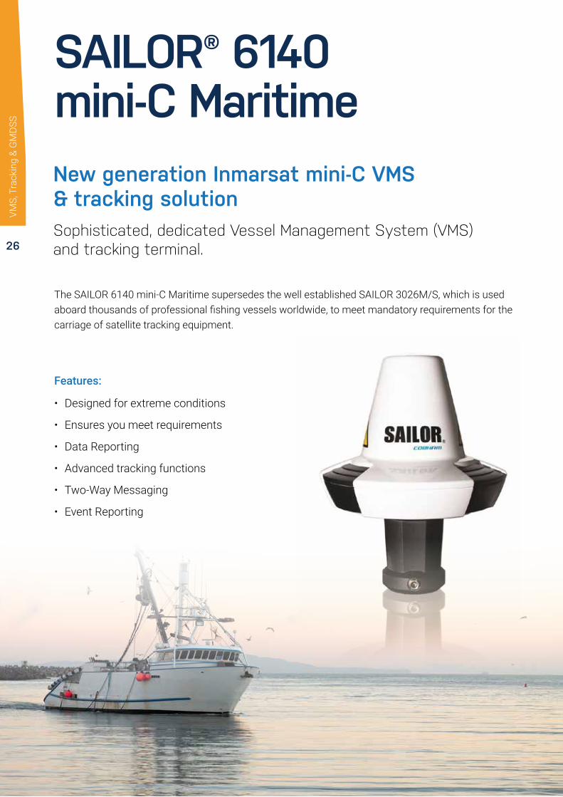
New generation Inmarsat mini-C VMS & tracking solutionSophisticated, dedicated Vessel Management System (VMS) and tracking terminal.
SAILOR® 6140 mini-C Maritime
• Designed for extreme conditions
• Ensures you meet requirements
• Data Reporting
• Advanced tracking functions
• Two-Way Messaging
• Event Reporting
Features:
VMS,
Tra
ckin
g &
GM
DSS
The SAILOR 6140 mini-C Maritime supersedes the well established SAILOR 3026M/S, which is used aboard thousands of professional fishing vessels worldwide, to meet mandatory requirements for the carriage of satellite tracking equipment.

27
Technical Specifications
VMS,
Tra
ckin
g &
GM
DSS
www.cobham.com
Subj
ect
to c
hang
e w
ithou
t fu
rthe
r no
tice.
COMPARISON CHART
SAILOR 6110 mini-C
SAILOR 6120 mini-C
SAILOR 6130 mini-C
SAILOR 6140 mini-C
SAILOR 6150 mini-C
GMDSS X
SSAS X X
LRIT X X X
SafetyNET X X X X
Non-SOLAS Distress X
Tracking X X X X X
ThraneLINKThraneLINK is a sophisticated communication protocol that connects the SAILOR products in a network, offering important new opportunities to vessels. It provides facility for remote diagnostics and enables access to all the SAILOR products from a single point for service. This results in optimized maintenance and lower cost of ownership because less time is needed for troubleshooting and service. Installation is made easier as ThraneLINK automatically identifies new products in the system. The uniform protocol is an open standard which provides a future proof solution for all vessels.
sailoR® 6140 Mini-C MaRiTiMENew generation Inmarsat mini-C VMS & tracking solution
For further information please contact:
Cobham saTCoM MaritimeLundtoftegaardsvej 93 D
DK-2800 Kgs. Lyngby
Denmark
www.cobham.com
Tel: +45 3955 8800
Fax: +45 3955 8888
GENERAL
General specifications Meets Inmarsat maritime specifications and
IMO LRIT requirements
Inmarsat Type Approval 4TT097
TERMINAL UNIT SPECIFICATIONS
Operating frequencies Rx Frequency Band: Rx: 1525 - 1545 MHz
Tx Frequency Band: Tx: 1626.5 - 1646.5 MHz
GPS module 50 channel
Terminal interface NMEA2K DeviceNet Mini-style, Male
ANTENNA UNIT SPECIFICATIONS
G/T -23.7 dBk at 5° elevation
EIRP Min. 7 dBW at 5° elevation
Antenna elevation -15° to 90°
POWER SPECIFICATIONS
Absolute power supply range 10.5 - 32 VDC
Nominal power input 15 VDC
Power consumption (typical) Rx: 1.85 W @ 15 VDC
Tx: 22 W @ 15 VDC
TERMINAL CONTROL UNIT SPECIFICATIONS
Interface options CAN interface NMEA2K mini
RS-232
LAN interface RJ45
DIMENSIONS AND WEIGHT
mini-C Terminal Diameter: 170.5 mm
Height: 145 mm (without pole mount)
Weight: 1,1 Kg
Terminal Control Unit 239 mm x 172 mm x 54 mm
Weight: 0,8 Kg
71-133781-B01 07.13 MBU
SAILOR N163S Power Supplyor SAILOR 6081 Power Supply
SAILOR 3027 Maritimemini-C Martime Terminal SAILOR 6194
Terminal Control Unit
Optional
GeneralGeneral specifications Meets Inmarsat maritime specifications and IMO LRIT requirementsInmarsat Type Approval 4TT097
Terminal Unit SpecificationsOperating frequencies Rx Frequency Band: Rx: 1525 - 1545 MHzTx Frequency Band: Tx: 1626.5 - 1646.5 MHzGPS module 50 channelTerminal interface NMEA2K DeviceNet Mini-style, Male
Antenna Unit SpecificationsG/T -23.7 dBk at 5° elevationEIRP Min. 7 dBW at 5° elevationAntenna elevation -15° to 90°
Power SpecificationsAbsolute power supply range 10.5 - 32 VDCNominal power input 15 VDCPower consumption (typical) Rx: 1.85 W @ 15 VDC
Tx: 22 W @ 15 VDC
Terminal Control Unit SpecificationsInterface options CAN interface NMEA2K mini
RS-232LAN interface RJ45
Dimensions And Weightmini-C Terminal Diameter: 170.5 mm
Height: 145 mm (without pole mount)Weight: 1.1 Kg
Terminal Control Unit 239 mm x 172 mm x 54 mmWeight: 0.8 Kg
ThraneLINK
ThraneLINK is a sophisticated communication protocol that connects the SAILOR products in a network, offering important new opportunities to vessels. It provides facility for remote diagnostics and enables access to all the SAILOR products from a single point for service. This results in optimized maintenance and lower cost of ownership because less time is needed for troubleshooting and service. Installation is made easier as ThraneLINK automatically identifies new products in the system. The uniform protocol is an open standard which provides a future proof solution for all vessels.

28
Touch-screen security in an uncertain worldProvides GMDSS, SSAS and LRIT, and is a genuine next generation safety solution offering enhancements across the board.
SAILOR® 6110 mini-C GMDSS
• First ever approved touch screen terminal for GMDSS use
• External storage via SD card or USB disk
• Innovative approach to cabling for simple networking and expansion
• Accurate, reliable 50 channel GPS module that is also Galileo ready
• ThraneLINK
Features:
VMS,
Tra
ckin
g &
GM
DSS
The SAILOR 6110 mini-C is more than just a way to meet mandatory GMDSS requirements, because as part of the innovative SAILOR 6000 Series, it is an integral part of a vessel’s communication system. The mini-C system features true triple functionality as it safely handles all GMDSS, SSAS and LRIT operation on board.

29
Technical Specifications
VMS,
Tra
ckin
g &
GM
DSS
www.cobham.com/satcom
Subj
ect
to c
hang
e w
ithou
t fu
rthe
r no
tice.
COMPARISON CHART
SAILOR 6110 mini-C
SAILOR 6120 mini-C
SAILOR 6130 mini-C
SAILOR 6140 mini-C
SAILOR 6150 mini-C
GMDSS X
SSAS X X
LRIT X X X
SafetyNET X X X X
Non-SOLAS Distress X
Tracking X X X X X
SAILOR® 6110 MINI-C GMDSSTouch-screen security in an uncertain world
71-132180-A04 02.18 MBU
N163S / 6081Power Supply
SAILOR 3027Cmini-C GMDSS Terminal SAILOR 6194
Terminal Control UnitSSAS
Add-on
SAILOR 6018Message TerminalSAILOR 3608A
Compact Printer Unit
SAILOR 6101 Alarm Panel
Optional
TERMINAL UNIT SPECIFICATIONS General specifications Inmarsat C GMDSS Type Approved Wheelmark Approved 3027C mini-C Transceiver
ANTENNA UNIT SPECIFICATIONS G/T -23.7 dBk at 5° elevationEIRP Min. 7 dBW at 5° elevationAntenna elevation -15° to 90°Operating frequencies Rx Frequency Band: Rx: 1525 - 1545 MHz Tx Frequency Band: Tx: 1626.5 - 1646.5 MHz
GENERAL SPECIFICATIONS Absolute power supply range 10.5 - 32 VDC Nominal power input 15 VDC Power consumption (typical) Rx: 1.85 W @ 15 VDC Tx: 22 W @ 15 VDCGPS module 50 channel (Galileo ready)Transceiver interface NMEA 2000 DeviceNet Mini-style, MaleI/O interface CAN-BUS (NMEA 2000)Dimensions Diameter: 170.5 mm Height: 145 mm (without pole mount)Weight 1.10 kg (without pole mount)
SAILOR® 6110 mini-C GMDSS SystemThe system is comprised of the following items:
SAILOR® 3027C mini-C GMDSS TerminalThe next generation mini-C terminal in the long line of successful SAILOR mini-C products.
SAILOR® 6018 Message TerminalThe revolutionary touch-screen message terminal features a 10.4” high resolution screen that offers seamless interface to all functions via the icon based interface. There is both SD card and USB ports for external storage.
SAILOR® 6194 Terminal Control Unit (TCU) - optionalThe TCU is used in conjunction with the SSAS option as a connection point, but its functionality can be expanded at a later stage. It meets maritime standards, with easy access and connection.
SAILOR® 6101 Alarm PanelA newly designed alarm panel for the SAILOR 6000 Series with both visual and audio alarm functionality as well as EGC message status. All received Inmarsat-C alarms can be muted with a single push.
SAILOR® 6103 Alarm PanelThis alarm panel has the same basic features as the SAILOR 6101 Alarm Panel but furthermore adds VHF and MF/HF distress functionality. As on the SAILOR 6101 Alarm Panel it is possible to mute all alarms with a single push.
SAILOR® 3608 PrinterSAILOR 3608 Compact Printer Unit This unit is designed to be connected to SAILOR 6006 Message Terminal to ensure that EGC and Safety messages can be printed. For further information please contact:
Terminal Unit SpecificationsInmarsat C GMDSS Type ApprovedWheelmark Approved3027C mini-C Transceiver
Antenna Unit SpecificationsG/T -23.7 dBk at 5° elevationEIRP Min. 7 dBW at 5° elevationAntenna elevation -15° to 90°Operating frequencies Rx Frequency Band: Rx: 1525 - 1545 MHz
Tx Frequency Band: Tx: 1626.5 - 1646.5 MHz
General SpecificationsAbsolute power supply range 10.5 - 32 VDCNominal power input 15 VDCPower consumption (typical) Rx: 1.85 W @ 15 VDC
Tx: 22 W @ 15 VDCGPS module 50 channel (Galileo ready)Transceiver interface NMEA 2000 DeviceNet Mini-style, MaleI/O interface CAN-BUS (NMEA 2000)Dimensions Diameter: 170.5 mm
Height: 145 mm (without pole mount)Weight 1.10 kg (without pole mount)
SAILOR® 6110 mini-C GMDSS System
The system is comprised of the following items:
SAILOR® 3027C mini-C GMDSS Terminal The next generation mini-C terminal in the long line of successful SAILOR mini-C products.
SAILOR® 6018 Message Terminal The revolutionary touch-screen message terminal features a 10.4” high resolution screen that offers seamless interface to all functions via the icon based interface. There is both SD card and USB ports for external storage.
SAILOR® 6194 Terminal Control Unit (TCU) - optional The TCU is used in conjunction with the SSAS option as a connection point, but its functionality can be expanded at a later stage. It meets maritime standards, with easy access and connection.
SAILOR® 6101 Alarm Panel A newly designed alarm panel for the SAILOR 6000 Series with both visual and audio alarm functionality as well as EGC message status. All received Inmarsat-C alarms can be muted with a single push.
SAILOR® 6103 Alarm Panel This alarm panel has the same basic features as the SAILOR 6101 Alarm Panel but furthermore adds VHF and MF/HF distress functionality. As on the SAILOR 6101 Alarm Panel it is possible to mute all alarms with a single push.
SAILOR® 3608 Printer SAILOR 3608 Compact Printer Unit This unit is designed to be connected to SAILOR 6006 Message Terminal to ensure that EGC and Safety messages can be printed.

30
Attractively priced reliable internet and global voice calling via SAILOR’s compact antenna.
Ideal for smaller vessels
• Compact 30cm antenna
• Easy installation
• Data connectivity up to 100kbps and voice calling on a single line.
• Reliable Cobham network
AMI Connect Special Offer FleetOne Leisure Plan
Fleet One Package Includes:
Terminal
Monthly subscription (Unlimited leisure plan)
Optional IP-Handset (when purchased with FleetOne)
Don’t have the space or the budget for internet on your vessel?
SAILOR® Fleet OneBr
oadb
and
& VS
AT S
yste
ms

31
Technical Specifications
Coverage and Rate Regions
ApprovalsInmarsat Fleet One approved. Compliant to RTTE, CE Marked. Tested to FCC part 25
Frequency BandRx 1518 - 1559 MHzTx 1626.5 - 1660.5 MHz
1668.0 - 1675.0 MHz
Ch. spacing 10.5 -189 kHz, Rx 21 - 189 kHz, Tx
Ch. size 1.25 KHz
Recommended Antenna Cable
Cable loss max/min 20 dB at 1,62 GHz and 1.0 Ω DC loop resistancemax. 3 dB at 36 - max. 4 dB at 54 MHz
Power Supply and ConsumptionDC input range (isolated) 10.5V to 32V DC
Power (max), 120 W @ 10-32 V incl. antenna & PoE output
Environmental ConditionsAmbient Temperature -25 to +55°CStorage -40 to +85°CSurvival (power on, non functional) -40 to +80°C
Automatic thermal surveillance shuts down system gradually in ease of own temperatureBDU operating humidity 95% non-condensing at +40°CADU enclosure IPX6ADU operating humidity “Exposed” according to EN60 945BDU enclosure IP30Icing (survival) Max 25 mm
Vibration (ADU)
Vibration, operational Random spectrum 1.05 g rms x 3 axes:5 to 20 Hz: 0.02 g2/Hz20 to 150 Hz: -3 dB/octave
Vibration, non-operational
Random spectrum 1.7 g rms 2 h x 3 axes (6 h total):5 to 20 Hz: 0.05 g2/Hz,20 to 150 Hz: -3 dB/octave
Ship MotionRoll +/- 30 deg. per. 4 s, max 0.7 g tan.Pitch +/- 15 deg. per. 3 s, max 0.6 g tan.Yaw +/- 10 deg. per. 5 s, max 0.3 g tan.Surge +/- 0.5gSway +/- 0.5gHeave +/- 0.7gTurning rate +/- 36˚/s; ACC 12˚/s²Headway speed 22 m/s (42 knots)Wind 100 knots
Mechanical Shock20g/11 half-sine
Antenna ConnectorADU TNC, femaleBDU TNC, female
ServicesStandard IP Up to 100 kbpsStreaming IP -ISDN Data -SMS (standard 3G) 160 charactersStandard Voice 4 kbps
InterfacesEthernet/PoE 2 portsPhone/Fax (2-wire) 1 portI/O Connector 1 connector with 5 configurable inputs/outputsStatus LED LED power indicatorSIM Card Slot 1 SIM Card slot for Fleet One SIM cardRouter Integral DHCP/NAT routerPBX Built-in PBX
www.cobham.com/satcom
Subj
ect t
o ch
ange
with
out f
urth
er n
otic
e.
SAILOR® FLEET ONEFirst choice for Fleet One
MECHANICAL SHOCK
20g/11 half-sine
ANTENNA CONNECTOR
ADU TNC, female
BDU TNC, female
SERVICES
Standard IP Up to 100 kbps
Streaming IP -
ISDN Data -
SMS (standard 3G) 160 characters
Standard Voice 4 kbps
INTERFACES
Ethernet/PoE 2 ports
Phone/Fax (2-wire) 1 port
I/O Connector 1 connector with 5 configurable inputs/outputs
Status LED LED power indicator
SIM Card Slot 1 SIM Card slot for Fleet One SIM card
Router Integral DHCP/NAT router
PBX Built-in PBX
COVERAGE AND RATE REGIONS
APPROVALS
Inmarsat Fleet One approved. Compliant to RTTE, CE Marked. Testet to FCC part 25
FREQUENCY BAND
Rx 1518 - 1559 MHz
Tx 1626.5 - 1660.5 MHz
1668.0 - 1675.0 MHz
Ch. spacing 10.5 -189 kHz, Rx
21 - 189 kHz, Tx
Ch. size 1.25 KHz
RECOMMENDED ANTENNA CABLE
Cable loss max/min 20 dB at 1,62 GHz and 1.0 Ω DC loop resistance
max. 3 dB at 36 - max. 4 dB at 54 MHz
POWER SUPPLY AND CONSUMPTION
DC input range (isolated) 10.5V to 32V DC
Power (max), 120 W @ 10-32 V
incl. antenna & PoE output
ENVIRONMENTAL CONDITIONS
Ambient Temperature -25 to +55°C
Storage -40 to +85°C
Survival (power on, non functional) -40 to +80°C
Automatic thermal surveillance shuts down system gradually in ease of own temperature
BDU operating humidity 95% non-condensing at +40°C
ADU enclosure IPX6
ADU operating humidity “Exposed” according to EN60 945
BDU enclosure IP30
Icing (survival) Max 25 mm
VIBRATION (ADU)
Vibration, operational Random spectrum 1.05 g rms x 3 axes:
5 to 20 Hz: 0.02 g2/Hz
20 to 150 Hz: -3 dB/octave
Vibration, non-operational Random spectrum 1.7 g rms 2 h x 3 axes (6 h total):
5 to 20 Hz: 0.05 g2/Hz,
20 to 150 Hz: -3 dB/octave
SHIP MOTION
Roll +/- 30 deg. per. 4 s, max 0.7 g tan.
Pitch +/- 15 deg. per. 3 s, max 0.6 g tan.
Yaw +/- 10 deg. per. 5 s, max 0.3 g tan.
Surge +/- 0.5g
Sway +/- 0.5g
Heave +/- 0.7g
Turning rate +/- 36˚/s; ACC 12˚/s²
Headway speed 22 m/s (42 knots)
Wind 100 knots
71-141561-A05 08.15 MBU
29
1,9
58
Ø 275,6
131
26
42
31
278
ø1
75
,4
41
SAILOR Fleet One Below Deck Unit (2,0 kg)
SAILOR Fleet One Above Deck Unit (3,9 kg)
29
1,9
58
Ø 275,6
131
26
42
31
278
ø1
75
,4
41
Voice and data Voice only
MA
RITIME >
Coverage
Voice and data Voice only
MA
RITIME >
Coverage
For further information please contact:
Broa
dban
d &
VSAT
Sys
tem
s

32
Coverage everywhere, and anytime you need it with SAILOR 4300 Iridium Certus
SAILOR® 4300 L-BAND
Next GenerationGround-breaking L-band global satellite constellation, which features a cross-linked Low-Earth Orbit (LEO) architecture to provide 100% coverage over the earth’s surface.
High Speeds for Heavy Duty requirementsSpeeds suitable for data-heavy applications including; videoconferencing, multi-user Internet/ VPN, IoT and telemedicine, alongside regular usage including email, electronic forms/reporting and crew communication.
Global calling from anywhere on EarthGuaranteed high bandwidth IP connectivity and three high-quality voice lines for global calling wherever you are.
Clever Certus HardwareLow maintenance and compact antenna, only 30cm wide x 25cm high for installation flexibility.
Iridium CertusSM and Iridium NEXTIridium NEXT features a cross-linked Low-Earth Orbit (LEO) architecture, providing coverage over 100 percent of the earth’s surface and with SAILOR 4300 L-band on board, it guarantees high bandwidth connectivity as a primary channel or as an integral part of a multi-band communication networks.
Broa
dban
d &
VSAT
Sys
tem
s
Introducing the newSAILOR 4300 L-band
The new SAILOR 4300 L-band is the pinnacle of L-band terminal design, representing over 20 years of unmatched maritime L-band expertise and quality.
The next generation SAILOR 4300 L-band antenna is the first in Cobham’s Iridium Certus Connected range of terminals. It is the perfect choice as either a high-performance, stand-alone terminal to upgrade your vessel’s communications, or as a dependable backup solution for your existing VSAT system.
More performance, less costSAILOR 4300 L-band enables you and your crew to operate with greater safety and efficiency through secure voice calling and reliable satellite connectivity regardless of weather conditions or worldwide location.
Through Iridium NEXT, the terminal enables fast internet speeds suitable for both data-heavy applications and everyday usage, such as email, electronic reporting and crew communication. SAILOR 4300 L-band also minimizes total cost of ownership with low hardware costs and no scheduled service requirements.
Simplicity and reliabilitySAILOR 4300 L-band has been designed for seamless compatibility with SAILOR VSAT. Both systems use the same interface and are simple to integrate using the built in applica-tion programming interface (API). The terminal is extremely light and compact, making it easy to install with one cable below deck and an integrated antenna and modem.
Built in-house for SAILOR quality and reliability-tested for all environments, SAILOR 4300 L-band represents the very best of Cobham’s world-class maritime satcom knowledge and capabilities. SAILOR 4300 L-band is also fully supported through our industry-leading Global Service Network.
Iridium CertusSM is a new portfolio of global satellite services powered by Iridium NEXT, a ground-breaking second-generation L-band global satellite constellation established to deliver an uncompromising solution for the future of global maritime communications.
Iridium NEXT features a cross-linked Low-Earth Orbit (LEO) architecture, providing coverage over 100 percent of the earth’s surface and with SAILOR 4300 L-band on board, it guarantees high bandwidth connectivity as a primary channel or as an integral part of a multi-band communication networks.
SAILOR 4300 L-band is a cost-effective way to upgrade your vessel’s communications or to ensure a reliable backup solution for VSAT systems.
Iridium CertusSM and Iridium NEXT

33
Technical Specifications
ApprovalsIridium next approved. Compliant to RED, CE Marked. Testet to FCC part 25
Frequency BandRx 1616 - 1626.5 MHzTx 1616 - 1626.5 MHz
Recommended Antenna Cable
Cable loss Maximum 1.8ohm DC loop resistancemaximum 10dB loss at 80MHz
Antenna ConnectorsADU TNC, femaleBDU TNC, female
Power Supply and ConsumptionDC input range (isolated) 10.8V to 31.2VPower (max) incl. antenna & PoE output 120W @ 10-32 V
Environmental ConditionsAmbient Temperature -25 to +55°CStorage -35 to +85°CAutomatic thermal surveillance
Shuts down system gradually in ease of own temperature
BDU operating humidity 95% non-condensing at +40°CBDU enclosure IP31ADU operating humidity 95% non-condensing at +40°CADU enclosure IPX6
Vibration (ADU)
Vibration, operational
Sine: Certified for IEC 60945 (8.7.2)Random spectrum 0,92 g rms x 3 axis5 to 20 Hz: 0.01 g2/Hz20 to 500 Hz: -3 dB/octave
Vibration, survival
Sine: Certified for IEC 60945 (8.7.2) dwellRandom spectrum 1.7 g rms 2 h x 3 axes (6 h total):5 to 20 Hz: 0.05 g2/Hz20 to 150 Hz: -3 dB/octave
Ship MotionRoll +/- 30 deg. per. 8 s, max 0.5 g tan.Pitch +/- 10 deg. per. 6 s, max 0.5 g tan.Yaw +/- 8 deg. per. 50 s, max 0.2 g tan.Surge +/- 0.2 gSway +/- 0.2 gHeave +/- 0.5 gTurning rate +/- 6 deg/s; acc. 1 deg./s²Headway speed 30 knots (15 m/s)Wind 200 km/hr (108 knots)
Mechanical Shock20g/11 half-sine
SpecificationStandard IP 176/352 kbpsEthernet/LAN 4 portsI/O Connector 1 connectorStatus LED Full status LED panelSIM Card Slot 1 SIM Card slot for Iridium SIM card
www.cobham.com/satcom
Subj
ect t
o ch
ange
with
out f
urth
er n
otic
e.
SHIP MOTIONRoll +/- 30 deg. per. 8 s, max 0.5 g tan.Pitch +/- 10 deg. per. 6 s, max 0.5 g tan.Yaw +/- 8 deg. per. 50 s, max 0.2 g tan.Surge +/- 0.2 gSway +/- 0.2 gHeave +/- 0.5 gTurning rate +/- 6 deg/s; acc. 1 deg./s²Headway speed 30 knots (15 m/s)Wind 200 km/hr (108 knots)
MECHANICAL SHOCK 20g/11 half-sine
SPECIFICATION Standard IP 176/352 kbpsEthernet/LAN 4 portsI/O Connector 1 connectorStatus LED Full status LED panelSIM Card Slot 1 SIM Card slot for Iridium SIM card
SAILOR® 4300 L-BANDThe flexible global connectivity and voice solution
APPROVALS Iridium next approved. Compliant to RED, CE Marked. Testet to FCC part 25 FREQUENCY BAND Rx 1616 - 1626.5 MHzTx 1616 - 1626.5 MHz
RECOMMENDED ANTENNA CABLE Cable loss Maximum 1.8ohm DC loop resistance maximum 10dB loss at 80MHz ANTENNA CONNECTORS ADU TNC, femaleBDU TNC, female POWER SUPPLY AND CONSUMPTION DC input range (isolated) 10.8V to 31.2VPower (max) incl. antenna & PoE output 120W @ 10-32 V
ENVIRONMENTAL CONDITIONSAmbient Temperature -25 to +55°CStorage -35 to +85°CAutomatic thermal surveillance Shuts down system gradually in ease of own temperatureBDU operating humidity 95% non-condensing at +40°CBDU enclosure IP31ADU operating humidity 95% non-condensing at +40°CADU enclosure IPX6
VIBRATION (ADU)Vibration, operational Sine: Certified for IEC 60945 (8.7.2) Random spectrum 0,92 g rms x 3 axis 5 to 20 Hz: 0.01 g2/Hz 20 to 500 Hz: -3 dB/octaveVibration, survival Sine: Certified for IEC 60945 (8.7.2) dwell Random spectrum 1.7 g rms 2 h x 3 axes (6 h total): 5 to 20 Hz: 0.05 g2/Hz 20 to 150 Hz: -3 dB/octave
71-159692-A00 03.18 MBU
For further information please contact:
SAILOR 4300 L-Band Above Deck Unit (8 kg)
SAILOR 4300 L-Band Below Deck Unit (3.2kg)
2017.10.23Connie Madsen Outline drawing, SAILOR 4300Above Deck Unit
1:594-159276-A
UNLESS OTHERWISE SPECIFIED DIMENSIONSARE IN MILIMETRE AND TOLERANCES ARE INACCORDANCE WITH
MATERIAL:
DR.
Per Christiansen
Connie Madsen
2017.10.23
2017.10.23
CH.
AP.
TITLE
FIRSTANGLE PROJECTION
SIZE ASSET NO. DRAWING NO.
A2SCALE SHEET 1 OF 1
SURFACE TREATMENT:
THIS DRAWING CONTAINS INFORMATION THAT IS PROPRIETARY TO COBHAM PLC. AND SHOULD NOT BE USED WITHOUT WRITTEN PERMISSION
DS/EN 22768-1-m
Original
HISTORYREV DESCRIPTION DATE APPROVAL
- - -VER
A
1
DE
CF
BG
AH
2 3 4 5 6 7 8 9 10
11
12
HG
FE
DC
BA
12
11
10987654321
Weight: Approx. 8 kg
367
3 8 0
253
102
6 0
113R (Ventilation hose)
73R (Connector)
120
1 2 0
200 (Mounting holes)
3 pcs. M8 x 20
Isometric views
n 4.5
n 5.5
n 5.5
Outline DrawingIridium ConnectedSAILOR SC4300
OPTIONAL CABLE TRAY
Weight: Approx. 3,2 Kg
KB2018.01.25Change of NamePlate position--B
2017.12.05Kenn Blomgren
2017.12.05Jesper Sundberg
2017.12.05Kenn Blomgren
1
KB2017.12.05RELEASED FOR PRODUCTION--A
1:1
94-159173
342.5138.5
66.5200175
252
270
42
Broa
dban
d &
VSAT
Sys
tem
s

34
65cm Ku-band Maritime VSAT Antenna System
Efficient RF PerformanceAMI Connect’s advanced RF design technology delivers highly efficient performance with compact and light mechanical structure compared to other 65 cm class systems. The v60E has improved tracking precision and reliability in a compact and streamlined mechanical design. The v60E system is only supplied with NJRC 6W BUC.
Connect Coverage NX Intelligent DiagnosisAMI Connect’s all-new integrated M&C platform Connect Coverage NX provides a responsive web user interface to manage and control the antenna system regardless of device types. The Installation Wizard in Connect Coverage NX automates functions for system configuration so that operators are minimally involved in system installation and operation.
Single Coaxial CableCombined Tx, Rx and DC power in a Single Cable solution, the v60E enables faster and cost efficient installation. The single coaxial cable is connected externally on the base of radome with no need to access the inside of the radome.
Standardized Modular Components Across E-SeriesModular components are used throughout the E-Series product range, such as motors with integrated encoders, main control unit and internal cables. Sharing common modules across AMI Connect’s E-series antenna systems, the number of spare parts is reduced by more than 30%.
Connect CoverageNX
Connect v60EBr
oadb
and
& VS
AT S
yste
ms

35
65cm Ku-band Maritime VSAT Antenna Systemv60E
TECHNICAL SPECIFICATIONS
AmericasIrvine Intellian Technologies USA, Inc.
T +1 949 727 4498F +1 949 271 4183Toll Free +1 888-201-9223
EMEARotterdamIntellian B.V.
T +31 1 0820 8655F +31 1 0820 8656
APACSeoul Intellian Technologies, Inc.
T +82 2 511 2244F +82 2 511 2235
Global HQInnovation Center Intellian Technologies, Inc
T +82 31 379 1000F +82 31 377 6185
Ø445.0 (17.52)
247.5 (9.74)
247.
5 (9
.74)
4 - Ø13.0 (0.51) Holes
Above Decks
Below Decks
ACU
Antenna
Modem(Not supplied) Tx Rx
Antenna
Tx, Rx, 48V DC Power
OpenAMIP
AC 100~240V
AC 100~240V
Ship's Gyro(Not supplied)
LANNMEA Input0183 (GYRO)
ModemTx
Modem Rx
Unit: mm (inch)
935
(36.
31)
Ø860 (33.85)
Par
t No.
202
0v60
E-0
319
Technical Specifications
Above Deck Unit
Radome Height 93.5 cm / 36.81"
Radome Diameter 86 cm / 33.85"
Reflector Diameter 65 cm / 25.6"
ADU Weight 42 kg / 92.6 lbs
Platform 3-axis / Azimuth, Elevation, Cross-level
Azimuth Range Unlimited
Elevation Range -20°to +115°
Cross-level Range Up to ± 37°
Stabilization Accuracy 0.2° max in presence of specified ship motions
Tx Frequency 13.75 ~ 14.5 GHz Ku-band
Tx Gain 37.7 dBi @ 14.25 GHz (excl. radome)
Rx Frequency 10.7 ~ 12.75 GHz Ku-band
Rx Gain 36.3 [email protected] GHz (excl. radome)
G/T 15.4 dB/[email protected] GHz (Clear Sky, 30° Elevation)
BUC Power 6W
LNB Universal PLL LNB
Polarization Linear, Cross-pol Only
Antenna Cable Single 50 ohm coax cable for Rx, Tx, FSK, Referenceand Power from ACU to ADU
Antenna Control Unit
Dimension (WxDxH) 43.1 cm x 35.0 cm x 4.4 cm / 17” x 13.8” x 1.7”
Weight 5.2 kg / 11.5 lbs
LED Indicator 6 LEDs for Power, INT/Search, Tracking, Lock, Setup, Error
Gyrocompass Interface NMEA0183
Modem Interface Ethernet port / RS-232C,-422C / I/O Console
Remote Management Yes
Management Port Yes
LAN Port Yes
Power Requirement 100~240 V AC, 50~60 Hz, 3A
©2020 Intellian Technologies, Inc. All rights reserved. Intellian and the Intellian logo are registered trademarks. v60E and v-Series are trademarks of Intellian Technologies, Inc. in the U.S. and/or various countries. All other trademarks are the property of their respective owners. Information in this document is subject to change without notice. ISO9001 / ISO14001 Certified Intellian has more offices worldwide. Addresses, phone numbers, and fax numbers are listed on the Intellian Website at intelliantech.com
System Diagram
System DimensionsTechnical Specifications
Above Deck UnitRadome Height 93.5 cm / 36.81"Radome Diameter 86 cm / 33.85"Reflector Diameter 65 cm / 25.6"ADU Weight 42 kg / 92.6 lbsPlatform 3-axis / Azimuth, Elevation, Cross-levelAzimuth Range UnlimitedElevation Range -20°to +115°Cross-level Range Up to ± 37°
Stabilization Accuracy 0.2° max in presence of specified ship motions
Tx Frequency 13.75 ~ 14.5 GHz Ku-bandTx Gain 37.7 dBi @ 14.25 GHz (excl. radome)Rx Frequency 10.7 ~ 12.75 GHz Ku-bandRx Gain 36.3 [email protected] GHz (excl. radome)
G/T 15.4 dB/[email protected] GHz (Clear Sky, 30° Elevation)
BUC Power 6WLNB Universal PLL LNBPolarization Linear, Cross-pol Only
Antenna Cable Single 50 ohm coax cable for Rx, Tx, FSK, Reference and Power from ACU to ADU
Antenna Control Unit
Dimension (WxDxH) 43.1 cm x 35.0 cm x 4.4 cm / 17” x 13.8” x 1.7”
Weight 5.2 kg / 11.5 lbs
LED Indicator 6 LEDs for Power, INT/Search, Tracking, Lock, Setup, Error
Gyrocompass Interface NMEA0183
Modem Interface Ethernet port / RS-232C,-422C / I/O Console
Remote Management YesManagement Port YesLAN Port YesPower Requirement 100~240 V AC, 50~60 Hz, 3A
Connect BoxThe Connect Box* - our unique 1U 19 inch rack mountable device enables you to use the attractive and affordable Connect mobile services by utilising your current KU band Satellite hardware.
Data only packagesMaximum Information Rate (MIR) data transfer speed for below data packages: 3Mbits/1Mbits. 20GB and 40GB packages are available for sharing between a fleet of vessels. Each vessel will be required to pay a small monthly network connection fee. For further information on sales and subscriptions please get in touch. For details of ‘always on’ unlimited data packages see below.
‘Always on’ Unlimited DataData transfer speed (in Kbits) based on Maximum Information Rate (MIR). A monthly connection fee per vessel applies each package after first month which is FREE.
Connect Global coverage area
Connect Regional coverage area
* Approximation of coverage only at time of issue. Subject to change at AMI Connect’s discretion. No service or availability guarantees may be implied herewith.
Broa
dban
d &
VSAT
Sys
tem
s

36
65cm Maritime VSAT Antenna SystemKu / Ka-band Convertible
Connect Coverage
Connect v65Br
oadb
and
& VS
AT S
yste
ms
Frequency Mobility DeliveredThe v65 can be converted from Ku-band operation to Ka-band in as little as 10 minutes through use of a compact, intuitive conversion kit (sold separately).
Superior RF performanceAMI Connect’s high efficiency RF design delivers superior antenna gain and cross-pol isolation over all other 60cm class systems, enabling higher data rates and enhanced global services.
Get the power you needThe v65 is designed as a flexible communications platform built to meet the unique needs of any customer while maintaining commonality of spare parts. In Ku-band configuration, the system comes standard equipped with NJRC’s 8W EXT Mini BUC, but can also support 4W and 16W variants out of the box. Ka-band configuration includes the NJRC 5W BUC.
Quick and easy installationShipped without any stow brackets and now featuring external RF cable connections on the radome base, there is no need to remove the radome of the v65 during installation, saving time and cost. AMI Connect’s Gyro-free satellite search function further simplifies installation by providing the option to track satellites without any input from the ship’s gyro-compass.
Reliability enhanced
The v65 is built upon the well-proven GX60 stabilized platform, currently in service on ships around the world. Additionally, new motors featuring built-in encorders and enhanced dynamic motor brakes deliver improved tracking precision in a more streamlined mechanical design.
Connect Coverage remote managementConnect Coverage, AMI Connect’s proprietary Management & Control software, enables full remote access and control of the system from any device, anywhere in the world. Available via PC, Web and Mobile, Connect Coverage enhances remote diagnostics, automates routine processes, and includes a built in spectrum analyzer. The Connect Coverage API enables easy integration directly with the NOC for total fleet-wide visibility.
AMI Connect LAN CapabilityThe AMI Connect LAN port on the ACU provides easy networking connectivity to other AMI Connect systems enabling integrated monitoring and control of all AMI Connect networked devices through a common, intuitive interface.

37
Key Features
System Diagram
System Dimensions
Technical Specifications
Connect BoxThe Connect Box* - our unique 1U 19 inch rack mountable device enables you to use the attractive and affordable Connect mobile services by utilising your current KU band Satellite hardware.
Data only packagesMaximum Information Rate (MIR) data transfer speed for below data packages: 3Mbits/1Mbits. 20GB and 40GB packages are available for sharing between a fleet of vessels. Each vessel will be required to pay a small monthly network connection fee. For further information on sales and subscriptions please get in touch. For details of ‘always on’ unlimited data packages see below.
‘Always on’ Unlimited DataData transfer speed (in Kbits) based on Maximum Information Rate (MIR). A monthly connection fee per vessel applies each package after first month which is FREE.
Connect Global coverage area
Connect Regional coverage area
* Approximation of coverage only at time of issue. Subject to change at AMI Connect’s discretion. No service or availability guarantees may be implied herewith.
PhysicalRadome Height 104cm / 40.9"Radome Diameter 90cm / 35.5”Reflector Diameter 65cm / 25.6”Weight 60kg / 132lbs
Stabilized Pedestal AssemblyPlatform 3-axis : Azimuth, Elevation, Cross-levelAzimuth Range UnlimitedElevation Range -20° to 115°Cross-level Rang ±37°
Stabilization Accuracy 0.2° peak mis-pointing @ max ship motion condition
Motor Brake System Elevation, Cross-level
Reflector & Feed AssemblyTX Frequency 13.75~14.5GHz Ku-bandTX Gain 37.7dBi @ Mid bandRX Frequency 10.7~12.75GHz Ku-bandRX Gain 36.3dBi @ Mid bandG/T 15.7dB/K (Clear Sky, 30° Elevation)BUC 8W, 16W (optional)LNB PLL LNBPolarization Linear, Cross-pol only
Antenna Control UnitDimensions (WxDxH) 43.1cm x 38.0cm x 4.4cm / 17” x 15” x 1.7”Weight 3.5kg / 7.7lbsDisplay 2 line 40 character graphic VFD moduleGyrocompass Interface NMEA / NMEA 2000Modem Interface Ethernet port / RS-232C / I/O portsModem Protocol iDirect, Comtech, SatLink, Hughes, GILATRemote Management YesWi-Fi Operation YesManagement Port YesLAN Port YesPower Requirement 100~240V AC, 50~60 Hz, 4A
• Embedded power supply• Supports up to 16W High Power BUC• Remote firmware upgrade• Automatic software diagnosis• Heading device input not required• Quick setup and install time
Broa
dban
d &
VSAT
Sys
tem
s
TECHNICAL SPECIFICATIONS
Antenna TX + 48V BUC Power
Modem TX
Satellite Modem
Antenna Control Unit
Modem Interface
* Modem not supplied
Modem RX
Antenna RX
Par
t No.
201
7N1-
DS
0310
_V3
Technical Specifications
PhysicalRadome Height 104 cm / 40.9”
Radome Diameter 90 cm / 35.5”
Reflector Diameter 65 cm / 25.6”
Weight 60 Kg / 132 lbs
Stabilized Pedestal AssemblyPlatform 3-axis / Azimuth, Elevation, Cross-level
Azimuth Range Unlimited
Elevation Range -20° to +115°
Cross-level Range ±37°
Stabilization Accuracy 0.2° peak mis-pointing @ max ship motion condition
Motor Brake System Elevation, Cross-level
Reflector & Feed AssemblyTX Frequency 13.75~14.5GHz Ku-band
TX Gain 37.7 dBi @ Mid band
RX Frequency 10.7~12.75 GHz Ku-band
RX Gain 36.3 dBi @ Mid band
G/T 15.7 dB/K (Clear Sky, 30° Elevation)
BUC 8W, 16W (Optional)
LNB PLL LNB
Polarization Linear, Cross-pol only
• All in oneEmbedded power supply
Supports up to 16W High Power BUC
• CCoonnnneecctt CCoovveerraaggee software control
Automatic diagnosis
Remote firmware upgrade
• Gyro-free OperationHeading device input not required
Quick setup to reduce installation time
System Dimensions
System Diagram
Antenna Control Unit (ACU) Key Features
43.1 cm (17")
47.5 cm (18.7")
20.
0 cm
(7.9
")
45.5 cm (17.9")
13.
0 cm
(5.1
")
48.5 cm (19.1")
46.6 cm (18.4")
3.2
cm
(1.3
")
4.4 cm (1.7")
38
cm (1
5")
104
cm (4
0.9"
)
90 cm (35.5")
24.8
cm
(9.8
")
24.8 cm (9.8")
Antenna Control UnitDimensions (WxDxH) 43.1cm x 38.0cm x 4.4cm / 17” x 15” x 1.7”
Weight 3.5kg / 7.7lbs
Display 2 line 40 character graphic VFD module
Gyrocompass Interface NMEA0183 / NMEA2000
Modem Interface Ethernet port / RS-232C / I/O ports
Modem Protocol iDirect, Comtech, SatLink, Hughes, GILAT
Remote Management Yes
Wi-Fi Operation Yes
Management Port Yes
LAN Port Yes
Power Requirement 100~240V AC, 50~60 Hz, 4A
65cm Maritime VSAT Antenna SystemKu / Ka-band Convertiblev65
©2017 Intellian Technologies, Inc. All rights reserved. Intellian and the Intellian logo are registered trademarks. v65 and v-Series are trademarks of Intellian Technologies, Inc. in the U.S. and/or various countries. All other trademarks are the property of their respective owners. Information in this document is subject to change without notice. ISO9001 / ISO14001 Certified Intellian has more offices worldwide. Addresses, phone numbers, and fax numbers are listed on the Intellian Website at intelliantech.com
AmericasIrvine Office Intellian Technologies USA, Inc.
T +1 949 727 4498F +1 949 271 4183Toll Free +1 888-201-9223
EMEARotterdam OfficeIntellian B.V.
T +31 1 0820 8655F +31 1 0820 8656
APACSeoul Office Intellian Technologies, Inc.
T +82 2 511 2244F +82 2 511 2235
Global HQInnovation Center / FactoryIntellian Technologies,Inc
T +82 31 379 1000F +82 31 377 6185
TEC
HN
ICA
L S
PE
CIF
ICAT
ION
S
Ante
nna
TX +
48V
BUC
Pow
er
Mod
em T
X
Sate
llite
M
odem
Ante
nna
Cont
rol U
nit
Mod
em In
terf
ace
* M
odem
not
sup
plie
d
Mod
em R
X
Ante
nna
RX
Part No. 2017N1-DS0310_V3
Tech
nica
l Spe
cific
atio
ns
Phys
ical
Rado
me
Heig
ht10
4 cm
/ 40
.9”
Rado
me
Diam
eter
90 c
m /
35.5
”
Refle
ctor
Dia
met
er65
cm
/ 25
.6”
Wei
ght
60 K
g / 1
32 lb
s
Stab
ilize
d Pe
dest
al A
ssem
bly
Plat
form
3-ax
is /
Azim
uth,
Ele
vatio
n, C
ross
-lev
el
Azim
uth
Rang
eUn
limite
d
Elev
atio
n Ra
nge
-20°
to +
115°
Cros
s-le
vel R
ange
±37
°
Stab
iliza
tion
Accu
racy
0.2°
pea
k m
is-p
oint
ing
@ m
ax s
hip
mot
ion
cond
ition
Mot
or B
rake
Sys
tem
El
evat
ion,
Cro
ss-le
vel
Refle
ctor
& F
eed
Asse
mbl
yTX
Fre
quen
cy13
.75~
14.5
GHz
Ku-
band
TX G
ain
37.7
dBi
@ M
id b
and
RX
Freq
uenc
y10
.7~1
2.75
GHz
Ku-
band
RX
Gain
36.3
dBi
@ M
id b
and
G/T
15.7
dB/
K (C
lear
Sky
, 30°
Ele
vatio
n)
BUC
8W, 1
6W (O
ptio
nal)
LNB
PLL
LNB
Pola
rizat
ion
Line
ar, C
ross
-pol
onl
y
•A
ll in
one
Embe
dded
pow
er s
uppl
y
Sup
port
s up
to 1
6W H
igh
Pow
er B
UC
•CC
oonnnnee
cctt CC
oovveerr
aaggee
soft
war
e co
ntro
l
Aut
omat
ic d
iagn
osis
Rem
ote
firm
war
e up
grad
e
•G
yro-
free
Ope
ratio
nH
eadi
ng d
evic
e in
put n
ot re
quire
d
Qui
ck s
etup
to re
duce
inst
alla
tion
time
Syst
em D
imen
sion
s
Syst
em D
iagr
am
Ant
enna
Con
trol
Uni
t (A
CU) K
ey F
eatu
res
43.
1 cm
(17"
)
47.
5 cm
(18.
7")
20.0 cm (7.9")
45.
5 cm
(17.
9")
13.0 cm (5.1")
48.
5 cm
(19.
1")
46.
6 cm
(18.
4")
3.2 cm (1.3")
4.4
cm
(1.7
") 38 cm (15")
104 cm (40.9")
90 c
m (3
5.5"
)
24.8 cm (9.8")
24.8
cm
(9.8
")
Ante
nna
Cont
rol U
nit
Dim
ensi
ons
(WxD
xH)
43.1
cm x
38.
0cm
x 4
.4cm
/ 17
” x
15”
x 1.
7”
Wei
ght
3.5k
g / 7
.7lb
s
Disp
lay
2 lin
e 40
cha
ract
er g
raph
ic V
FD m
odul
e
Gyro
com
pass
Inte
rfac
eN
MEA
0183
/ N
MEA
2000
Mod
em In
terf
ace
Et
hern
et p
ort /
RS-
232C
/ I/O
por
ts
Mod
em P
roto
col
iDire
ct, C
omte
ch, S
atLi
nk, H
ughe
s, G
ILAT
Rem
ote
Man
agem
ent
Yes
Wi-
Fi O
pera
tion
Yes
Man
agem
ent P
ort
Yes
LAN
Port
Ye
s
Pow
er R
equi
rem
ent
100~
240V
AC,
50~
60 H
z, 4
A
65cm
Mar
itim
e V
SAT
Ant
enna
Sys
tem
Ku /
Ka-b
and
Conv
ertib
lev6
5
©20
17 In
tellia
n Te
chno
logi
es, I
nc. A
ll rig
hts
rese
rved
. Int
ellia
n an
d th
e In
tellia
n lo
go a
re re
gist
ered
trad
emar
ks. v
65 a
nd v
-Ser
ies
are
trade
mar
ks o
f Int
ellia
n Te
chno
logi
es, I
nc. i
n th
e U
.S. a
nd/o
r var
ious
cou
ntrie
s. A
ll oth
er tr
adem
arks
are
the
prop
erty
of t
heir
resp
ectiv
e ow
ners
. Inf
orm
atio
n in
this
doc
umen
t is
subj
ect t
o ch
ange
with
out n
otic
e. IS
O90
01 /
ISO
1400
1 C
ertifi
ed In
tellia
n ha
s m
ore
offic
es w
orld
wid
e. A
ddre
sses
, pho
ne n
umbe
rs, a
nd fa
x nu
mbe
rs a
re lis
ted
on th
e In
tellia
n W
ebsi
te a
t int
ellia
ntec
h.co
m
Am
eric
asIr
vine
Offi
ce
Inte
llian
Tec
hnol
ogie
s U
SA
, Inc
.
T +1
949
727
449
8F
+1 9
49 2
71 4
183
Toll
Free
+1
888-
201-
9223
EM
EA
Rot
terd
am O
ffice
Inte
llian
B.V
.
T +3
1 1
0820
865
5F
+31
1 08
20 8
656
AP
AC
Seo
ul O
ffice
In
telli
an T
echn
olog
ies,
Inc.
T +8
2 2
511
2244
F +8
2 2
511
2235
Glo
bal
HQ
Inno
vati
on C
ente
r / F
acto
ryIn
telli
an T
echn
olog
ies,
Inc
T +8
2 31
379
100
0F
+82
31 3
77 6
185
TECHNICAL SPECIFICATIONS
Antenna TX + 48V BUC Power
Modem TX
Satellite Modem
Antenna Control Unit
Modem Interface
* Modem not supplied
Modem RX
Antenna RX
Par
t No.
201
7N1-
DS
0310
_V3
Technical Specifications
PhysicalRadome Height 104 cm / 40.9”
Radome Diameter 90 cm / 35.5”
Reflector Diameter 65 cm / 25.6”
Weight 60 Kg / 132 lbs
Stabilized Pedestal AssemblyPlatform 3-axis / Azimuth, Elevation, Cross-level
Azimuth Range Unlimited
Elevation Range -20° to +115°
Cross-level Range ±37°
Stabilization Accuracy 0.2° peak mis-pointing @ max ship motion condition
Motor Brake System Elevation, Cross-level
Reflector & Feed AssemblyTX Frequency 13.75~14.5GHz Ku-band
TX Gain 37.7 dBi @ Mid band
RX Frequency 10.7~12.75 GHz Ku-band
RX Gain 36.3 dBi @ Mid band
G/T 15.7 dB/K (Clear Sky, 30° Elevation)
BUC 8W, 16W (Optional)
LNB PLL LNB
Polarization Linear, Cross-pol only
• All in oneEmbedded power supply
Supports up to 16W High Power BUC
• CCoonnnneecctt CCoovveerraaggee software control
Automatic diagnosis
Remote firmware upgrade
• Gyro-free OperationHeading device input not required
Quick setup to reduce installation time
System Dimensions
System Diagram
Antenna Control Unit (ACU) Key Features
43.1 cm (17")
47.5 cm (18.7")
20.
0 cm
(7.9
")
45.5 cm (17.9")
13.
0 cm
(5.1
")
48.5 cm (19.1")
46.6 cm (18.4")
3.2
cm
(1.3
")
4.4 cm (1.7")
38
cm (1
5")
104
cm (4
0.9"
)
90 cm (35.5")
24.8
cm
(9.8
")
24.8 cm (9.8")
Antenna Control UnitDimensions (WxDxH) 43.1cm x 38.0cm x 4.4cm / 17” x 15” x 1.7”
Weight 3.5kg / 7.7lbs
Display 2 line 40 character graphic VFD module
Gyrocompass Interface NMEA0183 / NMEA2000
Modem Interface Ethernet port / RS-232C / I/O ports
Modem Protocol iDirect, Comtech, SatLink, Hughes, GILAT
Remote Management Yes
Wi-Fi Operation Yes
Management Port Yes
LAN Port Yes
Power Requirement 100~240V AC, 50~60 Hz, 4A
65cm Maritime VSAT Antenna SystemKu / Ka-band Convertiblev65
©2017 Intellian Technologies, Inc. All rights reserved. Intellian and the Intellian logo are registered trademarks. v65 and v-Series are trademarks of Intellian Technologies, Inc. in the U.S. and/or various countries. All other trademarks are the property of their respective owners. Information in this document is subject to change without notice. ISO9001 / ISO14001 Certified Intellian has more offices worldwide. Addresses, phone numbers, and fax numbers are listed on the Intellian Website at intelliantech.com
AmericasIrvine Office Intellian Technologies USA, Inc.
T +1 949 727 4498F +1 949 271 4183Toll Free +1 888-201-9223
EMEARotterdam OfficeIntellian B.V.
T +31 1 0820 8655F +31 1 0820 8656
APACSeoul Office Intellian Technologies, Inc.
T +82 2 511 2244F +82 2 511 2235
Global HQInnovation Center / FactoryIntellian Technologies,Inc
T +82 31 379 1000F +82 31 377 6185

38
Fully Managed Communication solutionsMany options available to suit your vessel
Connect VSATBr
oadb
and
& VS
AT S
yste
ms

39
From 60cm - 2.4m Dish Diameter
Broa
dban
d &
VSAT
Sys
tem
s
Termination and commission available via AMI Connect Service Department

40
Connect RedPort
Easily access accelerated satellite email, weather, web & tracking services while blocking unwanted data traffic.
RedPort Optimizer works together with either Iridium Mail & Web or RedPort XGate and many other satellite data optimization services to provide optimized email, web, weather, social media and blogging service. (Consult AMI Connect for compatibility.)
RedPort Optimizer works with smartphone, tablet and computer devices running the following operating systems: Android (current versions including those from Samsung, HTC, and more) Apple iOS (including iPad, iPhone, iPod Touch) Apple Macintosh (including Mac, MacBook, Mac Pro) Linux Windows.
RedPort Optimiser
Works with the following Iridium devices:
Iridium 9500 (with USB-to-Serial Adapter)
Iridium 9505
Iridium 9505A
Iridium 9555
Iridium Extreme®
Iridium OpenPort®
Iridium Pilot®
• Satellite Turns any IP-based satellite data signal into a Wi-Fi Hotspot.
• Firewall Stops all unwanted data traffic, saving time and money.
• GSM support Plug in a compatible GSM USB- modem when you have GSM access to keep all the speed and convenience benefits of Optimizer, wherever you are.
• Wi-Fi Hotspot Makes setup and use with compatible computers and tablets easy.
Features:
Band
wid
th M
anag
emen
t Sol
utio
ns

41
USB Adapter
USB cable
Ethernet cable
iPod Touch, iPhone or Android Smartphone
iPad or Android Tablet Windows, Linux or Macintosh
XGate, SatPhone.me,
SpeedMail,OCENS,
orIridium AxcessPoint
Mail & Web
BYOD – Bring Your Own Device for Satellite Email, Web, Weather, Social Media and Tracking
Redport Optimizer makes satellite data easy – with the devices you already own.
Optimizer is the original BYOD (Bring Your Own Devices) satellite hotspot letting you access the services you need with the smartphones, tablets and computers you already have.
Optimizer broadcasts your satellite data feed as a Wi-Fi hotspot, let you easily access email, web, weather and social media services, and even track your location. Most importantly, its powerful firewall blocks all unwanted service to eliminate runaway satellite phone airtime bills. Ba
ndw
idth
Man
agem
ent S
olut
ions

42
Connect SeaBrowser
Options for self administered, flexible and budget friendly voice, data and email communications.
Variety of packages, and pre-configured server options available
The seamless unified platform for voice and data communications
Band
wid
th M
anag
emen
t Sol
utio
ns
43
Connect SeaBrowser PlatformAll-in-one voice & data platform for on board communication and collaboration
Features for office & Vessel operations
Internet Tunnels Controlled and efficient way to access internet & intranet resources
WorkMail (Business Email) Use secure email with a domain of your choice. Supports Outlook, smart attachments, delivery notifications, blacklists, quota management, synchronised web-access from shore, IMAP and POP3
Voice (VOIP) & Inmarsat Voice Connect to your office or call the bridge at a fraction of the cost by utilising data channel
Business chat Collaborate freely and securely with your team in real time
File Sharing Reliably share files between vessels (multicast). and your office. Works as FTP/DropBox alternative. Receive notifications when files are uploaded, downloaded, added or viewed. Transfer and store large files.
Features for crew welfare
Pre-Paid Web Internet browsing with user configurable compression.
Voice Prepaid voice system.
Crew email Real-time crew email, with smart attachments.
Chat IM services such as Google Hangouts (gTalk) and others.
Direct Internet Channels Firewalled connection to social networks and internet browsing.
News Multilingual headlines from news sources worldwide.
• Self-registration & administration
• Suits Inmarsat, Iridium and VSAT terminals
• Voice calls, email, apps, web browsing
• Pre defined costs to suit all budgets
• Full pre-paid solution
Connect SeaBrowser WorkmailWorkMail transforms the way you share, manage and collaborate on your most valuable business information between vessel & your office.
Features
• Industry highest traffic compression rates
• Secure & encrypted communications
• Multi-platform and Multi-client support
• Full transparency and control of all the mailboxes from your office
• Unlimited number of mail accounts
• Maximized bandwidth utilization & legacy systems support (POP3, MAPI)
• Scheduled backup of all mailboxes on board
• Extensive functionality for Crew mail
• Custom Domain
• Robust Email Rule Engine
• Special Support for large email attachments
• All company offices connected via SIP trunk to central PBX, allowing VOIP calls between all branches and vessels.
Band
wid
th M
anag
emen
t Sol
utio
ns

44
Band
wid
th M
anag
emen
t Sol
utio
ns
Pro Plus Pro Hardware Specs Basic
CPU i3 i5 i7
Memory 8GB RAM 8GB RAM 8GB RAM
Storage 128 SSD 128 SSD 128 SSD
Network WAN1-FBB/VSATLAN1-OPS & CREWWIFI-BRIDGE
WAN1-FBBWAN2-VSATLAN1-OPSLAN2-CREWWIFI-BRIDGE
WAN1-FBBWAN2-VSATWAN3-3GLAN1-OPSLAN2-CREWLAN3-IOTWIFI-BRIDGE
SeaOS Networking and Firewall SeaBrowser Rugged BOX (pre-installed) *
GMDAS offers multiple delivery methods for warranty service, including but not limited to parts replacement and replacement server dispatches. Renewals and extensions of your limited hardware warranty may also be available after you purchase your product(s). Some components of the hardware you purchased may have a shorter warranty than that listed on your packing slip, invoice, receipt or other sales documentation. Duration of Hardware Warranty: 3 year extended warranty + 15%. Replacement, Repair or Refund Procedure for Hardware: GMDAS or its service provider will use commercially reasonable efforts to ship the repaired or replacement part, as applicable, for delivery within thirty (30) working days after confirmation of the defective product by GMDAS support. Actual delivery times may vary depending on customer location.
Hardware Warranty
AMI Connect offers multiple delivery methods for warranty service, including but not limited to parts replacement and replacement server dispatches. Some components of the hardware you purchased may have a shorter war-ranty than that listed on your packing slip, invoice, receipt or other sales documentation.
Duration of Hardware Warranty: Up to 3 year extended warranty. See extended warranty details for more information.
Connect SeaBrowser Pre-configured servers
Add Connect SeaProtectCyber security package that includes an advance firewall, antivirus for low bandwidth environments, anti-spam and web filtering protection.

45
Connect PTT
IP-based radio and data communications device that supports satellite/3G/LTE/LAN backhaul and Land Mobile Radio (LMR) integration to provide seamless switching between available networks in any situation.
Beyond Line-Of-Sight Push-To-Talk and Data Communication
Enhanced Capabilities
Solves many challenges faced by traditional LMR system operators:
• Coverage area can be extended by using satellite and existing cellular based networks.
• Lowers expensive terrestrial infrastructure costs
• High availability to support critical communications.
• Scalable from two to thousands of units.
• Seamless switching between available satellite, cellular, and LAN connectivity ensures constant communications
• Compatibility with many different brands of land mobile radios.
• Voice compression technologies are used to allow for the most efficient use of bandwidth across multiple transport mediums.
• 256 bit AES-CTR encryption
Interfaces
1 x LAN interface:
Connector type: RJ-45
Data rate: 10/100 Mbps
1 x I/O interface:
Connector type: 15 pin D-SUB containing: Loudspeaker output, Audio in, Audio out, PTT in, PTT out, serial port, 4-wire E&M interface.
2 x USB:
Connector type: USB host for Cellular Modems
1 x Microphone:
Connector type: 12 pin connector for the EXPLORER 6205 Control Speaker Microphone
User Interface:
Handset (CSM): Power On/Off, PTT button, 4 control buttons, 40x30mm Display, Jog wheel selector, Dimmer (display backlight)
Related Products
Cobham PRISM Managed Service 650000-001
EXPLORER Mobile Gateway Server
Pack Software
650000-002
Cobham PRISM Portal and PTT+
Support Agreement
650000-003
A ruggedized and easy to use digital Push-To-Talk communication solution.
Designed to cost effectively expand and augment Land Mobile Radio systems.
Built-in support for LMR devices to ensure over-the-horizon radio communication.
Voice-over-IP technologies optimized for use under difficult satellite or terrestrial link conditions.
Automatic voice and data routing between cellular (2G/3G/LTE) and satellite networks.
Beyond Line-Of-Sight communication - global coverage.
EXPLORER Mobile GatewayBeyond Line-Of-Sight Push-To-Talk and Data Communication
www.cobham.com/satcom
Power
Power supply:
EXPLORER Mobile: Nominal 12-24 VDC
Operating 10.5-32 VDC
EXPLORER 6205 CSM: Powered by the gateway
Power consumption:
Max wattage: 38W
Typical use: <10W
On/off Volume
Jogwheel selector
Control buttons- Menu Home- Menu Shift- Replay- Call
Distress button on the rear
PTT button
LCD Display- Network status- Current Group- Connection status
Specifications
Dimensions ( H / W / D ):
EXPLORER Mobile Gateway: 41 / 223 / 175 mm
1.6 / 8.8 / 6.9 inches
EXPLORER 6205 CSM: 148 / 67 / 40 mm
5.8 / 2.6 / 1.6 inches
Weight:
EXPLORER Mobile Gateway: 1 kg / 2.3 lbs
EXPLORER 6205 CSM: 375 g / 0.8 lbs
Services:
Push-To-Talk Voice: Group call, Dispatch call
IP Service: Seamless switching of IP Data
Approvals: CE, GMPCS, FCC
Environmental conditions
Temperature:
Operational: -15° to +55° Storage: -40° to +80°
Ingress Protection:
EXPLORER Mobile Gateway: IP31
EXPLORER 6205 CSM: IPX6
(Terminal)
(Control Speaker Microphone)
15 PIN D-SUB Input/Output
1 Line In + 600 Ohm input
2 Line Out + 600 Ohm output
3 +12 VDC output Fused, max. 100 mA
4 Input 1 PTT, active low
5 Input 2 General purpose digital input
6 Audio+ Amplified audio output 4-16 Ohm (1 W)
7 Output 1 PTT, push/pull 12 V
8 Output 2 Open drain
9 Service port (out) UART, RS-232 levels
10 Service port (in) UART, RS-232 levels
11 GND Ground
12 Audio- Amplified audio output
13 GND Ground
14 Line Out - Ground
15 Line In - Ground
Power connector (DC input)
A1 DC+
A2 DC-
1 Ignition
2 Common. Connected to pin 4 or pin 5.
3 General purpose open drain output. Max. 300 mA.
4 Connected to pin 2 when the PTT unit is on.
5 Connected to pin 2 when the PTT unit is off.
71-1
6522
7-A
01 0
1.19
LM
BU
Subject to change without notice.
For further information please contact:
Cobham SATCOM LandLundtoftegaardsvej 93 D
DK-2800 Kgs. Lyngby, Denmark
Tel: +45 3955 8800
Gateway
IP B
ased
Rad
io

Connect
AMI Connect Head Office: 107 Forsyth Street, O’Connor 6163, WAT: (08) 9331 0070 E: [email protected] Support: [email protected]
Branches Australia Wide & InternationalPerth, Adelaide, Sydney, Brisbane, Darwin, Cairns, Melbourne, Singapore & Vietnam
Visit us online: www.amiconnect.com.au A Member of the AMI Group | ABN: 88 569 498 390