CPC 100 - Reference Manual
382
CPC 100 Reference Manual PRIMARY TEST SYSTEM FOR SUBSTATION EQUIPMENT COMMISSIONING AND MAINTENANCE Accessories included
-
Upload
khangminh22 -
Category
Documents
-
view
0 -
download
0
Transcript of CPC 100 - Reference Manual

CPC 100Reference Manual
PRIMARY TEST SYSTEM
FOR SUBSTATION EQUIPMENT
COMMISSIONING AND MAINTENANCE
Accessories included

CPC 100 V1.41
Article Number VESD0600 - Manual Version: CPC100.AE.8
With regard to the functionality of the CPC 100 software, the CPC Explorer and the CPC Editor, this manual refers to the version V 1.41.
© OMICRON electronics 2008
This Reference Manual is a publication of OMICRON electronics GmbH.
All rights including translation reserved. Reproduction of any kind, e.g., photocopying, microfilming orstorage in electronic data processing systems, requires the explicit consent of OMICRON electronics.Reprinting, wholly or in part, is not permitted.
This Reference Manual represents the technical status at the time of printing. The product information,specifications, and all technical data contained within this Reference Manual are not contractuallybinding. OMICRON electronics reserves the right to make changes at any time to the technology and/orconfiguration without announcement. OMICRON electronics is not to be held liable for statements anddeclarations given in this Reference Manual. The user is responsible for every application described inthis Reference Manual and its results. OMICRON electronics explicitly exonerates itself from all liabilityfor mistakes in this manual.
OMICRON electronics translates this manual from its source language English into a number of otherlanguages. Any translation of this manual is done for local requirements, and in the event of a disputebetween the English and any non-English versions, the English version of this manual shall govern.

i
ContentsPreface . . . . . . . . . . . . . . . . . . . . . . . . . . . . . . . . . . . . . . . . . . . . . . . . . . . . . . . . .1
About this Reference Manual . . . . . . . . . . . . . . . . . . . . . . . . . . . . . . . . . . . . . . . . . . . . . . . . . 1-1
Glossary of Symbols and Terms . . . . . . . . . . . . . . . . . . . . . . . . . . . . . . . . . . . . . . . . . . . . . . . 1-2
Used Symbols . . . . . . . . . . . . . . . . . . . . . . . . . . . . . . . . . . . . . . . . . . . . . . . . . . . . . . . . . . 1-2
Used Terms . . . . . . . . . . . . . . . . . . . . . . . . . . . . . . . . . . . . . . . . . . . . . . . . . . . . . . . . . . . . 1-3
Safety Instructions for CPC 100 and its Accessories . . . . . . . . . . . . . . . . . . . . . . . . . . . . . . . 1-5
Principle Use According to Regulations . . . . . . . . . . . . . . . . . . . . . . . . . . . . . . . . . . . . . . . 1-5
Orderly Measures . . . . . . . . . . . . . . . . . . . . . . . . . . . . . . . . . . . . . . . . . . . . . . . . . . . . . . . . 1-5
Operator Qualifications and Primary Responsibilities . . . . . . . . . . . . . . . . . . . . . . . . . . . . 1-6
Safe Operation . . . . . . . . . . . . . . . . . . . . . . . . . . . . . . . . . . . . . . . . . . . . . . . . . . . . . . . . . . 1-6
Changing Fuses . . . . . . . . . . . . . . . . . . . . . . . . . . . . . . . . . . . . . . . . . . . . . . . . . . . . . . . . 1-11
CPC 100 in combination with CP TD1. . . . . . . . . . . . . . . . . . . . . . . . . . . . . . . . . . . . . . . . . . 1-12
Designated Use . . . . . . . . . . . . . . . . . . . . . . . . . . . . . . . . . . . . . . . . . . . . . . . . . . . . . . . . . . . 1-13
Functionality of CPC 100 . . . . . . . . . . . . . . . . . . . . . . . . . . . . . . . . . . . . . . . . . . . . . . . . . . . . 1-13
CPC 100 Versions . . . . . . . . . . . . . . . . . . . . . . . . . . . . . . . . . . . . . . . . . . . . . . . . . . . . . . . . . 1-15
Introduction . . . . . . . . . . . . . . . . . . . . . . . . . . . . . . . . . . . . . . . . . . . . . . . . . . . . .2Functional Components of CPC 100 . . . . . . . . . . . . . . . . . . . . . . . . . . . . . . . . . . . . . . . . . . . . 2-2
Front Panel . . . . . . . . . . . . . . . . . . . . . . . . . . . . . . . . . . . . . . . . . . . . . . . . . . . . . . . . . . . . . 2-2
High-Voltage and High-Current Outputs . . . . . . . . . . . . . . . . . . . . . . . . . . . . . . . . . . . . . . 2-3
ePC Interfaces . . . . . . . . . . . . . . . . . . . . . . . . . . . . . . . . . . . . . . . . . . . . . . . . . . . . . . . . . . 2-4
Functional Components in Detail . . . . . . . . . . . . . . . . . . . . . . . . . . . . . . . . . . . . . . . . . . . . 2-6
CPC 100 Block Diagram (Simplified). . . . . . . . . . . . . . . . . . . . . . . . . . . . . . . . . . . . . . . . . . . 2-13
Built-in ePC . . . . . . . . . . . . . . . . . . . . . . . . . . . . . . . . . . . . . . . . . . . . . . . . . . . . . . . . . . . . . . 2-14
How to Use the CPC 100 Software . . . . . . . . . . . . . . . . . . . . . . . . . . . . . . . . . . . . . . . . . . . . 2-17
The principles of test cards and test procedures . . . . . . . . . . . . . . . . . . . . . . . . . . . . . . . 2-17
Starting the Software . . . . . . . . . . . . . . . . . . . . . . . . . . . . . . . . . . . . . . . . . . . . . . . . . . . . 2-20
View Selector . . . . . . . . . . . . . . . . . . . . . . . . . . . . . . . . . . . . . . . . . . . . . . . . . . . . . . . . . . 2-21
Accelerator Keys . . . . . . . . . . . . . . . . . . . . . . . . . . . . . . . . . . . . . . . . . . . . . . . . . . . . . . . 2-22
Test Card View . . . . . . . . . . . . . . . . . . . . . . . . . . . . . . . . . . . . . . . . . . . . . . . . . . . . . . . . . 2-22

CPC 100 V1.41
ii
Test Procedure Overview . . . . . . . . . . . . . . . . . . . . . . . . . . . . . . . . . . . . . . . . . . . . . . . . 2-31
File Operations . . . . . . . . . . . . . . . . . . . . . . . . . . . . . . . . . . . . . . . . . . . . . . . . . . . . . . . . . 2-32
Options . . . . . . . . . . . . . . . . . . . . . . . . . . . . . . . . . . . . . . . . . . . . . . . . . . . . . . . . . . . . . . 2-33
Creating Defaults and Templates . . . . . . . . . . . . . . . . . . . . . . . . . . . . . . . . . . . . . . . . . . 2-42
Putting CPC 100 into Operation . . . . . . . . . . . . . . . . . . . . . . . . . . . . . . . . . . . . . . . . . . . . . . 2-46
Safety Aspects . . . . . . . . . . . . . . . . . . . . . . . . . . . . . . . . . . . . . . . . . . . . . . . . . . . . . . . . . 2-46
Preparations in Substation . . . . . . . . . . . . . . . . . . . . . . . . . . . . . . . . . . . . . . . . . . . . . . . . 2-46
Principle Steps to Carry Out a Test with CPC 100 . . . . . . . . . . . . . . . . . . . . . . . . . . . . . 2-47
Getting Started with Quick . . . . . . . . . . . . . . . . . . . . . . . . . . . . . . . . . . . . . . . . .3About Quick . . . . . . . . . . . . . . . . . . . . . . . . . . . . . . . . . . . . . . . . . . . . . . . . . . . . . . . . . . . . . . . 3-1
Measurement Settings. . . . . . . . . . . . . . . . . . . . . . . . . . . . . . . . . . . . . . . . . . . . . . . . . . . . . . . 3-3
The Frequency-Selective Measurement . . . . . . . . . . . . . . . . . . . . . . . . . . . . . . . . . . . . . . 3-6
Power Output Settings. . . . . . . . . . . . . . . . . . . . . . . . . . . . . . . . . . . . . . . . . . . . . . . . . . . . . . . 3-7
Trigger Settings . . . . . . . . . . . . . . . . . . . . . . . . . . . . . . . . . . . . . . . . . . . . . . . . . . . . . . . . . . . 3-11
Current Transformer . . . . . . . . . . . . . . . . . . . . . . . . . . . . . . . . . . . . . . . . . . . . . .4Scope of Current Transformer Tests . . . . . . . . . . . . . . . . . . . . . . . . . . . . . . . . . . . . . . . . . . . . 4-2
CT Ratio (and Burden). . . . . . . . . . . . . . . . . . . . . . . . . . . . . . . . . . . . . . . . . . . . . . . . . . . . . . . 4-3
Testing Ratio, Polarity (and Burden) with Injection to Current Input. . . . . . . . . . . . . . . . . . 4-3
Testing Ratio, Polarity (and Burden) with a Current Clamp . . . . . . . . . . . . . . . . . . . . . . . 4-10
CT Burden . . . . . . . . . . . . . . . . . . . . . . . . . . . . . . . . . . . . . . . . . . . . . . . . . . . . . . . . . . . . . . . 4-11
Test settings . . . . . . . . . . . . . . . . . . . . . . . . . . . . . . . . . . . . . . . . . . . . . . . . . . . . . . . . . . . 4-12
Measurements . . . . . . . . . . . . . . . . . . . . . . . . . . . . . . . . . . . . . . . . . . . . . . . . . . . . . . . . . 4-12
Automatic Test vs. Manual Test . . . . . . . . . . . . . . . . . . . . . . . . . . . . . . . . . . . . . . . . . . . 4-13
CT Excitation (Kneepoint) . . . . . . . . . . . . . . . . . . . . . . . . . . . . . . . . . . . . . . . . . . . . . . . . . . . 4-15
Test Settings. . . . . . . . . . . . . . . . . . . . . . . . . . . . . . . . . . . . . . . . . . . . . . . . . . . . . . . . . . . 4-16
Automatic Test vs. Manual Test . . . . . . . . . . . . . . . . . . . . . . . . . . . . . . . . . . . . . . . . . . . . 4-17
Demagnetization. . . . . . . . . . . . . . . . . . . . . . . . . . . . . . . . . . . . . . . . . . . . . . . . . . . . . . . . 4-19
Winding Resistance . . . . . . . . . . . . . . . . . . . . . . . . . . . . . . . . . . . . . . . . . . . . . . . . . . . . . . . . 4-20
Test settings . . . . . . . . . . . . . . . . . . . . . . . . . . . . . . . . . . . . . . . . . . . . . . . . . . . . . . . . . . 4-22
Measurements . . . . . . . . . . . . . . . . . . . . . . . . . . . . . . . . . . . . . . . . . . . . . . . . . . . . . . . . . 4-23
The "Temperature Compensation for Cu" Option . . . . . . . . . . . . . . . . . . . . . . . . . . . . . . 4-24

iii
Voltage Withstand Test . . . . . . . . . . . . . . . . . . . . . . . . . . . . . . . . . . . . . . . . . . . . . . . . . . . . . 4-25
Test Settings. . . . . . . . . . . . . . . . . . . . . . . . . . . . . . . . . . . . . . . . . . . . . . . . . . . . . . . . . . . 4-26
Measurements . . . . . . . . . . . . . . . . . . . . . . . . . . . . . . . . . . . . . . . . . . . . . . . . . . . . . . . . . 4-27
Polarity Check . . . . . . . . . . . . . . . . . . . . . . . . . . . . . . . . . . . . . . . . . . . . . . . . . . . . . . . . . . . . 4-28
Test Settings . . . . . . . . . . . . . . . . . . . . . . . . . . . . . . . . . . . . . . . . . . . . . . . . . . . . . . . . . . 4-30
Carrying Out the Polarity Check . . . . . . . . . . . . . . . . . . . . . . . . . . . . . . . . . . . . . . . . . . . . 4-31
Customizing Test Point Names . . . . . . . . . . . . . . . . . . . . . . . . . . . . . . . . . . . . . . . . . . . . 4-32
CT RatioV (with Voltage) . . . . . . . . . . . . . . . . . . . . . . . . . . . . . . . . . . . . . . . . . . . . . . . . . . . . 4-33
Test settings . . . . . . . . . . . . . . . . . . . . . . . . . . . . . . . . . . . . . . . . . . . . . . . . . . . . . . . . . . . 4-34
Measurements . . . . . . . . . . . . . . . . . . . . . . . . . . . . . . . . . . . . . . . . . . . . . . . . . . . . . . . . . 4-35
Automatic Test vs. Manual Test . . . . . . . . . . . . . . . . . . . . . . . . . . . . . . . . . . . . . . . . . . . 4-36
CT Rogowski (Ratio) . . . . . . . . . . . . . . . . . . . . . . . . . . . . . . . . . . . . . . . . . . . . . . . . . . . . . . . 4-38
Test Settings . . . . . . . . . . . . . . . . . . . . . . . . . . . . . . . . . . . . . . . . . . . . . . . . . . . . . . . . . . 4-39
Measurements . . . . . . . . . . . . . . . . . . . . . . . . . . . . . . . . . . . . . . . . . . . . . . . . . . . . . . . . . 4-40
Automatic Test vs. Manual Test . . . . . . . . . . . . . . . . . . . . . . . . . . . . . . . . . . . . . . . . . . . 4-41
CT Low Power (Ratio) . . . . . . . . . . . . . . . . . . . . . . . . . . . . . . . . . . . . . . . . . . . . . . . . . . . . . . 4-43
Test Settings. . . . . . . . . . . . . . . . . . . . . . . . . . . . . . . . . . . . . . . . . . . . . . . . . . . . . . . . . . . 4-44
Measurements . . . . . . . . . . . . . . . . . . . . . . . . . . . . . . . . . . . . . . . . . . . . . . . . . . . . . . . . . 4-45
Automatic Test vs. Manual Test . . . . . . . . . . . . . . . . . . . . . . . . . . . . . . . . . . . . . . . . . . . 4-46
TanDelta . . . . . . . . . . . . . . . . . . . . . . . . . . . . . . . . . . . . . . . . . . . . . . . . . . . . . . . . . . . . . . . . 4-48
Voltage Transformer . . . . . . . . . . . . . . . . . . . . . . . . . . . . . . . . . . . . . . . . . . . . . .5Scope of Voltage Transformer Tests . . . . . . . . . . . . . . . . . . . . . . . . . . . . . . . . . . . . . . . . . . . . 5-2
VT Ratio. . . . . . . . . . . . . . . . . . . . . . . . . . . . . . . . . . . . . . . . . . . . . . . . . . . . . . . . . . . . . . . . . . 5-3
Test Settings. . . . . . . . . . . . . . . . . . . . . . . . . . . . . . . . . . . . . . . . . . . . . . . . . . . . . . . . . . . . 5-4
Measurements . . . . . . . . . . . . . . . . . . . . . . . . . . . . . . . . . . . . . . . . . . . . . . . . . . . . . . . . . . 5-5
Automatic Test vs. Manual Test . . . . . . . . . . . . . . . . . . . . . . . . . . . . . . . . . . . . . . . . . . . . . 5-5
VT Burden . . . . . . . . . . . . . . . . . . . . . . . . . . . . . . . . . . . . . . . . . . . . . . . . . . . . . . . . . . . . . . . . 5-8
Test Settings. . . . . . . . . . . . . . . . . . . . . . . . . . . . . . . . . . . . . . . . . . . . . . . . . . . . . . . . . . . . 5-9
Measurements . . . . . . . . . . . . . . . . . . . . . . . . . . . . . . . . . . . . . . . . . . . . . . . . . . . . . . . . . 5-10
Automatic Test vs. Manual Test . . . . . . . . . . . . . . . . . . . . . . . . . . . . . . . . . . . . . . . . . . . . 5-10
Voltage Withstand Test . . . . . . . . . . . . . . . . . . . . . . . . . . . . . . . . . . . . . . . . . . . . . . . . . . . . . 5-13

CPC 100 V1.41
iv
Test Settings. . . . . . . . . . . . . . . . . . . . . . . . . . . . . . . . . . . . . . . . . . . . . . . . . . . . . . . . . . . 5-14
Measurements . . . . . . . . . . . . . . . . . . . . . . . . . . . . . . . . . . . . . . . . . . . . . . . . . . . . . . . . . 5-15
Polarity Check . . . . . . . . . . . . . . . . . . . . . . . . . . . . . . . . . . . . . . . . . . . . . . . . . . . . . . . . . . . . 5-16
Test Settings . . . . . . . . . . . . . . . . . . . . . . . . . . . . . . . . . . . . . . . . . . . . . . . . . . . . . . . . . . 5-18
Carrying Out the Polarity Check . . . . . . . . . . . . . . . . . . . . . . . . . . . . . . . . . . . . . . . . . . . 5-19
Customizing Test Point Names . . . . . . . . . . . . . . . . . . . . . . . . . . . . . . . . . . . . . . . . . . . . 5-20
VT Electronics . . . . . . . . . . . . . . . . . . . . . . . . . . . . . . . . . . . . . . . . . . . . . . . . . . . . . . . . . . . . 5-21
Test Settings. . . . . . . . . . . . . . . . . . . . . . . . . . . . . . . . . . . . . . . . . . . . . . . . . . . . . . . . . . . 5-22
Measurements . . . . . . . . . . . . . . . . . . . . . . . . . . . . . . . . . . . . . . . . . . . . . . . . . . . . . . . . . 5-23
Automatic Test vs. Manual Test . . . . . . . . . . . . . . . . . . . . . . . . . . . . . . . . . . . . . . . . . . . 5-24
TanDelta . . . . . . . . . . . . . . . . . . . . . . . . . . . . . . . . . . . . . . . . . . . . . . . . . . . . . . . . . . . . . . . . 5-26
Transformer . . . . . . . . . . . . . . . . . . . . . . . . . . . . . . . . . . . . . . . . . . . . . . . . . . . . .6Scope of Transformer Tests . . . . . . . . . . . . . . . . . . . . . . . . . . . . . . . . . . . . . . . . . . . . . . . . . . 6-2
TRRatio (per Tap) . . . . . . . . . . . . . . . . . . . . . . . . . . . . . . . . . . . . . . . . . . . . . . . . . . . . . . . . . . 6-3
Test Settings . . . . . . . . . . . . . . . . . . . . . . . . . . . . . . . . . . . . . . . . . . . . . . . . . . . . . . . . . . . 6-7
Measurements . . . . . . . . . . . . . . . . . . . . . . . . . . . . . . . . . . . . . . . . . . . . . . . . . . . . . . . . . 6-10
Carrying Out a TR Ratio Test (per Tap) . . . . . . . . . . . . . . . . . . . . . . . . . . . . . . . . . . . . . 6-11
Winding Resistance . . . . . . . . . . . . . . . . . . . . . . . . . . . . . . . . . . . . . . . . . . . . . . . . . . . . . . . . 6-13
Test settings . . . . . . . . . . . . . . . . . . . . . . . . . . . . . . . . . . . . . . . . . . . . . . . . . . . . . . . . . . 6-15
Measurements . . . . . . . . . . . . . . . . . . . . . . . . . . . . . . . . . . . . . . . . . . . . . . . . . . . . . . . . . 6-16
The "Temperature Compensation for Cu" Option . . . . . . . . . . . . . . . . . . . . . . . . . . . . . . 6-17
TRTapCheck (for OLTC) . . . . . . . . . . . . . . . . . . . . . . . . . . . . . . . . . . . . . . . . . . . . . . . . . . . . 6-18
Test settings . . . . . . . . . . . . . . . . . . . . . . . . . . . . . . . . . . . . . . . . . . . . . . . . . . . . . . . . . . 6-21
Measurements . . . . . . . . . . . . . . . . . . . . . . . . . . . . . . . . . . . . . . . . . . . . . . . . . . . . . . . . . 6-22
Examples using the TRTapCheck test card . . . . . . . . . . . . . . . . . . . . . . . . . . . . . . . . . . 6-23
Voltage Withstand Test . . . . . . . . . . . . . . . . . . . . . . . . . . . . . . . . . . . . . . . . . . . . . . . . . . . . . 6-26
Test Settings. . . . . . . . . . . . . . . . . . . . . . . . . . . . . . . . . . . . . . . . . . . . . . . . . . . . . . . . . . . 6-27
Measurements . . . . . . . . . . . . . . . . . . . . . . . . . . . . . . . . . . . . . . . . . . . . . . . . . . . . . . . . . 6-28
TanDelta . . . . . . . . . . . . . . . . . . . . . . . . . . . . . . . . . . . . . . . . . . . . . . . . . . . . . . . . . . . . . . . . 6-29
Resistance . . . . . . . . . . . . . . . . . . . . . . . . . . . . . . . . . . . . . . . . . . . . . . . . . . . . . .7Scope of Resistance Tests . . . . . . . . . . . . . . . . . . . . . . . . . . . . . . . . . . . . . . . . . . . . . . . . . . . 7-2

v
Resistance - µΩ Measurement . . . . . . . . . . . . . . . . . . . . . . . . . . . . . . . . . . . . . . . . . . . . . . . . 7-3
Test Settings. . . . . . . . . . . . . . . . . . . . . . . . . . . . . . . . . . . . . . . . . . . . . . . . . . . . . . . . . . . . 7-5
Measurements . . . . . . . . . . . . . . . . . . . . . . . . . . . . . . . . . . . . . . . . . . . . . . . . . . . . . . . . . . 7-6
Automatic Test vs. Manual Test . . . . . . . . . . . . . . . . . . . . . . . . . . . . . . . . . . . . . . . . . . . . . 7-6
Winding Resistance . . . . . . . . . . . . . . . . . . . . . . . . . . . . . . . . . . . . . . . . . . . . . . . . . . . . . . . . . 7-9
Test settings . . . . . . . . . . . . . . . . . . . . . . . . . . . . . . . . . . . . . . . . . . . . . . . . . . . . . . . . . . 7-11
Measurements . . . . . . . . . . . . . . . . . . . . . . . . . . . . . . . . . . . . . . . . . . . . . . . . . . . . . . . . . 7-12
The "Temperature Compensation for Cu" Option . . . . . . . . . . . . . . . . . . . . . . . . . . . . . . 7-13
RGround . . . . . . . . . . . . . . . . . . . . . . . . . . . . . . . . . . . . . . . . . . . . . . . . . . . . . . . . . . . . . . . . 7-14
Voltage Withstand Test . . . . . . . . . . . . . . . . . . . . . . . . . . . . . . . . . . . . . . . . . . . . . . . . . . . . . 7-22
Test Settings. . . . . . . . . . . . . . . . . . . . . . . . . . . . . . . . . . . . . . . . . . . . . . . . . . . . . . . . . . . 7-23
Measurements . . . . . . . . . . . . . . . . . . . . . . . . . . . . . . . . . . . . . . . . . . . . . . . . . . . . . . . . . 7-24
Others . . . . . . . . . . . . . . . . . . . . . . . . . . . . . . . . . . . . . . . . . . . . . . . . . . . . . . . . . .8Scope of Others. . . . . . . . . . . . . . . . . . . . . . . . . . . . . . . . . . . . . . . . . . . . . . . . . . . . . . . . . . . . 8-2
Sequencer . . . . . . . . . . . . . . . . . . . . . . . . . . . . . . . . . . . . . . . . . . . . . . . . . . . . . . . . . . . . . . . . 8-3
Defining a Sequence of States . . . . . . . . . . . . . . . . . . . . . . . . . . . . . . . . . . . . . . . . . . . . . . 8-4
Testing an Overcurrent Relay with ARC Function . . . . . . . . . . . . . . . . . . . . . . . . . . . . . . 8-11
Measuring a CT Ratio at Different Current Magnitudes . . . . . . . . . . . . . . . . . . . . . . . . . 8-14
Generating an Intermittent High-Current Output . . . . . . . . . . . . . . . . . . . . . . . . . . . . . . . 8-16
Ramping . . . . . . . . . . . . . . . . . . . . . . . . . . . . . . . . . . . . . . . . . . . . . . . . . . . . . . . . . . . . . . . . 8-18
Defining a Ramp. . . . . . . . . . . . . . . . . . . . . . . . . . . . . . . . . . . . . . . . . . . . . . . . . . . . . . . . 8-19
Testing PickUp/DropOff Value of an Overcurrent Relay . . . . . . . . . . . . . . . . . . . . . . . . 8-27
Amplifier. . . . . . . . . . . . . . . . . . . . . . . . . . . . . . . . . . . . . . . . . . . . . . . . . . . . . . . . . . . . . . . . . 8-29
Amplifier Use Case: GPS-Synchronized 3-Phase System for End-To-End Testing . . . . 8-31
Comment . . . . . . . . . . . . . . . . . . . . . . . . . . . . . . . . . . . . . . . . . . . . . . . . . . . . . . . . . . . . . . . . 8-33
Form Editor - Text Editor: . . . . . . . . . . . . . . . . . . . . . . . . . . . . . . . . . . . . . . . . . . . . . . . . 8-34
TanDelta . . . . . . . . . . . . . . . . . . . . . . . . . . . . . . . . . . . . . . . . . . . . . . . . . . . . . . . . . . . . . . . . 8-36
File Operations . . . . . . . . . . . . . . . . . . . . . . . . . . . . . . . . . . . . . . . . . . . . . . . . . . .9The CPC 100 File System . . . . . . . . . . . . . . . . . . . . . . . . . . . . . . . . . . . . . . . . . . . . . . . . . . . . 9-1
Navigating Through the File System . . . . . . . . . . . . . . . . . . . . . . . . . . . . . . . . . . . . . . . . . . . . 9-2
The Menus. . . . . . . . . . . . . . . . . . . . . . . . . . . . . . . . . . . . . . . . . . . . . . . . . . . . . . . . . . . . . . . . 9-2
CPC 100 V1.41
vi
Main File Operations menu . . . . . . . . . . . . . . . . . . . . . . . . . . . . . . . . . . . . . . . . . . . . . . . . 9-2
Submenu File . . . . . . . . . . . . . . . . . . . . . . . . . . . . . . . . . . . . . . . . . . . . . . . . . . . . . . . . . . . 9-3
Submenu Edit . . . . . . . . . . . . . . . . . . . . . . . . . . . . . . . . . . . . . . . . . . . . . . . . . . . . . . . . . . . 9-3
Common Functions . . . . . . . . . . . . . . . . . . . . . . . . . . . . . . . . . . . . . . . . . . . . . .10Test Assessment . . . . . . . . . . . . . . . . . . . . . . . . . . . . . . . . . . . . . . . . . . . . . . . . . . . . . . . . . . 10-2
The String Editor . . . . . . . . . . . . . . . . . . . . . . . . . . . . . . . . . . . . . . . . . . . . . . . . . . . . . . . . . . 10-3
The Template Strings . . . . . . . . . . . . . . . . . . . . . . . . . . . . . . . . . . . . . . . . . . . . . . . . . . . . 10-4
CPC 100 in a Network . . . . . . . . . . . . . . . . . . . . . . . . . . . . . . . . . . . . . . . . . . . .11General . . . . . . . . . . . . . . . . . . . . . . . . . . . . . . . . . . . . . . . . . . . . . . . . . . . . . . . . . . . . . . . . . 11-2
Setting the Communication Parameters . . . . . . . . . . . . . . . . . . . . . . . . . . . . . . . . . . . . . . . . 11-3
CPC 100 . . . . . . . . . . . . . . . . . . . . . . . . . . . . . . . . . . . . . . . . . . . . . . . . . . . . . . . . . . . . . . 11-3
PC or Notebook . . . . . . . . . . . . . . . . . . . . . . . . . . . . . . . . . . . . . . . . . . . . . . . . . . . . . . . . 11-5
OMICRON Device Browser . . . . . . . . . . . . . . . . . . . . . . . . . . . . . . . . . . . . . . . .12General . . . . . . . . . . . . . . . . . . . . . . . . . . . . . . . . . . . . . . . . . . . . . . . . . . . . . . . . . . . . . . . . . 12-2
Installation of the OMICRON Device Browser Software . . . . . . . . . . . . . . . . . . . . . . . . . . . . 12-2
Computer Requirements . . . . . . . . . . . . . . . . . . . . . . . . . . . . . . . . . . . . . . . . . . . . . . . . . 12-2
Installing the OMICRON Device Browser . . . . . . . . . . . . . . . . . . . . . . . . . . . . . . . . . . . . . 12-2
Using the OMICRON Device Browser . . . . . . . . . . . . . . . . . . . . . . . . . . . . . . . . . . . . . . . . . . 12-3
Starting the OMICRON Device Browser . . . . . . . . . . . . . . . . . . . . . . . . . . . . . . . . . . . . . 12-4
Upgrading and Configuring the Network of the CPC 100 . . . . . . . . . . . . . . . . . . . . . . . . 12-5
Viewing test files. . . . . . . . . . . . . . . . . . . . . . . . . . . . . . . . . . . . . . . . . . . . . . . . . . . . . . . . 12-5
CPC Explorer . . . . . . . . . . . . . . . . . . . . . . . . . . . . . . . . . . . . . . . . . . . . . . . . . . .13General . . . . . . . . . . . . . . . . . . . . . . . . . . . . . . . . . . . . . . . . . . . . . . . . . . . . . . . . . . . . . . . . . 13-2
Installation of the CPC Explorer Software . . . . . . . . . . . . . . . . . . . . . . . . . . . . . . . . . . . . . . . 13-2
Computer Requirements . . . . . . . . . . . . . . . . . . . . . . . . . . . . . . . . . . . . . . . . . . . . . . . . . 13-2
Installing CPC Explorer . . . . . . . . . . . . . . . . . . . . . . . . . . . . . . . . . . . . . . . . . . . . . . . . . . 13-3
Using CPC Explorer. . . . . . . . . . . . . . . . . . . . . . . . . . . . . . . . . . . . . . . . . . . . . . . . . . . . . . . . 13-4
Starting CPC Explorer . . . . . . . . . . . . . . . . . . . . . . . . . . . . . . . . . . . . . . . . . . . . . . . . . . . 13-5
Finding Connected CPC 100 Units . . . . . . . . . . . . . . . . . . . . . . . . . . . . . . . . . . . . . . . . . 13-6
Viewing Files . . . . . . . . . . . . . . . . . . . . . . . . . . . . . . . . . . . . . . . . . . . . . . . . . . . . . . . . . . 13-6
vii
Transferring Files and Folders . . . . . . . . . . . . . . . . . . . . . . . . . . . . . . . . . . . . . . . . . . . . 13-12
Upgrading the CPC 100 Software . . . . . . . . . . . . . . . . . . . . . . . . . . . . . . . . . . . . . . . . . 13-13
Options . . . . . . . . . . . . . . . . . . . . . . . . . . . . . . . . . . . . . . . . . . . . . . . . . . . . . . . . . . . . . 13-15
Saving a Test to PDF Format . . . . . . . . . . . . . . . . . . . . . . . . . . . . . . . . . . . . . . . . . . . . . . . 13-16
PDF Generators . . . . . . . . . . . . . . . . . . . . . . . . . . . . . . . . . . . . . . . . . . . . . . . . . . . . . . . 13-16
CPC Editor . . . . . . . . . . . . . . . . . . . . . . . . . . . . . . . . . . . . . . . . . . . . . . . . . . . . .14General . . . . . . . . . . . . . . . . . . . . . . . . . . . . . . . . . . . . . . . . . . . . . . . . . . . . . . . . . . . . . . . . . 14-1
Installation of the CPC Editor Software . . . . . . . . . . . . . . . . . . . . . . . . . . . . . . . . . . . . . . . . . 14-2
Computer Requirements . . . . . . . . . . . . . . . . . . . . . . . . . . . . . . . . . . . . . . . . . . . . . . . . . 14-2
Installing CPC Editor . . . . . . . . . . . . . . . . . . . . . . . . . . . . . . . . . . . . . . . . . . . . . . . . . . . . 14-3
Working with CPC Editor . . . . . . . . . . . . . . . . . . . . . . . . . . . . . . . . . . . . . . . . . . . . . . . . . . . . 14-4
Appending a Test Card . . . . . . . . . . . . . . . . . . . . . . . . . . . . . . . . . . . . . . . . . . . . . . . . . . 14-5
Inserting a Test Card . . . . . . . . . . . . . . . . . . . . . . . . . . . . . . . . . . . . . . . . . . . . . . . . . . . . 14-6
Inserting from File . . . . . . . . . . . . . . . . . . . . . . . . . . . . . . . . . . . . . . . . . . . . . . . . . . . . . . . 14-6
Copying a Test Card. . . . . . . . . . . . . . . . . . . . . . . . . . . . . . . . . . . . . . . . . . . . . . . . . . . . . 14-7
Renaming a Test Card . . . . . . . . . . . . . . . . . . . . . . . . . . . . . . . . . . . . . . . . . . . . . . . . . . 14-8
Saving a Test . . . . . . . . . . . . . . . . . . . . . . . . . . . . . . . . . . . . . . . . . . . . . . . . . . . . . . . . . . 14-8
Saving a Test as Template. . . . . . . . . . . . . . . . . . . . . . . . . . . . . . . . . . . . . . . . . . . . . . . . 14-8
Deleting a Test Card . . . . . . . . . . . . . . . . . . . . . . . . . . . . . . . . . . . . . . . . . . . . . . . . . . . . 14-9
Preparing a Test Offline with a PC . . . . . . . . . . . . . . . . . . . . . . . . . . . . . . . . . . . . . . . . 14-10
Excel CPC 100 File Loader . . . . . . . . . . . . . . . . . . . . . . . . . . . . . . . . . . . . . . . .15General . . . . . . . . . . . . . . . . . . . . . . . . . . . . . . . . . . . . . . . . . . . . . . . . . . . . . . . . . . . . . . . . . 15-1
Installation of the Excel CPC 100 File Loader Software . . . . . . . . . . . . . . . . . . . . . . . . . . . . 15-1
Computer Requirements . . . . . . . . . . . . . . . . . . . . . . . . . . . . . . . . . . . . . . . . . . . . . . . . . 15-1
Installing Excel CPC 100 File Loader . . . . . . . . . . . . . . . . . . . . . . . . . . . . . . . . . . . . . . . . 15-1
Working with Excel CPC 100 File Loader . . . . . . . . . . . . . . . . . . . . . . . . . . . . . . . . . . . . . . . 15-2
Template Usage . . . . . . . . . . . . . . . . . . . . . . . . . . . . . . . . . . . . . . . . . . . . . . . . . . . . . . . . . . 15-3
Technical Data . . . . . . . . . . . . . . . . . . . . . . . . . . . . . . . . . . . . . . . . . . . . . . . . . .16General . . . . . . . . . . . . . . . . . . . . . . . . . . . . . . . . . . . . . . . . . . . . . . . . . . . . . . . . . . . . . . . . . 16-2
Power Supply. . . . . . . . . . . . . . . . . . . . . . . . . . . . . . . . . . . . . . . . . . . . . . . . . . . . . . . . . . . . . 16-4

CPC 100 V1.41
viii
CPC 100 Outputs. . . . . . . . . . . . . . . . . . . . . . . . . . . . . . . . . . . . . . . . . . . . . . . . . . . . . . . . . . 16-5
High-Current and High-Voltage Outputs. . . . . . . . . . . . . . . . . . . . . . . . . . . . . . . . . . . . . . 16-5
Outputs on the CPC 100 Front Panel . . . . . . . . . . . . . . . . . . . . . . . . . . . . . . . . . . . . . . 16-15
Output "Ext. Booster" (option). . . . . . . . . . . . . . . . . . . . . . . . . . . . . . . . . . . . . . . . . . . . . 16-19
Output to Input Synchronization . . . . . . . . . . . . . . . . . . . . . . . . . . . . . . . . . . . . . . . . . . 16-20
CPC 100 Inputs . . . . . . . . . . . . . . . . . . . . . . . . . . . . . . . . . . . . . . . . . . . . . . . . . . . . . . . . . . 16-21
BIN IN Binary Input. . . . . . . . . . . . . . . . . . . . . . . . . . . . . . . . . . . . . . . . . . . . . . . . . . . . . 16-21
10A IAC/DC Input . . . . . . . . . . . . . . . . . . . . . . . . . . . . . . . . . . . . . . . . . . . . . . . . . . . . . 16-22
300V V1 AC Input. . . . . . . . . . . . . . . . . . . . . . . . . . . . . . . . . . . . . . . . . . . . . . . . . . . . . . 16-23
3V V2 AC Input. . . . . . . . . . . . . . . . . . . . . . . . . . . . . . . . . . . . . . . . . . . . . . . . . . . . . . . . 16-25
10V V DC Input . . . . . . . . . . . . . . . . . . . . . . . . . . . . . . . . . . . . . . . . . . . . . . . . . . . . . . . 16-27
CPC 100 Combined Specifications . . . . . . . . . . . . . . . . . . . . . . . . . . . . . . . . . . . . . . . . . . . 16-28
Resistance Measurement . . . . . . . . . . . . . . . . . . . . . . . . . . . . . . . . . . . . . . . . . . . . . . . . 16-28
ePC Interfaces . . . . . . . . . . . . . . . . . . . . . . . . . . . . . . . . . . . . . . . . . . . . . . . . . . . . . . . . . . . 16-29
PC and Network Interfaces (CPC 100 V0 only) . . . . . . . . . . . . . . . . . . . . . . . . . . . . . . . 16-29
Network Interface (CPC 100 V1 only) . . . . . . . . . . . . . . . . . . . . . . . . . . . . . . . . . . . . . . 16-29
USB Interface (CPC 100 V1 only) . . . . . . . . . . . . . . . . . . . . . . . . . . . . . . . . . . . . . . . . . 16-29
Serial Interface Connector . . . . . . . . . . . . . . . . . . . . . . . . . . . . . . . . . . . . . . . . . . . . . . . 16-30
Connector for External Safety Functions . . . . . . . . . . . . . . . . . . . . . . . . . . . . . . . . . . . . 16-31
Environmental Conditions . . . . . . . . . . . . . . . . . . . . . . . . . . . . . . . . . . . . . . . . . . . . . . . . . . 16-32
Climate . . . . . . . . . . . . . . . . . . . . . . . . . . . . . . . . . . . . . . . . . . . . . . . . . . . . . . . . . . . . . . 16-32
Shock and Vibration . . . . . . . . . . . . . . . . . . . . . . . . . . . . . . . . . . . . . . . . . . . . . . . . . . . . 16-32
Safety Standards, Electromagnetic Compatibility (EMC) . . . . . . . . . . . . . . . . . . . . . . . . . . 16-33
Weight and Dimensions. . . . . . . . . . . . . . . . . . . . . . . . . . . . . . . . . . . . . . . . . . . . . . . . . . . . 16-33
Accessories . . . . . . . . . . . . . . . . . . . . . . . . . . . . . . . . . . . . . . . . . . . . . . . . . . . .17Test Cards . . . . . . . . . . . . . . . . . . . . . . . . . . . . . . . . . . . . . . . . . . . . . . . . . . . . . . . . . . . . . . . 17-2
Earth Resistance Accessory Set . . . . . . . . . . . . . . . . . . . . . . . . . . . . . . . . . . . . . . . . . . . . . . 17-3
Current Booster CP CB2 . . . . . . . . . . . . . . . . . . . . . . . . . . . . . . . . . . . . . . . . . . . . . . . . . . . . 17-4
Technical Data of CP CB2 . . . . . . . . . . . . . . . . . . . . . . . . . . . . . . . . . . . . . . . . . . . . . . . . 17-5
Operation Modes of CP CB2 . . . . . . . . . . . . . . . . . . . . . . . . . . . . . . . . . . . . . . . . . . . . . . 17-6
Ordering Information for CP CB2 . . . . . . . . . . . . . . . . . . . . . . . . . . . . . . . . . . . . . . . . . . 17-8
ix
Polarity Checker CPOL . . . . . . . . . . . . . . . . . . . . . . . . . . . . . . . . . . . . . . . . . . . . . . . . . . . . . 17-9
Technical Data of CPOL. . . . . . . . . . . . . . . . . . . . . . . . . . . . . . . . . . . . . . . . . . . . . . . . . 17-10
Ordering Information for CPOL. . . . . . . . . . . . . . . . . . . . . . . . . . . . . . . . . . . . . . . . . . . . 17-10
Changing the Batteries in CPOL . . . . . . . . . . . . . . . . . . . . . . . . . . . . . . . . . . . . . . . . . . 17-11
Current Clamp C-Probe 1 . . . . . . . . . . . . . . . . . . . . . . . . . . . . . . . . . . . . . . . . . . . . . . . . . . 17-13
Ordering Information for C-Probe 1 . . . . . . . . . . . . . . . . . . . . . . . . . . . . . . . . . . . . . . . . 17-13
CP SA1 . . . . . . . . . . . . . . . . . . . . . . . . . . . . . . . . . . . . . . . . . . . . . . . . . . . . . . . . . . . . . . . . 17-14
Ordering Information for CP SA1 . . . . . . . . . . . . . . . . . . . . . . . . . . . . . . . . . . . . . . . . . . 17-14
Reference Manual . . . . . . . . . . . . . . . . . . . . . . . . . . . . . . . . . . . . . . . . . . . . . . . . . . . . . . . . 17-15
Cables . . . . . . . . . . . . . . . . . . . . . . . . . . . . . . . . . . . . . . . . . . . . . . . . . . . . . . . . . . . . . . . . . 17-15
Clamps. . . . . . . . . . . . . . . . . . . . . . . . . . . . . . . . . . . . . . . . . . . . . . . . . . . . . . . . . . . . . . . . . 17-16
Plugs . . . . . . . . . . . . . . . . . . . . . . . . . . . . . . . . . . . . . . . . . . . . . . . . . . . . . . . . . . . . . . . . . . 17-16
Assembly Instructions for Odu MINI-SNAP Plug . . . . . . . . . . . . . . . . . . . . . . . . . . . . . . 17-17
Contact Information / Technical Support. . . . . . . . . . . . . . . . . . . . . . . . . . . . .18
Index . . . . . . . . . . . . . . . . . . . . . . . . . . . . . . . . . . . . . . . . . . . . . . . . . . . . . . . . . .19

CPC 100 V1.41
x

Preface
1 - 1
PrefaceContents of this section
About this Reference Manual.......................................................... page 1-1
Glossary of Symbols and Terms ..................................................... page 1-2
Safety Instructions for CPC 100 and its Accessories...................... page 1-5
Principle Use According to Regulations..................................... page 1-5
Orderly Measures ...................................................................... page 1-5
Operator Qualifications and Primary Responsibilities................ page 1-6
Safe Operation........................................................................... page 1-6
Power Supply........................................................................ page 1-6
General ................................................................................. page 1-7
DC output to test objects with a high inductance .................. page 1-8
High-voltage and high-current outputs.................................. page 1-9
Changing Fuses....................................................................... page 1-11
Designated Use............................................................................. page 1-13
Functionality of CPC 100 .............................................................. page 1-13
CPC 100 Versions......................................................................... page 1-15
About this Reference ManualThe purpose of this Reference Manual is to familiarize users with CPC 100 and its various application fields. It contains helpful instructions on how to use CPC 100 safely, properly, and efficiently.
Following these instructions will help you to prevent danger, repair costs and possible down time due to incorrect operation. Furthermore it ensures the reliability and life-cycle of CPC 100.
CPC 100 must be used in observance of all existing safety requirements from national standards for accident prevention and environmental protection.
Reading the CPC 100 manual alone does not release the user from the duty of complying with all national and international safety regulations relevant for working with CPC 100, for example, the regulation EN50191 "Erection and Operation of Electrical Test Equipment”.

CPC 100 V1.41
1 - 2
The Reference Manual always has to be available at the site where CPC 100 is used.
It should be read and used by all people working with CPC 100.
In addition to the Reference Manual and the applicable regulations for accident prevention in the country and at the site of operation, the accepted technical procedures for safe and competent work should be heeded.
Glossary of Symbols and TermsThis manual uses different symbols to highlight text passages of special safety and/or operational relevance. These symbols are listed in the following section.
In addition, the glossary lists a number of terms that are frequently used throughout this manual.
Used SymbolsNoteIndicates notes with special meaning, that is additional important information.
CautionIndicates sections with special safety-relevant meaning.
Electrical Danger - CautionEmphasizes actions or instructions that hold potential risk to health and life. To be carried out by authorized personnel with extreme caution and full awareness of the safety regulations only.
Reference InformationIndicates an important cross-reference.
⇒ Glossary The arrow symbol followed by "Glossary" means that the preceding term is explained in the manual’s glossary.

Preface
1 - 3
Used TermsBooster Amplifier; for example the CPCB2 current booster option for
output currents of up to 2000 A.Combo box Component of the software UI (⇒ Glossary). Technical term for
the dialog box option that is a text box with an attached list box, for example, a measurement table.
DHCP Dynamic Host Configuration Protocol; used to connect CPC 100 to a PC network (refer to ”CPC 100 in a Network” in chapter 11).
ePC embedded Personal Computer, that is, fully-functional PC with processor, RAM, interfaces, operating system etc. that is embedded into CPC 100. An ePC, however, does not contain certain features that characterize a PC, such as floppy disk or CD-ROM drive, a hard disk drive or a sound card.
Ethernet One of the most popular network connection standards (IEEE 802.3), based on the CSMA/CD (Carrier Sense Multiple Access with Collision Detection) model. See also ⇒ NIC...
fs fs = full scale; used for determining the error value of a measurement range (for an example refer to ”General” on page 16-2).
Focus The term "focus" designates the currently selected (active) part of the software user interface: "the focus is on...", that is, the selected UI part is highlighted or inverted.
IP address IP = Internet Protocol address; used to connect CPC 100 to a PC network (refer to ”CPC 100 in a Network” in chapter 11).
LCD LCD = Liquid Crystal Display. CPC 100 built-in PC monitor is a LCD monitor.
NIC Network Interface Card; built-in board that serves as the interface between a device (PC, notebook, CPC 100) and the "outside world" (PC, network hub, Internet).The NICs used to interface with CPC 100 are ⇒ Ethernet boards with RJ-45 connectors.

CPC 100 V1.41
1 - 4
Typical Ethernet network interface card with BNC and RJ-45 connectors
Typical PCMCIA Ethernetnetwork interface card fornotebooks with BNC and
RJ-45 connectors
Offline Not connected to CPC 100, for example, "offline test preparation" means: preparing a test with a PC using CPC Explorer and CPC Editor.
PC Card PCMCIA network interface card. See also ⇒ NIC...Press The term "press" in the context of working with the CPC 100
software (for example, press the I N S E R T C A R D key) means:
a) pressing a menu or an accelerator key
b) or setting the focus (⇒ Glossary) onto a UI (⇒ Glossary) element by navigating to it with the handwheel, and pressing the handwheel to execute the E N T E R function
Quantity The term "quantity" designates a physical unit, such as Volt (V) or Ampere (A).
rd rd = reading; used for determining the error value of a measurement range (For an example, see ”General” on page 16-2.)
sel sel = frequency-selective measurement (see page 3-6)Test object The object to be tested by CPC 100, for example, a current or
voltage transformer.Trigger A trigger is an "initiator". In this case it is an electrical signal, for
example, at CPC 100 binary input, whose occurrence causes direct follow-up actions, such as switching off the output signals.
User interface (UI)
Operational surface of a software. A user interface contains all control elements necessary to work with the software.
V0 CPC 100 version V0 (see ”CPC 100 Versions” on page 15 of this chapter)
V1 CPC 100 version V1 (see ”CPC 100 Versions” on page 15 of this chapter)

Preface
1 - 5
Safety Instructions for CPC 100 and its AccessoriesBefore operating CPC 100, read the following safety instructions carefully. Do not turn on and do not use CPC 100 without understanding the information in this manual. If some points of the safety instructions are unclear, please contact OMICRON electronics.
Principle Use According to Regulations• CPC 100 should only be used in a safe manner, mindful of the dangers while
paying attention to the Reference Manual, and when it is in a technically sound condition and when its use is in accordance with the regulations. In particular, avoid disruptions that could in turn affect safety.
• If you have a cardiac pacemaker, do not use CPC 100! Before operating CPC 100, make sure there is no person with a cardiac pacemaker in the immediate vicinity.
• CPC 100 is exclusively intended for the application fields specified in detail in ”Designated Use” on page 1-13.
Any other use is deemed not to be according to the regulations. The manufacturer/distributor is not liable for damage resulting from improper usage. The user alone assumes all responsibility and risk.
• Following the instructions provided in this Reference Manual is also considered part of being in accordance with the regulations.
• Do not open the CPC 100 housing.
Orderly Measures• The Reference Manual, or alternatively the e-book in PDF format, should
always be available on the site where CPC 100 is being used.
• Personnel assigned to use CPC 100 should carefully read the Reference Manual - in particular this section on safety instructions - before beginning to work with it. On principle this also applies to personnel who only occasionally work with CPC 100.
• Do not undertake any modifications, extensions, or adaptations to CPC 100.
• Use CPC 100 in conjunction with original accessories only.
DANGER!

CPC 100 V1.41
1 - 6
Operator Qualifications and Primary Responsibilities• Testing with CPC 100 should only be carried out by authorized and qualified
personnel. Clearly establish the responsibilities!
• Personnel receiving training, instruction, direction, or education on CPC 100 should remain under the constant supervision of an experienced operator while working with the equipment.
Safe OperationWhen setting CPC 100 into operation, follow the instructions in ”Putting CPC 100 into Operation” on page 2-46.
If you have a cardiac pacemaker, do not use CPC 100! Before operating CPC 100, make sure there is no person with a cardiac pacemaker in the immediate vicinity.
Never use CPC 100 without a solid connection to ground with at least 6mm². Use a ground point as close as possible to the test object.
Power Supply• Supply CPC 100 only from a power outlet that has protective earth (PE).
• An error message (313) appears if either the PE connection is defective or the power supply has no galvanic connection to ground. In this case, make sure that the PE connection is intact. If the PE connection is intact and the error message still appears, select the "Disable ground check" check box at the Device Setup tab in the Options view (see ”Device Setup” on page 2-33).
• Ground the isolating transformer outputs on the N (neutral) output or select the "Disable ground check" check box as described above.
• Instead of supplying CPC 100 from phase - neutral (L1-N, A-N), it may also be supplied from phase - phase (for example, L1-L2; A-B). However, the voltage must not exceed 240V AC.
• Fuse-protect the power supply (16 A automatic circuit-breaker).
• Do not use an extension cable on a cable reel to prevent an overheating of the cord; run out the extension cord.
• Keep extension cables as short as possible to prevent power loss.
DANGER!

Preface
1 - 7
• If the power supply is ≤ 190V AC, CPC 100 cannot provide the full output power at the 800A AC output.
The same applies when an external current booster is used. Therefore, in order to gain the full output power, provide a sufficient power supply (190V ... 240V AC).
General• Before connecting or disconnecting test objects and/or cables, turn off
CPC 100 by either the POWER ON/OFF switch or the Emergency Stop button. Never connect or disconnect a test object while the outputs are active.
• Make sure that a test object’s terminals that are to be connected to CPC 100 do not carry any voltage potential. During a test, the only power source for a test object may be CPC 100.
• At their output sockets and especially in the cables connected to them, in operation the high-current 400A DC and 800A AC outputs generate a significant amount of heat (approx. 300W/m at 800A). To prevent burns, use gloves when touching the cables while in operation or a short while after.
• Do not insert objects (for example, screwdrivers, etc.) into any input/output socket.
• Never use the test cards Quick and Resistance to measure the resistance of windings with a high inductance because turning off the DC source results in life-threatening voltage levels.
For this kind of measurement only use the special winding resistance test card RWinding!
Caution: The connector "Ext. Booster" is always galvanically connected to mains, regardless whether or not an external booster is selected on the software tab Options | Device Setup, the green warning warning light (0) is on, the outputs are turned off or the Emergency Stop button is pressed.
Handle with extreme caution. Do not use any other booster cables than the ones supplied by OMICRON.
Note: Even if you switched off CPC 100, wait until the red I/O warning light is fully extinguished.
As long as this warning light is lit, there is still voltage and/or current potential on one or more of the outputs.

CPC 100 V1.41
1 - 8
• When measuring the ratio of voltage and power transformers make sure that the test voltage is connected to the corresponding primary winding, and the voltage of the secondary winding is the one that is measured. Accidentally mixing up the windings can generate life-threatening voltages within the transformer.
For example: feeding a voltage of 100V/√3 to the secondary winding of a voltage transformer that has a ratio of 400000V/√3 : 100V/√3, induces a voltage of 400000V/√3 in the transformer’s primary winding.
• Make sure that when testing a current transformer by feeding a test current into its primary winding, all secondary windings are shorted. On open secondary windings, life-threatening voltages can be induced!
DC output to test objects with a high inductanceUse the RWinding (winding resistance) and TRTapCheck (tap changer winding resistance and on-load tap changer interruption check) test cards only.
As long as the CPC 100 software shows the on-screen message "Switch off in progress", NEVER connect or disconnect test objects and/or cables.
The message "Switch off in progress" notifies you that, after CPC 100 was switched off, the connected external inductance (that is, the test object) still "feeds" voltage potential back into the 6A DC or 400A DC output.
The existence of this voltage potential at the 6A DC output is also indicated by a lit LED - even if CPC 100 is switched off.
The CP SA1 (see ”CP SA1” on page 17-14) must be connected to the CPC 100 V DC input sockets when using the 400A DC output to protect yourself and CPC 100 from high-voltage hazards.
If a test object with a big inductance was connected to CPC 100, short-out the test object additionally before disconnecting it from CPC 100.

Preface
1 - 9
High-voltage and high-current outputs• Use only one CPC 100 output at a time.
• All AC and DC output sockets of CPC 100 can carry life-hazardous voltage potential and provide life-hazardous currents. Therefore:
– While connecting cables to the CPC 100 high-voltage or high-current outputs or other conducting parts that are not protected against accidental contact, press the Emergency Stop button, and keep it pressed as long as an output signal is not absolutely necessary for the test.
– When connecting to the front panel input/output sockets, use wires with either 4 mm safety "banana" connectors and plastic housing or, where applicable, with the especially manufactured counterpart supplied by OMICRON electronics (for example, for the V2 AC measuring input).
– For the high-voltage and high-current output connectors on the left-hand side of the test set (2kV AC, 400A DC and 800A AC, ext. Booster), only use the specially manufactured cables supplied by OMICRON electronics (refer to ”Cables” on page 17-15).
One end of the high-voltage cable has a coaxial safety plug that is certified for a voltage level of 2kV AC. The other end is equipped with a safety banana plug that is insulated with a shrink tube.
When CPC 100 is switched on consider this part of the cable a hazard of electric shock!
– If you do not use the high-current 400A DC or 800A AC outputs or the high-voltage 2kV AC output, disconnect any cable that may be plugged in to these sockets.
The 400A DC or 800A AC outputs are not switched off by internal relays. Therefore, if a test mode is selected that does not use either one of these two outputs, they still generate current.
– Do not stand right next to or directly underneath a connection point because the clamps may fall off and touch you.This is a physical and an electrical hazard.
– The red warning light on the CPC 100 front panel indicates hazardous voltage and/or current levels at the CPC 100 outputs (red light "I" on or flashing). The green warning light indicates that the CPC 100 outputs are not activated.
– Both of the high-current output sockets on the left-hand side of the test set (400A DC and 800A AC) usually carry a relatively low-voltage potential.
Note: If none or both warning lights are on, the unit is defective and must not be used anymore.
CPC 100 V1.41
1 - 10
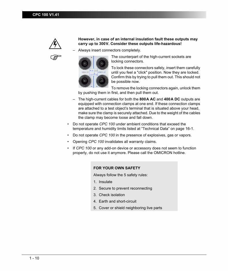
However, in case of an internal insulation fault these outputs may carry up to 300V. Consider these outputs life-hazardous!
– Always insert connectors completely.
The counterpart of the high-current sockets are locking connectors.
To lock these connectors safely, insert them carefully until you feel a "click" position. Now they are locked. Confirm this by trying to pull them out. This should not be possible now.
To remove the locking connectors again, unlock them by pushing them in first, and then pull them out.
– The high-current cables for both the 800A AC and 400A DC outputs are equipped with connection clamps at one end. If these connection clamps are attached to a test object’s terminal that is situated above your head, make sure the clamp is securely attached. Due to the weight of the cables the clamp may become loose and fall down.
• Do not operate CPC 100 under ambient conditions that exceed the temperature and humidity limits listed at ”Technical Data” on page 16-1.
• Do not operate CPC 100 in the presence of explosives, gas or vapors.
• Opening CPC 100 invalidates all warranty claims.
• If CPC 100 or any add-on device or accessory does not seem to function properly, do not use it anymore. Please call the OMICRON hotline.
FOR YOUR OWN SAFETY
Always follow the 5 safety rules:
1. Insulate
2. Secure to prevent reconnecting
3. Check isolation
4. Earth and short-circuit
5. Cover or shield neighboring live parts

Preface
1 - 11
Changing Fuses• Turn off CPC 100, unplug the power cord and/or press the Emergency Stop
button.
• We recommend to wait for about 30 seconds. This time is necessary for the internal electrolytic capacitors to fully discharge.
• Ground the test object, and disconnect it from CPC 100. By disconnecting it you prevent a possibly faulty test object feeding power back into CPC 100.
• Locate the blown fuse on the front panel of CPC 100, and replace it:
– 6.3A T (6.3 Amps slow-acting wire fuse 5x20mm) for AC OUTPUT in 6A operation mode1 or for DC OUTPUT.
– 3.15A T (3.15 Amps slow-acting wire fuse 5x20mm) for AC OUTPUT in 130V operation mode.
– 10A FF (10 Amps very-quick-acting wire fuse 5x20mm) for measuring inputs.
1. For detailed information about the difference between the 6A and the 130V operation mode referto ”Functional Components of CPC 100” on page 2-2.
Note: Replace with identical fuse type only.

CPC 100 V1.41
1 - 12
CPC 100 in combination with CP TD1CP TD1 is an optionally available high precision test system for on-site insulation tests of high-voltage systems like power and measuring transformers, circuit breakers, capacitors and isolators. CP TD1 works as an add-on device to CPC 100 and is described at ”CP TD1” in chapter 9” of this manual.
On principle, the safety instructions that apply to CPC 100 and its accessories also apply to CP TD1. However, CP TD1 requires some additional precautions and measures. They are listed in the ”CP TD1” chapter on page CP TD1-1.
Different Symbols for PECPC 100 and CP TD1 use different symbols for protective earth (PE):
This is due to a new standard and does not symbolize any functional difference.
Note: Both symbols mean exactly the same, that is, protective earth (PE) or equipotential ground.

Preface
1 - 13
Designated UseCPC 100, in conjunction with its accessories or as a stand-alone unit, is a multi-purpose primary test set for commissioning and maintaining substation equipment. It performs current transformer (CT), voltage transformer (VT) and power transformer (TR) tests. Furthermore it is used for contact and winding resistance testing, polarity checks as well as primary and secondary protection relay testing.
The various, partly automated tests are defined and parameterized via the front panel control of a built-in ePC (⇒ Glossary).
Functionality of CPC 100• Current transformer (CT)
– testing ratio, polarity (and burden) with injection to current input
– testing ratio, polarity (and burden) with a current clamp
– testing secondary burden
– measuring the excitation curve
– measuring winding resistance
– dielectric withstand voltage test (2kV AC)
– polarity check
– testing ratio and polarity by measuring the voltage ratio
– testing ratio and polarity of a Rogowski coil
– testing ratio and polarity of low power current transformer
• Voltage transformer (VT)– testing ratio and polarity
– testing secondary burden
– dielectric withstand voltage test (2kV AC)
– polarity check
– testing ratio & polarity of non-conventional electronic voltage transformers

CPC 100 V1.41
1 - 14
• Power transformer testing (TR)– ratio and polarity / tap changer test
– measuring winding resistance
– testing tap changer contacts
– dielectric withstand voltage test (2kV AC)
• Resistance testing– measuring contact resistance (µΩ)
– measuring winding resistance (µΩ - kΩ)
– measuring earth resistance (µΩ - kΩ)
– dielectric withstand voltage test (2kV AC)
• Other applications– Ramping, a pogrammable ramping generator and determination of
thresholds
– Sequencer for automatic testing with different states in real time
– Comment card to hold a user-defined comment and/or note regarding the actual test procedure.
– When using the Amplifier test card, an input signal fed into a synchronization input drives the high-current output’s magnitude, frequency and phase angle.
• Insulation tests (TanDelta)CP TD1 for on-site insulation tests of high-voltage systems like power and measuring transformers, circuit breakers, capacitors and isolators.
• Automated testing of each application via front panel control
• Automatic report generation: test results are automatically recorded and saved together with the test card
• CPC 100 can be connected to an external PC via an Ethernet connection. This way, test reports, for example, can be loaded onto this PC and customized in standard applications.
• CPC 100 provides a "dead man" function, that is the possibility to install an additional push-button that stops remote operation if released (refer to ”ePC Interfaces” on page 2-4).
Any other use of CPC 100 but the one mentioned above is considered improper use, and will not only invalidate all customer warranty claims but also exempt the manufacturer from its liability to recourse.

Preface
1 - 15
CPC 100 VersionsTwo different CPC 100 versions exist, V0 and V1. An upgrade from the version V0 to V1 is possible. For CPC 100 V1 units you will find the text "V1" in the "Options" field of the nameplate on the right-hand side of your CPC 100. Depending on the version, CPC 100 is delivered with different processor and ePC interface options described below.
For detailed information on the ePC interfaces, see ”ePC Interfaces” on page 2-4.
CPC 100 Version Processor
ePC InterfacesPC Network USB Serial Safety
V0 66 MHz x86 compatible × × × ×V1 400 MHz RISC CPU ×1
1. CPC 100 V1 units are equipped with one socket for connecting CPC 100 to both a PC and anetwork hub.
×1 × × ×

CPC 100 V1.41
1 - 16

Introduction
2 - 1
IntroductionContents of this section
Functional Components of CPC 100............................................... page 2-2
Front Panel ................................................................................ page 2-2
High-Voltage and High-Current Outputs .................................... page 2-3
ePC Interfaces ........................................................................... page 2-4
Functional Components in Detail ............................................... page 2-6
CPC 100 Block Diagram (Simplified) ............................................ page 2-13
Built-in ePC ................................................................................... page 2-14
How to Use the CPC 100 Software............................................... page 2-17
The principles of test cards and test procedures ..................... page 2-17
Starting the Software ............................................................... page 2-20
View Selector ........................................................................... page 2-21
Accelerator Keys...................................................................... page 2-22
Test Card View ........................................................................ page 2-22
Inserting Test Cards............................................................ page 2-23
Setting Up a Test Card ....................................................... page 2-25
Settings Page...................................................................... page 2-28
Starting a Test..................................................................... page 2-29
Temperature Monitoring...................................................... page 2-30
Test Procedure Overview ........................................................ page 2-31
File Operations......................................................................... page 2-32
Options..................................................................................... page 2-33
Creating Defaults and Templates ............................................ page 2-42
Putting CPC 100 into Operation.................................................... page 2-46
Principle Steps to Carry Out a Test with CPC 100 .................. page 2-47

CPC 100 V1.41
2 - 2
Functional Components of CPC 100Figure 1:CPC 100 front view
Front Panel
Note: With the CPC 100 V0, the number of test cards in one test procedure should be limited to 15 to avoid memory problems. The CPC 100 V1 allows using more test cards in one test procedure but we recommend not to use more than 15 test cards or more than 50 test results to keep the tests clearly structured.
Soft-touch keyboard
Built-in ePC
Built-in ePC with front-panel controlWe recommend not to use more than 15 test cards
or 50 test results in one test procedure(see Note below).
I / 0Warning lights that indicate either a safe operation, that is, no voltage at the CPC 100 outputs (green
light "0" on), or an operation with possibly hazardous voltage and/or current levels at the
CPC 100 outputs (red light "I" flashing).
Safety key lock
Emergency stop button
Navigation elements
DC OUTPUT
6A DC outputTest
Start/Stop
BIN IN
Binary trigger input
INPUT
Measuring inputs
AC OUTPUT
Fuse-protected 6A or 130V output
Fuses for 6A AC and 6A DC outputs

Introduction
2 - 3
High-Voltage and High-Current OutputsWhen CPC 100 outputs high current, observe the allowed duty cycles that may apply to the selected AC output range. For more information please refer to ”CPC 100 Outputs” on page 16-5.
Figure 2:High-voltage and high-current outputs on left-hand side of CPC 100
Caution: The connector "Ext. Booster" is always galvanically connected to mains, regardless whether or not an external booster is selected on the software tab Options | Device Setup, the green warning warning light (0) is on, the outputs are turned off or the Emergency Stop button is pressed.
Handle with extreme caution!
800A AC
(6.1-6.5V AC)
High AC current output
POWER ON /OFF switch
Mains power supply, 1 phase, 85V-264V AC
2kV AC
High-voltage output
400A DC
(4-4.5V DC)
High DC current output
Ext. Booster
for example, for the connection of
the CP CB2 current booster option for output currents of up to
2000A
Grounding terminal
Automatic circuit breaker I > 16A
CPC 100 V1.41
2 - 4
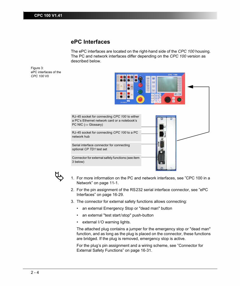
ePC InterfacesThe ePC interfaces are located on the right-hand side of the CPC 100 housing. The PC and network interfaces differ depending on the CPC 100 version as described below.
Figure 3:ePC interfaces of the CPC 100 V0
1. For more information on the PC and network interfaces, see ”CPC 100 in a Network” on page 11-1.
2. For the pin assignment of the RS232 serial interface connector, see ”ePC Interfaces” on page 16-29.
3. The connector for external safety functions allows connecting:
• an external Emergency Stop or "dead man" button
• an external "test start/stop" push-button
• external I/O warning lights.
The attached plug contains a jumper for the emergency stop or "dead man" function, and as long as the plug is placed on the connector, these functions are bridged. If the plug is removed, emergency stop is active.
For the plug’s pin assignment and a wiring scheme, see ”Connector for External Safety Functions” on page 16-31.
RJ-45 socket for connecting CPC 100 to either a PC’s Ethernet network card or a notebook’s PC NIC (⇒ Glossary)
RJ-45 socket for connecting CPC 100 to a PC network hub
Serial interface connector for connecting optional CP TD1 test set
Connector for external safety functions (see item 3 below)

Introduction
2 - 5
Figure 4:ePC interfaces of the CPC 100 V1
The CPC 100 V1 supports the USB interface 1.1 and 2.0 for connecting the USB memory stick shipped with the CPC 100.
Note: The full functionality is guaranteed only for the stick delivered with the CPC 100.
The serial and safety interfaces are identical with the CPC 100 V0 version (see above). The network interface is an auto-crossover Ethernet connector that can be connected to a network hub or directly to a PC or a notebook.
The CPC 100 V1 provides the following LEDs on the ePC interface:
• Green LED lights if CPC 100 is properly connected to a PC or network.
• Yellow LED lights if data is transferred from or to the network.
• Red LED serves for diagnosis purposes.
USB connector for connecting OMICRON USB memory sticks(see below)
RJ-45 socket for connecting CPC 100 to a PC or a network hub
Serial interface connector for connecting optional CP TD1 test set(see item 2 above)
Connector for external safety functions (see item 3 above)
Red LED
Yellow LED
Green LED

CPC 100 V1.41
2 - 6
Functional Components in Detail
AC OUTPUTProgrammable AC current and voltage outputs.
Figure 5:Functional group AC OUTPUT
1. The front panel output 6A/130V operates as either a 0...6A AC or a 0...130V AC output. The output range and the actual values are set by the software.
In current mode 0...6A, the maximum output voltage is 65V (390VA).
In voltage mode 0...130V, the maximum output current is 3A (390VA).
The 6.3A T (6.3 Amps slow-acting wire fuse 5x20mm) protects both the AC OUTPUT in 6A current mode and the DC OUTPUT.
The 3.15A T (3.15 Amps slow-acting wire fuse 5x20mm) protects the AC OUTPUT in 130V voltage mode and in the 3A AC current mode.
2. The 800A output sockets are situated at the left-hand side of CPC 100 as shown on page 2-3.
They provide an AC current of 0...800A at a voltage of 6.1...6.5V. The actual output power (4880VA max.) is range-dependent. For details refer to ”High-Current and High-Voltage Outputs” on page 16-5.
The current that flows from this output is measured internally by CPC 100, and displayed on the respective test card.
3. The 2kV output sockets are situated at the left-hand side of CPC 100 as shown on page 2-3.
Lit LED indicates that output is selected.

Introduction
2 - 7
They provide an output voltage of either
• 0 ... 0.5kV with a maximum current of 5A, or
• 0 ... 1kV with a maximum current of 2.5A, or
• 0 ... 2kV with a maximum current of 1.25A.
For details refer to ”High-Current and High-Voltage Outputs” on page 16-5.
Both the voltage of this output and the current that flows from this output are measured internally by CPC 100, and displayed on the respective test card.
All outputs are overload and short-circuit-proof and protected against external high-voltage signals as well as over-temperature.Note: The length of time a high current or a voltage can be applied may be
limited due to a high temperature occurrence of the internal transformer windings and/or heat dissipaters. This high temperature occurrence may even be increased if CPC 100 is operated in a hot environment or is exposed to direct sunlight.
It is highly recommended not to exceed the typical duration time tmax specified for each current and voltage output (refer to ”CPC 100 Outputs” on page 16-5). If you do, and CPC 100 develops too high an internal temperature, the outputs are shut off automatically.

CPC 100 V1.41
2 - 8
DC OUTPUTProgrammable DC current output.
Figure 6:Functional group DC OUTPUT
1. The 6A output provides a DC current of 0...6A with a maximum output voltage of 60V (360W). The output value is set by the software.
The 6.3A T (6.3 Amps slow-acting wire fuse 5x20mm, situated at the front panel’s AC OUTPUT group) protects both the AC OUTPUT in 6A current mode and the DC OUTPUT.
2. The 400A output is situated at the left-hand side of CPC 100 as shown at ”High-Voltage and High-Current Outputs” on page 2-3.
They provide an output current of 0...400A at a voltage of 4...4.5V. The actual output power (1600W max.) depends on the current magnitude. For details refer to ”High-Current and High-Voltage Outputs” on page 16-5.
The current that flows from this output is measured internally by CPC 100, and displayed on the respective test card.
All outputs are overload and short-circuit-proof and protected against external high-voltage signals as well as over-temperature.Note: The length of time a high current or a voltage can be applied may be
limited due to a high temperature occurrence of the internal transformer windings and/or heat dissipaters. This high temperature occurrence may even be increased if CPC 100 is operated in a hot environment or is exposed to direct sunlight.
It is highly recommended not to exceed the max. duration time tmax specified for each current and voltage output (refer to ”CPC 100 Outputs” on page 16-5). If you do, and CPC 100 develops too high an internal temperature, the outputs are shut off automatically.
LED indicates that output is selected.

Introduction
2 - 9
INPUTAnalog precision measuring inputs
Figure 7:Functional group INPUT
3. V2AC low level AC voltage measuring input
Measuring input for low-level AC voltage of 0...3V in a frequency range of 15...400Hz (for example, for low-power measuring transformers, or to connect a current clamp).
The software changes automatically between the measuring ranges 0.03V, 0.3V and 3V. For details about the accuracy of the individual ranges, please refer to ”3V V2 AC Input” on page 16-25.
4. VDC voltage measuring input 10V DCMeasuring input for DC voltage of 0...10V. The software changes automatically between the measuring ranges 0.01V / 0.1V / 1V / 10V.
Note: The V1 AC and V2 AC inputs are galvanically connected. All other inputs and outputs are separated.
1. IAC/DC current measuring input 10A AC and DC
Measuring input for AC and DC current of 0...10A, depending on the selected test card. AC current is measured in a frequency range of 15...400Hz.
For both AC and DC current measurement, the software changes automatically between the two measuring ranges 1A and 10A. In both ranges the measuring error is <±0.2%.
A 10A FF (10 Amps very quick-acting wire fuse 6.3x32mm) protects the 0...10A AC/DC current measuring input.
2. V1AC voltage measuring input 300V AC
Measuring input for AC voltage of 0...300V. AC voltage is measured in a frequency range of 15...400Hz.
During measurement, the software changes automatically between the measuring ranges 0.3V, 3V, 30V and 300V.
For details about the accuracy of the individual ranges, please refer to ”300V V1 AC Input” on page 16-23.
CPC 100 V1.41
2 - 10
For details about the accuracy of the individual ranges, please refer to ”10V V DC Input” on page 16-27.
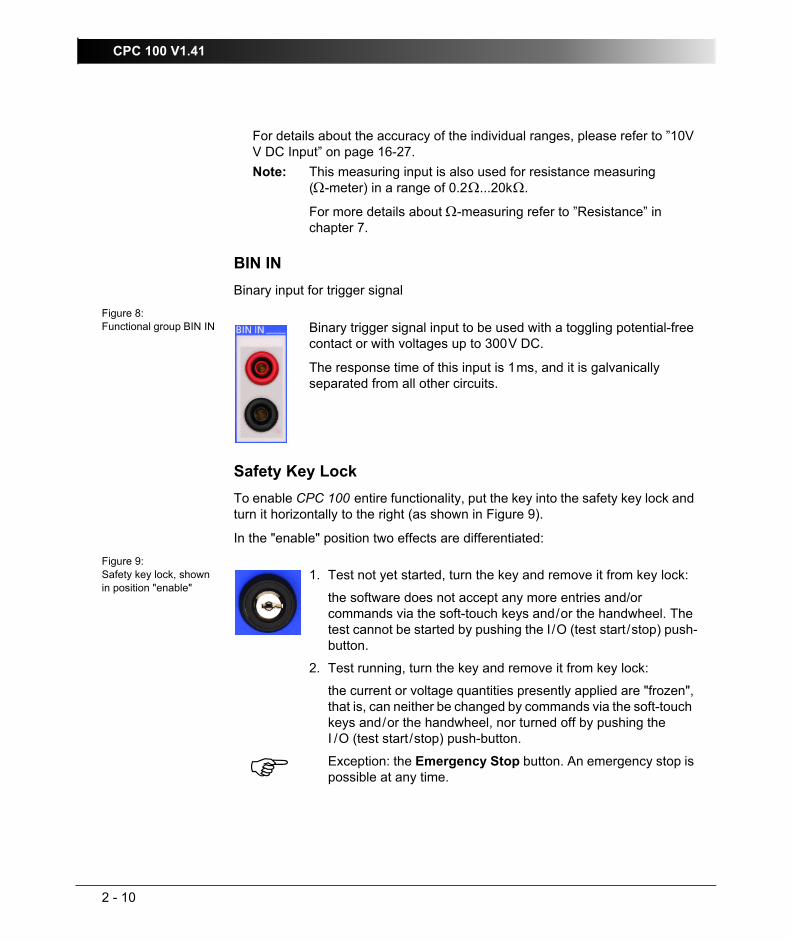
BIN INBinary input for trigger signal
Figure 8:Functional group BIN IN
Safety Key LockTo enable CPC 100 entire functionality, put the key into the safety key lock and turn it horizontally to the right (as shown in Figure 9).
In the "enable" position two effects are differentiated:
Figure 9:Safety key lock, shown in position "enable"
Note: This measuring input is also used for resistance measuring (Ω-meter) in a range of 0.2Ω...20kΩ.
For more details about Ω-measuring refer to ”Resistance” in chapter 7.
Binary trigger signal input to be used with a toggling potential-free contact or with voltages up to 300V DC.
The response time of this input is 1ms, and it is galvanically separated from all other circuits.
1. Test not yet started, turn the key and remove it from key lock:
the software does not accept any more entries and/or commands via the soft-touch keys and/or the handwheel. The test cannot be started by pushing the I/O (test start/stop) push-button.
2. Test running, turn the key and remove it from key lock:
the current or voltage quantities presently applied are "frozen", that is, can neither be changed by commands via the soft-touch keys and/or the handwheel, nor turned off by pushing the I /O (test start/stop) push-button.
Exception: the Emergency Stop button. An emergency stop is possible at any time.

Introduction
2 - 11
Warning lightsThe warning lights indicate either a safe or dangerous operating condition.
Figure 10:Warning lights
Emergency Stop ButtonFigure 11:Emergency Stop button
1. Outputs are switched OFF
Green warning light (0) on
Safe operating condition
2. Output was selected by the software, values are set and output is ready to be switched ON
Red signal lamp (I) flashes
Dangerous voltage and/or current at output.
3. Output is switched ON
Red signal lamp (I) flashes
Dangerous voltage and/or current at output.
safe operating condition
Dangerous operating condition!
Pressing the Emergency Stop button immediately shuts off all current and voltage outputs.
A running test is terminated, the software does not accept any more entries and/or commands.
Once the reason for the Emergency Stop is cleared and the Emergency Stop button released, the test needs to be re-started by pressing the I/O (test start/stop) push-button while in Test Card View.

CPC 100 V1.41
2 - 12
Ext. BoosterSocket to connect an external booster, for example, the CP CB2 current booster for output currents of up to 2000A.
Enable any external booster in the CPC 100 software on the tab Options | Device Setup (refer to ”Device Setup” on page 33 of this chapter).Note: The connector "Ext. Booster" is always galvanically connected to
mains, regardless whether or not an external booster is selected on the software tab Options | Device Setup, the green warning light (0) is on, the outputs are turned off or the Emergency Stop button is pressed.
Handle with extreme caution!

Introduction
2 - 13
CPC 100 Block Diagram (Simplified)Figure 12:Simplified block diagram of CPC 100
+
Rectifier& power
factor corrector
Filter
Switched mode
amplifier
500V 4A1kV 2A2kV 1A
500V
500V
500V
500V
65V
65V
3.15A
6.3AADC
I
U
U
U
U
I
IDSP(Digital Signal
Processor)
Built-inePC
Ethernet
RS 232
optional
optional interfaces (plug-in boards)
analog or digital
2kV
800A
R
R
-
+5V / 400A DC
10A AC/DC3V AC
300V AC
10V DCBIN IN
65V / 6A DC
6V / 800A AC
2kV
Ext. Booster
130V / 6A AC
Mains100-240V 50/60Hz
to ext. PC
Inp.
Outputs
L
N
PE

CPC 100 V1.41
2 - 14
Built-in ePCThe built-in ePC (⇒ Glossary) of CPC 100 runs under Microsoft Windows CE operating system and provides front panel control.
This section provides a brief overview of the front panel control components.
Section ”How to Use the CPC 100 Software” on page 17 of this chapter describes in detail how to work with the front panel control components, how to set up a test, execute it and save it for later use.
Via the built-in ePC, CPC 100 can be accessed from a stand-alone PC, for example, a notebook, via a PC network and via the Internet (refer to ”CPC 100 in a Network” in chapter 11).
Figure 13:CPC 100’s built-in ePC, components overview
Accelerator keysView selector
LCD monitorContext-dependent menu keys
Tab selectorTest start/stop
U P / D O W N keysJog-dial handwheel
Soft-touch keyboard

Introduction
2 - 15
LCD monitor
The monitor is a high-contrast gray-scale graphical LCD display with a resolution of 320x240 pixels.
Accelerator keys
Let you add the test card of your choice, for example, Quick, CT, VT... etc. (refer to ”Accelerator Keys” on page 22 of this chapter).
View Selector
Lets you select the view of your choice, for example, Test Card View, Test Procedure Overview, File Operations or Options (refer to ”View Selector” on page 21 of this chapter).
Jog-dial handwheel
Advanced jog-dial handwheel with "click" (E N T E R) function.
In "navigation" mode, turning the handwheel navigates you through the UI (⇒ Glossary) elements within one test card. Pressing the U P / D O W N keys has the same effect.
In "data entry" mode, that is, if the focus (⇒ Glossary) is set onto a data entry field or a combo box, and the handwheel was pressed to "enter" the field and to enable data entry, turning the handwheel increases/decreases the entry field’s value or browses through the preset values of the combo box, respectively.
Pressing the handwheel corresponds to the E N T E R function of the soft-touch keyboard.
Furthermore, the wheel comprises an adaptive acceleration function, that is, if the focus is, for example, set onto a data entry field, fast turning increments/decrements a value in increasingly bigger steps, slow turning in decreasingly smaller steps.
U P / D O W N keys
Soft-touch keys supplementing the handwheel. Depending on the current focus in the software user interface, pressing these keys either navigates through the UI elements within one test card, or - if in a data entry field, for example - increments/decrements a value.
Contrary to the handwheel, the U P / D O W N keys change a value in fixed coarse increments /decrements in order to ease a quick approximation to the end value. The fine adjustment is then done with the handwheel.
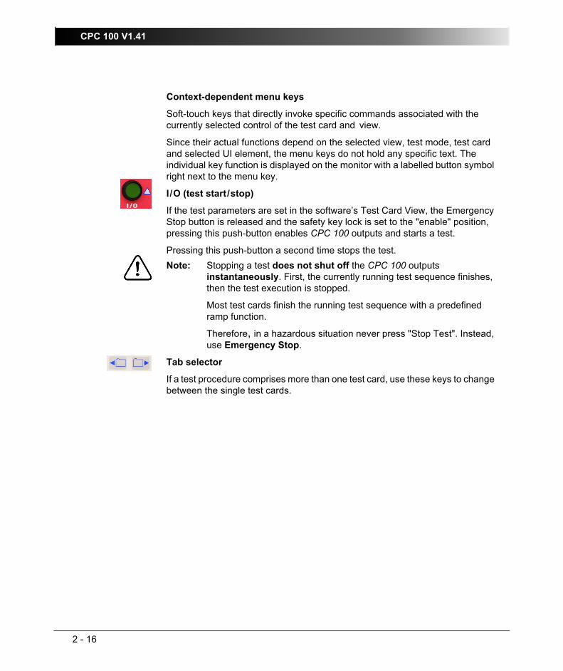
CPC 100 V1.41
2 - 16
Context-dependent menu keys
Soft-touch keys that directly invoke specific commands associated with the currently selected control of the test card and view.
Since their actual functions depend on the selected view, test mode, test card and selected UI element, the menu keys do not hold any specific text. The individual key function is displayed on the monitor with a labelled button symbol right next to the menu key.
I /O (test start/stop)
If the test parameters are set in the software’s Test Card View, the Emergency Stop button is released and the safety key lock is set to the "enable" position, pressing this push-button enables CPC 100 outputs and starts a test.
Pressing this push-button a second time stops the test.
Tab selector
If a test procedure comprises more than one test card, use these keys to change between the single test cards.
Note: Stopping a test does not shut off the CPC 100 outputs instantaneously. First, the currently running test sequence finishes, then the test execution is stopped.
Most test cards finish the running test sequence with a predefined ramp function.
Therefore, in a hazardous situation never press "Stop Test". Instead, use Emergency Stop.

Introduction
2 - 17
How to Use the CPC 100 SoftwareNote: This manual refers to the CPC 100 software version V 1.41.
Information about the software version of your CPC 100 can be found at the Options tab System Info (refer to ”System Info” on page 41 of this chapter).
This section provides an overview of the front panel control components, explains in detail how to navigate with them through the software, how to set up a test, execute it, save it for later use, etc.
The subsequent chapters (Quick, CT, VT, Resistance, Transformer...), explaining the various test procedures from a more practice-orientated point of view, are confined to test-relevant issues, and assume that you have read and understood this section.
The principles of test cards and test procedures• Test cards
The CPC 100 software comprises a number of test cards. A test card carries out one specific test, for example, measuring a CT excitation curve, or testing the ratio of a voltage transformer.
A test card holds a number of user-definable test settings and - after the test was run - test results.
• Test card default
Rather than repeatedly filling out blank test cards with frequently used settings, any test card with its actual settings can be made a test card default for that particular type of card, for example, filling out a CTRatioV test card with certain values and pressing S A V E A S D E F A U L T makes this card the new CTRatioV test card default.
Each card of this type that will later be inserted to a test procedure will already hold these new settings.Note: A test card default contains user-defined settings, not test results.
CPC 100 V1.41
2 - 18
• Test procedure
A test procedure contains multiple test cards.
The composition of such a test procedure and the settings of all single test cards can be freely defined by the user. Within a test procedure, each test card and its associated test is executed individually in a user-defined order.
Note: With the CPC 100 V0, the number of test cards in one test procedure should be limited to 15 to avoid memory problems. The CPC 100 V1 allows using more test cards in one test procedure but we recommend not to use more than 15 test cards to keep the tests clearly structured.
• Test procedure default
A test procedure with all of its test cards and specific settings - but without test results - can be made the test procedure default.When the CPC 100 software starts, it automatically loads the test procedure default.
Initially, that is, as long as no user-defined test procedure default is created, the the CPC 100 software loads one empty Quick test card.
• Report
For archiving or reporting purposes, or later processing, a test procedure with all of its test cards, specific settings and - after the test was run - test results and assessments can be saved. It is then considered a report. Such a report can later be opened any time in CPC 100 File Operations menu.
• Test procedure template
A report can be copied/pasted to be a test procedure template.
In this process, the settings are preserved, however, the test results are deleted.

Introduction
2 - 19
Figure 14:The principles of test cards, defaults and test procedures
(1) One Test Card Default for each type of test card
The following sections emphasize on test cards, defaults and templates in more detail. Also refer to ”Creating Defaults and Templates” on page 42 of this chapter.
Test Card
+Test Card
+ Test
settings
settings
= Test Procedure
settings
settings+
results+Test Card
+...
Test ProcedureTemplatename.xmt
Test Card Default (1)
Test Card
settings
settings
in Test Card View:
in Test Procedure Overview:Test Procedure
Default
settings
Test Procedurename.xml
(in file system)in Test Procedure Overview:
CPC 100 V1.41
2 - 20
Starting the SoftwareWhen CPC 100 is switched on, the operating system boots up, and the CPC 100 software starts automatically.
During the hardware and software initialization phase, the software displays a splash screen.
The CPC 100 software starts in the Test Card View loading the test procedure default (refer to ”The principles of test cards and test procedures” on page 17 of this chapter).
Initially, the test procedure default contains one empty Quick test card1. However, this default can be customized according to your specific requirements with as many test cards as needed and of all types of your choice.
By creating a user-defined test procedure default, CPC 100 starts up loading your most frequently used test cards already containing specific values.
To learn more about defining such a default, refer to ”Creating Defaults and Templates” on page 42 of this chapter.
1. More about Quick at ”Getting Started with Quick” in chapter 3.
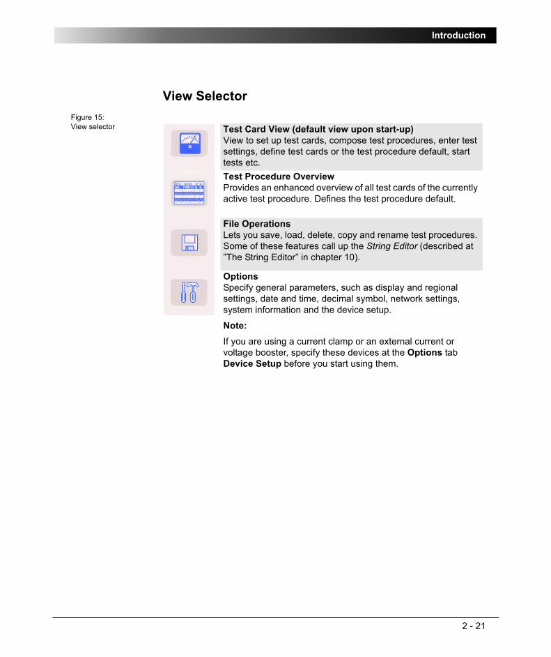
Introduction
2 - 21
View SelectorFigure 15:View selector Test Card View (default view upon start-up)
View to set up test cards, compose test procedures, enter test settings, define test cards or the test procedure default, start tests etc.Test Procedure OverviewProvides an enhanced overview of all test cards of the currently active test procedure. Defines the test procedure default.
File OperationsLets you save, load, delete, copy and rename test procedures. Some of these features call up the String Editor (described at ”The String Editor” in chapter 10).
OptionsSpecify general parameters, such as display and regional settings, date and time, decimal symbol, network settings, system information and the device setup.
Note:If you are using a current clamp or an external current or voltage booster, specify these devices at the Options tab Device Setup before you start using them.

CPC 100 V1.41
2 - 22
Accelerator KeysWith the exception of Quick, pressing an accelerator key opens the according Insert a new test card dialog box and lets you select the test card of your choice. Pressing Quick opens the Quick test card directly.
Test Card ViewThe Test Card View displays the test procedures. The CPC 100 software starts in the Test Card View loading the test procedure default.
A test card inserted to the Test Card View loads the values from the respective test card default. If no test card default has been defined yet by the user, the test card opens with preset default values.
Any test card with its actual settings can be made a test card default for that particular type of card, for example, filling out a CTRatioV test card with certain values and pressing S A V E A S D E F A U L T makes this card the new CTRatioV test card default.
Each card of this type that will later be inserted to a test procedure will already hold these new settings.
Quick test card
select from current transformer (CT) test cards
select from voltage transformer (VT) test cards
select from power transformer test cards
select from resistance test cards
select from other test applications...
– Ramping (primary / secondary protection relay testing)
– Sequencer (primary / secondary protection relay testing)
– Amplifier card (refer to page 8-29).
– Comment card (refer to page 8-33).
TanDelta (refer to the CP TD1 Reference Manual available on the CPC Explorer CD-ROM).
Note: A test card default contains user-defined settings, not test results.

Introduction
2 - 23
The Test Card View comprises a number of context-dependent menu keys. Some examples are given below:
Inserting Test CardsThe Insert a new test card dialog box displays the available tests and their associated test cards in a tree-like structure.
Figure 16:Insert a test card
Note: The actual function of the context-dependent menu keys depends on the selected view, test mode, test card and selected UI element.
To make the above listed functions visible, the focus (⇒ Glossary) must be set onto the test card tab designation, for example, ‘CTRatioV’.
Inserts a test card of your choice and places it after the selected test card of the current test procedure.
Deletes the current test card from the test procedure.
Opens the String Editor. You can rename the current test card to any new name of your choice (max. 15 characters).Clears the results of the current test card, and thus enables the start of a new test.Makes the current test card with all of its settings the new default for that particular type of card.Context-dependent menu item (shown here: "Demag.", CTExcitation).

CPC 100 V1.41
2 - 24
Use the context-dependent U P /D O W N menu keys to the right, or the handwheel, to browse through the structure.
Due to usability reasons, some test cards, such as Winding Resistance, Voltage Withstand Test or Polarity Check, appear in more than one test mode, e.g., Winding Resistance appears in Current Transformer, Power Transformer and Resistance.
With regard to their functionality, these test cards are identical.
To expand a collapsed group of tests , for example, CT, set the focus onto this group, and press E N T E R or the handwheel.
The group of tests expands and displays all of its associated test cards.
Browse to the test card of your choice, and when its highlighted press E N T E R .
This will switch from the Insert a new test card dialog to the Test Card View, inserting the test card of your choice after the last selected test card in the Test Card View.
You can insert as many test cards as needed and of all types of your choice by repeating this process.
Pressing E S C closes Insert a new test card, and brings you back to the previous view without inserting a new test card.
Note: Only test cards that are licensed can be inserted.
When you purchased CPC 100, you purchased a license for a number of test cards of your choice. Not licensed test cards are displayed in the Insert a new test card dialog, but the attempt to insert one of them to the test procedure results in an according on-screen message.
If you wish further information about licensing, please contact OMICRON electronics.
Note: With the CPC 100 V0, the number of test cards in one test procedure should be limited to 15 to avoid memory problems. The CPC 100 V1 allows using more test cards in one test procedure but we recommend not to use more than 15 test cards to keep the tests clearly structured.
If you need more test cards in one test procedure, we recommend not to save all cards in one, for example, the test procedure default, but to combine a smaller number of cards to logical groups, and to save these logical groups as test procedure templates with individual names (refer to ”Test Procedure Templates” on page 45 of this chapter).

Introduction
2 - 25
Setting Up a Test CardEach parameter whose numerical value can be changed in a data entry field has an associated minimum and maximum value as well as a preset number of decimal characters. The parameter value can be changed freely within this min. ... max. range.
Furthermore, each numerical value has a
– fixed precision value that is used as a step size when increased/decreased by means of the handwheel
– a coarse step value that is used as a step size when increased/decreased by pressing the U P / D O W N keys.
As shown above, the value itself is highlighted, the unit is not, and at the value’s end a blinking caret (cursor) indicates "ready for data entry".
Now either
– use the U P / D O W N keys to approximate the value of your choice quickly in coarse predefined steps
– rotate the handwheel to fine-adjust the value in precision steps
– type in the value of your choice using the numeric soft-touch keys to the left of the handwheel (refer to Figure17).
Within one test card, to navigate to the UI element of your choice either turn the handwheel or use the U P / D O W N keys at the right-hand side of the handwheel.
A selected UI element is entirely highlighted; it has the focus (⇒ Glossary).
If a data entry field, for example, "Imax:" has the focus, press the handwheel to "enter" the field and to enable

CPC 100 V1.41
2 - 26
Figure 17:Soft-touch keys to enter numerical values
Pressing E S C on the soft-touch keyboard while entering a value, discards the entry and restores the previous value.
When ready, press either the handwheel again or the E N T E R key to confirm your entry, and move forward to the next UI element of your choice by turning the handwheel or the U P / D O W N keys.
Pressing the context-dependent menu key B A C K T O T O P terminates the data entry mode, accepts all current values and sets the focus onto the test card tab designation.
Combo Box
The same principle applies at a combo box, for example, :
– press the handwheel (to "enter" the combo box for selection)
– and either navigate through the list of available parameters by rotating the handwheel, or by using the U P / D O W N keys.
Pressing E S C while scrolling through the list of values closes the combo box and returns to the previous value.
Check Box
Set the focus onto the check box, for example, and press either the E N T E R key or the handwheel to select /clear a check box.
Note: If a number key is pressed with the focus set onto a data entry field, this number is automatically written to the data entry field, and the field is enabled for data entry.
Soft-touch keys to enter numerical values.
Decimal point
: backspace
Esc: cancels the current action without saving
— : prefix for negative values, for example, angles
: E N T E R

Introduction
2 - 27
List BoxFigure 18:Example of a list box
List boxes are differentiated between read-only and editable list boxes:
• In a read-only list box (Figure 18), turning the handwheel scrolls from line to line.
When using the U P / D O W N keys, a read-only list box is treated as one UI element, that is, pressing one of the keys exits the list box, and sets the focus onto the next /previous UI element.
• In an editable list box, turning the handwheel scrolls from table cell to table cell. Press either the handwheel or E N T E R to "enter" a cell and to edit the value.
When using the U P / D O W N keys, the focus proceeds to the same table cell one line above or below.

CPC 100 V1.41
2 - 28
Settings PageSome test cards include the S E T T I N G S menu key. Pressing the S E T T I N G S menu key opens the Settings page.
Figure 19:Main page with SETTINGS menu key
The Settings page with the exception of the TRRatio test card looks as shown below.
Figure 20:Settings page
The Settings page allows setting the test cards individually. At the Device Setup tab in the Options view (see ”Options” on page 33 of this chapter), the same properties can be set for all test cards of a test procedure. As a rule, do not use the Settings page described here but the Device Setup tab in the Options view to set the test cards. Making different settings for the test cards is rarely a good idea. Set the test cards individually using the Settings page only in well-founded cases.
If a test card contains results, the settings cannot be changed. When a file containing results is loaded, the Settings page can be used to view the settings of the test procedure.

Introduction
2 - 29
Starting a Test
Preconditions to start a test
1. The required test card is defined, the test parameters are set.
2. The software is in the Test Card View.
3. The Emergency Stop button is released.
4. The safety key lock is set to the "enable" position.
Pressing the I/O (test start/stop) push-button starts the test. Pressing this push-button a second time stops the test.
While a test is running, several functions such as changing the test card, changing the view etc., are disabled.
To repeat the test, the test results need to be cleared beforehand. Otherwise the start is blocked.
Note: Tests can only be started and stopped with the I/O (test start/stop) push-button while in the Test Card View.
Each test card represents a separate test, and is started individually.
Note: Stopping a test does not shut off the CPC 100 outputs instantaneously. First, the currently running test sequence finishes, then the test execution is stopped.
Most test cards finish the running test sequence with a predefined ramp function.
Therefore, in an emergency situation never press "Stop Test". Instead, use Emergency Stop.

CPC 100 V1.41
2 - 30
Temperature Monitoring
Each test card contains a progress bar-like temperature gauge that displays CPC 100 actual temperature condition. When the temperature limit is reached, that is before an overheating condition occurs, the output is switched off automatically.
In addition, if an output is activated, both CPC 100 current consumption from the power supply and the current emitted at the high-current outputs is monitored and, together with the temperature, displayed by this temperature gauge. The temperature gauge’s bar therewith represents an indicator for the remaining time CPC 100 can output power.
Just as with over-temperature, if these limit values are exceeded, the output is switched off automatically.
With deactivated outputs, the temperature gauge’s bar represents an indicator how much the device has already cooled off.
No overload indication means no overload during that step of the measurement sequence. In the test report, "No" appears in the overload field or column.
Dotted overload indication means that there was an overload during that step of the measurement sequence but not all the time. In the test report, "Yes" appears in the overload field or column.
Solid overload indication means a permanent overload during that step of the measurement sequence. In the test report, "Yes!" appears in the overload field or column.
Note: To reach a maximum output time, we suggest to let CPC 100 cool off completely before switching it on again.
Note: For each line of measurement results there is a separate overload indication top right on the CPC 100’s screen (or in the report) explained below.

Introduction
2 - 31
Test Procedure OverviewFigure 21:Test Procedure Overview
The Test Procedure Overview lists all test cards of the currently active test procedure in a list box showing the card’s name, its creation date and time, whether test results are available and the test card’s assessment status.
Pressing I N S E R T C A R D switches to the Insert a new test card dialog. After inserting a new test card, the software automatically switches to the Test Card View, inserting the test card of your choice after the last selected test card in the Test Card View.
Pressing E S C at Insert a new test card brings you back to the previous view without inserting a new test card.
D E L E T E C A R D deletes the currently highlighted test card from the test procedure.
With S A V E A S D E F A U L T , Test Procedure Overview provides a function to save the current test procedure as the test procedure default, that is the default the CPC 100 software will start with in future.
To learn more about defaults, refer to section ”Creating Defaults and Templates” on page 42 of this chapter.
Unlike in Test Card View, where all context-dependent menu keys apply for that particular card only, the Test Procedure Overview has an additional menu item that applies for all test cards: whereas C L E A R R E S U L T S clears the test results of the currently highlighted test card only ("Comment" in Figure 21), C L E A R A L L R E S U L T S applies to all test cards, that is, clears the results of all cards listed in the Test Procedure Overview.
After both C L E A R R E S U L T S and C L E A R A L L R E S U L T S , re-start the test in the Test Card View by pressing the I/O (test start/stop) push-button.

CPC 100 V1.41
2 - 32
Automatically switches back to the Test Card View, and opens the test procedure default. If the current test procedure contains unsaved data, you will be asked whether or not you want to save them before you proceed.
File OperationsThe CPC 100 File Operations resemble the functionality known from the Windows Explorer. File Operations comprises a F I L E and an E D I T submenu with additional menu items as well as an O P E N and various S A V E . . . functions.
The highest hierarchical level of the CPC 100 file system, the "root", is named CPC 100. Below this, you can create additional folders in a tree-structure of your choice, save tests in these folders, and carry out file operations, such as open, save, rename, copy, paste etc. For CPC 100 V1 units with a USB memory stick plugged in, a second tree root USB Disk is displayed as shown above.
The CPC 100 file system differentiates two file types:
For a detailed description of the CPC 100 File Operations refer to ”File Operations” in chapter 9.
– name.xml A test procedure with all of its test cards and specific settings. An .xml file may also contain test results and assessments that were stored together with the settings as report in the CPC 100 file system for archiving purposes.
– name.xmt Test procedure template, that is, a user-defined template containing one or more test cards with all of their specific test settings but without test results.

Introduction
2 - 33
Options
Device SetupThe Device Setup tab in the Options view allows you to change the settings of all test cards of the test procedure running on CPC 100 and all test cards inserted afterwards. The test cards can be instantiated in different ways and for different purposes. Table 1: ”Instantiation procedures” below displays the instantiation procedures and the associated default values.
Table 1:Instantiation procedures
Because the settings of a test card containing results cannot be changed, the settings made at the Device Setup tab in the Options view apply only to new test cards if the currently loaded procedure contains results. To change the settings of a test procedure containing results (for example ,after pressing the K E E P R E S U L T S menu key or after loading a file), clear the results by pressing the C L E A R R E S U L T S menu key in all test cards before setting the test procedure in the Options view.
It is strongly recommended to set the test cards using the Options view. In well-founded cases, you can alternatively set a test card individually using the S E T T I N G S menu key (see ”Settings Page” on page 28 of this chapter).
Note: Changes made in the Options view are automatically saved when the view is changed (for example when Options is left to change to Test Card View).
Alternatively, changes can be saved instantly by pressing S A V E O P T I O N S .
Upon a power supply loss or an accidental switching off of CPC 100, unsaved changes are lost, and the old values are restored.
Procedure Default valuesNew test card Booster, clamp and default frequency
set in the Options viewNew test card saved as default Booster and clamp set in the Options
viewNew test procedure from template (*.xmt)
Booster, clamp and frequency remain as defined in the template
New procedure from report (*.xml) Booster, clamp and frequency remain as defined in the report

CPC 100 V1.41
2 - 34
Figure 22:Options tab Device Setup
External booster
The "External booster" combo box allows to set the external booster:
• CB2 for CP CB2 current booster
• CU20 for CP CU20 coupling unit
• CU1 for CP CU1 coupling unit
For the default value associated with different instantiation procedures, see Table 1: ”Instantiation procedures” on page 33.
Clamp & input transformer settings
When an input is not connected to the device under test directly but using a current clamp, a CT or a VT, the ratio of these devices can be set here.
The "Clamp & input transformer settings" group box displays and, if required, allows you to change settings for external devices:
• IClamp for the current clamp parameters
• CT for the transformation ratio of the current transformer
• VT for the transformation ratio of the voltage transformer
By default, the transformation ratios of the current and voltage transformers for the selected external device are preset. For the default value associated with different instantiation procedures, see Table 1: ”Instantiation procedures” on page 33.
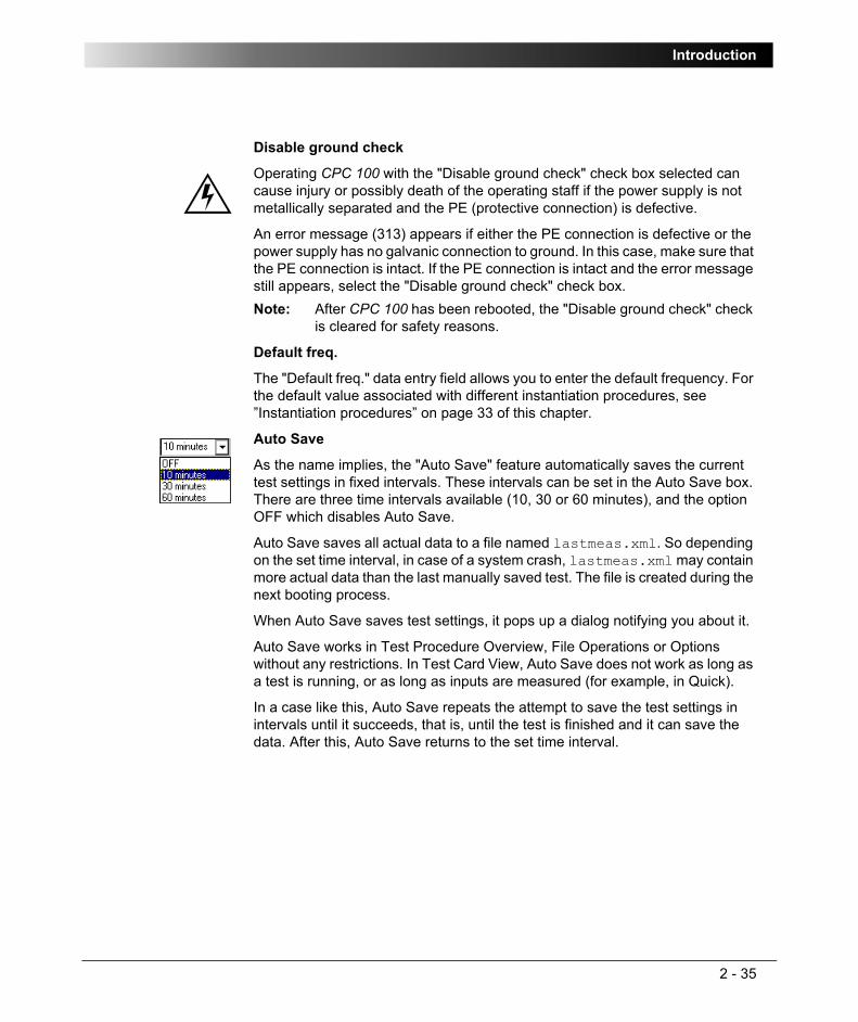
Introduction
2 - 35
Disable ground check
Operating CPC 100 with the "Disable ground check" check box selected can cause injury or possibly death of the operating staff if the power supply is not metallically separated and the PE (protective connection) is defective.
An error message (313) appears if either the PE connection is defective or the power supply has no galvanic connection to ground. In this case, make sure that the PE connection is intact. If the PE connection is intact and the error message still appears, select the "Disable ground check" check box.
Default freq.
The "Default freq." data entry field allows you to enter the default frequency. For the default value associated with different instantiation procedures, see ”Instantiation procedures” on page 33 of this chapter.
Auto Save
As the name implies, the "Auto Save" feature automatically saves the current test settings in fixed intervals. These intervals can be set in the Auto Save box. There are three time intervals available (10, 30 or 60 minutes), and the option OFF which disables Auto Save.
Auto Save saves all actual data to a file named lastmeas.xml. So depending on the set time interval, in case of a system crash, lastmeas.xml may contain more actual data than the last manually saved test. The file is created during the next booting process.
When Auto Save saves test settings, it pops up a dialog notifying you about it.
Auto Save works in Test Procedure Overview, File Operations or Options without any restrictions. In Test Card View, Auto Save does not work as long as a test is running, or as long as inputs are measured (for example, in Quick).
In a case like this, Auto Save repeats the attempt to save the test settings in intervals until it succeeds, that is, until the test is finished and it can save the data. After this, Auto Save returns to the set time interval.
Note: After CPC 100 has been rebooted, the "Disable ground check" check is cleared for safety reasons.

CPC 100 V1.41
2 - 36
Restore Defaults
Pressing the R E S T O R E D E F A U L T S menu key resets all user-specific settings made in the CPC 100 software to factory-defined defaults including:
• the test card defaults
• the test procedure default
• all settings made at the Device Setup tab (sets external booster to CB2, sets CT and VT to "OFF", and sets the value in the "Default freq." data entry field to 50 Hz)
• the String Editor’s template strings (refer to ”The Template Strings” on page 10-4).

Introduction
2 - 37
NetworkFigure 23:Options tab Network
Via the built-in ePC, CPC 100 can be accessed from a stand-alone PC, for example, a notebook and via a PC network. At the Network tab the communication settings are specified.
In the combo box select between
Section ”CPC 100 in a Network” in chapter 11 explains in detail how to connect CPC 100 to either a stand-alone PC or a PC network, and how to configure such a connection.
Once the communication parameters are configured, press S A V E O P T I O N S to save them to the Windows Registry.
For a change to come into effect, the operating system needs to be re-booted, that is, CPC 100 restarted.
– DHCP/Auto IP Configures all communication parameters automatically; the DHCP server will do it for you or it will be done via the Auto IP mechanism.The data entry fields for IP address, Subnet Mask, Default Gateway and DNS are read-only, no data can be entered. This is the recommended setting.
– Static IP Configure the communication parameters manually by entering the values into the data entry fields using the soft-touch keys.

CPC 100 V1.41
2 - 38
DisplayFigure 24:Options tab Display
The "sliding" regulator brightens or darkens the monitor display and the contrast within it. Adding contrast increases the difference in shading between areas.
Date / TimeFigure 25:Options tab Date/Time
Specify the system’s date and time here.
To set the time
– put the focus onto the “Time:” field using the handwheel
– use the U P / D O W N keys to select between hours, minutes and seconds
– turn the handwheel to increase or decrease the value
– press the handwheel to acknowledge your entry
Changing the current date and time does not require pressing S A V E O P T I O N S.

Introduction
2 - 39
Regional SettingsFigure 26:Options tab Regional Settings
Choose a regional setting for language, temperature unit, date and time style. These settings affect the way the CPC 100 software displays and sort dates, times, numbers and decimal points.
ServiceFigure 27:Options tab Service
During operation, CPC 100 creates a log file with a user-definable logging level (see below).
Every time CPC 100 is switched on, it generates a new log file, and saves the existing one as the "previous" log file. This way, the occurrences of the previous and the current session can be viewed (refer to ”Viewing the log file” on page 13-11).

CPC 100 V1.41
2 - 40
The logging level specifies the occurrences to be recorded in the log file:
The default setting is "Warning".
If the log file gets quite long, use either the scroll bar or the buttons P A G E U P /P A G E D O W N to navigate up and down in the list of logged occurrences.
C L E A R L O G deletes all log file entries and starts recording occurrences anew.
Logging level: recordsNone nothingError internal errors, hardware errors, operational errors,
overload conditions etc.Warning uncritical errors such as over-temperature, malfunction
etc.Info additional operational information about CPC 100.
This setting is suggested if the operator suspects, for example, an incorrect functioning or an operational malfunction of CPC 100. This setting records every relevant operational activity of CPC 100.
The log file can then be sent to OMICRON for diagnosis.
Note: The logging levels are hierarchical, that is, if logging level "Warning" is set, "Errors" are also recorded, or if "Info" is set, the logging levels "Warning" and "Error" also apply.

Introduction
2 - 41
System InfoFigure 28:Options tab System Info
Displays the following system information:
Serial Number: CPC 100 serial numberOS Version: operating system with versionSoftware Version: CPC 100 software versionHardware: CPC 100 hardware
The last two positions indicate the CPC 100 hardware version.
Free memory: currently available free memory (RAM)Free disk space: free disk space

CPC 100 V1.41
2 - 42
Creating Defaults and TemplatesThe CPC 100 software differentiates three types of templates:
1. test card default
2. test procedure default (default upon start-up)
3. test procedure templates.
Test Card DefaultRather than repeatedly filling out blank test cards with frequently used settings, any test card with its actual settings can be made a test card default for that particular type of card, for example, filling out a Quick test card with values and pressing S A V E A S D E F A U L T makes this card the new Quick test card default.
Each card of this type, here Quick, that will later be inserted to a test procedure will already hold these new settings.
In the CPC 100 file system, a test card default is not visible as a "file" (refer to ”The CPC 100 File System” in chapter 9).
Note: Pressing the R E S T O R E D E F A U L T S menu key at the Options tab Device Setup resets all user-specific settings made in the CPC 100 software to factory-defined defaults.
This includes the test card defaults and the test procedure default.
Note: The actual function of the context-dependent menu keys depends on the selected view, test mode, test card and selected UI element.
To make the function S A V E A S D E F A U L T visible, the focus (⇒ Glossary) must be set onto the test card tab designation, for example, ‘Quick’.
Note: A test card default contains user-defined settings, not test results.

Introduction
2 - 43
Test Procedure DefaultThe CPC 100 software always starts with the test procedure default. Initially, that is, as long as no user-defined test procedure default is created, this default contains one empty Quick test card. However, this default can be customized according to your specific requirements with as many test cards as needed and of all types of your choice.
In the CPC 100 file system, the test procedure default is not visible as a "file" (refer to ”The CPC 100 File System” in chapter 9).
Note: With the CPC 100 V0, the number of test cards in one test procedure should be limited to 15 to avoid memory problems. The CPC 100 V1 allows using more test cards in one test procedure but we recommend not to use more than 15 test cards to keep the tests clearly structured.
If you need more test cards in one test procedure, we recommend not to save all cards in one, for example, the test procedure default, but to combine a smaller number of cards to logical groups, and to save these logical groups as test procedure templates with individual names (refer to ”Test Procedure Templates” on page 45 of this chapter).
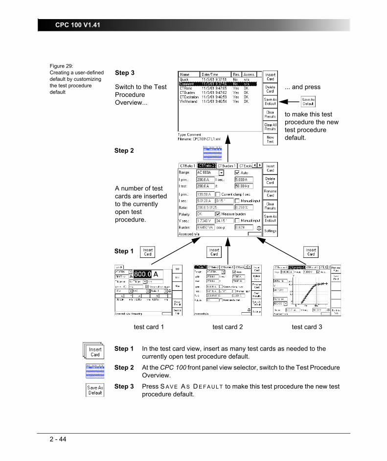
CPC 100 V1.41
2 - 44
Figure 29:Creating a user-defined default by customizing the test procedure default
Step 1 In the test card view, insert as many test cards as needed to the currently open test procedure default.
Step 2 At the CPC 100 front panel view selector, switch to the Test Procedure Overview.
Step 3 Press S A V E A S D E F A U L T to make this test procedure the new test procedure default.
test card 1 test card 2 test card 3
A number of test cards are inserted to the currently open test procedure.
Switch to the Test Procedure Overview...
... and press
to make this test procedure the new test procedure default.
Step 1
Step 2
Step 3

Introduction
2 - 45
Test Procedure TemplatesA test procedure template is a user-defined test procedure, and can be created from any test procedure that was saved to the CPC 100 file system beforehand (a name.xml file; refer to ”The CPC 100 File System” in chapter 9).
To create a test procedure template from an .xml file
– go to "File Operations"
– highlight the name.xml file of your choice
– select E D I T | C O P Y to copy the test procedure
– select P A S T E A S T E M P L .
– a file name.xmt is generated.
If this file name.xmt already exists, you will be asked whether or not to overwrite the existing file.
If you answer this question with N O, the String Editor opens (refer to ”The String Editor” in chapter 10).
Give the test procedure template a name of your choice (max. 15 characters), and select O K . The file name extension .xmt is appended automatically.
In this process, the settings of the original name.xml file are taken over to the newly created test procedure template name.xmt. The test results, however, are not taken over.
The original file name.xml remains unchanged.

CPC 100 V1.41
2 - 46
Putting CPC 100 into Operation
Safety AspectsWe strongly advise you to obey the following legal safety aspects:
– Tests with such high voltages and currents must only be carried out by authorized and qualified personnel.
– Personnel receiving training, instructions, directions, or education on high- voltage/current tests should remain under the constant supervision of an experienced operator while working with the equipment. The instructions have to be renewed at least once per year.
– The instructions must be available in written form and signed by each person assigned to do high-voltage/current tests.
Preparations in SubstationPrior to connecting a test object to CPC 100, the following steps need to be carried out by an authorized employee of the utility.
– Turn off and disconnect the high voltage from the test object.
– Protect yourself and your working environment against an accidental re-connection of high voltage by other persons and circumstances.
– Verify a safe isolation of the test object.
– Earth-connect and shorten out the test object’s terminals using a grounding set.
– Protect yourself and your working environment with a suitable protection against other (possibly live) circuits.
– Protect others from accessing the dangerous area and accidentally touching live parts by setting up a suitable barrier and, if applicable, warning lights.
– If there is a longer distance between the location of CPC 100 and the area of danger (that is, the test object), a second person with an additional "Emergency Stop" button is required.
Note: Before setting CPC 100 into operation and carrying out a test, it is essential that you have read and understood the section ”Safety Instructions for CPC 100 and its Accessories” on page 1-5.
Always be aware that all AC and DC output sockets of CPC 100 can carry life-hazardous voltage potential and provide life-hazardous currents.

Introduction
2 - 47
Principle Steps to Carry Out a Test with CPC 1001. Verify that the substation is prepared accordingly and you comply with all
safety regulations.
2. Connect the CPC 100 grounding terminal to the substation ground. Use a wire with a cross-section of ≥ 6mm², otherwise the housing may feed high voltage.
3. Connect CPC 100 to the mains power supply using the provided cable.
4. With the test object grounded and shorted out, connect CPC 100 to the test object according to your requirements.
5. Remove the grounding set from the test object.
6. Turn on CPC 100 at its POWER switch at the left-hand side.
The green warning light "O" lights up, showing that none of CPC 100 outputs carries a dangerous voltage or current yet.
7. Set up your test in the CPC 100 software, and, where applicable, determine whether you want to perform an automatic or a manual test.
The following chapters of this manual comprise an example for each available test.
For a detailed description of how to use the software refer to section ”How to Use the CPC 100 Software” on page 17 of this chapter.
8. Once all test cards are prepared and the parameters set, make sure the safety key lock is in position "release" (horizontal).
Connect CPC 100 grounding terminal to substation ground.

CPC 100 V1.41
2 - 48
9. Start the test by pressing the green I/O (test start/stop) push-button on CPC 100 front panel.
10.If a potentially hazardous voltage and/or current level is applied to the CPC 100 outputs, the red signal red light "I" starts flashing.
11.After testing, switch off the high voltage or current immediately with the I/O (test start/stop) push-button.
12.If you do not use CPC 100 anymore, turn the safety key to "lock" (vertical) and remove the key to avoid anybody accidentally turning on the high voltage or current.
After turning off the high voltage or current observe the warning lights: only when CPC 100 green warning light is on and the red one off, switch off the safety key lock and take off its key.
13.After turning off CPC 100 outputs, earth-connect and short-circuit the test object’s terminals again using a grounding set.
14.Remove the connection between CPC 100 and the test object.
Never touch any metallic terminals and/housing components without a visible ground connection!
Notes: • A test can only be started in the Test Card View and with all preconditions met (refer to ”Starting a Test” on page 29 of this chapter).
• If voltages ≥1kV are to be applied, after pressing the I/O (test start/stop) push-button for the first time a warning message appears on the screen.
Only after the I/O push-button is pressed a second time, the voltage is applied to the CPC 100 output.
• An error message (313) appears if either the PE connection is defective or the power supply has no galvanic connection to ground. In this case, make sure that the PE connection is intact. If the PE connection is intact and the error message still appears, select the "Disable ground check" check box at the Device Setup tab in the Options view (see ”Device Setup” on page 2-33).
Rather than starting a test and activating the outputs, pressing the I/O (test start/stop) push-button will then pop up a message box notifying you about this problem.
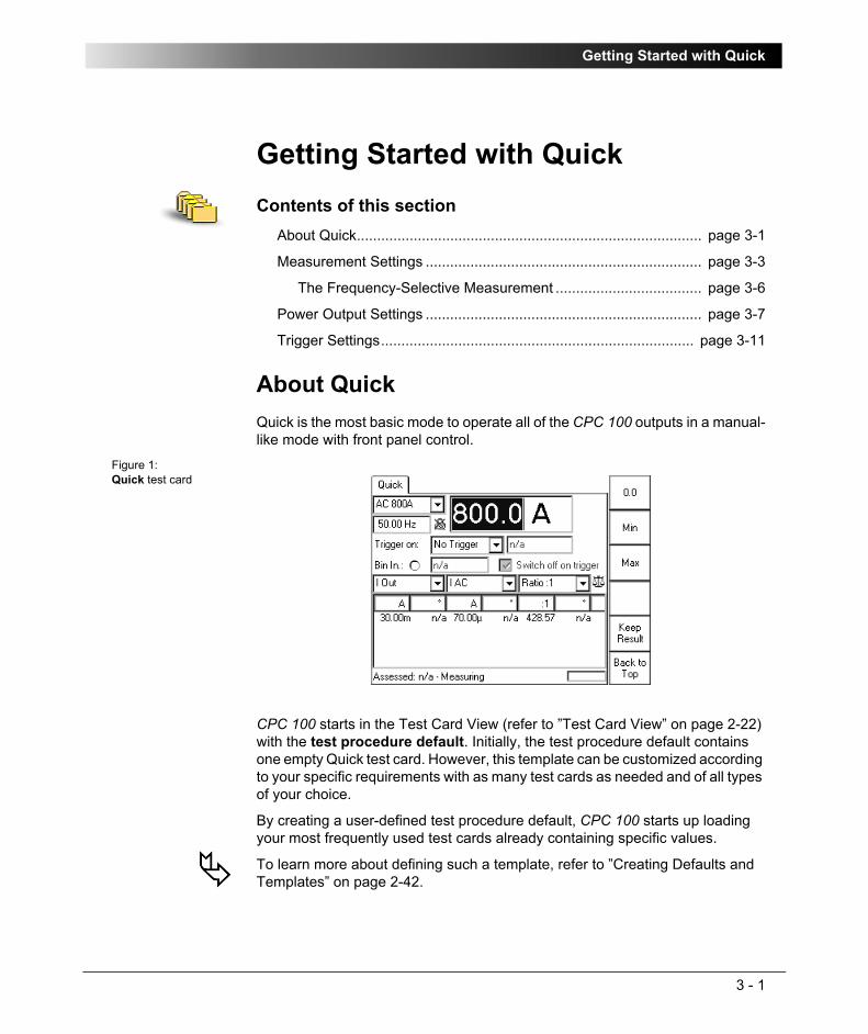
Getting Started with Quick
3 - 1
Getting Started with QuickContents of this section
About Quick..................................................................................... page 3-1
Measurement Settings .................................................................... page 3-3
The Frequency-Selective Measurement .................................... page 3-6
Power Output Settings .................................................................... page 3-7
Trigger Settings............................................................................. page 3-11
About QuickQuick is the most basic mode to operate all of the CPC 100 outputs in a manual-like mode with front panel control.
Figure 1:Quick test card
CPC 100 starts in the Test Card View (refer to ”Test Card View” on page 2-22) with the test procedure default. Initially, the test procedure default contains one empty Quick test card. However, this template can be customized according to your specific requirements with as many test cards as needed and of all types of your choice.
By creating a user-defined test procedure default, CPC 100 starts up loading your most frequently used test cards already containing specific values.
To learn more about defining such a template, refer to ”Creating Defaults and Templates” on page 2-42.

CPC 100 V1.41
3 - 2
Quick starts in "measuring" state with de-activated outputs, displaying the measured values in the measurement table of the Quick test card.
The measurements as well as the indication of the binary input’s signal status (refer to ”Bin.In:” on page 12 of this chapter) are updated with an interval of approx. 0.5s.
After having set all necessary parameters (more about this in the following sections), press the I/O (test start/stop) push-button. The Quick test card enters the "on" state, the set power output value is switched to the CPC 100 outputs, the measuring continues.
Pressing the Quick test card menu key K E E P R E S U L T S saves the currently measured values and "freezes" their display in the measurement table. Both the "measuring" and the "on" state remain active, the measurement continues in a new line of the measurement table.
While in "on" state, pressing the I/O (test start/stop) push-button terminates the test. The CPC 100 outputs are turned off, and Quick returns to the "measuring" mode.
Pressing the S E T T I N G S menu key opens the Settings page. The Settings page allows setting the test cards individually. As a rule, do not use the Settings page but the Device Setup tab in the Options view (see ”Device Setup” on page 2-33) to set the test cards. For more information, see ”Settings Page” on page 2-28.
Note 1: When testing capacitive test objects using voltages ≥ 500V, make sure that the test object’s capacity does not exceed 25nF.
Together with the test object’s capacity, the leakage inductance of CPC 100 internal output transformer forms a series resonant circuit. Especially at frequencies > 50/60Hz this may result in voltage superelevation.
Note 2: Never use Quick to measure the resistance of windings with a high inductance because turning off the DC source results in life-threatening voltage levels.
For this kind of measurement only use the special winding resistance test card RWinding!

Getting Started with Quick
3 - 3
Measurement Settings
After having pressed K E E P R E S U L T S , the combo boxes of the measured quantities are disabled, that is, the quantities cannot be changed.
Measured quantities (⇒ Glossary)
Combo boxes to select the first and second quantity to measure. Possible choices at each combo box:• V1 AC
• V1 AC sel1
• V2 AC
• V2 AC sel
• V Out
• V Out sel
• VT
• VT sel
• I AC
• I AC sel
1. sel = frequency-selective. To learn more about frequency-selective measurements, refer to ”TheFrequency-Selective Measurement” on page 6 of this chapter.
• I Out
• I Out sel
• I Clamp
• I Clamp sel
• CT
• CT sel
• V DC
• I DC
• f V1 AC
• f OutV Out and I Out represent the measured values of the actual output range.Each combo box has two corresponding cells in the measurement table below that display the measured values, where possible; otherwise"n/a" is displayed.
Note: Not all measured quantities are available in all output ranges.
Calculated valueBoth the items to select from in this combo box and the corresponding display at the measurement table below depend on the selected measured quantities.
In this combo box you determine what the measurement table displays (see Table ”Display of calculated value in measurement table” on page 4 of this chapter).

CPC 100 V1.41
3 - 4
Table 1:Display of calculated value in measurement table Measured
quantitiesDisplay of calculated value in
measurement table(m1) (m2)
V V Ratio:1, Ratio:5, Diff:
Ratio m1/m2 and phase angle ϕm1 - ϕm2 (if phase angles are available; else "n/a"), and differences ΔU and ΔϕU.
I I Ratio:1, Ratio:5, Diff:
Ratio m1/m2 and phase angle ϕm1 - ϕm2 (if phase angles are available; else "n/a"), and differences ΔI and ΔϕI.
V I For AC: Z or R, X
Impedance Z (magnitude in Ω and phase angle ϕ in °) or R and X in Ω.For DC: R
Resistance R (in Ω)else "n/a"
V I For AC: P, Q, S
Real power P (in W) and cosϕ, apparent power S (in VA) and cosϕ, reactive power Q (in var) and cosϕ.For DC: P
Real power P (in W)else "n/a"

Getting Started with Quick
3 - 5
After having pressed K E E P R E S U L T S , the combo box for the calculated quantity is disabled, that is, the calculated quantities cannot be changed.
V I Rs, Ls or Rp, Cp:
Resistance R and either inductance Ls in H (series equivalent circuit) or capacity Cp in F (parallel equivalent circuit).
This is just another representation of the impedance Z measurement; Z is displayed in its components.
Using Rs, Ls, the impedance is given by:Z = Rs + j ω Ls, where ω = 2 π f and the set frequency is used for the calculation.
Using Rp, Cp, the admittance is given by: 1/Z = 1 / Rp + j ω Cp, where ω = 2 π f and the set frequency is used for the calculation.
Measured quantities
Display of calculated value in measurement table
(m1) (m2)

CPC 100 V1.41
3 - 6
The Frequency-Selective MeasurementThe frequency-selective measurement is used to filter out interferences as they usually occur in substations. To do so, the frequency of the CPC 100 output quantity is set to a value different from the substation’s frequency, for example, the substation operates with a frequency of 50Hz, the CPC 100 output frequency is set to 55Hz.
The quantity measured back at the CPC 100 input is measured selectively, that is, only a quantity with the specified frequency is fully taken into consideration for the measurement. Quantities with different frequencies are filtered out according to the characteristics shown in Figure 2.
Figure 2:Characteristics of the frequency-selective measurement
Apart from Quick, the frequency-selective measurement is also available for other test cards:
In Quick, Sequencer and Ramping the frequency-selective measurement is selectable, whereas at the other test cards, it is preset and cannot be cleared.
CT
• CTRatio
• CTBurden
• CTRatioV
• CTLowPower
VT
• VTRatio
• VTBurden
• VTElectronics
Transformer
• TRRatio
Others
• Sequencer
• Ramping
Am
plitu
de in
dB
f in HzOffset from output frequency

Getting Started with Quick
3 - 7
Power Output SettingsThe main settings are the range definition and the value for the power output (the data entry field in Figure 3 that has the focus (⇒ Glossary)).
The power output value can be changed instantaneously with the handwheel, even in the "on" state and while connected to a test object.
Figure 3:Quick test card
Note: The designation of the menu keys changes depending on the focus.

CPC 100 V1.41
3 - 8
RangeCombo box to select between the output ranges AC 800A, AC 6A, AC 3A, DC 400A, DC 6A,AC 2kV, AC 1kV, AC 500V, AC 130V andCB2:1000A, CB2:2000A orCU20:10A, CU20:20A orCU1:10A, CU1:20A, CU1:50A, CU1:100A
Either CB2:, CU20: or CU1: output ranges are available if the respective external booster was selected at the Options tab Device Setup (see ”Options” on page 2-33) or on the Settings page of the Quick test card.
Each range has an associated minimum and maximum value, a fixed precision value as well as a preset number of decimal characters (refer also to ”Setting Up a Test Card” on page 2-25).
If Quick operates in the "on" state, the output range setting is locked and cannot be changed.
While in the "measuring" state with de-activated outputs, when a range is changed, the output changes accordingly to a new value within the allowed range between minimum and maximum.
After having pressed K E E P R E S U L T S, the output range setting and the measurements settings are locked and cannot be changed.

Getting Started with Quick
3 - 9
Power output valueCurrent (I) or voltage (V) value, depending on the specified range (see above).
Any value between minimum and maximum as well as the explicit value 0.0 is possible, even while in the "on" state.
The respective minimum and maximum values depend on the range and, for voltage ranges, also on the frequency. For frequencies smaller than 50Hz, and down to the minimum frequency of 15Hz, the possible maximum voltage value decreases linear proportional to the frequency value (refer to Figure 3, ”Typical maximum output voltage of 2kV AC output depending on frequency and power” on page 16-14).
Current ranges do not have such a dependency.
Frequency / Phase angleFrequency value in Hz or - if "Sync w/ V1AC" is selected (see below) - phase angle in degrees. For DC ranges this data entry field is disabled.
The frequency can be set within a range of 15.00 ... 400.00Hz, even while in the "on" state.
The phase angle is displayed in a range of -180.0 ... +180.0°, and can also be changed at any time. If this range is exceeded, the phase angle will adapt itself automatically, that is, change from -180.0 to +180.0°.

CPC 100 V1.41
3 - 10
Sync w/ V1ACSet S Y N C W/ V 1 A C by pressing the menu key that appears when the focus is on the frequency/phase angle data entry field.
This synchronizes the CPC 100 output frequency with the V1AC input frequency. In this case the phase angle of the output is displayed rather than the frequency. Set the phase angle value relative to the phase angle of the V1 AC input signal (we recommend a minimum input voltage of 10V on V1 AC, possible range 48 - 62Hz).
The icon next to the frequency/phase angle data entry field reflects the actual setting.
If "Sync w/ V1AC" is disabled, the frequency returns to the previously set frequency value and the icon changes.
If Quick operates in the "on" state, the status of "Sync w/ V1AC" cannot be changed.
Due to the PLL (phase-locked loop) technology, the synchronization with V1AC needs about 100ms.
If for the particular test object the synchronism within the first 100ms is relevant, start with a reduced magnitude of the output signal. Then enter the full magnitude of your choice, and press E N T E R .
This procedure assures that the high-level output signal is synchronized with V1AC right from the beginning.

Getting Started with Quick
3 - 11
Trigger SettingsA trigger is the occurrence of a selected event, for example, a binary trigger is the first change of the state at the binary input.
Trigger on:Selection of trigger event
– no trigger (default)
– binary trigger = CPC 100 input BIN IN is monitored for a trigger event
– trigger = first measurement value (m1) > set threshold value
– trigger = first measurement value (m1) < set threshold value
– trigger = second measurement value (m2) > set threshold value
– trigger = second measurement value (m2) < set threshold value
– overload = the trigger event is an overload condition that occurs at the selected output.
What is an "Overload" trigger?At the 800A AC output, an overload trigger is a condition in which the set current cannot be reached any longer, for example, because of an opening contact or circuit breaker.
Note: Current values < 50A do not initiate an "Overload" when the current circuit opens. Therefore, if you use the trigger condition "Overload", chose a nominal current value of ≥ 50A.
Quick differentiates two "Overload" trigger conditions:
1. the occurrence of an overload (as described above)
2. the clearing of an overload condition (clearing is delayed by 100 ms to debounce).
1 2
3 4 5
1

CPC 100 V1.41
3 - 12
Note: Trigger conditions with "<" are meaningful in combination with external signals only, that is, with signals that are not coming from CPC 100.
Reason: if the trigger signal comes from CPC 100, the trigger condition will always be "true" at the moment the I/O (test start/stop) push-button is pressed.
After having pressed K E E P R E S U L T S , the trigger event is locked and cannot be changed.Data entry field for the threshold value.
Setting a threshold value is not possible ("n/a", as shown above), if either
– a binary trigger condition
– no trigger
– overload
was selected.
After having pressed K E E P R E S U L T S , data entry for the threshold value is disabled, that is, the value cannot be changed.Bin.In:Indicates the signal condition at the binary input Bin In. 4 different characteristics are possible:
Closed: potential-free contact between BinIn+ and BinIn– closed.Open: potential-free contact between BinIn+ and BinIn– open.Come:
trigger signal with rising edge occurred at BinIn.
Go:
trigger signal with falling edge occurred at BinIn
Delay time display
The delay time is the time between the last change of the CPC 100 output value and the occurrence of the trigger event.
2
3
4

Getting Started with Quick
3 - 13
Switch off on triggerThis option is available if the trigger condition is either binary or overload. Else, "switch off on trigger" is preset and cannot be disabled.
"Switch off on trigger" is also locked and cannot be changed after having pressed K E E P R E S U L T S .
1. Enabled
When the trigger event occurs, the CPC 100 outputs are switched off immediately (that is, in real-time).
The measurements are updated to show the values at the time the trigger event occurred, and are then "frozen", that is, not updated anymore from that moment on. Quick turns to the "off" state.
At the field for the power output value setting, the data entry mode is automatically disabled to prevent this value from being changed. The focus, however, remains on that field, enabling instant navigation with the handwheel.
Pressing the menu key K E E P R E S U L T S saves the measured values in the measurement table. Quick returns to the "measuring" state, the measurement continues in a new line of the measurement table.
2. Disabled
The CPC 100 outputs remain active, that is, in "on" state, after the trigger event occurred. If the trigger is binary, the "BinIn" indicator reflects the occurrence of the trigger event accordingly.
The focus remains in data entry mode on the field for the power output value setting, allowing an immediate change of the output value.
The measurements continue after the trigger event.
As soon as the output value is changed, the display of the most recent delay time is removed.
5

CPC 100 V1.41
3 - 14

Current Transformer
4 - 1
Current TransformerContents of this section
Scope of Current Transformer Tests............................................... page 4-2
CT Ratio (and Burden) .................................................................... page 4-3
Testing Ratio, Polarity (and Burden) with Injection to Current Input ..................................................... page 4-3
Testing Ratio, Polarity (and Burden) with a Current Clamp ..... page 4-10
CT Burden..................................................................................... page 4-11
CT Excitation (Kneepoint) ............................................................. page 4-15
Winding Resistance ...................................................................... page 4-20
Voltage Withstand Test ................................................................. page 4-25
Polarity Check ............................................................................... page 4-28
CT RatioV (with Voltage)............................................................... page 4-33
CT Rogowski (Ratio) ..................................................................... page 4-38
CT Low Power (Ratio)................................................................... page 4-43
TanDelta........................................................................................ page 4-48
Note: With regard to software handling, this section confines to test-relevant issues, and does not go into detailed procedural descriptions.
It is assumed that you have read and understood the section ”How to Use the CPC 100 Software” on page 2-17.

CPC 100 V1.41
4 - 2
Scope of Current Transformer TestsGo to the Test Card View and press I N S E R T C A R D.
Use the context-dependent U P /D O W N menu keys to the right, or the handwheel, to browse through the structure. On CT, press E N T E R.
Alternatively, press the accelerator key to open Insert a new test card.
CT comprises the following test cards:
Figure 1:Inserting CT test cards
Highlight the test card of your choice either by navigating with the handwheel or by using the context-dependent U P /D O W N menu keys, and press E N T E R .
Note: The test cards
• CTRatio (and Burden)
• CTBurden
• CTRatioV (with Voltage)
• CTLowPower (Ratio)
employ the method of frequency-selective measurement, which is used to filter out interferences as they usually occur in substations.
To learn more about frequency-selective measurement, please refer to ”The Frequency-Selective Measurement” on page 3-6.

Current Transformer
4 - 3
CT Ratio (and Burden)Testing Ratio, Polarity (and Burden) with Injection to Current Input Use the CTRatio test card to measure a current transformer’s ratio and burden with injection on the CT’s primary side with up to 800 A from the 800A ACoutput or up to 2000 A using the CP CB2 current booster connected to the "EXT. BOOSTER" output.
It measures amplitude and phase angle of the current (at IAC) and voltage (at V1AC) on the transformer’s secondary side, and calculates the actual ratio and the deviation from the nominal ratio.
Figure 2:Setup of testing ratio, polarity (and burden) with injection to current input

CPC 100 V1.41
4 - 4
Test settingsFigure 3:CTRatio test card with test results
Navigate to the parameter fields, and enter the values according to your test requirements:
Pressing the S E T T I N G S menu key opens the Settings page. The Settings page allows setting the test cards individually. As a rule, do not use the Settings page but the Device Setup tab in the Options view (see ”Device Setup” on page 2-33) to set the test cards. For more information, see ”Settings Page” on page 2-28.
Range: output rangeIprim: nominal primary currentIsec: nominal secondary currentItest: primary injection current. f: output frequencyAuto select check box for automatic test (default), clear for manual
test (refer to page 4-7).
Note: If the test involves either an external booster to gain a higher output current or a current clamp to measure Isec, set these devices at the Options tab Device Setup before starting the test.
Measure Burden
The option "Measure Burden" lets you measure the burden, the secondary voltage and the cosϕ (cosinus of angle between secondary current and secondary voltage).

Current Transformer
4 - 5
Three methods to determine I secThe secondary current Isec can be determined either
1. by leading it directly via the 10A current input IAC (refer to Figure 2 on page 4-3), and let CPC 100 measure it.
2. by means of a current clamp that is connected, for example, to the V2AC low level AC voltage measuring input (refer to ”Testing Ratio, Polarity (and Burden) with a Current Clamp” on page 10 of this chapter).
3. by selecting the check box "Manual input". This option lets you enter the value for Isec manually, for example, when Isec was measured with an external current clamp that is not connected to CPC 100.
Measurements
Note: Select "Manual input" prior to starting the test. If the test card still contains results, clear them by pressing C L E A R R E S U L T S .
When "Manual input" is selected, there is no phase available. Consequently, the polarity and cosϕ cannot be calculated.
Iprim: actual current output at the 800A AC output that is injected into the CT’s primary side
Isec: measured secondary current and phase angle ϕ relative to Iprim
Ratio: ratio Iprim /Isec., here 200:5.01331
1. The value 5.0133 is calculated as follows:Isec act x (Iprim nom / Iprim act); here: 5.013 A x (200A / 199.99A) = 5.0133
and deviation of current ratio in %.
((Kn x Isec - Iprim) / Iprim) x 100%2
((200A / 5A * 5.013A - 199.99A) / 199.99A) x 100% = +0.265%
2. Kn = rated transformation value, here: 200A / 5A
Polarity: displays the status of the polarity
OK = phaseIsec - phaseIprim = -45°< 0° < +45°
NOT OK = all other cases
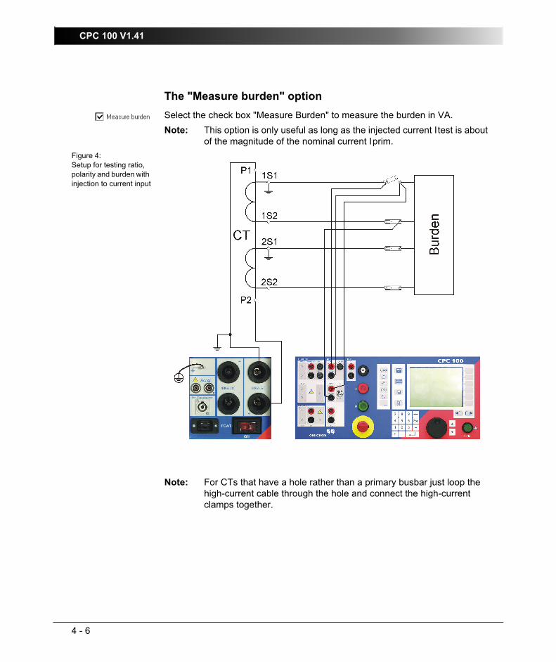
CPC 100 V1.41
4 - 6
The "Measure burden" optionSelect the check box "Measure Burden" to measure the burden in VA.
Figure 4:Setup for testing ratio, polarity and burden with injection to current input
Note: This option is only useful as long as the injected current Itest is about of the magnitude of the nominal current Iprim.
Note: For CTs that have a hole rather than a primary busbar just loop the high-current cable through the hole and connect the high-current clamps together.
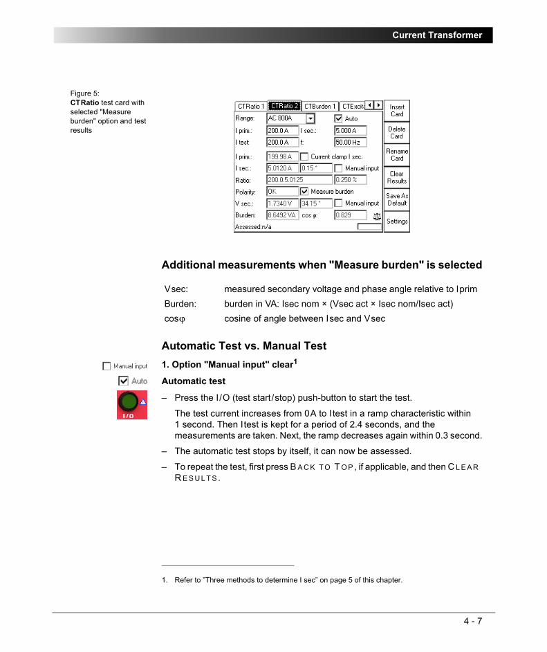
Current Transformer
4 - 7
Figure 5:CTRatio test card with selected "Measure burden" option and test results
Additional measurements when "Measure burden" is selected
Automatic Test vs. Manual Test1. Option "Manual input" clear1
Automatic test
– Press the I/O (test start/stop) push-button to start the test.
The test current increases from 0A to Itest in a ramp characteristic within 1 second. Then Itest is kept for a period of 2.4 seconds, and the measurements are taken. Next, the ramp decreases again within 0.3 second.
– The automatic test stops by itself, it can now be assessed.
– To repeat the test, first press B A C K T O T O P, if applicable, and then C L E A R R E S U L T S .
Vsec: measured secondary voltage and phase angle relative to Iprim Burden: burden in VA: Isec nom × (Vsec act × Isec nom/Isec act)cosϕ cosine of angle between Isec and Vsec
1. Refer to ”Three methods to determine I sec” on page 5 of this chapter.

CPC 100 V1.41
4 - 8
Manual test
Clearing "Auto" lets you set the test current Itest manually with the handwheel.
– Press the I/O (test start/stop) push-button to start the test. The focus is set onto the "I test:" entry field.
– Set the value of your choice either by turning the handwheel and/or by entering it with the numerical keys.
– Now the measurements are taken and displayed.
– To save the measurement press K E E P R E S U L T S (pressing the I/O push-button has the same effect). The last measured values are "frozen", the test can now be assessed.
– Stop the manual test by pressing the I/O (test start/stop) push-button.
– To repeat the test, first press B A C K T O T O P, if applicable, and then C L E A R R E S U L T S .
Note: A value set with the numerical keys needs to be fully entered and acknowledged by pressing either E N T E R or the handwheel before it is applied to the output. If needed, it can then be adjusted using the handwheel.
Values set by turning the handwheel are applied instantaneously.
Current Transformer
4 - 9
2. Option "Manual input" selected
Manual test
Clearing "Auto" lets you set the test current Itest manually with the handwheel.
– Press the I/O (test start/stop) push-button to start the test. The focus is set onto the "I test:" entry field.
– Set the value of your choice either by turning the handwheel and/or by entering it with the numerical keys.
– Iprim is measured and displayed.
– To save the measurement press K E E P R E S U L T S .
– Navigate to the Isec entry field.
– Enter the measured Isec value either by turning the handwheel or by entering this value with the numerical keys, and press E N T E R or the handwheel to acknowledge your setting.
– The ratio is calculated and displayed.
– To stop the manual test, press the I/O (test start/stop) push-button. The test can now be assessed.
– To repeat the test, first press B A C K T O T O P, if applicable, and then C L E A R R E S U L T S .
To learn more about test assessment, refer to ”Test Assessment” on page 10-2.
Note: Select "Manual input" prior to starting the test. If the test card still contains results, clear them by pressing C L E A R R E S U L T S .
When "Manual input" is selected, there is no phase available. Consequently, neither the polarity nor the phase angle nor cosϕ can be calculated.
Since an automatic test only lasts a very short period of time, and a manual measurement is rather difficult, an automatic test with a manual measurement is not useful. Therefore, this Reference Manual will not cover this subject.
Note: A value set with the numerical keys needs to be fully entered and acknowledged by pressing either E N T E R or the handwheel before it is applied to the output. If needed, it can then be adjusted using the handwheel.
Values set by turning the handwheel are applied instantaneously.
Note: Alternatively, it is possible to enter the manually measured value into the test card after the test was stopped (for example, if the measurement was carried out at a remote location).

CPC 100 V1.41
4 - 10
Testing Ratio, Polarity (and Burden) with a Current ClampTo measure Isec, a current clamp can be connected to, for example, the IAC/DC current measuring input (as shown in Figure 6).
Figure 6:Setup for testing ratio, polarity (and burden) with a current clamp
The test itself is carried out in the same way as the test described at ”Testing Ratio, Polarity (and Burden) with Injection to Current Input” on page 3 of this chapter. Please refer to this section.
Note 1: If a current clamp is used to measure Isec, select the corresponding check box on the test card, and specify the current clamp at the Options tab Device Setup (recommended) or on the Settings page.
Note 2: Due to cross-talk between the measuring inputs V1AC and V2AC, we suggest not to connect a current clamp to the input V2AC.
Therefore, use a current clamp with current output.

Current Transformer
4 - 11
CT BurdenUse the CTBurden test card to measure a current transformer’s secondary burden with AC current injection into the load (up to 6A).
To do so, open the circuit as shown in Figure 7, and inject the AC current from CPC 100 6A ACoutput into the burden.
The IAC input measures the current that flows into the burden, and the V1AC input measures the voltage at the burden.
From these measurements, the burden (in VA) and the power factor cosϕ are calculated.
This is the preferred method in cases when the current of max. 800A that CPC 100 can feed into the CT’s primary side is not sufficient.
Figure 7:Setup for a CT burden measurement

CPC 100 V1.41
4 - 12
Test settingsFigure 8:CTBurden test card with test results
Navigate to the parameter fields, and enter the values according to your test requirements:
Selecting the check box "Manual input" lets you enter the value for Vsec manually, for example, when Vsec was measured with an external volt meter rather than at input V1AC.
Measurements
Isec: nominal secondary currentItest: secondary injection current from 6A AC outputf: output frequencyAuto select check box for automatic test (default), clear for manual
test (refer to page 4-13).
Isec: actual secondary current, measured via input IACVsec: secondary voltage at the burden, measured at input V1AC,
and phase angle ϕ relative to IsecBurden: burden in VA: Isec nom × (Vsec act × Isec nom/Isec act)
cosϕ cosine of phase angle ϕ

Current Transformer
4 - 13
Automatic Test vs. Manual Test
1. Option "Manual input" clearAutomatic test
– Press the I/O (test start/stop) push-button to start the test.
The test current increases in a ramp characteristic from 0A to Itest within 1 second. Then Itest is kept and injected for a period of 2.4 seconds, the measurements are taken. Next, the ramp decreases again within 0.3 second.
– The automatic test stops by itself, it can now be assessed.
– To repeat the test, first press B A C K T O T O P, if applicable, and then C L E A R R E S U L T S .
Manual test
Clearing "Auto" lets you set the test current Itest manually with the handwheel.
– Press the I/O (test start/stop) push-button to start the test. The focus is set onto the "I test:" entry field.
– Set the value of your choice either by turning the handwheel and/or by entering it with the numerical keys.
– Now the measurements are taken and displayed.
– To save the measurement press K E E P R E S U L T S (pressing the I/O push-button has the same effect). The last measured values are "frozen", and can now be assessed.
– Stop the manual test by pressing the I/O (test start/stop) push-button. The test can now be assessed.
– To repeat the test, first press B A C K T O T O P, if applicable, and then C L E A R R E S U L T S .
Note: A value set with the numerical keys needs to be fully entered and acknowledged by pressing either E N T E R or the handwheel before it is applied to the output. If needed, it can then be adjusted using the handwheel.
Values set by turning the handwheel are applied instantaneously.

CPC 100 V1.41
4 - 14
2. Option "Manual input" selected
Manual test
Clearing "Auto" lets you set the test current Itest manually with the handwheel.
– Press the I/O (test start/stop) push-button to start the test. The focus is set onto the "I test:" entry field.
– Set the value of your choice either by turning the handwheel and/or by entering it with the numerical keys.
– Isec is measured and displayed.
– To save the measurement press K E E P R E S U L T S .
– Navigate to the "Vsec:" entry field
– Enter the measured Vsec value either by turning the handwheel or by entering this value with the numerical keys, and press E N T E R or the handwheel to acknowledge your setting.
– Now the burden is calculated and displayed.
– To stop the manual test, press the I/O (test start/stop) push-button. The test can now be assessed.
– To repeat the test, first press B A C K T O T O P, if applicable, and then C L E A R R E S U L T S .
To learn more about test assessment, refer to ”Test Assessment” on page 10-2.
Note: Select "Manual input" prior to starting the test. If the test card still contains results, clear them by pressing C L E A R R E S U L T S .
When "Manual input" is selected, there is no phase available. Consequently, neither the phase angle ϕ nor cosϕ can be calculated.
Since an automatic test only lasts a very short period of time, and a manual measurement is rather difficult, an automatic test with a manual measurement is not useful. Therefore, this Reference Manual will not cover this subject.
Note: A value set with the numerical keys needs to be fully entered and acknowledged by pressing either E N T E R or the handwheel before it is applied to the output. If needed, it can then be adjusted using the handwheel.
Values set by turning the handwheel are applied instantaneously.
Note: Alternatively, it is possible to enter the manually measured value into the test card after the test was stopped (for example, if the measurement was carried out at a remote location).
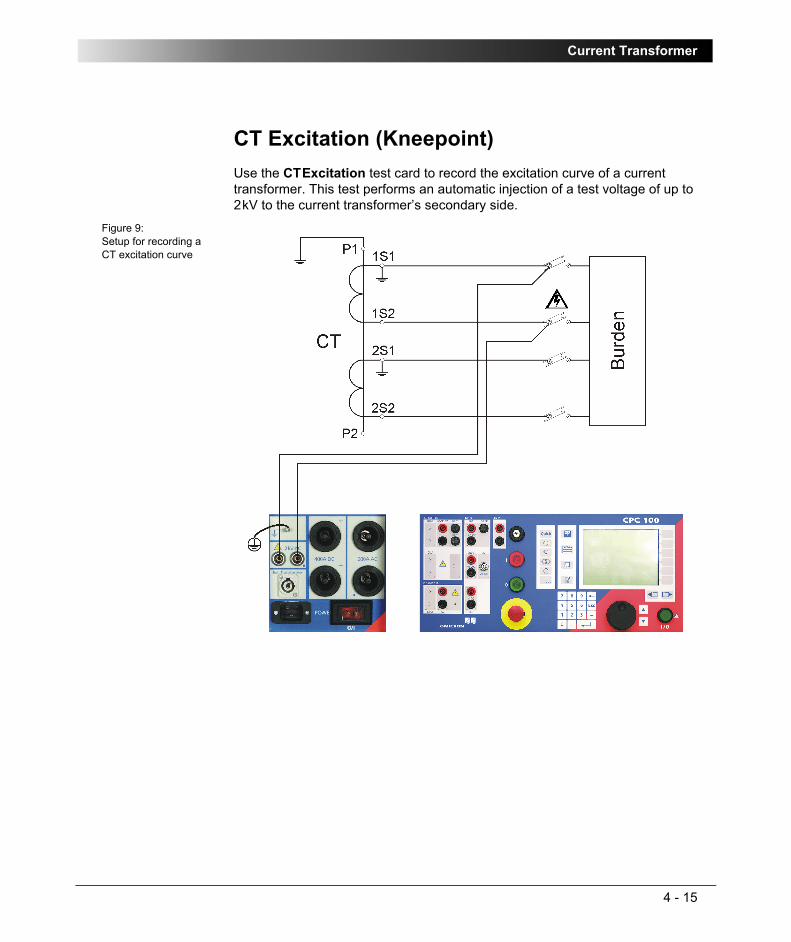
Current Transformer
4 - 15
CT Excitation (Kneepoint)Use the CTExcitation test card to record the excitation curve of a current transformer. This test performs an automatic injection of a test voltage of up to 2kV to the current transformer’s secondary side.
Figure 9:Setup for recording a CT excitation curve

CPC 100 V1.41
4 - 16
Test SettingsFigure 10:Blank CT Excitation test card
– Navigate to the parameter fields for "Imax:", "Vmax:" and "f:", and enter the values according to your test requirements.
– Select check box "Auto" for automatic test (default), clear it for manual test (refer to page 4-17).
– Set the focus onto the combo box underneath "I:".
– The options of this combo box let you determine the method for the knee point calculation:
Once the test is finished and the knee point calculated according to the selected method, it is possible to switch between IEC/BS, ANSI 45° and ANSI 30°. The knee point is recalculated accordingly.
IEC/BS According to IEC 60044-1, the knee point is defined as the point on the curve where a voltage increment of 10% increases the current by 50%.
ANSI 45° According to IEEE C57.13, the knee point is the point where, with a double logarithmic representation, the tangent line to the curve forms a 45° angle.
Applies to current transformer cores without an air gap.ANSI 30° Like ANSI 45° but forming a 30° angle.
Applies to current transformer cores with an air gap.
Note: According to the standards, the CTExcitation test card measures the rectified mean value (rmv) of the voltage, however, during the measurement the rms voltages are set. The rmv and rms values can differ considerably when the CT is in saturation.

Current Transformer
4 - 17
Automatic Test vs. Manual Test
Automatic testSelecting "Auto" increases and decreases the test voltage in a ramp characteristic, and places test points in an adaptive way to determine the knee point.
– Press the I/O (test start/stop) push-button to start the test.
The range from Vmin to Vmax is swept through, which is indicated by the crosshair cursor in the graphics.
– The software places test points between Vmax and Vmin in a heuristic manner to calculate the knee point with an adequate accuracy.
The graph1 displays these test points as markers. A test point is a voltage-current value pair.
– The automatic test stops by itself, it can now be assessed.
Manual testClearing "Auto" lets you set the test voltage Vtest manually with the handwheel.
– Press the I/O (test start/stop) push-button to start the test. The focus is set onto the "V:" entry field.
– Set the first value of your choice (rms value) either by turning the handwheel or by entering this value with the numerical keys.
– "I:" shows the corresponding current value and indicates it with the crosshair cursor in the graphics.
– Press A D D P O I N T to add the test point to the graph.
– Repeat this procedure for all additional test points.
The points you set are automatically connected (interpolated) with linear line segments.
– Press R E M O V E L A S T P . to undo the adding of the last test point. Press the key repeatedly to remove more than one point.
1. V over I graph, X and Y axes with a double logarithmic scale
Note: When using the handwheel, make sure not to increase the amplitude too fast since this may shortly exceed the set value Imax. Turn the handwheel slowly.

CPC 100 V1.41
4 - 18
– Press R E M O V E A L L to clear all points at once. This does not terminate the test but lets you set new test points.
– Once all test points are set, press the I/O (test start/stop) push-button to stop the manual test. The knee point is calculated, and its values are displayed at "Iknee:" and "Vknee:".
– The test can now be assessed.
Both cases, an automatic stop after the test and stopping the test manually during the sweep, reduce the test voltage to the minimum (Vmin) within approx. 1s of time, and demagnetize the transformer core.
Figure 11:CT Excitation test card - test points set in automatic test mode
The graph displays the test results in form of an interpolated curve with test point markers.
Turn the handwheel to set the focus onto the graph, and press it. This will bring up a crosshair cursor that lets you navigate through the list of test points by using the keys P R E V I O U S P O I N T and N E X T P O I N T . Turning the handwheel has the same effect. The fields "V:" and "I:" display the value pair of each test point.
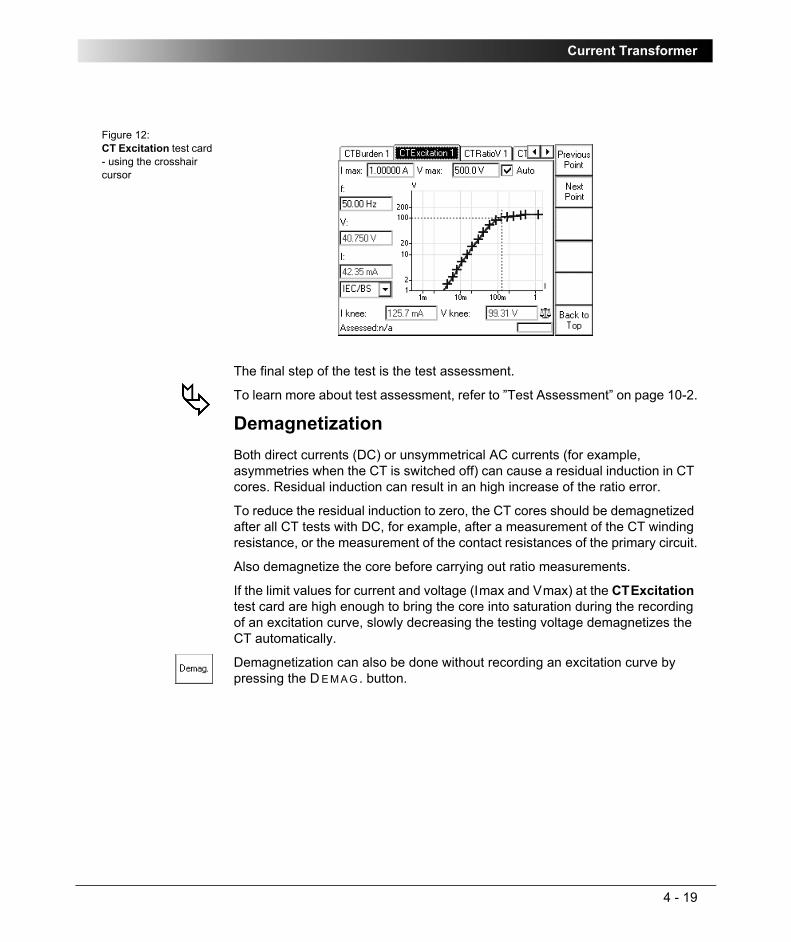
Current Transformer
4 - 19
Figure 12:CT Excitation test card - using the crosshair cursor
The final step of the test is the test assessment.
To learn more about test assessment, refer to ”Test Assessment” on page 10-2.
DemagnetizationBoth direct currents (DC) or unsymmetrical AC currents (for example, asymmetries when the CT is switched off) can cause a residual induction in CT cores. Residual induction can result in an high increase of the ratio error.
To reduce the residual induction to zero, the CT cores should be demagnetized after all CT tests with DC, for example, after a measurement of the CT winding resistance, or the measurement of the contact resistances of the primary circuit.
Also demagnetize the core before carrying out ratio measurements.
If the limit values for current and voltage (Imax and Vmax) at the CTExcitation test card are high enough to bring the core into saturation during the recording of an excitation curve, slowly decreasing the testing voltage demagnetizes the CT automatically.
Demagnetization can also be done without recording an excitation curve by pressing the D E M A G. button.

CPC 100 V1.41
4 - 20
Winding Resistance
Never open the measuring circuit while current flows. Dangerous voltage may occur! Check whether the red warning light “I” and the discharge LED are off before disconnecting the device under test. Before disconnecting from CPC 100, connect the device under test to protective earth.
Figure 13:Setup for a winding resistance test
Note: Some test cards are available in more than one test mode. For example, the test card RWinding can be selected in CT, Resistance and Transformer.
This is solely related to usability. With regard to functionality, the test card RWinding is identical in all test modes.
Off before disconnecting device under test
Off before disconnecting device under test

Current Transformer
4 - 21
Use the test card RWinding to measure the resistance of a current transformer’s secondary winding. To do so, open the circuit as shown in Figure 13, and inject DC current from the CPC 100 6A DC output into the transformer’s secondary winding. Currents higher than 6 A are not needed for measuring CTs.
It is recommended to perform all winding resistance measurements with the CP SA1 connected to the CPC 100 V DC input sockets to protect yourself and CPC 100 from high-voltage hazards. The CP SA1 must be used for measurements using 400A DC output. Before using CP SA1, you can check its functionality by following the test procedure in ”CP SA1” on page 17-14. If the CP SA1 is defective, contact OMICRON electronics sales office (for ordering information, see ”Ordering Information for CP SA1” on page 17-14). Before disconnecting the test leads, short-circuit the transformer’s terminals first and then remove the wirings to CPC 100.
V DC input measures the voltage generated at the transformer’s secondary winding. From that value the winding resistance is calculated.
Due to the significant time span needed for the transformer’s inductance to reach its saturation, this test evaluates the deviation of measured values within a time interval of 10 seconds. The winding resistance is continually measured and stored in CPC 100 internal memory. The calculated difference between the maximum and minimum measured values in % within the last 10 seconds is displayed.
Furthermore this test comprises the option to take a temperature compensation for copper (Cu) into consideration (refer to page 4-24).

CPC 100 V1.41
4 - 22
Test settingsFigure 14:RWinding test card with test results
Navigate to the parameter fields, and enter the values according to your test requirements:
Note: The transformer’s core is magnetized after the measurement. Demagnetization can be done using the CT Excitation test card (see ”CT Excitation (Kneepoint)” on page 15 of this chapter.
Range: output range (Use the 6A DC output for measuring CTs.)Itest: nominal test currentR min: calculated minimum winding resistance value (display only).
Depends on the value of the nominal test current and the measuring range:
– 400A DC: Rmin = 0.2mV / Itest
– 6A DC: Rmin = 0.2mV / I test
– V DC (2-wire): Rmin = 0.2ΩR max: calculated maximum winding resistance value (display only).
Depends on the value of the nominal test current and the measuring range:
– 400A DC: Rmax = 5V / Itest.
– 6A DC: Rmax = 10V / Itest.
– V DC (2-wire): Rmax = 20kΩ

Current Transformer
4 - 23
Measurements
Note: The VDC voltage is limited to 10 V. If n/a appears in the VDC box, decrease the test current to lower the voltage generated at the transformer’s secondary winding below 10 V.
IDC: actual test current from 6A DC output or 400A DC outputVDC: voltage that IDC generates at the transformer’s secondary
winding, measured at V DC inputR meas: transformer’s winding resistance, calculated from VDC / IDCTime: total elapsed test timeDev: deviation in % between the maximum and the minimum
measured values evaluated within the last 10 seconds of the measurement. The results are considered stable if Dev < 0.1%.

CPC 100 V1.41
4 - 24
The "Temperature Compensation for Cu" Option
Option selected
Provides two more parameters to enter:
Depending on these two parameters, the reference resistance (Rref, temperature-compensated winding resistance) is calculated:
Option cleared
For the winding resistance measurement there is no temperature compensation taken into consideration.
Once all settings are defined, press the I/O (test start/stop) push-button to start the test.
When the measurements are taken, finish the test by assessing it.
To learn more about test assessment, refer to ”Test Assessment” on page 10-2.
Tmeas: ambient temperature Tref: operating temperature of test object, that is, the current
transformer’s secondary winding
Rref: In Centigrade:
Rref = (VDC / IDC) x (235°C + Tref) / (235°C + Tmeas)
In Fahrenheit:
Rref = (VDC / IDC) x (391°F + Tref F) / (391°F + Tmeas F)
Note: Formula according to IEC 60076-1.

Current Transformer
4 - 25
Voltage Withstand Test
Use the test card VWithstand to measure the voltage withstand capability of the secondary winding and secondary wiring.
To do so, disconnect the burden. As shown in Figure 15, connect one cable of the 2kV output to the transformer’s secondary (1S1) winding connection and the other cable to earth and the transformer’s primary connection (P1). Open the secondary ground connection and ground the burden for safety reasons.
Warning: be aware that the terminal that is connected to the transformer’s secondary connection "1S1" leads life-hazardous voltage!
Figure 15:Setup for a voltage withstand test
Note: Some test cards are available in more than one test mode. For example, the test card VWithstand can be selected in CT, VT, Resistance and Transformer.
This is solely related to usability. With regard to functionality, the test card VWithstand is identical in all test modes.

CPC 100 V1.41
4 - 26
Test SettingsFigure 16:VWithstand test card with test results
Navigate to the parameter fields, and enter the values according to your test requirements:
Option "Switch off on IAC>"
Select this combo box and specify a current threshold to turn off the voltage withstand test automatically if this value is exceeded.
If the combo box is clear (default), I AC is measured, however, there is no current threshold to turn off the voltage withstand test automatically if this value is exceeded. The data entry field cannot be accessed.
Option "Auto"Select this combo box and specify a duration time for the voltage withstand test to run (default = 60 seconds). After this time, the test is turned off automatically.
Clear this combo box if you prefer to either turn off the test manually, or have it turned off by the option "Switch off on I AC>" without a duration time involved.
Vtest: nominal test voltage (2kV max.)f: output frequencyTime: time span Vtest is applied to the output
Note: If both options "Switch off on I AC>" and "Auto" are selected, they act as an OR operation, that is, whatever occurs first will turn off the voltage withstand test.

Current Transformer
4 - 27
Measurements
Once all settings are defined, press the I/O (test start/stop) push-button to start the test.
The test voltage increases in a ramp characteristic from 0V to Vtest. Vtest is then applied to the output for the specified time span. The measurements are continuously taken. Afterwards Vtest decreases in a ramp characteristic.
When the measurements are taken, finish the test by assessing it.
To learn more about test assessment, refer to ”Test Assessment” on page 10-2.
VAC: injected voltage from 2kV AC output at the time the test turned off
IAC: measured current between the transformer’s primary and secondary windings at the time the test turned off
Imax: maximum measured current between primary and secondary winding during the entire test cycle

CPC 100 V1.41
4 - 28
Polarity Check
Use the PolCheck test card to check a series of test points for correct polarity.
To do so, CPC 100 injects a special polarity test signal at a certain location. This signal can either be a voltage or a current signal from CPC 100, and has a signal characteristic similar to a saw-tooth signal with a different steepness for the rising and the falling slope.
The polarity check itself is then done with the accessory CPOL, a portable easy-to-use polarity checker.
Figure 17:Illustrated setup for a polarity check
Note: Some test cards are available in more than one test mode. For example, the PolCheck test card can be selected in CT and VT.
This is solely related to usability. With regard to functionality, the Polarity Check test card is identical in all test modes.
CPC 100 injects a special polarity check signal
polarity checkerCPOL
polarity checkerCPOL
☺

Current Transformer
4 - 29
If CPOL detects the same signal characteristic at a test point, it considers the polarity as OK, and lights up the green LED.
If the signal characteristic is inverted or distorted, CPOL considers the polarity not OK, and lights up the red LED.
If CPOL detects a signal that is too low, both LEDs light up at the same time. Remedy: increase the signal magnitude.
If you are not quite certain whether your measurement is correct, you can confirm it by reversing the probes of CPOL. In that case, the other LED should light up.
The battery of CPOLIf the capacity of CPOL’s battery gets low, the LEDs start flashing. As long as the LEDs are flashing, CPOL’s battery provides sufficient power to continue working. However, the battery should be changed as soon as possible.
Never operate CPOL with an open battery compartment. A life-hazardous voltage level may occur in the battery compartment if CPOL’s probe touches a test point with high-voltage potential!
Note: If you detect a wrong polarity in the current path, turn off CPC 100 first, and only then disconnect the terminals.
☺
☺ +
☺ + flashing
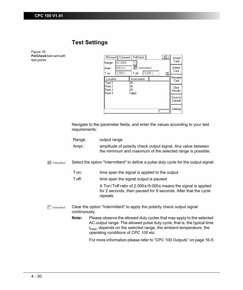
CPC 100 V1.41
4 - 30
Test SettingsFigure 18:PolCheck test card with test points
Navigate to the parameter fields, and enter the values according to your test requirements:
Select the option "Intermittent" to define a pulse duty cycle for the output signal:
Clear the option "Intermittent" to apply the polarity check output signal continuously.
Range: output rangeAmpl.: amplitude of polarity check output signal. Any value between
the minimum and maximum of the selected range is possible.
T on: time span the signal is applied to the outputT off: time span the signal output is paused
A Ton/Toff ratio of 2.000s/9.000s means the signal is applied for 2 seconds, then paused for 9 seconds. After that the cycle repeats.
Note: Please observe the allowed duty cycles that may apply to the selected AC output range. The allowed pulse duty cycle, that is, the typical time tmax, depends on the selected range, the ambient temperature, the operating conditions of CPC 100 etc.
For more information please refer to ”CPC 100 Outputs” on page 16-5.

Current Transformer
4 - 31
Pressing the S E T T I N G S menu key opens the Settings page. The Settings page allows setting the test cards individually. As a rule, do not use the Settings page but the Device Setup tab in the Options view (see ”Device Setup” on page 2-33) to set the test cards. For more information, see ”Settings Page” on page 2-28.
Carrying Out the Polarity Check1. Define the first set of parameters, and press the I/O (test start/stop) push-
button to start the test
2. CPC 100 now applies the polarity check signal with the specified parameters to the output.
3. Now carry out the polarity check at the test point of your choice using CPOL.
4. Add the first test point to the test point table by pressing "New Result".
The column "Location" displays a default name "Point 1", and a "n/a" in the column "Assessment" shows that no assessment was done yet.
5. If you need multiple test points, repeat items 3 - 4 as often as needed.
6. For the assessment there are two alternatives:
a) assess each test point right away as it is entered
b) or add all test points needed, stop the test, and then do the assessment test point for test point.
To learn more about test assessment, refer to ”Test Assessment” on page 10-2.
7. Press the I/O (test start/stop) push-button to stop the test.Note: Alternatively it is possible to enter test points after the test was
stopped (for example, if the measurement was carried out at a remote location).

CPC 100 V1.41
4 - 32
Customizing Test Point NamesFigure 19:Highlighting a test point changes the context-dependent menu keys
– Highlight the test point of your choice by turning the handwheel.
– Press E D I T L O C A T I O N to open the String Editor
– Use the String Editor functionality (refer to ”The String Editor” in chapter 10) to specify a name of your choice for the selected test point.

Current Transformer
4 - 33
CT RatioV (with Voltage)Use the CTRatioV test card to measure a current transformer’s ratio. To do so, from the 2kV AC output feed a voltage of up to 500V to the transformer’s secondary side.
The preferred method for CT ratio measurement is current injection using the CTRatio test card. However, on CTs such as some GIS CTs or bushing CTs on power transformers where the primary current path is not accessible, the method described in this section is the only solution.
Both the amplitude of the injected test voltage as well as amplitude and phase angle of the voltage on the transformer’s primary side are measured. The measurements taken are the basis for the calculation of the actual ratio and the deviation from the nominal ratio.
To measure the CT ratio using the CTRatioV test card, connect the 2kV AC output to the CT’s secondary winding and the V2 AC input to the main conductors, for example, on a power transformer to the transformer’s bushings of different phases.
Figure 20:Setup for testing the ratio and polarity by measuring the voltage ratio

CPC 100 V1.41
4 - 34
Test settingsFigure 21:CTRatioV test card with test results
Navigate to the parameter fields, and enter the values according to your test requirements:
Iprim: nominal primary currentIsec: nominal secondary currentVtest: secondary inception voltage f: output frequencyAuto: select check box for automatic test (default), clear for manual
test (refer to page 4-36).
Note: If the transformer’s knee point voltage is approximated or exceeded due to the transformer’s saturation, the measurement results are not correct anymore. If the knee point is extensively exceeded, the transformer can even be damaged.
Therefore, the knee point voltage should be known or measured beforehand.
Generally, to set the test voltage to 75% of the knee-point voltage is a good choice.
The frequency should be set 15 to 20 Hz off the mains frequency to avoid interferences by life systems in the neighborhood.

Current Transformer
4 - 35
Measurements
Selecting the check box "Manual input" lets you enter the value for Vprim manually, for example, when Vprim was measured with an external volt meter.
Vsec: actual output at the 2kV AC output that is injected to the CT’s secondary side
Vprim: measured voltage on CT’s primary side and phase angle ϕ relative to Vsec
Iout measured current from Vsec outputRatio: ratio Iprim /Isec, here 200:5.01341
1. The ratio value 5.0134A is calculated as follows:Vprim act x (Iprim nom / Vsec act); here: 1.2536V x (200A / 50.010V) = 5.0134A
and deviation of current ratio in %. Formula:
((Kn x Vprim - Vsec) / Vsec) x 100%2
((200A / 5A * 1.2536V - 50.010V) / 50.010V) x 100% = +0.268%
2. Kn = rated transformation value, here: 200A / 5A
Polarity: displays the status of the polarity
OK = phaseVprim - phaseVsec = -45° < 0° < 45°
NOT OK = all other cases

CPC 100 V1.41
4 - 36
Automatic Test vs. Manual Test
1. Option "Manual input" clearAutomatic test
– Press the I/O (test start/stop) push-button to start the test.
Within 1 second the test voltage increases in a ramp characteristic from 0V to Vtest. Then Vtest is kept for a period of 2.4 seconds, and the measurements are taken. Next, the ramp decreases again within 0.3 seconds.
– The automatic test stops by itself, it can now be assessed.
– To repeat the test, first press B A C K T O T O P, if applicable, and then C L E A R R E S U L T S .
Manual test
Clearing "Auto" lets you set the test voltage Vtest manually with the handwheel.
– Press the I/O (test start/stop) push-button to start the test. The focus is set onto the "V test:" entry field.
– Set the value of your choice either by turning the handwheel and/or by entering it with the numerical keys.
– Now the measurements are taken and displayed.
– To save the measurement press K E E P R E S U L T S (pressing the I/O push-button has the same effect). The last measured values are "frozen", and can now be assessed.
– Stop the manual test by pressing the I/O (test start/stop) push-button. The test can now be assessed.
– To repeat the test, first press B A C K T O T O P, if applicable, and then C L E A R R E S U L T S .
Note: A value set with the numerical keys needs to be fully entered and acknowledged by pressing either E N T E R or the handwheel before it is applied to the output. If needed, it can then be adjusted using the handwheel.
Values set by turning the handwheel are applied instantaneously.

Current Transformer
4 - 37
2. Option "Manual input" selected
Manual test
Clearing "Auto" lets you set the test voltage Vtest manually with the handwheel.
– Press the I/O (test start/stop) push-button to start the test. The focus is set onto the "V test:" entry field.
– Set the value of your choice either by turning the handwheel and/or by entering it with the numerical keys.
– Vsec is measured and displayed.
– To save the measurement press K E E P R E S U L T S .
– Navigate to the "Vprim:" entry field
– Enter the measured Vprim value either by turning the handwheel or by entering this value with the numerical keys, and press E N T E R or the handwheel to acknowledge your setting.
– The ratio is calculated and displayed.
– To stop the manual test, press the I/O (test start/stop) push-button. The test can now be assessed.
– To repeat the test, first press B A C K T O T O P, if applicable, and then C L E A R R E S U L T S .
To learn more about test assessment, refer to ”Test Assessment” on page 10-2.
Note: Select "Manual input" prior to starting the test. If the test card still contains results, clear them by pressing C L E A R R E S U L T S .
When "Manual input" is selected, there is no phase available. Consequently, neither the polarity nor the phase angle nor cosϕ can be calculated.
Since an automatic test only lasts a very short period of time, and a manual measurement is rather difficult, an automatic test with a manual measurement is not useful. Therefore, this Reference Manual will not cover this subject.
Note: A value set with the numerical keys needs to be fully entered and acknowledged by pressing either E N T E R or the handwheel before it is applied to the output. If needed, it can then be adjusted using the handwheel.
Values set by turning the handwheel are applied instantaneously.
Note: Alternatively it is possible to enter the manually measured value into the test card after the test was stopped (for example, if the measurement was carried out at a remote location).

CPC 100 V1.41
4 - 38
CT Rogowski (Ratio)Use the CTRogowski test card to measure a Rogowski coil’s ratio by injecting current up to 800 A from CPC 100 800A AC output or up to 2000 A using the CP CB2 current booster connected to the "EXT. BOOSTER" output into the current-carrying conductor, and by measuring the induced voltage at the end of the Rogowski coil windings.
A Rogowski coil’s induced voltage is proportional to the conductor current differentiated with respect to time. Therefore, in order to acquire a direct equivalent of the conductor’s current, the induced voltage needs to be integrated. In general, a Rogowski coil’s output signal is either lead via an integrating amplifier or fed into an electronic protection relay with integrator. The CTRogowski test card integrates the Rogowski coil’s output signal at the CPC 100 input V2AC.
Disconnect the Rogowski coil’s output signal from the electronic protection relay, and plug it into CPC 100 V2AC input.
The CTRogowski test card measures the amplitude of the injected current Iprim and the Rogowski coil’s output voltage Vsec, integrates this signal, and calculates the secondary current Isec, its phase angle as well as the actual ratio and the deviation.
Figure 22:Setup for a CT ratio test of a Rogowski coil
Please refer to the note below.
electronic protection relay with integrator (for example 150mV at
Shielded cable with twisted wires. Shield connected to Rogowski coil.
P1
P2

Current Transformer
4 - 39
Test SettingsFigure 23:CTRogowski test card with test results
Navigate to the parameter fields, and enter the values according to your test requirements:
Range: output rangeIprim:(upper field)
nominal primary current of Rogowski coil
Vsec: nominal secondary voltage of Rogowski coilfnom: nominal frequency of the Rogowski coil’s secondary voltageItest: primary injection currentf: frequency of injected current ItestAuto: select check box for automatic test (default), clear for manual
test (refer to page 4-41).
Note: When using the CTRogowski test card, the 3V V2AC input uses an additional software-based integration method.
In the range of 50Hz < f < 60Hz, this results in a phase shift of 90° as well as an additional phase error of +/- 0.1° and an additional amplitude error of +/- 0.01%. For frequencies in the range of 15Hz < f < 400Hz, the phase error is not specified, and the amplitude error can be up to +/- 0,50% higher.
Therefore, for phase measurements, use a frequency range of 50Hz < f < 60Hz only.

CPC 100 V1.41
4 - 40
Pressing the S E T T I N G S menu key opens the Settings page. The Settings page allows setting the test cards individually. As a rule, do not use the Settings page but the Device Setup tab in the Options view (see ”Device Setup” on page 2-33) to set the test cards. For more information, see ”Settings Page” on page 2-28.
Measurements
Selecting the check box "Manual input" lets you enter the value for Vsec manually, for example, when Vsec was measured with an external volt meter rather than at input V2AC.
Iprim:(lower field)
actual output current at the output that is injected into the Rogowski coil’s current-carrying conductor
Vsec: secondary voltage measured at V2AC
I’sec: calculated secondary current. I’sec =
with k = Iprim nom / (Vsec nom x 1s).
Note that the current I’sec does not really exist in the system. It is a calculated current only.
° phase angle of calculated secondary current with reference to the primary current
Ratio: Iprim / I’sec, here 240.0:239.971
1. The value 239.97 is calculated as follows:(I’sec / Iprim) x Iprim nom; here: (239.84A / 239.87A) x 240 A = 239.97A
% and deviation of current ratio in %. Formula:
((I’sec - Iprim) / Iprim) x 100%
((239.84A - 239.87A) / 239.87A) x 100% = -0.012%Polarity: displays the status of the polarity
OK = phaseI’sec - phaseIprim = -45° < 0° < 45°
NOT OK = all other cases
k V tdsec∫

Current Transformer
4 - 41
Automatic Test vs. Manual Test
1. Option "Manual input" clearAutomatic test
– Press the I/O (test start/stop) push-button to start the test.
The test current increases from 0A to Itest in a ramp characteristic within 1 second. Then Itest is kept for a period of 2.4 seconds, and the measurements are taken. Next, the ramp decreases again within 0.3 seconds.
– The automatic test stops by itself, it can now be assessed.
– To repeat the test, first press B A C K T O T O P, if applicable, and then C L E A R R E S U L T S .
Manual test
Clearing "Auto" lets you set the test current Itest manually with the handwheel.
– Press the I/O (test start/stop) push-button to start the test. The focus is set onto the "I test:" entry field.
– Set the value of your choice either by turning the handwheel and/or by entering it with the numerical keys.
– Now the measurements are taken and displayed.
– To save the measurement press K E E P R E S U L T S (pressing the I/O push-button has the same effect). The last measured values are "frozen", the test can now be assessed.
– Stop the manual test by pressing the I/O (test start/stop) push-button.
– To repeat the test, first press B A C K T O T O P, if applicable, and then C L E A R R E S U L T S .
Note: A value set with the numerical keys needs to be fully entered and acknowledged by pressing either E N T E R or the handwheel before it is applied to the output. If needed, it can then be adjusted using the handwheel.
Values set by turning the handwheel are applied instantaneously.

CPC 100 V1.41
4 - 42
2. Option "Manual input" selected
Manual test
Clearing "Auto" lets you set the test current Itest manually with the handwheel.
– Press the I/O (test start/stop) push-button to start the test. The focus is set onto the "I test:" entry field.
– Set the value of your choice either by turning the handwheel and/or by entering it with the numerical keys.
– Iprim is measured and displayed.
– To save the measurement press K E E P R E S U L T S .
– Navigate to the Vsec entry field.
– Enter the measured Vsec value either by turning the handwheel or by entering this value with the numerical keys, and press E N T E R or the handwheel to acknowledge your setting.
– The ratio is calculated and displayed.
– To stop the manual test, press the I/O (test start/stop) push-button. The test can now be assessed.
– To repeat the test, first press B A C K T O T O P, if applicable, and then C L E A R R E S U L T S .
To learn more about test assessment, refer to ”Test Assessment” on page 10-2.
Note: Select "Manual input" prior to starting the test. If the test card still contains results, clear them by pressing C L E A R R E S U L T S . When "Manual input" is selected, there is no phase available. Consequently, neither the polarity nor the phase angle can be calculated.
Since an automatic test only lasts a very short period of time, and a manual measurement is rather difficult, an automatic test with a manual measurement is not useful. Therefore, this Reference Manual will not cover this subject.
Note: A value set with the numerical keys needs to be fully entered and acknowledged by pressing either E N T E R or the handwheel before it is applied to the output. If needed, it can then be adjusted using the handwheel.
Values set by turning the handwheel are applied instantaneously.
Note: Alternatively it is possible to enter the manually measured value into the test card after the test was stopped (for example, if the measurement was carried out at a remote location).

Current Transformer
4 - 43
CT Low Power (Ratio)Use the CTLowPower test card to measure the ratio of a low power current transformer.
A low power current transformer contains a built-in burden, and provides an output voltage that is directly proportional to the primary current. For both protection and measurement only one transformer is required. A low power current transformer provides a wide nominal current range, and operates linear and without saturation through the entire range up to the short-circuit current.
To carry out this test, disconnect the ODU plug of the current transformer’s secondary side from the protection relay, plug it into CPC 100 V2AC input, and inject current up to 800 A from CPC 100 800A AC output or up to 2000 A using the CP CB2 current booster connected to the "EXT. BOOSTER" output to the current transformer’s primary side.
Figure 24:Setup for a CT ratio low power test
Please refer to the note below.
electronic protection relay with low voltage input (e.g. 22.5mV at Inom)
built-in burden
shielded cable with twisted wires

CPC 100 V1.41
4 - 44
Test SettingsFigure 25:CT LowPower test card with test results
Navigate to the parameter fields, and enter the values according to your test requirements:
Pressing the S E T T I N G S menu key opens the Settings page. The Settings page allows setting the test cards individually. As a rule, do not use the Settings page but the Device Setup tab in the Options view (see ”Device Setup” on page 2-33) to set the test cards. For more information, see ”Settings Page” on page 2-28.
Range: output rangeIprim: nominal primary currentVsec: nominal secondary voltage Itest: primary injection currentf: output frequencyAuto: select check box for automatic test (default), clear for manual
test (refer to page 4-46).
Note: If the test involves an external booster to gain a higher output current, set this booster at the Options tab Device Setup before starting the test.
Current Transformer
4 - 45
Measurements
Selecting the check box "Manual input" lets you enter the value for Vsec manually, for example, when Vsec was measured with an external volt meter rather than at input V2AC.
Iprim: actual output current at the output that is injected into the low power current transformer’s primary side
Vsec: secondary voltage measured at V2AC, and its phase angle relative to Iprim
Ratio: ratio Iprim/Vsec., here 200.0:22.53 A/mV1
1. The value 22.53mV is calculated as follows: Vsec act x (Iprim nom / Iprim act); here: 22.53mV x (199.99A / 200A) = 22.53 mV (rounded)
and deviation of current ratio in %. Formula:
((Kn x Vsec - Iprim) / Iprim) x 100%2
((200A / 22.5mV * 22.53mV - 199.99A) / 199.99A) x 100% = +0.138%
2. Kn = rated transformation value, here: 200A / 22.5mV
Polarity: displays the status of the polarity
OK = phaseVsec - phaseIprim = -45° < 0° < 45°
NOT OK = all other cases

CPC 100 V1.41
4 - 46
Automatic Test vs. Manual Test
1. Option "Manual input" clearAutomatic test
– Press the I/O (test start/stop) push-button to start the test.
The test current increases from 0A to Itest in a ramp characteristic within 1 second. Then Itest is kept for a period of 2.4 seconds, and the measurements are taken. Next, the ramp decreases again within 0.3 seconds.
– The automatic test stops by itself, it can now be assessed.
– To repeat the test, first press B A C K T O T O P, if applicable, and then C L E A R R E S U L T S .
Manual test
Clearing "Auto" lets you set the test current Itest manually with the handwheel.
– Press the I/O (test start/stop) push-button to start the test. The focus is set onto the "I test:" entry field.
– Set the value of your choice either by turning the handwheel and/or by entering it with the numerical keys.
– Now the measurements are taken and displayed.
– To save the measurement press K E E P R E S U L T S (pressing the I/O push-button has the same effect). The last measured values are "frozen", the test can now be assessed.
– Stop the manual test by pressing the I/O (test start/stop) push-button.
– To repeat the test, first press B A C K T O T O P, if applicable, and then C L E A R R E S U L T S .
Note: A value set with the numerical keys needs to be fully entered and acknowledged by pressing either E N T E R or the handwheel before it is applied to the output. If needed, it can then be adjusted using the handwheel.
Values set by turning the handwheel are applied instantaneously.

Current Transformer
4 - 47
2. Option "Manual input" selected
Manual test
Clearing "Auto" lets you set the test current Itest manually with the handwheel.
– Press the I/O push-button (test start/stop) to start the test. The focus is set to the "I test:" entry field.
– Set the value of your choice either by turning the handwheel and/or by entering it with the numerical keys.
– Iprim is measured and displayed.
– To save the measurement press K E E P R E S U L T S .
– Navigate to the Vsec entry field.
– Enter the measured Vsec value either by turning the handwheel or by entering this value with the numerical keys, and press E N T E R or the handwheel to acknowledge your setting.
– The ratio is calculated and displayed.
– To stop the manual test, press the I/O push-button (test start/stop). The test can now be assessed.
– To repeat the test, first press B A C K T O T O P, if applicable, and then C L E A R R E S U L T S .
To learn more about test assessment, refer to ”Test Assessment” on page 10-2.
Note: Select "Manual input" prior to starting the test. If the test card still contains results, clear them by pressing C L E A R R E S U L T S . When "Manual input" is selected, there is no phase available. Consequently, neither the polarity nor the phase angle can be calculated.
Since an automatic test only lasts a very short period of time, and a manual measurement is rather difficult, an automatic test with a manual measurement is not useful. Therefore, this Reference Manual will not cover this subject.
Note: A value set with the numerical keys needs to be fully entered and acknowledged by pressing either E N T E R or the handwheel before it is applied to the output. If needed, it can then be adjusted using the handwheel.
Values set by turning the handwheel are applied instantaneously.
Note: Alternatively it is possible to enter the manually measured value into the test card after the test was stopped (for example, if the measurement was carried out at a remote location).

CPC 100 V1.41
4 - 48
TanDeltaThe test card TanDelta was especially developed for CP TD1.
CP TD1 is an optionally available high precision test system for on-site insulation tests of high-voltage systems like power and measuring transformers, circuit breakers, capacitors and isolators. CP TD1 works as an add-on device to CPC 100 and is described in the CP TD1 Reference Manual available on the CPC Explorer CD-ROM.
The TanDelta test card can be accessed from CT, VT, Transformer and Others.

Voltage Transformer
5 - 1
Voltage TransformerContents of this section
Scope of Voltage Transformer Tests .............................................. page 5-2
VT Ratio .......................................................................................... page 5-3
VT Burden ....................................................................................... page 5-8
Voltage Withstand Test ................................................................. page 5-13
Polarity Check ............................................................................... page 5-16
VT Electronics ............................................................................... page 5-21
TanDelta........................................................................................ page 5-26
Note: With regard to software handling, this section confines to test-relevant issues, and does not go into detailed procedural descriptions.
It is assumed that you have read and understood the section ”How to Use the CPC 100 Software” on page 2-17.

CPC 100 V1.41
5 - 2
Scope of Voltage Transformer TestsGo to the Test Card View and press I N S E R T C A R D.
Use the context-dependent U P /D O W N menu keys to the right, or the handwheel, to browse through the structure. On VT, press E N T E R.
Alternatively, press the accelerator key to open Insert a new test card.
VT comprises the following test cards:
Figure 1:Inserting VT test cards
Highlight the test card of your choice either by navigating with the handwheel or by using the context-dependent U P /D O W N menu keys, and press E N T E R .
Note: The test cards
• VTRatio
• VTBurden
• VTElectronics
employ the method of frequency-selective measurement, which is used to filter out interferences as they usually occur in substations.
To learn more about frequency-selective measurement, please refer to ”The Frequency-Selective Measurement” on page 3-6.

Voltage Transformer
5 - 3
VT RatioUse the VTRatio test card to measure a voltage transformer’s ratio with injection on the VT’s primary side with up to 2kV from AC OUTPUT.
It measures amplitude and phase angle of the voltage (at V1AC) and the current on the transformer’s secondary side, and calculates the actual ratio and the deviation from the nominal ratio.
Figure 2:Setup for testing ratio

CPC 100 V1.41
5 - 4
Test SettingsFigure 3:VTRatio test card with test results
Navigate to the parameter fields, and enter the values according to your test requirements:
Vprim: nominal primary voltage with the option "value x 1/√3"Vsec: nominal secondary voltage with the options
– value x 1/√3
– value x 1/3Vtest: primary injection voltage.
By default, Vtest = Vprim (with option x 1/√3) if Vprim ≤ 2kV.
If Vprim > 2kV, Vtest = 2kV.f: output frequencyAuto: select check box for automatic test (default), clear for manual
test (refer to page 5-5).

Voltage Transformer
5 - 5
Measurements
Selecting the check box "Manual input" lets you enter the value for Vsec manually, for example when Vsec was measured with an external volt meter rather than at input V1AC.
Automatic Test vs. Manual Test1. Option "Manual input" clear
Automatic test
– Press the I/O (test start/stop) push-button to start the test.
The test voltage increases from 0V to Vtest in a ramp characteristic within 1 second. Then Vtest is kept for a period of 2.4 seconds, and the measurements are taken. Next, the ramp decreases again within 0.3 seconds.
– The automatic test stops by itself, it can now be assessed.
– To repeat the test, first press B A C K T O T O P, if applicable, and then C L E A R R E S U L T S .
Manual test
Clearing "Auto" lets you set the test voltage Vtest manually with the handwheel.
Vprim: actual output voltage at 2kV AC output that is injected into the voltage transformer’s primary side
Vsec: secondary voltage measured at V1AC, and its phase angle relative to Vprim nominal
Ratio: ratio Vprim /Vsec., here 10000.0/√3:100.43/√31
1. The value 100.43/√3 is calculated as follows:Vsec act * (Vprim nom / Vprim act) = 20.087V * (10000V / 2kV) = 100.43/√3
and deviation of voltage ratio in %. Formula:
((Kn x Vsec - Vprim) / Vprim) x 100%2
((10000V / 100V * 20.087V - 2000V) / 2000V) x 100% = 0.431%
2. Kn = rated transformation value, here: 10000V / 100V
Polarity: displays the status of the polarity
OK = phaseVsec - phaseVprim = -45° < 0° < 45°
NOT OK = all other cases

CPC 100 V1.41
5 - 6
– Press the I/O (test start/stop) push-button to start the test. The focus is set onto the "V test:" entry field.
– Set the value of your choice either by turning the handwheel and/or by entering it with the numerical keys.
– Now the measurements are taken and displayed.
– To save the measurement press K E E P R E S U L T S (pressing the I/O push-button has the same effect). The last measured values are "frozen", the test can now be assessed.
– Stop the manual test by pressing the I/O (test start/stop).
– To repeat the test, first press B A C K T O T O P, if applicable, and then C L E A R R E S U L T S .
2. Option "Manual input" selected
Manual test
Clearing "Auto" lets you set the test voltage Vtest manually with the handwheel.
– Press the I/O (test start/stop) push-button to start the test. The focus is set onto the "V test:" entry field.
– Set the value of your choice either by turning the handwheel and/or by entering it with the numerical keys.
Note: A value set with the numerical keys needs to be fully entered and acknowledged by pressing either E N T E R or the handwheel before it is applied to the output. If needed, it can then be adjusted using the handwheel.
Values set by turning the handwheel are applied instantaneously.
Note: Select "Manual input" prior to starting the test. If the test card still contains results, clear them by pressing C L E A R R E S U L T S .
When "Manual input" is selected, there is no phase available. Consequently, neither the polarity nor the phase angle can be calculated.
Since an automatic test only lasts a very short period of time, and a manual measurement is rather difficult, an automatic test with a manual measurement is not useful. Therefore, this Reference Manual will not cover this subject.
Note: A value set with the numerical keys needs to be fully entered and acknowledged by pressing either E N T E R or the handwheel before it is applied to the output. If needed, it can then be adjusted using the handwheel.
Values set by turning the handwheel are applied instantaneously.
Voltage Transformer
5 - 7
– Vprim is measured and displayed.
– To save the measurement press K E E P R E S U L T S .
– Navigate to the "V sec" entry field.
– Enter the measured Vsec value either by turning the handwheel or by entering this value with the numerical keys, and press E N T E R or the handwheel to acknowledge your setting.
– The ratio is calculated and displayed.
– To stop the manual test, press the I/O (test start/stop). The test can now be assessed.
– To repeat the test, first press B A C K T O T O P, if applicable, and then C L E A R R E S U L T S .
To learn more about test assessment, refer to ”Test Assessment” on page 10-2.
Note: Alternatively, it is possible to enter the manually measured value into the test card after the test was stopped (for example, if the measurement was carried out at a remote location).

CPC 100 V1.41
5 - 8
VT BurdenUse the VTBurden test card to measure a voltage transformer’s secondary burden with voltage injection on the VT’s secondary side with up to 130V from AC OUTPUT.
To do so, open the circuit as shown in Figure 4 and inject the AC voltage from CPC 100 130V ACoutput into the burden.
Input IAC measures the current that flows into the burden, and input V1AC the voltage at the burden.
From these measurements, the burden (in VA) and the power factor cosϕ are calculated.
Figure 4:Setup for a VT burden measurement

Voltage Transformer
5 - 9
Test SettingsFigure 5:VTBurden test card with test results
Navigate to the parameter fields, and enter the values according to your test requirements:
Pressing the S E T T I N G S menu key opens the Settings page. The Settings page allows setting the test cards individually. As a rule, do not use the Settings page but the Device Setup tab in the Options view (see ”Device Setup” on page 2-33) to set the test cards. For more information, see ”Settings Page” on page 2-28.
Vsec: nominal secondary voltage with the option "value x 1/√3"f: output frequencyAuto: select check box for automatic test (default), clear for manual
test (refer to page 5-10).Vtest: secondary injection voltage from 130V AC output
Note 1: If a current clamp is used to measure Isec, select the corresponding check box on the test card, and specify the current clamp device at the Options tab Device Setup.
Note 2: Due to cross-talk between the measuring inputs V1AC and V2AC, we suggest not to connect a current clamp to the input V2AC.
Therefore, use a current clamp with current output.

CPC 100 V1.41
5 - 10
Measurements
Selecting the check box "Manual input" lets you enter the value for Isec manually, for example, when Isec was measured with a current clamp rather than at input IAC.
Automatic Test vs. Manual Test
1. Option "Manual input" clearAutomatic test
– Press the I/O (test start/stop) push-button to start the test.
The test voltage increases in a ramp characteristic from 0V to Vtest within 1 second. Then Vtest is kept and injected for a period of 2.4 seconds, the measurements are taken. Next, the ramp decreases again within 0.3 seconds.
– The automatic test stops by itself, it can now be assessed.
– To repeat the test, first press B A C K T O T O P, if applicable, and then C L E A R R E S U L T S .
Manual test
Clearing "Auto" lets you set the test voltage Vtest manually with the handwheel.
– Press the I/O (test start/stop) push-button to start the test. The focus is set onto the "V test:" entry field.
– Set the value of your choice either by turning the handwheel and/or by entering it with the numerical keys.
– Now the measurements are taken and displayed.
Vsec: actual voltage at the burden, measured at input V1ACIsec: actual current through burden, measured via input IACBurden: burden in VA: Vsec nom × (Isec act × Vsec nom/Vsec act)
cosϕ cosinus of phase angle ϕ
Note: A value set with the numerical keys needs to be fully entered and acknowledged by pressing either E N T E R or the handwheel before it is applied to the output. If needed, it can then be adjusted using the handwheel.
Values set by turning the handwheel are applied instantaneously.

Voltage Transformer
5 - 11
– To save the measurement press K E E P R E S U L T S (pressing the I/O push-button has the same effect). The last measured values are "frozen", and can now be assessed.
– Stop the manual test by pressing the I/O (test start/stop). The test can now be assessed.
– To repeat the test, first press B A C K T O T O P, if applicable, and then C L E A R R E S U L T S .
2. Option "Manual input" selected
Manual test
Clearing "Auto" lets you set the test voltage Vtest manually with the handwheel.
– Press the I/O (test start/stop) push-button to start the test. The focus is set onto the "V test:" entry field.
– Set the value of your choice either by turning the handwheel and/or by entering it with the numerical keys.
– Vsec is measured and displayed.
– To save the measurement press K E E P R E S U L T S .
– Navigate to the "I sec:" entry field
– Enter the measured Isec value either by turning the handwheel or by entering this value with the numerical keys, and press E N T E R or the handwheel to acknowledge your setting.
– Now the burden is calculated and displayed.
Note: Select "Manual input" prior to starting the test. If the test card still contains results, clear them by pressing C L E A R R E S U L T S .
When "Manual input" is selected, there is no phase available. Consequently, neither the phase angle ϕ nor cosϕ can be calculated.
Since an automatic test only lasts a very short period of time, and a manual measurement is rather difficult, an automatic test with a manual measurement is not useful. Therefore, this Reference Manual will not cover this subject.
Note: A value set with the numerical keys needs to be fully entered and acknowledged by pressing either E N T E R or the handwheel before it is applied to the output. If needed, it can then be adjusted using the handwheel.
Values set by turning the handwheel are applied instantaneously.

CPC 100 V1.41
5 - 12
– To stop the manual test, press the I/O (test start/stop). The test can now be assessed.
– To repeat the test, first press B A C K T O T O P, if applicable, and then C L E A R R E S U L T S .
To learn more about test assessment, refer to ”Test Assessment” on page 10-2.
Note: Alternatively, it is possible to enter the manually measured value into the test card after the test was stopped (for example, if the measurement was carried out at a remote location).

Voltage Transformer
5 - 13
Voltage Withstand Test
Use the test card VWithstand to measure the voltage withstand capability of the secondary winding and secondary wiring.
To do so, disconnect the burden. As shown in Figure 6, connect the 2kV output socket without point to the transformer’s secondary (a) winding connection, and the output socket marked with a point to earth and the transformer’s primary connection (N).
Warning: Be aware that the terminals connected to the transformer’s secondary connection "a"and "n" lead life-hazardous voltage!
Figure 6:Setup for a voltage withstand test
Note: Some test cards are available in more than one test mode. For example, the test card VWithstand can be selected in CT, VT, Resistance and Transformer.
This is solely related to usability. With regard to functionality, the test card VWithstand is identical in all test modes.

CPC 100 V1.41
5 - 14
Test SettingsFigure 7:VWithstand test card with test results
Navigate to the parameter fields, and enter the values according to your test requirements:
Option "Switch off on IAC>"Select this combo box and specify a current threshold to turn off the voltage withstand test automatically if this value is exceeded.
If the combo box is clear (default), I AC is measured, however, there is no current threshold to turn off the voltage withstand test automatically if this value is exceeded. The data entry field cannot be accessed.
Option "Auto"Select this combo box and specify a duration time for the voltage withstand test to run (default = 60 seconds). After this time, the test is turned off automatically.
Clear this combo box if you prefer to either turn off the test manually, or have it turned off by the option "Switch off on I AC>" without a duration time involved.
Vtest: nominal test voltage (2kV max.)f: output frequencyTime: time span Vtest is applied to the output
Note: If both options "Switch off on I AC>" and "Auto" are selected, they act as an OR operation, that is, whatever occurs first will turn off the voltage withstand test.
Voltage Transformer
5 - 15
Measurements
Once all settings are defined, press the I/O (test start/stop) push-button to start the test.
The test voltage increases in a ramp characteristic from 0V to Vtest. Then Vtest is kept and injected for the time period set in the "Time" data entry field and the measurements are taken. Next, the ramp decreases again.
When the measurements are taken, finish the test by assessing it.
To learn more about test assessment, refer to ”Test Assessment” on page 10-2.
VAC: injected voltage from 2kV AC output at the time the test turned off
IAC: measured current between the transformer’s primary and secondary windings at the time the test turned off
Imax: maximum measured current between primary and secondary winding during the entire test cycle

CPC 100 V1.41
5 - 16
Polarity Check
Use the PolCheck test card to check a series of test points for correct polarity.
To do so, CPC 100 injects a special polarity test signal at a certain location. This signal can either be a voltage or a a current signal from CPC 100, and has a signal characteristic similar to a saw-tooth signal with a different steepness for the rising and the falling slope.
The polarity check itself is then done with the accessory CPOL, a portable easy-to-use polarity checker.
Figure 8:Illustrated setup for a polarity check
Note: Some test cards are available in more than one test mode. For example, the test card PolCheck can be selected in CT and VT.
This is solely related to usability. With regard to functionality, the test card PolCheck is identical in all test modes.
CPC 100 injects a special polarity check signal
polarity checkerCPOL
polarity checkerCPOL
☺

Voltage Transformer
5 - 17
If CPOL detects the same signal characteristic at a test point, it considers the polarity as OK, and lights up the green LED.
If the signal characteristic is inverted or distorted, CPOL considers the polarity not OK, and lights up the red LED.
If CPOL detects a signal that is too low, both LEDs light up at the same time. Remedy: increase the signal magnitude.
If you are not quite certain whether your measurement is correct, you can confirm it by reversing the probes of CPOL. In that case, the other LED should light up.
The battery of CPOLIf the capacity of CPOL’s battery gets low, both LEDs start flashing simultaneously. As long as the LEDs are flashing, CPOL’s battery provides sufficient power to continue working. However, the battery should be changed as soon as possible.
Never operate CPOL with an open battery compartment. A life-hazardous voltage level may occur in the battery compartment if CPOL’s probe touches a test point with high-voltage potential!
Note: If you detect a wrong polarity in the current path, turn off CPC 100 first, and only then disconnect the terminals.
☺
☺ +
☺ +
on/off

CPC 100 V1.41
5 - 18
Test SettingsFigure 9:PolCheck test card with test points
Navigate to the parameter fields, and enter the values according to your test requirements:
Clear the option "Intermittent" when working with voltage outputs.
Range: output rangeAmpl.: maximum amplitude of polarity check output signal. Any value
between the minimum and maximum of the selected range is possible.

Voltage Transformer
5 - 19
Carrying Out the Polarity Check1. Define the first set of parameters, and press the I/O (test start/stop) push-
button to start the test
2. CPC 100 now applies the polarity check signal with the specified parameters to the output.
3. Now carry out the polarity check at the test point of your choice using CPOL.
4. Add the first test point to the test point table by pressing N E W R E S U L T .
The column "Location" displays a default name "Point 0", and a "n/a" in the column "Assessment" shows that no assessment was done yet.
5. If you need multiple test points, repeat items 3 - 4 as often as needed.
6. For the assessment there are two alternatives:
a) assess each test point right away as it is entered
b) or add all test points needed, stop the test, and then do the assessment test point for test point.
To learn more about test assessment, refer to ”Test Assessment” on page 10-2.
7. Press the I/O (test start/stop) push-button to stop the test.Note: Alternatively, it is possible to enter test points after the test was
stopped (for example, if the measurement was carried out at a remote location).

CPC 100 V1.41
5 - 20
Customizing Test Point NamesFigure 10:Highlighting a test point changes the context-dependent menu keys
– Highlight the test point of your choice by turning the handwheel.
– Press E D I T L O C A T I O N to open the String Editor
– Use the String Editor functionality (refer to ”The String Editor” in chapter 10) to specify a name of your choice for the selected test point.

Voltage Transformer
5 - 21
VT ElectronicsUse the VTElectronics test card to test the ratio of non-conventional electronic voltage transformers with a very low level secondary voltage.
To carry out this test, disconnect the plug of the electronic transformer’s secondary side from the protection relay, plug it into CPC 100 V2AC input, and inject voltage from the 2kV AC output to the electronic transformer’s primary side.
Figure 11:Setup for an electronic voltage transformer ratio test
electronic voltage transformer
electronic protection relay with
low voltage input
Shielded cable with twisted wires
Please refer to the note below.

CPC 100 V1.41
5 - 22
Test SettingsFigure 12:VTElectronics test card with test results
Navigate to the parameter fields, and enter the values according to your test requirements:
Vprim: nominal primary voltage with the option "value x 1/√3"Vsec: nominal secondary voltage with the options
– value x 1/√3
– value x 1/3Vtest: primary injection voltage.
By default, Vtest = Vprim (with option x 1/√3) if Vprim ≤ 2kV.
If Vprim > 2kV, Vtest = 2kV.f: output frequencyAuto: select check box for automatic test (default), clear for manual
test (refer to page 5-24).

Voltage Transformer
5 - 23
Measurements
Selecting the check box "Manual input" lets you enter the value for Vsec manually, for example, when Vsec was measured with an external volt meter rather than at input V1AC.
Vprim: actual output voltage at 2kV AC output that is injected into the electronic voltage transformer’s primary side
Vsec: secondary voltage measured at V2AC, and its phase angle relative to Vprim nominal
Ratio: ratio Vprim /Vsec., here 10000.0/√3:1.002/√3 1
1. The value 1.002/√3 is calculated as follows:Vsec act x (Vprim nom / Vprim act) = 200.4mV x (10000V/√3 / 2kV) = 1.002 V/√3
and deviation of voltage ratio in %.
((Kn x Vsec - Vprim) / Vprim) x 100%2
((10000V / 1V x 0.2004V - 2000V) / 2000V) x 100% = 0.205%
2. Kn = rated transformation value, here: 10000V / 1V
Polarity: displays the status of the polarity
OK = phaseVsec - phaseVprim = -45° < 0° < 45°
NOT OK = all other cases

CPC 100 V1.41
5 - 24
Automatic Test vs. Manual Test1. Option "Manual input" clear
Automatic test
– Press the I/O (test start/stop) push-button to start the test.
The test voltage increases from 0V to Vtest in a ramp characteristic within 1 second. Then Vtest is kept for a period of 2.4 seconds, and the measurements are taken. Next, the ramp decreases again within 0.3 seconds.
– The automatic test stops by itself, it can now be assessed.
– To repeat the test, first press B A C K T O T O P, if applicable, and then C L E A R R E S U L T S .
Manual test
Clearing "Auto" lets you set the test voltage Vtest manually with the handwheel.
– Press the I/O (test start/stop) push-button to start the test. The focus is set onto the "V test:" entry field.
– Set the value of your choice either by turning the handwheel and/or by entering it with the numerical keys.
– Now the measurements are taken and displayed.
– To save the measurement press K E E P R E S U L T S (pressing the I/O push-button has the same effect). The last measured values are "frozen", the test can now be assessed.
– Stop the manual test by pressing the I/O (test start/stop).
– To repeat the test, first press B A C K T O T O P, if applicable, and then C L E A R R E S U L T S .
Note: A value set with the numerical keys needs to be fully entered and acknowledged by pressing either E N T E R or the handwheel before it is applied to the output. If needed, it can then be adjusted using the handwheel.
Values set by turning the handwheel are applied instantaneously.
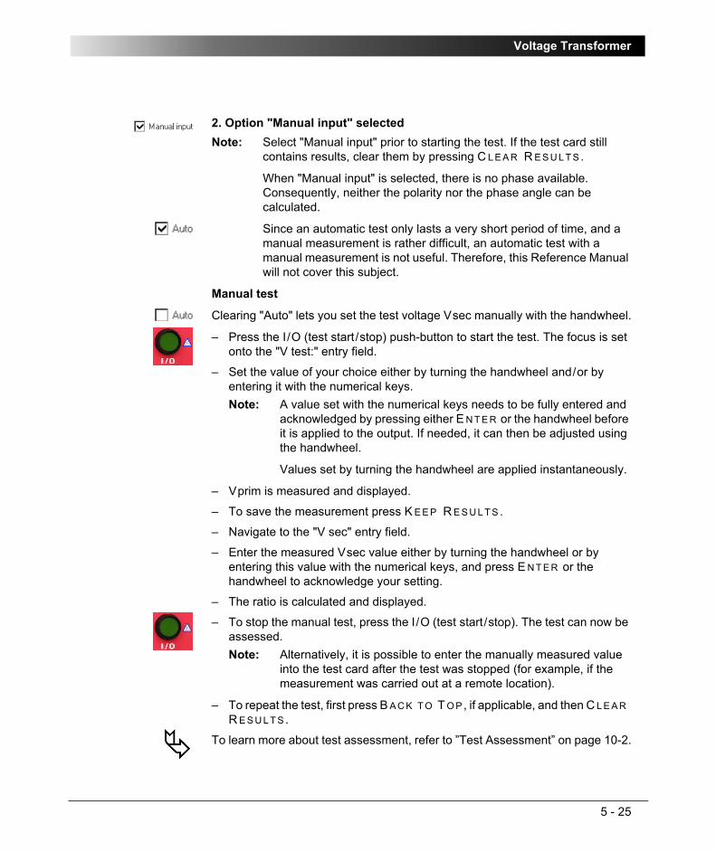
Voltage Transformer
5 - 25
2. Option "Manual input" selected
Manual test
Clearing "Auto" lets you set the test voltage Vsec manually with the handwheel.
– Press the I/O (test start/stop) push-button to start the test. The focus is set onto the "V test:" entry field.
– Set the value of your choice either by turning the handwheel and/or by entering it with the numerical keys.
– Vprim is measured and displayed.
– To save the measurement press K E E P R E S U L T S .
– Navigate to the "V sec" entry field.
– Enter the measured Vsec value either by turning the handwheel or by entering this value with the numerical keys, and press E N T E R or the handwheel to acknowledge your setting.
– The ratio is calculated and displayed.
– To stop the manual test, press the I/O (test start/stop). The test can now be assessed.
– To repeat the test, first press B A C K T O T O P, if applicable, and then C L E A R R E S U L T S .
To learn more about test assessment, refer to ”Test Assessment” on page 10-2.
Note: Select "Manual input" prior to starting the test. If the test card still contains results, clear them by pressing C L E A R R E S U L T S .
When "Manual input" is selected, there is no phase available. Consequently, neither the polarity nor the phase angle can be calculated.
Since an automatic test only lasts a very short period of time, and a manual measurement is rather difficult, an automatic test with a manual measurement is not useful. Therefore, this Reference Manual will not cover this subject.
Note: A value set with the numerical keys needs to be fully entered and acknowledged by pressing either E N T E R or the handwheel before it is applied to the output. If needed, it can then be adjusted using the handwheel.
Values set by turning the handwheel are applied instantaneously.
Note: Alternatively, it is possible to enter the manually measured value into the test card after the test was stopped (for example, if the measurement was carried out at a remote location).

CPC 100 V1.41
5 - 26
TanDeltaThe test card TanDelta was especially developed for CP TD1.
CP TD1 is an optionally available high precision test system for on-site insulation tests of high-voltage systems like power and measuring transformers, circuit breakers, capacitors and isolators. CP TD1 works as an add-on device to CPC 100 and is described in the CP TD1 Reference Manual available on the CPC Explorer CD-ROM.
The TanDelta test card can be accessed from CT, VT, Transformer and Others.

Transformer
6 - 1
TransformerContents of this section
Scope of Transformer Tests............................................................ page 6-2
TRRatio (per Tap) ........................................................................... page 6-3
Winding Resistance ...................................................................... page 6-13
TRTapCheck (for OLTC)............................................................... page 6-18
Voltage Withstand Test ................................................................. page 6-26
TanDelta........................................................................................ page 6-29
Note 1: With regard to software handling, this section confines to test-relevant issues, and does not go into detailed procedural descriptions.
It is assumed that you have read and understood the section ”How to Use the CPC 100 Software” on page 2-17.
Note 2: We strongly advise you to carefully read the transformer-specific safety instructions at ”General” on page 1-7 before carrying out transformer tests.

CPC 100 V1.41
6 - 2
Scope of Transformer TestsGo to the Test Card View and press I N S E R T C A R D.
Use the context-dependent U P /D O W N menu keys to the right, or the handwheel, to browse through the structure. On Transformer, press E N T E R.
Alternatively, press the accelerator key to open Insert a new test card.
Transformer comprises the following test cards:
Figure 1:Inserting Transformer test cards
Highlight the test card of your choice either by navigating with the handwheel or by using the context-dependent U P /D O W N menu keys, and press E N T E R .
Note: The test card TRRatio (per Tap) employs the method of frequency-selective measurement, which is used to filter out interferences as they usually occur in substations.
To learn more about frequency-selective measurement, please refer to ”The Frequency-Selective Measurement” on page 3-6.

Transformer
6 - 3
TRRatio (per Tap)Use the TRRatio test card to measure a power transformer’s ratio by injecting AC voltage with up to 2kV from AC OUTPUT into the transformer’s primary side (refer to Figures 2 and 3).
CPC 100 measures both the voltage it applies to AC OUTPUT and the transformer’s secondary voltage at V1 AC. From these values it calculates the ratio and its deviation from the nominal ratio in percent.
In addition, the exciting current is measured as well as the phase angles of both the secondary voltage and the exciting current.
Furthermore, the TRRatio test card is used to measure a power transformer’s ratio for each single tap changer position (see Figure 4).
Figure 2:Setup for testing a power transformer ratio: Yy0 transformer, primary and secondary side star connection

CPC 100 V1.41
6 - 4
Figure 3:Setup for testing a power transformer ratio: Yd5 transformer, primary side star connection, secondary side delta connection with a 5x30°=150° phase shift.

Transformer
6 - 5
Figure 4:Setup for a power transformer ratio tap changer test
Table 1 shows the Vprim and Vsec settings on the TRRatio test card for different connections of the transformer under test.
Table 1:TRRatio test card settings for different transformer’s windings connections
IEC 60076 vector group
Winding Connection to CPC 100 TRRatio settings
HV/H LV/X 2 kV output V1 AC inputred black red black Vprim Vsec
Dd0 U/H1 V/H2 u/X1 v/X2V/H2 W/H3 v/X2 w/X3W/H3 U/H1 w/X3 u/X1
Yy0 U/H1 V/H2 u/X1 v/X2V/H2 W/H3 v/X2 w/X3W/H3 U/H1 w/X3 u/X1
Dz0 U/H1 V/H2 u/X1 v/X2V/H2 W/H3 v/X2 w/X3W/H3 U/H1 w/X3 u/X1
U W
V
u w
v
U W
V
u w
v
U
V
W u
v
w

CPC 100 V1.41
6 - 6
Dy5 U/H1 V/H2 n/X0 u/X1V/H2 W/H3 n/X0 v/X2W/H3 U/H1 n/X0 w/X3
Yd5 U/H1 N/H0 w/X3 u/X1V/H2 N/H0 u/X1 v/X2W/H3 N/H0 v/X2 w/X3
Yz5 U/H1 V/H2 n/X0 u/X1V/H2 W/H3 n/X0 v/X2W/H3 U/H1 n/X0 w/X3
Dd6 U/H1 V/H2 v/X2 u/X1V/H2 W/H3 w/X3 v/X2W/H3 U/H1 u/X1 w/X3
Yy6 U/H1 V/H2 v/X2 u/X1V/H2 W/H3 w/X3 v/X2W/H3 U/H1 u/X1 w/X3
Dz6 U/H1 V/H2 v/X2 u/X1V/H2 W/H3 w/X3 v/X2W/H3 U/H1 u/X1 w/X3
Dy11 U/H1 V/H2 u/X1 n/X0V/H2 W/H3 v/X2 n/X0W/H3 U/H1 w/X3 n/X0
Yd11 U/H1 N/H0 u/X1 w/X3V/H2 N/H0 v/X2 u/X1W/H3 N/H0 w/X3 v/X2
Yz11 U/H1 V/H2 u/X1 n/X0V/H2 W/H3 v/X2 n/X0W/H3 U/H1 w/X3 n/X0
IEC 60076 vector group
Winding Connection to CPC 100 TRRatio settings
HV/H LV/X 2 kV output V1 AC inputred black red black Vprim Vsec
U
V
Ww
u
v
U
V
Ww
u
v
U
V
Ww
u
v
U
V
W
u
v
w
U
V
W
w u
v
U
V
W
w u
v
U
V
Ww
v
u
U
V
W
v
uw
U
V
W
v
uw

Transformer
6 - 7
Test SettingsFigure 5:TR Ratio test card with test results
Navigate to the parameter fields, and enter the values according to your test requirements:
Vprim: nominal primary voltage with the option "value x 1/√3"(can be set individually for each measurement)
Vsec: nominal secondary voltage with the option "value x 1/√3"(can be set individually for each measurement)
Ratio: nominal ratio, calculated from Vprim nom / Vsec nom
here: (110000.0V / √3) / 10000V = 6.3509
Note that this value is automatically calculated. It does not need to be entered. If Vprim is set individually for each measurement, the ratio value differs for each tap.
Vtest: nominal primary injection voltagef: output frequency

CPC 100 V1.41
6 - 8
Pressing the S E T T I N G S menu key opens the Settings page. The Settings page of the TRRatio test card has another functionality as on other test cards.
Figure 6:Settings page of the TTRatio test card
The Settings page allows adding the transformer’s ratio per tap as follows. After pressing the A D D T A P menu key first, the Vprim and Vsec values for the first tap are taken from the main page. Change the tap number to the lowest tap of the transformer under test (for example, –16 or 0). Add the next tap by pressing the A D D T A P menu key and enter the corresponding Vprim and Vsec values.
Tap: Data entry field to enter the transformer’s tap number for each measurement. If the transformer’s ratio was specified on the Settings page (see page 6-8), the Vprim and Vsec values for the tap are taken from there. The possible entry range from -999…999 allows the first digit to be used as a phase identifier.
Example for 3 phases:
– phase L1 (A): -101, 100, 101, 102, 103...
– phase L2 (B): -201, 200, 201, 202, 203...
– phase L3 (C): -301, 300, 301, 302, 303...
Example for 1 phase:
– phase: -001, 000, 001, 002, 003...Tap combo box:
The selection made at this combo box specifies the counting order of the taps in the measurement table’s column "Tap".
Possible selections are "Count up", "Count down" and "OFF". The number specified at the data entry field "Tap" (see above) represents the starting number.
"OFF" means, all lines in the measurement table show the same tap number.

Transformer
6 - 9
After then, pressing the A D D T A P menu key repeatedly adds more taps with a step calculated from the values for the first two taps. After adding all taps, press the M A I N P A G E menu key to transfer the data to the main page.
Note: After the transformer’s ratio was specified on the Settings page for one phase, by pressing the S A V E A S D E F A U L T menu key you can save the data. Then a new test card for the next phase will be inserted with the transformer’s ratio preset.

CPC 100 V1.41
6 - 10
MeasurementsThe TRRatio test card displays the measurement results in two display fields and a table:
Figure 7:Multiple measurement results, forexample from a power transformer ratio tap changer test
Iprim A primary current from 2kV AC output, measured by CPC 100 internally.
If the focus is on the table, scrolling through the lines will change this display accordingly, depending on the selected line.
° phase angle of primary current relative to Vprim nominalTap: (in table) displays the transformer tap number for the measurements in
the respective line of the table. This tap number is specified in the data entry field "Tap:" above the table.
Vprim actual voltage injected from AC OUTPUT into the transformer’s primary side
Vsec V secondary voltage of power transformer measured at V1 AC° phase angle of secondary voltage relative to Vprim nominal
Note: Even on transformers such as Yd5, only phase angles like 0° or 180° can be found using a single phase test set because a transformer can change the phase angle only by "mixing" different phases.
Ratio :1 calculated ratio value from Vprim act / Vsec act% deviation of actual ratio from nominal ratio in %. Formula:
((Kn1 x Vsec - Vprim) / Vprim2) x 100%
here (first line of table):
((110000V / (√3 x 10000) x 314.96V -2000V) / 2000V) x 100% =+0.013%
1. Kn = rated transformation value, here: 110000V / (3 x 10000)2. Vprim and Vsec can be set individually for each measurement.

Transformer
6 - 11
Carrying Out a TR Ratio Test (per Tap)1. Define the parameters first on the Settings page, then on the main page and
press the I/O (test start/stop) push-button to start the test.
2. The test voltage increases in a ramp characteristic from 0V to Vtest within 1 second. Then the first set of measurements is taken.
3. Save the test results of the first set by pressing K E E P R E S U L T S .
This adds the measured values to the first line of the table.
4. While passing through the power transformer’s tap changer positions, press K E E P R E S U L T S for each single position.
This adds new lines to the table holding the measured values.
Entering the tap number and an individual Vprim or Vsec per tap during a test
5. When all test points are measured, press the I/O (test start/stop) push-button to stop the test. Vtest decreases in a ramp characteristic within 1 second, and the last unsaved line, that is, the line that was not saved by pressing K E E P R E S U L T , will be discarded.
The tap number can also be set during test execution, that is, during a measurement.
Press the I/O (test start/stop) push-button to put the focus onto the "Tap:" field.
Now enter a tap number. The tap number is then displayed at the respective table column below.
Vprim and Vsec can be set individually for each measurement before K E E P R E S U L T is pressed. However, when defined on the Settings page before the test start, no changes should be needed here.

CPC 100 V1.41
6 - 12
Entering the tap number and an individual Vprim or Vsec per tap after a testEven at this time point, the Vprim, Vsec and tap number can still be entered. To do so, select the line of your choice in the measurement table and press the context-dependent E D I T T A P menu key.
The test can now be assessed.
To learn more about test assessment, refer to ”Test Assessment” on page 10-2.

Transformer
6 - 13
Winding Resistance
Never open the measuring circuit while current flows. Dangerous voltage may occur!
Figure 8:Setup of a winding resistance test
Use the RWinding test card to measure the resistance of a power transformer’s winding. To do so, loop the I DC current signal from CPC 100 6A DC output via IAC/DC as shown in Figure 8 and inject it into the transformer’s winding.
IAC/DC measures the injected current, and V DC input measures the voltage generated at the transformer’s winding. From these values the winding resistance is calculated.
Alternatively, inject the current directly from the 400A DC output (see Figure 9).
Note: Some test cards are available in more than one test mode. For example, the test card RWinding can be selected in CT, Resistance and Transformer.
This is solely related to usability. With regard to functionality, the test card RWinding is identical in all test modes.

CPC 100 V1.41
6 - 14
It is recommended to perform all winding resistance measurements with the CP SA1 connected to the CPC 100 V DC input sockets to protect yourself and CPC 100 from high-voltage hazards. The CP SA1 must be used for measurements using 400A DC output. Before using CP SA1, you can check its functionality by following the test procedure in ”CP SA1” on page 17-14. If the CP SA1 is defective, contact OMICRON electronics sales office (for ordering information, see ”Ordering Information for CP SA1” on page 17-14). Before disconnecting the test leads, short-circuit the transformer’s terminals and then remove the wirings to CPC 100.
Figure 9:Winding resistance test using 400A DC output
Due to the significant time span needed for the transformer’s inductance to finish its loading process, this test evaluates the deviation of measured values within a time interval of 10 seconds. The winding resistance is continually measured and stored in CPC 100 internal memory. The calculated difference between the maximum and minimum measured values in % within the last 10 seconds is displayed.
Furthermore, this test comprises the option to take a temperature compensation for copper (Cu) into consideration (refer to page 6-17).
CP SA1

Transformer
6 - 15
Test settingsFigure 10:RWinding test card with test results
Navigate to the parameter fields, and enter the values according to your test requirements:
Range: output rangeNote: The 400A DC output range provides maximum current 100 A.Itest: nominal test currentR min: calculated minimum winding resistance value (display only).
Depends on the value of the nominal test current and the measuring range:
– 400A DC: Rmin = 0.2mV / Itest
– 6A DC: Rmin = 0.2mV / I test
– V DC (2 wire): Rmin = 0.2ΩR max: calculated maximum winding resistance value (display only).
Depends on the value of the nominal test current and the measuring range:
– 400A DC: Rmax = 5V / Itest.
– 6A DC: Rmax = 10V / Itest.
– V DC (2 wire): Rmax = 20kΩ

CPC 100 V1.41
6 - 16
Measurements
IDC: actual test current from 6A DC output or 400A DC outputVDC: voltage that IDC generates at the transformer’s secondary
winding, measured at V DC inputR meas: transformer’s winding resistance, calculated from VDC / IDCTime: total elapsed test timeDev: deviation in % between the maximum and the minimum
measured values evaluated within the last 10 seconds of the measurement. The results are considered stable if Dev < 0.1%.
Press the context-dependent K E E P R E S U L T menu key to save the actual result in the measurement table. This adds a new line to the measurement table and the next measurement can be started.

Transformer
6 - 17
The "Temperature Compensation for Cu" Option
Option selected
Provides two more parameters to enter:
Depending on these two parameters, the reference resistance (Rref, temperature-compensated winding resistance) is calculated:
Option cleared
For the winding resistance measurement there is no temperature compensation taken into consideration.
Once all settings are defined, press the I/O (test start/stop) push-button to start the test.
When the measurements are taken, finish the test by assessing it.
To learn more about test assessment, refer to ”Test Assessment” on page 10-2.
Tmeas: ambient temperature Tref: operating temperature of test object, that is, the power
transformer’s secondary winding
Rref: In Centigrade:
Rref = (VDC / IDC) x (235°C + Tref) / (235°C + Tmeas)
In Fahrenheit:
Rref = (VDC / IDC) x (391°F + Tref F) / (391°F + Tmeas F)
Note: Formula according to IEC 60076-1.

CPC 100 V1.41
6 - 18
TRTapCheck (for OLTC)Use the TRTapCheck test card to measure the winding resistance of the individual taps of a power transformer’s tap changer, and to check whether the on-load tap changer (OLTC) switches without interruption.
CPC 100 injects a constant current from the 6A DC output into the power transformer and the current is led via the IAC/DC input for measurement. Alternatively, the current injected from the 400A DC output is measured internally. From this current value and the voltage measured by the V DC input (see Figure 12), the winding resistance is calculated.
In the moment the tap is changed, the IAC/DC measuring input detects the sudden, very short drop of the current flow. A properly working tab change differs from a malfunctioning one, for example, an interruption during the change, by the magnitude of the ripple and slope values. An interruption will result in much higher ripple and slope values than a properly functioning tab change.
The ripple and slope values are indicated at the TRTapCheck test card’s measurement table (refer to Figure 13).

Transformer
6 - 19
Figure 11:Simplified schematic of a tap changer
It is recommended to perform all winding resistance measurements with the CP SA1 connected to the CPC 100 V DC input sockets to protect yourself and CPC 100 from high-voltage hazards. The CP SA1 must be used for measurements using 400A DC output. Before using CP SA1, you can check its functionality by following the test procedure in ”CP SA1” on page 17-14. If the box is defective, contact OMICRON electronics sales office (for ordering information, see ”Ordering Information for CP SA1” on page 17-14). Before disconnecting the test leads, short-circuit the transformer’s terminals first and then remove the wirings to CPC 100.
OLTC
taps

CPC 100 V1.41
6 - 20
Figure 12:Setup for a tap changer test - winding resistance and interruption
Never open the measuring circuit while current flows. Dangerous voltage may occur!

Transformer
6 - 21
Test settingsFigure 13:TRTapCheck test card with test results
Navigate to the parameter fields, and enter the values according to your test requirements:
Range: output rangeNote: The 400A DC output range provides maximum current 100 A.Itest: nominal test currentTmeas: actual ambient temperatureTref: this is the reference temperature at which the manufacturer
measured the taps’ winding resistance values. Generally, this value is specified in the transformer’s data sheet.
The winding resistance value at this temperature always represents the nominal resistance value.
Tap: Data entry field to enter the transformer’s tap number for each measurement. The possible entry range of -999 ... 0 ... 999 allows for the first digit to be used as a phase identifier.
Example for 3 phases:
– phase L1 (A): -101, 100, 101, 102, 103...
– phase L2 (B): -201, 200, 201, 202, 203...
– phase L3 (C): -301, 300, 301, 302, 303...
Example for 1 phase:
– phase: -001, 000, 001, 002, 003...

CPC 100 V1.41
6 - 22
When results are measured, the A U T O K E E P R E S U L T menu key is available. After pressing the A U T O K E E P R E S U L T menu key, CPC 100 waits until stable results with a deviation less than 0.1% within the time period of 10 seconds are achieved. After then, a new result line is added and the next measurement starts.
Measurements
Tap combo box:
The selection made at this combo box specifies the counting order of the taps in the measurement table’s column "Tap".
Possible selections are "Count up", "Count down" and "OFF". The number specified at the data entry field "Tap" (see above) represents the starting number.
"OFF" means, all lines in the measurement table show the same tap number.
IDC: actual test current from 6A DC output measured at IAC/DC input or from 400A DC output measured internally
VDC: voltage measured at the 10V DC input
Columns of measurement table:Tap: displays the transformer tap number for the measurements in
the respective line of the table. This tap number in specified in the data entry field "Tap:" above the table.
Rmeas in Ω: actual resistance, calculated from VDC / IDCDev. in %: deviation in % between the maximum and the minimum
measured values evaluated within the last 10 seconds of the measurement. The results are considered stable if Dev < 0.1%
Press the context-dependent K E E P R E S U L T menu key to save the actual result in the measurement table. This adds a new line to the measurement table and the next measurement can be started.
Rref in Ω: Temperature-corrected resistance value, that is, the resistance value at an ambient temperature of Tref. Refer to formula on page 6-17.
Ripple in %: Samples and holds the biggest measured current ripple that occurred in the actual measuring cycle in negative direction. It is indicated in % with reference to IDC.
Slope in A/s: Samples and holds the biggest measured steepness of the falling edge of the actual test current.
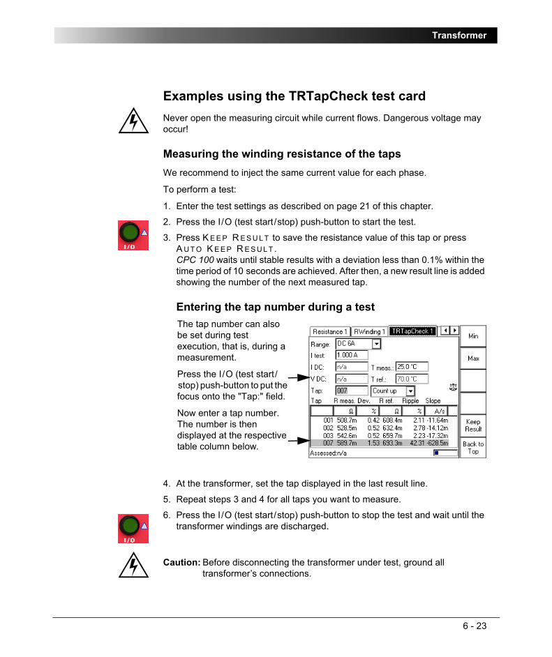
Transformer
6 - 23
Examples using the TRTapCheck test cardNever open the measuring circuit while current flows. Dangerous voltage may occur!
Measuring the winding resistance of the tapsWe recommend to inject the same current value for each phase.
To perform a test:
1. Enter the test settings as described on page 21 of this chapter.
2. Press the I/O (test start/stop) push-button to start the test.
3. Press K E E P R E S U L T to save the resistance value of this tap or press A U T O K E E P R E S U L T .CPC 100 waits until stable results with a deviation less than 0.1% within the time period of 10 seconds are achieved. After then, a new result line is added showing the number of the next measured tap.
Entering the tap number during a test
4. At the transformer, set the tap displayed in the last result line.
5. Repeat steps 3 and 4 for all taps you want to measure.
6. Press the I/O (test start/stop) push-button to stop the test and wait until the transformer windings are discharged.
Caution: Before disconnecting the transformer under test, ground all transformer’s connections.
The tap number can also be set during test execution, that is, during a measurement.
Press the I/O (test start/stop) push-button to put the focus onto the "Tap:" field.
Now enter a tap number. The number is then displayed at the respective table column below.
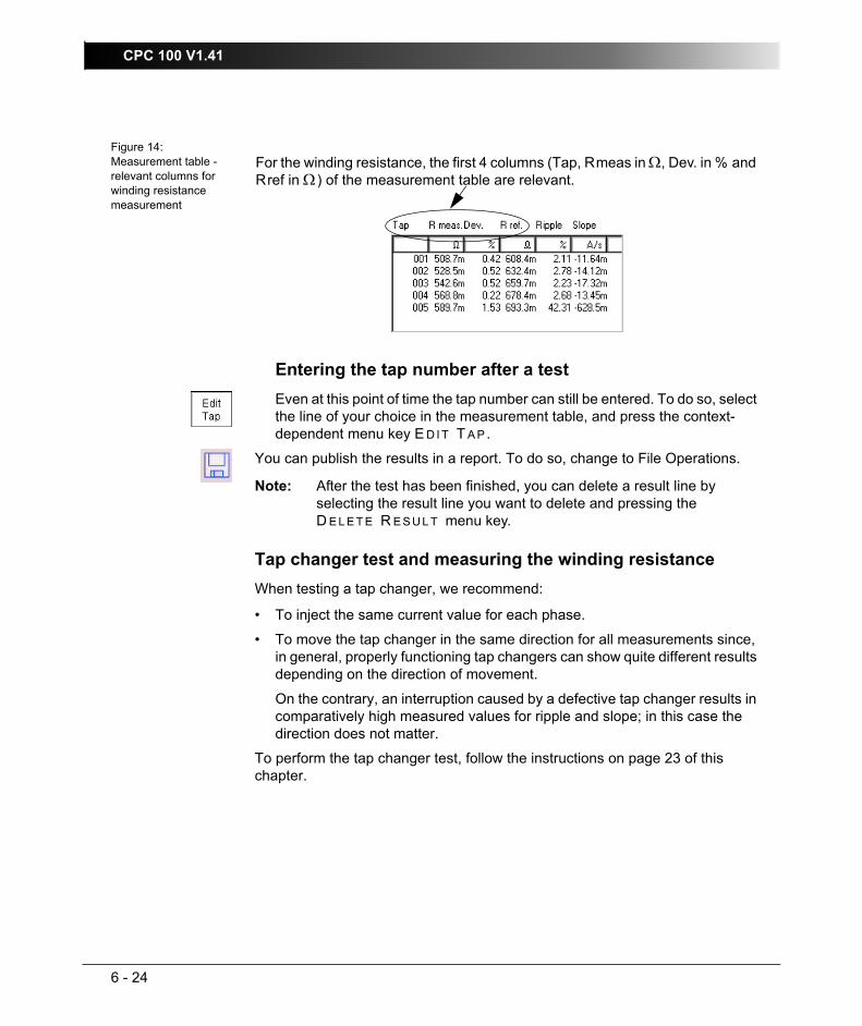
CPC 100 V1.41
6 - 24
Figure 14:Measurement table - relevant columns for winding resistance measurement
Entering the tap number after a testEven at this point of time the tap number can still be entered. To do so, select the line of your choice in the measurement table, and press the context-dependent menu key E D I T T A P .
You can publish the results in a report. To do so, change to File Operations.
Tap changer test and measuring the winding resistanceWhen testing a tap changer, we recommend:
• To inject the same current value for each phase.
• To move the tap changer in the same direction for all measurements since, in general, properly functioning tap changers can show quite different results depending on the direction of movement.
On the contrary, an interruption caused by a defective tap changer results in comparatively high measured values for ripple and slope; in this case the direction does not matter.
To perform the tap changer test, follow the instructions on page 23 of this chapter.
Note: After the test has been finished, you can delete a result line by selecting the result line you want to delete and pressing the D E L E T E R E S U L T menu key.
For the winding resistance, the first 4 columns (Tap, Rmeas in Ω, Dev. in % and Rref in Ω) of the measurement table are relevant.

Transformer
6 - 25
Figure 15:Measurement table with results of tap changer and winding resistance test
In Figure 15, you notice significantly higher values for ripple and slope in line 7. Compared to the properly functioning tap changer of line 5, at this transformer the ripple is about 30 times and the slope about 15 times higher.
Note: The measurement results shown in Figure 15 were taken from a 220/110kV 220MVA transformer by injecting a test current of 5A DC.
Note: The steps of this procedure are explained without explicitly outlining how to change/edit the tap number.
However, you can to do so each time K E E P R E S U L T was pressed to save the current test results and a new line was added to the measurement table. It is done in the same way as explained in ”Measuring the winding resistance of the taps” on page 23 of this chapter.
12
34
5
76
For the tap changer test, the last 2 columns of the table are relevant.
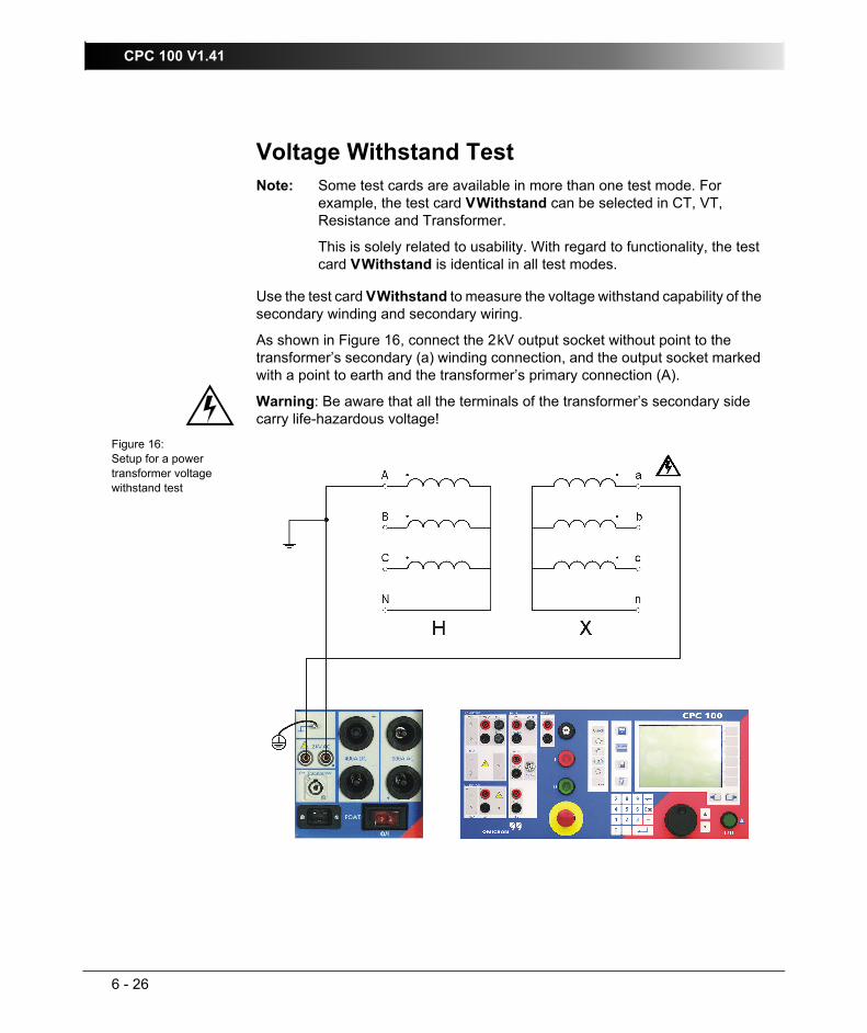
CPC 100 V1.41
6 - 26
Voltage Withstand Test
Use the test card VWithstand to measure the voltage withstand capability of the secondary winding and secondary wiring.
As shown in Figure 16, connect the 2kV output socket without point to the transformer’s secondary (a) winding connection, and the output socket marked with a point to earth and the transformer’s primary connection (A).
Warning: Be aware that all the terminals of the transformer’s secondary side carry life-hazardous voltage!
Figure 16:Setup for a power transformer voltage withstand test
Note: Some test cards are available in more than one test mode. For example, the test card VWithstand can be selected in CT, VT, Resistance and Transformer.
This is solely related to usability. With regard to functionality, the test card VWithstand is identical in all test modes.

Transformer
6 - 27
Test SettingsFigure 17:VWithstand test card with test results
Navigate to the parameter fields, and enter the values according to your test requirements:
Option "Switch off on IAC>"Select this combo box and specify a current threshold to turn off the voltage withstand test automatically if this value is exceeded.
If the combo box is clear (default), I AC is measured, however, there is no current threshold to turn off the voltage withstand test automatically if this value is exceeded. The data entry field cannot be accessed.
Option "Auto"Select this combo box and specify a duration time for the voltage withstand test to run (default = 60 seconds). After this time, the test is turned off automatically.
Clear this combo box if you prefer to either turn off the test manually, or have it turned off by the option "Switch off on I AC>" without a duration time involved.
Vtest: nominal test voltage (2kV max.)f: output frequencyTime: time span Vtest is applied to the output
Note: If both options "Switch off on I AC>" and "Auto" are selected, they act as an OR operation, that is, whatever occurs first will turn off the voltage withstand test.

CPC 100 V1.41
6 - 28
Measurements
Once all settings are defined, press the I/O (test start/stop) push-button to start the test.
The test voltage increases in a ramp characteristic from 0V to Vtest. Vtest is then applied to the output for the specified time span. The measurements are continuously taken. Afterwards Vtest decreases in a ramp characteristic.
When the measurements are taken, finish the test by assessing it.
To learn more about test assessment, refer to ”Test Assessment” on page 10-2.
VAC: injected voltage from 2kV ACoutput at the time the test turned off
IAC: measured current between the transformer’s primary and secondary windings at the time the test turned off
Imax: maximum measured current between primary and secondary winding during the entire test cycle

Transformer
6 - 29
TanDeltaThe test card TanDelta was especially developed for CP TD1.
CP TD1 is an optionally available high precision test system for on-site insulation tests of high-voltage systems like power and measuring transformers, circuit breakers, capacitors and isolators. CP TD1 works as an add-on device to CPC 100 and is described in the CP TD1 Reference Manual available on the CPC Explorer CD-ROM.
The TanDelta test card can be accessed from CT, VT, Transformer and Others.

CPC 100 V1.41
6 - 30

Resistance
7 - 1
ResistanceContents of this section
Scope of Resistance Tests ............................................................. page 7-2
Resistance - µΩ Measurement ....................................................... page 7-3
Winding Resistance ........................................................................ page 7-9
RGround........................................................................................ page 7-14
Voltage Withstand Test ................................................................. page 7-22
Note: With regard to software handling, this section confines to test-relevant issues, and does not go into detailed procedural descriptions.
It is assumed that you have read and understood the section ”How to Use the CPC 100 Software” on page 2-17.
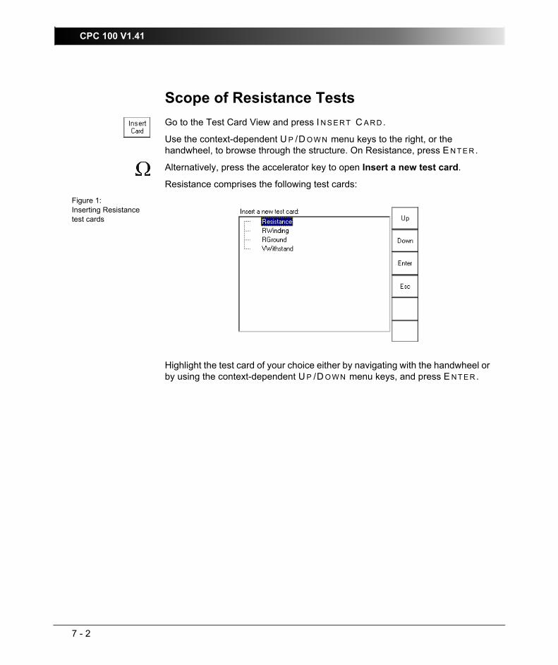
CPC 100 V1.41
7 - 2
Scope of Resistance TestsGo to the Test Card View and press I N S E R T C A R D.
Use the context-dependent U P /D O W N menu keys to the right, or the handwheel, to browse through the structure. On Resistance, press E N T E R.
Alternatively, press the accelerator key to open Insert a new test card.
Resistance comprises the following test cards:
Figure 1:Inserting Resistance test cards
Highlight the test card of your choice either by navigating with the handwheel or by using the context-dependent U P /D O W N menu keys, and press E N T E R .

Resistance
7 - 3
Resistance - µΩ MeasurementUse the Resistance test card to measure test objects with very low resistance, such as a contacts, windings etc.
To do so, CPC 100 injects DC current into the test object, measures the current that flows through the test object, and calculates the test object’s resistance.
The Resistance test card provides a total of three output ranges:
• 400A DC
• 6A DC
• V DC (2 wire)
The test setup depends on the selected range:
Figure 2:Setup for a µΩ measurement in the 400A DC range
Inject current from 400A DCoutput to both sides of the test object. Input VDC measures the voltage drop at the test object, the current is measured internally by CPC 100, and from these values the software calculates the test object’s resistance.
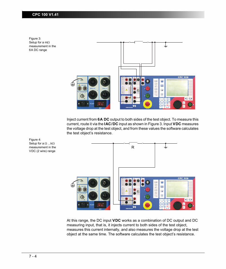
CPC 100 V1.41
7 - 4
Figure 3:Setup for a mΩ measurement in the 6A DC range
Inject current from 6A DC output to both sides of the test object. To measure this current, route it via the IAC/DC input as shown in Figure 3. Input VDC measures the voltage drop at the test object, and from these values the software calculates the test object’s resistance.
Figure 4:Setup for a Ω ...kΩ measurement in the VDC (2 wire) range
At this range, the DC input VDC works as a combination of DC output and DC measuring input, that is, it injects current to both sides of the test object, measures this current internally, and also measures the voltage drop at the test object at the same time. The software calculates the test object’s resistance.
R
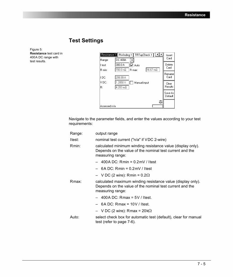
Resistance
7 - 5
Test SettingsFigure 5:Resistance test card in 400A DC range with test results.
Navigate to the parameter fields, and enter the values according to your test requirements:
Range: output rangeItest: nominal test current ("n/a" if VDC 2-wire)Rmin: calculated minimum winding resistance value (display only).
Depends on the value of the nominal test current and the measuring range:
– 400A DC: Rmin = 0.2mV / Itest
– 6A DC: Rmin = 0.2mV / I test
– V DC (2 wire): Rmin = 0.2ΩRmax: calculated maximum winding resistance value (display only).
Depends on the value of the nominal test current and the measuring range:
– 400A DC: Rmax = 5V / Itest.
– 6A DC: Rmax = 10V / Itest.
– V DC (2 wire): Rmax = 20kΩAuto: select check box for automatic test (default), clear for manual
test (refer to page 7-6).

CPC 100 V1.41
7 - 6
Measurements
Selecting the check box "Manual input" lets you enter the value for VDC manually, for example, when VDC was measured with an external volt meter rather than at input VDC.
Automatic Test vs. Manual Test1. Option "Manual input" clear
Automatic test
– Press the I/O (test start/stop) push-button to start the test.
The test current increases from 0A to Itest in a ramp characteristic within 1 second. Then Itest is kept for a period of 1 second, and the measurements are taken. Next, the ramp decreases again within 1 second.
– The automatic test stops by itself, it can now be assessed.
– To repeat the test, first press B A C K T O T O P, if applicable, and then C L E A R R E S U L T S .
Manual test
Clearing "Auto" lets you set the test current Itest manually with the handwheel.
– Press the I/O (test start/stop) push-button to start the test. The focus is set onto the "I test:" entry field.
– Set the value of your choice either by turning the handwheel and/or by entering it with the numerical keys.
– Now the measurements are taken and displayed.
– To save the measurement press K E E P R E S U L T S (pressing the I/O push-button has the same effect). The last measured values are "frozen", the test can now be assessed.
IDC: actual test current that is injected into the test objectVDC: measured voltage drop at the test objectR: calculated resistance of test object, R = VDC / IDC
Note: "Manual Input" cannot be selected at the range VDC (2 wire).
Note: A value set with the numerical keys needs to be fully entered and acknowledged by pressing either E N T E R or the handwheel before it is applied to the output. If needed, it can then be adjusted using the handwheel.
Values set by turning the handwheel are applied instantaneously.

Resistance
7 - 7
– Stop the manual test by pressing the I/O (test start/stop).
– To repeat the test, first press B A C K T O T O P, if applicable, and then C L E A R R E S U L T S .
2. Option "Manual input" selected
Manual test
Clearing "Auto" lets you set the test current Itest manually with the handwheel.
– Press the I/O (test start/stop) push-button to start the test. The focus is set onto the "I test:" entry field.
– Set the value of your choice either by turning the handwheel and/or by entering it with the numerical keys.
– IDC is measured and displayed.
– To save the measurement press K E E P R E S U L T S .
– Navigate to the "V DC" entry field.
– Enter the measured VDC value either by turning the handwheel or by entering this value with the numerical keys, and press E N T E R or the handwheel to acknowledge your setting.
– The ratio is calculated and displayed.
– To stop the manual test, press the I/O (test start/stop). The test can now be assessed.
Note: Select "Manual input" prior to starting the test. If the test card still contains results, clear them by pressing C L E A R R E S U L T S .
When "Manual input" is selected, there is no phase available. Consequently, neither the polarity nor the phase angle nor cosϕ can be calculated.
Since an automatic test only lasts a very short period of time, and a manual measurement is rather difficult, an automatic test with a manual measurement is not useful. Therefore, this Reference Manual will not cover this subject.
Note: A value set with the numerical keys needs to be fully entered and acknowledged by pressing either E N T E R or the handwheel before it is applied to the output. If needed, it can then be adjusted using the handwheel.
Values set by turning the handwheel are applied instantaneously.
Note: Alternatively, it is possible to enter the manually measured value into the test card after the test was stopped (for example, if the measurement was carried out at a remote location).

CPC 100 V1.41
7 - 8
– To repeat the test, first press B A C K T O T O P, if applicable, and then C L E A R R E S U L T S .
To learn more about test assessment, refer to ”Test Assessment” on page 10-2.

Resistance
7 - 9
Winding Resistance
Never open the measuring circuit while current flows. Dangerous voltage may occur!
Figure 6:Setup for a winding resistance test
Use the RWinding test card to measure the resistance of a current transformer’s secondary winding.
To do so, open the circuit as shown in Figure 6, loop the I DC current signal from CPC 100 6A DC output via IAC/DC or directly from 400A DC output, and inject it into the transformer’s secondary winding.
Note: Some test cards are available in more than one test mode. For example, the test card RWinding can be selected in CT, Resistance and Transformer.
This is solely related to usability. With regard to functionality, the test card RWinding is identical in all test modes.

CPC 100 V1.41
7 - 10
It is recommended to perform all winding resistance measurements with the CP SA1 connected to the CPC 100 V DC input sockets to protect yourself and CPC 100 from high-voltage hazards. The CP SA1 must be used for measurements using 400A DC output. Before using CP SA1, you can check its functionality by following the test procedure in ”CP SA1” on page 17-14. If the CP SA1 is defective, contact OMICRON electronics sales office (for ordering information, see ”Ordering Information for CP SA1” on page 17-14). Before disconnecting the test leads, short-circuit the transformer’s terminals first and then remove the wirings to CPC 100.
IAC/DC measures the injected current if the 6A DC output is used. The 400A DC output is measured internally. The V DC input measures the voltage that IDC generates at the transformer’s secondary winding; from these values the winding resistance is calculated.
Due to the significant time span needed for the transformer’s inductance to finish its loading process, this test evaluates the deviation of measured values within a time interval of 10 seconds. The winding resistance is continually measured and stored in CPC 100 internal memory. The calculated difference between the maximum and minimum measured values in % within the last 10 seconds is displayed.
Furthermore this test comprises the option to take a temperature compensation for copper (Cu) into consideration (refer to page 7-13).
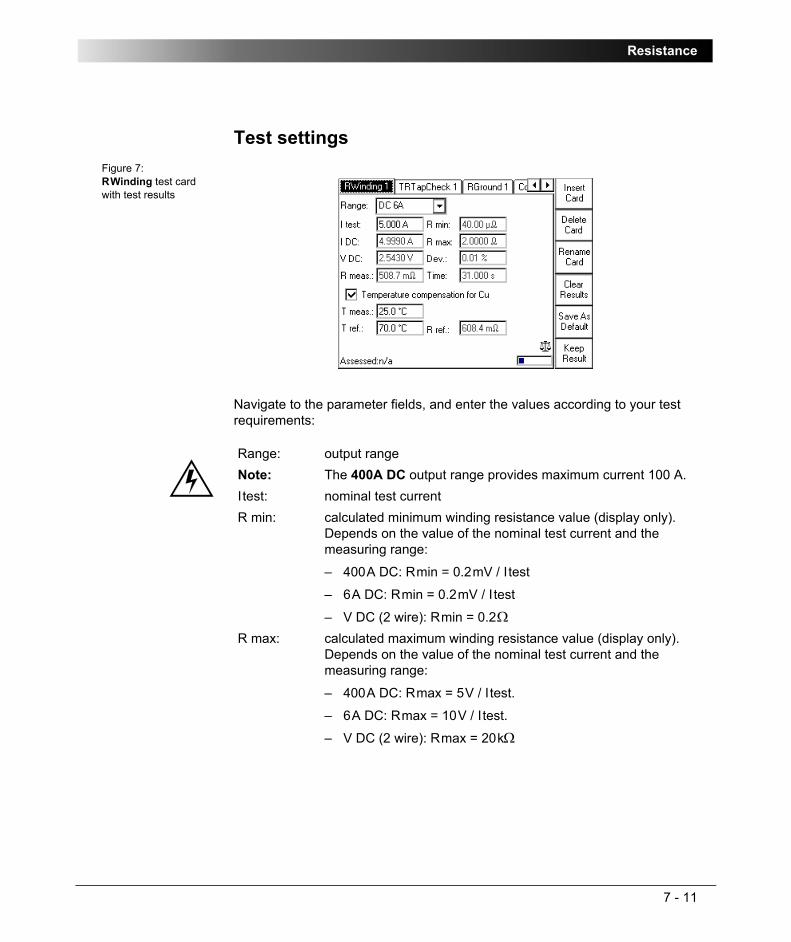
Resistance
7 - 11
Test settingsFigure 7:RWinding test card with test results
Navigate to the parameter fields, and enter the values according to your test requirements:
Range: output rangeNote: The 400A DC output range provides maximum current 100 A.Itest: nominal test currentR min: calculated minimum winding resistance value (display only).
Depends on the value of the nominal test current and the measuring range:
– 400A DC: Rmin = 0.2mV / Itest
– 6A DC: Rmin = 0.2mV / I test
– V DC (2 wire): Rmin = 0.2ΩR max: calculated maximum winding resistance value (display only).
Depends on the value of the nominal test current and the measuring range:
– 400A DC: Rmax = 5V / Itest.
– 6A DC: Rmax = 10V / Itest.
– V DC (2 wire): Rmax = 20kΩ

CPC 100 V1.41
7 - 12
Measurements
IDC: actual test current from 6A DC outputVDC: voltage that IDC generates at the transformer’s secondary
winding, measured at V DC inputR meas: transformer’s winding resistance, calculated from VDC / IDCTime: total elapsed test timeDev: deviation in % between the maximum and the minimum
measured values evaluated within the last 10 seconds of the measurement. The results are considered stable if Dev < 0.1%.
Press the context-dependent K E E P R E S U L T menu key to save the actual result in the measurement table. This adds a new line to the measurement table and the next measurement can be started.

Resistance
7 - 13
The "Temperature Compensation for Cu" Option
Option selected
Provides two more parameters to enter:
Depending on these two parameters, the reference resistance (Rref, temperature-compensated winding resistance) is calculated:
Option cleared
For the winding resistance measurement there is no temperature compensation taken into consideration.
Once all settings are defined, press the I/O (test start/stop) push-button to start the test.
When the measurements are taken, finish the test by assessing it.
To learn more about test assessment, refer to ”Test Assessment” on page 10-2.
Tmeas: ambient temperature Tref: operating temperature of test object, that is, the current
transformer’s secondary winding
Rref: In Centigrade:
Rref = (VDC / IDC) x (235°C + Tref) / (235°C + Tmeas)
In Fahrenheit:
Rref = (VDC / IDC) x (391°F + Tref F) / (391°F + Tmeas F)
Note: Formula according to IEC 60076-1.

CPC 100 V1.41
7 - 14
RGroundA good substation grounding system is crucial to protect people from injury and damage of equipment. International standards such as DIN VDE 0101/CENELEC HD637S1, IEEE Std 80-2000 or IEEE Std 81-1983 give guidelines how to measure such impedances.
Smaller grounding systems with a diameter of 100 m (300 ft) or smaller can be tested with the RGround test card and CPC 100 alone, for large systems the CP CU1 coupling unit and the Sequencer test card is a better choice. Note that no other grounding system must be close by.
The current-voltage method as called in CENELEC HD637S1 or fall of potential method as called in IEEE standards is a good solution to measure the ground impedance of a substation. The current is fed via a long cable into a remote ground. This ground can be any ground from a simple test probe to another large grounding system. The distance between this probe and the grounding system under test shall be at least 10 times the diameter of the grounding system, 15 to 20 times is better. Then measure the voltages with a second test probe at various distances around the substation. If possible, choose the measurement points in a 90º angle (bird’s-eye view) relative to the current path. In any case, avoid measuring close (< 60º) to the current path.
Measurement data at a large distance (typically three times the length of the substation) from the substation allow the calculation of the overall substation ground impedance Zground as defined in VDE 0101. Measurements at different distances are recommended. The measurement points should all show similar results. If the points are set too close to the substation or close to other grounding systems or over buried pipes, the results obtained are not stable.
Figure 8:Theoretical resistance characteristic of an earth electrode
linear range of earth resistance
Distance
100
200
300
400
500
600
Earth resistance mΩ
0

Resistance
7 - 15
Figure 9:Measuring the ground resistance of small ground systems
Note: Do not touch the test probe without insulating gloves outside of the substation area. In case of a high-current ground fault within the substation during the test, considerably high voltages could arise in any wire connected to the substation and leading away from it.
Δ U3 ... 5 x a
≈10 x a
Substation grounda = size of the earthing systema
a
Auxiliary electrode
U
Auxiliary electrode
I
I
90º(Bird’s-eye view)

CPC 100 V1.41
7 - 16
Note 1: The "Auxiliary electrode I" carries life threatening voltages during the test. Also the step voltage around the electrode can be quite high. Therefore it is recommended to mark an area of 10 m (30 ft) around the electrode as dangerous zone and to position a guard outside this area to keep people from entering the dangerous zone.
Note 2: If the desired current cannot be reached or an overload occurs, the contact resistance to the soil of the "Auxiliary electrode I" might be too high. Then it is a good idea to place several electrodes in a distance of few meters and connect them all together to keep the resistance to the soil low. This also reduces the hazard due to high voltages around the electrode.
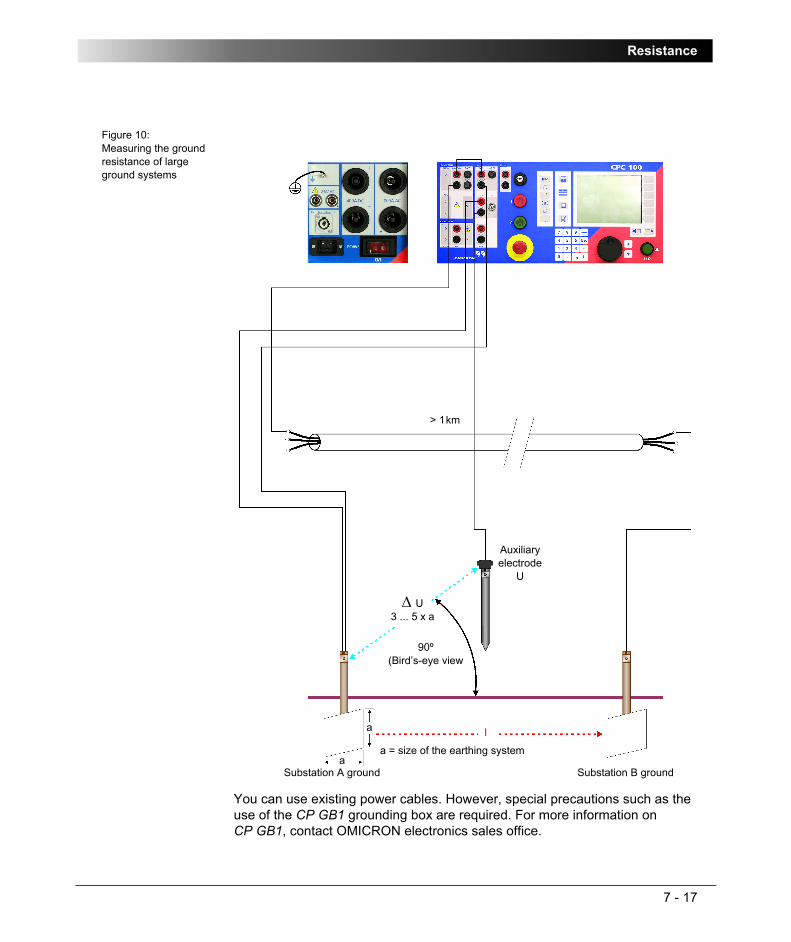
Resistance
7 - 17
Figure 10:Measuring the ground resistance of large ground systems
You can use existing power cables. However, special precautions such as the use of the CP GB1 grounding box are required. For more information on CP GB1, contact OMICRON electronics sales office.
I
Δ U3 ... 5 x a
Substation A ground Substation B ground
> 1km
Auxiliary electrode
U
a
aa = size of the earthing system
90º(Bird’s-eye view

CPC 100 V1.41
7 - 18
Figure 11:Measuring the soil resistivity
Legend:
ρ = soil resistivity
d = distance between auxiliary electrodes (identical between all electrodes)
R = calculated resistance as indicated at the RGround test card (R(f))
With the spacing of "d", the test measures the average soil resistivity between the U auxiliary electrodes down to a depth of "d". Therefore, varying "d" also varies the depth of the volume for which the soil resistivity is to be measured.
The following table lists typical resistivity of some common soil types.
Δ U
d d d
Auxiliary electrode
U
Auxiliary electrode
U
Auxiliary electrode
I
Auxiliary electrode
I
I
d = distance
d/20
ρ = 2 π d R

Resistance
7 - 19
Table 1:Typical resistance of common soil types
Figure 12:Measuring the resistance of a single ground rod
Soil Type Soil ResistivityMoor, marsh, very moist soil 1…50 ΩmLoess, clay 20…100 ΩmHumus, acre 10…200 ΩmSandy clay 50…500 ΩmGlass sand 200…3000 ΩmRock 300…5000 ΩmStony, grassy soil 100…300 ΩmGranite, freestone 1500…10000 Ωm
Substationground
groundrod 1
groundrod 2
groundrod 3
groundrod n

CPC 100 V1.41
7 - 20
In an earthing system with several grounding rods it may be of interest to measure the resistance of a single rod. To do so, disconnect the rod to be measured from the earthing system, and feed current through the rod into the grounding system (as shown in Figure 12 for rod 2). The voltage is measured directly at the current supply points.
Test settingsFigure 13:RGround test card with test results
Navigate to the parameter fields, and enter the values according to your test requirements:
Note: The resistance measured is only an approximation of the actual grounding resistance because the parallel resistance of all other ground rods is measured, too. If one electrode is too close by the measured electrode, values by far too small could be measured.
In order to obtain a more accurate result, the method shown in Figure 9 on page 7-15 can be used.
Itest: nominal test currentf: frequency of test current.
Select a frequency other than the 50 or 60Hz mains frequency to prevent interferences by stray earth currents (caused by the mains frequency and their harmonics). The value can be varied between 15 ... 400Hz. Default is 128Hz.

Resistance
7 - 21
Measurements
IRMS: actual test current (rms value)VRMS: measured voltage between substation ground and the auxiliary
electrode U (rms value).
This measurement represents a broad band measurement, that is, it detects all frequencies, for example, the 50 or 60Hz mains frequency. That way, possible dangerous voltage levels between the U auxiliary electrode and the substation ground are indicated.
Phase shift between VRMS and IRMS.R(f): calculated ohmic part of earth impedance (narrow-band
measurement)X(f): calculated inductive part of earth impedance (narrow-band
measurement)

CPC 100 V1.41
7 - 22
Voltage Withstand Test
Use the test card VWithstand to measure the voltage withstand capability of the secondary winding and secondary wiring. To do so, disconnect the burden.
As shown in Figure 14, connect the 2kV output socket without point to the transformer’s secondary (1S1) winding connection, and the output socket marked with a point to earth and the transformer’s primary connection (P1).
Warning: be aware that the terminal that is connected to the transformer’s secondary connection "1S1" leads life-hazardous voltage!
Figure 14:Setup for a voltage withstand test with a current transformer
Note: Some test cards are available in more than one test mode. For example, the test card VWithstand can be selected in CT, VT, Resistance and Transformer.
This is solely related to usability. With regard to functionality, the test card VWithstand is identical in all test modes.

Resistance
7 - 23
Test SettingsFigure 15:VWithstand test card with test results
Navigate to the parameter fields, and enter the values according to your test requirements:
Option "Switch off on IAC>"Select this combo box and specify a current threshold to turn off the voltage withstand test automatically if this value is exceeded.
If the combo box is clear (default), I AC is measured, however, there is no current threshold to turn off the voltage withstand test automatically if this value is exceeded. The data entry field cannot be accessed.
Option "Auto"Select this combo box and specify a duration time for the voltage withstand test to run (default = 60 seconds). After this time, the test is turned off automatically.
Clear this combo box if you prefer to either turn off the test manually, or have it turned off by the option "Switch off on I AC>" without a duration time involved.
Vtest: nominal test voltage (2kV max.)f: output frequencyTime: time span Vtest is applied to the output
Note: If both options "Switch off on I AC>" and "Auto" are selected, they act as an OR operation, that is, whatever occurs first will turn off the voltage withstand test.

CPC 100 V1.41
7 - 24
Measurements
Once all settings are defined, press the I/O (test start/stop) push-button to start the test.
The test voltage increases in a ramp characteristic from 0V to Vtest. Vtest is then applied to the output for the specified time span. The measurements are continuously taken. Afterwards Vtest decreases in a ramp characteristic.
When the measurements are taken, finish the test by assessing it.
To learn more about test assessment, refer to ”Test Assessment” on page 10-2.
VAC: injected voltage from 2kV ACoutput at the time the test turned off
IAC: measured current between the transformer’s primary and secondary windings at the time the test turned off
Imax: maximum measured current between primary and secondary winding during the entire test cycle

Others
8 - 1
OthersContents of this section
Scope of Others .............................................................................. page 8-2
Sequencer....................................................................................... page 8-3
Testing an Overcurrent Relay with ARC Function ................... page 8-11
Measuring a CT Ratio at Different Current Magnitudes........... page 8-14
Generating an Intermittent High-Current Output ...................... page 8-16
Ramping........................................................................................ page 8-18
Testing PickUp/DropOff Value of an Overcurrent Relay......... page 8-27
Amplifier ........................................................................................ page 8-29
Comment....................................................................................... page 8-33
TanDelta........................................................................................ page 8-36
Note: With regard to software handling, this section confines to test-relevant issues, and does not go into detailed procedural descriptions.
It is assumed that you have read and understood the section ”How to Use the CPC 100 Software” on page 2-17.

CPC 100 V1.41
8 - 2
Scope of OthersGo to the Test Card View and press I N S E R T C A R D.
Use the context-dependent U P /D O W N menu keys to the right, or the handwheel, to browse through the structure. On Others, press E N T E R.
Alternatively, press the accelerator key to open Insert a new test card.
Others comprises the following test cards:
Figure 1:Inserting test cards from Others
Highlight the test card of your choice either by navigating with the handwheel or by using the context-dependent U P /D O W N menu keys, and press E N T E R .
Note: The test cards
• Sequencer
• Ramping
employ the method of frequency-selective measurement, which is used to filter out interferences as they usually occur in substations.
To learn more about frequency-selective measurement, please refer to ”The Frequency-Selective Measurement” on page 3-6.

Others - Sequencer
8 - 3
SequencerUse the Sequencer test card to define a sequence of states to be applied to a connected test object.
A state represents an output quantity with defined settings, for example, a certain magnitude and frequency, for a preset period of time.
A sequence of up to 7 states can be defined. The states within that sequence execute sequentially. For each state, a trigger signal can be specified to prematurely terminate this state and execute the next one.
A sequence of states can either be executed once from state 1 to state x, or repeated continuously. Furthermore, the complete sequence can prematurely be terminated if during the execution of one of its states this state’s specified trigger condition occurs.
The test object’s characteristic is measured, and the values are displayed in the measurement table.
The Sequencer test card can be subdivided into three sections:
Figure 2:Sequencer test card
States table (state-specific settings)
– output quantity settings
– trigger specification
– duration of state
Measurement table
– definition of displayed quantities
– display of the measured values
Sequence settings (apply to all states)
– Range selection
– Synchronize with V1AC
– SOOT (switch off on trigger)
– Repeat sequence
To learn more about test assessment, refer to ”Test Assessment” on page 10-2.

CPC 100 V1.41
8 - 4
Pressing the S E T T I N G S menu key opens the Settings page. The Settings page allows setting the test cards individually. As a rule, do not use the Settings page but the Device Setup tab in the Options view (see ”Device Setup” on page 2-33) to set the test cards. For more information, see ”Settings Page” on page 2-28.
Defining a Sequence of StatesFirst set the sequence parameters, that is, the parameters that apply to all states.
Figure 3:Step 1 - Set the sequence parameters
From the range combo box select the CPC 100 output range of your choice.Click the "Sync w/ V1AC" icon to enable or disable this feature.
Enabling "Sync w/ V1AC" synchronizes the CPC 100 output frequency with the V1AC input frequency (we recommend a minimum input voltage of 10V on V1 AC, possible range 48 - 62Hz). In that case, the phase angle of the output is displayed in the states table rather than the frequency. Set the phase angle value relative to the phase angle of the V1 AC input signal (also refer to ”Sync w/ V1AC” on page 3-10).
After the start of a sequence the output needs up to 200ms to synchronize with V1AC. Therefore, define a first state with an amplitude other than zero.
If disabled, the states table displays the actual frequency value in Hz to be edited."SOOT" (switch off on trigger) check box selected:
• The complete sequence is prematurely terminated if during the execution of one of its states this state’s specified trigger condition (to be set at "Trigger") occurs.
"SOOT" check box cleared:
• The sequence is not terminated by an occurring state trigger. Such a trigger signal will only terminate this particular state, and continue executing the next state.
1 2 3 4
1
2
3

Others - Sequencer
8 - 5
Next set the state(s) parameters,that is, the parameters that apply to this particular state only. Each line of the states table represents one state.
Figure 4:Step 2 - Set the state parameters
"Repeat" check box selected:
• A sequence of states is executed from state 1 to state x, and then restarts with executing state 1 again. If "SOOT" is additionally selected, the complete sequence is prematurely terminated if during the execution of one of its states this state’s specified trigger condition occurs.
"Repeat" check box cleared:
• A sequence of states is executed from state 1 to state x, and then stops. If "SOOT" is additionally selected, the complete sequence is prematurely terminated if during the execution of one of its states this state’s specified trigger condition occurs.
4
Turn the handwheel to set the focus onto the states table’s first cell; in Figure 4 above it is the output current. Then press the handwheel. The cell turns into an entry field. Now set the output current value of your choice by turning the handwheel, or use the number keys of CPC 100 soft-touch keyboard. Press E N T E R or the handwheel to acknowledge your setting and move to the next table cell by turning the handwheel.
Note that the units of the states table (the table’s columns) depend on the selected output range.
On applications with overload it is recommended not to use currents above 600A without a current booster.Frequency of the output signal.If "Sync w/ V1AC" was selected (also refer to ), the table column displays the phase angle of the output rather than the frequency. Set the phase angle value relative to the phase angle of the V1 AC input signal.
5 6 7 8 9
5
62

CPC 100 V1.41
8 - 6
For each state, a trigger signal can be specified to prematurely terminate this state and execute the next one. If you move to the "Trigger" cell and press the handwheel, the cell turns into a combo box.
The following trigger conditions are available for each state:
• No Trigger: the state runs for the pre-defined period of time, no trigger signal will terminate this state.
• Binary: a trigger signal is fed into the Binary trigger input Bin In. The state is terminated as soon as this signal occurs.
• IOut>: as soon as the output current exceeds a certain threshold value (to define in column "Thresh"), the state is terminated.
• IOut<: as soon as the output current falls below a certain threshold value (to define in column "Thresh"), the state is terminated.
• V2 AC >: as soon as the signal connected to the low level voltage measuring input V2AC (0...3V AC) exceeds a certain threshold value (to define in column "Thresh"), the state is terminated.
• V2 AC <: as soon as the signal connected to the low level voltage measuring input V2AC (0...3V AC) falls below a certain threshold value (to define in column "Thresh"), the state is terminated.
The availability of the trigger signals depends on the selected values set at and of the measurement table (refer to Figure 5).
Note: Since the determination of the r.m.s. value requires some hundred milliseconds (τ ≈ 150ms), do not use this trigger condition for measurements in millisecond ranges.
• Overload: the state terminates as soon as an Overload condition occurs at the selected output.
What is an "Overload" trigger?– At the 800A AC output, an overload trigger is a condition in which
the set current cannot be reached any longer, for example, because of an opening contact or circuit breaker.
Note: Current values < 50A do not initiate an "Overload" when the current circuit opens. Therefore, if you use the trigger condition "Overload", chose a nominal current value of ≥ 50A.
7
10 11
Others - Sequencer
8 - 7
Press the A D D S T A T E button, and repeat steps to to define additional states. Note that the maximum possible number of states is 7.
Sequencer differentiates two "Overload" trigger conditions:
– the occurrence of an overload (as described above)
– the clearing of an overload condition.
Note: Clearing of an overload condition means: the CB closes again. For debouncing purposes, at CB closing time measurements, CPC 100 adds a fixed time of 100ms to the measured value. In order to determine the true CB closing time value, these 100ms need to be deducted from the value displayed in the measurement table (refer to the following examples).
The feature M A N U A L T R I G G E R provides a possibility to manually initiate a trigger signal (that is, a premature termination) of the current state at any time. This manual trigger has the same function as an automatic trigger signal.Trigger threshold.
Only available if a trigger ">" or "<" was selected (refer to ).
State duration. After this period of time the state terminates and the sequence continues with the next state (if any). If a trigger signal occurs before this time has elapsed, the currently running state terminates and the sequence continues with the next state. If "SOOT" is selected, the trigger signal terminates the complete sequence.
The default state duration time is 2s.
A current state has a minimal time of 250ms if the "Repeat" check box is cleared.
Note: Do not set the state duration shorter than 500 ms if the "Repeat" check box is selected.
A voltage state has a minimal time of 2s.
Setting a time of 0.000s makes the state infinite. Only a trigger signal will terminate it.
8
7
9
5 9

CPC 100 V1.41
8 - 8
Specify the values that the measurement table will eventually show.
Figure 5:Step 3 - Specify the values that the measurement table will eventually show
Turn the handwheel to set the focus onto the measurement table’s first combo box. Press the handwheel to display the available quantities to measure, and select the one of your choice.Repeat this step at the combo box for the second quantity to measure.
Possible choices of each combo box:• V1 AC
• V1 AC sel1
• V2 AC
• V2 AC sel
• VT
• VT sel
• I AC
• I AC sel
1. sel = frequency-selective. To learn more about frequency-selective measurements, refer to ”TheFrequency-Selective Measurement” on page 3-6.
• I Clamp
• I Clamp sel
• CT
• CT sel
• V DC
• I DC
• f V1 AC
• f Out
Each combo box has two corresponding cells in the measurement table below that display the measured quantities, where possible; otherwise "n/a" is displayed.
10 11 12
10
11

Others - Sequencer
8 - 9
Table 1:Display of calculated value in measurement table
Calculated valueBoth the items to select from in this combo box and the corresponding display at the measurement table below depend on the selected measured quantities.
In this combo box you determine whether the measurement table displays trigger signal characteristic / elapsed state time until trigger signal occurrence, ratio and phase angle difference, impedance Z or resistance R, real power P, apparent power S or the power factor cos ϕ.
12
Measured quantities
Display of calculated value in measurement table
(m1) (m2)Bin/Time If selected, the column "BinIn" displays the characteristic of
the trigger signal at the binary input BinIn, and the column "s" the elapsed state time until the occurrence of the trigger signal in seconds.
4 different characteristics are possible at BinIn:Closed: potential-free contact between BinIn+ and BinIn– closed.Open: potential-free contact between BinIn+ and BinIn– open.Come:
trigger signal with rising edge occurred at BinIn.
Go:
trigger signal with falling edge occurred at BinIn
V V Ratio:1, Ratio:5, Diff:
Ratio m1/m2 and phase angle ϕm1 - ϕm2 (if phase angles are available; otherwise "n/a"), and differences ΔU and ΔϕU.
I I Ratio:1, Ratio:5, Diff:
Ratio m1/m2 and phase angle ϕm1 - ϕm2 (if phase angles are available; otherwise "n/a"), and differences ΔI and ΔϕI.

CPC 100 V1.41
8 - 10
Press the I/O (test start/stop) push-button to start the output of the sequence of states (or the single state, if only one was defined).
In the states table, the first state is highlighted and its values are output. The measurement table displays the measured values, and updates them as well as the indication of the binary input’s signal status with an interval of approx. 0.5s.
At the end of each state - either after the state time has elapsed at the transition to the next state, or at the occurrence of the state’s trigger signal - the values in the measurement table are once more updated.
V I For AC: Z or R, X
Impedance Z (magnitude in Ω and phase angle ϕ in °) or R and X in Ω.For DC: R
Resistance R (in Ω)else "n/a"
V I For AC: P, Q, S
Real power P (in W) and cosϕ, apparent power S (in VA) and cosϕ, reactive power Q (in var) and cosϕ.For DC: P
Real power P (in W)else "n/a"
V I Rs, Ls or Rp, Cp:
Resistance R and either inductance Ls in H (series equivalent circuit) or capacity Cp in F (parallel equivalent circuit).
This is just another representation of the impedance Z measurement; Z is displayed in its components.
Using Rs, Ls, the impedance is given by:Z = Rs + j ω Ls, where ω = 2 π f and the set frequency is used for the calculation.
Using Rp, Cp, the admittance is given by: 1/Z = 1 / Rp + j ω Cp, where ω = 2 π f and the set frequency is used for the calculation.
Measured quantities
Display of calculated value in measurement table
(m1) (m2)

Others - Sequencer
8 - 11
Testing an Overcurrent Relay with ARC FunctionThis sequence of four states tests a complete autoreclosure cycle with both a short dead time (rapid autoreclosure) and a long dead time (slow autoreclosure).
Figure 6:Setup for testing an overcurrent relay with autoreclosure function I>
ONOFF
OFF
ON

CPC 100 V1.41
8 - 12
Figure 7:Sequencer test card with parameters and measurements of the four states
1 Current values < 50A do not initiate an "Overload" when the current circuit opens. For thisreason, a nominal current value of 50A was chosen here, even though the CB is open.
Note: For debouncing purposes, at CB closing time measurements, CPC 100 adds a fixed time of 100ms to the measured value. In order to determine the true CB closing time value, these 100ms need to be deducted from the value displayed in the measurement table.
State 2: "wait for the CB to close"
Short dead time. Set to output 50A until the "Overload" trigger condition that started state 2 clears.
The measurement table shows for state 2 that the short dead time + the CB closing time lasted 477ms. This time also includes the additional time to compensate for the debounce (see note below).
The actual value for CB close equals 477ms - 100ms = 377ms.
Note that the r.m.s. measurement of IOut reacts slow and therefore the measurement table does not show the full current.
State 3: "wait for the CB to open"
Like state 1.
State 1: "wait for the CB to open"
Set to output 400A until the trigger condition "Overload" occurs.
Here, trigger condition "Overload" means: CPC 100 cannot provide the 400A any longer because of the opening CB contact. Therefore, the opening CB contact terminates state 1.
The measurement table shows for state 1 that the relay time + the CB opening time lasted 290ms.
State 4: "wait for the CB to close"
Long dead time. Set to output 50A1 until the "Overload" trigger condition that started state 4 clears.
The measurement table shows for state 4 that the long dead time + the CB closing time lasted 3.1910s. This time also includes the additional time to compensate for the debounce (see note below).
The actual value for CB close equals 3.1910s - 100ms = 3.0910s.
Not relevant for this test.

Others - Sequencer
8 - 13
Time sequence of the four statesFigure 8:Time sequence of the four states to test the autoreclosure cycle
*) State 2 and 4 incl. the additional 100ms CPC 100 adds to compensate for the debounce(see note above).
state 1 state 2*)
short dead time
state 3 state 4*)
long dead time
t
CB opensfault inception: overcurrent condition occurs
CB autoreclosure
CB opens again
100ms
I
100ms

CPC 100 V1.41
8 - 14
Measuring a CT Ratio at Different Current MagnitudesExample of a sequence of five states to measure the ratio of a current transformer. To do so, different current amplitudes (5%, 20%, 50%, 100% and 120% of nominal value) are injected into the CT, and the CT’s secondary current is measured at CPC 100 current input IAC/DC.
Figure 9:Setup to measure the ratio of a current transformer at different current magnitudes
Parameters of the states 1 ... 5
Each of the five states injects a current with a different magnitude into the CT’s primary winding. There is no trigger specified, so each state runs exactly 2s.
A Hz Trigger Thresh s20 (= 5%) 50.00 No Trigger n/a 2.000
80 (= 20%) 50.00 No Trigger n/a 2.000200 (= 50%) 50.00 No Trigger n/a 2.000
400 (= 100%) 50.00 No Trigger n/a 2.000480 (= 120%) 50.00 No Trigger n/a 2.000

Others - Sequencer
8 - 15
Since the "Repeat" check box is cleared, the sequence of five states executes exactly one time and then terminates.
Figure 10:Sequencer test card with parameters and measurements of the five states (states 2...5 shown)
Measured values of the states 1 ... 5
I Out IAC Ratio:1A ° A ° :1 °
20 0 0.051 0.11 392.2 -0.1180 0 0.201 0.12 398.0 -0.12
200 0 0.502 0.11 398.4 -0.11400 0 1.004 0.13 398.4 -0.13480 0 1.205 0.15 398.3 -0.15

CPC 100 V1.41
8 - 16
Generating an Intermittent High-Current OutputIn a substation, certain control measurements and/or performance checks require the injection of high current at one location, and the respective measurement at another, sometimes remote location.
When CPC 100 outputs high current, duty cycles may apply to the selected AC output range. The allowed pulse duty cycle ("on/off" operation) depends on the selected range, the ambient temperature, the operating conditions of CPC 100 etc. For more information about duty cycles refer to ”CPC 100 Outputs” on page 16-5.
If you want to output high current for a longer period of time, perform such a test by creating two states in Sequencer:
– one state that outputs high current
– and another state with a sufficient pause.
The duration of both states need to comply with the permitted duty cycle. This will prevent an automatic shutdown of CPC 100 due to an overload.
Figure 11:Sequencer test card with two states for an intermittent high-current output
Set the states in such a way that they constantly repeat: select "Repeat".
Measurement table not relevant for this test.

Others - Sequencer
8 - 17
Time sequence of the repeating two states:Figure 12:Time sequence of the repeating two states to output an intermittent high current
The lower the averaged value of the output current Irms over the time the longer CPC 100 can be operated in that mode. This value is calculated with the following formula:
For more application examples, see the AN 0504 Application Note "Basic Circuit Breaker Tests Using CPC 100".
state 1
"on" cycle
state 2
"off" cycle
state 1
"on" cycle
state 2
"off" cyclet
I /O (test start/stop) push-button is pressedIsequence of state 1 and state 2 repeats
Irms = Itest x = 600A x = 268.3A3s(3s + 12s)
t on(t on + t off)
I testt on
t off

CPC 100 V1.41
8 - 18
RampingUse the Ramping test card to define a series of ramps to be applied to a connected test object.
Figure 13:A typical ramp characteristic: Δ q / Δ t,a linear change of either amplitude or frequency of one specified output signal within a defined period of time.
A series of up to 5 ramps can be defined. The ramps within that series execute sequentially, and run from a start to an end value within a set period of time.
It is possible to specify a trigger signal that prematurely terminates either
• the entire series of ramps
• or the actual ramp only, and then continues with the next one (if any).
The test object’s characteristic is measured, and the values are displayed in the measurement table.
The Ramping test card can be subdivided into three sections:
Figure 14:Ramping test card
q (output quantity)
t
A ramp represents a linear change of either amplitude or frequency of one specified output signal whereas the other quantity remains fixed.
To learn more about test assessment, refer to ”Test Assessment” on page 10-2.
Ramps table (ramp-specific settings)
– output quantity settings
– duration of ramp
– trigger specification
Measurement table
– definition of displayed quantities
– display of the measured values
Series settings (apply to all ramps)
– Range selection & display
– Ramp & fixed quantity
– SOOT (switch off on trigger)
– Start value (of first ramp)

Others - Ramping
8 - 19
Pressing the S E T T I N G S menu key opens the Settings page. The Settings page allows setting the test cards individually. As a rule, do not use the Settings page but the Device Setup tab in the Options view (see ”Device Setup” on page 2-33) to set the test cards. For more information, see ”Settings Page” on page 2-28.
Defining a RampFirst set the series parameters, that is, the parameters that apply to the entire series of ramps.
Figure 15:Step 1 - Set the series parameters
From the range combo box select the CPC 100 output range of your choice.During the output of a ramp, this field displays the currently output value of the signal’s quantity selected at .
From the combo box, select the output signal’s quantity to be ramped: "Amplitude" or "Frequency".Enter the value of the output signal’s fixed quantity.
If at "Amplitude" was selected as quantity to be ramped, enter the output signal’s fixed frequency value here. Otherwise, if "Frequency" was selected, enter the output signal’s fixed amplitude value."SOOT" (switch off on trigger) check box selected:
• The entire series of ramps is prematurely terminated if during the execution of one of its ramps this ramp’s specified trigger condition (to be set at "Trigger") occurs.
"SOOT" check box cleared:
• The series of ramps is not terminated by an occurring ramp trigger. Such a trigger signal will only terminate this particular ramp, and continue executing the next ramp.
Enter the ramp’s start value here. If a series contains more than one ramp, this is the start value of the first ramp of that series. The second ramp starts with the end value of the first one, and so on (refer to ”Example of a series of ramps” on page 23 of this chapter).
1 23 4
56
1
23
3
4
3
5
6

CPC 100 V1.41
8 - 20
Next, set the ramp(s) parameters, that is, the parameters that apply to this particular ramp only. Each line of the ramps table represents one ramp.
Figure 16:Step 2 - Set the ramp parameters
Turn the handwheel to set the focus onto the ramps table’s first cell; in Figure 16 above it is the output current. Then press the handwheel. The cell turns into an entry field. Now set the output current value of your choice by turning the handwheel, or use the number keys of CPC 100 soft-touch keyboard. Press E N T E R or the handwheel to acknowledge your setting and move to the next table cell by turning the handwheel.
Note that the units of the ramps table (the table’s columns) depend on the selected output range.Duration of ramp, that is, the time this particular ramp sweeps the selected signal from the start to the end value.
After this period of time the ramp terminates and the series continues with the next ramp (if any).
If a trigger signal occurs before this time has elapsed, the currently running ramp terminates and the series continues with the next ramp. If "SOOT" is selected, the trigger signal terminates the complete series of ramps.
78 109
7
8

Others - Ramping
8 - 21
For each ramp, a trigger signal can be specified to prematurely terminate this ramp and execute the next one. If you move to the "Trigger" cell and press the handwheel, the cell turns into a combo box.
The following trigger conditions are available for each ramp:
• No Trigger: the ramp sweeps the selected signal from the start to the end value within the pre-defined period of time, no trigger signal will terminate this ramp.
• Binary: a trigger signal is fed into the Binary trigger input Bin In. The ramp is terminated as soon as this signal occurs.
• IOut>: as soon as the output current exceeds a certain threshold value (to define in column "Thresh"), the ramp is terminated.
• IOut<: as soon as the output current falls below a certain threshold value (to define in column "Thresh"), the ramp is terminated.
• V2 AC >: as soon as the signal connected to the low level voltage measuring input V2AC (0...3V AC) exceeds a certain threshold value (to define in column "Thresh"), the ramp is terminated.
• V2 AC <: as soon as the signal connected to the low level voltage measuring input V2AC (0...3V AC) falls below a certain threshold value (to define in column "Thresh"), the ramp is terminated.
The availability of the trigger signals depends on the selected values set at and of the measurement table (refer to Figure 18).
Note: Since the determination of the r.m.s. value requires some hundred milliseconds (τ ≈ 150ms), do not use this trigger condition for measurements in millisecond ranges.
• Overload: the ramp terminates as soon as an Overload condition occurs at the selected output.
What is an "Overload" trigger?– At the 800A AC output, an overload trigger is a condition in which
the set current cannot be reached any longer, for example, because of an opening contact or circuit breaker.
Note: Current values < 50A do not initiate an "Overload" when the current circuit opens. Therefore, if you use the trigger condition "Overload", chose a nominal current value of ≥ 50A.
9
11 12

CPC 100 V1.41
8 - 22
Press the A D D R A M P button, and repeat steps to to define additional ramps. Note that the maximum possible number of ramps is 5.
Ramping differentiates two "Overload" trigger conditions:
– the occurrence of an overload (as described above)
– the clearing of an overload condition.
Note: Clearing of an overload condition means: the CB closes again. For debouncing purposes, at CB closing time measurements, CPC 100 adds a fixed time of 100ms to the measured value. In order to determine the true CB closing time value, these 100ms need to be deducted from the value displayed in the measurement table (refer to the following example).
– The feature M A N U A L T R I G G E R provides a possibility to manually initiate a trigger signal (that is, a premature termination) of the current ramp at any time. This manual trigger has the same function as an automatic trigger signal.
Trigger threshold.
Only available if a trigger ">" or "<" was selected (refer to ).
9cont.
10
9
7 10

Others - Ramping
8 - 23
Example of a series of rampsFigure 17:A series of three ramps defined in the ramps table
The three ramps defined in the ramps table shown above result in an output signal like this:
Ramp 1
• from 1A (set at "Start val:")
• to end value 200A (set in line 1 at column "A")
• in 5 s (set in line 1 at column "s")
Ramp 2
• from 200A (end value of ramp 1)
• to end value 200A (set in line 2 at column "A")
• for 10 seconds(set in line 2 at column "s")
Ramp 3
• from 200A(end value of ramp 2)
• to end value 0A(set in line 3 at column "A")
• in 5 seconds(set in line 3 at column "s")
Ramp 1Ramp 2Ramp 3
t
5s 15s
I
20s
1A
200A
Ram
p 1
Ramp 2
Ramp 3
0s

CPC 100 V1.41
8 - 24
Specify the values that the measurement table will eventually show.
Figure 18:Step 3 - Specify the values that the measurement table will eventually show
Turn the handwheel to set the focus onto the measurement table’s first combo box. Press the handwheel to display the available quantities to measure, and select the one of your choice.Repeat this step at the combo box for the second quantity to measure.
Possible choices of each combo box:• V1 AC
• V1 AC sel1
• V2 AC
• V2 AC sel
• VT
• VT sel
• I AC
• I AC sel
1. sel = frequency-selective. To learn more about frequency-selective measurements, refer to ”TheFrequency-Selective Measurement” on page 3-6.
• I Clamp
• I Clamp sel
• CT
• CT sel
• V DC
• I DC
• f V1 AC
• f Out
Each combo box has two corresponding cells in the measurement table below that display the measured quantities, where possible; otherwise "n/a" is displayed.
11 12 13
11
12

Others - Ramping
8 - 25
Table 2:Display of calculated value in measurement table
Calculated valueBoth the items to select from in this combo box and the corresponding display at the measurement table below depend on the selected measured quantities.
In this combo box you determine whether the measurement table displays trigger signal characteristic / elapsed ramp time until trigger signal occurrence, ratio and phase angle difference, impedance Z or resistance R, real power P, apparent power S or the power factor cos ϕ.
13
Measured quantities
Display of calculated value in measurement table
(m1) (m2)Bin/Time If selected, the column "BinIn" displays the characteristic of
the trigger signal at the binary input BinIn, and the column "t(s)" the elapsed ramp time until the occurrence of the trigger signal in seconds.
4 different characteristics are possible at BinIn:Closed: potential-free contact between BinIn+ and BinIn– closed.Open: potential-free contact between BinIn+ and BinIn– open.Come:
trigger signal with rising edge occurred at BinIn.
Go:
trigger signal with falling edge occurred at BinIn
V V Ratio:1, Ratio:5, Diff:
Ratio m1/m2 and phase angle ϕm1 - ϕm2 (if phase angles are available; otherwise "n/a"), and differences ΔU and ΔϕU.
I I Ratio:1, Ratio:5, Diff:
Ratio m1/m2 and phase angle ϕm1 - ϕm2 (if phase angles are available; otherwise "n/a"), and differences ΔI and ΔϕI.
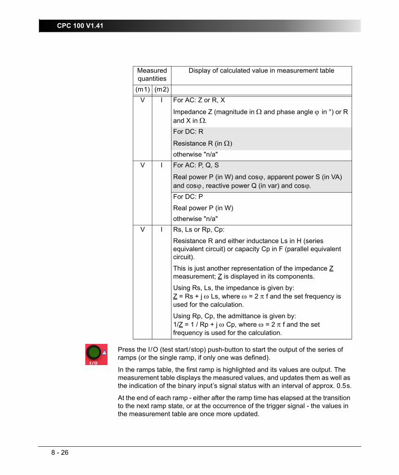
CPC 100 V1.41
8 - 26
Press the I/O (test start/stop) push-button to start the output of the series of ramps (or the single ramp, if only one was defined).
In the ramps table, the first ramp is highlighted and its values are output. The measurement table displays the measured values, and updates them as well as the indication of the binary input’s signal status with an interval of approx. 0.5s.
At the end of each ramp - either after the ramp time has elapsed at the transition to the next ramp state, or at the occurrence of the trigger signal - the values in the measurement table are once more updated.
V I For AC: Z or R, X
Impedance Z (magnitude in Ω and phase angle ϕ in °) or R and X in Ω.For DC: R
Resistance R (in Ω)otherwise "n/a"
V I For AC: P, Q, S
Real power P (in W) and cosϕ, apparent power S (in VA) and cosϕ, reactive power Q (in var) and cosϕ.For DC: P
Real power P (in W)otherwise "n/a"
V I Rs, Ls or Rp, Cp:
Resistance R and either inductance Ls in H (series equivalent circuit) or capacity Cp in F (parallel equivalent circuit).
This is just another representation of the impedance Z measurement; Z is displayed in its components.
Using Rs, Ls, the impedance is given by:Z = Rs + j ω Ls, where ω = 2 π f and the set frequency is used for the calculation.
Using Rp, Cp, the admittance is given by: 1/Z = 1 / Rp + j ω Cp, where ω = 2 π f and the set frequency is used for the calculation.
Measured quantities
Display of calculated value in measurement table
(m1) (m2)

Others - Ramping
8 - 27
Testing PickUp/DropOff Value of an Overcurrent RelayTo determine the pick up and the drop off value of a relay, a series of three ramps is defined. The first ramp determines the pick up value, the second one represents a 1s pause time, and the third ramp determines the drop off value.
Figure 19:Setup for testing the pick up and drop off values of an Overcurrent relay
The CPC 100 AC OUTPUT feeds the ramped current signal into a CT, which is connected to an overcurrent relay. The overcurrent relay’s trip contact is fed into CPC 100 binary input BinIn, and acts there as a trigger signal (as described on page 21 of this chapter).
I>

CPC 100 V1.41
8 - 28
Figure 20:Ramping test card with parameters and measurement values of the three ramps
Time sequence of the three ramps:Figure 21:Time sequence of the three ramps to determine the pick up and drop off values of an Overcurrent relay
Ramp 1:
Set to output a ramped current signal from 100.0A to either 200.0A in 10s, or until the trigger condition "Binary" occurs.
Here, trigger condition "Binary" means: the relay contact picks up. In this moment, ramp 1 terminates and the series continues with ramp 2.
The measurement table shows for ramp 1 that the relay contact picked up after 7.175s at a current value of 170.29A.
Ramp 3:
Because ramp 1 did not reach the 200A due to the trigger signal, ramp 3 starts with 170.29A, and then ramps down to zero with the set steepness (200.0A to 0.0A in 10s) until the trigger condition "Binary" occurs.
Here, trigger condition "Binary" means: the relay contact drops off. Since there are no further ramps defined, in this moment the sequence terminates.
The measurement table shows for ramp 3 that the relay contact dropped off 1.1s after ramp 3 started at a current value of 152.35A.
Ramp 2:
Pause time. Test current is output for 1s.
t
10s
I
21s
0A
200A
ramp 1
100A
170.29A
152.35A
0s 7.175s 1.1s
initially defined ramppick up
drop off
ramp 2
ramp 3
1s

Others - Amplifier
8 - 29
AmplifierUse the Amplifier test card to set CPC 100 to an "amplifier-like" mode. In this mode, an input signal fed into a synchronization input drives the high-current output’s magnitude, frequency and phase angle.
Select between IAC, V1AC and V2ACas synchronization inputs.
To prevent saturation, the output signal follows sudden magnitude changes at the synchronization input slowly. This smoothening effect delays the follow-up of the output current up to 250ms.
Both the "amplification" factor and the phase angle between input and output are set by the user in the Amplifier test card.
Figure 22:The Amplifier test card
Note 1: Changes in frequency and phase angle may result in unwanted effects. Both frequency and phase must be held stable.
Note 2: The input frequency is limited to a range of 48 ... 62Hz.
Set range
Set phase angle between input and output signal
Display of the measured high-current output signal
Select synchroniza-tion input
Value measured at synchroniza-tion input
Set the amplification factor to determine the ratio between the input and the output signal. Note: The synchronization input is not automatically range-switching, it is
fixed to its maximum value.
Measured phase angle between input and output signal
Measured input frequency (48 ... 62Hz)

CPC 100 V1.41
8 - 30
Pressing the S E T T I N G S menu key opens the Settings page. The Settings page allows setting the test cards individually. As a rule, do not use the Settings page but the Device Setup tab in the Options view (see ”Device Setup” on page 2-33) to set the test cards. For more information, see ”Settings Page” on page 2-28.
Starting a high-current output
– Set an amplification factor of “0”.
– Press I/O (test start/stop) to output the signal.
– With the measured input value in mind, enter the amplification factor now or increase the factor slowly using the handwheel.
– Acknowledge this entry by pressing the handwheel or the E N T E R key to start the output.
Depending on the measured input signal, setting the amplification factor can result in unintentionally high currents. It is strongly recommended to set the amplification factor to “0” before starting the test.

Others - Amplifier
8 - 31
Amplifier Use Case: GPS-Synchronized 3-Phase System for End-To-End TestingThis example shows how the three current outputs of a CMC 256-3 test set are led to the synchronization inputs IAC of three CPC 100 test sets to drive their high-current outputs. This way, the CPC 100 high-current outputs represent the "amplified" CMC 256-3 outputs and, in this example, are connected to three CTs.
Figure 23:Setup of a GPS-synchronized 3-phase system for end-to-end testing using a GPS synchronization unit CMGPS, a test set CMC 256-3 and three CPC 100
GPS synchronization unit CMGPS
Test set CMC 256-3
CPC 100 for phase 1
CPC 100 for phase 2
CPC 100 for phase 3
Protection relay
CT 1 CT 2 CT 3

CPC 100 V1.41
8 - 32
Figure 24:Settings of Amplifier test card for this example use case

Others - Comment
8 - 33
CommentThe Comment card is inserted to a test procedure in the same manner like a test card. Its purpose is to hold a user-defined comment and / or note regarding the actual test procedure or other important information such as operational data of a transformer, for example.
Figure 25:The Comment card
– Insert a Comment card to the actual test procedure by pressing I N S E R T C A R D. If required, you can insert more than one Comment cards.
– Press the context-dependent menu key E D I T to start the String Editor.
When used for the Comment card, the String Editor differentiates between the input modes "Form Editor" and "Text Editor".
After pressing E D I T , "Text Editor" is active. With the exception of the context-sensitive key to switch between these two modes, the user interface is identical.
To create "flowing" text with no tabs in it, either input mode can be used. Compose a text of your choice by selecting the individual characters and symbols needed one by one and confirm them by pressing the handwheel. When finished, acknowledge with O K .
This is a user-defined comment and/or note regarding the actual test procedure.

CPC 100 V1.41
8 - 34
Form Editor - Text Editor:To o create such a "2 columns" layout, press E D I T F O R M.
Enter the first word "Substation" and then a tab. Proceed with "Buers" and a carriage return. Proceed accordingly:
The tab quasi denotes a column-break.
The difference between Form Editor and Text Editor is that text left of the tab (the "first column", so to speak) cannot be accessed anymore in Text Editor, that is, it is protected. To add, edit or delete first column entries use the Form Editor.
More about function and handling of the String Editor at ”The String Editor” in chapter 10.
How to change a comment– IIf you need to change an existing comment, press E D I T . This starts the
String Editor.
– Start the appropriate input mode, "Form Editor" or "Text Editor", change the entries of your choice and press O K .
Sub.: BuersTrans.: TR24Manuf.: SiemensType: KFRM 1863A / 22EYear: 1955Se. No.: T-54953Power: 100 MVAVecGr.: YN/yn0Uprim: 220.000VIprim: 262.5AUsec: 110.000VIsec: 525.0AUk: 10.2%
Sub. Buers ↵Trans. TR24 ↵Manuf. Siemens ↵Type a.s.o.

Others - Comment
8 - 35
How to clear a comment– Press C L E A R C O M M E N T.
– The context-dependent menu keys change and provide two more keys: C L E A R A L L and C L E A R T E X T .
• Clear All: Deletes the entire comment at once, that is, all text in all columns.
• Clear Text: Deletes all to the right of the tab, that is, everything but the left-hand side column.

CPC 100 V1.41
8 - 36
TanDeltaThe test card TanDelta was especially developed for CP TD1.
CP TD1 is an optionally available high precision test system for on-site insulation tests of high-voltage systems like power and measuring transformers, circuit breakers, capacitors and isolators. CP TD1 works as an add-on device to CPC 100 and is described in the CP TD1 Reference Manual available on the CPC Explorer CD-ROM.
The TanDelta test card can be accessed from CT, VT, Transformer and Others.

File Operations
9 - 1
File OperationsContents of this section
The CPC 100 File System............................................................... page 9-1
Navigating Through the File System............................................... page 9-2
The Menus ...................................................................................... page 9-2
Submenu File............................................................................. page 9-3
Submenu Edit ............................................................................ page 9-3
The CPC 100 File SystemThe CPC 100 File Operations resemble the functionality known from, for example, the Windows Explorer. File Operations comprises a F I L E and an E D I T submenu with additional menu items as well as an O P E N and various S A V E . . . functions.
The highest hierarchical level of the CPC 100 file system, the "root", is named CPC100. Below this, you can create additional folders in a tree-structure of your choice, save tests in these folders, and carry out file operations, such as open, save, rename, copy, paste etc.
The CPC 100 file system differentiates two file types:
– name.xml A test procedure with all of its test cards and specific settings. An .xml file may also contain test results and assessments that were stored together with the settings as report in the CPC 100 file system for archiving purposes.
– name.xmt Test procedure template, that is, a user-defined template containing one or more test cards with all of their specific test settings but without test results.
Note: The file containing the up-to-date measurements should be saved regularly. If the test unit is switched off, or in case of a power outage, all unsaved measurements will be lost.
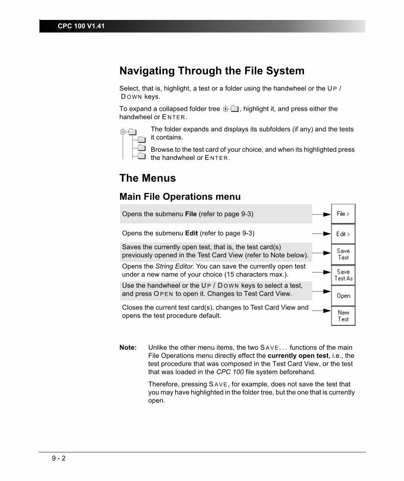
CPC 100 V1.41
9 - 2
Navigating Through the File SystemSelect, that is, highlight, a test or a folder using the handwheel or the U P /D O W N keys.
To expand a collapsed folder tree , highlight it, and press either the handwheel or E N T E R.
The folder expands and displays its subfolders (if any) and the tests it contains.
Browse to the test card of your choice, and when its highlighted press the handwheel or E N T E R.
The MenusMain File Operations menu
Note: Unlike the other menu items, the two S A V E . . . functions of the main File Operations menu directly effect the currently open test, i.e., the test procedure that was composed in the Test Card View, or the test that was loaded in the CPC 100 file system beforehand.
Therefore, pressing S A V E , for example, does not save the test that you may have highlighted in the folder tree, but the one that is currently open.
Opens the submenu File (refer to page 9-3)
Opens the submenu Edit (refer to page 9-3)
Saves the currently open test, that is, the test card(s) previously opened in the Test Card View (refer to Note below).Opens the String Editor. You can save the currently open test under a new name of your choice (15 characters max.).Use the handwheel or the U P / D O W N keys to select a test, and press O P E N to open it. Changes to Test Card View.
Closes the current test card(s), changes to Test Card View and opens the test procedure default.

File Operations
9 - 3
Submenu File
Submenu Edit
For more information about the String Editor, please refer to ”The String Editor” in chapter 10.
Note: If a folder is cut or copied to the Clipboard, the selection is recursive, that is, all of its subfolders will also be put to the Clipboard.
Cutting or copying a test or folder, and trying to paste it in the same location, opens the String Editor.
Since a test or folder cannot exist twice under the same name at the same location, determine a new name for it using the String Editor.
Opens the String Editor. You can create a new folder with any name of your choice.Appends the contents of a test file (.xml) or template (.xmt) of your choice to the currently open test.Deletes the currently selected test or folder from CPC 100 disk space.Opens the String Editor that enables you to rename the current test to any new name of your choice.
(for future use)
Closes the submenu and returns to the main File Operations menu.
Select the test of your choice. Press C U T to put the selected test or folder to the Clipboard. Proceed with P A S T E...Select the test of your choice. Press C O P Y to copy test or folder to the CPC 100 Clipboard. Proceed with P A S T E...Move to the destination folder of your choice. Press P A S T E to insert the contents of the CPC 100 Clipboard to this folder.Press P A S T E A S T E M P L . to make the contents of the CPC 100 Clipboard a test procedure template.
(for future use)
Closes the E D I T submenu and returns to the main File Operations menu.

CPC 100 V1.41
9 - 4

Common Functions
10 - 1
Common FunctionsThis chapter describes functions and procedures that repeat in all or various test cards. Since these functions are operated in the same fashion on all test cards, they are explained only once in a central place.
Contents of this sectionTest Assessment........................................................................... page 10-2
The String Editor ........................................................................... page 10-3
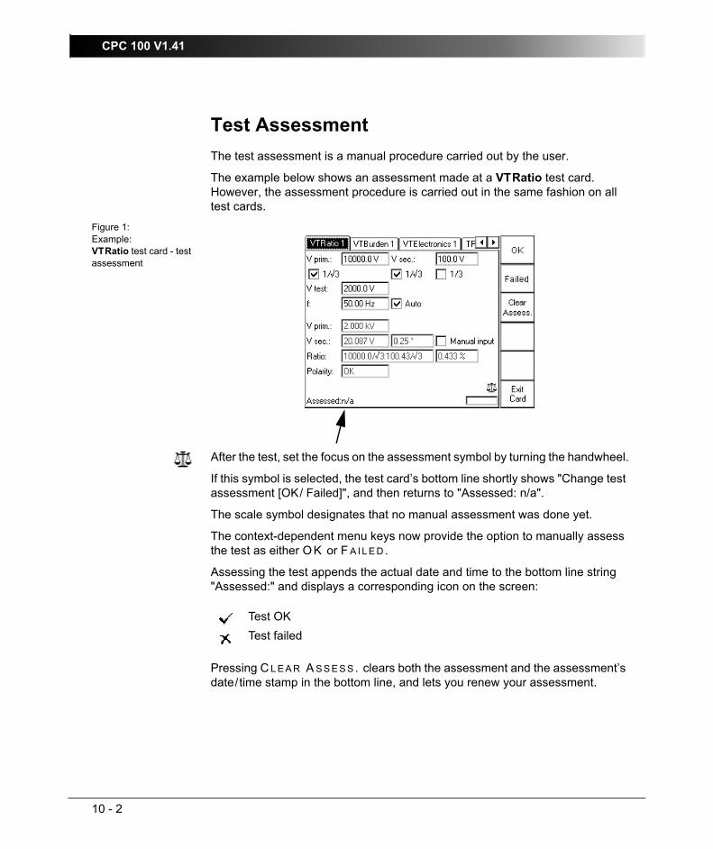
CPC 100 V1.41
10 - 2
Test AssessmentThe test assessment is a manual procedure carried out by the user.
The example below shows an assessment made at a VTRatio test card. However, the assessment procedure is carried out in the same fashion on all test cards.
Figure 1:Example:VTRatio test card - test assessment
After the test, set the focus on the assessment symbol by turning the handwheel.
If this symbol is selected, the test card’s bottom line shortly shows "Change test assessment [OK/ Failed]", and then returns to "Assessed: n/a".
The scale symbol designates that no manual assessment was done yet.
The context-dependent menu keys now provide the option to manually assess the test as either O K or F A I L E D .
Assessing the test appends the actual date and time to the bottom line string "Assessed:" and displays a corresponding icon on the screen:
Pressing C L E A R A S S E S S . clears both the assessment and the assessment’s date/time stamp in the bottom line, and lets you renew your assessment.
Test OKTest failed

Common Functions
10 - 3
The String EditorThe String Editor is used to name or rename test cards, tests and templates as well as to fill out the Comment card.
Every time such an operation becomes necessary, the String Editor starts automatically.
The number of available characters to choose from depends on the String Editor’s use. If, for example, a user-defined comment is to be entered in the Comment card, the number of available characters is bigger as if a test is to be renamed. This difference are special characters such as !, ?, _, [ ], etc.
Important special characters:↵ carriage return (line feed)
tab (special function in Form Editor mode; refer to page 8-34).
When started from Test Card View, Test Procedure Overview or File Operations, the String Editor’s respective entry field shows a default name.
To accept the default name, press the menu key O K or S A V E .
To change the default name, and to enter a name of your choice
– delete the default name by repeatedly pressing the backspace key
– enter the new test or folder name by consecutively selecting the characters of your choice from the "on-screen keyboard" with the U P / D O W N keys or by navigating to it with the handwheel
– acknowledge every selected character by pressing the handwheel or E N T E R
Use the String Editor’s arrow buttons to move the cursor to the position of your choice. These buttons are only available if the focus (⇒ Glossary) is on the character selection.
On the Comment Card, pressing C A R R I A G E R E T U R N starts a new line. Otherwise, C A R R I A G E R E T U R N is disabled.
Once the new name is entered, press the context-dependent menu key O K or S A V E - depending on the mode - to exit the String Editor.
Pressing C A N C E L closes the String Editor discarding all changes.

CPC 100 V1.41
10 - 4
The Template StringsThe String Editor provides a feature, that allows you to save strings, that is, names of test cards, tests, templates, folders and files. Once these strings are saved, they can then be selected as template strings from the combo box "Select a string".
Figure 2:CPC 100 String Editor with focus on "Select a String"
How to save a string:– enter a name of your choice in the way described above
– put the focus (⇒ Glossary) on the combo box "Select a string"
– press A D D T O S T R I N G S to add this name to the list of template strings.
How to select a template string:– put the focus (⇒ Glossary) onto the combo box
– press the handwheel and turn it to browse through the list of available, that is, previously saved, template strings
– highlight the template string of your choice, and press the handwheel or the context-dependent menu key O K . The template string is then automatically added to the upper entry field.
How to insert a template string:– select a template string as described above
– once the template string of your choice is highlighted, press I N S E R T I N T O E D I T . The string is then automatically inserted into the upper entry field at the cursor position (refer to Figure 2).
Common Functions
10 - 5
How to delete a template string:– highlight a template string as described above
– press D E L F R O M S T R I N G S to delete the selected string template from the list.
Note: The R E S T O R E D E F A U L T S menu key at the Options tab Device Setup (refer to ”Device Setup” on page 2-33) resets all user-specific settings made in the CPC 100 software to factory-defined defaults. This also includes the String Editor’s template strings.

CPC 100 V1.41
10 - 6

CPC 100 in a Network
11 - 1
CPC 100 in a NetworkContents of this section
General ......................................................................................... page 11-2
Setting the Communication Parameters ....................................... page 11-3
CPC 100 .................................................................................. page 11-3
DHCP/Auto-IP.................................................................... page 11-3
Static IP............................................................................... page 11-3
IP address........................................................................... page 11-4
Subnet mask ....................................................................... page 11-4
Default gateway .................................................................. page 11-4
DNS .................................................................................... page 11-4
PC or Notebook ....................................................................... page 11-5
Firewall and anti-virus software .......................................... page 11-7
DHCP allocator service....................................................... page 11-7
Setup for Windows 2000, Vista, XP.................................... page 11-8

CPC 100 V1.41
11 - 2
GeneralThe interface to access the CPC 100 built-in ePC is an Ethernet (⇒ Glossary) board. CPC 100 can be connected with a 10BaseT ("twisted pair") connection cable to either a stand-alone PC, or an existing PC network.
For this, the Ethernet board provides two RJ-45 connectors:
– the upper socket labelled "PC" connects CPC 100 to either a PC’s Ethernet network card or a notebook’s PC Card (⇒ Glossary)
Figure 1:CPC 100 connected to a stand-alone PC (here a notebook)
– the lower socket labelled "to Network" connects CPC 100 to a PC network hub.
Figure 2:CPC 100 in a PC network
"PC"
"Network"

CPC 100 in a Network
11 - 3
These two connectors only differ in one cross-connection in the upper RJ-45 connector "PC".
For both RJ-45 sockets the same 10BaseT connection cable type can be used. Therefore, make sure to insert your 10BaseT connection cable into the correct CPC 100 socket.
The communication protocol is the TCP/IP protocol.
Setting the Communication ParametersCPC 100For two devices to communicate using TCP/IP (the most-commonly used protocol for Ethernet), both devices need a unique network address, that is, an address that is different from all other addresses within this network.
In addition, these devices need an identical subnet mask.
The CPC 100 communication parameters are set on the Network tab of the Options (refer to ”Network” on page 2-37).
DHCP/Auto-IPMost PC networks have a DHCP (Dynamic Host Configuration Protocol) server that provides an address for every device connected to the network and defines the subnet mask. When connected to such a network, setting CPC 100 to DHCP/Auto-IP mode enables it to obtain an address from the DHCP server. If there is no DHCP server (for example, because CPC 100 is directly connected to a PC), CPC 100 generates its address automatically (Auto-IP).
Older versions of Microsoft Windows, such as Windows 95 or NT 4.0, support DHCP but not Auto-IP. For details about how to establish a communication via a direct connection, refer to the section ”Setup for Windows 2000, Vista, XP” on page 8 of this chapter.
Static IPIn smaller PC networks, all computers have individual static IP addresses. The system administrator has to assure that no IP address is used twice. He provides you with a unique address and all other settings for CPC 100.
If, by mistake, an IP address is used twice in the network, communication of one or both of the devices will fail to work.
If you are in doubt, set PC and CPC 100 to DHCP/Auto-IP.
Note: Connect only one RJ-45 connector at a time.

CPC 100 V1.41
11 - 4
IP addressThis is the unique network address of CPC 100. You need this setting only if static IP addresses are used. Your system administrator will provide you with a valid static IP address.
Subnet maskThis is the filter for the IP address. It has to be identical for all devices within one network. You need this setting only if static IP addresses are used. Your system administrator will provide you with a valid subnet mask.
Default gatewayThis is the address of a local IP router on the same network the CPC is in. It is used to enable data traffic to destinations beyond the local network.
Commonly, the default gateway is not needed and can therefore be set to 0.0.0.0 for DCHP/Auto IP. This setting is only accessible if static IP addresses are used. Your system administrator will provide you with details.
DNSThis is the address of the Domain Name System server.
Commonly, this address is not needed and can therefore be set to 0.0.0.0. This setting is only accessible if static IP addresses are used. Your system administrator will provide you with details.
CPC 100 in a Network
11 - 5
PC or NotebookIf your PC or notebook is capable of communicating in a PC network, communication with your CPC 100 either within a network or via a direct connection to CPC 100, should function without changing any of your PC settings.
To avoid possible communication problems, we recommend to first fully boot CPC 100, then connect CPC to the PC and eventually start CPC Explorer.
Computers with a Windows 95 or a NT 4.0 operating system need a special setup. These details are explained in chapter ”Setup for Windows 2000, Vista, XP” on page 8 of this chapter.
In a network with static IP addresses, your system administrator will provide you with valid settings for CPC 100.
In a network with dynamic address configuration (DHCP or Auto-IP), set your CPC 100 to "DHCP/Auto-IP". This way, both the addresses of your PC and CPC 100 will be generated automatically.
Troubleshooting in case of communication problemsShould communication problems occur, the CPC Explorer software will assist you in accessing CPC 100 through the network, and, if possible, make useful suggestions about the settings to enter. Generally, all you need to do is to press O K a few times to acknowledge suggested settings.
Since CPC 100 may re-boot, make sure to save your data beforehand.
If your CPC 100 is not listed in CPC Explorer’s top left-hand side pane1 although correctly connected, you need to check the Ethernet connection cable:
1. refer to ”Starting CPC Explorer” on page 13-5.

CPC 100 V1.41
11 - 6
1. Direct connection from CPC 100 "PC" port to the PCConnect and disconnect the 10BaseT connection cable several times and check whether the "link indicator" LED1 near the PC’s port turns on and off.
If you still don’t get a connection, try another 10BaseT connection cable.
If that still does not work, connect CPC 100 "Network" port and your PC to a network hub (as shown in Figure 2 on page 2 of this chapter).
If the link indicator LED works but you still cannot establish communication, try to deactivate firewall and/or antivirus software on your computer since applications like these may interfere and prevent proper communication.
If it still does not work, call the OMICRON hotline (+43 5523 507-333).
2. Connection of CPC 100 and PC via a network hubConnect and disconnect the 10BaseT connection cable several times and check whether the "link indicator" LED near the PC’s port turns on and off.
If you still don’t get a connection, try another 10BaseT connection cable on a different port of the hub.
If the link indicator LED works but you still cannot establish communication, try to deactivate firewall and/or antivirus software that is installed on your computer since applications like these may interfere and prevent proper communication.
If it still does not work, call the OMICRON hotline (+43 5523 507-333).
Note: In general, a communication is established quicker, however, under certain circumstances it may take up to 2 minutes until a proper communication is set up. During this phase, we recommend to click CPC Explorer’s F I N D button from time to time
1. LED close to your PC’s Ethernet connector that displays data traffic by going on and off.
Note: In general, a communication is established quicker, however, under certain circumstances it may take up to 2 minutes until a proper communication is set up. During this phase, we recommend to click CPC Explorer’s F I N D button from time to time
CPC 100 in a Network
11 - 7
Firewall and anti-virus softwareFirewall and antivirus software often block data traffic on several ports of the Ethernet interface. This may prevent proper communication between CPC and PC. Whenever communication problems occur, try to temporarily deactivate firewall and/or antivirus software that are installed on your computer.
During installation of CPC Explorer you are asked to open some ports on Windows firewalls. It is recommended to allow this. Otherwise, the "find" algorithm will not work.
DHCP allocator serviceIn most PC networks there is a DHCP server that provides the connected network nodes with valid addresses. That way, every PC in the network is assigned a unique address.
Because there is no DHCP server present when a CPC is connected directly to a PC (point to point), CPC 100 is capable of providing the PC with a valid address as long as there is no server detected and CPC Explorer is running on the PC. The address is chosen from the Auto-IP address range, so it does not interfere with other addresses within the network. It is also assured that only those PCs are provided with an IP address that run CPC Explorer.
Note: By default, CPC Explorer uses port 4987 to find connected CPC sets, and port 21 (FTP port) to download data from the CPC. It also needs the possibility to send and receive ICMP data packages ("PING" command has to work).

CPC 100 V1.41
11 - 8
Setup for Windows 2000, Vista, XP
There are two methods of using a Windows 95 or Windows NT 4.0 PC or notebook alternatively in a network or connected directly to CPC 100 without the necessity of having to re-configure its settings for each case:
• Installation of a second Ethernet network interface card.
This network card’s port is used exclusively for communication with CPC 100. It should be configured statically. It is recommended to set the network card to the Auto-IP address range:
• IP address: 169.254.77.33 ,
• Subnet Mask: 255.255.0.0 ,
• Default Gateway: 0.0.0.0
• DNS: 0.0.0.0
This way, it is possible to connect your PC to the network using the first network card’s port, and directly to CPC 100 using the second network card’s port.
Set CPC 100 to DHCP/Auto-IP to connect it to the network or directly to the PC.
• Setting PC and CPC 100 to a static IP address.
The DHCP server generates addresses within an address range defined by the subnet mask. In general, it is also possible to set static addresses within this range.
The addresses need to be provided by your system administrator.
Do not set addresses by your own. Always consult your system administrator. If, by mistake, an IP address is used twice in the network, communication of one or both of the devices will fail to work.
Note: Disconnecting your PC from the network and establishing a direct connection to CPC 100, for example, to test it in the office before you take it out for testing, may work - but establishing a communication hours later is no longer possible.
The reason for this is that the DHCP server provides the PC with both a valid address and an expiration date. The expiration date can be in hours or even weeks. After the address has expired, you need to change your PC configuration in order to establish a new communication (if your system administration did not restrict your setup rights).
Windows 95 and NT 4.0 do not support Auto-IP.
OMICRON Device Browser
12 - 1
OMICRON Device BrowserContents of this section
General ......................................................................................... page 12-2
Installation of the OMICRON Device Browser Software ............... page 12-2
Computer Requirements.......................................................... page 12-2
Installing the OMICRON Device Browser ................................ page 12-2
Using the OMICRON Device Browser .......................................... page 12-3
Starting the OMICRON Device Browser .................................. page 12-4
Upgrading and Configuring the Network of the CPC 100 ........ page 12-5
Viewing test files ...................................................................... page 12-5

CPC 100 V1.41
12 - 2
GeneralThe OMICRON Device Browser is an application embedded in the Windows operating system. You can access the directory of the connected CPC 100 through Windows Explorer and other applictions, such as Editor and Excel.
Installation of the OMICRON Device Browser SoftwareThe OMICRON Device Browser software is included on the CPC Explorer CD-ROM shipped with your CPC 100.
Computer RequirementsFor the installation requirements, see ”Computer Requirements” on page 13-2.
Installing the OMICRON Device BrowserFor the installation procedure, see ”Installing CPC Explorer” on page 13-3. A shortcut to start the OMICRON Device Browser appears on your desktop.

OMICRON Device Browser
12 - 3
Using the OMICRON Device BrowserThe OMICRON Device Browser allows you to access your CPC 100 through the Windows operating system.
With the OMICRON Device Browser, you can conduct easy file operations (for example cut, copy, delete, rename) in the Windows operating system from and to the CPC 100.
Furthermore, you can obtain direct reports of your tests, open or save your tests with CPC Editor or CPC Excel File Loader. The OMICRON Device Browser is used to upgrade your CPC 100 or configure your CPC 100 Network Configuration.

CPC 100 V1.41
12 - 4
Starting the OMICRON Device BrowserDouble-click the OMICRON Device Browser icon on your desktop or start the Windows Explorer and click on OMICRON Devices.
Note: You can only see a connected CPC 100.
Figure 1:OMICRON Device Browser user interface
Apart from the pull-down menus and the toolbar, the OMICRON Device Browser interface consists of two panes:
• the left-hand side pane displays the available devices
• the right-hand side pane displays the contents of any device selected in the left-hand side pane
Navigate through the tree structure in the left-hand side panes as you would in Windows Explorer. Double-clicking a closed folder or clicking on the plus sign beside it opens it. Double-clicking an open folder or clicking on the minus sign beside it closes it.
1
2
1
2

OMICRON Device Browser
12 - 5
Upgrading and Configuring the Network of the CPC 100Right-click on the respective device on the right-hand side pane to open the context menu and select either one of the options. The S E T N E T W O R K C O N F I G U R A T I O N option is used to set the network configuration of your CPC 100. Use the U P G R A D E D E V I C E option to upgrade the software of your CPC 100 with a newer version.
Figure 2:Upgrading and configuring the network
Viewing test filesTo display all tests, click on the "Tests" folder of the device on the left-hand side pane. All available tests will be listed.

CPC 100 V1.41
12 - 6
Figure 3:Available tests shown on the right-hand side pane
Right-click on the respective test on the right-hand side pane to open the context menu or use the Windows Explorer menus. You can copy, cut, paste, delete or rename the test files.
Figure 4:Viewing and editing test files
To display a test report, right-click on the file name and select D I S P L A Y T E S T R E P O R T from the context menu.

OMICRON Device Browser
12 - 7
Figure 5:Displaying a test report
The test report contents are then displayed in a separate window.
Figure 6:Test report contents

CPC 100 V1.41
12 - 8
Figure 7:Context menu on right-click when CPC Editor is installed
The O P E N W I T H C P C E D I T O R context menu allows you to directly open and edit your tests from the CPC 100 with CPC Editor.
Note: If you have CPC Editor installed on your computer, the context menu holds one more entry: O P E N W I T H C P C E D I T O R. . .
CPC Editor is an optionally available PC-based software program used for offline test preparation. For more information about CPC Editor, please refer to the according chapter of this Reference Manual.

OMICRON Device Browser
12 - 9
Figure 8:Directly open and edit your tests
You can save tests directly to the CPC 100 from the CPC Editor.

CPC 100 V1.41
12 - 10
Figure 9:Saving tests with the CPC Editor

OMICRON Device Browser
12 - 11
Furthermore, it is possible to load test results directly into the CPC Excel File Loader.
Figure 10:Loading files into the CPC Excel File Loader

CPC 100 V1.41
12 - 12

CPC Explorer
13 - 1
CPC ExplorerContents of this section
General ......................................................................................... page 13-2
Installation of the CPC Explorer Software..................................... page 13-2
Computer Requirements.......................................................... page 13-2
Installing CPC Explorer............................................................ page 13-3
Using CPC Explorer ...................................................................... page 13-4
Starting CPC Explorer.............................................................. page 13-5
Finding Connected CPC 100 Units .......................................... page 13-6
Viewing Files............................................................................ page 13-6
Viewing test reports ............................................................ page 13-6
Viewing test reports and editing them by opening them with CPC Editor............................................ page 13-8
Viewing the log file ............................................................ page 13-11
Viewing the license file...................................................... page 13-11
Transferring Files and Folders ............................................... page 13-12
Downloading files from CPC 100 to your PC.................... page 13-12
Uploading files from your PC to CPC 100......................... page 13-12
Upgrading the CPC 100 Software.......................................... page 13-13
Options................................................................................... page 13-15
Language.......................................................................... page 13-15
Default Stylesheet............................................................. page 13-15
Saving a Test to PDF Format...................................................... page 13-16

CPC 100 V1.41
13 - 2
GeneralCPC Explorer is a PC-based software program that is shipped with CPC 100. It is used to browse the tests stored in the CPC 100 file system, transfer tests between the PC and CPC 100, and upgrade the software of CPC 100.
CPC Explorer can also be used for remote trouble-shooting of CPC 100.
Installation of the CPC Explorer SoftwareThe CPC Explorer software and its installation program Setup Wizard are included on the CPC Explorer CD-ROM shipped with your CPC 100.
Computer Requirements
Minimum Computer Requirements• Pentium 200MHz
• 64MB RAM
• CD-ROM drive
• Ethernet connection
• Internet Explorer version 5.5 or later
• Windows 2000/XP/Vista
Recommended Computer Features• Pentium 233 MHz or higher
• 128 MB or more RAM
Note: All Windows operating systems require administrative rights on your local machine for installation.
CPC Explorer
13 - 3
Installing CPC ExplorerTo start the CPC Explorer installation:
1. Quit all other major programs running on your computer.
2. Insert the CPC Explorer CD-ROM into your computer’s CD-ROM drive. The Setup Wizard starts automatically displaying the CPC Explorer start screen.
3. On the start screen, click the language of your choice and follow the on-screen instructions.
Note: Should the Setup Wizard not start automatically a few seconds after the CD has been inserted into the CD-ROM drive, change to the Windows Explorer and double-click setup.exe on the CPC Explorer CD-ROM.
Note: The selected language affects all subsequent dialog boxes and all installed files.
Refer to ”Options” on page 15 of this chapter to learn how to change the language of the CPC Explorer user interface after the installation.

CPC 100 V1.41
13 - 4
Using CPC ExplorerCPC Explorer is the link between CPC 100 and your PC.
With CPC Explorer, you can browse and view the tests on your CPC 100 or on your PC.
Furthermore, you can transfer tests between CPC 100 and the PC for archiving purposes, or to print them out. CPC 100 automatically saves all test data locally in XML format. Using CPC Explorer, these data can be transferred from CPC 100 to your PC (refer to ”Transferring Files and Folders” on page 12 of this chapter). The test report can be edited, for example, for the inclusion in other reports or for further clarity by inserting comments (refer to page 13-9, E D I T button).
In addition, CPC Explorer enables you to upgrade the software of CPC 100 (refer to ”Upgrading the CPC 100 Software” on page 13 of this chapter).
During operation, CPC 100 creates a log file, recording a user-definable level of occurrences. With CPC Explorer, this log file can be viewed (refer to ”Viewing the log file” on page 11 of this chapter).

CPC Explorer
13 - 5
Starting CPC ExplorerDouble-click the CPC Explorer icon on your desktop, or click on S T A R T | P R O G R A M S | C P C E X P L O R E R.
Figure 1:CPC Explorer user interface
Apart from the pull-down menus and the toolbar, CPC Explorer interface consists of three panes:
• the top left-hand side pane displays the files of all connected CPC 100 units
• the bottom left-hand side pane displays the files of the PC
• the right-hand side pane displays the contents of any CPC 100 HTML or XML document selected in either one of the left-hand side panes.
Navigate through the tree structure in the left-hand side panes as you would in Windows Explorer. Double-clicking a closed folder or clicking on the plus sign beside it opens it. Double-clicking an open folder or clicking on the minus sign beside it closes it.
1
2 3
1
2
3

CPC 100 V1.41
13 - 6
Finding Connected CPC 100 UnitsTo refresh the display of the currently connected CPC 100 test units, click the F I N D button or select N E T W O R K | F I N D C P C ( S) .
Generally, the "Find" function will detect any CPC 100 unit as long as this unit is situated within the same subnet as the PC.
If a CPC 100 is to be detected that is in a different subnet as the PC, the IP address of this unit has to be entered manually.
To do so, select N E T W O R K | C O N N E C T C P C W I T H I P A D D R E S S. . .
In the Connect CPC with IP Address dialog box enter the corresponding address and click O K .
Figure 2:Connect CPC with IP Address dialog box - connecting to a CPC 100 of a different subnet
Viewing Files
Viewing test reportsThe tests generated by CPC 100 are saved in XML1 format for portability reasons. In the right-hand side pane, CPC Explorer displays the test report in HTML format2 (visual rendering).
This HTML representation is generated from the XML test data automatically by means of a stylesheet (also refer to ”Default Stylesheet” on page 15 of this chapter).
Note: CPC 100 test sets operating with software version 1.12 or older have to be connected by using the method of manually entering the IP address, too. They are not found automatically.
1. XML = EXtensible Markup Language2. HTML = HyperText Markup Language

CPC Explorer
13 - 7
The test to be displayed can be situated on either PC or CPC 100. To display a test, either right-click on the file name and select V I E W from the context-menu, or double-click the file name.
Figure 3:Context-menu on right-click
Figure 4:File contents displayed in right-hand side pane
If you select a folder rather than a single test, right-click the folder name and select V I E W from the context-menu, the contents of all tests of the entire folder structure will be displayed in the right-hand side pane.
The test report contents are then displayed in the right-hand side pane.

CPC 100 V1.41
13 - 8
This is indicated by the Multiple rendering confirmation dialog box.
Figure 5:Multiple rendering confirmation dialog box, indicating that more than one test is to be displayed
If you click Y E S , a comprehensive test report is generated and displayed in the right-hand side pane that, one after the other and separated by horizontal lines, lists all single test reports from that selected folder structure.
Figure 6:Context-menu on right-click when CPC Explorer is installed
An example, how CPC Explorer and CPC Editor work together is outlined at ”Preparing a Test Offline with a PC” on page 14-10.
To learn how to save a test report to the "portable" PDF format, please refer to ”Saving a Test to PDF Format” on page 16 of this chapter.
Note: if you have CPC Editor installed on your computer, the context menu holds one more entry: E D I T . . .
CPC Editor is an optionally available PC-based software program used for offline test preparation. For more information about CPC Editor, please refer to the according chapter of this Reference Manual.Right-clicking a CPC 100 XML file on your computer’s hard disk and selecting the context-menu’s command E D I T . . . automatically starts CPC Editor and loads the file.
Note that this does not work with files situated on CPC 100.

CPC Explorer
13 - 9
The toolbar buttonsClicking on the right-hand side pane activates the file-specific buttons in the toolbar. Otherwise, these buttons are unavailable.
The R E F R E S H button renews the display of the left-hand side pane. Alternatively, the function key F 5 or menu item V I E W | R E F R E S H do the same.
The P R I N T button brings up the Print dialog box. You can also use the keyboard shortcut Ctrl + P or F I L E | P R I N T to bring up the Print dialog box and print the current document.
The F O N T button changes the size of the font with which the file in the right-hand side pane is displayed. Clicking the F O N T button changes the size of the font to the largest available.
Figure 7:Display font sizes
Clicking on the "down" symbol on the right-hand side of the E D I T button displays the available applications to edit the displayed HTML file.
Figure 8:Available applications to edit the report
1. Choose E D I T W I T H M I C R O S O F T W O R D F O R W I N D O W S to start the application MS Word for Windows and load the HTML file of the displayed report. In MS Word, the test report can then be edited.
Clicking on the "down" symbol on the right-hand side of the F O N T button displays the list of available font sizes.
Note: MS Word for Windows 97 and previous versions do not support editing HTML files.
If MS Word for Windows is not installed on your computer, an error message will occur. In this case, use the MSHTML Editor.

CPC 100 V1.41
13 - 10
2. Choose E D I T W I T H M S H T M L E D I T O R to edit the displayed report in the WYSIWYG1 HTML editor.
Contrary to editing the report with MS Word for Windows, the MSHTML mode does not start an application. Instead, the cursor moves directly to the beginning of the first line of the report displayed in the right-hand side pane, and enables direct editing of the test report.
About the MSHTML editor:• Select the menu item E D I T | I N S E R T P A G E B R E A K to enter a page
break at the cursor’s position. In the test report view, this page break is represented by a horizontal line. However, when printed out the printer starts a new page at every inserted page break. The horizontal line itself is not printed.
• A right mouse click into the test report view opens a context menu which provides a cut/copyand paste functionality as known from other Windows applications.
Note that the MSHTML editor does not support the short-key functions Ctrl + X for cut, Ctrl + C for copy and Ctrl + V for paste.
Regardless whether MS Word for Windows or the MSHTML editor is used for editing, to prevent changes to test results, CPC Explorer will not allow you to directly modify the original test report. The only way to save your changes is saving the file with a new name (F I L E | S A V E A S . . . ).
1. WYSIWYG = what you see is what you get
CPC Explorer
13 - 11
Viewing the log fileDuring operation, CPC 100 creates a log file with a user-definable logging level (refer to ”Service” on page 2-39).
Every time CPC 100 is switched on, it generates a new log file, and saves the existing one as the "previous" log file. This way, the occurrences of the previous and the current session can be viewed.
To view the CPC 100 log files, proceed as follows:
1. In the top left-hand side pane of CPC Explorer highlight the CPC 100 whose log file you want to view.
2. Select the pull-down menu item T O O L S | L O G F I L E and select
– C U R R E N T L O G F I L E to view the log file that is currently recorded since the last time CPC 100 was switched on
– P R E V I O U S L O G F I L E to view the log file that was recorded during CPC 100 previous session.
Viewing the license fileTo view a CPC 100 license file, proceed as follows:
1. In the top left-hand side pane of CPC Explorer highlight the CPC 100 whose license file you want to view
2. Select the pull-down menu item T O O L S | L I C E N S E F I L E
3. The right-hand side pane of CPC Explorer displays the contents of the license file.

CPC 100 V1.41
13 - 12
Transferring Files and FoldersWith CPC Explorer, you can transfer single files, folders as well as entire folder trees between CPC 100 and your PC.
Downloading files from CPC 100 to your PC1. In the bottom left-hand side pane of CPC Explorer, highlight the target folder
for the download.
2. In the top left-hand side pane of CPC Explorer, highlight the file or folder of your choice on CPC 100.
3. Click the D O W N L O A D button or select N E T W O R K | D O W N L O A D.
The file or folder will be downloaded from CPC 100 to your PC.
Uploading files from your PC to CPC 1001. In the top left-hand side pane of CPC Explorer, highlight the target folder for
the upload.
2. In the bottom left-hand side pane of CPC Explorer, highlight the file or folder of your choice on CPC 100.
3. Click the U P L O A D button or select N E T W O R K | U P L O A D.
The file or folder will be uploaded from your PC to CPC 100.
Note: If a folder is highlighted for transmission, the selection is recursive, that is, all of its subfolders will also be downloaded.
Note: If a folder is highlighted for transmission, the selection is recursive, that is, all of its subfolders will also be uploaded.

CPC Explorer
13 - 13
Upgrading the CPC 100 Software
Software upgrades for CPC 100 are distributed in the form of package files. A package file is a compressed self-extracting archive with the file name extension .upg, that contains one or more single files. Prior to a software upgrade, CPC Explorer extracts this package file, and then transfers it to CPC 100.
A possible license file upgrade is handled the same way as a CPC 100 software upgrade.
To upgrade the CPC 100 software:
1. Select N E T W O R K | U P G R A D E C P C . . . to display the Upgrade CPC dialog box.
Figure 9:Upgrade CPC dialog box
Note: Before you upgrade the CPC 100 software, we recommend to
a) transfer all tests from CPC 100 to your PC (refer to ”Downloading files from CPC 100 to your PC” above)
b) and to delete all tests on CPC 100.
The reason for this is to provide sufficient disk space on CPC 100. Only after the upgrade is finished and CPC 100 rebooted, the old software version is replaced by the new one, that is, temporarily there is space required for two software versions.
If you are in doubt about the remaining available disk space, check "Free disk space" at the Options tab System Info (refer to page 2-41).
The available space for a software upgrade should be at least 10MB.
1
2
CPC 100 V1.41
13 - 14
The dialog box lists all available CPC 100 test sets with their individual IP addresses .
2. From the list, select the CPC 100 test set to be upgraded.
3. Click the B R O W S E button to navigate to the CPC 100 software upgrade file.
4. Select the CPC 100 software upgrade file and click the O P E N button to return to the Upgrade CPC dialog box. The selected file is displayed .
5. Click on the U P G R A D E button to begin upgrading the software of the selected CPC 100 unit(s).
When the CPC 100 software has been successfully upgraded, you will be asked to reboot CPC 100.
Only after the upgrade is finished, and CPC 100 is rebooted, the new software version is active.
Note: For CPC 100 test sets operating with software version 1.12 or earlier, contact OMICRON technical support.
Note: The process of upgrading the CPC 100 software may take some time. Do not interrupt the upgrade process.
1
2

CPC Explorer
13 - 15
OptionsFigure 10:Options dialog box
Select the pull-down menu item T O O L S | O P T I O N S .
The O P T I O N S menu provides two features to customize the CPC Explorer user interface:
1. LanguageYou can change the language of the CPC Explorer user interface "on the fly".
Click on the "down" symbol of the combo box to display the available languages, select the language of your choice, and click O K .
CPC Explorer re-starts automatically showing the user interface in the selected language.
2. Default StylesheetStylesheets describe how test reports are represented on screens or in print. A stylesheet contains formatting information, and offers the possibility to influence the presentation of test reports.
Upon request, OMICRON can provide you with customized XSL stylesheets1.
To apply a stylesheet, enter the path to this file into the entry field "Stylesheet", or click B R O W S E to search for it.
To finish and to close the Options dialog box, click O K .
You can specify your own stylesheet in order to customize the HTML representation of the test reports in the right-hand side pane.
This documentation, however, will not describe how to create new stylesheets. For more detailed information about XML, XSL and HTML please refer to specialized literature and/or special websites, or contact the OMICRON customer support.
1. EXtensible Stylesheet Language

CPC 100 V1.41
13 - 16
Saving a Test to PDF FormatThe XML format is a proprietary format of CPC Explorer. To view such a file, CPC Explorer is required on your computer.
To make CPC Explorer tests portable, that is, to view on other computers without installing CPC Explorer, we recommend to save them in PDF format. PDF is the abbreviation for Portable Document Format, a document exchange format created by Adobe (check http://www.Adobe.com) and has become the "quasi standard" for electronic documents.
To read such a PDF document, Adobe Reader (Adobe freeware) needs to be installed on your computer.
PDF GeneratorsThere is a variety of PDF generating software available, some free of charge or for a reasonable price, others, providing a larger number of options and features, more expensive.
Here is a little selection of PDF generators:
• PDFFactory http://www.fineprint.com/
• PDF995 http://www.PDF995.com
• Adobe Distiller http://www.Adobe.com
PDF generators are generally operated like printer drivers, that is, to save a file to PDF you need to select the menu item F I L E | P R I N T . . . and specify the location for the PDF file. The available options and settings depend on the used PDF generator.

CPC Editor
14 - 1
CPC EditorContents of this section
General ......................................................................................... page 14-1
Installation of the CPC Editor Software......................................... page 14-2
Computer Requirements.......................................................... page 14-2
Installing CPC Editor ................................................................ page 14-3
Working with CPC Editor............................................................... page 14-4
Preparing a Test Offline with a PC......................................... page 14-10
GeneralCPC Editor is an optionally available PC-based software program.
It is used for offline test preparation, that is to set up single test cards and/or entire tests with all of their test-specific settings on a PC, independent from the availability of a CPC 100.
The prepared test file (.xml file1) is then uploaded to CPC 100 using CPC Explorer (refer to ”Uploading files from your PC to CPC 100” on page 13-12). Therefore, CPC Editor requires an installation of CPC Explorer.
CPC Editor also opens executed and assessed test files that were downloaded from CPC 100 to your computer to view them, edit them, and, if required, save them on your computer’s hard disk.
Additionally, a test file can be saved as test procedure template, that is a user-defined template containing one or more test cards with all of their specific test settings. To learn more about templates in general, please refer to ”Creating Defaults and Templates” on page 2-42.
1. An .xml file is a test with all of its test cards and specific settings. It may also contain test resultsand assessments that were stored together with the settings as report in the CPC 100 filesystem for archiving purposes.

CPC 100 V1.41
14 - 2
Installation of the CPC Editor SoftwareThe CPC Editor software and its installation program Setup Wizard are stored on the CPC Editor CD-ROM. This CD-ROM is not part of all CPC 100 packages. If not included, it needs to be purchased separately.
Computer Requirements
Minimum Computer Requirements• Pentium 200MHz
• 64MB RAM
• CD-ROM drive
• Ethernet connection
• Internet Explorer version 5.5 or later
• Installed compatible CPC Explorer version
• Windows 2000/XP/VistaPlease note that Windows 95 is not supported.
Recommended Computer Features• Pentium 233 MHz or higher
• 128 MB or more RAM
Note: All Windows operating systems require administrative rights on your local machine for installation.
CPC Editor
14 - 3
Installing CPC Editor
To start the CPC Editor installation:
1. Quit all other major programs running on your computer.
2. Insert the CPC Editor CD-ROM into your computer’s CD-ROM drive. The Setup Wizard starts automatically displaying the CPC Editor start screen.
3. On the start screen, click the language of your choice and follow the on-screen instructions.
Note: CPC Editor requires an installation of CPC Explorer beforehand.
Note: Should the Setup Wizard not start automatically a few seconds after the CD has been inserted into the CD-ROM drive, change to the Windows Explorer and double-click setup.exe on the CPC Editor CD-ROM.
Note: The selected language affects all subsequent dialog boxes and all installed files.

CPC 100 V1.41
14 - 4
Working with CPC Editor
To start CPC Editor, double-click the CPC Editor icon on your desktop, or click on S T A R T | P R O G R A M S | C P C E D I T O R.
Figure 1:CPC Editor user interface holding one blank Quick test card
Apart from the pull-down menus and the toolbar, the CPC Editor interface consists of two panes:
• The left-hand side list view pane resembles the Test Procedure Overview of the CPC 100 software (refer to ”Test Procedure Overview” on page 2-31), and lists test cards showing the card’s name, its creation date and time, whether test results are available and the test card’s assessment status.
• The right-hand side test card pane resembles the user interface of the selected test card as it is laid out in the CPC 100 software. Here, the test card-specific parameters are specified.
Note: This section describes CPC Editor-specific functionality only.
Since the user interfaces and the functionality of the CPC Editor test cards largely resemble the actual test cards in CPC 100, all information about the definition and meaning of the single test card parameters can be found in the chapters of the respective test cards.
1
2
1
2

CPC Editor
14 - 5
Appending a Test CardAppending a test card means:
• appending it to an empty list, that is, make it the first test card
• appending it to the last position of an already existing list of test cards.
When CPC Explorer starts, the list view pane is empty. To insert a test card, either
– right-click the list view pane to open the shortcut menu and click I N S E R T T E S T C A R D. . .
Figure 2:Shortcut menu of the list view pane
– or select the pull-down menu item I N S E R T | T E S T C A R D . . .
In the Insert Test Card dialog box, select the test card of your choice and click A P P E N D.
Figure 3:Insert Test Card dialog
I N S E R T only becomes available if there are already test cards in the list (refer to ”Inserting a Test Card” on page 6 of this chapter).
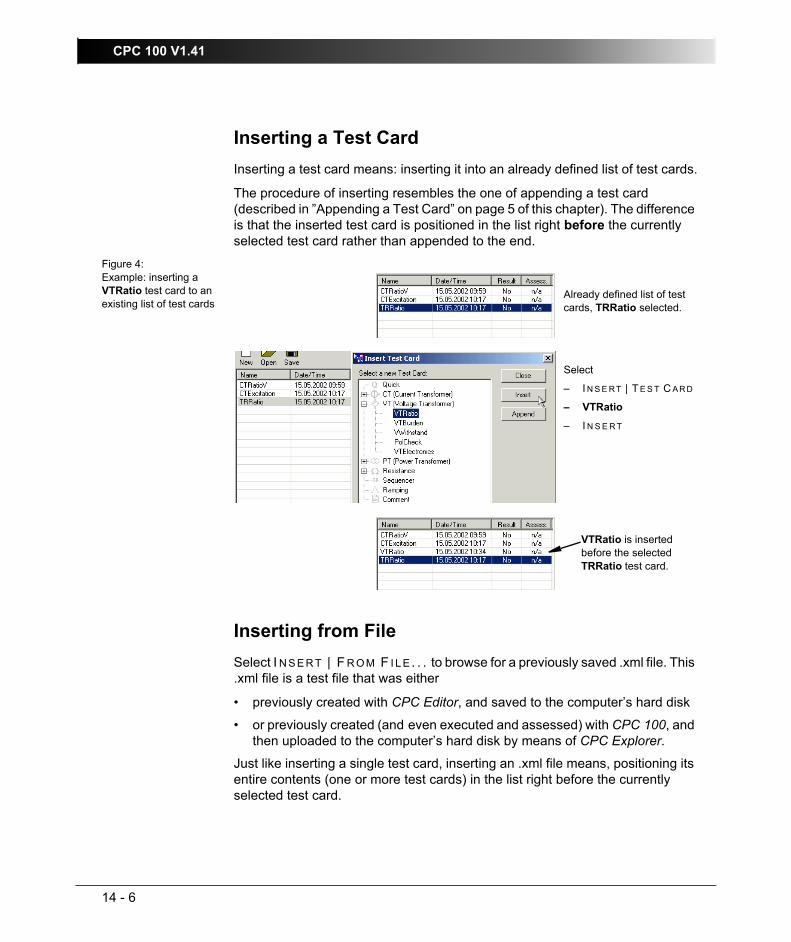
CPC 100 V1.41
14 - 6
Inserting a Test CardInserting a test card means: inserting it into an already defined list of test cards.
The procedure of inserting resembles the one of appending a test card (described in ”Appending a Test Card” on page 5 of this chapter). The difference is that the inserted test card is positioned in the list right before the currently selected test card rather than appended to the end.
Figure 4:Example: inserting a VTRatio test card to an existing list of test cards
Inserting from FileSelect I N S E R T | F R O M F I L E . . . to browse for a previously saved .xml file. This .xml file is a test file that was either
• previously created with CPC Editor, and saved to the computer’s hard disk
• or previously created (and even executed and assessed) with CPC 100, and then uploaded to the computer’s hard disk by means of CPC Explorer.
Just like inserting a single test card, inserting an .xml file means, positioning its entire contents (one or more test cards) in the list right before the currently selected test card.
Already defined list of test cards, TRRatio selected.
Select
– I N S E RT | T E S T C AR D
– VTRatio
– I N S E R T
VTRatio is inserted before the selected TRRatio test card.

CPC Editor
14 - 7
Copying a Test CardIn most cases, it is easier to copy/paste an existing and already parametrized test card, and to rename it accordingly, than to start a new one from the beginning.
To copy a test card either
– right-click the list view pane to open the shortcut menu and click C O P Y
– or select E D I T | C O P Y.
This copies the selected test card to the Clipboard.
You now have three choices.
1. Insert the test card from the Clipboard into your list view:– either right-click the list view pane to open the shortcut menu and click
I N S E R T C O P I E D T E S T C A R D. . .
– or select I N S E R T | C O P I E D T E S T C A R D. . . .
Note that the inserted test card is positioned in the list right before the currently selected test card.
2. Paste the test card from the Clipboard into the list view overwriting a test card of your choice:– either right-click the list view pane to open the shortcut menu and click
P A S T E
– or select E D I T | P A S T E
Note that the selected test card is overwritten by the one pasted from the Clipboard.
3. Paste the test card from the Clipboard into the list view of another running instance of CPC Editor:change to the other running instance of CPC Editor, or start CPC Editor once more and
– insert the test card either via the shortcut menu item I N S E R T C O P I E D T E S T C A R D. . . or the pull-down menu item I N S E R T C O P I E D T E S T C A R D. . .
– or overwrite the selected test card with the test card from the Clipboard either via the shortcut menu item P A S T E or the pull-down menu item E D I T | P A S T E .

CPC 100 V1.41
14 - 8
Renaming a Test CardTo rename the currently selected test card to any new name of your choice
– either right-click the list view pane to open the shortcut menu and click R E N A M E
– or select T E S T C A R D | R E N A M E
Enter the name of our choice (256 characters max.) and press E N T E R.
Saving a TestClick the S A V E icon or select F I L E | S A V E with the "Save as type:" option "CPC files (*.xml)" to save the currently open test, that is, the test card(s) listed in the list view with all of their settings, under its actual name.
If this test does not have a name yet, the Save As dialog box opens. Browse to the destination folder of your choice, and name your test accordingly.
Saving a Test as TemplateUsing the F I L E | S A V E A S . . . command with the "Save as type:" option "CPC templates (*.xmt)", any test file can be saved as a test procedure template, that is, a user-defined template containing one or more test cards with all of their specific test settings but without test results.
To learn more about templates in general, please refer to ”Creating Defaults and Templates” on page 2-42.
In this process, the settings of the original name.xml file are taken over to the newly created test procedure template name.xmt. Possible test results in the name.xml file, however, are not taken over. The original file name.xml remains unchanged.
The template is then uploaded to CPC 100 using CPC Explorer.
Note: The file name extension .xml is appended automatically. Do not enter any other file name extension as the F I L E O P E N command will then not show this file anymore.
Note: The file name extension .xmt is appended automatically. Do not enter any other file name extension as CPC 100 will not recognize it as valid template.

CPC Editor
14 - 9
Deleting a Test CardTo delete a test card from a test or a test procedure template
– either right-click the list view pane to open the shortcut menu and click D E L E T E
– or select E D I T | D E L E T E
Note: To delete an entire test or template, that is, an .xml or .xmt file, from your computer, use Windows Explorer.

CPC 100 V1.41
14 - 10
Preparing a Test Offline with a PC Outline of a typical proceeding for an offline test preparation with a PC using CPC Explorer and CPC Editor.
– Start CPC Explorer.
– Use CPC Explorer’s shortcut menu item N E W F O L D E R to create a folder for the new test on your local hard disk. Name the folder accordingly, for example, CPC Tests.
If this new folder is to be situated at the drive’s root, for example, right underneath C:\, use Windows Explorer to create it. CPC Explorer does not create folders right underneath the root level.
– Right-click on that newly created folder, here: C:\CPC Tests, and use the shortcut menu item N E W F O L D E R to create subfolders in a tree structure that corresponds with the substation:
Figure 5:Representation of the substation "Sulz" with its two 3-phase feeders "Klaus" and "Roethis" in a folder tree structure
– Start CPC Editor
– Set up the required test card(s) for this substation, compose your entire test, and eventually save the test in the appropriate folder that you created with CPC Explorer.
– If single test cards or entire tests are similar or even identical, use CPC Explorer’s and/or CPC Editor’s copy/paste functionality, rather than creating new tests from the beginning.

CPC Editor
14 - 11
For example:
Right-clicking a test file in CPC Explorer on your computer’s hard disk and selecting the shortcut menu command E D I T . . . automatically starts CPC Editor, loads the file and lets you edit it.
– Once all tests are composed, use CPC Explorer’s upload function to transfer the entire tree structure from your PC to CPC 100 at once.
In CPC Explorer, single test cards or even the entire structure with all subfolders and test files from Feeder Klaus\L1 can be copied to Feeder Klaus\L2 and L3. Use the shortcut menu commands C O P Y and P A S T E .
Afterwards, the test files in Feeder Klaus\L2 and L3. can be renamed accordingly in CPC Explorer (shortcut menu command R E N A M E) .

CPC 100 V1.41
14 - 12

Excel CPC 100 File Loader
15 - 1
Excel CPC 100 File LoaderContents of this section
General ......................................................................................... page 15-1
Installation of the Excel CPC 100 File Loader Software ............... page 15-1
Computer Requirements.......................................................... page 15-1
Installing Excel CPC 100 File Loader ...................................... page 15-1
Working with Excel CPC 100 File Loader ..................................... page 15-2
Template Usage............................................................................ page 15-3
GeneralExcel CPC 100 File Loader allows loading XML files into Microsoft Excel templates for post processing. Excel CPC 100 File Loader is installed with CPC Explorer. After the installation, a shortcut to start Excel CPC 100 File Loader appears on your desktop.
Installation of the Excel CPC 100 File Loader SoftwareThe Excel CPC 100 File Loader software and its installation program Setup Wizard are included on the CPC Explorer CD-ROM shipped with your CPC 100.
Computer RequirementsFor the installation requirements, see ”Computer Requirements” on page 13-2.
Installing Excel CPC 100 File LoaderFor the installation procedure, see ”Installing CPC Explorer” on page 13-3.

CPC 100 V1.41
15 - 2
Working with Excel CPC 100 File LoaderExcel CPC 100 File Loader allows loading XML files generated with CPC 100 into Microsoft Excel templates for post processing. Every test card within an XML file is represented by a sheet of a Microsoft Excel workbook. You can load new XML files into the Microsoft Excel template by generating all sheets or by loading data into existing sheets of the workbook. The mapping between the data in the file and in the sheets is done by using the same name for the CPC 100 test card and the corresponding sheet.
Note: Due to the mapping of the data, use unique name for the test cards in the XML files.
Because the results are converted into Microsoft Excel compatible numbers, post processing of the data is straightforward. In a blank customer sheet, you can reference to the data in the sheets designed by OMICRON electronics using Microsoft Excel formulas. Then, if the data in the OMICRON sheets is updated, the customer sheet is updated, too. By this means, special forms for post processing of the data, the so-called templates, can be created easily.

Excel CPC 100 File Loader
15 - 3
Template UsageTemplates are pairs of XML documents and Microsoft Excel templates designed by OMICRON electronics or end users for designated applications. The XML templates are predefined test procedures, often with comments, that run on CPC 100 and guide the user through the test. Once completed, the XML file is saved, downloaded to the PC using CPC Explorer and then loaded with CPC100 File Loader into the corresponding Microsoft Excel template. There the results are post processed and a final test report is generated. The template pairs facilitate and speed testing with CPC 100 and the evaluation of results.
Some template pairs allow version control. If an error message appears after loading the XML template, use a template pair of the same version. The template usage requires the CPC Explorer software to be installed on your PC. CPC Explorer enables you to transfer files (templates and test results) between the PC and CPC 100.
To run a test procedure according to a template:
1. Using CPC Explorer, upload a single XML template or a whole folder of templates for the intended application from the PC to CPC 100.The XML templates (*.xmt files) are available on the CPC Explorer CD-ROM in the Templates directory or in the customer area of www.omicron.at.
2. Open the template on CPC 100.
3. Run the test procedure according to the template.
4. After completing the test procedure, save the test as a new file.
5. Using CPC Explorer, download the test results from CPC 100 to your preferred working directory on the PC.
6. Open the corresponding Microsoft Excel template by double-clicking the *.xlt file in the folder labeled with the test procedure name in the Templates\CPC 100 directory.A Microsoft Excel workbook appears.
7. Click the Load XML-File button and open the *.xml file saved in your preferred working directory before loading the test results.Excel CPC 100 File Loader loads the test results from the XML file to the Microsoft Excel template.
8. After all worksheets are filled with data, the test results are calculated and displayed.

CPC 100 V1.41
15 - 4
Technical Data
16 - 1
Technical DataContents of this section
General ......................................................................................... page 16-2
Power Supply ................................................................................ page 16-4
CPC 100 Outputs .......................................................................... page 16-5
High-Current and High-Voltage Outputs .................................. page 16-5
800A AC output................................................................... page 16-5400A DC output .................................................................. page 16-72kV AC output..................................................................... page 16-8
Outputs on the CPC 100 Front Panel .................................... page 16-15
6A / 130V AC output - all ranges...................................... page 16-156A DC current output ........................................................ page 16-18
Output "Ext. Booster" (option) ................................................ page 16-19
Output to Input Synchronization............................................. page 16-20
CPC 100 Inputs........................................................................... page 16-21
BIN IN Binary Input ................................................................ page 16-21
10A IAC/DC Input .................................................................. page 16-22
300V V1 AC Input .................................................................. page 16-23
3V V2 AC Input ...................................................................... page 16-25
10V V DC Input ...................................................................... page 16-27
CPC 100 Combined Specifications ............................................. page 16-28
ePC Interfaces ............................................................................ page 16-29
PC and Network Interfaces (CPC 100 V0 only) ..................... page 16-29
USB Interface (CPC 100 V1 only).......................................... page 16-29
Network Interface (CPC 100 V1 only) .................................... page 16-29
Serial Interface Connector ..................................................... page 16-30
Connector for External Safety Functions ............................... page 16-31
Environmental Conditions ........................................................... page 16-32
Weight and Dimensions .............................................................. page 16-33
Weight and Dimensions .............................................................. page 16-33

CPC 100 V1.41
16 - 2
General• In the following tables, all guaranteed input data are specified for an ambient
temperature of 23°C ± 5°, a power supply of 230V AC, and after a warm-up time greater than 25min.
• All guaranteed output data are valid for the period of one year after factory adjustment.
• The error values of each measurement range (listed under "Accuracy" in the following tables) are specified in
To obtain the exact measurement error, multiply the displayed measured value with the given reading error (rd), and add the full scale value multiplied with the given full scale error (fs).
Example: – CPC 100 is set to the 800A AC range.
– The display shows a measured value of 720A at I Out.
– The guaranteed error is specified as 0.2% (rd) + 0.2% (fs).
– Therefore, the error is 720A x 0.2% (rd) + 800A x 0.2% (fs)= 1.44A + 1.6A = 3.04A.
• The listed value of the typical maximum output time "typical time tmax" applies
– at the high-current 800A AC and 400A DC outputs to a load consisting of 2x6m cables
– at the other outputs to the respective typical output power.
% of the reading (rd) + % of full scale (fs)
Note: All guaranteed specifications refer to standard AC or DC measurements. Other measurements, such as frequency-selective measurements, or measurements after a numeric integrator (like used with the CT-Rogowski test card) can have slightly higher errors.
Note: Never connect the 2kV output to any of the inputs! The 2kV output is measured internally.
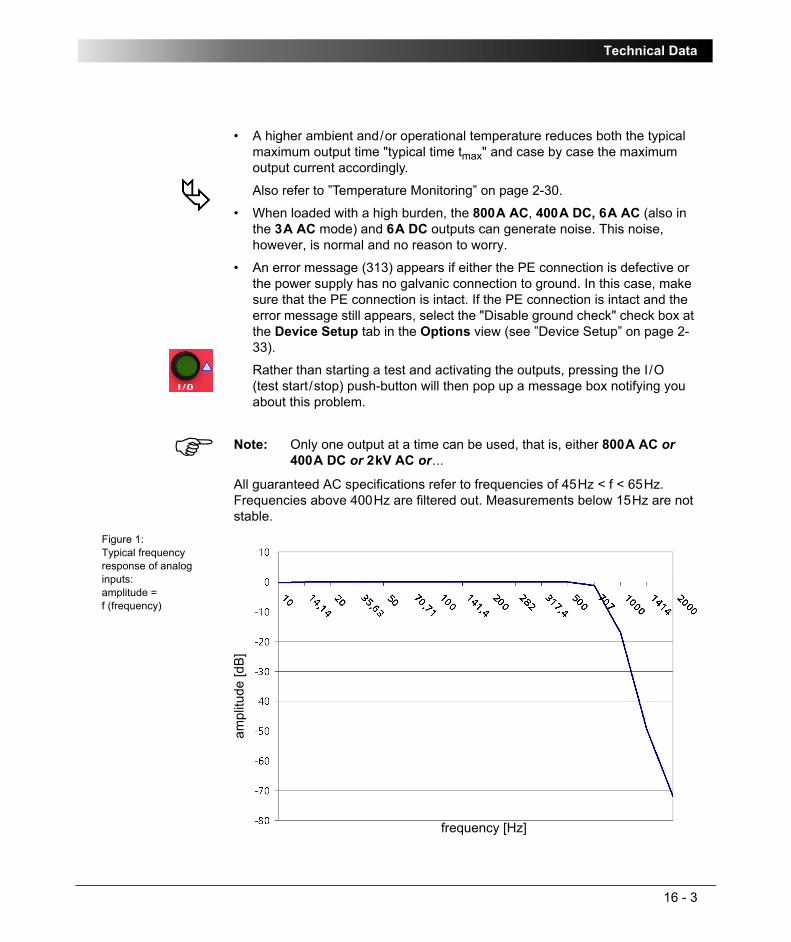
Technical Data
16 - 3
• A higher ambient and/or operational temperature reduces both the typical maximum output time "typical time tmax" and case by case the maximum output current accordingly.
Also refer to ”Temperature Monitoring” on page 2-30.
• When loaded with a high burden, the 800A AC, 400A DC, 6A AC (also in the 3A AC mode) and 6A DC outputs can generate noise. This noise, however, is normal and no reason to worry.
• An error message (313) appears if either the PE connection is defective or the power supply has no galvanic connection to ground. In this case, make sure that the PE connection is intact. If the PE connection is intact and the error message still appears, select the "Disable ground check" check box at the Device Setup tab in the Options view (see ”Device Setup” on page 2-33).
Rather than starting a test and activating the outputs, pressing the I/O (test start/stop) push-button will then pop up a message box notifying you about this problem.
All guaranteed AC specifications refer to frequencies of 45Hz < f < 65Hz. Frequencies above 400Hz are filtered out. Measurements below 15Hz are not stable.
Figure 1:Typical frequency response of analog inputs:amplitude = f (frequency)
Note: Only one output at a time can be used, that is, either 800A AC or 400A DC or 2kV AC or...
ampl
itude
[dB
]
frequency [Hz]

CPC 100 V1.41
16 - 4
Power SupplyImportant: for safety-relevant issues regarding CPC 100 power supply, also refer to ”Power Supply” on page 1-6.
Table 1:Main power supply technical data Main Power Supply
Connection AC voltage, 1 phase, connector IEC320/C20Voltage single phase
– nominal voltage
– permitted range
100 ... 240V AC
85 ... 264V ACPower fuse Automatic circuit breaker with magnetic overcurrent
tripping at I > 16APower consumption < 3500VA
< 7000VA short-term (< 10s)Frequency
– nominal frequency
– permitted range
50 / 60Hz
45 ... 65Hz
Note: If the power supply is ≤ 190V AC, CPC 100 cannot provide the full output power at the 800A AC output. The same applies when an external booster is used. Therefore, in order to gain the full output power, provide a sufficient power supply (190V ... 240V AC).

Technical Data
16 - 5
CPC 100 OutputsImportant: Due to safety-relevant issues regarding CPC 100 high-current and high-voltage outputs, also read ”High-voltage and high-current outputs” on page 1-9.
High-Current and High-Voltage OutputsThe high-current and high-voltage outputs are all situated at the left-hand side of CPC 100.
800A AC outputWhile using the 800A AC output, disconnect any cables that may be plugged in to the 400A DC output. These outputs are internally connected.
Table 2:800A AC output technical data 800A AC output
Connection 10mm connectorsInsulation Internally connected to the 400A DC output, insulated
against all other inputs and outputs.
Voltage with reference to earth must not exceed 300Vrms and 420Vpeak on either socket.
Reinforced insulation against mains power supply, all interfaces and other safety low-voltage circuits.
Output power at: typical app. power Smax
typical time tmax
duty cycle ton / toff
frequency
800A
600A
400A
300A
200A
4800VA
3780VA
2560VA
1940VA
1300VA
25s
200s
500s
15min
> 2hrs
5s / 55s
5s / 25s
5s / 5s
10s / 5s
cont. ON
50 ... 60Hz

CPC 100 V1.41
16 - 6
Figure 2:Typical maximum output voltage of 800A AC output depending on frequency and current
Measurement Internal precision current measurement from 0 ... 800A ACAbs. max. rating:
limited through output
Accuracy: typ. error < ± 0.1% (rd) ± 0.1% (fs),guaranteed < ± 0.2% (rd) ± 0.2% (fs)Possible crest factor: < 1.5
Phase tolerance at full scale:
typ. error < ± 0.1°,guaranteed < ± 0.2°
Resolution: Measurement Display100 mA/bit 10 mA
Connection: internally connected
800A AC output
Note: The signal for the 800A AC output is generated by an internal transformer. To avoid saturation, sudden magnitude changes are suppressed and the signal is output as a ramp. For several applications the magnitude change is deferred even more, for example, for CT ratio measurements.
The ramp changes for a full magnitude are
• one period of the signal, regardless of the size of the change for an increase ramp
• 300ms for a decreasing ramp, or accordingly less if the magnitude change is only a fraction of its full value.
volta
ge in
Vrm
s
frequency in Hz

Technical Data
16 - 7
400A DC outputWhile using the 400A DC output, disconnect any cables that may be plugged in to the 800A AC output. These outputs are internally connected.
Table 3:400A DC output technical data 400A DC output
Connection 10mm connectors Insulation Internally connected to the 800A AC output, insulated
against all other inputs and outputs.
Voltage with reference to earth must not exceed 300Vrms and 420Vpeak on either socket.
Reinforced insulation against mains power supply, all interfaces and other safety low-voltage circuits.
Output power at: typ. power Pmax typical time tmax
400A
300A
200A
100A
2600W
1950W
1300W
630W
140s
3min
> 2hrs
>> 2hrsMeasurement Internal precision current measurement from
0 ... 400A DCAbs. max. rating: limited through outputAccuracy: typ. error < ± 0.2% (rd) ± 0.05% (fs),
guaranteed < ± 0.4% (rd) ± 0.1%(fs)Resolution: Measurement Display
100 mA/bit 10 mAConnection: internally connected

CPC 100 V1.41
16 - 8
2kV AC outputWhile using the 2kV AC output, disconnect any cables that may be plugged in to any of the high-current outputs (800A AC or 400A DC).
Table 4:Technical data of 2kV AC output - all ranges
Table 5:Technical data of 2kV AC output at a voltage range of 2000V
2kV AC output - all rangesConnection High-voltage socketsInsulation Insulated against all other inputs and outputs.
Voltage with reference to earth must not exceed 2000Vrms and 2800Vpeak on either socket.
Reinforced insulation against mains power supply, all interfaces and other safety low-voltage circuits.
Measurement Internal precision current and voltage measurement, integrated in CPC 100 (for details, see tables below).Abs. max. rating: limited through outputConnection: internally connected
2kV AC output at a voltage range of 2000VMaximum current Peak current Ipeak < 3.0A
Effective current Irms < 1.25A
Output power at: typical apparent power Smax
typical time tmax frequency
2000V / 1.25A
2000V / 1A
2000V / 0.5A
2500VA
2000VA
1000VA
60s
130s
> 2hrs
50…200Hz
50...200Hz
50...400Hz

Technical Data
16 - 9
Measurement
Voltage
Voltage and currentRange: 0 ... 2000V ACAccuracy: typ. error <± 0.05%(rd) ± 0.05%(fs),
guaranteed <± 0.1% (rd) ± 0.1% (fs)
Possible crest factor: < 1.5Phase tolerance at full scale:
typ. error < ± 0.1°,guaranteed < ± 0.2°
Resolution: Measurement Display100 mV/bit 10 mV
Current Ranges (automatic range selection):
0 ... 5A AC0 ... 500mA AC0 ... 50mA AC1
Accuracy: 5A: typ. error< ± 0.2% (rd) ± 0.05% (fs),guaranteed< ± 0.4% (rd) ± 0.1% (fs)
500mA:typ. error< ± 0.05% (rd) ± 0.05% (fs),guaranteed< ± 0.1% (rd) ± 0.1% (fs)
50mA1: typ. error< ± 0.1% (rd) ± 0.1% (fs),guaranteed< ± 0.2% (rd) ± 0.2% (fs)
Possible peak value: ± 20AResolution: Measurement Display
5A: 1 mA/bit500mA: 100 μA/bit
50mA1: 10 μA/bit 1 μA
Phase tolerance at full scale:
typ. error < ± 0.1°,guaranteed < ± 0.2°
1. Available for the CPC 100 serial number Dxxxxx and higher.
2kV AC output at a voltage range of 2000V

CPC 100 V1.41
16 - 10
Table 6:Technical data of 2kV AC output at a voltage range of 1000V 2kV AC output at a voltage range of 1000V
Maximum current Peak current Ipeak < 6.0A
Effective current Irms < 2.5A
Output power at: typical apparent power Smax
typical time tmax frequency
1000V / 2.5A
1000V / 2A
1000V / 1A
2500VA
2000VA
1000VA
60s
130s
> 2hrs
50…200Hz
50...200Hz
50...400HzMeasurement
Voltage
Voltage and currentRange: 0 ... 1000V ACAccuracy: typ. error <± 0.05%(rd) ± 0.05%(fs),
guaranteed <± 0.1% (rd) ± 0.1% (fs)
Possible crest factor: < 1.5Phase tolerance at full scale:
typ. error < ± 0.15°,guaranteed < ± 0.3°

Technical Data
16 - 11
Current Ranges (automatic range selection):
0 ... 5A AC0 ... 500mA AC0 ... 50mA AC1
Accuracy: 5A: typ. error< ± 0.2% (rd) ± 0.05% (fs),guaranteed< ± 0.4% (rd) ± 0.1% (fs)
500mA:typ. error< ± 0.05% (rd) ± 0.05% (fs),guaranteed< ± 0.1% (rd) ± 0.1% (fs)
50mA1: typ. error< ± 0.1% (rd) ± 0.1% (fs),guaranteed< ± 0.2% (rd) ± 0.2% (fs)
Possible peak value: ± 20AResolution: Measurement Display
5A: 1 mA/bit500mA: 100 μA/bit
50mA1: 10 μA/bit 1 μA
Phase tolerance at full scale:
typ. error < ± 0.1°,guaranteed < ± 0.2°
1. Available for the CPC 100 serial number Dxxxxx and higher.
2kV AC output at a voltage range of 1000V

CPC 100 V1.41
16 - 12
Table 7:Technical data of 2kV AC output at a voltage range of 500V 2kV AC output at a voltage range of 500V
Maximum current Peak current Ipeak < 12.0A
Effective current Irms < 5.0A
Output power at: typical apparent power Smax
typical time tmax frequency
500V / 5A
500V / 4A
500V / 2A
2500VA
2000VA
1000VA
60s
130s
> 2hrs
50…200Hz
50...200Hz
50...400HzMeasurement
Voltage
Voltage and currentRange: 0 ... 500V ACAccuracy: typ. error <± 0.05%(rd) ± 0.05%(fs),
guaranteed <± 0.1% (rd) ± 0.1% (fs)
Possible crest factor: < 1.5Phase tolerance at full scale:
typ. error < ± 0.2°,guaranteed < ± 0.4°

Technical Data
16 - 13
Current Ranges (automatic range selection):
0 ... 5A AC0 ... 500mA AC0 ... 50mA AC1
Accuracy: 5A: typ. error< ± 0.2% (rd) ± 0.05% (fs),guaranteed< ± 0.4% (rd) ± 0.1% (fs)
500mA:typ. error< ± 0.05% (rd) ± 0.05% (fs),guaranteed< ± 0.1% (rd) ± 0.1% (fs)
50mA1: typ. error< ± 0.1% (rd) ± 0.1% (fs),guaranteed< ± 0.2% (rd) ± 0.2% (fs)
Possible peak value: ± 20AResolution: Measurement Display
5A: 1 mA/bit500mA: 100 μA/bit
50mA1: 10 μA/bit 1 μA
Phase tolerance at full scale:
typ. error < ± 0.1°,guaranteed < ± 0.2°
1. Available for the CPC 100 serial number Dxxxxx and higher.
2kV AC output at a voltage range of 500V

CPC 100 V1.41
16 - 14
Figure 3:Typical maximum output voltage of 2kV AC output depending on frequency and power
Note: The 2kV AC output signal is generated by an internal transformer. To avoid saturation, sudden magnitude changes are suppressed. The signal is output as a ramp. For several applications the magnitude change is deferred even more, for example, for Voltage Withstand to avoid stress of the device under test.
The fastest possible ramp changes for a full magnitude are
• 1200ms for an increasing ramp
• 300ms for a decreasing ramp.
The ramps need accordingly less if the magnitude change is only a fraction of its full value.
The 2kV AC output is electronically controlled to provide the nominal voltage. Consequently, the output impedance is of no importance.
volta
ge in
% o
f ful
l sca
le
frequency in Hz

Technical Data
16 - 15
Outputs on the CPC 100 Front Panel
6A / 130V AC output While using the 6A / 130V AC output, disconnect any cables that may be plugged in to any of the high-current outputs (800A AC or 400A DC), or to the 6A DC output.
Table 8:Technical data of 6A / 130V AC output - all ranges
Note: The outputs of the CPC 100 front panel are not controlled.
Furthermore, there is no internal measurement provided. To measure a front panel output signal, connect it to a measuring input:
• current measurement: to IAC/DC input
• voltage measurement: to V1AC or VDC input
6A / 130V AC output - all rangesConnection 4mm banana sockets Insulation The 6A/130V AC output is internally connected with
the 6A DC output. Apart from this, the output is insulated against all other inputs and outputs.
Voltage with reference to earth must not exceed 200Vrms and 280V peak on either socket.
Reinforced insulation against mains power supply, all interfaces and other safety low-voltage circuits.
Measurement No internal measurement provided. To measure this output signal, connect it to a measuring input:
current measurement: at IAC/DC input
voltage measurement: at V1AC input

CPC 100 V1.41
16 - 16
Table 9:Technical data of 6A / 130V AC output in 130V AC mode
Figure 4:Typical maximum output voltage of 6A / 130VAC output in 130V AC mode depending on frequency
6A / 130V AC output in 130V AC modeOutput power at: typical apparent
power Smax
typical time tmax frequency
130V 390VA > 2hrs 50 ... 400HzFuses Type: 3.15A T
The 3.15 Amps slow-acting wire fuse 5x20mm, situated at the front panel’s AC OUTPUT group, protects the AC OUTPUT in 130V voltage mode.
6.3A TIf the 6.3 Amps fuse is blown, the 130V AC output mode does not work either.
Note: The 130V AC output has a setting range of 150V. The set voltage represents the no-load voltage, that is, when a load is connected, the voltage at the 130V output will reduce by approx. 5V / A.
volta
ge V
rms
frequency in Hz

Technical Data
16 - 17
Table 10:Technical data of 6A / 130V AC output in 6A AC mode
Table 11:Technical data of 6A / 130V AC output in 3A AC mode
Figure 5:Typical maximum output voltage of 6A / 130V AC output in 3 and 6A AC mode depending on frequency and current
6A / 130V AC output in 6A AC modeOutput power at: typical apparent
power Smax
typical time tmax frequency
6.0A 330VA > 2hrs 50 ... 200HzFuse Type: 6.3A T
The 6.3 Amps slow-acting wire fuse 5x20mm, situated at the front panel’s AC OUTPUT group, protects the AC OUTPUT in 6A AC and 3A current mode and the DC OUTPUT
6A / 130V AC output in 3A AC modeOutput power at: typical apparent
power Smax
typical time tmax frequency
3.0A 330VA > 2hrs 50 ... 200HzFuse Type: 3.15A T
The 3.15 Amps slow-acting wire fuse 5x20mm, situated at the front panel’s AC OUTPUT group, protects the AC OUTPUT in 3A current mode.
6.3A TIf the 6.3 Amps fuse is blown, the 3A AC output mode does not work either.
volta
ge V
rms
frequency in Hz

CPC 100 V1.41
16 - 18
6A DC current outputWhile using the 6A DC output, disconnect any cables that may be plugged in to any of the high-current outputs (800A AC or 400A DC), or to the 6A / 130V AC output.
Table 12:6A DC output technical data 6A DC output
Connection 4mm banana sockets Insulation The 6A DC output is internally connected with the
6A / 130V AC output. Apart from this, the output is insulated against all other inputs and outputs.
Voltage with reference to earth must not exceed 200Vrms and 280V peak on either socket.
Reinforced insulation against mains power supply, all interfaces and other safety low-voltage circuits.
Protection If a large inductance is connected, and the output is switched off, an internal arc-suppression diode protects the user from voltage spikes from the inductance.
Additionally, a surge arrester with a short circuit spring that, in case of an overload, applies a short circuit to the output and protects the user if the arc-suppression should not be sufficient.
The existence of a discharge voltage potential is also indicated by a lit LED - even if CPC 100 is switched off. This LED is situated at the right-hand side of the 6A DC output sockets.
Current / voltage measurement
No internal measurement provided. To measure this output signal, connect it to a measuring input:
current measurement: at IAC/DC input
voltage measurement: at VDC inputOutput power at: typical power
Pmax
typical time tmax
6.0A
3.0A
360W
180W
> 2hrs
>> 2hrs

Technical Data
16 - 19
Output "Ext. Booster" (option)The output "Ext. Booster" does not have own specifications. They are determined by the device connected to this output, for example, by the current booster CPCB2.
For more information about boosters, please refer to ”Accessories” in chapter 17.
Fuse Type: 6.3A T The 6.3 Amps slow-acting wire fuse 5x20mm, situated at the front panel’s AC OUTPUT group, protects both the AC OUTPUT in 3A and 6A current mode and the DC OUTPUT
Note 1: If a test object with a large inductance is connected to CPC 100, earth both ends of the test object before you disconnect it from CPC 100.
Note 2: Do not connect a large inductance to this output in any other test card but RWinding (winding resistance) and TRTapCheck (tap changer winding resistance and on-load tap changer interruption check).
Unlike other test cards, RWinding and TRTapCheck provide special additional safety functions.
Note: The connector "Ext. Booster" is always galvanically connected to mains, regardless whether or not an external booster is selected on the software tab Options | Device Setup, the green warning light (0) is on, the outputs are turned off or the Emergency Stop button is pressed.
Handle with extreme caution!
6A DC output

CPC 100 V1.41
16 - 20
Output to Input SynchronizationThe feature S Y N C H W/ V 1 A C synchronizes the output frequency with the V1AC input frequency (refer to ”Sync w/ V1AC” on page 3-10).
The Amplifier test card provides the possibility to synchronize to various inputs.
CPC 100 filters the input signals, therefore, if mains is connected to, for example, the V1 AC input, possible signal interferences and / or noise do not affect the synchronization considerably. The ground wave of the input signal serves as reference for the synchronization.
Table 13:Output to input synchronization
How long does the synchronization take?Example for the 2kV AC output in Quick:
As explained on page 14 of this chapter, the 2kV AC output needs 1200ms to ramp up to its full magnitude, and accordingly less for a smaller magnitude.
Total synchronization time = time to reach 5% of full magnitude + settling time.
• The output ramps linear, therefore reaches 5% of its full magnitude after 5% of 1200ms = 60ms
• Then the 100ms settling time elapses
• Therefore, the entire synchronization lasts 60ms + 100ms = 160ms.
Test cards Quick, Sequencer
Test card Amplifier
Frequency Range 48 ... 62HzSynchronization inputs V1AC
(automatic range switching)
V1AC, V2AC, IAC(fixed to maximum range)
Input magnitude 10% of input range full scaleOutput magnitude 5% of output range full scaleSettling time 100ms after 5% of
output magnitude is reached
1000ms after 5% of output magnitude is reached
Signal changes All quantities must be ramped within 20 signal periods
No changes of frequency and phase. Magnitude changes without limitation. Output follows within 250ms.
Phase tolerance 0.5° within the limits as specified above
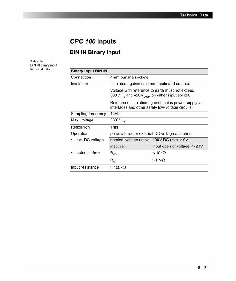
Technical Data
16 - 21
CPC 100 InputsBIN IN Binary Input
Table 14:BIN IN binary input technical data Binary input BIN IN
Connection 4mm banana socketsInsulation Insulated against all other inputs and outputs.
Voltage with reference to earth must not exceed 300Vrms and 420Vpeak on either input socket.
Reinforced insulation against mains power supply, all interfaces and other safety low-voltage circuits.
Sampling frequency 1kHzMax. voltage 330Vrms
Resolution 1msOperation potential-free or external DC voltage operation• ext. DC voltage nominal voltage active: 100V DC (min. > 0V)
inactive: input open or voltage < -20V• potential-free Ron < 10kΩ
Roff > 1MΩ
Input resistance > 100kΩ

CPC 100 V1.41
16 - 22
10A IAC/DC Input
Table 15:10A AC/DC input technical data
Note: Do not connect the 2kV output to this input! The 2kV output is measured internally.
10A IAC/DC inputConnection 4mm banana sockets Measurement ranges (autoranging)
0 ... 10A
0 ... 1AInsulation Insulated against all other inputs and outputs.
Voltage with reference to earth must not exceed 270Vrms and 380Vpeak on either input socket.
Reinforced insulation against mains power supply, all interfaces and other safety low-voltage circuits.
Protection The 10A IAC/DC current input is fuse-protected (see below). For measuring currents on high inductances, the input is protected before the fuse.
This is done by an internal surge arrester with a short circuit spring that, in case of an overload, applies a short circuit to the output, and protects the user in case the fuse is blown, and a current is still forced through the input with a high voltage.
Maximum current 11Arms
Accuracy• AC operation
(autoranging)10A: typ. error < ± 0.05% (rd) ± 0.05% (fs),
guaranteed < ± 0.1% (rd) ± 0.1% (fs)1A: typ. error < ± 0.05% (rd) ± 0.05% (fs),
guaranteed < ± 0.1 % (rd) ± 0.1% (fs)Possible crest factor: < 3.0Phase tolerance at full scale:10A: typ. error < ± 0.1°
guaranteed < ± 0.2°1A: typ. error < ± 0.15°
guaranteed < ± 0.3°
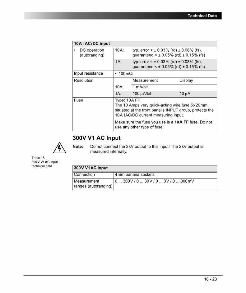
Technical Data
16 - 23
300V V1 AC Input
Table 16:300V V1AC input technical data
• DC operation(autoranging)
10A: typ. error < ± 0.03% (rd) ± 0.08% (fs),guaranteed < ± 0.05% (rd) ± 0.15% (fs)
1A: typ. error < ± 0.03% (rd) ± 0.08% (fs),guaranteed < ± 0.05% (rd) ± 0.15% (fs)
Input resistance < 100mΩResolution Measurement Display
10A: 1 mA/bit1A: 100 μA/bit 10 μA
Fuse Type: 10A FF The 10 Amps very quick-acting wire fuse 5x20mm, situated at the front panel’s INPUT group, protects the 10A IAC/DC current measuring input.
Make sure the fuse you use is a 10A FF fuse. Do not use any other type of fuse!
Note: Do not connect the 2kV output to this input! The 2kV output is measured internally.
10A IAC/DC input
300V V1AC inputConnection 4mm banana socketsMeasurement ranges (autoranging)
0 ... 300V / 0 ... 30V / 0 ... 3V / 0 ... 300mV
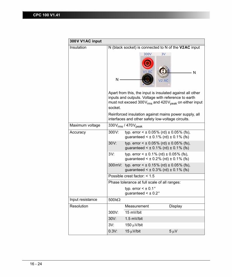
CPC 100 V1.41
16 - 24
Insulation N (black socket) is connected to N of the V2AC input
Apart from this, the input is insulated against all other inputs and outputs. Voltage with reference to earth must not exceed 300Vrms and 420Vpeak on either input socket.
Reinforced insulation against mains power supply, all interfaces and other safety low-voltage circuits.
Maximum voltage 330Vrms / 470Vpeak
Accuracy 300V: typ. error < ± 0.05% (rd) ± 0.05% (fs),guaranteed < ± 0.1% (rd) ± 0.1% (fs)
30V: typ. error < ± 0.05% (rd) ± 0.05% (fs),guaranteed < ± 0.1% (rd) ± 0.1% (fs)
3V: typ. error < ± 0.1% (rd) ± 0.05% (fs),guaranteed < ± 0.2% (rd) ± 0.1% (fs)
300mV: typ. error < ± 0.15% (rd) ± 0.05% (fs),guaranteed < ± 0.3% (rd) ± 0.1% (fs)
Possible crest factor: < 1.5Phase tolerance at full scale of all ranges:
typ. error < ± 0.1°guaranteed < ± 0.2°
Input resistance 500kΩResolution Measurement Display
300V: 15 mV/bit30V: 1.5 mV/bit3V: 150 μV/bit0.3V: 15 μV/bit 5 μV
300V V1AC input
N
N

Technical Data
16 - 25
3V V2 AC InputTable 17:3V V2AC input technical data 3V V2AC input
Connection Odu connector GX1B0C-L020009-00A1Measurement ranges (autoranging)
0 ... 3V / 0 ... 300mV / 0 ... 30mV
Insulation N is connected to N of the V1AC input (black socket).
Apart from this, the input is insulated against all other inputs and outputs. Voltage with reference to earth must not exceed 300Vrms and 420Vpeak on either input socket.Reinforced insulation against mains power supply, all interfaces and other safety low-voltage circuits.
Maximum voltage 10Vrms / 15Vpeak
Accuracy 3V: typ. error < ± 0.03% (rd) ± 0.08% (fs),guaranteed < ± 0.05% (rd) ± 0.15% (fs)
300mV: typ. error < ± 0.08% (rd) ± 0.08% (fs),guaranteed < ± 0.15 % (rd) ± 0.15% (fs)
30mV: typ. error < ± 0.1% (rd) ± 0.25% (fs),guaranteed < ± 0.2% (rd) ± 0.5% (fs)
Possible crest factor: < 1.5Phase tolerance at full scale3V typ. error < ± 0.1°
guaranteed < ± 0.2°300mV typ. error < ± 0.1°
guaranteed < ± 0.2°30mV typ. error < ± 0.15°
guaranteed < ± 0.3°Input resistance 10MΩ
N
N

CPC 100 V1.41
16 - 26
Resolution Measurement Display3V: 150 μV/bit300mV: 30 μV/bit30mV: 3 μV/bit 10 μV
Note: When using the CTRogowski test card, the 3V V2AC input uses an additional software-based integration method.
In the range of 50Hz < f < 60Hz, this results in a phase shift of 90° as well as an additional phase error of +/- 0.1° and an additional amplitude error of +/- 0.01%.
For frequencies in the range of 15Hz < f < 400Hz, the phase error is not specified, and the amplitude error can be up to +/- 0.50% higher.
3V V2AC input

Technical Data
16 - 27
10V V DC InputTable 18:10V VDC input technical data 10V VDC input
Connection 4mm banana socketsMeasurement ranges (autoranging)
0 ... 10V
0 ... 1V
0 ... 100mV
0 ... 10mVInsulation Insulated against all other inputs and outputs.
Voltage with reference to earth must not exceed 140Vrms and 200Vpeak on either input socket.
Reinforced insulation against mains power supply, all interfaces and other safety low-voltage circuits.
Maximum voltage 50Vrms / 75Vpeak
Accuracy 10V: typ. error < ± 0.03% (rd) ± 0.08% (fs),guaranteed < ± 0.05% (rd) ± 0.15% (fs)
1V: typ. error < ± 0.03% (rd) ± 0.08% (fs),guaranteed < ± 0.05% (rd) ± 0.15% (fs)
100mV: typ. error < ± 0.05% (rd) ± 0.1% (fs),guaranteed < ± 0.1% (rd) ± 0.2% (fs)
10mV: typ. error < ± 0.05% (rd) ± 0.15% (fs),guaranteed < ± 0.1% (rd) ± 0.3% (fs)
Input resistance 500kΩResolution Measurement Display
10V: 400 μV/bit1V: 75 μV/bit100mV: 4 μV/bit10mV: 0.4 μV/bit 0.1 μV
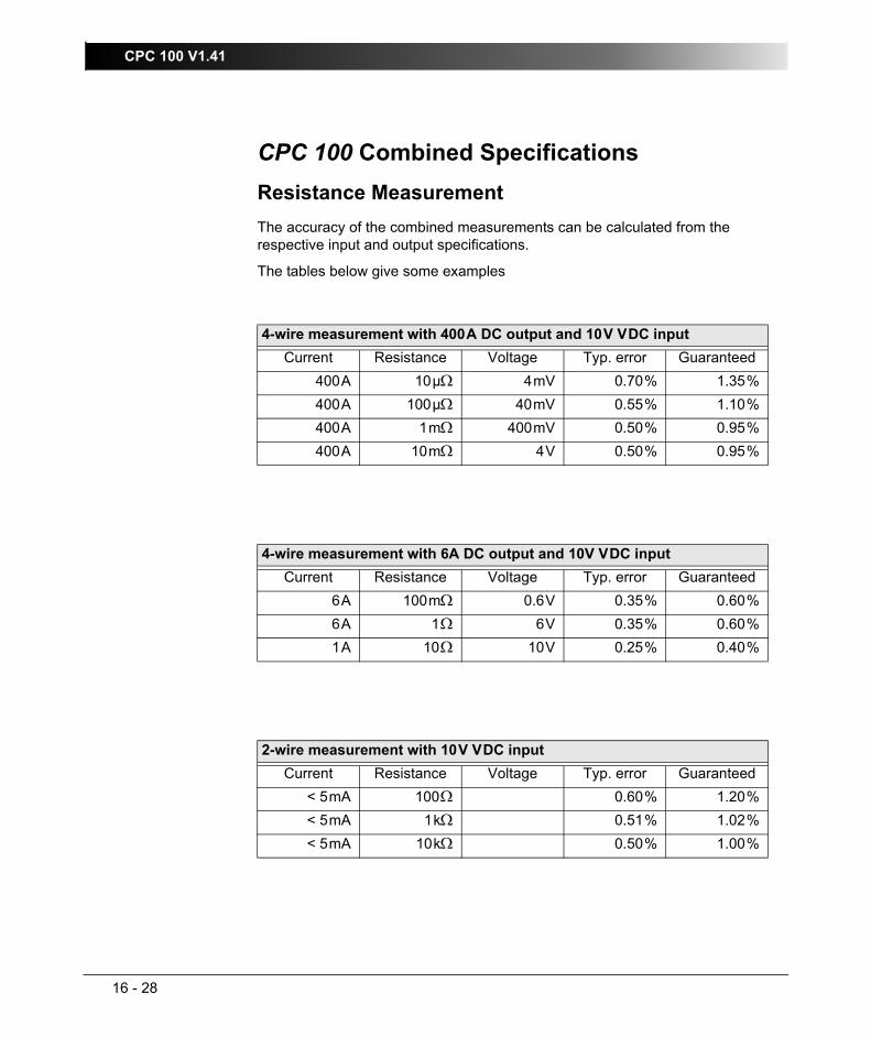
CPC 100 V1.41
16 - 28
CPC 100 Combined SpecificationsResistance MeasurementThe accuracy of the combined measurements can be calculated from the respective input and output specifications.
The tables below give some examples
4-wire measurement with 400A DC output and 10V VDC inputCurrent Resistance Voltage Typ. error Guaranteed
400A 10µΩ 4mV 0.70% 1.35%400A 100µΩ 40mV 0.55% 1.10%400A 1mΩ 400mV 0.50% 0.95%400A 10mΩ 4V 0.50% 0.95%
4-wire measurement with 6A DC output and 10V VDC inputCurrent Resistance Voltage Typ. error Guaranteed
6A 100mΩ 0.6V 0.35% 0.60%6A 1Ω 6V 0.35% 0.60%1A 10Ω 10V 0.25% 0.40%
2-wire measurement with 10V VDC inputCurrent Resistance Voltage Typ. error Guaranteed
< 5mA 100Ω 0.60% 1.20%< 5mA 1kΩ 0.51% 1.02%< 5mA 10kΩ 0.50% 1.00%

Technical Data
16 - 29
ePC InterfacesPC and Network Interfaces (CPC 100 V0 only)CPC 100 V0 supports the 10BaseT (twisted pair) Ethernet (⇒ Glossary) interface for connecting CPC 100 to a PC, a notebook or a network hub. CPC 100 V0 is equipped with two RJ-45 connectors. The connector labeled "PC" connects CPC 100 to a PC or a notebook, and the connector labeled "Network" connects CPC 100 to a network hub. These two connectors differ only in one cross-connection in the "PC" connector.
Network Interface (CPC 100 V1 only)The network connection of CPC 100 V1 is implemented by the 10/100BaseTX (twisted pair) Ethernet interface. CPC 100 V1 is equipped with one RJ-45 connector labeled "Network" for connecting CPC 100 to a PC, a notebook or a network hub.
USB Interface (CPC 100 V1 only)The CPC 100 V1 supports the USB interface for connecting the USB memory stick shipped with the CPC 100. The USB interface is compliant with the Universal Serial Bus (USB) Specification, Revision 1.1 and 2.0.
Note: The full functionality is guaranteed only for the USB memory stick delivered with the CPC 100.
Note: Connect only one RJ-45 connector at a time.
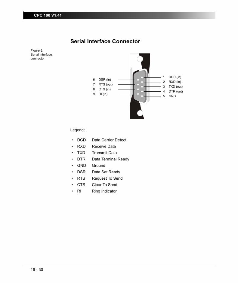
CPC 100 V1.41
16 - 30
Serial Interface ConnectorFigure 6:Serial interface connector
Legend:
• DCD Data Carrier Detect • RXD Receive Data• TXD Transmit Data• DTR Data Terminal Ready• GND Ground• DSR Data Set Ready• RTS Request To Send• CTS Clear To Send• RI Ring Indicator
1 DCD (in)2 RXD (in)3 TXD (out)4 DTR (out)5 GND
6 DSR (in)7 RTS (out)8 CTS (in)9 RI (in)

Technical Data
16 - 31
Connector for External Safety FunctionsFigure 7:Connector for external safety functions - pin assignment
The pins 1 and 2 provide an output of 12.9V / 85.5mA (V1) and 5V / 2.5 (V0).
Figure 8:Connector for external safety functions - wiring scheme
1 warning light green (TTL level)2 warning light red (TTL level)3 start button (n/o)4 common start n/o & em. stop5 emergency stop
ground 6ground 7start button (n/c) 8ground 9
1
9
external Start button (n/c)
external Emergency Stop button
warning lightred
warninglight
greenexternal Start button (n/o)

CPC 100 V1.41
16 - 32
Environmental ConditionsClimate
Table 19:Environmental conditions - climate
Shock and VibrationTable 20:Environmental conditions - shock and vibration
ClimateOperating temperature -10° ... +55°C (+14 ... +131F)Storage and transportation -20° ... +70°C (-4 ... +158F)Humidity 5 ... 95% relative humidity, no condensationDrip-water protection IP22, tested according to EN 60529/A1:2000
(13.2, 13.3, 14.2.2), not operating, upright position, that is, front panel must be horizontal.
IP22 means drip-water protection. Never operate CPC 100 with a wet front panel or wet sockets.
Make sure no water can come in through the ventilation slots.
Note: Since the AC and DC output sockets of CPC 100 can carry life-hazardous voltage potential and provide life-hazardous currents, we strongly advise you not to carry out tests with a wet CPC 100.
Before switching on CPC 100, make sure it is completely dry.
Shock and vibrationVibration • Tested according to IEC68-2-6 (operating
mode)
• Frequency range 10 ... 150Hz
• Acceleration 2g continuous (20 m/s²); 10 cycles per axis
Shock • Tested according to IEC68-2-27 (operating mode)
• 15g / 11ms, half-sinusoid, each axis

Technical Data
16 - 33
Safety Standards, Electromagnetic Compatibility (EMC)
Table 21:Safety Standards and EMC Compatibility
Weight and DimensionsTable 22:Weight and dimensions
CE Conformity, RequirementsThe product adheres to the specifications from the guidelines of the Council of the European Community for meeting the requirements of the member states according to the EMC Directive 2004/108/EC and LVD Directive 2006/95/EC.Electromagnetic CompatibilityEmission
Europe
International
EN 61000-6-4, EN 61000-3-2
IEC 61000-6-4; IEC 61000-6-4
FCC Subpart B of Part 15 Class AImmunity
Europe
International
EN 61000-6-2; EN 61000-4-2/3/4/8
IEC 61000-6-2; IEC 61000-4-2/3/4/8Safety Standards
Europe
International
EN 61010-1
IEC 61010-1Prepared to tests conform to IEEE 510, EN 50191, VDE 104Manufactured under an ISO9001-registered system
Weight and dimensionsWeight 29kg (64lbs), robust case with coverDimensions (w x h x d): 468 x 394 x 233mm (18.6 x 15.5 x 9.2")
(with cover, without handles)

CPC 100 V1.41
16 - 34

Accessories
17 - 1
AccessoriesThis chapter lists test cards that are optionally available to extend the functionality of the CPC 100 packages.
It furthermore describes hardware equipment that is optionally available for the CPC 100 primary test system, and provides ordering information for spare parts.
For information on the CP CU1 coupling unit and the CP TD1 high-precision test system, see the CP CU1 Reference Manual and the CP TD1 Reference Manual respectively on the CPC Explorer CD-ROM.
Contents of this sectionTest Cards..................................................................................... page 17-2
Earth Resistance Accessory Set................................................... page 17-3
Current Booster CP CB2............................................................... page 17-4
Technical Data of CP CB2 ....................................................... page 17-5
Operation Modes of CP CB2 ................................................... page 17-6
Ordering Information for CP CB2............................................. page 17-8
Polarity Checker CPOL ................................................................. page 17-9
Technical Data of CPOL ........................................................ page 17-10
Ordering Information for CPOL .............................................. page 17-10
Changing the Batteries in CPOL............................................ page 17-11
Current Clamp C-Probe 1 ........................................................... page 17-13
Ordering Information for C-Probe 1 ....................................... page 17-13
CP SA1 ....................................................................................... page 17-14
Ordering Information for CP SA1 ........................................... page 17-14
Reference Manual....................................................................... page 17-15
Cables ......................................................................................... page 17-15
Clamps ........................................................................................ page 17-16
Plugs ........................................................................................... page 17-16
Assembly Instructions for Odu MINI-SNAP Plug ................... page 17-17

CPC 100 V1.41
17 - 2
Test CardsTable 1:Ordering information for test cards Ordering information for test cards Article number
CT test cardsScope:
– CT Ratio (and Burden)
– CT Burden
– CT Excitation (Kneepoint)
– CT RatioV
– CT Rogowski (Ratio)
– CT Low Power (Ratio)
– Winding Resistance
– Voltage Withstand (2kV)
VESM0610
VT test cardsScope:
– VT Ratio
– VT Burden
– Voltage Withstand (2kV)
– VT Electronics
VESM0615
Transformer test cardsScope:
– TRRatio (per tap)
– TRTabCheck (for OLTC)
– Winding Resistance
– Voltage Withstand (2kV)
VESM0620
Resistance test cardsScope:
– Contact Resistance (µΩ ... mΩ)
– Winding Resistance (µΩ ... kΩ)
VESM0625

Accessories
17 - 3
Earth Resistance Accessory SetTable 2:Ordering information for the earth resistance accessory set
Earth ResistanceScope:
– software (test card RGround)
– earth resistance accessory set (see below)
VESM0640
CPOL (Polarity Checker)Scope:
Polarity checker CPOL + bag + software
Hardware only1:
Polarity checker CPOL + bag
VESM0645
VEHZ0650
RampingProgrammable ramping generator and determination of thresholds
VESM0630
SequencerFor automatic testing with different states in real time
VESM0635
1. Note: the CPOL hardware cannot be used without the software.
Ordering information for test cards Article number
Ordering information for the earth resistance accessory set
Article number
Earth Resistance accessory set
Consists of:
– 4 electrodes
– cable reel red, 50m
– cable reel black, 100m
VEHZ0660
Note: The earth resistance accessory set is included in "Earth Resistance" VESM0640, and does not work without it.

CPC 100 V1.41
17 - 4
Current Booster CP CB2Figure 1:Current booster CPCB2
CPCB2 is equipped with an over-temperature protection. In case CPCB2 develops an internal temperature that is too high, it shuts off automatically. There is no according on-screen message shown on the CPC 100 monitor.
If such an automatic shut-off occurs, let CPCB2 cool down for about ½ hour.Note 1: During operation, the current booster’s housing as well as the high-
current cables (95mm²) and their clamps can develop a rather high temperature. To prevent burns, use gloves when touching the housing or the cables while in operation or shortly after .
Note 2: The connector "Ext. Booster" is always galvanically connected to mains, regardless whether or not an external booster is selected on the software tab Options | Device Setup, the green warning light (0) is on, the outputs are turned off or the Emergency Stop button is pressed.
Handle with extreme caution!
High-current cable with a plug on one end and a clamp on the other end
Connection cable CPCB2 ⇔ CPC 100
current booster CPCB2

Accessories
17 - 5
Technical Data of CP CB2Table 3:Technical data of CPCB2 - all operating modes
More technical data can be found at ”Operation Modes of CP CB2” on page 6 of this chapter.
Technical Data CPCB2 - all operating modesAccuracy of current at 50/60Hz:
typ. error < ± 0.13% (rd) ± 0.13% (fs),guaranteed < ± 0.25% (rd) ± 0.25% (fs)
Phase tolerance at full scale: typ. error < ± 0.25%guaranteed < ± 0.5%
Weight: 16kg (35.3lbs)Dimensions (w x h x d): 18.6 x 16.6 x 22.0cm (7.3 x 6.5 x 8.7")

CPC 100 V1.41
17 - 6
Operation Modes of CP CB2Figure 2:Current booster CPCB2 in 2000A mode
Table 4:Technical data of current booster CPCB2 in 2000A mode Technical data of CPCB2 in 2000A mode
Connection Input: booster connector to connect the current booster CPCB2 with CPC 100.
Output: both CPCB2 outputs in parallelMeasurement Measurement in CPC 100Output power
at:typ. apparent power Smax
typical time tmax
duty cycleton / toff
frequency
2000A
1800A
1600A
1400A
1200A
1000A
600A
4900VA
4400VA
3950VA
3450VA
2950VA
2500VA
1500VA
25s
3min
5min
10min
18min
30min
> 2hrs
5sec / 55sec
5sec / 40sec
5sec / 30sec
5sec / 25sec
5sec / 15sec
5sec / 9sec
cont. ON
50 ... 60Hz
1500A 3500VA 5min 5sec / 30sec 15 ... 150Hz

Accessories
17 - 7
Figure 3:Current booster CPCB2 in 1000A mode
Table 5:Technical data of current booster CPCB2 in 1000A mode Technical data of CPCB2 in 1000A mode
Connection Input: booster connector to connect the current booster CPCB2 with CPC 100.
Output: both CPCB2 outputs in seriesMeasurement Measurement in CPC 100Output power
at:typ. apparent power Smax
typical time tmax
duty cycleton / toff
frequency
1000A
900A
800A
700A
600A
500A
300A
4900VA
4400VA
3950VA
3450VA
2950VA
2500VA
1500VA
25s
3min
5min
10min
18min
30min
> 2hrs
5sec / 55sec
5sec / 40sec
5sec / 30sec
5sec / 25sec
5sec / 15sec
5sec / 9sec
cont. ON
50 ... 60Hz
750A 3500VA 5min 5sec / 30sec 15 ... 150Hz

CPC 100 V1.41
17 - 8
Ordering Information for CP CB2Table 6:Ordering information for CPCB2 Ordering information for CPCB2 Article number
Current Booster CPCB2
includes the following items:
– high-current cable set:4 x 95mm² (2 x red, 2 x black), length 1.5m, special plug on one end, clamp on the other+1 x 95mm², length 0.6m, special plugs on both ends
VEHZ0630
VEHK0610
– Connection cable CPCB2 ⇔ PC3 x 2.5mm², length 20m
VEHK0611
– Grounding cable (GR/YE)1 x 6mm², length 6m
VEHK0615
– Travel case with wheels (same as CPC 100 travel case but with different inner shell).
VEHP0071

Accessories
17 - 9
Polarity Checker CPOLCPOL checks a series of test points for correct polarity.
More information about how to use CPOL can be found in ”Polarity Check” on page 4-28.
Figure 4:Polarity checker CPOL
Notes: 1. If you detect a wrong polarity in the current path, turn off CPC 100 first, and only then disconnect the terminals.
2. Never operate CPOL with an open battery compartment. A life-hazardous voltage level may occur in the battery compartment if CPOL’s probe touches a test point with high-voltage potential!

CPC 100 V1.41
17 - 10
Technical Data of CPOLTable 7:Technical data CPOL
Ordering Information for CPOLTable 8:Ordering information CPOL
Technical Data CPOLMeasuring range typical: 5mV ... 300V
guaranteed: 50mV ... 300VNominal frequency typical: 52.6Hz
possible: 40 ... 60HzMinimum slope ratio: 25 ... 90% or via pulse widthPower consumption: key pressed: 25mA
key not pressed: 0mAInput impedance: 400 kΩOperating temperature -10° ... +55°C (+14 ... +131F)Storage and transportation -20° ... +70°C (-4 ... +158F)Weight: 250g (0.11lbs) including batteries and bagDimensions (w x h x d): 200 x 45 x 35mm (78.7 x 17.7 x 13.8")Batteries: 4 x 1.5V Micro LR03 AAA AM4 MN2400
Ordering information for CPOL Article numberScope:
Polarity checker CPOL + cover + software
Hardware only1:
Polarity checker CPOL + cover
1. Note: the CPOL hardware cannot be used without the software
VESM0645
VEHZ0650

Accessories
17 - 11
Changing the Batteries in CPOL1. Open the cover of CPOL’s battery compartment using a screwdriver. Make
sure to position the screwdriver in an angled position as shown in the picture below and push it downwards to lift the cap of the battery compartment.
2. Remove the old batteries and dispose of properly.
3. Insert the two lower batteries first (next to the cover’s "—" symbol), and push them all the way in. Make sure you insert them with the "plus pole" going in first, the "minus" pole pointing towards the compartment’s open cover.

CPC 100 V1.41
17 - 12
Then insert the two upper batteries (next to the cover’s "+" symbol), and push them all the way in. Make sure you insert them with the "minus" pole going in first, the "plus" pole pointing towards the compartment’s open cover.
4. Close the battery compartment’s cover tightly until it snaps into position.
5. Press CPOL’s ON push-button. Both polarity LEDs should light up steadily, and the red LED above the product designation CPOL flashes shortly.
☺ +
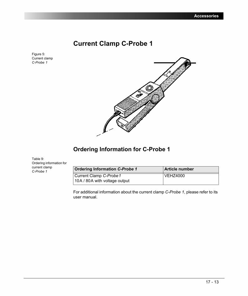
Accessories
17 - 13
Current Clamp C-Probe 1Figure 5:Current clamp C-Probe 1
Ordering Information for C-Probe 1Table 9:Ordering information for current clamp C-Probe 1
For additional information about the current clamp C-Probe 1, please refer to its user manual.
Ordering Information C-Probe 1 Article numberCurrent Clamp C-Probe1 10A / 80A with voltage output
VEHZ4000
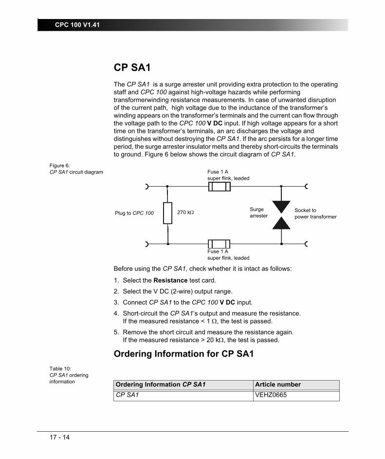
CPC 100 V1.41
17 - 14
CP SA1 The CP SA1 is a surge arrester unit providing extra protection to the operating staff and CPC 100 against high-voltage hazards while performing transformerwinding resistance measurements. In case of unwanted disruption of the current path, high voltage due to the inductance of the transformer’s winding appears on the transformer’s terminals and the current can flow through the voltage path to the CPC 100 V DC input. If high voltage appears for a short time on the transformer’s terminals, an arc discharges the voltage and distinguishes without destroying the CP SA1. If the arc persists for a longer time period, the surge arrester insulator melts and thereby short-circuits the terminals to ground. Figure 6 below shows the circuit diagram of CP SA1.
Figure 6:CP SA1 circuit diagram
Before using the CP SA1, check whether it is intact as follows:
1. Select the Resistance test card.
2. Select the V DC (2-wire) output range.
3. Connect CP SA1 to the CPC 100 V DC input.
4. Short-circuit the CP SA1’s output and measure the resistance.If the measured resistance < 1 Ω, the test is passed.
5. Remove the short circuit and measure the resistance again.If the measured resistance > 20 kΩ, the test is passed.
Ordering Information for CP SA1Table 10:CP SA1 ordering information
Surge arrester
Fuse 1 Asuper flink, leaded
270 kΩ
Fuse 1 Asuper flink, leaded
Plug to CPC 100 Socket topower transformer
Ordering Information CP SA1 Article numberCP SA1 VEHZ0665

Accessories
17 - 15
Reference ManualTable 11:Ordering information for CPC 100 Reference Manual
CablesTable 12:Ordering information for cables
Ordering description Article numberCPC 100 Reference ManualAvailable in English only
When ordering a manual, please notify us about the language of your choice, and about the software version your manual belongs to (refer to the copyright page of this manual).
VESD0600
Ordering description for cables Article numberHigh-current cable set for 800A AC and 400A DC output
Standard: 2 x 6m, 70mm²
Alternative: 2 x 9m, 70mm²
VEHK0612
VEHK0617High-voltage cable set for 2kV output, shielded
Standard: 2 x 6m, 0.5mm²
Alternative: 2 x 10m, 0.5mm²
VEHK0613
VEHK0618Measurement cable set,
Standard: 6 x 6m, 2.5mm²
1 x 0.5m, 2.5mm²
Alternative: 6 x 10m, 2.5mm²
1 x 0.5m, 2.5mm²
VEHK0614
VEHK0619
Grounding cable (GR/YE), 1 x 6m, 6mm² with connection clamps
VEHK0615
Ethernet ⇔ PC connection cable, 3m VEHK0622

CPC 100 V1.41
17 - 16
ClampsTable 13:Ordering information for clamps
PlugsTable 14:Ordering information for plugs
Power cord C19, 3 x 1.5mm², length 2.5m
• standard with open ends1
• VII connector, for most of Europe and the Middle East
• ZA connector for South Africa, Namibia and parts of India
• British BS connector for UK, Hong Kong and parts of India
Power cords for other countries on request. Please contact OMICRON electronics.
VEHK0621
VEHK0616
VEHK0620
VEHK0624
1. If your CPC 100 has a power cord with open ends, connect the three cables as follows:green/yellow PE (protective earth)brown phaseblue N (neutral)
Ordering description for cables Article number
Ordering description for clamps Article numberHigh-voltage connection clamp to connect to 4mm banana plug, set of 2 black and 2 red clamps
VEHZ0610
Crocodile clamp to connect to 4mm banana plug, set of 2 black and 2 red clamps
VEHZ0620
Ordering description for plugs Article numberPlug for AC low voltage level input V2AC (0 ... 3V), "Odu® MINI SNAP"
(refer to ”Assembly Instructions for Odu MINI-SNAP Plug” below).
VEHS0610
Low voltage adapter, 4mm banana to Odu® MINI SNAP plug
VEHK0623

Accessories
17 - 17
Assembly Instructions for Odu MINI-SNAP PlugFigure 7:Assembly components for Odu MINI-SNAP plug
Plug housing
Soldering insertEMI gasket collet backnut
Half shells

CPC 100 V1.41
17 - 18
How to assemble the Odu MINI-SNAP plug1. Slide cable into backnut, collet and gasket.
2. Strip cable and wire
We recommend tinning the strands with a soldering iron.
3. Solder each wire to its corresponding contact of the insert.

Accessories
17 - 19
4. Bend cable screen outwards, and place the two half shells on either side of the insulation body.
5. Slide gasket and collet against the half shells, and clamp the screen between gasket and half shells.
6. Trim protruding screen strands, and push the cable assembly into the housing, orientating the guides to the slots.
half shell
Guides
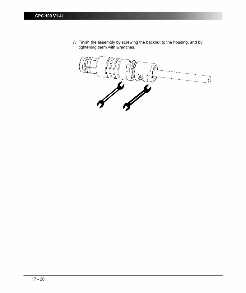
CPC 100 V1.41
17 - 20
7. Finish the assembly by screwing the backnut to the housing, and by tightening them with wrenches.

21
Contact Information / Technical Support
Contact Information / Technical Support
Europe, Africa, Middle EastOMICRON electronics GmbHOberes Ried 1, A-6833 Klaus, Austria
Phone: +43 5523 507-333
E-Mail: [email protected]
Web: www.omicron.at
Asia, PacificOMICRON electronics Asia Ltd, Hong Kong
Phone: +852 2634 0377
E-Mail: [email protected]
Web: www.omicron.at
North and South AmericaOMICRON electronics Corp. USA
Phone: +1 713 830-4660 or 1 800 OMICRON
E-Mail: [email protected]
Web: www.omicronusa.com
For addresses of OMICRON offices with customer service centers, regional sales offices or offices for training, consulting and commissioning please see our website.

OMICRON Contact Addresses
22

Index
19 - 1
IndexSection-page number
Numerics0...3V AC input . . . . . . . . . . . . . . . . . . . . . . 2-9
technical data . . . . . . . . . . . . . . . . . . . 16-25100ms debounce compensation . . . . . . . . 8-1210A I AC/DC input . . . . . . . . . . . . . . . . . . . . 2-9
synchronizing Amplifier test card . . . . . 8-29technical data . . . . . . . . . . . . . . . . . . . 16-22
10V DC input . . . . . . . . . . . . . . . . . . . . . . . . 2-9technical data . . . . . . . . . . . . . . . . . . . 16-27
2kV AC output . . . . . . . . . . . . . . . . . . . . . . . 2-6technical data . . . . . . . . . . . . . . . . . . . . 16-8
300V AC/DC input . . . . . . . . . . . . . . . . . . . . 2-9synchronizing of Amplifier test card . . . 8-29technical data . . . . . . . . . . . . . . . . . . . 16-23
3V AC inputsynchronizing Amplifier test card . . . . . 8-29
400A DC output . . . . . . . . . . . . . . . . . . . . . 2-8CAUTION, output is NOT switched off . 1-9technical data . . . . . . . . . . . . . . . . . . . . 16-7
6A DC output . . . . . . . . . . . . . . . . . . . . . . . 2-8technical data . . . . . . . . . . . . . . . . . . . 16-18
6A/130V AC output . . . . . . . . . . . . . . . . . . . 2-6technical data . . . . . . . . . . . . . . . . . . . 16-15
800A AC output . . . . . . . . . . . . . . . . . . . . . . 2-6technical data . . . . . . . . . . . . . . . . . . . . 16-5
800A DC outputCAUTION, output is NOT switched off . 1-9
AAC OUTPUT
description . . . . . . . . . . . . . . . . . . . . . . . 2-6accelerator keys
selecting a test . . . . . . . . . . . . . . . . . . . 2-15add test card. Refer to Insert Card
addressmanufacturer . . . . . . . . . . . . . . . . . . . . 18-21
AdobeDistiller . . . . . . . . . . . . . . . . . . . . . . . . 13-16Reader . . . . . . . . . . . . . . . . . . . . . . . . 13-16
Amplifiersynchronization inputs . . . . . . . . . . . . . . 8-29
Amplifier test card . . . . . . . . . . . . . . . . . . . 8-29anti-virus software . . . . . . . . . . . . . . . . . . . 11-7applications overview . . . . . . . . . . . . . . . . . 1-13ARC
testing an OVC relay w/ ARC function . 8-11article number
cable . . . . . . . . . . . . . . . . . . . . . . . . . . 17-15clamps . . . . . . . . . . . . . . . . . . . . . . . . . 17-16current booster CP CB2 . . . . . . . . . . . . 17-8current clamp C-Probe1 . . . . . . . . . . . 17-13earth resistance accesory set . . . . . . . . 17-3plugs . . . . . . . . . . . . . . . . . . . . . . . . . . 17-16polarity checker CPOL . . . . . . . . . . . . . 17-9Reference Manual . . . . . . . . . . . . . . . . 17-15
assessment . . . . . . . . . . . . . . . . . . . . . . . . 10-2Auto Save . . . . . . . . . . . . . . . . . . . . . . . . . . 2-35
Bbattery
changing CPOL batteries . . . . . . . . . . 17-11BIN IN (binary input) . . . . . . . . . . . . . . . . . . 2-10
for trigger signal in Quick . . . . . . . . . . . 3-11status display in Quick . . . . . . . . . . . . . 3-12technical data . . . . . . . . . . . . . . . . . . . 16-21
binary triggerin Quick . . . . . . . . . . . . . . . . . . . . . . . . . 3-11
block diagram CPC 100 . . . . . . . . . . . . . . . 2-13booster. Refer to ext. boosterBrowser
Device . . . . . . . . . . . . . . . . . . . . . . . . . . 12-2built-in PC. Refer to ePC

CPC 100 V1.41
19 - 2
Ccable
ordering information . . . . . . . . . . . . . . 17-15card. Refer to test cardcardiac pacemaker: DO NOT USE CPC100 1-5cascading style sheet in CPC Explorer . . 13-15CEconformity . . . . . . . . . . . . . . . . . . . . . 16-33CENELEC HD637S1 . . . . . . . . . . . . . . . . 7-14circuit breaker. Refer to fuseclamp
ordering information . . . . . . . . . . . . . . 17-16clear
(all) results in Test Procedure Overview 2-31column
create 2 columns in Form Editor (Comment card) . . . . . . . . . . . . . . . . . . . . . . . . . . . 8-34
Comment card . . . . . . . . . . . . . . . . . . . . . 8-33communication
establish comm. PC - CPC . . . . . . . . . 11-5ports used by CPC Explorer . . . . . . . . 11-7
compensationdebounce compensation . . . . . . . . . . . 8-12
computerpreparing a test with a computer . . . . 14-10
computer requirementsfor CPC Editor . . . . . . . . . . . . . . . . . . . 14-2for CPC Explorer . . . . . . . . . . . . . . . . . 13-2
connectorfor external safety functions . . . . . . . . 16-31RS232 ePC interface . . . . . . . . . . . . . 16-30
context menuin CPC Explorer . . . . . . . . . . . . . . . . . . 13-7in CPC Explorer with a CPC Editor installed 12-8, . . . . . . . . . . . . . . . . . . . . . . . . . . . 13-8
context-dependent menu keys . . . . . . . . . 2-16count
counting order tap numbers . . . . . . 6-8, 6-22CP CB2. Refer to current boosterCPC Editor
requirements for installation . . . . . . . . . 14-2CPC Explorer
changing language . . . . . . . . . . . . . . 13-15requirements for installation . . . . . 12-2, 13-2
saving a test report to PDF format . . . 13-16stylesheet . . . . . . . . . . . . . . . . . . . . . . 13-15toolbar buttons . . . . . . . . . . . . . . 12-9, 13-9Tools
Download . . . . . . . . . . . . . . . . . . . . 13-12Find CPC . . . . . . . . . . . . . . . . 12-5, 13-6License File . . . . . . . . . . . . . . . . . . 13-11Log File . . . . . . . . . . . . . . . . . . . . . 13-11Specify an IP address . . . . . . 12-5, 13-6Upgrade CPC . . . . . . . . . . . . . . . . . 13-13Upload . . . . . . . . . . . . . . . . . . . . . . 13-12
usage . . . . . . . . . . . . . . . . . . . . . 12-3, 13-4used communication ports . . . . . . . . . . 11-7viewing
license file . . . . . . . . . . . . . . . . . . . 13-11log file . . . . . . . . . . . . . . . . . . . . . . . 13-11test reports . . . . . . . . . . . . . . . . . . . . 13-6
CPC Explorer . . . . . . . . . . . . . . . . . . . . . . . 15-3CPOL polarity checker
changing batteries . . . . . . . . . . . . . . . . 17-11ordering information . . . . . . . . . . . . . . . 17-9
C-Probe1. Refer to current clampCSS in CPC Explorer . . . . . . . . . . . . . . . . 13-15CT
burden . . . . . . . . . . . . . . . . . . . . . . . . . . 4-11excitation, demagnetization . . . . . . . . . . 4-19excitation, test . . . . . . . . . . . . . . . . . . . . 4-15low power (ratio) . . . . . . . . . . . . . . . . . . 4-43polarity check . . . . . . . . . . . . . . . . . . . . 4-28ratio/burden . . . . . . . . . . . . . . . . . . . . . . . 4-3ratio/burden with current clamp . . . . . . . 4-10ratio/burden with current injection . . . . . . 4-3Rogowski (ratio) . . . . . . . . . . . . . . . . . . 4-38voltage withstand . . . . . . . . . . . . . . . . . 4-25
CT ratio measurement with Sequencer . . . 8-14current
max. current at AC OUTPUT . . . . . . . . . 2-6max. current at DC OUTPUT . . . . . . . . . 2-8output
how much for how long? . . . . . . . . . . 2-3current booster
operation modes . . . . . . . . . . . . . . . . . . 17-6ordering information . . . . . . . . . . . . . . . 17-8specify in Device Setup dialog . . . . . . . 2-34where to define in software . . . . . . . . . . 2-21

Index
19 - 3
current clampCT ratio/burden test . . . . . . . . . . . . . . . 4-10ordering information . . . . . . . . . . . . . . 17-13settings in Device Setup dialog . . . . . . 2-34where to define in software . . . . . . . . . 2-21
current outputhow much for how long? . . . . . . . . . . . . 2-3intermittent output of high current (Sequenc-er) . . . . . . . . . . . . . . . . . . . . . . . . . . . . 8-16
current transformer. Refer to CT
DDANGER
cardiac pacemaker: DO NOT USE CPC100 1-5
DC OUTPUTdescription . . . . . . . . . . . . . . . . . . . . . . . 2-8
dead man function . . . . . . . . . . . . . . . . . . 1-14debounce
compensation when measuring CB closing time . . . . . . . . . . . . . . . . . . . . . . . . . . . 8-12
defaultcreating defaults and templates . . . . . . 2-42Restore Factory Defaults . . . . . . . . . . . 2-36test card default . . . . . . . . . . . . . . 2-17, 2-42test procedure default . . . . . . . . . . 2-18, 3-1
on start-up . . . . . . . . . . . . . . . . 2-20, 2-43time of state duration in Sequencer . . . . 8-7
delay timein Quick . . . . . . . . . . . . . . . . . . . . . . . . 3-12
demagnetization . . . . . . . . . . . . . . . . . . . . 4-19Device
Browser . . . . . . . . . . . . . . . . . . . . . . . . 12-2DHCP / Auto-IP . . . . . . . . . . . . . . . . . . . . . 11-3dimensions
CPC . . . . . . . . . . . . . . . . . . . . . . . . . . 16-33CPC CB2 . . . . . . . . . . . . . . . . . . . . . . . 17-5
DIN VDE 0101 . . . . . . . . . . . . . . . . . . . . . 7-14downloading files with CPCExplorer . . . . 13-12duty cycle
800A AC output . . . . . . . . . . . . . . . . . . 16-5ext. booster 1000A mode . . . . . . . . . . . 17-7
ext. booster 2000A mode . . . . . . . . . . . 17-6intermittent output of high current (Sequenc-er) . . . . . . . . . . . . . . . . . . . . . . . . . . . . . 8-16
Eearth resistance accesory set
ordering information . . . . . . . . . . . . . . . 17-3earth resistance. Refer to RGroundEdit menu in File Operations . . . . . . . . . . . . 9-3editor
CPC Editor . . . . . . . . . . . . . . . . . 14-1, 15-1form editor (Comment card) . . . . . . . . . 8-33String Editor . . . . . . . . . . . . . . . . . . . . . 10-3text editor (Comment card) . . . . . . . . . . 8-33
electromagnetic compatibility . . . . . . . . . . 16-33electronic manual (PDF) . . . . . . . . . . . . . . . 1-5electronic voltage transformers . . . . . . . . . 5-21embedded PC. Refer to ePCEMC . . . . . . . . . . . . . . . . . . . . . . . . . . . . . 16-33Emergency Stop . . . . . . . . . . . . . . . . . . . . . 2-16
dead man function . . . . . . . . . . . . . . . . . 1-14external e.s. button . . . . . . . . . . . . . . . 16-31front panel button . . . . . . . . . . . . . . . . . 2-11
end-to-end testusing Amplifier test card . . . . . . . . . . . . 8-29
environmental conditionsclimate, tecnical data . . . . . . . . . . . . . . 16-32electromagnetic compatibility, tecnical data 16-33shock and vibration,tecnical data . . . . 16-32technical data . . . . . . . . . . . . . . . . . . . 16-32
ePCcomponents . . . . . . . . . . . . . . . . . . . . . . 2-14connecting CPC 100 to a PC (network) 11-1interfaces to ext. PC . . . . . . . . . . . . . . . . 2-4
Ethernet connector . . . . . . . . . . . . . . . . . . 16-29explorer. Refer to CPC Explorerext. booster
galvanic connection to mains! . . . . . . . . . 1-7techical data . . . . . . . . . . . . . . . . . . . . . 17-5
1000A mode . . . . . . . . . . . . . . . . . . . 17-72000A mode . . . . . . . . . . . . . . . . . . . 17-6

CPC 100 V1.41
19 - 4
where to connect . . . . . . . . . . . . . . . . . 2-12ext. transformer. Refer to ext. boosterexternal functions
connector for external safety functions 16-31
Ffile
File menu in File Operations . . . . . . . . . 9-3File Operations main menu . . . . . . . . . . 9-2name extension xml . . . . . . . . . . . . . . . . 9-1name extension xmt . . . . . . . . . . . . . . . . 9-1renaming file using String Editor . . . . . 10-3
file namexml . . . . . . . . . . . . . . . . . . . . . . . . . . . . . 9-1xmt . . . . . . . . . . . . . . . . . . . . . . . . . . . . . 9-1
find CPC 100 in CPC Explorer . . . . . 12-5, 13-6firewall software . . . . . . . . . . . . . . . . . . . . 11-7focus
definition in glossary . . . . . . . . . . . . . . . 1-3in software UI . . . . . . . . . . . . . . . . . . . . 2-25
folderrenaming folder using String Editor . . . 10-3
form editor (Comment card) . . . . . . . . . . . 8-33frequency
frequency-selective measurement . . . . . 3-6setting in Quick . . . . . . . . . . . . . . . . . . . 3-9specifying a default frequency . . . . . . . 2-35
front panelePC . . . . . . . . . . . . . . . . . . . . . . . . . . . 2-14functional components . . . . . . . . . . . . . . 2-2input/output sockets
safety instructions . . . . . . . . . . . . . . . 1-9what wires to connect . . . . . . . . . . . . 1-9
fs (full scale) . . . . . . . . . . . . . . . . . . . . . . . . 1-3functional components
of front panel . . . . . . . . . . . . . . . . . . . . . 2-2of left-hand side . . . . . . . . . . . . . . . . . . . 2-3of right-hand side . . . . . . . . . . . . . . . . . . 2-4
functionality of CPC 100 . . . . . . . . . . . . . . 1-13fuse
10 A FF . . . . . . . . . . . . . . . . . . . . . . . . . 2-93.15 A T . . . . . . . . . . . . . . . . . . . . . . . . . 2-6
6.3 A T . . . . . . . . . . . . . . . . . . . . . . . 2-6, 2-8changing the power fuses . . . . . . . . . . . 1-11
Gglossary
symbols . . . . . . . . . . . . . . . . . . . . . . . . . . 1-2terms . . . . . . . . . . . . . . . . . . . . . . . . . . . . 1-2
Hhandwheel . . . . . . . . . . . . . . . . . . . . . . . . . 2-15hide CPC on the network . . . . . . . . . . . . . . 2-37hotline . . . . . . . . . . . . . . . . . . . . . . . . . . . . 18-21humidity . . . . . . . . . . . . . . . . . . . . . . . . . . . 1-10
II AC input
synchronizing Amplifier test card . . . . . 8-29I out
setting in Quick . . . . . . . . . . . . . . . . . . . . 3-3IEEE Std 80-2000 . . . . . . . . . . . . . . . . . . . 7-14IEEE Std 81-1983 . . . . . . . . . . . . . . . . . . . 7-14impedance
ground . . . . . . . . . . . . . . . . . . . . . . . . . . 7-14INPUT
functional group, description . . . . . . . . . . 2-9input
binary . . . . . . . . . . . . . . . . . . . . . . . . . . 2-10synchronization inputs for Amplifier . . . 8-29
Insert Card . . . . . . . . . . . . . . . . . . . . . . . . . 2-23Inserting . . . . . . . . . . . . . . . . . . . . . . . . . . . 14-6installation
CPC Editor . . . . . . . . . . . . . . . . . . . . . . 14-3CPC Explorer . . . . . . . . . . . . . . . . . . . . 13-3
interfaceto ext. PC . . . . . . . . . . . . . . . . . . . . . . . . 2-4
technical data . . . . . . . . . . . . . . . . . 16-29

Index
19 - 5
IPAuto-IP . . . . . . . . . . . . . . . . . . . . . . . . . 11-3definition in glossary . . . . . . . . . . . . . . . 1-3specify IP address in CPC Explorer 12-5, 13-6
IP 22 drip-water protection . . . . . . . . . . . 16-32IP address . . . . . . . . . . . . . . . . . . . . . . . . . 11-4
Jjog dial handwheel . . . . . . . . . . . . . . . . . . 2-15
Kkey lock . . . . . . . . . . . . . . . . . . . . . . . . . . . 2-10keyboard. Refer to ePC components
Llanguage
of CPC Explorer interface . . . . . . . . . 13-15lastmeas.xml. Refer to Auto SaveLCD
definition in glossary . . . . . . . . . . . . . . . 1-3monitor . . . . . . . . . . . . . . . . . . . . . . . . . 2-15
LEDAC output selected . . . . . . . . . . . . . . . . 2-6DC output selected . . . . . . . . . . . . . . . . 2-8
license fileupgrading with CPC Explorer . . . . . . 13-13viewing in CPC Explorer . . . . . . . . . . 13-11
licensed test cards . . . . . . . . . . . . . . . . . . 2-24lights I/O . . . . . . . . . . . . . . . . . . . . . . . . . . 2-11log file
clearing the log file . . . . . . . . . . . . . . . . 2-40defining log file entries . . . . . . . . . . . . . 2-40viewing in CPC Explorer . . . . . . . . . . 13-11what’s a log file? . . . . . . . . . . . . . . . . . 2-39
low level AC voltage input
synchronizing Amplifier test card . . . . . 8-29low power current transformer . . . . . . . . . . 4-43
MMain Power Supply
technical data . . . . . . . . . . . . . . . . . . . . 16-4manufacturer address . . . . . . . . . . . . . . . 18-21max. values
at AC OUTPUT . . . . . . . . . . . . . . . . . . . . 2-6at DC OUTPUT . . . . . . . . . . . . . . . . . . . . 2-8
measured quantitysetting in Quick . . . . . . . . . . . . . . . . . . . . 3-3
measurementfrequency-selective measurement . . . . . 3-6
measuringin Quick . . . . . . . . . . . . . . . . . . . . . . . . . . 3-3measuring inputs . . . . . . . . . . . . . . . . . . . 2-9measuring state
in Quick . . . . . . . . . . . . . . . . . . . . . . . 3-2menu
context-dependent menu keys . . . . . . . 2-16Edit menu . . . . . . . . . . . . . . . . . . . . . . . . 9-3File menu . . . . . . . . . . . . . . . . . . . . . . . . 9-3File Operations . . . . . . . . . . . . . . . . . . . . 9-2
minimumstate duration in Sequencer . . . . . . . . . . 8-7
minimum computer requirementsfor CPC Editor . . . . . . . . . . . . . . . . . . . . 14-2for CPC Explorer . . . . . . . . . . . . . . . . . . 13-2
monitor . . . . . . . . . . . . . . . . . . . . . . . . . . . . 2-15
Nnavigation
handwheel . . . . . . . . . . . . . . . . . . . . . . . 2-15navig. elements front panel control . . . . 2-14
network10BaseT connecting cables . . . 11-3, 16-29communication parameters . . . . . . . . . . 11-3CPC 100 in a network . . . . . . . . . . . . . . 11-1

CPC 100 V1.41
19 - 6
hide CPC on the network . . . . . . . . . . . 2-37tab Options | Network . . . . . . . . . . . . . 2-37
new foldercreate folder with CPC Explorer . . . . . 13-7
OOdu MINI-SNAP plug, assembly instructions . . 17-17off state
in Quick . . . . . . . . . . . . . . . . . . . . . . . . . 3-2offline
definition in glossary . . . . . . . . . . . . . . . 1-4offline test preparation
example . . . . . . . . . . . . . . . . . . . . . . . 14-10with CPC Editor . . . . . . . . . . . . . . . . . . 14-1
OLTC (on load tap changer) . . . . . . . . . . . 6-18OMICRON address . . . . . . . . . . . . . . . . . 18-21on state
in Quick . . . . . . . . . . . . . . . . . . . . . . . . . 3-2operation
setting CPC 100 into operation . . . . . . 2-46ordering information
cable . . . . . . . . . . . . . . . . . . . . . . . . . 17-15clamps . . . . . . . . . . . . . . . . . . . . . . . . 17-16current booster CP CB2 . . . . . . . . . . . . 17-8current clamp C-Probe1 . . . . . . . . . . . 17-13earth resistance accesory set . . . . . . . 17-3plugs . . . . . . . . . . . . . . . . . . . . . . . . . 17-16polarity checker CPOL . . . . . . . . . . . . . 17-9Reference Manual . . . . . . . . . . . . . . . 17-15
outputof high current
how much for how long? . . . . . . . . . . 2-3settings in Quick . . . . . . . . . . . . . . . . . . 3-7
outputsambient temperature . . . . . . . . . . . . . . 16-2
Overcurrentpick up/drop off values of OVC relay . . 8-27testing an OVC relay w/ ARC function . 8-11
overload . . . . . . . . . . . . . . . . . . . . . . . . . . 3-11as trigger condition in Quick . . . . . . . . 3-11as trigger condition in Ramping . . . . . . 8-21
as trigger condition in Sequencer . . . . . . 8-6
Ppacemaker: DO NOT USE CPC100 . . . . . . . 1-5package file . . . . . . . . . . . . . . . . . . . . . . . 13-13parameter
how to enter in software . . . . . . . . . . . . 2-25PC
connecting CPC 100 to a PC (network) 11-1preparing a test with a PC . . . . . . . . . . 14-10
PC. Refer to ePCPDF
how to generate a PDF . . . . . . . . . . . . 13-16saving a CPC Explorer test report to PDF for-mat . . . . . . . . . . . . . . . . . . . . . . . . . . . 13-16
PDF manual . . . . . . . . . . . . . . . . . . . . . . . . . 1-5phase angle
setting in Quick . . . . . . . . . . . . . . . . . . . . 3-9plug
Odu MINI-SNAP, assembly instructions . 17-17ordering information . . . . . . . . . . . . . . 17-16
polarity checkCT . . . . . . . . . . . . . . . . . . . . . . . . . . . . . 4-28VT . . . . . . . . . . . . . . . . . . . . . . . . . . . . . 5-16
polarity checker. Refer to CPOLport
communication ports used . . . . . . . . . . 11-7power cord
how to connect . . . . . . . . . . . . . . . . . . 17-16types of power cords . . . . . . . . . . . . . . 17-16
power outputsetting in Quick . . . . . . . . . . . . . . . . . . . . 3-9
power supplytechnical data . . . . . . . . . . . . . . . . . . . . 16-4
pressdefinition in glossary . . . . . . . . . . . . . . . . 1-4
protective earthstandardized symbols . . . . . . . . . . . . . . 1-12

Index
19 - 7
Qqualification of operating personnel . . . . . . 1-6Quick
do not use for meas. winding resistance 1-7introduction . . . . . . . . . . . . . . . . . . . . . . 3-1
RRamping . . . . . . . . . . . . . . . . . . . . . . . . . . 8-18rd (reading) . . . . . . . . . . . . . . . . . . . . . . . . . 1-4Reference Manual
ordering information . . . . . . . . . . . . . . 17-15Registry
saving settings to R. . . . . . . . . . . . . . . 2-33report
what is a report? . . . . . . . . . . . . . . . . . 2-18reset
Restore Factory Defaults . . . . . . . . . . . 2-36Resistance
do not use for meas. winding resistance 1-7resistance
earth resistance (RGround) . . . . . . . . . 7-14uOhm measurement . . . . . . . . . . . . . . . 7-3voltage withstand . . . . . . . . . . . . . . . . . 7-22winding resistance . . . . . . . . . . . . . . . . . 7-9
Restore Factory Defaults . . . . . . . . . . . . . 2-36RGround
earth resistance test . . . . . . . . . . . . . . 7-14RJ-45 Ethernet connector . . . . . . . . . . . . 16-29Rogowski coil
CTRogowski (ratio) . . . . . . . . . . . . . . . 4-38RS232 ePC interface . . . . . . . . . . . . . . . 16-30
Ssafety
ambient conditions . . . . . . . . . . . . . . . . 1-10Emergency Stop . . . . . . . . . . . . . . . . . 2-11front panel input/output sockets . . . . . . . 1-9
instructions . . . . . . . . . . . . . . . . . . . . . . . 1-5key lock . . . . . . . . . . . . . . . . . . . . . . . . . 2-10qualification of operating personnel . . . . 1-6side panel output sockets . . . . . . . . . . . . 1-9signature of operating personnel . . . . . . 2-46training intervals . . . . . . . . . . . . . . . . . . 2-46warning lights I/O . . . . . . . . . . . . . . . . . 2-11
safety standards . . . . . . . . . . . . . . . . . . . . 16-33selecting
test . . . . . . . . . . . . . . . . . . . . . . . . . . . . 2-22view . . . . . . . . . . . . . . . . . . . . . . . . . . . . 2-21
sequenceof ramps (Ramping) . . . . . . . . . . . . . . . 8-23of states (Sequencer) . . . . . . . . . . . . . . . 8-4
Sequencer . . . . . . . . . . . . . . . . . . . . . . . . . . 8-3default time of state duration . . . . . . . . . . 8-7
ServiceOMICRON address . . . . . . . . . . . . . . . 18-21
setting CPC 100 into operation . . . . . . . . . 2-46settings
Restore Factory Defaults . . . . . . . . . . . 2-36side view
leftfunctional components . . . . . . . . . . . . 2-3
outputs, safety instructions . . . . . . . . . . . 1-9right
functional components . . . . . . . . . . . . 2-4soft-touch key. Refer to ePC componentssoftware
after start-up of CPC 100 . . . . . . . . . . . 2-20default template . . . . . . . . . . . . . . . . . . . 2-20how to use CPC100 software . . . . . . . . 2-17Insert Card . . . . . . . . . . . . . . . . . . . . . . 2-23Test Card View . . . . . . . . . . . . . . . . . . . 2-22test selection . . . . . . . . . . . . . . . . . . . . . 2-22use of
handwheel . . . . . . . . . . . . . . . . . . . . 2-25soft-touch keys . . . . . . . . . . . . . . . . . 2-25Up/Down keys . . . . . . . . . . . . . . . . . 2-25
versionCPC 100 software . . . . . . . . . . 1-2, 2-17CPC Editor . . . . . . . . . . . . . . . . . . . . 14-1
view selector . . . . . . . . . . . . . . . . . . . . . 2-21software user interface
check box, how to select/clear . . . . . . . 2-26
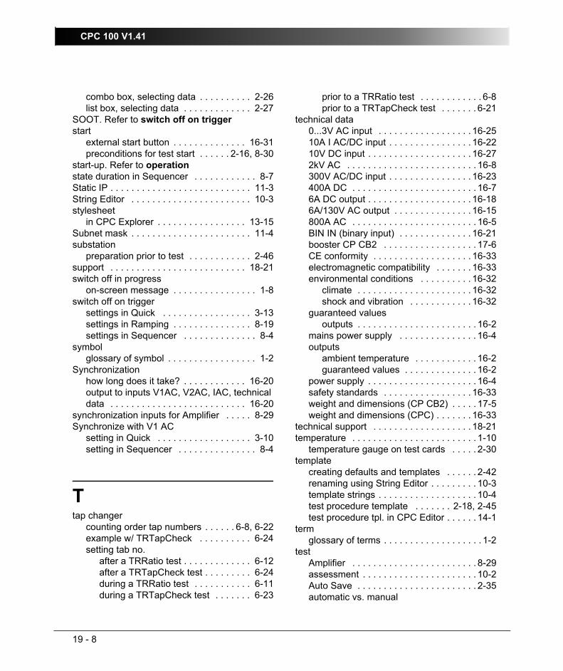
CPC 100 V1.41
19 - 8
combo box, selecting data . . . . . . . . . . 2-26list box, selecting data . . . . . . . . . . . . . 2-27
SOOT. Refer to switch off on triggerstart
external start button . . . . . . . . . . . . . . 16-31preconditions for test start . . . . . . 2-16, 8-30
start-up. Refer to operationstate duration in Sequencer . . . . . . . . . . . . 8-7Static IP . . . . . . . . . . . . . . . . . . . . . . . . . . . 11-3String Editor . . . . . . . . . . . . . . . . . . . . . . . 10-3stylesheet
in CPC Explorer . . . . . . . . . . . . . . . . . 13-15Subnet mask . . . . . . . . . . . . . . . . . . . . . . . 11-4substation
preparation prior to test . . . . . . . . . . . . 2-46support . . . . . . . . . . . . . . . . . . . . . . . . . . 18-21switch off in progress
on-screen message . . . . . . . . . . . . . . . . 1-8switch off on trigger
settings in Quick . . . . . . . . . . . . . . . . . 3-13settings in Ramping . . . . . . . . . . . . . . . 8-19settings in Sequencer . . . . . . . . . . . . . . 8-4
symbolglossary of symbol . . . . . . . . . . . . . . . . . 1-2
Synchronizationhow long does it take? . . . . . . . . . . . . 16-20output to inputs V1AC, V2AC, IAC, technical data . . . . . . . . . . . . . . . . . . . . . . . . . . 16-20
synchronization inputs for Amplifier . . . . . 8-29Synchronize with V1 AC
setting in Quick . . . . . . . . . . . . . . . . . . 3-10setting in Sequencer . . . . . . . . . . . . . . . 8-4
Ttap changer
counting order tap numbers . . . . . . 6-8, 6-22example w/ TRTapCheck . . . . . . . . . . 6-24setting tab no.
after a TRRatio test . . . . . . . . . . . . . 6-12after a TRTapCheck test . . . . . . . . . 6-24during a TRRatio test . . . . . . . . . . . 6-11during a TRTapCheck test . . . . . . . 6-23
prior to a TRRatio test . . . . . . . . . . . . 6-8prior to a TRTapCheck test . . . . . . . 6-21
technical data0...3V AC input . . . . . . . . . . . . . . . . . . 16-2510A I AC/DC input . . . . . . . . . . . . . . . . 16-2210V DC input . . . . . . . . . . . . . . . . . . . . 16-272kV AC . . . . . . . . . . . . . . . . . . . . . . . . . 16-8300V AC/DC input . . . . . . . . . . . . . . . . 16-23400A DC . . . . . . . . . . . . . . . . . . . . . . . . 16-76A DC output . . . . . . . . . . . . . . . . . . . . 16-186A/130V AC output . . . . . . . . . . . . . . . 16-15800A AC . . . . . . . . . . . . . . . . . . . . . . . . 16-5BIN IN (binary input) . . . . . . . . . . . . . . 16-21booster CP CB2 . . . . . . . . . . . . . . . . . . 17-6CE conformity . . . . . . . . . . . . . . . . . . . 16-33electromagnetic compatibility . . . . . . . 16-33environmental conditions . . . . . . . . . . 16-32
climate . . . . . . . . . . . . . . . . . . . . . . 16-32shock and vibration . . . . . . . . . . . . 16-32
guaranteed valuesoutputs . . . . . . . . . . . . . . . . . . . . . . . 16-2
mains power supply . . . . . . . . . . . . . . . 16-4outputs
ambient temperature . . . . . . . . . . . . 16-2guaranteed values . . . . . . . . . . . . . . 16-2
power supply . . . . . . . . . . . . . . . . . . . . . 16-4safety standards . . . . . . . . . . . . . . . . . 16-33weight and dimensions (CP CB2) . . . . . 17-5weight and dimensions (CPC) . . . . . . . 16-33
technical support . . . . . . . . . . . . . . . . . . . 18-21temperature . . . . . . . . . . . . . . . . . . . . . . . . 1-10
temperature gauge on test cards . . . . . 2-30template
creating defaults and templates . . . . . . 2-42renaming using String Editor . . . . . . . . . 10-3template strings . . . . . . . . . . . . . . . . . . . 10-4test procedure template . . . . . . . 2-18, 2-45test procedure tpl. in CPC Editor . . . . . . 14-1
termglossary of terms . . . . . . . . . . . . . . . . . . . 1-2
testAmplifier . . . . . . . . . . . . . . . . . . . . . . . . 8-29assessment . . . . . . . . . . . . . . . . . . . . . . 10-2Auto Save . . . . . . . . . . . . . . . . . . . . . . . 2-35automatic vs. manual
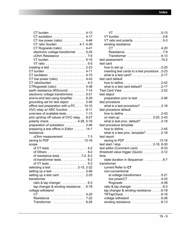
Index
19 - 9
CT burden . . . . . . . . . . . . . . . . . . . . 4-13CT excitation . . . . . . . . . . . . . . . . . . 4-17CT low power (ratio) . . . . . . . . . . . . 4-46CT ratio /burden . . . . . . . . . . . . 4-7, 4-36CT Rogowski (ratio) . . . . . . . . . . . . 4-41electronic voltage transformer . . . . 5-24uOhm Resistance . . . . . . . . . . . . . . . 7-6VT burden . . . . . . . . . . . . . . . . . . . . 5-10VT ratio . . . . . . . . . . . . . . . . . . . . . . . 5-5
creating a test . . . . . . . . . . . . . . . . . . . 2-23CT burden . . . . . . . . . . . . . . . . . . . . . . 4-11CT excitation . . . . . . . . . . . . . . . . . . . . 4-15CT low power (ratio) . . . . . . . . . . . . . . 4-43CT ratio/burden . . . . . . . . . . . . . . . . . . . 4-3CTRogowski (ratio) . . . . . . . . . . . . . . . 4-38earth resistance (RGround) . . . . . . . . . 7-14electronic voltage transformers . . . . . . 5-21end-to-end test using Amplifier . . . . . . 8-29grounding set for test object . . . . . . . . 2-46offline test preparation with a PC . . . . 14-10OVC relay w/ ARC function . . . . . . . . . 8-11overview of available tests . . . . . . . . . . 1-13pick up/drop off values of OVC relay . . 8-27polarity check . . . . . . . . . . . . . . . . 4-28, 5-16preparation of substation . . . . . . . . . . . 2-46preparing a test offline in Editor . . . . . . 14-1resistance
uOhm measurement . . . . . . . . . . . . . 7-3saving to PDF . . . . . . . . . . . . . . . . . . 13-16scope
of CT tests . . . . . . . . . . . . . . . . . . . . 4-2of Others . . . . . . . . . . . . . . . . . . . . . . 8-2of resistance tests . . . . . . . . . . . . 7-2, 8-2of transformer tests . . . . . . . . . . . . . . 6-2of VT tests . . . . . . . . . . . . . . . . . . . . . 5-2
selecting a test . . . . . . . . . . . . . . . 2-15, 2-22setting up a test . . . . . . . . . . . . . . . . . . 2-46setting up a test card . . . . . . . . . . . . . . 2-25transformer
ratio & tap changer . . . . . . . . . . . . . . 6-3tap changer & winding resistance . . 6-18
voltage withstandCT . . . . . . . . . . . . . . . . . . . . . . . . . . 4-25Resistance . . . . . . . . . . . . . . . . . . . 7-22Transformer . . . . . . . . . . . . . . . . . . 6-26
VT . . . . . . . . . . . . . . . . . . . . . . . . . . 5-13VT burden . . . . . . . . . . . . . . . . . . . . . . . . 5-8VT ratio and polarity . . . . . . . . . . . . . . . . 5-3winding resistance
CT . . . . . . . . . . . . . . . . . . . . . . . . . . 4-20Resistance . . . . . . . . . . . . . . . . . . . . . 7-9Transformer . . . . . . . . . . . . . . . . . . . 6-13
test assessment . . . . . . . . . . . . . . . . . . . . . 10-2test card
how to set up . . . . . . . . . . . . . . . . . . . . . 2-25inserting test cards to a test procedure . 2-23what is a test card? . . . . . . . . . . . . . . . . 2-17
test card defaulthow to define . . . . . . . . . . . . . . . . . . . . . 2-42what is a test card default? . . . . . . . . . . 2-17
Test Card View . . . . . . . . . . . . . . . . . . . . . . 2-22test object
preparation prior to test . . . . . . . . . . . . . 2-46test procedure
what is a test procedure? . . . . . . . . . . . 2-18test procedure default
how to define . . . . . . . . . . . . . . . . . . . . . 2-43on start-up . . . . . . . . . . . . . . . . . . 2-20, 2-43what is test proc. default? . . . . . . . . . . . 2-18
test procedure templatehow to define . . . . . . . . . . . . . . . . . . . . . 2-45what is a test proc. template? . . . . . . . . 2-18
test reportsaving to PDF . . . . . . . . . . . . . . . . . . . 13-16
test start / stop . . . . . . . . . . . . . . . . . 2-16, 8-30text editor (Comment card) . . . . . . . . . . . . 8-33threshold value trigger (Quick) . . . . . . . . . . 3-12time
state duration in Sequencer . . . . . . . . . . 8-7transformer
current.Refer to CTnon-conventional
el.voltage transformers . . . . . . . . . . 5-21low powerCT . . . . . . . . . . . . . . . . . . 4-43Rogowski . . . . . . . . . . . . . . . . . . . . . 4-38
ratio & tap changer . . . . . . . . . . . . . . . . . 6-3tap changer & winding resistance . . . . . 6-18TRTapCheck . . . . . . . . . . . . . . . . . . . . . 6-18voltage withstand . . . . . . . . . . . . . . . . . 6-26winding resistance . . . . . . . . . . . . . . . . . 6-13

CPC 100 V1.41
19 - 10
triggerdefinition in glossary . . . . . . . . . . . . . . . 1-4input BIN IN . . . . . . . . . . . . . . . . . . . . . 2-10settings in Quick . . . . . . . . . . . . . . . . . 3-11settings in Ramping . . . . . . . . . . . . . . . 8-21settings in Sequencer . . . . . . . . . . . . . . 8-6switch off on trigger (Quick) . . . . . . . . . 3-13switch off on trigger (Ramping) . . . . . . 8-19switch off on trigger (Sequencer) . . . . . . 8-4
UUp / Down keys . . . . . . . . . . . . . . . . . . . . . 2-15upgrade CPC 100 software . . . . . . . . . . . 13-13uploading files with CPCExplorer . . . . . . 13-12user interface
definition in glossary . . . . . . . . . . . . . . . 1-4See also software user interface
User Manual. Refer to Reference Manual
VV out
setting in Quick . . . . . . . . . . . . . . . . . . . 3-3V1 AC
synchronizing outputs with V1 ACQuick test card . . . . . . . . . . . . . . . . 3-10Sequencer test card . . . . . . . . . . . . . 8-4
V1 AC inputsynchronizing Amplifier test card . . . . . 8-29
V2 AC inputsynchronizing Amplifier test card . . . . . 8-29
valueshow to enter in software . . . . . . . . . . . . 2-25
VDE 0101 . . . . . . . . . . . . . . . . . . . . . . . . . 7-14version
CPC 100 software . . . . . . . . . . . . . 1-2, 2-17CPC Editor . . . . . . . . . . . . . . . . . . . . . . 14-1
viewview selector . . . . . . . . . . . . . . . . 2-15, 2-21
voltage
max. voltage at AC OUTPUT . . . . . . . . . 2-6voltage withstand
CT . . . . . . . . . . . . . . . . . . . . . . . . . . . . . 4-25Resistance . . . . . . . . . . . . . . . . . . . . . . 7-22Transformer . . . . . . . . . . . . . . . . . . . . . . 6-26VT . . . . . . . . . . . . . . . . . . . . . . . . . . . . . 5-13
VTburden . . . . . . . . . . . . . . . . . . . . . . . . . . . 5-8electronic voltage transformers . . . . . . . 5-21polarity check . . . . . . . . . . . . . . . . . . . . 5-16ratio and polarity . . . . . . . . . . . . . . . . . . . 5-3voltage withstand . . . . . . . . . . . . . . . . . 5-13
Wwarning lights I/O . . . . . . . . . . . . . . . . . . . . 2-11weight
CP CB2 . . . . . . . . . . . . . . . . . . . . . . . . . 17-5CPC . . . . . . . . . . . . . . . . . . . . . . . . . . . 16-33
winding resistanceCT . . . . . . . . . . . . . . . . . . . . . . . . . . . . . 4-20do not use Quick or Resistance . . . . . . . 1-7of tap changer, with TRTapCheck . . . . . 6-23Resistance . . . . . . . . . . . . . . . . . . . . . . . 7-9Transformer . . . . . . . . . . . . . . . . . . . . . . 6-13
Windows Registrysaving settings to W. R. . . . . . . . . . . . . 2-33
Xxml
Auto Save . . . . . . . . . . . . . . . . . . . . . . . 2-35xml, file name extension . . . . . . . . . . . . . . . . 9-1xmt, file name extension . . . . . . . . . . . . . . . 9-1