A 8 LA line array element user manual - Thomann
40
A 8 LA line array element user manual
-
Upload
khangminh22 -
Category
Documents
-
view
1 -
download
0
Transcript of A 8 LA line array element user manual - Thomann

A 8 LAline array element
user manual

Musikhaus Thomann
Thomann GmbH
Hans-Thomann-Straße 1
96138 Burgebrach
Germany
Telephone: +49 (0) 9546 9223-0
E-mail: [email protected]
Internet: www.thomann.de
11.02.2020, ID: 447346 (V4)

Table of contents
1 General information................................................................................................................................. 41.1 Further information........................................................................................................................... 51.2 Notational conventions.................................................................................................................... 61.3 Symbols and signal words............................................................................................................... 7
2 Safety instructions..................................................................................................................................... 9
3 Features....................................................................................................................................................... 14
4 Installation.................................................................................................................................................. 154.1 Installation.......................................................................................................................................... 17
5 Connections and controls................................................................................................................... 24
6 Starting up.................................................................................................................................................. 28
7 Networking and remote control...................................................................................................... 29
8 Technical specifications....................................................................................................................... 32
9 Plug and connection assignment.................................................................................................... 34
10 Protecting the environment.............................................................................................................. 36
Table of contents
A 8 LA
3

1 General information
This user manual contains important information on the safe operation of the device. Read andfollow all safety notes and all instructions. Save this manual for future reference. Make surethat it is available to all persons using this device. If you sell the device to another user, be surethat they also receive this manual.
Our products and user manuals are subject to a process of continuous development. We there‐fore reserve the right to make changes without notice. Please refer to the latest version of theuser manual which is ready for download under www.thomann.de.
General information
line array element
4

1.1 Further information
On our website (www.thomann.de) you will find lots of further information and details on thefollowing points:
Download This manual is also available as PDF file for you to download.
Keyword search Use the search function in the electronic version to find the topics ofinterest for you quickly.
Online guides Our online guides provide detailed information on technical basicsand terms.
Personal consultation For personal consultation please contact our technical hotline.
Service If you have any problems with the device the customer service willgladly assist you.
General information
A 8 LA
5

1.2 Notational conventions
This manual uses the following notational conventions:
The letterings for connectors and controls are marked by square brackets and italics.
Examples: [VOLUME] control, [Mono] button.
The individual steps of an instruction are numbered consecutively. The result of a step isindented and highlighted by an arrow.
Example:
1. Switch on the device.
2. Press [Auto].
ð Automatic operation is started.
3. Switch off the device.
Letterings
Instructions
General information
line array element
6

1.3 Symbols and signal words
In this section you will find an overview of the meaning of symbols and signal words that areused in this manual.
Signal word Meaning
DANGER! This combination of symbol and signal word indicates animmediate dangerous situation that will result in death orserious injury if it is not avoided.
WARNING! This combination of symbol and signal word indicates a pos‐sible dangerous situation that can result in death or seriousinjury if it is not avoided.
CAUTION! This combination of symbol and signal word indicates a pos‐sible dangerous situation that can result in minor injury if itis not avoided.
NOTICE! This combination of symbol and signal word indicates a pos‐sible dangerous situation that can result in material andenvironmental damage if it is not avoided.
General information
A 8 LA
7

Warning signs Type of danger
Warning – high-voltage.
Warning – suspended load.
Warning – danger zone.
General information
line array element
8

2 Safety instructions
This device is designed for sound reinforcement. Use the device only as described in this usermanual. Any other use or use under other operating conditions is considered to be improperand may result in personal injury or property damage. No liability will be assumed for damagesresulting from improper use.
This device may be used only by persons with sufficient physical, sensorial, and intellectualabilities and having corresponding knowledge and experience. Other persons may use thisdevice only if they are supervised or instructed by a person who is responsible for their safety.
DANGER!Danger for childrenEnsure that plastic bags, packaging, etc. are disposed of properly and are notwithin reach of babies and young children. Choking hazard!
Ensure that children do not detach any small parts (e.g. knobs or the like) fromthe unit. They could swallow the pieces and choke!
Never let children unattended use electrical devices.
Intended use
Safety
Safety instructions
A 8 LA
9

DANGER!Electric shock caused by high voltages insideWithin the device there are areas where high voltages may be present. Neverremove any covers.
There are no user-serviceable parts inside.
Do not use the device if covers, protectors or optical components are missing ordamaged.
DANGER!Electric shock caused by short-circuitAlways use proper ready-made insulated mains cabling (power cord). Do notmodify the mains cable. Failure to do so could result in electric shock/death orfire. If in doubt, seek advice from a registered electrician.
Safety instructions
line array element
10

CAUTION!Possible hearing damageThe device can produce volume levels that may cause temporary or permanenthearing impairment. Over an extended period of time, even levels that seem tobe uncritical can cause hearing damage.
Decrease the volume level immediately if you experience ringing in your ears orhearing impairment. If this is not possible, keep a greater distance or use suffi‐cient ear protectors.
NOTICE!Risk of fireDo not block areas of ventilation. Do not install the device near any direct heatsource. Keep the device away from naked flames.
Safety instructions
A 8 LA
11

NOTICE!Operating conditionsThis device has been designed for indoor use only. To prevent damage, neverexpose the device to any liquid or moisture. Avoid direct sunlight, heavy dirt, andstrong vibrations.
Only operate the device within the ambient conditions specified in the chapter‘Technical specifications’ of this user manual. Avoid heavy temperature fluctua‐tions and do not switch the device on immediately after it was exposed to tem‐perature fluctuations (for example after transport at low outside temperatures).
Dust and dirt inside can damage the unit. When operated in harmful ambientconditions (dust, smoke, nicotine, fog, etc.), the unit should be maintained byqualified service personnel at regular intervals to prevent overheating and othermalfunction.
Safety instructions
line array element
12

NOTICE!Power supplyBefore connecting the device, ensure that the input voltage (AC outlet) matchesthe voltage rating of the device and that the AC outlet is protected by a residualcurrent circuit breaker. Failure to do so could result in damage to the device andpossibly injure the user.
Unplug the device before electrical storms occur and when it is unused for longperiods of time to reduce the risk of electric shock or fire.
Safety instructions
A 8 LA
13

3 Features
n Active line array element featuring 1 × 1.4 tweeter with 2.5" voice coil and titanium dia‐phragm and 2 × 8" woofers with 2" voice coil
n 950 W + 350 W class-D amplifier with SMPSn XLR in and outputn Lockable in and output socket (Power Twist) for power supplyn Internal SHARC digital signal processor (DSP) with four presetsn Network port for controlling notebooks / computers using the Pronet softwaren Made in Europe
Features
line array element
14

4 Installation
Unpack and check carefully there is no transportation damage before using the unit. Keep theequipment packaging. To fully protect the product against vibration, dust and moisture duringtransportation or storage use the original packaging or your own packaging material suitablefor transport or storage, respectively.
Create all connections while the device is off. Use the shortest possible high-quality cables forall connections. Take care when running the cables to prevent tripping hazards.
WARNING!Risk of injury caused by falling objectsMake sure that the installation complies with the standards and rules that applyin your country. Always secure the device with a secondary safety attachment,such as a safety cable or a safety chain.
Installation
A 8 LA
15

CAUTION!Risk of injury due to heavy weightDue to the heavy weight of the device, at least two persons are required for trans‐port and installation.
CAUTION!Risk of injury due to improper installationAssembly and disassembly may only be carried out by qualified specialist per‐sonnel.
NOTICE!Possible property damage by magnetic fieldsLoudspeakers produce a static magnetic field. Therefore, maintain an appropriatedistance to devices that can be adversely affected or damaged by an externalmagnetic field.
Installation
line array element
16

NOTICE!Use of standsWhen mounting the device onto a stand, ensure that the stand is in a safe andstable position and that the weight of the device does not exceed the maximumpermissible load capacity of the stand.
4.1 Installation
Due to its mechanical structure, the device can either be individually put on the ground orhung, or arranged to line arrays of variable size. The units can be joined together using thebuilt-in fasteners without any additional parts. For easy, flexible and secure mounting, theflying frame (item number 448245) is available as optional accessories. This section shows howeasy the assembly is.
Overview
Installation
A 8 LA
17

To the left and right of the front panel, a safety pin is attached, allowing you to stably connectthe unit to the one directly above it. There is a fold-out vertical latch on the rear panel. Thislatch fits into the U-rail of the device mounted below, which has a series of numbered bores.Attach the latch of the upper unit to the U-rail of the underlying device with a safety pin. Byselecting the hole, you can set the desired angle of inclination. Figure and table show themechanical parts on the rear side and its function.
Connecting the devices to eachother
Installation
line array element
18

Installation
A 8 LA
19

1 Fold-out latch
2 Clearance bores.
Fix the bolt in the hole for the desired angle.
3 Use this hole to fix the latch in the zero position.
1 Bores for locking pin, front side
2 Thread (M10) for attaching standard screw feet for stack mounting
3 Clearance bores
4 Bores for locking pin, rear side
5 Numbering of the clearance bores
6 16 mm shackle, optionally available as accessory (item number 323399)
Flying frame (optional)
Installation
line array element
20

1. Attach the flying frame left and right at the front panel of top unit.
2. Secure the flying frame with the locking pins that are attached to the top unit.
3. Position the vertical bar of the unit on the flying frame.
Installation of a flown system
Installation
A 8 LA
21

4. Secure the latch in the correct position with a safety pin at the U-rail.
5. For flying operation, mount a shackle on the flying frame. It must be located directlyabove the centre of gravity of the entire system. In the figure, the centre of gravity ismarked by ‘C’, the arrow shows the correct position of the U-shackle for this installationsituation.
The maximum load capacity of the flying frame is 680 kg at an angle of 0°. With a safety factorof 10 : 1, up to twelve devices can be attached to it.
The flying frame can also be used as a framework for positioning of a device on the floor. Inthis case, turn the unit by 180° upside down and attach it to the flying frame, as described inchapter Installation of a flown system. Then turn the whole thing around and put the flyingframe with the rubber feet on the ground.
Assembly of a device for posi‐tioning
Installation
line array element
22

Usually, several units are so installed to a line array, that they are arranged arcuately. The figurealongside shows an example of how four elements can be combined into a system that standson the ground (ground stack).
In a ground stack, no more than four elements with maximum angulation of 10° maybe used.
In flying operation, the shackle must be mounted just above the centre of gravity of the entiresystem.
Mounting multiple devices in asystem
Installation
A 8 LA
23

5 Connections and controls
Rear panel
Connections and controls
line array element
24

1 [INPUT]
Audio signal input with lockable XLR chassis socket. The socket is electronically perfectly symmetrical wired to ach‐ieve an optimal signal-to-noise ratio and a sufficient power reserve, including A / D conversion.
2 [GND LIFT] pushbutton
If hum is caused by a ground loop, you can use this switch to disconnect the connection between the earth pin of thedevice and the signal ground of the device. Switching only has an effect when using balanced connection cables.
3 [LINK]
Audio signal output with XLR chassis plug to connect other line array elements or speakers to which the input signalis passed.
4 [TERMINATE] pushbutton
If the devices of a line arrays are networked together, the last unit must be terminated with the built-in load resist‐ance. Press the pushbutton [TERMINATE]. The LED above it lights up.
5, 6 [NETWORK IN/OUT]
RJ45 connectors (EtherCon) for establishing a connection to network, the Pronet software and the line array elements
Connections and controls
A 8 LA
25

7 Preset button
This button has two functions:
n If kept pressed while turning the device on, the ID assignment is made. The internal digital signal processor (DSP)assigns a new ID to the device for the remote control within the Pronet network. Each device must have a uniqueID so that it can be represented in the Pronet network. If you assign a new ID, all devices with already assignedIDs must be turned on and connected to the Pronet network.
n If the device is already on, pressing the button selects the DSP preset. The selected preset is indicated by thecorresponding LED.– [STANDARD]
This setting is suitable for vertically flown line arrays, which consist of four to eight devices, or for the middlearea of a larger flown array. It can also be used for stacked arrays.
– [LONG THROW]This setting can be used in arrays with more than six or eight devices and be loaded in the top or the top twodevices in order to achieve a more balanced distribution of sound pressure, especially when these devicesare aimed at distant targets or the upper galleries of a large house.
– [DOWN FILL / SINGLE BOX]This setting, which provides a much smoother frequency response can be loaded in the lower (usually one ortwo) devices of a large flown array to achieve a pleasant sound for the audience near the stage. This setting isalso very useful if the device is used alone at the front on very large stages.
– [USER]
Connections and controls
line array element
26
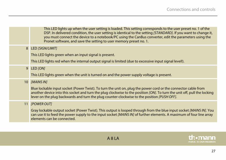
This LED lights up when the user setting is loaded. This setting corresponds to the user preset no. 1 of theDSP. In delivered condition, the user setting is identical to the setting [STANDARD]. If you want to change it,you must connect the device to a notebook/PC using the CanBus converter, edit the parameters using thePronet software, and save the setting to user memory preset no. 1.
8 LED [SIGN/LIMIT]
This LED lights green when an input signal is present.
This LED lights red when the internal output signal is limited (due to excessive input signal level!).
9 LED [ON]
This LED lights green when the unit is turned on and the power supply voltage is present.
10 [MAINS IN]
Blue lockable input socket (Power Twist). To turn the unit on, plug the power cord or the connector cable fromanother device into this socket and turn the plug clockwise to the position [ON]. To turn the unit off, pull the lockinglever on the plug backwards and turn the plug counter-clockwise to the position [PUSH OFF].
11 [POWER OUT]
Gray lockable output socket (Power Twist). This output is looped through from the blue input socket [MAINS IN]. Youcan use it to feed the power supply to the input socket [MAINS IN] of further elements. A maximum of four line arrayelements can be connected.
Connections and controls
A 8 LA
27

6 Starting up
After you have made all the required connections, turn on the audio system.
It is recommended to provide one switch for turning on the entire audio system and to alwaysleave the power supply plugs (Power Twist) connected to the sockets of the individual units.With this simple trick you can extend the life of the connectors.
Set the desired DSP preset ([STANDARD], [LONG THROW], [DOWN FILL / SINGLE BOX] or [USER].
Switching on
DSP preset
Starting up
line array element
28

7 Networking and remote control
Using the network ports on the rear panel, the individual devices of the entire audio systemcan be networked and remote controlled with a notebook / computer using the Pronet soft‐ware. The communication protocol used in the Pronet network is CanBus.
Network capability
Networking and remote control
A 8 LA
29
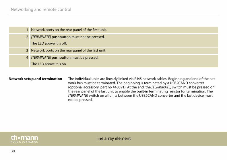
1 Network ports on the rear panel of the first unit.
2 [TERMINATE] pushbutton must not be pressed.
The LED above it is off.
3 Network ports on the rear panel of the last unit.
4 [TERMINATE] pushbutton must be pressed.
The LED above it is on.
The individual units are linearly linked via RJ45 network cables. Beginning and end of the net‐work bus must be terminated. The beginning is terminated by a USB2CAND converter(optional accessory, part no 440591). At the end, the [TERMINATE] switch must be pressed onthe rear panel of the last unit to enable the built-in terminating resistor for termination. The[TERMINATE] switch on all units between the USB2CAND converter and the last device mustnot be pressed.
Network setup and termination
Networking and remote control
line array element
30

Each device of a Pronet network must have a unique identifier or ID. By default, the USB2CANDconverter has the ID 0. Any other device can only have an ID equal or higher than 1. Theremust be no devices with the same ID on the network. The ID is assigned automatically when adevice connected to the network is turned on for the first time.
Proceed as follows to assign a unique ID to all devices in the Pronet network:
1. Turn off all devices.
2. Connect them with the RJ-45 network cables in the desired order.
3. Press the [TERMINATE] button on the rear panel of the last unit.
4. Turn on the first device while holding down its [PRESET] button on the rear panel.
5. Leave the first device turned on and repeat step 4 for all other devices until the lastdevice is turned on.
When a new device is to be added, only step 4 must be repeated. Each device keeps its ID,even if it is turned off, as it is stored in the internal memory of the device. The ID is only deletedor reassigned by explicit allocation as described above. Find more detailed information andinstructions in the User Manual supplied with the Pronet software.
ID assignment
Networking and remote control
A 8 LA
31

8 Technical specifications
Speaker 1 × 1.4" tweeter with 2.5" voice coil and titanium diaphragm
2 × 8" woofer with 2" voice coil
Input connections Power supply Lockable input socket (Power Twist)
Data interface RJ45 input (EtherCon) for control usingPronet software
Signal transmission XLR chassis socket
Input impedance 20 kΩ (balanced), 10 kΩ (unbalanced)
Input sensitivity +4 dBu / 1.25 V
Output connections Power supply Lockable output socket (Power Twist) forthe power supply of further units
Data interface RJ45 output (EtherCon) for control usingPronet software
Signal transmission XLR chassis plug
Technical specifications
line array element
32

Output power 900 W (RMS) + 350 W (RMS)
Frequency range 85 Hz…18 kHz (± 3 dB)
Dispersion angle, averaged (V × H) 10° × 110°
Sound pressure level (SPL), max. 134 dB
Power consumption 575 W (nominal)
1200 W (max.)
Operating supply voltage 230 V 50 Hz
Dimensions (W × H × D) 589 mm × 516 mm × 266 mm
Weight 27.5 kg
Ambient conditions Temperature range 0 °C…40 °C
Relative humidity 50 %, non-condensing
Technical specifications
A 8 LA
33

9 Plug and connection assignment
This chapter will help you select the right cables and plugs to connect your valuable equip‐ment in such a way that a perfect sound experience is ensured.
Please note these advices, because especially in ‘Sound & Light’ caution is indicated: Even if aplug fits into the socket, an incorrect connection may result in a destroyed power amp, a shortcircuit or ‘just’ in poor transmission quality!
Unbalanced transmission is mainly used in semi-professional environment and in hifi use.Instrument cables with two conductors (one core plus shielding) are typical representatives ofthe unbalanced transmission. One conductor is ground and shielding while the signal is trans‐mitted through the core.
Unbalanced transmission is susceptible to electromagnetic interference, especially at lowlevels, such as microphone signals and when using long cables.
In a professional environment, therefore, the balanced transmission is preferred, because thisenables an undisturbed transmission of signals over long distances. In addition to the conduc‐tors ‘Ground’ and ‘Signal’, in a balanced transmission a second core is added. This also transfersthe signal, but phase-shifted by 180°.
Introduction
Balanced and unbalanced trans‐mission
Plug and connection assignment
line array element
34

Since the interference affects both cores equally, by subtracting the phase-shifted signals, theinterfering signal is completely neutralized. The result is a pure signal without any noise inter‐ference.
1 Ground, shielding
2 Signal (in phase, +)
3 Signal (out of phase, –)
4 Shielding on plug housing (option)
XLR plug (balanced)
Plug and connection assignment
A 8 LA
35

10 Protecting the environment
For the transport and protective packaging, environmentally friendly materials have beenchosen that can be supplied to normal recycling.
Ensure that plastic bags, packaging, etc. are properly disposed of.
Do not just dispose of these materials with your normal household waste, but make sure thatthey are collected for recycling. Please follow the notes and markings on the packaging.
This product is subject to the European Waste Electrical and Electronic Equipment Directive(WEEE) in its currently valid version. Do not dispose with your normal household waste.
Dispose of this device through an approved waste disposal firm or through your local wastefacility. When discarding the device, comply with the rules and regulations that apply in yourcountry. If in doubt, consult your local waste disposal facility.
Disposal of the packaging mate‐rial
Disposal of your old device
Protecting the environment
line array element
36

Notes
A 8 LA
37

Notes
line array element
38


Musikhaus Thomann · Hans-Thomann-Straße 1 · 96138 Burgebrach · Germany · www.thomann.de