Redistribution of pump power and impairments in gain-equalized distributed fiber Raman amplifiers...
9
Redistribution of pump power and impairments in gain-equalized distributed fiber Raman amplifiers due to four-wave mixing and parametric amplification This article has been downloaded from IOPscience. Please scroll down to see the full text article. 2008 J. Opt. A: Pure Appl. Opt. 10 104004 (http://iopscience.iop.org/1464-4258/10/10/104004) Download details: IP Address: 128.178.23.47 The article was downloaded on 01/11/2012 at 14:23 Please note that terms and conditions apply. View the table of contents for this issue, or go to the journal homepage for more Home Search Collections Journals About Contact us My IOPscience
Transcript of Redistribution of pump power and impairments in gain-equalized distributed fiber Raman amplifiers...

Redistribution of pump power and impairments in gain-equalized distributed fiber Raman
amplifiers due to four-wave mixing and parametric amplification
This article has been downloaded from IOPscience. Please scroll down to see the full text article.
2008 J. Opt. A: Pure Appl. Opt. 10 104004
(http://iopscience.iop.org/1464-4258/10/10/104004)
Download details:
IP Address: 128.178.23.47
The article was downloaded on 01/11/2012 at 14:23
Please note that terms and conditions apply.
View the table of contents for this issue, or go to the journal homepage for more
Home Search Collections Journals About Contact us My IOPscience

IOP PUBLISHING JOURNAL OF OPTICS A: PURE AND APPLIED OPTICS
J. Opt. A: Pure Appl. Opt. 10 (2008) 104004 (8pp) doi:10.1088/1464-4258/10/10/104004
Redistribution of pump power andimpairments in gain-equalized distributedfiber Raman amplifiers due to four-wavemixing and parametric amplificationMarcelo A Soto and Ricardo Olivares
Department of Electronics, Universidad Tecnica Federico Santa Marıa, Casilla 110-V,Valparaıso, Chile
E-mail: [email protected]
Received 7 March 2008, accepted for publication 28 May 2008Published 27 August 2008Online at stacks.iop.org/JOptA/10/104004
AbstractIn this work, by using a comprehensive numerical model which rigorously describes theinteraction between stimulated Raman scattering (SRS) and four-wave mixing (FWM), weverify that FWM processes, including depletion and parametric gain, generate a redistributionof pump power in distributed fiber Raman amplifiers (DFRAs). As a consequence ofpump–pump FWM, several FWM components can be generated, which act as new sources ofSRS for Raman pumping. Due to new SRS–FWM interactions, a redistribution and exchange ofpump power along the fiber also occurs, producing degradation in the performance of theamplifier. Numerical results show impairments in distributed amplified systems due to theseinteractions, such as loss of flatness on the spectral gain, reduction on the net Raman gain, andthe presence of strong FWM products within the transmission band. We note that thelocalization of the zero dispersion wavelength (λZD) of the fiber is a critical factor in theoccurrence of these impairments. A reduction of net Raman gain up to 3 dB and tilt up to 7 dBin the spectral gain profile have been found in different amplified systems as consequence ofpump–pump FWM and parametric gain of Raman pumps.
Keywords: distributed fiber Raman amplifiers, four-wave mixing, parametric amplification
1. Introduction
Recent investigations have demonstrated the efficient amplifi-cation provided by distributed fiber Raman amplifiers (DFRAs)in ultra-broadband long-haul transmission systems [1]. DFRAsare characterized by having ultrawide bandwidth, flexiblewavelength operation, low noise, and capacity to miti-gate fiber nonlinearities. Nevertheless, the expected per-formance of a multi-pumped DFRA for broadband systemsis mainly determined by the efficiency and rigorousness ofthe method used to design it [1, 2]. Several techniqueshave been proposed to optimize the spectral gain profile ofa DFRA in order to provide a flat gain for all the wave-length division multiplexed (WDM) channels in the sys-tem [2–6]. The objective of all these methods is to findboth the optimum spectral position and the input power of
every pump of the amplifier. However, the main drawback isthat the mathematical models used in these approaches do notconsider the four-wave mixing (FWM) [7, 8] interaction be-tween pumps which can generate an important degradation inthe system performance. For instance, if the designed ampli-fier is implemented in a fiber with low chromatic dispersion inthe region where the pump are located, pump–pump FWM andparametric amplification of the pumps could be produced [9].As a consequence, redistribution and exchange of pump poweralong the fiber could occur, and FWM components acting asnew sources for Raman pumping might take place. All thiscould result in a distorted signal gain spectrum and degradedoptical signal-to-noise ratio (OSNR) [10].
FWM interactions in DFRAs have been studied by otherauthors [10–12], but the models that they have used ignore
1464-4258/08/104004+08$30.00 © 2008 IOP Publishing Ltd Printed in the UK1
J. Opt. A: Pure Appl. Opt. 10 (2008) 104004 M A Soto and R Olivares
pump depletion and parametric gain or consider stimulatedRaman scattering (SRS) and FWM processes separately,using analytical approximations [10] or iterative numericalmethods [11]. In this paper we use a novel and comprehensivenumerical model to analyze how the propagation of Ramanpumps is affected along the amplifier through FWM andparametric amplification processes [13], which solves theinteraction of SRS and FWM in a straightforward way. Bysimulating cases where co-propagating Raman pumps arelocated near the zero dispersion wavelength (λZD) we showa redistribution and exchange of pump power produced by theparametric processes involved, and we demonstrate how theyaffect the net Raman gain for different configurations of flat-gain multi-pumped DFRAs.
2. Theoretical model
In the model, the complex envelope of all electric fields isnormalized and expressed as AF (z) (where F is related tothe propagation frequency fF ) such that the optical poweris conveniently described as PF (z) = |AF (z)|2 [10]. Themathematical model used here to describe the interactionof SRS and FWM processes in a co-propagating Ramanpump configuration can be derived from the expressions givenin [3–8]. It describes the propagation of a lightwave atfrequency fF in direction +z, which interacts by SRS withother waves at different frequencies f j . When f j > fF themodel presents the Raman amplification of the wave at fF ,while f j < fF implies that the wave at fF is depleted dueto SRS. The model also considers waves at frequencies fl , fk ,and fm which produce FWM products or parametric gain atfrequency fF . Finally, the depletion of the wave at fF due toFWM when interacting with lightwaves at f p, fq , and fr isalso described. Thus, the model becomes
dAF(z)
dz= −αF
2AF(z)
+∑
f j > fF
gR( fF , f j )
2Aeff Keff( fF , f j )|A j(z)|2 AF (z)
−∑
f j < fF
fF
f j
gR( fF , f j )
2Aeff Keff( fF , f j )|A j(z)|2 AF (z)
+ i 13γ
∑
k,l �=m
{K f wm( fk, fl , fm)Dklm
× Ak(z)Al(z)A∗m(z) exp(i�βklm z)}
+ i 13γ
∑
p,r �=q
{K f wm( fF , fq , fr )Dprq
× A p(z)A∗q(z)Ar(z) exp(−i�βprqz)} (1)
where αF is the attenuation coefficient of the fiber atfrequency fF , Aeff is the effective area, gR is the Ramangain coefficient, γ is the nonlinear coefficient, Dklm(prq) isthe degeneracy factor, and �βklm(prq) is the linear phase-mismatch, so �βklm(prq) = βk(p) + βl(r) − βm(q) − βF [9].Keff and K f wm are the polarization factors for SRS and FWM,respectively. Keff is 0.5 or 1, depending on whether the wavesat frequency fF and f j have identical or random polarizationstates, respectively [3]. K f wm is 1 when the waves involved
in the FWM process have parallel linear polarizations, and(1/2)0.5 or (3/8)0.5 for partially degenerate and non-degenerateFWM with random polarization states, respectively [14].
The first term on the right-hand side of (1) representsthe fiber attenuation. The second and third terms describethe gain and depletion due to stimulated Raman scattering,respectively. The fourth term describes the contribution ofFWM products and the parametric gain to AF (z) obtained fromall the combinations of electric fields at frequencies fl , fk , andfm (with l, k �= m) that satisfy the relation fF = fk + fl − fm .The fifth term describes the depletion of AF (z) due to FWMprocesses for all the frequency combinations f p, fq , and fr
(with F, q �= r ) where the condition f p = fF + fq − fr issatisfied (here AF(z) acts as a pump of the FWM process).
Equation (1) provides a simultaneous description ofRaman gain/depletion, parametric gain, depletion due toFWM, and generation of FWM waves. This complete andsimultaneous description of both nonlinearities allows forsolving the model by a simple numerical method. Therefore, itis not required to use any iterative method to get convergencein the solution (iterative methods are required when SRSand FWM models are solved separately) [11, 12], whileultimately reducing the computing time. It is also a goodalternative instead of using closed mathematical expressionsbased on undepleted conditions for the waves [10], whichcan be inappropriate approximations when a strong interactionbetween SRS and FWM exists.
3. Numerical solution of the model
The proposed model describes the propagation of electric fieldwaves in terms of a system of complex, nonlinear and coupleddifferential equations. If N signals with different wavelengths,including pumps and WDM channels, are introduced intothe fiber, (N3 − N2)/2 FWM products will be generated.Therefore, in the worst case, a system of (N3 − N2)/2 + Ndifferential equations, each one similar to (1), will be obtained(one for each lightwave frequency). This system of equationscan be solved by a simple numerical technique. In this work,we have used the fourth-order Runge–Kutta method to solveit, separating (1) into two parts: one related to the amplitudeof the electric field (|AF (z)|), and the other associated with itsphase (φF(z)). Thus, from (1) the following expressions areobtained:
d|AF(z)|dz
= −αF
2|AF (z)|
+∑
f j > fF
gR( fF , f j )
2Aeff Keff( fF , f j )|A j(z)|2|AF (z)|
−∑
f j < fF
fF
f j
gR( fF , f j )
2Aeff Keff( fF , f j )|A j(z)|2|AF(z)|
− 13γ
∑
k,l �=m
{K f wm( fk, fl , fm)Dklm
× |Ak(z)||Al(z)||Am(z)| sin[�βklm z + φklm (z)]}− 1
3γ∑
p,r �=q
{K f wm( fF , fq , fr )Dprq
× |A p(z)||Aq(z)||Ar(z)| sin[−�βprqz + φprq(z)]} (2)
2

J. Opt. A: Pure Appl. Opt. 10 (2008) 104004 M A Soto and R Olivares
dφF (z)
dz= 1
3γ
∑
k,l �=m
{K f wm( fk, fl , fm)Dklm
× |Ak(z)||Al(z)||Am(z)||AF(z)| cos[�βklm z + φklm (z)]
}
+ 13γ
∑
p,r �=q
{K f wm( fF , fq , fr )Dprq
× |A p(z)||Aq(z)||Ar(z)||AF (z)| cos[−�βprqz + φprq(z)]
}(3)
where
φklm (z) = φk(z) + φl(z) − φm(z) − φF (z) (4)
φprq(z) = φp(z) + φr (z) − φq(z) − φF(z). (5)
The effect of FWM on the amplitude and phase of thepropagated lightwaves can be observed in (2) and (3),respectively. Meanwhile, absorption losses and SRS onlyaffect the amplitude of the electric field.
4. Efficiency of FWM
To understand the exchange of power process among Ramanpumps produced in a DFRA, due to pump–pump FWMprocesses and parametric amplification, we need to analyze theefficiency of the product terms generated through FWM in anamplifier. The well-known FWM efficiency is given by [8]
η = α2
α2 + �β2
{1 + 4e−αL sin2(�βL/2)
[1 − exp(−αL)]2
}(6)
where α is the attenuation coefficient, L is the fiber length, and�β is the linear phase-mismatch factor. Taking into accountthe frequencies involved in the FWM process ( fk, fl , and fm),the chromatic dispersion (Dc) and dispersion slope (Sc) of thefiber at a given reference frequency ( f0 = c/λ0), �β can beobtained as follows:
�β = 2πλ20
c[( fk − fm)( fl − fm)]Dc( f0)
− πλ40
c2[( fk − fm)( fl − fm)][ fk + fl − 2 f0]Sc( f0) (7)
where c is the speed of light. In particular, in low chromaticdispersion regions, equation (7) can be reduced as
�β = −πλ40
c2[( fk − fm)( fl − fm)][ fk + fl − 2 f0]Sc( f0)
(8)where the reference frequency corresponds to the frequencywith zero chromatic dispersion ( f0 = c/λZD). By usingthe definition of equivalent frequency separation (� fklm )
presented in [8], and defining the spectral separation of f0 withrespect to the middle frequency between fk and fl as � fM0,we have
�β = −2πλ40
c2� f 2
klm · � fM0 · Sc( f0) (9)
where� fklm = √| fk − fm || fl − fm | (10)
Figure 1. FWM efficiency as a function of � fklm and � fM0.
and
� fM0 = fk + fl
2− f0. (11)
Figure 1 depicts the FWM efficiency as a function of� fklm and � fM0, as is described by equation (6). Consideringthat fk , fl , and fm are three Raman pumps of a DFRA, thereare two ways to get a strong pump–pump FWM interaction(η = 1). The first one is when � fklm = 0; however, thiscase needs to satisfy the condition fk = fm or fl = fm ,which correspond to self-phase modulation (SPM) and cross-phase modulation (XPM) cases. The second case occurs whenthe condition � fM0 = 0 is satisfied. For degenerated FWMcases, it occurs when the degenerated pump coincides with λZD
( fk = fl = c/λZD). However, for non-degenerate FWM cases,that condition occurs when c/λZD coincides with the frequencyplaced in the middle of the pumps, fk and fl , of the process(c/λZD = ( fk + fl)/2).
The generated waves resulting from FWM processesdepend on the pump power levels and the efficiency of everyprocess. Due to the high level of pump power propagatinginto the fiber, strong pump–pump FWM components can beobtained even if the efficiency is not exactly equal to 1.
From both conditions presented above, note that, forbroadband DFRAs, it is difficult to satisfy � fklm ≈ 0, becauseRaman pumps are usually distributed in a broad spectral band.However, � fM0 ≈ 0 could easily occur depending on λZD andthe bandwidth of the system, which determines the number ofRaman pumps. Note that this condition is independent of thespectral spacing of the pumps. Analyzing these two conditions,we can deduce that depending on the position of λZD withinthe pump band of a DFRA, it is possible that at least one highefficient pump–pump FWM product can be generated. Forinstance, in a DFRA with N pumps, there are N(N − 1)/2possible λZD which will cause efficient non-degenerate FWMprocesses (η = 1), and N possibilities to produce degeneratedFWM. From all these possibilities, when λZD coincides witha Raman pump, N − 1 new degenerated FWM waves will beproduced, while N−2 new FWM components will be produced
3
J. Opt. A: Pure Appl. Opt. 10 (2008) 104004 M A Soto and R Olivares
Figure 2. Experimental setup.
from non-degenerate FWM. However, different effects will becaused in a given amplified system depending on the spectralposition and power of the pumps involved in an efficient FWMprocess.
Additionally, from equation (6) it is possible to realizethat the efficiency has an oscillatory behavior along the fiberbecause of the factor sin2(�βL/2) [15]. So, if there is nota complete phase matching (�β �= 0) the new lightwaveproduced by FWM will arise from noise at the fiber input(z = 0) and increase until it reaches its maximum at a givendistance z = Lcoh, defined as the coherence length. Then,between z = Lcoh and 2Lcoh, the FWM product will give backits energy to the pumps of the respective FWM process. Thecoherence length is defined as
Lcoh = π
�β. (12)
This parameter is very important for understanding howpump–pump FWM in a DFRA produces an oscillatoryredistribution and exchange of power between the Ramanpump and FWM components [15]. It also allows for explainingthe longitudinal oscillation produced on the intensity ofRaman pumps due to parametric amplification and the FWM(generation/depletion) process.
5. Experimental results
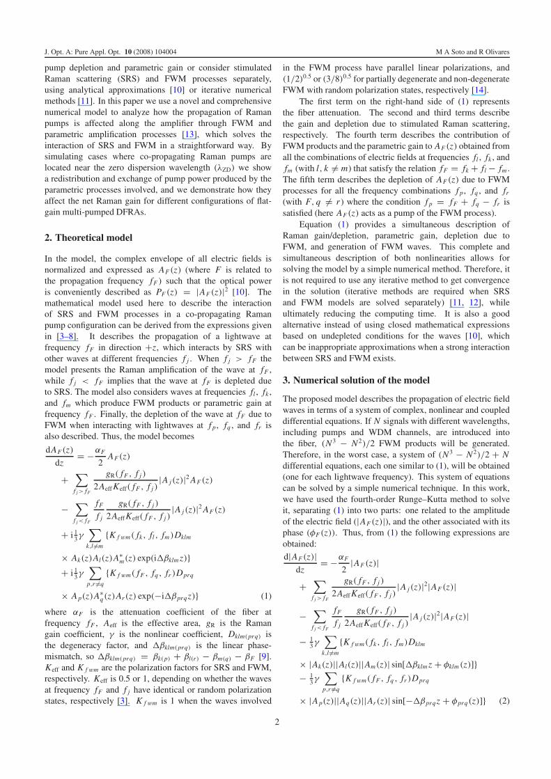
In order to show the non-negligible presence of pump–pumpFWM in a co-pumped distributed Raman amplifier, we set upthe experiment depicted in figure 2. It is composed of threedepolarized pump lasers at 1450, 1480, and 1488 nm, with100, 180, and 150 mW input power, respectively (these powervalues consider coupler and connector losses, i.e. they are thepump powers really launched at the fiber input). The DFRAamplifies six lineally polarized WDM channels, in the range1570–1577.5 nm (1 μW/channel input power), along 25 kmof TrueWave fiber (TWSMF) with λZD = 1498 nm, Aeff =55 μm2, Sc = 0.05 ps km−1 nm−2 and γ = 0.003 W−1 m−1.The fiber has been characterized in terms of Raman gainand attenuation coefficient, which have been measured as afunction of the wavelength, resulting in being similar to thosepresented in [16]. All these parameters are used to solvea system of equations (similar to (1)) which describes theexperiment.
Figure 3 shows the power spectrum at the fiber output(simulated results and measurements obtained from the optical
Figure 3. Experimental results.
Table 1. Designed WDM systems.
DFRA#1 DFRA#2 DFRA#3
No. of channels 20 40 40Band (nm) 1540–1560 1540–1580 1520–1600
spectrum analyzer (OSA)). We can observe the strong pump–pump FWM processes and FWM–SRS interactions thatoccurred due to the low chromatic dispersion of the fiber.The new lightwaves produced by FWM cause a redistributionof the pump power, and could act as pumps for theDFRA. The simulated results are similar to the experimentalmeasurements. The differences (<2 dB on average) can beattributed mainly to possible longitudinal random fluctuationsof some parameters along the fiber, such as effective areaand chromatic dispersion (note the high sensitivity of theFWM process with respect to Aeff and λZD for low dispersionregions).
6. Pump–pump four-wave mixing in gain-equalizeddistributed Raman amplifiers
In order to analyze the effects produced by parametric gainand FWM on the propagation of co-propagating Ramanpumps along a DFRA, three co-pumped WDM systems weredesigned with flat gain by using the optimization methoddescribed in [5]. The objective of this method is to findthe wavelength and power of each Raman pump in a DFRA,aiming at compensating the fiber attenuation, and providing aflat output power spectrum for all WDM channels involved.The optimization problem is divided into two parts, which aresolved sequentially [5]. First, using a genetic algorithm it ispossible to find the wavelength of each Raman pump, and then,the optimum input pump powers are found by means of aniterative method [5].
The three designed transmission systems are composedof 50 km of TWSMF and depolarized WDM channels with0.5 mW/channel input power. The characteristics of thedifferent amplified systems are shown in table 1.
4
J. Opt. A: Pure Appl. Opt. 10 (2008) 104004 M A Soto and R Olivares
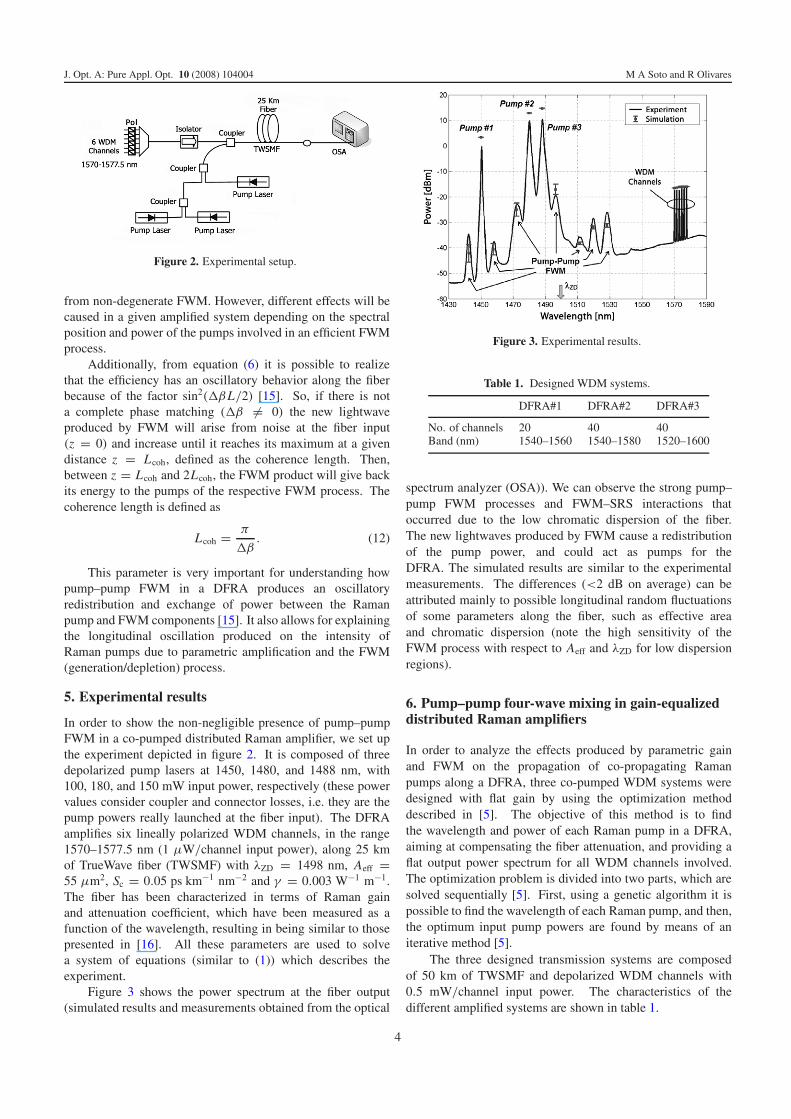
Figure 4. Longitudinal propagation of pump power on DFRA#1, when λZD = 1463.52 nm. (a) Pump at 1420.28 nm. (b) Pump at1438.14 nm. (c) Pump at 1463.52 nm.
Table 2. Optimized pumps for different DFRA configurations.
DFRA#1 λ (nm) 1420.28 1438.14 1463.52 — — —Power (mW) 160.93 92.24 99.61 — — —
DFRA#2 λ (nm) 1420.12 1437.87 1453.41 1474.30 — —Power (mW) 333.86 120.01 79.04 30.00 — —
DFRA#3 λ (nm) 1404.80 1420.10 1431.72 1444.41 1466.72 1490.05Power (mW) 53.43 144.58 113.36 60.93 34.38 16.77
For each amplifier, a ripple of 0.21, 0.36 and 0.84 dB wasachieved by the optimization method making use of 3, 4, and6 Raman pumps, respectively. Optimum pump powers andwavelengths for all three amplifiers are shown in table 2.
Due to the low chromatic dispersion of the TWSMFaround pump wavelengths and high pump powers, we expectthat strong pump–pump FWM interactions will be produced,generating new lightwaves and causing a redistribution of thepump power.
From equations (6), (9), and (11) we can note that severalpositions of the λZD will produce at least one FWM processwith unitary efficiency. These positions correspond to thosewhere � fM0 = 0, which occurs when fk = fl = c/λZD
for degenerated FWM, and c/λZD = ( fk + fl)/2 for non-degenerate FWM processes. Thus, according to the previouslypresented theory of FWM efficiency (section 4), 6, 10, and 21different positions of the λZD will produce at least one FWMprocess with η = 1, in DFRA#1, DFRA#2, and DFRA#3,respectively. However, different effects will be producedin a given amplifier depending on the dispersion properties(position of λZD) and characteristics of the transmission system(e.g. Raman pump levels, bandwidth, etc).
6.1. Analysis of DFRA#1
In a DFRA pumped by three Raman sources, two highlyefficient FWM waves are produced when λZD coincides withone of the pump wavelengths (degenerated FWM process).For example, in this amplifier, if λZD = 1463.52 nm thetwo lightwaves generated through FWM with the longestwavelength will have an efficiency η = 1. In figure 4, thepropagation along the fiber of the three Raman pumps ofthe amplifier, when FWM and parametric amplification areundertaken, is compared to the case when these nonlinearitiesare not considered. In figures 4(a) and (b) it is possible to
see the parametric amplification of the pumps at 1420.28 and1438.14 nm along the first kilometers of fiber, as well asthe strong depletion of the pump at 1463.52 nm, shown infigure 4(c). However, at distances longer than the coherentlength, Raman scattering becomes more relevant than FWM.Thus, the generated waves at 1489.81 and 1509.48 nm,resulting from FWM, are strongly amplified by SRS due totheir spectral position and high efficiency, as shown figure 5(a).Hence, an additional depletion of the pumps is producedas a consequence of the Raman amplification of these twoFWM components. Figure 5(b) depicts the output powerspectrum of the amplifier; note that the three Raman pumpshave lower output power than when FWM and parametricamplification are not considered. As a consequence, this pumpdepletion affects the total Raman gain of the amplifier, asshown figure 5(c). On average, the redistribution of pumppower produces a penalty of ∼3 dB in the net Raman gain.
On the other hand, when λZD is located at 1441.58 nm,which corresponds to the frequency in the middle of the pumpband, one non-degenerate FWM component at 1445.03 nmis produced, as shown in figure 6(a). Due to its high powerand spectral position, it pumps the WDM channels, affectingthe designed power equalization. Figure 6(b) shows howthe equalized condition for the output power spectrum iscompletely altered due to pump–pump FWM and FWM—SRSinteractions. It can be noted that more than 7.0 dB of ripple isobtained when FWM is undertaken.
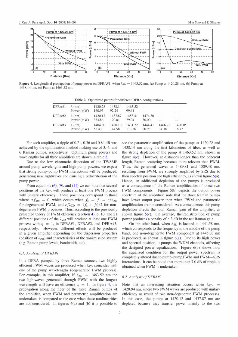
6.2. Analysis of DFRA#2
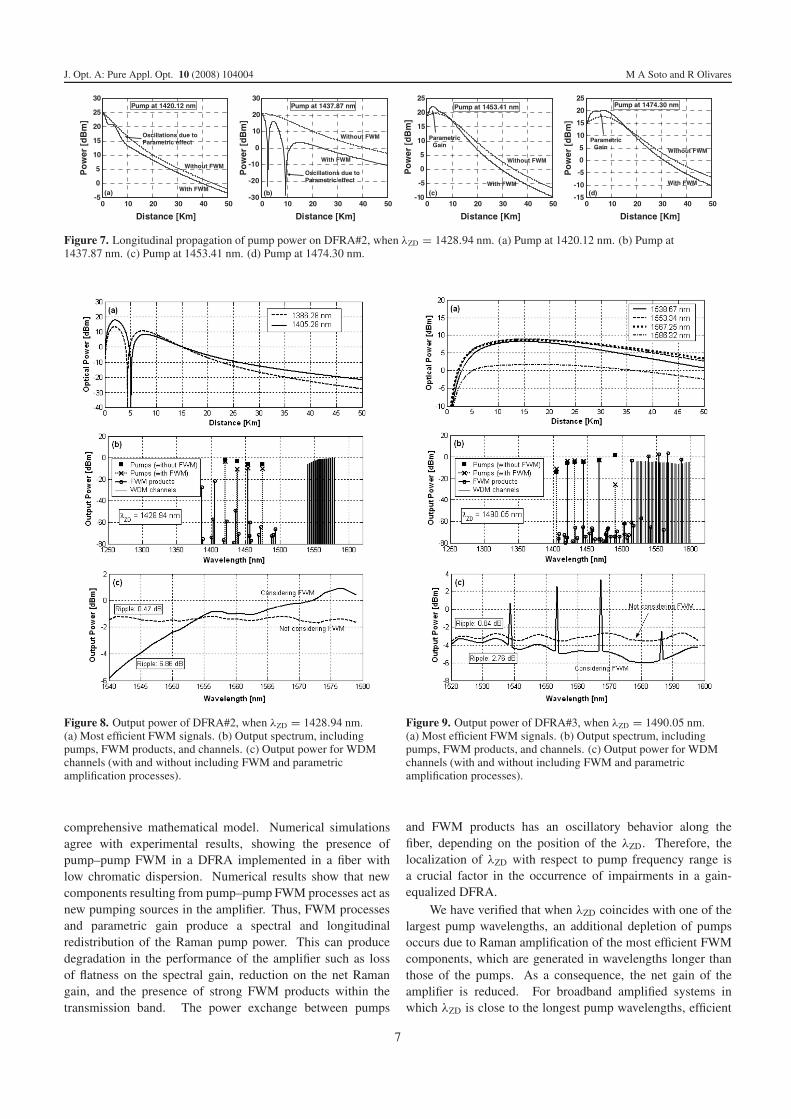
Note that an interesting situation occurs when λZD =1428.94 nm, where two FWM waves are produced with unitaryefficiency as result of two non-degenerate FWM processes.In this case, the pumps at 1420.12 and 1437.87 nm aredepleted because they transfer power mainly to the two
5

J. Opt. A: Pure Appl. Opt. 10 (2008) 104004 M A Soto and R Olivares
Figure 5. Output power of DFRA#1, when λZD = 1463.52 nm.(a) Most efficient FWM signals. (b) Output spectrum, includingpumps, FWM products, and channels. (c) Output power for WDMchannels (with and without including FWM and parametricamplification processes).
FWM products with unitary efficiency and to the pumpsat 1453.41 and 1474.30 nm. As consequence, these lasttwo pumps are amplified through parametric gain along thefirst kilometers of fiber. Thus, the power of pumps andefficient FWM waves show an oscillatory propagation alongthe first kilometers, as shown in figures 7 and 8(a). Aswe can note, all this exchange of power occurs spectrallyand spatially along the fiber, affecting the transfer of energyfrom Raman pumps to WDM channels. Hence, the Ramangain initially designed is completely modified. Thus, WDMchannels with shortest wavelengths are affected by lowerRaman gain, while channels with the longest wavelengthsare strongly amplified by SRS. Figure 8(a) depicts the FWMsignals with highest efficiency, while figure 8(b) shows theoutput power spectrum of the amplified system. Note thatafter 50 km of FWM–SRS interactions, the power levels ofall four pumps are lower than cases when FWM is not takeninto account. This is due to two reasons: first, the two pumpswith the lowest wavelengths are depleted as a consequenceof FWM and parametric amplification, and second, the othertwo pumps are additionally depleted due to SRS. Note that asthe pump power increases (in this case as a consequence ofparametric amplification), the pump depletion also increases asa consequence of higher transfer of energy. Figure 8(c) depictsa comparison between the equalized output power spectrum
Figure 6. Output power of DFRA#1, when λZD = 1441.58 nm.(a) Output spectrum, including pumps, FWM products, and channels.(b) Output power for WDM channels (with and without includingFWM and parametric amplification processes).
and the obtained spectrum including parametric gain of thepumps and pump–pump FWM processes. It can be noted that∼7.0 dB of ripple is obtained when FWM is undertaken.
6.3. Analysis of DFRA#3
In DFRA#3, the Raman pumps are spectrally spread in aband of ∼85 nm; hence, FWM products are also generatedin a wide bandwidth. Similar to previous systems, in thisamplifier there are several positions of λZD which will generateefficient FWM processes. However, when the λZD is near thelongest pump wavelengths, the most efficient FWM productswill be strongly amplified by SRS, mainly because of thebroadband characteristic of the DFRA. For instance, whenλZD = 1490.05 nm, five strong FWM components aregenerated at the longest wavelengths. Those FWM lightwavesgrow from noise at the fiber input, achieving a maximumintensity at a distance equal to the coherence length. Then,they are amplified by SRS with a gain depending on theirwavelengths, as shown in figures 9(a) and (b). The maindrawback is that these FWM components are generated withinthe WDM band, as shown in figures 9(b) and (c). Moreover, theintense Raman amplification of the mentioned FWM signalsproduces an additional depletion of the pumps. However, thepump at 1490.05 nm results to be the most affected one, mainlybecause of the depletion caused by the exchange of power inFWM processes. Meanwhile, pumps with shorter wavelengthare affected just by a small depletion. As consequence, thenet gain of the DFRA is reduced by 2.5 dB for channels at thelongest wavelengths.
7. Conclusions
In this work, we have rigorously analyzed the interplaybetween SRS and FWM in DFRAs by using a novel and
6
J. Opt. A: Pure Appl. Opt. 10 (2008) 104004 M A Soto and R Olivares
0 10 20 30 40 50-5
0
5
10
15
20
25
30
Distance [Km]
Po
wer
[d
Bm
]
Without FWM
With FWM
Oscillations due to Parametric effect
Pump at 1420.12 nm
(a)
0 10 20 30 40 50-30
-20
-10
0
10
20
30
Distance [Km]
Po
wer
[d
Bm
]
Without FWM
With FWM
Pump at 1437.87 nm
Oscillations due to Parametric effect
(b)
0 10 20 30 40 50-10
-5
0
5
10
15
20
25
Distance [Km]
Po
wer
[d
Bm
]
With FWM
Without FWM
ParametricGain
Pump at 1453.41 nm
(c)
0 10 20 30 40 50-15
-10
-5
0
5
10
15
20
25
Distance [Km]
Po
wer
[d
Bm
]
ParametricGain Without FWM
With FWM
Pump at 1474.30 nm
(d)
Figure 7. Longitudinal propagation of pump power on DFRA#2, when λZD = 1428.94 nm. (a) Pump at 1420.12 nm. (b) Pump at1437.87 nm. (c) Pump at 1453.41 nm. (d) Pump at 1474.30 nm.
Figure 8. Output power of DFRA#2, when λZD = 1428.94 nm.(a) Most efficient FWM signals. (b) Output spectrum, includingpumps, FWM products, and channels. (c) Output power for WDMchannels (with and without including FWM and parametricamplification processes).
comprehensive mathematical model. Numerical simulationsagree with experimental results, showing the presence ofpump–pump FWM in a DFRA implemented in a fiber withlow chromatic dispersion. Numerical results show that newcomponents resulting from pump–pump FWM processes act asnew pumping sources in the amplifier. Thus, FWM processesand parametric gain produce a spectral and longitudinalredistribution of the Raman pump power. This can producedegradation in the performance of the amplifier such as lossof flatness on the spectral gain, reduction on the net Ramangain, and the presence of strong FWM products within thetransmission band. The power exchange between pumps
Figure 9. Output power of DFRA#3, when λZD = 1490.05 nm.(a) Most efficient FWM signals. (b) Output spectrum, includingpumps, FWM products, and channels. (c) Output power for WDMchannels (with and without including FWM and parametricamplification processes).
and FWM products has an oscillatory behavior along thefiber, depending on the position of the λZD. Therefore, thelocalization of λZD with respect to pump frequency range isa crucial factor in the occurrence of impairments in a gain-equalized DFRA.
We have verified that when λZD coincides with one of thelargest pump wavelengths, an additional depletion of pumpsoccurs due to Raman amplification of the most efficient FWMcomponents, which are generated in wavelengths longer thanthose of the pumps. As a consequence, the net gain of theamplifier is reduced. For broadband amplified systems inwhich λZD is close to the longest pump wavelengths, efficient
7

J. Opt. A: Pure Appl. Opt. 10 (2008) 104004 M A Soto and R Olivares
FWM components can be generated within the transmissionband, interfering with several channels of the system anddegrading the OSNR.
On the other hand, when λZD is located near the shortestpump wavelengths, or near the middle of the pumping band,efficient FWM can produce a redistribution of pump poweraffecting the gain equalization of the system.
It is possible to conclude that FWM processes, includingdepletion and parametric amplification, must be taken intoaccount when designing gain-equalized DFRAs pumpedat multiple wavelengths, in order to ensure an expectedperformance.
Acknowledgments
The authors would like to thank the Chilean Agency CON-ICYT (Fondecyt project No. 1010437) and the UniversidadTecnica Federico Santa Marıa (DGIP project No. 230847) fortheir financial support of this work.
References
[1] Bromage J 2004 Raman amplification for fiber communicationssystems J. Lightwave Technol. 22 79–93
[2] Kidorf H, Rottwitt K, Nissov M, Ma M and Rabarijaona E 1999Pump interactions in a 100 nm bandwidth Raman amplifierIEEE Photon Technol. Lett. 11 530–2
[3] Perlin V E and Winful H G 2002 Optimal design of flat-gainwide-band fiber Raman amplifier J. Lightwave Technol.20 250–4
[4] Chen J, Liu X, Lu C, Wang Y and Li Z 2006 Design ofmultistage gain-flattened fiber Raman amplifiersJ. Lightwave Technol. 24 935–44
[5] Soto H, Pincheira V and Olivares R 2004 Optimal design basedon genetic algorithm of distributed fiber Raman amplifiercascades 5th Iberoamerican Mtg on Optics and 8th Latin
American Meeting on Optics, Lasers, and their Applications;Proc. SPIE 5622 364–7
[6] Cui S, Liu J and Ma X 2004 A novel efficient optimal designmethod for gain-flattened multiwavelength pumped fiberRaman amplifier IEEE Photon Technol. Lett. 16 2451–3
[7] Hill K O, Johnson D C, Kawasaki B and MacDonald R I 1978Cw three-wave mixing in single-mode optical fibers J. Appl.Phys. 49 5098–106
[8] Shibata N, Braun R and Waarts R 1987 Phase-mismatchdependence of efficiency of wave generation throughfour-wave mixing in a single-mode optical fiber IEEE J.Quantum Electron. 23 1205–10
[9] Inoue K 1992 Four-wave mixing in an optical fiber in thezero-dispersion wavelength region J. Lightwave Technol.10 1553–61
[10] Wong W S, Chen C-J, Ho M-C and Lee H K 2003Phase-matched four-wave mixing between pumps andsignals in a copumped Raman amplifier IEEE Photon.Technol. Lett. 15 209–11
[11] Bouteiller J-C, Leng L and Headley C 2004 Pump–pumpfour-wave mixing in distributed Raman amplified systemsJ. Lightwave Technol. 22 723–32
[12] Vanholsbeeck F, Coen S, Emplit P, Haelterman M andSylvestre T 2005 Coupled-mode analysis of stimulatedRaman scattering and four-wave mixing inwavelength-division multiplexed systems Opt. Commun.250 191–201
[13] Hansryd J, Andrekson P A, Westlund M, Li J andHedekvist P-O 2002 Fiber-based optical parametricamplifiers and their applications IEEE J. Sel. Top. QuantumElectron. 8 506–20
[14] Inoue K 1992 Polarization effect on four-wave mixingefficiency in a single-mode fiber IEEE J. Quantum Electron.28 883–94
[15] Hart D L, Judy A F, Roy R and Beletic J W 1998 Dynamicalevolution of multiple four-wave-mixing processes in anoptical fiber Phys. Rev. E 57 4757–74
[16] Grant A R 2002 Calculating the Raman pump distribution toachieve minimum gain ripple IEEE J. Quantum Electron.38 1503–9
8