Amplifiers - AGH
71
Amplifiers Amplifiers Amplifiers An electronic amplifier An electronic amplifier , , amplifier amplifier , , or or amp amp - - is an electronic device that is an electronic device that increases the power of increases the power of a a signal signal . . [http:// [http:// en en . . wikipedia wikipedia . . org org / / wiki wiki /] /]
-
Upload
khangminh22 -
Category
Documents
-
view
0 -
download
0
Transcript of Amplifiers - AGH

AmplifiersAmplifiersAmplifiersAn electronic amplifierAn electronic amplifier,, amplifieramplifier,, oror ampamp-- is an electronic device that is an electronic device that increases the power ofincreases the power of aa signalsignal. .
[http://[http://enen..wikipediawikipedia..orgorg//wikiwiki/]/]

AA Wheatstone bridge is an electrical circuit usedWheatstone bridge is an electrical circuit used toto measure an measure an unknown electrical resistanceunknown electrical resistance byby balancing two legs ofbalancing two legs of aa bridge bridge
circuitcircuit..
Rx is the unknown resistanceRx is the unknown resistance to beto be measuredmeasured. R1, R2. R1, R2 andand R3R3 are are resistors of known resistance and the resistanceresistors of known resistance and the resistance R2R2 is adjustableis adjustable.. If the If the ratio of the two resistances ratio of the two resistances R2 / R1R2 / R1 is equalis equal toto the ratio of Rxthe ratio of Rx / R3,/ R3, then then the voltage between the two midpointsthe voltage between the two midpoints; ; CC andand D will be zero. D will be zero.
R1
R2
R3
Rx
VgVcc
A
B
C D
A Wheatstone bridge A Wheatstone bridge A Wheatstone bridge

At theAt the pointpoint of balanceof balance,, the ratio ofthe ratio of::
31
231
2
RR
RRx
R
Rx
R
R
=
=
VccRR
R
RxR
RxVg )
21
2
3(
+−
+=
If all resistor values and the supply voltageIf all resistor values and the supply voltage ((VVcccc) ) are knownare known,, and the and the resistance of the galvanometer is highresistance of the galvanometer is high, , the voltage across the bridgethe voltage across the bridge((VVgg) ) cancan bebe foundfound byby working out the voltage from each potential divider working out the voltage from each potential divider and subtractingand subtracting oneone from the otherfrom the other.. The equationThe equation forfor this isthis is::
A Wheatstone bridge A Wheatstone bridge A Wheatstone bridge

[[wwwwww.analog..analog.comcom]]
Bridge CircuitsBBridgeridge CCircuitsircuits
Resistive elements are some of theResistive elements are some of the mostmost common sensorscommon sensors..
SensorSensor elements' resistances can range fromelements' resistances can range from lessless thanthan 100100ΩΩ totoseveral hundredseveral hundred kkΩΩ,, dependingdepending onon thethe sensorsensor design and the physical design and the physical environmentenvironment to beto be measuredmeasured..
Resistance of popular sensorsResistance of popular sensors::
--Strain GagesStrain Gages (czujniki nap(czujniki naprrężężeniaenia) 120) 120ΩΩ , 350, 350ΩΩ , 3500, 3500ΩΩ
--Pressure SensorsPressure Sensors (czujniki ci(czujniki ciśśnienia) 350nienia) 350ΩΩ -- 35003500ΩΩ
--Relative HumidityRelative Humidity (czujniki(czujniki wigotnowigotnośścici) 100k) 100kΩΩ -- 10M10MΩΩ
--Resistance Temperature DevicesResistance Temperature Devices (czujniki temperatury) 100(czujniki temperatury) 100ΩΩ , , 10001000ΩΩ
--ThermistorsThermistors (termistory) 100(termistory) 100ΩΩ -- 10M10MΩΩ

The basic Wheatstone bridge[[wwwwww.analog..analog.comcom]]
Bridge CircuitsBBridgeridge CCircuitsircuits

BBridgeridge CCircuitsircuits
InIn many bridge applicationsmany bridge applications,, there maythere may bebe twotwo,, or even four elements or even four elements which varywhich vary..
Four commonly used bridges suitableFour commonly used bridges suitable for sensorfor sensor applicationsapplications. . [[wwwwww.analog..analog.comcom]]
Bridge CircuitsBBridgeridge CCircuitsircuits

AmplifiersAmplifiersAmplifiers
-
+K
Vout
R VccR
RR
Bridge AmplifierBridge Amplifier
The Differential Amplifier circuit isThe Differential Amplifier circuit is aa very useful opvery useful op--amp circuit andamp circuit and bybyadding more resistors in parallel with the input resistorsadding more resistors in parallel with the input resistors R1R1 andand R3,R3, the the resultant circuit canresultant circuit can bebe mademade toto eithereither ""AddAdd"" oror ""SubtractSubtract"" the voltages the voltages appliedapplied toto their respective inputstheir respective inputs. One. One of theof the mostmost common ways of common ways of doing this isdoing this is toto connectconnect a "a "Resistive BridgeResistive Bridge"" commonly calledcommonly called aaWheatstone BridgeWheatstone Bridge toto the input of the amplifierthe input of the amplifier..
[http://[http://wwwwww..electronicselectronics--tutorialstutorials..wsws]]

-
+K
Vcct
VccR1
R2P
Thermistor
Adjust
V-V+
Rf
R3
RelayD
Temperature Activated SwitchTemperature Activated Switch
The circuit actsThe circuit acts as aas a temperaturetemperature--activated switch which turns the output activated switch which turns the output relay eitherrelay either "ON""ON" oror "OFF" as"OFF" as the temperature level detectedthe temperature level detected byby the the thermistor exceeds or falls belowthermistor exceeds or falls below aa prepre--setset value atvalue at V+V+ determineddetermined bybythe position ofthe position of P. P.
AmplifiersAmplifiersAmplifiers

Instrumentation AmplifierInstrumentation Amplifier
Instrumentation AmplifiersInstrumentation Amplifiers ((inin--ampsamps)) are very high gain differential are very high gain differential amplifiers which haveamplifiers which have aa high input impedance andhigh input impedance and a singlea single ended outputended output..Instrumentation amplifiers are mainly usedInstrumentation amplifiers are mainly used toto amplify very small amplify very small differential signals from strain gaugesdifferential signals from strain gauges,, thermocouples or current sensing thermocouples or current sensing devices indevices in motormotor control systemscontrol systems..
The instrumentation amplifier also hasThe instrumentation amplifier also has aa very good common mode very good common mode rejection ratiorejection ratio, CMRR (zero, CMRR (zero output whenoutput when V1 = V2)V1 = V2) well in excess ofwell in excess of100dB100dB atat DC.DC.
[http://[http://wwwwww..electronicselectronics--tutorialstutorials..wsws]]
AmplifiersAmplifiersAmplifiers
-+
-
+
-
+R1
R2
R2
RA
RA
RB
RBK1
K2
K3
V1
V2
Vout
Va
Vb
High Input Impedance Instrumentation AmplifierHigh Input Impedance Instrumentation Amplifier
[http://[http://wwwwww..electronicselectronics--tutorialstutorials..wsws]]
AmplifiersAmplifiersAmplifiers

)](1
221)[12(
RA
RB
R
RVVVout +−=
Instrumentation Amplifier EquationInstrumentation Amplifier Equation
AmplifiersAmplifiersAmplifiers

PrecisionPrecision Instrumentation AmplifierInstrumentation Amplifier AD524AD524
FEATURES
-Low noise: 0.3 µV p-p at 0.1 Hz to 10 Hz
-Low nonlinearity: 0.003% (G = 1)
-High CMRR: 120 dB (G = 1000) Low offset voltage: 50 µV
-Low offset voltage drift: 0.5 µV/°C
-Gain bandwidth product: 25 MHz
-Pin programmable gains of 1, 10, 100, 1000
-Input protection, power-on/power-off
-No external components required
-Internally compensated [[wwwwww.analog..analog.comcom]]
AmplifiersAmplifiersAmplifiers

Functional blockFunctional block diagramdiagram
[[wwwwww.analog..analog.comcom]]
AmplifiersAmplifiersAmplifiers

Metallization Photograph Contact factoryMetallization Photograph Contact factory forfor latest dimensionslatest dimensions;;Dimensions shown in inches andDimensions shown in inches and (mm)(mm)
[[wwwwww.analog..analog.comcom]]
AmplifiersAmplifiersAmplifiers

Indirect Ground ReturnsIndirect Ground Returns forfor Bias CurrentsBias Currents——ThermocoupleThermocouple
[[wwwwww.analog..analog.comcom]]
AmplifiersAmplifiersAmplifiers

Typical Bridge ApplicationTypical Bridge Application
[[wwwwww.analog..analog.comcom]]
AmplifiersAmplifiersAmplifiers

SingleSingle Supply BridgeSupply Bridge Transducer AmplifierTransducer Amplifier AD22055AD22055
FEATURES:
-Gain of 400. Alterable from 40 to 1000
-Supply Voltage: +3 V to +36 V
-Peak Input Voltage (40 ms): 60 V
-Reversed Supply Protection: –34 V
-Operating Temperature Range: –40°C to +125°C
APPLICATIONS:
Interface for Pressure Transducers, Position, Temperature Transducers
Indicator, Strain Gages and Other Low Level Signal Sources
[[wwwwww.analog..analog.comcom]]
AmplifiersAmplifiersAmplifiers

Functional block diagram[[wwwwww.analog..analog.comcom]]

Typical Application Circuit for a Pressure Sensor Interface
[[wwwwww.analog..analog.comcom]]

LT1101LT1101 PrecisionPrecision,, MicropowerMicropower, Single, Single Supply Instrumentation Supply Instrumentation AmplifierAmplifier ((Fixed GainFixed Gain = 10= 10 oror 100)100)
FEATURES:FEATURES:
--Supply CurrentSupply Current: 105: 105µµA MaxA Max
--OffsetOffset VoltageVoltage: 160: 160µµV MaxV Max
--CMRR, G = 100: 100dB MinCMRR, G = 100: 100dB Min
--Gain Bandwidth ProductGain Bandwidth Product: : 250kHz Min250kHz Min
--SingleSingle or Dual Supply Operationor Dual Supply Operation
APPLICATIONSAPPLICATIONS::
a.a.Differential Signal Amplification in Differential Signal Amplification in Presence of Common Mode VoltagePresence of Common Mode Voltage
b.b.Micropower Bridge Transducer Micropower Bridge Transducer AmplifierAmplifier
–– ThermocouplesThermocouples
–– Strain GaugesStrain Gauges
–– ThermistorsThermistors
c.c.Differential VoltageDifferential Voltage--toto--Current Current ConverterConverter
d.4mA to 20mAd.4mA to 20mA Bridge TransmitterBridge Transmitter[[wwwwww..linearlinear..comcom]]
AmplifiersAmplifiersAmplifiers

Block Block diagramdiagram
[[wwwwww..linearlinear..comcom]]
AmplifiersAmplifiersAmplifiers

MicropowerMicropower,, Battery Operated Remote TemperatureBattery Operated Remote Temperature SensorSensorTrim output to 250mV AT 25°C, Temperature range = 2.5°C TO 150°C, Accuracy = ±0.5°C [[wwwwww..linearlinear..comcom]]
AmplifiersAmplifiersAmplifiers

Voltage Controlled Current Voltage Controlled Current SourceSource
[[wwwwww..linearlinear..comcom]]
AmplifiersAmplifiersAmplifiers

Differential Voltage Amplification fromDifferential Voltage Amplification from aa Resistance BridgeResistance Bridge
[[wwwwww..linearlinear..comcom]]
AmplifiersAmplifiersAmplifiers

AmplifiersAmplifiersAmplifiers
INA333INA333 MicroMicro--PowerPower (50mA), Zer(50mA), Zerøø--DriftDrift,, RailRail--toto--Rail Out Rail Out Instrumentation AmplifierInstrumentation Amplifier
FEATURESFEATURES::
--LowLow offsetoffset voltagevoltage: 25mV (max),: 25mV (max),
--HighHigh CMRR: 100dB (min), G CMRR: 100dB (min), G ≥≥ 1010,,
Supply rangeSupply range: +1.8V to +5.5V: +1.8V to +5.5V,,
Input voltageInput voltage: (V: (V––) +0.1V to (V+) ) +0.1V to (V+) ––0.1V0.1V,,
Output rangeOutput range: (V: (V––) +0.05V to (V+) ) +0.05V to (V+) ––0.05V0.05V,,
Operating temperatureOperating temperature: : ––4040°°C to C to +125+125°°CC..
APPLICATIONS:APPLICATIONS:
--Bridge amplifiersBridge amplifiers,,
--Pressure sensorsPressure sensors,,
--Medical InstrumentationMedical Instrumentation,,
--Thermocouple amplifiersThermocouple amplifiers,,
--Data Data acquisitionnacquisitionn..
[[wwwwww..titi..comcom]]

Block diagram[[wwwwww..titi..comcom]]
AmplifiersAmplifiersAmplifiers

BasicBasic ConnectionsConnections
[[wwwwww..titi..comcom]]
AmplifiersAmplifiersAmplifiers
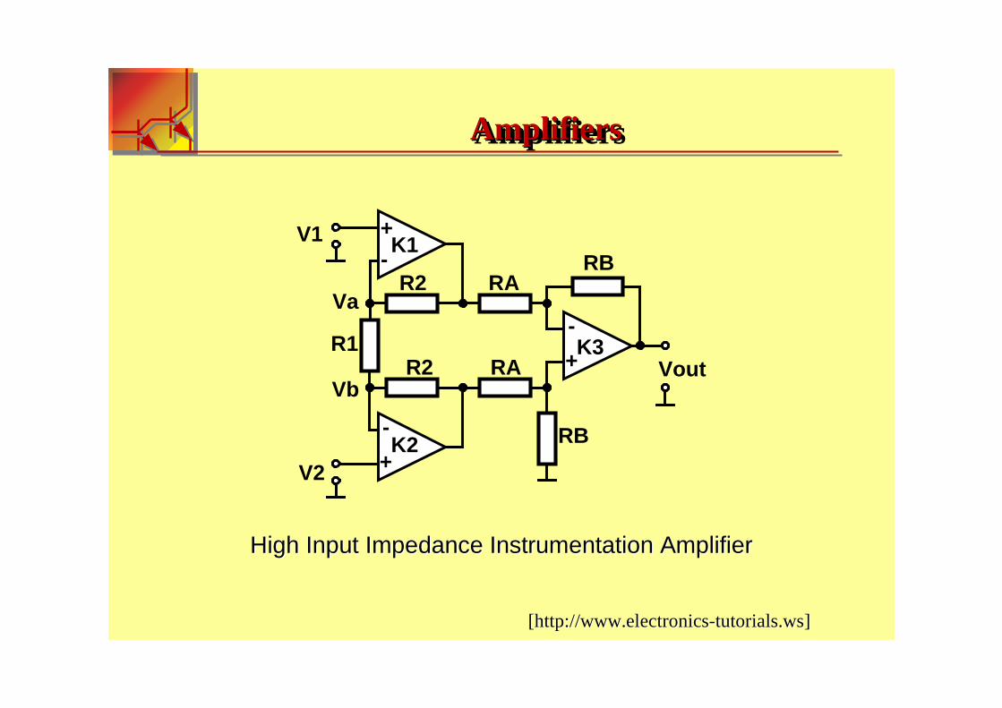
SingleSingle--Supply Bridge AmplifierSupply Bridge Amplifier
[[wwwwww..titi..comcom]]
AmplifiersAmplifiersAmplifiers

OscillatorsOscillatorsOscillatorsAn electronic oscillator is an electronic circuit that producesAn electronic oscillator is an electronic circuit that produces aa repetitiverepetitive,,
oscillating electronic signaloscillating electronic signal,, oftenoften a sinea sine wave orwave or aa square wavesquare wave..
[http://[http://enen..wikipediawikipedia..orgorg//wikiwiki/]/]

BasicBasic Oscillator Feedback CircuitOscillator Feedback Circuit
+
Vin Vout
Attenuator B
Amplifier
VoutB Vout
Vin+B VoutA
OscillatorsOscillatorsOscillators

AA-- open loop voltage gainopen loop voltage gain
BB-- feedback fractionfeedback fraction
AB
A
Vin
Vout
ABVoutAVin
VoutBVoutVinA
−=
−==+
1
)1(
)(
OscillatorOscillators are circuits that generates are circuits that generate aa continuous voltage output continuous voltage output waveform atwaveform at aa required frequency with the values of the inductorsrequired frequency with the values of the inductors,,capacitors or resistors formingcapacitors or resistors forming aa frequency selectivefrequency selective LCLC resonantresonant tanktankcircuit and feedback networkcircuit and feedback network.. This feedback network is an attenuation This feedback network is an attenuation network which hasnetwork which has aa gain ofgain of lessless thanthan one ( one ( BB <1 )<1 ) and starts oscillations and starts oscillations whenwhen AABB >1>1 which returnswhich returns to unity ( Ato unity ( ABB =1 )=1 ) once oscillations once oscillations commencecommence..
OscillatorsOscillatorsOscillators

TTypes of Oscillatorsypes of Oscillators
Sinusoidal OscillatorsSinusoidal Oscillators-- generatesgenerates aa purely sinusoidal waveform purely sinusoidal waveform which is of constant amplitude and frequencywhich is of constant amplitude and frequency..
NonNon--Sinusoidal OscillatorsSinusoidal Oscillators-- generate complex nongenerate complex non--sinusoidal sinusoidal waveformswaveforms as "as "SquareSquare--wavewave", "", "TriangularTriangular--wavewave"" oror ""SawtoothedSawtoothed--wavewave""
OscillatorsOscillatorsOscillators

TheThe RC RC OscillatorOscillator
AA singlesingle stage amplifierstage amplifier willwill produceproduce 180180OO of phase shift between its of phase shift between its output and input signals when connected inoutput and input signals when connected in aa classclass--AA type configurationtype configuration..
InIn anan RCRC Oscillator circuit the input is shiftedOscillator circuit the input is shifted 180180OO through the amplifier through the amplifier stage andstage and 180o180o again throughagain through aa second inverting stage giving ussecond inverting stage giving us " " 180180OO
+ + 180180OO = = 360360OO" " of phase shiftof phase shift..
In a RC In a RC OscillatorOscillator, we, we make use of the fact thatmake use of the fact that aa phase shift occurs phase shift occurs between the inputbetween the input to a RCto a RC network and the output from thenetwork and the output from the samesamenetworknetwork byby usingusing RCRC elements in the feedback branchelements in the feedback branch..
RC OscillatorsRC RC OscillatorsOscillators

RCRC PhasePhase--ShiftShift NetworkNetwork
C
R
input output
60o
C
R
C
R
C
Ro0
o0 o180
RC OscillatorsRC RC OscillatorsOscillators

90O
60O
output
180O
outputinput
Single stage
Three stage
PPhase shift between the inputhase shift between the input RC RC network and the outputnetwork and the output..

fCX C π2
1=
22 )( CXRZ +=
R
X C1tan −=φ
RC OscillatorsRC RC OscillatorsOscillators

An amplifier circuit will produce a phaseAn amplifier circuit will produce a phase--shift of shift of 180180OO between its input between its input and output. If a threeand output. If a three--stage RC phasestage RC phase--shift network is connected shift network is connected between this input and output of the amplifier, the total phase between this input and output of the amplifier, the total phase shift shift necessary for regenerative feedback will become 3 x necessary for regenerative feedback will become 3 x 6600OO + + 180180OO = = 360360OO ..
C
R
C
R
C
Ro0
o180o120o60 AB=1180o
RC OscillatorsRC RC OscillatorsOscillators

Basic RCBasic RC Oscillator CircuitOscillator Circuit
C
R
C
R
C
Ro0
o180o120o60
output
Vcc
R1 Rl
Re
RC OscillatorsRC RC OscillatorsOscillators

If all the resistorsIf all the resistors, R, R and the capacitorsand the capacitors, C, C in the phase shift network are in the phase shift network are equal in valueequal in value,, then the frequency of oscillations producedthen the frequency of oscillations produced byby thethe RCRCoscillator is givenoscillator is given as:as:
WhereWhere::
ƒƒrr-- Output Frequency inOutput Frequency in HertzHertz
RR-- Resistance in OhmsResistance in Ohms
CC-- Capacitance in FaradsCapacitance in Farads
NN-- number ofnumber of RC RC stagesstages (N = 3)(N = 3)
NRCfr
22
1
π−
RC OscillatorsRC RC OscillatorsOscillators

OpOp--ampamp RCRC Oscillator CircuitOscillator Circuit
C
R
C
R
C
Ro0
o180o120o60
output
A-
+
Rf
RC OscillatorsRC RC OscillatorsOscillators

ExampleExample
Hzfr
kR
FnFC
75,6491010000062
1
100
1011
9
9
=⋅⋅⋅⋅
=
Ω=⋅==
−
−
π
RC OscillatorsRC RC OscillatorsOscillators

The Wien Bridge OscillatorThe Wien Bridge Oscillator
The Wien Bridge Oscillator is so called because the circuit is bThe Wien Bridge Oscillator is so called because the circuit is basedased on aon afrequencyfrequency--selectiveselective formform of the Whetstone bridge circuitof the Whetstone bridge circuit..
RCRC PhasePhase ShiftShift NetworkNetwork
C1R1
R2 C2 VoutVin
R1=R2, C1=C2
RC OscillatorsRC RC OscillatorsOscillators

Output Gain and PhaseOutput Gain and Phase ShiftShift
fr
Vout
φ f
f
90
-90
o
o
Phase Shift
fr
Resonance
1/3 Vin
RC OscillatorsRC RC OscillatorsOscillators

Resonant FrequencyResonant Frequency
WhereWhere::
ƒƒr is the Resonant Frequency inr is the Resonant Frequency in HertzHertz
RR is the Resistance in Ohmsis the Resistance in Ohms
CC is the Capacitance in Faradsis the Capacitance in Farads
RCfR π2
1=
RC OscillatorsRC RC OscillatorsOscillators
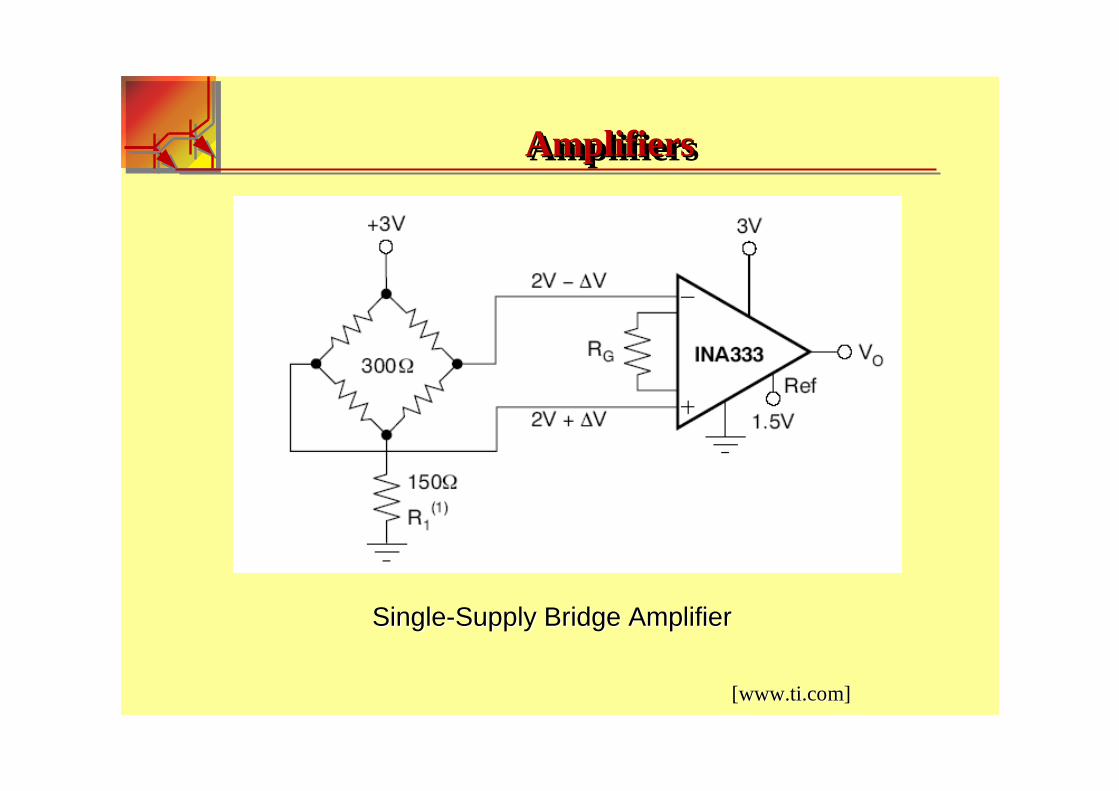
Wien Bridge OscillatorWien Bridge Oscillator
OneOne part of the feedback part of the feedback signal is connectedsignal is connected toto the the inverting inputinverting input terminal terminal ((negative feedbacknegative feedback) via) via the the resistor dividerresistor divider..
The other part is fed backThe other part is fed back totothe nonthe non--inverting inputinverting inputterminal (terminal (positive feedbackpositive feedback) ) viavia thethe RCRC Wien Bridge Wien Bridge networknetwork
V output
A+
-
RC
C
R
R1R2
1/3Vout
RC OscillatorsRC RC OscillatorsOscillators

Only aOnly at the selected resonant frequencyt the selected resonant frequency, (, ( ƒƒrr )) the voltages appliedthe voltages applied toto the the inverting and noninverting and non--inverting inputsinverting inputs will bewill be equal andequal and ""inin--phasephase„„..
The positive feedbackThe positive feedback willwill cancel out the negative feedback signal cancel out the negative feedback signal causing the circuitcausing the circuit toto oscillateoscillate..
TThe voltage gain of the amplifier circuithe voltage gain of the amplifier circuit MUST beMUST be equalequal toto threethree ""GainGain = = 3" for3" for oscillationsoscillations to startto start..
RC OscillatorsRC RC OscillatorsOscillators
The Quartz Crystal OscillatorsThe Quartz Crystal Oscillators
OneOne of theof the mostmost important features of any oscillator is its frequency important features of any oscillator is its frequency stabilitystability..
Frequency stability of the output signal canFrequency stability of the output signal can bebe improvedimproved byby the proper selection the proper selection of the components usedof the components used forfor the resonant feedback circuitthe resonant feedback circuit..
ToTo obtainobtain aa very high level of oscillator stabilityvery high level of oscillator stability aa Quartz Crystal is generally Quartz Crystal is generally usedused asas the frequency determining devicethe frequency determining device toto produce another types of oscillator produce another types of oscillator circuit known generallycircuit known generally as aas a Quartz Crystal OscillatorQuartz Crystal Oscillator
Quartz OscillatorsQuartzQuartz OscillatorsOscillators

Colpitts Crystal OscillatorColpitts Crystal Oscillator
These types of Crystal Oscillators are designed around the commoThese types of Crystal Oscillators are designed around the common n emitter amplifier stage ofemitter amplifier stage of aa Colpitts OscillatorColpitts Oscillator..
Quartz OscillatorsQuartzQuartz OscillatorsOscillators
output
Vcc
R1RL
ReR2Ce
C1 C2
Xt
The Other The Other Electrical WaveformsElectrical Waveforms
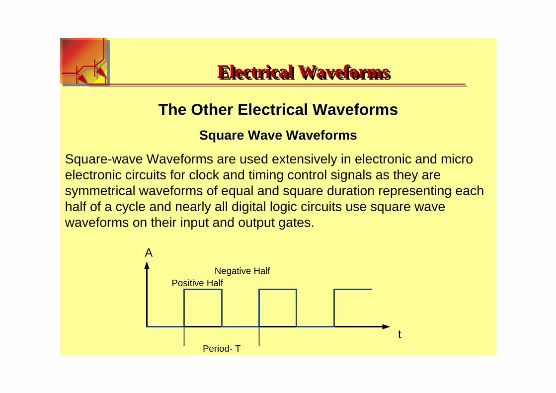
Square Wave WaveformsSquare Wave Waveforms
Square-wave Waveforms are used extensively in electronic and micro electronic circuits for clock and timing control signals as they are symmetrical waveforms of equal and square duration representing each half of a cycle and nearly all digital logic circuits use square wave waveforms on their input and output gates.
A
t
Positive HalfNegative Half
Period- T
Electrical WaveformsElectrical WaveformsElectrical Waveforms

Rectangular WaveformsRectangular Waveforms
Rectangular Waveforms are similar to the square wave waveform above,the difference being that the two pulse widths of the waveform are of an unequal time period. Rectangular waveforms are therefore classed as "Non-symmetrical" waveforms.
A
t
Positive HalfNegative Half
Period- T
Electrical WaveformsElectrical WaveformsElectrical Waveforms

Triangular WaveformsTriangular Waveforms
Triangular Waveforms are generally bi-directional non-sinusoidal waveforms that oscillate between a positive and a negative peak value.
A
tPeriod- T
Electrical WaveformsElectrical WaveformsElectrical Waveforms

Sawtooth WaveformsSawtooth Waveforms
Sawtooth Waveforms are another type of periodic waveform. As its name suggests, the shape of the waveform resembles the teeth of a sawblade.
A
t
Period- T
Electrical WaveformsElectrical WaveformsElectrical Waveforms

Function Generator
A Function Generator or sometimes called a Waveform Generator is adevice or circuit that produces a variety of different waveforms at adesired frequency. It can generate Sine waves, Square waves,Triangular and Sawtooth waveforms as well as other types of output waveforms
Electrical WaveformsElectrical WaveformsElectrical Waveforms

Functional Functional DiagramDiagram [http://[http://wwwwww..intersilintersil..comcom/]/]
ICL8038ICL8038-- Precision WaveformPrecision Waveform Generator/Generator/VoltageVoltage
Controlled OscillatorControlled Oscillator
IC Electrical WaveformsIC IC Electrical WaveformsElectrical Waveforms

Detailed SchematicDetailed Schematic[http://[http://wwwwww..intersilintersil..comcom/]/]
IC Electrical WaveformsIC IC Electrical WaveformsElectrical Waveforms

ParametersParameters::
--Low Frequency Drif with TemperatureLow Frequency Drif with Temperature
--Low DistirtionLow Distirtion-- 1% (Sine 1% (Sine Wave OutputWave Output))
--High LinearityHigh Linearity-- 0,1%0,1%
--Wide Frequency RangeWide Frequency Range-- 0,001Hz0,001Hz--300kHz300kHz
--High Level OutputsHigh Level Outputs-- TTL to 28VTTL to 28V
--EasyEasy to to useuse
[http://[http://wwwwww..intersilintersil..comcom/]/]
IC Electrical WaveformsIC IC Electrical WaveformsElectrical Waveforms

WaveformWaveform Generator ICGenerator IC
[[http://http://wwwwww..electronicselectronics--tutorialstutorials..wsws]]
IC Electrical WaveformsIC IC Electrical WaveformsElectrical Waveforms

AD5932 AD5932 Programmable Frequency Scan Waveform Generator
ParametersParameters::
--Programmable Frequency ScanProgrammable Frequency Scan
--No No external components necessaryexternal components necessary
--Output frequency upOutput frequency up to 25to 25 MHz MHz
--Power supplyPower supply: 2.3 V to 5.5 V: 2.3 V to 5.5 V
--Automotive temperature rangeAutomotive temperature range: : −−4040°°C to +125C to +125°°CC
[[http://http://wwwwww.analog..analog.comcom//]]
IC Electrical WaveformsIC IC Electrical WaveformsElectrical Waveforms

Functional Block Diagram
[[http://http://wwwwww.analog..analog.comcom//]]
IC Electrical WaveformsIC IC Electrical WaveformsElectrical Waveforms

80C51/80L51 to AD593280C51/80L51 to AD5932 InterfaceInterface
[[http://http://wwwwww.analog..analog.comcom//]]
IC Electrical WaveformsIC IC Electrical WaveformsElectrical Waveforms

-+
Vin
Voltage Controlled Current Source
C
Comparator
Vref
Vout
Reset
VoltageVoltage--CControlled ontrolled OOscillator scillator (VCO)(VCO)
VCO- Block diagram
[http://sequence15.[http://sequence15.blogspotblogspot..comcom/2008/02//2008/02/howhow--vcovco--worksworks..htmlhtml]]
Voltage-to-Frequency ConvertersVoltageVoltage--toto--Frequency ConverterFrequency Converterss

IfIf aa constant current is appliedconstant current is applied toto the capacitorthe capacitor,, the voltage across the capacitorthe voltage across the capacitorwillwill rise atrise at aa constant rateconstant rate..
AA fairly basic circuit can take the control voltage and outputfairly basic circuit can take the control voltage and output aa constant current constant current which is proportionalwhich is proportional toto the voltagethe voltage..
While capacitor is chargingWhile capacitor is charging, a, a voltage comparator constantly compares the voltage comparator constantly compares the voltage across the capacitorvoltage across the capacitor to ato a reference voltagereference voltage..
When the voltage across theWhen the voltage across the capcap exceeds the reference voltageexceeds the reference voltage,, the comparator the comparator momentarily triggers the transistor which shorts out themomentarily triggers the transistor which shorts out the cap,cap, discharging it backdischarging it backtoto the starting voltagethe starting voltage..
-+
Vin
Voltage Controlled Current Source
C
Comparator
Vref
Vout
Reset
VCOVCOVCO

VCOVCOVCO
LM566CLM566C Voltage Controlled OscillatorVoltage Controlled Oscillator
ConnectionConnection DiagramDiagram
[[wwwwww..nationalnational..comcom]]

VCOVCOVCO
Typical ApplicationTypical Application
11 kHz andkHz and 1010 kHzkHz TTL TTL CompatibleCompatible Voltage Controlled OscillatorVoltage Controlled Oscillator[[wwwwww..nationalnational..comcom]]

VCOVCOVCO
kRk
where
CR
VVf
O
OOO
202
)5(4,2
<<
−=+
V5V5-- voltage between pin voltage between pin 5 i 5 i pin pin 11
FeaturesFeatures
--Wide supply voltage rangeWide supply voltage range: 10V to : 10V to 24V24V
--Very linear modulation characteristicsVery linear modulation characteristics
--High temperature stabilityHigh temperature stability
--Frequency programmableFrequency programmable byby means of means of currentcurrent,, voltagevoltage,, resistor or capacitorresistor or capacitor
ApplicationsApplications
--FM FM modulationmodulation
--Signal generationSignal generation
--Function generationFunction generation
--Frequency shift keyingFrequency shift keying
--Tone generationTone generation
[[wwwwww..nationalnational..comcom]]
[[wwwwww..titi..comcom]]
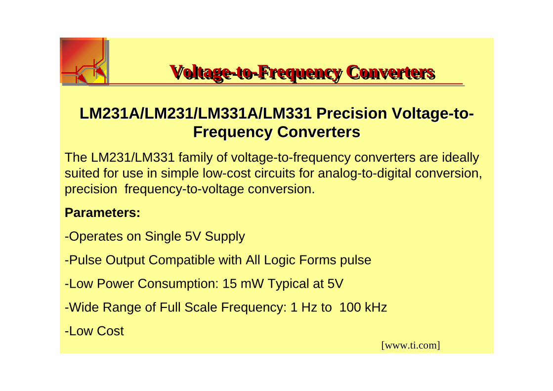
LM231A/LM231/LM331A/LM331LM231A/LM231/LM331A/LM331 Precision VoltagePrecision Voltage--toto--Frequency ConvertersFrequency Converters
The LM231/LM331 family of voltage-to-frequency converters are ideally suited for use in simple low-cost circuits for analog-to-digital conversion,precision frequency-to-voltage conversion.
Parameters:
-Operates on Single 5V Supply
-Pulse Output Compatible with All Logic Forms pulse
-Low Power Consumption: 15 mW Typical at 5V
-Wide Range of Full Scale Frequency: 1 Hz to 100 kHz
-Low Cost
Voltage-to-Frequency ConvertersVoltageVoltage--toto--Frequency ConverterFrequency Converterss

[[wwwwww..titi..comcom]]Functional Block Diagram
Voltage-to-Frequency ConvertersVoltageVoltage--toto--Frequency ConverterFrequency Converterss

Simplified BlockSimplified Block DiagramDiagram of Standof Stand--AloneAlone VoltageVoltage--toto--Frequency Frequency Converter andConverter and External ComponentsExternal Components
[[wwwwww..titi..comcom]]
Voltage-to-Frequency ConvertersVoltageVoltage--toto--Frequency ConverterFrequency Converterss
The voltage comparator compares a positive input voltage, V1, at pin 7 to the voltage, Vx, at pin 6. If V1 is greater, the comparator will trigger the 1-shot timer. The output of the timer will turn ON both the frequencyoutput transistor and the switched current source for a period t=1.1 RtCt.During this period, the current i will flow out of the switched current source and provide a fixed amount of charge, Q = i × t, into the capacitor, CL. This will normally charge Vx up to a higher level than V1.At the end of the timing period, the current will turn OFF, and the timerwill reset itself.
[[wwwwww..titi..comcom]]
Voltage-to-Frequency ConvertersVoltageVoltage--toto--Frequency ConverterFrequency Converterss

Simple StandSimple Stand--AloneAlone VV--toto--F F ConverterConverter withwith ±±0.03%0.03% Typical LinearityTypical Linearity (f = (f = 1010 HzHz to 11to 11 kHzkHz)) [[wwwwww..titi..comcom]]
Voltage-to-Frequency ConvertersVoltageVoltage--toto--Frequency ConverterFrequency Converterss

http://www.electronics-tutorials.ws/
www.ti.com
www.analog.com
http://www.electronicshub.org/
Bibliogaphy: