JDVC Digital Voice Command and Amplifiers Series - Product ...
116
E P/N 52567:E • ECN 06-821 Document 52567 7/02/2007 Digital Audio JDVC Digital Voice Command and Amplifiers Series Installation, Programming and Operations Manual
-
Upload
khangminh22 -
Category
Documents
-
view
1 -
download
0
Transcript of JDVC Digital Voice Command and Amplifiers Series - Product ...

EP/N 52567:E • ECN 06-821
Document 525677/02/2007
Digital Audio
JDVC DigitalVoice Command
and AmplifiersSeries
Installation, Programming and OperationsManual

Fire Alarm System LimitationsWhile a fire alarm system may lower insurance rates, it is not a substitute for fire insurance!An automatic fire alarm system—typically made up of smoke detectors, heat detectors, manual pull stations, audible warning devices, and a fire alarm control panel with remote notification capability—can provide early warning of a develop-ing fire. Such a system, however, does not assure protection against property damage or loss of life resulting from a fire.
The Manufacturer recommends that smoke and/or heat detec-tors be located throughout a protected premise following the recommendations of the current edition of the National Fire Protection Association Standard 72 (NFPA 72), manufacturer's recommendations, State and local codes, and the recommen-dations contained in the Guides for Proper Use of System Smoke Detectors, which are made available at no charge to all installing dealers. These documents can be found at http://www.systemsensor.com/html/applicat.html. A study by the Federal Emergency Management Agency (an agency of the United States government) indicated that smoke detectors may not go off in as many as 35% of all fires. While fire alarm systems are designed to provide early warning against fire, they do not guarantee warning or protection against fire. A fire alarm system may not provide timely or adequate warning, or simply may not function, for a variety of reasons:
Smoke detectors may not sense fire where smoke cannot reach the detectors such as in chimneys, in or behind walls, on roofs, or on the other side of closed doors. Smoke detectors also may not sense a fire on another level or floor of a building. A second-floor detector, for example, may not sense a first-floor or basement fire.
Particles of combustion or “smoke” from a developing fire may not reach the sensing chambers of smoke detectors because:
• Barriers such as closed or partially closed doors, walls, or chimneys may inhibit particle or smoke flow.
• Smoke particles may become “cold,” stratify, and not reach the ceiling or upper walls where detectors are located.
• Smoke particles may be blown away from detectors by air outlets.
• Smoke particles may be drawn into air returns before reaching the detector.
The amount of “smoke” present may be insufficient to alarm smoke detectors. Smoke detectors are designed to alarm at various levels of smoke density. If such density levels are not created by a developing fire at the location of detectors, the detectors will not go into alarm.
Smoke detectors, even when working properly, have sensing limitations. Detectors that have photoelectronic sensing chambers tend to detect smoldering fires better than flaming fires, which have little visible smoke. Detectors that have ion-izing-type sensing chambers tend to detect fast-flaming fires better than smoldering fires. Because fires develop in different ways and are often unpredictable in their growth, neither type of detector is necessarily best and a given type of detector may not provide adequate warning of a fire.
Smoke detectors cannot be expected to provide adequate warning of fires caused by arson, children playing with matches (especially in bedrooms), smoking in bed, and violent explosions (caused by escaping gas, improper storage of
Heat detectors do not sense particles of combustion and alarm only when heat on their sensors increases at a predeter-mined rate or reaches a predetermined level. Rate-of-rise heat detectors may be subject to reduced sensitivity over time. For this reason, the rate-of-rise feature of each detector should be tested at least once per year by a qualified fire pro-tection specialist. Heat detectors are designed to protect property, not life.
IMPORTANT! Smoke detectors must be installed in the same room as the control panel and in rooms used by the sys-tem for the connection of alarm transmission wiring, communi-cations, signaling, and/or power. If detectors are not so located, a developing fire may damage the alarm system, crip-pling its ability to report a fire.
Audible warning devices such as bells may not alert people if these devices are located on the other side of closed or partly open doors or are located on another floor of a building. Any warning device may fail to alert people with a disability or those who have recently consumed drugs, alcohol or medica-tion. Please note that:
• Strobes can, under certain circumstances, cause seizures in people with conditions such as epilepsy.
• Studies have shown that certain people, even when they hear a fire alarm signal, do not respond or comprehend the meaning of the signal. It is the property owner's responsi-bility to conduct fire drills and other training exercise to make people aware of fire alarm signals and instruct them on the proper reaction to alarm signals.
• In rare instances, the sounding of a warning device can cause temporary or permanent hearing loss.
A fire alarm system will not operate without any electrical power. If AC power fails, the system will operate from standby batteries only for a specified time and only if the batteries have been properly maintained and replaced regularly.
Equipment used in the system may not be technically com-patible with the control panel. It is essential to use only equip-ment listed for service with your control panel.
Telephone lines needed to transmit alarm signals from a premise to a central monitoring station may be out of service or temporarily disabled. For added protection against tele-phone line failure, backup radio transmission systems are rec-ommended.
The most common cause of fire alarm malfunction is inade-quate maintenance. To keep the entire fire alarm system in excellent working order, ongoing maintenance is required per the manufacturer's recommendations, and UL and NFPA stan-dards. At a minimum, the requirements of NFPA 72 shall be followed. Environments with large amounts of dust, dirt or high air velocity require more frequent maintenance. A main-tenance agreement should be arranged through the local man-ufacturer's representative. Maintenance should be scheduled monthly or as required by National and/or local fire codes and should be performed by authorized professional fire alarm installers only. Adequate written records of all inspections should be kept.
Limit-C1-2-2007
2 JDVC Series Digital Audio Manual — P/N 52567:E 7/02/2007flammable materials, etc.).

Installation PrecautionsAdherence to the following will aid in problem-free installation with long-term reliability:WARNING - Several different sources of power can be connected to the fire alarm control panel. Disconnect all sources of power before servicing. Control unit and associ-ated equipment may be damaged by removing and/or insert-ing cards, modules, or interconnecting cables while the unit is energized. Do not attempt to install, service, or operate this unit until manuals are read and understood.
CAUTION - System Re-acceptance Test after Software Changes: To ensure proper system operation, this product must be tested in accordance with NFPA 72 after any pro-gramming operation or change in site-specific software. Re-acceptance testing is required after any change, addition or deletion of system components, or after any modification, repair or adjustment to system hardware or wiring. All compo-nents, circuits, system operations, or software functions known to be affected by a change must be 100% tested. In addition, to ensure that other operations are not inadvertently affected, at least 10% of initiating devices that are not directly affected by the change, up to a maximum of 50 devices, must also be tested and proper system operation verified.
This system meets NFPA requirements for operation at 0-49º C/32-120º F and at a relative humidity 93% ± 2% RH (non-condensing) at 32°C ± 2°C (90°F ± 3°F). However, the useful life of the system's standby batteries and the electronic com-ponents may be adversely affected by extreme temperature ranges and humidity. Therefore, it is recommended that this system and its peripherals be installed in an environment with a normal room temperature of 15-27º C/60-80º F.
Verify that wire sizes are adequate for all initiating and indi-cating device loops. Most devices cannot tolerate more than a 10% I.R. drop from the specified device voltage.
Like all solid state electronic devices, this system may operate erratically or can be damaged when subjected to light-ning induced transients. Although no system is completely immune from lightning transients and interference, proper grounding will reduce susceptibility. Overhead or outside aerial wiring is not recommended, due to an increased susceptibility to nearby lightning strikes. Consult with the Technical Ser-vices Department if any problems are anticipated or encoun-tered.
Disconnect AC power and batteries prior to removing or inserting circuit boards. Failure to do so can damage circuits.
Remove all electronic assemblies prior to any drilling, filing, reaming, or punching of the enclosure. When possible, make all cable entries from the sides or rear. Before making modifi-cations, verify that they will not interfere with battery, trans-former, or printed circuit board location.
Do not tighten screw terminals more than 9 in-lbs. Over-tightening may damage threads, resulting in reduced terminal contact pressure and difficulty with screw terminal removal.
This system contains static-sensitive components. Always ground yourself with a proper wrist strap before han-dling any circuits so that static charges are removed from the body. Use static suppressive packaging to protect electronic assemblies removed from the unit.
Follow the instructions in the installation, operating, and pro-gramming manuals. These instructions must be followed to avoid damage to the control panel and associated equipment. FACP operation and reliability depend upon proper installation.
Precau-D1-9-2005
FCC WarningWARNING: This equipment generates, uses, and can radiate radio frequency energy and if not installed and used in accordance with the instruction manual may cause interference to radio communications. It has been tested and found to comply with the limits for class A computing devices pursuant to Subpart B of Part 15 of FCC Rules, which is designed to provide reasonable protection against such interference when devices are operated in a commercial environment. Operation of this equipment in a residential area is likely to cause interfer-ence, in which case the user will be required to correct the interference at his or her own expense.
Canadian RequirementsThis digital apparatus does not exceed the Class A limits for radiation noise emissions from digital apparatus set out in the Radio Interference Regulations of the Cana-dian Department of Communications.
Le present appareil numerique n'emet pas de bruits radi-oelectriques depassant les limites applicables aux appa-reils numeriques de la classe A prescrites dans le Reglement sur le brouillage radioelectrique edicte par le ministere des Communications du Canada.
HARSH™, NIS™, Notifier Integrated Systems™, NOTI•FIRE•NET™, and ONYXWorks™ are all trademarks; and FlashScan®, NION®, NOTIFIER®,ONYX®, UniNet®, VeriFire®, and VIEW® are all registered trademarks of Honeywell International Inc. Echelon® is a registered trademark and LonWorks™is a trademark of Echelon Corporation. ARCNET® is a registered trademark of Datapoint Corporation. Microsoft® and Windows® are registered trademarksof the Microsoft Corporation. LEXAN® is a registered trademark of GE Plastics, a subsidiary of General Electric Company. ©Thursday, August 16, 2007. All rights reserved. Unauthorized use of this document is strictly prohibited.
JDVC Series Digital Audio Manual — P/N 52567:E 7/02/2007 3

Documentation FeedbackYour feedback helps us keep our documentation up-to-date and accurate. If you have any comments or suggestions about our online Help or printed manuals, you can email us.
Please include the following information:
• Product name and version number (if applicable)• Printed manual or online Help• Topic Title (for online Help)• Page number (for printed manual)• Brief description of content you think should be improved or corrected• Your suggestion for how to correct/improve documentation
Send email messages to:
Please note this email address is for documentation feedback only. If you have any technical issues, please contact Technical Services.
4 JDVC Series Digital Audio Manual — P/N 52567:E 7/02/2007

Table of Contents General Information.................................................................................................................8
JDVC Digital Voice Command .................................... 10Section 1: JDVC Overview ..................................................................................................... 10
1.1: Description...................................................................................................................................................101.1.1: Features..............................................................................................................................................121.1.2: Options ..............................................................................................................................................131.1.3: Specifications.....................................................................................................................................13
1.2: JDVC Board Layout ....................................................................................................................................151.2.1: Wire Version......................................................................................................................................151.2.2: Fiber Versions....................................................................................................................................171.2.3: Switch Functions ...............................................................................................................................181.2.4: Indicators ...........................................................................................................................................19
1.3: Options.........................................................................................................................................................201.3.1: DVC-AO Analog Output Board Layout............................................................................................201.3.2: DVC-KD Keypad ..............................................................................................................................20
Section 2: JDVC Installation .................................................................................................. 212.1: Overview......................................................................................................................................................21
2.1.1: Chassis ...............................................................................................................................................212.1.2: Doors and Dress Panels .....................................................................................................................21
2.2: Prepare for Installation ................................................................................................................................222.3: Installation Checklist ...................................................................................................................................232.4: Cabinet .........................................................................................................................................................232.5: Mount JDVC Series Option Boards ............................................................................................................24
2.5.1: DVC-AO Analog Output Board ........................................................................................................242.5.2: DVC-KD Keypad ..............................................................................................................................25
2.6: Mount an NCM-W/F in a CA-1 or CA-2 Chassis .......................................................................................262.7: Mount a JDVC Series Board in a CA-1 or CA-2 Chassis ...........................................................................262.8: Move the Chassis for Wiring Access...........................................................................................................27
2.8.1: CA-1 ..................................................................................................................................................272.8.2: CA-2 ..................................................................................................................................................27
2.9: Wiring ..........................................................................................................................................................282.9.1: JDVC Series Board to 24V Power ...................................................................................................282.9.2: Alarm Bus .........................................................................................................................................282.9.3: Digital Audio Ports A and B on Wire Version Boards......................................................................302.9.4: RXA, RXB, TXA, TXB Fiber Version Board Connections .............................................................312.9.5: FFT Connectivity...............................................................................................................................322.9.6: Auxiliary Inputs A and B...................................................................................................................332.9.7: Network Connection (NUP) Ports.....................................................................................................342.9.8: Push-to-Talk Indicator.......................................................................................................................342.9.9: RM-1 Remote Microphone Interface ................................................................................................352.9.10: MIC-1 Local Microphone Interface ................................................................................................352.9.11: TELH-1 Local Phone Interface .......................................................................................................352.9.12: Analog Audio Outputs (DVC-AO)..................................................................................................362.9.13: UL Power-limited Wiring Requirements ........................................................................................37
2.10: Replacement of NVRAM Memory-Backup Battery .................................................................................37
Section 3: JDVC Configuration and Programming.............................................................. 383.1: Setting the Configuration Switches .............................................................................................................38
3.1.1: Piezo (Switch 5).................................................................................................................................383.1.2: EFA and EFB (Switches 7 and 6)......................................................................................................383.1.3: 4WIRE (Switch 8) .............................................................................................................................39
JDVC Series Digital Audio Manual — P/N 52567:E 7/02/2007 5

1Table of Contents
3.2: Panel Programming .....................................................................................................................................393.3: VeriFire Tools Programming ......................................................................................................................39
3.3.1: JDVC System Programming .............................................................................................................403.3.2: DAA Amplifier Programming...........................................................................................................483.3.3: Audio Message Programming ...........................................................................................................513.3.4: Logic Equation Builder .....................................................................................................................563.3.5: Prioritized Audio Matrix (PAM) Programming ................................................................................573.3.6: Reports...............................................................................................................................................61
3.4: Programming JDVC General Zones for Retrofits .......................................................................................623.5: Program Validation Service .........................................................................................................................62
Section 4: JDVC Operation .................................................................................................... 644.1: Using the DVC-KD Keypad........................................................................................................................64
4.1.1: Pre-defined Buttons/Indicators ..........................................................................................................644.1.2: LED Indicators ..................................................................................................................................654.1.3: 24 User-programmable Buttons.........................................................................................................66
4.2: Paging ..........................................................................................................................................................664.2.1: MIC-1 Microphone Paging................................................................................................................664.2.2: TELH-1 Telephone Paging................................................................................................................664.2.3: RM-1 Remote Microphone Paging....................................................................................................674.2.4: AUXA/AUXB Paging .......................................................................................................................674.2.5: FFT Paging ........................................................................................................................................68
4.3: JDVC Series Firefighter’s Telephone Network Communication ................................................................684.3.1: Description.........................................................................................................................................684.3.2: Examples ...........................................................................................................................................69
4.4: Display and Control Center (DCC) .............................................................................................................704.5: Trouble Messages ........................................................................................................................................70
DAA Digital Audio Amplifiers...................................... 72Section 5: DAA Overview....................................................................................................... 72
5.1: Description...................................................................................................................................................725.2: Features........................................................................................................................................................735.3: Specifications...............................................................................................................................................74
5.3.1: DAA-PS Power Supply Board ..........................................................................................................745.3.2: DAA-5025/70 and DAA-7525 Boards ..............................................................................................74
5.4: DAA Board Layouts ....................................................................................................................................765.4.1: Wire Versions ....................................................................................................................................765.4.2: Fiber Versions....................................................................................................................................785.4.3: Indicators ...........................................................................................................................................795.4.4: Switches and Jumper .........................................................................................................................81
Section 6: DAA Installation ....................................................................................................826.1: Cabinet .........................................................................................................................................................82
6.1.1: CAB-3 Cabinets.................................................................................................................................836.1.2: CAB-4 Series.....................................................................................................................................846.1.3: EQCAB Series Cabinets....................................................................................................................84
6.2: Batteries .......................................................................................................................................................856.2.1: In a CHS-BH1 Battery Chassis .........................................................................................................856.2.2: Within the CAB-4 Enclosure.............................................................................................................866.2.3: Outside the DAA Enclosure ..............................................................................................................86
6.3: Wiring ..........................................................................................................................................................866.3.1: Connecting the DAA Power Supply to AC Power............................................................................866.3.2: Connecting the DAA Power Supply to the Batteries ........................................................................876.3.3: Connecting the Alarm and Trouble Buses.........................................................................................896.3.4: Digital Audio Ports A and B on Wire Version Boards......................................................................916.3.5: RXA, RXB, TXA, TXB Fiber Version Board Connections .............................................................92
6

1Table of Contents
6.3.6: FFT Riser Connections......................................................................................................................936.3.7: Auxiliary Inputs A and B...................................................................................................................946.3.8: Speaker and Backup Circuits.............................................................................................................946.3.9: UL Power-limited Wiring Requirements ..........................................................................................97
6.4: Replacement of NVRAM Memory-Backup Battery ...................................................................................98
Section 7: DAA Configuration ............................................................................................... 997.1: Setting the Configuration Switches .............................................................................................................99
7.1.1: EFA and EFB (Switches 9 and 10)....................................................................................................997.1.2: 4WIRE (Switch 11) ...........................................................................................................................997.1.3: Address Switches.............................................................................................................................1007.1.4: Volume Control ...............................................................................................................................100
7.2: Programming .............................................................................................................................................100
Section 8: DAA Operation .................................................................................................... 1018.1: Pushbutton Controls...................................................................................................................................1018.2: Volume Control..........................................................................................................................................1018.3: FFT Paging ................................................................................................................................................1018.4: JDVC Firefighter’s Telephone Network Communication .........................................................................102
8.4.1: Description.......................................................................................................................................1028.5: Trouble Messages ......................................................................................................................................1038.6: Read/Alter Status .......................................................................................................................................104
Section 9: DAA Battery Calculations .................................................................................. 105Glossary................................................................................................................................. 109Index...................................................................................................................................... 110
7

General InformationStandards and Other Documents
The Digital Voice Command and Digital Audio Amplifiers Series comply with the following standards:
• NFPA 72 2002 National Fire Alarm Code• Underwriter Laboratories Standard UL 864 • Underwriter Laboratories of Canada (ULC) ULC-S527-99 Standard of Control Units for Fire
Alarm Systems• Part 15 Class A of the conducted radiated emissions as required by the FCC
The installer should be familiar with the following documents and standards:
NFPA StandardsNFPA 72 National Fire Alarm Code
Underwriter LaboratoriesUL 464 Audible Signaling AppliancesUL 864 Standard for Control Unit and Accessories for Fire Alarm SystemsUL 1481 Power Supplies for Fire Protective Signaling SystemsUL 1638 Visual Signaling Appliances - Private-Mode Emergency and General Utility SignalingUL 1711 Amplifiers for Fire Protective Signaling SystemsUL 60950 Safety of Information Technology EquipmentUL 1971 Signaling Devices for the Hearing Impaired
Underwriters Laboratories of Canada (ULC)ULC-S527-99 Standard of Control Units for Fire Alarm Systems
OtherFCC Part 15 Class A Conducted and Radiated Emissions
UL 864 Ninth Edition ComplianceThis product has been certified to comply with the requirements in the Standard for Control Units and Accessories for Fire Alarm Systems, UL 864 9th Edition.
Products Subject to AHJ ApprovalThe following products have not received UL 864 9th Edition certification and may only be used in retrofit applications. Operation of the JDVC Series with products not tested for UL 864 9th Edition has not been evaluated and may not comply with NFPA 72 and/or the latest edition of UL 864. These applications will require the approval of the local Authority Having Jurisdiction (AHJ).
Programming Features Subject to AHJ ApprovalThis product incorporates field-programmable software. The features and/or options listed below must be approved by the local AHJ.
IFC-640 Fire Alarm Control Panel AMG-1JNCA Network Control Annunciator XPIQ (NAC applications only)IFC-3030 Fire Alarm Control Panel
This product incorporates field-programmable software. In order for the product to comply with the requirements in the Standard for Control Units and Accessories for Fire Alarm Systems, UL 864, certain programming features or options must be limited to specific values or not used at all as indicated below.
Program Feature or Option Permitted in UL 864? (Y/N) Possible Settings Settings Permitted in UL 864
IP downloads over a local area network (LAN) or the internet (Wide Area Network - WAN)
No YesNo
No
8 JDVC Series Digital Audio Manual — P/N 52567:E 7/02/2007

General Information
Supplemental DocumentationThe table below provides a list of documents referenced in this manual, as well as documents for selected other compatible devices.
Related Documentation Table
Cautions and WarningsThis manual contains cautions and warnings to alert the reader as follows:
VeriFire Tools CD help file and CD pamphlet download from IFC-Fire.comNotifier DVC-AO Audio Option Board Installation Document 52728Notifier DVC-KD Keypad Product Installation Document 52709Notifier DAA Digital Audio Amplifiers Product Installation Document 52410CA-1 Chassis Product Installation Document 52474CA-2 Chassis Product Installation Document 52455CMIC-1 Product Installation Document 52476IFC2-3030 Installation, Programming and Operations Manuals 52563, 52564, 52565IFC2-640 Installation, Programming and Operations Manuals 52835, 52837, 52836Notifier AMPS-24 Manual 51907IFC-640 Installation, Programming, Operations Manuals 51864, 51866, 51865IFC-3030 Installation, Programming, Operations Manual 52024, 52025, 52026JNCA Network Control Annunciator Manual 51868JNCA-2 Network Control Annunciator Manual 52570IFW Intelligent Fire Workstation Manual 52028Notifier NCM Installation Document 51533Noti-Fire-Net Manual 51584Johnson ControlsSLC Wiring Manual 51870Notifier AA Series Audio Amplifier Manual 52526Notifier XPIQ Manual 51013Notifier ACS Annunciator Manual 15842AFAWS Automatic Fire Alarm Warden Station 50705M500FPJ Firephone Control Module 156-2550ACT-2 Audio Coupling Transformer 51118RM-1 Series Remote Microphones 51138CAB-4 Series Cabinets Installation Instructions 15330Notifier Audio Fiber Links Document 52230RSM-1A Residential Silence Module 156-006-000AIM-1A Audible Isolation Module 156-006-002Wire Guide Addendum for Digital Audio Loops 52916ADD
! CAUTION: Information about procedures that could cause programming errors, runtime errors, or equipment damage.
!WARNING: Indicates information about procedures that could cause irreversible damage to the control panel, irreversible loss of programming data, or personal injury.
JDVC Series Digital Audio Manual — P/N 52567:E 7/02/2007 9

JDVC Digital Voice CommandSection 1: JDVC Overview
1.1 DescriptionEach JDVC Series model is a multi-featured audio processor with digital audio functionality that operates as an event-driven audio message generator and router. It is designed for use with the DAA Series digital audio amplifiers in a single panel or networked environment, and may also be used as an analog audio source in retrofit applications. (See Figure 1.1.)
The IFC2-640 and IFC2-3030 may be directly connected to the JDVC for single panel applications. An associated JNCA-2 is required with the IFC2-640 when a DAL (digital audio loop) is part of the configuration. An associated JNCA-2 is not required with the IFC2-640 when there is no DAL. Refer to Figure 1.1 for illustrations of single panel configurations.
Network configurations require an associated JNCA-2, and will support all Network Control-by-Event (CCBE) from the following panels: IFC2-640, IFC-640, IFC2-3030, and IFC-3030.
When used with the optional DVC-KD keypad and a JNCA-2 or IFC2-3030, the Digital Command Center serves as an audio command center, accepting live paging from several sources and providing the ability to direct the paging to appropriate pre-programmed speaker zones in the system.
• JDVC - Digital Voice Command, wire version• JDVC-EM - Digital Voice Command, extended memory, wire version• JDVC-EMF - Digital Voice Command, extended memory, multi-mode fiber version• JDVC-EMSF - Digital Voice Command, extended memory, single-mode fiber version.
The JDVC-EM Series models listed above each contains up to 32 minutes of standard quality (11.025 KHz sampling rate, 8 bit µ-law, mono) audio storage, or 4 minutes of high quality (44.1 KHz sampling rate, 16 bit PCM, mono). The JDVC model listed above contains up to 16 minutes of standard quality audio storage, or 2 minutes of high quality.
Figure 1.1 gives simplified overview illustrations of typical applications for the JDVC Series and its Digital Audio Loop (DAL).
NOTE: The JDVC Series consists of all the model versions listed in the bullets below this note. Individual part numbers are used in this manual only when it is necessary to distinguish features or functions that differ. The term JDVC is used in all other cases.
NOTE: The term DAA is used in this manual to refer to all DAA wire and fiber models. Individual part numbers are used only when it is necessary to distinguish features or functions that differ.
NOTE: A DAL must be connected with one of the following: - All wire connections - All single-mode fiber connections, or - All multi-mode fiber connections.Wire and fiber, or multi-mode and single-mode, can not be mixed.
JDVC Series Digital Audio Manual — P/N 52567:E 7/02/2007 10

Description JDVC Overview
Figure 1.1 Block Diagrams of JDVC Series Applications
IFC2-3030 Single Panel Applications
Networked System
IFC2-3030
JDVC
IFC2-640
JNCA-2
Noti-Fire-Net
XPIQ
NUP
NCM
NCM
NCM
NCM
SLC
with JDVC and Digital Audio Loop (DAL).
Optional Style 7 return
Retrofit Networked System NCM
DVC-AO
DAL
AA Series Audio AmplifiersXPIQ, etc.
Low level analog audio
IFC2-3030
Noti-Fire-NetIFC2-640
NCM
NCM
Optional Style 7 returnDAL
DAA1
DAA2
DAA32
Optional Style 7 returnDAL
JDVCNUP
Optional Style 7 returnDAL
DVC-AO
with JDVC, DAL, and DVC-AO for retrofits.
NCM
IFC2-3030
Low level
analogaudio
NCM
IFC-320
NCM
IFC-320
A JNCA, IFC-640, or IFC-3030 with compatible software may be part of the network.
DAA1
DAA2
DAA32
JDVC DAA1
DAA2
DAA32
DAA1
DAA2
DAA32
JDVC
JNCA-2
IFC2-640 Single Panel Applications
with JDVC and DVC-AO for retrofits. DAL (digital audio loop) not compatible with this application.
with JDVC, JNCA-2, DAL, and DVC-AO for retrofits.
XPIQSLC
JDVCNUP
DVC-AOLow level
analogaudio
IFC2-640
IFC2-3030
JDVCNUP
Optional Style 7 returnDAL
DVC-AO
DAA1
DAA2
DAA32
IFC2-640
AA Series Audio AmplifiersXPIQ, etc.
Low level analog audio
JNCA-2 NUP
JDVC Series Digital Audio Manual — P/N 52567:E 7/02/2007 11

JDVC Overview Description
1.1.1 Features• Programmable from NUP port using VeriFire Tools with:
• JDVC - Up to 16 minutes of standard quality or 2 minutes of high quality digital audio storage of user-selected/created messages and tones.
• JDVC-EMs - up to 32 minutes of standard quality or 4 minutes of high quality digital audio storage of user-selected/created messages and tones.
• Up to 1000 audio sequences.• Message prioritization.• System configuration parameters.• Equations for distribution of messages.
• Digital audio ports for direct connection with up to 32 DAA amplifiers.• Multiple audio command centers supported within a system.• DCC (Display and Control Center) capabilities when used with DVC-KD and associated
JNCA-2 or IFW.• FireFighter’s Telephone (FFT) Riser, with local telephone handset option.• Local paging microphone option.• Remote microphone paging option with RM-1.• Broad paging functionality when used with DVC-KD via microphone, TELH-1 or FFT, RM-1,
AUX A or AUX B inputs.• All Call• Page Active Evac Areas• Page Active Alert Areas• Page Inactive Areas
• Auxiliary input for 12Vp-p analog low-level audio sources.• Auxiliary input for 1VRMS, to be used for background music input, an interface with a
telephone paging source, or other compatible audio sources. Includes user audio level adjustment feature.
• Operates as a node on Noti-Fire-Net.• Functional with IFC2-3030 or IFC2-640 as a standalone system (without Noti-Fire-Net).• Distribution of one channel of audio on Noti-Fire-Net.• Eight audio data and five Firefighters Telephone channels on the DAL (Digital Audio Loop).• Push-to-talk relay.• Isolated alarm bus input, to be used for backup activation of alarm messages when normal
digital communication is lost.
NOTE:Speaker placement must be given careful consideration when planning an audio system.
• Place speakers from different DALs (Digital Audio Loops) so they are not within the audible areas of other DALs.
• Carefully consider the audible range of speakers within a DAL; overlapping audio messages can be confusing.
NOTE: A maximum of 54 nodes may be used on Noti•Fire•Net when digital audio messages will be broadcast over it.
12 JDVC Series Digital Audio Manual — P/N 52567:E 7/02/2007
Description JDVC Overview
• Meets UL requirements for 800 Hz to 2.8 KHz bandwidth.Meets ULC requirements for 400 Hz to 4 KHz bandwidth.
1.1.2 OptionsDVC-AOThe DVC-AO audio output board has four low-level analog outputs. It mounts on the JDVC and is compatible with XPIQ, AA-30/E, AA-100/E, and AA-120/E amplifier products. Refer to Section “Analog Audio Outputs (DVC-AO)” on page 36.
DVC-KDThe DVC-KD keypad is for local annunciation and controls. Refer to “Using the DVC-KD Keypad” on page 64 and “DVC-KD Keypad” on page 25 for more information on the DVC-KD.
1.1.3 Specifications24VDC Power - TB1
24VDC input, 440 mA, alarm or standby, non-resettable, power-limited by the source, non-supervised.
•If a DVC-KD is attached, add: 60 mA• If a DVC-AO is attached, add: 175 mA• If an RM-1 is attached, add: 60 mA For a possible total of: 735 mA, alarm or standby
Recommended wiring: 14-18 AWG twisted-pair. Max. 14 AWG.
Digital Audio Ports A and B - TB2, TB3 (Refer to Table 1.1, and also to the Wiring Guide Addendum, p/n 52916ADD, for other recommended wire types)
EIA-485 format.Power-limited.
Single- and Multi-mode Fiber-Optic Digital Audio Ports - RXA,TXA, RXB and TXB (J100, J101, J102, and J103)
ST® Style (ST is a registered trademark of AT&T).Supervised.Fiber optic cable, multi-mode:50/125 or 62.5125 micrometers.Fiber optic cable, single-mode:9/125 micrometers.Attenuation of cabling between two nodes (fiber-optic circuits are point-to-point) must not exceed the Maximum attenuation, specified below.
To determine attenuation:
1. Find the rated dB loss per foot within the cable manufacturer’s specifications. Determine the total attenuation between the two nodes due to the cable. Loss = (loss/ft.) x (length in feet)
2. Establish the dB loss for each connector and splice. Sum all the losses.
Cable Type Maximum Distance between Ports
Belden 5320UJ (18 AWG, TP) FPL 1900 ft (609.6 m)
Genesis 4050 (18 AWG, TP) FPL 1000 ft (305.8 m)
Table 1.1 Recommended Digital Audio Port Cable Types
JDVC Series Digital Audio Manual — P/N 52567:E 7/02/2007 13

JDVC Overview Description
3. Total the attenuation factors obtained in steps 1 and 2. This will provide an approximate attenuation total. The actual attenuation can be measured end-to-end with fiber-optic industry standard equipment using a test wavelength of 850 nanometers (multi-mode)/1300 nanometers (single-mode). The Maximum attenuation: 4.2dB for multi-mode with 50/125 micrometer cable @ 850 nm. 8dB for multi-mode with 62.5/125 micrometer cable @ 850 nm. 5.0dB for single-mode with 9/125 micrometer cable @ 1300 nm.
Auxiliary Input A (AUX A) - TB 4Signal strength from low-level analog audio input (such as background music or telephone paging): 1Vp-p max. Optional supervision through programming.Recommended wiring: 18AWG, twisted-pair. Max. 14 AWG.Supervision programmable.Auxiliary input source must be within 25 feet (7.6 m) of the JDVC, and in the same room.
Auxiliary Input B (AUX B) - TB14Signal strength from low-level analog audio input: 12Vp-p nominal, 15Vp-p max. Optional supervision through programming.Recommended wiring: 14-18 AWG twisted-pair. Max. 14 AWG.Supervision programmable.
Remote Microphone Interface - TB9Recommended wiring: 14-18 AWG twisted-pair. Max. 14 AWG. Nominal AC signal strength 2.5VRMS , 3VRMS Max.Power-limited.Supervised.Max distance between remote microphone and JDVC: 1000 ft (300 m).
Push-to-talk Interface - TB10Dry contact.Common, non-supervisedRecommended wiring: 14-18 AWG twisted-pair. Max. 14 AWG.
Alarm Bus - TB12Power-limited by source.Non-supervised.Recommended wiring: 14-18 AWG twisted-pair. Max. 14 AWG.Requires 16 VDC @ 20mA across the terminals to activate.
FFT Riser - TB13Power-limited output.Max: 15V, 75 mA ACSupervised.Class A (Style Z) or Class B (Style Y) operation.Style Y 2-wire connections require a 3.9k ohm 1/2 watt end-of-line resistor (P/N R-3.9k).Max. wiring resistance (including individual telephone zone to last handset) permitted is 50 ohms, 10,000 ft. (3048 m) max. wiring distance at 14 AWG to last handset.
Optional DVC-AO Analog Audio Output Circuits - TB5, TB6, TB7 and TB8Power-limited outputs.Signal strength: Nominal , +12Vp-p AC. Maximum, 15V 150 mA AC.Supervision programmable.Recommended wiring: 18 AWG max, twisted-pair. Max. 14 AWG.
14 JDVC Series Digital Audio Manual — P/N 52567:E 7/02/2007

JDVC Board Layout JDVC Overview
Max impedence: 66 ohms.Distance based on impedence.Class A (Style Z) or Class B (Style Y) operation.
1.2 JDVC Board Layout
1.2.1 Wire VersionConnectionsBoard connections for the JDVC-EM are illustrated and identified in Figure 1.2.
Figure 1.2 Connections on Wire Version Boards
ALM IN +ALM IN -
ALM OUT +ALM OUT -TB12
AlarmRefer topage 28
USB B Connector J4Future Use
NUP Port A Connector
J1Refer to page 34
USB A Connector -J3Future Use
NUP Port B Connector
J2Refer to page 34
TELH-1 Local PhoneJ8
Refer to page 35
DAPA REFDAPA -DAPA +
TB3 - DigitalAudio Port A
Refer topage 30
DAPB REFDAPB -DAPB +
TB2 - DigitalAudio Port B
Refer topage 30
COMNCNOTB10 -
PUSH-TO-TALKRefer to page 34
24V OUT -24V OUT +
24V IN -24V IN +
TB1 - PowerRefer topage 28
DVC-KD Connection - J6
+ RISER OUT- RISER OUTSHLD RISER OUT+ RISER RTN- RISER RTNSHLD RISER RTN
TB 13Refer to page 32
+ RMI AUDIO- RMI AUDIOSHLD RMI AUDIO+ RMI PWR- RMI PWRSHLD RMI PWR
TB 9
Rem
ote Microphone
Refer to page
35
+ AUXB- AUXBSHLD AUXB
+ AUXA R- AUXA R+ AUXA L- AUXA L
TB 14Refer to page 33
TB 4Refer to page 33
MIC-1 LOCAL MICJ5Refer to page 35
DVC-AO Connection - J10
DVC
_Bbr
d.w
mf
NVRAM lithium batteryAlignment Dot for Replacement
JDVC board ID - JDVC boards are identified by the silkscreening on the board. This example shows a B board. It is silkscreened with PCB.
JDVC Series Digital Audio Manual — P/N 52567:E 7/02/2007 15

JDVC Overview JDVC Board Layout
Switches and IndicatorsSwitches and LED indicator locations on the JDVC-EM are illustrated in Figure 1.3
Figure 1.3 LED Indicator and Switch Locations on Wire Version Boards
Switches and Indicators: Refer to Tables 1.3 and 1.2.
LED 4 AL BUSSW 5 PIEZO
LED 13 USB ALED 17 RXALED 18 TXA
LED 14 USB B
SW 7 EFA
SW 8 EFB
LED 16 TXBLED 15 RXB
LED 20 PWRLED 19 RESET
LED 8 OUT 1LED 9 OUT 2
LED 10 OUT 3LED 11 OUT 4
LED 5 PHONE ACT
LED 7 AUX B
LED 6 AUX A
LED 12 MIC ACT
DVC
_Bbr
d.w
mf
LED 2 EFB
LED 1 EFA
SW 8 4WIRE
LED 21 - for diagnostics only
LED 3 TRBL
16 JDVC Series Digital Audio Manual — P/N 52567:E 7/02/2007

JDVC Board Layout JDVC Overview
1.2.2 Fiber VersionsConnectionsBoard connections for the JDVC-EMF and JDVC-EMSF are illustrated and identified in Figure 1.4.
Figure 1.4 Connectons for Fiber Version JDVC Boards
ALM IN +ALM IN -
ALM OUT +ALM OUT -TB12
AlarmRefer topage 28
USB B Connector J4Future Use
NUP Port A Connector
J1Refer to page 34
USB A Connector -J3Future Use
NUP Port B Connector
J2Refer to page 34
TELH-1 Local PhoneJ8
Refer to page 35
TXA
COMNCNOTB10 -
PUSH-TO-TALKRefer to page 34
24V OUT -24V OUT +
24V IN -24V IN +
TB1 - PowerRefer topage 28
DVC-KD Connection - J6
+ RISER OUT- RISER OUTSHLD RISER OUT+ RISER RTN- RISER RTNSHLD RISER RTN
TB 13Refer to page 32
+ RMI AUDIO- RMI AUDIOSHLD RMI AUDIO+ RMI PWR- RMI PWRSHLD RMI PWR
TB 9
Rem
ote Microphone
Refer to page
35
+ AUXB- AUXBSHLD AUXB
+ AUXA R- AUXA R+ AUXA L- AUXA L
TB 14Refer to page 33
TB 4Refer to page 33
MIC-1 LOCAL MICJ5Refer to page 35
DVC-AO Connection - J10
DV
Cfb
rd.w
mfNVRAM lithium battery
Alignment Dot for Replacement
RXA
TXB
RXB
DigitalAudioPort A
DigitalAudioPort B
Refer to page 30 for fiberDigital Audio Ports A and B
JDVC board ID - JDVC boards are identified by the silkscreening on the board. This example shows a B board. It is silkscreened with PCB.
JDVC Series Digital Audio Manual — P/N 52567:E 7/02/2007 17

JDVC Overview JDVC Board Layout
Indicators and SwitchesSwitches and LED indicator locations on the JDVC-EMF and JDVC-EMSF are illustrated in Figure 1.5.
Figure 1.5 LED Indicator and Switch Locations on Fiber Version Boards
1.2.3 Switch FunctionsThe switches described in Table 1.2 are for configuration or for diagnostic purposes. All are located as indicated in Figure 1.3 on page 16 or Figure 1.5 on page 18.
Table 1.2 JDVC Series Switches
Switches and Indicators: Refer to Tables 1.2 and 1.3.
LED 4 AL BUSSW 5 PIEZO
LED 13 USB A
LED 17 RXALED 18 TXA
LED 14 USB B
LED 20 PWRLED 19 RESET
LED 8 OUT 1LED 9 OUT 2
LED 10 OUT 3LED 11 OUT 4
LED 5 PHONE ACT
LED 7 AUX B
LED 6 AUX A
LED 12 MIC ACT
DV
Cfb
rd.w
mf
SW 8 4WIRE
LED 21 - for diagnostics only
LED 3 TRBL
LED 15 RXBLED 16 TXB
LED 101 RXB OK
LED 100 RXA OK
Name Number Description Default
PIEZO SW5 Enable/disable the piezo. EN (enable/on)
EFB SW6 Enable/disable Digital Audio Port B earth fault detection. Switch is on wire versions only.
DIS (Disable)
EFA SW7 Enable/disable Digital Audio Port A earth fault detection. Switch is on wire versions only.
DIS (Disable)
4WIRE SW8 Changes FFT Riser indication to 2- or 4-wire, depending on whether the riser is wired Class B or Class A.
2-wire
18 JDVC Series Digital Audio Manual — P/N 52567:E 7/02/2007

JDVC Board Layout JDVC Overview
1.2.4 IndicatorsThere are 18 diagnostic LEDs indicating various conditions and troubles. All are located as indicated in Figure 1.3 on page 16 or Figure 1.5 on page 18.
Table 1.3 JDVC Series LED Indicators
LED Name Color Description LED #
EFA Yellow Illuminates steadily when an earth fault has been detected at digital audio port DAP A. LED is on wire versions only.
1
EFB Yellow Illuminates steadily when an earth fault has been detected at digital audio port DAP B. LED is on wire versions only.
2
TRBL Yellow Illuminates when a trouble occurs. Blinks for an unacknowledged trouble, illuminates steadily for an acknowledged trouble.
3
AL BUS Red Illuminates steadily while the JDVC’s alarm bus input is active. 4
PHONE ACT
Green Illuminates steadily while at least one firefighter’s telephone is active on a DAA riser. 5
AUX A Green Illuminates steadily while audio is detected on AUX IN A. 6
AUX B Green Illuminates steadily while audio is detected on AUX IN B. 7
OUT 1 Green Illuminates steadily while analog signal is on audio output 1. 8
OUT 2 Green Illuminates steadily while analog signal is on audio output 2. 9
OUT 3 Green Illuminates steadily while analog signal is on audio output 3. 10
OUT 4 Green Illuminates steadily while analog signal is on audio output 4. 11
MIC ACT Green Illuminates steadily while push-to-talk is activated on the MIC-1 microphone. 12
USBA Future Use. 13
USBB Future Use. 14
RXB Green Illuminated while data is received on Digital Audio Port (DAP) B (wire versions) or RXB (fiber versions). Illumination will flicker, turning on when activity is detected and off when it is not.
15
TXB Green Illuminated while data is transmitted on Digital Audio Port (DAP) B (wire versions) or TXB (fiber versions). Illumination will flicker, turning on when activity is detected and off when it is not.
16
RXA Green Illuminated while data is received on Digital Audio Port (DAP) A (wire versions) or RXA (fiber versions). Illumination will flicker, turning on when activity is detected and off when it is not.
17
TXA Green Illuminated while data is transmitted on Digital Audio Port (DAP) A (wire versions) or TXA (fiber versions). Illumination will flicker, turning on when activity is detected and off when it is not.
18
RESET Yellow Factory use only. 19
POWER Green Illuminates steadily while local 24V from power supply is present. 20
N/A N/A Factory use only. 21
RXA OK Green Illuminates steadily when there is a successful single- or multi-mode fiber connection on the RXA connector. LED is on fiber versions only.
100
RXB OK Green Illuminates steadily when there is a successful single- or multi-mode fiber connection on the RXB connector. LED is on fiber versions only.
101
JDVC Series Digital Audio Manual — P/N 52567:E 7/02/2007 19

JDVC Overview Options
1.3 Options
1.3.1 DVC-AO Analog Output Board LayoutRefer to “Analog Audio Outputs (DVC-AO)” on page 36 for information on wiring these connections. See Figure 2.3, “Mounting a DVC-AO” on page 24 for information on mounting it onto a JDVC.
Figure 1.6 DVC-AO Board Layout
1.3.2 DVC-KD KeypadThe DVC-KD is used for paging and message routing functions, with status LEDs for certain functions and 24 user-programmable annunciator-type buttons. Refer to Section 2.5.2 on page 25 for information on mounting the keypad and slide-in labels, and “Using the DVC-KD Keypad” on page 64 for information on the keypad’s operation.
DV
CA
OP
CA
boar
d.w
mf
Connector for JDVC Series board
Analog 4 Out +Analog 4 Out -Analog 4 Out SHLD
TB8
Analog 4 Ret +Analog 4 Ret -Analog 4 Ret SHLD
TB8
Analog 3 Out +Analog 3 Out -Analog 3 Out SHLD
TB7
Analog 3 Ret +Analog 3 Ret -Analog 3 Ret SHLD
TB7
Analog 1 Ret +Analog 1 Ret -
Analog 1 Ret SHLDTB5
Analog 2 Ret +Analog 2 Ret -
Analog 2 Ret SHLDTB6
Analog 2 Out +Analog 2 Out -
Analog 2 Out SHLDTB6
Analog 1 Out +Analog 1 Out -
Analog 1 Out SHLDTB5
Out(Bottom) - the row of terminal blocks closest to the board.
Return(Top)- the row of terminal blocks farthest from the board.
The connector to the JDVC board is on the back side of the DVC-KD. See Section 2.5.2 on page 25.
Slots for slide-in labels.
DV
C-K
D.w
mf
Figure 1.7 DVC-KD Keypad
20 JDVC Series Digital Audio Manual — P/N 52567:E 7/02/2007

Section 2: JDVC Installation
2.1 Overview
2.1.1 ChassisAll the JDVC Series boards will mount in a size B, C or D CAB-4 series cabinet, in either one of the following chassis assemblies:
• CA-2 - This chassis assembly occupies two rows of a CAB-4 series enclosure. The left side accomodates a JDVC Series board mounted on a half-chassis and one IFC2-3030 or JNCA-2 mounted on a half-chassis. The right side houses a microphone and handset well. (Refer to Figure 2.1.)A MIC-1 microphone (not pictured) is included with the chassis assembly. A TELH-1 telephone handset may be ordered separately.
• CA-1 - This chassis occupies one row of a CAB-4 series enclosure. The left side accomodates one JDVC Series board, and the right side houses an optional CMIC-1, which consists of a MIC-1 microphone and well.
2.1.2 Doors and Dress PanelsDoors for CA-2 InstallationsDoors with clear window space revealing the audio command center components may be ordered for the CAB-B4, CAB-C4 and CAB-D4 enclosures. Add the “R” for red doors/backboxes.
• JADDR-B4/R -This door reveals a CA-2 with IFC2-3030/JNCA-2, JDVC Series board with keypad, and microphone and handset in the two rows of the “B” size cabinet (P/Ns SBB-B4/R).
• JADDR-C4/R - This door reveals the top two rows the same as the JADDR-B4, but also reveals the third row of the “C” size cabinet (P/Ns SBB-C4/R).
• JADDR-D4/R - This door reveals the top three rows the same as the JADDR-C4, but also reveals the fourth row of the “D” size cabinet (P/Ns SBB-D4/R).
Figure 2.1 CA-2 Chassis Assembly
CA
2cha
ssis
asse
mbl
y.w
mf
Half-chassis for IFC2-3030 or JNCA-2.
Half-chassis for JDVC board.
Well for MIC-1 microphone and TELH-1 telephone handset.
Figure 2.2 CA-1 Chassis and CMIC-1
CMIC-1 microphone and well assembly.
CA-1 Chassis
ca1_
chas
sis.
wm
fcm
ic1_
in_w
ell.w
mf
JDVC Series Digital Audio Manual — P/N 52567:E 7/02/2007 21

JDVC Installation Prepare for Installation
Doors for CA-1 InstallationsFor CA-1 installations, use standard CAB-4 Series doors based on the cabinet size used. (P/Ns JDR-A4/-A4R/-A4B/-A4BR for “A” size cabinets, JDR-B4/-B4R/-B4B/-B4BR for the “B” size , JDR-C4/-C4R/-C4B/-C4BR for the “C” size, JDR-D4/-D4R/-D4B/-D4BR for the “D” size.
Dress Panels for CA-2 InstallationsThe DPA-2B dress panel has an opening revealing the audio command center components in a CA-2 chassis. It covers two rows in any CAB-4 series enclosure.
Dress Panels for CA-1 InstallationsThe DPA-1 dress panel has an opening revealing a JDVC Series board and CMIC-1. For applications without a CMIC-1, use a DPA-1A4 to cover the two empty right-hand spaces with blank plates, or fill the right-hand spaces with annunciator or option cards. The DP-1B blank dress panel may be used to completely cover an installation without a DVC-KD and CMIC-1.
2.2 Prepare for InstallationCarefully unpack the equipment and inspect for shipping damage.
Before installation:
• Review the installation precautions at the front of this manual.• Installers should be familiar with the standards and codes specified in “Standards and Other
Documents” on page 8.• Ensure all wiring will comply with national and local codes.• Review installation instructions in “Installation Checklist” on page 23.
!WARNING: Install the system components in the sequence listed below. Failure to do so can damage the components.
! WARNING: Wear a static discharge strap on wrist to prevent equipment damage.
22 JDVC Series Digital Audio Manual — P/N 52567:E 7/02/2007

Installation Checklist JDVC Installation
2.3 Installation Checklist
Table 2.1 JDVC Series Installation Checklist
2.4 CabinetLocate the cabinet backbox on a surface that is in a clean, dry, vibration-free area. The top should be located so that all operational buttons, switches, displays, etc. are easily accessible and/or viewable to the operator - usually no more than 66 inches (1.7 m) above the floor. Allow sufficient clearance around the cabinet for the door to swing freely, and for easy installation and maintenance of equipment.
Use the four holes in the back surface of the backbox to provide secure mounting. Follow the instructions below.
1. Mark and pre-drill two holes for the keyhole mounting bolts. Install bolts.2. Select and punch open the appropriate cabinet knock-outs.3. Using the keyholes, mount the backbox on the two bolts.
Task Refer to:
Mount the cabinet backbox to the wall. “Cabinet” on page 23.
Mount the CA-1 or complete CA-2 chassis assembly into the backbox either at this point or after the components have been installed on the chassis.
CA-1 or CA-2 Chassis Product Installation Document.
Mount any option boards to the JDVC.
1. DVC-AO.
2. DVC-KD.
1. Section 2.5.1 on page 24.
2. Section 2.5.2 on page 25.
Load the CA-1 Chassis
1. Optional: Mount an NCM-W/F to the chassis.
2. Mount the JDVC in its chassis position.
3. Optional: Mount the CMIC-1 microphone and chassis well.
1. Section 2.6 on page 26.
2. Section 2.7 on page 26.
3. CA-1 or CMIC-1 Product Installation Document.
Load the CA-2 Chassis
1. Optional: Mount an NCM-W/F onto the JDVC half-chassis.
2. Mount the JDVC onto its half-chassis.
3. Optional: Mount an LCM-320 or stacked LCM-320/LEM-320 onto the IFC2-3030 half-chassis.
4. Mount the IFC2-3030 or JNCA-2 onto its half-chassis.
5. Mount the MIC-1 and optional TELH-1 handset into the chassis well.
1. Section 2.6 on page 26.
2. Section 2.7 on page 26.
3. IFC2-3030 installation manual.
4. IFC2-3030 installation manual or JNCA-2 manual.
5. CA-2 installation document.
Slide chassis component(s) aside for wiring. CA-1 - Section 2.8.1 on page 27CA-2 - Section 2.8.2 on page 27
Wire and program the panel. IFC2-640, IFC2-3030 or JNCA-2 manuals.
Wire and configure the JDVC. Sections 2.9, "Wiring" and 3.1, "Setting the Configuration Switches" in this manual.
Program the JDVC. VeriFire Tools and help files.
Install dress panels, doors and covers. CAB-4 Series installation document.
Test the system.
JDVC Series Digital Audio Manual — P/N 52567:E 7/02/2007 23

JDVC Installation Mount JDVC Series Option Boards
4. Mark the location for the two lower holes, remove the backbox and drill the mounting holes.
5. Mount the backbox over the top two screws, then install the remaining fasteners. Tighten all fasteners securely.
6. Feed wires through appropriate knockouts.7. Install Digital Voice Command according to this section before installing the door per the
CAB-4 Series Cabinet Installation Document.
2.5 Mount JDVC Series Option BoardsOption boards should be mounted to the JDVC at this point. If both the DVC-AO and DVC-KD are used, the DVC-AO must be mounted first, as it fits behind the DVC-KD.
2.5.1 DVC-AO Analog Output BoardMount the DVC-AO according the instructions in Figure 2.3.
Figure 2.3 Mounting a DVC-AO
1. Position three 1-1/4” male/female aluminum standoffs (included, P/N 42186) in holes in the JDVC board where indicated.
2. Fasten them at the back of the board with three 4-40 KEPS nuts (included, P/N 36045).
4. Carefully plug the DVC-AO onto its connector pins.
DV
Cw
AO
stnd
offs
.wm
fD
VC
andA
O.w
mf
5. Attach to the JDVC with three 4-40 1/4” standoff screws (included, P/N 38134).
3. Carefully attach the DVC-AO pin connector (included, P/N 08580) to the JDVC board at J10.
24 JDVC Series Digital Audio Manual — P/N 52567:E 7/02/2007
Mount JDVC Series Option Boards JDVC Installation
2.5.2 DVC-KD KeypadMount the DVC-KD according to the instructions in Figure 2.4.
Figure 2.4 Mounting a DVC-KD
Insert the slide-in labels that come with the DVC-KD keypad. Install the pre-printed labels in the two left slots. There are two labels with ALL CALL; one with and one without text descriptions of the bottom three buttons (See Figure 2.5). For single-channel systems where the Digital Voice Command and Digital Audio Amplifiers will always play the same audio message, the three buttons have no function and the alternate label should be inserted.
The two right slots provide for 24 annunciator-type functions that can be programmed in VeriFire Tools. Once they are programmed, label accordingly. For a custom professional appearance, generate the labels with Notifier’s LabelEase.
DV
Can
dKD
pins
.wm
fC
A2d
VC
_kds
tndf
fs.w
mf
2. Carefully attach the DVC-KD pin connector (included, P/N 08569) to the JDVC board at J6.
1. Screw the four 2-3/4” male/female 4-40 metal standoffs (included, P/N 42163) onto the JDVC standoff studs on the back side of the DVC-KD.
DVC
_ALL
.wm
f
3. Carefully plug the DVC-KD onto its connector pins. The metal standoffs will automatically fit into their standoff holes during this process.
DVC-KDJDVC (shown with DVC-AO)
4. Fasten the standoffs at the back of the JDVC
board with four 4-40 KEPS nuts (included, P/N 36045).
Figure 2.5 DVC-KD with Slide-in Labels
Pre-printed slide-in labels for functions that automatically activate when the DVC-KD is installed - P/N 52467 for the first (left) column, P/N 52468 for the second column
Two blank slide-in labels for other programmed functions (P/N 52469).
DVC
-KD
a.w
mf
ALL CALL
POWER
PAGE ACTIVE EVAC AREAS
PAGE ACTIVE ALERTAREAS
PAGE INACTIVE AREAS
ENABLE TELEPHONE PAGE
TROUBLE
DVC OFF-LINE
MICROPHONETROUBLEPHONE TROUBLE
BUSY / WAIT
PAGE INHIBITED
LAMP TEST
Alternate “ALL CALL” slide-in label (P/N 52598) for single-channel systems.
POWER
ALL CALL
PRE-ANNOUNCE
JDVC Series Digital Audio Manual — P/N 52567:E 7/02/2007 25

JDVC Installation Mount an NCM-W/F in a CA-1 or CA-2 Chassis
2.6 Mount an NCM-W/F in a CA-1 or CA-2 ChassisAn NCM-W/F card can be mounted behind a JDVC Series board in either the CA-1 or CA-2 chassis. Figure 2.6 illustrates how to install it in a CA-1. Mounting is the same behind a JDVC board in the lower half-chassis of a CA-2.
Figure 2.6 Installing an NCM-W/F (CA-1 Example)
CA-2 installations may require that a second NCM-W/F be mounted in the cabinet; one for the Digital Audio Amplifier and another for the FACP or network annunciator. This will require another cabinet row. The NCM-W/F may be mounted on a DAA chassis if one is installed in the cabinet (see the DAA Series manual for details), or it may be mounted in any chassis that will accomodate it in the cabinet.
2.7 Mount a JDVC Series Board in a CA-1 or CA-2 Chassis Figure 2.7 illustrates a CA-1 installation. Mounting is the same in the lower half-chassis of a CA-2.
Figure 2.7 Chassis Mounting (CA-1 Example)
A. Align NCM-W/F over four PEM studs of the CA-1 chassis as indicated.
B. Fasten with the four 4-40, 1/4” screws (P/N 31834) provided with NCM-W/F.
CA
1NC
M_i
nst.w
mf
CA
1NC
M.w
mf
Chassis cutaway view
DV
C_a
ll.w
mf
CA1
_cha
ssis
.wm
fD
VC
_inC
A1.
wm
f
C) Fasten with two 4-40, 1/4” screws (P/N 31834, included with the JDVC) at the top as indicated.
A) Slide the tabs at the bottom of the JDVC into the slots at the bottom of the chassis.
26 JDVC Series Digital Audio Manual — P/N 52567:E 7/02/2007

Move the Chassis for Wiring Access JDVC Installation
2.8 Move the Chassis for Wiring Access
2.8.1 CA-1The CMIC-1 chassis can be moved aside on the CA-1 to provide more space around the field-wiring connections. Loosen hex nuts and move the chassis to the side as indicated in Figure 2.8.
Figure 2.8 Moving the CMIC-1 Chassis Aside for Wiring Access
2.8.2 CA-2To provide more space around the field-wiring connections, loosen hex nuts and move chassis components to the side. Each half-chassis slides to the left; the double-well slides to the right.
Figure 2.9 Moving Aside the CA-2 Chassis Components for Wiring Access
Loosen Hex Nuts
Slide Chassis Well tothe Side
! CAUTION: Re-secure the hex nuts to prevent equipment damage.After returning the CMIC-1 chassis to its standard position, tighten all hex nuts. If the nuts are not re-secured, they could continue to loosen each time the well is moved and may eventually fall off.
Loosen Hex Nuts Slide Chassis Components to the Side
! CAUTION: Re-secure the hex nuts to prevent equipment damage.After returning the double-well and half-chassis to their standard position, tighten all hex nuts. If the nuts are not re-secured, they could continue to loosen each time the double-well is moved and may eventually fall off.
JDVC Series Digital Audio Manual — P/N 52567:E 7/02/2007 27

JDVC Installation Wiring
2.9 Wiring
2.9.1 JDVC Series Board to 24V Power TB1 IN
• Connect to a nonresettable +24V output of an IFC2-3030, IFC2-640 or a local power supply capable of supplying the JDVC’s power requirements. (For requirements, see “24VDC Power - TB1” on page 13.) Refer to the appropriate panel or power supply manual for connections.
• Power-limited by the source.• The power supply must be monitored from an IFC2-3030, IFC-640 or a JNCA-2.• 14 -18 AWG twisted-pair recommended.
TB1 OUT - Typically used to power annunciators.
Figure 2.10 TB1 - 24 Volt Power Connections
2.9.2 Alarm Bus The TB12 general alarm connections provide the option of receiving general alarm messages from an FACP via the SLC, or via a Notification Appliance Circuit of an FACP or power supply.
Figure 2.11 Alarm Bus Connections to M300CJ
+24V IN-24V IN +24V OUT
-24V OUTFrom control panel or local monitored power supply 24VDC connections.
24VDC OUT
DV
C24
Vtb
1.w
mf
JDVC Series Board
ALARM Bus to next JDVC ELR-47K, 1/2 watt resistor
JDVC
FMM
-1.w
mf
To Power Supply
M300CJ
+- SLC
from FACP
DV
CAL
AR
Mtb
12.w
mf
TB12
SLC to next device
+-
TB12
14-18 AWG twisted-pair recommended.
+ -
Program the control module at the FACP with an appropriate alarm Type ID code per the FACP manual.
Alarm Bus requires 16VDC @ 20mA across the terminals to activate.
28 JDVC Series Digital Audio Manual — P/N 52567:E 7/02/2007

Wiring JDVC Installation
Figure 2.12 Alarm Bus Connections to NAC
Refer to the SLC manual and specific panel or power supply manual for more information.
NAC CircuitA -
A +
B +
B -
ALARM Bus to next JDVC
JDVC
TB12 TB12
DV
CA
LAR
Mtb
12.w
mf
14-18 AWG twisted-pair recommended.
ELR per panel or power supply manual.
LIsted compatible panel or power supply with onboard NAC circuits.
Alarm Bus requires 16VDC @ 20mA across the terminals to activate.
JDVC Series Digital Audio Manual — P/N 52567:E 7/02/2007 29

JDVC Installation Wiring
2.9.3 Digital Audio Ports A and B on Wire Version BoardsDigital Audio Ports A and B (DAP A and DAP B) allow digital communication with wire version DAA Series audio amplifiers. The wiring between these ports provides a Digital Audio Loop (DAL) for programming; alarm, control, trouble, automatic audio messages, address and firefighter’s telephone data; and live voice paging communications.
Figure 2.13 Wire Digital Audio Loop Connections
Refer to “EFA and EFB (Switches 7 and 6)” on page 38 for information on enabling earth fault detection on the wire DAL.
JDVC-EM
TB3
DAA 1
DAP A+
DAP A-
REF ADAP B+
DAP B-
REF B
TB2
TBge
n3.w
mfTB2
and TB3
DAA 2 DAA 32
Optional Style 7 return
TB3
DAP A+
DAP A-
REF ADAP B+
DAP B-
REF B
TB2
TB3
DAP A+
DAP A-
REF ADAP B+
DAP B-
REF B
TB2
See “Digital Audio Ports A and B - TB2, TB3” on page 13 as well as the Wiring Guide, p/n 52916ADD, for cable types and associated distances between ports.
Connections are polarity sensitive.Connections are port sensitive. Always connect Port A to Port B.
DAPA DAPBREF REF
TB3
TB2
NOTE: Digital Audio Ports A and B must be wired in Style 4 or Style 7 configuration. Do not wire them in bus configuration.
NOTE: Style 4 configuration must be installed in accordance with the requirements for survivability from attack by fire in the National Fire Alarm Code, NFPA 72.
30 JDVC Series Digital Audio Manual — P/N 52567:E 7/02/2007

Wiring JDVC Installation
2.9.4 RXA, RXB, TXA, TXB Fiber Version Board ConnectionsFiber ports RXA, RXB, TXA and TXB allow digital communication with fiber version DAA Series audio amplifiers. The connection of these ports provides a Digital Audio Loop (DAL) for programming; alarm, control, trouble, automatic audio messages, address and firefighter’s telephone data; and live voice paging communications.
Figure 2.14 Fiber Digital Audio Loop Connections
NOTE: A DAL must be connected with one of the following: - All single-mode fiber connections, or - All multi-mode fiber connections.Multi-mode and single-mode can not be mixed.
TXA
RXA
TXB
RXBD
VC
_f_c
x.w
mf
DA
A_f
_cx.
wm
f
FiberJDVC
TXA RXA TXB RXB TXA RXA TXB RXB
Optional Style 7 return
TXA RXA TXB RXBDAA 1 DAA 2 DAA 32
Bend Radius must be greater than 1” (2.5 cm)
NOTE: Style 4 configuration must be installed in accordance with the requirements for survivability from attack by fire in the National Fire Alarm Code, NFPA 72.
JDVC Series Digital Audio Manual — P/N 52567:E 7/02/2007 31

JDVC Installation Wiring
2.9.5 FFT ConnectivityFFT Riser (TB13)The Firefighter’s Telephone Riser connections (TB13) provide for the use of firefighter’s telephones (FFTs) on an analog network. They are a means of connecting various FFT control modules and devices, such as M500MPJ modules, AFAWS, or XPIQ telephone circuits to the JDVC. The FFT riser may be wired in NFPA Class A (4-Wire) or Class B (2-Wire) configuration. VeriFire Tools must be used to select 4-Wire or 2-Wire for trouble supervision. A 3.9k 1/2 watt end-of-line resistor (included, P/N R-3.9k) is required for 2-wire configurations.
Figure 2.15 FFT Riser on JDVC Series Board (4-Wire Example)
An FHS firefighter’s handset may be used with the phone jacks in Figure 2.15. For a description of the firefighter’s telephone network operation, refer to “JDVC Series Firefighter’s Telephone Network Communication” on page 68. An FFT on this riser may be used for paging locally or to Noti-Fire-Net.
TB
1T
B2
TB
3T
B4
TB
5T
B6
TB
7T
B8
J7
J6
J11
J12
J13
TB
10
SW
4
JP1JP2
SW
1
EARTH FAULTDETECTION
EARTHFAULT
GEN TBL
DISABLED
ENABLED
P6
P5
P4
P3
P2
P1
Low
Level
Backup
INR
em
ote
Out
BC
KG
ND
MU
SIC
Rem
ote
In
High LevelBackup IN
High LevelBackup OUT
Low
Level
Backup
OU
T
J9
XPIQ-PS Control Cable
XPIQ-PS Power EXT TRBL IN
SW
3S
W2
PHONE1 AND 2
PHONE3 AND 4
CHGTRBL
Phone 4 TRBL
Phone 3 TRBL
Phone 2 TRBL
Phone1 TRBL
Riser TRBL
TRBL
TRBL
TRBL
TRBL
SPKR1
SPKR2
SPKR3
SPKR4
BATTRBL
A.C.Fail
J1
J2
J1
0
J4
J5
J8
Phone 1
Phone 2
Phone 3
Phone 4
Spkr1
Spkr2
Spkr3
Spkr4
TB9
2 X 2W
2 X 2W
1 X 4W
1 X 4W
PH
ON
E/N
AC
RIS
ER
XP
IQ-C
AO
ptio
n
SH
LD
-P
H+
SH
LD
-P
H+
+O
UT
-S
HLD
+O
UT
-S
HLD
+O
UT
-S
HLD
+O
UT
-S
HLD
CO
NT
RO
L/C
OM
M
AU
DIO
IN
AM
PL
IFIE
R#
4
AM
PL
IFIE
R#
3
AM
PL
IFIE
R#
2
AM
PL
IFIE
R#
1
12
12
34
56
S-
+S
-+
S-
+S
-+
12
31
23
12
31
23
12
31
23
12
31
23
56789
0 1234
NOTIFIER XPIQ-MBPCA REV.
FIREFIGHTER’S
PHONE JACK
FIREFIGHTER’S
PHONE JACK
SHLD SHLD
RISER OUT RISER RTN
Control Module or Telephone
Control Module
XPIQ
FPJ-1 Firefighter’s Phone Jack
JDVC
AFAWS Fire Alarm Warden
Station
TB13
Max wiring resistance (including individual telephone zone to last
handset) permitted is 50 ohms. 10,000 ft. (3048 m) max. wiring distance at 14
AWG to last handset.Control Module or Telephone
Control Module
Control Module
FPJ-1 Firefighter’s Phone Jack
DVC
FFTr
iser
.wm
f
FHS
FHS
phon
ehan
dset
.wm
fph
oneh
ands
etrt.
wm
f
NOTE: For supervision of the FFT riser when using an AMPS-24/E to power the JDVC, use assembly AMPS-24PCD or higher of the AMPS-24/E. Do not use AMPS-24PCC or less. The power supply’s metal cover must be removed to view the board’s assembly name. Refer to the illustration at right for location.
NOTE: Digital audio software Version 2.0 and above does not support FFT risers on JDVC or DAA PCA boards. Refer to Figures 1.2, 1.4, 5.2, and 5.4 for how to determine board type. Check VeriFire or an appropriate network display to determine the software version.
Location of assembly name on the AMPS-24/E board. Look for AMPS-24PCD or higher.
Metal Cover
AMPS-24/E
32 JDVC Series Digital Audio Manual — P/N 52567:E 7/02/2007

Wiring JDVC Installation
2.9.6 Auxiliary Inputs A and BThe JDVC provides two analog audio connections. Auxiliary inputs may be used for paging locally or to Noti-Fire-Net.
Auxiliary Input A Auxiliary Input A (AUXA) is intended for background music, and provides a high-fidelity connection to common audio appliances such as a radio, CD player, portable audio device, tape deck, or to a telephone paging source. Two-channel stereo signals are changed to monophonic signals.
VeriFire Tools programming determines if signal supervision of AUXA is enabled or disabled.
Figure 2.16 AUXA Auxiliary Audio Input
Auxiliary Input BAuxiliary Input B (AUXB) is provided to accept low-level analog audio input at 12Vp-p nominal, 15Vp-p max. The messages are then transmitted out to DAA speaker circuits as designated by programming.VeriFire Tools programming determines if signal supervision of AUXB is enabled.
Figure 2.17 AUXB Auxiliary Audio Input
Radio, CD player, portable audio
device, telephone paging source, or
tape deck.
_+
_+Left audio signal
Right audio signal
JDVC AUXA
DVC
AU
XA
tb4.
wm
f
TB4Stereo input shown. Monophonic input may connect to either AUXA R or AUXA L.
Signal strength from low-level analog audio input: 1Vp-p max.
18 AWG twisted-pair recommended.
JDVC AUXB
AMG-1 style low-level Audio
TB 14
DV
CA
UXB
tb14
.wm
f
14-18 AWG twisted-pair recommended.
Low-level analog audio output, 12Vp-p nominal, 15Vp-p max.
JDVC Series Digital Audio Manual — P/N 52567:E 7/02/2007 33

JDVC Installation Wiring
2.9.7 Network Connection (NUP) PortsNUP Ports A and B (J1 and J2 on the JDVC board) are functionally the same, and either may be used to connect the JDVC to:
• either NUP1 or NUP2 (not both) on an NCM-W/F,• to an IFC2-3030 or IFC2-640,• to VeriFire Tools.
NUP cables are included with NCM modules, with VeriFire Tools, and also with the JDVC.
2.9.8 Push-to-Talk IndicatorThe Push-to-Talk (PTT, TB10) output provides a means of quickly identifying a paging event in a retrofit system. The PTT output is a set of Form-C relay contacts that changes state when the PTT button is pressed on the JDVC’s MIC-1 microphone.
Figure 2.19 Push-to-Talk Connections
IFC2-3030 or IFC2-640
Figure 2.18 JDVC NUP Connections and Configurations
NU
Pcn
ctr.w
mf
NUP Port A or B(J1 or J2)
NUP Cable
JDVC
JDVC
NCM-W/F JVeriFire
JVeriFire
NUP Connections
NUP Connections
Acceptable JDVCconfigurations are
shown at right. Do notconnect an NCM-W/F
and an IFC2-640(E) orIFC2-3030 to a JDVC at
the same time.
FMM
-1.w
mf
M300MJ
+- SLC
from FACP
+-SLC to
next device
JDVC PTTTB 10
14-18 AWG twisted-pair recommended.
DV
CP
TTtb
10.w
mf
Program the monitor module with an appropriate non-fire Type ID code per the FACP manual.
34 JDVC Series Digital Audio Manual — P/N 52567:E 7/02/2007

Wiring JDVC Installation
2.9.9 RM-1 Remote Microphone InterfaceThe Remote Microphone Interface (RMI, TB9) accomodates one RM-1 Series microphone, providing the JDVC with remote paging and/or message override capabilities. The RM-1 may be used for paging locally or to Noti-Fire-Net. Refer to Figure 2.20 for JDVC connection to a single RM-1.
Figure 2.20 RM-1 to JDVC Connections
See the RM-1 Series manual for more information on this product. Refer only to single-microphone applications: multiples (e.g. daisy-chaining) are not compatible with the JDVC.
2.9.10 MIC-1 Local Microphone InterfaceThe local microphone interface (J5) is a plug-in connection for the cable on the MIC-1 microphone, which provides the JDVC with paging capabilities. The microphone connection will be monitored for continuity when MIC-1 is enabled in VeriFire Tools.
2.9.11 TELH-1 Local Phone InterfaceThe local phone interface (J8) is a plug-in connection for the cable on the TELH-1 firefighter’s telephone handset. This provides a connection to the analog FFT riser, and gives the JDVC paging capabilities (selectable from the DVC-KD and utilization of the phone’s push-to-talk button). The TELH-1 will be supervised for short or open circuit conditions when “Local FFT” is selected in .
JDVC RMITB 9
+24VDC
DC Common
Earth
DV
CR
MItb
9.w
mf
RM
1boa
rd.w
mf
RM-1 board
14-18 AWG twisted-pair recommended.
Max. distance between remote microphone and JDVC: 1000 ft (300m).
R-47K ohm resistor
Figure 2.21 MIC-1 Microphone Interface
JDVC Local Mic
J5
MIC-1 Cable
DVC
toC
MIC
cxj5
.wm
f
Figure 2.22 TELH-1 Telephone Interface
DVC
Loca
lPho
neJ8
.wm
f
JDVC Local Phone
J8
TELH-1 Cable
JDVC Series Digital Audio Manual — P/N 52567:E 7/02/2007 35

JDVC Installation Wiring
2.9.12 Analog Audio Outputs (DVC-AO)The DVC-AO option board generates low-level analog audio messages that may be used as inputs to AA-Series audio amplifiers, XPIQ audio input boards and ACT-1 audio coupling transformers.
Figure 2.23 and Figure 2.24 give examples of how the DVC-AO may be used. For more complete wiring instructions on the AA-Series amplifiers, XPIQ, and ACT-1, refer to the documentation that accompanies these devices.
Figure 2.23 Wiring the DVC-AO Board, Example A
DV
CA
Oap
p.w
mf
XPIQAIB-4
AA
-30.
wm
fX
PIQ
AIB
4.w
mf
XPI
QA
IB4t
erm
inal
s.w
mf
Low
leve
l ana
log
audi
o to
AA-
Serie
s au
dio
ampl
ifier
CH1 TB1
DVC-AO Outputs 1 - 4
CH2 TB2CH3 TB3
Opt
iona
l 4-w
ire re
turn
AA-Seriesaudio amplifier terminals
S + -Low level audio IN
Low level audio RET
Recommended wiring: 18 AWG or larger, twisted pair (shielding optional).Max. impedence: 66 ohms.Signal strength: +12Vp-pmax.
S + -
36 JDVC Series Digital Audio Manual — P/N 52567:E 7/02/2007

Replacement of NVRAM Memory-Backup Battery JDVC Installation
Figure 2.24 Wiring the DVC-AO Board, Example B
2.9.13 UL Power-limited Wiring RequirementsJDVC circuit wiring is all power-limited, and it may enter or exit the cabinet together. However, when the JDVC is in a cabinet with another product that has non-power-limited wiring, all of the JDVC’s circuitry must be separated from any non-power-limited circuitry in the cabinet. All power-limited circuit wiring must remain at least 0.25 inches (6.35 mm) from any non-power-limited circuit wiring. All power-limited and non-power-limited circuit wiring must enter and exit the cabinet through different knockout and/or conduits. Install tie wraps and adhesive squares to secure the wiring.
2.10 Replacement of NVRAM Memory-Backup BatteryThe JDVC board has a snap-in lithium battery that provides backup of the JDVC’s on-board memory during power loss. Refer to Figure 1.2 on page 15 for the location. The expected shelf-life for this battery is 10+ years. However, if battery connections are damaged or the battery does lose power, a system trouble message will appear: “NVRAM BATT TROUBLE”. A new battery ( SGS Thompson M4T32BR12SH1) must be purchased and installed to replace the old.
To replace the battery:
1. Power down the system.2. Remove any boards in front of the JDVC board to provide access to the battery.3. Use your fingers to carefully pull the battery off the board.4. Align and push the new battery into the same space. The dot in one corner of the battery should
align as indicated in Figure 1.2 on page 15 or Figure 1.4 on page 17.5. Replace the front boards and power up the system.6. Reset the time at Noti-Fire-Net’s master clock so the JDVC will immediately regain its clock
function. If this step is skipped, the JDVC will send out network messages with an invalid time stamp until it regains its clock function within an hour communicating on Noti-Fire-Net.
AA-100/AA-100E or AA-120/AA-120E
AA-30/AA-30E
AA-30/AA-30E
P3 P8
High-level Audio
Low
-leve
l ana
log
audi
o
Optional 4-wire return from last ACT-2
To other ACT-2s
P3
TB1
P1
Low-level AudioLow-level Audio
TB1
P1
P3
ACT-2
DVC-AO
ACT-2
To other AA-Series amplifiers in the
cabinet
To other AA-Series amplifiers in the
cabinet
DVC
_AO
act2
.wm
f
High-level Audio
JDVC Series Digital Audio Manual — P/N 52567:E 7/02/2007 37

Section 3: JDVC Configuration and Programming
3.1 Setting the Configuration Switches
3.1.1 Piezo (Switch 5)A JDVC Series board has a piezo that arrives from the factory enabled. It will sound during a JDVC trouble event, and may be acknowledged at an IFW, JNCA-2, or an IFC2-3030 or IFC2-640 that is not on Noti-Fire-Net. However, it will resound if another trouble event occurs within the JDVC.The piezo can be disabled or enabled using SW5. Disabling the piezo causes a trouble to be sent to the panel or network annunciator.
3.1.2 EFA and EFB (Switches 7 and 6)JDVC wire boards have two earth fault detection switches for use with Digital Audio Ports (DAPs) A and B. The switches arrive from the factory disabled, and may require resetting if earth fault detection is desired. (Refer to Figure 3.2).
Each DAP on a JDVC wire board is electrically isolated from the other DAP and all other circuitry on that board.
A DAP with its associated earth fault switch enabled must be connected to a DAP with its associated earth fault switch disabled for detection to occur. Otherwise, either
• no detection will occur (when two connected DAPs have their associated switches disabled), or
• an earth fault will be generated (when two connected DAPs have their associated switches enabled).
Refer to Figure 3.3.
Figure 3.3 Earth Fault Switch Settings for a Wire Digital Audio Loop (DAL)
Figure 3.1 Piezo Enable/Disable
SW5 in enabled position.
To disable, push the switch towards DIS.
DV
Cpi
ezoe
nabl
.wm
f
Figure 3.2 EFA/EFB Enable/Disable
SW6 and SW7 in enabled positions.
To disable, push the switch towards DIS.
DVC
dfAB
enab
l.wm
f
JDVC
EFA ENDAPA
DAPB
DAA DAA
DAPA DAPB DAPA DAPB
DAA
DAPA DAPB
Optional Style 7 return
For specific DAP wiring instructions refer to Figure 2.13, “Wire Digital Audio Loop Connections” on page 30.
Twisted-pair wire
EFB DIS
EFB
DIS
EFA
EN
EFB
DIS
EFA
EN
EFB
DIS
EFA
EN
38 JDVC Series Digital Audio Manual — P/N 52567:E 7/02/2007
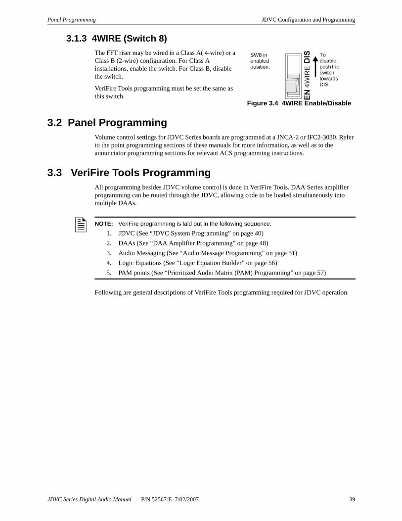
Panel Programming JDVC Configuration and Programming
3.1.3 4WIRE (Switch 8) The FFT riser may be wired in a Class A( 4-wire) or a Class B (2-wire) configuration. For Class A installations, enable the switch. For Class B, disable the switch.
VeriFire Tools programming must be set the same as this switch.
3.2 Panel ProgrammingVolume control settings for JDVC Series boards are programmed at a JNCA-2 or IFC2-3030. Refer to the point programming sections of these manuals for more information, as well as to the annunciator programming sections for relevant ACS programming instructions.
3.3 VeriFire Tools ProgrammingAll programming besides JDVC volume control is done in VeriFire Tools. DAA Series amplifier programming can be routed through the JDVC, allowing code to be loaded simultaneously into multiple DAAs.
Following are general descriptions of VeriFire Tools programming required for JDVC operation.
Figure 3.4 4WIRE Enable/Disable
SW8 in enabled position.
To disable, push the switch towards DIS.
NOTE: VeriFire programming is laid out in the following sequence:1. JDVC (See “JDVC System Programming” on page 40)2. DAAs (See “DAA Amplifier Programming” on page 48)3. Audio Messaging (See “Audio Message Programming” on page 51)4. Logic Equations (See “Logic Equation Builder” on page 56)5. PAM points (See “Prioritized Audio Matrix (PAM) Programming” on page 57)
JDVC Series Digital Audio Manual — P/N 52567:E 7/02/2007 39

JDVC Configuration and Programming VeriFire Tools Programming
3.3.1 JDVC System ProgrammingAll JDVC settings required for a functional JDVC Series board are included in this section of programming.
General I
Figure 3.5 DVC System Programming Service – General I
JDVC Label
Enter the network node label for this JDVC. You may enter up to 40 characters.
Common Settings
LOCAL CONTROL - Select to enable local JDVC control of the following DVC-KD keys: ALL CALL, PAGE ACTIVE EVAC AREAS, PAGE ACTIVE ALERT AREAS, and PAGE INACTIVE AREAS, ENABLE TELEPHONE PAGE.
ANALOG OUTPUTS - Describe the configuration (“Not Installed”, “Installed, Class A,” or “Installed, Class B”) of JDVC’s analog outputs. “Installed” analog outputs will be represented in the PAM as output circuits for DVC-0. (PAM programming is described in “Prioritized Audio Matrix (PAM) Programming” on page 57.)
LOCAL/REMOTE MICROPHONE - Select to install the local and/or remote microphone. See the RM-1 Series manual for more information on the remote microphone.
NOTE: The JDVC node number is assigned at the beginning of the VeriFire Tools session when the database is opened. The JDVC must always be assigned a unique node address, even when used with a standalone FACP. That is, when used with a standalone FACP, the JDVC must be assigned a node number different from that FACP.
DVC_General_1_TabBWa.jpg
40 JDVC Series Digital Audio Manual — P/N 52567:E 7/02/2007

VeriFire Tools Programming JDVC Configuration and Programming
DVC MODEL - Choose from the drop-down menu to indicate if the JDVC is the standard (JDVC) or an extended memory (JDVC-EM) version. The JDVC-EM Extended Memory versions contain up to 32 minutes of standard quality (11.025 kHz sampling rate, 8 bit µ-law, mono) audio storage, or 4 minutes of high quality (44.1 kHz sampling rate, 16 bit PCM, mono).
FIDELITY SELECTION - Choose the desired audio quality (standard or high). A message saved as high quality requires more storage space than the same message saved as standard quality.
Firefighter Telephone Settings
LOCAL FFT – Select when a local TELH-1 FFT is installed. The connection will be supervised for open and short circuit conditions.
FFT RISER WIRE SELECTION – Select to describe the wiring style, 2 WIRE (Class B) or 4 WIRE (Class A) of the FFT riser. Switch 8 (Refer to “4WIRE (Switch 8)” on page 39) must be set the same as this selection.
Auxiliary Input
AUX INPUT A and/or AUX INPUT B - Check the input(s) that are installed.
SUPERVISION - Check to enable supervision of the specified inputs.
AGC - Check to enable automatic gain control. This feature will smooth an incoming signal to produce a consistent sound.
BACKGROUND MUSIC - Check if the input is to be used for background music. When this box is checked, background music that has been pre-empted by a higher priority message (e.g. ALL CALL) will resume once the higher priority message has completed its broadcast.
NFN Media Interface Settings
Set Port A and Port B thresholds for HIGH or LOW to establish tolerable noise thresholds for network communications.
WIRING STYLE - Select according to your network’s configuration (STYLE 4 or STYLE 7). Refer to NOTI•FIRE•NET v.5.0 and Higher Manual for more information.
PROGRAM - This button will save your changes to the VeriFire Tools database.
CLOSE - This button will close the current service. If there are changes that have not been saved (by pressing the PROGRAM button), VeriFire Tools will prompt you to do so.
! CAUTION: DVC Model/Fidelity SelectionDo Not modify settings for “DVC Model” or fidelity programming once PAM points and Audio Messages are installed. Changing these selections will delete all PAM Points and Audio Messaging information.
NOTE: Enable automatic gain control only in applications where the input is a voice input, such as from a telephone paging system. Do not use automatic gain control when using background music.
JDVC Series Digital Audio Manual — P/N 52567:E 7/02/2007 41
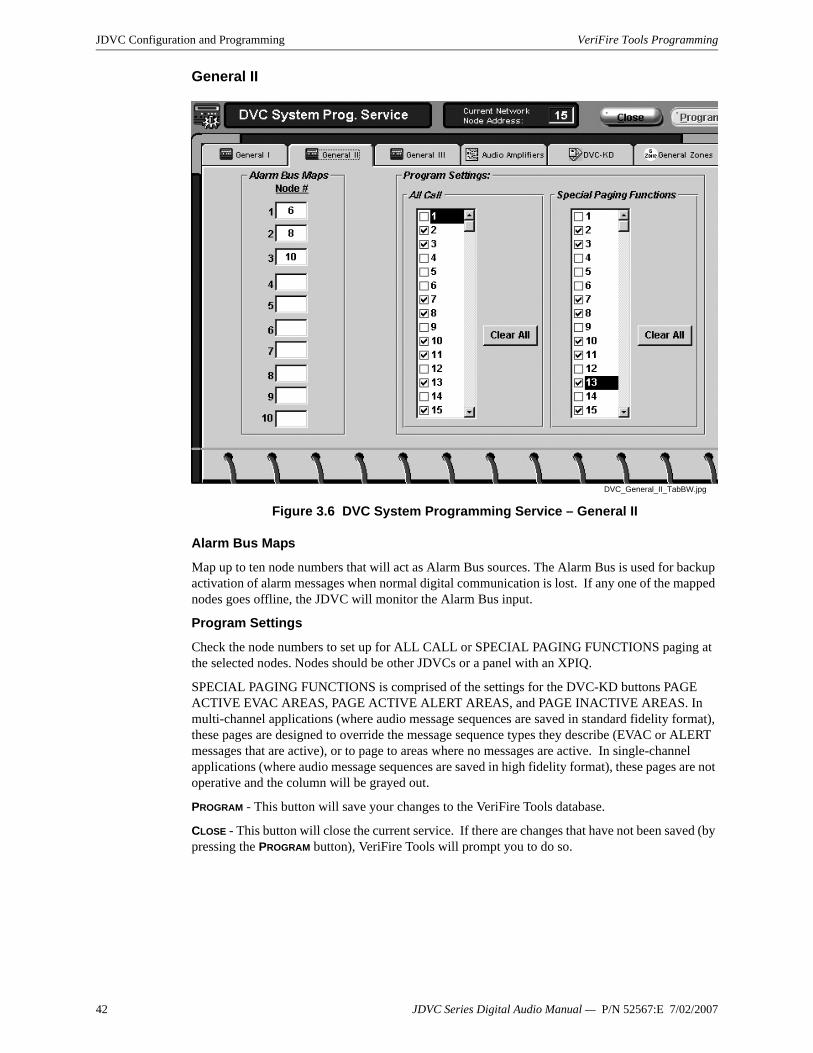
JDVC Configuration and Programming VeriFire Tools Programming
General II
Figure 3.6 DVC System Programming Service – General II
Alarm Bus Maps
Map up to ten node numbers that will act as Alarm Bus sources. The Alarm Bus is used for backup activation of alarm messages when normal digital communication is lost. If any one of the mapped nodes goes offline, the JDVC will monitor the Alarm Bus input.
Program Settings
Check the node numbers to set up for ALL CALL or SPECIAL PAGING FUNCTIONS paging at the selected nodes. Nodes should be other JDVCs or a panel with an XPIQ.
SPECIAL PAGING FUNCTIONS is comprised of the settings for the DVC-KD buttons PAGE ACTIVE EVAC AREAS, PAGE ACTIVE ALERT AREAS, and PAGE INACTIVE AREAS. In multi-channel applications (where audio message sequences are saved in standard fidelity format), these pages are designed to override the message sequence types they describe (EVAC or ALERT messages that are active), or to page to areas where no messages are active. In single-channel applications (where audio message sequences are saved in high fidelity format), these pages are not operative and the column will be grayed out.
PROGRAM - This button will save your changes to the VeriFire Tools database.
CLOSE - This button will close the current service. If there are changes that have not been saved (by pressing the PROGRAM button), VeriFire Tools will prompt you to do so.
DVC_General_II_TabBW.jpg
42 JDVC Series Digital Audio Manual — P/N 52567:E 7/02/2007

VeriFire Tools Programming JDVC Configuration and Programming
General III
Figure 3.7 DVC System Programming Service – General III
DAA BACKUP TONES:
Defines the message segments (usually tones) that will be broadcast during the loss of DAP communication. These backup messages are stored within each DAA for activation when the command bus is not functioning.
EMERGENCY - The message segment selected will broadcast when DAA’s alarm bus is active.
NON-EMERGENCY - The message segment selected will broadcast when the DAA’s alarm bus is inactive). This message will not broadcast during AC failure.
DCC SETTINGS:
Defines whether the JDVC will participate in DCC operation for paging functions, and if so, which network control node it will be associated with. See Section 4.4, “Display and Control Center (DCC)”.
DCC OPERATION – Check to enable DCC participation.
DCC ASSOCIATED NODE NUMBER – Map a DCC-designated JDVC to a network control node through which it will be able to assert network control for network paging purposes.
DVC_General_III_TabBb.jpg
JDVC Series Digital Audio Manual — P/N 52567:E 7/02/2007 43

JDVC Configuration and Programming VeriFire Tools Programming
Canadian Operations
Pre-Announce – To enable the Pre-Announce feature, click Pre-Announce, then select an audio sequence. The selected sequence will play before all pages from the JDVC’s MIC-1 local microphone, the TELH-1 local telephone, and teh RM-1. The “Pre-Announce” LED on the DVC-KD will light for the duration of the pre-announce.
Page Inhibit – The Page Inhibit selection applies to the ALL CALL, PAGE ACTIVE EVAC AREAS, PAGE ACTIVE ALERT AREAS, and PAGE INACTIVE AREAS buttons on the DVC-KD. To enable, check the box and select a logic equation that will inhibit the page while the logic equation is active. The “Page Inhibit” LED on the DVC-KD will light for the duration of the page inhibit.
DVC-KD Inhibit – The DVC-KD Inhibit selection applies to the 24 buttons on the right half of the DVC-KD. To enable, check the box and select a logic equation that will inhibit the DVC-KD while the logic equation is active. COMMON SETTINGS:
NFN AUDIO PAGING - Check this box if network paging from any of the JDVC’s live inputs to outputs on other JDVCs is desired. Live inputs can include the JDVC’s local microphone, an RM-1 remote microphone, a firefighter’s telephone, or a live input from an AUXA or AUXB connection. A check here creates the “Network” column in the PAM. (See “Prioritized Audio Matrix (PAM) Programming” on page 57.) If this box is not checked, network paging is disabled.
DAP WIRING STYLE – Select Style 4 or Style 7.
Trouble Reminder
TROUBLE REMINDER OPTIONS – Select a 24 hour reminder, or none.
IP ACCESSIBILITY
Check to enable IP Access. This setting allows the disabling/enabling of commands, downloads and programming from the Wide Area Network (WAN).
JDVC downloads can be initiated by clicking the WAN Download icon located on the top menu bar. . They are timed for six hours.
PROGRAM - This button will save your changes to the VeriFire Tools database.
CLOSE - This button will close the current service. If there are changes that have not been saved (by pressing the PROGRAM button), VeriFire Tools will prompt you to do so.
NOTE: When NFN Audio Paging is selected, the number of nodes allowed on Noti-Fire-Net is limited to 54.
NOTE: Use of the IP Accessibility feature is subject to the approval of the local AHJ.
44 JDVC Series Digital Audio Manual — P/N 52567:E 7/02/2007

VeriFire Tools Programming JDVC Configuration and Programming
Audio AmplifiersSelect and designate the function of the audio system’s DAAs (Primary or Backup). Click on an amplifier’s button to call up the DAA Amplifier Programming Service (page 48). An amplifier must be programmed into the system here before VeriFire Tools will allow configuration of its individual speakers circuits.
Figure 3.8 DVC System Programming Service – Audio Amplifiers
PROGRAM - This button will save your changes to the VeriFire Tools database.
CLOSE - This button will close the current service. If there are changes that have not been saved (by pressing the PROGRAM button), VeriFire Tools will prompt you to do so.
Audio_AMPBW.jpg
JDVC Series Digital Audio Manual — P/N 52567:E 7/02/2007 45

JDVC Configuration and Programming VeriFire Tools Programming
DVC-KDProgram the user-defined keys on the DVC-KD. Map a function to a node, module, detector, panel circuit point, zone, or PAM point.
Figure 3.9 DVC System Programming Service – DVC-KD
Explanation of Fields:
KEY -There are 24 user-defined keys on a DVC-KD. Refer to Figure 4.1 on page 64 for the numbering format.
FUNCTION - Select from Monitor, Control, Telephone, All Call, Page Evac, Page Alert, Page Inactive, Enable Paging or None.
• Select Telephone for all phone functions. Telephone may apply to either a telephone control module or a regular control module functioning with a telephone.
• Select All Call to broadcast to entire nodes.• When Enable Paging is selected, AUX A or AUX B will be selectable.
MAPPING - Enter the points, nodes or zones to be mapped.
• The Control function allows mapping of up to 8 points.• The All Call, Page Evac, Page Alert, and Page Inactive functions for the user-programmable
keys allow mapping of up to 8 nodes. These nodes do not have to be any of the nodes selected to function with the All Call, Page Active EVAC areas, Page Active ALERT area, or Page INACTIVE area buttons on the left side of the DVC-KD.
PROGRAM - This button will save your changes to the VeriFire Tools database.
CLOSE - This button will close the current service. If there are changes that have not been saved (by pressing the PROGRAM button), VeriFire Tools will prompt you to do so.
DVC_KDBW.jpg
46 JDVC Series Digital Audio Manual — P/N 52567:E 7/02/2007

VeriFire Tools Programming JDVC Configuration and Programming
JDVC General ZonesCustomize a JDVC general zone label using the following screen. See Section 3.4 on page 62 for information on programming JDVC general zones.
Figure 3.10 DVC System Programming Service – General Zones
DVC_GenZonBW.jpg
JDVC Series Digital Audio Manual — P/N 52567:E 7/02/2007 47

JDVC Configuration and Programming VeriFire Tools Programming
3.3.2 DAA Amplifier ProgrammingUse the following services to program associated amplifiers and speaker points with individual settings.
General I
Figure 3.11 DAA Amplifier Programming Service – General I
AMPLIFIER ADDRESS - Select the installed DAA to be programmed. (See page 45.)
SPEAKER WIRING CONFIGURATION – Make selection to program speaker circuit pairs (1/2 and 3/4.) Selection must reflect physical configuration (All Class A; All Class B; 1 and 2 = Class A, 3 and 4 = Class B; 1 and 2 = Class B, 3 and 4 = Class A).
BACKUP AMPLIFIER ADDRESS – If desired, select an amplifier that will operate in the event of a failure at this one.
FFT RISER WIRE SELECTION – Select the wiring style (2 WIRE or 4 WIRE) according to the configuration of the analog network.
Auxiliary Input Source
AUXILIARY A/B – Check to install either the AUXA or AUXB analog input (not both) into the database.
AGC – Check to enable automatic gain control. This feature will smooth an incoming signal to produce a consistent sound.
SUPERVISION – Check to enable or disable supervision of the auxiliary input.
DAA_System_1_TabBWa.jpg
! CAUTION: Changing the wiring class configuration after the speaker circuits have been programmed may delete the speaker circuit programming! (See page 50.)
NOTE: Enable automatic gain control only in applications where the input is a voice input, such as from a telephone paging system. Do not use automatic gain control when using background music.
48 JDVC Series Digital Audio Manual — P/N 52567:E 7/02/2007

VeriFire Tools Programming JDVC Configuration and Programming
AUXILIARY ACTIVATION – Check which speaker circuits on the DAA will be activated when amplifying data from the AUX input.
MODIFY - This button will save your changes to the VeriFire Tools database.
CLEAR - This button will restore all programmable options on this worksheet to their defaults.
NEXT and PRIOR - These buttons allow you to step through the amplifiers programmed in the VeriFire Tools database.
CLOSE - This button will close the current service. If there are changes that have not been saved, VeriFire Tools will prompt you to do so.
General II
Figure 3.12 DAA Amplifier Programming Service – General II
AMPLIFIER ADDRESS - Select the installed DAA to be programmed. (See page 45.)
SPEAKER WIRING CONFIGURATION - Displays the wiring configuration programmed at the first DAA worksheet. (See page 48.)
ROOM ISOLATOR MODULES – Future Use.
BATTERY SIZE – Select the size of the secondary power source.
DISABLE CHARGER – Check to disable the charger on this DAA. The charger should be disabled if this DAA is sharing batteries with at least one other DAA, and is not the DAA that will supply the battery charging. See “Battery Sharing” on page 88.
SUPERVISION TONE OUTPUT – Check to have the DAA send a 200 Hz tone to selected speakers when idle. A typical application would be with an ACT-2 audio coupling transformer. This feature is not for use in Class A applications.
DAA_System_II_TabBW.jpg
NOTE: Although 75 watt DAAs do not have a battery charger, this designation must still be made.
JDVC Series Digital Audio Manual — P/N 52567:E 7/02/2007 49

JDVC Configuration and Programming VeriFire Tools Programming
PARTICIPATING SPEAKER CIRCUITS – Select which speaker circuits will play the supervision tone.
MODIFY - This button will save your changes to the VeriFire Tools database.
CLEAR - This button will restore all programmable options to their defaults.
NEXT and PRIOR - These buttons allow you to step through the amplifiers programmed in the VeriFire Tools database.
CLOSE - This button will close the current service. If there are changes that have not been saved, VeriFire Tools will prompt you to do so.
Speakers
Figure 3.13 DAA Amplifier Programming Service – Speaker Circuits
AMPLIFIER ADDRESS - Select the installed DAA to be programmed. (See page 45.)
SPEAKER WIRING CONFIGURATION - Displays the wiring configuration programmed at the first DAA worksheet. (See page 48.)
SPEAKER CIRCUIT - Select the speaker circuit to be programmed.
Labels
CIRCUIT – Enter up to 20 characters to identify this speaker circuit.
EXTENDED – Enter up to an additional 12 characters for more specific identification of the speaker circuit.
The total number of installed speaker circuits on the selected DAA is listed on the lower right hand side of the service form.
MODIFY - This button will save your changes to the VeriFire Tools database.
UNINSTALL - This button will delete that speaker circuit from the VeriFire Tools database.
NEXT and PRIOR - These buttons allow you to step through the speaker circuits programmed in the VeriFire Tools database.
CLOSE - This button will close the current service. If there are changes that have not been saved , VeriFire Tools will prompt you to do so.
DAA_System_Speakers_TabBW.jpg
50 JDVC Series Digital Audio Manual — P/N 52567:E 7/02/2007

VeriFire Tools Programming JDVC Configuration and Programming
3.3.3 Audio Message ProgrammingUp to 1000 message sequences may be created using a sound library supplied with VeriFire Tools and/or separate sound files created through the recommended Goldwave Digital Audio Editor.
VeriFire Tools uses a “drag and drop” interface to easily sequence the sounds.
Message SegmentsMessage segments are sound files that can be used as part of a message sequence. The number of message segments that may be stored is relative to their size, fidelity, and the JDVC board used (JDVC or JDVC-EM/F/SF).
Use the Message Segment form illustrated in Figure 3.14 to select and catalog the sound files that will be used.
Acceptable .wav file formats are as follows:
• Standard quality - 11.025 kHz sampling rate, 8 bit µ-law, mono.• High quality - 44.1 kHz sampling rate, 16 bit PCM, mono.
Figure 3.14 Audio Message Programming Service – Message Segments
NOTE: The CD booklet included with the VeriFire Tools CD outlines the equipment requirements for creating a sound library. Use the equipment recommended in this booklet.
NOTE: The digital audio system uses files in specific .wav formats as described below.
Mess_SegBW.jpg
JDVC Series Digital Audio Manual — P/N 52567:E 7/02/2007 51

JDVC Configuration and Programming VeriFire Tools Programming
• AUDIO TYPE - Fidelity and storage capacity based on the fidelity selection and board type at the first JDVC form (See “Common Settings” on page 40) is displayed as a reminder in the AUDIO TYPE field at the top of the form.
• OPEN EXPLORER - Click this button to open the Windows Explorer. Import sound files into the segment library by dragging and dropping them from your PC. When a file is entered into the library it is assigned a segment number. The segment library may contain up to 1000 message segments.
• Total duration time will display in the top right corner of the service form. Specific message segment lengths are displayed in the Available Message Segments section of the Message Sequences screen. (See Figure 3.15 on page 53)Use the arrow keys to the right to re-assign a file’s segment number.
• Click the OPEN AUDIO EDITOR button to open the Goldwave sound editor. Create and/or edit sound files with this software program.
• Listen to a selected .wav file by clicking on PLAY SELECTION button at the bottom of the service.
PROGRAM - This button will save your changes to the VeriFire Tools database.
CLOSE - This button will close the current service. If there are changes that have not been saved (by pressing the PROGRAM button), VeriFire Tools will prompt you to do so.
Message SequencesBuild audio message sequences by combining message segments and sequence commands.
NOTE: Sound files used as message segments must be accessible when downloading to a JDVC.• They must be consistently mapped - that is, the path must remain unchanged if a database is exported onto another PC. • When accessed from external devices such as a CD drive, copy audio files onto your PC’s hard drive, or always ensure that external media containing these files is in the drive when downloading to the JDVC.
The Sequence (“1” in this example) displays in the # field in the Audio Sequences selection.
Mess_SequenceBW.jpg
52 JDVC Series Digital Audio Manual — P/N 52567:E 7/02/2007

VeriFire Tools Programming JDVC Configuration and Programming
Figure 3.15 Audio Message Programming Service – Message Sequences
To create an audio sequence:
1. Select a sequence number from the AUDIO SEQUENCES field. Assign the sequence an ALERT, EVAC, or OTHER message type.
2. Type a 20-character description of the audio sequence in the LABEL field, if desired.3. Drag and drop message segments and sequence commands into the SEQUENCE: field.
Segments may be grouped together and the group or individual segment may be played up to 14 times. An individual segment or group may also be commanded to play forever.
Each PLAY... command (PLAY X TIMES, PLAY FOREVER) must be completed with an END PLAY command. Segments without a PLAY.../END PLAY command will play only once. Note that the PLAY... and END PLAY commands are comparable to open (PLAY X TIMES, PLAY FOREVER) and closed (END PLAY) brackets of a logic equation.Sequences may be nested, as shown in Figure 3.16.
Figure 3.16 Nested Sequence
A sequence may have up to 125 steps.
CLEAR SEQUENCE - Click this button to delete all steps in a sequence.
PLAY SEQUENCE - Click this button to listen to and review the sequence as a test. During this test, the PLAY FOREVER command will only play 200 times. When this sequence is activated in a non-test situation, PLAY FOREVER will play indefinitely.
PROGRAM - This button will save your changes to the VeriFire Tools database.
CLOSE - This button will close the current service. If there are changes that have not been saved (by pressing the PROGRAM button), VeriFire Tools will prompt you to do so.
NOTE: Only ALERT and EVAC may be used when a JDVC with DVC-AO is directly connected to an IFC2-640 panel.
NOTE: For public mode signaling, messages activated during fire events must repeat indefinitely (the PLAY FOREVER command must be used).For private mode signaling, fire alarm messages may be of finite length (the PLAY X TIMES command may be used), but they must then be assigned the “OTHER” category.Security, supervisory, trouble, all finite-length messages, and all messages not activated by fire events must be assigned “OTHER” in VeriFire Tools.
1. Play Forever2. Play 3 Times3. AbortON.wav4. End Play5. Play 3 Times6. ACFail.wav7. End Play8. End Play
The AbortOn.wav file will play 3 times and stop.The ACFail.wav file will play 3 times and stop.
Sequences A and B will play forever.
Sequence A
Sequence B
JDVC Series Digital Audio Manual — P/N 52567:E 7/02/2007 53

JDVC Configuration and Programming VeriFire Tools Programming
InputsIn the digital audio system, each input source, live or recorded, is assigned a fixed input number and a programmable priority number. (See Table 3.1.) Use the Inputs service to program each input’s priority. The lower the priority number, the higher the priority.
Figure 3.17 Audio Message Programming Service – Inputs.
ARROW KEYS - Use to reassign the priority of an individual input.
RENUMBER - Click the button to sequentially reassign priorities to the all inputs.
RESTORE DEFAULTS - Click this button to re-apply default priorities to all inputs. See Table 3.1 for defaults.
PROGRAM - This button will save your changes to the VeriFire Tools database.
CLOSE - This button will close the current service. If there are changes that have not been saved (by pressing the PROGRAM button), VeriFire Tools will prompt you to do so.
Mes
s_In
putB
W.jp
g
This screen will also display a fixed input number column to the left of the Priority column. To view this column, place the cursor on the column wall left of the priority column and pull it out.
54 JDVC Series Digital Audio Manual — P/N 52567:E 7/02/2007

VeriFire Tools Programming JDVC Configuration and Programming
Table 3.1 Default Input Priorities
Input Number Input Source Default Priority
1 Local Microphone Page* 1
2 Network Microphone Page 2
3 – 15 RESERVED —
16 Local Telephone Page* 16
17 Network Telephone Page 17
18 – 30 RESERVED —
31 Message Sequence 1 31
32 Message Sequence 2 32
•••
•••
•••
1029 Message Sequence 999 1029
1030 Message Sequence 1000 1030
1031 – 1033 RESERVED —
1034 RESERVED —
1035 Network Workstation 1035
1036 RESERVED —
1037 Network Remote Workstation 1037
1038 Local RM-1 1038
1039 Network RM-1 1039
1040 Local AUXB 1040
1041 Network AUXB 1041
1042 RESERVED —
1043 Local AUXA 1043
1044 Network AUXA 1044
* Local Microphone Page will always take priority over Local Telephone Page.
JDVC Series Digital Audio Manual — P/N 52567:E 7/02/2007 55

JDVC Configuration and Programming VeriFire Tools Programming
3.3.4 Logic Equation BuilderThe Logic Equation Builder allows the programmer to set up Control-by-Event requirements for audio events.
Figure 3.18 Logic Equation Builder Service
The Logic Equation Builder is an easy way to enter logic equations for the audio system. Use the "point and click" method to select all available operators and operands and view your work as you build the equation in the window at the top of the screen. Use the Program Validation Service to check your work.
The Edit Section UNDO - This button will undo the last function that was executed. You can press the UNDO button until the entire entered equation is erased.
REDO - This button will reverse the action of the UNDO button. The REDO button can be pressed until the entire function is recovered.
ERASE - This button will clear the current equation so that a new equation can be entered. Once the ERASE button is pressed, both the UNDO and REDO button will become unavailable.
COPY and PASTE - These buttons can be used to copy an equation in whole or in part and paste it into another logic zone.
LABEL - Use this field to enter a label (up to 100 characters) for the logic equation. Labels are accessible by viewing the database using VeriFire Tools.
The Functions Section The Functions section lists the available operators to use. For every step that can be performed, the available choices will be left enabled, while unavailable options will be grayed out.
The Points SectionThe Points section allows the user to select operands that can be added to an equation. Pressing one of these buttons will bring up a dialog box so that you may enter the appropriate address for the device or zone.
DVC_LEBBW.jpg
56 JDVC Series Digital Audio Manual — P/N 52567:E 7/02/2007

VeriFire Tools Programming JDVC Configuration and Programming
Logic Equation Spreadsheet Use the Logic Equation Spreadsheet to select, view, or navigate through up to 2000 (ZL1 – ZL2000) logic equations.
Action CommandsMODIFY - Clicking this button will add the selected equation to the database.
CLEAR - Clicking this button will delete the selected equation from the database.
NEXT and PRIOR - Clicking these buttons cycle through the equations.
REFRESH -Clicking this button will restore the current logic equation from the database.
SPREADSHEET - Clicking this button displays the Logic Equation Spreadsheet in a separate screen.
CLOSE - This button will close the current service. If there are changes that have not been saved, VeriFire Tools will prompt you to do so.
3.3.5 Prioritized Audio Matrix (PAM) ProgrammingOverviewThe PAM point spreadsheet displays all programmed inputs and outputs except backup DAAs. Inputs are represented by rows, while outputs are represented by columns. A PAM point is the intersection between an input and an output. A PAM point address describes its input (I) number, amplifier (A) number and speaker circuit (S) number (IXXXXAXXSX). Local JDVC analog outputs use amplifier number zero. Where live paging over Noti-Fire-Net is employed, Noti-Fire-Net is considered an output on the source JDVC. The points associated with the intersection of the live inputs with Noti-Fire-Net have a PAM point address of IxxxxNET, where I is the input number.
Following are the means to activate a PAM point:
• Logic Equation• JDVC Alarm bus• ACS control (ACS mapping on IFC2-3030, or JNCA-2).• Point control (“Force On”/”Force Off” commands - IFW, JNCA-2, IFC2-640 or IFC2-3030)• DVC-KD (Pre-set paging buttons (ALL CALL, etc) and user-programmed buttons).
The PAM Programming screen shown in Figure 3.19 allows the programmer to select and program points for activation by either a specific logic equation or the JDVC alarm bus. ACS control, point control and DVC-KD activators do not display on this screen.
The programmer may also program the point for signal silence participation and switch inhibit.
JDVC Series Digital Audio Manual — P/N 52567:E 7/02/2007 57

JDVC Configuration and Programming VeriFire Tools Programming
Figure 3.19 PAM Programming Screen
Network PagingWhen “Paging to Network” is selected in the JDVC System Programming Service (see page 40), the JDVC is configured to send live audio to Noti-Fire-Net for audible output by other JDVCs on the network. The live audio present on the network can be used as input audio by another JDVC on Noti-Fire-Net, and may be played on any output circuit on that JDVC.
Inputs designated as “Local” in the PAM of the source JDVC become “Network” inputs of the same type in the PAM of all other network JDVCs. (See Table 3.2.)
A JDVC configured for network audio output may be commanded to transmit a live audio message to Noti-Fire-Net in a variety of ways. An MIC-1 Local Mic will always (provided the audio channel is free, or the input has sufficient priority to preempt another audio source using the channel) transmit its audio to Noti-Fire-Net when the Push-to-talk button on the microphone is depressed.
PAM point activation programming optionsPAM point
address NEW_PAM_PTsBW.jpg
Example: Input 31 Row. The selected cell in the row is a PAM point. When Logic Equation 3 is activated, Speaker Circuit 3 on the DAA at Address 4 will broadcast Sequence 1.
Inputs are represented by rows.
Example: Output circuit for DAA 4 S3 Column. The darkened cell in the column is a PAM point in the row designated Input 31, and has a PAM point address of I31A4S3. When Logic Equation 3 (the “3” that is in the darkened cell) is activated, Input 31 will broadcast Sequence 1 on this output. This output can also be activated by other PAM points in its column.
Outputs are represented by columns.
Input Name on Source JDVC Input Name on Other Network JDVCLocal Mic Network Mic
Local Tel Network Tel
Local RM-1 Network RM-1
Local Aux B Network Aux B
Local Aux A Network Aux A
Table 3.2 Local and Network Inputs
58 JDVC Series Digital Audio Manual — P/N 52567:E 7/02/2007

VeriFire Tools Programming JDVC Configuration and Programming
Live input from other than the MIC-1 may be activated to transmit to Noti-Fire-Net using “Enable Paging from input name ” buttons programmed to an annunciator button on an NCA-2, NFS2-3030 or DVC-KD. A pre-defined button labeled “Enable Telephone Page” exists on the DVC-KD for this purpose.
Live inputs may also be activated to Noti-Fire-Net using a logic equation. This programming is done in the PAM Programming Service, by mapping the logic equation to the NET column of the desired local input. Refer to Figure 3.19 on page 58, upper right, to view the NET column. The NET column appears only when “Paging to Network” is selected in the DVC Programming Service.
Network Paging From this JDVC, RM-1 Example
The RM-1 at this JDVC is configured with an JNCA-2 or IFC2-3030 annunciator (one button with a mode of ENABLE PAGING FROM RM-1, one button with a mode of ALL CALL) and programmed to transmit an ALL CALL message to other nodes.When the RM-1 is activated for network paging (by first pressing the two annunciator buttons, then the microphone’s push-to-talk button), it will send a live ALL CALL message out to Noti-Fire-Net through the PAM’s Local RM-1 input (Input 1038).
Network Paging to this JDVC, RM-1 Example
An RM-1 at another node initiates a live ALL CALL page over Noti-Fire-Net to this JDVC.The message will be sent to the target output(s) through the PAM’s Network RM-1 Input (1039)
Message OverridesWhen a PAM point is activated, its input will broadcast on its output. If more than one PAM point activate for a particular output, the PAM point with the highest priority input will play first, and it will pre-empt active messages of lesser priority. The pre-empted message will be set to either pending or turned off, as shown in Table 3.3 below.
Live Evac Alert Other
PAM point turned on by logic equation
PAM point turned on by user
(annunciator button or Alter
Status)
PAM point turned on by logic equation
Turned on by user
(annunciator button or
Alter Status)
PAM point turned on by logic equation
Turned on by user
(annunciator button or
Alter Status)
PAM point turned on by logic equation
Turned on by user
(annunciator button or
Alter Status)
Live Pending OFF Pending OFF Pending OFF Pending OFF
Evac Pending OFF Pending OFF OFF OFF OFF OFF
Table 3.3 Operation of Message Overrides
Input Priority Input Name NET
1038 1038 Local RM-1
1039 1039 Network RM-1
Prioritized Audio Matrix Rows
Live Page from Local
RM-1
ALL CALL message to Noti-Fire-Net.
Figure 3.20 Network Paging from This JDVC
Input Priority Input Name NET
1038 1038 Local RM-1
1039 1039 Network RM-1
Prioritized Audio Matrix Rows
Live Page from Remote
RM-1
to ALL CALL outputs at this JDVC node
Figure 3.21 Network Paging to This JDVC
JDVC Series Digital Audio Manual — P/N 52567:E 7/02/2007 59

JDVC Configuration and Programming VeriFire Tools Programming
Live - an input that was not created by Audio Sequence programming (that is, paging, telephone communication).
Evac, Alert, Other - Message type assigned to an audio sequence through Audio Sequence programming.
Pending - means the new input will pre-empt the active input, but will allow that input to resume its broadcasting once the new input has completed its broadcast.
OFF - means the new input will pre-empt the active input, and will turn it off.
Example:
A live page with a priority of one (1) occurs while an “Evac” message, initiated by a logic equation, is broadcasting. The live input has a higher priority than the “Evac” message. Table 3.3 shows that the new live message will cause the “Evac” message to be placed in a pending state. (The table cell where the “Live” row intersects with the “Evac, PAM point turned on by logic equation” column says “Pending”.) The “Evac” message will resume once the live page is completed.
Programming a PAM pointSelect a cell at the intersection of an input and an output. The point address will display at the lower right corner of the service. Choose how the PAM point will activate (either by alarm bus mapping or a logic equation), and whether signal silence participation and switch inhibit will be enabled.
ALARM BUS MAP – Check to have the PAM point activate when the JDVC alarm bus is activated and at least one of its mapped nodes is off-line. See page 42 for alarm bus programming.
LOGIC EQUATION – Enter a logic equation to have the PAM point activate when the conditions set in the logic equation are met. Choose from the logic equations displayed in the “Available Logic Equations” part of the screen. The Logic Equation Builder on page 56 describes how to set up these logic equations.
SILENCEABLE
This field determines whether the user can manually silence a PAM point. Based on the value chosen from the list below, a Signal Silence command at a network annunciator, or at a single-panel IFC2-3030 directly connected to a JDVC, will silence a PAM point.
Alert Pending OFF Pending OFF Pending OFF OFF OFF
Other Pending OFF Pending OFF Pending OFF Pending OFF
NO Not manually silenceable
YES - RESOUND FIRE Silenceable, resound on fire alarm events Network and Local Resound
YES - RESOUND SUPERV Silenceable, resound on supervisory events Network and Local Resound
YES - RESOUND SECURITY Silenceable, resound on security event Network and Local Resound
YES - RESOUND TROUBLE Silenceable, resound on local JDVC trouble event Network and Local Resound
Live Evac Alert Other
PAM point turned on by logic equation
PAM point turned on by user
(annunciator button or Alter
Status)
PAM point turned on by logic equation
Turned on by user
(annunciator button or
Alter Status)
PAM point turned on by logic equation
Turned on by user
(annunciator button or
Alter Status)
PAM point turned on by logic equation
Turned on by user
(annunciator button or
Alter Status)
Table 3.3 (Continued)Operation of Message Overrides
NOTE: Recorded messages programmed to activate based on security events must be programmed as non-silenceable; NO must be selected.
60 JDVC Series Digital Audio Manual — P/N 52567:E 7/02/2007

VeriFire Tools Programming JDVC Configuration and Programming
SWITCH INHIBIT – When this selection is enabled, the PAM point will disregard any ACS control.
3.3.6 ReportsPrinted reports can be generated from VeriFire Tools. The selections can be viewed from the drop-down Reports Menu on the menu bar. The reports include the following:
• SYSTEM - Includes the information entered in the DVC System Programming Service screens.
• DAA - Includes the information entered in the DAA Amplifier Programming screens.• AUDIO MESSAGE - Includes the information entered in theAudio Message Programming
Service screens.• PAM - Includes the information entered in the PAM Programming Service screens.• LOGIC EQUATIONS - Lists all logic equations.
JDVC Series Digital Audio Manual — P/N 52567:E 7/02/2007 61

JDVC Configuration and Programming Programming JDVC General Zones for Retrofits
3.4 Programming JDVC General Zones for RetrofitsThe JDVC has 105 general zones (Z000 - Z104) that apply to DVC-AO outputs only. Labels can be created for them using the JDVC System Programming Service. See “JDVC General Zones” on page 47.
These zones may be used in FACP logic equations to turn outputs on and off for messages or pages from the DVC-AO. Table 3.4 indicates the functions of each general zone.
Programming Example:
A network consists of an IFC2-3030 (Node 1) with an XPIQ and a JDVC (Node 2) with a DVC-AO connected to the XPIQ. When detector L01D001 on the IFC2-3030 goes into alarm, Sequence 1 in the JDVC will play over Analog Output 1 to an XPIQ output. When the detector leaves the alarm state, the XPIQ output will turn off.
To program:
• Program the JDVC as follows:• Create a logic zone (ZL1 in this example) with the detector’s address of N001L01D001.• Enter ZL1 into the PAM point at Audio Sequence 1 Input row (Input 31 in this example)
and Analog Output 1 column.• Create an IFC2-3030 logic zone (ZL5 in this example) with an equation that includes the
following:• N002Z001 - the JDVC’s general zone 1 that will activate when Input 31 (Sequence 1)
activates.• N002Z101 - the JDVC’s general zone 101 that will activate when any message is played
over Analog Output 1 of the DVC-AO.• Add ZL5 to the zone map of the control module point of the desired XPIQ output.
3.5 Program Validation ServiceThe message sequences created through audio message programming are prioritized in this part of VeriFire Tools programming.
General Zone Function
Z000 Automatically activates when any input is played over any of the DVC-AO outputs.
Z001 Automatically activates when any message sequence with the PAM input range of 31 through 40 activates.
Z002 Automatically activates when any message sequence with the PAM input range of 41 through 50 activates.
Z003 Automatically activates when any message sequence with the PAM input range of 51 through 60 activates.
.......... ........
Z100 Automatically activates when any input with the PAM input range of 1021 through 1030 activates.
Z101 Automatically activates when any input is played over DVC-AO Analog Output 1.
Z102 Automatically activates when any input is played over DVC-AO Analog Output 2.
Z103 Automatically activates when any input is played over DVC-AO Analog Output 3.
Z104 Automatically activates when any input is played over DVC-AO Analog Output 4.
Table 3.4 JDVC General Zone Functions
62 JDVC Series Digital Audio Manual — P/N 52567:E 7/02/2007

Program Validation Service JDVC Configuration and Programming
Use the Program Validator before you attempt to download a new database. This function will check the validity of the program that was created for a JDVC. VeriFire Tools checks the following items:
• Check message segments. Any message segments that are not in the correct format will be flagged.
• Check message sequences. Any message segments in the sequences that are not programmed will be flagged. Any message segments which are programmed, but the wave file does not exist, will also be flagged. Any message sequence that are not syntactically correct will also be flagged.
• Check logic equations. If a logic equation specifies a logic zone that does not have a logic equation, an error is flagged. When a logic equation is entered, forward reference checking is performed so that a logic equation cannot contain a logic zone that is the same or greater than the logic zone being programmed.
• Check PAM points. Any referenced logic zones that are not programmed will be flagged. In addition, these unreferenced logic zones will also be removed from the database. Any PAM points that reference the alarm bus will be flagged if the alarm bus does not have any nodes mapped.
• Check logic zone references. Any logic zones that have a logic equation specified must appear in another logic equation or in the PAM. If it does not appear in any of these locations, an error is flagged with a note that the logic zone may be used in another node’s zone map or logic equation.
• Check local emergency and non-emergency message segments. If the message segment is not programmed, it will be flagged. If the message segment is programmed, but the .wav file does not exist, it will also be flagged.
• Check pre-announce messages. If the message sequence is empty, it will be flagged.
If the Program Validator detects errors in the database, a warning message will appear and the Program Validation Results screen will display all detected errors. Clicking on each parameter listed under the Cause or Effect column will bring up the appropriate programming screen for editing.
VALIDATE - Click this button to validate the database.
SAVE - Click this button saves the validation results to an HTML file.
PRINT - Click this button prints the validation results.
CLOSE - Click this button closes the current service.
JDVC Series Digital Audio Manual — P/N 52567:E 7/02/2007 63

Section 4: JDVC Operation
4.1 Using the DVC-KD KeypadWhen a -JDVC Series board is utilized with a DVC-KD keypad, it operates with a network annunciator or IFC2-3030 as an audio command center, accepting and routing live paging, with LED status indicators for paging and other functions.
The DVC-KD contains push-button switches and indicators of two types:
• Those with pre-set functionality, all located along the two left columns.• Twenty-four user-programmable buttons similar to those on the ACM-24AT annunciators,
all located along the two right columns.
Figure 4.1 DVC-KD Keypad
4.1.1 Pre-defined Buttons/IndicatorsButtonsLAMP TEST
Press and hold to perform a lamp test of all the LEDs on the keypad. LEDs on the JDVC board will also be tested with the following exceptions: Reset, EFA, EFB, TXA, TXB, RXA and RXB.
LAMP TEST
TROUBLE
DVC OFF-LINE
MICROPHONE TROUBLEPHONE TROUBLE
BUSY / WAIT
ENABLE TELEPHONE PAGE
POWER
ALL CALL
PAGE ACTIVE EVAC AREAS
PAGE ACTIVE ALERT AREAS
PAGE INACTIVE AREAS
FFT CAFETERIA
User-programmable buttons. Refer to “JDVC
System Programming” on page 40.
Pre-defined buttons.See descriptions below this
figure.
PAGEFRONT DESK
DV
C-K
Da.
wm
f
FFT EAST WING
REMOTE MIC
PAGE 2nd FLOORMUSIC to AUDITORIUM
LEFT COLUMNS RIGHT COLUMNS
Buttons 1 - 12.Button 1 is at the top, button 12 is at the bottom.
Buttons 13 - 24.Button 13 is at
the top, button 24 is at the bottom.
PRE-ANNOUNCE
64 JDVC Series Digital Audio Manual — P/N 52567:E 7/02/2007

Using the DVC-KD Keypad JDVC Operation
ENABLE TELEPHONE PAGE
Press this button to engage/disengage ALL CALL, PAGE ACTIVE EVAC AREAS, PAGE ACTIVE ALERT AREAS and PAGE INACTIVE AREAS paging from the JDVC’s TELH-1 telephone handset or an FFT on a JDVC or DAA riser.
ALL CALL
Press this button to initiate ALL CALL paging. JDVC nodes that will receive the ALL CALL message are determined by VeriFire Tools programming. The green “active” LED will light if any of the mapped nodes are online. When one or more nodes are off-line, the yellow “trouble” LED will blink. If both the green and yellow LEDs are lit, paging can still proceed, broadcasting to all mapped nodes that are online.
PAGE ACTIVE EVAC AREAS
Press this button to initiate paging to active evacuation areas. Nodes that will receive the PAGE ACTIVE EVAC AREAS message are determined by VeriFire Tools programming. The green “active” LED will light if any of the mapped nodes are online. When one or more nodes are off-line, the yellow “trouble” LED will blink. If both the green and yellow LEDs are lit, paging can still proceed, broadcasting to all mapped nodes that are online.
PAGE ACTIVE ALERT AREAS
Press this button to initiate paging to active alert areas. Nodes that will receive the PAGE ACTIVE ALERT AREAS message are determined by VeriFire Tools programming. The green “active” LED will light if any of the mapped nodes are online. When one or more nodes are off-line, the yellow “trouble” LED will blink. If both the green and yellow LEDs are lit, paging can still proceed, broadcasting to all mapped nodes that are online.
PAGE INACTIVE AREAS
Press this button to initiate paging to inactive areas. Nodes that will receive the PAGE INACTIVE AREAS message are determined by VeriFire Tools programming. The green “active” LED will light if any of the mapped nodes are online. When one or more nodes are off-line, the yellow “trouble” LED will blink. If both the green and yellow LEDs are lit, paging can still proceed, broadcasting to all mapped nodes that are online.
4.1.2 LED IndicatorsTrouble - Illuminates during system initialization and when there are any troubles at the JDVC
node.DVC Offline - Illuminates when the JDVC is not providing fire protection. For example, there is a
problem with the JDVC board that requires service.Microphone Trouble - Illuminates when a connection failure exists, or when a JDVC microphone
page has been initiated but no microphone activity has occurred for 28 seconds.Phone Trouble - Illuminates when a connection failure exists, or when a JDVC telephone page
has been initiated but no telephone activity has occurred for 28 seconds.Busy/Wait - Illuminates when a code or database download from the JDVC to DAAs is in effect.
NOTE: The ALL CALL, PAGE ACTIVE EVAC AREAS, PAGE ACTIVE ALERT AREAS, and PAGE INACTIVE AREAS buttons will function only when “Local Control” has been selected in VeriFire Tools programming.
NOTE: A local microphone page, initiated at the JDVC’s MIC-1, will pre-empt a local telephone page from the JDVC’s TELH-1 or an FFT on the JDVC or a DAA riser.
JDVC Series Digital Audio Manual — P/N 52567:E 7/02/2007 65

JDVC Operation Paging
Page Inhibited - Another node has assumed paging control and locked out paging from this JDVC. This occurs when the JDVC requests paging permission over Noti-Fire-Net from the DCC node, and the DCC has not granted it. Also illuminates when the Page Inhibit feature is active.
Pre-Announce - Illuminates while the pre-announce sequence is playing before paging from the JDVC’s MIC-1 local microphone.
4.1.3 24 User-programmable ButtonsThese buttons are programmed in VeriFire Tools to perform annunciator-type control, monitor and telephone functions within the system.
4.2 PagingThe MIC-1 microphone, TELH-1 telephone handset, RM-1 remote microphone, and AUXA and AUXB inputs can perform paging operations to their local JDVC or across Noti-Fire-Net to another JDVC.
FFTs on the JDVC/DAA FFT risers can perform paging operations to the JDVC node or the network.
4.2.1 MIC-1 Microphone PagingTo page using the MIC-1:
1. Remove the microphone from its cradle.2. Press the DVC-KD button for the desired paging zone (for this example, ALL CALL). The
green LED at the ALL CALL button will light steady.3. If there is a pre-announce tone, it will play at this time and the Pre-Announce LED will light as
it plays. Wait until this LED goes off before paging.4. Press the push-to-talk button on the microphone.5. Page.6. Release the push-to-talk button on the microphone.7. Press the ALL CALL button to disengage the ALL CALL function. The green LED will turn off.
4.2.2 TELH-1 Telephone PagingTo page using the TELH-1:
1. Remove the handset from its cradle.2. Press the ENABLE TELEPHONE PAGE button. The green LED at the button will light steady.3. Press the DVC-KD or annunciator button for the desired paging zone (for this example, ALL
CALL). The green LED at the ALL CALL button will light steady.4. If there is a pre-announce tone, it will play at this time. Wait until it ends before paging.5. Press the handset’s push-to-talk button.6. Page.7. Release the push-to-talk button on the TELH-1.
NOTE: The DVC-KD Microphone Trouble LED will illuminate if paging is initiated but there is no activity for 28 seconds.
66 JDVC Series Digital Audio Manual — P/N 52567:E 7/02/2007

Paging JDVC Operation
8. Press the ENABLE TELEPHONE PAGE button to disengage the ALL CALL function. The green LEDs at the ALL CALL and ENABLE TELEPHONE PAGE buttons will turn off.
4.2.3 RM-1 Remote Microphone PagingTo page using a JDVC’s RM-1:
Configured with Annunciator1. Remove the microphone from its cradle.2. Press the annunciator button(s) mapped to the RM-1.
• Specific Local Paging (when there is no ENABLE PAGING button) - Press the single button for the specific area to be paged (ie. Cafeteria) to enable paging. The annunciator LED will blink.
• Specific Network Paging - Press the ENABLE PAGING button, then press the button for the specific area to be paged (i.e., Cafeteria, East Wing). The annunciator LEDs will blink.
• General Local and General Network Paging - Press the ENABLE PAGING button, then press the button for the type of paging desired (ALL CALL, PAGE EVAC, PAGE ALERT , PAGE INACTIVE) The annunciator LEDs will blink.
3. If there is a pre-announce tone, it will play at this time. Wait until it ends before paging.4. Press the push-to-talk button.5. Page.6. To end the page, release the push-to-talk button and press the paging function button (not the
ENABLE PAGING button) to deactivate. The annunciator LED(s) will turn off.
Configured with Keyswitch1. Remove the microphone from its cradle.2. Insert and turn the key in the keyswitch.3. If there is a pre-announce tone, it will play at this time. Wait until it ends before paging.4. Press the push-to-talk button.5. Page.6. To end the page, release the push-to-talk button and turn the key back to its original position.
4.2.4 AUXA/AUXB PagingTo page using a JDVC’s AUXA or AUXB inputs:
1. Activate the AUXA or AUXB input.2. Press the annunciator button(s) mapped to it.
• Specific Local Paging (when there is no ENABLE PAGING button) - Press the single button for the specific area to be paged (ie. Cafeteria) to enable paging. The annunciator LED will blink.
• Specific Network Paging - Press the ENABLE PAGING button, then press the button for the specific area to be paged (i.e., Cafeteria, East Wing). The annunciator LEDs will blink.
• General Local and General Network Paging - Press the ENABLE PAGING button, then press the button for the type of paging desired (ALL CALL, PAGE EVAC, PAGE ALERT , PAGE INACTIVE) The annunciator LEDs will blink.
3. Press the push-to-talk button.4. Page.
NOTE: The DVC-KD Telephone Trouble LED will illuminate if paging is initiated but there is no activity for 28 seconds.
JDVC Series Digital Audio Manual — P/N 52567:E 7/02/2007 67

JDVC Operation JDVC Series Firefighter’s Telephone Network Communication
5. To end the page, release the push-to-talk button and press the paging function button (not the ENABLE PAGING button) to deactivate. The annunciator LED(s) will turn off.
4.2.5 FFT PagingTo page using an FFT handset on the JDVC’s FFT riser or the FFT riser on one of its DAAs, follow the instructions below.
Configured with Annunciator1. Activate the handset for FFT communication by lifting the receiver or plugging in the phone
jack.2. Press the annunciator button(s) mapped to the FFT.
• Specific Local Paging (when there is no ENABLE PAGING button) - Press the single button for the specific area to be paged (ie. Cafeteria) to enable paging. The annunciator LED will blink.
• Specific Network Paging - Press the ENABLE PAGING button, then press the button for the specific area to be paged (i.e., Cafeteria, East Wing). The annunciator LEDs will blink.
• General Local and General Network Paging - Press the ENABLE PAGING button, then press the button for the type of paging desired (ALL CALL, PAGE EVAC, PAGE ALERT , PAGE INACTIVE) The annunciator LEDs will blink.
3. Press the push-to-talk button.4. Page.5. To end the page, release the push-to-talk button and press the paging function button (not the
ENABLE PAGING button) to deactivate. The annunciator LED(s) will turn off.
Configured with Keyswitch1. Activate the handset for FFT communication by lifting the receiver or plugging in the phone
jack.2. Insert and turn the key in the keyswitch.3. Press the push-to-talk button.4. Page.5. To end the page, release the push-to-talk button and turn the key back to its original position.
Not Configured for Paging1. May request the paging function from the JDVC operator once they have established digital
FFT communication. The JDVC operator must press the ENABLE TELEPHONE PAGE button, then the paging function button.
2. Press the push-to-talk button to page.3. When paging is complete, release the push-to-talk button. The JDVC operator must press the
ALL CALL button, then the ENABLE TELEPHONE PAGE button to end the page.
4.3 JDVC Series Firefighter’s Telephone Network Communication
4.3.1 DescriptionThe JDVC Series firefighter’s telephone network consists of the JDVC’s own analog riser, analog risers that exist on any of the (up to) 32 DAA audio amplifiers connected to the JDVC, and the Digital Audio Loop (DAL) that connects them all at the digital audio ports
FFT network activation (that is, when a handset on one of these risers is granted a connection by the operator and JDVC) allows intercommunication between the JDVC’s FFT analog riser and up to four other dynamically-changing sets of FFT risers on the DAAs. These risers are added to the network on a first-come, first-served basis by the JDVC. Each riser can sustain seven active FFT
68 JDVC Series Digital Audio Manual — P/N 52567:E 7/02/2007

JDVC Series Firefighter’s Telephone Network Communication JDVC Operation
handsets, so 35 handsets may be active within the network at the same time. If this number is exceeded, a short circuit trouble will be indicated by the JDVC; however, FFT communications will continue.
4.3.2 ExamplesFigure 4.2 and the text that follows gives an example of how activated analog FFT risers interact with the Digital Audio Loop (DAL).
Figure 4.2 Active JDVC Firefighter’s Telephone Network
1. A firefighter at DAA 1 activates a handset (A) on the analog FFT riser by lifting the receiver or plugging in a phone jack. An operator grants the firefighter a connection.
(A) will automatically be granted a Digital Audio Loop (DAL) connection.
[ 1 (DAA 1) analog riser + 1 (JDVC) analog riser = 2 risers interconnected on the DAL.]
2. Subsequently, firefighters at DAA 14 (B), DAA 24 (C), and DAA 32 (D) activate handsets and are granted connections by the operator.
(B), (C), and (D) will automatically be granted DAL connections.
[4 (DAA 1, 14, 24 and 32) analog risers +1 (JDVC) analog riser = 5 risers - the maximum allowed -interconnected on the DAL.]
3. A firefigher at DAA 16 activates a handset (E) and is granted a connection by the operator.
(E) will hear a ring tone on his handset.
(E) will be placed in a queue for the next available connection, because the maximum of 5 risers on the DAL has already been reached. (E) will hear the ring tone until either (A), (B), (C), or (D) is disconnected by the operator.
NOTE: The FFT riser on the JDVC is always one of the five active risers. Four FFT risers can be active on DAAs at the same time.
NOTE: The JDVC’s TELH-1 connection (J8) always counts as one of the seven active FFT handsets on the JDVC, whether there is a TELH-1 handset connected to it or not.
JDVC
DAA1
DAA14
Optional Style 7 return
A B
C
DE
DAA16
DAA24
DAA32
FFT
anal
og ri
ser
FFT
anal
og ri
ser
FFT
anal
og ri
ser
FFT
anal
og ri
ser
FFT
anal
og ri
ser
FFT
anal
og ri
ser
Digital Audio Loop (DAL)
DAP A
DAP B
phon
ehan
dset
.wm
fph
oneh
ands
etrt.
wm
f
JDVC Series Digital Audio Manual — P/N 52567:E 7/02/2007 69

JDVC Operation Display and Control Center (DCC)
4.4 Display and Control Center (DCC)A Display and Control Center (DCC) is a display location which can respond to events occurring at other participating locations. While there may be multiple Display and Control Centers on a network, an individual location can only accept the commands of one DCC at a time. The user’s actions at any participating station, panel, or remote display determine which location will be the DCC.
VeriFire Tools programming determines whether a JDVC has or does not have DCC capabilities. The JDVC does not have a display or indicator showing it has DCC control, and so it must be mapped in VeriFire Tools to a JNCA-2 or IFW. When the ALL CALL, PAGE ACTIVE ALERT AREAS, PAGE ACTIVE EVAC AREAS, PAGE INACTIVE AREAS, or ENABLE TELEPHONE PAGE button is pressed at a DCC-designated JDVC, the JDVC will attempt to get control of the network for its associated JNCA-2 or IFW. The “Controls Active” LED on the panel will light when control has been granted, and paging can proceed.
4.5 Trouble MessagesJDVC troubles will generate a trouble message to the panel or network annunciator through the NUP port. The NUP sends the specific trouble message generated by the JDVC, and that message appears on the panel or network annunciator’s screen as a JDVC trouble.
Table 4.1 lists and describes the system troubles that can be generated by the JDVC. These system troubles will be displayed at the network annunciator, or at an IFC2-3030 if it is a single panel connected to a JDVC.
NOTE: An IFC2-3030 or IFC2-640 will display specific JDVC troubles when connected directly to a JDVC and not to Noti-Fire-Net.
When a JDVC is a node on Noti-Fire-Net, specific JDVC troubles will display at the network annunciator (JNCA-2)
Trouble Description To Resolve
EXTERNAL RAM ERROR The external RAM test failed on the JDVC. Call Technical Services.
PROGRAM CORRUPTED The database that houses the JDVC programming is corrupt.
The database must be re-downloaded, or all programming must be cleared and re-entered. If the trouble still does not clear, call Technical Services.
FLASH IMAGE ERROR The JDVC software is corrupt. Re-download the panel code software from VeriFire Tools. If the trouble still does not clear, call Technical Services.
NETWORK FAIL PORT x Communication lost between Noti-Fire-Net Port x and corresponding node.
Investigate the cause and restore communication.
LOADING...NO SERVICE A program or database download is in progress. The JDVC is NOT providing fire protection communication during the download.
Proper authorities should be notified while a download is in progress so that other means of fire protection can be supplied, if necessary.
NVRAM BATT TROUBLE Battery backup and/or clock backup is low. Replace the battery. Refer to “Replacement of NVRAM Memory-Backup Battery” on page 37.
BUZZER OFF-LINE The piezo is disabled. Re-enable the piezo at switch 5.
NCM COMM LOSS Communication lost between NCM and JDVC Investigate cause and restore communication.
SELF TEST FAILED Diagnostic test failed. Call Technical Services.
SOFTWARE MISMATCH One or more DAAs has a software revision that does not match other DAA software revisions.
Update DAA software to match.
GROUND FAULT PORT x A ground fault has occurred on DAP x (A or B). Locate the ground fault and repair.
Table 4.1 JDVC System Troubles (1 of 2)
70 JDVC Series Digital Audio Manual — P/N 52567:E 7/02/2007

Trouble Messages JDVC Operation
Non-displayed EventsThe JDVC will generate messages for activations/deactivations that do not normally display at network annunciators. They can be displayed at anIFW by viewing the Background Activations screen. Refer to the IFW manual.The notation will appear as IxxxxAyySz, where xxxx equals the input number, yy equals the DAA address, and z equals the speaker circuit (1, 2, 3, or 4).
Read StatusThe IFW, JNCA-2, and IFC2-3030, as well as a computer running VeriFire Tools and connected to the NUP port of the JDVC, will be able to read the status of a JDVC. Refer to the appropriate panel manual or VeriFire Tools for Read Status display information.
AUXIN TROUBLE This trouble will be generated when the auxiliary input is supervised (as determined in VeriFire Tools programming) and no signal is detected on the input.
Check the wiring and source.
FFT TROUBLE There is a short or open on the FFT riser. Check that the 4-wire switch is correctly set, and that there is an end-of-line resistor in place for 2-wire operation.
DAP PORT x FAILURE Digital Audio Port x (A or B) (wire or fiber) is not communicating due to a break in the connection, a short, or faulty hardware.
Locate and fix the break or short. If the problem is not a short or break, call Technical Services.
DAA NO ANSWER ADAA is not responding. The address of the DAA that is not responding will display at the panel or network annunciator. Investigate and fix.
REMOTE MIC TROUBLE The remote microphone is in trouble. It is installed and supervised, but no signal is coming from it.
Investigate and fix.
LOCAL MIC TROUBLE The local microphone is in trouble. There is no communication, or paging has been enabled for over 28 seconds and no signal has been received.
Investigate whether the mic is plugged into the JDVC, or whether there is a problem with the local mic.
LOCAL PHONE TROUBLE The local FFT handset is in trouble. There is no communication, or paging has been enabled for over 28 seconds and no signal has been received.
Investigate whether the handset is plugged into the JDVC, or whether there is a problem with the handset.
ANALOG OUTPUT x TROUBLE A trouble has occurred on DVC-AO analog output x (1-4). The analog output is configured for Style 7, but no audio signal is returned.
Investigate and fix.
DATABASE CORRUPT The database that houses the JDVC programming is corrupt.
The database must be re-downloaded, or all programming must be cleared and re-entered. If the trouble still does not clear, call Technical Services.
AUDIO LIBRARY CORRUPT The audio library is corrupt. The library must be re-downloaded, or all programming must be cleared and re-entered. If the trouble still does not clear, call Technical Services.
DATABASE INCOMPATIBLE The programming database version is not compatible with application version.
The correct application or version must be downloaded.
AUDIO LIBRARY INCOMPATIBLE The Audio libratry is not compatible witht eh programming database.
The correct application or version must be downloaded.
DAA DOWNLOADING The JDVC is currently downloading to DAAs. N/A
Trouble Description To Resolve
Table 4.1 JDVC System Troubles (2 of 2)
NOTE: The JDVC does not generate point troubles. It does pass DAA system and point troubles to the network. See the DAA manual for the troubles it generates.
JDVC Series Digital Audio Manual — P/N 52567:E 7/02/2007 71

DAA Digital Audio AmplifiersSection 5: DAA Overview
5.1 DescriptionThe DAA Digital Audio Amplifiers are multi-featured amplifiers with digital audio functionality. They are designed for a networked or non-networked environment with the JDVC Digital Voice Command, and also for use with an analog audio source for retrofit applications.
NOTE: The term DAA is used in this manual to refer to all the model versions listed in the bullets below this note. Individual part numbers are used to distinguish features or functions that differ.
50 Watt Digital Audio Amplifiers
DAA-5025 (120 VAC) 25RMS Wire
DAA-5025E (240 VAC) 25RMS Wire
DAA-5070 (120 VAC) 70RMS Wire
DAA-5070E (240 VAC) 70RMS Wire
DAA-5025F (120 VAC) 25RMS Multi-mode fiber
DAA-5025EF (240 VAC) 25RMS Multi-mode fiber
DAA-5070F (120 VAC) 70RMS Multi-mode fiber
DAA-5070EF (240 VAC) 70RMS Multi-mode fiber
DAA-5025SF (120 VAC) 25RMS Single-mode fiber
DAA-5025ESF (240 VAC) 25RMS Single-mode fiber
DAA-5070SF (120 VAC) 70RMS Single-mode fiber
DAA-5070ESF (240 VAC) 70RMS Single-mode fiber
75 Watt Digital Audio Amplifiers
DAA-7525 (120 VAC) 25RMS Wire
DAA-7525E (240 VAC) 25RMS Wire
DAA-7525F (120 VAC) 25RMS Multi-mode fiber
DAA-7525EF (240 VAC) 25RMS Multi-mode fiber
DAA-7525SF (120 VAC) 25RMS Single-mode fiber
DAA-7525ESF (240 VAC) 25RMS Single-mode fiber
Table 5.1 Digital Audio Amplifier Models
NOTE: The term JDVC is used in this manual to refer to all JDVC wire and fiber model versions. Individual part numbers are used in this manual only to distinguish features or functions that differ. Available models are described in the JDVC Series manual.
NOTE: A Digital Audio Loop (DAL) must be connected with one of the following: - All wire connections - All single-mode fiber connections, or - All multi-mode fiber connections.Wire and fiber, or multi-mode and single-mode, can not be mixed.
JDVC Series Digital Audio Manual — P/N 52567:E 7/02/2007 72

Features DAA Overview
Figure 5.1 gives a simplified illustration of DAAs and their positions in the Digital Audio Loop (DAL) of a JDVC.
Figure 5.1 DAL Block Diagram
5.2 FeaturesThe DAA audio amplifiers have the following features:
• 50W total output power at 25VRMS (all DAA-5025 model versions) or 70 VRMS (all DAA-5070 model versions).
• 75W total output power at 25VRMS (all DAA-7525 model versions).• Two Class A (Style Z) connections for high-level audio output, or alternately, four Class B
(Style Y) connections, which dynamically share the 50W output capability.• Audio output activation via network control-by-event equations resident within the JDVC.• Isolated alarm bus input, to be used for backup activation of alarm messages when normal
digital communication is lost, or for retrofit applications.• Amplifies one channel of digital audio and distributes it on up to four outputs (50W
maximum).• Auxiliary input for 12VP-P analog low-level AMG-1 type audio sources.
• Auxiliary input for 1VRMS, to be used for background music input, an interface with a telephone paging source, or other compatible audio sources. Includes user audio level adjustment feature.
• Uploads and downloads via the JDVC.• Up to two minutes of standard quality or 15 seconds of high quality backup digital message
storage (from the VeriFire Tools message library, or created by the installer) for use in the event of communication loss.
• Battery charger (50 watt DAAs only) and power supply capable of supporting up to 55AH batteries.
• Relay contacts that will activate on a trouble condition.• Backup amplifier function.• Programmable through VeriFire Tools.• Meets UL requirements for 800 Hz to 2.8 KHz bandwidth.
Meets ULC requirements for 400 Hz to 4 KHz bandwidth.
JDVC DAA1
DAA2
DAA32
Optional Style 7 return
To panel or network connection
Digital Audio Loop (DAL)
NOTE:Speaker placement must be given careful consideration when planning an audio system.
• Place speakers from different DALs (Digital Audio Loops) so they are not within the audible areas of other DALs.
• Carefully consider the audible range of speakers within a DAL; overlapping audio messages can be confusing.
JDVC Series Digital Audio Manual — P/N 52567:E 7/02/2007 73

DAA Overview Specifications
5.3 Specifications
5.3.1 DAA-PS Power Supply BoardAC Power - TB1
115-120 VAC 60 Hz input, 4.5 A max.220-240 VAC 50/60 Hz input, 2.3 A max. (“E” versions)Recommended wiring: 12-14 AWG (1.6mm O.D.) with 600 VAC insulation.
Battery Connections - TB3Supplied cable connections to batteries for CAB-4 and CHS-BH1. For battery sharing, use 12 AWG either in the same cabinet or in conduit for no more than 20 ft (6.09 m).
Battery Charger (50 Watt Boards Only)Current-limited sealed lead acid battery charger which charges two 12 volt 12- 55 AH batteries in series.Charger current: Up to 1.0 A or 5.5 A setting based on battery size programming.Charger voltage: 27.6 VDC.For battery calculation worksheet and standby operating times, refer to “DAA Battery Calculations” on page 105.Utilizes wire sizes 12-18 AWG.Battery Fuse (F2) 15A, 3AG.
5.3.2 DAA-5025/70 and DAA-7525 BoardsDigital Audio Ports A and B - TB2, TB3
Refer to Table 5.2, and also to the Wiring Guide, p/n 52916ADD, for other acceptable wire types.)
EIA-485 format.Power-limited.
Single- and Multi-mode Fiber-Optic Digital Audio Ports - RXA,TXA, RXB and TXB (J100, J101, J102, and J103)
ST® Style (ST is a registered trademark of AT&T).Supervised.Fiber optic cable, multi-mode: 50/125 or 62.5125 micrometers.Fiber optic cable, single-mode: 9/125 micrometers.Attenuation of cabling between two nodes (fiber-optic circuits are point-to-point) must not exceed the Maximum attenuation, specified below.
To determine attenuation:
1. Find the rated dB loss per foot within the cable manufacturer’s specifications. Determine the total attenuation between the two nodes due to the cable. Loss = (loss/ft.) x (length in feet)
2. Establish the dB loss for each connector and splice. Sum all the losses.
Cable Type Maximum Distance between Ports
Belden 5320UJ (18 AWG, TP) FPL 1900 ft (609.6 m)
Genesis 4050 (18 AWG, TP) FPL 1000 ft (305.8 m)
Table 5.2 Recommended Digital Audio Port Cable Types
74 JDVC Series Digital Audio Manual — P/N 52567:E 7/02/2007

Specifications DAA Overview
3. Total the attenuation factors obtained in steps 1 and 2. This will provide an approximate attenuation total. The actual attenuation can be measured end-to-end with fiber-optic industry standard equipment using a test wavelength of 850 nanometers (multi-mode)/1300 nanometers (single-mode). The Maximum attenuation: 4.2dB for multi-mode with 50/125 micrometer cable @ 850 nm. 8dB for multi-mode with 62.5/125 micrometer cable @ 850 nm. 5.0dB for single-mode with 9/125 micrometer cable @ 1300 nm.
Alarm Bus - TB4Power-limited by source.Non-supervised.Recommended wiring: 14-18 AWG twisted-pair.Requires 16VDC @ 20mA across the terminals to activate.
Trouble Bus - TB5Dry contact.Common, non-supervised, contact rating 2A, 30VDC.Recommended wiring: 14-18 AWG twisted-pair.
FFT Riser - TB7Power-limited output.SupervisedClass A (Style Z) or Class B (Style Y) operation.Style Y 2-wire connections require a 3.9k ohm 1/2 watt resistor (P/N R-3.9k).Max. wiring resistance (including individual telephone zone to last handset) permitted is 50 ohms, 10,000 ft (3048 m) max. wiring distance at 14 AWG to last handset.
Auxiliary Input A (AUX A) - TB 9Signal strength from low-level analog audio input (such as background music or telephone paging): 1Vp-p max. Optional supervision through programming.Recommended wiring: 14-18 AWG, twisted-pair.Supervision programmable.Auxiliary input source must be within 25 ft ( 7.6 m) of the DAA, and within the same room.
Auxiliary Input B (AUX B) - TB 8Signal strength from low-level analog audio input: 12Vp-p nominal, 15Vp-p max. Optional supervision through programming.Recommended wiring: 14-18 AWG twisted-pair.Supervision programmable.
Speaker Circuits - TB10, TB11, TB12 and TB13Power-limited outputsDAA-5025/70 - 50 Watts dynamically shared among the four outputsDAA-7525 - 75 Watts dynamically shared among the four outputsSupervision determined by programming25VRMS - DAA-5025/DAA-7525 speaker circuits, 70VRMS - DAA-5070 speaker circuitsRecommended wiring: 12-18 AWG twisted -pair (shielded recommended).Class B (Style Y) or Class A (Style Z):
Class B requires 20k end-of-line resistors (included, P/N ELR-20k).Class A requires 10k end-of-line resistors (included, P/N R-10k) on the return.
JDVC Series Digital Audio Manual — P/N 52567:E 7/02/2007 75

DAA Overview DAA Board Layouts
D
5.4 DAA Board Layouts5.4.1 Wire Versions
Connection LocationsWire DAAs are each comprised of two boards; a larger rear board, and a smaller front power supply board. Figure 5.2 below shows the layouts for these boards.
Figure 5.2 Connection Locations for Wire Version DAA Boards
RISER (+) OUTRISER (-) OUT
RISER SHIELD OUT
AUXA R +AUXA R -AUXA L +AUXA L -
ALM INREF IN
ALM OUTREF OUT
RISER (+) RTNRISER (-) RTN
RISER SHIELD RTN
OUT 1 SHLDOUT 1-OUT 1+
TROUBLE OUT NOTROUBLE OUT NCTROUBLE OUT COM
BKIN 1+BKIN 1-BKIN 1 SHLDBKOUT 1+BKOUT 1-BKOUT 1 SHLD
TB10BACKUP
CKT 1
BKOUT 2 SHLDBKOUT 2-BKOUT 2+BKIN 2 SHLDBKIN 2-BKIN 2+
TB9Refer to page 94
TB4 - AlarmRefer to page 89
TB7 - FFT RiserRefer to page 93 TB10, TB11, TB12, TB13
Speaker CircuitsRefer to page 94
TB10SPKR CKT 1
TB5Refer to page 90
OUT 2 SHLDOUT 2-OUT 2+
BA
CKU
P
CK
T 2S
PKR
C
KT 2
BKOUT 3 SHLDBKOUT 3-BKOUT 3+BKIN 3 SHLDBKIN 3-BKIN 3+
OUT 3 SHLDOUT 3-OUT 3+
BAC
KU
P
CK
T 3S
PKR
C
KT 3
BKOUT 4 SHLDBKOUT 4-BKOUT 4+BKIN 4 SHLDBKIN 4-BKIN 4+
OUT 4 SHLDOUT 4-OUT 4+
BA
CK
UP
CK
T 4S
PKR
C
KT 4
USB Connector
J2Future Use
TB11
TB13
DAPA + DAPA - DAPA REF
DAPB + DAPB - DAPB REF
AUXB +AUXB -AUXB SHLD
TB2 - Digital Audio Port ARefer to page 91
TB3 - Digital Audio Port BRefer to page 91
AA Board
DAA-PS Power Supply Board
EARTHNEUTRAL
HOT
TB1AC INPUTRefer to page 86
TB3BATT CONNRefer to page 87
TB2Future use.
BATT+BATT- TB8
AUX BRefer to page 94
DA
Apw
rsup
bd.w
mf
DA
ABo
ard.
wm
f
Dotted rectangular area indicates case.
TB12
NVRAM lithium battery
Alignment dot for battery replacement
Note: If TB5 is a three-screw terminal, the DAA board is Revision B or higher.
DAA board ID - DAA boards can be identified by the silkscreening on the board. This example shows a B board. It is silkscreened with PCB.
76 JDVC Series Digital Audio Manual — P/N 52567:E 7/02/2007

DAA Board Layouts DAA Overview
Indicator, Jumper and Switch LocationsSwitches and LED indicator locations are illustrated in Figure 5.3.
Figure 5.3 LED Indicator, Jumper and Switch Locations
DAA Board
DAA-PS Power Supply Board
EFAEFB
AUXAL BUS
FFTTRBL
AMP FAIL
LED Indicators. Refer to Table 5.3
on page 80Switches. Refer to
Table 5.4 on page 81
ONESTENSF2F1
VOLUME
TRBL 1ON 1
TRBL 2ON 2
TRBL 3ON 3
TRBL 4ON 4
LED Indicators. Refer to
Table 5.3 on page 80
E. FAULT
+5VTRBL
LED Indicators. Refer to Table 5.3
on page 80D
AAp
wrs
upbd
.wm
fD
AAB
oard
.wm
f
Dotted rectangular area indicates case.
See also “Pushbutton Controls” on page 101
See also “DAA Configuration” on
page 99
EFBEFA
4WIRE
STATUSLOCSIL
RST
RX
ATX
AR
XB
TXB
AUDIO
Jumper JP2. Refer to Table 5.4 on page 81
JDVC Series Digital Audio Manual — P/N 52567:E 7/02/2007 77
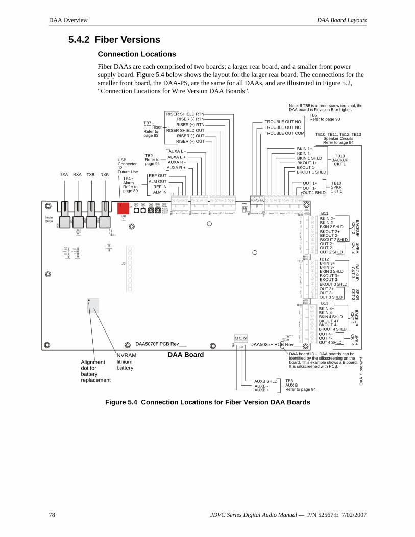
DAA Overview DAA Board Layouts
5.4.2 Fiber VersionsConnection LocationsFiber DAAs are each comprised of two boards; a larger rear board, and a smaller front power supply board. Figure 5.4 below shows the layout for the larger rear board. The connections for the smaller front board, the DAA-PS, are the same for all DAAs, and are illustrated in Figure 5.2, “Connection Locations for Wire Version DAA Boards”.
Figure 5.4 Connection Locations for Fiber Version DAA Boards
RISER (+) OUTRISER (-) OUT
RISER SHIELD OUT
AUXA R +AUXA R -AUXA L +AUXA L -
ALM INREF IN
ALM OUTREF OUT
RISER (+) RTNRISER (-) RTN
RISER SHIELD RTN
OUT 1 SHLDOUT 1-OUT 1+
TROUBLE OUT NOTROUBLE OUT NCTROUBLE OUT COM
BKIN 1+BKIN 1-BKIN 1 SHLDBKOUT 1+BKOUT 1-BKOUT 1 SHLD
TB10BACKUP
CKT 1
BKOUT 2 SHLDBKOUT 2-BKOUT 2+BKIN 2 SHLDBKIN 2-BKIN 2+
TB9Refer to page 94
TB4 - AlarmRefer to page 89
TB7 - FFT RiserRefer to page 93 TB10, TB11, TB12, TB13
Speaker CircuitsRefer to page 94
TB10SPKR CKT 1
TB5Refer to page 90
OUT 2 SHLDOUT 2-OUT 2+
BAC
KU
P
CKT 2
SPK
R
CK
T 2
BKOUT 3 SHLDBKOUT 3-BKOUT 3+BKIN 3 SHLDBKIN 3-BKIN 3+
OUT 3 SHLDOUT 3-OUT 3+
BA
CK
UP
CKT 3
SPK
R
CK
T 3
BKOUT 4 SHLDBKOUT 4-BKOUT 4+BKIN 4 SHLDBKIN 4-BKIN 4+
OUT 4 SHLDOUT 4-OUT 4+
BAC
KUP
C
KT 4
SPK
R
CKT 4
TB11
TB13
AUXB +AUXB -AUXB SHLD
DAA Board
TB8AUX BRefer to page 94
DA
A_f_
brd.
wm
f
TB12
NVRAM lithium battery
Alignment dot for battery replacement
USB Connector J2Future UseTXA RXA TXB RXB
Note: If TB5 is a three-screw terminal, the DAA board is Revision B or higher.
DAA board ID - DAA boards can be identified by the silkscreening on the board. This example shows a B board. It is silkscreened with PCB.
78 JDVC Series Digital Audio Manual — P/N 52567:E 7/02/2007

DAA Board Layouts DAA Overview
Indicator and Switch LocationsSwitches and LED indicator locations are illustrated in Figure 5.5. The connections for the smaller front board, the DAA-PS, are the same for all DAAs, and are illustrated in Figure 5.3, “LED Indicator, Jumper and Switch Locations”.
Figure 5.5 LED Indicator and Switch Locations, Fiber Boards
5.4.3 IndicatorsDiagnostic colored LEDs indicate various conditions and troubles. Table 5.3 lists and describes each.
DAA Board
AUX
AL BUSFFT
TRBLAMPFAIL
LED Indicators. Refer to Table 5.3
on page 80
Switches. Refer to Table 5.4 on
page 81
ONESTENSF2F1
VOLUME
TRBL 1ON 1
TRBL 2ON 2
TRBL 3ON 3
TRBL 4ON 4
LED Indicators. Refer to
Table 5.3 on page 80
DA
A_f_
brd.
wm
f
See also “Pushbutton Controls” on page 101
See also “DAA Configuration” on
page 99
4WIRE
STATUSLOCSILRST
RX
ATX
AR
XB
TXB
AUDIO
CHGRFAIL
LINK BRX OK
LINK ARX OK
DAA BoardLED Name Color Description LED #EFB Yellow Illuminates steadily when an earth fault has been detected at digital audio port DAP B. LED is on
wire versions only.1
EFA Yellow Illuminates steadily when an earth fault has been detected at digital audio port DAP A. LED is on wire versions only.
2
AMP FAIL Yellow Illuminates steadily while audio amplifier failure detected. 4ON 4 Green Illuminates steadily while analog signal is on speaker circuit 4. Blinking while 200Hz tone is on
speaker circuit 4.5
JDVC Series Digital Audio Manual — P/N 52567:E 7/02/2007 79

DAA Overview DAA Board Layouts
Table 5.3 LED Indicators
ON 3 Green Illuminates steadily while analog signal is on speaker circuit 3. Blinking while 200Hz tone is on speaker circuit 3.
6
ON 2 Green Illuminates steadily while analog signal is on speaker circuit 2. Blinking while 200Hz tone is on speaker circuit 2.
7
ON 1 Green Illuminates steadily while analog signal is on speaker circuit 1. Blinking while 200Hz tone is on speaker circuit 1.
8
TRBL Yellow Blinks when there is an unacknowledged trouble, illuminates steadily when a trouble is acknowledged but unresolved.
9
AL BUS Red Illuminates steadily while alarm bus input is active. 10AUX Green Illuminates while audio detected on either AUX IN A or AUX IN B. 11FFT Green Illuminates steadily while audio is detected on firefighter’s telephone riser. 12AUDIO Green OFF - No audio signal is present.
Fast blink - The DAA is receiving audio from the JDVC.Slow blink - The DAA is playing audio from stored backup tones.Steady - The DAA is playing audio from its AUX input.
13
TRBL 1 Yellow Illuminates steadily while a short is detected on speaker circuit 1. Blinks while an open is detected. 14TRBL 2 Yellow Illuminates steadily while a short is detected on speaker circuit 2. Blinks while an open is detected. 15TRBL 3 Yellow Illuminates steadily while a short is detected on speaker circuit 3. Blinks while an open is detected. 16TRBL 4 Yellow Illuminates steadily while a short is detected on speaker circuit 4. Blinks while an open is detected. 17USB Green Illuminated while communication is established on the USB port. 18DAP A TX Green Illuminates while data transmitted on Digital Audio Port A (wire or fiber). Illumination will flicker,
turning on when activity is detected and off when it is not. 19
DAP A RX Green Illuminates while data received on Digital Audio Port A (wire or fiber). Illumination will flicker, turning on when activity is detected and off when it is not.
20
DAP B TX Green Illuminates while data transmitted on Digital Audio Port B (wire or fiber). Illumination will flicker, turning on when activity is detected and off when it is not.
21
DAP B RX Green Illuminates while data received on Digital Audio Port B (wire or fiber). Illumination will flicker, turning on when activity is detected and off when it is not.
22
RST Yellow Illuminates when the board is not operational and maintenance is required. Call the factory. 23LOCSIL Yellow Illuminates when the Local Silence (F1) button is pressed to silence speaker outputs 1 through 4. 24STATUS Green Factory use only. 25RXA OK Green Illuminates steadily when there is a successful single- or multi-mode fiber connection on the RXA
connector. LED is on fiber versions only.100
RXB OK Green Illuminates steadily when there is a successful single- or multi-mode fiber connection on the RXB connector. LED is on fiber versions only.
101
DAA-PS Power Supply BoardLED Name Color Description LED #+5V Green Iluminated while 5V is present. 1E FAULT Yellow Illuminated while Earth fault is detected anywhere on the DAA except DAPs or AUX IN (A or B). 2TRBL Yellow Software-controlled as follows:
– OFF when the following system troubles are not present.– 1 blink - BROWNOUT. Priority 1, highest priority.– 2 blinks - HIGH BATTERY. Priority 2.– 3 blinks - LOW BATTERY. Priority 3.– 4 blinks - CHARGER TROUBLE. Priority 4, lowest priority.
If multiple troubles are present, the highest priority trouble will blink until cleared, then the next priority trouble will blink until cleared, etc.
3
DAA BoardLED Name Color Description LED #
80 JDVC Series Digital Audio Manual — P/N 52567:E 7/02/2007

DAA Board Layouts DAA Overview
5.4.4 Switches and JumperThe switches described in Table 5.4 are for configuring the DAA.
Table 5.4 Switches and Jumper
DAA BoardName Switch # Description DefaultTENS SW2 BCD rotary address selection switch. 0ONES SW3 BCD rotary address selection switch. 0F1 SW5 Pushbutton to silence speaker circuits during communication loss
with JDVC.N/A
F2 SW6 Pushbutton to reset the DAA. See page 101. N/AVOL SW7 BCD rotary switch for local background music. 0 (low)EFA SW9 Enable/disable Digital Audio Port A Earth fault detection. Switch is
on wire versions only.Off (disable)
EFB SW10 Enable/disable Digital Audio Port B Earth fault. Switch is on wire versions only.
Off (disable)
4 WIRE SW11 Changes FFT Riser indication to 2- or 4-wire, depending on whether the riser is wired Class B or Class A.
2-wire
DAA-PS Power Supply BoardName Number DescriptionJumper JP2 When DAAs are sharing batteries, cut this jumper for all but one of
the DAAs to disable Earth Fault detection. Only the DAA intended to report Earth Faults should have this jumper intact.Note that this jumper does not enable/disable Earth Fault detection on the Digital Audio Ports. That function is determined by SW9 and SW10.
N/A
JDVC Series Digital Audio Manual — P/N 52567:E 7/02/2007 81

Section 6: DAA Installation
6.1 CabinetThe DAA arrives from the factory already installed on its chassis. An NCM-W/F can be mounted on it. (Refer to Figure 6.2). The DAA chassis mounts in a CAB-4 Series cabinet, as well as in the EQCAB Series backboxes. It is compatible with CAB-3 Series cabinets per the instructions in Section 6.1.1
Prior to installation,
• Review the installation precautions at the front of this manual.• Installers should be familiar with the standards and codes specified in “Standards and Other
Documents” on page 8.• Ensure all wiring will comply with national and local codes.• Review the installation instructions in this section.
Locate the cabinet backbox on a surface that is in a clean, dry, vibration-free area. The top should be located so that all operational buttons, switches, displays, etc. are easily accessible and/or viewable to the operator - ususally no more than 66 inches (1.7 m) above the floor. Allow sufficient clearance around the cabinet for the door to swing freely, and for easy installation and maintenance of equipment.
Follow the instructions below.
1. Mark and pre-drill two holes for the keyhole mounting bolts. Install bolts.2. Select and punch open the appropriate cabinet knock-outs. (For selection guidelines, see
“UL Power-limited Wiring Requirements” on page 97.)3. Using the keyholes, mount the backbox on the two bolts.4. Mark the location of the two lower holes, remove backbox and drill the mounting holes.5. Mount the backbox over the top two screws, then install the remaining fasteners. Tighten
all fasteners securely.6. Feed wires through appropriate knockouts.7. Install DAA according to the following instructions before installing the door per the
CAB-4 Series Cabinet Installation Document.
The DAA fills one row of any CAB-4 series cabinet.
!WARNING:Wear a static discharge wrist strap to prevent equipment damage.
82 JDVC Series Digital Audio Manual — P/N 52567:E 7/02/2007

Cabinet DAA Installation
6.1.1 CAB-3 Cabinets
Figure 6.1 Using Older Backboxes
NOTE: The DAA is compatible with the CAB-3 Series backboxes. However, when installing the DAA in a CAB-3 Series or gray CAB-4 Series backboxes, the stud indicated in Figure 6.1 must be shortened to allow room for the TB12 connector. Stud height must not exceed . Gray versions of the CAB-4 Series backboxes and all CAB-3 Series backboxes have studs that require shortening.
WARNING: • Do not cut without nut in place to protect threading. • Remove all electronics from the backbox prior to cutting to avoid damage to electronics. • Wear protective eye covering.
!
Cut stud with metal-cutting
tool.
Verify stud height and cut if stud exceeds 0.375 in. (9.525 mm). See note and warning above.
DAA
CA
Bret
ro.e
ps
DAA row in backbox
Backbox DAA
_CAB
3stu
dct.w
mf
Procedure:1. Prior to DAA installation, apply nut to mounting stud to protect threading.2. Cut stud to proper length.3. Loosen nut slightly to allow DAA chassis installation, then tighten nut securely.
JDVC Series Digital Audio Manual — P/N 52567:E 7/02/2007 83
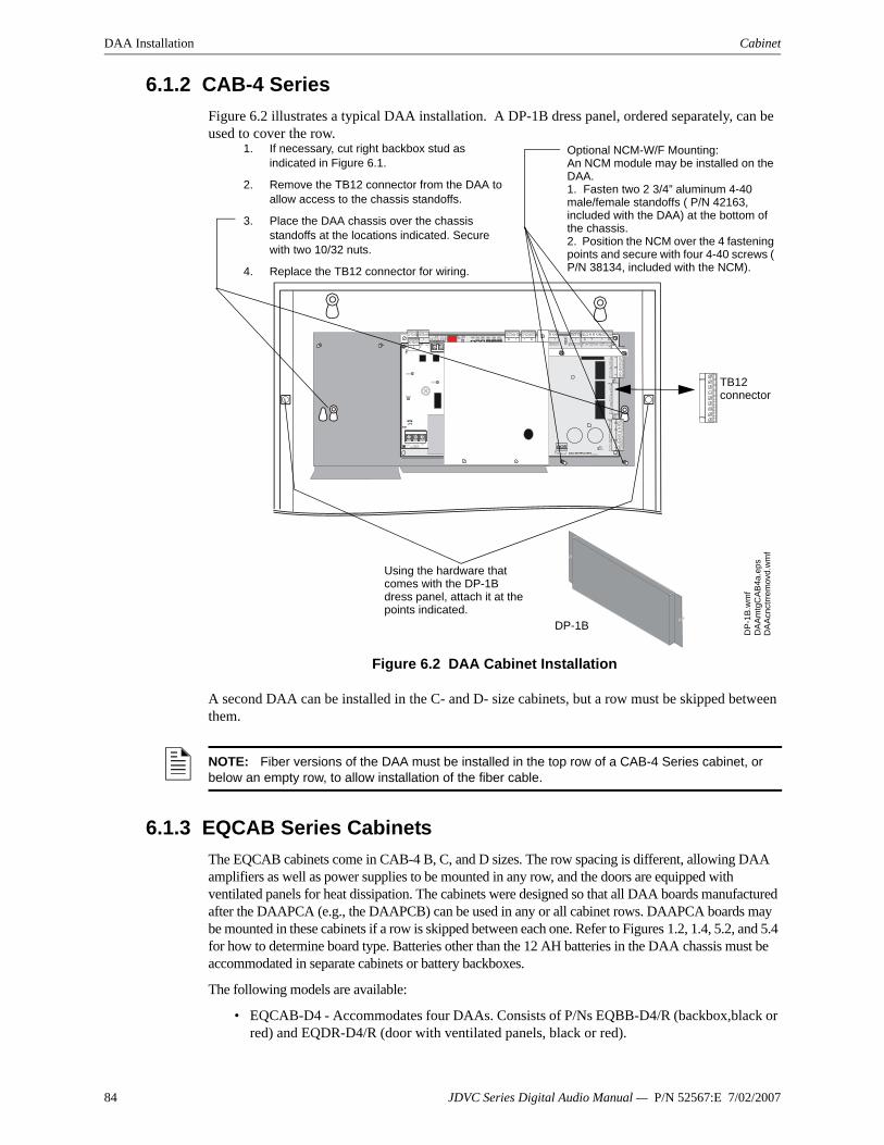
DAA Installation Cabinet
6.1.2 CAB-4 SeriesFigure 6.2 illustrates a typical DAA installation. A DP-1B dress panel, ordered separately, can be used to cover the row.
Figure 6.2 DAA Cabinet Installation
A second DAA can be installed in the C- and D- size cabinets, but a row must be skipped between them.
6.1.3 EQCAB Series CabinetsThe EQCAB cabinets come in CAB-4 B, C, and D sizes. The row spacing is different, allowing DAA amplifiers as well as power supplies to be mounted in any row, and the doors are equipped with ventilated panels for heat dissipation. The cabinets were designed so that all DAA boards manufactured after the DAAPCA (e.g., the DAAPCB) can be used in any or all cabinet rows. DAAPCA boards may be mounted in these cabinets if a row is skipped between each one. Refer to Figures 1.2, 1.4, 5.2, and 5.4 for how to determine board type. Batteries other than the 12 AH batteries in the DAA chassis must be accommodated in separate cabinets or battery backboxes.
The following models are available:
• EQCAB-D4 - Accommodates four DAAs. Consists of P/Ns EQBB-D4/R (backbox,black or red) and EQDR-D4/R (door with ventilated panels, black or red).
1. If necessary, cut right backbox stud as indicated in Figure 6.1.
2. Remove the TB12 connector from the DAA to allow access to the chassis standoffs.
3. Place the DAA chassis over the chassis standoffs at the locations indicated. Secure with two 10/32 nuts.
4. Replace the TB12 connector for wiring.
DA
Acn
ctrr
emov
d.w
mf
DA
Am
tgC
AB4a
.eps
TB12 connector
Using the hardware that comes with the DP-1B dress panel, attach it at the points indicated.
DP-1B
DP-
1B.w
mf
Optional NCM-W/F Mounting:An NCM module may be installed on the DAA.1. Fasten two 2 3/4” aluminum 4-40 male/female standoffs ( P/N 42163, included with the DAA) at the bottom of the chassis.2. Position the NCM over the 4 fastening points and secure with four 4-40 screws ( P/N 38134, included with the NCM).
NOTE: Fiber versions of the DAA must be installed in the top row of a CAB-4 Series cabinet, or below an empty row, to allow installation of the fiber cable.
84 JDVC Series Digital Audio Manual — P/N 52567:E 7/02/2007

Batteries DAA Installation
• EQCAB-C4 - Accommodates three DAAs. Consists of P/Ns EQBB-C4/R (backbox, black or red) and EQDR-C4/R (door with ventilated panels, black or red).
• EQCAB-B4 - Accommodates two DAAs. Consists of P/Ns EQBB-B4/R (backbox, black or red) and EQDR-B4/R (door with ventilated panels, black or red).
Figure 6.3 EQCAB-D4 Cabinet
6.2 Batteries
The DAA works with two 12AH minimum to 55 AH maximum batteries. See “DAA Battery Calculations” on page 105 for current draw calculations to determine the battery size required for this installation.
Batteries for the DAA may be installed in any of the following configurations:
• In a CHS-BH1 battery chassis (12AH batteries only), designed for use with the DAA chassis.
• In the bottom of a CAB-4 series cabinet that holds the DAA.• In a cabinet adjacent to the cabinet that holds a DAA, with connections in conduit.
6.2.1 In a CHS-BH1 Battery ChassisThis chassis will hold two 12AH batteries, and will mount on the left side of the DAA chassis, so that the DAA and batteries are contained in a single cabinet row.
To mount the CHS-BH1 onto the DAA chassis: Place battery holder against DAA chassis, resting on support as shown in Figure 6.4. Align chassis standoffs with holes. Fasten with the two 8/32” hex nuts supplied.
Place the batteries on their sides in their trays before wiring. Refer to “Connecting the DAA Power Supply to the Batteries” on page 87 for wiring instructions.
DAA Mounting Locations
CA
BDAA
_D4.
wm
f
!WARNING: Batteries contain sulfuric acid which can cause severe burns to the skin and eyes, and can destroy fabrics. If contact is made with sulfuric acid, immediately flush skin or eyes with water for 15 minutes and seek immediate medical attention.
JDVC Series Digital Audio Manual — P/N 52567:E 7/02/2007 85

DAA Installation Wiring
6.2.2 Within the CAB-4 EnclosurePlace the batteries in the bottom of the cabinet, as shown in Figure 6.5. Refer to “Connecting the DAA Power Supply to the Batteries” on page 87 for wiring instructions.
6.2.3 Outside the DAA EnclosureBatteries may be installed outside the DAA enclosure. The battery cables must be in conduit between the enclosures for the batteries and the DAA. Refer to “Connecting the DAA Power Supply to the Batteries” on page 87 for wiring instructions.
6.3 Wiring
6.3.1 Connecting the DAA Power Supply to AC Power
The DAA power supply requires connection to a separate dedicated AC branch circuit. Follow these guidelines when connecting the AC branch circuit:
• Label the branch circuit “Fire Alarm”.• Connect the branch circuit to the line side of the main power feed of the protected premises.
CH
S-BH
toD
AAc
hass
is.w
mf
CH
S-BH
wba
tts.w
mf
Place battery holder against DAA chassis, resting on support. Align chassis standoffs with holes. Fasten with the two washers (P/N 43123) and 8-32 KEPS hex nuts (P/N 36047) supplied.
Place batteries in the trays.
Support
Figure 6.4 Mounting the CHS-BH1
CAB
4Dw
DA
Abat
s.w
mf
DAA in top row of CAB-4D
Figure 6.5 Battery Installation Within the Cabinet
Batteries for DAA
!WARNING: High Voltages Present.
Use extreme caution when working with the DAA. High voltage and AC line-connected circuits are present. Turn off and remove all power sources. To reduce the risk of electric shock, make sure to properly ground the DAA.
Close the hinged cover for TB1 after wiring but before energizing.
86 JDVC Series Digital Audio Manual — P/N 52567:E 7/02/2007

Wiring DAA Installation
• Do not power other equipment from the fire alarm branch circuit.• Run the AC branch circuit wire continuously, without any disconnect devices, from the
power source to the power supply.• Overcurrent protection for the AC branch circuit must comply with Article 760 of the
National Electrical Codes, as well as local codes.• Use 12-14 AWG (1.6mm O.D.) wire with 600 VAC insulation for the AC branch circuit.
Connect primary power as follows:
1. Turn off the circuit breaker at the main power distribution panel.
2. Open the hinged plastic insulating cover from TB1.
3. Connect the earth ground terminal (TB1 EARTH) to a solid earth ground (a metallic, cold water pipe may be suitable in some installations). This connection is vital to maintaining the power supply’s immunity to unwanted transients generated by lightning and electrostatic discharge.
4. Connect the primary power neutral line to the terminal marked NEUTRAL and the primary power AC line to the terminal marked HOT.
5. Close the hinged plastic insulating cover over TB1.
6.3.2 Connecting the DAA Power Supply to the Batteries
The DAA works with two 12AH minimum to 55 AH maximum batteries. See “DAA Battery Calculations” on page 105 for current draw calculations to determine the battery size required for this installation.
DAAs can share batteries as follows:
• 26 AH batteries can accommodate one or two DAAs.• 55 AH batteries can accommodate up to four DAAs.
Battery cables (90”, 2.28 m) are included with the DAA for battery installation in any CAB-4 series cabinet that includes a DAA in one of the rows. Shorter battery cables (18”, 0.5 m) are included with the CHS-BH1. For battery sharing, use 12 AWG wire either in the same cabinet, or in conduit for no more than 20 ft. (6.09 m.).
!WARNING: Close the hinged plastic insulating cover for TB1 after wiring but before energizing. Refer to Figure 6.7.
Figure 6.6 AC Power Connection
EARTH NEUTRAL HOT
DA
APS
tb1.
wm
f
Figure 6.7 TB1 with Closed Cover
Close the hinged cover over TB1 after AC power has been wired but not energized.
acco
verin
st.w
mf
!WARNING: Do not connect the battery interconnect cable (See Figure 6.8) at this time. Leave the battery interconnect cable disconnected until after initial system power-up.
JDVC Series Digital Audio Manual — P/N 52567:E 7/02/2007 87

DAA Installation Wiring
Batteries Within the Same Enclosure as the DAARefer to Figure 6.8 for battery connections.
Figure 6.8 Connecting Batteries to TB3 on the DAA-PS
Batteries Outside the DAA EnclosureWhen the batteries are installed outside the DAA cabinet, connections are the same as in Figure 6.8. However, the battery cables between the two enclosures must be in conduit.
Figure 6.9 Using Conduit
Battery SharingUp to four DAAs may share a set of batteries. When DAAs share batteries, the JP2 jumpers must be cut on all but one DAA attached to a set of batteries, to disable Earth Fault detection on all but the one with JP2 left intact. (Refer to Figure 5.3 on page 77 and Figure 5.4 on page 78.)
VeriFire programming (see “Audio Amplifiers” on page 45) must designate all DAAs but one as having the charger disabled.
Only one DAA should have its JP2 jumper intact, and only one DAA should have a working charger. These DAAs do not have to be the same.
DAA
PSt
obat
ts.w
mf
Battery Interconnect Cable, P/N
71070
Leave disconnected until after initial
system power-up.
Batteries in CHS-BH, same cabinet row as DAA
Batteries in different cabinet row than DAA.
DAA
PSt
obat
tsa.
wm
f
A B
P/N 75560 (pos)
P/N 75561 (neg)
P/N 75621 (neg)
P/N 71071 (pos)
DA
Aba
ttext
erna
l.wm
f
DAABatteries
Conduit between enclosures
Battery Interconnect
Cable
Leave disconnected until after initial system power-up.
NOTE: This designation must be made for the 75 watt boards as well as the 50 watt boards.
NOTE: Only one DAA should have an intact JP2 jumper, and only one DAA should have the battery charger enabled. The DAA with the intact jumper does not have to be the same DAA that has the charger enabled.
88 JDVC Series Digital Audio Manual — P/N 52567:E 7/02/2007

Wiring DAA Installation
Connect all DAAs sharing a set of batteries directly to the batteries using 12 AWG. If the batteries are located outside of the DAA cabinet, the wiring must be in conduit that is no greater than 20 ft (6.09 m) long.
Figure 6.10 Four DAAs Sharing 55AH Batteries
6.3.3 Connecting the Alarm and Trouble BusesAlarm BusThe DAA general alarm connections are used to receive general alarm messages from an FACP via the SLC, or via the Notification Appliance Circuit of an FACP or power supply.
Figure 6.11 Alarm Bus Connections to M300CJ
If batteries are not in the same cabinet as the DAAs, wiring must be in conduit that is 20 ft (6.09 m) long or less. D
AA
tb3b
atsh
are.
wm
f
DAA 1 TB3
DAA 2 TB3
DAA 3 TB3
DAA 4 TB3
JP2 must be cut on all but one of these DAAs. VeriFire programming must indicate which are enabled/disabled.
M300CJ
ALARM Bus to next DAA ELR-47K, 1/2 watt resistor
DAA
FMM
-1.w
mf
To Power Supply
+- SLC
from FACP
DA
ABR
Dtb
4.w
mf
TB4
SLC to next device
+-
TB4
14-18 AWG twisted-pair recommended
+ -
Program the control module at the FACP with an appropriate alarm Type ID per the FACP manual.
Alarm Bus requires 16VDC at 20mA to activate.
JDVC Series Digital Audio Manual — P/N 52567:E 7/02/2007 89

DAA Installation Wiring
Figure 6.12 Alarm Bus Connections to NAC
Refer to the SLC manual and specific panel or power supply manual for more information.
Trouble BusThe DAA trouble bus connections are used to send general trouble messages to an FACP. The trouble relay is used mainly as a backup in the event the monitoring panel loses communication with the JDVC over Noti-Fire-Net. Figure 6.13 illustrates wiring the Common and Normally Open out connections to anM300MJ monitor module.
Figure 6.13 Trouble Bus to M300MJ
Refer to the SLC manual and specific panel manual for more information on panel and SLC wiring.
NAC CircuitA -
A +
B +
B -
ALARM Bus to next DAA
DA
ABR
Dtb
4.w
mfDAA
TB4 TB4
ELR per panel or power supply manual.
14-18 AWG twisted-pair recommended
Listed compatible panel or power supply with onboard NAC circuits.
Alarm Bus requires 16VDC at 20mA to activate.
DAA
M300MJFM
M-1
.wm
f
To another DAA
ELR-47K, 1/2 watt resistor
DA
ABR
Dtb
5.w
mf
TB5
+- SLC
from FACP
+-
TB5
SLC to next device
14-18 AWG twisted-pair recommended
Program the monitor module at the FACP with an appropriate Type ID per the FACP manual
90 JDVC Series Digital Audio Manual — P/N 52567:E 7/02/2007

Wiring DAA Installation
6.3.4 Digital Audio Ports A and B on Wire Version BoardsDigital Audio Ports A and B (DAP A and DAP B) allow digital communication with the JDVC over the Digital Audio Loop (DAL). Amplifier programming from the JDVC; control, audio, trouble, address and firefighter’s telephone data; and live voice paging can be communicated through these ports. They may also act as repeaters, in that what is received at one port is transmitted out the other. Events generated at the DAA will be transmitted out both ports.
Figure 6.14 Wire the DAA Digital Audio Loop Connections
JDVC
TB3
DAA 1
DAP A+
DAP A-
REF ADAP B+
DAP B-
REF B
See “Digital Audio Ports A and B - TB2, TB3” on page 74 for cable types and associated distances between ports.
TB2
TBge
n3.w
mfTB2
and TB3
DAA 2 DAA 32
Optional Style 7 return
TB3
DAP A+
DAP A-
REF ADAP B+
DAP B-
REF B
TB2
TB3
DAP A+
DAP A-
REF ADAP B+
DAP B-
REF B
TB2
Connections are polarity sensitive.Connections are port sensitive. Always connect Port A to Port B.
DAPA DAPBREF REF
TB3
TB2
NOTE: Digital Audio Ports A and B must be wired in Style 4 or Style 7 configuration. Do not wire them in bus configuration.
NOTE: Style 4 configuration must be installed in accordance with the requirements for survivability from attack by fire in the National Fire Alarm Code, NFPA 72.
JDVC Series Digital Audio Manual — P/N 52567:E 7/02/2007 91

DAA Installation Wiring
Refer to “EFA and EFB (Switches 9 and 10)” on page 99 for information on enabling earth fault detection on the wire DAL.
6.3.5 RXA, RXB, TXA, TXB Fiber Version Board ConnectionsFiber ports RXA, RXB, TXA and TXB allow digital communication with the JDVC fiber boards. The fiber cabling between these ports provides a Digital Audio Loop (DAL) for programming; alarm, control, trouble, automatic audio messages, address and firefighter’s telephone data; and live voice paging communications.
Figure 6.15 Fiber Digital Audio Loop Connections
NOTE: A fiber DAL must be connected with one of the following: - All single-mode fiber connections, or - All multi-mode fiber connections.Multi-mode and single-mode can not be mixed.
TXA
RXA
TXB
RXB
DV
C_f
_cx.
wm
fD
AA_
f_cx
.wm
f
JDVC Fiber Model
TXA RXA TXB RXB TXA RXA TXB RXB
Optional Style 7 return
TXA RXA TXB RXBDAA 1 DAA 2 DAA 32
Bend Radius must be greater than 1” (2.5 cm)
NOTE: Style 4 configuration must be installed in accordance with the requirements for survivability from attack by fire in the National Fire Alarm Code, NFPA 72.
92 JDVC Series Digital Audio Manual — P/N 52567:E 7/02/2007

Wiring DAA Installation
6.3.6 FFT Riser ConnectionsThe Firefighter’s Telephone Riser connections (TB7) provide for the use of firefighter’s telephones (FFTs) on an analog network. They are a means of connecting various FFT control modules and devices, such as M500FPJ modules, AFAWS, or XPIQ telephone circuits to the DAA.
The FFT riser may be wired in NFPA Class A or Class B configuration. VeriFire Tools must be used to select Class A or Class B for trouble supervision. Class B 2-Wire configurations require a 3.9K ohm 1/2 watt end-of-line resistor (P/N R-3.9k).
Figure 6.16 FFT Riser (Class A Example)
For a description of the JDVC firefighter’s telephone network operation, refer to Section 8.4 on page 102.
TB
1T
B2
TB
3T
B4
TB
5T
B6
TB
7T
B8
J7
J6
J11
J1
2
J1
3
TB
10
SW
4
JP1JP2
SW
1
EARTH FAULTDETECTION
EARTHFAULT
GEN TBL
DISABLED
ENABLED
P6
P5
P4
P3
P2
P1
Lo
wL
eve
lB
acku
pIN
Re
mo
teO
ut
BC
KG
ND
MU
SIC
Re
mo
teIn
High LevelBackup IN
High LevelBackup OUT
Lo
wL
eve
lB
acku
pO
UT
J9
XPIQ-PS Control Cable
XPIQ-PS Power EXT TRBL IN
SW
3S
W2
PHONE1 AND 2
PHONE3 AND 4
CHGTRBL
Phone 4 TRBL
Phone 3 TRBL
Phone 2 TRBL
Phone1 TRBL
Riser TRBL
TRBL
TRBL
TRBL
TRBL
SPKR1
SPKR2
SPKR3
SPKR4
BATTRBL
A.C.Fail
J1
J2
J1
0
J4
J5
J8
Phone 1
Phone 2
Phone 3
Phone 4
Spkr1
Spkr2
Spkr3
Spkr4
TB9
2 X 2W
2 X 2W
1 X 4W
1 X 4W
PH
ON
E/N
AC
RIS
ER
XP
IQ-C
AO
ptio
n
SH
LD
-P
H+
SH
LD
-P
H+
+O
UT
-S
HL
D+
OU
T-
SH
LD
+O
UT
-S
HL
D+
OU
T-
SH
LD
CO
NT
RO
L/C
OM
M
AU
DIO
IN
AM
PLIF
IER
#4
AM
PLIF
IER
#3
AM
PLIF
IER
#2
AM
PLIF
IER
#1
12
12
34
56
S-
+S
-+
S-
+S
-+
12
31
23
12
31
23
12
31
23
12
31
23
56789
0 1234
NOTIFIER XPIQ-MBPCA REV.
FIREFIGHTER’S
PHONE JACK
FIREFIGHTER’S
PHONE JACK
SHLD SHLD
RISER OUT RISER RTN
Control Module or Telephone
Control Module
XPIQ
FPJ-1 Firefighter’s Phone Jack
DV
CFF
Tris
er.w
mf
DAA
AFAWS Fire Alarm Warden
Station
TB7
Max wiring resistance (including individual telephone zone to last
handset) permitted is 50 ohms. 10,000 ft. (3048 m) max. wiring distance at 14
AWG to last handset.
14-18 AWG twisted-pair recommended
Control Module or Telephone
Control Module
Control Module
FPJ-1 Firefighter’s Phone Jack
NOTE: Digital audio software Version 2.0 and above does not support FFT risers on JDVC or DAA PCA boards. Refer to Figures 1.2, 1.4, 5.2, and 5.4 for how to determine board type. Check VeriFire or an appropriate network display to determine the software version.
JDVC Series Digital Audio Manual — P/N 52567:E 7/02/2007 93

DAA Installation Wiring
6.3.7 Auxiliary Inputs A and BThe DAA provides two analog audio connections. One or the other may be used, not both.
Auxiliary Input AAuxiliary Input A (AUXA) is intended for background music, and provides a high-fidelity connection to common audio appliances such as a radio, CD player, or tape deck. Two-channel stereo signals are changed to monophonic signals.
Figure 6.17 AUX A Auxiliary Audio Input
Background music will be silenced while batteries greater than 26AH are being fully charged.
Auxiliary Input BAuxiliary Input B (AUXB) is provided to accept low-level analog audio input at 12Vp-p nominal, 15Vp-p max. The messages are then transmitted out as high level audio to DAA speaker circuits as designated by programming. VeriFire Tools programming determines if signal supervision of AUXB is enabled.
Figure 6.18 AUXB Auxiliary Audio Input
6.3.8 Speaker and Backup CircuitsSpeaker circuits 1 through 4 (terminals 10 through 13) provide for two NFPA Class A (Style Z) connections for high-level audio output, four NFPA Class B (Style Y) connections, or One Class A and two Class B connections. These connections dynamically share the 50W output capability of the DAA.
A DAA may be wired using the “BKIN” and “BKOUT” terminals to back up an amplifier. If an amplifier fails, the signal automatically switches to the backup amplifier.
Radio, CD player, portable audio
device, telephone paging source, or
tape deck.
_+
_+
Left audio signal
Right audio signal
DAA
DA
ABR
Dtb
9.w
mf
TB9
Expected signal strength from Auxiliary Input: 1Vp-p max.
Stereo input shown. Monophonic input may connect to either AUXA R or AUXA L.
14-18 AWG twisted-pair recommended
JDVC AUXB
AMG-1 Style Low Level Audio
TB 14
DV
CA
UX
Btb1
4.w
mf
14-18 AWG twisted-pair recommended.
Low-level analog audio output, 12Vp-p nominal, 15Vp-p max.
94 JDVC Series Digital Audio Manual — P/N 52567:E 7/02/2007

Wiring DAA Installation
Speaker and backup connections are illustrated in Figure 6.19.
Figure 6.19 Speaker Circuit and Backup Connections
Speaker CircuitsThe amplified signal from the DAA may be connected directly to speakers, or to an ACT-2 Audio Coupling Transformer, for low-level signals to XPIQs or AA Series analog amplifiers. Following are illustrations of Class A and Class B configurations (Figures 6.20).
Figure 6.20 Two DAA Class A (Style Z) Circuits
TB10 (Ckt 1), TB11 (Ckt 2), TB12 (Ckt 3) and TB13 (Ckt 4) have the same layout for circuit connections with the following exceptions:
TB11: OUT 2andTB13 :OUT 4
DA
ABR
Dtb
10.w
mf
Backup InCkt 1,2,3,4
SHLD
Backup OutCkt 1,2,3,4
SHLD
High level audio Out, Ckt 1, 2, 3, 4.
SHLD
may act as 4-wire returns for TB10 (OUT 1) and TB12 (OUT 3) respectively. The board has the additional silkscreen labels RET 1 and RET 3 at these terminals. D
AAB
RD
tb11
.wm
fD
AAB
RD
tb13
.wm
f
*
*
12-18 AWG twisted-pair recommended
Circuit 1 Circuit 2 Circuit 3 Circuit 4
High Level Return
High Level Out
R-10k High Level Return
High Level Out
R-10k
ACT-2
AIB
XPIQ
-CA
XPIQ
DA
ABR
Dtb
10.w
mf
DA
ABR
Dtb
11.w
mf
DA
ABR
Dtb
13.w
mf
DA
ABR
Dtb
12.w
mf
JDVC Series Digital Audio Manual — P/N 52567:E 7/02/2007 95

DAA Installation Wiring
Figure 6.21 One DAA Class A (Style Z) Circuit, Two Class B (Style Y) Circuits
Speaker Backup CircuitsThe DAA supports one-to-one or one-to-many backup amplification. Each DAA must be designated a primary or backup amplifier through VeriFire Tools programming.
One-to-One Backup
Figure 6.22 illustrates output sources 1, 2, 3 and 4 on the primary amplifier backed up by the backup amplifier. Should the primary amplifier fail, all its messages will still be played as programmed.
Figure 6.22 One-to-one, All Sources Backed Up
High Level Return
High Level Out
R-10k
Circuit 1 Circuit 2 Circuit 3 Circuit 4
20k ohm end-of-line resistor, p/n ELR-20k
20k ohm end-of-line resistor, p/n ELR-20k
TB2JDVC
DAP A+DAP A-REF ADAP B+DAP B-REF B
TB3
Primary DAA Backup DAA
Digital Signal from JDVC
Optional Class A Return
VeriFire Tools Programming
Primary DAA Address 1Backup DAA Address 2
DA
spkr
bkup
.wm
f
20k ohm end-of-line resistor, p/n ELR-20k
ELR-20k
ELR-20k
ELR-20k
96 JDVC Series Digital Audio Manual — P/N 52567:E 7/02/2007

Wiring DAA Installation
One-to-Many Backup
One amplifier may be used to back up as many as 31 primary DAA amplifiers. All primary amplifiers backed by the same backup amplifier must be wired in the same style; that is, all Class A (Style Z) or all Class B (Style Y).
A backup amplifier can support one failed primary amplifier at a time. Should another primary amplifier also fail, the backup amplifier may also fail, generating an AMPLIFIER LIMIT trouble until the load is reduced or reset.
Figure 6.23 One-to-Many Backup
6.3.9 UL Power-limited Wiring RequirementsPower-limited and non-power-limited circuit wiring must remain separated in the cabinet. All power-limited circuit wiring must remain at least 0.25 inches (6.35 mm) from any non-power-limited circuit wiring. All power-limited and non-power-limited circuit wiring must enter and exit the cabinet through different knockouts and/or conduits.
Figure 6.24 Typical Backbox Wiring
Primary DAA 1 Primary DAA 2 Primary DAA 32
DA
AB
RD
tb10
.wm
f
From “Out” terminals on backup amplifier
ToSpeakers
ToSpeakers
ToSpeakers
Power-limited circuits
Nonpower-limited circuits
DA
AU
Lwiri
ng.w
mf
JDVC Series Digital Audio Manual — P/N 52567:E 7/02/2007 97

DAA Installation Replacement of NVRAM Memory-Backup Battery
6.4 Replacement of NVRAM Memory-Backup BatteryThe DAA board has a snap-in lithium battery that provides backup of the DAA’s on-board memory during power loss. Refer to Figure 5.2 on page 76 or Figure 5.4 on page 78 for the location. The expected shelf-life for this battery is 10+ years. However, if battery connections are damaged or the battery does lose power, a system trouble message will be generated: “NVRAM BATT TROUBLE”. A new battery (P/N 31005, SGS Thompson M4T32BR12SH1) must be purchased and installed to replace the old.
To replace the battery:
1. Power down the system.2. Use your fingers to carefully pull the battery off the board.3. Align the new battery and push it into the same space. The dot in one corner of the battery
should align as indicated in Figure 5.2 on page 76.4. Power up the system.
98 JDVC Series Digital Audio Manual — P/N 52567:E 7/02/2007

Section 7: DAA Configuration
7.1 Setting the Configuration Switches
7.1.1 EFA and EFB (Switches 9 and 10)The wire versions of the DAA boards have two earth fault detection switches for use with Digital Audio Ports (DAPs) A and B. The switches arrive from the factory disabled, and may require resetting if earth fault detection is desired.
Each DAP on a DAA or JDVC is electrically isolated from the other DAP and all other circuitry on the DAA or JDVC.
A DAP with its associated earth fault switch enabled must be connected to a DAP with its associated earth fault switch disabled for detection to occur. Otherwise, either
• no detection will occur (when two connected DAPs have their associated switches disabled), or
• an earth fault will be generated (when two connected DAPs have their associated switches enabled).
Refer to Figure 7.2.
Figure 7.2 Earth Fault Switch Settings for a Wire Digital Audio Loop (DAL)
7.1.2 4WIRE (Switch 11)The FFT riser may be wired in a Class A four-wire or a Class B two-wire configuration. For Class A installations, enable the switch. For Class B, disable the switch.
VeriFire Tools programming must be set the same as this switch.
Figure 7.1 EFA/EFB Enable/Disable
SW9 and SW10 in DISABLE position
To enable, push the switch towards EN.
DIS
EN
EFA
DISEFB EN
SW
gen.
wm
fS
Wge
na.w
mf
JDVC
EFA ENDAPA
DAPB
DAA DAA
DAPA DAPB DAPA DAPB
DAA
DAPA DAPB
Optional Style 7 return
For specific DAP wiring instructions refer to Figure 6.14, “Wire the DAA Digital Audio Loop Connections” on page 91.
Twisted-pair wire.
EFB DIS
EFB
DIS
EFA
EN
EFB
DIS
EFA
EN
EFB
DIS
EFA
EN
Figure 7.3 4WIRE Enable/Disable
SW11 in enabled position.
To disable, push the switch towards DIS.
DIS
EN
4W
IRE
JDVC Series Digital Audio Manual — P/N 52567:E 7/02/2007 99

DAA Configuration Programming
7.1.3 Address SwitchesA maximum of 32 DAAs may be connected to one JDVC. Each DAA must have its own address so the events it generates can be distinguished from those of other DAAs, for unique routing of messages and sounds, and for speaker circuit control. Address switches SW2 (tens) and SW3 (ones) are used to address the DAA. Refer to Figure 7.4 for an illustration of addess settings and to Figure 5.3 on page 77 for the location of the switches..
Addresses one (1) through 32 may be used for digital communication. Address 00 and addresses above 32 will generate a DAA trouble.
The default address setting for the DAA as it arrives from the factory is 00.
7.1.4 Volume ControlA rotary switch (SW7) is supplied to adjust the volume for local background music from the AUXA or AUXB input.The default volume setting for the DAA as it arrives from the factory is 0 (Low). Turning the arrow clockwise to point at higher numbers and then letters raises the volume.Refer to Figure 5.3 on page 77 for the location of this control.
7.2 ProgrammingThe DAA is programmed through VeriFire Tools. Refer to the JDVC Manual programming section as well as the VeriFire Tools CD and Help file for information on how to create, prioritize and download audio messages, create system equations for message distribution, and set system parameters.
Figure 7.4 DAA Address SwitchesDAA Address set to 14
The SW2 arrow points to one (1). Tens switch set to one (1).
The SW3 arrow points to four (4). Ones switch set to four (4).
DA
A A
ddrs
wtc
hs.w
mf
Figure 7.5 DAA Volume Control
DA
A v
olct
lSW
7.w
mf
100 JDVC Series Digital Audio Manual — P/N 52567:E 7/02/2007

Section 8: DAA OperationThere are two pushbutton controls and one volume control on the DAA board. Refer to Figure 5.3 on page 77 for their location.
8.1 Pushbutton ControlsTable 8.1 summarizes the functions of each pushbutton control.
Table 8.1 Pushbutton Controls
8.2 Volume ControlThe DAA provides a volume control for background music from auxiliary port A or B (See “Volume Control” on page 100). The volume of other audio messages is determined through the VeriFire Tools Read Status Service Form and FACP/network annunciator programming.
8.3 FFT PagingTo page using an FFT handset on the JDVC’s FFT riser or the FFT riser on one of its DAAs, follow the instructions below.
Configured with Annunciator1. Activate the handset for FFT communication by lifting the receiver or plugging in the phone
jack.2. Press the annunciator button(s) mapped to the FFT.
• Specific Local Paging (when there is no ENABLE PAGING button) - Press the single button for the specific area to be paged (ie. Cafeteria) to enable paging. The annunciator LED will blink.
• Specific Network Paging - Press the ENABLE PAGING button, then press the button for the specific area to be paged (i.e., Cafeteria, East Wing). The annunciator LEDs will blink.
• General Local and General Network Paging - Press the ENABLE PAGING button, then press the button for the type of paging desired (ALL CALL, PAGE EVAC, PAGE ALERT , PAGE INACTIVE) The annunciator LEDs will blink.
3. Press the push-to-talk button.4. Page.5. To end the page, release the push-to-talk button and press the paging function button (not the
ENABLE PAGING button) to deactivate. The annunciator LED(s) will turn off.
Configured with Keyswitch1. Activate the handset for FFT communication by lifting the receiver or plugging in the phone
jack.2. Insert and turn the key in the keyswitch.
Pushbutton Function When to use
F1 Silences speaker circuits 1 through 4. This pushbutton is enabled by the DAA when there is a communication loss with the JDVC.
To turn off speaker outputs on speaker circuits 1 through 4.
F2 Clears local signal silences and reinitializes the amplifier if it turned off due to overcurrent protection.
After causes of DAA trouble messages have been cleared.
JDVC Series Digital Audio Manual — P/N 52567:E 7/02/2007 101

DAA Operation JDVC Firefighter’s Telephone Network Communication
3. Press the push-to-talk button.4. Page.5. To end the page, release the push-to-talk button and turn the key back to its original position.
Not Configured for Paging1. May request the paging function from the JDVC operator once they have established digital
FFT communication. The JDVC operator must press the ENABLE TELEPHONE PAGE button, then the paging function button.
2. Press the push-to-talk button to page.3. When paging is complete, release the push-to-talk button. The JDVC operator must press the
ALL CALL button, then the ENABLE TELEPHONE PAGE button to end the page.
8.4 JDVC Firefighter’s Telephone Network Communication
8.4.1 DescriptionThe JDVC firefighter’s telephone network consists of the JDVC’s own analog riser, analog risers that exist on any of the (up to) 32 DAA audio amplifiers connected to the JDVC, and the Digital Audio Loop (DAL) that connects them all at DAPA and DAPB digital audio ports.
FFT network activation (that is, when a handset on one of these risers is granted a connection by the operator) allows intercommunication between the JDVC’s FFT analog riser and up to four other dynamically-changing sets of FFT risers on the DAAs at addresses 1-4. Each riser can sustain seven active FFT handsets, so 35 handsets may be active within the network at the same time. If this number is exceeded, a short circuit trouble will be generated by the JDVC; however, FFT communications will continue
Figure 8.1 and the text that follows gives an example of how activated analog FFT risers interact with the Digital Audio Loop (DAL).
Figure 8.1 Active JDVC Firefighter’s Telephone Network
NOTE: The FFT riser on the JDVC is always one of the five active risers. Four FFT risers can be active on DAAs at the same time.
NOTE: The JDVC’s TELH-1 connection (J8) always counts as one of the seven active FFT handsets on the JDVC, whether there is a TELH-1 handset connected to it or not.
JDVC
DAA1
DAA14
Optional Style 7 return
A B
C
DE
DAA16
DAA24
DAA32
FFT
anal
og ri
ser
FFT
anal
og ri
ser
FFT
anal
og ri
ser
FFT
anal
og ri
ser
FFT
anal
og ri
ser
FFT
anal
og ri
ser
Digital Audio Loop (DAL)
DAP A
DAP B
phon
ehan
dset
.wm
fph
oneh
ands
etrt.
wm
f
102 JDVC Series Digital Audio Manual — P/N 52567:E 7/02/2007

Trouble Messages DAA Operation
1. A firefighter at DAA 1 activates a handset (A) on the analog FFT riser by lifting the receiver or plugging in a phone jack. An operator grants the firefighter a connection.
(A) will automatically be granted a Digital Audio Loop (DAL) connection.
[ 1 (DAA 1) analog riser + 1 (JDVC) analog riser = 2 risers interconnected on the DAL.]
2. Subsequently, firefighters at DAA 14 (B), DAA 24 (C), and DAA 32 (D) activate handsets and are granted connections by the operator.
(B), (C), and (D) will automatically be granted DAL connections.
[4 (DAA 1, 14, 24 and 32) analog risers +1 (JDVC) analog riser = 5 risers - the maximum allowed -interconnected on the DAL.]
3. A firefigher at DAA 16 activates a handset (E) and is granted a connection by the operator.
(E) will hear a ring tone on his handset.
(E) will be placed in a queue for the next available connection, because the maximum of 5 risers on the DAL has already been reached. (E) will hear the ring tone until either (A), (B), (C), or (D) is disconnected by the operator.
8.5 Trouble MessagesDAAs will send trouble messages to the panel or network annunciator through the trouble relay, or through the wire or fiber DAL (Digital Audio Loop).
The trouble relay sends a general trouble message to the panel, and the trouble must then be investigated at the DAA by checking the LED indicators. The trouble relay is used mainly as a backup in the event the monitoring panel loses communication with the JDVC over Noti-Fire-Net.
The Digital Audio Loop carries the specific trouble message generated by the DAA, and that message appears on the panel or network annunciator’s screen as a DAA trouble. The specific trouble message displayed will identify the DAA that generated it by displaying the Noti-Fire-Net node number of its JDVC, then the DAAs amplifier address (1 - 32). If the trouble is a speaker circuit trouble, the address will also contain the speaker circuit (1-4). The format will be AxxSz, where xx is the DAA address, and z is the speaker circuit number.
Refer to Table 5.3 on page 80 for an explanation of the indicators.
NOTE: If the JDVC is directly connected to an IFC2-3030 (that is, they are not connected through an NCM-W/F), the IFC2-3030 will display specific DAA troubles.
When the JDVC is a node on Noti-Fire-Net, specific DAA troubles will display at the network annunciator (JNCA-2).
System Trouble Description To Resolve
GROUND FAULT There is a general ground fault on the DAA other than at a Digital Audio Port (DAP) or Auxiliary input (A or B).
Locate and fix the ground fault.
AC FAIL Loss of AC power.Note: When AC power is lost, the DAA does not broadcast non-emergency backup tones.
Investigate whether there is an AC power loss, or whether the DAA-PS is correctly installed and wired.
BATTERY The power supply’s battery voltage is too high or too low.
Check the batteries for problems. Replace batteries if necessary.
EXTERNAL RAM ERROR The external RAM test failed on the DAA. Call Technical Services.
JDVC Series Digital Audio Manual — P/N 52567:E 7/02/2007 103

DAA Operation Read/Alter Status
Table 8.2 DAA Troubles
8.6 Read/Alter StatusA JNCA-2, IFC2-3030and IFW, as well as a computer running VeriFire Tools and connected to the NUP port of the JDVC, will be able to read the status of a DAA and its speaker circuits. Refer to the appropriate panel manual or the VeriFire Tools Read Status Service Form.
PROGRAM CORRUPTED The database that houses the DAA programming is corrupt.
The database must be re-downloaded, or all programming must be cleared and re-entered. If the trouble still does not clear, call Technical Services.
FLASH IMAGE ERROR The DAA software is corrupt. Re-download the panel code software from VeriFire Tools.
CHARGER FAIL The battery charger is not functioning. Investigate and correct the charger problem.
LOADING...NO SERVICE A program or database download is in progress. The DAA is NOT providing fire protection communication during the download.
Proper authorities should be notified while a download is in progress so that other means of fire protection can be supplied, if necessary.
NVRAM BATT TROUBLE Battery backup is low. Replace the battery.
SELF TEST FAILED Diagnostic test failed. Call Technical Services.
GROUND FAULT PORT x A ground fault has occurred on Digital Audio Port (DAP) x. Wire versions only.
Locate the ground fault and repair.
DAA ADDRESS CONFLICT More than one DAA has the same address. Re-address DAA(s).
AMPLIFIER LIMIT The DAA is overloaded. Remove outputs to lower the load on the speaker circuits. Press reset when done.
AMPLIFIER SUPERVISION The amplifier’s internal supervision is not working. Call Technical Services.
AUXIN TROUBLE This trouble will be generated when the auxiliary input is supervised (as determined by VeriFire Tools programming) and insufficient signal is detected on the input.
Check the wiring and source.
DIGIN TROUBLE The DAA has determined that the JDVC has stopped transmitting audio data to the Digital Audio Loop (DAL), even though the loop is still functional.
Update code, ensure all code on the Digital Audio Loop is compatible. If the JDVC still does not transmit digital audio data, call Technical Services.
FFT TROUBLE There is a short or open on the FFT riser. Check that the 4-wire switch is correctly set and that there is and end-of-line resistor in place for 2-wire operation.
DAP PORT x FAILURE Digital Audio Port x (A or B), wire or fiber, is not communicating due to a break in the connection, a short, or faulty hardware.
Locate and fix the break or short. If the problem is not a short or break, call Technical Services.
POWER SUPPLY TROUBLE There is a communication failure with the DAA onboard power supply.
Service is required.
Speaker Trouble Description To Resolve
SHORT on x There is a short on speaker circuit x. Locate the short and fix.
OPEN on x There is an open on speaker circuit x. Locate the open and fix.
System Trouble Description To Resolve
104 JDVC Series Digital Audio Manual — P/N 52567:E 7/02/2007

Section 9: DAA Battery Calculations
Table 9.1 Current Draw Calculations Per DAA
Table 9.2 Secondary Power Standby and Fire Alarm Load
Description Column AAmps in Standby
Column BAmps in Alarm
QTY X current draw = Total QTY X current draw = Total
DAA* 1 X [ 0.350A ] = 0.350A 1 X [ 0.600A ] = 0.600A
Speakers:
1/4 watt [ ] X [ 0.016A ] =
1/2 watt [ ] X [ 0.032A ] =
3/4 watt [ ] X [ 0.0485A ] =
1 watt [ ] X [ 0.064A ] =
2 watt [ ] X [ 0.132A ] =
Other _______ [ ] X[ ] = [ ] X [ ] =
Total Column A _______ Total Column B _______
* Includes FFT Riser Draw
NOTE: Battery Sharing - When batteries are shared by two or more DAAs, Table 9.1 must be completed for each DAA. The totals for Columns A and Columns B must be summed and entered into Table 9.2 where indicated.
Load Totals Multiplied By Time Equals Secondary Amp Hour Totals
Enter total from Column A in Table 9.1. (Standby Load)
[ ] XRequired Secondary Non-
fire Alarm Standby Time (24 or 60 hours)
[ ] = [ ]Non-fire Alarm
Secondary Standby Amp Hours
Enter total from Column B in Table 9.1. (Alarm Load)
[ ] X Required Fire Alarm Time in Decimal Form* [ ] = [ ] Secondary Fire Alarm
Amp Hour Requirement
Sum column for Total Secondary Ampere Hours (AH) Calculated =
Multiply by the derating factor X 1.2 = [ ] Total Secondary Ampere Hours Required
*Following are decimal conversions for standard numbers of minutes:
5 minutes10 minutes15 minutes30 minutes60 minutes
0.0840.1670.2500.501.0
Standby operating times:• NFPA 72 Local, Proprietary, Auxiliary, Remote Station, and Central Station systems require 24 hours of standby power followed
by 5 minutes in alarm.• Some jurisdictions require 60 hours of standby power followed by 5 minutes in alarm for Auxiliary and Remote Station systems,
based on previous NFPA 72 requirements.• 24 hours of standby/supervisory condition followed by 2 hours of alarm.
JDVC Series Digital Audio Manual — P/N 52567:E 7/02/2007 105

DAA Battery Calculations
Table 9.3 Battery Size Requirements
Battery Size Voltage Rating Required Number Model Number
12 AH 12 volts Two BAT-12120
26 AH 12 volts Two BAT-12260
55 AH 12 volts Two BAT-12550
106 JDVC Series Digital Audio Manual — P/N 52567:E 7/02/2007

Notes
JDVC Series Digital Audio Manual — P/N 52567:E 7/02/2007 107

Notes
108 JDVC Series Digital Audio Manual — P/N 52567:E 7/02/2007

JDVC Series Digital Audio Manual — P/N 52567:E 7/02/2007 109
GlossaryAAll Call Paging to audio outputs mapped to the DVC-KD ALL CALL button, or to a user-pro-grammable DVC-KD button with its function set to ALL CALL.
CControl Module An addressable module that a) switches power to a Style Y or Style Z NAC, or b) functions as a Form-C control relay.
Control-by-Event A software function that provides a means to program a variety of output responses based on various initiating events. Networked CBE is sometimes referred to as CCBE (Cooperative Control-by-Event).
DDAL (Digital Audio Loop) Comprised of a DVC, DAAs, and the wire or fiber between them connected at the digital audio ports.
DCC (Display and Control Center) A dis-play location, programmed to participate in DCC, when it has control of Acknowledge, Sig-nal Silence, System Reset, Drill, and network paging functions.
FFFT Firefighter’s telephone.
HHigh Quality Audio 44.1 kHz sampling rate, 16 bit PCM, mono.
LLogic Equation Programmed expression of initiating events that provides the means to trig-ger various output events. A logic zone consists of a logic equation.
MMessage Segment A .wav file used to create an audio message sequence for alert, evacuation, or other messages. The .wav is either provided by the sound library supplied with VeriFire Tools or created by the user.
Message Sequence An audio message se-quence comprised of at least one audio message
segment and the commands to govern its broad-cast.
NNode Equipment that connects to Noti-Fire-Net and communicates with other equipment using that network may be referred to as a node. The minimum hardware requirement for No-ti•Fire•Net is two nodes connected via wire or fiber optic cable.
Noti-Fire-Net A series of modules and prod-ucts which allow a group of Fire Alarm Control Panels (FACPs) and other control equipment to connect, forming a true peer-to-peer network.
PPAM point Address of the intersection be-tween an audio input and output in the Priori-tized Audio Matrix. When a PAM point is activated the input will broadcast on its outputs.
Prioritized Audio Matrix (PAM) Database section of the DVC programmed to link priori-tized audio inputs to audio outputs.
SSPECIAL PAGING FUNCTIONS Paging to audio outputs mapped to the PAGE ACTIVE EVAC AREAS, PAGE ACTIVE ALERT AR-EAS, and PAGE INACTIVE AREAS buttons on the DVC-KD.
Standard Quality Audio 11.025 kHz sam-pling rate, 8 bit µ-law, mono.
VVeriFire Tools A software program utility for uploading and downloading system program-ming and databases between a personal com-puter and the control panel through compatible ports.

IndexNumerics08569 DVC-KD pin connector 2508580 pin connector 2424VDC Power
Specifications 13Wiring 28
36045 4-40 KEPS nut 2436045 4-40 KEPS nuts 2538134 4-40 standoff screws 2442163 2-3/4" 4-40 standoff 2542186 1-1/4" standoff 244WIRE Switch 39
AAA Series analog audio amplifiers 36, 95AA-100/AA-100E 13, 37AA-120/AA-120E 13, 37AA-30/AA-30E 13, 37AC FAIL and non-emergency backup tones 103AC Power 74ACT-1 36ACT-2 37, 95AFAWS 32, 93Alarm Bus
PAM point activation 57Programming 42Specifications 14, 75Wiring 28, 89
ALL CALLProgramming 42
AMG-1 8AMPS-24/E 32Application Block Diagrams 11Audio
high quality 10, 41, 51, 73standard quality 10, 41, 51, 73
Audio Message Programming 51See also "Programming, Audio Messages"
Audio storageDAA 73DVC 10, 41DVC-EM 10, 41
Auxiliary Input A (AUX A)Default Input Priority 55Paging 67Signal Supervision option 33, 41Specifications 14, 75VeriFire Tools Programming 41, 48Wiring 33, 94
Auxiliary Input B (AUX B)Default Input Priority 55Paging 67
Signal Supervision option 33, 41, 94Specifications 14, 75VeriFire Tools Programming 41, 48, 94Wiring 33, 94
BBackup Amplifier 94
Address Programming 48Backup Circuits 94Backup Tones, DAA 43Batteries
Battery Calculations 105Cables 87Charger Specifications 74Installation 85Sharing, DAA 88Size range 85Wiring
Battery Interconnect Cable 88Battery Sharing 88Using conduit 88
Battery, Lithiumlocation and alignment
DAA 76, 78DVC 15, 17
replacement procedureDAA 98DVC 37
CCA-1 Chassis 21
Mounting 26Sliding CMIC-1 for Wiring Access 27
CA-2 Chassis 21Mounting 26Sliding chassis aside for Wiring Access 27
CAB-3 Series Cabinets 82CAB-4 Series Cabinets 21, 82Canadian Operations 44CAUTION
Certain modifications will delete all PAMpoints and audio messaging infor-mation. 41
Changing wiring class configuration maydelete some speaker points. 48
Re-secure hex nuts to prevent equipmentdamage. 27
Channels, number of on DAL 12Chassis
See CA-1See CA-2See CHS-BH1
110 JDVC Series Digital Audio Manual — P/N 52567:E 7/02/2007

Index D–I
CHS-BH1 battery chassis 85CMIC-1 21
Sliding for Wiring Access 27Configuration Switches
4WIRE 39EFA and EFB earth fault detection 38Piezo 38Setting 38
Connector pinsDVC-AO 24DVC-KD 25
Control-By-Event 56Controls Active panel LED 70
DDAA
Board Layouts 76Configuring 99Features 73Identifying boards 76, 78Installation 82Operation 101Pushbutton Controls 101Specifications 74Two in a cabinet 84Volume Control 101Wiring 86
AC Power 86Alarm Bus 89AUX A and AUX B 94DAPs 91FFT Riser 93Speaker and backup circuits 94Trouble Bus 90
DAA-PS power supply boardConnection Illustration 76Indicator and Switch locations 77Specifications 74
DAL 10, 30, 31, 68, 91, 92, 102Block Diagram 73Connection rules 10Earth Fault Detection 99Number of Channels 12
DAPsSpecifications 13, 74Style 4, Style 7 30, 91Wiring 30, 91
DCC 12, 70DCC Settings 43Default Input Priorities 55Digital Audio Loop, See DALDigital Audio Ports, see DAPsDisplay and Control Center, see DCCDP-1B Dress Panel 84DPA-1 dress panel 22DPA-1A4 dress panel 22
DPA-2 dress panel 22DVC
Node number assignment 40See also "Programming, DVC"
DVC-AO 13Board Layout 20Specifications 14Wiring 36
DVC-EMAudio Storage 41VeriFire Tools Programming 40
DVC-KD 13, 20Indicators 64Labels 25Mapping 46Mounting to DVC 25Operation 64Pre-defined Buttons 64Slide-in labels 25
EEarth fault detection switch settings 38ELR-20k 75, 96EQCAB backboxes and doors 82EQCAB-X4 cabinets and part numbers 84
FFFT
Communication 101Network and Examples 68–69, 102–103
FFT RiserNFPA Class A or B configuration 32
DAA programming 48DVC programming 41
Software/hardware support of 32, 93Specifications 14, 75Wiring 32, 93
FPJ-1 32, 93
GGoldwave software program 52
HHigh quality audio 10, 41
IIdentifying boards
DAA 76, 78DAA, for EQCAB Series 84for FFT support 32, 93JDVC 15, 17
IFC2-3030 38, 39, 57, 60, 62, 71, 103, 104IFC2-3030 single panel application 11, 70IFC-640 8
JDVC Series Digital Audio Manual — P/N 52567:E 7/02/2007 111

J–P Index
IFW 38, 57, 70, 71, 104Input Priorities, Defaults 55Installation 21, 82IP Accessibility 44
JJADDR-B4/R 21JADDR-C4/R 21JADDR-D4/R 21JDVC
Board Layout, fiber 17Board Layout, wire 15Identifying boards 15, 17Specifications 13
JDVC-EMIdentifying boards 15, 17
JNCA-2 38, 39, 57, 70, 71, 104
KKeypad, see DVC-KD
LLabelEase 25Labels for DVC-KD keypad 25LED Indicator
Descriptions 19, 79DVC-KD 65Locations 16, 18, 77, 79
Lithium BatterySee Battery, Lithium
Local Control 40Local Microphone Interface
Wiring 35Local Phone Interface 35Logic Equation
Builder 56PAM point activation 60
MM300CJ 28, 89M300MJ 90Media Interface Settings 41Message Overrides 59Message Segments 51
Automatic number assignment 52Duration Time 52Library 52
Message Sequences 52Message Types 53MIC-1 21, 35
Cable 35Multi-channel applications 42
NNCM-W/F 84
Mounting in CA-1 or CA-2 26Network Connection Ports, see NUP PortsNetwork Paging, functional/programming over-view 58Networked System 11Node limitation on Noti-Fire-Net 12, 44Node number assignment 40Non-displayed Events 71non-emergency backup tones 103Noti-Fire-Net 12, 32, 33, 35NUP Ports 34NVRAM battery
See Battery, Lithium
OOperation 101Overrides, messages 59
PPaging 66
ALL CALL button 65AUXA and AUXB 67DVC-KD Inhibit 44FFT 68MIC-1 local mic 66Network 58PAGE ACTIVE ALERT AREAS button
65PAGE ACTIVE EVAC AREAS button 65PAGE INACTIVE AREAS button 65Page inhibit 44RM-1 Remote Mic 67TELH-1 local phone 66
PAM pointactivation 57address 57Programming 57Spreadsheet 57
Piezo 38Play commands 53Power-limited Requirements 97Programming 39, 100
Alarm Bus Maps 42ALL CALL 42Analog Output Wiring Class 40Audio Messages
Play Commands 53Segments 51Sequences 53
Control-By-Event 56DAA
Backup amplifier 48Battery Size 49
112 JDVC Series Digital Audio Manual — P/N 52567:E 7/02/2007

Index R–W
DAA Backup Tones 43Disable Charger 49FFT Riser 48Labels 50Primary/backup designation 45
DAP Wiring Style 44DCC 43DVC
Expander Board 41FFT Riser 41Label 40Local Control 40Node number assignment 40
DVC-KD key mapping 46Import .wav files into segment library 52Input Source
Default Priorities 55Fixed number 54Priority Number 54
Logic Equation Builder 56Microphones 40Node number assignment 40PAM (Prioritized Audio Matrix) 57TELH-1 local FFT 41Trouble reminder options 44Validation 62
Pushbutton Controls 101Push-to-talk Interface
Specifications 14Wiring 34
RR-10k 75, 95, 96R-3.9k 14, 32, 75, 93Read Status 71, 104Remote Microphone Interface
Specifications 14Wiring 35
Resound PAM points 60RM-1 Series microphone 35
See also Remote Microphone Interface 35Room Isolator Modules 49
SSegments, Audio Message 51Sequencing Audio Messages 53Silenceable settings, PAM point 60Single panel application, NFS2-3030, NFS2-64011Single-channel applications 42Speaker Circuits
Backup Wiring 94, 96Specifications 75Wiring 94
SPECIAL PAGING FUNCTIONSProgramming 42
SpecificationsDAA 74DAA-PS power supply board 74DVC 13DVC-AO 14DVC-AO, current draw 13DVC-KD, current draw 13RM-1, current draw 13
Spreadsheet, PAM points 57Standard quality audio 10, 41Supervision Programming
AUX A and AUX B 41, 48TELH-1 local phone 41Tone Output 49
Switch Inhibit, PAM point 61Switches 18
Description 81Location 77, 79Setting
4WIRE 99Addresses 100EFA and EFB 99Volume Control 100
TTELH-1 21, 35, 41Trouble Bus
Specifications 75Wiring 90
Trouble messages 70, 103
UUL 864 Ninth Edition Compliance 8UL Power-limited Wiring Requirements 37User-programmable Buttons 66
VValidation, Program 62VeriFire Tools Programming 39
See also, "Programming"Volume Control, point programming 39
WWARNING
Batteries contain sulfuric acid.... 85Close the insulating cover for TB1 before
energizing. 87Do not connect battery interconnect cable
until after initial system power-up. 87
High Voltages Present.... 86Install the system components in the se-
quence listed .... 22Protect threading, electronics, eyes while
JDVC Series Digital Audio Manual — P/N 52567:E 7/02/2007 113

X–X Index
cutting stud. 83Wear a static discharge strap... 22Wear a static discharge wrist strap... 82
Wiring24VDC Power, DVC 28Alarm Bus 28, 89Auxiliary Inputs A and B 33, 94DAA power supply to AC Power 86Digital Audio Ports A and B 30, 91DVC-AO 36FFT Riser 32, 93Local Microphone Interface 35Network Connection (NUP) Ports 34Push-to-talk Indicator 34Remote Microphone Interface 35Speaker and Backup Circuits 94Trouble Bus 90
XXPIQ 8, 13, 32, 36, 42, 93, 95
114 JDVC Series Digital Audio Manual — P/N 52567:E 7/02/2007

JDVC Series Digital Audio Manual — P/N 52567:E 7/02/2007 115

Controls Group507 E. Michigan StreetP.O. Box 423Milwaukee, WI 53201
www.johnsoncontrols.com
Release EPrinted in U.S.A.