record Speedgate flap User manual
24
record Speedgate flap User manual Translation of the original manual
-
Upload
khangminh22 -
Category
Documents
-
view
0 -
download
0
Transcript of record Speedgate flap User manual

record Speedgate flap
Use
r man
ual
Translation of the original manual

Table of content
2 / 24 BAL_Speedgate_flap_EN_1V0_REC_102-905401061
Table of content1 Safety................................................................................................................................................................. 3
1.1 Presentation of warning signs..................................................................................................................... 31.2 Intended purpose of use ............................................................................................................................. 31.3 General hazards ......................................................................................................................................... 31.4 State of technology ..................................................................................................................................... 61.5 Personal protective equipment ................................................................................................................... 61.6 Spare parts and liability .............................................................................................................................. 7
2 General information ......................................................................................................................................... 82.1 Purpose and use of the instructions ........................................................................................................... 82.2 Copyright .................................................................................................................................................... 82.3 Product identification .................................................................................................................................. 82.4 Document identification .............................................................................................................................. 82.5 Manufacturer agtatec ag............................................................................................................................. 82.6 Target groups ............................................................................................................................................. 8
3 Description........................................................................................................................................................ 103.1 Units............................................................................................................................................................ 103.2 Passage Management................................................................................................................................ 103.3 Product description ..................................................................................................................................... 10
4 Specifications ................................................................................................................................................... 114.1 Technical specifications.............................................................................................................................. 114.2 Dimensions and weights............................................................................................................................. 12
5 Operation........................................................................................................................................................... 135.1 Instructions for use ..................................................................................................................................... 135.2 Normally open............................................................................................................................................. 135.3 Emergency and fire alarm........................................................................................................................... 135.4 Operating Modes ........................................................................................................................................ 145.5 Passage Management................................................................................................................................ 145.6 Alarms......................................................................................................................................................... 155.7 Programmable parameters ......................................................................................................................... 15
6 Servicing and maintenance ............................................................................................................................. 166.1 General care ............................................................................................................................................... 166.2 Routine maintenance.................................................................................................................................. 16
7 Malfunctions ..................................................................................................................................................... 187.1 Fault Finding ............................................................................................................................................... 187.2 Fault diagnosis............................................................................................................................................ 187.3 Fault code tables ........................................................................................................................................ 19
8 Taking out of service and disposal................................................................................................................. 228.1 Decommissioning ....................................................................................................................................... 228.2 Dismantling and disposal............................................................................................................................ 22
Safety 1
BAL_Speedgate_flap_EN_1V0_REC_102-905401061 3 / 24
1 Safety1.1 Presentation of warning signs
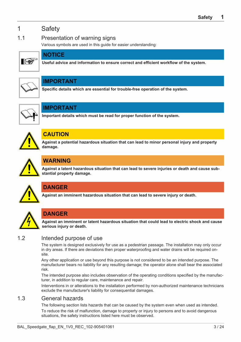
Various symbols are used in this guide for easier understanding:
NOTICEUseful advice and information to ensure correct and efficient workflow of the system.
IMPORTANTSpecific details which are essential for trouble-free operation of the system.
IMPORTANTImportant details which must be read for proper function of the system.
CAUTIONAgainst a potential hazardous situation that can lead to minor personal injury and propertydamage.
WARNINGAgainst a latent hazardous situation that can lead to severe injuries or death and cause sub-stantial property damage.
DANGERAgainst an imminent hazardous situation that can lead to severe injury or death.
DANGERAgainst an imminent or latent hazardous situation that could lead to electric shock and causeserious injury or death.
1.2 Intended purpose of useThe system is designed exclusively for use as a pedestrian passage. The installation may only occurin dry areas. If there are deviations then proper waterproofing and water drains will be required on-site.Any other application or use beyond this purpose is not considered to be an intended purpose. Themanufacturer bears no liability for any resulting damage; the operator alone shall bear the associatedrisk.The intended purpose also includes observation of the operating conditions specified by the manufac-turer, in addition to regular care, maintenance and repair.Interventions in or alterations to the installation performed by non-authorized maintenance techniciansexclude the manufacturer's liability for consequential damages.
1.3 General hazardsThe following section lists hazards that can be caused by the system even when used as intended.To reduce the risk of malfunction, damage to property or injury to persons and to avoid dangeroussituations, the safety instructions listed here must be observed.

1 Safety
4 / 24 BAL_Speedgate_flap_EN_1V0_REC_102-905401061
The specific safety instructions in the other sections of this manual must also be observed.
IMPORTANTThe country-specific regulations must be observed and complied with!
IMPORTANTTo avoid malfunctions, moving objects such as flags or parts of plants must not be allowed toenter the detection range of the sensors.
CAUTIONRisk of malfunctions, material damage or injury due to improper settings!a) Improper settings can lead to malfunctions, material damage or personal injury.ð Do not disconnect the system from the power supply overnight.ð Settings should only be made by personnel qualified to do so.ð Do not disassemble, put out of operation or manipulate safety devices.ð Have faults rectified by specialist personnel or by personnel qualified to do so.ð Have service and maintenance carried out according to locally applicable regulations or accord-
ing to a maintenance contract.
CAUTIONRisk of malfunctions, material damage or injuries due to insufficient or missing cleaning orcare!a) Insufficient or inattentive cleaning or care of the system can lead to malfunctions, damage to
property or injury to persons.ð Check the sensors regularly for dirt and clean them if necessary.ð Regularly remove dirt accumulations in the floor rail or under the floor mat.ð Keep the system free of snow and ice.ð Do not use aggressive or caustic cleaning agents.ð Use road salt or loose chippings only conditionally.ð Lay the floor mat without folds and flush with the floor.ð Equipment required for cleaning purposes such as ladders or similar must not be leaned on or at-
tached to the system.
CAUTIONRisk of material damage or injury due to unforeseen opening, closing or turning of the door!a) The door can open, close or turn unexpectedly. This may result in damage to property or injury
to persons.ð No persons may be present in the opening area of the system.ð Ensure that moving objects such as flags or parts of plants do not enter the detection range of
the sensors.ð Do not make any settings on the control unit when the system is in use.ð Have faults rectified immediately by specialist or personnel qualified to do so.ð Remove objects from the opening area.ð Do not disassemble, put out of operation or manipulate safety devices.ð Do not rush through a closing system.
Safety 1
BAL_Speedgate_flap_EN_1V0_REC_102-905401061 5 / 24
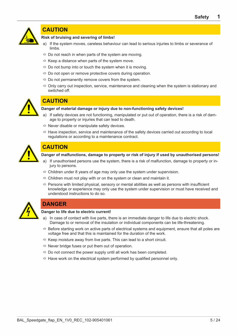
CAUTIONRisk of bruising and severing of limbs!a) If the system moves, careless behaviour can lead to serious injuries to limbs or severance of
limbs.ð Do not reach in when parts of the system are moving.ð Keep a distance when parts of the system move.ð Do not bump into or touch the system when it is moving.ð Do not open or remove protective covers during operation.ð Do not permanently remove covers from the system.ð Only carry out inspection, service, maintenance and cleaning when the system is stationary and
switched off.
CAUTIONDanger of material damage or injury due to non-functioning safety devices!a) If safety devices are not functioning, manipulated or put out of operation, there is a risk of dam-
age to property or injuries that can lead to death.ð Never disable or manipulate safety devices.ð Have inspection, service and maintenance of the safety devices carried out according to local
regulations or according to a maintenance contract.
CAUTIONDanger of malfunctions, damage to property or risk of injury if used by unauthorised persons!a) If unauthorised persons use the system, there is a risk of malfunction, damage to property or in-
jury to persons.ð Children under 8 years of age may only use the system under supervision.ð Children must not play with or on the system or clean and maintain it.ð Persons with limited physical, sensory or mental abilities as well as persons with insufficient
knowledge or experience may only use the system under supervision or must have received andunderstood instructions to do so.
DANGERDanger to life due to electric current!a) In case of contact with live parts, there is an immediate danger to life due to electric shock.
Damage to or removal of the insulation or individual components can be life-threatening.ð Before starting work on active parts of electrical systems and equipment, ensure that all poles are
voltage free and that this is maintained for the duration of the work.ð Keep moisture away from live parts. This can lead to a short circuit.ð Never bridge fuses or put them out of operation.ð Do not connect the power supply until all work has been completed.ð Have work on the electrical system performed by qualified personnel only.
1 Safety
6 / 24 BAL_Speedgate_flap_EN_1V0_REC_102-905401061
DANGERDanger to life due to non-functioning safety devices of the fire protection system!a) If safety devices of the fire protection system do not function properly, there is a risk of serious
or fatal injuries.ð Never disconnect the fire protection system from the power supply overnight.ð Do not disassemble, put out of operation or manipulate safety devices.ð Do not remove safety instructions on the system.ð Never block, hold open or otherwise prevent fire doors from closing.ð Have inspection, service and maintenance of the fire protection system carried out in accordance
with locally applicable regulations or according to a maintenance contract.ð Have the fire protection system checked and maintained according to the state of the art.
1.4 State of technologyThis system was developed using state of the art technology and officially recognized technical safetyregulations. The system, depending on its options and diameter, comply with the requirements of theMachine Guidelines 2006/42/EG as well as EN 16005 and DIN 18650 (D).Nevertheless, danger may arise if not used as intended.
IMPORTANTInstallation, commissioning, inspection, maintenance and repair work may only be conductedby qualified, trained and authorized technicians.After commissioning or repair work, fill in the check list and give it to the customer for safekeeping.We recommend obtaining a service agreement.
1.5 Personal protective equipmentPersonal protective equipment is used to protect persons from adverse effects on safety and health.Personnel must wear personal protective equipment during the various work activities on and with thesystem.Personal protective equipment is explained below:
Hearing protection is used to protect the hearing from noise. As a rule ofthumb, hearing protection is compulsory from when normal conversa-tion with other people is no longer possible.
The head protection serves to protect against falling and flying partsand materials. It also protects the head from bumping into hard objects.
Protective goggles protect the eyes from flying parts, dust, splinters orsplashes.

Safety 1
BAL_Speedgate_flap_EN_1V0_REC_102-905401061 7 / 24
Protective gloves are designed to protect hands from friction, abrasions,punctures or serious injury and from burning caused by contacting hotsurfaces.
Safety shoes protect the feet from crushing, falling parts and slipping onsurfaces. The puncture resistance of the shoes ensures, that pointy ob-jects do not penetrate the foot.
The high-visibility vest is used to make the personnel stand out andtherefore to be seen. With improved visibility and attention, the high-vis-ibility vest protects personnel in busy work areas from collisions withvehicles.
Depending on the place of work and the working environment, the protective equipment varies andmust be adapted accordingly. In addition to protective equipment for specific work, the work site mayrequire other protective equipment ( for example a harness).In hygiene-protected areas, special or additional requirements of personal protective equipment maybe required. These requirements must be considered when choosing personal protective equipment.If there is any uncertainty regarding the choice of personal protective equipment, the safety officermust be consulted at the place of work.
1.6 Spare parts and liabilityReliable and trouble free operation of the door is only guaranteed when using parts that were recom-mended by the manufacturer. The manufacturer declines any liability for damages resulting from un-authorized modifications to the door or the use of parts that are not permitted.
2 General information
8 / 24 BAL_Speedgate_flap_EN_1V0_REC_102-905401061
2 General information2.1 Purpose and use of the instructions
These instructions are an integral part of the system and enable efficient and safe handling of the sys-tem. In order to ensure proper functioning, the instructions must be accessible at all times and kept inthe immediate area of the system.Although only the male form has been chosen for reasons of better legibility, the information refers tomembers of both sexes.The operator must have read and understood the manual before starting any work. The basic require-ment for safe working is to follow the safety instructions and the handling instructions. In addition, thelocal regulations and safety rules apply.The manual can be handed over in extracts to instructed personnel who are familiar with the opera-tion of the system.The illustrations are for basic understanding and may differ from the actual presentation. Specific rep-resentations are contained in the drawings.
2.2 CopyrightThe copyright of the instructions remain at:agtatec agIt is prohibited to reproduce, distribute or use the manuals for purpose of competition without the writ-ten authorization of agtatec ag.Violation of the here stated copyrights will be prosecuted and fined with compensation of damage.Differences between product and manual are thereby possible.
2.3 Product identificationThe nameplate located on the door provides accurate identification of the product.
2.4 Document identificationName: BAL_Speedgate_flap_EN_1V0_REC_102-905401061Version: 1.0Article nr.: 102-905401061Publication date: 01/2021
2.5 Manufacturer agtatec agagtatec agAllmendstrasse 24CH – 8320 FehraltorfSwitzerlandPhone: +41 44 954 91 91Fax: +41 44 954 92 00
2.6 Target groups
CAUTIONRisk of injury if personnel are insufficiently qualified!If unqualified personnel work on the system or are in the danger zone of the system, dangers mayarise which can cause serious injuries and considerable damage to property.a) All work must be carried out by qualified personnel only.b) Keep unqualified personnel away from danger areas.
This operating manual is intended for the target groups listed below:

General information 2
BAL_Speedgate_flap_EN_1V0_REC_102-905401061 9 / 24
– Operating entity of the system:the person who is responsible for the technical maintenance of this system
– Operator of the system:the person who operates the system every day and has been suitably instructed
3 Description
10 / 24 BAL_Speedgate_flap_EN_1V0_REC_102-905401061
3 Description3.1 Units
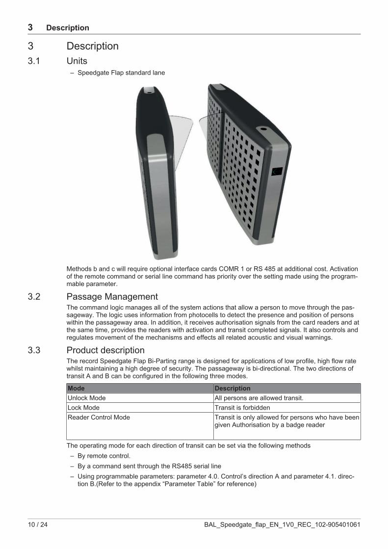
– Speedgate Flap standard lane
Methods b and c will require optional interface cards COMR 1 or RS 485 at additional cost. Activationof the remote command or serial line command has priority over the setting made using the program-mable parameter.
3.2 Passage ManagementThe command logic manages all of the system actions that allow a person to move through the pas-sageway. The logic uses information from photocells to detect the presence and position of personswithin the passageway area. In addition, it receives authorisation signals from the card readers and atthe same time, provides the readers with activation and transit completed signals. It also controls andregulates movement of the mechanisms and effects all related acoustic and visual warnings.
3.3 Product descriptionThe record Speedgate Flap Bi-Parting range is designed for applications of low profile, high flow ratewhilst maintaining a high degree of security. The passageway is bi-directional. The two directions oftransit A and B can be configured in the following three modes.
Mode DescriptionUnlock Mode All persons are allowed transit.Lock Mode Transit is forbiddenReader Control Mode Transit is only allowed for persons who have been
given Authorisation by a badge reader
The operating mode for each direction of transit can be set via the following methods– By remote control.– By a command sent through the RS485 serial line– Using programmable parameters: parameter 4.0. Control’s direction A and parameter 4.1. direc-
tion B.(Refer to the appendix “Parameter Table” for reference)
Specifications 4
BAL_Speedgate_flap_EN_1V0_REC_102-905401061 11 / 24
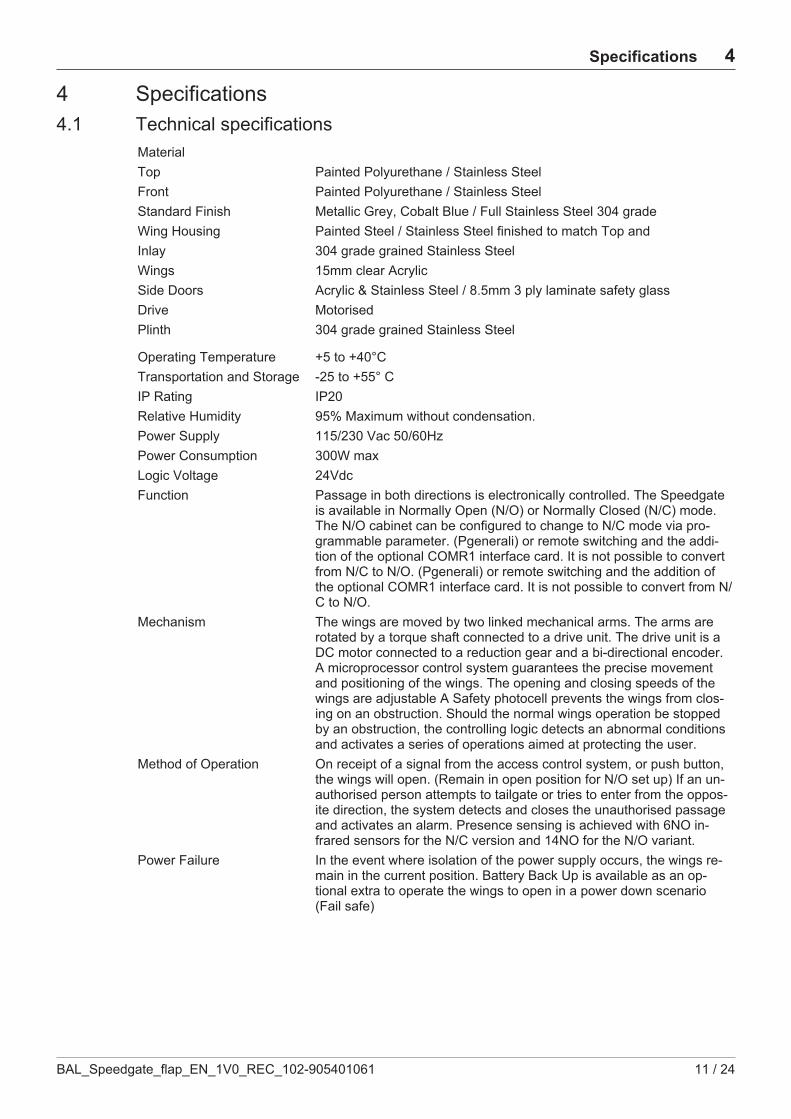
4 Specifications4.1 Technical specifications
MaterialTop Painted Polyurethane / Stainless SteelFront Painted Polyurethane / Stainless SteelStandard Finish Metallic Grey, Cobalt Blue / Full Stainless Steel 304 gradeWing Housing Painted Steel / Stainless Steel finished to match Top andInlay 304 grade grained Stainless SteelWings 15mm clear AcrylicSide Doors Acrylic & Stainless Steel / 8.5mm 3 ply laminate safety glassDrive MotorisedPlinth 304 grade grained Stainless Steel
Operating Temperature +5 to +40°CTransportation and Storage -25 to +55° CIP Rating IP20Relative Humidity 95% Maximum without condensation.Power Supply 115/230 Vac 50/60HzPower Consumption 300W maxLogic Voltage 24VdcFunction Passage in both directions is electronically controlled. The Speedgate
is available in Normally Open (N/O) or Normally Closed (N/C) mode.The N/O cabinet can be configured to change to N/C mode via pro-grammable parameter. (Pgenerali) or remote switching and the addi-tion of the optional COMR1 interface card. It is not possible to convertfrom N/C to N/O. (Pgenerali) or remote switching and the addition ofthe optional COMR1 interface card. It is not possible to convert from N/C to N/O.
Mechanism The wings are moved by two linked mechanical arms. The arms arerotated by a torque shaft connected to a drive unit. The drive unit is aDC motor connected to a reduction gear and a bi-directional encoder.A microprocessor control system guarantees the precise movementand positioning of the wings. The opening and closing speeds of thewings are adjustable A Safety photocell prevents the wings from clos-ing on an obstruction. Should the normal wings operation be stoppedby an obstruction, the controlling logic detects an abnormal conditionsand activates a series of operations aimed at protecting the user.
Method of Operation On receipt of a signal from the access control system, or push button,the wings will open. (Remain in open position for N/O set up) If an un-authorised person attempts to tailgate or tries to enter from the oppos-ite direction, the system detects and closes the unauthorised passageand activates an alarm. Presence sensing is achieved with 6NO in-frared sensors for the N/C version and 14NO for the N/O variant.
Power Failure In the event where isolation of the power supply occurs, the wings re-main in the current position. Battery Back Up is available as an op-tional extra to operate the wings to open in a power down scenario(Fail safe)
4 Specifications
12 / 24 BAL_Speedgate_flap_EN_1V0_REC_102-905401061
Fire Alarm An input facility is available for voltage free contact (supplied by Oth-ers) to open the walkway in the event of an emergency.
Location Indoor, out of rain and water sprays, Speedgate Swing Advanced isnot protected from dangerous effects of water penetration; non directsun light; Not along escape routes or obstructing emergency exits, Donot use in potentially explosive atmospheres.
Interface Potential free contact provided by either card reader or push button in-put. Card reader inhibit and reset output signals are available as stand-ard. The unit has an adjustable time out facility if required, for example;a “Go” Signal will be cancelled if the passage through the Speedgate isnot completed within a pre-set time i.e. 5-30 seconds
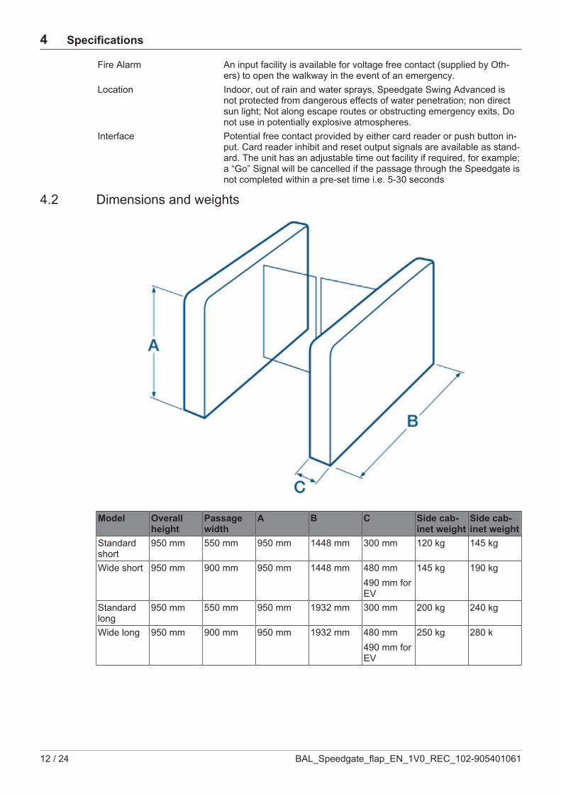
4.2 Dimensions and weights
Model Overallheight
Passagewidth
A B C Side cab-inet weight
Side cab-inet weight
Standardshort
950 mm 550 mm 950 mm 1448 mm 300 mm 120 kg 145 kg
Wide short 950 mm 900 mm 950 mm 1448 mm 480 mm490 mm forEV
145 kg 190 kg
Standardlong
950 mm 550 mm 950 mm 1932 mm 300 mm 200 kg 240 kg
Wide long 950 mm 900 mm 950 mm 1932 mm 480 mm490 mm forEV
250 kg 280 k
Operation 5
BAL_Speedgate_flap_EN_1V0_REC_102-905401061 13 / 24
5 Operation5.1 Instructions for use
The information contained in this section, should be used as a basis for the instruction of personnel inthe correct use of the Speedgate Range of Barriers.The Speedgate is unlocked by presenting a personalised identity card or device to the access controlreader. (Supplied by others) It can also be unlocked by depressing abutton on the casework or remote reception push button, (if fitted), or Free Passage configuration.This will activate the mechanism and retract the wings into the casework, rendering the Speedgateready for use, by walking through the passageway in the authorised direction.Should the user decide not to proceed with the passage, the Speedgate will remain unlocked for apredetermined time after which it will ‘time out’ and reset, becoming available for the nextperson/user.After the passage is complete, the mechanism will be reactivated automatically, operating thewings & driving them into the closed position.Always check the status lights (if fitted) mounted on the top of the Speedgate for rite ofpassage. E.g. A red Cross denotes the opposite direction has rite of passage or, a Green Arrow de-notes rite of passage.Should the Speedgate be used in the incorrect manner, i.e. used out of pas-sageway sequence,the wings will close and an alarm will sound. Do not panic, retreat from the walk-way & wait for the alarm to stop. The system will reset automatically. During the alarm stage, thestatus lights will flash, after a reset occurs, check the status of the lights for rite of passage.Do not attempt to follow a person through the Speedgate if you do not have authorisation.This isknown as Tailgating and will activate the controller to close the gates between theauthorised and un-authorised user. The Speedgate will then go into the alarm and reset phase.If the Speedgate and access control system has been configured for multiple authorisations, (knownas Stacking), the users may proceed in close proximity after the preceding passage occupant. Again,the status lights should be checked for rite of passage.Should the Speedgate be set up for free passage, there is no need to wait for any authorisation;the passage may be freely used. Again, check the status lights for rite of passage & in normal opera-tion, the opposite passage will be activated via the access control device requiring authorisation.
5.2 Normally openIn Normally Open configuration, the Speedgate will operate identically as for Normally Closed,except for the following.The wings in normal operation will be fully retracted into the casework. On acceptance of a badgefrom an authorised user, the Speedgate will remain inactive. However, should an unauthorised per-son attempt to gain access through the passage; the controller will activate the mechanism to blockthe walkway by closing the wings. The Speedgate will then go into the Alarm State.The Normally Open mode is available only for the long cabinet version.
5.3 Emergency and fire alarmThe Speedgate can be configured to fully open the wings when an emergency or fire Alarm signal isgiven to the controller by the appropriate detection system. (Supplied by others) This condition will re-main for the duration of the signal being received by the controller. Power FailureIn the event of isolation of the power supply, the wings remain in the current position. Battery Back Upis available as an optional extra to operate the wings to open in a power down scenario.The optional battery back up will operate the Speedgate to complete or commence an operatingcycle, so the wings drive open in the event of a power failure.
SafetyThe Speedgate passage is protected via a safety photocell, so that when a presence is detected, thewings will not operate until that presence is removed. In this condition, the Speedgate will automatic-ally go into Alarm condition. Should an obstacle be detected by the wings during the closing phase,they will back off into the open position. In this condition, the Speedgate will automatically go intoalarm condition.

5 Operation
14 / 24 BAL_Speedgate_flap_EN_1V0_REC_102-905401061
A ctivation of the remote command or serial line command has priority over the setting made usingthe programmable parameter.
CAUTIONDamage to the system or injury of personsNot taking care of the safety settings can cause damage to the system or can harm people.a) DO NOT- Walk through the barrier with large bags or briefcases in front, or trailing behind you.b) DO NOT- Drag bags over the casework top
5.4 Operating ModesThe Speedgate operation is bi-directional. The two passageways, direction A (the master casework isat the right hand of the user) and B can be managed in one of the following modes:
Free: The gate enables transit of all passengers in thecorresponding direction, the entry and/or exit Pic-tograms and waymodes have green arrows.
Blocked: The gate does not enable transit in correspondingdirection, entry and/or exit Pictograms and way-modes have the red cross.
Controlled: The gate allows transit only to persons authorizedby the access control system.
Normally Closed: In standby, the gate presents itself to the userwith the door closed.
Normally Open: In standby, the gate presents itself to the userwith the door open.
Free: the gate enables transit of all passengers in the corresponding direction, theentry and/or exit traffic-lights have the green arrow;
– Blocked: the gate does not enable transit in corresponding direction, entry and/or exit traffic-lightshave the red cross;
– Control: the gate allows transit only to persons authorized by the access controlsystem.The operating mode of the gate can be set by means of:
– Programmable parameters– Gate itself (on failure, etc.)– RS485 serial line or remote command on the COMR1 optional board.– The serial line or remote command has priority over the settings made using the
programmable parameter.The mode change is possible only if the gate is in stand-by condition: the gate should not beengaged, in alarm or emergency conditions.
5.5 Passage ManagementThe command logic manages all of the systems actions, which allows a person to move through thepassageway. The logic uses all the information interpreted from the photocells to detect the presenceand position of persons in the inside walkway.In addition, it receives permissive signals from the readers and at the same time, provides the readerswith activation and transit completed signals. It controls and regulates movement of the mechanismsand effects all related acoustic and visual warnings.In the controlled mode the gate waits for reader signal in order to allow transit of the user. It is pos-sible to allow the user to enter inside the gate and then to validate. Alternatively, the user must valid-ate standing outside the gate.

Operation 5
BAL_Speedgate_flap_EN_1V0_REC_102-905401061 15 / 24
This operation mode could be chosen by programmable parameter. In the first case, the user can waitfor the permissive signal inside the gate, but the permissive signal shall arrive within a time-out limit.This time-out depends on the value of specific programmable parameters (see “Transit Group” in theannex “Parameter Table”). At the end of the time-out, if the validation has not arrived, an alarm condi-tion is generated: in that case no acoustic signal is emitted but only visible signal in order to hurry upthe user to validate or free the gate.
5.6 AlarmsThe logic system for the passageway detectors will recognise situations or scenarios, wherepersons incorrectly use the passageway, including if they are not authorised to transit. Therefore,thesystem generates an alarm signal when these conditions occur.An alarm warning involves:
– A buzzer generates an acoustic sound which is repeated approximately at a one second cadence.– At the same time, the traffic lights and pictograms flash, displaying a Red Cross.– At the same time the alarm signal output on the COMR1 optional board is activated and de-activ-
ated.– The gate wings are closed.– On the LCM02 circuit board display, on the master command wing side, a message appears in-
dicating that specific condition. (Only if button SW2 is pressed once). The alarm signal output isactivated.
– The readers could be de-activated, depending on the value of the programmable parameterModoCntr.
– A message is sent via RS485 serial line regarding the type of alarm. The alarm signal continuesuntil the cause which generated it, is removed. It then stops after a short delay. This delay can beregulated with the programmable parameter TResAll.
The alarm signal continues until the cause which generated it is removed. The activation of the alarmsignal output relay could be delayed by means of a programmable parameter. The flashing frequencyof the traffic lights and pictograms can be regulated by means of a programmable parameter. Theseparameters are described into “Fraud Group” in the annex “Parameter Table”.When the system is in an alarm state, the unit can still accept validation signals from the access con-trol system, but the user will not be able to begin the transit until the alarm has cleared and the unithas returned to its secure default configuration.By means of a programmable parameter (see “Reader Group” in the annex “Parameter Table”), thelogic could be set to ignore any new reader authorization during the alarm. In that case the authoriza-tion is not registered by the system and the user will need to restart the signal validation process afterthe alarm has cleared and the unit is back to its secure default configuration.The tailgating detection system selectivity of the Speedgate Flap can be tuned (the ability to intercepta person who follows a person with authorisation for transit) with the friendly usability of the gate. Seethe section “Fraud Alarms Selectivity” for more details.
5.7 Programmable parametersThe system operation is conditioned by the values given to certain parameters stored in the EEPROMon the control board.When the control logic microprocessor executes the resident program, it consultsthe values of the programmable parameters and sets the timings of certain actions and internal al-gorithms. The values of these parameters can be adjusted or reset to a standard configuration by fol-lowing the procedures given.

6 Servicing and maintenance
16 / 24 BAL_Speedgate_flap_EN_1V0_REC_102-905401061
6 Servicing and maintenance6.1 General care
CAUTIONAccess to the electrical installation is strictly reserved to authorized maintenance techni-cians.
The Speedgate Swing Slim must be cleaned and greased at regular intervals, using the following ap-proved materials in order to ensure a constant functioning and to extend service life.
Routine cleaning, all finishesCleaning agent: Soap or mild detergent water.Action: Sponge rinse with clean water, wipe dry as necessary.
Stubborn stains and discolouration, all finishesCleaning agent: Mild cleaning solutions or domestic service cleaners.Actions: Rinse well with clean water and wipe dry.
Oil, Grease marks, all finishesCleaning agent: Organic solvents (acetone, alcohol, genclene, trichlorethane).Action: Clean after with soap and water, rinse well with clean water and wipe dry.
Rust and other Corrosion products, Stainless finishesCleaning agent: Oxalic acid. The cleaning solution should be applied with a swab and allowed tostand for 15 to 20 minutes before being washed away with water. Continue using a domestic surfacecleaner to give a final clean.Action: Rinse well with clean water (precautions for acid cleaners should be observed).
Minor scratches on painted surfacesCleaning agent: Lightly rub with cutting paste. Rinse area with water and dry. Apply touchup paint infine layers.Action: Allow 2 weeks to harden. Blend into surrounding paint work, using fine cutting paste
Deep scratches on painted finishes causing rustCleaning agent: Remove rust with a small sharp knife. Apply rust inhibiting paint. Fill scratch with finebody filler to just under finished surface. Follow procedure for minor scratches.
GreasingThis action is carried out by the Service Engineer during service visits.
6.2 Routine maintenanceThe mechanism should be inspected and cleaned at regular intervals, in order to maintain all com-ponents correctly & to keep them in good working order. Also to check for signs of wear.
WARNINGTo avoid the risk of electric shock, always ensure that the electrical power and batteries aredisconnected before inspecting the mechanism.
Servicing and maintenance 6
BAL_Speedgate_flap_EN_1V0_REC_102-905401061 17 / 24
NOTICEThe following indications refer to an installation where the average number of transits peryear is equal to one million.When used in dusty conditions, increase the inspection intervals.
LubricantsFor the lubrication of parts subject to wear, use Molycote BR2 Plus grease or equivalent grease con-taining graphite or molybdenum sulphide (MoS2).Do not grease moving parts unless specifically indicated in this manual. The use of grease can leadto a build-up of dust that can impair operation of the mechanism.
ComponentsAnnual Checks (Operations to be carried out with the power supply disconnected).Cables and Connectors (Operations to be carried out with the power supply disconnected).
– Check that the wire connectors are firmly attached.– Check that the terminals are fully tightened.– Check that the insulation of the wires is in good condition and that no conductors are exposed.
Electrical CircuitsNo general Maintenance is required apart from replacement fuses in the event of a failure.
7 Malfunctions
18 / 24 BAL_Speedgate_flap_EN_1V0_REC_102-905401061
7 Malfunctions7.1 Fault Finding
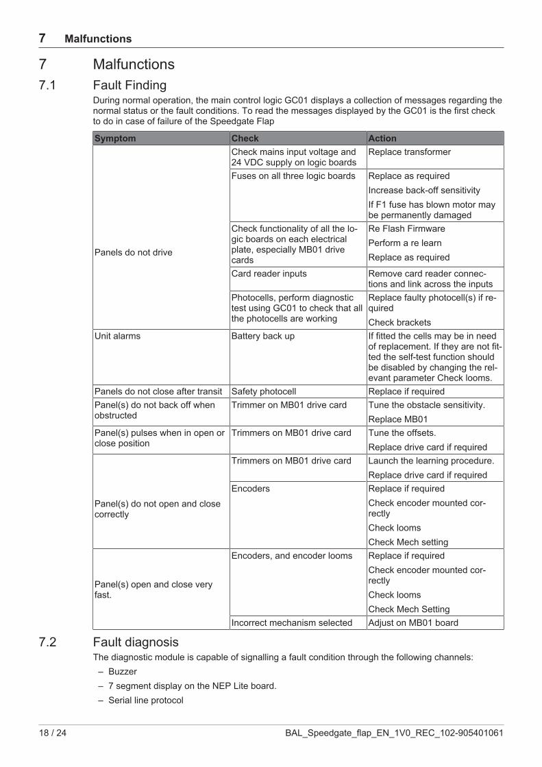
During normal operation, the main control logic GC01 displays a collection of messages regarding thenormal status or the fault conditions. To read the messages displayed by the GC01 is the first checkto do in case of failure of the Speedgate Flap
Symptom Check Action
Panels do not drive
Check mains input voltage and24 VDC supply on logic boards
Replace transformer
Fuses on all three logic boards Replace as requiredIncrease back-off sensitivityIf F1 fuse has blown motor maybe permanently damaged
Check functionality of all the lo-gic boards on each electricalplate, especially MB01 drivecards
Re Flash FirmwarePerform a re learnReplace as required
Card reader inputs Remove card reader connec-tions and link across the inputs
Photocells, perform diagnostictest using GC01 to check that allthe photocells are working
Replace faulty photocell(s) if re-quiredCheck brackets
Unit alarms Battery back up If fitted the cells may be in needof replacement. If they are not fit-ted the self-test function shouldbe disabled by changing the rel-evant parameter Check looms.
Panels do not close after transit Safety photocell Replace if requiredPanel(s) do not back off whenobstructed
Trimmer on MB01 drive card Tune the obstacle sensitivity.Replace MB01
Panel(s) pulses when in open orclose position
Trimmers on MB01 drive card Tune the offsets.Replace drive card if required
Panel(s) do not open and closecorrectly
Trimmers on MB01 drive card Launch the learning procedure.Replace drive card if required
Encoders Replace if requiredCheck encoder mounted cor-rectlyCheck loomsCheck Mech setting
Panel(s) open and close veryfast.
Encoders, and encoder looms Replace if requiredCheck encoder mounted cor-rectlyCheck loomsCheck Mech Setting
Incorrect mechanism selected Adjust on MB01 board
7.2 Fault diagnosisThe diagnostic module is capable of signalling a fault condition through the following channels:
– Buzzer– 7 segment display on the NEP Lite board.– Serial line protocol
Malfunctions 7
BAL_Speedgate_flap_EN_1V0_REC_102-905401061 19 / 24
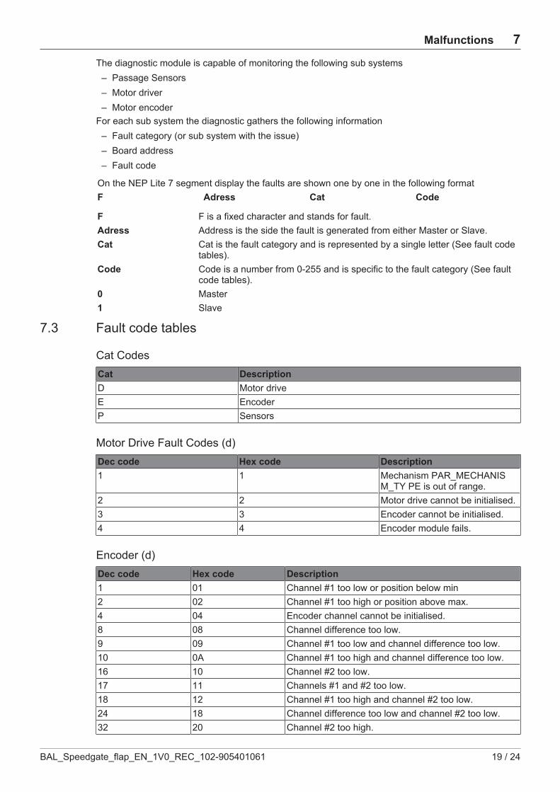
The diagnostic module is capable of monitoring the following sub systems– Passage Sensors– Motor driver– Motor encoder
For each sub system the diagnostic gathers the following information– Fault category (or sub system with the issue)– Board address– Fault code
On the NEP Lite 7 segment display the faults are shown one by one in the following formatF Adress Cat Code
F F is a fixed character and stands for fault.Adress Address is the side the fault is generated from either Master or Slave.Cat Cat is the fault category and is represented by a single letter (See fault code
tables).Code Code is a number from 0-255 and is specific to the fault category (See fault
code tables).0 Master1 Slave
7.3 Fault code tables
Cat CodesCat DescriptionD Motor driveE EncoderP Sensors
Motor Drive Fault Codes (d)Dec code Hex code Description1 1 Mechanism PAR_MECHANIS
M_TY PE is out of range.2 2 Motor drive cannot be initialised.3 3 Encoder cannot be initialised.4 4 Encoder module fails.
Encoder (d)Dec code Hex code Description1 01 Channel #1 too low or position below min2 02 Channel #1 too high or position above max.4 04 Encoder channel cannot be initialised.8 08 Channel difference too low.9 09 Channel #1 too low and channel difference too low.10 0A Channel #1 too high and channel difference too low.16 10 Channel #2 too low.17 11 Channels #1 and #2 too low.18 12 Channel #1 too high and channel #2 too low.24 18 Channel difference too low and channel #2 too low.32 20 Channel #2 too high.

7 Malfunctions
20 / 24 BAL_Speedgate_flap_EN_1V0_REC_102-905401061
Dec code Hex code Description33 21 Channel #1 too low and channel #2 too high.34 22 Channels #1 and #2 too high.40 28 Channel difference too low and channel #2 too high.41 29 Channel #1 too low, channel #2 too high, and channel
difference too low.42 2A Channels #1 and #2 too high and channel difference
too low.128 80 Channel difference too high.129 81 Channel #1 too low and channel difference too high.130 82 Channel #1 too high and channel difference too high.144 90 Channel #2 too low and channel difference too high.145 91 Channels #1 and #2 too low and channel difference too
high.146 92 Channel #1 too high, channel #2 too low, and channel
difference too high.160 A0 Channel #2 too high and channel difference too high.161 A1 Channel #1 too low, channel #2 too high, and channel
difference too high.162 A2 Channels #1 and #2 too high and channel difference
too high.
Sensors (p)Dec code Hex code Description1 1 At least one passage sensor failed test #132 20 Passage sensor #1 failed test #233 21 Passage sensor #2 failed test #234 22 Passage sensor #3 failed test #235 23 Passage sensor #4 failed test #236 24 Passage sensor #5 failed test #237 25 Passage sensor #6 failed test #238 26 Passage sensor #7 failed test #239 27 Passage sensor #8 failed test #240 28 Passage sensor #9 failed test #241 29 Passage sensor #10 failed test #2
Non secure Direction B

Malfunctions 7
BAL_Speedgate_flap_EN_1V0_REC_102-905401061 21 / 24
Secure Direction A
8 Taking out of service and disposal
22 / 24 BAL_Speedgate_flap_EN_1V0_REC_102-905401061
8 Taking out of service and disposal8.1 Decommissioning
When shutting down or taking out of service, the system is disconnected from the mains supply andany existing battery is unplugged.
NOTICEAfter each temporary shutdown a new commissioning must be carried out.
8.2 Dismantling and disposal
IMPORTANTAll machine parts must be sorted by type of material and disposed of according tolocal regulations and guidelines.
NOTICEThe door systems can be completely disassembled in reverse order.
The automatic door mainly consists of the following materials:
Aluminum:– Linking profiles– Gearbox, Drive panel– Door wing profiles and side profiles– Various profiles and small parts
Steel / iron parts:– Stainless steel casing, Floor panel, Box recess for floor installation– Optional spacer or reinforcement profiles– Gear components, springs– Various small parts like fittings, covers, linking parts, etc.
Glass:– Door wings and side panels
Various electronic and electromechanical components:– Sensors, control and operator components– Lead batteries and nickel-cadmium rechargeable batteries
Various plastics:– Rollers– Cable clips, coupling and linking parts– Sealing profiles– Casing of electromechanical components and sensors


record Group
www.record.group
Great Britain
www.recorduk.co.uk
Australia
www.recorddoors.com.au
Canada
www.recorddoors.com
China
www.record.net.cn
Deutschland
www.record.de
Denmark
www.record-danmark.dk
España
www.record.es
France
www.record.fr
Malaysia
www.recorddoors.my
Polska
pl.record.global
Schweiz
www.record.ch
Sverige
www.record.se
Türkiye
tr.record.global
United States
www.recorddoors.com
record global export
www.record.global
Subject to technical modificationsCopyright © agtatec agNo. 102-905401061