Computational Investigation of Gurney Flap Effects on Rotors in Forward Flight
8
Computational Investigation of Gurney Flap Effects on Rotors in Forward Flight Byung-Young Min, ∗ Lakshmi N. Sankar, † Nischint Rajmohan, ∗ and J. V. R. Prasad ‡ Georgia Institute of Technology, Atlanta, Georgia 30332-0150 DOI: 10.2514/1.41918 A hybrid Navier–Stokes/free-wake solver has been employed to investigate the performance of a rotor equipped with a Gurney flap in steady level flight and in descent. A scaled model of the BO-105 rotor was studied. The calculations were coupled to a comprehensive analysis to properly account for the effects of the elastic deformations on the aerodynamic loads and to account for trim. Fixed and dynamically deployed Gurney flaps were considered. In forward flight, it was found that a properly chosen azimuthal deployment schedule of the Gurney flaps may reduce the peak-to-peak variations in hub loads, potentially reducing vibrations. In descent flight, it was found that the deployment of a fixed Gurney flap decreased the descent rate needed to maintain autorotation. Nomenclature C l = airfoil lift coefficient C m = airfoil pitching moment coefficient C n = airfoil normal force coefficient C P = rotor power coefficient C T = rotor thrust coefficient D = drag D e = equivalent drag GF = Gurney flap F = force L = lift l G = deployed Gurney flap length M = Mach number, moment PL = power loading C T =C P R = blade radius r = blade radial location V 1 = freestream velocity = angle of attack s = shaft angle of attack = solidity = azimuth angle = rotor rotational speed I. Introduction A GURNEY flap is a passive high-lift device that has applications in many areas ranging from racing cars to helicopters. In its simplest form, it is a small vertical tab attached to the trailing edge of a wing. Because of its high-lift potential, it is being considered for use in vertical-lift systems such as micro unmanned aerial vehicles. Researchers at the U.S. Army Aeroflightdynamics Directorate have recently conducted a series of tests to understand the physical mechanisms behind the high-lift generation. Static airfoil data as well as dynamic stall data were collected and compared against similar results for a plain airfoil (without Gurney flap) and against an airfoil with a variable-droop leading-edge shape [1]. Very-high-lift values may be achieved at relatively low angles of attack for an airfoil equipped with a Gurney flap. This increase in lift forces may be used to improve the autorotative performance of the rotor and may be exploited for individual blade control or onboard control of the rotor. The present authors have recently studied the steady and unsteady load characteristics of a VR-12 airfoil with and without the Gurney flap [2]. It was found that the use of a Gurney flap could improve the static lift characteristics giving rise to a higher C l;max (close to 1.8) compared to the conventional airfoil (close to 1.4). The dynamic stall characteristics of the Gurney-flap-equipped sections were not suffi- ciently different from that of a VR-12 airfoil, however. In a follow-up study, the present researchers and their coworkers examined the beneficial effects of Gurney flaps on helicopter rotors in descent [3]. It was found that an existing rotor (similar to that used in BO-105), when retrofitted with a Gurney flap, could dramatically improve the thrust characteristics. It was found that the autorotative characteristics of the rotor (where a portion of the lift is tilted forward, causing an induced thrust rather than induced drag) could be improved with a Gurney-flap-equipped rotor. The present work builds on the preliminary work reported in [3] for rotors in autorotative descent at fixed control setting. One of the objectives of the present work is to determine how the autorotative performance is affected if the Gurney-flap-equipped rotor is trimmed to the same hub forces and moments as the baseline rotor. A second objective of this work is to study the effects of Gurney flaps on blade loads and performance in steady level flight. Specifically, the effects of the Gurney flap on the blade root loads and hub vibratory loads are examined. II. Computational Method and Validation Studies A hybrid three-dimensional Navier–Stokes/free-wake method is used in this study. Modeling Gurney flaps required extensive modifications to the Navier–Stokes portion and, in particular, the single-block structure of the flow solver. Toward this end, the Navier–Stokes portion of this method has been replaced with a general-purpose multiblock solver called GENCAS (Generic Numerical Compressible Airflow Solver), developed by the first author [3,4]. This is a generic Reynolds-averaged Navier–Stokes solver that may be used to model a broad class of internal and external flows. This analysis solves the 3-D compressible viscous flow equations on a curvilinear body-fitted coordinate system. The base- line third-order upwind scheme was replaced with fifth- and seventh- order weighted essentially nonoscillatory (WENO5 and WENO7) flux reconstruction schemes. The baseline Spalart–Allmaras (SA) turbulence model was replaced with the SA-DES (detached eddy simulation) -! model, a -!=- blended model, and Menter’ s -! shear stress transport model. Finally, the overall computational time Presented as Paper 6726 at the 26th AIAA Applied Aerodynamics Conference, Honolulu, HI, 18–21 August 2008; received 30 October 2008; revision received 29 August 2009; accepted for publication 6 September 2009. Copyright © 2009 by the American Institute of Aeronautics and Astronautics, Inc. All rights reserved. Copies of this paper may be made for personal or internal use, on condition that the copier pay the $10.00 per-copy fee to the Copyright Clearance Center, Inc., 222 Rosewood Drive, Danvers, MA 01923; include the code 0021-8669/09 and $10.00 in correspondence with the CCC. ∗ Graduate Research Assistant, School of Aerospace Engineering. Student Member AIAA. † Regents Professor and Associate Chair, School of Aerospace Engineer- ing. Associate Fellow AIAA. ‡ Professor, School of Aerospace Engineering. Associate Fellow AIAA. JOURNAL OF AIRCRAFT Vol. 46, No. 6, November–December 2009 1957
Transcript of Computational Investigation of Gurney Flap Effects on Rotors in Forward Flight

Computational Investigation of Gurney Flap Effectson Rotors in Forward Flight
Byung-Young Min,∗ Lakshmi N. Sankar,† Nischint Rajmohan,∗ and J. V. R. Prasad‡
Georgia Institute of Technology, Atlanta, Georgia 30332-0150
DOI: 10.2514/1.41918
A hybrid Navier–Stokes/free-wake solver has been employed to investigate the performance of a rotor equipped
with a Gurney flap in steady level flight and in descent. A scaled model of the BO-105 rotor was studied. The
calculations were coupled to a comprehensive analysis to properly account for the effects of the elastic deformations
on the aerodynamic loads and to account for trim. Fixed and dynamically deployedGurney flapswere considered. In
forward flight, it was found that a properly chosen azimuthal deployment schedule of the Gurney flaps may reduce
the peak-to-peak variations in hub loads, potentially reducing vibrations. In descent flight, it was found that the
deployment of a fixed Gurney flap decreased the descent rate needed to maintain autorotation.
Nomenclature
Cl = airfoil lift coefficientCm = airfoil pitching moment coefficientCn = airfoil normal force coefficientCP = rotor power coefficientCT = rotor thrust coefficientD = dragDe = equivalent dragGF = Gurney flapF = forceL = liftlG = deployed Gurney flap lengthM = Mach number, momentPL = power loading CT=CPR = blade radiusr = blade radial locationV1 = freestream velocity = angle of attacks = shaft angle of attack = solidity = azimuth angle = rotor rotational speed
I. Introduction
A GURNEYflap is a passive high-lift device that has applicationsin many areas ranging from racing cars to helicopters. In its
simplest form, it is a small vertical tab attached to the trailing edge ofawing. Because of its high-lift potential, it is being considered for usein vertical-lift systems such as micro unmanned aerial vehicles.
Researchers at the U.S. Army Aeroflightdynamics Directoratehave recently conducted a series of tests to understand the physicalmechanisms behind the high-lift generation. Static airfoil data aswellas dynamic stall data were collected and compared against similarresults for a plain airfoil (without Gurney flap) and against an airfoil
with a variable-droop leading-edge shape [1]. Very-high-lift valuesmay be achieved at relatively low angles of attack for an airfoilequipped with a Gurney flap. This increase in lift forces may be usedto improve the autorotative performance of the rotor and may beexploited for individual blade control or onboard control of the rotor.
The present authors have recently studied the steady and unsteadyload characteristics of a VR-12 airfoil with and without the Gurneyflap [2]. It was found that the use of a Gurney flap could improve thestatic lift characteristics giving rise to a higher Cl;max (close to 1.8)compared to the conventional airfoil (close to 1.4). The dynamic stallcharacteristics of the Gurney-flap-equipped sections were not suffi-ciently different from that of a VR-12 airfoil, however.
In a follow-up study, the present researchers and their coworkersexamined the beneficial effects of Gurney flaps on helicopter rotorsin descent [3]. It was found that an existing rotor (similar to that usedin BO-105), when retrofitted with a Gurney flap, could dramaticallyimprove the thrust characteristics. It was found that the autorotativecharacteristics of the rotor (where a portion of the lift is tilted forward,causing an induced thrust rather than induced drag) could beimproved with a Gurney-flap-equipped rotor.
The present work builds on the preliminary work reported in [3]for rotors in autorotative descent at fixed control setting. One of theobjectives of the present work is to determine how the autorotativeperformance is affected if the Gurney-flap-equipped rotor is trimmedto the same hub forces and moments as the baseline rotor. A secondobjective of this work is to study the effects of Gurney flaps on bladeloads and performance in steady level flight. Specifically, the effectsof the Gurney flap on the blade root loads and hub vibratory loads areexamined.
II. Computational Method and Validation Studies
A hybrid three-dimensional Navier–Stokes/free-wake method isused in this study. Modeling Gurney flaps required extensivemodifications to the Navier–Stokes portion and, in particular, thesingle-block structure of the flow solver. Toward this end, theNavier–Stokes portion of this method has been replaced with ageneral-purpose multiblock solver called GENCAS (GenericNumerical Compressible Airflow Solver), developed by the firstauthor [3,4]. This is a generic Reynolds-averaged Navier–Stokessolver thatmay be used tomodel a broad class of internal and externalflows. This analysis solves the 3-D compressible viscous flowequations on a curvilinear body-fitted coordinate system. The base-line third-order upwind schemewas replaced with fifth- and seventh-order weighted essentially nonoscillatory (WENO5 and WENO7)flux reconstruction schemes. The baseline Spalart–Allmaras (SA)turbulence model was replaced with the SA-DES (detached eddysimulation) -!model, a -!=- blended model, and Menter’s -!shear stress transport model. Finally, the overall computational time
Presented as Paper 6726 at the 26th AIAA Applied AerodynamicsConference, Honolulu, HI, 18–21 August 2008; received 30 October 2008;revision received 29 August 2009; accepted for publication 6 September2009. Copyright © 2009 by the American Institute of Aeronautics andAstronautics, Inc. All rights reserved. Copies of this paper may be made forpersonal or internal use, on condition that the copier pay the $10.00 per-copyfee to the Copyright Clearance Center, Inc., 222 Rosewood Drive, Danvers,MA 01923; include the code 0021-8669/09 and $10.00 in correspondencewith the CCC.
∗Graduate Research Assistant, School of Aerospace Engineering. StudentMember AIAA.
†Regents Professor and Associate Chair, School of Aerospace Engineer-ing. Associate Fellow AIAA.
‡Professor, School of Aerospace Engineering. Associate Fellow AIAA.
JOURNAL OF AIRCRAFT
Vol. 46, No. 6, November–December 2009
1957

required to perform the simulations was reduced by implementinga distributed computing approach based on a message-passinginterface. The GENCAS solver, as a standalone solver, was validatedfor several 2-D AGARD standard test cases (e.g., RAE 2822 airfoil)and 3-D internal flow configurations (e.g., turbine guide vanes). In allof the calculations to be presented here, a third-order upwind schemewith a one-equation transport model for eddy viscosity, called theSA-DES model, was used.
In this hybrid approach, the time-consuming Navier–Stokessimulations are carried out only for a single blade, in a small regionsurrounding this reference blade (Fig. 1). The wake structure behindthis reference blade and those of the other blades are modeled using afree-wake vortexmodel. Only the trailing vortices from the blade tipsare modeled. The vortex strength of the most recently generated tipvortex segment was assumed to be peak bound circulation at theinstance the vortex segment was generated. The tip vortices werepropagated in time at a local velocity, calculated as the inducedvelocity due to all vortex filaments plus the freestream velocity.The induced velocities due to wake structure are also calculated atthe Navier–Stokes (N-S) computational domain outer surface andapplied as an inflow boundary condition. This allows the vortices toreenter the computational domain. If the rotor is in steady flight, onlya single blade is modeled by the N-S solver, since the solution isperiodic.
At the start of the calculations, for the very first iteration, the wakeis prescribed for five full revolutions. This initial guess reduces theN-S domain revolutions required to reach steady-state (periodic)solution. Subsequently, three–four additional revolutions were madeto get the converged solution. The time step was chosen so that theblades rotated by 0.05 deg in the azimuthal direction. The wakestructure was updated at every 5 deg.
A finite element solver called DYMORE is used in this study formodeling the aeroelastic response of the blades. DYMORE uses amultibody dynamics approach for the modeling of the rotor as anonlinear elastic multibody system. This approach allows modelingof complex rotor configurations with emphasis on detail. Thecode incorporates robust and efficient time integration algorithmsfor integrating the resulting large-scale, nonlinear, differential, oralgebraic equations. Figure 2 shows a multibody representation of abearingless and articulated rotor system in DYMORE.
The calculations presented here exchange aerodynamic loadsand deflections between the computational fluid dynamics (CFD)and computational structural dynamics (CSD) solvers at periodicintervals. The CFD/CSD coupling methodology framework is alsoshown in Fig. 2. The first step involves running the CSD code thatcomputes airloads using its internal lifting-line-based aerodynamicmodel. These airloads are applied on the rotor structural model tocompute the elastic deformations. The solver also trims the rotor tomatch the specified hub loads by adjusting the pitch controls. Theperiodic blade deformations obtained from this run are transferred tothe CFD solver using a fluid–structure interface. The CFD solverdeforms the blade mesh and computes the periodic airloads, which issubsequently transferred to the structural dynamics system using thedelta airloads method, explained in detail in [5–8]. The delta airloadsare first recast in a shaft-fixed frame as three components of forcesand moments at each radial location before its use in the CSDanalysis. The coupling iterations are executed until convergence isobserved in hub loads obtained from the CFD solver and pitchcontrols obtained from the CSD solver. The coupling betweenDYMORE and the present CFD analysis uses the original fluid–structure interface (FSI) format to exchange data. Other com-prehensive analyses (e.g., CAMRAD-II or RCAS) may also be usedif desired.
The present coupled methodology has been validated with acompanion hybrid CFD analysis called GT-Hybrid developed by thethird author [9,10], before its use in the present study. Figure 3 showsthe azimuthal variation of the airloads (lift and sectional pitchingmoment) at several radial locations for the UH-60A rotor in steady
Fig. 1 A schematic view of the hybrid method [19].
Fig. 2 Details of the multibody representation of a rotor system and the CFD/CSD coupling process.
1958 MIN ETAL.

r/R=0.775
-0.10
0.00
0.10
0.20
0.30
0 90 180 270 360
azimuth(deg)
Cn
M^2
r/R=0.40
0
0.05
0.1
0.15
0.2
0 90 180 270 360
azimuth(deg)
Cn
M^2
r/R=0.55
0.00
0.05
0.10
0.15
0.20
0.25
0 90 180 270 360
azimuth(deg)
Cn
M^2
r/R=0.865
-0.20
-0.10
0.00
0.10
0.20
0.30
0 90 180 270 360
azimuth(deg)
Cn
M^2
r/R=0.92
-0.20
-0.10
0.00
0.10
0.20
0.30
0 90 180 270 360
azimuth(deg)
Cn
M^2
r/R=0.965
-0.20
-0.10
0.00
0.10
0.20
0 90 180 270 360
azimuth(deg)
Cn
M^
2r/R=0.99
-0.20
-0.10
0.00
0.10
0.20
0 90 180 270 360
azimuth(deg)
Cn
M^2
r/R=0.675
0.00
0.05
0.10
0.15
0.20
0.25
0 90 180 270 360
azimuth(deg)
Cn
M^2
r/R=0.225
-0.1
-0.05
0
0.05
0.1
0.15
0 90 180 270 360
azimuth(deg)C
nM
^2
r/R=0.225
-0.01
0.00
0.01
0.02
0.03
0 90 180 270 360azimuth(deg)
Cm
M^
2
r/R=0.40
-0.004
-0.002
0.000
0.002
0.004
0 90 180 270 360
azimuth(deg)
Cm
M^2
r/R=0.55
-0.008
-0.004
0.000
0.004
0.008
0 90 180 270 360
azimuth(deg)
Cm
M^2
r/R=0.675
-0.010
-0.005
0.000
0.005
0.010
0 90 180 270 360
azimuth(deg)
Cm
M^2
r/R=0.775
-0.010-0.008-0.006-0.004-0.0020.0000.0020.0040.006
0 90 180 270 360azimuth(deg)
Cm
M^2
r/R=0.865
-0.030
-0.015
0.000
0.015
0 90 180 270 360
azimuth(deg)
Cm
M^2
r/R=0.92
-0.030
-0.020
-0.010
0.000
0.010
0.020
0 90 180 270 360azimuth(deg)
Cm
M^2
r/R=0.965
-0.030
-0.020
-0.010
0.000
0.010
0.020
0 90 180 270 360azimuth(deg)
Cm
M^2
r/R=0.99
-0.020
-0.010
0.000
0.010
0.020
0.030
0 90 180 270 360azimuth(deg)
Cm
M^2
a) Normal forces
b) Pitching moments
Fig. 3 Sectional normal forces and pitching moments for a UH-60A rotor in steady level flight (counter C8534).
MIN ETAL. 1959
level flight. The flight condition is referred to as counter 8534(advance ratio of 0.3675;CT= of 0.084; tip speed of 725 ft=s, whichcorresponds to a tipMach number of 0.642; and shaft angle of 7.3 degrelative to the direction of flight). It is shown that the simulations is ingood agreement with measured loads.
For additional details on the coupling process and a detailedvalidation of the present hybrid methodology to rotors in forwardflight, the reader is referred to [3,10]. Thismethodology has also beenvalidated for horizontal-axis wind turbines for a range ofwind speedsand yaw angles [11].
III. Results and Discussions
We now turn to the primary focus of the present study: the effectsof Gurney flaps on the autorotative descent and forward-flightcharacteristics of a helicopter rotor. In this study, the BO-105 rotorwas chosen because it is representative of rotors found on moderncommercial rotorcraft. The blade elastic characteristics correspond tothose of a model BO-105 rotor tested at the DNW tunnel [12].
A C-H type of grid system with 131 65 45 (chordwise,spanwise, and surface normal direction) points (Fig. 4) is used, and48 grid segments in the spanwise direction were placed on the bladesurface. Boundary conditions applied are shown in Fig. 4. Flowproperties were extrapolated from computational domain at inboard.Induced velocity due to wakes was added to grid velocity at the farfield and outboard surface and then a characteristic-based non-reflecting boundary condition was applied.
Dynamic deployment of the Gurney flap was simulated via adynamic wall boundary condition using the grid system shown inFig. 4. If the Gurney flap is not deployed, the vertical 1.5%-chord-length portion behind the trailing edge becomes an extension ofthe wake cut, and a fluid interface boundary condition enforcingcontinuity of the flow properties is applied.When the reference blade
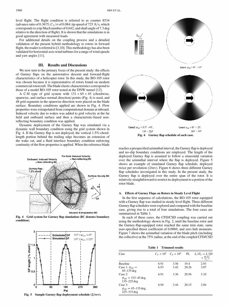
reaches a prespecified azimuthal interval, theGurneyflap is deployedand no-slip boundary conditions are employed. The length of thedeployed Gurney flap is assumed to follow a sinusoidal variationover the azimuthal interval where the flap is deployed. Figure 5shows an example of simulated Gurney flap schedule, deployedtwice per revolution (2/rev). Figure 6 shows three different Gurneyflap schedules investigated in this study. In the present study, theGurney flap is deployed over the entire span of the rotor. It isrelatively straightforward to restrict its deployment to a portion of therotor blade.
A. Effects of Gurney Flaps on Rotors in Steady Level Flight
In the first sequence of calculations, the BO-105 rotor equippedwith a Gurney flap was studied in steady level flight. Three differentGurneyflap scheduleswere explored and comparedwith the baselinecase, giving rise to a total of four simulations. The four cases aresummarized in Table 1.
In each of these cases, the CFD/CSD coupling was carried outusing the methodology shown in Fig. 2, until the baseline rotor andthe Gurney-flap-equipped rotor reached the same trim state, sameuser-specified thrust coefficient of 0.0069, and zero hub moments.Figure 7 shows the azimuthal variation of the blade pitch (includingthe collective) at the 75% radius, at the end of the coupled CFD/CSD
Fig. 4 Grid system for Gurney flap simulation (BC denotes boundary
condition).
Psi
GF
leng
th[%
chor
d]
0 90 180 270 3600
0.5
1
1.5
2Scheduled GFSimulated GF oo
oo
225135
45315
1
1
??
??
GF
GF
??
0 90 180 270 3600
0.5
1
1.5
2
oo
oo
225135
45315
1
1
≤≤
≤≤
GF
GF
ψψ
Fig. 5 Sample Gurney flap deployment schedule (2=rev).
Table 1 Trimmed results
Case CT 103 CP 104 PL L=De L=DMz
V1
Baseline 6.91 3.56 19.4 2.93Case 1: GF 45–135 deg
6.93 3.42 20.26 3.07
Case 2: GF 315–45 deg,135–225 deg
6.91 3.36 20.56 3.10
Case 3: GF 45–135 deg,225–315 deg
6.94 3.44 20.15 3.04
Fig. 6 Gurney flap schedule of each case.
1960 MIN ETAL.
trim process. As shown in Fig. 7, holding the flight conditions fixedand operating at the same thrust setting with deployment of Gurneyflaps altered the trim state. The new trim states changed thedistribution of induced velocity, sectional lift, and drag. As a result,the nondimensional power loading CT=CP and equivalent rotorL=De both show small differences compared to the baseline, as
shown in Table 1. In this particular study under the given flightcondition, dynamic deployment of a Gurney flap resulted in a slightdecrease in rotor power. Similar power reductions were observed inother studies that used a Gurney flap [13], actively controlled flap[14,15], and higher harmonic control [16–18].
Wenext study the effects of theGurneyflap deployment on the hubloads. Recall that in the first case, the Gurney flaps are deployed onlyover the advancing side (between 45 and 135 deg azimuth). In thesecondcase, theGurneyflapisdeployedwhenthebladesare in theforeandaftportionsof the rotordisk, increasing the liftover thoseportions.The third case studied is where the Gurney flaps are deployed on theright and left portions of the rotor disk.
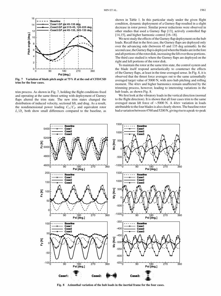
Tomaintain the rotor at the same trim state, the control system andthe blade itself respond aeroelastically to counteract the effectsof the Gurney flaps, at least in the time-averaged sense. In Fig. 8, it isobserved that the thrust force averages out to the same azimuthallyaveraged target value of 5000 N, with zero hub pitching and rollingmoment. The 4/rev and higher harmonics remain unaffected by thetrimming process, however, leading to interesting variations in thehub loads, as shown Fig. 8.
We first look at the vibratory loads in the vertical direction (normalto the flight direction). It is shown that all four cases trim to the sameaveraged mean lift force of 5000 N. A 4/rev variation in loadsattributable to the four blades is also clearly shown.Thebaseline rotorhadavariationbetween4760and5200N,givingrise toapeak-to-peak
Psi [deg.]
Pitc
han
gle
[deg
.]
0 90 180 270 3600
2
4
6
8
10
12
14
16BaselineCase1:GF psi 45-135 deg.Case2:GF psi 315-45, 135-225 deg.Case3:GF psi 45-135, 225-135 deg.
Fig. 7 Variation of blade pitch angle at 75% R at the end of CFD/CSD
trim for the four cases.
Psi [deg.]
Fz
[N]
0 90 180 270 3604600
4800
5000
5200
5400BaselineCase1Case2Case3
Psi [deg.]
Fx
[N]
0 90 180 270 360
0
50
100
150
200BaselineCase1Case2Case3
Psi [deg.]
Fy
[N]
0 90 180 270 360-100
-50
0
50
100 BaselineCase1Case2Case3
Psi [deg.]
Mx
[Nm
]
0 90 180 270 360-1000
-500
0
500
1000
1500BaselineCase1Case2Case3
Psi [deg.]
My
[Nm
]
0 90 180 270 360-1000
-500
0
500
1000
1500BaselineCase1Case2Case3
Psi [deg.]
Mz
[Nm
]
0 90 180 270 360-650
-600
-550
-500
-450
-400
-350BaselineCase1Case2Case3
Case1: Case2: Case3:
Psi [deg.]
Fz
[N]
0 90 180 270 3604600
4800
5000
5200
5400BaselineCase1Case2Case3
Psi [deg.]
Fx
[N]
0 90 180 270 360
0
50
100
150
200BaselineCase1Case2Case3
Psi [deg.]
Fy
[N]
0 90 180 270 360-100
-50
0
50
100 BaselineCase1Case2Case3
Psi [deg.]
Mx
[Nm
]
0 90 180 270 360-1000
-500
0
500
1000
1500BaselineCase1Case2Case3
Psi [deg.]
My
[Nm
]
0 90 180 270 360-1000
-500
0
500
1000
1500BaselineCase1Case2Case3
Psi [deg.]
Mz
[Nm
]
0 90 180 270 360-650
-600
-550
-500
-450
-400
-350BaselineCase1Case2Case3
Case1: Case2: Case3:
Fig. 8 Azimuthal variation of the hub loads in the inertial frame for the four cases.
MIN ETAL. 1961

variation of approximately 440 N. Case 1, in which the Gurney flapwasdeployedonlybetween45and135degon theadvancing side, hada comparable peak-to-peak variation (between 4730 and 5170 N). Incase3, inwhich theGurneyflapisdeployedonboth theadvancingside(between 45 and 135 deg azimuth) and retreating side (225 and315deg), the loads varied between4720 and5210N.Case 2, inwhichtheGurneyflapisdeployedover thefront (135to225degazimuth)andaftportion(315to45degazimuth),gavethelowestpeak-to-peakloads(4820 to 5170 N).
We next look at the variation of theH force of the entire rotor. Thebaseline rotor had the lowest azimuthally averaged value of 26N anda peak-to-peak49 to3 N.When theGurneyflapwas deployed onthe advancing side (case 1), or on both the advancing and retreatingsides (case 3), theH force increased both in magnitude and peak-to-peak variations. In case 2, the time-averaged H force was higher at42 N, but the peak-to-peak values were smaller (varying between 50and 34 N).
We next look at the Y-force variations. The baseline Y force variedbetween28 and 6 N, with a mean side force of 17 N. Case 3, inwhich the flap is deployed on the advancing and retreating sides, hada higher mean value, but the peak-to-peak variations were small.Case 2, in which the Gurney flaps are deployed on the front and aftportions of the rotor disk, gave significant variation in local sectionaldrag forces. Since a significant portion of this drag force is pointedalong the Y axis, the net effect is to produce a large peak-to-peakvariation of the Y force.
The effects of the Gurney flap deployment on the hub rolling andpitching moments as well as the shaft torque can similarly beexamined. As shown in Fig. 8, case 1 and case 3 tend to give higherpeak-to-peak rolling moments compared to the baseline case,although the mean values trim out to zero. Case 3 has hub rolling andpitching moment variations that are comparable to, if not smallerthan, those for the baseline rotor.
In some applications, especially for hingeless rotors, it is highlydesirable that the flexbeam loads and moments be reduced, both inmean values and the peak-to-peak variations. The present method-ology allows the aerodynamic loads, structural loads, and bladedeformations to bemonitored virtually anywhere on the rotor systemfor these purposes. Figure 9 shows the variation in the aerodynamic
loads at an arbitrarily selected sensor location on the flexbeam.It should be possible to monitor the loads and optimize the Gurneyflap deflections to reduce the loads, deformations, and stress levels.Among the four cases studied, case 3 tended to have the largest peak-to-peak variations in the loads.
B. Effects of Gurney Flaps on the Autorotative Descent of Rotors
Wenext look at the effects of Gurneyflaps on autorotative descent.The BO-105 rotor was considered again. In this study, the Gurneyflaps were permanently deployed. In autorotative descent withoutpower, there will not be enough control power available for periodicdeployment of these devices. To simplify the analysis, all thecalculations were done for a rigid rotor with a rigid Gurney flap.Several different flap settings were examined.
When the Gurney flaps are deployed, the blade sections generatehigher lift force than would the baseline section. If the descent rate ishigh enough so that a portion of this lift force is pointing forward, as
Psi [deg.]
Mx
[Nm
]M
z[N
m]
My
[Nm
]
0 90 180 270 360-15
-10
-5
0
5
10
15
20
25BaselineCase1Case2Case3
Psi [deg.]0 90 180 270 360
-200
-100
0
100
200BaselineCase1Case2Case3
Psi [deg.]0 90 180 270 360
-300
-200
-100
0
100BaselineCase1Case2Case3
Psi [deg.]
Fz
[N]
90 180 270 360500
1000
1500
2000
2500BaselineCase1Case2Case3
Case1: Case2: Case3:
Psi [deg.] Psi [deg.]
Psi [deg.] Psi [deg.]
Psi [deg.] Psi [deg.]
Psi [deg.] Psi [deg.]0
a
Fig. 9 Azimuthal variation of the flexbeam loads in the rotating frame for the four cases.
Fig. 10 Autorotation of a rotor in descent.
1962 MIN ETAL.

shown in Fig. 10, the blade will enter the windmill state andautorotate.
The analyses were done as follows. The rotor rpm (and hence thetip Mach number of the rotor) was held fixed. The advance ratio wasparametrically varied between 0.1 and 0.2 in 0.05 increments. Onlythe 0.15 advance ratio case is discussed here, for brevity. The targetCT= of the baseline rotor (i.e., without a Gurney flap) wasnominally set at 0.047, representative of the typical operating con-dition of a helicopter. In all three cases reported here (baseline rotorand rotorswithGurneyflaps set at 30 and 45 deg angles relative to thechord line), the collective pitch and the cyclic pitch were iterativelyadjusted until CT= reached the target value and the azimuthallyaveraged rotor rolling and pitching moments at the hub were drivento zero. Although the freestream velocitywas held constant, the shaftangle of attackwas iteratively adjusted alongwith control inputs untilthe autorotative state was established where the torque converges tozero. The elastic deformations were ignored for this preliminarystudy, and the calculations were carried out in the rigid rotor mode.
Figure 11 shows the azimuthal and radial variation of the normalforces and torque consumption/production distributions for the 0.15advance ratio case. All of the cases trim to the same CT=, zero hubmoments and zero total torque. This information may be fed into aCSD analysis to extract structural responses and tomonitor blade androot stresses, if desired. It is interesting to examinewhich parts of therotor disk are responsible for torque production and which parts ofthe rotor disk consume torque. It is shown in Fig. 11 that much of theaft side of the rotor disk is driven (i.e., consume torque), whereasmuch of the front half of the rotor disk is driving (produces torque),with the exception of the tip regions.
Of more interest is the vertical descent rate needed to maintainautorotative state at a given thrust setting and forward speed.Table 2 shows these results. It is shown that the vertical descentrate may be reduced with a modest 30 deg Gurney flap by approxi-mately 40%. Increasing the flap angle to 45 deg causes localseparation on the leeward side of the Gurney flap (see Fig. 12) andincreases the section drag somewhat, leading to a higher descentrate than the 30 deg flap case.
IV. Conclusions
Navier–Stokes simulations have been carried out for an existingrotor retrofitted with a Gurney flap. The steady level flight loads andautorotative characteristics have been examined. In forward flight,for identical thrust and hub moment settings, it was found that thedeployment of the flap significantly alters the vibratory loadcharacteristics of the rotor. Deploying the Gurney flaps in the foreand aft portions of the rotor disk had the largest reduction in peak-to-peak vertical load fluctuations compared to the baseline case.Other deployment schedules were modestly beneficial in reducingthe H force, Y force, and peak-to-peak variations in hub rolling andpitching moments. By judiciously combining the flap schedules, andpossibly through the use of individual onboard control of the flaps, itshould be possible to reduce the vibratory loads of the rotor. TheGurney flap was deployed over the entire blade span in this study.Placing the Gurney flaps only over the outboard radial locationsshould retain the benefits of this concept while improving theefficiency. The deployment of the Gurney flaps showed a slightdecrease in power consumption.
In autorotative flight, deployment of Gurney flaps can increase thethrust coefficient during the flare maneuver decelerating the vehiclebefore touchdown. For a fixed thrust setting, use of Gurney flapsdecreased the descent rate needed to maintain autorotation. Gurneyflaps with moderate angles relative to the chord line were moreeffective in improving the autorotative performance than flaps thatare placed at higher angles relative to the chord line, due to thepresence of separated flow aft of the Gurney Flap and the attendantdrag rise.
Baseline 30 deg. GF 45 deg. GF
V∞ / R=0.15
NormalForce
Torque
2MCn
QC
zero-torque line zero-torque line
Freestream
ο90=
Drivingregion
Drivingregion
Drivingregion
Baseline 30 deg. GF 45 deg. GF
V /ΩR=0.15
NormalForce
Torque
2MCn
QC
zero-torque line zero-torque line
Freestream
ο90=ψ
Drivingregion
Drivingregion
Drivingregion
Fig. 11 Effects of Gurney flap on azimuthal distribution of normal forces and torque consumed for three different Gurney flap angles.
Table 2 Effect of Gurney flap on the vertical descentrate needed to sustain autorotation (zero torque)
Thrust and descent rate Baseline 30 deg GF 45 deg GF
CT 3:6 1003 3:6 1003 3:8 1003
s, deg 28.9 17.5 25.0V1 sins=R 0.0735 0.0457 0.0642
90= ο 180 0=
Baseline
30 deg. GF
45 deg. GF
Ψ Ψ Ψ Ψ= ο 270= ο 0= ο
Baseline
30 deg. GF
45 deg. GF
Baseline
30 deg. GF
45 deg. GF
Fig. 12 Streamlines in the vicinity of the Gurney flap for the BO-105
rotor in autorotative descent.
MIN ETAL. 1963

Acknowledgment
This work was funded by NASA Cooperative AgreementNNX07AP33A entitled “Flight Mechanics and Control OrientedModeling for Next Generation On-Blade Control Concepts” withWayne Johnson as Technical Monitor.
References
[1] Chandrasekhara, M. S., Martin, P. B., and Tung, C., “CompressibleDynamic Stall Performance of a Variable Droop Leading Edge Airfoilwith a Gurney Flap,” AIAA Paper 2004-0041, Jan. 2004.
[2] Guzel, G., Sankar, L. N., and Rhee, M., “Computational Investigationof the Effects of Gurney Flap on the Aerodynamic Performance of VR-12 Airfoil,” AIAA Paper 2005-4960, June 2005.
[3] Min, B. Y., Sankar, L. N., and Yu, Y. H., “Computational Studies of theEffects of Gurney Flaps on the Autorotative Performance of Rotors inDescent Flight,” AHS Aeromechanics Specialists Meeting [CD-ROM],AHS International, Alexandria, VA, Jan. 2008.
[4] Min, B. Y., Lee, W., Englar, R., and Sankar, L. N., “NumericalInvestigation of Circulation Control Airfoils,” Journal of Aircraft,Vol. 46, No. 4, July–August 2009, pp. 1403–1410.doi:10.2514/1.41638
[5] Sitaraman, J., “CFDBasedUnsteadyAerodynamicModeling for RotorAeroelastic Analysis,” Ph.D. Dissertation, Department of AerospaceEngineering, Univ. of Maryland, College Park, MD, 2003.
[6] Datta, A., Sitaraman, J., Chopra, I., and Baeder, J. D., “CFD/CSDPrediction of Rotor Vibratory Loads in High-Speed Flight,” Journal ofAircraft, Vol. 43, No. 6, Nov.–Dec. 2006, pp. 1698–1709.doi:10.2514/1.18915
[7] Datta, A., and Chopra, I., “Prediction of UH-60A Dynamic Stall Loadsin High Altitude Level Flight using CFD/CSD Coupling,” AHS
Aeromechanics Specialists Meeting [CD-ROM], AHS International,Alexandria, VA, June 2005.
[8] Potsdam, M., Yeo, H., and Johnson, W., “Rotor AerodynamicPrediction Using Loose Aerodynamic/Structural Coupling,” AHS
Aeromechanics Specialists Meeting [CD-ROM], AHS International,Alexandria, VA, June 2004.
[9] Rajmohan, N., “Application of Hybrid Methodology to Rotors inSteady and Maneuvering Flight,” Ph.D. Dissertation, School ofAerospace Engineering, Georgia Inst. of Technology, Atlanta (to bepublished).
[10] Rajmohan,N., Sankar, L.N., Bauchau,O.,Makinen, S.M., Egolf, T.A.,
and Charles, B. D., “Application of Hybrid Methodology to Rotors inSteady and Maneuvering Flight,” AHS Aeromechanics Specialists
Meeting [CD-ROM], AHS International, Alexandria, VA, 2008.[11] Tongchitpakdee, C., Benjanirat, S., and Sankar, L. N., “Numerical
Studies of the Effects of Active and Passive Circulation EnhancementConcepts on Wind Turbine Performance,” AIAA Paper 2006-0198,Jan. 2006.
[12] Yu,Y.H., Tung, C., van derWall, B.G., Pausder,H., Burley, C., Brooks,T., Beaumier, P., Delrieux, Y.,Mercker, E., and Pengel, K., “TheHART-II Test: Rotor Wakes and Aeroacoustics with Higher-Harmonic PitchControl (HHC) Inputs—The Joint German/French/Dutch/US Project,”AHS Aeromechanics Specialists Meeting [CD-ROM], AHS Interna-tional, Alexandria, VA, June 2002.
[13] Yeo, H., “Assessment of Active Controls for Rotor PerformanceEnhancement,” Journal of the American Helicopter Society, Vol. 53,No. 2, April 2008, pp. 152–163.doi:10.4050/JAHS.53.152
[14] Glaz, B., Friedmann, P. P., and Liu, L., “Vibration Reduction andPerformance Enhancement of Helicopter Rotors Using an Active/Passive Approach,” AIAA Paper 2008-2178, April 2008.
[15] Liu, L., Friedmann, P. P., Kim, I., and Bernstein, D. S., “RotorPerformance Enhancement and Vibration Reduction in Presence ofDynamic Stall Using Actively Controlled Flaps,” Journal of the
American Helicopter Society, Vol. 53, No. 4, Oct. 2008, pp. 338–350.doi:10.4050/JAHS.53.338
[16] Shaw, J., Albion, N., Hanker, E. J., Jr., and Teal, R. S., “HigherHarmonic Control: Wind Tunnel Demonstration of Fully EffectiveVibratory Hub Force Suppression,” Journal of the AmericanHelicopterSociety, Vol. 34, No. 1, Jan. 1989, pp. 14–25.doi:10.4050/JAHS.34.14
[17] Nguyen, K., and Chopra, I., “Effects of Higher Harmonic Control onRotor Performance and Control Loads,” Journal of Aircraft, Vol. 29,No. 3, May–June 1992, pp. 336–342.doi:10.2514/3.46166
[18] Cheng, R. P., and Celi, R., “Optimum Two-Per-Revolution Inputs forImproved Rotor Performance,” Journal of Aircraft, Vol. 42, No. 6,Nov.–Dec. 2005, pp. 1409–1417.doi:10.2514/1.20884
[19] Tongchitpakdee, C., “Computational Studies of the Effects of Activeand Passive Circulation Enhancement Concepts on Wind TurbinePerformance,” Ph.D. Dissertation, School of Aerospace Engineering,Georgia Inst. of Technology, Atlanta, 2007.
1964 MIN ETAL.