Recent advances in Machining of Polymeric Composite Materials
21
Polimery i kompozyty konstrukcyjne 1998 Ashraf I. HASSAN, Jan KOSMOL, Jerzy BURSA Katedra Budowy Maszyn, Politechnika Śląska, Gliwice RECENT ADVANCES IN MACHINING OF POLYMERIC COMPOSITE MATERIALS BY AWJM Abstract. Conventional machining of polymeric composite materials is often both technically and economically less effective because the structural characteristics inherent in fibre reinforcement promote excessive tool wear. In recent years, abrasive waterjet machining (AWJM) has been proving to be successful in the machining of such materials. This paper presents a state of the art review of research in AWJM of polymeric composite materials. Among the main topics discussed are mechanisms of material removal, productivity and surface quality. 1. INTRODUCTION Polymeric composite materials, or fibre reinforced plastics (FRP), are increasingly being to be rapidly developing commercial materials for use in applications which require both high strength and light weight. Their applications extend in industrial fields such as aircraft, aerospace, automobile, construction, corrosion resistant, electrical and marine [1]. As composite materials become commonplace, the search for efficient machining processes becomes more significant. However, conventional machining of polymeric composite materials is often not effective because the structural characteristics inherent in fibre reinforcement promote excessive tool wear [2]. Also the material is subject to severe damage including inter laminar delamination, fibre pullout and poor surface quality that may adversely affect the part performance under service loading conditions. Abrasive waterjet machining (AWJM) has been successfully applied in the machining of different types of composite materials such as metal matrix composites [3,4,5] and ceramic matrix composites [3,4,6] where conventional machining is often not technically or economically feasible. Figure 1 shows the principle of AWJM, where water at high pressure (P), up to 400 MPa, exits from a sapphire nozzle, whose diameter is (d n ), and it is mixed with fine abrasives, which are fed from an abrasive feed hooper at a rate of ( & m ), to form a high velocity, high pressure coherent jet exiting from a mixing tube nozzle of inside diameter (d m ), and length (l m ). This jet is able to cut any type of material of any contour by a feed motion
Transcript of Recent advances in Machining of Polymeric Composite Materials
Polimery i kompozyty konstrukcyjne 1998
Ashraf I. HASSAN, Jan KOSMOL, Jerzy BURSA
Katedra Budowy Maszyn, Politechnika Śląska, Gliwice
RECENT ADVANCES IN MACHINING OF POLYMERIC
COMPOSITE MATERIALS BY AWJM
Abstract. Conventional machining of polymeric composite materials is often both
technically and economically less effective because the structural characteristics
inherent in fibre reinforcement promote excessive tool wear. In recent years, abrasive
waterjet machining (AWJM) has been proving to be successful in the machining of such
materials. This paper presents a state of the art review of research in AWJM of
polymeric composite materials. Among the main topics discussed are mechanisms of
material removal, productivity and surface quality.
1. INTRODUCTION
Polymeric composite materials, or fibre reinforced plastics (FRP), are increasingly being to
be rapidly developing commercial materials for use in applications which require both high
strength and light weight. Their applications extend in industrial fields such as aircraft,
aerospace, automobile, construction, corrosion resistant, electrical and marine [1]. As
composite materials become commonplace, the search for efficient machining processes
becomes more significant. However, conventional machining of polymeric composite materials
is often not effective because the structural characteristics inherent in fibre reinforcement
promote excessive tool wear [2]. Also the material is subject to severe damage including inter
laminar delamination, fibre pullout and poor surface quality that may adversely affect the part
performance under service loading conditions.
Abrasive waterjet machining (AWJM) has been successfully applied in the machining of
different types of composite materials such as metal matrix composites [3,4,5] and ceramic
matrix composites [3,4,6] where conventional machining is often not technically or
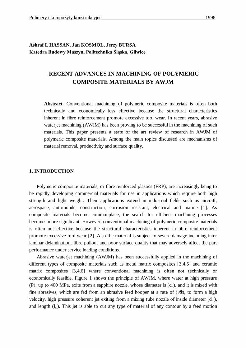
economically feasible. Figure 1 shows the principle of AWJM, where water at high pressure
(P), up to 400 MPa, exits from a sapphire nozzle, whose diameter is (dn), and it is mixed with
fine abrasives, which are fed from an abrasive feed hooper at a rate of ( &m ), to form a high
velocity, high pressure coherent jet exiting from a mixing tube nozzle of inside diameter (dm),
and length (lm). This jet is able to cut any type of material of any contour by a feed motion
Ashraf I. HASSAN, Jan KOSMOL, Jerzy BURSA
called the traverse rate (u). The mixing tube is usually displaced from the workpiece surface
by a small stand off distance (S).
Fig. 1 Principle of AWJM
Compared with conventional and other non conventional machining of polymeric
composite materials, AWJM has the following advantages [6, 7, 8]:
Suitable for many machining operations such as turning, drilling or milling
Able to machine both very soft and very hard composites
Able to machine multi layered composites
Can cut stacks of different composites
Omnidirectional machining
No thermal stresses
The real benefit of AWJM lies in the last item of the advantages i.e. the non thermal machining
of high cost heat sensitive materials such as polymeric composite materials to justify the slower
traverse rates than plasma arc machining whose principal limitation is the thermal damage of
the workpiece surface [9].
Ashraf_bht
Typewritten Text
24
Recent advances in machining of polymeric composite materials by AWJM
The following limitations are relevant to AWJM of composite materials [10]: high capital
investments are required, high cutting power is required, delamination occasionally occurs, the
jet has only a limited stability perpendicular to its own axis, and the process is noisy and
produces a great deal of spray.
Two recent reviews conducted by Hassan and Kosmol [11] and Hoogstrate et al [12]
provided a state of the art review of AWJM technology. An early study on the practical
applications of AWJM [10] provided a comprehensive list of potential composite materials that
were successfully machined.
This paper is a review of recent developments in AWJM of polymeric composite materials.
We will not deal with other types of composite materials such as metal matrix and ceramic
matrix. Much of the research, although scarce, has dealt with the mechanisms of material
removal, productivity and surface quality. Historically, plain waterjet machining (WJM) was
initially applied on composite materials at the late seventies and the beginning of the eighties.
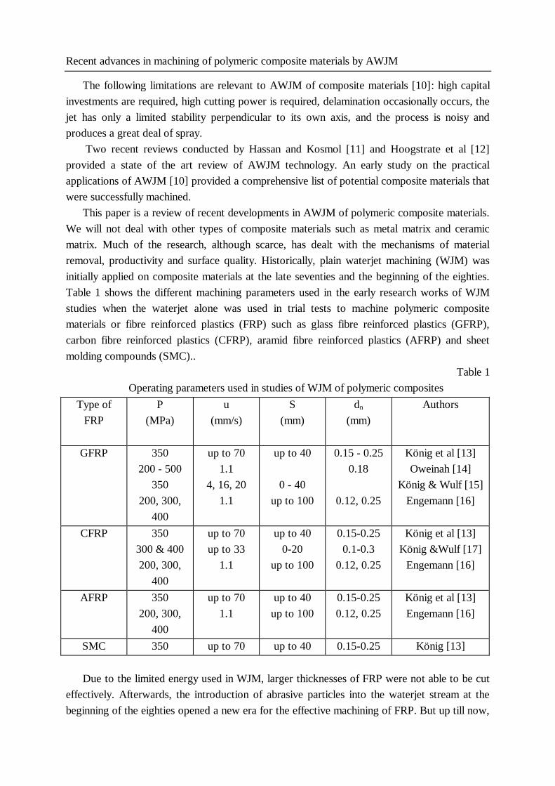
Table 1 shows the different machining parameters used in the early research works of WJM
studies when the waterjet alone was used in trial tests to machine polymeric composite
materials or fibre reinforced plastics (FRP) such as glass fibre reinforced plastics (GFRP),
carbon fibre reinforced plastics (CFRP), aramid fibre reinforced plastics (AFRP) and sheet
molding compounds (SMC)..
Table 1
Operating parameters used in studies of WJM of polymeric composites
Type of
FRP
P
(MPa)
u
(mm/s)
S
(mm)
dn
(mm)
Authors
GFRP 350
200 - 500
350
200, 300,
400
up to 70
1.1
4, 16, 20
1.1
up to 40
0 - 40
up to 100
0.15 - 0.25
0.18
0.12, 0.25
König et al [13]
Oweinah [14]
König & Wulf [15]
Engemann [16]
CFRP 350
300 & 400
200, 300,
400
up to 70
up to 33
1.1
up to 40
0-20
up to 100
0.15-0.25
0.1-0.3
0.12, 0.25
König et al [13]
König &Wulf [17]
Engemann [16]
AFRP 350
200, 300,
400
up to 70
1.1
up to 40
up to 100
0.15-0.25
0.12, 0.25
König et al [13]
Engemann [16]
SMC 350 up to 70 up to 40 0.15-0.25 König [13]
Due to the limited energy used in WJM, larger thicknesses of FRP were not able to be cut
effectively. Afterwards, the introduction of abrasive particles into the waterjet stream at the
beginning of the eighties opened a new era for the effective machining of FRP. But up till now,
Ashraf_bht
Typewritten Text
Ashraf_bht
Typewritten Text
25
Ashraf I. HASSAN, Jan KOSMOL, Jerzy BURSA
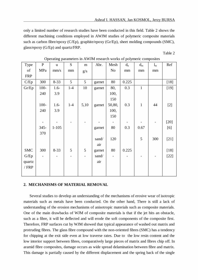
only a limited number of research studies have been conducted in this field. Table 2 shows the
different machining conditions employed in AWJM studies of polymeric composite materials
such as carbon fibre/epoxy (C/Ep), graphite/epoxy (Gr/Ep), sheet molding compounds (SMC),
glass/epoxy (G/Ep) and quartz/FRP.
Table 2
Operating parameters in AWJM research works of polymeric composites
Type
of
FRP
P
MPa
u
mm/s
S
mm
m
g/s
Abr. Mesh
No
dn
mm
dm
mm
lm
mm
Ref
C/Ep 300 8-33 5 5 garnet 80 0.225 [18]
Gr/Ep
SMC
G/Ep
quartz
/ FRP
100-
240
100-
240
-
345-
370
300
-
1.6-
3.9
1.6-
3.9
-
1-105
8-33
-
1-4
1-4
-
5
-
10
5,10
-
5
-
garnet
garnet
-
garnet
sand/
air
garnet
sand/
air
80,
100,
150
50,80,
100,
150
-
80
120
80
-
0.3
0.3
-
0.3
0.225
-
1
1
-
0.67
5
-
44
-
300
-
[19]
[2]
[20]
[6]
[21]
[18]
[22]
2. MECHANISMS OF MATERIAL REMOVAL
Several studies to develop an understanding of the mechanisms of erosive wear of isotropic
materials such as metals have been conducted. On the other hand, There is still a lack of
understanding of the erosion mechanisms of anisotropic materials such as composite materials.
One of the main drawbacks of WJM of composite materials is that if the jet hits an obstacle,
such as a fibre, it will be deflected and will erode the soft components of the composite first.
Therefore, FRP surfaces cut by WJM showed that typical appearance of washed out matrix and
protruding fibres. The glass fibre compound with the non-oriented fibres (SMC) has a tendency
for chipping at the exit side even at low traverse rates. Due to the low resin content and the
low interior support between fibres, comparatively large pieces of matrix and fibres chip off. In
aramid fibre composites, damage occurs as wide spread delamination between fibre and matrix.
This damage is partially caused by the different displacement and the spring back of the single
Ashraf_bht
Typewritten Text
Ashraf_bht
Typewritten Text
26
Recent advances in machining of polymeric composite materials by AWJM
fibre layers, and by some part caused by water pressed in between the laminate layers. This
latter effect is the main cause of damage for CFRP [13].
After switching to AWJM in the early eighties, several studies concerning the erosion
process had been evolved. In an early study of sand blasting of polymeric composite materials,
Tilly and Sage [23] found that composite materials generally behave in an ideally brittle fashion
i.e. maximum erosion rate occurs at normal impact, i.e. at 90°. Fibre reinforcement may
improve or worsen the resistance to erosion, depending on the type of fibres used. In addition,
the erosion rate in composites increases with the particle size. It was found that the erosion
rate of fibre reinforced plastics is greater than that of steel. Zahavi and schmitt [22] found out
that three polymeric composite materials, quartz-polyimide, glass-epoxy and quartz-
polybutadiene, showed maximum erosion at normal impact i.e. 75 -90. This is consistent with
their properties as thermosetting resins and inorganic fibres. The material removal mechanism
in fibre reinforced plastics (FRP), as described by them can be characterized as follow:
1. There is a local removal from the resin material from the impacted surface which results in
exposure of the fibres to the erosion environment.
2. Abrasive particles impact on the fibres and cause fibres to break because of the formation of
cracks perpendicular to their length due to fibre bending stresses.
3. Further damage results when the interfaces between the broken fibres and matrix resin are
degraded until the fibres are removed to subsequent impact.
This mechanism was later verified by Pool et al [21] using scanning electron microscopy for
three different composite materials, graphite/epoxy, graphite/polyphenylene sulfide and
aramid/epoxy.
In an early study on the application of AWJM to composite materials, Hashish [10] showed
for the first time the possibility of AWJM of composite materials such as kevlar/fiberglass/steel
wire with reasonable traverse rates and less delamination than other processes. Ramulu and
Arola [2] carried out a scanning electron microscopic study on Graphite/Epoxy composite and
suggested that for 90° fibre orientation to the direction of the traverse rate, the dominant
modes of material removal are shearing and abrasive micro machining. Fibre pullout and the
degree of fibre-matrix delamination is limited due to the high interfacial bond strength. For 00
fibre orientation, the abrasives account for the dominant portions for material removal and the
matrix remains intact in the machined surface. Shallow abrasive wear tracks are observed on
the surface of the machined specimens. The process of erosion by solid particle impact has
been investigated by several notable researchers since 1960. The early work of Finnie [24] is
still regarded as the leading work, since then a number of researchers in AWJM have
developed several cutting models on erosion. Later, an intensive work in the field of AWJ
erosion was conducted by Hashish [25,26-28]. A simplified model, based on Finnie's model, for
cutting of ductile materials was suggested [26]. Two mechanisms have been identified as the
dominant modes of material removal. These are the cutting wear mode and the deformation
wear mode. The surface produced by the first mode is relatively smooth due to cutting wear at
a shallow angle of impact and it exists at the upper portion of the cutting kerf. The surface
Ashraf_bht
Typewritten Text
Ashraf_bht
Typewritten Text
27

Ashraf I. HASSAN, Jan KOSMOL, Jerzy BURSA
produced by the other mode is striated due to deformation wear mode at large angles of impact
which is characterized by material removal due to excessive plastic deformation.This wear
mode results in an unsteady penetration process. Later, these two mechanisms were found to
apply also to brittle materials such as glass [27]. The relative contribution of each mechanism
significantly depends on the process parameters. However, the deformation wear mode
becomes more dominant in brittle materials. This is concluded from the lower ratios of cutting
wear depth to deformation wear depth obtained for brittle materials.
Recent studies in AWJM of graphite/epoxy composites pointed out the existence of a small
initial damage zone near the jet entrance, which is evident from the curvature at the top of the
kerf, in addition to the previous two modes which are characteristic for AWJM [2,19]. The
initial damage zone at the top of the kerf is due to jet expansion prior to impingement as shown
in Fig. 2. Workpieces machined with a low stand off distance exhibited the smallest initial
damage zone whose width may reach 500 µm and its depth 600 µm in some cases. The effect
of other AWJM parameters were negligible. Regression models were developed with the aid of
Fig. 2 Initial damage zone in AWJM [19]
measurements of the width and depth of the initial damage zones. The length of the cutting
wear zone was found to be most affected by abrasive grain size, pressure and the traverse rate.
On the other hand, stand off distance has a little effect on this length. The mechanism of
material removal in FRP includes broken fibres, pullout in all the three zones and rather large
removal pockets in the initial damage zone. Therefore, changes in kerf geometry and kerf wall
characteristics with cutting depth are solely a product of the inherent energy of the jet.
Ashraf_bht
Typewritten Text
Ashraf_bht
Typewritten Text
28
Recent advances in machining of polymeric composite materials by AWJM
3. PRODUCTIVITY
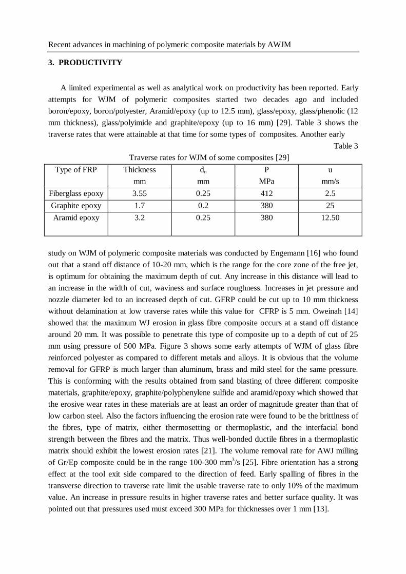
A limited experimental as well as analytical work on productivity has been reported. Early
attempts for WJM of polymeric composites started two decades ago and included
boron/epoxy, boron/polyester, Aramid/epoxy (up to 12.5 mm), glass/epoxy, glass/phenolic (12
mm thickness), glass/polyimide and graphite/epoxy (up to 16 mm) [29]. Table 3 shows the
traverse rates that were attainable at that time for some types of composites. Another early
Table 3
Traverse rates for WJM of some composites [29]
Type of FRP
Thickness
mm
dn
mm
P
MPa
u
mm/s
Fiberglass epoxy 3.55 0.25 412 2.5
Graphite epoxy 1.7 0.2 380 25
Aramid epoxy
3.2
0.25
380
12.50
study on WJM of polymeric composite materials was conducted by Engemann [16] who found
out that a stand off distance of 10-20 mm, which is the range for the core zone of the free jet,
is optimum for obtaining the maximum depth of cut. Any increase in this distance will lead to
an increase in the width of cut, waviness and surface roughness. Increases in jet pressure and
nozzle diameter led to an increased depth of cut. GFRP could be cut up to 10 mm thickness
without delamination at low traverse rates while this value for CFRP is 5 mm. Oweinah [14]
showed that the maximum WJ erosion in glass fibre composite occurs at a stand off distance
around 20 mm. It was possible to penetrate this type of composite up to a depth of cut of 25
mm using pressure of 500 MPa. Figure 3 shows some early attempts of WJM of glass fibre
reinforced polyester as compared to different metals and alloys. It is obvious that the volume
removal for GFRP is much larger than aluminum, brass and mild steel for the same pressure.
This is conforming with the results obtained from sand blasting of three different composite
materials, graphite/epoxy, graphite/polyphenylene sulfide and aramid/epoxy which showed that
the erosive wear rates in these materials are at least an order of magnitude greater than that of
low carbon steel. Also the factors influencing the erosion rate were found to be the brittlness of
the fibres, type of matrix, either thermosetting or thermoplastic, and the interfacial bond
strength between the fibres and the matrix. Thus well-bonded ductile fibres in a thermoplastic
matrix should exhibit the lowest erosion rates [21]. The volume removal rate for AWJ milling
of Gr/Ep composite could be in the range 100-300 mm3/s [25]. Fibre orientation has a strong
effect at the tool exit side compared to the direction of feed. Early spalling of fibres in the
transverse direction to traverse rate limit the usable traverse rate to only 10% of the maximum
value. An increase in pressure results in higher traverse rates and better surface quality. It was
pointed out that pressures used must exceed 300 MPa for thicknesses over 1 mm [13].
Ashraf_bht
Typewritten Text
Ashraf_bht
Typewritten Text
29

Ashraf I. HASSAN, Jan KOSMOL, Jerzy BURSA
Pressure (P) MPa
Fig. 3 Effect of pressure on the depth of cut in WJM of GFRP [29]
Table 4 summarizes the results of traverse rates for different thichnesses obtained by Hashish
[6]. Observe that the maximum traverse rate is primarily controlled by the matrix material.
Table 4
Typical traverse rates for AWJM of selected composite materials [6]
Type of
FRP
t = 0.79
1.6
3.18
Thick (t)
mm
6.36
12.7
19.1
50.8
plastics&
FRP
u = 53 38 29 21 15 10 2.5
G/Ep u = 105 95 76 42 17 12 5
Gr/Ep u = 74 63 52 40 15 10 4.2
Ashraf_bht
Typewritten Text
Ashraf_bht
Typewritten Text
30
Recent advances in machining of polymeric composite materials by AWJM
Table 5 shows the optimum traverse rates for cutting of two different thicknesses of CFRP
based on optimum edge quality which results in a smooth edge with a minimum kerf taper. The
optimum traverse rate in terms of edge quality is about two thirds that of the maximum
possible traverse rate.
Table 5
Optimum traverse rates for CFRP [9]
P = 690 Mpa S = 2 mm dm = 3 mm Abrasive : Zirconia &m = 33 g/s
Workpiece thickness
mm
Traverse rate mm/s
2 17
8 5.8
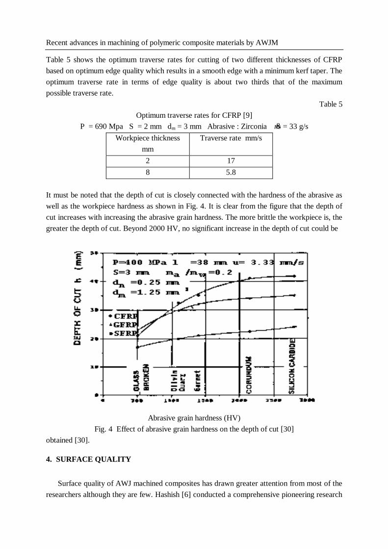
It must be noted that the depth of cut is closely connected with the hardness of the abrasive as
well as the workpiece hardness as shown in Fig. 4. It is clear from the figure that the depth of
cut increases with increasing the abrasive grain hardness. The more brittle the workpiece is, the
greater the depth of cut. Beyond 2000 HV, no significant increase in the depth of cut could be
Abrasive grain hardness (HV)
Fig. 4 Effect of abrasive grain hardness on the depth of cut [30]
obtained [30].
4. SURFACE QUALITY
Surface quality of AWJ machined composites has drawn greater attention from most of the
researchers although they are few. Hashish [6] conducted a comprehensive pioneering research
Ashraf_bht
Typewritten Text
31
Ashraf I. HASSAN, Jan KOSMOL, Jerzy BURSA
work on the surface quality and productivity of some composite materials including fibre
reinforced plastics, such as carbon epoxy and fibre reinforced thermoplastic composites. It was
found that the matrix material is more influential on the surface quality than the reinforcement
material to the contrary of machining using conventional processes. Removal rates were found
to be larger than many of the other machining processes, but the dimensional accuracy was still
low. Table 6 lists the different parameters representing the surface quality which were reported
in different studies.
Table 6
Surface quality of AWJ machined workpieces
Surface
feature
Material Type of analysis Authors
kerf taper Gr/Ep experimental
experimental
Arola & Ramulu [19]
Ramulu & Arola [2]
kerf width Gr/Ep
CFRP
Theor/exp
experimental
Arola & Ramulu [19]
König & Wulf [17]
surface
roughness
Gr/Ep
CFRP
experimental
experimental
Ramulu & Arola [2]
König & Wulf [17]
delamination Gr/Ep theoretical Ho-Cheng [20]
4.1 Kerf width and taper
A preliminary experimental work on WJM of CFRP was conducted by König and Wulf
[17]. It was shown that the stand off distance has a great influence on the interance width of
cut. As the stand off distance increases, the entrance width of cut also increases. On the other
hand, it has little influence on the exit width of cut. Increasing the pressure from 300 MPa to
400 MPa has a slight effect. A similar effect was found by the same authors [15] to apply to a
hybrid laminate of AFRP/GFRP.
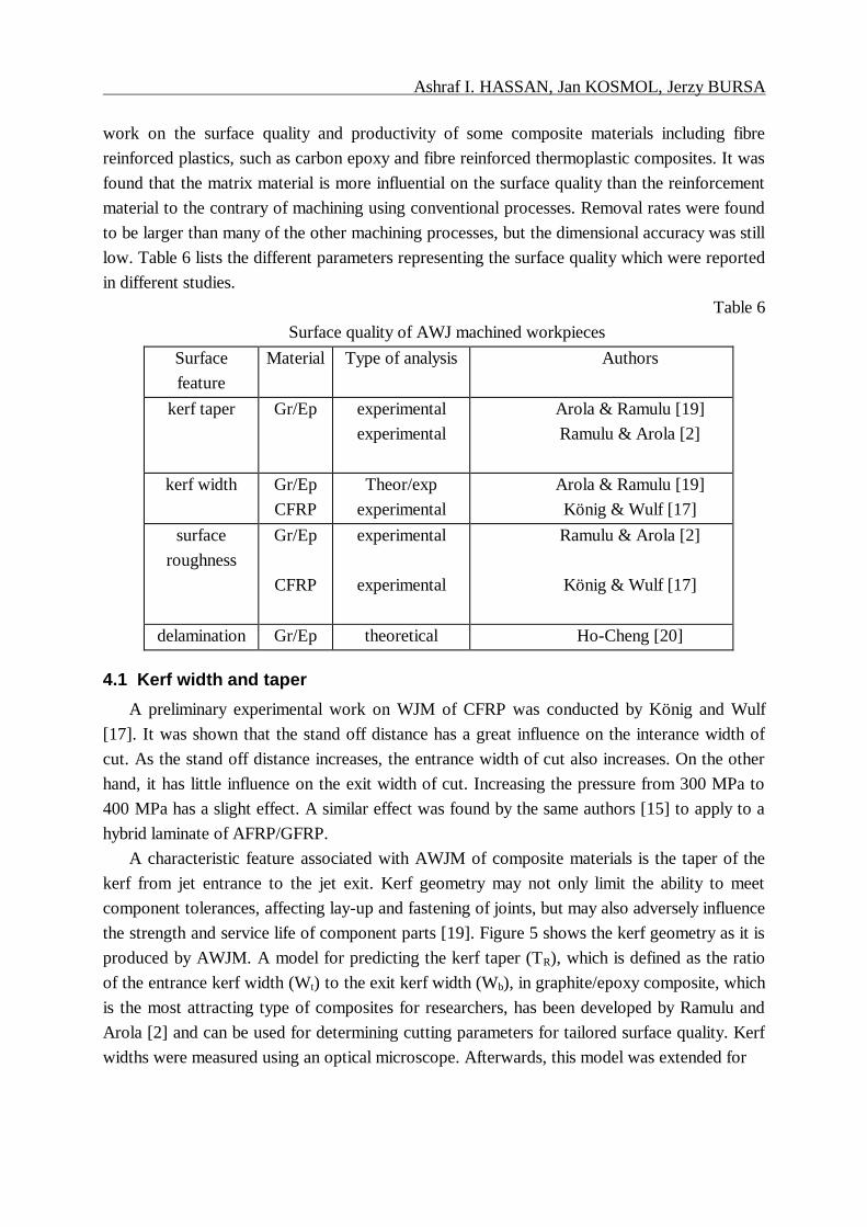
A characteristic feature associated with AWJM of composite materials is the taper of the
kerf from jet entrance to the jet exit. Kerf geometry may not only limit the ability to meet
component tolerances, affecting lay-up and fastening of joints, but may also adversely influence
the strength and service life of component parts [19]. Figure 5 shows the kerf geometry as it is
produced by AWJM. A model for predicting the kerf taper (TR), which is defined as the ratio
of the entrance kerf width (Wt) to the exit kerf width (Wb), in graphite/epoxy composite, which
is the most attracting type of composites for researchers, has been developed by Ramulu and
Arola [2] and can be used for determining cutting parameters for tailored surface quality. Kerf
widths were measured using an optical microscope. Afterwards, this model was extended for
Ashraf_bht
Typewritten Text
Ashraf_bht
Typewritten Text
32
Recent advances in machining of polymeric composite materials by AWJM
Fig. 5 Kerf Geometry schematic [19]
kerf profile prediction and the effect of cutting parameters on kerf characteristics could be
obtained using analysis of variance techniques [19]. The effect of AWJM conditions on the kerf
taper is shown in Fig. 6. Higher pressures significantly reduce the kerf taper over the whole
depth of cut, Fig. 6 (a). It is recommended to use pressures in excess of 250 MPa for
machining of thick laminates. Large abrasives increase the initial damage zone which results in
a wider entrance kerf and in turn, a larger taper ratio, Fig. 6 (b). Increasing the traverse rate
results in a lower kerf taper, Fig. 6 (c), due to the reduction in kerf entrance width due to the
decrease in exposure time. It must be noted that the increase in the traverse rate at lower jet
pressures result in higher kerf taper ratios. It is apparent from Fig. 6 (d) that as the stand off
distance increases beyond 2 mm, the kerf taper begins to decrease due to the reduced effects of
jet expansion. Generally when higher jet pressures are used, the kerf taper increases with an
increase in the stand off distance.
Ashraf_bht
Typewritten Text
Ashraf_bht
Typewritten Text
33

Ashraf I. HASSAN, Jan KOSMOL, Jerzy BURSA
Fig. 6 Effect of AWJM parameters on kerf taper [2]
4.2 Surface texture
The surface texture that may be associated with WJM include: surface waviness, burr
formation, surface finish and lay. König and Wulf [17] found that increasing the pressure from
300 MPa to 400 MPa in WJM of CFRP would improve the surface finish of the machined
surfaces. Yet the values of surface roughness were comparatively high (up to Rt = 100 µm). As
the jet penetrates into the workpiece material, the loss of the WJ velocity causes a decrease in
the surface quality towards the exit side, Fig. 7. The variations of measured roughness values in
FRP are significantly higher than in metals due to the inhomogenious material structure. The
dependency of roughness on the angle between the fibre and feed direction in WJM is less
pronounced than other machining processes. The surface texture machined by AWJM exhibits
two distinct contributions from the process: roughness occurring at the upper portion of the
kerf, due to the micro effects of each impacting particle and waviness or striation, occurring at
the lower portion of the kerf, due to jet penetration and loss of stability as the cutting depth
Ashraf_bht
Typewritten Text
Ashraf_bht
Typewritten Text
34
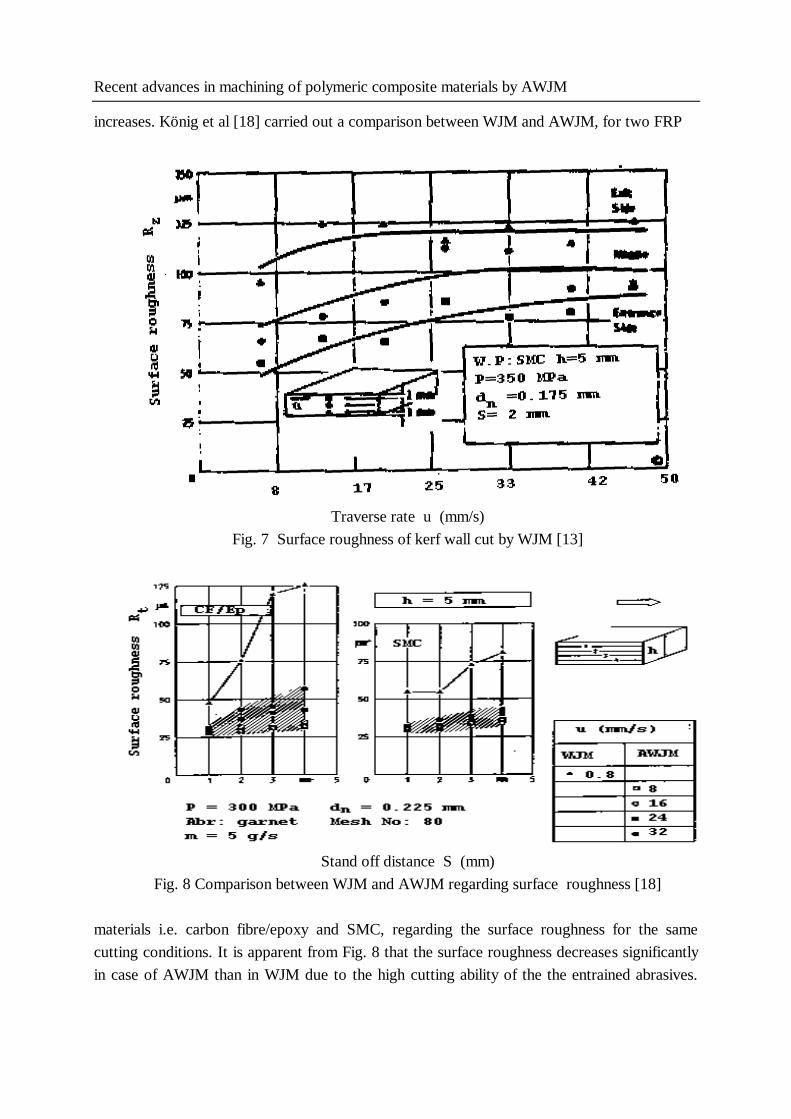
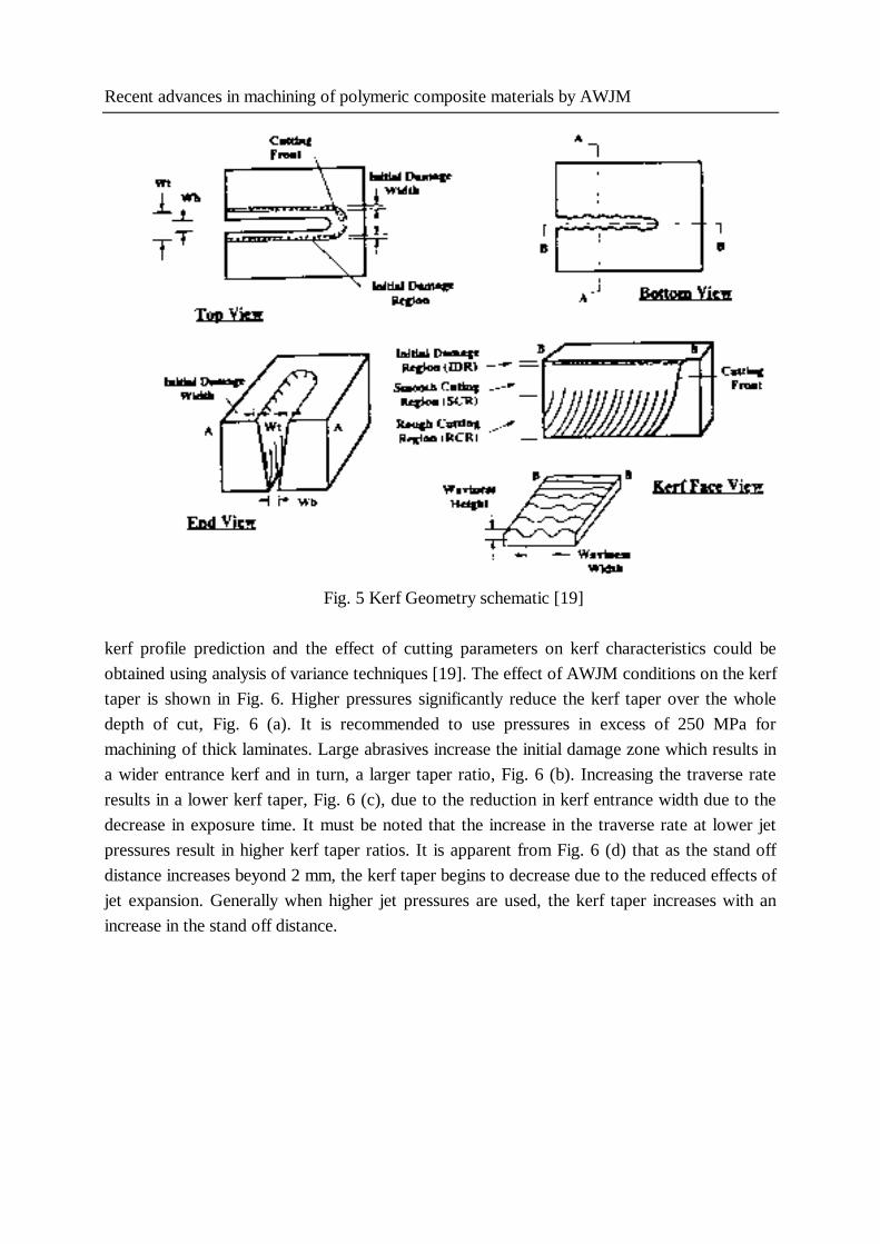
Recent advances in machining of polymeric composite materials by AWJM
increases. König et al [18] carried out a comparison between WJM and AWJM, for two FRP
Traverse rate u (mm/s)
Fig. 7 Surface roughness of kerf wall cut by WJM [13]
Stand off distance S (mm)
Fig. 8 Comparison between WJM and AWJM regarding surface roughness [18]
materials i.e. carbon fibre/epoxy and SMC, regarding the surface roughness for the same
cutting conditions. It is apparent from Fig. 8 that the surface roughness decreases significantly
in case of AWJM than in WJM due to the high cutting ability of the the entrained abrasives.
Ashraf_bht
Typewritten Text
35
Ashraf I. HASSAN, Jan KOSMOL, Jerzy BURSA
Also high traverse rates, 20 times higher than WJM in Fig. 8, could be used and hence, higher
productivity is available.
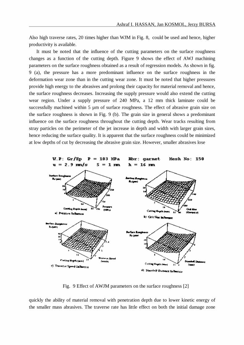
It must be noted that the influence of the cutting parameters on the surface roughness
changes as a function of the cutting depth. Figure 9 shows the effect of AWJ machining
parameters on the surface roughness obtained as a result of regression models. As shown in fig.
9 (a), the pressure has a more predominant influence on the surface roughness in the
deformation wear zone than in the cutting wear zone. It must be noted that higher pressures
provide high energy to the abrasives and prolong their capacity for material removal and hence,
the surface roughness decreases. Increasing the supply pressure would also extend the cutting
wear region. Under a supply pressure of 240 MPa, a 12 mm thick laminate could be
successfully machined within 5 µm of surface roughness. The effect of abrasive grain size on
the surface roughness is shown in Fig. 9 (b). The grain size in general shows a predominant
influence on the surface roughness throughout the cutting depth. Wear tracks resulting from
stray particles on the perimeter of the jet increase in depth and width with larger grain sizes,
hence reducing the surface quality. It is apparent that the surface roughness could be minimized
at low depths of cut by decreasing the abrasive grain size. However, smaller abrasives lose
Fig. 9 Effect of AWJM parameters on the surface roughness [2]
quickly the ability of material removal with penetration depth due to lower kinetic energy of
the smaller mass abrasives. The traverse rate has little effect on both the initial damage zone
Ashraf_bht
Typewritten Text
Ashraf_bht
Typewritten Text
36
Recent advances in machining of polymeric composite materials by AWJM
and the cutting wear zone, Fig. 9 (c). Its effect becomes more prominent in the deformation
wear zone due to the formation of the waviness patterns which is attributed to severe jet
deflection as the traverse rate increases. The effect of stand off distance is more predominant in
the initial damage zone, Fig. 9 (d), due to its effect on the coherency of the jet prior to
impingement on the workpiece surface. Increasing the stand off distance results in increasing
the jet diameter and in turn reduces the energy density of the jet. The minimum surface
roughness appears to occur at a stand off distance of 2 mm.
It was observed that AWJM of FRP produces a striated surface just as the surfaces
produced in ductile metals. This waviness increases with the depth of cut and the largest degree
of waviness in the deformation wear zone is observed in workpieces machined with a
combination of low pressure, small abrasive grain size and high traverse rate [2]. Later, Arola
and Ramulu [19] used regression techniques in developing mathematical models for the initial
damage zone, and for waviness height on the kerf wall within deformation wear zone. Table 7
shows the results of surface waviness for some composites.
Table 7
Surface waviness and corresponding traverse rates for graphite/epoxy composite [6]
P = 370 MPa dn = 0.299 mm dm = 0.762 mm Abrasive: garnet Mesh No : 80
Type of
FRP
W = 1.9
2.5
Waviness
(W) m
3.8
5
6
8
Gr/Ep
t =3.18 mm
u = 4 8 12 20 30
Gr/Ep
t=18.5 mm
u = 0.6 0.85 1.7 2.5 3.4 4.25
4.3 Surface integrity
Delamination is usually observed when machining FRP using AWJM. It only occurs if the
deformation wear mode of erosion exists. The impact of the jet on a step formed at a certain
depth will result in water deflection which, if with sufficient pressure, will laterally penetrate
between layers to cause delamination. This mechanism of delamination occurs if the abrasive
flow rate is interrupted during cutting [31]. Ramulu and Arola [2] found out that fibre pullout
and fibre/matrix delamination are limited due to high interfacial bond strength coupled with the
localized cutting forces associated with AWJ. Nearly all the matrix remains intact in its
supportive position adjacent to the fibres after AWJM. The mechanism of delamination in
WJM was studied in detail by Ho-Cheng [20] using fracture mechanics and the optimum
waterjet pressure for no delamination is now predictable. This pressure could be applied in a
control strategy for maximizing productivity. In waterjet drilling of composite laminates, there
is a thrust jet force acting perpendicularly to the laminate that show flexural bending in
Ashraf_bht
Typewritten Text
Ashraf_bht
Typewritten Text
37
Ashraf I. HASSAN, Jan KOSMOL, Jerzy BURSA
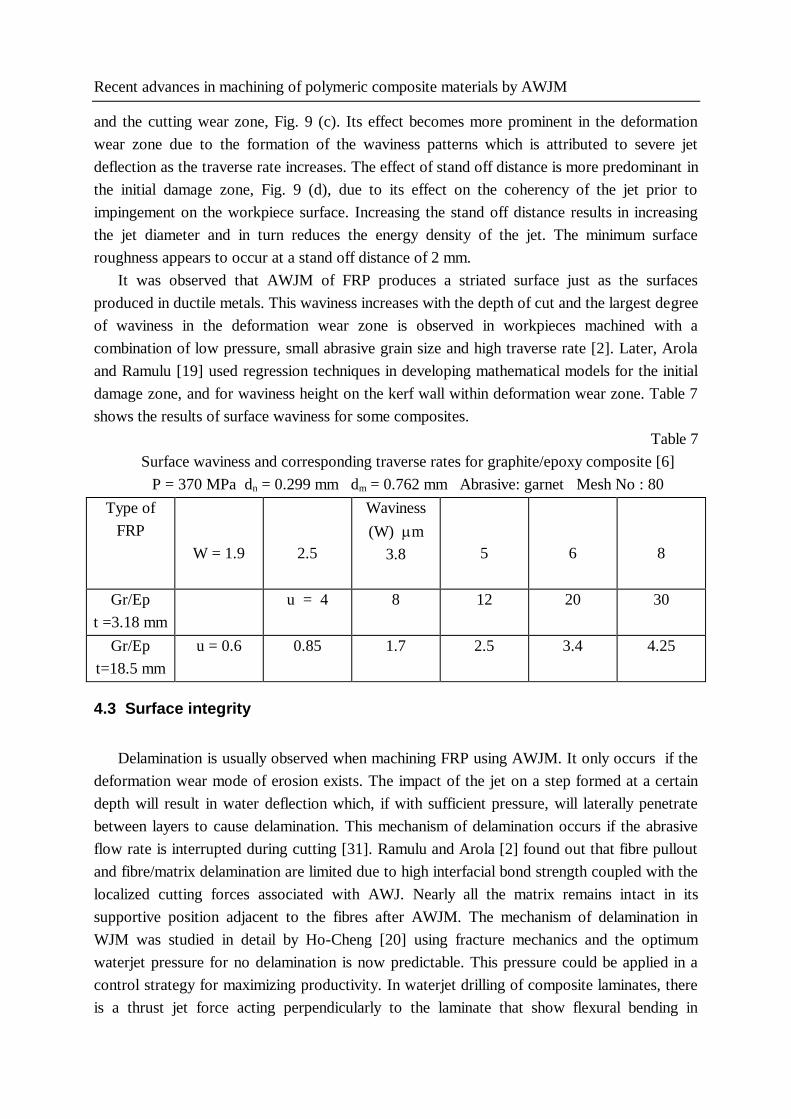
response and the laminate tends to be pushed away. At a certain point the jet force causes such
a deformation that the interlaminar bond strength can no longer hold and delamination around
the exit hole occurs. This happens before the laminate is completely pierced by the waterjet as
shown in Fig. 10. As soon as an interlaminar crack is created, water is pressed into the opening
Fig. 10 Waterjet-induced delamination at exit [24]
causing damage around the hole. Nozzle diameter and pressure affect delamination by changing
the magnitude of the jet force. The waterjet pressure should not exceed a critical value to avoid
delamination. Many idealizations of HoCheng's model are the main reason for significant
inaccuracies of the results. Hashish [6] found that the pressure plays an important role in the
delamination process while drilling Gr/Ep composite using the piercing method. When reducing
pressure from 345 MPa to 240 MPa, hole delamination at the bottom was significantly
reduced. This is not always the proper strategy, but the pressure must be selected so that the
lateral flow does not cause delamination.
5. TYPES OF AWJM PROCESSES
Most of researchers have been working in AWJ slotting [2,19]. This could be performed
either in linear cutting or contour cutting using a robot or a CNC control. A limited number of
attempts were made in an effort to apply AWJ to other types of machining processes. An early
attempt to apply AWJ to milling of FRP was conducted by Hashish [25]. The preliminary
results were encouraging in providing reasonable metal removal rates. But on the other hand,
controlling the depth of cut was a difficult problem and an optimum machining strategy was
needed to maximize metal removal rates and minimize the surface texture effects. Small
diameter holes in the range of 0.5 mm could be drilled [10]. Another attempts [6,20] were
aiming at applying AWJ to drilling. While a limited success was observed for AWJ turning of
metal matrix composites [32,33]. However, no data were reported for its application to FRP.
Table 8 shows the different machining processes used in the AWJM process.
Ashraf_bht
Typewritten Text
Ashraf_bht
Typewritten Text
38
Recent advances in machining of polymeric composite materials by AWJM
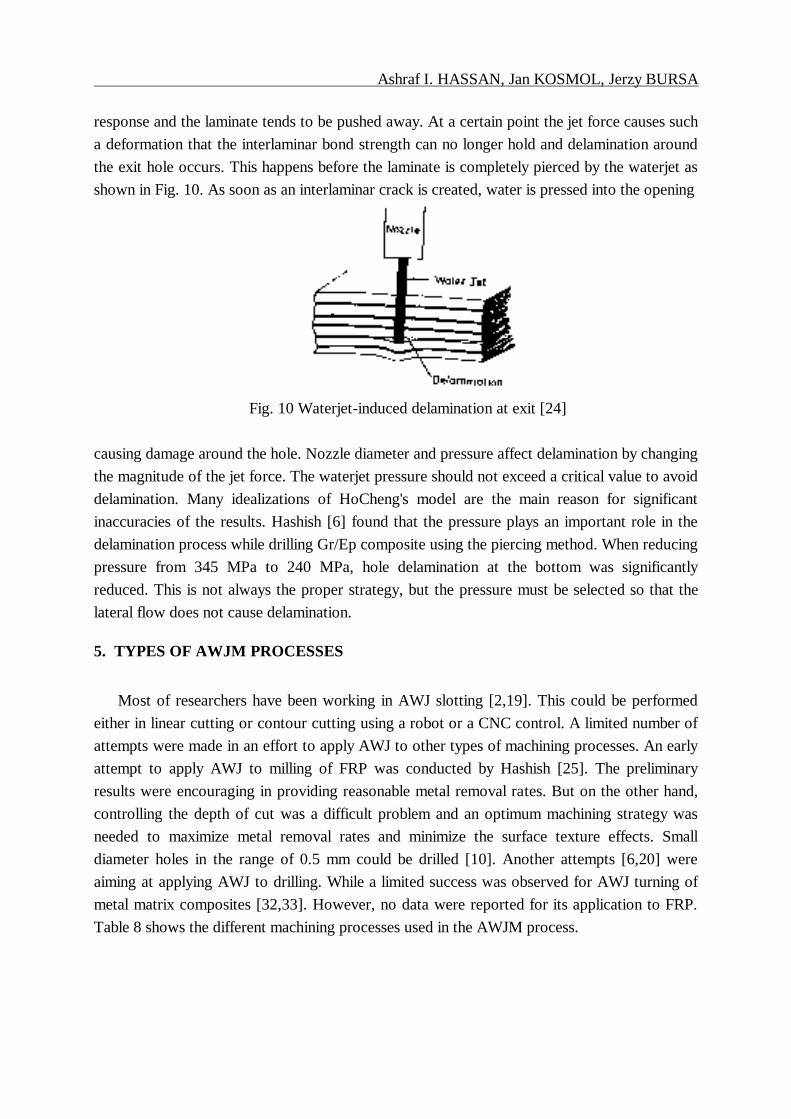
Table 8
Different types of AWJM processes
AWJM process Material Limitations Remarks Authors
Slot cutting Arola & Ramulu
[19]
Ramulu & Arola
[2]
Drilling
Gr/Ep
Gr/Ep
fracture,
cracking or
delamination at
high pressures
(200-400) MPa
burr formation
or chipping at
the bottom of
hole at high
pressures e.g.
350 MPa
AWJ piercing
AWJ piercing
Hocheng [20]
Hashish [6]
Hashish [6]
Milling kerfs had
irregular depths,
delamination
depth of cut
controlled by u,
S and jet angle
Hashish [6]
6. NOZZLE WEAR
A new gradually contracting conical WJ nozzle was designed by König and Wulf [34]. This
new design was found to produce better kerf width and kerf taper than the conventional
cylindrical nozzle while machining of glass/kevlar reinforced epoxy. Also the dynamic cutting
forces were reduced. No data has been reported in the literature about the nozzle wear in case
of AWJM of composite materials. This area needs to be explored if more economical
machining is required.
7. COMPARISON WITH ALTERNATIVE MACHINING PROCESSES
In any comparison with other machining processes, the required post-cutting finishing
operations, often encountered in thermal cutting, are an additional cost item that may not be
needed if AWJM is used [25]. Although it is faster, laser cutting of composite materials does
Ashraf_bht
Typewritten Text
Ashraf_bht
Typewritten Text
39
Ashraf I. HASSAN, Jan KOSMOL, Jerzy BURSA
not prove advantageous. For example, laser cutting of CFRP causes the material to burn as
well as delamination may occur as a result of the difference in thermal conductivity between the
fibre and the resin. GFRP could not also be machined by laser unless very low traverse rates
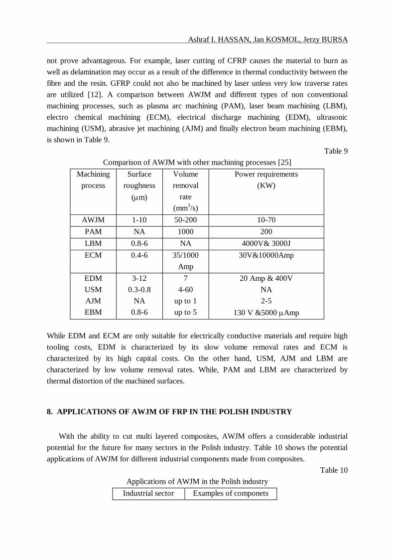
are utilized [12]. A comparison between AWJM and different types of non conventional
machining processes, such as plasma arc machining (PAM), laser beam machining (LBM),
electro chemical machining (ECM), electrical discharge machining (EDM), ultrasonic
machining (USM), abrasive jet machining (AJM) and finally electron beam machining (EBM),
is shown in Table 9.
Table 9
Comparison of AWJM with other machining processes [25]
Machining
process
Surface
roughness
(m)
Volume
removal
rate
(mm3/s)
Power requirements
(KW)
AWJM 1-10 50-200 10-70
PAM NA 1000 200
LBM 0.8-6 NA 4000V& 3000J
ECM 0.4-6 35/1000
Amp
30V&10000Amp
EDM
USM
AJM
EBM
3-12
0.3-0.8
NA
0.8-6
7
4-60
up to 1
up to 5
20 Amp & 400V
NA
2-5
130 V &5000 Amp
While EDM and ECM are only suitable for electrically conductive materials and require high
tooling costs, EDM is characterized by its slow volume removal rates and ECM is
characterized by its high capital costs. On the other hand, USM, AJM and LBM are
characterized by low volume removal rates. While, PAM and LBM are characterized by
thermal distortion of the machined surfaces.
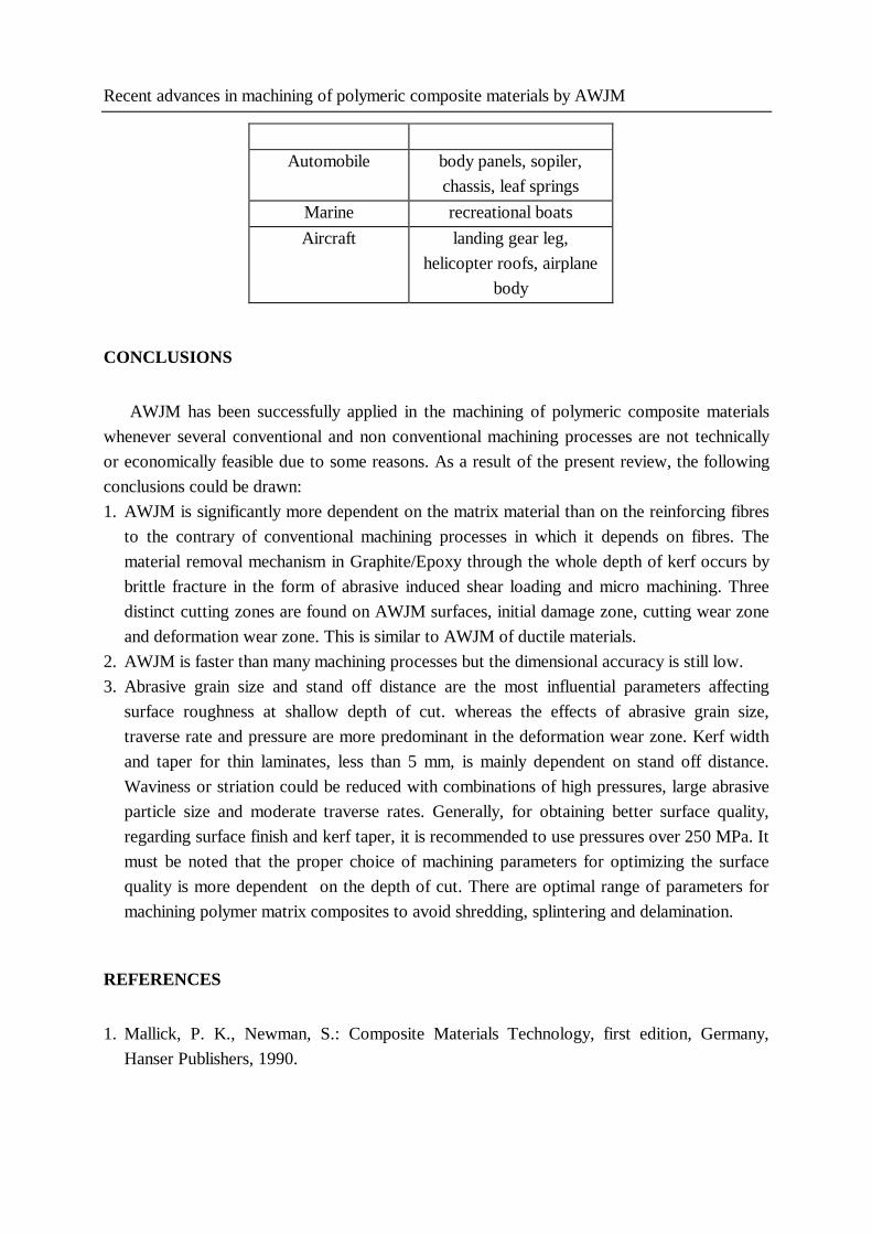
8. APPLICATIONS OF AWJM OF FRP IN THE POLISH INDUSTRY
With the ability to cut multi layered composites, AWJM offers a considerable industrial
potential for the future for many sectors in the Polish industry. Table 10 shows the potential
applications of AWJM for different industrial components made from composites.
Table 10
Applications of AWJM in the Polish industry
Industrial sector Examples of componets
Ashraf_bht
Typewritten Text
Ashraf_bht
Typewritten Text
40
Recent advances in machining of polymeric composite materials by AWJM
Automobile body panels, sopiler,
chassis, leaf springs
Marine recreational boats
Aircraft landing gear leg,
helicopter roofs, airplane
body
CONCLUSIONS
AWJM has been successfully applied in the machining of polymeric composite materials
whenever several conventional and non conventional machining processes are not technically
or economically feasible due to some reasons. As a result of the present review, the following
conclusions could be drawn:
1. AWJM is significantly more dependent on the matrix material than on the reinforcing fibres
to the contrary of conventional machining processes in which it depends on fibres. The
material removal mechanism in Graphite/Epoxy through the whole depth of kerf occurs by
brittle fracture in the form of abrasive induced shear loading and micro machining. Three
distinct cutting zones are found on AWJM surfaces, initial damage zone, cutting wear zone
and deformation wear zone. This is similar to AWJM of ductile materials.
2. AWJM is faster than many machining processes but the dimensional accuracy is still low.
3. Abrasive grain size and stand off distance are the most influential parameters affecting
surface roughness at shallow depth of cut. whereas the effects of abrasive grain size,
traverse rate and pressure are more predominant in the deformation wear zone. Kerf width
and taper for thin laminates, less than 5 mm, is mainly dependent on stand off distance.
Waviness or striation could be reduced with combinations of high pressures, large abrasive
particle size and moderate traverse rates. Generally, for obtaining better surface quality,
regarding surface finish and kerf taper, it is recommended to use pressures over 250 MPa. It
must be noted that the proper choice of machining parameters for optimizing the surface
quality is more dependent on the depth of cut. There are optimal range of parameters for
machining polymer matrix composites to avoid shredding, splintering and delamination.
REFERENCES
1. Mallick, P. K., Newman, S.: Composite Materials Technology, first edition, Germany,
Hanser Publishers, 1990.
Ashraf_bht
Typewritten Text
Ashraf_bht
Typewritten Text
41
Ashraf I. HASSAN, Jan KOSMOL, Jerzy BURSA
2. Ramulu M., Arola D.: The influence of Abrasive Waterjet Cutting Conditions on the
Surface Quality of Graphite/Epoxy Laminates, International Journal of Machine Tools and
Manufacture, No. 3, Vol. 34, 1994, pp. 295.
3. Savrun E., Taya M.: Surface Characterization of SiC Whisker/2124 Aluminum and Al2O3
Composites Machined by Abrasive Waterjet, Journal of Materials Science, Vol. 23, 1988,
pp. 1453.
4. Hamatani G., Ramulu M.: Machinability of High Temperature Composites by Abrasive
Waterjet, Transactions of the ASME, Journal of Engineering Materials and Technology,
Vol. 112, Oct. 1990, pp. 381.
5. Ramulu M., Raju S. P., Inove H., Zeng J.: Hydro-Abrasive Erosion Characteristics of 30
vol % SiC/6061-T6 Al Composite at Shallow Impact Angles, Wear, No. 1, Vol. 166, 1993,
pp. 55.
6. Hashish M.: Machining of Advanced Composites with Abrasive-Waterjets, Winter Annual
Meeting of the American Society of Mechanical Engineers, PED-Vol. 35, MD-Vol. 12,
1988, pp. 1.
7. Kulpa, C.:Hochdruck-Wasserstrahlschneiden von Kuntostoffen: Souveräne Technologie,
Schweitz Maschinenmarkt, No. 6, 1995, pp.12.
8. Henning A., Anders S.: Integration der Wasserstrahltechnik in die Fertigung, VDI-Z, No.
3/4, Vol. 140, 1998, pp. 54.
9. Harris I. D. : Abrasive Waterjet Cutting and Its Applications at TWI (UK), Welding in the
World, No. 4, Vol. 33, 1994, pp. 277.
10.Hashish M.: Cutting with Abrasive Waterjets, Mechanical Engineering, Vol. 106, March
1984, pp. 60.
11.Hassan A. I., Kosmol J.: An Overview of Abrasive Waterjet Machining (AWJM), Prace
Naukowe Katedry Budowy Maszyn, Politechnika Slaska, Gliwice, No. 2, 1997, pp. 181.
12.Hoogstrate A. M., et al : Opportunities in Abrasive Water-Jet Machining, Annals of the
CIRP, No. 2, Vol. 46, 1997, pp. 697.
13.König W., Wulf Ch., Grab P., Wilershied H.: Machining of Fibre Reinforced Plastics,
Annals of the CIRP, No. II, Vol. 34, 1985, pp. 537.
14.Oweinah H.: Hochgeschwindigkeits-Wasserstrahlen (Fluid-Jet-Cutting), Industrie Anzeiger,
No. 35, Vol. 106, 1984, pp. 47.
15.König W., Wulf Ch.: Ein sauberes Trennverfahren für Faserverbundwerkstoffe, Industrie
Anzeiger, No. 56, Vol. 105, 1983, pp. 32.
16.Engemann B. K. : Water Jet Cutting of Fibre Reinforced Composite Materials, Industrial &
Production Engineering, No. 3, 1981, pp. 162.
17.König W., Wulf Ch.: Kolenstoffaserverstärkte Kunststoffe mit Hochdruck Wasserstrahl
bearbeiten, Industrie Anzeiger, No. 49, Vol. 104, 1982, pp. 84.
18.König W., Trasser, Fr.-J., Schmelzer M.: Bearbeitung fasserverstärkter Kunststoffe mit
Wasser und Laserstrahl, VDI-Z, No. 11, Vol. 129, 1987, pp. 6.
Ashraf_bht
Typewritten Text
Ashraf_bht
Typewritten Text
42
Recent advances in machining of polymeric composite materials by AWJM
19.Arola D., Ramulu M.: A study of Kerf Characteristics in Abrasive Waterjet Machining of
Graphite/Epoxy Composite, Transactions of the ASME, Journal of Engineering Materials
and Technology, Vol. 118, Apr 1996, pp. 256.
20.Ho-Cheng H.: A Failure Analysis of Water Jet Drilling in Composite Laminates,
International Journal of Machine Tools and Manufacture, No. 3, Vol. 30, 1990, pp. 423.
21.Pool K.V., Dharan C.K., Finnie I.: Erosive Wear of Composite Materials", Wear, Vol. 107,
1986, pp.1.
22.Zahavi J., Schmitt Jr., G. F.: Solid Particle Erosion of Reinforced Composite Materials,
Wear, Vol 71, 1981, pp. 179.
23.Tilly G.P., Sage W.: The interaction of Particle and Material Behavior in Erosion Processes,
Wear, Vol. 16, 1970, pp.447.
24.Finnie I.: Erosion of Surfaces by Solid Particles, Wear, No. 3, Vol. 3, 1960, pp. 87.
25.Hashish M.: An Investigation of Milling with Abrasive-Waterjets, Transactions of the
ASME, Journal of Engineering for Industry, Vol. 111, May 1989, pp. 158.
26.Hashish M.: A Modeling Study of Metal Cutting with Abrasive Waterjets, Transactions of
the ASME, Journal of Engineering Materials and Technology, No. 1, Vol. 106, 1984, pp.
88.
27.Hashish M.: Visualization of the Abrasive-Waterjet Cutting Process, Experimental
Mechanics, June 1988, pp. 159.
28.Hashish M.: A Model for Abrasive-Waterjet (AWJ) Machining, Transactions of the ASME,
Journal of Engineering Materials and Technology, Vol. 111, Apr 1989, pp. 154.
29.Machinability Data Handbook, Vol II, Third edition, Cincinnatti, USA, Machinability Data
Center, 1980.
30.Faber K., Oweinah H.: Influence of Process Parameters on Blasting Performance with the
Abrasive-Jet, Proceedings of the 10th International Conference on Jet Cutting Technology,
1991, pp. 365.
31.Hashish M. : Characteristics of Surfaces Machined with Abrasive-Waterjets, Transactions
of the ASME, Journal of Engineering Materials and Technology, Vol. 113, July 1991, pp.
355.
32.Ansari A. I., Hashish M.: Effect of Abrasive Waterjet Parameters on Volume Removal
Trends in Turning, Transactions of the ASME, Journal of Engineering for Industry, Vol.
117, Nov 1995, pp. 475.
33.Hashish M.: Turning with Abrasive Waterjets- A First Investigation, Transactions of the
ASME, Journal of Engineering for Industry, Vol. 109, Nov. 1987, pp. 281.
34.König W., Wulf Ch.: Düsen mit stetiger Geometrie: Wasserstrahlschneiden, Industrie
Anzeiger, No. 92, Vol. 106, 1984, pp. 3.
Ashraf_bht
Typewritten Text
Ashraf_bht
Typewritten Text
43