Real-time robot software framework on Raspberry Pi using ...
54
REAL-TIME ROBOT SOFTWARE FRAMEWORK ON RASPBERRY PI USING XENOMAI AND ROS2 A. (Bram) Meijer MSC ASSIGNMENT Committee: dr. ir. J.F. Broenink A. Hofstede dr. ir. G. van Oort dr. ing. K.H. Chen October, 2021 070RaM2021 Robotics and Mechatronics EEMCS University of Twente P.O. Box 217 7500 AE Enschede The Netherlands
-
Upload
khangminh22 -
Category
Documents
-
view
10 -
download
0
Transcript of Real-time robot software framework on Raspberry Pi using ...

REAL-TIME ROBOT SOFTWARE FRAMEWORKON RASPBERRY PI USING XENOMAI AND ROS2
A. (Bram) Meijer
MSC ASSIGNMENT
Committee:dr. ir. J.F. Broenink
A. Hofstededr. ir. G. van Oortdr. ing. K.H. Chen
October, 2021
070RaM2021Robotics and Mechatronics
EEMCSUniversity of Twente
P.O. Box 2177500 AE Enschede
The Netherlands

ii Real-time robot software framework on Raspberry Pi using Xenomai and ROS2
Bram Meijer University of Twente

iii
Summary
This report introduces a real-time framework based on Xenomai to run 20-sim-generated mod-els on a Raspberry Pi 4. The framework can interact with ROS2 to log the outgoing data and toinstruct the framework with setpoints. The software and hardware choices are made based ona design space exploration and analysis of the various options that can fit the set requirements.The chosen software and hardware are the basis for the created framework.
This framework overcomes the problems that were found using the TERRA/LUNA frameworkthat has been made at the University of Twente. The new framework consists of various classes,each producing an easy-to-use interface with the RT functionality of Xenomai. The frameworkconsists of three main classes, which handle the thread, task, and communication. Functionsthat need to be executed inside a real-time task are created as a derived class, after which theyare handed to the thread creator. Communication is done by using a Xenomai protocol thatincludes inter-process communication (IDDP) and inter-kernel communication (XDDP). Thedeveloped framework supports multiple Xenomai-scheduled tasks. ROS2 is integrated into thearchitecture giving the user a possibility to interact with a running RT task from a non-real-timeinteractive environment. Two ROS2 nodes are created that can handle incoming and outgoingdata.
The viability of the framework is measured using multiple 20-sim-generated tasks implemen-ted on the Raspberry Pi. Various tests are run to analyze the performance of the created frame-work, including core affinity and isolation, stress testing, and comparisons to actual 20-simsimulation data. The output of the framework is visually identical to the output of a 20-simsimulation. The jitter was measured using a Xenomai clock command due to the lack of per-formance of the secondary Raspberry Pi logic analyzer. The optimal performance of the frame-work is achieved in an isolated, non-shared setup, as predicted. When two 20-sim generatedmodels containing a plant and controller of a two-degrees of freedom gimbal are used in theframework, the timing results show no deadline misses (> 30µs).
Test results indicate that the framework’s performance meets the set requirements and caneffectively provide the user with a stable RT framework that can be used in educational coursesor research setups.
Subsequent steps are to integrate physical plant control using an external PWM generator thatis communicated via SPI. Afterwards, the framework can be field-tested to see if all function-ality is understandable and useable. This will probably result in small code adjustments andnewly required functionality.
Robotics and Mechatronics Bram Meijer

iv Real-time robot software framework on Raspberry Pi using Xenomai and ROS2
Contents
Summary iii
1 Introduction 1
1.1 Context . . . . . . . . . . . . . . . . . . . . . . . . . . . . . . . . . . . . . . . . . . . . 1
1.2 Goal . . . . . . . . . . . . . . . . . . . . . . . . . . . . . . . . . . . . . . . . . . . . . . 1
1.3 Report structure . . . . . . . . . . . . . . . . . . . . . . . . . . . . . . . . . . . . . . . 2
2 Background 3
2.1 Introduction . . . . . . . . . . . . . . . . . . . . . . . . . . . . . . . . . . . . . . . . . 3
2.2 Basic concepts of real-time systems . . . . . . . . . . . . . . . . . . . . . . . . . . . 3
2.3 Real-time operating systems . . . . . . . . . . . . . . . . . . . . . . . . . . . . . . . 5
2.4 ROS2 . . . . . . . . . . . . . . . . . . . . . . . . . . . . . . . . . . . . . . . . . . . . . 8
2.5 Modelling software . . . . . . . . . . . . . . . . . . . . . . . . . . . . . . . . . . . . . 8
3 Analysis 10
3.1 Introduction . . . . . . . . . . . . . . . . . . . . . . . . . . . . . . . . . . . . . . . . . 10
3.2 Requirements . . . . . . . . . . . . . . . . . . . . . . . . . . . . . . . . . . . . . . . . 10
3.3 Hardware . . . . . . . . . . . . . . . . . . . . . . . . . . . . . . . . . . . . . . . . . . . 12
3.4 Software . . . . . . . . . . . . . . . . . . . . . . . . . . . . . . . . . . . . . . . . . . . 14
3.5 Conclusion . . . . . . . . . . . . . . . . . . . . . . . . . . . . . . . . . . . . . . . . . . 15
4 Design 17
4.1 General design . . . . . . . . . . . . . . . . . . . . . . . . . . . . . . . . . . . . . . . . 17
4.2 Real-time design . . . . . . . . . . . . . . . . . . . . . . . . . . . . . . . . . . . . . . 18
4.3 Non-real-time design . . . . . . . . . . . . . . . . . . . . . . . . . . . . . . . . . . . . 26
5 Testing method 28
5.1 Introduction . . . . . . . . . . . . . . . . . . . . . . . . . . . . . . . . . . . . . . . . . 28
5.2 Test setup . . . . . . . . . . . . . . . . . . . . . . . . . . . . . . . . . . . . . . . . . . 28
5.3 Test method . . . . . . . . . . . . . . . . . . . . . . . . . . . . . . . . . . . . . . . . . 29
6 Results 31
6.1 Measurement accuracy . . . . . . . . . . . . . . . . . . . . . . . . . . . . . . . . . . 31
6.2 Functionality . . . . . . . . . . . . . . . . . . . . . . . . . . . . . . . . . . . . . . . . 32
6.3 Performance . . . . . . . . . . . . . . . . . . . . . . . . . . . . . . . . . . . . . . . . . 32
6.4 Discussion . . . . . . . . . . . . . . . . . . . . . . . . . . . . . . . . . . . . . . . . . . 34
7 Conclusion 36
7.1 Conlusion . . . . . . . . . . . . . . . . . . . . . . . . . . . . . . . . . . . . . . . . . . 36
Bram Meijer University of Twente

CONTENTS v
7.2 Future work . . . . . . . . . . . . . . . . . . . . . . . . . . . . . . . . . . . . . . . . . 36
A Xenomai installation 37
A.1 Xenomai installation . . . . . . . . . . . . . . . . . . . . . . . . . . . . . . . . . . . . 37
A.2 Directory initialization . . . . . . . . . . . . . . . . . . . . . . . . . . . . . . . . . . . 37
A.3 Patching linux with xenomai . . . . . . . . . . . . . . . . . . . . . . . . . . . . . . . 38
A.4 Building linux . . . . . . . . . . . . . . . . . . . . . . . . . . . . . . . . . . . . . . . . 38
A.5 Installing the linux kernel on the Micro-SD card . . . . . . . . . . . . . . . . . . . . 39
A.6 Installing the xenomai libraries on the Raspberry pi . . . . . . . . . . . . . . . . . . 40
B ROS2 installation 41
C xenoThread class 43
Bibliography 47
Robotics and Mechatronics Bram Meijer

vi Real-time robot software framework on Raspberry Pi using Xenomai and ROS2
Bram Meijer University of Twente

1
1 Introduction
1.1 Context
Robots are quickly becoming a natural occurrence in manufacturing workplaces. From 66 ro-bots on every 10.000 employees in 2015, the distribution has risen to 74 for every 10.000 em-ployees (International Federation of Robotics (IFR), 2019).
Robots are controlled repeatedly to ensure that their movement decisions are made with cur-rent knowledge of their surroundings and up-to-date input data. The sensors on the robotregister the current state of the robot, which is used in a real-time controller. This controllercomputes the subsequent motor movement using the current motor position and its desiredposition. To ensure that all these steps are processed within a set period, real-time software isused to ensure that this requirement is met.
Robot Operating System (ROS) (Open Robotics, 2021) is often used as a sequence controller,laying out the connection between multiple parts of a robot. The sequence controller givesinput data to the real-time controller to put the various parts of a robot in their desired position.Furthermore, ROS based programs are used to provide the user with a possibility to manuallyinput data and for its connectivity using various communication protocols. ROS is a free andopen-source framework. ROS is predominantly known for its modular communication andwidely supported packages. The current iteration, ROS2, is a successor to the first ROS release.It is redesigned to improve internal communication and start to support embedded hardware.ROS2 also focuses on making the framework real-time friendly.
The Robotics and Mechatronics group (RaM) of the University of Twente uses ROS in researchtest setups and educational courses. As for the real-time controller, the university has de-veloped the Twente Embedded Real-time Robot Application(TERRA) to design real-time sys-tems for the same purposes. LUNA is a library that is used to formally describe the softwarearchitectures based on CSP (Communicating Sequential Processes). LUNA is introduced in thework of Bezemer et al. (2011). Subsequently, Hofstede (2020) and van der Werff (2016) workedon creating a bridge between LUNA and ROS to promote quick development and rapid proto-typing.
The LUNA/TERRA framework, in conjunction with the ROS bridge, integrates the real-timeplanning and execution of LUNA and the structure and packages of ROS. However, due to thestructuring of the framework, some principal features are impossible, such as multi-threadingat the LUNA side. Moreover, TERRA/LUNA shields the real-time programming from the user,aiming to simplify the user experience. However, when using it for educational purposes, thisis unwanted. Moreover, the interface of LUNA/TERRA is built to be convenient but becomescluttered and difficult to use when creating larger projects.
Since ROS2 is still used within university courses and as base for research setups, a replacementfor LUNA/TERRA must be found. The main issues herein lie that the replacement frameworkneeds to be easy in use and its target device easy to obtain.
1.2 Goal
The aim of this thesis is to develop a framework that integrates real-time tasks and ROS2 tocontrol physical robots. The functionality of these tasks is defined in code written by the user orby using code generation of a modelling tool. This framework can be used for easy deploymentof tasks in a real-time environment and testing robot setups. The framework could be usedwithin the University of Twente as an educational tool within the course Real-Time SoftwareDevelopment or when programming research setups.
Robotics and Mechatronics Bram Meijer

2 Real-time robot software framework on Raspberry Pi using Xenomai and ROS2
Due to the restricted amount of time that can be spent on this thesis, the focus lies in creat-ing the real-time environment within the selected hardware. IO interfacing and controlling aphysical robot are out of scope of this thesis.
The framework must be able to run real-time threads which can communicate with each other.These threads are able to simulate plants and controllers or execute user-made functions. ROS2provides inputs for these real-time threads and can also log the results. Therefore, a connectionbetween the real-time environment of the thread and the non-real-time environment of ROS2must be made.
The main goals of this thesis are formulated as follows:
• Design space exploration to find the best hardware and software alternative for buildingthe framework on top of.
• Creation of a framework to run tasks in real-time that can communicate to non-real-timeROS2 nodes.
• Testing and validating the created framework.
1.3 Report structure
Chapter 2 focusses on the background of real-time, the Robot Operating System, and modellingtools. Chapter 3 applies this knowledge in deciding which software and hardware solutionsare used best. Chapter 4 describes the framework and the design decisions. Subsequently,the method for testing the framework is described in Chapter 5. The results of these tests areshown and discussed in Chapter 6. Finally, the outcome of the thesis is concluded in Chapter 7together with some recommendations.
Bram Meijer University of Twente

3
2 Background
2.1 Introduction
This chapter introduces the necessary background information for understanding the follow-ing chapters of this thesis. It covers real-time as definition and when used in a system. Further-more, ROS2 is covered, including its organization, communication, and functionality. Finally,modelling tools are treated shortly to provide context for later used generated code.
2.2 Basic concepts of real-time systems
The definition of real-time is given in many articles. The most general description from Kopetz(1997) is:
"A real-time computer system is a computer system where the correctness of the sys-tem behaviour depends not only on the logical results of the computations, but alsoon the physical time when these results are produced."
However, this definition does not include deadlines or timing requirements. The definitions inBruyninckx (2002) are more detailed and highlight the two most important aspects in real-timeengineering:
"A real-time operating system is able to execute all of its tasks without violating spe-cified timing constraints."
This definition touches upon the set requirements for real-time tasks in the form of deadlines.However, this does not include the ability of the program to be predetermined. These determin-istic processes are the backbone of any real-time system since their runtime can be calculatedto a full extent. Another definition of real-time from Bruyninckx (2002) includes deterministicbehaviour:
"Times at which tasks will execute can be predicted deterministically on the basis ofknowledge about the system’s hardware and software."
The deterministic requirement is helpful when calculating if a program’s longest execution timeis sufficient such that it does not violate its timing constraints.
Concluding, a real-time task is a task that has to be finished before the deadline and can only doso consistently when the used software and hardware are able to perform the task in a determ-inistic environment. No undefined interruptions should happen within the task’s executionwindow.
2.2.1 Periodic real-time tasks
A periodic real-time task is a repeated real-time task. It executes at regular intervals, called peri-ods. A periodic real-time task has multiple properties which define its functionality (Buttazzo,2011). These properties are:
• Release time (ai ) The time at which the process becomes available to execute.• Start time (si ) The time that the process starts to execute.• Finish time ( fi ) The time that the process is finished executing. ( fwc,i ) represents the
worst case finish time.• Period (p) The time span that is available to execute the process.
Robotics and Mechatronics Bram Meijer

4 Real-time robot software framework on Raspberry Pi using Xenomai and ROS2
• Relative deadline (di ) The point in time, relative to the beginning of the execution, atwhich the process must be finished executing.
• The worst-case execution time (W C ET ) The maximum time that the process takes toexecute completely.
Figure 2.1: Periodic real-time task. Adapted from Buttazzo (2011)
Figure 2.1 visualizes a periodic real-time tasks with parameters. In real-time systems, the WCETmust be less than the deadline minus the release time, such that the finish time can never bebehind the deadline. The deadline of a process is not necessarily the end of the period. Aftermeeting the deadline, the task awaits its next release time.
2.2.2 Classification of real-time tasks
There are three different classifications for real-time tasks. These all serve different situationsin which real-time systems are necessary.
The result of a real-time task is of great importance when controlling robotics. When a taskmisses its deadline, the usefulness of this result changes. This usefulness or utility can be shownin a graph, which changes after a deadline miss. All different real-time classifications are listedbelow, shown with their appropriate utility function in Figure 2.2.
Figure 2.2: Utilities of the result of a real-time task. Image from Boode (2018).
1. Hard real-timeAviation computers, precise robotics, and power-plant applications all have in commonthat they must be controlled very precisely. If this is not achieved, the results are cata-strophic. Applications such as these require the use of ‘hard’ real time. In the case ofhard real-time, there is absolutely no flexibility. A missed deadline could cause a big dis-aster, which is why these systems are designed to be deterministic. Hard real-time taskutility drops to minus infinity when a deadline is missed, shown in Figure 2.2a.
2. Firm real-timeSystems where calculations are done in high frequency and are not a safety hazard often
Bram Meijer University of Twente

CHAPTER 2. BACKGROUND 5
allow a number of deadline misses. Multiple missed deadlines within a certain periodof time could increase the likeliness of a critical failure. These tasks are considered firmreal-time. Within a firm real-time system, a task may miss k deadlines within a period tbefore the utility drops to −∞. The utility function of a firm real-time system is shown inFigure 2.2b.
3. Soft real-timeSoft real-time is the most flexible system of all real-time systems, where the result of amissed deadline can still be used. Nevertheless, it can most often only be used up toa certain point in time. Soft real-time systems are most used in streaming services orinternet services. The utility function of a soft real-time system is shown in Figure 2.2c.
2.2.3 Jitter
Jitter is the deviation from the true execution time of a task. When a task deviates excessivelyfrom its usual finish time, the deadline that is set could be missed.
In most real-time systems, there is some room for jitter. This room is present to catch unpre-dictable events, if they may happen. Jitter is an important characteristic of real-time computerssince it defines how a system behaves when under load. The maximum measured jitter of a sys-tem can be used to check if that system is safe for its application.
Jitter is mainly caused by asynchronous events in the operating system. For example, an inter-rupt issued by the system could suspend a task and therefore delay it.
There are multiple sources of jitter. First of all, there is the distinction between deterministicand random jitter. Deterministic jitter is a bounded jitter, with the maximum and minimumextent are defined. Random jitter is not bounded and is Gaussian in nature (Bruyninckx, 2002).
Next to jitter causes, there are also distinct jitter variants (SiTime, 2021).
• Period jitter is defined as the deviation of the cycle time in comparison to the idealperiod. This can be measured by measuring a large number of periods and comparingthem to their ideal period.
• Cycle-to-cycle jitter is the inequality between the period of two adjacent cycles. Thiscan be measured by measuring the period of two adjacent cycles and computing thedifference.
• Long-term jitter, also called accumulated jitter, is the drift of the period time when meas-uring it over a long period of time. Measuring long-term jitter is done by measuring thestart and finish of a 10.000 cycle period. Then it is compared to the ideal period of 10.000cycles.
Within robotics the cycle-to-cycle jitter is the most commonly used type of jitter.
2.3 Real-time operating systems
Real-time systems are hard to manage, especially when there are multiple tasks that need to runsimultaneously. Simple functionality can easily be designed on bare-metal (running a programdirectly on the chip, without an operating system), without additional tasks that can interruptor preempt it. However, when multiple tasks are needed, scheduling is required. Schedulingis done by a kernel, which handles low-level tasks for the operating system (OS). The kernelschedules the different tasks that need to be run according to their set priority. A real-timeoperating system (RTOS) is an OS that is specialized in running one or multiple real-time tasks.These tasks have the requirement not to be interrupted at the wrong time. In addition, anRTOS has to handle real-time organizational items. The most important jobs of an RTOS are:(Buttazzo, 2011)
Robotics and Mechatronics Bram Meijer

6 Real-time robot software framework on Raspberry Pi using Xenomai and ROS2
• Task management and scheduling• Interrupt handling• Inter-process communication and synchronization• Memory management
A real-time operating system is no different from a general operating system. They focus ondifferent key aspects of operating systems. Whereas a general OS has a higher throughput, areal-time operating system compromises that and focuses on better responsiveness. The mostimportant part of an RTOS is to offer low response time and provide a deterministic latency.
2.3.1 RTOS architecture
Real-time kernels can be put into two categories. An RT kernel can be deployed as a standalonekernel, going by the name of a monolithic kernel. This kernel has all the OS services runningon the same mode as the low-level processes. For instance, the scheduler and the interrupthandler. On the other hand, a micro-kernel separates these low-level tasks from the regular OStasks. A monolithic kernel is easier to optimize since all the tasks are within one scheduler. Amicro-kernel creates a distinction between an OS-task and an RT-task, which allows for betterperformance and determinism. Moreover, when an OS-Task blocks, the RT-tasks are not auto-matically blocked since they are not handled by the same scheduler. A schematic of these twolayouts can be seen in Figure 2.3.
Figure 2.3: Different kernel architectures. (a) is a micro-kernel layout and (b) is a monolithic layout.Image from Johansson (2018).
When working with multiple kernels, various problems can arise. For instance, the resourcesthat are available by the hardware must be shared when working with a micro-kernel layout.This is where a Hardware Abstraction Layer (HAL) comes into play. A HAL is a layer between thehardware and the kernels and can distribute hardware resources to both kernels (Huang andWu, 2018). A typically used HAL for the Linux operating system is Adeos. Adeos is a resourcevirtualization layer that can be patched over Linux. Adeos got refactored into I-pipe, which is apipeline that only contains the core functionality. This makes the patch easier to interpret anduse (Gerum, 2005).
2.3.2 Linux and the PREEMPT_RT patch
Regular operating systems such as Linux cannot meet real-time requirements. The main causeherein lies in that high-priority tasks can still be interrupted by the OS. In 2005 the Linux found-ation started researching a more deterministic kernel. In 2016 this work was continued inthe Real-time Linux collaborative project, which worked on the implementation of a real-timepatch for Linux. This patch is called PREEMPT_RT. With the PREEMPT_RT patch, the OS tasksbecome preemptable, which turns Linux into a real-time operating system (Reghenzani et al.,2019).
Bram Meijer University of Twente

CHAPTER 2. BACKGROUND 7
Linux with the PREEMPT_RT patch contains a monolithic kernel, just as the regular Linux oper-ating system. This makes the implementation of real-time tasks similar to creating user-spacetasks. Nevertheless, some scheduler and priority settings need to be made. PREEMPT_RT en-ables developers to reuse existing Linux libraries and tools. Despite that PREEMPT_RT wasdeveloped with hard real-time tasks in mind, it can only be considered 95% hard real-time(Reghenzani et al., 2019). This is due to the fact that it remains a monolithic kernel and has torun regular Linux tasks in the same scheduler as the real-time tasks. PREEMPT_RT can be con-sidered a firm real-time operating system where deadline misses are allowed up to a probabilityof 5%.
2.3.3 Xenomai
Xenomai is a micro-kernel RTOS developed for Linux (Gerum, 2001). Recently, it also startedsupporting a single kernel approach, called the Mercury kernel. The main project, called thecobalt kernel, runs on top of the HAL I-Pipe. Xenomai runs, in cobalt-core setup, as a micro-kernel with a higher priority than Linux. Hence Xenomai can decide when Linux processes getto execute. This way, Xenomai can put priority on its tasks and therefore assure their in-timeexecution. Interrupts are first caught by I-Pipe. I-Pipe decides which interrupt goes where anddistributes it correctly, again with Xenomai having a higher priority.
Xenomai reimplements numerous Linux functions, overwriting their original purpose withreal-time behaviour. This overwriting of previous functions is called a skin. In this manner,Xenomai can be used with functions from the Posix definitions or other RTOS such as VxWorksand RTAI. Next to these, the native skin contains all real-time functionality in a proprietary in-struction set (Kuppens, 2015). A schematic of Xenomai next to Linux is shown in Figure 2.4.
Figure 2.4: Architecture of the Xenomai cobalt kernel. Image from Johansson (2018).
As described above, the Xenomai kernel runs next to Linux. This way, Xenomai can decidewhen to schedule Linux. When a Xenomai real-time task wants to make a system call, a modeswitch happens. This will put the Xenomai kernel out of control temporarily while the systemcall is being performed. System calls cause the program to be vulnerable to variation in execu-tion, making them non-deterministic.
Robotics and Mechatronics Bram Meijer

8 Real-time robot software framework on Raspberry Pi using Xenomai and ROS2
2.4 ROS2
The Robot Operating System (ROS) is a free and open-source software framework for develop-ing robot applications. When using ROS, rapid application building can be expected withoutrestrictions in complexity. One of the key strengths of ROS is the collaboration with other users.There are hundreds of software packages that are actively maintained. These can range fromimage recognition libraries to communication protocols. Hence, ROS has become one of thestandards for research and development in the robotics field. The first iteration of ROS, ROS1,was developed with a single robot in mind. Consequently, the communication system in ROS1was build with a single master node in mind. This was done since every node was on the samesystem. ROS2 addresses the shortcomings of ROS1 by developing it with a broader use case setin mind. ROS2 is being developed to maximize its flexibility and modularity.
2.4.1 Organization
As described above, one of the major shortcomings of ROS1 is that it uses one central node.ROS2 fixed this by applying the use of a Data Distribution Service (DDS). The DDS takes careof all the communication needs between processes. DDS uses a Real-Time Publish-Subscribe(RTPS) protocol. As described in Gutiérrez et al. (2018), this protocol is suitable for soft andpossibly firm real-time messaging. This real-time behaviour is only present in one paid versionof DDS, the ConnextDDS (rti, 2021). Since this is a paid version of DDS, the online communityis smaller and most questions have to be asked via official help channels at the manufacturer.All ROS2 user-code and the DDS are separated by an API layer. This removes the need for coderefactoring after an update to the DDS.
ROS2 encourages the user to separate all tasks into different services. These services can thenbe called via callbacks such as incoming messages or timers. The services are structured intonodes. ROS2 combines this with the above-mentioned publish-subscribe system. This enablesall nodes to publish messages to topics to which other nodes can subscribe. The subscribednodes will then receive the data that is published to said topic. An example of this describedstructure of topics and nodes can be seen in Figure 2.5.
Figure 2.5: ROS publish-subscribe mechanism. Image from Randolph (2021).
Although ROS2 defines the structure of nodes and communication, it does not define how andwhen nodes react to messages and how many nodes are reacting. Moreover, it runs on topof Linux, which also adds additional jitter. All summed up makes ROS2 a potential candidatefor real-time use in the future. At the moment it is less suitable since the performance is notsufficient.
2.5 Modelling software
Modelling software is used to build representative models for real-life plants and their appro-priate controllers. Real-life behaviour can be modelled into modelling software using graphicalobjects or programming languages. There are many different modelling suites. Research withinthe University of Twente RaM group is mainly done using 20-sim, which is made by ControllabProducts situated on the University campus (Controllab Products, 2021).
Bram Meijer University of Twente

CHAPTER 2. BACKGROUND 9
20-Sim excels at modelling and simulation in which users can create models graphically. Withthese models, one can simulate and analyze their behaviour and create control systems to con-trol these or their accompanying real-life plant.
These models can be converted to code, enabling the user to use this code in their robot. Codegeneration is used in Chapter 4: Design and treated more specifically in Section 4.2.4.
Robotics and Mechatronics Bram Meijer

10 Real-time robot software framework on Raspberry Pi using Xenomai and ROS2
3 Analysis
3.1 Introduction
The goal of this thesis is to create an easy-to-use framework that can be run on widely availablehardware. The main functional requirements of this framework are that it must be able to runreal-time tasks and integrate these with ROS2. Further requirements of the framework and itstesting setup are described in this chapter. Because of a distinct separation in software andhardware requirements, the latter part of this chapter is divided into hardware and software.
The software part includes the options and choices that were made regarding operating system,communication protocol, and general integration. The hardware sections describe varioushardware alternatives and their functionality. Furthermore, the system needs to be analyzedafter construction, for which a test setup will be used. The test setup allows the framework tobe tested if the requirements are met. The requirements to which the test setup must adhereare given in Section 3.2.2.
3.2 Requirements
3.2.1 Use cases
Education and research are the two use cases of the proposed framework. Educational usewill be such that students can use real-time systems without having to write the complete taskstructure and communication structure. On the other hand, they should still be able to grasp itcompletely and must be able to take a look under the hood to see what is going on.
Regarding research, the framework must offer easy implementation since there is no learningaspect in this case. Rapid prototyping is in high demand in a research environment, mainly forcreating research setups quickly. A framework that could easily execute and deploy a createdmodel would be very useful.
3.2.2 Functional requirements
1. Architectural requirements
(a) The design must support firm real-time.The main goal of the design is to implement a user-friendly way to combine real-time and non-real-time tasks. The system is used to control robots which, do notrequire an absolute 100% timing guarantee. Therefore, a reasonable requirementwould be that the system must support firm real-time instead of hard real-timearchitecture. The maximum jitter should be no more than 3% of the set period.Moreover, the design may miss 0.01% of its deadlines.
(b) The design must be able to interface with ROS2.ROS1 is an often-used tool within the RaM group. Since ROS2 is a successor toROS1 and includes new functionality, this is a better alternative. ROS2 is becomingindustry-standard, which makes it valuable knowledge for upcoming graduates.
(c) Externally generated controller code must be supported.Pre-generated controller code must be supported to create a rapid-prototypingframework. Both 20-sim and Simulink are used within the university to create con-trollers using objects. The system must support 20-sim to enable rapid prototypingsince 20-sim is the most used within the RaM group. Simulink, another frequentlyused modelling tool, could also be supported.
(d) The architecture must implement a multicore or multi-device layout.An increasing amount of hardware contains a processor which consists of multiple
Bram Meijer University of Twente

CHAPTER 3. ANALYSIS 11
cores. Only using one is a waste of resources, which would be a shame in com-plex systems. To account for this change in hardware architecture and to sustainthe need for large processing power, multi-core must be supported. Besides, thepossibility to separate real-time and non-real-time tasks is useful.
(e) The system should be able to support multiple real-time controller loops.Many modern controller setups include multiple running control loops. The archi-tecture should try to support this by allowing multiple threads inside the real-timepart. When the framework is not able to include this functionality, the possibilityfor extension must be available.
(f) The system should implement an error handler and tracer.When working with multiple programs and priorities, it is beneficial to have a gooderror handler. An error handler improves the speed of bug fixing since the systemcan point towards code that has possible bugs. Without this, the user must guess inwhich part the bug is located, which would slow down debugging.
2. Communication requirements
(a) The communication within the real-time part of the controller must be real-timecapable.Because of the requirement that the system must support firm-real-time, the com-munication protocol must also support firm-real-time.
(b) The communication between the non-real-time part and the real-time part of thedesign must not interrupt the real-time task.Since the system will support non-real-time task input, connecting communicationmust be established. This communication must be designed such that it does notinterrupt the real-time task.
3. Hardware requirements
(a) The hardware used by the system must be widely available.To ensure that research and educational staff can use the framework, the hardwareon which it is built must be widely available. Furthermore, the hardware must below in price since all students should be able to buy a device. Widely available hard-ware also ensures that there is a widespread online community for it.
(b) The chosen hardware must support multi-core or multi-device.One of the main architecture requirements is that the framework must supportmulti-core. When choosing a hardware piece, this requirement should be taken intoconsideration. The chosen hardware can either be a multi-core device or multipledevices with one or more cores.
(c) The hardware must have sufficient I/O (inputs and outputs) to drive a robot control-ler.Because the framework is being developed to be used with robots, the hardwaremust also support this. This means that there must be sufficient I/O pins on thedevice. These outputs must also support SPI/I2C to communicate to a motor con-troller board or FPGA if needed.
4. Test setup requirements
(a) The test setup must test the real-time capabilities.The real-time performance of the framework is set to be tested using a test setup.The test setup includes the hardware piece along with a logic analyzer and two real-time tasks running.
Robotics and Mechatronics Bram Meijer

12 Real-time robot software framework on Raspberry Pi using Xenomai and ROS2
(b) The test setup should be able to test multiple real-time loops.When the system can support multiple real-time loops, the test setup should alsobe able to test this.
3.2.3 Non-functional requirements
1. The designed architecture must be able to run on open-source hardware or partly open-source hardware.When working with open-source hardware or partly open-source hardware, the onlinecommunity is much bigger than with proprietary standards. Which, in its turn, couldprove useful when bug fixing. Furthermore, the different onboard components are listedby the manufacturer, which makes finding compatibilities easier.
2. All steps in the code generation or deployment should be accessible to users.The system should not shield its real-time code from the user for the sake of simplicity.Earlier done by TERRA/LUNA, which is not a good learning experience when used forlearning real-time aspects.
3. A comprehensive guide on how to run simple controllers and install the framework mustbe availableFor both the ROS2 implementation and the RTOS installation, there should be clear in-stallation instructions. Next to these, example codes must be available to demonstratethe functionality of the framework.
3.3 Hardware
Hardware options are abundant, although many are unsuitable due to the set requirements.
The first thing to consider is the processor architecture since it has to be suitable for real-timetasks. Another thing is the different I/O connections that are present on the board, for thereason that it has to support motor controllers. The device must be multi-core. This can eitherbe achieved by using two separate devices or a single device.
Considering that the useable software is highly dependent on the chosen hardware, pre-selecting hardware is the best option.
3.3.1 Selection criteria
The selection criteria are drawn up with the requirements in mind. Furthermore, the selec-tion criteria are also given from within the University of Twente to be suitable for use withineducational courses and research.
1. Independency describes the portability and independence of the device. When using adevice that needs to be connected to multiple other devices, the independence is low.Low independence increases the complexity of a controller setup.
2. Processing power determines which programs can execute on the hardware. When con-sidering multiple devices, the combined processing power is weighed.
3. Input/output ports need to support regular digital outputs. Some devices have specifiedports for common hardware interfaces such as I2C, SPI, and UART.
4. Supported protocols are nice-to-have, not a priority. The common hardware interfacesare described in the previous criterion. The supported protocols refer to ethernet stand-ards, USB ports, among others.
5. Availability makes sure that the device is obtainable.6. Ease of use outlines the practicality of the hardware. Multiple pieces of hardware re-
quire intermediate communication, which increases its complexity. Additionally, pro-gramming multiple platforms can be cumbersome.
Bram Meijer University of Twente

CHAPTER 3. ANALYSIS 13
7. Cost is mainly a criterion from an educational viewpoint. Students should be able toafford the hardware. However, within research, the hardware should not consume theentire research budget either.
The weight factor of each selection criteria is dependant on its importance. The main require-ment of the hardware is that it should be a suitable base for building a real-time framework.Therefore ‘processing power’, ‘IO ports’, and ‘availability’ are double as important as secondaryselection criteria. The ‘ease of use’ criteria also has weight 2 since it describes the practicalityof the selected hardware setup.
3.3.2 Alternatives
Raspberry Pi The Raspberry Pi (Raspberry Pi foundation, 2019) is one of the most used open-hardware devices, mainly because of its small form-factor, low price, and good performance.It is also widely available and has lots of support online. The current iteration, Raspberry Pi4B, uses a Broadcom BCM2711 quad-core Cortex-A72 (ARM v8). This processor is runningat 1.5GHz. The Raspberry Pi is mainly used with Linux and therefore supports most Debianpackages and Linux-based RTOS. It also has a wide variety of in and output pins which make itgreat for robotics.
Arduino The Arduino (Arduino, 2010) is one of the most accessible devices when doing homeprojects. It can be easily programmed and is able to execute in hard real-time because of bare-metal programming. Because the Arduino contains an extensive I/O, it is able to communicatevia the most general protocols such as SPI and I2C. This makes it suitable as a companion nextto a more capable processor. A microcontroller in a two-board setup can be used to performtime-sensitive tasks. Although the Arduino is suitable for small real-time tasks, it lacks suffi-cient speed to perform extensive programs. The Arduino contains a low-frequency microcon-troller (ATmega328P) which runs at 16MHz.
ESP32 The ESP32 (Espressif systems, 2016) is a microcontroller that is somewhat a successorto the Arduino. The most common form is a developer board with the ESP32 integrated, con-taining a crystal, GPIO, and flash memory. One of the main advantages of an ESP32 over anArduino is its wireless connectivity. The ESP32 SoC includes Bluetooth Low Energy (BLE) andWiFi capabilities. Similar to the Arduino, this board also requires bare-metal programming.This makes this board suitable for real-time processes and excludes extensive and multipletasks. The newer versions of the ESP32 also feature a multi-core microprocessor. The ESP32contains an Xtensa dual-core (or single-core) 32-bit LX6 microprocessor, operating at 160 or240 MHz.
RaMstiX The RaMstiX is a board developed by the RaM group at the University of Twente.It features an FPGA and an Overo Gumstix. The two are connected with a general-purposememory controller (GPMC), which provides communication. The Gumstix contains an ARM®Cortex™-A8 processor and can be expanded by modules such as wireless communication oradditional storage. The FPGA can be used to program time-sensitive tasks or to handle in-put/output.
Personal computer An alternative to all listed options is to use a Personal Computer(PC) todo all the tasks. Nevertheless, additional hardware would need to be purchased to enable in-put/output from the PC. Moreover, a seperate device is needed for real-time task execution.
3.3.3 Hardware conclusion
There are two main setup layouts: dual device and single device. Whether one or the other isbetter also depends on the devices used. The use-cases and requirements indicate that rapid-
Robotics and Mechatronics Bram Meijer

14 Real-time robot software framework on Raspberry Pi using Xenomai and ROS2
prototyping is of great importance. A two-device setup requires an increased amount of codedivision, inter-device communication, and hardware equipment. Therefore a single device lay-out would be better suited.
The ESP32 and the Arduino contain too little processing power to run user tasks. As a con-sequence, they are only viable with a companion device.
The RaMstiX accommodates two devices on a single board. However, it requires requires com-munication between the FPGA and the Gumstix and VHDL Programming knowledge.
The weighted decision on each criterion for each of the options is shown in Table 3.1.
Table 3.1: Weighted decision table for hardware choices
Weight PC + arduino/ESP Raspberry Pi rPi + arduino rPi + ESP32 RamstixSeparability 1 - - + + + +
Processing power 2 + + +/- + +Input/output ports 2 - + ++ ++ ++
Supported protocols 1 + ++ ++ ++ +/-Availability 2 ++ + +/- +/- +/-Ease of use 2 +/- + - - -
Cost 1 + + +/- +/- -Total: 11 2 12 5 7 4
The Raspberry Pi is a single-device setup. This layout fulfills the requirements since the Rasp-berry Pi is a multi-core device thus can run multiple tasks in parallel. The single-device setupenables quick debugging and straightforward communication.
3.4 Software
The single-device setup of the Raspberry Pi restricts the choice of the software. Small em-bedded real-time operating systems such as FreeRTOS (Real Time Engineers, 2003) or Zephyr(Linux Foundation, 2016) do not support the Raspberry Pi. The most used operating system onRaspberry Pi is Linux, which allows for any Linux-based RTOS.
3.4.1 Operating system
There are various options when choosing a valid RTOS for the Raspberry Pi. On one side, thereis the possibility for upgrading the regular Linux release, and on the other side to use a special-ized RTOS next to Linux.
Linux PREEMPT_RT As explained in Section 2.3.2, PREEMPT_RT is a patch to make regularLinux real-time capable. It has the advantage that regular Linux commands can be used tocreate real-time tasks. Next to that, Linux packages can still be used as they would be regularly.
On the downside, the performance of this real-time operating system is less than ideal. It sub-stantially reduces the maximum latency in a timed loop. The maximum latency under stresscan be reduced from 628µs to 149µs (Carvalho et al., 2019). Together with an average of 23µsand a standard deviation of 16µs, this is not suitable for firm or hard real-time systems.
Xenomai Xenomai, as Section 2.3.3 describes, is a specialized real-time OS. However, as itruns as a micro-kernel next to Linux, one can still use the native Linux packages. Moreover,Xenomai offers a Linux skin that overwrites Linux’s Posix threads (Pthreads) with real-time im-plementation.
In Huang et al. (2015) the difference between Xenomai 2 & 3 and PREEMPT_RT was measured.In that study, PREEMPT_RT, Xenomai 3 and regular Linux are subjected to the same tests. The
Bram Meijer University of Twente
CHAPTER 3. ANALYSIS 15
PREEMPT_RT test results show a maximum jitter of 62µs while Xenomai had a maximum of37µs in a CPU-stressed environment.
These results show that Xenomai is significantly better at ensuring timing. Due to these per-formance differences and identical programming interfaces, Xenomai is a better fit to be thebackbone of the framework.
3.4.2 Communication
As Xenomai is the best option for the real-time operating system, the layout of the system is amicro-kernel. Thus, the Linux kernel will run next to Xenomai. Upwards from Xenomai 2.5.x,an RTIPC framework was merged into Xenomai. RTIPC stands for Real-Time Inter-ProcessCommunication. This framework contains three communication protocols, described below.RTIPC is a meta-driver over which the three protocols are built. The goal of the RTIPC is toprovide users with a socket-type interface running in Xenomai primary mode (Gerum, 2009).
Two of the three different communication protocols are designed to function within theprimary mode of Xenomai. Therefore, they are used to communicate between multiple real-time tasks. These are BUFP and IDDP. The various communication protocol options are listedbelow.
• BUFP stands for Buffer Protocol, which starts a byte stream from one task to another. TheBUFP protocol does not have a built-in message boundary system, which makes it a verysimple protocol to use.
• IDDP is the more complex version of BUFP. It stands for Intra-Domain Datagram Pro-tocol. It uses a socket interface on which datagrams can be sent. The functionality isnearly identical to the native socket implementation in the Linux Domain.
• XDDP is a cross-kernel protocol, which is used between the regular Linux user tasks andXenomai real-time tasks. XDDP stands for Cross-Domain Datagram Protocol. It connectsa Real-Time Driver Model (RTDM) to one of the /dev/rtp* pseudo-devices. The Linux sidecan also connect to this device, after which connection is established.
XDDP will be used for cross-kernel connection and IDDP for inter-kernel connection. BUFP isnot suitable for creating larger scaled systems due to its simplicity. Therefore, IDDP is a betterchoice.
3.4.3 Integration
Multi-core operability is a major requirement for the framework. As described in Section 2.3.3,Linux Pthread commands can be used to start real-time processes. In a similar fashion, theaffinity of the tasks can be set. The affinity determines which CPU core the task will run.
Additionally, integration with modelling software is a requirement. Section 2.5 mainly dis-cusses 20-sim since it is the most used tool within the RaM group. The 20-sim code-generationtool can generate code in C or C++. C++ is a better choice for a framework since it is more suit-able when programming object oriented. Xenomai also supports both languages and thereforeC++ is the preferred choice.
ROS2 integration is discussed in Chapter 4. ROS2 can run packages as C++ and is able to integ-rate with Xenomai via the pseudo-devices that are created by the XDDP protocol.
3.5 Conclusion
Concluding, the Raspberry Pi is being used together with the latest compatible release ofXenomai as its real-time OS. Xenomai will run next to the latest compatible Linux release for
Robotics and Mechatronics Bram Meijer

16 Real-time robot software framework on Raspberry Pi using Xenomai and ROS2
Raspberry Pi. Xenomai 3.1 is used next to Linux release 4.19.86. The full installation is listed inAppendix A.
Xenomai is chosen to be the RTOS due to its better performance and similar programming in-terface to Linux. The PREEMPT_RT patch also uses this interface, yet its real-time performanceis not suitable.
An overview of the environment in which the framework is built is shown in Figure 3.1.
Figure 3.1: Hardware and software layout
Bram Meijer University of Twente

17
4 Design
This chapter contains a description of all components in the framework. First, the design de-cisions are discussed, after which the implementation is highlighted together with an evalu-ation of the added components.
4.1 General design
The framework needs to be able to run multiple real-time tasks in parallel. Using dedicatedcores to perform tasks increases the control over the task distribution in a machine.
Bruyninckx et al. (2019) discuss a pattern of the composition of (a)synchronous threads. Thisarchitecture is shown in Figure 4.1.
Figure 4.1: Multi-threading architecture as described in Bruyninckx et al. (2019)
It consists of at least three threads, all with varying capabilities. The architecture’s main aim isto make sure that an important thread can run without being interrupted or blocked. The threedifferent thread templates are listed below.
1. The Main thread This thread starts the other threads and manages its memory. Whenreal-time threads would manage their own memory, it could cause latency or even fail-ures. The thread affinity and priority are set from within the main thread. Also, I/O isassigned to these threads when necessary. Figure 4.1 shows a buffer between main andthe synchronous thread; however, this is unlikely to be used since the main thread is usedfor initialization and not for data input.
2. The synchronous thread This thread is running on its own core and handles the coreactivity of the application. This thread should never block because that might producedelays that are unwanted in real-time loops. The communication from this thread tohardware should only happen when the communication protocol is real-time capable.
3. The asynchronous thread(s) This thread or multiple threads are functioning as peri-pheral tasks for the synchronous thread. They can also provide the synchronous threadwith data from non-real-time inputs. These threads can be blocked to handle blockingtasks such that the synchronous thread does not have to. There is a buffer between the
Robotics and Mechatronics Bram Meijer

18 Real-time robot software framework on Raspberry Pi using Xenomai and ROS2
synchronous thread and its asynchronous threads such that the data can be read on aself-set time by the synchronous thread.
The asynchronous thread can be used to receive user input or to output logging data ontoa non real-time communication protocol.
This system architecture gives a solid base structure for the further development of the frame-work.
The framework introduced in this thesis implements a variation on the architecture ofBruyninckx et al. (2019). It consists of a class structure that contains the various communic-ation protocols and thread-creation code. Next to that, a wrapper class is used to encapsulate20-sim code. ROS2 is linked to the framework using XDDP communication that crosses fromnon-real-time to real-time. The class system is set up such that it can be used with variouspurposes in mind and not solely for the deployment of a model + plant setup.
The ‘main thread’ from Bruyninckx architecture is implemented to create the various threadsthat need to be run together with the affinity and their priority. Moreover, the connectionbetween the different threads is defined in the main code. In this manner, the exact amount ofmemory that is needed for the communication buffer is allocated before the thread is started.Controlling a physical plant is out of scope for this thesis. The design must nevertheless bemade with this expansion in mind.
The asynchronous threads are not implemented at this moment but can be used later on tointeract with blocking tasks or communication protocols such as UDP or ethernet.
The synchronous thread represents the main controller when working with a plant or someother form of real-time task. The requirements state that there must also be room for multiplecontroller tasks. Therefore it is necessary to extend Bruyninckx et al. (2019) architecture. Mul-tiple synchronous threads can be created and placed on different cores. When working withmultiple synchronous threads on one core, the priorities must be set with performance dropsin mind. The highest-priority task must receive the highest scheduling priority. With a restric-tion that only one thread can receive the maximum priority.
A ROS2 node provides the conversion from real-time to non-real-time. This conversion is doneby using two different node types. One provides reception of real-time data and publishes thisto a topic. The second type of node receives data from a topic and sends that to the real-timetask.
RTIPC is used between the different CPU cores and tasks. The cross-kernel RTIPC protocolimplements a buffer that can be read from both real-time and non-real-time sides. An exampleof the complete framework architecture is shown in Figure 4.2.
The following sections go into more detail on the real-time design and the non-real-timedesign.
4.2 Real-time design
This section contains the explanation for the complete class structure created in this thesis.Moreover, it describes the steps to set up a communicating real-time task structure. Firstly, thecomplete structure and classes are described minimalistic to give the reader a birds-eye view.The subsequent subsections dive into the details of each part.
The main goal of this thesis is to run 20-sim generated tasks in a real-time environment and letthem communicate with ROS2. 20-sim produces its own generated code in the form of a classstructure. This class structure contains the necessary functions to execute the built model.
Figure 4.3 shows the complete class diagram, including a 20-sim and user-task implementa-tion. The different classes are shortly discussed below.
Bram Meijer University of Twente

CHAPTER 4. DESIGN 19
Figure 4.2: Example setup of the complete framework architecture.
• runnablerunnable is the glue of the class structure. It is a class with merely pure virtual functionswhich have to be overwritten by derived classes. This function then provides an interfacefor xenoThread to execute and start a thread with.
• wrapper20This is one of the possible derived classes of runnable and the one most used in thisthesis. It implements a 20-sim task in the interface form that is presented in runnable.
• xenoThreadxenoThread can be used with anyrunnablederived class. Afterwards,xenoThreadcan initialize and start a real-time thread.
• frameworkCommThe inter-task communication is handled by frameworkComm. This class is createdand initialized previously to handing to a runnable derivate. This class is not mandat-ory to use since it is given as a private object to the derived class. wrapper20 uses thiscommunication class to communicate to other wrapper20 based 20-sim classes. It ispossible to use it in a user-made task; however, the implementation needs to be tailoredfor each individual task and needs to be written inside the user-made runnable deriv-ative.
4.2.1 Framework setup
The task that needs to be executed in real-time needs to be shaped in the form of pre-determined functions. These functions are all implemented in the virtual base class run-nable.
All runnable functions are all declared as pure virtual, such that any class that inherits fromrunnable must overwrite these. The main strength of this solution comes from polymorph-ism. Polymorphism allows the use of the abstract base class as a public interface instead of theindividual types. Subtype polymorphism has another key feature: the pointer to a derived classis type-compatible with a pointer to its base class.
Any runnable derived class can then be initialized as a pointer with the type of runnableitself. This allows easy use with the thread class xenoThread, explained in Section 4.2.2.
Robotics and Mechatronics Bram Meijer

20 Real-time robot software framework on Raspberry Pi using Xenomai and ROS2
Figure 4.3: Complete simplified class diagram of the framework
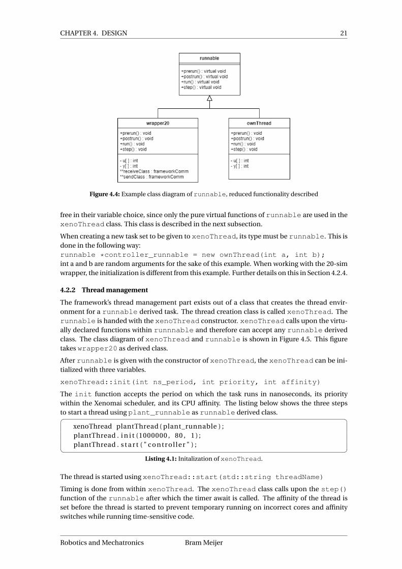
Figure 4.4 contains two examples that can be derived fromrunnable. One is thewrapper20that is used for 20-sim classes and the other is ownThread, which can be used for own imple-mentations. wrapper20 is further explained in Section 4.2.4.
The main functions in runnable are:
• prerun() Initalizes all variables within the derived class and prepares for execution.• run() Implementation for continuous execution of the derived class. Should include
own timer implementation and await() statements. xenoThread does not call thisfunction and its unused in the current framework setup; however, its included for com-pleteness.
• step() Implementation for one-time execution of the derived class. When periodicallycalling this function, it operates similary to run().
• postrun()Concludes the execution of the derived class. This function contains any fi-nalizing computations that have to be done before class destruction. The class destructoris called with the virtual destructor of the runnable.
Section 4.2.4 describes the use of wrapper20 which uses u and y as its task variables. For theexample given in Figure 4.4, ownThread is also given these variables. The derived classes are
Bram Meijer University of Twente
CHAPTER 4. DESIGN 21
Figure 4.4: Example class diagram of runnable, reduced functionality described
free in their variable choice, since only the pure virtual functions of runnable are used in thexenoThread class. This class is described in the next subsection.
When creating a new task set to be given to xenoThread, its type must be runnable. This isdone in the following way:runnable *controller_runnable = new ownThread(int a, int b);int a and b are random arguments for the sake of this example. When working with the 20-simwrapper, the initialization is different from this example. Further details on this in Section 4.2.4.
4.2.2 Thread management
The framework’s thread management part exists out of a class that creates the thread envir-onment for a runnable derived task. The thread creation class is called xenoThread. Therunnable is handed with the xenoThread constructor. xenoThread calls upon the virtu-ally declared functions within runnnable and therefore can accept any runnable derivedclass. The class diagram of xenoThread and runnable is shown in Figure 4.5. This figuretakes wrapper20 as derived class.
After runnable is given with the constructor of xenoThread, the xenoThread can be ini-tialized with three variables.
xenoThread::init(int ns_period, int priority, int affinity)
The init function accepts the period on which the task runs in nanoseconds, its prioritywithin the Xenomai scheduler, and its CPU affinity. The listing below shows the three stepsto start a thread using plant_runnable as runnable derived class.� �
xenoThread plantThread ( plant_runnable ) ;plantThread . i n i t (1000000 , 80 , 1 ) ;plantThread . s t a r t ( " c o n t r o l l e r " ) ;� �
Listing 4.1: Initalization of xenoThread.
The thread is started using xenoThread::start(std::string threadName)
Timing is done from within xenoThread. The xenoThread class calls upon the step()function of the runnable after which the timer await is called. The affinity of the thread isset before the thread is started to prevent temporary running on incorrect cores and affinityswitches while running time-sensitive code.
Robotics and Mechatronics Bram Meijer

22 Real-time robot software framework on Raspberry Pi using Xenomai and ROS2
Figure 4.5: Class diagram of thread class architecture
4.2.3 Communication
This subsection is focussed on the functioning of communication within the wrapper20class. This class is described in more detail in Section 4.2.4. The functionality could be im-plemented similar to this in other task classes, such as ownThread.
When working with real-life plants, the control loop must work correctly from start to finish.Therefore, no mode-switches may happen after the threads have started executing. Becauseof this, initialization of the communication protocols is done before starting their respectivethreads. Another reason for communication initialization in ’main’ is to simplify all task cre-ation and put it in one visible code. This way, it is possible to create a ready-to-go code fromwithin a ’main’ code without changing real-time threads independently.
Figure 4.6: Class diagram of communication protocols
Figure 4.6 shows the class diagram of the framework’s communication part. The IDDP andXDDP base communication is handled by their respective classes: XDDPConnection andIDDPConnection. These contain base functions such as sendDouble() to send doublesvia an RTIPC protocol.
Bram Meijer University of Twente

CHAPTER 4. DESIGN 23
Each frameworkComm creates its own RTIPC connection. Figure 4.7 shows that frame-workComm has a uni-directional association with XDDPConnection or IDDPConnection.This type of association should be interpreted as a "has a" relationship, meaning that everyframeworkComm has a (XDDP/IDDP)Connection.
frameworkComm provides both IDDP and XDDP with base function declarations, such thatthey can be used within runnable derived tasks.
Communication between tasks is initialized via the following steps:
1. Task variableswrapper20 uses an input array (u[]) and an output array (y[]). The task uses theelements from u[] as input for computations and stores the results in y[]. Elementsfrom these arrays are called the task variables.There are also n communication channels in a task.Data is received and put in elements of u[] and sent from elements of y[].To explain the communication process in more detail, an example with two tasks is used.It contains two real-time tasks: a controller and a plant. They communicate mutuallyand also log their data to a non-real-time task. The controller receives setpoints from anon-real-time task and processes them. Moreover, it receives current plant information.Figure 4.7 and Figure 4.8 visualize this example.
Figure 4.7: Block diagram of communication example with communication ports
Figure 4.8: Block diagram of communication example with task variable indexes
Figure 4.7 shows a layout with two real-time tasks and two non-real-time tasks. The real-time tasks are communicating with each other via IDDP (grey). Both real-time tasks alsolog their output to a Logging thread in non-real-time via XDDP (orange). Next to this, the
Robotics and Mechatronics Bram Meijer

24 Real-time robot software framework on Raspberry Pi using Xenomai and ROS2
Controller thread receives setpoint data from a setpoint thread. The numbers next to thecommunication arrays represent the input and output ports.
2. Element parametersEvery timestep, the task receives and sends data from the the task variables. Which indexthe data is put on to or taken from is described in input/output parameters. This datacan be put into frameworkComm’s child classes when creating them.An (IDDP/XDDP)Comm class takes an array of element parameters, an input and anoutput port, and the number of element parameters. The element parameters define onwhich index of the task variable array the incoming/outgoing data is set or taken from.When looking at the example in Figure 4.8, the real-time controller has two inputs andone output. The one output is being sent to two different addresses.Resulting, the Controller task needs four frameworkComm Connections. All connec-tions are singular, meaning that only one variable is received and put on one index. Thisresults in four parameter-arrays with only one variable in each.The input from the Setpoint thread is set to go on index 1 of the task variables array. Theinput from the plant is set to index 0. There is only one output; however, it needs to besent to both the plant and the logging thread. The indexes ofu[] andy[] are also shownin Figure 4.8.This results in the following parameter arrays:� �
int iddp_uParam_PlantData [ ] = { 0 } ;int xddp_uParam_Setpoint [ ] = { 1 } ;int iddp_yParam_ControlOutput [ ] = { 0 } ;int xddp_yParam_Logging [ ] = { 0 } ;� �
Listing 4.2: Creation of communication parameters
3. frameworkComm creationThe next step involves the assignment of port numbers and the parameter size. To usethis communication class structure, the task receives one or multiple arrays of frame-workComm derived pointers. These all indicate one connection either going in or out ofthe task.When this communication protocol is used, an array or multiple arrays of framework-Comm pointers is given to the derivate class of wrapper20. These frameworkCommclasses are initalalized with the following arguments:(IDDP/XDDP)Comm(int ownPort, int destPort, int size, intparameters[]);An XDDP connection sends to its own address, whereas IDDP connection needs to sendto a different address. The addresses are identical to the example in Figure 4.7. TheframeworkComm arrays are initalized as shown below:� �
frameworkComm * control ler_uPorts [ ] = {new IDDPComm( 5 , −1 , 1 , iddp_uParam_PlantData ) ,new XDDPComm(10 , −1 , 1 , xddp_uParam_Setpoint ) } ;
frameworkComm * control ler_yPorts [ ] = {new IDDPComm( 2 , 3 , 1 , iddp_yParam_ControlOutput ) ,new XDDPComm(26 , 26 , 1 , xddp_yParam_Logging ) } ;� �
Listing 4.3: Creation of frameworkComm derived pointers
It is also possible for a task to instantly send multiple values to another task. This is doneby declaring multiple arguments and setting the right size when initalizing the frame-workComm pointer.The size of the u and y parameters is predetermined by the model that is used, passedon with the creation of runnable. In this case, u[] has length 2 and y[] length 1.
Bram Meijer University of Twente

CHAPTER 4. DESIGN 25
4. Use with threadsAfter the threads are created, the uPorts and yPorts are handed to the runnableconstructor.Furthermore, the size of the arrays is given to the thread, since C++ arrays are not self-conscious about their length. std::vector is not used since they are not real-timefriendly because of their variable length and exceptions that they can rise. the uPort andyPort arrays are given to the wrapper20 in Section 4.2.4, specifically in Listing 4.4.
4.2.4 Model management
20-Sim is used as modelling language, and supports c++ code generation from its model soft-ware. This C++ code contains a class structure with all the common capabilities and a top classwith the main task functions. The main functions are Initalize(), Calculate(), andTerminate().
As described in Section 4.2.1, runnable is a base class which executes various tasks. To ex-ecute 20-sim C++ code, wrapper20 is used. This is a class which is derived from runnableused to run 20-sim generated classes. In the following sections a typical 20-sim class is calledController.
To ensure thatwrapper20 functions with all different 20-sim classes, wrapper20 is declaredwith a C++ template. The template is filled during compilation and therefore the wrap-per20 class does not have to be declared with one 20-sim C++ class. wrapper20 is initializedas follows, in the case that the user wants to use the 20-sim class ‘Controller’.� �
Controller * c o n t r o l l e r _ c l a s s = new Controller ;runnable * controller_runnable = new wrapper20<Controller >(
c o n t r o l l e r _ c l a s s , controller_uPorts ,control ler_yPorts , uPorts_length , yPorts_length
) ;� �Listing 4.4: Creation of of wrapper20 class.
First of all, a pointer to a Controller is created. This pointer is then given with the ini-tialization of wrapper20 with as type runnable. The template of wrapper20 is specifiedwith the type ofcontroller_runnable. Thiswrapper20 can then be used when creatingxenoThread, as in Listing 4.1
Listing 4.4 shows that controller_uPorts and controller_yPorts from Listing 4.3are given to the constructor of wrapper20. The uPorts are put onto receiveArray and theyPorts onto sendArray.
After the xenoThread is initialized and started (Listing 4.1), the following operations are ex-ecuted.
1. Receive data with the receiveArray that was passed to the runnable.� �for ( int i = 0 ; i < receiveArraySize ; i ++)
{receiveClass [ i ]−> receive (u ) ;
}� �Listing 4.5: Receiving data via the receiveArray, initalized in Listing 4.4
In Listing 4.5, all elements of the receiveArray are called to perform function re-ceive. Since the frameworkComm already knows how much information it is goingto receive, the complete task variable array u is given as variable to the receive func-
Robotics and Mechatronics Bram Meijer

26 Real-time robot software framework on Raspberry Pi using Xenomai and ROS2
tion. The parameters given with the frameworkComm constructor are used to identifyon which index of u the received data must be written.
2. Calculate the tasks response with the newly received data. This is done by calling thecalculate() function within the 20-sim generated class.
3. Send the results from the calculated data. This is similar to Listing 4.5, only with send-Class and using send().
4. Await timer to start over. This functionality is implemented in the loop function ofxeno-Thread.
The reason for this order is the performance difference. When working with real-time modelsand plants, reaction time is very important. A period-old value from a sensor could already beworthless if the output of the controller changed during that period. Therefore the input valuesare read before execution.
Operation 1-3 happen in thestep() function ofwrapper20 and operation 4 happens withinxenoThread. This particular division is made to ensure that all thread related operationsare performed within the xenoThread class and all model/task related operations within arunnable derived class.
4.3 Non-real-time design
ROS2 functions as the connection point from real-time to non-real-time. A ROS2 package isbuilt to connect to the pseudo-device created by the XDDP connection from the real-time task.There are two different ROS2 nodes:
• Receiving nodeThe receiving node connects to the XDDP port and receives all data that is sent from thereal-time side. This information is type converted and published on a supplied topic.
• Sending nodeThe sending node receives data on a topic after which sends it to a supplied XDDP port.
When controlling an actual robotic setup, a sequence controller sets the setpoint for motormovement. Most likely, there will be external inputs into the sequence control, such as userinputs or automated image recognition loops. ROS2 provides an excellent base to create thissequence control loop. A connecting node is built to ensure a complete connection from real-time to non-real-time. This connecting node receives data from the receiving node and processthis. This information is then combined with data from other ROS2 nodes that provide generalsetpoints or other input data.
A complete example is shown in Figure 4.9.
Figure 4.9: Example of plant-controller setup with ROS2 integration
The receiving node requires a sending topic and a port to listen to, while the sending nodeneeds a topic to listen to and a port to send information via XDDP. These parameters are
Bram Meijer University of Twente

CHAPTER 4. DESIGN 27
handed with ROS2 command line parameters. These allow a user to start a node with theirparameters. A listening node can be set up as such:
ros2 run ros2-xenomai listener --ros-args -p "topicName:=receivedData"-p "xddpPort:=26"
and a sending node:
ros2 run ros2-xenomai talker --ros-args -p "topicName:=sendData"-p "xddpPort:=10"
Robotics and Mechatronics Bram Meijer

28 Real-time robot software framework on Raspberry Pi using Xenomai and ROS2
5 Testing method
5.1 Introduction
In the final part of this thesis, the framework is subjected to performance analysis. These areperformed to determine if the requirements are fulfilled and if the main goals of this thesis areachieved. Latency tests are done to access the real-time performance of the framework.
5.2 Test setup
To access the performance of the framework, a setup with two real-time tasks is used. One sim-ulates a real-life robot used by the University of Twente for educational purposes, called ‘plant’from now on. This robot, called JIWY, consists of two motors that each control the gimbal thatgives the webcam 2 degrees of freedom. The JIWY robot is shown in Figure 5.1.
Figure 5.1: JIWY robot setup at the University of Twente
Controlling the real-life robot is out of scope for this thesis; however, as mentioned, a simulatedmodel is available. A controller is designed to control the JIWY robot. Both are made in the 20-sim modelling software.
Both the controller and the plant run at 1000Hz as specified in the requirements. This corres-ponds to the refresh rate when controlling a physical JIWY robot.
A period is measured by toggling a GPIO pin or a timing signal after the computations are done.The change on the GPIO pin or timing signal can be registered by a logic analyzer. The differ-ence between the previous measurement and the most recent is the length of the period.
xenoThread possesses a specific function for jitter measurement via General Purpose In Out(GPIO).enableGPIOTiming() enables a GPIO toggle every time a period is completed. Thismakes this GPIO pin suitable to be read with a logic analyzer to determine jitter.
A separate Raspberry Pi is used to function as the logic analyzer with the software from PiGPIO(PiGPIO, 2021). Due to corona restrictions, the laboratory at the university was unavailableduring the time span of this thesis. Although the Raspberry Pi is functional as a logic analyzer,its accuracy is questionable.
Another manner in gathering timing information is to let the thread retrieve the system clock.This clock is the most accurate clock on the Raspberry Pi; however, the native system-call toretrieve the necessary information is not. Luckily, Xenomai implemented a real-time-friendlycall to receive the time with clock_gettime(). Next to this, Xenomai 3.x.x also implementsa real-time-friendly version of printf(), included in its Posix skin.
Bram Meijer University of Twente

CHAPTER 5. TESTING METHOD 29
rt_printf() works using a circular buffer, which overwrites itself when there are too manyitems in the buffer. This command is usually used with printing status information and otherlogging statements; however, it is not meant for printing multiple lines every 0.001s. Thereforeit is better to use communication to send them to the non-real-time environment. Afterwards,these retrieved items can be put in a Comma Separated Value file (CSV).
An external non-real-time thread provides setpoint info to the controller. A similar thread isused to receive timing information and save that for analysis. Both these threads are standardlinux threads and connect to the XDDP pseudo-device. The block diagram of the setup is shownin Figure 5.2. The core affinity is not shown in this figure since it is adjusted in the different tests.
Figure 5.2: Test setup block diagram
5.3 Test method
Section 2.2.3 describes different manners for testing the jitter of a system. Since update rateis most important when controlling robotic systems, long period jitter is of lesser importance.When the clock drifts ever so slightly, the performance of the controller does not suffer. How-ever, when jitter appears as significant cycle-to-cycle jitter, the performance of the robot willbe affected.
5.3.1 Measurement accuracy
Before testing, the accuracy of the measurement tools needs to be validated. The gettime()statement is used to measure the complete jitter spread and is afterwards checked by overlayingit with the Raspberry Pi logic analyzer results. If these seem identical, one can assume thatgettime() is accurate enough.
5.3.2 Functionality
Once the accuracy is validated, the functionality of the framework can be tested. To check if theframework can produce the same results as the modelling tool that created the code, the resultsof the modelling tool simulation and the results produced by the framework can be compared.This will show if the framework can replicate simulated results.
To determine the performance of the framework, the optimal performance mode needs to befound. This is done by using tests that change the core isolation and affinity of the real-timethreads.
Robotics and Mechatronics Bram Meijer

30 Real-time robot software framework on Raspberry Pi using Xenomai and ROS2
5.3.3 Performance
Core isolation Core isolation is set in the boot instructions of the Linux OS. These instructionsdetermine which cores the Linux kernel cannot run. The ‘xenomai supported cpus’ instructiondetermines which cores the Xenomai kernel will run. Therefore to have an equal spread overthe cores, we need to isolate two cores and allocate them to Xenomai.
isolcpus=0,1 xenomai.supported_cpus=0x3 is added to cmdline.txt to enablecore isolation. These steps are also included in Appendix A. This shields Linux from cores 0 and1 and will put Xenomai on these. The 0x03 represent the binary number ‘0011’, which indicatesthe first two cores.
Core isolation testing will research the difference in performance due to the task’s core. This istested with and without core isolation.
The core isolation tests are described below:
• A Xenomai thread is run on a core which is isolated from the Linux kernel.• A Xenomai real-time thread is run on a core which is not isolated but shared with the
Linux kernel.
Core affinity The affinity of the task can be set from within xenoThread. This enables theuser to put specific tasks on specific CPU cores. When a user sets the affinity of a real-time taskto a core that is not specified for Xenomai, the scheduler will correct this and place the task onany of the defined cores.
From pre-running the framework, it is clear that the main thread is visible and running in boththe Xenomai and the Linux domain. The full test can be seen in Appendix C.
• Both real-time tasks are run on the same core. This core is also used by the main thread.• Both real-time tasks run on the same core; however, this core is not the same as the
Xenomai main thread.• The real-time tasks are separated on different cores, One on the core with the Xenomai
main thread and one on a separate core.• The real-time tasks are separated. Both task run on different cores, the Xenomai main
thread runs on a separate core.
Stress All previous tasks are performed within Xenomai’s kernel. Stress is added to the Linuxkernel to check the performance of the Xenomai tasks when Linux is stress tested. The per-formance of the controller and plant could be a hint towards its performance when runningROS2 simultaneously. Stress is added using the stress-NG library made for Linux. Within thisstress-tool, thetaskset property is used to pinpoint stress tests to certain cpu’s. The schedul-ing option sched is set to ‘other’ to prevent interruption with the Xenomai scheduler.
Bram Meijer University of Twente

31
6 Results
This chapter shows the results of testing the framework. The tests are described in Chapter 5.Furthermore, some basic functioning of the framework is shown in Section 6.2. This includesthe basic controller-plant layout and some ROS2 functionality. The results are shown, ex-plained, and discussed in the same chapter to make the information more compact. The com-plete code is shown and explained in Appendix C. This chapter includes snippets from this‘main’ code, simplified to make presenting them more concise.
6.1 Measurement accuracy
To determine if the testing setup is sufficiently accurate to measure the timing of the frame-work’s real-time threads, an accuracy test is performed. A controller-plant setup is run with theframework while both the Raspberry Pi-powered logic analyzer and the clock_gettime()command log the timing information of a thread. The results of these measurements can beseen in Figure 6.1. The configuration of the setup does not matter in this instance.
(a) Output from the Raspberry Pi logic analyzer
(b) Output obtained using the clock_gettime() command.
Figure 6.1: Jitter performance of the controller and plant from both internal clock measurement (a) andlogic analyzer (b).
As seen in Figure 6.1 the resolution of the logic analyzer is approximately 1µs. The logic ana-lyzer seems to round to 5µs. Compared to gettime() this is a significantly lower accuracy. InFigure 6.1b the visible accuracy is limited by the size of the histogram bins.
The maximum jitter is shown with a vertical red line when this is within the range of the graph.When it is outside of the range, the arrow and subscript indicate the maximum jitter.
The histogram bin size is chosen such that the comparison between the logic analyzer andthe internal clock is adequately visible. The difference between Figure 6.1a and Figure 6.1bis mainly in resolution. The results are approximately the same which is visible in a similarmaximum jitter.
The following tests in this chapter will be shown using internal clock measurements. The res-ults are still double-checked with the logic analyzer. This double-check is done to make surethat the maximum jitter measured by the internal clock is not significantly above or below thelogic analyzer.
Robotics and Mechatronics Bram Meijer

32 Real-time robot software framework on Raspberry Pi using Xenomai and ROS2
When measuring jitter the first and last few samples can be the cause of a high maximum jittersince the code has to start up and finish up in those periods of time. This is also measured whenusing both the clock_gettime() statement or the internal clock measurement. Therefore,the first 20 samples and the last 20 samples of each measurement are removed to prevent un-realistic maximum jitter.
6.2 Functionality
First of all, the framework must be able to execute a 20sim task. This is done by using wrap-per20 as described in Chapter 5. For the controller-plant test, only one of the two inputs isused. The JIWY has two motors that correspond to the pan and tilt of the webcam. During theperformance tests, only the pan input is used. An example output of the JIWY plant and thecontroller as simulated in 20-sim can be seen in Figure 6.2a.
(a) Output of JIWY simulation in 20-sim
(b) Output of JIWY simulation with framework generated threads
Figure 6.2: JIWY-setup simulated outputs both from 20-sim simulation (a) and the framework’s output(b) with identical setpoint data.
The framework is set up as described in Section 4.2.3 and specifically Figure 4.7. The Real-timecontroller and plant are the 20-sim generated code combined with the wrapper20. The res-ults of the controller and plant are sent to a non-real-time task that receives and logs them. Theoutput of this setup is shown in Figure 6.2b. Figure 6.2 a and b are nearly identical, except forthe framework’s output which is slightly ahead of the 20-sim simulated output in Figure 6.2b.This is due to the fact that the setpoint thread is activated at the moment that the XDDP-portopens and not at the moment that the thread is started.
6.3 Performance
To check what influence core affinity has on performance, various tests as described inChapter 5 are executed.
Bram Meijer University of Twente

CHAPTER 6. RESULTS 33
6.3.1 Core affinity
Figure 6.1 shows the results of a jiwy simulation when running the controller on core 0 togetherwith the main thread and the plant on its individual core 1. The difference is clearly visiblebetween the shared core and the individual core. The controller is placed on the shared corewith the main, which results in more jitter from 5µs to 10µs.
Subsequent tests are performed with the controller on the individual core and the plant on theshared core; however, the maximum jitter stayed similar to the results in Figure 6.1. This provesthat the controller/plant setup is not suitable to measure core affinity performances since theirindividual task performance is different.
The logical step is to instruct the framework to start two similar threads. This way, the twocan be compared more fairly. This is done by using a prime number calculator. A small pieceof code is put into two threads that calculate all the prime numbers up to a certain point. Toimplement this, runnable is used to create a new class, called ownThread.
Two threads with prime calculations up to 700 are run simultaneously. More calculations perperiod are not feasible on the Raspberry Pi, since the processor is not able to process both atthe same time. Prime calculations up to 700 give the task room to calculate these primes, sendXDDP timing information, and toggle GPIO pins. The result for two different core layouts withtwo threads running on 1kHz is shown in Figure 6.3.
(a) Thread 1 and thread 2 on the same core, not shared by main
(b) Thread 1 on a shared core with main and thread 2 on an individual core.
Figure 6.3: Timing results when running two threads that are calculating prime numbers up to 700 every0.001 seconds.
Figure 6.3a shows two threads running on identical cores. This is an isolated core on whichnothing is set to run, not even the main thread. Therefore the performance of threads 1 and 2is similar.
The results in Figure 6.3b show the jitter results from running on two different cores. Thread 1is running on core 0 together with the main thread and thread 2 is on core 1. The main threadis also using processing power on core 0, which is visible in the spread in jitter of thread 1.
6.3.2 Core isolation and stress
Core isolation can be measured using the controller/plant layout when a base for measurementis set from the beginning. To prevent the main thread from influencing the test results, it is setto run on a separate isolated core.
Robotics and Mechatronics Bram Meijer

34 Real-time robot software framework on Raspberry Pi using Xenomai and ROS2
Therefore, three cores are used for Xenomai in the first test, running either main, controller, orplant. This result is shown in Figure 6.4a. The second test changes the Xenomai usage from3 to 2 cores. The results can be seen in Figure 6.4b. To check whether Linux influences theperformance of tasks running on the same core, the third test includes stressing the secondcore. The final test is shown in Figure 6.4c.
(a) Plant on core 1, Controller on core 2, main on 0. Core 0, 1, and 2 are Linux isolated.
(b) Plant on core 1, Controller on core 2, main on 0. Core 0 and 1 are Linux isolated. Core 2 is shared with Linux.
(c) Plant on core 1, Controller on core 2, main on 0. Core 0 and 1 are Linux isolated. Core 2 is shared with Linux.Stress is applied to Linux.
Figure 6.4
The controller in Figure 6.4c shows a similar result to the plant in Figure 6.1. Both are on anisolated core with approximately similar performance. The plant results in Figure 6.4 are all onan individual core which is visible with almost identical results.
The difference can be seen when looking at the controller. The isolation influences the per-formance of the task significantly, as seen in the difference between (a), (b), and (c) in Fig-ure 6.4.
6.4 Discussion
As discussed in Appendix C, first pointed to in Chapter 4, the main thread is not only present onthe Linux kernel. The main thread also runs on the Xenomai side, which shows when runninganother thread on the same core as the main thread. The main thread was expected to only runin the Linux domain; however, when calling Xenomai threads from code, it will show up in theXenomai scheduler and therefore is able to run on Linux isolated cores.
The Raspberry Pi logic analyzer underperformed since it is almost only useable for determiningthe maximum delay and examining if the internal clock results match that of the logic analyzer.
Figure 6.4 shows the result of changing the isolation of cores of the controller task. The plant inFigure 6.4b and Figure 6.4c have slightly higher jitter, which is probably caused by the delayedmessaging from the controller thread. The results of the controller task are expected since thecores are shared in Figure 6.4 b and c. Therefore, when a real-time task is on a shared Linux-
Bram Meijer University of Twente

CHAPTER 6. RESULTS 35
Xenomai core, the task is sometimes interrupted by Linux interrupts. This can cause higherjitter values.
The quantitative requirements that were set describe that the maximum jitter may not be above3% of the period. Moreover, the number of deadline misses should not be above 0.01% of thenumber of periods. The performed tests were all analyzed on a sample of 10.000 periods, res-ulting in a total number of allowed deadline misses of 1. The maximum jitter that would notcause a deadline miss is in this instance: 0.001s ·0.03% = 30µs.
When looking at Figure 6.4b the maximum jitter crosses the threshold, which results in a dead-line miss. This effect can not be seen in Figure 6.4c, which could prove that the deadline miss inFigure 6.4b is a one-time event. In all three measurements in Figure 6.4, the plant thread doesnot have any jitter higher than 30µs.
Robotics and Mechatronics Bram Meijer

36 Real-time robot software framework on Raspberry Pi using Xenomai and ROS2
7 Conclusion
7.1 Conlusion
The goal of this thesis is to create a framework that integrates real-time task functionality andROS2. Modelling software integration is also a requirement to enable the framework to run pre-made controllers and plants. The framework has been built with these goals in mind. Hardwareand software options have been analyzed and selected to focus on availability and ease of use.In the end, the Raspberry Pi together with the Xenomai real-time kernel is used. The class sys-tem, in combination with the ROS2 package, creates an accessible entry point for real-timeprogramming. To test if the framework suffices the requirements, period jitter has been meas-ured. The results show a sufficient real-time performance with jitter being below the set 3%.Error handling is implemented in the form of adequate print statements, which translate thestate of the threads. These results prove that the framework is suitable to be adapted for real-liferobotic systems and is suitable to perform hardware simulations of robotic hardware.
7.2 Future work
The framework functions on a base level; however, to provide wide useability for various plat-forms, the framework requires future work. Small programming work is needed inside theframework to fit it to the need of the course ‘Real-time software development’. Items such aserror handling and logging functions need to be updated to be ready for larger systems. On asimilar note, there are some redundant classes that can be merged together. These small issuesare mostly present inside the communication classes. The XDDPComm and IDDPComm couldbe refactored in the XDDPConnection or IDDPConnection to simplify the class structure.
Physical plant integration is one of the first things to tackle after these small changes. Theability to control physical plants using real-time threads that are started by the framework is themain goal of the framework. The communication framework allows for the extension with theaddition of a new frameworkComm derived class. This way, the send and receive code insiderunnable loop through the frameworkComm arrays and also send some of the data to anexternal device. This external device tackles the conversion of data to a motor suitable PWMsignal. One possibility for an external device is an FPGA (Field Programmable Gate Array). TheRaspberry Pi is capable to communicate with the FPGA using the SPI protocol. Xenomai 3claims to have implemented a real-time-friendly driver for SPI, which can be used to send datato the FPGA.
A test that was not executed to check the performance of the framework was measuring thedelay of the RTIPC protocol. When this is measured, it could be helpful in fully understand-ing latency inside the framework. The latencies in ROS2 are already mapped by Maruyamaet al. (2016). When working with a remote topic monitor, these delays increase significantly. Togauge if the framework is actually useful and easy to use, field testing should be performed. Thebest way to implement this is to let students test the framework. Afterwards, their requestedchanges can be put into the framework to increase its usefulness. This approach also reducespossible bugs that are present in the framework.
The real-time capabilities of ROS2 need to be further explored. This could prove useful whenimplementing a sequence controller inside a ROS2 node. Moreover, for educational purposes,the difference between a non-real-time execution of the framework and the original perform-ance could be insightful.
Bram Meijer University of Twente

37
A Xenomai installation
The repository can be found on:https://git.ram.eemcs.utwente.nl/meijera/xenomai-ros2-20sim-pipeline/-/tree/master/.
A.1 Xenomai installation
These steps will help you through the installation of xenomai on the raspberry pi 4. The kernelthat is used is the 4.19.86 linux kernel. Patches from Tantham-h are used to help the installationand make the USB work through the PCIE-bus that is added in the Raspberry pi 4.
Requirements:
• Raspberry pi 4
• 16gb Micro-SD card + reader
• Computer with Ubuntu
• Wifi/LAN connection
A.2 Directory initialization
1. We start by pulling the linux repository and the patches on the host computer.host@ubuntu:~$ git clone git://github.com/raspberrypi/linux.gitlinux-rpi-4.19.86-xeno3
(if git is not installed, install it by usingsudo apt-get updates and thensudo apt-getinstall git)
1. Then we enter the directory and reset the git repository tohost@ubuntu:~$ cd linux-rpi-4.19.86-xeno3host@ubuntu:~/linux-rpi-4.19.86-xeno3$ git reset --hard c078c64fecb325ee86da705b91ed286c90aae3f6host@ubuntu:~/linux-rpi-4.19.86-xeno3$ cd ..
2. Then we create a linked folder for easy access.host@ubuntu:~$ ln -s linux-rpi-4.19.86-xeno3 linux
3. Download the xenomai tar.bz2 and extract it. Also create a linked folder for the xenomaiinstallation.host@ubuntu:~$ wget https://xenomai.org/downloads/xenomai/stable/xenomai-3.1.tar.bz2host@ubuntu:~$ tar - xjvf xenomai-3.1.tar.bz2host@ubuntu:~$ ln -s xenomai-3.1 xenomai
4. Download the patches into xeno3-patcheshost@ubuntu:~$ mkdir xeno3-patches && cd xeno3-patcheshost@ubuntu:~/xeno3-patches$ wget https://github.com/thanhtam-h/rpi4-xeno3/blob/master/scripts/ipipe-core-4.19.82-arm-6-mod-4.49.86.patchhost@ubuntu:~/xeno3-patches$ wget https://github.com/thanhtam-h/rpi4-xeno3/blob/master/scripts/pre-rpi4-4.19.86-xenomai3-simplerobot.
Robotics and Mechatronics Bram Meijer

38 Real-time robot software framework on Raspberry Pi using Xenomai and ROS2
patchhost@ubuntu:~/xeno3-patches$ cd ..
A.3 Patching linux with xenomai
1. Patch linux with the pre-patch from Tantham-hhost@ubuntu:~$ cd linuxhost@ubuntu:~/linux$ patch -p1 <../xeno3-patches/pre-rpi4-4.19.86-xenomai3-simplerobot.patch(If the patch returns with error, just ignore)
2. Patch linux with xenomaihost@ubuntu:~/linux$ ../xenomai/scripts/prepare-kernel.sh --linux=./ --arch=arm --ipipe=../xeno3-patches/ipipe-core-4.19.82-arm-6-mod-4.49.86.patch
A.4 Building linux
1. Get the default config of the BCM2711 into the linux directoryhost@ubuntu:~/linux$ make -j8 O=build ARCH=arm CROSS_COMPILE=arm-linux-gnueabihf- bcm2711_defconfig
2. Set the menuconfig to the right settingshost@ubuntu:~/linux$ make -j8 O=build ARCH=arm CROSS_COMPILE=arm-linux-gnueabihf- menuconfigEdit the following variables:
Kernel features —>
Timer frequency 1000Hz
General setup —>
(-v72-xeno3) Local version - append to kernel release
CPU power management –> CPU Frequency scaling –>
[] CPU Frequency scaling
Memory Managament options —>
[] Allow for memory compaction
Kernel hacking —>
[] KDGB: kernel debugger
Xenomai/cobalt —> Drivers —> Real-time GPIO drivers —>
[*] GPIO controller
Xenomai/cobalt —> Drivers —> Real-time IPC drivers –>
Bram Meijer University of Twente

APPENDIX A. XENOMAI INSTALLATION 39
[*] RTIPC protocol familty
3. Build the linux kernel, edit the -jX variable so that ‘X’ is: (your number of CPU’s - 1).host@ubuntu:~/linux$ make -jX O=build ARCH=arm CROSS_COMPILE=arm-linux-gnueabihf-bzImage modules dtbs(This can take some time, so get coffee or tea. . . )
A.5 Installing the linux kernel on the Micro-SD card
1. Create a new raspbian image on the micro-SD card with the Pi imager. Choose the “Rasp-berry PI OS 32-Bit lite” version.
Also create a shortcut to the identifier for the PI4 ARM version of the kernel:
host@ubuntu:~/Linux$ KERNEL=kernel7l
2. In terminal, locate the fresh installed SD card and see which mounts points are created:\host@ubuntu:~/Linux$ lsblk sdb sdb1 sdb2with sdb1 being the FAT (boot) partition, and sdb2 being the ext4 filesystem (root) parti-tion.
3. Create mount points for both these partitions and mount the sd card to them.host@ubuntu:~/Linux$ mkdir mnthost@ubuntu:~/Linux$ mkdir mnt/fat32host@ubuntu:~/Linux$ mkdir mnt/ext4host@ubuntu:~/Linux$ sudo mount /dev/sdb1 mnt/fat32host@ubuntu:~/Linux$ sudo mount /dev/sdb2 mnt/ext4
4. Install the modules of the build linux system and install them on the root partition.host@ubuntu:~/Linux$ sudo env PATH=$PATH make O=build ARCH=armCROSS_COMPILE=arm-linux-gnueabihf- INSTALL_MOD_PATH=mnt/ext4modules_install
5. Install the kernel image, bts packets and the overlays into the boot partition.Also the original kernel image is saved, in the case that the kernel does not boot.host@ubuntu:~/Linux$ sudo cp mnt/fat32/$KERNEL.imgmnt/fat32/$KERNEL-backup.imghost@ubuntu:~/Linux$sudo cp arch/arm/boot/zImage mnt/fat32/$KERNEL.imghost@ubuntu:~/Linux$sudo cp arch/arm/boot/dts/*.dtb mnt/fat32/host@ubuntu:~/Linux$sudo cp arch/arm/boot/dts/overlays/*.dtb*mnt/fat32/overlays/
6. Edit the neccessary boot configs and cmdline such that the pi can boot, also add the sshaccess file.host@ubuntu:~/Linux$ touch mnt/fat32/sshhost@ubuntu:~/Linux$ sudo nano mnt/fat32/cmdline.txtAdd:dwc_otg.fiq_enable=0 dwc_otg.fiq_fsm_enable=0 dwc_otg.nak_holdoff=0isolcpus=0,1 xenomai.supported_cpus=0x3 at the end of the FIRST line.host@ubuntu:~/Linux$ sudo nano mnt/fat32/config.txtAdd somewhere in the beginning:
Robotics and Mechatronics Bram Meijer

40 Real-time robot software framework on Raspberry Pi using Xenomai and ROS2
total_mem=3072
7. Unmount the SD card and insert it into the Raspberry pi and power it up with the ethernetcable attached to the host computer.host@ubuntu:~/Linux$sudo umount mnt/fat32host@ubuntu:~/Linux$sudo umount mnt/ext4
8. Boot the raspberry pi and ssh into it, check the linux kernel with uname -r
A.6 Installing the xenomai libraries on the Raspberry pi
1. Also on the host PC, build the xenomai libraries.host@ubuntu:~$ cd xenomaihost@ubuntu:~/xenomai$ ./scripts/bootstraphost@ubuntu:~/xenomai$ ./configure --host=arm-linux-gnueabihf--enable-smp --with-core=cobalthost@ubuntu:~/xenomai$ makehost@ubuntu:~/xenomai$ sudo make installhost@ubuntu:~/xenomai$ tar -cjvf rpi4-xeno3-deploy.tar.bz2/usr/xenomai
2. Copy the constructed tar.bz2 file to your raspberry pi.
host@ubuntu:~/xenomai$ scp rpi4-xeno3-deploy.tar.bz2 pi@<raspberry pi IP address>
(if you do not know the pi IP address check it using an ipscanner)
3. Switch to the raspberry pi (SSH into the raspberry pi)host@ubuntu:~/xenomai$ ssh pi@<raspberry pi IP address>
4. Inside the raspberry pi, unpack the tar.bz2 and copy it to /usrpi@raspberrypi:~$ cd /usrpi@raspberrypi:~$ sudo tar -xjvf rpi4-xeno3-deploy.tar.bz2 -C /
5. Create a config file and add the xenomai libraries to it.pi@raspberrypi:~$ sudo nano /etc/ld.so.conf.d/xenomai.confAnd add:/usr/local/lib /usr/xenomai/lib
6. Load the config and reboot, then run some tests and you are done!pi@raspberrypi:~$ sudo ldconfigpi@raspberrypi:~$ sudo reboot
pi@raspberrypi:~$ sudo /usr/xenomai/bin/xeno-testpi@raspberrypi:~$ sudo /usr/xenomai/bin/latency
Bram Meijer University of Twente

41
B ROS2 installation
Installation of ROS2 Eloquent
Installation is from ROS2 on RPI4 and ROS2 eloquent building.
1. Add the appropriate locales to the RPI4.
pi@raspberrypi:~ $ sudo nano /etc/locale.gen
and uncomment the line: en_US.UTF-8 after that run:
pi@raspberrypi:~ $ sudo apt update && sudo apt install localespi@raspberrypi:~ $ sudo locale-gen en_US en_US.UTF-8pi@raspberrypi:~ $ sudo update-locale LC_ALL=en_US.UTF-8 LANG=en_US.UTF-8pi@raspberrypi:~ $ export LANG=en_US.UTF-8
and
pi@raspberrypi:~ $ sudo locale-gen en_US.UTF-8pi@raspberrypi:~ $ sudo update-locale en_US.UTF-8
and check if all the locales are set to en_US.UTF-8 with:
pi@raspberrypi:~ $ localeLANG=en_US.UTF-8LANGUAGE=en_US.UTF-8LC_CTYPE="en_US.UTF-8"LC_NUMERIC="en_US.UTF-8"LC_TIME="en_US.UTF-8"LC_COLLATE="en_US.UTF-8"LC_MONETARY="en_US.UTF-8"LC_MESSAGES="en_US.UTF-8"LC_PAPER="en_US.UTF-8"LC_NAME="en_US.UTF-8"LC_ADDRESS="en_US.UTF-8"LC_TELEPHONE="en_US.UTF-8"LC_MEASUREMENT="en_US.UTF-8"LC_IDENTIFICATION="en_US.UTF-8"LC_ALL=en_US.UTF-8
2. Add the repositories to your RPI4
complete the steps on Add the ROS-2 repo. until you are at the Build the code in the workspace.
3. let Cmake ignore some packages to save time and errors
pi@raspberrypi:~ $ cd ros2_eloquentpi@raspberrypi:~/ros2_eloquent $ touch src/ros2/rviz/AMENT_IGNOREpi@raspberrypi:~/ros2_eloquent $ touch src/ros-visualization/AMENT_IGNOREpi@raspberrypi:~/ros2_eloquent $ touch src/ros2/system_tests/AMENT_IGNORE
Robotics and Mechatronics Bram Meijer

42 Real-time robot software framework on Raspberry Pi using Xenomai and ROS2
4. Add some colcon build instructions to .colcon
pi@raspberrypi:~ $ mkdir .colconpi@raspberrypi:~ $ sudo nano .colcon/defaults.yaml
and add:
build:cmake-args:
--DCMAKE_SHARED_LINKER_FLAGS=’-latomic -lpython3.7m’--DCMAKE_EXE_LINKER_FLAGS=’-latomic -lpython3.7m’--DCMAKE_BUILD_TYPE=RelWithDebInfo
repeat the steps above within the directory ros2_eloquent.
5. Building ROS2
Continue with the steps on Building ROS-2
Bram Meijer University of Twente

43
C xenoThread class
This appendix describes a more in-depth example using the different classes created in thisthesis. The complete main code is shown in Listing C.1.� �
1
2 bool exitbool = true ;3
4 void my_handler ( int s )5 {6 p r i n t f ( "Caught s ignal %d\n" , s ) ;7 exitbool = f a l s e ;8 }9
10 int main ( )11 {12 / / CREATE CNTRL−C HANDLER13 s ignal ( SIGINT , my_handler ) ;14
15 / / CREATE PARAM AND WRAPPER FOR CONTROLLER16 int iddpcontroller_uParam [ ] = { 0 , 1 } ;17 int xddptiltcontroller_uParam [ ] = { 2 } ;18 int xddppancontroller_uParam [ ] = { 3 } ;19
20 frameworkComm * control ler_uPorts [ ] = {21 new IDDPComm( 5 , −1 , 2 , iddpcontroller_uParam ) ,22 new XDDPComm(10 , −1 , 1 , xddptiltcontroller_uParam ) ,23 new XDDPComm(11 , −1 , 1 , xddppancontroller_uParam ) } ;24 int controller_yParam [ ] = { 0 , 1 } ;25 int controller_yParam_logging [ ] = { 0 } ;26 frameworkComm * control ler_yPorts [ ] = {27 new IDDPComm( 2 , 3 , 2 , controller_yParam )28 } ;29 Controller * c o n t r o l l e r _ c l a s s = new Controller ;30 runnable * controller_runnable = new wrapper<Controller >(31 c o n t r o l l e r _ c l a s s , controller_uPorts , control ler_yPorts , 3 , 1 ) ;32 controller_runnable −> setSiz e ( 4 , 2 ) ;33
34
35 / / CREATE PARAM AND WRAPPER FOR PLANT36 int plant_uParam [ ] = { 0 , 1 } ;37 frameworkComm * plant_uPorts [ ] = {38 new IDDPComm( 3 , −1 , 2 , plant_uParam ) } ;39 int plant_yParam [ ] = { 0 , 1 } ;40 int plant_yParam_logging [ ] = { 0 } ;41 frameworkComm * plant_yPorts [ ] = {42 new IDDPComm( 4 , 5 , 2 , plant_yParam )43 } ;44 Plant * plant_class = new Plant ;45 runnable * plant_runnable = new wrapper<Plant >(
Robotics and Mechatronics Bram Meijer

44 Real-time robot software framework on Raspberry Pi using Xenomai and ROS2
46 plant_class , plant_uPorts , plant_yPorts , 1 , 1 ) ;47 plant_runnable −> setSi ze ( 2 , 2 ) ;48
49
50 / / INIT XENOTRHEAD FOR CONTROLLER + PLANT51 xenoThread plantClass ( plant_runnable ) ;52 xenoThread control lerClass ( controller_runnable ) ;53 plantClass . i n i t (1000000 , 99 , 1 ) ;54 control lerClass . i n i t (1000000 , 98 , 0 ) ;55
56 plantClass . enableLogging ( true , 2 5 ) ;57 control lerClass . enableLogging ( true , 2 6 ) ;58
59 / / START THREADS60 control lerClass . s t a r t ( " c o n t r o l l e r " ) ;61 plantClass . s t a r t ( " plant " ) ;62
63 / / WAIT FOR CNTRL−C64 while ( exitbool )65 ;66 p r i n t f ( "STOP RUNNNING. . . \ n" ) ;67
68 / / CLEANUP69 control lerClass . stopThread ( ) ;70 plantClass . stopThread ( ) ;71 controller_runnable −>~xenoThread ( ) ;72 plant_runnable −>~xenoThread ( ) ;73 controller_runnable −>~runnable ( ) ;74 plant_runnable −>~runnable ( ) ;75 return 1 ;76 }� �
Listing C.1: Example of xenoThread code with controller and plant, simulating pan and tilt of the JIWYrobot.
The example is essentially an increased complicated version of the example used in Sec-tion 4.2.3. It does not only include one channel from the Controller but two variables overthe same channel. This is due to the fact that the JIWY robot has two degrees of freedom andhas two motors that need to be controlled.
A signal handler is used to make the program exit whenever the user requests this. Line 2-9include the handler which makes the exitbool = true;.
This is then used in the infinite while loop running on lines 66-68. When cntrl-c is pressed, theexitbool is put to true and the loop is finished. Afterward, the complete code is cleaned up.Line 13 starts a signal monitor with as interrupt handler the function my_handler.
Afterward, the different parameters and frameworkComm arrays are created in lines 16-50.These lines also include the creation of the wrapper20 classes. The created arrays are passedwhen creating these and afterward their u and y sizes are set.
The size of the controller is twice as big since there needs to be information from the plant andfrom the setpoint thread for both tilt and pan.
Bram Meijer University of Twente

APPENDIX C. XENOTHREAD CLASS 45
Next in line is the initialization of the thread classes. This is done on lines 53-56 and the tim-ing logs are enabled on 58-59. The plant thread is initialized with priority 99 on core 1. Thecontroller receives a lower priority and is put on core 0. When these are created and initialized,the threads can be started with their name as an argument. This results in the following printstatements in the Raspberry Pi terminal, shown in Figure C.1.
Figure C.1: Print statements when starting the main c++ program.
Figure C.1 shows the different ports being initialized correctly. First, are the communicationports described until line 50 and then the two logging ports on lines 58-59.
Afterward, the program begins to spin periodically on the set period of 1000000ns. When theprogram is set to verbose, the terminal will print every step with all the received and sent data.This can be used for debugging. Figure C.2 shows the output when running the program fromListing C.1 with only the tilt receiving external inputs.
Figure C.2: Print statements while running the main c++ program.
sudo cat /proc/xenomai/sched/stat can be called to check the scheduler statisticson all running Xenomai programs. The output of this command while running the main codeis shown in Figure C.3
Figure C.3: Print statement when calling the scheduler statistics function of Xenomai while running themain c++ program.
The main thread is visible next to the controller and the plant. MSW represents the number ofmode switches made by Xenomai. This only changes when firing up the program, not whilerunning. This proves that the programs keep running in real-time for their complete duration.Also visible is the CPU core in the left column and the name assigned on lines 60-61 in the rightcolumn.
When cntrl-c is pressed, the cleanup starts and all the threads are stopped and destroyed. Allthe runnables are destructed too, which automatically closes the ports of the communicationsthat were given to the runnables. The output of this can be seen in Figure C.4
Robotics and Mechatronics Bram Meijer

46 Real-time robot software framework on Raspberry Pi using Xenomai and ROS2
Figure C.4: Print statements when cleaning up the main c++ program.
Bram Meijer University of Twente

47
BibliographyArduino (2010), Arduino Uno Rev3, accessed on 12 Oktober 2021.https://store.arduino.cc/products/arduino-uno-rev3
Bezemer, M., R. Wilterdink and J. Broenink (2011), LUNA: Hard Real-Time, Multi-Threaded,CSP-Capable Execution Framework, in Communicating Process Architectures 2011, Eds.P. Welch, A. Sampson, J. Pedersen, J. Kerridge, J. Broenink and F. Barnes, IOS Press,Netherlands, number WoTUG-33 in Concurrent System Engineering Series, pp. 157–175,ISBN 978-1-60750-773-4, doi:10.3233/978-1-60750-774-1-157.
Boode, A. (2018), On the Automation of Periodic Hard Real-Time Processes: AGraph-Theoretical Approach, Ph.D. thesis, University of Twente,doi:10.3990/1.9789036545518.
Bruyninckx, H. (2002), Real-time and embedded guide, KU Leuven, Mechanical Engineering.http://www.cs.ru.nl/lab/xenomai/RealtimeAndEmbeddedGuide-Bruyninckx.pdf
Bruyninckx, H., E. Scioni, N. Hü, M. Frigerio, M. Morelli, D. Stampfer and C. Schlegel (2019),Composable Models and Software for Robotics Systems, pp. 251–254.
Buttazzo, G. C. (2011), Hard Real-Time Computing Systems: Predictable Scheduling Algorithmsand Applications, Real-Time Systems Series 24, Springer US, 3 edition, ISBN1461406757,9781461406754.http://gen.lib.rus.ec/book/index.php?md5=c288c25ea2196367a738fc9a975bb084
Carvalho, A., C. Machado and F. Moraes (2019), Raspberry Pi Performance Analysis inReal-Time Applications with the RT-Preempt Patch, in 2019 Latin American RoboticsSymposium (LARS), 2019 Brazilian Symposium on Robotics (SBR) and 2019 Workshop onRobotics in Education (WRE), pp. 162–167, doi:10.1109/LARS-SBR-WRE48964.2019.00036.
Controllab Products (2021), 20-sim homepage, accessed on 26 July 2021.https://www.20sim.com/
Espressif systems (2016), ESP32, accessed on 11 Oktober 2021.https://www.espressif.com/en/products/socs/esp32
Gerum, P. (2001), Xenomai Wiki, accessed on 21 July 2021.https://source.denx.de/Xenomai/xenomai/-/wikis/home
Gerum, P. (2005), Life With Adeos, accessed on 20 July 2021.http://www.cs.ru.nl/lab/xenomai/life-with-adeos.pdf
Gerum, P. (2009), RTIPC protocol driver set, accessed on 2 August 2021.https://xenomai.org/pipermail/xenomai/2009-September/017631.html
Gutiérrez, C. S. V., L. U. S. Juan, I. Z. Ugarte and V. M. Vilches (2018), Towards a distributed andreal-time framework for robots: Evaluation of ROS 2.0 communications for real-time roboticapplications.
Hofstede, A. (2020), Integration of hard and soft real-time tasks in cyber-physical systems,Master’s thesis, University of Twente.
Huang, C., C.-H. Lin and C.-K. Wu (2015), Performance evaluation of Xenomai 3, inProceedings of the 17th Real-Time Linux Workshop (RTLWS), Graz, Austria, pp. 21–22.
Huang, D. and H. Wu (2018), Chapter 2 - Virtualization, in Mobile Cloud Computing, Eds.D. Huang and H. Wu, Morgan Kaufmann, pp. 31–64, ISBN 978-0-12-809641-3,doi:https://doi.org/10.1016/B978-0-12-809641-3.00003-X.
Robotics and Mechatronics Bram Meijer

48 Real-time robot software framework on Raspberry Pi using Xenomai and ROS2
https://www.sciencedirect.com/science/article/pii/B978012809641300003X
International Federation of Robotics (IFR) (2019), Robot density rises globally, accessed on 28July 2021.https://ifr.org/ifr-press-releases/news/robot-density-rises-globally
Johansson, G. (2018), Real-Time Linux Testbench on Raspberry Pi 3 using Xenomai, Master’sthesis, KTH royal institute of technology, school of electrical engineering and computerscience.
Kopetz, H. (1997), Real-Time Systems: Design Principles for Distributed EmbeddedApplications, Kluwer Academic Publishers, USA, 1st edition, ISBN 0792398947.
Kuppens, H. (2015), Real-time Linux (Xenomai), accessed on 22 July 2021.http://www.cs.ru.nl/J.Hooman/DES/XenomaiExercises/Background.html
Linux Foundation (2016), Zephyr project, accessed on 11 Oktober 2021.https://www.zephyrproject.org/
Maruyama, Y., S. Kato and T. Azumi (2016), Exploring the Performance of ROS2, in Proceedingsof the 13th International Conference on Embedded Software, Association for ComputingMachinery, New York, NY, USA, EMSOFT ’16, ISBN 9781450344852,doi:10.1145/2968478.2968502.https://doi.org/10.1145/2968478.2968502
Open Robotics (2021), ROS2 Wiki homepage, accessed on 20 August 2021.https://docs.ros.org/en/foxy/index.html
PiGPIO (2021), PIGPIO library, accessed on 12 August 2021.https://abyz.me.uk/rpi/pigpio/
Randolph, C. (2021), Improving the Predictability of Event Chains in ROS 2, Master’s thesis,Delft University of Technology.http://resolver.tudelft.nl/uuid:a5839cb4-c310-40e1-8f51-b5eab98f0171
Raspberry Pi foundation (2019), Raspberry Pi model 4b, accessed on 12 Oktober 2021.https://www.raspberrypi.com/products/raspberry-pi-4-model-b/
Real Time Engineers (2003), FreeRTOS, accessed on 11 Oktober 2021.https://www.freertos.org/
Reghenzani, F., G. Massari and W. Fornaciari (2019), The real-time linux kernel: A survey onPreempt_RT, ACM Computing Surveys, vol. 52, pp. 1–36, doi:10.1145/3297714.
rti (2021), DDS: An Open Standard for Real-Time Applications, accessed on 11 Oktober 2021.https://www.rti.com/products/dds-standard
SiTime (2021), Clock Jitter Definitions and Measurement Methods, accessed on 7 July 2021.https://www.sitime.com/api/gated/AN10007-Jitter-and-measurement.pdf
van der Werff, W. (2016), Connecting ROS to the LUNA embedded real-time framework,Master’s thesis, University of Twente.http://essay.utwente.nl/70628/
Bram Meijer University of Twente