
Teach-In 2014 Raspberry Pi – Part 6
76
Teach-In 2014 Raspberry Pi – Part 6 EXTREMELY ACCURATE GPS 1PPS TIMEBASE MAXIMUM ACCURACY FOR YOUR 12-DIGIT FREQUENCY COUNTER PLUS: NET WORK, CIRCUIT SURGERY, TECHNO TALK PIC N’ MIX AND PRACTICALLY SPEAKING INFRASOUND DETECTOR Measure frequencies down to one hertz or less Detect sound way below human hearing Uses an inexpensive electret microphone Sophisticated software option EPE’s comprehensive guide to Raspberry Pi AUTOMATIC POINTS CONTROLLER FOR MODEL TRAINS RAILWAY FUN WITH INFRARED SENSORS AND AUTOMATIC SWITCHING MARCH 2014 £4.40
-
Upload
khangminh22 -
Category
Documents
-
view
0 -
download
0
Transcript of Teach-In 2014 Raspberry Pi – Part 6

Teach-In 2014 Raspberry Pi – Part 6
ExtrEmEly accuratE GPS 1PPS timEbaSEmaximum accuracy for your 12-DiGit frEquEncy countEr
plus: Net work, CirCuit surgery, teChNo talk piC N’ MiX aND praCtiCally speakiNg
infraSounD DEtEctormeasure frequencies down to one hertz or lessDetect sound way below human hearinguses an inexpensive electret microphoneSophisticated software option
EPE’s comprehensive guide to Raspberry Pi
automatic PointS controllEr for moDEl trainSrailway fun with infrarED SEnSorS anD automatic SwitchinG
MARCH 2014 £4.40
MARCH 14 Cover.indd 1 16/01/2014 12:53:03

MIKROELEKTRONIKA MARCH 14.indd 1 16/01/2014 12:55:23

Everyday Practical Electronics, March 2014 1
INCORPORATING ELECTRONICS TODAY INTERNATIONAL
www.epemag.com
ISSN 0262 3617
PROJECTS THEORY NEWS COMMENT POPULAR FEATURES
VOL. 43. No 3 March 2014
Readers’ Services • Editorial and Advertisement Departments 7
© Wimborne Publishing Ltd 2014. Copyright in all drawings, photographs and articles published in EVERYDAY PRACTICAL ELECTRONICS is fully protected, and reproduction or imitations in whole or in part are expressly forbidden.
Our April 2014 issue will be published on Thursday 06 March 2014, see page 72 for details.
Projects and CircuitsInfRASounD DEtECtoR 10 by Allan Linton-Smith and Ross TesterMeasure infrasound in your environment without spending thousandsExTREMELY ACCURATE GPS 1PPS TiMEbASE FOR 20 A FREqUENCY COUNTER by Jim RoweGet maximum accuracy from your 12-Digit Frequency CounterHiGH-ENERGY ELECTRONiC iGNiTiON SYSTEM – PART 2 26 by John ClarkeReplace a failed ignition module or upgrade a mechanical systemAutomAtIC PoIntS ContRollER foR youR moDEl 32 RAiLWAY LAYOUTby Jeff MonegalUse IR sensors to detect an approaching train and with just four cheap ICs and two MOSFETs control a standard twin-coil snap-action points motor
Series and featuresTECHNO TALk by Mark Nelson 25Super stuff from ‘Tin Valley’
TEACH-iN 2014 by Mike and Richard Tooley 38Part 6: Raspberry Pi: building an I2C-interface-based DACMAx’S COOL bEANS by Max The Magnificent 48Arduino galore... Infinity mirror... My Steampunk project... Prototyping shieldsPRACTiCALLY SPEAkiNG by Robert Penfold 52Hard wiring and cablesPiC N’ Mix by Mike Hibbett 56Kitchen timer software designCiRCUiT SURGERY by Ian Bell 59MOSFET basics – Part 1NET WORk by Alan Winstanley 66Quite TecTile... Size matters... Smart home... Fuzzy logic
Regulars and ServicesEPE bACk iSSUES – Did you miss these? 4
SUbSCRibE TO EPE and save money 5
EDItoRIAl 7Heists out, hacks inNEWS – Barry Fox highlights technology’s leading edge 8Plus everyday news from the world of electronicsmICRoChIP READER offER 31EPE Exclusive – Win an LED Lighting Development Kit EPE bACk ISSuES CD-Rom 47EPE PIC PRojECtS CD-Rom vol. 1 55CD-RomS foR ElECtRonICS 62A wide range of CD-ROMs for hobbyists, students and engineersDIRECt book SERvICE 68A wide range of technical books available by mail order, plus more CD-ROMsEPE PCb SERvICE 70PCBs for EPE projects
ADvERtISERS InDEX 71NExT MONTH! – Highlights of next month’s EPE 72
TEACh-In 5 InSIDE bACk CovER
Contents Mar 2014.indd 1 17/01/2014 10:01:41

,,
Quasar SEPT 2013.indd 1 16/07/2013 11:11:04

,
,,
,
Quasar SEPT 2013.indd 2 16/07/2013 11:11:15

4 Everyday Practical Electronics, March 2014
We can supply back issues of EPE by post, most issues from the past five years are available. An EPE index for the last five years is also available at www.epemag.com. Where we are unable to provide a back issue a photocopy of any one article (or one part of a series) can be purchased for the same price. Issues from Jan. 99 are available on CD-ROM or DVD-ROM – and back issues from recent years are also available to download from
www.epemag.com. Please make sure all components are still available before commencing any project from a back-dated issue.
BACK ISSUESDID YOU MISS THESE?
BACK ISSUES ONLY £5.00 (each inc. UK p&p.)
Overseas prices £5.80 each surface mail, £6.80 each airmail.We can also supply issues from years: 2006 (except Jan., Feb., Mar., Apr., May, July). 2007 (except June, July, Aug), 2008 (except Aug, Nov, Dec) 2009 (except Jan, Mar, Apr.).
2010 (except May, June, July, August, Oct, Nov, Dec) 2011 (except Jan). Where we do not have an issue a photocopy of any one article or one part of a series can be provided at the same price.
Theft Alarm
Peace of mind while you are on holiday
WIN A MICROCHIP CAN DEVELOPER’S KIT
Practically sPeaking, Pic n’ MiX, net work, circuit surgery, readout, techno talk
Get your monthly slice of Pi!This month’s hands-on project – A Real Time Clock
hard of hearing? let us help!start of a fascinating series on boosting hearing
What are loops?
hearing loop receiverpick up signals from a loop and drive headphones
amplifier designhistory of the telecoil
ultrasonic anti-fouling for boats – part 1save money on dry docking with our electronic barnacle blaster!!
Jump Start
sept 2012 £4.40
SEPTEMBER 2012 Cover.indd 1 16/07/2012 11:13:22
ORDER FORM – BACK ISSUES – PHOTOCOPIES– INDEXES
Send back issues dated. . . . . . . . . . . . . . . . . . . . . . . . . . . . . . . . . . . . . . . . . . . . . . . . . . . . . . . . . . . . . . . . . . . .
Send photocopies of (article title and issue date) . . . . . . . . . . . . . . . . . . . . . . . . . . . . . . . . . . . . . . . . . . . . . . . .
Name . . . . . . . . . . . . . . . . . . . . . . . . . . . . . . . . . . . . . . . . . . . . . . . . . . . . . . . . . . . . . . . . . . . . . . . . . . . . . . . . . . . . .
Address. . . . . . . . . . . . . . . . . . . . . . . . . . . . . . . . . . . . . . . . . . . . . . . . . . . . . . . . . . . . . . . . . . . . . . . . . . . . . . . . . . . .
. . . . . . . . . . . . . . . . . . . . . . . . . . . . . . . . . . . . . . . . . . . . . . Tel: . . . . . . . . . . . . . . . . . . . . . . . . . . . . . . . . . . . . . . . . . .
I enclose cheque/P.O./bank draft to the value of £ . . . . . . . . . . . .
Please charge my Visa/Mastercard/Maestro £ . . . . . . . . . . . . . . .
Card No . . . . . . . . . . . . . . . . . . . . . . . . . . . . . . . . . . . . . . . . . . . . . . . . . . . . Maestro Issue No . . . . . . . . . . . . . . . . . . . . .
Valid From . . . . . . . . . . . . . Card Expiry Date . . . . . . . . . . . . Card Security Code . . . . . . . . . . (The last 3 digits on or just under the signature strip)
SEND TO: Everyday Practical Electronics, Wimborne Publishing Ltd., 113 Lynwood Drive, Merley,
Wimborne, Dorset BH21 1UU.Tel: 01202 880299. Fax: 01202 843233.
E-mail: [email protected] On-line Shop: www.epemag.comPayments must be in £ sterling – cheque or bank draft drawn on a UK bank. Normally posted within seven days of
receipt of order. Send a copy of this form, or order by letter if you do not wish to cut your issue. M03/14
Spooky Circuits
Don’t let electronics scare you!!
WIN A MICROCHIP dsPICDEM SMPS BuCk BOARD
interface, Pic n’ MiX, net work, circuit Surgery, readout, techno talk
digital lighting controller – Start planning the beSt chriStmaS lighting diSplay in your Street!
hearing loop deSign and inStallation – part 2a survey of commercial equipment
ultraSonic anti-fouling for boatS – part 2installing our electronic barnacle blaster!!
• integrate music into your system• up to 32 lighting channels• easy to program, and includes remote control
Jump Start
oct 2012 £4.40
OCTOBER 2012 Cover.indd 1 22/08/2012 15:55:49
PROJECTS • 3-Input Stereo Audio Switcher • Stereo Compressor • Low Capacitance Adaptor For DMMs • Universal USB Data Logger – Part 2 FEATURES • Jump Start – iPod Speaker • Techno Talk • PIC N’ Mix • Raspberry Pi – Keypad and LCD Interface • Circuit Surgery • Practically Speaking • Max’s Cool Beans • Net Work
PROJECTS • Semtest – Part 1 • Crystal DAC • 10W LED Floodlight • Built-In Speakers • Universal USB Data Logger – Part 3FEATURES • Jump Start – Logic Probe • Techno Talk • PIC N’ Mix • Raspberry Pi – Software Investigation • Circuit Surgery • Interface • Max’s Cool Beans • Net Work
PROJECTS • Lightning Detector • SemTest – Part 2 • Digital Spirit Level • Interplanetary Voice • Ingenuity UnlimitedFEATURES • Jump Start – DC Motor Controller • Techno Talk • PIC N’ Mix • Raspberry Pi – Further Investigation • Circuit Surgery • Practically Speaking • Max’s Cool Beans • Net Work
PROJECTS • SoftStarter • 6-Decade Resistance Substitution Box • SemTest – Part 3FEATURES • Jump Start – Egg Timer • Techno Talk • PIC N’ Mix • Circuit Surgery • Interface • Max’s Cool Beans • Net Work
PROJECTS • Electronic Stethoscope • PIC/AVR Programming Adaptor Board – Part 1 • Cheap, High-Current Bench Supply • Ingenuity UnlimitedFEATURES • Jump Start – Signal Injector Probe • Techno Talk • Raspberry Pi • PIC N’ Mix • Circuit Surgery • Practically Speaking • Max’s Cool Beans • Net Work
PROJECTS • Mix-It • PIC/AVR Programming Adaptor Board – Part 2 • A Handy USB Breakout Box • Converter For Neon Lamp Experiments • Ingenuity UnlimitedFEATURES • Jump Start – Simple Radio Receiver • Techno Talk • PIC N’ Mix • Circuit Surgery • Interface • Max’s Cool Beans • Net Work
PROJECTS • 6-Decade Capacitance Subs-titution Box • Soft Starter For Power Tools • High Power Brushless Motors From Old CD/DVD Drives • High-Current Adaptor For Scopes And DMMs
FEATURES • Jump Start – Temperature Alarm • Techno Talk • Circuit Surgery • Practically Speaking • Max’s Cool Beans • Net Work
PROJECTS • Driveway Sentry • Milliohm Meter Adaptor For DMMs • Build A Vox • Superb Four-Channel Amplifier – On The CheapFEATURES • Techno Talk • Circuit Surgery • Interface • Max’s Cool Beans • Net Work • Computer Error: Reliable Digital Processing – Part 1
PROJECTS • Digital Sound Effects Module • USB Stereo Recording & Playback Interface • Vacuum Pump From Junk • Minireg 1.3-22V Adjustable Regulator • Ingenuity UnlimitedFEATURES • Techno Talk • Circuit Surgery • Practically Speaking • Max’s Cool Beans • Net Work • Computer Error: Reliable Digital Processing – Part 2
PROJECTS • LED Musicolour – Part 1 • High-Temperature Thermometer/Thermostat • Ingenuity UnlimitedFEATURES • Teach-In 2014 – Part 1 • Techno Talk • Circuit Surgery • Interface • Max’s Cool Beans • Net Work • Computer Error: Reliable Digital Processing – Part 3
PROJECTS • CLASSiC-D Amplifier – Part 1 • LED Musicolour – Part 2 • Mains Timer For Fans Or Lights • Ingenuity Unlimited
FEATURES • Teach-In 2014 – Part 2 • Techno Talk • Circuit Surgery • Practically Speaking • Max’s Cool Beans • Net Work
PROJECTS • Six Test Instruments In One Tiny Box • Virtins Technology Multi-Instrument 3.2 • CLASSiC-D Amplifier – Part 2 • FEATURES • Teach-In 2014 – Part 3 • Techno Talk • Circuit Surgery • Interface • Max’s Cool Beans • Net Work
PROJECTS • 2.5GHz 12-Digit Frequency Counter With Add-on GPS Accuracy – Part 1 • The Champion Amplifier • Simple 1.5A Switching Regulator • FEATURES • Teach-In 2014 – Part 4 • Techno Talk • Circuit Surgery • Practically Speaking • Max’s Cool Beans • Net Work • PIC N’ Mix • Net Work
PROJECTS • High-energy Electronic Ignition System – Part 1 • Mobile Phone Loud Ringer! • 2.5GHz 12-Digit Frequency Counter With Add-on GPS Accuracy – Part 2 • FEATURES • Teach-In 2014 – Part 5 • Techno Talk • Circuit Surgery • Interface • Max’s Cool Beans • Net Work • PIC N’ Mix • Net Work
JAN ’13
Digital insulation MeterCheck the safety of your mains equipment!
PLUS
Dual traCking ±0V to 19V Power suPPly – Part 1
interface, Pic n’ MiX, net work, circuit Surgery, readout, techno talk
Quiz Machine
More fun from our exciting new series for newcomers to electronics
solar-PowereD ligHting Controller – Part 2 using free power off grid to run lights
WIN ONE OF FIVE MICROCHIP MICROSTICK II HARDWARE PLATFORMS
• linear power supply delivers up to 1.6a• easy-to-read display of voltage and current • Voltage accuracy better than 1%• excellent load regulation, ripple and noise figures
Jump Start
June 2012 £4.40
JUNE 2012 Cover.indd 1 17/04/2012 16:05:58
PLUS
lab-standard 16-bit digital potentiometer
practically speaking, pic n’ MiX, net work, circuit surgery, readout, techno talk
Battery Voltage Checker
More fun from our exciting new series for newcomers to electronics
dual tracking ±0V to 19V power supply – part 2 assembling our high qualit y bench supply
WIN ONE OF THREE MICROCHIP PICDEM 2 PLUS BOARDS
• works with ac or dc • directly programmable via a keypad• 16-bit resolution, giving 65,535 steps• uses just 4.5w from a 12V supply
Jump Start
intelligent 12V fan controllercool things down this summer!
June 2012 £4.40
JULY 2012 Cover.indd 1 22/05/2012 12:46:46
Solar Powered Charger
More fun from our exciting new series for newcomers to electronics
WIN A MICROCHIP PICDEM PIC18 EXPLORER BOARD
Jump Start
ElEctrolytic capacitor rEformEr and tEstEr – part 1Bring old caps back from the dead!
+ =
HigH-pErformancE micropHonE prEamplifiErget the most from microphones with this low-noise project
Ultrasonic clEanEr• clean complex parts with the ultimate bubble bath • 19-42kHz operation with pic control• High-power ultrasonic transducer• Easy and safe to use
Another energy-saving project for you to build
iNTERFACE, PiC N’ MiX, NET woRk, CiRCuiT SuRgERy, REAdouT, TEChNo TAlk
Raspberry PiSpecial Hands-On Review
What is the Raspberry Pi?
aUgUst 2012 £4.40
AUGUST 2012 Cover.indd 1 19/06/2012 15:46:36
JAN ’14
FEB ’13
MAR ’13
APR ’13
MAY ’13
JUNE ’13
JULY ’13
AUG ’13
SEPT ’13
OCT ’13
NOv ’13
DEC ’13
FEB ’14
Back Issues Mags.indd 4 16/01/2014 12:17:51

Everyday Practical Electronics, March 2014 5
UK readers you can SAVE 81p on every issue of EPE
How would you like to pay £3.59 instead of £4.40 for your copy of EPE ?
WIN A MICROCHIP REMOTE CONTROL DEMO BOARD WITH ZENA WIRELESS ADAPTOR
Teach-In 2014 Raspberry Pi – Part 3
CLASSiC-D AmpLifierConStruCting our high-power high-performAnCe Amp
plus: Net work, readout, CirCuit surgery, teChNo talk, piC N’ MiX & iNterFaCe
uSB muLti-inStrument projeCtpC controlled
2-channel digital scope
Spectrum analyser
Dmm and frequency counter
Audio function generator
EPE’s comprehensive guide to Raspberry Pi
DEC 2013 £4.40
DEC 13 Cover.indd 1 18/10/2013 09:10:33
WIN A MICROCHIP MPLAB STARTER KIT FOR DIGITAL POWER
Teach-In 2014 Raspberry Pi – Part 2LED MusicoLour – Part 2sPEctacuLar Light anD Music show
plus: Net work, readout, CirCuit surgery, teChNo talk & praCtiCally speakiNg
cLassic-D aMPLifiErhigh efficiency, high power
Low distortion, low noise
Bridging option for 8Ω loads
speaker protection module
EPE’s comprehensive guide to Raspberry Pi
NOV 2013 £4.40
NOV 13 Cover.indd 1 18/09/2013 18:33:28
WIN A MICROCHIP PIC32 GUI DEVELOPMENT BOARD
Teach-In 2014 Raspberry Pi – Part 1
HigH-TemperaTure THermomeTer/THermosTaT precise measuremenT and relay conTrol of TemperaTure
plus: IngenuIty unlImIted, net work, readout, CIrCuIt surgery, teChno talk & InterfaCe
led musicolourindividual control of 16 strings of leds
16-bit dsp microcontroller
pWm led drive
operation via infrared remote
EPE’s comprehensive guide to Raspberry Pi
OCT 2013 £4.40
OCT 13 Cover.indd 1 22/08/2013 13:19:46
Well you can – just take out a one year subscription and save 81p an issue, or £9.80 over the year.You can even save £1.08 an issue if you subscribe for two years – a total saving of £26.10.
Overseas rates also represent exceptional value.You also: •Avoidanycoverpriceincreaseforthedurationofyoursubscription •Getyourmagazinedeliveredtoyourdooreachmonth •Ensureyourcopy,evenifthenewsagentssellout
Orderbyphoneorfaxwithacreditcardorbypostwithachequeorpostalorder,orbuyonlinefromwww.epemag.com(gototheOnlineShop).
SUBSCRIPTION PRICESSubscriptions for delivery direct to any address in the UK: 6 months £23.50, 12 months £43.00, two years £79.50; Europe Airmail: 6 months £27.00, 12 months £50.00, 24 months £95.00; Rest Of The World Airmail: 6 months £37.00, 12 months £70.00, 24 months £135.00.
Cheques or bank drafts (in £ sterling only) payable to Everyday Practical Electronics and sent to EPE Subs. Dept., Wimborne Publishing Ltd., 113 Lynwood Drive, Merley, Wimborne, Dorset, BH21 1UU. Tel: 01202 880299. Fax: 01202 843233. Email: [email protected]. Also via the Web at: www.epemag.com.
Subscriptions start with the next available issue. We accept MasterCard, Maestro or Visa. (For past issues see the Back Issues page.)
ONLINE SUBSCRIPTIONSOnline subscriptions, for reading the magazine via the Internet, £19.99 for one year, visit www.epemag.com for more details.
SUBSCRIPTION ORDER FORM
6 Months: UK £23.50, Europe £27.00 (Airmail), Rest Of The World £37.00 (Airmail)
1 Year: UK £43.00, Europe £50.00 (Airmail), Rest Of The World £70.00 (Airmail)
2 Years: UK £79.50, Europe £95.00 (Airmail), Rest Of The World £135.00 (Airmail)
To: Everyday Practical Electronics,Wimborne Publishing Ltd., 113 Lynwood Drive, Merley,
Wimborne, Dorset BH21 1UUTel: 01202 880299 Fax: 01202 843233
E-mail: [email protected]
I enclose payment of £ .............. (cheque/PO in £ sterling only), payable to Everyday Practical Electronics
Please charge my Visa/Mastercard/Maestro
My card number is: .......................................................................Please print clearly, and check that you have the number correct
Signature ......................................................................................
Card Security Code .................. Valid From Date........................(The last 3 digits on or just under the signature strip)
Card Ex. Date ...................................Maestro Issue No. ..............
Name ............................................................................................
Address ........................................................................................
Post code .................................. Tel. ...........................................
Subscriptions can only start with the next available issue.
WIN ONE OF TWO MICROCHIP MPLAB STARTER KITS FORPIC32MX1XX/2XX
Teach-In 2014 Raspberry Pi – Part 4
The Champion amplifierTiny audio module ThaT Can deliver 7W peak
plus: Net work, CirCuit surgery, teChNo talk piC N’ MiX aND praCtiCally speakiNg
high-resoluTion frequenCy/period CounTerrange: below 10hz to over 2.5ghzaccuracy approaching an atomic clock12-digit resolutiongps accuracy option
EPE’s comprehensive guide to Raspberry Pi
simple 1.5a sWiTChing regulaTorsmall, effiCienT and Cheap To build
JAN 2014 £4.40
JAN 14 Cover.indd 1 20/11/2013 13:36:49
Subs page.indd 5 16/01/2014 12:17:07

07/11
Prices INCLUDE Delivery* & VAT.*Delivery to any UK Mainland address,
please call for delivery options forHighland & Island, Northern Ireland,Ireland, Isle of Man, Isle of Wight &
Channel Islandswww.esr.co.uk
Station RoadCullercoatsTyne & WearNE30 4PQ
Tel: 0191 2514363Fax: 0191 [email protected]
2.4GHz Frequency Counter0.01Hz to 2.4GHz8 Digit LED DisplayGate Time: 100ms to 10s2 Channel Operating modePower Supply: 110-220Vac 5WQuote: EPE24G
£81.00Inc Delivery* & VAT
FREE withEvery Order3½ Digital Class III 600V DVMAC / DC Voltage upto 600VDC Current upto 10AResistance upto 20MAudible ContinuityOne per customer, while stocks lastoffer valid until: end of April 2014
FREE DVM Worth
£19.96Antex 660TC SolderingStation £174 RRP
Includes: Solder &HQ Desolder Pump
50W Temperature Controlled Soldering station, adjustable temp 65-425°C, Stand withsponge included Quote: EPE660
£127.76Inc Delivery* & VAT
3D Printer Kit K8200Build your own 3D Printer.FREE 1kg Roll of Filament# with every order worth over £27Print objects upto 200 x 200 x 200mm via your PC or stand alone con-troller (VM8201 available separately) The High Quality self assembly kitis an advanced level kit, requiring mechanical & electronic construction-al experience. # Colour may vary. Quote: EPE3DFREE
£699.00 Inc Delivery* & VAT
FREE
2.4GHz Frequency Counter0.01Hz to 2.4GHz8 Digit LED DisplayGate Time: 100ms to 10s2 Channel Operating modePower Supply: 110-220Vac 5WQuote: EPE24G
Breadboard & Components Starter PackA High Quality Large Breadboard with binding posts, a140 piece Jump Wire Kit and 6 Component Packs withover 1100 components. Quote: EPEBCS
£77.62 Inc Delivery* & VAT
Capacitors
Capacitors
LEDs
Diodes
Resistors
Transistors
Build your own OscilloscopeA new self assembly kit, ideal for education and way to visualisesignals. Features: Markers, Frequency, dB, True RMS readoutsTimebase range:10µs-500ms/division (15 steps)Input sensitvity:100mV-5V/division (6 steps)Max Input voltage: 30VppMax Sample Rate:1ms/s repetitive signal,100ks/s real time signalDim: 80 x 115 x 40mm
Quote: EPESCOPE£65.00
Inc Delivery* & VAT
£114.00 Inc Delivery* & VAT
30V 5A Programmable PSUDual LED (Voltage & Current) DisplaysCourse & Fine V /A Adjustment5 Programmable MemoriesPC Link via USB or RS232Output: 0-30Vdc 0-5A
Quote: EPEPSU
Uses FREE Software
Over 1100 Components
03/14
ESR - March 2014 - Copy.indd 1 16/01/2014 12:51:17

Editorial Offices:EVERYDAY PRACTICAL ELECTRONICS EDITORIAL Wimborne Publishing Ltd., 113 Lynwood Drive, Merley, Wimborne, Dorset, BH21 1UUPhone: (01202) 880299. Fax: (01202) 843233.Email: [email protected]: www.epemag.comSee notes on Readers’ Technical Enquiries below – we regret technical enquiries cannot be answered over the telephone.
Advertisement Offices:Everyday Practical Electronics Advertisements113 Lynwood Drive, Merley, Wimborne, Dorset, BH21 1UUPhone: 01202 880299 Fax: 01202 843233Email: [email protected]
Editor: MATT PULZERSubscriptions: MARILYN GOLDBERGGeneral Manager: FAY KEARNGraphic Design: RYAN HAWKINSEditorial/Admin: 01202 880299Advertising and Business Manager: STEWART KEARN 01202 880299On-line Editor: ALAN WINSTANLEY
Publisher: MIKE KENWARD
READERS’ TECHNICAL ENQUIRIESEmail: [email protected] are unable to offer any advice on the use, purchase, repair or modification of commercial equipment or the incorporation or modification of designs published in the magazine. We regret that we cannot provide data or answer queries on articles or projects that are more than five years’ old. Letters requiring a personal reply must be accompanied by a stamped self-addressed envelope or a self-addressed envelope and international reply coupons. We are not able to answer technical queries on the phone.
PROJECTS AND CIRCUITSAll reasonable precautions are taken to ensure that the advice and data given to readers is reliable. We cannot, however, guarantee it and we cannot accept legal responsibility for it.
A number of projects and circuits published in EPE employ voltages that can be lethal. You should not build, test, modify or renovate any item of mains-powered equipment unless you fully understand the safety aspects involved and you use an RCD adaptor.
COMPONENT SUPPLIESWe do not supply electronic components or kits for building the projects featured, these can be supplied by advertisers.
We advise readers to check that all parts are still available before commencing any project in a back-dated issue.
ADVERTISEMENTSAlthough the proprietors and staff of EVERYDAY PRACTICAL ELECTRONICS take reasonable precautions to protect the interests of readers by ensuring as far as practicable that advertisements are bona fide, the magazine and its publishers cannot give any undertakings in respect of statements or claims made by advertisers, whether these advertisements are printed as part of the magazine, or in inserts.
The Publishers regret that under no circumstances will the magazine accept liability for non-receipt of goods ordered, or for late delivery, or for faults in manufacture.
TRANSMITTERS/BUGS/TELEPHONEEQUIPMENTWe advise readers that certain items of radio transmitting and telephone equipment which may be advertised in our pages cannot be legally used in the UK. Readers should check the law before buying any transmitting or telephone equipment, as a fine, confiscation of equipment and/or imprisonment can result from illegal use or ownership. The laws vary from country to country; readers should check local laws.
E D I T O R I A L
Heists out, hacks inA couple of interesting BBC reports caught my eye over the Christmas break. It seems that the days of the old-fashioned bank robber are numbered. The British Banker’s Association reported that there was a greater than 90% drop in the number of physical robberies from banks between 1992 (847) and 2011 (just 66). A number of reasons were given for this dramatic reduction – the improved design and security of banks, thanks to drop-down barriers, better CCTV and ‘DNA spray’, which results in robbers being covered with a unique, traceable material that is very difficult to wash off skin and can prove that a suspect was at the scene of a robbery. However, top of the list was the move to various kinds of digital or cyber crime.
Laptops not shotgunsWe are all too familiar with the assorted scams that bombard our email inboxes with offers and invitations to reveal our online bank account details, passwords and PINs. On top of this variation of the old-fashioned ‘con’ are much more sophisticated cybercrimes that involve hacking large amounts of data about credit card accounts, which are then used to access cash machines. Criminals in New York recently stole $45 million from ATMs using an illegally sourced database of pre-paid credit card information.
ATM attackNot surprisingly, boxes with large amounts of money (ATMs) sitting on the High Street are popular targets for both crude and technologically aware criminals. While some resort to stealing a JCB digger and literally gouging the ATM out of the wall, others have adopted a much more sophisticated approach. A small hole is drilled in the ATM’s housing, giving access to its control system interface. ‘Malware’ is downloaded from a USB stick and then the hole patched up. The newly installed software allows thieves to activate a special user interface, which gives them control over the machine, delivering its contents. A ‘nice’ extra touch from the software developers prevents the malware user copying the USB stick and going solo – he or she has to phone the gang leader for a special code each time the system is activated – as the old saying goes, there’s no honour among thieves!So, be careful out there – you may not have a bank or ATM that needs protecting, but cybercriminals seem to be endlessly creative in their search for helping themselves to OPM (other people’s money).
7
VOL. 43 No. 03 MARCH 2014
EPE Editorial_100144WP.indd 7 16/01/2014 12:18:19

Pushed to give the trade and pub-lic some certainty and some idea of a new target date for analogue ra-dio switch-off, Minister Ed Vaizey would say only, ‘there is a high pos-sibility it will happen’. He guard-edly endorsed the prediction made
by other speakers, by saying ‘a lot of people say 2020’.
This prompted Steve Holebrook, MD terrestrial broadcast at Arqiva, the UK’s transmitter network opera-tor, to warn that this approach cre-ates a Catch 22 situation: FM cover ‘equivalence’ could be achieved by 2016, but only if the government commits to a firm switch-over date.
US route to digitalI took the opportunity to ask Minis-ter Ed Vaizey whether he had con-sidered adopting the policy adopted in the US to enable overnight TV switchover – offering coupons to help listeners make the change.
‘No work has yet been done on that. We will look at it as we get close,’ he replied. ‘We first want to provide the opportunity to convert.’
‘Patronising’ – the pro-DAB ‘Love’ campaign has been damned by BBC Radio 2’s DJ, Simon Mayo (the above is a crop of a full advert)
A roundup of the latest Everyday News from the world of
electronics
NEWS
8 Everyday Practical Electronics, March 2014
Radio switchover: a never-ending story – by Barry FoxThe UK government has
abandoned its plan to switch off analogue radio in 2015, and can now only guardedly hope for 2020. The admission was made by Communications Minister Ed Vaizey at the Go Digital conference organised by industry body Digital Radio UK, held at the BBC’s Broadcasting House shortly before Christmas.
Vaizey explained the Government’s change of position on digital radio switchover: ‘We have to bring the lis-tener with us. We can’t wave a magic wand and make it happen. We set ourselves a series of benchmarks. Digital lis-tening should be at 50 per cent. Listening via digital (all platforms in-cluding DAB radio, dig-ital TV and computer) is currently 35.6 per cent. Coverage needs to match FM coverage for all stations moving from analogue. We are not there yet. So now is not the time to switch over.’
The trouble with cars‘Cars are the intractable problem’ Ed Vaizey went on, admitting the blin-dingly obvious practical problem that a succession of previous gov-ernment and industry policy makers have failed to recognise.
As Helen Boaden, director of radio at the BBC, reminded, 20 per cent of all radio listening is done in cars and 90 per cent of the 30 million cars already on the road in the UK cannot receive DAB digital radio.
‘But 41 per cent of new cars now have DAB’ Vaizey noted.
A new scheme, due to be imple-mented in 2014 and based on the scheme used for digital TVs in the UK, will oblige manufacturers of DAB radios to have them tested by a Government-approved facility, and carry a ‘Digital Tick’ to signify com-
pliance with the DAB specification and new DAB+ standard already used in Germany.
Minister Vaizey could give no clear reassur-ance on how the scheme would be policed to stop the sale of untested equipment by fly-by-night manufacturers.
DAB siliconOn a more upbeat note, Sir Hossein Yassaie, CEO of Imagination Technologies, the Brit-ish company that stole a march on the majors
in 2002 and developed the world’s first commercially affordable DAB chipset that is now used in 80% of all DAB radios, confirmed that his company has now worked with UK chip-maker Frontier Silicon.
‘There is nothing it doesn’t do’ Yassaie said when asked whether his new chip can really handle all digital radio standards. ‘The hard-ware is ready and it will work in mobiles. It can be in products with-in 12 months. We are doers not talk-ers. You will not find a standard that this chip doesn’t do’.
Antony Sethill, CEO Frontier Sili-con, revealed that converting Imagi-nation’s design to silicon had taken two years and cost $10m. Finished samples will go to radio manufac-turers in two to three months. The chip provides a unified service
News Mar 2014.indd 8 16/01/2014 12:19:01

Everyday Practical Electronics, March 2014 9
Z-axis tape – a lot cleverer than it looks!
A new roll of tape distributed by Sparkfun Electronics is one of those ‘how on earth do they do that?’ products that defies a lot of standard thinking about conductors.
‘Z-axis conductive tape (or 3M Electrically Conductive Adhesive Transfer Tape 9703, to give it its full industrial name) is an easy-to-use, pressure-sensitive, double-sided tape designed for connecting, bond-ing and grounding flex circuits and PCBs. This conductive tape can con-nect most medium pitch flexible circuits with other flexible circuits, PCBs or LCD screens by simply ap-plying pressure with your finger. That sounds useful, but hardly revo-lutionary – what’s so special about conductive ‘Sellotape’? The really clever feature of this tape lies in the Z-axis part of its name. It only con-ducts through the tape, not along the tape’s axis, or in fact in any direction in the plane of the tape (ie, the X and Y-axes).
Z-axis conduction onlyThis means a user can place a single piece of tape over a fiddly surface-mount array of pads on a PCB and then simply stick an IC on top of the tape above the pads and the device will work normally. Even though you might think all the pads/pins should be shorted to each other, they aren’t because of the Z-axis-only rule for conduc-tion. Pad-to-pad connections are all in the plane of the tape and hence they are electrically isolated from each other.
3M explain the ‘anisotropic electri-cal conductivity’ behavior as due to the fact that the tape matrix is filled with conductive particles which al-low interconnection between sub-strates through the adhesive thick-ness (the Z-axis) but are spaced far
If you have some breaking news you would like to share with
our readers, then please email: [email protected]
iPhone accessory manufacturers have come up with a couple of
stunning add-ons for the iconic smartphone – in one case, literally.
US-based manufacturer Yellow Jacket (the name of a North Ameri-can predatory wasp), have put a sting in the tail of their iPhone case. Not only does it offer protection to the phone and carry a rechargeable battery that can ‘double the life of your phone’, but also included is a high-voltage stun gun, delivering 650kV through sharp prongs in the top of the case. The device includes a dual safety switch, and users must flip off the sturdy electrode cover to deliver a shock – simply answering a call will not give you an unexpect-ed jolt! (UK readers are reminded that such accessories are considered to be ‘prohibited firearms’ under UK law – they are strictly illegal.)
Infra-red cameraUsing infra-red sensor technology originally developed for military night vision, FLIR ONE has created a camera accessory that converts heat levels into colour images. These images allow users to observe dif-ferences in temperature of just frac-tions of a degree.
Such a device opens up a new world of possibilities where consumers can see in the dark and detect otherwise invisible heat sources.
True to the spirit of the app-oriented iPhone, in Q1 2014, FLIR will release a software developers kit (SDK) that will give third-party developers all the tools they need to create new apps for specific markets and applications.
Electrically conductive tape
iPhone captures thermal images... and stuns!
enough apart for the product to be electrically insulating in the plane of the adhesive.
Adhesion and RFIThe tape connects and mechani-cally bonds medium-pitch flexible circuits with other flexible circuits, rigid printed circuit boards (PCB) or LCD screens. It offers good adhesion to common PCB substrates such as copper, gold, FR-4 epoxy, Kapton polyimide and polyester films. It can also connect and mechanically bond EMI/RFI shield and gaskets to metal frames and enclosures. (The low contact resistance and tape construction results in good EMI performance and it adheres well to common EMI/RFI substrates such as aluminium, stainless steel, and smooth gasket materials.)
Sparkfun Electronics sells a 12.5mm × 2.75m roll for $14.95. Fur-ther details, including a brief but im-pressive demo video are available at: www.sparkfun.com/products/12042
list of all broadcasts or all formats, available for reception, he said.
‘Power consumption for a DAB chipset ten years ago was 700-800mW’ he said. ‘Now it is 70mW with the radio full on’.
Although Sethill was cagey over price, he confirmed, ‘$5 or $6 is the ballpark, depending on volume’.
The conference ended on an un-expected note when guest speaker Simon Mayo, one of the BBC’s top radio presenters, could not resist a comment on the industry’s TV and radio commercials for digital radio.
These feature an animated midget black DJ, with Barry White-style voice, who wants to ‘spread the love’ for DAB.
‘I hate those commercials,’ Mayo burst out. ‘I absolutely loathe them. They are patronising and I don’t know what their message is sup-posed to be’.
To the obvious surprise of the Digital Radio UK team which had created the commercials, Mayo’s outburst brought spontaneous ap-plause from many in the conference audience.
News Mar 2014.indd 9 16/01/2014 12:19:07

10 Everyday Practical Electronics, March 2014
Constructional Project Constructional Project
Are wind turbines making you sick? Is building vibration making you nauseous? Or do you just want to measure infrasound in your environment? You don’t need to spend thousands of dollars to do it properly – just build our low-cost but accurate Infrasound Detector.
Measure sound and vibration way below human hearing
Infrasound Detector
by Allan Linton-Smith
and Ross Tester
There’s been a lot of press lately about infrasound, particularly as it applies to wind turbines.
But until now, you’ve needed tens of thousands of pounds of test equipment to detect and measure it.
Our Infrasound Detector can be built for less than a hundred pounds, yet will give very accurate results. You can either read the sound pressure directly or store and analyse readings on your computer.
So what exactly is infrasound? It can be defined as sound below the range of normal human hear-ing. That’s generally reckoned to be below about 20Hz. At these frequen-
cies you can perhaps sense or even ‘feel’ sound, but you can’t actually hear it.
In practice, infrasound involves frequencies from about 20Hz to 0.5Hz, but some natural phenomena can cause infrasound down to the mil-lihertz (0.001Hz) region.
When people complain about ill-effects from infrasound (and there are legions of those reports), many acoustic consultants have taken the attitude that ‘if you can’t hear it, it can’t be doing you harm’.
Reported human reaction to sources of infrasound, such as wind turbines is varied, but some of the reports associate infrasound with a general
feeling of malaise, nausea, vertigo, blurred vision, memory problems, tinnitus, anxiety, uneasiness, extreme sorrow, nervous feelings of revulsion or fear, chills down the spine and feel-ings of pressure on the chest.
Others have reported headaches and migraines, major sleep disorders and even self-harm tendencies.
Some researchers have even given it a label: ‘wind turbine syndrome’.
Wind turbines are one example, but you’ll also find infrasound caused by traffic noise, heavy surf, engines/motors (especially things like compressors), building vibra-tions being excited by wind, machin-ery and so on.
Infrasound Detector
Photo: Harvey McDaniel, Wikipedia
Infrasound-Mar 13 (MP).indd 10 16/01/2014 12:19:38

Everyday Practical Electronics, March 2014 11
Constructional Project Constructional Project
Large animals such as whales, crocodiles, alligators, elephants and emus communicate with infrasound. So, if you want to record amorous crocodiles, our Infrasound Detector is a good way to go about it (from a safe location).
Other source of infrasonics are heavy artillery, the calving of icebergs from glaciers and earthquakes.
In fact, there is a theory that the buildup of stresses within the earth’s crust before a major earthquake causes infrasound – which could explain why birds and some other animals appear to have some warning of an imminent quake.
Want another example? The very act of opening or closing a door produces infrasound waves. But that is transi-tory – you don’t normally open and close doors for hours.
Whatever the infrasonic phenom-enon you want to investigate, our-Infrasound Detector is an effective and low-cost way to do it, and it compares more than favourably with commer-cially available equipment.
While it’s economic, it’s also ac-curate and reliable – we believe it can be just as accurate and reliable as com-mercial gear.
In fact, while our unit should cost well under £100 to build and is easy to put together, it took hundreds of hours
Photo: Harvey McDaniel, Wikipedia
IC1LM386N
IC1LM386N
1
2
3
4
5
6
7
8
2011SC
220 F16V
100 F16V
10 F10V
1k
4700 F16V
100nF
10
'CHAMP' AMPLIFIER(MODIFIED)
10k(SEETEXT)
VR2
2.2k
10 F16V
1000 F
100k22k
8.2k
150k
1002.2k
120pF
470 F16V
470 F16V
ELECTRETMICROPHONE
TO PCSOUNDCARD
VR1100k
ANALYSERGAIN
SHIELDEDLEAD
Q1BC548
Q2BC558
100 F16V
CCB
BE
E
JAYCARQM1327MULTI-
METER ONFREQUENCY
RANGE
INFRASOUND TESTING UNITCOMPONENTS IN RED ARE CHANGED/ADDED
*10k RESISTORADDED TO
POWERELECTRET MIC
CE
B
BC548, BC558
1uFMKT
S2*
10k*
9VBATTERY
68
POWER
0.778
S1
EARTHOUTPUT
ELECTRET
*SEE TEXT
39k
'PRE-CHAMP’ PREAMP(MODIFIED)
A
K
12VLED
LED
AK
Fig.1: the testing unit is based on a modified PreCHAMP preamplifier which detects sound via the electret microphone, then removes all but signals below 20Hz. This signal can then be analysed by a computer running ‘fatpigdog’ software, or it can be fed to a modified CHAMP amplifier which drives a multimeter in its AC range to deliver readings of sound pressure levels.
INFRASOUND TESTING UNIT
Infrasound-Mar 13 (MP).indd 11 16/01/2014 12:20:02

12 Everyday Practical Electronics, March 2014
Constructional Project Constructional Project
. to develop and test. That is because infrasound sweeps can take hours to settle, measure and average – and some very specialised and expensive equip-ment was required to design and test it.
If you wanted to buy that commercial equipment yourself, you’d have little change from £20,000!
We also had to develop a method for testing and calibrating high levels of infrasound without upsetting the neighbours.
How it worksThe output from a wide-range electret microphone is fed to a very-low-frequency bandpass filter. The infra-sound signal is amplified and fed to a ‘virtual’ spectrum analyser which then plots the amplitude of the infrasound signal on the vertical (y) scale versus frequency on the horizontal (x) scale using a principal known as Fast Fourier Transform (FFT).
A computer can then be used to analyse the signal and/or a direct fre-quency readout can be obtained if used in the field.
CHAMP amp After constructing many circuits which offered good theoretical performance we discovered that an old (nearly 20 years) preamplifier/amplifier project pair were perfect. The PreCHAMP preamplifier, combined with the CHAMP audio amplifier, can be easily modified to do the job admirably (see box below Parts list).
Yes, we know, we said only two months ago that our new CHAMPION amplifier would kill off older designs, but there’s a good reason for resurrect-ing these here: low quiescent current.
The PreCHAMP and CHAMP draw only about 4mA each on idle, so pro-longed operation (which you’ll need for field checks) is quite practical using only a 9V battery.
By comparison, the CHAMPION draws up to 60mA, so your 9V battery wouldn’t last long.
If you built the CHAMPION project (based on the Panasonic AN7511), you could use it for infrasound with only a few modifications, but you’ll probably need to use it with an ex-ternal supply.
As used here, the modified Pre-CHAMP now has much improved fre-quency response; within ±0.2dB over the range 2Hz – 20kHz. The modified CHAMP also gives a flat frequency
Our Infrasound Detector is built into a small diecast box, with an old microphone shield attached to the front. Inside this shield is a low-cost electret mic insert. The terminals at left are the output to a frequency counter (or in our case, a budget multimeter) while a socket is provided on the right side for output to a PC sound card. Suitable analysis software is quite cheap.
SpecificationsMicrophone frequency response G-weighted: ............. ±2.0dB corrected (0.5Hz-26Hz)Microphone frequency response C-weighted: ............. ±2.0dB (10Hz-20kHz)Microphone intermodulation distortion: ............................ 0.8% @ 100dB SPLPreamplifier frequency response: ........................................ ±0.2dB (0.5Hz-20kHz)Power amplifier frequency response: ................................ ±0.2dB (0.5Hz-20kHz)Power amplifier output (before clipping): ...................... 200mW into 8ΩFrequency response of virtual instrument: ................... ±0.4dB (0.5Hz-20kHz)Overall measuring accuracy – Without calibration table: ................................................... ±15dB (20Hz-20kHz) Using calibration table: ...................................................... ±1.0dB (2Hz-20kHz)THD+N preamplifier: ....................................................................... 0.102% at 1kHz (5Hz-22kHz)THD+N power amplifier: ............................................................... 0.40% at 1kHz (5Hz-22kHz); 250mWPreamp input maximum: .......................................50mVPreamp input minimum: ................................................................ 1.0mVPower amp input maximum: ....................................................... 500mVPower amp input minimum: ......................................................... 30mVPreamp phase distortion: .......................................±6.35° (below 200Hz)Preamp intermodulation distortion: ........................0.095% (88mV output 70Hz/7kHz)Preamp S/N ratio: ...................................................–107dBV (10Hz-80kHz ref 630Hz 25mV)
Infrasound-Mar 13 (MP).indd 12 16/01/2014 12:20:02

Everyday Practical Electronics, March 2014 13
Constructional Project Constructional Project
response at around 0.25-0.5W – so you can feed any oscilloscope or low frequency counter.
Optional CHAMPThe CHAMP is optional – it has been included so that you can take quick measurements in the field.
The PreCHAMP is set up as a band-pass filter and high gain amplifier that is approximately G-weighted, ie, its centre frequency is around 10Hz with –3dB points at 500mHz (0.5Hz) and 26Hz.
A selector switch is provided for switching to ‘C’ weighting (ie, flat re-sponse) so that the unit can easily be calibrated at 1kHz.
The infrasound signal from the Pre-CHAMP is fed to the CHAMP ampli-fier, which has been modified to give a flat frequency response from 0.5Hz to 20kHz and is set at high gain so that the signal output to a frequency counter is over 130mV at 1Hz.
Frequency counter?Whoops! Haven’t got one of those? That little problem is solved very cheaply with a multimeter – specifically the Jaycar QM1327 auto-ranging multime-ter, which can read read down to 0.1Hz and sells for around £12.
While its specs state it needs a mini-mum of 3V RMS AC before it will show a frequency reading, we found that it far exceeded its specification and 130mV was sufficient. Few frequency counters go below 10Hz, so the Jaycar meter rep-resents good value in this application.
If you use the CHAMP together with the Jaycar multimeter, then you will be able to determine SPL (the sound pres-sure level in dB) by switching the DMM to AC volts. This will give an approxi-mate SPL in dB (decibels) as described.
For signals below 0.5Hz this ap-proach will not be accurate, but this will be more than sufficient for the majority of applications.
fatpigdog!The direct readout is very handy in the field, but if you want to do some real analysis, you’ll need a computer and suitable software.
We recommend spectrum analyser software from ‘fatpigdog’ (version 4.04 or later). You can purchase and down-load the software for around $40 from: www.fatpigdog.com
On their website, you will also find various dedicated benchtop spectrum
Electret MicrophonesThe electret microphone is pretty inefficient at frequencies below 25Hz, hence the very high amplification.
There are lots of electret microphone inserts available, but we are specifying a particular Jaycar model (Cat AM-4011) because we found it to be a very good match for this project. However, you can see from the graphs below that even these specific Jaycar mics are not all the same – some are more sensitive than others due to manufacturing variations – so you may need to buy a few to experiment.
Because they have flying pigtails changing them is a pretty easy soldering task. Each electret will need to be calibrated as described below in the ‘Calibration’ section to enable you to assess sound pressure level (SPL).
By the way, we averaged the frequency response of several of the Jaycar electret microphones combined with the PreCHAMP and compared them with an accurately calibrated Bruel & Kjaer microphone/preamp (expensive!) – and found that the Jaycar electret was actually better at infrasound frequencies!
Infrasound-Mar 13 (MP).indd 13 16/01/2014 12:20:11
14 Everyday Practical Electronics, March 2014
Constructional Project Constructional Project
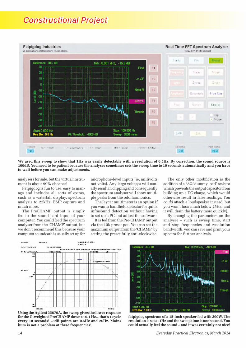
analysers for sale, but the virtual instru-ment is about 99% cheaper!
Fatpigdog is fun to use, easy to man-age and includes all sorts of extras, such as a waterfall display, spectrum analysis to 22kHz, BMP capture and much more.
The PreCHAMP output is simply fed to the sound card input of your computer. You could feed the spectrum analyser from the ‘CHAMP’ output, but we don’t recommend this because your computer soundcard is usually set up for
microphone-level inputs (ie, millivolts not volts). Any large voltages will usu-ally result in clipping and consequently the spectrum analyser will show multi-ple peaks from the odd harmonics.
The Jaycar multimeter is an option if you want a handheld detector for quick infrasound detection without having to set up a PC and adjust the software.
It is fed from the Pre-CHAMP output via the 10k preset pot. You can set the maximum output from the ‘CHAMP’ by setting the preset fully anti-clockwise.
The only other modification is the addition of a 68Ω ‘dummy load’ resistor which prevents the output capacitor from building up a DC charge, which would otherwise result in false readings. You could attach a loudspeaker instead, but you won’t hear much below 25Hz (and it will drain the battery more quickly).
By changing the parameters on the analyser – such as sweep time, start and stop frequencies and resolution bandwidth, you can save and print your spectra for further analysis.
fatpigdog spectrum of a 15-inch speaker fed with 200W. The resolution is set at 1Hz and the sweep time is one second. You could actually feel the sound – and it was certainly not nice!
Using the Agilent 35670A, the sweep gives the lower response for the G-weighted PreCHAMP down to 0.1 Hz…that’s 1 cycle every 10 seconds! –3dB points are 0.5Hz and 26Hz. Mains hum is not a problem at these frequencies!
We used this sweep to show that 1Hz was easily detectable with a resolution of 0.5Hz. By correction, the sound source is 100dB. You need to be patient because the analyser sometimes sets the sweep time to 10 seconds automatically and you have to wait before you can make adjustments.
Infrasound-Mar 13 (MP).indd 14 16/01/2014 12:20:21

Everyday Practical Electronics, March 2014 15
Constructional Project Constructional Project
Furthermore, by setting the spec-trum analyser to ‘max hold’ you will be able to observe any infrasound which occurs during an extended period of time.
Using the virtual spectrum analyser requires some practice and patience (just like a real benchtop spectrum analyser) but if you experiment, you will learn to master it all fairly quickly. We’ll have much more to say on this later.
inputs, as is normal practice for an amplifier.
Start by constructing the Pre-CHAMP pre-amplifier as per the instructions given with the kit.
See Figs.1 and 2 for the modifications required – you will only need to change the values of three capacitors and these will easily fit on the PCB.
The 39kΩ resistor should be sol-dered to the underside of the board input or across the input pins.
ConstructionThe ‘hardware’ is built into an alu-minium diecast box (to minimise noise) measuring 119 × 93.5 × 34mm. Inside this are the PCBs for the modified Pre-CHAMP (and CHAMP if you wish to use it) and a 9V battery in suitable holder.
Layout is not particularly critical, but given the very high amplification of the PreCHAMP/CHAMP combi-nation (about 4000 times), outputs should be kept relatively clear of
This spectrum shows the maximum sound level for suburban traffic. The microphone is a good 5-10 metres away from vehicles and there is significant noise at 2Hz. Note also the peak at around 20Hz – probably from vehicle engines.
You can set up the detector and leave it running for up to an hour. We caught a distant thunder clap at 5Hz and a calculated 84dB. The resolution was set at 1.0Hz and the sweep time was one second. The maximum hold function runs continuously and updates every second.
The Jaycar QM1327 Multimeter works fine as a frequency meter and also an AC voltmeter. It’s simply held in place on the back of the Infrasound Detector with self-adhesive hook’n’loop tape (usually sold under the ‘Velcro’ brand).
Infrasound-Mar 13 (MP).indd 15 16/01/2014 12:20:32
16 Everyday Practical Electronics, March 2014
Constructional Project Constructional Project
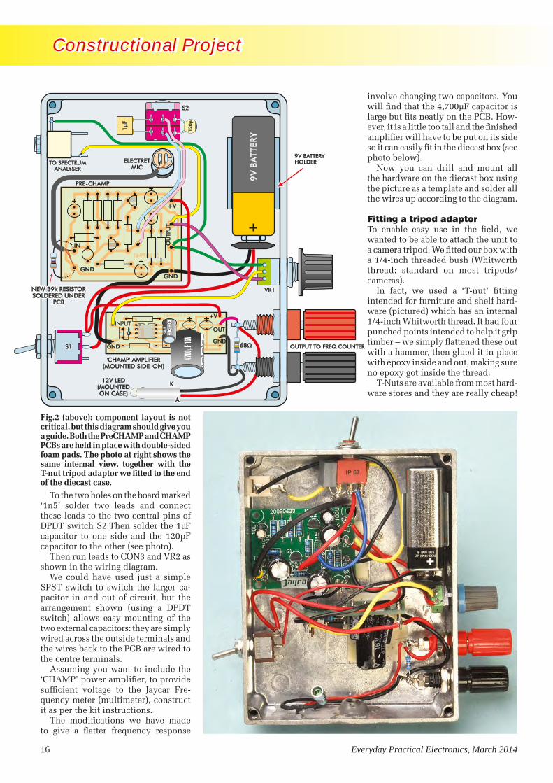
To the two holes on the board marked ‘1n5’ solder two leads and connect these leads to the two central pins of DPDT switch S2.Then solder the 1µF capacitor to one side and the 120pF capacitor to the other (see photo).
Then run leads to CON3 and VR2 as shown in the wiring diagram.
We could have used just a simple SPST switch to switch the larger ca-pacitor in and out of circuit, but the arrangement shown (using a DPDT switch) allows easy mounting of the two external capacitors: they are simply wired across the outside terminals and the wires back to the PCB are wired to the centre terminals.
Assuming you want to include the ‘CHAMP’ power amplifier, to provide sufficient voltage to the Jaycar Fre-quency meter (multimeter), construct it as per the kit instructions.
The modifications we have made to give a flatter frequency response
involve changing two capacitors. You will find that the 4,700µF capacitor is large but fits neatly on the PCB. How-ever, it is a little too tall and the finished amplifier will have to be put on its side so it can easily fit in the diecast box (see photo below).
Now you can drill and mount all the hardware on the diecast box using the picture as a template and solder all the wires up according to the diagram.
Fitting a tripod adaptorTo enable easy use in the field, we wanted to be able to attach the unit to a camera tripod. We fitted our box with a 1/4-inch threaded bush (Whitworth thread; standard on most tripods/cameras).
In fact, we used a ‘T-nut’ fitting intended for furniture and shelf hard-ware (pictured) which has an internal 1/4-inch Whitworth thread. It had four punched points intended to help it grip timber – we simply flattened these out with a hammer, then glued it in place with epoxy inside and out, making sure no epoxy got inside the thread.
T-Nuts are available from most hard-ware stores and they are really cheap!
9V
BA
T TER
Y
S1 OUTPUT TO FREQ COUNTER
01107941
SC
01102941
SC
GND
+V
OU
TPU
T
1F
120p
S2S2
PRE-CHAMPPRE-CHAMP
ELECTRETMIC
ELECTRETMIC
IN
GND
VR1VR1
S1S1
CON1
4700 F
16V
68
220
FTO SPECTRUM
ANALYSERTO SPECTRUM
ANALYSER
INPUT
GNDGND
+V
OUT
9V BATTERYHOLDER
'CHAMP' AMPLIFIER(MOUNTED SIDE-ON)
'CHAMP' AMPLIFIER(MOUNTED SIDE-ON)
K12V LED
(MOUNTEDON CASE)
K
AA
NEW 39k RESISTORSOLDERED UNDER
PCB
NEW 39k RESISTORSOLDERED UNDER
PCB
Fig.2 (above): component layout is not critical, but this diagram should give you a guide. Both the PreCHAMP and CHAMP PCBs are held in place with double-sided foam pads. The photo at right shows the same internal view, together with the T-nut tripod adaptor we fitted to the end of the diecast case.
Infrasound-Mar 13 (MP).indd 16 16/01/2014 12:20:44

Everyday Practical Electronics, March 2014 17
Constructional Project Constructional Project
However, you need to ensure you do get 1/4 Whitworth – it appears that 5/16 and 3/8 are much more common.
If you must use 3/8-inch, 3/8 to 1/4-inch adaptors are available from better photographic stores.
Finishing offIt will be easier to solder the wires to the boards first, then solder the wires to all the switches and sockets before mounting them inside the box.
Because the circuit boards are tiny and sometimes have no provision for normal screw mounts, you will have to use some good quality, thick double-sided foam pads. Cut it to cover the bottom of the ‘pre-CHAMP’ board then press it firmly in place, allowing plenty of room for everything to clear.
Next, fit the ‘CHAMP’ amplifier by putting double-sided tape on the side of the 4,700µF capacitor and the side of the board and then press it all into place as shown.
Check again to see if any wires have come loose, then mount the battery in its holder and switch on. The current drain should be about 8mA. If all is OK, put the lid on and plug in your computer, set up the software and start testing.
Parts List – Infrasonic Detector1 PreCHAMP PCB available from the
EPE PCB Service, coded 01107941 (A Kit is available from Jaycar KC5166*)
1 CHAMP PCB available from the EPE PCB Service, coded 01102941 (A Kit is available from from Jaycar KC5152*) [optional – see text]
1 Diecast box1 frequency-reading multimeter (Jaycar*
QM1327) [optional – see text]1 SPST miniature toggle switch (S1)1 DPDT minature toggle switch (S2)1 3.5mm mono socket, panel-mounting1 banana socket – red1 banana socket – black1 short red wire fitted with banana
plugs each end1 short black wire fitted with banana
plugs each end1 electret microphone insert (eg
Jaycar* AM-4011) [see text]1 microphone 1 1/4-in Whitworth T-nut for tripod
mount [see text]1 9V battery1 U-shaped 9V battery holder1 3.5mm to 3.5mm shielded audio
cable (to connect to sound card)Short lengths hookup wire and
shielded audio cableDouble-sided adhesive foam pads Self-adhesive hook and loop tape, etcEpoxy glue (for tripod adaptor)1 Fatpigdog Virtual Analyzer program
(download from www.fatpigdog.com [approx. $40]).
Semiconductors1 LED, panel mounting 12V type
Capacitors1 4700µF 16V electrolytic1 1000µF 25V electroyltic2 470µF 16V electrolytic1 1µF MKT1 120pF ceramic
Resistors1 39kΩ 1 8.2kΩ 1 68Ω 1 100kΩ (or 50kΩ) log pot1 knob to suit pot
Items marked ‘*’ are available from: www.jaycarelectronics.co.uk
PreCHAMP and CHAMPThese projects were originally published by Silicon Chip in February 1994, but have stood the test of time well. We recommend buying them in kit form from Jaycar.
The microphoneFor the microphone assembly, drill a hole large enough for the electret in the base of the box, solder a short length of shielded cable to the microphone with the shielding to earth (the side connected to the outer case of the elec-tret) and the other end to the the input terminals of the PreCHAMP.
We are looking at frequencies below 30Hz on the G-weighting setting, so hum should not be a problem until you switch to C-weighting
We cut the top off an old dynamic mic and mounted it on the box, then attached the electret to the side with double sided tape as shown.
We maintained the original mic thread to allow us to attach a wind shield and also to calibrate our setup and to make quick changes to test various microphones without having to unscrew the box all the time. But this is not critical and you can just stick the electret to the inside of the box with double-sided tape or even solder it directly to the input pins and just have an appropriate hole in the diecast box.
Whatever you do, you should be able to access the electret to enable quick changes because there is sig-nificant variation between electrets, as the graphs will show and having it mounted on shielded cable makes it easier to solder and unsolder.
Checking it outOnce everything is done, connect the output from the pre-CHAMP to your computer mic input, making sure your sound card mixer is set flat; ie, no bass or treble boost.
Check to see if the microphone is working by switching to C-weighting and then talking or whistling. Measure
As it has a 1/4-inch Whitworth internal thread (same as most tripods) we used a furniture T-nut from a hardware store, flattened out the points, and drilled the box to suit. Then we glued it in place with some two-part epoxy.
Here’s how we mounted the electret microphone, using an old dynamic mic windshield as the base. The insert is held in place with an adhesive foam tab.
Infrasound-Mar 13 (MP).indd 17 17/01/2014 10:51:03

18 Everyday Practical Electronics, March 2014
Constructional Project Constructional Project
the output with a DMM set on AC or plug the output into an amplifier or oscilloscope.
Alternatively, you might like to plug the output of the Pre-CHAMP into the mic socket of your computer sound-card and view your ‘whistle’ on the spectrum analyser. Your whistle should give you a peak at around 1-2kHz, plus harmonics at 2 and 3kHz.
Once all your checks are done, switch it to G-weighting and observe the LED (assuming you have added the CHAMP) It should flash in time with the signal and you can open and shut a door to test it (a car door opening is approx 0.5-2Hz). If all goes well you will finally be ready to fine tune it and try some infrasound testing.
Plug in the Jaycar multimeter, switch it to the Hz range and read off the frequency. On C-weighting you will
Frequency (Hz) ADD dB to measurement 0.5 ................................41 1 ...................................29 2 ...................................17 3 ...................................11 4 .....................................8 5 .....................................5 6 .....................................4 7 .....................................3 8 .....................................2 9 .....................................1 10 ...................................0 11 ...................................0 12 ...................................0 13 ...................................0 14 ...................................0 15 ...................................0 16 ...................................0 17 ...................................0 18 ...................................0 19 ...................................0 20 ................................0.5 21 ...................................1 22 ...................................1 23 ................................1.5 24 ................................1.8 25 ................................2.5 26 ...................................3 27 ................................3.2 28 ................................3.3 29 ................................3.4 30 ................................3.5
probably see something in kHz, but on the G-weighting setting you should see frequencies below 20Hz.
The frequencies will probably jump around a bit and you can vary the gain control to stabilise the readings.
During testing indoors, we saw 8Hz coming up consistently on the counter and also on the spectrum analyser.
It disappeared when we switched off our air conditioner but it was a hot day so we put up with the 8Hz (although it was less than 75dB [SPL]).
CalibrationAs we mentioned before, calibration is only really needed if you want to establish sound pressure level .
Frequency calibration is already inbuilt in the software and multimeter and is not required for our purposes.
It is fairly straightforward, but it will help if you already have a sound level meter (like the Jaycar QM1591) and an audio oscillator – but if you don’t have these items and you don’t calibrate, you will still get a pretty good idea from the relative dB levels indicated in the spectrum analyser.
For example, our leaf blower is rated at SPL 70dB at one metre. We set the detector to C-weighting and found that the fatpigdog analyser indicated –15dB at 35Hz at 1 metre, so switching to G-weighting will mean that any infrasound frequency BELOW 26Hz will also be 70dB, if you see –15dB on the analyser.
Sure, it’s a rough measurement, but there are many devices which have a dB rating on their label such as mowers or saws, and you can check these out.
For a more accurate calibration, feed a tone (say 1kHz) through an amplifier and loudspeaker and check your C-weighted result against your C- weighted sound level meter. Try vari-ous levels, incrementing them by 5dB.
Most sound level meters have abso-lutely no response below 35Hz, so there is no point checking the G-weighted setting.
If you don’t use fatpigdog’s software, don’t worry, because you can switch the Jaycar multimeter to ‘AC volts’, making sure the gain control is fully advanced and just take note of the reading at various sound pressure levels. Our setup showed approx 0.9V AC at 94dB.
For frequencies below 7Hz the ac-curacy falls off somewhat, but if you are looking at 0.5Hz, just switch it to DC volts and watch the rise and fall!
Other unique applications – vibration anaysisThis instrument is very useful in check-ing out vibration problems, as we found with our 8Hz air conditioning. Some-times these problems go undetected for years and some have claimed that they may be responsible for nausea, headaches, sleep problems or just a general sense of unpleasantness.
Additionally, traditional methods of sound level monitoring have only focussed on the audible spectrum and have not even considered infrasound effects on the human (or animal) body, and access to infrasound measuring devices has been both difficult and expensive.
Any vibrating device will give off sound, and our setup will detect it and/or datalog it. Not only that, but for a few pounds it could be used in just about any industrial situation where vibrations may be destructive – such as engines, chassis, suspensions even buildings and bridges.
Data logging with waterfall analysis The software will also enable you to do waterfall analysis, which is really a way of viewing a spectrum analysis as it varies over time.
It can be used as a datalogger for infrasound and audio signals. The vertical scale shows the frequencies of the various harmonics, while the horizontal scale is time – so, the whole chart is a record of a few minutes.
Table 1: Correction table for a Jaycar AM-4011 electret mic insert.
SETUP FOR WATERFALL CHARTSThe wiring setup is virtually the same as for testing spectrum analysis microphone ‘Pre-champ’ output (for voice prints)
The setup for the virtual instrument is:Click on ‘preset’Then ‘display’ Then ‘waterfall F2’Then ‘rotate’Then try different sweep times and
resolution bandwidths (Res. Bw…..). And try different colour schemes by clicking on ‘jet’
Press BMP to save image you want.
Reproduced by arrangement with SILICON CHIP
magazine 2014.www.siliconchip.com.au
Infrasound-Mar 13 (MP).indd 18 16/01/2014 12:21:04

Everyday Practical Electronics, March 2014 19
Constructional Project Constructional Project
We assume you have downloaded the Spectrum Analyzer software from: www.fatpigdog.com/SpectrumAnalyzer (or updated if you’re using an older version).
The originator, Spyro Gumas, is very communicative and can assist if you have any problems.
To start, open and run the program. We used Windows XP but check the website first for compatibility with Vista, Windows 7 or 8.
Initially, you will see the black and white MS-DOS screen appear. You may have to wait (perhaps two minutes or so) and the instrument will appear similar to the trace below:
This sweep shows the frequency response of the modified PreCHAMP: the top line is C weighted and is flat from 10Hz-20kHz. The middle line is an un-modified PreCHAMP (not used) and bottom line (red) is the G-weighted response which joins the top line at 10Hz.Calibration can be carried out at 1kHz on the C setting and then is the same when the unit is switched to G, up to a max of 20Hz.
NOTE: Our Audio Precision analyser cannot go below 10Hz.
Once the virtual instrument pops up, plug the output from the PreCHAMP into your soundcard mic input, switch to G weighting then set up as follows.You can attach the multimeter to the CHAMP output if you wish, but in this case it is redundant.
On the virtual analyser:Click on ‘reset’ to clear any previous settings.Click on frequencyClick on start (F2) and type in ‘0.5’ <enter>.Click on stop key (F3) and type ‘100’ <enter> (This sets the
range to 0.5Hz-100Hz)Click on Lin/Log key (F4) so you see lin/(log) – now the
frequency range is set to a logarithmic scale.Then:Click on bandwidthClick on RBW and type in ‘0.5’ <enter>Click on sweep and type ‘10000’ <enter>Click on ‘trace’ and then ‘max hold’
The analyser will then sweep continuously and indicate the number of averages at the top of the page.
The analyser is now ready to do a ten-second sweep of your sound source from 0.5Hz to 100Hz with a resolution of 0.5Hz, and will continuously update itself with the maximum signal. For example, we set it going during a thunderstorm to record the sound over a period of 20 minutes
You can save an image anytime by pressing ‘BMP’ (bitmap) and you can play around with the RBW (resolution bandwidth) which you can set as low as 0.1Hz.
Refer to the fatpigdog manual provided if you have difficulty because some computers have different delay arrangements with the soundcard and you may need to compensate this with ‘tstupid’.
When you are happy with a particular trace, you might like to activate the marker to examine points of interest.
Click on ‘marker’ then ‘ON’ and then click ‘peak’. The marker will then indicate the dominant frequency.
You will see a red dot appear on the trace, then move the marker to the area you want to measure by clicking on ‘<’ (backward) or ‘>’ (forward) keys.
The marker reading appears at the top of the page eg, ‘Mrk 2.558Hz, –86.2dB’.
Once you have measurements of the points you are inter-ested in, go to Table 1 and add or subtract the dB value at the frequency of interest. For example, if you measured –10dB at 5Hz from the chart you have to ADD 5dB, ie –10+5=–5
During calibration for our setup we found that –15dB on our spectrum analyser was 74dB SPL, so we have to add 10dB (because –5dB is 10dB louder than –15dB).
So SPL = 74+10 = 84dB
AccuracyThe figures quoted in this article are those achieved on a PC fitted with a generic sound card (nothing special!) so we have every reason to believe that you should achieve similar results.
This shows the actual frequency response of the finished setup using the Jaycar electret and is usable down to 1Hz. You need to allow for fall off by using the table provided. For example, for 1Hz you need to add 29dB to your base figure to obtain the correct SPL.
Setting up and operating the Virtual Analyzer
Infrasound-Mar 13 (MP).indd 19 16/01/2014 12:21:18


Everyday Practical Electronics, March 2014 21
Constructional Project Constructional Project
Parts List
1 PCB, available from the EPE PCB Service, code 04103131, 66mm × 46mm
1 GPS receiver module with in-built patch antenna and 1pps output
1 6-way SIL pin strip2 3-way SIL pin strips2 jumper shunts4 M3 × 10mm untapped nylon
spacers*4 M3 × 25mm nylon screws*8 M3 nutsHook-up wire for GPS module25 × 25mm doubled-sided adhesive
foam (to secure GPS module)
Semiconductors1 BC338 NPN transistor (Q1)1 BC328 PNP transistor (Q2)1 LP2950-3.3 (TO-92) or
LM3940IT-3.3 LDO regulator**
Capacitors1 100µF 16V RB electrolytic (or 2 if
a 3.3V supply required)
Resistors (0.25W, 1%)1 22kΩ 1 1kΩ 1 100Ω1 10kΩ 2 2.2kΩ
*Only if project is built inside the frequency counter**Only for a GPS module which requires a 3.3V supply
Extra parts for jiffy box version1 UB-5 jiffy box, 83 × 54 × 31mm1 5-pin DIN socket, PCB-mount1 5-pin DIN socket, panel mount, for
frequency counter2 5-pin DIN plugs1 2-core shielded cable4 M3 × 10mm machine screws
123456
SERIAL RxSERIAL Tx
GND
+3.3V
BACKUP V+
1PPS OUT
FASTRAX UP501GLOBALSAT EM-406A
1
2
3
4
5
6
GND
GND
1PPS OUT
SERIAL Rx
SERIAL Tx
Vin (+5V)
(PATCH ANTENNAAT TOP)
(PATCHANTENNA
AT TOP)
The EM-406A has its own built-in GPS patch antenna and operates di-rectly from 5V DC. It features the SiRF Star III high-performance GPS chipset, very high sensitivity and an extremely fast time to first fix (ie, from a cold start).
The UP501 and other compatible GPS modules operate from 3.3V DC, so for these we have made provision for fitting a 5V-3.3V LDO (low dropout) regulator (REG1). You can use either an LP2950-3.3 regulator which comes in a TO-92 package or an LM3940IT-3.3 which comes in a TO-220 package.
Apart from the power supply arrange-ments, there is a simple buffer and level translator for the 1Hz pulses provided by the GPS module. This uses transis-tors Q1 (BC338) and Q2 (BC328) to ensure that the 1Hz pulses fed out to the counter have a peak-to-peak amplitude of 5V, regardless of the supply voltage used by the GPS module.
Link LK2 allows the 1Hz pulses to be inverted or not by the buffer, so that their ‘leading edges’ are positive-going regardless of their polarity out of the GPS module (some modules may output them as inverted.)
Why do we need to ensure that the leading edges of the 1Hz pulses fed
RECEIVERGPS TIME
04103131C 2013
100 F
Q1
BC33
81k
10k
2.2k
2.2k
100
22k
+5VLK1
+
+V
RX
TX
1PPS
GND
NC
4455
+5V+5V
1PPS1PPS
11
22
33
GLOBALSATEM-406A
GPS RX MODULE
(PATCH ANT)
123456
GNDGNDCON1
Q2
BC32
8 LK2
USING EM406A GPS RECEIVER
RECEIVERGPS TIME
04103131C 2013
LM3940IT-LM3940IT-
100 F
100
FQ
1BC
338
1k
10k
2.2k
2.2k
100
22k
+5VLK1
3.33.3
OROR
+
+
+V
RX
TX
1PPS
GND
NC
+3.3V
4455
+5V+5V
1PPS1PPS
11
22
33
REG1REG1LP2950-3.3LP2950-3.3
GNDGNDCON1
Q2
BC32
8 LK2
USING UP501 GPS RECEIVER
FASTRAXUP501 GPSRX MODULE
(PATCH ANT)
1
2
3
4
5
6
to the 12-Digit Frequency Counter are positive-going? Simply because it’s the leading edges of the pulses that are locked closely to the ‘atomic time’ provided by the GPS satellites. The counter uses the positive-going edges of the external timebase pulses to clock its main gate flipflop, so this ensures the highest measurement accuracy.
AssemblyAll the parts fit on a PCB coded 04103131, measuring just 66mm × 46mm, which is available from the EPE PCB Service. Fig.3 shows the as-sembly details. Almost half of this tiny PCB is reserved for the GPS module itself, which is usually mounted using double-sided adhesive foam.
To allow for convenient connection back to the counter when it is being used remotely, we have provided space for a 5-pin mini-DIN socket (CON1) at the righthand end of the PCB. This allows you to use a cable fitted with a 5-pin DIN plug to link the GPS timebase back to the counter, at the same time providing the unit with +5V power.
This socket is not needed if the PCB is fitted inside the 12-Digit Frequency
Fig.2: the pin connections for the GlobalSat EM-406A and Fastrax UP501 GPS modules. Check the pin connections if you use a different module.
Fig.3: follow these diagrams to build the GPS 1pps Timebase Module. Omit CON1 if the unit is to go inside the frequency counter’s case and omit REG1 and its 100μF output capacitor if the GPS module uses a 5V supply, eg the GlobalSat EM-406A. Alternatively, fit REG1 and the 100μF capacitor for the Fastrax UP501. Don’t forget to set link LK1 accordingly.
GPS1pps 0213 (MP).indd 21 16/01/2014 12:22:20

22 Everyday Practical Electronics, March 2014
Constructional Project Constructional Project
COUNTER
MAIN BOARD
HIGH RESOLUTION
C 2012
04112121 bot
1s
10s
100s
1000s
FREQ
*/PR
D
EXT/
INT
TB
0411
2121
topC
201
2
SEL
CH
AN
A
SEL
CH
AN
B
HIG
H R
ESO
LUTI
ON
CO
UN
TER
MA
IN B
OA
RD
1MH
z
TMR1
IN
VC2
6-30
pF
1k
22k
9-12
V D
C IN
D7
D5
D6
100nF
220k
10M
39pF
100nF
100nF
100nF
VC1
6-30
pF
8.00
MH
z
X232
768H
z
100nF
100nF
100nF
100nF 100nF
100nF
100n
F
100n
F
100n
F
27pF
39pF100nF
100nF
100nF
100nF
TP2
TP1
CO
N4
CO
N4
IC24
IC24
74H
C16
174
HC
161
IC14 IC1474AC163 74AC163 IC16 IC1674HC160 74HC160
IC12
IC12
74A
C10
74A
C10
IC13
IC13
74A
C00
74A
C00
IC18
IC18
74H
C00
74H
C00
IC17
IC17
74A
C74
74A
C74
IC6
IC6
4060
B40
60B
IC7
IC7
4518
B45
18B
IC11
IC11
4012
B40
12B
IC9
IC9
4518
B45
18B
IC8
IC8
4093
B40
93B
IC10
IC10
4093
B40
93B
IC19 IC1974HC244 74HC244
74HC244 74HC244
IC23
IC23
74H
C37
374
HC
373
IC22 IC22PIC16F877A PIC16F877A
5819
4148
4148
CO
N3
EXT
TB IN
IC15 74AC00 IC15 74AC00
X1
TPG
TP4
TPG
TP5
TPG
+5V
SUPP
LY
GRO
UN
D
1PPS
PU
LSES
WIR
ES C
ON
NEC
TIN
GTO
GPS
MIN
I TIM
ERE
CEI
VER
PCB
Compatible GPS ModulesThe following GPS receiver modules should be compatible with this unit:
•GlobalSat EM-406A: 30 × 30 × 10.5mm including patch antenna. Operates from 5V DC with a current drain of 44mA. Provides a 1pps output plus a ‘fix’ indicator LED. Rated sensitivity –159dBm.
•Digilent PmodGPS: approximately 30 × 55 × 12mm including patch antenna. Operates from 3.3V DC with a current drain of 24/30mA. Provides a 1pps output plus a ‘fix’ indicator LED. Rated sensitivity –165dBm.
•RF Solutions GPS-622R: 43 × 31 × 6mm including patch antenna. Operates from 3.3V DC with a cur-rent drain of 23/50mA. Provides a 1pps output plus a ‘fix’ indicator LED. Rated sensitivity –148dBm/–165dBm.
•Fastrax UP501: 22 × 22 × 8mm including patch antenna. Operates from 3.3V DC with a current drain of 23mA. Provides a 1pps output. Rated sensitivity –165dBm.
Note that for use in this project, the GPS receiver module should have a built-in ceramic patch antenna and also provide an output for the GPS-derived 1Hz pulses. Not all GPS modules currently available provide both these features.
Counter’s case. In this situation, the GPS PCB is linked to the counter’s main PCB using three short lengths of insulated hook-up wire.
Two other components shown in Fig.3 are required only if your GPS module needs a 3.3V DC supply, rather than 5V. These are REG1 and the 100µF electrolytic capacitor connected between its output and ground. If you are using the EM-406A module (which requires 5V) and you are also mount-ing the receiver inside the counter box, leave out CON1, REG1 and the 100µF capacitor. Conversely, install REG1 and the 100µF capacitor if you are using the UP501 GPS module.
As previously stated, LK2 must be fitted in the position that provides out-put pulses with positive-going leading edges (see scope grab – Fig.7).
Most GPS receiver modules, includ-ing those specified here, provide 1Hz pulses with this polarity anyway, so the jumper shunt will probably need
Fig
.4:
only
th
ree
lead
s ar
e re
quir
ed t
o co
nn
ect
the
tim
ebas
e m
odu
le t
o th
e m
ain
PC
B i
n t
he
freq
uen
cy c
oun
ter.
Th
ese
lead
s ar
e co
nn
ecte
d d
irec
tly
to t
he
GP
S t
imeb
ase
boar
d i
f it
is
mou
nte
d i
nsi
de
the
cou
nte
r ca
se o
r ru
n t
o a
pan
el-m
oun
t D
IN s
ock
et (
inst
alle
d o
n t
he
cou
nte
r’s
rear
pan
el)
if t
he
GP
S t
imeb
ase
is m
oun
ted
in
a s
epar
ate
case
(se
e p
anel
).
GPS1pps 0213 (MP).indd 22 16/01/2014 12:22:28
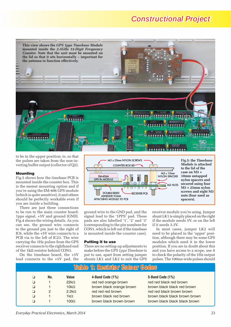
Everyday Practical Electronics, March 2014 23
Constructional Project Constructional Project
Table 1: Resistor Colour Codes o No. Value 4-Band Code (1%) 5-Band Code (1%) o 1 22kΩ red red orange brown red red black red brown o 1 10kΩ brown black orange brown brown black black red brown o 2 2.2kΩ red red red brown red red black brown brown o 1 1kΩ brown black red brown brown black black brown brown o 1 100Ω brown black brown brown brown black black black brown
to be in the upper position; ie, so that the pulses are taken from the non-in-verting buffer output (collector of Q2).
MountingFig.5 shows how the timebase PCB is mounted inside the counter box. This is the easiest mounting option and if you’re using the EM-406 GPS module (which is quite sensitive), it and others should be perfectly workable even if you are inside a building.
There are just three connections to be run to the main counter board: 1pps signal, +5V and ground (GND). Fig.4 shows the wiring details. As you can see, the ground wire connects to the ground pin just to the right of IC6, while the +5V wire connects to a PCB via to the left of IC23. The wire carrying the 1Hz pulses from the GPS receiver connects to the righthand end of the 1kΩ resistor behind CON3.
On the timebase board, the +5V lead connects to the +5V pad, the
ground wire to the GND pad, and the signal lead to the ‘1PPS’ pad. These pads are also labelled ‘1’, ‘2’ and ‘3’ (corresponding to the pin numbers for CON1, which is left out if the timebase is mounted inside the counter case).
Putting it to useThere are no setting-up adjustments to make before the GPS 1pps Timebase is put to use, apart from setting jumper shunts LK1 and LK2 to suit the GPS
receiver module you’re using. Jumper shunt LK1 is simply placed on the right if the module needs 5V, or on the left if it needs 3.3V.
In most cases, jumper LK2 will need to be placed in the ‘upper’ posi-tion, although there may be some GPS modules which need it in the lower position. If you are in doubt about this and you have access to a scope, use it to check the polarity of the 1Hz output pulses. The 100ms-wide pulses should
This view shows the GPS 1pps Timebase Module mounted inside the 2.5GHz 12-Digit Frequency Counter. Note that the unit must be mounted on the lid so that it sits horizontally – important for the antenna to function effectively.
EM-406AGPS Rx MODULE
COUNTER BOX LID
M3 x 25mm NYLON SCREWS
M3 x 10mmNYLON SPACERS
M3 NUTS
RECEIVER PCBDOUBLE-SIDEDADHESIVE FOAM
ATTACHING MODULE TO PCB
Q1 Q2
Fig.5: the Timebase Module is attached to the lid of the case on M3 × 10mm untapped nylon spacers and secured using four M3 × 25mm nylon screws and eight M3 nuts (four used as spacers).
GPS1pps 0213 (MP).indd 23 16/01/2014 12:22:42
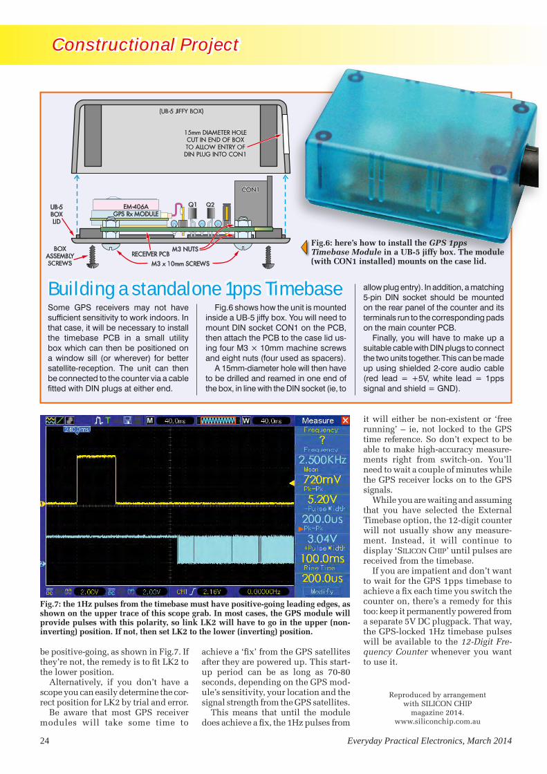
24 Everyday Practical Electronics, March 2014
Constructional Project Constructional Project
be positive-going, as shown in Fig.7. If they’re not, the remedy is to fit LK2 to the lower position.
Alternatively, if you don’t have a scope you can easily determine the cor-rect position for LK2 by trial and error.
Be aware that most GPS receiver modules will take some time to
achieve a ‘fix’ from the GPS satellites after they are powered up. This start-up period can be as long as 70-80 seconds, depending on the GPS mod-ule’s sensitivity, your location and the signal strength from the GPS satellites.
This means that until the module does achieve a fix, the 1Hz pulses from
it will either be non-existent or ‘free running’ – ie, not locked to the GPS time reference. So don’t expect to be able to make high-accuracy measure-ments right from switch-on. You’ll need to wait a couple of minutes while the GPS receiver locks on to the GPS signals.
While you are waiting and assuming that you have selected the External Timebase option, the 12-digit counter will not usually show any measure-ment. Instead, it will continue to display ‘SILICON CHIP’ until pulses are received from the timebase.
If you are impatient and don’t want to wait for the GPS 1pps timebase to achieve a fix each time you switch the counter on, there’s a remedy for this too: keep it permanently powered from a separate 5V DC plugpack. That way, the GPS-locked 1Hz timebase pulses will be available to the 12-Digit Fre-quency Counter whenever you want to use it.
Fig.7: the 1Hz pulses from the timebase must have positive-going leading edges, as shown on the upper trace of this scope grab. In most cases, the GPS module will provide pulses with this polarity, so link LK2 will have to go in the upper (non-inverting) position. If not, then set LK2 to the lower (inverting) position.
Some GPS receivers may not have sufficient sensitivity to work indoors. In that case, it will be necessary to install the timebase PCB in a small utility box which can then be positioned on a window sill (or wherever) for better satellite-reception. The unit can then be connected to the counter via a cable fitted with DIN plugs at either end.
(UB-5 JIFFY BOX)(UB-5 JIFFY BOX)
EM-406AGPS Rx MODULE
M3 x 10mm SCREWS
M3 NUTSRECEIVER PCB
Q1
CON1CON1
15mm DIAMETER HOLECUT IN END OF BOXTO ALLOW ENTRY OFDIN PLUG INTO CON1
15mm DIAMETER HOLECUT IN END OF BOXTO ALLOW ENTRY OFDIN PLUG INTO CON1
UB-5BOXLID
Q2
BOXASSEMBLYSCREWS
Building a standalone 1pps TimebaseFig.6 shows how the unit is mounted
inside a UB-5 jiffy box. You will need to mount DIN socket CON1 on the PCB, then attach the PCB to the case lid us-ing four M3 × 10mm machine screws and eight nuts (four used as spacers).
A 15mm-diameter hole will then have to be drilled and reamed in one end of the box, in line with the DIN socket (ie, to
allow plug entry). In addition, a matching 5-pin DIN socket should be mounted on the rear panel of the counter and its terminals run to the corresponding pads on the main counter PCB.
Finally, you will have to make up a suitable cable with DIN plugs to connect the two units together. This can be made up using shielded 2-core audio cable (red lead = +5V, white lead = 1pps signal and shield = GND).
Fig.6: here’s how to install the GPS 1pps Timebase Module in a UB-5 jiffy box. The module (with CON1 installed) mounts on the case lid.
Reproduced by arrangement with SILICON CHIP
magazine 2014.www.siliconchip.com.au
GPS1pps 0213 (MP).indd 24 16/01/2014 12:22:59

Everyday Practical Electronics, March 2014 25
Mark Nelson
Super stuff from ‘Tin Valley’
you’re not wrong. States Zhang: ‘The effect is not exactly the same but somewhat similar to superconductors – the key difference is that in the field of superconductors, no material was ever predicted and then confirmed; they were all found experimentally. But in topological insulators everything was predicted and then confirmed – so you can appreciate the tremendous power of being able to predict a material theoretically much more quickly that trying to discover it experimentally in a chemistry lab.’
According to Zhang, a likely first application for this stanene-fluorine combination could be in the internal connections between the many sections of a microprocessor, allowing electrons to flow as freely as cars on a highway. Traffic congestion would still occur at on- and off-ramps made of conventional conductors, he said. But stanene wiring should significantly reduce the power consumption and heat production of microprocessors. Manufacturing chips using stanene presents some challenges, such as ensuring that only a single layer of tin is deposited and keeping that single layer intact during high-temperature chip-making processes. But Zhang is not deterred, predicting: ‘Eventually, we can imagine stanene being used for many more circuit structures, including replacing silicon in the hearts of transistors. Someday, we might even call this area “Tin Valley” rather than “Silicon Valley”.’
Sanity breaks outHave you ever considered how daft it is that power supplies for laptops and other portable devices are not standardised? With luck, this situation will soon improve, reports EasyNewsWeb, with the publication of the first globally-relevant Technical Specification for a single external charger for a wide range of notebook computers and laptops. This is the work of the International Electrotechnical Commission (IEC), which is the international standards and conformity assessment body for all fields of electrical technologies.
It’s good news for consumers, who will be able to use a single external charger with a wide range of notebook computers, making it much easier for external chargers to be reused or replaced when needed. It will also avoid the need
to discard computers that may work perfectly well, after their PSUs have failed. Announcing the new standard, IEC General Secretary Frans Vreeswijk stated: “A single power supply covering a wide range of notebook computers is the next step in lowering e-waste and its impact on our planet.”
Square pegs in round holesSomething that has not been standardised to any great extent is the variety of line voltages, frequencies and electrical connectors used around the world for electrical supplies and appliances. With the notable exception of Ireland and Britain, Europe has more or less settled on 230V 50Hz, using connectors with two round pins of fixed dimensions for line and neutral (the arrangements for the earth connection are not as well agreed). The flimsy (to British eyes) two flat blades used for North American and Japanese mains connections are also (almost) standardised, but the others details are not (117V 60Hz in the Americas and the alternatives of 100V 50Hz or 60Hz in Japan).
All this means that the harmonisation of PSU connectors mentioned above is a far simpler task than achieving the same for mains voltages and connectors. Just how mammoth a task this is you can discover at: www.iec.ch/worldplugs. On this website you can read how the IEC has codified most of the plugs and sockets in use today, also why things are as they are and how they might be improved. It also provides information on the plugs, sockets and voltage used around the world, along with illustrations of the various plugs and sockets available.
It really is a bit of a mess out there in the crazy world of connecting to the grid. For example, the IEC lists 14 official types of plug in use around the world, and despite their attempt to provide standardisation with the design for a universal plug back in the 1970s, so far only Brazil and South Africa have adopted it. Many countries use more than one type of plug, with the Maldives having an astonishing seven varieties. The great British three-pin plug turns up in some surprising places – while I can understand it’s use in the Falklands Islands and Kenya, I had no idea it was an official option in Saudi Arabia and Vietnam.
RemembeR graphene, the form of carbon that is an excellent conductor of heat and electricity,
covered extensively in this column? Well, forget it! Instead, make a note of ‘stanene’, a special form of metallic tin that theorists predict could surpass graphene, conducting electricity with 100 per cent efficiency at room temperature. A team of theoretical physicists led by researchers from the National Accelerator Laboratory at Stanford University (California) is making this assertion and suggesting that stanene could replace silicon as the basis of semiconductors. The name of the new material – stanene – combines the Latin name for tin (stannum) with the suffix used in graphene, another single-layer material whose novel electrical properties hold promise for a wide range of applications. If so, the name should be ‘stannene’ but I suspect the fact that it was developed at Stanford University influenced its given name.
The new supermaterial‘Stanene could increase the speed and lower the power needs of future generations of computer chips, if our prediction is confirmed by experiments that are underway in several laboratories around the world,’ enthuses team leader Shoucheng Zhang, a physics professor at Stanford. For the past decade, Zhang and colleagues have been investigating the electronic properties of a special class of materials known as ‘topological insulators’, which conduct electricity only on their outside edges or surfaces, not through their interiors. When topological insulators are just one atom thick, their edges conduct electricity with 100 per cent efficiency.
‘The magic of topological insulators is that by their very nature, they force electrons to move in defined lanes without any speed limit, like the German autobahn,’ Zhang says. ‘As long as they’re on the freeway – the edges or surfaces – the electrons will travel without resistance.’
The team’s calculations indicate that a single layer of tin would be a topological insulator at and above room temperature, and that adding fluorine atoms to the tin would extend its operating range to at least 100ºC. If this brings superconductors to mind,
The quest for ‘superconductivity’ and substances with zero resistance at room temperature has met with little success – until now. mark Nelson reports on the latest supermaterial based on tin. Tired of acquiring an endless collection of laptop PSUs? We’ve got good news there too!
TechnoTalk Mar 2014 proofed.indd 25 16/01/2014 12:23:35

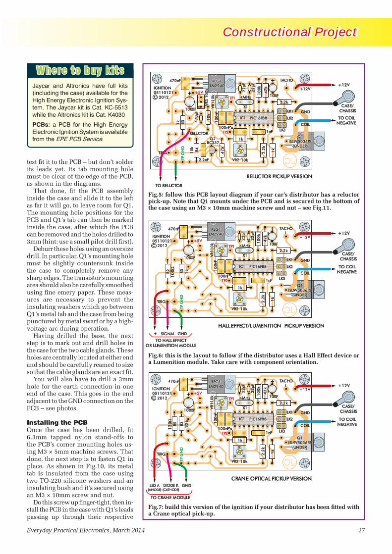
Everyday Practical Electronics, March 2014 27
Constructional Project Constructional Project
test fit it to the PCB – but don’t solder its leads yet. Its tab mounting hole must be clear of the edge of the PCB, as shown in the diagrams.
That done, fit the PCB assembly inside the case and slide it to the left as far it will go, to leave room for Q1. The mounting hole positions for the PCB and Q1’s tab can then be marked inside the case, after which the PCB can be removed and the holes drilled to 3mm (hint: use a small pilot drill first).
Deburr these holes using an oversize drill. In particular, Q1’s mounting hole must be slightly countersunk inside the case to completely remove any sharp edges. The transistor’s mounting area should also be carefully smoothed using fine emery paper. These meas-ures are necessary to prevent the insulating washers which go between Q1’s metal tab and the case from being punctured by metal swarf or by a high-voltage arc during operation.
Having drilled the base, the next step is to mark out and drill holes in the case for the two cable glands. These holes are centrally located at either end and should be carefully reamed to size so that the cable glands are an exact fit.
You will also have to drill a 3mm hole for the earth connection in one end of the case. This goes in the end adjacent to the GND connection on the PCB – see photos.
Installing the PCBOnce the case has been drilled, fit 6.3mm tapped nylon stand-offs to the PCB’s corner mounting holes us-ing M3 × 5mm machine screws. That done, the next step is to fasten Q1 in place. As shown in Fig.10, its metal tab is insulated from the case using two TO-220 silicone washers and an insulating bush and it’s secured using an M3 × 10mm screw and nut.
Do this screw up finger-tight, then in-stall the PCB in the case with Q1’s leads passing up through their respective
10
0k
47
k
1k
2.2
k
VR1
1nF
X1
22
pF
22
pF
10
0nF
VR2
100nF
TP1TP1
TP2TP2
1k
LK1
LK2
LK3
470nF
100 F
+12V
COIL
GND
10 F
TP G
ND
TP G
ND
2.2k
TACHO
IGNITION05110121C 2012 4MHz
TRIG.
10k
10
k
+5V+5V
IC1IC1 PIC16F88PIC16F88
REG1LM2940
REG1LM2940
Q1ISL9V5036P3
(UNDER)
Q1ISL9V5036P3
(UNDER)
+12V
CASE/CHASSIS
SIGNAL
HALL EFFECT/LUMENITION PICKUP VERSION
R2 R3
10
0 1k
+ GND
TO HALL EFFECTOR LUMENITION MODULE
TO COILNEGATIVE
10
0k
47
k
1k
2.2
k
VR1
1nF
X1
22
pF
22
pF
10
0nF
VR2
100nF
TP1TP1
TP2TP2
1k
LK1
LK2
LK3
470nF
100 F
+12V
COIL
GND
10 F
TP G
ND
TP G
ND
2.2k
TACHO
IGNITION05110121C 2012 4MHz
TRIG.
10k
10
k
+5V+5V
IC1IC1 PIC16F88PIC16F88
REG1LM2940
REG1LM2940
Q1ISL9V5036P3
(UNDER)
Q1ISL9V5036P3
(UNDER)
+12V
CASE/CHASSIS
RELUCTOR PICKUP VERSIONR3
R4 47
k
TO RELUCTOR
RELUCTOR
10k
10k
VR3
10
0k
2.2nF
1k 47
0pF
Q2BC337
TO COILNEGATIVE
10
0k
47
k
1k
2.2
k
VR1
1nF
X1
22
pF
22
p F
10
0nF
VR2
100nF
TP1TP1
TP2TP2
1k
LK1
LK2
LK3
470nF
100 F
+12V
COIL
GND
10 F
TP G
ND
TP G
ND
2.2k
TACHO
IGNITION05110121C 2012 4MHz
TRIG.
10k
10
k
+5V+5V
IC1IC1 PIC16F88PIC16F88
REG1LM2940
REG1LM2940
Q1ISL9V5036P3
(UNDER)
Q1ISL9V5036P3
(UNDER)
+12V
TO COILNEGATIVE
CASE/CHASSIS
DIODE K(CATHODE)
CRANE OPTICAL PICKUP VERSION
R5 R3
12
0
22
k
LED A(ANODE)
GND
TO CRANE MODULE
Fig.5: follow this PCB layout diagram if your car’s distributor has a reluctor pick-up. Note that Q1 mounts under the PCB and is secured to the bottom of the case using an M3 × 10mm machine screw and nut – see Fig.11.
Fig.6: this is the layout to follow if the distributor uses a Hall Effect device or a Lumenition module. Take care with component orientation.
Fig.7: build this version of the ignition if your distributor has been fitted with a Crane optical pick-up.
Where to buy kitsJaycar and Altronics have full kits (including the case) available for the High Energy Electronic Ignition Sys-tem. The Jaycar kit is Cat. KC-5513 while the Altronics kit is Cat. K4030
PCBs: a PCB for the High Energy Electronic Ignition System is available from the EPE PCB Service.
IgnitionPt2 1212 V2 (MP).indd 27 16/01/2014 12:24:14
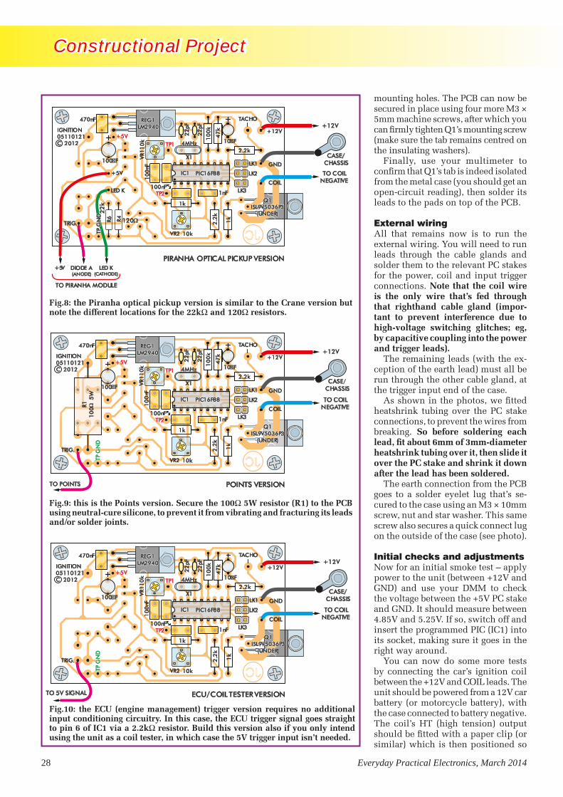
28 Everyday Practical Electronics, March 2014
Constructional Project Constructional Project
mounting holes. The PCB can now be secured in place using four more M3 × 5mm machine screws, after which you can firmly tighten Q1’s mounting screw (make sure the tab remains centred on the insulating washers).
Finally, use your multimeter to confirm that Q1’s tab is indeed isolated from the metal case (you should get an open-circuit reading), then solder its leads to the pads on top of the PCB.
External wiringAll that remains now is to run the external wiring. You will need to run leads through the cable glands and solder them to the relevant PC stakes for the power, coil and input trigger connections. Note that the coil wire is the only wire that’s fed through that righthand cable gland (impor-tant to prevent interference due to high-voltage switching glitches; eg, by capacitive coupling into the power and trigger leads).
The remaining leads (with the ex-ception of the earth lead) must all be run through the other cable gland, at the trigger input end of the case.
As shown in the photos, we fitted heatshrink tubing over the PC stake connections, to prevent the wires from breaking. So before soldering each lead, fit about 6mm of 3mm-diameter heatshrink tubing over it, then slide it over the PC stake and shrink it down after the lead has been soldered.
The earth connection from the PCB goes to a solder eyelet lug that’s se-cured to the case using an M3 × 10mm screw, nut and star washer. This same screw also secures a quick connect lug on the outside of the case (see photo).
Initial checks and adjustmentsNow for an initial smoke test – apply power to the unit (between +12V and GND) and use your DMM to check the voltage between the +5V PC stake and GND. It should measure between 4.85V and 5.25V. If so, switch off and insert the programmed PIC (IC1) into its socket, making sure it goes in the right way around.
You can now do some more tests by connecting the car’s ignition coil between the +12V and COIL leads. The unit should be powered from a 12V car battery (or motorcycle battery), with the case connected to battery negative. The coil’s HT (high tension) output should be fitted with a paper clip (or similar) which is then positioned so
10
0k
47
k
1k
2.2
k
VR1
1nF
X1
22
pF
22
pF
10
0nF
VR2
100nF
TP1TP1
TP2TP2
1k
LK1
LK2
LK3
470nF
100 F
+12V
COIL
GND
10 F
TP G
ND
TP G
ND
2.2k
TACHO
IGNITION05110121C 2012 4MHz
TRIG.
10k
10
k
+5V+5V
IC1IC1 PIC16F88PIC16F88
REG1LM2940
REG1LM2940
Q1ISL9V5036P3
(UNDER)
Q1ISL9V5036P3
(UNDER)
+12V
CASE/CHASSIS
TO 5V SIGNAL ECU/COIL TESTER VERSION
TO COILNEGATIVE
10
0k
47
k
1k
2.2
k
VR1
1nF
X1
22
pF
22
pF
10
0nF
VR2
100nF
TP1TP1
TP2TP2
1k
LK1
LK2
LK3
470nF
100 F
+12V
COIL
GND
10 F
TP G
ND
TP G
ND
2.2k
TACHO
IGNITION05110121C 2012 4MHz
TRIG.
10k
10
k
+5V+5V
IC1IC1 PIC16F88PIC16F88
REG1LM2940
REG1LM2940
Q1ISL9V5036P3
(UNDER)
Q1ISL9V5036P3
(UNDER)
10
05
WR1
+12V
CASE/CHASSIS
TO POINTS POINTS VERSION
TO COILNEGATIVE
10
0k
47
k
1k2
.2k
VR1
1nF
X1
22
pF
22
pF
10
0nF
VR2
100nF
TP1TP1
TP2TP2
1k
LK1
LK2
LK3
470nF
100 F
+12V
COIL
GND
10 F
2.2k
TACHO
IGNITION05110121C 2012 4MHz
TRIG.
10k
10
k+5V+5V
IC1IC1 PIC16F88PIC16F88
REG1LM2940
REG1LM2940
Q1ISL9V5036P3
(UNDER)
Q1ISL9V5036P3
(UNDER)
+12V
CASE/CHASSIS
DIODE A(ANODE)
PIRANHA OPTICAL PICKUP VERSION
R6 R4 120
22
k
LED K(CATHODE)
+5V
TO PIRANHA MODULE
+5V
LED K
TP G
ND
TP G
ND
TO COILNEGATIVE
Fig.9: this is the Points version. Secure the 100W 5W resistor (R1) to the PCB using neutral-cure silicone, to prevent it from vibrating and fracturing its leads and/or solder joints.
Fig.8: the Piranha optical pickup version is similar to the Crane version but note the different locations for the 22kW and 120W resistors.
Fig.10: the ECU (engine management) trigger version requires no additional input conditioning circuitry. In this case, the ECU trigger signal goes straight to pin 6 of IC1 via a 2.2kW resistor. Build this version also if you only intend using the unit as a coil tester, in which case the 5V trigger input isn’t needed.
IgnitionPt2 1212 V2 (MP).indd 28 16/01/2014 12:24:29
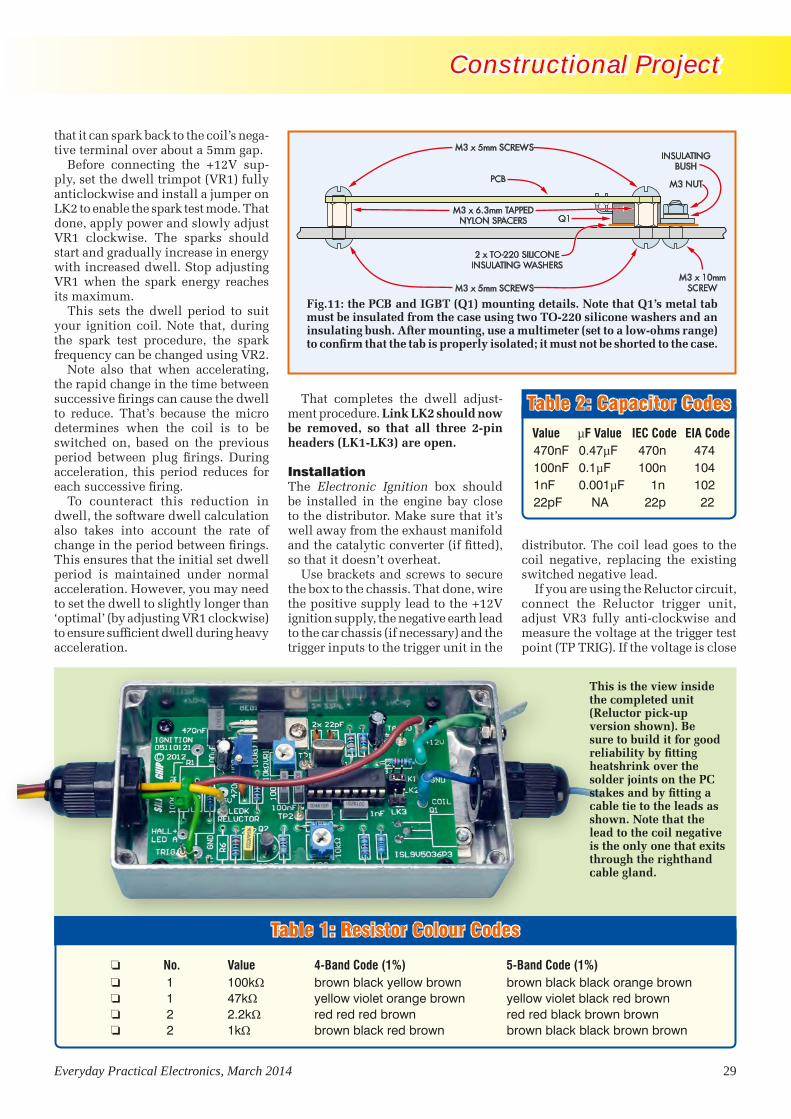
Everyday Practical Electronics, March 2014 29
Constructional Project Constructional Project
that it can spark back to the coil’s nega-tive terminal over about a 5mm gap.
Before connecting the +12V sup-ply, set the dwell trimpot (VR1) fully anticlockwise and install a jumper on LK2 to enable the spark test mode. That done, apply power and slowly adjust VR1 clockwise. The sparks should start and gradually increase in energy with increased dwell. Stop adjusting VR1 when the spark energy reaches its maximum.
This sets the dwell period to suit your ignition coil. Note that, during the spark test procedure, the spark frequency can be changed using VR2.
Note also that when accelerating, the rapid change in the time between successive firings can cause the dwell to reduce. That’s because the micro determines when the coil is to be switched on, based on the previous period between plug firings. During acceleration, this period reduces for each successive firing.
To counteract this reduction in dwell, the software dwell calculation also takes into account the rate of change in the period between firings. This ensures that the initial set dwell period is maintained under normal acceleration. However, you may need to set the dwell to slightly longer than ‘optimal’ (by adjusting VR1 clockwise) to ensure sufficient dwell during heavy acceleration.
That completes the dwell adjust-ment procedure. Link LK2 should now be removed, so that all three 2-pin headers (LK1-LK3) are open.
Installation The Electronic Ignition box should be installed in the engine bay close to the distributor. Make sure that it’s well away from the exhaust manifold and the catalytic converter (if fitted), so that it doesn’t overheat.
Use brackets and screws to secure the box to the chassis. That done, wire the positive supply lead to the +12V ignition supply, the negative earth lead to the car chassis (if necessary) and the trigger inputs to the trigger unit in the
distributor. The coil lead goes to the coil negative, replacing the existing switched negative lead.
If you are using the Reluctor circuit, connect the Reluctor trigger unit, adjust VR3 fully anti-clockwise and measure the voltage at the trigger test point (TP TRIG). If the voltage is close
PCB
M3 x 5mm SCREWS
M3 x 5mm SCREWS
M3 x 6.3mm TAPPEDNYLON SPACERS
M3 x 10mmSCREW
2 x TO-220 SILICONEINSULATING WASHERS
M3 NUT
INSULATINGBUSH
Q1
Fig.11: the PCB and IGBT (Q1) mounting details. Note that Q1’s metal tab must be insulated from the case using two TO-220 silicone washers and an insulating bush. After mounting, use a multi meter (set to a low-ohms range) to confirm that the tab is properly isolated; it must not be shorted to the case.
Table 2: Capacitor Codes Value µF Value IEC Code EIA Code 470nF 0.47µF 470n 474 100nF 0.1µF 100n 104 1nF 0.001µF 1n 102 22pF NA 22p 22
This is the view inside the completed unit (Reluctor pick-up version shown). Be sure to build it for good reliability by fitting heatshrink over the solder joints on the PC stakes and by fitting a cable tie to the leads as shown. Note that the lead to the coil negative is the only one that exits through the righthand cable gland.
Table 1: Resistor Colour Codes
o No. Value 4-Band Code (1%) 5-Band Code (1%) o 1 100kΩ brown black yellow brown brown black black orange brown o 1 47kΩ yellow violet orange brown yellow violet black red brown o 2 2.2kΩ red red red brown red red black brown brown o 2 1kΩ brown black red brown brown black black brown brown
IgnitionPt2 1212 V2 (MP).indd 29 16/01/2014 12:24:43

30 Everyday Practical Electronics, March 2014
Constructional Project Constructional Project
0 1 2 3 4 5 6 7 8 9 10 11 12 13 14 15 16 17 18 19 20 21 22 23 24 25 26
0
1
2
3
4
5
1: 0V
2: 1.08V
3: 2.21V
4: 2.68V5: 2.92V
6: 3.6V
7: 5V
Dwell vs TP1 Voltage
TP
1(V
)
Dwell (ms)
after 10s for debounce periods greater than 2ms. The debounce setting can be measured by connecting a multimeter between TP2 and TP GND. As stated, VR2 sets the debounce period and the calibration is 1ms per 1V.
Ignition coilFor most installations, it’s usually best to keep the original ignition coil and ballast resistor (if one is used). If you intend using a different coil, make sure it is suitable, especially if you intend setting the debounce period so that there’s a 10s delay before the coil switches off in the absence of trigger signals. In that case, it’s important that
the coil is able to cope with the con-tinuous current that will flow through it for this period without overheating.
A ballast resistor will prevent exces-sive current flow through coils that have a low resistance (ie, below 3Ω).
Connecting a tachometerFinally, the Tacho output (top-right of the PCB) should be suitable for driving most digital tachometers. However, an impulse tachometer will require a signal voltage that’s derived from the negative side of the coil. If that doesn’t work, try operating the ignition unit in ‘follow’ mode by installing a jumper across LK1.
Fig.13: you can check the dwell setting by measuring the voltage at test point TP1 and then reading the dwell period (in milliseconds) off this graph. The dwell is adjusted using trimpot VR1 to give maximum spark energy, as described in the text (see initial checks and adjustments).
The quick-connect terminal at the right-hand end of the case provides a convenient connection point for the earth lead.The quick-connect terminal at the right-hand end of the case provides a convenient connection point for the earth lead.
to zero, wind VR3 clockwise several turns until the voltage goes to +5V, then wind it another two turns clock-wise and leave VR3 at that setting.
Now check that LK1-LK3 are all open (ie, no jumpers installed), then try to start the engine. If it doesn’t start, try the invert mode by installing LK3.
If you have a Reluctor pick-up, it’s important that the engine fires on the leading edge of the trigger signal. That edge should coincide with the leading edge of each tooth on the Reluctor ring as the distributor shaft rotates, otherwise the timing will usually be so far out that the car won’t start. In that case, you can either swap the Reluctor leads or install LK3 as described above.
Once the engine starts, adjust the de-bounce trimpot (VR2) for best results. This adjustment should be set as low as possible (ie, set VR2 anticlockwise as far as possible). An increased de-bounce period will be required if the engine runs erratically and it’s just a matter of adjusting VR2 clockwise until smooth running is obtained.
If that doesn’t do the trick, then the follow mode may be necessary. This is selected using LK1 and will typically be required for badly worn points or worn distributor shaft cam lobes and/or shaft bearings.
Note that, in the absence of trigger signals, the coil switches off after 1s for debounce settings of 2ms and less, or
Reproduced by arrangement with SILICON CHIP
magazine 2014.www.siliconchip.com.au
IgnitionPt2 1212 V2 (MP).indd 30 16/01/2014 12:25:04


34 Everyday Practical Electronics, March 2014
Constructional Project Constructional Project
The low from pin 3 is coupled around to pin 12 via a 22µF capacitor. This capacitor then charges via a 150kΩ resistor, taking around 1.5 seconds to reach a level that will allow IC3d to be triggered by a high coming in on pin 13, from the other sensor circuit.
When a trigger pulse comes in from either sensor, the associated 22µF/150kΩ circuits stop the flipflop from being toggled back again within this 1.5-second period. This ensures that when a sensor toggles the points it cannot be toggled back again by a signal
from the other sensor until the capaci-tor discharge unit (CDU) for the points drive circuit has charged up again.
It also prevents the points swapping back and forth in the event that both sensors are detecting trains.
During actual layout operation, the situation where two trains are approaching the same set of points, should not be allowed to occur; a seri-ous crash could result.
The outputs of the flipflop are fed to the non-inverting (+) inputs of two op amps, IC4a and IC4b. These op amps
are there solely to increase the 5V sig-nal from the sensor circuits to a level sufficient to reliably turn on either of the two MOSFETs, Q5 and Q6.
The outputs of each op amp are cou-pled to the MOSFET gates via 2.2µF capacitors. In conjunction with the 390kΩ resistors, this results in a gate pulse of around two seconds. Once the 2.2µF capacitors have charged, the MOSFETs gate are pulled low via the 390kΩ resistors.
Using series capacitors ensures that the MOSFETs only remain switched
SENSOR 1
SENSOR 2
TRAIN DIRECTION
TRAIN DIRECTION
POINTS BLADEACTUATOR
A
B
DISTANCES A & B (BETWEEN SENSORS AND POINTS BLADE)ARE NOT CRITICAL, BUT SHOULD BE AT LEAST ENOUGH
TO ALLOW POINTS BLADE TO CHANGE POSITION BEFORETRAIN ARRIVES AT THE BLADE. A DISTANCE OF 50CM
SHOULD ALLOW FOR SLOW-ACTING POINTS MOTORS.The sensors are mounted on the approach side of the points from both tracks. In most circumstances, the distance from the sensors to the points is not critical.
GND
INOUT
IC1567
IC2567
IC1567
IC2567
8
8
4
4
3
3
5
5
1
1
7
7
6
6
2
2
IN
IN
OUT
OUT
LoopFilt
LoopFilt
OutFilt
OutFilt
Ct
Ct
Rt
Rt
GND
GND
V+
V+
C
C
C
C
B
B
B
B
E
E
E
E
1
2
3
1
2
3
REFL IR SENSOR 1
REFL IR SENSOR 2
100nF
100nF
470nF
100nF
100nF
470nF
100nF
100nF
4.7k
4.7k
100k
100k
560
560
4.7k
4.7k
10k
10k
15k
15k
2.2 F
2.2 F
1k
1k
A
A
A
A
A
A
A
K
K
K
K
K
K
K
LED1
LED2
Q1BC548C8050
Q3BC548
Q2BC558
Q4BC558
REG1 7805
10 F 1000 F
22 F
22 F
150k
100k
150k
100k
IC3aIC3a
IC3bIC3bIC3cIC3c
IC3dIC3d
1
2
3
4
5
6
7
8
1
2 3
4
5
6
7
8
9
10
11
12
13
14
IC3: 4011B
+5V
+5V
+12V
47k
22k
IC4aIC4a
IC4bIC4b
2.2 F
2.2 F
1k
1k
390k
IC4: LM358
D11N4148
D21N4148
390k
Q5IRFZ44Z*
G
G
S
S
D
D
D5 1N4004
CO
IL2
CO
IL1
D31N4004
D41N4004
+12V
CDU
0V
0V
Q6IRFZ44Z*
2013SC MODEL RAILWAY AUTO POINTs CONTROL
*OR IRF540N,IRF2804,
IRF2907 ETC.
KA KA
LEDS
AK
CE
B
BC548, BC558
GD
D
S
IRFZ44Z, ETC
D1, D2D3–D5
POINTMOTOR
B
A
C
MODEL RAILWAY AUTO POINTS CONTROL
rail Mar 13 (MP).indd 34 16/01/2014 12:29:49
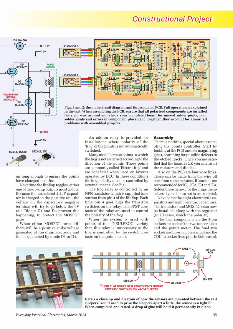
Everyday Practical Electronics, March 2014 35
Constructional Project Constructional Project
on long enough to ensure the points have changed position.
Next time the flipflop toggles, either one of the op-amp outputs must go low. Because the associated 2.2µF capaci-tor is charged to the positive rail, the voltage on the capacitor’s negative terminal will try to go below the 0V rail. Diodes D1 and D2 prevent this happening, to protect the MOSFET gates.
When either MOSFET turns off, there will be a positive spike voltage generated at the drain electrode and this is quenched by diode D3 or D4.
An add-on relay is provided for installations where polarity of the ‘frog’ of the points is not automatically switched.
Many modellers use points in which the frog is not switched according to the direction of the points. These points are commonly called ‘Electro-frog’ and are beneficial when used on layouts operated by DCC. In these conditions the frog polarity must be controlled by external means. See Fig.3.
The frog relay is controlled by an NPN transistor which is supplied base current from pin 4 of the flipflop. Each time pin 4 goes high the transistor switches on the relay. The SPST con-tacts of the relay are used to control the polarity of the frog.
When this system is used with points of the ‘INSULFROG’ variety then this relay is unnecessary as the frog is controlled by the switch con-tacts on the points itself.
AssemblyThere is nothing special about assem-bling the points controller. Start by looking at the PCB under a magnifying glass, searching for possible defects in the etched tracks. Once you are satis-fied that the board is OK you can insert the resistors and diodes.
Also on the PCB are four wire links. These can be made from the wire off cuts from some resistors. IC sockets are recommended for IC1, IC2, IC3 and IC4. Solder these in next (or the chips them-selves if you choose not to use sockets).
Next come the eight electrolytic ca-pacitors and eight ceramic capacitors. The transistors and MOSFETs can now be installed, along with the regulator (in all cases, watch the polarity).
The final components are the 3-pin sockets for each of the two sensor leads and the points motor. The final two sockets are those for power input and the CDU in socket (two pins in both cases).
JWM
JWM
08/12
JWM
REG1 7808
47
0nF
47
0nF
100k
4.7k
10
k
560
4.7k
15k
560
4.7k
15k
10
k
4.7k
100k
1k
10
0k
150k
15
0k
10
0k
47k
22
k
1k
2.2 F
2.2 F
2.2 F
2.2 F
1k
39
0k
39
0k
D1
D2
D3
D4
D5
10 FBC548
BC5
58
Q1
BC548
BC5
58
22 F100nF
100nF
100nF
100nF
100nF
100nF
22
F
1k
SENS 2
SENS 1
POINTMOTOR
1
3
31
2
2 A
B C+12V
GND
CD
U
MAIN UNIT
IR SENSOR 1
IR SENSOR 2
41
48
41
48
IC3
40
11
BIC
3 4
01
1B
IC1
56
7IC
15
67
IC2
56
7IC
25
67
IC4
LM3
58
IC4
LM3
58
4001
4001 4001
1000 F
Q3
Q2
LED1
Q4
LED2Q5
Q6
TXRX
12
3TXRX
12
3
A
A A
AAA
A
K
K K K
KK
K
SLEEPERSSENSORSENSOR
RAILS SENSORPCB
* NOTE THAT DOMES OF IR COMPONENTS SHOULDPROTRUDE ONLY SLIGHTLY ABOVE SLEEPERS
*
Here’s a close-up and diagram of how the sensors are mounted between the rail sleepers. You’ll need to prise the sleepers apart a little: the sensor is a tight fit.When completed and tested, a drop of glue will hold it permanently in place.
Figs. 1 and 2: the main circuit diagram and its associated PCB. Full operation is explained in the text. When assembling the PCB, ensure that all polarised components are installed the right way around and check your completed board for missed solder joints, poor solder joints and errors in component placement. Together, they account for almost all problems with assembled projects.
GND
INOUT
IC1567
IC2567
IC1567
IC2567
8
8
4
4
3
3
5
5
1
1
7
7
6
6
2
2
IN
IN
OUT
OUT
LoopFilt
LoopFilt
OutFilt
OutFilt
Ct
Ct
Rt
Rt
GND
GND
V+
V+
C
C
C
C
B
B
B
B
E
E
E
E
1
2
3
1
2
3
REFL IR SENSOR 1
REFL IR SENSOR 2
100nF
100nF
470nF
100nF
100nF
470nF
100nF
100nF
4.7k
4.7k
100k
100k
560
560
4.7k
4.7k
10k
10k
15k
15k
2.2 F
2.2 F
1k
1k
A
A
A
A
A
A
A
K
K
K
K
K
K
K
LED1
LED2
Q1BC548C8050
Q3BC548
Q2BC558
Q4BC558
REG1 7805
10 F 1000 F
22 F
22 F
150k
100k
150k
100k
IC3aIC3a
IC3bIC3bIC3cIC3c
IC3dIC3d
1
2
3
4
5
6
7
8
1
2 3
4
5
6
7
8
9
10
11
12
13
14
IC3: 4011B
+5V
+5V
+12V
47k
22k
IC4aIC4a
IC4bIC4b
2.2 F
2.2 F
1k
1k
390k
IC4: LM358
D11N4148
D21N4148
390k
Q5IRFZ44Z*
G
G
S
S
D
D
D5 1N4004
CO
IL2
CO
IL1
D31N4004
D41N4004
+12V
CDU
0V
0V
Q6IRFZ44Z*
2013SC MODEL RAILWAY AUTO POINTs CONTROL
*OR IRF540N,IRF2804,
IRF2907 ETC.
KA KA
LEDS
AK
CE
B
BC548, BC558
GD
D
S
IRFZ44Z, ETC
D1, D2D3–D5
POINTMOTOR
B
A
C
rail Mar 13 (MP).indd 35 16/01/2014 12:30:08
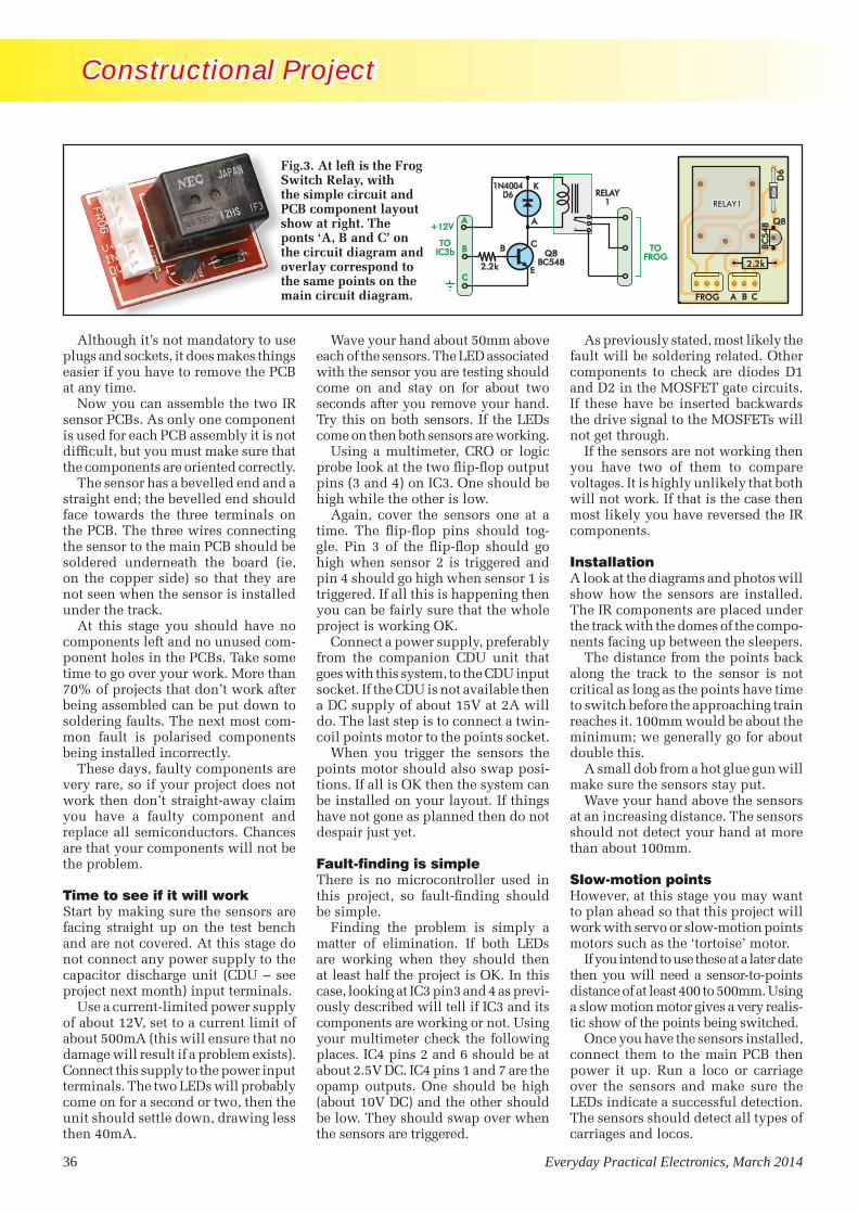
36 Everyday Practical Electronics, March 2014
Constructional Project Constructional Project
Although it’s not mandatory to use plugs and sockets, it does makes things easier if you have to remove the PCB at any time.
Now you can assemble the two IR sensor PCBs. As only one component is used for each PCB assembly it is not difficult, but you must make sure that the components are oriented correctly.
The sensor has a bevelled end and a straight end; the bevelled end should face towards the three terminals on the PCB. The three wires connecting the sensor to the main PCB should be soldered underneath the board (ie, on the copper side) so that they are not seen when the sensor is installed under the track.
At this stage you should have no components left and no unused com-ponent holes in the PCBs. Take some time to go over your work. More than 70% of projects that don’t work after being assembled can be put down to soldering faults. The next most com-mon fault is polarised components being installed incorrectly.
These days, faulty components are very rare, so if your project does not work then don’t straight-away claim you have a faulty component and replace all semiconductors. Chances are that your components will not be the problem.
Time to see if it will workStart by making sure the sensors are facing straight up on the test bench and are not covered. At this stage do not connect any power supply to the capacitor discharge unit (CDU – see project next month) input terminals.
Use a current-limited power supply of about 12V, set to a current limit of about 500mA (this will ensure that no damage will result if a problem exists). Connect this supply to the power input terminals. The two LEDs will probably come on for a second or two, then the unit should settle down, drawing less then 40mA.
Wave your hand about 50mm above each of the sensors. The LED associated with the sensor you are testing should come on and stay on for about two seconds after you remove your hand. Try this on both sensors. If the LEDs come on then both sensors are working.
Using a multimeter, CRO or logic probe look at the two flip-flop output pins (3 and 4) on IC3. One should be high while the other is low.
Again, cover the sensors one at a time. The flip-flop pins should tog-gle. Pin 3 of the flip-flop should go high when sensor 2 is triggered and pin 4 should go high when sensor 1 is triggered. If all this is happening then you can be fairly sure that the whole project is working OK.
Connect a power supply, preferably from the companion CDU unit that goes with this system, to the CDU input socket. If the CDU is not available then a DC supply of about 15V at 2A will do. The last step is to connect a twin-coil points motor to the points socket.
When you trigger the sensors the points motor should also swap posi-tions. If all is OK then the system can be installed on your layout. If things have not gone as planned then do not despair just yet.
Fault-finding is simpleThere is no microcontroller used in this project, so fault-finding should be simple.
Finding the problem is simply a matter of elimination. If both LEDs are working when they should then at least half the project is OK. In this case, looking at IC3 pin3 and 4 as previ-ously described will tell if IC3 and its components are working or not. Using your multimeter check the following places. IC4 pins 2 and 6 should be at about 2.5V DC. IC4 pins 1 and 7 are the opamp outputs. One should be high (about 10V DC) and the other should be low. They should swap over when the sensors are triggered.
FROG SWITCHRELAY
2.2k
Q8
BC5
48
D6
CBAFROG
RELAY1RELAY1
4004
As previously stated, most likely the fault will be soldering related. Other components to check are diodes D1 and D2 in the MOSFET gate circuits. If these have be inserted backwards the drive signal to the MOSFETs will not get through.
If the sensors are not working then you have two of them to compare voltages. It is highly unlikely that both will not work. If that is the case then most likely you have reversed the IR components.
InstallationA look at the diagrams and photos will show how the sensors are installed. The IR components are placed under the track with the domes of the compo-nents facing up between the sleepers.
The distance from the points back along the track to the sensor is not critical as long as the points have time to switch before the approaching train reaches it. 100mm would be about the minimum; we generally go for about double this.
A small dob from a hot glue gun will make sure the sensors stay put.
Wave your hand above the sensors at an increasing distance. The sensors should not detect your hand at more than about 100mm.
Slow-motion pointsHowever, at this stage you may want to plan ahead so that this project will work with servo or slow-motion points motors such as the ‘tortoise’ motor.
If you intend to use these at a later date then you will need a sensor-to-points distance of at least 400 to 500mm. Using a slow motion motor gives a very realis-tic show of the points being switched.
Once you have the sensors installed, connect them to the main PCB then power it up. Run a loco or carriage over the sensors and make sure the LEDs indicate a successful detection. The sensors should detect all types of carriages and locos.
Fig.3. At left is the Frog Switch Relay, with the simple circuit and PCB component layout show at right. The ponts ‘A, B and C’ on the circuit diagram and overlay correspond to the same points on the main circuit diagram.
A
K
C
E
B
2.2k
A+12V
BTO
IC3b
C
TOFROGQ8
BC548
1N4004D6 RELAY
1
rail Mar 13 (MP).indd 36 16/01/2014 12:30:21

Everyday Practical Electronics, March 2014 37
Constructional Project Constructional Project
Parts List - Automatic Points Switching
1 main PCB available from the EPE PCB Service, measuring 105 × 55mm, coded 09103132 (includes 2 sensor PCBs, measuring 17 × 8mm)
3 3-pin PCB mount sockets2 2-pin PCB mount sockets3 8-pin IC sockets1 14-pin IC socket
Semiconductors2 LM567 tone decoders (IC1, IC2)1 4011B quad Nand gate (IC3)1 LM358 dual op amp (IC4)2 Vishay TCRT5000 sensors (Sensor1,2)2 BC548 NPN transistors (Q1, Q3)2 BC558 PNP transistor (Q2, Q4)2 IRFZ44 N-channel MOSFETs [or equivalent] Q5, Q6)2 1N4148 silicon signal diodes D1, D2)3 1N4004 silicon power diodes (D3-D5)2 5mm LEDs (red, green or yellow; LED1,LED2)1 7805 3 terminal regulator
Capacitors1 1000µF 25V electrolytic2 22µF 25V electrolytic1 10µF 25V electrolytic4 2.2µF 25V electrolytic2 470nF MKT (code 470n or 474)6 100nF MKT (code 100n or 104)
Resistors (all 1/4 W carbon)2 560Ω 4 1kΩ 4 4.7kΩ 2 10kΩ 2 15kΩ1 22kΩ 1 47kΩ 4 100kΩ 2 150kΩ 2 390kΩ
Extra components required for the Frog Switching relay1 PCB, available from the EPE PCB Service, measuring 37mm × 27mm,
coded 091031331 SPDT relay1 IN4004 power diode 1 2.2kΩ resistor1 BC548 or C8050 NPN transistor [or equivalent]
All enquires for this project should be directed to the designer, Jeff Monegal. He can be contacted via email only: [email protected] All emails will be answered, but please allow up to 48 hours for a reply.
Once that is done, you can complete the installation, then sit back and enjoy another automated section of your layout.
Off-track sensorsDuring development of this system a sensor was installed inside a small electrical equipment box model that was then installed next to the track. As a train passed the electrical box the sensor reliably detected the passing of the train every time.
Although the sensors need to be dis-guised somehow, this is another idea on how to reliably detect the passing of trains and has the advantage of not having to disguise the sensors that are installed under the track.
Next month...In our April 2014 issue we will present a cheap, simple, but highly effective capacitor discharge unit (CDU) pro-ject to safely drive single or multiple points motors.
Resistor Colour Codes No. Value 4-Band Code (1%) 5-Band Code (1%) o 2 390kΩ orange white yellow brown orange white black orange brown o 2 150kΩ brown green yellow brown brown green black orange brown o 4 100kΩ brown black yellow brown brown black black orange brown o 1 47kΩ yellow violet orange brown yellow violet black red brown o 1 22kΩ red red orange brown red red black red brown o 2 15kΩ brown green orange brown brown green black red brown o 2 10kΩ brown black orange brown brown black black red brown o 4 4.7kΩ yellow violet red brown yellow violet black brown brown o 4 1kΩ brown black red brown brown black black brown brown o 2 560Ω green blue brown brown green blue black black brown
A close-up view of the under-side of the points motors. Obviously, enough clearance needs to be allowed under the tracks in your layout to accommodate the bulk of these motors.
Reproduced by arrangement with SILICON CHIP
magazine 2014.www.siliconchip.com.au
rail Mar 13 (MP).indd 37 20/01/2014 09:44:17


num_str = input("Enter a numeric value: ")value = int(num_str)
# Test inputprint(value)
Enter ‘123’ as an input and this code fragment works fine, just as you would expect. However, entering ‘123.0’ (ie, a floating point value with decimal point) results in:
Enter a numeric value: 123.0Traceback (most recent call last): File "C:/Python33/data_validation_4.py", line 3, in <module> value = int(num_str)ValueError: invalid literal for int() with base 10: '123.0'
Now, what happens if a space character is present in the input string? Entering ‘ 123’ (with a leading white space) as our input gives:
Enter a numeric value: 123Traceback (most recent call last): File "C:/Python33/data_validation_4.py", line 3, in <module> value = int(num_str)ValueError: invalid literal for int() with base 10: ' 123'
Now let’s suppose that a non-numeric characters (such as the letter ‘a’) appears in the user’s input. Entering ‘a123’ for our supposed numeric input results in the following:
Enter a numeric value: a123Traceback (most recent call last): File "C:/Python33/data_validation_4.py", line 3, in <module> value = int(num_str)ValueError: invalid literal for int() with base 10: 'a123'
These examples show that things are often not quite as simple as they might first appear. In this case, when a user’s input should be a number we do need to ensure that it really is a number by checking that there are no stray non-numeric characters in the input string. The characters that we do need to allow are:• Numbers 0 to 9 • Plus (+) and minus (–) signs• Stop or period (.) that we might need in floating-point numbers
When the user inputs a whole number (ie, a number with no decimal point) it needs to be interpreted as an integer, but when the input contains a decimal point it needs to be interpreted as a floating-point value, or ‘float’. So, for example, 123 should be interpreted as an integer while 123.0 and 123.4 should be interpreted as floats.
Fortunately, these requirements can all be satisfied using a user-defined function that waits for an input from the user, rejects any invalid characters in the input string before returning a numeric value of the correct type. Here’s an example of a user-defined function, get_number(), that does the following:1. Prompts the user for a numeric value2. Removes any leading or trailing white space3. Checks that all of the characters contained in the input string are valid numeric
characters (ie: + – . 0 1 2 3 4 5 6 7 8 9)4. Prints a message if any of the input characters are found to be invalid5. Returns either an integer or a floating-point number depending on whether a decimal
point is present in the input string.
def get_number(prompt = "Enter a numeric value: "): while True: # First remove any leading or trailing whitespace num_str = input(prompt).strip() # make sure that all char can be in a typical number if all(c in '+-.0123456789' for c in num_str): break else: print('Invalid character - try again!') # Check whether integer or float has been input if '.' in num_str: return float(num_str) else: return int(num_str)
# Test the get_number() functionvalue = get_number()print(value)
Alphanumeric inputAlphanumeric input is relatively straightforward, but we often need to limit the user’s input to a sub-set of acceptable characters and/or limit the number of characters that a user provides. In addition, we might need to ensure that the user’s input does not contain any unwanted whitespace characters. Here is an example of a simple input routine that’s designed to accept only one of the four cardinal points of the compass (N, E, S and W) from an input supplied by the user. The user-defined function, get_direction(), does the following:
1. Prompts user for a required direction2. Removes leading or trailing white space3. Checks to ensure that all of the
characters contained in the input string are valid characters that represent a direction (ie, upper-case NESW and also their lower-case equivalents, nesw)
4. Checks to ensure that the user has only supplied a single character
5. Prints a message if any of the input characters is invalid or if there is more than one character present in the input string
6. Returns the character as an upper case letter (ie, one of NESW).
Everyday Practical Electronics, March 2014 39
In Python, a string is a sequence of ASCII characters. The string’s literal value is defined by enclosing it in matching quotation marks (") or apostrophes ('). A basic string might just be "Hello World" or 'Press any key…'
The basic ASCII character set is a 7-bit code and is restricted to a maximum of 128 unique states (0000000 to 1111111 in binary code). By adding an extra leading bit, the basic ASCII character set can be expanded to provide 256 unique codes (not all of these can be used to represent alphanumeric characters, some are reserved for controlling data flow; eg, shift and delete characters).
Most of today’s 8-bit codes (eg, ISO 8859-1, the default Linux character set) encompass the standard ASCII characters when the leading bit (bit-7) is not set. The remaining characters (when the leading bit is set) provide additional characters. ISO 8859-1 encodes the 191 basic alphanumeric characters (plus punctuation) in what has become known as ‘Latin Alphabet No.1’
Unicode (such as UTF-8) is a more comprehensive, multi-byte encoding scheme. Unicode aims to provide a universal character set that will correctly show any characters from any common language. Every Unicode character requires between 1 and 4 bytes of storage. A special ‘escape sequence’ can be used to represent Unicode characters that aren’t found on your keyboard. Each escape sequence must be preceded by the backslash character (\).
Strings and things
TI-6 MP.indd 41 16/01/2014 12:31:02
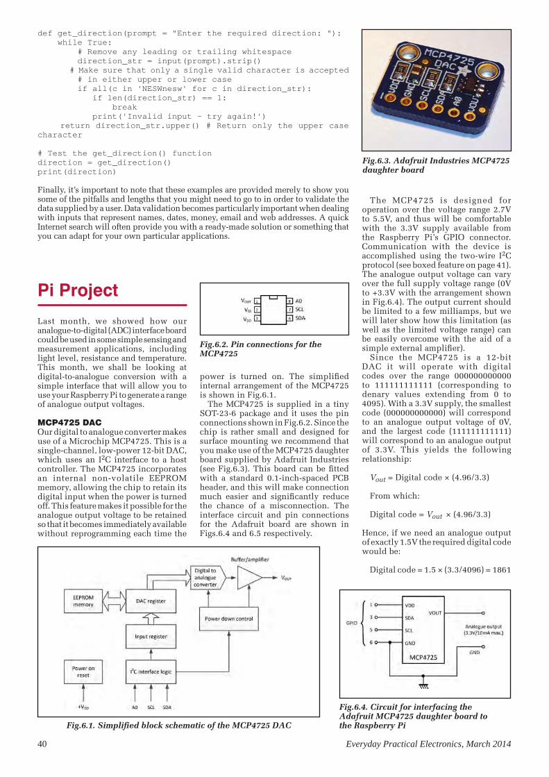
def get_direction(prompt = "Enter the required direction: "): while True: # Remove any leading or trailing whitespace direction_str = input(prompt).strip() # Make sure that only a single valid character is accepted # in either upper or lower case if all(c in 'NESWnesw' for c in direction_str): if len(direction_str) == 1: break print('Invalid input - try again!') return direction_str.upper() # Return only the upper case character
# Test the get_direction() functiondirection = get_direction()print(direction)
Finally, it’s important to note that these examples are provided merely to show you some of the pitfalls and lengths that you might need to go to in order to validate the data supplied by a user. Data validation becomes particularly important when dealing with inputs that represent names, dates, money, email and web addresses. A quick Internet search will often provide you with a ready-made solution or something that you can adapt for your own particular applications.
Pi Project
Last month, we showed how our analogue-to-digital (ADC) interface board could be used in some simple sensing and measurement applications, including light level, resistance and temperature. This month, we shall be looking at digital-to-analogue conversion with a simple interface that will allow you to use your Raspberry Pi to generate a range of analogue output voltages.
MCP4725 DACOur digital to analogue converter makes use of a Microchip MCP4725. This is a single-channel, low-power 12-bit DAC, which uses an I2C interface to a host controller. The MCP4725 incorporates an internal non-volatile EEPROM memory, allowing the chip to retain its digital input when the power is turned off. This feature makes it possible for the analogue output voltage to be retained so that it becomes immediately available without reprogramming each time the
Fig.6.1. Simplified block schematic of the MCP4725 DAC
power is turned on. The simplified internal arrangement of the MCP4725 is shown in Fig.6.1.
The MCP4725 is supplied in a tiny SOT-23-6 package and it uses the pin connections shown in Fig.6.2. Since the chip is rather small and designed for surface mounting we recommend that you make use of the MCP4725 daughter board supplied by Adafruit Industries (see Fig.6.3). This board can be fitted with a standard 0.1-inch-spaced PCB header, and this will make connection much easier and significantly reduce the chance of a misconnection. The interface circuit and pin connections for the Adafruit board are shown in Figs.6.4 and 6.5 respectively.
The MCP4725 is designed for operation over the voltage range 2.7V to 5.5V, and thus will be comfortable with the 3.3V supply available from the Raspberry Pi’s GPIO connector. Communication with the device is accomplished using the two-wire I2C protocol (see boxed feature on page 41). The analogue output voltage can vary over the full supply voltage range (0V to +3.3V with the arrangement shown in Fig.6.4). The output current should be limited to a few milliamps, but we will later show how this limitation (as well as the limited voltage range) can be easily overcome with the aid of a simple external amplifier).
Since the MCP4725 is a 12-bit DAC it will operate with digital codes over the range 000000000000 to 111111111111 (corresponding to denary values extending from 0 to 4095). With a 3.3V supply, the smallest code (000000000000) will correspond to an analogue output voltage of 0V, and the largest code (111111111111) will correspond to an analogue output of 3.3V. This yields the following relationship:
Vout = Digital code × (4.96/3.3)
From which: Digital code = Vout × (4.96/3.3)
Hence, if we need an analogue output of exactly 1.5V the required digital code would be:
Digital code = 1.5 × (3.3/4096) = 1861
Fig.6.2. Pin connections for the MCP4725
Fig.6.3. Adafruit Industries MCP4725 daughter board
Fig.6.4. Circuit for interfacing the Adafruit MCP4725 daughter board to the Raspberry Pi
40 Everyday Practical Electronics, March 2014
TI-6 MP.indd 42 16/01/2014 12:31:13
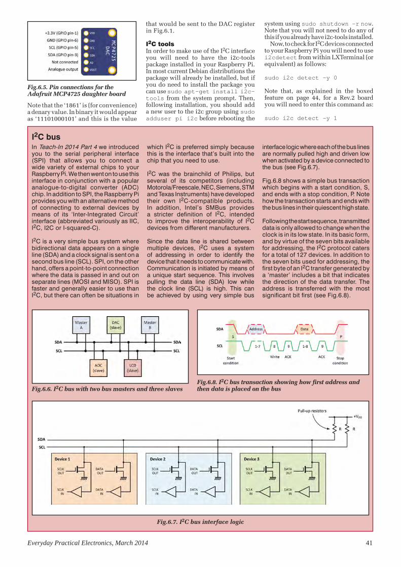
Note that the ‘1861’ is (for convenience) a denary value. In binary it would appear as ‘11101000101’ and this is the value
Everyday Practical Electronics, March 2014 41
that would be sent to the DAC register in Fig.6.1.
I2C toolsIn order to make use of the I2C interface you will need to have the i2c-tools package installed in your Raspberry Pi. In most current Debian distributions the package will already be installed, but if you do need to install the package you can use sudo apt-get install i2c-tools from the system prompt. Then, following installation, you should add a new user to the i2c group using sudo adduser pi i2c before rebooting the
Fig.6.5. Pin connections for the Adafruit MCP4725 daughter board
In Teach-In 2014 Part 4 we introduced you to the serial peripheral interface (SPI) that allows you to connect a wide variety of external chips to your Raspberry Pi. We then went on to use this interface in conjunction with a popular analogue-to-digital converter (ADC) chip. In addition to SPI, the Raspberry Pi provides you with an alternative method of connecting to external devices by means of its ‘Inter-Integrated Circuit’ interface (abbreviated variously as IIC, I2C, I2C or I-squared-C).
I2C is a very simple bus system where bidirectional data appears on a single line (SDA) and a clock signal is sent on a second bus line (SCL). SPI, on the other hand, offers a point-to-point connection where the data is passed in and out on separate lines (MOSI and MISO). SPI is faster and generally easier to use than I2C, but there can often be situations in
which I2C is preferred simply because this is the interface that’s built into the chip that you need to use.
I2C was the brainchild of Philips, but several of its competitors (including Motorola/Freescale, NEC, Siemens, STM and Texas Instruments) have developed their own I2C-compatible products. In addition, Intel’s SMBus provides a stricter definition of I2C, intended to improve the interoperability of I2C devices from different manufacturers.
Since the data line is shared between multiple devices, I2C uses a system of addressing in order to identify the device that it needs to communicate with. Communication is initiated by means of a unique start sequence. This involves pulling the data line (SDA) low while the clock line (SCL) is high. This can be achieved by using very simple bus
interface logic where each of the bus lines are normally pulled high and driven low when activated by a device connected to the bus (see Fig.6.7).
Fig.6.8 shows a simple bus transaction which begins with a start condition, S, and ends with a stop condition, P. Note how the transaction starts and ends with the bus lines in their quiescent high state.
Following the start sequence, transmitted data is only allowed to change when the clock is in its low state. In its basic form, and by virtue of the seven bits available for addressing, the I2C protocol caters for a total of 127 devices. In addition to the seven bits used for addressing, the first byte of an I2C transfer generated by a ‘master’ includes a bit that indicates the direction of the data transfer. The address is transferred with the most significant bit first (see Fig.6.8).
I2C bus
Fig.6.8. I2C bus transaction showing how first address and then data is placed on the bus
Fig.6.7. I2C bus interface logic
Fig.6.6. I2C bus with two bus masters and three slaves
system using sudo shutdown –r now. Note that you will not need to do any of this if you already have i2c-tools installed.
Now, to check for I2C devices connected to your Raspberry Pi you will need to use i2cdetect from within LXTerminal (or equivalent) as follows:
sudo i2c detect –y 0
Note that, as explained in the boxed feature on page 44, for a Rev.2 board you will need to enter this command as:
sudo i2c detect –y 1
TI-6 MP.indd 43 16/01/2014 12:31:24
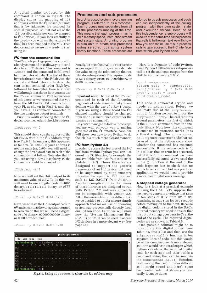
A typical display produced by this command is shown in Fig.6.9. The display shows the mapping of 128 addresses within the I2C space (but note that a few addresses are reserved for special purposes, so that not all of the 128 possible addresses can be mapped to I2C devices). If you look carefully at the display you will see that address 62 (hex) has been mapped to the MCP4725 device and so we are now ready to start using it.
I2C from the command lineThe i2c-tools package provides you with a handy command that allows you to send data to an I2C device. The command is i2cset and the command is followed by three bytes of data. The first of these bytes is the address of the I2C device; the second and third bytes are the data to be sent in conventional order (high-byte followed by low-byte). Here is a brief walkthrough that shows how you can use the i2cset command. For the purposes of this exercise we’ve assumed that you have the MCP4725 DAC connected to your Pi, as shown in Fig.6.4, and that you have a DC voltmeter connected to the two analogue output terminals.
First, it’s worth checking that the I2C device is connected and check its address:
i2cdetect –y 0
This should show you the address of the MCP4725 within the I2C address range (see Fig.6.9). In our case, this appeared as 62 hex. (ie, 0x62). If your address is not the same (eg, 0x60) you will need to change the first byte of data in each of the commands that follow. Note also that if you are using a Rev.2 Raspberry Pi the command should be changed to:
i2cdetect –y 1
Now we will set the DAC output to its maximum value of 3.3V. To do this, we will need to use a digital code of 4095 denary, 111111111111 binary, or 0FFF hexadecimal:
i2cset –y 0 0x62 0x0f 0xff
Next, we will set the DAC output back to 0V and check that the voltage has returned to zero. To do this we will need a digital code of 0 denary, 000000000000 binary, or 0000 hexadecimal:
i2cset –y 0 0x62 0x00 0x00
42 Everyday Practical Electronics, March 2014
Here is a fragment of code (written using Python 3.x) that uses a sub-process call to set the analogue output from the DAC to approximately 1.86V:
import subprocessreturn_code = subprocess.call(["i2cset –y 0 0x62 0x09 0x00"], shell = True)print(return_code)
This code is somewhat cryptic and needs an explanation. Before we can make use of the subprocess.call() function we need to import the subprocess library. The call requires several parameters, the first of which is the i2cset command from the i2c-tools library. Note how this command is enclosed in quotation marks (it is a literal string). The subprocess.call()generates a return code that can be used to let the Python code know whether the command has executed successfully. If the return code is 1, this tells us that an error has occurred, but if it is 0, the command has been successfully executed. We’ve used the print() function at the end of the code fragment just to check that no errors have occurred, but in a practical application we would need to provide a more meaningful error message.
A stepped voltage generatorNow let’s look at a practical example of using the DAC. Let’s suppose that we need to generate a voltage that rises in ten steps of 0.3V from 0V to 3V, remaining at each step for two seconds before moving on to the next. Because the digital code is stored in the DAC’s internal memory we need to ensure that the output voltage goes back to 0V at the end of the cycle. The required digital codes are as shown in Table 6.5.
One possible solution might be to incorporate the digital codes from Table 6.5 into a list and then use the subprocess.call() function in ten separate lines of code, but this would be rather cumbersome. A more elegant solution would be to use a loop in which Python calculates the required digital code for each step and then builds a command string that can be sent via the subprocess.call() function. Fortunately, this isn’t quite as difficult as it might sound and here’s some commented code that shows you how easily it can be done:
Finally, let’s set the DAC to 1V (or as near as we can get). To do this, we can calculate the value using the relationship that we introduced on page 40. The required code is 1232 denary, 010011010000 binary, or 04D0 hexadecimal:
i2cset –y 0 0x62 0x04 0xd0
Important note: The use of the i2cset command in each of the foregoing fragments of code assumes that you are dealing with the use of a Rev.1 board. If you are using a Rev.2 board the I2C channel numbers should be changed from 0 to 1 (as mentioned earlier for the i2cdetect command).
If you’ve managed to follow these steps you are well on your way to making good use of the I2C interface. Next, we will show you how to use Python to do the job in a much more elegant manner!
I2C from Python 3.xIn order to access the features of the I2C bus from within Python you can use one of the I2C libraries, for example, the one available from Adafruit Industries (Adafruit_I2C). These libraries are designed to support the generic framework of an I2C device, but need to be augmented by supplementary libraries for specific I2C devices, such as I2C_DAC.PY from Adafruit. Another complication is that many of these libraries are designed to run with Python 2.7 and may currently not be compatible with version 3.x. All of this makes life rather difficult, so we’ve decided to opt for a more simple approach that makes use of operating system sub-process calls directly from our Python code. Later, we will show how the ‘System Management Bus’ (SMBus or SMB) can be used to access I2C devices in a more elegant way (see page 44).
Fig.6.9. Using i2cdetect to show the i2c address map
In a Unix-based system, every running program is referred to as a ‘process’. Each process runs separately from all of the processes running at the time. This means that each program has its own memory space, instruction stream and system state. A running program is also able to create new processes using selected operating system library functions. These processes are
referred to as sub-processes and each can run independently of the calling program with their own system state and execution thread. Because of this independence, a sub-process will execute at the same time as the process that calls it. In the main text we will show how you can make use of sub-process calls to gain access to the I2C interface from within your Python code.
Processes and sub-processes
TI-6 MP.indd 44 16/01/2014 12:31:31

Everyday Practical Electronics, March 2014 43
# Import the required librariesimport timeimport subprocess# Initial voltage = 0Vvoltage = 0step = 0while step < 10: voltage = step * voltage # Calculate the digital code volts = voltage * 4096 / 3.3 # Convert the digital code to two bytes code = int(volts) first = int(code / 255) second = code - (first * 256) # Format the two hexadecimal values value1 = format(first, '#04x') value2 = format(second, '#04x') # Build the command string command_string = "i2cset -y 0 0x62 " + value1 + " " + value2 # Make the sub-process call return_code = subprocess.call([command_string], shell=True) # Hold the voltage steady for two seconds time.sleep(2) # Increment the step counter step = step + 1# After exiting the loop set the output back to 0Vcommand_string = "i2cset -y 0 0x62 0x00 0x00"return_code = subprocess.call([command_string], shell=True)
See Fig.6.10 for the voltage waveform generated by the Python ramp generator code.And finally, here’s a complete Python 3.x program that will let you produce any
desired output voltage from the DAC in the range 0V to 3.3V:
# MCP4725 DAC for Python 3.ximport subprocessvoltage = 0while True: value = input("Output voltage: ") voltage = float(value) while voltage >= 0 and voltage < 3.3: volts = voltage * 4096 / 3.3 code = int(volts) first = int(code / 255) second = code - (first * 256) value1 = format(first, '#04x') value2 = format(second, '#04x') command_string = "i2cset -y 0 0x62 " + value1 + " " + value2 return_code = subprocess.call([command_string], shell=True) if return_code == 0: print("Success - output now set to ", value + " V") else: print("Error setting DAC - output not changed!") voltage = -1
The main points of the program are as follows:1. Prompt the user for the required output
voltage and convert the input to a floating point number.
2. Check that the user’s input is within the acceptable range (0V to +3.3V)
3. Convert the floating-point value into two hexadecimal bytes
4. Insert the two hexadecimal bytes into the i2cset() command string
5. Make the subprocess.call(0)6. Check the return code and warn the
user if an error is detected.
Note that the code is designed for use with a Rev.1 Raspberry Pi board. If you are using a Rev.2 board you will need to change command_string as noted earlier, with the 0 replaced by a 1 (see boxed feature on page 44).
Increasing the voltage and currentThe basic ADC will produce a current of up to around 10mA at voltages in the range 0 to 3.3V. Unfortunately, this will be inadequate for many applications but these limitations can be easily overcome with the use of an external power amplifier stage, as shown in Fig.6.11.
L165 power operational amplifierThe L165 is a high-power operational amplifier supplied in a Pentawatt package (see Fig.6.12). The device is able to deliver currents of up to 3A and it operates from a symmetrical voltage supply of typically ±12V (±18V max.).
As with all operational amplifiers, the voltage gain provided by the L165 can be made adjustable by means of negative feedback. In the circuit of Fig.6.9, the voltage gain is variable over the range 2 to 4 by means of RV1. At
Table 6.5 Digital codes (and their hexadecimal equivalents) for the stepped voltage generator
Step number Voltage Digital code Hex. equivalent
0 0 0 0000
1 0.3 372 0175
2 0.6 744 02E83 0.9 1117 045D4 1.2 1489 05D15 1.5 1861 07456 1.8 2234 08BA7 2.1 2606 0A2E8 2.4 2978 0BA29 2.7 3356 0D1C10 3.0 3724 0E8B
Fig.6.10 Python ramp generator waveform
Fig.6.11. Additional amplifier stage for use with the DAC
TI-6 MP.indd 45 16/01/2014 12:31:41

44 Everyday Practical Electronics, March 2014
mid-position of RV1, the voltage gain will be approximately 3 and thus a 3.3V input from the MCP4725 will result in an output of around +10V. In a practical application (see Python code opposite) RV1 is adjusted for the required full-scale value (10V in this case) when an output of 10V is requested.
When the MCP4725 DAC is used with the L165 amplifier, the following Python code will produce any desired output voltage over the increased range 0V to 10V and with an output current of up to 1A:
# MCP4725 DAC with amplifier for Python 3.ximport subprocessvoltage = 0while True: value = input("Output voltage: ") voltage = float(value) while voltage >= 0 and voltage < 10.1: volts = voltage * 4096 / 11 code = int(volts) first = int(code / 255) second = code - (first * 256) value1 = format(first, '#04x') value2 = format(second, '#04x') command_string = "i2cset -y 0 0x62 " + value1 + " " + value2 return_code = subprocess.call([command_string], shell=True) if return_code == 0: print("Success - output now set to ", value + " V") else: print("Error setting DAC - output not changed!") voltage = -1
Once again, this code has been written for a Rev.1 Raspberry Pi board. If you are using a Rev.2 board you will need to make changes to the command_string so
that the 0 becomes a 1 (see boxed feature opposite/below).
Finally, and if you are intending to drive loads that are significantly inductive, such as solenoids, relays and motors, you might find it worthwhile adding some additional protection diodes to the output of the L165 amplifier, as shown in Fig.6.13. These diodes provide an external path for back EMF, augmenting the diodes that the L165 has internally. D1 and D2 should be rated at currents of at least 1A and PIV of at least 50V.
I2C from Python 2.xAs br ie f ly ment ioned ear l ie r, subprocess.call() provides us with a way of accessing the I2C bus from Python 3.x, avoiding the use of libraries that are not currently compatible with the latest version of Python. A less cumbersome solution (but one which will only work with earlier versions of Python) is using the SMBus library. In next month’s Teach-In 2014 we will explain how this operates in greater depth, but for the sake of completeness, here are some Python 2.x versions of the code that we met earlier. These programs all make use of the SMBus library rather than sub-process calls.
The Raspberry Pi supports two I2C channels, 0 and 1. However, on the most recent Raspberry Pi revision (Rev.2) the primary and secondary I2C channels have been reversed. On Rev.1 (and earlier) boards the physical connections to the I2C channels are as shown in Table 6.1, but on the Rev.2 boards they are as shown in Table 6.2.
To facilitate the additional I/O present on Rev.2 boards, a new connector, P5, can be fitted. The connecting pads for P5 are located immediately adjacent to the GPIO connector, P1. P5 makes available four additional GPIO signals, together with power. The pin assignment for P5 is shown in Table 6.3.
If you are unsure of which revision you have you can determine a board’s revision status by entering the following at the command line: cat /proc/cpuinfo. This will show you the hardware revision code for the board in question and this can be used to determine the board’s revision number (see Table 6.4).
I2C and Raspberry Pi board revisions
Table 6.1 I2C channels and physical connections for pre-Rev.2 Raspberry Pi boards
Table 6.2 I2C channels and physical connections Rev.2 Raspberry Pi boards
Table 6.3 P5 connections for Rev.2 Raspberry Pi
Table 6.4 Hardware revision codes and board revision numbers
I2C channel
I2Csignal
Physical connection
BCM2835 signal
0 SCL0 P1 pin-5 GPIO1
0 SDA0 P1 pin-3 GPIO0
1 SCL1 S5 pin-13 GPIO31 SDA1 S5 pin-14 GPIO2
I2C channel
I2Csignal
Physical connection
BCM2835 signal
0 SCL0 S5 pin-13 GPIO1
0 SDA0 S5 pin-14 GPIO0
1 SCL1 P1 pin-5 GPIO31 SDA1 P1 pin-3 GPIO2
P5 pin number
Signal connection
1 +5V
2 +3.3V
3 GPIO284 GPIO295 GPIO306 GPIO317 GND8 GND
Hardware code
Board revision
2 Model B Rev.1
3 Model B Rev.1
4 Model B Rev.25 Model B Rev.2
6Model B
Rev.2
Fig.6.12. L165 pin connections
Fig.6.13. External diode protection for inductive loads
TI-6 MP.indd 46 16/01/2014 12:31:51

Everyday Practical Electronics, March 2014 45
Stepped ramp generator (see code on page 43)# MCP4725 DAC for Python 2.x
# Import the required librariesimport timeimport smbus
# Set the bus to use (for Rev.2 change 0 to 1)bus = smbus.SMBus(0)
# DAC's I2C bus addressDAC = 0x62
# Initial voltage = 0Vvoltage = 0step = 0while step < 11: voltage = step * 0.3 # Calculate the digital code volts = voltage * 4096 / 3.3 # Convert the digital code to two bytes code = int(volts) first = int(code / 255) second = code - (first * 256) bus.write_word_data(DAC,first,second) # Hold the voltage steady for two seconds time.sleep(2) # Increment the step counter
step = step + 1# After exiting the loop set the output back to 0Vbus.write_word_data(DAC,0x00,0x00
0 to 3.3V from the MCP4725 DAC (see code on page 43)# MCP4725 DAC for Python 2.x
# Import the required librariesimport timeimport smbus
# Set the bus to use (for Rev.2 change 0 to 1)bus = smbus.SMBus(0)
# DAC's I2C bus addressDAC = 0x62
voltage = 0while True: value = input("Output voltage: ") voltage = float(value) while voltage >= 0 and voltage < 3.3: volts = voltage * 4096 / 3.3 code = int(volts) first = int(code / 255) second = code - (first * 256) bus.write_word_data(DAC,first,second) voltage = -1
Our external power amplifier requires a ±12V supply capable of delivering a current of up to about 2A, depending upon the load that it is connected to. A simple solution to this problem makes use of a surplus ATX computer power supply. Such a unit can be removed from a scrapped PC and will only require a few
external components in order to operate as a versatile stand-alone power supply, see Fig.6.14.
The standard wiring of a 20-way ATX power connector is shown in Fig.6.15 and the output ratings for a 250W ATX power supply are shown in Table 6.6
A low-cost ±12V high-current supply
Fig.6.14. Circuit of the ± 12V supply based on an ATX power supply
Fig.6.15. The ATX power connector
Fig.6.16. The author’s ATX-basedpower unit makes a handy bench supply
Table 6.6 Typical ATX specification
Voltage rail Colour ATX 20-way connector pin
number(s)Typical current rating
(250W supply)+12V Yellow 10 10A
+5V Red 4, 6, 19, 20 25A
-12V Blue 12 0.5A+3.3V Orange 1, 2, 11 13A
-5V White 18 0.3A+5V SB Dark grey 9 2A
GND Black 3, 5, 7, 13, 15, 16, 17 n/a
TI-6 MP.indd 47 16/01/2014 12:32:07

0 to 10V from the MCP4725 DAC and L165 amplifier (see code on page 44)
# MCP4725 DAC with amplifier for Python 2.x
# Import the required librariesimport timeimport smbus
# Set the bus to use (for Rev.2 change 0 to 1)bus = smbus.SMBus(0)
# DAC's I2C bus addressDAC = 0x62
voltage = 0while True: value = input("Output voltage: ") voltage = float(value) while voltage >= 0 and voltage < 10.1: volts = voltage * 4096 / 11 code = int(volts) first = int(code / 255) second = code - (first * 256) bus.write_word_data(DAC,first,second) voltage = -1
In next month’s Teach-In with Raspberry PiIn next month’s Teach-In 2014, our Pi Project features the construction of a 16-channel port expander for the Raspberry Pi. Our Pi Class introduces binary, octal and hexadecimal numbers, while Python Quickstart deals with methods of handling and manipulating binary, octal and hexadecimal data. We will also be showing you how the System Management Bus (SMBus) can provide you with a simple way of accessing a wide-range of I2C devices.
46 Everyday Practical Electronics, March 2014
REMEMBER WE HAVE BOOKS TO HELP!
FOR A FULL DESCRIPTION OF THESE BOOKS GO TO THE ONLINE
SHOP ON OUR WEBSITE
www.epemag.com
Build This Project
Thinking of building this project ?The MCP4725 board featured inthis article and many more Adafruitproducts are available from Tandy.
£.3.59 Inc. VAT(£2.99 Ex. VAT)
www.tandyonline.co.uk
Catalogue number980-935
Imaginethis...
TI-6 MP.indd 48 16/01/2014 12:32:14

Everyday Practical Electronics, March 2014 47
BACK ISSUES DVD/CD-ROM ORDER FORM
Please send me the following Back Issue DVD/CD-ROMs.
Volume Numbers:. . . . . . . . . . . . . . . . . . . . . . . . . . . . . . . . . . . . . . . . . . . . . .
. . . . . . . . . . . . . . . . . . . . . . . . . . . . . . . . . . . . . . . . . . . . . . . . . . . . . . . . . .
Price £16.45 each, £29.95 for Five Year DVD/CD-ROMs –
includes postage to anywhere in the world.
Name . . . . . . . . . . . . . . . . . . . . . . . . . . . . . . . . . . . . . . . . . . . . . . . . . . . .
Address . . . . . . . . . . . . . . . . . . . . . . . . . . . . . . . . . . . . . . . . . . . .
. . . . . . . . . . . . . . . . . . . . . . . . . . . . . . . . . . . . . . . . . . . . . . . . . . .
. . . . . . . . . . . . . . . . . . . . . . . . . . . . . . . . . . . . . . . . . . . . . . . . . . .
Post Code. . . . . . . . . . . . . . . . . . . . . . . . . . . . . . . . . . . . . . . . . . .
I enclose cheque/P.O./bank draft to the value of £ . . . . . . . . .
please charge my Visa/Mastercard/Maestro £ . . . . . . . . . . . .
Card No. . . . . . . . . . . . . . . . . . . . . . . . . . . . . . . . . . . . . . . . . . . . .
Card Security Code . . . . . . . . . . (The last 3 digits on or just under the signature strip)
Valid From. . . . . . . . . . . . . . . . Expiry Date . . . . . . . . . . . . . . . . .
Maestro Issue No.. . . . . . . . . .
SEND TO: Everyday Practical Electronics,Wimborne Publishing Ltd., 113 Lynwood Drive, Merley,
Wimborne, Dorset BH21 1UU.
Tel: 01202 880299. Fax: 01202 843233.E-mail: [email protected]
Payments must be by card or in £ Sterling – cheque or bank draft drawn on a UK bank.
Normally posted within seven days of receipt of order.
VOL 1: BACK ISSUES – January 1999 to June 1999 Plus some bonus material from Nov and Dec 1998
VOL 2: BACK ISSUES – July 1999 to December 1999
VOL 3: BACK ISSUES – January 2000 to June 2000
VOL 4: BACK ISSUES – July 2000 to December 2000
VOL 5: BACK ISSUES – January 2001 to June 2001
VOL 6: BACK ISSUES – July 2001 to December 2001
VOL 7: BACK ISSUES – January 2002 to June 2002
VOL 8: BACK ISSUES – July 2002 to December 2002
VOL 9: BACK ISSUES – January 2003 to June 2003
VOL 10: BACK ISSUES – July 2003 to December 2003
VOL 11: BACK ISSUES – January 2004 to June 2004
VOL 12: BACK ISSUES – July 2004 to December 2004
VOL 13: BACK ISSUES – January 2005 to June 2005
VOL 14: BACK ISSUES – July 2005 to December 2005
VOL 15: BACK ISSUES – January 2006 to June 2006
VOL 16: BACK ISSUES – July 2006 to December 2006
VOL 17: BACK ISSUES – January 2007 to June 2007
VOL 18: BACK ISSUES – July 2007 to December 2007
VOL 19: BACK ISSUES – January 2008 to June 2008
VOL 20: BACK ISSUES – July 2008 to December 2008
VOL 21: BACK ISSUES – January 2009 to June 2009
VOL 22: BACK ISSUES – July 2009 to December 2009
VOL 23: BACK ISSUES – January 2010 to June 2010
VOL 24: BACK ISSUES – July 2010 to December 2010
VOL 25: BACK ISSUES – January 2011 to June 2011
VOL 26: BACK ISSUES – July 2011 to December 2011
VOL 27: BACK ISSUES – January 2012 to June 2012
VOL 28: BACK ISSUES – July 2012 to December 2012
VOL 29: BACK ISSUES – January 2013 to June 2013
FIVE YEAR CD/DVD-ROMs
No.1 – Jan ’03 to Dec ’07No.2 – Jan ’04 to Dec ’08No.3 – Jan ’05 to Dec ’09No.4 – Jan ’06 to Dec ’10No.5 – Jan ’07 to Dec ’11No.6 – Jan ’08 to Dec ’12
NOTE: These DVD/CD-ROMs are suitable for use on any PC with a DVD/CD-ROM drive. They require Adobe Acrobat Reader (available free from the Internet – www.adobe.com/acrobat)
WHAT IS INCLUDEDAll volumes include the EPE Online content of every listed issue. Please note that we are unable to answer technical queries or provide data on articles that are more than five years old. Please also ensure that all components are still available before commencing construction of a project from a back issue.
A great way to buy EPE Back Issues – our DVD/CD-ROMs contain back issues from our EPE Online website. Note: no free gifts are
included.
Order on-line fromwww.epemag.com (go to the UK store)
or by phone, fax, email or post
ONLY
£16.45(£29.95 FOR 5 YEAR) each including VAT and p&p
FIVE YEAR DVD/CD-ROMs
NOW AVAILABLE
STORE YOUR BACK ISSUES ON CD-ROMS
WIN A MICROCHIP PIC32 GUI
DEVELOPMENT BOARD
Teach-In 2014 Raspberry Pi – Part 1
HigH-TemperaTure THermomeTer/THermosTaT precise measuremenT and relay
conTrol of TemperaTure
plus: IngenuIty unlImIted, net work, readout,
CIrCuIt surgery, teChno talk & InterfaCe
led musicolourindividual control of 16 strings of leds
16-bit dsp microcontrollerpWm led driveoperation via infrared remote
EPE’s comprehensive guide to Raspberry Pi
OCT 2013 £4.40OCT 13 Cover.indd 1
22/08/2013 13:19:46
WIN A MICROCHIP
LCD EXPLORER DEVELOPMENT BOARD
Build a most useful tool!
MiniReg AdjustABle
RegulAtoR
Vacuum Pump from junkFully regulated dC: 1.3V to 22V, up to 1a
usB steReo RecoRding & PlAyBAck
inteRfAce use youR Pc to MAke high-quAlity
steReo Audio RecoRdings
plus: Net work, CirCuit surgery, teChNo talk
praCtiCally speakiNg, reaDout
digitAl sound effects Module
usB configuration interface
1.5-125 seconds playback time
inexpensive, compact and flexible
Works with WAV files via a Windows Pc
SEPTEMBER 2013
SEPT 13 Cover.indd 1
18/07/2013 12:55:21
WIN A MICROCHIP MPLAB STARTER KIT FOR DIGITAL POWER
Teach-In 2014 Raspberry Pi – Part 2LED MusicoLour – Part 2sPEctacuLar Light anD Music show
plus: Net work, readout, CirCuit surgery, teChNo talk & praCtiCally speakiNg
cLassic-D aMPLifiErhigh efficiency, high power
Low distortion, low noise
Bridging option for 8Ω loads
speaker protection module
EPE’s comprehensive guide to Raspberry Pi
NOV 2013 £4.40
NOV 13 Cover.indd 1 18/09/2013 18:33:28
Back Issues CDs.indd 47 20/01/2014 11:13:02

48 Everyday Practical Electronics, January 2014
Arduino galore!As you may recall from my last few columns, I’m really plunging into the world of Arduino microcontrollers. I did recently run into one small ‘gotcha’ when my main notepad computer asked if I wanted to upgrade from Win-dows 8 to Windows 8.1. When I did so, the USB COM port I’d been using to program my Arduino disappeared (the Tools > Serial Port menu item in the Arduino de-velopment environment is greyed out). I’ve not yet worked out how to solve this little conundrum, but my Windows 7-based notepad continues to work just fine. (FYI: I used the File > Preferences command to modify my Sketchbook location to point to my Dropbox folder, which means all of my Arduino programs are backed up in the cloud and are accessible from any of my computers.)
Truth be told, I currently have so many Arduino-based projects ‘on the go’ that I don’t really know where to start. In a previous column I mentioned that I was building a 4×4×4 3D tri-color LED cube powered by an Arduino-compatible controller. Well, I finished that and it looks great – it’s sitting on my desk entertaining me with a be-guiling light display as I pen these words. This led me to want to build something else that involved LEDs (show me a flashing LED, and I’ll show you a man entranced saying, ‘Oooh, shiny!’).
Infinity mirrorEventually I decided to make an Infinity Mirror (http://bit.ly/19Tbg9N), which involves a thin box frame with a full mirror at the back, a half (one-way) mirror at the front, and a bunch of LEDs mounted around the inside periphery of the frame sandwiched between the two mir-rors. When the LEDs are activated, it appears as though you have rows and rows of them receding to infinity. You can find a lot of information about building these on the web, including things like creating your own half-mirror using regular glass coated with a sheet of the same film you use to tint car windows. Unfortunately, these websites tend to be a bit thin-on-the-ground when
Max’s Cool Beans
By Max The Magnificent
48 Everyday Practical Electronics, March 2014
it comes to specifics, such as the optimal gap between the two mirrors and the type of window-tinting film to use. The end result is that I’ve spent a happy few weeks experimenting with different setups (I will report fur-ther in a future column).
As part of my Infinity Mirror project, I decided to use a strip of NeoPixels from Adafruit.com. The one-metre strip I chose to play with boasts 60 of these incredibly bright, tri-color LEDs (http://bit.ly/1lPDFgN). The really cool thing about these LEDs is that you need only use a single digital output pin on your Arduino to control the entire strip, you can daisy-chain multiple strips together, and can essentially control the colour and brightness of each LED individually.
My Steampunk projectBut that’s not what I wanted to talk to you about. Several years ago, I saw a really funny image of a ‘Man vs Wom-an’ piece of pseudo-electronic equipment (http://bit.ly/1hvRvHv) and I thought to myself ‘I’d like to build one of those.’ The thing is, I want mine to look really cool and tasty – I’m thinking of a Steampunk look-and-feel – so for the past few years I’ve been collecting antique knobs and switches and analogue meters and suchlike. All of this is going to be presented in a superb wooden radio cabinet from 1929. (You can read much more about this project in a series of articles I wrote at http://bit.ly/1eHtHf8)
This has been an ongoing ‘back-burner’ project. Every now and then I’ve played around with one microcon-troller or another, experimenting with driving lots of LEDs (there will be about 120 on the front panel) and control-ling analogue meters. But each prototype grew to be over-complicated, at which time my mind would wander off to contemplate something else. So you can only imagine my excitement while I was playing around with my In-finity Mirror project when I thought to myself ‘Hang on, if I use Adafruit’s NeoPixels, I can control all 120 LEDs on my front panel using a single digital output from my Arduino!’ Furthermore, in the case of an Arduino Mega
(http://bit.ly/1gEbS2r), I can use the 15 PWM (pulse-width modulated) outputs to drive my ana-logue meters, the 16 ana-logue inputs to monitor rotary potentiometers, and the remainder of the 54 digital pins to moni-tor switches and control other ‘stuff.’
Prototyping shieldsThus it was that my Pedagogical and Phan-tasmagorical Inamo-rata Prognostication Engine (Mark 1) project returned to the fore-front of my attention. This is actually very Fig.1. Screw-block prototyping shield
Blog - MARCH 2014.indd 48 16/01/2014 12:14:51

much progressed – I hope to have the whole thing working in no more than a couple of months – there’s just one snag... You can get standard prototyping shields for the Arduino Uno (http://bit.ly/1cPd1zc) and the Arduino Mega (http://bit.ly/1kqVKGA). You can also get a really cool prototyping shield equipped with screw-block terminals for the Arduino Uno (http://bit.ly/1bRS72a). Using these screw-block terminals would make prototyping ‘The Beast’ a whole lot easier. Sad to relate, however, I’ve not been able to track down an off-the-shelf equivalent for an Arduino Mega.
But turn that frown upside down into a smile. I called my friend Duane Benson, who is the Marketing Manager at Screaming Circuits (http://bit.ly/1cZbjj1). Don’t let the ‘Marketing Manager’ fool you – Duane is a microcontroller expert who creates PCBs for his own hobby projects. Before you could say ‘Max truly is magnificent,’ Duane had whipped up the most amazing screw-block prototyping shield as shown in Fig.1.
This is really rather clever. The reason the shield is presented in two pieces is that the left-hand board will work on both an Arduino Uno and the left-hand half of an Arduino Mega. Meanwhile, the right-hand board can be applied to the right-hand half of an Arduino Mega.
Now, sometimes I will want a screw-block terminal to be connected directly to its associated header pin. In other cases, however, I will want to have a circuit in the prototyping area with a header pin con-nected to some component and its associated screw-block terminal connected to other components.
Everyday Practical Electronics, March 2014 49
Our solution to this is really rather cunning. Consider the con-nectors on the upper side of the left-hand board, for example. The green ‘jelly-bean’ shaped graphics at the very top represent the screw block terminals facing the outside world. Next in we see the whitish area, which corresponds to the header pins that are used to connect this shield to the Arduino Mega below (also you can plug additional shields into these headers from above).
Moving 1/10 of an inch further into the board, the first row of pads are connected to their corresponding header pins, while the next row of pads are connected to the associated screw-block terminals (the next row of pads highlighted in red are connected to +5V; the corre-sponding row at the bottom of the board is connected to 0V). Thus, if I wish to connect a header pin to its associated screw-block terminal, I need only insert a small jumper connecting the two pads between the header and the power rail. Alterna-tively, I can use wires to connect these pads to com-ponents in the main proto-typing area. I have to say that I’m very excited by all of this; I cannot wait for these boards to come back from the shop. Until next time, have a good one!
Blog - MARCH 2014.indd 49 16/01/2014 12:15:08

50 Everyday Practical Electronics, March 2014
IT IS BACK...
EVERYDAY PRACTICAL ELECTRONICS IS NOW
AVAILABLE IN PDF FORMAT AGAIN
REQUIREMENTS:
YOU NEED TO BE RUNNING A WINDOWS PCUSING ADOBE ACROBAT READER
GO TO
www.epemag.comTO ORDER
WIN A MICROCHIP
REMOTE CONTROL DEMO BOARD WITH ZENA WIRELESS
ADAPTOR
Teach-In 2014 Raspberry Pi – Part 3
CLASSiC-D AmpLifier
ConStruCting our high-power
high-performAnCe Amp
plus: Net work, readout, CirCuit surgery,
teChNo talk, piC N’ MiX & iNterFaCe
uSB muLti-inStrument
projeCtpC controlled
2-channel digital scope
Spectrum analyser
Dmm and frequency counter
Audio function generator
EPE’s comprehensive guide to Raspberry Pi
DEC 2013 £4.40
DEC 13 Cover.indd 1
18/10/2013 09:10:33
PDF EPE Sub Page.indd 50 16/01/2014 12:34:23

Everyday Practical Electronics, March 2014 51
AGILENT E4407B Spectrum Analyser – 100HZ-26.5GHZ £6,500AGILENT E4402B Spectrum Analyser – 100HZ-3GHZ £3,500HP 3325A Synthesised Function Generator £250HP 3561A Dynamic Signal Analyser £800HP 3581A Wave Analyser – 15HZ-50KHZ £250HP 3585A Spectrum Analyser – 20HZ-40MHZ £995HP 53131A Universal Counter – 3GHZ £600HP 5361B Pulse/Microwave Counter – 26.5GHZ £1,500HP 54502A Digitising Scope 2ch – 400MHZ 400MS/S £295HP 54600B Oscilloscope – 100MHZ 20MS/S from £195HP 54615B Oscilloscope 2ch – 500MHZ 1GS/S £800HP 6030A PSU 0-200V 0-17A – 1000W £895HP 6032A PSU 0-60V 0-50A – 1000W £750HP 6622A PSU 0-20V 4A twice or 0-50v2a twice £350HP 6624A PSU 4 Outputs £350HP 6632B PSU 0-20V 0-5A £195HP 6644A PSU 0-60V 3.5A £400HP 6654A PSU 0-60V 0-9A £500HP 8341A Synthesised Sweep Generator – 10MHZ-20GHZ £2,000HP 8350B with 83592a Generator – 10MHZ-20GHZ £600HP 83731A Synthesised Signal Generator – 1-20GHZ £2,500HP 8484A Power Sensor – 0.01-18GHZ 3nW-10uW £125HP 8560A Spectrum Analyser synthesised – 50HZ -2.9GHZ £2,100HP 8560E Spectrum Analyser synthesised – 30HZ--2.9GHZ £2,500HP 8563A Spectrum Analyser synthesised – 9KHZ-22GHZ £2,995HP 8566A Spectrum Analyser – 100HZ-22GHZ £1,600HP 8662A RF Generator – 10KHZ-1280MHZ £1,000HP 8672A Signal Generator – 2-18GHZ £500HP 8673B Synthesised Signal Generator – 2-26GHZ £1,000HP 8970B Noise Figure Meter £995HP 33120A Function Generator – 100 microHZ-15MHZ £395MARCONI 2022E Synthesised AM/FM Sig Generator – 10KHZ-1.01GHZ £395MARCONI 2024 Synthesised Signal Generator – 9KHZ-2.4GHZ from £800MARCONI 2030 Synthesised Signal Generator – 10KHZ-1.35GHZ £950MARCONI 2305 Modulation Meter £250MARCONI 2440 Counter20GHZ £395MARCONI 2945 Comms Test Set various options £3,000
MARCONI 2955 Radio Comms Test Set £595MARCONI 2955A Radio Comms Test Set £725MARCONI 2955B Radio Comms Test Set £850MARCONI 6200 Microwave Test Set £2,600MARCONI 6200A Microwave Test Set – 10MHZ-20GHZ £3,000MARCONI 6200B Microwave Test Set £3,500IFR 6204B Microwave Test Set – 40GHZ £12,500MARCONI 6210 Reflection Analyser for 6200Test Sets £1,500MARCONI 6960B with 6910 Power Meter £295MARCONI TF2167 RF Amplifier – 50KHZ-80MHZ 10W £125TEKTRONIX TDS3012 Oscilloscope – 2ch 100MHZ 1.25GS/S £1,100TEKTRONIX TDS540 Oscilloscope – 4ch 500MHZ 1GS/S £600TEKTRONIX TDS620B Oscilloscope – 2+2ch 500MHZ 2.5GHZ £600TEKTRONIX TDS684A Oscilloscope – 4ch 1GHZ 5GS/S £2,000TEKTRONIX 2430A Oscilloscope Dual Trace – 150MHZ 100MS/S £350TEKTRONIX 2465B Oscilloscope – 4ch 400MHZ £600TEKTRONIX TFP2A Optical TDR £350R&S APN62 Synthesised Function Generator – 1HZ-260KHZ £225R&S DPSP RF Step Attenuator – 139db £400R&S SME Signal Generator – 5KHZ-1.5GHZ £500R&S SMK Sweep Signal Generator – 10MHZ-140MHZ £175R&S SMR40 Signal Generator – 10MHZ-40GHZ with options £13,000R&S SMT06 Signal Generator – 5KHZ-6GHZ £4,000R&S SW0B5 Polyscope – 0.1-1300MHZ £250CIRRUS CL254 Sound Level Meter with Calibrator £60FARNELL AP60/50 PSU 0-60V 0-50A 1KW Switch Mode £250FARNELL H60/50 PSU 0-60V 0-50A £500FARNELL B30/10 PSU 30V 10A Variable No meters £45FARNELL B30/20 PSU 30V 20A Variable No meters £75FARNELL XA35/2T PSU 0-35V 0-2A twice Digital £75FARNELL LF1 Sine/sq Oscillator – 10HZ-1MHZ £45
FARNELL XA35/2T PSU 0-35V 0-2A twice Digital £75FARNELL LF1 Sine/sq Oscillator 10HZ-1MHZ £45RACAL 1792 Receiver £250RACAL 1991 Counter/Timer 160MHZ 9 digit £150RACAL 2101 Counter20GHZ LED £350
SPECIAL OFFERS for full sales listcheck our website
STEWART OF READING17A King Street, Mortimer, Near Reading, RG7 3RSTelephone: 0118 933 1111• Fax: 0118 933 2375
9am – 5pm, Monday – FridayPlease check availability before ordering or CALLING IN
Used Equipment – GUARANTEEDAll items supplied as tested in our Lab
Prices plus Carriage and VAT
Page 51.indd 39 16/01/2014 12:36:44

IN the days of valve (vacuum tube) circuits it was the norm for the interconnections in electronic
equipment to be carried by numerous pieces of wire. This approach did not work very well with semiconductor based circuits, and printed circuit boards gradually took over from the old ‘hard wired’ approach to building circuits. With modern electronic projects, it is normal for the majority of interconnections to be carried by copper tracks on printed circuit boards. In extreme cases, the hard wiring is totally absent, and once everything has been fitted on the circuit board the electronics are ready to go.
Spoilt for choiceAlthough hard wiring is much less in evidence than was once the case when building electronic projects, it remains something that is a crucial part of many electronic devices. It is certainly something that every electronic project builder needs to master. The importance of humble pieces of wire becomes apparent if you look through the relevant section of a large online electronic component catalogue. There will probably be thousands of different types, colours, and lengths to choose from, plus countless accessories associated with various kinds of wiring.
Fortunately, many of the wires and cables listed in the large catalogues are of a highly specialised nature, or are intended for general electrical use rather than the internal wiring of an electronic device. A much more limited range of wires and cables is sufficient to cover the majority of general electronic requirements, although there are still quite a few types to contend with. So why are a number of different types of cable needed for the seemingly simple task of carrying an electrical signal over, what in many cases will be very short distances?
There can be purely physical reasons for using one type of cable rather than another, but the diversity of cable types has more to do with the widely differing types of signal encountered in modern electronics. For example, a thin wire that is intended for carrying low currents will, at best, cause unwanted voltage drops if it is used with high currents. At worst it will overheat and could cause a fire. A cable that is capable of carrying very high currents can be used to carry low-level signals, but wire of this type is physically quite thick and a bit ‘over the top’ for general use. It is also relatively expensive. High frequency signals and low-level audio signals usually require an appropriate variety of screened cable rather than simple connecting wires. There is no
universal cable that is ideal for every purpose, or even one that is a passable choice for every application.
Straightforward electrical wires fall into two main categories: the single-strand and multiple-core varieties. The single-core type has the advantage of being easily formed into complex shapes which it will retain. This makes it easy to neatly run a wire from one point to another, following any desired route. It also makes it much easier to neatly run several wires side-by-side to effectively provide a single multi-way cable.
You’re nickedAlthough single-core wires do have one or two advantages, it is actually the multi-core variety that is used for the hard wiring in most electronic projects. In order to avoid accidental short circuits it is normally essential to use insulated wires and the wire within is easily damaged when the plastic insulation is stripped away. The risk of the wire being nicked slightly can be minimised by using proper wire strippers that are set up correctly, but this does not guarantee absolutely perfect results every time. Unfortunately, even very minor damage tends to seriously weaken the wire at that point, possibly resulting in it breaking with any flexing of the wire.
With multi-strand wire there are typically about six to 16 very fine wires instead of one thick one. I suppose that using multi-core wire does not guarantee that the wire will be impervious to damage and breaking, but it is far less likely to occur. Even if a few strands of wire should be damaged when stripping some of the insulation, there should still be plenty of strands left intact. Ordinary connecting wire, which is also known as ‘hook-up’ or ‘equipment’ wire, is usually called something like ‘12/0.1 equipment wire’ in component catalogues. In this example there are 12 strands of 0.1 millimetre diameter wire.
For interconnections that carry low currents it does not really matter whether the wire has six or 16 strands, and any general-purpose multi-strand equipment wire will do. However, bear in mind that these light-duty connecting wires can only handle currents up to about 0.5A (500mA). This is actually much higher than the highest currents found in most projects, but a medium-duty wire such as the popular 7/0.2 variety might be a better choice for general project wiring. Its maximum current rating of about 1.5A makes it suitable for a slightly wider range of projects. The slightly larger diameter of this wire makes it somewhat easier to use.
Prac
tical
ly S
peak
ing
Robe
rt P
enfo
ld lo
oks
at th
e Te
chni
ques
of A
ctua
lly D
oing
it!
Hard wiring and cables
52 Everyday Practical Electronics, March 2014
Practically Speaking - New layout.indd 56 16/01/2014 12:37:24

There are heavier gauge equipment wires such as the 24/0.2 type, which can safely handle currents up to about 6A. These are only needed for projects that handle high currents, such as power supply units and audio power amplifiers. Heavy-duty connecting wire is a bit unwieldy and relatively difficult to use. It can also be quite expensive. It is only worthwhile using heavy-duty wire when the currents involved are high enough to necessitate its use.
Single strandedSingle-strand equipment wire is available in various thicknesses, such as 1/0.6. In this example the ‘1’ indicates that there is a single core, and the ‘0.6’ gives its diameter as 0.6mm. Most component catalogues list enamelled copper wires in a range of gauges, and this is another form of single-core insulated wire. The insulation is in the form of a very thin layer of varnish or lacquer. This can be carefully scraped away using a penknife or a miniature file, and does not require wire strippers.
Enamelled copper wire has its uses, such as home-made solenoids and inductors. It is far from ideal for hard wiring because of the ease with which the insulation is damaged. The thickness of enamelled copper wire used to be given in the form of a standard or American wire gauge value, but these days it is more likely to be given simply as a diameter in millimetres. Single-strand wire is also available in the form of tinned copper wire, which lacks any insulation. It is useful for link-wires on circuit boards and probably has other uses, but is not suitable for hard wiring.
Ribbon cableA multi-way cable can be produced by tying or taping together a number of individual insulated wires to make a cable having the required number of leads. Alternatively, a number of separate connecting wires can be used, but this can produce some rather scrappy looking results. Another alternative, and a popular one these days, is to use some form of ready-made multi-way cable. Other types of multi-way cable are available, but ribbon cable is by far the most popular choice for modern circuits. This type of cable has numerous insulated wires laid side by side and joined together to produce a flat cable that usually has upwards of 10 wires. Commercial electronic
Everyday Practical Electronics, March 2014 53
equipment often uses special ribbon cables that have metal tracks on very thin and flexible strips of plastic. These are not very durable, and do not seem to feature significantly in projects for the home-constructor.
There are two types of ribbon cable that are used in electronic projects, and one of these is specifically designed for use with solderless computer connectors (Fig.1). Mostly, this type of cable is grey in colour apart from some red markings on a lead at one edge, and it has the wires on a 0.05-inch pitch to match the spacing of the terminals on the connectors. The convention is for the red lead to connect to pin 1 on one connector to the corresponding pin of the other connector. This type of ribbon cable can be used for conventional hard wiring, but it is difficult to use and there are better alternatives. It works well when used for something like connecting a main circuit board to a display board, with the two boards and the cable fitted with suitable connectors.
The other type of ribbon cable is basically the same, but its slightly larger size and heavier build makes it easier to use for conventional hard wiring. Also, the wires have the plastic insulation in different colours so that each wire is easily distinguished from its neighbours (Fig.2). It is usually sold in 10- and 20-way varieties, but peeling off a strip having the required number of wires is very easy.
There is a potential problem with ribbon cable, or any other simple form of multi-way cable for that matter. This includes multi-way cables made up from individual wires. Capacitance between the wires can result in signals being coupled from one wire to another, or ‘crosstalk’ as it is sometimes termed. Although the capacitance values involved are quite small, the unwanted signal coupling can be sufficient to prevent circuits from working properly. It is particularly troublesome with high frequency signals, and logic signals that switch very rapidly from one logic level to the other. There can also be problems with low frequency circuits if the wiring produces small but significant amounts of capacitance between the output and input of the circuit. This produces feedback that can give problems with stability, and can even send the circuit into oscillation.
Where appropriate, the notes on construction should give warnings of potential problems with feedback or crosstalk,
Fig.1. The finer ribbon cables, together with suitable connectors, are suitable for connecting main circuit boards to subassemblies such as display boards. This is a 26-way cable fitted with an IDC connector
Fig.2. The heavier gauge multi-coloured ribbon cables are suitable for hard wiring where a number of interconnections are required. This is part of a cable used for experimenting with a PC’s printer port
Practically Speaking - New layout.indd 57 16/01/2014 12:37:36

together with suitable solutions. A common ploy is to have every other lead connected to the equipment’s earth rail. These leads act as screens between the leads that actually carry the signals and greatly reduce any cross coupling.
Screened leadsA screened cable has a normal insulated wire at its core, but this is covered by some form of metal screen. In the case of a ‘lapped’ screen there are a number of fine wires that are wrapped around the insulation of the inner wire. The lower cable in Fig.3 is a lapped type with a section of the screen un-lapped. Some screened cables are more complex than this, with the wires woven into a braiding, as in the middle cable of Fig.3. The upper cable of Fig.3 shows another variation, with aluminium foil providing the screen. There are some fine copper wires running the length of the cable beneath the foil screen. With all the screened cables an overall plastic sheath protects the screen and holds everything together.
Using a screened cable might seem like a major case of doing things the hard way, but the basic idea is to have the screen carry the earth connection so that it acts as a barrier between the inner wire and the outside world. Electrical noise is prevented from reaching the inner conductor, and the screen will also prevent any signals from being radiated by the inner wire. Screened leads are mainly used for such things as the external wiring in audio systems, televisions aerial leads, video cables, etc. You are therefore more likely to encounter them when making something like a hi-fi connecting cable than when building an electronic project. However, there are some projects that require internal screened cables. For instance, they can be used to prevent problems with feedback, or in order to screen sensitive leads from the mains ‘hum’ signal produced by an internal power supply.
Audio screened cables are available in single and dual varieties, with the latter being intended for stereo use. There are two types of stereo screened cables, with one having the two inner conductors in a common screen, and the other consisting of two separate screened cables having a common overall plastic sheath. Having separate screens helps to minimise crosstalk between the stereo channels, especially where long cables are involved. For short lengths of internal wiring there is probably no noticeable difference in the performance of the two types.
It is perhaps worth pointing out that some projects, and particularly audio types, often have metal cases that are earthed to one of the supply rails. This is usually done in order to screen sensitive parts of the circuit from ‘hum’ and other electrical noise in the outside world. Using a plastic or other non-metallic case for this type of project could produce a major reduction in the project’s performance.
Special screened cables are also needed for use at high frequencies. In essence, these are much the same as ordinary
54 Everyday Practical Electronics, March 2014
screened cables, but in general they are much thicker. They are often called ‘coaxial’ or ‘coax’ cables in component catalogues, although strictly speaking, practically all screened cables are coaxial types. A radio frequency cable is designed to operate with a certain source and load impedance, which is often 50Ω or 75Ω. The middle cable in Fig.3 is a 75Ω coaxial cable. Using a cable of the wrong impedance is unlikely to give good results. Connectors used with coaxial cables should be of a type specifically designed for use with that type of cable.
Stripped for actionThe first task when preparing the end of a screened cable is to remove a piece of the outer sheath. Audio cables are relatively thin and this can usually be achieved using ordinary wire strippers. There are special heavy-duty wire strippers for use with the thicker coaxial cables. A simple alternative is to make cuts on opposite sides of the sheath so that it can be peeled back and trimmed. A sharp modelling knife is required, and due care should be exercised when making the cuts. With any method of removing the outer sheath, try to avoid significantly damaging any of the fine wires in the screen.
With lapped cables, the wires in the screen can be twisted together to form a short lead, which is then tinned with solder to prevent the wires from splaying. To complete the job, wire strippers are used to remove a short piece of insulation from the inner conductor and the end of the wire is then tinned with solder. Fig.4 (top) shows a lapped cable that has been prepared in this way.
It is possible to use essentially the same method with braided cables, where the wires in the braiding can be easily separated and formed into a single wire. This will not always be the case though. The standard approach with awkward screened cables is to remove a generous amount of the outer sheath, and then tease apart the wires in the braiding to produce a gap close to the end of the sheath. The inner conductor and its insulating sleeving are then pulled down and out through the gap in the braiding. The latter can then be squeezed and twisted to form a leads that is then tinned with solder to keep everything in place (Fig.4 bottom).
This method is not practical with some of the thicker coaxial cables, including many of the 50Ω types. The problem is that these cables are very thick and the inner conductor and its sleeving lack the necessary flexibility. Cutting along the exposed screen and peeling it back should provide a solution to the problem. As explained previously, some coaxial cables have an aluminium foil screen plus some fine copper wires. Presumably this is a cheap way of obtaining excellent screening properties, but the aluminium foil lacks durability and cannot be used with ordinary electrical solders. Anyway, with cables of this type any exposed foil is simply torn off so that it cannot produce any accidental short circuits. Connections to the screen are then made via the copper wires.
Fig.3. From top to bottom: a coaxial cable having an aluminium foil screen, a coaxial cable with a braided screen, and a lapped audio cable. The cable with the foil screen also has some fine wires running under the screen
Fig.4. Two screened cables that have been prepared and are ready for connection. The upper one is a lapped audio cable and the lower one is a braided coaxial cable
Practically Speaking - New layout.indd 58 16/01/2014 15:51:16

Everyday Practical Electronics, March 2014 55
PIC-Based Ultrasonic Tape MeasureYou’ve got it taped if you PIC this ultrasonic distance measuring calculatorEPE Mind PICklerWant seven ways to relax? Try our PIC-controlled mind machine!PIC MIDI Sustain PedalAdd sustain and glissando to your MIDI line-up with this inexpensive PIC-controlled effects unitPIC-based MIDI HandbellsRing out thy bells with merry tolling – plus a MIDI PIC-up, of course!EPE Mood PICkerOh for a good night’s sleep! Insomniacs rejoice – your wakeful nights could soon be over with this mini-micro under the pillow!PIC Micro-ProbeA hardware tool to help debug your PIC softwarePIC Video CleanerImproving video viewing on poorly maintained TVs and VCRsPIC Graphics LCD ScopeA PIC and graphics LCD signal monitor for your workshopPIC to Printer InterfaceHow to use dot-matrix printers as data loggers with PIC microcontrollersPIC PolywhatsitA novel compendium of musical effects to delight the creative musicianPIC Magick MusickConjure music from thin air at the mere untouching gesture of a fingertipPIC Mini-EnigmaShare encrypted messages with your friends — true spymaster entertainmentPIC Virus ZapperCan disease be cured electronically? Investigate this controversial subject for yourselfPIC Controlled Intruder AlarmA sophisticated multi-zone intruder detection system that offers a variety of monitoring facilitiesPIC Big-Digit DisplayControl the giant ex-British Rail platform clock 7-segment digits that are now available on the surplus marketPIC Freezer AlarmHow to prevent your food from defrosting unexpectedlyPIC World ClockGraphically displays world map, calendar, clock and global time-zone dataPICAXE ProjectsA 3-part series using PICAXE devices – PIC microcontrollers that do not need specialist knowledge or programming equipmentPIC-based Tuning Fork and MetronomeThrill everyone by at long last getting your instrument properly tuned!Versatile PIC FlasherAn attractive display to enhance your Christmas decorations or your child’s ceiling
EPE PIC PROJECTS VOLUME 1 CD-ROM
A plethora of 20 ‘hand-PICked’ PIC Projects from selected past issues of EPETogether with the PIC programming software for each project plus bonus articlesThe projects are:
EPE PIC PROJECTS CD-ROM ORDER FORM
Please send me ........ (quantity)
EPE PIC PROJECTS VOL 1 CD-ROM
Price £14.75 each – includes postage to anywhere in the world.
Name .............................................................................
Address .........................................................................
........................................................................................
........................................................................................
.................................... Post Code .................................
I enclose cheque/P.O./bank draft to the value of £ ..........
please charge my Visa/Mastercard/Maestro £ ................
Card No. ........................................................................
Card Security Code .......... (The last 3 digits on or just under the signature strip)
Valid From ........................ Expiry Date .........................
Maestro Issue No. .................
SEND TO: Everyday Practical Electronics,
Wimborne Publishing Ltd.,113 Lynwood Drive, Merley, Wimborne,
Dorset BH21 1UU.Tel: 01202 880299. Fax: 01202 843233.Email: [email protected]
Payments must be by card or in £ Sterling – cheque or bank draft drawn on a UK bank.
Normally posted within seven days of receipt of order. Send a copy of this form, or order by letter if you do
not wish to cut your issue.
Order on-line fromwww.epemag.com
or by Phone, Fax, Email or Post.
NOTE: The PDF files on this CD-ROM are suitable to use on any PC with a CD-ROM drive. They require Adobe Acrobat Reader
– included on the CD-ROM
BECOME A PIC PROJECT BUILDER WITH THE HELP OF EPE!
ONLY£14.75INCLUDING
VAT and P&P
PIC Projects.indd 55 16/01/2014 12:38:27
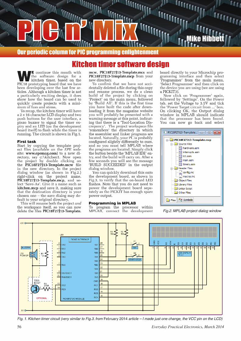
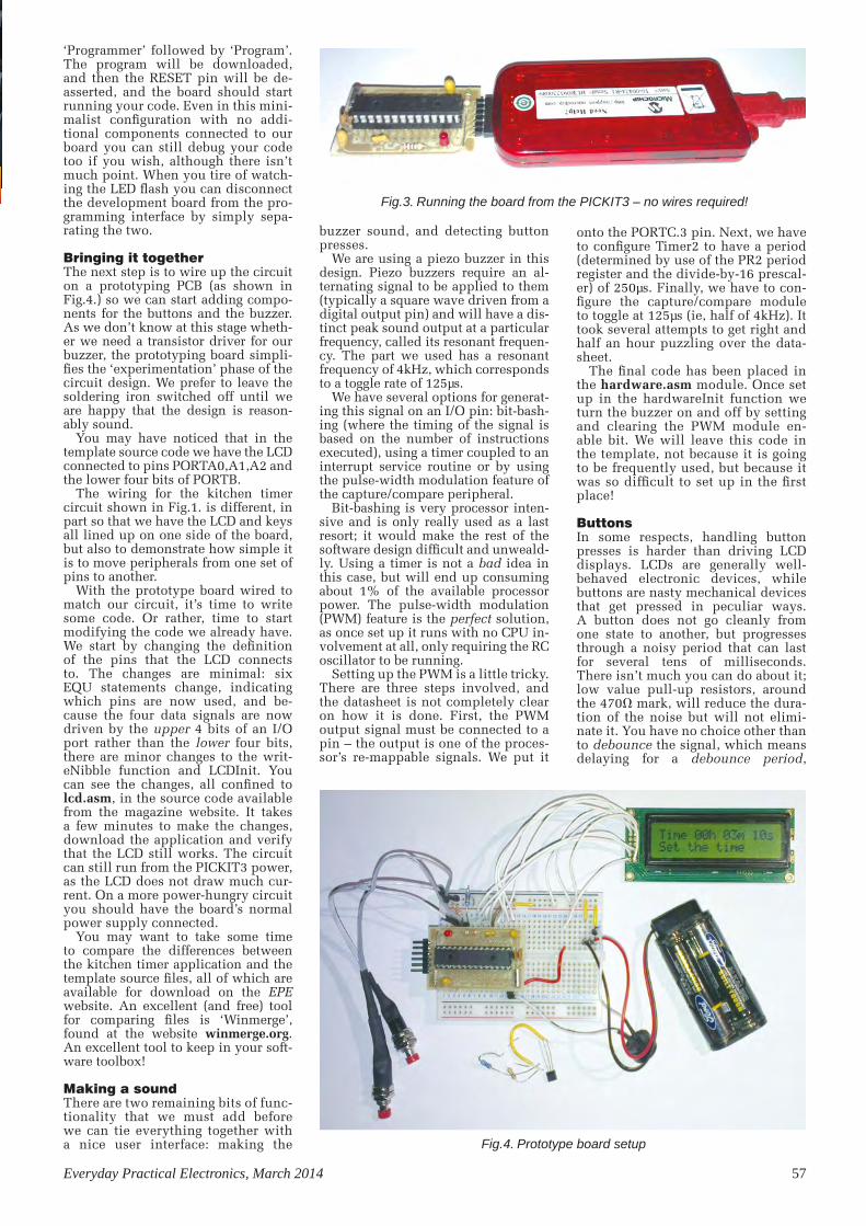
Everyday Practical Electronics, March 2014 57
‘Programmer’ followed by ‘Program’. The program will be downloaded, and then the RESET pin will be de-asserted, and the board should start running your code. Even in this mini-malist configuration with no addi-tional components connected to our board you can still debug your code too if you wish, although there isn’t much point. When you tire of watch-ing the LED flash you can disconnect the development board from the pro-gramming interface by simply sepa-rating the two.
Bringing it togetherThe next step is to wire up the circuit on a prototyping PCB (as shown in Fig.4.) so we can start adding compo-nents for the buttons and the buzzer. As we don’t know at this stage wheth-er we need a transistor driver for our buzzer, the prototyping board simpli-fies the ‘experimentation’ phase of the circuit design. We prefer to leave the soldering iron switched off until we are happy that the design is reason-ably sound.
You may have noticed that in the template source code we have the LCD connected to pins PORTA0,A1,A2 and the lower four bits of PORTB.
The wiring for the kitchen timer circuit shown in Fig.1. is different, in part so that we have the LCD and keys all lined up on one side of the board, but also to demonstrate how simple it is to move peripherals from one set of pins to another.
With the prototype board wired to match our circuit, it’s time to write some code. Or rather, time to start modifying the code we already have. We start by changing the definition of the pins that the LCD connects to. The changes are minimal: six EQU statements change, indicating which pins are now used, and be-cause the four data signals are now driven by the upper 4 bits of an I/O port rather than the lower four bits, there are minor changes to the writ-eNibble function and LCDInit. You can see the changes, all confined to lcd.asm, in the source code available from the magazine website. It takes a few minutes to make the changes, download the application and verify that the LCD still works. The circuit can still run from the PICKIT3 power, as the LCD does not draw much cur-rent. On a more power-hungry circuit you should have the board’s normal power supply connected.
You may want to take some time to compare the differences between the kitchen timer application and the template source files, all of which are available for download on the EPE website. An excellent (and free) tool for comparing files is ‘Winmerge’, found at the website winmerge.org. An excellent tool to keep in your soft-ware toolbox!
Making a soundThere are two remaining bits of func-tionality that we must add before we can tie everything together with a nice user interface: making the
buzzer sound, and detecting button presses.
We are using a piezo buzzer in this design. Piezo buzzers require an al-ternating signal to be applied to them (typically a square wave driven from a digital output pin) and will have a dis-tinct peak sound output at a particular frequency, called its resonant frequen-cy. The part we used has a resonant frequency of 4kHz, which corresponds to a toggle rate of 125µs.
We have several options for generat-ing this signal on an I/O pin: bit-bash-ing (where the timing of the signal is based on the number of instructions executed), using a timer coupled to an interrupt service routine or by using the pulse-width modulation feature of the capture/compare peripheral.
Bit-bashing is very processor inten-sive and is only really used as a last resort; it would make the rest of the software design difficult and unweald-ly. Using a timer is not a bad idea in this case, but will end up consuming about 1% of the available processor power. The pulse-width modulation (PWM) feature is the perfect solution, as once set up it runs with no CPU in-volvement at all, only requiring the RC oscillator to be running.
Setting up the PWM is a little tricky. There are three steps involved, and the datasheet is not completely clear on how it is done. First, the PWM output signal must be connected to a pin – the output is one of the proces-sor’s re-mappable signals. We put it
onto the PORTC.3 pin. Next, we have to configure Timer2 to have a period (determined by use of the PR2 period register and the divide-by-16 prescal-er) of 250µs. Finally, we have to con-figure the capture/compare module to toggle at 125µs (ie, half of 4kHz). It took several attempts to get right and half an hour puzzling over the data-sheet.
The final code has been placed in the hardware.asm module. Once set up in the hardwareInit function we turn the buzzer on and off by setting and clearing the PWM module en-able bit. We will leave this code in the template, not because it is going to be frequently used, but because it was so difficult to set up in the first place!
ButtonsIn some respects, handling button presses is harder than driving LCD displays. LCDs are generally well-behaved electronic devices, while buttons are nasty mechanical devices that get pressed in peculiar ways. A button does not go cleanly from one state to another, but progresses through a noisy period that can last for several tens of milliseconds. There isn’t much you can do about it; low value pull-up resistors, around the 470Ω mark, will reduce the dura-tion of the noise but will not elimi-nate it. You have no choice other than to debounce the signal, which means delaying for a debounce period,
Fig.3. Running the board from the PICKIT3 – no wires required!
Fig.4. Prototype board setup
Pic n Mix.indd 57 16/01/2014 16:51:21

58 Everyday Practical Electronics, March 2014
typically 20ms to 50ms, and check-ing the signal again. If the state is the same as it was previously, you accept that value. If it is different, you repeat the test again after another debounce period has elapsed, and repeat until the level is stable.
There are two ways to achieve this effect – in a tight code loop or via an interrupt routine called by a timer. There is an obvious danger with doing it in a tight loop, in that the code may never exit (unlikely, but it could po-tentially take several seconds if some-one is messing with the buttons) and so this technique might mess up other parts of the software. Interrupt routine polling is better – you set a flag visible to the main code when a key press is detected – but is, obviously, a bit hard-er to get working initially.
Sometimes, a simple tight loop im-plementation is fine, and the poten-tially long delays caused by polling the keys is not a problem. This little project is one such example, as the timing critical stuff (flashing the LED, counting down the time, buzzing the sounder) are all handled elsewhere away from the main code loop. We have implemented two functions for each button; one to wait for the key to be released, and the other to re-turn the current state of the button. It’s important to detect both the press and the release, as otherwise you will find the software reading multiple key presses.
Key processing is simple, and proj-ect specific, so we have not included the code we have written back into the template.
Connecting the buttons to the ex-ternal interrupt pins (which in our application are free, as we are not using them) would add a consider-able benefit – it would enable us to switch the oscillator off and place
the processor into a deep power down state. This would eliminate the need for a physical on/off switch, as the current consumption would be negligible. We will return to this idea next month when we recreate the application in the ‘C’ program-ming language.
User interfaceWith the lower level code having been created or modified from the template, the completion of the proj-ect becomes a straightforward pro-gramming activity, gluing the lower level code together. Although it is good practice to split an applica-tions functionality into several files, this project is small enough and simple enough that we could keep it all within the main application file kitchen.asm.
The user interface is simple: a key press will start the program, then the TIME button can be used to increment the timer, and the START button will move from seconds, to minutes, to hours and then on the next press start the timer.
At this point, the timer will display the countdown of the time in hours, minutes and seconds. Either button will stop the alarm, and turn it off. When the timer reaches zero, the buzz-er will sound, until a button is pressed.
The LED will flash every two sec-onds while the timer is running.
The periodic decrementing of the time is done in the interrupt routine, as the code to do this is minimal. It would be perfectly acceptable to sim-ply set a flag to indicate ‘decrement the timer’ and let the foreground task handle the work. Which is exactly what we do for updating the display – writing to the LCD takes a lot of time, relatively, and so it is better to do this in the main code loop.
Writing the timer handling code – the increment and decrement code – was painfully boring. There is no value in creating tight, small, fast code for this part of the design and so the effort involved in writing this in assembly language was not really rewarding. This is where program-ming in a higher level language can be a joy.
Wrapping it all upCreating the kitchen timer took a few evenings effort; creating the template code, non-functional though it is, took four times as long – much of it procras-tinating over nuances of the processor, trying ideas out and puzzling over why things did not work. This was a fairly clear validation of the whole template code idea in the first place.
It’s also important to evaluate any newly written piece of software and decide whether it is generic enough and useful enough to go into the template code. The only thing worse than writing boring code, is writing the same boring code again!
Some things did not work out as expected; the transistor driver to the buzzer was found to be unnecessary, but then that is the point of using pro-totyping boards before committing to PCB design (or gluing the components in place, as we did).
Next monthNext month, we will start our move away from assembly language pro-gramming and into the higher level programming language, C, creating a new template project file set. We will take a look at some other useful tem-plate features, such as serial interfac-es, and look at how serial-to-Bluetooth adaptors may change the way we con-trol and exchange data with our em-bedded projects.
Looking to advertise?
Contact Stewart Kearn on:
01202 880299
or email
Pic n Mix.indd 58 16/01/2014 16:52:43

Everyday Practical Electronics, March 2014 59
MOSFET basics – Part 1
Circuit SurgeryRegular Clinic by Ian Bell
REcEnTly there has been a thread on EPE Chat Zone discussing
power MOSFETS. This was prompted by dave_g pointing out the usefulness of International Rectifier’s Application Note AN-937 ‘Gate Drive Characteristics and Requirements for HEXFET Power MOSFETs’. It was pointed out that power MOSFET gate driving has also been discussed in Circuit Surgery (Jan 2007). Later, basementboy made an appeal for a basic guide to FETs.
‘Is there a quick and dirty FET guide? For example, NPN transistors are readily turned on with a small +ve current WRT E and conduct C to E. For a small transistor up to say 24V, a 1k is fine to turn it on. Connect the base to the supply and you no longer own a transistor. What would be the equivalent for a FET, and what must be avoided?’
Power MOSFET drive is a relatively advanced topic and although the aforementioned application note starts with a quick overview, it is really aimed at designers who are already familiar with the basics. So this month we will look at the basic theory of MOSFET operation, for MOSFETs in general, rather than specifically for power devices. The following may not be ‘quick and dirty’, but hopefully it will provide some insight into the basics of MOSFETs.
MOSFET layoutThe MOSFET is a semiconductor device which has three main connections – the gate (G), source (S) and drain (D). For those familiar with bipolar transistors, these correspond roughly with base, emitter
and collector. Strictly speaking, the MOSFET actually has four terminals – the fourth is the substrate or bulk (B) semiconductor in which the device is formed. In many cases (particularly discrete devices) the bulk and source are shorted within the fabricated structure of the device, so there are only three external connections. Like the two types of bipolar transistor (NPN and PNP) there are two types of MOSFET – N-channel and P-channel, often referred to as NMOS and PMOS transistors, or simply N and P transistors.
Enhancement and depletion modesThe term ‘channel’ refers to the conducting channel between source and drain, which as we will see is a key feature of MOSFET operation. This channel is most commonly created by the action of the applied voltages, in which case the MOSFET is called an enhancement-mode device. It is also possible to build the channel in which the MOSFET is fabricated, so applying appropriate voltages can remove it. This is called a depletion-mode MOSFET.
Holes and electronsThe, N and P in NMOS and PMOS (and NPN and PNP) refer to the type of chemical used to ‘dope’ pure silicon to create interesting semiconductor behaviour. N-type silicon has more electrons free to take place in electrical conduction than in pure silicon. P-type has fewer electrons than pure silicon, but these gaps can he regarded as mobile ‘holes’ which
act as positive charge carriers and allow electrical conduction. Placing an N region next to a P region creates a PN junction, also known as a diode junction, through which current will usually flow in only one direction.
If a sufficiently positive voltage is applied to a diode junctions’ P side (called the anode) with respect to the N side (cathode) a current will flow. This is indicated by the arrow direction in the diode’s schematic symbol (P to N). Holes can flow from the P to N side and electrons from the N to P side. Electrons move in the opposite direction to that which we designate as current flow, despite the fact that most electrical circuits are connected using metal conductors, in which conduction takes place due to electron movement. This is known as conventional current. Historically, the convention of current being defined as flowing from positive to negative was agreed before the discovery of conduction by electrons.
When a PN junction is formed, electrons from the N side move into the P side and holes from the P side move into the N side. They combine (effectively cancel on another out) to create a region close to the junction without any free mobile charge carriers. This is known as a depletion region. A diode conducts in forward bias when sufficient voltage has been applied to remove the depletion region. Reverse bias makes the depletion region larger. Depletion regions are important in MOSFET operation too, as we will see later.
SymbolsA number of versions of the MOSFET schematic symbol are in use (see Fig.1 and Fig.2). The full symbol shows the bulk as a separate connection, however, as mentioned, the bulk is often connected to the
Fig.2. Example depletion-mode N-chan-nel MOSFET symbols. Continuous or thicker ‘channel’ lines are used to indicate depletion mode (compare with Fig.1)Fig.1. Enhancement-mode MOSFET symbols
CS2MAR1424mm x 1 COL
GD
S S
GD
CS1MAR1452mm x 2 COL
GS
D
G
B
BD
S
G
D
S
GD
G
D
S
S
DG
GS
D
GD
S S
p-CHANNEL
FULL SYMBOL
FULL SYMBOL(BULKCONNECTEDTO SOURCE)
SIMPLIFIEDSYMBOL
LOGICSYMBOL
n-CHANNEL
Circuit Surgery.indd 59 17/01/2014 09:56:05
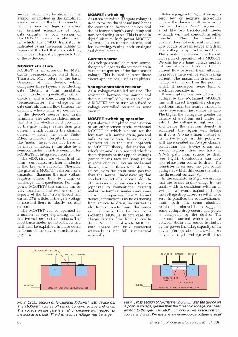
60 Everyday Practical Electronics, March 2014
source, which may be shown in the symbol, or implied in the simplified symbol in which the bulk connection is not shown. For logic schematics (eg, internal schematics of logic gate circuits), a logic version of the MOSFET symbol is often used in which the PMOS transistor is indicated by an ‘inversion bubble’ to represent the fact that its switching behaviour is logically opposite to that of the N device.
MOSFET structureMOSFET is an acronym for Metal Oxide Semiconductor Field Effect Transistor. MOS refers to the basic structure of the device, which comprises three layers: a conducting gate (Metal), a thin insulating layer (Oxide – specifically silicon dioxide) and a conducting channel (Semiconductor). The voltage on the gate controls current flow through the channel, whose ends are connected to the device’s source and drain terminals. The gate insulation means that it is the electric field produced by the gate voltage, rather than gate current, which controls the channel current – hence the name Field-Effect Transistor. Despite the name, the ‘metal’ layer does not have to be made of metal; it can also be a semiconductor, which is common for MOSFETs in integrated circuits.
The MOS, structure which is of the form conductor/insulator/conductor is like that of a capacitor. Therefore the gate of a MOSFET behaves like a capacitor. Changing the gate voltage requires current flow to charge or discharge the capacitance. For large power MOSFETS this current can be very significant and was one of the aspects of the Chat Zone thread and earlier EPE article. If the gate voltage is constant there is (ideally) no gate current.
The MOSFET can be operated in a number of ways depending on the relative voltages on its terminals. The most basic modes are listed below and will then be explained in more detail in terms of the device structure and physics.
Referring again to Fig.3, if we apply zero, low or negative gate-source voltage the device is off because the source-bulk-drain N-P-N regions act a bit like two back-to-back diodes – which will not conduct in either direction. Thus the conducting channel does not exist and no current flow occurs between source and drain if a voltage is applied across them. This situation is referred to as the cut-off region of operation of a MOSFET. We can have a large voltage applied between drain and source but no current flow between them, although in practice there will be some leakage current. The maximum drain-source voltage will depend on the point at which it undergoes some form of electrical breakdown.
If we apply a positive gate-source voltage to the N-channel MOSFET, this will attract (negatively charged) electrons from the nearby silicon to the P-type region just under the gate. The higher the voltage the greater the density of electrons just under the gate. If the voltage is high enough, and hence the electron density is sufficient, the region will behave as if it is N-type silicon instead of its native P-type. At this point, we will have created an N-type channel connecting the N-type drain and source regions, thus we have an N-N-N path from source to drain (see Fig.4). Conduction can now take place from source to drain. The transistor is on and the gate-source voltage at which this occurs is called the threshold voltage, VT.
In the scenario in Fig.4 we assume that the source-drain voltage is very small – this is consistent with an on switch – we would expect and hope the voltage drop across a switch to be zero. In practice, the source-channel-drain path has some electrical resistance (referred to as RDS,ON) so some voltage drop occurs and power is dissipated by the device. The maximum current which can flow between drain and source is limited by the power handling capacity of the device. For operation as a switch, we may have a gate voltage well above
MOSFET switchingAs an on/off switch. The gate voltage is used to switch the channel (and hence the connection between source and drain) between highly conducting and non-conducting states. This is used in digital circuits, high power MOSFET switches (as mentioned above), and for switching/routing both analogue and digital signals.
Current sourceAs a voltage-controlled current source, the gate voltage sets the source to drain current irrespective of the drain source voltage. This is used in most linear circuit applications, such as amplifiers.
Voltage-controlled resistorAs a voltage-controlled resistor. The resistance between the source and drain is controlled by the gate voltage. A MOSFET can be used as a fixed or voltage controlled resistor in some circuits.
MOSFET switching operationFig.3 shows a simplified cross-section of an enhancement-mode N-channel MOSFET in which we can see the four terminals: source, drain, gate and bulk. As can be seen, the structure is symmetrical. In the usual approach to MOSFET theory, designation of which terminal is source and which is drain depends on the applied voltages (which means they can swap round in some circuits). For an N-channel device, current flows from drain to source, with the drain more positive than the source. Understanding that conduction actually occurs due to electrons moving from source to drain (opposite to conventional current) makes the terminal names make more sense. In comparison, for a P-channel device, conduction is by holes flowing from source to drain, so current is also from source to drain. The source is more positive than the drain for a P-channel MOSFET. In both cases the charge carriers flow from source to drain. Note that a discrete MOSFET with source and bulk connected internally is not full symmetrical externally.
CS3MAR1446mm x 1.5 COL
SUBSTRATE OR BULK SEMICONDUCTOR
SOURCE (S)
GATE OXIDE (INSULATOR)
BULK (B)
GATE (G) DRAIN (D)
N N
Fig.3. Cross section of N-Channel MOSFET with device off. The MOSFET acts as off switch between source and drain. The voltage on the gate is small or negative with respect to the source and bulk. The drain source voltage may be large
CS4MAR1446mm x 1.5 COL
N
PSUBSTRATE OR BULK SEMICONDUCTOR
CHANNEL
SOURCE (S)
BULK (B)
GATE (G) DRAIN (D)
DRAIN-SOURCECURRENT
N N
Fig.4. Cross section of N-Channel MOSFET with the device on. A positive voltage, greater than the threshold voltage, has been applied to the gate. The MOSFET acts as on switch between source and drain. We assume the drain-source voltage is small
Circuit Surgery.indd 60 17/01/2014 09:56:18
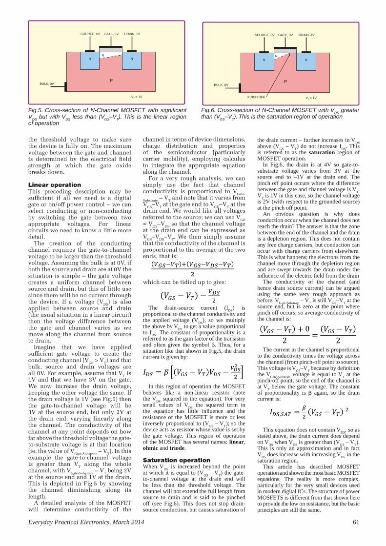
Everyday Practical Electronics, March 2014 61
the threshold voltage to make sure the device is fully on. The maximum voltage between the gate and channel is determined by the electrical field strength at which the gate oxide breaks down.
Linear operationThis preceding description may be sufficient if all we need is a digital gate or on/off power control – we can select conducting or non-conducting by switching the gate between two appropriate voltages. For linear circuits we need to know a little more detail.
The creation of the conducting channel requires the gate-to-channel voltage to be larger than the threshold voltage. Assuming the bulk is at 0V, if both the source and drain are at 0V the situation is simple – the gate voltage creates a uniform channel between source and drain, but this of little use since there will be no current through the device. If a voltage (VDS) is also applied between source and drain (the usual situation in a linear circuit) then the voltage difference between the gate and channel varies as we move along the channel from source to drain.
Imagine that we have applied sufficient gate voltage to create the conducting channel (VGS > VT) and that bulk, source and drain voltages are all 0V. For example, assume that VT is 1V and that we have 3V on the gate. We now increase the drain voltage, keeping the other voltage the same. If the drain voltage is 1V (see Fig.5) then the gate-to-channel voltage will be 3V at the source end, but only 2V at the drain end, varying linearly along the channel. The conductivity of the channel at any point depends on how far above the threshold voltage the gate-to-substrate voltage is at that location (ie, the value of VGate-Substrate – VT). In this example the gate-to-channel voltage is greater than VT along the whole channel, with VGate-Substrate – VT being 2V at the source end and 1V at the drain. This is depicted in Fig.5 by showing the channel diminishing along its length.
A detailed analysis of the MOSFET will determine conductivity of the
channel in terms of device dimensions, charge distribution and properties of the semiconductor (particularly carrier mobility), employing calculus to integrate the appropriate equation along the channel.
For a very rough analysis, we can simply use the fact that channel conductivity is proportional to VGate-
Substrate – VT and note that it varies from VGS–VT at the gate end to VGD–VT at the drain end. We would like all voltages referred to the source; we can use VGD = VGS–VDS so that the channel voltage at the drain end can be expressed as VGS–VDS–VT. We then simply assume that the conductivity of the channel is proportional to the average at the two ends, that is:
which can be tidied up to give:
The drain-source current (IDS
) is proportional to the channel conductivity and the applied voltage (V
DS), so we multiply
the above by VDS
to get a value proportional to I
DS. The constant of proportionality is a
referred to as the gain factor of the transistor and often given the symbol β. Thus, for a situation like that shown in Fig.5, the drain current is given by:
In this region of operation the MOSFET behaves like a non-linear resistor (note the V
DS squared in the equation). For very
small values of VDS
the squared term in the equation has little influence and the resistance of the MOSFET is more or less inversely proportional to (V
GS – V
T); so the
device acts as resistor whose value is set by the gate voltage. This region of operation of the MOSFET has several names: linear, ohmic and triode.
Saturation operationWhen V
DS is increased beyond the point
at which it is equal to (VGS
– VT) the gate-
to-channel voltage at the drain end will be less than the threshold voltage. The channel will not extend the full length from source to drain and is said to be pinched off (see Fig.6). This does not stop drain-source conduction, but causes saturation of
the drain current – further increases in VDS
above (V
GS – V
T) do not increase I
DS. This
is referred to as the saturation region of MOSFET operation.
In Fig.6, the drain is at 4V so gate-to-substrate voltage varies from 3V at the source end to –1V at the drain end. The pinch off point occurs where the difference between the gate and channel voltage is V
T.
VT is 1V in this case, so the channel voltage
is 2V (with respect to the grounded source) at the pinch off point.
An obvious question is why does conduction occur when the channel does not reach the drain? The answer is that the zone between the end of the channel and the drain is a depletion region. This does not contain any free charge carriers, but conduction can occur with charge carriers from elsewhere. This is what happens; the electrons from the channel move through the depletion region and are swept towards the drain under the influence of the electric field from the drain
The conductivity of the channel (and hence drain source current) can be argued using the same very rough approach as before. V
Gate-Substrate – V
T is still V
GS–V
T at the
source end, but is zero at the point where pinch off occurs, so average conductivity of the channel is:
The current in the channel is proportional to the conductivity times the voltage across the channel (from pinch-off point to source). This voltage is V
GS–V
T because by definition
the VGate-Substrate
voltage is equal to VT at the
pinch-off point, so the end of the channel is at V
T below the gate voltage. The constant
of proportionality is β again, so the drain current is:
This equation does not contain VDS
, so as stated above, the drain current does depend on V
DS when V
DS is greater than (V
GS – V
T).
This is only an approximation and in fact V
DS does increase with increasing V
DS in the
saturation region.This article has described MOSFET
operation and shown the most basic MOSFET equations. The reality is more complex, particularly for the very small devices used in modern digital ICs. The structure of power MOSFETS is different from that shown here to provide the low on resistance, but the basic principles are still the same.
CS5MAR1446mm x 1.5 COL
P
SOURCE, 0V
BULK, 0V
GATE, 3V DRAIN, 2V
VT = 1V
NN
N
CS6MAR1446mm x 1.5 COL
P
SOURCE, 0V
BULK, 0V
PINCH OFF
GATE, 3V DRAIN, 4V
NN
N
VT = 1V
Fig.5. Cross-section of N-Channel MOSFET with significant VDS but with VDS less than (VGS–VT). This is the linear region of operation
Fig.6. Cross-section of N-Channel MOSFET with VDS greater than (VGS–VT). This is the saturation region of operation
Circuit Surgery
Ian Bell
11/02/14(𝑉𝑉𝐺𝐺𝐺𝐺−𝑉𝑉𝑇𝑇)+(𝑉𝑉𝐺𝐺𝐺𝐺−𝑉𝑉𝐷𝐷𝐺𝐺−𝑉𝑉𝑇𝑇)
2,
(𝑉𝑉𝐺𝐺𝐺𝐺 − 𝑉𝑉𝑇𝑇) − 𝑉𝑉𝐷𝐷𝐺𝐺2
.
𝐼𝐼𝐷𝐷𝐺𝐺 = 𝛽𝛽 (𝑉𝑉𝐺𝐺𝐺𝐺 − 𝑉𝑉𝑇𝑇)𝑉𝑉𝐷𝐷𝐺𝐺 −𝑉𝑉𝐷𝐷𝐺𝐺2
2 .
(𝑉𝑉𝐺𝐺𝐺𝐺 − 𝑉𝑉𝑇𝑇) + 02
=(𝑉𝑉𝐺𝐺𝐺𝐺 − 𝑉𝑉𝑇𝑇)
2
𝐼𝐼𝐷𝐷𝐺𝐺,𝐺𝐺𝑆𝑆𝑇𝑇 = 𝛽𝛽2
(𝑉𝑉𝐺𝐺𝐺𝐺 − 𝑉𝑉𝑇𝑇) 2.
Circuit Surgery
Ian Bell
11/02/14(𝑉𝑉𝐺𝐺𝐺𝐺−𝑉𝑉𝑇𝑇)+(𝑉𝑉𝐺𝐺𝐺𝐺−𝑉𝑉𝐷𝐷𝐺𝐺−𝑉𝑉𝑇𝑇)
2,
(𝑉𝑉𝐺𝐺𝐺𝐺 − 𝑉𝑉𝑇𝑇) − 𝑉𝑉𝐷𝐷𝐺𝐺2
.
𝐼𝐼𝐷𝐷𝐺𝐺 = 𝛽𝛽 (𝑉𝑉𝐺𝐺𝐺𝐺 − 𝑉𝑉𝑇𝑇)𝑉𝑉𝐷𝐷𝐺𝐺 −𝑉𝑉𝐷𝐷𝐺𝐺2
2 .
(𝑉𝑉𝐺𝐺𝐺𝐺 − 𝑉𝑉𝑇𝑇) + 02
=(𝑉𝑉𝐺𝐺𝐺𝐺 − 𝑉𝑉𝑇𝑇)
2
𝐼𝐼𝐷𝐷𝐺𝐺,𝐺𝐺𝑆𝑆𝑇𝑇 = 𝛽𝛽2
(𝑉𝑉𝐺𝐺𝐺𝐺 − 𝑉𝑉𝑇𝑇) 2.
Circuit Surgery
Ian Bell
11/02/14(𝑉𝑉𝐺𝐺𝐺𝐺−𝑉𝑉𝑇𝑇)+(𝑉𝑉𝐺𝐺𝐺𝐺−𝑉𝑉𝐷𝐷𝐺𝐺−𝑉𝑉𝑇𝑇)
2,
(𝑉𝑉𝐺𝐺𝐺𝐺 − 𝑉𝑉𝑇𝑇) − 𝑉𝑉𝐷𝐷𝐺𝐺2
.
𝐼𝐼𝐷𝐷𝐺𝐺 = 𝛽𝛽 (𝑉𝑉𝐺𝐺𝐺𝐺 − 𝑉𝑉𝑇𝑇)𝑉𝑉𝐷𝐷𝐺𝐺 −𝑉𝑉𝐷𝐷𝐺𝐺2
2 .
(𝑉𝑉𝐺𝐺𝐺𝐺 − 𝑉𝑉𝑇𝑇) + 02
=(𝑉𝑉𝐺𝐺𝐺𝐺 − 𝑉𝑉𝑇𝑇)
2
𝐼𝐼𝐷𝐷𝐺𝐺,𝐺𝐺𝑆𝑆𝑇𝑇 = 𝛽𝛽2
(𝑉𝑉𝐺𝐺𝐺𝐺 − 𝑉𝑉𝑇𝑇) 2.
Circuit Surgery
Ian Bell
11/02/14(𝑉𝑉𝐺𝐺𝐺𝐺−𝑉𝑉𝑇𝑇)+(𝑉𝑉𝐺𝐺𝐺𝐺−𝑉𝑉𝐷𝐷𝐺𝐺−𝑉𝑉𝑇𝑇)
2,
(𝑉𝑉𝐺𝐺𝐺𝐺 − 𝑉𝑉𝑇𝑇) − 𝑉𝑉𝐷𝐷𝐺𝐺2
.
𝐼𝐼𝐷𝐷𝐺𝐺 = 𝛽𝛽 (𝑉𝑉𝐺𝐺𝐺𝐺 − 𝑉𝑉𝑇𝑇)𝑉𝑉𝐷𝐷𝐺𝐺 −𝑉𝑉𝐷𝐷𝐺𝐺2
2 .
(𝑉𝑉𝐺𝐺𝐺𝐺 − 𝑉𝑉𝑇𝑇) + 02
=(𝑉𝑉𝐺𝐺𝐺𝐺 − 𝑉𝑉𝑇𝑇)
2
𝐼𝐼𝐷𝐷𝐺𝐺,𝐺𝐺𝑆𝑆𝑇𝑇 = 𝛽𝛽2
(𝑉𝑉𝐺𝐺𝐺𝐺 − 𝑉𝑉𝑇𝑇) 2.
Circuit Surgery
Ian Bell
11/02/14(𝑉𝑉𝐺𝐺𝐺𝐺−𝑉𝑉𝑇𝑇)+(𝑉𝑉𝐺𝐺𝐺𝐺−𝑉𝑉𝐷𝐷𝐺𝐺−𝑉𝑉𝑇𝑇)
2,
(𝑉𝑉𝐺𝐺𝐺𝐺 − 𝑉𝑉𝑇𝑇) − 𝑉𝑉𝐷𝐷𝐺𝐺2
.
𝐼𝐼𝐷𝐷𝐺𝐺 = 𝛽𝛽 (𝑉𝑉𝐺𝐺𝐺𝐺 − 𝑉𝑉𝑇𝑇)𝑉𝑉𝐷𝐷𝐺𝐺 −𝑉𝑉𝐷𝐷𝐺𝐺2
2 .
(𝑉𝑉𝐺𝐺𝐺𝐺 − 𝑉𝑉𝑇𝑇) + 02
=(𝑉𝑉𝐺𝐺𝐺𝐺 − 𝑉𝑉𝑇𝑇)
2
𝐼𝐼𝐷𝐷𝐺𝐺,𝐺𝐺𝑆𝑆𝑇𝑇 = 𝛽𝛽2
(𝑉𝑉𝐺𝐺𝐺𝐺 − 𝑉𝑉𝑇𝑇) 2.
Circuit Surgery.indd 61 17/01/2014 09:56:30

62 Everyday Practical Electronics, March 2014
EPE IS PLEASED TO BE ABLE TO OFFER YOU THESE
ELECTRONICS CD-ROMS
Chip Pack (Hobbyist/Student) . . . . . . . . . . . . . . . . . . . .Pro-pack (Schools/HE/FE/Industry) . . . . . . . . . . . . . . .Flowkit . . . . . . . . . . . . . . . . . . . . . . . . . . . . . . . . . . . . . .
PRICES Prices for each of the items above are: (Order form on third page)
(UK and EU customers add VAT to ‘plus VAT’
prices)
PICMICRO/AVR/DSPIC/PIC24 & ARM Download only£94 .80 inc . VAT£299 .00 plus VAT£64 .90 plus VAT
Flowcode 6
Please note: Due to popular demand, Flowcode PICmicro, AVR, DSPIC, PIC24 & ARM V6 are now available as a download . Please include your email address and a username (of your choice) on your order . A unique download code will then be emailed to you .
If you require the CDROM as a back-up then please add an extra £14 to the above price .
NEWOUT NOW
Flowcode is one of the world’s most advanced environments for electronic and electromechanical system development. Engineers use Flowcode to develop systems for control and measurement based on microcontrollers, on rugged industrial interfaces or on Windows compable personal computers
New simulation, 3D and test features allow you to design a greater range of systems including:
...robotic systems design... ...electromechanical system design...
...machine building... ...pumping and heating systems
Now you can develop complex electronic and electromechanical systems with ease
FREE VERSIONThe free edition of Flowcode allows users to sample the fully featured product for 30days, after which it will revert to a more limited form and will lose its ability to compile to micro-controllers. It will continue to provide most of its functionality with Matrix hardware devices like the Matrix Forumula Flowcode robot, MIAC and ECIO.
CHIP PACK ONLY - £79 .00Purchasing a Chip Pack only will provide the ability to compile to hardware. Chip Pack versions are suitable for users who only re-quire the basic Flowcode components. The Chip Pack version is equivalent to the Flow-code v5 Student/Home version. Multiple chip packs can be purchased to allow Flowcode to compile to more hardware targets.
PROFESSIONAL UPGRADE PACK - £220 .00Adding the Professional bolt-on pack to the Flowcode licence will unlock all the functions and components available in Flowcode. It will also be licensed for commercial use.
ACADEMIC VERSIONSSpecial arrangements can be made for Academic versions of Flowcode. Academic multi-user versions (10 user, 50 user) are also available. Only educational schools, col-leges and universities are able to apply to purchase an Academic version of Flowcode. Please contact us for more information.
FLOWCODE 5 TO FLOWCODE 6 UPGRADEUpgrades from Flowcode 5 to Flowcode 6 will be given a discount of 50% to the appro-priate licence prices in Flowcode v6.
FLOWCODE 4 TO FLOWCODE 6 UPGRADEUpgrades from Flowcode 4 to Flowcode 6 will given a discount of 30% to the appropri-ate licence prices in Flowcode v6 (pay 70% of the price).
CD-ROMs Pages.indd 62 16/01/2014 12:40:11

Everyday Practical Electronics, March 2014 63
PICmicro TUTORIALS AND PROGRAMMINGPICmicro Multiprogrammer
Board and Development BoardSuitable for use with the three software packages
listed below
This flexible PICmicro microcontroller programmer board and combination board allows students and professional engineers to learn how to program PICmicro microcontrollers as well as program a range of 8, 18, 28 and 40 pin devices from the 12, 16 and 18 series PICmicro ranges. For experienced programmers all programming software is included in the PPP utility that comes with the multiprogrammer board. For those who want to learn, choose one or all of the packages below to use with the hardware.
• Makes it easier to develop PICmicro projects
• Supports low cost Flash-programmable PICmicro devices
• Fully featured integrated displays – 16 individual LEDs, quad 7-segment display and alphanumeric LCD display
• Supports PICmicro microcontrollers with A/D converters
• Fully protected expansion bus for project work
• USB programmable
• Compatible with the E-blocks range of accessories
ASSEMBLY FOR PICmicro V4
(Formerly PICtutor)Assembly for PICmicro microcontrollers V3.0 (previously known as PICtutor) by John Becker contains a complete course in programming the PIC16F84 PICmicro microcontroller from Arizona Microchip. It starts with fundamental concepts and extends up to complex programs including watchdog timers, interrupts and sleep modes.
The CD makes use of the latest simulation techniques which provide a superb tool for learning: the Virtual PICmicro microcontroller, this is a simulation tool that allows users to write and execute MPASM assembler code for the PIC16F84 microcontroller on-screen. Using this you can actually see what happens inside the PICmicro MCU as each instruction is executed, which enhances understanding.
• Comprehensive instruction through 45 tutorial sections • Includes Vlab, a Virtual PICmicro microcontroller: a fully functioning simulator • Tests, exercises and projects covering a wide range of PICmicro MCU applications • Includes MPLAB assembler • Visual representation of a PICmicro showing architecture and functions • Expert system for code entry helps first time users
• Shows data flow and fetch execute cycle and has challenges (washing machine, lift, crossroads etc.)
• Imports MPASM files.
‘C’ FOR 16 Series PICmicroVersion 4
The C for PICmicro microcontrollers CD-ROM is designed for students and professionals who need to learn how to program embedded microcontrollers in C. The CD-ROM contains a course as well as all the software tools needed to create Hex code for a wide range of PICmicro devices – including a full C compiler for a wide range of PICmicro devices.
Although the course focuses on the use of the PICmicro microcontrollers, this CD-ROM will provide a good grounding in C programming for any microcontroller.
• Complete course in C as well as C programming for PICmicro microcontrollers • Highly interactive course • Virtual C PICmicro improves understanding • Includes a C compiler for a wide range of PICmicro devices • Includes full Integrated Development Environment • Includes MPLAB software • Compatible with most PICmicro programmers • Includes a compiler for all the PICmicro devices.
FLOWCODE FOR PICmicro V6 (see opposite page)
£167 including VAT and postage, supplied with USB cable and programming software
HARDWARE
SOFTWARE
Hobbyist/Student . . . . . . . . . . . . . . . . . . . . . . . . . . . . . . £58 .80 inc VATProfessional (Schools/HE/FE/Industry) . . . . . . . . . . . . £150 plus VATProfessional 10 user (Network Licence) . . . . . . . . . . . £499 plus VATSite Licence . . . . . . . . . . . . . . . . . . . . . . . . . . . . . . . . . . £999 plus VAT
Flowcode 10 user (Network Licence) . . . . . . . . . . . . . . POA plus VATFlowcode Site Licence . . . . . . . . . . . . . . . . . . . . . . . . . POA plus VAT
PRICESPrices for each of the CD-ROMs above are:
See previous page for Flowcode Hobbyist/Student prices(Order form on next page)
(UK and EU customers add VAT to ‘plus VAT’ prices)
Minimum system requirements for these items: Pentium PC running, 2000, ME, XP; CD-ROM drive; 64MB RAM; 10MB
hard disk space.Flowcode will run on XP or later
operating systems
Flowcode is a very high level language programming system based on flowcharts. Flowcode allows you to design and simulate complex systems in a matter of minutes. A powerful language that uses macros to facilitate the control of devices like 7-segment displays, motor controllers and LCDs. The use of macros allows you to control these devices without getting bogged down in understanding the programming. When used in conjunction with the Version 3 development board this provides a seamless solution that allows you to program chips in minutes.
• Requires no programming experience
• Allows complex PICmicro applications to be designed quickly
• Uses international standard flow chart symbols
• Full on-screen simulation allows debugging and speeds up the development process.
• Facilitates learning via a full suite of demonstration tutorials
• Produces ASM code for a range of 18, 28 and 40-pin devices
• 16-bit arithmetic strings and string manipulation
• Pulse width modulation
• I2C.
Features include panel creator, in circuit debug, virtual networks, C code customisation, floating point and new components. The Hobbyist/Student version is limited to 4K of code (8K on 18F devices)
CD-ROMs Pages.indd 63 16/01/2014 12:40:22

64 Everyday Practical Electronics, March 2014
By integrating the entire design process, Circuit Wizard provides you with all the tools necessary to produce an electronics project from start to finish – even including on-screen testing of the PCB prior to construction!
* Circuit diagram design with component library (500 components Standard,1500 components Professional) * Virtual instruments (4 Standard, 7 professional)* On-screen animation * Interactive circuit diagram simulation * True analogue/digital simulation
* Simulation of component destruction * PCB Layout * Interactive PCB layout simulation * Automatic PCB routing * Gerber export
* Multi-level zoom (25% to 1000%) * Multiple undo and redo
* Copy and paste to other software * Multiple document support
CIRCUIT WIZARD
Please send me: CD-ROM ORDER FORM
Assembly for PICmicro V4 ‘C’ for 16 Series PICmicro V4
Flowcode for PICmicro V6 (DOWNLOAD ONLY) Flowcode for AVR V6 (DOWNLOAD ONLY) Flowcode for ARM V6 (DOWNLOAD ONLY) Flowcode for dsPIC V6 (DOWNLOAD ONLY) Flowcode for PIC24 V6 (DOWNLOAD ONLY) Flowkit
Email: . . . . . . . . . . . . . . . . . . . . . . . . . . . . . .
Username: . . . . . . . . . . . . . . . . . . . . . . . . . .
PICmicro Multiprogrammer Board and Development Board V4 (hardware)
Circuit Wizard – Standard Circuit Wizard – Professional GCSE Electronics
Full name: . . . . . . . . . . . . . . . . . . . . . . . . . . . . . . . . . . . . . . . . . . . . . . . . . . . . . . . . . . . . . . . . .
Address: . . . . . . . . . . . . . . . . . . . . . . . . . . . . . . . . . . . . . . . . . . . . . . . . . . . . . . . . . . . . . . . . . .
. . . . . . . . . . . . . . . . . . . . . . Post code: . . . . . . . . . . . . . . . . . Tel. No: . . . . . . . . . . . . . . . . . . .
Signature: . . . . . . . . . . . . . . . . . . . . . . . . . . . . . . . . . . . . . . . . .
I enclose cheque/PO in £ sterling payable to WIMBORNE PUBLISHING LTD for £ . . . . . . . . . Please charge my Visa/Mastercard/Maestro: £ . . . . . . . . . . Valid From: . . . . . . . . . . Card expiry date: . . . . . . . . . . . . . Card No: . . . . . . . . . . . . . . . . . . . . . . . . . . . . . . . . . . . . . . . . Maestro Issue No. . . . . . . . . .Card Security Code . . . . . . . . . . (The last 3 digits on or just under the signature strip)
Note: The software on each version is the same, only the licence for use varies.
Minimum system requirements for these CD-ROMs: Pentium PC, CD-ROM drive, 32MB
RAM, 10MB hard disk space. Windows 2000/ME/XP, mouse, sound card, web browser.
ORDERINGALL PRICES INCLUDE UK
POSTAGE
Student/Single User/Standard/Hobbyist Version price includes postage to most
countries in the worldEU residents outside the UK add £5 for
airmail postage per order
Professional, Multiple User and Site License Versions – overseas readers add £5 to the basic price of each order for airmail postage (do not add VAT unless you live in an EU (European Union) country, then add VAT at 20% or provide your official VAT registration number).
Send your order to:Direct Book Service
Wimborne Publishing Ltd113 Lynwood Drive, Merley,
Wimborne, Dorset BH21 1UU
To order by phone ring
01202 880299. Fax: 01202 843233Goods are normally sent within seven days
E-mail: [email protected] shop:
www.epemag.com
Circuit Wizard is a revolutionary software system that combines circuit design, PCB design, simulation and
CAD/CAM manufacture in one complete package. Two versions are available, Standard or Professional.
Version required: Chip pack (Hobbyist/Student) Pro pack (Schools/HE/FE/Ind.)
This software can be used with the Jump Start and Teach-In 2011 series (and the Teach-In 4 book).
Standard £61.25 inc. VAT Professional £91.90 inc. VAT
Suitable for any student who is serious about studying and who wants to achieve the best grade possible. Each program’s clear, patient and structured delivery will aid understanding of electronics and assist in developing a confident approach to
answering GCSE questions. The CD-ROM will be invaluable to anyone studying electronics, not just GCSE students.
* Contains comprehensive teaching material to cover the National Curriculum syllabus * Regular exercises reinforce the teaching points * Retains student interest with high quality animation and graphics * Stimulates learning through interactive exercises * Provides sample examination ques-tions with model solutions * Authored by practising teachers * Covers all UK examination board syllabuses * Caters for all levels of ability * Useful for self-tuition and revision
GCSE ELECTRONICS
£12.50 inc. VAT and P&P
SUBJECTS COVEREDElectric Circuits – Logic Gates – Capacitors & Inductors – Relays – Transistors – Electric Transducers – Operational Amplifiers – Radio Circuits – Test Instruments
Over 100 different sections under the above headings
Version required: Hobbyist/Student Professional Professional 10 user Site licence
CD-ROMs Pages.indd 64 16/01/2014 12:40:33

Everyday Practical Electronics, March 2014 65
Upgrade your Programmable Electronics to the Next Generationwith
TinyDuinoAs powerful as the Arduino Uno but smaller than a 2 pence coin.
Programmable Electronics
All the power of the Arduino in a fraction of the space, greatfor building intelligence in to your projects.
www.eshop.icsat.co.uk
As an authorised reseller with an educational andtraining focus we can support all aspects of thisoutstanding piece of kit!
Get yours today via our eShop
Complete with a wide and growing rangeof TinyShields - where will your nextproject take you?
Move up to the Next Generation!
Fantastic for schools especially D&T andComputing, meets the new requirements
www.picotech.com/PS229
Travel Essentials*
PC Oscilloscopeup to 200 MHz
from £1591 GS/sAWG FFT
Serial decodingMask tests
Advanced triggers
*Dont forget your toothbrush
MEASUREMENTS & STATISTICSCOLOR PERSISTENCE
LIN
UART
SPI I2C
I2S
CRICKLEWOODELECTRONICS
Visit our shop at:40-42 Cricklewood BroadwayLondon NW2 3ET020 8452 0161
Frustrated with your suppier?Visit our component packed
website for a vast range ofparts - old and new,
many unavailable elsewhere!www.cricklewoodelectronics.com
10001000’s OF PRICES REDUCED!
Alternatively phone us on020 8452 0161 with your
requirements.
Visit our Shop, Call or Buy online at:www.cricklewoodelectronics.com
Established 1981
supplier?
Cricklewood - MAR09.indd 1 28/01/2009 11:08:21
Page 65.indd 61 16/01/2014 12:44:35

66 Everyday Practical Electronics, March 2014
Last month, I explained how Near-Field Comm-unications (NFC) can work in conjunction with an NFC-equipped smartphone to automate some
tasks such as turning on the phone’s built-in flashlight, launching a website or configuring the phone for in-car or cycle use. NFC is a short-distance RF system with a working range of a few centimetres and it’s found in many modern smartphones. NFC labels or tags are sold online by RapidNFC.com, Amazon, eBay and Maplin and a range of apps for Android and Windows is available from the usual sources.
NFC technology seems to have flown under the radar of most smartphone users, not helped by the total omission from Apple’s iPhone lineup. However, Apple’s arch-rival Samsung has its own take on NFC labels in the shape of Samsung TecTiles, a programmable 25mm square adhesive NFC tag with an 888-byte memory. You can set alarms, send a text message, open a website, use the phonebook or launch a choice of apps. by tapping your NFC-enabled phone onto a TecTile. NFC tags and TecTiles lend themselves to some imaginative uses that might appeal to social networkers for example: a hotel or sports club could have a tag on its reception desk that allows visitors to tap and update their Facebook status automatically. Attending a theatre or conference? Visitors could be asked to tap their NFC-enabled phone onto a tag to switch it to silent mode.
For iPhone users, perhaps in the future, iBeacon technology (see last month) might set an iPhone to silent mode wirelessly with no intervention from the user being needed. Looking even further ahead, as an alternative to GPS-driven services, maybe smartphone owners will be able to opt into a third-party site that allows their MAC code to be detected automatically by a location’s wireless network; social network sites could be updated without the user doing anything with their phone. (See last month’s item on Euclid Analytics, which uses a mobile phone’s MAC code to track a shopper’s physical movements in-store.)
There now appears to be a UK-compatible app for Samsung TecTiles or you can try downloading your own choice of NFC
Quite TecTileapp from Google Play Store. TecTiles reportedly work on any brand of NFC-equipped Android phone, but this has not been proven by the author, and you should test the compatibility of hardware and software using the Samsung TecTile app with your own phone. There is also the option to ‘lock’ a TecTile, which sets the tag to read-only mode for ever, which may be a wasteful expense. Software apps, especially from small or solo developers, seem to be constantly updated and some niggles might limit the usefulness of NFC tags until they are ironed out, but they are an interesting development and worth bearing in mind. More details of Samsung TecTiles are at: http://tinyurl.com/pybphkh and TecTile labels can be sourced from Amazon and eBay.
There is plenty of potential to automate tasks using mobile and wireless technology. Samsung, for example, also markets a small range of laser printers and multi-function devices that are NFC-enabled, including the M2022W. Simply ‘Tap & Print’ and a file on your mobile NFC device will be printed wirelessly. Perhaps it’s more hassle-free than pairing a Bluetooth device.
size mattersHere in Britain, it’s reported that in the past decade an average home has shrunk by two square metres as hard-pressed families struggle to cram more stuff (and kids) into smaller homes that are blighted by inadequate storage. If more evidence is needed, householders often use the garage to contain their overspill while parking their expensive cars outside (which may also be used for more storage). Entire streets are dotted with junk-filled garages, while cars are parked on the drive.
This brings me to the 2014 Consumer Electronics Show in Las Vegas where a new range of Samsung Ultra HD TVs and Smart TVs was launched, including a 105-inch monster-size Samsung TV set that most households would struggle to find a space for. Apart from giant curved-screen UHD TVs, and a bendable one that converts from flat to curved at the touch of a button, another buzz hailing from Samsung was ‘Smart Home’, their vision for the future and how they think everything will gradually become connected together. Sadly, my ability to watch Samsung’s hour-long PR movie from CES 2014 was hampered by the typically mediocre ADSL bandwidth in my rural English locality, but Samsung’s objectives and aspirations for the future made interesting viewing none the less.
Samsung Electronics’ President and CEO BK Yoon reckoned that it’s the consumer, not technology, that is driving the way forward. He cited a number of trends that will determine the way technology shapes itself in the future, starting with the facts that there are now almost as many mobile phone subscribers as there are people on planet Earth, and 70% of US subscribers own smartphones. As consumers, we’re also heading (not always voluntarily) away from rural areas into townships and consequently the level of urbanisation will rise from 50% to 60% by 2030, he claimed. The implication is that the demand for
Samsung TecTiles are programmable NFC tags for use with a compatible app and NFC device.
Network - New layout.indd 66 16/01/2014 12:45:09
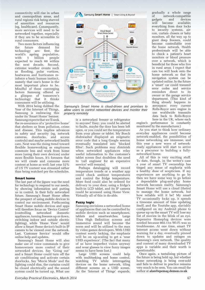
Everyday Practical Electronics, March 2014 67
connectivity will rise in urban and cosmopolitan areas, and rural regions risk being starved of amenities and resources (eg, healthcare). Consequently, more services will need to be networked together, especially if they are to be accessible to rural consumers.
Two more factors influencing the future demand for technology are: first, the world’s ageing population, with 1 billion people expected to reach 60 within the next decade. Second, extreme weather events such as flooding, polar vortices, heatwaves and hurricanes re-inforce a basic human instinct, namely that one’s home is the most important place to be. Mindful of these converging factors Samsung offered us a glimpse of tomorrow’s technology that it thinks consumers will be utilising.
With 2014 being dubbed the Year of the Internet of Things, Samsung is embracing this under its ‘Smart Home’ banner. Samsung expects that we’ll seek the re-assurance of a ‘protective home’ that shelters us from pollution, crime and disease. This implies advances in safety and security (eg, network cameras, doorlocks, and access controls) and maybe networked health care. Next was the rising trend toward flexible homeworking as employees commute less and work from home more (using their own devices) under more flexible hours. It’s foreseen that we will create and consume more content at home as well; last year 52% of US TV content was streamed rather than being watched per the schedules.
Smart homeThe last part of the jigsaw was the need for technology to respond to our needs, by showing information and putting us in control. In their fully networked future, Samsung’s Smart Home offers the prospect of using mobile devices to control our environment. Forthcoming Smart Home mobile devices and apps will therefore focus on ‘Device Control’ (controlling networked domestic appliances, turning freezers up or down, switching indoor and outside electric lighting), while ‘Home View’ would allow a Smart Home device’s built-in IP camera to be viewed over the network. Last, ‘Customer Service’ would offer online help and updates.
Samsung’s Smart Home will also make use of voice commands to give homeowners more control of their networked devices. Say ‘Going out’ and a Smart Home could turn off the air conditioning and activate certain doorlocks. Say ‘Movie Mode’ and the lighting could dim, the curtains could be closed electrically and the sound system could be turned up. What use
is a networked freezer or refrigerator to anyone? Easy; you could be alerted to faults, maybe the door has been left open, or you could set the temperature from your phone or tablet. My Bosch dishwasher displayed an enigmatic error code that a long Google session eventually translated into ‘blocked filter’. Such problems may diminish when networked appliances relay useful information to the customer’s tablet screen (but doubtless the need to ‘call engineer for an expensive service’ will remain).
Perhaps datalogging will record temperature trends or a weather app could check ambient temperatures and control the fridge temperature. More food could also be ordered for delivery to your door, using a fridge’s built-in LCD tablet, and its IP camera could be accessed using Home View. Virtually all of this is do-able.
Fuzzy logicSamsung envisions a networked home of appliances that can be controlled by mobile devices such as smartphones, tablets and smartwatches. Large Ultra High Definition screens and immersive sound will become the norm and will be utilised to the max by video games developers. With UHD content sorely lacking, the emphasis will be on up-scaling to get a ‘near UHD experience’. (The fact that many of us have imperfect vision anyway and wear glasses to view fuzzy images seems to have been lost.)
Large UHD screens could help with multitasking and home control, watching TV while interrogating devices on the home network, tiling different screens on a UHD screen. As the ‘Internet of Things’ expands,
gradually a whole range of network-compatible gadgets and devices will become available; everything from door locks to security systems, air-con, curtain closers or baby monitors, all the way up to giant deep freezers, could become controllable over the home network. Health professionals will be able to check a patient’s heart monitors or blood pressure over a network, which is beneficial for those who live in rural areas. I expect that cars too will hook onto the home network so that its navigation system can be updated online. In the future a ‘smart’ car could transmit error codes and service reminders direct to its owner or the garage service department. (This kind of thing already happens in aerospace: every current Rolls-Royce aero engine in use worldwide transmits data back to Rolls-Royce here in the UK, where each
engine’s performance is constantly monitored by the manufacturer.)
As you start to think how ordinary everyday appliances could become network-enabled, the possibilities of home networking are immense, and this year a new wave of network-ready appliances will start to arrive as a precursor to building a fully-networked home.
All of this is very exciting stuff. To date, though, in the writer’s case a year of smart TV ownership has tinged any sense of euphoria with a healthy dose of scepticism. If my experiences are anything to go by then we have some way to go before a dependable plug-and-play home network becomes reality. Samsung’s Smart Home will use a cloud (theirs) to manage the home network, but how reliable will it be? My smart TV occasionally locks up, it spends a tiresome amount of time updating itself, and the Youtube app, slavishly configured on my Android phone to queue up on the smart TV will lose my list of movies in the blink of an eye. Expensive Homeplug devices were needed because 802.11n Wi-Fi was so troublesome. At one time, smart TV Internet access went down without warning for a day, eventually pinned down to updates and outages on Samsung’s own network. The quality and content of many downloaded TV apps is variable and their worth is questionable.
Once again, a tantalising picture of the future is being held up, but whether home networking is being over-sold and fails to deliver in practice remains very much to be seen. You can email the author at [email protected]
Samsung’s Smart Home is cloud-driven and promises to allow users to control networked devices and monitor their property remotely
Network - New layout.indd 67 16/01/2014 12:45:24

68 Everyday Practical Electronics, March 2014
DIRECT BOOK SERVICEThe books listed have been selected by Everyday Practical Electronics editorial staff as being of special interest to everyone involved in electronics and computing. They are supplied by mail order direct to your door. Full ordering details are given on the next page.
All prices include UK postage
FOR A FULL DESCRIPTION OF THESE BOOKS AND
CD-ROMS SEE THE SHOP ON OUR WEBSITE www.epemag.com
PROJECTCONSTRUCTION
IC 555 PROJECTSE. A. Parr167 pages Order code BP44 £5.49
1
135 pages Order code BP392 £5.99
ELECTRONIC PROJECT BUILDING FOR BEGINNERS R. A. Penfold
RASPBERRY Pi MANUAL: A practical guide to the revolutionary small computer
THEORY AND REFERENCE
ELECTRONICS TEACH-IN BUNDLE –SPECIAL BUNDLE PRICE £14 FOR PARTS 1, 2 & 3
ELECTRONICS TEACH-IN 3 CD-ROM
The three sections of this CD-ROM cover a very wide range of subjects that will interest everyone involved in electronics, from hobbyists and students to professionals. The first 80-odd pages of Teach-In 3 are dedicated to Circuit Surgery, the regular EPE clinic dealing with readers’ queries on circuit design problems – from voltage regulation to using SPICE circuit simulation software.
The second section – Practically Speaking – covers the practical aspects of electronics construction. Again, a whole range of subjects, from soldering to avoiding problems with static electricity and indentifying components, are covered. Finally, our collection of Ingenuity Unlimited circuits provides over 40 circuit designs submitted by the readers of EPE.
The CD-ROM also contains the complete Electronics Teach-In 1 book, which provides a broad-based introduction to electronics in PDF form, plus interactive quizzes to test your knowledge, TINA circuit simulation software (a limited version – plus a specially written TINA Tutorial).
The Teach-In 1 series covers everything from Electric Current through to Microprocessors and Microcontrollers and each part includes demonstration circuits to build on breadboards or to simulate on your PC. CD-ROM Order code ETI3 CD-ROM £8.50
ELECTRONICS TEACH-IN 2 CD-ROMUSING PIC MICROCONTROLLERS A PRACTICAL INTRODUCTIONThis Teach-In series of articles was originally published in EPE in 2008 and, following demand from readers, has now been collected together in the Electronics Teach-In 2 CD-ROM.
The series is aimed at those using PIC microcontrollers for the first time. Each part of the series includes breadboard layouts to aid understanding and a simple programmer project is provided.
Also included are 29 PIC N’ Mix articles, also republished from EPE. These provide a host of practical programming and interfacing information, mainly for those that have already got to grips with using PIC microcontrollers. An extra four part beginners guide to using the C programing language for PIC microcontrollers is also included.
The CD-ROM also contains all of the software for the Teach-In 2 series and PIC N’ Mix articles, plus a range of items from Microchip – the manufacturers of the PIC microcontrollers. The material has been compiled by Wimborne Publishing Ltd. with the assistance of Microchip Technology Inc.
CD-ROMs Order code ETI BUN Bundle Price £14.00
ELECTRONICS TEACH-IN 4
ELECTRONICS TEACH-IN 4 CD-ROM
A Broad-Based Introduction to Electronics.The Teach-In 4 CD-ROM covers three of the most important electronics units that are currently studied in many schools and colleges. These include, Edexcel BTEC level 2 awards and the electronics units of the new Diploma in Engineering, Level 2.
The CD-ROM also contains the full Modern Electronics Manual, worth £29.95. The Manual contains over 800 pages of electronics theory, projects, data, assembly instructions and web links.
A package of exceptional value that will appeal to all those interested in learning about electronics or brushing up on their theory, be they hobbyists, students or professionals.
CD-ROM Order code ETI4 CD-ROM £8.99
CD-ROM Order code ETI2 CD-ROM £9.50
RASPBERRY PI
176 pages Order code H001 £17.99
RASPBERRY Pi USER-GUIDE
262 pages Order code JW001 £12.99
PRACTICAL FIBRE-OPTIC PROJECTS R. A. Penfold
132 pages Order code BP374 £5.45
MICROPROCESSORS
298 pages Order code NE48 £30.99
INTERFACING PIC MICROCONTROLLERSMartin Bates
PROGRAMMING 16-BIT PIC MICROCONTROLLERS IN C– LEARNING TO FLY THE PIC24 Lucio Di Jasio (Application Segments Manager, Microchip, USA)
496 pages +CD-ROM Order code NE45 £38.00
INTRODUCTION TO MICROPROCESSORS AND MICROCONTROLLERS – SECOND EDITIONJohn Crisp
222 pages Order code NE31 £29.99
THE PIC MICROCONTROLLERYOUR PERSONAL INTRODUCTORY COURSE – THIRD EDITION. John Morton
270 pages Order code NE36 £25.00
PIC IN PRACTICE (2nd Edition)David W. Smith
308 pages Order code NE39 £24.99
MICROCONTROLLER COOKBOOKMike James
240 pages Order code NE26 £36.99
440 pages Order code NE21 £32.50
PRACTICAL ELECTRONICS HANDBOOK –Fifth Edition. Ian Sinclair
STARTING ELECTRONICS – 4th Edition Keith Brindley
296 pages Order code NE100 £18.99
ELECTRONIC CIRCUITS – FUNDAMENTALS & APPLICATIONS – Third Edition Mike Tooley
400 pages Order code TF43 £25.99
FUNDAMENTAL ELECTRICAL AND ELECTRONIC PRINCIPLES – Third Edition C.R. Robertson
368 pages Order code TF47 £21.99
A BEGINNER’S GUIDE TO TTL DIGITAL ICsR.A. Penfold
142 pages Order code BP332 £5.45
UNDERSTANDING ELECTRONIC CONTROL SYSTEMSOwen Bishop
228 pages Order code NE35 £36.99
Order code ETIBUNDLE
ELECTRONICS
TEACH-IN 3
8 TINA Circuit Simulation Program
(Limited version)
8 FLOWCODE V3 PIC Programming
Software (Limited version)
8 Interactive Quizzes to Test
Your Knowledge
Electr
onics Teach-In 1
© Wim
borne Publishing Ltd 2010
CD Cover.indd 1
29/04/2010 13:21:42
FROM THE PUBLISHERS OF
£7.99
FREE
CD
-RO
M
TEACH-IN 1 CD-ROM
TWO TEACH-INs FOR
THE PRICE OF ONE!
i The free CD-ROM provides
a broad-based introduction
to electronics
i A complete stand-alone
tutorial in 11 parts plus free
software
FREE
CIRCUIT SURGERY
i The how and why of circuit design
PRACTICALLY SPEAKING
i The techniques of electronic
project construction
INGENUITY UNLIMITED
i Over 40 different circuit ideas
Teach In 3 Cover.indd 1
06/05/2010 16:22:29
ELECTRONICS TEACH-IN 4FREE CD-ROMWORTH£29.95
BASE MANUALwww.epemag.co.uk
© Wimborne Publishing Ltd. 2011
This CD-ROM requiresAdobe® Reader™
Downloadable Free fromwww.adobe.com
This software should autorun, if not, open in Windows Explorer and double-click index.pdf
FROM THE PUBLISHERS OF
£8.99
FREE
CD-ROM
A BROAD-BASED INTRODuCTION TO ELECTRONICS
i An eleven part tutoriali uses inexpensive circuit
simulation softwareFREECD-ROM
THE MODERN ELECTRONICS MANuALThe essential reference work for everyone
studying electronicsi Over 800 PDF pages i In-depth theoryi Extensive data tables
and web linksTeach In 4 Cover.indd 1
14/11/2011 20:33:21
ELECTRONICS TEACH-IN 5
Provides a practical
introduction to PIC
microcontrollers
CD ROM for Windows
This CD should start
automatically, if not
double-click index.html
Plus:
MikroElektronika,
Microchip
L-Tek PoScope
software
Electronics Teach-In 2
© 2013 Wimborne Publishing Ltd
The Microchip name and logo, MPLAB, PIC and dsPIC are
registered trademarks of Microchip Technology Incorporated
in the USA and other countries. © 2013 Microchip Technology
Inc. All rights reserved. Issue 1. MCCD1016-02.09
Teach In 2 - JUL13.indd 1
29/07/2013 09:59:25
FROM THE PUBLISHERS OF
£8.99FREE
CD-ROM
JUMP START 15 design and build circuit projects dedicated to newcomers or those following courses in schools and colleges
FREE
CD-ROM
TEACH-IN 2 TWO TEACH-INs FOR THE PRICE OF ONE!
PRACTICALLY SPEAKINGThe techniques of project construction
PIC ‘N MIxStarting out with PIC microcontrollers
The free CD-ROM provides a practical introduction to PIC microcontrollersPlus MikroElektronika, Microchip and L-Tek PoScope software
Teach In 5 Cover.indd 1 29/07/2013 10:00:29
ELECTRONICS TEACH-IN 5
PROGRAMMING THE RASPBERRY Pi
192 pages Order code MGH4 £10.99
ELECTRONICS TEACH-IN 5
Jump Start – 15 design and build circuit projects dedicated to new-comers or those following courses in school and colleges. The projects are: Moisture Detector, Quiz Machine, Battery Voltage Checker, Solar-Powered Charger, Ver-satile Theft Alarm, Spooky Circuits, Frost Alarm, Mini Christmas Lights, iPod Speaker, Logic Probe, DC Motor Controller, Egg Timer, Signal Injector Probe, Simple Radio Receiver, Tempera-ture Alarm.
PLUS:
PIC’ N MIX – starting out with PIC Microcontrollers and PRACTICALLy SPEAkINg – the techniques of project construction.
FREE CD-ROM – The free CD-ROM is the complete Teach-In 2 book providing a practical introduction to PIC Microprocessors plus MikroElektronika, Microchip and L-Tek PoScope software.
FREECD-ROM
160 Pages Order code ETI5 £8.99
GETTING STARTED WITH RASPBERRY Pi
164 pages Order code OR01 £11.50
STARTING ELECTRONICS
By Keith Brindley
Starting Electronics is unrivalled as a highly practical introduction
for technicians, non-electronic engineers, software engineers,
students, and hobbyists. Keith Brindley introduces readers to the
functions of the main component types, their uses, and the basic
principles of building and designing electronic circuits. Breadboard
layouts make this very much a ready-to-run book for the
experimenter, and the use of readily available, inexpensive
components makes this practical exploration of electronics easily
accessible to all levels of engineer and hobbyist.
Other books tell readers what to do, but sometimes fail to explain
why - Brindley gives readers hands-on confidence in addition to real
scientific knowledge, and insight into the principles as well as the
practice. All written explanations and steps are supplemented with
numerous photos, charts, tables and graphs. Concepts and practical
aspects are explained thoroughly with mathematical formulae and
technical schematic drawings.
Each chapter introduces a concept or tool, explains the basic theory,
and provides clear instructions for a simple experiment to apply the
concept or tool, with quiz sections and answers, at the end of each
chapter.
296 pages Order code NE???? £20.99Books1.indd 68 16/01/2014 12:46:01

69
COMPUTING AND ROBOTICSFAULT FINDING AND TEST
EQUIPMENT
GETTING THE MOST FROM YOUR MULTIMETERR. A. Penfold
96 pages Order code BP239 £5.49
PRACTICAL ELECTRONIC FAULT FINDING AND TROUBLESHOOTINGRobin Pain
274 pages Order code NE22 £41.99
HOW ELECTRONIC THINGS WORK – AND WHAT TO DO WHEN THEY DON’TRobert Goodman
394 pages Order code MGH3 £21.99
OSCILLOSCOPES – FIFTH EDITIONIan Hickman
288 pages Order code NE37 £36.99
HOW TO USE OSCILLOSCOPES AND OTHER TEST EQUIPMENTR.A. Penfold
104 pages Order code BP267 £5.49
AUDIO & VIDEO
VALVE AMPLIFIERS – Second EditionMorgan Jones
288 pages Order code NE33 £40.99
BUILDING VALVE AMPLIFIERS Morgan Jones
368 pages Order code NE40 £29.00
DIGITAL AUDIO RECORDING Ian Waugh
60 pages Order code PC121 £7.95
MAKING MUSIC WITH YOUR COMPUTER Stephen Bennett
QUICK GUIDE TO MP3 AND DIGITAL MUSICIan Waugh
60 pages Order code PC119 £7.45
92 pages Order code PC120 £10.95
QUICK GUIDE TO DIGITAL AUDIO RECORDING Ian Waugh
208 pages Order code PC121 £7.95
ELECTRONIC PROJECTS FOR VIDEO ENTHUSIASTSR.A. Penfold
109 pages Order code BP356 £5.45
All prices include UK postage. For postage to Europe (air) and the rest of the world (surface) please add £3 per book. Surface mail can take up to 10 weeks to some countries. For the rest of the world airmail add £4 per book. CD-ROM prices include VAT and/or postage to anywhere in the world. Send a PO, cheque, international money order (£ sterling only) made payable to Direct Book Service or card details, Visa, Mastercard or Maestro to: DIRECT BOOK SERVICE, WIMBORNE PUBLISHING LIMITED, 113 LYNWOOD DRIVE, MERLEY, WIMBORNE, DORSET BH21 1UU.
Books are normally sent within seven days of receipt of order, but please allow 28 days for delivery – more for overseas orders. Please check price and availability (see latest issue of Everyday Practical Electronics) before ordering from old lists.
For a full description of these books please see the shop on our website. Tel 01202 880299 Fax 01202 843233. E-mail: [email protected]
Order from our online shop at: www.epemag.com
BOOK ORDERING DETAILS
Full name: .......................................................................................................................................
Address: ..........................................................................................................................................
.........................................................................................................................................................
.........................................................................................................................................................
.............................................. Post code: ........................... Telephone No: ....................................
Signature: ........................................................................................................................................
I enclose cheque/PO payable to DIRECT BOOK SERVICE for £ ..............................................
Please charge my card £ ....................................... Card expiry date.........................................
Card Number ....................................................................... Maestro Issue No..............................
Valid From Date ................ Card Security Code ................ (The last three digits on or just below the signature strip)
Please send book order codes: .......................................................................................................
.......................................................................................................................................................... Please continue on separate sheet of paper if necessary
BOOK ORDER FORM
NEWNES INTERFACING COMPANIONTony Fischer-Cripps
295 pages Order code NE38 £41.00
HOW TO BUILD A COMPUTER MADE EASYR.A. Penfold
120 pages Order code BP707 £8.49
128 pages Order code BP721 £7.99
THE INTERNET – TWEAKS, TIPS AND TRICKSR. A. Penfold
EASY PC CASE MODDINGR.A. Penfold
192 pages + CDROM Order code BP542 £8.99
FREE DOWNLOADS TO PEP-UP AND PROTECT YOUR PCR.A. Penfold
128 pages Order code BP722 £7.99
WINDOWS XP EXPLAINEDN. Kantaris and P.R.M. Oliver
264 pages Order code BP514 £7.99
eBAY – TWEAKS, TIPS AND TRICKSR. A. Penfold
128 pages Order code BP716 £7.50
COMPUTING FOR THE OLDER GENERATIONJim Gatenby
308 pages Order code BP601 £8.99
ANDROIDS, ROBOTS AND ANIMATRONSSecond Edition – John Iovine
224 pages Order code MGH1 £16.99
ROBOT BUILDERS COOKBOOKOwen Bishop
366 pages Order code NE46 £26.00
INTRODUCING ROBOTICS WITH LEGO MINDSTORMSRobert Penfold
288 pages + Order code BP901 £14.99
MORE ADVANCED ROBOTICS WITH LEGOMINDSTORMS – Robert Penfold
298 pages Order code BP902 £14.99
WINDOWS 7 – TWEAKS, TIPS AND TRICKSAndrew Edney
120 pages Order code BP708 £8.49
GETTING STARTED IN COMPUTING FOR THE OLDER GENERATIONJim Gatenby
120 pages Order code BP704 £8.49
HOW TO FIX YOUR PC PROBLEMSR. A. Penfold
128 pages Order code BP705 £8.49
AN INTRODUCTION TO eBAY FOR THE OLDER GENERATIONCherry Nixon
120 pages Order code BP709 £8.49
Books1.indd 69 16/01/2014 12:46:11

70 Everyday Practical Electronics, March 2014
Basic printed circuit boards for most recent EPE constructional projects are available from the PCB Service, see list. These are fabricated in glass fibre, and are drilled and roller tinned, but all holes are a standard size. They are not silk-screened, nor do they have solder resist. Double-sided boards are NOT plated through hole and will require ‘vias’ and some components soldering to both sides. * NOTE: PCBs from the July 2013 issue with eight digit codes have silk screen overlays and, where applicable, are double-sided, plated through-hole, with solder masks, they are similar to the photos in the relevent project articles.
All prices include VAT and postage and packing. Add £2 per board for airmail outside of Europe. Remittances should be sent to The PCB Service, Everyday Practical Electronics, Wimborne Publishing Ltd., 113 Lynwood Drive, Merley, Wimborne, Dorset BH21 1UU. Tel: 01202 880299; Fax 01202 843233; Email: [email protected]. On-line Shop: www.epemag.com. Cheques should be crossed and made payable to Everyday Practical Electronics (Payment in £ sterling only).
NOTE: While 95% of our boards are held in stock and are dispatched within seven days of receipt of order, please allow a maximum of 28 days for delivery – overseas readers allow extra if ordered by surface mail.
Back numbers or photocopies of articles are available if required – see the Back Issues page for details. WE DO NOT SUPPLY KITS OR COMPONENTS FOR OUR PROJECTS.
PCB SERVICE CHECK US OUT ON THE WEB
PROJECT TITLE ORDER CODE COST
DECEmbER ’13CLASSiC-D Amplifier – Power SupplyUSB Instrument Interface – Front Panel
JANUARY ’14Champion Simple 1.5A Switching Regulator
FEbRUARY ’142.5GHz 12-Digit Frequency Counter – Display PCB – Main PCB – Front PanelHigh-Energy Electronic Ignition SystemMobile Phone LOUD Ringer!
mARCH ’14Extremely accurate GPS 1pps Timebase For AFrequency CounterInfrasound Detector – Pre CHAMP PCB – CHAMP PCBAutomatic Points Controller (inc. 2 sensor PCBs)Automatic Points Controller – Frog Relay
EPE SOFTWARE All software programs for EPE Projects marked with a star, and others
previously published can be downloaded free from the Library on our website, accessible via our home page at: www.epemag.com
EPE PRINTED CIRCUIT BOARD SERVICEOrder Code Project Quantity Price
. . . . . . . . . . . . . . . . . . . . . . . . . . . . . . . . . . . . . . . . . . . . . .
Name . . . . . . . . . . . . . . . . . . . . . . . . . . . . . . . . . . . . . . . .
Address . . . . . . . . . . . . . . . . . . . . . . . . . . . . . . . . . . . . . .
. . . . . . . . . . . . . . . . . . . . . . . . . . . . . . . . . . . . . . . . . . . . . .
Tel. No. . . . . . . . . . . . . . . . . . . . . . . . . . . . . . . . . . . . . . . .
I enclose payment of £ . . . . . . . . . . . . . . (cheque/PO in £ sterling only) to:
Everyday PracticalElectronics
Card No. . . . . . . . . . . . . . . . . . . . . . . . . . . . . . . . . . . . . .
Valid From . . . . . . . . . . . . . Expiry Date . . . . . . . . . . . .
Card Security No. . . . . . . . Maestro Issue No. . . . . . .
Signature . . . . . . . . . . . . . . . . . . . . . . . . . . . . . . . . . . . . .
Note: You can also order PCBs by phone, Fax or Email or via the Shop on our website on a secure server:
http://www.epemag.com
PROJECT TITLE ORDER CODE COST
FEbRUARY ’1310W LED Floodlight Crystal DAC (double-sided)Jump Start – Logic Probe
mARCH ’13Lightning Detector Digital Spirit Level SemTest – Part 2 – Main/Lower Board – Display/Upper Board
Interplanetary Voice Jump Start – DC Motor Controller
APRIL ’13Six-Decade Resistance Substitution BoxSoftStarter (single-sided)Jump Start – Egg TimerSemTest HV DC Crowbar
mAY ’13Electronic StethoscopePIC/AVR Programming Adaptor Board (d’ble-sided)Jump Start – Signal Injector Probe
JUNE ’13USB Breakout BoxJump Start – Simple Radio ReceiverMix-It
JULY ’136-Decade Capacitance Substitution Box6-Decade Capacitance Substitution Box Panel/LidSoftStarter For Power ToolsHigh-Current Adaptor For Scopes And DMMsJump Start – Temperature Alarm
AUGUST ’13Driveway SentryBuild A VoxMilliohm Meter Adaptor For DMMs
SEPTEmbER ’13MiniReg Adjustable RegulatorUSB Stereo Recording InterfaceDigital Sound Effects Module
OCTObER ’13High-Temperature Thermometer/ThermostatLED Musicolour
NOvEmbER ’13Mains Timer For Fans Or LightsCLASSiC-D Amplifier (inc. 3 Rockby Capacitors) – Speaker Protector
011091112410912124109122
1109121/218102121
0411112204111121041111230511012112110121
0410313101107941011029410910313209103133
£16.66£26.38£28.54
£8.88£5.53
£12.88£27.13£22.38£9.10£9.10
£8.88£5.54£5.54£13.42£5.54
Please check price and availability in the latest issue. A large number of older boards are listed on, and can be ordered from, our website.
Boards can only be supplied on a payment with order basis.
* See NOTE above left regarding PCBs with eight digit codes *
885886887
888889
890891
£6.75£18.46£6.42
£8.75£8.75
£16.52£15.55
892893
£8.75£8.55
894895896897
898899900
£10.10£8.36£8.36£13.61
£9.72£23.33£8.16
PCB MASTERSPCB masters for boards published from the March ’06 issue onwards can
also be downloaded from our website (www.epemag.com); go to the ‘Library’ section.
901902903
£7.97£8.94£11.28
04106121041061221010712104108121904
£18.00£18.00£9.00£18.00£7.97
031071210120711104102101
£18.00£22.00£18.00
181121110710611109109121
£6.00£18.00£9.00
2110512116110121
101081210110812101108122
£22.00£22.00
£9.10£26.50£9.10
PCB Service.indd 70 20/01/2014 09:30:03

Everyday Practical Electronics, March 2014 71
If you want your advertisements to be seen by the largest readership at the most economical price our classified page offers excellent value. The rate for semi-display space is £10 (+VAT) per centimetre high, with a minimum height of 2·5cm. All semi-display adverts have a width of 5.5cm. The prepaid rate for classified adverts is 40p (+VAT) per word (minimum 12 words).All cheques, postal orders, etc., to be made payable to Everyday Practical Electronics. VAT must be added. Advertisements, together with remittance, should be sent to Everyday Practical Electronics Advertisements, 113 Lynwood Drive, Merley, Wimborne, Dorset, BH21 1UU. Phone: 01202 880299. Fax: 01202 843233. Email: [email protected]. For rates and information on display and classified advertising please contact our Advertisement Manager, Stewart Kearn as above.
BETA LAYOUT. . . . . . . . . . . . . . . . . . . . . . . . . . . . . . . . . . . . 72CRICKLEWOOD ELECTRONICS . . . . . . . . . . . . . . . . . . . . . . 65ESR ELECTRONIC COMPONENTS . . . . . . . . . . . . . . . . . . . . . 6iCSAT . . . . . . . . . . . . . . . . . . . . . . . . . . . . . . . . . . . . . . . . . . 65JPG ELECTRONICS . . . . . . . . . . . . . . . . . . . . . . . . . . . . . . . . 72L-TEK POSCOPE . . . . . . . . . . . . . . . . . . . . . . . . . . . . . . . . . . 46MICROCHIP . . . . . . . . . . . . . . . . . . . . . . . . . . . . . . . . Cover (iv)LASER BUSINESS SYSTEMS . . . . . . . . . . . . . . . . . . . . . . . . . . 58TEACH-IN 5 . . . . . . . . . . . . . . . . . . . . . . . . . . . . . . . . Cover (iii)MIKROELEKTRONIKA . . . . . . . . . . . . . . . . . . . . . . . . . Cover (ii)PEAK ELECTRONIC DESIGN . . . . . . . . . . . . . . . . . . . . . . . . . 51PICO TECHNOLOGY . . . . . . . . . . . . . . . . . . . . . . . . . . . . . . 65QUASAR ELECTRONICS . . . . . . . . . . . . . . . . . . . . . . . . . . . . 2/3
STEWART OF READING . . . . . . . . . . . . . . . . . . . . . . . . . . . . 51TANDY . . . . . . . . . . . . . . . . . . . . . . . . . . . . . . . . . . . . . . . . . 46TECHNOBOTS . . . . . . . . . . . . . . . . . . . . . . . . . . . . . . . . . . . 49
ADVERTISEMENT OFFICES:113 LYNWOOD DRIVE, MERLEY, WIMBORNE, DORSET BH21 1UUPHONE: 01202 880299 FAX: 01202 843233EMAIL: [email protected] WEB: www.epemag.comFor editorial address and phone numbers see page 7
WANTED – 2061D IC by Nikko 20-Pin and data information. Good reward – contact Mr Ward 01425 475445
MISCELLANEOUS
VALVES AND ALLIED COMPONENTS IN STOCK. Phone for free list. Valves, books and magazines wanted. Geoff Davies (Radio), tel. 01788 574774.
BTEC ELECTRONICSTECHNICIAN TRAINING
LONDON ELECTRONICS COLLEGE20 PENYWERN ROAD
EARLS COURT, LONDON SW5 9SUTEL: (020) 7373 8721
www.lec.org.uk
NATIONAL ELECTRONICSVCE ADVANCED ICT
HNC AND HND ELECTRONICSFOUNDATION DEGREES
NVQ ENGINEERING AND ITDESIGN AND TECHNOLOGY
BOWOOD ELECTRONICS LTDSuppliers of Electronic Components
Place a secure order on our website or call our sales lineAll major credit cards accepted
Web: www.bowood-electronics.co.ukUnit 10, Boythorpe Business Park, Dock Walk, Chesterfield,
Derbyshire S40 2QR. Sales: 01246 200222Send 60p stamp for catalogue
Bowood - Jan 09.indd 1 17/11/2008 16:12:31
Canterbury WindingsUK manufacturer of toroidal transformers
(10VA to 3kVA)All transformers made to order. No design fees.
No minimum order.www.canterburywindings.co.uk
01227 450810
VINTAGE ELECTRONIC VALVES
For Repairers of old equipmentFor full info Visit Section 22
www.partridgeelectronics.co.uk
Everyday Practical Electronics reaches more UK readers than any
other UK monthly hobby electronics magazine, our sales figures prove it.
We have been the leading monthly magazine in this market for the last
twenty-six years.
PIC DEVELOPMENT KITS, DTMF kits and modules, CTCSS Encoder and Decoder/Display kits. Visit www.cstech.co.uk
CLOSING DOWN SALESend 50p stamp for list of
available stock to: -
Sherwood Electronics, 10 Newstead StreetMansfield, Notts, NG19 6JJ
SHERWOOD ELECTRONICS
Sherwood - March 2014.indd 1 13/01/2014 14:31:00
EPE Classifieds_100144WP.indd 71 16/01/2014 15:48:38

Open Monday to Friday 9am to 5:30pm And Saturday 9:30am to 5pm
• Aerials, Satellite Dishes & LCD Brackets• Audio Adaptors, Connectors & Leads• BT, Broadband, Network & USB Leads• Computer Memory, Hard Drives & Parts• DJ Equipment, Lighting & Supplies• Extensive Electronic Components - ICs, Project Boxes, Relays & Resistors• Raspberry Pi & Arduino Products• Replacement Laptop Power Supplies• Batteries, Fuses, Glue, Tools & Lots more...
T: 01246 211 202E: [email protected] Electronics, Shaw’s Row,Old Road, Chesterfield, S40 2RBW: www.jpgelectronics.com
Welcome to JPG ElectronicsSelling Electronics in Chestereld for 29 Years
Open Monday to Friday 9am to 5:30pm And Saturday 9:30am to 5pm
• Aerials, Satellite Dishes & LCD Brackets• Audio Adaptors, Connectors & Leads• BT, Broadband, Network & USB Leads• Computer Memory, Hard Drives & Parts• DJ Equipment, Lighting & Supplies• Extensive Electronic Components
Welcome to JPG ElectronicsWelcome to JPG ElectronicsWelcome to JPG ElectronicsWelcome to JPG ElectronicsWelcome to JPG ElectronicsWelcome to JPG ElectronicsWelcome to JPG ElectronicsWelcome to JPG ElectronicsWelcome to JPG ElectronicsWelcome to JPG ElectronicsWelcome to JPG ElectronicsWelcome to JPG ElectronicsWelcome to JPG ElectronicsWelcome to JPG ElectronicsWelcome to JPG ElectronicsWelcome to JPG ElectronicsWelcome to JPG ElectronicsWelcome to JPG ElectronicsWelcome to JPG ElectronicsWelcome to JPG ElectronicsWelcome to JPG ElectronicsWelcome to JPG ElectronicsWelcome to JPG ElectronicsWelcome to JPG ElectronicsWelcome to JPG ElectronicsSelling Electronics in Chestereld for 29 YearsSelling Electronics in Chestereld for 29 YearsSelling Electronics in Chestereld for 29 YearsSelling Electronics in Chestereld for 29 YearsSelling Electronics in Chestereld for 29 YearsSelling Electronics in Chestereld for 29 YearsSelling Electronics in Chestereld for 29 YearsSelling Electronics in Chestereld for 29 YearsSelling Electronics in Chestereld for 29 YearsSelling Electronics in Chestereld for 29 YearsSelling Electronics in Chestereld for 29 YearsSelling Electronics in Chestereld for 29 YearsSelling Electronics in Chestereld for 29 YearsSelling Electronics in Chestereld for 29 YearsSelling Electronics in Chestereld for 29 YearsSelling Electronics in Chestereld for 29 YearsSelling Electronics in Chestereld for 29 YearsSelling Electronics in Chestereld for 29 YearsSelling Electronics in Chestereld for 29 YearsWelcome to JPG ElectronicsSelling Electronics in Chestereld for 29 Years
Retail & Trade Welcome • Free Parking • Google St View Tour: S40 2RB
Johnsons
JPG Electronics
Old
Hal
l Roa
d
Chatsworth Road
Maison Mes Amis
Sparks
Britannia Inn
Morrisons
Old Road
Shaw
’s Ro
w
Rose & Crown
Published on approximately the first Thursday of each month by Wimborne Publishing Ltd., 113 Lynwood Drive, Merley, Wimborne, Dorset BH21 1UU. Printed in England by Acorn Web Offset Ltd., Normanton, WF6 1TW. Distributed by Seymour, 86 Newman St., London W1T 3EX. Subscriptions INLAND: £23.50 (6 months); £43.00 (12 months); £79.50 (2 years). EUROPE: airmail service, £27.00 (6 months); £50.00 (12 months); £95.00 (2 years). REST OF THE WORLD: airmail service, £37.00 (6 months); £70.00 (12 months); £135.00 (2 years). Payments payable to “Everyday Practical Electronics’’, Subs Dept, Wimborne Publishing Ltd. Email: [email protected]. EVERYDAY PRACTICAL ELECTRONICS is sold subject to the following conditions, namely that it shall not, without the written consent of the Publishers first having been given, be lent, resold, hired out or otherwise disposed of by way of Trade at more than the recommended selling price shown on the cover, and that it shall not be lent, resold, hired out or otherwise disposed of in a mutilated condition or in any unauthorised cover by way of Trade or affixed to or as part of any publication or advertising, literary or pictorial matter whatsoever.
Next MonthJacob’s LadderRemember those amazing spark generators in the original Frankenstein films? They are called ‘Jacob’s Ladders’. Our version looks and sounds spectacular and is quite easy to build. As the high voltage sparks climb up the vertical wires they snap and snarl, almost as a warning for you to keep your distance! It even smells convincing, as the purplish discharge generates ozone.
Deluxe GPS 1pps TimebaseDid you enjoy the precision GPS timebase featured in this issue? That was the ‘no frills’ version. Nest month, we present a Deluxe GPS 1pps Timebase, which also suits our recently described 12-Digit Frequency Counter. It not only provides the same near-atomic-clock-accuracy 1pps pulses for the counter’s timebase, but also extracts the NMEA 0183 data stream from the GPS satellites for processing on your PC.
Rugged Battery Charger from Bits’n’PiecesNeed a big, powerful, simple and cheap battery charger? Then look no further, we havejust the design you’ve been looking for!
Capacitor Discharge Unit for twin-coil points motorsGot a model railway? If it’s not just a simple loop of track it’s bound to have one, two or maybe dozens of sets of points. That means you need at least one Capacitor Discharge Unit
(CDU) to power them.
Teach-In 2014: Raspberry Pi – Part 7Next month, in Teach-In 2014, we’ll feature the construction of a 15-channel port expander for the Raspberry Pi. We look at methods of handling and manipulating binary, octal and hexadecimal data. Plus, we’ll show how the System Management Bus
(SMBus) can provide access to a wide-range of I2C devices.
Custom Front Panels
PANEL
-POOL®
is a
reg
iste
red
trad
emar
k of
Bet
a LA
YOUT
Gm
bH
www.panel-pool.com
Free Design Software
Digital printing
APRIL ’14 ISSUE ON SALE 6 MARCH 2014
Content may be subject to change
CarryOver - MARCH 2014.indd 72 16/01/2014 12:47:07


The Microchip name and logo, MPLAB, and PIC are registered trademarks of Microchip Technology Incorporated in the U.S.A., and other countries. mTouch is a trademark of Microchip Technology Inc. in the U.S.A. and other countries. All other trademarks mentioned herein are the property of their respective companies. DS300010046A. ME1089Eng10.13
For more information, go to: www.microchip.com/get/euGC010
With a powerful combination of rich analog integration and lowpower consumption, the PIC24FJ128GC010 family enables a signifi cant cost reduction over a multi-chip design as well as enabling lower noise, faster throughput, smaller PCB size and a faster time to market.
In addition to Microchip’s fi rst 16-bit ADC and a 10 Msps 12-bit ADC, the PIC24FJ128GC010 integrates a DAC and dual op amps to simplify precision analog design. The on-chip LCD driver provides the ability to drive displays with up to 472 segments for information-rich user displays; whilst mTouch™ capacitive touch sensing adds advanced touch capabilities.
The PIC24FJ128GC010 family helps to reduce noise to deliver more consistent analog performance in a very small form factor. Simply add sensors to the low-cost starter kit for easy prototyping.
Looking to speed your analog development time? PIC® MCUs with Intelligent Analog make designs easier
GET STARTED IN 3 EASY STEPS:
1. Begin with the low-cost PIC24F Starter Kit for Intelligent Analog (DM240015)
2. Add custom sensors to the clean analog header to create a prototype
3. Re-use and modify the demo code to speed development
PIC24F Starter Kit for Intelligent Analog(DM240015)
MARCH 2014.indd 1 16/01/2014 12:58:43