Readme Installation 2 First steps
1573
02/2010 00002013 STEP 7 V10.5 SP2 Readme 1 Installation 2 First steps 3 Introduction to the TIA Portal 4 Editing projects 5 Configuring devices and networks 6 Programming a PLC 7 Visualize processes 8 Using online and diagnostics functions 9 Source documents 10
-
Upload
independent -
Category
Documents
-
view
0 -
download
0
Transcript of Readme Installation 2 First steps

02/201000002013
STEP 7 V10.5 SP2
Readme 1
Installation 2
First steps 3
Introduction to the TIA Portal 4
Editing projects 5Configuring devices andnetworks 6
Programming a PLC 7
Visualize processes 8Using online and diagnosticsfunctions 9
Source documents 10

Safety GuidelinesThis manual contains notices you have to observe in order to ensure your personal safety, as well as to preventdamage to property. The notices referring to your personal safety are highlighted in the manual by a safety alertsymbol, notices referring only to property damage have no safety alert symbol. These notices shown below aregraded according to the degree of danger.
Dangerindicates that death or severe personal injury will result if proper precautions are not taken.
Warningindicates that death or severe personal injury may result if proper precautions are not taken.
Cautionwith a safety alert symbol, indicates that minor personal injury can result if proper precautions are not taken.
Cautionwithout a safety alert symbol, indicates that property damage can result if proper precautions are not taken.
Noticeindicates that an unintended result or situation can occur if the corresponding information is not taken intoaccount.
If more than one degree of danger is present, the warning notice representing the highest degree of danger willbe used. A notice warning of injury to persons with a safety alert symbol may also include a warning relating toproperty damage.
Qualified PersonnelThe device/system may only be set up and used in conjunction with this documentation. Commissioning andoperation of a device/system may only be performed by qualified personnel. Within the context of the safetynotes in this documentation qualified persons are defined as persons who are authorized to commission, groundand label devices, systems and circuits in accordance with established safety practices and standards.
Prescribed UsageNote the following:
WarningThis device may only be used for the applications described in the catalog or the technical description and onlyin connection with devices or components from other manufacturers which have been approved or recommendedby Siemens. Correct, reliable operation of the product requires proper transport, storage, positioning andassembly as well as careful operation and maintenance.
TrademarksAll names identified by ® are registered trademarks of the Siemens AG. The remaining trademarks in thispublication may be trademarks whose use by third parties for their own purposes could violate the rights of theowner.
Siemens AGAutomation and DrivesPostfach 48 4890437 NÜRNBERGGERMANY
Order No.: 00002013Edition 02/2010
Copyright © Siemens AG .Technical data subject tochange

This document was created with the "My Documentation Manager" system.
Created by Karl-Heinz Busch on 11.02.2010.
The "My Documentation Manager" system can be found at http://www.automation.siemens.com/MDM
Please read the following legal notice:
This document has been compiled by the user with the help of the free "My Documentation Manager" systemand is a free excerpt from the documentation and/or the documentation created and provided by Siemens forthis product. SIEMENS AG assumes no liability for the contents of the linked Web sites.
A list of the documentation used for this purpose can be found in the attachment. This documentation can befound on the Siemens website at: http://support.automation.siemens.com.
The user bears sole responsibility for ensuring that the contents are up to date by regularly checking the relevantdocumentation which can be found at http://support.automation.siemens.com.
The user shall bear all responsibility and risk for compiling this document. In this respect, Siemens disclaims allliability for the document compiled by the user.
The document shall only be used for the user's own internal purposes and, unless explicitly permitted by theSupplementary Terms of Use for "My Documentation Manager", shall not be passed on to third parties.
The use of this document is subject to the Additional Terms of Use for "My Documentation Manager" availableat: https://www.automation.siemens.com/mdm/ExtendedAGB.

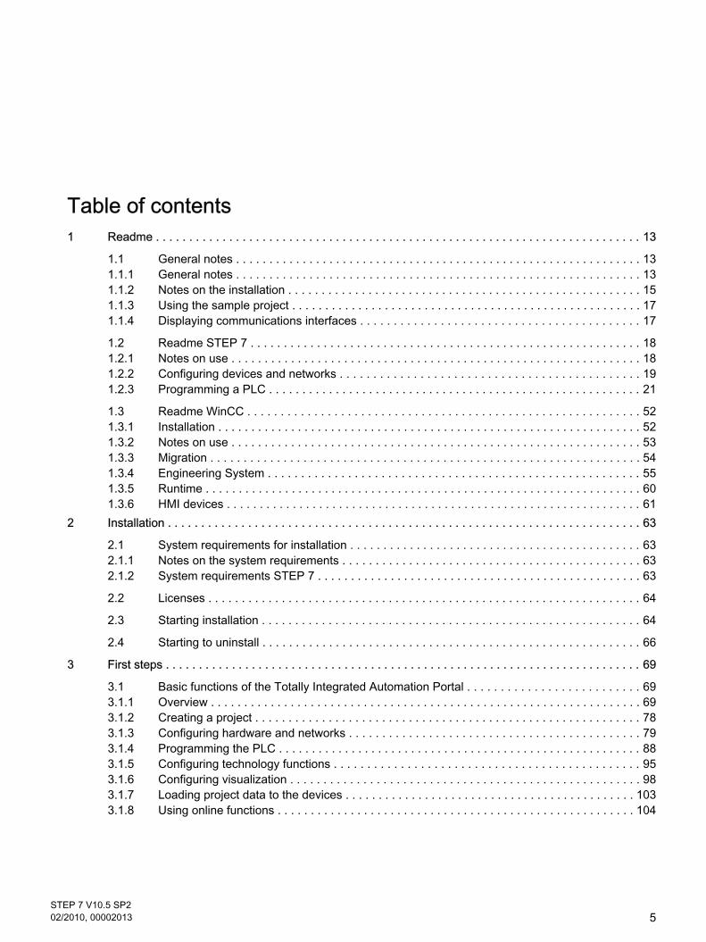
Table of contents1 Readme . . . . . . . . . . . . . . . . . . . . . . . . . . . . . . . . . . . . . . . . . . . . . . . . . . . . . . . . . . . . . . . . . . . . . . . . . 13
1.1 General notes . . . . . . . . . . . . . . . . . . . . . . . . . . . . . . . . . . . . . . . . . . . . . . . . . . . . . . . . . . . . . 131.1.1 General notes . . . . . . . . . . . . . . . . . . . . . . . . . . . . . . . . . . . . . . . . . . . . . . . . . . . . . . . . . . . . . 131.1.2 Notes on the installation . . . . . . . . . . . . . . . . . . . . . . . . . . . . . . . . . . . . . . . . . . . . . . . . . . . . . 151.1.3 Using the sample project . . . . . . . . . . . . . . . . . . . . . . . . . . . . . . . . . . . . . . . . . . . . . . . . . . . . . 171.1.4 Displaying communications interfaces . . . . . . . . . . . . . . . . . . . . . . . . . . . . . . . . . . . . . . . . . . 17
1.2 Readme STEP 7 . . . . . . . . . . . . . . . . . . . . . . . . . . . . . . . . . . . . . . . . . . . . . . . . . . . . . . . . . . . 181.2.1 Notes on use . . . . . . . . . . . . . . . . . . . . . . . . . . . . . . . . . . . . . . . . . . . . . . . . . . . . . . . . . . . . . . 181.2.2 Configuring devices and networks . . . . . . . . . . . . . . . . . . . . . . . . . . . . . . . . . . . . . . . . . . . . . 191.2.3 Programming a PLC . . . . . . . . . . . . . . . . . . . . . . . . . . . . . . . . . . . . . . . . . . . . . . . . . . . . . . . . 21
1.3 Readme WinCC . . . . . . . . . . . . . . . . . . . . . . . . . . . . . . . . . . . . . . . . . . . . . . . . . . . . . . . . . . . 521.3.1 Installation . . . . . . . . . . . . . . . . . . . . . . . . . . . . . . . . . . . . . . . . . . . . . . . . . . . . . . . . . . . . . . . . 521.3.2 Notes on use . . . . . . . . . . . . . . . . . . . . . . . . . . . . . . . . . . . . . . . . . . . . . . . . . . . . . . . . . . . . . . 531.3.3 Migration . . . . . . . . . . . . . . . . . . . . . . . . . . . . . . . . . . . . . . . . . . . . . . . . . . . . . . . . . . . . . . . . . 541.3.4 Engineering System . . . . . . . . . . . . . . . . . . . . . . . . . . . . . . . . . . . . . . . . . . . . . . . . . . . . . . . . 551.3.5 Runtime . . . . . . . . . . . . . . . . . . . . . . . . . . . . . . . . . . . . . . . . . . . . . . . . . . . . . . . . . . . . . . . . . . 601.3.6 HMI devices . . . . . . . . . . . . . . . . . . . . . . . . . . . . . . . . . . . . . . . . . . . . . . . . . . . . . . . . . . . . . . . 61
2 Installation . . . . . . . . . . . . . . . . . . . . . . . . . . . . . . . . . . . . . . . . . . . . . . . . . . . . . . . . . . . . . . . . . . . . . . . 63
2.1 System requirements for installation . . . . . . . . . . . . . . . . . . . . . . . . . . . . . . . . . . . . . . . . . . . . 632.1.1 Notes on the system requirements . . . . . . . . . . . . . . . . . . . . . . . . . . . . . . . . . . . . . . . . . . . . . 632.1.2 System requirements STEP 7 . . . . . . . . . . . . . . . . . . . . . . . . . . . . . . . . . . . . . . . . . . . . . . . . . 63
2.2 Licenses . . . . . . . . . . . . . . . . . . . . . . . . . . . . . . . . . . . . . . . . . . . . . . . . . . . . . . . . . . . . . . . . . 64
2.3 Starting installation . . . . . . . . . . . . . . . . . . . . . . . . . . . . . . . . . . . . . . . . . . . . . . . . . . . . . . . . . 64
2.4 Starting to uninstall . . . . . . . . . . . . . . . . . . . . . . . . . . . . . . . . . . . . . . . . . . . . . . . . . . . . . . . . . 66
3 First steps . . . . . . . . . . . . . . . . . . . . . . . . . . . . . . . . . . . . . . . . . . . . . . . . . . . . . . . . . . . . . . . . . . . . . . . . 69
3.1 Basic functions of the Totally Integrated Automation Portal . . . . . . . . . . . . . . . . . . . . . . . . . . 693.1.1 Overview . . . . . . . . . . . . . . . . . . . . . . . . . . . . . . . . . . . . . . . . . . . . . . . . . . . . . . . . . . . . . . . . . 693.1.2 Creating a project . . . . . . . . . . . . . . . . . . . . . . . . . . . . . . . . . . . . . . . . . . . . . . . . . . . . . . . . . . 783.1.3 Configuring hardware and networks . . . . . . . . . . . . . . . . . . . . . . . . . . . . . . . . . . . . . . . . . . . . 793.1.4 Programming the PLC . . . . . . . . . . . . . . . . . . . . . . . . . . . . . . . . . . . . . . . . . . . . . . . . . . . . . . . 883.1.5 Configuring technology functions . . . . . . . . . . . . . . . . . . . . . . . . . . . . . . . . . . . . . . . . . . . . . . 953.1.6 Configuring visualization . . . . . . . . . . . . . . . . . . . . . . . . . . . . . . . . . . . . . . . . . . . . . . . . . . . . . 983.1.7 Loading project data to the devices . . . . . . . . . . . . . . . . . . . . . . . . . . . . . . . . . . . . . . . . . . . . 1033.1.8 Using online functions . . . . . . . . . . . . . . . . . . . . . . . . . . . . . . . . . . . . . . . . . . . . . . . . . . . . . . 104
STEP 7 V10.5 SP202/2010, 00002013
5

4 Introduction to the TIA Portal . . . . . . . . . . . . . . . . . . . . . . . . . . . . . . . . . . . . . . . . . . . . . . . . . . . . . . . . 111
4.1 User interface and operation . . . . . . . . . . . . . . . . . . . . . . . . . . . . . . . . . . . . . . . . . . . . . . . . . 1114.1.1 Special features specific to the operating system . . . . . . . . . . . . . . . . . . . . . . . . . . . . . . . . . 1114.1.2 Starting, setting and exiting the TIA Portal . . . . . . . . . . . . . . . . . . . . . . . . . . . . . . . . . . . . . . 1134.1.3 Layout of the user interface . . . . . . . . . . . . . . . . . . . . . . . . . . . . . . . . . . . . . . . . . . . . . . . . . . 1164.1.4 Adapting the user interface . . . . . . . . . . . . . . . . . . . . . . . . . . . . . . . . . . . . . . . . . . . . . . . . . . 1294.1.5 Keyboard shortcuts . . . . . . . . . . . . . . . . . . . . . . . . . . . . . . . . . . . . . . . . . . . . . . . . . . . . . . . . 132
4.2 Help on the information system . . . . . . . . . . . . . . . . . . . . . . . . . . . . . . . . . . . . . . . . . . . . . . . 1364.2.1 General remarks on the information system . . . . . . . . . . . . . . . . . . . . . . . . . . . . . . . . . . . . . 1364.2.2 Using the Help . . . . . . . . . . . . . . . . . . . . . . . . . . . . . . . . . . . . . . . . . . . . . . . . . . . . . . . . . . . . 1394.2.3 Disabling the display of tooltip cascades . . . . . . . . . . . . . . . . . . . . . . . . . . . . . . . . . . . . . . . . 1414.2.4 Safety Guidelines . . . . . . . . . . . . . . . . . . . . . . . . . . . . . . . . . . . . . . . . . . . . . . . . . . . . . . . . . 142
5 Editing projects . . . . . . . . . . . . . . . . . . . . . . . . . . . . . . . . . . . . . . . . . . . . . . . . . . . . . . . . . . . . . . . . . . . 145
5.1 The basics of projects . . . . . . . . . . . . . . . . . . . . . . . . . . . . . . . . . . . . . . . . . . . . . . . . . . . . . . 145
5.2 Creating a new project . . . . . . . . . . . . . . . . . . . . . . . . . . . . . . . . . . . . . . . . . . . . . . . . . . . . . 145
5.3 Opening projects . . . . . . . . . . . . . . . . . . . . . . . . . . . . . . . . . . . . . . . . . . . . . . . . . . . . . . . . . . 146
5.4 Saving projects . . . . . . . . . . . . . . . . . . . . . . . . . . . . . . . . . . . . . . . . . . . . . . . . . . . . . . . . . . . 146
5.5 Closing projects . . . . . . . . . . . . . . . . . . . . . . . . . . . . . . . . . . . . . . . . . . . . . . . . . . . . . . . . . . . 147
5.6 Deleting projects . . . . . . . . . . . . . . . . . . . . . . . . . . . . . . . . . . . . . . . . . . . . . . . . . . . . . . . . . . 147
5.7 Comparing project data . . . . . . . . . . . . . . . . . . . . . . . . . . . . . . . . . . . . . . . . . . . . . . . . . . . . . 1485.7.1 Overview of the comparison editor . . . . . . . . . . . . . . . . . . . . . . . . . . . . . . . . . . . . . . . . . . . . 1485.7.2 Comparing online-offline . . . . . . . . . . . . . . . . . . . . . . . . . . . . . . . . . . . . . . . . . . . . . . . . . . . . 1505.7.3 Using the filter for comparison results . . . . . . . . . . . . . . . . . . . . . . . . . . . . . . . . . . . . . . . . . . 1515.7.4 Running a detailed comparison . . . . . . . . . . . . . . . . . . . . . . . . . . . . . . . . . . . . . . . . . . . . . . . 1515.7.5 Updating comparison results . . . . . . . . . . . . . . . . . . . . . . . . . . . . . . . . . . . . . . . . . . . . . . . . . 1525.7.6 Specifying actions . . . . . . . . . . . . . . . . . . . . . . . . . . . . . . . . . . . . . . . . . . . . . . . . . . . . . . . . . 1525.7.7 Synchronizing comparison actions . . . . . . . . . . . . . . . . . . . . . . . . . . . . . . . . . . . . . . . . . . . . 153
5.8 Compiling project data . . . . . . . . . . . . . . . . . . . . . . . . . . . . . . . . . . . . . . . . . . . . . . . . . . . . . . 1535.8.1 General information on compiling project data . . . . . . . . . . . . . . . . . . . . . . . . . . . . . . . . . . . 1535.8.2 Compiling project data . . . . . . . . . . . . . . . . . . . . . . . . . . . . . . . . . . . . . . . . . . . . . . . . . . . . . . 154
5.9 Loading project data on the device . . . . . . . . . . . . . . . . . . . . . . . . . . . . . . . . . . . . . . . . . . . . 1555.9.1 General information on loading . . . . . . . . . . . . . . . . . . . . . . . . . . . . . . . . . . . . . . . . . . . . . . . 1555.9.2 Downloading project data from the project tree to the device . . . . . . . . . . . . . . . . . . . . . . . . 1555.9.3 Loading project data to an accessible device . . . . . . . . . . . . . . . . . . . . . . . . . . . . . . . . . . . . 157
5.10 Printing project contents . . . . . . . . . . . . . . . . . . . . . . . . . . . . . . . . . . . . . . . . . . . . . . . . . . . . 1585.10.1 Documentation settings . . . . . . . . . . . . . . . . . . . . . . . . . . . . . . . . . . . . . . . . . . . . . . . . . . . . . 1585.10.2 Creating a print preview . . . . . . . . . . . . . . . . . . . . . . . . . . . . . . . . . . . . . . . . . . . . . . . . . . . . 1585.10.3 Printing project data . . . . . . . . . . . . . . . . . . . . . . . . . . . . . . . . . . . . . . . . . . . . . . . . . . . . . . . 159
5.11 Migrating projects . . . . . . . . . . . . . . . . . . . . . . . . . . . . . . . . . . . . . . . . . . . . . . . . . . . . . . . . . 1605.11.1 Migrating projects . . . . . . . . . . . . . . . . . . . . . . . . . . . . . . . . . . . . . . . . . . . . . . . . . . . . . . . . . 1605.11.2 Displaying the project history . . . . . . . . . . . . . . . . . . . . . . . . . . . . . . . . . . . . . . . . . . . . . . . . 1605.11.3 Displaying the log file of a migration . . . . . . . . . . . . . . . . . . . . . . . . . . . . . . . . . . . . . . . . . . . 161
Table of contents
6STEP 7 V10.5 SP202/2010, 00002013

5.12 Finding and replacing in projects . . . . . . . . . . . . . . . . . . . . . . . . . . . . . . . . . . . . . . . . . . . . . . 1615.12.1 Information on the search function . . . . . . . . . . . . . . . . . . . . . . . . . . . . . . . . . . . . . . . . . . . . 1615.12.2 Search and replace . . . . . . . . . . . . . . . . . . . . . . . . . . . . . . . . . . . . . . . . . . . . . . . . . . . . . . . . 162
5.13 Working with memory cards . . . . . . . . . . . . . . . . . . . . . . . . . . . . . . . . . . . . . . . . . . . . . . . . . 1635.13.1 Basics about memory cards . . . . . . . . . . . . . . . . . . . . . . . . . . . . . . . . . . . . . . . . . . . . . . . . . 1635.13.2 Adding a user-defined card reader . . . . . . . . . . . . . . . . . . . . . . . . . . . . . . . . . . . . . . . . . . . . 1645.13.3 Accessing memory cards . . . . . . . . . . . . . . . . . . . . . . . . . . . . . . . . . . . . . . . . . . . . . . . . . . . 1655.13.4 Selecting the card type of a memory card . . . . . . . . . . . . . . . . . . . . . . . . . . . . . . . . . . . . . . . 1655.13.5 Displaying properties of memory cards . . . . . . . . . . . . . . . . . . . . . . . . . . . . . . . . . . . . . . . . . 166
5.14 Working with text lists . . . . . . . . . . . . . . . . . . . . . . . . . . . . . . . . . . . . . . . . . . . . . . . . . . . . . . 1675.14.1 Text lists . . . . . . . . . . . . . . . . . . . . . . . . . . . . . . . . . . . . . . . . . . . . . . . . . . . . . . . . . . . . . . . . 1675.14.2 Creating user-defined text lists . . . . . . . . . . . . . . . . . . . . . . . . . . . . . . . . . . . . . . . . . . . . . . . 1685.14.3 Editing user-defined text lists . . . . . . . . . . . . . . . . . . . . . . . . . . . . . . . . . . . . . . . . . . . . . . . . 1695.14.4 Editing system-defined text lists . . . . . . . . . . . . . . . . . . . . . . . . . . . . . . . . . . . . . . . . . . . . . . 169
5.15 Working with multi-language projects . . . . . . . . . . . . . . . . . . . . . . . . . . . . . . . . . . . . . . . . . . 1705.15.1 Project text basics . . . . . . . . . . . . . . . . . . . . . . . . . . . . . . . . . . . . . . . . . . . . . . . . . . . . . . . . . 1705.15.2 Select project languages . . . . . . . . . . . . . . . . . . . . . . . . . . . . . . . . . . . . . . . . . . . . . . . . . . . . 1725.15.3 Setting the editing language . . . . . . . . . . . . . . . . . . . . . . . . . . . . . . . . . . . . . . . . . . . . . . . . . 1725.15.4 Translating texts directly . . . . . . . . . . . . . . . . . . . . . . . . . . . . . . . . . . . . . . . . . . . . . . . . . . . . 1735.15.5 Translating texts using reference texts . . . . . . . . . . . . . . . . . . . . . . . . . . . . . . . . . . . . . . . . . 173
5.16 Working with libraries . . . . . . . . . . . . . . . . . . . . . . . . . . . . . . . . . . . . . . . . . . . . . . . . . . . . . . 1745.16.1 Library basics . . . . . . . . . . . . . . . . . . . . . . . . . . . . . . . . . . . . . . . . . . . . . . . . . . . . . . . . . . . . 1745.16.2 "Libraries" task card . . . . . . . . . . . . . . . . . . . . . . . . . . . . . . . . . . . . . . . . . . . . . . . . . . . . . . . . 1755.16.3 Using the elements and parts view . . . . . . . . . . . . . . . . . . . . . . . . . . . . . . . . . . . . . . . . . . . . 1775.16.4 Working with the project library . . . . . . . . . . . . . . . . . . . . . . . . . . . . . . . . . . . . . . . . . . . . . . . 1785.16.5 Working with global libraries . . . . . . . . . . . . . . . . . . . . . . . . . . . . . . . . . . . . . . . . . . . . . . . . . 182
5.17 Protecting project data . . . . . . . . . . . . . . . . . . . . . . . . . . . . . . . . . . . . . . . . . . . . . . . . . . . . . 1895.17.1 Protection concept for project data . . . . . . . . . . . . . . . . . . . . . . . . . . . . . . . . . . . . . . . . . . . . 189
5.18 Using cross-references . . . . . . . . . . . . . . . . . . . . . . . . . . . . . . . . . . . . . . . . . . . . . . . . . . . . . 1905.18.1 Using cross-references . . . . . . . . . . . . . . . . . . . . . . . . . . . . . . . . . . . . . . . . . . . . . . . . . . . . . 190
6 Configuring devices and networks . . . . . . . . . . . . . . . . . . . . . . . . . . . . . . . . . . . . . . . . . . . . . . . . . . . . 191
6.1 Hardware and network editor . . . . . . . . . . . . . . . . . . . . . . . . . . . . . . . . . . . . . . . . . . . . . . . . 1916.1.1 Overview of hardware and network editor . . . . . . . . . . . . . . . . . . . . . . . . . . . . . . . . . . . . . . . 1916.1.2 Network view . . . . . . . . . . . . . . . . . . . . . . . . . . . . . . . . . . . . . . . . . . . . . . . . . . . . . . . . . . . . . 1926.1.3 Device view . . . . . . . . . . . . . . . . . . . . . . . . . . . . . . . . . . . . . . . . . . . . . . . . . . . . . . . . . . . . . . 1946.1.4 Printing hardware and network configurations . . . . . . . . . . . . . . . . . . . . . . . . . . . . . . . . . . . 1966.1.5 Changing the print options . . . . . . . . . . . . . . . . . . . . . . . . . . . . . . . . . . . . . . . . . . . . . . . . . . 1976.1.6 Inspector window . . . . . . . . . . . . . . . . . . . . . . . . . . . . . . . . . . . . . . . . . . . . . . . . . . . . . . . . . 1976.1.7 Hardware catalog . . . . . . . . . . . . . . . . . . . . . . . . . . . . . . . . . . . . . . . . . . . . . . . . . . . . . . . . . 1986.1.8 Information on hardware components . . . . . . . . . . . . . . . . . . . . . . . . . . . . . . . . . . . . . . . . . . 2006.1.9 Enabling product support . . . . . . . . . . . . . . . . . . . . . . . . . . . . . . . . . . . . . . . . . . . . . . . . . . . 2016.1.10 Keyboard action in the hardware and network editor . . . . . . . . . . . . . . . . . . . . . . . . . . . . . . 201
6.2 Configuring devices . . . . . . . . . . . . . . . . . . . . . . . . . . . . . . . . . . . . . . . . . . . . . . . . . . . . . . . . 2026.2.1 Basics . . . . . . . . . . . . . . . . . . . . . . . . . . . . . . . . . . . . . . . . . . . . . . . . . . . . . . . . . . . . . . . . . . 202
Table of contents
STEP 7 V10.5 SP202/2010, 00002013
7

6.2.2 Configuring individual devices . . . . . . . . . . . . . . . . . . . . . . . . . . . . . . . . . . . . . . . . . . . . . . . . 210
6.3 Networking devices . . . . . . . . . . . . . . . . . . . . . . . . . . . . . . . . . . . . . . . . . . . . . . . . . . . . . . . . 2206.3.1 Communication and networks . . . . . . . . . . . . . . . . . . . . . . . . . . . . . . . . . . . . . . . . . . . . . . . . 2206.3.2 Networking devices in the network view . . . . . . . . . . . . . . . . . . . . . . . . . . . . . . . . . . . . . . . . 2216.3.3 Tabular network overview . . . . . . . . . . . . . . . . . . . . . . . . . . . . . . . . . . . . . . . . . . . . . . . . . . . 2236.3.4 Networking devices in the device view . . . . . . . . . . . . . . . . . . . . . . . . . . . . . . . . . . . . . . . . . 2246.3.5 Checking or changing network parameters and interface parameters . . . . . . . . . . . . . . . . . 2256.3.6 Changing networkings . . . . . . . . . . . . . . . . . . . . . . . . . . . . . . . . . . . . . . . . . . . . . . . . . . . . . . 2266.3.7 Copying, cutting or deleting subnets . . . . . . . . . . . . . . . . . . . . . . . . . . . . . . . . . . . . . . . . . . . 2266.3.8 Configuring Industrial Ethernet . . . . . . . . . . . . . . . . . . . . . . . . . . . . . . . . . . . . . . . . . . . . . . . 2276.3.9 Open User Communication . . . . . . . . . . . . . . . . . . . . . . . . . . . . . . . . . . . . . . . . . . . . . . . . . . 2306.3.10 HMI connections . . . . . . . . . . . . . . . . . . . . . . . . . . . . . . . . . . . . . . . . . . . . . . . . . . . . . . . . . . 239
6.4 Configuring operation . . . . . . . . . . . . . . . . . . . . . . . . . . . . . . . . . . . . . . . . . . . . . . . . . . . . . . 2476.4.1 Selecting a CPU . . . . . . . . . . . . . . . . . . . . . . . . . . . . . . . . . . . . . . . . . . . . . . . . . . . . . . . . . . 2476.4.2 Changing properties of the modules . . . . . . . . . . . . . . . . . . . . . . . . . . . . . . . . . . . . . . . . . . . 2486.4.3 CPU properties . . . . . . . . . . . . . . . . . . . . . . . . . . . . . . . . . . . . . . . . . . . . . . . . . . . . . . . . . . . 2506.4.4 Addressing modules . . . . . . . . . . . . . . . . . . . . . . . . . . . . . . . . . . . . . . . . . . . . . . . . . . . . . . . 2566.4.5 Time-of-day functions . . . . . . . . . . . . . . . . . . . . . . . . . . . . . . . . . . . . . . . . . . . . . . . . . . . . . . 2606.4.6 High-speed counters . . . . . . . . . . . . . . . . . . . . . . . . . . . . . . . . . . . . . . . . . . . . . . . . . . . . . . . 2616.4.7 Point-to-point communication . . . . . . . . . . . . . . . . . . . . . . . . . . . . . . . . . . . . . . . . . . . . . . . . 2666.4.8 Using clock memory . . . . . . . . . . . . . . . . . . . . . . . . . . . . . . . . . . . . . . . . . . . . . . . . . . . . . . . 2746.4.9 Setting options for the level of protection . . . . . . . . . . . . . . . . . . . . . . . . . . . . . . . . . . . . . . . 2756.4.10 Loading a configuration . . . . . . . . . . . . . . . . . . . . . . . . . . . . . . . . . . . . . . . . . . . . . . . . . . . . . 276
6.5 Diagnosing hardware . . . . . . . . . . . . . . . . . . . . . . . . . . . . . . . . . . . . . . . . . . . . . . . . . . . . . . 2786.5.1 Overview of hardware diagnostics . . . . . . . . . . . . . . . . . . . . . . . . . . . . . . . . . . . . . . . . . . . . 2786.5.2 Showing non-editable and current values of configurable module properties . . . . . . . . . . . . 2846.5.3 Showing the current values of dynamic modules properties . . . . . . . . . . . . . . . . . . . . . . . . . 2866.5.4 Checking a module for defects . . . . . . . . . . . . . . . . . . . . . . . . . . . . . . . . . . . . . . . . . . . . . . . 2896.5.5 Changing the properties of a module or the programming device / PC . . . . . . . . . . . . . . . . 2936.5.6 Diagnostics in STOP mode . . . . . . . . . . . . . . . . . . . . . . . . . . . . . . . . . . . . . . . . . . . . . . . . . . 296
6.6 References . . . . . . . . . . . . . . . . . . . . . . . . . . . . . . . . . . . . . . . . . . . . . . . . . . . . . . . . . . . . . . 2986.6.1 Creating an unspecified CPU . . . . . . . . . . . . . . . . . . . . . . . . . . . . . . . . . . . . . . . . . . . . . . . . 2986.6.2 Open User Communication . . . . . . . . . . . . . . . . . . . . . . . . . . . . . . . . . . . . . . . . . . . . . . . . . . 299
7 Programming a PLC . . . . . . . . . . . . . . . . . . . . . . . . . . . . . . . . . . . . . . . . . . . . . . . . . . . . . . . . . . . . . . . 311
7.1 Functional description of S7-1200 CPUs . . . . . . . . . . . . . . . . . . . . . . . . . . . . . . . . . . . . . . . 3117.1.1 Operating modes . . . . . . . . . . . . . . . . . . . . . . . . . . . . . . . . . . . . . . . . . . . . . . . . . . . . . . . . . . 3117.1.2 Memory areas . . . . . . . . . . . . . . . . . . . . . . . . . . . . . . . . . . . . . . . . . . . . . . . . . . . . . . . . . . . . 3177.1.3 I/O data area . . . . . . . . . . . . . . . . . . . . . . . . . . . . . . . . . . . . . . . . . . . . . . . . . . . . . . . . . . . . . 3227.1.4 Basics of program execution . . . . . . . . . . . . . . . . . . . . . . . . . . . . . . . . . . . . . . . . . . . . . . . . . 323
7.2 Creating a user program . . . . . . . . . . . . . . . . . . . . . . . . . . . . . . . . . . . . . . . . . . . . . . . . . . . . 3347.2.1 Programming basics . . . . . . . . . . . . . . . . . . . . . . . . . . . . . . . . . . . . . . . . . . . . . . . . . . . . . . . 3347.2.2 Declaring PLC tags . . . . . . . . . . . . . . . . . . . . . . . . . . . . . . . . . . . . . . . . . . . . . . . . . . . . . . . . 3947.2.3 Creating and managing blocks . . . . . . . . . . . . . . . . . . . . . . . . . . . . . . . . . . . . . . . . . . . . . . . 4067.2.4 Programming blocks . . . . . . . . . . . . . . . . . . . . . . . . . . . . . . . . . . . . . . . . . . . . . . . . . . . . . . . 4217.2.5 Comparing blocks . . . . . . . . . . . . . . . . . . . . . . . . . . . . . . . . . . . . . . . . . . . . . . . . . . . . . . . . . 521
Table of contents
8STEP 7 V10.5 SP202/2010, 00002013

7.2.6 Compiling blocks . . . . . . . . . . . . . . . . . . . . . . . . . . . . . . . . . . . . . . . . . . . . . . . . . . . . . . . . . . 5257.2.7 Downloading blocks . . . . . . . . . . . . . . . . . . . . . . . . . . . . . . . . . . . . . . . . . . . . . . . . . . . . . . . 5287.2.8 Protecting blocks . . . . . . . . . . . . . . . . . . . . . . . . . . . . . . . . . . . . . . . . . . . . . . . . . . . . . . . . . . 536
7.3 Displaying program information . . . . . . . . . . . . . . . . . . . . . . . . . . . . . . . . . . . . . . . . . . . . . . . 5387.3.1 Overview of available program information . . . . . . . . . . . . . . . . . . . . . . . . . . . . . . . . . . . . . . 5387.3.2 Displaying an assignment list . . . . . . . . . . . . . . . . . . . . . . . . . . . . . . . . . . . . . . . . . . . . . . . . 5397.3.3 Displaying the call structure . . . . . . . . . . . . . . . . . . . . . . . . . . . . . . . . . . . . . . . . . . . . . . . . . 5467.3.4 Displaying the dependency structure . . . . . . . . . . . . . . . . . . . . . . . . . . . . . . . . . . . . . . . . . . 5527.3.5 Displaying CPU resources . . . . . . . . . . . . . . . . . . . . . . . . . . . . . . . . . . . . . . . . . . . . . . . . . . 557
7.4 Displaying cross-references . . . . . . . . . . . . . . . . . . . . . . . . . . . . . . . . . . . . . . . . . . . . . . . . . 5617.4.1 General information about cross references . . . . . . . . . . . . . . . . . . . . . . . . . . . . . . . . . . . . . 5617.4.2 Structure of the cross-reference list . . . . . . . . . . . . . . . . . . . . . . . . . . . . . . . . . . . . . . . . . . . 5617.4.3 Displaying the cross-reference list . . . . . . . . . . . . . . . . . . . . . . . . . . . . . . . . . . . . . . . . . . . . 5637.4.4 Displaying cross-references in the Inspector window . . . . . . . . . . . . . . . . . . . . . . . . . . . . . . 564
7.5 Testing the user program . . . . . . . . . . . . . . . . . . . . . . . . . . . . . . . . . . . . . . . . . . . . . . . . . . . 5657.5.1 Basics of testing the user program . . . . . . . . . . . . . . . . . . . . . . . . . . . . . . . . . . . . . . . . . . . . 5657.5.2 Testing with program status . . . . . . . . . . . . . . . . . . . . . . . . . . . . . . . . . . . . . . . . . . . . . . . . . 5657.5.3 Testing with the watch table . . . . . . . . . . . . . . . . . . . . . . . . . . . . . . . . . . . . . . . . . . . . . . . . . 570
7.6 Programming examples . . . . . . . . . . . . . . . . . . . . . . . . . . . . . . . . . . . . . . . . . . . . . . . . . . . . 6027.6.1 LAD programming examples . . . . . . . . . . . . . . . . . . . . . . . . . . . . . . . . . . . . . . . . . . . . . . . . . 6027.6.2 FBD programming examples . . . . . . . . . . . . . . . . . . . . . . . . . . . . . . . . . . . . . . . . . . . . . . . . . 612
7.7 Using technology objects . . . . . . . . . . . . . . . . . . . . . . . . . . . . . . . . . . . . . . . . . . . . . . . . . . . 6237.7.1 Using Motion Control . . . . . . . . . . . . . . . . . . . . . . . . . . . . . . . . . . . . . . . . . . . . . . . . . . . . . . . 6237.7.2 Using PID Compact . . . . . . . . . . . . . . . . . . . . . . . . . . . . . . . . . . . . . . . . . . . . . . . . . . . . . . . . 649
7.8 References . . . . . . . . . . . . . . . . . . . . . . . . . . . . . . . . . . . . . . . . . . . . . . . . . . . . . . . . . . . . . . 6677.8.1 Instructions . . . . . . . . . . . . . . . . . . . . . . . . . . . . . . . . . . . . . . . . . . . . . . . . . . . . . . . . . . . . . . 6677.8.2 Extended instructions . . . . . . . . . . . . . . . . . . . . . . . . . . . . . . . . . . . . . . . . . . . . . . . . . . . . . . 935
8 Visualize processes . . . . . . . . . . . . . . . . . . . . . . . . . . . . . . . . . . . . . . . . . . . . . . . . . . . . . . . . . . . . . . 1017
8.1 Migration . . . . . . . . . . . . . . . . . . . . . . . . . . . . . . . . . . . . . . . . . . . . . . . . . . . . . . . . . . . . . . . 10178.1.1 Migration . . . . . . . . . . . . . . . . . . . . . . . . . . . . . . . . . . . . . . . . . . . . . . . . . . . . . . . . . . . . . . . 10178.1.2 Migration basics . . . . . . . . . . . . . . . . . . . . . . . . . . . . . . . . . . . . . . . . . . . . . . . . . . . . . . . . . 10178.1.3 Object support during migration . . . . . . . . . . . . . . . . . . . . . . . . . . . . . . . . . . . . . . . . . . . . . 10188.1.4 Migrating projects from WinCC flexible 2008 . . . . . . . . . . . . . . . . . . . . . . . . . . . . . . . . . . . 10218.1.5 Migration of data types . . . . . . . . . . . . . . . . . . . . . . . . . . . . . . . . . . . . . . . . . . . . . . . . . . . . 1023
8.2 Working with screens . . . . . . . . . . . . . . . . . . . . . . . . . . . . . . . . . . . . . . . . . . . . . . . . . . . . . 10258.2.1 Basics . . . . . . . . . . . . . . . . . . . . . . . . . . . . . . . . . . . . . . . . . . . . . . . . . . . . . . . . . . . . . . . . . 10258.2.2 Working with objects . . . . . . . . . . . . . . . . . . . . . . . . . . . . . . . . . . . . . . . . . . . . . . . . . . . . . . 10428.2.3 Working with text lists and graphics lists . . . . . . . . . . . . . . . . . . . . . . . . . . . . . . . . . . . . . . . 10818.2.4 Dynamizing screens . . . . . . . . . . . . . . . . . . . . . . . . . . . . . . . . . . . . . . . . . . . . . . . . . . . . . . 10978.2.5 Working with function keys . . . . . . . . . . . . . . . . . . . . . . . . . . . . . . . . . . . . . . . . . . . . . . . . . 11068.2.6 Working with layers . . . . . . . . . . . . . . . . . . . . . . . . . . . . . . . . . . . . . . . . . . . . . . . . . . . . . . . 11178.2.7 Working with libraries . . . . . . . . . . . . . . . . . . . . . . . . . . . . . . . . . . . . . . . . . . . . . . . . . . . . . 11248.2.8 Display and operating objects . . . . . . . . . . . . . . . . . . . . . . . . . . . . . . . . . . . . . . . . . . . . . . . 11368.2.9 Configuring screen navigation for Basic Panels . . . . . . . . . . . . . . . . . . . . . . . . . . . . . . . . . 1161
Table of contents
STEP 7 V10.5 SP202/2010, 00002013
9

8.3 Working with tags . . . . . . . . . . . . . . . . . . . . . . . . . . . . . . . . . . . . . . . . . . . . . . . . . . . . . . . . 11638.3.1 Basics . . . . . . . . . . . . . . . . . . . . . . . . . . . . . . . . . . . . . . . . . . . . . . . . . . . . . . . . . . . . . . . . . 11638.3.2 Working with tags . . . . . . . . . . . . . . . . . . . . . . . . . . . . . . . . . . . . . . . . . . . . . . . . . . . . . . . . 11678.3.3 Working with arrays . . . . . . . . . . . . . . . . . . . . . . . . . . . . . . . . . . . . . . . . . . . . . . . . . . . . . . . 11848.3.4 Working with cycles . . . . . . . . . . . . . . . . . . . . . . . . . . . . . . . . . . . . . . . . . . . . . . . . . . . . . . . 11888.3.5 Displaying tags . . . . . . . . . . . . . . . . . . . . . . . . . . . . . . . . . . . . . . . . . . . . . . . . . . . . . . . . . . 1189
8.4 Working with alarms . . . . . . . . . . . . . . . . . . . . . . . . . . . . . . . . . . . . . . . . . . . . . . . . . . . . . . 11918.4.1 Basics . . . . . . . . . . . . . . . . . . . . . . . . . . . . . . . . . . . . . . . . . . . . . . . . . . . . . . . . . . . . . . . . . 11918.4.2 Working with alarms . . . . . . . . . . . . . . . . . . . . . . . . . . . . . . . . . . . . . . . . . . . . . . . . . . . . . . 12018.4.3 Operating alarms in Runtime . . . . . . . . . . . . . . . . . . . . . . . . . . . . . . . . . . . . . . . . . . . . . . . . 12258.4.4 Reference . . . . . . . . . . . . . . . . . . . . . . . . . . . . . . . . . . . . . . . . . . . . . . . . . . . . . . . . . . . . . . 1231
8.5 Working with recipes . . . . . . . . . . . . . . . . . . . . . . . . . . . . . . . . . . . . . . . . . . . . . . . . . . . . . . 12678.5.1 Basics . . . . . . . . . . . . . . . . . . . . . . . . . . . . . . . . . . . . . . . . . . . . . . . . . . . . . . . . . . . . . . . . . 12678.5.2 Elements and basic settings . . . . . . . . . . . . . . . . . . . . . . . . . . . . . . . . . . . . . . . . . . . . . . . . 12738.5.3 Displaying and editing recipes in Runtime . . . . . . . . . . . . . . . . . . . . . . . . . . . . . . . . . . . . . 12768.5.4 Configuring recipes . . . . . . . . . . . . . . . . . . . . . . . . . . . . . . . . . . . . . . . . . . . . . . . . . . . . . . . 12798.5.5 Using recipes in Runtime . . . . . . . . . . . . . . . . . . . . . . . . . . . . . . . . . . . . . . . . . . . . . . . . . . 1289
8.6 Working with the user administration . . . . . . . . . . . . . . . . . . . . . . . . . . . . . . . . . . . . . . . . . 12958.6.1 Field of application of the user administration . . . . . . . . . . . . . . . . . . . . . . . . . . . . . . . . . . . 12958.6.2 Form of the user administration . . . . . . . . . . . . . . . . . . . . . . . . . . . . . . . . . . . . . . . . . . . . . . 12968.6.3 Elements and basic settings . . . . . . . . . . . . . . . . . . . . . . . . . . . . . . . . . . . . . . . . . . . . . . . . 12988.6.4 Setting up the user administration . . . . . . . . . . . . . . . . . . . . . . . . . . . . . . . . . . . . . . . . . . . . 13028.6.5 Reference . . . . . . . . . . . . . . . . . . . . . . . . . . . . . . . . . . . . . . . . . . . . . . . . . . . . . . . . . . . . . . 13208.6.6 Examples . . . . . . . . . . . . . . . . . . . . . . . . . . . . . . . . . . . . . . . . . . . . . . . . . . . . . . . . . . . . . . . 1321
8.7 Working with system functions . . . . . . . . . . . . . . . . . . . . . . . . . . . . . . . . . . . . . . . . . . . . . . 13308.7.1 Basics . . . . . . . . . . . . . . . . . . . . . . . . . . . . . . . . . . . . . . . . . . . . . . . . . . . . . . . . . . . . . . . . . 13308.7.2 Working with function lists . . . . . . . . . . . . . . . . . . . . . . . . . . . . . . . . . . . . . . . . . . . . . . . . . . 13328.7.3 Example . . . . . . . . . . . . . . . . . . . . . . . . . . . . . . . . . . . . . . . . . . . . . . . . . . . . . . . . . . . . . . . 13388.7.4 Reference . . . . . . . . . . . . . . . . . . . . . . . . . . . . . . . . . . . . . . . . . . . . . . . . . . . . . . . . . . . . . . 1341
8.8 Working with the Scheduler . . . . . . . . . . . . . . . . . . . . . . . . . . . . . . . . . . . . . . . . . . . . . . . . . 13968.8.1 Field of application of the Scheduler . . . . . . . . . . . . . . . . . . . . . . . . . . . . . . . . . . . . . . . . . . 13968.8.2 Working with tasks and triggers . . . . . . . . . . . . . . . . . . . . . . . . . . . . . . . . . . . . . . . . . . . . . 13968.8.3 Elements and basic settings . . . . . . . . . . . . . . . . . . . . . . . . . . . . . . . . . . . . . . . . . . . . . . . . 13978.8.4 Examples . . . . . . . . . . . . . . . . . . . . . . . . . . . . . . . . . . . . . . . . . . . . . . . . . . . . . . . . . . . . . . . 1401
8.9 Working with connections . . . . . . . . . . . . . . . . . . . . . . . . . . . . . . . . . . . . . . . . . . . . . . . . . . 14028.9.1 Basics . . . . . . . . . . . . . . . . . . . . . . . . . . . . . . . . . . . . . . . . . . . . . . . . . . . . . . . . . . . . . . . . . 14028.9.2 Working with connections . . . . . . . . . . . . . . . . . . . . . . . . . . . . . . . . . . . . . . . . . . . . . . . . . . 14048.9.3 User data area . . . . . . . . . . . . . . . . . . . . . . . . . . . . . . . . . . . . . . . . . . . . . . . . . . . . . . . . . . . 14118.9.4 Commissioning components . . . . . . . . . . . . . . . . . . . . . . . . . . . . . . . . . . . . . . . . . . . . . . . . 1432
8.10 Importing and exporting project data . . . . . . . . . . . . . . . . . . . . . . . . . . . . . . . . . . . . . . . . . . 14338.10.1 Importing and exporting project data . . . . . . . . . . . . . . . . . . . . . . . . . . . . . . . . . . . . . . . . . . 14338.10.2 Importing and exporting recipes . . . . . . . . . . . . . . . . . . . . . . . . . . . . . . . . . . . . . . . . . . . . . 1434
8.11 Compiling and loading . . . . . . . . . . . . . . . . . . . . . . . . . . . . . . . . . . . . . . . . . . . . . . . . . . . . . 14388.11.1 Compiling and loading projects . . . . . . . . . . . . . . . . . . . . . . . . . . . . . . . . . . . . . . . . . . . . . . 14388.11.2 Simulating projects . . . . . . . . . . . . . . . . . . . . . . . . . . . . . . . . . . . . . . . . . . . . . . . . . . . . . . . 1446
Table of contents
10STEP 7 V10.5 SP202/2010, 00002013

8.11.3 Servicing the HMI device . . . . . . . . . . . . . . . . . . . . . . . . . . . . . . . . . . . . . . . . . . . . . . . . . . . 14528.11.4 Reference . . . . . . . . . . . . . . . . . . . . . . . . . . . . . . . . . . . . . . . . . . . . . . . . . . . . . . . . . . . . . . 1455
8.12 Operation in Runtime . . . . . . . . . . . . . . . . . . . . . . . . . . . . . . . . . . . . . . . . . . . . . . . . . . . . . 14578.12.1 Basics . . . . . . . . . . . . . . . . . . . . . . . . . . . . . . . . . . . . . . . . . . . . . . . . . . . . . . . . . . . . . . . . . 14578.12.2 Commissioning projects . . . . . . . . . . . . . . . . . . . . . . . . . . . . . . . . . . . . . . . . . . . . . . . . . . . 14608.12.3 Languages in runtime . . . . . . . . . . . . . . . . . . . . . . . . . . . . . . . . . . . . . . . . . . . . . . . . . . . . . 14658.12.4 Operating projects . . . . . . . . . . . . . . . . . . . . . . . . . . . . . . . . . . . . . . . . . . . . . . . . . . . . . . . . 1469
8.13 Performance features . . . . . . . . . . . . . . . . . . . . . . . . . . . . . . . . . . . . . . . . . . . . . . . . . . . . . 15238.13.1 Engineering system . . . . . . . . . . . . . . . . . . . . . . . . . . . . . . . . . . . . . . . . . . . . . . . . . . . . . . . 15238.13.2 Basic Panel . . . . . . . . . . . . . . . . . . . . . . . . . . . . . . . . . . . . . . . . . . . . . . . . . . . . . . . . . . . . . 1523
8.14 Displaying cross-references . . . . . . . . . . . . . . . . . . . . . . . . . . . . . . . . . . . . . . . . . . . . . . . . 15268.14.1 General information about cross references . . . . . . . . . . . . . . . . . . . . . . . . . . . . . . . . . . . . 15268.14.2 Displaying the cross-reference list . . . . . . . . . . . . . . . . . . . . . . . . . . . . . . . . . . . . . . . . . . . 15268.14.3 Structure of the cross-reference list . . . . . . . . . . . . . . . . . . . . . . . . . . . . . . . . . . . . . . . . . . 15278.14.4 Displaying cross-references in the Inspector window . . . . . . . . . . . . . . . . . . . . . . . . . . . . . 1528
9 Using online and diagnostics functions . . . . . . . . . . . . . . . . . . . . . . . . . . . . . . . . . . . . . . . . . . . . . . . 1531
9.1 General information about online mode . . . . . . . . . . . . . . . . . . . . . . . . . . . . . . . . . . . . . . . 1531
9.2 Online access . . . . . . . . . . . . . . . . . . . . . . . . . . . . . . . . . . . . . . . . . . . . . . . . . . . . . . . . . . . 1532
9.3 Displaying accessible devices . . . . . . . . . . . . . . . . . . . . . . . . . . . . . . . . . . . . . . . . . . . . . . . 1533
9.4 Opening the properties of an interface . . . . . . . . . . . . . . . . . . . . . . . . . . . . . . . . . . . . . . . . 1534
9.5 Setting parameters for the Ethernet interface . . . . . . . . . . . . . . . . . . . . . . . . . . . . . . . . . . . 15349.5.1 Setting parameters for the Industrial Ethernet interface . . . . . . . . . . . . . . . . . . . . . . . . . . . 15349.5.2 Displaying operating system parameters . . . . . . . . . . . . . . . . . . . . . . . . . . . . . . . . . . . . . . 15359.5.3 Connecting the PG/PC interface to a subnet . . . . . . . . . . . . . . . . . . . . . . . . . . . . . . . . . . . 15369.5.4 Setting parameters for the Ethernet interface . . . . . . . . . . . . . . . . . . . . . . . . . . . . . . . . . . . 15369.5.5 Assigning a temporary IP address . . . . . . . . . . . . . . . . . . . . . . . . . . . . . . . . . . . . . . . . . . . 15379.5.6 Managing temporary IP addresses . . . . . . . . . . . . . . . . . . . . . . . . . . . . . . . . . . . . . . . . . . . 1538
9.6 Establishing and canceling an online connection . . . . . . . . . . . . . . . . . . . . . . . . . . . . . . . . 1538
10 Source documents . . . . . . . . . . . . . . . . . . . . . . . . . . . . . . . . . . . . . . . . . . . . . . . . . . . . . . . . . . . . . . . 1541Index . . . . . . . . . . . . . . . . . . . . . . . . . . . . . . . . . . . . . . . . . . . . . . . . . . . . . . . . . . . . . . . . . . . . . . . . . 1543
TabellenTable 7-1 Sorted by symbolic name . . . . . . . . . . . . . . . . . . . . . . . . . . . . . . . . . . . . . . . . . . . . . . . . . . . . . 329Table 7-2 Sorted by numerical name . . . . . . . . . . . . . . . . . . . . . . . . . . . . . . . . . . . . . . . . . . . . . . . . . . . . 331Table 7-3 Bit operands . . . . . . . . . . . . . . . . . . . . . . . . . . . . . . . . . . . . . . . . . . . . . . . . . . . . . . . . . . . . . . . 578Table 7-4 Byte operands . . . . . . . . . . . . . . . . . . . . . . . . . . . . . . . . . . . . . . . . . . . . . . . . . . . . . . . . . . . . . 579Table 7-5 Word operands . . . . . . . . . . . . . . . . . . . . . . . . . . . . . . . . . . . . . . . . . . . . . . . . . . . . . . . . . . . . . 579Table 7-6 Double word operands . . . . . . . . . . . . . . . . . . . . . . . . . . . . . . . . . . . . . . . . . . . . . . . . . . . . . . . 579Table 7-7 Bit operands . . . . . . . . . . . . . . . . . . . . . . . . . . . . . . . . . . . . . . . . . . . . . . . . . . . . . . . . . . . . . . . 580Table 7-8 Byte operands . . . . . . . . . . . . . . . . . . . . . . . . . . . . . . . . . . . . . . . . . . . . . . . . . . . . . . . . . . . . . 580Table 7-9 Word operands . . . . . . . . . . . . . . . . . . . . . . . . . . . . . . . . . . . . . . . . . . . . . . . . . . . . . . . . . . . . . 580
Table of contents
STEP 7 V10.5 SP202/2010, 00002013
11

Table 7-10 Double word operands . . . . . . . . . . . . . . . . . . . . . . . . . . . . . . . . . . . . . . . . . . . . . . . . . . . . . . . 581Table 8-1 The following table shows which symbols display the assignment of the function keys: . . . . 1107Table 8-2 10000 - Printer alarms . . . . . . . . . . . . . . . . . . . . . . . . . . . . . . . . . . . . . . . . . . . . . . . . . . . . . . 1234Table 8-3 20000 - Global script alarms . . . . . . . . . . . . . . . . . . . . . . . . . . . . . . . . . . . . . . . . . . . . . . . . . . 1234Table 8-4 30000 - Alarms for IFwSetValue: SetValue() . . . . . . . . . . . . . . . . . . . . . . . . . . . . . . . . . . . . . 1235Table 8-5 40000 - Linear scaling alarms . . . . . . . . . . . . . . . . . . . . . . . . . . . . . . . . . . . . . . . . . . . . . . . . 1235Table 8-6 50000 - Data server alarms . . . . . . . . . . . . . . . . . . . . . . . . . . . . . . . . . . . . . . . . . . . . . . . . . . 1235Table 8-7 60000 - Win32 function alarms . . . . . . . . . . . . . . . . . . . . . . . . . . . . . . . . . . . . . . . . . . . . . . . . 1235Table 8-8 70000 - Win32 function alarms . . . . . . . . . . . . . . . . . . . . . . . . . . . . . . . . . . . . . . . . . . . . . . . . 1236Table 8-9 80000 - Archive alarms . . . . . . . . . . . . . . . . . . . . . . . . . . . . . . . . . . . . . . . . . . . . . . . . . . . . . . 1239Table 8-10 90000 - FDA alarms . . . . . . . . . . . . . . . . . . . . . . . . . . . . . . . . . . . . . . . . . . . . . . . . . . . . . . . . 1242Table 8-11 110000 - Offline function alarms . . . . . . . . . . . . . . . . . . . . . . . . . . . . . . . . . . . . . . . . . . . . . . . 1243Table 8-12 120000 - Trend alarms . . . . . . . . . . . . . . . . . . . . . . . . . . . . . . . . . . . . . . . . . . . . . . . . . . . . . . 1243Table 8-13 130000 - System information alarms . . . . . . . . . . . . . . . . . . . . . . . . . . . . . . . . . . . . . . . . . . . 1243Table 8-14 140000 - Connection alarms: chns7: Connection + device . . . . . . . . . . . . . . . . . . . . . . . . . . 1244Table 8-15 150000 - Connection alarms: chnAS511: Connection . . . . . . . . . . . . . . . . . . . . . . . . . . . . . . 1246Table 8-16 160000 - Connection alarms: IVar (WinLC) / OPC: Connection . . . . . . . . . . . . . . . . . . . . . . . 1247Table 8-17 170000 - S7 dialog alarms . . . . . . . . . . . . . . . . . . . . . . . . . . . . . . . . . . . . . . . . . . . . . . . . . . . 1247Table 8-18 180000 - Misc/common alarms . . . . . . . . . . . . . . . . . . . . . . . . . . . . . . . . . . . . . . . . . . . . . . . 1248Table 8-19 190000 - Tag alarms . . . . . . . . . . . . . . . . . . . . . . . . . . . . . . . . . . . . . . . . . . . . . . . . . . . . . . . 1248Table 8-20 190100 - Area pointer alarms . . . . . . . . . . . . . . . . . . . . . . . . . . . . . . . . . . . . . . . . . . . . . . . . . 1250Table 8-21 200000 - PLC coordination alarms . . . . . . . . . . . . . . . . . . . . . . . . . . . . . . . . . . . . . . . . . . . . . 1250Table 8-22 200100 - PLC user version alarms . . . . . . . . . . . . . . . . . . . . . . . . . . . . . . . . . . . . . . . . . . . . 1251Table 8-23 210000 - PLC job alarms . . . . . . . . . . . . . . . . . . . . . . . . . . . . . . . . . . . . . . . . . . . . . . . . . . . . 1251Table 8-24 220000 - WinCC channel adapter alarms . . . . . . . . . . . . . . . . . . . . . . . . . . . . . . . . . . . . . . . 1252Table 8-25 230000 - View alarms . . . . . . . . . . . . . . . . . . . . . . . . . . . . . . . . . . . . . . . . . . . . . . . . . . . . . . . 1252Table 8-26 240000 - Authorization alarms . . . . . . . . . . . . . . . . . . . . . . . . . . . . . . . . . . . . . . . . . . . . . . . . 1255Table 8-27 250000 - S7 Force alarms . . . . . . . . . . . . . . . . . . . . . . . . . . . . . . . . . . . . . . . . . . . . . . . . . . . 1255Table 8-28 260000 - Password alarms . . . . . . . . . . . . . . . . . . . . . . . . . . . . . . . . . . . . . . . . . . . . . . . . . . . 1255Table 8-29 270000 - System events . . . . . . . . . . . . . . . . . . . . . . . . . . . . . . . . . . . . . . . . . . . . . . . . . . . . . 1258Table 8-30 280000 - DPHMI alarms Connection . . . . . . . . . . . . . . . . . . . . . . . . . . . . . . . . . . . . . . . . . . . 1258Table 8-31 290000 - Recipe system events . . . . . . . . . . . . . . . . . . . . . . . . . . . . . . . . . . . . . . . . . . . . . . . 1259Table 8-32 300000 - Alarm_S alarms . . . . . . . . . . . . . . . . . . . . . . . . . . . . . . . . . . . . . . . . . . . . . . . . . . . . 1264Table 8-33 310000 - Report system events . . . . . . . . . . . . . . . . . . . . . . . . . . . . . . . . . . . . . . . . . . . . . . . 1264Table 8-34 320000 - Alarms . . . . . . . . . . . . . . . . . . . . . . . . . . . . . . . . . . . . . . . . . . . . . . . . . . . . . . . . . . . 1264Table 8-35 330000 - GUI alarms . . . . . . . . . . . . . . . . . . . . . . . . . . . . . . . . . . . . . . . . . . . . . . . . . . . . . . . 1266Table 8-36 350000 - GUI alarms . . . . . . . . . . . . . . . . . . . . . . . . . . . . . . . . . . . . . . . . . . . . . . . . . . . . . . . 1266
Table of contents
12STEP 7 V10.5 SP202/2010, 00002013

Readme 11.1 General notes
1.1.1 General notesThe information in this readme file supersede statements made in other documents.
Read the following notes carefully because they include important information for installationand use. Read these notes prior to installation.
Security settingsTo allow the software packages to run in the TIA Portal, modifications will be made to thesecurity settings of your system during installation:
• Port 4410 for TCP will be entered as an exception in the Windows firewall.
• The following subfolder will be shared for all users in the installation folder: Portal V10.5\Data
Installing new .Net versions or .Net service packs
• Close the TIA portal before installing a new .Net version or a new .Net service pack on yourprogramming device/PC.
• Restart the TIA portal only after successful installation of the new .Net version or the new .Net servicepack.
Error when repairing an existing installation of STEP 7 Basic V10.5If WinCC flexible 2008 SP1 and STEP 7 Basic V10.5 are installed and you start a STEP 7 repairinstallation using the setup program on the DVD, an error occurs.
To repair the installation, copy the content of the STEP 7 Basic V10.5 DVD to your hard diskand restart the repair from here using the setup program.
Notes on handling
• If a project in the list of projects last used is located on a network drive that is not connected, you mayexperience delays when opening the "Project" menu.
1 Readme1.1 General notes1.1.1 General notes
STEP 7 V10.5 SP202/2010, 00002013
13

• When you insert a CPU, you may need to wait for some time if the project editor is open at the sametime. This generally takes longer when you insert the first CPU in a newly created project. To be ableto continue working more quickly, you should close the project editor before inserting a CPU.
• The message "Application is not responding" may appear in VISTA with functions that take a longtime to run (loading the CPU for example). If this occurs, wait until the function has correctly finished.
• If you have installed a Microsoft mouse with IntelliPoint, you may find that it superimposes componentsover the buttons of the title bar. If this is the case, uninstall the IntelliPoint software from Microsoft.
• Enabling the "Virtual Desktop" options with NVIDIA graphics cards can cause problems. In this case,disable the "nView virtual desktop manager" of your NVIDIA graphics driver.
Using the TIA Portal via a remote desktopIn principle, it is possible to use the TIA Portal via a remote desktop connection. Duringconfiguration, you should, however, avoid disconnecting the connection to the desktop client.In rare cases, this can lead to the software user interface being blocked.
If you experience this blockage, follow these steps on the desktop client.
1. Open the Windows Task-Manager and close the "rdpclip.exe" process.
2. Type in "rdpclip.exe" in the command prompt to restart the process.
Note that the current content of the clipboard will be lost. You can, however, then continueconfiguration as usual. To be on the safe side, you should restart the TIA Portal at the nextopportunity.
Opening the TIA portal multiple timesIf you are running several applications of the TIA portal and they continually become active inturn, you can briefly switch to another application or use the key combination <ALT+Tab> tosolve the problem.
Note on SD cardsThe SD cards have been formatted and initialized by Siemens for use with S7-1200 modules.This format must not be overwritten otherwise the card will no longer be accepted by theS7-1200 modules. Formatting with Windows tools is therefore not permitted.
Behavior in case of open force jobs
Note that active force jobs will be retained even after you have loaded a new project to the SDcard. This means you should first delete all active force jobs before you remove an SD cardfrom the CPU and before you overwrite the card in the PC with a new project.
Issues when shutting down Windows XP or when activating a screen saverWindows XP uses the ACPI (Advanced Configuration and Power Interface) to shut down thecomputer or to go to standby mode. It can happen that while the system is processing a newlyinstalled tool that the screen saver is not activated by the ACPI or that after exiting the tool thatWindows XP cannot be shut down properly.
If the TIA Portal is running, the Standby function of the computer is deactivated. To put thecomputer into Standby, you have to first exit the TIA Portal.
Readme1.1 General notes
14STEP 7 V10.5 SP202/2010, 00002013

The following description shows several optional settings in the "Power Options Properties"you can use to set the Standby mode of the computer with the function "Hibernate":
1. In Windows XP, open the "Power Options Properties" by pointing at "Start > Settings > Control Panel> Power Options" and select the tab "Hibernate". Select the "Enable hibernation" check box.
2. Switch to the "Advanced" tab. In the dialog field "Power buttons" click the drop-down list box under"When I close the lid of my portable computer:" and select the option "Hibernate".
3. Then click the drop-down list box under"When I press the power button on my computer:" and selectthe option "Shut down".
4. Click "Apply" and confirm the settings with "OK".
5. Afterwards, restart the PC.
If you experience problems shutting down the computer, make sure that the TIA Portal hasclosed completely.
1. In the shortcut menu, select the Task Manager from the shortcut menu on the Taskbar.
2. If you see the process "Siemens.Automation.ObjectFrame.FileStorage.Server.exe" in the"Processes" tab, wait until this process has closed.
3. Then you can shut down the computer.
FAQs on the TIA PortalFAQs on the TIA Portal are available at http://support.automation.siemens.com.
1.1.2 Notes on the installation
ContentsInformation that could not be included in the online help.
Requirements for installation of STEP 7 Basic V10.5 SP2The following conditions have to be met in addition to the requirements listed in the installationinstructions:
• The Internet download version of SP2 for STEP 7 Basic V10.5 requires STEP 7 Basic V10.5 forinstallation.
• The trial version of SP2 is not compatible with STEP 7 Basic V10.5. You cannot install it on a computerthat already has a version of STEP 7 Basic V10.5 installed.
Installation with "start.exe /unattendedmode" If you want to make an identical installation on several computers, you can use the setupprogram to save all the settings in an INI file.
1. Open the Windows command prompt with "Start > Run".
2. If you want to create an INI file, start Setup with "start.exe/recordmode". Select the settings you wantto use for the installation in the dialogs. Setup closes after the licensing dialog. No installation is
1.1.2 Notes on the installation
Readme1.1 General notes
STEP 7 V10.5 SP202/2010, 00002013
15

performed when Setup closes. All of the settings are stored in the "SIA_Auto.ini" file that is saved inthe "My Documents" folder.
3. If you want to perform an installation based on an INI file, start Setup with "start.exe/unattendedmode".The program will look for the "SIA_Auto.ini" file in "My Documents" or "InstData\Resources" folders.
When an INI file is found, the installation is performed with the settings it contains.
A message appears if no INI file is found.
Integrating installation with "start.exe /unattendedmode" in a batchTo start installation with "start.exe/unattendedmode" in a batch, you can change the parametersof the "SIA_Auto.ini" file as needed.
• SuppressReboot
Rebooting is suppressed at the end of the installation process, regardless whether or not it isnecessary.
• SuppressLicenseDialog
The dialog for the license request is suppressed.
• SuppressErrorDialog
Error messages are suppressed.
• SuppressDoneDialog
The finish dialog at the end of Setup is suppressed.
Installation of STEP 7 Basic V10.5 under Windows XP with Turkish Regional and Language OptionsInstallation of STEP 7 Basic V10.5 under Windows XP may be cancelled, if the regional andlanguage options have been set to Turkish. In this case change the regional and languageoptions from Turkish to English or German.
1. Open the Control Panel under Windows with one of the following commands:
― "Start > Control Panel" (Start menu under Windows XP)
― "Start > Settings > Control Panel" (classic start menu)
2. Open the "Regional and Language Options".
3. Select the "Regional Options" tab.
4. Under "Standards and formats" select "German" or "English" in the drop-down list.
5. Click "Apply" and confirm with OK.
6. Restart your PC for the setting to become active. Now you can continue with the installation of STEP 7Basic V10.5.
7. After installation, you can revert the regional and language settings (as described in steps 1 to 4) toTurkish.
RemovingIn rare cases removal of the program can cause the computer to freeze, even when a full versionof SQL Server 2005 is installed. In this occurs, disconnect the computer from the network tocontinue the removal process.
Readme1.1 General notes
16STEP 7 V10.5 SP202/2010, 00002013

1.1.3 Using the sample project
ContentsInformation that could not be included in the online help.
IntroductionOn the installation data medium, there is a sample project that soon gets you working withprojects in the TIA Portal. You can edit the sample project to suit your purposes.
Procedure To use the sample project, follow these steps:
1. Insert the installation medium in the relevant drive.
2. Navigate to the folder "<Drive>\Documents\Examples\DEMO Project S7-1200".
3. Copy the "DEMO Project S7-1200" folder to a local drive.
4. Open the TIA Portal.
5. Select the "Open" command in the "Project" menu.
The "Open project" dialog opens and includes the list of most recently used projects.
6. Click the "Browse" button and navigate to the "DEMO Project S7-1200" folder on the local drive.
7. Select the "DEMO Project S7-1200.ap10" file.
8. Confirm your selection with "Open".
The sample project opens and you can edit it.
You can copy the sample project from the installation data medium again whenever you wantto.
1.1.4 Displaying communications interfaces
ContentsInformation that could not be included in the online help.
IntroductionCommunications interfaces are displayed in the TIA Portal only if they already existed on yourcomputer when you installed the TIA Portal. If you have installed the TIA Portal on yourcomputer and then install a new CP (communications processor), this CP is detected by theoperating system and displayed in the Windows Device Manager but it is not displayed in theproject tree of the TIA Portal under "Online access".
1.1.3 Using the sample project1.1.4 Displaying communications interfaces
Readme1.1 General notes
STEP 7 V10.5 SP202/2010, 00002013
17

Procedure To display communications processors installed later in the TIA Portal, follow these steps:
1. Install/update the relevant drivers if the Windows "Hardware Update Wizard" opens after you insertthe device.
2. Close the TIA Portal.
3. Select "Start > Settings> Control Panel> Set PG/PC Interface" and close the application with OK.
4. Restart the TIA Portal.
ResultThe hardware now exists and can be used and the communications interface is displayed under"Online access".
1.2 Readme STEP 7
1.2.1 Notes on use
ContentsInformation that could not be included in the online help.
Online operation Simultaneous online operation of STEP 7 and STEP 7 Basic has not been approved.
Number of the time error interrupt OB Time error interrupt OB280 is mentioned in a few topics of the online help. The correct numberof the time error interrupt OB is 80.
Configuring and assigning module parameters You will find an overview of the modules you can configure and assign with STEP 7 Basic V10.5at http://support.automation.siemens.com.
1.2 Readme STEP 71.2.1 Notes on use
Readme1.2 Readme STEP 7
18STEP 7 V10.5 SP202/2010, 00002013

1.2.2 Configuring devices and networks
1.2.2.1 Setting flow control for CM 1241
ContentsInformation that could not be included in the online help.
Values for XON and XOFF If flow control is enabled for the CM 1241 (RS-232) communications module and set to "XON/XOFF", you can enter identical values for the XON and XOFF characters. From a technicalpoint of view, however, this configuration is impractical. You should therefore use differentvalues for XON and XOFF.
1.2.2.2 Notes on Open User Communication
Unique connection ID for Open User CommunicationYou will have to enter a unique value for the connection ID in the connection settings of theOpen User Communication in case you know the connection partner. The uniqueness of theconnection ID will not be checked by the connection settings and there will be no default settingmade for the connection ID when you create a new connection.
1.2.2.3 Notes on online and diagnostics
ContentsInformation that could not be included in the online help.
Setting the language of the diagnostic texts The language for the diagnostics texts is the same as the user interface language that was setwhen the project was created. If you want diagnostic texts to displayed in another language,go to "Language & Resources > Project languages" in the project tree of your project. Selectthe check box for the additional language. Then compile the devices that are relevant fordiagnostics. The diagnostic texts will now be displayed in the language set for the user interface.
Displaying event texts during online access after changing the editing language If you click "Online > Accessible devices > Update" and then set a different editing languagein the project tree in "Language & Resources > Project languages" or change the user interfacelanguage in "Options > Settings", no event texts will be displayed for CPUs in "Online > Online& Diagnostics > Diagnostics buffer". Click "Online > Accessible devices > Update" again. Thetexts are then displayed again.
1.2.2 Configuring devices and networks1.2.2.1 Setting flow control for CM 12411.2.2.2 Notes on Open User Communication1.2.2.3 Notes on online and diagnostics
Readme1.2 Readme STEP 7
STEP 7 V10.5 SP202/2010, 00002013
19

Diagnostics data from high-speed counters and pulse generators For high-speed counters and pulse generators that have not been activated, the table with thedevice overview shows the diagnostics icon which means: "No diagnostics data availablebecause the current online configuration data differs from the offline configuration data".
Opening the online and diagnostics view for inputs/outputs You can call up the "Online & Diagnostics" function context-sensitive with a selected device inthe hardware and network editor using the key combination <Ctrl+D>. You can select either anentire CPU or individual input/output modules in the device overview table and open thecorresponding online and diagnostics view with the key combination <Ctrl+D>. You can alsoopen the online and diagnostics view for the integrated inputs/outputs, if you have selected thecorresponding line for an integrated input/output in the tabular device view of the CPU.
Language in the Online and Diagnostics view If you start the online and diagnostics view from a device in the list of available nodes, therewill be some rare cases when the events in the online and diagnostics view are not displayedin the language of the user interface. To display the events in the correct language, you willhave to match the editing language to the language of the user interface in the respectiveproject. Restart the TIA Portal.
Hardware detection followed by online connection When the "Online > Hardware detection" command is performed for an unspecified CPU, theonline configuration is not loaded from the CPU. If you do not load the configuration resultingfrom the hardware detection to the CPU, the device and network views will always show adifference between the offline and online configurations. It will appear there are differentconfigurations in the online and diagnostic views, although the MLFBs are identical in the actualCPU and the offline CPU.
Assigning an IP address If an IP address is assigned directly to a PLC with "Functions > Assigning an IP address" viathe diagnostics and online function, this IP address will be set permanently and retained evenafter a restart or power failure.
1.2.2.4 Notes on cycle time
Violation of cycle monitoring time When the cycle time exceeds the cycle monitoring time for the first time, there is an attempt tostart the time error interrupt OB (OB 80). If there is no time error interrupt OB in the CPU, theCPU will switch to "RUN" mode. The CPU will switch to "STOP" mode if the cycle time exceedsthe cycle monitoring time for a second time in the same cycle.
1.2.2.4 Notes on cycle time
Readme1.2 Readme STEP 7
20STEP 7 V10.5 SP202/2010, 00002013

1.2.2.5 Compiling the hardware of a pulse generator
ContentsInformation that could not be included in the online help.
Compiling with a disabled pulse generator If a pulse generator is deactivated and the following error message nevertheless appearsduring compilation of the hardware "Pulse generator as: PTO cannot be selected. Associatedhigh speed counter not correctly configured.", follow these steps:
1. Deactivate the high-speed counter.
2. Activate the pulse generator and set the operating mode to "PTO".
3. Deactivate the pulse generator.
4. Recompile the hardware.
1.2.3 Programming a PLC
1.2.3.1 General notes on PLC programming
ContentsInformation that could not be included in the online help.
Loss of retentive data after deleting online blocks or after downloading to the device If you delete online blocks or download an element of your project to the CPU (for example aprogram block, a data block or the hardware configuration), the next time the CPU changes toRUN mode, it runs cold restart. Apart from deleting the inputs, initializing the outputs anddeleting the non-retentive memory, the retentive memory areas are also deleted.
All subsequent changes from STOP to RUN are warm restarts (during which the retentivememory is not deleted).
Updating the block folder in the list of available nodes Note that the content of the block folder in the list of available nodes is only updated when youclose and open the block folder. To ensure that the latest content is displayed after changingthe online program, close the block folder and open it again.
Calling blocks as multi-instance You can only call up function blocks as multiple instances if they are included in the librariessupplied with STEP 7 V10.5. You cannot call up any function blocks you have created yourselfas multiple instances.
1.2.2.5 Compiling the hardware of a pulse generator1.2.3 Programming a PLC1.2.3.1 General notes on PLC programming
Readme1.2 Readme STEP 7
STEP 7 V10.5 SP202/2010, 00002013
21

IEC check
• The "IEC check" option is disabled as default.
• You cannot link operands of the REAL data type and operands of the DWORD data type in oneinstruction regardless of the "IEC check" setting. You will have to perform an explicit conversion withthe "CONVERT" instruction.
Global libraries You will find information on global libraries on the product DVD in the directory "<drive>\Documents\AdditionalDocuments".
MODBUS libraryThe instruction "MB_SLAVE" was updated in STEP 7 V10.5 SP2.
If you have already used "MB_SLAVE" V1.0 in a project, you will have to manually replace thisversion with the latest version "MB_SLAVE" V1.1" after installation of SP2.
To do this, follow these steps:
1. Delete "MB_SLAVE" V1.0 from all blocks in the project.
2. Delete "MB_SLAVE" V1.0 from the project library.
3. Insert "MB_SLAVE" V1.1 in all required locations of use.
4. Compile the project.
Program status of LAD and FBD boxes If LAD/FBD boxes do not have the ENO connected, in certain situations, the status of the boxcannot be displayed, for example with
• SCALE
• NORMALIZE
• MOVE
Process image of PTO/PWM outputs Do not use PTO/PWM outputs in the process image (for example, for accesses in the userprogram, for online functions or in the HMI). The update rate of the process image is muchslower than the rate of the signal changes. The display in the process image does not reflectthe signal flow.
Loss of symbolic constants after moving a signal boardAfter moving a signal board to another device, no symbolic constants are created. This affectsthe programming of the blocks because the required constants are not available. Duringcompilation an alarm is generated related to the missing constants. The hardware interruptshave to be deactivated on the signal board and then reactivated so that the symbolic constantscan be recreated.
Readme1.2 Readme STEP 7
22STEP 7 V10.5 SP202/2010, 00002013

Changing the mnemonic settingsTo avoid error messages when compiling blocks after changing the mnemonic settings, saveyour project, close the project and then reopen it.
1.2.3.2 LREAL data type
1.2.3.2 Using LREAL data type
ContentsInformation that could not be included in the online help.
Introduction In some instructions you can use the LREAL (64 bit) data type in addition to the REAL (32 bit)data type to represent floating-point numbers. The LREAL data type is only available in blocksfor which you have set purely symbolic addressing.
Use in instructionsThe following table shows the instructions available for the LREAL data type:
1.2.3.2 LREAL data type1.2.3.2 Using LREAL data type
Readme1.2 Readme STEP 7
STEP 7 V10.5 SP202/2010, 00002013
23

Operation Mnemonics Description
Comparator CMP == Query if the first comparison value isequal to the second comparison value.
CMP <> Query if the first comparison value isunequal to the second comparisonvalue.
CMP >= Query if the first comparison value isgreater than or equal to the secondcomparison value.
CMP <= Query if the first comparison value is lessthan or equal to the second comparisonvalue.
CMP > Query if the first comparison value isgreater than the second comparisonvalue.
CMP < Query if the first comparison value is lessthan the second comparison value.
-|OK|- Query if the value of a tag is a validfloating-point number.
-|NOT_OK|- Query if the value of a tag is an invalidfloating-point number.
Moving MOVE Copies the content of input IN to theoutput OUT when the signal state is "1"at the EN enable input.
MOVE_BLK Copies the contents of the memory area(source area) at the input IN to thememory area (destination area) at theoutput OUT. Use the COUNT parameterto specify the number of elements youwant to copy to the destination area.
UMOVE_BLK Copies the contents of the memory area(source area) at the input IN to thememory area (destination area) at theoutput OUT without interruption. Use theCOUNT parameter to specify thenumber of elements you want to copy tothe destination area.
FILL_BLK Fills a memory area (destination area) atthe output OUT with the value of input IN.The destination area is filled beginningwith the address specified at the OUToutput. The number of repeated copyoperations is specified with the COUNTparameter.
Readme1.2 Readme STEP 7
24STEP 7 V10.5 SP202/2010, 00002013

Operation Mnemonics Description
UFILL_BLK Fills a memory area (destination area) atthe output OUT with the value of input INwithout interruption. The destinationarea is filled beginning with the addressspecified at the OUT output. The numberof repeated copy operations is specifiedwith the COUNT parameter.
Readme1.2 Readme STEP 7
STEP 7 V10.5 SP202/2010, 00002013
25

Operation Mnemonics Description
Mathematic functions ADD Adds the value at the IN1 input to thevalue at the IN2 input and outputs thesum at the OUT output (OUT = IN1+IN2).
SUB Subtracts the value at the IN2 input fromthe value at the IN1 input and outputs thedifference at the OUT output (OUT =IN1-IN2).
MUL Multiplies the value at the IN1 input bythe value at the IN2 input and outputs theproduct at the OUT output (OUT =IN1*IN2).
DIV Divides the value at the IN1 input by thevalue at the IN2 input and outputs thequotient at the OUT output (OUT = IN1/IN2).
NEG Changes the sign of the value at the INinput and outputs the result at the OUToutput.
ABS Forms the absolute value of a number.
SQR Forms the square of a floating-pointnumber.
SQRT Forms the square root of a floating-pointnumber.
LN Forms the natural logarithm of a floating-point number.
EXP Forms the exponential value of afloating-point number to base e.
SIN Forms the sine value of a floating-pointnumber. The floating-point number hererepresents an angle in a radian.
COS Forms the cosine value of a floating-point number. The floating-point numberhere represents an angle in a radian.
TAN Forms the tangent value of a floating-point number. The floating-point numberhere represents an angle in a radian.
ASIN Forms the arcsine value of a floating-point number whose range of definitionis -1 <= input value <= 1. In this case, theresult represents an angle in a radianmeasure.
ACOS Forms the arc cosine value of a floating-point number with a range of definition -1<= input value <= 1. In this case, theresult represents an angle in a radianmeasure.
ATAN Forms the arc tangent value of a floating-point number. In this case, the resultrepresents an angle in a radianmeasure.
FRAC Determines the decimal places of thevalue at the IN input.
EXPT Exponentiates the value at the IN1 inputby the value at the IN2 input.
Readme1.2 Readme STEP 7
26STEP 7 V10.5 SP202/2010, 00002013

Operation Mnemonics Description
Converter CONVERT Reads the content of the IN parameterand converts it according to the specifieddata types.
ROUND Rounds the value at the IN input to thenext integer and outputs the result at theOUT output.
CEIL Rounds the value at the IN input to thenext greater integer and outputs theresult at the OUT output.
FLOOR Rounds the value at the IN input to thenext smaller integer and outputs theresult at the OUT output.
TRUNC Selects the integer part of the floating-point number at the IN input and outputsthis without decimal places to the OUToutput.
1.2.3.2 LREAL
ContentsInformation that could not be included in the online help.
Description Tags of the LREAL data type have a length of 64 bits and are used to display floating-pointnumbers. A tag of the LREAL data type consists of the following three components:
• Sign: The sign is determined by the signal state of bit 63. The bit 63 assumes the value "0" (positive)or "1" (negative).
• 11-bit exponents to base 2: The exponent is increased by a constant (base, +1023), so that it has arange of 2047.
• 52-bit mantissa: Only the fraction part of the mantissa is shown. The integer part of the mantissa isnot stored, as it is always equal to "1" within the valid value range.
The following table lists the properties of an LREAL tag:
Length (bits) Format Range of values Examples of value input
64 Floating-point numbers toIEEE 754 standard
-1.7976931348623158e+308 to -2.2250738585072014e-308±0+2.2250738585072014e-308 to+1.7976931348623158e+308
1.0e-5
Floating-point numbers 1.0
1.2.3.2 LREAL
Readme1.2 Readme STEP 7
STEP 7 V10.5 SP202/2010, 00002013
27

The following illustration shows the structure of an LREAL tag:
See alsoUsing LREAL data type (Page 23)
1.2.3.3 Reset IEC timer
1.2.3.3 ---
ContentsInformation that could not be included in the online help.
IntroductionIn addition to the instructions described above, you have an instruction in LAD to reset IECtimers.
Symbol <Operand>
--- ( RT ) ---
Parameter Data type Memory area Description
<Operand> DB D DB of the IEC timer resetat RLO = "1".
DescriptionUse the operation "Reset IEC timer" to reset IEC time to "0".
The operation is only executed if the result of logic operation (RLO) at the input of the coil is"1". If current flows to the coil (RLO is "1"), then the parameters of the IEC timer DB are set to"0". If the result of the logic operation at the input of the coil is "0" (no signal flow at the coil),then the parameters will remain unchanged.
The operation does not influence the RLO. The RLO at the input of the coil is sent immediatelyto the output of the coil.
1.2.3.3 Reset IEC timer1.2.3.3 ---
Readme1.2 Readme STEP 7
28STEP 7 V10.5 SP202/2010, 00002013

PlacementThe operation "Reset IEC timer" can be placed at any location in the network.
Example
The IEC timer "TON_Motor1" will be reset, if one of the following conditions is met:
• The inputs I 0.0 AND I 0.1 are "1".
• The signal state at input I 0.2 is "0".
1.2.3.3 ---
ContentsInformation that could not be included in the online help.
IntroductionIn addition to the instructions described above, you have an instruction in FBD to reset IECtimers.
Symbol
Parameter Data type Memory area Description
<Operand> DB D DB of the IEC timer resetat RLO = "1".
DescriptionUse the operation "Reset IEC timer" to reset IEC time to "0".
The operation is only executed if the result of logic operation (RLO) is "1" at the box input. Ifthe box input supplies the signal status "1", then the parameters of the IEC timer DB are set to"0". If the result of logic operation is "0" at the box input, the parameters remain unchanged.
1.2.3.3 ---
Readme1.2 Readme STEP 7
STEP 7 V10.5 SP202/2010, 00002013
29

The operation does not influence the RLO. The RLO at the box input is transferred directly tothe box output.
PlacementThe operation "Reset IEC timer" can be placed at any location in the logic string.
Example
The IEC timer "TON_Motor1" will be reset, if one of the following conditions is met:
• The inputs I 0.0 AND I 0.1 have signal state "1".
• The signal state at input I 0.2 is "0".
1.2.3.4 Read field
1.2.3.4 Read field
IntroductionIn addition to the instructions described above, you have an instruction in LAD to read individualcomponents of a field.
NoteInsert instruction "Read field"
You insert the instruction "Read field" by dragging an empty box from the "Favorites" pane andselecting the instruction from the drop-down list of the empty box.
1.2.3.4 Read field1.2.3.4 Read field
Readme1.2 Readme STEP 7
30STEP 7 V10.5 SP202/2010, 00002013

Symbol
Figure1-1
Parameter Data type Memory area Description
EN BOOL I, Q, M, D, L Enable input
ENO BOOL I, Q, M, D, L Enable output
INDEX DINT I, Q, M, D, L or constant Index of fieldcomponents that areread out
MEMBER All elementary datatypes as components ofan ARRAY tag
I, Q, M, D, L First component of thefield from which will beread
VALUE All elementary datatypes
I, Q, M, D, L Tag to which the fieldcomponent is written
You can select the data type for the instruction from the "DT" drop-down list.
DescriptionUse the instruction "Read field" to read out a specific component from the field displayed at theMEMBER parameter and transfer its contents to the tag at the VALUE parameter. You specifythe index of the field components to be read at the INDEX parameter. Enter the first componentof the field which is read at the MEMBER parameter.
The data type of the field component at the MEMBER parameter and the tags at the VALUEparameter have to match the data type of the instruction "Read field".
The processing of the "Read field" instruction can only be started when the signal state at theEN enable input is "1". If no error occurs during execution, the ENO output also has signal state"1".
The enable output ENO returns signal state "0" if one of the following conditions applies:
• The EN input has signal state "0".
• The field component indicated at the INDEX parameter is not defined in the field entered at MEMBERparameter.
• Errors such as an overflow occur during processing.
Readme1.2 Readme STEP 7
STEP 7 V10.5 SP202/2010, 00002013
31

Example
Figure1-1
Parameter Tag Value
INDEX a_index 4
MEMBER "DB_1".Main_Field[-10] The first component of the field "Main_Field[-10..10] of REAL" in data block "DB_1"
VALUE a_real The component with index 4 of the field"Main_Field[-10..10] of REAL"
The field component with index 4 is read out from the field "Main_Field[-10...10] of REAL" andwritten to the tag "a_real". The field component to be read is specified by the value at the INDEXparameter.
1.2.3.4 Read field
IntroductionIn addition to the instructions described above, you have an instruction in LAD to read individualcomponents of a field.
NoteInsert instruction "Read field"
You insert the instruction "Read field" by dragging an empty box from the "Favorites" pane andselecting the instruction from the drop-down list of the empty box.
1.2.3.4 Read field
Readme1.2 Readme STEP 7
32STEP 7 V10.5 SP202/2010, 00002013

Symbol
Figure1-1
Parameter Data type Memory area Description
EN BOOL I, Q, M, D, L Enable input
ENO BOOL I, Q, M, D, L Enable output
INDEX DINT I, Q, M, D, L or constant Index of fieldcomponents that areread out
MEMBER All elementary datatypes as components ofan ARRAY tag
I, Q, M, D, L First component of thefield from which will beread
VALUE All elementary datatypes
I, Q, M, D, L Tag to which the fieldcomponent is written
You can select the data type for the instruction from the "DT" drop-down list.
DescriptionUse the instruction "Read field" to read out a specific component from the field displayed at theMEMBER parameter and transfer its contents to the tag at the VALUE parameter. You specifythe index of the field component to be read at the INDEX parameter. Enter the first componentof the field which is read at the MEMBER parameter.
The data type of the field component at the MEMBER parameter and the tags at the VALUEparameter have to match the data type of the instruction "Read field".
The processing of the "Read field" instruction can only be started when the signal state at theEN enable input is "1". If no error occurs during execution, the ENO output also has signal state"1".
The enable output ENO returns signal state "0" if one of the following conditions applies:
• The EN input has signal state "0".
• The field component indicated at the INDEX parameter is not defined in the field entered at MEMBERparameter.
• Errors such as an overflow occur during processing.
Readme1.2 Readme STEP 7
STEP 7 V10.5 SP202/2010, 00002013
33

Example
Figure1-1
Parameter Tag Value
INDEX a_index 4
MEMBER "DB_1".Main_Field[-10] The first component of the field "Main_Field[-10..10] of REAL" in data block "DB_1"
VALUE a_real The component with index 4 of the field"Main_Field[-10..10] of REAL"
The field component with index 4 is read out from the field "Main_Field[-10...10] of REAL" andwritten to the tag "a_real". The field component to be read is specified by the value at the INDEXparameter.
1.2.3.5 Write field
1.2.3.5 Write field
IntroductionIn addition to the instructions described above, you have an instruction in LAD to write individualfield components of a field.
NoteInsert instruction "Write field"
You insert the instruction "Write field" by dragging an empty box from the "Favorites" pane andselecting the instruction from the drop-down list of the empty box.
1.2.3.5 Write field1.2.3.5 Write field
Readme1.2 Readme STEP 7
34STEP 7 V10.5 SP202/2010, 00002013

Symbol
Figure1-1
Parameter Data type Memory area Description
EN BOOL I, Q, M, D, L Enable input
ENO BOOL I, Q, M, D, L Enable output
INDEX DINT I, Q, M, D, L or constant Index of field componentthat is written
VALUE All elementary datatypes
I, Q, M, D, L or constant Tag whose content iscopied
MEMBER All elementary datatypes as components ofan ARRAY tag
I, Q, M, D, L First component of thefield to which you write
You can select the data type for the operation from the "DT" drop-down list.
DescriptionUse the instruction "Write field" to transfer the content of the tag at the VALUE parameter to aspecific component of the field at the MEMBER parameter. You specify the index of the fieldcomponent that is described by the value at the INDEX parameter. Enter the first componentof the field to which is written at the MEMBER parameter.
The data types of the field component specified at the MEMBER parameter and the tag at theVALUE parameter have to match the data type of the instruction "Write field".
The processing of the "Write field" instruction can only be started when the signal state at theEN enable input is "1". If no error occurs during execution, the ENO output also has signal state"1".
The enable output ENO returns signal state "0" if one of the following conditions applies:
• The EN input has signal state "0".
• The field component indicated at the INDEX parameter is not defined in the field entered at MEMBERparameter.
• Errors such as an overflow occur during processing.
Readme1.2 Readme STEP 7
STEP 7 V10.5 SP202/2010, 00002013
35

Example
Figure1-1
Parameter Tag Value
INDEX a_index 4
VALUE a_real 10.54
MEMBER "DB_1".Main_Field[-10] The first component of the field "Main_Field[-10..10] of REAL" in data block"DB_1"
The value "10.54" of the tag "a_real" is written to the field component with index 4 of the field"Main_Field[-10...10] of REAL". The index of the field component to which the content of the"a_real" tag is transferred" is specified by the value at the INDEX parameter.
1.2.3.5 Write field
IntroductionIn addition to the instructions described above, you have an instruction in LAD to write individualfield components of a field.
NoteInsert instruction "Write field"
You insert the instruction "Write field" by dragging an empty box from the "Favorites" pane andselecting the instruction from the drop-down list of the empty box.
1.2.3.5 Write field
Readme1.2 Readme STEP 7
36STEP 7 V10.5 SP202/2010, 00002013

Symbol
Figure1-1
Parameter Data type Memory area Description
EN BOOL I, Q, M, D, L Enable input
ENO BOOL I, Q, M, D, L Enable output
INDEX DINT I, Q, M, D, L or constant Index of field componentthat is written
VALUE All elementary datatypes
I, Q, M, D, L or constant Tag whose content iscopied
MEMBER All elementary datatypes as components ofan ARRAY tag
I, Q, M, D, L First component of thefield to which you write
You can select the data type for the operation from the "DT" drop-down list.
DescriptionUse the instruction "Write field" to transfer the content of the tag at the VALUE parameter to aspecific component of the field at the MEMBER parameter. You specify the index of the fieldcomponent that is described by the value at the INDEX parameter. Enter the first componentof the field to which is written at the MEMBER parameter.
The data types of the field component specified at the MEMBER parameter and the tag at theVALUE parameter have to match the data type of the instruction "Write field".
The processing of the "Write field" instruction can only be started when the signal state at theEN enable input is "1". If no error occurs during execution, the ENO output also has signal state"1".
The enable output ENO returns signal state "0" if one of the following conditions applies:
• The EN input has signal state "0".
• The field component indicated at the INDEX parameter is not defined in the field entered at MEMBERparameter.
• Errors such as an overflow occur during processing.
Readme1.2 Readme STEP 7
STEP 7 V10.5 SP202/2010, 00002013
37

Example
Figure1-1
Parameter Tag Value
INDEX a_index 4
VALUE a_real 10.54
MEMBER "DB_1".Main_Field[-10] The first component of the field "Main_Field[-10..10] of REAL" in data block "DB_1"
The value "10.54" of the tag "a_real" is written to the field component with index 4 of the field"Main_Field[-10...10] of REAL". The index of the field component to which the content of the"a_real" tag is transferred" is specified by the value at the INDEX parameter.
1.2.3.6 Comparing blocks
1.2.3.6 Know-how protected blocks
ContentsInformation that could not be included in the online help.
Special considerations when comparing know-how protected blocksIf you download a know-how-protected block to a device, no restore information is loaded alongwith it. This means you can no longer open or read the user program of a know-how protectedblock that was loaded to a device. You cannot alter this behavior by using the correct password.
Because the user program can no longer be read, detailed comparison is not possible withknow-how protected blocks.
1.2.3.6 Comparing blocks1.2.3.6 Know-how protected blocks
Readme1.2 Readme STEP 7
38STEP 7 V10.5 SP202/2010, 00002013

Notice
You can neither read nor edit know-how protected blocks that you load from a device to yourproject. We recommend that you create backup copies of the offline version of the relevantblock before you load a know-how protected block from a device to your project.
1.2.3.7 Testing the user program
1.2.3.7 Testing with the watch table
ContentsInformation that could not be included in the online help.
Multiple access to the same CPU Access to a CPU from a PG/PC is permitted only when a TIA portal is open. Multiple accessto the same CPU is not permitted and can lead to errors.
Modify with trigger When modifying with a trigger, for example when permanently modifying a tag, an existingcontrol job is aborted if the CPU memory is currently being reset (MRES). The control job isalso terminated even if you answer "no" to the prompt asking whether to stop modifying withtrigger in the watch table dialog.
Rounding floating-point numbers In the watch table, floating-point numbers are stored as binary numbers in IEEE format. Sincesome floating-point numbers (real, long real) that can be displayed in the user interface cannotbe mapped exactly to the IEEE format, it is possible that floating-point numbers will be rounded.
If a floating-point number has been rounded for this reason and it is then copied to anotherinput cell in the watch table, the rounding may result in a slight deviation.
Loading data blocks during an active control job
Notice
Loading changed data blocks during an active control job can result in unforeseen operatingstates. The control job continues to control the specified address, although the addressallocation may have changed in the data block. Complete active control jobs before loadingdata blocks.
1.2.3.7 Testing the user program1.2.3.7 Testing with the watch table
Readme1.2 Readme STEP 7
STEP 7 V10.5 SP202/2010, 00002013
39

1.2.3.8 Using technological objects
1.2.3.8 Using PID Compact
ContentsInformation that could not be included in the online help.
Restarting the "PID_Compact" technological object after restarting the CPU After turning on the power and restarting the CPU, the "PID_Compact" technological objectchanges to automatic mode if this was the last mode of the technological object.
The automatic change to automatic mode can be disabled. To do this, set the"sb_RunModeByStartup" variable in the instance DB to the value FALSE.
Using an analog manipulated variable output of the "PID_Compact" technological objectIf you use the manipulated variable outputs "Output" or "Output_PER", any times of the "PWMlimits" that may have changed must be corrected to the value 0.0. You set the "PWM limits" inthe "Advanced settings > PWM limits" configuration window.
Incomplete parameters for the "PID_Compact" instructionIf the parameters for the "PID_Compact" instruction are incomplete (three red question marks),this is not indicated as an error during compilation.
Prior to compilation and before downloading to the device, make sure that the parameters forthe "PID_Compact" instruction are complete and have correct values.
1.2.3.8 Using Motion Control
1.2.3.8 General notes on motion control
ContentsInformation that could not be included in the online help.
Reaction times of the control panel The reaction time of the control panel depends on the communication load of the CPU. Closeall other online windows of the Portal in order to keep the reaction time low.
Starting motion commands following error acknowledgment via "MC_Reset"If an axis error occurs which has to be acknowledged with the motion control instruction"MC_Reset", please proceed as follows:
1.2.3.8 Using technological objects1.2.3.8 Using PID Compact1.2.3.8 Using Motion Control1.2.3.8 General notes on motion control
Readme1.2 Readme STEP 7
40STEP 7 V10.5 SP202/2010, 00002013

1. Remove the cause of the problem.
2. Acknowledge the error using the motion control instruction "MC_Reset".
3. Check the following signal statuses before starting a new motion command:
― Output parameter "Done" = TRUE
― Tag for the technology object "Axis".StatusBits.Error" = FALSE
Active homing with auto reverse after reaching hardware limit switchThe auto reverse after reaching hardware limit switch functions if the following configurationcondition is met: "Approach velocity" > "Reduced velocity".
1.2.3.8 Limits of the pulse generators
ContentsInformation that could not be included in the online help.
Limits of the pulse generators (PTO) The following limits apply when you use the pulse generators of the CPU 1211C, CPU 1212Cand CPU 1214C in connection with an "Axis" technological object:
• Minimum frequency 2 Hz
• Maximum frequency 100 kHz (when using 20 kHz signal board)
• Minimum frequency change (acceleration/deceleration) 0.28 Hz/s
• Maximum frequency change (acceleration/deceleration) 9500 MHz/s
1.2.3.8 Hardware limit switch and reference point switch
ContentsInformation that could not be included in the online help.
Delay time hardware limit switch and reference point switch The digital inputs are set to a 6.4 ms filter time by default.
Unwanted delays may occur if you use them as hardware limit switches.
Unwanted delays and inaccuracies may occur if you use them as reference point limit switches.Depending on the approach velocity and the level of the reference point switch, the referencepoint may not be detected.
If this occurs, reduce the filter time for the corresponding digital inputs in the deviceconfiguration of the digital inputs.
1.2.3.8 Limits of the pulse generators1.2.3.8 Hardware limit switch and reference point switch
Readme1.2 Readme STEP 7
STEP 7 V10.5 SP202/2010, 00002013
41

1.2.3.8 Axis configuration in runtime
ContentsInformation that could not be included in the online help.
Changing the axis configuration during the runtime of the user program The selection of the axis configuration data can be changed by the user program during runtime.The following can be accessed in the configuration data of the axis in the user program throughthe tags of the technological object:
• Configuration of the hardware/software limit switch
― "Axis".Config.PositionLimits_HW.Active
Enabling of the hardware limit switch (TRUE = enabled)
― "Axis".Config.PositionLimits_SW.Active
Enabling of the software limit switch (TRUE = enabled)
― "Axis".Config.PositionLimits_SW.MinPosition
Position of the low software limit switch
― "Axis".Config.PositionLimits_SW.MaxPosition
Position of the high software limit switch
Change takes effect after the axis is stopped and a new movement job is started.
• Configuration of dynamic values
― "Axis".Config.DynamicDefaults.Acceleration
Acceleration of the axis
― "Axis".Config.DynamicDefaults.Deceleration
Delay of the axis
"Axis".Config.DynamicDefaults.EmergencyDeceleration Emergency stop delay of the axis
Change takes effect when a new movement job is started.
1.2.3.8 Calling motion control instructions
ContentsInformation that could not be included in the online help.
Calling motion control instructionsA motion control instruction may not be interrupted by the same motion control instruction in ahigher priority class if they are using the same instance block.
Avoid such interruption by taking the following measures:
1.2.3.8 Axis configuration in runtime1.2.3.8 Calling motion control instructions
Readme1.2 Readme STEP 7
42STEP 7 V10.5 SP202/2010, 00002013

• Prevent simultaneous execution of motion control instructions with the same instance block in the userprogram (by using conditional block call, for example).
• Use different instance data blocks in different priority classes.
1.2.3.8 List of ErrorIDs and ErrorInfos
ContentsInformation that could not be included in the online help.
List of ErrorIDs/ErrorInfos The following tables list the ErrorIDs and ErrorInfos that can be displayed in the motion controlstatements. This list replaces the section "List of ErrorIDs and ErrorInfos".
Operational fault with stop of the axis
ErrorID ErrorInfo Description Remedy
16#8000 Drive error, "Drive ready" failure
16#0001 - Acknowledge the error with the "MC_Reset"statement; Providing the drive signal
16#8001 Lower software limit switch was triggered
16#000E The axis has reached the limit switch Acknowledge the error with the "MC_Reset"statement; set a motion command to move the axisin positive direction out of the range of the SW limitswitch
16#000F The axis has reached the limit switch(emergency stop)
16#0010 The axis has overshot the limit switch(emergency stop)
16#8002 Upper software limit switch was triggered
16#000E The axis has reached the limit switch Acknowledge the error with the "MC_Reset"statement; set a motion command to move the axisin negative direction out of the range of the SW limitswitch
16#000F The axis has reached the limit switch(emergency stop)
16#0010 The axis has overshot the limit switch(emergency stop)
16#8003 Lower hardware limit switch was triggered
16#000E The axis has reached the limit switch Acknowledge the error with the "MC_Reset"statement; set a motion command to move the axisin positive direction out of the range of the HW limitswitch
16#8004 Upper hardware limit switch was triggered
1.2.3.8 List of ErrorIDs and ErrorInfos
Readme1.2 Readme STEP 7
STEP 7 V10.5 SP202/2010, 00002013
43

ErrorID ErrorInfo Description Remedy
16#000E The axis has reached the limit switch Acknowledge the error with the "MC_Reset"statement; set a motion command to move the axisin negative direction out of the range of the HW limitswitch
16#8005 PTO and HSC are already in use by a different axis
16#0001 - Correct the configuration of the PTO und HSC anddownload it to the controller
Operational fault without stop of the axis
ErrorID ErrorInfo Description Remedy
16#8200 Axis is not enabled
16#0001 - Enable the axis; restart the command
16#8201 Axis has already been enabled by another statement " MC_Power "
16#0001 - Enable the axis with only one "MC_Power"statement
16#8202 The maximum number of simultaneously active Motion Control commands was exceeded (max. 256commands for all Motion Control technological objects)
16#0001 - Reduce the number of simultaneously activecommands; restart the command
16#8203 Axis is currently operated in "Manual control" (control panel)
16#0001 - Exit "Manual control"; restart the command
16#8204 Axis is not homed
16#0001 - Home the axis by means of the "MC_Home"statement; restart the command
16#8205 The axis is currently controlled by the user program (the error is only displayed in the control panel)
16#0001 - Lock axis with the "MC_Power" instruction andselect "Manual control" again in the control panel
16#8206 Technological object is not yet enabled
16#0001 - Enable the axis with the "MC_Power" statement orin the axis control panel.
16#8207 Command rejected
16#0016 Active homing running; Passive homing cannotbe started.
Wait for active homing to complete or cancel activehoming with a movement command such as"MC_Halt". Passive homing can then be started.
Readme1.2 Readme STEP 7
44STEP 7 V10.5 SP202/2010, 00002013

Block parameter error
ErrorID ErrorInfo Description Remedy
16#8400 Incorrect value at the "Position" parameter of the Motion Control statement
16#0002 Value with invalid number format Correct the "position" value; restart the command
16#0005 The value is outside the number range (greaterthan 1e12)
16#0006 The value is outside the number range (less than-1e12)
16#8401 Incorrect value at the " Distance " parameter of the motion control statement
16#0002 Value with invalid number format Correct "Distance" value; restart the command
16#0005 The value is outside the number range (greaterthan 1e12)
16#0006 The value is outside the number range (less than-1e12)
16#8402 Incorrect value at the " Velocity " parameter of the motion control statement
16#0002 Value with invalid number format Correct "Velocity" value; restart the command
16#0008 The maximum velocity is exceeded
16#0009 The velocity is less than the start / stop velocity
16#8403 Incorrect value at the " Direction " parameter of the motion control statement
16#0011 Invalid selection value Correct the selection value; restart the command
16#8404 Incorrect value at the " Mode " parameter of the Motion Control statement " MC_Home "
16#0011 Invalid selection value Correct the selection value; restart the command
16#0015 Active/passive homing is not configured Correct the configuration and download it to thecontroller; restart the command
16#0017 Axis reversal is activated at the HW limit switch,despite the fact that the hardware limit switchesare disabled
Enable the hardware limit switch with the tag"Axis".Config.PositionLimits_HW.Active = TRUE orcorrect the configuration and download it to thecontroller; restart the command
16#8405 Incorrect value at the " StopMode " parameter of the Motion Control statement " MC_Power "
16#0011 Invalid selection value Correct the selection value; restart the command
16#8406 Simultaneous jogging backwards and forwards not allowed
16#0001 - Prevent the simultaneous signal state TRUE for the"JogForward" and "JogBackward" parameters;restart the command.
16#8407 Changing the axis at the "MC_Power" statement only allowed with locked axis.
16#0001 - Lock active axis; the axis can be changed andenabled again with Status = FALSE and Busy =FALSE.
Readme1.2 Readme STEP 7
STEP 7 V10.5 SP202/2010, 00002013
45

Configuration error
ErrorID ErrorInfo Description Remedy
16#8600 Invalid configuration of the pulse generator ( PTO)
16#000B Invalid address Correct the configuration and download it to thecontroller; re-enable the axis by calling the"MC_Power" statement
16#8601 Invalid configuration of the high-speed counter ( HSC )
16#000B Invalid address Correct the configuration and download it to thecontroller; re-enable the axis by calling the"MC_Power" statement
16#8602 Invalid configuration of the "Drive enable" output
16#000D Invalid address Correct the configuration and download it to thecontroller; re-enable the axis by calling the"MC_Power" statement
16#8603 Invalid configuration of the "Drive ready" input
16#000D Invalid address Correct the configuration and download it to thecontroller; re-enable the axis by calling the"MC_Power" statement
16#8604 Invalid "Pulses per motor revolution" value
16#000A The value is less than or equal to zero Correct the configuration and download it to thecontroller; re-enable the axis by calling the"MC_Power" statement
16#8605 Invalid "Distance per motor revolution" value
16#0002 Value with invalid number format Revise the configuration and download it to thecontroller; re-enable the axis by calling the"MC_Power" statement16#000A The value is less than or equal to zero
16#8606 Invalid "Start / stop velocity" value
16#0002 Value with invalid number format Correct the configuration and download it to thecontroller; re-enable the axis by calling the"MC_Power" statement16#0003 Value exceeds the hardware limit
16#0004 Value is less than the hardware limit
16#0007 The start/stop velocity is greater than themaximum velocity
16#8607 Invalid "maximum velocity" value
16#0002 Value with invalid number format Correct the configuration and download it to thecontroller; re-enable the axis by calling the"MC_Power" statement16#0003 Value exceeds the hardware limit
16#0004 Value is less than the hardware limit
16#8608 Invalid "Acceleration" value
Readme1.2 Readme STEP 7
46STEP 7 V10.5 SP202/2010, 00002013

ErrorID ErrorInfo Description Remedy
16#0002 Value with invalid number format Correct the configuration and download it to thecontroller; re-enable the axis by calling the"MC_Power" statement16#0003 Value exceeds the hardware limit
16#0004 Value is less than the hardware limit
16#8609 Invalid "Deceleration" value
16#0002 Value with invalid number format Correct the configuration and download it to thecontroller; re-enable the axis by calling the"MC_Power" statement16#0003 Value exceeds the hardware limit
16#0004 Value is less than the hardware limit
16#860A Invalid "Emergency stop deceleration" value
16#0002 Value with invalid number format Correct the configuration and download it to thecontroller; re-enable the axis by calling the"MC_Power" statement16#0003 Value exceeds the hardware limit
16#0004 Value is less than the hardware limit
16#860B Invalid position value for the lower SW limit switch
16#0002 Value with invalid number format Correct the configuration and download it to thecontroller; re-enable the axis by calling the"MC_Power" statement16#0005 The value is outside the number range (greater
than 1e12)
16#0006 The value is outside the number range (less than-1e12)
16#0007 The position value of the lower SW limit switchis greater than that of the upper SW limit switch
16#860C Invalid position value for the upper SW limit switch
16#0002 Value with invalid number format Correct the configuration and download it to thecontroller; re-enable the axis by calling the"MC_Power" statement16#0005 The value is outside the number range (greater
than 1e12)
16#0006 The value is outside the number range (less than-1e12)
16#860D Invalid address of the lower HW limit switch
16#000C Invalid address of the falling edge Correct the configuration and download it to thecontroller; re-enable the axis by calling the"MC_Power" statement16#000D Invalid address of the rising edge
16#860E Invalid address of the upper HW limit switch
16#000C Invalid address of the falling edge Correct the configuration and download it to thecontroller; re-enable the axis by calling the"MC_Power" statement16#000D Invalid address of the rising edge
16#860F Invalid "reference point shift" value
Readme1.2 Readme STEP 7
STEP 7 V10.5 SP202/2010, 00002013
47

ErrorID ErrorInfo Description Remedy
16#0002 Value with invalid number format Correct the configuration and download it to thecontroller; re-enable the axis by calling the"MC_Power" statement16#0005 The value is outside the number range (greater
than 1e12)
16#0006 The value is outside the number range (less than-1e12)
16#8610 Invalid "startup velocity" value
16#0002 Value with invalid number format Correct the configuration and download it to thecontroller; re-enable the axis by calling the"MC_Power" statement16#0008 The maximum velocity is exceeded
16#0009 The velocity is less than the start/stop velocity
16#8611 Invalid "approach velocity" value
16#0002 Value with invalid number format Correct the configuration and download it to thecontroller; re-enable the axis by calling the"MC_Power" statement16#0008 The maximum velocity is exceeded
16#0009 The velocity is less than the start/stop velocity
16#8612 Invalid address of the reference point switch
16#000C Invalid address of the falling edge Correct the configuration and download it to thecontroller; re-enable the axis by calling the"MC_Power" statement16#000D Invalid address of the rising edge
16#8613 Reversal is enabled at the hardware limit switch for active homing, although the hardware limitswitches are not configured
16#0001 - Correct the configuration and download it to thecontroller; re-enable the axis by calling the"MC_Power" statement
Internal error
ErrorID ErrorInfo Description Remedy
16#8FFF Internal error
16#F0** - Restart the CPU by means of POWER OFF andPOWER ON
Readme1.2 Readme STEP 7
48STEP 7 V10.5 SP202/2010, 00002013

1.2.3.9 Communications instructions
1.2.3.9 Notes on communications instructions
ContentsInformation that could not be included in the online help.
Communication connection via ISO-on-TCPUse only ASCII characters in the TSAP extension for passive communication partners whenconfiguring a connection via ISO-on-TCP with the "S7-1200" controller.
Sending and receiving data
• If you are using symbolic values at the DATA parameter of the instructions "TRCV_C", "TSEND_C","TRCV" or "TSEND", then the LEN parameter must have the value "0".
• When sending data (rising edge at the REQ parameter) with the TSEND_C instruction, the CONTparameter must have the value TRUE in order to make or keep a connection.
• When receiving data (falling edge at the EN_R parameter) with the TRCV_C instruction, the CONTparameter must have the value TRUE in order to make or keep a connection.
TSEND_CThe values of the STATUS parameter described in the online help have the following meanings:
STATUS Description
8086 The ID parameter is outside the permitted range.
8088 The value at the LEN parameter does not match the receive area set at the DATAparameter.
80A1 • Connection or port already being used by user.
• Communications error:― The specified connection has not yet been established.
― The specified connection is being terminated. Transfer over this connection isnot possible.
― The interface is being re-initialized.
80A3 • Attempt being made to re-establish an existing connection.
• Attempt being made to terminate a non-existent connection.
80B3 Inconsistent parameter assignment: Group error for error codes W#16#80A0 toW#16#80A2, W#16#80A4, W#16#80B4 to W#16#80B9
80C3 • All connection resources are being used.
• A block with this ID is already being processed in a different priority group.
• Internal lack of resources.
1.2.3.9 Communications instructions1.2.3.9 Notes on communications instructions
Readme1.2 Readme STEP 7
STEP 7 V10.5 SP202/2010, 00002013
49
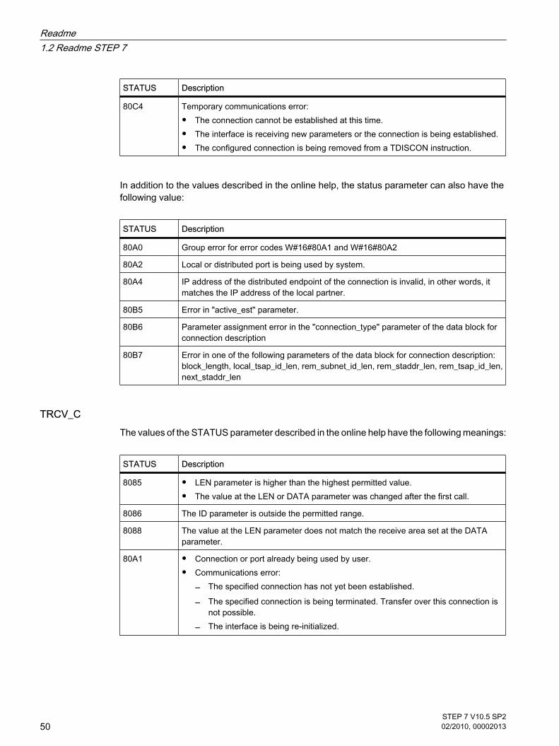
STATUS Description
80C4 Temporary communications error:
• The connection cannot be established at this time.
• The interface is receiving new parameters or the connection is being established.
• The configured connection is being removed from a TDISCON instruction.
In addition to the values described in the online help, the status parameter can also have thefollowing value:
STATUS Description
80A0 Group error for error codes W#16#80A1 and W#16#80A2
80A2 Local or distributed port is being used by system.
80A4 IP address of the distributed endpoint of the connection is invalid, in other words, itmatches the IP address of the local partner.
80B5 Error in "active_est" parameter.
80B6 Parameter assignment error in the "connection_type" parameter of the data block forconnection description
80B7 Error in one of the following parameters of the data block for connection description:block_length, local_tsap_id_len, rem_subnet_id_len, rem_staddr_len, rem_tsap_id_len,next_staddr_len
TRCV_CThe values of the STATUS parameter described in the online help have the following meanings:
STATUS Description
8085 • LEN parameter is higher than the highest permitted value.
• The value at the LEN or DATA parameter was changed after the first call.
8086 The ID parameter is outside the permitted range.
8088 The value at the LEN parameter does not match the receive area set at the DATAparameter.
80A1 • Connection or port already being used by user.
• Communications error:― The specified connection has not yet been established.
― The specified connection is being terminated. Transfer over this connection isnot possible.
― The interface is being re-initialized.
Readme1.2 Readme STEP 7
50STEP 7 V10.5 SP202/2010, 00002013

In addition to the values described in the online help, the status parameter can also have thefollowing value:
STATUS Description
80A0 Group error for error codes W#16#80A1 and W#16#80A2
80A2 Local or distributed port is being used by system.
80A3 • Attempt being made to re-establish an existing connection.
• Attempt being made to terminate a non-existent connection.
80A4 IP address of the distributed endpoint of the connection is invalid, in other words, itmatches the IP address of the local partner.
80A7 Communications error: You executed TDISCON before TCON had completed.
80B3 Inconsistent parameter assignment: Group error for error codes W#16#80A0 toW#16#80A2, W#16#80A4, W#16#80B4 to W#16#80B9
80B4 IP address of the distributed endpoint of the connection is invalid, in other words, itmatches the IP address of the local partner.
80B5 Error in "active_est" parameter.
80B6 Parameter assignment error in the "connection_type" parameter of the data block forconnection description
80B7 Error in one of the following parameters of the data block for connection description:block_length, local_tsap_id_len, rem_subnet_id_len, rem_staddr_len, rem_tsap_id_len,next_staddr_len
80C3 • All connection resources are being used.
• A block with this ID is already being processed in a different priority group.
• Internal lack of resources.
80C4 Temporary communications error:
• The connection cannot be established at this time.
• The interface is receiving new parameters or the connection is being established.
• The configured connection is being removed from a TDISCON instruction.
8722 Error in "CONNECT" parameter: Invalid source area (area not declared in data block).
873A Error in "CONNECT" parameter: Access to connection description is not possible (noaccess to data block).
877F Error in "CONNECT" parameter: Internal error
"CONDITIONS" data type The permitted value ranges for the following parameters of the "CONDITIONS" data type are:
Readme1.2 Readme STEP 7
STEP 7 V10.5 SP202/2010, 00002013
51

Parameter Range of values Description
MAXLEN 0 to 1024 Maximum number of characters in a message. The end of amessage is recognized when the maximum length of a messageis exceeded.
N 1 to 1024 Offset of the length field in the message. This value specifies theposition of the character at which the length field begins.
These value ranges also apply to the corresponding hardware settings for specifying the endof message.
1.3 Readme WinCC
1.3.1 Installation
ContentsInformation that could not be included in the online help.
Parallel installation of STEP 7 V10.5 (incl. WinCC V10.5) and other SIMATIC HMI productsParallel installation of STEP 7 V10.5 (incl. WinCC V10.5) has been released with
• WinCC flexible 2008; WinCC flexible 2008 SP1
• WinCC V6.2 as of SP3 (please read the information in FAQ 30576253 if you want to install WinCCV6.2 SP3 after STEP 7 V10.5).
• WinCC V7
Parallel installation of STEP 7 V10.5 (incl. WinCC V10.5) is not permitted with
• WinCC flexible 2004 and WinCC flexible 2004 SP1
• WinCC flexible 2005 and WinCC flexible 2005 SP1
• WinCC flexible 2007
• All versions of WinCC prior to WinCC V6.2 SP2
Configured system time for installationTo successfully perform the installation of Microsoft SQL Express, the system time of theinstallation computer needs to be set to the current time of day.
Missing fonts after installing and uninstalling WinCC flexibleAfter installing or uninstalling WinCC flexible, it is possible that some fonts are no longeravailable. This happens in the following situations:
• If you have installed WinCC flexible 2008 after STEP 7 V10.5.
1.3 Readme WinCC1.3.1 Installation
Readme1.3 Readme WinCC
52STEP 7 V10.5 SP202/2010, 00002013

• If you have uninstalled WinCC flexible 2008 or WinCC flexible 2008 SP1 after STEP 7 V10.5.
The fonts are nevertheless still on the computer and only need to be made known to Windowsagain. Follow these steps:
1. Open Windows Explorer.
2. Enter "%WINDIR%\Fonts" in the address bar. The folder with the fonts opens.
3. Select "File > Install New Font..."
4. In the "Folders" box, select the folder in which Windows stores the fonts. You will see the folder in theaddress bar in the Windows Explorer.
5. Select the following fonts in the "List of fonts" box.
Siemens Sans Global
Siemens Sans Global Bold
Siemens Sans Global Bold Italic
Siemens Sans Global Italic
6. Confirm your selection with "OK".
Note
In Windows Vista, you require administrator privileges to install fonts.
1.3.2 Notes on use
ContentsInformation that could not be included in the online help.
Compiling and loadingThe project is not continually compiled in the background during configuration in WinCC V10.5.
If internal errors or warnings occur during compiling, compile the complete project using thecommand "Compile > Software (rebuild all)" in the shortcut menu of the HMI device.
Before you start productive operation with your project, compile the project completely usingthe command "Compile > Software (rebuild all)" in the shortcut menu of the HMI device.
If you are using HMI tags that are connected to the control tags in your project, compile allmodified blocks with the command "Compile > Software" in the shortcut menu before youcompile the HMI device.
1.3.2 Notes on use
Readme1.3 Readme WinCC
STEP 7 V10.5 SP202/2010, 00002013
53

Copying HMI devices with HMI connectionsIf you copy an HMI device with HMI connections to a PLC, the HMI connection in the new HMIdevice will not automatically be connected to an existing PLC with the same name. Thisstatements applies to copying within a project as well as copying across projects.
To access the PLC tag via HMI tag in the new HMI device, you will have to complete the HMIconfiguration immediately after the copying step. Proceed as follows:
1. Open the "Devices & Networks" editor.
2. Connect the new HMI device with the desired network.
3. Open the connection table.
4. Select the HMI connection of the new HMI device.
5. Select the desired PLC under "Partner."
If you compile the new HMI device or connect additional PLC tags in between copying the HMIdevice and completing the connection, there may be some instances in which you create anadditional HMI connection to the same PLC. This is especially true if you connect HMI tagswith DB array elements.
1.3.3 Migration
ContentsYou can continue to use projects from WinCC flexible 2008 in WinCC V10.5. "Basic Panels"type HMI devices can be migrated.
You cannot migrate projects from WinCC flexible 2008 SP1 directly to WinCC V10.5. If youwish to continue using such projects in WinCC V10.5, you must first migrate them toWinCC flexible 2008.
Changing the names of alarm classesIn contrast to WinCC flexible, the names of the predefined alarm classes are not dependenton the user interface language currently in use. During migration, the names of the alarmclasses are assigned as follows:
WinCC flexible WinCC
Error Alarms
System System
Warnings Events
The names of the alarm classes can be changed as necessary after migration.
1.3.3 Migration
Readme1.3 Readme WinCC
54STEP 7 V10.5 SP202/2010, 00002013

Project languages in WinCC V10.5WinCC V10.5 does not support all project languages that were available in WinCC flexible,such as Arabic. If you receive an empty project as the result of your migration, you may wantto check the set editing language. Do not set the project languages that are not supported asediting language in the source project. Proceed as follows:
1. Open the project with WinCC flexible.
2. Change the editing language to English, for example.
3. Save the project.
4. Restart the migration.
See alsoObject support during migration (Page 1018)→ Object support during migration (13279660683/14023607307.htm)
1.3.4 Engineering System
1.3.4.1 Screens and Screen Objects
ContentsInformation that could not be included in the online help.
Text format of output fields in alarm textIt is not possible to underline tags and text list entries.
Copying display objects between two projects or two devicesIn Project_1 configure an alarm window in the Global Screen, for example. You copy the alarmwindow and paste it in the Global Screen in Project_2.
The enabled alarm classes are partly not enabled in the alarm window after pasting.
This behavior applies to the following display objects:
• Alarm window
• Alarm indicator
• Alarm view
Representation of the cross-references in the Inspector windowThe Inspector window displays objects used by a screen object in the "About > Cross-reference" tab.
A screen is open and an object selected. You are using an HMI tag at the object as processtag.
1.3.4 Engineering System1.3.4.1 Screens and Screen Objects
Readme1.3 Readme WinCC
STEP 7 V10.5 SP202/2010, 00002013
55
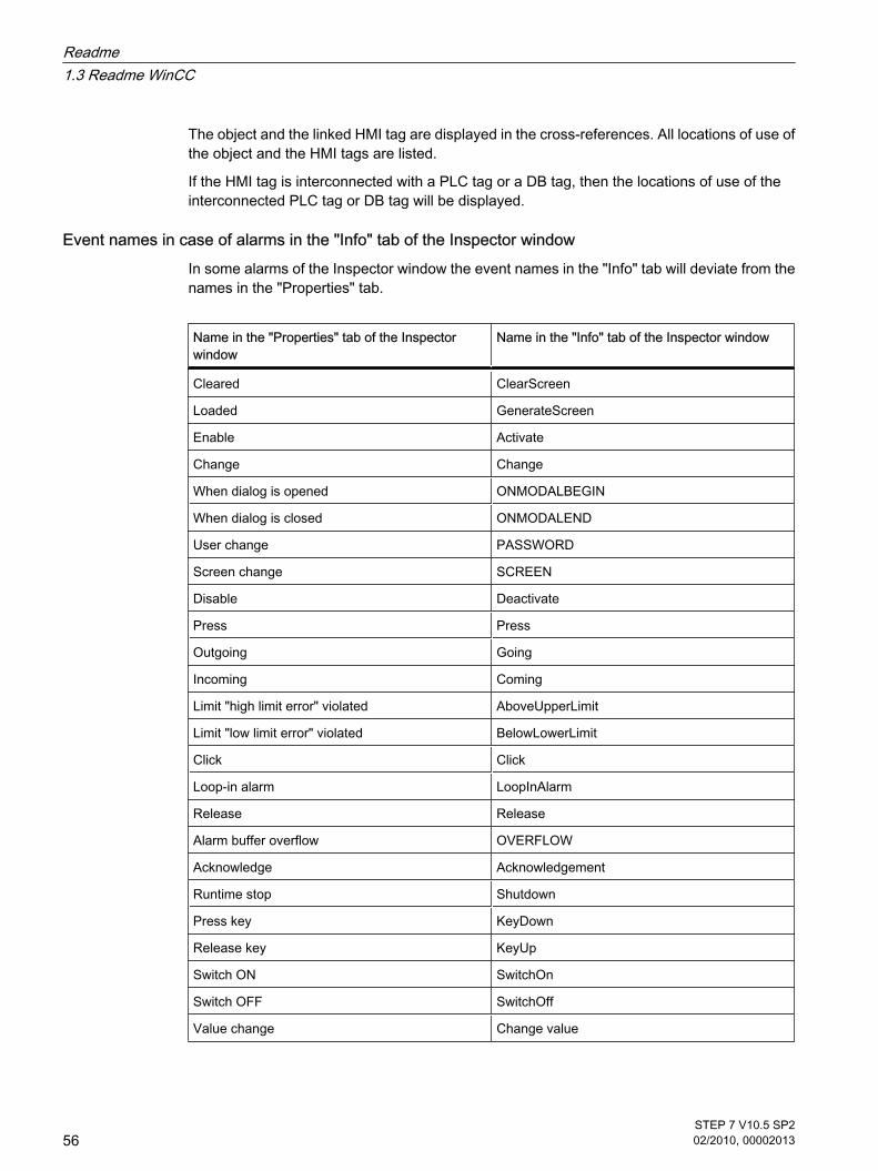
The object and the linked HMI tag are displayed in the cross-references. All locations of use ofthe object and the HMI tags are listed.
If the HMI tag is interconnected with a PLC tag or a DB tag, then the locations of use of theinterconnected PLC tag or DB tag will be displayed.
Event names in case of alarms in the "Info" tab of the Inspector windowIn some alarms of the Inspector window the event names in the "Info" tab will deviate from thenames in the "Properties" tab.
Name in the "Properties" tab of the Inspectorwindow
Name in the "Info" tab of the Inspector window
Cleared ClearScreen
Loaded GenerateScreen
Enable Activate
Change Change
When dialog is opened ONMODALBEGIN
When dialog is closed ONMODALEND
User change PASSWORD
Screen change SCREEN
Disable Deactivate
Press Press
Outgoing Going
Incoming Coming
Limit "high limit error" violated AboveUpperLimit
Limit "low limit error" violated BelowLowerLimit
Click Click
Loop-in alarm LoopInAlarm
Release Release
Alarm buffer overflow OVERFLOW
Acknowledge Acknowledgement
Runtime stop Shutdown
Press key KeyDown
Release key KeyUp
Switch ON SwitchOn
Switch OFF SwitchOff
Value change Change value
Readme1.3 Readme WinCC
56STEP 7 V10.5 SP202/2010, 00002013

Global and local assignment of function keysIn the "Global screen" editor, the function key F1 is assigned with a function and a graphic.
The option "Use global assignment" is disabled in the template "Temp_1" for the function keyF1. The function key is not assigned.
The screen "Screen_1" is based on the template "Temp_1". The option "Use local template" isenabled.
The function list of function key F1 is empty in screen "Screen_1", but the graphic of the globalscreen is visible.
Proceed as follows to change this behavior:
1. Enable the function key F1 in the screen "Screen_1".
2. Disable the option "Use local template" in the Inspector window under "Properties > General".
3. If the graphic is still visible, click under "Graphic" in the list.
4. Select "<None>".
1.3.4.2 Tags
ContentsInformation that could not be included in the online help.
Tag namesHMI tag names may not start with the character @.
Display of deleted array elements at location of use of HMI tagsThe locations of use of HMI tags, such as the process value of IO fields, are usually indicatedby the tag name. If the element of an array tag is used, then the tag name will be extended bythe index of the array element indicated in brackets.
If a used tag is no longer included in the project, then the tag name will still be displayed at thelocation of use. The field will be displayed with a red background to indicate the missing tag. Ifa used array element or the array tag is no longer present, then only the index of the arrayelement will be displayed in brackets. The tag name will not be displayed. The field is highlightedin red. You can no longer identify the name of the associated array tag based on the locationof use in this instance.
If you do not know which array tag was linked to this location of use, then it may be necessaryto link the array element once again.
If a tag or array tag was created based on a reference, then the selected reference will beclosed automatically.
If an HMI tag is connected with an array element of a PLC tag and the PLC tag does no longerexist in the project, then the same behavior will take place in the "HMI tags" editor.
1.3.4.2 Tags
Readme1.3 Readme WinCC
STEP 7 V10.5 SP202/2010, 00002013
57

Array tags as list entry of multiplex tagsYou can use the array tags of the Char data type just like the tags of the String data type.
The use of an array tag of the Char data type as list entry of a multiplex tag in the "HMItags" editor is not supported.
1.3.4.3 Alarm system and alarm displays
ContentsInformation that could not be included in the online help.
Displaying special characters in alarm textsWhen configuring alarm texts, a fixed character set is used in the Engineering System. Thischaracter set allows you to use numerous special characters in alarm texts.
Language-dependent fonts are used in runtime to display the texts, for example MS PGothic,SimSun. The fonts used in runtime do not support all special characters. As a result, somespecial characters are not displayed in runtime.
Use of multiplex tags in output boxes with alarm textsIn the engineering system, it is also possible to use multiplex tags in the output boxes of alarmtexts. During runtime, this leads to an incorrect display of the alarm, because the use ofmultiplex tags is not supported by the basic panels.
1.3.4.4 System functions
ContentsInformation that could not be included in the online help.
1.3.4.5 Recipes
ContentsInformation that could not be included in the online help.
1.3.4.6 User administration
ContentsInformation that could not be included in the online help.
1.3.4.3 Alarm system and alarm displays1.3.4.4 System functions1.3.4.5 Recipes1.3.4.6 User administration
Readme1.3 Readme WinCC
58STEP 7 V10.5 SP202/2010, 00002013

Exporting and importing user dataYou cannot import or export user data.
1.3.4.7 Connections
ContentsInformation that could not be included in the online help.
Use of the "DTL" data type for area pointersUse the "DTL" data type for configuration of area pointers "Date/time" and "Date/time PLC".The "DTL" data type supports time stamp information in the nanosecond range. Because BasicPanels support time stamp information only down to the millisecond range, you will encounterthe following restrictions when using the area pointers:
• Area pointer "Date/time" For transmission of time information from a Basic Panel to the PLC, the smallest unit of time is 1millisecond. The value range from microseconds to nanoseconds of the "DTL" data type will be filledwith zeros.
• Area pointer "Date/time PLC" For transmission of time information from a PLC to a Basic Panel, the area from microseconds tonanoseconds will be ignored. The time information will be processed on the panel down tomilliseconds.
Limited number of possible HMI connectionsAn error message will be displayed during compilation of a device indicating that theconfiguration of the HMI connection in the "Devices & Networks" editor is invalid. The reasonmay be that the maximum number of possible connections of the HMI device or PLC may beexceeded.
Check the maximum number of possible connections. Consult the device manuals of thedevices you are using.
1.3.4.8 Compiling and loading
ContentsInformation that could not be included in the online help.
Incorrect installation of ProSaveIf you receive an error message during installation of ProSave when loading data to a targetdevice or maintenance of an HMI device, then you cannot remedy this error using the repairfunction of setup. Remove ProSave via the Control Panel. Then start setup and install the"ProSave" component again.
1.3.4.7 Connections1.3.4.8 Compiling and loading
Readme1.3 Readme WinCC
STEP 7 V10.5 SP202/2010, 00002013
59

Checking the address parametersDuring compilation of an HMI device in the project tree with the command "Compile > Software"in the shortcut menu, the address parameters of the HMI device, such as the IP address, willnot be checked. If you want to ensure that the address parameters are checked as well, youwill have to compile the HMI device in the "Devices & Networks" editor of the toolbar.
Error message when downloading data to the PLCA panel and a PLC are connected and communicating with other.
If a tag is accessed while downloading data from the panel to the PLC, an error message isdisplayed on the panel.
1.3.5 Runtime
1.3.5.1 Notes on operation in Runtime
ContentsInformation that could not be included in the online help.
CautionEthernet communication
In Ethernet-based communication, the end user is responsible for the security of his datanetwork. The proper functioning of the device cannot be guaranteed in all circumstances;targeted attacks, for example, can lead to overload of the device.
Special characters in the user viewSpecial characters, such as / " § $ % & ' ?, are not permitted when entering a name or thepassword in the user view.
Language behavior - Layout of screen keyboardThe layout of the screen keyboard is not switched when the runtime language changes.
Tag values overwrite the maximum length You enter a character string in a string tag via an I/O field. If the character string exceeds thenumber of configured tags, the character string will be shortened to the configured length.
1.3.5 Runtime1.3.5.1 Notes on operation in Runtime
Readme1.3 Readme WinCC
60STEP 7 V10.5 SP202/2010, 00002013

1.3.6 HMI devices
1.3.6.1 General notes
ContentsInformation that could not be included in the online help.
Simulation of the Basic PanelsUse an output field in an alarm text to output an external tag. The content of the output fieldwill always be displayed with "0" during simulation.
Simulation with real PLC connectionThe access point used by the simulation is independent from the settings of the EngineeringSystem and can only be altered in the Control Panel with the "Setting PG/PC Interface" tool. Ifthe PLC connection is terminated right after the start of the simulation with message 140001,you should check the access point used by the simulation with "Setting PG/PC Interface".
1. Double-click "Setting PG/PC Interface" in the Control Panel. A dialog opens.
2. Select" "S7ONLINE" in the "Access point of application" field as standard for HMI.
3. Select the interface in the "Interface Parameter Assignment Used" area.
4. Exit the dialog "Setting PG/PC Interface" with OK
Loading of projects without recipe data recordsYou are using recipes in a project. You transfer the project to a Basic Panel without recipe datarecords.
You may encounter inconsistencies if you have altered the structure of the recipe in theEngineering System and the device already held recipe data records.
Check the consistency of the data records in this case. The device will not issue a note for allstructural changes.
1.3.6 HMI devices1.3.6.1 General notes
Readme1.3 Readme WinCC
STEP 7 V10.5 SP202/2010, 00002013
61

Readme1.3 Readme WinCC
62STEP 7 V10.5 SP202/2010, 00002013

Installation 22.1 System requirements for installation
2.1.1 Notes on the system requirements
System requirements for individual productsThe system requirements may differ depending on the products you want to install. You shouldtherefore check the individual system requirements of your products.
If you want to install several products, make sure that your system meets the demands of theproduct with the highest requirements.
Displaying PDF filesTo be able to read the supplied PDF files, you require a PDF reader that is compatible withPDF 1.7 (ISO32000-1:2008 PDF).
2.1.2 System requirements STEP 7
2.1.2.1 Software and hardware requirements STEP 7
System requirements for installationThe following table shows the minimum software and hardware requirements for installation ofthe "SIMATIC STEP 7 Basic" software package:
Hardware/Software Requirements
Processor type Pentium 4, 1.7 GHz or similar
RAM Windows XP: 1 GBWindows Vista: 2 GB
2 Installation2.1 System requirements for installation2.1.1 Notes on the system requirements2.1.2 System requirements STEP 72.1.2.1 Software and hardware requirements STEP 7
STEP 7 V10.5 SP202/2010, 00002013
63

Hardware/Software Requirements
Free hard disk space 2 GB
Operating systems * • Windows XP (Home SP3, Professional SP3)
• Windows Vista (Home Premium SP1, Business SP1, UltimateSP1)
Graphics card 32 MB RAM32-bit color depth
Screen resolution 1024 x 768
Network 10Mbit/s Ethernet or faster
Optical drive DVD-ROM
* For more detailed information on operating systems, refer to the help on Microsoft Windowsor the Microsoft homepage.
2.2 Licenses
Availability of licenses The licenses for the products of the TIA Portal are supplied on the installation data mediumand installed automatically by the Automation License Manager (ALM) during the installationprocess. This means you do not receive a separate installation medium with licenses and youcannot transfer the licenses to other computers. If you uninstall the TIA Portal, thecorresponding licenses are also uninstalled automatically.
Automation License Manager (ALM) The Automation License Manager is used to manage licenses. It is supplied on the installationdata medium and is installed automatically during the installation process. If you uninstall theTIA Portal, the Automation License Manager remains installed on your system.
2.3 Starting installation
Introduction Software packages are installed automatically by the setup program. The setup program startsonce the installation medium has been inserted in the drive.
2.2 Licenses2.3 Starting installation
Installation2.3 Starting installation
64STEP 7 V10.5 SP202/2010, 00002013

Note
The first time you install the TIA Portal in Windows Vista, a user group called "TIA-Engineer"is created. The currently logged in user who installs the TIA Portal is automatically added tothe new user group.
Requirement
• Hardware and software of the programming device or PC meet the system requirements.
• The software package has not yet been installed on your computer.
• All open programs are closed.
ProcedureTo install the software packages, follow these steps:
1. Insert the installation medium in the relevant drive.
The setup program starts automatically unless you have disabled Autostart on the programmingdevice or PC.
2. If the setup program does not start up automatically, start it manually by double-clicking the "Start.exe"file.
The dialog for selecting the setup language opens.
3. Select the language you want for the dialogs of the setup program and click "Next".
The dialog for selecting the product language opens.
4. Select the languages for the product user interface.
5. If you want to read the product notes, click the "Yes, I would like to read the Product Information"button.
The help file with the product notes opens.
6. After you have read the product notes, close the help file again.
7. Click the "Next" button.
The dialog for selecting the product configuration opens.
8. Select the directory in which you want to install the selected products. Please note that the length ofthe installation path does not exceed 89 characters.
9. Click the "Next" button.
The next dialog displays an overview of the installation setting and the license agreements.
10.
Check the selected installation settings. If you want to make any changes, click the "Back" button untilyou reach the point in the dialog where you want to make changes.
11.
Read and accept all the license conditions.
12.
Click the "Install" button.
Installation is started.
Installation2.3 Starting installation
STEP 7 V10.5 SP202/2010, 00002013
65

Note
If the installation is successful, a message to this effect is displayed on the screen. If errorsoccurred during installation, an error message is displayed informing you of the type of erroror errors.
13.
It may be necessary to restart the computer. If this is the case, select the "Yes, restart my computernow." option button.
14.
Click the "Finish" or "Restart" button.
ResultThe TIA Portal along with the products and licenses you have ordered and the AutomationLicense Manager have been installed on your computer.
See alsoSystem requirements for installation (Page 63)Starting to uninstall (Page 66)
2.4 Starting to uninstall
IntroductionSoftware packages are uninstalled automatically by the setup program. The Setup program isincluded in the installation package and there is no need to install it separately. Once started,the Setup program guides you step-by-step through the entire uninstall procedure.
Procedure To uninstall the software packages, follow these steps:
1. Open the Control Panel with "Start > Settings > Control Panel".
2. Double click on "Add or Remove Programs" in the control panel.
The "Add or Remove Programs" dialog opens.
3. Select the software package to be removed in the dialog "Add or Remove Programs", and click"Remove".
The dialog for selecting the setup language opens.
4. Select the language you want for the dialogs of the setup program and click "Next".
The dialog for selecting the products you want to uninstall opens.
5. Select the products you want to uninstall.
6. Click the "Next" button.
7. Check the list with the products to be uninstalled. If you want to make any changes, click the "Back"button.
8. Click the "Uninstall" button.
2.4 Starting to uninstall
Installation2.4 Starting to uninstall
66STEP 7 V10.5 SP202/2010, 00002013

Uninstallation is started.
9. It may be necessary to restart the computer. If this is the case, select the "Yes, restart my computernow." option button.
10.
Click the "Finish" or "Restart" button.
Note
The Automation License Manager will not be uninstalled automatically when you uninstallthe software packages, because it is used for the administration of several license keys forproducts supplied by Siemens AG.
Installation2.4 Starting to uninstall
STEP 7 V10.5 SP202/2010, 00002013
67

Installation2.4 Starting to uninstall
68STEP 7 V10.5 SP202/2010, 00002013

First steps 33.1 Basic functions of the Totally Integrated Automation Portal
3.1.1 Overview
3.1.1.1 Basic functions of the Totally Integrated Automation Portal
IntroductionThe Totally Integrated Automation Portal (TIA portal) integrates the SIMATIC Totally IntegratedAutomation (TIA) products in a software application with which you can increase yourproductivity and efficiency. All TIA products work together smoothly and transparently withinthe the TIA portal and support you in all areas in creating an automation solution.
A typical automation solution encompasses the following:
• The PLC controls the machine with the help of a user program.
• You use the HMI device to operate and monitor the process.
3 First steps3.1 Basic functions of the Totally Integrated Automation Portal3.1.1 Overview3.1.1.1 Basic functions of the Totally Integrated Automation Portal
STEP 7 V10.5 SP202/2010, 00002013
69

TasksThe TIA portal supports you in configuring your automation solution. The most importantconfiguration steps are:
• Creating the project
• Configuring the hardware
• Networking the devices
• Programming the PLC
• Configuring the visualization
• Loading the configuration data
• Using the online and diagnostic functions
New engineering conceptYou can use the TIA to configure both the PLC and the visualization in a uniform engineering.The listed tasks not only use a common user interface but are are also optimally coordinatedtogether. The TIA portal offers the following advantages:
• Common data
• Easy handling of programs, configuration data and visualization data
• Easy editing using drag-and-drop operation
• Easy loading of data to the devices
• Easy operation
• Graphic supported configured and diagnostics
First steps3.1 Basic functions of the Totally Integrated Automation Portal
70STEP 7 V10.5 SP202/2010, 00002013
3.1.1.2 Basic procedure
Procedural sequenceThere are many ways to solve an automation task. The following figures shows how the TIAportal supports you during these work steps.
Basic procedure1. Opening/creating a project
First you must either create a new project or open an existing project. The sequence of the furthersteps is not fixed. You can continue with any task.
2. Alternatively:
― Configuring a device
― Creating a PLC program
― Configuring an HMI screen
3. Loading project data to the devices
4. Monitoring devices online
3.1.1.2 Basic procedure
First steps3.1 Basic functions of the Totally Integrated Automation Portal
STEP 7 V10.5 SP202/2010, 00002013
71

Typical procedure in the Portal viewThe typical procedure in the TIA portal is displayed if you select "First Steps" in the Portal viewafter the creation of a new project.
3.1.1.3 Working with various views
The Totally Integrated Automation Portal provides to different views for increasing yourproductivity: the portal view and the project view.
While the Portal view guides you through the key tasks, the Project view provides you with anobject-oriented view of the elements in the project. You simply click to switch between Portalview and Project view.
Function-oriented display in the Portal viewThe goal of the portal view is to provide a simple navigation in the tasks and data of the project.This means the functions of the application can be reached via individual portals for the most
3.1.1.3 Working with various views
First steps3.1 Basic functions of the Totally Integrated Automation Portal
72STEP 7 V10.5 SP202/2010, 00002013

important tasks. The following illustration is an example of a portal for the configuration ofdevices and their networking:
① Portal selection
② Actions
③ Project data
Description of the portals
Portal Description
Start You use the Start portal to set up the project for your application. Here, you can create new projects,open existing ones and navigate to the most important tasks of the project.
Devices & networks In the "Devices & Networks" portal you define and configure the devices and their communicationrelationships in the project. You configure, for example, the PLC and HMI devices and define thenetwork connections between the devices. You also create the logical links by means of which thedevices can use tags in common.
PLC programming You use the PLC Programming portal to create the control program for each device in the project.
Visualization In the Visualization portal you create the screens for the HMI devices in your project.
Online & Diagnostics In the "Online & Diagnostics" portal you can display the accessible devices and their online status.
First steps3.1 Basic functions of the Totally Integrated Automation Portal
STEP 7 V10.5 SP202/2010, 00002013
73

Quick access to the first stepsThe "First steps" overview is displayed in the Start portal to allow you to quickly select a portalfor a particular task. Clicking the specific links here takes you to the required portal.
Access to all elements of the project in the Project viewThe Project view is a data-based view of the project and shows all elements of a project in astructured format. This provides you with quick access to all project data.
First steps3.1 Basic functions of the Totally Integrated Automation Portal
74STEP 7 V10.5 SP202/2010, 00002013

① Project tree
② Work area
③ Task cards
④ Inspector window
Project treeThe project tree gives you access to all devices and project data. You can perform, for example,the following tasks in the project tree:
• Adding new devices
• Editing existing devices
• Requesting properties
• Open editors to process project data
Work areaYou open the editors in the work area that you can use to process the project data.
Task cardsDepending on the edited or selected object, there are task cards available in the editors thatallow you perform additional actions. These actions include:
• Selecting objects from a library or from the hardware catalog
• Searching for and replacing objects in the project
First steps3.1 Basic functions of the Totally Integrated Automation Portal
STEP 7 V10.5 SP202/2010, 00002013
75

• Dragging predefined objects to the work area
Inspector window Additional information on an object selected or on actions executed are displayed in theinspector window.
See alsoProject tree (Page 119)Work area (Page 122)Inspector window (Page 123)Task cards (Page 125)
3.1.1.4 Accessing Help
Elements of the Help systemA comprehensive Help system is available for solving your tasks. It describes basic concepts,instructions and functions. While working with the program, you receive in addition the followingsupport:
• Roll-out for correct inputs in dialog boxes
• Tooltip with information about user interface elements, for example text boxes, buttons and symbols.Some of the tooltips are supplemented by cascades containing additional information.
• Help on the current context, on menu commands for example when you click on the keys <F1> or<Shift+F1>.
Roll-outsCertain text boxes offer information that rolls out and helps you to enter valid parameters andvalues. The roll-out informs you about permissible value ranges and data types of the textboxes.
The following figure shows examples of a roll-out:
Roll-out example: Valid value
Roll-out example: Error message if value isinvalid
3.1.1.4 Accessing Help
First steps3.1 Basic functions of the Totally Integrated Automation Portal
76STEP 7 V10.5 SP202/2010, 00002013

Tool tipsInterface elements offer you a tooltip for easier identification.
Tooltips that have an arrow symbol on the left contain additional information in tooltip cascades.If additional information is contained in the Help, a link appears to the corresponding Help topicin the cascade. The following figure shows a tooltip with opened cascade:
HelpThe Help describes concepts, instructions and functions. It also contains reference informationand examples.
The Help opens up in its own window on the right side of the screen.
You can display a navigation field in the Help. You have access to the following functions there:
• Table of contents
• Search in the index
• Full text search of the entire Help
• Favorites
Additional information on working with Help is available in the Chapter "Using the Help system(Page 139) ".
Identification of the topics in the Help The help topics are identified by different symbols depending on the type of information theycontain.
Symbol Information type Explanation
Operating instructions Describes the steps to follow in order to carry out a particular task.
Example Contains a concrete example to explain the task.
Factual information Contains background information that you need to know to carryout a task.
Reference Contains detailed reference information, for example descriptionsof program blocks.
First steps3.1 Basic functions of the Totally Integrated Automation Portal
STEP 7 V10.5 SP202/2010, 00002013
77

3.1.2 Creating a project
IntroductionTo begin, create a new project. Data and programs that occur during the creation of anautomation task are stored in ordered manner in the project. For this example, open the TotallyIntegrated Automation Portal in the Portal view. The Start portal contains commands forcreating a new project and for opening an existing project.
ProcedureTo create a project, follow these steps:
1. Select the "Create new project" command.
2. Enter a name for the project (for example, "Project1" or "First steps").
3. Click "Create".
ResultThe project is created.
The buttons for selecting the various, task-oriented portals are enabled in the Portal view.
TipAfter creating or opening a project, you can use the "First steps" command to execute tasksfor creating an automation application.
Next stepsAfter the project has been created, carry out the following task:
• Configure the hardware, either by online PLC recognition or by manual configuration
• Create a program to control the application
3.1.2 Creating a project
First steps3.1 Basic functions of the Totally Integrated Automation Portal
78STEP 7 V10.5 SP202/2010, 00002013

You can define the order of these steps. If you configure the hardware first, you cansubsequently assign the configured PLC to the program. If you create the program blocks first,these blocks will be assigned to an automatically created, unspecified PLC.
3.1.3 Configuring hardware and networks
3.1.3.1 Introduction to the hardware configuration
To set up an automation system, you will need to configure, parameterize and interlink theindividual hardware elements. Both PLC and HMI devices can be inserted in the project in thesame context and in the same manner.
Hardware configuration in Portal view and Project viewYou can add a new device in either Portal view or in Project view.
You add a PLC device (CPU) or an HMI device in the "Devices & Networks" portal.
If you want to insert additional modules or network the devices, you will require the Projectview.
3.1.3.2 Adding devices in the Portal view
Adding a SIMATIC PLC in the Portal viewTo add a SIMATIC PLC, follow these steps:
1. Select "Devices & Networks" in the Portal view.
2. Select the "Add new device" command.
3. Click the "SIMATIC PLC" button. The list of the SIMATIC PLCs opens.
4. Select a SIMATIC S7-1200 and click "Add".
3.1.3 Configuring hardware and networks3.1.3.1 Introduction to the hardware configuration3.1.3.2 Adding devices in the Portal view
First steps3.1 Basic functions of the Totally Integrated Automation Portal
STEP 7 V10.5 SP202/2010, 00002013
79

Adding an HMI device in Portal viewTo add an HMI device, follow these steps:
1. Select the "Add new device" command.
2. Click the "SIMATIC HMI" button. The list of the SIMATIC HMI panels opens.
3. Select an HMI panel and click "Add".
What do I do next?You configure the PLC and the HMI device.
Double-click one of the devices displayed in the project to navigate to the hardware and networkeditor of the Project view.
3.1.3.3 Devices and networks in Project view
Hardware configuration in the Project viewThe hardware and network editor is available in the Project view. This editor is an integrateddevelopment environment for configuring, parameterizing and networking devices andmodules, offering you maximum support in carrying out the automation task.
Double-click "Devices and Networks" in the project tree to open the hardware and networkeditor.
3.1.3.3 Devices and networks in Project view
First steps3.1 Basic functions of the Totally Integrated Automation Portal
80STEP 7 V10.5 SP202/2010, 00002013

① Project tree
② Network view
③ Device view
④ Hardware catalog
⑤ Inspector window
Network view and Device viewThe hardware and network editor consists of a Device view and a Network view. You can switchbetween these two components at any time depending on whether you want to produce andedit individual devices or entire networks.
Hardware catalogDrag the devices and modules you need for your automation system from the hardware cataloginto the network or device view.
Inspector window The Inspector window contains information on the object currently marked under "Properties".Here you can change the settings for the object marked.
First steps3.1 Basic functions of the Totally Integrated Automation Portal
STEP 7 V10.5 SP202/2010, 00002013
81

3.1.3.4 Adding devices in the Project view
Inserting a device in the Project viewThere are various ways of adding a CPU or an HMI device to the hardware configuration in theProject view, for example:
• Command "Add new device" in the project tree
• Double-click the device in the hardware catalog
• Drag-and-drop from the hardware catalog in the Network view
• Command "Insert > Device" from menu bar in Network view
A suitable rack is created along with the new CPU. The selected device is inserted at the firstpermitted slot of the rack.
Regardless of the method selected, the added device is visible in the project tree and theNetwork view of the hardware and network editor.
What do I do next?You configure the PLC by plugging additional modules into the rack.
You define the device settings of the HMI panel.
3.1.3.5 Plugging additional modules into racks
Introduction After you have added a CPU to your configuration, equip the device with additional modules.You have various options for adding these modules, for example:
• Double-click a module in the hardware catalog
• Drag a module from the hardware catalog to a free slot
The device view contains an illustration of the device selected within a rack. The graphicillustration of the rack in the software corresponds to the real structure, which means that youcan see the same number of slots as exist in the real structure.Tip
To enter the device view from the Network view, double-click on a device or station in theNetwork view.
Requirement
• You are in the device view.
• The hardware catalog is open.
Adding modules from the hardware catalogHow to insert a module from the hardware catalog into a rack is illustrated based on the exampleof a signal module. To do so, follow these steps:
3.1.3.4 Adding devices in the Project view3.1.3.5 Plugging additional modules into racks
First steps3.1 Basic functions of the Totally Integrated Automation Portal
82STEP 7 V10.5 SP202/2010, 00002013

1. Go to the required module board in the hardware catalog.
2. Select the module you want.
3. Drag the signal module to a free slot in the rack.
You have now inserted the digital signal module in a slot in the rack. Repeat these steps withthe other modules.
3.1.3.6 Editing properties and parameters
After you have assigned hardware components on your rack, you can edit their defaultproperties, for example, parameters or addresses, in the Network or Device view.
RequirementYou are in the device view.
Note
You can also edit properties and parameters in the Network view. In Network view you onlyhave access to the network-related hardware components and the station.
Procedure To change the properties and parameters of the hardware components, follow these steps:
1. In the Graphic view, select the module, rack or interface you want to edit.
2. Edit the settings for the selected object:
― Use the Table view, for example, to edit addresses and names.
― In the Inspector window additional setting possibilities are available in "Properties".
3.1.3.6 Editing properties and parameters
First steps3.1 Basic functions of the Totally Integrated Automation Portal
STEP 7 V10.5 SP202/2010, 00002013
83

Example of changing settings
① Selection of interface
② Editing option for addresses in the device overview
③ Selection options in the inspector window
④ Editing option for addresses in the inspector window
First steps3.1 Basic functions of the Totally Integrated Automation Portal
84STEP 7 V10.5 SP202/2010, 00002013

3.1.3.7 Modifying settings for HMI devices
Settings for HMI devicesThe HMI device wizard opens after you have inserted an HMI device. You can define theproperties immediately here, for example:
• Figures
• Alarms
• User administration
• Language and font
The following figure shows an example of the HMI device wizard.
Changing the device settings for runtimeTo query and change the device settings in Project view, follow these steps:
1. Open the project tree and go to the HMI device.
2. Click "Device settings".
3.1.3.7 Modifying settings for HMI devices
First steps3.1 Basic functions of the Totally Integrated Automation Portal
STEP 7 V10.5 SP202/2010, 00002013
85
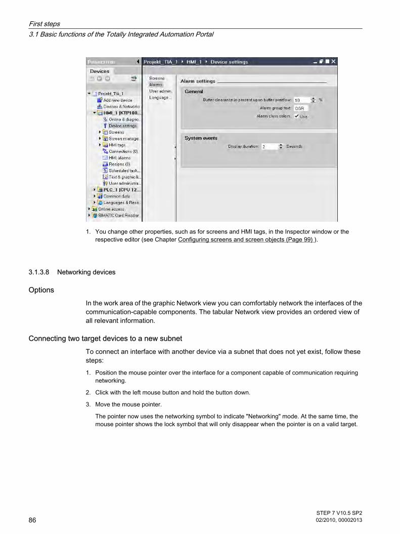
1. You change other properties, such as for screens and HMI tags, in the Inspector window or therespective editor (see Chapter Configuring screens and screen objects (Page 99) ).
3.1.3.8 Networking devices
OptionsIn the work area of the graphic Network view you can comfortably network the interfaces of thecommunication-capable components. The tabular Network view provides an ordered view ofall relevant information.
Connecting two target devices to a new subnetTo connect an interface with another device via a subnet that does not yet exist, follow thesesteps:
1. Position the mouse pointer over the interface for a component capable of communication requiringnetworking.
2. Click with the left mouse button and hold the button down.
3. Move the mouse pointer.
The pointer now uses the networking symbol to indicate "Networking" mode. At the same time, themouse pointer shows the lock symbol that will only disappear when the pointer is on a valid target.
3.1.3.8 Networking devices
First steps3.1 Basic functions of the Totally Integrated Automation Portal
86STEP 7 V10.5 SP202/2010, 00002013

4. Now move the pointer onto the interface of the target device. You can either keep the mouse buttonpressed or release it.
5. Now release the left mouse button or press it again (depending on previous action).
A new subnet is created. The interfaces are now connected via the new subnet. Consistentaddress parameters are set automatically for the interface.
The following figure shows the two networked devices:
Creating a subnet To create a subnet and to connect it to an interface, follow these steps:
1. Select the interface of a CPU.
2. Select the "Create subnet" command in the shortcut menu of the interface.
The selected interface is connected to a new subnet of the appropriate subnet type. Consistentaddress parameters are set automatically for the interface.
The following schematic shows an interface with outgoing line connecting to a subnet:
First steps3.1 Basic functions of the Totally Integrated Automation Portal
STEP 7 V10.5 SP202/2010, 00002013
87

3.1.4 Programming the PLC
3.1.4.1 Programming environment in the TIA portal.
This section provides an overview of the TIA portal's programming environment:
• Programming languages
• Program editor
• Symbolic programming
• Libraries
Programming languagesThe TIA portal supports you in the programming of code blocks in the following programminglanguages:
• Ladder Logic (LAD)
• Function Block Diagram (FBD)
Program editorThe program editor is the integrated development environment for programming functions,function blocks, and organization blocks. If offers comprehensive support for programming andtroubleshooting.
Using LAD as an example, the following figure shows the components of the program editor:
3.1.4 Programming the PLC3.1.4.1 Programming environment in the TIA portal.
First steps3.1 Basic functions of the Totally Integrated Automation Portal
88STEP 7 V10.5 SP202/2010, 00002013

Symbolic programmingTo make the program layout clearer and to simplify trouble-shooting, it is advisable to usesymbolic names for the operands and tags in the programming.
You specify the symbolic names:
• Define symbolic names for global tags in the PLC tag table.
• In the block interface, specify symbolic names for local tags in logic blocks or in global data blocks.Support during programming
When programming you can start out working with symbolic operands and then assign theabsolute addresses later. The program can still be saved, even though the assignment isincomplete.
An operand to which no absolute address has yet been assigned is highlighted by a red wavyunderline.
LibrariesYou can store objects you want to use more than once in libraries. It is possible to reuse thestored objects throughout a project or across projects. This means you can, for example, createblock templates for use in different projects and adapt them to the particular requirements ofyour automation task.
Libraries can accommodate a large number of objects. These include, for example:
• Functions (FCs)
• Function blocks (FBs)
• Data blocks (DBs)
• Devices
• PLC data types
• Watch tables
• Process pictures
• Faceplates
3.1.4.2 Adding blocks
To create the program for your automation solution, you have to add the blocks in the projectand program them. You can add new devices in either Portal view or in Project view. Theprogram editor and the task cards in the Project view support you in the programming.
Adding blocks in Portal viewTo add a block in Portal view, follow these steps:
1. Select "PLC programming > Add new block".
3.1.4.2 Adding blocks
First steps3.1 Basic functions of the Totally Integrated Automation Portal
STEP 7 V10.5 SP202/2010, 00002013
89

2. Click on one of the buttons to create the block type you want.
3. Select the programming language for code blocks.
4. If necessary, change the block properties.
5. Click "Create".
ResultThe block is created and opened in the program editor.
Adding blocks in Portal viewTo add a block in Portal view, follow these steps:
1. Go to the required device in the project tree.
2. Double-click "Add new block" under "Program blocks".
The same selection dialog as in Portal view opens.
3. Execute steps 2. to 5. as in the Portal view.
Additional stepsYou program a code block.
First steps3.1 Basic functions of the Totally Integrated Automation Portal
90STEP 7 V10.5 SP202/2010, 00002013

3.1.4.3 Programming a code block
This section shows you how to program a function block in the programming language LAD inthe program editor.
RequirementThe function block is created and opened in the program editor.
ProcedureTo program a function block, follow these steps in any order:
• Programming instructions
• Declaring the block interface
• Declaring PLC tags and using these in the program
These actions are explained below on the basis of examples.
Programming instructionsYou have the following options for inserting LAD elements in a block:
• Per drag-and-drop operation from the "Instructions" task card
• With the help of an empty box to which you subsequently assign a LAD instruction. You can find theempty box under "General", in the "Instructions" task card. To assign an instruction, click the yellowtriangle in the upper right corner and select the instruction from the drop-down list box.
Declaring the block interfaceThe block interface is shown as a table in the upper part of the program editor.
3.1.4.3 Programming a code block
First steps3.1 Basic functions of the Totally Integrated Automation Portal
STEP 7 V10.5 SP202/2010, 00002013
91

To declare a tag in the block interface, follow these steps:
1. Select the section (Input, Output, ...).
2. Enter the tag name in the "Name" column.
3. In the "Data type" column, select a data type from the list.
4. If required, enter a default value.
ResultThe tag is created. A syntax check is performed after each entry, and any errors found aredisplayed in red.
First steps3.1 Basic functions of the Totally Integrated Automation Portal
92STEP 7 V10.5 SP202/2010, 00002013

3.1.4.4 Declaring PLC tags
Using PLC tags and local tags in the programYou can define tags with different scopes for your program:
• PLC tags are valid for the entire CPU and can be used by all blocks of a CPU. PLC tags are definedin the PLC tag table.
• Local tags apply only to the block in which they are defined.
Opening the PLC tag tableTo open the PLC tag table in a CPU, proceed as follows:
1. Open the "PLC tags" folder under the CPU in the project tree.
2. Double-click the PLC tag table in the folder.
3. In the top right corner select the "PLC tags" tab or the "Constants" tab.
Structure of the PLC tag tableThe figure below shows an example of the structure of the PLC tag table.
3.1.4.4 Declaring PLC tags
First steps3.1 Basic functions of the Totally Integrated Automation Portal
STEP 7 V10.5 SP202/2010, 00002013
93

You can click the symbol in the first column to drag a tag into a network and use it there as anoperand.
Declaring PLC tagsOperands that are not declared as PLC tag will be displayed in red in the program editor. Youcan declare PLC tags in the following way:
• Directly in the program
Select an operand and click "Define tag" in the shortcut menu. The "Define tag" dialog box is opened.This dialog displays a declaration table in which the name of the operand is already entered.
In the "Section" column, select the type you want and enter address, data type and comment in theother columns.
• In the PLC tag table
Open the PLC tag table you want to use. Enter the name for each PLC tag and select the data type.
First steps3.1 Basic functions of the Totally Integrated Automation Portal
94STEP 7 V10.5 SP202/2010, 00002013

3.1.5 Configuring technology functions
3.1.5.1 Introduction to the technology functions
Integrated technology functions of the devices, such as technological object "Axis" or PIDcontroller, can be configured using their own editors.
Technological objectsYou can create and configure the technological objects directly in the project tree.
The following section will show you how to edit a motion control function.
3.1.5.2 Basic approach to motion tasks
RequirementA project with a CPU 12xx was created.
ProcedureTo use a technological object "Axis", follow these steps:
1. Add technological object "Axis"
Click <PLC> "Technological objects > Add new object" in the project tree.
2. Select the object type and the required properties, then click "OK".
The new technology object will be created and saved in the project tree in the folder "Technologyobjects".
3.1.5 Configuring technology functions3.1.5.1 Introduction to the technology functions3.1.5.2 Basic approach to motion tasks
First steps3.1 Basic functions of the Totally Integrated Automation Portal
STEP 7 V10.5 SP202/2010, 00002013
95

3. Configuring the axis parameters
Open the group of the required technology object in the project tree.
Double-click on the object "Configuration".
First steps3.1 Basic functions of the Totally Integrated Automation Portal
96STEP 7 V10.5 SP202/2010, 00002013

4. Creating a user program
The available blocks are listed in the task card "Extended instructions, Motion Control" and can beinserted in block OB1 of the user program.
Example: Motion Control instruction "MC_Power"
5. Load project in CPU
6. Function test of the axis with the axis control panel
7. Testing axis control with "Diagnostics"
First steps3.1 Basic functions of the Totally Integrated Automation Portal
STEP 7 V10.5 SP202/2010, 00002013
97

3.1.6 Configuring visualization
3.1.6.1 Visualization in the TIA portal
This section provides an overview of the visualization options of the TIA portal.
HMI - Human Machine InterfaceAn HMI system represents the interface between the operator and the process. The PLC hasthe actual control over the process. There is therefore an interface between the operator andthe HMI panel and an interface between the HMI panel and the PLC.
The human machine interface offers transparency during operation and monitoring.
For operating and monitoring machines and plants the TIA portal offers the following options:
• Display processes
• Operate processes
• Output alarms
• Archive process values and alarms
• Document process values and alarms
• Administer process parameters and machine parameters
3.1.6 Configuring visualization3.1.6.1 Visualization in the TIA portal
First steps3.1 Basic functions of the Totally Integrated Automation Portal
98STEP 7 V10.5 SP202/2010, 00002013

EditorsIn the core area of the visualization there is a special editor for each configuration task.
• Figures
• HMI tags
• HMI alarms
• Recipes
• Schedulers
• Text and graphics lists
• User administration
3.1.6.2 Configuring screens and screen objects
You can use the TIA portal to create screens for operating and monitoring machines and plants.Predefined objects are available to help you create these screens; you can use these objectsto simulate your plant, display processes and define process values.
HMI screensA screen can consist of static and dynamic elements.
• Static elements such as text or graphic objects do not change their status in runtime. The tank labelsshown in this example of a mixing unit are such static elements.
• Dynamic elements change their status depending on the process. You visualize current processvalues as follows:
― From the memory of the PLC
― From the memory of the HMI device in the form of alphanumeric displays, trends and bars.
― Input fields on the HMI device are also considered dynamic objects. The fill level values of thetanks in our example of a mixing plant are dynamic objects.
Process values and operator inputs are exchanged between the controller and the HMI devicevia tags.
Configuring screen objects in the TIA portalThe functions of the HMI device determine project visualization in WinCC and the functionalscope of the screen objects.
Simply drag the screen objects from the task card "Tools" into the screen. You make specificsettings for the selected screen object in the Inspector window "Properties".
3.1.6.2 Configuring screens and screen objects
First steps3.1 Basic functions of the Totally Integrated Automation Portal
STEP 7 V10.5 SP202/2010, 00002013
99

3.1.6.3 Configuring HMI tags
You use the "HMI tag" editor to configure internal and external tags.
External tagsExternal tags allow communication (exchange of data) between the components of anautomation process, such as between the HMI device and the PLC.
An external tag is the image of a defined memory location in the PLC. You have read and writeaccess to this memory location from both the HMI device and from the PLC.
Internal tagsInternal tags have no connection to the PLC. Internal tags are stored in the memory of the HMIdevice. Therefore, only this HMI device has read and write access to the internal tags. You cancreate internal tags to perform local calculations, for example.
HMI Tags editorAll HMI tags for the visualization project are created in the "HMI Tags" editor. Depending onthe category, you change the properties of a tag in the Property view. You also have the option
3.1.6.3 Configuring HMI tags
First steps3.1 Basic functions of the Totally Integrated Automation Portal
100STEP 7 V10.5 SP202/2010, 00002013

of changing the properties directly in the Table view. The Table view can be adjusted to yourrequirements.
3.1.6.4 TIA: Configuring PLC tags in the HMI screen
Configuring PLC tagsIf you want to configure already configured PLC tags in an HMI screen, follow these steps:
1. Open an HMI screen.
2. In the project tree, select the "PLC Tags" editor.
All external tags are show under "Detail view"
3. Drag the external tag per drag-and-drop operation to the HMI screen.
An IO field with linked PLC tag is created in the HMI screen.
3.1.6.4 TIA: Configuring PLC tags in the HMI screen
First steps3.1 Basic functions of the Totally Integrated Automation Portal
STEP 7 V10.5 SP202/2010, 00002013
101

3.1.6.5 Configuring recipes
Recipes are a collection of production data that belongs together, such as mixing ratios. Amixing ratio can be transferred from the panel to the PLC in one work step, for example, tochange the production types.
A recipe consists of several elements: One tag is assigned to each element. The data recordsof a recipe are the various mixing ratios of the individual recipe elements.
Assigning external tags to a recipe element.1. Open the "Recipes" editor.
2. In the project tree, select the "PLC Tags" editor.
All external tags are show under "Detail view"
3. Drag the external tag per drag-and-drop operation to the area "..."
The recipe element is now linked to the external tag.
3.1.6.5 Configuring recipes
First steps3.1 Basic functions of the Totally Integrated Automation Portal
102STEP 7 V10.5 SP202/2010, 00002013

3.1.7 Loading project data to the devices
Scope of the loaded project dataThe project data loaded on the devices is divided into hardware and software project data:
• Hardware project data results from configuring the hardware, networks, and connections.
• Software project data involves the blocks of the user program.
Depending on the device, the following options are available:
• Hardware configuration
• Software
• Software (all blocks)
• All - common load process for hardware and software project data.
Loading optionsYou can load individual objects, folders or complete devices depending on the scope of theinstallation. The following options are available for loading:
• Loading the project data in the project tree
• You can drag project data to load it to an accessible device.
• You can drag project data per drag-and-drop operation to load it to a memory card.
3.1.7 Loading project data to the devices
First steps3.1 Basic functions of the Totally Integrated Automation Portal
STEP 7 V10.5 SP202/2010, 00002013
103

RequirementThe project data is consistent.
The project is compiled - for the selected devices or objects. If not, the project data is compiledautomatically before it is loaded.
Example: You can drag project data to load it to an accessible device.
ResultThe project data is loaded to the selected device. You can then carry out the test anddiagnostics functions on the device.
3.1.8 Using online functions
3.1.8.1 Overview of online functions
Online modeIn online mode, there is an online connection between your programming device/PC and oneor more devices. An online connection between the programming device/PC and device isrequired for loading programs and configuration data to the device as well as for activities suchas the following:
3.1.8 Using online functions3.1.8.1 Overview of online functions
First steps3.1 Basic functions of the Totally Integrated Automation Portal
104STEP 7 V10.5 SP202/2010, 00002013

• Testing user programs
• Displaying and changing the operating mode of the CPU
• Displaying and setting the date and time-of-day of the CPU
• Displaying module information
• Comparing online and offline blocks
• Diagnosing hardware
Displaying accessible devicesAccessible devices are all devices connected to an interface of the programming device / PCand that are turned on.
To display accessible devices, follow these steps:
1. Select "Online & Diagnostics" in the Portal view.
2. Click on "Accessible devices".
The dialog "Accessible devices" lists all devices and their addresses in a table. You can selectthe PG/PC interface for the online connection and have the LED flash on a selected device.
Going onlineAn online connection to a device can be established both in the Portal view and
in the Project view. The following figure shows how you start the online mode from the "Online& Diagnostics" portal view. To do this, click "Online Status".
First steps3.1 Basic functions of the Totally Integrated Automation Portal
STEP 7 V10.5 SP202/2010, 00002013
105

Displaying diagnostics informationYou can then use the Online and Diagnostics view or the "Online tools" task card to access thedata on the device. The current online status of a device is displayed symbolically in the variousviews. For information on the meaning of the individual status symbols, refer to the relevanttooltip.
See alsoDiagnostic functions for hardware and networks (Page 108)
3.1.8.2 Testing the user program
You have the option of testing the running of your user program on the device. You can thenmonitor signal states and values of tags and can assign values to tags to simulate certainsituations in the running of the program.
Requirement
• An online connection to the device is established.
• The project data including an executable program are loaded to the device.
3.1.8.2 Testing the user program
First steps3.1 Basic functions of the Totally Integrated Automation Portal
106STEP 7 V10.5 SP202/2010, 00002013

Test optionsThe following test options are available to you:
• Testing with program status
The program status allows you to monitor the running of the program. You can display the values ofoperands and the results of logic operations of the networks so that you can recognize and fix logicalerrors in your program.
• Testing with the watch table
With the watch table, you can monitor, modify or force the current values of individual tags in the userprogram or on a CPU. You can assign values to individual tags for testing and run the program in avariety of different situations. You can also assign fixed values to the I/O outputs of a CPU in STOPmode, for example to check the wiring.
Example: Displays in program statusThe display of the program status is updated cyclically. It begins at the selected network. Thefollowing figure shows an example of the program status display for LAD:
Figure3-1 You can recognize the status of individual operations and lines of a network quicklybased on the color and type of lines and symbols.
Example: Testing with the watch tableA watch table contains the tags you defined for the entire CPU. A "Watch tables" folder isautomatically generated for each CPU created in the project. You create a new watch table inthis folder by selecting the "Add new watch table" command.
The following figure shows the layout of the watch table in basic mode with the ("Control") and("Force") columns:
You can use the symbol ("Monitor immediately") to start the monitoring immediately and thencontrol and force the tags.
First steps3.1 Basic functions of the Totally Integrated Automation Portal
STEP 7 V10.5 SP202/2010, 00002013
107

3.1.8.3 Diagnostic functions for hardware and networks
Diagnostic functions for hardware and networksThe following views and work areas are available for the diagnostics of the hardware and thenetworks:
• The Online and Diagnostics view provides you with comprehensive information, also in graphics form,about the status of a device and can transfer commands to the device, set the time-of-day for example.
• For modules with their own operating mode, the "Online tools" task card allows you to query andtransfer current diagnostics information and commands to the module, change operating mode forexample.
• In the "Diagnostics > Device Info" area of the Inspector window you will obtain an overview of thedefective devices that are connected online.
Symbolic display of the status and diagnostics informationWhen establishing the online connection with a device, the status and, if necessary, theoperating mode of the associated modules are also determined and displayed.
The display is performed in these views:
• In the Device view, diagnostics symbols are displayed in most of the hardware components. Formodules with their own operating mode, the operating state symbol is also displayed.
• In the Network view a diagnostic symbol is shown for each device, showing the collective status of allassociated hardware components.
• The diagnostics icon is shown in the network overview and device overview for each hardwarecomponent.
• In the project tree, the diagnostics symbol is displayed behind the hardware components forcentralized IO devices. For modules with their own operating mode the operating state symbol is alsodisplayed in the top right corner of the module symbol.
• In the Online and Diagnostics view, the online status is displayed in the "Status" area of the "Onlineaccess" group.
ExampleThe following figure shows the devices in online mode in the Network view.
3.1.8.3 Diagnostic functions for hardware and networks
First steps3.1 Basic functions of the Totally Integrated Automation Portal
108STEP 7 V10.5 SP202/2010, 00002013

First steps3.1 Basic functions of the Totally Integrated Automation Portal
STEP 7 V10.5 SP202/2010, 00002013
109

First steps3.1 Basic functions of the Totally Integrated Automation Portal
110STEP 7 V10.5 SP202/2010, 00002013

Introduction to the TIA Portal 44.1 User interface and operation
4.1.1 Special features specific to the operating system
4.1.1.1 Influence of user rights
Restrictions when user rights are limitedThe software provides several functions that require direct access to the hardware of theprogramming device / PC and therefore also to the installed operating system. To make fulluse of the range of functions, the software must cooperate closely with the operating system.To ensure problem-free interaction, you should therefore be logged on to the operating systemwith adequate user rights. Ideally, you should log on as administrator with the full set of rights.
In particular, you may not be able to use functions requiring an online connection or those thatchange the settings of interface cards if you work with limited user rights.
Recognizing restricted functionsYou can recognize functions requiring special rights as follows:
• A shield icon is displayed beside the function.
The function can be used but is regulated by the user account control.
• A box is grayed out and cannot be accessed.
You require administrator privileges to access the box. In some operating system environments, youcan obtain administrator privileges by entering an administrator password.
Note
A box being grayed out does not necessarily mean a lack of rights. You should also checkthe additional information in the tooltip cascades to find out the conditions for editing thebox.
4 Introduction to the TIA Portal4.1 User interface and operation4.1.1 Special features specific to the operating system4.1.1.1 Influence of user rights
STEP 7 V10.5 SP202/2010, 00002013
111

4.1.1.2 Expanding user rights
Counteracting restrictions due to user rightsCertain functions may not be available if you are not logged on to the operating system withadequate rights. You can counteract these restrictions in the following ways:
• Enabling of extended rights using Windows user account control
• Obtaining administrator privileges
― Logging on to the operating system with administrator privileges
― Obtaining administrator privileges temporarily
Obtaining extended rights using the Windows user account controlTo be able to use a function indicated by the shield icon of the Windows user account control,follow these steps:
1. Click on the box or button with the shield icon.
The security prompt of the Windows user account control opens.
2. Follow the instructions of the Windows user account control and, when prompted enter anadministrator password, if possible.
The function can now be used once without restrictions.
Logging on to the operating system with administrator privilegesTo be able to use a function that is disabled due to lack of user rights, follow these steps:
1. Close the software.
2. Log off from the operating system.
3. Log on to the operating system with administrator privileges.
4. Restart the software.
Obtaining administrator privileges temporarilyTo obtain administrator privileges temporarily, follow these steps:
1. Click the "Change settings" button. You will find this button in dialogs that allow the temporaryassignment of administrator privileges.
An operating system dialog box for entering an administrator password opens.
2. Enter an administrator password.
The settings can be temporarily changed. When you call the dialog again, the procedure mustbe repeated.
4.1.1.2 Expanding user rights
Introduction to the TIA Portal4.1 User interface and operation
112STEP 7 V10.5 SP202/2010, 00002013

Note
This function is not supported by all operating systems. If no "Change settings" button is presentor the button is grayed out, you will need to log on to the operating system with administratorprivileges instead.
4.1.2 Starting, setting and exiting the TIA Portal
4.1.2.1 Starting and exiting the TIA Portal
Starting the TIA PortalFollow the steps below to start the TIA Portal:
1. In Windows, select "Start > Programs > Siemens Automation > Totally Integrated Automation PortalV10."
Exiting the TIA PortalFollow the steps below to exit the TIA Portal:
1. In the "Project" menu, select the "Exit" command.
If the project contains any changes that have not been saved, you will be asked if you wish to savethem.
― Select "Yes" to save the changes in the current project and close the TIA Portal.
― Select "No" to close the TIA Portal without saving the most recent changes in the project.
― Select "Cancel" to cancel the closing procedure. The TIA Portal will remain open if you select thisoption.
See alsoSetting the start view (Page 113)Start settings (Page 114)Storage locations (Page 115)
4.1.2.2 Setting the start view
You can determine the view that will be displayed when the project opens. You can select oneof the following options:
• "Most recent view"
The program will be opened in the view that was displayed when you last closed it.
• Portal view (Page 116)
The program is always opened in portal view.
4.1.2 Starting, setting and exiting the TIA Portal4.1.2.1 Starting and exiting the TIA Portal4.1.2.2 Setting the start view
Introduction to the TIA Portal4.1 User interface and operation
STEP 7 V10.5 SP202/2010, 00002013
113

• Project view (Page 118)
The program is always opened in project view.
RequirementThe project view is open.
ProcedureTo determine the start view follow the steps below:
1. In the "Options" menu, select the "Settings" command.
The "Settings" window appears in the work area.
2. Select the "General" group.
3. In the "Start view" area, select the start view you require.
The change will come into effect the next time the program is started.
See alsoStarting and exiting the TIA Portal (Page 113)Start settings (Page 114)Storage locations (Page 115)
4.1.2.3 Start settings
You can select the following options via the start settings:
• Start most recent project
Activate this option to load the most recently opened project once the program has started.
• Show list of recently used projects
Use this option to determine how many existing projects are displayed in the project list on the portalscreen.
• Load most recent window settings
Activate this option to load the most recently saved window settings when the program starts.
RequirementThe project view is open.
ProcedureTo determine the start settings, follow these steps:
1. In the "Options" menu, select the "Settings" command.
The "Settings" window appears in the work area.
2. Select the "General" group.
3. Select the required options in the "Start settings" area.
4.1.2.3 Start settings
Introduction to the TIA Portal4.1 User interface and operation
114STEP 7 V10.5 SP202/2010, 00002013

The change will come into effect the next time the program is started.
See alsoStarting and exiting the TIA Portal (Page 113)Setting the start view (Page 113)Storage locations (Page 115)
4.1.2.4 Storage locations
You have the option of determining the locations in the program where new projects andlibraries are saved. This enables you to avoid manual selection of save locations when creatingprojects and libraries.
RequirementThe project view is open.
ProcedureTo determine the save settings, follow these steps:
1. In the "Options" menu, select the "Settings" command.
The "Settings" window appears in the work area.
2. Select the "General" group.
3. In the "Storage locations" area, select either "Recently used storage location" or "Default storagelocation".
4. If you have selected "Default storage location", enter the save locations for new projects and libraries.
If you specify a location that is not available, the standard save location settings will be used.
5. To apply a save location that is not yet available, click "Browse".
6. The "Find folder" dialog opens.
7. Navigate to the directory you require and click "Create new folder".
8. Enter a name for the new folder.
The change will come into effect the next time a project or library is created.
See alsoStarting and exiting the TIA Portal (Page 113)Setting the start view (Page 113)Start settings (Page 114)
4.1.2.4 Storage locations
Introduction to the TIA Portal4.1 User interface and operation
STEP 7 V10.5 SP202/2010, 00002013
115

4.1.3 Layout of the user interface
4.1.3.1 Views
ViewsTwo different views are available for your automation project:
• The portal view (Page 116) is a task-oriented view of the project tasks.
• The project view (Page 118) is a view of the components of the project, as well as the relevant workareas and editors.
You can change over between the two views using a link.
4.1.3.2 Portal view
Purpose of the portal view The portal view provides you with a task-oriented view of the tools. Here, you can quickly decidewhat you want to do and call up the tool for the task in hand. If necessary, the view changesautomatically to the project view (Page 118) for the selected task.
Layout of the portal viewThe following figure shows an example of the components in the portal view:
4.1.3 Layout of the user interface4.1.3.1 Views4.1.3.2 Portal view
Introduction to the TIA Portal4.1 User interface and operation
116STEP 7 V10.5 SP202/2010, 00002013

① Portals for different tasks
② Actions for the selected portal
③ Selection panel for the selected action
④ Change to the project view
⑤ Display of the project that is currently open
PortalsThe portals provide the basic functions for the individual task areas. The portals that areprovided in the portal view depends on the products that have been installed.
Actions for the selected portalHere, you will find the actions available to you in the portal you have selected. You can call upthe help function in every portal on a context-sensitive basis.
Selection panel for the selected actionThe selection panel is available in all portals. The content of the panel adapts to your currentselection.
Change to the project viewYou can use the "Project view" link to change to the project view.
Introduction to the TIA Portal4.1 User interface and operation
STEP 7 V10.5 SP202/2010, 00002013
117

Display of the project that is currently openHere, you can obtain information about which project is currently open.
See alsoProject tree (Page 119)Work area (Page 122)Inspector window (Page 123)Task cards (Page 125)Details view (Page 127)
4.1.3.3 Project view
Purpose of the project view The project view is a structured view of all components of the project.
Layout of the project viewThe following figure shows an example of the components of the project view:
① Title bar
② Menu bar
③ Toolbar
4.1.3.3 Project view
Introduction to the TIA Portal4.1 User interface and operation
118STEP 7 V10.5 SP202/2010, 00002013

④ Project tree (Page 119)
⑤ Work area (Page 122)
⑥ Task cards (Page 125)
⑦ Details view (Page 127)
⑧ Inspector window (Page 123)
⑨ Change to the Portal view (Page 116)
⑩ Editor bar
⑪ Status bar
Title barThe name of the project is displayed in the title bar.
Menu barThe menu bar contains all the commands that you require for your work.
ToolbarThe toolbar provides you with buttons for commands you will use frequently. This gives youfaster access to these commands.
Changing to the portal viewYou can use the "Portal view" link to change to the portal view.
Editor barThe Editor bar displays the open editors. If you have opened a lot of editors, they are showngrouped together. You can use the Editor bar to change quickly between the open elements.
Status barYou can find the most recently generated alarm on the status bar.
4.1.3.4 Project tree
Function of the project tree Using the project tree features gives you access to all components and project data. You canperform the following tasks in the project tree:
• Add new components
• Edit existing components
• Scan and modify the properties of existing components
4.1.3.4 Project tree
Introduction to the TIA Portal4.1 User interface and operation
STEP 7 V10.5 SP202/2010, 00002013
119

Layout of project treeThe following figure shows an example of the project tree components:
① Title bar
② Toolbar
③ Project
④ Devices
⑤ Common data
⑥ Languages & resources
⑦ Online access
Introduction to the TIA Portal4.1 User interface and operation
120STEP 7 V10.5 SP202/2010, 00002013

⑧ SIMATIC Card Reader
Title barThe title bar of the project tree has a button to collapse the project tree. Once it has collapsed,the button will be positioned at the left-hand margin. It changes from an arrow pointing left toone that is pointing right, and can now be used to reopen the project tree.
ToolbarYou can do the following tasks in the toolbar of the project tree:
• Create a new user folder; for example, in order to group blocks in the "Program blocks" folder.
• Navigate forward to the source of a link and back to the link itself.
There are two buttons for links in the project tree. You can use these to navigate from the link to thesource and back.
• Show an overview of the selected object in the work area.
When the overview is displayed, the lower-level objects and actions of the elements in the project treeare hidden. To show them again, minimize the overview.
ProjectYou will find all the objects and actions related to the project in the "Project" folder, e.g.:
• Devices
• Languages & resources
• Online access
DeviceThere is a separate folder for each device in the project, which has an internal project name.Objects and actions belonging to the device are arranged inside this folder.
Common dataThis folder contains data that you can use across more than one device, such as commonmessage classes, scripts and text lists.
Languages & resourcesYou can determine the project languages and texts in this folder.
Online accessThis folder contains all the interfaces of the programming device / PC, even if they are not usedfor communication with a module.
SIMATIC Card ReaderThis folder is used to manage all card readers connected to the programming device / PC.
Introduction to the TIA Portal4.1 User interface and operation
STEP 7 V10.5 SP202/2010, 00002013
121

See alsoPortal view (Page 116)Project view (Page 118)Work area (Page 122)Inspector window (Page 123)Task cards (Page 125)Details view (Page 127)
4.1.3.5 Work area
Function of the work area The objects that you can open for editing purposes are displayed in the work area. Theseobjects include, for example:
• Editors and views
• Tables
You can open several objects. However, normally it is only possible to see one of these at atime in the work area. All other objects are displayed as tabs in the Editor bar. If, for the purposeof certain tasks, you would like to view two objects at the same time, you can split the workarea either horizontally or vertically. If no objects are open, the work area will be empty.
See also: Adapting the work area (Page 129)
Layout of the work areaThe following figure shows an example of a vertically split work area:
4.1.3.5 Work area
Introduction to the TIA Portal4.1 User interface and operation
122STEP 7 V10.5 SP202/2010, 00002013

① Title bar of left-hand editor
② Work area of left-hand editor
③ Title bar of right-hand editor
④ Work area of right-hand editor
See alsoProject tree (Page 119)Portal view (Page 116)Project view (Page 118)Inspector window (Page 123)Task cards (Page 125)Details view (Page 127)
4.1.3.6 Inspector window
Function of the Inspector windowAdditional information on an object selected or on actions executed are displayed in theinspector window.
4.1.3.6 Inspector window
Introduction to the TIA Portal4.1 User interface and operation
STEP 7 V10.5 SP202/2010, 00002013
123

Layout of the Inspector windowThe following figures show the components of the Inspector window:
① "Properties" tab
② "Info" tab
③ "Diagnostics" tab
④ Navigation within the tabs:
• Area navigation within the "Properties" tab
• Lower-level tabs in the "Info" and "Diagnostics" tabs
"Properties" tabThis tab displays the properties of the object selected. You can change editable propertieshere.
Introduction to the TIA Portal4.1 User interface and operation
124STEP 7 V10.5 SP202/2010, 00002013

"Info" tabThis tab displays additional information on the object selected, as well as alarms on the actionsexecuted (such as compiling).
"Diagnostics" tabThis tab provides information on system diagnostics events and configured alarm events.
Navigation within the tabsYou can use area navigation and the lower-level tabs to display the information you requirewithin the tabs.
See alsoProject tree (Page 119)Work area (Page 122)Portal view (Page 116)Project view (Page 118)Task cards (Page 125)Details view (Page 127)
4.1.3.7 Task cards
Function of task cardsDepending on the edited or selected object, task cards that allow you perform additional actionsare available. These actions include:
• Selecting objects from a library or from the hardware catalog
• Searching for and replacing objects in the project
• Dragging predefined objects to the work area
The task cards available can be found in a bar on the right-hand side of the screen. You cancollapse and reopen them at any time. Which task cards are available depends on the productsinstalled. More complex task cards are divided into panes that you can also collapse andreopen.
Layout of task cardsThe following figure shows an example of the bar with the task cards:
4.1.3.7 Task cards
Introduction to the TIA Portal4.1 User interface and operation
STEP 7 V10.5 SP202/2010, 00002013
125

① Task cards closed
② "Library" task card open
③ "Project library" pane open
④ Pane closed
See alsoProject tree (Page 119)Work area (Page 122)Inspector window (Page 123)Portal view (Page 116)Project view (Page 118)Details view (Page 127)
Introduction to the TIA Portal4.1 User interface and operation
126STEP 7 V10.5 SP202/2010, 00002013

4.1.3.8 Details view
Purpose of the details view Certain content of the selected object is shown in the details view. This might include text listsor tags.
The content of folders is not shown, however. To display the content of folders, use the projecttree or the overview window.
Layout of the details viewThe following figure shows an example of the details view:
① Title bar
② Content of the selected object
Title barThe arrow for closing the details view is located in the title bar of the details view. After it hasclosed, the direction in which the arrow is pointing changes from left to right. It can now be usedto reopen the details view.
ObjectsThe displayed content varies depending on the selected object. You can move the content ofobjects from the details view to the required location using drag-and-drop.
See alsoProject tree (Page 119)Work area (Page 122)Inspector window (Page 123)Task cards (Page 125)Portal view (Page 116)Project view (Page 118)Overview window (Page 128)
4.1.3.8 Details view
Introduction to the TIA Portal4.1 User interface and operation
STEP 7 V10.5 SP202/2010, 00002013
127

4.1.3.9 Overview window
Functions of the overview windowThe overview window supplements the project tree. The overview window shows the contentof the folder currently selected in the project tree.
In addition, you can perform the following actions in the overview window:
• Open objects
• Display and edit the properties of objects in the Inspector window
• Rename objects
• Call object-specific actions from the shortcut menu
Layout of the overview windowThe following figure shows the components of the overview window:
① Overview window
② Switch to the Details view
③ Switch to the List view
④ Switch to the Icon view
⑤ Move to higher level
⑥ Display of folder content
4.1.3.9 Overview window
Introduction to the TIA Portal4.1 User interface and operation
128STEP 7 V10.5 SP202/2010, 00002013

Display form of the overview windowThe content of the overview window can be displayed as follows:
• Details view
The objects are displayed in a list with additional information, such as the date of the last change.
• List view
The objects are displayed in a simple list.
• Icon view
The objects are displayed as icons.
See alsoProject tree (Page 119)
4.1.4 Adapting the user interface
4.1.4.1 Selecting the language
You have the option of changing the language of the user interface.
Procedure To change the user interface language, follow these steps:
1. In the "Options" menu, select the "Settings" command.
2. Select the "General" group in the area navigation.
3. In "General settings", select the required language from the "User interface language" drop-down list.
The user interface language setting is changed. In future, the program will open in this user interfacelanguage.
See alsoAdapting the work area (Page 129)
4.1.4.2 Adapting the work area
You have the option of adapting the work area to meet your requirements. The followingfunctions are available for this purpose:
• Maximizing the work area
You can close the task cards, project tree and inspector window with a single click. This increases thesize of the work area.
• Minimizing elements in the work area
4.1.4 Adapting the user interface4.1.4.1 Selecting the language4.1.4.2 Adapting the work area
Introduction to the TIA Portal4.1 User interface and operation
STEP 7 V10.5 SP202/2010, 00002013
129

You can minimize the elements that are open in the work area, such as editors or tables. However,an element remains open even if it has been minimized, and can quickly be maximized again usingthe Editor bar.
• Splitting the work area vertically or horizontally
If you want to display two elements in the work area at the same time, you can split the work areaeither vertically or horizontally.
• Detaching elements from the work area
You can also detach elements completely from the work area and open them in a new window.
• Restoring the work area
If you have maximized the work area or detached elements, you can undo these actions with a singleclick.
Maximizing the work area To maximize the work area, follow these steps:
1. Open an element such as an editor or a table.
The element appears in the work area.
2. Click the "Maximize" button in the title bar of the element.
The task cards, project tree and inspector window collapse, and the work area is shown with itsmaximum dimensions.
Minimizing the work areaTo minimize the work area again, follow these steps:
1. Click the "Restore down" button in the title bar of the displayed element.
The task cards, project tree and inspector window reopen.
Minimizing elements in the work areaTo minimize elements in the work area, follow these steps:
1. Click the "Minimize" button in the title bar of the element.
The element is minimized, but can still be accessed via the Editor bar.
To minimize all elements at the same time, follow these steps:
1. In the "Window" menu, select the "Minimize all" command.
Maximizing elements in the work areaTo maximize elements in the work area again, follow these steps:
1. Click the required element in the Editor bar.
The element is maximized and appears in the work area.
Splitting the work area vertically or horizontallyTo split the work area vertically or horizontally, follow these steps:
Introduction to the TIA Portal4.1 User interface and operation
130STEP 7 V10.5 SP202/2010, 00002013

1. In the "Window" menu, select the "Split editor space vertically" or "Split editor space horizontally"command.
The element you have clicked and the next element in the Editor bar will be displayed either next toone another or one above the other.
Note
If there are fewer than two elements in the work area, the "Split editor space vertically" and"Split editor space horizontally" functions will not be available.
Detaching elements from the work areaTo detach elements from the work area, follow these steps:
1. Click the "Detach" button in the title bar of the element.
The element will be released from the work area and displayed in its own window. You can now placethe window wherever you wish. If you have minimized the window, you can restore it via the Editorbar.
Docking elements in the work areaTo dock elements in the work area again, follow these steps:
1. Click the "Embed" button in the title bar of the element.
The element will appear in the work area again.
Switching between the elements in the work areaYou can switch between the elements in the work area at any time. To switch to the previousor next editor, follow these steps:
1. In the "Window" menu, select the "Next editor" or "Previous editor" command.
The next or previous editor will be displayed.
See alsoWork area (Page 122)Selecting the language (Page 129)
4.1.4.3 Adapting tables
You can optimize the width of the table column to be able to read all the text in the rows.
Optimizing column width To adapt the width of a column to the content, follow these steps:
1. In the table header, move the mouse pointer to the right-hand separation line of the column whosewidth you want to adjust.
The mouse pointer will change to a vertical line, with an arrow pointing left and an arrow pointing right.
4.1.4.3 Adapting tables
Introduction to the TIA Portal4.1 User interface and operation
STEP 7 V10.5 SP202/2010, 00002013
131

2. Double-click the separation line.
NoteNote the following:
― In the case of columns that are too narrow, the entire content of the individual cells will appear asa tooltip when the mouse pointer is briefly hovered over the relevant field.
― The column widths and visible columns will be saved with project-specific settings when the projectis closed. This means that all the settings will remain valid, even if you open the project on adifferent computer.
4.1.5 Keyboard shortcuts
4.1.5.1 Keyboard shortcuts for project editing
Editing a project
Function Key combination Menu command
Create a new project <Ctrl+N> Project > New
Open a project <Ctrl+O> Project > Open
Close a project <Ctrl+W> Project > Close
Save a project <Ctrl+S> Project > Save
Save a project under a different name <Ctrl+Shift+S> Project > Save as
Print project <Ctrl+P> Project > Print
Compile a project <Ctrl+B> Edit > Compile
Editing objects within a project
Function Key combination Menu command
Rename a project <F2> Edit > Rename
Highlight all objects in an area <Ctrl+A> Edit > Select all
Copy an object <Ctrl+C> Edit > Copy
Cut an object <Ctrl+X> Edit > Cut
Paste an object <Ctrl+V> Edit > Paste
Delete an object <Del> Edit > Delete
Find or replace object <Ctrl+F> Edit > Find and replace
4.1.5 Keyboard shortcuts4.1.5.1 Keyboard shortcuts for project editing
Introduction to the TIA Portal4.1 User interface and operation
132STEP 7 V10.5 SP202/2010, 00002013

Calling up the help function
Function Key combination Menu command
Call up the help function <F1> or <Shift+F1> Help > Show help
4.1.5.2 Keyboard shortcuts for windows
Opening and closing windows
Function Key combination Menu command
Open/close project tree <Ctrl+1> View > Project tree
Opening/closing the detailed view <Ctrl+4> View > Details view
Opening/closing the overview <Ctrl+2> View > Overview
Opening/closing a task card <Ctrl+3> View > Task card
Open/close inspector window <Ctrl+5> View > Inspector window
Close all editors <Ctrl+Shift+F4> Window > Close all
Open the shortcut menu <Shift+F10> -
4.1.5.3 Keyboard shortcuts in the project tree
Keyboard shortcuts in the project tree
Function Key combination
Jump to the start of the project tree <Home> or <Page Up>
Jump to the end of the project tree <End> or <Page Down>
Open folder <Arrow Right>
Close folder <Arrow Left>
4.1.5.2 Keyboard shortcuts for windows4.1.5.3 Keyboard shortcuts in the project tree
Introduction to the TIA Portal4.1 User interface and operation
STEP 7 V10.5 SP202/2010, 00002013
133

4.1.5.4 Keyboard shortcuts in tables
General keyboard shortcuts in tables
Function Key combination
Place a cell in edit mode <F2> or <Return>
Open drop-down list box in a cell <Return>
Navigate in tables
Function Key combination
Go to the next cell <Arrow keys>
Go to the next editable cell on the right <Tab>
Go to the next editable cell on the left <Shift+Tab>
Move a screen upwards <PgUp>
Move a screen downwards <PgDn>
Go to the first cell in the row <Home>
Go to the last cell in the row <End>
Go to the first cell in the table <Ctrl+Home>
Go to the last cell in the table <Ctrl+End>
Go to the top cell in the column <Ctrl+up arrow>
Go to the bottom cell in the column <Ctrl+down arrow>
Highlighting areas in tables
Function Key combination
Highlight a column <Ctrl+space bar>
Highlight a row <Shift+space bar>
Highlight all cells <Ctrl+A>
Highlight to expand a cell <Shift+arrow keys>
Extend highlighting to the first visible cell <Shift+PgUp>
Extend highlighting to the last visible cell <Shift+PgDn>
Extend highlighting to the first row <Ctrl+Shift+up arrow>
Extend highlighting to the last row <Ctrl+Shift+down arrow>
4.1.5.4 Keyboard shortcuts in tables
Introduction to the TIA Portal4.1 User interface and operation
134STEP 7 V10.5 SP202/2010, 00002013

Function Key combination
Extend highlighting to the first cell in the row <Ctrl+Shift+left arrow>
Extend highlighting to the last cell in the row <Ctrl+Shift+right arrow>
4.1.5.5 Keyboard shortcuts for text editing
Editing text
Function Key combination
Switch to insert or overwrite mode <Insert>
Exit edit mode <Esc>
Delete <Del>
Delete characters <Backspace>
4.1.5.6 Screen keyboard
IntroductionWhen working with the TIA portal, you also have the Microsoft on-screen keyboard available.
Displaying the on-screen keyboardTo display the on-screen keyboard, follow these steps:
1. In the "View" menu, select the "Screen keyboard" command.
Exiting the on-screen keyboardTo exit the on-screen keyboard, follow these steps:
1. In the "File" menu of the on-screen keyboard, select the "Exit" command.
4.1.5.5 Keyboard shortcuts for text editing4.1.5.6 Screen keyboard
Introduction to the TIA Portal4.1 User interface and operation
STEP 7 V10.5 SP202/2010, 00002013
135

4.2 Help on the information system
4.2.1 General remarks on the information system
Quick answers to your questions A comprehensive Help system is available for solving your tasks. It describes basic concepts,instructions and functions. While working with the program, you also receive the followingsupport:
• Roll-out for correct inputs in dialog boxes
• Tooltips for information on elements of the user interface, for example text boxes, buttons and icons.Some of the tooltips are supplemented by cascades containing more precise information.
• Help on the current context, on menu commands for example when you click on the keys <F1> or<Shift+F1>.
The following figure shows an example of a cascading tooltip (top) and a roll-out (bottom):
HelpThe Help system describes concepts, instructions and functions. It also contains referenceinformation and examples.
The Help system opens up in its own window on the right side of the screen.
You can display a navigation field in the Help system. You have access to the followingfunctions there:
• Table of contents
• Search in the index
• Full text search of the entire Help
4.2 Help on the information system4.2.1 General remarks on the information system
Introduction to the TIA Portal4.2 Help on the information system
136STEP 7 V10.5 SP202/2010, 00002013

• Favorites
You will find further information on working with Help in the Chapter "Using the Help system(Page 139) ".
Identification of the topics in the Help system The help topics are identified by different symbols depending on the type of information theycontain.
Symbol Information type Explanation
Operating instructions Describes the steps to follow in order to carry out a particular task.
Example Contains a concrete example to explain the task.
Factual information Contains background information that you need to know to carryout a task.
Reference Contains comprehensive reference information to refer back to.
Roll-out Certain text boxes offer information that rolls out and helps you to enter valid parameters andvalues. The roll-out informs you about permissible value ranges and data types of the textboxes.
The following figure shows a roll-out (yellow) and a roll-out error message (red), which indicatesan invalid value:
Introduction to the TIA Portal4.2 Help on the information system
STEP 7 V10.5 SP202/2010, 00002013
137

Tooltip Interface elements offer you a tooltip for easier identification.
Tooltips, which have an arrow icon on the left, contain additional information in tooltip cascades.If you position the mouse pointer briefly over the tooltip or click the arrow icon, this informationis displayed. The automatic display of tooltip cascades can be disabled.
If additional information is contained in the Help system, a link appears to the correspondingHelp topic in the cascade. If you click on the link, the corresponding topic opens in Help.
The following figure shows a tooltip with opened cascade:
See alsoUsing the Help (Page 139)Disabling the display of tooltip cascades (Page 141)Safety Guidelines (Page 142)
Introduction to the TIA Portal4.2 Help on the information system
138STEP 7 V10.5 SP202/2010, 00002013

4.2.2 Using the Help
Opening the Help system You can open the Help system in the following ways:
1. In the "Help" menu, select the command "Show help" or press <F1> to display the corresponding helpfor the respective context.
or
1. Click on the link in a tooltip cascade to go directly to an additional point in the Help system.
Navigation via the toolbar Click the "Show/hide table of contents" button on the left of the toolbar to show/hide thenavigation area with the table of contents, search functions, index and favorites.
Use the "Forward" and "Back" buttons to display previous Help topics again.
Click on the "Display start page" button to return to the start page of the Help system.
Navigation via the menuThe Help system has its own menu containing the menu items "Examples", "See also", "History"and "Extra".
• Examples
If available, examples are provided on the topic currently opened.
• See also
If they exist, you will also find additional help topics here whose content is related to the current topic.Select a topic from the list to obtain additional information.
• History
Select a topic that you have recently looked at in order to return to it.
• Extra
Select the "Glossary" command to call up the glossary. The glossary contains explanations onimportant terms in alphabetical order.
Finding help topics based on the index 1. Click the "Show/hide table of contents" button in the help toolbar.
The table of contents is displayed and the "Index", "Search" and "Favorites" tabs are visible.
2. Open the "Index" tab.
3. Enter the search term in the input box or select the search term from the list of key words.
4. Click "Display".
Full-text search 1. Click the "Show/hide table of contents" button in the help toolbar.
The table of contents is displayed and the "Index", "Search" and "Favorites" tabs are visible.
4.2.2 Using the Help
Introduction to the TIA Portal4.2 Help on the information system
STEP 7 V10.5 SP202/2010, 00002013
139

2. Open the "Search" tab.
3. Type in your search term in the text box.
4. Refine your search if necessary using additional criteria:
― Select "Search previous results" to start an additional search operation of your last search resultsonly.
― Select "Search for similar words" to find words that differ only slightly to your search term.
― Select "Search titles only" to obtain exclusively results that contain your search term in the title.The contents of the Help topics are not taken into consideration during the search.
5. Click on the arrow icon on the right of the search field to use logic operations. The following logicoperations are available:
― Combine two or more search terms using the "AND" operator to find only Help topics that containall the words searched for in the text.
― Combine two or more search terms using the "OR" operator to find only Help topics that containone or more of the search terms in the text.
― Combine two or more search terms using the "NEAR" operator to find only Help topics that containdirectly associated terms (eight words).
― Precede a word with the "NOT" operator to exclude Help topics from the search that contain thisword.
6. Click on "List topics" to start the search.
The results are now listed with title, position and grade. The "Position" column contains the chapterin which the Help topic found is located. Sorting according to grade takes place in accordance withthe position of the Help topics found in the table of contents and in accordance with the hits in theHelp topics.
Using favoritesYou can save individual help topics as favorites. This saves you searching for the help topic asecond time.
To save a help topic as a favorite, follow these steps:
1. Open the help topic or the chapter you want to save as a favorite.
2. Click the "Show/hide table of contents" button in the help toolbar.
The table of contents is displayed and the "Index", "Search" and "Favorites" tabs are visible.
3. Open the "Favorites" tab.
4. Click "Add".
The help topic or chapter is saved as a favorite and is available the next time you open the help system.
To open a help topic saved as a favorite, follow these steps:
1. Click the "Show/hide table of contents" button in the help toolbar.
The table of contents is displayed and the "Index", "Search" and "Favorites" tabs are visible.
2. Open the "Favorites" tab.
3. Select the topic you want to open from the list.
Introduction to the TIA Portal4.2 Help on the information system
140STEP 7 V10.5 SP202/2010, 00002013

4. Click the "Display" button.
To remove a help topic from the favorites list, follow these steps:
1. Click the "Show/hide table of contents" button in the help toolbar.
The table of contents is displayed and the "Index", "Search" and "Favorites" tabs are visible.
2. Open the "Favorites" tab.
3. Select the topic you want to remove from the list.
4. Click the "Remove" button.
Printing information You can either print all the contents of the Help system or individual topics only. To mark thetopics you would like to print, follow these steps:
1. Click the "Print" button. The table of contents opens in a separate window.
2. In "Print help topics", tick the folders and Help topics you would like printed.
3. Click on the "Print" button to print the selected information.
The "Print" dialog opens.
4. Select the printer on which you want print the help topics.
5. Click "Settings" if you want to make additional printer settings.
6. Confirm your entries with "Print".
The help topics are printed out on the selected printer.
See alsoSafety Guidelines (Page 142)Disabling the display of tooltip cascades (Page 141)
4.2.3 Disabling the display of tooltip cascadesYou can suppress the automatic display of tooltip cascades. Manual display remains possible.
ProcedureTo disable the automatic display of tooltip cascades, follow these steps:
1. In the "Options" menu, select the "Settings" command.
2. Select the "General" group in the area navigation.
3. Disable the "Show cascading tooltips automatically" check box in the "General settings".
If you want to display a tooltip cascade manually, click on the arrow icon within the tooltip.
See alsoGeneral remarks on the information system (Page 136)Using the Help (Page 139)
4.2.3 Disabling the display of tooltip cascades
Introduction to the TIA Portal4.2 Help on the information system
STEP 7 V10.5 SP202/2010, 00002013
141

4.2.4 Safety Guidelines
Safety guidelinesThis Help manual contains you have to observe in order to ensure your personal safety, as wellas to prevent damage to property. The notices referring to your personal safety are highlightedin the manual by a safety alert symbol, notices referring only to property damage have no safetyalert symbol. These notices shown below are graded according to the degree of danger.
Danger
indicates that death or severe personal injury will result if proper precautions are not taken.
Warning
indicates that death or severe personal injury may result if proper precautions are not taken.
Caution
with a safety alert symbol, indicates that minor personal injury can result if proper precautionsare not taken.
Caution
without a safety alert symbol, indicates that property damage can result if proper precautionsare not taken.
Notice
indicates that an unintended result or situation can occur if the corresponding information isnot taken into account.
If more than one degree of danger is present, the warning notice representing the highestdegree of danger will be used. A notice warning of injury to persons with a safety alert symbolmay also include a warning relating to property damage.
Qualified PersonnelThe device/system may only be set up and used in conjunction with this documentation.Commissioning and operation of a device/system may only be performed by qualifiedpersonnel. Within the context of the safety notes in this documentation qualified persons aredefined as persons who are authorized to commission, ground and label devices, systems andcircuits in accordance with established safety practices and standards.
4.2.4 Safety Guidelines
Introduction to the TIA Portal4.2 Help on the information system
142STEP 7 V10.5 SP202/2010, 00002013

Prescribed UsageNote the following:
Warning
This device may only be used for the applications described in the catalog or the technicaldescription and only in connection with devices or components from other manufacturers whichhave been approved or recommended by Siemens. Correct, reliable operation of the productrequires proper transport, storage, positioning and assembly as well as careful operation andmaintenance.
TrademarksAll names identified by ® are registered trademarks of the Siemens AG. The remainingtrademarks in this publication may be trademarks whose use by third parties for their ownpurposes could violate the rights of the owner.
Disclaimer of LiabilityWe have reviewed the contents of this publication to ensure consistency with the hardware andsoftware described. Since variance cannot be precluded entirely, we cannot guarantee fullconsistency. However, the information in this publication is reviewed regularly and anynecessary corrections are included in subsequent editions.
Introduction to the TIA Portal4.2 Help on the information system
STEP 7 V10.5 SP202/2010, 00002013
143

Introduction to the TIA Portal4.2 Help on the information system
144STEP 7 V10.5 SP202/2010, 00002013

Editing projects 55.1 The basics of projects
Introduction Projects are used to organize the storage of data and programs resulting from the creation ofan automation solution. The data that makes up a project includes the following:
• Configuration data on the hardware structure and parameter assignment data for modules
• Project engineering data for communication over networks
• Project engineering data for the devices
Project hierarchyData is stored in a project in the form of objects. Within the project, the objects are arrangedin a tree structure (project hierarchy).
The project hierarchy is based on the devices and stations along with the configuration dataand programs belonging to them.
Common data of the project and online access, for example, are also displayed in the projecttree.
See alsoCreating a new project (Page 145)Opening projects (Page 146)Saving projects (Page 146)Deleting projects (Page 147)
5.2 Creating a new project
ProcedureTo create a new project, follow these steps:
1. Select the "New" command in the "Project" menu.
The "Create a new project" dialog opens.
5 Editing projects5.1 The basics of projects5.2 Creating a new project
STEP 7 V10.5 SP202/2010, 00002013
145

2. Enter your project name and path or accept the proposed settings.
3. Click the "Create" button.
ResultThe new project is created and displayed in the project tree.
See alsoThe basics of projects (Page 145)Opening projects (Page 146)Saving projects (Page 146)Deleting projects (Page 147)
5.3 Opening projects
ProcedureTo open an existing project, follow these steps:
1. Select the "Open" command in the "Project" menu.
The "Open project" dialog opens and includes the list of most recently used projects.
2. Select a project from the list and click "Open".
3. If the project you require is not included in the list, click the "Browse" button. Navigate to the requiredproject folder and open the project file. The file extension is ".ap10".
ResultThe project opens in the project view.
See alsoThe basics of projects (Page 145)Creating a new project (Page 145)Saving projects (Page 146)Deleting projects (Page 147)
5.4 Saving projectsYou can save the project at any time either under the same or a different name. You can evensave a project when it still contains elements with errors.
Saving a projectTo save a project, follow these steps:
1. Select the "Save" command in the "Project" menu.
All changes to the project are saved under the current project name.
5.3 Opening projects5.4 Saving projects
Editing projects5.4 Saving projects
146STEP 7 V10.5 SP202/2010, 00002013

Project Save asTo save a project under another name, follow these steps:
1. Select the "Save as" command in the "Project" menu.
The "Save current project as" dialog opens.
2. Select the project folder in the "Save in" box.
3. Enter the new project name in the "File name" box.
4. Confirm your entry with "Save".
The project is saved under the new name and opened.
See alsoThe basics of projects (Page 145)Creating a new project (Page 145)Opening projects (Page 146)Deleting projects (Page 147)
5.5 Closing projects
ProcedureTo close a project, follow these steps:
1. Select the "Close" command in the "Project" menu.
If you have made changes to the project since the last time you saved it, a message is displayed.
2. Decide whether or not you want to save the changes.
5.6 Deleting projects
Notice
When you delete a project, the entire project data is removed from the storage medium.
RequirementThe project you want to delete is not open.
ProcedureFollow the steps below to delete an existing project:
1. Select the "Delete project" command in the "Project" menu.
5.5 Closing projects5.6 Deleting projects
Editing projects5.6 Deleting projects
STEP 7 V10.5 SP202/2010, 00002013
147

The "Delete project" dialog opens and includes the list of most recently used projects.
2. Select a project from the list and click the "Delete" button.
If the project you require is not included in the list, click the "Browse" button. Navigate to the requiredproject folder and open the project file. The file extension is ".ap10".
ResultThe entire project folder is deleted from the file system.
See alsoThe basics of projects (Page 145)Creating a new project (Page 145)Opening projects (Page 146)Saving projects (Page 146)
5.7 Comparing project data
5.7.1 Overview of the comparison editor
FunctionThe comparison editor allows you to make an online-offline comparison of your project data.This allows you to display discrepancies and to react to them. Which project data you cancompare, depends on the installed products.
Components of the comparison editor The comparison editor is made up of the following components:
① Comparison editor toolbar
② Tabular comparison overview
5.7 Comparing project data5.7.1 Overview of the comparison editor
Editing projects5.7 Comparing project data
148STEP 7 V10.5 SP202/2010, 00002013

Comparison editor toolbarWith the toolbar, you can access the following comparison editor functions:
• Filter for comparison results
Using the filter, you can display or hide the objects that are identical online and offline.
• Start detailed comparison
You can start a detailed comparison of the objects that differ online and offline. This function is,however, not available for every object.
• Update comparison results
After you have modified objects, you can update the view of the comparison editor with this function.
• Synchronize comparison actions
You can synchronize objects that differ online and offline with specific, customized comparisonactions. The selected comparison action has an effect on all objects. After synchronization, the objectsare identical online and offline.
Tabular comparison overviewThe following table shows the meaning of the columns of the comparison overview:
Column Meaning
Object name Name of the objects or folder, for which the online-offline comparison is beingconducted.
Status Status of the online-offline comparison, indicated by means of symbols
Action Action for object synchronization
Description Description of the selected action
Symbols of the comparison overviewThe status of the comparison is indicated by means of symbols. The following table shows therelevant symbols and their meaning:
Symbol Column Meaning
Status Folder contains objects whose online and offline versions differ
Status Online and offline versions of the object are identical
Status Online and offline versions of the object are different
Status Object only exists offline
Status Object only exists online
Editing projects5.7 Comparing project data
STEP 7 V10.5 SP202/2010, 00002013
149

Symbol Column Meaning
Action No action
Action Load object on the device
Action Upload the object from the device to the programming device / PC
The status information is also shown in the project tree.
See alsoComparing online-offline (Page 150)Using the filter for comparison results (Page 151)Updating comparison results (Page 152)Specifying actions (Page 152)Synchronizing comparison actions (Page 153)
5.7.2 Comparing online-offline
RequirementThe project tree is open.
ProcedureTo obtain an overview of the comparison status of the project data, follow these steps:
1. Select a device in the project tree.
2. Select the "Compare offline/online" command in the shortcut menu.
If you have not yet established an online connection, the "Connect online" dialog opens. If the onlineconnection has already been defined, the comparison editor opens.
ResultAll objects that exist online and offline are displayed. You can see the status of the objectsbased on the icons. You can now define the actions you require for the objects.
See alsoOverview of the comparison editor (Page 148)Using the filter for comparison results (Page 151)Updating comparison results (Page 152)Specifying actions (Page 152)Synchronizing comparison actions (Page 153)
5.7.2 Comparing online-offline
Editing projects5.7 Comparing project data
150STEP 7 V10.5 SP202/2010, 00002013

5.7.3 Using the filter for comparison resultsTo make the comparison easier to view, you can show and hide objects whose online andoffline versions are identical.
Requirement The comparison editor is open.
Showing identical objectsTo show identical objects again, follow these steps:
1. Click the "Filter for comparison results" button in the toolbar.
All elements are displayed again.
Hiding identical objectsTo hide identical objects, follow these steps:
1. Click the "Filter for comparison results" button in the toolbar.
Only the elements that differ online and offline are displayed.
See alsoComparing online-offline (Page 150)Overview of the comparison editor (Page 148)Updating comparison results (Page 152)Specifying actions (Page 152)Synchronizing comparison actions (Page 153)
5.7.4 Running a detailed comparisonYou can display a detailed comparison of the objects whose versions differ online and offline.
Note
This function is not available for every object.
Requirement The comparison editor is open.
ProcedureTo display a detailed comparison of an object, follow these steps:
1. Select the object in the comparison editor.
5.7.3 Using the filter for comparison results5.7.4 Running a detailed comparison
Editing projects5.7 Comparing project data
STEP 7 V10.5 SP202/2010, 00002013
151

2. Click the "Start detailed comparison" button in the toolbar.
If a detailed comparison is possible for the selected object, the object is opened in the online andoffline version and the differences are highlighted.
5.7.5 Updating comparison resultsAs soon as you change an object, the comparison results are no longer valid and must beupdated.
RequirementThe comparison editor is open.
ProcedureTo update the comparison results, follow these steps:
1. Click the "Update comparison results" button in the toolbar.
The comparison results are updated.
See alsoOverview of the comparison editor (Page 148)Comparing online-offline (Page 150)Using the filter for comparison results (Page 151)Specifying actions (Page 152)Synchronizing comparison actions (Page 153)
5.7.6 Specifying actionsIf you have performed a comparison, you can specify the actions to be performed for non-identical objects in the comparison editor. You cannot select any actions for identical objects.
RequirementThe comparison editor is open.
ProcedureTo select an action for a non-identical object, follow these steps:
1. Right-click the icon in the "Action" column in the row of the object for which you want to select theaction.
2. Select the action you require in the shortcut menu of the object.
See alsoOverview of the comparison editor (Page 148)Comparing online-offline (Page 150)
5.7.5 Updating comparison results5.7.6 Specifying actions
Editing projects5.7 Comparing project data
152STEP 7 V10.5 SP202/2010, 00002013

Using the filter for comparison results (Page 151)Updating comparison results (Page 152)Synchronizing comparison actions (Page 153)
5.7.7 Synchronizing comparison actionsWhen you synchronize, the actions you specified for objects that are not identical are executed.
See also: Specifying actions (Page 152)
Requirement
• The comparison editor is open.
• The desired actions have been selected.
ProcedureTo synchronize the comparison actions, follow these steps:
1. Click the "Synchronize online and offline" button in the toolbar.
ResultThe actions you specified for the objects are performed.
See alsoOverview of the comparison editor (Page 148)Comparing online-offline (Page 150)Using the filter for comparison results (Page 151)Updating comparison results (Page 152)
5.8 Compiling project data
5.8.1 General information on compiling project data
Compiling project data During compilation, project data is converted so that it can be read by the device. Hardwareconfiguration data and program data can be compiled separately or together. You can compilethe project data for one or more target systems at the same time.
The following project data must be compiled prior to loading:
• Hardware project data, for example configuration data of the devices or networks and connections
• Software project data, for example, program blocks or process pictures
5.7.7 Synchronizing comparison actions5.8 Compiling project data5.8.1 General information on compiling project data
Editing projects5.8 Compiling project data
STEP 7 V10.5 SP202/2010, 00002013
153

Scope of the compilationWhen you compile project data, you have the following options depending on the deviceinvolved:
• All
• Hardware configuration
• Software
• Software (rebuild all blocks)
See alsoCompiling project data (Page 154)
5.8.2 Compiling project dataThe following section describes the general procedure for compiling project data in the projecttree. You will find details of how certain objects are compiled and any special points to note inthe help on programming and configuring your specific hardware.
Procedure To compile project data, follow these steps:
1. In the project tree, right-click on the device for which you want to compile the project data.
2. Select the option you require in "Compile" shortcut menu.
Note
Note that the options available to you depend on the selected device.
ResultThe project data is compiled. You can check whether or not the compilation was successful inthe Inspector window with "Info > Compile".
See alsoGeneral information on compiling project data (Page 153)
5.8.2 Compiling project data
Editing projects5.8 Compiling project data
154STEP 7 V10.5 SP202/2010, 00002013

5.9 Loading project data on the device
5.9.1 General information on loading
Loaded project data The project data loaded on the devices is divided into hardware and software project data:
• Hardware project data results from configuring the hardware, networks, and connections. The firsttime you load, the entire hardware project data is loaded. When you load again later, only changes tothe configuration are loaded.
• Software project data involves the blocks of the user program. The first time you load, the entiresoftware project data is loaded. When you load again later, you can decide whether to load the entiresoftware or only the software changes.
You can load individual objects, folders or complete devices depending on the scope of theinstallation. The following options are available for loading:
• Loading the project data in the project tree
• Loading project data to an accessible device
You can drag-and-drop project data to load it to an accessible device.
• Loading project data to a memory card
You can drag-and-drop project data to load it to a memory card.
Scope of the loaded project dataWhen you load the project data to the devices of the project, you have the following optionsdepending on the device:
• All
• Hardware configuration
• Software
• Software (all blocks)
Which options are available depends on the object you want to load.
See alsoDownloading project data from the project tree to the device (Page 155)
5.9.2 Downloading project data from the project tree to the deviceThe following section describes the general procedure for downloading project data to a devicein the project tree. You will find details of how certain objects are loaded and any special pointsto note in the help on programming and configuring your specific hardware.
5.9 Loading project data on the device5.9.1 General information on loading5.9.2 Downloading project data from the project tree to the device
Editing projects5.9 Loading project data on the device
STEP 7 V10.5 SP202/2010, 00002013
155

Requirement
• The project data is consistent.
• Each device is accessible via an online access.
ProcedureTo load the project data to the selected devices, follow these steps:
1. Select one or more devices systems in the project tree.
2. Right-click on a selected element.
The shortcut menu opens.
3. Select the option you require in the shortcut menu of the "Download to device" menu.
Note
Note that the options available to you depend on the selected device.
If you had not previously established an online connection, the "Extended download to device" dialogis opened. If you have already defined an online connection, the "Load preview" dialog opens.Continue then with step 6.
4. Select the interface for your programming device / PC from the "PG/PC interface for loading" drop-down list box in the "Extended download to device" dialog. If there is a subnet, select also your subnetfrom the "Connection to subnet" drop-down list.
5. Select your device in the "Accessible devices in target subnet" table and confirm your selection with"Load".
When necessary, the project data is compiled. The "Load preview" dialog opens. This dialog displaysmessages and proposes actions necessary for loading.
6. Check the messages and, where necessary, enable the actions in the "Action" column.
Notice
Performing the proposed actions during operation of the plant can cause serious damageto property or injury to persons if there are functional disturbances or program errors!
Make sure that no dangerous situations can arise before you start the actions!
As soon as loading becomes possible, the "Load" button is enabled.
7. Click the "Load" button.
8. The load is performed. The "Load results" dialog then opens. In this dialog, you can check whetheror not the load was successful and take any further action that may be necessary.
9. Click the "Finish" button.
Editing projects5.9 Loading project data on the device
156STEP 7 V10.5 SP202/2010, 00002013

ResultThe selected project data was loaded to the devices.
See alsoGeneral information on loading (Page 155)
5.9.3 Loading project data to an accessible deviceThe following section describes the general procedure for downloading project data to anaccessible device in the project tree. You will find details of how certain objects are loaded andany special points to note in the help on programming and configuring your specific hardware.
Requirement The accessible devices are displayed.
See also: Displaying accessible devices (Page 1533)
ProcedureTo load project data to an accessible device, follow these steps:
1. In the project tree, drag the folder containing your device to the accessible device.
The "Load preview" dialog opens. This dialog displays messages and proposes actions necessary forloading.
2. Check the messages and, where necessary, enable the actions in the "Action" column.
Notice
Performing the proposed actions during operation of the plant can cause serious damageto property or injury to persons if there are functional disturbances or program errors!
Make sure that no dangerous situations can arise before you start the actions!
3. As soon as loading becomes possible, the "Load" button is enabled.
4. Click the "Load" button.
The load is performed. The "Load results" dialog then opens. In this dialog, you can check whetheror not the load was successful and take any further action that may be necessary.
5. Click the "Finish" button.
5.9.3 Loading project data to an accessible device
Editing projects5.9 Loading project data on the device
STEP 7 V10.5 SP202/2010, 00002013
157

5.10 Printing project contents
5.10.1 Documentation settings
IntroductionOnce you have created a project, you can print out the entire project data clearly. A well-structured printout is helpful when editing the project or performing service work. The printoutcan also be used for customer presentations.
Documentation settings The documentation settings are used to create and manage plant documentation in printedform. You can prepare your project in the form of standardized circuit diagrams and print it ina uniform layout. You can either print the entire project or a compact overview of the project.The printout is always created based on the current project engineering.
You can also design the appearance of the printed pages according to your own requirements,for example with your company logo or company layout. The cover page of the printout inparticular provides many editing options.
There are design templates available to allow to design the subsequent printout. These includetemplates complying with the ISO standard for technical documentation.
See alsoPrinting project data (Page 159)
5.10.2 Creating a print preview
Creating a print preview You can create a preview of the printout. Just as when you actually print, you can select printtemplates and templates for cover pages. The settings are retained for later printing.
ProcedureTo create a print preview and to set the scope of the later printout, follow these steps:
1. Select the "Print preview" command in the "Project" menu.
The "Print preview" dialog opens.
2. Select the frame layout you want to use for the printout.
― Select the print template in the "Frame" drop-down list.
― Disable the "Exclude cover page" check box to specify a cover page for the printout. Select thetemplate for the cover page from the "Cover page" drop-down list.
3. Select the "Compact" check box to print a shortened version of the project data. If you do not selectthis option, the full project data will be printed.
5.10 Printing project contents5.10.1 Documentation settings5.10.2 Creating a print preview
Editing projects5.10 Printing project contents
158STEP 7 V10.5 SP202/2010, 00002013

4. Confirm with "Preview"
A print preview is created in the working view.
See alsoPrinting project data (Page 159)
5.10.3 Printing project data
RequirementAt least one printer is configured.
Printing project dataTo print the data of the current project, follow these steps:
1. Select the "Print" command in the "Project" menu.
The "Print" dialog opens.
2. Select the printer in the "Name" box.
3. Click "Advanced" if you want to specify additional printer settings.
4. Select the frame layout you want to use for the printout.
― Select the print template in the "Frame" drop-down list.
― Disable the "Exclude cover page" check box to specify a cover page for the printout. Select thetemplate for the cover page from the "Cover page" drop-down list.
5. Select the "Compact" check box to print a shortened version of the project data. If you do not selectthis option, the full project data will be printed.
6. Confirm your entries with "Print".
The project data is printed out on the selected printer.
See alsoDocumentation settings (Page 158)
5.10.3 Printing project data
Editing projects5.10 Printing project contents
STEP 7 V10.5 SP202/2010, 00002013
159

5.11 Migrating projects
5.11.1 Migrating projects
Migration of existing projectsYou can migrate objects or entire projects from previous automation solutions to the TIA portal.Each time you migrate, a new project is created for the migrated data with which you can thenwork.
All the migrations that go to make up a project are displayed clearly in a table. In the table, youhave access to a log file that is created automatically for each migration.
The project parts you can migrate and the requirements that must be met depend on the initialproduct that was used used and the currently installed products. For more information on themigration options for your products, you can, for example, refer to the Service & SupportInternet pages and the documentation of your software products.
See alsoDisplaying the project history (Page 160)Displaying the log file of a migration (Page 161)
5.11.2 Displaying the project historyYou can display an overview table of all the previous migrations.
The table shows the following:
• The product and the product version with which a project was created
• The product and the product version into which the migration was integrated
• A migration log for each migration
• The time of each migration
Procedure To display the previous migrations in an overview table, follow these steps:
1. Select the open project in the project tree.
2. Select "Properties" in the shortcut menu of the project.
The "Properties" dialog of the project opens.
3. Select "Project history" in the area navigation.
The overview table is displayed.
See alsoDisplaying the log file of a migration (Page 161)
5.11 Migrating projects5.11.1 Migrating projects5.11.2 Displaying the project history
Editing projects5.11 Migrating projects
160STEP 7 V10.5 SP202/2010, 00002013

5.11.3 Displaying the log file of a migrationA log file in XML format is created for each migration. You can display the log file in the MicrosoftInternet Explorer.
The log file contains the following information:
• Migrated objects
• Modifications to the objects caused by the migration
• Errors that occurred during migration
Procedure To display the log file of a migration, follow these steps:
1. Select the open project in the project tree.
2. Select "Properties" in the shortcut menu of the project.
The "Properties" dialog of the project opens.
3. Select "Project history" in the area navigation.
The overview table is displayed.
4. Click on the link to the log file in the "Log file" column.
The log file is displayed in the Microsoft Internet Explorer.
5.12 Finding and replacing in projects
5.12.1 Information on the search function
Find and replace You can search for texts in the editors. The search function finds all texts containing the searchkey in the currently opened editor. The results are selected in sequence in the opened editor.
You also have the following options:
• Narrowing down the search with additional options
• Replacing found texts
The additional options and the type of texts for which you can search depend on the installedproducts and the currently open editor.
See alsoSearch and replace (Page 162)
5.11.3 Displaying the log file of a migration5.12 Finding and replacing in projects5.12.1 Information on the search function
Editing projects5.12 Finding and replacing in projects
STEP 7 V10.5 SP202/2010, 00002013
161

5.12.2 Search and replace
Using Find The "Find and replace" function enables you to search for or replace texts in an editor.
Additional options for searchingYou can narrow down your search by selecting one of the following additional options:
• Whole words only
Only whole words are found. Words that contain the search key as part of the word are ignored.
• Match case
Upper- and lowercase letters are taken into account in the search.
• Find in substructures
The search also includes texts contained in a parent object.
• Find in hidden texts
Texts that are assigned to another text but that are currently hidden are also included in the search.
• Use wildcards
Enter an asterisk as the wildcard for any number of characters. Example: You want to search for allwords starting with "Device". Type in "Device*" in the search key box.
Enter a question mark as the wildcard, however, if you only want to leave out a single character.
• Use regular expressions (for searching in scripts only)
A regular expression is a character string used to describe sets of values and for filtering. This allowsyou to create complex search patterns.
The additional options available depend on the installed products and the editor opened.
Start search Follow these steps to start the "Find and replace" function:
1. Select the "Find and replace" command in the "Edit" menu or select the "Find and replace" pane inthe "Tasks" task card.
The "Find and replace" pane opens.
2. Enter a term in the "Find" drop-down list.
As an alternative, you can select the most recent search key from the drop-down list.
3. Select the options desired for the search.
4. Using the option buttons, select the starting point for the search and the search direction.
― Select "Whole document" if you want to search through the entire editor regardless of the currentselection,
― Select "From current position" if you want to start the search at the current selection.
― Select "Selection" if you only want to search within the current selection.
― Select "Down" to search through the editor from top to bottom or from left to right.
5.12.2 Search and replace
Editing projects5.12 Finding and replacing in projects
162STEP 7 V10.5 SP202/2010, 00002013

― Select "Up" to search through the editor from bottom to top or from right to left.
5. Click "Find".
The first hit is marked in the editor.
6. Click "Find next" to display the next hit.
The next hit is marked in the editor. Repeat this process until you reach the last hit.
Replacing the search key You have the option of replacing hits individually or automatically replacing all the found texts,if the respective editor supports this function. Follow these steps to replace terms:
1. Enter a term in the "Find" drop-down list.
As an alternative, you can select the most recent search key from the drop-down list.
2. Select the options desired for the search.
3. Click the "Find" button to start a search for the specified search key.
The first hit is displayed in the editor.
4. In the "Replace" drop-down list, enter the text you wish to use to replace the search key.
As an alternative, you can select the most recently text specified from the drop-down list.
5. Click the "Replace" button to replace the selected hit with the specified text.
The found text is replaced and the next hit is marked in the editor.
Repeat this process until you have replaced all the hits as wanted. To skip to the next hit withoutreplacing the marked word, click the "Find" button instead of "Replace".
6. Click "Replace all" to automatically replace all hits at once.
See alsoInformation on the search function (Page 161)
5.13 Working with memory cards
5.13.1 Basics about memory cards
Introduction Memory cards are plug-in cards that can be used for a variety of purposes. There are severaldifferent types of memory cards available. With devices of the S7-1200 series, you can onlyuse SD cards from Siemens. The SD card is accessed either using an SD card readerconnected to the programming device or directly via the device.
Before you insert a memory card in the CPU or remove a card from it, make sure that you turnthe CPU off. The CPU restarts automatically when it is powered up again.
5.13 Working with memory cards5.13.1 Basics about memory cards
Editing projects5.13 Working with memory cards
STEP 7 V10.5 SP202/2010, 00002013
163

Using memory cardsBefore you can use a memory card, you first need to specify the card type. Depending on thecard type you select, you can use the card for various tasks. You can choose from the followingcard types:
• Program
If it is used as a program card, you can load the user program on the memory card. In this case, theinternal load memory of the device is replaced by the memory card and the internal load memory iserased. The user program is then fully executable from the memory card. If the memory card with theuser program is removed, there is no longer a program available.
• Transfer
If it is used as a transfer card, you can transfer the user program from the memory card to the internalload memory of the CPU. You can then remove the memory card again.
See alsoAdding a user-defined card reader (Page 164)Accessing memory cards (Page 165)Selecting the card type of a memory card (Page 165)Displaying properties of memory cards (Page 166)
5.13.2 Adding a user-defined card reader
IntroductionIf your card reader is not detected automatically, you can add it manually.
RequirementThe project view is open.
ProcedureTo add a card reader, follow these steps:
1. Open the project tree.
2. Select "SIMATIC Card Reader > Add user-defined Card Reader" in the "Project" menu.
The "Add user-defined Card Reader" dialog opens.
3. In the drop-down list box, select the path for the card reader.
4. Confirm your entries with "OK".
See alsoBasics about memory cards (Page 163)Accessing memory cards (Page 165)Selecting the card type of a memory card (Page 165)Displaying properties of memory cards (Page 166)
5.13.2 Adding a user-defined card reader
Editing projects5.13 Working with memory cards
164STEP 7 V10.5 SP202/2010, 00002013

5.13.3 Accessing memory cards
Requirement
• A memory card is inserted in the card reader.
• The project view is open.
ProcedureTo access memory cards, follow these steps:
1. Open the project tree.
2. Select "SIMATIC Card Reader > Show SIMATIC Card Reader" in the "Project" menu.
The "SIMATIC Card Reader" folder opens in the project tree.
3. Open the "SIMATIC Card Reader" folder.
You can now access the memory card.
See alsoBasics about memory cards (Page 163)Adding a user-defined card reader (Page 164)Selecting the card type of a memory card (Page 165)Displaying properties of memory cards (Page 166)
5.13.4 Selecting the card type of a memory card
Requirement
• A memory card is inserted in the card reader.
• The project view is open.
ProcedureTo select the card type of a memory card, follow these steps:
1. Right-click on the memory card for which you want to select the card type.
2. Select the "Properties" command in the shortcut menu.
The "Memory Card <name of the memory card>" dialog opens.
3. In the "Card type" drop-down list, select the required card type.
See alsoBasics about memory cards (Page 163)Adding a user-defined card reader (Page 164)Accessing memory cards (Page 165)Displaying properties of memory cards (Page 166)
5.13.3 Accessing memory cards5.13.4 Selecting the card type of a memory card
Editing projects5.13 Working with memory cards
STEP 7 V10.5 SP202/2010, 00002013
165

5.13.5 Displaying properties of memory cards
Overview of the properties The following table shows which properties of the current memory card you can display:
Property Description
Name Name of the memory card
Write protection Shows if the memory card is read-only.
File system File system of the memory card
Memory capacity Available memory on the memory card
Used space in bytes Card memory in use in bytes
Free space in bytes Free memory of the memory card in bytes
Serial number The serial number of the memory card is displayed if the memorycard supports this function.
Card type Display and selection of the card type
Requirement
• A memory card is inserted in the card reader.
• The project view is open.
ProcedureTo display the properties of a memory card, follow these steps:
1. Right-click on the memory card for which you want to display the properties.
2. Select the "Properties" command in the shortcut menu.
The "Memory Card <name of the memory card>" dialog opens. The properties are displayed in thisdialog.
See alsoBasics about memory cards (Page 163)Adding a user-defined card reader (Page 164)Accessing memory cards (Page 165)Selecting the card type of a memory card (Page 165)
5.13.5 Displaying properties of memory cards
Editing projects5.13 Working with memory cards
166STEP 7 V10.5 SP202/2010, 00002013

5.14 Working with text lists
5.14.1 Text lists
Introduction You can manage texts to be referenced in alarms centrally. All the texts are stored in text lists.Each text list has a unique name with which you can call up its content. A range of values isassigned to each text in a text list. If a value from a range of values occurs, the correspondingtext is called up.
All the texts can be translated to all project languages. Here, you have two options available:
• You can enter the translation of the texts in a list.
• You can export all texts to an Excel or CSV file and enter the translation in a spreadsheet program.The translations can then be imported again.
Each device in the project has its own text lists. For this reason, they are arranged under thedevices in the project tree.
User-defined and system-defined text listsThere are two types of text lists:
• User-defined text lists
You can create user-defined text lists yourself and fill them with texts; in other words, you can specifyvalue ranges and the corresponding texts yourself. The name of user-defined text lists begins with"USER" or a user-selected name.
• System-defined text lists
System-defined text lists are created by the system. These always involve texts relating to modules.They are automatically created as soon as you insert a module in your project. With system alarms,the name of the text list begins with "SYSTEM". The name of the text list and the ranges of values itcontains cannot be modified. You can only edit texts assigned to individual value ranges.
User-defined text lists System-defined text lists
A user-defined text list can only be assigned to onedevice.
System-defined text lists can be assigned both toa device as well as to the entire project.
You can create new text lists and delete existingtext lists.
You cannot create new text lists or delete text lists.
You can add and delete value ranges in the textlists.
You cannot add or delete value ranges in the textlists.
You can specify both the value ranges as well asthe associated texts.
You can only edit the text associated with one valuerange.
5.14 Working with text lists5.14.1 Text lists
Editing projects5.14 Working with text lists
STEP 7 V10.5 SP202/2010, 00002013
167

Device-specific and cross-device text listsDevice-specific text lists relate to only one device in the project and are therefore only valid forthis device. For this reason, they are arranged under a device in the project tree. Device-specifictext lists can be used-defined or created by the system.
If system-defined text lists are generally valid for several devices or not intended uniquely forone device, these are grouped together in the project tree under "Common data". These textlists are available for all devices. Cross-device text lists are always created by the system andare used solely for system diagnostics alarms. For this reason, you cannot store any user-defined text lists under "Common data".
See alsoProject text basics (Page 170)Creating user-defined text lists (Page 168)Editing user-defined text lists (Page 169)Editing system-defined text lists (Page 169)
5.14.2 Creating user-defined text lists
Creating text listsYou can create user-defined text lists for individual devices.
Requirement
• You are in the project view
• A project is open
• The project includes a least one device
ProcedureTo create user-defined text lists, follow these steps:
1. Click on the arrow to the left of a device in the project tree.
The elements arranged below the device are displayed.
2. Double-click on "Text lists".
All the text lists assigned to the device are displayed in the work area listed in a table.
3. Double-click on the first free row in the table.
A new user-defined text list is created.
4. Enter a name for your new text list in the "Name" column.
5. From the drop-down list in the "Selection" column, select whether you want to specify the value rangesin decimal, binary or in bits.
6. Enter a comment in the "Comment" column.
A new user-defined text list has been created and you can now enter the value ranges and texts.
5.14.2 Creating user-defined text lists
Editing projects5.14 Working with text lists
168STEP 7 V10.5 SP202/2010, 00002013

See alsoEditing user-defined text lists (Page 169)
5.14.3 Editing user-defined text lists
Editing user-defined text lists You can enter value ranges and the corresponding texts in user-defined text lists. User-definedtext lists are always located below a device in the project tree.
Requirement
• You are in the project view
• A project is open
• The project includes a least one device
Adding to user-defined text lists with value ranges and texts To add to user-defined text lists with value ranges and texts, follow these steps:
1. Click on the arrow to the left of a device in the project tree or the "Common data" element.
The elements arranged below are displayed.
2. Double-click on "Text lists".
All the text lists assigned to the device are displayed in the work area listed in a table.
3. Select a text list in the table.
An additional table is opened in the work area below the text lists in which you can enter the valuerange and texts.
4. Enter the value ranges you require in the "Range from" and " Range to" columns. The entry must bemade in the numeric format selected for the text list.
5. Enter a text for each value range in the "Entry" column.
See alsoEditing system-defined text lists (Page 169)Translating texts directly (Page 173)
5.14.4 Editing system-defined text lists
Editing system-defined text lists In system-defined text lists, you can only modify the individual texts assigned to a value range.
System-defined text lists are located in the project tree either below a device or under "Commondata".
5.14.3 Editing user-defined text lists5.14.4 Editing system-defined text lists
Editing projects5.14 Working with text lists
STEP 7 V10.5 SP202/2010, 00002013
169

Requirement
• You are in the project view
• A project is open
• The project includes a least one device
Modifying texts in system-defined text lists To add to or edit texts in system-defined text lists that are assigned to a value range, followthese steps:
1. Click on the arrow to the left of a device in the project tree or the "Common data" element.
The elements arranged below are displayed.
2. Double-click on "Text lists".
All the text lists assigned to the device or used in common are displayed in the work area listed in atable.
3. Select a text list in the table.
A further table is opened in the work area below the text lists. Here, you can add to or edit the textsassigned to a value range.
4. Enter a text for each value range in the "Entry" column.
See alsoEditing user-defined text lists (Page 169)Translating texts directly (Page 173)
5.15 Working with multi-language projects
5.15.1 Project text basics
Texts in different languages in the project Texts that are output on display devices during processing are typically entered in the languagein which the automation solution is programmed. Comments and the names of objects are alsoentered in this language.
If operators do not understand this language, they require a translation of all operator-relevanttexts into a language they understand. You can therefore translate all the texts into anylanguage. In this way, you can ensure that anyone who is subsequently confronted with thetexts sees the texts in his/her language of choice.
Editing language and project languagesEvery project has an editing language. When you enter texts, these are always created in theediting language.
5.15 Working with multi-language projects5.15.1 Project text basics
Editing projects5.15 Working with multi-language projects
170STEP 7 V10.5 SP202/2010, 00002013

Project languages are all languages in which a project will later be used. Based on the editinglanguage, all the texts can be translated to the various project languages.
Text types that can be managed in more than one languageYou can, for example, manage the following types of text in more than one language:
• Titles and comments
― Block titles and block comments
― Network titles and network comments
― Statement comments from STL programs
― Comments in tables
• Display texts
― Alarm texts
― Operator-relevant texts
― Text lists
Translating textsThere are two ways of translating texts.
• Translating texts directly
You can enter the translations for the individual project languages directly in the "Project texts" table.
• Translating texts using reference texts
For smaller amounts of text, you can change the editor language. All the text cells are filled again withthe default values and can be filled in the current language.
NoteUsing Asian project languages
A language is only available as a runtime language if it has been installed in the operatingsystem. If you want to create a project with Asian fonts, you need to enable the support forthe respective language in the operating system. See the documentation for the operatingsystem for details about the procedure.
See alsoText lists (Page 167)Select project languages (Page 172)Translating texts directly (Page 173)Selecting the language (Page 129)Setting the editing language (Page 172)Translating texts using reference texts (Page 173)
Editing projects5.15 Working with multi-language projects
STEP 7 V10.5 SP202/2010, 00002013
171

5.15.2 Select project languages
Select project languagesAll the texts can be displayed in the same language that you selected for your software userinterface. This means that all texts must exist in the corresponding language. You can selectthe available languages yourself.
Requirement
• You are in the project view
• A project is open
ProcedureTo select the project languages, follow these steps:
1. Click on the arrow to the left of "Languages & resources" in the project tree.
The elements below this are displayed.
2. Double-click on "Project languages".
In the work area, you will see a list of languages that you can select.
3. Select the required languages.
All texts can be displayed in the enabled languages.
5.15.3 Setting the editing language
Setting the editing language All the texts in the project are created in the editing language. If you change the editinglanguage, all future text input will be stored in the new editing language.
Requirement
• You are in the project view
• A project is open
ProcedureTo change the editing language, follow these steps:
1. Click on the arrow to the left of "Languages & resources" in the project tree.
The low-level elements are displayed.
2. Double-click on "Project languages".
The possible settings for the project languages are displayed in the work area.
3. Select the editing language in "General > Editing language".
5.15.2 Select project languages5.15.3 Setting the editing language
Editing projects5.15 Working with multi-language projects
172STEP 7 V10.5 SP202/2010, 00002013

5.15.4 Translating texts directly
Translating textsIf you use more than one language in your project, you can enter translations of individual textsdirectly in the selected project languages. As soon as you change the language of the softwareuser interface, the translated texts are available in the selected language.
Requirement
• You are in the project view
• A project is open
• You have selected at least one further project language.
ProcedureTo translate individual texts, follow these steps:
1. Click on the arrow to the left of "Languages & resources" in the project tree.
The elements below this are displayed.
2. Double-click on "Project texts".
A list with the texts in the project is displayed in the work area. There is a separate column for eachproject language.
― To group identical texts and to translate them all at once, click the "Switch on/off grouping" buttonin the toolbar.
― To hide texts that do not have a translation, click the "Filter for empty texts on/off" button in thetoolbar.
3. Enter the translation in the relevant column.
Note
If there is no translation for a text in a particular language, the English text is displayed.
5.15.5 Translating texts using reference texts
Introduction After changing the editing language, all texts are shown in input boxes in the new editinglanguage. If there is not yet a translation available for this language, the input boxes are emptyor filled with default values.
If you enter text again in an input field, this is saved in the current editing language. Followingthis, the texts exist in two project languages for this input field, in the previous editing languageand in the current editing language. This makes it possible to create texts in several projectlanguages.
5.15.4 Translating texts directly5.15.5 Translating texts using reference texts
Editing projects5.15 Working with multi-language projects
STEP 7 V10.5 SP202/2010, 00002013
173

You can display existing translations for an input box in other project languages. These serveas a comparison for text input in the current editing language and they are known as thereference language.
Note
The "Show reference texts" function depends on the installed products and the open editor.
RequirementThere is at least one translation into a different project language for an input field.
ProcedureTo display the translation of an input cell in a reference language, follow these steps:
1. In the "Tasks" task card, select the "Languages & resources" pane.
2. Select a reference language from the "Reference language" drop-down list.
ResultThe reference language is preset. If you click in a text block, translations that already exist inother project languages are shown in the "Tasks > Reference text" task card.
5.16 Working with libraries
5.16.1 Library basics
IntroductionYou can store objects you want to use more than once in libraries. It is possible to reuse thestored objects throughout a project or across projects. This means you can, for example, createblock templates for use in different projects and adapt them to the particular requirements ofyour automation task.
Library typesDepending on the task, you can use one of the following library types:
• Project library
Each project has its own library. Here, you store the objects you want to use more than once in theproject. This project library is always opened, saved, and closed together with the current project.
• Global libraries
5.16 Working with libraries5.16.1 Library basics
Editing projects5.16 Working with libraries
174STEP 7 V10.5 SP202/2010, 00002013

You can also create other libraries in addition to the project library. Here, you store the objects youwant to use in more than one project. You can create, change, save, and transfer these global librariesindependent of projects.
In the global libraries area, you will also find libraries that ship with the software. These include off-the-peg functions and function blocks that you can use within your project. You cannot modify thesupplied libraries.
Library objectsLibraries can accommodate a large number of objects. These include, for example:
• Functions (FCs)
• Function blocks (FBs)
• Data blocks (DBs)
• Devices
• PLC data types
• Watch tables
• Process screens
• Faceplates
Use typesYou can use the library objects as either a copy template or an instance. You use copytemplates to create true copies. If you make changes to the template later, these changes willnot be made to the copies that are in use. However, if you create instances, the change will beapplied to each point of use.
Note
The use as an instance is not available for every object, however.
See alsoProject library basics (Page 178)Global library basics (Page 182)
5.16.2 "Libraries" task card
Function of the "Libraries" task card The "Libraries" task card enables you to work efficiently with the project library and the globallibraries.
You can show or hide the task card as needed.
5.16.2 "Libraries" task card
Editing projects5.16 Working with libraries
STEP 7 V10.5 SP202/2010, 00002013
175

Structure of the "Libraries" task cardThe "Libraries" task card consists of the following components:
① "Project library" pane
② "Global libraries" pane
③ Supplied global libraries
④ "Elements" pane
⑤ "Parts" pane
Editing projects5.16 Working with libraries
176STEP 7 V10.5 SP202/2010, 00002013

"Project library" paneIn this pane, you can store the objects that you want to use more than once in the project.
"Global libraries" paneIn this pane, you can store the objects you want to use more than once in various projects.
Supplied global librariesThe "Global libraries" pane also lists libraries that ship with the system. These libraries provideyou with ready-made functions and function blocks. You can use these supplied global librariesbut cannot modify them.
"Elements" paneIn this pane, you can display the elements of a library.
"Parts" paneIn this pane, you can display the contents of the library elements.
5.16.3 Using the elements and parts view
Introduction When you open the "Libraries" task card the first time, the "Project library" and "Global libraries"panes are opened and the "Parts" pane is closed. You need to open the "Elements" paneexplicitly.
The elements view shows the elements of the selected library. You can select one of thefollowing views:
• Details
• List
• Overview
The parts view shows the contents of the selected library element.
RequirementThe "Libraries" task card is displayed.
ProcedureTo use the elements and parts view, follow these steps:
1. Click "Open or close element view" in the "Project library" or "Global libraries" pane.
5.16.3 Using the elements and parts view
Editing projects5.16 Working with libraries
STEP 7 V10.5 SP202/2010, 00002013
177

5.16.4 Working with the project library
5.16.4.1 Project library basics
Function In the project library, you can store the elements that you want to use more than once in theproject. The project library is generated and saved automatically with the project.
See alsoLibrary basics (Page 174)
5.16.4.2 Creating folders in the project library
You can structure the elements of the project library individually to suit your purposes usingfolders and subfolders.
RequirementThe "Libraries" task card is displayed.
ProcedureTo create a new folder in the project library, follow these steps:
1. Right-click on the project library or an existing folder.
2. Select "Add folder" from the shortcut menu.
A new folder is created.
3. Enter a name for the new folder.
5.16.4.3 Adding elements to the project library
PrerequisitesThe "Libraries" task card is displayed.
ProcedureTo add a new element to the project library, follow these steps:
1. Select the element you want to add to the project library.
2. Drag the selected element onto the book icon of the project library in the "Project library" palette inthe "Libraries" task card. Release the left mouse button when a small plus symbol appears below themouse pointer.
5.16.4 Working with the project library5.16.4.1 Project library basics5.16.4.2 Creating folders in the project library5.16.4.3 Adding elements to the project library
Editing projects5.16 Working with libraries
178STEP 7 V10.5 SP202/2010, 00002013

5.16.4.4 Using elements of the project library
RequirementThe "Libraries" task card is displayed.
Procedure To use an element from the project library in your project, follow these steps:
1. Open the project library so that you can see the elements of the library.
2. Drag the element from the "Project library" pane to the location where you want to use it. If you arenot permitted to insert it at this location, the mouse pointer changes to a circle with a slash.
If there is already an element with the same name at this location, the "Paste" dialog opens. In thisdialog, you can decide whether to replace the existing element or to insert the element from the projectlibrary with a different name.
Note
The "Paste" dialog is not displayed for all elements. The elements for which the dialog isavailable depends on the installed products.
Or:
1. Open the element view.
2. Drag the element from the "Elements" pane to the location where you want to use it. If you are notpermitted to insert it at this location, the mouse pointer changes to a circle with a slash.
If there is already an element with the same name at this location, the "Paste" dialog opens. In thisdialog, you can decide whether to replace the existing element or to insert the element from the projectlibrary with a different name.
Note
The "Paste" dialog is not displayed for all elements. The elements for which the dialog isavailable depends on the installed products.
5.16.4.5 Editing elements of a project library
You can use the following editing commands on library elements:
• Copy
• Cut
• Paste
• Moving within the library
5.16.4.4 Using elements of the project library5.16.4.5 Editing elements of a project library
Editing projects5.16 Working with libraries
STEP 7 V10.5 SP202/2010, 00002013
179

• Rename
• Delete
Each of these commands can always be executed via the keyboard (Page 132) , menu, andshortcut menu.
Requirement The "Libraries" task card is displayed.
Copying elementsTo copy a library element, follow these steps:
1. Right-click on the library element you want to copy.
2. Select the "Copy" command in the shortcut menu.
Cutting elementsTo cut a library element, follow these steps:
1. Right-click on the library element you want to cut.
2. Select the "Cut" command in the shortcut menu.
Pasting elementsTo paste a library element, follow these steps:
1. Copy or cut a library element.
2. Right-click on the library where you want to paste the element.
3. Select the "Paste" command in the shortcut menu.
Moving elementsTo move a library element within a library, follow these steps:
1. Select the library element you want to move.
2. Drag the library element to the library where you want to insert the element.
Note
When you move an element from a library to another library, the element is copied and notmoved.
Renaming elementsTo rename a library element, follow these steps:
1. Right-click on the element you want to rename.
Editing projects5.16 Working with libraries
180STEP 7 V10.5 SP202/2010, 00002013

2. Select the "Rename" command in the shortcut menu.
3. Enter the new name.
Deleting elementsTo delete a library element, follow these steps:
1. Right-click on the library element you want to delete.
2. Select the "Delete" command in the shortcut menu.
5.16.4.6 Removing elements from the project library
PrerequisitesThe "Libraries" task card is displayed.
ProcedureTo remove an element from the project library, follow these steps:
1. Maximize the project library in the "Project library" palette so that you can see the elements of thelibrary.
2. Right-click on the element you want to remove.
3. Select the "Delete" command in the context menu.
Or:
1. Open the element view.
2. Right-click on the element you want to remove in the "Elements" palette.
3. Select the "Delete" command in the context menu.
5.16.4.7 Filtering the view
To make viewing of extensive libraries more straightforward, you can use filter options to limitthe display.
RequirementThe "Libraries" task card is displayed.
ProcedureTo filter the view, follow these steps:
1. Open either the "Project library" pane or "Global libraries" pane.
2. In the drop-down list, select the object type for which you want to display the library elements.
5.16.4.6 Removing elements from the project library5.16.4.7 Filtering the view
Editing projects5.16 Working with libraries
STEP 7 V10.5 SP202/2010, 00002013
181

ResultOnly the library elements that are available for the object type are displayed. You can set thefilter to "All" at any time to revert to an unfiltered view.
5.16.5 Working with global libraries
5.16.5.1 Global library basics
Function You can store elements in global libraries that you want to use in other projects. You mustcreate global libraries explicitly.
Shared work with global librariesYou can use global libraries together with other users. This requires, however, that all userswho want to access to the global library open the library as read-only.
See alsoLibrary basics (Page 174)
5.16.5.2 Creating a new global library
RequirementThe "Libraries" task card is displayed.
Procedure To create a new global library, follow these steps:
1. Click "Create new global library" in the toolbar of the "Global libraries" pane or select the menucommand "Options > Global libraries > Create new library".
The "Create new global library" dialog box opens.
2. Specify the name and the storage location for the new global library.
3. Confirm your entries with "Create".
ResultThe new global library is generated and inserted into the "Global libraries" pane. A folder withthe name of the global library is created in the file system at the storage location of the globallibrary. This actual library file is given the file name extension ".al10".
5.16.5 Working with global libraries5.16.5.1 Global library basics5.16.5.2 Creating a new global library
Editing projects5.16 Working with libraries
182STEP 7 V10.5 SP202/2010, 00002013

5.16.5.3 Opening a global library
RequirementThe "Libraries" task card is displayed.
Procedure To open a global library, follow these steps:
1. Click "Open global library" in the toolbar of the "Global libraries" pane or select the menu command"Options > Global libraries > Open library".
The "Open global library" dialog box opens.
2. Select the global library you want to open. Library files are identified by the file name extension ".al10".
3. You can also open the library so that it is write-protected. To do this, enable the "Open as read-only"option in the "Open global library" dialog.
NoteNote the following:
― You cannot enter any additional elements in the global library if you open the library as read-only.
― All users have to open the library as read-only if multiple users want to access the library. This isa requirement for shared access to the library.
4. Click "Open".
The selected global library is opened and inserted into the "Global libraries" pane.
5.16.5.4 Saving a global library
You can save changes made to global libraries not supplied by Siemens at any time. You cansave a global library under another name using the "Save as" command.
Requirement
• The "Libraries" task card is displayed.
• The global library is not write protected.
Saving changesTo save a global library, follow these steps:
1. Right-click on the global library you want to save.
2. Select the "Save library" command in the shortcut menu.
Saving a global library under another nameTo save a global library under another name, follow these steps:
1. Right-click on the global library you want to rename.
5.16.5.3 Opening a global library5.16.5.4 Saving a global library
Editing projects5.16 Working with libraries
STEP 7 V10.5 SP202/2010, 00002013
183

2. Select the "Save library as" command in the shortcut menu.
The "Save global library as" dialog opens.
3. Select the storage location and enter the file name.
4. Confirm your entries with "Save".
5.16.5.5 Closing a global library
Global libraries are independent of projects. This means that they are not closed together withyour project. You must therefore close global libraries explicitly.
RequirementThe "Libraries" task card is displayed.
ProcedureTo close a global library, follow these steps:
1. Right-click on the global library you want to close.
2. Select the "Close library" command in the shortcut menu.
3. If you make changes to the global library, a dialog box opens where you can choose whether youwant to save the changes to the global library. Click "Yes" or "No", depending on whether or not youwould like to save your changes.
The global library is closed.
5.16.5.6 Deleting a global library
A global library is deleted in the Windows Explorer.
RequirementThe global library has been closed by all users.
ProcedureTo delete a global library, follow these steps:
1. Open Windows Explorer.
2. Right-click on the library directory.
3. Select the "Delete" command in the shortcut menu.
4. Confirm the safety prompt with "Yes".
5.16.5.5 Closing a global library5.16.5.6 Deleting a global library
Editing projects5.16 Working with libraries
184STEP 7 V10.5 SP202/2010, 00002013

5.16.5.7 Creating folders in the global libraries
You can organize the elements of your custom global libraries to suit your purposes usingfolders and subfolders.
Requirement
• The "Libraries" task card is displayed.
• The global library is not write protected.
ProcedureTo create a new folder in the global library, follow these steps:
1. Right-click on the global library or an existing folder.
2. Select "Add folder" from the shortcut menu.
A new folder is created.
3. Enter a name for the new folder.
5.16.5.8 Adding elements to a global library
Prerequisites
• The "Libraries" task card is displayed.
• The global library is not write protected.
ProcedureTo add a new element to a global library, follow these steps:
1. Select the element you want to add to the library.
2. Drag the element selected in the "Global libraries" palette in the "Libraries" task card to the book iconof the library to which you want to add the element. Release the left mouse button when a small plussymbol appears below the mouse pointer.
5.16.5.9 Using elements of a global library
RequirementThe "Libraries" task card is displayed.
Procedure To use an element from a global library in your project, follow these steps:
1. Maximize the global library so that you can see the elements of the library.
5.16.5.7 Creating folders in the global libraries5.16.5.8 Adding elements to a global library5.16.5.9 Using elements of a global library
Editing projects5.16 Working with libraries
STEP 7 V10.5 SP202/2010, 00002013
185

2. Drag the element from the "Global libraries" pane to the location where you want to use it, for exampleto the project tree. If you are not permitted to insert it at this location, the mouse pointer changes to acircle with a slash.
If there is already an element with the same name at this location, the "Paste" dialog opens. In thisdialog, you can decide whether to replace the existing element or to insert the element from the projectlibrary with a duplicate identification (Name_Number).
Note
The "Paste" dialog is not displayed for all elements. The elements for which the dialog isavailable depends on the installed products.
Or:
1. Open the element view.
2. Drag the element either from the "Elements" pane or the "Parts" pane to the location where you wantto use it, for example to the project tree. If you are not permitted to insert it at this location, the mousepointer changes to a circle with a slash.
If there is already an element with the same name at this location, the "Paste" dialog opens. In thisdialog, you can decide whether to replace the existing element or to insert the element from the projectlibrary with a duplicate identification (Name_Number).
Note
The "Paste" dialog is not displayed for all elements. The elements for which the dialog isavailable depends on the installed products.
5.16.5.10
Editing elements of a global library
You can use the following editing commands on library elements:
• Copy
• Cut
• Paste
• Moving within the library
• Rename
• Delete
Each of these commands can always be executed via the keyboard (Page 132) , menu, andshortcut menu.
Requirement
• The "Libraries" task card is displayed.
5.16.5.10 Editing elements of a global library
Editing projects5.16 Working with libraries
186STEP 7 V10.5 SP202/2010, 00002013

• The global library is not write protected.
Copying elementsTo copy a library element, follow these steps:
1. Right-click on the library element you want to copy.
2. Select the "Copy" command in the shortcut menu.
Cutting elementsTo cut a library element, follow these steps:
1. Right-click on the library element you want to cut.
2. Select the "Cut" command in the shortcut menu.
Pasting elementsTo paste a library element, follow these steps:
1. Copy or cut a library element.
2. Right-click on the library where you want to paste the element.
3. Select the "Paste" command in the shortcut menu.
Moving elementsTo move a library element within a library, follow these steps:
1. Select the library element you want to move.
2. Drag the library element to the library where you want to insert the element.
Note
When you move an element from a library to another library, the element is copied and notmoved.
Renaming elementsTo rename a library element, follow these steps:
1. Right-click on the element you want to rename.
2. Select the "Rename" command in the shortcut menu.
3. Enter the new name.
Deleting elementsTo delete a library element, follow these steps:
1. Right-click on the library element you want to delete.
Editing projects5.16 Working with libraries
STEP 7 V10.5 SP202/2010, 00002013
187

2. Select the "Delete" command in the shortcut menu.
5.16.5.11
Removing elements from a global library
Prerequisites
• The "Libraries" task card is displayed.
• The global library is not write protected.
ProcedureTo remove an element from a global library, follow these steps:
1. Maximize the global library in the "Global libraries" palette so that you can see the elements of thelibrary.
2. Right-click on the element you want to remove.
3. Select the "Delete" command in the context menu.
Or:
1. Open the element view.
2. Right-click on the element you want to remove in the "Elements" palette.
3. Select the "Delete" command in the context menu.
5.16.5.12
Using a supplied global library
Depending on the products you install, various global libraries ship with the system.
RequirementThe "Libraries" task card is displayed.
ProcedureTo use an element from a supplied global library in your project, follow these steps:
1. Open the relevant library so that you can see the elements of the library.
2. Drag the element from the "Global libraries" pane to the location where you want to use it, for exampleto the project tree. If you are not permitted to insert it at this location, the mouse pointer changes to acircle with a slash.
Or:
1. Open the element view.
5.16.5.11 Removing elements from a global library5.16.5.12 Using a supplied global library
Editing projects5.16 Working with libraries
188STEP 7 V10.5 SP202/2010, 00002013

2. Drag the element from the "Parts" pane to the location where you want to use it, for example to theproject tree. If you are not permitted to insert it at this location, the mouse pointer changes to a circlewith a slash.
5.16.5.13
Filtering the view
To make viewing of extensive libraries more straightforward, you can use filter options to limitthe display.
RequirementThe "Libraries" task card is displayed.
ProcedureTo filter the view, follow these steps:
1. Open either the "Project library" pane or "Global libraries" pane.
2. In the drop-down list, select the object type for which you want to display the library elements.
ResultOnly the library elements that are available for the object type are displayed. You can set thefilter to "All" at any time to revert to an unfiltered view.
5.17 Protecting project data
5.17.1 Protection concept for project data
Introduction You can protect your project data from unauthorized access. These include, for example:
• Restrictions when accessing devices
• Copy and display protection of blocks
5.16.5.13 Filtering the view5.17 Protecting project data5.17.1 Protection concept for project data
Editing projects5.17 Protecting project data
STEP 7 V10.5 SP202/2010, 00002013
189

5.18 Using cross-references
5.18.1 Using cross-references
Introduction to cross-referencesThe cross-reference list provides an overview of the use of objects within the project. You cansee which objects are interdependent and where the individual objects are located. Cross-references are therefore part of the project documentation.
You can also jump directly to the point of use of an object.
Which objects you can display and localize in the cross-reference list depends on the installedproducts.
5.18 Using cross-references5.18.1 Using cross-references
Editing projects5.18 Using cross-references
190STEP 7 V10.5 SP202/2010, 00002013

Configuring devices and networks 66.1 Hardware and network editor
6.1.1 Overview of hardware and network editor
Function of the hardware and network editor The hardware and network editor is the integrated development environment for configuring,networking and assigning parameters to devices and modules. It offers maximum assistancein the realization of the automation project.
Structure of the hardware and network editor The hardware and network editor consists of the following components:
6 Configuring devices and networks6.1 Hardware and network editor6.1.1 Overview of hardware and network editor
STEP 7 V10.5 SP202/2010, 00002013
191

① Device view (Page 194) and/or network view (Page 192)
② Inspector window (Page 197)
③ Hardware catalog (Page 198)
The hardware and network editor consists of a device view and a network view. You can switchbetween these two components at any time depending on whether you want to produce andedit individual devices and modules or entire networks and device configurations.
The inspector window contains information on the object currently marked. Here you canchange the settings for the object marked.
Drag the devices and modules you need for your automation system from the hardware cataloginto the network or device view.
6.1.2 Network view
IntroductionThe network view is the network editor's work area. You undertake the following tasks here:
• Configuring and assigning device parameters
• Networking devices with one another
Structure The following diagram shows the components of the network view:
6.1.2 Network view
Configuring devices and networks6.1 Hardware and network editor
192STEP 7 V10.5 SP202/2010, 00002013

① Selection network view/device view
② Toolbar of network view
③ Graphic area of network view
④ Overview navigation
⑤ Table area of network view
You can use your mouse to change the spacing between the graphic and table areas of thenetwork view. To do this, click on the upper edge of the table view and expand or contract thisby moving the mouse with the mouse button held down. You can use the two small arrow keysto minimize, maximize or select the latest table structure of the table view with just one click.
ToolbarUse the toolbar to select from networking or connection of devices (Page 220) :
• Networks
• Connections and connection type
Use the symbol "Show addresses" to display the interface addresses in the graphic area ofnetwork view.
Symbol Meaning
Display addresses
Use the zoom function to change the display in the graphic area.
Graphic areaThe graphic area of the network view displays any network-related devices, networks,connections and relations. In this area, you add devices from the hardware catalog (Page
Configuring devices and networks6.1 Hardware and network editor
STEP 7 V10.5 SP202/2010, 00002013
193

210) , connect them with each other via their interfaces and configure the communicationsettings.
Overview navigationClick in the overview navigation to obtain an overview of the created objects in the graphic area.By holding down the mouse button, you can quickly navigate to the desired objects and displaythem in the graphic area.
Table areaThe table area of the network view includes various tables for the devices, connections andcommunication settings present:
• Network overview
• Connections
See alsoLayout of the user interface (Page 116)Adapting the user interface (Page 129)Determination of online status and display using symbols (Page 280)
6.1.3 Device view
IntroductionThe device view is the hardware editor's work area. You undertake the following tasks here:
• Configuring and assigning device parameters
• Configuring and assigning module parameters
Structure The following diagram shows the components of the device view:
6.1.3 Device view
Configuring devices and networks6.1 Hardware and network editor
194STEP 7 V10.5 SP202/2010, 00002013

① Selection network view/device view
② Toolbar of device view
③ Graphic area of the network view
④ Overview navigation
⑤ Table area of network view
You can use your mouse to change the spacing between the graphic and table areas of thenetwork view. To do this, click on the upper edge of the table view and expand or contract thisby moving the mouse with the mouse button held down. You can use the two small arrow keysto minimize, maximize or select the latest table structure of the table view with just one click.
ToolbarUse the device view to toggle between the different devices by selecting the respective devicefrom the drop-down list.
There are additional symbols to display a variety of information:
Symbol Meaning
Change to network view (Page 192)
Clipboard for unassigned modules (Page 209)
Show module titles (Page 206)
Use the zoom function to change the display in the graphic area.
Configuring devices and networks6.1 Hardware and network editor
STEP 7 V10.5 SP202/2010, 00002013
195

Graphic areaThe graphic area of the device view displays devices and associated modules that are assignedto each other via one or more racks. Here you have the option to install additional hardwareobjects from the hardware catalog into the slots on the racks (Page 211) .
Overview navigationClick in the overview navigation to obtain an overview of the created objects in the graphic area.By holding down the mouse button, you can quickly navigate to the desired objects and displaythem in the graphic area.
Table areaThe table area of the device view gives you an overview of the modules used and the mostimportant technical and organizational data (Page 207) .
See alsoLayout of the user interface (Page 116)Adapting the user interface (Page 129)Determination of online status and display using symbols (Page 280)
6.1.4 Printing hardware and network configurations
Printout of hardware and network configurationsYou can print out the following elements of the hardware and network views as part of theproject documentation:
• Graphic network view
• Network overview table
• Graphic device view
• The device overview table
• The parameters of the object currently selected in the editor
Scope of printoutWhen you start printing, the editor that is currently open is always printed. By default, thegraphic representation as well as the table associated with the editor are always printed. Youcan adapt the scope of the printout. Refer to the section "Changing the print options (Page197) " for instructions on how to do this.
Parameters of selected objects are printed out along with the current value settings in text form.If a module is selected, the parameters of related modules are also printed. For example, if youhave selected a CPU, the parameters of an inserted signal board, if present, are printed aswell.
6.1.4 Printing hardware and network configurations
Configuring devices and networks6.1 Hardware and network editor
196STEP 7 V10.5 SP202/2010, 00002013

Form of printoutGraphics are always printed in the currently selected zoom setting. If a graphic or a table doesnot fit the selected paper format, the printout is split up over multiple sheets.
See alsoChanging the print options (Page 197)Documentation settings (Page 158)Creating a print preview (Page 158)Printing project data (Page 159)
6.1.5 Changing the print options
Changing the scope of the printoutWhen printing from the device or network view, you can specify whether both graphics andtables are to be printed or just one or the other. Both are printed by default.
ProcedureTo change the scope of the printout, follow these steps:
1. In the "Options" menu, select the "Settings" command.
2. Open the "Hardware configuration" group in the area navigation.
3. Select or clear the "Active graphic view" check box, depending on whether you want to print thegraphics of the network and device views as well.
4. Select or clear the "Active table" check box, depending on whether you want to print the device andnetwork overview tables as well.
See alsoPrinting hardware and network configurations (Page 196)
6.1.6 Inspector window The properties and parameters shown for the object selected can be edited in the inspectorwindow.
Structure The inspector window consists of the following components:
6.1.5 Changing the print options6.1.6 Inspector window
Configuring devices and networks6.1 Hardware and network editor
STEP 7 V10.5 SP202/2010, 00002013
197

① Switch between various information and work areas
② Navigation between various pieces of information and parameters
③ Display showing the selected information and parameters
FunctionThe information and parameters in the inspector window are split into different types ofinformation:
• Properties
• Info
• Diagnostics
To display the corresponding information and parameters, click in the area you want. The"Properties" area is the most important one for configuring an automation system. This area isdisplayed by default.
The left pane of the inspector window is used for area navigation. Information and parametersare arranged there in groups. If you click on the arrow symbol to the left of the group name,you can expand the group if sub-groups are available. If you select a group or sub-group, thecorresponding information and parameters are displayed in the right pane of the inspectorwindow and can be edited there too.
See alsoEditing properties and parameters (Page 218)Overview of hardware and network editor (Page 191)
6.1.7 Hardware catalog The "Hardware catalog" task card gives you easy access to a wide range of hardwarecomponents.
Structure The "Hardware catalog" task card consists of the following panes:
6.1.7 Hardware catalog
Configuring devices and networks6.1 Hardware and network editor
198STEP 7 V10.5 SP202/2010, 00002013

① "Catalog" pane, search and filter function
② "Catalog" palette, component selection
③ "Information" pane
Function
• The "Catalog" pane and search and filter functions make it easy to search for particular hardwarecomponents. If you activate the filter function, only objects that you can position in the current contextare displayed. Objects that can be used in the current context include, for example, interconnectableobjects in the network view or only modules compatible with the device in the device view.
• The "Catalog" pane contains the various hardware components in a tree structure. You can move thedevices or modules you want from the catalog to the graphic work area of the device or network view.
• The "Information" pane contains detailed information on the object selected from the catalog:
― Schematic representation
― Name
Configuring devices and networks6.1 Hardware and network editor
STEP 7 V10.5 SP202/2010, 00002013
199

― Version number
― Order number
― Brief description
See alsoBrowsing the hardware catalog (Page 204)Overview of hardware and network editor (Page 191)Information on hardware components (Page 200)
6.1.8 Information on hardware componentsIn the hardware catalog, you can display information on selected hardware components in the"Information" pane. You can also display further information on the selected hardwarecomponents using the shortcut menu.
Access to further informationIf you select a hardware object in the hardware catalog and open the shortcut menu, you notonly have the "Copy" function available but also three options for accessing information onService & Support:
• Product support
• FAQs
• Manuals
The required information is displayed in the work area of the hardware and network editor.
Note
You can only access Service & Support when you are connected to the Internet and the functionis enabled. By default, the function is disabled. To enable the function, refer to the instructionsin the section "Enabling product support (Page 201) ".
Information regarding product support Here, you have access to general information on hardware and software components. Theorder number of the selected hardware object is entered automatically in the search mask. Youcan, however, also search for other hardware and software components.
FAQs Here, you have access to "Frequently Asked Questions" (FAQs). You can view various entrieson hardware and software questions. Using a detailed search mask, you can filter the requiredtopics.
6.1.8 Information on hardware components
Configuring devices and networks6.1 Hardware and network editor
200STEP 7 V10.5 SP202/2010, 00002013

Manuals Here, you have access to the manuals of the various hardware components. This is particularlyuseful if the configuration, addressing or parameter assignment you are planning requires moredetailed knowledge of the hardware you are using.
See alsoHardware catalog (Page 198)Enabling product support (Page 201)
6.1.9 Enabling product support
Enabling Service & Support functionFor each device in the hardware catalog, you have the option of displaying additionalinformation that is stored in the Service & Support area of the Siemens website. By default, thefunction is disabled. Instructions for enabling the function are given below.
RequirementThe software must have access to the Internet.
ProcedureTo enable the Service & Support function, follow these steps:
1. In the "Options" menu, select the "Settings" command.
2. Open the "Hardware configuration" group in the area navigation.
3. Select the "Via Internet" check box.
ResultYou can now access product support, FAQs, and manuals from the hardware catalog via theshortcut menu for the module.
See alsoInformation on hardware components (Page 200)
6.1.10 Keyboard action in the hardware and network editorYou can execute some of the functions of the network and device view directly with acombination of keyboard and mouse in the hardware and network editor. The keyboardoperation in tables (Page 132) corresponds to standard behavior. Here you find the keyboardoperation for the graphic work area of the network and device view.
6.1.9 Enabling product support6.1.10 Keyboard action in the hardware and network editor
Configuring devices and networks6.1 Hardware and network editor
STEP 7 V10.5 SP202/2010, 00002013
201

General keyboard operation
Function Key combination Comment
Zoom in on view in frame <Ctrl+Space> + mouse button pressed No object selection
Move view <Space> + mouse button pressed Mouse may not be positioned above anobject
Cancel current operation <Esc> -
Separate connection <Esc> or double-click When making a connection
Selected objects
Function Key combination Comment
Select object Mouse click -
Move object <Ctrl+X>, then <Ctrl+V> Copy selected object to move and thenpaste in new position
Copy object <Ctrl+C> Copy selected object to clipboard
Paste object <Ctrl+V> Paste object from clipboard to selection
Delete selected object <Del> -
Select several objects 1 <Shift> + click Select objects individually
Select several objects 2 <Ctrl> + click Selected objects can also be deselected
Move selection Mouse button pressed Move to permitted slot
Copy selection <Ctrl> + mouse button pressed Move to permitted slot
6.2 Configuring devices
6.2.1 Basics
6.2.1.1 Introduction to configuring hardware
To set up an automation system, you will need to configure, assign parameters and interlinkthe individual hardware components. The work needed for this is undertaken in the device andnetwork views.
6.2 Configuring devices6.2.1 Basics6.2.1.1 Introduction to configuring hardware
Configuring devices and networks6.2 Configuring devices
202STEP 7 V10.5 SP202/2010, 00002013

Configuring "Configuring" is understood to mean arranging, setting and networking devices and moduleswithin the device or network view. Racks are represented symbolically. Just like "real" racks,they allow you to plug in a defined number of modules.
An address is automatically assigned to each module. You can change the module addressesif the CPU permits free assignment of addresses.
When the automation system is started, the CPU compares the setpoint configuration producedby the software with the system's actual configuration. Possible errors can be detected andreported straight away.
Assigning parameters "Assigning parameters" is understood to mean setting the properties of the components used.Hardware components and settings for the exchange of data are assigned:
• Properties of modules with selectable parameters
• Settings for data exchange between components
The parameters are loaded into the CPU and transferred to the corresponding modules whenthe CPU starts up. Modules can be replaced with ease since the parameters set areautomatically loaded into the new module during startup.
Need to configure hardwareYou need to configure hardware if you want to set up, expand or change an automation project.To do this, add more hardware components to your structure, link these with existingcomponents and adapt the hardware properties to the tasks.
The properties of the automation systems and modules are preset such that in many casesthey do not have to be parameterized again. Parameter assignment is however needed in thefollowing cases:
• You want to change the default parameter settings of a module.
• You want to use special functions.
• You want to configure communication connections.
See alsoChanging properties of the modules (Page 248)
6.2.1.2 General slot rules
Introduction Specific slot rules apply to each automation system and module.
If you select a module from the hardware catalog in the device view, all possible slots for themodule selected are marked in the rack. You can only drag modules to marked slots.
If you insert, move or swap a module, the slot rules are also applied.
6.2.1.2 General slot rules
Configuring devices and networks6.2 Configuring devices
STEP 7 V10.5 SP202/2010, 00002013
203

Consistency Some slot rules depend on how the environment is configured. This means that you cansometimes plug modules into the rack although this would result in inconsistencies at thecurrent time. If you change the configuration, e.g. by selecting different modules or moduleparameter settings, you can however make the configuration consistent again.
In cases where inserting a module results in an inconsistency that can be corrected, this willbe permitted. A consistency check is run when transferring the configuration. Inconsistenciesare displayed as alarms in the inspector window under "Info". You can revise your configurationon the basis of the results of the consistency check and make it consistent.
General rules for arranging modulesAs a rule of thumb, the following applies to modules in racks:
• Can only be inserted in certain slots
• Inertion depends on other modules, CPUs or settings
• Limitation of the number of times used in a rack
6.2.1.3 Browsing the hardware catalog
Introduction To select the hardware components you want for a hardware configuration, use the "Hardwarecatalog" task card. Use the hardware catalog to select the interconnectable hardwarecomponents in the network view and to select the modules you want in the device view.
Context filter There is a filter function in the hardware catalog. If the filter function is deactivated, all theobjects available in the catalog are always displayed for you in the hardware catalog.
To only display the objects that you can use in the current context, activate the "Filter" checkbox.
If you have activated the filter, only the following objects are displayed:
• Only networkable objects are displayed in the network view.
• All modules that are part of the context of the current device are displayed in the device view.
If you switch between network and device view, the view of the filter objects is adapted to thecurrent context.
Search options You can use the search function to search for specific entries in the hardware catalog. Notethe following rules when entering a search term:
• No distinction is made between upper and lower case text.
• Spaces and/or tabs or hyphens are entered as displayed in the hardware catalog.
6.2.1.3 Browsing the hardware catalog
Configuring devices and networks6.2 Configuring devices
204STEP 7 V10.5 SP202/2010, 00002013

• The search function considers parts of a search term.
Note
Note the difference between spaces and hyphens in order numbers.
You start the search from an object highlighted in the hardware catalog and either searchupwards or downwards.
Symbol Meaning
Downwards search
Upwards search
Browsing the hardware catalog If you want to browse the hardware catalog, proceed as follows:
1. Click in the entry field of the search function
2. Enter a search term. The search includes the following elements:
― Name of a device or module
― Order number
― Info text
3. Click on either the "Downwards search" or "Upwards search" buttons.
Note
To ensure the right search direction, note which point you have marked in the hardwarecatalog. To browse the entire catalog, click on the topmost object of the hardware catalogand start the search once you have entered the search term by clicking "Downwardssearch".
The first match with the search term found is displayed as the result. For more searchresults, again click on the "Downwards search" or "Upwards search" button.
See alsoHardware catalog (Page 198)Information on hardware components (Page 200)
Configuring devices and networks6.2 Configuring devices
STEP 7 V10.5 SP202/2010, 00002013
205

6.2.1.4 Working with racks
Introduction To assign modules to a device, you need a rack, e.g. a mounting rail. Secure the modules onthe rack and connect these via the backplane bus with the CPU, a power supply or othermodules.
Creating a rackIf you insert a device in the network view, a station and a rack suitable for the device selectedare created automatically. The rack and slots available are displayed in the device view. Thenumber of slots available again depends on the type of device used.
Rack structure A rack always contains the device that has been inserted in the network view. The device ispermanently assigned a slot which will depend on the type of device in question. There areadditional slots on the right of the device and, if necessary, on left of the device; slot numbersare located above slots in which devices are plugged.
A corresponding short description is displayed above the plugged devices and modules. Youshow or hide this short description via the toolbar under "View" with the command "Displaymodule titles" or the corresponding symbol in the toolbar of the device view (Page 194) .
Symbol Meaning
Show module titles
When modules are selected in the hardware catalog, all the slots permitted for these modulesare marked. This allows you to see immediately the slot into which the selected module canbe inserted.
In the following screenshot, a signal module has been selected in the hardware catalog for apartly filled rack:
Since slots 101-103 are reserved for communications modules, only the other free slots areshown as available slots.
6.2.1.4 Working with racks
Configuring devices and networks6.2 Configuring devices
206STEP 7 V10.5 SP202/2010, 00002013

You can expand and collapse the front group of slots using an arrow symbol above theexpandable slot. When the group of slots is collapsed, the first and last of the group's slotnumbers are displayed.
The following figure shows the expanded slot group:
Groups of slots into which modules have already been plugged cannot be collapsed.
Multiple selection of modules and slots There are various ways of selecting several modules or slots:
• By pressing <Shift> or <Ctrl>, you can select several modules or slots at the same time.
• Click outside the rack and then hold the mouse button and drag the frame to include the modules orslots you want to select.
6.2.1.5 Objects in the device overview
You can see the device overview in the bottom part of the device view. The device overview isa table showing you the key information about the modules inserted in the rack.
Structure and content of device overview In the device overview, you are shown the assignment of racks in tabular form. Each line in thetable contains the information for assigning a slot.
The following screenshot shows the device view with the configuration of a SIMATIC S7-1200CPU.
6.2.1.5 Objects in the device overview
Configuring devices and networks6.2 Configuring devices
STEP 7 V10.5 SP202/2010, 00002013
207

In the upper part, you can see the graphic view showing how the rack is occupied by variousmodules in slots 1 to 3 as well as 101. In the lower part you can see a tabular representationof the rack in the device overview.
Each line in the device overview represents one slot. The key information for each slot isdisplayed in the various columns:
Column Meaning
Module Name of module, can be edited in any way
Slot Slot number
I address Input address area, can be edited in any way
Q address Output address area, can be edited in any way
Type Catalog name of module
Order no. Module order number
Firmware Firmware version of module
Comments Optional comments
See alsoDevice view (Page 194)
Configuring devices and networks6.2 Configuring devices
208STEP 7 V10.5 SP202/2010, 00002013

6.2.1.6 Area of unplugged modules
In some cases, the modules for a hardware configuration are not assigned a slot for shortperiods. Such unplugged modules are moved to the "area of unplugged modules", a specialarea in the device view.
Adding modules to the storage area The modules, which e.g. are to be assigned to a device using a copy action but for which thecorresponding rack does not have a free compatible slot, are moved automatically into the areaof unplugged modules.
Modules are added to the area of unplugged modules under the following conditions:
• In the network view, a module is moved to a device but the rack does not have a compatible free slot.
• In the device view, a module is moved from the rack, the hardware catalog, or the project tree straightinto the storage area.
Using the area of unplugged modulesUse the corresponding button to open the area of unplugged modules.
You will find the "area of unplugged modules" in the device view.
You open the area of unplugged modules with the respective symbol in the toolbar of the deviceview (Page 194) .
Symbol Meaning
Open area of unplugged modules
Note
To free up slots, move modules from your configuration into the storage area and plug themodules you want from the storage area into the freed up slots.
You can use this approach to temporarily move modules that have already been parameterizedout of the configuration without deleting them.
6.2.1.6 Area of unplugged modules
Configuring devices and networks6.2 Configuring devices
STEP 7 V10.5 SP202/2010, 00002013
209

Treatment of modules in the storage areaThe following rules apply to modules in the storage area:
• The modules appear in the project tree under the corresponding device in the "Local modules" folder.
• The modules retain all settings and parameters previously provided.
• The modules are not taken into account when downloading to a target system so a consistency checkis not undertaken for modules in the area of unplugged modules.
6.2.2 Configuring individual devices
6.2.2.1 Adding a device to the hardware configuration
Introduction There are various ways of adding a CPU from the hardware configuration in the network view:
• Command "Add new device" in the project tree
• Double-click device in hardware catalog
• Drag-and-drop from the hardware catalog in network view
• Command "Add > Device" from menu bar in network view
• Shortcut menu of a device in the hardware catalog for copying and pasting
A suitable rack is created along with the new device. The selected device is inserted at the firstpermitted slot of the rack.
Regardless of the method selected, the added device is visible in the project tree and thenetwork view of the hardware and network editor.
Adding device using the project tree To use the project tree to add a device to the hardware configuration, follow these steps:
1. Click on the command "Add new device" in the project tree.
The "Add new device" dialog box is opened.
2. Display the required device in the tree structure:
― Go to required device in the tree structure.
― Enter a device name in the entry field.
3. Select the required device from the tree.
More information about the device presently selected is displayed on the right-side of the dialog box.
4. If necessary, set the firmware version using the drop-down list in the dialog box.
5. Select the "Open device view" check box if you want to change to the device view immediately afteradding the device.
6.2.2 Configuring individual devices6.2.2.1 Adding a device to the hardware configuration
Configuring devices and networks6.2 Configuring devices
210STEP 7 V10.5 SP202/2010, 00002013

There you can immediately continue with device configuration and equipping the rack.
6. Click on "OK" to add the device selected.
The dialog box closes.
Adding device from the hardware catalog To add a device to the hardware configuration using the hardware catalog, follow these steps:
1. Open the network view.
2. Open the hardware catalog.
3. Go to the required CPU in the hardware catalog.
4. Click on the chosen CPU to select it.
5. If necessary, set the firmware version using the drop-down list in the hardware catalog.
6. Drag the CPU to the network view.
You have now placed the CPU in the network view. A "PLC" station has been created. Double-click on the device or station frame to open the device view and view the new rack and insertedCPU. In the next steps, you can configure the device in the device view and equip the rack withmodules.
See alsoNetwork view (Page 192)Creating an unspecified CPU (Page 298)Information on hardware components (Page 200)
6.2.2.2 Inserting a module into a rack
Introduction Once you have added devices from the hardware catalog to your configuration in network view,you can add modules to the devices.
There are various ways of adding a module to a rack in the device view:
• If there is an available valid slot, double-click a module in the hardware catalog.
• Use drag-and-drop to move the module from the hardware catalog to an available valid slot in thegraphic or table area.
6.2.2.2 Inserting a module into a rack
Configuring devices and networks6.2 Configuring devices
STEP 7 V10.5 SP202/2010, 00002013
211

• Select "Copy" in the shortcut menu for a module in the hardware catalog, and then select "Paste" inthe shortcut menu on an available valid slot in the graphic or table area.
To access the device view from the network view, double-click a device or station in the networkview or select the Device view tab. The device view contains an illustration of the deviceselected within a rack. The graphic illustration of the rack in the software corresponds to thereal structure, i.e. you can see the same number of slots as exist in the real structure.
Note
You can also move a module to a rack in the network view. The filter function for the hardwarecatalog must be deactivated in this instance. The module is automatically plugged into a freeand permitted slot. If there are no slots available, the module will be moved to the area ofunplugged modules (Page 209) .
Equipping a rack Arrange the modules on a rack according to the applicable slot rules.
After a module has been inserted in the rack, the address areas are checked automatically sothat addresses are not assigned twice. After it has been inserted, each module then has onevalid address range.
Requirement
• You are in the device view.
• The hardware catalog is open.
Adding module from the hardware catalogHow to insert a module from the hardware catalog into a rack is illustrated based on the exampleof a signal module. To do so, follow these steps:
1. Go to the required module board in the hardware catalog.
Note
If you activate the filter function of the hardware catalog, only those modules which matchthe selected device type will be displayed.
2. Select the chosen module.
3. If necessary, set the firmware version using the drop-down list in the hardware catalog.
4. Drag the signal module to a free slot in the rack.
Configuring devices and networks6.2 Configuring devices
212STEP 7 V10.5 SP202/2010, 00002013

You have now inserted the digital signal module in a slot in the rack. Repeat these steps withthe other modules.
The names of the modules are displayed above the inserted modules. You can activate ordeactivate module labeling in the menu bar with "View > Show module labels".
Inserting module You can also drag modules and insert them between modules that have already been inserted.To do this, drag a module above and between the two existing modules while holding downthe mouse button.
A mouse pointer appears. When you release the mouse button, all modules plugged to theright of the pointer are moved one slot to the right. Any redundant modules are moved to thearea of unplugged modules. The new module is plugged at the point of the freed up slot.
See alsoDevice view (Page 194)Area of unplugged modules (Page 209)Information on hardware components (Page 200)
6.2.2.3 Deleting a hardware component
You can delete hardware components in the device or network view. Deleted hardwarecomponents are removed from the system and assigned addresses made available again.
6.2.2.3 Deleting a hardware component
Configuring devices and networks6.2 Configuring devices
STEP 7 V10.5 SP202/2010, 00002013
213

Rules
• Modules inserted in the rack and placed in the area of unplugged modules can be deleted.
• CPUs and racks with a CPU inserted cannot be deleted individually, but only in the network view orproject tree together with all plugged hardware components (deleting the entire station).
Procedure Proceed as follows to delete a hardware component:
1. Select the hardware components you want to delete.
― Device view: Select the racks or modules in racks or in the area of unplugged modules.
― Network view: Select the stations or the relevant hardware component from the network view.
2. Select "Delete" from the shortcut menu or press <Del>.
If the "Delete" menu item is unavailable, your selection contains at least one component that cannotbe deleted.
The selected hardware components are deleted.
Note
Deleting hardware components may result in inconsistencies in the project, e.g. infringementof slot rules. Inconsistencies are reported during the consistency check. Correct theinconsistencies by taking appropriate action, for example, make sure that slot rules are keptto.
See alsoKeyboard action in the hardware and network editor (Page 201)
6.2.2.4 Copying a hardware component
You can copy hardware components in the device or network view. Copied hardwarecomponents are stored on a clipboard and can be pasted at another point from this clipboard.Copied stations are pasted as new stations in the network view. Copied devices and modulescan be pasted into existing racks in the network and device view.
Rules
• Modules inserted in the rack and in the area of unplugged modules can be copied.
• You can only copy devices and modules to free and valid slots in keeping with the slot rules.
• CPUs and racks with a CPU inserted cannot be copied individually, but only as complete units alongwith all inserted hardware components.
6.2.2.4 Copying a hardware component
Configuring devices and networks6.2 Configuring devices
214STEP 7 V10.5 SP202/2010, 00002013
Procedure Proceed as follows to copy a hardware component:
1. Select the hardware components you want to copy.
― Device view: Select the module in a rack or in the area of unplugged modules.
― Network view: Select the station or the relevant hardware component from the network view.
― Project tree: Select the station or module.
2. Select "Copy" from the shortcut menu or press <Ctrl+C>.
If the "Copy" menu item is unavailable, your selection contains at least one component that cannotbe copied.
3. Select the location at which the content of the clipboard is to be pasted.
― Device view: Select a free slot in the rack or area of unplugged modules.
― Network view: Select a station where you want to insert devices or modules or move the mousepointer to a free location in the network view to paste a copied station or a hardware componentrelevant to the network view.
4. Select "Paste" from the shortcut menu or press <Ctrl+V>.
If the "Paste" menu item is unavailable, the clipboard is empty or contains at least one componentthat cannot be pasted at this point.
The selected object is pasted at the chosen point.
Once you have selected a station where you want to insert a module in the network view, themodule is inserted in the first free and valid slot. If no free, valid slots are available, the objectis inserted in the area of unplugged modules.
Note
You can also copy a module from one device to another:
To do so, copy a module in the hardware and network editor, select a different device in thenetwork view or the drop down list of the device view, and insert the module.
You can insert the copied object directly in a slot or place it in the area of unplugged modulesin the device view. If you add the copied object in the network view of a station, it will be insertedin the first available slot.
If there is no slot available for the object, it is automatically placed in the area of unpluggedmodules (Page 209) .
Note
You can use <Ctrl> and drag-and-drop to directly copy a selected hardware component.
Configuring devices and networks6.2 Configuring devices
STEP 7 V10.5 SP202/2010, 00002013
215

See alsoKeyboard action in the hardware and network editor (Page 201)
6.2.2.5 Moving a hardware component
You can move hardware components in the device or network view.
Rules
• You can move devices and modules from the rack and the area of unplugged modules as long as youkeep to the slot rules.
• CPUs cannot be moved.
Procedure Proceed as follows to move a hardware component:
1. Select the hardware component you want to move.
― Device view: Select the module in a rack or put it in the area of unplugged modules.
― Network view: Select the hardware component of relevance to the network view.
2. Select "Cut" from the shortcut menu or press <Ctrl+X>.
If the "Cut" menu item is unavailable, your selection contains at least one component that cannot becut.
3. Select the location to which the cut object is to be moved.
― Device view: Select a free slot in the rack or area of unplugged modules.
― Network view: Select a station where you want to insert devices or modules.
4. Select "Paste" from the shortcut menu or press <Ctrl+V>.
If the "Paste" menu item is unavailable, the clipboard is empty or contains at least one componentthat cannot be pasted at this point.
The selected hardware component is moved to the target. If the hardware component beingmoved is a networked object, it is disconnected from the network.
Note
You can use drag-and-drop to directly move a selected hardware component.
See alsoKeyboard action in the hardware and network editor (Page 201)
6.2.2.5 Moving a hardware component
Configuring devices and networks6.2 Configuring devices
216STEP 7 V10.5 SP202/2010, 00002013

6.2.2.6 Replacing a hardware component
You can replace hardware components with others. This, for example, allows you to replaceunspecified CPUs (Page 298) with available CPUs from the hardware catalog.
RulesYou can only replace hardware components if they support module replacement and if the twocomponents are compatible.
Procedure To replace one module with another, follow these steps:
1. Select the module you want to replace.
2. Open the shortcut menu:
― If the "Change device type" entry is enabled, the module can be replaced.
― If the "Change device type" entry is disabled, the module cannot be replaced.
3. Click on "Change device type" in the shortcut menu. The "Change device type" dialog opens.
4. Under "New device" in the tree structure, select the module with which you want to replace your currentmodule.
5. Click "OK".
The existing module is replaced by the new one.
As an alternative, you can take a module by dragging it from the hardware catalog to the moduleyou are replacing. If the module can be replaced by the selected module, this is indicated bythe mouse pointer symbol.
6.2.2.7 Inserting a signal board in a CPU
Introduction Using signal boards allows you to increase the number of the CPU's own inputs and outputs.Just like all other hardware components, you will find signal boards in the hardware catalog.However, you do not insert signal boards in the rack like other modules but directly in a slot ofthe CPU itself.
Note the following points when using a signal board:
• Each CPU can have only one signal board inserted in it.
• A signal board can only be inserted when the slot in the CPU is free.
There are various ways of inserting a signal board in a CPU:
• Double click on a signal board in the hardware catalog when there is a free slot in the CPU
• Drag from the hardware catalog to a free slot in the CPU
• Shortcut menu of a signal board in the hardware catalog for copying and pasting
6.2.2.6 Replacing a hardware component6.2.2.7 Inserting a signal board in a CPU
Configuring devices and networks6.2 Configuring devices
STEP 7 V10.5 SP202/2010, 00002013
217
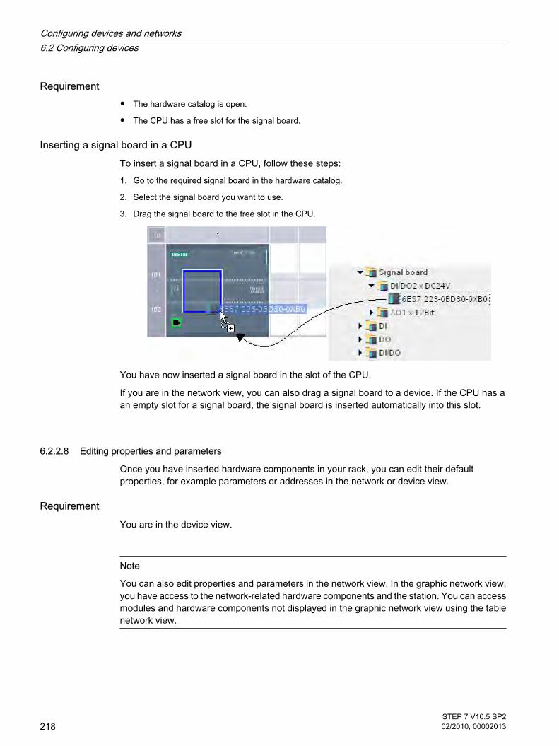
Requirement
• The hardware catalog is open.
• The CPU has a free slot for the signal board.
Inserting a signal board in a CPU To insert a signal board in a CPU, follow these steps:
1. Go to the required signal board in the hardware catalog.
2. Select the signal board you want to use.
3. Drag the signal board to the free slot in the CPU.
You have now inserted a signal board in the slot of the CPU.
If you are in the network view, you can also drag a signal board to a device. If the CPU has aan empty slot for a signal board, the signal board is inserted automatically into this slot.
6.2.2.8 Editing properties and parameters
Once you have inserted hardware components in your rack, you can edit their defaultproperties, for example parameters or addresses in the network or device view.
RequirementYou are in the device view.
Note
You can also edit properties and parameters in the network view. In the graphic network view,you have access to the network-related hardware components and the station. You can accessmodules and hardware components not displayed in the graphic network view using the tablenetwork view.
6.2.2.8 Editing properties and parameters
Configuring devices and networks6.2 Configuring devices
218STEP 7 V10.5 SP202/2010, 00002013

Procedure To change the properties and parameters of the hardware components, follow these steps:
1. In the graphic view, select the CPU, module, rack or interface you want to edit.
2. Edit the settings for the selected object:
― Use the table view to edit addresses and names, for example.
― In the Inspector window additional setting possibilities are available in "Properties".
Example of changing settings
① Selection of a module
② Editing option for addresses in the device overview
③ Selection options in the inspector window
④ Editing option for addresses in the inspector window
Configuring devices and networks6.2 Configuring devices
STEP 7 V10.5 SP202/2010, 00002013
219

See alsoInspector window (Page 197)
6.3 Networking devices
6.3.1 Communication and networks
Communication between devices The basis of all types of communication is always a previously configured network. The networkconfiguration lays the foundation for communication, in other words:
• All the devices in a network have a unique address;
• The devices process communication with consistent transmission properties.
Network configuration The following steps are necessary when configuring networks:
• Connect devices to subnet
• Specify the properties/parameters for each subnet
• Specify the device properties for every networked module
• Download configuration data to the devices to supply interfaces with the settings resulting from thenetwork configuration
• Document the network configuration
For Open User Communication, creating and configuring a subnet is supported by theconnection parameter assignment.
Relation between network configuration and project Within a project, subnets and their properties are managed. Properties result mainly fromadjustable network parameters and the quantity and communication properties of theconnected devices.
The devices to be networked must be in the same project.
Subnet name and subnet IDWithin the project, subnets are clearly identified by a subnet name and ID. The subnet ID issaved in all components along with interconnectable interfaces. Components can then beclearly assigned to a subnet even after uploading into a project.
Networking optionsIn the project, you can create and network devices with components capable of communication.The following basic options are available for networking the devices:
6.3 Networking devices6.3.1 Communication and networks
Configuring devices and networks6.3 Networking devices
220STEP 7 V10.5 SP202/2010, 00002013

• You link the interfaces of the components capable of communication with one another. A new subnetis created suitable for the type of interface.
• You connect the interface of the devices capable of communication with a new or existing subnet.
• You create an Open User Communication connection. When you assign parameters to the connectionfor Open User Communication, a subnet is created automatically between the communicationspartners.
Due to the different tasks of the devices or the span of the plant, you may need to use severalsubnets. These subnets are managed in a project.
6.3.2 Networking devices in the network view
OptionsIn the graphic network view, you have an overview of the subnets of the entire system in theproject. You can use the tabular network overview for additional support.
Depending on the starting situation, there are various ways of undertaking configuration tonetwork the interface for a component capable of communication. Possible starting situationsare:
• A suitable subnet is not yet available.
• The subnet with which you want to connect the component already exists.
Procedure - creating a single subnet To create a subnet and to connect it to an interface, follow these steps:
1. Select the interface of a CPU.
2. Select the "Create subnet" command in the shortcut menu of the interface.
The selected interface is connected to a new subnet. Consistent address parameters are setautomatically for the interface.
The following schematic shows an interface with outgoing line connecting to a subnet:
Procedure - creating several subnets at one time To create several subnets at one time, follow these steps:
1. Select several interfaces by clicking on them while pressing the <Ctrl> button.
2. Select the "Create subnet" command in the shortcut menu of the interface.
6.3.2 Networking devices in the network view
Configuring devices and networks6.3 Networking devices
STEP 7 V10.5 SP202/2010, 00002013
221

Each selected interface is connected to a new subnet. Consistent address parameters are setautomatically for the interface.
The following figure shows multiple subnets created by selecting multiple interfaces:
Procedure - connecting two target devices to a new subnetTo connect an interface with another device via a subnet that does not yet exist, follow thesesteps:
1. Position the mouse pointer over the interface for a component capable of communication requiringnetworking.
2. Click with the left mouse button and hold the button down.
3. Move the mouse pointer.
The pointer now uses the networking symbol to indicate "Networking" mode. At the same time, themouse pointer shows the lock symbol that will only disappear when the pointer is on a valid target.
4. Now move the pointer onto the interface of the target device. You can either keep the mouse buttonpressed or release it.
5. Now release the left mouse button or press it again (depending on previous action).
A new subnet is created. The interfaces are now connected via the new subnet. Consistentaddress parameters are set automatically for the interface.
The following schematic shows two networked devices:
Configuring devices and networks6.3 Networking devices
222STEP 7 V10.5 SP202/2010, 00002013

Procedure - connecting two devices to an existing subnet To connect an interface to an existing subnet, follow these steps:
1. Position the mouse pointer on the interface of a communications-compliant component you want tonetwork or on the existing subnet.
2. Click with the left mouse button and hold the button down.
3. Move the mouse pointer.
The pointer now uses the networking symbol to indicate "Networking" mode. At the same time, themouse pointer shows the lock symbol that will only disappear once the pointer is moved to a validtarget.
4. Now move the mouse pointer to the existing subnet or to the interface to be networked. You can eitherkeep the mouse button pressed or release it.
5. Now release the left mouse button or press it again (depending on previous action).
Result:
The interface and selected subnet are now connected. Consistent address parameters are setautomatically for the interface.
Procedure - selecting an existing subnet from a listTo link an interface with a subnet that has already been created, proceed as follows:
1. Select the interface of a CPU.
2. Select the "Assign to new subnet" command in the shortcut menu of the interface.
A list box containing the available subnets appears.
3. Select a subnet from the list.
The interface and selected subnet are now connected. Consistent address parameters are setautomatically for the interface.
6.3.3 Tabular network overview
MeaningThe tabular network overview adds the following functions to the graphic network view:
• You obtain detailed information on the structure and parameter settings of the devices.
6.3.3 Tabular network overview
Configuring devices and networks6.3 Networking devices
STEP 7 V10.5 SP202/2010, 00002013
223

• Using the "Subnet" column, you can connect components capable of communication with createdsubnets.
Basic functions for tablesThe network overview supports the following basic functions for editing a table:
• Displaying and hiding table columns
Note: The columns of relevance to configuration cannot be hidden.
• Optimizing column width
• Sorting table
• Displaying the meaning of a column, line or field using tool tips.
6.3.4 Networking devices in the device view
Networking in the device view In the device view, you can check and set all the parameters of the components belonging toa device and the interfaces in detail. Here you can also assign the interfaces to the subnetscreated in the project.
Requirement
• The subnet with which you want to connect an interface has already been created.
• If the subnet has not yet been created, change to the network view and make the settings requiredfor networking.
Procedure - connecting to an existing subnet To connect an interface to an existing subnet, follow these steps:
1. Select the entire communications-compliant component or the interface to be networked. The properties of the selected interface or component are displayed in the Inspector window.
2. Select the "Ethernet Addresses" parameter group for the selected interface in the Inspector window.
3. Select the subnet to be connected from the "Interface connected with" drop-down list.
The interface and selected subnet are now connected. Consistent address parameters are setautomatically for the interface.
Procedure - creating a new subnet To create a subnet and to connect it to the interface, follow these steps in the device view:
1. Select the entire communications-compliant component or the interface to be networked. The properties of the selected interface or component are displayed in the Inspector window.
2. Select the "Ethernet Addresses" parameter group for the selected interface in the Inspector window.
3. In "Interface connected with", click the "Add new subnet" button.
6.3.4 Networking devices in the device view
Configuring devices and networks6.3 Networking devices
224STEP 7 V10.5 SP202/2010, 00002013
The interface is connected to a new subnet of the appropriate subnet type. Consistent addressparameters are set automatically for the interface.
6.3.5 Checking or changing network parameters and interface parameters
Introduction Communication between networked devices requires the following parameters to beconfigured:
• Network parameters
Network parameters identify the network within the system configuration, for example, using a name.
• Interface parameters
Interface parameters define specific properties of a component capable of communication. Addressesand transmission characteristics are set automatically and are consistent with the network parameters.
Note
Network parameters and interface parameters are usually set during networking such thatcommunication can take place for numerous applications without the parameters having tobe changed.
Procedure - checking or changing network parameters Proceed as follows to check or change network parameters:
1. Enter the network view.
2. Select the subnet from the network view.
You can see the network parameters in the "Properties" tab in the inspector window.
3. If necessary, check or modify the network parameters in the relevant group of parameters.
Procedure - checking or changing interface parameters You can check and modify interface parameters in the network and device view.
Proceed as follows to check or change interface parameters:
1. Enter the network view or device view.
2. Select the interface.
You can see the interface parameters in the "Properties" tab in the inspector window.
3. If necessary, check or modify the interface parameters in the relevant group of parameters.
6.3.5 Checking or changing network parameters and interface parameters
Configuring devices and networks6.3 Networking devices
STEP 7 V10.5 SP202/2010, 00002013
225

6.3.6 Changing networkings
IntroductionYou can cancel an interface's network connection or assign it to another subnet of the samesubnet type.
ConsequencesDepending on the version, a distinction should be made between:
• Canceling a network connection for an interface
The configured parameters for the interface remain unchanged.
• Assigning a network connection to another subnet
If the addresses in the assigned subnet are not unique, in other words, they already exist, they will bechanged automatically to make them unique.
Procedure - disconnecting from a network Proceed as follows to cancel the network connection for an interface:
1. Select the networked interface.
2. Select the "Disconnect from subnet" command in the shortcut menu for the interface.
The network connection is deleted, the interface addresses are, however, not changed.
Configured connections are retained; however these connections are marked red in theconnection table because they are not networked. Specified connections remain specified.
See alsoNetworking devices in the network view (Page 221)
6.3.7 Copying, cutting or deleting subnets
IntroductionYou can copy subnets as individual objects or copy them along with networked devices or othernetworks.
For example, you can create complex configurations to be used more than once in differentvariants within the project with no additional effort.
6.3.6 Changing networkings6.3.7 Copying, cutting or deleting subnets
Configuring devices and networks6.3 Networking devices
226STEP 7 V10.5 SP202/2010, 00002013

Effects on the copied subnet Properties that have to be assigned explicitly within a project are re-assigned appropriatelywhen the copied objects are copied.
For subnets, this means: The subnet ID and name are re-assigned to the copied subnet.
The configured properties are adopted in the copied subnet.
Procedure - copying a subnetProceed as follows to copy one or more subnets:
1. Select one or more subnets.
2. In the shortcut menu, select the "Copy" command.
3. Select the "Paste" command in the shortcut menu.
The copied subnets are shown as "orphaned" subnets in the top part of the network view.
Procedure - copying a subnet with connected devices To copy one or more subnets with networked devices, follow these steps:
1. Select one or more subnets with the connected devices, for example by drawing a lasso around them.
2. In the shortcut menu, select the "Copy" command.
3. Select the "Paste" command in the shortcut menu.
Complete copies of the subnets and connected devices are created.
Configured connections are adopted and remain within the copied devices. Connections todevices that have not been copied are interrupted and become unspecified.
6.3.8 Configuring Industrial Ethernet
Rules for the network configuration The Ethernet interfaces have a default IP address that you change.
6.3.8 Configuring Industrial Ethernet
Configuring devices and networks6.3 Networking devices
STEP 7 V10.5 SP202/2010, 00002013
227

IP address The IP parameters are visible if the module capable of communication supports the TCP/IPprotocol. This is usually the case for all Ethernet modules.
The IP address consists of 4 decimal figures in the range of 0 to 255. The decimal figures areseparated from one another by a dot.
Example: 140.80.0.2
The IP address consists of
• The address of the (sub) net
• The address of the node (generally also called host or network node)
Subnet mask The subnet mask splits these two addresses. It determines which part of the IP addressaddresses the network and which part of the IP address addresses the node.
The set bits of the subnet mask determine the network part of the IP address.
Example:
Subnet mask: 255.255.0.0 = 11111111.11111111.00000000.00000000
In the example given for the above IP address, the subnet mask shown here has the followingmeaning:
The first 2 bytes of the IP address identify the subnet - i.e. 140.80. The last two bytes addressthe node, thus 0.2.
It is generally true that:
• The network address results from AND linking the IP address and subnet mask.
• The node address results from AND NOT linking the IP address and subnet mask.
Relation between IP address and default subnet mask An agreement exists relating to the assignment of IP address ranges and so-called "Defaultsubnet masks". The first decimal number (from the left) in the IP address determines thestructure of the default subnet mask. It determines the number of "1" values (binary) as follows:
IP address (decimal) IP address (binary) Address class Default subnet mask
0 to 126 0xxxxxxx.xxxxxxxx.... A 255.0.0.0
128 to 191 10xxxxxx.xxxxxxxx... B 255.255.0.0
192 to 223 110xxxxx.xxxxxxxx... C 255.255.255.0
Configuring devices and networks6.3 Networking devices
228STEP 7 V10.5 SP202/2010, 00002013

NoteRange of values for the first decimal point
A value of between 224 and 255 is also possible for the first decimal number of the IP address(address class D etc). This is, however, not recommended because there is no address checkfor these values.
Masking other subnets You can use the subnet mask to add further structures and form "private" subnets for a subnetthat is assigned one of the address classes A, B or C. This is done by setting other lower pointsof the subnet mask to "1". For each bit set to "1", the number of "private" networks doubles andthe number of nodes they contain is halved. Externally, the network functions like an individualnetwork as it did previously.
Example:
You have a subnet of address class B (e.g. IP address 129.80.xxx.xxx) and change the defaultsubnet mask as follows:
Masks Decimal Binary
Default subnet mask 255.255.0.0 11111111.11111111.00000000.00000000
Subnet mask 255.255.128.0 11111111.11111111.10000000.00000000
Result:
All nodes with addresses between 129.80.001.xxx and 129.80.127.xxx are on one subnet, allnodes with addresses between 129.80.128.xxx and 129.80.255.xxx are on another subnet.
Router The job of the routers is to connect the subnets. If an IP datagram is to be sent to anothernetwork, it first has to be conveyed to a router. To make this possible, in this case you have toenter the address of the router for each node in the subnet.
The IP address of a node in the subnet and the address of the router may only differ at thepoints at which there is a "0" in the subnet mask.
Configuring devices and networks6.3 Networking devices
STEP 7 V10.5 SP202/2010, 00002013
229

6.3.9 Open User Communication
6.3.9.1 Basics of Open User Communication
Introduction Open User Communication is the name of a program-controlled communications technique forcommunication via the integrated PN/IE interface of the CPU. Various connection types areavailable for this communications technique.
The main feature of Open User Communication is its high degree of flexibility in terms of thedata structures transferred. This allows open data exchange with any communicating devicesproviding they support the connection types available here. Since this communication iscontrolled solely by instructions in the user program, event-driven connection establishmentand termination is possible. Connections can also be modified by the user program duringruntime.
For S7-1200 CPUs with an integrated PN/IE interface, the TCP and ISO-on-TCP connectiontypes are available for Open User Communication. The communications partners can be twoSIMATIC PLCs or a SIMATIC PLC and a suitable third-party device.
Instructions for Open User Communication To create the connections, you have various instructions available after opening the programeditor in the "Instructions > Extended instructions > Communication" task card:
• Compact instructions for sending or receiving data with the integrated functions for establishing andterminating the connection:
― TSEND_C (Page 958) (connection establishment/termination, sending)
― TRCV_C (Page 961) (connection establishment/termination, receiving)
• Individual instructions for sending and receiving data or for establishing or terminating connections:
― TCON (Page 965) (connection establishment)
― TDISCON (Page 968) (connection termination)
― TSEND (Page 970) (send)
― TRCV (Page 972) (receive)
Connection establishment For Open User Communication, instructions for establishing and terminating the connectionmust exist for both communications partners. One communications partner sends its data usingTSEND or TSEND_C while the other communications partner receives the data using TRCVor TRCV_C.
One of the communications partners starts the connection establishment as the active partner.The other communications partner reacts by starting its connection establishment as thepassive partner. If both communication partners have triggered their connection establishmentthen the operating system can completely establish the communication connection.
6.3.9 Open User Communication6.3.9.1 Basics of Open User Communication
Configuring devices and networks6.3 Networking devices
230STEP 7 V10.5 SP202/2010, 00002013

Connection parameter assignment You can assign parameters to establish the connection using a connection description DB withthe TCON_Param structure as follows:
• Manually create, assign parameters, and write directly to the instruction.
• Supported by connection parameter assignment.
Connection parameter assignment supports the establishment of the connection and should,therefore, be given preference over the other methods.
You specify the following in the connection parameter assignment:
• Connection partner
• Connection type
• Connection ID
• Connection description DB
• Address details according to selected connection type
In addition, you specify here which communication partner activates the connectionestablishment and which partner establishes a connection passively in response to a requestfrom its communications partner.
See alsoPrinciple of operation of connection-oriented protocols (Page 299)
6.3.9.2 Overview of connection parameter assignment
IntroductionYou will find the connection parameter assignment in the Inspector window of the programeditor if you want to program Open User Communication with the TSEND_C, TRCV_C or TCONexpanded instructions.
Connection parameter assignment supports the flexible functionality of communicationsprogramming: The parameters entered in the connection parameter assignment are stored inan automatically created instance DB with a fixed structure of the type TCON_Param. You canmodify the connection parameters in this connection description DB.
Structure of the connection parameter assignment The connection parameter assignment is made up of the following components:
6.3.9.2 Overview of connection parameter assignment
Configuring devices and networks6.3 Networking devices
STEP 7 V10.5 SP202/2010, 00002013
231

① Expanded instruction for Open User Communication (TCON, TSEND_C or TRCV_C)
② "Configuration" tab in the "Properties" tab
③ Area navigation of the "Configuration" tab
④ General properties of the connection parameters
⑤ Address details in the connection parameters
"Configuration" tabEnter the desired connection parameters in the "Configuration" tab. The area navigation of the"Configuration" tab includes the "Connection parameters" group. This group contains theconnection parameter assignment. Here, you can enter the parameters for the connectionsand the address details with system support. Here, you also initialize the CONNECT (TCON,
Configuring devices and networks6.3 Networking devices
232STEP 7 V10.5 SP202/2010, 00002013

TSEND_C, TRCV_C) and ID (TCON, TSEND, TRCV) parameters of the selectedcommunication instructions.
When all the required parameters are assigned, a check mark is set in front of the "Connectionparameters" group in the area navigation.
Notice
The connection parameter assignment does not check that connection IDs and port numbers(TCP) or TSAPs (ISO-on-TCP) are unique. When you configure Open User Communication,you should, therefore, make sure that the parameter settings are unique within a device.
See alsoParameters of communication connections (Page 301)
6.3.9.3 Description of the connection parameters
Overview The following table shows the general connection parameters:
Parameter Description
Endpoint The names of the local endpoint and the partner endpoint are shown.The local endpoint is the CPU for which TCON, TSEND_C or TRCV_C is programmed. Thelocal endpoint is, therefore, always known.The partner endpoint is selected from the drop-down list. The drop-down list shows allavailable possible connection partners including unspecified connection partners for deviceswhose data is unknown in the project.As long as no connection partner is set, all other parameters in the mask are disabled.
Interface The interface of the local endpoint is displayed. The partner interface is displayed only aftera specified partner endpoint.
Subnet The subnet of the local endpoint is displayed. The partner subnet is displayed only after thepartner endpoint has been selected.If the selected partner endpoint is not connected to the local end point over a subnet, thenetworking of both connection partners is created automatically. The partner endpoint mustbe specified for this purpose.A connection between partners in different subnets is only possible with IP routing. The routingsettings can be edited in the relevant interface properties.
Address The IP address of the local endpoint is displayed. The IP address of the partner is displayedonly after the partner endpoint has been selected.If you have selected an unspecified connection partner, the input box is empty and has a redbackground. In this case, you will need to specify a valid IP address.
6.3.9.3 Description of the connection parameters
Configuring devices and networks6.3 Networking devices
STEP 7 V10.5 SP202/2010, 00002013
233

Parameter Description
Connection type Select the connection type you want to use from the "Connection type" drop-down list:
• TCP
• ISO-on-TCPThe parameters for the required connection data change depending on the selectedconnection type.
Connection ID Enter the connection ID in the input box. When you create a new connection, the default value1 is assigned. You can change the connection ID in the input boxes or enter it directly in TCON.Ensure that the connection ID assigned is unique within the device.
Connection data The names of the connection description DBs for the connection description structuredaccording to TCON_Param are displayed in the drop-down lists.When you create the connection, one data block each is generated for the specifiedconnection partner and automatically filled with the values from the connection parameterassignment. For the local connection partner, the name of the selected data block is enteredautomatically in the block parameter CONNECT of the selected TSEND_C, TRCV_C, orTCON instruction.For the second connection partner, the connection description DB generated by the firstconnection partner can also be used directly at the CONNECT input of the TSEND_C,TRCV_C or TCON instructions. With this procedure, you can use the existing connectiondescription DB after selecting the first connection partner or create a new connectiondescription DB.From the drop-down list, you can also reference another valid data block. If a DB is referencedusing the CONNECT input parameter of the TSEND_C, TRCV_C or TCON expandedinstruction and this does not correspond to the structure of a TCON_Param, the drop-downlist is shown with no content on a red background.
Active connectionestablishment
Enable the "Active connection establishment" check box to specify the active partner for OpenUser Communication.
Port(TCP only)
Address component for a TCP connection. The default after creating a new TCP connectionis 2000.You can change the port numbers.The port numbers must be unique on the device!
TSAP(ISO-on-TCP only)
Address component for an ISO-on-TCP connection. The default after creating a new ISO-on-TCP connection is E0.01.49.53.4F.6F.6E.54.43.50.2D.31.You can enter the TSAP-ID with an extension or as an ASCII TSAP.The TSAPs must be unique on the device!
See alsoParameters of communication connections (Page 301)Assignment of port numbers (Page 303)TSAP structure (Page 305)Examples of TSAP assignment (Page 307)Ability to read back connection description parameters (Page 304)Creating and assigning parameters to connections (Page 235)
Configuring devices and networks6.3 Networking devices
234STEP 7 V10.5 SP202/2010, 00002013

6.3.9.4 Starting connection parameter assignment
The connection parameter assignment for Open User Communication is enabled as soon asa TCON, TSEND_C or TRCV_C instruction for communication is selected in a program block.
Requirement
• Your project must contain at least one S7-CPU.
• The program editor is open.
• A network is available.
Procedure To insert the expanded instructions for Open User Communication, follow these steps:
1. Open the task card, pane and folder "Instructions > Extended instructions > Communication".
2. Drag one of the following instructions to a network:
― TSEND_C
― TRCV_C
― TCON (in the "Others" subfolder)
The "Call options" dialog is opened.
3. Edit the properties of the instance DB in the "Call properties" dialog. You have the following options:
― Change the default name.
― Select the "Manual" check box to assign your own number.
4. Click "OK" to complete your entry.
ResultA connection description DB structured according to TCON_Param is created as an instanceDB belonging to the inserted instruction.
With TSEND_C, TRCV_C or TCON selected, you will see the "Configuration" tab under"Properties" in the Inspector window. The "Connection parameters" group in area navigationcontains the connection parameter assignment that you can now make.
See alsoInserting FBD elements using the "Instructions" task card (Page 484)Inserting LAD elements using the "Instructions" task card (Page 452)Creating and assigning parameters to connections (Page 235)
6.3.9.5 Creating and assigning parameters to connections
In the connection parameter assignment for Open User Communication, you can create andmake the parameter settings for connections of the type TCP or ISO-on-TCP.
6.3.9.4 Starting connection parameter assignment6.3.9.5 Creating and assigning parameters to connections
Configuring devices and networks6.3 Networking devices
STEP 7 V10.5 SP202/2010, 00002013
235

RequirementA CPU exists with a TCON, TSEND_C or TRCV_C expanded instruction.
Procedure To create a connection for Open User Communication, follow these steps:
1. Select a TCON, TSEND_C or TRCV_C block of Open User Communication in the program editor.
2. Open the "Properties > Configuration" tab in the inspector window.
3. Select the "Connection parameters" group. Until you select a connection partner, only the empty drop-down list for the partner endpoint is enabled. All other input options are disabled.
The connection parameters already known are displayed:
― Name of the local endpoint
― Interface of the local endpoint
― IP address of the local endpoint
― Connection ID with default of 1
― Unique name of the data block for the connection data
― Local endpoint as active connection partner
4. In the drop-down list box of the partner endpoint, select a connection partner. You can select anunspecified device or a CPU in the project as the communications partner. Certain connectionparameters are then entered automatically.
An existing partner is automatically networked with the local endpoint and a data block structured forthe connection data according to TCON_Param is created for the partner CPU. The followingparameters are set:
― Interface of the partner endpoint
― Name of the local subnet and the partner subnet
― IP address of the partner endpoint
― ISO-on-TCP connection type
― Connection ID with default of 1
― Unique name of the data block for the connection data
― TSAP-ID E0.01.54.43.50.2D.31
With an unspecified partner, the following parameters are set:
― TCP connection type
― Port number 2000
5. Select the connection type you want from the relevant drop-down list. You can choose between thefollowing:
― TCP
― ISO-on-TCP
Configuring devices and networks6.3 Networking devices
236STEP 7 V10.5 SP202/2010, 00002013

The address details are switched over between port numbers (TCP) and TSAP (ISO-on-TCP)depending on the connection type.
6. Enter the connection IDs in the relevant input boxes of the connection partner. No connection ID canbe assigned to an unspecified partner.
7. You can select a different connection description DB in the relevant "Connection data" drop-down listor change the name of the connection description DB to create a new data block:
― You can also see the selected data block at the interconnection of the CONNECT input parameterof the selected TCON, TSEND_C or TRCV_C instruction.
― If you have already specified a connection description DB for the connection partner using theCONNECT parameter of the TCON, TSEND_C or TRCV_C instruction, you can either use this DBor create a new DB.
― If you edit the name of the displayed data block in the drop-down list, a new data block with thechanged name but with the same structure and content is generated and used for the connection.
― Changed names of a data block must be unique in the context of the communications partner.
― A connection description DB must have the TCON_Param structure.
― A data block cannot be selected for an unspecified partner.
8. Set the behavior for connection establishment using the "Active connection establishment" checkboxes. You can decide which communications partner establishes the connection actively.
9. You can edit the input boxes in the address details. Depending on the selected protocol, you can editthe ports (for TCP) or the TSAPs (for ISO-on-TCP).
Changed values are checked immediately for input errors by the connection parameterassignment and entered in the data block for the connection description.
Note
Open User Communication between two communications partners can only work when theprogram section for the partner endpoint has been downloaded to the hardware. To achievefully functional communication, make sure that you load not only the connection description ofthe local CPU on the device but also that of the partner CPU as well.
See alsoDescription of the connection parameters (Page 233)Starting connection parameter assignment (Page 235)TSAP structure (Page 305)Assignment of port numbers (Page 303)Parameters of communication connections (Page 301)
Configuring devices and networks6.3 Networking devices
STEP 7 V10.5 SP202/2010, 00002013
237

6.3.9.6 Deleting connections
IntroductionThe data of a created connection for Open User Communication is stored in a connectiondescription DB. You can delete the connection by deleting the data block containing theconnection description.
RequirementYou have created an Open User Communication connection.
Procedure To delete a connection, follow these steps:
1. Select a communications partner for Open User Communication in the project tree.
2. Open the "Program blocks" folder below the selected communications partner.
3. Select the "Delete" command from the shortcut menu of the data block with the connection parameterassignment.
Note
If you are not certain which block to delete, open the expanded instruction TCON, TSEND_Cor TRCV_C. You will find the name of the data block as the CONNECT input parameter or inthe connection parameter assignment as the "Connection data" parameter.
If you only delete the instance DBs of the expanded instructions TCON, TSEND_C or TRCV_C,the assigned connections are not deleted as well.
Note
If the connection DB is used by other blocks of the expanded instructions, then thecorresponding calls, their instance DBs, and the combination blocks TSEND_C and TRCV_Care also deleted from the block folder, provided they are not used elsewhere.
This action prevents the program from being inconsistent.
ResultYou have deleted the connection.
Note
Insert an expanded instruction TCON, TSEND_C or TRCV_C again to reference an existingconnection description with the TCON_Param structure via the "Connection data" parameter.
6.3.9.6 Deleting connections
Configuring devices and networks6.3 Networking devices
238STEP 7 V10.5 SP202/2010, 00002013

6.3.10 HMI connections
6.3.10.1 Introduction to configuring connections
Definition A connection defines a logical assignment of two communication partners in order to undertakecommunication services. A connection defines the following:
• Communication partner involved
• Type of connection (e.g., HMI connection)
• Special properties (e.g., whether a connection is established permanently or whether it is establishedand terminated dynamically in the user program, and whether status messages are to be sent)
• Connection path
What you need to know about connection configurationDuring connection configuration, a local connection name is assigned for an HMI connectionas a unique local identification.
In the network view, a "Connections" tab is displayed in addition to the "Network overview" tab.This tab contains the connection table. A line in this connection table represents a configuredconnection, e.g., between an HMI device and PLC, along with its properties.
See alsoConfiguring a connection (Page 1405)Automatic creation of a connection (Page 1408)
6.3.10.2 What you need to know about using connection resources
IntroductionEach connection requires connection resources for the end point and/or transition point on thedevices involved. The number of connection resources is device-specific.
If all the connection resources of a communication partner are assigned, no new connectionscan be established. This situation is apparent when a newly created connection in theconnection table has a red background. The configuration is then inconsistent and cannot becompiled.
HMI connectionsFor HMI connections via the integrated PN interface, one connection resource for the endpointper HMI connection is occupied for the HMI device.
One connection resource is also required for the connection partner (PLC).
6.3.10 HMI connections6.3.10.1 Introduction to configuring connections6.3.10.2 What you need to know about using connection resources
Configuring devices and networks6.3 Networking devices
STEP 7 V10.5 SP202/2010, 00002013
239

6.3.10.3 Views containing information about the configured connections
The views described below will provide you with comprehensive access to all the informationand functions regarding configuring and checking communication connections.
• Connection display in the network view
• Connection table
• "Properties" tab for a connection in the inspector window
BenefitsThe information shown in these views are always up-to-date in terms of the current user actions.This means:
• The connection table displays all connections created.
• If you have selected a connection in the connection table:
― You will graphically see the connection path in the network view.
― The "Properties" tab in the Inspector window displays the parameters of this connection.
6.3.10.3 Views containing information about the configured connections
Configuring devices and networks6.3 Networking devices
240STEP 7 V10.5 SP202/2010, 00002013

The connection tableThe connection table offers the following functions:
• List of all connections in the project
• Selection of a connection and display of connections associated with it in the network view
• Changing of connection partners
• Display showing status information
"Properties" tab for a connection in the inspector windowThe properties dialog has the following meaning:
• Display for connection parameters
• Display of connection path
• Subsequent specification of connections using the "Find connection path" button
6.3.10.4 Creating a new connection
Creating a connection - alternativesYou have the following options for creating a connection in the network view:
• Graphic connection configuration
• Interactive connection configuration
You'll find the individual steps for this in the following chapters.
Requirement and resultYou have created the devices with CPUs and HMI devices between which you want to configureconnections in the network view.
Specifying a connectionIf both partners for the connection type selected are networked on the same network, use thegraphic or interactive selection of both communication partners to create a fully specifiedconnection.
This connection is entered automatically into the connection table of the HMI device. A localconnection name is assigned for this connection.
The following schematic shows a configured connection with a networked device:
6.3.10.4 Creating a new connection
Configuring devices and networks6.3 Networking devices
STEP 7 V10.5 SP202/2010, 00002013
241

6.3.10.5 Creating a new connection graphically
Graphically configuring connectionsWhen using the graphic connection configuration, if necessary the system asks you to definethe connection path. Select the devices to be connected in the current configuration.
Automatically determining connection pathTo create a connection graphically, follow these steps:
1. Click the "Connections" button.
The connection mode for the connection type you have selected is then activated.
You will see this from the following:
The devices that can be used for the connection type selected in your project are color-highlighted inthe network view.
2. Hold down the mouse button and drag the mouse pointer from the device from which the connectionwill originate to the device at which the connection ends.
3. Release the mouse button over the destination device to create the connection between the twodevices.
Result
• A specified connection is created.
• The connection path is highlighted.
• The connection is entered in the connection table.
6.3.10.5 Creating a new connection graphically
Configuring devices and networks6.3 Networking devices
242STEP 7 V10.5 SP202/2010, 00002013

6.3.10.6 Interactively creating a new connection
Interactively configuring connectionsDefine the local device and its connection partners.
ProcedureProceed as follows to interactively create a connection:
1. Select the "Create new connection" command in the shortcut menu of a connection partner for whichyou want to create a connection.
The "Create new connection" dialog is opened.
2. Select the partner endpoint.
In the right pane of the dialog, a possible connection path fitting the selected endpoint is displayed, ifavailable. Incomplete paths, for example, for a non-specified CPU, are marked by an exclamationmark on a red background.
3. To close the dialog, click "OK". To accept the configured connection and to configure additional connections to other endpoints, click"Apply".
6.3.10.7 Working in the network view
Highlighting connection path and partner in the network viewTo display the connection partners for all or certain connection types in the network view,proceed as follows:
1. Click the "Connections" button.
2. Select the "Highlight connection partners" command in the shortcut menu for the HMI device whoseconnection partners you want to display in the network view.
3. Select "All connection partners" in the following menu.
The local device and the CPUs of the target devices are selected. The local connection partner showsan arrow pointing right and the remote connection partners show an arrow pointing left.
4. To open a list with information on the target devices, click the arrow of the local device. This additionalfunction is useful in complex network configurations in which some devices are not visible.
6.3.10.6 Interactively creating a new connection6.3.10.7 Working in the network view
Configuring devices and networks6.3 Networking devices
STEP 7 V10.5 SP202/2010, 00002013
243

Note
You can display one of the connection partners which cannot be seen in the current displayrange of the network view. Click on the communication partner in the list that appears. Result:The display is moved such that the connection partner becomes visible.
See alsoCreating a new connection graphically (Page 242)
6.3.10.8 Working with the connection table
Basic functions for tablesThe connection table supports the following basic functions for editing a table:
• Changing column width
• Displaying the meaning of a column, line or field using tool tips.
Changing column widthTo adjust the width of a column to the content so that all texts in the lines are legible, followthese steps:
1. Position the cursor in the header of the connection table to the right of the column that you want tooptimize until the cursor changes its shape to two parallel lines (as if you wanted to change the widthof the column by dragging it with the cursor).
2. Double click on this point.
For columns that are too narrow, the complete content of specific fields is shown when youpause with the cursor on the respective field.
Using cursor keys to move within the connection tableYou can use the UP and DOWN cursor keys to select a connection from the connection table;the selected connection is marked and is shown highlighted in the network view.
Changing properties of connectionYou can directly edit the parameters displayed in the connection table in some cases. Tochange the name of a connection, you do not have to navigate to the Inspector window.
Changing connection partnersYou can change the connection partner of a connection as follows:
1. Select the connection.
2. Select the new connection partner from the open drop-down list in the "Partner" column.
6.3.10.8 Working with the connection table
Configuring devices and networks6.3 Networking devices
244STEP 7 V10.5 SP202/2010, 00002013

6.3.10.9 Deleting connections
You can delete configured connections via the network view or the connection table.
In the network view you can delete a highlighted connection. In the connection table you candelete one or more connections.
Procedure in the connection tableTo delete a highlighted connection, proceed as follows:
1. In the connection table select the connection that you want to delete.
2. Open the shortcut menu with a right mouse click.
3. Select the "Delete" command.
The selected connection will be completely deleted.
4. Load the relevant device.
6.3.10.10
Copying connections
IntroductionConnections are not copied singly but always in context along with the project or the device.
You can copy:
• Entire projects
• One or more devices within a project or from one project to another
Copying a projectWhen you copy a project all configured connections will also be copied. No settings whatsoeverare required for the copied connections because the connections remain consistent.
Copying devicesIf you copy devices for which connections have been configured (HMI devices), the connectionsare copied as well. To complete the connection path, you must still finalize the networking.
An S7-1200 is merely a server for HMI connections and has no connection configuration itself.For this reason, when an S7-1200 CPU is copied, no connections are copied along with it.
6.3.10.11
Inconsistent connections - connections without assignment
With an inconsistent connection the structure of the connection data is destroyed or theconnection is not functional in the project context.
6.3.10.9 Deleting connections6.3.10.10 Copying connections6.3.10.11 Inconsistent connections - connections without assignment
Configuring devices and networks6.3 Networking devices
STEP 7 V10.5 SP202/2010, 00002013
245

Inconsistent connections cannot be compiled and loaded - operation is not possible with sucha connection.
In the connection table inconsistent connections are marked in red.
Possible causes for inconsistent connections
• Deletion or change of the hardware configuration.
• Missing interface network links in the project, which are necessary for a connection.
• Connection resources are exceeded
• Errors when backing up data due to insufficient memory
• Connections to an unspecified connection partner without partner address information.
Detailed information regarding the reasons for the inconsistency can be found in the "Compile"tab following compilation (Edit > Compile).
RemediesIf the connection cannot be repaired by opening the connection properties, changing them orundoing them in the configuration, then it may be necessary to delete the connection and re-create it.
6.3.10.12
HMI connection general settings
General connection parametersGeneral connection parameters are displayed in the "General" parameter group under theproperties of the connection; these connection parameters identify the local connection endpoint.
Here, you can also assign the connection path and specify all aspects of the connection partner.
Special connection propertiesDisplay of the connection properties (cannot be changed):
• Active connection establishment
The connection establishment always starts from the HMI device. This option is selected by default ifthe address of the partner is specified.
• One-way
One-way means that the connection partner functions as a server on this connection and cannot sendor receive actively.
• Sending operating mode messages
Not relevant for HMI devices.
6.3.10.12 HMI connection general settings
Configuring devices and networks6.3 Networking devices
246STEP 7 V10.5 SP202/2010, 00002013

Address detailsDisplaying address details of the HMI connection. With an unspecified partner, the values forthe rack and slot can be changed. All other values are obtained from the current configurationand cannot be changed.
MiscellaneousDisplay of the access points for the online connection between HMI device and connectionpartner.
6.4 Configuring operation
6.4.1 Selecting a CPU
IntroductionSelect a CPU from the hardware catalog and place it, together with a rack, in the network view.On this device drag the desired modules from the hardware catalog; they are arrangedautomatically on the rack.
Selecting the components in the hardware catalog Each hardware component is displayed as a folder in the hardware catalog. When you openthis folder you will see the different versions of the selected hardware component with itsrespective order numbers.
There will be an example of how to set up a CPU with a rack in network view.
Requirement
• The hardware catalog is open.
• You must be in the network view.
ProcedureTo select a CPU from the hardware catalog, proceed as follows:
1. In the hardware catalog navigate to the folder with the desired CPUs.
2. Open the folder with the desired CPU type; you will see all order numbers for the selected CPU type.
3. Click on a CPU order number to get information about the selected CPU under "Information" pane.
6.4 Configuring operation6.4.1 Selecting a CPU
Configuring devices and networks6.4 Configuring operation
STEP 7 V10.5 SP202/2010, 00002013
247

4. Set up the CPU and a rack. You have the following options:
― Use drag-and-drop to drag the CPU from the hardware catalog into network view.
― Use Copy & Paste to copy the CPU to the network view.
― Double-click the CPU entry in the hardware catalog.
See alsoBrowsing the hardware catalog (Page 204)Adding a device to the hardware configuration (Page 210)Inserting a module into a rack (Page 211)Working with racks (Page 206)Creating an unspecified CPU (Page 298)Information on hardware components (Page 200)
6.4.2 Changing properties of the modules
Default settingsWhen they leave the factory, all hardware components with parameters have default settingssuitable for standard applications. These default values allow the hardware components to beused immediately without making any additional settings.
6.4.2 Changing properties of the modules
Configuring devices and networks6.4 Configuring operation
248STEP 7 V10.5 SP202/2010, 00002013

You can, however, modify the behavior and the properties of the hardware components to suitthe requirements and circumstances of your application. Hardware components with settableparameters include, for example, communications modules and several analog and digitalmodules.
Setting and loading parametersWhen you have selected a hardware component in the device or network view, you can set theproperties in the Inspector window. When you save a device configuration with its parameters,data is generated that needs to be loaded on the CPU. This data is transferred to the relevantmodules during startup.
Properties of the CPUs The properties of the CPUs have special significance for system behavior. For example for aCPU you can set:
• Interfaces
• Inputs and outputs
• High-speed counters
• Pulse generators
• Startup behavior
• Time-of-day
• Protection level
• Bit memory for system and clock
• Cycle time
• Communications load
The entry possibilities specify what is adjustable and in which value ranges. Fields that cannotbe edited are disabled or are not shown in the properties window.
RequirementYou have already arranged the hardware components for which you want to change propertieson a rack.
ProcedureTo change the properties and parameters of the hardware components, follow these steps:
1. In the device or network view, select the hardware component or interface that you want to edit.
2. Edit the settings for the selected object:
― For example in the device view you can edit addresses and names.
― In the Inspector window additional setting possibilities are available.
You do not need to confirm your entries, the changed values will be applied immediately.
Configuring devices and networks6.4 Configuring operation
STEP 7 V10.5 SP202/2010, 00002013
249

See alsoEditing properties and parameters (Page 218)Introduction to loading a configuration (Page 276)
6.4.3 CPU properties
6.4.3.1 Overview of the CPU properties
Overview The following table provides you with an overview of the CPU properties:
Group Properties Description
General Project information General information to describe the inserted CPU. Apart from theslot number, you can change all the settings
Catalog information Read-only information from the hardware catalog for this CPU.
PROFINET interface General Name and comment for this PROFINET interface. The name islimited to 128 characters.
Ethernet addresses Selects whether the Ethernet interface is networked. If subnetshave already been created in project, they can be selected in thedrop-down list. If not, you can create a new subnet with the "Addnew subnet" button.Information on the IP address, subnet mask, and IP router usagein the subnet is available in the IP protocol. If an IP router is used,the information about the IP address of the IP router is necessary.
Extended Name of and comment on the port of the Ethernet interface
Time-of-day synchronization Settings for time-of-day synchronization in the NTP time format.The NTP (network time protocol) is a general mechanism forsynchronizing system clocks in local and global area networks.In NTP mode, the interface of the CPU sends time queries (inclient mode) at regular intervals to NTP servers on the subnet(LAN) and the addresses must be set in the parameters here.Based on the replies from the server, the most reliable and mostaccurate time is calculated and synchronized. The advantage ofthis mode is that it allows the time to be synchronized acrosssubnets. The accuracy depends on the quality of the NTP serverbeing used.
6.4.3 CPU properties6.4.3.1 Overview of the CPU properties
Configuring devices and networks6.4 Configuring operation
250STEP 7 V10.5 SP202/2010, 00002013

Group Properties Description
DI#/DO# General Name of and comment on the integrated digital inputs of the CPU.
Digital inputs Input delays can be set for digital inputs. The input delays can beset in groups (in each case for 4 inputs).The detection of a rising and a falling edge can be enabled foreach digital input. A name and a hardware interrupt can beassigned to this event.Depending on the CPU, pulse catches can be activated at variousinputs. When the pulse catch is activated, even pulse edges thatare shorter than the cycle time of the program are detected.
Digital outputs The reaction to a mode change from RUN to STOP can be set forall digital outputs:The state can either be frozen (corresponds to retain last value)or you set a substitute value ("0" or "1")
I/O/Diagnostic addresses The address space of the input and output addresses is specifiedas is the process image. The hardware ID of the device isdisplayed.
AI# General Name of and comment on the integrated analog inputs of theCPU.
Analog inputs During noise reduction, the specified integration time suppressesinterference frequencies at the specified frequency (in Hz).The channel address, measurement type, voltage range,smoothing, and overflow diagnostics must be specified in the"Channel #" group. The measurement type and voltage range areset permanently to voltage, 0 to 10 V.Smoothing analog values provides a stable analog signal forfurther processing. Smoothing analog values can be useful withslow measured value changes, for example in temperaturemeasurement. The measured values are smoothed with digitalfiltering. Smoothing is achieved by the module forming meanvalues from a specified number of converted (digitalized) analogvalues. The selected level (slight, medium, strong) decides thenumber of analog signals used to create the mean value.If overflow diagnostics is enabled, a diagnostics event isgenerated if an overflow occurs.
I/O/Diagnostic addresses The address space of the input addresses is specified as is theprocess image. The hardware ID of the device is displayed.
High-speed counter(HSC)
High-speed counter (HSC)# High-speed counters are typically used to drive countingmechanisms.For description and parameter assignment, see: Configuring high-speed counters (Page 264)
Configuring devices and networks6.4 Configuring operation
STEP 7 V10.5 SP202/2010, 00002013
251

Group Properties Description
Pulse generators(PTO/PWM)
PTO#/PWM# A pulse generator is activated and can be initialized with projectinformation.For the parameter assignment of an activated pulse generator,specify the usage as PWM (Pulse Width Modulation) or as PTO(Pulse Train Output).Specify the output source, time base, pulse width format, cycletime, and initial pulse width for PWM. A pulse output is specifiedas the hardware output. The PWM output is controlled by theCTRL_PWM instruction, see CTRL_PWM (Page 1014) .Specify the output source for PTO. A pulse output and a directionoutput are specified as the hardware outputs. A PTO is operatedtogether with a high-speed counter in the "motion axis" countmode and controlled by the Motion Control technology object, seeConfiguration - General (Page 627) .The hardware ID is displayed in the I/O/Diagnostic addressesand, if the PWM function is selected, the address space of theoutput addresses and the process image can be selected.
Startup Startup type Setting the start up behavior after cycling power.See: Principles of the STARTUP mode (Page 313)
Time-of-day Local time and daylight-savingtime
Setting of the time zone in which the CPU is operated and settingof the daylight-saving/standard time changeover.
Protection Protection and password for read/write access
Setting options for the level of protection (Page 275)
System and clockmemory bits
System memory bits and clockmemory bits
You use system memory bits for the following scans:
• Is the current cycle the first since cycling power?
• Have there been any diagnostics state changes comparedwith the previous cycle?
• Scan for "1" (high)
• Scan for "0" (low)Clock memory bits change their values at specified periodicintervals.See: Using clock memory (Page 274)
Cycle time Maximum cycle time andminimum cycle time.
See: Cycle time and maximum cycle time (Page 253)
Communications load Maximum allocation of the cyclefor communication (as apercentage)
See: Cycle loading by communications (Page 254)
Configuring devices and networks6.4 Configuring operation
252STEP 7 V10.5 SP202/2010, 00002013

Group Properties Description
I/O addressesoverview
- Tabular representation of all addresses used by the CPU forintegrated inputs/outputs as well as for the inserted modules.Addresses that are not used by any module are represented asgaps.The view can be filtered according to:
• Input addresses
• Output addresses
• Address gaps
See alsoSpecifying input and output addresses (Page 257)Configuring high-speed counters (Page 264)Setting options for the level of protection (Page 275)Cycle time and maximum cycle time (Page 253)Cycle loading by communications (Page 254)Assigning parameters to hardware interrupt OBs (Page 417)Principles of the STARTUP mode (Page 313)Access to the I/O addresses (Page 322)Using clock memory (Page 274)Addressing modules (Page 256)Special features during startup (Page 315)
6.4.3.2 Cycle time and maximum cycle time
Function The cycle time is the time that the operating system requires to execute the cyclic program andall the program sections that interrupt this cycle. The program execution can be interrupted by:
• Time errors and 2xMaxCycleTime errors
• System activities, e.g., process image updating
The cycle time (Tcyc) is therefore not the same for every cycle.
The following schematic shows an example of different cycle times (TZ1 ≠ TZ2) for S7-1200CPUs:
6.4.3.2 Cycle time and maximum cycle time
Configuring devices and networks6.4 Configuring operation
STEP 7 V10.5 SP202/2010, 00002013
253

In the current cycle, the cyclic OB used here (e.g., OB 1) is interrupted by a time error (e.g.,OB 280) Following the cyclic OB, the next cycle OB 201 is processed.
Maximum cycle timeThe operating system monitors the execution time of the cyclic program for a configurable upperlimit known as the maximum cycle time. You can restart this time monitoring at any point inyour program by calling the RE_TRIGR instruction.
If the cyclic program exceeds the maximum cycle time, the operating system attempts to startthe time error OB (for example OB 280). If this does not exist, the CPU changes to "STOP"mode.
In addition to monitoring the execution time for the maximum cycle time, adherence to aminimum cycle time is guaranteed. To do this, the operating system delays the start of the newcycle until the minimum cycle time has been reached. During this waiting time, new events andoperating system services are processed.
If the maximum cycle time is exceeded a second time, for example while the time error OB isbeing processed (2xMaxCycleTime error), the CPU changes to STOP mode.
6.4.3.3 Cycle loading by communications
Function The cycle time of the CPU can be extended due to communications processes. Thesecommunications processes include for example:
• Transferring data to another CPU
• Loading of blocks initiated by a programming device
You can control the duration of these communications processes to some extent using the CPUparameter "Cycle load due to communication".
In addition to communications processes, test functions also extend the cycle time. The "Cycleload due to communication" parameter has very little influence on the duration of thesefunctions.
6.4.3.3 Cycle loading by communications
Configuring devices and networks6.4 Configuring operation
254STEP 7 V10.5 SP202/2010, 00002013

How the parameter worksYou use the "Cycle load due to communication" parameter to enter the percentage of the overallCPU processing capacity that can be available for communications processes. This CPUprocessing capacity is now available at all times for communication. When not required forcommunication, this processing capacity is available to the rest of the processing.
Effect on the actual cycle timeThe "Cycle load due to communication" parameter can be used to extend the cycle time of thecyclic organization block (e.g., OB 1) by a factor calculated according to the following formula:
The formula does not take into account the effect of asynchronous events such as hardwareinterrupts or cyclic interrupts on the cycle time.
If the cycle time is extended due to communication processes, more asynchronous events mayoccur within the cycle time of the cyclic organization block. This extends the cycle still further.The extension depends on how many events occur and how long it takes to process them.Example 1 – no additional asynchronous events:
If the "Cycle load due to communication" parameter is set to 50%, this can cause the cycle timeof the cyclic organization block to increase by up to a factor of 2.Example 2 – additional asynchronous events:
For a pure cycle time of 500 ms, a communication load of 50% can result in an actual cycletime of up to 1000 ms, provided that the CPU always has enough communications jobs toprocess. If, parallel to this, a cyclic interrupt with 20 ms processing time is executed every 100ms, this cyclic interrupt would extend the cycle by a total of 5*20 ms = 100 ms withoutcommunication load. That is, the actual cycle time would be 600 ms. Because a cyclic interruptalso interrupts communications, it affects the cycle time by adding 10 * 20 ms at 50 %communication load. That is, in this case, the actual cycle time amounts to 1200 ms instead of1000 ms.
Note
Observe the following:
• Check the effects of changing the value of the "Cycle load due to communication" parameter whilethe system is running.
• The communications load must always be taken into account when setting the minimum cycle time;otherwise, time errors will occur.
Recommendations
• Increase this value only if the CPU is used primarily for communication purposes and the user programis not time critical.
Configuring devices and networks6.4 Configuring operation
STEP 7 V10.5 SP202/2010, 00002013
255

• In all other situations you should only reduce this value.
6.4.4 Addressing modules
6.4.4.1 Addressing modules
Introduction In the device view you see the addresses or address ranges of the modules in the I-addressand Q-address columns. There are other addresses as well, which are explained below.
I/O address I/O addresses are required to read inputs and/or set outputs in the user program.
Input and output addresses are assigned automatically when inserting modules in the rack.The address of the first channel is the start address of a module. The addresses of the otherchannels are derived from this start address. The address end is derived from the module-specific address length.
Device address (e.g., Ethernet address)Device addresses are addresses of programmable modules (Industrial Ethernet addresses).They are required to address the different stations of a subnet, e.g. to load a user program intoa CPU.
Hardware ID for identification of modules or functional units of modulesIn addition to the I addresses and Q addresses, a hardware identifier is also assignedautomatically and is used to identify the module. Functional units of a module, for example anintegrated counter, also receive a hardware identifier.
The hardware identifier consists of a whole number and is output by the system along withdiagnostics alarms to allow the faulty module or functional unit to be localized.
You also use the hardware identifier for a number of instructions to identify the relevant moduleon which the instruction will be used.
The hardware ID cannot be changed.
Example: Identifying a high-speed counter
6.4.4 Addressing modules6.4.4.1 Addressing modules
Configuring devices and networks6.4 Configuring operation
256STEP 7 V10.5 SP202/2010, 00002013

The hardware ID is assigned automatically when components are inserted in the device ornetwork view and in the constants table of the PLC tags. A name is also assigned automaticallyfor the hardware ID. These entries in the constants table of the PLC tags cannot be changedeither.
See alsoSpecifying input and output addresses (Page 257)Assigning addresses to a location in the program (Page 257)Introduction to loading a configuration (Page 276)
6.4.4.2 Specifying input and output addresses
Default input and output addresses are set automatically. You can, however, change theaddress assignment later.
All addresses of modules are located in the process image area. The process image isautomatically updated cyclically.
RequirementYou are in the device view.
Procedure To change the preset address range proceed as follows:
1. In the device view, click on the module for which you want to set the start address.
2. Go to "I/O diagnostics addresses" in "Properties" in the Inspector window.
3. Under "Start address" enter the required start address.
4. Press <Return> or click on any object to accept a modified value.
If you have entered an invalid address, a message indicating the next available address isdisplayed.
Note
You can also change the addresses directly in the device overview.
See alsoEditing properties and parameters (Page 218)
6.4.4.3 Assigning addresses to a location in the program
You can assign addresses or symbols from the I/O channels of the modules directly to thelocations in the program.
6.4.4.2 Specifying input and output addresses6.4.4.3 Assigning addresses to a location in the program
Configuring devices and networks6.4 Configuring operation
STEP 7 V10.5 SP202/2010, 00002013
257

RequirementThe device view of the hardware and network editor as well as the instruction window of theprogram editor must be opened and arranged one below the other.
Procedure To assign addresses or symbols of modules and locations in the program, proceed as follows:
1. In the device view, navigate to the module with the desired I/O channel.
2. Use the zoom function to specify a magnification of at least 200%: At a magnification level of 200%and higher, the labels of the individual address channels are displayed and can be edited.
3. In the program, navigate to the block with the matching location.
4. Keep the mouse button pressed and drag the desired address or the icon to the appropriate locationof the block or the I/O channel of the module.
Configuring devices and networks6.4 Configuring operation
258STEP 7 V10.5 SP202/2010, 00002013

The address or the symbol of the module is assigned to the location in the program or theaddress or the symbol in the program is assigned to an I/O channel of the module.
Configuring devices and networks6.4 Configuring operation
STEP 7 V10.5 SP202/2010, 00002013
259

6.4.5 Time-of-day functions
6.4.5.1 Basic principles of time of day functions
All S7-1200 CPUs are equipped with an internal clock. The backup supports the display of thecorrect time for up to 10 hours if the power supply is interrupted.
Time-of-day format The clock always shows the time of day with a resolution of 1 millisecond and the date includingthe day of the week. The time adjustment for daylight-saving time is also taken into account.
6.4.5.2 Setting and reading the time of day
Setting the time of day as a system function You can set and start the time of day and date of the CPU clock with the following systemfunctions:
• "SFC 0 SET_CLK"
• "SFC 100 SET_CLKS", if it exists on the CPU
Note
To avoid time-of-day display differences in HMI systems, set the CPU to standard time or usecentral time-of-day synchronization.
Reading the time of day as a system functionYou read the current date and time of day of the CPU with system function "SFC 1 READ_CLK"or via a menu command from the programming device.
Manual settingYou can also read and set the time of day manually in the online and diagnostics view under"Functions > Set time of day".
6.4.5.3 Parameterizing the clock
Clock parametersThe clock parameters allow you to make the following settings:
• Enable time-of-day synchronization using an NTP server
6.4.5 Time-of-day functions6.4.5.1 Basic principles of time of day functions6.4.5.2 Setting and reading the time of day6.4.5.3 Parameterizing the clock
Configuring devices and networks6.4 Configuring operation
260STEP 7 V10.5 SP202/2010, 00002013

Select this check box if you want the internal clock to be synchronized using the NTP synchronizationmode.
• Network time server
The IP addresses of up to four NTP servers need to be configured.
• Update interval
The update interval defines the interval between time queries.
6.4.6 High-speed counters
6.4.6.1 General information on high-speed counters
Introduction High-speed counters are typically used to drive counting mechanisms in which a shaft turningat a constant speed is equipped with an incremental step encoder. The incremental stepencoder ensures a certain number of count values per rotation and a reset pulse once perrotation. The clock memory bit(s) and the reset pulse of the incremental step encoder supplythe inputs for the high-speed counter.
The various S7-1200 CPUs have differing numbers of high-speed counters available:
S7-1200 CPU Number of HSCs HSC designation
CPU 1211C 3 (with digital signal board 4)* HSC1…3 (and HSC5)*
CPU 1212C 4 (with digital signal board 5)* HSC1…4 (and HSC5)*
CPU 1214C 6 HSC1…6
* with DI2/DO2 signal board
How it works The first of several default values is loaded on the high-speed counter. The required outputsare enabled for the time during which the current value of the counter is lower than the defaultvalue. The counter is set up so that an interrupt occurs if the current value of the counter isequal to the default value or when the counter is reset.
If the current value is equal to the default value and an interrupt event results, a new defaultvalue is loaded and the next signal state is set for the outputs. If an interrupt event occursbecause the counter is reset, the first default value and the first signal states of the outputs areset and the cycle repeated.
Since the interrupts occur much less frequently than the high-speed counter counts, a precisecontrol of the fast operations can be implemented with only a slight influence on the overallcycle of the automation system. Since you can assign specific interrupt programs to interrupts,
6.4.6 High-speed counters6.4.6.1 General information on high-speed counters
Configuring devices and networks6.4 Configuring operation
STEP 7 V10.5 SP202/2010, 00002013
261

each new default can be loaded in a separate interrupt program allowing simple control of thestate.
Note
You can also process all interrupt events in a single interrupt program.
Description of the various countersAll counters work in the same way in the same counter mode, however, some high-speedcounters do not support all count modes. There are four basic counter modes:
• Single-phase counter with internal direction control
• Single-phase counter with external direction control
• 2-phase counter with 2 clock inputs
• A/B counter
Each high-speed counter can be used with or without a reset input. If the reset input is activated,this resets the current value. The current value remains reset until the reset input is deactivated.
See alsoConfiguring high-speed counters (Page 264)Interdependency of the counter mode and counter inputs (Page 262)
6.4.6.2 Interdependency of the counter mode and counter inputs
General information on counter mode and counter inputs You can assign not only the counter modes and counter inputs to the high-speed counters butalso functions such as clock pulse generator, direction control, and reset. The following rulesapply:
• An input cannot be used for two different functions.
• If an input is not required by the current counter mode of the defined high-speed counter, it can beused other purposes.
If, for example, you set HSC1 to counter mode 1, in which inputs I0.0 and I0.3 are required,you can use I0.1 for edge interrupts or for HSC2.
If, for example, you set HSC1 and HSC5, inputs I0.0 (HSC1) and I1.0 (HSC5) are always usedwith the counting and frequency counter modes. As a result, these two inputs are not availablefor any other functions when counters are operated.
You have additional inputs available if you use a digital signal board.
6.4.6.2 Interdependency of the counter mode and counter inputs
Configuring devices and networks6.4 Configuring operation
262STEP 7 V10.5 SP202/2010, 00002013

Overview of the interdependency of counter mode and counter inputs
Counter mode Description Inputs
HSC1 I0.0 (CPU)I4.0 (signal board)
I0.1 (CPU)I4.1 (signal board)
I0.3 (CPU)I4.3 (signal board)
HSC2 I0.2 (CPU)I4.2 (signal board)
I0.3 (CPU)I4.3 (signal board)
I0.1 (CPU)I4.1 (signal board)
HSC3* I0.4 (CPU) I0.5 (CPU) I0.7 (CPU)
HSC4 (CPU 1212/14C only) I0.6 (CPU) I0.7 (CPU) I0.5 (CPU)
HSC5 (CPU 1214C only)** I1.0 (CPU)I4.0 (signal board)
I1.1 (CPU)I4.1 (signal board)
I1.2 (CPU)I4.3 (signal board)
HSC6 (CPU 1214C only)** I1.3 (CPU) I1.4 (CPU) I1.5 (CPU)
Counting /frequency
Single-phase counter withinternal direction control
Clock pulsegenerator
Counting Clock pulsegenerator
Resetting
Counting /frequency
Single-phase counter withexternal direction control
Clock pulsegenerator
Direction
Counting Clock pulsegenerator
Direction Resetting
Counting /frequency
2-phase counter with 2 clockinputs
Clock pulsegenerator forwards
Clock pulsegenerator backwards
Counting Clock pulsegenerator forwards
Clock pulsegenerator backwards
Resetting
Counting /frequency
A/B counter Clock pulsegenerator A
Clock pulsegenerator B
Counting Clock pulsegenerator A
Clock pulsegenerator B
Resetting
Motion axis Pulse generators PWM/PTO HSC1 and HSC2 support the motion axis count mode for the PTO1and PTO2 pulse generators:
• For PTO1, HSC1 evaluates the Q0.0 outputs for the number ofpulses.
• For PTO2, HSC2 evaluates the Q0.2 outputs for the number ofpulses.
Q0.1 is used as the output for the motion direction.
* HSC3 can only be used for CPU 1211 without a reset input
** HSC5 can be also be used for CPU 1211/12 if a DI2/DO2 signal board is used
See alsoGeneral information on high-speed counters (Page 261)
Configuring devices and networks6.4 Configuring operation
STEP 7 V10.5 SP202/2010, 00002013
263

Configuring high-speed counters (Page 264)
6.4.6.3 Configuring high-speed counters
RequirementAn S7-1200 CPU has been inserted in the hardware configuration.
Procedure To configure a high-speed counter, follow these steps:
1. Select an S7-1200 CPU in the device or network view.
2. Click on the required high-speed counter under "Properties > High-speed counter" in the Inspectorwindow:
― CPU 1211C: HSC1 to HSC3 (also HSC5 with a DI2/DO2 signal board)
― CPU 1212C: HSC1 to HSC4 (also HSC5 with a DI2/DO2 signal board)
― CPU 1214C: HSC1 to HSC6
3. Enable the high-speed counter in the "General" parameter group using the relevant check box.
Note
If you use a CPU 1211C or CPU 1212C with a DI2/DO2 signal board, you can also enablethe high-speed counter HSC5.
Note
If you activate the pulse generators and operate them as PTO1 or PTO2, they use theassociated high-speed counter HSC1 or HSC2 with "Motion axis" counting mode to evaluatethe hardware outputs. If you configure high-speed counter HSC1 or HSC2 for other countingtasks, these cannot be used by pulse generator PTO1 or PTO2, respectively.
If required, you can enter a name and a comment for the high-speed counter here.
4. Define the functionality of the high-speed counter in the "Function" parameter group:
― Count mode: Select what you want to be counted from the drop-down list.
― Operating phase: Select the count algorithm from the drop-down list.
― Input source: Select the on-board CPU inputs or the inputs of an optional digital signal board asthe input source for the count pulses from the drop-down list.
― Count direction is specified by: If you have selected a single-phase operating phase, open thedrop-down list and select whether the count direction is set internally by an SFB parameter of theuser program or externally via a digital input.
6.4.6.3 Configuring high-speed counters
Configuring devices and networks6.4 Configuring operation
264STEP 7 V10.5 SP202/2010, 00002013

― Initial count direction: If the user program is set as the internal direction control for the countdirection, you can select the count direction at the start of counting from the drop-down list.
― Frequency meter period: If frequency is set as the count mode, you can select the duration of thefrequency meter periods in the drop-down list.
5. Specify the initial values and reset condition of the high-speed counter in the "Reset to initial values"parameter group:
― Initial counter value: Enter a start value for the high-speed counter.
― Initial reference value: Enter a maximum value for the high-speed counter.
Here, you can also specify whether the high-speed counter will use a reset input and the set thecorresponding signal level for the reset input from the drop-down list.
6. Configure the reaction of the high-speed counter to certain events in the "Event configuration"parameter group. The following events can trigger an interrupt:
― The counter value matches the reference value.
― An external reset event was generated.
― A change of direction was triggered.
Enable an interrupt reaction using the check box, enter a name and select a hardware interrupt forthe interrupt from the drop-down list.
7. Assign the start address for the high-speed counter in the "I/O/Diagnostic addresses" parametergroup.
Note
In the "Hardware inputs" parameter group, you can only see which hardware inputs andvalues are being used for the clock, direction determination, reset pulse, and maximumcount speed.
ResultYou have now adapted the parameters of the high-speed counter to the requirements of yourproject.
See alsoCTRL_HSC: Control high-speed counters in FBD (Page 835)General information on high-speed counters (Page 261)Interdependency of the counter mode and counter inputs (Page 262)
Configuring devices and networks6.4 Configuring operation
STEP 7 V10.5 SP202/2010, 00002013
265

6.4.7 Point-to-point communication
6.4.7.1 Overview of point-to-point communication
PtP communication is communication via a serial interface that uses standardized UART datatransmission (Universal Asynchronous Receiver/Transmitter). The S7-1200 usescommunications modules with an RS-232 or RS-485 interface to establish PtP communication.
Functions of point-to-point communication Point-to-point communication (PtP) allows numerous applications:
• Direct transmission of information to an external device, for example a printer or a barcode reader
• Reception of information from external devices such as barcode readers, RFID readers, cameras andthird-party optical systems as well as many other devices.
• Exchange of information with third-party devices, for example GPS devices, radio modems and manyothers
The Freeport protocol The S7-1200 supports the Freeport protocol for character-based serial communication. UsingFreeport communication, the data transmission protocol can be configured entirely by the userprogram.
Siemens provides libraries with Freeport communication functions that you can use in youruser program:
• USS Drive protocol
• Modbus RTU Master protocol
• Modbus RTU Slave protocol
See alsoConfiguring a communications port (Page 267)
6.4.7.2 Using RS-232 and RS-485 communications modules
Communications modules with RS-232 and RS-485 interfaces In an S7-1200 CPU, you can use two different communications modules:
• RS-232 communications module
• RS-485 communications module
The communications modules can be connected to the S7-1200 CPU via the I/O channel onthe left. You can plug in up to three different modules.
6.4.7 Point-to-point communication6.4.7.1 Overview of point-to-point communication6.4.7.2 Using RS-232 and RS-485 communications modules
Configuring devices and networks6.4 Configuring operation
266STEP 7 V10.5 SP202/2010, 00002013
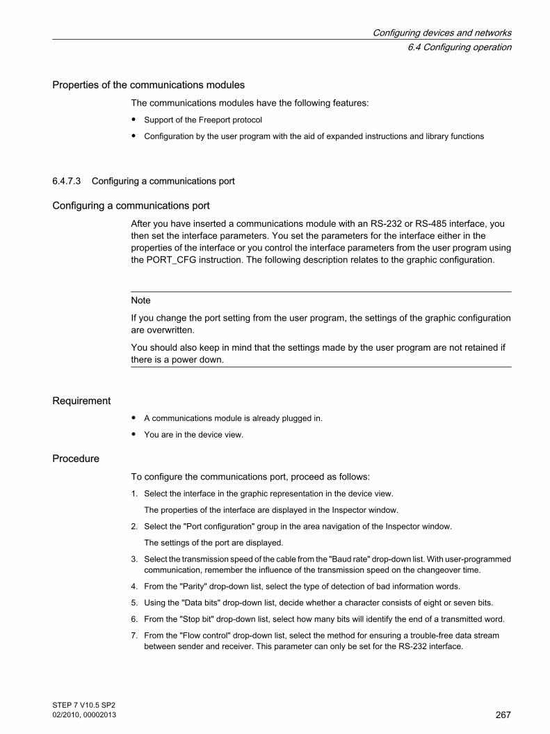
Properties of the communications modules The communications modules have the following features:
• Support of the Freeport protocol
• Configuration by the user program with the aid of expanded instructions and library functions
6.4.7.3 Configuring a communications port
Configuring a communications port After you have inserted a communications module with an RS-232 or RS-485 interface, youthen set the interface parameters. You set the parameters for the interface either in theproperties of the interface or you control the interface parameters from the user program usingthe PORT_CFG instruction. The following description relates to the graphic configuration.
Note
If you change the port setting from the user program, the settings of the graphic configurationare overwritten.
You should also keep in mind that the settings made by the user program are not retained ifthere is a power down.
Requirement
• A communications module is already plugged in.
• You are in the device view.
ProcedureTo configure the communications port, proceed as follows:
1. Select the interface in the graphic representation in the device view.
The properties of the interface are displayed in the Inspector window.
2. Select the "Port configuration" group in the area navigation of the Inspector window.
The settings of the port are displayed.
3. Select the transmission speed of the cable from the "Baud rate" drop-down list. With user-programmedcommunication, remember the influence of the transmission speed on the changeover time.
4. From the "Parity" drop-down list, select the type of detection of bad information words.
5. Using the "Data bits" drop-down list, decide whether a character consists of eight or seven bits.
6. From the "Stop bit" drop-down list, select how many bits will identify the end of a transmitted word.
7. From the "Flow control" drop-down list, select the method for ensuring a trouble-free data streambetween sender and receiver. This parameter can only be set for the RS-232 interface.
6.4.7.3 Configuring a communications port
Configuring devices and networks6.4 Configuring operation
STEP 7 V10.5 SP202/2010, 00002013
267

― Enter a HEX value in the "XON character" box that will cause the transmission of the message tobe continued when it is detected. This parameter can only be set for software-controlled data flowcontrol.
― Enter a HEX value in the "XOFF character" box that will cause the transmission of the messageto be suspended for the set wait time. This parameter can only be set for software-controlled dataflow control.
8. In the "Wait time" box, enter a wait time in ms that must be kept to after the end of the message beforethe next transmission can start.
NoteNote
You can configure the interface in the network view as well. To do so, you must first select thecommunication module in the tabular network view and then select the interface in the Inspectorwindow. Then you can continue as described above.
See alsoSetting data flow control (Page 268)
6.4.7.4 Setting data flow control
Data flow controlData flow control is a method that ensures a balanced send and receive behavior. In the idealsituation, the intelligent control does not allow data to be lost. It ensures that a device does notsend more information than the receiving partner can process.
There are two methods of data flow control:
• Hardware-controlled data flow control
• Software-controlled data flow control
With both methods, the DSR signals of the communications partners must be active at thebeginning of transmission. If the DSR signals are inactive, the transmission is not started.
The RS-232 communications module can handle both methods. The RS-485 communicationsmodule does not support data flow control.
Hardware-controlled data flow controlHardware-controlled data flow control uses the request to send (RTS) and clear to send (CTS)signals. With the RS-232 communications module, the RTS signal is transmitted via the outputby pin 7. The CTS signal is received via pin 8.
If hardware-controlled data flow control is enabled, the RTS signal is then always set toactivated when data is sent. At the same time, the CTS signal is monitored to check whetherthe receiving device can accept data. If the CTS signal is active, the module can transfer data
6.4.7.4 Setting data flow control
Configuring devices and networks6.4 Configuring operation
268STEP 7 V10.5 SP202/2010, 00002013

until the CTS signal becomes inactive. If the CTS signal is inactive, the data transfer must besuspended for the set wait time. If the CTS signal is still inactive after the set wait time, the datatransfer is aborted and an error is signaled back to the user program.
Data flow control using hardware handshakingIf data flow control is controlled by hardware handshaking, the sending device sets the RTSsignal to active as default. A device such as a modem can then transfer data at any time. Itdoes not wait for the CTS signal of the receiver. The sending device itself monitors it owntransmission by sending only a limited number of frames (characters), for example to preventoverflow of the receive buffer. If there is nevertheless an overflow, the transferring device musthold back the message and signal an error back to the user program.
Software-controlled data flow controlSoftware-controlled data flow control uses certain characters within the messages and thesecontrol the transfer. These characters are ASCII characters selected for XON and XOFF.
XOFF indicates when a transmission must be suspended. XON indicates when a transmissioncan be continued.
If the sending device receives the XOFF character, it must suspend sending for the selectedwait time. If the XON character is sent after the selected wait time, the transfer is continued. Ifno XON character is received after the wait time, an error is signaled back to the user program.
Software data flow control requires full duplex communication because the receiving partnerneeds to send the XON character during the ongoing transfer.
See alsoConfiguring a communications port (Page 267)
6.4.7.5 Configuration of message transfer
User-programmed communication You can control the data traffic between a communications module and a device connectedexternally via the serial interface using your own mechanisms. If you want to do this, you willneed to define a communications protocol yourself. In user-programmed communication, ASCIIand binary protocols are supported for message transfer.
Within the communications protocol, you will need to specify the criteria by which the start andend of a transferred message can be recognized in the data stream.
User-programmed communication can only be activated in RUN mode. If there is a change toSTOP mode, the user-programmed communication is stopped.
Specifying the communications protocol You can specify the communications protocol as follows:
• With the user program
6.4.7.5 Configuration of message transfer
Configuring devices and networks6.4 Configuring operation
STEP 7 V10.5 SP202/2010, 00002013
269

― The behavior when sending data is controlled by the SEND_CFG instruction.
― The behavior when receiving data is controlled by the RCV_CFG instruction.
• Using parameter settings set graphically in the Inspector window
Note
If you change the communications protocol from the user program, the settings of thegraphic configuration are overwritten.
You should keep in mind that the settings made by the user program are not retained if thereis a power down.
See alsoUser-programmed communication with RS-232 devices (Page 270)Making the settings for sending (Page 272)Specifying the start of the message (Page 272)Specifying the end of the message (Page 273)
6.4.7.6 User-programmed communication with RS-232 devices
RS-232/PPI multi-master cable and user-programmed communication with RS-232 devicesUsing the RS-232/PPI multi-master cable and user-programmed communication, you canconnect a wide variety of RS-232-compliant devices to the communications modules of theS7-1200. The cable must, however, be set to the "PPI/user-programmed communication"mode.
Settings on the cableThe switches on the cable must be set as follows:
• Switch 5 must be set to 0
• Switch 6 sets either the local mode (DCE) or the remote mode (DTE):
― Switch set to 0 for the local mode
― Switch set to 1 for the remote mode
Changing over between send and receive modeThe RS-232/PPI multi-master cable is in send mode when data is sent from the RS-232interface to the RS-485 interface. The cable is in receive mode when it is idle or when data issent from the RS-485 interface to the RS-232 interface. The cable changes from receive tosend mode immediately when it detects characters on the RS-232 send line.
6.4.7.6 User-programmed communication with RS-232 devices
Configuring devices and networks6.4 Configuring operation
270STEP 7 V10.5 SP202/2010, 00002013

Supported baud ratesThe RS-232/PPI multi-master cable supports baud rates between 1200 baud and 115.2 kbaud.The RS-232/PPI multi-master cable can be set to the required baud rate using the DIP switchon the PC/PPI cable.
The following table shows the switch settings for the various baud rates:
Baud rate Switchover time Settings (1 = up)
115200 0.15 ms 110
57600 0.3 ms 111
38400 0.5 ms 000
19200 1.0 ms 001
9600 2.0 ms 010
4800 4.0 ms 011
2400 7.0 ms 100
1200 14.0 ms 101
The cable returns to receive mode when the RS-232 send line is idle for a certain time that isdefined as the changeover time of the cable. The set baud rate influences the changeover timeas shown in the table.
Influence of the changeover timeWhen working with an RS-232/PPI multi-master cable in a system in which user-programmedcommunication is used, the program must take into account the changeover time for thefollowing reasons:
• The communications module reacts to messages sent by the RS-232 device.
Once the communications module has received a request from the RS-232 device, it must delay thereaction message for a period that is equal to or longer than the changeover time of the cable.
• The RS-232 device reacts to messages sent by the communications module.
Once the communications module has received a reaction message from the RS-232 device, it mustdelay the next request message for a period that is equal to or longer than the changeover time of thecable.
In both situations, the RS-232-PPI multi-master cable has enough time to change from sendto receive mode so that the data can be sent from the RS-485 interface to the RS-232 interface.
See alsoConfiguration of message transfer (Page 269)Making the settings for sending (Page 272)Specifying the start of the message (Page 272)Specifying the end of the message (Page 273)
Configuring devices and networks6.4 Configuring operation
STEP 7 V10.5 SP202/2010, 00002013
271

6.4.7.7 Making the settings for sending
Sending messages You can program pauses between individual messages.
The following table shows which pauses can be set:
Parameter Definition
RTS ON delay You can set the time that must elapse after the send request RTS(request to send) before the actual data transfer starts.
RTS OFF delay You can set the time that must elapse after the complete transfer beforeRTS signal is deactivated.
Send pause at the start of themessage
You can specify that a pause is sent at the start of every messagetransfer when the RTS ON delay has elapsed.The pause is specified in bit times.
Send Idle Line after a pause You can make a setting so that following a selected pause at the startof the message, the "Idle Line" signal is output to signal that the line isnot in use. To enable the parameter, "Send pause at message start"must be set.The duration of the "Idle Line" signal is specified in bit times.
See alsoSpecifying the start of the message (Page 272)Specifying the end of the message (Page 273)User-programmed communication with RS-232 devices (Page 270)
6.4.7.8 Specifying the start of the message
Recognizing the start of the message To signal to the receiver when the transfer of a message is completed and when the nextmessage transfer starts, criteria must be specified in the transmission protocol to identify theend and start of a message.
If a criterion is met that indicates the start of a message, the receiver starts searching the datastream for criteria that mean the end of the message.
There are two different methods for identifying the start of a message:
• Starting with any character:
Any character can defined the start of a message. This is the default method.
• Starting with a specific condition:
The start of a message is identified based on selected conditions.
6.4.7.7 Making the settings for sending6.4.7.8 Specifying the start of the message
Configuring devices and networks6.4 Configuring operation
272STEP 7 V10.5 SP202/2010, 00002013

Conditions for detecting the start of a messageThe following table shows the various options for defining the start of a message:
Parameter Definition
Recognize start of messageby line break
The receiver recognizes a line break when the received data stream isinterrupted for longer than one character. If this is the case, the start ofthe message is identified by the line break.
Recognize start of messageby idle line
The start of a message is recognized when the send transmission line isin the idle state for a certain time (specified in bit times) followed by anevent such as reception of a character.
Recognize start of messagewith individual characters
The start of a message is recognized when a certain character occurs.You can enter the character as a HEX value.
Recognize start of messageby a character string
The start of a message is detected when one of the specified charactersequences arrives in the data stream. You can specify up to fourcharacter sequences each with up to five characters.
The individual conditions can be logically linked in any way.
See alsoMaking the settings for sending (Page 272)User-programmed communication with RS-232 devices (Page 270)
6.4.7.9 Specifying the end of the message
Recognizing the end of the message To signal to the receiver when the transfer of a message is completed and when the nextmessage transfer starts, criteria must be specified in the transmission protocol to identify theend and start of a message.
In total, there are six different methods of recognizing the end of a message and these can allbe logically linked in any way. The following table shows the various possible setting options:
Parameter Definition
Recognize end of message bymessage timeout
The end of a message is recognized automatically when a selectedmaximum duration for a message is exceeded. Values from 0 to 65535ms can be set.
Recognize end of message byreply timeout
The end of a message is recognized when there is no reply within a settime after transferring data. Values from 0 to 65535 ms can be set.
6.4.7.9 Specifying the end of the message
Configuring devices and networks6.4 Configuring operation
STEP 7 V10.5 SP202/2010, 00002013
273

Parameter Definition
Recognize end of message bytimeout between characters
The end of a message is detected when the time between twocharacters specified in bit times is exceeded. Values from 0 to 2500 bittimes can be set.The S7-1200 CPU only accepts a maximum time of eight seconds evenif the value that is set results in a duration of more than eight seconds.
Recognize end of message bymaximum length
The end of a message is recognized when the maximum length of amessage is exceeded. Values from 1 to 4132 characters can be set.
Read message length frommessage
The message itself contains information about the length of themessage. The end of a message is reached when the value taken fromthe message is reached. Which characters are used for the evaluationof the message length is specified with the following parameters:
• Offset of the length field in the messageThe value decides the position of the character in the message thatwill be used to indicate the message length. Values from 0 to 4131 characters can be set.
• Size of the length fieldThis value specifies how many characters starting at the firstevaluation position will be used to indicate the message length. Values of 0, 1, 2 and 4 characters can be set.
• The data following the length field (does not belong to the message length)The value specifies the number of bytes after the length field thatmust be ignored in the evaluation of the message length. Values from 0 to 255 characters can be set.
Recognize message length bya character string
The end of a message is detected when the specified charactersequence arrives in the data stream. You can define up to fivecharacters in the character string.
See alsoMaking the settings for sending (Page 272)User-programmed communication with RS-232 devices (Page 270)
6.4.8 Using clock memory
Clock memoryA clock memory is a bit memory that changes its binary status periodically in the pulse-no-pulseratio of 1:1.
You decide which memory byte of the CPU will become the clock memory byte when assigningthe clock memory parameters.
6.4.8 Using clock memory
Configuring devices and networks6.4 Configuring operation
274STEP 7 V10.5 SP202/2010, 00002013

BenefitsYou can use clock memory, for example, to activate flashing indicator lamps or to initiateperiodically recurring operations such as recording of actual values.
Available frequenciesEach bit of the clock bit memory byte is assigned a frequency. The following table shows theassignment:
Bit of the clockmemory byte
7 6 5 4 3 2 1 0
Period (s) 2,0 1,6 1,0 0,8 0,5 0,4 0,2 0,1
Frequency (Hz) 0,5 0,625 1 1,25 2 2,5 5 10
Note
Clock memory runs asynchronously to the CPU cycle, i.e. the status of the clock memory canchange several times during a long cycle.
The selected memory byte cannot be used for intermediate storage of data.
6.4.9 Setting options for the level of protection
Protection level In the following sections, you will learn how to use the various protection levels of the CPU.
Effects of the protection level settingYou can choose between the following protection levels:
• No protection: corresponds to the default behavior. You cannot enter a password. Read and writeaccess is always permitted.
• Write protection: Read only access is possible. You cannot change any data on the CPU and cannotload any blocks or a configuration. Diagnostics data and PLC tags that you have marked as relevantfor HMI are excluded from the write protection.
• Read/write protection: No write or read access is possible in the "Accessible devices" area or in theproject for devices that are switched online. Only the CPU type and the identification data can bedisplayed in the project tree under "Accessible devices". Online information or blocks cannot bedisplayed under "Accessible devices" or in the project for devices switched online unless you enter apassword.
The following objects are excluded from read/write protection:
― PLC tags that are marked as HMI-relevant
6.4.9 Setting options for the level of protection
Configuring devices and networks6.4 Configuring operation
STEP 7 V10.5 SP202/2010, 00002013
275
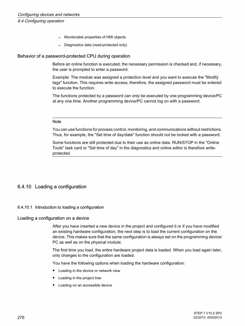
― Monitorable properties of HMI objects
― Diagnostics data (read-protected only)
Behavior of a password-protected CPU during operationBefore an online function is executed, the necessary permission is checked and, if necessary,the user is prompted to enter a password.
Example: The module was assigned a protection level and you want to execute the "Modifytags" function. This requires write access; therefore, the assigned password must be enteredto execute the function.
The functions protected by a password can only be executed by one programming device/PCat any one time. Another programming device/PC cannot log on with a password.
Note
You can use functions for process control, monitoring, and communications without restrictions.Thus, for example, the "Set time of day/date" function should not be locked with a password.
Some functions are still protected due to their use as online data. RUN/STOP in the "OnlineTools" task card or "Set time of day" in the diagnostics and online editor is therefore write-protected.
6.4.10 Loading a configuration
6.4.10.1 Introduction to loading a configuration
Loading a configuration on a deviceAfter you have inserted a new device in the project and configured it or if you have modifiedan existing hardware configuration, the next step is to load the current configuration on thedevice. This makes sure that the same configuration is always set on the programming device/PC as well as on the physical module.
The first time you load, the entire hardware project data is loaded. When you load again later,only changes to the configuration are loaded.
You have the following options when loading the hardware configuration:
• Loading in the device or network view
• Loading in the project tree
• Loading on an accessible device
6.4.10 Loading a configuration6.4.10.1 Introduction to loading a configuration
Configuring devices and networks6.4 Configuring operation
276STEP 7 V10.5 SP202/2010, 00002013

See alsoSpecial features during startup (Page 315)
6.4.10.2 Loading the hardware configuration on a device
Within the project tree, you can load the hardware configuration of a device on the relevantdevice.
WarningLoad only in STOP mode
After loading, you may experience unexpected behaviors on the machine or in the process ifthe parameter settings are incorrect. The CPU must be set to STOP mode for the load operationto rule out possible damage to equipment or personal injury.
Loading multiple blocks on a device in the project tree To load the hardware configuration on the relevant device, follow these steps:
1. Select the "Load to device > Hardware configuration" command in the shortcut menu of the device.
― If you have not previously established an online connection, the "Extended loading" dialog isopened.
― If you have already defined an online connection, the "Load preview" dialog opens. Continue thenwith step 4.
2. Select the interface for your PG/PC from the "Programming device/PC interface for loading process"drop-down list box in the "Extended loading" dialog.
3. Select your device in the "Accessible devices in the target subnet" table and confirm your selectionwith "OK".
The "Load preview" dialog opens.
4. Click "Load".
The hardware configuration is loaded and the "Load results" dialog opens. This dialog shows you thestatus and the actions after loading.
5. Close the "Load results" dialog with "OK".
ResultThe configured hardware configurations on the programming device/PC and on the device arenow identical.
The messages under "Info > General" in the inspector window report whether the loadingprocess was successful.
See alsoSpecial features during startup (Page 315)
6.4.10.2 Loading the hardware configuration on a device
Configuring devices and networks6.4 Configuring operation
STEP 7 V10.5 SP202/2010, 00002013
277

6.5 Diagnosing hardware
6.5.1 Overview of hardware diagnostics
6.5.1.1 Principal methods of hardware diagnostics
Principal methods of hardware diagnostics Hardware diagnostics can be performed as follows:
• Using the online and diagnostics view
• Using the "Online Tools" task card
• Using the "Diagnostics > Device Info" area of the Inspector window
• Using diagnostics symbols, for example, in the device view and the project tree
Structure of the online and diagnostics view The online and diagnostics view consists of two windows alongside each other:
• The left window shows a tree structure with folders and - when you open the folder - groups.
• The right window contains detailed information on the selected folder or selected group.
The "Online access" group and the "Diagnostics" and "Functions" folders are located here:
• "Online access" group: Displays whether or not there is currently an online connection with theassociated target. In addition, you can establish or disconnect the online connection.
• "Diagnostics": Contains several diagnostics groups for the selected module
• "Functions": Contains several groups, in which you can make settings for the selected module or issuecommands to the module
Function and structure of the "Online Tools" task card For modules with their own operating mode (such as CPUs), the "Online tools" task card allowsyou to read current diagnostics information and commands to the module.
If you selected a module without its own operating mode or if you selected several modulesbefore activation of the "Online Tools" task card, the task card relates to the relevant CPU.
The "Online Tools" task card consists of the following panes:
• CPU control panel
• Cycle time
• Memory
6.5 Diagnosing hardware6.5.1 Overview of hardware diagnostics6.5.1.1 Principal methods of hardware diagnostics
Configuring devices and networks6.5 Diagnosing hardware
278STEP 7 V10.5 SP202/2010, 00002013

Note
A pane is filled with content only if the module controls the associated functions and anonline connection exists.
If there is no online connection to the respective module, the display "No online connection"appears in blue.
Structure or the "Diagnostics" tab of the Inspector window The "Diagnostics" tab of the Inspector window itself consists of one tab:
• Device information
This tab relates to all CPUs of the project to which the online connection is established. Alarms arereported here if one or more CPUs are defective or are not in the RUN mode.
See alsoTask cards (Page 125)Inspector window (Page 123)
6.5.1.2 Determination of which of the devices that are connected online are defective
Overview of the defective devicesIn the "Diagnostics > Device Info" area of the Inspector window you will obtain an overview ofthe defective devices that are connected online.
The "Diagnostics> Device Info" area of the Inspector window consists of the following elements:
• Header line with the number of defective devices
• Table with detailed information on each defective device
If you originate the establishment of an online connection to a device which is not reachableor reports one or more faults or is not in RUN mode, it will rank as defective.
Structure of the table with detailed information on the defective devicesThe table consists of the following columns:
• Online status: Contains the online status as a diagnostic symbol and in words
• Operating mode: Contains the operating mode as a symbol and in words
• Device / module: Name of the affected device or the affected module
• Message: explains the preceding column
• Details: The link opens the online and diagnostics view for the device, and places it in the foreground.
• Help: The link supplies further information on the defect that has occurred.
See alsoInspector window (Page 123)Determination of online status and display using symbols (Page 280)
6.5.1.2 Determination of which of the devices that are connected online are defective
Configuring devices and networks6.5 Diagnosing hardware
STEP 7 V10.5 SP202/2010, 00002013
279

6.5.1.3 Determination of online status and display using symbols
Determination of online status and display using symbols When establishing the online connection with a device, the status and, if necessary, theoperating mode of the associated module are also identified and displayed.
The display is performed in these views:
• Device view
With the exception of the signal board on the CPU, the diagnostics icon is displayed here in everyhardware component. For modules with their own operating mode, the operating state icon is alsodisplayed.
• Device overview
The diagnostics icon is shown here for each hardware component.
• Network view
Here a diagnostic symbol is shown for each device, showing the collective status of all associatedhardware components.
• Network overview
The diagnostics icon is shown here for each hardware component.
• Project tree
Here the diagnostic symbol is shown behind the hardware components. For modules with their ownoperating mode, the operating state icon is also displayed in the top right corner of the module icon.
• Online and diagnostics view
The online status is displayed in the "Status" area of the "Online access" group. Here, you can alsoestablish and terminate the online connection.
Note
The "Online access" group exists only with CPUs. However, if you have called the onlineand diagnostics view with the "Show / update accessible devices" function, it will not bedisplayed.
• Detail view in the project tree
This step requires that you have selected "Local modules" in the project tree.
Diagnostics symbols for modules and devices The following table shows the available symbols and their respective meaning:
Symbol Meaning
The connection with a CPU is currently being established.
The CPU is not reachable at the set address.
6.5.1.3 Determination of online status and display using symbols
Configuring devices and networks6.5 Diagnosing hardware
280STEP 7 V10.5 SP202/2010, 00002013

Symbol Meaning
The configured CPU and the CPU actually present are of incompatible types.
No fault
Maintenance required
Maintenance request
Error
The module or the device cannot be reached from the CPU (valid for modules anddevices below a CPU).
Diagnostics data are not available because the current online configuration data differfrom the offline configuration data.
The configured module or device and the module or device actually present areincompatible (valid for modules or devices under a CPU).
The connection is established, but the state of the module has not yet beendetermined.
The configured module does not support display of the diagnostics status
Icons for the comparison status The diagnostics icons can be combined with additional smaller icons that indicate the result ofthe online/offline comparison. The following table shows the available symbols and theirmeaning.
Symbol Meaning
Folder contains objects whose online and offline versions differ (only in the projecttree)
Online and offline versions of the object are different
Object only exists online
Object only exists offline
Combined diagnostics and comparison iconsThe following table shows examples of combined icons and their meaning.
Symbol Meaning
No fault. Folder contains objects whose online and offline versions differ (only in theproject tree)
Configuring devices and networks6.5 Diagnosing hardware
STEP 7 V10.5 SP202/2010, 00002013
281

Symbol Meaning
The module or the device cannot be reached from the CPU (valid for modules anddevices below a CPU). Object only exists offline
Operating mode symbols for CPUs and CPs The following table shows the available symbols and their respective operating states.
Symbol Operating mode
RUN
STOP
STARTUP
HOLD
DEFECTIVE
Unknown operating mode
The configured module does not support display of the operating mode
6.5.1.4 Start online and diagnostics view
RequirementThe project with the module to be diagnosed is open.
Note
This requirement does not apply if you call the online and diagnostics view from the project treeafter you have identified the accessible devices.
ProcedureTo start the online and diagnostics view of a module, follow these steps:
1. In the project tree, open the respective device folder.
2. Double click on the "Online & Diagnostics" function.
6.5.1.4 Start online and diagnostics view
Configuring devices and networks6.5 Diagnosing hardware
282STEP 7 V10.5 SP202/2010, 00002013

Note
The "Online & Diagnostics" function is always available if the module in the project tree hassub-entries, for example in PLCs.
Or:
1. In the project tree, select the respective device folder.
2. Select the "Online & Diagnostics" command in the shortcut menu or the "Online" main menu.
Or:
1. Open the device view in the device configuration.
2. Select the module to be diagnosed.
3. Select the "Online & Diagnostics" command in the shortcut menu or the "Online" main menu.
Or:
1. Open the network view in the device configuration.
2. Select the station with the module to be diagnosed.
3. Select the "Online & Diagnostics" command in the shortcut menu or the "Online" main menu.
Or:
1. In the project tree, open the "Online access" folder.
2. Open the folder for the interface with which you want to establish the online connection.
3. Double click on "Show/Update accessible devices".
4. Select the module to be diagnosed.
5. Select the "Online & Diagnostics" command from the shortcut menu or the "Online" main menu.
Or:
1. In the project tree, open the "Local modules" folder.
2. Select the respective device or the module that is to be diagnosed.
3. Select the "Online & Diagnostics" command in the shortcut menu or the main menu.
ResultThe online and diagnostics view of the module to be diagnosed will be started. If an onlineconnection to the associated CPU had previously been created, the header bar of the Onlineand Diagnostics view will now have an orange background.
Note
If no online connection exists when the online and diagnostics view is started, no onlineinformation is displayed and the display fields remain empty.
Configuring devices and networks6.5 Diagnosing hardware
STEP 7 V10.5 SP202/2010, 00002013
283

6.5.1.5 Activation of the "Online Tools" task card
Activation of the "Online Tools" task card You can activate this task card as follows:
1. Start the online and diagnostics view.
2. Click on the "Online Tools" task card.
Or:
1. Start the device view.
2. Click on the "Online Tools" task card.
Or:
1. Start the network view.
2. Click on the "Online Tools" task card.
6.5.2 Showing non-editable and current values of configurable module properties
6.5.2.1 Showing general properties and system-relevant information for a module
Where do I find the information I need?The general properties and system-relevant information for a module can be found in the"General" group in the "Diagnostics" folder in the online and diagnostics view of the module tobe diagnosed.
Structure of the "General" groupThe "General" group consists of the following areas:
• Module
• Module information
• Manufacturer information
"Module" areaThis area shows the following data for the module:
• Short designation, for example, CPU 1214C DC/DC/DC
• Order number
• Hardware
• Firmware
• Racks
• Slot
6.5.1.5 Activation of the "Online Tools" task card6.5.2 Showing non-editable and current values of configurable module properties6.5.2.1 Showing general properties and system-relevant information for a module
Configuring devices and networks6.5 Diagnosing hardware
284STEP 7 V10.5 SP202/2010, 00002013

"Module information" areaThis area shows the following module specifications that you specified during the hardwareconfiguration:
• Module name
"Manufacturer information" areaThis area shows the following data for the module:
• Manufacturer
Note
With the exception of Siemens AG, the manufacturer's code is shown as a decimal number.The associated manufacturer names can be found in the Manufacturer ID table inPROFIBUS International (see "www.profibus.com").
• Serial number
• Profile: Profile ID as hexadecimal number
Note
You will find the corresponding profile name in the profile ID table for PROFIBUSInternational (see "www.profibus.com").
• Profile details: Profile-specific type as hexadecimal number
Note
You will find the corresponding profile-specific type name in the profile-specific type tablefor PROFIBUS International (see "www.profibus.com").
6.5.2.2 Display configured cycle times
Where do I find the information I need? The required information can be found in the following places:
• In the "Cycle time" group in the "Diagnostics" folder of the online and diagnostics view of the moduleto be diagnosed (this is where all the assigned cycle times are displayed).
• In the "Online Tools" task card of the "Cycle time" pane (only the maximum cycle time of the configuredcycle times is shown here).
Structure of the "Cycle time" group in the "Diagnostics" folder of the online and diagnostics viewThe "Cycle time" group consists of the following areas:
6.5.2.2 Display configured cycle times
Configuring devices and networks6.5 Diagnosing hardware
STEP 7 V10.5 SP202/2010, 00002013
285

• Cycle time diagram (graphic display of the measured cycle times)
• Cycle time configured (display of the configured cycle times as absolute values)
• Cycle times measured (display of the measured cycle times as absolute values)
Parameterized cycle timesThe following configured times are displayed:
• Minimum cycle time
• Maximum cycle time
Structure of the "Cycle time" pane of the "Online Tools" task cardThe "Cycle time" pane provides information regarding the configured maximum cycle time andthe measured cycle times.
Maximum cycle timeThe value at the end of the time diagram represents the maximum cycle time.
6.5.3 Showing the current values of dynamic modules properties
6.5.3.1 Display measured cycle times
Where do I find the information I need?The measured cycle times can be found at each of the following places:
• In the "Cycle time" group in the "Diagnostics" folder in the online and diagnostics view of the moduleto be diagnosed.
• In the "Cycle time" pane of the "Online Tools" task card
Structure of the "Cycle time" group in the "Diagnostics" folder of the online and diagnostics viewThe "Cycle time" group consists of the following areas:
• Cycle time diagram (graphic display of the measured cycle times)
• Cycle time configured (display of the configured cycle times as absolute values)
• Cycle times measured (display of the measured cycle times as absolute values)
Measured cycle timesThe following times are displayed:
• Shortest cycle time: Duration of the shortest cycle since the last transition from STOP to RUN
This is shown in the graphic display by the black arrow.
• Current / last cycle time: Duration of the last cycle
6.5.3 Showing the current values of dynamic modules properties6.5.3.1 Display measured cycle times
Configuring devices and networks6.5 Diagnosing hardware
286STEP 7 V10.5 SP202/2010, 00002013

This is shown in the graphic display by the green arrow.
If the duration of the last cycle comes close to the maximum cycle time this indicates the possibilitythat this may be exceeded and the module may switch to the STOP operating mode. If for instanceyou are monitoring the tags in your program, this will increase the cycle time.
• Longest cycle time: Duration of the longest cycle since the last transition from STOP to RUN.
This is shown in the graphic display by the blue arrow.
NoteGraphic display
The time axis is limited by the parameterized limit values for the cycle time.
Arrows and bars shown in red denote times that lie outside the parameterized limit values.
Structure of the "Cycle time" pane of the "Online Tools" task cardThe "Cycle time" pane provides information regarding the configured maximum cycle time andthe measured cycle times.
Measured timesThe following measured times are shown:
• Shortest cycle time since the last activation of the "Online Tools" task card shown in gray.
• Current/last cycle time shown in green.
• Longest cycle time since the last activation of the "Online Tools" task card shown in blue.
6.5.3.2 Showing the current status of the LEDs of a CPU
Where do I find the information I need?The current status of the LEDs of a CPU can be found in the display area of the "CPU controlpanel" pane of the "Online tools" task card.
Display area of the "CPU control panel" pane of the "Online Tools" task card This area contains the following displays:
• Station name and CPU type (short designation)
• RUN / STOP (corresponds to the "RUN / STOP" LED of the CPU)
• ERROR (corresponds to the "ERROR" LED on the CPU)
• MAINT (corresponds to the "MAINT" LED on the CPU)
6.5.3.2 Showing the current status of the LEDs of a CPU
Configuring devices and networks6.5 Diagnosing hardware
STEP 7 V10.5 SP202/2010, 00002013
287

6.5.3.3 Showing fill levels of all types of memory on a CPU
Where do I find the information I need? The fill levels of all types of memory on a CPU can be found on the following two pages:
• In the display area of the "Memory" group in the "Diagnostics" folder in the online and diagnostics viewof the module to be diagnosed.
• In the "Memory" pane display area of the "Online Tools" task card
Display area of the "Memory" group in the "Diagnostics" folder of the online and diagnostics viewThis area contains the current memory utilization of the respective module and details of theindividual memory areas.
The memory utilization is shown both as a bar diagram and as a numerical value (percentage).
The following memory utilizations are shown:
• Load memory
If no memory card is inserted, the internal load memory is displayed.
If a memory card is inserted, the operating system only uses the inserted load memory as the loadmemory. This is displayed here.
• Work memory
• Retentive memory
Display area of the "Memory" pane of the "Online Tools" task cardThis area contains the current memory utilization of the module. The available memory is shownboth as a bar diagram and as a numerical value (percentage). The numerical value is roundedto an integer value.
Note
If a memory area is utilized to less than 1%, the available portion of this memory area is shownas "99%".
The following memory utilizations are shown:
• Load memory
If no memory card is inserted, the internal load memory is displayed.
If a memory card is inserted, the operating system only uses the inserted load memory as the loadmemory. This is displayed here.
• Work memory
• Retentive memory
6.5.3.3 Showing fill levels of all types of memory on a CPU
Configuring devices and networks6.5 Diagnosing hardware
288STEP 7 V10.5 SP202/2010, 00002013

See alsoLoad memory (Page 317)Work memory (Page 317)Retentive memory areas (Page 319)
6.5.4 Checking a module for defects
6.5.4.1 Determining the diagnostic status of a module
Where is the diagnostic status of a module displayed? The diagnostic status of a module is displayed in the "Diagnostic status" group in the"Diagnostics" folder in the online and diagnostics view of the module to be diagnosed.
"Diagnostic status" groupThe following status information is displayed in the "Diagnostic status" group:
• Status of the module as viewed by the CPU, for example:
― Module available and OK.
― Module defective.
If the module experiences a fault and you have enabled the diagnostic interrupt duringconfiguration, the "Module defective" status is displayed.
― Module configured, but not available.
• Detected differences between the configured and the inserted module. Provided it can be ascertained,the order number will be displayed for the set and actual type.
Scope of the displayed informationThe scope of the displayed information depends on the selected module.
6.5.4.2 Reading out the diagnostics buffer of a CPU
Where do you read out the diagnostics buffer of a CPU? You read out the diagnostics buffer of a CPU in the "Diagnostics buffer" group in the"Diagnostics" folder in the online and diagnostics view.
Structure of the "Diagnostics buffer" groupThe "Diagnostics buffer" group consists of the "Events" tab.
6.5.4 Checking a module for defects6.5.4.1 Determining the diagnostic status of a module6.5.4.2 Reading out the diagnostics buffer of a CPU
Configuring devices and networks6.5 Diagnosing hardware
STEP 7 V10.5 SP202/2010, 00002013
289

Diagnostics bufferThe diagnostics buffer is used as a log file for the diagnostics events that occurred on the CPUand the modules assigned to it. These are entered in the order of their occurrence, with thelatest event shown at the top.
"Events" tabThe "Events" tab consists of the following elements:
• "Time including CPU/local time difference" check box
• Events list
• Details of the event
• "Freeze view/Cancel freeze", "Help on event", "Open block", "Save as..." buttons.
"Time including CPU/local time difference" check boxIf you have not activated the check box, the diagnostics buffer entries are shown with themodule time.
If you have activated the check box, the diagnostics buffer entries are shown with the time givenby the following formula:
Displayed time = module time + time zone offset on your programming device / PC
This requires the module time to be identical to UTC.
You should use this setting if you wish to see the times of the diagnostics buffer entries for themodule expressed in the local time of your programming device / PC.
Selecting or clearing the check box immediately changes the times displayed for thediagnostics buffer entries.
Note
If you use the "WR_SYS_T" instruction in your program or if you set the real-time clock of theCPU using an HMI device instead of using UTC, we recommend that you clear the "Real-timeincl. CPU/local time difference" check box. In this case, the module time is the sole time ofconcern.
Events listThe following information is listed for each diagnostic event:
• Sequential number of the entry
The first entry contains the latest event.
• Date and time of the diagnostic event
If no date and time are shown, the module has no integral clock.
• Short name of the event and, if applicable, the reaction of the CPU
Configuring devices and networks6.5 Diagnosing hardware
290STEP 7 V10.5 SP202/2010, 00002013

Note
If an individual parameter of a text cannot be determined, the character string "###" is shownin its place.
If no display text is yet available for new modules or new events, the numbers of the eventsand the individual parameters are stated as hexadecimal values.
Details of the eventIf you select a line in the list you will obtain a detailed description of the respective event:
• Event ID and designation of the event
• Addition information related to the event, such as the address of the command that caused the event,and the operating mode transition that was caused by the diagnostic event
• Incoming or outgoing event
"Freeze view" or "Cancel view"The "Freeze view" or "Cancel freeze" button is only enabled when there is an online connectionto the CPU.
The default setting is "Freeze view".
The following happens if you click the "Freeze view" button:
• The current display of the diagnostics buffer entries is frozen.
• The labeling of the button changes to "Cancel freeze".
If an error has occurred in your system, diagnostic events can occur very quickly in succession.This produces a high update rate on the display. Freezing the display allows you to calmlyexamine the situation in more detail.
If the display is frozen and you click the "Cancel freeze" button, the following happens:
• The display of the diagnostics buffer entries is updated again.
• The labeling of the button changes to "Freeze view".
Note
If you freeze the diagnostics buffer display, the CPU continues to enter events in the diagnosticsbuffer.
"Help on event" buttonIf you click on this button, the selected event is explained in more detail and any remediesgiven.
Configuring devices and networks6.5 Diagnosing hardware
STEP 7 V10.5 SP202/2010, 00002013
291

Note
If the selected event is not a CPU event, the "Help on event" button is unavailable.
"Open block" buttonThe "Open block" button can be selected only if there is a pointer to the relative address of ablock in the diagnostic event. This is the address of the command that caused the event.
The "Open block" function opens the referenced block in the offline view at the programminginstruction that causes the error. This allows you to check and, if necessary, change the sourcecode of the block at the specified place and then download it again to the CPU.
"Save as ..." buttonIf you click this button, the content of the diagnostics buffer is saved in a text file. "Diagnose.txt"is proposed as the file name. You can however change this name.
See alsoBasic information on the diagnostics buffer (Page 296)
6.5.4.3 Performing module-specific diagnostics of non-CPU modules
Where are the module-specific diagnostics of non-CPU modules displayed? The module-specific diagnostics of non-CPU modules are displayed in the "Standarddiagnostics" group in the online and diagnostics view.
"Standard diagnostics" groupThe following diagnostics information for non-CPU modules is displayed in the "Standarddiagnostics" group:
• Internal and external defects which relate to the overall module
• Associated diagnostics events
Examples of such diagnostic information are:
• Entire backup supply failed
• Module defective
6.5.4.3 Performing module-specific diagnostics of non-CPU modules
Configuring devices and networks6.5 Diagnosing hardware
292STEP 7 V10.5 SP202/2010, 00002013

NoteDiagnostic interrupts
A diagnostics interrupt can be reported to the CPU only if the module is diagnostics interrupt-capable and the diagnostics interrupt has been enabled.
The display of the diagnostics interrupt is a snapshot. Sporadic defects in a module can berecognized diagnostics buffer of the respective CPU.
6.5.5 Changing the properties of a module or the programming device / PC
6.5.5.1 Changing the mode of a CPU
RequirementThere is an online connection to the CPU whose mode you want to change.
ProcedureTo change the mode of the CPU, follow these steps:
1. Enable the "Online tools" task card of the CPU.
2. Click the "RUN" button in the "CPU control panel" pane if you want to change the CPU to RUN modeor the "STOP" button if you want to change the CPU to STOP mode.
Note
The only button active is the one that can be selected in the current operating mode of theCPU.
3. Answer the prompt for confirmation with "OK".
ResultThe CPU is changed to the required mode.
6.5.5.2 Performing a memory reset
Requirement
• There is an online connection to the CPU on which the memory reset is to be performed.
• The CPU is in STOP mode.
6.5.5 Changing the properties of a module or the programming device / PC6.5.5.1 Changing the mode of a CPU6.5.5.2 Performing a memory reset
Configuring devices and networks6.5 Diagnosing hardware
STEP 7 V10.5 SP202/2010, 00002013
293

Note
If the CPU is still in RUN mode and you start the memory reset, you can place it in STOPmode after acknowledging a confirmation prompt.
ProcedureTo perform a memory reset on a CPU, follow these steps:
1. Enable the "Online Tools" task card of the CPU.
2. Click the "MRES" button in the "CPU control panel" pane.
3. Acknowledge the confirmation prompt with "OK".
ResultThe CPU is switched to STOP mode, if necessary, and the memory reset is performed on theCPU.
See alsoBasics of a memory reset (Page 316)
6.5.5.3 Determining and setting the time of day on a CPU
Where do I find the functions I need? You determine and change the time of day on a CPU in the "Set time of day" group in the"Functions" folder of the online and diagnostics view. This requires an online connection.
Structure of the "Set time of day" groupThe "Set time of day" group consists of the following areas:
• Programming device / PC time
Here the time zone setting, the current date and the current time setting of your programming device /PC are displayed.
• Module time
Here the date and time values currently read from the module (for example the CPU), are convertedto local time and date and displayed.
If the "Take from PG/PC" check box is selected, when you click the "Apply" button, the date and thePG/PC time converted to UTC are transferred to the module.
If the "Take from PG/PC" check box is not selected, you can assign the date and time for the integratedclock of the module. After clicking the "Apply" button, the date and the time recalculated to UTC timeare transferred to the module.
6.5.5.3 Determining and setting the time of day on a CPU
Configuring devices and networks6.5 Diagnosing hardware
294STEP 7 V10.5 SP202/2010, 00002013

6.5.5.4 Configuring Ethernet devices
Overview You can assign an IP address and IP parameters to a module for the first time.
The IP address thus established can then be used to reach the module, for instance to loadconfiguration data or to perform diagnostics.
Requirement
• The Ethernet LAN connection must already be established.
• The Ethernet interface of your programming device or PC must be located in the same IP range asthe module to be configured.
• The module must be in the same subnet as the programming device or PC.
ProcedureTo configure the module as an Ethernet device, follow these steps:
1. Open the online and diagnostics view of the module.
2. Select the "Assign IP address" group from the "Functions" folder.
3. Enter the MAC address if you know it.
4. Enter the IP address.
5. Enter the subnet mask.
6. If a router is to be used, select the "Use router" check box and enter its IP address.
7. Click "Assign IP address".
ResultThe IP configuration is assigned to the module.
6.5.5.5 Resetting a CPU to the factory settings
Requirement
• There is no memory card inserted in the CPU.
• There is an online connection to the CPU that you want to reset to the factory settings.
• The CPU is in STOP mode.
Note
If the CPU is still in RUN mode and you start the reset operation, you can place it in STOPmode after acknowledging a confirmation prompt.
6.5.5.4 Configuring Ethernet devices6.5.5.5 Resetting a CPU to the factory settings
Configuring devices and networks6.5 Diagnosing hardware
STEP 7 V10.5 SP202/2010, 00002013
295

ProcedureTo reset a CPU to the factory settings, follow these steps:
1. Open the online and diagnostics view of the CPU.
2. Select the "Reset to factory settings" group from the "Functions" folder.
3. Select the "Retain IP address" check box if you want to retain the IP address or the "Delete IP address"if you want to delete the IP address.
4. Click the "Reset" button.
5. Acknowledge the confirmation prompt with "OK".
ResultThe module is switched to STOP mode, if necessary, and the factory settings are then reset.This means:
• The work memory and the internal load memory and all operand areas are deleted.
• All parameters are reset to their defaults.
• The diagnostics buffer is cleared.
• The time of day is reset.
• The IP address is retained or deleted depending on the setting you make.
6.5.6 Diagnostics in STOP mode
6.5.6.1 Basic information on the diagnostics buffer
Function The operating system of the CPU enters the errors detected by the CPU and the diagnostics-capable modules into the diagnostics buffer in the order in which they occurred. This includesthe following events:
• Every mode change of the CPU (POWER UP, change to STOP mode, change to RUN mode)
• Every hardware and diagnostic error interrupt
The top entry contains the most recent event. The entries in the diagnostics buffer are storedpermanently. They are retained even if the power supply fails and can only be deleted byresetting the CPU to factory settings.
A diagnostics buffer entry contains the following elements:
• Time stamp
• Error ID
• Additional information specific to the error ID
6.5.6 Diagnostics in STOP mode6.5.6.1 Basic information on the diagnostics buffer
Configuring devices and networks6.5 Diagnosing hardware
296STEP 7 V10.5 SP202/2010, 00002013

Advantages of the diagnostics bufferThe diagnostics buffer offers the following advantages:
• After the CPU has changed to STOP mode, you can evaluate the last events prior to the STOP sothat you can locate and identify the cause of the STOP.
• You can detect and eliminate the causes of errors more quickly and thus increase the availability ofthe system.
• You can evaluate and optimize the dynamic system response.
Organization of the diagnostics bufferThe diagnostics buffer is a ring buffer. The maximum number of entries for the S7-1200 CPUsis 50. When the diagnostics buffer is full and a further entry needs to be made, all existingentries are shifted by one position (which means that the oldest entry is deleted) and the newentry is made at the top position that is now free (FIFO principle: first in, first out).Evaluation of the diagnostics buffer
The contents of the diagnostics buffer can be accessed as follows:
• Using the online and diagnostics view
The evaluation of events occurring prior to the error event (e.g., transition to STOP mode)allows you to obtain a picture of the possible causes or to zero in more closely or specify inmore detail the possible causes (depending on the error type).
Read the detailed information about the events carefully and use the "Help on event" button toobtain additional information and possible causes of individual entries.
Note
To make the best use of the time stamp information on the diagnostics buffer entries in time-critical systems, it is advisable to check and correct the date and time of day on the CPUoccasionally.
Alternatively, it is possible to perform a time-of-day synchronization using an NTP time server.
See alsoResetting a CPU to the factory settings (Page 295)Determining the cause of a STOP of a CPU (Page 297)Determining and setting the time of day on a CPU (Page 294)Parameterizing the clock (Page 260)
6.5.6.2 Determining the cause of a STOP of a CPU
RequirementThe CPU you want to analyze is in STOP mode.
6.5.6.2 Determining the cause of a STOP of a CPU
Configuring devices and networks6.5 Diagnosing hardware
STEP 7 V10.5 SP202/2010, 00002013
297

ProcedureTo find out the reason why a CPU changed to STOP, follow these steps:
1. Open the online and diagnostics view of the CPU.
2. Select the "Diagnostics buffer" group from the "Diagnostics" folder.
3. Evaluate the events occurring prior to the transition to STOP mode. Use this to obtain a picture of thepossible causes or to zero in on or specify in more detail the possible causes (depending on the errortype).
Read the detailed information about the events carefully and use the "Help on event" button to obtainadditional information and possible causes of individual entries.
ResultYou were able to zero in on or determine in more detail the cause of the CPU STOP.
Note
If the analysis does not enable you to overcome the problem, contact Customer Support. Inthis case, use the "Save as" button to back up the content of the diagnostics data to a text fileand submit it to Customer Support.
See alsoReading out the diagnostics buffer of a CPU (Page 289)
6.6 References
6.6.1 Creating an unspecified CPU
IntroductionIf you have not yet selected a CPU but have already started programming or want to use anexisting program, you have the option of using an unspecified CPU.
Creating an unspecified CPUTo create an unspecified CPU, follow these steps:
1. Go to the portal view.
2. Click "Start > Getting started"
3. Click "Create a PLC program"
An unspecified CPU is created.
6.6 References6.6.1 Creating an unspecified CPU
Configuring devices and networks6.6 References
298STEP 7 V10.5 SP202/2010, 00002013

Or
1. Go to the portal view.
2. Now, click one of the following options:
― "Devices & networks > Add new device"
― "PLC programming" > "Device" button
3. Select the unspecified CPU from the tree structure of the "Add new device" dialog.
4. Click OK.
An unspecified CPU is created.
Further options for creating unspecified CPUsIn the project view, you can create unspecified CPUs as well as specified CPUs:
• Using the "Create new device" button in the project navigator
• In the "Hardware catalog" task card
You can also use these methods to create multiple unspecified CPUs.
Specifying unspecified CPUsYou have two options for specifying unspecified CPUs:
• Use drag-and-drop to assign an existing CPU from the hardware catalog to an unspecified CPU bymeans of module replacement (Page 217) .
• Select an unspecified CPU, and then click "Online > Hardware detection" in the menu bar and assigna CPU identified online. For this purpose, you assign an IP address using the "Add address for PG/PC" button.
See alsoSelecting a CPU (Page 247)Adding a device to the hardware configuration (Page 210)
6.6.2 Open User Communication
6.6.2.1 Principle of operation of connection-oriented protocols
IntroductionConnection-oriented protocols establish a logical connection to the communication partnerbefore data transmission is started. After the data transmission is complete, they then terminatethe connection, if necessary. In particular, connection-oriented protocols are used for datatransmission when reliable, guaranteed delivery is of importance. Several logical connectionscan exist over one physical line.
Open User Communication supports the following connection types:
6.6.2 Open User Communication6.6.2.1 Principle of operation of connection-oriented protocols
Configuring devices and networks6.6 References
STEP 7 V10.5 SP202/2010, 00002013
299
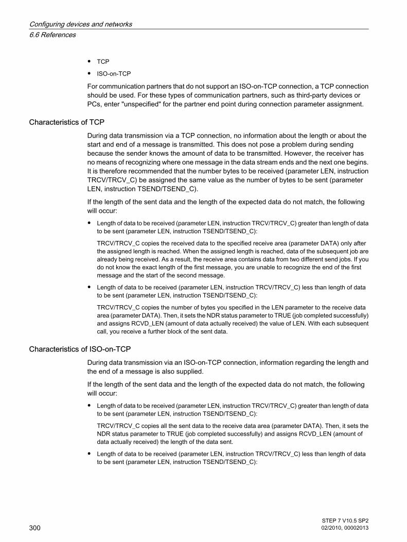
• TCP
• ISO-on-TCP
For communication partners that do not support an ISO-on-TCP connection, a TCP connectionshould be used. For these types of communication partners, such as third-party devices orPCs, enter "unspecified" for the partner end point during connection parameter assignment.
Characteristics of TCPDuring data transmission via a TCP connection, no information about the length or about thestart and end of a message is transmitted. This does not pose a problem during sendingbecause the sender knows the amount of data to be transmitted. However, the receiver hasno means of recognizing where one message in the data stream ends and the next one begins.It is therefore recommended that the number bytes to be received (parameter LEN, instructionTRCV/TRCV_C) be assigned the same value as the number of bytes to be sent (parameterLEN, instruction TSEND/TSEND_C).
If the length of the sent data and the length of the expected data do not match, the followingwill occur:
• Length of data to be received (parameter LEN, instruction TRCV/TRCV_C) greater than length of datato be sent (parameter LEN, instruction TSEND/TSEND_C):
TRCV/TRCV_C copies the received data to the specified receive area (parameter DATA) only afterthe assigned length is reached. When the assigned length is reached, data of the subsequent job arealready being received. As a result, the receive area contains data from two different send jobs. If youdo not know the exact length of the first message, you are unable to recognize the end of the firstmessage and the start of the second message.
• Length of data to be received (parameter LEN, instruction TRCV/TRCV_C) less than length of datato be sent (parameter LEN, instruction TSEND/TSEND_C):
TRCV/TRCV_C copies the number of bytes you specified in the LEN parameter to the receive dataarea (parameter DATA). Then, it sets the NDR status parameter to TRUE (job completed successfully)and assigns RCVD_LEN (amount of data actually received) the value of LEN. With each subsequentcall, you receive a further block of the sent data.
Characteristics of ISO-on-TCPDuring data transmission via an ISO-on-TCP connection, information regarding the length andthe end of a message is also supplied.
If the length of the sent data and the length of the expected data do not match, the followingwill occur:
• Length of data to be received (parameter LEN, instruction TRCV/TRCV_C) greater than length of datato be sent (parameter LEN, instruction TSEND/TSEND_C):
TRCV/TRCV_C copies all the sent data to the receive data area (parameter DATA). Then, it sets theNDR status parameter to TRUE (job completed successfully) and assigns RCVD_LEN (amount ofdata actually received) the length of the data sent.
• Length of data to be received (parameter LEN, instruction TRCV/TRCV_C) less than length of datato be sent (parameter LEN, instruction TSEND/TSEND_C):
Configuring devices and networks6.6 References
300STEP 7 V10.5 SP202/2010, 00002013

TRCV/TRCV_C does not copy any data to the receive data area (parameter DATA), but insteadsupplies the following error information: ERROR=1, STATUS=W#16#8088 (destination buffer toosmall).
See alsoBasics of Open User Communication (Page 230)TSEND_C (Page 958)TRCV_C (Page 961)TSEND (Page 970)TRCV (Page 972)
6.6.2.2 Parameters of communication connections
Data block for connection description A connection description DB with a structure according to TCON_Param is used to assign thecommunication connection parameters for TCP and ISO-on-TCP. The fixed data structure ofthe TCON_Param contains all the parameters that are needed to establish the connection. Theconnection description DB is automatically created for a new connection by the connectionparameter assignment for Open User Communication when the TSEND_C, TRCV_C, or TCONinstruction is used.
The CONNECT connection parameter of the instance DBs for TSEND_C, TRCV_C, or TCONcontains a reference to the utilized data block.
Structure of the connection description according to TCON_Param
Byte Parameter Data type Initial value Description
0 … 1 block_length UINT 64 Length: 64 bytes (fixed)
2 … 3 id CONN_OUC 1 Reference to this connection (range of values: 1 to 4095).You specify the value of this parameter for the TSEND_C,TRCV_C, or TCON instruction under ID.
4 connection_type USINT 17 Connection type:
• 17: TCP
• 18: ISO-on-TCP
5 active_est BOOL TRUE ID for the manner in which the connection is established:
• FALSE: Passive connection establishment
• TRUE: Active connection establishment
6 local_device_id USINT 2 ID for the local PN/IE interface.
6.6.2.2 Parameters of communication connections
Configuring devices and networks6.6 References
STEP 7 V10.5 SP202/2010, 00002013
301

Byte Parameter Data type Initial value Description
7 local_tsap_id_len USINT 0 Length of parameter local_tsap_id used, in bytes; possiblevalues:
• 0 or 2, if connection type = 17 (TCP)Only the value 0 is permissible for the active side.
• 2 to 16, if connection type = 18 (ISO-on-TCP)
8 rem_subnet_id_len USINT 0 This parameter is not used.
9 rem_staddr_len USINT 4 Length of address of partner end point, in bytes:
• 0: unspecified, i.e., parameter rem_staddr is irrelevant.
• 4: Valid IP address in parameter rem_staddr
10 rem_tsap_id_len USINT 2 Length of parameter rem_tsap_id used, in bytes; possiblevalues:
• 0 or 2, if connection type = 17 (TCP)Only the value 0 is permissible for the passive side.
• 2 to 16, if connection type = 18 (ISO-on-TCP)
11 next_staddr_len USINT 0 This parameter is not used.
12 …27
local_tsap_id ARRAY[1..16] ofBYTE
- Local address component of connection:
• 17 (TCP): local port no. (possible values: 1 to 49151;recommended values: 2000...5000);local_tsap_id[1] = high byte of port no. in hexadecimalnotation;local_tsap_id[2] = low byte of port no. in hexadecimalnotation;local_tsap_id[3-16] = irrelevant
• 18 (ISO-on-TCP): local TSAP-ID:local_tsap_id[1] = B#16#E0;local_tsap_id[2] = rack and slot of local end points (bits 0to 4: slot number, bits 5 to 7: rack number);
local_tsap_id[3-16] = TSAP extension, optionalNote: Make sure that every value of local_tsap_id is uniquewithin the CPU.
28 …33
rem_subnet_id ARRAY [1..6]of USINT
- This parameter is not used.
34 …39
rem_staddr ARRAY [1..6]of USINT
- IP address of the partner end point, e.g. for 192.168.002.003:rem_staddr[1] = 192 rem_staddr[2] = 168 rem_staddr[3] = 002 rem_staddr[4] = 003 rem_staddr[5-6]= irrelevant
Configuring devices and networks6.6 References
302STEP 7 V10.5 SP202/2010, 00002013

Byte Parameter Data type Initial value Description
40 …55
rem_tsap_id ARRAY[1..16] ofBYTE
- Partner address component of connection
• 17 (TCP): partner port no. (possible values: 1 to 49151;recommended values: 2000...5000); rem_tsap_id[1] = high byte of the port no. in hexadecimalnotation; rem_tsap_id[2] = low byte of the port no. in hexadecimalnotation;
rem_tsap_id[3-16] = irrelevant
• 18 (ISO-on-TCP): partner TSAP-ID: rem_tsap_id[1] = B#16#E0; rem_tsap_id[2] = rack and slot of partner end point (bits 0to 4: slot number, bits 5 to 7: rack number); rem_tsap_id[3-16] = TSAP extension, optional
56 …61
next_staddr ARRAY [1..6]of BYTE
- This parameter is not used.
62 …63
spare WORD W#16#0000 Reserved.
See alsoPrinciple of operation of connection-oriented protocols (Page 299)Description of the connection parameters (Page 233)Ability to read back connection description parameters (Page 304)Basic principles for programming of data blocks (Page 510)Overview of connection parameter assignment (Page 231)
6.6.2.3 Assignment of port numbers
IntroductionWhen an Open User Communication is created, the value 2000 is automatically assigned asthe port number.
Permissible values for port numbers are 1 to 49151. You can assign any port number withinthis range. However, because some ports may already be used depending on the system, portnumbers within the range from 2000 to 5000 are recommended.
Overview of port numbers The following table summarizes the system reactions to various port numbers.
6.6.2.3 Assignment of port numbers
Configuring devices and networks6.6 References
STEP 7 V10.5 SP202/2010, 00002013
303

Port no. Description System reaction
2000 … 5000 Recommended range No warning, no error message on entryPort number is permitted and accepted
1 … 1999, 5001 … 49151 Can be used, but is outside therecommended range
Warning message on entryPort number is permitted and accepted
20, 21, 25, 80, 102, 135, 161, 34962 …34964
Can be used conditionally*
53, 80, 102, 135, 161, 162, 443, 520,9001, 34962 … 34964
Can be used conditionally**
* These ports are used by TSEND_C and TRCV_C with the TCP connection type.
** These ports are blocked depending on the function scope of the utilized S7-1200 CPU. Thedocumentation of the respective CPUs provides the assignment of these ports.
See alsoDescription of the connection parameters (Page 233)Creating and assigning parameters to connections (Page 235)
6.6.2.4 Ability to read back connection description parameters
Changing parameter values in the connection description The connection description for exactly one connection of the Open User Communication isentered from the connection parameter assignment in the connection description DB.
You can change the parameter values of the connection description DB outside of theconnection parameter assignment in the user program. The structure of the connectiondescription cannot be changed.
Connection description DBs containing values you changed subsequently can be read backfrom the connection parameter assignment. Under "Properties > Configuration > Connectionparameters", the Inspector window displays only the connection parameters stored in theconnection description DB.
The connection parameter assignment does not support nested entries of connectiondescriptions in DB types that can only be found via offset referencing (e.g., Global-DB).
Ability to read back individual connection parameters For the "Address" parameter of the communication partner, its IP address from the"rem_staddr" parameter of the connection description is displayed.
The following values can also be reloaded from the connection description:
• Connection type
• Local connection ID:
6.6.2.4 Ability to read back connection description parameters
Configuring devices and networks6.6 References
304STEP 7 V10.5 SP202/2010, 00002013

• Connection establishment (active/passive)
• Local TSAP (ISO-on-TCP only)
• Partner TSAP (ISO-on-TCP only)
• Local port (TCP only)
• Partner port (TCP only)
The values of the connection ID parameters of the communication partner, the connection data,as well as the connection establishment, are not included in the connection description in thelocal connection description DB. Consequently, these parameters cannot be displayed whenthe connection parameter assignment is reopened. The connection establishment of thepartner results from the local connection establishment and is therefore also displayed.
A new communication partner can be selected at any time in the "Partners" drop-down list box.
When a CPU recognized in the project is selected as a specified communication partner, theentry options for the connection ID and the connection data are shown again.
See alsoParameters of communication connections (Page 301)Description of the connection parameters (Page 233)
6.6.2.5 TSAP structure
Introduction For an ISO-on-TCP connection, Transport Service Access Points (TSAPs) must be assignedfor both communication partners. TSAP IDs are assigned automatically after an ISO-on-TCPconnection is created. To ensure the uniqueness of TSAP IDs within a device, you can changethe preassigned TSAPs in the connection parameter assignment.
Structure of TSAPs You must comply with certain rules when assigning TSAPs. A TSAP must contain a certainnumber of bytes, which are able to be displayed and entered as hexadecimal values (TSAP-ID) or as ASCII characters (ASCII-TSAP):
Entries or changes of the TSAP-ID or the ASCII-TSAP in the corresponding entry fields alwaystake effect in the other display format as well.
If a TSAP contains no valid ASCII characters, the TSAP is displayed only as TSAP-ID and notas ASCII-TSAP. This is the case after a connection is created. The first two hex characters as
6.6.2.5 TSAP structure
Configuring devices and networks6.6 References
STEP 7 V10.5 SP202/2010, 00002013
305

TSAP-ID identify the communication type and the rack/slot. Because these characters are notvalid ASCII characters for a CPU, the ASCII-TSAP is not displayed in this case.
In addition to the rules for length and structure of TSAPs, you must also ensure the uniquenessof the TSAP-ID. The assigned TSAPs are not automatically unique.
Length and content of TSAPsA TSAP is structured as follows:
• TSAP-ID with TSAP extension
Length = 2 to 16 bytes
x_tsap_id[0] = 0xE0 (Open User Communication)
x_tsap_id[1] (bits 0 to 4) = slot number of CPU
x_tsap_id[1] (bits 5 to 7) = rack number of CPU
x_tsap_id[2...15] = any characters (TSAP extension, optional)
(x = loc (local) or x = rem (partner))
• TSAP-ID as ASCII-TSAP
Length = 3 to 16 bytes
x_tsap_id[0 to 2] = 3 ASCII characters (0x20 to 0x7E)
x_tsap_id[3...15] = any characters (optional)
(x = loc (local) or x = rem (partner))
The following table shows the schematic structure of a TSAP-ID:
TSAP-ID tsap_id_len tsap_id[0] tsap_id[1] tsap_id[2..15] tsap_id[3..15]
...with extension 2...16 bytes 0xE0 0x01 (0x00)* Extension (optional)
Extension (optional)
...as ASCII-TSAP 3...16 bytes 0x20...0x7E 0x20...0x7E 0x20...0x7 Any (optional)
*A recognized CPU is normally inserted on rack 0 in slot 1. For this reason, hex value 01 isvalid for the second place of the TSAP-ID with extension. If the connection partner is anunspecified CPU, e.g., a third-party device, the hex value 00 is also permissible for the slotaddress.
Configuring devices and networks6.6 References
306STEP 7 V10.5 SP202/2010, 00002013

Note
For unspecified communication partners, the local TSAP-ID and the partner TSAP-ID can havea length of 0 to 16 bytes, in which all hex values from 00 to FF are permitted.
ASCII code table for entry of ASCII TSAPs For entry of an ASCII-TSAP in the connection parameter assignment, only hexadecimal valuesfrom 20 to 7E are permitted:
Code ..0 ..1 ..2 ..3 ..4 ..5 ..6 ..7 ..8 ..9 ..A ..B ..C ..D ..E ..F
2.. ! " # $ % & ’ ( ) * + , - . /
3.. 0 1 2 3 4 5 6 7 8 9 : ; < = > ?
4.. @ A B C D E F G H I J K L M N O
5.. P Q R S T U V W X Y Z [ \ ] ^ _
6.. ` a b c d e f g h i j k l m n o
7.. p q r s t u v w x y z { | } ~
See alsoExamples of TSAP assignment (Page 307)Description of the connection parameters (Page 233)Creating and assigning parameters to connections (Page 235)
6.6.2.6 Examples of TSAP assignment
The following examples illustrate various aspects of editing TSAPs:
• Example 1: Creating a new connection for PLC-PLC communication
• Example 2: Entry of a local ASCII-TSAP
• Example 3: Entry of a TSAP extension in the TSAP-ID
• Example 4: Incorrect editing of the TSAP-ID
• Example 5: Entry of an ASCII-TSAP via the "TSAP-ID" entry field
Example 1: Creating a new connection for PLC-PLC communicationOnce you have created a new connection with two PLCs for the Open User Communication,the TSAP extension "ISOonTCP-1" is assigned automatically.
This TSAP extension produces the TSAP-ID E0.01.49.53.4F.6F.6E.54.43.50.2D.31, which isentered automatically in the connection description DB and in the entry fields of the local andthe partner TSAP. The entry fields of the ASCII-TSAPs remain empty:
6.6.2.6 Examples of TSAP assignment
Configuring devices and networks6.6 References
STEP 7 V10.5 SP202/2010, 00002013
307

Local TSAP Partner TSAP
TSAP (ASCII)
TSAP-ID E0.01.49.53.4F.6F.6E.54.43.50.2D.31 E0.01.49.53.4F.6F.6E.54.43.50.2D.31
You can change the values in the entry fields of the TSAP-ID and the ASCII-TSAP at any time.
The entry field of the TSAP-ID shows the complete TSAP stored in the data block of theconnection description. The TSAP-ID with TSAP extension, which is limited to 16 characters,is not displayed in the "TSAP (ASCII)" entry field because the character E0 does not representa valid character for the ASCII-TSAP.
If the displayed TSAP-ID is a valid ASCII-TSAP, it is displayed in the "TSAP (ASCII)" entry field.
Changes in the entry fields for TSAP-ID and ASCII-TSAP affect the other field.
Example 2: Entry of a local ASCII-TSAPIf you have created a new connection and assigned an ASCII value for the local TSAP in the"TSAP (ASCII)" entry field, e.g., "ISOonTCP-1", the resulting TSAP-ID is created automatically.
When you exit the "TSAP (ASCII)" entry field, the number of ASCII characters is checkedautomatically for compliance with the limit (3 to 16 characters) and the resulting TSAP-ID isentered into the corresponding entry field:
Local TSAP Partner TSAP
TSAP (ASCII) ISOonTCP-1
TSAP-ID 49.53.4F.6F.6E.54.43.50.2D.31 E0.01.49.53.4F.6F.6E.54.43.50.2D.31
Example 3: Entry of a TSAP extension in the TSAP-IDIf, following creation of a connection and entry of an ASCII-TSAP (see examples 1 and 2) inthe entry field of the local TSAP-ID, you add the prefix "E0.01" to the TSAP value, the ASCII-TSAP will no longer be displayed when the entry field is exited.
Local TSAP Partner TSAP
TSAP (ASCII)
TSAP-ID E0.01.49.53.4F.6F.6E.54.43.50.2D.31 E0.01.49.53.4F.6F.6E.54.43.50.2D.31
Once you have exited the entry field of the TSAP-ID, a check is performed automatically todetermine whether the first character of the TSAP-ID is a valid ASCII character. Since thecharacter "E0" now present in the TSAP-ID is not a valid character for the ASCII-TSAP, the"TSAP (ASCII)" entry field no longer displays an ASCII-TSAP.
If a valid ASCII character is used, the check for compliance with the length specification of 2to 16 characters follows.
Configuring devices and networks6.6 References
308STEP 7 V10.5 SP202/2010, 00002013

Example 4: Incorrect editing of the TSAP-IDIf you remove the hex value "E0" from a TSAP-ID beginning with "E0.01", the TSAP-ID nowbegins with "01" and therefore no longer complies with the rules and is invalid:
Local TSAP Partner TSAP
TSAP (ASCII)
TSAP-ID 01.49.53.4F.6F.6E.54.43.50.2D.31 E0.01.49.53.4F.6F.6E.54.43.50.2D.31
After the entry field is exited, a message is output because the TSAP-ID is neither a valid ASCII-TSAP (this would have to have a hex value in the range from 20 to 7E as the first value) or avalid TSAP-ID (this would have to have the identifier "E0" as the first value).
Example 5: Entry of an ASCII-TSAP via the "TSAP-ID" entry fieldIf you remove the value "01" in addition to the value "E0" from the incorrect TSAP-ID in example4, the TSAP-ID begins with the hex value 49. This value is within the permissible range forASCII-TSAPs:
Local TSAP Partner TSAP
TSAP (ASCII)
TSAP-ID 49.53.4F.6F.6E.54.43.50.2D.31 E0.01.49.53.4F.6F.6E.54.43.50.2D.31
When you exit the entry field, the TSAP-ID is recognized as a valid ASCII-TSAP and theresulting ASCII-TSAP "ISOonTCP-1" is written to the "TSAP (ASCII)" entry field.
See alsoTSAP structure (Page 305)Description of the connection parameters (Page 233)
Configuring devices and networks6.6 References
STEP 7 V10.5 SP202/2010, 00002013
309

Configuring devices and networks6.6 References
310STEP 7 V10.5 SP202/2010, 00002013

Programming a PLC 77.1 Functional description of S7-1200 CPUs
7.1.1 Operating modes
7.1.1.1 Principles of the operating modes of S7-CPUs
Introduction Operating modes describe the behavior of the CPU. The following operating modes arepossible:
• STARTUP
• RUN
• STOP
In these operating modes, the CPU can communicate via the PN/IE interface, for example.
Other operating modesIf the CPU is not ready for operation, it is in one of following two operating modes:
• Deenergized, i.e. the supply voltage is switched off.
• Defective, which means an internal error has occurred.
If the "Defective" status is caused by a firmware error, this state is indicated by the status LEDs of theCPU (refer to the description of the CPU). To find out the cause, follow these steps:
― Turn the power supply switch off and on again.
― Read out the diagnostics buffer when the CPU starts up and send the data for analysis to CustomerSupport.
If the CPU does not start up, replace it.
See also"STARTUP" operating mode (Page 313)
7 Programming a PLC7.1 Functional description of S7-1200 CPUs7.1.1 Operating modes7.1.1.1 Principles of the operating modes of S7-CPUs
STEP 7 V10.5 SP202/2010, 00002013
311

STOP mode (Page 316)RUN mode (Page 316)
7.1.1.2 Operating mode transitions
Overview The following figure shows the operating modes and the operating mode transitions of S7-1200CPUs:
The following table shows the conditions under which the operating modes will change:
No. Operating mode transition Conditions
① STOP After you turn on the power supply, the CPU is in "STOP" mode. It then determinesthe required type of startup and changes to the next operating mode.
② STOP → STARTUP If the hardware configuration and the program blocks are consistent, the CPUchanges to "STARTUP" mode in the following situations:
• The CPU is set to "RUN" from the programming device.
• After automatic triggering of a STARTUP operating mode by "POWER-ON".
③ STARTUP → STOP The CPU returns to the "STOP" mode in the following situations:
• An error is detected during startup.
• The CPU is set to "STOP" from the programming device.
• A STOP command is executed in the STARTUP OB.
④ STARTUP → RUN If the STARTUP is successful, the CPU switches to "RUN".
⑤ RUN → STOP The CPU returns to the "STOP" mode in the following situations:
• An error is detected that prevents continued processing.
• The CPU is set to "STOP" from the programming device.
• A STOP command is executed in the user program.
7.1.1.2 Operating mode transitions
Programming a PLC7.1 Functional description of S7-1200 CPUs
312STEP 7 V10.5 SP202/2010, 00002013

7.1.1.3 "STARTUP" operating mode
7.1.1.3 Principles of the STARTUP mode
Function After turning on the CPU, it executes a startup program before starting to execute the cyclicuser program.
By suitably programming startup OBs, you can specify certain initialization variables for yourcyclic program in the startup program. There is no rule in terms of the number of startup OBs.That is, you can set up one or several startup OBs in your program, or none at all.
Parameter settings for startup characteristicsYou can specify whether the CPU remains in STOP mode or whether a warm restart is run.Over and above this, you can set the response during startup (RUN or previous mode) in the"Startup" group of the CPU properties.
Special characteristicsNote the following points regarding the "STARTUP" mode:
• The startup OBs are executed. All startup OBs you have programmed are executed, regardless of theselected startup mode.
• No time-based or interrupt-based program execution can be performed.
• The outputs on the modules are disabled.
• The process image is not updated; direct I/O access to inputs is possible.
See alsoEditing properties and parameters (Page 218)Principles of the operating modes of S7-CPUs (Page 311)Organization blocks for startup (Page 338)Warm restart (Page 313)
7.1.1.3 Warm restart
FunctionDuring a warm restart, all non-retentive bit memory is deleted and non-retentive DB contentsare reset to the initial values from load memory. Retentive bit memory and DB contents areretained.
Program execution begins at the call of the first startup OB.
7.1.1.3 "STARTUP" operating mode7.1.1.3 Principles of the STARTUP mode7.1.1.3 Warm restart
Programming a PLC7.1 Functional description of S7-1200 CPUs
STEP 7 V10.5 SP202/2010, 00002013
313

Triggering a warm restart You can trigger a "Warm restart" using a corresponding menu command on your programmingdevice in the following situations:
• The CPU must be in "STOP" mode.
• After a memory reset
• After loading a consistent program and a consistent hardware configuration with the CPU in "STOP"mode.
"POWER ON" triggers a "warm restart" if you have set the following parameters for the startupresponse:
• Startup type "warm restart - RUN" (regardless of the CPU operating mode prior to POWER OFF).
• "Warm restart - mode prior to POWER OFF" (depending on the CPU operating mode prior to POWEROFF. The CPU must have been in RUN mode prior to this.)
See alsoRetentive memory areas (Page 319)
7.1.1.3 Startup activities
Overview The following table shows which activities the CPU performs at STARTUP:
Activities in execution sequence At warm restart
Clear non-retentive bit memories Yes
Clear all bit memories No
Clear the process image output Yes
Processing startup OBs Yes
Update the process image input Yes
Enable outputs after changing to "RUN" mode Yes
SequenceThe following figure shows the activities of the CPU in "STOP", "STARTUP", and "RUN" modes.
You can use the following measures to specify the state of the I/O outputs in the first cycle ofthe user program:
• Use assignable output modules to be able to output substitute values or to retain the last value.
• Set default values for outputs in startup OBs.
During the startup, all interrupt events are entered in a queue so that they can be processedlater during RUN mode. In RUN mode, hardware interrupts can be processed at any time.
7.1.1.3 Startup activities
Programming a PLC7.1 Functional description of S7-1200 CPUs
314STEP 7 V10.5 SP202/2010, 00002013

7.1.1.3 Special features during startup
Response when expected and actual configurations do not match The expected configuration is represented by the engineering configuration loaded on the CPU.The actual configuration is the actual configuration of the automation system.
If the expected configuration and actual configuration differ, the CPU nevertheless initiallychanges to RUN.
Canceling a STARTUPIf errors occur during startup, the startup is canceled and the CPU remains in "STOP" mode.
Under the following conditions, a startup will not be performed or will be canceled:
• If there is no valid SIMATIC SD card inserted.
7.1.1.3 Special features during startup
Programming a PLC7.1 Functional description of S7-1200 CPUs
STEP 7 V10.5 SP202/2010, 00002013
315
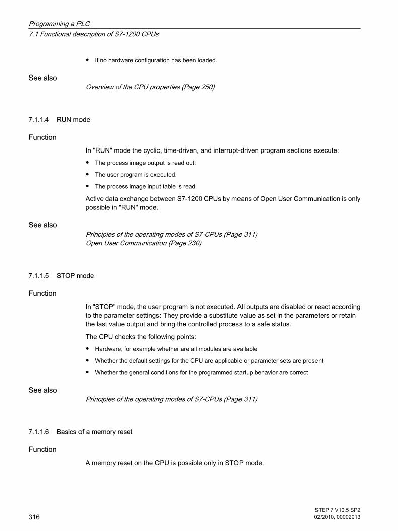
• If no hardware configuration has been loaded.
See alsoOverview of the CPU properties (Page 250)
7.1.1.4 RUN mode
Function In "RUN" mode the cyclic, time-driven, and interrupt-driven program sections execute:
• The process image output is read out.
• The user program is executed.
• The process image input table is read.
Active data exchange between S7-1200 CPUs by means of Open User Communication is onlypossible in "RUN" mode.
See alsoPrinciples of the operating modes of S7-CPUs (Page 311)Open User Communication (Page 230)
7.1.1.5 STOP mode
Function In "STOP" mode, the user program is not executed. All outputs are disabled or react accordingto the parameter settings: They provide a substitute value as set in the parameters or retainthe last value output and bring the controlled process to a safe status.
The CPU checks the following points:
• Hardware, for example whether are all modules are available
• Whether the default settings for the CPU are applicable or parameter sets are present
• Whether the general conditions for the programmed startup behavior are correct
See alsoPrinciples of the operating modes of S7-CPUs (Page 311)
7.1.1.6 Basics of a memory reset
Function A memory reset on the CPU is possible only in STOP mode.
7.1.1.4 RUN mode7.1.1.5 STOP mode7.1.1.6 Basics of a memory reset
Programming a PLC7.1 Functional description of S7-1200 CPUs
316STEP 7 V10.5 SP202/2010, 00002013

When memory is reset, the CPU is changed to an "initial status". This means:
• Work memory is cleared (retentive and non retentive data).
• The load memory (code and data blocks) is then copied to work memory. As a result, the DBs nolonger have current values but their initial values.
• An existing online connection between your programming device/PC and the CPU is terminated.
• The diagnostics buffer, the time, the IP address, the hardware configuration and active force jobs areretained.
Note
If you replace the memory card when the CPU is turned off, the CPU runs a memory resetwhen you turn on the power again.
7.1.2 Memory areas
7.1.2.1 Load memory
Function Each CPU has an internal load memory. The size of this internal load memory depends on theCPU used.
This internal load memory can be replaced by using external memory cards. If there is nomemory card inserted, the CPU uses the internal load memory; if a memory card is inserted,the CPU uses the memory card as load memory.
The size of the usable external load memory cannot, however, be greater than the internal loadmemory even if the inserted SD card has more free space.
See alsoWorking with memory cards (Page 163)
7.1.2.2 Work memory
Function Work memory is a non-retentive memory area for storing elements of the user program thatare relevant for program execution. The user program is executed exclusively in work memoryand system memory.
7.1.2 Memory areas7.1.2.1 Load memory7.1.2.2 Work memory
Programming a PLC7.1 Functional description of S7-1200 CPUs
STEP 7 V10.5 SP202/2010, 00002013
317

7.1.2.3 System memory
7.1.2.3 System memory areas
Function System memory contains the memory elements that each CPU makes available to the userprogram, such as the process image and bit memory.
By using appropriate operations in your user program, you address the data directly in therelevant operand area.
The following table shows the operand areas of the system memory:
Operand area Description Access via units of the following size: S7 notation
Process image output The CPU writes the valuesfrom the process imageoutput table to the outputmodules at the start of thecycle.
Output (bit) Q
Output byte QB
Output word QW
Output double word QD
Process image input The CPU reads the inputsfrom the input modules andsaves the values to theprocess image input table atthe start of the cycle.
Input (bit) I
Input byte IB
Input word IW
Input double word ID
Bit memory This area provides storagefor intermediate resultscalculated in the program.
Bit memory (bit) M
Memory byte MB
Memory word MW
Memory double word MD
Data block Data blocks store informationfor the program. They caneither be defined so that allcode blocks can access them(global DBs) or assigned to aspecific FB or SFB (instanceDB).Requirement: The blockattribute "Symbolic accessonly" is not enabled.
Data bit DBX
Data byte DBB
Data word DBW
Data double word DBD
7.1.2.3 System memory7.1.2.3 System memory areas
Programming a PLC7.1 Functional description of S7-1200 CPUs
318STEP 7 V10.5 SP202/2010, 00002013

Operand area Description Access via units of the following size: S7 notation
Local data This area contains thetemporary data of a blockwhile the block is beingprocessed.Requirement: The blockattribute "Symbolic accessonly" is not enabled.Recommendation: Onlyaccess local data (temp)symbolically.
Local data bit L
Local data byte LB
Local data word LW
Local data double word LD
I/O input area The I/O input and outputareas permit direct access tocentral and distributed inputand output modules.
I/O input bit <tag>:P
I/O input byte
I/O input word
I/O input double word
I/O output area I/O output bit
I/O output byte
I/O output word
I/O output double word
See alsoDiagnostics buffer (Page 321)Basic principles of process images (Page 320)Basic principles for programming of data blocks (Page 510)Declaring local tags in the block interface (Page 435)Layout of the block interface (Page 432)Access to the I/O addresses (Page 322)
7.1.2.3 Retentive memory areas
Retentive memory areas Data loss after power failure can be avoided by marking certain data as retentive. This data isstored in a retentive memory area. A retentive memory area is an area that retains its contentfollowing a warm restart, in other words, after cycling the power when the CPU changes fromSTOP to RUN.
The values of retentive data are deleted during a cold restart.
The following data can be assigned retentivity:
• Bit memory: The precise width of the memory can be defined for bit memory in the PLC tag table orin the assignment list.
7.1.2.3 Retentive memory areas
Programming a PLC7.1 Functional description of S7-1200 CPUs
STEP 7 V10.5 SP202/2010, 00002013
319

• Tags of a function block (FB): In the interface of an FB, you can define individual tags as being retentiveif you have enabled symbolic tag addressing. Retentivity settings can only be defined in the assignedinstance data block if symbolic addressing is not activated for the FB.
• Tags of a global data block: Depending on the settings for symbolic addressing you can defineretentivity either for individual or for all tags of a global data block. "Symbolic access only" attribute of the DB is enabled: Retentivity can be set for each individualtag. "Symbolic access only" attribute of the DB is disabled: The retentivity setting applies to all tags of theDB; either all tags are retentive or no tag is retentive.
See alsoSetting the retentivity of PLC tags (Page 401)Setting the retentivity of local tags (Page 440)Setting retentivity in global data blocks (Page 517)Warm restart (Page 313)
7.1.2.3 process image input/output
7.1.2.3 Basic principles of process images
FunctionWhen the user program addresses the input (I) and output (O) operand areas, it does not queryor change the signal states on the digital signal modules. Instead, it accesses a memory areain the system memory of the CPU. This memory area is referred to as the process image.
Advantages of the process imageCompared with direct access to input and output modules, the main advantage of accessingthe process image is that the CPU has a consistent image of the process signals for the durationof one program cycle. If a signal state on an input module changes during program execution,the signal state in the process image is retained until the process image is updated again inthe next cycle. The process of repeatedly scanning an input signal within a user programensures that consistent input information is always available.
Access to the process image also requires far less time than direct access to the signal modulessince the process image is located in the internal memory of the CPU.
7.1.2.3 Updating the process images
Sequence The operating system updates the process images at cyclic intervals unless defined otherwisein your configuration. The process image input/output is updated in the following order:
1. The internal tasks of the operating system are performed.
7.1.2.3 process image input/output7.1.2.3 Basic principles of process images7.1.2.3 Updating the process images
Programming a PLC7.1 Functional description of S7-1200 CPUs
320STEP 7 V10.5 SP202/2010, 00002013

2. The process image output (PIQ) table is written to the outputs of the module.
3. The status of inputs is read to the process image input (PII) table.
Input bits which do not have corresponding hardware inputs are set to 0 unless they are forced.
4. The user program is executed with all the blocks that are called in it.
The operating system automatically controls the writing of the process image output to theoutputs of the modules and the reading of the process image input.
Special characteristicsYou have the option of accessing inputs or outputs directly using direct I/O access.
• If an instruction accesses an output directly and the output address is located in the process imageoutput, the process image of the relevant output is updated.
• If an instruction accesses an output directly and the output address is not located in the process imageoutput, the process image of the relevant output is not updated.
Example of normal I/O access by way of the process image
Update QW10 in the I/O output area with the value from MW0.
I/O access error during process image updatingIf an error occurs while updating the process image (I/O access error), the CPU reacts with thedefault system reaction "STOP".
See alsoTroubleshooting options (Page 507)Start address of a module (Page 322)Access to the I/O addresses (Page 322)Startup activities (Page 314)
7.1.2.3 Diagnostics buffer
Function The diagnostics buffer is part of the system memory of the CPU. It contains the errors detectedby the CPU or modules with diagnostics capability. It includes the following events:
• Every mode change of the CPU (for example, POWER UP, change to STOP mode, change to RUNmode)
• Every diagnostics interrupt
The diagnostics buffer of the S7-1200-CPU has a capacity of 50 entries of which the last (mostrecent) 10 entries are retained following power cycling.
7.1.2.3 Diagnostics buffer
Programming a PLC7.1 Functional description of S7-1200 CPUs
STEP 7 V10.5 SP202/2010, 00002013
321

Those entries can only be cleared by restoring the CPU to factory defaults.
You can read the content of the diagnostics buffer with the help of the Online and Diagnosticsview.
See alsoBasic information on the diagnostics buffer (Page 296)
7.1.3 I/O data area
7.1.3.1 Start address of a module
Definition The start address is the lowest byte address of a module. It represents the start address of theuser data area in the module and is used in many cases to represent the entire module.
Configuring module start addresses The addresses used in the user program and the module start addresses are coordinated whenthe modules are configured.
In the module properties ("I/O addresses" group), you can change the start addresses that wereassigned automatically after the modules were inserted.
You can also make a setting that decides whether or not the addresses are located in theprocess image.
7.1.3.2 Access to the I/O addresses
I/O addresses If you insert a module in the device view, its user data is located in the process image of theS7-1200-CPU (default). The CPU handles the data exchange between the module and theprocess image area automatically during the update of the process images.
Append the suffix ":P" to the I/O address if you want the program to access user data directlyinstead of using the process image.
This could be necessary, for example, during execution of a time time-sensitive program whichalso has to control the outputs within the same cycle.
7.1.3 I/O data area7.1.3.1 Start address of a module7.1.3.2 Access to the I/O addresses
Programming a PLC7.1 Functional description of S7-1200 CPUs
322STEP 7 V10.5 SP202/2010, 00002013
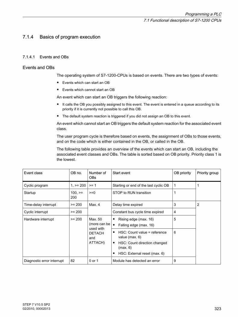
7.1.4 Basics of program execution
7.1.4.1 Events and OBs
Events and OBsThe operating system of S7-1200-CPUs is based on events. There are two types of events:
• Events which can start an OB
• Events which cannot start an OB
An event which can start an OB triggers the following reaction:
• It calls the OB you possibly assigned to this event. The event is entered in a queue according to itspriority if it is currently not possible to call this OB.
• The default system reaction is triggered if you did not assign an OB to this event.
An event which cannot start an OB triggers the default system reaction for the associated eventclass.
The user program cycle is therefore based on events, the assignment of OBs to those events,and on the code which is either contained in the OB, or called in the OB.
The following table provides an overview of the events which can start an OB, including theassociated event classes and OBs. The table is sorted based on OB priority. Priority class 1 isthe lowest.
Event class OB no. Number ofOBs
Start event OB priority Priority group
Cyclic program 1, >= 200 >= 1 Starting or end of the last cyclic OB 1 1
Startup 100, >=200
>=0 STOP to RUN transition 1
Time-delay interrupt >= 200 Max. 4 Delay time expired 3 2
Cyclic interrupt >= 200 Constant bus cycle time expired 4
Hardware interrupt >= 200 Max. 50(more can beused withDETACHandATTACH)
• Rising edge (max. 16)
• Falling edge (max. 16)5
• HSC: Count value = referencevalue (max. 6)
• HSC: Count direction changed(max. 6)
• HSC: External reset (max. 6)
6
Diagnostic error interrupt 82 0 or 1 Module has detected an error 9
7.1.4 Basics of program execution7.1.4.1 Events and OBs
Programming a PLC7.1 Functional description of S7-1200 CPUs
STEP 7 V10.5 SP202/2010, 00002013
323

Event class OB no. Number ofOBs
Start event OB priority Priority group
Time error 80 0 or 1 Maximum cycle time exceeded 26 3
• Called OB is still being executed
• Queue overflow
• Interrupt loss due to high interruptload
The following table describes events which do not trigger an OB start, including thecorresponding reaction of the operating system. The table is sorted based on event priority.
Event class Event Event priority System reaction
Insertion/removal Insertion/removal of a module 21 STOP
Access error I/O access error during process image update 22 Ignore
Programming error Programming error in a block for which youuse system reactions provided by theoperating system (note: the error handlingroutine in the block program is executed if youactivated local error handling).
23 STOP
I/O access error I/O access error in a block for which you usesystem reactions provided by the operatingsystem (note: the error handling routine in theblock program is executed if you activatedlocal error handling).
24 STOP
Maximum cycle timeexceeded twice
Maximum cycle time exceeded twice 27 STOP
Assignment between OBs and eventsWith the exception of the cyclic program and startup program and event can only be assignedto one OB. However, in certain event classes such as hardware interrupts one and the sameOB can be assigned to several events.
The assignment between OBs and events is defined in the hardware configuration. Definedassignments can be changed at runtime by means of ATTACH and DETACH instructions.
OB priority and runtime behaviorS7-1200 CPUs support priority classes 1 (lowest) to 27 (highest) that are split up into 3 prioritygroups. An OB is assigned the priority of its start event.
Events of a priority group override any OB of a lower priority group. This means:
• Any event of priority group 2 interrupts cyclic program execution.
• An OB of priority group 2 cannot be interrupted by any other event of priority group 2. This rule alsoapplies to events of a priority higher than that of the currently active OB.
Programming a PLC7.1 Functional description of S7-1200 CPUs
324STEP 7 V10.5 SP202/2010, 00002013

Any further event of priority group 2 generated while an OB of priority group 2 is being executed isadded to a queue in accordance with its priority. The queues are processed at a later time based onthe order of their priority (starting at the highest priority). Start events within a queue are processedin chronological order.
• A time error interrupts any other OB.
OB start informationCertain OBs have start information, while others do not. This is explained in greater detail inthe description of the relevant OB.
See alsoEvent-based program execution (Page 325)Principles of local error handling (Page 508)ATTACH (Page 992)DETACH (Page 993)Basics of organization blocks (Page 337)Troubleshooting options (Page 507)
7.1.4.2 Event-based program execution
OB priority and runtime behaviorS7-1200-CPUs support the priority classes 1 (lowest) to 27 (highest). An OB is assigned thepriority of its start event.
Interrupt OBs can only be interrupted by time error interrupts. This rule also applies to eventsof a priority higher than that of the currently active OB. That is, only one interrupt OB can beactive, with exception of the time error interrupt OB.
Any further event of generated while an interrupt OB is being executed is added to a queue inaccordance with its priority. Start events within a queue are processed later based on thechronological order of their occurrence.
Program execution on the CPUProgram execution on the CPU is handled at three different levels:
• The level of cyclic organization blocks (e.g. OB 1)
• The level of organization blocks called due to events such as hardware interrupts (interrupt OBs)
• The level of time error interrupt organization blocks (time error interrupt OB)
Cyclic OBs are interrupted by interrupt OBs.
Interrupt OBs can only be interrupted by time error interrupt OBs.
The following figure shows the basic sequence:
7.1.4.2 Event-based program execution
Programming a PLC7.1 Functional description of S7-1200 CPUs
STEP 7 V10.5 SP202/2010, 00002013
325

Figure7-1 Program sequence
Description of program execution
① and ② An event (e.g. a hardware interrupt) calls its associated OB.A called OB is executed without interruption, including all of its nested blocks. Executionof the cyclic OB is resumed on completion of interrupt processing, provided the queuedoes not contain any events which trigger an OB start.
③ An interrupt OB can only be interrupted by a time error interrupt OB (OB 80).
④ An new alarm-triggering event occurs during interrupt processing. This new event is addedto a queue. The queued events successively call their corresponding OBs only afterexecution of the current interrupt OBs was completed and according to the following rules:
• Events are processed in the order of their priority (starting at the highest priority)
• Events of the same priority are processed in chronological order
⑤ The cyclic OBs are processed one after the other.
Programming a PLC7.1 Functional description of S7-1200 CPUs
326STEP 7 V10.5 SP202/2010, 00002013

Notes on queues
• Every priority class (OBs of the same priority to be called) is assigned a separate queue. The size ofthose queues is set by default.
• Any new event leading to the overflow of a queue is discarded and therefore lost. A "time error interruptevent" is generated simultaneously. Information identifying the OB that caused the error is includedin the start information of the time error interrupt OB (OB 80). A corresponding reaction such as analarm trigger can be programmed in the time error interrupt OB.
See alsoBasics of organization blocks (Page 337)
7.1.4.3 Example of a hardware interrupt event
The function principle of event-oriented program execution in the S7-1200-CPU is describedbased on the example of a hardware interrupt-triggering module.
Process events and their priorityProcess events are triggered by the I/O (e.g. at a digital input) and initiate a call of the assignedOB in the S7-1200 CPU. OBs assigned to a hardware interrupt event are so-called hardwareinterrupt OBs.
Examples of process events and their priority:
• Process events "rising edge" or "falling edge" at an interrupt-triggering module: The hardware interruptOB started by such an event is always assigned priority 5.
• Process events from a high-speed counter
― Count value corresponds to the reference value
― Change count direction
― External reset of the high-speed counter
The hardware interrupt OB started by this event is always assigned priority 6.
The OBs are executed in ascending order of their priority.
The following figure shows the sequence of hardware interrupt execution.
7.1.4.3 Example of a hardware interrupt event
Programming a PLC7.1 Functional description of S7-1200 CPUs
STEP 7 V10.5 SP202/2010, 00002013
327

Hardware interrupt execution
① A hardware interrupt-triggering event such as a rising edge at the input calls the OB to which it isassigned.
② If a new event occurs that triggers a hardware interrupt while the OB is executing, this event isentered in a queue.
③ The new event that triggers a hardware interrupt starts the hardware interrupt OB assigned to theevent.
Assigning the interrupt-triggering eventThe interrupt-triggering event is assigned to an OB in the input properties of the device view.
• An interrupt-triggering event can only be assigned to a single OB.
• OBs, however, can be assigned to several interrupt-triggering events. That is, you could assign both the rising and the falling edge event to the same interrupt OB in orderto trigger the same reaction to any transition of the input signal.
Programming a PLC7.1 Functional description of S7-1200 CPUs
328STEP 7 V10.5 SP202/2010, 00002013

• The started OB can interrupt a cycle OB at every instruction. Consistent data access is secured up todword size.
• You can parameterize module-specific interrupt-triggering events such as a rising and the falling edgeat the input.
• Assign the interrupt-triggering event and the OB to be started in the configuration of the interrupt-triggering module. However, within the started hardware interrupt OB you can override this assignmentusing the DETACH instruction, or assign the same event to a different OB using the ATTACHinstruction. This functionality allows a flexible reaction to external process signals.
See alsoOrganization blocks for hardware interrupts (Page 343)Assigning parameters to hardware interrupt OBs (Page 417)ATTACH (Page 992)DETACH (Page 993)
7.1.4.4 Symbolic and numerical names of instructions
Symbolic and numerical namesAdvanced instructions and instructions from the global libraries call functions (FC), functionblocks (FB), system functions (SFC) and system function blocks (SFB) that are identifiedinternally by numbers.
This rule is also valid for default data structures (UDT) which are used in advanced instructions.
The following tables show the assignments to advanced instructions and instructions fromglobal libraries for AS1200-CPUs, sorted by their symbolic or numerical name.
Table7-1 Sorted by symbolic name
Symbolic name Numerical name
ATH SFC198
ATTACH SFC192
CAN_DINT SFC33
CONDITIONS UDT1001
CTRL_PWM SFB122
DETACH SFC193
DIS_AIRT SFC41
EN_AIRT SFC42
HTA SFC199
MB_COMM_LOAD FC1080
MB_MASTER FB1081
7.1.4.4 Symbolic and numerical names of instructions
Programming a PLC7.1 Functional description of S7-1200 CPUs
STEP 7 V10.5 SP202/2010, 00002013
329

Symbolic name Numerical name
MB_PORT FBT1083
MB_SLAVE FB1082
○MC_Halt FB1100
MC_Home FB1101
MC_MoveAbsolute FB1102
MC_MoveJog FB1103
MC_MoveRelative FB1104
MC_MoveVelocity FB1105
MC_Power FB1107
MC_Reset FB1108
PID_Compact FB1130
PORT_CFG SFB110
RCV_CFG SFB112
RCV_PTP SFB114
RCV_RST SFB117
RD_LOC_T SFC154
RD_SYS_T SFC151
RE_TRIGR SFC43
S_CONV (DI_STRG) SFC216
S_CONV (I_STRG) SFC215
S_CONV (R_STRG) SFC218
S_CONV (SI_STRG) SFC214
S_CONV (STRG_DI) SFC206
S_CONV (STRG_I) SFC205
S_CONV (STRG_R) SFC208
S_CONV (STRG_SI) SFC204
S_CONV (STRG_UDI) SFC202
S_CONV (STRG_UI) SFC201
S_CONV (STRG_USI) SFC200
S_CONV (UDI_STRG) SFC212
S_CONV (UI_STRG) SFC211
S_CONV (USI_STRG) SFC210
SEND_CFG SFB111
Programming a PLC7.1 Functional description of S7-1200 CPUs
330STEP 7 V10.5 SP202/2010, 00002013

Symbolic name Numerical name
SEND_PTP SFB113
SGN_GET SFB115
SGN_SET SFB116
SRT_DINT SFC32
STP SFC46
T_ADD SFC159
T_DIFF SFC158
T_SUB SFC157
TCON SFB102
TDISCON SFB103
TO_AXIS_1 FBT1
TO_AXIS_PTO FBT2
TRCV SFB101
TRCV_C FB1031
TSEND SFB100
TSEND_C FB1030
USS_COMM_LOAD FC1070
USS_DRIVE FB1071
USS_RPM FB1072
USS_WPM FB1073
WR_SYS_T SFC156
Table7-2 Sorted by numerical name
Numerical name Symbolic name
FB1030 TSEND_C
FB1031 TRCV_C
FB1071 USS_DRIVE
FB1072 USS_RPM
FB1073 USS_WPM
FB1081 MB_MASTER
FB1082 MB_SLAVE
FB1100 ○MC_Halt
FB1101 MC_Home
Programming a PLC7.1 Functional description of S7-1200 CPUs
STEP 7 V10.5 SP202/2010, 00002013
331

Numerical name Symbolic name
FB1102 MC_MoveAbsolute
FB1103 MC_MoveJog
FB1104 MC_MoveRelative
FB1105 MC_MoveVelocity
FB1107 MC_Power
FB1108 MC_Reset
FB1130 PID_Compact
FBT1 TO_AXIS_1
FBT2 TO_AXIS_PTO
FBT1083 MB_PORT
FC1070 USS_COMM_LOAD
FC1080 MB_COMM_LOAD
SFB100 TSEND
SFB101 TRCV
SFB102 TCON
SFB103 TDISCON
SFB110 PORT_CFG
SFB111 SEND_CFG
SFB112 RCV_CFG
SFB113 SEND_PTP
SFB114 RCV_PTP
SFB115 SGN_GET
SFB116 SGN_SET
SFB117 RCV_RST
SFB122 CTRL_PWM
SFC32 SRT_DINT
SFC33 CAN_DINT
SFC41 DIS_AIRT
SFC42 EN_AIRT
SFC43 RE_TRIGR
SFC46 STP
SFC151 RD_SYS_T
SFC154 RD_LOC_T
Programming a PLC7.1 Functional description of S7-1200 CPUs
332STEP 7 V10.5 SP202/2010, 00002013

Numerical name Symbolic name
SFC156 WR_SYS_T
SFC157 T_SUB
SFC158 T_DIFF
SFC159 T_ADD
SFC192 ATTACH
SFC193 DETACH
SFC198 ATH
SFC199 HTA
SFC200 S_CONV (STRG_USI)
SFC201 S_CONV (STRG_UI)
SFC202 S_CONV (STRG_UDI)
SFC204 S_CONV (STRG_SI)
SFC205 S_CONV (STRG_I)
SFC206 S_CONV (STRG_DI)
SFC208 S_CONV (STRG_R)
SFC210 S_CONV (USI_STRG)
SFC211 S_CONV (UI_STRG)
SFC212 S_CONV (UDI_STRG)
SFC214 S_CONV (SI_STRG)
SFC215 S_CONV (I_STRG)
SFC216 S_CONV (DI_STRG)
SFC218 S_CONV (R_STRG)
UDT1001 CONDITIONS
Note
The list shows any sublevel blocks which are called in an instruction enclosed in parenthesis,depending on the data type transferred (instruction S_CONV). Note that the list only containsinstructions which are implemented as blocks. Instructions with internal calls of macro ormachine commands do not have block numbers.
Programming a PLC7.1 Functional description of S7-1200 CPUs
STEP 7 V10.5 SP202/2010, 00002013
333

7.2 Creating a user program
7.2.1 Programming basics
7.2.1.1 Operating system and user program
7.2.1.1 Operating system
Function Every CPU comes with an integrated operating system that organizes all CPU functions andsequences not associated with a specific control task.
The tasks of the operating system, for example, include the following:
• Handling Warm restart (Page 313)
• Updating the process image of the inputs and outputs
• Calling the user program
• Detecting interrupts and calling interrupt OBs
• Detecting and handling errors
• Managing memory areas
The operating system is a component of the CPU and is already installed there upon delivery.
See alsoUser program (Page 334)
7.2.1.1 User program
FunctionThe user program contains all functions that are necessary for processing your specificautomation task.
The tasks of the user program include:
• Checking the requirements for a (warm) restart using startup OBs, for example, limit switch in correctposition or safety relay active.
• Processing process data, e.g. linking binary signals, reading in and evaluating analog values, definingbinary signals for output, and outputting analog values
• Reaction to interrupts, for example, diagnostic error interrupt if the limit value of an analog expansionmodule is overshot.
7.2 Creating a user program7.2.1 Programming basics7.2.1.1 Operating system and user program7.2.1.1 Operating system7.2.1.1 User program
Programming a PLC7.2 Creating a user program
334STEP 7 V10.5 SP202/2010, 00002013

• Error handling in normal program execution
You write the user program and load it into the CPU.
See alsoOperating system (Page 334)
7.2.1.2 Blocks in the user program
7.2.1.2 Linear and structured programming
Linear programming Solutions for small automation tasks can be programmed linearly in a program cycle OB. Thisis only recommended for simple programs.
The following figure shows a linear program schematically: In this case the "Main1" programcycle OB contains the complete user program.
Structured programming Complex automation tasks can be more easily handled and managed by dividing them intosmaller sub-tasks that correspond to the technological functions of the process or that can bereused. These sub-tasks are represented in the user program by corresponding programsections, known as blocks. Each block is then an independent section of the user program.
Structuring the program offers the following advantages:
• Extensive programs are easier to understand.
• Individual program sections can be standardized.
• Program organization is simplified.
• Changes to the program can be made more easily.
7.2.1.2 Blocks in the user program7.2.1.2 Linear and structured programming
Programming a PLC7.2 Creating a user program
STEP 7 V10.5 SP202/2010, 00002013
335

• Debugging is simplified since separate sections can be tested.
• Commissioning is simplified.
The following figure shows a structured program schematically: The "Main1" program cycle OBcalls subprograms one after the other that execute defined subtasks.
7.2.1.2 Block types
7.2.1.2 Overview of the block types
Block types Different BLOCK types are available to perform tasks within an automation system. Thefollowing table shows the available block types:
Block type Brief description
Organization blocks (Page 337) (OB) Organization blocks define the structure of the user program.
Functions (Page 346) (FC) Functions contain program routines for recurring tasks. They have no"memory".
Function blocks (Page 346) (FB) Function blocks are code blocks that store their values permanently ininstance data blocks, so that they remain available even after the block hasbeen executed.
Instance data blocks (Page 347) Instance data blocks are assigned to a function block when it is is called forthe purpose of storing program data.
Global data blocks (Page 347) Global data blocks are data areas for storing data that can be used by anyblocks.
7.2.1.2 Block types7.2.1.2 Overview of the block types
Programming a PLC7.2 Creating a user program
336STEP 7 V10.5 SP202/2010, 00002013

7.2.1.2 Organization blocks
7.2.1.2 Basics of organization blocks
Definition Organization blocks (OBs) form the interface between the operating system and the userprogram. They are called by the operating system and control the following operations:
• Startup behavior of the automation system
• Cyclic program execution
• Interrupt-driven program execution
• Error handling
You can program the organization blocks and at the same time determine the behavior of theCPU.
Use of organization blocksVarious options are available for using organization blocks in your program:
• Startup OB, program cycle OB, time error interrupt OB and diagnostics OB:
It is easy to insert and program these organization blocks in your project. You do not have to assignparameters or call these organization blocks.
• Hardware interrupt OBs and cyclic interrupt OBs:
After these organization blocks have been inserted into your program, you need to make parametersettings for them. Hardware interrupt OBs can also be attached to an event at run time using theATTACH instruction or detached again using DETACH.
• Time-delay interrupt OB:
You can insert and program the time delay interrupt OB in your project. You must call it using theSRT_DINT instruction. No parameter assignment is necessary.
Start information of organization blocksAt the start of many organization blocks the operating system outputs information that can beevaluated in the user program. The descriptions of the organization blocks contain informationon whether information is output and on which information is output.
See alsoBasics of program execution (Page 323)Organization blocks for startup (Page 338)Organization blocks for cyclic program execution (Page 338)Organization blocks for interrupt-driven program execution (Page 340)Organization block for time error (Page 345)
7.2.1.2 Organization blocks7.2.1.2 Basics of organization blocks
Programming a PLC7.2 Creating a user program
STEP 7 V10.5 SP202/2010, 00002013
337

7.2.1.2 Organization blocks for startup
Description You can determine the boundary conditions for the startup behavior of your CPU, for examplethe initialization values for "RUN". To do this, write a startup program. The startup programconsists of one or more startup OBs (OB numbers 100 or >= 200).
The startup program is executed once during the transition from "STOP" mode to "RUN" mode.Current values from the process image of the inputs are not available for startup program, norcan these values be set.
After the complete execution of the startup OBs, the process image of the inputs is read in andthe cyclic program is started.
There is no time limit for executing the startup program. Therefore the maximum cycle time isnot active. Time-driven or interrupt-driven organization blocks cannot be used.
Start informationA startup OB has the following start information:
Tag Data type Description
LostRetentive BOOL = 1, if retentive data storage areas have been lost
LostRTC BOOL = 1, if realtime clock has been lost
See also"STARTUP" operating mode (Page 313)Basics of organization blocks (Page 337)Events and OBs (Page 323)
7.2.1.2 Organization blocks for cyclic program execution
Introduction For the program execution to start, at least one program cycle OB must be present in the project.The operating system calls this program cycle OB once in each cycle and thereby starts theexecution of the user program. You can use multiple OBs (OB numbers >= 200).
The program cycle OBs have the priority class 1. This corresponds to the lowest priority of allOBs. The cyclic program can be interrupted by events of any other event class.
Programming cyclic program executionYou program cyclic program execution by writing your user program in the cycle OBs and theblocks that they call.
7.2.1.2 Organization blocks for startup7.2.1.2 Organization blocks for cyclic program execution
Programming a PLC7.2 Creating a user program
338STEP 7 V10.5 SP202/2010, 00002013

The first cyclic program execution begins as soon as the startup program has ended withouterrors. The cycle restarts after the end of each cyclic program execution.
Sequence of cyclic program executionOne cycle of the program execution encompasses the following steps:
1. The operating system starts the maximum cycle time.
2. The operating system writes the values from the process image output to the output modules.
3. The operating system reads out the state of the inputs of the input modules and updates the processimage input.
4. The operating system processes the user program and executes the operations contained in theprogram.
5. At the end of a cycle, the operating system executes any tasks that are pending, for example, loadingand deleting blocks, or calling other cycle OBs.
6. Finally, the CPU returns to the start of the cycle and restarts the watchdog.
See also: process image input/output (Page 320)
Options for interruptingCyclic program execution can be interrupted by the following events:
• An interrupt
• A STOP command, triggered by
― Operation of the programming device
― "STP" instruction
• Supply voltage failure
• Occurrence of a device fault or program error
Start informationCycle OBs have no start information.
See alsoBasics of organization blocks (Page 337)Events and OBs (Page 323)
Programming a PLC7.2 Creating a user program
STEP 7 V10.5 SP202/2010, 00002013
339

7.2.1.2 Organization blocks for interrupt-driven program execution
7.2.1.2 Information regarding interrupt-driven program execution
Function The processing of the cyclic organization blocks can be interrupted by start events of otherorganization blocks. These interrupting organization blocks can, for example, be interrupt OBsor the time error interrupt OB.
Interrupt OBs are called in the following two cases:
• Parts of the user program should be executed periodically.
• The user program should react to external signals from the process.
In the event of an interrupt, the operating system will ensure that the corresponding interruptOB is called. You program how the automation system will react to the interrupt in the interruptOB.
Interrupt OBs can only be interrupted by interrupt OBs with a higher priority and not by interruptOBs with the same or lower priority.
Interrupt types and applicationsThe following table shows the interrupt types and examples of the use of interrupt OBs:
Interrupt type Interrupt OBs Number of OBs Application examples
Time delay interrupt(Page 340)
> = 200 < = 4 Controlling a fan, which should run for 20 safter a motor is switched off, and then beswitched off.
Cyclic interrupt (Page342)
> = 200 Scanning a signal level for a closed-loopcontrol system.
Hardware interrupt(Page 343)
> = 200 < = 50 Reporting that the maximum level of a tankhas been reached.
Interrupt OBs have no start information.
7.2.1.2 Organization blocks for the time-delay interrupt
Description A time-delay interrupt OB is started after a configurable time delay of the operating system.The delay time starts after the SRT_DINT instruction is called.
7.2.1.2 Organization blocks for interrupt-driven program execution7.2.1.2 Information regarding interrupt-driven program execution7.2.1.2 Organization blocks for the time-delay interrupt
Programming a PLC7.2 Creating a user program
340STEP 7 V10.5 SP202/2010, 00002013

You can use up to four time-delay interrupt OBs or cyclic OBs (OB numbers >= 200) in yourprogram. If, for example, you are already using two cyclic interrupt OBs, you can insert amaximum of two further time-delay interrupt OBs in your program.
You can use the CAN_DINT instruction to prevent the execution of a time-delay interrupt thathas not yet started.
Function of time-delay interrupt OBsThe operating system starts the corresponding OB after the delay time, which you havetransferred with an OB number and an identifier to the SRT_DINT instruction.
To use a time-delay interrupt OB, you must execute the following tasks:
• You must call the instruction SRT_DINT.
• You must download the time-delay interrupt OB to the CPU as part of your program.
The delay time is measured with a precision of 1 ms. A delay time can immediately start againafter it expires.
Time delay interrupt OBs are executed only when the CPU is in the "RUN" mode. A warmrestart clears all start events of time-delay interrupt OBs.
The operating system calls the time-delay interrupt OB if one of the following events occurs:
• If the operating system attempts to start an OB that is not loaded and you specified its number whencalling the SRT_DINT instruction.
• If the next start event for a time-delay interrupt occurs before the time delay OB has completelyexecuted.
You can disable and re-enable time-delay interrupts using the DIS_AIRT and EN_AIRTinstructions.
Note
If you disable an interrupt with DIS_AIRT after executing SRT_DINT, this interrupt executesonly after it has been enabled with EN_AIRT. The delay time is extended accordingly.
Start informationTime delay interrupt OBs have no start information.
See alsoSRT_DINT (Page 994)CAN_DINT (Page 995)Basics of organization blocks (Page 337)Events and OBs (Page 323)
Programming a PLC7.2 Creating a user program
STEP 7 V10.5 SP202/2010, 00002013
341

7.2.1.2 Organization blocks for cyclic interrupts
Description Cyclic interrupt OBs serve to start program in periodic time intervals independently of the cyclicprogram execution. The start times of a cyclic interrupt OB are specified using the time baseand the phase offset.
The time base defines the intervals at which the cyclic interrupt OB is started and is a wholemultiple of the basic clock cycle of 1 ms. The phase offset is the time by which the start time isoffset compared with the basic clock cycle. If several cyclic interrupt OBs are being used, youcan use this offset to prevent a simultaneous start time if the time bases of the cyclic interruptOBs have common multiples.
You can specify a time period between 1 ms and 60000 ms.
You can use up to four cyclic interrupt OBs or time-delay OBs (OB numbers >= 200) in yourprogram. If, for example, you are already using two time-delay interrupt OBs, you can insert amaximum of two further cyclic interrupt OBs in your program.
Note
The execution time of each cyclic interrupt OB must be noticeably smaller than its time base.If a cyclic interrupt OB has not been completely executed but execution is again pendingbecause the cycle clock has expired, the time error interrupt OB is started. The cyclic interruptthat caused the error is executed later or discarded.
Example of the use of phase offsetYou have inserted two cyclic interrupt OBs in your program:
• Cyclic interrupt OB1
• Cyclic interrupt OB2
For cyclic interrupt OB1, you have set a time base of 20 ms and for cyclic interrupt OB2 a timebase of 100 ms. After the expiry of the time base of 100 ms, the cyclic interrupt OB1 reachesthe start time for the fifth time, cyclic interrupt OB2 for the first time. To nevertheless executethe cyclic interrupt OBs offset, enter a phase offset for one of the two cyclic interrupt OBs.
Start informationCyclic interrupt OBs have no start information.
See alsoBasics of organization blocks (Page 337)Assigning parameters to cyclic interrupt OBs (Page 418)Events and OBs (Page 323)
7.2.1.2 Organization blocks for cyclic interrupts
Programming a PLC7.2 Creating a user program
342STEP 7 V10.5 SP202/2010, 00002013

7.2.1.2 Organization blocks for hardware interrupts
Description You can use hardware interrupt OBs to react to specific events. You can assign an event thattriggers an alarm to precisely one hardware interrupt OB. A hardware interrupt OB in contrastcan be assigned to several events.
Hardware interrupts can be triggered by high-speed counters and input channels. For eachhigh-speed counter and input channel that should trigger a hardware interrupt, the followingproperties need to be configured:
• The process event that should trigger the hardware interrupt (for example, the change of a countdirection of a high-speed counter)
• The number of the hardware interrupt OB which is assigned to this process event
You can use up to 50 hardware interrupt OBs (OB numbers >= 200) that are independent ofeach other in your program.
Function of a hardware interrupt OBAfter triggering a hardware interrupt, the operating system identifies the channel of the inputor the high-speed counter and determines the assigned hardware interrupt OB.
If no other interrupt OB is active, the determined hardware interrupt OB is called. If a differentinterrupt OB is already being executed, the hardware interrupt is placed in the queue of itspriority class. The hardware interrupt is acknowledged after the completion of the assignedhardware interrupt OB.
If another event that triggers a hardware interrupt occurs on the same module during the timebetween identification and acknowledgement of a hardware interrupt, the following applies:
• If the event occurs on the channel that previously triggered the hardware interrupt, then no additionalhardware interrupt is triggered. Another hardware interrupt can only be triggered if the currenthardware interrupt is acknowledged.
• If the event occurs on a different channel, a hardware interrupt is triggered.
Hardware interrupt OBs are called only in the CPU's "RUN" mode.
Start informationHardware interrupt OBs have no start information.
See alsoBasics of organization blocks (Page 337)Assigning parameters to hardware interrupt OBs (Page 417)Events and OBs (Page 323)
7.2.1.2 Organization blocks for hardware interrupts
Programming a PLC7.2 Creating a user program
STEP 7 V10.5 SP202/2010, 00002013
343

7.2.1.2 Organization block for diagnostic error interrupts
Description You can enable the diagnostic error interrupt for diagnostics-capable modules so that themodule detects changes in the I/O status. As a result, the module triggers a diagnostic errorinterrupt in the following cases:
• A fault is present (incoming event)
• A fault is no longer present (outgoing event)
If no other interrupt OB is active, the diagnostic error interrupt OB is called. If another interruptOB is already being executed, the diagnostic error interrupt is placed in the queue of its prioritygroup.
You can use only one diagnostic error interrupt OB in your program.
Start informationThe diagnostic error interrupt OB has the following start information:
Tag Data type Description
IO_state WORD Contains the I/O status of the diagnostics-capable module.
laddr HW_ANY HW-ID
Channel UINT Channel number
multi_error BOOL = 1, if there is more than one error
IO_state tagThe following table shows the possible I/O states that the IO_state tag can contain:
IO_state Description
Bit 0 Configuration correct:= 1, if the configuration is correct= 0, if the configuration is no longer correct
Bit 4 Error:= 1, if an error is present, e.g., a wire break= 0, if the error is no longer present
Bit 5 Configuration not correct:= 1, if the configuration is not correct= 0, if the configuration is correct again
7.2.1.2 Organization block for diagnostic error interrupts
Programming a PLC7.2 Creating a user program
344STEP 7 V10.5 SP202/2010, 00002013

IO_state Description
Bit 6 I/O cannot be accessed:= 1, if an I/O access error has occurred In this case, laddr contains the hardware identifier of the I/O with the access error.= 0, if the I/O can be accessed again
See alsoBasics of organization blocks (Page 337)Events and OBs (Page 323)
7.2.1.2 Organization block for time error
Description The operating system calls the time error interrupt OB if one of the following events occurs:
• The cyclic program exceeds the maximum cycle time.
• The called OB is currently being executed (possible for time-delay interrupt OBs and cyclic interruptOBs).
• An overflow has occurred in an interrupt OB queue.
• An interrupt was lost due to the excessive interrupt load.
If you have not programmed a time error interrupt OB, the appropriate system reactions areexecuted.
See also: Events and OBs (Page 323)
The twice repeated violation of the maximum cycle time is a serious error and does not resultin the calling of an OB. Instead, the CPU goes to STOP. You can avoid the second violationby restarting the cycle monitoring of the CPU with the RE_TRIGR instruction.
You can use only one time error interrupt OB in your program.
Start informationThe time error interrupt OB has the following start information:
Tag Data type Description
fault_id BYTE 0x01: Maximum cycle time exceeded0x02: Called OB is still being executed0x07: Queue overflow0x09: Interrupt loss due to excessive interrupt load
csg_OBnr OB_ANY Number of the OB being executed at the time of the error
csg_prio UINT Priority of the OB being executed at the time of the error
7.2.1.2 Organization block for time error
Programming a PLC7.2 Creating a user program
STEP 7 V10.5 SP202/2010, 00002013
345

See alsoBasics of organization blocks (Page 337)
7.2.1.2 Functions
Definition Functions (FCs) are code blocks without memory. After the function has been executed, thedata in the temporary tags is therefore lost. Functions can use global data blocks to store datapermanently.
ApplicationA function contains a program that is executed when the function is called by another codeblock. Functions can be used, for example, for the following purposes:
• To return function values to the calling block, e.g. for mathematical functions
• To execute technological functions, e.g. individual controls using bit logic operations
A function can also be called several times at different points in a program. As a result, theysimplify programming of frequently recurring complex functions.
See alsoCreating functions and function blocks (Page 407)
7.2.1.2 Function blocks
Definition Function blocks are code blocks that store their values permanently in instance data blocks,so that they remain available even after the block has been executed. They save their input,output and in/out parameters permanently in the instance data blocks. Consequently, theparameters are still available after the block execution. Therefore they are also referred to asblocks "with memory".
ApplicationFunction blocks contain subroutines that are always executed when a function block is calledby another code block. A function block can also be called several times at different points ina program. As a result, they simplify programming of frequently recurring complex functions.
Instances of function blocksA call of a function block is referred to as an instance.
Each instance of a function block is assigned an instance data block, which contains the datathat the function block uses.
7.2.1.2 Functions7.2.1.2 Function blocks
Programming a PLC7.2 Creating a user program
346STEP 7 V10.5 SP202/2010, 00002013

Note
To avoid errors when working with function blocks, refer to the section "Parameter transfer atblock call (Page 353) "
See alsoCall of a function by another function (Page 355)Creating functions and function blocks (Page 407)Multi-instances (Page 351)Instance data blocks (Page 347)
7.2.1.2 Instance data blocks
DefinitionThe call of a function block is referred to as an instance. An instance data block is assigned toevery function block call that transfers parameters. This instance data block serves as a datamemory. The actual parameters and the static data of the function block are stored in it.
The maximum size of instance data blocks varies depending on the CPU. The tags declaredin the function block determine the structure of the instance data block.
See also: Call function blocks as single or multi-instances (Page 351)
See alsoCreating data blocks (Page 0 )Insert block calls in LAD (Page 0 )Inserting block calls in FBD (Page 0 )
7.2.1.2 Global data blocks
Definition Data blocks, in contrast to code blocks, contain no instructions, but serve only to store userdata. Data blocks thus contain variable data to be used by the user program. Global data blocksstore data that can be used by all other blocks.
The maximum size of data blocks varies depending on the CPU. You can define the structureof global data blocks anyway you please.
Global data blocks in the user programIf a code block is called it can open a memory area in the form of a data block. The datacontained in a data block is not deleted when the data block is closed or the execution of thecorresponding code block comes to an end.
7.2.1.2 Instance data blocks7.2.1.2 Global data blocks
Programming a PLC7.2 Creating a user program
STEP 7 V10.5 SP202/2010, 00002013
347

Every function block, function, or organization block can read the data from a global data blockor can itself write data to a global data block. This data remains in the data block even after thedata block is exited. A global data block and an instance data block can be open at the sametime.
The following figure shows the different accesses to data blocks:
See alsoCreating data blocks (Page 0 )
7.2.1.3 Block calls
7.2.1.3 Principles of block calls
Function of block calls For your blocks to be executed in the user program, they need to be called from another block.
When one block calls another block, the operations of the called block are executed. Only whenexecution of the called block has been completed does execution of the calling block resume.The execution is continued with the operation that follows on the block call.
When a block is called, you must assign values to the parameters in the block interface. Byproviding input parameters you specify the data with which the block is executed. By providingthe output parameters you specify where the execution results are saved.
The following figure shows the sequence of a block call within a user program:
7.2.1.3 Block calls7.2.1.3 Principles of block calls
Programming a PLC7.2 Creating a user program
348STEP 7 V10.5 SP202/2010, 00002013

See alsoCall hierarchy (Page 349)Basics of single instances and multi-instances (Page 350)Parameter transfer at block call (Page 353)
7.2.1.3 Call hierarchy
DefinitionThe order and nesting of block calls is referred to as the call hierarchy. The permissible nestingdepth depends on the CPU.
The following figure shows an example of the order and nesting of block calls within anexecution cycle:
See alsoBasics of single instances and multi-instances (Page 350)Principles of block calls (Page 348)
7.2.1.3 Call hierarchy
Programming a PLC7.2 Creating a user program
STEP 7 V10.5 SP202/2010, 00002013
349

7.2.1.3 Call function blocks as single or multi-instances
7.2.1.3 Basics of single instances and multi-instances
Use of single instances and multi-instances Function blocks (FBs) store their data in instance data blocks. When you program the call ofa function block, assign an instance data block to the function block. The values of the blockparameters and the static local data are stored in the assigned instance data block
You can assign instance data blocks as follows:
• Calling as a single instance:
One instance data block for each instance of a function block
• Calling as a multi-instance:
― One instance data block for several instances of a function block
― One instance data block for several instances of different function blocks
See alsoPrinciples of block calls (Page 348)Accessing the data of a multi-instance (Page 0 )Multi-instances (Page 351)Single instances (Page 350)Call hierarchy (Page 349)
7.2.1.3 Single instances
Definition The call of a function block, which is assigned its own instance data block, is called a singleinstance data block.
By assigning the instance data block, you specify which data are to be processed. You canassign a different instance data block for each call, thus increasing reusability of the block.
Example of a single instance You can control several motors using one function block. For this purpose, you assign adifferent instance data block for each function block call for motor control.
The different data for the various motors, such as speed, ramp-up time, total operating time,are saved in the different instance data blocks. A different motor will be controlled, dependingon the instance data block assigned.
The following figure shows the control of three motors using one function block and threedifferent data blocks:
7.2.1.3 Call function blocks as single or multi-instances7.2.1.3 Basics of single instances and multi-instances7.2.1.3 Single instances
Programming a PLC7.2 Creating a user program
350STEP 7 V10.5 SP202/2010, 00002013

See alsoBasics of single instances and multi-instances (Page 350)Multi-instances (Page 351)Accessing the data of a multi-instance (Page 0 )
7.2.1.3 Multi-instances
If the performance data of your S7-CPU limits the number of available instance data blocks,you can use multi-instances.
Definition Multi-instances enable a called function block to store its data in the instance data block of thecalling function block.
This allows you to concentrate the instance data in one instance data block and thus makebetter use of the number of instance data blocks available.
One instance data block for the instances of different function blocksThe following figure shows how multiple different function blocks store their data in a callingblock. FB 10 consecutively calls FB 4, FB 5, and FB 2. The called blocks store their data in DB10, the data block of the calling block.
7.2.1.3 Multi-instances
Programming a PLC7.2 Creating a user program
STEP 7 V10.5 SP202/2010, 00002013
351

One instance data block for multi-instances of a function blockThe following figure shows how a function block that is called in multi-instances stores the datafor all the instances in one instance data block.
The function block FB 21 calls three instances of FB 22. The instances are "Motor_1","Motor_2", and "Motor_3". Each call uses different instance data. However, all instance dataare located in a single instance data block, DB 100.
Notice
Do not use multi-instance data blocks if online changes can be expected while the CPU isrunning. A bumpless reloading can only be ensured if you use instance data blocks.
Programming a PLC7.2 Creating a user program
352STEP 7 V10.5 SP202/2010, 00002013

See alsoInstance data blocks (Page 347)Basics of single instances and multi-instances (Page 350)Single instances (Page 350)Accessing the data of a multi-instance (Page 0 )
7.2.1.3 Parameter transfer at block call
7.2.1.3 Parameter transfer
Principle of parameter transferWhen you call functions or function blocks, data exchange takes place between the calling andthe called block. The interface of the called block contains parameters used for executing theblock. These parameters are referred to as formal parameters. They are merely placeholdersfor the parameters that are transferred to the block when it is called. The parameters transferredto the block when it is called are referred to as actual parameters.
Warning
When programming the called block, ensure that a parameter declared as an output parameteris also written to. Otherwise the values output are random!
7.2.1.3 Parameter assignment of functions
Assignment of function parametersFunctions (FCs) have no data memory in which values of block parameters can be saved.Therefore, when a function is called, all formal parameters must be assigned actualparameters.
Unassigned output parametersIf an output parameter of a function was not assigned a value, the value that was returned tothe called block can be random.
Unassigned in/out parametersFor the in/out parameters of a function, the output values cannot be random, since here theold output value or the input value will be retained if the parameter is not written. Nevertheless,the above information should be noted, to ensure that the old values are not processedinadvertently.
7.2.1.3 Parameter transfer at block call7.2.1.3 Parameter transfer7.2.1.3 Parameter assignment of functions
Programming a PLC7.2 Creating a user program
STEP 7 V10.5 SP202/2010, 00002013
353

RecommendationsNote the following rules when assigning parameters:
• Make sure that the output parameters are always written - independent of all possible program pathswithin the block. Pay special attention here to the call statements.
• Note that the set and reset commands are dependent on the result of logic operation. If the value ofan output parameters is determined with these commands and RLO = 0, a value will not be generated.
7.2.1.3 Parameter assignment of function blocks
Assignment of function block parameters The parameter values for function blocks (FBs) are saved in the instance data block.
Unassigned input, output, and in/out parametersIf the input, output, or in/out parameters of a function block were not assigned with values, thevalues stored in the instance data block will be used.
Contrary to functions (FCs), no random values can be used. However, there is the danger thatthe old values will inadvertently continue to be processed. Therefore we recommend that allblock parameters be assigned.
In some cases, you must assign parameters.
The following table shows which parameters of a function block must be assigned actualparameters:
Parameter Elementary data type Complex data type Parameter type
Input optional optional required
Output optional optional required
InOut optional required required
Assigning initial values to formal parametersYou can assign initial values to the formal parameters in the function block interface. Thesevalues are transferred to the associated instance data block.
If you do not assign actual parameters to the formal parameters in the call instruction, the valuescurrently stored in the instance data block will be used.
The following table shows which tags can be assigned an initial value:
Tags Elementary data type Complex data type Parameter type
Input optional optional not possible
7.2.1.3 Parameter assignment of function blocks
Programming a PLC7.2 Creating a user program
354STEP 7 V10.5 SP202/2010, 00002013

Tags Elementary data type Complex data type Parameter type
Output optional optional not possible
InOut optional not possible not possible
Static optional optional not possible
Temporary not possible not possible not possible
7.2.1.3 Permitted data types for parameter transfer
7.2.1.3 Rules
Rules for parameter transfer between blocks Either a tag or a constant can be specified as an actual parameter. However certain restrictionsapply. For example, output and in/out parameters cannot be assigned a constant value,because the purpose of an output and an in/out is to accept a variable value, for example, theresult of a calculation.
Rules for supplying block parameters with valuesThe following table shows data types that you can assign to block parameters:
Declaration type PLC tag Tag in the block interface Constant
Input Elementary data typesComplex data types
Elementary data typesComplex data types
Elementary data types
Output Elementary data typesComplex data types
Elementary data typesComplex data types
-
InOut Elementary data typesComplex data types
Elementary data typesComplex data types
-
7.2.1.3 Call of a function by another function
Permissible data types for the call of a function by another functionYou can assign the formal parameters of the calling function to the formal parameters of thecalled function. The following figure shows the formal parameters of function FC 10 that areassigned as actual parameters to the formal parameters of function FC 12:
7.2.1.3 Permitted data types for parameter transfer7.2.1.3 Rules7.2.1.3 Call of a function by another function
Programming a PLC7.2 Creating a user program
STEP 7 V10.5 SP202/2010, 00002013
355

The assignment of formal parameters of a function to the formal parameters of another functionis restricted. The following table shows the permissible data types when a function calls anotherfunction:
FC → FC Input InOut Output
Input Elementary data typesComplex data types
‑ ‑
InOut Elementary data typesComplex data types
Elementary data typesComplex data types
Elementary data typesComplex data types
Output ‑ ‑ Elementary data typesComplex data types
7.2.1.3 Call of a function by a function block
Permissible data types for the call of a function by a function blockYou can assign the formal parameters of the calling function block to the formal parameters ofthe called function. The following figure shows the formal parameters of function block FB 10that are assigned as actual parameters to the formal parameters of function FC 12:
7.2.1.3 Call of a function by a function block
Programming a PLC7.2 Creating a user program
356STEP 7 V10.5 SP202/2010, 00002013

The assignment of the formal parameters of a function block to the formal parameters of afunction is restricted. For example, you cannot assign parameters with parameter type as actualparameters. The following table shows the permissible data types when a function block callsa function:
FB → FC Input InOut Output
Input Elementary data typesComplex data types
‑ ‑
InOut Elementary data typesComplex data types
Elementary data typesComplex data types
Elementary data typesComplex data types
Output ‑ ‑ Elementary data typesComplex data types
7.2.1.3 Calling a function block by a function
Permissible data types for the call of a function block by a functionYou can assign the formal parameters of the calling function to the formal parameters of thecalled function block. The following figure shows the formal parameters of function FC 10 thatare assigned as actual parameters to the formal parameters of function block FB 12:
7.2.1.3 Calling a function block by a function
Programming a PLC7.2 Creating a user program
STEP 7 V10.5 SP202/2010, 00002013
357
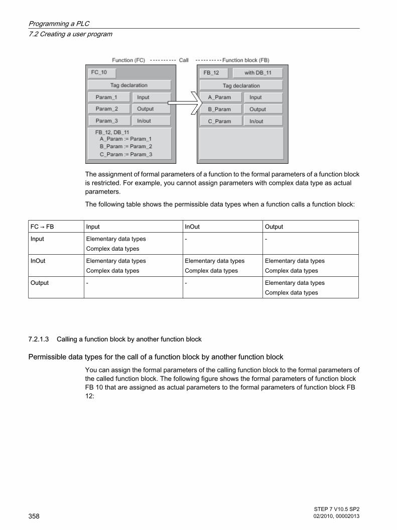
The assignment of formal parameters of a function to the formal parameters of a function blockis restricted. For example, you cannot assign parameters with complex data type as actualparameters.
The following table shows the permissible data types when a function calls a function block:
FC → FB Input InOut Output
Input Elementary data typesComplex data types
‑ ‑
InOut Elementary data typesComplex data types
Elementary data typesComplex data types
Elementary data typesComplex data types
Output ‑ ‑ Elementary data typesComplex data types
7.2.1.3 Calling a function block by another function block
Permissible data types for the call of a function block by another function blockYou can assign the formal parameters of the calling function block to the formal parameters ofthe called function block. The following figure shows the formal parameters of function blockFB 10 that are assigned as actual parameters to the formal parameters of function block FB12:
7.2.1.3 Calling a function block by another function block
Programming a PLC7.2 Creating a user program
358STEP 7 V10.5 SP202/2010, 00002013

The assignment of formal parameters of a function block to the formal parameters of anotherfunction block is restricted. For example, you cannot assign input or output parameters withcomplex data type as actual parameters to the input or output parameters of a called functionblock.
The following table shows the permissible data types when a function block calls anotherfunction block:
FB → FB Input InOut Output
Input Elementary data typesComplex data types
‑ ‑
InOut Elementary data typesComplex data types
Elementary data typesComplex data types
Elementary data typesComplex data types
Output ‑ ‑ Elementary data typesComplex data types
7.2.1.4 EN/ENO mechanism
7.2.1.4 Basics of the EN/ENO mechanism
Description Some operations can create runtime errors that would require a program abort. To preventsuch program aborts, the affected operations have one enable input (EN) and one enableoutput (ENO). With this EN/ENO mechanism you can query and react to runtime errors in blocksor operations. A CPU internal status word serves for the transfer of the execution results. If theoperation is completed without error, the enable out ENO is set. If an error has occurred, thevalues of the EN and ENO differ.
7.2.1.4 EN/ENO mechanism7.2.1.4 Basics of the EN/ENO mechanism
Programming a PLC7.2 Creating a user program
STEP 7 V10.5 SP202/2010, 00002013
359

• ENO <> EN (error in the box)
A runtime error has occurred.
• ENO = EN (error in the box = 0)
No runtime error has occurred.
UseThe EN/ENO mechanism is used for the following operations:
• Math operations
• Transfer and conversion operations
• Shift and rotate operations
• Word logic instructions
The EN/ENO mechanism is not used for the following operations:
• Bit logic operations
• Comparators
• Counters
• Timers
• Program control
These operations cannot create runtime errors that would require a program abort. Therefore,the EN/ENO mechanism is not needed in this case.
See alsoExample of the use of the EN/ENO mechanism (Page 360)
7.2.1.4 Example of the use of the EN/ENO mechanism
Description The following figure shows an ADD instruction with EN and ENO protective circuit:
After the normally open contact, the RLO contains the previous result of logic operation:
• If the RLO is "0" the addition is not executed. EN and ENO both lead to the signal state "0".
• If the RLO is "1", EN is also "1" and the addition is executed. If no errors occur during execution ofthe operation, the ENO output has signal state "1" and output Q 4.0 is set.
7.2.1.4 Example of the use of the EN/ENO mechanism
Programming a PLC7.2 Creating a user program
360STEP 7 V10.5 SP202/2010, 00002013

See alsoADD: Add (Page 717)
7.2.1.5 Symbolic programming
7.2.1.5 Symbolic programming
Symbolic programming When programming you work with operands and tags such as inputs, outputs and bit memories.The CPU identifies these operands based on a numerical, absolute address. This absoluteaddress consists of an operand ID and an address (such as Q 4.0, I 1.1, M 2.0).
However, to make the program layout clearer and to simplify trouble-shooting, you should usesymbolic names for the operands and tags in the programming.
You specify the symbolic names:
• Define symbolic names for global tags in the PLC tag table.
• In the block interface, specify symbolic names for local tags in code blocks or in global data blocks.
You can, for example, assign the symbolic name "Motor_on" to an input signal I 1.0.
Support during programmingWhen programming you can start out working with symbolic operands and then assign theabsolute addresses later. The program can still be saved, even though the assignment isincomplete.
An operand to which no absolute address has yet been assigned is highlighted by a red wavyunderline. To assign an absolute address, select the operands and click "Define tag" in theshortcut menu.
7.2.1.5 Symbolic programming7.2.1.5 Symbolic programming
Programming a PLC7.2 Creating a user program
STEP 7 V10.5 SP202/2010, 00002013
361

See alsoPLC tags and local tags (Page 365)Displaying symbolic and absolute addresses (Page 362)Symbolic addressing of blocks only (Page 363)Activating symbolic addressing for new blocks only (Page 364)
7.2.1.5 Displaying symbolic and absolute addresses
You have the following options for displaying operands in the program editor:
• Symbolic representation
The symbolic operands are displayed in the program. The corresponding absolute addresses areshown in tooltips if you hold the mouse pointer over the operand.
• Absolute representation
The absolute addresses are displayed in the program. The corresponding symbolic operands aredisplayed in tooltips.
• Symbolic and absolute representation
Symbolic operands and absolute addresses are displayed in program.
RequirementThe program editor is open.
7.2.1.5 Displaying symbolic and absolute addresses
Programming a PLC7.2 Creating a user program
362STEP 7 V10.5 SP202/2010, 00002013

ProcedureTo change the representation of the operands, follow these steps:
1. Click the "Absolute operands on/off" button in the program editor toolbar.
Each time you click the button, the representation and the symbol on the button change.
Or:
1. Click the small arrow next to the "Absolute operands on/off" button in the program editor toolbar.
A drop-down list is displayed.
2. Select the required representation from the drop-down list.
The symbol on the button changes.
See alsoSymbolic programming (Page 361)PLC tags and local tags (Page 365)
7.2.1.5 Symbolic addressing of blocks only
7.2.1.5 Symbolic addressing of blocks only
Symbolic declaration and addressing of tags Tags within a block can be declared in two different ways:
• Symbolic declaration
The declaration contains only one symbolic name, no fixed addressing within the block. The absoluteaddress of the tag is transmitted dynamically during compilation and not displayed in the blockinterface. The tags are saved in the available memory area in such a way as make optimal use of thisarea's capacity. You can address symbolically declared tags only in symbolic form. For example, youaccess the "Fill Level" tag in the "Data" DB as follows:
"Data".Fill Level
• Symbolic and absolute declaration
The declaration contains only one symbolic name and a fixed absolute address within the block. Theaddress is display, for example, in the "Offset" column of the block interface.
You can address these tags in a symbolic or absolute manner. For example, you access the "FillLevel" tag in the "Data" DB as follows:
"Data".Fill Level or %DB1.DBX0.0
Advantages of purely symbolic declarationThe purely symbolic declaration of tags offers the following advantages:
• The data are structured and aligned in a way that is optimal for the CPU used. This allows you toincrease the performance of the CPU.
7.2.1.5 Symbolic addressing of blocks only7.2.1.5 Symbolic addressing of blocks only
Programming a PLC7.2 Creating a user program
STEP 7 V10.5 SP202/2010, 00002013
363

• You can define specific individual tags as retentive. In the case of absolute declaration, the retentivitysettings apply for all the block's tags.
Symbolically addressed blocks and non-symbolically addressed blocks in one programWithin one program you can randomly combine the two types of blocks.
See alsoActivating symbolic addressing for new blocks only (Page 364)Symbolic programming (Page 361)Retentive memory areas (Page 319)
7.2.1.5 Activating symbolic addressing for new blocks only
Introduction You can set the symbolic access of the tags centrally for all code blocks and global data blocksthat are newly created in the program. All newly created blocks are then created with thisdefault. This setting has no effect on instance data blocks, as they take over the access fromhigher-level code blocks. This setting also has no effect on existing or migrated blocks.
Through the setting of the symbolic access, a block's tags can be declared purely symbolically,without information on an absolute address. Furthermore, the symbolic access allows you toset the retentive behavior of the individual tags in the block.
ProcedureTo set the symbolic access for all new blocks in the program, proceed as follows:
1. Select the "Settings" command in the "Options" menu.
The "Settings" window is displayed in the work area.
2. In the area navigation, select the "PLC Programming" group.
3. Select the "Symbolic access only" check box in the "Default settings for new blocks" group.
ResultThe symbolic access is activated for all new blocks in the program. The retentive behavior canbe set specifically for the individual tags of a block.
See alsoSymbolic addressing of blocks only (Page 363)Symbolic programming (Page 361)Retentive memory areas (Page 319)
7.2.1.5 Activating symbolic addressing for new blocks only
Programming a PLC7.2 Creating a user program
364STEP 7 V10.5 SP202/2010, 00002013

7.2.1.6 Use of tags
7.2.1.6 Using tags within the program
Definition A tag defines a data value that is used in the program and whose content varies. A tag consistsof an operand (such as M 3.1) and a data type (such as BOOL) and is identified with a symbol(such as BELT_ON).
Use of tags within the programThe use of tags makes your program more flexible. For example, you can assign differentvalues to tags that you have declared in the block interface for each block call. As a result, youcan reuse a block you have already programmed for various purposes.
See alsoPLC tags and local tags (Page 365)Reserved key words (Page 366)
7.2.1.6 PLC tags and local tags
PLC tags and local tags You can define tags with different scopes for your program:
• PLC tags that apply in all areas of the CPU
• Local tags apply only to the block in which they are defined.
The following table shows the difference between PLC tags and local tags:
PLC tags Local tags
Scope • Are valid throughout the entire CPU.
• Can be used by all blocks on the CPU.
• Have the same meaning in all blocks.
• The name is unique within the CPU.
• Are known only in the block in whichthey were defined.
• The same tag name can be used inother blocks for different purposes.
Permissible characters • Letters, numbers, special characters
• Quotation marks are not permitted.• Letters, numbers, special characters
• If special characters are used, tagsmust be enclosed in quotationmarks.
7.2.1.6 Use of tags7.2.1.6 Using tags within the program7.2.1.6 PLC tags and local tags
Programming a PLC7.2 Creating a user program
STEP 7 V10.5 SP202/2010, 00002013
365

PLC tags Local tags
Use You can define PLC tags for:
• I/O signals (I, IB, IW, ID, Q, QB, QW, QD)
• Bit memory (M, MB, MW, MD)
You can define local tags for:
• Block parameters (input, output andin/out parameters),
• Static data of a block
• Temporary local data of a block
Location of definition PLC tag table Block interface
Representation PLC tags are shown in quotes.Example: "Anna".
Local tags from the block interface arerepresented with the prefix #.Example: #Berta.
See alsoSymbolic programming (Page 361)Using tags within the program (Page 365)Reserved key words (Page 366)Displaying symbolic and absolute addresses (Page 362)
7.2.1.6 Reserved key words
SIMATIC recognizes a range of key words whose definitions are fixed and which have a certainmeaning in the program. You should not use these keywords as names for tags.
If it is necessary to use a key word as the name of a tag, you must first declare it in the PLCtag table or in the block interface. It cannot be entered directly in the program.
Table of reserved key words The following table shows all the reserved key words.
Keywords German mnemonics
Keywords English mnemonics
Description
A Q Output, bit
AB QB Output, byte
AD QD Output, double word
ANY ANY Designation for ANY data type
AR1 AR1 Address Register 1
AR2 AR2 Address Register 2
ARRAY ARRAY Introduces the specification of anarray and is followed by the indexlist between "[" and "]"
7.2.1.6 Reserved key words
Programming a PLC7.2 Creating a user program
366STEP 7 V10.5 SP202/2010, 00002013

Keywords German mnemonics
Keywords English mnemonics
Description
AUTHOR AUTHOR Name of the author, companyname, department name, orother name (max. 8 characters,no spaces)
AW QW Output, word
AX QX Output, bit
B B Byte
BEGIN BEGIN Introduces the instruction part forcode blocks or initialization partfor a data block
BIE BR Binary result
BOOL BOOL Elementary data type for binarydata
BY BY Increment of the FOR loop
BYTE BYTE Elementary data type
CALL CALL Call
CASE CASE Introduction to the caseinstruction
CHAR CHAR Elementary data type
CODE_VERSION1 CODE_VERSION1 Label, whether an FB is multi-instance capable or not. If youwant to declare multi-instances,the FB must not have thischaracteristic.
CONST CONST Start of the constant declaration
CONTINUE CONTINUE Instruction to exit a loop in SCL
DATA_BLOCK DATA_BLOCK Introduces the data block
DATE DATE Elementary data type for date
DATE_AND_TIME DATE_AND_TIME Complex data type for date andtime
DB DB Data block, bit
DBB DBB Data byte
DBD DBD Data double word
DBLG DBLG Data block length
DBNO DBNO Data block number
DBW DBW Data word
DBX DBX Data bit
Programming a PLC7.2 Creating a user program
STEP 7 V10.5 SP202/2010, 00002013
367

Keywords German mnemonics
Keywords English mnemonics
Description
DI DI Data block, opened with "DBOPEN"
DIB DIB Data byte
DID DID Data double word
DILG DILG Instance data block length
DINO DINO Instance data block number
DINT DINT Elementary data type for wholenumbers (integers) doubleprecision
DIW DIW Data word
DIX DIX Data bit
DO DO Introduction of the instruction partin FOR and WHILE instruction
DT DT Elementary data type for dateand time
DWORD DWORD Elementary data type for doubleword
E I Input, (via process image), bit
EB IB Input, (via process image), byte
ED ID Input, (via process image),double word
ELSE ELSE Alternative branch in IF andCASE instruction
ELSIF ELSIF Alternative condition of the IFinstruction
EN EN System operand of the EN/ENOmechanism
ENO ENO System operand of the EN/ENOmechanism
END_CASE END_CASE End of the CASE instruction
END_DATA_BLOCK END_DATA_BLOCK Ends the data block
END_FOR END_FOR End of the FOR instruction
END_FUNCTION END_FUNCTION Ends the function
END_FUNCTION_BLOCK END_FUNCTION_BLOCK Ends the function block
END_IF END_IF End of the IF instruction
END_ORGANIZATION_BLOCK END_ORGANIZATION_BLOCK Ends the organization block
Programming a PLC7.2 Creating a user program
368STEP 7 V10.5 SP202/2010, 00002013

Keywords German mnemonics
Keywords English mnemonics
Description
END_REPEAT END_REPEAT End of the REPEAT instruction
END_STRUCT END_STRUCT Ends the specification of astructure
END_SYSTEM_FUNCTION END_SYSTEM_FUNCTION Ends the system function
END_SYSTEM_FUNCTION_BLOCK
END_SYSTEM_FUNCTION_BLOCK
Ends the system function block
END_TYPE END_TYPE Ends the UDT
END_VAR END_VAR Ends a declaration block
END_WHILE END_WHILE End of the WHILE instruction
EW IW Input, (via process image), word
EXIT EXIT Instruction to exit a loop in SCL
FALSE FALSE Predefined Boolean constant:Logical condition false, valueequal to 0
FAMILY FAMILY Block family name: for example,closed-loop controller (max. 8characters, no spaces)
FB FB Function block
FC FC Function
FOR FOR Introduction of the FORinstruction
FUNCTION FUNCTION Introduces the function
FUNCTION_BLOCK FUNCTION_BLOCK Introduces the function block
GOTO GOTO Introduction of the GOTOinstruction
IF IF Introduction of the IF instruction
INT INT Elementary data type for wholenumbers (integers) singleprecision
KNOW_HOW_PROTECT KNOW_HOW_PROTECT Block protection; a blockcompiled with this option permitsno view of the instruction part.
L L Local data bit
LB LB Local data byte
LD LD Local data double word
LW LW Local data word
M M Bit memory, bit
Programming a PLC7.2 Creating a user program
STEP 7 V10.5 SP202/2010, 00002013
369

Keywords German mnemonics
Keywords English mnemonics
Description
MB MB Bit memory, byte
MD MD Bit memory, double word
MOD MOD Modulo operator
MW MW Bit memory, word
NAME NAME Block name (max. 8 characters)
NETWORK NETWORK Network
NOT NOT Logic inversion
OB OB Organization block
OF OF Introduction of the data typespecification / Introduction of theinstruction part of the CASEinstruction
OR OR Or logical operation logicalexpressions
ORGANIZATION_BLOCK
ORGANIZATION_BLOCK
Introduces the organization block
OS OS Save overflow
OV OV Overflow
PA PQ Output (direct output), bit
PAB PQB Output (direct output), byte
PAD PQD Output (direct output), doubleword
PAW PQW Output (direct output), word
PE PI Input (direct input), bit
PEB PIB Input (direct input), byte
PED PID Input (direct input), double word
PEW PIW Input (direct input), word
POINTER POINTER Pointer data type, only permittedin parameter declaration in theparameter block
READ_ONLY READ_ONLY Write protection for data blocks;their data can be read, but notchanged.
REAL REAL Elementary data type
REPEAT REPEAT Introduction of the REPEATinstruction
Programming a PLC7.2 Creating a user program
370STEP 7 V10.5 SP202/2010, 00002013

Keywords German mnemonics
Keywords English mnemonics
Description
RET_VAL RET_VAL Return value
RETURN RETURN RETURN instruction in SCL
S5T S5T Syntax for S5 data type
S5TIME S5TIME Elementary data type for timeinformation, special S5 format
S7_ S7_ Keywords for system attributes(basic package)
SDB SDB System data block
SFB SFB System function block
SFC SFC System function
STANDARD STANDARD
STRING STRING Data type for character string
STRUCT STRUCT Introduces the specification of astructure and is followed by a listof components
STW STW Status word
SYSTEM_FUNCTION SYSTEM_FUNCTION System function
SYSTEM_FUNCTION_BLOCK SYSTEM_FUNCTION_BLOCK System function block
T T Time element (timer)
THEN THEN Introduction of the instruction partof an IF instruction
TIME TIME Elementary data type for timeinformation
TIME_OF_DAY TIME_OF_DAY Elementary data type for time ofday
TITLE TITLE Optional block title or network title
TO TO Definition of the full-scale value ofa FOR instruction
TOD TOD Elementary data type for time ofday
TRUE TRUE Predefined Boolean constant:Logical condition true, value notequal to 0
TYPE TYPE Introduces UDT
UDT UDT Global or PLC data type
UNLINKED UNLINKED Marking 'non runtime-related'
Programming a PLC7.2 Creating a user program
STEP 7 V10.5 SP202/2010, 00002013
371

Keywords German mnemonics
Keywords English mnemonics
Description
UNTIL UNTIL End of the instruction part of aREPEAT instruction
UO AO Interrogation after (Q1=1) AND(Q0=1)
VAR VAR Introduces a declaration block
VAR_IN_OUT VAR_IN_OUT Introduces a declaration block
VAR_INPUT VAR_INPUT Introduces a declaration block
VAR_OUTPUT VAR_OUTPUT Introduces a declaration block
VAR_TEMP VAR_TEMP Introduces a declaration block
VERSION VERSION Version number of the block
VOID VOID No return value on function call
WHILE WHILE Introduction of a WHILEinstruction
WORD WORD Elementary data type for word
XOR XOR Logic operation
C C Counter
$_<any character> $_ Alignment symbol
See alsoUsing tags within the program (Page 365)PLC tags and local tags (Page 365)
7.2.1.7 Use of constants
7.2.1.7 Basics of constants
Introduction of constants Constants are tags assigned with a fixed value These serve to make static values availableunder a name in the program. Constants can be read by various program elements during theexecution of the program but cannot be overwritten. A change of the constant value during theprogram's execution can lead to syntax or runtime errors.
7.2.1.7 Use of constants7.2.1.7 Basics of constants
Programming a PLC7.2 Creating a user program
372STEP 7 V10.5 SP202/2010, 00002013
Declaration of constantsConstants are declared in the "Constants" tab of the PLC tag table. To declare a constant youhave to enter a symbolic name, a data type and a fixed value. The input format and the valuerange of the constant depend on the data type of the constant.
See alsoData types (Page 373)Structure of the PLC tag table (Page 394)
7.2.1.8 Data types
7.2.1.8 Introduction to data types and parameter types
Data types All data used in a user program must be identified by a data type. The following data types areavailable:
• Elementary data types
• Complex data types, formed by linking elementary data types.
• Parameter types, with which you can define parameters to be transferred to functions or functionblocks.
• System data types that are made available by the system and have a predefined, non-editablestructure.
• Hardware data types that are supplied by the CPU.
Size of the data objectsThe operations work with data objects of specific size. Bit instructions work for example withbits, transfer operations with bytes, words and double words.
A bit is a binary digit "0" or "1". A byte is made up of 8 bits, a word of 16 bits, and a double wordof 32 bits.
Mathematical operations work with data types that have the width of bytes, words, or doublewords. Numbers in various formats (for example, integers or floating-point numbers) can becoded using the various bit locations.
7.2.1.8 Data types7.2.1.8 Introduction to data types and parameter types
Programming a PLC7.2 Creating a user program
STEP 7 V10.5 SP202/2010, 00002013
373

7.2.1.8 Elementary data types
7.2.1.8 Overview of the elementary data types
Overview of the elementary data types You use the data type to specify the length and the admissible ranges and representation typesfor the values of a tag or constant.
The following table shows the basic properties of elementary data types:
Data type Length(bits)
Standard format Value range Example of value input
BOOL (Page375)
1 Boolean TRUE/FALSE TRUE
BYTE (Page 375) 8 Hexadecimal number 16#0 to16#FF 16#F0
WORD (Page375)
16 Hexadecimal number 16#0 to16#FFFF
16#F0F0
DWORD (Page376)
32 Hexadecimal number 16#0000_0000 to16#FFFF_FFFF
16#F0F0_F0F0
SINT (Page 376) 8 Signed integers -128 to 127 (+)120
USINT (Page377)
8 Unsigned integers 0 to 255 50
INT (Page 378) 16 Signed integer -32768 to 32767 (+)1
UINT (Page 378) 16 Unsigned integers 0 to 65535 300
DINT (Page 379) 32 Signed integers - 2 147 483 648 to + 2 147 483 647 (+)2131754992
UDINT (Page380)
32 Unsigned integers 0 to 4294967295 4042322160
REAL (Page 380) 32 Floating-point numbers -3.402823e+38 to -1.175 495e-38±0+1.175 495e-38 to +3.402823e+38
1.234567e+13
TIME (Page 381) 32 Time period with sign: T# -24d20h31m23s648mstoT#+24d20h31m23s647ms
T#10d20h30m20s630ms
CHAR (Page381)
8 ASCII characters ASCII character set 'I'
7.2.1.8 Elementary data types7.2.1.8 Overview of the elementary data types
Programming a PLC7.2 Creating a user program
374STEP 7 V10.5 SP202/2010, 00002013

7.2.1.8 BOOL
Description A tag of the BOOL data type can contain one of the following bit values:
• TRUE
• FALSE
The following table shows the properties of a BOOL tag:
Length (bits) Format Value range Examples of value input
1 Boolean FALSE or TRUE TRUE
Binary numbers 0 or 1 1
Octal numbers 8#0 or 8#1 8#1
Hexadecimal numbers 16#0 or 16#1 16#1
7.2.1.8 BYTE
Description A tag of the BYTE data type is a bit sequence of 8 bits.
The following table shows the properties of a BYTE tag:
Length (bits) Format Value range Examples of value input
8 Unsigned integers 0 to 255 15
Binary numbers 2#0 to 2#11111111 2#00001111
Octal numbers 8#0 to 8#377 8#17
Hexadecimal numbers B#16#0 to B#16#FF B#16#F, 16#F
7.2.1.8 WORD
Description A tag of the WORD data type is a bit sequence of 16 bits.
The following table shows the properties of a WORD tag:
7.2.1.8 BOOL7.2.1.8 BYTE7.2.1.8 WORD
Programming a PLC7.2 Creating a user program
STEP 7 V10.5 SP202/2010, 00002013
375
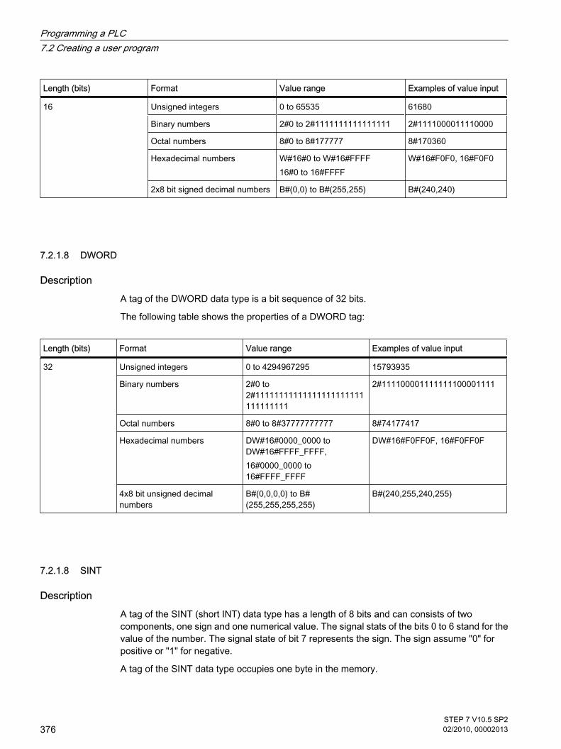
Length (bits) Format Value range Examples of value input
16 Unsigned integers 0 to 65535 61680
Binary numbers 2#0 to 2#1111111111111111 2#1111000011110000
Octal numbers 8#0 to 8#177777 8#170360
Hexadecimal numbers W#16#0 to W#16#FFFF16#0 to 16#FFFF
W#16#F0F0, 16#F0F0
2x8 bit signed decimal numbers B#(0,0) to B#(255,255) B#(240,240)
7.2.1.8 DWORD
Description A tag of the DWORD data type is a bit sequence of 32 bits.
The following table shows the properties of a DWORD tag:
Length (bits) Format Value range Examples of value input
32 Unsigned integers 0 to 4294967295 15793935
Binary numbers 2#0 to2#11111111111111111111111111111111
2#111100001111111100001111
Octal numbers 8#0 to 8#37777777777 8#74177417
Hexadecimal numbers DW#16#0000_0000 toDW#16#FFFF_FFFF,16#0000_0000 to16#FFFF_FFFF
DW#16#F0FF0F, 16#F0FF0F
4x8 bit unsigned decimalnumbers
B#(0,0,0,0) to B#(255,255,255,255)
B#(240,255,240,255)
7.2.1.8 SINT
Description A tag of the SINT (short INT) data type has a length of 8 bits and can consists of twocomponents, one sign and one numerical value. The signal stats of the bits 0 to 6 stand for thevalue of the number. The signal state of bit 7 represents the sign. The sign assume "0" forpositive or "1" for negative.
A tag of the SINT data type occupies one byte in the memory.
7.2.1.8 DWORD7.2.1.8 SINT
Programming a PLC7.2 Creating a user program
376STEP 7 V10.5 SP202/2010, 00002013

The following table shows the properties of a SINT tag:
Length (bits) Format Value range Examples of valueinput
8 Signed integers -128 to 127 +50
Binary numbers 2#0 to 0111111 2#01010000
Octal numbers 8#0 to 8#177 8#120
Hexadecimal numbers 16#0 to 16#7F 16#50
The following figure shows the integer +44 as a binary number:
7.2.1.8 USINT
Description A tag of the USINT data type (unsigned short INT) has a length of 8 bits and can containunsigned numerical values.
A tag of the USINT data type occupies one byte in the memory.
The following table shows the properties of a USINT tag:
Length (bits) Format Value range Examples of valueinput
8 Unsigned integers 0 to 255 78
Binary numbers 2#0 to 2#11111111 2#01001110
Octal numbers 8#0 to 8#377 8#116
Hexadecimal numbers 16#0 to 16#FF 16#4E
The following figure shows the integer 78 as a binary number:
7.2.1.8 USINT
Programming a PLC7.2 Creating a user program
STEP 7 V10.5 SP202/2010, 00002013
377

7.2.1.8 INT
Description A tag of the INT data type has a length of 16 bits and consists of two components: one signand one numerical value. The signal stats of the bits 0 to 14 stand for the value of the number.The signal state of bit 15 represents the sign. The sign assume the value "0" (positive) or"1" (negative).
A tag of the INT data type occupies two bytes in the memory.
The following table shows the properties of an INT tag:
Length (bits) Format Value range Examples of valueinput
16 Signed integers - 32768 to 32767 +44
Binary numbers (onlypositive)
2#0 to2#0111111111111111
2#0000000000101100
Octal numbers (onlypositive)
8#0 to 8#77777 8#54
Hexadecimal numbers (onlypositive)
16#0 to 16#7FFF 16#2C
The following figure shows the integer +44 as a binary number:
7.2.1.8 UINT
Description A tag of the UINT data type (unsigned INT) has a length of 16 bits and can contain unsignednumerical values.
A tag of the UINT data type occupies two bytes in the memory.
The following table shows the properties of a UINT tag:
7.2.1.8 INT7.2.1.8 UINT
Programming a PLC7.2 Creating a user program
378STEP 7 V10.5 SP202/2010, 00002013

Length (bits) Format Value range Examples of valueinput
16 Unsigned integers 0 to 65535 65295
Binary numbers 2#0 to2#1111111111111111
2#1111111100001111
Octal numbers 8#0 to 8#177777 8#177417
Hexadecimal numbers 16#0 to 16#FFFF 16# FF0F
The following figure shows the integer 44 as a binary number:
7.2.1.8 DINT
Description A tag of the DINT data type has a length of 32 bits and consists of two components: one signand one numerical value. The signal stats of the bits 0 to 30 stand for the value of the number.The signal state of bit 31 represents the sign. The sign assume the value "0" (positive) or"1" (negative).
A tag of the DINT data type occupies four bytes in the memory.
The following table shows the properties of a DINT tag:
Length (bits) Format Value range Examples of value input
32 Signed integers - 2 147 483 648 to + 2 147 483647
2131754992
Binary numbers 2#0 to2#01111111111111111111111111111111
2#01111111100001111111111110000
Octal numbers 8#0 to 8#17777777777 8#17703777760
Hexadecimalnumbers
16#0000_0000 to16#7FFFF_FFFF
16#7F0FFFF0
7.2.1.8 DINT
Programming a PLC7.2 Creating a user program
STEP 7 V10.5 SP202/2010, 00002013
379

7.2.1.8 UDINT
Description A tag of the UDINT data type (unsigned double INT) has a length of 32 bits and can containunsigned numerical values.
A tag of the UDINT data type occupies four bytes in the memory.
The following table shows the properties of a UDINT tag:
Length (bits) Format Value range Examples of value input
32 Unsigned integers 0 to 4294967295 4042322160
Binary numbers 2#0 to2#11111111111111111111111111111111
2#11110000111100001111000011110000
Octal numbers 8#0 to 8# 37777777777 8#36074170360
Hexadecimal numbers 16#0000_0000 to 16# FFFF_FFFF
16#F0F0F0F0
7.2.1.8 REAL
Description Tags of the REAL data type have a length of 32 bits and are used to display floating-pointnumbers. A tag of the REAL data type consists of the following three components:
• Sign: The sign is determined by the signal state of bit 31. The bit 31 assume the value "0" (positive)or "1" (negative).
• 8-bit exponents to basis 2: The exponent is increased by one constant (basis, +127), so that it has arange of 255.
• 23-bit mantissa: Only the broken part of the mantissa is shown. The integer part of the mantissa isnot stored, as it is always equal to "1" within the valid value range.
The following table shows the properties of a REAL tag:
Length (bits) Format Value range Examples of value input
32 Floating-point numbers toIEEE 754 standard
-3.402823e+38 to -1.175 495e-38±0+1.175 495e-38 to +3.402823e+38
1.0e-5
Floating-point numbers 1.0
The following figure shows the structure of a REAL tag:
7.2.1.8 UDINT7.2.1.8 REAL
Programming a PLC7.2 Creating a user program
380STEP 7 V10.5 SP202/2010, 00002013

7.2.1.8 TIME
Description A tag of the TIME data type occupies 32 bits in the memory. The duration contains informationfor days (d), hours (h), minutes (m), seconds (s) and milliseconds (ms).
The following table shows the properties of a TIME tag:
Length(bits)
Format Value range Examples of value input
32 Time period with sign: T# -24d20h31m23s648mstoT#+24d20h31m23s647ms
T#10d20h30m20s630ms,TIME#10d20h30m20s630ms,10d20h30m20s630ms;
It is not necessary to specify all time units. So for instance T#5h10s is valid. If only one unit isspecified, the absolute value of days, hours, and minutes must not exceed the high or low limits.When more than one unit of time is specified, the value of the unit must not exceed 23 hours59 minutes 59 seconds 999 milliseconds.
7.2.1.8 CHAR
Description A tag of the CHAR data type has a length of 8 bits and occupies one byte in the memory.
The CHAR data type stores a single character in ASCII format.
The following table shows the value range of the CHAR data type:
Length (bits) Format Value range Examples of value input
8 ASCII characters ASCII character set ’Q’
7.2.1.8 TIME7.2.1.8 CHAR
Programming a PLC7.2 Creating a user program
STEP 7 V10.5 SP202/2010, 00002013
381

7.2.1.8 Complex data types
7.2.1.8 Overview of the complex data types
Introduction Complex data types define data groups that are composed of other data types.
You cannot use any constants as actual parameters for complex data types. Neither can youtransfer any absolute addresses as actual parameters to complex data types.
The following table provides an overview of the complex data types:
Data type Description
DTL (Page 382) The DTL data type represents a point in time defined by thedate and time.
STRING (Page 383) The STRING data type represents a character stringcomprising a maximum of 254 characters.
ARRAY The ARRAY data type represents a field that consists of afixed number of components of the same data type.
STRUCT (Page 386) The STRUCT data type represents a structure that consistsof a fixed number of components. The various structuralcomponents can have different data types.
7.2.1.8 DTL
Description A tag of the DTL data type has a length of 12 bytes and saves information on date and time ina predefined structure.
The following table shows the properties of a DTL tag:
Length (bytes) Format Value range Example of value input
12 Clock and calendar(Year-Monthtag:Hour:Minute:Second.Nanoseconds)
Min.: DTL#1970-01-01-00:00:00.0Max.:DTL#2554-12-31-23:59:59.999 999999
DTL#2008-12-16-20:30:20.250
7.2.1.8 Complex data types7.2.1.8 Overview of the complex data types7.2.1.8 DTL
Programming a PLC7.2 Creating a user program
382STEP 7 V10.5 SP202/2010, 00002013

The structure of a DTL tag consists of several components each of which can contain a differentdata type and range of values. The data type of a specified value must match the data type ofthe corresponding components.
The following table shows the structure components of a DTL tag and its properties:
Byte Component Data type Value range
0 Year UINT 1970 to 2554
1
2 Month USINT 0 to 12
3 Day USINT 1 to 31
4 Day of week USINT 1(Sunday) to 7(Saturday)The weekday is not considered in the value entry.
5 Hour USINT 0 to 23
6 Minute USINT 0 to 59
7 Second USINT 0 to 59
8 Nanoseconds UDINT 0 to 999 999 999
9
10
11
7.2.1.8 STRING
Description A tag from the STRING data type saves several characters in a character string that consistsof maximum 254 characters. The maximum length of the character string for each tag can bespecified by the keyword STRING in square brackets (for example, STRING[4]). If theinformation on maximum length is omitted, the standard length of 254 characters is set for therespective tag.
In the memory, a tag of STRING data type occupies two bytes more than the specifiedmaximum length(s).
Tags of the STRING data type can be assigned characters. The characters are specified insingle quotation marks. If the actual length of a specified character string is shorter than thedeclared maximum length, the remaining character spaces remain empty. Only occupiedcharacter spaces are considered in the value processing.
The following table shows the properties of a STRING tag:
7.2.1.8 STRING
Programming a PLC7.2 Creating a user program
STEP 7 V10.5 SP202/2010, 00002013
383

Length (bytes) Format Value range Example of value input
n + 2 ASCII character string 0 to 254 characters 'Name'
ExampleThe example below shows the byte sequence if the STRING[4] data type is specified with outputvalue 'AB':
7.2.1.8 ARRAY
7.2.1.8 Format of ARRAY
Description The ARRAY data type represents a field that consists of a fixed number of components of thesame data type. Components of all elementary data types can be combined in an ARRAY tag.
The information on the ranges of the ARRAY components is shown in square brackets afterthe keyword ARRAY. The low limit value must be smaller than or equal to the high limit valueof a range. An ARRAY can contain a dimension.
The following table shows the properties of an ARRAY tag:
Length Format Value range
Number of elements * length ofthe data type
ARRAY [low limit value...highlimit value] of <data type>
[- 32 768.. +32 767] of <datatype>
ExampleThe following example shows how tags of the ARRAY data type can be declared:
7.2.1.8 ARRAY7.2.1.8 Format of ARRAY
Programming a PLC7.2 Creating a user program
384STEP 7 V10.5 SP202/2010, 00002013

Name Data type Comment
Measured value ARRAY[1..20] of REAL One-dimensional ARRAY tagwith 20 components
Time-of-day ARRAY[-5..5] of INT One-dimensional ARRAY tagwith 11 components
See alsoDeclaring tags of ARRAY data type (Page 437)Example of a one-dimensional ARRAY (Page 385)
7.2.1.8 Example of a one-dimensional ARRAY
Declaration of a one-dimensional ARRAY tag The following table shows the declaration of a one-dimensional ARRAY tag:
Name Data type Comment
Op_Temp ARRAY[1..3] of INT One-dimensional ARRAY tag with 3 components.
The following figure shows the structure of the declared ARRAY tag:
Access to ARRAY componentsThe individual array components are accessed via an index.. The index of the first ARRAYcomponent is [1], of the second [2], and of the third [3]. To access the value of the secondARRAY component, the specification "OP_Temp[2]" is required in the program in this case.
The tag "Op_Temp" could also be declared as ARRAY[-1..1] of INT. The index of the firstARRAY components would then be [-1], of the second [0], and of the third [1].
See alsoFormat of ARRAY (Page 384)Declaring tags of ARRAY data type (Page 437)
7.2.1.8 Example of a one-dimensional ARRAY
Programming a PLC7.2 Creating a user program
STEP 7 V10.5 SP202/2010, 00002013
385

7.2.1.8 STRUCT
Description A tag of the STRUCT data type saves values in a structure that consists of a fixed number ofcomponents. The various structural components can have different data types. It is not possibleto nest structures in a STRUCT tag.
A STRUCT tag always starts with one byte with even address and occupies the memory up tothe next word limit.
The following table shows the properties of a STRUCT tag:
Length Format Value range Example of value input
A STRUCT tag startswith one byte with evenaddress and occupiesthe memory up to thenext word limit.
STRUCT The value ranges of theused data types apply.
The value input rules ofthe used data typesapply.
The following figure shows an example of the structure of a STRUCT tag:
See alsoDeclaring tags of STRUCT data type (Page 438)
7.2.1.8 Parameter types
7.2.1.8 Overview of parameter types
Introduction In addition to the elementary and complex data types, you can also define parameter types forformal parameters that are transferred between blocks.
The following table provides an overview of parameter types:
7.2.1.8 STRUCT7.2.1.8 Parameter types7.2.1.8 Overview of parameter types
Programming a PLC7.2 Creating a user program
386STEP 7 V10.5 SP202/2010, 00002013

Parameter Size (bytes) Description
VARIANT (Page 387) 0 A parameter of the VARIANT type is a pointer that can point to tags of various dataor parameter types. The VARIANT parameter type can recognize structures andpoint to these.
VOID - Saves no values. The VOID data type is used if a function requires no return value.
7.2.1.8 VARIANT
Description A parameter of the VARIANT type is a pointer that can point to tags of various data or parametertypes. The VARIANT parameter type can recognize structures and point to these. With theparameter type VARIANT you can also point to individual components of a STRUCT tag. AVARIANT parameter type tag does not occupy any space in the memory.
The following table shows the properties of the VARIANT parameter type:
Representation
Format Length (bytes) Example of value input
Symbolic Operand 0 MyTag
NameDataBlock.NameOperand.Component
MyDB.StructTag.FirstComponent
Absolute Operand %MW10
DataBlockNumber.Operand Type Length P#DB10.DBX10.0 INT12
7.2.1.8 VOID
DescriptionThe VOID data type saves no values. It is used if a function requires no return value.
7.2.1.8 VARIANT7.2.1.8 VOID
Programming a PLC7.2 Creating a user program
STEP 7 V10.5 SP202/2010, 00002013
387

7.2.1.8 System data types
7.2.1.8 System data types
DescriptionThe system data types (SDT) are made available by the system and have a predefinedstructure. The structure of a system data type consists of a fixed number of components thatcan have various data types. It is not possible to change the structure of a system data type.
The system data types can only be used for specific instructions. The following table showsthe available system data types and their purpose:
System data type Structure length in bytes Description
IEC_TIMER 16 Structure of a clock This data type is used for the "TP","TOF", "TON" and "TONR" instructions,for example.
IEC_SCOUNTER 3 Structure of a counter, the count ofwhich is the SINT data type This data type is used for the CTU","CTD" and "CTUD" instructions, forexample.
IEC_USCOUNTER 3 Structure of a counter, the count ofwhich is the USINT data type This data type is used for the CTU","CTD" and "CTUD" instructions, forexample.
IEC_COUNTER 6 Structure of a counter, the count ofwhich is the INT data type This data type is used for the CTU","CTD" and "CTUD" instructions, forexample.
IEC_UCOUNTER 6 Structure of a counter, the count ofwhich is the UINT data type This data type is used for the CTU","CTD" and "CTUD" instructions, forexample.
IEC_DCOUNTER 12 Structure of a counter, the count ofwhich is the DINT data type This data type is used for the CTU","CTD" and "CTUD" instructions, forexample.
7.2.1.8 System data types7.2.1.8 System data types
Programming a PLC7.2 Creating a user program
388STEP 7 V10.5 SP202/2010, 00002013

System data type Structure length in bytes Description
IEC_UDCOUNTER 12 Structure of a counter, the count ofwhich is the UDINT data type This data type is used for the CTU","CTD" and "CTUD" instructions, forexample.
ERROR_STRUCT 28 Structure of error information for aprogramming or I/O access error This data type is used for the"GET_ERROR" instruction, forexample.
CONDITIONS 52 Defined data structure, that define theconditions for the start and end of datareception. This data type is used for the"RCV_GFG" instruction, for example.
TCON_Param 64 Specifies the structure of a data blockwhich stores descriptions ofconnections for open communicationvia Industrial Ethernet (PROFINET).
VOID - The VOID data type saves no values.This data type is used if no return valuesare required for an output. The VOIDdata type, for example, can be specifiedat the STATUS output if no errorinformation is required.
7.2.1.8 Hardware data types
7.2.1.8 Hardware data types
DescriptionThe hardware data types are made available by the CPU. The number of available hardwaredata types depends on the CPU.
Constants of a specific hardware data type are stored based on the modules set in the hardwareconfiguration. When an instruction for controlling or activating a configured module is insertedin the user program, the available constants can be used for the parameters.
The following table shows the available hardware data types and their purpose:
7.2.1.8 Hardware data types7.2.1.8 Hardware data types
Programming a PLC7.2 Creating a user program
STEP 7 V10.5 SP202/2010, 00002013
389

Data type Basic data type Description
HW_ANY WORD Identification of any HWcomponent, such as a module
HW_IO HW_ANY Identification of an I/Ocomponent
HW_SUBMODULE HW_IO Identification of a central HWcomponent
HW_INTERFACE HW_SUBMODULE Identification of an interfacecomponent
HW_HSC HW_SUBMODULE Identification of a fast counter This data type is used for the"CTRL_HSC" instruction, forexample.
HW_PWM HW_SUBMODULE Identification of pulse widthmodulation This data type is used for the"CTRL_PWM" instruction, forexample.
HW_PTO HW_SUBMODULE Identification of a pulse sensor This data type is used for motioncontrol
AOM_IDENT DWORD Identification of an object in theruntime system of the AS.
EVENT_ANY AOM_IDENT Used to identify any event
EVENT_ATT EVENT_ANY Used to identify an event that canbe dynamically assigned to anOB. This data type is used for the"ATTACH" and "DETACH"instructions, for example.
EVENT_HWINT EVENT_ATT Used to identify a hardwareinterrupt event.
OB_ANY INT Used to identify any OB.
OB_DELAY OB_ANY Used to identify an OB calledwhen a time-delay interruptoccurs. This data type is used, forexample, for the "SRT_DINT"and "CAN_DINT" instructions.
OB_CYCLIC OB_ANY Used to identify an OB calledwhen a cyclic interrupt occurs.
Programming a PLC7.2 Creating a user program
390STEP 7 V10.5 SP202/2010, 00002013

Data type Basic data type Description
OB_ATT OB_ANY Used to identify an OB that canbe dynamically assigned to anevent. This data type is used for the"ATTACH" and "DETACH"instructions, for example.
OB_PCYCLE OB_ANY Used to identify an OB that canbe assigned to an event of the"Cyclic program" event class.
OB_HWINT OB_ATT Used to identify an OB calledwhen a hardware interruptoccurs.
OB_DIAG OB_ANY Used to identify an OB calledwhen a diagnostic error interruptoccurs.
OB_TIMEERROR OB_ANY Used to identify an OB calledwhen a time error occurs.
OB_STARTUP OB_ANY Used to identify an OB calledwhen a startup event occurs.
PORT UINT Used to identify a communicationport This data type is used for point-to-point communication.
CONN_ANY WORD Used to identify any connection
CONN_OUC CONN_ANY Used to identify a connection foropen communication viaIndustrial Ethernet (PROFINET)
7.2.1.8 Data type conversion
7.2.1.8 Overview of data type conversion
Introduction If you link several operands in an instruction, you must make sure that the data types arecompatible. This applies also for assignments or for supplying block parameters. If theoperands are not the same data type, a conversion has to be carried out.
There are two options for the conversion:
• Implicit conversion
The conversion take place automatically when the instruction is executed.
7.2.1.8 Data type conversion7.2.1.8 Overview of data type conversion
Programming a PLC7.2 Creating a user program
STEP 7 V10.5 SP202/2010, 00002013
391

• Explicit conversion
You use an explicit conversion instruction before the actual instruction is executed.
Implicit conversionAn implicit conversion is executed automatically if the data types of the operands arecompatible. This compatibility test can be carried out according to criteria that are more or lessstrict:
• With IEC check (default setting):
Strict compatibility rules are applied: Operands that are linked in an instruction have to be of the samedata type.
• Without IEC check
The compatibility test is carried out according to rules that are less strict. Operands that are linked inan instruction do not necessarily have to be of the same data type. However, the data types have tohave the same data width.
When IEC check is disabled you can, for example, link an operand of the INT data type with an operandof the WORD data type.
Note
The conversion from REAL to TIME or TIME to REAL is an exception. This conversion isimplicitly not possible.
Explicit conversionIf the operands are not compatible and an implicit conversion is therefore not possible, you canuse an explicit conversion instruction. You can find the conversion instructions in the"Instructions" task card in the sections "Math", "String + Char" and "Convert".
The advantage with explicit conversion is that any violation of the range can be checked at theENO output.
The following figure shows an example in which an explicit data type conversion must be carriedout:
The "Block" function block expects a tag of the INT data type at the "IN_INT" input parameter.The value in the "IN_DINT" tag therefore first must be converted from DINT to INT. It can thenbe transferred with the INT data type to "Block".
During conversion from DINT to INT the low-value bits of DINT are used and interpreted asINT. However, a currently existing sign can get lost in the process.
Programming a PLC7.2 Creating a user program
392STEP 7 V10.5 SP202/2010, 00002013

See alsoSetting IEC test (Page 393)
7.2.1.8 Setting IEC test
When an instruction is executed, the data types are checked for compatibility to the employedoperands. This compatibility test can be carried out according to criteria that are more or lessstrict. If "IEC Check" is activated, stricter criteria are applied.
You can set the IEC check centrally for all new blocks of the project or for specific blocks.
Setting IEC check for new blocksTo set the IEC check for all new blocks in the project, proceed as follows:
1. Select the "Settings" command in the "Options" menu.
The "Settings" window is displayed in the work area.
2. Select the "PLC programming > General" group in the area navigation.
3. Select or clear the "IEC Check" check box in the "Default settings for new blocks" group.
The IEC check is enabled or disabled for all new blocks in the program.
Setting IEC check for a blockTo set the IEC check for a block, proceed as follows:
1. Open the block.
2. Open the "Properties" tab in the inspector window.
3. Click the "Attributes" group in area navigation.
4. Select or clear the "IEC Check" check box.
The IEC check is enabled or disabled for this block. The setting is not saved, however, until the projectis saved.
See alsoOverview of data type conversion (Page 391)
7.2.1.9 Procedure for block programming
7.2.1.9 Basic procedure
OverviewAfter you have created the concept for the automation solution, the next step is to implementit. We recommend the following procedure:
7.2.1.8 Setting IEC test7.2.1.9 Procedure for block programming7.2.1.9 Basic procedure
Programming a PLC7.2 Creating a user program
STEP 7 V10.5 SP202/2010, 00002013
393

Declaring PLC tags
↓
Creating blocks (Page 406)
↓
Declaring local tags (Page 432)
↓
Creating program code (Page 443)
↓
Save (Page 146)
↓
Compile (Page 527)
↓
Load (Page 528)
↓
Test (Page 565)
7.2.2 Declaring PLC tags
7.2.2.1 Structure of the PLC tag table
Definition The PLC tag table contains the definition of the tags and constants that are valid throughoutthe CPU. A PLC tag table is created automatically for each CPU used in the project. The PLCtag table contains a tab for tags and a tab for constants.
Structure of the "PLC tags" tabIn the "PLC tags" tab you declare the global tags that you require in the program. The followingfigure shows the tab structure:
The following table shows the meaning of the individual columns:
7.2.2 Declaring PLC tags7.2.2.1 Structure of the PLC tag table
Programming a PLC7.2 Creating a user program
394STEP 7 V10.5 SP202/2010, 00002013

Column Description
Symbol you can click in order to move a tag into a network via a drag-and-drop operation for use as an operand.
Name Unique name throughout the CPU that you specify for the tag.
Data type Data type that you specify for the tag
Address Tag address.
Retain Marks the tag as retentive.The values of retentive tags are retained even after the power supplyis switched off.
Monitor value Current data value in the CPU.This column only appears if an online connection is available andyou select the "Monitor" button.
Comment Comments to document the tags.
Structure of the "Constants" tabThe constants required by the system are shown in the "Constants" tab. The following figureshows the tab structure:
The following table shows the meaning of the individual columns:
Column Description
Symbol for the constants
Name CPU-wide unique name for the constants.
Data type Data type of the constants
Value Value of the constants,
Comment Comments to document the tags.
See alsoData types (Page 373)Hardware data types (Page 389)Opening the PLC tag table (Page 396)Declaring tags in the PLC tag table (Page 398)
Programming a PLC7.2 Creating a user program
STEP 7 V10.5 SP202/2010, 00002013
395

PLC tags and local tags (Page 365)Basics of constants (Page 372)Symbolic programming (Page 361)Keyboard shortcuts in tables (Page 134)
7.2.2.2 Opening the PLC tag table
Procedure To open the PLC tag table in a CPU, proceed as follows:
1. Open the "PLC tags" folder under the CPU in the project tree.
2. Double-click the PLC tag table in the folder.
3. In the top right corner select the "PLC tags" tab or the "Constants" tab.
ResultThe PLC tag table associated with the CPU opens. You can declare the required tags andconstants.
7.2.2.3 Declaring PLC tags
7.2.2.3 Rules for PLC tags
7.2.2.3 Permissible addresses and data types of PLC tags
Mnemonics used The addresses that you enter in the PLC tag table are automatically adapted to the setmnemonics.
Permissible addresses and data types for tagsThe following table shows the permissible addresses and data types:
Englishmnemonics
Germanmnemonics
Explanation: Data type: Address area:
I E Input bit BOOL 0.0..1023.7
IB EB Input byte BYTE, CHAR, SINT,USINT
0..1023
IW EW Input word WORD, INT, UINT 0..1022
7.2.2.2 Opening the PLC tag table7.2.2.3 Declaring PLC tags7.2.2.3 Rules for PLC tags7.2.2.3 Permissible addresses and data types of PLC tags
Programming a PLC7.2 Creating a user program
396STEP 7 V10.5 SP202/2010, 00002013

Englishmnemonics
Germanmnemonics
Explanation: Data type: Address area:
ID ED Input double word DWORD, DINT,UDINT, REAL, TIME
0..1020
Q A Output bit BOOL 0.0..1023.7
QB AB Output byte BYTE, CHAR, SINT,USINT
0..1023
QW AW Output word WORD, INT, UINT 0..1022
QD AD Output double word DWORD, DINT,UDINT, REAL, TIME
0..1020
M M Memory bit BOOL 0.0..8191.7
MB MB Memory byte BYTE, CHAR, SINT,USINT
0..8191
MW MW Memory word WORD, INT, UINT 0..8190
MD MD Memory double word DWORD, DINT,UDINT, REAL, TIME
0..8188
See alsoSetting the mnemonics (Page 443)
7.2.2.3 Incomplete and ambiguous entries in the PLC tag table
Incomplete definitions You can save even incompletely defined tags or constants. For example, you can first specifyjust the name and later add the data type information. You can therefore interrupt your workon the PLC tag table at any time and save the interim information.
However you cannot compile blocks that contain these tags or constants until their definitionis complete.
Ambiguous definitionsThe names of the PLC tags must be unique throughout the CPU. You cannot use a name thathas already been assigned to an object within the CPU – for example, a block or another PLCtag – for a new PLC tag. If you enter an already assigned name another time, a sequentialnumber is automatically appended to the second name entered. For example, if you enter thename "Motor" a second time, the second entry will be changed to "Motor_1".
The addresses must also be unique throughout the CPU. If you enter an address that is alreadyassigned to another tag, the address will be highlighted at both places in yellow and an errormessage will be issued.
7.2.2.3 Incomplete and ambiguous entries in the PLC tag table
Programming a PLC7.2 Creating a user program
STEP 7 V10.5 SP202/2010, 00002013
397

7.2.2.3 Declaring PLC tags
7.2.2.3 Declaring tags in the PLC tag table
RequirementThe "PLC tags" tab of the PLC tag table is open.
ProcedureTo define PLC tags, proceed as follows:
1. Enter a tag name in the "Name" column.
2. Click the arrow key in the "Data type" column and select the desired data type.
An address corresponding to the data type is automatically appended.
3. If necessary, modify the address of the tag in the "Address" column.
4. If you want, enter comments in the "Comment" column.
5. Repeat steps 1 to 4 for all the tags you require.
See also: Permissible addresses and data types of PLC tags (Page 396)
Syntax checkA syntax check is performed after each entry, and any errors found are displayed in red. Youdo not have to correct these errors immediately - you can continue editing and make anycorrections later. However, you will not be able to compile the program if the tag declarationcontains syntax errors.
See alsoIncomplete and ambiguous entries in the PLC tag table (Page 397)Structure of the PLC tag table (Page 394)Editing the PLC tag table (Page 405)Inserting table rows (Page 0 )Sorting rows in the PLC tag table (Page 405)Keyboard shortcuts in tables (Page 134)
7.2.2.3 Declaring PLC tags in the program editor
Requirement
• The program editor is open.
• One or more operands are used in the program.
ProcedureTo declare operands as global PLC tags, proceed as follows:
7.2.2.3 Declaring PLC tags7.2.2.3 Declaring tags in the PLC tag table7.2.2.3 Declaring PLC tags in the program editor
Programming a PLC7.2 Creating a user program
398STEP 7 V10.5 SP202/2010, 00002013

1. Select one or more operands.
2. Select the "Define tag" command in the shortcut menu.
The "Define tag" dialog box opens. This dialog box displays a declaration table in which the name ofthe operand is already entered.
3. Click the arrow key in the "Section" column and select one of the following entries:
― Global Memory
― Global Input
― Global Output
4. In the other columns, enter the address, data type, and comments.
See also: Permissible addresses and data types of PLC tags (Page 396)
5. Click the "Define" button to complete your entry.
ResultThe tag declaration is written to the PLC tag table and is valid for all blocks in the CPU.
See alsoIncomplete and ambiguous entries in the PLC tag table (Page 397)Keyboard shortcuts in tables (Page 134)Automatically filling in cells in the PLC tag table (Page 404)
7.2.2.3 Changing addresses of PLC tags
You can change the address of a PLC tag in the PLC tag table or directly in the program editor.The changes take immediate effect throughout the entire program.
Procedure To change the address of a PLC tag, proceed as follows:
1. Double-click on the PLC tag table in the project tree.
The PLC tag table opens.
2. Open the "Tag" tab.
3. Change the entry in the "Address" column.
Or
1. Select one or more tags at their point of use in the program.
2. Select the "Rewire tag" command in the shortcut menu.
The "Rewire tag" dialog box opens.
3. Change the entry in the "Address" column.
4. Click the "Change" button to complete your entry.
7.2.2.3 Changing addresses of PLC tags
Programming a PLC7.2 Creating a user program
STEP 7 V10.5 SP202/2010, 00002013
399

ResultThe address of the tag is changed automatically at all points of use in the program.
See alsoPermissible addresses and data types of PLC tags (Page 396)
7.2.2.3 Changing the name of PLC tags
You can change the name of a PLC tag in the PLC tag table or directly in the program editor.The changes take immediate effect throughout the entire program.
Procedure To change the name of PLC tag, follow these steps:
1. Double-click on the PLC tag table in the project tree.
The PLC tag table opens.
2. Open the "Tag" tab.
3. Change the entry in the "Name" column.
Or
1. Select one or more tags at their point of use in the program.
2. Select the "Rename tag" command in the shortcut menu.
The "Rename tag" dialog box opens.
3. Change the entry in the "Name" column.
4. Click the "Change" button to complete your entry.
ResultThe name of the tag is changed automatically at all points of use in the program.
See alsoPermissible addresses and data types of PLC tags (Page 396)
7.2.2.3 Changing the name of PLC tags
Programming a PLC7.2 Creating a user program
400STEP 7 V10.5 SP202/2010, 00002013

7.2.2.3 Setting the retentivity of PLC tags
7.2.2.3 Retentive behavior of PLC tags
Retentive memory areas for bit memories To prevent data loss in the event of power failure, you can define a retentive memory area forbit memories. A retentive memory area is an area whose content is retained after the switchingoff of the supply voltage and after switching on upon a transition from "STOP" to "RUN". Youcan specify the exact width of the retentive memory area in the PLC tag table.
The values of retentive memory area are saved to the backup memory on the CPU. Thesevalues are retained in the event of a hot restart.
See alsoSetting the retentive behavior of PLC tags (Page 401)
7.2.2.3 Setting the retentive behavior of PLC tags
Introduction In the PLC tag table you can specify the width of the retentive memory area for bit memories.All tags that are addressed in this memory area are then designated as retentive. You canrecognize the retentivity setting of a tag by the check mark set in the "Retain" column of thePLC tag table.
RequirementThe "PLC tags" tab of the PLC tag table is open.
ProcedureTo define the width of the retentive memory area for bit memories, proceed as follows:
1. On the toolbar, click the "Retain" button.
The "Retain memory" dialog box opens.
2. Specify the width of the retentive memory area by entering the last byte of the area, counting from 0,in the text box. When specifying not the addresses of existing tags that are declared as bit memories.
3. Click the "OK" button.
ResultThe width if the retentive memory area is defined. In the "Retain" column of the tag table acheck mark is automatically set for all tags that are located within the retentive memory area.
See alsoRetentive behavior of PLC tags (Page 401)
7.2.2.3 Setting the retentivity of PLC tags7.2.2.3 Retentive behavior of PLC tags7.2.2.3 Setting the retentive behavior of PLC tags
Programming a PLC7.2 Creating a user program
STEP 7 V10.5 SP202/2010, 00002013
401

7.2.2.3 Editing the properties of PLC tags
7.2.2.3 Properties of PLC tags
Overview The following table gives an overview of the properties of PLC tags:
Group Property Description
General Tag name A unique name within the table.
Address Tag address.
Comment Comment on the tag,
Data type Data type of the tags.
Time stamp Created on Time when the tag was created (cannot be changed).
Changed on Time when the tag was last changed (cannot be changed).
Usage Visible in HMI Default setting for the operand selection in HMI.
Read only for HMI Write protection in HMI
User defined sortcriterion
Identifier for sorting the tags in external tables.
Values Initial value Value of the tag if a current value is not stored in a datablock.This value must be compatible with the declared data type.
Low limit Value that the tag may not be less than.
High limit Value that the tag may not exceed.
See alsoEditing the properties of PLC tags (Page 402)
7.2.2.3 Editing the properties of PLC tags
Editing general properties in the PLC tag table To edit the general properties of one or more tags, proceed as follows:
1. Double-click the PLC tag table of the CPU in the project tree.
The PLC tag table opens.
2. Change the entries in the "Name", "Address", or "Comment" columns.
7.2.2.3 Editing the properties of PLC tags7.2.2.3 Properties of PLC tags7.2.2.3 Editing the properties of PLC tags
Programming a PLC7.2 Creating a user program
402STEP 7 V10.5 SP202/2010, 00002013

Editing detailed properties in the properties windowTo edit the detailed properties of an individual tag, proceed as follows:
1. Select a tag in the network.
2. Select the "Properties" command in the shortcut menu.
The properties dialog opens. This dialog displays the detailed properties of the tag.
3. Change the entries in the properties window.
See alsoProperties of PLC tags (Page 402)
7.2.2.4 Monitoring of PLC tags
7.2.2.4 Monitoring of PLC tags
You can monitor the current data values of the tags on the CPU directly in the PLC tag table.
Requirement An online connection is available.
ProcedureTo monitor the data values, proceed as follows:
1. Start monitoring by clicking the "Monitor all" button.
The additional "Monitor value" column is displayed in the table. This shows the current data values.
2. End the monitoring by clicking the "Monitor all" button again.
See alsoStructure of the PLC tag table (Page 394)
7.2.2.5 Editing the PLC tag table
7.2.2.5 Copying entries in the PLC tag table
You can copy PLC tags within a table.
Procedure To copy a tag, proceed as follows:
1. Select the tags you want to copy.
7.2.2.4 Monitoring of PLC tags7.2.2.4 Monitoring of PLC tags7.2.2.5 Editing the PLC tag table7.2.2.5 Copying entries in the PLC tag table
Programming a PLC7.2 Creating a user program
STEP 7 V10.5 SP202/2010, 00002013
403

You can also select several tags by clicking on them one after the other while holding down the <Ctrl>key or by pressing and holding down <Shift> and clicking on the first and last tag.
2. Select "Copy" in the shortcut menu.
3. Position the insertion pointer at the location where you want to insert the tags.
4. Select "Paste" in the shortcut menu.
Or
1. Select the tag.
2. Hold down the left mouse button.
3. At the same time, press <Ctrl>.
4. Drag the tag to the destination.
Result
• The tag is copied to the destination.
• If there is a name conflict, a number is automatically appended to the tag name. For example, "Tag"would become "Tag_1".
• All other properties of the tag remain unchanged.
See alsoKeyboard shortcuts in tables (Page 134)Adapting tables (Page 131)
7.2.2.5 Deleting entries in the PLC tag table
Procedure To delete a tag, proceed as follows:
1. Select the row with the tag to be deleted. You can also select several rows by clicking on them oneafter the other while holding down the <Ctrl> key or by pressing and holding down <Shift> and clickingon the first and last row.
2. Select the "Delete" command in the shortcut menu.
See alsoAdapting tables (Page 131)Keyboard shortcuts in tables (Page 134)
7.2.2.5 Automatically filling in cells in the PLC tag table
You can load the contents of one or several table cells into the cells below and thusautomatically fill in up to 100 successive cells.
If you automatically fill in cells in the "Name" column, a consecutive number will be appendedto each name. For example, "Motor" will become "Motor_1".
7.2.2.5 Deleting entries in the PLC tag table7.2.2.5 Automatically filling in cells in the PLC tag table
Programming a PLC7.2 Creating a user program
404STEP 7 V10.5 SP202/2010, 00002013

If you fill the cells in the column "address" automatically, the addresses will be increaseddepending on the indicated data type.
Procedure To automatically fill in successive cells, proceed as follows:
1. Select the cells to be loaded.
2. Click the "Fill" symbol in the bottom right corner of the cell.
The mouse pointer is transformed into a crosshair.
3. Keep the mouse button pressed and drag the mouse pointer downwards over the cells that you wantto fill in automatically.
4. Release the mouse button.
See alsoAdapting tables (Page 131)Keyboard shortcuts in tables (Page 134)
7.2.2.5 Inserting table rows
Procedure To insert row above the position of the mouse pointer, proceed as follows:
1. Position the mouse pointer in the row above which you want to insert a new row.
2. Click the "Insert row" button on the toolbar of the table.
A new row is inserted above the selected row.
See alsoKeyboard shortcuts in tables (Page 134)Adapting tables (Page 131)
7.2.2.5 Sorting rows in the PLC tag table
You can sort the rows in the table alphanumerically by name, data type, or address.
Procedure To sort the table rows, proceed as follows:
1. Select the column by which you want to sort.
2. Click the column header.
The column will be sorted in order of increasing values.
An up arrow shows the sort sequence.
3. In order to change the sort sequence, click the arrow.
7.2.2.5 Inserting table rows7.2.2.5 Sorting rows in the PLC tag table
Programming a PLC7.2 Creating a user program
STEP 7 V10.5 SP202/2010, 00002013
405

The column will be sorted in order of decreasing values.
A down arrow shows the sort sequence.
4. To restore the original sequence, click a third time on the column header.
See alsoKeyboard shortcuts in tables (Page 134)Adapting tables (Page 131)
7.2.3 Creating and managing blocks
7.2.3.1 Creating blocks
7.2.3.1 Block folder
FunctionYou can find a "Program blocks" folder in the project tree, in which you can create and managethe following blocks:
• Organization blocks (OB) (Page 406)
• Function blocks (FB) (Page 407)
• Functions (FC) (Page 407)
• Data blocks (DB) (Page 0 )
A program cycle OB is automatically generated for each device and inserted in the "Programblocks" folder.
7.2.3.1 Creating organization blocks
RequirementThe "Program blocks" folder opens in the project tree.
ProcedureTo create an organization block, proceed as follows:
1. Double-click the "Add new block" command.
The "Add new block" dialog box opens.
2. Click the "Organization block (OB)" button.
3. Select an organization block.
7.2.3 Creating and managing blocks7.2.3.1 Creating blocks7.2.3.1 Block folder7.2.3.1 Creating organization blocks
Programming a PLC7.2 Creating a user program
406STEP 7 V10.5 SP202/2010, 00002013

4. Select the "Manual" option button if you want to assign the number of the organization block.
5. In the "Language" drop-down list, select the programming language for the new organization block.
6. If you insert a cyclic interrupt OB, you can enter the cycle time in the "Scan time" text box.
7. To add additional properties for the new organization block, click the arrow beside "Furtherinformation" in the lower part of the dialog box.
An area with further input fields is displayed.
8. Enter all the properties you require.
9. Confirm your entries with "OK".
ResultThe new organization block is created. You can find the organization block in the project treein the "Program blocks" folder.
Note
You can select the "Add new and open" check box at the bottom of the dialog box. As a result,the organization block will be opened immediately after it is created.
See alsoOrganization blocks (OB) (Page 337)Assigning parameters to hardware interrupt OBs (Page 417)Assigning parameters to cyclic interrupt OBs (Page 418)
7.2.3.1 Creating functions and function blocks
Requirement The "Program blocks" folder opens in the project tree.
ProcedureTo create a function (FC) or a function block (FB), proceed as follows:
1. Double-click the "Add new block" command.
The "Add new block" dialog box opens.
2. Click the "function block (FB)" or "function (FC)" button.
3. Enter a name for the block.
4. In the "Language" drop-down list, select the programming language for the new block.
5. Select the "Manual" option button if you want to assign the number of the block.
6. If you choose to use manual assignment, enter the block number in the input field.
7.2.3.1 Creating functions and function blocks
Programming a PLC7.2 Creating a user program
STEP 7 V10.5 SP202/2010, 00002013
407

7. To add additional properties for the new block, click the arrow beside "Further information" in the lowerpart of the dialog box.
An area with further input fields is displayed.
8. Enter all the properties you require.
9. Confirm your entries with "OK".
ResultThe new block is created. You can find the block in the project tree in the "Program blocks"folder.
Note
You can select the "Add new and open" check box at the bottom of the dialog box. As a result,the block will be opened immediately after it is created.
See alsoFunction blocks (FB) (Page 346)Functions (FCs) (Page 346)
7.2.3.1 Creating data blocks
Prerequisites The "Program blocks" folder opens in the project tree.
ProcedureTo create a data block, proceed as follows:
1. Double-click the "Add new block" command.
The "Add new block" dialog box opens.
2. Click the "Data block (DB)" button.
3. Enter a name for the data block.
4. Select the type of the data block. You have the following options available to you:
― To create a global data block, select the list entry "Global DB".
― To create an instance data block, select the function block to which you want to assign the instancedata block from the list.
5. Select the "Manual" option button if you want to assign the number of the block.
6. If you choose to use manual assignment, enter the block number in the input field.
7. To add additional properties for the data new block, click the arrow beside "Further information" in thelower part of the dialog box.
7.2.3.1 Creating data blocks
Programming a PLC7.2 Creating a user program
408STEP 7 V10.5 SP202/2010, 00002013

An area with further input fields is displayed.
8. Enter all the properties you require.
9. Confirm your entry with "OK".
ResultThe new data block is created. You can find the data block in the project tree in the "Programblocks" folder.
Note
You can select the "Add new and open" check box at the bottom of the dialog box. As a result,the block will be opened immediately after it is created.
See alsoInstance data blocks (Page 347)Programming data blocks (Page 510)Global data blocks (DB) (Page 347)
7.2.3.1 Using blocks from libraries
You can save blocks in the project library or in a global library, so that you can use them morethan once within a user program.
Requirement
• The "Libraries" task card is displayed.
• No write protection is set for global libraries.
Adding blocks to the project library or to a global libraryTo add new blocks to the project library or to a global library, proceed as follows:
1. Select the block that you want to add to the library.
2. Use a drag-and-drop operation to move the selected block to the book symbol of the library in thelibrary pane in the "Libraries" task card. Don't release the left mouse button until a small plus signappears underneath the mouse pointer.
Using blocks of the project library or a global libraryTo use a block from the project library or a global library in your project, proceed as follows:
1. Maximize the project library or the global library, so that you can see the elements of the library.
2. Use a drag-and-drop operation to move the block to the CPU block folder. If the selected insertionpoints is not allowed, the mouse pointer will appear as a circle with a slash.
7.2.3.1 Using blocks from libraries
Programming a PLC7.2 Creating a user program
STEP 7 V10.5 SP202/2010, 00002013
409

See alsoWorking with libraries (Page 177)Opening a global library (Page 183)
7.2.3.1 Copying and pasting blocks
7.2.3.1 Principles of copying and inserting blocks
Function You can also create new blocks by copying existing blocks and pasting the copy. Observe thefollowing principles when using this method:
• You can copy organization blocks (OBs), functions (FCs), function blocks (FBs), and global datablocks (DBs) without restriction.
• You can copy instance data blocks only for the same function block, since the assignment to thefunction block cannot be changed afterwards. However, the assignment is canceled if you copy theinstance data block to a different CPU. If a function block with the same number exists there, theinstance data block will be assigned to this function block. If you copy the instance data block togetherwith the function block into the other CPU, the instance data block is assigned to the copy of thefunction block.
Copying dataWith paste, all the block data is copied and forwarded to the copy. This data includes:
• Block interface tags
• All networks
• Comments in all existing compilations
• Interrupts defined in the block
• The entire program code of the copied block including the call instructions contained in the block.
However, called blocks and their associated instance data blocks are not copied.
Avoiding name conflicts during pastingWhen pasting copied blocks with identical names to already existing blocks, the followingmechanisms are used to avoid name conflicts:
• Pasting the copied block into the same CPU:
The copy of the block gets a name that is extended by a number. For example, if block "A" is copied,a possible name for the copy is "A_1". Consecutive numbering is not used, but rather the smallestfree number. The copy of block "A" can also get the name "A_25", if no lower number is available.
• Pasting the copied block into another CPU:
A dialog box opens in which you can select whether the block with the same name will be replacedor the copied block will be pasted with a duplicate designation (Name_Number).
7.2.3.1 Copying and pasting blocks7.2.3.1 Principles of copying and inserting blocks
Programming a PLC7.2 Creating a user program
410STEP 7 V10.5 SP202/2010, 00002013

Note
Number conflicts may occur, if the pasted block has the same block number as an existingblock. The block number is not automatically changed during pasting. This double number mayhave an effect on block calls. When you copy blocks you should therefore check the blocknumber carefully and correct duplicate block numbers manually or using the block properties.
See alsoCopying blocks (Page 411)Inserting blocks (Page 411)
7.2.3.1 Copying blocks
RequirementThe "Program blocks" folder is opened in the project tree.
ProcedureTo copy a block, follow these steps:
1. Right-click the block that you want to copy.
2. Select "Copy" in the shortcut menu.
ResultA copy of the block is now on the clipboard and can be pasted either into the same CPU or intoanother one.
See alsoPrinciples of copying and inserting blocks (Page 410)
7.2.3.1 Inserting blocks
RequirementYou have copied a block.
Procedure To paste a copied block and its data into a CPU, proceed as follows:
1. In the project tree, open the folder structure for the CPU into which you want to paste the copied block.
2. Right-click on the "Program blocks" folder.
3. Select "Paste" in the shortcut menu.
7.2.3.1 Copying blocks7.2.3.1 Inserting blocks
Programming a PLC7.2 Creating a user program
STEP 7 V10.5 SP202/2010, 00002013
411
― If you are pasting the block into the same CPU as the original block, "_<consecutive number>" willbe appended to the name of the copy.
― If you are pasting the block into a different CPU where a block of the same name already exists,the "Paste" dialog box opens. Select the required option and confirm with "OK".
See alsoPrinciples of copying and inserting blocks (Page 410)
7.2.3.1 Entering a block title
The block title is the title of the block. It is not the same thing as the block name, which wasassigned when the block was created. The length of the block title is restricted to one row. Youcan enter the block title for open and closed blocks.
Requirement A code block is available.
Enter block title for open blockTo insert the block title in an open block, proceed as follows:
1. Click "....." in the title bar of the block in program editor.
The "....." text passage is selected.
2. Enter the block title.
Enter block title for closed blocksTo insert the block title in a closed block, follow these steps:
1. Right-click the block in the project tree.
2. Select the "Properties" command in the shortcut menu.
The "Properties" dialog box opens.
3. Select the entry "Information" in the area navigation.
4. Enter the block title in the "Title" input field.
5. Confirm your entry with "OK".
7.2.3.1 Entering a block comment
You can use the block comment to document the entire code block. For example, you canindicate the purpose of the block or draw attention to special characteristics. You can enter theblock comment for open and closed blocks.
Requirement A code block is available.
7.2.3.1 Entering a block title7.2.3.1 Entering a block comment
Programming a PLC7.2 Creating a user program
412STEP 7 V10.5 SP202/2010, 00002013

Enter block comment for open blocksTo insert a block comment in an open block, proceed as follows:
1. Click the small arrow in front of the block title.
The right arrow becomes a down arrow, and the comment area is displayed.
2. Click "Comment" in the comment area.
The "Comment" text passage is selected.
3. Enter the block comment.
Enter block comments for closed blocksTo insert the block comment in a closed block, follow these steps:
1. Right-click the block in the project tree.
2. Select the "Properties" command in the shortcut menu.
The "Properties" dialog box opens.
3. Select the entry "Information" in the area navigation.
4. Enter the block comment in the "Comment" input field.
5. Confirm your entry with "OK".
7.2.3.2 Specifying block properties and parameters
7.2.3.2 Basics of block properties and parameters
Block properties Each block has certain properties, which you can display and edit. These properties are usedto:
• Identify the block
• Display the memory requirements and the compilation status of the block
• Display the time stamp
• Display the reference information
• Specify the access protection
Block parameters Organization blocks have block parameters with which you can assign parameters for specifictypes of behavior, for example the assignment of an event to an organization block.
See alsoDisplay and edit block properties (Page 415)
7.2.3.2 Specifying block properties and parameters7.2.3.2 Basics of block properties and parameters
Programming a PLC7.2 Creating a user program
STEP 7 V10.5 SP202/2010, 00002013
413

Setting the mnemonics (Page 443)
7.2.3.2 Block properties
7.2.3.2 Overview of block properties
Overview The following table shows the block properties:
Group Property Description
General Name Unique block name within the station
Constant name Name of the constant pasted for the OB in the PLC tag table
Type Block type (cannot be changed)
Number Block number
Event class Event class of an OB (cannot be changed)
Language Programming language of the block
Information Title Block title
Comment Block comment
Version Version number of the block
Author Name of the author, company name, department name, or othernames
Family Block family name
User-defined ID ID created by the user
Time stamp Block/data type Times of creation and time of change of the block (cannot bechanged)
Interface Time of creation of the block interface (cannot be changed)
Code/data Time of change of code/data (cannot be changed)
Compilation Status Details of the last compilation run (cannot be changed)
Lengths Details of the block lengths (cannot be changed)
Protection Protection Know-how protection of the block (cannot be changed)
7.2.3.2 Block properties7.2.3.2 Overview of block properties
Programming a PLC7.2 Creating a user program
414STEP 7 V10.5 SP202/2010, 00002013

Group Property Description
Attributes Symbolic access only Specifies if the tags in the interface of this block are declaredpurely symbolically without the declaration of an absoluteaddress. You specify this setting as default for the creation of newblocks in the project. You cannot change this setting in existingblocks.See also: General settings for the PLC programming (Page0 )
IEC Check The compatibility of the operands in comparison operations andarithmetic operations are tested according to IEC 61131. Youhave to explicitly convert non-compatible operands.See also: Data type conversion
Handle errors within block Error handling inside the block with the GetError or GetErrorIDinstruction (cannot be changed).See also: Handling program execution errors (Page 507)
Data block write-protected in thedevice
Indicates whether the data block is read-only in the target system,and cannot be overwritten while the program is running (for datablocks only)
Only store in load memory On activation the data block is stored only in the load memory,occupies no space in the work memory, and is not linked into theprogram. The "Instructions" task card in the "Move" section offersoptions for the transfer of data blocks to the work memory. (onlyfor data blocks)
Triggers Triggers Assigns the organization block to event by means of which it canbe started. (only hardware interrupt OB)See also: Assigning parameters to hardware interrupt OBs (Page417)
Cyclic interrupt Cyclic interrupt Settings for the cyclic interrupt OBSee also: Assigning parameters to cyclic interrupt OBs (Page418)
See alsoDisplay and edit block properties (Page 415)Symbolic addressing of blocks only (Page 363)Protecting blocks (Page 536)
7.2.3.2 Display and edit block properties
The properties that can be displayed and edited vary according to the selected block. Propertiesthat can only be displayed are write-protected.
Displaying and editing properties of a closed block To display and edit the properties of a closed block, proceed as follows:
7.2.3.2 Display and edit block properties
Programming a PLC7.2 Creating a user program
STEP 7 V10.5 SP202/2010, 00002013
415
1. Open the "Program blocks" folder in the project tree.
2. Right-click the block whose properties you want to display or edit.
3. Select the "Properties" command in the shortcut menu.
The properties dialog box of the block opens.
4. In the area navigation, click a group whose properties you want to display or edit.
5. Change the relevant property.
6. Confirm your entries with "OK".
Displaying and editing properties of an open blockTo display or edit the properties of an open block, proceed as follows:
1. In the "View" menu, select the "Inspector window" check box.
The Inspector window opens.
2. Click the "Properties" tab.
3. Click the title of the block.
The properties of the block are shown in the "Properties" tab of the Inspector window.
4. In the area navigation, click a group whose properties you want to display or edit.
5. Change the relevant property.
ResultThe specific properties of the block will be changed. The changes are not saved until the projectis saved.
See alsoOverview of block properties (Page 414)
7.2.3.2 Block parameters of organization blocks
7.2.3.2 Basics of block parameters
Introduction Several organization blocks (OBs) have properties with which you can control their behavioror their assignment to specific events. You can influence these properties by assigningparameters.
OverviewYou can assign parameters to the properties for the following organization blocks:
• Hardware interrupt OBs
7.2.3.2 Block parameters of organization blocks7.2.3.2 Basics of block parameters
Programming a PLC7.2 Creating a user program
416STEP 7 V10.5 SP202/2010, 00002013

• Cyclic interrupt OBs
See alsoAssigning parameters to hardware interrupt OBs (Page 417)Assigning parameters to cyclic interrupt OBs (Page 418)
7.2.3.2 Assigning parameters to hardware interrupt OBs
Introduction You must select the corresponding event and assign the following parameters for every inputchannel and high-speed counter that should trigger a hardware interrupt:
• Event name
• Number of the hardware interrupt OB that is assigned to this process event
The parameters of the hardware interrupt are assigned in the properties of the correspondingdevice. You can assign parameters for up to 50 hardware interrupt OBs.
You can create the hardware interrupt OB to be assigned parameters either before or duringactivation of an event.
ProcedureTo assign parameters for the hardware interrupt OB, follow these steps:
1. Double-click the "Devices & Networks" command in the project tree.
The hardware and network editor opens in the network view.
2. Change to the device view.
3. If the Inspector window closed in the device view, select the "Inspector window" check box in the"View" menu.
The Inspector window opens.
4. Click the "Properties" tab.
5. In the device view, select the module for which you want to a assign a hardware interrupt.
6. Select the corresponding event.
7. Enter an event name.
8. Select an existing hardware interrupt OB from the "Hardware interrupt" drop-down list.
Note
If you have not previously created any hardware interrupt OB, you can click "Add new block"in the drop-down list.
See also: Creating organization blocks (Page 406)
9. If you want to assign further hardware interrupts, repeat steps 5 to 8.
7.2.3.2 Assigning parameters to hardware interrupt OBs
Programming a PLC7.2 Creating a user program
STEP 7 V10.5 SP202/2010, 00002013
417

See alsoBasics of block parameters (Page 416)Organization blocks for hardware interrupts (Page 343)Events and OBs (Page 323)CTRL_HSC: Control high-speed counters in FBD (Page 835)
7.2.3.2 Assigning parameters to cyclic interrupt OBs
Introduction You can use cyclic interrupt OBs to start programs at regular time intervals. To do so you mustenter a scan time and a phase shift for each cyclic interrupt OB used.
You can use up to four cyclic interrupt OBs or time-delay OBs (OB numbers >= 200) in yourprogram. If, for example, you are already using two time-delay interrupt OBs, you can insert amaximum of two further cyclic interrupt OBs in your program.
Note
If you assign multiple cyclic OBs, make sure that you assign a different cycle time or phaseoffset to each cyclic interrupt OB to avoid them executing at the same time or having to queue.When you create a cyclic interrupt OB, the cycle time 100 and the phase offset 0 are enteredas the start values.
ProcedureTo enter a scan time and a phase shift for a cyclic interrupt OB, proceed as follows:
1. Open the "Program blocks" folder in the project tree.
2. Right-click on an existing cyclic interrupt OB.
3. Select the "Properties" command in the shortcut menu.
The "<Name of the cyclic interrupt OB>" dialog box opens.
4. Click the "Cyclic interrupt" group in the area navigation.
The text boxes for the scan time and the phase shift are displayed.
5. Enter the scan time and the phase shift.
6. Confirm your entries with "OK".
See alsoCreating organization blocks (Page 406)Basics of block parameters (Page 416)Organization blocks for cyclic interrupts (Page 342)
7.2.3.2 Assigning parameters to cyclic interrupt OBs
Programming a PLC7.2 Creating a user program
418STEP 7 V10.5 SP202/2010, 00002013

7.2.3.3 Managing blocks
7.2.3.3 Saving blocks
Blocks are always saved together with the project. Faulty blocks can also be saved. This allowsthe error to be resolved at a convenient time.
ProcedureSee also: Saving projects (Page 146)
7.2.3.3 Closing blocks
ProcedureTo close a block, follow these steps:
1. Click the "Close" button in the title bar of the program editor.
Notice
Note that the block will not be saved on closing.
7.2.3.3 Renaming blocks
RequirementThe "Program blocks" folder is opened in the project tree.
ProcedureTo change the name of a block, follow these steps:
1. Right-click the block that you want to rename.
2. Select the "Rename" command in the shortcut menu.
The block name in the project tree changes to an input field.
3. Input the new name for the block.
4. Confirm your entry with the Enter key.
ResultThe name of the block is now changed at all points of use in the program.
7.2.3.3 Managing blocks7.2.3.3 Saving blocks7.2.3.3 Closing blocks7.2.3.3 Renaming blocks
Programming a PLC7.2 Creating a user program
STEP 7 V10.5 SP202/2010, 00002013
419

7.2.3.3 Deleting blocks offline
Requirement The "Program blocks" folder opens in the project tree.
ProcedureTo delete a block that exists offline, proceed as follows:
1. In the project tree in the "Program blocks" folder, right-click on the block that you want to delete.
2. Select the "Delete" command in the shortcut menu.
3. Confirm the safety prompt with "Yes".
The block is deleted offline from the project.
Note
If you are deleting organization blocks, note that events may be assigned to these blocks. Ifyou delete such organization block the program cannot respond to parameterized events.
See alsoDownloading blocks (Page 528)
7.2.3.3 Deleting blocks online
Requirement The "Program blocks" folder of an accessible node is open.
ProcedureTo delete a block that exists online, proceed as follows:
1. In the accessible node in the "Program blocks" folder, right-click on the block that you want to delete.
2. Select the "Delete" command in the shortcut menu.
3. Confirm the safety prompt with "Yes".
The block is deleted in the device.
7.2.3.3 Deleting blocks offline7.2.3.3 Deleting blocks online
Programming a PLC7.2 Creating a user program
420STEP 7 V10.5 SP202/2010, 00002013

7.2.4 Programming blocks
7.2.4.1 Program editor
7.2.4.1 Overview of the program editor
Function of the program editor The program editor is the integrated development environment for programming functions,function blocks, and organization blocks. If offers comprehensive support for programming andtroubleshooting.
The appearance and functionality of the program editor can vary depending on theprogramming language used.
Structure of the program editor Using LAD as an example, the following figure shows the components of the program editor:
7.2.4 Programming blocks7.2.4.1 Program editor7.2.4.1 Overview of the program editor
Programming a PLC7.2 Creating a user program
STEP 7 V10.5 SP202/2010, 00002013
421

① Toolbar (Page 422)
② Block interface (Page 423)
③ "Favorites" pane in the "Instructions" task card (Page 424) and Favorites in the program editor(Page 424)
④ Instruction window (Page 427)
⑤ "Instructions" pane in the "Instructions" task card (Page 424)
⑥ "Extended Instructions" pane in the "Instructions" task card (Page 424)
⑦ "Instructions" task card (Page 424)
⑧ "Testing" task card (Page 426)
7.2.4.1 Function bar
FunctionThe toolbar allows you access the principal functions of the program editor, such as:
• Insert, delete, open, and close networks
• Show and hide absolute operands
• Show and hide network comments
• Showing and hiding favorites
• Skip to syntax errors
7.2.4.1 Function bar
Programming a PLC7.2 Creating a user program
422STEP 7 V10.5 SP202/2010, 00002013

• Updating block calls
• Show and hide program status
7.2.4.1 Block interface
Function The block interface allows local tags to be created and managed.
See also: Declaring the block interface (Page 432) .
RepresentationThe block interface is shown as table. The number of columns depends on the block type. Thefollowing table shows the meaning of the individual columns:
Column Description
Name Name of the tags.You can declare the tags in various sections of the block interface.See also: Layout of the block interface (Page 432)
Data type Data type of the tags.
Default value Value with which you pre-assign the tag in the interface of the codeblock.Specification of the default value is optional. If you do not specify anyvalue the predefined value for the indicated data type will be used. Forexample, the value "false" is predefined for BOOL.The default value is accepted as initial value in the correspondinginstance data block. You can replace these values with instance-specific initial values in the instance data block.The column is only available in the interface of function blocks.
Retain Marks the tag as retentive.The values of retentive tags are retained even after the power supplyis switched off.This column is only visible if the block is marked as "symbolic accessonly".See also: Symbolic addressing of blocks only (Page 363)The column is only available in the interface of function blocks.
Comment Comments to document the tags.
7.2.4.1 Block interface
Programming a PLC7.2 Creating a user program
STEP 7 V10.5 SP202/2010, 00002013
423

7.2.4.1 Favorites
Function The favorites provide quick access to the instructions that you use frequently.
The program editor displays the favorites that you created in the "Instructions" task card. Thisallows you to access these favorites even when you either have another task card in theforeground or you have closed all task cards. You can show and hide the favorites using theprogram editor toolbar.
The following figure shows the favorites in the "Favorites" pane of the "Instructions" task cardand in the program editor:
① Favorites in the program editor
② Favorites in the "Favorites" pane of the "Instructions" task card
See alsoAdding elements to Favorites (Page 0 )
7.2.4.1 "Instructions" task card
FunctionThe "Instructions" task card offers you easy access to all operations that you can use whencreating your program.
Layout of the "Instructions" task cardThe "Instructions" task card consists of the following components:
7.2.4.1 Favorites7.2.4.1 "Instructions" task card
Programming a PLC7.2 Creating a user program
424STEP 7 V10.5 SP202/2010, 00002013
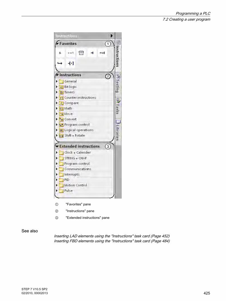
① "Favorites" pane
② "Instructions" pane
③ "Extended instructions" pane
See alsoInserting LAD elements using the "Instructions" task card (Page 452)Inserting FBD elements using the "Instructions" task card (Page 484)
Programming a PLC7.2 Creating a user program
STEP 7 V10.5 SP202/2010, 00002013
425

7.2.4.1 "Testing" task card
Function of the testing task card In the testing task card, you can make settings for troubleshooting using the program status.The functions of the "Test" task card are only available in online mode.
Layout of the testing task cardThe testing task card consists of the following components:
① CPU control panel
② Call hierarchy
7.2.4.1 "Testing" task card
Programming a PLC7.2 Creating a user program
426STEP 7 V10.5 SP202/2010, 00002013

CPU control panelIn the CPU control panel you can switch the CPU operating mode.
See also: Changing the mode of a CPU (Page 293)
Call hierarchyIn this pane you can trace the call hierarchy of the blocks. You only see the call hierarchy duringthe monitoring of the blocks.
7.2.4.1 Instruction window
FunctionThe instruction window is the work area of the program editor. You can perform the followingtasks here:
• Creating and managing networks
• Entering titles and comments for blocks and networks
• Entering program code
The following figure shows the instruction window of the program editor:
See alsoCreating program code (Page 443)
7.2.4.1 Instruction window
Programming a PLC7.2 Creating a user program
STEP 7 V10.5 SP202/2010, 00002013
427

7.2.4.1 Enlarge the working area of the instruction window
Introduction When all components of the application are shown, the area of the instruction window isrelatively small. If the program code is large, you may find you have to rearrange the work areaconstantly. To avoid this problem, you can hide or minimize the display of the followingcomponents of the application and of the program editor:
• Project tree
• Task cards
• Block interface
• Favorites
• Comments
• Networks
Hiding and showing the project tree The project tree allows you to access all areas of the project. It is therefore displayed after aproject has been opened. You can hide the project tree while you are creating a program togain more area for the instruction window.
To show and hide the project tree, proceed as follows:
1. Select the "Project tree" check box in the "View" menu, or click "Collapse" on the project tree title bar.
Opening and closing task cardsThe task cards are located at the right-hand edge of the application window.
To open or close the task cards, proceed as follows:
1. Select the "Task card" check box in the "View" menu, or click "Collapse" or "Expand" on the task cardstitle bar.
Hiding and showing the block interface After a block has been opened, the block interface is shown in the upper area of the programeditor. During programming you can show and hide it as required.
To show and hide the block interface, proceed as follows:
1. In the lower part of the interface within the window splitter, click on the Up arrow or Down arrow.
Showing and hiding favorites To hide or show the favorites in the program editor, proceed as follows:
1. Click the "Show favorites also in the editor" button in the program editor toolbar.
Showing and hiding comments Within a block you can enter a comment for the block or for each network. These two types ofcomments are shown and hidden differently.
7.2.4.1 Enlarge the working area of the instruction window
Programming a PLC7.2 Creating a user program
428STEP 7 V10.5 SP202/2010, 00002013

To show or hide a block comment, proceed as follows:
1. Click the the triangle at the start of the line with the block title.
To show or hide network comments, proceed as follows:
1. Click "Network comments on/off" on the program editor toolbar.
Opening and closing networksYou can open or close the networks in your program either individually or collectively.
To open or close networks, follow these steps:
1. If you want to open a network, click the right arrow in front of the network title. If you want to close anetwork, click the down arrow in front of the network title.
To open and close networks, proceed as follows:
1. Click "Open all networks" or "Close all networks" in the program editor toolbar.
7.2.4.1 Using the keyboard in the program editor
Navigate in the network
Function Selected object Keyboard shortcut
Navigate between objects in the network. Object in the network Arrow keys
Edit instructions (LAD/FBD)
Function Selected object Keyboard shortcut
Delete an operation. Operation <Del>
Enter operands (LAD/FBD)
Function Selected object Keyboard shortcut
Enable the input field for the first operand of theoperation.
Operation <Enter>Or<Any letter><Return> opens an emptyinput field; with any otherletter, this letter will beentered in the input field.
7.2.4.1 Using the keyboard in the program editor
Programming a PLC7.2 Creating a user program
STEP 7 V10.5 SP202/2010, 00002013
429

Function Selected object Keyboard shortcut
Enable input field for the operand. Operand <F2>
Delete value of the operand. <Del>
Define tag <Alt+Shift+D>
Entering operands Input field foroperands
<Any letters/numbers>
Confirm entry of the operand. <Enter>
Open operand selection. <Ctrl+I>
Discard current change. <Esc>The input field is deactivatedand the previous contentrestored.
See alsoKeyboard shortcuts for project editing (Page 132)Keyboard shortcuts in the project tree (Page 133)Keyboard shortcuts for windows (Page 133)Keyboard shortcuts in tables (Page 134)Keyboard shortcuts for text editing (Page 135)
7.2.4.1 General settings for the PLC programming
7.2.4.1 Overview of the general settings
Overview The following table shows the general settings that you can make:
Group Setting Description
View With comments Comments are shown
Print With interface Block interface is printed out alongside
With comments Comments are printed out alongside
Zoom factor Scaling of networks for print-out
Compilation Delete actual parameters on interfaceupdate
Actual parameters are deleted if theassociated formal parameters weredeleted in the called block, and you runthe "Update block call" function.
7.2.4.1 General settings for the PLC programming7.2.4.1 Overview of the general settings
Programming a PLC7.2 Creating a user program
430STEP 7 V10.5 SP202/2010, 00002013

Group Setting Description
Default settings for new blocks IEC Check The compatibility of the operands incomparison operations and arithmeticoperations will be tested. You have toexplicitly convert non-compatibleoperands.
Symbolic access only Tags in the interface of this block aredeclared purely symbolically without thedeclaration of an absolute address andtherefore can be addressed onlysymbolically.
Additional settings Display operand selection The operand selection is displayed
Mnemonics German and internationalrepresentation of the instructions
See alsoChanging the settings (Page 0 )Inserting operands into LAD instructions (Page 0 )Inserting operands into FBD instructions (Page 495)Permissible addresses and data types of PLC tags (Page 396)
7.2.4.1 Changing the settings
ProcedureTo change the settings, proceed as follows:
1. Select the "Settings" command in the "Options" menu.
The "Settings" window is displayed in the work area.
2. In the area navigation, select the "PLC programming" group.
3. Change the settings.
ResultThe change will be loaded directly, there is no need to save it explicitly.
7.2.4.1 Changing the settings
Programming a PLC7.2 Creating a user program
STEP 7 V10.5 SP202/2010, 00002013
431

7.2.4.2 Programming code blocks
7.2.4.2 Declaring the block interface
7.2.4.2 Layout of the block interface
Definition See also: Block interface (Page 423)
The interface contains the declarations of local tags that are used solely within the block. Thetags are subdivided into two groups:
• Block parameters that form the block interface when it is called in the program.
• Local data that are used for storage of intermediate results.
The block interface is shown as a table in the upper part of the program editor.
Block parametersThe following table shows the types of block parameters:
Type Section Function Available in
Input parameters Input Parameters whose values are read by theblock.
Functions, function blocks andsome types of organizationblocks
Output parameters Output Parameters whose values are written by theblock.
Functions and function blocks
InOut parameters InOut Parameters whose values are read by theblock when it is called, and whose values arewritten again by the block after execution.
Functions and function blocks
Local dataThe following table shows the types of local data:
Type Section Function Available in
Temporary local data Temp Tags that are used to store temporaryintermediate results. Temporary local dataare retained for only one cycle.
Functions, function blocks andorganization blocks
7.2.4.2 Programming code blocks7.2.4.2 Declaring the block interface7.2.4.2 Layout of the block interface
Programming a PLC7.2 Creating a user program
432STEP 7 V10.5 SP202/2010, 00002013

Type Section Function Available in
Static local data Static Tags that are used for storage of staticintermediate results in the instance datablock. Static data is retained until overwritten,which may be after several cycles.
Function blocks
7.2.4.2 Purpose of local tag declaration
Purpose of tag declaration You use tag declaration to define the names and data types of tags that you want to use in theblock.
In the function blocks you can assign default values for the block parameters and static localdata.
Effect of tag declarationTag declaration has the following effects:
• Tag declaration for a function block reserves memory space in the instance DB.
• Tag declaration for a code block determines the call interface of the function block in the program.
• Tag declaration for a function block determines the data structure of each instance DB that is assignedto the FB.
See alsoPLC tags and local tags (Page 365)Block interface (Page 423)
7.2.4.2 Rules for local tags
7.2.4.2 Valid data types in the code block interfaces
Valid data types for the interface of organization blocksThe following rules apply to the interface of an organization block:
• The TEMP and INPUT sections can contain elementary and complex data types as well as theVARIANT data type. Other parameter types are not permissible.
• An organization block does not have input, output, or in/out parameters, since it is not called by otherblocks.
• An organization block has no static tags, since it has no instance DBs.
7.2.4.2 Purpose of local tag declaration7.2.4.2 Rules for local tags7.2.4.2 Valid data types in the code block interfaces
Programming a PLC7.2 Creating a user program
STEP 7 V10.5 SP202/2010, 00002013
433

The following table shows the valid data types for the interface of an organization block:
Section Elementary data types Complex data types VARIANT parameter type
Temp ♦ ♦ ♦
Input ♦ ♦ ♦
♦: valid assignment
-: invalid assignment
Valid data types for the interface of function blocksThe following rules apply to the interface of a function block:
• Elementary and complex data types, as well as the VARIANT parameter type, are permissible whendeclaring the input parameters.
• No parameter types are permissible when declaring the output parameters.
• Only VARIANT is permitted as a parameter type when declaring in/out parameters.
• Only the VARIANT parameter type is permitted for the declaration of temporary tags. All otherparameter types are invalid.
The following table shows the valid data types for the interface of a function block:
Section Elementary data types Complex data types VARIANT parameter type
Input ♦ ♦ ♦
Output ♦ ♦ -
InOut ♦ ♦(3) ♦
Static ♦ ♦ -
Temp ♦ ♦ ♦
♦: valid assignment
-: invalid assignment(3) STRING can be defined only in default length of 254 characters.
Valid data types for the interface of a functionThe following rules apply to the interface of a function:
• A function has no static tags, since it does not have an instance DB.
• Only the VARIANT parameter type is permitted in the Input, Output, and InOut sections. All otherparameter types are prohibited.
Programming a PLC7.2 Creating a user program
434STEP 7 V10.5 SP202/2010, 00002013

• The TEMP section can contain elementary and complex data types as well as the VARIANT data type.Other parameter types are not permissible.
The following table shows the valid data types for the interface of a function:
Section Elementary data types Complex data types VARIANT parameter type
Input ♦ ♦(2) ♦
Output ♦ ♦(2) ♦
InOut ♦ ♦(2) ♦
Temp ♦ ♦ ♦
♦: valid assignment
-: invalid assignment(2) STRING can be defined only in default length of 254 characters.
7.2.4.2 Declaring local tags
7.2.4.2 Declaring local tags in the block interface
Requirement The block is open.
ProcedureTo declare a tag of the elementary data type, follow these steps:
1. Select the appropriate section in the interface:
― Input
― Output
― InOut
― Static
― Temp
See also: Layout of the block interface (Page 432)
Enter a tag name in the "Name" column.
2. Click the arrow key in the "Data type" column and select the desired data type.
The default initial value for this data type will be entered in the "Default value" column.
3. If necessary, change the default value.
7.2.4.2 Declaring local tags7.2.4.2 Declaring local tags in the block interface
Programming a PLC7.2 Creating a user program
STEP 7 V10.5 SP202/2010, 00002013
435

ResultThe tag is created.
Syntax checkA syntax check is performed after each entry, and any errors found are displayed in red. Youdo not have to correct these errors immediately - you can continue editing and make anycorrections later. However, you will not be able to compile the program if the tag declarationcontains syntax errors.
Note
If you change the interface of a block, you then also have to change all the locations in theprogram where this block is called.
The call locations are updated automatically if you select the "Program blocks" folder in projecttree and compile it.
See alsoInserting a table row in the interface (Page 0 )Adding table rows at the end (Page 0 )Keyboard shortcuts in tables (Page 134)Editing the block interface (Page 0 )Basic information on initial values (Page 515)
7.2.4.2 Declaring local tags directly in the program editor
RequirementOne or more operands are used in the program.
ProcedureTo declare an operand as a local tag, follow these steps:
1. Select one or more operands.
2. Select the "Define tag" command in the shortcut menu.
The "Define tag" dialog box opens. This dialog box displays a declaration table in which the name ofthe selected operand is already entered.
3. Position the cursor in the "Section" column.
An arrow button is displayed.
4. Click the arrow button.
5. To declare a local tag, select one of the following sections:
7.2.4.2 Declaring local tags directly in the program editor
Programming a PLC7.2 Creating a user program
436STEP 7 V10.5 SP202/2010, 00002013

― Local In
― Local Out
― Local InOut
― Local Static
― Local Temp
6. In the other columns, enter data type and comments.
7. Click the "Define" button to complete your entry.
ResultThe declaration is written directly into the block interface and is valid within the entire block.
Note
If you change the interface of a block, you then also have to change all the locations in theprogram where this block is called.
The call locations are updated automatically if you select the "Program blocks" folder in projecttree and compile it.
7.2.4.2 Declaring tags of ARRAY data type
Requirement The block is open.
ProcedureTo declare a tag of the ARRAY data type, follow these steps:
1. Enter a tag name in the "Name" column in the interface.
2. In the "Data type" column, click the arrow key and select the data type "Array [o .. hi] of type".
3. Then enter the desired dimensions in the same column, showing high limit and low limit and the datatype. (for example, ARRAY [1..10] of Bool). A space must be inserted between the closing squarebracket and the keyword "of" and also between "of" and the data type information for the ARRAYelements.
Note
You cannot define specific default values for ARRAY elements. You can, however, assign thema start value in the instance data block.
7.2.4.2 Declaring tags of ARRAY data type
Programming a PLC7.2 Creating a user program
STEP 7 V10.5 SP202/2010, 00002013
437

See alsoFormat of ARRAY (Page 384)Example of a one-dimensional ARRAY (Page 385)
7.2.4.2 Declaring tags of STRUCT data type
Requirement The block interface is open.
ProcedureTo declare a tag of the STRUCT data type, follow these steps:
1. Enter a tag name in the "Name" column.
2. In the "Data type" column, click the arrow key and select the "Struct" entry.
Two empty rows are inserted after the new tag.
3. Insert the first structure element in the first empty row.
An additional empty row is inserted after the element.
4. Select a data type for the structure element.
5. Optionally, enter a default value for the structure element.
6. Repeat the step 3 to 5 for all additional structure elements.
It is not necessary to end the structure explicitly. The structure ends with the last element that isentered.
7. To insert a new tag after the structure, leave a blank row after the end of the structure and then startthe new tag in the second empty row.
See alsoSTRUCT (Page 386)
7.2.4.2 Changing the names of local tags
You can change the name of a local tag at the following locations:
• in the block interface
• directly in the program editor
ProcedureTo change the name of a local tag, follow these steps:
1. Select the tag in the block interface.
2. Change the entry in the "Name" column.
Or
7.2.4.2 Declaring tags of STRUCT data type7.2.4.2 Changing the names of local tags
Programming a PLC7.2 Creating a user program
438STEP 7 V10.5 SP202/2010, 00002013

1. Select the tag at its point of use in the program.
2. Select the "Rename tag" command in the shortcut menu.
The "Rename tag" dialog box opens.
3. Change the entry in the "Name" column.
ResultThe name of the tag is changed automatically at all points of use in the program.
7.2.4.2 Changing the data types of local tags
You can change the data type of a local tag in the block interface.
ProcedureTo change the data type of a tag, follow these steps:
1. Select the tag in the block interface.
2. Click the arrow button in the "Data type" column.
A selection of the permissible data types is displayed. The selection depends on the block type andsection.
See also: Valid data types in the code block interfaces (Page 433)
3. Select one of the displayed data types.
4. If required, change the default value of the tag.
ResultThe data type is changed.
7.2.4.2 Defining the default values of local tags
You can define a default value for each tag in the interface of a function block. These defaultvalues are used as initial values during the creation of the instance data block. You can thenreplace these values with instance-specific initial values in the instance data block.
In the block interface you cannot assign any default values for tags of ARRAY data type.
Requirement A tag name is entered in a row of the interface.
ProcedureTo change the default value of a tag, follow these steps:
1. Click the "Default value" column in the block interface.
2. Enter a default value that is appropriate for the indicated data type.
7.2.4.2 Changing the data types of local tags7.2.4.2 Defining the default values of local tags
Programming a PLC7.2 Creating a user program
STEP 7 V10.5 SP202/2010, 00002013
439

Note
If you do not enter a default value, the standard value for the indicated data type will be used.For example, the default value for the BOOL data type is "False".
See alsoBasic information on initial values (Page 515)
7.2.4.2 Setting the retentivity of local tags
7.2.4.2 Retentive behavior and symbolic addressing of code blocks
Symbolic access of blocksYou have the option of defining blocks as "Symbolic access only". If the setting is set to"symbolic access only", the tags of a block can be declared purely symbolically without thespecification of an absolute address.
Retentive behavior of local tags.The option of setting the retentivity depends on the set addressability of the block.
• In blocks that can only be accessed symbolically, you can define individual tags as retentive.
• In blocks that can be accessed otherwise, you cannot make retentivity settings for the individual tagsin the block interface. You can only defined the assigned instance data block as retentive. All tagscontained in the block are then considered as retentive.
The following table provides an overview of the possible settings:
Block type Block property "Symbolic access only"enabled
Block property "Symbolic accessonly" disabled
FB The retentivity can be set for individualtags.
The retentivity cannot be set.
Instance DB The retentivity setting is made by thehigher-level code block.
The retentivity can be set for theentire instance DB.
See alsoSymbolic addressing of blocks only (Page 363)
7.2.4.2 Setting the retentivity of local tags7.2.4.2 Retentive behavior and symbolic addressing of code blocks
Programming a PLC7.2 Creating a user program
440STEP 7 V10.5 SP202/2010, 00002013

7.2.4.2 Setting the retentive behavior of local tags in a function block
IntroductionIf symbolic access is enabled, you can set the retentive behavior of each individual tag in onefunction block. The "Retentivity" column of the block interface provides a drop-down list withthe following selection options for this:
• Retain
The tag is defined as retentive. This setting is accepted by the assigned instance data block andcannot be changed in this block.
• Non-retain
The tag is defined as non-retentive. This setting is accepted by the assigned instance data block andcannot be changed in this block.
If you make no setting, the tags are defined as non-retentive.
Requirement
• The symbolic access of the tags in enabled in the opened function block.
• Tags are declared in the block interface
ProcedureTo set the retentive behavior of a local tag, follow these steps:
1. In the "Retain" column, select the cell of a tag for which you want to set the retentive behavior.
2. Click the arrow on the right border of the cell.
The drop-down list with the entries "Retain" and "Non-retain" opens.
3. Select the required setting from the drop-down list.
7.2.4.2 Editing the properties of local tags
7.2.4.2 Editing the properties of local tags
You can find a description of the properties of local tag on the following page:
Layout of the block interface (Page 432)
Editing properties in the block interface To edit the properties of one or more tags, follow these steps:
1. Open the block interface.
2. Change the entries in the "Name", "Comments" and other columns.
7.2.4.2 Setting the retentive behavior of local tags in a function block7.2.4.2 Editing the properties of local tags7.2.4.2 Editing the properties of local tags
Programming a PLC7.2 Creating a user program
STEP 7 V10.5 SP202/2010, 00002013
441

Renaming tags directly in the program editorTo rename one or more tags, follow these steps:
1. Select one or more tags in the program.
2. Select the "Rename tag" command in the shortcut menu.
The "Rename tag" dialog box opens. This dialog box displays a declaration table with the selectedtags.
3. Change the entries in the "Name" column.
4. Confirm the input by clicking the "Change" button.
7.2.4.2 Editing the block interface
7.2.4.2 Deleting entries in the PLC tag table
Procedure To delete a tag, proceed as follows:
1. Select the row with the tag to be deleted. You can also select several rows by clicking on them oneafter the other while holding down the <Ctrl> key or by pressing and holding down <Shift> and clickingon the first and last row.
2. Select the "Delete" command in the shortcut menu.
See alsoAdapting tables (Page 131)Keyboard shortcuts in tables (Page 134)
7.2.4.2 Inserting table rows
Procedure To insert row above the position of the mouse pointer, proceed as follows:
1. Position the mouse pointer in the row above which you want to insert a new row.
2. Click the "Insert row" button on the toolbar of the table.
A new row is inserted above the selected row.
See alsoKeyboard shortcuts in tables (Page 134)Adapting tables (Page 131)
7.2.4.2 Editing the block interface7.2.4.2 Deleting entries in the PLC tag table7.2.4.2 Inserting table rows
Programming a PLC7.2 Creating a user program
442STEP 7 V10.5 SP202/2010, 00002013

7.2.4.2 Adding table rows at the end
Procedure To add a new row at the end of the table or at the end of a complex data type, follow thesesteps:
1. Click the "Add row" button on the table toolbar.
A new empty row will be added at the end of the table or at the end of a complex data type.
See alsoKeyboard shortcuts in tables (Page 134)Adapting tables (Page 131)
7.2.4.2 Creating program code
7.2.4.2 Setting the mnemonics
You can program blocks using German or international mnemonics. If you open the TIA portalfor the first the international mnemonics is set as default. You can change the mnemonics atany time.
Procedure To set the mnemonics, follow these steps:
1. Select the "Settings" command in the "Options" menu.
The "Settings" window is displayed in the work area.
2. Select the "General" group in the area navigation.
3. In the "General settings" group, select the mnemonics that you want to use.
The mnemonics is changed in all blocks.
7.2.4.2 Creating LAD programs
7.2.4.2 Basic information on LAD
7.2.4.2 LAD programming language
Overview of the Ladder Logic (LAD) programming language LAD is a graphical programming language. The representation is based on circuit diagrams.
7.2.4.2 Adding table rows at the end7.2.4.2 Creating program code7.2.4.2 Setting the mnemonics7.2.4.2 Creating LAD programs7.2.4.2 Basic information on LAD7.2.4.2 LAD programming language
Programming a PLC7.2 Creating a user program
STEP 7 V10.5 SP202/2010, 00002013
443

The program is mapped in one or more networks. On both the left and right edge the networkcontains one power rail from which the rungs go out. The binary signals are arranged in theform of contacts on the rungs. The serial arrangement of the elements on a branch creates aseries connection, the arrangement on simultaneous branches creates a parallel connection.Complex functions are represented by boxes.
A rung is closed by a coil in which the result of logic operation is written.
Example of networks in LADThe following figures shows a LAD network with normally open contacts, normally closedcontacts and a coil:
7.2.4.2 Overview of the LAD elements
LAD elementsA LAD program consists of separate elements that you can arrange in series or parallel on thepower rail of a network. Most program elements must be supplied with tags. For timer andcounter operations, a data block must also be created to store the formal parameters.
There is at least one rung from the power rail. The programming of the network start at the leftedge of the rung. You can extend a power rail with several rungs and branches.
For example, the following figure shows elements of a LAD network:
Figure7-2
1) Power rail
7.2.4.2 Overview of the LAD elements
Programming a PLC7.2 Creating a user program
444STEP 7 V10.5 SP202/2010, 00002013

2) Rung
3) Branch
4) Contact
5) Coil
6) Box
Power railEach LAD network consists of a power rail that contains at least one rung. A network can beextended by adding additional rungs. You can use branches to program parallel connectionsin the specific rungs.
ContactsYou can use contacts to create or interrupt a current-carrying connection between twoelements. In such cases the elements can be the LAD program elements or the edges of thepower rail. The current is relayed from left to right. You can use contacts to query the signalstate or the value of an operand and control it depending on the result of the current flow.
The following types of contact are available to you in a LAD program:
• Normally open contacts: Normally open contacts forward the current if the signal state of a specified binary operand is "1".
• Normally closed contacts: Normally open contacts forward the current if the signal state of a specified binary operand is "0".
• Contact with additional function: Contacts with additional function forward the current if a specific condition is met. With these contactsyou can also execute an additional function, such as an RLO edge detection and a comparison.
CoilsYou can use coils to control binary operands. Coils can set or reset a binary operand dependingon the signal state of the result of logic operation.
The following types of coils are available to you in a LAD program:
• Standard coils: Standard coils set a binary operand if current flows in the coil. The "Relay coil, output" operation is anexample of a standard coil.
• Coils with additional function: These coils have additional functions besides the evaluation of the result of logic operation. Coils forRLO edge detection and program control are examples of coils with additional function. In the caseof coils for program control, a jump destination is specified instead of an operand.
BoxesBoxes are LAD elements with complex functions. The empty box is an exception. You can usethe empty box as a placeholder in which you can select the required operation.
The following types of boxes are available to you in a LAD program:
Programming a PLC7.2 Creating a user program
STEP 7 V10.5 SP202/2010, 00002013
445

• Boxes without EN/ENO mechanism: A box is executed depending on the signal state at the box inputs. The error status of the processingcannot be queried.
• Boxes with EN/ENO mechanism: A box is only executed if the enabling input "EN" carries the signal state "1". If the box is processedcorrectly, the "ENO" enable output has signal state "1". If an error occurs during the processing, the"ENO" output is reset.
Calls of code block are also shown in the network as boxes with EN/ENO mechanism.
See alsoRules for the use of LAD elements (Page 451)
7.2.4.2 Settings for LAD
7.2.4.2 Overview of the settings for LAD
OverviewThe following table shows the settings that you can make:
Group Setting Description
Font Size Font size in program editor
View Layout Compact or wideChanges the vertical spacing betweenoperands and other objects (such asoperand and contact). The changebecomes visible once the block isreopened.
With absolute information Additional display of the absoluteaddresses
Operand field Maximum width Maximum number of characters that canbe entered horizontally in the operandfield
Maximum height Maximum number of characters that canbe entered vertically in the operand field
7.2.4.2 Settings for LAD7.2.4.2 Overview of the settings for LAD
Programming a PLC7.2 Creating a user program
446STEP 7 V10.5 SP202/2010, 00002013

7.2.4.2 Changing the settings
ProcedureTo change the settings, proceed as follows:
1. Select the "Settings" command in the "Options" menu.
The "Settings" window is displayed in the work area.
2. In the area navigation, select the "PLC programming" group.
3. Change the settings.
ResultThe change will be loaded directly, there is no need to save it explicitly.
7.2.4.2 Working with networks
7.2.4.2 Using networks
FunctionThe user program is created in the block within networks. For a code block to be programmed,it must contain at least one network. To achieve a better overview of the user program, youcan also subdivide your program into several networks.
See alsoInserting networks (Page 0 )Selecting networks (Page 0 )Copying and inserting networks (Page 0 )Deleting networks (Page 0 )Expanding and collapsing networks (Page 0 )
7.2.4.2 Inserting networks
RequirementA block is open.
ProcedureTo insert a new network, follow these steps:
1. Select the network after which you want to insert a new network.
2. Select the "Insert network" command in the shortcut menu.
7.2.4.2 Changing the settings7.2.4.2 Working with networks7.2.4.2 Using networks7.2.4.2 Inserting networks
Programming a PLC7.2 Creating a user program
STEP 7 V10.5 SP202/2010, 00002013
447

Note
If you insert an element into the last (and still empty) network of the block in an LAD or FBDprogram, a new empty network is automatically inserted below it.
ResultA new empty network is inserted into the block.
See alsoUsing networks (Page 0 )
7.2.4.2 Selecting networks
RequirementA network is available.
Selecting a networkTo select a network, follow these steps:
1. Click the title bar of the network that you want to select.
Selecting several networksTo select several networks, follow these steps:
1. Press and hold down the <Ctrl> key.
2. Click all the networks that you want to select.
To select several successive networks, follow these steps:
1. Press and hold down the <Shift> key.
2. Click the first network that you want to select.
3. Click the last network that you want to select.
The first and last networks and all those in between are selected.
See alsoUsing networks (Page 0 )
7.2.4.2 Copying and inserting networks
Copied networks can be pasted within the block or in another block. If the network is pastedinto a block written in a different programming language, the programming language of thenetwork is retained.
7.2.4.2 Selecting networks7.2.4.2 Copying and inserting networks
Programming a PLC7.2 Creating a user program
448STEP 7 V10.5 SP202/2010, 00002013

PrerequisiteA network is available.
ProcedureTo copy and paste a network, follow these steps:
1. Select the network or networks to be copied.
2. Select "Copy" in the shortcut menu.
3. Select the network after which you want to paste the copied network.
4. Select "Paste" in the shortcut menu.
Note
You can also copy networks from one block to another.
See alsoUsing networks (Page 0 )
7.2.4.2 Deleting networks
RequirementA network is available.
ProcedureTo delete a network, follow these steps:
1. Select the network that you want to delete.
2. Select the "Delete" command in the shortcut menu.
See alsoUsing networks (Page 0 )
7.2.4.2 Expanding and collapsing networks
RequirementA network is available.
7.2.4.2 Deleting networks7.2.4.2 Expanding and collapsing networks
Programming a PLC7.2 Creating a user program
STEP 7 V10.5 SP202/2010, 00002013
449

Opening and closing a network1. Select the network that you want to open or close.
2. Select "Expand" or "Collapse" in the shortcut menu.
Opening and closing all networks1. Click "Open all networks" or "Close all networks" in the toolbar.
See alsoUsing networks (Page 0 )
7.2.4.2 Entering the network title
The network title is the header of a network. The length of the network title is unrestricted, butit cannot occupy more than one line.
RequirementA network is available.
ProcedureTo enter a network title, follow these steps:
1. Double-click "....." in the title bar of the network.
The "....." text passage is selected.
2. Enter the network title.
7.2.4.2 Entering network comments in LAD networks
You can use network comments to document individual networks. For example, you canindicate the function of the network or draw attention to special characteristics.
RequirementA network is available.
ProcedureTo enter a network comment, follow these steps:
1. Click the small arrow in front of the network title.
The right arrow becomes a down arrow.
2. If the comment area is not visible, click "Network comments on/off" in the toolbar.
The comment area is displayed.
3. Click "Comment" in the comment area.
7.2.4.2 Entering the network title7.2.4.2 Entering network comments in LAD networks
Programming a PLC7.2 Creating a user program
450STEP 7 V10.5 SP202/2010, 00002013

The "Comment" text passage is selected.
4. Enter the network comment.
7.2.4.2 Inserting LAD elements
7.2.4.2 Rules for the use of LAD elements
Rules Note the following rules when inserting LAD elements:
• Every LAD network must terminate with a coil or a box. However, the following LAD elements mustnot be used to terminate a network:
― Comparator boxes
― Coils for positive or negative RLO edge detection
• The starting point of the branch for a box connection must always be the left power rail. Logicoperations or other boxes can be present in the branch before the box.
• Coils are automatically placed on the right edge of the network, where they are used to terminate abranch. Coils for positive or negative RLO edge detection are an exception. These can be positionedneither at the far left nor the far right of the branch. Nor are they permissible in additional branches.
• Only contacts can be inserted into simultaneous branches with preceding logic operations. Thecontact for negating the result of logic operation (-|NOT|-) is an exception here. The contact fornegating the result of logic operation, as well as coils and boxes, can be used in simultaneousbranches if they originate directly from the power rail.
• Operations for positive or negative RLO edge detection may not be arranged directly at the left edgeof the power rail.
• Jump operations can be positioned only at the end, RET can also be positioned at the start.
• Enable input "EN" and enable output "ENO" can be connected to boxes, but this is not mandatory.
• Constants (e.g. TRUE or FALSE) cannot be assigned to normally open or normally closed contacts.Instead, use the operands of the BOOL data type.
For information on where you can insert LAD elements on the power rail, refer to the LADreference help.
See alsoEN/ENO mechanism (Page 359)Prohibited interconnections in LAD (Page 452)Overview of the LAD elements (Page 444)
7.2.4.2 Inserting LAD elements7.2.4.2 Rules for the use of LAD elements
Programming a PLC7.2 Creating a user program
STEP 7 V10.5 SP202/2010, 00002013
451

7.2.4.2 Prohibited interconnections in LAD
Power flow from right to leftNo branches can be programmed that could result in a power flow in the reverse direction.
Short-circuitNo branches may be programmed that would cause a short-circuit.
Logic operationsThe following rules apply to logic operations:
• Only Boolean inputs can be combined with preceding logic operations.
• Only the first Boolean output can be combined with a further logic operation.
• Only one complete logical path can exist per network. Paths that are not connected can be linked.
See alsoRules for the use of LAD elements (Page 451)
7.2.4.2 Inserting LAD elements using the "Instructions" task card
RequirementA network is available.
ProcedureTo insert a LAD element into a network using the "Instructions" task card, follow these steps:
1. Open the "Instructions" task card.
2. Navigate to the LAD element that you want to insert.
3. Use a drag-and-drop operation to move the element to the desired place in the network.
7.2.4.2 Prohibited interconnections in LAD7.2.4.2 Inserting LAD elements using the "Instructions" task card
Programming a PLC7.2 Creating a user program
452STEP 7 V10.5 SP202/2010, 00002013

If the element is a function block (FB) within the system, the data of the function block must be storedin a data block. The "Call options" dialog box is therefore opened, in which you can create thecorresponding data block.
Or
1. Select the point in the network at which you want to insert the element.
2. Open the "Instructions" task card.
3. Double-click on the element you want to insert.
If the element is a function block (FB) within the system, the data of the function block must be storedin a data block. The "Call options" dialog box is therefore opened, in which you can create thecorresponding data block.
ResultThe selected LAD element is inserted with placeholders for the parameters.
See alsoInserting LAD elements using an empty box (Page 453)Inserting LAD elements using favorites (Page 0 )
7.2.4.2 Inserting LAD elements using an empty box
RequirementA network is available.
ProcedureTo insert an LAD element into a network using an empty box, follow these steps:
1. Open the "Instructions" task card.
2. Navigate to "General > Empty box".
3. Use a drag-and-drop operation to move the "Empty box" element to the desired place in the network.
4. Hover the cursor over the yellow triangle in the top right corner of the empty box.
A drop-down list is displayed.
5. Select the desired LAD element from the drop-down list.
ResultThe empty box is changed to the respective LAD element. Placeholders are inserted for theparameters.
See alsoInserting LAD elements using the "Instructions" task card (Page 452)Inserting LAD elements using favorites (Page 0 )
7.2.4.2 Inserting LAD elements using an empty box
Programming a PLC7.2 Creating a user program
STEP 7 V10.5 SP202/2010, 00002013
453

7.2.4.2 Selecting the data type of a LAD element
7.2.4.2 Selecting a data type
IntroductionSome operations can be executed with several different data types. If one of these operationsis used in the program, a valid data type must be specified for the operation at the specific pointin the program. Data types for the inputs and outputs must be explicitly selected for someoperations.
Note
The valid data type (BOOL) for the tags on the enable input ENO and the enable output ENOis predefined by the system and cannot be changed.
The valid data types for an operation are listed in the drop-down list of the operation. You specifythe data type of the operation by selecting an entry from the drop-down list. If the data type ofa indicated tag deviates from the data type of the operation, the tag name is displayed in red.
7.2.4.2 Specifying the data type of an operation
IntroductionSome operations can be executed with several different data types. If such operations have tobe inserted in the program a data type has to be specified at a specific point in the program fortheir execution.
Specifying the data type by means of the drop-down listTo specify the data type of an operation by means of the drop-down list, follow these steps:
1. Insert the operation by drag-and-drop operation at the required point in the program.
The operation will be inserted at the required point in the program. The entry "???" (undefined) isdisplayed in the drop-down list.
2. Click the yellow triangle in the upper corner of the drop-down list.
The drop-down list opens displaying the data types that are valid for the operation.
3. Select a data type from the drop-down list.
The selected data type is displayed.
4. If the operation has two drop-down list, select the data type for the inputs of the operation in the leftdrop-down list and the data type for the outputs of the operation in the right drop-down list.
7.2.4.2 Selecting the data type of a LAD element7.2.4.2 Selecting a data type7.2.4.2 Specifying the data type of an operation
Programming a PLC7.2 Creating a user program
454STEP 7 V10.5 SP202/2010, 00002013

Specifying data type by assigning tagsTo specify the data type of an operation by assigning tags, follow these steps:
1. Insert the operation by drag-and-drop operation at the required point in the program.
The operation will be inserted at the required point in the program. The entry "???" (undefined) isdisplayed in the drop-down list.
2. At an input or output, specify a valid tag the data type of which is to be accepted as data type of theoperation.
The selected data type is displayed in the drop-down list.
3. If data types have to be specified for the inputs and outputs of the operation, enter a valid tag at aninput and a valid tag at an output. The tag specified at the input determines the data type of the inputsand the tag specified at the output determines the data type of the outputs of the operation.
7.2.4.2 Using favorites in LAD
7.2.4.2 Adding elements to Favorites
Requirement A block is open.
ProcedureTo add elements to Favorites, follow these steps:
1. Open the "Instructions" task card.
2. Maximize the "Instructions" pane.
3. Navigate in the "Instructions" pane to the element that you want to add to the favorites.
4. Drag the element to the "Favorites" pane or to the Favorites area in the program editor.
See alsoInserting FBD elements using favorites (Page 0 )
7.2.4.2 Inserting LAD elements using favorites
Requirement
• A network is available.
• Favorites are available.
7.2.4.2 Using favorites in LAD7.2.4.2 Adding elements to Favorites7.2.4.2 Inserting LAD elements using favorites
Programming a PLC7.2 Creating a user program
STEP 7 V10.5 SP202/2010, 00002013
455

ProcedureTo insert an element into a network using favorites, follow these steps:
1. If the Favorites are not displayed in the program editor, click the "Show favorites also in the editor"button in the program editor toolbar.
The Favorites are displayed under the block interface.
2. Drag the desired element from Favorites to the network.
Or
1. Select the point in the network at which you want to insert the element.
2. In the Favorites, click on the element you want to insert.
See alsoAdding elements to Favorites (Page 0 )Inserting FBD elements using the "Instructions" task card (Page 484)Inserting FBD elements using an empty box (Page 485)
7.2.4.2 Removing elements from Favorites
PrerequisitesA code block is open.
ProcedureTo remove elements from Favorites, follow these steps:
1. Either open the "Favorites" pane in the "Instructions" task card or click the "Show favorites also in theeditor" button in the program editor in the toolbar to show the favorites.
2. Right-click the element that you want to remove.
3. Select the "Remove instruction" command in the shortcut menu.
7.2.4.2 Insert block calls in LAD
7.2.4.2 Inserting block calls using drag & drop
You can insert calls for existing functions (FC) and function blocks (FB) using a drag-and-dropoperation from the project tree. If you call function blocks from other function blocks, you cancall these either as single instance or as multi-instance.
Requirement
• A network is available.
• The block that is to be called is available.
7.2.4.2 Removing elements from Favorites7.2.4.2 Insert block calls in LAD7.2.4.2 Inserting block calls using drag & drop
Programming a PLC7.2 Creating a user program
456STEP 7 V10.5 SP202/2010, 00002013

Inserting a call of a function (FC)To insert a call of a function (FC) into a network using a drag-and-drop operation, follow thesesteps:
1. Drag the function from the project tree into the network.
Inserting a call of a function block (FB) as a single instanceYou can call a function block as a single instance. In this case, the called function block storesits data in a data block of its own.
See also: Single instances (Page 350)
To insert the call for a function block (FB) into a network as a single instance using a drag-and-drop operation, follow these steps:
1. Drag the function block from the project tree into the network.
The "Call options" dialog opens.
2. Click the "Single instance" button.
3. Enter a name for the data block that is to be assigned to the function block.
4. Confirm your entries with "OK".
Inserting a call of a function block (FB) as a multi-instanceYou can call a function block as a multi-instance. In this case, the called function block storesits data in the instance data block of the calling function block.
See also: Multi-instances (Page 351)
To insert the call for a function block (FB) into a network as a multi-instance using a drag-and-drop operation, follow these steps:
1. Drag the function block from the project tree into the network.
The "Call options" dialog opens.
2. Click the "Multi instance" button.
3. In the "Name in the interface" text block, enter the name of the tag with which the called function blockwill be entered as a static tag in the interface of the calling block.
4. Confirm your entries with "OK".
ResultThe function or the function block is inserted with its parameters. You can then assign theparameters.
See also: Parameter transfer at block call (Page 353)
Programming a PLC7.2 Creating a user program
STEP 7 V10.5 SP202/2010, 00002013
457

Note
If when calling a function block you specify an instance data block that does not exist, it will becreated. If you have called a function block as a multi-instance, this will be entered as a statictag in the interface.
7.2.4.2 Calling functions and function blocks from supplied global libraries
In your user program, you can call pre-programmed functions and function blocks that arecontained in the supplied global libraries.
Requirement The "Libraries" task card is displayed.
Calling a function from a supplied global libraryTo call a function (FC) from a supplied global library, follow these steps:
1. Maximize the "Global libraries" pane.
2. Maximize the library in which the desired element is located.
3. Drag the function to the network.
Or:
1. Maximize the "Global libraries" pane.
2. Maximize the library in which the desired element is located.
3. Open the element view.
4. Drag the function from the "Elements" pane to the network.
Calling a function block from a supplied global libraryTo call a function block (FB) from a supplied global library, follow these steps:
1. Maximize the "Global libraries" pane.
2. Maximize the library in which the desired element is located.
3. Use a drag-and-drop operation to move the function block into the network.
The "Call options" dialog opens.
4. Select either single or multi-instance and enter a name for the data block.
5. Confirm your selection with "OK".
Or:
1. Maximize the "Global libraries" pane.
2. Maximize the library in which the desired element is located.
3. Open the element view.
7.2.4.2 Calling functions and function blocks from supplied global libraries
Programming a PLC7.2 Creating a user program
458STEP 7 V10.5 SP202/2010, 00002013

4. Drag the function block from the "Elements" pane to the network.
The "Call options" dialog opens.
5. Select either single or multi-instance and enter a name for the data block.
6. Confirm your selection with "OK".
See alsoParameter transfer at block call (Page 353)
7.2.4.2 Update block calls
If interface parameters of a called block are changed, the block call can no longer be executedcorrectly. You can avoid such inconsistent block calls by updating the block calls.
You have two options to update the block calls:
• Explicit updating in the program editor.
The block calls in the open block will be updated.
• Implicit update during compilation.
All block calls in the program as well as the used PLC data types will be updated.
Update blocks in the program editorTo update a block call within a block, follow these steps:
1. Open the block in the program editor
2. Click "Update inconsistent block calls" in the toolbar.
Or:
1. Open the block in the program editor.
2. Right-click on the instruction with the block call.
3. Select the "Update block call" command in the shortcut menu.
The "Interface update" dialog opens. This dialog shows the differences between the block interfacein use and the changed interface of the called block.
4. If you want to update the block call, click "OK". To cancel the update, click "Cancel".
Update block calls during compilationProceed as follows to update all block calls and uses of PLC data types during compilationimplicitly:
1. Open the project tree.
2. Select the "Program blocks" folder.
3. Select the "Compile > Software (rebuild all blocks)" command in the shortcut menu.
7.2.4.2 Update block calls
Programming a PLC7.2 Creating a user program
STEP 7 V10.5 SP202/2010, 00002013
459

7.2.4.2 Correcting the call type
Call typeThere are two ways of calling function blocks:
• As a single instance
• As a multi-instance
See also: Call function blocks as single or multi-instances (Page 351)
You can modify a defined call type at any time.
RequirementA network contains a block call.
ProcedureTo change the call type of a function block, follow these steps:
1. Select the block call.
2. Select the "Change call type" command in the shortcut menu.
The "Call options" dialog opens.
3. Click the "Single instance" or "Multi instance" button.
― If you select the "Single instance" call type, enter a name for the data block that will be assignedto the function block.
― If you select "Multi instance" as the call type, enter the name of the tag in the "Name in the interface"text box, with which the called function block will be entered as a static tag in the interface of thecalling block.
4. Confirm your entries with "OK".
7.2.4.2 Changing LAD elements
7.2.4.2 Replacing LAD elements
You can easily exchange LAD elements with other LAD elements of the same type. This hasthe advantage that the parameters are retained and need not be entered again. For example,you can exchange normally open contacts and normally closed contacts, RS FlipFlop and SRFlipFlop, or timers.
RequirementA network with at least one LAD element is present.
7.2.4.2 Correcting the call type7.2.4.2 Changing LAD elements7.2.4.2 Replacing LAD elements
Programming a PLC7.2 Creating a user program
460STEP 7 V10.5 SP202/2010, 00002013
ProcedureTo replace an LAD element with another LAD element, follow these steps:
1. Select the LAD element that you want to replace.
2. Hover the cursor over the yellow triangle in the top right corner of the LAD element.
A drop-down list is displayed.
3. From the drop-down list, select the LAD element that you want to use to replace the existing LADelement.
7.2.4.2 Editing LAD elements
You can edit LAD elements using the following edit commands:
• Copy
• Cut
• Paste
• Delete
Each command can always be executed via the keyboard, menu, and shortcut menu.
RequirementAn LAD element is available.
CopyingTo copy a LAD element, follow these steps:
1. Right-click the LAD element that you want to copy.
2. Select "Copy" in the shortcut menu.
CuttingTo cut a LAD element, follow these steps:
1. Right-click the LAD element that you want to cut.
2. Select "Cut" in the shortcut menu.
InsertingTo paste a LAD element, follow these steps:
1. Copy a LAD element or cut a LAD element.
2. Right-click the point in the network where you want to paste the element.
3. Select "Paste" in the shortcut menu.
DeletingTo delete a LAD element, follow these steps:
7.2.4.2 Editing LAD elements
Programming a PLC7.2 Creating a user program
STEP 7 V10.5 SP202/2010, 00002013
461

1. Right-click the LAD element that you want to delete.
2. Select the "Delete" command in the shortcut menu.
7.2.4.2 Inserting additional inputs and outputs
Introduction You can expand the LAD elements with additional inputs that execute commutative arithmeticoperations. Such elements are, for example, the instructions "Add" (ADD) and "Multiply" (MUL).The number of inserted inputs is not limited.
You can insert additional outputs only for the LAD element "Transmit value" (MOVE).
RequirementAn LAD element is available that permits the insertion of additional inputs and outputs.
Inserting an additional inputTo add an additional input to the box of a LAD element, follow these steps:
1. Right-click on an existing input of the LAD element.
2. Select "Insert input" in the shortcut menu.
An additional input is added to the box of the LAD element.
Inserting an additional outputTo add an additional output to the box of a LAD element, follow these steps:
1. Right-click on an existing output of the LAD element.
2. Select "Insert output" from the shortcut menu.
An additional output is added to the box of the LAD element.
See alsoInserting LAD elements (Page 452)
7.2.4.2 Removing inputs and outputs
Introduction For LAD elements that you have extended with additional inputs, you can subsequently removethese inputs. If you have added outputs to the LAD element "Copy value" (MOVE), you canalso remove these outputs.
RequirementAn LAD element is available to which you have added additional inputs and outputs.
7.2.4.2 Inserting additional inputs and outputs7.2.4.2 Removing inputs and outputs
Programming a PLC7.2 Creating a user program
462STEP 7 V10.5 SP202/2010, 00002013

Remove inputTo remove an input, follow these steps:
1. Select the input that you want to remove.
2. Select the "Delete" command in the shortcut menu.
The input of the LAD element is removed.
Remove outputTo remove an output of the LAD element "Copy value", follow these steps:
1. Select the output that you want to remove.
2. Select the "Delete" command in the shortcut menu.
The output of the LAD element "Copy value" is removed.
7.2.4.2 Inserting operands into LAD instructions
7.2.4.2 Inserting operands
When a LAD element is inserted, the string of question marks "???" and "..." are inserted asplaceholders for the parameters. The "???" string displayed in red indicates parameters thatmust be connected. The "..." string displayed in black indicates parameters that may beconnected.
Note
Hover the mouse cursor over the placeholder to display the expected data type.
RequirementAn LAD element is available.
ProcedureTo connect the parameters of a LAD element, follow these steps:
1. Double-click the placeholder of the parameter.
An entry field opens, and the placeholder is selected.
2. Enter the appropriate parameter.
7.2.4.2 Inserting operands into LAD instructions7.2.4.2 Inserting operands
Programming a PLC7.2 Creating a user program
STEP 7 V10.5 SP202/2010, 00002013
463

Note
If you enter the absolute address of a parameter that has already been defined, this absoluteaddress will be changed to the symbolic name of the parameter as soon as the input isconfirmed. If you have not yet defined the parameter, a new tag with this absolute addressand the default name "Tag_1" will be entered in the PLC tag table. When you confirm yourinput, the absolute address will be replaced with the symbolic name "Tag_1".
3. Confirm the parameter with the Enter key.
4. If you have not yet defined the parameter, you can define it directly in the program editor using theshortcut menu.
See also: Declaring PLC tags in the program editor (Page 398)
Alternatively, using the operand selection:
1. Double-click the placeholder of the parameter.
2. To open the operand selection, click the symbol beside the text box.
3. Enter the initial letter of the parameter.
A list of all the defined parameters starting with this letter is displayed.
4. Select the relevant parameter from the list and confirm your selection with the Enter key.
See also: Using the operand selection (Page 0 )
Or drag from it the PLC tag table:
1. In the project tree, select the "PLC tags" folder or open the PLC tag table.
2. If you have opened the PLC tag table, drag the symbol from the first column of the desired tag to theappropriate place in your program. If you have not opened the PLC tag table yet, open the detail viewnow. Drag the desired tag from the detail view to the appropriate place in your program.
Or drag from it the block interface:
1. Open the block interface.
2. Drag the required operand from the block interface to the instruction window.
Result
• If the syntax is error-free, the displayed parameter is black. The editor then jumps to the nextplaceholder.
• If there is an error in the syntax, the cursor stays in the entry field and a corresponding error messageis displayed in the status line. If you press the Enter key again, the entry field is closed and the faultyentry is displayed in red italics.
See alsoSymbolic programming (Page 361)
Programming a PLC7.2 Creating a user program
464STEP 7 V10.5 SP202/2010, 00002013

7.2.4.2 Using the operand selection
The operand selection is a drop-down list that displays all available operands for a selectedinstruction. It contains all global and local tags of the suitable data type.
Requirement The operand selection is enabled.
See also: General settings for the PLC programming (Page 0 )
ProcedureTo select an operand from the operand selection, follow these steps:
1. Select an instruction.
2. Press the <Return> key.
The input field for the operand opens. The icon for operand selection appears next to the input field.
3. Click on the icon for operand selection.
The operand selection opens. This contains local and global tags, data blocks and multi-instances.
4. If necessary, filter the list:
― Enter one or several letters to show only the operands that start with these initial letters.
― Enter # in the first location to show only local operands from the block interface.
― Enter " in the first position to show global operands from the PLC tag table and the existing datablocks.
5. Select an operand.
If the selected operand is a structured tag, a data block or a multi-instance, a period is insertedautomatically after the higher-level element. The lower-level elements of the first operand are thendisplayed in the list.
6. Select the lower-level element.
Note
Even if operand selection is disabled in the general settings, you can display an operandselection list when necessary. You can do this with the <Ctrl+I> keyboard shortcut.
See alsoInserting and editing operands (Page 495)Accessing ARRAYs (Page 0 )Accessing the data of STRUCT (Page 0 )Accessing the data of a multi-instance (Page 0 )
7.2.4.2 Using the operand selection
Programming a PLC7.2 Creating a user program
STEP 7 V10.5 SP202/2010, 00002013
465

7.2.4.2 Accessing ARRAYs
Accessing data in an ARRAY You access the data in an ARRAY using the index of the specific element in the ARRAY. Anindex consists of any integer values (-32768 to 32767) enclosed in square brackets, forexample Motor.Waerme_1x3[2].
Using ARRAYs as block parametersYou can transfer ARRAYs as parameters. If a block has an input parameter of ARRAY type,you must transfer as actual parameter an ARRAY with identical structure. You can also transferindividual elements of an ARRAY as actual parameter if the element corresponds to the datatype of the formal parameter.
7.2.4.2 Accessing the data of STRUCT
Accessing the data in structures You access individual elements in a structure using "StructureName.ElementName".
Example of accessing a structureYou access the "Temperature" element in the "Stack_1" structure as follows:
"Stack_1.Temperature"
Using structures as block parametersYou can transfer structures as parameters. If a block has an input parameter of the STRUCTtype, you must transfer as actual parameter a STRUCT with identical structure. You can alsotransfer individual elements of an STRUCT as actual parameter if the element corresponds tothe data type of the formal parameter.
7.2.4.2 Accessing the data of a multi-instance
Access to multi-instance dataYou can access the data of a multi-instance block within the multi-instance block and from thecaller block.
• Within the multi-instance block you address the data from the block interface, the same as for all otherdata.
For example, the "On" input parameter of the multi-instance block is accessed using "#On".
• You access the data of the multi-instance block from the calling block using "Multi-instanceName.TagName".
For example, the "On" input parameter of the multi-instance block "Multi" is accessed using "Multi.On".
7.2.4.2 Accessing ARRAYs7.2.4.2 Accessing the data of STRUCT7.2.4.2 Accessing the data of a multi-instance
Programming a PLC7.2 Creating a user program
466STEP 7 V10.5 SP202/2010, 00002013

7.2.4.2 Accessing I/O with LAD
Basics The process image of the CPU is updated once in a cycle. In time-critical applications, however,it can be that the current state of a digital input or output has to be read or transferred moreoften than once per cycle. For this purpose you can use a suffix for I/O access ID on the operandto directly access the I/O.
Immediate readIf you want to read the input directly from the I/O, use the peripheral input memory area (PI)instead of the process image of the inputs (I). The I/O memory area can be read as a bit, byte,word, or double word.
To read a signal directly from an input, you can add the suffix for I/O access ":P", e.g. "Switch:P",to the operand.
Immediate writeTo perform an immediate write to an output, use the peripheral output (PQ) memory areainstead of the process images of the outputs (Q). The peripheral output memory area can bewritten as a bit, byte, word, or double word.
To transfer a signal directly to peripheral output, you can add the suffix for I/O access ":P" toan operand, for example "Motor1:P".
Warning
Note that the immediate writing to the I/O can lead to hazardous states, for example whenwriting multiple times to an output in one program cycle.
See alsoI/O data area (Page 322)process image input/output (Page 320)
7.2.4.2 Wiring hidden parameters
IntroductionDepending on the CPU used, you can use complex instructions in your program that aredispatched with the TIA portal. These instructions can contain parameters that are declared ashidden.
If an instruction contains hidden parameters, the instruction box has a small arrow on the loweredge. You can recognize hidden parameters by their white font.
You can show and wire the hidden parameters at any time.
7.2.4.2 Accessing I/O with LAD7.2.4.2 Wiring hidden parameters
Programming a PLC7.2 Creating a user program
STEP 7 V10.5 SP202/2010, 00002013
467

Showing or hiding hidden parametersTo show or hide hidden parameters, follow these steps:
1. Click on the small down arrow at the lower edge of the instruction box to show hidden parameters.
2. Click on the small up arrow at the lower edge of the instruction box to hide hidden parameters.
Wiring hidden parametersTo wire parameters, follow these steps:
1. Wire the hidden parameters like normally visible parameters.
The hidden parameter is transformed into a visible parameter.
See alsoInserting operands into FBD instructions (Page 495)
7.2.4.2 Branches in LAD
7.2.4.2 Basic information on branches in LAD
DefinitionYou use branches to program parallel circuits with the Ladder Logic (LAD) programminglanguage. Branches are inserted in the main rung. You can insert several contacts into thebranch and thus achieve a parallel circuit of series connections. This allows you to programcomplex ladder logic.
The figure below shows an example of the use of branches:
MOTOR carries signal 1, if one of the following conditions is fulfilled:
• Signal 1 is pending on S2 or S4
• Signal 0 is pending on S5.
See alsoRules for branches in LAD (Page 469)
7.2.4.2 Branches in LAD7.2.4.2 Basic information on branches in LAD
Programming a PLC7.2 Creating a user program
468STEP 7 V10.5 SP202/2010, 00002013

7.2.4.2 Rules for branches in LAD
RulesThe following rules apply to simultaneous branches:
• Simultaneous branches are opened downwards or are connected directly to the power rail. They areterminated upwards.
• Simultaneous branches are opened after the selected LAD element.
• Simultaneous branches are terminated after the selected LAD element.
• To delete a simultaneous branch, you must delete all LAD elements of this branch. When the last LADelement is removed from the branch, the rest of the branch is also removed.
See alsoBasic information on branches in LAD (Page 468)Inserting branches into the LAD network (Page 469)Deleting branches in LAD networks (Page 470)Closing branches in the LAD network (Page 469)
7.2.4.2 Inserting branches into the LAD network
You can create several branches in a network.
Requirement
• A network is available.
• The network contains elements.
ProcedureTo insert a new branch in a network, follow these steps:
1. Open the "Instructions" task card.
2. Navigate in the "Instructions" pane to "General > Open branches".
3. Use a drag-and-drop operation to move the element to the desired place in the network.
If you want to connect the new branch directly to the power rail, drag the element to the power rail.
See alsoClosing branches in the LAD network (Page 469)Rules for branches in LAD (Page 469)
7.2.4.2 Closing branches in the LAD network
Branches must be closed again at suitable places. When a branch is closed, any necessaryempty elements are added. If necessary, branches will be arranged so that they do not crosseach other.
7.2.4.2 Rules for branches in LAD7.2.4.2 Inserting branches into the LAD network7.2.4.2 Closing branches in the LAD network
Programming a PLC7.2 Creating a user program
STEP 7 V10.5 SP202/2010, 00002013
469

RequirementA branch is available.
ProcedureTo close an open branch, follow these steps:
1. Select the open branch.
2. Press and hold down the left mouse button.
A dashed line will appear as soon as the cursor is moved.
3. Drag the dashed line to a suitable place on the network. Permissible connections are indicated bygreen lines.
4. Release the left mouse button.
See alsoInserting branches into the LAD network (Page 469)Deleting branches in LAD networks (Page 470)Rules for branches in LAD (Page 469)
7.2.4.2 Deleting branches in LAD networks
RequirementA closed branch is available.
ProcedureTo disconnect a closed branch, follow these steps:
1. Select the connection line that links the branch to the main branch.
2. Select the "Delete" command in the shortcut menu.
See alsoClosing branches in the LAD network (Page 469)Rules for branches in LAD (Page 469)
7.2.4.2 Deleting branches in LAD networks
Programming a PLC7.2 Creating a user program
470STEP 7 V10.5 SP202/2010, 00002013

7.2.4.2 Crossings in LAD
7.2.4.2 Introduction
DefinitionA crossing is a place in a LAD network where one branch is closed and at the same time anotherbranch is opened.
Q 2.4 contains signal 1, if the following two conditions are fulfilled:
• M4.0 or I8.0 carries signal 1
• I6.0 or M4.6 carries signal 0.
See alsoInserting crossings (Page 471)Rearranging crossings (Page 472)Deleting crossings (Page 472)
7.2.4.2 Inserting crossings
You can insert crossings in a LAD network by creating connections between the main branchand an additional branch or between different branches.
RequirementA branch is available.
Procedure1. Open the "Instructions" task card.
2. Navigate in the "Instructions" pane to "General > Open branch".
3. Use a drag-and-drop operation to move the element and after the new branch.
4. Insert any element into the open branch.
5. Click the arrow of the open branch after the inserted element.
6. Hold down the left mouse button and drag the dashed connecting line to the main branch.
7. Release the left mouse button.
7.2.4.2 Crossings in LAD7.2.4.2 Introduction7.2.4.2 Inserting crossings
Programming a PLC7.2 Creating a user program
STEP 7 V10.5 SP202/2010, 00002013
471

See alsoIntroduction (Page 471)Inserting branches into the LAD network (Page 469)
7.2.4.2 Rearranging crossings
RequirementA crossing is available.
Rearranging a crossingTo rearrange a connection, follow these steps:
1. Select the connection line that defines the crossings in the respective branches.
2. Select the "Delete" command in the shortcut menu.
3. Open the "Instructions" task card.
4. Navigate in the "Instructions" pane to "General > Open branch".
5. Use a drag-and-drop operation to move the element to the place in the network where you want toinsert the new crossing.
6. Insert any element into the open branch.
7. Click the arrow of the open branch after the inserted element.
8. Hold down the left mouse button and drag the dashed connecting line to the main branch.
9. Release the left mouse button.
See alsoIntroduction (Page 471)
7.2.4.2 Deleting crossings
RequirementA crossing is available.
ProcedureTo delete a crossing, follow these steps:
1. Select the connection line that defines the crossings in the respective branches.
2. Select the "Delete" command in the shortcut menu.
See alsoIntroduction (Page 471)
7.2.4.2 Rearranging crossings7.2.4.2 Deleting crossings
Programming a PLC7.2 Creating a user program
472STEP 7 V10.5 SP202/2010, 00002013

7.2.4.2 Rungs in LAD
7.2.4.2 Introduction
Using rungs The program is mapped in one or more networks. On both the left and right edge, a networkcontains one power rail from which one or more rungs go out. The binary signals are arrangedin the form of contacts on the rungs. The serial arrangement of the elements on a branch createsa series connection, the arrangement on simultaneous branches creates a parallel connection.A rung is closed by a coil in which the result of logic operation is written.
The figure below shows an example of the use of several rungs within a network:
RulesRemember the following rules when using several rungs:
• Connections are not permitted between rungs.
• Only one jump instruction is permissible per network. The positioning rules for jump instructions remainvalid.
Running rungsRungs and networks are executed from top to bottom and from left to right. This means thatthe first instruction in the first rung of the first network is processed first. All instructions of thisrung are then processed. After this come all other rungs of the first network. The next networkis processed only after all rungs have first been run.
Differences between branches and rungsThe difference between branches and rungs is that the rungs are independent branches thatcan also stand in a different network. Branches, on the other hand, permit the programming ofa parallel connection.
See alsoInsert rung (Page 474)Deleting a rung (Page 474)
7.2.4.2 Rungs in LAD7.2.4.2 Introduction
Programming a PLC7.2 Creating a user program
STEP 7 V10.5 SP202/2010, 00002013
473

7.2.4.2 Insert rung
Requirement
• A block is open.
• A network is available.
Procedure To insert a new rung in a network, proceed as follows:
1. Insert any coil on the left power rail.
A new rung will be inserted and the coil positioned at the end of the rung.
2. Insert additional instructions in the new rung.
See alsoIntroduction (Page 473)Deleting a rung (Page 474)
7.2.4.2 Deleting a rung
RequirementA rung is available.
Procedure To delete a rung, proceed as follows:
1. Hold down the left mouse button and draw a frame around the rung. At the same time, make sure thatyou select all instructions. Alternatively, you can hold down the <Shift> key and select the first the lastinstruction of the rung.
2. Right-click on one of the instructions in the rung.
3. Select the "Delete" command in the shortcut menu.
See alsoIntroduction (Page 473)Insert rung (Page 474)
7.2.4.2 Insert rung7.2.4.2 Deleting a rung
Programming a PLC7.2 Creating a user program
474STEP 7 V10.5 SP202/2010, 00002013

7.2.4.2 Using free-form comments
7.2.4.2 Basic information on using free-form comments in LAD
Introduction Free-form comments allow you to add comments to the source code for graphic programminglanguages similar to line comments for textual languages.
Free-form comments can be used for the following elements:
• Boxes
• Coils
7.2.4.2 Inserting free-form comments
ProcedureTo insert free-form comments, proceed as follows:
1. Right-click on the object for which you want to insert a free-form comment.
2. Select the "Insert comment" command in the shortcut menu.
A comment box with a standard comment opens. The comment box is connected by an arrow to thecorresponding object.
7.2.4.2 Editing free comments
Introduction Free-form comments can be edited as follows:
• Changing the comment text
• Changing the positioning or size of the comment box
• Attaching a comment to another element
• Showing and hiding free-form comments
Changing the comment textTo change the text of free-form comments, proceed as follows:
1. Double-click in the comment box.
2. Enter the desired text.
Changing the positioning of the comment boxTo change the positioning of the comment box, follow the steps below:
7.2.4.2 Using free-form comments7.2.4.2 Basic information on using free-form comments in LAD7.2.4.2 Inserting free-form comments7.2.4.2 Editing free comments
Programming a PLC7.2 Creating a user program
STEP 7 V10.5 SP202/2010, 00002013
475

1. Left-click the comment box and keep the mouse button pressed.
2. Drag the comment box to the desired location.
Changing the size of the comment boxTo change the size of the comment box, follow the steps below:
1. Click the edge of the comment box.
2. Drag the comment box on the move handle in the lower right corner to the desired size.
Attaching a comment to another elementTo attach a free-form comment to another element, proceed as follows:
1. Left-click the point of the arrow that links the comment box with the instruction and keep the mousebutton pressed.
2. Drag the arrow to the element to which you want to attach the comment. Possible insertion points aremarked with a green square.
3. Release the mouse button.
Showing and hiding free-form commentsTo show or hide a free-form comments, proceed as follows:
1. Click "Show / hide free comments" in the toolbar.
7.2.4.2 Deleting free-form comments
Procedure To delete a free-form comment, proceed as follows:
1. Right-click on the free-form comment that you want to delete.
2. Select the "Delete" command in the shortcut menu.
7.2.4.2 Deleting free-form comments
Programming a PLC7.2 Creating a user program
476STEP 7 V10.5 SP202/2010, 00002013

7.2.4.2 Creating FBD programs
7.2.4.2 Basic information on FBD
7.2.4.2 FBD programming language
Overview of the Function Block Diagram (FBD) programming language FBD is a graphical programming language. The representation is based on electronic circuitsystems.
The program is mapped in one or more networks. A network contains one or more logicoperation paths. The binary signals are linked by boxes. The representation of the logic is basedon the graphical logic symbols used in Boolean algebra.
Example of networks in FBDThe following figure shows an FBD network with AND and OR boxes and an assignment:
See alsoWorking with networks (Page 0 )
7.2.4.2 Overview of the FBD elements
FBD elementsAn FBD program consists of separate elements that are linked by means of a binary signalflow. Most program elements must be supplied with tags. For timer and counter operations, adata block must also be created to store the formal parameters.
A FBD network is programmed from left to right.
For example, the following figure shows elements of an FBD network:
7.2.4.2 Creating FBD programs7.2.4.2 Basic information on FBD7.2.4.2 FBD programming language7.2.4.2 Overview of the FBD elements
Programming a PLC7.2 Creating a user program
STEP 7 V10.5 SP202/2010, 00002013
477

Figure7-2
1) Binary function
2) Standard box
3) Complex box
Binary functionsYou can use binary functions to query binary operands and to combine their signal states. Thefollowing operations are examples of binary functions: "AND operation", "OR operation" and"EXCLUSIVE operation".
Standard boxes:You can use standard boxes to control binary operands, perform RLO edge detection orexecute jump functions in the program. Standard boxes generally have only one single input.
Complex boxesComplex boxes represent program elements with complex functions. The empty box is anexception. You can use the empty box as a placeholder in which you can select the requiredoperation.
The following types of boxes are available to you in an FBD program:
• Complex boxes without EN/ENO mechanism: A box is executed independent of the signal state at the box inputs. The error status of the processingcannot be queried.
Programming a PLC7.2 Creating a user program
478STEP 7 V10.5 SP202/2010, 00002013

• Boxes with EN/ENO mechanism: A box is only executed if the enabling input "EN" carries the signal state "1". If the box is processedcorrectly, the "ENO" enable output has signal state "1". If an error occurs during processing, the "ENO"output is reset. If the EN enable input is not interconnected, the box is always executed.
Calls of code block are also shown in the network as complex boxes with EN/ENO mechanism.
7.2.4.2 Settings for FBD
7.2.4.2 Overview of the settings for LAD
OverviewThe following table shows the settings that you can make:
Group Setting Description
Font Size Font size in program editor
View Layout Compact or wideChanges the vertical spacing betweenoperands and other objects (such asoperand and contact). The changebecomes visible once the block isreopened.
With absolute information Additional display of the absoluteaddresses
Operand field Maximum width Maximum number of characters that canbe entered horizontally in the operandfield
Maximum height Maximum number of characters that canbe entered vertically in the operand field
7.2.4.2 Changing the settings
ProcedureTo change the settings, proceed as follows:
1. Select the "Settings" command in the "Options" menu.
The "Settings" window is displayed in the work area.
2. In the area navigation, select the "PLC programming" group.
7.2.4.2 Settings for FBD7.2.4.2 Overview of the settings for LAD7.2.4.2 Changing the settings
Programming a PLC7.2 Creating a user program
STEP 7 V10.5 SP202/2010, 00002013
479

3. Change the settings.
ResultThe change will be loaded directly, there is no need to save it explicitly.
7.2.4.2 Working with networks
7.2.4.2 Using networks
FunctionThe user program is created in the block within networks. For a code block to be programmed,it must contain at least one network. To achieve a better overview of the user program, youcan also subdivide your program into several networks.
See alsoInserting networks (Page 0 )Selecting networks (Page 0 )Copying and inserting networks (Page 0 )Deleting networks (Page 0 )Expanding and collapsing networks (Page 0 )
7.2.4.2 Inserting networks
RequirementA block is open.
ProcedureTo insert a new network, follow these steps:
1. Select the network after which you want to insert a new network.
2. Select the "Insert network" command in the shortcut menu.
Note
If you insert an element into the last (and still empty) network of the block in an LAD or FBDprogram, a new empty network is automatically inserted below it.
7.2.4.2 Working with networks7.2.4.2 Using networks7.2.4.2 Inserting networks
Programming a PLC7.2 Creating a user program
480STEP 7 V10.5 SP202/2010, 00002013

ResultA new empty network is inserted into the block.
See alsoUsing networks (Page 0 )
7.2.4.2 Selecting networks
RequirementA network is available.
Selecting a networkTo select a network, follow these steps:
1. Click the title bar of the network that you want to select.
Selecting several networksTo select several networks, follow these steps:
1. Press and hold down the <Ctrl> key.
2. Click all the networks that you want to select.
To select several successive networks, follow these steps:
1. Press and hold down the <Shift> key.
2. Click the first network that you want to select.
3. Click the last network that you want to select.
The first and last networks and all those in between are selected.
See alsoUsing networks (Page 0 )
7.2.4.2 Copying and inserting networks
Copied networks can be pasted within the block or in another block. If the network is pastedinto a block written in a different programming language, the programming language of thenetwork is retained.
PrerequisiteA network is available.
ProcedureTo copy and paste a network, follow these steps:
7.2.4.2 Selecting networks7.2.4.2 Copying and inserting networks
Programming a PLC7.2 Creating a user program
STEP 7 V10.5 SP202/2010, 00002013
481

1. Select the network or networks to be copied.
2. Select "Copy" in the shortcut menu.
3. Select the network after which you want to paste the copied network.
4. Select "Paste" in the shortcut menu.
Note
You can also copy networks from one block to another.
See alsoUsing networks (Page 0 )
7.2.4.2 Deleting networks
RequirementA network is available.
ProcedureTo delete a network, follow these steps:
1. Select the network that you want to delete.
2. Select the "Delete" command in the shortcut menu.
See alsoUsing networks (Page 0 )
7.2.4.2 Expanding and collapsing networks
RequirementA network is available.
Opening and closing a network1. Select the network that you want to open or close.
2. Select "Expand" or "Collapse" in the shortcut menu.
Opening and closing all networks1. Click "Open all networks" or "Close all networks" in the toolbar.
7.2.4.2 Deleting networks7.2.4.2 Expanding and collapsing networks
Programming a PLC7.2 Creating a user program
482STEP 7 V10.5 SP202/2010, 00002013

See alsoUsing networks (Page 0 )
7.2.4.2 Entering the network title
The network title is the header of a network. The length of the network title is unrestricted, butit cannot occupy more than one line.
RequirementA network is available.
ProcedureTo enter a network title, follow these steps:
1. Double-click "....." in the title bar of the network.
The "....." text passage is selected.
2. Enter the network title.
7.2.4.2 Entering network comments in LAD networks
You can use network comments to document individual networks. For example, you canindicate the function of the network or draw attention to special characteristics.
RequirementA network is available.
ProcedureTo enter a network comment, follow these steps:
1. Click the small arrow in front of the network title.
The right arrow becomes a down arrow.
2. If the comment area is not visible, click "Network comments on/off" in the toolbar.
The comment area is displayed.
3. Click "Comment" in the comment area.
The "Comment" text passage is selected.
4. Enter the network comment.
7.2.4.2 Entering the network title7.2.4.2 Entering network comments in LAD networks
Programming a PLC7.2 Creating a user program
STEP 7 V10.5 SP202/2010, 00002013
483

7.2.4.2 Inserting FBD elements
7.2.4.2 Rules for the use of FBD elements
Rules Note the following rules when inserting FBD elements:
• An FBD network can consist of several elements. All elements of a logic path must be linked to eachother in accordance with IEC 61131-3.
• Standard boxes (flip flops, counters, timers, math operations, etc.) can be added as output to boxeswith binary logic operations (for example AND, OR). Comparison boxes are excluded from this rule.
• Only Boolean inputs can be combined with preceding logic operations.
• Only the bottom Boolean output can be combined with an additional logic operation.
• Jump operations can be positioned only at the end, RET can also be positioned at the start.
• Enable input "EN" and enable output "ENO" can be connected to boxes, but this is not mandatory.
• Constants (e.g. TRUE or FALSE) cannot be assigned to binary logic operations. Instead of this, usetags of the BOOL data type.
For information on where you can paste FBD elements in the network, refer to the FBDreference help.
7.2.4.2 Inserting FBD elements using the "Instructions" task card
Requirement A network is available.
ProcedureTo insert FBD elements into a network using the "Instructions" task card, proceed as follows:
1. Open the "Instructions" task card.
2. Navigate to the FBD element that you want to insert.
3. Use a drag-and-drop operation to move the element to the desired place in the network.
If the element is a function block (FB) within the system, the data of the function block must be storedin an instance data block. In this case the "Call options" dialog box is opened, in which you can createthe corresponding data block.
Or
1. Select the point in the network at which you want to insert the element.
2. Open the "Instructions" task card.
3. Double-click on the element you want to insert.
7.2.4.2 Inserting FBD elements7.2.4.2 Rules for the use of FBD elements7.2.4.2 Inserting FBD elements using the "Instructions" task card
Programming a PLC7.2 Creating a user program
484STEP 7 V10.5 SP202/2010, 00002013
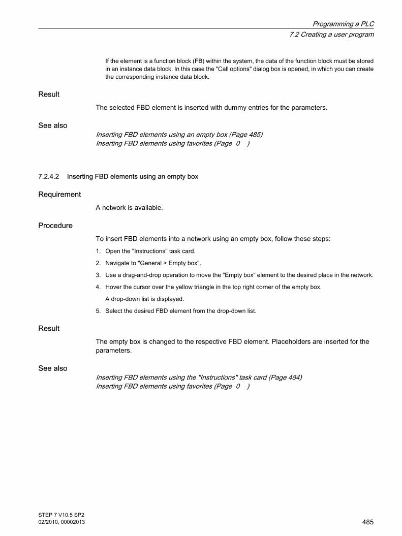
If the element is a function block (FB) within the system, the data of the function block must be storedin an instance data block. In this case the "Call options" dialog box is opened, in which you can createthe corresponding instance data block.
ResultThe selected FBD element is inserted with dummy entries for the parameters.
See alsoInserting FBD elements using an empty box (Page 485)Inserting FBD elements using favorites (Page 0 )
7.2.4.2 Inserting FBD elements using an empty box
RequirementA network is available.
ProcedureTo insert FBD elements into a network using an empty box, follow these steps:
1. Open the "Instructions" task card.
2. Navigate to "General > Empty box".
3. Use a drag-and-drop operation to move the "Empty box" element to the desired place in the network.
4. Hover the cursor over the yellow triangle in the top right corner of the empty box.
A drop-down list is displayed.
5. Select the desired FBD element from the drop-down list.
ResultThe empty box is changed to the respective FBD element. Placeholders are inserted for theparameters.
See alsoInserting FBD elements using the "Instructions" task card (Page 484)Inserting FBD elements using favorites (Page 0 )
7.2.4.2 Inserting FBD elements using an empty box
Programming a PLC7.2 Creating a user program
STEP 7 V10.5 SP202/2010, 00002013
485

7.2.4.2 Selecting the data type of an FBD element
7.2.4.2 Selecting a data type
IntroductionSome operations can be executed with several different data types. If one of these operationsis used in the program, a valid data type must be specified for the operation at the specific pointin the program. Data types for the inputs and outputs must be explicitly selected for someoperations.
Note
The valid data type (BOOL) for the tags on the enable input ENO and the enable output ENOis predefined by the system and cannot be changed.
The valid data types for an operation are listed in the drop-down list of the operation. You specifythe data type of the operation by selecting an entry from the drop-down list. If the data type ofa indicated tag deviates from the data type of the operation, the tag name is displayed in red.
7.2.4.2 Specifying the data type of an operation
IntroductionSome operations can be executed with several different data types. If such operations have tobe inserted in the program a data type has to be specified at a specific point in the program fortheir execution.
Specifying the data type by means of the drop-down listTo specify the data type of an operation by means of the drop-down list, follow these steps:
1. Insert the operation by drag-and-drop operation at the required point in the program.
The operation will be inserted at the required point in the program. The entry "???" (undefined) isdisplayed in the drop-down list.
2. Click the yellow triangle in the upper corner of the drop-down list.
The drop-down list opens displaying the data types that are valid for the operation.
3. Select a data type from the drop-down list.
The selected data type is displayed.
4. If the operation has two drop-down list, select the data type for the inputs of the operation in the leftdrop-down list and the data type for the outputs of the operation in the right drop-down list.
7.2.4.2 Selecting the data type of an FBD element7.2.4.2 Selecting a data type7.2.4.2 Specifying the data type of an operation
Programming a PLC7.2 Creating a user program
486STEP 7 V10.5 SP202/2010, 00002013

Specifying data type by assigning tagsTo specify the data type of an operation by assigning tags, follow these steps:
1. Insert the operation by drag-and-drop operation at the required point in the program.
The operation will be inserted at the required point in the program. The entry "???" (undefined) isdisplayed in the drop-down list.
2. At an input or output, specify a valid tag the data type of which is to be accepted as data type of theoperation.
The selected data type is displayed in the drop-down list.
3. If data types have to be specified for the inputs and outputs of the operation, enter a valid tag at aninput and a valid tag at an output. The tag specified at the input determines the data type of the inputsand the tag specified at the output determines the data type of the outputs of the operation.
7.2.4.2 Using favorites
7.2.4.2 Adding elements to Favorites
Requirement A block is open.
ProcedureTo add elements to Favorites, follow these steps:
1. Open the "Instructions" task card.
2. Maximize the "Instructions" pane.
3. Navigate in the "Instructions" pane to the element that you want to add to the favorites.
4. Drag the element to the "Favorites" pane or to the Favorites area in the program editor.
See alsoInserting FBD elements using favorites (Page 0 )
7.2.4.2 Inserting LAD elements using favorites
Requirement
• A network is available.
• Favorites are available.
7.2.4.2 Using favorites7.2.4.2 Adding elements to Favorites7.2.4.2 Inserting LAD elements using favorites
Programming a PLC7.2 Creating a user program
STEP 7 V10.5 SP202/2010, 00002013
487

ProcedureTo insert an element into a network using favorites, follow these steps:
1. If the Favorites are not displayed in the program editor, click the "Show favorites also in the editor"button in the program editor toolbar.
The Favorites are displayed under the block interface.
2. Drag the desired element from Favorites to the network.
Or
1. Select the point in the network at which you want to insert the element.
2. In the Favorites, click on the element you want to insert.
See alsoAdding elements to Favorites (Page 0 )Inserting FBD elements using the "Instructions" task card (Page 484)Inserting FBD elements using an empty box (Page 485)
7.2.4.2 Removing elements from Favorites
PrerequisitesA code block is open.
ProcedureTo remove elements from Favorites, follow these steps:
1. Either open the "Favorites" pane in the "Instructions" task card or click the "Show favorites also in theeditor" button in the program editor in the toolbar to show the favorites.
2. Right-click the element that you want to remove.
3. Select the "Remove instruction" command in the shortcut menu.
7.2.4.2 Inserting block calls in FBD
7.2.4.2 Inserting block calls using drag & drop
You can insert calls for existing functions (FC) and function blocks (FB) using a drag-and-dropoperation from the project tree. If you call function blocks from other function blocks, you cancall these either as single instance or as multi-instance.
Requirement
• A network is available.
• The block that is to be called is available.
7.2.4.2 Removing elements from Favorites7.2.4.2 Inserting block calls in FBD7.2.4.2 Inserting block calls using drag & drop
Programming a PLC7.2 Creating a user program
488STEP 7 V10.5 SP202/2010, 00002013

Inserting a call of a function (FC)To insert a call of a function (FC) into a network using a drag-and-drop operation, follow thesesteps:
1. Drag the function from the project tree into the network.
Inserting a call of a function block (FB) as a single instanceYou can call a function block as a single instance. In this case, the called function block storesits data in a data block of its own.
See also: Single instances (Page 350)
To insert the call for a function block (FB) into a network as a single instance using a drag-and-drop operation, follow these steps:
1. Drag the function block from the project tree into the network.
The "Call options" dialog opens.
2. Click the "Single instance" button.
3. Enter a name for the data block that is to be assigned to the function block.
4. Confirm your entries with "OK".
Inserting a call of a function block (FB) as a multi-instanceYou can call a function block as a multi-instance. In this case, the called function block storesits data in the instance data block of the calling function block.
See also: Multi-instances (Page 351)
To insert the call for a function block (FB) into a network as a multi-instance using a drag-and-drop operation, follow these steps:
1. Drag the function block from the project tree into the network.
The "Call options" dialog opens.
2. Click the "Multi instance" button.
3. In the "Name in the interface" text block, enter the name of the tag with which the called function blockwill be entered as a static tag in the interface of the calling block.
4. Confirm your entries with "OK".
ResultThe function or the function block is inserted with its parameters. You can then assign theparameters.
See also: Parameter transfer at block call (Page 353)
Programming a PLC7.2 Creating a user program
STEP 7 V10.5 SP202/2010, 00002013
489

Note
If when calling a function block you specify an instance data block that does not exist, it will becreated. If you have called a function block as a multi-instance, this will be entered as a statictag in the interface.
7.2.4.2 Calling functions and function blocks from supplied global libraries
In your user program, you can call pre-programmed functions and function blocks that arecontained in the supplied global libraries.
Requirement The "Libraries" task card is displayed.
Calling a function from a supplied global libraryTo call a function (FC) from a supplied global library, follow these steps:
1. Maximize the "Global libraries" pane.
2. Maximize the library in which the desired element is located.
3. Drag the function to the network.
Or:
1. Maximize the "Global libraries" pane.
2. Maximize the library in which the desired element is located.
3. Open the element view.
4. Drag the function from the "Elements" pane to the network.
Calling a function block from a supplied global libraryTo call a function block (FB) from a supplied global library, follow these steps:
1. Maximize the "Global libraries" pane.
2. Maximize the library in which the desired element is located.
3. Use a drag-and-drop operation to move the function block into the network.
The "Call options" dialog opens.
4. Select either single or multi-instance and enter a name for the data block.
5. Confirm your selection with "OK".
Or:
1. Maximize the "Global libraries" pane.
2. Maximize the library in which the desired element is located.
3. Open the element view.
7.2.4.2 Calling functions and function blocks from supplied global libraries
Programming a PLC7.2 Creating a user program
490STEP 7 V10.5 SP202/2010, 00002013

4. Drag the function block from the "Elements" pane to the network.
The "Call options" dialog opens.
5. Select either single or multi-instance and enter a name for the data block.
6. Confirm your selection with "OK".
See alsoParameter transfer at block call (Page 353)
7.2.4.2 Update block calls
If interface parameters of a called block are changed, the block call can no longer be executedcorrectly. You can avoid such inconsistent block calls by updating the block calls.
You have two options to update the block calls:
• Explicit updating in the program editor.
The block calls in the open block will be updated.
• Implicit update during compilation.
All block calls in the program as well as the used PLC data types will be updated.
Update blocks in the program editorTo update a block call within a block, follow these steps:
1. Open the block in the program editor
2. Click "Update inconsistent block calls" in the toolbar.
Or:
1. Open the block in the program editor.
2. Right-click on the instruction with the block call.
3. Select the "Update block call" command in the shortcut menu.
The "Interface update" dialog opens. This dialog shows the differences between the block interfacein use and the changed interface of the called block.
4. If you want to update the block call, click "OK". To cancel the update, click "Cancel".
Update block calls during compilationProceed as follows to update all block calls and uses of PLC data types during compilationimplicitly:
1. Open the project tree.
2. Select the "Program blocks" folder.
3. Select the "Compile > Software (rebuild all blocks)" command in the shortcut menu.
7.2.4.2 Update block calls
Programming a PLC7.2 Creating a user program
STEP 7 V10.5 SP202/2010, 00002013
491

7.2.4.2 Correcting the call type
Call typeThere are two ways of calling function blocks:
• As a single instance
• As a multi-instance
See also: Call function blocks as single or multi-instances (Page 351)
You can modify a defined call type at any time.
RequirementA network contains a block call.
ProcedureTo change the call type of a function block, follow these steps:
1. Select the block call.
2. Select the "Change call type" command in the shortcut menu.
The "Call options" dialog opens.
3. Click the "Single instance" or "Multi instance" button.
― If you select the "Single instance" call type, enter a name for the data block that will be assignedto the function block.
― If you select "Multi instance" as the call type, enter the name of the tag in the "Name in the interface"text box, with which the called function block will be entered as a static tag in the interface of thecalling block.
4. Confirm your entries with "OK".
7.2.4.2 Changing FBD elements
7.2.4.2 Inserting FBD elements
You can easily exchange FBD elements with other FBD elements of the same type. This hasthe advantage that the parameters are retained and need not be entered again. For example,you can exchange OR and AND, RS-FlipFlop and SR-FlipFlop, comparison functions or jumpinstructions.
RequirementA network with at least one FBD element is present.
7.2.4.2 Correcting the call type7.2.4.2 Changing FBD elements7.2.4.2 Inserting FBD elements
Programming a PLC7.2 Creating a user program
492STEP 7 V10.5 SP202/2010, 00002013

ProcedureTo replace an FBD element with another FBD element, follow these steps:
1. Select the FBD element that you want to replace.
If elements compatible to the selected FBD element are available, a yellow triangle appears in theupper right-hand corner of the element.
2. Move the cursor over the yellow triangle of the FBD element.
A drop-down list is displayed.
3. From the drop-down list, select the FBD element that you want to use to replace the existing FBDelement.
7.2.4.2 Editing FBD elements
You can edit FBD elements using the following edit commands:
• Copy
• Cut
• Paste
• Delete
Each command can always be executed via the keyboard, menu, and shortcut menu.
CopyingTo copy an FBD element, proceed as follows:
1. Right-click the FBD element that you want to copy.
2. Select "Copy" in the shortcut menu.
CuttingTo cut an FBD element, proceed as follows:
1. Right-click the FBD element that you want to cut.
2. Select "Cut" in the shortcut menu.
InsertingTo paste an FBD element, proceed as follows:
1. Copy an FBD element or cut an FBD element.
2. Right-click the point in the network where you want to paste the element.
3. Select "Paste" in the shortcut menu.
DeletingTo delete an FBD element, proceed as follows:
7.2.4.2 Editing FBD elements
Programming a PLC7.2 Creating a user program
STEP 7 V10.5 SP202/2010, 00002013
493

1. Right-click the FBD element that you want to delete.
2. Select the "Delete" command in the shortcut menu.
7.2.4.2 Pasting additional inputs and outputs
Introduction You can expand the FBD elements with additional inputs that execute arithmetic or binaryoperations. Such elements are, for example, the instructions "Add" (ADD), "Multiply" (MUL),AND or OR.
You can insert additional outputs only for the FBD element "Transmit value" (MOVE).
RequirementAn FBD element is available that permits the insertion of additional inputs and outputs.
Inserting an additional inputTo add an additional input to the box of an FBD element, proceed as follows:
1. Right-click on an existing input of the FBD element.
2. Select "Insert input" in the shortcut menu.
An additional input is added to the box of the FBD element.
Inserting an additional outputTo add an additional output to the box of an FBD element, proceed as follows:
1. Right-click on an existing output of the FBD element.
2. Select "Insert output" from the shortcut menu.
An additional output is added to the box of the FBD element.
See alsoInserting FBD elements (Page 484)
7.2.4.2 Removing inputs and outputs
IntroductionFor FBD elements that you have extended with additional inputs, you can subsequently removethese inputs. If you have added outputs to the FBD element "Transfer value" (MOVE), you canalso remove these outputs.
RequirementAn FBD element is available, which you have expanded with additional inputs or outputs.
7.2.4.2 Pasting additional inputs and outputs7.2.4.2 Removing inputs and outputs
Programming a PLC7.2 Creating a user program
494STEP 7 V10.5 SP202/2010, 00002013

Remove inputTo remove an input, follow these steps:
1. Select the input that you want to remove.
2. Select the "Delete" command in the shortcut menu.
The input of the FBD element is removed.
Remove outputTo remove an output of the FBD element "Transfer value", follow these steps:
1. Select the output that you want to remove.
2. Select the "Delete" command in the shortcut menu.
The output of the FBD element "Transfer value" is removed.
7.2.4.2 Inserting operands into FBD instructions
7.2.4.2 Inserting and editing operands
When an FBD element is inserted, the character strings "???", "??.?" and "..." are inserted asplaceholders for the parameters. The "???" and "??.?" strings displayed in red indicateparameters that must be connected. The "..." string displayed in black indicates parametersthat may be connected. "??.?" stands for Boolean placeholders.
Note
To display the available data types in a tooltip, move the cursor over the placeholder.
Requirement An FBD element is present.
ProcedureTo connect the parameters of an FBD element, proceed as follows:
1. Click the placeholder of the parameter.
An input field is opened.
2. Enter the corresponding parameters, for example a PLC tag, a local tag or a constant.
7.2.4.2 Inserting operands into FBD instructions7.2.4.2 Inserting and editing operands
Programming a PLC7.2 Creating a user program
STEP 7 V10.5 SP202/2010, 00002013
495

Note
If you enter the absolute address of a parameter that has already been defined, this absoluteaddress will be changed to the symbolic name of the parameter as soon as the input isconfirmed. If you have not yet defined the parameter, a new tag with this absolute addressand the default name "Tag_1" will be entered in the PLC tag table. When you confirm yourinput, the absolute address will be replaced with the symbolic name "Tag_1".
3. Confirm the parameter with the Enter key.
4. If you have not yet defined the parameter, you can define it directly in the program editor using theshortcut menu.
See also: "Declaring PLC tags in the program editor (Page 398) ".
Alternatively, using the operand selection:
1. Click the placeholder of the parameter.
2. Press <Ctrl + I> to open the operand selection.
3. Enter the initial letter of the parameter.
A list is displayed of all defined parameters that start with this letter and have a compatible data type.To further restrict the selection, you can enter additional letters.
4. Select the relevant parameter from the list and confirm your selection with the Enter key.
See also: Using the operand selection (Page 0 )
Or drag from it the PLC tag table:
1. In the project tree, select the "PLC tags" folder and open the PLC tag table.
2. If you have opened the PLC tag table, drag the desired tag to the corresponding location in yourprogram. If you have not opened the PLC tag table yet, open the detail view now. Drag the desiredtag from the detail view to the appropriate place in your program.
Or drag from it the block interface:
1. Open the block interface.
2. Drag the desired operand from the block interface to the corresponding location in your program.
Result
• If the syntax is error-free, the displayed parameter is black.
• If there is an error in the syntax, the cursor stays in the input field and a corresponding error messageis displayed in the inspector window in the "Info > Syntax" register.
See alsoSymbolic programming (Page 361)
7.2.4.2 Using the operand selection
The operand selection is a drop-down list that displays all available operands for a selectedinstruction. It contains all global and local tags of the suitable data type.
7.2.4.2 Using the operand selection
Programming a PLC7.2 Creating a user program
496STEP 7 V10.5 SP202/2010, 00002013

Requirement The operand selection is enabled.
See also: General settings for the PLC programming (Page 0 )
ProcedureTo select an operand from the operand selection, follow these steps:
1. Select an instruction.
2. Press the <Return> key.
The input field for the operand opens. The icon for operand selection appears next to the input field.
3. Click on the icon for operand selection.
The operand selection opens. This contains local and global tags, data blocks and multi-instances.
4. If necessary, filter the list:
― Enter one or several letters to show only the operands that start with these initial letters.
― Enter # in the first location to show only local operands from the block interface.
― Enter " in the first position to show global operands from the PLC tag table and the existing datablocks.
5. Select an operand.
If the selected operand is a structured tag, a data block or a multi-instance, a period is insertedautomatically after the higher-level element. The lower-level elements of the first operand are thendisplayed in the list.
6. Select the lower-level element.
Note
Even if operand selection is disabled in the general settings, you can display an operandselection list when necessary. You can do this with the <Ctrl+I> keyboard shortcut.
See alsoInserting and editing operands (Page 495)Accessing ARRAYs (Page 0 )Accessing the data of STRUCT (Page 0 )Accessing the data of a multi-instance (Page 0 )
7.2.4.2 Accessing ARRAYs
Accessing data in an ARRAY You access the data in an ARRAY using the index of the specific element in the ARRAY. Anindex consists of any integer values (-32768 to 32767) enclosed in square brackets, forexample Motor.Waerme_1x3[2].
7.2.4.2 Accessing ARRAYs
Programming a PLC7.2 Creating a user program
STEP 7 V10.5 SP202/2010, 00002013
497

Using ARRAYs as block parametersYou can transfer ARRAYs as parameters. If a block has an input parameter of ARRAY type,you must transfer as actual parameter an ARRAY with identical structure. You can also transferindividual elements of an ARRAY as actual parameter if the element corresponds to the datatype of the formal parameter.
7.2.4.2 Accessing the data of STRUCT
Accessing the data in structures You access individual elements in a structure using "StructureName.ElementName".
Example of accessing a structureYou access the "Temperature" element in the "Stack_1" structure as follows:
"Stack_1.Temperature"
Using structures as block parametersYou can transfer structures as parameters. If a block has an input parameter of the STRUCTtype, you must transfer as actual parameter a STRUCT with identical structure. You can alsotransfer individual elements of an STRUCT as actual parameter if the element corresponds tothe data type of the formal parameter.
7.2.4.2 Accessing the data of a multi-instance
Access to multi-instance dataYou can access the data of a multi-instance block within the multi-instance block and from thecaller block.
• Within the multi-instance block you address the data from the block interface, the same as for all otherdata.
For example, the "On" input parameter of the multi-instance block is accessed using "#On".
• You access the data of the multi-instance block from the calling block using "Multi-instanceName.TagName".
For example, the "On" input parameter of the multi-instance block "Multi" is accessed using "Multi.On".
7.2.4.2 Accessing I/O with LAD
Basics The process image of the CPU is updated once in a cycle. In time-critical applications, however,it can be that the current state of a digital input or output has to be read or transferred more
7.2.4.2 Accessing the data of STRUCT7.2.4.2 Accessing the data of a multi-instance7.2.4.2 Accessing I/O with LAD
Programming a PLC7.2 Creating a user program
498STEP 7 V10.5 SP202/2010, 00002013

often than once per cycle. For this purpose you can use a suffix for I/O access ID on the operandto directly access the I/O.
Immediate readIf you want to read the input directly from the I/O, use the peripheral input memory area (PI)instead of the process image of the inputs (I). The I/O memory area can be read as a bit, byte,word, or double word.
To read a signal directly from an input, you can add the suffix for I/O access ":P", e.g. "Switch:P",to the operand.
Immediate writeTo perform an immediate write to an output, use the peripheral output (PQ) memory areainstead of the process images of the outputs (Q). The peripheral output memory area can bewritten as a bit, byte, word, or double word.
To transfer a signal directly to peripheral output, you can add the suffix for I/O access ":P" toan operand, for example "Motor1:P".
Warning
Note that the immediate writing to the I/O can lead to hazardous states, for example whenwriting multiple times to an output in one program cycle.
See alsoI/O data area (Page 322)process image input/output (Page 320)
7.2.4.2 Wiring hidden parameters
IntroductionDepending on the CPU used, you can use complex instructions in your program that aredispatched with the TIA portal. These instructions can contain parameters that are declared ashidden.
If an instruction contains hidden parameters, the instruction box has a small arrow on the loweredge. You can recognize hidden parameters by their white font.
You can show and wire the hidden parameters at any time.
Showing or hiding hidden parametersTo show or hide hidden parameters, follow these steps:
1. Click on the small down arrow at the lower edge of the instruction box to show hidden parameters.
7.2.4.2 Wiring hidden parameters
Programming a PLC7.2 Creating a user program
STEP 7 V10.5 SP202/2010, 00002013
499

2. Click on the small up arrow at the lower edge of the instruction box to hide hidden parameters.
Wiring hidden parametersTo wire parameters, follow these steps:
1. Wire the hidden parameters like normally visible parameters.
The hidden parameter is transformed into a visible parameter.
See alsoInserting operands into FBD instructions (Page 495)
7.2.4.2 Branches in FBD
7.2.4.2 Basic information on branches in FBD
DefinitionYou can use the Function Block Diagram (FBD) programming language to program parallelbranches. This is done using branches that are inserted between the boxes. You can insertadditional boxes within the branch and in this way build up complex function block diagrams.
The figure below shows an example of the use of branches:
See alsoRules for branches in FBD (Page 500)Inserting branches in FBD networks (Page 501)Deleting branches in FBD networks (Page 501)
7.2.4.2 Rules for branches in FBD
RulesThe following rules apply to the use of branches in FBD:
• Branches are opened downward.
7.2.4.2 Branches in FBD7.2.4.2 Basic information on branches in FBD7.2.4.2 Rules for branches in FBD
Programming a PLC7.2 Creating a user program
500STEP 7 V10.5 SP202/2010, 00002013

• Branches can be inserted only between FBD elements.
• To delete a branch, you must delete all FBD elements, including the branch itself.
• If you delete the connection between two branches, the FBD elements of the branches are moved toseparate logic paths.
See alsoBasic information on branches in FBD (Page 500)Inserting branches in FBD networks (Page 501)Deleting branches in FBD networks (Page 501)
7.2.4.2 Inserting branches in FBD networks
RequirementA network is available.
ProcedureTo insert a new branch in a network, follow these steps:
1. Open the "Instructions" task card.
2. Navigate in the "Instructions" pane to "General > Branch".
3. Use a drag-and-drop operation to move the element to the desired place in the network.
See alsoRules for branches in FBD (Page 500)Basic information on branches in FBD (Page 500)Deleting branches in FBD networks (Page 501)
7.2.4.2 Deleting branches in FBD networks
RequirementA branch is available.
ProcedureTo delete a branch, follow these steps:
1. Select the connection line that links the branch to the main branch.
2. Select the "Delete" command in the shortcut menu.
ResultThe branch is now deleted. Boxes connected to the deleted branch are placed freely within thenetwork.
7.2.4.2 Inserting branches in FBD networks 7.2.4.2 Deleting branches in FBD networks
Programming a PLC7.2 Creating a user program
STEP 7 V10.5 SP202/2010, 00002013
501

See alsoRules for branches in FBD (Page 500)Basic information on branches in FBD (Page 500)Inserting branches in FBD networks (Page 501)
7.2.4.2 Logic paths in FBD
7.2.4.2 Introduction
Use of logic paths The program is mapped in one or more networks. The networks can contain one or more logicpaths on which the binary signals are arranged in the form of boxes.
The following figure shows an example of the use of several logic paths within a network:
RulesRemember the following rules when using logic paths:
• Connections are not permitted between logic paths.
• Only one jump instruction is permissible per network. The positioning rules for jump instructions remainvalid.
Executing logic pathsLogic paths are executed from top to bottom and from left to right. This means that the firstinstruction in the first logic path of the first network is executed first. All instructions of this logicpath are then executed. After this come all other logic paths of the first network. The nextnetwork is executed only after all logic paths have first been executed.
When jumps are used the regular execution of the logic paths is circumvented and theinstruction is executed at the jump destination.
Differences between branches and logic pathsThe difference between branches and logic paths is that the logic paths are independentbranches that can also stand in a different network. Branches, on the other hand, permit theprogramming of a parallel connection.
7.2.4.2 Logic paths in FBD7.2.4.2 Introduction
Programming a PLC7.2 Creating a user program
502STEP 7 V10.5 SP202/2010, 00002013

See alsoInserting a logic path (Page 503)Deleting a logic operation path (Page 503)
7.2.4.2 Inserting a logic path
Requirement
• A block is open.
• A network is available.
Procedure To insert a new logic path in a network, proceed as follows:
1. Insert any instruction in a network in such a way that it has no connection to existing instructions.
A new logic path is inserted.
2. Insert an assignment at the end of the new logic path.
3. Insert additional instructions in the new logic path.
See alsoIntroduction (Page 502)Deleting a logic operation path (Page 503)
7.2.4.2 Deleting a logic operation path
RequirementA logic path is available.
Procedure To delete a logic path, proceed as follows:
1. Hold down the left mouse button and draw a frame around the logic path. At the same time, makesure that you select all instructions of the logic path. Alternatively, you can hold down the <Shift> keyand select the first the last instruction of the logic path.
2. Right-click on one of the instructions in the logic path.
3. Select the "Delete" command in the shortcut menu.
See alsoIntroduction (Page 502)Inserting a logic path (Page 503)
7.2.4.2 Inserting a logic path7.2.4.2 Deleting a logic operation path
Programming a PLC7.2 Creating a user program
STEP 7 V10.5 SP202/2010, 00002013
503

7.2.4.2 Using free-form comments
7.2.4.2 Basic information on using free comments in FBD
Introduction Free-form comments allow you to add comments to the source code for graphic programminglanguages similar to line comments for textual languages.
Free-form comments can be used for all non-binary boxes.
7.2.4.2 Inserting free-form comments
ProcedureTo insert free-form comments, proceed as follows:
1. Right-click on the object for which you want to insert a free-form comment.
2. Select the "Insert comment" command in the shortcut menu.
A comment box with a standard comment opens. The comment box is connected by an arrow to thecorresponding object.
7.2.4.2 Editing free comments
Introduction Free-form comments can be edited as follows:
• Changing the comment text
• Changing the positioning or size of the comment box
• Attaching a comment to another element
• Showing and hiding free-form comments
Changing the comment textTo change the text of free-form comments, proceed as follows:
1. Double-click in the comment box.
2. Enter the desired text.
Changing the positioning of the comment boxTo change the positioning of the comment box, follow the steps below:
1. Left-click the comment box and keep the mouse button pressed.
2. Drag the comment box to the desired location.
7.2.4.2 Using free-form comments7.2.4.2 Basic information on using free comments in FBD7.2.4.2 Inserting free-form comments7.2.4.2 Editing free comments
Programming a PLC7.2 Creating a user program
504STEP 7 V10.5 SP202/2010, 00002013

Changing the size of the comment boxTo change the size of the comment box, follow the steps below:
1. Click the edge of the comment box.
2. Drag the comment box on the move handle in the lower right corner to the desired size.
Attaching a comment to another elementTo attach a free-form comment to another element, proceed as follows:
1. Left-click the point of the arrow that links the comment box with the instruction and keep the mousebutton pressed.
2. Drag the arrow to the element to which you want to attach the comment. Possible insertion points aremarked with a green square.
3. Release the mouse button.
Showing and hiding free-form commentsTo show or hide a free-form comments, proceed as follows:
1. Click "Show / hide free comments" in the toolbar.
7.2.4.2 Deleting free-form comments
Procedure To delete a free-form comment, proceed as follows:
1. Right-click on the free-form comment that you want to delete.
2. Select the "Delete" command in the shortcut menu.
7.2.4.2 Finding syntax errors in the program
Syntax errors in the user program are highlighted by red underlining. This allows you to seeerroneous entries at a glance. You can also jump from error to error within a block. In addition,syntax errors are listed in the "Info" tab of the inspector window together with an error message.
Procedure To find syntax errors in the program, follow these steps:
1. Select the block title.
2. Click "Go to next error" in the toolbar.
The first error in the block is marked.
You can use "Go to next error" and "Go to previous error" in the toolbar to find and correct allerrors in the block.
Or:
7.2.4.2 Deleting free-form comments7.2.4.2 Finding syntax errors in the program
Programming a PLC7.2 Creating a user program
STEP 7 V10.5 SP202/2010, 00002013
505

1. Open the error list in the inspector window with "Info > Syntax".
All syntax errors are listed in the table with a short description of the error.
2. If there are any errors, click on the blue question mark next to the error text to obtain information oneliminating the problem.
3. Double-click the error you want to correct.
The corresponding error is highlighted.
7.2.4.2 Changing the programming language
7.2.4.2 Rules for changing the programming language
Rules Observe the following rules if you want to change the programming language for a block:
• You can only change between the graphic programming languages LAD and FBD.
• If the language of individual networks of the block cannot be changed, these networks will be displayedin their original language.
• You can only change the programming language of entire blocks. The programming language cannotbe changed for individual networks.
• However, you can create networks within a block using another programming language and then copythem into the desired block.
See alsoChanging the programming language (Page 506)
7.2.4.2 Changing the programming language
ProcedureTo change the programming language, proceed as follows:
1. Right-click the block in the project tree.
2. Select the "Properties" command in the shortcut menu.
The "Properties" dialog box opens.
3. Select the "General" entry in the area navigation.
4. Select the new programming language in the "Language" drop-down list.
5. Confirm your selection with "OK".
See alsoRules for changing the programming language (Page 506)
7.2.4.2 Changing the programming language7.2.4.2 Rules for changing the programming language7.2.4.2 Changing the programming language
Programming a PLC7.2 Creating a user program
506STEP 7 V10.5 SP202/2010, 00002013

7.2.4.2 Handling program execution errors
7.2.4.2 Troubleshooting options
IntroductionYou can use the error handling settings to specify how the system should respond to anyprogramming or IO area access errors that occur. The following options are available:
• You use the system reactions already provided by the operating system.
• You use separate local error handling.
Using system reactionsThe operating system uses the following system reactions for error handling:
• STOP
• Ignore
Using local error handlingLocal error handling refers to an error handling within a block. Local error handling has thefollowing advantages:
• The error information is stored in the system memory, which you can query and evaluate.
• You can use the error information to program a response in the block to the error that has occurred.
• Programmed error evaluation and error reactions do not interrupt the program cycle.
• The system performance is not unnecessarily burdened by the local error handling. If no errors occur,programmed error analyses and reactions are not executed.
Local error handling applies only to blocks for which it has been set explicitly. If local errorhandling is set for a block, the system reaction is ignored during the execution of this block.
See alsoBasics of program execution (Page 323)Events and OBs (Page 323)Local error handling (Page 508)GetError (Page 954)GetErrorID (Page 957)
7.2.4.2 System reactions
Use During the execution of the user program, programming and IO area access errors can occurto which there must be a reaction. The operating system provides two system reactions for this:"Ignore" and "STOP".
7.2.4.2 Handling program execution errors7.2.4.2 Troubleshooting options7.2.4.2 System reactions
Programming a PLC7.2 Creating a user program
STEP 7 V10.5 SP202/2010, 00002013
507

The system reaction is always used for handing programming errors provided you do not uselocal error handling. If you set local error handling for a block, this has priority over the systemreaction.
7.2.4.2 Local error handling
7.2.4.2 Principles of local error handling
Introduction Local error handling makes it possible to query the occurrence of errors within a block andevaluate the associated error information. You can set local error handling for organizationblocks (OBs), function blocks (FBs), and functions (FCs). If local error handling is enabled, thesystem reaction is ignored.
Local error handling applies only to blocks for which it has been set explicitly. The local errorhandling setting is not assumed by a calling block, nor is it transferred to called blocks. Forhigher-level blocks and lower-level blocks, the system settings still apply provided errorhandling has not been programmed for these blocks.
General procedure for local error handlingWhen errors occur while a block is being executed with local error handling, a predefinedresponse is initiated based on the following error types:
• Write errors: These errors are ignored, and program execution simply continues.
• Read errors: Program execution continues with the substitute value "0".
• Execution errors: Execution of the instruction is aborted. Program execution resumes with the nextinstruction.
Information about the first error that occurs is stored in the system memory. This informationcan be queried and output with an instruction (GET_ERROR or GET_ERRORID). Errorinformation is output in a format that can undergo additional processing. You can use additionalinstructions to analyze error information and program a reaction to the error based.
When information about the first error is queried, the error memory space in the system memoryis enabled. Then, when additional errors occur, information about the next error is output.
Instructions for local error handlingYou can use the following instructions for local error handling:
• GET_ERROR (Page 954)
• GET_ERRORID (Page 957)
The instructions GET_ERROR and GET_ERRORID differ in the amount of error informationthat is output with each one.
7.2.4.2 Local error handling7.2.4.2 Principles of local error handling
Programming a PLC7.2 Creating a user program
508STEP 7 V10.5 SP202/2010, 00002013

7.2.4.2 Error output priorities
Overview of the priorities In local error handling, information about the first error that occurred is displayed. If multipleerrors occur at the same time while an instruction is being executed, these errors are displayedaccording to their priority. The following table shows the priority of different types of errors.
Priority Error type
1 Error in the program code
2 Missing reference
3 Invalid range
4 DB does not exist
5 Operands are not compatible
6 Width of specified area is not sufficient
7 Timers or counters do not exist
8 No write access to a DB
9 I/O error
10 Instruction does not exist
11 Block does not exist
12 Invalid nesting depth
The highest priority is 1 and the lowest priority is 12.
See alsoGetError (Page 954)GetErrorID (Page 957)
7.2.4.2 Enabling local error handling for a block
IntroductionLocal error handling is enabled for a block if you insert one of the following instructions in anetwork.
• GET_ERROR (Page 954)
• GET_ERRORID (Page 957)
If local error handling is enabled for a block, the system reactions for this block are ignored.
7.2.4.2 Error output priorities7.2.4.2 Enabling local error handling for a block
Programming a PLC7.2 Creating a user program
STEP 7 V10.5 SP202/2010, 00002013
509

Prerequisites
• The block is open.
• The "Instructions" task card is open.
ProcedureTo enable local error handling for a block, proceed as follows:
1. Navigate to the "Extended Instructions" pane of the "Instructions" task card.
2. Open the "Program Control" folder.
3. Drag the GET_ERROR or GET_ERRORID instruction to the desired network.
ResultLocal error handling is enabled for the open block. In the Inspector window under "Properties> Attributes", the "Handle errors within block" check box is selected. This setting cannot beedited in the Inspector window. The local error handling can be disabled by deleting the insertedinstructions to the local error handling.
7.2.4.3 Programming data blocks
7.2.4.3 Basic principles for programming of data blocks
A data block (DB) is used to save the values that are written during execution of the program.
In contrast to the code block, the data block contains only tag declarations. It contains nonetworks or instructions. The tag declarations define the structure of the data block.
Types of data blocks There are two types of data blocks:
• Global data blocks
The global data block is not assigned to a code block. You can access the values of a global datablock from any code block. A global data block contains only static tags.
You enter the tags that the global data block should contain in the declaration table.
• Instance data blocks
The instance data block is a block that is assigned directly to a function block (FB). The structure ofan instance data block is determined by the interface declaration of the function block. It containsexactly those block parameters and static tags that are declared there.
However, you can define instance-specific values in instance data blocks, e.g. initial values for thedeclared tags.
7.2.4.3 Programming data blocks7.2.4.3 Basic principles for programming of data blocks
Programming a PLC7.2 Creating a user program
510STEP 7 V10.5 SP202/2010, 00002013

Retentivity of data valuesTo prevent data loss in the event of power failure, you can store the data values in a retentivememory area.
Monitoring data values online If an online connection is available, you can display the current data values in data blocks.
See alsoCreating data blocks (Page 0 )
7.2.4.3 Structure of the declaration table for data blocks
Structure of the declaration table for data blocks The form of the declaration table depends on various settings, for example, the symbolic accessof the block.
The figure below shows the structure of the declaration table with a symbolic access data blockin online view as an example.
Meaning of the columnsThe following table shows the meaning of the individual columns:
Column Description
Name Name of the tags.
Data type Data type of the tags.
Offset Relative address of the tags.This column is only visible in data blocks that cannot be symbolicallyaddressed.
Default value Value with which the tag in the interface of a higher-level code block is pre-assigned.The "Default value" column is hidden per default. To show it, click "Expandedmode". The values contained in this column can only be changed in the higher-level code block. The values are only displayed in the data block.
7.2.4.3 Structure of the declaration table for data blocks
Programming a PLC7.2 Creating a user program
STEP 7 V10.5 SP202/2010, 00002013
511

Column Description
Initial value Value that the tag should assume at startup.The default values defined in a code block are used as initial values during thecreation of the data block. You can then replace these values with instance-specific initial values in the data block.Specification of an initial value is optional. If you do not specify any value, thetag assumes the default value at startup. If a default is not defined either, thedefault value valid for the data type is used. For example, the value "FALSE"is specified as standard for BOOL.
Monitor value Current data value in the CPU.This column only appears if an online connection is available and you selectthe "Monitor" button.
Retain Marks the tag as retentive. The values of retentive tags are retained even afterthe power supply is switched off.
Comment Comments to document the tags.
See alsoCreating data blocks (Page 0 )Creating a data structure for global data blocks (Page 513)Defining initial values (Page 516)Setting the retentivity of data valuesBasic information on initial values (Page 515)
7.2.4.3 Creating data blocks
Prerequisites The "Program blocks" folder opens in the project tree.
ProcedureTo create a data block, proceed as follows:
1. Double-click the "Add new block" command.
The "Add new block" dialog box opens.
2. Click the "Data block (DB)" button.
3. Enter a name for the data block.
4. Select the type of the data block. You have the following options available to you:
― To create a global data block, select the list entry "Global DB".
― To create an instance data block, select the function block to which you want to assign the instancedata block from the list.
5. Select the "Manual" option button if you want to assign the number of the block.
7.2.4.3 Creating data blocks
Programming a PLC7.2 Creating a user program
512STEP 7 V10.5 SP202/2010, 00002013

6. If you choose to use manual assignment, enter the block number in the input field.
7. To add additional properties for the data new block, click the arrow beside "Further information" in thelower part of the dialog box.
An area with further input fields is displayed.
8. Enter all the properties you require.
9. Confirm your entry with "OK".
ResultThe new data block is created. You can find the data block in the project tree in the "Programblocks" folder.
Note
You can select the "Add new and open" check box at the bottom of the dialog box. As a result,the block will be opened immediately after it is created.
See alsoInstance data blocks (Page 347)Programming data blocks (Page 510)Global data blocks (DB) (Page 347)
7.2.4.3 Creating a data structure for global data blocks
7.2.4.3 Declaring tags with elementary data type
Requirement A global data block is open.
ProcedureTo declare a tag of the elementary data type, proceed as follows:
1. Enter a tag name in the "Name" column.
2. Click the arrow key in the "Data type" column and select the desired data type.
See also: Declaring tags of STRUCT data type (Page 514)
See also: Declaring tags of the ARRAY data type (Page 514)
3. Repeat steps 1 and 2 for all tags that are to be declared.
See alsoDisplay and edit block properties (Page 415)
7.2.4.3 Creating a data structure for global data blocks7.2.4.3 Declaring tags with elementary data type
Programming a PLC7.2 Creating a user program
STEP 7 V10.5 SP202/2010, 00002013
513

Keyboard shortcuts in tables (Page 134)Editing the declaration table for data blocks (Page 0 )Defining initial values (Page 516)Setting the retentivity of data valuesMonitoring data values online (Page 519)
7.2.4.3 Declaring tags of the ARRAY data type
Requirement A data block is open.
ProcedureTo declare a tag of the ARRAY data type, follow these steps:
1. Enter a tag name in the "Name" column.
2. In the "Data type" column, click the arrow key and select the data type "Array [o .. hi] of type".
3. Then enter the dimensions in the same column, showing high limit and low limit and the data type (forexample, ARRAY [1..10] of Bool). A space must be inserted between the closing square bracket andthe keyword "of" and also between "of" and the data type information for the ARRAY elements.
Entering initial values of ARRAY elementsTo initialize the individual elements of an ARRAY, follow these steps:
1. Click the "Expanded mode" button.
The ARRAY opens and the individual ARRAY elements are shown in separate rows.
2. Enter the required value in the "Initial value" column.
3. To close the ARRAY again, click the "Expanded mode" button.
See alsoDefining initial values (Page 516)Setting the retentivity of data valuesMonitoring data values online (Page 519)Editing the declaration table for data blocks (Page 0 )
7.2.4.3 Declaring tags of STRUCT data type
Requirement A data block is open.
ProcedureTo declare a tag of the STRUCT data type, proceed as follows:
7.2.4.3 Declaring tags of the ARRAY data type7.2.4.3 Declaring tags of STRUCT data type
Programming a PLC7.2 Creating a user program
514STEP 7 V10.5 SP202/2010, 00002013
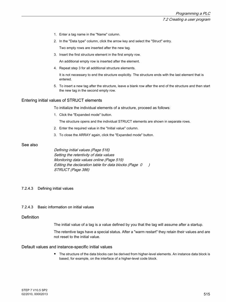
1. Enter a tag name in the "Name" column.
2. In the "Data type" column, click the arrow key and select the "Struct" entry.
Two empty rows are inserted after the new tag.
3. Insert the first structure element in the first empty row.
An additional empty row is inserted after the element.
4. Repeat step 3 for all additional structure elements.
It is not necessary to end the structure explicitly. The structure ends with the last element that isentered.
5. To insert a new tag after the structure, leave a blank row after the end of the structure and then startthe new tag in the second empty row.
Entering initial values of STRUCT elementsTo initialize the individual elements of a structure, proceed as follows:
1. Click the "Expanded mode" button.
The structure opens and the individual STRUCT elements are shown in separate rows.
2. Enter the required value in the "Initial value" column.
3. To close the ARRAY again, click the "Expanded mode" button.
See alsoDefining initial values (Page 516)Setting the retentivity of data valuesMonitoring data values online (Page 519)Editing the declaration table for data blocks (Page 0 )STRUCT (Page 386)
7.2.4.3 Defining initial values
7.2.4.3 Basic information on initial values
DefinitionThe initial value of a tag is a value defined by you that the tag will assume after a startup.
The retentive tags have a special status. After a "warm restart" they retain their values and arenot reset to the initial value.
Default values and instance-specific initial values
• The structure of the data blocks can be derived from higher-level elements. An instance data block isbased, for example, on the interface of a higher-level code block.
7.2.4.3 Defining initial values7.2.4.3 Basic information on initial values
Programming a PLC7.2 Creating a user program
STEP 7 V10.5 SP202/2010, 00002013
515

In this case you can define a default value for each tag in the higher-level element. The defaultvalues defined in the code block are used as initial values during the creation of the data block.You can then replace these values with instance-specific initial values in the data block.
Specification of an initial value is optional. If you do not specify any value, the tag assumes thedefault value at startup. If a default is not defined either, the default value valid for the data typeis used. For example, the value "FALSE" is specified as standard for BOOL.
See alsoDefining initial values (Page 516)Structure of the declaration table for data blocks (Page 511)Declaring local tags in the block interface (Page 435)
7.2.4.3 Defining initial values
Requirement A data block is opened and contains declared tags.
ProcedureTo determine the initial values for the tags, follow these steps:
1. Click the "Expanded mode" button to show all elements of structured data types.
2. Enter the desired initial values in the "Initial value" column. The value must match the data type of thetag and should not exceed the range of the data type.
Note
The "Default value" column contains the default values that were defined for the tags in theinterface of a higher-level code block.
ResultThe instance-specific initial values are defined. The tag takes the defined value at startup,provided it was not declared as retentive.
See alsoBasic information on initial values (Page 515)
7.2.4.3 Defining initial values
Programming a PLC7.2 Creating a user program
516STEP 7 V10.5 SP202/2010, 00002013

7.2.4.3 Setting the retentivity of data values
7.2.4.3 Setting retentivity in global data blocks
7.2.4.3 Retentive behavior and symbolic addressing in global data blocks
Symbolic access By setting symbolic access, you can specify how tags of a global data block are declared,symbolic only or both symbolic and absolute. If symbolic access is enabled, you can declaretags only by entering a symbolic name. In this case the tags are automatically addressed,making optimum use of the available memory capacity. If symbolic access is not enabled, thetag also gets a fixed absolute address. The memory area is allocated depending on the addressof the declared tags.
Retentive behaviorIf symbolic access is enabled you can specify the retentive behavior of individual tags in aglobal data block. If a tag is defined as retentive it is automatically stored in the retentive memoryarea of the global data block.
If symbolic access is disabled in a global data block, you cannot specify the retentive behaviorof individual tags. In this case the retentivity settings are valid for all tags of the global datablock.
See alsoSymbolic addressing of blocks only (Page 363)Retentive memory areas (Page 319)
7.2.4.3 Setting retentive behavior in global data block
Introduction Depending on the setting for symbolic access, the retentivity behavior in a global data blockcan be set either for individual or for all tags. To specify the retentive behavior, the followingsettings of the global data block must be considered:
• The symbolic access of the tags is enabled:
The retentive behavior can be specified for the individual tags. For tags with structured data types,retentivity settings are transferred for all tag elements.
• The symbolic access of tags is disabled:
The retentivity settings are valid for all tags of the global data block.
7.2.4.3 Setting the retentivity of data values7.2.4.3 Setting retentivity in global data blocks7.2.4.3 Retentive behavior and symbolic addressing in global data blocks7.2.4.3 Setting retentive behavior in global data block
Programming a PLC7.2 Creating a user program
STEP 7 V10.5 SP202/2010, 00002013
517

RequirementA global data block is open.
ProcedureTo set the retentive behavior of the tags in a global data block, follow these steps:
1. In the "Retain" column, select the cell of tags for which you want to set a retentive behavior.
2. Select the check box in the "Retain" column.
Result
• If symbolic access is enabled, the selected tag is defined as retentive.
• If symbolic access is disabled, all tags of the global data block are defined as retentive.
See alsoRetentive behavior and symbolic addressing in global data blocks (Page 517)Symbolic addressing of blocks only (Page 363)Retentive memory areas (Page 319)
7.2.4.3 Setting retentivity in instance data blocks
7.2.4.3 Retentive behavior in instance data blocks
Retentive behavior of local tags in an instance data block Depending on the settings for symbolic access in the higher-level function block, the retentivityin an instance data block can be set either for all or for some of the tags. To specify the retentivebehavior in an instance data block, the following settings of the function data block must beconsidered:
• Symbolic access is enabled in the higher-level function block:
The instance data block assumes the retentivity settings of all tags from the higher-level function block.This property is displayed in the structure of the instance data block and cannot be edited.
• Symbolic access is disabled in the higher-level function block:
The retentivity settings can be edited and are valid for all tags of the instance data block.
The setting for symbolic access of the higher-level function block is displayed as write-protectedunder the "Attribute" group in the property view of the instance data block and cannot bechanged. In the instance data block, you can recognize the tags defined as retentive by thecheck mark set in the "Retain" column.
See alsoSetting retentive behavior in an instance data block (Page 519)Retentive behavior and symbolic addressing of code blocks (Page 440)
7.2.4.3 Setting retentivity in instance data blocks7.2.4.3 Retentive behavior in instance data blocks
Programming a PLC7.2 Creating a user program
518STEP 7 V10.5 SP202/2010, 00002013

Setting the retentive behavior of local tags in a function block (Page 441)Retentive memory areas (Page 319)
7.2.4.3 Setting retentive behavior in an instance data block
Introduction In an instance data block, the editability of the retentivity behavior depends on the settings forsymbolic access in the higher-level function block. In this case the retentive behavior cannotbe set individually for each tag. The retentivity settings always affect all tags that are containedin an instance data block.
See also: Retentive behavior in instance data blocks (Page 518)
Requirement
• An instance data block is opened.
ProcedureTo set the retentive behavior of the tags in an instance block, follow these steps:
1. Select a tag.
2. Select the check box in the "Retain" column of the tags.
ResultAll tags are defined as retentive.
7.2.4.3 Monitoring data values online
7.2.4.3 Monitoring data values in data blocks online
You can monitor the current data values of the tags in the CPU directly in the declaration table.
Requirement
• An online connection is available.
• The data block has been loaded to the CPU.
ProcedureTo monitor the data values, proceed as follows:
1. Start monitoring by clicking the "Monitor all" button.
The additional "Monitor value" column is displayed in the table. This shows the current data values.
See also: Structure of the declaration table for data blocks (Page 511)
7.2.4.3 Setting retentive behavior in an instance data block7.2.4.3 Monitoring data values online7.2.4.3 Monitoring data values in data blocks online
Programming a PLC7.2 Creating a user program
STEP 7 V10.5 SP202/2010, 00002013
519

2. End the monitoring by clicking the "Monitor all" button again.
7.2.4.3 Editing the declaration table for data blocks
7.2.4.3 Deleting tags in data blocks
RequirementA global data block is open.
Procedure To delete a tag, follow these steps:
1. Select the row that contains the tag you want to delete.
2. Select the "Delete" command in the shortcut menu.
Note
Only global data blocks permit tags to be deleted. You cannot directly change the structure ofinstance data blocks, because the structures of these blocks are defined by the function block.
The type of the data block is entered in the block properties.
See also: Display and edit block properties (Page 415)
See alsoKeyboard shortcuts in tables (Page 134)Adapting tables (Page 131)
7.2.4.3 Inserting table rows
Procedure To insert row above the position of the mouse pointer, proceed as follows:
1. Position the mouse pointer in the row above which you want to insert a new row.
2. Click the "Insert row" button on the toolbar of the table.
A new row is inserted above the selected row.
7.2.4.3 Editing the declaration table for data blocks7.2.4.3 Deleting tags in data blocks7.2.4.3 Inserting table rows
Programming a PLC7.2 Creating a user program
520STEP 7 V10.5 SP202/2010, 00002013

See alsoKeyboard shortcuts in tables (Page 134)Adapting tables (Page 131)
7.2.4.3 Adding table rows at the end
Procedure To add a new row at the end of the table or at the end of a complex data type, follow thesesteps:
1. Click the "Add row" button on the table toolbar.
A new empty row will be added at the end of the table or at the end of a complex data type.
See alsoKeyboard shortcuts in tables (Page 134)Adapting tables (Page 131)
7.2.5 Comparing blocks
7.2.5.1 Basics of block comparison
Function Block comparison allows you to compare a block in the programming device with a block in theCPU. There are two ways of displaying the differences:
• Comparison editor (Page 148)
Only the time stamp of the blocks is compared in the comparison editor. This comparison gives youan overview of the differences of all blocks. You can read the respective status from the symbols.
• Detailed comparison (Page 522)
The offline and online versions of a block are opened side-by-side and the differences are highlighted.
You can perform a block comparison for the following blocks:
• Code blocks
With code blocks, you can run a comparison with the comparison editor and make a detailedcomparison.
• Data blocks
Data blocks can only be compared using the time stamp in the comparison editor.
7.2.4.3 Adding table rows at the end7.2.5 Comparing blocks7.2.5.1 Basics of block comparison
Programming a PLC7.2 Creating a user program
STEP 7 V10.5 SP202/2010, 00002013
521

Objects to be comparedFor the comparison of code blocks, both the block interfaces and the individual networks arecompared. In addition, any different tag names are also determined. All comments and otherblock attributes are excluded from the comparison.
Procedure for the detailed comparison of code blocksWhen networks are compared, first inserted or deleted networks are detected. Then the othernetworks are compared. Instructions are the same if the operator and operand are the same.In each case the first difference per operation is displayed. However, several differences pernetwork can be displayed.
If the block interface changes, the respective time stamp of the block interface of the onlineand offline version of the code block changes. This change means a change in the time stampof the program code. For the comparison of block interfaces, the time stamps of the programcode of the online and offline versions of the code block are therefore compared first. If thesetime stamps are the same, it is assumed that the interfaces are the same. If these time stampsare different, the next step is to compare the data types of the interfaces, section by section.Multi-instances and PLC data types are included in the comparison. If the data types in thesections are the same, the initial values of the tags are compared. All differences are displayed.
7.2.5.2 Detailed comparison
7.2.5.2 Start detail comparison
Requirement
• The comparison editor is open.
• There is a block available with different online and offline versions.
See also: Overview of the comparison editor (Page 148)
ProcedureTo perform a detailed comparison for a block, follow these steps:
1. In the comparison editor, right-click on the block for which you want to perform a detailed comparison.
2. Select the "Start detailed comparison"" command in the shortcut menu.
ResultOne instance of the program editor is opened for the online version of the block and anotherinstance for the offline version of the block, and the two instances are arranged side-by-side.The differences in the two variants are highlighted in color.
See also: Representation of the detailed comparison (Page 523)
7.2.5.2 Detailed comparison7.2.5.2 Start detail comparison
Programming a PLC7.2 Creating a user program
522STEP 7 V10.5 SP202/2010, 00002013

7.2.5.2 Representation of the detailed comparison
Identification of the differences The detailed comparison allows you to identify the exact places where the online and offlineversions of a block differ. The following color coding allows you to find these places as quicklyas possible:
• The lines where there are differences are highlighted in gray.
• Differing operands and operations are highlighted in green.
• If the number of networks differs, pseudo-networks are added to allow the display of identical networksto be synchronized. These pseudo-networks are highlighted in grey and contain the text "Nocorresponding network found" in the title bar of the network. Pseudo-networks cannot be edited.
• If the sequence of the networks is incorrect, pseudo networks will be inserted at the correspondinglocations. These pseudo networks are highlighted in gray and contain the text "The networks are notsynchronized" in the title bar of the network. The pseudo network also features a "Go to network <No>"link, which you can use to navigate to the corresponding network.
ExampleThe following figure shows an example of the detailed comparison for the LAD programminglanguage:
Reducing the number of differences displayedFor the sake of clarity, not all the differences are highlighted but rather the first difference of anoperation in each case. For example, if all the inputs in a box with multiple inputs are different
7.2.5.2 Representation of the detailed comparison
Programming a PLC7.2 Creating a user program
STEP 7 V10.5 SP202/2010, 00002013
523

in the offline and online versions of the block, only the first input is highlighted as a difference.You can resolve this difference and update the comparison list. The next input will then behighlighted as a difference.
The number of differences highlighted within a network therefore depends on the number ofexisting operations.
7.2.5.2 Navigating in the detailed comparison
RequirementYou have run a detailed comparison.
Navigate to the differences To navigate to a difference between the two blocks, follow these steps:
1. Open the list of results for the detailed comparison under "Info > Comparison result" in the Inspectorwindow.
2. Double-click a difference.
The difference is selected in both editors.
Or:
1. Click one of the following navigation buttons on the toolbar:
― Position on first difference
Navigates to the first difference in the block, and displays the difference in both editors.
― Position on previous difference
Navigates to the previous difference starting from the current position, and displays the differencein both editors.
― Position on next difference
Navigates to the next difference starting from the current position, and displays the difference inboth editors.
― Position on last difference
Navigates to the last difference in the block, and displays the difference in both editors.
Switching off/on the synchronization of the vertical scrolling between the editors The scrolling for both editors is synchronized to ensure that the corresponding networks arevisible parallel to each other during vertical scrolling. You can switch this mode off and on. Todo this, follow these steps:
1. To switch off synchronized scrolling, click the "Synchronize scrolling between editors" button in thetoolbar.
2. To switch on synchronized scrolling again, click the "Synchronize scrolling between editors" buttonone more time in the toolbar.
7.2.5.2 Navigating in the detailed comparison
Programming a PLC7.2 Creating a user program
524STEP 7 V10.5 SP202/2010, 00002013

7.2.5.2 Changing networks during the detailed comparison
Changing the offline blockYou can change the offline block at any time.
Changing the online blockYou cannot change the online block.
7.2.5.2 Updating the comparison results
As soon as you change an object, the comparison results are no longer valid and must beupdated.
RequirementYou have run a detailed comparison.
ProcedureTo update the comparison results, proceed as follows:
1. Click "Update the comparison result" in the toolbar.
7.2.6 Compiling blocks
7.2.6.1 Basic information on compiling blocks
IntroductionA user program must first be compiled before the CPU can execute it. You need to recompileyour program each time you make a change.
The following procedures take place during compilation:
• The user program is checked for syntax errors.
• All the block calls within the compiled blocks are checked. If changes have been made to the interfacesof called blocks, the block calls are updated.
• Finally, the user program is compiled into a code that can be read by the CPU.
Compilation methodsYou can start compilation in the following windows or editors:
• Compiling blocks in the project tree
7.2.5.2 Changing networks during the detailed comparison7.2.5.2 Updating the comparison results7.2.6 Compiling blocks7.2.6.1 Basic information on compiling blocks
Programming a PLC7.2 Creating a user program
STEP 7 V10.5 SP202/2010, 00002013
525

Used to compile individual blocks or for the simultaneous compilation of all blocks in the "Programblocks" folder.
• Compiling blocks in the program editor
This is intended for compilation of a single open block.
• Compiling blocks in the call or dependency structure
Used to compile individual blocks.
See also: Call structure (Page 546) , Dependency structure (Page 552)
Compilation optionsIf you are compiling blocks in project tree, you have further options:
• Software
Only the changed blocks are compiled.
• Software (rebuild all blocks)
All blocks are compiled. This is recommended for the first compilation and after major revisions.
See alsoCompiling project data (Page 154)
7.2.6.2 Compiling blocks in the project navigation
You can compile one block, multiple blocks or all of the blocks in the project tree.
RequirementThe project tree is open.
Compiling multiple blocks in the project tree To compile multiple blocks in the project tree, follow these steps:
1. Open the "Program blocks" folder in project tree.
2. Select the blocks you want to compile.
3. You can select one of two different options for the compilation:
― If you want to compile only the changes since the last compilation, select the "Compile > Software"command in the shortcut menu.
― If you want to compile all blocks completely, select the "Compile > Software (rebuild all blocks)"command in the shortcut menu.
Compiling all blocks in the project treeTo compile all blocks in the "Program blocks" folder in project tree, follow these steps:
1. Select the "Program blocks" folder in the project tree.
2. You can select one of two different options for the compilation:
7.2.6.2 Compiling blocks in the project navigation
Programming a PLC7.2 Creating a user program
526STEP 7 V10.5 SP202/2010, 00002013

― If you want to compile only the changes since the last compilation, select the "Compile > Software"command in the shortcut menu.
― If you want to compile all blocks completely, select the "Compile > Software (rebuild all blocks)"command in the shortcut menu.
ResultThe code for the blocks is generated.
If the blocks to be compiled call blocks whose interface has changed, the block calls areupdated.
• If you have selected one or more blocks for compilation, the block calls will be updated within theselected blocks.
• If you have selected the folder "Program blocks" for compilation, all block calls in the program as wellas the used PLC data types will be updated.
The message under "Info > Compilation" in the Inspector window reports whether thecompilation was successful.
See also: Correcting compilation errors (Page 528)
See alsoFinding syntax errors in the program (Page 505)
7.2.6.3 Compiling blocks in the program editor
RequirementThe block to be compiled is open.
ProcedureTo compile a block in the program editor, follow these steps:
1. Right-click the white area underneath a network in the instruction window of the program editor.
2. Select the "Compile" command in the shortcut menu.
ResultThe code for the block is generated. If the block to be compiled has block calls in which theinterface has changed, the block calls are updated.
The message under "Info > Compilation" in the inspector window reports whether thecompilation was successful.
See also: Correcting compilation errors (Page 528)
7.2.6.3 Compiling blocks in the program editor
Programming a PLC7.2 Creating a user program
STEP 7 V10.5 SP202/2010, 00002013
527

7.2.6.4 Correcting compilation errors
In the Inspector window in "Info > Compile", you can see whether any compilation wassuccessful or whether errors were detected in the program. If errors occur, you will need tocorrect them and then start the compilation again.
ProcedureTo correct errors following compilation, proceed as follows:
1. Open the error list in the Inspector window with "Info > Compile".
2. Click on the blue question mark next to the error text to obtain information on eliminating the problem.
3. Double-click the error you want to correct.
The corresponding error is highlighted.
4. Correct the error.
5. Restart compilation.
7.2.7 Downloading blocks
7.2.7.1 Introduction to loading of blocks
Downloading blocks to device So that the CPU can execute the user program, the program must first be compiled and thendownloaded to the device. The following options are available for downloading:
• Downloading blocks to the program editor
This is intended for downloading a single open block.
• Downloading blocks to the project tree
This is intended for simultaneous downloading of several or all blocks in the block folder.
• Downloading blocks to an accessible device
You can download blocks to an accessible device by dragging them.
Note
Observe the following:
• If you download a know-how-protected block to a device, no restore information is installed along withit. This means that you cannot reopen a know-how-protected block if you upload it from the device.
• To avoid inconsistencies between calling and called blocks, all affected blocks are complied anddownloaded each time global changes, such as changes in the block interface, are made.
7.2.6.4 Correcting compilation errors7.2.7 Downloading blocks7.2.7.1 Introduction to loading of blocks
Programming a PLC7.2 Creating a user program
528STEP 7 V10.5 SP202/2010, 00002013

Uploading blocks from deviceYou can upload blocks from an accessible device to your project. This is necessary, forexample, if you want to edit blocks that only exist in the device. All existing blocks (organizationblocks, function blocks, functions, data blocks) and the global tags are then uploaded to theproject.
Uploading blocks from or downloading blocks to a memory cardMemory cards are plug-in cards used, for example, to expand the memory of a device. OnlySiemens SD cards can be used for devices of the S7-1200 series.
To use a memory card as replacement of the load memory, you must download the userprogram or individual blocks to a memory card. You can just as well upload blocks from amemory card back into the project.
Note
Note the following when uploading to or downloading from a memory card:
• If the CPU contains no previous program and you insert an empty memory card in the CPU theprogram will be loaded from the PG/PC to the memory card and not to the CPU.
• If you insert an empty memory card prior to the startup of the CPU, the program that is on the CPUwill be transferred automatically to the memory card. The program on the CPU will then be deleted.
• If you insert a memory card with a program in the CPU prior to the startup of the CPU and the CPUalready contains a program, the program on the memory card will be executed and not the programon the CPU. The program on the CPU will be deleted.
See alsoUploading blocks from or downloading blocks to a memory card (Page 534)Loading blocks from an accessible device (Page 534)
7.2.7.2 Downloading blocks to device
7.2.7.2 Loading blocks in device in the program editor
Requirement The block to be downloaded is open.
Procedure To download a block from the program editor to the device, follow these steps:
1. Right-click the white area underneath a network in the instruction window of the program editor.
7.2.7.2 Downloading blocks to device7.2.7.2 Loading blocks in device in the program editor
Programming a PLC7.2 Creating a user program
STEP 7 V10.5 SP202/2010, 00002013
529

2. Select the "Download to device" command in the shortcut menu.
If you have not already established an online connection, the "Extended download to device" dialogopens.
If you have already specified an online connection, the "Download preview" dialog opens. Continuethen with step 5.
Note
You can also open the "Extended download to device" dialog with the "Online" menu.
3. Select the interface for your PG/PC from the "PG/PC interface for downloading" drop-down list in the"Extended download to device" dialog. If a subnet is available, also select a subnet from the"Connection to subnet" drop-down list.
4. Select your device in the "Accessible devices in target subnet" table and confirm your selection with"Load".
When necessary, the project data is compiled. The "Download preview" dialog opens. This dialogdisplays messages and proposes actions necessary for uploading.
5. Check the messages and, where necessary, enable the actions in the "Action" column.
Notice
Performing the proposed actions during operation of the plant can cause serious damageto property or injury to persons if there are functional disturbances or program errors!
Make sure that no dangerous situations can arise before you start the actions!
As soon as downloading becomes possible, the "Download" button is enabled.
6. Click "Download".
7. The block is downloaded and the "Download results" dialog opens. This dialog shows you the statusand the actions after downloading.
8. If you want to start the modules again directly after downloading, select the "Start all" check box.
9. To close the "Download results" dialog box, click "Finish".
ResultThe code for the blocks is downloaded to the device. If the changes affect additional blocks,these will be compiled and also downloaded to the device. Blocks that exist only online in thedevice are deleted. Inconsistencies between the blocks in the user program are avoided bydownloading all affected blocks and deleting the unneeded blocks in the device.
The messages under "Info > General" in the Inspector window report whether the downloadingprocess was successful.
Programming a PLC7.2 Creating a user program
530STEP 7 V10.5 SP202/2010, 00002013

7.2.7.2 Loading blocks into the device in the project tree
In the project tree you can download one block, multiple blocks or all blocks to a device.
Downloading multiple blocks in the project tree to the device To download one block or multiple blocks to the device from the project tree, follow these steps:
1. Open the "Program blocks" folder in project tree.
2. Select the blocks you want to download.
3. Select the "Download to device" command in the shortcut menu.
4. If you only want to download the changes since the last download, select the "Software" option. If youwant to download all blocks in their entirety, select the "Software (all blocks)" option.
― If you have not already established an online connection, the "Extended download to device" dialogopens.
― If you have already specified an online connection, the "Download preview" dialog opens. Continuethen with step 7.
Note
You can also open the "Extended download to device" dialog with the "Online" menu.
5. Select the interface for your PG/PC from the "PG/PC interface for downloading" drop-down list in the"Extended download to device" dialog. If a subnet is available, also select your subnet from the"Connection to subnet" drop-down list.
6. Select your device in the "Accessible devices in target subnet" table and confirm your selection with"Load".
When necessary, the project data is compiled. The "Download preview" dialog opens. This dialogdisplays messages and proposes actions necessary for the downloading.
7. Check the messages and, where necessary, enable the actions in the "Action" column.
Notice
Performing the proposed actions during operation of the plant can cause serious propertydamage and personal injury if there are malfunctions or program errors!
Make sure that no dangerous situations can arise before you start the actions!
As soon as downloading becomes possible, the "Download" button is enabled.
8. Click "Download".
The block is downloaded and the "Download results" dialog opens. This dialog shows you the statusand the actions after downloading.
9. If you want to start the modules again directly after downloading, select the "Start all" check box.
10.
To close the "Download results" dialog box, click "Finish".
7.2.7.2 Loading blocks into the device in the project tree
Programming a PLC7.2 Creating a user program
STEP 7 V10.5 SP202/2010, 00002013
531

Downloading all blocks in the project tree to the deviceTo download all blocks in the "Program blocks" folder to the device from the project tree, followthese steps:
1. Select the "Program blocks" folder in the project tree.
2. Select the "Download to device" submenu in the shortcut menu.
3. If you only want to download the changes since the last download, select the "Software" option. If youwant to download all blocks in their entirety, select the "Software (all blocks)" option.
― If you have not already established an online connection, the "Extended download to device" dialogopens.
― If you have already specified an online connection, the "Download preview" dialog opens. Continuethen with step 6.
Note
You can also open the "Extended download to device" dialog with the "Online" menu.
4. Select the interface for your PG/PC from the "PG/PC interface for downloading" drop-down list in the"Extended download to device" dialog. If a subnet is available, also select your subnet from the"Connection to subnet" drop-down list.
5. Select your device in the "Accessible devices in target subnet" table and confirm your selection with"Load".
When necessary, the project data is compiled. The "Download preview" dialog opens. This dialogdisplays messages and proposes actions necessary for the downloading.
6. Check the messages and, where necessary, enable the actions in the "Action" column.
Notice
Performing the proposed actions during operation of the plant can cause serious propertydamage and personal injury if there are malfunctions or program errors!
Make sure that no dangerous situations can arise before you start the actions!
As soon as downloading becomes possible, the "Download" button is enabled.
7. Click "Download".
The block is downloaded and the "Download results" dialog opens. This dialog shows you the statusand the actions after downloading.
8. If you want to start the modules again directly after downloading, select the "Start all" check box.
9. To close the "Download results" dialog box, click "Finish".
ResultThe code for the blocks is downloaded to the device. If the changes affect additional blocks,these will be compiled and also downloaded to the device. Blocks that exist only online in the
Programming a PLC7.2 Creating a user program
532STEP 7 V10.5 SP202/2010, 00002013
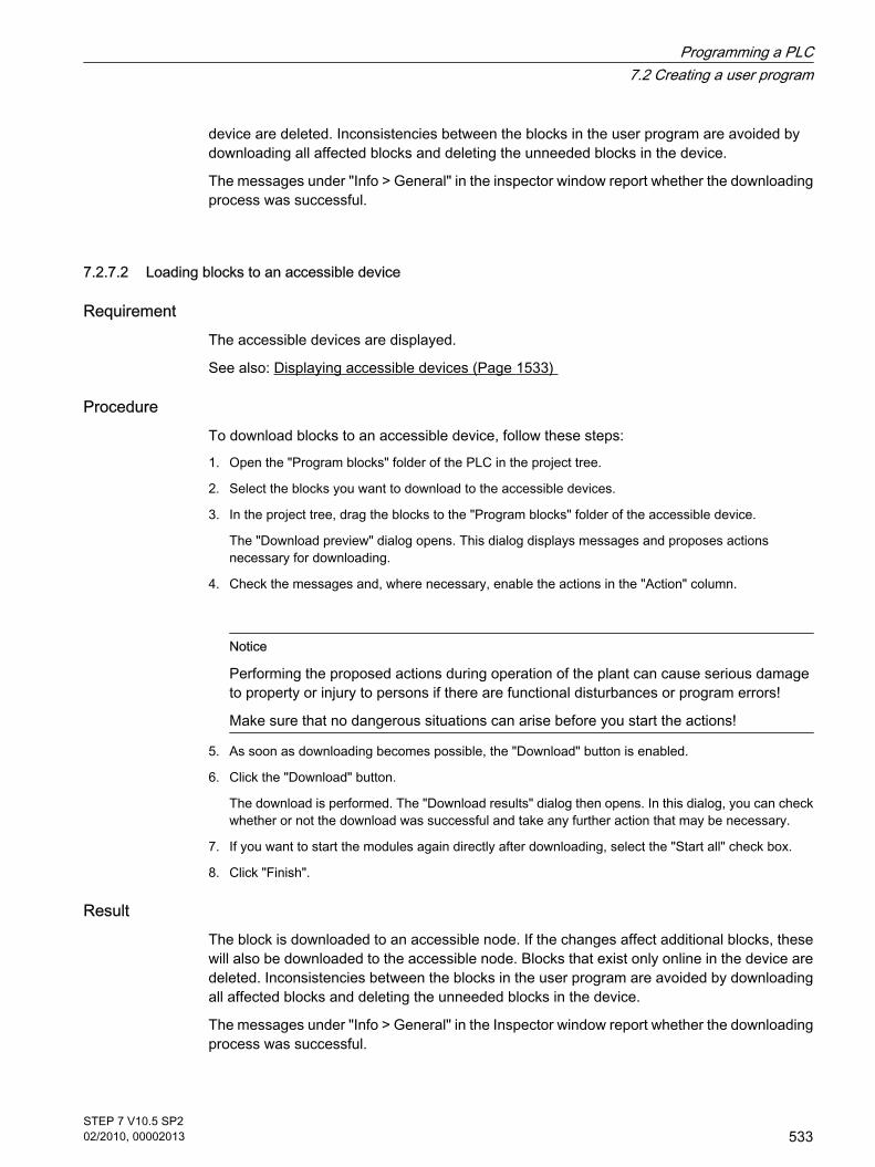
device are deleted. Inconsistencies between the blocks in the user program are avoided bydownloading all affected blocks and deleting the unneeded blocks in the device.
The messages under "Info > General" in the inspector window report whether the downloadingprocess was successful.
7.2.7.2 Loading blocks to an accessible device
Requirement The accessible devices are displayed.
See also: Displaying accessible devices (Page 1533)
ProcedureTo download blocks to an accessible device, follow these steps:
1. Open the "Program blocks" folder of the PLC in the project tree.
2. Select the blocks you want to download to the accessible devices.
3. In the project tree, drag the blocks to the "Program blocks" folder of the accessible device.
The "Download preview" dialog opens. This dialog displays messages and proposes actionsnecessary for downloading.
4. Check the messages and, where necessary, enable the actions in the "Action" column.
Notice
Performing the proposed actions during operation of the plant can cause serious damageto property or injury to persons if there are functional disturbances or program errors!
Make sure that no dangerous situations can arise before you start the actions!
5. As soon as downloading becomes possible, the "Download" button is enabled.
6. Click the "Download" button.
The download is performed. The "Download results" dialog then opens. In this dialog, you can checkwhether or not the download was successful and take any further action that may be necessary.
7. If you want to start the modules again directly after downloading, select the "Start all" check box.
8. Click "Finish".
ResultThe block is downloaded to an accessible node. If the changes affect additional blocks, thesewill also be downloaded to the accessible node. Blocks that exist only online in the device aredeleted. Inconsistencies between the blocks in the user program are avoided by downloadingall affected blocks and deleting the unneeded blocks in the device.
The messages under "Info > General" in the Inspector window report whether the downloadingprocess was successful.
7.2.7.2 Loading blocks to an accessible device
Programming a PLC7.2 Creating a user program
STEP 7 V10.5 SP202/2010, 00002013
533

7.2.7.3 Uploading blocks from device
7.2.7.3 Loading blocks from an accessible device
Requirement
• The accessible devices are displayed.
See also: Displaying accessible devices (Page 1533)
• The PLC folder in the project contains no data.
ProcedureTo upload blocks from an accessible device to your project, follow these steps:
1. In the project tree, drag the "Program blocks" folder of the accessible device to the "Program blocks"folder of the PLC in the project.
The "Upload preview" dialog box opens. This dialog displays messages and proposes actionsnecessary for uploading. If the PLC folder in the project already contains data, a message informsyou that these data will be replaced.
2. Check the messages and, where necessary, enable the actions in the "Action" column.
3. As soon as uploading becomes possible, the "Upload from device" button is enabled.
4. Click the "Upload from device" button.
7.2.7.4 Uploading blocks from or downloading blocks to a memory card
7.2.7.4 Loading blocks to a memory card
Requirement
• The memory card is not marked as program card.
• The "Program blocks" folder of the memory card is open.
See also: Accessing memory cards (Page 165)
Procedure To download blocks to a memory card, follow these steps:
1. Open the "Program blocks" folder of the PLC in the project tree.
2. Select the blocks you want to download to the memory card.
3. Drag the blocks in project tree to the "Program blocks" folder of the memory card.
The "Download preview" dialog opens. This dialog displays messages and proposes actionsnecessary for uploading.
7.2.7.3 Uploading blocks from device7.2.7.3 Loading blocks from an accessible device7.2.7.4 Uploading blocks from or downloading blocks to a memory card7.2.7.4 Loading blocks to a memory card
Programming a PLC7.2 Creating a user program
534STEP 7 V10.5 SP202/2010, 00002013

4. Check the messages and, where necessary, enable the actions in the "Action" column.
5. As soon as downloading becomes possible, the "Download" button is enabled.
6. Click the "Download" button.
The download is performed. The "Download results" dialog then opens. In this dialog, you can checkwhether or not the download was successful and take any further action that may be necessary.
7. Click "Finish".
ResultThe block is downloaded to the memory card If the changes affect additional blocks, these willalso be downloaded to the memory card. Blocks that exist only on the memory card are deleted.Inconsistencies between the blocks in the user program are avoided by downloading allaffected blocks and the deleting of the non-required blocks on the memory card.
The messages under "Info > General" in the Inspector window report whether the downloadingprocess was successful.
7.2.7.4 Loading blocks from a memory card
RequirementThe "Program blocks" folder of the memory card is open.
See also: Accessing memory cards (Page 165)
Procedure To upload blocks from a memory card to your project, follow these steps:
1. Select the blocks you want to upload in the "Program blocks" folder of the memory card in project tree.
2. Drag the blocks to the "Program blocks" folder of the PLC.
The "Upload preview" dialog box opens. This dialog displays messages and proposes actionsnecessary for uploading.
3. Check the messages and, where necessary, enable the actions in the "Action" column.
4. As soon as uploading becomes possible, the "Upload from device" button is enabled.
5. Click the "Upload from device" button.
7.2.7.4 Loading blocks from a memory card
Programming a PLC7.2 Creating a user program
STEP 7 V10.5 SP202/2010, 00002013
535

7.2.8 Protecting blocks
7.2.8.1 Protecting blocks
Introduction You can protect one or more blocks of the types OB, FB, FC and DB from unauthorized accessusing a password.
If a block is know-how protected, only the following data is readable:
• Interface parameters Input, Output, InOut, Return
• Block title
• Block comment
• Block properties
• Program structure
• Global tags in the cross-references without information on the point of use
The following actions can still be performed with a know-how protected block:
• Copying and deleting
• Calling in a program
• Checking and where necessary updating when compiling
The code of the block, on the other hand, is protected from unauthorized reading andmodification.
Note
Observe the following:
• If you download a know-how-protected block to a device, no restore information is loaded along withit. This means that you cannot open a know-how-protected block again even with the correct passwordif you upload it from the device. A block comparison between the offline and online version of the blockremains possible with the correct password.
• If you forget the password, you will no longer be able to access the block.
Possible actionsThe following actions are possible depending on the protection status of a block:
• If no know-how protection exists, you can set up know-how protection.
• If know-how protection already exists, you can either cancel the know-how protection or change thepassword.
7.2.8 Protecting blocks7.2.8.1 Protecting blocks
Programming a PLC7.2 Creating a user program
536STEP 7 V10.5 SP202/2010, 00002013

See alsoSetting up know-how protection (Page 537)
7.2.8.2 Setting up know-how protection
Setting up know-how protectionYou can use a password to apply know-how protection to blocks to protect them fromunauthorized access.
Setting up know-how protection To set up know-how protection, proceed as follows:
1. Select the blocks you want to protect.
2. Select the command "Know-how protection > Enable know-how protection" in the "Edit" menu.
The "Enable know-how protection" dialog box opens.
3. Enter a password in the "Enter password" box.
4. Enter the same password in the "Confirm password" box.
5. Confirm your entries with "OK".
Changing a password To change the password, proceed as follows:
1. Select the know-how protected block for which you want to change the password.
2. Select the "Know-how protection > Change password" command in the "Edit" menu.
The "Change password" dialog box opens.
3. Enter the old password in the "Enter old password" box.
4. Enter the new password in the "Enter new password" box.
5. Enter the same new password in the "Confirm new password" box.
6. Confirm your entries with "OK".
Disabling know-how protection To disable know-how protection, proceed as follows:
1. Select the block for which you want to disable know-how protection.
2. Select the command "Know-how protection > Disable know-how protection" in the "Edit" menu.
The "Disable know-how protection" dialog box opens.
3. Enter the password.
4. Confirm your entries with "OK".
7.2.8.2 Setting up know-how protection
Programming a PLC7.2 Creating a user program
STEP 7 V10.5 SP202/2010, 00002013
537

7.3 Displaying program information
7.3.1 Overview of available program information
Program information The program information of a user program contains the view specified in the following table.
View Application
Assignment list (Page 539) Provides an overview of the address bits for the I,Q, and M memory areas already allocated withinthe user program.Also indicates if an address has been allocated byaccess from an S7 program or if the address hasbeen assigned to a SIMATIC S7 module.
Call structure (Page 546) Shows the call structure of the blocks within theuser program and provides an overview of theblocks used and their relationships.
Dependency structure (Page 552) Shows the list of blocks used in the user program.A block is shown at the first level and blocks thatcall or use this block are indented below it. Incontrast to the call structure, instance blocks arelisted separately.
Resources (Page 557) Shows the hardware resources of the CPU forobjects (OB, FC, FB, DB, PLC tags and user-defined data types), for CPU memory areas and forthe existing I/O modules.
Displaying several views simultaneouslyYou can generate and display several views for one or more user programs to facilitate testingand changing your user program.
Displaying multiple views, for example, enables you to:
• Display all program information for a user program next to one another
• Compare different user programs
7.3 Displaying program information7.3.1 Overview of available program information
Programming a PLC7.3 Displaying program information
538STEP 7 V10.5 SP202/2010, 00002013

7.3.2 Displaying an assignment list
7.3.2.1 Introduction to the assignment list
Program information in the assignment list The assignment list shows if an address has been allocated by access from an S7 program orif the address has been assigned to a SIMATIC S7 module. It is therefore an important basisfor locating errors or changes in the user program.
The assignment list provides you with an overview of the bits in the bytes of the memory areaslisted below:
• Input (I)
• Output (O)
• Bit memory (M)
• I/O (P)
Display of the assignment listThe assignment list of inputs, outputs, and bit memories is displayed in several separate workwindows.
FiltersYou can filter the display within the assignment list. You can use predefined filters or createyour own.
Displaying cross-reference informationYou have the option of displaying cross-reference information for selected addresses in theassignment list.
You can display the cross references to selected addresses or to individual selected bits in theInspector window by selecting the command "Display usage" from the shortcut menu. Thecommand "Tools > Cross References" allows you to also open the cross-reference list for theselected object.
Displaying the PLC tag tableYou can open the PLC tag table from the assignment list and edit the properties of the tagsused.
To do this select an address of the assignment list and select the "Open editor" command inthe shortcut menu.
Enabling the display of retentivityYou can enable and disable the display of the retentive state of bit memories by selecting the"Display/hide retentivity" toolbar button.
7.3.2 Displaying an assignment list7.3.2.1 Introduction to the assignment list
Programming a PLC7.3 Displaying program information
STEP 7 V10.5 SP202/2010, 00002013
539

See alsoSymbols in the assignment list (Page 540)Layout of the assignment list (Page 540)
7.3.2.2 Layout of the assignment list
Layout of the assignment list The assignment list is displayed in several work windows separated by:
• Inputs and outputs
• Bit memories
• I/O
Each line in the assignment list is dedicated to a byte of the memory area, in which thecorresponding eight bits from 7 to 0 are labeled according to their access. In conclusion, a "bar"indicates if access is made by a byte (B), word (W) or double word (D).
Displaying inputs, outputs, and bit memoriesThe list displays all input/output bytes and bit memory bytes used and their assignment in theS7 user program.
You can find an explanation of the symbols in the assignment list here. (Page 540)
See alsoIntroduction to the assignment list (Page 539)
7.3.2.3 Symbols in the assignment list
Meaning of the symbols in the assignment list The following table shows the meaning of the symbols in the assignment list:
Symbol Meaning
Indicates the address assignment in the selected state.
Indicates the address assignment in the non-selected state.
Indicates that a pointer start address and a tag address access thesame address range and that they are selected.
Indicates that a pointer start address and a tag address access thesame address range and that they are not selected.
7.3.2.2 Layout of the assignment list7.3.2.3 Symbols in the assignment list
Programming a PLC7.3 Displaying program information
540STEP 7 V10.5 SP202/2010, 00002013

Symbol Meaning
Indicates the pointer assignment in the selected state.
Indicates the pointer assignment in the non-selected state.
Indicates that the byte is in use with byte access and thecorresponding tag is selected. The shortcut menu allows you todisplay cross-reference information for the selected variables as wellas the PLC tag table.
Indicates that the byte is in use with byte access and thecorresponding tag is not selected.
Indicates that the byte is in use with word access and thecorresponding tag is selected. The shortcut menu allows you todisplay cross-reference information for the selected variables as wellas the PLC tag table.
Indicates that the byte is in use with word access and thecorresponding tag is not selected.
Indicates that the byte is in use with double word access and thecorresponding tag is selected. The shortcut menu allows you todisplay cross-reference information for the selected variables as wellas the PLC tag table.
Indicates that the byte is in use with double word access and thecorresponding tag is not selected.
Background color: gray Indicates that a byte is in use with byte, word or double word accessand that the address is also in use by the hardware. The graybackground color indicates overlapping memory access.
Background color: yellow Indicates that the address is not in use by the hardware.
See alsoLayout of the assignment list (Page 540)Introduction to the assignment list (Page 539)
7.3.2.4 Displaying an assignment list
RequirementA project has been created with programmed blocks.
ProcedureProceed as follows to display the assignment list:
7.3.2.4 Displaying an assignment list
Programming a PLC7.3 Displaying program information
STEP 7 V10.5 SP202/2010, 00002013
541

1. Select the block folder or one or more of the blocks contained therein.
2. Select the "Assignment list" command in the "Tools" menu.
ResultThe assignment list for the selected program is displayed.
View options in the assignment listRefer to view respective view options that are set to display the desired information in theassignment list.
See alsoSetting the view options for the assignment list (Page 542)Layout of the assignment list (Page 540)
7.3.2.5 Setting the view options for the assignment list
IntroductionThe following view options are available for the assignment list:
• Used addresses:
When this check box is activated, the addresses, I/Os and pointers used in the program are displayed.
• Free hardware addresses:
When this check box is activated, only the free hardware addresses are displayed.
Requirement
• A project has been created with programmed blocks.
• The assignment list is open.
ProcedureProceed as follows to set the view options for the assignment list:
1. Click on the arrow of the
symbol ("View options") in the task bar.
The view options for the call structure opens. Check marks are set in front of the activated view options.
2. If you want to activate or deactivate a view option, click on the respective check box and set or removethe check mark.
ResultThe view options are set and the desired information is displayed in the assignment list.
7.3.2.5 Setting the view options for the assignment list
Programming a PLC7.3 Displaying program information
542STEP 7 V10.5 SP202/2010, 00002013

7.3.2.6 Filter options in the assignment list
Filter settings You can define your own filter settings for the assignment list. The following options areavailable for defining filters:
• Display all addresses of the address areas specified
• Show single, defined addresses from the selected address area, for example, "IB 0" and "IB 200".
• Show complete area from the selected address area, for example, "IB 0" to "IB 256".
The following table provides an overview of all available options:
Selection in the Selection Symbol Meaning
Address area All addresses (I, Q, M) can beenabled either separately or as inthe default setting.
Check box is activated The assignment list onlydisplays the enabled addressareas (I, Q, M).
Filter area Show assignment for all addresses * Displays the assignment of alladdresses of the enabledaddress areas (I, Q, M).
Show assignment for selectedaddresses, for example, for theinputs "IB 0" and "IB 256"
0;256Separate individual addressesand areas by a semicolon.
Assignments of selectedaddresses for the activatedaddress areas (I) are shown.
Show assignment for selectedareas, for example, for the inputs "IB0 to IB 100" and "IB 200 to IB 256".
0-100;200-256Contiguous areas should beconnected by a hyphen.
Assignments of selected areasfor the activated address areas(I) are shown.
7.3.2.7 Defining filters for assignment list
Requirement
• A project has been created with programmed blocks.
• The assignment list is open.
Defining filterProceed as follows to define a filter for the assignment list:
1. Click on the
symbol ("Filter") in the task bar.
The "Filter" dialog opens.
2. Click on the
7.3.2.6 Filter options in the assignment list7.3.2.7 Defining filters for assignment list
Programming a PLC7.3 Displaying program information
STEP 7 V10.5 SP202/2010, 00002013
543

symbol ("Create new filter") in the task bar.
A new filter is created with the name "Filter_1". The check boxes for all addresses (inputs, outputs,bit memories) are set by default for the filter.
3. If you want to change the name of the filter, click on the drop-down list in the task bar and enter a newtitle.
4. Deactivate the check boxes of addresses that are not to be affected by the filter.
5. Enter one of the following options in the filter area of the activated address:
― Show all addresses used = "*"
― Show single, defined addresses, for examle, IB 0" and IB 25 = "0;25". Individual addresses andaddress areas are separated by a semicolon.
― Show complete address areas, for example, IB 0 to IB 256 = "0-256". Complete address areasshould be connected by a hyphen.
6. Confirm your entries with "OK".
The newly defined filter is shown in the task bar of the assignment list under the specified name.
Delete filterProceed as follows to delete a filter:
1. Click on the
symbol ("Filter") in the task bar.
The "Filter" dialog opens.
2. In the drop-down list of the task bar, select the filter you want to delete.
3. Click on the
symbol ("Delete selected filter") in the task bar.
The selected filter is deleted.
See alsoFilter options in the assignment list (Page 543)Displaying an assignment list (Page 541)Introduction to the assignment list (Page 539)
7.3.2.8 Filtering an assignment list
Requirement
• A project has been created with programmed blocks.
• The assignment list is open.
7.3.2.8 Filtering an assignment list
Programming a PLC7.3 Displaying program information
544STEP 7 V10.5 SP202/2010, 00002013

Procedure1. Click on the arrow on the drop-down list.
The available filter are displayed.
2. Select the desired filter.
ResultThe assignment list is filtered according to the settings of the selected filter.
Note
The filter settings are saved when the project is closed.
7.3.2.9 Defining retentive memory areas for bit memories
IntroductionIn the assignment list you can define the width of the retentive memory area for bit memories.The content of tags which are addressed in retentive memory is retained after power off andat the STOP to RUN transition after power on.
The display of retentive bit memories can be enabled and disabled in the assignment list. Iftheir display is enabled, retentive bit memories are identified by an icon in the "Address" column.
RequirementThe assignment list is open.
ProcedureProceed as follows to define the width of the retentive memory area for bit memories:
1. Click "Retentivity" in the toolbar.
The "Retentive memory areas" dialog opens.
2. Starting at the count of 0, define the width of the retentive memory area by entering the last byte ofthis area in the input field. Watch out for any addresses of tags already assigned to the retentive area.
3. Load the block to the target system. Select the "Program blocks" folder in the Project tree and selectthe "Download to device" submenu in the shortcut menu.
ResultThe width of the retentive memory area is defined. If enabled in the assignment list, an iconwill indicate the retentive state of all tags in the "Address" column.
7.3.2.9 Defining retentive memory areas for bit memories
Programming a PLC7.3 Displaying program information
STEP 7 V10.5 SP202/2010, 00002013
545

7.3.2.10 Enabling the display of retentive bit memories
Introduction In the assignment list you can enable and disable the display of retentive bit memories. Theretentive bit memories are identified by means of an icon in the "Address" column if the displayof retentivity is enabled.
RequirementThe assignment list is open.
ProcedureProceed as follows to enable and disable the display of retentive bit memories:
1. Click "Display/hide retentivity" in the toolbar.
ResultThe retentive tags are identified by means of an icon in the "Address" column of the bit memoryarea if the display of retentivity is enabled. The icons in the "Address" column are hidden if thedisplay of retentivity is disabled.
7.3.3 Displaying the call structure
7.3.3.1 Introduction to the call structure
Call structure The call structure describes the call hierarchy of the block within an S7 program.
It provides an overview of:
• The blocks used
• Jumps to the places of use of the blocks
• Relationships between blocks
• Local data requirements of the blocks
• Status of the blocks
Information in the call structureDisplaying the call stucture provides you with a list of the blocks used in the user program. Thefirst level of the call structure is highlighted in color and shows the blocks that are not called byany other block in the program. Organization blocks are always shown on the first level of thecall structure. Functions, function blocks and data blocks are only shown on the first level if
7.3.2.10 Enabling the display of retentive bit memories7.3.3 Displaying the call structure7.3.3.1 Introduction to the call structure
Programming a PLC7.3 Displaying program information
546STEP 7 V10.5 SP202/2010, 00002013

they are not called by an organization block. When a block calls other blocks or functions, theyare listed indented under the calling block. System functions and blocks are shown in the callstructure only if they are called by a block.
View optionsThe following view options are available for the call structure:
• Display conflicts only:
When this check box is activated, only the conflicts within the call structure are displayed.
• Group several calls:
When this check box is activated, several block calls are grouped together. The number of block callsis displayed in the "Number of calls" column. The links to the various call locations are offered in adrop-down list in the "Details" column.
Displaying the block callsYou can display the block calls in a block by clicking on the arrow in front of the block title. Todisplay the call information of all blocks, click on the
symbol ("Expand all") in the toolbar.
You can hide the total overview by clicking on the
symbol ("Collapse all").
Displaying cross-reference informationYou can display the cross-reference information for a block in the Inspector window by right-clicking on the respective block and selecting the "Display Usage" command from the shortcutmenu.
Displaying blocks in the program editorYou can open the program editor and edit blocks there from the call structure.
To do this select the required block in the call structure and select the "Open" command in theshortcut menu.
Displaying deleted blocksThe lines for deleted blocks are marked with the
icon.
Programming a PLC7.3 Displaying program information
STEP 7 V10.5 SP202/2010, 00002013
547

7.3.3.2 Layout of the call structure
Layout of the call structure The view of the call structure consists of the following columns:
Column Content/meaning
Call structure Shows an overview of the blocks calledSeveral block calls are grouped and the "Number of calls"column is displayed if the "Group calls" check box is set.
Call type (!) Shows the type of call, for example recursive block call.
Address Shows the absolute address of the block. With a functionblock, the absolute address of the corresponding instancedata block is also shown.
Details Shows the network or interface of the calling block. Allinformation are offered as a link in this column. With this link,you can jump to the location of the block call in the programeditor. When the "Group several calls" view option isactivated, the calls are grouped and offered as links in a drop-down list.
Local data (in the path) Indicates the local data requirement of the full path.Blocks which can only be addressed symbolically have higherlocal data requirements because the information for thesymbolic addressing is stored with them.
Local data (for blocks) Show the local data requirements of the block.Blocks which can only be addressed symbolically have higherlocal data requirements because the information for thesymbolic addressing is stored with them.
See alsoSymbols in the call structure (Page 548)Introducing the consistency check in the call structure (Page 551)
7.3.3.3 Symbols in the call structure
Meaning of the symbols in the call structure The following table shows the meaning of the symbols in the call structure:
Symbol Meaning
Indicates an organization block (OB).
7.3.3.2 Layout of the call structure7.3.3.3 Symbols in the call structure
Programming a PLC7.3 Displaying program information
548STEP 7 V10.5 SP202/2010, 00002013

Symbol Meaning
Indicates a function block (FB).
Indicates a function (FC).
Indicates a data block (DB).
Indicates that the block is declared as a multiinstance.
The object has an interface dependency to an object connected to the left.
Indicates that the block needs to be compiled again.
Indicates that the data block needs to be compiled again.
Indicates that the object is not available.
Indicates that the interface causes a time stamp conflict.
Indicates that the variable causes a time stamp conflict.
Indicates that the block is not called directly or indirectly from an OB.
Indicates that an object is marked with know-how protection. An object with thisproperty cannot be edited.
Indicates that the block is normally called recursively.
Indicates that a tag declaration in the interface has a recursive dependency:
• Scenario 1: FB1 calls FB2 and then FB2 calls FB1. The instance data blocksof these FBs have a recursion in the interface.
• Scenario 2: A multi-instance FB uses the instance DB of its parent FB as aglobal DB.
7.3.3.4 Displaying the call structure
Requirement A project has been created with blocks.
ProcedureProceed as follows to display the call structure:
1. Select the block folder or one or more of the blocks contained therein.
2. Select the "Call structure" command in the "Tools" menu.
7.3.3.4 Displaying the call structure
Programming a PLC7.3 Displaying program information
STEP 7 V10.5 SP202/2010, 00002013
549

ResultThe call structure for the selected object is displayed.
See alsoSetting the view options for the call structure (Page 550)
7.3.3.5 Setting the view options for the call structure
Introduction The following view options are available for the call structure:
• Display conflicts only:
Only the blocks causing conflicts within the call structure are displayed if this check box is activated.
The following blocks cause conflicts:
― Blocks executing any calls with older or newer code time stamps.
― Blocks calling a block with modified interface.
― Blocks using a tag with modified address and/or data type.
― Block called neither directly, nor indirectly by an OB.
― Blocks calling a block which no longer exists.
• Group several calls:
When this check box is enabled, several block calls and data block accesses are grouped together.The number of block calls is shown in the "Number" column. The links to the various call locations areoffered in a drop-down list in the "Details" column.
Requirement
• A project has been created with programmed blocks.
• The call structure is open.
ProcedureProceed as follows to set the view options for the call structure:
1. Click on the arrow of the
symbol ("View options") in the task bar.
The view options for the call structure opens. Check marks are set in front of the activated view options.
2. If you want to activate or deactivate a view option, click on the respective check box and set or removethe check mark.
7.3.3.5 Setting the view options for the call structure
Programming a PLC7.3 Displaying program information
550STEP 7 V10.5 SP202/2010, 00002013
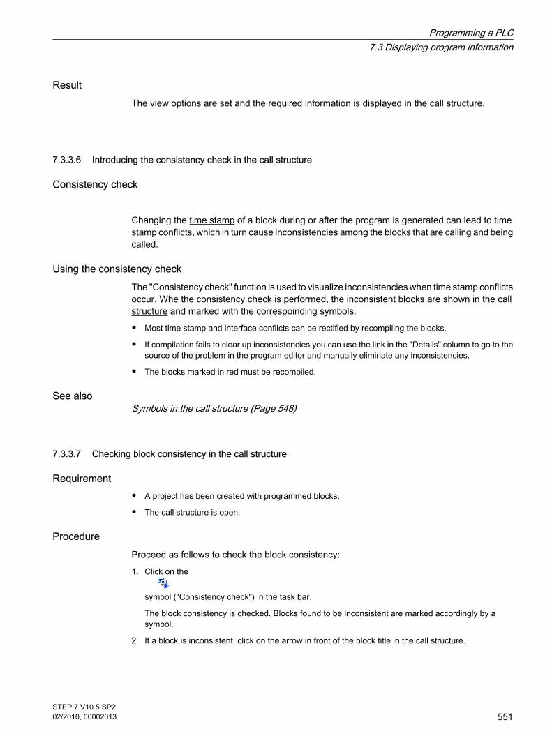
ResultThe view options are set and the required information is displayed in the call structure.
7.3.3.6 Introducing the consistency check in the call structure
Consistency check
Changing the time stamp of a block during or after the program is generated can lead to timestamp conflicts, which in turn cause inconsistencies among the blocks that are calling and beingcalled.
Using the consistency checkThe "Consistency check" function is used to visualize inconsistencies when time stamp conflictsoccur. Whe the consistency check is performed, the inconsistent blocks are shown in the callstructure and marked with the correspoinding symbols.
• Most time stamp and interface conflicts can be rectified by recompiling the blocks.
• If compilation fails to clear up inconsistencies you can use the link in the "Details" column to go to thesource of the problem in the program editor and manually eliminate any inconsistencies.
• The blocks marked in red must be recompiled.
See alsoSymbols in the call structure (Page 548)
7.3.3.7 Checking block consistency in the call structure
Requirement
• A project has been created with programmed blocks.
• The call structure is open.
ProcedureProceed as follows to check the block consistency:
1. Click on the
symbol ("Consistency check") in the task bar.
The block consistency is checked. Blocks found to be inconsistent are marked accordingly by asymbol.
2. If a block is inconsistent, click on the arrow in front of the block title in the call structure.
7.3.3.6 Introducing the consistency check in the call structure7.3.3.7 Checking block consistency in the call structure
Programming a PLC7.3 Displaying program information
STEP 7 V10.5 SP202/2010, 00002013
551

The inconsistent blocks are displayed. The exact problem locations are listed as links in the "Details"column.
3. Click on the respective link in the "Details" column to jump to the location in the block requiringcorrection.
4. Check and correct the inconsistencies in the blocks.
5. Recompile the blocks by selecting the required blocks and clicking on the command "Compile" in theshortcut menu.
6. Download the corrected blocks to the target system by clicking the command "Download to device"in the shortcut menu.
ResultThe block consistency is checked. The inconsistencies in the blocks are corrected. Thecorrected blocks are loaded to the target system.
See alsoSymbols in the call structure (Page 548)
7.3.4 Displaying the dependency structure
7.3.4.1 Introduction to the dependency structure
Introduction The dependency structure shows the dependencies each block has to other blocks in theprogram.
Information in the dependency structureDisplaying the dependency structure provides you with a list of the blocks used in the userprogram. A block is shown at the far left and blocks that call or use this block are indentedbelow it.
The dependency structure also shows the status of the individual blocks using symbols.
Objects causing a time stamp conflict and perhaps leading to an inconsistency in the programare marked with various symbols.
The dependency structure is an extension of the cross-reference list for objects.
View optionsThe following view options are available for the dependency structure:
• Display conflicts only:
When this check box is activated, only the conflicts within the dependency structure are displayed.
• Group several calls:
7.3.4 Displaying the dependency structure7.3.4.1 Introduction to the dependency structure
Programming a PLC7.3 Displaying program information
552STEP 7 V10.5 SP202/2010, 00002013

When this check box is activated, several block calls are grouped together. The number of block callsis shown numerically in the "dependency structure" column. The links to the various call locations areoffered in a drop-down list in the "Details" column.
Displaying the dependency structureClicking on the arrow in front of the block title displays the blocks that call or use this block. Todisplay the dependency structure for all blocks, click on the
symbol ("Expand all") in the task bar.
You can hide the total overview by clicking on the
symbol ("Collapse all").
Displaying cross-reference informationYou can display the cross-reference information for a block in the Inspector window by right-clicking on the respective block and selecting the "Display Usage" command from the shortcutmenu.
Displaying blocks in the program editorYou can open the program editor and edit blocks there from the dependency structure. To dothis select the required block in the dependency structure and select the "Open" command inthe shortcut menu.
Displaying deleted blocksThe lines for deleted blocks are marked with the
icon.
7.3.4.2 Layout of the dependency structure
Layout of the dependency structure The view of the dependency structure consists of the following columns:
Column Content/meaning
Dependency structure It indicates the dependencies between each block and theother blocks in the program.
Call type (!) Shows the type of call, for example recursive block call.
Address Shows the absolute address of the block.
7.3.4.2 Layout of the dependency structure
Programming a PLC7.3 Displaying program information
STEP 7 V10.5 SP202/2010, 00002013
553

Column Content/meaning
Number of calls Indicates the number of multiple calls of blocks.
Details Shows the network or interface of the called block. Allinformation are offered as a link in this column. With this link,you can jump to the location of the block call in the programeditor. When the "Group several calls" view option isactivated, the calls are grouped and offered as links in a drop-down list.
See alsoSymbols in the dependency structure (Page 554)
7.3.4.3 Symbols in the dependency structure
Meaning of the symbols in the dependency structure The following table shows the meaning of the symbols in the dependency structure:
Symbol Meaning
Indicates an organization block (OB).
Indicates a function block (FB).
Indicates a function (FC).
Indicates a data block (DB).
Indicates that the block is declared as a multiinstance.
The object has an interface dependency to an object connected to the left.
Indicates that the block needs to be compiled again.
Indicates that the data block needs to be compiled again.
Indicates that the object is not available.
Indicates that the interface causes a time stamp conflict.
Indicates that there is an inconsistency with this object.
Indicates that an object is marked with know-how protection. An object with thisproperty cannot be edited.
7.3.4.3 Symbols in the dependency structure
Programming a PLC7.3 Displaying program information
554STEP 7 V10.5 SP202/2010, 00002013
Symbol Meaning
Indicates that a tag declaration in the interface has a recursive dependency:
• Scenario 1: FB1 calls FB2 and then FB2 calls FB1. The instance data blocksof these FBs have a recursion in the interface.
• Scenario 2: A multi-instance FB uses the instance DB of its parent FB as aglobal DB.
7.3.4.4 Displaying the dependency structure
RequirementA project has been created with programmed blocks.
ProcedureProceed as follows to display the dependency structure:
1. Select the block folder or one or more of the blocks contained therein.
2. Select the "Dependency structure" command in the "Tools" menu.
ResultThe dependency structure for the selected program is displayed.
See alsoSetting the view options for the dependency structure (Page 555)
7.3.4.5 Setting the view options for the dependency structure
Introduction The following view options are available for the dependency structure:
• Display conflicts only:
When this check box is activated, only the conflicts within the dependency structure are displayed.
The following blocks cause conflicts:
― Blocks executing any calls with older or newer code time stamps.
― Blocks called by a block with modified interface.
― Blocks using a tag with modified address and/or data type.
― Block called neither directly, nor indirectly by an OB.
• Group several calls:
7.3.4.4 Displaying the dependency structure7.3.4.5 Setting the view options for the dependency structure
Programming a PLC7.3 Displaying program information
STEP 7 V10.5 SP202/2010, 00002013
555

When this check box is activated, several block calls are grouped together. The number of block callsis shown in the relevant column. The links to the various call locations are offered in a drop-down listin the "Details" column.
Requirement
• A project has been created with programmed blocks.
• The dependency structure is open.
ProcedureProceed as follows to set the view options for the dependency structure:
1. Click on the arrow of the
symbol ("View options") in the task bar.
The view options for the call structure opens. Check marks are set in front of the activated view options.
2. If you want to activate or deactivate a view option, click on the respective check box and set or removethe check mark.
ResultThe view options are set and the required information is displayed in the call structure.
7.3.4.6 Introducing the consistency check in the dependency structure
Consistency check
Changing the time stamp of a block during or after the program is generated can lead to timestamp conflicts, which in turn cause inconsistencies among the blocks that are calling and beingcalled.
Using the consistency checkThe "Consistency check" function is used to visualize inconsistencies. Whe the consistencycheck is performed, the inconsistent blocks are shown in the dependency structure and markedwith the correspoinding symbols.
• Most time stamp and interface conflicts can be rectified by recompiling the blocks.
• If compilation fails to clear up inconsistencies you can use the link in the "Details" column to go to thesource of the problem in the program editor and manually eliminate any inconsistencies.
• The blocks marked in red must be recompiled.
See alsoLayout of the dependency structure (Page 553)Symbols in the dependency structure (Page 554)
7.3.4.6 Introducing the consistency check in the dependency structure
Programming a PLC7.3 Displaying program information
556STEP 7 V10.5 SP202/2010, 00002013

7.3.4.7 Checking block consistency in the dependency structure
Requirement
• A project has been created with programmed blocks.
• The dependency structure is open.
ProcedureProceed as follows to check the block consistency:
1. Click on the
symbol ("Consistency check") in the task bar.
The block consistency is checked. Blocks found to be inconsistent are marked accordingly by asymbol.
2. If a block is inconsistent, click on the arrow in front of the block title in the call structure.
The inconsistent blocks are displayed. The exact problem locations are listed as links in the "Details"column.
3. Check and correct the inconsistencies in the blocks.
4. Recompile the blocks by selecting the required blocks and clicking on the command "Compile" in theshortcut menu.
5. Download the corrected blocks to the target system by clicking the command "Download to device"in the shortcut menu.
ResultThe block consistency is checked. The inconsistencies in the blocks are corrected. Thecorrected blocks are loaded to the target system.
See alsoSymbols in the dependency structure (Page 554)
7.3.5 Displaying CPU resources
7.3.5.1 Introducing resources
Introduction The "Resources" tab indicates the hardware resources of the configured CPU for:
• the used programming objects,
• the assignment of memory areas within the CPU and
• the assigned inputs and outputs of the existing input and output modules.
7.3.4.7 Checking block consistency in the dependency structure7.3.5 Displaying CPU resources7.3.5.1 Introducing resources
Programming a PLC7.3 Displaying program information
STEP 7 V10.5 SP202/2010, 00002013
557

Information provided in the "Resources" tabThe resources tab provides an overview of the hardware resources used on your CPU for:
• the programming objects used in the CPU (e.g. OB, FC, FB, DB, PLC tags, and user-defined datatypes),
• the memory areas available on the CPU (work memory, load memory, retentive memory), theirmaximum size and utilization by the programming objects stated above,
• the I/O of modules which can be configured for the CPU (I/O modules, digital input modules, digitaloutput modules, analog input modules, and analog output modules), including the I/O already in use.
Display of the maximum available load memoryThe maximum size of available load memory can be selected from a drop-down list box in the"Total" row of the "Load memory" column.
Display of the maximum available work memoryThe maximum size of available work memory can be selected from a drop-down list box in the"Total" row of the "Work memory" column.
Display of the maximum available retentive memoryThe maximum size of available retentive memory can be selected from a drop-down list box inthe "Total" row of the "Retentive memory" column.
NoteRetentive memory data
All bit memories and data blocks specified as retentive will be integrated in the calculation ofthe retentive data.
Updating the display in the "Resources" tabClick the "Update view" toolbar button to update the display of objects.
Benefits of the display in the "Resources" tabThe "Resources" tab of the program information dialog provides a detailed list of all objects andof the corresponding memory area used.
The tab also indicates shortage of resources and helps to avoid such states.
Blocks which are not compiled can be identified as their size is indicated by a question mark.
See alsoLayout of the "Resources" tab (Page 559)Displaying resources (Page 560)Selecting the maximum load memory available (Page 560)
Programming a PLC7.3 Displaying program information
558STEP 7 V10.5 SP202/2010, 00002013

7.3.5.2 Layout of the "Resources" tab
Layout of the "Resources" tab in the program information The view of the "Resources" tab consists of the following columns:
Column Content/meaning
Objects The "Details" area provides an overview of the programmingobjects available in the CPU, including their memoryassignments.
Load memory Displays the maximum load memory resources of the CPUas a percentage and as absolute value.The values displayed under "Total" provide information on themaximum memory available in the load memory.The values displayed under "Used" provide information onthe memory actually used in the load memory.
Work memory Displays the maximum work memory resources of the CPUas a percentage and as absolute value.The values displayed under "Total" provide information on themaximum memory available in the load memory.The values displayed under "Used" provide information onthe memory actually used in the load memory.
Retentive memory Displays the maximum resources for retentive memory in theCPU as a percentage and as absolute value.The values displayed under "Total" provide information on themaximum memory available in the load memory.The values displayed under "Used" provide information onthe memory actually used in the load memory.
I/O Displays the I/Os which are available on the CPU, includingtheir module-specific availability in the next columns.The values displayed at "Configured" provide informationabout the maximum number of I/O available.The values displayed under "Used" provide information onthe memory actually used in the load memory.
DI / DQ / AI / AQ Displays the number of configured and used inputs/outputs:DI = Digital inputsDQ = Digital outputsAI = Analog inputsAQ = Analog outputsThe values displayed at "Configured" provide informationabout the maximum number of I/O available.The values displayed under "Used" provide information onthe actually used inputs and outputs.
7.3.5.2 Layout of the "Resources" tab
Programming a PLC7.3 Displaying program information
STEP 7 V10.5 SP202/2010, 00002013
559

See alsoDisplaying resources (Page 560)Selecting the maximum load memory available (Page 560)Introducing resources (Page 557)
7.3.5.3 Displaying resources
Requirement A project with programmed blocks has been created.
ProcedureProceed as follows to display the resources of the respective CPU memory areas:
1. Select the block folder or one or several of the blocks contained therein.
2. Select the "Resources" command in the "Tools" menu.
ResultThe memory resources of the CPU are displayed.
7.3.5.4 Selecting the maximum load memory available
Requirement A project with programmed blocks has been created.
ProcedureProceed as follows to display the available maximum of load memory resources:
1. Open the drop-down list in the "Total" field of the "Load memory" column by clicking the icon.
2. Select a corresponding value for the CPU used by clicking it in the drop-down list box.
ResultThe "Total" field displays the selected maximum memory resources.
7.3.5.3 Displaying resources7.3.5.4 Selecting the maximum load memory available
Programming a PLC7.3 Displaying program information
560STEP 7 V10.5 SP202/2010, 00002013

7.4 Displaying cross-references
7.4.1 General information about cross references
IntroductionThe cross-reference list provides an overview of the use of operands and tags within the userprogram.
Uses of cross-referencesThe cross-reference list offers you the following advantages:
• When creating and changing a program, you retain an overview of the operands, tags and block callsyou have used.
• From the cross-references, you can jump directly to the point of use of operands and tags.
• During a program test or when troubleshooting, you are informed of the following:
― which operand is processed by which command in which block,
― which tag is used in which picture,
― which block is called by which other block.
• As part of the project documentation, the cross-references provide a comprehensive overview of alloperands, memory areas, blocks, tags and pictures used.
• You can display the point of use of objects, for example to modify or delete them.
• You can display the points of use of deleted objects and adapt them when necessary.
See alsoStructure of the cross-reference list (Page 561)Displaying the cross-reference list (Page 563)Displaying cross-references in the Inspector window (Page 564)
7.4.2 Structure of the cross-reference list
Views of the cross-reference list There are two views of the cross-reference list. The difference between the two views is in theobjects displayed in the first column:
• Used by:
Display of the referenced objects. Here, you can see where the object is used.
• Used:
Display of the referencing objects. Here, you can see the users of the object.
The assigned tool tips provide additional information about each object.
7.4 Displaying cross-references7.4.1 General information about cross references7.4.2 Structure of the cross-reference list
Programming a PLC7.4 Displaying cross-references
STEP 7 V10.5 SP202/2010, 00002013
561

Structure of the cross-reference listThe cross-reference list has the following structure:
Column Content/meaning
Object Name of the object that uses the lower-level objects or that is beingused by the lower-level objects.
Quantity Quantity of uses
Location Each location of use, for example, network
Property Special properties of referenced objects, for example, the tag namesin multi-instance declarations.
as Shows additional information about the object, e.g., that an instanceDB is used as template or as multiple instance.
Access Type of access, whether access to the operand is read access (R) and/or write access (W).
Address Address of the operand
Type Information on the type and language used to create the object
Path Path of object in project tree
Depending on the installed products, additional columns or different columns are displayed forthe cross-references.
Settings in the cross-reference listYou can make the following settings using the buttons in the toolbar of the cross-reference list:
• Update cross-reference list
Updates the current cross-reference list.
• Making settings for the cross-reference list
Here, you select check boxes to specify whether all used, all unused, all defined or all undefinedobjects will be displayed. If the "Undefined objects" option is enabled, references to previously deletedobjects are also displayed.
• Collapse entries
Reduces the entries in the current cross-reference list by closing the lower-level objects.
• Expand entries
Expands the entries in the current cross-reference list by opening the low-level objects.
Sorting in the cross-reference listYou can sort the entries in the "Object" column, including other product-specific columns, inascending or descending order. To do this, click on the relevant column title.
Programming a PLC7.4 Displaying cross-references
562STEP 7 V10.5 SP202/2010, 00002013

See alsoGeneral information about cross references (Page 561)Displaying the cross-reference list (Page 563)
7.4.3 Displaying the cross-reference list
PrerequisitesYou have created a project.
IntroductionThere are several ways of displaying cross-references depending on whether you are in thePortal view or in the Project view and which object you have selected in the project tree.
In the Portal view, you can only display cross-references for the entire CPU; in the Project view,you can display cross-references for the following objects:
• "PLC" folder
• "Blocks" folder
• Individual blocks
• "PLC tags" folder
• "Tags and connections" folder
• Individual tags
Displaying cross-references Proceed as follows to display cross-references:
1. Select the required action in the Portal view, for example "Program PLC" and the "Show cross-references" command or select one of the objects listed above in the Project view and select the"Cross-references" command in the "Tools" menu.
2. Click the "Used by" button to display where the objects shown in the cross-reference list are used.
3. Click the "Used" button to view the users of the objects displayed in the cross-reference list.
4. You can perform the following actions using the buttons in the toolbar:
― Update cross-reference list
― Making settings for the cross-reference list
― Collapse entries
― Expand entries
5. You can sort the entries in the "Object" and "Address" columns in ascending or descending order byclicking on the relevant column title.
6. To go to the point of use of the object, click on the displayed link.
7.4.3 Displaying the cross-reference list
Programming a PLC7.4 Displaying cross-references
STEP 7 V10.5 SP202/2010, 00002013
563

See alsoGeneral information about cross references (Page 561)Structure of the cross-reference list (Page 561)
7.4.4 Displaying cross-references in the Inspector window
IntroductionThe Inspector window displays cross-reference information about an object you have selectedin the "About > Cross-reference" tab. This tab displays the instances where a selected objectis being used and the other objects using it.
The Inspector window also includes blocks which are only available online in the cross-references.
StructureThe Inspector window displays the cross-reference information in tabular format. Each columncontains specific and detailed information on the selected object and its application. The tablebelow shows the additional information listed in the "About > Cross-reference" tab:
Column Meaning
Object Name of the object that uses the lower-levelobjects or that is being used by the lower-levelobjects.
Quantity Quantity of uses
Location Each location of use, for example, network
Property Special properties of referenced objects, forexample, the tag name in multi-instancedeclarations
as Shows additional information about the object,e.g., that an instance DB is used as template or asmultiple instance.
Access Access modeShows whether the operand is accessed by a read(R) and/or write (W) operation.
Address Address of the operand
Type Information about the type and language used tocreate the object
Path Path of object in project tree
Depending on the installed products, additional columns or different columns are displayed forthe cross-references.
7.4.4 Displaying cross-references in the Inspector window
Programming a PLC7.4 Displaying cross-references
564STEP 7 V10.5 SP202/2010, 00002013

7.5 Testing the user program
7.5.1 Basics of testing the user program
FunctionYou have the option of testing the running of your user program on the device. You can thenmonitor signal states and values of tags and can assign values to tags to simulate certainsituations in the running of the program.
RequirementThere must be an executable program loaded on the device.
Test optionsThe following test options are available:
• Testing with program status
The program status allows you to monitor the running of the program. You can display the values ofoperands and the results of logic operations (RLO) of the networks, allowing you to recognize and fixlogical errors in your program.
• Testing with the watch table
With the watch table, you can monitor, modify or force the current values of individual tags in the userprogram or on a CPU. You can assign values to individual tags for testing and run the program in avariety of different situations. You can also assign fixed values to the I/O outputs of a CPU in STOPmode, for example to check the wiring.
See alsoIntroduction to testing with program status (Page 565)Introduction to testing with the watch table (Page 570)
7.5.2 Testing with program status
7.5.2.1 Introduction to testing with program status
FunctionIf you display the program status, you can monitor the execution of the program. You can enablethe status starting at a specific location in the program and you then obtain an overview of the
7.5 Testing the user program7.5.1 Basics of testing the user program7.5.2 Testing with program status7.5.2.1 Introduction to testing with program status
Programming a PLC7.5 Testing the user program
STEP 7 V10.5 SP202/2010, 00002013
565

values of the individual operands and the results of logic operations. This allows you to checkwhether or not the components of the automation system are being correctly controlled.
Warning
Testing while the plant is operating can cause serious damage to property or injury to personsif there are functional disturbances or program errors.
Make sure that no dangerous situations can arise before you conduct a test.
7.5.2.2 Testing the program
7.5.2.2 Switching test with program status on/off
Requirement
• The identical block exists in the device.
• The block is open.
Switching the program status on or off To switch the program status for a block on or off, follow these steps:
1. Click the "Monitoring on/off" button in the toolbar.
Enabling program status starting at a specific point in a networkTo start the program status at a specific point, follow these steps:
1. Click the "Monitoring on/off" button in the toolbar.
2. Right-click on the tag you want program status to start from.
3. Select "Start monitoring here" in the shortcut menu.
Note
The resources for testing with program status are limited. If there are not enough resources forthe current test, earlier tests will be terminated.
7.5.2.2 Testing the program7.5.2.2 Switching test with program status on/off
Programming a PLC7.5 Testing the user program
566STEP 7 V10.5 SP202/2010, 00002013

ResultIf you enable the display of the program status, an online connection is established and theprogram status is displayed. When you enable the display of the program status, you will beasked if you want to interrupt the online connection.
See alsoDisplays in program status (Page 568)
7.5.2.2 Editing blocks during the program test
If you edit blocks while the test with program status is still running, online monitoring will beinterrupted and you will be able to edit the block offline. If the block is not available offline inthe project, you will first have to load it from the device to the project. After editing the block,you will also have to compile and load it again.
Requirement The test with program status is enabled.
ProcedureTo edit blocks while the test with program status is still running, follow these steps:
1. Edit the block as necessary.
The test with program status is interrupted and the block is switched offline assuming it exists offline.
2. If the block does not exist offline, load it to the project from the device.
3. Compile the block.
See also: Compiling blocks (Page 527)
4. Download the block to the device.
See also: Downloading blocks (Page 528)
ResultThe block now contains your modifications both online and offline. The online connection is re-established and testing with program status continues.
7.5.2.2 Modifying tags in the program status
While testing with the program status, you have the option of modifying tags to the followingvalues once and immediately:
• Modify to 1
Modifies tags of the "Bool" data type to the value "True".
• Modify to 0
7.5.2.2 Editing blocks during the program test7.5.2.2 Modifying tags in the program status
Programming a PLC7.5 Testing the user program
STEP 7 V10.5 SP202/2010, 00002013
567

Modifies tags of the "Bool" data type to the value "False"
• Modify value
You can enter a modify value for tags that do not belong to the "Bool" data type.
Note that you cannot modify I/O inputs.
Procedure To modify tags during testing with the program status, proceed as follows:
1. Right-click on the tag you want to modify.
2. Select one of the following commands in the shortcut menu:
― "Modify > Modify to 1"
― "Modify > Modify to 0"
― "Modify > Modify value"
3. If you select "Modify value", the "Modify" dialog opens. Enter the value you require in the "Modifyvalue" box and confirm with "OK".
7.5.2.3 Displays in program status
7.5.2.3 Program status display for LAD programs
Displays in program statusThe display of the program status is updated cyclically. It begins at the selected network.
The following figure shows an example of the program status display for LAD:
Representation of the program statusYou can recognize the status of individual operations and lines of a network quickly based onthe color and type of lines and symbols. The following table shows the relationship betweenrepresentation and status:
7.5.2.3 Displays in program status7.5.2.3 Program status display for LAD programs
Programming a PLC7.5 Testing the user program
568STEP 7 V10.5 SP202/2010, 00002013

Representation Status
Green solid Satisfied
Blue dashed Not satisfied
Gray solid Unknown or not executed
Black Not interconnected
Parameter in a frame with a saturation of 100 % Value is current
Parameter in a frame with a saturation of 50 % Value originates from an earlier cycle. The point inthe program was not executed in the current cycle.
7.5.2.3 Program status display for FBD programs
Displays in program statusThe display of the program status is updated cyclically. It begins at the selected network.
The following figure shows an example of the program status display for FBD:
Representation of the program statusYou can recognize the status of individual operations and lines of a network quickly based onthe color and type of lines and symbols. The following table shows the relationship betweenrepresentation and status:
Representation Status
Green solid Satisfied
Blue dashed Not satisfied
Gray solid Unknown or not executed
Black Not interconnected
Parameter in a frame with a saturation of 100 % Value is current
7.5.2.3 Program status display for FBD programs
Programming a PLC7.5 Testing the user program
STEP 7 V10.5 SP202/2010, 00002013
569

Representation Status
Parameter in a frame with a saturation of 50 % Value originates from an earlier cycle. The point inthe program was not executed in the current cycle.
The values of the operands are displayed above the relevant operand name in a gray box.
7.5.3 Testing with the watch table
7.5.3.1 Introduction to testing with the watch table
OverviewThe following functions are available for testing with the watch table:
• Monitoring tags This displays the current values of the individual tags of a user program or a CPU on the programmingdevice or PC.
• Modifying tags You can use this function to assign specific values to the individual tags of a user program or CPU.Modifying is also possible with Test with program status (Page 565) .
• "Enable peripheral outputs" and "Modify now" These two functions enable you to assign specific values to individual peripheral outputs of a CPU inSTOP mode. You can also use them to check your wiring.
• Forcing tags Use this function to assign a specific value to individual tags of a user program or CPU.
Monitoring and modifying tagsThe following tags can be monitored and modified:
• Inputs, outputs, and bit memories
• Contents of data blocks
• I/O
Possible applicationsThe advantage of the watch table is that a variety of test environments can be stored. Thisenables you to reproduce tests during commissioning or for service and maintenance purposes.
See alsoCreating and editing watch tables (Page 571)Basic procedure for testing with the watch table (Page 573)
7.5.3 Testing with the watch table7.5.3.1 Introduction to testing with the watch table
Programming a PLC7.5 Testing the user program
570STEP 7 V10.5 SP202/2010, 00002013

7.5.3.2 Creating and editing watch tables
7.5.3.2 Creating a watch table
IntroductionIf you want to monitor and modify tags, you enter them in a watch table. Once you have createda watch table, you can save it, duplicate it, and print it and use it again and again to monitor,modify, and force tags.
Requirements A project is open.
ProcedureTo create a watch table, follow these steps:
1. Click "Project view" in the status bar.
The project view is displayed.
2. In the project tree, double-click the CPU for which you want to create a watch table.
3. Double-click the "Watch Tables" folder and then the "Add watch table" command.
A new watch table is added.
4. In the "Name" column or in the "Address" column, enter the name or the absolute address for the tagsthat you want to monitor or modify.
5. You can select a display format from the drop-down list in the "Display format" column if you want tochange this default setting.
6. Now decide whether you want to monitor, modify, or force the entered tags and, if applicable, enterthe desired values for modifying or forcing.
See alsoAdapting tables (Page 131)
7.5.3.2 Opening a watch table
RequirementsA watch table has been created.
ProcedureTo open a watch table, follow these steps:
1. Open the "Watch tables" folder below the CPU.
2. Double-click on the relevant watch table in the folder.
7.5.3.2 Creating and editing watch tables7.5.3.2 Creating a watch table7.5.3.2 Opening a watch table
Programming a PLC7.5 Testing the user program
STEP 7 V10.5 SP202/2010, 00002013
571

ResultThe selected watch table opens.
7.5.3.2 Copying and pasting a watch table
PrerequisiteA watch table has been created.
ProcedureTo copy a watch table, follow these steps:
1. Right-click the watch table that you want to copy.
2. In the context menu, select "Copy".
3. In the project tree, open the folder structure for the CPU in which you want to paste the copied watchtable.
4. Right-click the "Watch Tables" folder.
5. In the context menu, select "Paste".
6. Alternatively, you can select the entire contents of the watch table and drag-and-drop it onto anotherwatch table.
ResultA copy of the watch table is pasted in the "Watch Tables" folder of the CPU.
7.5.3.2 Saving a watch table
PrerequisiteA watch table has been created.
ProcedureTo save a watch table, follow these steps:
1. If you wish to change the preset name of the table, select the "Rename" command in the context menuand enter a new name for the table.
2. In the "Project" menu, select "Save". Note that this save operation will save the entire project.
ResultThe contents of the watch table and the project are saved.
7.5.3.2 Copying and pasting a watch table7.5.3.2 Saving a watch table
Programming a PLC7.5 Testing the user program
572STEP 7 V10.5 SP202/2010, 00002013

Note
You can reuse saved watch tables to monitor, modify and force tags when retesting yourprogram.
7.5.3.3 Basic procedure for testing with the watch table
OverviewFollow the steps below to use the monitor, modify and force tag functions in the watch table:
Creating and editing watch tables (Page 571)
↓
Entering tags in the watch table (Page 582)
↓
Monitoring tags in the watch table (Page 582)
↓
Modifying tags in the watch table (Page 591)
↓
Forcing tags in the watch table (Page 594)
You will find more detailed information on the individual steps in the sections listed above.
7.5.3.4 Form of the watch table
IntroductionA watch table contains the tags you defined for the entire CPU. A "Watch tables" folder isautomatically generated for each CPU created in the project. You create a new watch table inthis folder by selecting the "Add watch table" command.
Layout of the watch table The columns displayed in the watch table depend on the mode you are working in: basic modeor expanded mode.
The following additional columns are shown in expanded mode:
• Monitor with trigger
• Modify with trigger
are shown.The names of the columns can also be changed dynamically based on the action.
7.5.3.3 Basic procedure for testing with the watch table7.5.3.4 Form of the watch table
Programming a PLC7.5 Testing the user program
STEP 7 V10.5 SP202/2010, 00002013
573

Meaning of the columnsThe following table shows the meaning of the individual columns in basic mode and expandedmode:
Mode Column Meaning
Basic mode Identifier column
Name Name of the inserted tag
Address Address of the inserted tag
Display format Selected display format
Monitoring value Values of the tags, depending on the selected displayformat.
Modify value Value with which the tag is modified.
Force value Value with which the tag is forced.
Value Value with which the tag is modified and forced.
("Modify")
Select the tag to be modified by clicking the correspondingcheck box.
("Force")
Select the tag to be forced by activating the correspondingcheck box.
Comment Comment for documentation of the tags
The following additionalcolumns are shown inexpanded mode:
Monitor with trigger Display of selected monitoring mode
Modify with trigger Display of selected modify mode
7.5.3.5 Basic mode and advanced mode
Difference between basic mode and expanded mode Depending on the mode specified, the watch table displays different columns and columnheadings that can be used to perform different actions.
You will find a detailed list of the columns in Layout of the watch table (Page 573) .
Switching between basic mode and expanded modeYou have the following options of toggling between the basic and expanded mode:
• Click the icon
("Display/hide all expanded mode columns"). Click this icon again to return to the basic mode.
7.5.3.5 Basic mode and advanced mode
Programming a PLC7.5 Testing the user program
574STEP 7 V10.5 SP202/2010, 00002013

Or:
• Activate the check box for the "Expanded mode" command in the "Online" menu. Deactivate this checkbox to return to the basic mode.
Functionality in expanded modeThe following functionality is only possible in expanded mode:
• Monitor with trigger
• Modify with trigger
• Enable peripheral outputs
7.5.3.6 Icons in the watch table
Meaning of the icons in the watch tableThe following table shows the meaning of the icons in the watch table:
Icon Meaning
Modifies the addresses of all selected tags immediately and once. Thiscommand is executed once and as quickly as possible without reference toa defined trigger point in the user program.
Modifies the addresses of all selected tags with reference to a definedtrigger point in the user program.
Disables the command output disable of the peripheral outputs. You canthen modify the peripheral outputs when the CPU is in STOP mode.
Displays all columns of expanded mode. If you click this icon again, thecolumns of expanded mode will be hidden.
Displays all force columns. If you click this icon again, the force columns willbe hidden.
Displays all modify columns. If you click this icon again, the modify columnswill be hidden.
Starts forcing for all addresses of the selected tags. If forcing is alreadyrunning, the previous action is replaced without interruption.
Stops forcing of addresses in the active watch table.
Displays all addresses that are being forced in the CPU in the active watchtable.
Starts monitoring of the visible tags in the active watch table. The defaultsetting for the monitoring mode in basic mode is "permanent". In expandedmode, you can set defined trigger points for the monitoring of tags.
Starts monitoring of the visible tags in the active watch table. This commandis executed immediately and the tags are monitored once.
7.5.3.6 Icons in the watch table
Programming a PLC7.5 Testing the user program
STEP 7 V10.5 SP202/2010, 00002013
575
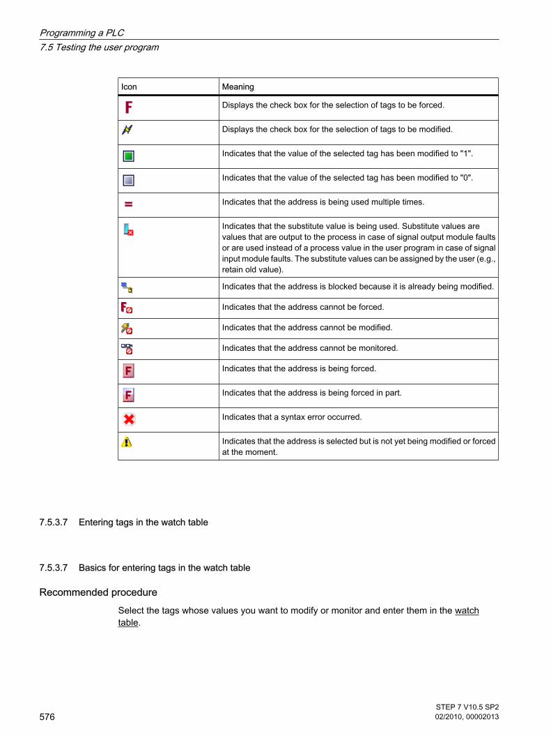
Icon Meaning
Displays the check box for the selection of tags to be forced.
Displays the check box for the selection of tags to be modified.
Indicates that the value of the selected tag has been modified to "1".
Indicates that the value of the selected tag has been modified to "0".
Indicates that the address is being used multiple times.
Indicates that the substitute value is being used. Substitute values arevalues that are output to the process in case of signal output module faultsor are used instead of a process value in the user program in case of signalinput module faults. The substitute values can be assigned by the user (e.g.,retain old value).
Indicates that the address is blocked because it is already being modified.
Indicates that the address cannot be forced.
Indicates that the address cannot be modified.
Indicates that the address cannot be monitored.
Indicates that the address is being forced.
Indicates that the address is being forced in part.
Indicates that a syntax error occurred.
Indicates that the address is selected but is not yet being modified or forcedat the moment.
7.5.3.7 Entering tags in the watch table
7.5.3.7 Basics for entering tags in the watch table
Recommended procedure Select the tags whose values you want to modify or monitor and enter them in the watchtable.
7.5.3.7 Entering tags in the watch table7.5.3.7 Basics for entering tags in the watch table
Programming a PLC7.5 Testing the user program
576STEP 7 V10.5 SP202/2010, 00002013

When entering tags, work from the outside to the inside. This means that you start by enteringthe tags for the inputs in the watch table. Then, you enter the tags that are affected by the inputsor that affect the outputs. Finally, you enter the tags for the outputs.
Example of filling out a watch table
• If, for example, you want to monitor input bit "1.0", memory word "5" and output byte "0", enter thefollowing values in the "Address" column:
I 1.0
MW 5
QB 0
Or:
• Enter the corresponding symbolic name in the "Name" column.
• As an option, you can select the display format you require from the drop-down list in the "Displayformat" column, if you do not want to use the default setting.
• Now decide whether you want to monitor, modify, or force the entered tags.
Syntax checkWhen you enter the tags in the watch table, the syntax of each cell is checked when you exitthe cell. Incorrect entries are marked in red.
Note
When you place the mouse pointer in a cell marked in red, brief information is displayed withadditional notes on the error.
See alsoPermitted addresses for the watch table (Page 577)Permissible modify values for the watch table (Page 578)
7.5.3.7 Permitted addresses for the watch table
Entry of operands in the watch tableThe following table shows the operands that are permitted for the watch table:
Permitted operand Data type Example (Internationalmnemonics)
Input/output/bit memory BOOL I1.0, Q1.7, M10.1I0.0:P; Q0.0:P
7.5.3.7 Permitted addresses for the watch table
Programming a PLC7.5 Testing the user program
STEP 7 V10.5 SP202/2010, 00002013
577

Permitted operand Data type Example (Internationalmnemonics)
Input/output/bit memory BYTE IB1/QB10/MB100IB1:P; QB1:P
Input/output/bit memory WORD IW1; QW10; MW100IW2:P; QW3:P
Input/output/bit memory DWORD ID4; QD10; MD100ID2:P; QD1:P
Data block BOOL DB1.DBX1.0
Data block BYTE DB1.DBB1
Data block WORD DB1.DBW1
Data block DWORD DB1.DBD1
Note
You cannot enter "DB0..." because it is used by the system!
See alsoBasics for entering tags in the watch table (Page 576)
7.5.3.7 Permissible modify values for the watch table
Entry of modify values in the watch table The following table shows the operands that are permitted for the entry of force values in thewatch table:
Table7-3 Bit operands
Possible bit operands Example for permitted modify values
I1.0 True
M1.7 False
Q1.0 0
Q1.1:P 1
DB1.DBX1.1 2#0
M1.6 2#1
7.5.3.7 Permissible modify values for the watch table
Programming a PLC7.5 Testing the user program
578STEP 7 V10.5 SP202/2010, 00002013

Table7-4 Byte operands
Possible byte operands Example for permitted modify values
IB1 2#00110011
MB12 B#16#1F
QB10 1F
QB11:P 'a'
DB1.DBB1 10
Table7-5 Word operands
Possible word operands Example for permitted modify values
IW1 2#0011001100110011
MW12 W#16#ABCD
MW14 ABCD
QW10 B#(12, 34)
QW12:P 12345
DB1.DBW1 'ab'
MW16 S5t#12s340ms
MW18 C#123
MW9 D#2006-12-31
Table7-6 Double word operands
Possible double word operands Example for permitted modify values
ID1 2#00110011001100110011001100110011
MD0 1.23e4
MD4 01 Feb
QD10 Dw#16#abcdef10
QD12:P ABCDEF10
DB1.DBD2 b#(12,34,56,78)
MD8 L#-12
MD12 L#12
MD16 123456789
MD20 123456789
MD24 T#12s345ms
MD28 Tod#1:2:34.567
MD32 P#e0.0
Programming a PLC7.5 Testing the user program
STEP 7 V10.5 SP202/2010, 00002013
579

7.5.3.7 Permissible force values for the watch table
Entry of force values in the watch table The following table shows the operands that are permitted for the entry of force values in thewatch table:
Table7-7 Bit operands
Possible bit operands Example for permitted force values
I1.0:P True
I1.1:P False
Q1.0P 0
Q1.1:P 1
I2.0:P 2#0
I2.1:P 2#1
Table7-8 Byte operands
Possible byte operands Example for permitted force values
IB1:P 2#00110011
IB2:P B#16#1F
QB14:P 1F
QB10:P 'a'
IB3:P 10
Table7-9 Word operands
Possible word operands Example for permitted force values
IW0:P 2#0011001100110011
IW2:P W#16#ABCD
QW10:P ABCD
QW12:P B#(12, 34)
IW4:P 'ab'
IW6:P 12345
IW8:P S5t#12s340ms
IW10:P C#123
IW12:P D#2006-12-31
7.5.3.7 Permissible force values for the watch table
Programming a PLC7.5 Testing the user program
580STEP 7 V10.5 SP202/2010, 00002013

Table7-10 Double word operands
Possible double word operands Example for permitted force values
ID0:P 2#00110011001100110011001100110011
ID4:P 1.23e4
QD10:P 1.2
QD14:P Dw#16#abcdef10
ID8:P ABCDEF10
ID12:P b#(12,34,56,78)
ID16:P L#-12
ID20:P L#12
ID24:P 123456789
ID28:P 123456789
ID32:P T#12s345ms
ID36:P Tod#1:2:34.567
ID40:P P#e0.0
7.5.3.7 Introducing the display formats
Display formats in the watch tableThe display format you select specifies the representation of a tag value. Select a display formatfor each tag from the drop-down list in the "Display formats" column of the watch table. Thedrop-down list only offers the display formats which are valid for the data type of the selectedtag.
The following table shows an example of the display formats you can select in the watch tablefor a corresponding tag type:
Data type Display formats
BOOL (Page 375) e.g.: Bool, Hex, BCD, Octal, Bin, Dec, Dec+/-
BYTE (Page 375) e.g.: Hex, BCD, Octal, Bin, Dec, Dec+/-, Character
WORD (Page 375) e.g.: Hex, BCD, Octal, Bin, Dec, Dec+/-, Dec_Sequence, Character,SIMATIC_Timer, Date
DWORD (Page 376) e.g.: Hex, BCD, Octal, Bin, Dec, Dec+/-, Dec_Sequence, Character, Floating-point number, Time of day, Timer, Pointer
For more information, refer to the description of data types (Page 373) .
7.5.3.7 Introducing the display formats
Programming a PLC7.5 Testing the user program
STEP 7 V10.5 SP202/2010, 00002013
581

7.5.3.7 Selecting the display format for tags
ProcedureTo select the display format of the tags in the watch table, follow these steps:
1. Enter the desired tag in the watch table.
2. Click the desired cell in the "Display format" column, and open the drop-down list.
The permissible display formats are shown.
3. Select a display format from the drop-down list.
7.5.3.8 Monitoring tags in the watch table
7.5.3.8 Introduction to monitoring tags
IntroductionThe watch table allows you to monitor the tags of the configured input and output modules inthe CPU, depending on the monitoring and modify mode (Page 582) selected. To monitorthe tags, an online connection to the CPU must exist.
Options for monitoring tagsThe following options are available for monitoring tags:
• Monitor all This command starts the monitoring of the visible tags in the active watch table:
― In basic mode, the monitoring mode is set to "permanent" by default.
― In expanded mode, monitoring depends on the monitoring mode defined at the time. If themonitoring mode is changed while in expanded mode and then a switch is made to basic mode,the monitoring mode setting will also be applied in basic mode.
• Monitor now This command starts the monitoring of the visible tags in the active watch table. The tags are monitoredimmediately and once only.
7.5.3.8 Setting the monitoring and modify mode
IntroductionBy selecting the monitoring and modify mode, you specify the trigger point and the duration ofthe tag monitoring in the watch table.
7.5.3.7 Selecting the display format for tags7.5.3.8 Monitoring tags in the watch table7.5.3.8 Introduction to monitoring tags7.5.3.8 Setting the monitoring and modify mode
Programming a PLC7.5 Testing the user program
582STEP 7 V10.5 SP202/2010, 00002013

Possible monitoring and modify modes (duration of monitoring or modifying)The following monitoring and modify modes are available:
• Permanent
― In this mode, the inputs can be monitored at the start of the scan cycle and the outputs at the end.
• Once only, at start of scan cycle
• Once only, at end of scan cycle
• Permanently, at start of scan cycle
• Permanently, at end of scan cycle
• Only once, at transition from RUN to STOP
• Permanently, at transitions from RUN to STOP
Selecting the trigger pointThe trigger points "Beginning of scan cycle", "End of scan cycle", and "Switch to stop" specifythe time at which the tags are to be read from the CPU or updated in the CPU.
The following diagram illustrates the position of these trigger points:
Position of the trigger pointsFrom the position of the trigger points, it follows that:
• Modifying of inputs is only appropriate at the beginning of the scan cycle (corresponding to thebeginning of the user program OB 1), because otherwise the process image input is updated againafter modifying and is thus overwritten.
Programming a PLC7.5 Testing the user program
STEP 7 V10.5 SP202/2010, 00002013
583

• Modifying of outputs is only appropriate at the end of the scan cycle (corresponding to the end of theuser program OB 1), because otherwise the process image output can be overwritten by the userprogram.
• The modified value is displayed in the "Monitoring value" column, provided that monitoring is activeand the modified value is not overwritten by the user program.
Monitoring of tagsWhen tags are being modified, the following applies to the trigger points:
• If you have specified the modify mode as "once only", you will receive a message if the selected tagscannot be modified.
• In "permanent" modify mode, you do not receive a message.
Note regarding the "Modify now" commandYou can modify the values of selected tags immediately using the "Online > Modify now"command. This command is executed once only and as quickly as possible without referenceto a defined position (trigger point) in the user program. This function is used mainly formodifying when the CPU is in STOP mode.
7.5.3.8 "Monitor all" command for tags
IntroductionThe "Monitor all" command allows you to start monitoring the visible tags in the active watchtable. The default setting for the monitoring mode in basic mode of the watch table is"permanent". In expanded mode, you can specify defined trigger points for the monitoring oftags. In this case, the tags are monitored with reference to the specified trigger points.
Requirements
• A watch table has been created.
• An online connection to the CPU exists.
ProcedureTo execute the "Monitor all" command, follow these steps:
1. Enter the tags to be monitored and the corresponding addresses in the watch table.
2. Switch to expanded mode by clicking
the
icon in the toolbar ("Show/hide advanced settings columns").
3. If you want to change the default monitoring mode for a tag, click the appropriate cell in the "Monitorwith trigger" column and select the desired monitoring mode from the drop-down list.
4. Click the
7.5.3.8 "Monitor all" command for tags
Programming a PLC7.5 Testing the user program
584STEP 7 V10.5 SP202/2010, 00002013
icon in the toolbar ("Monitor all").
ResultThe tags of the active watch table are monitored using the monitoring mode selected.
See alsoIcons in the watch table (Page 575)Entering tags in the watch table (Page 582)Basic mode and advanced mode (Page 574)
7.5.3.8 "Monitor now" command for tags
IntroductionThe "Monitor once and now" command starts the monitoring of tags immediately withoutreference to defined trigger points. The tag values are read out once only and displayed in thewatch table.
Requirements
• A watch table has been created.
• An online connection to the CPU exists.
ProcedureTo execute the "Monitor once and now" command, follow these steps:
1. Enter the tags to be monitored and the corresponding addresses in the watch table.
2. Click the
icon in the toolbar ("Monitor once and now").
ResultThe tags of the active watch table are monitored immediately and once only.
See alsoIcons in the watch table (Page 575)Entering tags in the watch table (Page 582)Basic mode and advanced mode (Page 574)
7.5.3.8 "Monitor now" command for tags
Programming a PLC7.5 Testing the user program
STEP 7 V10.5 SP202/2010, 00002013
585
7.5.3.9 Modifying tags in the watch table
7.5.3.9 Introduction to modifying tags
IntroductionThe watch table allows you to modify the tags of the configured input and output modules inthe CPU, depending on the monitoring and modify mode (Page 582) selected. To monitor thetags, an online connection to the CPU must exist.
NoteWhen modifying, note the following:
Modifying can not be undone.
Options for modifying tagsThe following options are available for modifying tags:
• Modify to "0"
This command modifies the selected address to the modify value "0".
• Modify to "1"
This command modifies the selected address to the modify value "1".
• Modify once only and immediately
This command modifies all selected addresses in the active watch table "once only and immediately".
• Modify with trigger
This command modifies all selected addresses in the active watch table using the monitoring andmodify mode (Page 582) selected.
The "Modify with trigger" function is only available in expanded mode. You will not receive a messageindicating whether or not the selected addresses were actually modified with the specified value. Youshould use the "Modify once only and immediately" function if you require such a confirmation.
• Enable peripheral outputs
This command disables the command output disable.
This function can only be executed in expanded mode and when the CPU is in STOP.
7.5.3.9 Modifying tags in the watch table7.5.3.9 Introduction to modifying tags
Programming a PLC7.5 Testing the user program
586STEP 7 V10.5 SP202/2010, 00002013

DangerDanger when modifying:
Serious personal injury and material damage can result from changes in the tags oraddresses during plant operation in the event of malfunctions or program errors! Make certain that dangerous conditions cannot occur before you execute the "Modify"function.
7.5.3.9 Modify tags to "0"
IntroductionYou can assign one-time values to tags independent of the monitoring and modify mode andmodify them. The modify command is executed as fast as possible, similar to a "Trigger now"command, without reference to a defined position in the user program.
DangerDanger when modifying:
Serious personal injury and material damage can result from changes in the tags or addressesduring plant operation in the event of malfunctions or program errors! Make certain that dangerous conditions cannot occur before you execute the "Modify" function.
Prerequisite
• A watch table has been created.
• An online connection to the CPU exists.
ProcedureTo modify tags to "0", follow these steps:
1. Enter the desired address in the watch table.
2. Select the "Online > Modify > Modify to 0" command in order to modify the selected address with thespecified value.
ResultThe selected address is modified to "0".
NoteWhen modifying, note the following:
Modifying can not be undone!
7.5.3.9 Modify tags to "0"
Programming a PLC7.5 Testing the user program
STEP 7 V10.5 SP202/2010, 00002013
587

7.5.3.9 Modify tags to "1"
IntroductionYou can assign one-time values to tags independent of the monitoring and modify mode andmodify them. The modify command is executed as fast as possible, similar to a "Trigger now"command, without reference to a defined position in the user program.
DangerDanger when modifying:
Serious personal injury and material damage can result from changes in the tags or addressesduring plant operation in the event of malfunctions or program errors! Make certain that dangerous conditions cannot occur before you execute the "Modify" function.
Prerequisite
• A watch table has been created.
• An online connection to the CPU exists.
ProcedureTo modify tags to "1", follow these steps:
1. Enter the desired address in the watch table.
2. Select the "Online > Modify > Modify to 1" command in order to modify the selected address with thespecified value.
ResultThe selected address is modified to "1".
NoteWhen modifying, note the following:
Modifying can not be undone!
7.5.3.9 "Modify now" command for tags
IntroductionYou can assign one-time values to tags independent of the monitoring and modify mode andmodify them immediately. The modify command is executed as fast as possible, similar to a"Trigger now" command, without reference to a defined position in the user program.
7.5.3.9 Modify tags to "1"7.5.3.9 "Modify now" command for tags
Programming a PLC7.5 Testing the user program
588STEP 7 V10.5 SP202/2010, 00002013
DangerDanger when modifying:
Serious personal injury and material damage can result from changes in the tags or addressesduring plant operation in the event of malfunctions or program errors! Make certain that dangerous conditions cannot occur before you execute the "Modify" function.
Requirements
• A watch table has been created.
• An online connection to the CPU exists.
ProcedureTo modify tags immediately, follow these steps:
1. Enter the desired addresses and modify values in the watch table.
2. Select the addresses to be modified by selecting the check boxes for modifying in the column afterthe "Modify value". A yellow triangle appears behind the selected check box, indicating that the address is now selectedfor modifying but has not yet been modified.
3. Select the "Online > Modify > Modify once and now" command in order to immediately modify theselected address once only with the specified value.
ResultThe selected addresses are modified immediately and once only.
NoteWhen modifying, note the following:
Modifying can not be undone!
7.5.3.9 "Modify with trigger" command for tags
IntroductionYou can assign values to addresses dependent on the defined monitoring and modify modeand modify them. The modify command is executed as specified in the monitoring and modifymode, with reference to the defined trigger position in the user program.
7.5.3.9 "Modify with trigger" command for tags
Programming a PLC7.5 Testing the user program
STEP 7 V10.5 SP202/2010, 00002013
589

DangerDanger when modifying:
Serious personal injury and material damage can result from changes in the tags or addressesduring plant operation in the event of malfunctions or program errors! Make certain that dangerous conditions cannot occur before you execute the "Modify" function.
Requirements
• A watch table has been created.
• An online connection to the CPU exists.
• The watch table has to be in expanded mode.
ProcedureTo modify tags "with trigger", follow these steps:
1. Enter the desired addresses and modify values in the watch table.
2. Select the addresses to be modified by selecting the check boxes for modifying in the column afterthe "Modify value". A yellow triangle appears behind the selected check box, indicating that the address is now selectedfor modifying but has not yet been modified.
3. Switch to expanded mode using the
icon ("Show/hide all columns of expanded mode" in the toolbar or the "Online > Expanded mode"command.
The "Monitor with trigger" and "Modify with trigger" columns are displayed.
4. In the "Modify with trigger" column, select the desired modify mode from the drop-down list box. Thefollowing options are available:
― Permanent
― Permanently, at start of scan cycle
― Once only, at start of scan cycle
― Permanently, at end of scan cycle
― Once only, at end of scan cycle
― Permanently, at transition to STOP
― Once only, at transition to STOP
5. Start modifying using the "Online > Modify > Modify with trigger" command.
6. Confirm the prompt with "Yes" if you want to start modifying with trigger.
ResultThe selected tags are modified using the selected monitoring and modify mode. The yellowtriangle is no longer displayed.
Programming a PLC7.5 Testing the user program
590STEP 7 V10.5 SP202/2010, 00002013

NoteWhen modifying, note the following:
Modifying can not be undone!
7.5.3.9 Enable I/O outputs
IntroductionThe "Enable peripheral outputs" function deactivates the command output disable of theperipheral outputs. You can then modify the peripheral outputs when the CPU is in STOP mode.This function is available in the watch table in "Expanded mode" only.
DangerDanger when modifying:
Serious personal injury and material damage can result from changes in the tags or addressesduring plant operation in the event of malfunctions or program errors! Make certain that dangerous conditions cannot occur before you execute the "Modify" function.
Requirements
• A watch table has been created.
• An online connection to the CPU exists.
• The CPU is in STOP mode before you can enable the peripheral outputs.
• The watch table has to be in expanded mode.
Note
The function "Enable Peripheral Outputs" is possible only in STOP mode. The function is exitedby an operating state change of the CPU and by the termination of the online connection.
ProcedureTo enable the peripheral outputs in STOP mode, follow these steps:
1. Enter the desired addresses and modify values in the watch table.
2. Select the addresses to be modified by selecting the check boxes for modifying in the column afterthe "Modify value".
7.5.3.9 Enable I/O outputs
Programming a PLC7.5 Testing the user program
STEP 7 V10.5 SP202/2010, 00002013
591

A yellow triangle appears behind the selected check box, indicating that the address is now selectedfor modifying but has not yet been modified.
3. Switch to expanded mode using the
icon ("Show/hide all columns of expanded mode") in the toolbar or the "Online > Expanded mode"command.
The "Monitor with trigger" and "Modify with trigger" columns are displayed.
4. Change the relevant CPU to STOP using the operator panel.
5. Right-click to open the shortcut menu and select "Enable peripheral outputs".
6. Confirm the prompt with "Yes" if you want to unlock the command output disable for the peripheraloutputs.
7. Modify the peripheral outputs using the "Online > Modify > Modify once and now" command.
ResultThe peripheral outputs are modified with the selected modify values. The yellow triangle is nolonger displayed.
Enabling the peripheral outputsThe "Enable peripheral outputs" function remains active until:
• The "Enable peripheral outputs" command is deactivated again via the shortcut menu or via the"Online > Modify > Enable peripheral outputs" command.
• The CPU is no longer in STOP mode.
• The online connection is terminated.
NoteWhen modifying, note the following:
Modifying can not be undone!
7.5.3.10 Forcing tags in the watch table
7.5.3.10 Introduction to forcing tags
IntroductionYou can use the watch table to assign permanent values to individual tags of the user program.This action is referred to as forcing.
To use the forcing function, you must have an online connection to the CPU and the utilizedCPU must support this functionality.
7.5.3.10 Forcing tags in the watch table7.5.3.10 Introduction to forcing tags
Programming a PLC7.5 Testing the user program
592STEP 7 V10.5 SP202/2010, 00002013

Possible applicationsYou can force default tag values which you activate in the user program to test the programmedfunctions. Forcing is possible in basic mode and in expanded mode (Page 574) .
Caution when forcing tagsBefore forcing, you must review the safety precautions (Page 594) for this procedure.
DangerPrevent personal injury and material damage!
Note that an incorrect action when executing the "Force" function can:
• Endanger the life or health of personnel
• Cause damage to machinery or the entire plant
Options for forcing tagsThe following options are available for forcing tags:
• Force to "0"
This command forces the selected address to the force value "0".
• Force to "1"
This command forces the selected address to the force value "1".
• Force all
This command starts forcing of the selected addresses in the active watch table.
• Stop forcing
This command stops forcing of all addresses in the active watch table.
• Show force values
This command shows all addresses forced in the CPU in the active watch table.
Constraints when forcing tagsObserve the following restrictions when forcing values:
• Forcing is always dependent on the operand scope of the CPU used.
• A CPU of the S7-1200 product line can only force I/Os, that is: "Tag_1":P or "QW0:P" or "IW0:P". Notethat "Tag_1":P must not be the symbolic name of a bit memory.
Unique aspects when forcing tagsNote that forcing of tags will overwrite values in the CPU and will continue even after the onlineconnection to the CPU is terminated.
• Stop forcing
Programming a PLC7.5 Testing the user program
STEP 7 V10.5 SP202/2010, 00002013
593

Terminating the online connection is not sufficient to stop the forcing operation! To stop forcing, youmust select the "Online > Force > Stop forcing" command. Only then will the tags visible in the activewatch table no longer be forced.
• Show all forced values
To stop forcing tags, the tags must be inserted in the active watch table. If tags that are contained inanother watch table are already being forced, these tags must be inserted at the end of the activewatch table using the "Online > Force > Show forced values" command. These tags must be visiblein the active watch table before their forcing can be stopped using the "Online > Force > Stop forcing"command.
• Stop forcing of individual tags
The "Online > Force > Stop forcing" command always applies to all tags displayed in the active watchtable. To stop forcing of individual tags, you must clear the check mark for these tags in the activewatch table and restart forcing using the "Online > Force > Force all" command.
7.5.3.10 Safety precautions when forcing tags
Safety precautions when forcing tagsBecause the forcing function allows you to intervene permanently in the process, observanceof the following notices is essential:
DangerPrevent personal injury and material damage!
Note that an incorrect action when executing the "Force" function can:
• Endanger the life or health of personnel
• Cause damage to machinery or the entire plant
7.5.3.10 Safety precautions when forcing tags
Programming a PLC7.5 Testing the user program
594STEP 7 V10.5 SP202/2010, 00002013

CautionPrevent personal injury and material damage
• Before you start the "Force" function, you should ensure that no one else is currently executing thisfunction on the same CPU.
• Forcing can only be stopped by clicking the
icon ("Stop forcing") or using the "Online > Force > Stop forcing" command. Closing the active watchtable does not stop the forcing!
• Forcing can not be undone!
• Review the differences between " modifying tags" (Page 586) and "forcing tags" (Page 592) .
• If a CPU does not support the "Force" function, the relevant icons cannot be selected.
• If the peripheral outputs are enabled by selecting the "Online > Modify > Enable peripheral outputs"command and selecting the check box, all forced output modules will output their forced value.
7.5.3.10 Force tags to "0"
IntroductionYou can use the force function to assign permanent values to individual tags of a user program.
Caution when forcing tagsBefore forcing, you must review the safety precautions when forcing tags (Page 594) .
DangerPrevent personal injury and material damage!
Note that an incorrect action when executing the "Force" function can:
• Endanger the life or health of personnel
• Cause damage to machinery or the entire plant
Requirements
• A watch table has been created.
• An online connection to the CPU exists.
• The utilized CPU supports the force function.
7.5.3.10 Force tags to "0"
Programming a PLC7.5 Testing the user program
STEP 7 V10.5 SP202/2010, 00002013
595

ProcedureTo force tags to "0", follow these steps:
1. Enter the desired address in the watch table.
2. Select the "Online > Force> Force to 0" command in order to force the selected address with thespecified value.
3. Confirm the next dialog with "Yes".
ResultThe selected address is forced to "0". The yellow triangle is no longer displayed. A red "F" isdisplayed in the first column indicating that the tag is being forced.
Stop forcingTo stop forcing, follow these steps:
1. Select the "Online > Force > Stop forcing" command.
2. Confirm the next dialog with "Yes".
ResultForcing of the selected values is stopped. The red "F" in the first column is no longer displayed.The yellow triangle reappears behind the check box again to indicate that the address isselected for forcing but is not being forced at the moment.
NoteWhen forcing, note the following:
• Forcing can not be undone!
• Terminating the online connection does not stop the forcing!
• To stop forcing, the forced address must be visible in the active watch table. If necessary, use the"Online > Force > Show force values" command to display all forced addresses in the active watchtable.
7.5.3.10 Force tags to "1"
IntroductionYou can use the force function to assign permanent values to individual tags of a user program.
Caution when forcing tagsBefore forcing, you must review the safety precautions when forcing tags (Page 594) .
7.5.3.10 Force tags to "1"
Programming a PLC7.5 Testing the user program
596STEP 7 V10.5 SP202/2010, 00002013

DangerPrevent personal injury and material damage!
Note that an incorrect action when executing the "Force" function can:
• Endanger the life or health of personnel
• Cause damage to machinery or the entire plant
Requirement
• A watch table has been created.
• An online connection to the CPU exists.
• The utilized CPU supports the force function.
ProcedureTo force tags to "1", follow these steps:
1. Enter the desired address in the watch table.
2. Select the "Online > Force> Force to 1" command in order to force the selected address with thespecified value.
3. Confirm the next dialog with "Yes".
ResultThe selected address is forced to "1". The yellow triangle is no longer displayed. A red "F"indicating that the tag is being forced is displayed in the first column.
Stop forcingTo stop forcing, follow these steps:
1. Select the "Online > Force > Stop forcing" command.
2. Confirm the next dialog with "Yes".
ResultForcing of the selected values is stopped. The red "F" in the first column is no longer displayed.The yellow triangle reappears behind the check box again to indicate that the address isselected for forcing but is not being forced at the moment.
Programming a PLC7.5 Testing the user program
STEP 7 V10.5 SP202/2010, 00002013
597

NoteWhen forcing, note the following:
• Forcing can not be undone!
• Terminating the online connection does not stop the forcing!
• To stop forcing, the forced address must be visible in the active watch table. If necessary, use the"Online > Force > Show force values" command to display all forced addresses in the active watchtable.
7.5.3.10 "Force all" command for tags
IntroductionYou can use the force function to assign permanent values to individual tags of a user program.
If forcing is already active, this forcing operation is replaced without interruption by the "Online> Force > Force all" command. Any forced addresses that are not selected will no longer beforced.
Caution when forcing tagsBefore forcing, you must review the safety precautions when forcing tags (Page 594) .
DangerPrevent personal injury and material damage!
Note that an incorrect action when executing the "Force" function can:
• Endanger the life or health of personnel
• Cause damage to machinery or the entire plant
Requirements
• A watch table has been created.
• An online connection to the CPU exists.
• The utilized CPU supports the force function.
ProcedureTo force tags with the "Online > Force all" command, follow these steps:
1. Open a watch table and click the
icon ("Show/hide all force columns") in order to display the force columns.
2. Enter the desired addresses and force values in the watch table.
7.5.3.10 "Force all" command for tags
Programming a PLC7.5 Testing the user program
598STEP 7 V10.5 SP202/2010, 00002013

3. Select the addresses to be forced by selecting the check boxes for forcing in the column after the"Force value". A yellow triangle appears behind the selected check box, indicating that the address is selected forforcing but is not being forced at the moment.
4. Select the "Online > Force> Force all" command in order to force the selected addresses with thespecified values.
5. Confirm the next dialog with "Yes".
ResultThe selected addresses are forced to the specified values. The yellow triangle is no longerdisplayed. A red "F" is displayed in the first column indicating that the tag is being forced.
Stop forcingTo stop forcing, follow these steps:
1. Select the "Online > Force > Stop forcing" command.
2. Confirm the next dialog with "Yes".
ResultForcing of the selected addresses is stopped. The red "F" in the first column is no longerdisplayed. The yellow triangle reappears behind the check box again to indicate that theaddress is selected for forcing but is not being forced at the moment.
NoteWhen forcing, note the following:
• Forcing can not be undone!
• Terminating the online connection does not stop the forcing!
• To stop forcing, the forced address must be visible in the active watch table. If necessary, use the"Online > Force > Show force values" command to display all forced addresses in the active watchtable.
7.5.3.10 Show force values
IntroductionYou can use the force function to assign permanent values to individual tags of a user program.
You can define these tags in one or more watch tables. The "Show force values" command isavailable to ensure that all tags forced in the CPU can be displayed in one watch table. This
7.5.3.10 Show force values
Programming a PLC7.5 Testing the user program
STEP 7 V10.5 SP202/2010, 00002013
599

command is only available if tags are being forced in more than one watch table. If tags arebeing forced in only one watch table, this command is not active.
Caution when forcing tagsBefore forcing, you must review the safety precautions when forcing tags (Page 594) .
DangerPrevent personal injury and material damage!
Note that an incorrect action when executing the "Force" function can:
• Endanger the life or health of personnel
• Cause damage to machinery or the entire plant
Requirements
• A watch table is defined in which tags are forced.
• An online connection to the CPU exists.
• The utilized CPU supports the force function.
ProcedureTo show all tags forced in the CPU in a watch table, follow these steps:
1. Open an existing watch table in which tags are being forced.
2. Click the
icon ("Show/hide all force columns") in order to display the force columns.
3. Select the "Online > Force > Show force values" command to display all tags forced in the CPU in thecurrent watch table.
ResultAll tags forced in the CPU are displayed in the open watch table. Tags that were defined inother watch tables are inserted at the bottom of the current watch table. A red "F" is displayedin the first column indicating that the tag is being forced.
Stop forcingTo stop forcing, follow these steps:
1. Select the "Online > Force > Stop forcing" command.
2. Confirm the "Stop forcing" dialog with "Yes".
Programming a PLC7.5 Testing the user program
600STEP 7 V10.5 SP202/2010, 00002013

ResultForcing of the selected values is stopped. The red "F" in the first column is no longer displayed.The yellow triangle reappears again behind the check box for forcing to indicate that the addressis selected for forcing but is not being forced at the moment.
NoteWhen forcing, note the following:
• Forcing can not be undone!
• Terminating the online connection does not stop the forcing!
• To stop forcing, the forced address must be visible in the active watch table. If necessary, use the"Online > Force > Show force values" command to display all forced addresses in the active watchtable.
7.5.3.10 Stop forcing
IntroductionNote the following before you stop forcing tags:
• Forcing can not be undone!
• Terminating the online connection does not stop the forcing!
• To stop forcing, the forced address must be visible in the active watch table. If necessary, use the"Online > Force > Show force values" command to display all forced addresses in the active watchtable, if you want to stop forcing all tags simultaneously.
Caution when forcing tagsBefore forcing, you must review the safety precautions when forcing tags (Page 594) .
DangerPrevent personal injury and material damage!
Note that an incorrect action when executing the "Force" function can:
• Endanger the life or health of personnel
• Cause damage to machinery or the entire plant
7.5.3.10 Stop forcing
Programming a PLC7.5 Testing the user program
STEP 7 V10.5 SP202/2010, 00002013
601

Requirements
• A watch table is created in which tags are being forced.
• An online connection to the CPU exists.
• The utilized CPU supports the force function.
ProcedureTo stop forcing tags, follow these steps:
1. Open a watch table and click the
icon ("Show/hide all force columns") in order to display the force columns.
2. Use the "Online > Force > Show force values" command to show all addresses forced in the CPU.
3. Select the "Online > Force > Stop forcing" command in order to stop forcing the displayed addresses.
4. Confirm the "Stop forcing" dialog with "Yes".
ResultForcing of the selected values is stopped. The red "F" in the first column is no longer displayed.The yellow triangle reappears behind the check box again to indicate that the address isselected for forcing but is not being forced at the moment.
7.6 Programming examples
7.6.1 LAD programming examples
7.6.1.1 Overview of programming examples
Practical applications The "Programming examples" chapter uses practical applications to reinforce yourunderstanding of individual LAD instructions. The following automation tasks will be used forthis purpose:
• Controlling a conveyor belt using bit logic instructions (Page 603)
• Detecting the direction of a conveyor belt using bit logic instructions (Page 605)
• Detecting the fill level of a storage area using counter and comparison instructions (Page 606)
• Calculating an equation using mathematic functions (Page 609)
• Controlling room temperature using timer and bit logic instructions (Page 610)
7.6 Programming examples7.6.1 LAD programming examples7.6.1.1 Overview of programming examples
Programming a PLC7.6 Programming examples
602STEP 7 V10.5 SP202/2010, 00002013

Instructions used
Mnemonics Instruction Description
---| |--- (Page 667) Bit logic instruction Normally open contact
---|/|--- (Page 668) Bit logic instruction Normally closed contact
---| NOT |--- (Page 670) Bit logic instruction Invert result of logic operation
---( )--- (Page 670) Bit logic instruction Output coil
---( R )--- (Page 672) Bit logic instruction Reset output
---( S )--- (Page 673) Bit logic instruction Set output
---| P |--- (Page 679) Bit logic instruction Query positive signal edge of anoperand
CTUD (Page 697) Counter Count up and down
CMP >= (Page 706) Comparator Query if the first comparisonvalue is greater than or equal tothe second comparison value.
CMP < (Page 711) Comparator Query if the first comparisonvalue is less than the secondcomparison value.
ADD (Page 717) Mathematic functions Add
MUL (Page 720) Mathematic functions Multiply
DIV (Page 722) Mathematic functions Divide
TP (Page 687) Timer instructions Generate pulse
7.6.1.2 Example of controlling a conveyor belt
Controlling a conveyor belt The following figure shows a conveyor belt that can be activated electrically. There are twopush-button switches at the beginning of the belt: S1 for Start and S2 for Stop. There are alsotwo push-button switches at the end of the belt: S3 for Start and S4 for Stop. It is possible tostart or stop the belt from either end.
7.6.1.2 Example of controlling a conveyor belt
Programming a PLC7.6 Programming examples
STEP 7 V10.5 SP202/2010, 00002013
603

Figure7-2
ImplementationThe following table shows the definition of the tags used:
Name Data type Comment
StartSwitch_Left Bool Start switch on the left side of theconveyor belt
StopSwitch_Left Bool Stop switch on the left side of theconveyor belt
StartSwitch_Right Bool Start switch on the right side ofthe conveyor belt
StopSwitch_Right Bool Stop switch on the right side ofthe conveyor belt
MOTOR_ON Bool Turn on the conveyor belt motor
The following networks show the LAD programming for solving this task:
Network 1: The conveyor belt motor is switched on when Start switch "S1" or "S3" is pressed.
Figure7-2
Network 2: The conveyor belt motor is switched off when Stop switch "S2" or "S4" is pressed.
Figure7-2
Programming a PLC7.6 Programming examples
604STEP 7 V10.5 SP202/2010, 00002013

See also---( R )---: Reset output (Page 672)---( S )---: Set output (Page 673)---| |---: Normally open contact (Page 667)
7.6.1.3 Example of detecting the direction of a conveyor belt
Detecting the direction of a conveyor belt The following figure shows a conveyor belt that is equipped with two photoelectric barriers(PEB1 and PEB2). These are designed to detect the direction in which a package is movingon the belt.
Figure7-2
ImplementationThe following table shows the definition of the tags used:
Name Data type Comment
PEB1 Bool Photoelectric barrier 1
PEB2 Bool Photoelectric barrier 2
RIGHT Bool Display during movement to right
LEFT Bool Display during movement to left
CM1 Bool Edge bit memory 1
CM2 Bool Edge bit memory 2
The following networks show the LAD programming for solving this task:
Network 1: If the signal changes from "0" to "1" (positive edge) at "PEB1" and, at the sametime, the signal state at "PEB2" is "0", then the package on the belt is moving to the left.
7.6.1.3 Example of detecting the direction of a conveyor belt
Programming a PLC7.6 Programming examples
STEP 7 V10.5 SP202/2010, 00002013
605

Figure7-2
Network 2: If the signal changes from "0" to "1" (positive edge) at "PEB2" and, at the sametime, the signal state at "PEB1" is "0", then the package on the belt is moving to the right.
Figure7-2
See also---( R )---: Reset output (Page 672)---( S )---: Set output (Page 673)--|P|--: Scan positive signal edge at operand (Page 679)---| / |---: Normally closed contact (Page 668)
7.6.1.4 Example of detecting the fill level of a storage area
Detecting the fill level of a storage area The following figure shows a system with two conveyor belts and a temporary storage areabetween them. Conveyor belt 1 delivers packages to the storage area. A photoelectric barrierat the end of conveyor belt 1 near the storage area detects how many packages are deliveredto the storage area. Conveyor belt 2 transports packages from the temporary storage area toa loading dock onto which the packages are loaded for delivery to customers by truck. Aphotoelectric barrier at the storage area exit detects how many packages leave the storagearea to go to the loading dock. A display panel with five lamps indicates the utilization of thetemporary storage area.
When a conveyor belt is restarted, the current count value is set to the number of packagesavailable in the storage area.
7.6.1.4 Example of detecting the fill level of a storage area
Programming a PLC7.6 Programming examples
606STEP 7 V10.5 SP202/2010, 00002013

Figure7-2
ImplementationThe following table shows the definition of the tags used:
Name Data type Comment
PEB1 BOOL Photoelectric barrier 1
PEB2 BOOL Photoelectric barrier 2
RESET BOOL Reset counter
LOAD BOOL Set counter to value of "PV"parameter
STOCK UINT Stock at restart
PACKAGECOUNT UINT Number of packages in thestorage area (current countvalue)
STOCK_PACKAGE BOOL Is set if the current count value isgreater than or equal to the valueof the tag "STOCK".
STOR_EMPTY BOOL Display lamp: Storage areaempty
STOR_NOT_EMPTY BOOL Display lamp: Storage area notempty
STOR_50%_FULL BOOL Display lamp: Storage area 50%full
STOR_90%_FULL BOOL Display lamp: Storage area 90%full
STOR_FULL BOOL Display lamp: Storage area full
Programming a PLC7.6 Programming examples
STEP 7 V10.5 SP202/2010, 00002013
607

Name Data type Comment
VOLUME_50 UINT Comparison value: 50 packages
VOLUME_90 UINT Comparison value: 90 packages
VOLUME_100 UINT Comparison value: 100packages
The following networks show the LAD programming for activating the lamps:
Network 1: When a package is delivered to the storage area, the signal state at "PEB1" switchesfrom "0" to "1" (positive edge). On a positive edge at "PEB1", the "Up" counter is enabled, andthe current count value of "PACKAGECOUNT" is increased by one.
When a package is delivered from the storage area to the loading dock, the signal state at"PEB2" switches from "0" to "1" (positive edge). On a positive edge at "PEB2", the "Down"counter is enabled, and the current count value of "PACKAGECOUNT" is decreased by one.
If there are no packages in the storage area ("PACKAGECOUNT" = "0"), the "STOR_EMPTY"tag is set to signal state "1", and the "Storage area empty" lamp is switched on.
The current count value can be reset to "0" if the "RESET" tag is set to signal state "1".
If the "LOAD" tag is set to signal state "1", the current count value is set to the value of the"STOCK" tag. If the current count value is greater than or equal to the value of the "STOCK"tag , the "STOCK_PACKAGE" tag supplies the signal state "1".
Figure7-2
Network 2: As long as there are packages in the storage area the "STOR_NOT_EMPTY" tagis set to signal state "1", and the "Storage area not empty" lamp is switched on.
Figure7-2
Programming a PLC7.6 Programming examples
608STEP 7 V10.5 SP202/2010, 00002013

Network 3: If the number of packages in the storage area is greater than or equal to 50, the"Storage area 50% full" lamp switches on.
Figure7-2
Network 4: If the number of packages in the storage area is greater than or equal to 90, the"Storage area 90% full" lamp switches on.
Network 5: If the number of packages in the storage area reaches 100, the "Storage area full"lamp switches on.
See also---( )---: Output coil (Page 670)CTUD: Count up and down (IEC) (Page 697)CMP >=: Greater than or equal to (Page 706)---| |---: Normally open contact (Page 667)---| / |---: Normally closed contact (Page 668)
7.6.1.5 Example of calculating an equation
Calculating an equation The sample program shows you how to use three mathematic functions to produce the sameresult as the following equation:
RESULT = ((A + B) x 15) / E
ImplementationThe following table shows the definition of the tags used:
Name Data type Comment
A INT First value for addition
7.6.1.5 Example of calculating an equation
Programming a PLC7.6 Programming examples
STEP 7 V10.5 SP202/2010, 00002013
609

Name Data type Comment
B INT Second value for addition
C INT First intermediate result
15 INT Multiplier
D INT Second intermediate result
E INT Divisor
RESULT INT End result
The following network shows the LAD programming for calculating the equation:
Figure7-2
The value of operand "A" is added to the value of operand "B". The sum is stored in operand"C". The value of operand "C" is multiplied by "15". The multiplication result is stored in operand"D". The value stored in operand "D" is then divided by the value of operand "E". The end resultis stored in the "RESULT" operand.
See alsoADD: Add (Page 717)MUL: Multiply (Page 720)DIV: Divide (Page 722)
7.6.1.6 Example of controlling room temperature
Controlling room temperature In a cold room, the temperature must be maintained below zero degrees Celsius. Temperaturefluctuations are monitored by means of a sensor. If the temperature rises above zero degreesCelsius, the cooling system switches on for a predetermined time. The "Cooling system On"lamp is lit during this time.
The cooling system and the lamp are turned off if one of the following conditions is fulfilled:
• The sensor reports a temperature fall below zero degrees Celsius.
• The preset cooling time has elapsed.
• The pushbutton switch "Stop" has been pressed.
If the preset cooling time has expired, and the temperature in the cold room is still too high, thecooling system can be restarted by means of the pushbutton switch "Reset".
7.6.1.6 Example of controlling room temperature
Programming a PLC7.6 Programming examples
610STEP 7 V10.5 SP202/2010, 00002013

Figure7-2
ImplementationThe following table shows the definition of the tags used:
Name Data type Comment
Sensor BOOL Temperature sensor signal
Reset BOOL Restart
Stop BOOL The cooling system is switchedoff.
MaxCoolTime TIME Predetermined cooling timeThis tag is defined in the"DB_Cool" data block.
CurrCoolTime TIME Currently elapsed cooling timeThis tag is defined in the"DB_Cool" data block.
CoolSystem BOOL The cooling system is switchedon.
Lamp BOOL The "Cooling system On" lamp isswitched on.
The following network shows the LAD programming for controlling room temperature:
Figure7-2
When the temperature in the cold room rises above zero degrees Celsius, the signal state atthe "Sensor" operand switches from "0" to "1" (positive edge). On a positive edge at input "IN"of the timer function, the predetermined cooling time is started, and the cooling system and
Programming a PLC7.6 Programming examples
STEP 7 V10.5 SP202/2010, 00002013
611

lamp are switched on. If the temperature in the cold room falls below zero degrees Celsius, thesignal state of the sensor switches back to "0". This switches the cooling system and lamp off.
If the sensor does not signal a temperature drop, the cooling system and lamp are switchedoff after the predetermined cooling time has elapsed, at the latest. In this case, the coolingprocess can be restarted by pressing the "Reset" push-button switch. Pressing and releasingthe push-button switch generates a new positive edge at input "IN", which restarts the coolingsystem.
The cooling system and the display lamps can be turned off with the pushbutton switch "Stop"at any time.
See also---( )---: Output coil (Page 670)---| |---: Normally open contact (Page 667)---| / |---: Normally closed contact (Page 668)--|NOT|--: Invert result of logic operation (Page 670)TON: On delay (IEC) (Page 688)
7.6.2 FBD programming examples
7.6.2.1 Overview of programming examples
Practical applications The "Programming examples" chapter uses practical applications to reinforce yourunderstanding of individual FBD instructions. The following automation tasks will be used forthis purpose:
• Controlling a conveyor belt using bit logic instructions (Page 613)
• Detecting the direction of a conveyor belt using bit logic instructions (Page 614)
• Detecting the fill level of a storage area using counter and comparison instructions (Page 616)
• Calculating an equation using mathematic functions (Page 620)
• Controlling room temperature using timer and bit logic instructions (Page 621)
Instructions used
Mnemonics Instruction Description
& (Page 799) Bit logic instruction AND logic operation
>=1 (Page 801) Bit logic instruction OR logic operation
= (Page 806) Bit logic instruction Assignment
7.6.2 FBD programming examples7.6.2.1 Overview of programming examples
Programming a PLC7.6 Programming examples
612STEP 7 V10.5 SP202/2010, 00002013

Mnemonics Instruction Description
Bit logic instruction Negate binary input
R (Page 808) Bit logic instruction Reset output
S (Page 809) Bit logic instruction Set output
P (Page 815) Bit logic instruction Query positive signal edge of an operand
CTUD (Page 832) Counter Count up and down
CMP >= (Page 840) Comparator Query if the first comparison value isgreater than or equal to the secondcomparison value.
CMP < (Page 845) Comparator Query if the first comparison value is lessthan the second comparison value.
ADD (Page 851) Mathematic functions Add
MUL (Page 854) Mathematic functions Multiply
DIV (Page 856) Mathematic functions Divide
TP (Page 822) Timer instructions Generate pulse
See alsoNegate binary value (Page 805)
7.6.2.2 Example of controlling a conveyor belt
Controlling a conveyor belt The following figure shows a conveyor belt that can be activated electrically. There are twopush-button switches at the beginning of the belt: S1 for Start and S2 for Stop. There are alsotwo push-button switches at the end of the belt: S3 for Start and S4 for Stop. It is possible tostart or stop the belt from either end.
Figure7-2
7.6.2.2 Example of controlling a conveyor belt
Programming a PLC7.6 Programming examples
STEP 7 V10.5 SP202/2010, 00002013
613

ImplementationThe following table shows the definition of the tags used:
Name Data type Comment
StartSwitch_Left Bool Start switch on the left side of theconveyor belt
StopSwitch_Left Bool Stop switch on the left side of theconveyor belt
StartSwitch_Right Bool Start switch on the right side ofthe conveyor belt
StopSwitch_Right Bool Stop switch on the right side ofthe conveyor belt
MOTOR_ON Bool Turn on the conveyor belt motor
The following networks show the FBD programming for accomplishing this task:
Network 1: The conveyor belt motor is switched on when Start switch "S1" or "S3" is pressed.
Figure7-2
Network 2: The conveyor belt motor is switched off when Stop switch "S2" or "S4" is pressed.
Figure7-2
See alsoR: Reset output (Page 808)S: Set output (Page 809)OR logic operation (Page 801)
7.6.2.3 Example of detecting the direction of a conveyor belt
Detecting the direction of a conveyor belt The following figure shows a conveyor belt that is equipped with two photoelectric barriers(PEB1 and PEB2). These are designed to detect the direction in which a package is movingon the belt.
7.6.2.3 Example of detecting the direction of a conveyor belt
Programming a PLC7.6 Programming examples
614STEP 7 V10.5 SP202/2010, 00002013

Figure7-2
ImplementationThe following table shows the definition of the tags used:
Name Data type Comment
PEB1 Bool Photoelectric barrier 1
PEB2 Bool Photoelectric barrier 2
RIGHT Bool Display during movement to right
LEFT Bool Display during movement to left
CM1 Bool Edge bit memory 1
CM2 Bool Edge bit memory 2
The following networks show the FBD programming for solving this task:
Network 1: If the signal changes from "0" to "1" (positive edge) at "PEB1" and, at the sametime, the signal state at "PEB2" is "0", then the package on the belt is moving to the left.
Figure7-2
Network 2: If the signal state changes from "0" to "1" (positive edge) at "PEB2" and, at the sametime, the signal state at "PEB1" is "0", then the package on the belt is moving to the right.
Programming a PLC7.6 Programming examples
STEP 7 V10.5 SP202/2010, 00002013
615

Figure7-2
See alsoR: Reset output (Page 808)S: Set output (Page 809)P: Scan positive signal edge at operand (Page 815)Negate binary value (Page 805)AND logic operation (Page 799)
7.6.2.4 Example of detecting the fill level of a storage area
Detecting the fill level of a storage area The following figure shows a system with two conveyor belts and a temporary storage areabetween them. Conveyor belt 1 delivers packages to the storage area. A photoelectric barrierat the end of conveyor belt 1 near the storage area detects how many packages are deliveredto the storage area. Conveyor belt 2 transports packages from the temporary storage area toa loading dock onto which the packages are loaded for delivery to customers by truck. Aphotoelectric barrier at the storage area exit detects how many packages leave the storagearea to go to the loading dock. A display panel with five lamps indicates the utilization of thetemporary storage area.
When a conveyor belt is restarted, the current count value is set to the number of packagesavailable in the storage area.
7.6.2.4 Example of detecting the fill level of a storage area
Programming a PLC7.6 Programming examples
616STEP 7 V10.5 SP202/2010, 00002013

Figure7-2
ImplementationThe following table shows the definition of the tags used:
Name Data type Comment
PEB1 BOOL Photoelectric barrier 1
PEB2 BOOL Photoelectric barrier 2
RESET BOOL Reset counter
LOAD BOOL Set counter to value of "CV"parameter
STOCK UINT Stock at restart
PACKAGECOUNT UINT Number of packages in thestorage area (current countvalue)
STOCK_PACKAGE BOOL Is set if the current count value isgreater than or equal to the valueof the tag "STOCK".
STOR_EMPTY BOOL Display lamp: Storage areaempty
STOR_NOT_EMPTY BOOL Display lamp: Storage area notempty
STOR_50%_FULL BOOL Display lamp: Storage area 50 %full
STOR_90%_FULL BOOL Display lamp: Storage area 90%full
STOR_FULL BOOL Display lamp: Storage area full
Programming a PLC7.6 Programming examples
STEP 7 V10.5 SP202/2010, 00002013
617

Name Data type Comment
VOLUME_50 UINT Comparison value: 50 packages
VOLUME_90 UINT Comparison value: 90 packages
VOLUME_100 UINT Comparison value: 100packages
The following networks show the FBD programming for activating the lamps:
Network 1: When a package is delivered to the storage area, the signal state at "PEB1" switchesfrom "0" to "1" (positive edge). On a positive edge at "PEB1", the "Up" counter is enabled, andthe current count value of "PACKAGECOUNT" is increased by one.
When a package is delivered from the storage area to the loading dock, the signal state at"PEB2" switches from "0" to "1" (positive edge). On a positive edge at "PEB2", the "Down"counter is enabled, and the current count value of "PACKAGECOUNT" is decreased by one.
If there are no packages in the storage area ("PACKAGECOUNT" = "0"), the "STOR_EMPTY"tag is set to signal state "1", and the "Storage area empty" lamp is switched on.
The current count value can be reset to "0" if the "RESET" tag is set to signal state "1".
If the "LOAD" tag is set to signal state "1", the current count value is set to the value of the"STOCK" tag. If the current count value is greater than or equal to the value of the "STOCK"tag , the "STOCK_PACKAGE" tag supplies the signal state "1".
Figure7-2
Network 2: As long as there are packages in the storage area the "STOR_NOT_EMPTY" tagis set to signal state "1", and the "Storage area not empty" lamp is switched on.
Figure7-2
Network 3: If the number of packages in the storage area is greater than or equal to 50, the"Storage area 50 % full" lamp switches on.
Programming a PLC7.6 Programming examples
618STEP 7 V10.5 SP202/2010, 00002013

Figure7-2
Network 4: If the number of packages in the storage area is greater than or equal to 90, the"Storage area 90% full" lamp switches on.
Figure7-2
Network 5: If the number of packages in the storage area reaches 100, the "Storage area full"lamp switches on.
See also=: Assignment (Page 806)CTUD: Count up and down (IEC) (Page 832)CMP >=: Greater than or equal to (Page 840)Negate binary value (Page 805)OR logic operation (Page 801)
Programming a PLC7.6 Programming examples
STEP 7 V10.5 SP202/2010, 00002013
619

7.6.2.5 Example of calculating an equation
Calculating an equation The sample program shows you how to use three mathematic functions to produce the sameresult as the following equation:
RESULT = ((A + B) x 15) / E
ImplementationThe following table shows the definition of the tags used:
Name Data type Comment
A INT First value for addition
B INT Second value for addition
C INT First intermediate result
15 INT Multiplier
D INT Second intermediate result
E INT Divisor
RESULT INT End result
The following network shows the FBD programming for calculating the equation:
Network 1: The value of operand "A" is added to the value of operand "B". The sum is storedin operand "C". The value of operand "C" is multiplied by "15". The multiplication result is storedin operand "D". The value stored in operand "D" is then divided by the value of operand "E".The end result is stored in the "RESULT" operand.
Figure7-2
See alsoADD: Add (Page 851)MUL: Multiply (Page 854)DIV: Divide (Page 856)
7.6.2.5 Example of calculating an equation
Programming a PLC7.6 Programming examples
620STEP 7 V10.5 SP202/2010, 00002013

7.6.2.6 Example of controlling room temperature
Controlling room temperature In a cold room, the temperature must be maintained below zero degrees Celsius. Temperaturefluctuations are monitored by means of a sensor. If the temperature rises above zero degreesCelsius, the cooling system switches on for a predetermined time. The "Cooling system On"lamp is lit during this time.
The cooling system and the lamp are turned off if one of the following conditions is fulfilled:
• The sensor reports a temperature fall below zero degrees Celsius.
• The preset cooling time has elapsed.
• The pushbutton switch "Stop" has been pressed.
If the preset cooling time has expired, and the temperature in the cold room is still too high, thecooling system can be restarted by means of the pushbutton switch "Reset".
Figure7-2
ImplementationThe following table shows the definition of the tags used:
Name Data type Comment
Sensor BOOL Temperature sensor signal
Reset BOOL Restart
Stop BOOL The cooling system is switchedoff.
MaxCoolTime TIME Predetermined cooling timeThis tag is defined in the"DB_Cool" data block.
CurrCoolTime TIME Currently elapsed cooling timeThis tag is defined in the"DB_Cool" data block.
CoolSystem BOOL The cooling system is switchedon.
7.6.2.6 Example of controlling room temperature
Programming a PLC7.6 Programming examples
STEP 7 V10.5 SP202/2010, 00002013
621

Name Data type Comment
Lamp BOOL The "Cooling system On" lamp isswitched on.
The following network shows the FBD programming for controlling room temperature:
Figure7-2
When the temperature in the cold room rises above zero degrees Celsius, the signal state atthe "Sensor" operand switches from "0" to "1" (positive edge). On a positive edge at input "IN"of the timer function, the predetermined cooling time is started, and the cooling system andlamp are switched on. If the temperature in the cold room falls below zero degrees Celsius, thesignal state of the sensor switches back to "0". This switches the cooling system and lamp off.
If the sensor does not signal a temperature drop, the cooling system and lamp are switchedoff after the predetermined cooling time has elapsed, at the latest. In this case, the coolingprocess can be restarted by pressing the "Reset" push-button switch. Pressing and releasingthe push-button switch generates a new positive edge at input "IN", which restarts the coolingsystem.
The cooling system and the display lamps can be turned off with the pushbutton switch "Stop"at any time.
See alsoTONR: Retentive on delay (IEC) (Page 827)=: Assignment (Page 806)Negate binary value (Page 805)AND logic operation (Page 799)OR logic operation (Page 801)TON: On delay (IEC) (Page 824)
Programming a PLC7.6 Programming examples
622STEP 7 V10.5 SP202/2010, 00002013

7.7 Using technology objects
7.7.1 Using Motion Control
7.7.1.1 Motion Control guideline
The "Axis" technological object creates an image of an axis in the controller and is suitable forcontrolling stepper motors and servo drives with pulse interface. The "Axis" technological objectis controlled by means of Motion Control statements. The following commands (statements)can be called in the user program:
• MC_Power: Enable/disable axes
• MC_Reset: Acknowledge error
• MC_Home: Home axes, set reference point
• MC_Halt: Stop axes
• MC_MoveAbsolute: Position axes absolute
• MC_MoveRelative: Position axes relative
• MC_MoveVelocity: Move axes with speed preset
• MC_MoveJog: Move axes in jogging mode
RequirementsTo use the "Axis" technological object, you must create a project with a CPU S7-1200.
ProcedureTo use a technological object "Axis", follow these steps:
1. Add technological object Axis (Page 626)
2. Configuring the technological object (Page 626)
3. Download to CPU (Page 644)
4. Function test of the axis in the commissioning window (Page 645)
5. Creating a user program (Page 634)
6. Diagnostics of the axis control (Page 648)
See alsoMC_Power: Enable, disable axis (Page 1001)MC_Reset: Acknowledge error (Page 1003)MC_Home: Home axes, set home position (Page 1004)MC_Halt: Halt axis (Page 1006)MC_MoveAbsolute: Absolute positioning of axes (Page 1007)MC_MoveRelative: Relative positioning of axes (Page 1009)
7.7 Using technology objects7.7.1 Using Motion Control7.7.1.1 Motion Control guideline
Programming a PLC7.7 Using technology objects
STEP 7 V10.5 SP202/2010, 00002013
623

MC_MoveVelocity: Move axes at preset rotational speed (Page 1010)MC_MoveJog: Move axes in jog mode (Page 1012)
7.7.1.2 Axes - Basics
7.7.1.2 Difference between Axis and Drive
The term "Axis" denotes the technical image of the drive by the "Axis" technological object. The"Axis" technological object interfaces the user program with the drive. The technological objectreceives the Motion Control commands from the user program, executes them and monitorstheir runtime. The Motion Control commands are initiated in the user program by means ofMotion Control statements.
The term "Drive" denotes the electromechanical unit of a stepper motor plus power section ora servo drive plus converter with pulse interface. The drive is controlled by the "Axis"technological object via a pulse generator of the CPU S7-1200.
See alsoMC_Power: Enable, disable axis (Page 1001)MC_Reset: Acknowledge error (Page 1003)MC_Home: Home axes, set home position (Page 1004)MC_Halt: Halt axis (Page 1006)MC_MoveAbsolute: Absolute positioning of axes (Page 1007)MC_MoveRelative: Relative positioning of axes (Page 1009)MC_MoveVelocity: Move axes at preset rotational speed (Page 1010)MC_MoveJog: Move axes in jog mode (Page 1012)
7.7.1.2 Homing
The position entries and displays for position-controlled axes refer to the axis coordinatesystem. The axis coordinate system must be synchronized with the real, physical position ofthe axis (homing).
7.7.1.2 Axes - Basics7.7.1.2 Difference between Axis and Drive7.7.1.2 Homing
Programming a PLC7.7 Using technology objects
624STEP 7 V10.5 SP202/2010, 00002013

Note
Please note the following:
• The homed state of the axis can be lost under the following conditions.
― CPU memory reset
― POWER OFF -> POWER ON
― CPU restart
― Reset of the axis enable at the Motion Control statement "MC_Power" (the axis is blocked in thisstate)
• With the exception of the Motion Control statement "MC_MoveAbsolute", all motion commands canbe executed in a non-homed state.
Axis homing is initiated by the Motion Control statement "MC_Home". During homing, thereference point coordinate is set at a defined mechanical position of the axis.
Homing modes
• Active homing
In active homing mode, the Motion Control statement "MC_Home" performs the required referencepoint approach. All other active motions are cancelled.
• Passive homing
In passive homing mode, the Motion Control statement "MC_Home" does not execute a referencepoint approach. Other active motions are not cancelled. Approaching the reference point switch mustbe executed by the user via Motion Control statements or by mechanical movement.
• Direct homing absolute
The axis position is set irrespective of the reference cam position. Other active motions are notcancelled. The value of the "Position" parameter in the "MC_Home" statement is activated immediatelyas a reference point and position value of the axis. The axis must be at a standstill in order to allowthe precise assignment of the reference point to a mechanical position.
• Direct homing relative
The axis position is set irrespective of the reference cam position. Other active motions are notcancelled. Rule for the reference point and axis position:
New axis position = current axis position + value of the "Position" parameter.
The value for the reference point and axis position is activated immediately. The axis must be at astandstill in order to allow the precise assignment of the reference point to a mechanical position.
See alsoMC_Home: Home axes, set home position (Page 1004)Configuration - Homing (Page 632)
Programming a PLC7.7 Using technology objects
STEP 7 V10.5 SP202/2010, 00002013
625

7.7.1.3 Add technological object Axis
To add an "Axis" technological object in the project navigator, follow these steps:
RequirementsA project with a CPU S7-1200 has been created.
Procedure1. Open the CPU folder in the project navigator.
2. Open the technological objects folder.
3. Double-click the "Add new object" object. The "Add new object" dialog box opens.
4. Type in an individual name for the technological object in the "Name" input field.
5. Click "Axis". The required "TO_AXIS_PTO" type is already selected.
6. Select the "Manual" option if you want to change the proposed data block number.
7. Click "Further information" if you want to supplement user information for the technological object.
8. Click "OK" to add the technological object. Click "Cancel" to discard your entries.
ResultThe new technological object is created and saved to the "Technological objects" folder in theproject navigator.
Note
You can select the "Add and open new block" check box at the bottom of the dialog box. Thisopens the configuration of the technological object after adding has been completed.
7.7.1.4 Configuring
7.7.1.4 Configuring the technological object
You configure the properties of the Motion Control technological object in the configurationwindow. To open the configuration window of the technological object, follow these steps:
1. Open the group of the selected technological object in the project navigator.
2. Double-click the "Configuration" object.
Icons of the configuration windowIcons in the area navigation of the configuration show additional information about thecompleteness of the configuration:
7.7.1.3 Add technological object Axis7.7.1.4 Configuring7.7.1.4 Configuring the technological object
Programming a PLC7.7 Using technology objects
626STEP 7 V10.5 SP202/2010, 00002013

The configuration contains default values and is complete. The configuration only contains default values. With those default values you can use the technological object withoutfurther changes.
The configuration contains user-defined values and is complete All values in the input fields of the configuration are valid and at least one default value was modified.
Incomplete or incorrect configuration At least one input field or a drop-down list box contains no value or an invalid value. The corresponding field, or the drop-down list box, is displayed on a red background. Click the roll-out error message to indicate the cause of error.
See alsoConfiguration - General (Page 627)Configuration - Drive signals (Page 629)Configuration - Mechanics (Page 629)Configuration - Position monitoring (Page 630)Configuration - General dynamic response (Page 631)Configuration - Dynamic emergency stop (Page 631)Configuration - Homing (Page 632)
7.7.1.4 Basic parameters
7.7.1.4 Configuration - General
Configure the fundamental properties of the "Axis" technological object in the "General"configuration window.
Axis nameDefine the name of the axis and technological object in this field. The "Axis" technological objectis listed in the project navigator under this name.
Hardware interfaceThe technological object generates the pulses for the stepper motor control via PTO(Pulse Train Output). The pulses are output to the power section of the stepper motor viapermanently assigned digital outputs.
On CPUs with integrated relay outputs, the pulse signal cannot be output because the relaysdo not support the switching frequencies of the signals. To enable the use of PTO on suchCPUs, you must implement a signal board with digital outputs.
7.7.1.4 Basic parameters7.7.1.4 Configuration - General
Programming a PLC7.7 Using technology objects
STEP 7 V10.5 SP202/2010, 00002013
627
Note
The PTO internally requires the functionality of a high-speed counter (HSC). The user cannotuse the respective high-speed counter in any other way.
The first PTO is interconnected with the first high-speed counter; the second PTO isinterconnected with the second high-speed counter.
To configure the selected PTO, proceed as follows:
1. Select "Pulse_1" or "Pulse_2" from the "PTO selection drive control" drop-down list box.
2. Click on "Device configuration".
3. In the area navigator, open the "Pulse generators" group.
4. In the area navigator, click the selected PTO. The configuration of the PTO is displayed.
5. Select the "Enable this pulse generator" check box.
6. Select the "PTO" entry in the "Pulse generator as" drop-down list box.
7. Go to the "Output source" drop-down list box and select either an integrated output of the CPU, or theoutput of signal board.
If the corresponding high-speed counter is not in use by any other application, the PTO fields in the"General" axis configuration are not output on a red background. If this is not the case, correct theconfiguration based on the error messages.
User-defined unitSelect the measuring system for axis positioning from the drop-down list box.
Notice
If you change the measuring system at a later time, the values might not be converted correctlyin all configuration windows. In this case, check the configuration of all axis parameters.
See alsoConfiguring the technological object (Page 626)Configuration - Drive signals (Page 629)Configuration - Mechanics (Page 629)Configuration - Position monitoring (Page 630)Configuration - General dynamic response (Page 631)Configuration - Dynamic emergency stop (Page 631)Configuration - Homing (Page 632)
Programming a PLC7.7 Using technology objects
628STEP 7 V10.5 SP202/2010, 00002013

7.7.1.4 Advanced parameters
7.7.1.4 Configuration - Drive signals
Configure the enable signal and the "Ready" feedback signal of the drive in the "Drive signals"configuration window. You don't have to set up the parameters if the drive does not provideany such interfaces.
See alsoConfiguring the technological object (Page 626)Configuration - General (Page 627)Configuration - Mechanics (Page 629)Configuration - Position monitoring (Page 630)Configuration - General dynamic response (Page 631)Configuration - Dynamic emergency stop (Page 631)Configuration - Homing (Page 632)
7.7.1.4 Configuration - Mechanics
Configure the mechanical properties of the drive in the "Mechanics" configuration window.
Pulses per motor revolutionConfigure the pulses required for one revolution of the stepper motor in this field.
Distance per motor revolutionIn this field, configure the distance per motor revolution covered by the mechanical system ofyour unit.
Inverting the sense of directionSet the "Invert sense of direction" check box if the direction of the mechanical drive system isreciprocal to the sense of direction of the stepper motor.
See alsoConfiguring the technological object (Page 626)Configuration - General (Page 627)Configuration - Drive signals (Page 629)Configuration - Position monitoring (Page 630)Configuration - General dynamic response (Page 631)Configuration - Dynamic emergency stop (Page 631)Configuration - Homing (Page 632)
7.7.1.4 Advanced parameters7.7.1.4 Configuration - Drive signals7.7.1.4 Configuration - Mechanics
Programming a PLC7.7 Using technology objects
STEP 7 V10.5 SP202/2010, 00002013
629

7.7.1.4 Configuration - Position monitoring
Configure the software and hardware limit switches of the axis in the "Position monitoring"configuration window.
Activate hardware limit switchesThe check box activates the upper and lower hardware limit switches. After the axis hasapproached or passed the hardware limit switch, it is ramped down to a standstill by means ofemergency stop deceleration. Braking with an emergency stop deceleration during an activehoming procedure (Page 632) can be replaced with an axis reversal on the hardware limitswitch.
Activate software limit switchesThis check box activates the upper and lower software limit switches. An active motion isstopped after the axis has reached a position of the software limit switch. The technologicalobject reports a fault. The axis can be returned to its working range after the fault has beenacknowledged.
Notice
The activate software limit switches setting only affects a homed axis.
Lower / upper HW limit switch inputSelect the digital input for the lower or upper hardware limit switch from the drop-down list box.The input must support alarm functionality. The integrated CPU inputs and the inputs of a signalboard can be selected as inputs for the HW limit switches.
Signal level selectionSelect the triggering signal level ("Lower level" / "Upper level") of the hardware limit switch. At"Lower level", the input signal is FALSE after the axis has reached or passed the hardware limitswitch. At "Upper level", the input signal is TRUE after the axis has reached or passed thehardware limit switch.
Lower / upper SW limit switch inputSpecify the position of the corresponding software limits switch in these fields.
See alsoConfiguring the technological object (Page 626)Configuration - General (Page 627)Configuration - Drive signals (Page 629)Configuration - Mechanics (Page 629)Configuration - General dynamic response (Page 631)Configuration - Dynamic emergency stop (Page 631)Configuration - Homing (Page 632)
7.7.1.4 Configuration - Position monitoring
Programming a PLC7.7 Using technology objects
630STEP 7 V10.5 SP202/2010, 00002013

7.7.1.4 Dynamic response
7.7.1.4 Configuration - General dynamic response
In the "General dynamic response" configuration window, set up the maximum velocity, thestart/stop velocity, and the maximum acceleration/deceleration of the axis.
Unit for velocity limitSelect the physical unit for the velocity limits from the drop-down list box.
VelocityDefine the maximum and start/stop velocity of the axis in those fields.
Acceleration/decelerationSet the acceleration value in the "Ramp-up time" or "Acceleration" fields. Set the decelerationvalue in the "Ramp-down time" or "Deceleration" fields.
Note
All changes to velocity limits have an effect on the acceleration/deceleration values of the axis.The ramp-up and ramp-down times are retained.
See alsoConfiguring the technological object (Page 626)Configuration - General (Page 627)Configuration - Drive signals (Page 629)Configuration - Mechanics (Page 629)Configuration - Position monitoring (Page 630)Configuration - Dynamic emergency stop (Page 631)Configuration - Homing (Page 632)
7.7.1.4 Configuration - Dynamic emergency stop
Configure the maximum emergency stop deceleration of the axis in the "Dynamic emergencystop" configuration window. In the event of an error, the axis is brought to a standstill at thisdeceleration rate.
VelocityThe velocity values configured in the "General dynamic response" configuration window poweronce again displayed in this information area.
7.7.1.4 Dynamic response7.7.1.4 Configuration - General dynamic response7.7.1.4 Configuration - Dynamic emergency stop
Programming a PLC7.7 Using technology objects
STEP 7 V10.5 SP202/2010, 00002013
631

DecelerationSet the deceleration limit for emergency stop in the "Emergency stop ramp-down time" or"Emergency stop deceleration" fields.
See alsoConfiguring the technological object (Page 626)Configuration - General (Page 627)Configuration - Drive signals (Page 629)Configuration - Mechanics (Page 629)Configuration - Position monitoring (Page 630)Configuration - General dynamic response (Page 631)Configuration - Homing (Page 632)
7.7.1.4 Configuration - Homing
Configure the parameters for active and passive homing in the "Homing" configuration window.The homing mode of the active reference point approach is set up by means of the statement"MC_Home" Mode = 3; passive homing is set up with Mode = 2.
Reference cam input (active and passive homing)Select the digital input for the reference point switch from the drop-down list box. The inputmust support alarm functionality. The integrated CPU inputs and the inputs of a signal boardcan be selected for the reference point switch.
Allow reversal at the hardware limit switch (active homing only)Activate the check box to use the hardware limit switch as a reversing cam for the referencepoint approach. After the axis has reached the hardware limit switch during active homing, it isramped down at the set deceleration rate and then reversed. The reference point switch is thensensed in reverse direction. If this function is not active and the axis reaches the hardware limitswitch during active homing, the reference point approach is canceled with an error and theaxis is stopped by means of emergency stop deceleration ramp.
Approach direction (active homing only)Here, you specify the approach direction for sensing the reference point switch.
Reference cam (active and passive homing)Select either the left or the right side of the reference point switch as homing position.
Note
Depending on the start position of the axis, the reference point approach can differ from thesequence displayed in the diagram in the configuration window.
7.7.1.4 Configuration - Homing
Programming a PLC7.7 Using technology objects
632STEP 7 V10.5 SP202/2010, 00002013

Startup velocity (active homing only)In this field, specify the velocity at which the reference point switch is sensed during thereference point approach.
Approach velocity (active homing only)In this field, specify the velocity at which the axis approaches the reference point switch forhoming.
Reference point shift (active homing only)In the case of a different position of the reference point switch and reference point position, inthis field enter the respective reference point shift. The axis approaches the homing positionat approach velocity.
The absolute reference point coordinate is specified at the "Position" parameter in the"MC_Home" statement.
See alsoConfiguring the technological object (Page 626)Configuration - General (Page 627)Configuration - Drive signals (Page 629)Configuration - Mechanics (Page 629)Configuration - Position monitoring (Page 630)Configuration - General dynamic response (Page 631)Configuration - Dynamic emergency stop (Page 631)Homing (Page 624)MC_Home: Home axes, set home position (Page 1004)
7.7.1.5 Programming
7.7.1.5 Overview of the Motion Control statements
The Motion Control statements represent the interface between the user program and the "Axis"technological object. The Motion Control statements are used to transfer commands to thetechnological object for their processing and monitoring.
The status of the technological object and error events can be read from the output parametersof the Motion Control statements and from the "diagnostics" in the project navigator. Thefollowing Motion Control statements are available:
• MC_Power: Enable, disable axis (Page 1001)
• MC_Reset: Acknowledge error (Page 1003)
• MC_Home: Home axes, set home position (Page 1004)
• MC_Halt: Halt axis (Page 1006)
• MC_MoveAbsolute: Absolute positioning of axes (Page 1007)
7.7.1.5 Programming7.7.1.5 Overview of the Motion Control statements
Programming a PLC7.7 Using technology objects
STEP 7 V10.5 SP202/2010, 00002013
633

• MC_MoveRelative: Relative positioning of axes (Page 1009)
• MC_MoveVelocity: Move axes at preset rotational speed (Page 1010)
• MC_MoveJog: Move axes in jog mode (Page 1012)
7.7.1.5 Creating a user program
In the section below you learn how to create a user program with the basic configuration forcontrolling your axis. The Motion Control statements to be inserted are used to control allmotions of your axis.
Requirements
• A technological object was created and configured without errors.
Before creating and testing the user program, it is advisable to test the axis and drive functionsusing the control panel (Page 645) .
Procedure1. In the project navigator, double click your program block (the program block must be called in the
cyclic program).
The block is opened in the programming editor and all available statements are displayed.
2. Open the advanced statements and the "Motion Control" folder.
3. Drag-and-drop the "MC_Power" statement to the selected network of the block.
The dialog box for defining the instance DB opens.
4. Click "Single instance" and select whether to define the number of the instance DB automatically ormanually.
5. Click "OK".
The Motion Control statement "MC_Power" is inserted into the network.
The programming editor provides the following control options:
Click the stethoscope icon if you want to open the diagnostics dialog for the technological object. Clickthe toolbox icon to open the configuration window of the technological object. Click the arrow downicon to view additional parameters of the Motion Control statement.
7.7.1.5 Creating a user program
Programming a PLC7.7 Using technology objects
634STEP 7 V10.5 SP202/2010, 00002013

All parameters marked with "<???>" must be configured. Parameters displayed in black font arerequired for a practical use of the Motion Control statement. Grayed parameters are optional.
6. Double click <???> and select the "Axis" technological object from the address list.
7. Insert the Motion Control statements "MC_Reset", "MC_Home", "MC_Halt", "MC_MoveAbsolute","MC_MoveRelative", "MC_MoveVelocity" and "MC_MoveJog" into further networks in accordancewith steps 3 to 6.
ResultYou have created the basic configuration for axis control in the user program. In a further sectionof the user program you control the parameter values of the Motion Control statements. Foradditional information about the parameters, refer to the description of the Motion Controlstatement.
See alsoMC_Power: Enable, disable axis (Page 1001)MC_Reset: Acknowledge error (Page 1003)MC_Home: Home axes, set home position (Page 1004)MC_Halt: Halt axis (Page 1006)MC_MoveAbsolute: Absolute positioning of axes (Page 1007)MC_MoveRelative: Relative positioning of axes (Page 1009)MC_MoveVelocity: Move axes at preset rotational speed (Page 1010)MC_MoveJog: Move axes in jog mode (Page 1012)Commissioning (Page 645)
7.7.1.5 Monitoring active commands
Monitor the command status of the Motion Control statement by means of the Busy, Done,InVelocity and CommandAborted output parameters.
While the Motion Control command is active: output parameter Busy has the value TRUE, andafter the command was completed Busy has the value FALSE. The Done, InVelocity andCommandAborted output parameters indicate the status at least for the duration of one cycle.These status messages are displayed in retentive mode as long as input parameter Executeis set to TRUE.
7.7.1.5 Monitoring active commands
Programming a PLC7.7 Using technology objects
STEP 7 V10.5 SP202/2010, 00002013
635

Motion Control statements with output parameter DoneThe commands of the following Motion Control statements have a defined conclusion:
• MC_Reset
• MC_Home
• MC_Halt
• MC_MoveAbsolute
• MC_MoveRelative
Output parameter Done returns the value TRUE to signal successful completion of thecommand.
The section below shows the behavior of the command status based on three example phases:
Phase 1
• The command is started with a positive edge at input parameter Execute = TRUE .
• Output parameter displays Busy = TRUE. during command execution
• Output parameter Busy changes to FALSE and output parameter Done changes to TRUE aftercommand execution has been completed.
• If Execute = FALSE , output parameter Done changes to FALSE.
Phase 2
• The command is started with a positive edge at input parameter Execute .
• Output parameter displays Busy = TRUE. during command execution
• Output parameter Busy changes to FALSE. and output parameter Done changes to TRUE aftercommand execution has been completed.
Phase 3
• The command is started with a positive edge at input parameter Execute = TRUE .
• Output parameter displays Busy = TRUE. during command execution
• Command execution is canceled by another command.
• Output parameter CommandAborted changes from FASLE to TRUE after command execution wascanceled.
Programming a PLC7.7 Using technology objects
636STEP 7 V10.5 SP202/2010, 00002013

• Output parameter Busy changes to FALSE. after command execution has been completed.
• If Execute = FALSE , output parameter CommandAborted changes to FALSE.
Motion Control statements with output parameter DoneThe commands of the following Motion Control statements do not have a defined conclusion:
• MC_MoveVelocity
• MC_MoveJog
The Motion Control statements listed indicate at output parameter InVelocity that the selectedoperating state was reached the first time. The section below shows the behavior of thecommand status in two example phases, based on the Motion Control statement"MC_MoveVelocity":
Phase 1
• The command is started with a positive edge at input parameter Execute = TRUE .
• Output parameter displays Busy = TRUE. during command execution
• The InVelocity output parameter is set to TRUE as soon as the target velocity is reached.
• The command is canceled by another command:
― Output parameter Busy changes to FALSE.
― Output parameter InVelocity changes to FALSE.
― Output parameter CommandAborted returns the value TRUE to indicate that the command wascanceled.
• If Execute = FALSE , output parameter CommandAborted changes to FALSE.
Phase 2
• The command is started with a positive edge at input parameter Execute = TRUE .
• Output parameter displays Busy = TRUE. during command execution
• The InVelocity output parameter is set to TRUE as soon as the target velocity is reached.
• The command is canceled by another command:
― Output parameter Busy changes to FALSE.
Programming a PLC7.7 Using technology objects
STEP 7 V10.5 SP202/2010, 00002013
637

― Output parameter InVelocity changes to FALSE.
― Output parameter CommandAborted returns the value TRUE during one execution cycle toindicate that the command was canceled.
7.7.1.5 Behavior of the Motion Control commands after POWER OFF and restart
The technological object is initialized after each POWER OFF (POWER OFF -> POWER ON)and restart (RUN-STOP -> STOP-RUN).
The axis must be re-enabled with the Motion Control statement "MC_Power".
If homing is required, the axis must be re-referenced with the Motion Control statement"MC_Home".
Active commands will not be initialized before a POWER OFF or restart.
7.7.1.5 Error displays of the Motion Control statements
The Motion Control statements indicate all errors of the technological object at outputparameters Error, ErrorID und, ErroInfo.
Error display at output parameters Error, ErrorID and ErrorInfoOutput parameter Error = TRUE indicates that the Motion Control statement was unable toexecute the command. The cause of error is indicated by the value at output parameter ErrorID .More information about the cause of error is returned by the value at output parameter ErrorInfo.We distinguish between the following error classes for error indication:
• Operational fault without stop of the axis
Operational faults are faults that occur during the term of the Motion Control statement. Operationalfaults without axis stop are indicated only at the triggering Motion Control statement. The MotionControl statement can be restarted after the error has been remedied without error acknowledgement.
• Operational fault with stop of the axis
Operational faults are faults that occur during the term of the Motion Control statement. Operationalfaults with axis stop are indicated at the triggering Motion Control statement and at the "MC_Power"statement. The axis is stopped at the configured emergency stop deceleration rate. The technologicalobject can only accept new motion commands after the error has been acknowledged by means of"MC_Reset" statement.
• Configuration error of the Motion Control statement
Configuration errors are incorrect entries on the input parameters of the Motion Control statement thathas caused the error. The error is indicated only at the triggering Motion Control statement. The MotionControl statement can be restarted after the error has been remedied without error acknowledgement.
• Configuration error
There is a configuration error if the axis parameter has been incorrectly configured. The error isindicated at the triggering Motion Control statement and at the "MC_Power" statement. The followingoptions are available for troubleshooting:
7.7.1.5 Behavior of the Motion Control commands after POWER OFF and restart7.7.1.5 Error displays of the Motion Control statements
Programming a PLC7.7 Using technology objects
638STEP 7 V10.5 SP202/2010, 00002013

― Download the technological object once again to the controller.
― Correct the configuration error online.
Acknowledge the error by means of the "MC_Reset" statement.
Enable the axis again with the "MC_Power" statement.
• Internal error
The error is indicated at the triggering Motion Control statement and at the "MC_Power" statement. Ifnecessary, the error can be reset by restarting the controller.
See alsoList of ErrorIDs and ErrorInfos (Page 639)
7.7.1.5 List of ErrorIDs and ErrorInfos
List of ErrorIDs / ErrorInfosThe following tables list the ErrorIDs and ErrorInfos that can be displayed on the Motion Controlstatements.
Operational fault with stop of the axis
ErrorID ErrorInfo Description Remedy
8000 Drive error, "Drive ready" failure
0001 - Providing the drive signal
8001 Lower software limit switch was triggered
000E The axis has reached the limit switch Acknowledge the error with the "MC_Reset"statement; set a motion command to move the axisin positive direction out of the range of the SW limitswitch
0010 The axis has passed the limit switch
8002 Upper software limit switch was triggered
000E The axis has reached the limit switch Acknowledge the error with the "MC_Reset"statement; set a motion command to move the axisin negative direction out of the range of the SW limitswitch
0010 The axis has passed the limit switch
8003 Lower hardware limit switch was triggered
000E The axis has reached the limit switch Acknowledge the error with the "MC_Reset"statement; set a motion command to move the axisin positive direction out of the range of the HW limitswitch
8004 Upper hardware limit switch was triggered
7.7.1.5 List of ErrorIDs and ErrorInfos
Programming a PLC7.7 Using technology objects
STEP 7 V10.5 SP202/2010, 00002013
639

ErrorID ErrorInfo Description Remedy
000E The axis has reached the limit switch Acknowledge the error with the "MC_Reset"statement; set a motion command to move the axisin negative direction out of the range of the HW limitswitch
8005 PTO and HSC are already in use by a different axis
0001 - Revise the configuration of the PTO and HSC anddownload it to the controller
Operational fault without stop of the axis
ErrorID ErrorInfo Description Remedy
8200 Axis is not enabled
0001 - Enable the axis; restart the command
8201 Axis has already been enabled by another statement " MC_Power "
0001 - Enable the axis with only one "MC_Power"statement
8202 The maximum number of simultaneously active Motion Control commands was exceeded (max. 256commands for all Motion Control technological objects)
0001 - Reduce the number of simultaneously activecommands; restart the command
8203 Axis is currently operated in "Manual control" (control panel)
0001 - Exit "Manual control"; restart the command
8204 Axis is not homed
0001 - Home the axis by means of the "MC_Home"statement; restart the command
8205 The axis is currently controlled by the user program (the error is only displayed in the control panel)
0001 -
Block parameter error
ErrorID ErrorInfo Description Remedy
8400 Incorrect value at the "Position" parameter of the Motion Control statement
0005 The value is outside the number range (greaterthan 1e12)
Correct the "position" value; restart the command
0006 The value is outside the number range (less than-1e12)
Correct the "position" value; restart the command
8401 Incorrect value at the "Distance" parameter of the Motion Control statement
Programming a PLC7.7 Using technology objects
640STEP 7 V10.5 SP202/2010, 00002013
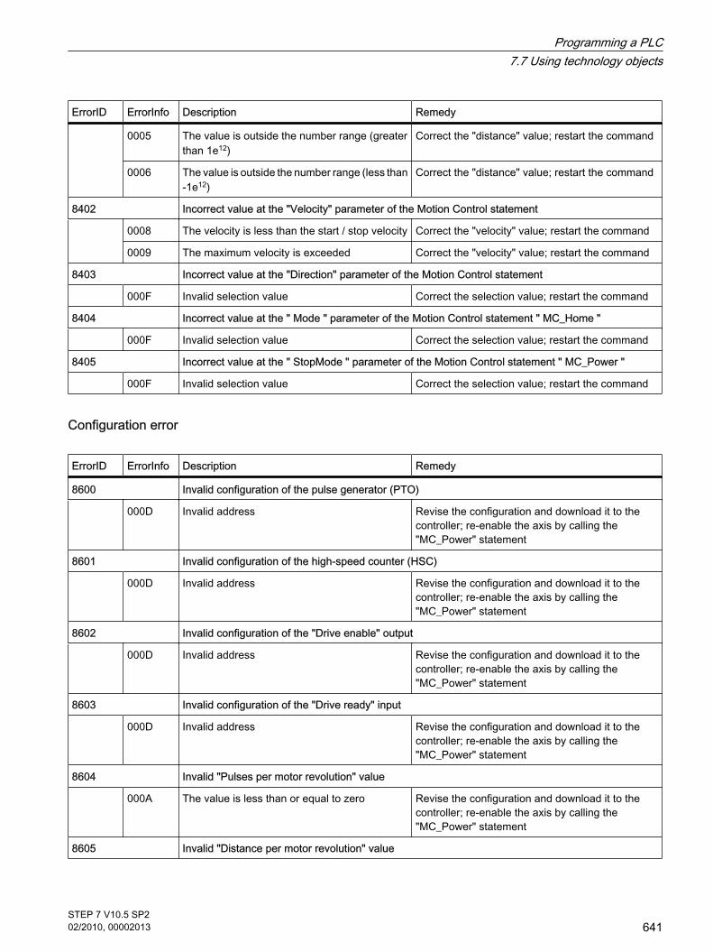
ErrorID ErrorInfo Description Remedy
0005 The value is outside the number range (greaterthan 1e12)
Correct the "distance" value; restart the command
0006 The value is outside the number range (less than-1e12)
Correct the "distance" value; restart the command
8402 Incorrect value at the "Velocity" parameter of the Motion Control statement
0008 The velocity is less than the start / stop velocity Correct the "velocity" value; restart the command
0009 The maximum velocity is exceeded Correct the "velocity" value; restart the command
8403 Incorrect value at the "Direction" parameter of the Motion Control statement
000F Invalid selection value Correct the selection value; restart the command
8404 Incorrect value at the " Mode " parameter of the Motion Control statement " MC_Home "
000F Invalid selection value Correct the selection value; restart the command
8405 Incorrect value at the " StopMode " parameter of the Motion Control statement " MC_Power "
000F Invalid selection value Correct the selection value; restart the command
Configuration error
ErrorID ErrorInfo Description Remedy
8600 Invalid configuration of the pulse generator (PTO)
000D Invalid address Revise the configuration and download it to thecontroller; re-enable the axis by calling the"MC_Power" statement
8601 Invalid configuration of the high-speed counter (HSC)
000D Invalid address Revise the configuration and download it to thecontroller; re-enable the axis by calling the"MC_Power" statement
8602 Invalid configuration of the "Drive enable" output
000D Invalid address Revise the configuration and download it to thecontroller; re-enable the axis by calling the"MC_Power" statement
8603 Invalid configuration of the "Drive ready" input
000D Invalid address Revise the configuration and download it to thecontroller; re-enable the axis by calling the"MC_Power" statement
8604 Invalid "Pulses per motor revolution" value
000A The value is less than or equal to zero Revise the configuration and download it to thecontroller; re-enable the axis by calling the"MC_Power" statement
8605 Invalid "Distance per motor revolution" value
Programming a PLC7.7 Using technology objects
STEP 7 V10.5 SP202/2010, 00002013
641

ErrorID ErrorInfo Description Remedy
0002 Value with invalid number format Revise the configuration and download it to thecontroller; re-enable the axis by calling the"MC_Power" statement000A The value is less than or equal to zero
8606 Invalid "Start / stop velocity" value
0002 Value with invalid number format Revise the configuration and download it to thecontroller; re-enable the axis by calling the"MC_Power" statement0003 Value exceeds the hardware limit
0004 Value is less than the hardware limit
8607 Invalid "maximum velocity" value
0002 Value with invalid number format Revise the configuration and download it to thecontroller; re-enable the axis by calling the"MC_Power" statement0003 Value exceeds the hardware limit
0004 Value is less than the hardware limit
8608 Invalid "Acceleration" value
0002 Value with invalid number format Revise the configuration and download it to thecontroller; re-enable the axis by calling the"MC_Power" statement0003 Value exceeds the hardware limit
0004 Value is less than the hardware limit
8609 Invalid "Deceleration" value
0002 Value with invalid number format Revise the configuration and download it to thecontroller; re-enable the axis by calling the"MC_Power" statement0003 Value exceeds the hardware limit
0004 Value is less than the hardware limit
860A Invalid "Emergency stop deceleration" value
0002 Value with invalid number format Revise the configuration and download it to thecontroller; re-enable the axis by calling the"MC_Power" statement0003 Value exceeds the hardware limit
0004 Value is less than the hardware limit
860B Invalid position value for the lower SW limit switch
0002 Value with invalid number format Revise the configuration and download it to thecontroller; re-enable the axis by calling the"MC_Power" statement0005 The value is outside the number range (greater
than 1e12)
0006 The value is outside the number range (less than-1e12)
0007 The position value of the lower SW limit switchis greater than that of the upper SW limit switch
860C Invalid position value for the upper SW limit switch
Programming a PLC7.7 Using technology objects
642STEP 7 V10.5 SP202/2010, 00002013

ErrorID ErrorInfo Description Remedy
0002 Value with invalid number format Revise the configuration and download it to thecontroller; re-enable the axis by calling the"MC_Power" statement0005 The value is outside the number range (greater
than 1e12)
0006 The value is outside the number range (less than-1e12)
860D Invalid address of the lower HW limit switch
000B Invalid address of the falling edge Revise the configuration and download it to thecontroller; re-enable the axis by calling the"MC_Power" statement000C Invalid address of the rising edge
860E Invalid address of the upper HW limit switch
000B Invalid address of the falling edge Revise the configuration and download it to thecontroller; re-enable the axis by calling the"MC_Power" statement000C Invalid address of the rising edge
860F Invalid "reference point shift" value
0002 Value with invalid number format Revise the configuration and download it to thecontroller; re-enable the axis by calling the"MC_Power" statement0005 The value is outside the number range (greater
than 1e12)
0006 The value is outside the number range (less than-1e12)
8610 Invalid "startup velocity" value
0002 Value with invalid number format Revise the configuration and download it to thecontroller; re-enable the axis by calling the"MC_Power" statement0008 The velocity is less than the start / stop velocity
0009 The maximum velocity is exceeded
8611 Invalid "approach velocity" value
0002 Value with invalid number format Revise the configuration and download it to thecontroller; re-enable the axis by calling the"MC_Power" statement0008 The velocity is less than the start / stop velocity
0009 The maximum velocity is exceeded
8612 Invalid address of the reference point switch
000B Invalid address of the falling edge Revise the configuration and download it to thecontroller; re-enable the axis by calling the"MC_Power" statement000C Invalid address of the rising edge
8613 Axis reversal is activated at the HW limit switch, despite the fact that the hardware limit switches aredisabled
0001 - Revise the configuration and download it to thecontroller; re-enable the axis by calling the"MC_Power" statement
Programming a PLC7.7 Using technology objects
STEP 7 V10.5 SP202/2010, 00002013
643

Internal error
ErrorID ErrorInfo Description Remedy
8FFF Internal error
F001 - Restart the CPU by means of POWER OFF andPOWER ON
F002 -
F003 -
F004 -
F005 -
F006 -
F007 -
F008 -
See alsoError displays of the Motion Control statements (Page 638)
7.7.1.6 Download to CPU
A new or modified configuration of the technological object must be downloaded to the CPUfor the online mode. The following menu and shortcut menu commands are available for thedownload:
• Menu command Online > Download to device
Downloads the configuration of the technological object, the compiled hardware data and theremaining software project data to the device.
• Menu command Online > Advanced download to device
Sets up an online connection to the selected device and downloads the compiled hardware andsoftware project data, including the configuration of a technological object to the device.
The CPU object was selected in the project navigator.
• Download to Device > All shortcut menu command
Downloads the configuration of the technological object, the compiled hardware data and theremaining software project data to the device.
• Download to Device > Software shortcut menu command
Downloads the modified configuration of the technological object and the modified blocks to a device.Only the modified objects are transferred to the device.
• Download to Device > Software (all blocks) shortcut menu command
Downloads all blocks and the technological objects, including the objects which were not changed tothe device.
7.7.1.6 Download to CPU
Programming a PLC7.7 Using technology objects
644STEP 7 V10.5 SP202/2010, 00002013

The "Program blocks" object was selected in the project navigator.
• Download to Device > Software shortcut menu command
Downloads the modified configuration of the technological object and the modified blocks to a device.Only the modified objects are transferred to the device.
• Download to Device > Software (all blocks) shortcut menu command
Downloads all blocks and the technological objects, including the objects which were not changed, tothe device.
7.7.1.7 Commissioning
Use the control panel to test the axis and drive functions or to move the axis in manual mode.The control panel can only be used if an online connection to the CPU is set up.
"Manual control" buttonClick "Manual control" to move the axis in manual control mode. Start by clearing the axisenable at the Motion Control statement "MC_Power" in the user program. In "Manual control"mode, the control panel assumes control priority for the axis and drive functions. The userprogram has no influence on the axis functions.
Warning
The Manual control is active for one axis only. A second axis could be moved in Automaticcontrol, but this would bring about a dangerous situation.
In this case, set the second axis out of operation.
"Auto mode" buttonClick "Auto mode" to end the "Manual control" mode. Control priority is transferred again to thecontroller.
Re-enable the axis with a FALSE -> TRUE edge at input parameter "Enable" of the MotionControl statement "MC_Power" and initiate axis homing by means of Motion Control statement"MC_Home".
"Enable" buttonClick "Enable" to move the axis in manual control mode.
"Lock" buttonClick "Lock" to temporarily lock the axis in manual control mode.
7.7.1.7 Commissioning
Programming a PLC7.7 Using technology objects
STEP 7 V10.5 SP202/2010, 00002013
645

"Command" areaOperation in the "Command" area is only possible if the axis is enabled. You can select one ofthe following command inputs:
• Jog
This command is equivalent to the Motion Control command "MC_MoveJog" in the user program.
• Positioning
This command is equivalent to the Motion Control commands "MC_MoveAbsolute" and"MC_MoveRelative" in the user program. The axis must be homed for absolute positioning.
• Homing
This command is equivalent to the Motion Control command "MC_Home" in the user program.
Depending on your selection, the screen displays different fields for setpoint input and differentbuttons for starting the command.
"Axis status" areaIf "Manual control" mode is active, the displays in the "Axis status" area output the current stateof the axis and drive. The current position and velocity of the axis is displayed at "Actual values".
Click "Acknowledge" to acknowledge all cleared errors.
Last errorIn "Manual control" mode, the "Last error" field indicates the most recent error and thecorresponding additional error information. Having eliminated the cause of error, click"Acknowledge" to clear the error entry.
7.7.1.8 Diagnostics
7.7.1.8 Status and error bits
Use the "Status and error bits" diagnostics function to monitor the vital status and faultmessages of the axis. The display of diagnostics functions is available in online mode in the"Manual control" mode and in "Auto mode". The status error messages have the followingmeaning:
Status of the axis
Status Description
Enabled The axis is enabled and ready to accept Motion Control commands.
Homed The axis is homed and is capable of executing positioning commands such as those of the"MC_MoveAbsolute" statement. The axis does not have to be homed for relative homing.The status is FALSE during active homing with the "MC_Home" statement.
7.7.1.8 Diagnostics7.7.1.8 Status and error bits
Programming a PLC7.7 Using technology objects
646STEP 7 V10.5 SP202/2010, 00002013

Status Description
Error An error occurred at the axis technological object. Depending on the type of error, either the axis isstopped, or the command is rejected. More information about the error is available in auto mode atthe ErrorID and ErrorInfo parameters of the Motion Control statements. In manual mode, the "Lasterror" field of the control panel displays more information about the cause of error.
Control panel active The "Manual control" mode was enabled in the control panel. The control panel takes control priorityover the axis technological object. The user program has no influence over the technological object.
Drive status
Status Description
Drive ready The drive is ready.
Error The drive has reported an error after failure of its ready signal.
Status of the axis motion
Status Description
Standstill The axis is at a standstill.
Acceleration The axis accelerates.
Constant velocity The axis travels at a constant velocity.
Deceleration The axis decelerates (slows down).
Status of the motion mode
Status Description
Positioning The axis is executing a positioning command (e.g. by means of the "MC_MoveAbsolute" or"MC_MoveRelative" statement).
Motion with speed preset The axis is executing a command of the following Motion Control statement:
• MC_MoveVelocity
• MC_MoveJog
• MC_Halt
Homing The axis is executing a homing command (e.g. by means of "MC_Home" statement).
Programming a PLC7.7 Using technology objects
STEP 7 V10.5 SP202/2010, 00002013
647

Error bits
Error Description
SW limit switch has reachedthe negative end position
The negative end position of the SW limit switch was reached; the axis is stopped.
SW limit switch has exceededthe negative end position
The negative end position of the SW limit switch was exceeded; the axis is stopped.
SW limit switch has reachedthe positive end position
The positive end position of the SW limit switch was reached; the axis is stopped.
SW limit switch has exceededthe positive end position
The positive end position of the SW limit switch was exceeded; the axis is stopped.
HW limit switch at negative endposition
The negative end position of the HW limit switch was reached or exceeded; the axis isstopped with emergency stop deceleration.
HW limit switch at positive endposition
The positive end position of the HW limit switch was reached or exceeded; the axis is stoppedwith emergency stop deceleration.
PTO and HSC are already inuse
The axis cannot access the assigned pulse generator and high-speed counter. The axis isstopped and locked.
Configuration error The technological object is unable to execute the command due to a configuration error. Theaxis is stopped and locked
Internal error An internal error has occurred. The axis is stopped and locked.
7.7.1.8 Motion status
Use the diagnostics function "Motion status" to monitor the motion commands of the axis. Thedisplay of diagnostics functions is available in online mode in the "Manual control" mode andin "Auto mode". The displayed fields have the following meaning:
Motion status
Status Description
Target position The "Target position" indicates the current target position of positioning command (e.g. by meansof the "MC_MoveAbsolute" or "MC_MoveRelative" statement).The target position is only displayed if the axis is homed and a positioning command is active.
Current position The "Current position" field indicates the current axis position. The field only indicates the currentposition of a homed axis.
Current velocity The "Current velocity" field indicates the actual axis velocity.
7.7.1.8 Motion status
Programming a PLC7.7 Using technology objects
648STEP 7 V10.5 SP202/2010, 00002013

Dynamic limits
Dynamic limit Description
Velocity The "Velocity" field indicates the configured maximum velocity of the axis.
Acceleration The "Acceleration" field indicates the configured maximum acceleration of the axis.
Deceleration The "Deceleration" field indicates the configured maximum deceleration of the axis.
7.7.2 Using PID Compact
7.7.2.1 Guidelines for "PID Compact"
The "PID_Compact" technology object makes available a PID controller with optimizing selftuning for automatic and manual mode.
Within a control loop the PID controller continuously acquires the measured actual value of thecontrolled variable and compares it with the desired setpoint. From the resulting systemdeviation the PID controller calculates a controller output that adapts the controlled variable tothe setpoint as rapidly and stably as possible. At the PID controller the calculated value of thecontroller output consists of three components:
• Proportional component
The value of the controller output calculated by the proportional component is proportional to thesystem deviation.
• Integral component
The value of the controller output calculated by the integral component increases with the duration ofthe controller output and finally results in the controller output being compensated.
• Derivative component
The derivative component of the PID controller increases as the rate of change of the system deviationincreases. The controlled variable is adapted as fast as possible to the setpoint. When the rate ofchange of the system deviation decreases, the derivative component decreases as well.
The technology object calculates the proportional. integral and derivative component of the PIDcontroller by itself during the "Self tuning during initial start". The parameters can be optimizedfurther by means of a "Self-tuning in the operating point".
RequirementTo use the "PID Compact" technology object, a project has to be created with a CPU S7-1200.
ProcedureTo use a "PID Compact" technology object, follow these steps:
7.7.2 Using PID Compact7.7.2.1 Guidelines for "PID Compact"
Programming a PLC7.7 Using technology objects
STEP 7 V10.5 SP202/2010, 00002013
649

1. Adding a "PID Compact" technology object (Page 650)
2. Calling the "PID_Compact" instruction in the user program (Page 656)
3. Configuring the technology object (Page 651)
4. Download to CPU (Page 657)
5. Commissioning (Page 659)
6. Saving the optimized PID parameters (Page 666)
7.7.2.2 Adding a "PID Compact" technology object
You have the following options for creating the "PID Compact" technology object within theproject:
Adding a "PID Compact" technology object in the project navigatorWhen a technology object is added, an instance DB is created for the "PID_Compact"instruction. The configuration of the technology object is stored in this instance DB. To add a"PID Compact" technology object in the project navigator, follow these steps:
RequirementA project with a CPU S7-1200 has been created.
Procedure1. Open the CPU folder in the project tree.
2. Open the "Technology objects" folder.
3. Double-click the "Add new object" object. The "Add new object" dialog box opens.
4. Enter an individual name for the technology object in the "Name" input field.
5. Click the "PID controller" button.
6. Select the "Manual" option if you want to change the suggested data block number of the instanceDB.
7. Click "Further information" if you want to add own information to the technology object.
8. Click "OK" if you want to add the technology object. Click "Cancel" if you want to reject your entries.
ResultThe new technology object has been created and stored in the project tree in the "Technologyobjects" folder.
Note
You can select the "Add and open new block" check box at the bottom of the dialog box. Thisopens the configuration of the technology object after adding has been completed.
7.7.2.2 Adding a "PID Compact" technology object
Programming a PLC7.7 Using technology objects
650STEP 7 V10.5 SP202/2010, 00002013

Adding the technology object by inserting the "PID_Compact" instruction in the program editor.An instance DB is created when the "PID_Compact" instruction is added in the program editor.The instance DB corresponds to the "PID Compact" technology object. The configuration ofthe technology object is stored in this instance DB. To add the "PID Compact" technology objectin the program editor, follow these steps:
RequirementA project with a CPU S7-1200 has been created.
Procedure1. Open the cyclic interrupt OB in which you want to insert the "PID_Compact" instruction.
In order to ensure a constant scan time of the controller, the "PID_Compact" instruction has to becalled in a cyclic interrupt OB.
2. In the "Instructions" window open the "Extended instructions" group and the "PID" folder.
3. Select the "PID_Compact" instruction and drag it to your block. The "Call options" dialog box opens.
4. Enter an individual name for the technology object in the "Name" input field.
5. Select "Manual" if you want to change the suggested data block number of the instance DB.
6. Click "OK" if you want to add the instance DB or the technology object.
ResultThe "PID_Compact" instruction is inserted and the new technology object is created. The objectis stored in the project navigation in the "Technology objects" folder.
See alsoProgramming (Page 656)
7.7.2.3 Configuring
7.7.2.3 Configuring the technology object
The properties of the "PID Compact" technology object can be configured in the configurationwindow and in the inspector window.
• In the configuration window: For all the configuration properties
• In the inspector window: For the configuration properties required during operation
Configuration in the configuration windowTo open the configuration window of the technology object, follow these steps:
7.7.2.3 Configuring7.7.2.3 Configuring the technology object
Programming a PLC7.7 Using technology objects
STEP 7 V10.5 SP202/2010, 00002013
651

1. Open the group of the desired technology object in the project tree.
2. Double-click the "Configuration" object.
Configuration in the inspector windowTo open the inspector window of the "PID Compact" technology object, follow these steps:
1. Open the "Program blocks" folder in the project tree.
2. Double-click the block (cyclic interrupt OB) in which the "PID Compact" instruction is called. The block is opened in the work area.
3. Click the "PID_Compact" instruction.
4. In the inspector window, select the "Properties" and "Configuration" tabs consecutively.
Icons of the configuration windowIcons in the area navigation of the configuration and in the inspector window show additionaldetails about the completeness of the configuration:
The configuration contains default values and is complete. The configuration contains exclusively default values. With these default values the use of the technology object ispossible without further changes.
The configuration contains values defined by the user and is complete All the input fields of the configuration contain valid values, and at least one default value has been changed.
The configuration is incomplete or faulty At least one input field or a drop-down list box contains no value or an invalid value. The corresponding field or the drop-down list box has a red background. When clicked the roll-out error message indicates the cause of the error.
See alsoBasic parameters (Page 652)Actual value scaling (Page 653)Input monitoring (Page 654)PWM limitations (Page 655)Manipulated value limits (Page 655)PID parameters (Page 656)
7.7.2.3 Basic parameters
Configure the basic properties of the "PID Compact" technology object in the "Default settings"in the inspector window or in the configuration window.
Type of control systemSelect the desired unit for the type of control system by means of the "Type of control system"preselection.
7.7.2.3 Basic parameters
Programming a PLC7.7 Using technology objects
652STEP 7 V10.5 SP202/2010, 00002013

Select the "Inversion of the control direction" check box if an increase in the manipulated valueis to effect a decrease of the actual value (for example, sinking water level owing to an increaseof the valve position or declining temperature owing to an increase in the cooling performance).
Input / output supplyIn this section valid values are assigned to the input and output parameters for the setpoint,actual value and manipulated variable of the "PID_Compact" instruction. The input and outputparameters can only be configured in the inspector window.
• Setpoint
In the drop-down list box, select whether the value at the function block or the value of the instanceDB is to be used.
• Actual value
In the drop-down list box, select whether the input parameter "Input" or "Input_PER" is to be used.
― Use "Input" if you want to use an actual value from the user program. In the drop-down list box,also select whether the value at the function block or the value of the instance DB is to be used.
― Use "Input_PER" if you want to use the actual value of an analog input.
In the field below this specify the parameter suitable for the actual value.
• Manipulated variable
In the drop-down list box, select the to-be-configured, manipulated variable of the "PID_Compact"instruction. The following options are available:
― Output
Uses a variable of the user program as the manipulated variable output.
― Output_PER
Uses an analog output as the manipulated variable output.
― Output_PWM
Uses a digital switching output and controls it by means of a pulse width modulation. Themanipulated variable is formed by means of variable turn-on and turn-off times.
In the field below this specify the parameter suitable for the manipulated variable output.
See alsoConfiguring the technology object (Page 651)Actual value scaling (Page 653)Input monitoring (Page 654)PWM limitations (Page 655)Manipulated value limits (Page 655)PID parameters (Page 656)
7.7.2.3 Actual value scaling
In the "Actual value scaling" configuration window, configure the scaling of your actual valueand specify the absolute actual value limits.
7.7.2.3 Actual value scaling
Programming a PLC7.7 Using technology objects
STEP 7 V10.5 SP202/2010, 00002013
653

ScalingSpecify the scaling of your actual value by means of a lower and an upper pair of values.
Each pair of values consists of the analog value of the analog input and the physical value ofthe respective scaling point. Depending on the configuration of the default setting, a processvalue of the user program can also be used instead of the analog value of the analog input.
Upper and lower limitSpecify the absolute upper and lower limit of the actual value. As soon as these limits areexceeded or undershot during operation, the regulatory control switches off and themanipulated variable is set to 0%.
"Default setting" buttonClick the "Default setting" button if you want to load the default setting value for the scaling andthe upper and lower limits and want to replace the existing values.
See alsoConfiguring the technology object (Page 651)Basic parameters (Page 652)Input monitoring (Page 654)PWM limitations (Page 655)Manipulated value limits (Page 655)PID parameters (Page 656)
7.7.2.3 Advanced parameters
7.7.2.3 Input monitoring
In the "Input monitoring" configuration window, configure a lower and an upper warning limitfor the actual value. If one of the warning limits is exceeded or undershot during operation, awarning is displayed at the "PID_Compact" instruction:
• At the "InputWarning_H" output parameter if the upper warning limit was exceeded
• At the "InputWarning_L" output parameter if the lower warning limit was undershot
See alsoConfiguring the technology object (Page 651)Basic parameters (Page 652)Actual value scaling (Page 653)PWM limitations (Page 655)Manipulated value limits (Page 655)PID parameters (Page 656)
7.7.2.3 Advanced parameters7.7.2.3 Input monitoring
Programming a PLC7.7 Using technology objects
654STEP 7 V10.5 SP202/2010, 00002013

7.7.2.3 PWM limitations
In the "PWM limitations" configuration window configure the minimum permissible ON and OFFswitching times of the pulse width modulation. Extend the minimum ON and OFF times if youwant to reduce the number of switching cycles.
The configuration of the PWM limitations affects the manipulated variable output"Output_PWM". The manipulated variable is switched via a pulse width modulation to the"Output_PWM" switching output. The ON and OFF switching times of the pulse widthmodulation are a multiple of the call cycle of the "PID_Compact" instruction.
Note
The switching output for the pulse width modulation is controlled by the "PID_Compact"instruction. The pulse generators integrated in the CPU are not used.
See alsoConfiguring the technology object (Page 651)Basic parameters (Page 652)Actual value scaling (Page 653)Input monitoring (Page 654)Manipulated value limits (Page 655)PID parameters (Page 656)
7.7.2.3 Manipulated value limits
In the "Manipulated value limits" configuration window configure the absolute limits of yourmanipulated variable. Absolute manipulated variable limits are not exceeded or undershoteither in manual mode or in automatic mode. If a manipulated variable outside the limits isspecified in manual mode, the effective value is limited in the CPU to the configured limits.
Note
If the "Output_PWM" manipulated variable output is used, only positive manipulated variablescan be controlled.
See alsoConfiguring the technology object (Page 651)Basic parameters (Page 652)Actual value scaling (Page 653)Input monitoring (Page 654)PWM limitations (Page 655)PID parameters (Page 656)
7.7.2.3 PWM limitations7.7.2.3 Manipulated value limits
Programming a PLC7.7 Using technology objects
STEP 7 V10.5 SP202/2010, 00002013
655
7.7.2.3 PID parameters
In the "PID parameters" configuration window, configure the parameters of the PID controller.Use the configuration if you want to manually specify the PID parameters of the technologyobject. To do so, select the "Use manual PID parameters" check box and enter the desired PIDparameters.
Depending on the initial situation, the following values are displayed at the call:
• After the technology object has been added
After the technology object has been added, the default values of the technology object are displayed.
• After the "Load PID parameters into project" icon has been clicked
After the icon has been clicked in the commissioning window, the PID parameters currently acting inthe CPU are loaded into the project and displayed in the configuration.
See alsoConfiguring the technology object (Page 651)Basic parameters (Page 652)Actual value scaling (Page 653)Input monitoring (Page 654)PWM limitations (Page 655)Manipulated value limits (Page 655)
7.7.2.4 Programming
7.7.2.4 Calling the "PID_Compact" instruction in the user program
RequirementThe sampling time of the "PID Compact" controller is determined by the interval between thecalls. To comply strictly with the sampling time, the "PID_Compact" instruction has to be calledin a cyclic interrupt organization block. Add the desired cyclic interrupt OB to the project.Configure the value of the desired sampling time as a "time frame" of the cyclic interrupt OB.
ProcedureProceed as follows to call the "PID_Compact" instruction in the user program:
1. Open the "Program blocks" folder in the project tree.
2. Double-click the required watchdog interrupt OB. The block is opened in the work area.
3. In the "Instructions" window open the "Extended instructions" group and the "PID" folder.
4. Select the "PID_Compact" instruction and drag it to your cyclic interrupt OB. The "Call options" dialog box opens.
5. Depending on the initial situation, carry out the following actions:
7.7.2.3 PID parameters7.7.2.4 Programming7.7.2.4 Calling the "PID_Compact" instruction in the user program
Programming a PLC7.7 Using technology objects
656STEP 7 V10.5 SP202/2010, 00002013

― Technology object "PID Compact" was already added: Click "Cancel" to close the "Call options" dialog. On the work area, double-click in the input field for the instance DB. Select the technology object from the list.
― Technology object "PID Compact" was not yet added: The "Call options" dialog opens. In the "Name" input field, type in an individual name for the technology object. Select "manual" if you want to change the proposed data block number of the instance DB (thetechnology object and instance DB are identical at technology object "PID Compact"). To add the instance DB or the technology object, confirm your entries with "OK".
ResultThe "PID_Compact" instruction is inserted and the new technology object is created. The objectis created in the project tree in the "Technology objects" folder.
See alsoPID_Compact: PID controller with self tuning (Page 997)Download to CPU (Page 657)Read/write access to the variable of the technology objects (Page 658)
7.7.2.4 Download to CPU
A new or modified configuration of the technology object must be downloaded to the CPU forthe online mode. The following menu and shortcut menu commands are available for thedownload:
• Menu command Online > Download to device
Downloads the configuration of the technology object, the compiled hardware data and the remainingsoftware project data to the device.
• Menu command Online > Advanced download to device
Sets up an online connection to the selected device and downloads the compiled hardware andsoftware project data, including the configuration of a technology object to the device.
The CPU object was selected in the project navigator
• Download to Device > All shortcut menu command
Downloads the configuration of the technology object, the compiled hardware data and the remainingsoftware project data to the device.
• Download to Device > Software shortcut menu command
Downloads the modified configuration of the technology object and the modified blocks to a device.Only the modified objects are transferred to the device
• Download to Device > Software (all blocks) shortcut menu command
Downloads all blocks and the technology objects, including the objects which were not changed tothe device
The "Program blocks" object was selected in the project navigator
7.7.2.4 Download to CPU
Programming a PLC7.7 Using technology objects
STEP 7 V10.5 SP202/2010, 00002013
657

• Download to Device > Software shortcut menu command
Downloads the modified configuration of the technology object and the modified blocks to a device.Only the modified objects are transferred to the device
• Download to Device > Software (all blocks) shortcut menu command
Downloads all blocks and the technology objects, including the objects which were not changed tothe device
See alsoCalling the "PID_Compact" instruction in the user program (Page 656)
7.7.2.4 Read/write access to the variable of the technology objects
You can access the essential configuration data, the operating mode of the PID controller, aswell as additional status displays of the technology object using the variables of the instanceDB (corresponds to the "PID Compact" technology object).
The following table lists the available variables and describes their effect and meaning:
Variable Data type Description
sRet.i_Mode INT The operating mode is changed edge-controlled.
0 Select "Inactive" mode (stops the controller)
1 Select "Self tuning during initial start" mode
2 Select "Self tuning in the operating point" mode
3 Select "Automatic mode" mode
4 Select "Manual" mode
sPid_Cmpt.r_Sp_Hlm REAL Absolute setpoint upper limit (default setting is the configured absoluteactual value upper limit)
sPid_Cmpt.r_Sp_Llm REAL Absolute setpoint lower limit (default setting is the configured absoluteactual value lower limit)
sPid_Cmpt.r_Pv_Norm_IN_1 REAL Lower analog value of the "Input_PER" analog input
sPid_Cmpt.r_Pv_Norm_IN_2 REAL Upper analog value of the "Input_PER" analog input
sPid_Cmpt.r_Pv_Norm_OUT_1 REAL Physical value of the lower scaling point
sPid_Cmpt.r_Pv_Norm_OUT_2 REAL Physical value of the upper scaling point
sPid_Cmpt.r_Lmn_Hlm REAL Upper manipulated variable limit for the "Output" output parameter
sPid_Cmpt.r_Lmn_Llm REAL Lower manipulated variable limit for the "Output" output parameter
sPid_Cmpt.r_Lmn_Pwm_PPTm REAL Minimum ON time of the pulse width modulation in seconds
sPid_Cmpt.r_Lmn_Pwm_PBTm REAL Minimum OFF time of the pulse width modulation in seconds
7.7.2.4 Read/write access to the variable of the technology objects
Programming a PLC7.7 Using technology objects
658STEP 7 V10.5 SP202/2010, 00002013

Variable Data type Description
sPid_Cmpt.b_InvCtrl BOOL FALSE Do not invert control direction
TRUE Invert control direction
sPid_Cmpt.b_Input_PER_On BOOL FALSE "Input_PER" input parameter not activated
TRUE "Input_PER" input parameter activated
sPid_Cmpt.b_LoadBackUp BOOL Activate the back-up parameter set. If an optimization has failed, youcan reactivate the previous PID parameters by setting this bit.
sPid_Calc.d_CycCountEnd DINT Estimated maximum number of processing cycles that the"PID_Compact" instruction executes until the current self tuning hasbeen completed.
sPid_Calc.d_CycCounter DINT Current number of processing cycles that the "PID_Compact"instruction has executed since starting the self tuning.
Note
Edit the variables listed in this table in the "Inactive" mode to avoid malfunction of the PIDcontroller. The "Inactive" mode is forced by setting the value "0" at the "si_Mode" variable.
7.7.2.5 Commissioning
7.7.2.5 Commissioning
The commissioning window helps you commission the PID controller. You can monitor thevalues for the setpoint, actual value and manipulated variable along the time axis in the trendview. The following functions are supported in the commissioning window:
• Optimizing the controller using "Self tuning during initial start"
• Optimizing the controller using "Self tuning in the operating point"
Use "Self tuning in the operating point" if you want to carry out fine adjustment of the controlleroptimization.
• Monitoring the current closed-loop control in the trend view
• Testing the process by specifying a manual manipulated variable
The commissioning window can only be used if an online connection to the CPU has beenestablished.
7.7.2.5 Commissioning7.7.2.5 Commissioning
Programming a PLC7.7 Using technology objects
STEP 7 V10.5 SP202/2010, 00002013
659

Basic handling
• Select the desired updating cycle in the "Updating cycle" drop-down list box.
All the values displayed in the commissioning window are updated in the selected updating cycle.
• Click the "Measuring on" icon if you want to use the commissioning functions.
Recording of the values is started. The current values for the setpoint, actual value and manipulatedvariable are entered in the trend view. Operation of the commissioning window is enabled.
• Click the "Measuring off" icon if you want to end the commissioning functions.
The values recorded in the trend view can continue to be analyzed.
When the commissioning window is closed, the recording in the trend view is terminated andthe recorded values are deleted.
See also"Self tuning during initial start" mode (Page 660)"Self tuning in the operating point" mode (Page 661)Using the trend view (Page 662)"Manual" mode (Page 665)Saving the optimized PID parameters (Page 666)
7.7.2.5 "Self tuning during initial start" mode
The following section describes how to carry out "Self tuning during initial start" in thecommissioning window of the "PID Compact" technology object.
Requirement
• The "PID_Compact" instruction is called in a cyclic interrupt OB.
• An online connection to the CPU is established and the CPU is in "RUN" mode.
• The functions of the commissioning window have been enabled via the "Measuring on" icon.
• The "Manual manipulated variable" check box is not selected.
• The setpoint and the actual value lie within the configured limits (see "Input monitoring" configuration).
• The distance between the setpoint and the actual value > 50% (referenced to the configured limits ofthe "Input monitoring").
ProcedureTo carry out "Self tuning during initial start", follow these steps:
1. Select the "Self tuning during initial start" option in the "Optimization" section of the commissioningwindow.
2. Click the "Start self tuning" icon.
Self tuning starts. The "Status" field displays the current steps and any errors that may have occurred.The progress bar indicates the progress of the current step.
7.7.2.5 "Self tuning during initial start" mode
Programming a PLC7.7 Using technology objects
660STEP 7 V10.5 SP202/2010, 00002013

Note
Click the "Stop controller" icon when the progress bar has reached 100% and blocking ofthe self tuning function has to be assumed. Check the configuration of the technology objectand, if necessary, restart self tuning.
ResultIf self tuning was executed without errors, the PID parameters have been optimized. The PIDcontroller changes to automatic mode and uses the optimized parameters. The optimized PIDparameters are retained during power ON and a restart of the CPU.
See alsoCommissioning (Page 659)"Self tuning in the operating point" mode (Page 661)Using the trend view (Page 662)"Manual" mode (Page 665)Saving the optimized PID parameters (Page 666)
7.7.2.5 "Self tuning in the operating point" mode
The following section describes how to carry out "Self tuning in the operating point" in thecommissioning window of the "PID Compact" technology object.
Requirement
• The "PID_Compact" instruction is called in a cyclic interrupt OB.
• An online connection to the CPU is established and the CPU is in "RUN" mode.
• The functions of the commissioning window have been enabled via the "Measuring on" icon.
• The "Manual manipulated variable" check box is not selected.
• The setpoint and the actual value lie within the configured limits (see "Input monitoring" configuration).
• The distance between the setpoint and the actual value < 50% (referenced to the limits of the "Inputmonitoring").
If the distance is greater than 50%, "Self tuning during initial start" is carried out. "Self tuning in theoperating point" is carried out automatically after that.
ProcedureTo carry out the "Self tuning in the operating point", follow these steps:
1. Select the "Self tuning in the operating point" option in the "Optimization" section of the commissioningwindow.
2. Click the "Start self tuning" icon.
Self tuning starts. The "Status" field displays the current steps and any errors that may have occurred.The progress bar indicates the progress of the current step.
7.7.2.5 "Self tuning in the operating point" mode
Programming a PLC7.7 Using technology objects
STEP 7 V10.5 SP202/2010, 00002013
661

Note
Click the "Stop controller" icon when the progress bar has reached 100% and blocking ofthe self tuning function has to be assumed. Check the configuration of the technology objectand, if necessary, restart self tuning.
ResultIf self tuning was executed without errors, the PID parameters have been optimized. The PIDcontroller changes to automatic mode and uses the optimized parameters. The optimized PIDparameters are retained during power ON and a restart of the CPU.
See alsoCommissioning (Page 659)"Self tuning during initial start" mode (Page 660)Using the trend view (Page 662)"Manual" mode (Page 665)Saving the optimized PID parameters (Page 666)
7.7.2.5 Using the trend view
The trend view is used for graphic illustration of the setpoint, actual value and manipulatedvariable. The values of the trend view are updated in the selected updating cycle. Start therecording of the trend values by clicking "Measurement on" and stop it by clicking"Measurement off".
Elements of the trend view
7.7.2.5 Using the trend view
Programming a PLC7.7 Using technology objects
662STEP 7 V10.5 SP202/2010, 00002013

① Selection of the display mode
② Trend view
③ Area for moving and scaling the axes
④ Ruler
⑤ Legend with the trend values at the ruler
Selection of the display modeThe following display modes can be selected for displaying the trend recording:
• Strip (continuous display)
New trend values are entered at the right-hand trend view. Previous trend values are scrolled to theleft. The time axis cannot be moved.
• Scope (jumping area display)
New trend values are entered within the trend view from left to right. When the right-hand margin ofthe trend view is reached, the monitoring area is moved one view width to the right. The time axis canbe moved within the limits of the monitoring area.
• Sweep (rotating display)
New trend values are displayed in the trend view in accordance with a rotating display. The trendvalues are entered from left to right. The trend values of the last rotating display are overwritten at thewriting position. The time axis cannot be moved.
• Static (static area display)
Writing of the trends is interrupted. Recording of the new trend values is carried out in the background.The time axis can be moved across the entire previous recording period.
The ratio of the visible area to the recorded area is shown in the ratio display:
The width of the ratio display represents the complete duration of the recording. The yellowsection of the display represents that part of the recording that is visible in the trend view. Thegrayed section of the display represents that part of the recording that is not visible in the trendview.
In the "Static" display mode, you can move the visible range of the ratio display along the axisby dragging it with the mouse.
Trend viewThe trends for the setpoint, actual value and manipulated variable are displayed in the trendview. In addition to different colors, the trends are identified by symbols (refer to legend).
Moving and scaling the axesThe axes for the setpoint and actual value, for the manipulated variable and the time axis canbe moved and scaled individually. The right and left mouse buttons are assigned alternatingfunctions. You can use the following icons and mouse actions:
Programming a PLC7.7 Using technology objects
STEP 7 V10.5 SP202/2010, 00002013
663

Moving the setpoint / actual value axes, or the manipulated variable axis up or down.The axis cannot be moved if the upper or the lower scaling value is blocked.
Moving the time axis to the right or left.The axis cannot be moved if the left or right scaling value is blocked.
Stretch and compress the setpoint , actual value axes, or the manipulated variable axis.
• The scaling of the axes is stretched or compressed symmetrically if none of the scaling values is blocked.
• Blocked scaling values are retained when you stretch or compress an axis.
Stretching and compressing the time axis
• The scaling of the axis is stretched or compressed symmetrically if none of the scaling values is blocked.
• Blocked scaling values are retained when you stretch or compress an axis.
Stretching and compressing the setpoint / actual value axes, or the manipulated variable axis.The lower scaling value is not changed as a result of stretching or compressing.
Stretch and compress the setpoint / actual value or the manipulated variable axis. The upper scaling value is not changed during stretching or compressing.
Stretching and compressing the time axis. The right scaling value is not changed as a result of stretching or compressing.
Stretching and compressing the time axis. The left scaling value is not changed as a result of stretching or compressing.
Enter a scaling value.
The current scaling value can be blocked using the padlock icon. Only one value of a respective axis can beblocked.
Double-clicking in the trend view optimizes the scaling and position of the setpoint, actual value andmanipulated variable in the trend view.
Double-clicking in the axis area restores the default position and scaling of the axis.
Working with rulersUse one or several rulers to analyze discrete values of the trend profile.
The ruler parking position is located at the left edge of the trend area. A second parking positionis located at the top edge of the trend area. However, the values of those rulers cannot bedisplayed.
Programming a PLC7.7 Using technology objects
664STEP 7 V10.5 SP202/2010, 00002013

Move the mouse to the left edge of the trend area and watch out for the transition of the mousepointer. Drag a vertical ruler onto the measuring trend that you want to analyze.
The trend values are output left-aligned on the ruler. The time of the ruler position is displayedat the base of the ruler.
The trend values of the active ruler are displayed in the legend. If several rulers are draggedto the trend area, the respectively last ruler is active. The active ruler is indicated by thecorrespondingly colored
symbol.
You can reactivate an inactive ruler by clicking it.
Use the shortcut ALT+Click to remove rulers which are no longer required.
See alsoCommissioning (Page 659)"Self tuning during initial start" mode (Page 660)"Self tuning in the operating point" mode (Page 661)"Manual" mode (Page 665)Saving the optimized PID parameters (Page 666)
7.7.2.5 "Manual" mode
The following section describes how you can use the "Manual" operating mode in thecommissioning window of the "PID Compact" technology object.
Requirement
• The "PID_Compact" instruction is called in a cyclic interrupt OB.
• An online connection to the CPU has been established and the CPU is in the "RUN" mode.
• The functions of the commissioning window have been enabled via the "Measuring on" icon.
7.7.2.5 "Manual" mode
Programming a PLC7.7 Using technology objects
STEP 7 V10.5 SP202/2010, 00002013
665
ProcedureUse "Manual mode" in the commissioning window if you want to test the process by specifyinga manual manipulated variable. To specify a manual manipulated variable, follow these steps:
1. In the "Current values" area, select the "Manual manipulated variable" check box.
The connection between controller output and manipulated variable output is disconnected. The PIDcontroller continues to run in automatic mode.
The last current manipulated variable of the closed-loop control remains active as the manualmanipulated variable at the manipulated variable outputs.
2. Enter the desired manipulated variable in the "Output" field as a % value.
3. Click the control icon
.
ResultThe manipulated variable is written to the CPU and is active immediately.
Note
Since the PID controller continues to monitor the actual value, any resultant violation of actualvalue limits is displayed in the "Status" field and the PID controller is deactivated.
Clear the "Manual manipulated variable" check box if the manipulated variable is to be specifiedagain by the PID controller.
See alsoCommissioning (Page 659)"Self tuning during initial start" mode (Page 660)"Self tuning in the operating point" mode (Page 661)Using the trend view (Page 662)Saving the optimized PID parameters (Page 666)
7.7.2.5 Saving the optimized PID parameters
The PID controller is optimized in the CPU. If you want to use the PID parameters that wereoptimized in the CPU again when the project data are reloaded to the CPU, save the PIDparameters in the project. Follow these steps:
Requirement
• An online connection to the CPU is established and the CPU is in "RUN" mode.
• The functions of the commissioning window have been enabled by means of the "Measuring on"button.
7.7.2.5 Saving the optimized PID parameters
Programming a PLC7.7 Using technology objects
666STEP 7 V10.5 SP202/2010, 00002013

Procedure1. Click the "Load PID parameters into project" icon in the commissioning window.
ResultThe currently active PID parameters are stored in the project data.
See alsoCommissioning (Page 659)"Self tuning during initial start" mode (Page 660)"Self tuning in the operating point" mode (Page 661)Using the trend view (Page 662)"Manual" mode (Page 665)
7.8 References
7.8.1 Instructions
7.8.1.1 LAD
7.8.1.1 Bit logic
7.8.1.1 ---| |---: Normally open contact
Symbol <Operand>
---| |---
Parameter Data type Memory area Description
<Operand> BOOL I, Q, M, L, D (Page 318) Operand whose signalstate is queried.
DescriptionThe activation of the normally open contact depends on the signal state of the associatedoperand. If the operand has signal state "1," the normally open contact is closed. Power flows
7.8 References7.8.1 Instructions7.8.1.1 LAD7.8.1.1 Bit logic7.8.1.1 ---| |---: Normally open contact
Programming a PLC7.8 References
STEP 7 V10.5 SP202/2010, 00002013
667

from the left power rail through the normally open contact into the right power rail and the signalstate at the output of the operation is set to "1".
If the operand has signal state "0," the normally open contact is not activated. The power flowto the right power rail is interrupted and the signal state at the output of the operation is resetto "0".
Two or more normally open contacts are linked bit-by-bit by AND when connected in series.With a serial connection, power flows when all contacts are closed.
The normally open contacts are linked by OR when connected in parallel. With a parallelconnection, power flows when one contact is closed.
PlacementThe "Normally open contact" operation can be placed at any position in the network.
Example
Output Q 4.0 is set when one of the following conditions is fulfilled:
• Inputs I 0.0 AND I 0.1 have signal state "1".
• The signal state at input I 0.2 is "1".
See alsoInserting operands into LAD instructions (Page 0 )Inserting LAD elements (Page 452)Changing LAD elements (Page 460)Example of controlling a conveyor belt (Page 603)Example of detecting the fill level of a storage area (Page 606)Example of controlling room temperature (Page 610)
7.8.1.1 ---| / |---: Normally closed contact
Symbol <Operand>
—| / |—
7.8.1.1 ---| / |---: Normally closed contact
Programming a PLC7.8 References
668STEP 7 V10.5 SP202/2010, 00002013

Parameter Data type Memory area Description
<Operand> BOOL I, Q, M, L, D (Page 318) Operand whose signalstate is queried.
DescriptionThe activation of the normally closed contact depends on the signal state of the associatedoperand. When the operand has signal state "1," the contact "opens" and the power flow to theright power rail is interrupted. The output of the operation in this case has signal state "0".
If the operand has signal state "0," the normally closed contact is "closed". Power flows throughthe normally closed contact into the right power rail and the output of the operation is set tosignal state "1".
Two or more normally closed contacts are linked bit-by-bit by AND when connected in series.With a serial connection, power flows when all contacts are closed.
The normally closed contacts are linked by OR when connected in parallel. With a parallelconnection, power flows when one contact is closed.
PlacementThe operation can be placed at any position in the network.
Example
Output Q 4.0 is set when one of the following conditions is fulfilled:
• Inputs I 0.0 and I 0.1 have signal state "1".
• The signal state at input I 0.2 is "0".
See alsoInserting LAD elements (Page 452)Changing LAD elements (Page 460)Inserting operands into LAD instructions (Page 0 )Example of detecting the direction of a conveyor belt (Page 605)Example of detecting the fill level of a storage area (Page 606)Example of controlling room temperature (Page 610)
Programming a PLC7.8 References
STEP 7 V10.5 SP202/2010, 00002013
669

7.8.1.1 --|NOT|--: Invert result of logic operation
Symbol ---| NOT |---
DescriptionYou can use the "Invert result of logic operation" operation to invert the signal state of the resultof logic operation (RLO). When the signal state is "1" at the input of the operation, the outputof the operation provides the signal state "0". When the signal state is "0" at the input of theoperation, the output of the operation provides the signal state "1".
PlacementThe "Invert result of logic operation" operation can be placed at any position in the network.
Example
Output Q 4.0 is reset when one of the following conditions is fulfilled:
• Input I 0.0 has signal state "1".
• The signal state at inputs I 0.1 AND I 0.2 is "1".
See alsoInserting LAD elements (Page 452)Changing LAD elements (Page 460)Example of controlling room temperature (Page 610)Inserting operands into LAD instructions (Page 0 )
7.8.1.1 ---
Symbol <Operand>
--- ( ) ---
Parameter Data type Memory area Description
<Operand> BOOL I, Q, M, L, D (Page 318) Operand which is setwith RLO = "1".
7.8.1.1 --|NOT|--: Invert result of logic operation7.8.1.1 ---
Programming a PLC7.8 References
670STEP 7 V10.5 SP202/2010, 00002013

DescriptionYou can use the "Output coil" operation to set the bit of a specified operand. When the resultof logic operation (RLO) at the input of the coil is "1," the specified operand is set to signal state"1". When the signal state is "0" at the input of the coil, the bit of the specified operand is resetto "0".
The operation does not influence the RLO. The RLO at the input of the coil is sent immediatelyto the output.
PlacementThe "Output coil" operation can be placed at any position in the network. Using branches,several coils can be placed within each other.
Example
Figure7-2
Output Q 4.0 is set when one of the following conditions is fulfilled:
• Inputs I 0.0 AND I 0.1 have signal state "1".
• The signal state at input I 0.2 is "0".
Output Q 4.1 is set when one of the following conditions is fulfilled:
• Inputs I 0.0 AND I 0.1 as well as the input I 0.3 have signal state "1".
• The signal state at the input I 0.2 "0" AND at the input I 0.3 is "1".
See alsoInserting LAD elements (Page 452)Inserting operands into LAD instructions (Page 0 )Example of detecting the fill level of a storage area (Page 606)Example of controlling room temperature (Page 610)Changing LAD elements (Page 460)
7.8.1.1 --
Symbol <Operand>
--- ( / ) ---
7.8.1.1 --
Programming a PLC7.8 References
STEP 7 V10.5 SP202/2010, 00002013
671

Parameter Data type Memory area Description
<Operand> BOOL I, Q, M, D, L (Page318)
Operand which is setwith RLO = "0".
DescriptionThe "Negated coil" operation inverts the result of logic operation (RLO) and assigns it to thespecified operand. When the RLO at the input of the coil is "1", the operand is reset. When theRLO at the input of the coil is "0", the operand is set to signal state "1".
The operation does not influence the RLO. The RLO at the input of the coil is sent immediatelyto the output of the coil.
PlacementThe "Negated coil" operation can be placed at any position in the network.
Example
Figure7-2
Output Q 4.0 is reset when one of the following conditions is fulfilled:
• Inputs I 0.0 AND I 0.1 have signal state "1".
• The signal state at input I 0.2 is "1".
See alsoInserting LAD elements (Page 452)Inserting operands into LAD instructions (Page 0 )Changing LAD elements (Page 460)
7.8.1.1 ---
Symbol <Operand>
--- ( R ) ---
7.8.1.1 ---
Programming a PLC7.8 References
672STEP 7 V10.5 SP202/2010, 00002013

Parameter Data type Memory area Description
<Operand> BOOL I, Q, M, L, D (Page318)
Operand which is resetwith RLO = "1".
DescriptionYou can use the "Reset output" operation to set the signal state of a specified operand to "0".
The operation is only executed if the result of logic operation (RLO) at the input of the coil is"1". If power flows to the coil (RLO is "1"), the specified operand is set to "0". If the result oflogic operation at the input of the coil is "0" (no signal flow to the coil), the signal state of thespecified operand remains unchanged.
The operation does not influence the RLO. The RLO at the input of the coil is sent immediatelyto the output of the coil.
PlacementThe "Reset output" operation can be placed at any position in the network.
Example
Figure7-2
Output Q 4.0 is reset when one of the following conditions is fulfilled:
• The inputs I 0.0 AND I 0.1 "1"
• The signal state at input I 0.2 is "0".
See alsoInserting LAD elements (Page 452)Changing LAD elements (Page 460)Inserting operands into LAD instructions (Page 0 )Example of controlling a conveyor belt (Page 603)Example of detecting the direction of a conveyor belt (Page 605)
7.8.1.1 ---
Symbol <Operand>
7.8.1.1 ---
Programming a PLC7.8 References
STEP 7 V10.5 SP202/2010, 00002013
673

--- ( S ) ---
Parameter Data type Memory area Description
<Operand> BOOL I, Q, M, L, D (Page318)
Operand which is setwith RLO = "1".
DescriptionYou can use the "Set output" operation to set the signal state of a specified operand to "1".
The operation is only executed if the result of logic operation at the input of the coil is "1". Ifpower flows to the coil (RLO is "1"), the specified operand is set to "1". If the result of logicoperation at the input of the coil is "0" (no signal flow to the coil), the signal state of the specifiedoperand remains unchanged.
The operation does not influence the RLO. The RLO at the input of the coil is sent immediatelyto the output.
PlacementThe "Set output" operation can be placed at any position in the network.
Example
Figure7-2
Output Q 4.0 is set when one of the following conditions is fulfilled:
• Inputs I 0.0 AND I 0.1 have signal state "1".
• The signal state at input I 0.2 is "0".
See alsoInserting LAD elements (Page 452)Changing LAD elements (Page 460)Inserting operands into LAD instructions (Page 0 )Example of controlling a conveyor belt (Page 603)Example of detecting the direction of a conveyor belt (Page 605)
Programming a PLC7.8 References
674STEP 7 V10.5 SP202/2010, 00002013

7.8.1.1 SET_BF: Set bit field
Symbol
Parameter Data type Memory area Description
<Operand1> BOOL I, Q, M, D, L (Page318)
Pointer to the first bit tobe set
<Operand2> UINT Constant Number of bits to be set
DescriptionYou can use the "Set bit field" operation to set several bits beginning with a certain address.The number of bits to be set determine the value of <Operand2>. The address of the first bitto be set is defined by <Operand1>. If the value of <Operand2> is greater than the number ofbits in a selected byte, the bits of the next byte are set. The bits remain set until they are explicitlyreset, for example, by another operation.
The operation is only executed if the signal state is "1" at the enable input. If the signal state is"0" at the input, the operation is not executed.
PlacementThe "Set bit field" operation can be assigned only to the right end of the network.
Example
Figure7-2
If inputs I 0.0 AND I 0.1 have signal state "1", outputs Q 20.0, Q 20.1, Q 20.2, Q 20.3 and Q20.4 are set.
See alsoInserting LAD elements (Page 452)Changing LAD elements (Page 460)Inserting operands into LAD instructions (Page 0 )
7.8.1.1 SET_BF: Set bit field
Programming a PLC7.8 References
STEP 7 V10.5 SP202/2010, 00002013
675

7.8.1.1 RESET_BF: Reset bit array
Symbol
Parameter Data type Memory area Description
<Operand1> BOOL I, Q, M, D, L (Page318)
Pointer to the first bit tobe reset
<Operand2> UINT Constant Number of bits to bereset
DescriptionYou can use the "Reset bit field" operation to reset several bits beginning with a certain address.The number of bits to be reset determine the value of <Operand2>. The address of the first bitto be reset is defined by <Operand1>. If the value of <Operand2> is greater than the numberof bits in a selected byte, the bits of the next byte are reset. The bits remain reset until they areexplicitly set, for example, by another operation.
The operation is only executed if the signal state is "1" at the enable input. If the signal state is"0" at the input, the operation is not affected.
PlacementThe "Reset bit field" operation can be assigned only to the right end of the network.
Example
Figure7-2
If inputs I 0.0 AND I 0.1 have signal state "1", outputs Q 20.0, Q 20.1, Q 20.2, Q 20.3 and Q20.4 are reset.
See alsoInserting LAD elements (Page 452)Changing LAD elements (Page 460)Inserting operands into LAD instructions (Page 0 )
7.8.1.1 RESET_BF: Reset bit array
Programming a PLC7.8 References
676STEP 7 V10.5 SP202/2010, 00002013

7.8.1.1 SR: Set reset flip-flop
Symbol
Figure7-2
Parameter Data type Memory area Description
<Operand> BOOL I, Q, M, L, D (Page318)
Operand that isspecified.
S BOOL I, Q, M, L, D Set enable
R1 BOOL I, Q, M, L, D Reset enable
Q BOOL I, Q, M, L, D Signal state of thespecified operand
DescriptionYou can use the "Set reset set flip-flop" operation to set or reset the bit of the specified operandbased on the signal state of the inputs S and R1. If the signal state at input S is "1" and is "0"at input R1, the specified operand is set to "1". If the signal state at input S is "0" and is "1" atinput R1, the specified operand is reset to "0".
Input R1 takes priority over input S. If the signal state is "1" at the two inputs S and R1, thesignal state of the specified operand is reset to "0".
The operation is not executed if the signal state at the two inputs R1 and S is "0". The signalstate of the operand then remains unchanged.
The current signal state of the operand is transferred to output Q and can be queried there.
PlacementThe "Set reset flip-flop" operation can be assigned to the right side of the network.
Example
Figure7-2
Bit memory M 0.0 and output Q 4.0 are set when the following conditions are fulfilled:
7.8.1.1 SR: Set reset flip-flop
Programming a PLC7.8 References
STEP 7 V10.5 SP202/2010, 00002013
677

• Input I 0.0 has signal state "1".
• Input I 0.1 has signal state "0".
The bit memory M 0.0 and output Q 4.0 are reset when one of the following conditions is fulfilled:
• Input I 0.0 has signal state "0" and input I 0.1 has signal state "1".
• Both inputs I 0.0 and I 0.1 have signal state "1".
See alsoInserting LAD elements (Page 452)Changing LAD elements (Page 460)Inserting operands into LAD instructions (Page 0 )
7.8.1.1 RS: Reset set flip-flop
Symbol
Figure7-2
Parameter Data type Memory area Description
<Operand> BOOL I, Q, M, L, D (Page318)
Operand that isspecified.
R BOOL I, Q, M, L, D Reset enable
S1 BOOL I, Q, M, L, D Set enable
Q BOOL I, Q, M, L, D Signal state of thespecified operand
DescriptionYou can use the "Reset set flip-flop" operation to set or reset the bit of the specified operandbased on the signal state of the inputs R and S1. If the signal state at input R is "1" and is "0"at input S1, the specified operand is reset to "0". If the signal state at input R is "0" and is "1"at input S1, the specified operand is set to "1".
Input S1 takes priority over input R. If the signal state is "1" at the two inputs R and S1, thesignal state of the specified operand is set to "1".
The operation is not executed if the signal state at the two inputs R and S1 is "0". The signalstate of the operand then remains unchanged.
The current signal state of the operand is transferred to output Q and can be queried there.
7.8.1.1 RS: Reset set flip-flop
Programming a PLC7.8 References
678STEP 7 V10.5 SP202/2010, 00002013

PlacementThe "Reset set flip-flop" operation can be assigned to the right side of the network.
Example
Figure7-2
Bit memory M 0.0 and output Q 4.0 are set when the following conditions are fulfilled:
• Input I 0.0 has signal state "0" and input I 0.1 has signal state "1".
• Both inputs I 0.0 and I 0.1 have signal state "1".
Bit memory M 0.0 and output Q 4.0 are reset when the following conditions are fulfilled:
• Input I 0.0 has signal state "1".
• Input I 0.1 has signal state "0".
See alsoInserting LAD elements (Page 452)Changing LAD elements (Page 460)Inserting operands into LAD instructions (Page 0 )
7.8.1.1 --|P|--: Scan positive signal edge at operand
Symbol <Operand1>
--|P|--
<Operand2>
Parameter Data type Memory area Description
<Operand1> BOOL I, Q, M, L, D (Page318)
Signal to be queried
<Operand2> BOOL I, Q, M, L, D Edge memory bit in whichthe signal state of theprevious query is saved.
7.8.1.1 --|P|--: Scan positive signal edge at operand
Programming a PLC7.8 References
STEP 7 V10.5 SP202/2010, 00002013
679

DescriptionYou can use the "Scan positive signal edge at operand" operation to determine if there is a "0"to "1" change in the signal state of a specified operand (<operand1>). The operation comparesthe current signal state of <operand1> to the signal state of the previous query saved in<operand2>. If the operation detects a change in the result of logic operation from "0" to "1",there is a positive, rising edge.
If a rising edge is detected, the output of the operation has signal state "1". In all other cases,the signal state at the output of the operation is "0".
Note
The address of the edge memory bit must not be used more than once in the program, otherwisethe memory bit would be overwritten. This would influence edge evaluation and the result wouldno longer be unequivocal.
PlacementThe "Scan positive signal edge at operand" operation can be placed at any position in thenetwork.
Example
Output Q 4.0 is set when the following conditions are fulfilled:
• Inputs I 0.0 AND I 0.1 AND I 0.2 have signal state "1".
• There is a rising edge at input I 0.3.
• The signal state at input I 0.4 is "1".
See alsoInserting LAD elements (Page 452)Changing LAD elements (Page 460)Inserting operands into LAD instructions (Page 0 )Example of detecting the direction of a conveyor belt (Page 605)
7.8.1.1 --|N|--: Scan negative signal edge at operand
Symbol<Operand1>
7.8.1.1 --|N|--: Scan negative signal edge at operand
Programming a PLC7.8 References
680STEP 7 V10.5 SP202/2010, 00002013
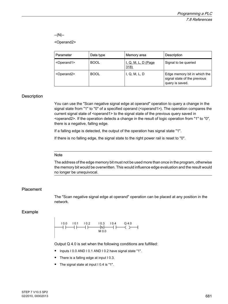
--|N|--
<Operand2>
Parameter Data type Memory area Description
<Operand1> BOOL I, Q, M, L, D (Page318)
Signal to be queried
<Operand2> BOOL I, Q, M, L, D Edge memory bit in which thesignal state of the previousquery is saved.
DescriptionYou can use the "Scan negative signal edge at operand" operation to query a change in thesignal state from "1" to "0" of a specified operand (<operand1>). The operation compares thecurrent signal state of <operand1> to the signal state of the previous query saved in<operand2>. If the operation detects a change in the result of logic operation from "1" to "0",there is a negative, falling edge.
If a falling edge is detected, the output of the operation has signal state "1".
If there is no falling edge, the signal state to the right power rail is reset to "0".
Note
The address of the edge memory bit must not be used more than once in the program, otherwisethe memory bit would be overwritten. This would influence edge evaluation and the result wouldno longer be unequivocal.
PlacementThe "Scan negative signal edge at operand" operation can be placed at any position in thenetwork.
Example
Output Q 4.0 is set when the following conditions are fulfilled:
• Inputs I 0.0 AND I 0.1 AND I 0.2 have signal state "1".
• There is a falling edge at input I 0.3.
• The signal state at input I 0.4 is "1".
Programming a PLC7.8 References
STEP 7 V10.5 SP202/2010, 00002013
681
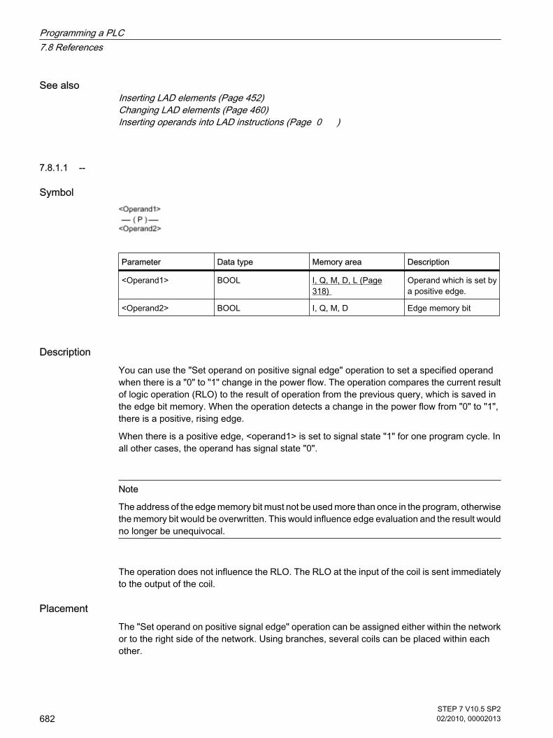
See alsoInserting LAD elements (Page 452)Changing LAD elements (Page 460)Inserting operands into LAD instructions (Page 0 )
7.8.1.1 --
Symbol
Parameter Data type Memory area Description
<Operand1> BOOL I, Q, M, D, L (Page318)
Operand which is set bya positive edge.
<Operand2> BOOL I, Q, M, D Edge memory bit
DescriptionYou can use the "Set operand on positive signal edge" operation to set a specified operandwhen there is a "0" to "1" change in the power flow. The operation compares the current resultof logic operation (RLO) to the result of operation from the previous query, which is saved inthe edge bit memory. When the operation detects a change in the power flow from "0" to "1",there is a positive, rising edge.
When there is a positive edge, <operand1> is set to signal state "1" for one program cycle. Inall other cases, the operand has signal state "0".
Note
The address of the edge memory bit must not be used more than once in the program, otherwisethe memory bit would be overwritten. This would influence edge evaluation and the result wouldno longer be unequivocal.
The operation does not influence the RLO. The RLO at the input of the coil is sent immediatelyto the output of the coil.
PlacementThe "Set operand on positive signal edge" operation can be assigned either within the networkor to the right side of the network. Using branches, several coils can be placed within eachother.
7.8.1.1 --
Programming a PLC7.8 References
682STEP 7 V10.5 SP202/2010, 00002013

Example
Figure7-2
Output Q 3.0 is set for one program cycle, when the signal state at the input of the coil switchesfrom "0" to "1" (positive edge). In all other cases, output Q 3.0 has signal state "0".
See alsoInserting LAD elements (Page 452)Changing LAD elements (Page 460)Inserting operands into LAD instructions (Page 0 )
7.8.1.1 --
Symbol
Parameter Data type Memory area Description
<Operand1> BOOL I, Q, M, D, L (Page318)
Operand which is set bya negative edge.
<Operand2> BOOL I, Q, M, D Edge memory bit
DescriptionYou can use the "Set operand on negative signal edge" operation to set a specified operandwhen there is a "1" to "0" change in the power flow. The operation compares the current resultof logic operation (RLO) to the result of operation from the previous query, which is saved inthe edge bit memory. When the operation detects a change in the power flow from "1" to "0",there is a negative, falling edge.
When a negative edge is detected, <operand1> is set to signal state "1" for one program cycle.In all other cases, the operand has signal state "0".
7.8.1.1 --
Programming a PLC7.8 References
STEP 7 V10.5 SP202/2010, 00002013
683

Note
The address of the edge memory bit must not be used more than once in the program, otherwisethe memory bit would be overwritten. This would influence edge evaluation and the result wouldno longer be unequivocal.
The operation does not influence the RLO. The RLO at the input of the coil is sent immediatelyto the output of the coil.
PlacementThe "Set operand on negative signal edge" operation can be assigned either within the networkor to the right side of the network. Using branches, several coils can be placed within eachother.
Example
Figure7-2
Output Q 3.0 is set for one program cycle, when the signal state at the input of the coil switchesfrom "1" to "0" (positive edge). In all other cases, output Q 3.0 has signal state "0".
See alsoInserting LAD elements (Page 452)Changing LAD elements (Page 460)Inserting operands into LAD instructions (Page 0 )
7.8.1.1 P_TRIG: Set output on positive signal edge
Symbol
Parameter Data type Memory area Description
<Operand> BOOL I, Q, M, L, D (Page318)
Edge memory bit inwhich the RLO of thelast query is saved.
7.8.1.1 P_TRIG: Set output on positive signal edge
Programming a PLC7.8 References
684STEP 7 V10.5 SP202/2010, 00002013

Parameter Data type Memory area Description
CLK BOOL Current RLO
Q BOOL Result of edgeevaluation
DescriptionYou can use the "Set output on positive signal edge" operation to query a change in the signalstate of the result of logic operation from "0" to "1". The operation compares the current signalstate of the result of logic operation (RLO) to the signal state from the previous query, which issaved in the edge bit memory. If the operation detects a change in the RLO from "0" to "1",there is a positive, rising edge.
If a rising edge is detected, the output of the operation has signal state "1". In all other cases,the signal state at the output of the operation is "0".
PlacementThe "Set output on positive signal edge" operation can be assigned within the network.
Example
The RLO from the complete bit logic operation is saved in edge bit memory M 0.0. If there is achange in the signal state of the RLO from "1" to "0", the program jumps to jump label CAS1.
See alsoInserting LAD elements (Page 452)Changing LAD elements (Page 460)Inserting operands into LAD instructions (Page 0 )
7.8.1.1 N_TRIG: Set output on negative signal edge
Symbol
7.8.1.1 N_TRIG: Set output on negative signal edge
Programming a PLC7.8 References
STEP 7 V10.5 SP202/2010, 00002013
685

Parameter Data type Memory area Description
<Operand> BOOL I, Q, M, L, D (Page318)
Edge memory bit inwhich the RLO of thelast query is saved.
CLK BOOL Current RLO
Q BOOL Result of edgeevaluation
DescriptionYou can use the "Set output on negative signal edge" operation to detect a "1" to "0" changein the signal state of the result of logic operation (RLO). The operation compares the currentsignal state of the result of logic operation to the signal state of the previous query saved in theedge memory bit. If the operation detects a change in the RLO from "1" to "0", there is anegative, falling edge.
If a falling edge is detected, the output of the operation has signal state "1". In all other cases,the signal state at the output of the operation is "0".
PlacementThe "Set output on negative signal edge" operation can be assigned within the network.
Example
The RLO of the preceding bit logic operation is saved in the edge memory bit M 0.0. If a "1" to"0" signal change is detected at the RLO, the program jumps to jump label CAS1.
See alsoInserting LAD elements (Page 452)Changing LAD elements (Page 460)Inserting operands into LAD instructions (Page 0 )
Programming a PLC7.8 References
686STEP 7 V10.5 SP202/2010, 00002013

7.8.1.1 Timers
7.8.1.1 TP: Pulse generation
Symbol
Figure7-2
Parameter Data type Memory area Description
IN BOOL I, Q, M, D, L (Page 318) Start input
PT TIME I, Q, M, D, L or constant Duration of the pulse.PT must be positive.
Q BOOL I, Q, M, D, L Pulse output
ET TIME I, Q, M, D, L Elapsed time
DescriptionYou can use the "Generate pulse" operation to set the Q output for a pre-programmed periodof time. The operation is started when the result of logic operation (RLO) at the IN input changesfrom "0" to "1". When the operation is started, the time programmed for PT starts running.Output Q is set for the period of time, PT, regardless of the subsequent course of the inputsignal. Even when a new positive edge is detected, the signal state at the Q output is notaffected as long as PT is running.
It is possible to query how long the current timer function has been running at output ET. Thistime starts at T#0s and ends when the value set for the PT timer is reached. The value at theET output can be queried as long as the PT timer is running and the input IN has signal state"1".
'When inserting the "Generate pulse" operation, an instance data block is created in which theoperation data is saved.
PlacementThe "Generate pulse" operation requires a preceding logic operation for the edge evaluation.It can placed within or at the end of the network.
7.8.1.1 Timers7.8.1.1 TP: Pulse generation
Programming a PLC7.8 References
STEP 7 V10.5 SP202/2010, 00002013
687

Pulse diagram
Figure7-2
See alsoInserting LAD elements (Page 452)Changing LAD elements (Page 460)Inserting operands into LAD instructions (Page 0 )Selecting the data type of a LAD element (Page 0 )
7.8.1.1 TON: On delay
Symbol
Figure7-2
Parameter Data type Memory area Description
IN BOOL I, Q, M, D, L (Page318)
Start input
PT TIME I, Q, M, D, L or constant Time by which the risingedge is delayed at theIN input.
Q BOOL I, Q, M, D, L Output, which is delayedby the time PT.
7.8.1.1 TON: On delay
Programming a PLC7.8 References
688STEP 7 V10.5 SP202/2010, 00002013

Parameter Data type Memory area Description
ET TIME I, Q, M, D, L Elapsed time
DescriptionYou can use the "On delay" operation to delay a rising edge by the time set at PT. The "Ondelay" operation is executed when the result of logic operation (RLO) changes from "0" to "1"at input IN (rising edge). When the operation is started, the time set for PT starts running. Whenthe PT time expires, output Q has signal state "1". Output Q remains set as long as the startinput is still "1". If there is a signal change at the start input from "1" to "0", output Q is reset.The timer function is started again when a new positive edge is detected at the start input.
The ET output supplies the time that has elapsed since the last rising edge at the IN input. Thistime starts at T#0s and ends when the value set for the PT timer is reached. The elapsed timecan be queried at output ET as long as input IN has signal state "1".
'When inserting the "On delay" operation, an instance data block is created in which theoperation data is saved.
PlacementThe "On delay" operation requires a preceding logic operation for the edge evaluation. It canplaced within or at the end of the network.
Pulse diagram
Programming a PLC7.8 References
STEP 7 V10.5 SP202/2010, 00002013
689

Figure7-2
See alsoInserting LAD elements (Page 452)Changing LAD elements (Page 460)Selecting the data type of a LAD element (Page 0 )Inserting operands into LAD instructions (Page 0 )Example of controlling room temperature (Page 610)
7.8.1.1 TOF: Off delay
Symbol
Figure7-2
7.8.1.1 TOF: Off delay
Programming a PLC7.8 References
690STEP 7 V10.5 SP202/2010, 00002013

Parameter Data type Memory area Description
IN BOOL I, Q, M, D, L (Page318)
Start input
PT TIME I, Q, M, D, L or constant Time by which the fallingedge is delayed at the INinput. PT must bepositive.
Q BOOL I, Q, M, D, L Output, which is delayedby the time PT.
ET TIME I, Q, M, D, L Elapsed time
DescriptionYou can use the "Off delay" operation to delay a falling edge by the time set at PT. The Q outputis set when the result of logic operation (RLO) at input IN changes from "0" to "1". When thesignal state at the IN input switches back to "0", the time set at PT starts. Output Q remains setas long the time set at PT is running. The Q output is reset when the PT time expires. If thesignal state at the IN input changes to "1" before the time set at PT time expires, the timer isreset. The signal state at the Q output will continue to be "1".
It is possible to query how long the current timer function has been running at output ET. Thistime starts at T#0s and ends when the value set for the PT timer is reached. When the timeset at PT expires, output ET remains set to the current value until input IN changes back to "1".If the IN input switches to "1" before the PT time has expired, the ET output is reset to the valueT#0.
'When inserting the "OFF delay" operation, an instance data block is created in which theoperation data is saved.
PlacementThe "Off delay" operation requires a preceding logic operation for the edge evaluation. It canplaced within or at the end of the network.
Programming a PLC7.8 References
STEP 7 V10.5 SP202/2010, 00002013
691

Pulse diagram
Figure7-2
See alsoInserting LAD elements (Page 452)Changing LAD elements (Page 460)Selecting the data type of a LAD element (Page 0 )Inserting operands into LAD instructions (Page 0 )
7.8.1.1 TONR: Time accumulator
Symbol
Figure7-2
Parameter Data type Memory area Description
IN BOOL I, Q, M, D, L (Page318)
Start input
R BOOL I, Q, M, D, L Reset input
PT TIME I, Q, M, D, L or constant Maximum duration oftime recording
7.8.1.1 TONR: Time accumulator
Programming a PLC7.8 References
692STEP 7 V10.5 SP202/2010, 00002013

Parameter Data type Memory area Description
Q BOOL I, Q, M, D, L Output that is set whenthe PT time expires.
ET TIME I, Q, M, D, L Accumulated time
DescriptionYou can use the "Time accumulator" operation to accumulate time values within a period setwith the PT parameter. When input IN changes to signal state "1", the operation is executedand the time set at PT starts. While the time set at PT is running, the time values areaccumulated that are recorded at signal state "1" at input IN. The accumulated time is writtento output ET and can be queried there. When the PT time expires, output Q has signal state"1".
Input R resets the outputs ET and Q regardless of the signal state at the start input.
'When inserting the "Time accumulator" operation, an instance data block is created in whichthe operation data is saved.
PlacementThe "Time accumulator" operation requires a preceding logic operation. It can placed within orat the end of the network.
Pulse diagram
Programming a PLC7.8 References
STEP 7 V10.5 SP202/2010, 00002013
693

See alsoInserting LAD elements (Page 452)Changing LAD elements (Page 460)Selecting the data type of a LAD element (Page 0 )Inserting operands into LAD instructions (Page 0 )
7.8.1.1 Counters
7.8.1.1 CTU: Count up
Symbol
Figure7-2
ParameterEnglish
Data type Memory area Description
CU BOOL I, Q, M, D, L (Page318)
Count input
R BOOL I, Q, M, D, L Reset input
PV SINT, INT, DINT,USINT, UINT, UDINT
I, Q, M, D, L or constant Preset count
Q BOOL I, Q, M, D, L Counter status
CV SINT, INT, DINT,USINT, UINT, UDINT
I, Q, M, D, L Actual count value
You can select the data type for the operation from the "DT" drop-down list.
DescriptionYou can use the "Count up" operation to increment the value at the CV output. If the signalstate at the CU input changes from "0" to "1" (positive edge), the operation is executed and thecurrent count value at the CV output is incremented by one. The first time the operation isexecuted, the current count at the CV output is set to zero. The count is incremented each timea positive edge is detected, until it reaches the high limit for the specified data type at the CV
7.8.1.1 Counters7.8.1.1 CTU: Count up
Programming a PLC7.8 References
694STEP 7 V10.5 SP202/2010, 00002013

output. When the high limit is reached, the signal state at the CU input no longer has an effecton the operation.
The counter status can be queried at the Q output. The signal state at output Q is determinedby the PV parameter. If the current count value is greater than or equal to the value of the PVparameter, the Q output is set to signal state "1". In all other cases, the signal state at the Qoutput is "0".
The value at the CV output is reset to zero when the signal state at R input changes to "1". Aslong as there is the signal state "1" at R input, the signal state at input CU has no effect on theoperation.
'When inserting the "Count up" operation, an instance data block is created in which theoperation data is saved.
PlacementThe "Count up" operation requires a preceding logic operation for the edge evaluation. It canplaced within or at the end of the network.
Example
Figure7-2
When the signal state at the input I 0.0 changes from "0" to "1", the "Count up" operation isexecuted and the current count at the MW30 output is increased by one. With each furtherpositive edge, the count value is incremented until the high limit value of the specified data type(32 767) is reached.
The value at the MW20 parameter is applied as the limit for determining the output Q 4.0. OutputQ 4.0 has signal state "1" as long as the current count is greater than or equal to the value atthe MW20 parameter. In all other cases, output Q 4.0 has signal state "0".
See alsoInserting LAD elements (Page 452)Changing LAD elements (Page 460)Selecting the data type of a LAD element (Page 0 )Inserting operands into LAD instructions (Page 0 )
Programming a PLC7.8 References
STEP 7 V10.5 SP202/2010, 00002013
695

7.8.1.1 CTD: Count down
Symbol
Figure7-2
ParameterEnglish
Data type Memory area Description
CD BOOL I, Q, M, D, L (Page318)
Count input
LOAD BOOL I, Q, M, D, L Load input
PV SINT, UINT, DINT,USINT, UINT, UDINT
I, Q, M, D, L or constant Preset count
Q BOOL I, Q, M, D, L Counter status
CV SINT, UINT, DINT,USINT, UINT, UDINT
I, Q, M, D, L Actual count value
You can select the data type for the operation from the "DT" drop-down list.
DescriptionYou can use the "Count down" operation to decrement the value at the CV output. If the signalstate at the CD input changes from "0" to "1" (positive edge), the operation is executed and thecurrent count value at the CV output is decremented by one. The first time the operation isexecuted, the current count at the CV output is set to zero. Each time a positive edge isdetected, the count value is further decremented until it reaches the low limit value of thespecified data type. When the low limit value is reached, the signal state at the CD input hasno further effect on the operation.
The counter status can be queried at the Q output. If the current count value is less than orequal to zero, output Q is set to signal state "1". In all other cases, the signal state at the Qoutput is "0".
The value at the CV output is set to the value of the PV parameter when the signal state atLOAD input changes to "1". As long as there is the signal state "1" at the LOAD input, the signalstate at the CD input has no effect on the operation.
'When inserting the "Count down" operation, an instance data block is created in which theoperation data is saved.
7.8.1.1 CTD: Count down
Programming a PLC7.8 References
696STEP 7 V10.5 SP202/2010, 00002013

PlacementThe "Count down" operation requires a preceding logic operation for the edge evaluation. Itcan placed within or at the end of the network.
Example
Figure7-2
When the signal state at the input I 0.0 changes from "0" to "1", the "Count down" operation isexecuted and the value at the MW30 output is decreased by one. With each further positiveedge, the count value is decremented until the low limit value of the specified data type (-32768) is reached.
Output Q 4.0 has signal state "1" as long as the current count value is less than or equal tozero. In all other cases, output Q 4.0 has signal state "0".
See alsoInserting LAD elements (Page 452)Changing LAD elements (Page 460)Selecting the data type of a LAD element (Page 0 )Inserting operands into LAD instructions (Page 0 )
7.8.1.1 CTUD: Count up and down
Symbol
Figure7-2
7.8.1.1 CTUD: Count up and down
Programming a PLC7.8 References
STEP 7 V10.5 SP202/2010, 00002013
697

ParameterEnglish
Data type Memory area Description
CU BOOL I, Q, M, D, L (Page318)
Count up input
CD BOOL I, Q, M, D, L Count down input
R BOOL I, Q, M, D, L Reset input
LOAD BOOL I, Q, M, D, L Load input
PV SINT, UINT, DINT,USINT, UINT, UDINT
I, Q, M, D, L or constant Preset count
QU BOOL I, Q, M, D, L Status of theincremental counter
QD BOOL I, Q, M, D, L Status of thedecremental counter
CV SINT, UINT, DINT,USINT, UINT, UDINT
I, Q, M, D, L Actual count value
You can select the data type for the operation from the "DT" drop-down list.
DescriptionYou can use the "Count up and down" operation to increment and decrement the count valueat the CV output. If the signal state at CU input changes from "0" to "1" (positive edge), thecurrent count value is incremented by one and stored in the CV output. If the signal state atCD input changes from "0" to "1" (positive edge), the count value at the CV output isdecremented by one. If there is a positive edge at the CU and CD inputs in one program cycle,the current count value at the CV output remains unchanged.
The count value can be incremented until it reaches the high limit value of the data typespecified at the CV output. When the high limit value is reached, the count value is no longerincremented on a positive edge. When the low limit value of the specified data type is reached,the count value is not decremented any further.
When the signal state at the LOAD input changes to "1", the count value at the CV output isset to the value of the PV parameter. As long as there is the signal state "1" at the LOAD input,the signal state at the CU and CD inputs has no effect on the operation.
The count value is set to zero when the signal state at input R changes to "1". As long as thesignal state at the R input is "1", changes of signal state at inputs CU and CD and LOAD haveno effect on the "Count up and down" operation.
The incremental counter status can be queried at QU output. If the current count value is greaterthan or equal to the value of the PV parameter, QU output has signal state "1". In all othercases, the signal state at the QU output is "0".
The decremental counter status can be queried at QD output. If the current count value is lessthan or equal to zero, output QD has signal state "1". In all other cases, the signal state at theQD output is "0".
Programming a PLC7.8 References
698STEP 7 V10.5 SP202/2010, 00002013

'When inserting the "Count up and down" operation, an instance data block is created in whichthe operation data is saved.
PlacementThe "Count up and down" operation requires a preceding logic operation for the edgeevaluation. It can placed within or at the end of the network.
Example
Figure7-2
If the signal state at input I 0.0 or at input I 0.1 changes from "0" to "1" (positive edge), the"Count up and down" operation is executed. When there is a positive edge at the input I 0.0,the current count is increased by one and stored at the output MW30. When there is a positiveedge at the input I 0.1, the current count is decreased by one and stored at the output MW30.When there is a positive edge at CU input the count value is incremented until it reaches thehigh limit of 32 767. When there is a positive edge at input I 0.1, the count value is decrementeduntil it reaches the low limit value of -32 768.
Output Q 4.0 has signal state "1" as long as the current count is greater than or equal to thevalue at the MW20 input. In all other cases, output Q 4.0 has signal state "0".
Output Q 6.0 has signal state "1" as long as the current count value is less than or equal tozero. In all other cases, output Q 6.0 has signal state "0".
See alsoInserting LAD elements (Page 452)Changing LAD elements (Page 460)Selecting the data type of a LAD element (Page 0 )Inserting operands into LAD instructions (Page 0 )Example of detecting the fill level of a storage area (Page 606)
Programming a PLC7.8 References
STEP 7 V10.5 SP202/2010, 00002013
699

7.8.1.1 High-speed counters
7.8.1.1 CTRL_HSC: Control high-speed counters in LAD
Symbol
Figure7-2
Parameter Data type Memory area Description
EN BOOL I, Q, M, L, D (Page 318) Enable input
ENO BOOL I, Q, M, L, D Enable output
HSC HW_HSC L, D or constant Hardware address ofthe high-speed counter(HW-ID)
DIR BOOL I, Q, M, L, D Enables the new countdirection (seeNEW_DIR)
CV BOOL I, Q, M, L, D Enables the new countvalue (see NEW_CV)
RV BOOL I, Q, M, L, D Enables the newreference value (seeNEW_RV)
PERIOD BOOL I, Q, M, L, D Enables the new periodof a frequencymeasurement (seeNEW_PERIOD)
NEW_DIR INT I, Q, M, L, D Count direction loadedwhen DIR = TRUE.
NEW_CV DINT I, Q, M, L, D Count value loadedwhen CV = TRUE.
7.8.1.1 High-speed counters7.8.1.1 CTRL_HSC: Control high-speed counters in LAD
Programming a PLC7.8 References
700STEP 7 V10.5 SP202/2010, 00002013

Parameter Data type Memory area Description
NEW_RV DINT I, Q, M, L, D Reference value loadedwhen CV = TRUE.
NEW_PERIOD INT I, Q, M, L, D Period of the frequencymeasurement loadedwhen PERIOD = TRUE.
BUSY BOOL I, Q, M, L, D Processing status
STATUS WORD I, Q, M, L, D Status of the operation
DescriptionWith the "Control high-speed counters" operation, you can make parameter settings and controlthe high-speed counters supported by the CPU by loading new values into the counter. Error-free execution of the operation is possible only when the high-speed counter you want to controlis enabled in the hardware configuration. You can only insert and execute one "Control high-speed counters" operation per high-speed counter in the program. You enter the hardwareidentifier of the high-speed counter (HW-ID), whose values you want to assign at the HSC input.
Only tags of the data type "HW_HSC" can be specified at the HSC input. The hardware datatype "HW_HSC" has a length of one WORD.
You can load the following parameter values into a high-speed counter using the "Control high-speed counters" operation:
• Count direction (NEW_DIR): The count direction defines whether a high-speed counter counts up ordown. The count direction is defined by the following values at the NEW_DIR input: 1 = up, -1 =down. A change to the count direction with the "Control high-speed counters" operation is possible only whendirection control is set in the parameters by the program. The count direction specified at the NEW_DIR input is loaded into a high-speed counter when the bitat the DIR input is set.
• Count value (NEW_CV): The count value is the initial value at which a high-speed counter startscounting. The count value can be in a range from - 2147483648 to 2147483647. The count value specified at the NEW_CV input is loaded into a high-speed counter when the bit atthe CV input is set.
• Reference value (NEW_RV): The reference value is the highest value that a high-speed counter canreach. The reference value can be in a range from - 2147483648 to 2147483647. The reference value specified at the NEW_RV input is loaded into a high-speed counter when the bitat the RV input is set.
• Period of the frequency measurement (NEW_PERIOD): The period of the frequency measurement isspecified by the following values at the NEW_PERIOD input: 10 = 0.01s, 100 = 0.1s, 1000 = 1s. The period can be updated when the "Frequency measurement" function is set in the parameters ofthe specified high-speed counter. The period specified at the NEW_PERIOD input is loaded into a high-speed counter if the bit at thePERIOD input is set.
Programming a PLC7.8 References
STEP 7 V10.5 SP202/2010, 00002013
701

The "Control high-speed counters" operation is only executed if the signal state at the EN inputis "1". As long as the operation is executing, the bit at the BUSY output is set. Once the operationhas executed completely, the bit at the BUSY output is reset.
The ENO enable output is set only when the EN input has signal state "1" and no errors occurredduring execution of the operation.
'When inserting the "Control high-speed counters" operation, an instance data block is createdin which the operation data is saved.
Parameter STATUSAt the STATUS output, you can query whether errors occurred during execution of the "Controlhigh-speed counters" operation. The following table shows the meaning of the values outputat the STATUS output:
Error code (hexadecimal) Description
0 No error
80A1 Hardware identifier of the high-speed counterinvalid
80B1 Count direction (NEW_DIR) invalid
80B2 Count value (NEW_CV) invalid
80B3 Reference value (NEW_RV) invalid
80B4 Period of the frequency measurement(NEW_PERIOD) invalid
80C0 Multiple access to the high-speed counter
See alsoInserting LAD elements (Page 452)Changing LAD elements (Page 460)Inserting operands into LAD instructions (Page 0 )Configuring high-speed counters (Page 264)Assigning parameters to hardware interrupt OBs (Page 417)
Programming a PLC7.8 References
702STEP 7 V10.5 SP202/2010, 00002013

7.8.1.1 Compare
7.8.1.1 CMP ==: Equal to
Symbol
Parameter Data type Memory area Description
Operand1 USINT, UINT, UDINT,SINT, INT, DINT, REAL,CHAR, STRING, TIME,DTL
I, Q, M, L, D (Page 318)or constant
First value to compare
Operand2 USINT, UINT, UDINT,SINT, INT, DINT, REAL,CHAR, STRING, TIME,DTL
I, Q, M, L, D or constant Second value tocompare
You can select the data type for the operation from the "DT" drop-down list.
DescriptionYou can use the "Equal" operation to determine if a first comparison value is equal to a secondcomparison value. Both values to be compared must be of the same data type.
If the comparison is true, the result of logic operation of the instruction is "1". The RLO is linkedto the RLO of the entire current path as follows:
• By AND, when the comparison operation is connected in series.
• By OR, when the comparison operation is connected in parallel.
The individual characters are compared by means of their ASCII code (for example, 'a' isgreater than 'A') during the comparison of the strings. The comparison is performed from leftto right. The first character to be different decides the result of the comparison.
The following table shows examples of string comparisons:
<Operand1> <Operand2> RLO of operation
'AA' 'AA' 1
'Hello World' 'HelloWorld' 0
'AA' 'aa' 0
7.8.1.1 Compare7.8.1.1 CMP ==: Equal to
Programming a PLC7.8 References
STEP 7 V10.5 SP202/2010, 00002013
703

PlacementThe "Equal" operation can be assigned at the left-hand edge or within the network.
Example
Figure7-2
Output Q 4.0 is set when the following conditions are fulfilled:
• Inputs I 0.0 AND I 0.1 have signal state "1".
• The condition of the comparison operation is fulfilled (MW0 = MW2).
See alsoInserting LAD elements (Page 452)Changing LAD elements (Page 460)Inserting operands into LAD instructions (Page 0 )Selecting the data type of a LAD element (Page 0 )
7.8.1.1 CMP <>: Not equal to
Symbol
Parameter Data type Memory area Description
Operand1 USINT, UINT, UDINT,SINT, INT, DINT, REAL,CHAR, STRING, TIME,DTL
I, Q, M, L, D (Page 318)or constant
First value to compare
Operand2 USINT, UINT, UDINT,SINT, INT, DINT, REAL,CHAR, STRING, TIME,DTL
I, Q, M, L, D or constant Second value tocompare
You can select the data type for the operation from the "DT" drop-down list.
7.8.1.1 CMP <>: Not equal to
Programming a PLC7.8 References
704STEP 7 V10.5 SP202/2010, 00002013

DescriptionYou can use the "Not equal" operation to determine if a first comparison value is not equal toa second comparison value. Both values to be compared must be of the same data type.
If the comparison is true, the RLO is "1". The RLO is linked to the RLO of the entire currentpath as follows:
• By AND, when the comparison operation is connected in series.
• By OR, when the comparison operation is connected in parallel.
The individual characters are compared by means of their ASCII code (for example, 'a' isgreater than 'A') during the comparison of the strings. The comparison is performed from leftto right. The first character to be different decides the result of the comparison.
The following table shows examples of string comparisons:
<Operand1> <Operand2> RLO of operation
'AA' 'aa' 1
'Hello World' 'HelloWorld' 1
'AA' 'AA' 0
PlacementThe "Not equal" operation can be assigned at the left-hand edge or within the network.
Example
Figure7-2
Output Q 4.0 is set when the following conditions are fulfilled:
• Inputs I 0.0 AND I 0.1 have signal state "1".
• The condition of the comparison operation is fulfilled (MW0 <> MW2).
See alsoInserting LAD elements (Page 452)Changing LAD elements (Page 460)Inserting operands into LAD instructions (Page 0 )Selecting the data type of a LAD element (Page 0 )
Programming a PLC7.8 References
STEP 7 V10.5 SP202/2010, 00002013
705

7.8.1.1 CMP >=: Greater than or equal to
Symbol
Parameter Data type Memory area Description
Operand1 USINT, UINT, UDINT,SINT, INT, DINT, REAL,CHAR, STRING, TIME,DTL
I, Q, M, L, D (Page 318)or constant
First value to compare
Operand2 USINT, UINT, UDINT,SINT, INT, DINT, REAL,CHAR, STRING, TIME,DTL
I, Q, M, L, D or constant Second value tocompare
You can select the data type for the operation from the "DT" drop-down list.
DescriptionYou can use the "Greater or equal" operation to determine if a first comparison value is greaterthan or equal to a second comparison value. Both values to be compared must be of the samedata type.
If the comparison is true, the RLO is "1". The RLO is linked to the RLO of the entire currentpath as follows:
• By AND, when the comparison operation is connected in series.
• By OR, when the comparison operation is connected in parallel.
The individual characters are compared by means of their ASCII code (for example, 'a' isgreater than 'A') during the comparison of the strings. The comparison is performed from leftto right. The first character to be different decides the result of the comparison. If the left partof the longer string is identical to the shorter string, the longer string is considered greater.
The following table shows examples of string comparisons:
<Operand1> <Operand2> RLO of operation
'BB' 'AA' 1
'AAA' 'AA' 1
'Hello World' 'Hello World' 1
'Hello World' 'HelloWorld' 0
'AA' 'aa' 0
7.8.1.1 CMP >=: Greater than or equal to
Programming a PLC7.8 References
706STEP 7 V10.5 SP202/2010, 00002013

<Operand1> <Operand2> RLO of operation
'AAA' 'a' 0
In comparing time values the RLO is "1" if the point of time at <Operand1> is greater (morerecent) than or equal to the point of time at <Operand2>.
PlacementThe "Greater or equal" operation can be assigned at the left-hand edge or within the network.
Example
Figure7-2
Output Q 4.0 is set when the following conditions are fulfilled:
• Inputs I 0.0 AND I 0.1 have signal state "1".
• The condition of the comparison operation is fulfilled (MW0 >= MW2).
See alsoInserting LAD elements (Page 452)Changing LAD elements (Page 460)Inserting operands into LAD instructions (Page 0 )Selecting the data type of a LAD element (Page 0 )Example of detecting the fill level of a storage area (Page 606)
7.8.1.1 CMP <=: Less than or equal to
Symbol
Parameter Data type Memory area Description
Operand1 USINT, UINT, UDINT,SINT, INT, DINT, REAL,CHAR, STRING, TIME,DTL
I, Q, M, L, D (Page 318)or constant
First value to compare
7.8.1.1 CMP <=: Less than or equal to
Programming a PLC7.8 References
STEP 7 V10.5 SP202/2010, 00002013
707

Parameter Data type Memory area Description
Operand2 USINT, UINT, UDINT,SINT, INT, DINT, REAL,CHAR, STRING, TIME,DTL
I, Q, M, L, D or constant Second value tocompare
You can select the data type for the operation from the "DT" drop-down list.
DescriptionYou can use the "Less or equal" operation to determine if a first comparison value is less thanor equal to a second comparison value. Both values to be compared must be of the same datatype.
If the comparison is true, the RLO is "1". The RLO is linked to the RLO of the entire currentpath as follows:
• By AND, when the comparison operation is connected in series.
• By OR, when the comparison operation is connected in parallel.
The individual characters are compared by means of their ASCII code (for example, 'a' isgreater than 'A') during the comparison of the strings. The comparison is performed from leftto right. The first character to be different decides the result of the comparison. If the left partof the longer string is identical to the shorter string, the shorter string is considered smaller.
The following table shows examples of string comparisons:
<Operand1> <Operand2> RLO of operation
'AA' 'aa' 1
'AAA' 'a' 1
'Hello World' 'Hello World' 1
'HelloWorld' 'Hello World' 0
'BB' 'AA' 0
'AAA' 'AA' 0
In comparing time values the RLO is "1" if the point of time at <Operand1> is smaller (lessrecent) than or equal to the point of time at <Operand2>.
PlacementThe "Less or equal" operation can be assigned at the left-hand edge or within the network.
Programming a PLC7.8 References
708STEP 7 V10.5 SP202/2010, 00002013

Example
Figure7-2
Output Q 4.0 is set when the following conditions are fulfilled:
• Inputs I 0.0 AND I 0.1 have signal state "1".
• The condition of the comparison operation is fulfilled (MW0 <= MW2).
See alsoInserting LAD elements (Page 452)Changing LAD elements (Page 460)Inserting operands into LAD instructions (Page 0 )Selecting the data type of a LAD element (Page 0 )
7.8.1.1 CMP >: Greater than
Symbol
Parameter Data type Memory area Description
Operand1 USINT, UINT, UDINT,SINT, INT, DINT, REAL,CHAR, STRING, TIME,DTL
I, Q, M, L, D (Page 318)or constant
First value to compare
Operand2 USINT, UINT, UDINT,SINT, INT, DINT, REAL,CHAR, STRING, TIME,DTL
I, Q, M, L, D or constant Second value tocompare
You can select the data type for the operation from the "DT" drop-down list.
DescriptionYou can use the "Greater than" operation to determine if a first comparison value is greaterthan a second comparison value. Both values to be compared must be of the same data type.
If the comparison is true, the RLO is "1". The RLO is linked to the RLO of the entire currentpath as follows:
7.8.1.1 CMP >: Greater than
Programming a PLC7.8 References
STEP 7 V10.5 SP202/2010, 00002013
709

• By AND, when the comparison operation is connected in series.
• By OR, when the comparison operation is connected in parallel.
The individual characters are compared by means of their ASCII code (for example, 'a' isgreater than 'A') during the comparison of the strings. The comparison is performed from leftto right. The first character to be different decides the result of the comparison. If the left partof the longer string is identical to the shorter string, the longer string is considered greater.
The following table shows examples of string comparisons:
<Operand1> <Operand2> RLO of operation
'BB' 'AA' 1
'AAA' 'AA' 1
'AA' 'aa' 0
'AAA' 'a' 0
In comparing time values, the RLO is "1" if the point of time at <Operand1> is greater (morerecent) than the point of time at <Operand2>.
PlacementThe "Greater" operation can be assigned at the left-hand edge or within the network.
Example
Figure7-2
Output Q 4.0 is set when the following conditions are fulfilled:
• Inputs I 0.0 AND I 0.1 have signal state "1".
• The condition of the comparison operation is fulfilled (MW0 > MW2).
See alsoInserting LAD elements (Page 452)Changing LAD elements (Page 460)Inserting operands into LAD instructions (Page 0 )Selecting the data type of a LAD element (Page 0 )
Programming a PLC7.8 References
710STEP 7 V10.5 SP202/2010, 00002013

7.8.1.1 CMP <: Less than
Symbol
Parameter Data type Memory area Description
Operand1 USINT, UINT, UDINT,SINT, INT, DINT, REAL,CHAR, STRING, TIME,DTL
I, Q, M, L, D (Page 318)or constant
First value to compare
Operand2 USINT, UINT, UDINT,SINT, INT, DINT, REAL,CHAR, STRING, TIME,DTL
I, Q, M, L, D or constant Second value tocompare
You can select the data type for the operation from the "DT" drop-down list.
DescriptionYou can use the "Less than" operation to determine if a first comparison value is less than asecond comparison value. Both values to be compared must be of the same data type.
If the comparison is true, the RLO is "1". The RLO is linked to the RLO of the entire currentpath as follows:
• By AND, when the comparison operation is connected in series.
• By OR, when the comparison operation is connected in parallel.
The individual characters are compared by means of their ASCII code (for example, 'a' isgreater than 'A') during the comparison of the strings. The comparison is performed from leftto right. The first character to be different decides the result of the comparison. If the left partof the longer string is identical to the shorter string, the shorter string is considered smaller.
The following table shows examples of string comparisons:
<Operand1> <Operand2> RLO of operation
'AA' 'aa' 1
'AAA' 'a' 1
'BB' 'AA' 0
'AAA' 'AA' 0
7.8.1.1 CMP <: Less than
Programming a PLC7.8 References
STEP 7 V10.5 SP202/2010, 00002013
711

In comparing time values, the RLO is "1" if the point of time at <Operand1> is smaller (lessrecent) than the point of time at <Operand2>.
PlacementThe "Smaller" operation can be assigned at the left-hand edge or within the network.
Example
Figure7-2
Output Q 4.0 is set when the following conditions are fulfilled:
• Inputs I 0.0 AND I 0.1 have signal state "1".
• The condition of the comparison operation is fulfilled (MW0 < MW2).
See alsoInserting LAD elements (Page 452)Changing LAD elements (Page 460)Inserting operands into LAD instructions (Page 0 )Selecting the data type of a LAD element (Page 0 )
7.8.1.1 IN_RANGE: Value within range
Symbol
Parameter Data type Memory area Description
Box input BOOL I, Q, M, L, D (Page318)
Result of the previouslogic operation
Box output BOOL I, Q, M, L, D Result of thecomparison
MIN SINT, INT, DINT,USINT, UINT, UDINT,REAL
I, Q, M, L, D or constant Low limit of the valuerange
7.8.1.1 IN_RANGE: Value within range
Programming a PLC7.8 References
712STEP 7 V10.5 SP202/2010, 00002013

Parameter Data type Memory area Description
VAL SINT, INT, DINT,USINT, UINT, UDINT,REAL
I, Q, M, L, D or constant Comparison value
MAX SINT, INT, DINT,USINT, UINT, UDINT,REAL
I, Q, M, L, D or constant High limit of the valuerange
You can select the data type for the operation from the "DT" drop-down list.
DescriptionYou can use the "Value within range" operation to determine of the value at the VAL input iswithin a specific value range. You specify the limits of the value range with the MIN and MAXparameters. When the query is processed, the "Value within range" operation compares thevalue at the VAL input to the values of the MIN and MAX parameters and sends the result tothe box output. If the value at the VAL input satisfies the comparison MIN <= VALUE <= MAX,the box output has signal state "1". If the comparison is not fulfilled, the signal state is "0" atthe box output.
If the signal state at the box input is "0", the "Value within range" operation is not executed.
The comparison function can only execute if the values to be compared are of the same datatype and the box output is interconnected.
PlacementThe "Value within range" operation can be assigned at the left-hand edge or within the network.
Example
Figure7-2
Output Q 4.0 is set when all of the following conditions are fulfilled:
• The signal state at inputs I 0.0 AND I 0.1 is "1".
• The value at the MD12 input is within the value range, which is specified by the current values at theinputs MD8 and MD10 (MIN <= VAL <= MAX).
• Input I 0.4 has signal state "1".
See alsoInserting LAD elements (Page 452)Changing LAD elements (Page 460)
Programming a PLC7.8 References
STEP 7 V10.5 SP202/2010, 00002013
713

Inserting operands into LAD instructions (Page 0 )Selecting the data type of a LAD element (Page 0 )GetError (Page 954)
7.8.1.1 OUT_RANGE: Value outside range
Symbol
Parameter Data type Memory area Description
Box input BOOL I, Q, M, L, D (Page318)
Result of the previouslogic operation
Box output BOOL I, Q, M, L, D Result of thecomparison
MIN SINT, INT, DINT,USINT, UINT, UDINT,REAL
I, Q, M, L, D or constant Low limit of the valuerange
VAL SINT, INT, DINT,USINT, UINT, UDINT,REAL
I, Q, M, L, D or constant Comparison value
MAX SINT, INT, DINT,USINT, UINT, UDINT,REAL
I, Q, M, L, D or constant High limit of the valuerange
You can select the data type for the operation from the "DT" drop-down list.
DescriptionYou can use the "Value outside range" operation to query whether or nor the value at the VALinput is outside a specific range. You specify the limits of the value range with the MIN andMAX parameters. When the query is processed, the "Value outside range" operation comparesthe value at the VAL input to the values of the MIN and MAX parameters and sends the resultto the box output. If the value at the VAL input satisfies the comparison MIN > VAL or VAL >MAX, the box output has signal state "1". If the comparison is not fulfilled, the signal state is"0" at the box output.
If the signal state at the box input is "0", the "Value outside range" operation is not executed.
The comparison function can only execute if the values to be compared are of the same datatype and the box output is interconnected.
7.8.1.1 OUT_RANGE: Value outside range
Programming a PLC7.8 References
714STEP 7 V10.5 SP202/2010, 00002013

PlacementThe "Value outside range" operation can be assigned at the left-hand edge or within thenetwork.
Example
Figure7-2
Output Q 4.0 is set when the following conditions are fulfilled:
• The signal state at inputs I 0.0 and I 0.1 is "1".
• The value at input MD12 is outside the range of values set by the values of inputs MD8 and MD10(MIN > VAL or VAL > MAX).
• Input I 0.4 has signal state "1".
See alsoInserting LAD elements (Page 452)Changing LAD elements (Page 460)Inserting operands into LAD instructions (Page 0 )Selecting the data type of a LAD element (Page 0 )GetError (Page 954)
7.8.1.1 ----I OK I----: Check validity
Symbol
Parameter Data type Memory area Description
<Operand> REAL I, Q, M, L, D (Page 318)or constant
Value to be checked.
DescriptionYou can use the "Check validity" operation to check if the value of a tag (<operand>) is a validfloating-point number. The query is started in each program cycle when the signal state at theinput of the operation is "1". When the tag value at the point in time of the query is a valid
7.8.1.1 ----I OK I----: Check validity
Programming a PLC7.8 References
STEP 7 V10.5 SP202/2010, 00002013
715

floating-point number, the output to the right power rail has signal state "1". In all other cases,the signal state at the output of the "Check validity" operation is "0".
You can use the "Check validity" operation together with the EN mechanism. If you connectthe OK box to an EN enable input, the enable input is set only when the result of the validityquery of the value is positive. You can use this function to ensure that an operation is enabledonly when the value of the specified tag is a valid floating-point number.
PlacementThe "Check validity" operation can be assigned at the left-hand edge or within the network.
Example
When MD0 AND MD4 show valid floating-point numbers, the "Multiply" (MUL) operation isactivated and the ENO output is set. When the "Multiply" (MUL) operation is executed, the valueat input MD0 is multiplied by the value of MD4. The product of the multiplication is stored atoutput MD10. If no errors occur during execution of the operation, outputs ENO and Q 4.0 areset to signal state "1".
See alsoInserting LAD elements (Page 452)Changing LAD elements (Page 460)Inserting operands into LAD instructions (Page 0 )
7.8.1.1 ----I NOT_OK I----: Check invalidity
Symbol
Parameter Data type Memory area Description
<Operand> REAL I, Q, M, L, D (Page 318)or constant
Value to be checked.
7.8.1.1 ----I NOT_OK I----: Check invalidity
Programming a PLC7.8 References
716STEP 7 V10.5 SP202/2010, 00002013

DescriptionYou can use the "Check invalidity" operation to check if the value of a tag (<operand>) is aninvalid floating-point number. The query is started in each program cycle when the signal stateat the input of the operation is "1". When the tag value at the point in time of the query is aninvalid floating-point number and the signal state to the left power rail is "1", the output to theright power rail has signal state "1". In all other cases, the signal state at the output of the "Checkinvalidity" operation is "0".
PlacementThe "Check invalidity" operation can be assigned at the left-hand edge or within the network.
Example
Figure7-2
When the value at the MD0 input is an invalid floating-point number, the "Move value" operation(MOVE) is not executed. Output Q 4.0 is reset to signal state "0".
See alsoInserting LAD elements (Page 452)Changing LAD elements (Page 460)Inserting operands into LAD instructions (Page 0 )
7.8.1.1 Math
7.8.1.1 ADD: Add
Symbol
Figure7-2
7.8.1.1 Math7.8.1.1 ADD: Add
Programming a PLC7.8 References
STEP 7 V10.5 SP202/2010, 00002013
717

Parameter Data type Memory area Description
EN BOOL I, Q, M, L, D (Page318)
Enable input
ENO BOOL I, Q, M, L, D Enable output
IN1 SINT, INT, DINT,USINT, UINT, UDINT,REAL
I, Q, M, L, D or constant First value for addition
IN2 SINT, INT, DINT,USINT, UINT, UDINT,REAL
I, Q, M, L, D or constant Second value foraddition
OUT SINT, INT, DINT,USINT, UINT, UDINT,REAL
I, Q, M, L, D Result of addition
You can select the data type for the operation from the "DT" drop-down list.
DescriptionYou can use the "Add" operation to add the value at the IN1 input to the value at the IN2 inputand query the sum at the OUT output (OUT =IN1+IN2).
The operation is only executed if the signal state at the enable input EN is "1". If no errors occurduring execution of the operation, the ENO output also has signal state "1".
The enable output ENO returns signal state "0" if one of the following conditions applies:
• The EN input has signal state "0".
• The result of the operation is outside the range permitted for the data type specified at the OUT output.
• An input tag of the REAL data type has an invalid value.
PlacementThe "Add" operation can be placed at any position in the network.
Example
Figure7-2
If the input I 0.0 has signal state "1", the "Add" operation is executed. The value at the MW0input is added to the value at the MW2 input. The result of the addition is stored at the MW10output. If no errors occur during execution of the operation, the ENO output has signal state"1" and output Q 4.0 is set.
Programming a PLC7.8 References
718STEP 7 V10.5 SP202/2010, 00002013

See alsoInserting LAD elements (Page 452)Changing LAD elements (Page 460)Selecting the data type of a LAD element (Page 0 )Inserting operands into LAD instructions (Page 0 )Inserting additional inputs and outputs (Page 462)Example of calculating an equation (Page 609)
7.8.1.1 SUB: Subtract
Symbol
Figure7-2
Parameter Data type Memory area Description
EN BOOL I, Q, M, L, D (Page318)
Enable input
ENO BOOL I, Q, M, L, D Enable output
IN1 SINT, INT, DINT,USINT, UINT, UDINT,REAL
I, Q, M, L, D or constant First value forsubtraction
IN2 SINT, INT, DINT,USINT, UINT, UDINT,REAL
I, Q, M, L, D or constant Value to be subtracted.
OUT SINT, INT, DINT,USINT, UINT, UDINT,REAL
I, Q, M, L, D Result of subtraction
You can select the data type for the operation from the "DT" drop-down list.
DescriptionYou can use the "Subtract" operation to subtract the value at input IN2 from the value at inputIN1 and query the difference at the OUT output (OUT =IN1-IN2).
The operation is only executed if the signal state is "1" at the enable input EN. If no errors occurduring execution of the operation, the ENO output also has signal state "1".
The enable output ENO returns signal state "0" if one of the following conditions applies:
7.8.1.1 SUB: Subtract
Programming a PLC7.8 References
STEP 7 V10.5 SP202/2010, 00002013
719

• The EN input has signal state "0".
• The result of the operation is outside the range permitted for the data type specified at the OUT output.
• An input tag of the REAL data type has an invalid value.
PlacementThe "Subtract" operation can be placed at any position in the network.
Example
Figure7-2
If input I 0.0 has signal state "1", the "Subtract" operation is executed. The value at the MW2input is subtracted from the value at the MW0 input. The result of the subtraction is stored atthe MW10 output. If no errors occur during execution of the operation, the ENO output hassignal state "1" and output Q 4.0 is set.
See alsoInserting LAD elements (Page 452)Changing LAD elements (Page 460)Inserting operands into LAD instructions (Page 0 )Selecting the data type of a LAD element (Page 0 )
7.8.1.1 MUL: Multiply
Symbol
Figure7-2
Parameter Data type Memory area Description
EN BOOL I, Q, M, L, D (Page318)
Enable input
ENO BOOL I, Q, M, L, D Enable output
7.8.1.1 MUL: Multiply
Programming a PLC7.8 References
720STEP 7 V10.5 SP202/2010, 00002013

Parameter Data type Memory area Description
IN1 SINT, INT, DINT,USINT, UINT, UDINT,REAL
I, Q, M, L, D or constant First value formultiplication
IN2 SINT, INT, DINT,USINT, UINT, UDINT,REAL
I, Q, M, L, D or constant Second value formultiplication
OUT SINT, INT, DINT,USINT, UINT, UDINT,REAL
I, Q, M, L, D Result of multiplication
You can select the data type for the operation from the "DT" drop-down list.
DescriptionYou can use the "Multiply" operation to multiply the value at the IN1 input to the value at theIN2 input and query the product at the OUT output (OUT =IN1*IN2).
The operation is only executed if the signal state is "1" at the enable input EN. If no errors occurduring execution of the operation, the ENO output also has signal state "1".
The enable output ENO returns signal state "0" if one of the following conditions applies:
• The EN input has signal state "0".
• The result is outside the range permitted for the data type specified at the OUT output.
• An input tag of the REAL data type has an invalid value.
PlacementThe "Multiply" operation can be placed at any position in the network.
Example
Figure7-2
If the input I 0.0 has signal state "1", the "Multiply" operation is executed. The value at inputMD0 is multiplied by the value at input MD2. The product of the multiplication is stored in outputMD10. If no errors occur during execution of the operation, the ENO output has signal state "1"and output Q 4.0 is set.
See alsoInserting LAD elements (Page 452)Changing LAD elements (Page 460)
Programming a PLC7.8 References
STEP 7 V10.5 SP202/2010, 00002013
721

Inserting operands into LAD instructions (Page 0 )Inserting additional inputs and outputs (Page 462)Selecting the data type of a LAD element (Page 0 )Example of calculating an equation (Page 609)
7.8.1.1 DIV: Divide
Symbol
Figure7-2
Parameter Data type Memory area Description
EN BOOL I, Q, M, L, D (Page318)
Enable input
ENO BOOL I, Q, M, L, D Enable output
IN1 SINT, USINT, INT,UINT, DINT, UDINT,REAL
I, Q, M, L, D or constant Dividend
IN2 SINT, USINT, INT,UINT, DINT, UDINT,REAL
I, Q, M, L, D or constant Divisor
OUT SINT, USINT, INT,UINT, DINT, UDINT,REAL
I, Q, M, L, D Result of division
You can select the data type for the operation from the "DT" drop-down list.
DescriptionYou can use the "Divide" operation to divide the value at the IN1 input by the value at the IN2input and query the quotient at the OUT output (OUT =IN1/IN2).
The operation is only executed if the signal state is "1" at the enable input EN. If no errors occurduring execution of the operation, the ENO output also has signal state "1".
The enable output ENO returns signal state "0" if one of the following conditions applies:
• The EN input has signal state "0".
• The result of the operation is outside the range permitted for the data type specified at the OUT output.
• An input tag of the REAL data type has an invalid value.
7.8.1.1 DIV: Divide
Programming a PLC7.8 References
722STEP 7 V10.5 SP202/2010, 00002013

PlacementThe "Divide" operation can be placed at any position in the network.
Example
Figure7-2
If the input I 0.0 has signal state "1", the "Divide" operation is executed. The value at input MD0is divided by the value at input MD2. The result of the division is stored at the MD10 output. Ifno errors occur during execution of the operation, the ENO output has signal state "1" andoutput Q 4.0 is set.
See alsoInserting LAD elements (Page 452)Changing LAD elements (Page 460)Inserting operands into LAD instructions (Page 0 )Selecting the data type of a LAD element (Page 0 )Example of calculating an equation (Page 609)
7.8.1.1 MOD: Return remainder of division
Symbol
Figure7-2
Parameter Data type Memory area Description
EN BOOL I, Q, M, L, D (Page318)
Enable input
ENO BOOL I, Q, M, L, D Enable output
IN1 SINT, INT, DINT,USINT, UINT, UDINT
I, Q, M, L, D or constant Dividend
IN2 SINT, INT, DINT,USINT, UINT, UDINT
I, Q, M, L, D or constant Divisor
7.8.1.1 MOD: Return remainder of division
Programming a PLC7.8 References
STEP 7 V10.5 SP202/2010, 00002013
723

Parameter Data type Memory area Description
OUT SINT, INT, DINT,USINT, UINT, UDINT
I, Q, M, L, D Remainder of division
You can select the data type for the operation from the "DT" drop-down list.
DescriptionYou can use the "Return remainder of division" operation to divide the value at the IN1 inputby the value at the IN2 input and query the remainder at the OUT output.
The operation is only executed if the signal state at the EN input is "1". If no errors occur duringexecution of the operation, the ENO output also has signal state "1".
The operation is not executed if the signal state at the EN input is "0". In this case, the ENOoutput is reset.
PlacementThe "Return remainder of division" operation can be placed at any position in the network.
Example
Figure7-2
If the input I 0.0 has signal state "0", the "Return remainder of division" operation is performed.The value at the MD0 input is divided by the value at the MD4 input. The remainder of thedivision is provided at output MD10. If no errors occur during execution of the operation, theENO output has signal state "1" and output Q 4.0 is set.
See alsoInserting LAD elements (Page 452)Changing LAD elements (Page 460)Inserting operands into LAD instructions (Page 0 )Selecting the data type of a LAD element (Page 0 )
Programming a PLC7.8 References
724STEP 7 V10.5 SP202/2010, 00002013

7.8.1.1 NEG: Create twos complement
Symbol
Figure7-2
Parameter Data type Memory area Description
EN BOOL I, Q, M, L, D (Page318)
Enable input
ENO BOOL I, Q, M, L, D Enable output
IN SINT, INT, DINT, REAL I, Q, M, L, D or constant Input value
OUT SINT, INT, DINT, REAL I, Q, M, L, D Twos complement of theinput value
You can select the data type for the operation from the "DT" drop-down list.
DescriptionYou can use the "Create twos complement" operation to change the sign of the value at the INinput and query the result at the OUT output. If there is a positive value at the IN input, forexample, the negative equivalent of this value is sent to the OUT output.
The operation is only executed if the signal state is "1" at the enable input EN. If no errors occurduring execution of the operation, the ENO output also has signal state "1".
The enable output ENO returns signal state "0" if one of the following conditions applies:
• The EN input has signal state "0".
• The result of the operation is outside the range permitted for the data type specified at the OUT output.
• An input tag of the REAL data type has an invalid value.
PlacementThe "Create twos complement" operation can be placed at any position in the network.
7.8.1.1 NEG: Create twos complement
Programming a PLC7.8 References
STEP 7 V10.5 SP202/2010, 00002013
725

Example
Figure7-2
If input I 0.0 has signal state "1", the "Create twos complement" operation is performed. Thesign of the value at input MD8 is changed and the result is provided at output MD12. If no errorsoccur during execution of the operation, the ENO output has signal state "1" and output Q 4.0is set.
See alsoInserting LAD elements (Page 452)Changing LAD elements (Page 460)Inserting operands into LAD instructions (Page 0 )Selecting the data type of a LAD element (Page 0 )
7.8.1.1 INC: Increment
Symbol
Parameter Data type Memory area Description
EN BOOL I, Q, M, D, L (Page318)
Enable input
ENO BOOL I, Q, M, D, L Enable output
IN/OUT SINT, USINT, INT,UINT, DINT, UDINT
I, Q, M, D, L Value to beincremented.
You can select the data type for the operation from the "DT" drop-down list.
DescriptionYou can use the "Increment" operation to change the tag at the IN/OUT output to the next highervalue and query the result. The "Increment" operation can only be started when the signal stateat the EN enable input is "1". If no overflow error occurs during the execution, the ENO outputalso has signal state "1".
7.8.1.1 INC: Increment
Programming a PLC7.8 References
726STEP 7 V10.5 SP202/2010, 00002013

If the signal state is "0" at the enable input EN, the operation is not executed. In this case, theENO enable output is reset.
PlacementThe "Increment" operation can be placed at any position in the network.
Example
Figure7-2
If the inputs I 0.0 AND I 0.1 have signal state "1", the value at the MW20 output is incrementedby one and output Q 4.0 is set.
See alsoInserting LAD elements (Page 452)Changing LAD elements (Page 460)Inserting operands into LAD instructions (Page 0 )Selecting the data type of a LAD element (Page 0 )
7.8.1.1 DEC: Decrement
Symbol
Parameter Data type Memory area Description
EN BOOL I, Q, M, D, L (Page318)
Enable input
ENO BOOL I, Q, M, D, L Enable output
IN/OUT SINT, USINT, INT,UINT, DINT, UDINT
I, Q, M, D, L Value to bedecremented.
You can select the data type for the operation from the "DT" drop-down list.
7.8.1.1 DEC: Decrement
Programming a PLC7.8 References
STEP 7 V10.5 SP202/2010, 00002013
727

DescriptionWith the "Decrement" operation, you can change the value of the tag at the output IN/OUToutput to the next lower value and query the result. Execution of the "Decrement" operation isstarted when the signal state at the EN enable input is "1". If no underflow error occurs duringthe execution, the ENO output also has signal state "1".
If the signal state is "0" at the enable input EN, the operation is not executed. In this case, theENO enable output is reset.
PlacementThe "Decrement" operation can be placed at any position in the network.
Example
Figure7-2
If the inputs I 0.0 AND I 0.1 have signal state "1", the value at the MW20 output is decrementedby one and output Q 4.0 is set.
See alsoInserting LAD elements (Page 452)Changing LAD elements (Page 460)Selecting the data type of a LAD element (Page 0 )Inserting operands into LAD instructions (Page 0 )
7.8.1.1 ABS: Form absolute value
Symbol
Parameter Data type Memory area Description
EN BOOL I, Q, M, L, D (Page318)
Enable input
ENO BOOL I, Q, M, L, D Enable output
7.8.1.1 ABS: Form absolute value
Programming a PLC7.8 References
728STEP 7 V10.5 SP202/2010, 00002013

Parameter Data type Memory area Description
IN SINT, INT, DINT, REAL I, Q, M, L, D or constant Input value
OUT SINT, INT, DINT, REAL I, Q, M, L, D Absolute value of theinput value
DescriptionYou can use the "Form absolute value" operation to calculate the absolute value of the valuespecified at input IN. The result of the operation is provided at the OUT output and can bequeried there.
The operation is only executed if the signal state is "1" at the enable input EN. If no errors occurduring execution of the operation, the ENO output also has signal state "1".
The enable output ENO returns signal state "0" if one of the following conditions applies:
• The EN input has signal state "0".
• The value of a specified REAL tag is not a valid floating-point number.
PlacementThe "Form absolute value" operation can be placed at any position in the network.
Example
Figure7-2
IN MD8 = - 6, 234
OUT MD12 = 6, 234
If input I 0.0 has signal state "1", the "Form absolute value" operation is executed. The operationcalculates the absolute amount of the value at the MD8 input and sends the result to the MD12output. If no errors occur during execution of the operation, output Q 4.0 is set.
See alsoInserting LAD elements (Page 452)Changing LAD elements (Page 460)Inserting operands into LAD instructions (Page 0 )Selecting the data type of a LAD element (Page 0 )
Programming a PLC7.8 References
STEP 7 V10.5 SP202/2010, 00002013
729

7.8.1.1 MIN: Determine minimum
Symbol
Figure7-2
Parameter Data type Memory area Description
EN BOOL I, Q, M, L, D (Page318)
Enable input
ENO BOOL I, Q, M, L, D Enable output
IN1 SINT, USINT, INT,UINT, DINT, UDINT,REAL
I, Q, M, L, D or constant First input value
IN2 SINT, USINT, INT,UINT, DINT, UDINT,REAL
I, Q, M, L, D or constant Second input value
OUT SINT, USINT, INT,UINT, DINT, UDINT,REAL
I, Q, M, L, D Result
You can select the data type for the operation from the "DT" drop-down list.
DescriptionThe "Get minimum" operation compares the value at the IN1 input to the value at the IN2 inputand writes the lower value to the OUT output. The operation can only be executed if the tagsset for all parameters are of the same data type.
The operation is only executed if the signal state is "1" at the enable input EN. If no errors occurduring execution of the operation, the ENO enable output also has signal state "1".
The enable output ENO returns signal state "0" if one of the following conditions applies:
• The EN input has signal state "0".
• The specified tags are not of the same data type.
• An input tag of the REAL data type has an invalid value.
PlacementThe "Get minimum" operation can be placed at any position in the network.
7.8.1.1 MIN: Determine minimum
Programming a PLC7.8 References
730STEP 7 V10.5 SP202/2010, 00002013

Example
Figure7-2
IN1 MW8 = 12 666
IN2 MW12 = 14 444
OUT MW20 = 12 666
If the inputs I 0.0 AND I 0.1 have signal state "1", the "Get minimum" operation is executed.The operation compares the value at the MW8 input to the value at the MW12 input and selectsthe lower value (MW8). This value is copied to the MW20 output. If no errors occur duringexecution of the operation, output Q 4.0 is set.
See alsoInserting LAD elements (Page 452)Changing LAD elements (Page 460)Inserting operands into LAD instructions (Page 0 )Selecting the data type of a LAD element (Page 0 )
7.8.1.1 MAX: Determine maximum
Symbol
Figure7-2
Parameter Data type Memory area Description
EN BOOL I, Q, M, L, D (Page318)
Enable input
ENO BOOL I, Q, M, L, D Enable output
7.8.1.1 MAX: Determine maximum
Programming a PLC7.8 References
STEP 7 V10.5 SP202/2010, 00002013
731
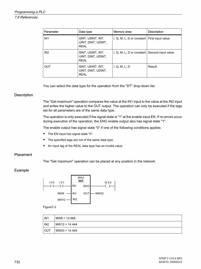
Parameter Data type Memory area Description
IN1 SINT, USINT, INT,UINT, DINT, UDINT,REAL
I, Q, M, L, D or constant First input value
IN2 SINT, USINT, INT,UINT, DINT, UDINT,REAL
I, Q, M, L, D or constant Second input value
OUT SINT, USINT, INT,UINT, DINT, UDINT,REAL
I, Q, M, L, D Result
You can select the data type for the operation from the "DT" drop-down list.
DescriptionThe "Get maximum" operation compares the value at the IN1 input to the value at the IN2 inputand writes the higher value to the OUT output. The operation can only be executed if the tagsset for all parameters are of the same data type.
The operation is only executed if the signal state is "1" at the enable input EN. If no errors occurduring execution of the operation, the ENO enable output also has signal state "1".
The enable output has signal state "0" if one of the following conditions applies:
• The EN input has signal state "0".
• The specified tags are not of the same data type.
• An input tag of the REAL data type has an invalid value.
PlacementThe "Get maximum" operation can be placed at any position in the network.
Example
Figure7-2
IN1 MW8 = 12 666
IN2 MW12 = 14 444
OUT MW20 = 14 444
Programming a PLC7.8 References
732STEP 7 V10.5 SP202/2010, 00002013

If the inputs I 0.0 AND I 0.1 have signal state "1", the "Get maximum" operation is executed.The operation compares the value at the MW8 input to the value at the MW12 input and selectsthe higher value (MW12). This value is copied to the MW20 output. If no errors occur duringexecution of the operation, output Q 4.0 is set.
See alsoInserting LAD elements (Page 452)Changing LAD elements (Page 460)Selecting the data type of a LAD element (Page 0 )Inserting operands into LAD instructions (Page 0 )
7.8.1.1 LIMIT: Set limit value
Symbol
Parameter Data type Memory area Description
EN BOOL I, Q, M, L, D (Page318)
Enable input
ENO BOOL I, Q, M, L, D Enable output
MIN SINT, USINT, INT,UINT, DINT, UDINT,REAL
I, Q, M, L, D or constant Low limit
IN SINT, USINT, INT,UINT, DINT, UDINT,REAL
I, Q, M, L, D or constant Input value
MAX SINT, USINT, INT,UINT, DINT, UDINT,REAL
I, Q, M, L, D or constant High limit
OUT SINT, USINT, INT,UINT, DINT, UDINT,REAL
I, Q, M, L, D Result
You can select the data type for the operation from the "DT" drop-down list.
7.8.1.1 LIMIT: Set limit value
Programming a PLC7.8 References
STEP 7 V10.5 SP202/2010, 00002013
733

DescriptionYou can use the "Set limit value" operation to limit the value at input IN to the values at theinputs MIN and MAX. If the value at input IN satisfies the condition MIN < IN < MAX, it is copiedto output OUT. If the condition is not fulfilled and the input value is below the low limit, the outputis set to the value of the MIN input. If the high limit is exceeded, output OUT is set to the valueof the MAX input.
The operation is only executed if the signal state is "1" at the enable input EN. If no errors occurduring execution of the operation, the ENO enable output also has signal state "1".
The enable output ENO returns signal state "0" if one of the following conditions applies:
• The EN input has signal state "0".
• The specified tags are not of the same data type.
• An input tag has an invalid value.
• The value at the MIN input is greater than the value at the MAX input.
PlacementThe "Set limit value" operation can be placed at any position in the network.
Example
Figure7-2
MIN MW8 = 12 000
IN MW12 = 8 000
MAX MW16 = 16 000
OUT MW20 = 12 000
If the inputs I 0.0 AND I 0.1 have signal state "1", the "Set limit value" operation is executed.The value at the MW12 input is compared to the values at the inputs MW8 and MW16. Sincethe value at the MW12 input is less than the low limit, the MW8 input is copied to the MW20output. If no errors occur during execution of the operation, output Q 4.0 is set.
See alsoInserting LAD elements (Page 452)Changing LAD elements (Page 460)
Programming a PLC7.8 References
734STEP 7 V10.5 SP202/2010, 00002013

Selecting the data type of a LAD element (Page 0 )Inserting operands into LAD instructions (Page 0 )
7.8.1.1 SQR: Form square
Symbol
Parameter Data type Memory area Description
EN BOOL I, Q, M, L, D (Page318)
Enable input
ENO BOOL I, Q, M, L, D Enable output
IN REAL I, Q, M, L, D or constant
Input value
OUT REAL I, Q, M, L, D Square of the inputvalue
DescriptionYou can use the "Form square" operation to square the value at the IN input and query theresult at the OUT output.
The operation is only executed if the signal state is "1" at the enable input EN. If no errors occurduring execution of the operation, the ENO output also has signal state "1".
The enable output ENO returns signal state "0" if one of the following conditions applies:
• The EN input has signal state "0".
• The value at input IN is not a valid floating-point number.
PlacementThe "Form square" operation can be placed at any position in the network.
7.8.1.1 SQR: Form square
Programming a PLC7.8 References
STEP 7 V10.5 SP202/2010, 00002013
735

Example
Figure7-2
IN MD8 = 5
OUT MD12 = 25
If input I 0.0 has signal state "1", the "Form square" operation is performed. The operationcalculates the square of the value at the MD8 input and sends the result to the MD12 output.If no errors occur during execution of the operation, output Q 4.0 is set.
See alsoInserting LAD elements (Page 452)Changing LAD elements (Page 460)Inserting operands into LAD instructions (Page 0 )Selecting the data type of a LAD element (Page 0 )
7.8.1.1 SQRT: Form square root
Symbol
Parameter Data type Memory area Description
EN BOOL I, Q, M, L, D (Page318)
Enable input
ENO BOOL I, Q, M, L, D Enable output
IN REAL I, Q, M, L, D or constant
Input value
OUT REAL I, Q, M, L, D Square root of the inputvalue
7.8.1.1 SQRT: Form square root
Programming a PLC7.8 References
736STEP 7 V10.5 SP202/2010, 00002013

DescriptionYou can use the "Form square root" operation to find the square root of the value at the IN inputand query the result at the OUT output. The operation has a positive result if the input value isgreater than zero. If input values are less than zero, the OUT output returns an invalid floating-point number. If the value at input IN is "-0", the result is also "-0".
The operation is only executed if the signal state is "1" at the enable input. If no errors occurduring execution of the operation, the ENO output also has signal state "1".
The enable output ENO returns signal state "0" if one of the following conditions applies:
• The EN input has signal state "0".
• The value at input IN is not a valid floating-point number.
• The value at IN input is negative.
PlacementThe "Form square root" operation can be placed at any position in the network.
Example
Figure7-2
IN MD8 = 25
OUT MD12 = 5
If the input I 0.0 has signal state "1", the "Form square root" operation is executed. The operationcalculates the square root of the value at the MD8 input and sends the result to the MD12output. If no errors occur during execution of the operation, output Q 4.0 is set.
See alsoInserting LAD elements (Page 452)Changing LAD elements (Page 460)Inserting operands into LAD instructions (Page 0 )Selecting the data type of a LAD element (Page 0 )
Programming a PLC7.8 References
STEP 7 V10.5 SP202/2010, 00002013
737

7.8.1.1 LN: Form natural logarithm
Symbol
Parameter Data type Memory area Description
EN BOOL I, Q, M, L, D (Page318)
Enable input
ENO BOOL I, Q, M, L, D Enable output
IN REAL I, Q, M, L, D or constant
Input value:
OUT REAL I, Q, M, L, D Result of the operation
DescriptionYou can use the "Form natural logarithm" operation to calculate the natural logarithm of thevalue at input IN to base e (e=2.718282e+00). The result is provided at the OUT output andcan be queried there. The operation has a positive result if the input value is greater than zero.If input values are less than zero, the OUT output returns an invalid floating-point number.
The operation is only executed if the signal state is "1" at the enable input EN. If no errors occurduring execution of the operation, the ENO output also has signal state "1".
The enable output ENO returns signal state "0" if one of the following conditions applies:
• The EN input has signal state "0".
• The value at input IN is not a valid floating-point number.
• The value at IN input is negative.
PlacementThe "Form natural logarithm" operation can be placed at any position in the network.
Example
Figure7-2
7.8.1.1 LN: Form natural logarithm
Programming a PLC7.8 References
738STEP 7 V10.5 SP202/2010, 00002013

If input I 0.0 has signal state "1", the "Form natural logarithm" operation is executed. Theoperation forms the natural logarithm of the value at the MD0 input and sends the result to theMD10 output. If no errors occur during execution of the operation, output Q 4.0 is set.
See alsoInserting LAD elements (Page 452)Changing LAD elements (Page 460)Inserting operands into LAD instructions (Page 0 )Selecting the data type of a LAD element (Page 0 )
7.8.1.1 EXP: Form exponential value
Symbol
Parameter Data type Memory area Description
EN BOOL I, Q, M, L, D (Page318)
Enable input
ENO BOOL I, Q, M, L, D Enable output
IN REAL I, Q, M, L, D or constant
Input value
OUT REAL I, Q, M, L, D Output value
DescriptionYou can use the "Form exponential value" operation to calculate the exponent from the basee (e = 2.718282e+00) and the value set at input IN. The result is provided at the OUT outputand can be queried there (OUT = eIN).
The operation is only executed if the signal state is "1" at the enable input EN. If no errors occurduring execution of the operation, the ENO output also has signal state "1".
The enable output ENO returns signal state "0" if one of the following conditions applies:
• The EN input has signal state "0".
• The value at input IN is not a valid floating-point number.
PlacementThe "Form exponential value" operation can be placed at any position in the network.
7.8.1.1 EXP: Form exponential value
Programming a PLC7.8 References
STEP 7 V10.5 SP202/2010, 00002013
739

Example
Figure7-2
If input I 0.0 has signal state "1", the "Form exponential value" operation is performed. Theoperation forms the power to base e with the value at input MD0 and sends the result to outputMD10. If no errors occur during execution of the operation, output Q 4.0 is set.
See alsoInserting LAD elements (Page 452)Changing LAD elements (Page 460)Inserting operands into LAD instructions (Page 0 )Selecting the data type of a LAD element (Page 0 )
7.8.1.1 SIN: Form sine value
Symbol
Figure7-2
Parameter Data type Memory area Description
EN BOOL I, Q, M, L, D (Page318)
Enable input
ENO BOOL I, Q, M, L, D Enable output
IN REAL I, Q, M, L, D or constant
Size of angle in theradian measure
OUT REAL I, Q, M, L, D Sine of the specifiedangle
DescriptionYou can use the "Form sine value" operation to form the sine of the angle specified in the radianmeasure at the IN input. The result of the operation is provided at the OUT output and can bequeried there.
7.8.1.1 SIN: Form sine value
Programming a PLC7.8 References
740STEP 7 V10.5 SP202/2010, 00002013

The operation is only executed if the signal state is "1" at the enable input EN. If no errors occurduring execution of the operation, the ENO output also has signal state "1".
The enable output ENO returns signal state "0" if one of the following conditions applies:
• The EN input has signal state "0".
• The value at input IN is not a valid floating-point number.
PlacementThe "Form sine value" operation can be placed at any position in the network.
Example
Figure7-2
IN MD0 = +1.570796e+00 (π/2)
OUT MD10 = 1
If input I 0.0 has signal state "1", the "Form sine value" operation is performed. The operationcalculates the sine of the angle specified at the MD0 input and sends the result to the MD10output. If no errors occur during execution of the operation, output Q 4.0 is set.
See alsoInserting LAD elements (Page 452)Changing LAD elements (Page 460)Inserting operands into LAD instructions (Page 0 )Selecting the data type of a LAD element (Page 0 )
7.8.1.1 COS: Form cosine value
Symbol
Figure7-2
7.8.1.1 COS: Form cosine value
Programming a PLC7.8 References
STEP 7 V10.5 SP202/2010, 00002013
741

Parameter Data type Memory area Description
EN BOOL I, Q, M, L, D (Page318)
Enable input
ENO BOOL I, Q, M, L, D Enable output
IN REAL I, Q, M, L, D or constant
Size of angle in theradian measure
OUT REAL I, Q, M, L, D Cosine of the specifiedangle
DescriptionYou can use the "Form cosine value" operation to calculate the cosine of an angle. The sizeof the angle is specified in the radian measure at input IN. The result of the operation is providedat the OUT output and can be queried there.
The operation is only executed if the signal state is "1" at the enable input EN. If no errors occurduring execution of the operation, the ENO output also has signal state "1".
The enable output ENO returns signal state "0" if one of the following conditions applies:
• The EN input has signal state "0".
• The value at input IN is not a valid floating-point number.
PlacementThe "Form cosine value" operation can be placed at any position in the network.
Example
Figure7-2
IN MD0 = +1.570796e+00 (π/2)
OUT MD10 = 0
If input I 0.0 has signal state "1", the "Form cosine value" operation is performed. The operationcalculates the cosine of the angle specified at the MD0 input and sends the result to the MD10output. If no errors occur during execution of the operation, output Q 4.0 is set.
See alsoInserting LAD elements (Page 452)Changing LAD elements (Page 460)
Programming a PLC7.8 References
742STEP 7 V10.5 SP202/2010, 00002013

Inserting operands into LAD instructions (Page 0 )Selecting the data type of a LAD element (Page 0 )
7.8.1.1 TAN: Form tangent value
Symbol
Figure7-2
Parameter Data type Memory area Description
EN BOOL I, Q, M, L, D (Page318)
Enable input
ENO BOOL I, Q, M, L, D Enable output
IN REAL I, Q, M, L, D or constant
Size of angle in theradian measure
OUT REAL I, Q, M, L, D Tangent of the specifiedangle
DescriptionYou can use the "Form tangent value" operation to calculate the tangent of an angle. The sizeof the angle is specified in the radian measure at input IN. The result of the operation is providedat the OUT output and can be queried there.
The operation is only executed if the signal state is "1" at the enable input EN. If no errors occurduring execution of the operation, the ENO output also has signal state "1".
The enable output ENO returns signal state "0" if one of the following conditions applies:
• The EN input has signal state "0".
• The value at input IN is not a valid floating-point number.
PlacementThe "Form tangent value" operation can be placed at any position in the network.
7.8.1.1 TAN: Form tangent value
Programming a PLC7.8 References
STEP 7 V10.5 SP202/2010, 00002013
743

Example
Figure7-2
IN MD0 = +3.141593e++00 (π)
OUT MD10 = 0
If input I 0.0 has signal state "1", the "Form tangent value" operation is performed. The operationcalculates the tangent of the angle specified at the MD0 input and sends the result to the MD10output. If no errors occur during execution of the operation, output Q 4.0 is set.
See alsoInserting LAD elements (Page 452)Changing LAD elements (Page 460)Inserting operands into LAD instructions (Page 0 )Selecting the data type of a LAD element (Page 0 )
7.8.1.1 ASIN: Form arcsine value
Symbol
Figure7-2
Parameter Data type Memory area Description
EN BOOL I, Q, M, L, D (Page318)
Enable input
ENO BOOL I, Q, M, L, D Enable output
IN REAL I, Q, M, L, D or constant
Sine value
OUT REAL I, Q, M, L, D Size of angle in theradian measure
7.8.1.1 ASIN: Form arcsine value
Programming a PLC7.8 References
744STEP 7 V10.5 SP202/2010, 00002013

DescriptionYou can use the "Form arcsine value" operation to calculate the size of the angle from the sinevalue specified at the IN input, which corresponds to this value. Only valid floating-pointnumbers within the range -1 to +1 can be specified at the IN input. The calculated angle sizeis given in the radian measure at the OUT output and can range in value from -π/2 to +π/2.
The operation is only executed if the signal state is "1" at the enable input EN. If no errors occurduring execution of the operation, the ENO output also has signal state "1".
The enable output ENO returns signal state "0" if one of the following conditions applies:
• The EN input has signal state "0".
• The value at input IN is not a valid floating-point number.
• The value at input IN is outside the permitted range (-1 to +1).
PlacementThe "Form arcsine value" operation can be placed at any position in the network.
Example
Figure7-2
IN MD0 = 1
OUT MD10 = +1.570796e+00 (π/2)
If input I 0.0 has signal state "1", the "Form arcsine value" operation is performed. The operationcalculates the size of the angle corresponding to the sine value at input MD0. The result of theoperation is stored at output MD10. If no errors occur during execution of the operation, outputQ 4.0 is set.
See alsoInserting LAD elements (Page 452)Changing LAD elements (Page 460)Inserting operands into LAD instructions (Page 0 )Selecting the data type of a LAD element (Page 0 )
Programming a PLC7.8 References
STEP 7 V10.5 SP202/2010, 00002013
745

7.8.1.1 ACOS: Form arccosine value
Symbol
Figure7-2
Parameter Data type Memory area Description
EN BOOL I, Q, M, L, D (Page318)
Enable input
ENO BOOL I, Q, M, L, D Enable output
IN REAL I, Q, M, L, D or constant
Cosine value
OUT REAL I, Q, M, L, D Size of angle in theradian measure
DescriptionYou can use the "Form arccosine value" operation to calculate the size of the angle from thecosine value specified at the IN input, which corresponds to this value. Only valid floating-pointnumbers within the range -1 to +1 can be specified at the IN input. The calculated angle sizeis given in the radian measure at the OUT output and can range in value from 0 to +π.
The operation is only executed if the signal state is "1" at the enable input EN. If no errors occurduring execution of the operation, the ENO output also has signal state "1".
The enable output ENO returns signal state "0" if one of the following conditions applies:
• The EN input has signal state "0".
• The value at input IN is not a valid floating-point number.
• The value at input IN is outside the permitted range (-1 to +1).
PlacementThe "Form arccosine value" operation can be placed at any position in the network.
Example
Figure7-2
7.8.1.1 ACOS: Form arccosine value
Programming a PLC7.8 References
746STEP 7 V10.5 SP202/2010, 00002013

IN MD0 = 0
OUT MD10 = +1.570796e+00 (π/2)
If input I 0.0 has the signal state "1", the "Form arccosine value" operation is performed. Theoperation calculates the size of the angle corresponding to the cosine value at input MD0. Theresult of the operation is stored at output MD10. If no errors occur during execution of theoperation, output Q 4.0 is set.
See alsoInserting LAD elements (Page 452)Changing LAD elements (Page 460)Inserting operands into LAD instructions (Page 0 )Selecting the data type of a LAD element (Page 0 )
7.8.1.1 ATAN: Form arctangent value
Symbol
Figure7-2
Parameter Data type Memory area Description
EN BOOL I, Q, M, L, D (Page318)
Enable input
ENO BOOL I, Q, M, L, D Enable output
IN REAL I, Q, M, L, D or constant
Tangent value
OUT REAL I, Q, M, L, D Size of angle in theradian measure
DescriptionYou can use the "Form arctangent value" operation to calculate the size of the angle from thetangent value specified at the IN input, which corresponds to this value. Only valid floating-point numbers may be specified at the IN input. The calculated angle size is given in the radianmeasure at the OUT output and can range in value from -π/2 to +π/2.
The operation is only executed if the signal state is "1" at the enable input EN. If no errors occurduring execution of the operation, the ENO output also has signal state "1".
7.8.1.1 ATAN: Form arctangent value
Programming a PLC7.8 References
STEP 7 V10.5 SP202/2010, 00002013
747

The enable output ENO returns signal state "0" if one of the following conditions applies:
• The EN input has signal state "0".
• The value at input IN is not a valid floating-point number.
PlacementThe "Form arctangent value" operation can be placed at any position in the network.
Example
Figure7-2
IN MD0 = 1
OUT MD10 =+0.785398e++00 (π/4)
If input I 0.0 has signal state "1", the "Form arctangent value" operation is performed. Theoperation calculates the size of the angle corresponding to the tangent value at input MD0. Theresult of the operation is stored at output MD10. If no errors occur during execution of theoperation, output Q 4.0 is set.
See alsoInserting LAD elements (Page 452)Changing LAD elements (Page 460)Inserting operands into LAD instructions (Page 0 )Selecting the data type of a LAD element (Page 0 )
7.8.1.1 FRAC: Return fraction
Symbol
7.8.1.1 FRAC: Return fraction
Programming a PLC7.8 References
748STEP 7 V10.5 SP202/2010, 00002013

Parameter Data type Memory area Description
EN BOOL I, Q, M, L, D (Page318)
Enable input
ENO BOOL I, Q, M, L, D Enable output
IN REAL I, Q, M, L, D or constant Value, whose decimalplaces are to bedetermined.
OUT REAL I, Q, M, L, D Decimal places of thevalue at the IN input
DescriptionYou can use the "Return fraction" operation to find the decimal places of the value at the INinput. The result of the query is stored at the OUT output and can be queried there. If the valueat input IN is, for example, 123.4567, output OUT returns the value 0.4567. The operation isstarted when there is a "1" at the EN input. In this case, the enable output ENO also has signalstate "1".
The enable output ENO returns signal state "0" if one of the following conditions applies:
• The EN input has signal state "0".
• Errors occur during processing of the operation, for example there is no valid floating-point numberat the input.
PlacementThe "Return fraction" operation can be placed at any position in the network.
Example
Figure7-2
If the inputs I 0.0 AND I 0.1 have signal state "1", the "Return fraction" operation is started. Thedecimal places from the value at the MD8 input are copied to the MD20 output. If no errorsoccur during execution of the operation, the ENO output has signal state "1" and output Q 4.0is set.
See alsoInserting LAD elements (Page 452)Changing LAD elements (Page 460)Selecting the data type of a LAD element (Page 0 )Inserting operands into LAD instructions (Page 0 )
Programming a PLC7.8 References
STEP 7 V10.5 SP202/2010, 00002013
749

7.8.1.1 EXPT: Exponentiate
Symbol
Parameter Data type Memory area Description
EN BOOL I, Q, M, L, D (Page318)
Enable input
ENO BOOL I, Q, M, L, D Enable output
IN1 REAL I, Q, M, L, D or constant Base value
IN2 REAL, INT, UINT,USINT, SINT, DINT,UDINT
I, Q, M, L, D or constant Value with which thebase value isexponentiated
OUT REAL I, Q, M, L, D Result
You can select the data type for the operation from the "DT" drop-down list.
DescriptionYou can use the "Exponentiate" operation to raise the value at the IN1 input by a powerspecified with the value at the IN2 input. The result of the operation is provided at the OUToutput and can be queried there (OUT = IN1IN2).
The IN1 input can only be assigned valid floating-point numbers. Integers are also allowed forsetting the IN2 input.
The "Exponentiate" operation can only be executed when the signal state at the EN enableinput is "1". In this case, the ENO enable output has signal state "1".
The enable output ENO returns signal state "0" if one of the following conditions applies:
• The EN input has signal state "0".
• Errors occur during processing of the operation, for example there is an overflow.
PlacementThe "Exponentiate" operation can be placed at any position in the network.
7.8.1.1 EXPT: Exponentiate
Programming a PLC7.8 References
750STEP 7 V10.5 SP202/2010, 00002013

Example
Figure7-2
If the inputs I 0.0 AND I 0.1 have signal state "1", the "Exponentiate" operation is executed.The value at the MD8 input is raised to the power specified by the value at the MD12 input.The result is stored at the MD20 output. If no errors occur during execution of the operation,the ENO output has signal state "1" and output Q 4.0 is set.
See alsoInserting LAD elements (Page 452)Changing LAD elements (Page 460)Selecting the data type of a LAD element (Page 0 )Inserting operands into LAD instructions (Page 0 )
7.8.1.1 Move
7.8.1.1 MOVE: Move value
Symbol
Figure7-2
Parameter Data type Memory area Description
EN BOOL I, Q, M, D, L (Page318)
Enable input
ENO BOOL I, Q, M, D, L Enable output
IN All elementary datatypes, DTL, STRUCT,ARRAY
I, Q, M, D, L or constant
Source value
OUT1 All elementary datatypes, DTL, STRUCT,ARRAY
I, Q, M, D, L Destination address
7.8.1.1 Move7.8.1.1 MOVE: Move value
Programming a PLC7.8 References
STEP 7 V10.5 SP202/2010, 00002013
751

DescriptionYou can use the "Move value" operation to transfer the content of the operand at the IN inputto the operand at the OUT1 output. The transfer is always made in the direction of the ascendingaddress.
If IEC test is enabled the tags at IN input and OUT1 output must be of the same data type. Ifthe IEC test is not enabled, the operand width at the IN input and the OUT1 output of theoperation must be the same.
Copying entire arrays is possible only when the array components of the tags at input IN andat output OUT1 are of the same data type.
For the "Move value" operation, you can insert additional outputs. In this case, the content ofthe operand at the IN input is transferred to all available outputs.
The operation is only executed if the signal state is "1" at the enable input EN. In this case, theENO output also has signal state "1".
If the signal state at the EN input is "0", the enable output ENO is reset to "0".
The "Move block" (MOVE_BLK) and "Move block uninterruptible" (UMOVE_BLK) operationscan also be used to copy tags of the ARRAY data type. You can copy tags of the STRING datatype with the operation S_CONV.
PlacementThe "Move value" operation can be placed at any position in the network.
Example
Figure7-2
IN MW10 = 0011 1111 1010 1111
OUT1 MW20 = 0011 1111 1010 1111
If input I 0.0 has signal state "1", the "Move value" operation is executed. The operation copiesthe contents of the input operand (MW10) to the output operand (MW20) and sets the outputQ 4.0 to the signal state "1".
See alsoInserting LAD elements (Page 452)Changing LAD elements (Page 460)Inserting additional inputs and outputs (Page 462)Inserting operands into LAD instructions (Page 0 )
Programming a PLC7.8 References
752STEP 7 V10.5 SP202/2010, 00002013

7.8.1.1 MOVE_BLK: Move block
Symbol
Parameter Data type Memory area Description
EN BOOL I, Q, M, D, L (Page318)
Enable input
ENO BOOL I, Q, M, D, L Enable output
IN ARRAY D, L The first element of thesource area to becopied.
COUNT UINT I, Q, M, D, L or constant Number of elements tobe copied from thesource area to thedestination area.
OUT ARRAY D, L The first element of thedestination area towhich the content of thesource area is copied.
DescriptionYou can use the "Move block" operation to copy the content of a memory area (source area)to another memory area (destination area). The number of elements to be copied to thedestination area is specified with the COUNT parameter. The width of the elements to be copiedis defined by the width of the element at input IN. The copy operation takes place in the directionof ascending addresses.
The operation is only executed if the signal state is "1" at the enable input EN. If no errors occurduring execution of the operation, the ENO output also has signal state "1".
The enable output ENO returns signal state "0" if one of the following conditions applies:
• The EN input has signal state "0".
• More data is copied than is available in the memory area at output OUT.
PlacementThe "Move block" operation can be placed at any position in the network.
7.8.1.1 MOVE_BLK: Move block
Programming a PLC7.8 References
STEP 7 V10.5 SP202/2010, 00002013
753

Example
Figure7-2
IN The tag "a_array" is an ARRAY data type andconsists of 5 elements of the INT data type.
COUNT IW2 = 3
OUT The tag "b_array" is an ARRAY data type andconsists of 6 elements of the INT data type.
If the inputs I 0.0 AND I 0.1 have signal state "1", the "Move block" operation is executed. Theoperation selects three INT elements from the "a_array" tag (a_array[2..4]) and copies thecontent to the output tag "b_array" (b_array[1..3]). If no errors occur during execution of theoperation, the ENO output has signal state "1" and output Q 4.0 is set.
See alsoInserting LAD elements (Page 452)Changing LAD elements (Page 460)Inserting additional inputs and outputs (Page 462)Inserting operands into LAD instructions (Page 0 )
7.8.1.1 UMOVE_BLK: Move block uninterruptible
Symbol
Figure7-2
Parameter Data type Memory area Description
EN BOOL I, Q, M, D, L (Page318)
Enable input
7.8.1.1 UMOVE_BLK: Move block uninterruptible
Programming a PLC7.8 References
754STEP 7 V10.5 SP202/2010, 00002013

Parameter Data type Memory area Description
ENO BOOL I, Q, M, D, L Enable output
IN ARRAY D, L The first element of thesource area to becopied.
COUNT UINT I, Q, M, D, L or constant Number of elements tobe copied from thesource area to thedestination area.
OUT ARRAY D, L The first element of thedestination area towhich the content of thesource area is copied.
DescriptionYou can use the "Move block uninterruptible" operation to copy the content of a memory area(source area) to another memory area (destination area) without interruption. The number ofelements to be copied to the destination area is specified with the COUNT parameter. Thewidth of the elements to be copied is defined by the width of the element at input IN.
The content of the source area is copied to the destination area in the direction of the ascendingaddress. The copy operation cannot be interrupted by other operating system activities. Thisis why the alarm reaction times of the CPU increase during the execution of the "Move blockuninterruptible" operation.
The operation is only executed if the signal state is "1" at the enable input EN. If no errors occurduring execution of the operation, the ENO output also has signal state "1".
The enable output ENO returns signal state "0" if one of the following conditions applies:
• The EN input has signal state "0".
• More data is copied than is made available at output OUT.
PlacementThe "Move block uninterruptible" operation can be placed at any position in the network.
Example
Figure7-2
Programming a PLC7.8 References
STEP 7 V10.5 SP202/2010, 00002013
755

IN The tag "a_array" is an ARRAY data type andconsists of 5 elements of the INT data type.
COUNT IW20 = 3
OUT The tag "b_array" is an ARRAY data type andconsists of 6 elements of the INT data type.
If the inputs I 0.0 AND I 0.1 have signal state "1", the "Move block" operation is executed. Theoperation selects three INT elements from the "a_array" tag (a_array[2..4]) and copies thecontent to the output tag "b_array" (b_array[1..3]). The copy operation cannot be interruptedby other operating system activities. If no errors occur during execution of the operation, theENO output has signal state "1" and output Q 4.0 is set.
See alsoInserting LAD elements (Page 452)Changing LAD elements (Page 460)Inserting operands into LAD instructions (Page 0 )Inserting additional inputs and outputs (Page 462)
7.8.1.1 FILL_BLK: Fill block
Symbol
Parameter Data type Memory area Description
EN BOOL I, Q, M, D, L (Page318)
Enable input
ENO BOOL I, Q, M, D, L Enable output
IN ARRAY D, L or constant Element used to fill thedestination area.
COUNT UINT I, Q, M, D, L or constant Number of repeatedcopy operations
OUT ARRAY D, L Address in destinationarea where fillingbegins.
7.8.1.1 FILL_BLK: Fill block
Programming a PLC7.8 References
756STEP 7 V10.5 SP202/2010, 00002013

DescriptionYou can use the "Fill block" operation to fill a memory area (destination area) with the value ofthe IN input. The destination area is filled beginning with the address specified at the OUToutput. The number of repeated copy operations is specified with the COUNT parameter. Whenthe operation is executed, the value at input IN is selected and copied to the destination areaas often as specified by the value of the COUNT parameter.
The operation is only executed if the signal state is "1" at the enable input EN. If no errors occurduring execution of the operation, the ENO output also has signal state "1".
The enable output ENO returns signal state "0" if one of the following conditions applies:
• The EN input has signal state "0".
• More data is copied than is available in the memory area at output OUT.
PlacementThe "Fill block" operation can be placed at any position in the network.
Example
Figure7-2
IN The tag "a_array" is an ARRAY data type and consists of 4 elements of the WORDdata type (ARRAY[1..4] of WORD).
COUNT IW20=3
OUT The tag "b_array" is an ARRAY data type and consists of 5 elements of the WORDdata type (ARRAY[1..5] of WORD).
If the inputs I 0.0 AND I 0.1 have signal state "1", the "Fill block" operation is executed. Theoperation copies the second element (a_array[2]) of the "a_array" tag three times to the outputtag "b_array" (b_array[1..3]). If no errors occur during execution of the operation, outputs ENOand Q 4.0 are set to signal state "1".
See alsoInserting LAD elements (Page 452)Changing LAD elements (Page 460)Inserting operands into LAD instructions (Page 0 )Inserting additional inputs and outputs (Page 462)
Programming a PLC7.8 References
STEP 7 V10.5 SP202/2010, 00002013
757

7.8.1.1 UFILL_BLK: Fill block uninterruptible
Symbol
Figure7-2
Parameter Data type Memory area Description
EN BOOL I, Q, M, D, L (Page318)
Enable input
ENO BOOL I, Q, M, D, L Enable output
IN ARRAY D, L or constant Element used to fill thedestination area.
COUNT UINT I, Q, M, D, L or constant Number of repeatedcopy operations
OUT ARRAY D, L Address in destinationarea where fillingbegins.
DescriptionYou can use the "Fill block uninterruptible" operation to fill a memory area (destination area)with the value of the IN input without interruption. The destination area is filled beginning withthe address specified at the OUT output. The number of repeated copy operations is specifiedwith the COUNT parameter. When the operation is executed, the value at input IN is selectedand copied to the destination area as often as specified by the value of the COUNT parameter.
The copy operation cannot be interrupted by other operating system activities. This is why thealarm reaction times of the CPU increase during the execution of the "Fill block uninterruptible"operation.
The operation is only executed if the signal state is "1" at the enable input EN. If no errors occurduring execution of the operation, the ENO output also has signal state "1".
The enable output ENO returns signal state "0" if one of the following conditions applies:
• The EN input has signal state "0".
• More data is copied than is available in the memory area at output OUT.
PlacementThe "Fill block uninterruptible" operation can be placed at any position in the network.
7.8.1.1 UFILL_BLK: Fill block uninterruptible
Programming a PLC7.8 References
758STEP 7 V10.5 SP202/2010, 00002013

Example
Figure7-2
IN The tag "a_array" is an ARRAY data type and consists of 4 elements of the WORDdata type (ARRAY[1..4] of WORD).
COUNT IW20=3
OUT The tag "b_array" is an ARRAY data type and consists of 5 elements of the WORDdata type (ARRAY[1..5] of WORD).
If the inputs I 0.0 AND I 0.1 have signal state "1", the "Fill block" operation is executed. Theoperation copies the second element (a_array[2]) of the "a_array" tag three times to the outputtag "b_array" (b_array[1..3]). The copy operation cannot be interrupted by other operatingsystem activities. If no errors occur during execution of the operation, outputs ENO and Q 4.0are set to signal state "1".
See alsoInserting LAD elements (Page 452)Changing LAD elements (Page 460)Inserting operands into LAD instructions (Page 0 )Inserting additional inputs and outputs (Page 462)
7.8.1.1 SWAP: Swap
Symbol
Parameter Data type Memory area Description
EN BOOL I, Q, M, L, D (Page318)
Enable input
ENO BOOL I, Q, M, L, D Enable output
7.8.1.1 SWAP: Swap
Programming a PLC7.8 References
STEP 7 V10.5 SP202/2010, 00002013
759

Parameter Data type Memory area Description
IN WORD, DWORD I, Q, M, L, D or constant Operand whose bytesare swapped.
OUT WORD, DWORD I, Q, M, L, D Result
You can select the data type for the operation from the "DT" drop-down list.
DescriptionYou can use the "Swap" operation to change the order of the bytes within the tag at the IN inputand query the result at the OUT output.
The following figure shows how the bytes of a DWORD data type tag are swapped using the"Swap" operation:
Figure7-2
The "Swap" operation is only executed if the signal state at the EN enable input is "1". In thiscase, the ENO enable output has signal state "1".
The ENO enable output is reset when the EN enable input has signal state "0" or errors occurduring execution of the operation.
PlacementThe "Swap" operation can be placed at any position in the network.
Example
Figure7-2
Programming a PLC7.8 References
760STEP 7 V10.5 SP202/2010, 00002013

IN IW10 = 0000 1111 0101 0101
OUT QW20 = 0101 0101 0000 1111
If the input I 0.1 has signal state "1", the "Swap" operation is executed. The arrangement of thebytes is changed and stored in the QW20 tag. If no errors occur during execution of theoperation, the ENO output has signal state "1" and output Q 4.0 is set.
See alsoInserting LAD elements (Page 452)Changing LAD elements (Page 460)Inserting operands into LAD instructions (Page 0 )Selecting the data type of a LAD element (Page 0 )Inserting additional inputs and outputs (Page 462)
7.8.1.1 Convert
7.8.1.1 CONVERT: Convert value
Symbol
Parameter Data type Memory area Description
EN BOOL I, Q, M, D, L (Page318)
Enable input
ENO BOOL I, Q, M, D, L Enable output
IN BYTE, WORD,DWORD, SINT, INT,DINT, USINT, UINT,UDINT, BCD16,BCD32, REAL
I, Q, M, D, L or constant Value to be converted.
OUT BYTE, WORD,DWORD, SINT, INT,DINT, USINT, UINT,UDINT, BCD16,BCD32, REAL
I, Q, M, D, L Result of the conversion
7.8.1.1 Convert7.8.1.1 CONVERT: Convert value
Programming a PLC7.8 References
STEP 7 V10.5 SP202/2010, 00002013
761

You can select the data type for the operation from the "DT" drop-down list.
DescriptionThe "Convert" operation reads the content of the IN parameter and converts it according to thespecified data types.
The "Convert" operation can only be started when the signal state at the EN enable input is"1". If no error occurs during execution, the ENO output also has signal state "1".
The enable output ENO returns signal state "0" if one of the following conditions applies:
• The EN input has signal state "0".
• Errors such as an overflow occur during processing.
PlacementThe "Convert" operation can be placed at any position in the network.
Example
Figure7-2
If input I 0.0 = 1, the content of MW10 is read as a three-digit BCD-coded number and convertedto an integer (16 bits). The result is stored in MW12. Output Q 4.0 is "1" if the conversion is notexecuted (ENO = EN = 0).
See alsoInserting LAD elements (Page 452)Changing LAD elements (Page 460)Inserting operands into LAD instructions (Page 0 )Selecting the data type of a LAD element (Page 0 )
7.8.1.1 ROUND: Round to double integer
Symbol
Figure7-2
7.8.1.1 ROUND: Round to double integer
Programming a PLC7.8 References
762STEP 7 V10.5 SP202/2010, 00002013

Parameter Data type Memory area Description
EN BOOL I, Q, M, L, D (Page318)
Enable input
ENO BOOL I, Q, M, L, D Enable output
IN REAL I, Q, M, L, D or constant Input value to berounded.
OUT INT, USINT, UINT,SINT, UDINT, DINT,REAL
I, Q, M, L, D Output value
You can select the data type for the operation from the "DT" drop-down list.
DescriptionYou can use the "Round numerical value" operation to round the value at the IN input to thenearest integer. The operation interprets the value at input IN as a floating-point number andconverts this to the nearest double integer. If the input value is exactly between an even andodd number, the even number is selected. The result of the operation is provided at the OUToutput and can be queried there.
The operation is only executed if the signal state is "1" at the enable input EN. If no errors occurduring execution of the operation, the ENO output also has signal state "1".
The enable output ENO returns signal state "0" if one of the following conditions applies:
• The EN input has signal state "0".
• Errors such as an overflow occur during processing.
PlacementThe "Round numerical value" operation can be placed at any position in the network.
Example
Figure7-2
IN MD8 = 0.50000000
OUT MD12 = 0
Programming a PLC7.8 References
STEP 7 V10.5 SP202/2010, 00002013
763

If input I 0.0 has signal state "1", the "Round numerical value" operation is executed. Thefloating-point number at input MD8 is rounded to the nearest even double integer and sent tothe OUT output. If no errors occur during execution of the operation, output Q 4.0 is set.
See alsoChanging LAD elements (Page 460)Inserting LAD elements (Page 452)Selecting the data type of a LAD element (Page 0 )Inserting operands into LAD instructions (Page 0 )
7.8.1.1 CEIL: Generate next higher integer from floating-point number
Symbol
Figure7-2
Parameter Data type Memory area Description
EN BOOL I, Q, M, L, D (Page318)
Enable input
ENO BOOL I, Q, M, L, D Enable output
IN REAL I, Q, M, L, D or constant Input value
OUT INT, USINT, UINT,SINT, UDINT, DINT,REAL
I, Q, M, L, D Output value
You can select the data type for the operation from the "DT" drop-down list.
DescriptionYou can use the "Generate next higher integer from floating-point number" operation to roundthe value at the IN input to the next higher integer. The operation interprets the value at the INinput as a floating-point number and converts this to the next higher integer. The result of theoperation is provided at the OUT output and can be queried there. The output value can begreater than or equal to the input value.
The operation is only executed if the signal state is "1" at the enable input EN. If no errors occurduring execution of the operation, the ENO output also has signal state "1".
The enable output ENO returns signal state "0" if one of the following conditions applies:
• The EN input has signal state "0".
7.8.1.1 CEIL: Generate next higher integer from floating-point number
Programming a PLC7.8 References
764STEP 7 V10.5 SP202/2010, 00002013

• Errors such as an overflow occur during processing.
PlacementThe "Generate next higher integer from floating-point number" operation can be placed at anyposition in the network.
Example
Figure7-2
IN MD8 = 0.50000000
OUT MD12 = 1
If input I 0.0 has signal state "1", the "Generate next higher integer from floating-point number"operation is executed. The floating-point number at input MD8 is rounded to the next higherinteger and sent to the MD12 output. If no errors occur during execution of the operation, outputQ 4.0 is set.
See alsoChanging LAD elements (Page 460)Inserting LAD elements (Page 452)Selecting the data type of a LAD element (Page 0 )Inserting operands into LAD instructions (Page 0 )
7.8.1.1 FLOOR: Generate next lower integer from floating-point number
Symbol
Figure7-2
7.8.1.1 FLOOR: Generate next lower integer from floating-point number
Programming a PLC7.8 References
STEP 7 V10.5 SP202/2010, 00002013
765

Parameter Data type Memory area Description
EN BOOL I, Q, M, L, D (Page318)
Enable input
ENO BOOL I, Q, M, L, D Enable output
IN REAL I, Q, M, L, D or constant Input value
OUT INT, USINT, UINT,SINT, UDINT, DINT,REAL
I, Q, M, L, D Output value
You can select the data type for the operation from the "DT" drop-down list.
DescriptionYou can use the "Generate next lower integer from floating-point number" operation to roundthe value at the IN input to the next lower integer. The operation interprets the value at inputIN as a floating-point number and converts this to the next higher integer. The result of theoperation is provided at the OUT output and can be queried there. The output value can beless than or equal to the input value.
The operation is only executed if the signal state is "1" at the enable input EN. If no errors occurduring execution of the operation, the ENO output also has signal state "1".
The enable output ENO returns signal state "0" if one of the following conditions applies:
• The EN input has signal state "0".
• Errors such as an overflow occur during processing.
PlacementThe "Generate next lower integer from floating-point number" operation can be placed at anyposition in the network.
Example
Figure7-2
IN MD8 = 0.50000000
OUT MD12 = 0
If input I 0.0 has signal state "1", the "Generate next lower integer from floating-point number"operation is executed. The floating-point number at input MD8 is rounded to the next lower
Programming a PLC7.8 References
766STEP 7 V10.5 SP202/2010, 00002013

integer and sent to the MD12 output. If no errors occur during execution of the operation, outputQ 4.0 is set.
See alsoInserting LAD elements (Page 452)Changing LAD elements (Page 460)Inserting operands into LAD instructions (Page 0 )Selecting the data type of a LAD element (Page 0 )
7.8.1.1 TRUNC: Truncate to integer
Symbol
Figure7-2
Parameter Data type Memory area Description
EN BOOL I, Q, M, L, D (Page318)
Enable input
ENO BOOL I, Q, M, L, D Enable output
IN REAL I, Q, M, L, D or constant Input value
OUT INT, USINT, UINT,SINT, UDINT, DINT,REAL
I, Q, M, L, D Integer part of the inputvalue
You can select the data type for the operation from the "DT" drop-down list.
DescriptionYou can use the "Truncate numerical value" operation to form an integer without rounding thevalue at the IN input. The value at input IN is interpreted as a floating-point number. Theoperation selects only the integer part of the floating-point number and sends this to the OUToutput without decimal places.
The operation is only executed if the signal state is "1" at the enable input EN. If no errors occurduring execution of the operation, the ENO output also has signal state "1".
The enable output ENO returns signal state "0" if one of the following conditions applies:
• The EN input has signal state "0".
• Errors such as an overflow occur during processing.
7.8.1.1 TRUNC: Truncate to integer
Programming a PLC7.8 References
STEP 7 V10.5 SP202/2010, 00002013
767

PlacementThe "Truncate numerical value" operation can be placed at any position in the network.
Example
Figure7-2
IN MD8 = 0.50000000
OUT MD12 = 0
If the input I 0.0 has signal state "1", the "Truncate numerical value" operation is executed. Theinteger part of the floating-point number at input MD8 is converted to an integer and sent to theMD12 output. If no errors occur during execution of the operation, output Q 4.0 is set.
See alsoInserting LAD elements (Page 452)Changing LAD elements (Page 460)Inserting operands into LAD instructions (Page 0 )Selecting the data type of a LAD element (Page 0 )
7.8.1.1 SCALE_X: Scale
Symbol
Figure7-2
Parameter Data type Memory area Description
EN BOOL I, Q, M, D, L (Page318)
Enable input
7.8.1.1 SCALE_X: Scale
Programming a PLC7.8 References
768STEP 7 V10.5 SP202/2010, 00002013

Parameter Data type Memory area Description
ENO BOOL I, Q, M, D, L Enable output
VALUE REAL I, Q, M, D, L or constant Value to be scaled.
MIN SINT, INT, DINT,USINT, UINT, UDINT,REAL
I, Q, M, D, L or constant Low limit of the valuerange
MAX SINT, INT, DINT,USINT, UINT, UDINT,REAL
I, Q, M, D, L or constant High limit of the valuerange
OUT SINT, INT, DINT,USINT, UINT, UDINT,REAL
I, Q, M, D, L Result of scaling
You can select the data type for the operation from the "DT" drop-down list.
DescriptionYou can use the "Scale" operation to scale the value at the VALUE input by mapping it to aspecified value range. When the "Scale" operation is executed, the floating-point value at theVALUE input is scaled to the value range, which is defined by the MIN and MAX parameters.The result of the scaling is an integer, which is stored at the OUT output.
The following figure shows an example of how values can be scaled:
The "Scale" operation is only executed if the signal state is "1" at the enable input EN. In thiscase, the enable output ENO also has signal state "1".
The enable output ENO returns signal state "0" if one of the following conditions applies:
• The EN input has signal state "0".
Programming a PLC7.8 References
STEP 7 V10.5 SP202/2010, 00002013
769
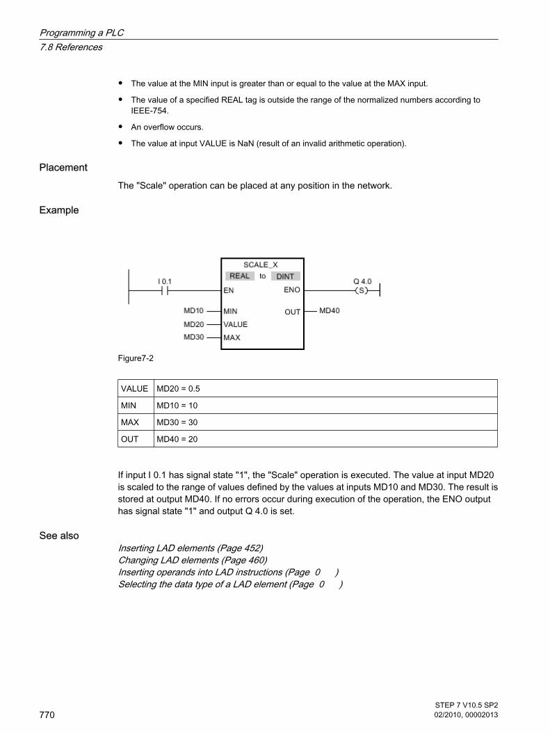
• The value at the MIN input is greater than or equal to the value at the MAX input.
• The value of a specified REAL tag is outside the range of the normalized numbers according toIEEE-754.
• An overflow occurs.
• The value at input VALUE is NaN (result of an invalid arithmetic operation).
PlacementThe "Scale" operation can be placed at any position in the network.
Example
Figure7-2
VALUE MD20 = 0.5
MIN MD10 = 10
MAX MD30 = 30
OUT MD40 = 20
If input I 0.1 has signal state "1", the "Scale" operation is executed. The value at input MD20is scaled to the range of values defined by the values at inputs MD10 and MD30. The result isstored at output MD40. If no errors occur during execution of the operation, the ENO outputhas signal state "1" and output Q 4.0 is set.
See alsoInserting LAD elements (Page 452)Changing LAD elements (Page 460)Inserting operands into LAD instructions (Page 0 )Selecting the data type of a LAD element (Page 0 )
Programming a PLC7.8 References
770STEP 7 V10.5 SP202/2010, 00002013

7.8.1.1 NORM_X: Standardize
Symbol
Figure7-2
Parameter Data type Memory area Description
EN BOOL I, Q, M, D, L (Page318)
Enable input
ENO BOOL I, Q, M, D, L Enable output
VALUE SINT, INT, DINT,USINT, UINT, UDINT,REAL
I, Q, M, D, L or constant Value to be normalized.
MIN SINT, INT, DINT,USINT, UINT, UDINT,REAL
I, Q, M, D, L or constant Low limit of the valuerange
MAX SINT, INT, DINT,USINT, UINT, UDINT,REAL
I, Q, M, D, L or constant High limit of the valuerange
OUT REAL I, Q, M, D, L Result of thenormalization
You can select the data type for the operation from the "DT" drop-down list.
DescriptionYou can use the "Normalize" operation to normalize the value of the tag at the VALUE inputby mapping it to a linear scale. You can use the MIN and MAX parameters to define the limitsof a value range that is applied to the scale. The result at the OUT output is calculated andstored as a floating-point number depending on the location of the normalized value in thisvalue range. If the value to be normalized is equal to the value at the MIN input, the OUT outputreturns the value "0.0". If the value to be normalized is equal to the value at the MAX input, theOUT output has the value "1.0".
The following figure shows an example of how values can be normalized:
7.8.1.1 NORM_X: Standardize
Programming a PLC7.8 References
STEP 7 V10.5 SP202/2010, 00002013
771

Figure7-2
The "Normalize" operation is only executed if the signal state is "1" at the enable input EN. Inthis case, the ENO enable output has signal state "1".
The enable output ENO returns signal state "0" if one of the following conditions applies:
• The EN input has signal state "0".
• The value at the MIN input is greater than or equal to the value at the MAX input.
• The value of a specified REAL tag is outside the range of the normalized numbers according toIEEE-754.
• An overflow occurs.
• The value at input VALUE is NaN (result of an invalid arithmetic operation).
PlacementThe "Normalize" operation can be placed at any position in the network.
Example
Figure7-2
Programming a PLC7.8 References
772STEP 7 V10.5 SP202/2010, 00002013

VALUE MD20 = 20
MIN MD10 = 10
MAX MD30 = 30
OUT MD40 = 0.5
If input I 0.1 has signal state "1", the "Normalize" operation is executed. The value at inputMD20 is assigned to value range defined by the values at inputs MD10 and MD30. The tagvalue at the input MD20 is normalized corresponding to the defined value range. The result isstored as a floating-point number in output MD40. If no errors occur during execution of theoperation, the ENO output has signal state "1" and output Q 4.0 is set.
See alsoInserting LAD elements (Page 452)Changing LAD elements (Page 460)Inserting operands into LAD instructions (Page 0 )Selecting the data type of a LAD element (Page 0 )
7.8.1.1 Program control
7.8.1.1 ---
Symbol <jump label>
--- ( JMP )
DescriptionYou can use the "Jump in block if 1 (conditionally)" operation to interrupt the linear executionof the program and resume it in another network. The target network must be identified by ajump label. The name of this jump label is specified for execution of the operation. The specifiedjump label is located above the operation.
The specified jump label must be in the same block in which the operation is executed. Thename you specify can only occur once in the block.
If the result of logic operation (RLO) at the input of the operation is "1", the jump to the networkidentified by the jump label is executed. The jump direction can be towards higher or lowernetwork numbers.
If the condition at the input of the operation is not fulfilled (RLO = 0), execution of the programcontinues in the next network.
7.8.1.1 Program control7.8.1.1 ---
Programming a PLC7.8 References
STEP 7 V10.5 SP202/2010, 00002013
773

PlacementThe "Jump in block if 1 (conditionally)" operation can only be placed at the right-side edge ofthe network.
Example
If input I 0.0 has signal state "1", the "Jump in block if 1 (conditionally)" operation is executed.The linear execution of the program is interrupted and continues in Network 3, which is identifiedby the jump label CAS1. If input I 0.4 has signal state "1", output Q 4.1 is reset.
See alsoInserting LAD elements (Page 452)Changing LAD elements (Page 460)
7.8.1.1 ---
Symbol <jump label>
--- ( JMPN )
DescriptionYou can use the "Jump in block if 0 (conditionally)" operation to interrupt the linear executionof the program and resume it in another network, when the result of logic operation at the inputof the operation is "0". The target network must be identified by a jump label. The name of thisjump label is specified for execution of the operation. The specified jump label is located abovethe operation.
The specified jump label must be in the same block in which the operation is executed. Thename you specify can only occur once in the block.
7.8.1.1 ---
Programming a PLC7.8 References
774STEP 7 V10.5 SP202/2010, 00002013
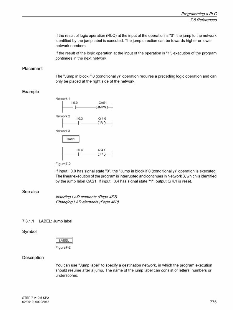
If the result of logic operation (RLO) at the input of the operation is "0", the jump to the networkidentified by the jump label is executed. The jump direction can be towards higher or lowernetwork numbers.
If the result of the logic operation at the input of the operation is "1", execution of the programcontinues in the next network.
PlacementThe "Jump in block if 0 (conditionally)" operation requires a preceding logic operation and canonly be placed at the right side of the network.
Example
Figure7-2
If input I 0.0 has signal state "0", the "Jump in block if 0 (conditionally)" operation is executed.The linear execution of the program is interrupted and continues in Network 3, which is identifiedby the jump label CAS1. If input I 0.4 has signal state "1", output Q 4.1 is reset.
See alsoInserting LAD elements (Page 452)Changing LAD elements (Page 460)
7.8.1.1 LABEL: Jump label
Symbol
Figure7-2
DescriptionYou can use "Jump label" to specify a destination network, in which the program executionshould resume after a jump. The name of the jump label can consist of letters, numbers orunderscores.
7.8.1.1 LABEL: Jump label
Programming a PLC7.8 References
STEP 7 V10.5 SP202/2010, 00002013
775

The jump label and the operation in which the jump label is specified must be located in thesame block. The name of a jump label can only be assigned once in a block.
Each jump label can jump to several locations.
Example
Figure7-2
If input I 0.0 has signal state "1", the "Jump in block if 1 (conditionally)" operation is executed.The linear execution of the program is interrupted and continues in Network 3, which is identifiedby the jump label CAS1. If input I 0.4 has signal state "1", output Q 4.1 is reset.
See alsoInserting LAD elements (Page 452)Changing LAD elements (Page 460)
7.8.1.1 --
Symbol
Figure7-2
Parameter values Data type Memory area Description
TRUE - - The status of the callfunction is set to "1".
FALSE - - The status of the callfunction is set to "0".
<Operand> BOOL I, Q, M, L, D (Page318)
The status of the callfunction is set to thesignal state of thespecified operand.
7.8.1.1 --
Programming a PLC7.8 References
776STEP 7 V10.5 SP202/2010, 00002013

DescriptionYou can use the "Return" operation to stop the execution of a block. The operation is then onlyexecuted if the signal state at the left connector is "1". If this condition is fulfilled, programexecution is terminated in the currently called block and continued after the call function in thecalling block (for example in the calling OB). The status of the call function is determined bythe parameter of the "Return" operation. This can assume the following values:
• TRUE: Output ENO of the call function is set to "1".
• FALSE: Output ENO of the call function is reset to "0".
• <Operand>: Output ENO of the call function is determined by the signal state of the specified operand.
If an organization block is terminated by the "Return" operation, the CPU continues in thesystem program.
If the signal state at the input of the "Return" operation is "0", the operation is not executed. Inthis case, program execution continues in the next network of the called block.
PlacementThe "Return" operation can be assigned to the left or right side of the network.
Example
Figure7-2
If the input I 0.0 has signal state "0", the "Return" operation is executed. Program execution inthe called block is terminated and continues in the calling block. Output ENO of the call functionis reset to signal state "0".
See alsoInserting LAD elements (Page 452)Changing LAD elements (Page 460)
Programming a PLC7.8 References
STEP 7 V10.5 SP202/2010, 00002013
777

7.8.1.1 Logical operations
7.8.1.1 AND: AND logic operation
Symbol
Figure7-2
Parameter Data type Memory area Description
EN BOOL I, Q, M, L, D (Page318)
Enable input
ENO BOOL I, Q, M, L, D Enable output
IN1 BYTE, WORD, DWORD I, Q, M, L, D or constant First value for logicoperation
IN2 BYTE, WORD, DWORD I, Q, M, L, D or constant Second value for logicoperation
OUT BYTE, WORD, DWORD I, Q, M, L, D Result of the operation
You can select the data type for the operation from the "DT" drop-down list.
DescriptionYou can use the "AND logic operation" to link the value at the IN1 input to the value at the IN2input bit-by-bit by AND logic and query the result at the OUT output.
When the operation is executed, bit 0 of the value at the IN1 input is linked by AND to bit 0 ofthe value at the IN2 input. The result is stored in bit 0 of the OUT output. The same logicoperation is executed for all other bits of the specified values.
The result bit has signal state "1" only when both of the bits in the logic operation also havesignal state "1". If one of the two bits of the logic operation has signal state "0", thecorresponding result bit is reset.
The operation is only executed if the signal state is "1" at the enable input EN. In this case, theENO output also has signal state "1".
If the signal state at the enable input EN is "0", the enable output ENO is reset to signal state"0".
7.8.1.1 Logical operations7.8.1.1 AND: AND logic operation
Programming a PLC7.8 References
778STEP 7 V10.5 SP202/2010, 00002013

PlacementThe "AND logic operation" can be placed at any position in the network.
Example
Figure7-2
IN1 MW0 = 01010101 01010101
IN2 MW2 = 00000000 00001111
OUT MW10= 00000000 00000101
If input I 0.0 has signal state "1", the "AND logic operation" is executed. The value at the MW0input is linked by AND logic to the value at the MW2 input. The result is mapped bit-for-bit andsent to the MW10 output. Output ENO and output Q 4.0 are set to signal state "1".
See alsoInserting LAD elements (Page 452)Changing LAD elements (Page 460)Inserting operands into LAD instructions (Page 0 )Selecting the data type of a LAD element (Page 0 )
7.8.1.1 OR: OR logic operation
Symbol
Figure7-2
Parameter Data type Memory area Description
EN BOOL I, Q, M, L, D (Page318)
Enable input
7.8.1.1 OR: OR logic operation
Programming a PLC7.8 References
STEP 7 V10.5 SP202/2010, 00002013
779

Parameter Data type Memory area Description
ENO BOOL I, Q, M, L, D Enable output
IN1 BYTE, WORD, DWORD I, Q, M, L, D or constant First value for logicoperation
IN2 BYTE, WORD, DWORD I, Q, M, L, D or constant Second value for logicoperation
OUT BYTE, WORD, DWORD I, Q, M, L, D Result of the operation
You can select the data type for the operation from the "DT" drop-down list.
DescriptionYou can use the "OR logic operation" to link the value at the IN1 input to the value at the IN2input bit-by-bit by OR logic and query the result at the OUT output.
When the operation is executed, bit 0 of the value at the IN1 input is linked by OR to bit 0 ofthe value at the IN2 input. The result is stored in bit 0 of the OUT output. The same logicoperation is executed for all bits of the specified tags.
The result bit has signal state "1" when at least one of the two bits in the logic operation hassignal state "1". If both of the bits of the logic operation have signal state "0", the correspondingresult bit is reset.
The operation is only executed if the signal state is "1" at the enable input EN. In this case, theENO output also has signal state "1".
If the signal state at the enable input EN is "0", the enable output ENO is reset to signal state"0".
PlacementThe "OR logic operation" can be placed at any position in the network.
Example
Figure7-2
IN1 MW0 = 01010101 01010101
IN2 MW2 = 00000000 00001111
OUT MW10= 01010101 01011111
Programming a PLC7.8 References
780STEP 7 V10.5 SP202/2010, 00002013

If input I 0.0 has signal state "1", the "OR logic operation" is executed. The value at the MW0input is linked by OR logic to the value at the MW2 input. The result is mapped bit-for-bit andsent to the MW8 output. Output ENO and output Q 4.0 are set to signal state "1".
See alsoInserting LAD elements (Page 452)Changing LAD elements (Page 460)Inserting operands into LAD instructions (Page 0 )Selecting the data type of a LAD element (Page 0 )
7.8.1.1 XOR: EXCLUSIVE OR logic operation
Symbol
Parameter Data type Memory area Description
EN BOOL I, Q, M, L, D (Page318)
Enable input
ENO BOOL I, Q, M, L, D Enable output
IN1 BYTE, WORD, DWORD I, Q, M, L, D or constant First value for logicoperation
IN2 BYTE, WORD, DWORD I, Q, M, L, D or constant Second value for logicoperation
OUT BYTE, WORD, DWORD I, Q, M, L, D Result of the operation
You can select the data type for the operation from the "DT" drop-down list.
DescriptionYou can use the "EXCLUSIVE OR logic operation" to link the value at the IN1 input to the valueat the IN2 input bit-by-bit by EXCLUSIVE OR logic and query the result at the OUT output.
When the operation is executed, bit 0 of the value at the IN1 input is linked by EXCLUSIVE ORto bit 0 of the value at the IN2 input. The result is stored in bit 0 of the OUT output. The samelogic operation is executed for all other bits of the specified value.
The result bit has signal state "1" when one of the two bits in the logic operation has signalstate "1". If both of the bits of the logic operation have signal state "1" or "0", the correspondingresult bit is reset.
7.8.1.1 XOR: EXCLUSIVE OR logic operation
Programming a PLC7.8 References
STEP 7 V10.5 SP202/2010, 00002013
781

The operation is only executed if the signal state is "1" at the enable input EN. In this case, theENO output also has signal state "1".
If the signal state at the enable input EN is "0", the enable output ENO is reset to signal state"0".
PlacementThe "EXCLUSIVE OR logic operation" can be placed at any position in the network.
Example
Figure7-2
IN1 MW0 = 01010101 01010101
IN2 MW2 = 00000000 00001111
OUT MW10= 01010101 01011010
If input I 0.0 has signal state "1", the "EXCLUSIVE OR logic operation" is executed. The valueat the MW0 input is linked by EXCLUSIVE OR logic to the value at the MW2 input. The resultis mapped bit-for-bit and sent to the MW8 output. Output ENO and output Q 4.0 are set to signalstate "1".
See alsoInserting LAD elements (Page 452)Changing LAD elements (Page 460)Inserting operands into LAD instructions (Page 0 )Selecting the data type of a LAD element (Page 0 )
7.8.1.1 INV: Create ones complement
Symbol
Figure7-2
7.8.1.1 INV: Create ones complement
Programming a PLC7.8 References
782STEP 7 V10.5 SP202/2010, 00002013

Parameter Data type Memory area Description
EN BOOL I, Q, M, D, L (Page318)
Enable input
ENO BOOL I, Q, M, D, L Enable output
IN BYTE, WORD,DWORD, USINT, UINT,UDINT, SINT, INT, DINT
I, Q, M, D, L or constant Input value
OUT BYTE, WORD,DWORD, USINT, UINT,UDINT, SINT, INT, DINT
I, Q, M, D, L Ones complement of thevalue at input IN
You can select the data type for the operation from the "DT" drop-down list.
DescriptionYou can use the "Create ones complement" operation to invert the signal status of the bits atthe IN input. When the operation is executed, the value at the IN input is linked by EXCLUSIVEOR to a hexadecimal mask (W#16#FFFF for 16-bit numbers or DW#16#FFFF FFFF for 32-bitnumber). This inverts the signal state of the individual bits that are then stored in the OUToutput.
The operation is only executed if the signal state is "1" at the enable input EN. In this case, theENO output also has signal state "1".
If the signal state at the enable input EN is "0", the enable output ENO is reset to signal state"0".
PlacementThe "Create ones complement" operation can be placed at any position in the network.
Example
Figure7-2
IN MW8 = W#16#000F
OUT MW10 = W#16#FFF0
If input I 0.0 has signal state "1", the "Create ones complement" operation is executed. Theoperation inverts the signal state of the individual bits at the MW8 input and writes the result tothe MW10 output. Output ENO and output Q 4.0 are set to signal state "1".
Programming a PLC7.8 References
STEP 7 V10.5 SP202/2010, 00002013
783

See alsoInserting LAD elements (Page 452)Changing LAD elements (Page 460)Inserting operands into LAD instructions (Page 0 )Selecting the data type of a LAD element (Page 0 )
7.8.1.1 DECO: Decode
Symbol
Figure7-2
Parameter Data type Memory area Description
EN BOOL I, Q, M, D, L (Page 318) Enable input
ENO BOOL I, Q, M, D, L. Enable output
IN UINT I, Q, M, D, L or constant Input value
OUT BYTE, WORD, DWORD I, Q, M, D, L Output value
You can select the data type for the operation from the "DT" drop-down list.
DescriptionYou can use the "Decode" operation to set a bit in the output value specified by the input value.
The "Decode" operation reads the value at the IN input and sets the bit in the output value,whose bit position corresponds to the value read. The other bits in the output value are filledwith zeroes. When the value at the IN input is greater than 31, a modulo 32 operation isexecuted.
The "Decode" operation can only be started when the signal state at the EN enable input is "1".If no error occurs during execution, the ENO output also has signal state "1".
If the signal state at the enable input EN is "0", the enable output ENO is reset to signal state"0".
PlacementThe "Decode" operation can be placed at any position in the network.
7.8.1.1 DECO: Decode
Programming a PLC7.8 References
784STEP 7 V10.5 SP202/2010, 00002013

Example
Figure7-2
Figure7-2
If the input I 0.0 has signal state "1", the "Decode" operation is executed. The operation readsbit number "3" from the value at the MW10 input and set the third bit to the value at the MD20output.
If no errors occur during execution of the operation, the ENO output has signal state "1" andoutput Q 4.0 is set.
See alsoInserting LAD elements (Page 452)Changing LAD elements (Page 460)Inserting operands into LAD instructions (Page 0 )Selecting the data type of a LAD element (Page 0 )
7.8.1.1 ENCO: Encode
Symbol
Figure7-2
Parameter Data type Memory area Description
EN BOOL I, Q, M, D, L (Page 318) Enable input
ENO BOOL I, Q, M, D, L. Enable output
IN BYTE, WORD, DWORD I, Q, M, D, L or constant Input value
OUT INT I, Q, M, D, L Output value
7.8.1.1 ENCO: Encode
Programming a PLC7.8 References
STEP 7 V10.5 SP202/2010, 00002013
785

You can select the data type for the operation from the "DT" drop-down list.
DescriptionYou can used the "Encode" operation to read the bit number of the least significant set bit inthe input value and send it to the OUT output.
The "Encode" operation selects the least significant bit of the value at input IN and writes thisbit number to the tag at the OUT output.
The "Encode" operation can only be started when the signal state at the EN enable input is "1".If no error occurs during execution, the ENO output also has signal state "1".
If the signal state at the enable input EN is "0", the enable output ENO is reset to signal state"0".
PlacementThe "Encode" operation can be placed at any position in the network.
Example
Figure7-2
Figure7-2
If the input I 0.0 has signal state "1", the "Encode" operation is executed. The operation selectsthe least significant bit set at the MD10 input and writes bit position 3 to the tag at the MW20output.
If no errors occur during execution of the operation, the ENO output has signal state "1" andoutput Q 4.0 is set.
See alsoInserting LAD elements (Page 452)Changing LAD elements (Page 460)Inserting operands into LAD instructions (Page 0 )Selecting the data type of a LAD element (Page 0 )
Programming a PLC7.8 References
786STEP 7 V10.5 SP202/2010, 00002013

7.8.1.1 SEL: Select
Symbol
Figure7-2
Parameter Data type Memory area Description
EN BOOL I, Q, M, D, L (Page 318) Enable input
ENO BOOL I, Q, M, D, L Enable output
G BOOL I, Q, M, D, L Selection switch
IN0 BYTE, WORD,DWORD, SINT, USINT,INT, UINT, DINT,UDINT, REAL, TIME,CHAR
I, Q, M, D, L or constant First input value
IN1 BYTE, WORD,DWORD, SINT, USINT,INT, UINT, DINT,UDINT, REAL, TIME,CHAR
I, Q, M, D, L or constant Second input value
OUT BYTE, WORD,DWORD, SINT, USINT,INT, UINT, DINT,UDINT, REAL, TIME,CHAR
I, Q, M, D, L Value of the selectedinput
You can select the data type for the operation from the "DT" drop-down list.
DescriptionThe "Select" operation selects one of the inputs IN0 or IN1 depending on a switch (parameterG) and copies its content to the OUT output. If parameter G has signal state "0", the value atinput IN0 is copied. When the G parameter has the signal status "1", the value at the IN1 inputis copied to the OUT output.
The operation is only executed if the signal state is "1" at the enable input EN. If no error occursduring execution, the ENO output also has signal state "1".
The ENO enable output is reset when the EN enable input has signal state "0" or errors occurduring execution of the operation.
7.8.1.1 SEL: Select
Programming a PLC7.8 References
STEP 7 V10.5 SP202/2010, 00002013
787

PlacementThe "Select" operation can be placed at any position in the network.
Example
Figure7-2
G I 1.0 = 1
IN0 MW10 = W#16#0000
IN1 MW12 = W#16#FFFF
OUT MW20 = W#16#FFFF
If the input I 0.0 has signal state "1", the "Select" operation is executed. Based on the signalstatus at the input I 1.0, the value at the MW12 input is selected and copied to the MW20 output.If no errors occur during execution of the operation, the ENO output has signal state "1" andoutput Q 4.0 is set.
See alsoInserting LAD elements (Page 452)Changing LAD elements (Page 460)Inserting operands into LAD instructions (Page 0 )Selecting the data type of a LAD element (Page 0 )
7.8.1.1 MUX: Multiplex
Symbol
Figure7-2
7.8.1.1 MUX: Multiplex
Programming a PLC7.8 References
788STEP 7 V10.5 SP202/2010, 00002013

Parameter Data type Memory area Description
EN BOOL I, Q, M, D, L (Page 318) Enable input
ENO BOOL I, Q, M, D, L Enable output
K UINT I, Q, M, D, L Specifies the inputwhose content is to becopied.
IN0 BYTE, WORD,DWORD, INT, DINT,UINT, UDINT, SINT,USINT, REAL, CHAR,TIME
I, Q, M, D, L or constant First available input
INn BYTE, WORD,DWORD, INT, DINT,UINT, UDINT, SINT,USINT, REAL, CHAR,TIME
I, Q, M, D, L or constant Available input
ELSE BYTE, WORD,DWORD, INT, DINT,UINT, UDINT, SINT,USINT, REAL, CHAR,TIME
I, Q, M, D, L or constant Specifies the value to becopied with K > n.
OUT BYTE, WORD,DWORD, INT, DINT,UINT, UDINT, SINT,USINT, REAL, CHAR,TIME
I, Q, M, D, L Output to which thevalue is to be copied.
You can select the data type for the operation from the "DT" drop-down list.
DescriptionYou can use the "Multiplex" operation to copy the content of a selected input to the OUT output.The number of selectable inputs of the MUX box can be expanded. The inputs are automaticallynumbered in the box. Numbering starts at IN0 and is incremented continuously with each newinput. You can use the K parameter to determine the input whose content should be copied tothe OUT output. If the value of the K parameter is greater than the number of available inputs,the content of the ELSE parameter is copied to the OUT output and the enable output ENO isassigned signal state "0".
The "Multiplex" operation can only be executed, when the tags at all inputs and at the OUToutput are from the same data type. The K parameter is an exception, since only integers canbe specified for it.
The operation is only executed if the signal state is "1" at the enable input EN. If no error occursduring execution, the ENO output also has signal state "1".
The enable output ENO is reset if one of the following conditions applies:
• The enable input EN has signal state "0".
Programming a PLC7.8 References
STEP 7 V10.5 SP202/2010, 00002013
789

• The value of the K parameter is greater than the number of available inputs.
• Errors occurred during processing of the operation.
PlacementThe "Multiplex" operation can be placed at any position in the network.
Example
Figure7-2
K MW10 = 1
IN0 MD20 = DW#16#00000000
IN1 MD30 = DW#16#FFFFFFFF
ELSE MD50 = DW#16#FFFF0000
OUT MD40 = DW#16#FFFFFFFF
If the input I 0.1 has signal state "1", the "Multiplex" operation is executed. Based on the valueat the MW10 input, the value at the MD30 input is copied and assigned to the tag at the MD40output. If no error occurs during execution of the operation, the outputs ENO and Q 4.0 are set.
See alsoInserting LAD elements (Page 452)Changing LAD elements (Page 460)Inserting operands into LAD instructions (Page 0 )Selecting the data type of a LAD element (Page 0 )
Programming a PLC7.8 References
790STEP 7 V10.5 SP202/2010, 00002013

7.8.1.1 Shift + rotate
7.8.1.1 SHR: Shift right
Symbol
Figure7-2
Parameter Data type Memory area Description
EN BOOL I, Q, M, L, D (Page318)
Enable input
ENO BOOL I, Q, M, L, D Enable output
IN BYTE, WORD,DWORD, USINT, UINT,UDINT, SINT, INT, DINT
I, Q, M, L, D or constant Value to be shifted.
N UINT I, Q, M, L, D or constant Number of bit positionsby which the value isshifted.
OUT BYTE, WORD,DWORD, USINT, UINT,UDINT, SINT, INT, DINT
I, Q, M, L, D Result of the shiftoperation
You can select the data type for the operation from the "DT" drop-down list.
DescriptionYou can use the "Shift right" operation to shift the content of the tag at the IN input bit-by-bit tothe right and query the result at the OUT output. You can use the N parameter to specify thenumber of bit positions by which the specified value should be shifted.
When the N parameter has the value "0", the value at the IN input is copied to the tag at theOUT output.
When the value at the N parameter is greater than the number of bit positions, the tag value atIN input is moved by the available number of bit positions to the right.
The freed bit positions in the left area of the tag are filled by zeroes when values without signsare shifted. If the specified value has a sign, the free bit positions are filled with the signal stateof the sign bit.
7.8.1.1 Shift + rotate7.8.1.1 SHR: Shift right
Programming a PLC7.8 References
STEP 7 V10.5 SP202/2010, 00002013
791

The following figure show how the content of a integer data type tag is shifted four bit positionsto the right:
Figure7-2
The "Shift right" operation is only executed if the signal state is "1" at the enable input EN. Inthis case, the enable output ENO also has signal state "1".
If the signal state at the enable input EN is "0", the enable output ENO is reset to signal state"0".
PlacementThe Shift right operation can be placed anywhere in the network.
Example
Figure7-2
IN MW10 = 0011 1111 1010 1111
N MW12 = 3
OUT MW40 = 0000 0111 1111 010 1
If input I 0.0 has signal state "1", the "Shift right" operation is executed. The content of theMW10 tag is shifted three bit positions to the right. The result is stored at the MW40 output. If
Programming a PLC7.8 References
792STEP 7 V10.5 SP202/2010, 00002013

no errors occur during execution of the operation, the ENO output has signal state "1" andoutput Q 4.0 is set.
See alsoInserting LAD elements (Page 452)Changing LAD elements (Page 460)Inserting operands into LAD instructions (Page 0 )Selecting the data type of a LAD element (Page 0 )
7.8.1.1 SHL: Shift left
Symbol
Figure7-2
Parameter Data type Memory area Description
EN BOOL I, Q, M, L, D (Page318)
Enable input
ENO BOOL I, Q, M, L, D Enable output
IN BYTE, WORD,DWORD, SINT, USINT,INT, UINT, DINT,UDINT
I, Q, M, L, D or constant Value to be shifted.
N UINT I, Q, M, L, D or constant Number of bit positionsby which the value isshifted.
OUT BYTE, WORD,DWORD, SINT, USINT,INT, UINT, DINT,UDINT
I, Q, M, L, D Result of the shiftoperation
You can select the data type for the operation from the "DT" drop-down list.
DescriptionYou can use the "Shift left" operation to shift the content of the tag at the IN input bit-by-bit tothe left and query the result at the OUT output. You can use the N parameter to specify thenumber of bit positions by which the specified value should be shifted.
7.8.1.1 SHL: Shift left
Programming a PLC7.8 References
STEP 7 V10.5 SP202/2010, 00002013
793

When the N parameter has the value "0", the value at the IN input is copied to the tag at theOUT output.
When the value at the N parameter is greater than the number of bit positions, the tag value atIN input is moved by the available number of bit positions to the left.
The bit positions in the right part of the tag freed by shifting are filled with zeros.
The following figure show how the content of a WORD data type tag is shifted six bit positionsto the left:
Figure7-2
The "Shift left" operation is only executed if the signal state is "1" at the enable input EN. In thiscase, the enable output ENO also has signal state "1".
If the signal state at the enable input EN is "0", the enable output ENO is reset to signal state"0".
PlacementThe "Shift left" operation can be placed anywhere in the network.
Example
Figure7-2
IN MW10 = 0011 1111 1010 1111
Programming a PLC7.8 References
794STEP 7 V10.5 SP202/2010, 00002013

N MW12 = 4
OUT MW40 = 1111 1010 1111 0000
If input I 0.0 has signal state "1", the "Shift left" operation is executed. The content of the MW10tag is shifted four bit positions to the left. The result is stored at the MW40 output. If no errorsoccur during execution of the operation, the ENO output has signal state "1" and output Q 4.0is set.
See alsoInserting LAD elements (Page 452)Changing LAD elements (Page 460)Inserting operands into LAD instructions (Page 0 )Selecting the data type of a LAD element (Page 0 )
7.8.1.1 ROR: Rotate right
Symbol
Figure7-2
Parameter Data type Memory area Description
EN BOOL I, Q, M, L, D (Page318)
Enable input
ENO BOOL I, Q, M, L, D Enable output
IN BYTE, WORD, DWORD I, Q, M, L, D or constant Value to be rotated.
N UINT I, Q, M, L, D or constant Number of bit positionsby which the value isrotated.
OUT BYTE, WORD, DWORD I, Q, M, L, D Result of the operation
You can select the data type for the operation from the "DT" drop-down list.
DescriptionYou can use the "Rotate right" operation to rotate the content of the tag at the IN input bit-by-bit to the right and query the result at the OUT output. The N parameter specifies the number
7.8.1.1 ROR: Rotate right
Programming a PLC7.8 References
STEP 7 V10.5 SP202/2010, 00002013
795

of bit positions by which the specified value will be rotated. The bit positions freed by rotatingare filled with the bit positions that are pushed out.
When the N parameter has the value "0", the value at the IN input is copied to the tag at theOUT output.
When the value at the N parameter is greater than the number of bit positions, the tag value atIN input is rotated by the available number of bit positions.
The following figure show how the content of a DWORD data type tag is rotated three bitpositions to the right:
Figure7-2
The "Rotate right" operation is only executed if the signal state is "1" at the enable output ENO.In this case, the enable output ENO also has signal state "1".
If the signal state at the enable input EN is "0", the enable output ENO is reset to signal state"0".
PlacementThe "Rotate right" operation can be placed anywhere in the network.
Example
Figure7-2
Programming a PLC7.8 References
796STEP 7 V10.5 SP202/2010, 00002013

IN MW10 = 0000 1111 1001 0101
N MW12 = 5
OUT MW40 = 1010 1000 0111 1100
If input I 0.0 has signal state "1", the "Rotate right" operation is executed. The content of theMW10 tag is rotated five bit positions to the right. The result is stored at the MW40 output. Ifno errors occur during execution of the operation, the ENO output has signal state "1" andoutput Q 4.0 is set.
See alsoInserting LAD elements (Page 452)Changing LAD elements (Page 460)Inserting operands into LAD instructions (Page 0 )Selecting the data type of a LAD element (Page 0 )
7.8.1.1 ROL: Rotate left
Symbol
Figure7-2
Parameter Data type Memory area Description
EN BOOL I, Q, M, L, D (Page318)
Enable input
ENO BOOL I, Q, M, L, D Enable output
IN BYTE, WORD, DWORD I, Q, M, L, D or constant Value to be rotated.
N UINT I, Q, M, L, D or constant Number of bit positionsby which the value isrotated.
OUT BYTE, WORD, DWORD I, Q, M, L, D Result of the operation
You can select the data type for the operation from the "DT" drop-down list.
DescriptionYou can use the "Rotate left" operation to rotate the content of the tag at the IN input bit-by-bitto the left and query the result at the OUT output. The N parameter specifies the number of bit
7.8.1.1 ROL: Rotate left
Programming a PLC7.8 References
STEP 7 V10.5 SP202/2010, 00002013
797

positions by which the specified value will be rotated. The bit positions freed by rotating arefilled with the bit positions that are pushed out.
When the N parameter has the value "0", the value at the IN input is copied to the tag at theOUT output.
When the value at the N parameter is greater than the number of bit positions, the tag value atIN input is rotated by the available number of bit positions.
The following figure show how the content of a DWORD data type tag is rotated three bitpositions to the left:
Figure7-2
The "Rotate left" operation is only executed if the signal state is "1" at the enable output ENO.In this case, the enable output ENO also has signal state "1".
If the signal state at the enable input EN is "0", the enable output ENO is reset to signal state"0".
PlacementThe "Rotate left" operation can be placed anywhere in the network.
Example
Figure7-2
Programming a PLC7.8 References
798STEP 7 V10.5 SP202/2010, 00002013
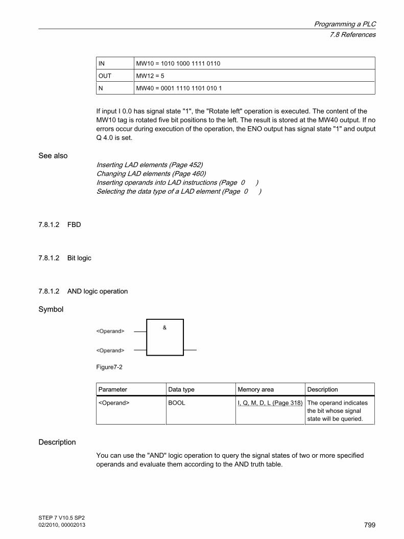
IN MW10 = 1010 1000 1111 0110
OUT MW12 = 5
N MW40 = 0001 1110 1101 010 1
If input I 0.0 has signal state "1", the "Rotate left" operation is executed. The content of theMW10 tag is rotated five bit positions to the left. The result is stored at the MW40 output. If noerrors occur during execution of the operation, the ENO output has signal state "1" and outputQ 4.0 is set.
See alsoInserting LAD elements (Page 452)Changing LAD elements (Page 460)Inserting operands into LAD instructions (Page 0 )Selecting the data type of a LAD element (Page 0 )
7.8.1.2 FBD
7.8.1.2 Bit logic
7.8.1.2 AND logic operation
Symbol
Figure7-2
Parameter Data type Memory area Description
<Operand> BOOL I, Q, M, D, L (Page 318) The operand indicatesthe bit whose signalstate will be queried.
DescriptionYou can use the "AND" logic operation to query the signal states of two or more specifiedoperands and evaluate them according to the AND truth table.
7.8.1.2 FBD7.8.1.2 Bit logic7.8.1.2 AND logic operation
Programming a PLC7.8 References
STEP 7 V10.5 SP202/2010, 00002013
799

If the signal state of all the operands is "1", then the conditions are fulfilled and the operationreturns the result "1". If the signal state of one of the operands is "0", then the conditions arenot fulfilled and the operation generates the result "0".
If the "AND" logic operation is the first operation in a logic string, it saves the result of its signalstate query in the RLO bit.
Each "AND" logic operation that is not the first operation in the logic string, logically combinesthe result of its signal state query with the value saved in the RLO bit. This logical combinationis performed according to the AND truth table.
Example
Figure7-2
Output Q 4.0 is set when the signal state is "1" at input I 0.0 AND I 0.1.
See alsoAND truth table (Page 800)Inserting FBD elements (Page 484)Changing FBD elements (Page 492)Inserting operands into FBD instructions (Page 495)Example of detecting the direction of a conveyor belt (Page 614)Example of controlling room temperature (Page 621)
7.8.1.2 AND truth table
Results of the logic operation
Signal state I1.0 Signal state I1.1 Result of the logic operation
1 1 1
0 1 0
1 0 0
0 0 0
See alsoAND logic operation (Page 799)
7.8.1.2 AND truth table
Programming a PLC7.8 References
800STEP 7 V10.5 SP202/2010, 00002013

7.8.1.2 OR logic operation
Symbol
Figure7-2
Parameter Data type Memory area Description
<Operand> BOOL I, Q, M, D, L (Page318)
The operand indicatesthe bit whose signalstate will be queried.
DescriptionYou can use the "OR" logic operation to query the signal states of two or more specifiedoperands and evaluate them according to the OR truth table.
If the signal state of one of the operands is "1", then the conditions are fulfilled and the operationreturns the result "1". If the signal state of all the operands is "0", then the conditions are notfulfilled and the operation generates the result "0".
If the "OR" logic operation is the first operation in a logic string, it saves the result of its signalstate query in the RLO bit.
Each "OR" logic operation that is not the first operation in the logic string logically combinesthe result of its signal state query with the value saved in the RLO bit. This logical combinationis performed according to the OR truth table.
Example
Figure7-2
Output Q 4.0 is set when the signal state is "1" at input I 0.0 OR at input I 0.1.
See alsoOR truth table (Page 802)Inserting FBD elements (Page 484)Changing FBD elements (Page 492)Inserting operands into FBD instructions (Page 495)Example of controlling a conveyor belt (Page 613)Example of detecting the fill level of a storage area (Page 616)
7.8.1.2 OR logic operation
Programming a PLC7.8 References
STEP 7 V10.5 SP202/2010, 00002013
801

Example of controlling room temperature (Page 621)
7.8.1.2 OR truth table
Results of the logic operation
Signal state I1.0 Signal state I1.1 Result of the logic operation
1 0 1
0 1 1
1 1 1
0 0 0
See alsoOR logic operation (Page 801)
7.8.1.2 AND-before-OR logic operation and OR-before-AND logic operation
DescriptionWith an "AND-before-OR" logic operation, you can query the result of a signal state queryaccording to the OR truth table. With an AND-before-OR logic operation, the signal state is 1when at least one AND logic operation is fulfilled.
Example
Output Q 3.1 is set when at least one AND logic operation is fulfilled.
Output Q 3.1 is reset when no AND logic operation is fulfilled.
DescriptionWith an "OR-before-AND" logic operation, you can query the result of a signal state queryaccording to the AND truth table. With an OR logic operation, the signal state is 1 when all ORlogic operations are fulfilled.
7.8.1.2 OR truth table7.8.1.2 AND-before-OR logic operation and OR-before-AND logic operation
Programming a PLC7.8 References
802STEP 7 V10.5 SP202/2010, 00002013

Example
Output Q 3.1 is set when both OR logic operations are fulfilled.
Output Q 3.1 is reset when one or both OR logic operations are not fulfilled.
See alsoInserting FBD elements (Page 484)Changing FBD elements (Page 492)Inserting operands into FBD instructions (Page 495)
7.8.1.2 X: EXCLUSIVE OR logic operation
Symbol
Figure7-2
Parameter Data type Memory area Description
<Operand> BOOL I, Q, M, D, L (Page 318) The operand indicatesthe bit whose signalstate will be queried.
DescriptionYou can use the "EXCLUSIVE OR" operation to query the result of a signal state queryaccording to the the EXCLUSIVE OR truth table.
With an "EXCLUSIVE OR" operation, the signal state is "1" when the signal state of one of thetwo specified operands is "1". When XOR elements are used to query more than two operands,the common result is "1" if an odd number of the queried operands returns the result "1".
7.8.1.2 X: EXCLUSIVE OR logic operation
Programming a PLC7.8 References
STEP 7 V10.5 SP202/2010, 00002013
803

Example
Figure7-2
Output Q 3.1 is set when the signal state is "1" either at input I 0.0 OR at input I 0.2EXCLUSIVELY.
See alsoEXCLUSIVE OR truth table (Page 804)Inserting FBD elements (Page 484)Inserting operands into FBD instructions (Page 495)
7.8.1.2 EXCLUSIVE OR truth table
Results of the logic operation
Signal state I1.0 Signal state I1.1 Result of the logic operation
1 0 1
0 1 1
1 1 0
0 0 0
See alsoChanging FBD elements (Page 492)
7.8.1.2 Insert binary input
Symbol
Figure7-2
7.8.1.2 EXCLUSIVE OR truth table7.8.1.2 Insert binary input
Programming a PLC7.8 References
804STEP 7 V10.5 SP202/2010, 00002013

Parameter Data type Memory area Description
<Operand> BOOL I, Q, M, D, L (Page 318) The operand indicatesthe bit whose signalstate will be queried.
DescriptionYou can use the "Insert binary input" operation to add a further binary input to an AND, OR, orXOR box after the marker.
Example
Figure7-2
Output Q 4.0 is set when the inputs I 1.0 AND I 1.1 AND I 1.2 have signal state "1".
See alsoInserting FBD elements (Page 484)Changing FBD elements (Page 492)Inserting operands into FBD instructions (Page 495)
7.8.1.2 Negate binary value
Symbol
DescriptionYou can use the "Negate binary value" operation to invert the result of logic operation of anoperation.
If the result of logic operation is negated, remember the following rules:
• If the result of logic operation at the first input of an AND or OR box is negated, there is no nesting.
• If the result of logic operation is negated but not at the first input of an OR box, the entire binary logicoperation before the input is included in the OR logic operation.
• If the result of logic operation is negated but not at the first input of a AND box, the entire binary logicoperation before the input is included in the AND logic operation.
7.8.1.2 Negate binary value
Programming a PLC7.8 References
STEP 7 V10.5 SP202/2010, 00002013
805

Example
Output Q 4.0 is set when the following conditions are fulfilled:
• Inputs I 1.0 AND I 1.1 have signal state "0".
• Inputs I 1.2 AND I 1.3 have signal state "0" OR input I 1.4 has signal state "1".
See alsoInserting FBD elements (Page 484)Changing FBD elements (Page 492)Inserting operands into FBD instructions (Page 495)Example of detecting the direction of a conveyor belt (Page 614)Example of detecting the fill level of a storage area (Page 616)Example of controlling room temperature (Page 621)
7.8.1.2 =: Assignment
Symbol
Figure7-2
Parameter Data type Memory area Description
<Operand> BOOL I, Q, M, D, L (Page318)
Operand which is setwith RLO = "1".
DescriptionYou can use the "Assignment" operation to set the bit of a specified operand. If the result oflogic operation (RLO) at the box input has signal state "1", the specified operand is set to signalstate "1". If the signal state at the box input is "0", the bit of the specified operand is reset to"0".
The operation does not influence the RLO. The RLO at the box input is transferred directly tothe box output.
7.8.1.2 =: Assignment
Programming a PLC7.8 References
806STEP 7 V10.5 SP202/2010, 00002013
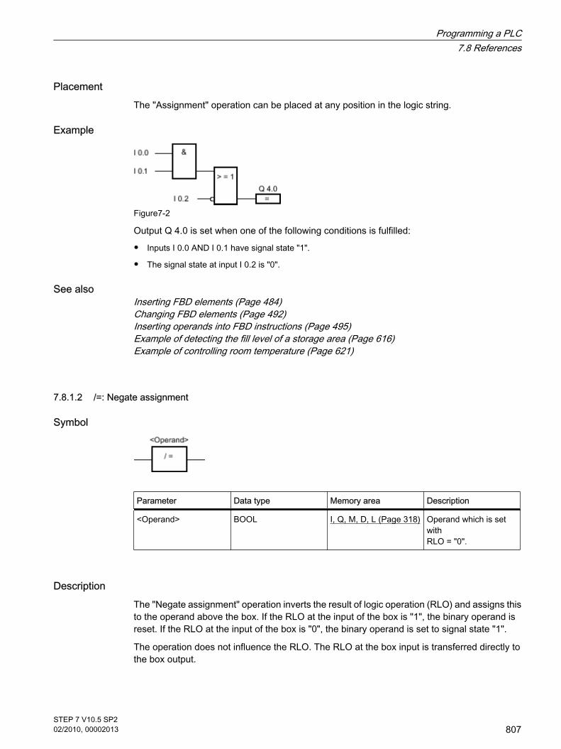
PlacementThe "Assignment" operation can be placed at any position in the logic string.
Example
Figure7-2
Output Q 4.0 is set when one of the following conditions is fulfilled:
• Inputs I 0.0 AND I 0.1 have signal state "1".
• The signal state at input I 0.2 is "0".
See alsoInserting FBD elements (Page 484)Changing FBD elements (Page 492)Inserting operands into FBD instructions (Page 495)Example of detecting the fill level of a storage area (Page 616)Example of controlling room temperature (Page 621)
7.8.1.2 /=: Negate assignment
Symbol
Parameter Data type Memory area Description
<Operand> BOOL I, Q, M, D, L (Page 318) Operand which is setwith RLO = "0".
DescriptionThe "Negate assignment" operation inverts the result of logic operation (RLO) and assigns thisto the operand above the box. If the RLO at the input of the box is "1", the binary operand isreset. If the RLO at the input of the box is "0", the binary operand is set to signal state "1".
The operation does not influence the RLO. The RLO at the box input is transferred directly tothe box output.
7.8.1.2 /=: Negate assignment
Programming a PLC7.8 References
STEP 7 V10.5 SP202/2010, 00002013
807

PlacementThe "Negate assignment" operation can be placed at any position in the logic string.
Example
Figure7-2
Output Q 4.0 is reset when the following conditions are fulfilled:
• Inputs I 0.0 OR I 0.1 have signal state "1".
• The signal state at input I 0.2 is "0".
See alsoInserting FBD elements (Page 484)Changing FBD elements (Page 492)Inserting operands into FBD instructions (Page 495)
7.8.1.2 R: Reset output
Symbol
Figure7-2
Parameter Data type Memory area Description
<Operand> BOOL I, Q, M, D, L (Page318)
Operand that is resetwhen RLO = "0".
DescriptionYou can use the "Reset output" operation to reset the signal state of a specified operand to "0".
The operation is only executed if the result of logic operation (RLO) is "1" at the box input. Ifthe box input has signal state "1", the specified operand is reset to "0". If there is a result oflogic operation of "0" at the box input, the signal state of the specified operand remainsunchanged.
The operation does not influence the RLO. The RLO at the box input is transferred directly tothe box output.
7.8.1.2 R: Reset output
Programming a PLC7.8 References
808STEP 7 V10.5 SP202/2010, 00002013
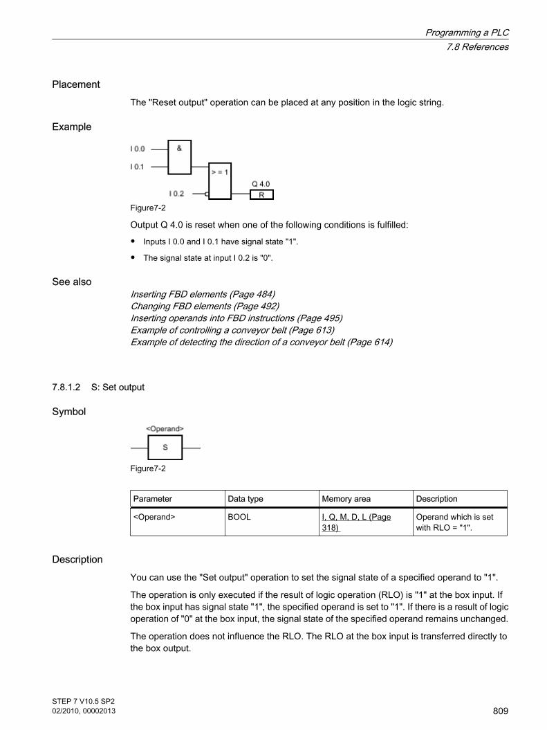
PlacementThe "Reset output" operation can be placed at any position in the logic string.
Example
Figure7-2
Output Q 4.0 is reset when one of the following conditions is fulfilled:
• Inputs I 0.0 and I 0.1 have signal state "1".
• The signal state at input I 0.2 is "0".
See alsoInserting FBD elements (Page 484)Changing FBD elements (Page 492)Inserting operands into FBD instructions (Page 495)Example of controlling a conveyor belt (Page 613)Example of detecting the direction of a conveyor belt (Page 614)
7.8.1.2 S: Set output
Symbol
Figure7-2
Parameter Data type Memory area Description
<Operand> BOOL I, Q, M, D, L (Page318)
Operand which is setwith RLO = "1".
DescriptionYou can use the "Set output" operation to set the signal state of a specified operand to "1".
The operation is only executed if the result of logic operation (RLO) is "1" at the box input. Ifthe box input has signal state "1", the specified operand is set to "1". If there is a result of logicoperation of "0" at the box input, the signal state of the specified operand remains unchanged.
The operation does not influence the RLO. The RLO at the box input is transferred directly tothe box output.
7.8.1.2 S: Set output
Programming a PLC7.8 References
STEP 7 V10.5 SP202/2010, 00002013
809
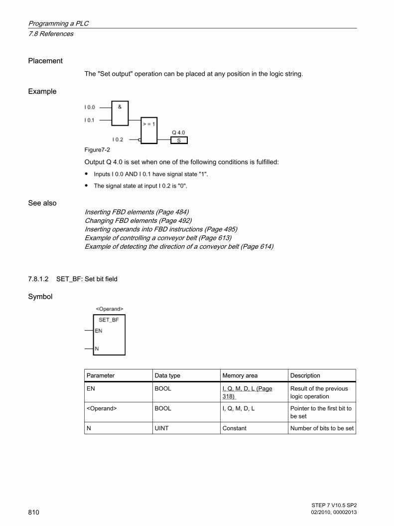
PlacementThe "Set output" operation can be placed at any position in the logic string.
Example
Figure7-2
Output Q 4.0 is set when one of the following conditions is fulfilled:
• Inputs I 0.0 AND I 0.1 have signal state "1".
• The signal state at input I 0.2 is "0".
See alsoInserting FBD elements (Page 484)Changing FBD elements (Page 492)Inserting operands into FBD instructions (Page 495)Example of controlling a conveyor belt (Page 613)Example of detecting the direction of a conveyor belt (Page 614)
7.8.1.2 SET_BF: Set bit field
Symbol
Parameter Data type Memory area Description
EN BOOL I, Q, M, D, L (Page318)
Result of the previouslogic operation
<Operand> BOOL I, Q, M, D, L Pointer to the first bit tobe set
N UINT Constant Number of bits to be set
7.8.1.2 SET_BF: Set bit field
Programming a PLC7.8 References
810STEP 7 V10.5 SP202/2010, 00002013

DescriptionYou can use the "Set bit field" operation to set several bits starting at a specified address. Youspecify the number of bits to be set with the value of the N parameter. The address of the firstbit to be set is specified by the (<Operand>) operand. If the value of the N parameter is greaterthan the number of bits in a selected byte, the bits of the next byte are set. The bits remain setuntil they are explicitly reset, for example, by another operation.
The operation is only executed if the signal state at the EN input is "1". If the signal state is "0"at the input EN, the operation is not executed.
PlacementThe "Set bit field" operation can be assigned only to the end of the logic string.
Example
Figure7-2
If inputs I 0.1 AND I 0.2 have signal state "1", outputs Q 20.0, Q 20.1, Q 20.2, Q 20.3 and Q20.4 are set.
See alsoInserting FBD elements (Page 484)Changing FBD elements (Page 492)Inserting operands into FBD instructions (Page 495)
7.8.1.2 RESET_BF: Reset bit field
Symbol
Parameter Data type Memory area Description
EN BOOL I, Q, M, D, L (Page318)
Result of the previouslogic operation
7.8.1.2 RESET_BF: Reset bit field
Programming a PLC7.8 References
STEP 7 V10.5 SP202/2010, 00002013
811

Parameter Data type Memory area Description
<Operand> BOOL I, Q, M, D, L Pointer to the first bit tobe reset
N UINT Constant Number of bits to bereset
DescriptionYou can use the "Reset bit field" operation to reset several bits starting at a specified address.You specify the number of bits to be reset with the value of the N parameter. The address ofthe first bit to be reset is specified by the (<Operand>) operand. If the value of the N parameteris greater than the number of bits in a selected byte, the bits of the next byte are reset. The bitsremain reset until they are explicitly set, for example, by another operation.
The operation is only executed if the signal state at the EN input is "1". If the signal state is "0"at the input EN, the operation is not executed.
PlacementThe "Reset bit field" operation can be assigned only to the end of the logic string.
Example
Figure7-2
If inputs I 0.0 AND I 0.1 have signal state "1", outputs Q 20.0, Q 20.1, Q 20.2, Q 20.3 and Q20.4 are reset.
See alsoInserting FBD elements (Page 484)Changing FBD elements (Page 492)Inserting operands into FBD instructions (Page 495)
Programming a PLC7.8 References
812STEP 7 V10.5 SP202/2010, 00002013

7.8.1.2 SR: Set reset flip-flop
Symbol
Figure7-2
Parameter Data type Memory area Description
<Operand> BOOL I, Q, M, D, L (Page318)
Operand that isspecified.
S BOOL I, Q, M, D, L Enabled set
R1 BOOL I, Q, M, D, L Enabled reset
Q BOOL I, Q, M, D, L Signal state of thespecified operand
DescriptionYou can use the "Set reset flip-flop" operation to set or reset the bit of the specified operandbased on the signal state of the inputs S and R1. If the signal state at input S is "1" and is "0"at input R1, the specified operand is set to "1". If the signal state at input S is "0" and is "1" atinput R1, the specified operand is reset to "0".
Input R1 takes priority over input S. If the signal state is "1" at the two inputs S and R1, thesignal state of the specified operand is reset to "0".
The operation is not executed if the signal state at the two inputs R and S1 is "0". The signalstate of the operand then remains unchanged.
The current signal state of the operand is transferred to output Q and can be queried there.
PlacementThe "Set reset flip-flop" operation can be placed within or at the end of the logic string.
Example
Figure7-2
Bit memory M 0.0 and output Q 4.0 are set when the following conditions are fulfilled:
• Input I 0.0 has signal state "1".
• Input I 0.1 has signal state "0".
7.8.1.2 SR: Set reset flip-flop
Programming a PLC7.8 References
STEP 7 V10.5 SP202/2010, 00002013
813

Bit memory M 0.0 and output Q 4.0 are reset when the following conditions are fulfilled:
• Input I 0.0 has signal state "0".
• Input I 0.1 has signal state "1".
See alsoInserting FBD elements (Page 484)Changing FBD elements (Page 492)Inserting operands into FBD instructions (Page 495)
7.8.1.2 RS: Reset set flip-flop
Symbol
Figure7-2
Parameter Data type Memory area Description
<Operand> BOOL I, Q, M, D, L (Page318)
Operand that isspecified.
R BOOL I, Q, M, D, L Enabled reset
S1 BOOL I, Q, M, D, L Enabled set
Q BOOL I, Q, M, D, L Signal state of thespecified operand
DescriptionYou can use the "Reset set flip-flop" operation to set or reset the bit of the specified operandbased on the signal state of the inputs R and S1. If the signal state at input R is "1" and is "0"at input S1, the specified operand is reset to "0". If the signal state at input R is "0" and is "1"at input S1, the specified operand is set to "1".
Input S1 takes priority over input R. If the signal state is "1" at the two inputs R and S1, thesignal state of the specified operand is set to "1".
The operation is not executed if the signal state at the two inputs R and S1 is "0". The signalstate of the operand then remains unchanged.
The current signal state of the operand is transferred to output Q and can be queried there.
PlacementThe "Reset set flip-flop" operation can be placed within or at the end of the logic string.
7.8.1.2 RS: Reset set flip-flop
Programming a PLC7.8 References
814STEP 7 V10.5 SP202/2010, 00002013

Example
Figure7-2
Bit memory M 0.0 and output Q 4.0 are reset when the following conditions are fulfilled:
• Input I 0.0 has signal state "1".
• Input I 0.1 has signal state "0".
Bit memory M 0.0 and output Q 4.0 are set when the following conditions are fulfilled:
• Input I 0.0 has signal state "0".
• Input I 0.1 has signal state "1".
See alsoInserting FBD elements (Page 484)Changing FBD elements (Page 492)Inserting operands into FBD instructions (Page 495)
7.8.1.2 P: Scan positive signal edge at operand
Symbol
Parameter Data type Memory area Description
<Operand1> BOOL I, Q, M, D, L (Page318)
Signal to be queried
<Operand2> BOOL I, Q, M, D Edge memory bit inwhich the signal state ofthe previous query issaved.
DescriptionYou can use the "Scan positive signal edge at operand" operation to determine if there is a "0"to "1" change in the signal state of a specified operand (<operand1>). The operation comparesthe current signal state of <operand1> to the signal state of the previous query saved in<operand2>. If the operation detects a change in the result of logic operation from "0" to "1",there is a positive, rising edge.
7.8.1.2 P: Scan positive signal edge at operand
Programming a PLC7.8 References
STEP 7 V10.5 SP202/2010, 00002013
815

If a rising edge is detected, the output of the operation has signal state "1". In all other cases,the signal state at the output of the operation is "0".
Note
The address of the edge memory bit must not be used more than once in the program, otherwisethe memory bit would be overwritten. This would influence edge evaluation and the result wouldno longer be unequivocal.
PlacementThe "Scan positive signal edge at operand" operation can be placed at any position in the logicstring.
Example
Figure7-2
Output Q 4.0 is set when the following conditions are fulfilled:
• There is a rising edge at input I 0.3.
• The signal state at input I 0.4 is "1".
See alsoInserting FBD elements (Page 484)Changing FBD elements (Page 492)Inserting operands into FBD instructions (Page 495)Example of detecting the direction of a conveyor belt (Page 614)
7.8.1.2 N: Scan negative signal edge at operand
Symbol
7.8.1.2 N: Scan negative signal edge at operand
Programming a PLC7.8 References
816STEP 7 V10.5 SP202/2010, 00002013

Parameter Data type Memory area Description
<Operand1> BOOL I, Q, M, D, L (Page318)
Signal to be queried
<Operand2> BOOL I, Q, M, D Edge memory bit inwhich the signal state ofthe previous query issaved.
DescriptionYou can use the "Scan negative signal edge at operand" operation to query a change in thesignal state from "1" to "0" of a specified operand (<operand1>). The operation compares thecurrent signal state of <operand1> to the signal state of the previous query saved in<operand2>. If the operation detects a change in the result of logic operation from "1" to "0",there is a negative, falling edge.
If a falling edge is detected, the output of the operation has signal state "1".
If no falling edge is detected, the output of the operation has signal state "0".
Note
The address of the edge memory bit must not be used more than once in the program, otherwisethe memory bit would be overwritten. This would influence edge evaluation and the result wouldno longer be unequivocal.
PlacementThe "Scan negative signal edge at operand" operation can be placed at any position in the logicstring.
Example
Figure7-2
Output Q 4.0 is set when the following conditions are fulfilled:
• There is a falling edge at input I 0.3.
• The signal state at input I 0.4 is "1".
See alsoInserting FBD elements (Page 484)Inserting operands into FBD instructions (Page 495)
Programming a PLC7.8 References
STEP 7 V10.5 SP202/2010, 00002013
817

7.8.1.2 P=: Set operand on positive signal edge
Symbol
Parameter Data type Memory area Description
<Operand1> BOOL I, Q, M, D, L (Page318)
Operand which is set bya positive edge.
<Operand2> BOOL I, Q, M, D Edge memory bit
DescriptionYou can use the "Set operand on positive signal edge" operation to detect a change in theresult of logic operation (RLO) from "0" to "1". When processing the query, the operationcompares the current RLO with the RLO of the previous query saved in the edge memory bit.If the operation detects a change in the RLO from "0" to "1", there is a rising, positive edge.
If a positive edge is detected, <operand1> is set to signal state "1" for one program cycle. Inall other cases, the operand has signal state "0".
Note
The address of the edge memory bit must not be used more than once in the program, otherwisethe memory bit would be overwritten. This would influence edge evaluation and the result wouldno longer be unequivocal.
The operation does not influence the RLO. The RLO at the input of the box is transferred directlyto the output of the box.
PlacementThe "Set operand on positive signal edge" operation can be placed either within or at the endof the logic string.
Example
7.8.1.2 P=: Set operand on positive signal edge
Programming a PLC7.8 References
818STEP 7 V10.5 SP202/2010, 00002013

Output Q 3.0 is set for one program cycle if the signal state at the box input changes from "0"to "1" (positive edge). In all other cases, output Q 3.0 has signal state "0".
See alsoInserting FBD elements (Page 484)Changing FBD elements (Page 492)Inserting operands into FBD instructions (Page 495)
7.8.1.2 N=: Set operand on negative signal edge
Symbol
Parameter Data type Memory area Description
<Operand1> BOOL I, Q, M, D, L (Page318)
Operand which is set bya negative edge.
<Operand2> BOOL I, Q, M, D, L Edge memory bit
DescriptionYou can use the "Set operand on negative signal edge" operation to detect a change in theresult of logic operation (RLO) from "1" to "0". When processing the query, the operationcompares the current RLO with the RLO of the previous query saved in the edge memory bit.If the operation detects a change in the RLO from "1" to "0", there is a falling, negative edge.
If a negative edge is detected, <operand1> is set to signal state "1" for one program cycle. Inall other cases, the operand has signal state "0".
Note
The address of the edge memory bit must not be used more than once in the program, otherwisethe memory bit would be overwritten. This would influence edge evaluation and the result wouldno longer be unequivocal.
The operation does not influence the RLO. The RLO at the input of the box is transferred directlyto the output of the box.
7.8.1.2 N=: Set operand on negative signal edge
Programming a PLC7.8 References
STEP 7 V10.5 SP202/2010, 00002013
819

PlacementThe "Set operand on negative signal edge" operation can be placed either within or at the endof the logic string.
Example
Output Q 3.0 is set for one program cycle if the signal state at the box input changes from "1"to "0" (negative edge). In all other cases, output Q 3.0 has signal state "0".
See alsoInserting FBD elements (Page 484)Inserting operands into FBD instructions (Page 495)
7.8.1.2 P_TRIG: Set output on positive signal edge
Symbol
Parameter Data type Memory area Description
<Operand> BOOL I, Q, M, D, L (Page318)
Edge memory bit inwhich the RLO of thelast query is saved.
CLK BOOL I, Q, M, D, L Current RLO.
Q BOOL I, Q, M, D, L Result of edgeevaluation
DescriptionYou can use the "Set output on positive signal edge" operation to query a change in the signalstate of the result of logic operation from "0" to "1". The operation compares the current signalstate of the result of logic operation to the signal state of the previous query saved in the edgememory bit. If the operation detects a change in the RLO from "0" to "1", there is a positive,rising edge.
If a rising edge is detected, the output of the operation has signal state "1". In all other cases,the signal state at the output of the operation is "0".
7.8.1.2 P_TRIG: Set output on positive signal edge
Programming a PLC7.8 References
820STEP 7 V10.5 SP202/2010, 00002013

PlacementThe "Set output on positive signal edge" operation can be placed either within or at the end ofthe logic string.
Example
The RLO of the preceding bit logic operation is saved in the edge memory bit M 0.0. If a "0" to"1" signal change is detected at the RLO, the program jumps to label CAS1.
See alsoInserting FBD elements (Page 484)Changing FBD elements (Page 492)Inserting operands into FBD instructions (Page 495)
7.8.1.2 N_TRIG: Set output on negative signal edge
Symbol
Figure7-2
Parameter Data type Memory area Description
<Operand> BOOL I, Q, M, D, L (Page318)
Edge memory bit inwhich the RLO of thelast query is saved.
CLK BOOL I, Q, M, D, L Current RLO
Q BOOL I, Q, M, D, L Result of edgeevaluation
DescriptionYou can use the "Set output on negative signal edge" operation to detect a "1" to "0" changein the signal state of the result of logic operation (RLO). The operation compares the currentsignal state of the result of logic operation to the signal state of the previous query saved in the
7.8.1.2 N_TRIG: Set output on negative signal edge
Programming a PLC7.8 References
STEP 7 V10.5 SP202/2010, 00002013
821

edge memory bit. If the operation detects a change in the RLO from "1" to "0", there is anegative, falling edge.
If a falling edge is detected, the output of the operation has signal state "1". In all other cases,the signal state at the output of the operation is "0".
PlacementThe "Set output on negative signal edge" operation can be placed either within or at the endof the logic string.
Example
The RLO of the preceding bit logic operation is saved in the edge memory bit M 0.0. If a "1" to"0" signal change is detected at the RLO, the program jumps to jump label CAS1.
See alsoInserting FBD elements (Page 484)Changing FBD elements (Page 492)Inserting operands into FBD instructions (Page 495)
7.8.1.2 Timers
7.8.1.2 TP: Pulse timer
Symbol
Figure7-2
Parameter Data type Memory area Description
IN BOOL I, Q, M, D, L (Page318)
Start input
7.8.1.2 Timers7.8.1.2 TP: Pulse timer
Programming a PLC7.8 References
822STEP 7 V10.5 SP202/2010, 00002013

Parameter Data type Memory area Description
PT TIME I, Q, M, D, L or constant Duration of the pulse.PT must be positive.
ET TIME I, Q, M, D, L Elapsed time
Q BOOL I, Q, M, D, L Pulse output
DescriptionYou can use the "Generate pulse" operation to set the Q output for a pre-programmed periodof time. The operation is started when the result of logic operation (RLO) at the IN input changesfrom "0" to "1". When the operation is started, the time programmed for PT starts running.Output Q is set for the period of time, PT, regardless of the subsequent course of the inputsignal. Even when a new positive edge is detected, the signal state at output Q is not affectedas long as the PT timer is running.
It is possible to query how long the current timer function has been running at output ET. Thistime starts at T#0s and ends when the value set for the PT timer is reached. The value at theET output can be queried as long as the PT timer is running and the input IN has signal state"1".
'When inserting the "Generate pulse" operation, an instance data block is created in which theoperation data is saved.
PlacementThe "Generate pulse" operation requires a preceding logic operation for the edge evaluation.It can be located within or at the end of the logic string.
Pulse diagram
Figure7-2
Programming a PLC7.8 References
STEP 7 V10.5 SP202/2010, 00002013
823
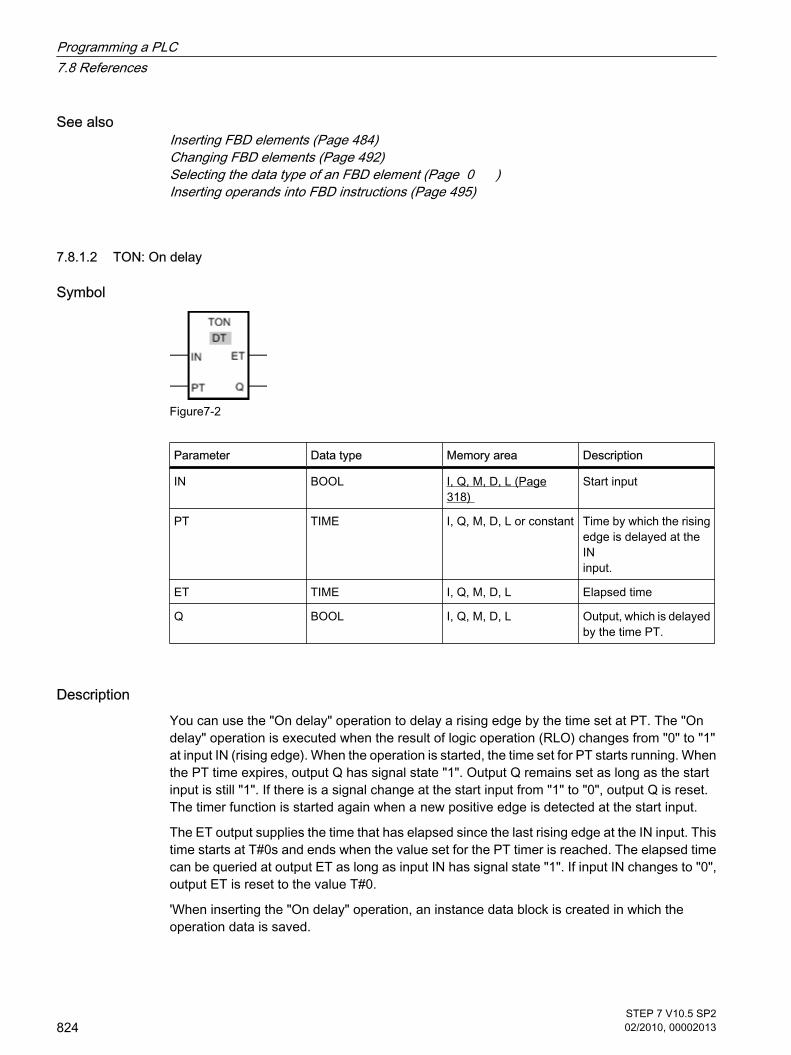
See alsoInserting FBD elements (Page 484)Changing FBD elements (Page 492)Selecting the data type of an FBD element (Page 0 )Inserting operands into FBD instructions (Page 495)
7.8.1.2 TON: On delay
Symbol
Figure7-2
Parameter Data type Memory area Description
IN BOOL I, Q, M, D, L (Page318)
Start input
PT TIME I, Q, M, D, L or constant Time by which the risingedge is delayed at theIN input.
ET TIME I, Q, M, D, L Elapsed time
Q BOOL I, Q, M, D, L Output, which is delayedby the time PT.
DescriptionYou can use the "On delay" operation to delay a rising edge by the time set at PT. The "Ondelay" operation is executed when the result of logic operation (RLO) changes from "0" to "1"at input IN (rising edge). When the operation is started, the time set for PT starts running. Whenthe PT time expires, output Q has signal state "1". Output Q remains set as long as the startinput is still "1". If there is a signal change at the start input from "1" to "0", output Q is reset.The timer function is started again when a new positive edge is detected at the start input.
The ET output supplies the time that has elapsed since the last rising edge at the IN input. Thistime starts at T#0s and ends when the value set for the PT timer is reached. The elapsed timecan be queried at output ET as long as input IN has signal state "1". If input IN changes to "0",output ET is reset to the value T#0.
'When inserting the "On delay" operation, an instance data block is created in which theoperation data is saved.
7.8.1.2 TON: On delay
Programming a PLC7.8 References
824STEP 7 V10.5 SP202/2010, 00002013

PlacementThe "On delay" operation requires a preceding logic operation for the edge evaluation. It canbe located within or at the end of the logic string.
Pulse diagram
Figure7-2
See alsoInserting FBD elements (Page 484)Changing FBD elements (Page 492)Selecting the data type of an FBD element (Page 0 )Inserting operands into FBD instructions (Page 495)Example of controlling room temperature (Page 621)
Programming a PLC7.8 References
STEP 7 V10.5 SP202/2010, 00002013
825

7.8.1.2 TOF: Off delay
Symbol
Figure7-2
Parameter Data type Memory area Description
IN BOOL I, Q, M, D, L (Page318)
Start input
PT TIME I, Q, M, D, L or constant Time by which the fallingedge is delayed at the INinput. PT must bepositive.
ET TIME I, Q, M, D, L Elapsed time
Q BOOL I, Q, M, D, L Output, which is delayedby the time PT.
DescriptionYou can use the "Off delay" operation to delay a falling edge by the time set at PT. The Q outputis set when the result of logic operation (RLO) at input IN changes from "0" to "1". When thesignal state at the IN input switches back to "0", the time set at PT starts. Output Q remains setas long the time set at PT is running. The Q output is reset when the PT time expires. If thesignal state at IN input changes to "1" before the time set at PT expires, the timer is reset. Thesignal state at the Q output will continue to be "1".
It is possible to query how long the current timer function has been running at output ET. Thistime starts at T#0s and ends when the value set for the PT timer is reached. When the timeset at PT expires, output ET remains set to the current value until input IN changes back to "1".
'When inserting the "OFF delay" operation, an instance data block is created in which theoperation data is saved.
PlacementThe "Off delay" operation requires a preceding logic operation for the edge evaluation. It canbe located within or at the end of the logic string.
7.8.1.2 TOF: Off delay
Programming a PLC7.8 References
826STEP 7 V10.5 SP202/2010, 00002013

Pulse diagram
Figure7-2
See alsoInserting FBD elements (Page 484)Changing FBD elements (Page 492)Selecting the data type of an FBD element (Page 0 )Inserting operands into FBD instructions (Page 495)
7.8.1.2 TONR: Retentive on delay
Symbol
Figure7-2
Parameter Data type Memory area Description
IN BOOL I, Q, M, D, L (Page 318) Start input
R BOOL I, Q, M, D, L Reset input
PT TIME I, Q, M, D, L or constant Maximum duration oftime recording
ET TIME I, Q, M, D, L Accumulated time
7.8.1.2 TONR: Retentive on delay
Programming a PLC7.8 References
STEP 7 V10.5 SP202/2010, 00002013
827

Parameter Data type Memory area Description
Q BOOL I, Q, M, D, L Output that is set whenthe PT time expires.
DescriptionYou can use the "Time accumulator" operation to accumulate time values within a period setwith the PT parameter. When input IN changes to signal state "1", the operation is executedand the time set at PT starts. While the time set at PT is running, the time values areaccumulated that are recorded at signal state "1" at input IN. The accumulated time is writtento output ET and can be queried there. When the PT time expires, output Q has signal state"1".
Input R resets the timer function and output Q regardless of the signal state at the start input.
'When inserting the "Time accumulator" operation, an instance data block is created in whichthe operation data is saved.
PlacementThe "Time accumulator" operation requires a preceding logic operation. It can be located withinor at the end of the logic string.
Pulse diagram
Figure7-2
Programming a PLC7.8 References
828STEP 7 V10.5 SP202/2010, 00002013

See alsoInserting FBD elements (Page 484)Changing FBD elements (Page 492)Selecting the data type of an FBD element (Page 0 )Inserting operands into FBD instructions (Page 495)
7.8.1.2 Counters
7.8.1.2 CTU: Count up
Symbol
ParameterEnglish
Data type Memory area Description
CU BOOL I, Q, M, D, L (Page318)
Count input
R BOOL I, Q, M, D, L Reset input
PV SINT, INT, DINT,USINT, UINT, UDINT
I, Q, M, D, L or constant Preset count
CV SINT, INT, DINT,USINT, UINT, UDINT
I, Q, M, D, L Actual count value
Q BOOL I, Q, M, D, L Counter status
You can select the data type for the operation from the "DT" drop-down list.
DescriptionYou can use the "Count up" operation to increment the value at the CV output. If the signalstate at the CU input changes from "0" to "1" (positive edge), the operation is executed and thecurrent count value at the CV output is incremented by one. The first time the operation isexecuted, the current count at the CV output is set to zero. The count is continually incrementedeach time a positive edge is detected, until it reaches the high limit for the data type specified
7.8.1.2 Counters7.8.1.2 CTU: Count up
Programming a PLC7.8 References
STEP 7 V10.5 SP202/2010, 00002013
829

at the CV output. When the high limit is reached, the signal state at the CU input no longer hasan effect on the operation.
The counter status can be queried at the Q output. The signal state at output Q is determinedby the PV parameter. If the current count value is greater than or equal to the value of the PVparameter, the Q output is set to signal state "1". In all other cases, the signal state at the Qoutput is "0".
The value at the CV output is reset to zero when the signal state at R input changes to "1". Aslong as there is the signal state "1" at R input, the signal state at input CU has no effect on theoperation.
'When inserting the "Count up" operation, an instance data block is created in which theoperation data is saved.
PlacementThe "Count up" operation requires a preceding logic operation for the edge evaluation. It canbe located within or at the end of the logic string.
Example
Figure7-2
When the signal state at the input I 0.0 changes from "0" to "1", the "Count up" operation isexecuted and the current count at the MW30 output is increased by one. With each furtherpositive edge, the count value is incremented until the high limit value of the specified data type(32 767) is reached.
The value at the MW20 parameter is applied as the limit for determining the output Q 4.0. OutputQ 4.0 has signal state "1" as long as the current count is greater than or equal to the value atthe MW20 parameter. In all other cases, output Q 4.0 has signal state "0".
See alsoInserting FBD elements (Page 484)Changing FBD elements (Page 492)Inserting operands into FBD instructions (Page 495)Selecting the data type of an FBD element (Page 0 )
Programming a PLC7.8 References
830STEP 7 V10.5 SP202/2010, 00002013

7.8.1.2 CTD: Count down
Symbol
Figure7-2
ParameterEnglish
Data type Memory area Description
CD BOOL I, Q, M, D, L (Page318)
Count input
LOAD BOOL I, Q, M, D, L Load input
PV SINT, UINT, DINT,USINT, UINT, UDINT
I, Q, M, D, L or constant Preset count
Q BOOL I, Q, M, D, L Counter status
CV SINT, UINT, DINT,USINT, UINT, UDINT
I, Q, M, D, L Actual count value
You can select the data type for the operation from the "DT" drop-down list.
DescriptionYou can use the "Count down" operation to decrement the value at the CV output. If the signalstate at the CD input changes from "0" to "1" (positive edge), the operation is executed and thecurrent count value at the CV output is decremented by one. The first time the operation isexecuted, the current count at the CV output is set to zero. Each time a positive edge isdetected, the count value is further decremented until it reaches the low limit value of thespecified data type. When the low limit value is reached, the signal state at the CD input hasno further effect on the operation.
The counter status can be queried at the Q output. If the current count value is less than orequal to zero, output Q is set to signal state "1". In all other cases, the signal state at the Qoutput is "0".
The value at the CV output is set to the value of the PV parameter when the signal state atLOAD input changes to "1". As long as there is the signal state "1" at the LOAD input, the signalstate at the CD input has no effect on the operation.
'When inserting the "Count down" operation, an instance data block is created in which theoperation data is saved.
7.8.1.2 CTD: Count down
Programming a PLC7.8 References
STEP 7 V10.5 SP202/2010, 00002013
831

PlacementThe "Count down" operation requires a preceding logic operation for the edge evaluation. Itcan be located within or at the end of the logic string.
Example
Figure7-2
When the signal state at the input I 0.0 changes from "0" to "1", the "Count down" operation isexecuted and the value at the MW30 input is decreased by one. With each further positiveedge, the count value is decremented until the low limit value of the specified data type (-32768) is reached.
Output Q 4.0 has signal state "1" as long as the current count value is less than or equal tozero. In all other cases, output Q 4.0 has signal state "0".
See alsoChanging FBD elements (Page 492)Inserting FBD elements (Page 484)Inserting operands into FBD instructions (Page 495)Selecting the data type of an FBD element (Page 0 )
7.8.1.2 CTUD: Count up and down
Symbol
Figure7-2
7.8.1.2 CTUD: Count up and down
Programming a PLC7.8 References
832STEP 7 V10.5 SP202/2010, 00002013

ParameterEnglish
Data type Memory area Description
CU BOOL I, Q, M, D, L (Page318)
Count up input
CD BOOL I, Q, M, D, L Count down input
R BOOL I, Q, M, D, L Reset input
LOAD BOOL I, Q, M, D, L Load input
PV SINT, UINT, DINT,USINT, UINT, UDINT
I, Q, M, D, L or constant Preset count
QU BOOL I, Q, M, D, L Status of theincremental counter
QD BOOL I, Q, M, D, L Status of thedecremental counter
CV SINT, UINT, DINT,USINT, UINT, UDINT
I, Q, M, D, L Actual count value
You can select the data type for the operation from the "DT" drop-down list.
DescriptionYou can use the "Count up and down" operation to increment and decrement the count valueat the CV output. If the signal state at CU input changes from "0" to "1" (positive edge), thecurrent count value is incremented by one and stored in the CV output. If the signal state atCD input changes from "0" to "1" (positive edge), the count value at the CV output isdecremented by one. If there is a positive edge at the CU and CD inputs in one program cycle,the current count value at the CV output remains unchanged.
The count value can be incremented until it reaches the high limit value of the data typespecified at the CV output. When the high limit value is reached, the count value is no longerincremented on a positive edge. When the low limit value of the specified data type is reached,the count value is not decremented any further.
When the signal state at the LOAD input changes to "1", the count value at the CV output isset to the value of the PV parameter. As long as there is the signal state "1" at the LOAD input,the signal state at the CU and CD inputs has no effect on the operation.
The count value is set to zero when the signal state at input R changes to "1". As long as thesignal state at the R input is "1", changes of signal state at inputs CU and CD and LOAD haveno effect on the "Count up and down" operation.
The incremental counter status can be queried at QU output. If the current count value is greaterthan or equal to the value of the PV parameter, QU output has signal state "1". In all othercases, the signal state at the QU output is "0".
The decremental counter status can be queried at QD output. If the current count value is lessthan or equal to zero, output QD has signal state "1". In all other cases, the signal state at theQD output is "0".
Programming a PLC7.8 References
STEP 7 V10.5 SP202/2010, 00002013
833

'When inserting the "Count up and down" operation, an instance data block is created in whichthe operation data is saved.
PlacementThe "Count up and down" operation requires a preceding logic operation for the edgeevaluation. It can be located within or at the end of the logic string.
Example
Figure7-2
If the signal state at input I 0.0 or at input I 0.1 changes from "0" to "1" (positive edge), the"Count up and down" operation is executed. When there is a positive edge at the input I 0.0,the current count is increased by one and stored at the output MW30. When there is a positiveedge at the input I 0.1, the current count is decreased by one and stored at the output MW30.When there is a positive edge at CU input the count value is incremented until it reaches thehigh limit of 32 767. When there is a positive edge at input I 0.1, the count value is decrementeduntil it reaches the low limit value of -32 768.
Output Q 4.0 has signal state "1" as long as the current count is greater than or equal to thevalue at the MW20 input. In all other cases, output Q 4.0 has signal state "0".
Output Q 6.0 has signal state "1" as long as the current count value is less than or equal tozero. In all other cases, output Q 6.0 has signal state "0".
See alsoInserting FBD elements (Page 484)Changing FBD elements (Page 492)Inserting operands into FBD instructions (Page 495)Selecting the data type of an FBD element (Page 0 )Example of detecting the fill level of a storage area (Page 616)
Programming a PLC7.8 References
834STEP 7 V10.5 SP202/2010, 00002013

7.8.1.2 High-speed counters
7.8.1.2 CTRL_HSC: Control high-speed counters in FBD
Symbol
Figure7-2
Parameter Data type Memory area Description
EN BOOL I, Q, M, L, D (Page 318) Enable input
ENO BOOL I, Q, M, L, D Enable output
HSC HW_HSC L, D or constant Hardware address ofthe high-speed counter(HW-ID)
DIR BOOL I, Q, M, L, D Enables the new countdirection (seeNEW_DIR)
CV BOOL I, Q, M, L, D Enables the new countvalue (see NEW_CV)
RV BOOL I, Q, M, L, D Enables the newreference value (seeNEW_RV)
PERIOD BOOL I, Q, M, L, D Enables the new periodof a frequencymeasurement (seeNEW_PERIOD)
NEW_DIR INT I, Q, M, L, D Count direction loadedwhen DIR = TRUE.
NEW_CV DINT I, Q, M, L, D Count value loadedwhen CV = TRUE.
7.8.1.2 High-speed counters7.8.1.2 CTRL_HSC: Control high-speed counters in FBD
Programming a PLC7.8 References
STEP 7 V10.5 SP202/2010, 00002013
835

Parameter Data type Memory area Description
NEW_RV DINT I, Q, M, L, D Reference value loadedwhen CV = TRUE.
NEW_PERIOD INT I, Q, M, L, D Period of the frequencymeasurement loadedwhen PERIOD = TRUE.
BUSY BOOL I, Q, M, L, D Processing status
STATUS WORD I, Q, M, L, D Status of the operation
DescriptionWith the "Control high-speed counters" operation, you can make parameter settings and controlthe high-speed counters supported by the CPU by loading new values into the counter. Theoperation can only execute if a high-speed counter you want to control is enabled. You canonly insert and execute one "Control high-speed counters" operation per high-speed counterin the program. You enter the hardware identifier of the high-speed counter (HW-ID), whosevalues you want to assign at the HSC input.
You can load the following parameter values into a high-speed counter using the "Control high-speed counters" operation:
• Count direction (NEW_DIR): The count direction defines whether a high-speed counter counts up ordown. The count direction is defined by the following values at the NEW_DIR input: 1 = up, -1 =down. A change to the count direction with the "Control high-speed counters" operation is possible only whendirection control is set in the parameters by the program. The count direction specified at the NEW_DIR input is loaded into a high-speed counter when the bitat the DIR input is set.
• Count value (NEW_CV): The count value is the initial value at which a high-speed counter startscounting. The count value can be in a range from - 2147483648 to 2147483647. The count value specified at the NEW_CV input is loaded into a high-speed counter when the bit atthe CV input is set.
• Reference value (NEW_RV): The reference value is the highest value that a high-speed counter canreach. The reference value can be in a range from - 2147483648 to 2147483647. The reference value specified at the NEW_RV input is loaded into a high-speed counter when the bitat the RV input is set.
• Period of the frequency measurement (NEW_PERIOD): The period of the frequency measurement isspecified by the following values at the NEW_PERIOD input: 10 = 0.01s, 100 = 0.1s, 1000 = 1s. The period can be updated when the "Frequency measurement" function is set in the parameters ofthe specified high-speed counter. The period specified at the NEW_PERIOD input is loaded into a high-speed counter if the bit at thePERIOD input is set.
The "Control high-speed counters" operation is only executed if the signal state at the EN inputis "1". As long as the operation is executing, the bit at the BUSY output is set. Once the operationhas executed completely, the bit at the BUSY output is reset.
Programming a PLC7.8 References
836STEP 7 V10.5 SP202/2010, 00002013

The ENO enable output is set only when the EN input has signal state "1" and no errors occurredduring execution of the operation.
'When inserting the "Control high-speed counters" operation, an instance data block is createdin which the operation data is saved.
Parameter STATUSAt the STATUS output, you can query whether errors occurred during execution of the "Controlhigh-speed counters" operation. The following table shows the meaning of the values outputat the STATUS output:
Error code (hexadecimal) Description
0 No error
80A1 Hardware identifier of the high-speed counterinvalid
80B1 Count direction (NEW_DIR) invalid
80B2 Count value (NEW_CV) invalid
80B3 Reference value (NEW_RV) invalid
80B4 Period of the frequency measurement(NEW_PERIOD) invalid
80C0 Multiple access to the high-speed counter
See alsoChanging FBD elements (Page 492)Inserting FBD elements (Page 484)Inserting operands into FBD instructions (Page 495)Selecting the data type of an FBD element (Page 0 )Configuring high-speed counters (Page 264)Assigning parameters to hardware interrupt OBs (Page 417)
7.8.1.2 Compare
7.8.1.2 CMP ==: Equality
Symbol
7.8.1.2 Compare7.8.1.2 CMP ==: Equality
Programming a PLC7.8 References
STEP 7 V10.5 SP202/2010, 00002013
837

Parameter Data type Memory area Description
Operand1 USINT, UINT, UDINT,SINT, INT, DINT, REAL,CHAR, STRING, TIME,DTL
I, Q, M, L, D (Page 318)or constant
First value to compare
Operand2 USINT, UINT, UDINT,SINT, INT, DINT, REAL,CHAR, STRING, TIME,DTL
I, Q, M, L, D or constant Second value tocompare
You can select the data type for the operation from the "DT" drop-down list.
DescriptionYou can use the "Equal" operation to query whether the first value of the comparison is equalto the second value. Both values to be compared must be of the same data type.
The individual characters are compared by means of their ASCII code (for example, 'a' isgreater than 'A') during the comparison of the strings. The comparison is performed from leftto right. The first character to be different decides the result of the comparison.
The following table shows examples of string comparisons:
<Operand1> <Operand2> RLO of operation
'AA' 'AA' 1
'Hello World' 'HelloWorld' 0
'AA' 'aa' 0
PlacementThe "Equal" operation can be placed at any position in the logic string.
Example
Figure7-2
Output Q 4.0 is set when the following conditions are fulfilled:
• The condition of the comparison operation is fulfilled (MW0 = MW2).
• Input I 0.0 has signal state "1".
See alsoInserting FBD elements (Page 484)
Programming a PLC7.8 References
838STEP 7 V10.5 SP202/2010, 00002013

Changing FBD elements (Page 492)Inserting operands into FBD instructions (Page 495)Selecting the data type of an FBD element (Page 0 )
7.8.1.2 CMP <>: Inequality
Symbol
Parameter Data type Memory area Description
Operand1 USINT, UINT, UDINT,SINT, INT, DINT, REAL,CHAR, STRING, TIME,DTL
I, Q, M, L, D (Page 318)or constant
First value to compare
Operand2 USINT, UINT, UDINT,SINT, INT, DINT, REAL,CHAR, STRING, TIME,DTL
I, Q, M, L, D or constant Second value tocompare
You can select the data type for the operation from the "DT" drop-down list.
DescriptionWith the "Not equal" operation, you can query whether the first value of the comparison is notequal to the second value. Both values to be compared must be of the same data type.
The individual characters are compared by means of their ASCII code (for example, 'a' isgreater than 'A') during the comparison of the strings. The comparison is performed from leftto right. The first character to be different decides the result of the comparison.
The following table shows examples of string comparisons:
<Operand1> <Operand2> RLO of operation
'AA' 'aa' 1
'Hello World' 'HelloWorld' 1
'AA' 'AA' 0
7.8.1.2 CMP <>: Inequality
Programming a PLC7.8 References
STEP 7 V10.5 SP202/2010, 00002013
839

PlacementThe "Not equal" operation can be placed at any position in the logic string.
Example
Figure7-2
Output Q 4.0 is set when the following conditions are fulfilled:
• The condition of the comparison operation is fulfilled (MW0 <> MW2).
• Input I 0.0 has signal state "1".
See alsoInserting FBD elements (Page 484)Changing FBD elements (Page 492)Inserting operands into FBD instructions (Page 495)Selecting the data type of an FBD element (Page 0 )
7.8.1.2 CMP >=: Greater than or equal to
Symbol
Parameter Data type Memory area Description
Operand1 USINT, UINT, UDINT,SINT, INT, DINT, REAL,CHAR, STRING, TIME,DTL
I, Q, M, L, D (Page 318)or constant
First value to compare
Operand2 USINT, UINT, UDINT,SINT, INT, DINT, REAL,CHAR, STRING, TIME,DTL
I, Q, M, L, D or constant Second value tocompare
You can select the data type for the operation from the "DT" drop-down list.
7.8.1.2 CMP >=: Greater than or equal to
Programming a PLC7.8 References
840STEP 7 V10.5 SP202/2010, 00002013

DescriptionYou can use the "Greater or equal" operation to determine if a first comparison value is greaterthan or equal to the second comparison value. Both values to be compared must be of thesame data type.
The individual characters are compared by means of their ASCII code (for example, 'a' isgreater than 'A') during the comparison of the strings. The comparison is performed from leftto right. The first character to be different decides the result of the comparison. If the left partof the longer string is identical to the shorter string, the longer string is considered greater.
The following table shows examples of string comparisons:
<Operand1> <Operand2> RLO of operation
'BB' 'AA' 1
'AAA' 'AA' 1
'Hello World' 'Hello World' 1
'Hello World' 'HelloWorld' 0
'AA' 'aa' 0
'AAA' 'a' 0
In comparing time values the RLO is "1" if the point of time at <Operand1> is greater (morerecent) than or equal to the point of time at <Operand2>.
PlacementThe "Greater or equal" operation can be placed at any position in the logic string.
Example
Figure7-2
Output Q 4.0 is set when the following conditions are fulfilled:
• The condition of the comparison operation is fulfilled (MW0 >= MW2).
• Input I 0.0 has signal state "1".
See alsoInserting FBD elements (Page 484)Changing FBD elements (Page 492)Inserting operands into FBD instructions (Page 495)Selecting the data type of an FBD element (Page 0 )Example of detecting the fill level of a storage area (Page 616)
Programming a PLC7.8 References
STEP 7 V10.5 SP202/2010, 00002013
841
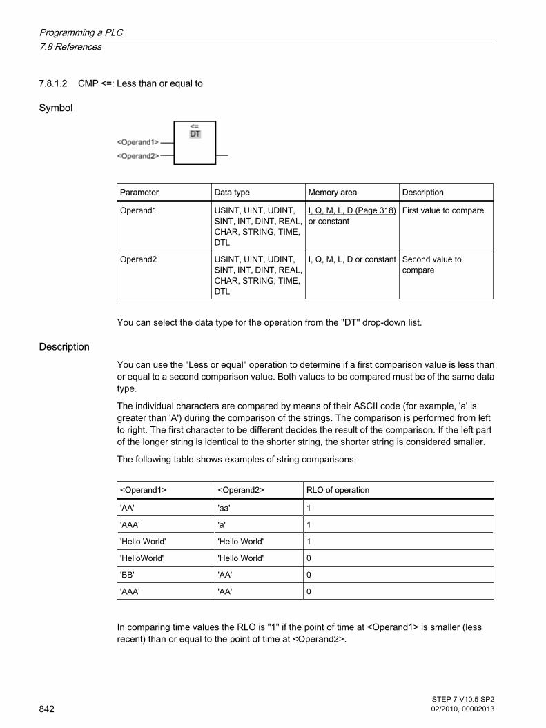
7.8.1.2 CMP <=: Less than or equal to
Symbol
Parameter Data type Memory area Description
Operand1 USINT, UINT, UDINT,SINT, INT, DINT, REAL,CHAR, STRING, TIME,DTL
I, Q, M, L, D (Page 318)or constant
First value to compare
Operand2 USINT, UINT, UDINT,SINT, INT, DINT, REAL,CHAR, STRING, TIME,DTL
I, Q, M, L, D or constant Second value tocompare
You can select the data type for the operation from the "DT" drop-down list.
DescriptionYou can use the "Less or equal" operation to determine if a first comparison value is less thanor equal to a second comparison value. Both values to be compared must be of the same datatype.
The individual characters are compared by means of their ASCII code (for example, 'a' isgreater than 'A') during the comparison of the strings. The comparison is performed from leftto right. The first character to be different decides the result of the comparison. If the left partof the longer string is identical to the shorter string, the shorter string is considered smaller.
The following table shows examples of string comparisons:
<Operand1> <Operand2> RLO of operation
'AA' 'aa' 1
'AAA' 'a' 1
'Hello World' 'Hello World' 1
'HelloWorld' 'Hello World' 0
'BB' 'AA' 0
'AAA' 'AA' 0
In comparing time values the RLO is "1" if the point of time at <Operand1> is smaller (lessrecent) than or equal to the point of time at <Operand2>.
7.8.1.2 CMP <=: Less than or equal to
Programming a PLC7.8 References
842STEP 7 V10.5 SP202/2010, 00002013

PlacementThe "Less or equal" operation can be placed at any position in the logic string.
Example
Figure7-2
Output Q 4.0 is set when the following conditions are fulfilled:
• The condition of the comparison operation is fulfilled (MW0 <= MW2).
• Input I 0.0 has signal state "1".
See alsoInserting FBD elements (Page 484)Changing FBD elements (Page 492)Inserting operands into FBD instructions (Page 495)Selecting the data type of an FBD element (Page 0 )
7.8.1.2 CMP >: Greater than
Symbol
Parameter Data type Memory area Description
Operand1 USINT, UINT, UDINT,SINT, INT, DINT, REAL,CHAR, STRING, TIME,DTL
I, Q, M, L, D (Page 318)or constant
First value to compare
Operand2 USINT, UINT, UDINT,SINT, INT, DINT, REAL,CHAR, STRING, TIME,DTL
I, Q, M, L, D or constant Second value tocompare
You can select the data type for the operation from the "DT" drop-down list.
7.8.1.2 CMP >: Greater than
Programming a PLC7.8 References
STEP 7 V10.5 SP202/2010, 00002013
843

DescriptionWith the "Greater than" operation, you can query whether the first value of the comparison isgreater than the second value. Both values to be compared must be of the same data type.
The individual characters are compared by means of their ASCII code (for example, 'a' isgreater than 'A') during the comparison of the strings. The comparison is performed from leftto right. The first character to be different decides the result of the comparison. If the left partof the longer string is identical to the shorter string, the longer string is considered greater.
The following table shows examples of string comparisons:
<Operand1> <Operand2> RLO of operation
'BB' 'AA' 1
'AAA' 'AA' 1
'AA' 'aa' 0
'AAA' 'a' 0
In comparing time values, the RLO is "1" if the point of time at <Operand1> is greater (morerecent) than the point of time at <Operand2>.
PlacementThe "Greater than" operation can be placed at any position in the logic string.
Example
Figure7-2
Output Q 4.0 is set when the following conditions are fulfilled:
• The condition of the comparison operation is fulfilled (MW0 > MW2).
• Input I 0.0 has signal state "1".
See alsoInserting FBD elements (Page 484)Changing FBD elements (Page 492)Inserting operands into FBD instructions (Page 495)Selecting the data type of an FBD element (Page 0 )
Programming a PLC7.8 References
844STEP 7 V10.5 SP202/2010, 00002013

7.8.1.2 CMP <: Less than
Symbol
Parameter Data type Memory area Description
Operand1 USINT, UINT, UDINT,SINT, INT, DINT, REAL,CHAR, STRING, TIME,DTL
I, Q, M, L, D (Page 318)or constant
First value to compare
Operand2 USINT, UINT, UDINT,SINT, INT, DINT, REAL,CHAR, STRING, TIME,DTL
I, Q, M, L, D or constant Second value tocompare
You can select the data type for the operation from the "DT" drop-down list.
DescriptionWith the "Less than" operation, you can query whether the first value of the comparison is lessthan the second value. Both values to be compared must be of the same data type.
The individual characters are compared by means of their ASCII code (for example, 'a' isgreater than 'A') during the comparison of the strings. The comparison is performed from leftto right. The first character to be different decides the result of the comparison. If the left partof the longer string is identical to the shorter string, the shorter string is considered smaller.
The following table shows examples of string comparisons:
<Operand1> <Operand2> RLO of operation
'AA' 'aa' 1
'AAA' 'a' 1
'BB' 'AA' 0
'AAA' 'AA' 0
In comparing time values, the RLO is "1" if the point of time at <Operand1> is smaller (lessrecent) than the point of time at <Operand2>.
PlacementThe "Less than" operation can be placed at any position in the logic string.
7.8.1.2 CMP <: Less than
Programming a PLC7.8 References
STEP 7 V10.5 SP202/2010, 00002013
845

Example
Figure7-2
Output Q 4.0 is set when the following conditions are fulfilled:
• The condition of the comparison operation is fulfilled (MW0 < MW2).
• Input I 0.0 has signal state "1".
See alsoInserting FBD elements (Page 484)Changing FBD elements (Page 492)Inserting operands into FBD instructions (Page 495)Selecting the data type of an FBD element (Page 0 )
7.8.1.2 IN_RANGE: Value within range
Symbol
Parameter Data type Memory area Description
MIN SINT, INT, DINT,USINT, UINT, UDINT,REAL
I, Q, M, L, D (Page 318)or constant
Low limit of the valuerange
VAL SINT, INT, DINT,USINT, UINT, UDINT,REAL
I, Q, M, L, D or constant Comparison value
MAX SINT, INT, DINT,USINT, UINT, UDINT,REAL
I, Q, M, L, D or constant High limit of the valuerange
Box output BOOL I, Q, M, L, D Result of thecomparison
You can select the data type for the operation from the "DT" drop-down list.
7.8.1.2 IN_RANGE: Value within range
Programming a PLC7.8 References
846STEP 7 V10.5 SP202/2010, 00002013

DescriptionYou can use the "Value within range" operation to determine of the value at the VAL input iswithin a specific value range. You specify the limits of the value range with the MIN and MAXparameters. When the query is processed, the "Value within range" operation compares thevalue at the VAL input to the values of the MIN and MAX parameters and sends the result tothe box output. If the value at the VAL input satisfies the comparison MIN <= VALUE <= MAX,the box output has signal state "1". If the comparison is not fulfilled, the signal state is "0" atthe box output.
The comparison function can only execute if the values to be compared are of the same datatype and the box output is interconnected.
PlacementThe "Value within range" operation can be placed at the start of the logic string or within it.
Example
Figure7-2
Output Q 4.0 is set when the following conditions are fulfilled:
• The signal state at input I 0.0 OR at input I 0.1 is "1".
• Input I 0.2 has signal state "1".
• The value at the MD12 input is within the value range, which is specified by the current values at theinputs MD8 and MD20 (MIN <= VAL <= MAX).
See alsoInserting FBD elements (Page 484)Changing FBD elements (Page 492)Inserting operands into FBD instructions (Page 495)Selecting the data type of an FBD element (Page 0 )GetError (Page 954)
Programming a PLC7.8 References
STEP 7 V10.5 SP202/2010, 00002013
847

7.8.1.2 OUT_RANGE: Value outside range
Symbol
Parameter Data type Memory area Description
MIN SINT, INT, DINT,USINT, UINT, UDINT,REAL
I, Q, M, L, D (Page 318)or constant
Low limit of the valuerange
VAL SINT, INT, DINT,USINT, UINT, UDINT,REAL
I, Q, M, L, D or constant Comparison value
MAX SINT, INT, DINT,USINT, UINT, UDINT,REAL
I, Q, M, L, D or constant High limit of the valuerange
Box output BOOL I, Q, M, L, D Result of thecomparison
You can select the data type for the operation from the "DT" drop-down list.
DescriptionYou can use the "Value outside range" operation to query whether or nor the value at the VALinput is outside a specific range. You specify the limits of the value range with the MIN andMAX parameters. When the query is processed, the "Value outside range" operation comparesthe value at the VAL input to the values of the MIN and MAX parameters and sends the resultto the box output. If the value at the VAL input satisfies the comparison MIN > VAL or VAL >MAX, the box output has signal state "1". If the comparison is not fulfilled, the signal state is"0" at the box output.
The comparison function can only execute if the values to be compared are of the same datatype and the box output is interconnected.
PlacementThe "Value outside range" operation can be placed at the start of the logic string or within it.
7.8.1.2 OUT_RANGE: Value outside range
Programming a PLC7.8 References
848STEP 7 V10.5 SP202/2010, 00002013

Example
Figure7-2
Output Q 4.0 is set when the following conditions are fulfilled:
• The signal state at input I 0.0 is "1".
• The value at input MD12 is outside the range of values set by the values of inputs MD8 and MD10(MIN > VAL or VAL > MAX).
See alsoInserting FBD elements (Page 484)Changing FBD elements (Page 492)Inserting operands into FBD instructions (Page 495)Selecting the data type of an FBD element (Page 0 )GetError (Page 954)
7.8.1.2 OK: Test validity
Symbol
Parameter Data type Memory area Description
<Operand> REAL I, Q, M, L, D (Page 318)or constant
Value to be checked.
DescriptionYou can use the "Check validity" operation to check if the value of a tag (<operand>) is a validfloating-point number. The query starts in every program cycle. If the value of the tag is a validfloating-point number at the time of the query, the output to the right-hand connection has signalstate "1". In all other cases, the signal state at the output of the "Check validity" operation is"0".
You can use the "Check validity" operation together with the EN mechanism. If you connectthe OK box to an EN enable input, the enable input is set only when the result of the validity
7.8.1.2 OK: Test validity
Programming a PLC7.8 References
STEP 7 V10.5 SP202/2010, 00002013
849

query of the value is positive. You can use this function to ensure that an operation is enabledonly when the value of the specified tag is a valid floating-point number.
PlacementThe "Check validity" operation can be placed at the start of the logic string or within it.
Example
Figure7-2
If MD0 AND MD4 are valid floating-point numbers, the "Multiply" operation (MUL) is performedand output ENO is set. When the "Multiply" (MUL) operation is executed, the value at inputMD0 is multiplied by the value of MD4. The product of the multiplication is stored at outputMD10. If no errors occur during execution of the operation, outputs ENO and Q 4.0 are set tosignal state "1".
See alsoInserting FBD elements (Page 484)Changing FBD elements (Page 492)Inserting operands into FBD instructions (Page 495)Selecting the data type of an FBD element (Page 0 )
7.8.1.2 NOT_OK: Check invalidity
Symbol
Parameter Data type Memory area Description
<Operand> REAL I, Q, M, L, D (Page 318)or constant
Value to be checked.
DescriptionYou can use the "Check invalidity" operation to check if the value of a tag (<operand>) is aninvalid floating-point number. The query starts in every program cycle. If the value of the tag is
7.8.1.2 NOT_OK: Check invalidity
Programming a PLC7.8 References
850STEP 7 V10.5 SP202/2010, 00002013

an invalid floating-point number at the time of the query and the signal state at the input of thebox is "1", the output has signal state "1". In all other cases, the signal state at the output ofthe "Check invalidity" operation is "0".
PlacementThe "Check invalidity" operation can be placed at the start of the logic string or within it.
Example
Figure7-2
If the value at input MD0 is an invalid floating-point number, the "Move value" (MOVE) operationis not executed. Output Q 4.0 is reset to signal state "0".
See alsoInserting FBD elements (Page 484)Changing FBD elements (Page 492)Inserting operands into FBD instructions (Page 495)Selecting the data type of an FBD element (Page 0 )
7.8.1.2 Math
7.8.1.2 ADD: Add
Symbol
Figure7-2
Parameter Data type Memory area Description
EN BOOL I, Q, M, L, D (Page318)
Enable input
ENO BOOL I, Q, M, L, D Enable output
7.8.1.2 Math7.8.1.2 ADD: Add
Programming a PLC7.8 References
STEP 7 V10.5 SP202/2010, 00002013
851

Parameter Data type Memory area Description
IN1 SINT, INT, DINT,USINT, UINT, UDINT,REAL
I, Q, M, L, D or constant First value for addition
IN2 SINT, INT, DINT,USINT, UINT, UDINT,REAL
I, Q, M, L, D or constant Second value foraddition
OUT SINT, INT, DINT,USINT, UINT, UDINT,REAL
I, Q, M, L, D Result of addition
You can select the data type for the operation from the "DT" drop-down list.
DescriptionYou can use the "Add" operation to add the value at input IN1 and the value at input IN2 andquery the sum at the OUT output (OUT =IN1+IN2).
The operation is only executed if the signal state at the enable input EN is "1". If no errors occurduring execution of the operation, the ENO output also has signal state "1".
The enable output ENO returns signal state "0" if one of the following conditions applies:
• The EN input has signal state "0".
• The result of the operation is outside the range permitted for the data type specified at the OUT output.
• An input tag of the REAL data type has an invalid value.
PlacementThe "Add" operation can be placed at any position in the logic string.
Example
Figure7-2
If the input I 0.0 has signal state "1", the "Add" operation is executed. The value at the MW0input is added to the value at the MW2 input. The result of the addition is stored at the MW10output. If no errors occur during execution of the operation, the ENO output has signal state"1" and output Q 4.0 is set.
See alsoInserting FBD elements (Page 484)Changing FBD elements (Page 492)Inserting operands into FBD instructions (Page 495)
Programming a PLC7.8 References
852STEP 7 V10.5 SP202/2010, 00002013

Selecting the data type of an FBD element (Page 0 )Pasting additional inputs and outputs (Page 494)Example of calculating an equation (Page 620)
7.8.1.2 SUB: Subtract
Symbol
Figure7-2
Parameter Data type Memory area Description
EN BOOL I, Q, M, L, D (Page318)
Enable input
ENO BOOL I, Q, M, L, D Enable output
IN1 SINT, INT, DINT,USINT, UINT, UDINT,REAL
I, Q, M, L, D or constant First value forsubtraction
IN2 SINT, INT, DINT,USINT, UINT, UDINT,REAL
I, Q, M, L, D or constant Value to be subtracted.
OUT SINT, INT, DINT,USINT, UINT, UDINT,REAL
I, Q, M, L, D Result of subtraction
You can select the data type for the operation from the "DT" drop-down list.
DescriptionYou can use the "Subtract" operation to subtract the value at input IN2 from the value at inputIN1 and query the difference at the OUT output (OUT =IN1-IN2).
The operation is only executed if the signal state is "1" at the enable input EN. If no errors occurduring execution of the operation, the ENO output also has signal state "1".
The enable output ENO returns signal state "0" if one of the following conditions applies:
• The EN input has signal state "0".
• The result of the operation is outside the range permitted for the data type specified at the OUT output.
• An input tag of the REAL data type has an invalid value.
7.8.1.2 SUB: Subtract
Programming a PLC7.8 References
STEP 7 V10.5 SP202/2010, 00002013
853

PlacementYou can place the "Subtract" operation at any position in the logic string.
Example
Figure7-2
If input I 0.0 has signal state "1", the "Subtract" operation is performed. The value at the MW2input is subtracted from the value at the MW0 input. The result of the subtraction is stored atthe MW10 output. If no errors occur during execution of the operation, the ENO output hassignal state "1" and output Q 4.0 is set.
See alsoInserting FBD elements (Page 484)Changing FBD elements (Page 492)Inserting operands into FBD instructions (Page 495)Selecting the data type of an FBD element (Page 0 )Pasting additional inputs and outputs (Page 494)Example of calculating an equation (Page 620)
7.8.1.2 MUL: Multiply
Symbol
Figure7-2
Parameter Data type Memory area Description
EN BOOL I, Q, M, L, D (Page318)
Enable input
ENO BOOL I, Q, M, L, D Enable output
IN1 SINT, INT, DINT,USINT, UINT, UDINT,REAL
I, Q, M, L, D or constant First value formultiplication
7.8.1.2 MUL: Multiply
Programming a PLC7.8 References
854STEP 7 V10.5 SP202/2010, 00002013

Parameter Data type Memory area Description
IN2 SINT, INT, DINT,USINT, UINT, UDINT,REAL
I, Q, M, L, D or constant Second value formultiplication
OUT SINT, INT, DINT,USINT, UINT, UDINT,REAL
I, Q, M, L, D Result of multiplication
You can select the data type for the operation from the "DT" drop-down list.
DescriptionYou can use the "Multiply" operation to multiply the value at the IN1 input to the value at theIN2 input and query the product at the OUT output (OUT =IN1*IN2).
The operation is only executed if the signal state is "1" at the enable input EN. If no errors occurduring execution of the operation, the ENO output also has signal state "1".
The enable output ENO returns signal state "0" if one of the following conditions applies:
• The EN input has signal state "0".
• The result is outside the range permitted for the data type specified at the OUT output.
• An input tag of the REAL data type has an invalid value.
PlacementThe "Multiply" operation can be placed at any position in the logic string.
Example
Figure7-2
If the input I 0.0 has signal state "1", the "Multiply" operation is executed. The value at inputMD0 is multiplied by the value at input MD2. The product of the multiplication is stored in outputMD10. If no errors occur during execution of the operation, the ENO output has signal state "1"and output Q 4.0 is set.
See alsoInserting FBD elements (Page 484)Changing FBD elements (Page 492)Inserting operands into FBD instructions (Page 495)Pasting additional inputs and outputs (Page 494)Example of calculating an equation (Page 620)Selecting the data type of an FBD element (Page 0 )
Programming a PLC7.8 References
STEP 7 V10.5 SP202/2010, 00002013
855

7.8.1.2 DIV: Divide
Symbol
Figure7-2
Parameter Data type Memory area Description
EN BOOL I, Q, M, L, D (Page318)
Enable input
ENO BOOL I, Q, M, L, D Enable output
IN1 SINT, USINT, INT,UINT, DINT, UDINT,REAL
I, Q, M, L, D or constant Dividend
IN2 SINT, USINT, INT,UINT, DINT, UDINT,REAL
I, Q, M, L, D or constant Divisor
OUT SINT, USINT, INT,UINT, DINT, UDINT,REAL
I, Q, M, L, D Result of division
You can select the data type for the operation from the "DT" drop-down list.
DescriptionYou can use the "Divide" operation to divide the value at the IN1 input by the value at the IN2input and query the quotient at the OUT output (OUT =IN1/IN2).
The operation is only executed if the signal state is "1" at the enable input EN. If no errors occurduring execution of the operation, the ENO output also has signal state "1".
The enable output ENO returns signal state "0" if one of the following conditions applies:
• The EN input has signal state "0".
• The result of the operation is outside the range permitted for the data type specified at the OUT output.
• An input tag of the REAL data type has an invalid value.
PlacementYou can place the "Divide" operation at any position in the logic string.
7.8.1.2 DIV: Divide
Programming a PLC7.8 References
856STEP 7 V10.5 SP202/2010, 00002013

Example
Figure7-2
If the input I 0.0 has signal state "1", the "Divide" operation is executed. The value at input MD0is divided by the value at input MD2. The result of the division is stored at the MD10 output. Ifno errors occur during execution of the operation, the ENO output has signal state "1" andoutput Q 4.0 is set.
See alsoInserting FBD elements (Page 484)Changing FBD elements (Page 492)Inserting operands into FBD instructions (Page 495)Selecting the data type of an FBD element (Page 0 )Pasting additional inputs and outputs (Page 494)Example of calculating an equation (Page 620)
7.8.1.2 MOD: Return remainder of division
Symbol
Figure7-2
Parameter Data type Memory area Description
EN BOOL I, Q, M, L, D (Page318)
Enable input
ENO BOOL I, Q, M, L, D Enable output
IN1 SINT, INT, DINT,USINT, UINT, UDINT
I, Q, M, L, D or constant Dividend
IN2 SINT, INT, DINT,USINT, UINT, UDINT
I, Q, M, L, D or constant Divisor
OUT SINT, INT, DINT,USINT, UINT, UDINT
I, Q, M, L, D Remainder of division
7.8.1.2 MOD: Return remainder of division
Programming a PLC7.8 References
STEP 7 V10.5 SP202/2010, 00002013
857

You can select the data type for the operation from the "DT" drop-down list.
DescriptionYou can use the "Return remainder of division" operation to divide the value at the IN1 inputby the value at the IN2 input and query the remainder at the OUT output.
The operation is only executed if the signal state at the EN input is "1". If no errors occur duringexecution of the operation, the ENO output also has signal state "1".
The operation is not executed if the signal state at the EN input is "0". In this case, the ENOoutput is reset.
PlacementThe "Return remainder of division" operation can be placed at any position in the logic string.
Example
Figure7-2
If the input I 0.0 has signal state "0", the "Return remainder of division" operation is performed.The value at input MD0 is divided by the value at input MD2. The remainder of the division isprovided at output MD10. If no errors occur during execution of the operation, the ENO outputhas signal state "1" and output Q 4.0 is set.
See alsoInserting FBD elements (Page 484)Changing FBD elements (Page 492)Inserting operands into FBD instructions (Page 495)Selecting the data type of an FBD element (Page 0 )Pasting additional inputs and outputs (Page 494)Example of calculating an equation (Page 620)
Programming a PLC7.8 References
858STEP 7 V10.5 SP202/2010, 00002013

7.8.1.2 NEG: Create twos complement
Symbol
Figure7-2
Parameter Data type Memory area Description
EN BOOL I, Q, M, L, D (Page318)
Enable input
ENO BOOL I, Q, M, L, D Enable output
IN SINT, INT, DINT, REAL I, Q, M, L, D or constant Input value
OUT SINT, INT, DINT, REAL I, Q, M, L, D Twos complement of theinput value
You can select the data type for the operation from the "DT" drop-down list.
DescriptionYou can use the "Create twos complement" operation to change the sign of the value at the INinput and query the result at the OUT output. If there is a positive value at the IN input, forexample, the negative equivalent of this value is sent to the OUT output.
The operation is only executed if the signal state is "1" at the enable input EN. If no errors occurduring execution of the operation, the ENO output also has signal state "1".
The enable output ENO returns signal state "0" if one of the following conditions applies:
• The EN input has signal state "0".
• The result of the operation is outside the range permitted for the data type specified at the OUT output.
• An input tag of the REAL data type has an invalid value.
PlacementThe "Create twos complement" operation can be placed at any position in the logic string.
7.8.1.2 NEG: Create twos complement
Programming a PLC7.8 References
STEP 7 V10.5 SP202/2010, 00002013
859

Example
Figure7-2
If input I 0.0 has signal state "1", the "Create twos complement" operation is performed. Thesign of the value at input MD8 is changed and the result is provided at output MD12. If no errorsoccur during execution of the operation, the ENO output has signal state "1" and output Q 4.0is set.
See alsoInserting FBD elements (Page 484)Changing FBD elements (Page 492)Inserting operands into FBD instructions (Page 495)Selecting the data type of an FBD element (Page 0 )Pasting additional inputs and outputs (Page 494)Example of calculating an equation (Page 620)
7.8.1.2 INC: Increment
Symbol
Parameter Data type Memory area Description
EN BOOL I, Q, M, D, L (Page318)
Enable input
ENO BOOL I, Q, M, D, L Enable output
IN/OUT SINT, USINT, INT,UINT, DINT, UDINT
I, Q, M, D, L Value to beincremented.
You can select the data type for the operation from the "DT" drop-down list.
7.8.1.2 INC: Increment
Programming a PLC7.8 References
860STEP 7 V10.5 SP202/2010, 00002013

DescriptionWith the "Increment" operation, you can change the value of the tag at the output IN/OUT outputto the next higher value and query the result. The "Increment" operation can only be startedwhen the signal state at the EN enable input is "1". If no overflow error occurs during execution,the ENO output also has signal state "1".
If the signal state is "0" at the enable input EN, the operation is not executed. In this case, theENO enable output is reset.
PlacementThe "Increment" operation can be placed at any position in the logic string.
Example
Figure7-2
If the inputs I 0.0 AND I 0.1 have signal state "1", the value at the MW20 output is incrementedby one and output Q 4.0 is set.
See alsoInserting FBD elements (Page 484)Changing FBD elements (Page 492)Inserting operands into FBD instructions (Page 495)Selecting the data type of an FBD element (Page 0 )Pasting additional inputs and outputs (Page 494)Example of calculating an equation (Page 620)
7.8.1.2 DEC: Decrement
Symbol
7.8.1.2 DEC: Decrement
Programming a PLC7.8 References
STEP 7 V10.5 SP202/2010, 00002013
861

Parameter Data type Memory area Description
EN BOOL I, Q, M, D, L (Page318)
Enable input
ENO BOOL I, Q, M, D, L Enable output
IN/OUT SINT, USINT, INT,UINT, DINT, UDINT
I, Q, M, D, L Value to bedecremented.
You can select the data type for the operation from the "DT" drop-down list.
DescriptionWith the "Decrement" operation, you can change the value of the tag at the output IN/OUToutput to the next lower value and query the result. Execution of the "Decrement" operation isstarted when the signal state at the enable input EN is "1". If no underflow error occurs duringthe execution, the ENO output also has signal state "1".
If the signal state is "0" at the enable input EN, the operation is not executed. In this case, theENO enable output is reset.
PlacementThe "Decrement" operation can be placed at any position in the logic string.
Example
Figure7-2
If the inputs I 0.0 AND I 0.1 have signal state "1", the value at the MW20 output is decrementedby one and output Q 4.0 is set.
See alsoInserting FBD elements (Page 484)Changing FBD elements (Page 492)Selecting the data type of an FBD element (Page 0 )Inserting operands into FBD instructions (Page 495)Pasting additional inputs and outputs (Page 494)Example of calculating an equation (Page 620)
Programming a PLC7.8 References
862STEP 7 V10.5 SP202/2010, 00002013

7.8.1.2 ABS: Form absolute value
Symbol
Parameter Data type Memory area Description
EN BOOL I, Q, M, D, L (Page318)
Enable input
ENO BOOL I, Q, M, D, L Enable output
IN SINT, INT, DINT, REAL I, Q, M, D, L or constant Input value
OUT SINT, INT, DINT, REAL I, Q, M, D, L Absolute value of theinput value
DescriptionYou can use the "Form absolute value" operation to calculate the absolute value of the valuespecified at input IN. The result of the operation is provided at the OUT output and can bequeried there.
The operation is only executed if the signal state is "1" at the enable input EN. If no errors occurduring execution of the operation, the ENO output also has signal state "1".
The enable output ENO returns signal state "0" if one of the following conditions applies:
• The EN input has signal state "0".
• The value of a specified REAL tag is not a valid floating-point number.
PlacementThe "Form absolute value" operation can be placed at any position in the logic string.
Example
Figure7-2
IN MD8 = - 6.234
OUT MD10 = 6.234
7.8.1.2 ABS: Form absolute value
Programming a PLC7.8 References
STEP 7 V10.5 SP202/2010, 00002013
863

If input I 0.0 has signal state "1", the "Form absolute value" operation is executed. The operationcalculates the absolute value of the value at input MD8 and sends the result to output MD10.If no errors occur during execution of the operation, output Q 4.0 is set.
See alsoInserting FBD elements (Page 484)Changing FBD elements (Page 492)Inserting operands into FBD instructions (Page 495)Selecting the data type of an FBD element (Page 0 )Pasting additional inputs and outputs (Page 494)Example of calculating an equation (Page 620)
7.8.1.2 MIN: Get minimum
Symbol
Figure7-2
Parameter Data type Memory area Description
EN BOOL I, Q, M, L, D (Page318)
Enable input
ENO BOOL I, Q, M, L, D Enable output
IN1 SINT, USINT, INT,UINT, DINT, UDINT,REAL
I, Q, M, L, D or constant First input value
IN2 SINT, USINT, INT,UINT, DINT, UDINT,REAL
I, Q, M, L, D or constant Second input value
OUT SINT, USINT, INT,UINT, DINT, UDINT,REAL
I, Q, M, L, D Result
You can select the data type for the operation from the "DT" drop-down list.
7.8.1.2 MIN: Get minimum
Programming a PLC7.8 References
864STEP 7 V10.5 SP202/2010, 00002013

DescriptionThe "Get minimum" operation compares the value at the IN1 input to the value at the IN2 inputand writes the lower value to the OUT output. The operation can only be executed if the tagsset for all parameters are of the same data type.
The operation is only executed if the signal state is "1" at the enable input EN. If no errors occurduring execution of the operation, the ENO enable output also has signal state "1".
The enable output ENO returns signal state "0" if one of the following conditions applies:
• The EN input has signal state "0".
• The specified tags are not of the same data type.
• An input tag of the REAL data type has an invalid value.
PlacementThe "Get minimum" operation can be placed at any position in the logic string.
Example
Figure7-2
IN1 MW8 = 12 666
IN2 MW12 = 14 444
OUT MW20 = 12 666
If the inputs I 0.0 AND I 0.1 have signal state "1", the "Get minimum" operation is executed.The operation compares the value at the MW8 input to the value at the MW12 input and selectsthe lower value (MW8). This value is copied to the MW20 output. If no errors occur duringexecution of the operation, output Q 4.0 is set.
See alsoInserting FBD elements (Page 484)Changing FBD elements (Page 492)Inserting operands into FBD instructions (Page 495)Selecting the data type of an FBD element (Page 0 )Pasting additional inputs and outputs (Page 494)Example of calculating an equation (Page 620)
Programming a PLC7.8 References
STEP 7 V10.5 SP202/2010, 00002013
865

7.8.1.2 MAX: Get maximum
Symbol
Parameter Data type Memory area Description
EN BOOL I, Q, M, L, D (Page318)
Enable input
ENO BOOL I, Q, M, L, D Enable output
IN1 SINT, USINT, INT,UINT, DINT, UDINT,REAL
I, Q, M, L, D or constant First input value
IN2 SINT, USINT, INT,UINT, DINT, UDINT,REAL
I, Q, M, L, D or constant Second input value
OUT SINT, USINT, INT,UINT, DINT, UDINT,REAL
I, Q, M, L, D Result
You can select the data type for the operation from the "DT" drop-down list.
DescriptionThe "Get maximum" operation compares the value at the IN1 input to the value at the IN2 inputand writes the higher value to the OUT output. The operation can only be executed if the tagsset for all parameters are of the same data type.
The operation is only executed if the signal state is "1" at the enable input EN. If no errors occurduring execution of the operation, the ENO enable output also has signal state "1".
The enable output has signal state "0" if one of the following conditions applies:
• The EN input has signal state "0".
• The specified tags are not of the same data type.
• An input tag of the REAL data type has an invalid value.
PlacementThe "Get maximum" operation can be placed at any position in the logic string.
7.8.1.2 MAX: Get maximum
Programming a PLC7.8 References
866STEP 7 V10.5 SP202/2010, 00002013

Example
Figure7-2
IN1 MW8 = 12 666
IN2 MW12 = 14 444
OUT MW20 = 14 444
If the inputs I 0.0 AND I 0.1 have signal state "1", the "Get maximum" operation is executed.The operation compares the value at the MW8 input to the value at the MW12 input and selectsthe higher value (MW12). This value is copied to the MW20 output. If no errors occur duringexecution of the operation, output Q 4.0 is set.
See alsoInserting FBD elements (Page 484)Changing FBD elements (Page 492)Inserting operands into FBD instructions (Page 495)Selecting the data type of an FBD element (Page 0 )Pasting additional inputs and outputs (Page 494)Example of calculating an equation (Page 620)
7.8.1.2 LIMIT: Set limit value
Symbol
7.8.1.2 LIMIT: Set limit value
Programming a PLC7.8 References
STEP 7 V10.5 SP202/2010, 00002013
867

Parameter Data type Memory area Description
EN BOOL I, Q, M, L, D (Page318)
Enable input
ENO BOOL I, Q, M, L, D Enable output
MIN SINT, USINT, INT,UINT, DINT, UDINT,REAL
I, Q, M, L, D or constant Low limit
IN SINT, USINT, INT,UINT, DINT, UDINT,REAL
I, Q, M, L, D or constant Input value
MAX SINT, USINT, INT,UINT, DINT, UDINT,REAL
I, Q, M, L, D or constant High limit
OUT SINT, USINT, INT,UINT, DINT, UDINT,REAL
I, Q, M, L, D Result
You can select the data type for the operation from the "DT" drop-down list.
DescriptionYou can use the "Set limit value" operation to limit the value at input IN to the values at theinputs MIN and MAX. If the value at input IN satisfies the condition MIN < IN < MAX, it is copiedto output OUT. If the condition is not fulfilled and the input value is below the low limit, the outputis set to the value of the MIN input. If the high limit is exceeded, output OUT is set to the valueof the MAX input.
The operation is only executed if the signal state is "1" at the enable input EN. If no errors occurduring execution of the operation, the ENO enable output also has signal state "1".
The enable output ENO returns signal state "0" if one of the following conditions applies:
• The EN input has signal state "0".
• The specified tags are not of the same data type.
• An input tag has an invalid value.
• The value at the MIN input is greater than the value at the MAX input.
PlacementThe "Set limit value" operation can be placed at any position in the logic string.
Programming a PLC7.8 References
868STEP 7 V10.5 SP202/2010, 00002013

Example
Figure7-2
MIN MW8 = 12 000
IN MW12 = 8 000
MAX MW16 = 16 000
OUT MW20 = 12 000
If the inputs I 0.0 AND I 0.1 have signal state "1", the "Set limit value" operation is executed.The value at the MW12 input is compared to the values at the inputs MW8 and MW16. Sincethe value at the MW12 input is less than the low limit, the MW8 input is copied to the MW20output. If no errors occur during execution of the operation, output Q 4.0 is set.
See alsoInserting FBD elements (Page 484)Changing FBD elements (Page 492)Inserting operands into FBD instructions (Page 495)Pasting additional inputs and outputs (Page 494)Selecting the data type of an FBD element (Page 0 )Example of calculating an equation (Page 620)
7.8.1.2 SQR: Form square
Symbol
7.8.1.2 SQR: Form square
Programming a PLC7.8 References
STEP 7 V10.5 SP202/2010, 00002013
869

Parameter Data type Memory area Description
EN BOOL I, Q, M, D, L (Page318)
Enable input
ENO BOOL I, Q, M, D, L Enable output
IN REAL I, Q, M, D, L or constant Input value
OUT REAL I, Q, M, D, L Square of the inputvalue
DescriptionYou can use the "Form square" operation to square the value at the IN input and query theresult at the OUT output.
The operation is only executed if the signal state is "1" at the enable input EN. If no errors occurduring execution of the operation, the ENO output also has signal state "1".
The enable output ENO returns signal state "0" if one of the following conditions applies:
• The EN input has signal state "0".
• The value at input IN is not a valid floating-point number.
PlacementThe "Form square" operation can be placed at any position in the logic string.
Example
Figure7-2
IN MD0 = 5
OUT MD10 = 25
If input I 0.0 has signal state "1", the "Form square" operation is performed. The operation formsthe square of the value at input MD0 and sends the result to output MD10. If no errors occurduring execution of the operation, output Q 4.0 is set.
See alsoInserting FBD elements (Page 484)Changing FBD elements (Page 492)Inserting operands into FBD instructions (Page 495)Selecting the data type of an FBD element (Page 0 )
Programming a PLC7.8 References
870STEP 7 V10.5 SP202/2010, 00002013

Pasting additional inputs and outputs (Page 494)Example of calculating an equation (Page 620)
7.8.1.2 SQRT: Form square root
Symbol
Parameter Data type Memory area Description
EN BOOL I, Q, M, D, L (Page318)
Enable input
ENO BOOL I, Q, M, D, L Enable output
IN REAL I, Q, M, D, L or constant Number
OUT REAL I, Q, M, D, L Square root of thenumber
DescriptionYou can use the "Form square root" operation to find the square root of the value at the IN inputand query the result at the OUT output. The operation has a positive result if the input value isgreater than zero. If input values are less than zero, the OUT output returns an invalid floating-point number. If the value at input IN is "-0", the result is also "-0".
The operation is only executed if the signal state is "1" at the enable input. If no errors occurduring execution of the operation, the ENO output also has signal state "1".
The enable output ENO returns signal state "0" if one of the following conditions applies:
• The EN input has signal state "0".
• The value at input IN is not a valid floating-point number.
• The value at IN input is negative.
PlacementThe "Form square root" operation can be placed at any position in the logic string.
7.8.1.2 SQRT: Form square root
Programming a PLC7.8 References
STEP 7 V10.5 SP202/2010, 00002013
871

Example
Figure7-2
IN MD0 = 25
OUT MD10 = 5
If the input I 0.0 has signal state "1", the "Form square root" operation is executed. The operationfinds the square root of the value at input MD0 and sends the result at output MD10. If no errorsoccur during execution of the operation, output Q 4.0 is set.
See alsoInserting FBD elements (Page 484)Changing FBD elements (Page 492)Inserting operands into FBD instructions (Page 495)Selecting the data type of an FBD element (Page 0 )Pasting additional inputs and outputs (Page 494)Example of calculating an equation (Page 620)
7.8.1.2 LN: Form natural logarithm
Symbol
Parameter Data type Memory area Description
EN BOOL I, Q, M, D, L (Page318)
Enable input
ENO BOOL I, Q, M, D, L Enable output
IN REAL I, Q, M, D, L or constant Input value
OUT REAL I, Q, M, D, L Result of the operation
7.8.1.2 LN: Form natural logarithm
Programming a PLC7.8 References
872STEP 7 V10.5 SP202/2010, 00002013

DescriptionYou can use the "Form natural logarithm" operation to calculate the natural logarithm of thevalue at input IN to base e (e=2.718282e+00). The result is provided at the OUT output andcan be queried there. The operation has a positive result if the input value is greater than zero.If input values are less than zero, the OUT output returns an invalid floating-point number.
The operation is only executed if the signal state is "1" at the enable input EN. If no errors occurduring execution of the operation, the ENO output also has signal state "1".
The enable output ENO returns signal state "0" if one of the following conditions applies:
• The EN input has signal state "0".
• The value at input IN is not a valid floating-point number.
• The value at IN input is negative.
PlacementThe "Form natural logarithm" operation can be placed at any position in the logic string.
Example
Figure7-2
If input I 0.0 has signal state "1", the "Form natural logarithm" operation is executed. Theoperation forms the natural logarithm of the value at MD0 input and sends the result to MD10output. If no errors occur during execution of the operation, output Q 4.0 is set.
See alsoInserting FBD elements (Page 484)Changing FBD elements (Page 492)Inserting operands into FBD instructions (Page 495)Selecting the data type of an FBD element (Page 0 )Pasting additional inputs and outputs (Page 494)Example of calculating an equation (Page 620)
Programming a PLC7.8 References
STEP 7 V10.5 SP202/2010, 00002013
873

7.8.1.2 EXP: Form exponential value
Symbol
Parameter Data type Memory area Description
EN BOOL I, Q, M, D, L (Page318)
Enable input
ENO BOOL I, Q, M, D, L Enable output
IN REAL I, Q, M, D, L or constant Input value
OUT REAL I, Q, M, D, L Output value
DescriptionYou can use the "Form exponential value" operation to calculate the exponent from the basee (e = 2.718282e+00) and the value set at input IN. The result is provided at the OUT outputand can be queried there (OUT = eIN).
The operation is only executed if the signal state is "1" at the enable input EN. If no errors occurduring execution of the operation, the ENO output also has signal state "1".
The enable output ENO returns signal state "0" if one of the following conditions applies:
• The EN input has signal state "0".
• The value at input IN is not a valid floating-point number.
PlacementThe "Form exponential value" operation can be placed at any position in the logic string.
Example
Figure7-2
If input I 0.0 has signal state "1", the "Form exponential value" operation is performed. Theoperation forms the power to base e with the value at input MD0 and sends the result to outputMD10. If no errors occur during execution of the operation, output Q 4.0 is set.
7.8.1.2 EXP: Form exponential value
Programming a PLC7.8 References
874STEP 7 V10.5 SP202/2010, 00002013

See alsoInserting FBD elements (Page 484)Changing FBD elements (Page 492)Inserting operands into FBD instructions (Page 495)Selecting the data type of an FBD element (Page 0 )Pasting additional inputs and outputs (Page 494)Example of calculating an equation (Page 620)
7.8.1.2 SIN: Form sine value
Symbol
Parameter Data type Memory area Description
EN BOOL I, Q, M, L, D (Page318)
Enable input
ENO BOOL I, Q, M, L, D Enable output
IN REAL I, Q, M, L, D or constant
Size of angle in theradian measure
OUT REAL I, Q, M, L, D Sine of the specifiedangle
DescriptionYou can use the "Form sine value" operation to form the sine of the angle specified in the radianmeasure at the IN input. The result of the operation is provided at the OUT output and can bequeried there.
The operation is only executed if the signal state is "1" at the enable input EN. If no errors occurduring execution of the operation, the ENO output also has signal state "1".
The enable output ENO returns signal state "0" if one of the following conditions applies:
• The EN input has signal state "0".
• The value at input IN is not a valid floating-point number.
PlacementThe "Form sine value" operation can be placed at any position in the logic string.
7.8.1.2 SIN: Form sine value
Programming a PLC7.8 References
STEP 7 V10.5 SP202/2010, 00002013
875

Example
Figure7-2
IN MD0 = +1.570796e+00 (π/2)
OUT MD10 = 1
If input I 0.0 has signal state "1", the "Form sine value" operation is performed. The operationcalculates the sine of the angle specified at the MD0 input and sends the result to the MD10output. If no errors occur during execution of the operation, output Q 4.0 is set.
See alsoInserting FBD elements (Page 484)Changing FBD elements (Page 492)Selecting the data type of an FBD element (Page 0 )Inserting operands into FBD instructions (Page 495)Pasting additional inputs and outputs (Page 494)Example of calculating an equation (Page 620)
7.8.1.2 COS: Form cosine value
Symbol
Figure7-2
Parameter Data type Memory area Description
EN BOOL I, Q, M, L, D (Page318)
Enable input
ENO BOOL I, Q, M, L, D Enable output
IN REAL I, Q, M, L, D or constant
Size of angle in theradian measure
OUT REAL I, Q, M, L, D Cosine of the specifiedangle
7.8.1.2 COS: Form cosine value
Programming a PLC7.8 References
876STEP 7 V10.5 SP202/2010, 00002013

DescriptionYou can use the "Form cosine value" operation to calculate the cosine of an angle. The sizeof the angle is specified in the radian measure at input IN. The result of the operation is providedat the OUT output and can be queried there.
The operation is only executed if the signal state is "1" at the enable input EN. If no errors occurduring execution of the operation, the ENO output also has signal state "1".
The enable output ENO returns signal state "0" if one of the following conditions applies:
• The EN input has signal state "0".
• The value at input IN is not a valid floating-point number.
PlacementThe "Form cosine value" operation can be placed at any position in the logic string.
Example
Figure7-2
IN MD0 = +1.570796e+00 (π/2)
OUT MD10 = 0
If input I 0.0 has signal state "1", the "Form cosine value" operation is performed. The operationcalculates the cosine of the angle specified at the MD0 input and sends the result to the MD10output. If no errors occur during execution of the operation, output Q 4.0 is set.
See alsoInserting FBD elements (Page 484)Changing FBD elements (Page 492)Selecting the data type of an FBD element (Page 0 )Inserting operands into FBD instructions (Page 495)Pasting additional inputs and outputs (Page 494)Example of calculating an equation (Page 620)
Programming a PLC7.8 References
STEP 7 V10.5 SP202/2010, 00002013
877

7.8.1.2 TAN: Form tangent value
Symbol
Figure7-2
Parameter Data type Memory area Description
EN BOOL I, Q, M, L, D (Page318)
Enable input
ENO BOOL I, Q, M, L, D Enable output
IN REAL I, Q, M, L, D or constant
Size of angle in theradian measure
OUT REAL I, Q, M, L, D Tangent of the specifiedangle
DescriptionYou can use the "Form tangent value" operation to calculate the tangent of an angle. The sizeof the angle is specified in the radian measure at input IN. The result of the operation is providedat the OUT output and can be queried there.
The operation is only executed if the signal state is "1" at the enable input EN. If no errors occurduring execution of the operation, the ENO output also has signal state "1".
The enable output ENO returns signal state "0" if one of the following conditions applies:
• The EN input has signal state "0".
• The value at input IN is not a valid floating-point number.
PlacementThe "Form tangent value" operation can be placed at any position in the logic string.
Example
Figure7-2
IN MD0 = +3.141593e++00 (π)
7.8.1.2 TAN: Form tangent value
Programming a PLC7.8 References
878STEP 7 V10.5 SP202/2010, 00002013
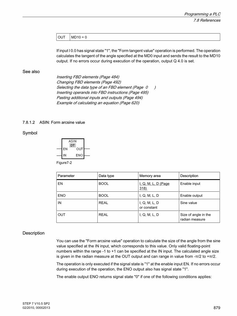
OUT MD10 = 0
If input I 0.0 has signal state "1", the "Form tangent value" operation is performed. The operationcalculates the tangent of the angle specified at the MD0 input and sends the result to the MD10output. If no errors occur during execution of the operation, output Q 4.0 is set.
See alsoInserting FBD elements (Page 484)Changing FBD elements (Page 492)Selecting the data type of an FBD element (Page 0 )Inserting operands into FBD instructions (Page 495)Pasting additional inputs and outputs (Page 494)Example of calculating an equation (Page 620)
7.8.1.2 ASIN: Form arcsine value
Symbol
Figure7-2
Parameter Data type Memory area Description
EN BOOL I, Q, M, L, D (Page318)
Enable input
ENO BOOL I, Q, M, L, D Enable output
IN REAL I, Q, M, L, D or constant
Sine value
OUT REAL I, Q, M, L, D Size of angle in theradian measure
DescriptionYou can use the "Form arcsine value" operation to calculate the size of the angle from the sinevalue specified at the IN input, which corresponds to this value. Only valid floating-pointnumbers within the range -1 to +1 can be specified at the IN input. The calculated angle sizeis given in the radian measure at the OUT output and can range in value from -π/2 to +π/2.
The operation is only executed if the signal state is "1" at the enable input EN. If no errors occurduring execution of the operation, the ENO output also has signal state "1".
The enable output ENO returns signal state "0" if one of the following conditions applies:
7.8.1.2 ASIN: Form arcsine value
Programming a PLC7.8 References
STEP 7 V10.5 SP202/2010, 00002013
879

• The EN input has signal state "0".
• The value at input IN is not a valid floating-point number.
• The value at input IN is outside the permitted range (-1 to +1).
PlacementThe "Form arcsine value" operation can be placed at any position in the network.
Example
Figure7-2
IN MD0 = 1
OUT MD10 = +1.570796e+00 (π/2)
If input I 0.0 has signal state "1", the "Form arcsine value" operation is performed. The operationcalculates the size of the angle corresponding to the sine value at input MD0. The result of theoperation is stored at output MD10. If no errors occur during execution of the operation, outputQ 4.0 is set.
See alsoInserting FBD elements (Page 484)Changing FBD elements (Page 492)Selecting the data type of an FBD element (Page 0 )Inserting operands into FBD instructions (Page 495)Pasting additional inputs and outputs (Page 494)Example of calculating an equation (Page 620)
7.8.1.2 ACOS: Form arccosine value
Symbol
7.8.1.2 ACOS: Form arccosine value
Programming a PLC7.8 References
880STEP 7 V10.5 SP202/2010, 00002013

Parameter Data type Memory area Description
EN BOOL I, Q, M, L, D (Page318)
Enable input
ENO BOOL I, Q, M, L, D Enable output
IN REAL I, Q, M, L, D or constant
Cosine value
OUT REAL I, Q, M, L, D Size of angle in theradian measure
DescriptionYou can use the "Form arccosine value" operation to calculate the size of the angle from thecosine value specified at the IN input, which corresponds to this value. Only valid floating-pointnumbers within the range -1 to +1 can be specified at the IN input. The calculated angle sizeis given in the radian measure at the OUT output and can range in value from 0 to +π.
The operation is only executed if the signal state is "1" at the enable input EN. If no errors occurduring execution of the operation, the ENO output also has signal state "1".
The enable output ENO returns signal state "0" if one of the following conditions applies:
• The EN input has signal state "0".
• The value at input IN is not a valid floating-point number.
• The value at input IN is outside the permitted range (-1 to +1).
PlacementThe "Form arccosine value" operation can be placed at any position in the logic string.
Example
Figure7-2
IN MD0 = 0
OUT MD10 = +1.570796e+00 (π/2)
If input I 0.0 has the signal state "1", the "Form arccosine value" operation is performed. Theoperation calculates the size of the angle corresponding to the cosine value at input MD0. Theresult of the operation is stored at output MD10. If no errors occur during execution of theoperation, output Q 4.0 is set.
Programming a PLC7.8 References
STEP 7 V10.5 SP202/2010, 00002013
881

See alsoInserting FBD elements (Page 484)Changing FBD elements (Page 492)Selecting the data type of an FBD element (Page 0 )Inserting operands into FBD instructions (Page 495)Pasting additional inputs and outputs (Page 494)Example of calculating an equation (Page 620)
7.8.1.2 ATAN: Form arctangent value
Symbol
Figure7-2
Parameter Data type Memory area Description
EN BOOL I, Q, M, L, D (Page318)
Enable input
ENO BOOL I, Q, M, L, D Enable output
IN REAL I, Q, M, L, D or constant
Tangent value
OUT REAL I, Q, M, L, D Size of angle in theradian measure
DescriptionYou can use the "Form arctangent value" operation to calculate the value of the angle thatcorresponds to the tangent value specified at the IN input. Only valid floating-point numbersmay be specified at the IN input. The calculated angle size is given in the radian measure atthe OUT output and can range in value from -π/2 to +π/2.
The operation is only executed if the signal state is "1" at the enable input EN. If no errors occurduring execution of the operation, the ENO output also has signal state "1".
The enable output ENO returns signal state "0" if one of the following conditions applies:
• The EN input has signal state "0".
• The value at input IN is not a valid floating-point number.
PlacementThe "Form arctangent value" operation can be placed at any position in the logic string.
7.8.1.2 ATAN: Form arctangent value
Programming a PLC7.8 References
882STEP 7 V10.5 SP202/2010, 00002013

Example
Figure7-2
IN MD0 = 1
OUT MD10 = +0.785398e++00 (π/4)
If input I 0.0 has signal state "1", the "Form arctangent value" operation is performed. Theoperation calculates the size of the angle corresponding to the tangent value at input MD0. Theresult of the operation is stored at output MD10. If no errors occur during execution of theoperation, output Q 4.0 is set.
See alsoInserting FBD elements (Page 484)Changing FBD elements (Page 492)Selecting the data type of an FBD element (Page 0 )Inserting operands into FBD instructions (Page 495)Pasting additional inputs and outputs (Page 494)Example of calculating an equation (Page 620)
7.8.1.2 FRAC: Return fraction
Symbol
Parameter Data type Memory area Description
EN BOOL I, Q, M, L, D (Page 318) Enable input
ENO BOOL I, Q, M, L, D Enable output
IN REAL I, Q, M, L, D or constant Value, whose decimalplaces are to bedetermined.
OUT REAL I, Q, M, L, D Decimal places of thevalue at the IN input
7.8.1.2 FRAC: Return fraction
Programming a PLC7.8 References
STEP 7 V10.5 SP202/2010, 00002013
883

DescriptionYou can use the "Return fraction" operation to find the decimal places of the value at the INinput. The result of the query is stored at the OUT output and can be queried there. If the valueat input IN is, for example, 123.4567, output OUT returns the value 0.4567. The operation isstarted when there is a "1" at the EN input. In this case, the enable output ENO also has signalstate "1".
The enable output ENO returns signal state "0" if one of the following conditions applies:
• The EN input has signal state "0".
• Errors occur during processing of the operation, for example there is no valid floating-point numberat the input.
PlacementThe "Return fraction" operation can be placed at any position in the logic string.
Example
Figure7-2
If the inputs I 0.0 AND I 0.1 have signal state "1", the "Return fraction" operation is started. Thedecimal places of the value at input MD8 are copied to output MD20. If no errors occur duringexecution of the operation, the ENO output has signal state "1" and output Q 4.0 is set.
See alsoInserting FBD elements (Page 484)Changing FBD elements (Page 492)Selecting the data type of an FBD element (Page 0 )Inserting operands into FBD instructions (Page 495)Pasting additional inputs and outputs (Page 494)Example of calculating an equation (Page 620)
Programming a PLC7.8 References
884STEP 7 V10.5 SP202/2010, 00002013

7.8.1.2 EXPT: Exponentiate
Symbol
Parameter Data type Memory area Description
EN BOOL I, Q, M, L, D (Page318)
Enable input
ENO BOOL I, Q, M, L, D Enable output
IN1 REAL I, Q, M, L, D or constant Base value
IN2 REAL, INT, UINT,USINT, SINT, DINT,UDINT
I, Q, M, L, D or constant Value by which the basevalue is exponentiated.
OUT REAL I, Q, M, L, D Result
You can select the data type for the operation from the "DT" drop-down list.
DescriptionYou can use the "Exponentiate" operation to raise the value at the IN1 input by a powerspecified with the value at the IN2 input. The result of the operation is provided at the OUToutput and can be queried there (OUT =IN1IN2).
The value at input IN1 must be a valid floating-point number. Integers are also allowed forsetting the IN2 input.
Execution of the "Exponentiate" operation requires a signal state of "1" at the enable input EN.In this case, the ENO enable output has signal state "1".
The enable output ENO returns signal state "0" if one of the following conditions applies:
• The EN input has signal state "0".
• Errors occur during processing of the operation, for example there is an overflow.
PlacementThe "Exponentiate" operation can be placed at any position in the logic string.
7.8.1.2 EXPT: Exponentiate
Programming a PLC7.8 References
STEP 7 V10.5 SP202/2010, 00002013
885

Example
Figure7-2
If inputs I 0.0 AND I 0.1 have signal state "1", the "Exponentiate" operation is started. The valueat the MD8 input is raised to the power specified by the value at the MD12 input. The result isstored at the MD20 output. If no errors occur during execution of the operation, the ENO outputhas signal state "1" and output Q 4.0 is set.
See alsoInserting FBD elements (Page 484)Changing FBD elements (Page 492)Selecting the data type of an FBD element (Page 0 )Inserting operands into FBD instructions (Page 495)Pasting additional inputs and outputs (Page 494)Example of calculating an equation (Page 620)
7.8.1.2 Move
7.8.1.2 MOVE: Copy value
Symbol
Figure7-2
Parameter Data type Memory area Description
EN BOOL I, Q, M, D, L (Page318)
Enable input
ENO BOOL I, Q, M, D, L Enable output
IN All elementary datatypes, DTL, STRUCT,ARRAY
I, Q, M, D, L or constant
Source value
7.8.1.2 Move7.8.1.2 MOVE: Copy value
Programming a PLC7.8 References
886STEP 7 V10.5 SP202/2010, 00002013

Parameter Data type Memory area Description
OUT1 All elementary datatypes, DTL, STRUCT,ARRAY
I, Q, M, D, L Destination address
DescriptionYou can use the "Move value" operation to transfer the content of the operand at the IN inputto the operand at the OUT1 output. The transfer is always made in the direction of ascendingaddresses.
If IEC test is enabled the tags at IN input and OUT1 output must be of the same data type. Ifthe IEC test is not enabled, the operand width at the IN input and the OUT1 output of theoperation must be the same.
Copying entire arrays is possible only when the array components of the tags at input IN andoutput OUT1 are of the same data type.
For the "Move value" operation, you can insert additional outputs. In this case, the content ofthe operand at the IN input is transferred to all available outputs.
The operation is only executed if the signal state is "1" at the enable input EN. In this case, theENO output also has signal state "1".
If the signal state at the EN input is "0", the enable output ENO is reset to "0".
The "Move block" (MOVE_BLK) and "Move block uninterruptible" (UMOVE_BLK) operationscan also be used to copy tags of the ARRAY data type. You can copy tags of the STRING datatype with the operation S_CONV.
PlacementThe "Move value" operation can be placed at any position in the logic string.
Example
Figure7-2
IN MW10 = 0011 1111 1010 1111
OUT1 MW20 = 0011 1111 1010 1111
If input I 0.0 has signal state "1", the "Move value" operation is executed. The operation copiesthe contents of the input operand (MW10) to the output operand (MW20) and sets the outputQ 4.0 to the signal state "1".
Programming a PLC7.8 References
STEP 7 V10.5 SP202/2010, 00002013
887

See alsoInserting FBD elements (Page 484)Changing FBD elements (Page 492)Inserting operands into FBD instructions (Page 495)Pasting additional inputs and outputs (Page 494)
7.8.1.2 MOVE_BLK: Copy area
Symbol
Figure7-2
Parameter Data type Memory area Description
EN BOOL I, Q, M, D, L (Page318)
Enable input
ENO BOOL I, Q, M, D, L Enable output
IN ARRAY D, L The first element of thesource area to becopied.
COUNT UINT I, Q, M, D, L or constant Number of elements tobe copied from thesource area to thedestination area.
OUT ARRAY D, L The first element of thedestination area towhich the content of thesource area is copied.
DescriptionYou can use the "Move block" operation to copy the content of a memory area (source area)to another memory area (destination area). The number of elements to be copied to thedestination area is specified with the COUNT parameter. The width of the elements to be copiedis defined by the width of the element at input IN. The copy operation takes place in the directionof ascending addresses.
The operation is only executed if the signal state is "1" at the enable input EN. If no errors occurduring execution of the operation, the ENO output also has signal state "1".
7.8.1.2 MOVE_BLK: Copy area
Programming a PLC7.8 References
888STEP 7 V10.5 SP202/2010, 00002013

The enable output ENO returns signal state "0" if one of the following conditions applies:
• The EN input has signal state "0".
• More data is copied than is available in the memory area at output OUT.
PlacementThe "Move block" operation can be placed at any position in the logic string.
Example
Figure7-2
IN The tag "a_array" is an ARRAY data type andconsists of 5 elements of the INT data type.
COUNT IW20 = 3
OUT The tag "b_array" is an ARRAY data type andconsists of 6 elements of the INT data type.
If the inputs I 0.0 AND I 0.1 have signal state "1", the "Move block" operation is executed. Theoperation selects three INT elements from the "a_array" tag (a_array[2..4]) and copies thecontent to the output tag "b_array" (b_array[1..3]). If no errors occur during execution of theoperation, the ENO output has signal state "1" and output Q 4.0 is set.
See alsoInserting FBD elements (Page 484)Changing FBD elements (Page 492)Inserting operands into FBD instructions (Page 495)Pasting additional inputs and outputs (Page 494)
Programming a PLC7.8 References
STEP 7 V10.5 SP202/2010, 00002013
889

7.8.1.2 UMOVE_BLK: Copy area uninterruptible
Symbol
Figure7-2
Parameter Data type Memory area Description
EN BOOL I, Q, M, D, L (Page318)
Enable input
ENO BOOL I, Q, M, D, L Enable output
IN ARRAY D, L The first element of thesource area to becopied.
COUNT UINT I, Q, M, D, L or constant Number of elements tobe copied from thesource area to thedestination area.
OUT ARRAY D, L The first element of thedestination area towhich the content of thesource area is copied.
DescriptionYou can use the "Move block uninterruptible" operation to copy the content of a memory area(source area) to another memory area (destination area) without the function being interrupted.The number of elements to be copied to the destination area is specified with the COUNTparameter. The width of the elements to be copied is defined by the width of the element atinput IN.
The content of the source area is copied to the destination area in the direction of the ascendingaddress. The copy operation cannot be interrupted by other operating system activities. Thisis why the alarm reaction times of the CPU increase during the execution of the "Move blockuninterruptible" operation.
The operation is only executed if the signal state is "1" at the enable input EN. If no errors occurduring execution of the operation, the ENO output also has signal state "1".
The enable output ENO returns signal state "0" if one of the following conditions applies:
• The EN input has signal state "0".
• More data is copied than is made available at output OUT.
7.8.1.2 UMOVE_BLK: Copy area uninterruptible
Programming a PLC7.8 References
890STEP 7 V10.5 SP202/2010, 00002013

PlacementThe "Move block uninterruptible" operation can be placed at any position in the logic string.
Example: using complex data types
Figure7-2
IN The tag "a_array" is an ARRAY data type andconsists of 5 elements of the INT data type.
COUNT IW2 = 3
OUT The tag "b_array" is an ARRAY data type andconsists of 6 elements of the INT data type.
If the inputs I 0.0 AND I 0.1 have signal state "1", the "Move block" operation is executed. Theoperation selects three INT elements from the "a_array" tag (a_array[2..4]) and copies thecontent to the output tag "b_array" (b_array[1..3]). The copy operation cannot be interruptedby other operating system activities. If no errors occur during execution of the operation, theENO output has signal state "1" and output Q 4.0 is set.
See alsoInserting FBD elements (Page 484)Changing FBD elements (Page 492)Inserting operands into FBD instructions (Page 495)Pasting additional inputs and outputs (Page 494)
7.8.1.2 FILL_BLK: Fill area
Symbol
Figure7-2
7.8.1.2 FILL_BLK: Fill area
Programming a PLC7.8 References
STEP 7 V10.5 SP202/2010, 00002013
891

Parameter Data type Memory area Description
EN BOOL I, Q, M, D, L (Page318)
Enable input
ENO BOOL I, Q, M, D, L Enable output
IN ARRAY D, L or constant Element used to fill thedestination area.
COUNT UINT I, Q, M, D, L or constant Number of repeatedcopy operations
OUT ARRAY D, L Address in destinationarea where fillingbegins.
DescriptionYou can use the "Fill block" operation to fill a memory area (destination area) with the value ofthe IN input. The destination area is filled beginning with the address specified at the OUToutput. The number of repeated copy operations is specified with the COUNT parameter. Whenthe operation is executed, the value at input IN is selected and copied to the destination areaas often as specified by the value of the COUNT parameter.
The operation is only executed if the signal state is "1" at the enable input EN. If no errors occurduring execution of the operation, the ENO output also has signal state "1".
The enable output ENO returns signal state "0" if one of the following conditions applies:
• The EN input has signal state "0".
• More data is copied than is available in the memory area at output OUT.
PlacementThe "Fill block" operation can be placed at any position in the logic string.
Example
Figure7-2
IN The tag "a_array" is an ARRAY data type and consists of 4 elements of the WORD datatype (ARRAY[1..4] of WORD).
COUNT IW20=3
Programming a PLC7.8 References
892STEP 7 V10.5 SP202/2010, 00002013

OUT The tag "b_array" is an ARRAY data type and consists of 5 elements of the WORD datatype (ARRAY[1..5] of WORD).
If the inputs I 0.0 AND I 0.1 have signal state "1", the "Fill block" operation is executed. Theoperation copies the second element (a_array[2]) of the "a_array" tag three times to the outputtag "b_array" (b_array[1..3]). If no errors occur during execution of the operation, outputs ENOand Q 4.0 are set to signal state "1".
See alsoInserting FBD elements (Page 484)Changing FBD elements (Page 492)Pasting additional inputs and outputs (Page 494)Inserting operands into FBD instructions (Page 495)
7.8.1.2 UFILL_BLK: Fill area uninterruptible
Symbol
Figure7-2
Parameter Data type Memory area Description
EN BOOL I, Q, M, D, L (Page318)
Enable input
ENO BOOL I, Q, M, D, L Enable output
IN ARRAY D, L or constant Element used to fill thedestination area.
COUNT UINT I, Q, M, D, L or constant Number of repeatedcopy operations
OUT ARRAY D, L Address in destinationarea where fillingbegins.
DescriptionYou can use the "Fill block uninterruptible" operation to fill a memory area (destination area)with the value of the IN input without interruption. The destination area is filled beginning with
7.8.1.2 UFILL_BLK: Fill area uninterruptible
Programming a PLC7.8 References
STEP 7 V10.5 SP202/2010, 00002013
893

the address specified at the OUT output. The number of repeated copy operations is specifiedwith the COUNT parameter. When the operation is executed, the value at input IN is selectedand copied to the destination area as often as specified by the value of the COUNT parameter.
The copy operation cannot be interrupted by other operating system activities. This is why thealarm reaction times of the CPU increase during the execution of the "Fill block uninterruptible"operation.
The operation is only executed if the signal state is "1" at the enable input EN. If no errors occurduring execution of the operation, the ENO output also has signal state "1".
The enable output ENO returns signal state "0" if one of the following conditions applies:
• The EN input has signal state "0".
• More data is copied than is available in the memory area at output OUT.
PlacementThe "Fill block uninterruptible" operation can be placed at any position in the logic string.
Example
Figure7-2
IN The tag "a_array" is an ARRAY data type and consists of 4 elements of the WORDdata type (ARRAY[1..4] of WORD).
COUNT IW20=3
OUT The tag "b_array" is an ARRAY data type and consists of 5 elements of the WORDdata type (ARRAY[1..5] of WORD).
If the inputs I 0.0 AND I 0.1 have signal state "1", the "Fill block" operation is executed. Theoperation copies the second element (a_array[2]) of the "a_array" tag three times to the outputtag "b_array" (b_array[1..3]). The copy operation cannot be interrupted by other operatingsystem activities. If no errors occur during execution of the operation, outputs ENO and Q 4.0are set to signal state "1".
See alsoInserting FBD elements (Page 484)Changing FBD elements (Page 492)Inserting operands into FBD instructions (Page 495)Pasting additional inputs and outputs (Page 494)
Programming a PLC7.8 References
894STEP 7 V10.5 SP202/2010, 00002013

7.8.1.2 SWAP: Swap
Symbol
Figure7-2
Parameter Data type Memory area Description
EN BOOL I, Q, M, L, D (Page318)
Enable input
ENO BOOL I, Q, M, L, D Enable output
IN WORD, DWORD I, Q, M, L, D or constant Operand whose bytesare swapped.
OUT WORD, DWORD I, Q, M, L, D Result
You can select the data type for the operation from the "DT" drop-down list.
DescriptionYou can use the "Swap" operation to change the order of the bytes within the tag at the IN inputand query the result at the OUT output.
The following figure shows how the bytes of a DWORD data type tag are swapped using the"Swap" operation:
Figure7-2
The operation is only executed if the signal state is "1" at the enable input EN. If no errors occurduring execution of the operation, the ENO output also has signal state "1".
If the signal state at the EN input is "0", the enable output ENO is reset to "0".
7.8.1.2 SWAP: Swap
Programming a PLC7.8 References
STEP 7 V10.5 SP202/2010, 00002013
895

PlacementThe "Swap" operation can be placed at any position in the logic string.
Example
Figure7-2
IN IW10 = 0000 1111 0101 0101
OUT QW20 = 0101 0101 0000 1111
If input I 0.1 has signal state "1", the "Swap" operation is executed. The arrangement of thebytes is changed and stored in the QW20 tag. If no errors occur during execution of theoperation, outputs ENO and Q 4.0 are set to signal state "1".
See alsoInserting FBD elements (Page 484)Changing FBD elements (Page 492)Selecting the data type of an FBD element (Page 0 )Inserting operands into FBD instructions (Page 495)Pasting additional inputs and outputs (Page 494)
7.8.1.2 Convert
7.8.1.2 CONVERT: Convert value
Symbol
7.8.1.2 Convert7.8.1.2 CONVERT: Convert value
Programming a PLC7.8 References
896STEP 7 V10.5 SP202/2010, 00002013

Parameter Data type Memory area Description
EN BOOL I, Q, M, D, L (Page318)
Enable input
ENO BOOL I, Q, M, D, L Enable output
IN BYTE, WORD,DWORD, SINT, INT,DINT, USINT, UINT,UDINT, BCD16,BCD32, REAL
I, Q, M, D, L or constant Value to be converted.
OUT BYTE, WORD,DWORD, SINT, INT,DINT, USINT, UINT,UDINT, BCD16,BCD32, REAL
I, Q, M, D, L Result of the conversion
You can select the data type for the operation from the "DT" drop-down list.
DescriptionThe "Convert" operation reads the content of the IN parameter and converts it according to thespecified data types.
The "Convert" operation can only be started when the signal state at the EN enable input is"1". If no error occurs during execution, the ENO output also has signal state "1".
The enable output ENO returns signal state "0" if one of the following conditions applies:
• The EN input has signal state "0".
• Errors such as an overflow occur during processing.
PlacementThe "Convert" operation can be placed at any position in the logic string.
Example
Figure7-2
If input I 0.0 = 1, the content of MW10 is read as a three-digit BCD-coded number and convertedto an integer (16 bits). The result is stored in MW12. Output Q 4.0 is "1" if the conversion wasexecuted (ENO = EN = 1).
See alsoInserting FBD elements (Page 484)
Programming a PLC7.8 References
STEP 7 V10.5 SP202/2010, 00002013
897

Changing FBD elements (Page 492)Inserting operands into FBD instructions (Page 495)Selecting the data type of an FBD element (Page 0 )
7.8.1.2 ROUND: Round to double integer
Symbol
Figure7-2
Parameter Data type Memory area Description
EN BOOL I, Q, M, D, L (Page318)
Enable input
ENO BOOL I, Q, M, D, L Enable output
IN REAL I, Q, M, D, L or constant
Input value to berounded.
OUT INT, USINT, UINT,SINT, UDINT, DINT,REAL
I, Q, M, D, L Output value
You can select the data type for the operation from the "DT" drop-down list.
DescriptionYou can use the "Round numerical value" operation to round the value at the IN input to thenearest integer. The operation interprets the value at input IN as a floating-point number andconverts this to the nearest double integer. If the input value is exactly between an even andodd number, the even number is selected. The result of the operation is provided at the OUToutput and can be queried there.
The operation is only executed if the signal state is "1" at the enable input EN. If no errors occurduring execution of the operation, the ENO output also has signal state "1".
The enable output ENO returns signal state "0" if one of the following conditions applies:
• The EN input has signal state "0".
• Errors such as an overflow occur during processing.
PlacementThe "Round numerical value" operation can be placed at any position in the logic string.
7.8.1.2 ROUND: Round to double integer
Programming a PLC7.8 References
898STEP 7 V10.5 SP202/2010, 00002013

Example
Figure7-2
IN MD8 = 0.50000000
OUT MD12 = 0
If input I 0.0 has signal state "1", the "Round numerical value" operation is performed. Thefloating-point number at input MD8 is rounded to the nearest even double integer and sent tothe OUT output. If no errors occur during execution of the operation, output Q 4.0 is set.
See alsoInserting FBD elements (Page 484)Changing FBD elements (Page 492)Inserting operands into FBD instructions (Page 495)Selecting the data type of an FBD element (Page 0 )
7.8.1.2 CEIL: Generate next higher integer from floating-point number
Symbol
Figure7-2
Parameter Data type Memory area Description
EN BOOL I, Q, M, D, L (Page318)
Enable input
ENO BOOL I, Q, M, D, L Enable output
IN REAL I, Q, M, D, L or constant Input value
OUT INT, USINT, UINT,SINT, UDINT, DINT,REAL
I, Q, M, D, L Output value
7.8.1.2 CEIL: Generate next higher integer from floating-point number
Programming a PLC7.8 References
STEP 7 V10.5 SP202/2010, 00002013
899

You can select the data type for the operation from the "DT" drop-down list.
DescriptionYou can use the "Generate next higher integer from floating-point number" operation to roundthe value at the IN input to the next higher integer. The operation interprets the value at the INinput as a floating-point number and converts this to the next higher integer. The result of theoperation is provided at the OUT output and can be queried there. The output value can begreater than or equal to the input value.
The operation is only executed if the signal state is "1" at the enable input EN. If no errors occurduring execution of the operation, the ENO output also has signal state "1".
The enable output ENO returns signal state "0" if one of the following conditions applies:
• The EN input has signal state "0".
• Errors such as an overflow occur during processing.
PlacementThe "Generate next higher integer from floating-point number" operation can be placed at anyposition in the logic string.
Example
Figure7-2
IN MD8 = 0.50000000
OUT MD12 = 1
If input I 0.0 has signal state "1", the "Generate next higher integer from floating-point number"operation is executed. The floating-point number at input MD8 is rounded to the next higherinteger and sent to the MD12 output. If no errors occur during execution of the operation, outputQ 4.0 is set.
See alsoInserting FBD elements (Page 484)Changing FBD elements (Page 492)Selecting the data type of an FBD element (Page 0 )Inserting operands into FBD instructions (Page 495)
Programming a PLC7.8 References
900STEP 7 V10.5 SP202/2010, 00002013

7.8.1.2 FLOOR: Generate next lower integer from floating-point number
Symbol
Figure7-2
Parameter Data type Memory area Description
EN BOOL I, Q, M, D, L (Page318)
Enable input
ENO BOOL I, Q, M, D, L Enable output
IN REAL I, Q, M, D, L or constant
Input value
OUT INT, USINT, UINT,SINT, UDINT, DINT,REAL
I, Q, M, D, L Output value
You can select the data type for the operation from the "DT" drop-down list.
DescriptionYou can use the "Generate next lower integer from floating-point number" operation to roundthe value at the IN input to the next lower integer. The operation interprets the value at inputIN as a floating-point number and converts this to the next higher integer. The result of theoperation is provided at the OUT output and can be queried there. The output value can beless than or equal to the input value.
The operation is only executed if the signal state is "1" at the enable input EN. If no errors occurduring execution of the operation, the ENO output also has signal state "1".
The enable output ENO returns signal state "0" if one of the following conditions applies:
• The EN input has signal state "0".
• Errors such as an overflow occur during processing.
PlacementThe "Generate next lower integer from floating-point number" operation can be placed at anyposition in the logic string.
7.8.1.2 FLOOR: Generate next lower integer from floating-point number
Programming a PLC7.8 References
STEP 7 V10.5 SP202/2010, 00002013
901

Example
Figure7-2
IN MD8 = 0.50000000
OUT MD12 = 0
If input I 0.0 has signal state "1", the "Generate next lower integer from floating-point number"operation is executed. The floating-point number at input MD8 is rounded to the next lowerinteger and sent to the MD12 output. If no errors occur during execution of the operation, outputQ 4.0 is set.
See alsoSelecting the data type of an FBD element (Page 0 )Inserting FBD elements (Page 484)Inserting operands into FBD instructions (Page 495)
7.8.1.2 TRUNC: Truncate to integer
Symbol
Figure7-2
Parameter Data type Memory area Description
EN BOOL I, Q, M, D, L (Page318)
Enable input
ENO BOOL I, Q, M, D, L Enable output
IN REAL I, Q, M, D, L or constant
Input value
OUT INT, USINT, UINT,SINT, UDINT, DINT,REAL
I, Q, M, D, L Integer component ofthe input value
7.8.1.2 TRUNC: Truncate to integer
Programming a PLC7.8 References
902STEP 7 V10.5 SP202/2010, 00002013

You can select the data type for the operation from the "DT" drop-down list.
DescriptionYou can use the "Truncate numerical value" operation to form an integer without rounding thevalue at the IN input. The value at input IN is interpreted as a floating-point number. Theoperation selects only the integer part of the floating-point number and sends this to the OUToutput without decimal places.
The operation is only executed if the signal state is "1" at the enable input EN. If no errors occurduring execution of the operation, the ENO output also has signal state "1".
The enable output ENO returns signal state "0" if one of the following conditions applies:
• The EN input has signal state "0".
• Errors such as an overflow occur during processing.
PlacementThe "Truncate numerical value" operation can be placed at any position in the logic string.
Example
Figure7-2
IN MD8 = 0.50000000
OUT MD12 = 0
If the input I 0.0 has signal state "1", the "Truncate numerical value" operation is executed. Theinteger part of the floating-point number at input MD8 is converted to an integer and sent to theMD12 output. If no errors occur during execution of the operation, output Q 4.0 is set.
See alsoInserting FBD elements (Page 484)Changing FBD elements (Page 492)Inserting operands into FBD instructions (Page 495)Selecting the data type of an FBD element (Page 0 )
Programming a PLC7.8 References
STEP 7 V10.5 SP202/2010, 00002013
903

7.8.1.2 SCALE_X: Scale
Symbol
Figure7-2
Parameter Data type Memory area Description
EN BOOL I, Q, M, D, L (Page318)
Enable input
ENO BOOL I, Q, M, D, L Enable output
VALUE REAL I, Q, M, D, L or constant Value to be scaled.
MIN SINT, INT, DINT,USINT, UINT, UDINT,REAL
I, Q, M, D, L or constant Low limit of the valuerange
MAX SINT, INT, DINT,USINT, UINT, UDINT,REAL
I, Q, M, D, L or constant High limit of the valuerange
OUT SINT, INT, DINT,USINT, UINT, UDINT,REAL
I, Q, M, D, L Result of scaling
You can select the data type for the operation from the "DT" drop-down list.
DescriptionYou can use the "Scale" operation to scale the value at the VALUE input by mapping it to aspecified value range. When the "Scale" operation is executed, the floating-point value at theVALUE input is scaled to the value range, which is defined by the MIN and MAX parameters.The result of the scaling is an integer, which is stored at the OUT output.
The following figure shows an example of how values can be scaled:
7.8.1.2 SCALE_X: Scale
Programming a PLC7.8 References
904STEP 7 V10.5 SP202/2010, 00002013

Figure7-2
The "Scale" operation is only executed if the signal state is "1" at the enable input EN. In thiscase, the enable output ENO also has signal state "1".
The enable output ENO returns signal state "0" if one of the following conditions applies:
• The EN input has signal state "0".
• The value at the MIN input is greater than or equal to the value at the MAX input.
• The value of a specified REAL tag is outside the range of the normalized numbers according toIEEE-754.
• An overflow occurs.
• The value at input VALUE is NaN (result of an invalid arithmetic operation).
PlacementThe "Scale" operation can be placed at any position in the logic string.
Example
Figure7-2
Programming a PLC7.8 References
STEP 7 V10.5 SP202/2010, 00002013
905

VALUE MD20 = 0.5
MIN MD10 = 10
MAX MD30 = 30
OUT MD40 = 20
If the input I 0.1 has signal state "1", the "Scale" operation is performed. The value at inputMD20 is scaled to the range of values defined by the values at inputs MD10 and MD30. Theresult is stored at output MD40. If no errors occur during execution of the operation, the ENOoutput has signal state "1" and output Q 4.0 is set.
See alsoInserting FBD elements (Page 484)Selecting the data type of an FBD element (Page 0 )Inserting operands into FBD instructions (Page 495)
7.8.1.2 NORM_X: Normalize
Symbol
Figure7-2
Parameter Data type Memory area Description
EN BOOL I, Q, M, D, L (Page318)
Enable input
ENO BOOL I, Q, M, D, L Enable output
VALUE SINT, INT, DINT,USINT, UINT, UDINT,REAL
I, Q, M, D, L or constant Value to be normalized.
MIN SINT, INT, DINT,USINT, UINT, UDINT,REAL
I, Q, M, D, L or constant Low limit of the valuerange
MAX SINT, INT, DINT,USINT, UINT, UDINT,REAL
I, Q, M, D, L or constant High limit of the valuerange
7.8.1.2 NORM_X: Normalize
Programming a PLC7.8 References
906STEP 7 V10.5 SP202/2010, 00002013

Parameter Data type Memory area Description
OUT REAL I, Q, M, D, L Result of thenormalization
You can select the data type for the operation from the "DT" drop-down list.
DescriptionYou can use the "Normalize" operation to normalize the value of the tag at the VALUE inputby mapping it to a linear scale. You can use the MIN and MAX parameters to define the limitsof a value range that is applied to the scale. The result at the OUT output is calculated andstored as a floating-point number depending on the location of the normalized value in thisvalue range. If the value to be normalized is equal to the value at the MIN input, the OUT outputreturns the value "0.0". If the value to be normalized is equal to the value at the MAX input, theOUT output has the value "1.0".
The following figure shows an example of how values can be normalized:
Figure7-2
The "Normalize" operation is only executed if the signal state is "1" at the enable input EN. Inthis case, the ENO enable output has signal state "1".
The enable output ENO returns signal state "0" if one of the following conditions applies:
• The EN input has signal state "0".
• The value at the MIN input is greater than or equal to the value at the MAX input.
• The value of a specified REAL tag is outside the range of the normalized numbers according toIEEE-754.
• An overflow occurs.
• The value at input VALUE is NaN (result of an invalid arithmetic operation).
Programming a PLC7.8 References
STEP 7 V10.5 SP202/2010, 00002013
907

PlacementThe "Normalize" operation can be placed at any position in the logic string.
Example
Figure7-2
VALUE MD20 = 20
MIN MD10 = 10
MAX MD30 = 30
OUT MD40 = 0.5
If the input I 0.1 has signal state "1", the "Normalize" operation is performed. The value at inputMD20 is assigned to value range defined by the values at inputs MD10 and MD30. The tagvalue at the input MD20 is normalized corresponding to the defined value range. The result isstored as a floating-point number in output MD40. If no errors occur during execution of theoperation, the ENO output has signal state "1" and output Q 4.0 is set.
See alsoInserting FBD elements (Page 484)Selecting the data type of an FBD element (Page 0 )Inserting operands into FBD instructions (Page 495)
7.8.1.2 Program control
7.8.1.2 JMP: Jump in block if 1
Symbol
Figure7-2
7.8.1.2 Program control7.8.1.2 JMP: Jump in block if 1
Programming a PLC7.8 References
908STEP 7 V10.5 SP202/2010, 00002013

DescriptionYou can use the "Jump in block if 1 (conditionally)" operation to interrupt the linear executionof the program and resume it in another network. The target network must be identified by ajump label. The name of this jump label is specified for execution of the operation. The specifiedjump label is located above the operation.
The specified jump label must be in the same block in which the operation is executed. Thename you specify can only occur once in the block.
If the result of logic operation (RLO) at the input of the operation is "1", the jump to the networkidentified by the jump label is executed. The jump direction can be towards higher or lowernetwork numbers.
If the condition at the input of the operation is not fulfilled (RLO = 0), execution of the programcontinues in the next network.
PlacementThe "Jump in block if 1 (conditionally)" operation can only be placed at the right-side edge ofthe network.
Example
If input I 0.0 has signal state "1", the "Jump in block if 1 (conditionally)" operation is executed.The linear execution of the program is interrupted and continues in Network 3, which is identifiedby the jump label CAS1. If input I 0.4 has signal state "1", output Q 4.1 is reset.
See alsoInserting FBD elements (Page 484)Changing FBD elements (Page 492)Inserting operands into FBD instructions (Page 495)
Programming a PLC7.8 References
STEP 7 V10.5 SP202/2010, 00002013
909

7.8.1.2 JMPN: Jump in block if 0
Symbol
Figure7-2
DescriptionYou can use the "Jump in block if 0 (conditionally)" operation to interrupt the linear executionof the program and resume it in another network, when the result of logic operation at the inputof the operation is "0". The target network must be identified by a jump label. The name of thisjump label is specified for execution of the operation. The specified jump label is located abovethe operation.
The specified jump label must be in the same block in which the operation is executed. Thename you specify can only occur once in the block.
If the result of logic operation (RLO) at the input of the operation is "0", the jump to the networkidentified by the label is executed. The jump direction can be towards higher or lower networknumbers.
If the condition at the input of the operation is not fulfilled (RLO = 1), execution of the programcontinues in the next network.
PlacementThe "Jump in block if 0 (conditionally)" operation requires a preceding logic operation and canonly be placed at the end of the logic string.
Example
If input I 0.0 has signal state "0", the "Jump in block if 0 (conditionally)" operation is executed.The linear execution of the program is interrupted and continues in Network 3, which is identifiedby the jump label CAS1. If input I 0.4 has signal state "1", output Q 4.1 is reset.
7.8.1.2 JMPN: Jump in block if 0
Programming a PLC7.8 References
910STEP 7 V10.5 SP202/2010, 00002013

See alsoInserting FBD elements (Page 484)Changing FBD elements (Page 492)Inserting operands into FBD instructions (Page 495)
7.8.1.2 LABEL: Jump label
Symbol
Figure7-2
DescriptionYou can use "Jump label" to specify a destination network, in which the program executionshould resume after a jump. The name of the jump label can consist of letters, numbers orunderscores.
The jump label and the operation in which the jump label is specified must be located in thesame block. The name of a jump label can only be assigned once in a block.
Each jump label can jump to several locations.
Example
Figure7-2
If input I 0.0 has signal state "1", the "Jump in block if 1 (conditionally)" operation is executed.The linear execution of the program is interrupted and continues in Network 3, which is identifiedby the jump label CAS1. If input I 0.4 has signal state "1", output Q 4.1 is reset.
See alsoInserting FBD elements (Page 484)Changing FBD elements (Page 492)Inserting operands into FBD instructions (Page 495)
7.8.1.2 LABEL: Jump label
Programming a PLC7.8 References
STEP 7 V10.5 SP202/2010, 00002013
911

7.8.1.2 RET: Return
Symbol
Figure7-2
Parameter values Data type Memory area Description
TRUE - - The status of the callfunction is set to "1".
FALSE - - The status of the callfunction is set to "0".
<Operand> BOOL I, Q, M, L, D (Page318)
The status of the callfunction is set to thesignal state of thespecified operand.
DescriptionYou can use the "Return" operation to stop the execution of a block. The operation is then onlyexecuted if the signal state at the left connector is "1". If this condition is fulfilled, programexecution is terminated in the currently called block and continued after the call function in thecalling block (for example in the calling OB). The status of the call function is determined bythe parameter of the "Return" operation. This can assume the following values:
• TRUE: Output ENO of the call function is set to "1".
• FALSE: Output ENO of the call function is reset to "0".
• <Operand>: Output ENO of the call function is determined by the signal state of the specified operand.
If an organization block is terminated by the "Return" operation, the CPU continues in thesystem program.
If the signal state at the input of the "Return" operation is "0", the operation is not executed. Inthis case, program execution continues in the next network of the called block.
PlacementThe "Return" operation can be placed at the start or end of the logic string.
Example
Figure7-2
7.8.1.2 RET: Return
Programming a PLC7.8 References
912STEP 7 V10.5 SP202/2010, 00002013

If input I 0.0 OR I 0.1 has signal state "0", the "Return" operation is executed. Program executionin the called block is terminated and continues in the calling block. Output ENO of the callfunction is reset to signal state "0".
See alsoInserting FBD elements (Page 484)Changing FBD elements (Page 492)Inserting operands into FBD instructions (Page 495)
7.8.1.2 Logical operations
7.8.1.2 AND: AND logic operation
Symbol
Figure7-2
Parameter Data type Memory area Description
EN BOOL I, Q, M, L, D (Page318)
Enable input
ENO BOOL I, Q, M, L, D Enable output
IN1 BYTE, WORD, DWORD I, Q, M, L, D or constant First value for logicoperation
IN2 BYTE, WORD, DWORD I, Q, M, L, D or constant Second value for logicoperation
OUT BYTE, WORD, DWORD I, Q, M, L, D Result of the operation
You can select the data type for the operation from the "DT" drop-down list.
DescriptionYou can use the "AND logic operation" to link the value at the IN1 input to the value at the IN2input bit-by-bit by AND logic and query the result at the OUT output.
When the operation is executed, bit 0 of the value at the IN1 input is linked by AND to bit 0 ofthe value at the IN2 input. The result is stored in bit 0 of the OUT output. The same logicoperation is executed for all other bits of the specified values.
7.8.1.2 Logical operations7.8.1.2 AND: AND logic operation
Programming a PLC7.8 References
STEP 7 V10.5 SP202/2010, 00002013
913

The result bit has signal state "1" only when both of the bits in the logic operation also havesignal state "1". If one of the two bits of the logic operation has signal state "0", thecorresponding result bit is reset.
The operation is only executed if the signal state is "1" at the enable input EN. In this case, theENO output also has signal state "1".
If the signal state at the enable input EN is "0", the enable output ENO is reset to signal state"0".
PlacementThe "AND logic operation" can be placed at any position in the logic string.
Example
Figure7-2
IN1 MW0 = 01010101 01010101
IN2 MW2 = 00000000 00001111
OUT MW10= 00000000 00000101
If input I 0.0 has the signal state "1", the "AND logic operation" is executed. The value at theMW0 input is linked by AND logic to the value at the MW2 input. The result is mapped bit-for-bit and sent to the MW10 output. Output ENO and output Q 4.0 are set to signal state "1".
See alsoInserting FBD elements (Page 484)Changing FBD elements (Page 492)Selecting the data type of an FBD element (Page 0 )Inserting operands into FBD instructions (Page 495)
Programming a PLC7.8 References
914STEP 7 V10.5 SP202/2010, 00002013

7.8.1.2 OR: OR logic operation
Symbol
Figure7-2
Parameter Data type Memory area Description
EN BOOL I, Q, M, L, D (Page318)
Enable input
ENO BOOL I, Q, M, L, D Enable output
IN1 BYTE, WORD, DWORD I, Q, M, L, D or constant First value for logicoperation
IN2 BYTE, WORD, DWORD I, Q, M, L, D or constant Second value for logicoperation
OUT BYTE, WORD, DWORD I, Q, M, L, D Result of the operation
You can select the data type for the operation from the "DT" drop-down list.
DescriptionYou can use the "OR logic operation" to link the value at the IN1 input to the value at the IN2input bit-by-bit by OR logic and query the result at the OUT output.
When the operation is executed, bit 0 of the value at the IN1 input is linked by OR to bit 0 ofthe value at the IN2 input. The result is stored in bit 0 of the OUT output. The same logicoperation is executed for all bits of the specified tags.
The result bit has signal state "1" when at least one of the two bits in the logic operation hassignal state "1". If both of the bits of the logic operation have signal state "0", the correspondingresult bit is reset.
The operation is only executed if the signal state is "1" at the enable input EN. In this case, theENO output also has signal state "1".
If the signal state at the enable input EN is "0", the enable output ENO is reset to signal state"0".
PlacementThe "OR logic operation" can be placed at any position in the logic string.
7.8.1.2 OR: OR logic operation
Programming a PLC7.8 References
STEP 7 V10.5 SP202/2010, 00002013
915

Example
Figure7-2
IN1 MW0 = 01010101 01010101
IN2 MW2 = 00000000 00001111
OUT MW10= 01010101 01011111
If input I 0.0 has signal state "1", the "OR logic operation" is executed. The value at the MW0input is linked by OR logic to the value at the MW2 input. The result is mapped bit-for-bit andsent to the MW10 output. Output ENO and output Q 4.0 are set to signal state "1".
See alsoInserting FBD elements (Page 484)Changing FBD elements (Page 492)Inserting operands into FBD instructions (Page 495)Selecting the data type of an FBD element (Page 0 )
7.8.1.2 XOR: EXCLUSIVE OR logic operation
Symbol
Figure7-2
Parameter Data type Memory area Description
EN BOOL I, Q, M, L, D (Page318)
Enable input
ENO BOOL I, Q, M, L, D Enable output
IN1 BYTE, WORD, DWORD I, Q, M, L, D or constant First value for logicoperation
7.8.1.2 XOR: EXCLUSIVE OR logic operation
Programming a PLC7.8 References
916STEP 7 V10.5 SP202/2010, 00002013

Parameter Data type Memory area Description
IN2 BYTE, WORD, DWORD I, Q, M, L, D or constant Second value for logicoperation
OUT BYTE, WORD, DWORD I, Q, M, L, D Result of the operation
You can select the data type for the operation from the "DT" drop-down list.
DescriptionYou can use the "EXCLUSIVE OR logic operation" to link the value at the IN1 input to the valueat the IN2 input bit-by-bit by EXCLUSIVE OR logic and query the result at the OUT output.
When the operation is executed, bit 0 of the value at the IN1 input is linked by EXCLUSIVE ORto bit 0 of the value at the IN2 input. The result is stored in bit 0 of the OUT output. The samelogic operation is executed for all other bits of the specified value.
The result bit has signal state "1" when one of the two bits in the logic operation has signalstate "1". If both of the bits of the logic operation have signal state "1" or "0", the correspondingresult bit is reset.
The operation is only executed if the signal state is "1" at the enable input EN. In this case, theENO output also has signal state "1".
If the signal state at the enable input EN is "0", the enable output ENO is reset to signal state"0".
PlacementThe "EXCLUSIVE OR logic operation" can be placed at any position in the logic string.
Example
Figure7-2
IN1 MW0 = 01010101 01010101
IN2 MW2 = 00000000 00001111
OUT MW10= 01010101 01011010
If input I 0.0 has signal state "1", the "EXCLUSIVE OR logic operation" is executed. The valueat the MW0 input is linked by EXCLUSIVE OR logic to the value at the MW2 input. The resultis mapped bit-for-bit and sent to the MW10 output. Output ENO and output Q 4.0 are set tosignal state "1".
Programming a PLC7.8 References
STEP 7 V10.5 SP202/2010, 00002013
917

See alsoInserting FBD elements (Page 484)Changing FBD elements (Page 492)Selecting the data type of an FBD element (Page 0 )Inserting operands into FBD instructions (Page 495)
7.8.1.2 INV: Create ones complement
Symbol
Figure7-2
Parameter Data type Memory area Description
EN BOOL I, Q, M, D, L (Page318)
Enable input
ENO BOOL I, Q, M, D, L Enable output
IN BYTE, WORD,DWORD, USINT, UINT,UDINT, SINT, INT, DINT
I, Q, M, D, L or constant Input value
OUT BYTE, WORD,DWORD, USINT, UINT,UDINT, SINT, INT, DINT
I, Q, M, D, L Ones complement of thevalue at input IN
You can select the data type for the operation from the "DT" drop-down list.
DescriptionYou can use the "Create ones complement" operation to invert the signal status of the bits atthe IN input. When the operation is executed, the value at the IN input is linked by EXCLUSIVEOR to a hexadecimal mask (W#16#FFFF for 16-bit numbers or DW#16#FFFF FFFF for 32-bitnumber). This inverts the signal state of the individual bits that are then stored in the OUToutput.
The operation is only executed if the signal state is "1" at the enable input EN. In this case, theENO output also has signal state "1".
If the signal state at the enable input EN is "0", the enable output ENO is reset to signal state"0".
7.8.1.2 INV: Create ones complement
Programming a PLC7.8 References
918STEP 7 V10.5 SP202/2010, 00002013

PlacementThe "Create ones complement" operation can be placed at any position in the logic string.
Example
Figure7-2
IN MW8 = W#16#000F
OUT MW12 = W#16#FFF0
If input I 0.0 has signal state "1", the "Create ones complement" operation is executed. Theoperation inverts the signal state of the individual bits at the MW8 input and writes the result tothe MW12 output. Output ENO and output Q 4.0 are set to signal state "1".
See alsoInserting FBD elements (Page 484)Changing FBD elements (Page 492)Inserting operands into FBD instructions (Page 495)Selecting the data type of an FBD element (Page 0 )
7.8.1.2 DECO: Decode
Symbol
Figure7-2
Parameter Data type Memory area Description
EN BOOL I, Q, M, D, L (Page318)
Enable input
ENO BOOL I, Q, M, D, L. Enable output
IN UINT I, Q, M, D, L or constant Input value
OUT BYTE, WORD, DWORD I, Q, M, D, L Result
7.8.1.2 DECO: Decode
Programming a PLC7.8 References
STEP 7 V10.5 SP202/2010, 00002013
919

You can select the data type for the operation from the "DT" drop-down list.
DescriptionYou can use the "Decode" operation to set a bit in the output value specified by the input value.
The "Decode" operation reads the value at the IN input and sets the bit in the output value,whose bit position corresponds to the value read. The other bits in the output value are filledwith zeroes. When the value at the IN input is greater than 31, a modulo 32 operation isexecuted.
The "Decode" operation can only be started when the signal state at the EN enable input is "1".If no error occurs during execution, the ENO output also has signal state "1".
If the signal state at the enable input EN is "0", the enable output ENO is reset to signal state"0".
PlacementThe "Decode" operation can be placed at any position in the logic string.
Example
Figure7-2
Figure7-2
If the input I 0.0 has signal state "1", the "Decode" operation is executed. The operation readsbit number "3" from the value at the MW10 input and set the third bit to the value at the MD20output.
If no errors occur during execution of the operation, the ENO output has signal state "1" andoutput Q 4.0 is set.
See alsoInserting FBD elements (Page 484)Changing FBD elements (Page 492)Selecting the data type of an FBD element (Page 0 )Inserting operands into FBD instructions (Page 495)
Programming a PLC7.8 References
920STEP 7 V10.5 SP202/2010, 00002013

7.8.1.2 ENCO: Encode
Symbol
Parameter Data type Memory area Description
EN BOOL I, Q, M, D, L (Page318)
Enable input
ENO BOOL I, Q, M, D, L. Enable output
IN BYTE, WORD, DWORD I, Q, M, D, L or constant Input value
OUT INT I, Q, M, D, L Output value
You can select the data type for the operation from the "DT" drop-down list.
DescriptionWith the "Encode" operation, you can read the bit number of the least significant set bit in theinput value and store it in the OUT output.
The "Encode" operation selects the least significant bit of the value at input IN and writes thisbit number to the tag at the OUT output.
The "Encode" operation can only be started when the signal state at the EN enable input is "1".If no error occurs during execution, the ENO output also has signal state "1".
If the signal state at the enable input EN is "0", the enable output ENO is reset to signal state"0".
PlacementThe "Encode" operation can be placed at any position in the logic string.
Example
Figure7-2
7.8.1.2 ENCO: Encode
Programming a PLC7.8 References
STEP 7 V10.5 SP202/2010, 00002013
921

Figure7-2
If the input I 0.0 has signal state "1", the "Encode" operation is executed. The operation selectsthe least significant bit set at the MD10 input and writes bit position 3 to the tag at the MW20output.
If no errors occur during execution of the operation, the ENO output has signal state "1" andoutput Q 4.0 is set.
See alsoChanging FBD elements (Page 492)Inserting FBD elements (Page 484)Selecting the data type of an FBD element (Page 0 )Inserting operands into FBD instructions (Page 495)
7.8.1.2 SEL: Select
Symbol
Parameter Data type Memory area Description
EN BOOL I, Q, M, D, L (Page318)
Enable input
ENO BOOL I, Q, M, D, L Enable output
G BOOL I, Q, M, D, L Selection switch
IN0 BYTE, WORD,DWORD, SINT, USINT,INT, UINT, DINT,UDINT, REAL, TIME,CHAR
I, Q, M, D, L or constant First input value
7.8.1.2 SEL: Select
Programming a PLC7.8 References
922STEP 7 V10.5 SP202/2010, 00002013

Parameter Data type Memory area Description
IN1 BYTE, WORD,DWORD, SINT, USINT,INT, UINT, DINT,UDINT, REAL, TIME,CHAR
I, Q, M, D, L or constant Second input value
OUT BYTE, WORD,DWORD, SINT, USINT,INT, UINT, DINT,UDINT, REAL, TIME,CHAR
I, Q, M, D, L Value of the selectedinput
You can select the data type for the operation from the "DT" drop-down list.
DescriptionThe "Select" operation selects one of the inputs IN0 or IN1 depending on a switch (parameterG) and copies its content to the OUT output. If parameter G has signal state "0", the value atinput IN0 is copied. When the G parameter has signal state "1", the value at input IN1 is copiedto the output OUT.
The operation is only executed if the signal state is "1" at the enable input EN. If no error occursduring execution, the ENO output also has signal state "1".
The ENO enable output is reset when the EN enable input has signal state "0" or errors occurduring execution of the operation.
PlacementThe "Select" operation can be placed at any position in the logic string.
Example
Figure7-2
G I 1.0 = 1
IN0 MW10 = W#16#0000
IN1 MW12 = W#16#FFFF
OUT MW20 = W#16#FFFF
Programming a PLC7.8 References
STEP 7 V10.5 SP202/2010, 00002013
923

If input I 0.0 has signal state "1", the "Select" operation is executed. Based on the signal statusat the input I 1.0, the value at the MW12 input is selected and copied to the MW20 output. Ifno errors occur during execution of the operation, outputs ENO and Q 4.0 are set.
See alsoInserting FBD elements (Page 484)Changing FBD elements (Page 492)Inserting operands into FBD instructions (Page 495)Selecting the data type of an FBD element (Page 0 )
7.8.1.2 MUX: Multiplex
Symbol
Figure7-2
Parameter Data type Memory area Description
EN BOOL I, Q, M, D, L (Page318)
Enable input
ENO BOOL I, Q, M, D, L Enable output
K UINT I, Q, M, D, L Specifies the inputwhose content is to becopied.
IN0 BYTE, WORD,DWORD, INT, DINT,UINT, UDINT, SINT,USINT, REAL, CHAR,TIME
I, Q, M, D, L or constant First available input
INn BYTE, WORD,DWORD, INT, DINT,UINT, UDINT, SINT,USINT, REAL, CHAR,TIME
I, Q, M, D, L or constant Available input
7.8.1.2 MUX: Multiplex
Programming a PLC7.8 References
924STEP 7 V10.5 SP202/2010, 00002013

Parameter Data type Memory area Description
ELSE BYTE, WORD,DWORD, INT, DINT,UINT, UDINT, SINT,USINT, REAL, CHAR,TIME
I, Q, M, D, L or constant Specifies the value to becopied when K > n.
OUT BYTE, WORD,DWORD, INT, DINT,UINT, UDINT, SINT,USINT, REAL, CHAR,TIME
I, Q, M, D, L Output to which thevalue is to be copied.
You can select the data type for the operation from the "DT" drop-down list.
DescriptionYou can use the "Multiplex" operation to copy the content of a selected input to the OUT output.The number of selectable inputs of the MUX box can be expanded. The inputs are numberedautomatically in the box. Numbering starts at IN0 and is incremented continuously with eachnew input. You can use the K parameter to determine the input whose content should be copiedto the OUT output. If the value of the K parameter is greater than the number of available inputs,the content of the ELSE parameter is copied to the OUT output and the enable output isassigned signal state "0".
The "Multiplex" operation can only execute when the tags at all inputs and at the OUT outputare of the same data type. The exception here is the K parameter that can only be specifiedas an integer.
The operation is only executed if the signal state is "1" at the enable input EN. If no error occursduring execution, the ENO output also has signal state "1".
The enable output ENO is reset if one of the following conditions applies:
• The enable input EN has signal state "0".
• The value of the K parameter is greater than the number of available inputs.
• Errors occurred during processing of the operation.
PlacementThe "Multiplex" operation can be placed at any position in the logic string.
Programming a PLC7.8 References
STEP 7 V10.5 SP202/2010, 00002013
925

Example
Figure7-2
K MW10 = 1
IN0 MD20 = DW#16#00000000
IN1 MD30 = DW#16#FFFFFFFF
ELSE MD50 = DW#16#FFFF0000
OUT MD40 = DW#16#FFFFFFFF
If the input I 0.1 has signal state "1", the "Multiplex" operation is executed. Based on the valueat the MW10 input, the value at the MD30 input is copied and assigned to the tag at the MD40output. If no errors occur during execution of the operation, outputs ENO and Q 4.0 are set.
See alsoInserting FBD elements (Page 484)Changing FBD elements (Page 492)Inserting operands into FBD instructions (Page 495)Selecting the data type of an FBD element (Page 0 )
7.8.1.2 Shift + rotate
7.8.1.2 SHR: Shift right
Symbol
Figure7-2
7.8.1.2 Shift + rotate7.8.1.2 SHR: Shift right
Programming a PLC7.8 References
926STEP 7 V10.5 SP202/2010, 00002013

Parameter Data type Memory area Description
EN BOOL I, Q, M, L, D (Page318)
Enable input
ENO BOOL I, Q, M, L, D Enable output
IN BYTE, WORD,DWORD, SINT, USINT,INT, UINT, DINT,UDINT
I, Q, M, L, D or constant Value to be shifted.
N UINT I, Q, M, L, D or constant Number of bit positionsby which the value isshifted.
OUT BYTE, WORD,DWORD, SINT, USINT,INT, UINT, DINT,UDINT
I, Q, M, L, D Result of the shiftoperation
You can select the data type for the operation from the "DT" drop-down list.
DescriptionYou can use the "Shift right" operation to shift the content of the tag at the IN input bit-by-bit tothe right and query the result at the OUT output. You can use the N parameter to specify thenumber of bit positions by which the specified value should be shifted.
When the N parameter has the value "0", the value at the IN input is copied to the tag at theOUT output.
When the value at the N parameter is greater than the number of bit positions, the tag value atIN input is moved by the available number of bit positions to the right.
The freed bit positions in the left area of the tag are filled by zeroes when values without signsare shifted. If the specified value has a sign, the free bit positions are filled with the signal stateof the sign bit.
The following figure show how the content of a integer data type tag is shifted four bit positionsto the right:
Programming a PLC7.8 References
STEP 7 V10.5 SP202/2010, 00002013
927

Figure7-2
The "Shift right" operation is only executed if the signal state is "1" at the enable input EN. Inthis case, the enable output ENO also has signal state "1".
If the signal state at the enable input EN is "0", the enable output ENO is reset to signal state"0".
PlacementThe "Shift right" operation can be placed at any position in the logic string.
Example
Figure7-2
IN MW10 = 0011 1111 1010 1111
N MW12 = 3
OUT MW40 = 0000 0111 1111 010 1
If input I 0.0 has signal state "1", the "Shift right" operation is executed. The content of theMW10 tag is shifted three bit positions to the right. The result is stored at the MW40 output. Ifno errors occur during execution of the operation, the ENO output has signal state "1" andoutput Q 4.0 is set.
Programming a PLC7.8 References
928STEP 7 V10.5 SP202/2010, 00002013

See alsoInserting FBD elements (Page 484)Changing FBD elements (Page 492)Inserting operands into FBD instructions (Page 495)Selecting the data type of an FBD element (Page 0 )
7.8.1.2 SHL: Shift left
Symbol
Figure7-2
Parameter Data type Memory area Description
EN BOOL I, Q, M, L, D (Page318)
Enable input
ENO BOOL I, Q, M, L, D Enable output
IN BYTE, WORD,DWORD, SINT, USINT,INT, UINT, DINT,UDINT
I, Q, M, L, D or constant Value to be shifted.
N UINT I, Q, M, L, D or constant Number of bit positionsby which the value isshifted.
OUT BYTE, WORD,DWORD, SINT, USINT,INT, UINT, DINT,UDINT
I, Q, M, L, D Result of the shiftoperation
You can select the data type for the operation from the "DT" drop-down list.
DescriptionYou can use the "Shift left" operation to shift the content of the tag at the IN input bit-by-bit tothe left and query the result at the OUT output. You can use the N parameter to specify thenumber of bit positions by which the specified value should be shifted.
When the N parameter has the value "0", the value at the IN input is copied to the tag at theOUT output.
When the value at the N parameter is greater than the number of bit positions, the tag value atIN input is moved by the available number of bit positions to the left.
7.8.1.2 SHL: Shift left
Programming a PLC7.8 References
STEP 7 V10.5 SP202/2010, 00002013
929

The bit positions in the right part of the tag freed by shifting are filled with zeros.
The following figure show how the content of a WORD data type tag is shifted six bit positionsto the left:
Figure7-2
The "Shift left" operation is only executed if the signal state is "1" at the enable input EN. In thiscase, the enable output ENO also has signal state "1".
If the signal state at the enable input EN is "0", the enable output ENO is reset to signal state"0".
PlacementThe "Shift left" operation can be placed at any position in the logic string.
Example
Figure7-2
IN MW10 = 0011 1111 1010 1111
N MW12 = 4
OUT MW40 = 1111 1010 1111 0000
If input I 0.0 has signal state "1", the "Shift left" operation is executed. The content of the MW10tag is shifted four bit positions to the left. The result is stored at the MW40 output. If no errors
Programming a PLC7.8 References
930STEP 7 V10.5 SP202/2010, 00002013
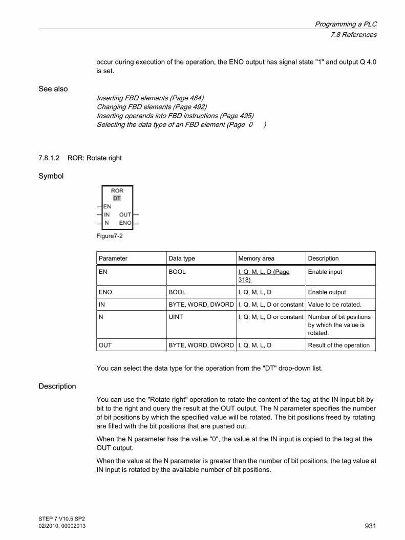
occur during execution of the operation, the ENO output has signal state "1" and output Q 4.0is set.
See alsoInserting FBD elements (Page 484)Changing FBD elements (Page 492)Inserting operands into FBD instructions (Page 495)Selecting the data type of an FBD element (Page 0 )
7.8.1.2 ROR: Rotate right
Symbol
Figure7-2
Parameter Data type Memory area Description
EN BOOL I, Q, M, L, D (Page318)
Enable input
ENO BOOL I, Q, M, L, D Enable output
IN BYTE, WORD, DWORD I, Q, M, L, D or constant Value to be rotated.
N UINT I, Q, M, L, D or constant Number of bit positionsby which the value isrotated.
OUT BYTE, WORD, DWORD I, Q, M, L, D Result of the operation
You can select the data type for the operation from the "DT" drop-down list.
DescriptionYou can use the "Rotate right" operation to rotate the content of the tag at the IN input bit-by-bit to the right and query the result at the OUT output. The N parameter specifies the numberof bit positions by which the specified value will be rotated. The bit positions freed by rotatingare filled with the bit positions that are pushed out.
When the N parameter has the value "0", the value at the IN input is copied to the tag at theOUT output.
When the value at the N parameter is greater than the number of bit positions, the tag value atIN input is rotated by the available number of bit positions.
7.8.1.2 ROR: Rotate right
Programming a PLC7.8 References
STEP 7 V10.5 SP202/2010, 00002013
931

The following figure show how the content of a DWORD data type tag is rotated three bitpositions to the right:
Figure7-2
The "Rotate right" operation is only executed if the signal state is "1" at the enable output ENO.In this case, the enable output ENO also has signal state "1".
If the signal state at the enable input EN is "0", the enable output ENO is reset to signal state"0".
PlacementThe "Rotate right" operation can be placed at any position in the logic string.
Example
Figure7-2
IN MW10 = 0000 1111 1001 0101
N MW12 = 5
OUT MW40 = 1010 1000 0111 1100
If input I 0.0 has signal state "1", the "Rotate right" operation is executed. The content of theMW10 tag is rotated five bit positions to the right. The result is stored at the MW40 output. Ifno errors occur during execution of the operation, the ENO output has signal state "1" andoutput Q 4.0 is set.
Programming a PLC7.8 References
932STEP 7 V10.5 SP202/2010, 00002013

See alsoInserting FBD elements (Page 484)Changing FBD elements (Page 492)Selecting the data type of an FBD element (Page 0 )Inserting operands into FBD instructions (Page 495)
7.8.1.2 ROL: Rotate left
Symbol
Figure7-2
Parameter Data type Memory area Description
EN BOOL I, Q, M, L, D (Page318)
Enable input
ENO BOOL I, Q, M, L, D Enable output
IN BYTE, WORD, DWORD I, Q, M, L, D or constant Value to be rotated.
N UINT I, Q, M, L, D or constant Number of bit positionsby which the value isrotated.
OUT BYTE, WORD, DWORD I, Q, M, L, D Result of the operation
You can select the data type for the operation from the "DT" drop-down list.
DescriptionYou can use the "Rotate left" operation to rotate the content of the tag at the IN input bit-by-bitto the left and query the result at the OUT output. The N parameter specifies the number of bitpositions by which the specified value will be rotated. The bit positions freed by rotating arefilled with the bit positions that are pushed out.
If the value on the parameter N is "0", the value on the input IN is copied to the tag on the outputOUT.
If the value on the parameter N is greater than the number of available bit places, the tag valueon the input IN rotates through the available bit places.
The following figure show how the content of a DWORD data type tag is rotated three bitpositions to the left:
7.8.1.2 ROL: Rotate left
Programming a PLC7.8 References
STEP 7 V10.5 SP202/2010, 00002013
933

Figure7-2
The "Rotate left" operation is only executed if the signal state is "1" at the enable output ENO.In this case, the enable output ENO also has signal state "1".
If the signal state on the enable input EN is “0”, the enable output ENO also has the signal state“0”.
PlacementThe "Rotate left" operation can be placed at any position in the logic string.
Example
IN MW10 = 1010 1000 1111 0110
OUT MW12 = 5
N MW40 = 0001 1110 1101 010 1
If input I 0.0 has signal state "1", the "Rotate left" operation is performed. The content of theMW10 tag is rotated five bit positions to the left. The result is stored at the MW40 output. If noerrors occur during execution of the operation, the ENO output has signal state "1" and outputQ 4.0 is set.
See alsoInserting FBD elements (Page 484)
Programming a PLC7.8 References
934STEP 7 V10.5 SP202/2010, 00002013

Changing FBD elements (Page 492)Inserting operands into FBD instructions (Page 495)Selecting the data type of an FBD element (Page 0 )
7.8.2 Extended instructions
7.8.2.1 Clock and calendar
7.8.2.1 Time-of-day functions
7.8.2.1 WR_SYS_T
Description You can use WR_SYS_T to set the date and time of the CPU clock. You specify the date andtime in the DTL format at the IN input of the instruction. At the RET_VAL output, you can querywhether errors have occurred during execution of the instruction.
You cannot send information about the local time zone or daylight saving time using the"WR_SYS_T" instruction.
Parameter
Parameter Declaration Data type Memory area Description
IN IN DTL M, D, L Date and time
RET_VAL OUT INT M, D, L Status of the instruction
Parameter RET_VAL
Error code
(W#16#...)
Description
0000 No error
8081 Year invalid
8082 Month invalid
8083 Day invalid
7.8.2 Extended instructions7.8.2.1 Clock and calendar7.8.2.1 Time-of-day functions7.8.2.1 WR_SYS_T
Programming a PLC7.8 References
STEP 7 V10.5 SP202/2010, 00002013
935

Error code
(W#16#...)
Description
8084 Hour information invalid
8085 Minute information invalid
8086 Second information invalid
8087 Nanosecond information invalid
80B0 The realtime clock has failed.
7.8.2.1 RD_SYS_T
Description You can use RD_SYS_T to read the current date and current time of the CPU clock. The datais provided in DTL format at the OUT output of the instruction. The provided value does notinclude information about the local time zone or daylight saving time. At the RET_VAL output,you can query whether errors have occurred during execution of the instruction.
Parameter
Parameter Declaration Data type Memory area Description
OUT OUT DTL M, D, L Date and time of CPU
RET_VAL OUT INT M, D, L Status of the instruction
Parameter RET_VAL
Error code
(W#16#...)
Description
0000 No error
8222 The result is outside the permissible range of values
8223 The result cannot be saved with the specified data type
7.8.2.1 RD_SYS_T
Programming a PLC7.8 References
936STEP 7 V10.5 SP202/2010, 00002013

7.8.2.1 RD_LOC_T
DescriptionYou can use RD_LOC_T to read the current local time from the CPU clock and output this inDTL format at the OUT output. Information about the time zone and the beginning of daylightsaving time and standard time, which you have set in the configuration of the CPU clock, areincluded in the local time information.
Parameters
Parameter Declaration Data type Memory area Description
OUT OUT DTL M, D, L Local time
RET_VAL OUT INT M, D, L Status of the instruction
Parameter RET_VAL
Error code
(W#16#...)
Description
0000 No error
8080 Cannot read the local time.
7.8.2.1 T_CONV
Description Using T_CONV, you convert the value at the IN input to the data format specified at the OUToutput. The following conversions are possible:
• Conversion of a time (TIME) to a numeric value (DINT)
• Conversion of a value (DINT) to a time (TIME)
You decide the type of conversion by selecting the data types for the input and output of theinstruction. You can query the result of the conversion at the OUT output.
7.8.2.1 RD_LOC_T7.8.2.1 T_CONV
Programming a PLC7.8 References
STEP 7 V10.5 SP202/2010, 00002013
937

Parameter
Parameter Declaration Data type Memory area Description
IN IN TIME, DINT M, D, L Value to beconverted
OUT OUT TIME, DINT M, D, L Result of theconversion
7.8.2.1 T_ADD
Description Using T_ADD, you add the time at the IN1 input to the time at the IN2 input. You can query theresult at the OUT output. You can add the following formats:
• Addition of a time period (TIME) and another time period (TIME). The result can be output to a tagwith the TIME format.
• Addition of a time period (TIME) to a point in time (DTL). The result can be output to a tag with theDTL format.
You decide the formats at the IN1 input and OUT output by selecting the data types for inputand output of the instruction. At the IN2 input, you can only specify times in the TIME format.
Parameter
Parameter Declaration Data type Memory area Description
IN1 IN TIME, DTL M, D, L Summand
IN2 IN TIME M, D, L Summand
OUT OUT TIME, DTL M, D, L Result of addition
7.8.2.1 T_SUB
DescriptionUsing T_SUB, you subtract the time at the IN2 input from the time at the IN1 input. You canquery the difference at the OUT output. You can subtract the following formats:
• Subtraction of a time period (TIME) from another time period (TIME). The result can be output to atag with the TIME format.
7.8.2.1 T_ADD7.8.2.1 T_SUB
Programming a PLC7.8 References
938STEP 7 V10.5 SP202/2010, 00002013

• Subtraction of a time period (TIME) from a point in time (DTL). The result can be output to a tag withthe DTL format.
You decide the formats at the IN1 input and OUT output by selecting the data types for inputand output of the instruction. At the IN2 input, you can only specify times in the TIME format.
Parameter
Parameter Declaration Data type Memory area Description
IN1 IN TIME, DTL M, D, L Minuend
IN2 IN TIME M, D, L Subtrahend
OUT OUT TIME, DTL M, D, L Result ofsubtraction
7.8.2.1 T_DIFF
Description Using T_DIFF, you subtract the time at the IN2 input from the time at the IN1 input. The resultis output at the OUT output in the TIME format. Only values in the DTL format can be specifiedat the IN1 and IN2 inputs.
If the time specified at the IN2 input is greater than the time specified at the IN1 input, the resultis output as a negative value at the OUT output. If the result of the instruction is outside thepermitted range, the result is limited to the relevant value and the enable output ENO is set to"0".
Parameter
Parameter Declaration Data type Memory area Description
IN1 IN DTL M, D, L Minuend
IN2 IN DTL M, D, L Subtrahend
OUT OUT TIME M, D, L Difference in theTIME format
7.8.2.1 T_DIFF
Programming a PLC7.8 References
STEP 7 V10.5 SP202/2010, 00002013
939

7.8.2.2 STRING and CHAR
7.8.2.2 S_CONV
Description Using S_CONV, you convert the value at the IN input to the data format you specified at theOUT output. The following conversions are possible:
• Conversion of a character string (STRING) to a numeric value: The conversion is made for all characters of the string specified at the IN input. The characterspermitted are the numbers 0 to 9, the decimal point and the plus and minus signs. The first characterof the string may be a valid number or a sign. Leading spaces and exponential representations areignored. The character conversion can be interrupted by invalid characters. In this case, the enable outputENO is set to "0". You decide the output format of the conversion by selecting a data type for the OUT output.
• Conversion of a numeric value to a character string (STRING): You decide the format of the numeric value to be converted by selecting a data type for the IN input.A valid tag of the STRING data type must be specified at the OUT output. The length of the characterstring after conversion depends on the value at the IN input. The result of the conversion is storedstarting at the third byte of the character string, since the first byte contains the maximum length andthe second byte the actual length of the string. Positive numeric value are output without a sign.
• Copying a character string: If you enter the STRING data type at the input and output of the instruction, the character string at theinput IN will be copied to the output OUT. If the actual length of the character string at the IN inputexceeds the maximum length of the character string at the OUT output, that part of the character stringat IN will be copied that fits exactly in the character string at OUT, and the enable output ENO will beset to the value "0".
ParametersParameter for converting a character string into a a numeric value:
Parameter Declaration Data type Memory area Description
IN IN STRING D, L or constant Value to be converted
OUT OUT USINT, SINT,UINT, INT,UDINT, DINT,REAL
I, Q, M, D, L Result of the conversion
Parameter for converting a numeric value into a character string:
7.8.2.2 STRING and CHAR7.8.2.2 S_CONV
Programming a PLC7.8 References
940STEP 7 V10.5 SP202/2010, 00002013

Parameter Declaration Data type Memory area Description
IN IN USINT, SINT,UINT, INT,UDINT, DINT,REAL
I, Q, M, D, L or constant Value to be converted
OUT OUT STRING D, L Result of the conversion
Parameter for copying a character string:
Parameter Declaration Data type Memory area Description
IN IN STRING D, L or constant Value to be copied
OUT OUT STRING D, L Result of the copy operation
ExampleThe following table shows examples of the conversion of a character string to a numeric value:
IN (STRING) OUT (data type) OUT (value) ENO status
'123' INT/DINT 123 1
'-00456' INT/DINT -456 1
'123.45' INT/DINT 123 1
'+2345' INT/DINT 2345 1
'00123AB' INT/DINT 123 1
'123' REAL 123.0 1
'123.45' REAL 123.45 1
'1.23e-4' REAL 1.23 1
'1.23E-4' REAL 1.23 1
'12,345.67' REAL 12345.67 1
'3.4e39' REAL 3.4 1
'-3.4e39' REAL -3.4 1
'1.17549e-38' REAL 1.17549 1
'12345' SINT 0 0
'A123' -/- 0 0
'' -/- 0 0
'++123' -/- 0 0
'+-123' -/- 0 0
Programming a PLC7.8 References
STEP 7 V10.5 SP202/2010, 00002013
941

ExampleThe following table shows examples of the conversion of a numeric value to a character string:
IN (value) IN (data type) OUT (STRING) ENO status
123 UINT '123' 1
0 UINT '0' 1
12345678 UDINT '12345678' 1
-Inf 1) REAL 'Inf' 0
+Inf 2) REAL 'Inf' 0
NaN 3) REAL 'NaN' 0
1) -Inf: Floating-point number representing a negative infinite value. 2) +Inf: Floating-point number representing a positive infinite value. 3) NaN: Value returned as the result of invalid math operations.
See alsoSTRING (Page 383)
7.8.2.2 STRG_VAL
Description Using STRG_VAL, you convert a character string to a numeric value. You specify the characterstring to be converted at the IN input. You decide the format of the output value by selecting adata type for the OUT output. You can query the result at the OUT output.
The conversion starts at the character whose position you specified in the P parameter. If, forexample, the value "1" is specified in the P parameter, the conversion starts at the first characterof the specified character string. The characters permitted for the conversion are the numbers0 to 9, the decimal point, the decimal comma, notations "E" and "e" and the plus and minuscharacters. The conversion can be interrupted by invalid characters. In this case, the enableoutput ENO is set to "0".
With the FORMAT parameter, you specify how the characters of a string are to be interpreted.Exponential values can also be converted and represented with the "STRG_VAL" instruction.Only tags of the USINT data type can be specified for the FORMAT parameter.
The following table shows the possible values of the FORMAT parameter and their meaning:
Value(W#16#....)
Notation Decimal representation
0000 Decimal fraction "."
0001 ","
7.8.2.2 STRG_VAL
Programming a PLC7.8 References
942STEP 7 V10.5 SP202/2010, 00002013

Value(W#16#....)
Notation Decimal representation
0002 Exponential "."
0003 ","
0004 to FFFF Invalid values
Parameters
Parameter Declaration Data type Memory area Description
IN IN STRING D, L or constant Character string to be converted
FORMAT IN WORD I, Q, M, D, L orconstant
Output format of the characters
P IN_OUT UINT I, Q, M, D, L Character at which the conversion starts
OUT OUT USINT, SINT,UINT, INT, UDINT,DINT, REAL
I, Q, M, D, L Result of the conversion
ExampleThe following table shows examples of the conversion of a character string to a numeric value:
IN (STRING) FORMAT(W#16#....)
OUT (data type) OUT (value) ENO status
'123' 0000 INT/DINT 123 1
'-00456' 0000 INT/DINT -456 1
'123.45' 0000 INT/DINT 123 1
'+2345' 0000 INT/DINT 2345 1
'00123AB' 0000 INT/DINT 123 1
'123' 0000 REAL 123.0 1
'-00456' 0001 REAL -456.0 1
'+00456' 0001 REAL 456.0 1
'123.45' 0000 REAL 123.45 1
'123.45' 0001 REAL 12345.0 1
'123,45' 0000 REAL 12345.0 1
'123,45' 0001 REAL 123.45 1
'.00123AB' 0001 REAL 123.0 1
Programming a PLC7.8 References
STEP 7 V10.5 SP202/2010, 00002013
943

IN (STRING) FORMAT(W#16#....)
OUT (data type) OUT (value) ENO status
'1.23e-4' 0000 REAL 1.23 1
'1.23E-4' 0000 REAL 1.23 1
'1.23E-4' 0002 REAL 1.23E-4 1
'12,345.67' 0000 REAL 12345.67 1
'12,345.67' 0001 REAL 12.345 1
'3.4e39' 0002 REAL W#16#7F800000 1
'-3.4e39' 0002 REAL W#16#FF800000 1
'1.1754943e-38' 0002 REAL 0.0 1
'12345' -/- SINT 0 0
'A123' -/- -/- 0 0
'' -/- -/- 0 0
'++123' -/- -/- 0 0
'+-123' -/- -/- 0 0
See alsoSTRING (Page 383)
7.8.2.2 VAL_STRG
Description Using VAL_STRG, you convert a numeric value to a character string. You specify the value tobe converted at the IN input. You decide the format of the numeric value by selecting a datatype. You query the result of the conversion at the OUT output.
With the P parameter, you specify the character in the string starting at which the result iswritten. If, for example, the value "2" is specified in the P parameter, the converted value issaved starting at the second character of the string.
With the SIZE parameter you specify how many characters of the string are written. This iscounted from the character specified in the P parameter. If the length defined by the P andSIZE parameters is not adequate, the enable output ENO is set to "0". If the output value isshorter than the specified length, the result is written to the character string right-justified. Theempty character positions are filled with blanks.
The characters permitted for the conversion are the numbers 0 to 9, the decimal point, thedecimal comma, notations "E" and "e" and the plus and minus characters. The conversion canbe interrupted by invalid characters. In this case, the enable output ENO is set to "0".
7.8.2.2 VAL_STRG
Programming a PLC7.8 References
944STEP 7 V10.5 SP202/2010, 00002013
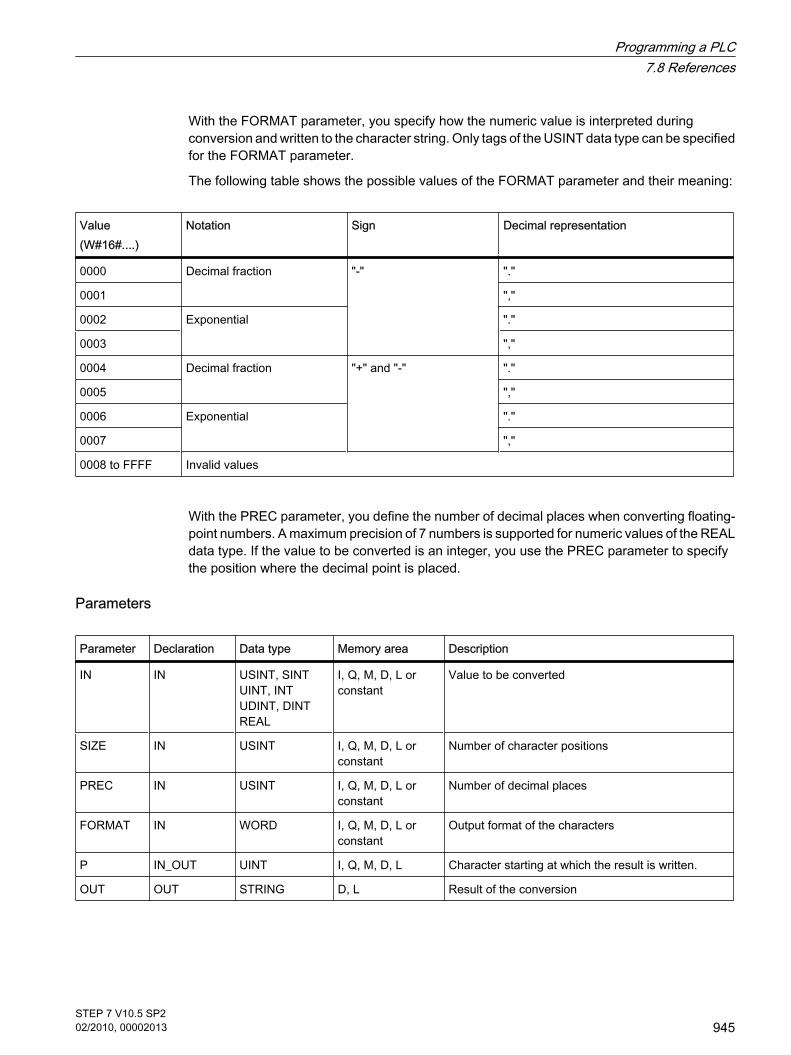
With the FORMAT parameter, you specify how the numeric value is interpreted duringconversion and written to the character string. Only tags of the USINT data type can be specifiedfor the FORMAT parameter.
The following table shows the possible values of the FORMAT parameter and their meaning:
Value(W#16#....)
Notation Sign Decimal representation
0000 Decimal fraction "-" "."
0001 ","
0002 Exponential "."
0003 ","
0004 Decimal fraction "+" and "-" "."
0005 ","
0006 Exponential "."
0007 ","
0008 to FFFF Invalid values
With the PREC parameter, you define the number of decimal places when converting floating-point numbers. A maximum precision of 7 numbers is supported for numeric values of the REALdata type. If the value to be converted is an integer, you use the PREC parameter to specifythe position where the decimal point is placed.
Parameters
Parameter Declaration Data type Memory area Description
IN IN USINT, SINT UINT, INT UDINT, DINT REAL
I, Q, M, D, L orconstant
Value to be converted
SIZE IN USINT I, Q, M, D, L orconstant
Number of character positions
PREC IN USINT I, Q, M, D, L orconstant
Number of decimal places
FORMAT IN WORD I, Q, M, D, L orconstant
Output format of the characters
P IN_OUT UINT I, Q, M, D, L Character starting at which the result is written.
OUT OUT STRING D, L Result of the conversion
Programming a PLC7.8 References
STEP 7 V10.5 SP202/2010, 00002013
945

ExampleThe following table shows examples of the conversion of numeric values to a character string.
IN (value) IN (data type) P SIZE FORMAT (W#16#....)
PREC OUT (STRING) ENO status
123 UINT 16 10 0000 0 xxxxxxx123 C 1
0 UINT 16 10 0000 2 xxxxxx0.00 C 1
12345678 UDINT 16 10 0000 3 x12345.678 C 1
12345678 UDINT 16 10 0001 3 x12345.678 C 1
123 INT 16 10 0004 0 xxxxxx+123 C 1
-123 INT 16 10 0004 0 xxxxxx-123 C 1
-0.00123 REAL 16 10 0004 4 xxx-0.0012 C 1
-0.00123 REAL 16 10 0006 4 -1.2300E-3 C 1
-Inf 1) REAL 16 10 -/- 4 xxxxxx-INF C 0
+Inf 2) REAL 16 10 -/- 4 xxxxxx+INF C 0
NaN 3) REAL 16 10 -/- 4 xxxxxxxNaN C 0
12345678 UDINT 16 6 -/- 3 xxxxxxxxxx C 0
"x" represents blanks 1) -Inf: Floating-point number representing a negative infinite value. 2) +Inf: Floating-point number representing a positive infinite value. 3) NaN: Value returned as the result of invalid math operations.
See alsoSTRING (Page 383)
7.8.2.2 Instructions
7.8.2.2 LEN
Description A tag of the STRING type contains two lengths: the maximum length and the current length(this is the number of currently valid characters). The maximum length of the string is specifiedfor each tag in the STRING keyword in square brackets. The current length represents thenumber of the character places actually used. The current length must be less than or equalto the maximum length. The number of bytes occupied by a string is 2 greater than the maximumlength.
7.8.2.2 Instructions7.8.2.2 LEN
Programming a PLC7.8 References
946STEP 7 V10.5 SP202/2010, 00002013
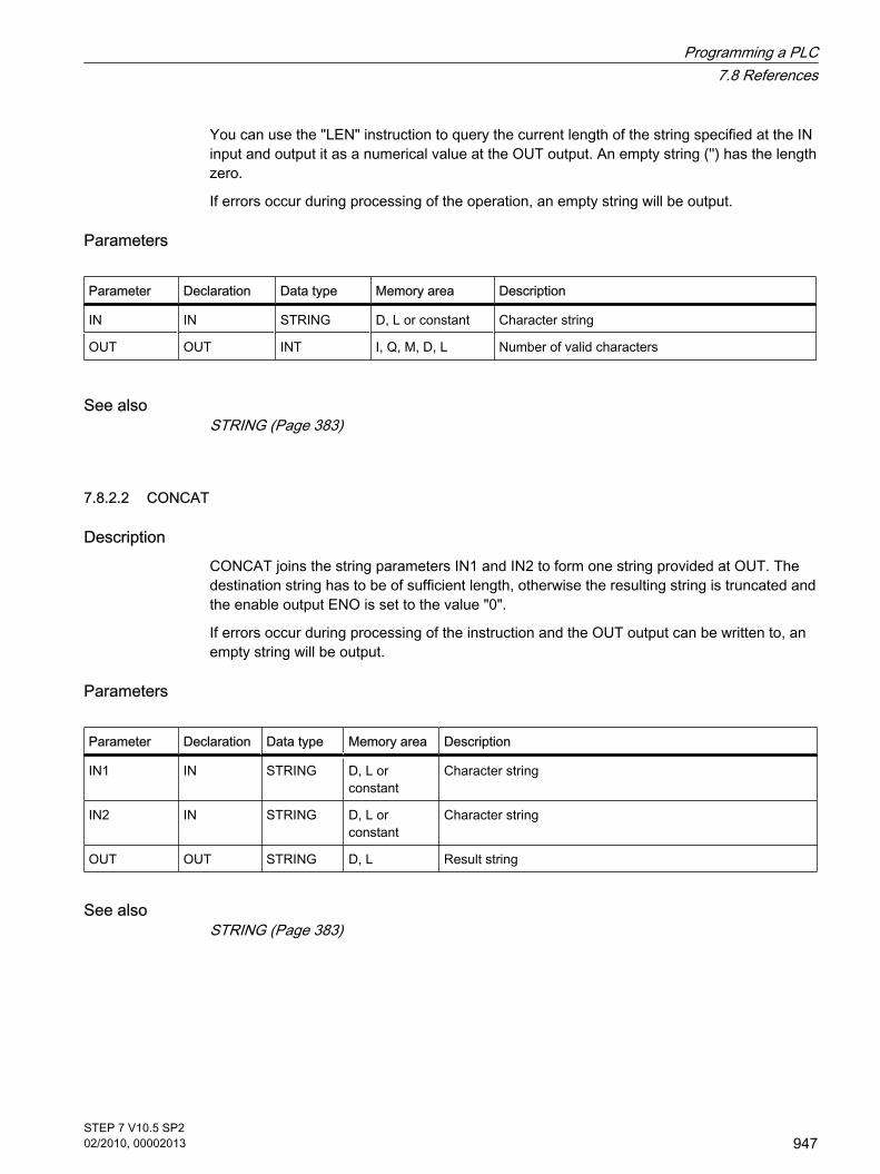
You can use the "LEN" instruction to query the current length of the string specified at the INinput and output it as a numerical value at the OUT output. An empty string ('') has the lengthzero.
If errors occur during processing of the operation, an empty string will be output.
Parameters
Parameter Declaration Data type Memory area Description
IN IN STRING D, L or constant Character string
OUT OUT INT I, Q, M, D, L Number of valid characters
See alsoSTRING (Page 383)
7.8.2.2 CONCAT
DescriptionCONCAT joins the string parameters IN1 and IN2 to form one string provided at OUT. Thedestination string has to be of sufficient length, otherwise the resulting string is truncated andthe enable output ENO is set to the value "0".
If errors occur during processing of the instruction and the OUT output can be written to, anempty string will be output.
Parameters
Parameter Declaration Data type Memory area Description
IN1 IN STRING D, L orconstant
Character string
IN2 IN STRING D, L orconstant
Character string
OUT OUT STRING D, L Result string
See alsoSTRING (Page 383)
7.8.2.2 CONCAT
Programming a PLC7.8 References
STEP 7 V10.5 SP202/2010, 00002013
947

7.8.2.2 LEFT
Description You can use LEFT to extract a partial string beginning with the first character of the string atthe IN input. You specify the number of characters to be extracted with the L parameter. Theextracted characters are output at the OUT output in the STRING format.
If the number of character to be extracted is greater than the current length of the string, theOUT output returns the input string as a result. An empty string is return with the value "0" atthe L parameter or with an empty string as the input value. If the value at the L parameter isnegative, an empty string is output and the ENO enable output is set to the value "0".
If errors occur during processing of the instruction and the OUT output can be written to, anempty string will be output.
Parameter
Parameter Declaration Data type Memory area Description
IN IN STRING D, L or constant Character string
L IN INT I, Q, M, D, L orconstant
Number of characters to be extracted
OUT OUT STRING D, L Extracted partial string
See alsoSTRING (Page 383)
7.8.2.2 RIGHT
Description You can use RIGHT to extract a partial string beginning with the last character of the string atthe IN input. You specify the number of characters to be extracted with the L parameter. Theextracted characters are output at the OUT output in the STRING format.
If the number of character to be extracted is greater than the current length of the string, theOUT output returns the input string as a result. An empty string is return with the value "0" atthe L parameter or with an empty string as the input value. If the value at the L parameter isnegative, an empty string is output and the ENO enable output is set to the value "0".
If errors occur during processing of the instruction and the OUT output can be written to, anempty string will be output.
7.8.2.2 LEFT7.8.2.2 RIGHT
Programming a PLC7.8 References
948STEP 7 V10.5 SP202/2010, 00002013

Parameter
Parameter Declaration Data type Memory area Description
IN IN STRING D, L or constant Character string
L IN INT I, Q, M, D, L orconstant
Number of characters to be extracted
OUT OUT STRING D, L Extracted partial string
See alsoSTRING (Page 383)
7.8.2.2 MID
DescriptionYou can use MID to extract a portion of the string at the IN input. You can specify the positionof the first character to extract with the P parameter. You specify the length of the string toextract with the L parameter. The extracted partial string is output at the OUT output.
The following rules should be observed when executing the instruction:
• If the number of characters to be extracted exceeds the current length of the string at the IN input, apartial string is output, beginning with the character position P and continuing to the end of the string.
• If the character position specified with the P parameter is beyond the current length of the string atthe IN input, an empty string is output at the OUT output and the ENO enable output is set to the value"0".
• If the value of the P or L parameter equals zero or is negative, an empty string is output at the OUToutput and the ENO enable output is set to the value "0".
If errors occur during processing of the instruction and the OUT output can be written to, anempty string will be output.
Parameters
Parameter Declaration Data type Memory area Description
IN IN STRING D, L or constant Character string
P IN INT I, Q, M, D, L orconstant
Position of the first character to be extracted (first character= 1)
L IN INT I, Q, M, D, L orconstant
Length of the string to be extracted
OUT OUT STRING D, L Extracted partial string
7.8.2.2 MID
Programming a PLC7.8 References
STEP 7 V10.5 SP202/2010, 00002013
949

See alsoSTRING (Page 383)
7.8.2.2 DELETE
DescriptionYou can use DELETE to delete a portion of the string at the IN input. You can specify theposition of the first character to be deleted with the P parameter. You can use the L parameterto specify the number of characters to be deleted. The remaining partial string is output at theOUT output in the STRING format.
The following rules should be observed when executing the instruction:
• If the value at the L or P parameter equals zero, the input string is returned at the OUT output.
• If the value at the P parameter is greater than the current length of the string at the IN input, the inputstring is returned at the OUT output.
• If the number of characters to be deleted is greater than the length of the string at the IN input, anempty string is output.
• If the value at the L or P parameter is negative, an empty string is output and the ENO enable outputis set to the value "0".
If errors occur during processing of the instruction and the OUT output can be written to, anempty string will be output.
Parameters
Parameters Declaration Data type Memory area Description
IN IN STRING D, L or constant Character string
L IN INT I, Q, M, D, L orconstant
Number of characters to be deleted
P IN INT I, Q, M, D, L orconstant
Position of first character to be deleted
OUT OUT STRING D, L Result string
See alsoSTRING (Page 383)
7.8.2.2 DELETE
Programming a PLC7.8 References
950STEP 7 V10.5 SP202/2010, 00002013

7.8.2.2 INSERT
DescriptionInserts string 2 into string 1 beginning at character position and stores the result in the stringdestination. You can use the P parameter to specify the position of the character at which thecharacters should be inserted. The result is output at the OUT output in the STRING format.
The following rules should be observed when executing the instruction:
• If the value at the P parameter P exceeds the current length of the string at the IN1 input, the stringfrom the IN2 input is appended to the string from the IN1 input.
• If the value at the P parameter is negative or equals zero, an empty string is output at the OUT output.The ENO enable output is set to the value "0".
• If the results string is longer than the tag specified at the OUT output, the results string is limited tothe available length. The ENO enable output is set to the value "0".
If errors occur during processing of the instruction and the OUT output can be written to, anempty string will be output.
Parameters
Parameters Declaration Data type Memory area Description
IN1 IN STRING D, L or constant Character string
IN2 IN STRING D, L or constant String to insert
P IN INT I, Q, M, D, L orconstant
Insert position
OUT OUT STRING D, L Result string
See alsoSTRING (Page 383)
7.8.2.2 REPLACE
DescriptionYou can use REPLACE to replace a string at the IN1 input with the string at the IN2 input. Youcan specify the position of the first character to be replaced with the P parameter. You specifythe number of characters to be replaced with the L parameter. The result is output at the OUToutput in the STRING format.
The following rules should be observed when executing the instruction:
• If the value at the L parameter equals zero, the string at the IN1 input is returned at the OUT output.
• If P equals one, the string at the IN1 input is replaced beginning with (and including) the first character.
7.8.2.2 INSERT7.8.2.2 REPLACE
Programming a PLC7.8 References
STEP 7 V10.5 SP202/2010, 00002013
951

• If the value at the P parameter P exceeds the current length of the string at the IN1 input, the stringfrom the IN2 input is appended to the string from the IN1 input.
• If the value at the P parameter is negative or equals zero, an empty string is output at the OUT output.The ENO enable output is set to the value "0".
• If the results string is longer than the tag specified at the OUT output, the results string is limited tothe available length. The ENO enable output is set to the value "0".
If errors occur during processing of the instruction and the OUT output can be written to, anempty string will be output.
Parameters
Parameters Declaration Data type Memory area Description
IN1 IN STRING D, L or constant String with characters to be replaced.
IN2 IN STRING D, L or constant String with characters to be inserted.
L IN INT I, Q, M, D, L orconstant
Number of characters to be replaced
P IN INT I, Q, M, D, L orconstant
Position of first character to be replaced
OUT OUT STRING D, L Result string
See alsoSTRING (Page 383)
7.8.2.2 FIND
DescriptionYou can use FIND to search through the string at the IN1 input to locate a specific characteror a specific string of characters. You specify the value to be searched for at the IN2 input. Thesearch is made from left to right. The position of the first hit is output at the OUT output. If thesearch returns no match, the value "0" is output at the OUT output.
If errors occur during processing of the instruction, an empty string will be output.
Parameters
Parameter I/O Data type Memory area Description
IN1 IN STRING D, L orconstant
String searched through
7.8.2.2 FIND
Programming a PLC7.8 References
952STEP 7 V10.5 SP202/2010, 00002013

Parameter I/O Data type Memory area Description
IN2 IN STRING,CHAR
D, L orconstant(For CHARalso I, Q, M)
Characters to search for
OUT OUT INT I, Q, M, D, L Character position
See alsoSTRING (Page 383)
7.8.2.3 Program control
7.8.2.3 RE_TRIGR
Description With RE_TRIGR, you restart the CPU cycle monitoring. The cycle time monitoring then restartswith the time you set in the CPU configuration. By restarting the cycle monitoring time, you canprevent errors being triggered or the CPU changing to STOP.
The instruction "RE_TRIGR" can be used in blocks of the priority class 1 (for example, theprogram cycle OB) and in the blocks called in this.
If the instruction is called in a block with a higher priority, for example a hardware interrupt, adiagnostic error interrupt or a cyclic interrupt, the enable output ENO is set to "0" and"RE_TRIGR" is not executed.
ParametersThe "RE_TRIGR" instruction has no parameters.
See alsoEvents and OBs (Page 323)
7.8.2.3 STP
Description With STP, you change the CPU to STOP mode and therefore terminate program execution.The effects of changing from RUN to STOP depend on the CPU configuration.
When the EN enable input is "1", the CPU changes to "STOP" mode and program executionis terminated. The signal state of "ENO" is not evaluated.
7.8.2.3 Program control7.8.2.3 RE_TRIGR7.8.2.3 STP
Programming a PLC7.8 References
STEP 7 V10.5 SP202/2010, 00002013
953

When the EN enable input is "0", ENO is also "0".
ParametersThe "STP" instruction has no parameters.
7.8.2.3 GetError
Description With the "GetError" instruction, you can query the occurrence of errors within a block. If thesystem signals errors during block execution, detailed information about the first error thatoccurred is saved in the tag at the ERROR output.
Only tags of the "ErrorStruct" system data type can be specified at the ERROR output. The"ErrorStruct" system data type specifies the exact structure in which the information about theerror is stored. Using additional instructions, you can evaluate this structure and program anappropriate response. When the first error has been eliminated, the instruction outputsinformation about the next error that occurred.
Parameters
Parameter Declaration Data type Memory area Description
ERROR OUT ErrorStruct D, L Error information
"ErrorStruct" data typeThe following table shows which information a tag of the "ErrorStruct" data type can contain:
Structure components Data type Description
ERROR_ID WORD Error ID
FLAGS BYTE Shows if an error occurred during a block call.16#01: Error during a block call.16#00: No error during a block call.
REACTION BYTE Default reaction:0: Ignore (write error),1: Continue with substitute value "0" (read error),2: Skip instruction (system error)
BLOCK_TYPE BYTE Type of block where the error occurred:1: OB2: FC3: FB
7.8.2.3 GetError
Programming a PLC7.8 References
954STEP 7 V10.5 SP202/2010, 00002013
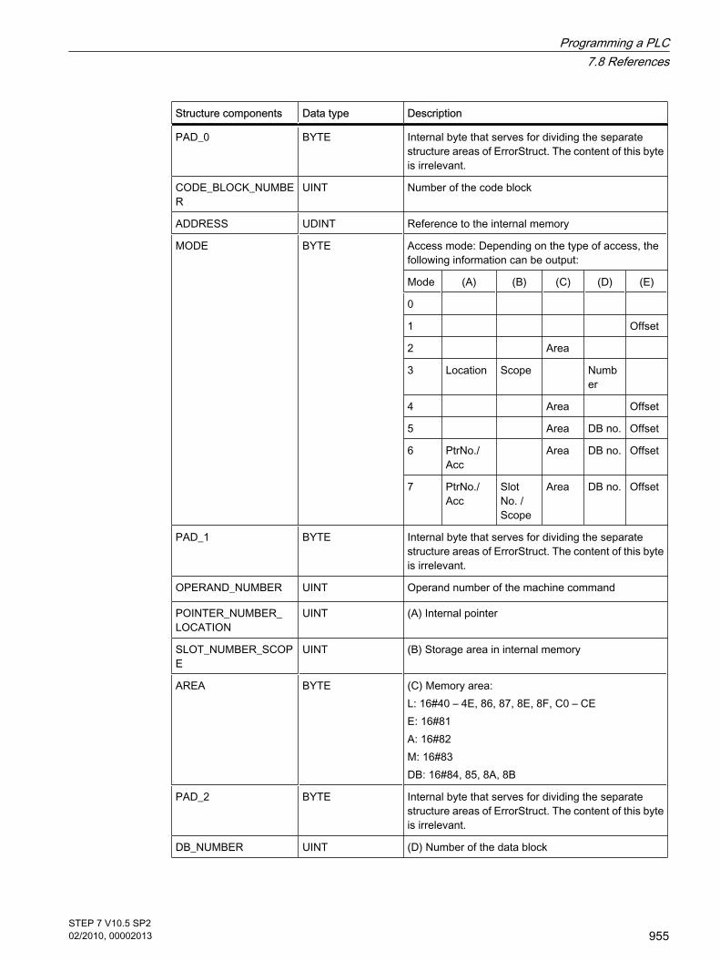
Structure components Data type Description
PAD_0 BYTE Internal byte that serves for dividing the separatestructure areas of ErrorStruct. The content of this byteis irrelevant.
CODE_BLOCK_NUMBER
UINT Number of the code block
ADDRESS UDINT Reference to the internal memory
MODE BYTE Access mode: Depending on the type of access, thefollowing information can be output:
Mode (A) (B) (C) (D) (E)
0
1 Offset
2 Area
3 Location Scope Number
4 Area Offset
5 Area DB no. Offset
6 PtrNo./Acc
Area DB no. Offset
7 PtrNo./Acc
SlotNo. /Scope
Area DB no. Offset
PAD_1 BYTE Internal byte that serves for dividing the separatestructure areas of ErrorStruct. The content of this byteis irrelevant.
OPERAND_NUMBER UINT Operand number of the machine command
POINTER_NUMBER_ LOCATION
UINT (A) Internal pointer
SLOT_NUMBER_SCOPE
UINT (B) Storage area in internal memory
AREA BYTE (C) Memory area:L: 16#40 – 4E, 86, 87, 8E, 8F, C0 – CEE: 16#81A: 16#82M: 16#83DB: 16#84, 85, 8A, 8B
PAD_2 BYTE Internal byte that serves for dividing the separatestructure areas of ErrorStruct. The content of this byteis irrelevant.
DB_NUMBER UINT (D) Number of the data block
Programming a PLC7.8 References
STEP 7 V10.5 SP202/2010, 00002013
955
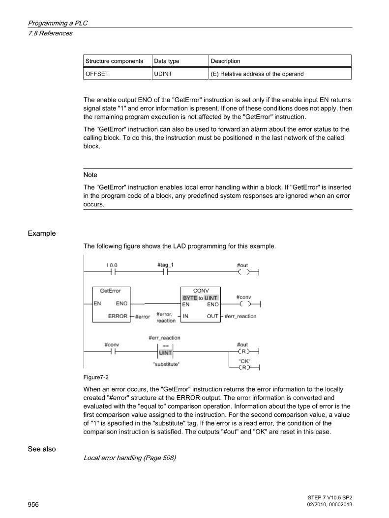
Structure components Data type Description
OFFSET UDINT (E) Relative address of the operand
The enable output ENO of the "GetError" instruction is set only if the enable input EN returnssignal state "1" and error information is present. If one of these conditions does not apply, thenthe remaining program execution is not affected by the "GetError" instruction.
The "GetError" instruction can also be used to forward an alarm about the error status to thecalling block. To do this, the instruction must be positioned in the last network of the calledblock.
Note
The "GetError" instruction enables local error handling within a block. If "GetError" is insertedin the program code of a block, any predefined system responses are ignored when an erroroccurs.
ExampleThe following figure shows the LAD programming for this example.
Figure7-2
When an error occurs, the "GetError" instruction returns the error information to the locallycreated "#error" structure at the ERROR output. The error information is converted andevaluated with the "equal to" comparison operation. Information about the type of error is thefirst comparison value assigned to the instruction. For the second comparison value, a valueof "1" is specified in the "substitute" tag. If the error is a read error, the condition of thecomparison instruction is satisfied. The outputs "#out" and "OK" are reset in this case.
See alsoLocal error handling (Page 508)
Programming a PLC7.8 References
956STEP 7 V10.5 SP202/2010, 00002013

7.8.2.3 GetErrorID
Description With the "GetErrorID" instruction, you can query the occurrence of errors within a block. If thesystem signals errors during block execution, the error ID of the first error that occurred is savedin the tag at the "ID" output. Only tags of the WORD data type can be specified at the "ID"output. When the first error has been eliminated, the instruction outputs the error ID of the nexterror that occurred.
The output of the "GetErrorID" instruction is only set if the input of the instruction returns signalstate "1" and error information is present. If one of these conditions does not apply, theremaining program execution is not influenced by "GetErrorID".
The "GetErrorID" instruction can also be used to forward an alarm about the error status to thecalling block. To do this, the instruction must be positioned in the last network of the calledblock.
Note
The "GetErrorID" instruction enables local error handling within a block. If "GetErrorID" isinserted in the program code of a block, any predefined system responses are ignored whenan error occurs.
Parameters
Parameter Declaration Data type Memory area Description
ID OUT WORD I, Q, M, D, L Error ID
"ID" parameter
ID (hexadecimal)
ID (decimal)
Description
2503 9475 Invalid pointer
2522 9506 Read errors: Operand outside the valid range
2523 9507 Write errors: Operand outside the valid range
2524 9508 Read errors: Invalid operand
2525 9509 Write errors: Invalid operand
2528 9512 Read errors: Data alignment
2529 9513 Write errors: Data alignment
2530 9520 Write errors: Data block
7.8.2.3 GetErrorID
Programming a PLC7.8 References
STEP 7 V10.5 SP202/2010, 00002013
957

ID (hexadecimal)
ID (decimal)
Description
253A 9530 Global data block does not exist
253C 9532 Faulty information or the function does not exist
253D 9533 System function does not exist
253E 9534 Faulty information or the function block does not exist
253F 9535 System block does not exist
2575 9589 Error in the program nesting depth
2576 9590 Error in the local data distribution
2942 10562 Read errors: Input
2943 10563 Write errors: Output
See alsoLocal error handling (Page 508)
7.8.2.4 Communication
7.8.2.4 Open user communication
7.8.2.4 TSEND_C
Description TSEND_C is asynchronous and has the following functions:
• Setting up and establishing a communications connection: TSEND_C sets up a TCP or ISO-on-TCP communications connection and establishes it. After theconnection is set up and established, it is automatically maintained and monitored by the CPU. The connection description specified at the CONNECT parameter is used to set up thecommunications connection. To establish a connection, the CONT parameter must be set to the value"1". When a connection is successfully established the DONE parameter for a cycle is set to "1". When the CPU goes to STOP mode an existing connection is terminated and the setup connectionremoved. TSEND_C must be executed again to set up and establish the connection again. For information on the number of possible communications connections, refer to the technicalspecifications of your CPU.
• Sending data via an existing communications connection: You specify the area to be sent with the DATA parameter. This includes the address and the lengthof the data to be sent. The send job executes when a rising edge is detected at the REQ parameter.With the LEN parameter, you specify the maximum number of bytes sent with a send job. The data
7.8.2.4 Communication7.8.2.4 Open user communication7.8.2.4 TSEND_C
Programming a PLC7.8 References
958STEP 7 V10.5 SP202/2010, 00002013

to be sent must not be edited until the send job has completed. If the send job executes successfully,the DONE parameter is set to "1". Signal state "1" at the DONE parameter does not imply confirmationthat the sent data has been read by the communications partner.
• Terminating the communications connection: The communications connection is terminated when the CONT parameter is set to "0".
TSEND_C is executed again when the COM_RST parameter is set to "1". This terminates theexisting communications connection and a new connection established. If data is beingtransferred when it executes again, this can lead to a loss of data.
Parameters
Parameters Declaration Data type Memory area Description
REQ INPUT BOOL I, Q, M, D, L Starts the send job on a rising edge.
CONT INPUT BOOL I, Q, M, D, L Controls the communications connection:
• 0: Disconnect the communications connection
• 1: Establish and maintain the communicationsconnection
LEN INPUT UINT I, Q, M, D, L orconstant
Maximum number of bytes to be sent with the job .
CONNECT IN_OUT TCON_Param
D Pointer to the connection descriptionSee: Creating and assigning parameters to connections(Page 235)
DATA IN_OUT VARIANT I, Q, M, D, L Pointer to the send area containing the address and thelength of the data to be sent.
COM_RST IN_OUT BOOL I, Q, M, D, L Restarts the instruction:
• 0: Irrelevant
• 1: Complete restart of the instruction causing anexisting connection to be terminated and a newconnection to be established.
DONE OUTPUT BOOL I, Q, M, D, L Status parameter with the following values:
• 0: Job not yet started or is still executing
• 1: Job completed free of error
BUSY OUTPUT BOOL I, Q, M, D, L Status parameter with the following values:
• 0: Job not yet started or already completed.
• 1: Job not yet completed. A new job cannot be started.
ERROR OUTPUT BOOL I, Q, M, D, L Status parameter with the following values:
• 0: No error
• 1: Error occurred
STATUS OUTPUT WORD I, Q, M, D, L Status of the instruction
Programming a PLC7.8 References
STEP 7 V10.5 SP202/2010, 00002013
959

BUSY, DONE and ERROR parametersYou can check the status of the job with the BUSY, DONE, ERROR and STATUS parameters.The BUSY parameter indicates the processing status. With the DONE parameter, you cancheck whether or not a job executed successfully. The ERROR parameter is set when errorsoccurred during execution of TSEND_C. The error information is output at the STATUSparameter.
The following table shows the relationship between the BUSY, DONE and ERROR parameters:
BUSY DONE ERROR Description
1 - - The job is being processed.
0 1 0 The job was completed successfully.
0 0 1 The job ended with an error. The cause of the error is specified in the STATUSparameter.
0 0 0 No new job was assigned.
Parameters ERROR and STATUS
ERROR STATUS(W#16#...)
Description
0 0000 Job completed error-free
0 7000 No job processing active
0 7001 • Start execution of the job
• Establish connection
• Wait for connection partner
0 7002 Data are being sent
0 7003 Connection is terminated
0 7004 Connection established and monitored, no job processing active.
1 8085 LEN parameter has the value 0 or is greater than the highest permitted value.
1 8086 The CONNECT parameter is outside the permitted range.
1 8087 Maximum number of connections reached; no additional connection possible.
1 8088 The LEN parameter is longer than the area specified in DATA. The area for receiving data is too short.
1 8089 The parameter CONNECT does not point to a data block.
1 8091 Maximum nesting depth exceeded.
1 809A The CONNECT parameter points to a field that does not match the length of the connectiondescription.
1 809B The ID of the local device in the connection description does not match the CPU.
Programming a PLC7.8 References
960STEP 7 V10.5 SP202/2010, 00002013

ERROR STATUS(W#16#...)
Description
1 80A1 Communications error:
• The specified connection has not yet been established.
• The specified connection is being terminated. A transfer over this connection is not possible.
• The interface is being re-initialized.
1 80A3 Attempt being made to terminate a non-existent connection.
1 80A7 Communications error: You called TDISCON before TSEND_C had completed.
1 80B2 The CONNECT parameter points to a data block that was generated with the keywordUNLINKED.
1 80B3 Inconsistent parameters:
• Error in the connection description
• The local port already exists in a different connection description
• The ID in the connection description is different from the ID specified as the parameter
1 80B4 You have violated one or both of the following conditions for passive connection establishment(active_est = FALSE) when using the ISO-on-TCP protocol variant (connection_type = B#16#12):"local_tsap_id_len >= B#16#02" and/or "local_tsap_id[1] = B#16#E0".
1 80C3 All connection resources are being used.
1 80C4 Temporary communications error:
• The connection cannot be established at this time.
• The interface is currently receiving new parameters.
• The configured connection is being removed from a TDISCON instruction.
1 8722 CONNECT parameter: The source area is invalid. The area does not exist in the DB.
1 873A CONNECT parameter: Access to the connection description is not possible (for example, DBdoes not exist).
1 877F CONNECT parameter: Internal error.
See alsoBasics of Open User Communication (Page 230)Principle of operation of connection-oriented protocols (Page 299)Parameters of communication connections (Page 301)General status information of the communications blocks (Page 992)
7.8.2.4 TRCV_C
Description TRCV_C is asynchronous and has the following functions:
• Setting up and establishing a communications connection:
7.8.2.4 TRCV_C
Programming a PLC7.8 References
STEP 7 V10.5 SP202/2010, 00002013
961

TRCV_C sets up a TCP or ISO-on-TCP communications connection and establishes it. After theconnection has been set up and established, it is automatically maintained and monitored by theCPU. The communications connection is set up using the connection description specified with theCONNECT parameter. To establish a connection, the CONT parameter must be set to the value "1".When a connection is successfully established the DONE parameter for a cycle is set to "1". When the CPU goes to STOP mode an existing connection is terminated and the setup connectionremoved. TRCV_C must be executed again to set up and establish the connection again. For information on the number of possible communications connections, refer to the technicalspecifications of your CPU.
• Receiving data via an existing communications connection: If the EN_R parameter is set to the value "1", reception of data is enabled. The received data is enteredin a receive area. You specify the length of the receive area depending on the protocol variant beingused either with the LEN parameter (if LEN <> 0) or the length information of the DATA parameter (ifLEN = 0). After data has been received successfully, the signal state at the DONE parameter is "1". If errorsoccur in the data transfer, the DONE parameter is set to "0".
• Terminating the communications connection: The communications connection is terminated when the CONT parameter is set to "0".
TRCV_C is executed again when the COM_RST parameter is set. This terminates the existingcommunications connection and a new connection established. If data is being received whenit executes again, this can lead to a loss of data
Receive modes of TRCV_CThe following table shows how the received data is entered in the receive area.
Protocolvariant
Availability of data in the receivearea "connection_type"
parameter with connectiondescription
Parameter LEN
Parameter RCVD_LEN
TCP (ad-hocmode)
The data are immediatelyavailable.
B#16#11 0 1 to x (x: length definedat the DATAparameter)
TCP (Datareception withspecifiedlength)
The data are available as soonas the specified data length wasreceived at the LEN parameter.
B#16#11 1 to 8192 Identical with thevalue at the LENparameter
ISO-on-TCP(protocol-controlled datatransfer)
The data are available as soonas the specified data length wasreceived at the LEN parameter.
B#16#12 • 1 to 1452, if a CP isused.
• 1 to 8192, if no CP isused.
Identical with thevalue at the LENparameter
Programming a PLC7.8 References
962STEP 7 V10.5 SP202/2010, 00002013

TCP (ad-hoc mode)The ad-hoc mode is only available with the TCP protocol variant. You set ad-hoc mode byassigning the value 0 to the LEN parameter. The length of the receive area is defined by thepointer at the DATA parameter. The actually received data length at the RCVD_LEN parametermust be identical with the length defined at the DATA parameter. A maximum of 8192 bytescan be received.
TCP (Data reception with specified length)You use the value of the LEN parameter to specify the length for the data reception. The dataspecified at the DATA parameter are available in the receive area as soon as the lengthspecified at the LEN parameter has been completely received.
ISO-on-TCP (protocol-controlled data transfer)With the ISO-on-TCP protocol variant, data is transferred protocol-controlled.
The receive area is defined by the LEN and DATA parameters.
Parameters
Parameter Declaration Data type Memory area Description
EN_R IN BOOL I, Q, M, D, L Receive enable
CONT IN BOOL I, Q, M, D, L Controls the communications connection:
• 0: Disconnect the communications connection
• 1: Establish and maintain the communicationsconnection
LEN IN UINT I, Q, M, D, L orconstant
Length of the receive area in bytes
CONNECT IN_OUT TCON_Param
D Pointer to the connection descriptionSee: Creating and assigning parameters to connections(Page 235)
DATA IN_OUT VARIANT I, Q, M, D, L Pointer to the receive area
COM_RST IN_OUT BOOL I, Q, M, D, L Restarts the instruction:
• 0: Irrelevant
• 1: Complete restart of the instruction causing anexisting connection to be terminated
DONE OUT BOOL I, Q, M, D, L Status parameter with the following values:
• 0: Job not yet started or is still executing
• 1: Job completed error-free
BUSY OUT BOOL I, Q, M, D, L Status parameter with the following values:
• 0: Job not yet started or already completed
• 1: Job not yet completed. A new job cannot be started
Programming a PLC7.8 References
STEP 7 V10.5 SP202/2010, 00002013
963

Parameter Declaration Data type Memory area Description
ERROR OUT BOOL I, Q, M, D, L ERROR status parameter:
• 0: No error
• 1: Error occurred
STATUS OUT WORD I, Q, M, D, L Status of the instruction
RCVD_LEN OUT WORD I, Q, M, D, L Amount of data actually received in bytes
BUSY, DONE and ERROR parametersYou can check the status of the job with the BUSY, DONE, ERROR and STATUS parameters.The BUSY parameter indicates the processing status. With the DONE parameter, you cancheck whether or not a job executed successfully. The ERROR parameter is set when errorsoccurred during execution of TRCV_C. The error information is output at the STATUSparameter.
The following table shows the relationship between the BUSY, DONE and ERROR parameters:
BUSY DONE ERROR Description
1 - - The job is being processed.
0 1 0 The job was completed successfully.
0 0 1 The job ended with an error. The cause of the error is output at the STATUSparameter.
0 0 0 No new job was assigned.
Parameters ERROR and STATUS
ERROR STATUS(W#16#...)
Description
0 0000 Job completed error-free
0 7000 No job processing active
0 7001 • Start execution of the job
• Establish connection
• Wait for connection partner
0 7002 Data is being received
0 7003 Connection is being terminated
0 7004 • Connection established and monitored
• No job processing active
1 8085 LEN parameter has the value 0 or is greater than the highest permitted value.
Programming a PLC7.8 References
964STEP 7 V10.5 SP202/2010, 00002013

ERROR STATUS(W#16#...)
Description
1 8086 The CONNECT parameter is outside the permitted range.
1 8087 Maximum number of connections reached; no additional connection possible
1 8088 The LEN parameter is longer than the area specified in DATA. The area for receiving data is too short.
1 8089 The parameter CONNECT does not point to a data block.
1 8091 Maximum nesting depth exceeded.
1 809A The CONNECT parameter points to a field that does not match the length of the connectiondescription.
1 809B The ID of the local device (local_device_id) in the connection description does not match theCPU.
1 80A1 Communications error:
• The specified connection has not yet been established.
• The specified connection is being terminated. A transfer over this connection is not possible.
• The interface is being re-initialized.
See alsoBasics of Open User Communication (Page 230)Principle of operation of connection-oriented protocols (Page 299)Parameters of communication connections (Page 301)General status information of the communications blocks (Page 992)
7.8.2.4 Others
7.8.2.4 TCON
Description With TCON, you set up a communications connection and establish it. After the connection isset up and established, it is automatically maintained and monitored by the CPU. TCON isasynchronous.
To set up the communications connection, the connection data specified for the CONNECTand ID parameters is used. To establish the connection, a rising edge must be detected at theREQ parameter. If the connection establishment is successful, the DONE parameter is set to"1".
7.8.2.4 Others7.8.2.4 TCON
Programming a PLC7.8 References
STEP 7 V10.5 SP202/2010, 00002013
965

Number of possible connectionsFor information on the number of possible communications connections, refer to the technicalspecifications for your CPU.
Connection with TCP and ISO-on-TCPBoth communication partners call the "TCON" instruction to set up and establish thecommunications connection. In the parameters you specify which partner is the activecommunication end point and which is the passive one.
If the connection aborts, for example due to a line break or due to the remote communicationspartner, the active partner attempts to reestablish the configured connection. You do not haveto call TCON again.
An existing connection is terminated and the set-up connection is removed when the"TDISCON" instruction executes or when the CPU has changed to STOP mode. To set up andestablish the connection again, you will need to execute TCON again.
Parameters
Parameter Declaration Data type Memory area Description
REQ IN BOOL I, Q, M, D, L Starts the job to establish the connection specified in theID on a rising edge.
ID IN CONN_OUC L, D or constant Reference to the assigned connection. Range: W#16#0001 to W#16#0FFF
CONNECT IN_OUT TCON_Param D Pointer to the connection descriptionSee: Creating and assigning parameters to connections(Page 235)
DONE OUT BOOL I, Q, M, D, L Status parameter with the following values:
• 0: Job not yet started or is still executing
• 1: Job completed error-free
BUSY OUT BOOL I, Q, M, D, L Status parameter with the following values:
• 0: Job not yet started or already completed.
• 1: Job not yet completed. A new job cannot be started
ERROR OUT BOOL I, Q, M, D, L ERROR status parameter:
• 0: No error
• 1: Error occurred
STATUS OUT WORD I, Q, M, D, L Status of the instruction
BUSY, DONE and ERROR parametersYou can check the status of the job with the BUSY, DONE, ERROR and STATUS parameters.The BUSY parameter indicates the processing status. With the DONE parameter, you can
Programming a PLC7.8 References
966STEP 7 V10.5 SP202/2010, 00002013

check whether or not a job executed successfully. The ERROR parameter is set when errorsoccurred during execution of TCON. The error information is output at the STATUS parameter.
The following table shows the relationship between the BUSY, DONE and ERROR parameters:
BUSY DONE ERROR Description
1 - - The job is being processed.
0 1 0 The job was completed successfully.
0 0 1 The job ended with an error. The cause of the error is output at the STATUSparameter.
0 0 0 No new job was assigned.
Parameters ERROR and STATUS
ERROR STATUS (W#16#...)
Explanation
0 0000 Connection was established successfully
0 7000 No job processing active
0 7001 Start job execution, establish connection.
0 7002 Connection is being established (REQ irrelevant)
1 8086 The ID parameter is outside the permitted range
1 8087 Maximum number of connections reached; no additional connection possible
1 8089 The parameter CONNECT does not point to a data block.
1 809A The CONNECT parameter points to a field that does not match the length of the connectiondescription.
1 809B The ID of the local device in the connection description does not match the CPU.
1 80A0 Group error for error codes W#16#80A1 and W#16#80A2
1 80A1 Connection or port already being used by user.
1 80A2 Local or distributed port is being used by system.
1 80A3 Attempt being made to re-establish an existing connection.
1 80A4 IP address of the distributed endpoint of the connection is invalid, in other words, it matches theIP address of the local partner.
1 80A7 Communications error: You executed TDISCON before TCON had completed.
1 80B3 Inconsistent parameter assignment: Group error for error codes W#16#80A0 to W#16#80A2,W#16#80A4, W#16#80B4 to W#16#80B9
Programming a PLC7.8 References
STEP 7 V10.5 SP202/2010, 00002013
967

ERROR STATUS (W#16#...)
Explanation
1 80B4 You have violated one or more of the following conditions for passive connection establishmentwith the ISO-on-TCP protocol variant (connection_type = B#16#12):
• local_tsap_id_len >= B#16#02
• local_tsap_id[1] = B#16#E0
• With local_tsap_id_len >= B#16#03, local_tsap_id[1] is an ASCII character.
• local_tsap_id[1] is an ASCII character and local_tsap_id_len >= B#16#03.
1 80B6 Parameter assignment error in the "connection_type" parameter of the data block for connectiondescription
1 80B7 Error in one of the following parameters of the data block for connection description:block_length, local_tsap_id_len, rem_subnet_id_len, rem_staddr_len, rem_tsap_id_len,next_staddr_len
1 80B8 Parameter in the local connection description and ID parameter are different.
1 80C3 All connection resources are being used.
1 80C4 Temporary communications error:
• The connection cannot be established at this time.
• The interface is currently receiving new parameters.
• The configured connection is being removed from a TDISCON instruction.
See alsoBasics of Open User Communication (Page 230)Principle of operation of connection-oriented protocols (Page 299)Parameters of communication connections (Page 301)General status information of the communications blocks (Page 992)
7.8.2.4 TDISCON
Description Using TDISCON, you terminate a communications connection. The job to terminate thecommunications connection begins when a rising edge is detected at the REQ parameter. Inthe ID parameter, you enter the reference of the connection you want to terminate. TDISCONis asynchronous.
After TDISCON has executed, the ID specified for TCON is no longer valid and can thereforenot be used for sending or receiving.
7.8.2.4 TDISCON
Programming a PLC7.8 References
968STEP 7 V10.5 SP202/2010, 00002013

Parameters
Parameter Declaration Data type Memory area Description
REQ IN BOOL I, Q, M, D, L Starts the job to terminate the connection specified in theID on a rising edge.
ID IN CONN_OUC L, D or constant Reference to the connection established with TCON. Value range: W#16#0001 to W#16#0FFF
DONE OUT BOOL I, Q, M, D, L Status parameter with the following values:
• 0: Job not yet started or is still executing
• 1: Job completed error-free
BUSY OUT BOOL I, Q, M, D, L Status parameter with the following values:
• 0: Job not yet started or already completed
• 1: Job not yet completed. A new job cannot be started.
ERROR OUT BOOL I, Q, M, D, L ERROR status parameter:
• 0: No error
• 1: Error occurred
STATUS OUT WORD I, Q, M, D, L Status of the instruction
BUSY, DONE and ERROR parametersYou can check the status of the job with the BUSY, DONE, ERROR and STATUS parameters.The BUSY parameter indicates the processing status. With the DONE parameter, you cancheck whether or not a job executed successfully. The ERROR parameter is set when errorsoccurred during execution of TDISCON. The error information is output at the STATUSparameter.
The following table shows the relationship between the BUSY, DONE and ERROR parameters:
BUSY DONE ERROR Description
1 - - The job is being processed.
0 1 0 The job was completed successfully.
0 0 1 The job ended with an error. The cause of the error is output at the STATUSparameter.
0 0 0 No new job was assigned.
Parameters ERROR and STATUS
ERROR STATUS (W#16#...)
Explanation
0 0000 Connection successfully terminated
Programming a PLC7.8 References
STEP 7 V10.5 SP202/2010, 00002013
969

ERROR STATUS (W#16#...)
Explanation
0 7000 No job processing active
0 7001 Start of job execution, connection is being terminated.
0 7002 Connection being terminated (REQ irrelevant).
1 8086 The ID parameter is outside the permitted address range.
1 80A3 Attempt being made to terminate a non-existent connection.
1 80C4 Temporary communications error: The interface is receiving new parameters or the connectionis being established.
See alsoBasics of Open User Communication (Page 230)Principle of operation of connection-oriented protocols (Page 299)Parameters of communication connections (Page 301)General status information of the communications blocks (Page 992)
7.8.2.4 TSEND
Description With TSEND, you send data over an existing communications connection. TSEND isasynchronous.
You specify the send area with the DATA parameter. This includes the address and the lengthof the data to be sent. The send job executes when a rising edge is detected at the REQparameter. With the LEN parameter, you specify the maximum number of bytes sent with asend job. The data to be sent must not be edited until the send job has completed. If the sendjob executes successfully, the DONE parameter is set to "1". Signal state "1" at the DONEparameter does not imply confirmation that the sent data has been read out by thecommunications partner.
Parameters
Parameter Declaration Data type Memory area Description
REQ IN BOOL I, Q, M, D, L Starts the send job on a rising edge.
ID IN CONN_OUC
L, D or constant Reference to the connection established with TCON. Value range: W#16#0001 to W#16#0FFF
LEN IN UINT I, Q, M, D, L Maximum number of bytes to be sent with the job .
7.8.2.4 TSEND
Programming a PLC7.8 References
970STEP 7 V10.5 SP202/2010, 00002013

Parameter Declaration Data type Memory area Description
DATA IN_OUT VARIANT I, Q, M, D, L Pointer to the send area containing the address and thelength of the data to be sent. The address references:
• The process image input
• The process image output
• A memory bit
• A data block
DONE OUT BOOL I, Q, M, D, L Status parameter with the following values:
• 0: Job not yet started or is still executing
• 1: Job completed error-free
BUSY OUT BOOL I, Q, M, D, L Status parameter with the following values:
• 0: Job not yet started or already completed
• 1: Job not yet completed. A new job cannot bestarted.
ERROR OUT BOOL I, Q, M, D, L Status parameter with the following values:
• 0: No error
• 1: Error occurred
STATUS OUT WORD I, Q, M, D, L Status of the instruction
BUSY, DONE and ERROR parametersYou can check the status of the job with the BUSY, DONE, ERROR and STATUS parameters.The BUSY parameter indicates the processing status. With the DONE parameter, you cancheck whether or not a job executed successfully. The ERROR parameter is set when errorsoccurred during execution of TSEND. The error information is output at the STATUS parameter.
The following table shows the relationship between the BUSY, DONE and ERROR parameters:
BUSY DONE ERROR Description
1 - - The job is being processed.
0 1 0 The job was completed successfully.
0 0 1 The job ended with an error. The cause of the error is specified in the STATUSparameter.
0 0 0 No new job was assigned.
Note
Because TSEND is asynchronous, you need to keep the data in the send area consistent untilthe DONE parameter or the ERROR parameter changes to the value "1".
Programming a PLC7.8 References
STEP 7 V10.5 SP202/2010, 00002013
971

Parameters ERROR and STATUS
ERROR STATUS (W#16#...)
Description
0 0000 Send job completed without error.
0 7000 No job processing active.
0 7001 Start of job execution, data is being sent.When processing this job, the operating system accesses the data in the DATA send area.
0 7002 Job executing (REQ irrelevant).When processing this job, the operating system accesses the data in the DATA send area.
1 8085 LEN parameter has the value 0 or is greater than the highest permitted value.
1 8086 The ID parameter is outside the permitted address range.
1 8088 LEN parameter is greater than the area specified in DATA.
1 80A1 Communications error:
• The specified connection has not yet been established.
• The specified connection is being terminated. Transfer over this connection is not possible.
• The interface is being re-initialized.
1 80C3 • A block with this ID is already being processed in a different priority group.
• Internal lack of resources.
1 80C4 Temporary communications error:
• The connection cannot be established to the partner at this time.
• The interface is receiving new parameter settings or the connection is being established.
See alsoBasics of Open User Communication (Page 230)Principle of operation of connection-oriented protocols (Page 299)Parameters of communication connections (Page 301)General status information of the communications blocks (Page 992)
7.8.2.4 TRCV
Description With TRCV, you receive data over an existing communications connection. TRCV isasynchronous.
Reception of data is enabled when the EN_R parameter is set to the value "1". The receiveddata is entered in a receive area. You specify the length of the receive area depending on the
7.8.2.4 TRCV
Programming a PLC7.8 References
972STEP 7 V10.5 SP202/2010, 00002013

protocol variant being used either with the LEN parameter (if LEN <> 0) or the length informationof the DATA parameter (if LEN = 0).
After successful data reception, the NDR parameter is set to the value "1". You can query theamount of data actually received at the RCVD_LEN parameter.
Receive modes of TRCVThe following table shows how the received data is entered in the receive area.
Protocolvariant
Availability of data in the receivearea "connection_type"
parameter with connectiondescription
Parameter LEN
Parameter RCVD_LEN
TCP (ad-hocmode)
The data are immediatelyavailable.
B#16#11 0 1 to x (x: length definedat the DATAparameter)
TCP (Datareception withspecifiedlength)
The data are available as soonas the specified data length wasreceived at the LEN parameter.
B#16#11 1 to 8192 Identical with thevalue at the LENparameter
ISO-on-TCP(protocol-controlled datatransfer)
The data are available as soonas the specified data length wasreceived at the LEN parameter.
B#16#12 • 1 to 1452, if a CP isused.
• 1 to 8192, if no CP isused.
Identical with thevalue at the LENparameter
TCP (ad-hoc mode)The ad-hoc mode is only available with the TCP protocol variant. You set ad-hoc mode byassigning the value 0 to the LEN parameter. The length of the receive area is defined by thepointer at the DATA parameter. The actually received data length at the RCVD_LEN parametermust be identical with the length defined at the DATA parameter. A maximum of 8192 bytescan be received.
TCP (Data reception with specified length)You use the value of the LEN parameter to specify the length for the data reception. The dataspecified at the DATA parameter are available in the receive area as soon as the lengthspecified at the LEN parameter has been completely received.
ISO-on-TCP (protocol-controlled data transfer)With the ISO-on-TCP protocol variant, data is transferred protocol-controlled.
The receive area is defined by the LEN and DATA parameters.
Programming a PLC7.8 References
STEP 7 V10.5 SP202/2010, 00002013
973

Parameters
Parameter Declaration Data type Memory area Description
EN_R IN BOOL I, Q, M, D, L Receive enable
ID IN CONN_OUC
L, D or constant Reference to the connection established with TCON. Value range: W#16#0001 to W#16#0FFF
LEN IN UINT I, Q, M, D, L orconstant
Length of the receive area in bytes
DATA IN_OUT VARIANT I, Q, M, D Pointer to the receive area
NDR OUT BOOL I, Q, M, D, L Status parameter with the following values:
• 0: Job not yet started or is still executing
• 1: Job completed error-free
BUSY OUT BOOL I, Q, M, D, L Status parameter with the following values:
• 0: Job not yet started or already completed
• 1: Job not yet completed. A new job cannot be started
ERROR OUT BOOL I, Q, M, D, L ERROR status parameter:
• 0: No error
• 1: Error occurred
STATUS OUT WORD I, Q, M, D, L Status of the instruction
RCVD_LEN OUT UINT I, Q, M, D, L Amount of data actually received in bytes
BUSY, NDR and ERROR parametersYou can check the status of the job with the BUSY, NDR, ERROR and STATUS parameters.The BUSY parameter indicates the processing status. With the NDR parameter, you can checkwhether or not a job executed successfully. The ERROR parameter is set when errors occurredduring execution of TRCV. The error information is output at the STATUS parameter.
The following table shows the relationship between the BUSY, NDR and ERROR parameters:
BUSY NDR ERROR Description
1 - - The job is being processed.
0 1 0 The job was completed successfully.
0 0 1 The job ended with an error. The cause of the error is output at the STATUSparameter.
0 0 0 No new job was assigned.
Programming a PLC7.8 References
974STEP 7 V10.5 SP202/2010, 00002013

Note
Because TRCV is asynchronous, the data in the receive area is only consistent when the NDRparameter is set to the value "1".
Parameters ERROR and STATUS
ERROR STATUS (W#16#...)
Explanation
0 0000 Job executed successfully. The current length of the received data is output at the RCVD_LENparameter.
0 7000 Block not ready to receive.
0 7001 Block ready to receive, receive job was activated.
0 7002 Interim call, the receive job is executing.Note: While the job is being processed, data is written to the receive area. This means that anerror can lead to inconsistent data in the receive area.
1 8085 • LEN parameter is higher than the highest permitted value.
• The value of the LEN or DATA parameter was changed after the first call.
1 8086 The ID parameter is outside the permitted address range.
1 8088 • Receive area is too small.
• The value of the LEN parameter is greater than the receive area specified with the DATAparameter.
1 80A1 Communications error:
• The specified connection has not yet been established.
• The specified connection is being terminated. Receive job over this connection is notpossible.
• The connection is being re-initialized.
1 80B3 Inconsistent parameter assignment
1 80C3 • A block with this ID is already being processed in a different priority group.
• Internal lack of resources.
1 80C4 Temporary communications error:
• The connection cannot be established to the partner at this time.
• The interface is receiving new parameter settings or the connection is being established.
See alsoBasics of Open User Communication (Page 230)Principle of operation of connection-oriented protocols (Page 299)Parameters of communication connections (Page 301)General status information of the communications blocks (Page 992)
Programming a PLC7.8 References
STEP 7 V10.5 SP202/2010, 00002013
975

7.8.2.4 Point-to-point
7.8.2.4 PORT_CFG
Description PORT_CFG allows dynamic configuration of communications parameters for a point-to-pointcommunications port.
You set up the original static configuration of the port in the hardware configuration. You canchange this configuration by executing the "PORT_CFG" instruction. With PORT_CFG, youcan influence the following communications parameter settings:
• Parity
• Baud rate
• Number of bits per character
• Number of stop bits
• Type and properties of flow control
The changes made by the "PORT_CFG" instruction are not stored permanently on the targetsystem.
You can transfer serial data via the electrical connections RS-232 (half and full duplex) andRS-485 (half duplex).
Parameters
Parameter Declaration Data type Description
REQ IN BOOL Activates the configuration change on a rising edge
PORT IN PORT (UINT)
ID of the communications port (module ID)
PROTOCOL IN UINT Transmission protocol:
• 0: Point-to-point communication protocol
• 1..n: Future definition for specific transmission protocols
7.8.2.4 Point-to-point7.8.2.4 PORT_CFG
Programming a PLC7.8 References
976STEP 7 V10.5 SP202/2010, 00002013

Parameter Declaration Data type Description
BAUD IN UINT Baud rate of the port:
• 1: 300 baud
• 2: 600 baud
• 3: 1200 baud
• 4: 2400 baud
• 5: 4800 baud
• 6: 9600 baud (default)
• 7: 19200 baud
• 8: 38400 baud
• 9: 57600 baud
• 10: 76800 baud
• 11: 115200 baud
PARITY IN UINT Parity of the port:
• 1: No parity (default)
• 2: Even parity
• 3: Odd parity
• 4: Mark parity
• 5: Space parity
DATABITS IN UINT Bits per character:
• 1: 8 bits per character (default)
• 2: 7 bits per character
STOPBITS IN UINT Number of stop bits:
• 1: 1 stop bit (default)
• 2: 2 stop bits
FLOWCTRL IN UINT Data flow control:
• 1: None (default)
• 2: XON/XOFF
• 3: Hardware flow control (RTS always activated)
• 4: Hardware flow control (RTS can be deactivated duringtransmission)
XONCHAR INPUT CHAR Indicates the character used as XON character. The character DC1(11H) is set as default.
XOFFCHAR INPUT CHAR Indicates the character used as XOFF character. The character DC3(13H) is set as default.
WAITIME IN UINT Specifies the wait time for XON or CTS after the start of thetransmission.The specified value must be greater than 0. 2000 milliseconds areset as default.
Programming a PLC7.8 References
STEP 7 V10.5 SP202/2010, 00002013
977

Parameter Declaration Data type Description
DONE OUT BOOL Status parameter with the following values:
• 0: Job not yet started or is still executing
• 1: Job completed error-free
ERROR OUT BOOL Status parameter with the following values:
• 0: No error
• 1: Error occurred
STATUS OUT WORD Status of the instruction
Parameter STATUS
STATUS(W#16#...)
Description
80A0 The specified protocol is invalid.
80A1 The specified baud rate is invalid.
80A2 The specified parity rate is invalid.
80A3 The specified number of bits per character is invalid.
80A4 The specified number of stop bits is invalid.
80A5 The specified type of flow control is invalid.
80A6 Incorrect value at the WAITTIME parameterWhen the data flow control is enabled, the value at the WAITTIME parameter must be greater than zero
See alsoGeneral status information of the communications blocks (Page 992)Point-to-point communication (Page 270)
7.8.2.4 SEND_CFG
Description SEND_CFG allows dynamic configuration of serial transmission parameters for a point-to-pointcommunications port. All the messages waiting for transfer are discarded after SEND_CFGexecutes.
You set up the original static configuration of the port in the hardware configuration. You canchange this configuration by executing the "SEND_CFG" instruction. With SEND_CFG, youcan influence the following transmission parameter settings:
• Time between the activating RTS and the start of the transmission
7.8.2.4 SEND_CFG
Programming a PLC7.8 References
978STEP 7 V10.5 SP202/2010, 00002013

• Time between the end of transmission and the activating RTS
• Define bit times for breaks
The changes made by the "SEND_CFG" instruction are not stored permanently on the targetsystem.
You can transfer serial data via the electrical connections RS-232 (half and full duplex) andRS-485 (half duplex).
Parameters
Parameter Declaration Data type Description
REQ IN BOOL Activates the configuration change on a rising edge
PORT IN PORT (UINT)
ID of the communications port (HW ID)
RTSONDLY IN UINT The time that should elapse after activating RTS and the start oftransmission.Valid values for this parameter are as follows:
• 0 (default)
• 0 to 65535 ms in steps of 1 msThis parameter does not apply to RS-485 modules.
RTSOFFDLY IN UINT Time that should elapse after the end of transmission untildeactivation of RTS.Valid values for this parameter are as follows:
• 0 (default)
• 0 to 65535 ms in steps of 1 msThis parameter does not apply to RS-485 modules.
BREAK IN UINT Specifies the bit times for a break, which are sent at the start of themessage.12 bit times are set as default. A maximum of 25000 bit times can bespecified.
IDLELINE IN UINT Specifies the bit times for idle line after the break at the start of themessage.12 bit times are set as default. A maximum of 25000 bit times can bespecified.
DONE OUT BOOL Status parameter with the following values:
• 0: Job not yet started or is still executing
• 1: Job completed error-free
ERROR OUT BOOL Status parameter with the following values:
• 0: No error
• 1: Error occurred
STATUS OUT WORD Status of the instruction
Programming a PLC7.8 References
STEP 7 V10.5 SP202/2010, 00002013
979

Parameter STATUS
STATUS(W#16#...)
Description
80B0 The configuration of a transmission interruption is not permitted.
80B1 The specified break time exceeds the permitted maximum of 25000 bit times.
80B2 The specified time for idle line exceeds the permitted maximum of 25000 bit times.
See alsoGeneral status information of the communications blocks (Page 992)Point-to-point communication (Page 270)
7.8.2.4 RCV_CFG
Description RCV_CFG allows dynamic configuration of serial receive parameters for a point-to-pointcommunications port. You can use this instruction to configure the conditions that specify thestart and end of the message to be transmitted. The receipt of messages that correspond tothese conditions can be enabled by the "RCV_PTP" instruction.
You set up the original static configuration of the port in the properties of the hardwareconfiguration. Execute the "RCV_CFG" instruction in your program to change the configuration.The changes made by the "RCV_CFG" instruction are not stored permanently on the targetsystem.
All the messages waiting for transfer are discarded after the RCV_CFG instruction executes.
Parameters
Parameter Declaration Data type Description
REQ IN BOOL Activates the configuration change on a rising edge.
PORT IN PORT (UINT)
ID of the communications port (HW ID)
CONDITIONS IN CONDITIONS User-defined data structure defining the conditions for start and end.
DONE OUT BOOL Status parameter with the following values:
• 0: Job not yet started or is still executing
• 1: Job completed error-free
ERROR OUT BOOL Status parameter with the following values:
• 0: No error
• 1: Error occurred.
7.8.2.4 RCV_CFG
Programming a PLC7.8 References
980STEP 7 V10.5 SP202/2010, 00002013
Parameter Declaration Data type Description
STATUS OUT WORD Status of the instruction
Start and end conditions for the reception of message.You can use the CONDITIONS data type to define the start and end conditions for the messagetransmission. The start and end conditions shows the receiver when the transmission of amessage is completed and when the next message transmission begins. You can define oneor more start and end conditions for this. If you specify multiple start or end conditions theseare linked by an OR logic instruction.
The start of the message is recognized by the receiver if a configured start condition applies.The following conditions can be defined as start conditions for message reception:
• Start character: The start of a message is recognized when a certain character occurs. This characteris stored as first character of the message. All characters received before the start character arerejected.
• Any character: Any character can defined the start of a message. This character is stored as firstcharacter of the message.
• Line Break: The receiver recognizes a message if the received data stream is interrupted for longerthan one character.
• Idle Line: The start of a message is recognized when the send transmission line is in the idle state fora certain time (specified in bit times) followed by an event such as reception of a character.
• Character string (sequence): The start of a message is detected when a specified character sequenceoccurs in the data stream. You can specify up to four character sequences each with up to fivecharacters.
The start of the message is recognized by the receiver if a configured end condition applies.The following conditions can be defined as end conditions for message reception:
• Reply timeout: The end of a message is recognized automatically when a selected maximum durationfor the reception of a character is exceeded. The maximum duration is defined at the RCVTIMEparameter. The defined time starts to run down as soon at the last transmission is completed and theRCV_PTP instruction enables the reception of the message. If no character was received within thedefined time (RCVTIME), the RCV_PTP instruction reports an error.
• Message timeout: The end of a message is recognized automatically when a selected maximumduration for the reception of a character is exceeded. The maximum duration is defined at theMSGTIME parameter. The defined time starts to run down as soon as the first character of themessage is received.
• Timeout within the character string: The end of the message is recognized when the time intervalbetween the reception of two consecutive characters is longer than the value at the CHARGAPparameter.
• Maximum length: The end of a message is recognized when the length of the message defined at theMAXLEN parameter is exceeded.
• Reading message length (N+LEN+M): The end of a message is recognized when a certain messagelength is reached. This length is calculated by the values of the following parameter:
― N: Position of the character in the message, from which the length field begins.
Programming a PLC7.8 References
STEP 7 V10.5 SP202/2010, 00002013
981

― LENGTHSIZE: Size of the length field in bytes
― LENGTHM: Number of end characters that follow the length field. These characters are not takeninto account in the evaluation of the message length.
• Character string: The end of a message is recognized when a defined character sequence is received.The character string can contain a maximum of five characters. For each character of the characterstring, you can use the bit position to define if this will be considered or ignored in the evaluation.
CONDITIONS data typeThe following table shows the structure of a tag of the CONDITIONS data type:
Parameter Data type Description
START STRUCT Start conditions
Programming a PLC7.8 References
982STEP 7 V10.5 SP202/2010, 00002013

Parameter Data type Description
STARTCOND UINT Specifies the start condition.The start condition can be specified as a 16-bit hexadecimal value.Possible values for the start condition are:
• 1: Start character
• 2: Any character (default)
• 4: Line break
• 8: Idle line
• 16: Character string 1
• 32: Character string 2
• 64: Character string 3
• 128: Character string 4Multiple start conditions can also be defined at the STARTCONDparameter. The total from the values of the individual conditions isspecified for this. If, for example, you want to define "Idle line" OR"Character string 1" OR "Character string 4" are start condition, thevalue "152" must be specified.
IDLETIME UINT Specifies the maximum idle time of the line before reception isstarted.Valid values for this parameter are as follows:
• 40 bit times (default)
• 0 to 2500 bit times
STARTCHAR BYTE Specifies the start character. This setting is only enabled when theconfigured start condition is "Start character"..Valid values for this parameter are as follows:
• 02 (STX): Default setting
• B#16#00 to B#16#FF
SEQ[1].CTL BYTE Character string 1: Control sequence for each characterYou can use the bit position of the character to define whichcharacters of the character string will be considered or ignored. Toevaluate the characters, the corresponding bits have to be set.
• Bit 0: 1 character
• Bit 1: 2 characters
• Bit 2: 3 characters
• Bit 3: 4 characters
• Bit 4: 5 charactersA character is ignored when the corresponding bit is reset.
SEQ[1].STR CHAR[5] Character string 1: Start character (5 characters)
SEQ[2].CTL BYTE Character string 2: Ignore/compare control sequence for eachcharacter
SEQ[2].STR CHAR[5] Character string 2: Start character (5 characters)
SEQ[3].CTL BYTE Character string 3: Ignore/compare control sequence for eachcharacter
SEQ[3].STR CHAR[5] Character string 3: Start character (5 characters)
SEQ[4].CTL BYTE Character string 4: Ignore/compare control sequence for eachcharacter
SEQ[4].STR CHAR[5] Character string 4: Start character (5 characters)
Programming a PLC7.8 References
STEP 7 V10.5 SP202/2010, 00002013
983

Parameter Data type Description
END STRUCT End conditions
Programming a PLC7.8 References
984STEP 7 V10.5 SP202/2010, 00002013

Parameter Data type Description
ENDCOND UINT Specifies the end condition.The end condition can be specified as a 16-bit hexadecimal value.Possible values for the end condition are:
• 1: Reply timeout
• 2: Message timeout
• 4: Timeout within the character string
• 8: Maximum length
• 16: N+LEN+M
• 32: Character string 1Multiple end conditions can also be defined at the ENDCONDparameter. The total from the values of the individual end conditionsis specified for this. If, for example, you want to define the endcondition "Maximum length" OR "Sequence 1", the value "40" mustbe specified.
MAXLEN UINT Specifies the maximum number of characters in a message.Valid values for this parameter are as follows:
• 1 character (default)
• 0 to 4132 charactersThis setting is only enabled if the "Maximum length" end condition isset at the ENDCOND parameter.
N UINT Offset of the length field in the messageValid values for this parameter are as follows:
• 0 character (default)
• 0 to 4131 charactersThis setting is only enabled if the "N+LEN+M" end condition is set atthe ENDCOND parameter.
LENGTHSIZE UINT Size of the length field in bytesValid values for this parameter are as follows:
• 0 bytes (default)
• 1 bytes
• 2 bytes
• 4 bytesThis setting is only enabled if the "N+LEN+M" end condition is set atthe ENDCOND parameter.
LENGTHM UINT Specifies the number of end characters that follow the length fieldbut are not contained in the length of the message.Valid values for this parameter are as follows:
• 0 character (default)
• 0 to 255 charactersThis setting is only enabled if the "N+LEN+M" end condition is set atthe ENDCOND parameter.
RCVTIME UINT Specifies the maximum duration of the reception of a character.Valid values for this parameter are as follows:
• 200 ms (default)
• 0 to 65535 ms in steps of 1 msThis setting is only enabled if the "Reply timeout" end condition is setat the ENDCOND parameter.
MSGTIME UINT Specifies the maximum duration of the reception of a message.Valid values for this parameter are as follows:
• 200 ms (default)
• 0 to 65535 ms in steps of 1 msThis setting is only enabled if the "Message timeout" end conditionis set at the ENDCOND parameter.
CHARGAP UINT Specifies the time interval between received consecutive characters.Valid values for this parameter are as follows:
• 12 bit times (default)
• 0 to 2500 bit timesThis setting is only enabled if the "Timout within the character string"end condition is set at the ENDCOND parameter.
SEQ.CTL BYTE Character string: Control sequence for each characterYou can use the bit position of the character to define whichcharacters of the character string will be considered or ignored. Toevaluate the characters, the corresponding bits have to be set.
• Bit 0: 1 character
• Bit 1: 2 characters
• Bit 2: 3 characters
• Bit 3: 4 characters
• Bit 4: 5 charactersA character is ignored when the corresponding bit is reset.
SEQ.STR CHAR[5] Character string: Start character (5 characters)
Programming a PLC7.8 References
STEP 7 V10.5 SP202/2010, 00002013
985

Parameter STATUS
STATUS(W#16#...)
Description
80C0 Error in start condition
80C1 • Error in end condition
• No end condition defined
80C2 Receive interrupt enabled
80C3 A value that is equal to 0 or greater than 4132 was entered at the MAXLEN parameter while the"Maximum length" end condition was set.
80C4 A value that is greater than 4131 was entered at the N parameter while the "N+LEN+M" end conditionwas set.
80C5 A value that is equal to 0 or invalid was entered at the LENGTHSIZE parameter while the "N+LEN+M"end condition was set.
80C6 A value that is greater than 255 was entered at the LENGTHHM parameter while the "N+LEN+M" endcondition was set.
80C7 A message length greater than 4132 was calculated while the "N+LEN+M" end condition was set.
80C8 A value that is equal to 0 was entered at the RCVTIME parameter while the "Reply timeout" end conditionwas set.
80C9 A value that is equal to 0 or greater than 2500 was entered at the CHARGAP parameter while the"Timeout within a character string" end condition was set.
80CA A value that is equal to 0 or greater than 2500 was entered at the IDLETIME parameter while the "Idleline" end condition was set.
80CB All characters of the character string are marked as "Don't care" even though "Character string" is setas the end condition.
80CC All characters of the character string are marked as "Don't care" even though "Character string" is setas the start condition.
See alsoGeneral status information of the communications blocks (Page 992)Point-to-point communication (Page 270)
7.8.2.4 SEND_PTP
Description With SEND_PTP, you start the transmission of data. The "SEND_PTP" instruction does notexecute the actual transmission of the data. The data of the transmit buffer is transferred to therelevant communications partner. The communications partner handles the actualtransmission.
7.8.2.4 SEND_PTP
Programming a PLC7.8 References
986STEP 7 V10.5 SP202/2010, 00002013

Parameter
Parameter Declaration Data type Description
REQ IN BOOL Enables the requested transmission on a rising edge
PORT IN PORT (UINT)
ID of the communications port (module ID)
BUFFER IN VARIANT Points to the start address of the transmit buffer.
LENGTH IN UINT Length of the transmit buffer
PTRCL IN BOOL Specifies the transmit buffer for freely programmable communicationor for certain protocols provided by Siemens that are available on theconnected communications partner or in the expansion modules.
DONE OUT BOOL Status parameter with the following values:
• 0: Job not yet started or is still executing
• 1: Job completed free of error
ERROR OUT BOOL Status parameter with the following values:
• 0: No error
• 1: Error occurred
STATUS OUT WORD Status of the instruction
Parameter STATUS
STATUS (W#16#...)
Description
80D0 A new send request was received while a transmission was taking place.
80D1 The transmission was interrupted because the CTS signal was not confirmed within thespecified wait time.
80D2 The send request was interrupted because the communications partner (DCE) signaledthat it was not willing to receive (DSR).
8080 The port number is invalid.
7000 The send operation is not active.
7001 The send operation is processing the first call.
7002 The send operation is processing subsequent calls (queries following the first call).
See alsoGeneral status information of the communications blocks (Page 992)Point-to-point communication (Page 270)
Programming a PLC7.8 References
STEP 7 V10.5 SP202/2010, 00002013
987

7.8.2.4 RCV_PTP
Description With RCV_PTP, you enable receipt of a sent message. Each message must be enabledindividually. The sent data is only available in the receive area when the message has beenacknowledged by the relevant communications partner.
Parameters
Parameter Declaration Data type Description
EN_R IN BOOL Enables reception on a rising edge
PORT IN PORT (UINT)
ID of the communications port (HW ID)
BUFFER IN VARIANT Points to the start address of the receive buffer
LENGTH OUT UINT Length of the message in the receive buffer
NDR OUT BOOL Status parameter with the following values:
• 0: Job not yet started or is still executing
• 1: Job completed free of error
ERROR OUT BOOL Status parameter with the following values:
• 0: No error
• 1: Error occurred
STATUS OUT WORD Status of the instruction
Parameter STATUS
STATUS (W#16#....)
Description
80E0 The message was terminated because the receive buffer is full.
80E1 The message was terminated as a result of a parity error.
80E2 The message was terminated as a result of a framing error.
80E3 The message was terminated as a result of an overrun error.
80E4 The message was terminated because the calculated message length (N+LEN+M) exceeds the size ofthe receive buffer.
8080 The port number is invalid.
0094 The message was terminated because the maximum character length was received.
0095 The message was terminated because the complete message was not received in the specified time.
0096 The message was terminated because the next character was not received in the specified time.
0097 The message was terminated because the first character was not received in the specified time.
7.8.2.4 RCV_PTP
Programming a PLC7.8 References
988STEP 7 V10.5 SP202/2010, 00002013

STATUS (W#16#....)
Description
0098 The message was terminated because the "h+len+m" length condition has been satisfied.
0099 The message was terminated because the end sequence has been satisfied.
See alsoGeneral status information of the communications blocks (Page 992)Point-to-point communication (Page 270)
7.8.2.4 RCV_RST
DescriptionWith RCV_RST, you delete the receive buffer of a communications partner.
Parameter
Parameter Declaration Type Description
REQ IN BOOL Enables deleting of the receive buffer on a rising edge
PORT IN UINT ID of the communications port (module ID)
DONE OUT BOOL Status parameter with the following values:
• 0: Job not yet started or is still executing
• 1: Job completed free of error
ERROR OUT BOOL Status parameter with the following values:
• 0: No error
• 1: Error occurred
STATUS OUT WORD Status of the instruction(General information on the status of the communications blocks areoutput at the STATUS parameter.)
See alsoGeneral status information of the communications blocks (Page 992)Point-to-point communication (Page 270)
7.8.2.4 RCV_RST
Programming a PLC7.8 References
STEP 7 V10.5 SP202/2010, 00002013
989

7.8.2.4 SGN_GET
Description With SGN_GET, you query the current state of several signals of an RS-232 communicationsmodule.
Parameters
Parameter Declaration Data type Description
REQ IN BOOL Enables the query on a rising edge
PORT IN PORT (UINT)
ID of the communications port (HW ID)
NDR OUT BOOL Is set for one cycle if new data are ready for sending and theinstruction was executed error-free.
DTR OUT BOOL Date terminal ready, module ready
DSR OUT BOOL Data set ready, communications partner ready
RTS OUT BOOL Send request, module ready to send
CTS OUT BOOL Clear to send, communications partner can receive data fromthe module (reaction to RTS = ON of the module).
DCD OUT BOOL Data carrier detect, received signal level
RING OUT BOOL Ring display, display of an incoming call
ERROR OUT BOOL Status parameter with the following values:
• 0: No error
• 1: Error occurred
STATUS OUT WORD Status of the instruction
Parameter STATUS
STATUS (W#16#....)
Description
80F0 The communication module is an RS-485 module and no signals are available.
80F1 No signals are settable because H/W flow control is enabled.
80F2 DSR cannot be set because the module is a DTE device.
80F3 DTR cannot be set because the module is a DCE device.
See alsoGeneral status information of the communications blocks (Page 992)Point-to-point communication (Page 270)
7.8.2.4 SGN_GET
Programming a PLC7.8 References
990STEP 7 V10.5 SP202/2010, 00002013

7.8.2.4 SGN_SET
Description With SGN_SET (set RS-232 signals), you set the status of the output signals of an RS-232communications module.
Parameters
Parameter
Declaration Datatype
Initialvalue
Description
REQ IN BOOL FALSE Activates the action on a rising edge
PORT IN PORT (UINT)
0 ID of the communications port (module ID)
SIGNAL IN BYTE FALSE Specifies the signals to be set:
• Set 01H = RTS
• Set 02H = DTR
• Set 04H = DSR
RTS IN BOOL FALSE Send request, module ready to send
DTR IN BOOL FALSE Date terminal ready, module ready
DSR IN BOOL FALSE Data set ready (applies only to interfaces of the DCE type)
DONE OUT BOOL FALSE Status parameter with the following values:
• 0: Job not yet started or is still executing
• 1: Job completed free of error
ERROR OUT BOOL FALSE Status parameter with the following values:
• 0: No error
• 1: Error occurred
STATUS OUTPUT WORD 0 Status of the instruction
Parameter STATUS
STATUS (W#16#....)
Description
80F0 The communication module is an RS-485 module and no signals are available.
80F1 No signals are settable because H/W flow control is enabled.
80F2 DSR cannot be set because the module is a DTE device.
80F3 DTR cannot be set because the module is a DCE device.
7.8.2.4 SGN_SET
Programming a PLC7.8 References
STEP 7 V10.5 SP202/2010, 00002013
991

See alsoGeneral status information of the communications blocks (Page 992)Point-to-point communication (Page 270)
7.8.2.4 General status information of the communications blocks
General information on execution status of the communications blocksThe following table shows which general information can be output at the STATUS parameterof the communications blocks:
STATUS (W#16#....)
Description
8070 All internal instance memory is in use
8080 The identifier entered for the communications port is invalid
8081 Timeout, module error, internal error
8090 Message length invalid, module invalid, message invalid
8091 Incorrect version in parameterization message
8092 Invalid record length in parameterization message
7.8.2.5 Interrupts
7.8.2.5 ATTACH
Description With ATTACH, you assign an organization block (OB) to an event.
You enter the symbolic or numeric name of the organization block in the OB_NR parameter.This will then be assigned to the event specified with the EVENT parameter.
If the event in the EVENT parameter occurs following error-free execution of the ATTACHinstruction, the organization block specified by the OB_NR parameter is called and its programexecuted.
With the ADD parameter, you specify whether previous assignments of the organization blockto other events should be canceled or retained. If the ADD parameter has the value "0", theexisting assignments are replaced by the current assignment.
7.8.2.4 General status information of the communications blocks7.8.2.5 Interrupts7.8.2.5 ATTACH
Programming a PLC7.8 References
992STEP 7 V10.5 SP202/2010, 00002013

Parameter
Parameter Declaration Data type Memoryarea
Description
OB_NR IN OB_ATT M, D, L Organization block
EVENT IN EVENT_ATT M, D, L Event
ADD IN BOOL M, D, L Effects on previous assignments:
• ADD=0 (default): This event replaces all previous eventassignments for this OB.
• ADD=1: This event is added to the previous eventassignments for this OB.
RET_VAL OUT INT M, D, L Status of the instruction
Parameter RET_VAL
RET_VAL (W#16#....)
Description
0 No error
8090 OB does not exist
8091 OB is incorrect type
8093 Event does not exist
7.8.2.5 DETACH
Description With DETACH, you cancel the assignment of an organization block to one or more eventsduring runtime.
If you have selected a single event, the assignment of the OB to this event will be cancelled.All other currently existing assignments remain active.
If you have selected no event, all currently existing assignments of the organization block toevents will be canceled.
You enter the symbolic or numeric name of the organization block in the OB_NR parameter.The assignment of this organization block to the event specified with the EVENT parameterwill then be canceled.
7.8.2.5 DETACH
Programming a PLC7.8 References
STEP 7 V10.5 SP202/2010, 00002013
993

Parameters
Parameter Declaration Data type Memory area Description
OB_NR IN OB_ATT M, D, L Organization block
EVENT IN EVENT_ATT M, D, L Event
RET_VAL OUT INT M, D, L Status of the instruction
Parameter RET_VAL
RET_VAL (W#16#....)
Description
0 No error
1 No assignment exists (warning)
8090 OB does not exist
8091 OB is incorrect type
8093 Event does not exist
7.8.2.5 Time-delay interrupts
7.8.2.5 SRT_DINT
Description You can use SER_DINT to start a delay interrupt that calls a delay interrupt OB after the delaytime configured at the DTIME parameter has elapsed. The delay time is started when a negativeedge is generated on the EN enable input.
If the countdown of the delay time is interrupted, the organization block specified at the OB_NRparameter is not executed.
AccuracyThe maximum time between the "SRT_DINT" instruction call and the start of the time-delayinterrupt OB is one millisecond less than the assigned delay time, provided that no interruptionevents delay the call.
7.8.2.5 Time-delay interrupts7.8.2.5 SRT_DINT
Programming a PLC7.8 References
994STEP 7 V10.5 SP202/2010, 00002013

Parameters
Parameter Declaration Data type Memory area Description
OB_NR IN OB_ATT M, D, L Number of the OB to be executed after a delaytime
DTIME IN TIME M, D, L or constant Time delay (1 to 60000 ms)You can realize longer times, for example, byusing a counter in a time-delay interrupt OB.
SIGN IN WORD M, D, L or constant Note: You must assign a value to this parameterupon call. However, the value has no significance.
RET_VAL OUT INT M, D, L Status of the instruction
Parameter RET_VAL
OUT
(W#16#...)
Description
0000 No error
8090 Incorrect parameter OB_NR
8091 Incorrect parameter DTIME
7.8.2.5 CAN_DINT
Description You can use CAN_DINT to cancel a started time-delay interrupt and while also canceling thecall of the time-delay interrupt OB that would normally be executed after the configured delaytime. You use the OB_NR parameter to specify the number of the organization block, the callof which is to be cancelled.
Parameters
Parameter Declaration Data type Memory area Description
OB_NR IN OB_ATT M, D, L Number of the OB whose call will be canceled
RET_VAL OUT INT M, D, L Status of the instruction
7.8.2.5 CAN_DINT
Programming a PLC7.8 References
STEP 7 V10.5 SP202/2010, 00002013
995

Parameter RET_VAL
OUT
(W#16#...)
Description
0000 No error
8090 Incorrect parameter OB_NR
7.8.2.5 Asynchronous statements
7.8.2.5 DIS_AIRT
Description You can use DIS_AIRT to delay the processing of interrupt OBs whose priority are higher thanthe priority of the current organization block.
You can call DIS_AIRT multiple times in an organization block. The DIS_AIRT calls are countedby the operating system. Processing is delayed more and more each time DIS_AIRT isexecuted. To cancel a delay, you need to execute the "EN_AIRT" instruction. To cancel alldelays, the number of EN_AIRT executions be equal the number of DIS_AIRT calls.
You can query the number of delays at the RET_VAL parameter of the DIS_AIRT instruction.There are no delays if the value at the RET_VAL parameter is "0".
Parameter
Parameter Declaration Type Memory area Description
RET_VAL OUT INT M, D, L Number of delays
7.8.2.5 EN_AIRT
Description You can use EN_AIRT to enable processing of organization blocks when interrupts occur,which have been delayed by the "DIS_AIRT" instruction.
Each execution of EN_AIRT cancels a processing delay, which has been registered by theoperating system by a DIS_AIRT call. To cancel all delays, the number of EN_AIRT executionsbe equal the number of DIS_AIRT calls. If, for example, you have called DIS_AIRT five times
7.8.2.5 Asynchronous statements7.8.2.5 DIS_AIRT7.8.2.5 EN_AIRT
Programming a PLC7.8 References
996STEP 7 V10.5 SP202/2010, 00002013

and thereby delayed the processing five times, you need to call the "EN_AIRT" instruction fivetimes to cancel all five delays.
You can query the number of interrupt delays, which have not yet been enabled after theexecution of EN_AIRT, at the RET_VAL parameter of the "EN_AIRT" instruction. The value "0"at the RET_VAL parameter means that all delays enabled by DIS_AIRT have been cancelled.
Parameter
Parameter Declaration Type Memory area Description
RET_VAL OUT INT M, D, L Number of configured delays
7.8.2.6 PID
7.8.2.6 PID_Compact: PID controller with self tuning
DescriptionThe "PID_Compact" instruction provides a PID controller with optimizing self tuning forautomatic and manual mode.
RequirementsThe "PID_Compact" instruction is called at the constant intervals of the sampling time(preferably in a cyclic interrupt OB).
Parameters
Parameter Declaration Data type Initial value Description
Setpoint INPUT REAL 0.0 Setpoint of the PID controller in automatic mode
In the inspector window of the "PID_Compact" call configurewhether the "Input" or "Input_PER" input is to be used.
Input INPUT REAL 0.0 Variable of the user program as the source of the actual value
Input_PER INPUT WORD W#16#0 Analog input as the source of the actual value
ManualEnable INPUT BOOL FALSE • A FALSE -> TRUE edge selects the "Manual mode"
• A TRUE -> FALSE edge selects the most recently activeoperating mode
ManualValue INPUT REAL 0.0 Manipulated variable for manual mode
7.8.2.6 PID7.8.2.6 PID_Compact: PID controller with self tuning
Programming a PLC7.8 References
STEP 7 V10.5 SP202/2010, 00002013
997

Parameter Declaration Data type Initial value Description
Reset INPUT BOOL FALSE Restarts the controller.The following rules apply to Reset = TRUE:
• "Inactive" operating mode
• Manipulated variable = 0
• Interim values of the controller are reset (PID parametersare retained)
ScaledInput OUTPUT REAL 0.0 Output of the scaled actual value
The outputs "Output", "Output_PER" and "Output_PWM" can beused at the same time.
Output OUTPUT REAL 0.0 Variable of the user program for output of the manipulatedvariable
Output_PER OUTPUT WORD W#16#0 Analog output for outputting the manipulated variable
Output_PWM OUTPUT BOOL FALSE Switching output for outputting the manipulated variable usingpulse width modulation
SetpointLimit_H OUTPUT BOOL FALSE TRUE The absolute setpoint high limit has been reached orexceeded. In the CPU the setpoint is limited to theconfigured absolute high limit of the actual value.
SetpointLimit_L OUTPUT BOOL FALSE TRUE The absolute setpoint low limit has been reached orunderpassed. In the CPU the setpoint is limited to theconfigured absolute low limit of the actual value.
InputWarning_H OUTPUT BOOL FALSE TRUE The actual value has reached or exceeded the highwarning limit.
InputWarning_L OUTPUT BOOL FALSE TRUE The actual value has reached or fallen below the lowwarning limit.
State OUTPUT INT 0 Current operating mode of the PID controller:
0 Inactive (manipulated variable is set to 0)
1 Self tuning during initial start
2 Self tuning in operating point
3 Automatic mode
4 Manual mode
Error OUTPUT DWORD W#32#0 Error message
0000 0000 There is no error.
> 0000 0000 One or several errors are pending. The PIDcontroller enters the "inactive" mode. Refer tothe "Error messages" to analyze the activeerror.
Programming a PLC7.8 References
998STEP 7 V10.5 SP202/2010, 00002013

Monitoring of the sampling timeThe "PID_Compact" instruction measures the time interval between two calls and evaluatesthe results for monitoring the sampling time. A mean value of the sampling time is generatedat each mode changeover and during initial startup. This value is used as reference for themonitoring function and is used for calculation in the block. Monitoring includes the currentmeasuring time between two calls and the mean value of the defined controller sampling time.
The following conditions set the PID controller to the "Inactive" operating mode:
• New mean value >= 1.5 x old mean value
• New mean value <= 0.5 x old mean value
• Current sampling time >= 2 x current mean value or 0
Operating modesThe following section explains the effects of the operating modes of the "PID_Compact"instruction.
Mode of operation Description
Inactive When the user program is downloaded the first time to the CPU after the "PID Compact"technology object has been configured, the PID controller remains in the "Inactive"operating mode. In this case carry out a "Self tuning during initial start" in thecommissioning window.During ongoing operation the PID controller changes to the "Inactive" operating mode,when an error occurs or when the "Controller stop" icon is clicked in the commissioningwindow.Active errors are acknowledged when an alternative operating mode is selected.
Self tuning during initial start / Self tuning in the operating point
The "Self tuning during initial start" or "Self tuning at the operating point" operating modeexecutes when the function is called in the commissioning window.
Automatic mode In auto mode, the "PID_Compact" technology object corrects the control loop inaccordance with specified parameters. The controller changes to auto mode if thefollowing conditions were met:
• Self-tuning during initial startup was completed successfully.
• Self-tuning at the operating point was completed successfully.
• If the "Use manual PID parameters" check box is selected in the "PID parameters"configuration window: The "sRet.i_Mode" variable is set to 3.
Manual mode The manipulated variable can be set manually if the PID controller is operated in manualmode. The manual mode can be selected as follows:
• Value TRUE at parameter "ManualEnable"
• Selecting the "Manual manipulated variable" check box in the commissioningwindow
Programming a PLC7.8 References
STEP 7 V10.5 SP202/2010, 00002013
999

Error messages at the "Error" parameter
Error
(W#32#...)
Description
0000 0000 There is no error.
0000 0001 The actual value lies outside the configured actual value limits.
0000 0002 There is an invalid value at the "Input_PER" parameter. Check whether there is an error at the analoginput.
0000 0004 Error during the "Self tuning in the operating point". Oscillation of the actual value could not be maintained.
0000 0008 Error while starting the "Self tuning during initial start". The actual value is too close to the setpoint. Startthe self tuning in the operating point.
0000 0010 The setpoint has changed during the self tuning.
0000 0020 The "Self tuning during initial start" is in automatic mode and is not allowed during "Self tuning in theoperating point".
0000 0040 Error during the "Self tuning in the operating point". The setpoint is too close to the manipulated variablelimits.
0000 0080 The manipulated variable limits have not been configured correctly.
0000 0100 Error during the self tuning resulted in invalid parameters.
0000 0200 Invalid value at the "Input" parameter:
• Value outside the number range (value less than -1e12 or greater than 1e12)
• Value with invalid number format
0000 0400 Invalid value at the "Output" parameter:
• Value outside the number range (value less than -1e12 or greater than 1e12)
• Value with invalid number format
0000 0800 Sampling time error: The "PID_Compact" instruction is called in the cyclic program or the settings of thecyclic interrupt were changed.
0000 1000 Invalid value at the "Setpoint" parameter:
• Value outside the number range (value less than -1e12 or greater than 1e12)
• Value with invalid number format
If several errors are pending, the values of the error codes are displayed by means of binaryaddition. The display of error code 0000 0003, for example, indicates that the errors 0000 0001and 0000 0002 are pending.
See alsoCalling the "PID_Compact" instruction in the user program (Page 656)Configuring (Page 652)
Programming a PLC7.8 References
1000STEP 7 V10.5 SP202/2010, 00002013

7.8.2.7 Motion Control
7.8.2.7 MC_Power: Enable, disable axis
DescriptionThe "MC_Power" Motion Control statement enables or disables an axis.
Prerequisites
• The technological object has been configured correctly.
• There is no pending enable-inhibiting error.
• The "MC_Power" Motion Control statement is called in the user program only one time per axis.
Override characteristics of the Motion Control commandAn MC_Power command cannot be canceled by any other Motion Control command.
An MC_Power command does not cancel any other Motion Control commands withEnable = TRUE .
An MC_Power command cancels all other Motion Control commands on this technologicalobject with Enable = FALSE.
Parameters
Parameter Declaration Data type Initial value Description
Axis INPUT TO_Axis_PTO - Axis technological object
Enable INPUT BOOL FALSE TRUE Motion Control attempts to enable the axis. The axisis enabled if there are no pending enable-inhibitingerrors.
FALSE All current commands are canceled according to theparameter settings of "StopMode".
StopMode INPUT INT 0 0 Emergency stopWhen disabled, the axis decelerates at theconfigured emergency stop deceleration rate. Theaxis is disabled after reaching standstill.
1 Emergency stopWhen the axis is disabled, the axis is immediatelyblocked without delay. Pulse output is stoppedimmediately.
7.8.2.7 Motion Control7.8.2.7 MC_Power: Enable, disable axis
Programming a PLC7.8 References
STEP 7 V10.5 SP202/2010, 00002013
1001

Parameter Declaration Data type Initial value Description
Status OUTPUT BOOL FALSE Status of axis enable
FALSE No enable signal. Axis disabledThe axis does not execute any motion commandsand does not accept any new motion commands.The axis is not homed.When the axis is disabled, a delay may occur beforethe status changes to FALSE.
TRUE EnabledThe system is not enabled if there are pendingenable-inhibiting errors.
Busy OUTPUT BOOL FALSE TRUE The command is being executed.
Error OUTPUT BOOL FALSE FALSE Technological object executed without error.
TRUE Command initiation with error. The command isrejected. The cause of error can be found in the"ErrorID"". The detailed information on the error canbe found in the "ErrorInfo".
ErrorID OUTPUT WORD 0000 Error ID (Page 639) of the "Error"" output parameter
ErrorInfo OUTPUT WORD 0000 Error ID (Page 639) of the "ErrorID" output parameter
Notice
An axis switched off due to an error is re-enabled with Enable = TRUE after the error has beeneliminated and acknowledged.
Recommended procedure for disabling an axisTo disable an axis:
1. Stop the drive.
2. Disable the axis after the drive has stopped (Enable = FALSE).
See alsoList of ErrorIDs and ErrorInfos (Page 639)MC_Reset: Acknowledge error (Page 1003)MC_Home: Home axes, set home position (Page 1004)MC_Halt: Halt axis (Page 1006)MC_MoveAbsolute: Absolute positioning of axes (Page 1007)MC_MoveRelative: Relative positioning of axes (Page 1009)MC_MoveVelocity: Move axes at preset rotational speed (Page 1010)MC_MoveJog: Move axes in jog mode (Page 1012)
Programming a PLC7.8 References
1002STEP 7 V10.5 SP202/2010, 00002013

Motion Control guideline (Page 623)Creating a user program (Page 634)
7.8.2.7 MC_Reset: Acknowledge error
DescriptionThe "MC_Reset" Motion Control statement is used to acknowledge all Motion Control errorsthat require acknowledgment. Fatal errors can be acknowledged by cycling power or bydownloading the project data to the module again.
If the cause of the errors has been eliminated, the values of the Error, ErrorID, and ErrorInfoparameters of the Motion Control statements are reset upon acknowledgment.
Prerequisites
• None
Override characteristics of the Motion Control statementAn MC_Reset command cannot be canceled by any other Motion Control command.
A new MC_Reset command does not cancel any current Motion Control commands.
Parameters
Parameter Declaration Data type Initial value Description
Axis INPUT TO_Axis_PTO - Axis technological object
Execute INPUT BOOL FALSE Start of the command at the positive edge
Done OUTPUT BOOL FALSE TRUE Error has been acknowledged.
Busy OUTPUT BOOL FALSE TRUE The command is being executed.
Error OUTPUT BOOL FALSE FALSE Command initiation without error.
TRUE Command initiation with error. The command isrejected. The cause of error can be found in the"ErrorID"". The detailed information on the error canbe found in the "ErrorInfo".
ErrorID OUTPUT WORD 0000 Error ID (Page 639) of the "Error"" output parameter
ErrorInfo OUTPUT WORD 0000 Error ID (Page 639) of the "ErrorID" output parameter
See alsoList of ErrorIDs and ErrorInfos (Page 639)MC_Power: Enable, disable axis (Page 1001)MC_Home: Home axes, set home position (Page 1004)MC_Halt: Halt axis (Page 1006)
7.8.2.7 MC_Reset: Acknowledge error
Programming a PLC7.8 References
STEP 7 V10.5 SP202/2010, 00002013
1003

MC_MoveAbsolute: Absolute positioning of axes (Page 1007)MC_MoveRelative: Relative positioning of axes (Page 1009)MC_MoveVelocity: Move axes at preset rotational speed (Page 1010)MC_MoveJog: Move axes in jog mode (Page 1012)Motion Control guideline (Page 623)Creating a user program (Page 634)
7.8.2.7 MC_Home: Home axes, set home position
DescriptionThe "MC_Home" Motion Control statement establishes a position-based correlation betweenthe control and the mechanical system by means of a measuring system. Homing is requiredfor absolute positioning of the axis. The following types of homing can be executed:
• Active homing
The homing procedure is executed automatically.
• Passive homing
The homing procedure must be executed by the user.
• Direct homing absolute
The home position is set in absolute terms.
• Direct homing relative
The home position is set relative to the current position.
Prerequisites
• The axis is enabled.
Override characteristics of the Motion Control statementA new MC_Home command (Mode = 0, 1, 2) cancels the following current Motion Controlcommands:
• MC_Home command (Mode = 2)
Position-based motion commands continue according to the new position.
A new MC_Home command (Mode = 3) cancels the following current Motion Controlcommands:
• MC_Home command (Mode = 0, 1, 2, 3)
• MC_Halt command
• MC_MoveAbsolute command
• MC_MoveRelative command
• MC_MoveVelocity command
• MC_MoveJog command
7.8.2.7 MC_Home: Home axes, set home position
Programming a PLC7.8 References
1004STEP 7 V10.5 SP202/2010, 00002013

Parameters
Parameter Declaration Data type Initial value Description
Axis INPUT TO_Axis_PTO - Axis technological object
Execute INPUT BOOL FALSE Start of the command at the positive edgeThe command can also be initiated when the axis ishomed.
Position INPUT REAL 0.0 • Absolute position when reaching the homeposition (Mode = 2 and 3)
• Position setpoint (Mode = 1)
• Position correction value (Mode = 2)
Mode INPUT INT 0 Homing mode
0 Direct homing absolute. New axis position is value of Positionparameter.
1 Direct homing relative. New axis position is current axis position+ value of Position parameter.
2 Passive homing. Homing in accordance with axisconfiguration. The value of the Positionparameter is used as the home positioncoordinate.
3 Active referencing Homing procedure in accordance with axisconfiguration. The value of the Position parameter isused as the home position coordinate.
Done OUTPUT BOOL FALSE TRUE Command completed
Busy OUTPUT BOOL FALSE TRUE The command is being executed.
CommandAborted OUTPUT BOOL FALSE TRUE The command was canceled by anothercommand or as a result of error during itsexecution.
Error OUTPUT BOOL FALSE FALSE Command initiation without error.
TRUE Command initiation with error. Thecommand is rejected. The cause of errorcan be found in the "ErrorID"". Thedetailed information on the error can befound in the "ErrorInfo".
ErrorID OUTPUT WORD 0000 Error ID (Page 639) of the "Error"" output parameter
ErrorInfo OUTPUT WORD 0000 Error ID (Page 639) of the "ErrorID" output parameter
Programming a PLC7.8 References
STEP 7 V10.5 SP202/2010, 00002013
1005

Note
Axis homing is lost under the following conditions:
• Axis disabled by "MC_Power" statement
• After POWER OFF (POWER OFF -> POWER ON)
• After CPU restart (RUN-STOP -> STOP-RUN)
See alsoList of ErrorIDs and ErrorInfos (Page 639)MC_Power: Enable, disable axis (Page 1001)MC_Reset: Acknowledge error (Page 1003)MC_Halt: Halt axis (Page 1006)MC_MoveAbsolute: Absolute positioning of axes (Page 1007)MC_MoveRelative: Relative positioning of axes (Page 1009)MC_MoveVelocity: Move axes at preset rotational speed (Page 1010)MC_MoveJog: Move axes in jog mode (Page 1012)Homing (Page 624)Configuration - Homing (Page 632)Motion Control guideline (Page 623)Creating a user program (Page 634)
7.8.2.7 MC_Halt: Halt axis
DescriptionThe "MC_Halt" Motion Control statement stops all motions and brings the axis to a standstill.The standstill position is not defined. The command is completed when the axis has reacheda standstill or it is canceled by a new motion command.
Prerequisites
• The axis is enabled.
Override characteristics of the Motion Control statementA new MC_Halt command cancels the following current Motion Control commands:
• MC_Home command (Mode = 3)
• MC_Halt command
• MC_MoveAbsolute command
• MC_MoveRelative command
• MC_MoveVelocity command
• MC_MoveJog command
7.8.2.7 MC_Halt: Halt axis
Programming a PLC7.8 References
1006STEP 7 V10.5 SP202/2010, 00002013

Parameters
Parameter Declaration Data type Initial value Description
Axis INPUT TO_Axis_PTO - Axis technological object
Execute INPUT BOOL FALSE Start of the command at the positive edge
Done OUTPUT BOOL FALSE TRUE Zero velocity reached
Busy OUTPUT BOOL FALSE TRUE The command is being executed.
CommandAborted OUTPUT BOOL FALSE TRUE The command was canceled by anothercommand or as a result of error during itsexecution.
Error OUTPUT BOOL FALSE FALSE Command initiation without error.
TRUE Command initiation with error. Thecommand is rejected. The cause of error canbe found in the "ErrorID"". The detailedinformation on the error can be found in the"ErrorInfo".
ErrorID OUTPUT WORD 0000 Error ID (Page 639) of the "Error" output parameter
ErrorInfo OUTPUT WORD 0000 Error ID (Page 639) of the "ErrorID" output parameter
See alsoList of ErrorIDs and ErrorInfos (Page 639)MC_Power: Enable, disable axis (Page 1001)MC_Reset: Acknowledge error (Page 1003)MC_Home: Home axes, set home position (Page 1004)MC_MoveAbsolute: Absolute positioning of axes (Page 1007)MC_MoveRelative: Relative positioning of axes (Page 1009)MC_MoveVelocity: Move axes at preset rotational speed (Page 1010)MC_MoveJog: Move axes in jog mode (Page 1012)Motion Control guideline (Page 623)Creating a user program (Page 634)
7.8.2.7 MC_MoveAbsolute: Absolute positioning of axes
DescriptionThe "MC_MoveAbsolute" Motion Control statement starts the positioning motion of an axis toan absolute position. The command is terminated when the target position is reached.
Prerequisites
• The axis is enabled.
• The axis is homed.
7.8.2.7 MC_MoveAbsolute: Absolute positioning of axes
Programming a PLC7.8 References
STEP 7 V10.5 SP202/2010, 00002013
1007

Override characteristics of the Motion Control statementA new MC_MoveAbsolute command cancels the following current Motion Control commands:
• MC_Home command (Mode = 3)
• MC_Halt command
• MC_MoveAbsolute command
• MC_MoveRelative command
• MC_MoveVelocity command
• MC_MoveJog command
Parameters
Parameter Declaration Data type Initial value Description
Axis INPUT TO_Axis_PTO - Axis technological object
Execute INPUT BOOL FALSE Start of the command at the positive edge
Position INPUT REAL 0.0 Target position (negative or positive)
Velocity INPUT REAL 10.0 Desired maximum velocityThe maximum velocity is not always reached onaccount of the configured acceleration anddeceleration and the target position.The velocity must be greater or equal to the configuredstart / stop velocity.
Done OUTPUT BOOL FALSE TRUE Target position reached
Busy OUTPUT BOOL FALSE TRUE The command is being executed.
CommandAborted OUTPUT BOOL FALSE TRUE The command was canceled by anothercommand or as a result of error during itsexecution.
Error OUTPUT BOOL FALSE FALSE Command initiation without error.
TRUE Command initiation with error. Thecommand is rejected. The cause of error canbe found in the "ErrorID"". The detailedinformation on the error can be found in the"ErrorInfo".
ErrorID OUTPUT WORD 0000 Error ID (Page 639) of the "Error" output parameter
ErrorInfo OUTPUT WORD 0000 Error ID (Page 639) of the "ErrorID" output parameter
See alsoList of ErrorIDs and ErrorInfos (Page 639)MC_Power: Enable, disable axis (Page 1001)MC_Reset: Acknowledge error (Page 1003)
Programming a PLC7.8 References
1008STEP 7 V10.5 SP202/2010, 00002013

MC_Home: Home axes, set home position (Page 1004)MC_Halt: Halt axis (Page 1006)MC_MoveRelative: Relative positioning of axes (Page 1009)MC_MoveVelocity: Move axes at preset rotational speed (Page 1010)MC_MoveJog: Move axes in jog mode (Page 1012)Motion Control guideline (Page 623)Creating a user program (Page 634)
7.8.2.7 MC_MoveRelative: Relative positioning of axes
DescriptionThe "MC_MoveRelative" Motion Control statement starts a positioning motion relative to thestart position.
Prerequisites
• The axis is enabled.
Override characteristics of the Motion Control statementA new MC_MoveRelative command cancels the following current Motion Control commands:
• MC_Home command (Mode = 3)
• MC_Halt command
• MC_MoveAbsolute command
• MC_MoveRelative command
• MC_MoveVelocity command
• MC_MoveJog command
Parameters
Parameter Declaration Data type Initial value Description
Axis INPUT TO_Axis_PTO - Axis technological object
Execute INPUT BOOL FALSE Start of the command at the positive edge
Distance INPUT REAL 0.0 Positioning distance (negative or positive)
Velocity INPUT REAL 10.0 Desired maximum velocityThe maximum velocity is not always reached onaccount of the configured acceleration anddeceleration and the target position.The velocity must be greater or equal to the configuredstart / stop velocity.
Done OUTPUT BOOL FALSE TRUE Target position reached
7.8.2.7 MC_MoveRelative: Relative positioning of axes
Programming a PLC7.8 References
STEP 7 V10.5 SP202/2010, 00002013
1009

Parameter Declaration Data type Initial value Description
Busy OUTPUT BOOL FALSE TRUE The command is being executed
CommandAborted OUTPUT BOOL FALSE TRUE The command was canceled by anothercommand or as a result of error during itsexecution.
Error OUTPUT BOOL FALSE FALSE Command initiation without error.
TRUE Command initiation with error. Thecommand is rejected. The cause of error canbe found in the "ErrorID"". The detailedinformation on the error can be found in the"ErrorInfo".
ErrorID OUTPUT WORD 0000 Error ID (Page 639) of the "Error" output parameter
ErrorInfo OUTPUT WORD 0000 Error ID (Page 639) of the "ErrorID" output parameter
See alsoList of ErrorIDs and ErrorInfos (Page 639)MC_Power: Enable, disable axis (Page 1001)MC_Reset: Acknowledge error (Page 1003)MC_Home: Home axes, set home position (Page 1004)MC_Halt: Halt axis (Page 1006)MC_MoveAbsolute: Absolute positioning of axes (Page 1007)MC_MoveVelocity: Move axes at preset rotational speed (Page 1010)MC_MoveJog: Move axes in jog mode (Page 1012)Motion Control guideline (Page 623)Creating a user program (Page 634)
7.8.2.7 MC_MoveVelocity: Move axes at preset rotational speed
DescriptionThe "MC_MoveVelocity" Motion Control statement causes the axis to move at the presetvelocity.
Prerequisites
• The axis is enabled.
Override characteristics of the Motion Control statementA new MC_MoveVelocity command cancels the following current Motion Control commands:
• MC_Home command (Mode = 3)
• MC_Halt command
• MC_MoveAbsolute command
7.8.2.7 MC_MoveVelocity: Move axes at preset rotational speed
Programming a PLC7.8 References
1010STEP 7 V10.5 SP202/2010, 00002013

• MC_MoveRelative command
• MC_MoveVelocity command
• MC_MoveJog command
Parameters
Parameter Declaration Data type Initial value Description
Axis INPUT TO_Axis_PTO - Axis technological object
Execute INPUT BOOL FALSE Start of the command at the positive edge
Velocity INPUT REAL 10.0 Final velocity of the axis
0 permitted
>0 and < start / stop velocity notpermitted
>= start / stop velocity permitted
Direction INPUT INT 0 Direction command
0 Direction of rotation corresponds to the signof the value on the "velocity" parameter
1 Positive direction of rotation
2 Negative direction of rotation
Current INPUT BOOL FALSE Maintain current velocity
FALSE "Maintain current velocity" is disabled.
TRUE The current velocity and direction aremaintained. The "Velocity" and "Direction"parameters are not taken into account.When the axis resumes motion at the currentvelocity, the "InVelocity" parameter returnsthe value TRUE.
InVelocity OUTPUT BOOL FALSE TRUE • "Current" = FALSE: The velocity defined in the "Velocity"parameter has been reached and isbeing maintained.
• "Current" = TRUE: The last current velocity is maintained.
Busy OUTPUT BOOL FALSE TRUE The command is being executed
CommandAborted OUTPUT BOOL FALSE TRUE The command was canceled by anothercommand or as a result of error during itsexecution.
Programming a PLC7.8 References
STEP 7 V10.5 SP202/2010, 00002013
1011

Parameter Declaration Data type Initial value Description
Error OUTPUT BOOL FALSE FALSE Command initiation without error.
TRUE Command initiation with error. Thecommand is rejected. The cause of error canbe found in the "ErrorID"". The detailedinformation on the error can be found in the"ErrorInfo".
ErrorID OUTPUT BOOL 0000 Error ID (Page 639) of the "Error" output parameter
ErrorInfo OUTPUT BOOL 0000 Error ID (Page 639) of the "ErrorID" output parameter
See alsoList of ErrorIDs and ErrorInfos (Page 639)MC_Power: Enable, disable axis (Page 1001)MC_Reset: Acknowledge error (Page 1003)MC_Home: Home axes, set home position (Page 1004)MC_Halt: Halt axis (Page 1006)MC_MoveAbsolute: Absolute positioning of axes (Page 1007)MC_MoveRelative: Relative positioning of axes (Page 1009)MC_MoveJog: Move axes in jog mode (Page 1012)Motion Control guideline (Page 623)Creating a user program (Page 634)
7.8.2.7 MC_MoveJog: Move axes in jog mode
DescriptionThe "MC_MoveJog" Motion Control statement makes it possible to move an axis with closed-loop speed control in jog mode. Use this Motion Control statement for testing andcommissioning purposes.
Prerequisites
• The axis is enabled.
Override characteristics of the Motion Control statementA new MC_MoveJog command cancels the following current Motion Control commands:
• MC_Home command (Mode = 3)
• MC_Halt command
• MC_MoveAbsolute command
• MC_MoveRelative command
• MC_MoveVelocity command
• MC_MoveJog command
7.8.2.7 MC_MoveJog: Move axes in jog mode
Programming a PLC7.8 References
1012STEP 7 V10.5 SP202/2010, 00002013

Parameters
Parameter Declaration Data type Initial value Description
Axis INPUT TO_Axis_PTO - Axis technological object
JogForward INPUT BOOL FALSE When this parameter is TRUE, the axis moves in thepositive direction at the preset "Velocity".
JogBackward INPUT BOOL FALSE When this parameter is TRUE, the axis moves in thenegative direction at the preset "Velocity".
If both input parameters are TRUE, the axis stops andan error is issued on the "ErrorID" output parameter.
Velocity INPUT REAL 10.0 Preset velocity for jog mode
InVelocity OUTPUT BOOL FALSE The velocity defined at the "Velocity" parameter hasbeen reached and is being maintained.
Busy OUTPUT BOOL FALSE The command is being executed.
CommandAborted OUTPUT BOOL FALSE The command was canceled by another command oras a result of error during its execution.
Error OUTPUT BOOL FALSE FALSE Command initiation without error.
TRUE Command initiation with error. Thecommand is rejected. The cause of error canbe found in the "ErrorID"". The detailedinformation on the error can be found in the"ErrorInfo".
ErrorID OUTPUT WORD 0000 Error ID (Page 639) of the "Error" output parameter
ErrorInfo OUTPUT WORD 0000 Error ID (Page 639) of the "ErrorID" output parameter
See alsoList of ErrorIDs and ErrorInfos (Page 639)MC_Power: Enable, disable axis (Page 1001)MC_Reset: Acknowledge error (Page 1003)MC_Home: Home axes, set home position (Page 1004)MC_Halt: Halt axis (Page 1006)MC_MoveAbsolute: Absolute positioning of axes (Page 1007)MC_MoveRelative: Relative positioning of axes (Page 1009)MC_MoveVelocity: Move axes at preset rotational speed (Page 1010)Motion Control guideline (Page 623)Creating a user program (Page 634)
Programming a PLC7.8 References
STEP 7 V10.5 SP202/2010, 00002013
1013

7.8.2.8 Pulse
7.8.2.8 CTRL_PWM
Description With the "CTRL_PWM" instruction, you can enable and disable a pulse generator supportedby the CPU using the software.
Note
Pulse generators are parameterized exclusively in the device configuration and not by meansof the "CTRL_PWM" instruction. Any change of parameters that is intended to have an effecton the CPU must therefore be made while the CPU is in STOP mode.
You enter the hardware ID of the pulse generator you want to control with the instruction at thePWM input. Error-free execution of the instruction is possible only when the specified pulsegenerator is enabled in the hardware configuration.
Only tags of the data type "HW_PWM" can be specified at the "PWM" input. The hardware datatype "HW_PWM" has a length of one WORD.
The pulse generator is enabled when the bit at the ENABLE input of the instruction is set. IfENABLE has the value TRUE, the pulse generator generates pulses that have the propertiesdefined in the device configuration. When the bit at the ENABLE input is reset or the CPUchanges to STOP, the pulse generator is disabled and no more pulses are generated.
The "CTRL_PWM" instruction is only executed if the signal state at the EN input is "1".
Since the S7-1200 enables the pulse generator when the CTRL_PWM instruction is executed,BUSY at S7-1200 always has the value FALSE.
The ENO enable output is set only when the "EN" enable input has signal state "1" and noerrors occurred during execution of the instruction.
Parameters
Parameter Declaration Data type Memory area Description
PWM IN HW_PWM L, D or constant Hardware identification of the pulsegenerator (HW ID)
ENABLE IN BOOL I, Q, M, L, D orconstant
The pulse generator is enabled whenENABLE = TRUE and disabled whenENABLE = FALSE.
BUSY OUT BOOL I, Q, M, L, D Processing status
STATUS OUT BOOL I, Q, M, L, D Status of the instruction
7.8.2.8 Pulse7.8.2.8 CTRL_PWM
Programming a PLC7.8 References
1014STEP 7 V10.5 SP202/2010, 00002013

Parameter STATUS
Error code (hexadecimal) Description
0 No error
80A1 Hardware ID of the pulse generator is invalid
Programming a PLC7.8 References
STEP 7 V10.5 SP202/2010, 00002013
1015

Programming a PLC7.8 References
1016STEP 7 V10.5 SP202/2010, 00002013

Visualize processes 88.1 Migration
8.1.1 Migration
IntroductionYou can continue to use projects from WinCC flexible 2008 in WinCC V10.5. "Basic Panels"type HMI devices can be migrated. With other HMI devices, the HMI device type must first bechanged in WinCC flexible 2008.
You cannot migrate projects from WinCC flexible 2008 SP1 directly to WinCC V10.5. If youwish to continue using such projects in WinCC V10.5, you must first migrate them toWinCC flexible 2008.
Projects from ProTool Pro and from earlier versions of WinCC flexible cannot be migrateddirectly to WinCC V10.5. If you wish to continue using such projects in WinCC V10.5, you firstneed to migrate them to WinCC flexible 2008 and then change the HMI device type.
You cannot continue using projects from WinCC Classic in WinCC V10.5.
See alsoMigration basics (Page 1017)Object support during migration (Page 1018)Migrating projects from WinCC flexible 2008 (Page 1021)Migration of data types (Page 1023)
8.1.2 Migration basics
IntroductionNote that WinCC 10.5 only supports the following HMI device types when migrating projectsfrom WinCC flexible 2008:
• KTP400 Basic mono PN
8 Visualize processes8.1 Migration8.1.1 Migration8.1.2 Migration basics
STEP 7 V10.5 SP202/2010, 00002013
1017

• KTP400 Basic mono PN Portrait
• KTP600 Basic mono PN
• KTP600 Basic mono PN Portrait
• KTP600 Basic color PN
• KTP600 Basic color PN Portrait
• KTP1000 Basic PN
• TP1500 Basic PN
WinCC V10.5 only supports the functions offered by these HMI device types.
Only the SIMATIC S7 1200 communication driver is available in WinCC 10.5. SIMATIC S7300/400 and SIMATIC S7 200 communication drivers are therefore not migrated.
Additional functions which are not migrated due to the limited selection of devices andcommunication drivers are documented in the following sections.
Adaptations before migrationIf the HMI device has changed in the project being migrated, the project needs to be recompiledbefore migration. The compilation process will adjust the size of the screens and screenelements.
Migration of a project integrated in STEP 7You cannot migrate a project that is integrated in STEP 7 directly to WinCC. To migrate anintegrated project, you will first have to take it out of the integration. Open the project first inWinCC flexible and then select the menu command "Project > Copy from STEP 7". TheWinCC flexible project will be taken out of the integration. Then migrate your WinCC flexibleproject.
See alsoMigration (Page 1017)
8.1.3 Object support during migration
IntroductionDuring migration of projects from WinCC flexible 2008, all object types and functions that areavailable and can be mapped to the new project environment are fully migrated.
If an object is supported by migration, but has references to objects or functions that are notsupported, then the object itself will be migrated. The reference will be lost during migration.
Example:
You have created a project in WinCC flexible 2008, which you wish to use for both the MP 277and the KTP 1000 type of target device. Switching the device enables/disables functionssupported by the specific device type.
8.1.3 Object support during migration
Visualize processes8.1 Migration
1018STEP 7 V10.5 SP202/2010, 00002013

Your project for the MP 277 HMI device contains a VB script that you can start by clicking abutton in runtime. When you compile the project for the KTP 1000 HMI device, you get thewarning about an invalid function.
If you want to migrate the project to WinCC V10.5, you need to set the KTP 1000 HMI device.The VB script is not migrated during the subsequent migration. The reference to the VB scriptis lost. The button is migrated.
Supported object typesThe following object types are supported for migration:
• Animations
• Scheduler
• User administration
• Screens
• Screen template
• Data types The data types of external tags will be mapped to data types of internal tags because connections willnot be migrated. See Migration of data types (Page 1023) for additional information.
• Events
• Function lists
• Graphics lists
• Display and operating elements Migration supports all display and operating elements available on the supported HMI devices.
• Alarms
• Alarm classes
• Alarm groups
• Project languages
• Recipes
• Runtime languages
• Runtime scripting
• System functions
• Texts
• Text lists
• Tags
• Cycles (cycles defined by the user are not supported by the migration).
Settings for download to the HMI deviceThe settings for the Ethernet interface are included in the migration. The computer name or IPaddress most recently used for download is migrated. The "Use device address for downloadto device" option is selected so that the project can be downloaded to an HMI device after the
Visualize processes8.1 Migration
STEP 7 V10.5 SP202/2010, 00002013
1019

migration. The IP address of the currently connected HMI device is used when this option isselected. The destination address therefore does not have to be changed to download theproject.
The following options for downloading are also migrated:
• Overwrite user administration
• Overwrite recipe data
If you have changed the type of HMI device in WinCC flexible without a transfer, you will haveto update the settings for uploading to WinCC. Select the HMI device in the project tree andselect "Properties" from the shortcut menu. The "Properties" dialog of the HMI device opens.Select the "Load" group and verify the interface settings. Click "OK" to confirm your settings.
Limitations and adaptations after migrationSome limitations apply during migration of the supported object types.Migration of tags
Connections to PLCs will not be migrated because the configurable controls in WinCC flexible2008 and WinCC V10.5 are different. External tags will be mapped to internal tags duringmigration. These internal tags have to be connected with the PLC tags after migration andconfiguration of a connection.
Additional information on migration of data types of external tags is available at Migration ofdata types (Page 1023) .Names of tags, screens and screen objects
In WinCC flexible 2008, tags saved in different folders could have had the same name. InWinCC, the tag name must be unique on the configured HMI device. This means tags of thesame name from different folders will be renamed during migration.
Renaming takes place based on the following scheme:
Before migration After migration
Folder_1/Tag_1 Folder_1/Tag_1
Folder_1/Tag_2 Folder_1/Tag_2
Folder_2/Tag_1 Folder_2/Tag_1#Mig1
Folder_2/Tag_2 Folder_2/Tag_2#Mig1
Folder_3/Tag_1 Folder_3/Tag_1#Mig2
Folder_3/Tag_2 Folder_3/Tag_2#Mig2
Renaming of screens and screen objects takes place according to this scheme.Object position not in valid range
The permitted value range for specifying the position of objects in screens was greater inWinCC flexible than in WinCC. If the value for specifying the position of a display object oroperator control is outside the valid value range, it will be set to the maximum or minimum valueby the migration.
Visualize processes8.1 Migration
1020STEP 7 V10.5 SP202/2010, 00002013

Migration of alarm groups
Migration will migrate only those alarm groups actually in use.
Alarm groups with an ID from 1-31 will be migrated 1:1. The IDs of the alarm groups > 31 willbe counted upwards during migration. This means for alarm groups with IDs > 31, the ID maychange after migration when alarm group names have been assigned to the ID.
You should also note the following:
During migration of alarm groups with identical group name, the first alarm group to be migratedwill receive the name without changes. All other alarm groups with the same group name willreceive a name extension in form of a continuous number.
References to deleted objectsReferences to deleted objects are not migrated. If a reference to a deleted object is detectedduring migration, it will be logged.
Unsupported object typesThe following object types are not supported by migration:
• Connections
• Area pointer
• References to deleted objects
• Libraries
• Dictionaries
• Change log
• Project versions
• Cycles defined by the user
You can configure area pointers and a connection in WinCC V10.5 later using the SIMATICS7 1200 communication driver.
See alsoMigration of data types (Page 1023)Migration (Page 1017)
8.1.4 Migrating projects from WinCC flexible 2008
IntroductionWhen you migrate a project, data from a WinCC flexible 2008 project is loaded into a newproject for WinCC V10.5. A new project is therefore created automatically for project migration.You cannot migrate to an existing project.
You can start the migration in both the Portal view and the Project view.
8.1.4 Migrating projects from WinCC flexible 2008
Visualize processes8.1 Migration
STEP 7 V10.5 SP202/2010, 00002013
1021

A migration should only take place in a newly started TIA Portal. Save the project after migrationand restart the TIA Portal.
Requirement
• You are in the portal view.
• No project is open.
• A project from WinCC flexible 2008 is available.
• The project may not be open in WinCC flexible 2008.
ProcedureYou migrate a project as follows:
1. Select the action "Start > Migrate Project".
2. In the "Source path" box, navigate to the project you want to migrate.
Visualize processes8.1 Migration
1022STEP 7 V10.5 SP202/2010, 00002013

3. Select the WinCC flexible project file "*.hmi".
4. Change the information for the project to be created, if necessary. For example, change the projectname or project path. The data to be migrated is created in the new project.
5. Click "Migrate". A new project is created and migration of the data is started:
― The progress of the migration is shown in a migration window.
― If an error occurs during migration, an alarm will appear in the output window.
6. Once migration is completed, save the project.
When migration is complete, you will find a newly created device for each migrated HMI devicein the project tree. These devices contain the migrated data, such as screens, alarms and tags.
Once the project is successfully migrated, a notice appears reporting the success.
Opening the migration logInformation about the migration is stored in a log file. You can read this file as follows:
1. Select the project.
2. Open the "Properties" menu.
3. Click "Project History."
4. Click on the log file.
See alsoMigration (Page 1017)
8.1.5 Migration of data types
IntroductionThe following table describes the mapping of data types from WinCC flexible 2008 to the datatypes in WinCC.
Migration of data typesThe internal data types are mapped as follows during migration:
Internal data types WinCC flexible 2008 Internal data types WinCC
Bool Bool
Char SByte
Byte UByte
Int Short
UInt UShort
8.1.5 Migration of data types
Visualize processes8.1 Migration
STEP 7 V10.5 SP202/2010, 00002013
1023

Internal data types WinCC flexible 2008 Internal data types WinCC
Long Long
ULong ULong
Float Float
Double Double
String WString
DateTime DateTime
The data types of S7 300/400 are mapped to internal data types as follows:
S7 300/400 data type Internal data type WinCC
Bool Bool
Char SByte
Byte UByte
Int Short
Word UShort
DInt Long
DWord ULong
Real Float
Double Double
String WString
StringChar WString
Time Long
Timer ULong
Date and Time DateTime
Date DateTime
Time of Day DateTime
Counter UShort
The data types of S7 200 are mapped to internal data types as follows:
S7 200 data type Internal data type WinCC
Bool Bool
Char SByte
Visualize processes8.1 Migration
1024STEP 7 V10.5 SP202/2010, 00002013

S7 200 data type Internal data type WinCC
Byte UByte
Int Short
Word UShort
DInt Long
DWord ULong
Real Float
Double Double
StringChar WString
Timer ULong
See alsoMigration (Page 1017)
8.2 Working with screens
8.2.1 Basics
8.2.1.1 Screen basics
IntroductionIn WinCC you create screens that an operator can use to control and monitor machines andplants. When you create your screens, the object templates included support you in visualizingprocesses, creating images of your plant, and defining process values.
Application exampleThe figure shows a screen that was created in WinCC. With the help of this screen, the operatorcan operate and monitor the mixing station of a fruit juice manufacturing system. Fruit juicebase is supplied from various tanks to a mixing unit. The screen indicates the fill level of thetanks.
8.2 Working with screens8.2.1 Basics8.2.1.1 Screen basics
Visualize processes8.2 Working with screens
STEP 7 V10.5 SP202/2010, 00002013
1025
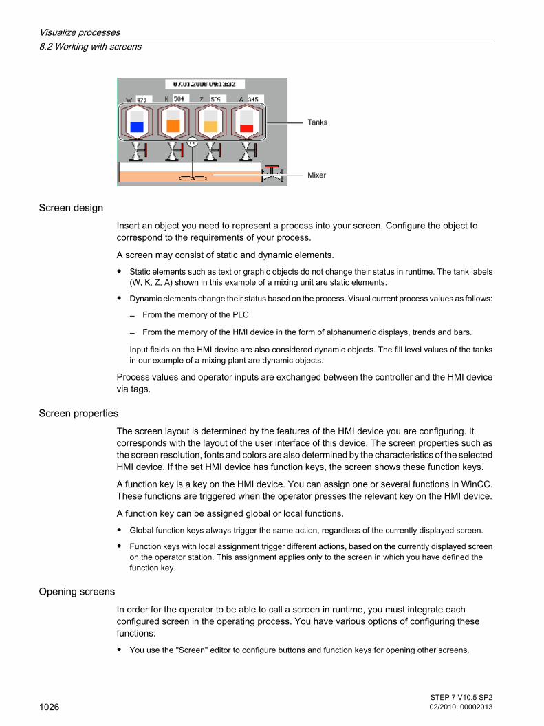
Screen designInsert an object you need to represent a process into your screen. Configure the object tocorrespond to the requirements of your process.
A screen may consist of static and dynamic elements.
• Static elements such as text or graphic objects do not change their status in runtime. The tank labels(W, K, Z, A) shown in this example of a mixing unit are static elements.
• Dynamic elements change their status based on the process. Visual current process values as follows:
― From the memory of the PLC
― From the memory of the HMI device in the form of alphanumeric displays, trends and bars.
Input fields on the HMI device are also considered dynamic objects. The fill level values of the tanksin our example of a mixing plant are dynamic objects.
Process values and operator inputs are exchanged between the controller and the HMI devicevia tags.
Screen propertiesThe screen layout is determined by the features of the HMI device you are configuring. Itcorresponds with the layout of the user interface of this device. The screen properties such asthe screen resolution, fonts and colors are also determined by the characteristics of the selectedHMI device. If the set HMI device has function keys, the screen shows these function keys.
A function key is a key on the HMI device. You can assign one or several functions in WinCC.These functions are triggered when the operator presses the relevant key on the HMI device.
A function key can be assigned global or local functions.
• Global function keys always trigger the same action, regardless of the currently displayed screen.
• Function keys with local assignment trigger different actions, based on the currently displayed screenon the operator station. This assignment applies only to the screen in which you have defined thefunction key.
Opening screensIn order for the operator to be able to call a screen in runtime, you must integrate eachconfigured screen in the operating process. You have various options of configuring thesefunctions:
• You use the "Screen" editor to configure buttons and function keys for opening other screens.
Visualize processes8.2 Working with screens
1026STEP 7 V10.5 SP202/2010, 00002013

• You use the "Global Screen" editor to configure globally assigned function keys.
See alsoTask cards (Page 1028)Steps (Page 1032)Basics on working with templates (Page 1036)Availability of screens for specific HMI devices (Page 1027)Overview of objects (Page 1042)Basics on text lists (Page 1081)Basic principles of graphics lists (Page 1089)Working with function keys (Page 1106)Basics on working with layers (Page 1117)Basics on libraries (Page 1124)Bar (Page 1136)Basics for screen navigation (Page 1161)
8.2.1.2 Availability of screens for specific HMI devices
IntroductionThe functions of the HMI device determine project visualization in WinCC and the functionalscope of the editors.
While creating the project, select the corresponding HMI device for the project. Use the Projectwindow to change the type of HMI device or add additional devices.
The following screen properties are determined by the functions of the selected HMI:
• Layout
• Screen resolution
• Color depth
• Fonts
• Objects availableDevice layout
The device layout of a screen forms the image of the HMI device in your configuration. Thedevice layout of the screen shows all the function keys available on the HMI device, for example.
Color depth
You can assign colors to the screen objects. The number of possible colors is determined bythe color depth and specific colors supported on the selected HMI device.Fonts
You can customize the appearance of the texts in all the screen objects that contain static ordynamic text. You could, for example, identify the priority of individual texts within a screen.Select the font, font style and size, and set additional effects such as underscoring, for example.
8.2.1.2 Availability of screens for specific HMI devices
Visualize processes8.2 Working with screens
STEP 7 V10.5 SP202/2010, 00002013
1027

Which fonts are available depends on the selected HMI device. The selected font determineswhich font properties are available.
The settings for the text markups such as font style and effects always refer to the entire textof a screen object. That is, you can display the complete title in bold format, but not its individualcharacters or words, for example.Objects available
Some of the screen objects can not be configured globally for all HMI devices. These screenobjects are not displayed in the toolbox. For a TP 170 touch panel unit you can not configureany buttons, for example.
See alsoScreen basics (Page 1025)
8.2.1.3 Elements and basic settings
8.2.1.3 Task cards
IntroductionThe following task cards are available in the "Screens" editor:
• Tools: Display and operating objects
• Animations: Templates for dynamic configuration
• Layout: Aid for customizing the display
• Libraries: Administration of the project library and of the global libraries
8.2.1.3 Elements and basic settings8.2.1.3 Task cards
Visualize processes8.2 Working with screens
1028STEP 7 V10.5 SP202/2010, 00002013

NoteBasic Panels
The "Animations" task card is not available for Basic Panels.
ToolsThe "Tools" task card contains objects in different panes:
• Basic objects
• Elements
• Controls
• User controls (optional)
• Graphics
Objects are inserted from the panes into your screens by dragging-and-dropping them. Theobjects available for selection are determined by the features of the HMI device you areconfiguring. The following icons are used to change the display mode:
Icon Meaning
Displays the objects as a list.
Displays the objects as a graphic.
AnimationsThe "Animations" task card contains the possible dynamizations of a screen object in the panes:
• Movements: Diagonal, direct, horizontal, vertical
• Display: Appearance, visibility
• Miscellaneous: Operability
Use drag-and-drop to add the animation to a screen object from the "Movements", "Display"and "Miscellaneous" panes.
LayoutThe "Layout" task card contains the following panes for displaying objects and elements:
• Zoom: For selecting the detailed view
• Layers: Manages the objects of the screen. They are displayed in a tree view and contain informationabout visibility and the active layer.
• Grid: You specify whether the objects are to be aligned to a grid and set the grid size for a grid.
• Objects out of range: Objects that lie outside the visible area are displayed with name, position andtype.
LibrariesThe "Libraries" task card show the following libraries in separate panes:
Visualize processes8.2 Working with screens
STEP 7 V10.5 SP202/2010, 00002013
1029

• Project library: The project library is stored together with the project.
• Global library: The global library is stored in a separate file in the specified path on your configurationPC.
See alsoScreen basics (Page 1025)Move view (Page 1030)Zooming the view (Page 1031)
8.2.1.3 Move view
IntroductionYou have the following options to display only a section of the entire screen in the work area:
• With the
icon of the "Screens" editor.
• With the miniature view of the entire screen in the "Zoom" palette of the "Layout" task card.
Requirement
• A screen is open.
• The view shows only a screen section.
ProcedureProceed as follows to move a view:
1. Click the
icon at the bottom right corner of the work area and press the left mouse button.
A miniature view of the full screen is shown. An orange frame shows the currently selected area.
2. Hold down the mouse button and drag the frame to the desired area.
Note
The screen is scrolled when you drag a screen object from the visible to a currently hiddensection.
See alsoTask cards (Page 1028)
8.2.1.3 Move view
Visualize processes8.2 Working with screens
1030STEP 7 V10.5 SP202/2010, 00002013

8.2.1.3 Zooming the view
IntroductionTo view a small screen section in closer detail, use the zoom tool to magnify the screen in theworking area. The maximum zoom amounts to 800%.
The following functions are available:
• Free zooming with the help of a selection frame.
• Enter the zooming factor.
• Use the icons
and
icons from the "Zoom" object group of the "Layout" task card to zoom in gradually.
RequirementThe screen is opened.
ProcedureProceed as follows to zoom a view:
1. Click the
toolbar button.
2. Use the mouse to draw a selection frame in the screen.
After you have released the mouse button, the section enclosed by the selection frame iszoomed to fit the complete work area.
In the "Zoom"
toolbar, you may alternatively directly enter a zoom ratio in [%] units.
This toolbar also contains the icons
and
. These icons are used to zoom the view in or out step-by-step.
You can alternatively change the view of the screen by using the "Layout" task card.
ResultThe selected screen section is magnified.
8.2.1.3 Zooming the view
Visualize processes8.2 Working with screens
STEP 7 V10.5 SP202/2010, 00002013
1031

See alsoTask cards (Page 1028)
8.2.1.4 Working with screens
8.2.1.4 Steps
StepsTo create screens, you need to take the following initial steps:
• Plan the structure of the process visualization: Number of screens and their hierarchic structure.
Example: Subprocesses are visualized in separate screens, and merged in a master screen.
• Define your screen navigation control strategies.
• Adapt the templates.
The templates that are stored in WinCC for the selected HMI device apply to all your project screens.You perform centralized configuration in the template objects and assign the function keys globallyfor the HMI devices with function keys. For some HMI devices, you can also store objects that areintegrated into every screen in the permanent window. You can create, and administer multipletemplates of your own for each HMI device.
• Create the screens. Use the following options of efficient screen creation:
― Creating a screen structure in the "Screen navigation" editor
― Working with libraries
― Working with layers
NoteBasic Panels
The "Screen Navigation" editor is not available for Basic Panels.
See alsoScreen basics (Page 1025)Creating a new screen (Page 1033)Managing Screens (Page 1034)Defining the start screen of the project (Page 1035)
8.2.1.4 Working with screens8.2.1.4 Steps
Visualize processes8.2 Working with screens
1032STEP 7 V10.5 SP202/2010, 00002013

8.2.1.4 Creating a new screen
IntroductionYou can set up a screen in two different ways:
• Without template
All the changes apply only for the current screen.
• On the basis of a template
In the template you carry out all changes centrally for all screens that use this template. With HMIdevices featuring function keys, you centrally assign the function keys in a template to all screens thatuse the given template. The function keys you assign globally in the "Global Screen" editor apply toall screens of an HMI device.
The possibilities of using template and global elements simultaneously are described in thechapter "Basics on working with templates."
Requirement
• The project has been created.
• The Inspector window is open.
ProcedureProceed as follows to create a screen:
1. Double-click "Add Screen" in the project tree.
The screen is generated in the project and appears in your view. The screen properties are shown inthe Inspector window.
2. Enter a meaningful name for the screen.
3. Configure the screen properties in the Inspector window:
― Specify whether and on which template the screen is based.
― Set the "Background Color" and the "Screen Number."
― Specify a documenting text under "Infotext."
― Specify the layers to be displayed under "Layers" in the engineering system.
― Select dynamic screen update under "Animations."
― Select "Events" to define which functions you want to execute in Runtime when you call and exitthe screen or at other events.
NoteHMI device dependency
Not all the HMI devices support the "Visibility" animation for screens.
8.2.1.4 Creating a new screen
Visualize processes8.2 Working with screens
STEP 7 V10.5 SP202/2010, 00002013
1033

ResultYou created the screen in your project. You can now add objects and control elements fromthe Toolbox window.
See alsoSteps (Page 1032)
8.2.1.4 Managing Screens
IntroductionYou can move screens within a project to other groups, or copy, rename, and delete them.
Moving screens in a groupWinCC allows you to create several screens and sort your screens into them.
Proceed as follows to move a screen into a group:
1. Select the "Screens" folder in the project tree.
2. Select the "Add group" command from the shortcut menu.
A folder called "Group_x" is inserted.
3. Select the screen in the project tree.
4. Drag-and-drop the screen to the required group.
The screen is moved into this group.
Copy screenIn WinCC you can cut a screen and paste it into the same or a different group.
Proceed as follows to copy a screen:
1. Select the screen in the project tree.
2. Select the "Copy" command in the shortcut menu to copy the screen to the clipboard.
3. In the project tree, select the screen insert position.
4. Select "Paste" from the shortcut menu to insert the screen.
A copy of the screen is inserted. A consecutive number is appended to the name of the original in thecopy.
Alternatively, press <Ctrl> while you drag the screen to the required position.
Note
If you copy a screen with interconnected template for several devices and projects, the templatewill also be copied. Any existing matching template is not used. This holds particularly truewhen you copy the screens with drag-and-drop.
8.2.1.4 Managing Screens
Visualize processes8.2 Working with screens
1034STEP 7 V10.5 SP202/2010, 00002013

Rename screenProceed as follows to rename a screen:
1. Select the screen in the project tree.
2. Select "Rename" from the shortcut menu.
3. Type in a new name.
Do not use the special characters ?, ", /, \, *, <, >
4. Press <Enter>.
As an option, use the <F2> function key to rename the screen.
Delete screenProceed as follows to delete a screen:
1. Select the screen in the project tree.
2. Select "Delete" from the shortcut menu.
The screen and all its objects are deleted from the current project.
See alsoSteps (Page 1032)
8.2.1.4 Defining the start screen of the project
IntroductionThe start screen is the initial screen opened at the start of project in Runtime. You can definea different start screen for each one of the HMI devices. Beginning at this start screen, theoperator calls the other screens.
RequirementThe project contains the screen you want to use as the start screen.
Defining the start screen in the "Runtime settings" editorProceed as follows:
1. Double-click "Runtime settings" in the project tree.
You have opened the "Runtime settings" editor.
2. Double-click "Screens".
8.2.1.4 Defining the start screen of the project
Visualize processes8.2 Working with screens
STEP 7 V10.5 SP202/2010, 00002013
1035

3. Select the desired screen under "Start screen."
ResultThe start screen opens on the HMI at the start of Runtime.
See alsoSteps (Page 1032)
8.2.1.5 Working with Templates
8.2.1.5 Basics on working with templates
Templates and global screenEvery HMI device has a template in the project that takes the properties of the device intoconsideration. It is used when you add a screen. In the template you configure objects that aredisplayed in all the screens that are based on this template.
Note the following rules:
• A screen can only be based on one template.
• You can create several templates for one device.
You specify global elements for all the screens of an HMI device, regardless of the templateused. The "Alarm window" and "Alarm indicator" objects that are available as global objectsare configured within the "Global screen" editor.
The following rules apply:
• Configurations in the screen have priority 1 and overlap the configurations of the template.
• Configurations in the template have priority 2 and overlap the configurations of the screen.
• Configurations of objects in the global screen have priority 2.
8.2.1.5 Working with Templates8.2.1.5 Basics on working with templates
Visualize processes8.2 Working with screens
1036STEP 7 V10.5 SP202/2010, 00002013

The following figure shows the prioritizations of the configurations:
Objects for a templateYou specify the following functions and objects within the template that are to apply for all thescreens on the basis of this template:
• Operator controls: You can insert the same operator controls that you also use for a screen into atemplate.
• Assignment of function keys: You assign the function keys locally in the template for HMI devices withfunction keys. This assignment overwrites a possible global assignment.
• Permanent window: Some devices, such as the MP 370, support a permanent window for all thescreens in the upper section of the screen. In contrast to the template, the permanent window occupiesan area of the screen for itself alone.
Application examples
• You want to assign the ActivateScreen" function to a function key in the template. The operator usesthis key to switch to another screen in runtime. This configuration applies to all screens that are basedon this template.
• A graphic with your company logo can be added to the template. The logo appears on all screens thatare based on this template.
Note
If an object from the template has the same position as an object in the screen, the templateobject is covered.
Permanent window
NoteAvailability for specific devices
The permanent window is not available for Basic Panels.
Visualize processes8.2 Working with screens
STEP 7 V10.5 SP202/2010, 00002013
1037

Proceed as follows to configure a permanent window:
1. Open a screen or a template for an HMI device with a permanent window.
2. Use the mouse (cursor shape:
) to drag the top edge of the editable screen area down.
The permanent window area above this boundary is now shared by all the screens of this HMI device.All configured screen objects are moved downwards, by a factor determined by the height of thepermanent window.
3. Configure the elements in the permanent window to suit your requirements.
4. The content of the permanent window appears on every screen, and in the template.
The default height of the permanent window is "0". The maximum height is the maximum heightof the screen minus 10.
Show template in screenWhen you edit a screen, you use an existing template and display it in the screen.
Proceed as follows to display a template in the screen:
1. Activate the "Show templates in screens" option in the "Options > Settings> Visualization" menu.
Note
You create the "Alarm window" and "Alarm indicator" objects using the "Global screen"editor.
See alsoCustomizing template (Page 1039)Creating a new template (Page 1039)Managing templates (Page 1040)Global screen (Page 1041)Screen basics (Page 1025)
Visualize processes8.2 Working with screens
1038STEP 7 V10.5 SP202/2010, 00002013

8.2.1.5 Customizing template
IntroductionEvery screen that is based on this template will contain the function keys and objects that youconfigured in the template. Changes to an object or of a soft key assignment in the templateare applied to all object instances in the screens which are based on this template.
You configure local function keys in the templates. You create global function keys using the"Global Screen" editor. Local function keys overwrite global function keys.
NoteHMI device dependency
Function keys are not available on all HMI devices.
RequirementThe project has been created.
ProcedureProceed as follows to create a template:
1. In the Project window, double-click on the template you want to change under "Screen Management> Templates."
The template opens in your working area.
2. In this template, customize the function keys and objects to be shared by the screens which are basedon this template.
ResultAll of the screens which are based on this template share the objects configured in this template.The same applies to the soft key assignments you have set in the template. Change the specialkey assignments for each individual screen.
See alsoBasics on working with templates (Page 1036)
8.2.1.5 Creating a new template
IntroductionA screen is always based on only one template. You can also create multiple templates for oneHMI device. A template is not based on another template. The name of a new template isassigned automatically.
8.2.1.5 Customizing template8.2.1.5 Creating a new template
Visualize processes8.2 Working with screens
STEP 7 V10.5 SP202/2010, 00002013
1039

In a template, you can centrally modify objects and function keys. Changes in the template takeimmediate effect in all the screens based on the template.
NoteHMI device dependency
Function keys are not available on all HMI devices.
Requirement
• The project has been created.
• The Inspector window is open.
ProcedureProceed as follows to create a template:
1. Select "Screen management > Templates" in the project tree and then double-click "Add template".
The template is created in the project, and appears in your view. The properties of the template aredisplayed in the Inspector window.
2. Configure the template in the Inspector window:
― Specify the template name under "General."
― Add the objects of the template
― Specify the layers in the engineering system that are displayed under "Layers."
3. Configure the function keys.
ResultThe template is created in your project. You can now add objects and control elements fromthe toolbox and assign function keys.
See alsoBasics on working with templates (Page 1036)
8.2.1.5 Managing templates
IntroductionYou can move, copy, rename, and delete templates within a project in the Project window.
Moving a template into a groupUse WinCC to create several groups and sort your templates in them.
Proceed as follows to move a template into a group:
8.2.1.5 Managing templates
Visualize processes8.2 Working with screens
1040STEP 7 V10.5 SP202/2010, 00002013

1. Select the "Screen management" folder in the project tree.
2. Select the "Add group" command from the shortcut menu.
A folder called "Group_x" is inserted.
3. Select the template in the project navigation.
4. Drag-and-drop the template to the required group.
The template is moved to this group.
Copying templatesYou use Copy and Paste to copy a template in WinCC.
Proceed as follows to copy a template:
1. Select the template in the project navigation and select "Copy" from the shortcut menu.
2. Select the position in the project navigation where you want to paste the template.
3. Select "Paste" from the shortcut menu to insert the template.
A unique name is assigned automatically to the copy.
Alternatively, you can hold down the <Ctrl> key, and drag the template into position.
Deleting a templateProceed as follows to delete a template:
1. In the project navigation, select the template to be deleted.
2. Select "Delete" from the shortcut menu.
The template, and all its objects are deleted from the current project.
Assigning a template to a screenProceed as follows to assign a template to a screen:
1. In the project navigation, select the screen to which you want to assign the template.
2. Select "General" in the Inspector window.
3. Select the desired template under "Template."
The selected template and all the objects contained in it are assigned to the screen.
See alsoBasics on working with templates (Page 1036)
8.2.1.5 Global screen
IntroductionA global screen is used to assign the following objects or functions to all the screens of an HMIdevice:
8.2.1.5 Global screen
Visualize processes8.2 Working with screens
STEP 7 V10.5 SP202/2010, 00002013
1041

• Functions: Assignment of function keys for devices with function keys
• Indicator and control objects for alarms: Alarm windows, alarm indicators
The objects and function keys used in the global screen are configured in the respectiveInspector window of the "Global screen" editor.
Function keysThe function keys for HMI devices are assigned globally within the "Global Screen" editor. Thisglobal assignment applies to all the screens of an HMI device unless there is anotherassignment in the template used or in the screen itself. Note the following rules:
• Local assignments in the screen overwrite the local assignments in the template and the globalassignment within the "Global Screen" editor.
• Local assignments in the template overwrite the global assignment within the "Global Screen" editor.
Indicator and control objects for alarmsYou can only insert alarm windows and alarm indicators into a screen as global elements.
Note
If you have configured a permanent window in the screen or the template, do not position thealarm window and alarm indicator in the area of the permanent window. Otherwise, the alarmwindow and the alarm indicator will not be displayed in Runtime. The permanent window is notvisible in the "Global screen" editor.
See alsoBasics on working with templates (Page 1036)
8.2.2 Working with objects
8.2.2.1 Overview of objects
IntroductionObjects are graphics elements which you use to design the screens of your project.
The "Tools" task card contains all objects that can be used for the HMI device. Display the TaskCard with menu command "View" by activating the "Task Card" option.
The toolbox contains various palettes, depending on the currently active editor. If the "Screens"editor is open, the toolbox contains the following palettes:
• "Basic objects"
8.2.2 Working with objects8.2.2.1 Overview of objects
Visualize processes8.2 Working with screens
1042STEP 7 V10.5 SP202/2010, 00002013

Basic objects include graphic objects such as "Line" or "Circle," and standard control elements, suchas "Text field" or "Graphic display."
• "Elements"
Elements include standard control elements, such as "IO field" or "Button."
• "Controls"
The controls provide advanced functions. They also represent process operations dynamically, forexample Trend view and Recipe view.
• "Graphics"
Graphics are broken down into subjects in the form of a directory tree structure. The various folderscontain the following graphic illustrations:
― Machine and plant areas
― Measuring equipment
― Control elements
― Flags
― Buildings
You can create links to your own graphic folders. The external graphics are located in these foldersand subfolders. They are displayed in the toolbox and incorporated into the project using links.
• "Libraries" task card
In addition to the display and operator controls, the library objects are available. They are locatedwithin the palettes of the "Libraries" task card. A library contains preconfigured objects such asgraphics of pipes, pumps, or preconfigured buttons. You can also integrate multiple instances of libraryobjects into your project without having to reconfigure them.
The WinCC software package includes libraries.
NoteAvailability for specific HMI devices
Some of the toolbox objects are either available with restricted functionality, or not at all. Thisdepends on the HMI device you are configuring. Unavailable properties of an object aredisplayed as deactivated, and cannot be selected.
Basic objects
Icon Object Instructions
"Line" -
"Polyline" The polyline is an open object. Even if the start and end points havethe same coordinates, the area they enclose cannot be filled in. If youwant to fill a polygon, select the "Polygon" object.
Visualize processes8.2 Working with screens
STEP 7 V10.5 SP202/2010, 00002013
1043

Icon Object Instructions
"Polygon" -
"Ellipsis" -
"Circle" -
"Rectangle" -
"Text box" One or more lines of text. The font and layout are adjustable.
"Graphic view" Displays graphics from external graphic programs, and inserts OLEobjects. The following graphic formats can be used: "*.emf", "*.wmf","*.dib", "*.bmp", "*.jpg", "*.jpeg", "*.gif" and "*.tif".
Elements
Icon Object Instructions
"I/O field" Outputs the values of a tag, and/or writes values to a tag.You can define limits for the tag values shown in the I/O field. To hidethe operator input in Runtime, activate "Hidden input."
"Button" Executes a list of functions, or a script as configured.
"Symbolic I/O field" Outputs the values of a tag, and/or writes values to a tag. A text froma text list is displayed in relation to the tag value.
"Graphic I/O field" Outputs the values of a tag, and/or writes values to a tag. A graphicfrom a graphics list is displayed in relation to the tag value.
"Date/time field" Outputs the system date and time, or the time and date from a tag.This allows the operator to enter new values. The display format isadjustable.
"Bar" The bar represents a value from the PLC in the form of a scaled bargraph.
"Switch" Toggles between two defined states. You can label a switch with text,or a graphic.
"Symbol library" Used to add screen objects based on controls of the same name.
"Slider" Displays a current value from the PLC, or sends a numeric value tothe PLC.
"Gauge" Displays numeric values.The appearance of the gauge is adjustable.
"Clock" Displays the system time in analog or digital format.
Visualize processes8.2 Working with screens
1044STEP 7 V10.5 SP202/2010, 00002013

Controls
Icon Object Description
"Alarm view" Shows selected alarms or alarm events from the alarmbuffer or alarm log.
"Trend view" Represents multiple curves with values from the PLC,or from a log.
"User view" Allows an administrator to administer users on the HMIdevice.It also allows an operator without administrator rightsto change his password.
"Status force" This function gives the operator direct read / writeaccess to individual address areas in the connectedSIMATIC S7.
"Recipe view" Displays data records, and allows them to be edited.
"Navigation button" Changes to the root screen of the current screenhierarchy.Changes to the next screen that is positioned in thescreen hierarchy on the same level to the left of thecurrent screen.Changes to the parent screen.Changes to the screen that is positioned leftmost in thelower hierarchy level.Changes to the next screen that is positioned in thescreen hierarchy on the same level to the right of thecurrent screen.
"Dynamic navigationbutton"
Reserves a button position for a dynamic navigationbutton. If a screen has child screens in the screenhierarchy, the dynamic navigation buttons aregenerated automatically at this position.
See alsoScreen basics (Page 1025)Options for Editing Objects (Page 1046)Inserting an object (Page 1047)Deleting an Object (Page 1049)Positioning an object (Page 1050)Resizing an object (Page 1051)Selecting multiple objects (Page 1053)Aligning objects (Page 1054)Moving an object forward or backward (Page 1057)Show objects outside the screen area (Page 1058)
Visualize processes8.2 Working with screens
STEP 7 V10.5 SP202/2010, 00002013
1045

Rotating objects (Page 1059)Flipping objects (Page 1060)Inserting multiple objects of the same type (stamping tool) (Page 1061)Repositioning and resizing multiple objects (Page 1062)External graphics (Page 1063)Managing external graphics (Page 1064)Storing an external image in the graphics library. (Page 1066)Basics on groups (Page 1068)Example: Inserting and configuring a rectangle (Page 1078)
8.2.2.2 Options for Editing Objects
IntroductionObjects are graphics elements which you use to design the screens of your project.
You have the following options for editing objects:
• Copying, pasting or deleting objects using the shortcut menu If you copy an object in a screen andthe screen already includes an object of the same name, the name of the object is changed.
• Maintaining the standard size of the objects you are inserting or customizing their size on insertion.
• Changing the properties of an object, e.g. the size
• Positioning an object
• Moving an object in front of or behind other objects
• Rotating objects
• Mirroring objects
• Changing default properties of the objects
• Defining the tab order for objects
• Stamping: Inserting several objects of the same type
• Selecting several objects simultaneously
• Repositioning and resizing multiple objects
• You can assign external graphics to objects, e.g. in the Graphic View.
You can view only the images you have previously stored in the graphic browser of yourWinCC project.
You can save graphics in the graphic browser as follows:
― Via drag & drop from the "Graphics" object group to the working area
― As graphic files in the following formats: *.bmp, *.dib, *.ico, *.emf, *.wmf, *.gif, *.tif, *.jpeg or *.jpg
― As an OLE object
You either create a new OLE object or save an existing graphic file as an OLE object. To save anOLE object, an OLE-compatible graphics program must be installed on the configuration computer.
8.2.2.2 Options for Editing Objects
Visualize processes8.2 Working with screens
1046STEP 7 V10.5 SP202/2010, 00002013

See alsoOverview of objects (Page 1042)Example: Inserting and configuring a rectangle (Page 1078)
8.2.2.3 Inserting an object
IntroductionYou can add objects from the toolbox, or from the WinCC graphics folder to screens or reportsin the "Screens" or "Reports" editor. Use the mouse to drag the objects into the work area. Youeither keep the objects in their original size, or scale them up or down when you paste them.
Every user can define his own standard sizes for the objects.
For lines and objects consisting of lines to be defined, define the size when you insert theminto the work area.
NoteBasic Panels
The "Reports" editor is not available for Basic Panels.
RequirementThe "Tools" task card is open.
Inserting objects in their standard sizeProceed as follows to insert an object in its standard size:
1. In the "Toolbox" task card, select the desired graphic object or the desired graphic in the WinCCgraphics folder.
When you move the cursor across the work area, it turns into a crosshair with an appended objecticon.
2. Click the location in the work area where you want to insert the object or graphic.
The object is inserted with its standard size at the desired position in the work area.
3. You can always resize an object by dragging the resizing handle of its selection rectangle.
You can also enter the required size in pixels in "Layout" in the "Position & Size" area in the Inspectorwindow.
4. You can specify additional object properties in the Inspector window.
To add further image objects, repeat steps 1 and 2.
Inserting objects and at the same time selecting their sizeProceed as follows to insert an object and select its size at the same time:
8.2.2.3 Inserting an object
Visualize processes8.2 Working with screens
STEP 7 V10.5 SP202/2010, 00002013
1047

1. In the "Toolbox" task card, select the desired graphic object or the desired graphic in the WinCCgraphics folder.
2. Move the cursor to the location in the work area where you want to insert the object.
The mouse pointer is transformed into a crosshair with an appended object icon.
3. Press the left mouse button and drag the object to the required size.
Release the mouse button to paste the object with the required size at the desired position in the workarea.
To add further image objects, repeat steps 1 and 2.
Inserting linesProceed as follows to insert lines:
1. Select the desired graphic object in the "Tools" task card.
2. Click on the location in the work area where you want the line to start.
This fixes the starting point of the line.
3. Move the mouse pointer in the work area.
This draws a line between the starting point and the position of the cursor.
4. Click on the location in the work area where you want the line to end.
This fixes the end point of the line.
Inserting a polygon or polylineProceed as follows to insert line objects:
1. Select the desired object "Polyline" or "Polygon" in the "Tools" task card.
2. Click on the location in the work area where you want the object to start.
This fixes the starting point of the object.
3. Click on location in the work area where you want a corner of the object.
4. Repeat step 3 for every other corner of the object.
5. Double-click on location in the work area where you want to define the last corner of the object.
This fixes all the points of the polygon or polyline.
NoteBasic Panels
The "Polyline" and "Polygon" objects are not available for Basic Panels.
Visualize processes8.2 Working with screens
1048STEP 7 V10.5 SP202/2010, 00002013

Note
If you want to insert several objects of the same type, use the "Stamp" function. This avoidshaving to reselect the object in the "Tools" task card every time before inserting it. To do so,select the
icon in the toolbar of the "Tools" task card.
See alsoOverview of objects (Page 1042)Example: Inserting and configuring a rectangle (Page 1078)
8.2.2.4 Deleting an Object
Introduction You can delete objects individually or with a multiple selection.
RequirementYou have opened the work area containing at least one object.
ProcedureProceed as follows to delete an object:
1. Select the object that you want to delete.
To delete multiple objects, keep the <Shift> key pressed and select the objects to be deleted one afterthe other.
2. Select "Delete" from the shortcut menu.
ResultThe selected objects are deleted.
See alsoOverview of objects (Page 1042)Example: Inserting and configuring a rectangle (Page 1078)
8.2.2.4 Deleting an Object
Visualize processes8.2 Working with screens
STEP 7 V10.5 SP202/2010, 00002013
1049

8.2.2.5 Positioning an object
IntroductionWhen you select an object, it is enclosed by a rectangle with resizing handles. This rectangleis the selection rectangle. The position of the object is defined by the coordinates of the upperleft corner of the selection rectangle.
Note
If the position is outside the work area, which means one of the coordinates assumes a negativevalue, the object cannot be visualized in runtime.
You have the following options of repositioning an object:
• Dragging the object into a new position
• Moving an object with the arrow keys
• Changing the "Position" property in the Inspector window
GridA grid is shown in the work area. If you want to position an object, or change its size using themouse, the object is automatically snapped to the grid. If you hold down the <Alt> key, theobject is no longer snapped to the grid.
Note
The grid and the "Snap to grid" function are always active for reports.
For screens you activate and deactivate the grid and the "Snap to grid" function as follows:
• In the "Options > Settings > Visualization" menu
• In the "Screens" editor: Open the "Layout" task card and activate the required functions in the "Grid"palette.
RequirementYou have opened the work area containing at least one object.
8.2.2.5 Positioning an object
Visualize processes8.2 Working with screens
1050STEP 7 V10.5 SP202/2010, 00002013

ProcedureProceed as follows to change the position of an object:
1. Select the object you want to move.
The selected object is framed by a rectangle with resizing handles.
2. Left-click the object and keep the mouse button pressed.
3. Move the mouse pointer onto the new position.
The contour of the object moves with the mouse and displays the new position for the object.
The object initially remains at its original position.
4. Now release the mouse button.
The object is moved into the position indicated by the contour of the selection rectangle.
― When the "Snap to grid" function is activated, the object is snapped to the grid.
― If you keep the <Alt> key pressed down whilst dragging the object, this function is deactivated.
Or:
1. In the Inspector window select "Properties > Layout."
2. Enter the X and Y values for the position under "Position & Size".
ResultThe object appears at its new position.
See alsoOverview of objects (Page 1042)Example: Inserting and configuring a rectangle (Page 1078)
8.2.2.6 Resizing an object
IntroductionWhen you select an object, it is enclosed by a rectangle with resizing contacts. You have thefollowing options of resizing an object:
• Drag the resizing contacts using the mouse.
• Modify the "Size" property in the Inspector window.
8.2.2.6 Resizing an object
Visualize processes8.2 Working with screens
STEP 7 V10.5 SP202/2010, 00002013
1051

GridA grid is shown in the work area. If you want to position an object, or change its size using themouse, the object is automatically snapped to the grid. If you hold down the <Alt> key, theobject is no longer snapped to the grid.
Note
The grid and the "Snap to grid" function are always active for reports.
For screens you enable and disable the grid and the "Snap to grid" function as follows:
• In the "Options > Settings > Visualization" menu
• In the "Screens" editor: Open the "Layout" task card and activate the required functions in the "Grid"palette.
RequirementYou have opened the work area containing at least one object.
Procedure Proceed as follows to resize an object:
1. Select the object you want to resize.
The selection rectangle appears. The following picture shows a selected object:
2. Drag a resizing contact of the rectangle to a new position.
The size of the object changes.
― The size of the object is aligned to the grid pattern, provided the "Snap to grid" function is set.
― Press <ALT> to disable this function while you drag the object.
Note
In order to scale the object proportionally, keep the <Shift> key pressed while changingthe size with the mouse.
Or:
1. Select "Layout" in the Inspector window.
2. Enter the size of the object under "Position & Size".
Visualize processes8.2 Working with screens
1052STEP 7 V10.5 SP202/2010, 00002013

ResultThe object now appears with its new size.
See alsoOverview of objects (Page 1042)Example: Inserting and configuring a rectangle (Page 1078)
8.2.2.7 Selecting multiple objects
Introduction Select all objects you want to align with each other or to change global properties. Thisprocedure is called "multiple selection."
The Inspector window shows all the properties of the selected objects.
You now have several options of selecting multiple objects:
• Draw a selection frame around the objects.
• Hold down the <Shift> key, and click the required objects.
Selection frame of a multiple selectionThe selection frame surrounds all objects of a multiple selection. The selection frame iscomparable with the rectangle that surrounds an individual object.
The selection frame is not visible. When you have made your multiple selection, the followingframe is displayed:
• The reference object is indicated by the rectangle around it.
• The other selected objects are indicated by a dashed-line frame.
Specifying a reference object The reference object is the object upon which the other objects are oriented. The referenceobject is framed by a rectangle with handles. The following picture shows a reference objectwith two other selected objects:
You have the following options to specify the reference object:
• Select the objects via multiple selection. The object selected first is then the reference object.
8.2.2.7 Selecting multiple objects
Visualize processes8.2 Working with screens
STEP 7 V10.5 SP202/2010, 00002013
1053

• Draw a selection frame around the objects. The reference object compiled automatically. If you wishto specify a different object within the selection as the reference object, click on the desired object.This action does not cancel your multiple selection.
RequirementYou have opened the work area containing at least two objects.
Selecting multiple objects with a selection frameProceed as follows to select several objects using a selection frame:
1. Position the mouse pointer in the work area close to one of the objects to be selected.
2. Hold down the mouse button, and draw a selection frame around the objects to be selected.
Or:
1. Hold down the <Shift> key.
2. Click the relevant objects, working in succession.
All the selected objects are identified by frames.
The object selected first is identified as reference object.
Note
To remove an object from the multiple selection, press <SHIFT>, hold it down and then clickthe relevant object once again.
ResultMultiple objects are selected. One of those is identified as the reference object. You can nowperform the following steps:
• Changing the object properties of all the objects
• Resizing all the objects by the same ratio, by dragging the selection frame to increase or reduce thesize
• Moving all the objects in one group
• Aligning the objects to the reference object
See alsoOverview of objects (Page 1042)Example: Inserting and configuring a rectangle (Page 1078)
8.2.2.8 Aligning objects
ProcedureProceed as follows to align objects:
8.2.2.8 Aligning objects
Visualize processes8.2 Working with screens
1054STEP 7 V10.5 SP202/2010, 00002013

1. Select the objects via multiple selection.
2. Specify an object as the reference object.
3. Select the command from the toolbar, or the shortcut menu (see table below.)
The selected objects will be aligned.
Aligning objects flush The selected objects will be aligned flush to the reference object.
Icon Description
Aligns the selected objects to the left edge of the reference object.
Aligns the selected objects to the vertical center axis of the reference object.
Aligns the selected objects to the right edge of the reference object.
Aligns the selected objects to the upper edge of the reference object.
Aligns the selected objects to the horizontal center axis of the reference object.
Aligns the selected objects to the lower edge of the reference object.
Centers the selected objects to the center points of the reference object.
Distributing objects evenly You need at least three selected objects. A reference object is not required.
1. Select the objects.
2. Click one of the buttons "Distribute horizontally equal" or "Distribute vertically equal."
The selected objects are distributed at equal distances.
The following screen shows how you align the vertical spacing of the selected objects:
Visualize processes8.2 Working with screens
STEP 7 V10.5 SP202/2010, 00002013
1055

Icon Description
Aligns the horizontal distance between the objects.The position of the objects on the extreme left and right side remains unchanged. Allother objects are distributed evenly between them.
Aligns the vertical distance between the objects.The position of the objects at the extreme top and bottom (right and left) remainsunchanged. All other objects are distributed evenly between them.
Harmonizing the object size The selected objects are adapted in height or width to the height or width of the reference object.
1. Select the objects.
2. Click one of the buttons,
or
.
The size of the selected objects is matched to each other.
The following screen shows how the selected objects are adapted to the height of the referenceobject:
Icon Description
Aligns the selected objects to the width of the reference object.
Aligns the selected objects to the height of the reference object.
Visualize processes8.2 Working with screens
1056STEP 7 V10.5 SP202/2010, 00002013

See alsoOverview of objects (Page 1042)Example: Inserting and configuring a rectangle (Page 1078)
8.2.2.9 Moving an object forward or backward
IntroductionYou can use the "Order" functions in the shortcut menu of a selected object or in the toolbar tomove a selected object in front of or behind other objects within an object layer.
Note
ActiveX controls are always positioned in front of an object layer (.NET property).
RequirementYou have opened a screen which contains a layer with multiple objects.
ProcedureProceed as follows to change the order of the objects within a layer:
1. Select the object you want to move forward or backward.
2. Select the "Sort" command and one of the following commands from the shortcut menu:
Icon Description
Moves the selected object before all the other objects of the same layer
Moves the selected object to the lowest position in the same layer
Moves the selected object up by one position
Moves the selected object down by one position
Alternative procedureProceed as follows:
1. Open the "Layers" palette of the "Layout" task card.
2. Navigate to the required object.
3. Hold down the mouse button, and drag the object in the tree topology to the required position in thelayer.
4. Now release the mouse button.
8.2.2.9 Moving an object forward or backward
Visualize processes8.2 Working with screens
STEP 7 V10.5 SP202/2010, 00002013
1057

ResultThe object is moved up or down.
See alsoOverview of objects (Page 1042)Example: Inserting and configuring a rectangle (Page 1078)
8.2.2.10 Show objects outside the screen area
IntroductionIf you assign objects to positions that are outside the configurable area, these objects will behidden. The functions of the "Objects outside the visible area" palette in the "Layout" task cardare used to move these objects back into the screen.
Requirement
• You have opened a screen which contains objects that are outside the configurable area.
• The "Layout" task card is open.
ProcedureProceed as follows:
1. Open the "Objects outside the area" palette of the "Layout" task card.
This displays a list of objects that are outside the configurable area.
2. Select the objects that you want to move back into the screen.
3. Click "Move to screen" in the "Objects outside range" palette.
Alternatively open the "Layer" palette of the "Layout" task card. Objects outside the area areindicated by the
icon. If you click this icon, the object is moved back into the screen.
ResultThe objects are displayed on the right-hand margin of the configurable area.
See alsoOverview of objects (Page 1042)Example: Inserting and configuring a rectangle (Page 1078)
8.2.2.10 Show objects outside the screen area
Visualize processes8.2 Working with screens
1058STEP 7 V10.5 SP202/2010, 00002013

8.2.2.11 Rotating objects
Introduction You can rotate a suitable object clockwise or counterclockwise around its center axis in stepsof 90°.
Note
Not all the objects can be rotated. Some objects that can be rotated in screens cannot be rotatedin reports.
You can also rotate multiple objects using the multiple selection function. Certain WinCCobjects such as buttons cannot be rotated.
The alignment of elements in an object will change in a rotated object. The following figureshows how a rectangle and an ellipse behave under the different commands for rotating anobject:
RequirementYou have opened the work area containing at least one object.
ProcedureProceed as follows to rotate an object:
1. Select the object that you want to rotate.
2. Click one of the following toolbar icons:
8.2.2.11 Rotating objects
Visualize processes8.2 Working with screens
STEP 7 V10.5 SP202/2010, 00002013
1059
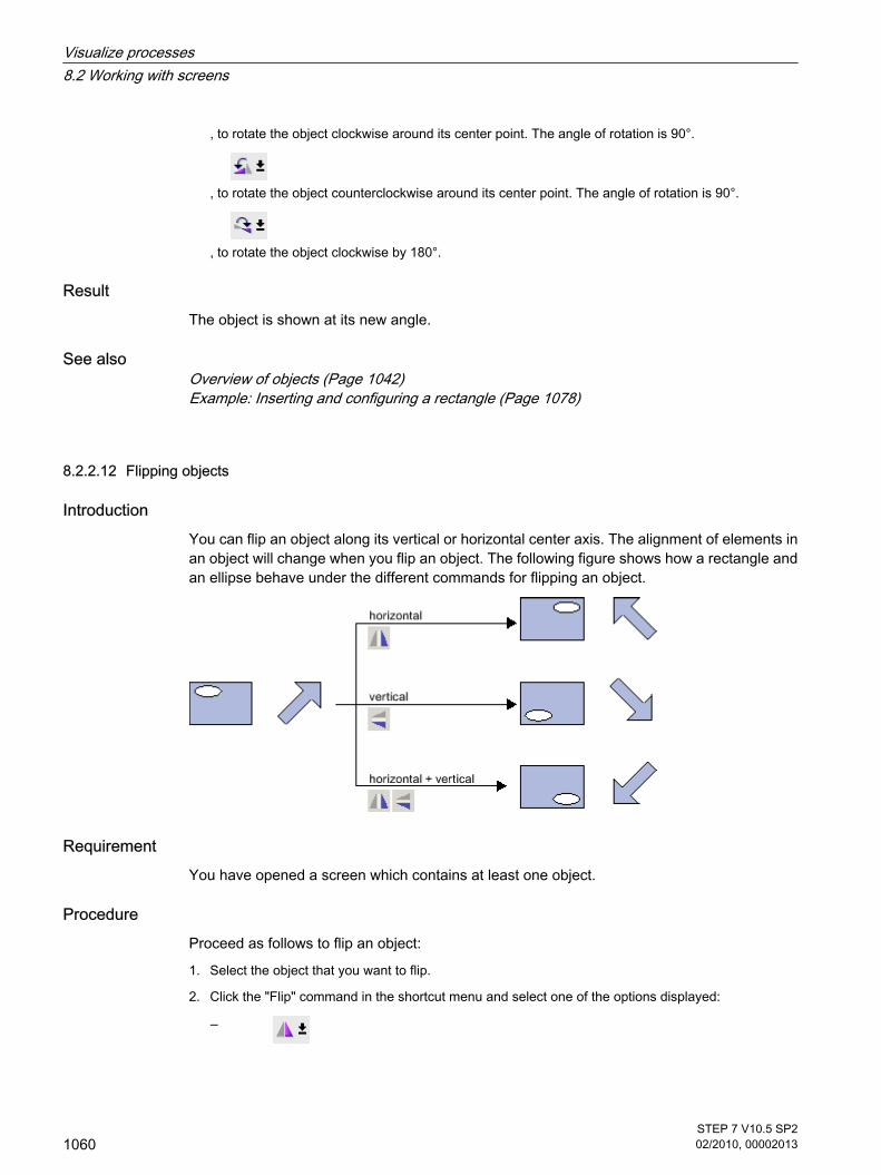
, to rotate the object clockwise around its center point. The angle of rotation is 90°.
, to rotate the object counterclockwise around its center point. The angle of rotation is 90°.
, to rotate the object clockwise by 180°.
ResultThe object is shown at its new angle.
See alsoOverview of objects (Page 1042)Example: Inserting and configuring a rectangle (Page 1078)
8.2.2.12 Flipping objects
IntroductionYou can flip an object along its vertical or horizontal center axis. The alignment of elements inan object will change when you flip an object. The following figure shows how a rectangle andan ellipse behave under the different commands for flipping an object.
RequirementYou have opened a screen which contains at least one object.
ProcedureProceed as follows to flip an object:
1. Select the object that you want to flip.
2. Click the "Flip" command in the shortcut menu and select one of the options displayed:
―
8.2.2.12 Flipping objects
Visualize processes8.2 Working with screens
1060STEP 7 V10.5 SP202/2010, 00002013

, to flip the selected object along its vertical center axis.
―
, to flip the selected object along its horizontal center axis.
ResultThe object is shown at its flipped position.
See alsoOverview of objects (Page 1042)Example: Inserting and configuring a rectangle (Page 1078)
8.2.2.13 Inserting multiple objects of the same type
IntroductionWinCC offers the possibility of "stamping" or inserting several objects of the same type directlyand consecutively. You then do not have to select the object each time again. In addition youhave the possibility of multiplying an object that has already been inserted.
RequirementThe "Tools" task card is open.
Inserting several objects of one typeProceed as follows to insert several objects of one type:
1. Select the object that you want to insert in the "Tools" task card.
2. Click the
icon in the toolbar of the "Tools" task card.
The "Stamp" function is activated.
3. To insert the object with its standard size, click the relevant insertion position in the work area.
To insert the object with another size, position the mouse pointer at the desired location in the workarea. Press the left mouse button and drag the object to the required size.
The object is inserted in the work area as soon as you release the mouse button.
4. Repeat step 3 to insert further objects of the same type.
5. Click the
icon again.
The "Stamp" function is deactivated.
8.2.2.13 Inserting multiple objects of the same type
Visualize processes8.2 Working with screens
STEP 7 V10.5 SP202/2010, 00002013
1061

Note
You can copy existing objects using the drag-and-drop +<CTRL> function. The existingobject is not moved in this case. You paste a copy of this object into the new position instead.
Inserting and multiplying an object
Proceed as follows to insert and multiply an object:
1. Insert the desired object from the "Tools" task card.
2. Press the <Ctrl> key and position the cursor on one of the handles displayed in the figure shownbelow.
3. Drag the handles to the right and/or down while keeping the left mouse button pressed.
4. The object is multiplied depending on available space if you keep moving the cursor.
See alsoOverview of objects (Page 1042)Example: Inserting and configuring a rectangle (Page 1078)
8.2.2.14 Repositioning and resizing multiple objects
Possible modificationsAfter you have selected multiple objects, you edit these as follows:
• Shift using the mouse
8.2.2.14 Repositioning and resizing multiple objects
Visualize processes8.2 Working with screens
1062STEP 7 V10.5 SP202/2010, 00002013

― To change the absolute position of the marked objects, position the mouse pointer over an object,and shift the multiple selection with the mouse button pressed.
― To resize all the objects by the same ratio, grab the resizing handles of the reference object.
• Move over the work area with the icons of the toolbar
― Change the position of the marked objects with respect to each other
― Align the height and width of the marked objects
• Moving with the shortcut menu commands of the work area
― Change the position of the marked objects with respect to each other
― Align the height and width of the marked objects
See alsoOverview of objects (Page 1042)Example: Inserting and configuring a rectangle (Page 1078)
8.2.2.15 External graphics
IntroductionIn WinCC you use graphics that were created with an external graphics editor. To use thesegraphics you store them in the graphic browser of the WinCC project.
You can save graphics in the graphic browser as follows:
• When you drag-and-drop graphics objects from the "Graphics" pane into the work area, these arestored automatically in the graphic browser. The graphic names are numbered in the order of theircreation, for example, "Graphic_1." Use the <F2> function key to rename the graphic.
• As a graphic file with the following formats:
*.bmp, *.ico, *.emf, *.wmf, *.gif, *.tif, *.jpeg or *.jpg
• As an OLE object that is embedded in WinCC and is linked to an external graphic editor. In the caseof an OLE link, you open the external graphic editor from WinCC. The linked object is edited usingthe graphic editor. An OLE link only works if the external graphic editor is installed on your PC, andsupports OLE.
Use of graphics from the graphic browserGraphics from the graphic browser are used as follows in your screens:
• In a graphic view
• In a graphics list
• As labeling for a button/function key
Transparent graphicsIn WinCC you also use graphics with a transparent background. When a graphic with atransparent background is inserted into a graphic object of WinCC, the transparency is replaced
8.2.2.15 External graphics
Visualize processes8.2 Working with screens
STEP 7 V10.5 SP202/2010, 00002013
1063

by the background color specified for the graphic object. The selected background color islinked firmly with the graphic. If you use the graphic in another graphic object of WinCC, thisobject is displayed with the same background color as the graphic object that was configuredfirst. If you want to use the graphic with different background colors, include this graphic in thegraphic browser again under a different name. The additional background color is configuredwhen the graphic is used at the corresponding graphic object of WinCC.
Managing graphicsAn extensive collection of graphics, icons and symbols is installed with WinCC, for example:
• Machine and plant areas
• Measuring equipment
• Control elements
• Flags
• Buildings
In the Toolbox window of the "Graphic" pane the graphic objects are structured by topic in the"WinCC graphics folder." The link to the WinCC graphics folder cannot be removed, edited orrenamed.
The "Graphics" pane is also used to manage the external graphics. The following possibilitiesare available:
• Creating links to graphics folders
The external graphic objects in this folder, and in the subfolders, are displayed in the toolbox and arethus integrated in the project.
• Folder links
― Editing
― Rename
― Updating
― Removing
• You open the program required for editing of the external graphic in WinCC.
See alsoOverview of objects (Page 1042)Example: Inserting and configuring a rectangle (Page 1078)
8.2.2.16 Managing external graphics
Introduction External graphics that you want to use in WinCC are managed in the "Screens" editor by usingthe "Tools" task card in the "Graphics" pane.
8.2.2.16 Managing external graphics
Visualize processes8.2 Working with screens
1064STEP 7 V10.5 SP202/2010, 00002013

Requirement
• The "Screens" editor is open.
• The "Tools" task card is open.
In order to display external graphics in the toolbox:
• The graphics files are available.
• The image files are in the following formats:
*.bmp, *.ico, *.emf, *.wmf, *.gif, *.tif, *.jpeg or *.jpg
Creating a folder link Proceed as follows to create folder links:
1. Click "My graphics folder."
The "Create link to folder" dialog is opened. The dialog suggests a name for the folder link.
2. Edit the name as required. Select the path containing the graphic objects.
3. Click "OK" to confirm your input.
The new folder link is added to the "Graphics" object group. The external graphics that are located inthe target folder and in sub-folders are displayed in the toolbox.
Editing folder links Proceed as follows to edit folder links:
1. Select the folder link to edit.
2. Select the "Edit link..." command from the shortcut menu. The "Create link to folder" dialog is opened.
3. Edit the name and path of the folder link as required.
4. Click "OK" to confirm your input.
Renaming the folder link Proceed as follows to rename folder links:
1. Select the folder link to rename.
2. Select "Rename" from the shortcut menu.
3. Assign a name to the new folder link.
Removing a folder link Proceed as follows to remove folder links:
1. Select the folder link you want to delete.
2. Select "Remove" in the shortcut menu.
Edit external graphicsProceed as follows to edit external graphics:
Visualize processes8.2 Working with screens
STEP 7 V10.5 SP202/2010, 00002013
1065

1. Select the graphic you want to edit.
2. Select "Open screen editor..." from the shortcut menu.
This opens the screen editor associated with the graphic object file.
Editing graphics folders from WinCCProceed as follows to edit graphics folders from WinCC:
1. Select the graphic you want to edit.
2. Select the "Open parent folder" command from the shortcut menu.
The Windows Explorer opens.
See alsoOverview of objects (Page 1042)Example: Inserting and configuring a rectangle (Page 1078)
8.2.2.17 Storing an external image in the graphics library.
IntroductionTo display graphics that have been created in an external graphics program in your screens,you will first have to store these graphics in the graphics browser of the WinCC project.
Requirement
• A screen has been created.
• A Graphic View is inserted in the screen.
• The Inspector window of the graphics view is open.
To store an external graphic in the image browser:
• A graphic is available.
To store an OLE object in the browser:
• An OLE-compatible graphics program is installed on your configuration computer.
Save graphics fileProceed as follows to save a graphics file:
1. Open the Windows Explorer.
2. Select the graphic that you want to store.
3. Drag-and-drop the graphic into the graphic browser.
Creating and saving a new graphic as an OLE objectProceed as follows:
1. Click the "General" group in the Inspector window of the graphics view.
8.2.2.17 Storing an external image in the graphics library.
Visualize processes8.2 Working with screens
1066STEP 7 V10.5 SP202/2010, 00002013

2. Open the graphic selection list.
3. Click
.
4. The "Insert object" dialog box opens.
Note
In addition, the dialog "External application running..." will open. The dialog will not closeuntil you exit the external application.
5. From the "Insert object" dialog box, select "New" and an object type. The settings in "Settings > "OLEsettings" determine which object types are shown.
6. Click "OK." The associated graphic program is opened.
When you are finished creating graphics, end the graphic programming software with "File > Close"or "File > Close & return to WinCC."
The graphic will be stored in the graphic programming software standard format and added to thegraphic browser.
Inserting created graphics in WinCC
Note
A new graphic object created as OLE object may not be directly accepted in WinCC when yousave it to an external graphics program.
Proceed as follows:
1. Reopen the dialog for inserting a graphic.
2. From the "Insert object" dialog box, select "Create from file."
3. Click the "Browse" button.
4. Navigate to the created graphic and select it.
Saving an existing graphic object as an OLE objectProceed as follows:
1. Click the "General" group in the Inspector window of the graphics view.
2. Open the graphic selection list.
3. Click
.
Visualize processes8.2 Working with screens
STEP 7 V10.5 SP202/2010, 00002013
1067

4. The "Insert object" dialog box opens.
Note
In addition, the dialog "External application running..." will open. The dialog will not closeuntil you exit the external application.
5. From the "Insert object" dialog box, select "Create from file."
6. Click the "Browse" button.
7. Use the dialog to help you navigate to the folder in which the graphic file is saved.
To import graphics files, note the following size restrictions:
"*.bmp"≤4 MB
"*.jpg"≤1 MB
"*.jpeg"≤1 MB
ResultThe image file is now stored in your image browser. It is viewed in a screen with a graphicdisplay, or is added as a list element in an image list.
You can double-click OLE objects in your library to open them for editing in the correspondinggraphic editor. When you have finished editing graphics, end the graphic programming softwarewith "File > Close" or "File > Close & return to WinCC." The changes are applied to WinCC.
See alsoOverview of objects (Page 1042)Example: Inserting and configuring a rectangle (Page 1078)
8.2.2.18 Working with object groups
8.2.2.18 Basics on groups
IntroductionGroups are several objects that are grouped together with the "Group" function. You edit agroup in the same way as any other object.
OverviewWinCC offers the following methods for editing multiple objects:
• Multiple selection (Page 1053)
• Creating object groups (Page 1069)
8.2.2.18 Working with object groups8.2.2.18 Basics on groups
Visualize processes8.2 Working with screens
1068STEP 7 V10.5 SP202/2010, 00002013

Editing modeTo edit an object of a group individually select the object within the "Layout" task card in the"Layers" palette.
Hierarchical groupsYou add further objects or groups to extend a group. The group will then be increased to includethe new objects, and will be broken down hierarchically into main and subgroups or objects.Such hierarchical groups must be broken up in stages. You also break up the group in the sameorder in which you grouped the objects or groups. It takes exactly the same number of stepsto break up these hierarchical groups as it did to create them.
Rectangle surrounding the objectWith a group only one rectangle surrounding the object is shown for the entire group. However,in the case of a multiple selection, the rectangles surrounding all objects are displayed.
LayersAll objects of a group are located in the same layer.
See alsoUngroup (Page 1071)Adding objects to a group (Page 1071)Removing Objects from the Group (Page 1072)Editing an Object in a Group (Page 1073)Overview of objects (Page 1042)Example: Inserting and configuring a rectangle (Page 1078)
8.2.2.18 Creating object groups
IntroductionThe "Group" command combines multiple objects to form a group.
You can change the size and position of the group. The following rules apply:
• The system automatically adapts the position coordinates of the grouped objects when you repositionthe group. The relative position of the grouped objects to the group is not affected.
• The system automatically adapts the height and width of the grouped objects in proportion to a changeof the group size.
• To change the size of the group proportionately, hold down the <Shift> key and drag the rectanglearound the object until has the required size.
Note
To create a hierarchical group, organize the individual groups like objects.
8.2.2.18 Creating object groups
Visualize processes8.2 Working with screens
STEP 7 V10.5 SP202/2010, 00002013
1069

Requirement
• You have opened a screen which contains at least two objects.
Creating object groupsProceed as follows:
1. Select all the objects you want to organize in a group.
2. Select the command "Group > Group" from the shortcut menu.
The objects of the group are displayed with a rectangle around the objects.
Grouping objects within a groupProceed as follows:
1. Select the group you want to edit.
2. Select the command "Group > Edit group" from the shortcut menu.
The group you want to edit is highlighted by a red frame.
3. Select the objects of a group that you want to combine into a subgroup.
4. Select the command "Group > Group" from the shortcut menu.
A subgroup with the objects is created.
Adding objects into an existing groupProceed as follows:
1. Select the group to which you want to add objects.
2. Press the <Shift> key and select the object you want to add to the group.
3. Select the "Group > Add to group" command from the shortcut menu.
The object is added to this group.
Alternative procedureYou can also edit groups in the "Layout" task card. Using drag-and-drop you can also easilyedit nested groups in the "Layers" pane.
ResultThe selected objects are combined in a group. The multiple selection rectangle becomes therectangle surroundings the objects in the group. The handles are shown only for the group.The group in in the active layer.
See alsoBasics on groups (Page 1068)Example: Inserting and configuring a rectangle (Page 1078)
Visualize processes8.2 Working with screens
1070STEP 7 V10.5 SP202/2010, 00002013

8.2.2.18 Ungroup
IntroductionSelect the "Ungroup" command to split a group into the original object fractions.
Requirement
• You have opened a screen that contains a group.
UngroupProceed as follows:
1. Select the group.
2. Select the "Group > Ungroup" command from the shortcut menu.
Ungrouping a group within a groupProceed as follows to ungroup a group within a group:
1. Select the higher-level group.
2. Select the command "Group > Edit group" from the shortcut menu.
The group you want to edit is highlighted by a red frame.
3. Select the lower-level group.
4. Select the "Group > Ungroup" command from the shortcut menu.
The lower-level group is ungrouped. The objects are assigned to the next higher group.
Alternative procedureYou can also edit groups in the "Layout" task card. Using drag-and-drop you can also easilyedit nested groups in the "Layers" pane.
See alsoBasics on groups (Page 1068)Example: Inserting and configuring a rectangle (Page 1078)
8.2.2.18 Adding objects to a group
IntroductionThe "Add objects to group" command is used to add objects to a group, without ungrouping itfirst.
RequirementsYou have opened a group, and at least one object.
8.2.2.18 Ungroup8.2.2.18 Adding objects to a group
Visualize processes8.2 Working with screens
STEP 7 V10.5 SP202/2010, 00002013
1071

Adding objects to a groupProceed as follows:
1. Select the group.
2. Press the <Shift> key and select the object you want to add to the group.
3. Select the "Group > Add to group" command from the shortcut menu.
The group consists of the original objects, and the newly-added objects. The added objectsare arranged at the front of the group.
Alternative procedureYou can also edit groups in the "Layout" task card. Using drag-and-drop you can also easilyedit nested groups in the "Layers" pane.
See alsoBasics on groups (Page 1068)Example: Inserting and configuring a rectangle (Page 1078)
8.2.2.18 Removing Objects from the Group
IntroductionYou use the "Remove objects from group" command to remove individual objects from a group,without ungrouping it first.
Removing objects from a groupProceed as follows:
Note
You do not have to remove the object from the group to edit an object in a group. You can editthe objects of a group individually.
Requirement
• You have opened a screen that contains a group.
Removing objects from a groupProceed as follows to remove an object from a group:
1. Select the group.
2. Select the command "Group > Edit group" from the shortcut menu.
8.2.2.18 Removing Objects from the Group
Visualize processes8.2 Working with screens
1072STEP 7 V10.5 SP202/2010, 00002013

The group you want to edit is highlighted by a red frame.
3. Select all objects in the group that you want to remove from the group.
4. Select the "Group > Remove from group" command from the shortcut menu.
The objects are removed from the group.
Note
The group is not automatically deleted even when all objects are removed from it.
Deleting objects from a groupTo remove an object from the group, and from the screen, follow these steps:
1. Select the group.
2. Select the command "Group > Edit group" from the shortcut menu.
The group you want to edit is highlighted by a red frame.
3. Select the objects in the group that you want to delete.
4. Select "Delete" from the shortcut menu.
Note
The group is not automatically deleted even when all objects are deleted from it.
Alternative procedureYou can also edit groups in the "Layout" task card. Using drag-and-drop you can also easilyedit nested groups in the "Layers" pane.
See alsoBasics on groups (Page 1068)Example: Inserting and configuring a rectangle (Page 1078)
8.2.2.18 Editing an Object in a Group
IntroductionYou can edit the objects of a group individually.
RequirementYou have opened a screen that contains a group.
8.2.2.18 Editing an Object in a Group
Visualize processes8.2 Working with screens
STEP 7 V10.5 SP202/2010, 00002013
1073

Editing grouped objectsProceed as follows:
1. Select the group.
The properties of the group are displayed in the Inspector window.
2. Change the position and size of the grouped objects in "Layout."
3. Change the name of the group under "Miscellaneous."
Specify the active layer and activate the visibility of the group in Runtime.
Modifying the properties of an object within a groupProceed as follows:
1. Select the group.
2. Select the object whose properties you want to change in the Inspector window.
The properties of the object are displayed.
3. Change the object properties.
Visualize processes8.2 Working with screens
1074STEP 7 V10.5 SP202/2010, 00002013

ResultAlthough you have edited the object, it is still an element of the group. These changes do notaffect the other objects of the group.
See alsoBasics on groups (Page 1068)Example: Inserting and configuring a rectangle (Page 1078)
8.2.2.19 Configuring the keyboard access
8.2.2.19 Overview of keyboard access
IntroductionFor keyboard units without a mouse, the operator activates control objects using the <Tab>key. You can set up keyboard input to make the process easier to run, and to make sure thatthe operator enters all the necessary values. If you are using the keyboard, use the <Tab> keyto activate the objects in a certain order, and to enter the necessary values.
For HMI devices without key, you can simulate the <Tab> key by configuring the"SimulateSystemKey" system function to a function key.
Operator authorizations and operator control enablesIf you configure an object for operator input with the <Tab> key, the object must have both anoperator authorization, and an operator control enable.
Editing the tab sequenceThe tab sequence is determined automatically when the control objects are created. Thenumbers of the tab sequence are assigned in the sequence in which the libraries are created.
It makes sense to change the tab sequence in the following cases:
• The operator changes directly to a specific control object.
• The screen requires a specific sequence
Change to the tab sequence mode to change the tab sequence. In this mode, the tab sequencenumber is displayed at the top left of the control objects. The tab sequence numbers of hiddenobjects are also shown. The distribution of these numbers is edited using the mouse.
Note
Other functions are not available in the tab sequence mode.
8.2.2.19 Configuring the keyboard access8.2.2.19 Overview of keyboard access
Visualize processes8.2 Working with screens
STEP 7 V10.5 SP202/2010, 00002013
1075

See alsoDefining the Operator Authorization and Operator Control Enable for an Object (Page 1076)Setting the tab sequence order (Page 1076)
8.2.2.19 Defining the Operator Authorization and Operator Control Enable for an Object
IntroductionIf you configure an object for operator input with the <Tab> key, the object must have both anoperator authorization, and an operator control enable.
RequirementYou have opened a screen which contains at least one object.
ProcedureProceed as follows to specify the operator authorization and operator control enable for anobject:
1. Select the object.
2. Select the "Security" group in the Inspector window.
3. Select the operator authorization under "Authorization."
4. Activate the authorization to operate.
ResultThe operator can use the <Tab> key in Runtime to select the object.
See alsoOverview of keyboard access (Page 1075)
8.2.2.19 Setting the tab sequence order
IntroductionAll operable objects can be reached in runtime with the <Tab> key. You use the "Tab sequence"command to define the order in which the operator can activate objects in runtime.
Note
You cannot reach objects with the "Output" or "Two states" mode in runtime with the <Tab>key.
8.2.2.19 Defining the Operator Authorization and Operator Control Enable for an Object8.2.2.19 Setting the tab sequence order
Visualize processes8.2 Working with screens
1076STEP 7 V10.5 SP202/2010, 00002013

Alternatively, you can operate the screen in runtime as follows:
• Using the <Tab> key
• Using the mouse
• Using a configured hotkey
Requirement
• The active screen contains operable objects.
• No object is selected.
• The objects have been enabled for use in runtime, and have operator authorization.
ProcedureProceed as follows:
1. Select "Edit tab sequence" command in the "Edit" menu.
Tab sequence mode is activated. The tab sequence number is displayed for all objects that can beused. The tab sequence number is also displayed for hidden objects.
2. Use edit the tab sequence mode, click the accessible objects in the order in which you want them tobe activated using <Tab> in runtime.
The following figure shows how the tab sequence is defined in the screen. In runtime, the <Tab> keyfirst activates the alarm view (number 1), then the I/O field (number 2), and then the button (number3):
3. To exclude a screen object from the tab sequence, press the key combination <Shift+Ctrl> and clickon the desired object.
The tab sequence number is no longer displayed in the screen object. The screen object is nowexcluded from the tab sequence. The remaining tab sequence numbers are automatically decreasedby 1.
4. To reenter an excluded screen object in the tab sequence, repeat step 3.
The screen object entered as the first object in the tab sequence.
ResultThe operator can use the <Tab> key in runtime to activate the objects in the defined order.
See alsoOverview of keyboard access (Page 1075)
Visualize processes8.2 Working with screens
STEP 7 V10.5 SP202/2010, 00002013
1077

8.2.2.20 Examples
8.2.2.20 Example: Inserting and configuring a rectangle
TaskIn this example, you insert a rectangle in a screen. You can configure the following properties:
• Name = "MyRectangle"
• Position = (20, 20)
• Size = (100,100)
• Color = red
• Black frame 2 pixels wide
PrincipleThe rectangle is a closed object which can be filled with a color or pattern. The height and widthof a rectangle can be adjusted to allow its horizontal and vertical alignment.
OverviewCarry out the following steps in order to create a rectangle:
• Inserting a rectangle
• Configuring a rectangle
See alsoExample: Inserting a rectangle (Page 1079)Example: Configuring a rectangle (Page 1079)Overview of objects (Page 1042)
8.2.2.20 Examples8.2.2.20 Example: Inserting and configuring a rectangle
Visualize processes8.2 Working with screens
1078STEP 7 V10.5 SP202/2010, 00002013

8.2.2.20 Example: Inserting a rectangle
TaskIn this example, you insert and rename a rectangle. Do not use the special characters ?, ", /,\, *, <, > for the name.
Requirement
• A screen is open.
• The Inspector window is open.
• The "Tools" task card is open.
ProcedureProceed as follows to insert the rectangle:
1. Click the "Basic objects" palette in the "Tools" task card.
2. Drag the "Rectangle" object into the screen.
3. Select "Miscellaneous" in the Inspector window.
4. Type in the new name "MyRectangle".
ResultThe rectangle is now inserted and named "MyRectangle". The rectangle has the defaultproperties of the "rectangle" object.
See alsoExample: Inserting and configuring a rectangle (Page 1078)
8.2.2.20 Example: Configuring a rectangle
TaskIn this example you configure a rectangle as follows:
• Color = red
• Black frame 2 pixels wide
• Position = (20, 20)
• Size = (100,100)
Changing the color of the rectangleProceed as follows to change the color of the rectangle:
1. Select the rectangle.
2. Select the "Color" red in the "Background" area under "Appearance" in the Inspector window.
8.2.2.20 Example: Inserting a rectangle8.2.2.20 Example: Configuring a rectangle
Visualize processes8.2 Working with screens
STEP 7 V10.5 SP202/2010, 00002013
1079
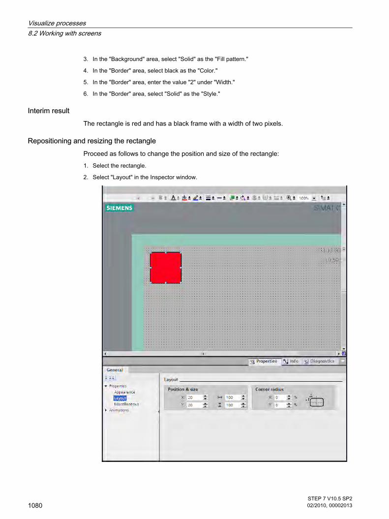
3. In the "Background" area, select "Solid" as the "Fill pattern."
4. In the "Border" area, select black as the "Color."
5. In the "Border" area, enter the value "2" under "Width."
6. In the "Border" area, select "Solid" as the "Style."
Interim resultThe rectangle is red and has a black frame with a width of two pixels.
Repositioning and resizing the rectangleProceed as follows to change the position and size of the rectangle:
1. Select the rectangle.
2. Select "Layout" in the Inspector window.
Visualize processes8.2 Working with screens
1080STEP 7 V10.5 SP202/2010, 00002013

3. Set "20" for the both the X and Y coordinates under "Position & Size".
4. Set "100" for the height and for the width.
ResultThe rectangle is positioned at the coordinates (20, 20), and has a width and height of 100 pixels.
See alsoExample: Inserting and configuring a rectangle (Page 1078)
8.2.3 Working with text lists and graphics lists
8.2.3.1 Working with text lists
8.2.3.1 Basics on text lists
IntroductionTexts are assigned to the values of a tag in a text list. During configuration, you can assign thetext list, for example, to a symbolic I/O field. This supplies the text to be displayed to the object.
The text lists are created in the ""Text List" editor. You configure the interface between the textlist and a tag at the object that uses the text list.
NoteRuntime dependency
The selection of objects that can have a text list assigned depends on the Runtime.
ApplicationThe text list is used, for example, to display a drop-down list in a symbolic I/O field.
You can configure multiple languages for the texts in a text list. The texts will then be displayedin the set language in Runtime.
NoteHMI device dependency
The availability of the text list is determined by the HMI device used.
8.2.3 Working with text lists and graphics lists8.2.3.1 Working with text lists8.2.3.1 Basics on text lists
Visualize processes8.2 Working with screens
STEP 7 V10.5 SP202/2010, 00002013
1081

FunctionIf the symbolic I/O field is a display field, the associated texts will differ according to the valueof the configured tags. If the symbolic I/O field is an input field, the configured tag assumes theassociated value when the operator selects the corresponding text in Runtime.
NoteRuntime dependency
The display of tag values to which no text has been assigned depends on the Runtime:
• The display and operating object remains empty.
• Three asterisks *** are displayed.
Multilingual textsYou can configure multiple languages for the texts in a text list. To this purpose you set thelanguages in the Project window under "Language support > Project languages."
Configuration stepsThe following steps are required to display texts, for example, in a symbolic I/O field:
1. Creating the text list
2. Assigning texts and values/value ranges to the text list
3. Assigning a text list in the display object, for example the symbolic I/O field
See alsoScreen basics (Page 1025)Creating a text list (Page 1082)Assigning texts and values to a range text list (Page 1084)Assigning texts and values to a bit text list (Page 1085)Assigning texts and values to a bit number text list (Page 1087)Configuring objects with a text list (Page 1088)
8.2.3.1 Creating a text list
IntroductionThe text list allows you to assign specific texts to values and to output these in Runtime, forexample in a symbolic I/O field. The type of symbolic I/O field can be specified, for example asa pure input field.
8.2.3.1 Creating a text list
Visualize processes8.2 Working with screens
1082STEP 7 V10.5 SP202/2010, 00002013

NoteRuntime dependency
The selection of the possible I/O field types depends on the Runtime used.
The following types of list are available:
• Range
• Bit
• Bit Number
You define the content and properties of a text list using the "Text and graphics list" editor.
ProcedureProceed as follows to create a text list:
1. Open the "Text and graphics lists" editor and the "Text lists" tab in the project tree.
2. Click in the first free table row of the upper work area.
The Inspector window of the text list is open.
3. Assign a name to the text list that indicates its function.
4. Select the text list type under "Selection":
― Range (... - ...): Text from the text list is displayed when the tag has a value that lies within thespecified range.
― Bit (0,1): A text from the text list is displayed when the tag has the value 0. A different text fromthe text list is displayed when the tag has the value 1.
― Bit number (0-31): Text from the text list is displayed when the tag has the value of the assignedbit number.
5. Enter a comment for the text list.
Visualize processes8.2 Working with screens
STEP 7 V10.5 SP202/2010, 00002013
1083

NoteHMI device dependency
The availability of the text list is determined by the HMI device used.
Note
You must not use semicolons in the texts in a text list. The semicolon is a control characterand is automatically deleted from a text.
ResultA text list is created.
See alsoBasics on text lists (Page 1081)
8.2.3.1 Assigning texts and values to a range text list
IntroductionFor each range text list you specify which texts are to be displayed at which value range.
Requirement
• The "Text and graphics list" editor is open.
• The "Text lists" tab is open.
• A range text list has been created and selected.
ProcedureProceed as follows to assign values and text to the range text list:
1. Click the first free line in the "List entries" editing area.
The Inspector window for this list entry opens.
8.2.3.1 Assigning texts and values to a range text list
Visualize processes8.2 Working with screens
1084STEP 7 V10.5 SP202/2010, 00002013

2. Select the type of value range:
― "Range": Minimum tag value to maximum tag value, for example 1 ≦ Value ≦ 21
― "Single value": Exactly one tag value, for example Value = 21
3. Enter the value or range of values at which a text from the text list is to be displayed under "Value".
4. Enter the text that is to be displayed in Runtime when the tag has the specified value or lies within thespecified range of values under "Text."
5. Activate "Default entry" if the entered text is to be displayed whenever the tag has an undefined value.Only one default entry is possible per list.
6. Create further corresponding list entries for additional value ranges of the same text list.
Note
Do not use one of the following special characters in the texts of the text list: ?, ", /, \, *, <,> and semicolon. Control characters are deleted automatically in a text.
ResultA range text list is created. Texts that appear in Runtime are assigned to the possible values.
See alsoBasics on text lists (Page 1081)
8.2.3.1 Assigning texts and values to a bit text list
IntroductionFor each text list you specify which texts are to be displayed at which bit value.
8.2.3.1 Assigning texts and values to a bit text list
Visualize processes8.2 Working with screens
STEP 7 V10.5 SP202/2010, 00002013
1085

Requirement
• The "Text and graphics list" editor is open.
• The "Text lists" tab is open.
• A bit text list has been created and selected.
ProcedureProceed as follows to assign values and texts to the bit text list:
1. Click the first free line in the "List entries" editing area.
The Inspector window for this list entry will open.
2. Enter "0" under "Value."
3. Enter the text that is to be displayed in Runtime when the tags have the value "0".
Note
Do not use one of the following special characters in the texts of the text list: ?, ", /, \, *, <,> and semicolon. Control characters are deleted automatically in a text.
4. Click the next free line in the "List entries" editing area.
The Inspector window for the next list entry opens.
5. Enter "1" under "Value."
6. Enter the text that is to be displayed in Runtime when the tags have the value "1".
ResultA bit text list is created. Texts that appear in Runtime are assigned to the possible values "0"and "1".
See alsoBasics on text lists (Page 1081)
Visualize processes8.2 Working with screens
1086STEP 7 V10.5 SP202/2010, 00002013

8.2.3.1 Assigning texts and values to a bit number text list
IntroductionFor each bit number text list you specify which texts are to be displayed at which bit number.
Requirement
• The "Text and graphics list" editor is open.
• The "Text lists" tab is open.
• A bit number text list has been created and selected.
ProcedureProceed as follows to assign values and texts to the bit number text list:
1. Click the first free line in the "List entries" editing area.
The Inspector window for this list entry will open.
2. Enter the bit number at which a text of the text list is to be displayed under "Value".
3. Enter the text that is to be displayed in Runtime when the tag has the specified bit number.
4. Activate "Default entry" if the entered text is to be displayed whenever the tag has an undefined value.Only one default entry is possible per list.
5. Create further corresponding list entries for additional bit numbers of the same text list.
Note
Do not use one of the following special characters in the texts of the text list: ?, ", /, \, *, <,> and semicolon. Control characters are deleted automatically in a text.
ResultA bit number text list is created. Texts that appear in Runtime are assigned to the specified bitnumbers.
8.2.3.1 Assigning texts and values to a bit number text list
Visualize processes8.2 Working with screens
STEP 7 V10.5 SP202/2010, 00002013
1087
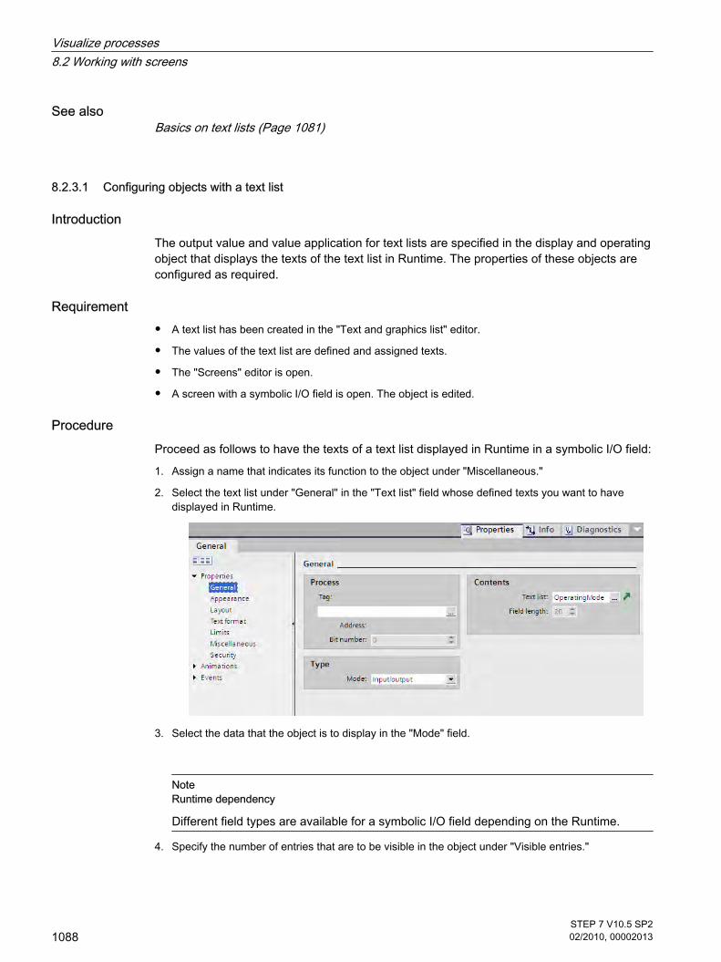
See alsoBasics on text lists (Page 1081)
8.2.3.1 Configuring objects with a text list
IntroductionThe output value and value application for text lists are specified in the display and operatingobject that displays the texts of the text list in Runtime. The properties of these objects areconfigured as required.
Requirement
• A text list has been created in the "Text and graphics list" editor.
• The values of the text list are defined and assigned texts.
• The "Screens" editor is open.
• A screen with a symbolic I/O field is open. The object is edited.
ProcedureProceed as follows to have the texts of a text list displayed in Runtime in a symbolic I/O field:
1. Assign a name that indicates its function to the object under "Miscellaneous."
2. Select the text list under "General" in the "Text list" field whose defined texts you want to havedisplayed in Runtime.
3. Select the data that the object is to display in the "Mode" field.
NoteRuntime dependency
Different field types are available for a symbolic I/O field depending on the Runtime.
4. Specify the number of entries that are to be visible in the object under "Visible entries."
8.2.3.1 Configuring objects with a text list
Visualize processes8.2 Working with screens
1088STEP 7 V10.5 SP202/2010, 00002013

5. Activate "Apply value on exit" under "Characteristics."
The values are applied when you exit the object in Runtime.
ResultThe defined texts of the text list are displayed in the symbolic I/O field in Runtime when the taghas the specified value.
See alsoBasics on text lists (Page 1081)
8.2.3.2 Working with graphics lists
8.2.3.2 Basic principles of graphics lists
IntroductionThe possible values of a tag are assigned to specific graphics in a graphics list. Duringconfiguration, you can create a graphics list for a button or a graphic I/O field. This supplies thegraphics to be displayed to the object.
The graphics lists are created with the "Text and graphics list" editor. You configure the interfacebetween the graphics list and a tag at the object that uses the graphics list.
ApplicationYou can configure the graphics list for the following situations:
• Drop-down list with a graphic I/O field
• State-specific graphic for a button
The graphics in a graphics list can be configured as multilingual. The graphics will then bedisplayed in the set language in runtime.
NoteAvailability for specific HMI devices
The availability of the graphics list is determined by the HMI device used.
Graphic sourcesGraphics can be added to the graphics list from the following sources:
• By selecting from a graphic browser
• By selecting an existing file You can use the following file types:
8.2.3.2 Working with graphics lists8.2.3.2 Basic principles of graphics lists
Visualize processes8.2 Working with screens
STEP 7 V10.5 SP202/2010, 00002013
1089

*.bmp, *.ico, *.cur, *.emf, *.wmf, *.gif, *.tif, *.jpeg and *.jpg.
• By creating a new file
FunctionIf the graphic I/O field is a display field, the associated graphics will differ according to the valueof the configured tags. If the graphic I/O field is an input field, the configured tag assumes theassociated value when the operator selects a graphic in runtime.
NoteAvailability for specific runtimes
The display of tag values to which no graphic has been assigned depends on the runtime:
• The display and operating object remains empty
• A defined default graphic is displayed
Configuration stepsThe following tasks are required to display graphics, for example, in a graphic I/O field:
1. Creating the graphics list
2. Assigning graphics and values/value ranges to the graphics list
3. Assigning a graphics list in the display object, for example the graphic I/O field
See alsoScreen basics (Page 1025)Creating a graphics list (Page 1090)Assigning a graphic and values to a range graphics list (Page 1092)Assigning graphics and values to a bit graphics list (Page 1094)Assigning graphics and values to a bit number graphics list (Page 1095)Configuring objects with a graphics list (Page 1096)
8.2.3.2 Creating a graphics list
IntroductionThe graphics list allows you to assign specific graphics to variable values and to output thesein a graphic I/O field in Runtime. You can specify the type of graphic I/O field, for example asa pure output field.
8.2.3.2 Creating a graphics list
Visualize processes8.2 Working with screens
1090STEP 7 V10.5 SP202/2010, 00002013

NoteRuntime dependency
The selection of the possible I/O field types depends on the Runtime used.
NoteHMI device dependency
The availability of the graphics list is determined by the HMI device used.
ProcedureProceed as follows to create a graphics list:
1. Open the "Text and graphics lists" editor and the "Graphics lists" tab in the project tree.
2. Click in the first free table row of the upper work area.
The Inspector window of the graphics list will open up.
Visualize processes8.2 Working with screens
STEP 7 V10.5 SP202/2010, 00002013
1091

3. Assign an expressive name to the graphics list.
4. Select the graphics list type under "Selection":
― Range (... - ...): Graphic from the graphics list is displayed when the variable has a value that lieswithin the specified range.
― Bit (0,1): A graphic from the graphics list is displayed when the variable has the value 0. A differentgraphic from the graphics list is displayed when the variable has the value 1.
― Bit number (0-31): Graphic from the graphics list is displayed when the variable has the value ofthe assigned bit number.
5. Enter a comment for the graphics list.
ResultA range graphics list is created.
See alsoBasic principles of graphics lists (Page 1089)
8.2.3.2 Assigning a graphic and values to a range graphics list
IntroductionFor each range graphics list you specify which graphics are to be displayed at which valuerange.
Requirement
• The "Text and graphics list" editor is open.
• The "Graphics list" tab is open.
• A range graphics list has been created and selected.
ProcedureProceed as follows to assign values and graphics to the range graphics list:
8.2.3.2 Assigning a graphic and values to a range graphics list
Visualize processes8.2 Working with screens
1092STEP 7 V10.5 SP202/2010, 00002013

1. Click the first free line in the "List entries" editing area.
The Inspector window for this list entry opens.
2. Select the type of value range under "Value":
― "Range": Minimum tag value to maximum tag value, for example 1 ≦ Value ≦ 21
― "Single value": Exactly one tag value, for example Value = 21
3. Enter the value or range of values at which a graphic from the graphics list is to be displayed under"Value".
4. Select the graphic that is to be displayed in Runtime when the tags have the specified value or liewithin the specified range of values under "Graphic."
5. Activate "Default entry" if the specified entry is to be displayed whenever the tag has an undefinedvalue. Only one default entry is possible per list.
ResultA range graphics list is created. Graphics that appear in Runtime are assigned to the possiblevalues.
See alsoBasic principles of graphics lists (Page 1089)
Visualize processes8.2 Working with screens
STEP 7 V10.5 SP202/2010, 00002013
1093

8.2.3.2 Assigning graphics and values to a bit graphics list
IntroductionFor each graphics list you specify which graphics are to be displayed at which bit value.
Requirement
• The "Text and graphics list" editor is open.
• The "Graphics list" tab is opened.
• A bit graphics list has been created and selected.
ProcedureProceed as follows to assign values and graphics to the bit graphics list:
1. Click the first free line in the "List entries" editing area.
The Inspector window for this list entry opens.
2. Enter "0" under "Value."
3. Select the graphic that is to be displayed in Runtime when the tag has the value "0".
4. Click the next free line in the "List entries" editing area.
The Inspector window for the next list entry opens.
5. Enter "1" under "Value."
6. Select the graphic that is to be displayed in Runtime when the tag has the value "1".
ResultA bit graphics list is created. Graphics that appear in Runtime are assigned to the values "0"and "1".
See alsoBasic principles of graphics lists (Page 1089)
8.2.3.2 Assigning graphics and values to a bit graphics list
Visualize processes8.2 Working with screens
1094STEP 7 V10.5 SP202/2010, 00002013

8.2.3.2 Assigning graphics and values to a bit number graphics list
IntroductionFor each bit number graphics list you specify which graphics are displayed at which bit number.
Requirement
• The "Text and graphics list" editor is open.
• The "Graphics list" tab is open.
• A bit number graphics list has been created and selected.
ProcedureProceed as follows to assign values and graphics to the bit number graphics list:
1. Click the first free line in the "List entries" editing area.
The Inspector window for this list entry will open.
2. Enter the bit number at which a graphic of the graphics list is to be displayed under "Value."
3. Select the graphic that is to be displayed in Runtime when the variable has the value of the specifiedbit number under "Graphic."
4. Activate "Default entry" if the specified entry is to be displayed whenever the tag has an undefinedvalue. Only one default entry is possible per list.
5. Create additional corresponding list entries for more bit numbers of the same graphics list.
ResultA bit number graphics list is created. Graphics that appear in Runtime are assigned to thespecified bit numbers.
8.2.3.2 Assigning graphics and values to a bit number graphics list
Visualize processes8.2 Working with screens
STEP 7 V10.5 SP202/2010, 00002013
1095

See alsoBasic principles of graphics lists (Page 1089)
8.2.3.2 Configuring objects with a graphics list
IntroductionThe output value and value application for graphics list are specified in the display and operatingobject that displays the graphics of the graphics list in Runtime. The properties of these objectsare configured as required.
Requirement
• A graphics list has been created in the "Text and graphics list" editor. The values have been defined.Graphics have been assigned to the values.
• The "Screens" editor is open.
• A screen with a graphics I/O field is open. The object is edited.
ProcedureProceed as follows to have a graphic of a graphics list displayed in Runtime in a graphic I/Ofield:
1. Assign a name that indicates its function to the object under "Miscellaneous."
2. Select the graphics list under "General" in the "Graphics list" field whose defined graphics you wantto have displayed in Runtime.
3. Select the data that the object is to display under "Type" in the "Mode" field.
NoteRuntime dependency
Different field types are available for a graphic I/O field depending on the Runtime.
8.2.3.2 Configuring objects with a graphics list
Visualize processes8.2 Working with screens
1096STEP 7 V10.5 SP202/2010, 00002013

ResultThe defined graphics of the graphics list are displayed in the graphic I/O field in Runtime whenthe tag has the specified value.
See alsoBasic principles of graphics lists (Page 1089)
8.2.4 Dynamizing screens
8.2.4.1 Basics on dynamizing
IntroductionIn WinCC, you can make object properties dynamic to map your plant onto HMI devices andto display process sequences. One example is the mapping of a tank, the liquid level of whichrises or falls in relation to a process value.
Dynamization of object properties You can assign dynamic properties to any graphic object. You use predefined animations forthis purpose.
Operator control objects react to events, such as a mouse click. You can configure systemfunctions to react to events. For additional information, refer to "Working with the SystemFunctions (Page 1330) ".
The options for dynamization depend on the object involved. When you copy an object, itsdynamization functions are included.
Animations
NoteHMI device dependency
The "Control enable" animation is not available for every HMI device.
WinCC helps you to implement dynamization using predefined animations. If you want to makean object property dynamic, first configure the required animation using tools from the toolboxor from the Inspector window of the object. Then customize the animation in the Inspectorwindow to suit the requirements of your project.
Animations are available to make the following object properties dynamic:
• Appearance
8.2.4 Dynamizing screens8.2.4.1 Basics on dynamizing
Visualize processes8.2 Working with screens
STEP 7 V10.5 SP202/2010, 00002013
1097

The object changes its appearance, such as its color.
• Position
The screen object is animated.
• Visibility
The object is shown or hidden.
• Operability of operator control objects
The object is enabled or locked for operation.
You can customize the default properties for the animations available in the toolbox just as youwould customize the default properties of other graphic objects.
See alsoConfiguring a new animation (Page 1099)
8.2.4.2 Elements and basic settings
IntroductionIn WinCC, you use dynamic objects to map the plant onto HMI devices and to display processsequences.
You can implement dynamization for all graphic objects that you have configured in a screen.Which dynamization functions and events are actually available depends on the selectedobject.
NoteHMI device dependency
The "Control enable" animation is not available for every HMI device.
"Animations" task cardThe "Animations" task card contains the following groups and elements for configuration ofanimations:
• Movements: horizontal, vertical, diagonal, and direct movement
• Layout: Appearance and visibility
• Miscellaneous: Activate object
NoteBasic Panels
The "Animations" task card is not available for Basic Panels.
8.2.4.2 Elements and basic settings
Visualize processes8.2 Working with screens
1098STEP 7 V10.5 SP202/2010, 00002013

Inspector windowThe Inspector window shows all the animations that are configured for the selected object inthe "Animations" group:
• Diagonal, horizontal, vertical, or direct movement: The screen object is animated.
• Design: The object changes its appearance, such as its color or flashing properties.
• Visibility: The object is shown or hidden.
• Activate object: The object can or cannot be used.
8.2.4.3 Animations
8.2.4.3 Configuring a new animation
IntroductionYou configure animations for graphic objects using simple mouse actions. You must onlyconfigure one animation of the same type for each object.
Requirement
• You have opened a screen which contains at least one dynamic object.
• The Inspector window is open.
• The Toolbox window is displayed.
ProcedureProceed as follows to configure an animation:
1. Open the Inspector window or the property list of the object to be dynamized.
2. In the "Animation" group, double-click the "New animation" entry.
3. Select the animation you want to use.
4. Click "Add".
Alternative procedure1. Open the object group containing the required animation in the "Animations" task card.
2. Drag the animation onto the object that you want to make dynamic.
Otherwise: Select the required animation from the toolbox. Then click the object that you want to makedynamic.
8.2.4.3 Animations8.2.4.3 Configuring a new animation
Visualize processes8.2 Working with screens
STEP 7 V10.5 SP202/2010, 00002013
1099

NoteBasic Panels
The "Animations" task card is not available for Basic Panels.
ResultThe animation appears in the Inspector window of the object. You can now configure theanimation.
Administering configured animationsIn the Inspector window the Animations shortcut menu contains the following menu items foradministering animations:
• "Copy animation": This menu item is used to copy the selected animation.
• "Insert animation": Use this menu item to insert an animation from the Clipboard into the Inspectorwindow of another object.
• "Remove animation": Use this option to delete animations that you no longer need.
See alsoDynamizing the appearance of an object (Page 1100)Configuring movement (Page 1102)Dynamizing the visibility of an object (Page 1104)Animations for object groups and for multiple selection (Page 1105)Basics on dynamizing (Page 1097)
8.2.4.3 Dynamizing the appearance of an object
IntroductionYou can control the foreground and background color and the flashing properties of an objectdynamically. In Runtime, the appearance of the object is controlled by the change in value ofa tag. When the tag acquires a certain value, or changes its value within a certain interval, theobject changes its color or flashing response according to its configuration.
Appearance variantsHow many variants of the appearance you can configure depends on your setting for the datatype of the tag:
• "Range":
The range value of the tag is considered. You can define any number of values or intervals forcontrolling the appearance of an object. You may not define overlapping ranges.
• "Multiple bits"
With multiple bits, the value of the tags is considered. The tag can have an integer value between 0and 31. You can assign each one of these values to a variant of the object appearance. The "Multiplebits" data type does not allow you to define an interval, but only the values in the "From" column.
8.2.4.3 Dynamizing the appearance of an object
Visualize processes8.2 Working with screens
1100STEP 7 V10.5 SP202/2010, 00002013

• "Single bit"
Only the specified bit of the tag is considered. You can define two layout variants for the objectappearance, namely for bit = 1 and bit = 0. The "Single bit" data type does not permit you to definean interval.
Note
You can make the appearance of the control element dependent on the operator's input.To do this, use the same tag in an I/O field to save the input and to control the appearance.
Example: The background color of the I/O field changes in Runtime in response to the input.
Requirement
• You have opened a screen which contains at least one dynamic object.
• The Inspector window is open.
• The Toolbox window is displayed.
ProcedureProceed as follows to object property the flashing of the object:
1. Select the screen object you want to control dynamically.
The object properties are displayed in the Inspector window.
2. Click "Animations > New animation" in the Inspector window.
The animations available for the selected object are displayed.
3. Select the "Appearance" animation.
The parameters of the animation are displayed.
4. Click "Tag" to open the list of tags, then select which tag will be used to control the appearance of theobject.
The tag appears in the "Tag" field.
5. Select a data type for the tag. The number of values or intervals you can define for controlling theobject appearance depends on the data type of the tag.
6. Click in the first cell of the "Value" or "Range" column.
Visualize processes8.2 Working with screens
STEP 7 V10.5 SP202/2010, 00002013
1101

7. Enter a tag value:
Enter a tag value for "Single bit" and "Multiple bits" in the "Value" column.
Enter a tag interval for a range, 0 - 60 for example, in the "Range" column.
8. In the "Foreground color" and "Background color" columns, select the colors the object is two acquirein Runtime when the tag reaches the set value or interval.
9. Select a flashing mode for the object from the "Flashing" list.
10.
Repeat steps 6 to 10 if you want to define the appearance of another value or an interval of the tag.
ResultIn Runtime, the flashing response, and color of the object change dynamically according to theprocess value returned in the tag.
See alsoConfiguring a new animation (Page 1099)
8.2.4.3 Configuring movement
IntroductionYou can configure dynamic objects so that they move along a certain path, or to shift by acertain number of pixels relative to their current position. The movement is controlled via tags.Whenever the tags are updated, the object moves on one step.
You can only program one type of movement for each object. The following types of movementare available:
• "Diagonal movement", "Horizontal movement" or "Vertical movement":
The object moves along a path which has defined start and end points. The relative position of theobject along this path is determined by the value of a tag.
• "Direct movement"
8.2.4.3 Configuring movement
Visualize processes8.2 Working with screens
1102STEP 7 V10.5 SP202/2010, 00002013

The object is moved in the X and Y directions by a certain number of pixels. The movement is definedby the absolute values in two variables.
Graphic programming supportThe "Screens" editor allows graphic programming of diagonal, horizontal and verticalmovements. During configuration, a transparent copy of the object is shown on screen. Thiscopy is connected to the source object by an arrow. When you move the object copy to thedesired destination, the system automatically saves the pixel values corresponding to themovement in the Inspector window.
Requirement
• You have opened a screen which contains at least one dynamic object.
• The Inspector window is open.
• The Toolbox window is displayed.
Configuring "Diagonal movement", "Horizontal movement" or "Vertical movement"Proceed as follows to configure the animations:
1. Select the screen object you want to control dynamically.
The object properties are displayed in the Inspector window.
2. Click "Animations > New animation" in the Inspector window.
The animations available for the selected object are displayed.
3. Select a type of movement.
The parameters of the animation are displayed.
4. Select a tag for control of movement.
A transparent copy of the object is shown in the work area, which is connected to the source objectby means of an arrow.
Visualize processes8.2 Working with screens
STEP 7 V10.5 SP202/2010, 00002013
1103
5. Move the object copy to the relevant destination. The system automatically enters the pixel values ofthe final position in the Inspector window.
6. Customize the range of values for the tag as required.
Configuring "Direct movement"Proceed as follows to configure the "Direct movement" animation:
1. Select the screen object you want to control dynamically.
The object properties are displayed in the Inspector window.
2. Click "Animations > New animation" in the Inspector window.
The animations available for the selected object are displayed.
3. Select "Direct movement".
4. Select a tag for controlling the offset in the X direction.
5. Select a tag for controlling the offset in the Y direction.
ResultIn Runtime, the object moves in response to every change in value of the tag that is used tocontrol the movement. The direction of movement corresponds to the configured type ofmovement.
See alsoConfiguring a new animation (Page 1099)
8.2.4.3 Dynamizing the visibility of an object
IntroductionYou can control the visibility of an object dynamically. If a tag value falls within a configuredinterval, the object is shown, or hidden in Runtime.
The "Simple recipe view" and "Simple alarm view" objects are always visible.
Application exampleDynamization of the "Visibility" property allows you to output an alarm to your screen, which istriggered when the tag value exceeds a critical range, for example. The alarm is cleared whenthe tag value returns to the non-critical range.
Requirement
• You have opened a screen containing an object that you want to show or hide in Runtime.
• The Inspector window is open.
Procedure1. Select the control element you want to control dynamically.
8.2.4.3 Dynamizing the visibility of an object
Visualize processes8.2 Working with screens
1104STEP 7 V10.5 SP202/2010, 00002013

The object properties are displayed in the Inspector window.
2. Click "New Animation" in the "Animations" group of the Inspector window.
The animations available for the selected object are displayed.
3. Select the "Visibility" animation.
The parameters of the animation are displayed.
4. Set the required "Status": "Visible" or "Hidden."
The selected status is set at the start of Runtime if you do not define a tag for controlling the status.
5. To control the display of an object using a tag, select a tag and define an interval.
The set object status is applied as long as the tag value lies within the range of the set interval.
ResultThe object is shown or hidden in Runtime, depending on the tag value.
See alsoConfiguring a new animation (Page 1099)
8.2.4.3 Animations for object groups and for multiple selection
Applying animations to object groupsYou can configure all animations for an object group that are supported by an individual objectfrom the object group. If you configure an animation for an object group, this animation willapply to all individual objects that support this animation.
Changing animations for multiple objectsFor a multiple selection, the animations that are configured for the reference object appear inthe Inspector window. You can change the animations as usual. The changes will apply to allthe objects in the multiple selection that support the configured animation. This means thateven objects for which you have not yet configured an animation will have the reference object'sanimation.
Application exampleSelect a button, and a circle at the same time. The button is the reference object. The"Appearance" animation is already configured for the button, so it appears in the Inspectorwindow of the multiple selection. If you activate the "Flashing" property in the "Animations"group, the settings for the "Appearance" animation will then apply to both the button and thecircle.
Configuring new animations for multiple objectsIf you configure a new animation for the objects of a multiple selection, this animation will applyto all selected objects that support the configured animation. If the new animation replaces anexisting animation, a security prompt appears.
8.2.4.3 Animations for object groups and for multiple selection
Visualize processes8.2 Working with screens
STEP 7 V10.5 SP202/2010, 00002013
1105

Application exampleYou select a circle, and a rectangle. The "Diagonal movement" animation is already configuredfor the circle. You configure the "Horizontal movement" animation for the multiple selection.This animation applies to the rectangle since no animation of the Movement type is yetconfigured for it. For the circle, you are asked to confirm that you want to replace the existing"Diagonal movement" animation with the new "Horizontal movement" animation.
See alsoConfiguring a new animation (Page 1099)
8.2.5 Working with function keys
8.2.5.1 Working with function keys
IntroductionThe function key is a physical key on your HMI device and its functions can be configured. Afunction list can be configured for the events "Key pressed" and "Release key".
A function key can be assigned global or local functions.
NoteAvailability for specific HMI devices
Function keys are not available on all HMI devices.
Global function keysGlobal function keys always trigger the same action, regardless of the displayed screen.
Global function keys are configured in the "Global Screen" editor. The global assignmentapplies for all the screens of the set HMI device.
Global function keys reduce programming considerably, because there is no need to assignthese global keys to each individual screen.
Local function keys in screensLocal function keys in screens can trigger a different action in each screen. This assignmentapplies only to the screen in which you have defined the function key.
Using a local function key you can overwrite global function keys and the local function keysof a template.
8.2.5 Working with function keys8.2.5.1 Working with function keys
Visualize processes8.2 Working with screens
1106STEP 7 V10.5 SP202/2010, 00002013

Note
If a screen with local function keys is overlapped by an alarm view or an alarm window, thenthe function keys are still active in runtime. This may happen in particular on HMI devices witha small display.
Local function keys in templatesLocal functions keys that are assigned in templates are valid for all the screens based on thistemplate. They can trigger a different action in every screen. Function keys for templates areassigned in the template of the "Screens" editor. You overwrite the global assignment of afunction key by a local assignment in the template.
Hotkey assignmentYou can assign hotkeys, such as buttons, to control objects. The available hotkeys depend onthe HMI device.
Note
The function key has a local or global action assigned to it. If the function key also has a hotkeyassigned to it, then the hotkey function will be executed in Runtime.
GraphicsWhen a function key is placed directly next to the display, you can assign a graphic to it to makethe function of the function key more clear.
Display of assignment
Table8-1 The following table shows which symbols display the assignment of the function keys:
Function key Description
Not assigned
Global assignment
Assigned locally in the template
Visualize processes8.2 Working with screens
STEP 7 V10.5 SP202/2010, 00002013
1107

Function key Description
Local assignment
Local assignment (local assignment of the template overwrites globalassignment)
Local assignment (local assignment overwrites global assignment)
Local assignment (local assignment overwrites local assignment of the template)
Local assignment (local assignment overwrites local assignment of the template,which already overwrites global assignment)
Assigning buttons with screen navigation
NoteBasic Panels
The "Screen Navigation" editor is not available for Basic Panels.
See alsoScreen basics (Page 1025)Assigning function keys globally (Page 1109)Local assignment of function keys (Page 1110)Assigning a function key to a function (Page 1111)Assigning operator authorization for a function key (Page 1112)Assigning a function key to a graphic (Page 1114)Example: Using function keys for screen navigation (Page 1115)
Visualize processes8.2 Working with screens
1108STEP 7 V10.5 SP202/2010, 00002013
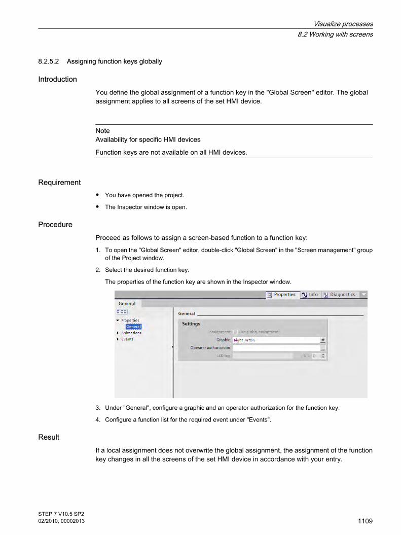
8.2.5.2 Assigning function keys globally
IntroductionYou define the global assignment of a function key in the "Global Screen" editor. The globalassignment applies to all screens of the set HMI device.
NoteAvailability for specific HMI devices
Function keys are not available on all HMI devices.
Requirement
• You have opened the project.
• The Inspector window is open.
ProcedureProceed as follows to assign a screen-based function to a function key:
1. To open the "Global Screen" editor, double-click "Global Screen" in the "Screen management" groupof the Project window.
2. Select the desired function key.
The properties of the function key are shown in the Inspector window.
3. Under "General", configure a graphic and an operator authorization for the function key.
4. Configure a function list for the required event under "Events".
ResultIf a local assignment does not overwrite the global assignment, the assignment of the functionkey changes in all the screens of the set HMI device in accordance with your entry.
8.2.5.2 Assigning function keys globally
Visualize processes8.2 Working with screens
STEP 7 V10.5 SP202/2010, 00002013
1109

See alsoWorking with function keys (Page 1106)
8.2.5.3 Local assignment of function keys
IntroductionFunction keys are assigned globally and locally. A local assignment of the function keys is onlyvalid for the screen or the template in which it was defined. The following local function keysare available:
• Local function keys of a screen
Different functions are assigned to the function key for each screen. This assignment applies only tothe screen in which you have defined the function key.
• Local function keys of a template
You assign the function keys in a template. The assignment applies to all the screens that are basedon this template and are not overwritten by a local assignment in a screen.
A local assignment overwrites the global assignment of a function key.
NoteAvailability for specific HMI devices
Function keys are not available on all HMI devices.
Using existing assignmentsThe option for using existing assignments is referred to as follows in the Inspector window:
• In a template: "Use global assignment"
• In a screen:
― Screen based on a template: "Use local template"
― Screen not based on a template: "Use global assignment"
The "Use local template" option includes the use of the local assignment in the template andthe global assignment.
Requirement
• You have opened the screen or the template in which you want to assign a function key locally.
• The Inspector window is open.
ProcedureProceed as follows:
8.2.5.3 Local assignment of function keys
Visualize processes8.2 Working with screens
1110STEP 7 V10.5 SP202/2010, 00002013

1. Select the desired function key in the screen or in the template.
The properties of the function key are shown in the Inspector window.
2. Click "General" in the Inspector window.
3. Disable the "Use local template" or "Use global assignment" option.
4. Under "General", configure a graphic and an operator authorization for the function key.
5. Configure a function list for the required event under "Events".
ResultThe function key is assigned the configured function in the screen or in the template.
See alsoWorking with function keys (Page 1106)
8.2.5.4 Assigning a function key to a function
IntroductionA function key can have two states:
• Pressed: Defined by the "Key pressed" event.
• Released: Defined by the "Release key" event.
Both of these events are configured in the Inspector window of the function key. You can assignany event a function list which contains system functions or scripts. Execution of this functionlist is event-driven in runtime.
NoteAvailability for specific HMI devices
Function keys are not available on all HMI devices.
8.2.5.4 Assigning a function key to a function
Visualize processes8.2 Working with screens
STEP 7 V10.5 SP202/2010, 00002013
1111

NoteBasic Panels
Scripts are not available for Basic Panels.
RequirementTo assign the function key a global function:
• The "Global Screen" editor is open.
To assign the function key a local function:
• The screen in which you want to assign a function key is open.
If you want to assign a function key locally in a template:
• The template in which you want to assign a function key is open.
• The Inspector window is open.
ProcedureProceed as follows:
1. Select the function key you want to define.
The properties of the function key are shown in the Inspector window.
2. Configure the function list for the desired result in the Inspector window under "Properties" in the"General" group.
ResultThe function list is executed in runtime when the operator presses or releases the function key.
See alsoWorking with function keys (Page 1106)
8.2.5.5 Assigning operator authorization for a function key
IntroductionIn WinCC you can assign an operator authorization for a function key in runtime. This allowsyou to restrict access to the function keys to specific persons or operator groups when youconfigure your project. Only authorized personnel can then change important parameters andsettings in runtime.
You configure access protection in order to avoid operator errors and increase plant or machinesecurity.
8.2.5.5 Assigning operator authorization for a function key
Visualize processes8.2 Working with screens
1112STEP 7 V10.5 SP202/2010, 00002013

NoteAvailability for specific HMI devices
Function keys are not available on all HMI devices.
Requirement
• The user groups have been defined.
To protect a global function key:
• The "Global Screen" editor is open.
If you want to protect a local function key of a screen or of a template:
• The screen or the template which contains the function key is open.
• The Inspector window is open.
ProcedureProceed as follows:
1. Select the relevant function key.
The properties of the function key are shown in the Inspector window.
2. Click "General" in the Inspector window.
3. In the "Authorization" list, select the user group you want to allow runtime access to the function key.
ResultThe operator authorization is configured.
See alsoWorking with function keys (Page 1106)
Visualize processes8.2 Working with screens
STEP 7 V10.5 SP202/2010, 00002013
1113
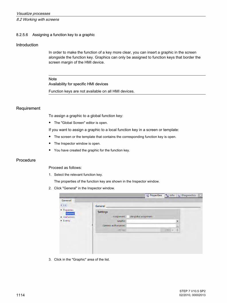
8.2.5.6 Assigning a function key to a graphic
IntroductionIn order to make the function of a key more clear, you can insert a graphic in the screenalongside the function key. Graphics can only be assigned to function keys that border thescreen margin of the HMI device.
NoteAvailability for specific HMI devices
Function keys are not available on all HMI devices.
RequirementTo assign a graphic to a global function key:
• The "Global Screen" editor is open.
If you want to assign a graphic to a local function key in a screen or template:
• The screen or the template that contains the corresponding function key is open.
• The Inspector window is open.
• You have created the graphic for the function key.
ProcedureProceed as follows:
1. Select the relevant function key.
The properties of the function key are shown in the Inspector window.
2. Click "General" in the Inspector window.
3. Click in the "Graphic" area of the list.
8.2.5.6 Assigning a function key to a graphic
Visualize processes8.2 Working with screens
1114STEP 7 V10.5 SP202/2010, 00002013

The graphic browser of your WinCC project appears. The pane on the left side shows the externalgraphics which are stored in the browser. The pane on the right side shows you a preview of thegraphic you have selected in the browser.
Using the
and
icons, you can display the collection either in form of thumbnails or as a list.
In order to open and edit OLE objects with the associated graphics program, double-click on the object.
4. In the browser click the desired graphic or store the relevant graphic in the graphic browser.
The graphic preview is shown in the right pane.
5. Click "Select" to add the graphic to the screen.
Click "Clear" to remove the graphic from the screen.
ResultThe graphic is displayed next to the function key.
See alsoWorking with function keys (Page 1106)
8.2.5.7 Example: Using function keys for screen navigation
TaskIn this example you create a local function key in a screen. When the operator presses thisfunction key, a screen change to a predefined screen is triggered, for example "Boiler 2".
8.2.5.7 Example: Using function keys for screen navigation
Visualize processes8.2 Working with screens
STEP 7 V10.5 SP202/2010, 00002013
1115

NoteAvailability for specific HMI devices
Function keys are not available on all HMI devices.
Requirement
• The screen in which you want to assign the function key is open.
• You have created the "Boiler 2" screen.
• The Inspector window is open.
ProcedureProceed as follows to use the "ActivateScreen" function:
1. Select the desired function key.
The properties of the function key are shown in the Inspector window.
2. Click "General."
3. To overwrite a global assignment, disable the "Use local template" option.
4. Click "Key pressed" under "Events".
5. Select the "ActivateScreen" system function from the list.
The "ActivateScreen" function appears in the "Function list" dialog box, including the "Screen name"and "Object number" parameters.
Visualize processes8.2 Working with screens
1116STEP 7 V10.5 SP202/2010, 00002013

6. Select the "Boiler 2" screen from the "Screen name" list.
ResultThe operator changes to the "Boiler 2" screen in runtime by pressing the selected function key.
See alsoWorking with function keys (Page 1106)
8.2.6 Working with layers
8.2.6.1 Basics on working with layers
LayersUse layers in order to achieve differentiated editing of the objects in a screen. A screen consistsof 32 layers that you can give any names. If you assign objects to the layers, you thereby definethe screen depth. Objects of layer 0 are located at the screen background, while objects oflayer 31 are located in the foreground.
8.2.6 Working with layers8.2.6.1 Basics on working with layers
Visualize processes8.2 Working with screens
STEP 7 V10.5 SP202/2010, 00002013
1117

The objects of a single layer are also arranged hierarchically. When you create a screen, theobject inserted first is located at the rear within the layer. Each further object is placed oneposition towards the front. You can shift objects forwards and backwards within a layer.
Principle of the layer techniqueAlways one layer of the 32 layers is active. New objects you add to the screen are alwaysassigned to the active layer. The number of the active layer is indicated in the "Layer" toolbarand in the Inspector window of the screen.
When you open a screen, all 32 layers of the screen are displayed. You can hide all layersexcept the active layer in the Inspector window of the screen. You then explicitly edit objectsof the active layer.
Use the Inspector window of the screen to define if the layers are to be shown for theEngineering System only. This function is useful if you want to hide data in the screen.
In the tree view of the "Layers" palette in the "Layout" task card, you administer layers andobjects with drag-and-drop and the context menu.
Application examplesUse layers, for example, in the following cases:
• To hide the labeling of objects when editing,
• To hide objects, such as alarm windows, while configuring further screens.
See alsoScreen basics (Page 1025)Moving objects between layers (Page 1119)Setting the active layer (Page 1120)Show and hide layers (Page 1121)Renaming layers (Page 1122)
Visualize processes8.2 Working with screens
1118STEP 7 V10.5 SP202/2010, 00002013

8.2.6.2 Moving objects between layers
IntroductionBy default, a new object is inserted on the active layer. You can, however, assign an object toanother layer at a later time.
Requirement
• A screen with an object is open.
• The Inspector window is open.
Moving objects to another layerProceed as follows to move objects to a different layer:
1. Select the object in the screen.
The object properties are displayed in the Inspector window.
2. Click "Miscellaneous."
3. Under "Layer", enter the layer to which you want to move the object.
Alternatively, select the object from the "Layout" task card and drag it to the required layer.
Changing the order of objectsProceed as follows:
1. Select the object in the screen.
The object properties are displayed in the Inspector window.
2. To move the object to the front or back, select the "Order" > "Move backward" or "Move forward"command from the shortcut menu.
Alternatively, use the
or
icons in the toolbar.
Assign an object to an adjacent layerProceed as follows:
1. Select the object in the screen.
The object properties are displayed in the Inspector window.
2. To assign the object to the next lowest or next highest layer, select the "Order" > "Move backward"or "Move forward" command from the shortcut menu.
Alternatively, use the
or
8.2.6.2 Moving objects between layers
Visualize processes8.2 Working with screens
STEP 7 V10.5 SP202/2010, 00002013
1119

icons in the toolbar.
ResultThe object is assigned to the selected layer, and positioned at the top of the layer.
See alsoBasics on working with layers (Page 1117)
8.2.6.3 Setting the active layer
IntroductionThe screen objects are always assigned to one of the 32 layers. There is always an active layerin the screen. New objects you add to the screen are always assigned to the active layer.
The number of the active layer is indicated in the "Layer" toolbar. The active layer is indicatedby the
icon in the "Layout" task card in the "Layers" palette.
Layer 0 is the active layer when you start programming. You can activate a different layer duringconfiguration, if necessary.
Requirement
• You have opened a screen which contains at least one object.
• The Inspector window of the active screen is open.
Activating a different layerProceed as follows to activate other layers:
1. Click "Layers" in the Inspector window of the current screen.
2. Enter the layer number in the "Active layer" field under "Settings."
Alternative procedureProceed as follows:
1. Select the "Layers" palette in the "Layout" task card.
2. Select the "Active layer" command from the context menu.
ResultThe layer with the specified number is now active.
8.2.6.3 Setting the active layer
Visualize processes8.2 Working with screens
1120STEP 7 V10.5 SP202/2010, 00002013

See alsoBasics on working with layers (Page 1117)
8.2.6.4 Show and hide layers
IntroductionYou can show or hide the layers of a screen as required. You specify the layers that are shownin the Engineering System. When you open a screen, all the layers are always shown.
Requirement
• The screen is opened.
• The "Layout" task card is open.
Hiding or showing layersProceed as follows to hide or show layers:
1. Select the layers that you want to hide or show in the "Layout" task card of the "Layers" palette.
2. Click one of the icons next to the corresponding layer:
―A shown layer is hidden
―A hidden layer is shown
Note
The active layer cannot be hidden.
Using the Inspector window to show or hide layersProceed as follows to show or hide layers using the Inspector window:
8.2.6.4 Show and hide layers
Visualize processes8.2 Working with screens
STEP 7 V10.5 SP202/2010, 00002013
1121

1. Click in an area of the screen that does not contain an object.
The screen properties are shown in the Inspector window.
2. Click "Layers" in the Inspector window.
3. In the list, enable, or disable the layers that you want to show, or hide.
If you activate "All ES layers" for a layer, the objects in this layer will be shown in the EngineeringSystem.
ResultThe layers are shown according to your settings.
See alsoBasics on working with layers (Page 1117)
8.2.6.5 Renaming layers
IntroductionWhen you create a screen, the 32 layers are numbered consecutively by default. To improveclarity, you can rename the layers to suit your requirements.
Requirement
• The screen is opened.
• The "Layout" task card is open.
Renaming a layer in the "Layout" task cardProceed as follows to rename a layer in the "Layout" task card:
1. Select the layer that you want to rename in the "Layers" palette.
2. Select "Rename" from the shortcut menu.
8.2.6.5 Renaming layers
Visualize processes8.2 Working with screens
1122STEP 7 V10.5 SP202/2010, 00002013

You can now edit the name of the layer.
3. Enter the new name.
Renaming layers in the Inspector windowProceed as follows to rename a layer in the Inspector window:
1. Click in an area of the screen that does not contain an object.
The screen properties are shown in the Inspector window.
2. Click "Layers" in the Inspector window.
3. Enter the new layer name.
ResultThe layer is displayed with the new name.
See alsoBasics on working with layers (Page 1117)
Visualize processes8.2 Working with screens
STEP 7 V10.5 SP202/2010, 00002013
1123

8.2.7 Working with libraries
8.2.7.1 Basics on libraries
IntroductionStore all objects you need frequently in the libraries. An object that is stored in the library onlyhas to be configured once. It can then be used repeatedly as often as required. Library objectsextend the number of available screen objects and increase the effectiveness duringconfiguration through the multiple usage of ready-to-use objects.
Your WinCC software package is supplied with comprehensive libraries that contain, forexample, "Motor" or "Valve" objects. You may, however, define your own library objects.
Libraries are managed in the "Libraries" task card. The following libraries are available here iflibrary objects are stored:
• Project library
• Global libraries
8.2.7 Working with libraries8.2.7.1 Basics on libraries
Visualize processes8.2 Working with screens
1124STEP 7 V10.5 SP202/2010, 00002013

Note
There is a symbol library in the "Tools" task card in the "Elements" palette.
Library objects A library can contain all WinCC objects. Examples:
• Complete HMI device
• Screens
• Display and control objects including tags and functions
• Object groups including tags and functions
• Graphics
• Tags
• Alarms
• Text and graphics lists
• Logs
• Scripts
To use a library object in a project, copy the object and all referenced objects to the project.The copied object looses its interconnection with the library. Changes in the library do not affectany of the copied library objects.
NoteBasic Panels
No scripts or logs are available for Basic Panels.
Project libraryThere is one library for each project. Objects of the project library are stored alongside with theproject data and are available only for the project in which the library was created. When youmove the project to a different computer, the project library created therein is included.
To use the library object of the project library in other objects, move or copy the object into aglobal library.
Global librariesIn addition to the objects from the project library, you can also incorporate objects from globallibraries in your projects. A global library is stored independent of the project data in a separatefile with the extension *.al10.
If you want to use a global library from another project, open the corresponding library.
Visualize processes8.2 Working with screens
STEP 7 V10.5 SP202/2010, 00002013
1125

A project can access several global libraries. A global library may be used concurrently inseveral projects.
When a library object is changed by a project, this library will be changed in all projects in whichthese libraries are open.
Among the global libraries you will also find the libraries supplied with your WinCC package.
CategoriesTo sort library objects by topics, you can either split a library into categories or create severalglobal libraries. A particular global library may contain all of the objects you need to configuremotor controls, for example. Another global library may contain all of the objects you need toconfigure the pump controls.
PartsThe components of a library element or the element are displayed in the "Parts" palette,depending on the element type:
• When a single object is assigned to the library, this object is shown in the "Parts" palette.
• If a group of several objects are assigned to the library, the group is shown in the "Parts" palette andnot the objects it contains.
• When a selection of multiple objects is assigned to the library, only one of the objects with name isshown under "Global libraries". The "Parts" palette, however, contains all objects that were insertedwith this object.
• When a complete screen is assigned to a library with all its objects, the name of the screen is shownunder "Global libraries" and in the "Parts" palette. The individual objects are not displayed. If youchange the name of this element in the global library, the name of the screen remains unchanged inthe "Parts" palette.
See alsoScreen basics (Page 1025)Displaying library objects (Page 1126)Managing library objects (Page 1129)Storing an object in a library (Page 1130)Inserting a library object (Page 1131)Creating a global library (Page 1132)Saving a global library (Page 1133)Opening a global library (Page 1134)
8.2.7.2 Displaying library objects
IntroductionThe libraries are displayed as file folders in the corresponding palette. The elements containedin the library are displayed in the file folder and in the "Elements" palette.
8.2.7.2 Displaying library objects
Visualize processes8.2 Working with screens
1126STEP 7 V10.5 SP202/2010, 00002013

Requirement
• At least one library object has been created in a library.
• The "Libraries" task card is opened.
Displaying library elementsProceed as follows to display the elements contained in a library:
1. Select the library in the corresponding palette whose library objects you want to display.
2. Click
.
The contained library objects are displayed in the "Elements" palette.
3. Click one of the following icons:
Icon Description
Element view in detailed mode
Visualize processes8.2 Working with screens
STEP 7 V10.5 SP202/2010, 00002013
1127
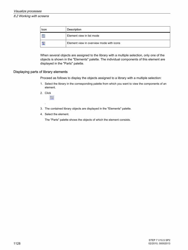
Icon Description
Element view in list mode
Element view in overview mode with icons
When several objects are assigned to the library with a multiple selection, only one of theobjects is shown in the "Elements" palette. The individual components of this element aredisplayed in the "Parts" palette.
Displaying parts of library elementsProceed as follows to display the objects assigned to a library with a multiple selection:
1. Select the library in the corresponding palette from which you want to view the components of anelement.
2. Click
.
3. The contained library objects are displayed in the "Elements" palette.
4. Select the element.
The "Parts" palette shows the objects of which the element consists.
Visualize processes8.2 Working with screens
1128STEP 7 V10.5 SP202/2010, 00002013

ResultThe library objects are displayed in accordance with the configuration. The components of thefaceplates are displayed.
See alsoBasics on libraries (Page 1124)
8.2.7.3 Managing library objects
IntroductionYou can always copy or move library objects within the categories of a library. Delete the libraryobjects you do not require.
Requirement
• You have opened a library which contains several categories and at least one object.
• The library object is shown.
8.2.7.3 Managing library objects
Visualize processes8.2 Working with screens
STEP 7 V10.5 SP202/2010, 00002013
1129

Moving a library objectProceed as follows to move a library object:
1. Select the library object.
2. Drag-and-drop the object into the relevant category.
The library object is moved.
Copying a library objectProceed as follows to copy a library object:
1. Select the library object.
2. Select "Copy" from the shortcut menu.
3. Select the destination category.
4. Select "Paste" from the shortcut menu.
The copy of the library object is pasted into the destination category.
Deleting a library objectProceed as follows to delete a library object:
1. Select the library object that you want to delete.
2. Select "Delete" from the shortcut menu.
The library object is deleted.
ResultDepending on the selected action, the library object is either moved, or copied, or deleted.
See alsoBasics on libraries (Page 1124)
8.2.7.4 Storing an object in a library
IntroductionYou can store all of WinCC objects, such as screens, tags, graphic objects or alarms in yourlibraries. You can use drag-and-drop to move the corresponding object from the work area,project tree or detail view to the library. In a library you have divided into categories, you candirectly add objects to a specific category.
Below you can see how to insert the display and operator control from the work area to thelibrary.
Requirement
• The "Screens" editor is open.
8.2.7.4 Storing an object in a library
Visualize processes8.2 Working with screens
1130STEP 7 V10.5 SP202/2010, 00002013

• The object which is to be saved to the library is shown in your work area.
• The created libraries are displayed.
ProcedureProceed as follows to add an object to a library:
1. Select the object in the work area of the "Screens" editor.
2. Drag-and-drop the object from the work area to the desired library.
The mouse pointer is transformed into a crosshair with an appended object icon.
In the same manner, drag other WinCC objects, such as screens, from the project tree to thelibrary.
ResultThe object is saved to the library for further use in multiple instances of your configuration.
See alsoBasics on libraries (Page 1124)
8.2.7.5 Inserting a library object
IntroductionYou can drag-and-drop library objects into the work area or project tree.
The system always assigns the inserted library object a name which consists of the name ofthe object type and of a consecutive number. If the inserted object already exists, you can use
8.2.7.5 Inserting a library object
Visualize processes8.2 Working with screens
STEP 7 V10.5 SP202/2010, 00002013
1131

a dialog window to specify whether or not the existing object should be replaced or insertedunder a new name. Enter a new name if you do not want to replace the existing object.
You cannot insert library objects that are not supported by the HMI device.
Note
If you insert a screen with interconnected template from the library, the template will also beinserted. Any existing matching template is not used.
Below, you can see an example of a library object in the work area of an editor.
Requirement
• The "Libraries" task card is opened.
• The library that contains the object is selected.
• The editor in which you want to insert the library object is open.
ProcedureProceed as follows to insert a library object in an editor:
1. Select the library object that you want to insert in the library.
2. Drag-and-drop the library object to the position in the work area where you want to insert the object.
The library folder is inserted.
3. Select the library object in the screen and resize it using the selection markers.
See alsoBasics on libraries (Page 1124)
8.2.7.6 Creating a global library
IntroductionIn the libraries you store the configured objects that you want to use several times in yourconfiguration.
Create a global library if you want to use objects in several projects.
Requirement
• You have opened the project.
• The "Libraries" task card is opened.
8.2.7.6 Creating a global library
Visualize processes8.2 Working with screens
1132STEP 7 V10.5 SP202/2010, 00002013

ProcedureProceed as follows to create a global library:
1. Click the
icon in the "Libraries" task card in the "Global libraries" palette.
The "Create new global library" dialog is displayed.
2. Enter a name for the new library and select the path in which the new library is to be stored.
3. Click "Save."
ResultThe new library is shown in the "Global libraries" palette. You can save objects to the library.
See alsoBasics on libraries (Page 1124)
8.2.7.7 Saving a global library
IntroductionA global library is stored in a separate file on your hard disk drive. The file contains the objectsof the global library including the referenced objects. For example, the reference to a tagconfigured for an I/O field is also stored in the library.
WinCC prompts you to save the global libraries when you close WinCC or your project withoutsaving. You also can store the global library during configuration, without having to store theentire project.
Requirement
• You have opened a project which contains at least one library.
8.2.7.7 Saving a global library
Visualize processes8.2 Working with screens
STEP 7 V10.5 SP202/2010, 00002013
1133

• The "Libraries" task card is opened.
Storing a libraryProceed as follows to store a global library:
1. Select the global library that you want to save.
2. Click the
icon in the "Libraries" task card in the "Global libraries" palette.
You can alternatively select the "Save Library" command in the shortcut menu.
If you want to save the global library in another folder, select the "Save As" command in theshortcut menu, select the path where the new library should be saved and enter a file name.
ResultThe global libraries are saved under their current file name or a file name you have specified.
See alsoBasics on libraries (Page 1124)
8.2.7.8 Opening a global library
IntroductionIn WinCC, the global libraries are stored in separate files. You can use a global library in anyproject by opening the relevant library.
Requirement
• You have saved a global library.
• You have opened the project in which you want to use the global library.
• The "Libraries" task card is opened.
ProcedureProceed as follows to open a global library:
8.2.7.8 Opening a global library
Visualize processes8.2 Working with screens
1134STEP 7 V10.5 SP202/2010, 00002013
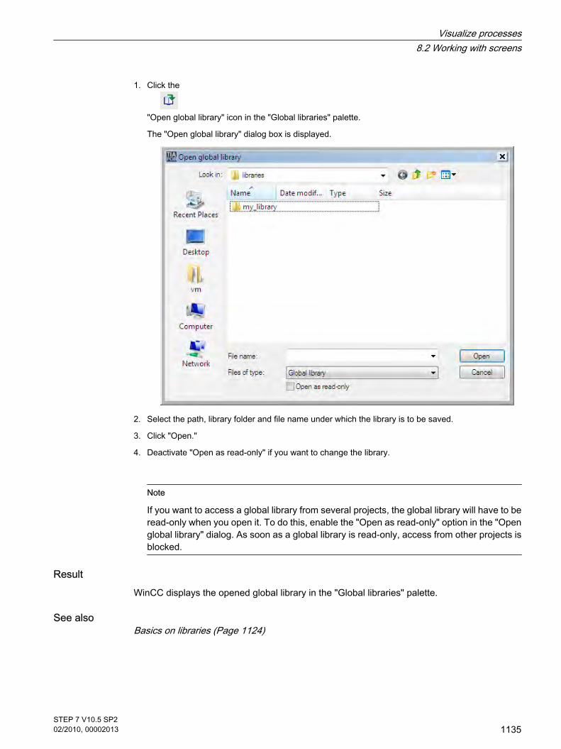
1. Click the
"Open global library" icon in the "Global libraries" palette.
The "Open global library" dialog box is displayed.
2. Select the path, library folder and file name under which the library is to be saved.
3. Click "Open."
4. Deactivate "Open as read-only" if you want to change the library.
Note
If you want to access a global library from several projects, the global library will have to beread-only when you open it. To do this, enable the "Open as read-only" option in the "Openglobal library" dialog. As soon as a global library is read-only, access from other projects isblocked.
ResultWinCC displays the opened global library in the "Global libraries" palette.
See alsoBasics on libraries (Page 1124)
Visualize processes8.2 Working with screens
STEP 7 V10.5 SP202/2010, 00002013
1135

8.2.8 Display and operating objects
8.2.8.1 Bar
ApplicationThe process values are displayed graphically using the "Bar" object. Add a scale to label thebar display.
LayoutIn the Inspector window, you customize the settings for the position, shape, style, color, andfont types of the object. You can adapt the following properties in particular:
• Color transition: Specifies the change in color display when limit values are exceeded.
• Displaying the limit lines / limit marking: Shows the configured limit as a line or marker.
• Define bar segments: Defines the gradations on the bar scale.
• Define scale gradation: Defines the subdivisions, scale markings and intervals of a bar scale.
Color transitionYou define how the color change is represented under "Appearance" in the "Properties" groupin the Property window.
Color transition Description
"Segmented" The color changes segment by segment.
"Entire bar" The color of the entire bar changes.
Displaying limit lines and limit markingYou display the configured limit in the bar as a line or marking in Runtime using the "Lines" and"Markings" property. Proceed as follows:
1. Click "Appearance" in the Inspector window.
8.2.8 Display and operating objects8.2.8.1 Bar
Visualize processes8.2 Working with screens
1136STEP 7 V10.5 SP202/2010, 00002013

2. Activate the "Lines" and "Markings" options in the "Limits" area.
Define bar segmentsUse the "Number of subdivisions" property to define the number of segments into which thebar is divided by the main gradations on the scale.
Use the "Interval" property to divide the distance between the main gradations. The valueappears as the difference in value between two adjacent main gradations. Proceed as follows:
1. Click "Scales" in the Inspector window.
2. Activate "Show scale."
3. Select the corresponding value under "Number of subdivision" in the "Settings" area.
4. Select the corresponding value under "Marks label" in the "Settings" area.
5. Select the corresponding value under "Interval" in the "Large interval" area.
See alsoScreen basics (Page 1025)User view (Page 1137)Date/time field (Page 1138)I/O field (Page 1139)Ellipse (Page 1141)Graphic view (Page 1142)Graphic I/O field (Page 1144)Circle (Page 1145)Trend view (Page 1146)Line (Page 1148)Alarm view (Page 1148)Alarm window (Page 1151)Alarm indicator (Page 1153)Rectangle (Page 1154)Recipe view (Page 1155)Switch (Page 1156)Button (Page 1157)Symbolic I/O field (Page 1158)Text field (Page 1160)Availability of screens for specific HMI devices (Page 1027)
8.2.8.2 User view
Application The "User view" object is used to set up and administer users and authorizations.
8.2.8.2 User view
Visualize processes8.2 Working with screens
STEP 7 V10.5 SP202/2010, 00002013
1137

Note
Do not use the simple user view in a group.
Layout In the Inspector window, you customize the position, shape, style, color and font types of theobject. You can adapt the following properties in particular:
• Number of lines: Specifies the maximum number of visible entries.
Number of lines The number of lines in the user view displayed in Runtime is specified in the Inspector window.The setting for the number of lines is only effective if the property "Auto-sizing" is active.
1. Click the "General" group in the Inspector window.
2. Enter an integer value in the "Number of lines" field under "Settings".
3. In the Inspector window, activate "Properties > Layout > Size."
4. In the "Size" area, activate "Auto-sizing."
See alsoBar (Page 1136)Availability of screens for specific HMI devices (Page 1027)
8.2.8.3 Date/time field
Application The "Date/time field" object shows the system time and the system date. The appearance ofthe "Date/time field" depends on the language set on the HMI device.
8.2.8.3 Date/time field
Visualize processes8.2 Working with screens
1138STEP 7 V10.5 SP202/2010, 00002013

Layout In the Inspector window, you customize the position, shape, style, color and font types of theobject. You can adapt the following properties in particular:
• Display system time: Specifies that the system time is displayed.
• Using tags: Specifies that the time of the connected tag is displayed.
• Long date/time format: This setting defines the format displayed for the data and time.
Display system time The time displayed in the "Date/time field" on the HMI device is specified in the Inspectorwindow.
1. Click the "General" group in the Inspector window.
2. Activate the "System time" option in the "Format" area.
Using tags The time of the interconnected tag is displayed in the date/time field.
1. Click the "General" group in the Inspector window.
2. In the "Format" area, select a tag with the "DateTime" data type, e.g. an internal tag. Information aboutdata types which are available for connection to other PLCs can be found in the documentation aboutthe respective communication drivers.
Long date/time format The layout of the date and time is specified in the "Format" area under "General" in the Inspectorwindow.
Option Description
"Enabled" Date and time are displayed in full, e.g. "Sunday, December 31, 2000 10:59:59AM"
"Disabled" Date and time are displayed in short form, e.g. "12/31/2000 10:59:59 AM"
See alsoBar (Page 1136)Screen basics (Page 1025)Availability of screens for specific HMI devices (Page 1027)
8.2.8.4 I/O field
Application The "I/O field" object is used to enter and display process values.
8.2.8.4 I/O field
Visualize processes8.2 Working with screens
STEP 7 V10.5 SP202/2010, 00002013
1139

Layout In the Inspector window, you customize the position, shape, style, color and font types of theobject. You can adapt the following properties in particular:
• Mode: Specifies the response of the object in Runtime.
• Display format: Specifies the display format in the I/O field for input and output of values.
• Hidden input: Specifies whether the input value is displayed normally or encrypted during input.
NoteReports
Only the "Output" mode is available in reports.
The "Hidden input" option is not available in reports.
Mode The response of the I/O field is specified in the "I/O field type" area in the "General" group ofthe Inspector window.
Mode Description
"Input" Values can only be input into the I/O field in runtime.
"Input/output" Values can be input and output in the I/O field in runtime.
"Output" The I/O field is used for the output of values only.
Layout The display format for the input and output of values is specified in the "Format" area under"General" in the Inspector window.
Layout
"Binary" Input and output of values in binary form
"Decimal" Input and output of values in decimal form
"Hexadecimal" Input and output of values in hexadecimal form
"Date" Input and output of date information. The format depends on the language settingon the HMI device.
"Date/time" Input and output of date and time information. The format depends on the languagesetting on the HMI device.
Visualize processes8.2 Working with screens
1140STEP 7 V10.5 SP202/2010, 00002013

Layout
"Time" Input and output of times. The format depends on the language setting on the HMIdevice.
"Character string" Input and output of character strings.
"Time" Input and output of times.
Hidden input In Runtime the input can be displayed normally or encrypted, for example for hidden input ofa password. A "*" is displayed for every character during hidden input. The data format of thevalue entered cannot be recognized.
1. Click "Characteristics" in the Inspector window.
2. Activate the option "Hidden input" in the "Field" area.
Avoiding overlaps at output fields of OP 73, OP 73micro, OP 77A, TP 177A, TP 177microIf several I/O fields are configured as output fields with a transparent background in a screen,these I/O fields may overlap. The transparent part of the one field covers the digits of the otherfield. This may cause display problems in Runtime. In order to avoid such overlaps, set themargins of the I/O fields to zero in the object properties under "Properties > Layout". Activatethe check box "Fit object to contents."
See alsoBar (Page 1136)Screen basics (Page 1025)
8.2.8.5 Ellipse
Application The "Ellipse" is an enclosed object that can be filled with a color or pattern.
Layout In the Inspector window you can customize the settings for the object position, geometry, style,frame and color. You can adapt the following properties in particular:
• Radius X: Specifies the horizontal radius of the elliptical object.
• Radius Y: Specifies the vertical radius of the elliptical object.
8.2.8.5 Ellipse
Visualize processes8.2 Working with screens
STEP 7 V10.5 SP202/2010, 00002013
1141

Radius X The horizontal radius of the "Ellipse" object is specified in the Inspector window. The value isentered in pixels.
1. Click "Layout" under "Properties."
2. Enter a value between 0 and 2500 under "Horizontal."
Radius Y The vertical radius of the "Ellipse" object is specified in the Inspector window. The value isentered in pixels.
1. Click "Layout" under "Properties."
2. Enter a value between 0 and 2500 at "Vertical."
See alsoBar (Page 1136)
8.2.8.6 Graphic view
Application The "Graphic view" object is used to display graphics.
Layout In the Inspector window, you customize the position, shape, style, color and font types of theobject. You can adapt the following properties in particular:
• Graphic: Specifies the graphic file that is displayed in the object.
• Stretch graphic: Specifies the automatic size stretching for objects with graphics.
• Transparent color: Specify whether or not the transparent color is used for the graphic.
Inserting graphics The following graphic format is used in the "Graphic view" object: *.bmp, *.tif, *.png, *.ico, *.emf,*.wmf, *.gif, *.jpg or *.jpeg. You may also use graphics as OLE objects in the graphic view.
8.2.8.6 Graphic view
Visualize processes8.2 Working with screens
1142STEP 7 V10.5 SP202/2010, 00002013

1. Click "General" in the Inspector window.
2. Select the graphic you want to add in the drop-down list under "Graphic".
The graphic preview is shown in the right pane.
3. Click "Assign" to insert the graphic in the graphic view. Click "Delete" to delete a graphic from a graphicdisplay.
Stretch graphic Whether a graphic displayed in a graphic view is stretched to the size of the graphic view inruntime is specified in the Inspector window.
1. Click "Layout" in the Inspector window.
2. Select one of the following options from the "Fit to size" area:
― Fit object size to content
― Fit content to object size
Transparent color This property defines whether the transparent color is used for the graphic to be displayed. Thetransparent color can only be used when the object is assigned a 3D frame or no frame.
1. Click "Layout" in the Inspector window.
2. Activate "Transparent color" in the "Color" area.
Note
The use of bitmaps in WinCC screens requires the "Transparent color" setting for their high-performance visualization on panel HMI devices. Visualization performance is enhanced bydisabling the "Transparent color" setting in the properties of the relevant display object. Thisrestriction applies in particular when bitmaps are used as background image.
NoteBasic Panels
The "Transparent color" property is not available for Basic Panels.
See alsoScreen basics (Page 1025)Availability of screens for specific HMI devices (Page 1027)Bar (Page 1136)
Visualize processes8.2 Working with screens
STEP 7 V10.5 SP202/2010, 00002013
1143

8.2.8.7 Graphic I/O field
Application The "Graphic I/O field" object can be used to configure a list for display and selection of graphicfiles.
Layout In the Inspector window, you customize the position, shape, style, color and font types of theobject. You can adapt the following properties in particular:
• Mode: Specifies the response of the object in Runtime.
• Scroll bar type: Specifies the graphic layout of the scroll bar.
NoteBasic Panels
The scroll bar is not available for Basic Panels.
NoteReports
Only the "Output" mode is available in reports.
The scroll bar is not available in reports.
Mode The response of the "Graphic I/O field" object is specified under "General > Type > Mode" inthe Inspector window.
Mode Description
"Input" The "Graphic I/O field" object is only used to select graphics.
"Input/output" The "Graphic I/O field" object is used to select and display graphics.
"Output" The "Graphic I/O field" object is used to display graphics only.
"Two states" The "Graphic I/O field" object is only used to display graphics and can have amaximum of two states.
8.2.8.7 Graphic I/O field
Visualize processes8.2 Working with screens
1144STEP 7 V10.5 SP202/2010, 00002013

Scroll bar typeThe response for the graphic representation in the display window is specified under"Appearance > Scroll Bar > Type" in the Inspector window.
Type Description
"Permanent" The scroll bar is always visible.
"No scrollbar" The scroll bar is not visible.
"Visible after clicking" The scroll bar is made visible by a mouse click.
See alsoBar (Page 1136)Availability of screens for specific HMI devices (Page 1027)
8.2.8.8 Circle
ApplicationThe "Circle" object is a closed object which can be filled with a color or pattern.
LayoutIn the Inspector window you can customize the settings for the object position, geometry, style,frame and color. You can adapt the following properties in particular:
• Radius: Specifies the size of the circle.
RadiusThe radius of the "Circle" object is specified in the Inspector window. The value is entered inpixels.
1. Click "Layout."
2. Enter a value between 0 and 2500 in the "Radius" area.
See alsoBar (Page 1136)Availability of screens for specific HMI devices (Page 1027)
8.2.8.8 Circle
Visualize processes8.2 Working with screens
STEP 7 V10.5 SP202/2010, 00002013
1145

8.2.8.9 Trend view
Application The trend view is meant for the graphical representation of tag values from the current processor from a log in form of trends.
Layout In the Inspector window, you customize the position, shape, style, color, and font types of theobject. You can adapt the following properties in particular:
• Display value table, ruler and grid: Specifies whether a value table, a ruler or a grid is displayed inaddition to the coordinate system to improve legibility.
• Toolbars: Defines the display of the control elements.
Display value table, ruler and gridFor improved legibility a value table, a ruler and a grid can be displayed in Runtime.
1. Activate the "Show ruler" option under "Layout."
2. Activate the "Show table" option under "Table."
3. Activate the "Show grid" option under "Table."
Toolbars The layout of the control elements is specified in the Inspector window under "Toolbar." Theydisplay the control elements either not at all, as a toolbar or as buttons.
NoteBasic Panels
The control elements are not available for Basic Panels.
8.2.8.9 Trend view
Visualize processes8.2 Working with screens
1146STEP 7 V10.5 SP202/2010, 00002013

Button Toolbar Brief description Description
"Go to start" Scrolls back to the beginning of the trendrecording. The start values with which thetrend recording started are displayed.
"Zoom in" Zooms into the displayed time section.
"Zoom out" Zooms out of the displayed time section.
"Ruler backward" Moves the ruler back.
"Ruler forward" Moves the ruler forward.
"Backward" Scrolls back one display width.
"Forward" Scrolls forward one display width.
"Ruler" Shows or hides the ruler. The ruler displaysthe X-value associated with a Y-value.
"Start/stop" Stops trend recording or continues trendrecording.
Configuration behaviorDisplaying column titles
The layout of the table in the trend view depends on the view settings in the Control Panel.Depending on the setting, the table headers may be truncated. This setting is found under"Display > Layout" in the control panel. To display column titles correctly, set the display in"Windows and buttons" to "Windows Classic" style.
This behavior only occurs during configuration. The column titles are displayed correctly inRuntime.Consistency test
If warnings or errors are displayed in the output window during a consistency check inconnection with curve displays, clicking "Go to Error/Tag" on the shortcut menu will not alwaystake you to the exact error position. In some cases only the curve display is shown as causeof error.
Adding, configuring, and removing trendsThe trends of the trend view are managed in the Inspector window of the trend view under"Properties > Trend." You can copy trends between different trend views.
See alsoBar (Page 1136)Availability of screens for specific HMI devices (Page 1027)
Visualize processes8.2 Working with screens
STEP 7 V10.5 SP202/2010, 00002013
1147
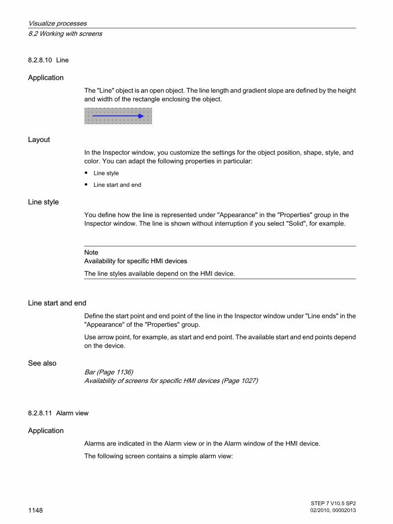
8.2.8.10 Line
Application The "Line" object is an open object. The line length and gradient slope are defined by the heightand width of the rectangle enclosing the object.
Layout In the Inspector window, you customize the settings for the object position, shape, style, andcolor. You can adapt the following properties in particular:
• Line style
• Line start and end
Line style You define how the line is represented under "Appearance" in the "Properties" group in theInspector window. The line is shown without interruption if you select "Solid", for example.
NoteAvailability for specific HMI devices
The line styles available depend on the HMI device.
Line start and end Define the start point and end point of the line in the Inspector window under "Line ends" in the"Appearance" of the "Properties" group.
Use arrow point, for example, as start and end point. The available start and end points dependon the device.
See alsoBar (Page 1136)Availability of screens for specific HMI devices (Page 1027)
8.2.8.11 Alarm view
Application Alarms are indicated in the Alarm view or in the Alarm window of the HMI device.
The following screen contains a simple alarm view:
8.2.8.10 Line8.2.8.11 Alarm view
Visualize processes8.2 Working with screens
1148STEP 7 V10.5 SP202/2010, 00002013

Layout In the Inspector window, you customize the position, shape, style, color and font types of theobject.
Note
The fonts available for selection depend on the "Language and fonts" you have configured inthe Runtime settings.
You can adapt the following properties in particular:
• Control elements: Defines the operator controls of the alarm display.
• Alarm classes: This setting defines which alarm classes are displayed in the alarm view.
• Columns: Specifies the displayed columns in runtime.
Note
If you have different alarm classes output, these will be initially sorted into alarm classes inruntime, and then by when the alarm occurred.
Control elements The control elements that can be used to control the alarm display in runtime are specified inthe Inspector window under "Display > Settings". The following table shows the controlelements in the alarm view, and what they do:
Button Function
"Info text" Displays info text for an alarm.
Visualize processes8.2 Working with screens
STEP 7 V10.5 SP202/2010, 00002013
1149

Button Function
"Acknowledge" Acknowledges an alarm.
"Loop-In-Alarm" Switches to the screen containing information about the error thathas occurred.
Select alarm classes1. Click "Properties" in the Inspector window.
2. Under "Alarm classes" activate the alarm classes to be displayed in the alarm view in runtime .
Define columns Define the columns to be displayed in the alarm view in runtime in the Inspector window.
1. In the Inspector window, click "Properties > Columns".
2. Activate the columns that are to be displayed in runtime under "Columns".
Configuration behaviorDisplaying column titles
The layout of the alarm view is dependent on the view settings in the control panel. Dependingon the setting, the column titles may be truncated. This setting is found under "Display > Layouttab" in the control panel. To display column titles correctly, set the display in "Windows andbuttons" to "Windows Classic" style.
This behavior only occurs during configuration. The column titles are displayed correctly inruntime.
Note
In the engineering system you can dynamically control the visibility of an object, for example,in the "Animations" group of the Inspector window. In runtime, the "Simple alarm view" doesnot support animations. If you have configured an animation and, for example, wish to performa consistency check of the project, then an error alarm is issued in the Output window.
See alsoBar (Page 1136)Availability of screens for specific HMI devices (Page 1027)
Visualize processes8.2 Working with screens
1150STEP 7 V10.5 SP202/2010, 00002013

8.2.8.12 Alarm window
Application Alarms are indicated in the Alarm view or in the Alarm window of the HMI device. The layoutand operation of the Alarm window are similar to that of the Alarm view. The Alarm window hasthe following characteristics that are the same as in the Alarm view:
• Simple alarm window
• Advanced alarm window
• Alarm line
NoteBasic Panels
Only the simple alarm window is available for Basic Panels.
The Alarm window is configured in the "Global screen" editor.
The Alarm window is independent of the process screen. Depending on the configuration, theAlarm window opens automatically as soon as a new, unacknowledged alarm has beenreceived. If applicable, the Alarm window is configured so that it only closes after all alarmshave been acknowledged. The following figure shows an advanced Alarm window:
Note
In the engineering system you dynamize, for example, the visibility of an object in the"Animations" group in the Inspector window. In runtime, the "Simple alarm window" object doesnot support animations. If you have configured an animation and, for example, wish to performa consistency check of the project, then an error alarm is issued in the Output window.
Note
The "Alarm window" object cannot be grouped.
8.2.8.12 Alarm window
Visualize processes8.2 Working with screens
STEP 7 V10.5 SP202/2010, 00002013
1151

Layout In the Inspector window, you customize the position, shape, style, color and font types of theobject. You configure the Alarm window in the same way as the Alarm view. In addition youadapt the following properties:
• Fixed alarm windows: Specifies that the Alarm window retains the focus after a screen change.
• Window: You define the operator input and response of the Alarm window in runtime.
Note
If you have different alarm classes output, these will be initially sorted into alarm classes inruntime, and then by when the alarm occurred.
Control elements The control elements that can be used to control the alarm display in runtime are specified inthe Inspector window under "Display > Settings". The following table shows the controlelements in the Alarm window, and what they do:
Button Function
"Info text" Displays info text for an alarm.
"Acknowledge" Acknowledges an alarm.
"Loop-In-Alarm" Switches to the screen containing information about the error thathas occurred.
Access protection in runtimeConfigure access protection in the "Properties > Security" group in the properties of the alarmview. If a logged-on user has the required authorization, he can acknowledge and edit alarmsusing the operator controls in the alarm view. If the logged-in user does not have the requiredauthorization, or if no user is logged in, clicking the "Acknowledge" or "Edit" buttons or double-clicking an alarm line opens the login dialog box.
NoteBasic Panels
Access control is not available for Basic Panels.
Activating the focus of the Alarm windowSelect the following option so that the Alarm window does not lose the focus after a screenchange:
Visualize processes8.2 Working with screens
1152STEP 7 V10.5 SP202/2010, 00002013

1. Click "Mode" in the "Properties" group in the Inspector window.
2. Enable "Label".
WindowDefine the response of the Alarm window in the "Mode" category of the "Window" area in theInspector window. The following table shows the possible properties:
Option Function
Automatic display The Alarm window is automatically displayed when a system alarmoccurs, for example.
Closable The window closes again after a set time has elapsed. You define thedisplay duration in the alarm settings.
Modal The Alarm window is linked to a confirmation, such as: Alarm must beacknowledged. If the modal alarm window has the focus, the buttons inthe screen behind it cannot be used. The functions configured for afunction key are carried out.
Sizeable You can change the size of the Alarm window in runtime.
See alsoBar (Page 1136)Availability of screens for specific HMI devices (Page 1027)
8.2.8.13 Alarm indicator
Application The alarm indicator is a graphic symbol that shows current errors or errors that need to beacknowledged, depending on the configuration. The alarm indicator is configured in the "Globalscreen" editor. The following picture contains an alarm indicator:
LayoutIn the Inspector window, you customize the position, shape, style, color and font types of theobject. You can adapt the following properties in particular:
• Alarm classes: Establishes the alarm classes where the alarm indicator is displayed.
• Operator control in Runtime: Defines the operator actions in Runtime that cause the Alarm window toopen.
8.2.8.13 Alarm indicator
Visualize processes8.2 Working with screens
STEP 7 V10.5 SP202/2010, 00002013
1153

Alarm classesYou define which alarm classes are shown with an alarm indicator under "General > Alarmclasses" in the Inspector window. Alarm classes include warnings, or errors.
Define operator control in RuntimeYou define for which events the alarm window is visible, or hidden under "Events" in theInspector window.
1. Select the alarm indicator in the screen.
2. Click on "Click" or "Click when flashing" in the "Events" group in the Inspector window.
3. The "function list" opens. Click the first line of the function list. The list of system functions, and scriptsavailable in the project opens.
4. Select the "ActivateScreen" system function under "Alarms." Under "object name" select the name ofthe Alarm window from the selection list. Under "Layout", define whether the Alarm window should bevisible, hidden, or should toggle between the two states.
See alsoBar (Page 1136)Availability of screens for specific HMI devices (Page 1027)
8.2.8.14 Rectangle
Application The "Rectangle" is a closed object which you can fill with a color.
Layout In the Inspector window, you customize the position, shape, style, color and font types of theobject. You can adapt the following properties in particular:
• Corner X radius and corner Y radius: Specifies the horizontal and vertical distance between the cornerof the rectangle and the start point of a rounded corner.
Corner X radius and corner Y radius The corners of the "Rectangle" object can be rounded to suit your requirements. If the "CornerX radius" and "Corner Y radius" properties are set to the value of 100%, the rectangle isdisplayed as ellipse. As soon as one of the properties has the value 0%, a normal rectanglewithout a rounded corner is shown.
8.2.8.14 Rectangle
Visualize processes8.2 Working with screens
1154STEP 7 V10.5 SP202/2010, 00002013

1. Click "Layout" in the "Properties" group.
2. Enter a value for "Corner X radius" in the "Corner radius" area. The input value is the percentageproportion of half the width of the rectangle.
3. Enter a value for "Corner Y radius" in the "Corner radius" area. The input value is the percentageproportion of half the height of the rectangle.
See alsoBar (Page 1136)Availability of screens for specific HMI devices (Page 1027)
8.2.8.15 Recipe view
Application The "Recipe view" object is used to display and modify recipes.
Layout In the Inspector window, you customize the position, shape, style, color and font types of theobject. You can adapt the following properties in particular:
• Control elements: Specifies the menu commands of the recipe view.
Control elements The menu commands with which the recipe view is operated in runtime are configured under"Properties > Buttons" in the Inspector window.
Menu command Description
"Info text" Calls up the configured info text for the selected recipe.
"New record" Creates a new recipe record in the recipe.
"Delete record" Deletes the selected record.
"Saving" Saves the modified record with its current name.
"Save as" Saves the modified record with a new name.
"Write to PLC" Sends the current value to the PLC.
"Read from PLC" Reads the current value from the PLC.
8.2.8.15 Recipe view
Visualize processes8.2 Working with screens
STEP 7 V10.5 SP202/2010, 00002013
1155

Configuration behavior
Note
In the engineering system you can, for example, dynamically control the visibility of an objectin the "Animations" group of the Properties window. In runtime, the "Simple recipe view" doesnot support animations. If you have configured an animation and, for example, want to checkthe consistency of the project, an error alarm is displayed in the Output window.
See alsoBar (Page 1136)Availability of screens for specific HMI devices (Page 1027)
8.2.8.16 Switch
Application The "Switch" object is used to configure a switch that is used to switch between two predefinedstates in Runtime. The current state of the "Switch" object can be visualized with either a labelor a graphic.
The following figure shows a "Switch" type switch.
Layout In the Inspector window, you customize the position, shape, style, color and font types of theobject. In particular, you can customize the following property:
• Type: Defines the graphic representation of the object.
Type The switch is specified in the Inspector window in the "Settings" area in the "General" group.
Type Description
"Switch" The two states of the "Switch" are displayed in the form of a switch. Theposition of the switch indicates the current state. The state is changed inruntime by sliding the switch.You specify the direction of movement of the switch in "Switch orientation" withthis type.
8.2.8.16 Switch
Visualize processes8.2 Working with screens
1156STEP 7 V10.5 SP202/2010, 00002013

Type Description
"Switch with text" The switch is shown as a button. The current state is visualized with a label.In runtime click the button to actuate the switch.
"Switch with graphic" The switch is shown as a button. The current state is visualized with a graphic.In runtime click the button to actuate the switch.
NoteBasic Panels
The "Switch" type is not available for Basic Panels.
See alsoBar (Page 1136)Availability of screens for specific HMI devices (Page 1027)
8.2.8.17 Button
Application The "Button" object allows you to configure an object that the operator can use in runtime toexecute any configurable function.
Layout In the Inspector window, you customize the position, shape, style, color and font types of theobject. You can adapt the following properties in particular:
• Type: Defines the graphic representation of the object.
• Text / Graphic: Defines whether the graphic view is static or dynamic.
• Define hotkey: Defines a key, or shortcut that the operator can use to actuate the button.
Note
You can only define a hotkey for HMI devices with keys.
Type The button display is defined in the "Type" area under "General" in the Inspector window.
8.2.8.17 Button
Visualize processes8.2 Working with screens
STEP 7 V10.5 SP202/2010, 00002013
1157

Type Description
"Invisible" The button is not visible in runtime.
"Text" The current state of the button is visualized with a label.
"Graphic" The current state of the button is visualized with a graphic.
Text / Graphic The "Type" property settings are used to define whether the display is static or dynamic. Thedisplay is defined in the "Text" or "Graphic" area of the "General" group in the Inspector window.
Type Option Description
"Text" "Text" "Text OFF" is used to specify a text that appears in the button when thestate is "OFF".If you enable "Text ON", you can enter a text for the "ON" state.
"Text list" The text in the button depends on the state. The entry from the text listcorresponding to the state is displayed.
"Graphic" "Graphic" "Graphic OFF" is used to specify a graphic that is displayed in the buttonwhen the state is "OFF".If you enable "Graphic ON", you can enter a graphic for the "ON" state.
"Graphiclist"
The graphic in the button depends on the state. The entry from the graphiclist corresponding to the state is displayed.
Define hotkey In the Inspector window, a key or key combination is defined that the operator can use to controlthe button in runtime.
1. Click the "General" group in the Properties window.
2. Select a key or key combination from the selection list in the "Hotkey" area.
See alsoBar (Page 1136)Availability of screens for specific HMI devices (Page 1027)
8.2.8.18 Symbolic I/O field
Application The "Symbolic I/O field" object can be used to configure a selection list for input and output oftexts in Runtime.
8.2.8.18 Symbolic I/O field
Visualize processes8.2 Working with screens
1158STEP 7 V10.5 SP202/2010, 00002013

Layout In the Inspector window, you customize the position, shape, style, color and font types of theobject. You can adapt the following properties in particular:
• Mode: Specifies the response of the object in Runtime.
• Text list: Specifies the text list that is linked to the object.
• Button for selection list: Specifies that the object has a button to open the selection list.
NoteReports
Only the "Output" mode is available in reports.
The "Button for selection list" option is not available in reports.
Mode The response of the symbolic I/O field is specified in the Inspector window in the "General"group in the "Type" area.
Mode Description
"Output" The symbolic I/O field is used to output values.
"Input" The symbolic I/O field is used to input values.
"Input/output" The symbolic I/O field is used for the input and output of values.
"Two states" The symbolic I/O field is used only to output values and has a maximum of twostates. The field switches between two predefined texts. This is used, forexample, to visualize the two states of a valve: closed or open.
Note
The behavior possible for the symbolic I/O field depends on the Runtime.
Text list In the Inspector window, you specify which text list is linked to the symbolic I/O field.
1. Activate "General" in the Inspector window.
2. Open the selection list in the "View" area at "Text list". Select the text list.
Button for selection listThe "Button for selection list" property is used to display a button for opening the selection list.
1. Activate "Layout" in the Inspector window.
2. Activate the "Button for selection list" option in the "Settings" area.
Visualize processes8.2 Working with screens
STEP 7 V10.5 SP202/2010, 00002013
1159

NoteBasic Panels
The "Button for selection list" option is not available for Basic Panels.
See alsoBar (Page 1136)Availability of screens for specific HMI devices (Page 1027)
8.2.8.19 Text field
ApplicationThe "Text field" is a closed object which you can fill with a color.
LayoutIn the Inspector window, you customize the position, shape, style, color and font types of theobject. You can adapt the following properties in particular:
• Text: Specifies the text for the text field.
• Size of text field: Defines whether the size of the object is adapted to the space required by the largestlist entry.
TextSpecify the text for the text field in the Inspector window.
1. Click the "General" group in the Inspector window.
2. Input a text of any length in the "Text" area. For texts over several lines you can set a line break bypressing <Enter>, with the key combination <Shift + Enter> or the key combination <Ctrl + Enter>.
Size of text fieldIn the Inspector window, you can define whether the size of the object is adapted to the spacerequired by the largest list entry.
1. Click "Layout" in the "Properties" group in the Inspector window.
2. In the "Size" area, activate the "Auto-sizing" option.
3. Otherwise you can set the size manually. In the "Size" area, deactivate the "Auto-sizing" option. Pressthe mouse button and drag the text field to the required size.
See alsoBar (Page 1136)Availability of screens for specific HMI devices (Page 1027)
8.2.8.19 Text field
Visualize processes8.2 Working with screens
1160STEP 7 V10.5 SP202/2010, 00002013

8.2.9 Configuring screen navigation for Basic Panels
8.2.9.1 Basics for screen navigation
Types of navigation for the screen changeFor a production process consisting of multiple subprocesses, you will configure multiplescreens. You have the following options to enable the operator to switch from one screen tothe next in Runtime:
• Assign buttons to screen changes
• Configuring screen changes at local function keys
ProcedureBefore you create a screen change, define the plant structure and derive from it the screenchanges that you want to configure. If you have not already defined a start screen in the projectwizard, create the start screen in the Runtime settings.
See alsoScreen basics (Page 1025)Configuring a screen change (Page 1161)
8.2.9.2 Configuring a screen change
IntroductionTo change between the screens on the HMI device during operation, you need to configure abutton, function key, or both, on the screen using drag-and-drop.
You can configure a screen change as follows:
• To create a button in the screen that calls another screen, drag this second screen from the projecttree into the open screen.
• To configure a function key in the screen that calls another screen, drag this second screen from theproject tree into the function key.
Note
If you have set the "Visibility" of animations to "Hidden" in the Inspector window of a screen,this screen cannot be called up in Runtime.
Requirements
• An HMI device with at least two screens must be available.
• The screen from which the screen change is to be called must be open.
8.2.9 Configuring screen navigation for Basic Panels8.2.9.1 Basics for screen navigation8.2.9.2 Configuring a screen change
Visualize processes8.2 Working with screens
STEP 7 V10.5 SP202/2010, 00002013
1161

Assign screen change to buttonProceed as follows to assign a button to a screen change:
1. From the project tree drag the screen that is to be opened with the button into the opened screen.
The system adds a button, and labels it with the screen name.
2. Click "Click" in the "Events" category in the Inspector window.
The "ActivateScreen" function is displayed in the "Function list" group. This function has twoparameters:
― "Screen name"
The "Screen name" parameter contains the name of the screen that is to be called when youchange screens in Runtime.
― "Object number".
The optional "Object number" parameter is the tab order number of the object on which the focusis set after a screen change.
3. At the "Object number" attribute, define, if required, the tab order number of the object on which thefocus is to be set after a screen change. You can also specify a tag that contains the object number.
Assign screen change to function keyProceed as follows:
1. From the project tree, drag the screen that is to be opened with the function key onto the function key.
The configured function key displays a yellow triangle.
2. Click "Press" in the "Events" category of the Inspector window.
The "ActivateScreen" function is displayed in the "Function list" group. This function has twoparameters:
― "Screen name"
The "Screen name" parameter contains the name of the screen that is to be called when youchange screens in Runtime.
― "Object number".
The optional "Object number" parameter is the tab order number of the object on which the focusis set after a screen change.
3. At the "Object number" attribute, define, if required, the tab order number of the object on which thefocus is to be set after a screen change. You can also specify a tag that contains the object number.
ResultIn Runtime, the operator uses the button or function key to switch to the specified screen. Ifyou have specified an object number, the object with this object number has the focus followinga screen change.
See alsoBasics for screen navigation (Page 1161)
Visualize processes8.2 Working with screens
1162STEP 7 V10.5 SP202/2010, 00002013

8.3 Working with tags
8.3.1 Basics
8.3.1.1 Basics on tags
IntroductionData is forwarded in a project using tags. A tag has an address and a symbolic name that isused in the project. The address is used in communication with the automation system.
WinCC works with two types of tag:
• Process tags
• Internal tags
WinCC also facilitates management of tags by providing tag groups.
PrincipleIn WinCC, tags that are supplied with values by the process are known as process tags orexternal tags. With process tags, the properties of the tag are used to define the connectionthat WinCC uses to communicate with the automation system and how the data is exchanged.
Tags that are not supplied with values by the process - the internal tags - are not connected tothe automation system. In the tag's "Connection" property, this is identified by the "Internal tag"entry.
You can also compile tags into groups for greater clarity. When you create tag groups, a treeappears in the Project window. You can navigate through this tree as you would in WindowsExplorer.
8.3.1.2 Internal tags
IntroductionInternal tags do not have any connection to the PLC.
PrincipleInternal tags are stored in the memory of the HMI device. Therefore, only this HMI device hasread and write access to the internal tags. You can create internal tags to perform localcalculations, for example.
You can use the HMI data types for internal tags.
The following HMI data types are available:
8.3 Working with tags8.3.1 Basics8.3.1.1 Basics on tags8.3.1.2 Internal tags
Visualize processes8.3 Working with tags
STEP 7 V10.5 SP202/2010, 00002013
1163

HMI data type Data format
SByte Signed 8-bit value
UByte Unsigned 8-bit value
Short Signed 16-bit value
UShort Unsigned 16-bit value
Long Signed 32-bit value
ULong Unsigned 32-bit value
Float Floating-point number 32-bit IEEE 754
Double Floating-point number 64-bit IEEE 754
Bool Binary tag
WString Text tag, 16-bit character set
DateTime Date and time in the format 'DD.MM.YYYY hh:mm:ss'
8.3.1.3 External tags
IntroductionExternal tags allow communication (exchange of data) between the components of anautomation system, such as between the HMI device and the PLC.
PrincipleAn external tag is the image of a defined memory location in the PLC. You have read and writeaccess to this storage location from both the HMI device and from the PLC.
The PLC is accessed with symbolic addressing. This setup simplifies the configuration, sinceit enables you to access the PLC via the symbol table. See the "Basics of symbolic access(Page 1165) " section for additional details.
Since external tags are the image of a storage location in the PLC, the applicable data typesdepend on the PLC which is connected to the HMI device.
Data typesThe HMI data types for using external tags are available within WinCC. In addition, you canalso use other data types, which are intended specifically for the PLC to which a connectionexists. The data types may vary even though they have the same name. For example, theversion of the "Byte" data type for the connection via SIMATIC S7 protocol is "unsigned". TheHMI data type "SByte" format in WinCC is "signed". The types for the HMI data types and thedata type for the connected PLC are converted to match.
8.3.1.3 External tags
Visualize processes8.3 Working with tags
1164STEP 7 V10.5 SP202/2010, 00002013
Note
During configuration for an HMI runtime, there are also area pointers for communicationbetween the HMI device and PLC, in addition to the external tags. You can set up and enablethe area indicators in the "Connections" editor.
Updating tag values in system functionsSystem functions always fetch the value of an external tag from runtime memory. When a tagvalue is requested, the current value is read from the PLC and written to runtime memory. Next,the tag value will be updated to the set cycle time. System functions first access tag valuesread from the PLC at the previous scan cycle checkpoint.
8.3.1.4 Basics of symbolic access
IntroductionWith symbolic access, you enter a symbolic name as the destination in the PLC instead of adirect address. You define the symbolic name when you write the PLC program.
• You define symbolic names for global PLC tags in the PLC tag table.
• In the respective block, specify symbolic names for local tags in logic blocks or in global data blocks.
See Symbolic programming (Page 361) for additional information.
When you then interconnect an HMI tag to the PLC, you only select the symbolic name fromthe PLC tag table or from a data block.
When the addressing is changed in the PLC program, only the assignment of the address tothe symbolic name in the symbol table changes. The symbolic name and therefore theinterconnection to the HMI device does not change. You do not have to match the change inthe configuration of the HMI device.
RequirementYou have to meet the following requirements for symbolic access of HMI tags:
• A PLC tag must be in the PLC program or a local tag must be in a program block.
• Program blocks have to be compiled for the local tags from the PLC to be available on the HMI device.
How symbolic access worksFirst, write the controller program for PLC control in WinCC. Use the symbolic declaration whenwriting the program.
Compile the PLC program when it is finished. When compiling is complete, the symbolic namesare available to the HMI device.
If you want to subsequently change the PLC program, you need to perform a new compilationfor the changes to be made available to the HMI device.
8.3.1.4 Basics of symbolic access
Visualize processes8.3 Working with tags
STEP 7 V10.5 SP202/2010, 00002013
1165

You then create the configuration for the HMI device. Interconnect the HMI tags directly to thesymbols in the PLC tag table or in the program blocks of the PLC.
AdvantagesWith symbolic declaration in the PLC, the data are optimally organized for the employed CPU.This setup increases the performance in the PLC.
Symbolic access also increases the performance of the communication between the HMIdevice and PLC.
The configuration of the HMI device does not depend on changes at the PLC end, because thesymbolic name does not change when the address in the PLC changes.
RestrictionsThe following restrictions apply to symbolic access:
• The address multiplex is not available, you can only multiplex through the multiplex tag.
• The data type of an HMI tag and the PLC tag linked to it must basically be identical. This means onlythe full value of a tag can be read and written. You change individual bits, for example in a tag, thatserve as triggers for HMI alarms with corresponding programming in the PLC. You can find additionalinformation in the documentation on PLC programming.
Reaction to changesNot all changes to the project need to be compiled and downloaded for symbolic access. Theproject needs to be compiled and downloaded for the following changes to the PLC program.Changes to PLC tags
The PLC program needs to be compiled and downloaded when changes are made to a PLCtag.
The project does not need to be compiled and downloaded if only the address offset of a PLCtag changes, for example %MB5 to %MB10. The project also needs to be compiled anddownloaded when changes are made to the address area, data type or tag name.
Changes in program blocksThe PLC program does not need to be compiled and downloaded if you change the name ofa data block. The PLC program always needs to be compiled and downloaded if you makeadditional changes to a program block.
The project needs to be compiled and downloaded to the HMI device if you make the followingchanges:
• When a tag from a data block is already interconnected to an HMI tag and you change the tag name.
• When you have created a structure in a data block and you change a name within this structure.
• When you change the number of a data block.
• When you change the data type of a tag interconnected to the HMI device.
• When you change the name of a tag array.
• When you change the limits of an array.
Visualize processes8.3 Working with tags
1166STEP 7 V10.5 SP202/2010, 00002013

The project does not need to be compiled and downloaded to the HMI device if you change,add or delete a tag in a block that is not interconnected to the HMI device.
8.3.2 Working with tags
8.3.2.1 Creating tags
8.3.2.1 Creating external tags
IntroductionYou can access an address in the PLC via a PLC tag using an external tag. Access is performedvia the symbol table in the PLC linked to the HMI device. You cannot directly specify the addressin the PLC. Creating a PLC tag in the PLC automatically creates an entry in the symbol table.You have direct access to the symbol table via the "PLC tag" field when you create an HMI tag.There you select the PLC tag using its symbolic name.
For additional information on symbolic access see the section "Symbolic programming (Page361) ".
Requirement
• You have opened the project.
• A PLC is included in the project.
• A connection is configured between the HMI device and the PLC.
• At least one PLC tag is available in the project.
• The Inspector window is open.
ProcedureTo create an external tag, proceed as follows:
1. Open the "HMI tags" folder in the project tree and double-click "HMI tags". The " HMI tags" editoropens.
2. Double-click "Add" in the "Name" column of the editor table. A new tag is created.
3. Select the "General" category in the Inspector window and, if required, enter a unique tag name in the"Name" field. This tag name must be unique throughout the project.
4. Select the connection to the required PLC in the "Connection" box. If the connection you require isnot displayed, you must first create the connection to the PLC. Create the connection in the "Hardware& Networks" editor.
5. In the "PLC tag" field, click on the
button and select the desired PLC tag in the object list. Click the
8.3.2 Working with tags8.3.2.1 Creating tags8.3.2.1 Creating external tags
Visualize processes8.3 Working with tags
STEP 7 V10.5 SP202/2010, 00002013
1167

button to confirm the selection.
6. Select the required cycle time for updating the tag from the "Acquisition cycle" field.
7. Enter information about the use of the tag in the "Comment" field for documentation purposes.
You can optionally configure all the tag properties directly in the table of the "HMI Tags" editor.To view hidden columns, activate the column titles using the shortcut menu.
You can also create new tags directly at the point of use. by clicking the
button in the object list. You can then configure the new tag in the Properties window.
ResultAn external tag has been created and linked to a PLC tag in the PLC. In additional steps, youcan configure the tag, for example, by setting an event at a value change.
See alsoSymbolic programming (Page 361)
8.3.2.1 Creating internal tags
IntroductionYou must at least set the name and data type for internal tags. Select the "Internal tag" item,rather than a connection to a PLC.
8.3.2.1 Creating internal tags
Visualize processes8.3 Working with tags
1168STEP 7 V10.5 SP202/2010, 00002013

For documentation purposes, it is a good idea to enter a comment for every tag.
RequirementYou have opened the project.
Procedure1. Open the "HMI tags" folder in the project tree and double-click "HMI tags".
The " HMI tags" editor opens.
2. If the Inspector window is not open, select the "Inspector Window" command in the "View" menu.
3. Under "General" in the "Properties" group of the Inspector window, enter a unique tag name in the"Name" field. This tag name must be unique throughout the project.
4. Select "Internal tag" as the connection in the "Connection" field.
5. Select the required data type in the "Data Type" field.
6. In the "Length" field, you must specify the maximum number of characters to be stored in the tagaccording to the selected data type. The length is automatically defined by the data type for numericaltags.
7. As an option, you can enter a comment regarding the use of the tag. To do so, click on "Comment"in the "Properties" group and enter the text of your comment.
You can optionally configure all the tag properties directly in the table of the "HMI Tags" editor.To view hidden columns, activate the column titles using the shortcut menu.
You can also create new tags directly at the point of use. by clicking the
button in the object list. You can then configure the new tag in the Properties window.
ResultAn internal tag is created. You can now use this in your project.
You can now also configure your tag by defining the start value and limit values, for example.
8.3.2.1 Creating multiple tags
IntroductionIn the "HMI Tags" editor, you can create a large number of identical tags by automatically fillingthe rows of the table below a tag.
When you use the auto fill function, the tag names and memory locations are automaticallyincremented.
You can also use the auto fill function to fill table cells below with a single tag property and thusmodify the corresponding tags.
If you apply automatic filling to cells of the "HMI Tags" editor that are already filled, these cellswill be overwritten.
8.3.2.1 Creating multiple tags
Visualize processes8.3 Working with tags
STEP 7 V10.5 SP202/2010, 00002013
1169

Automatic filling is limited to 100 tags per action.
Requirement
• You have opened the project.
• The "HMI Tags" editor is open.
• The tag which is to serve as a template for other tags is configured.
Procedure1. If you want to create new tags, mark in the "Name" column the tag that should be used as a template
for the new tags.
If you want to copy a property of a tag to the tags below it, select the cell which contains this property.
The selected cell will be highlighted in color and a small blue square will appear in its bottom rightcorner. If you move the mouse over this square, the cursor will change to a black cross.
2. Hold down the mouse button and drag this square over the cells below that you wish to fillautomatically.
The marking will be extended to cover this area.
3. Now release the mouse button. All of the marked cells will be filled automatically.
New tags will be created in all empty cells in the marked area.
Visualize processes8.3 Working with tags
1170STEP 7 V10.5 SP202/2010, 00002013

ResultDepending on which cells were selected, the function may automatically fill individual propertiesor create new tags.
8.3.2.2 Editing tags
8.3.2.2 Editing a tag
IntroductionYou can always rename, copy or delete tags.
If you rename a tag, the new name must be unique throughout the project.
If you use the "Copy" command to copy a tag to the clipboard, the objects and references linkedto the tag will be copied as well. If a tag is linked to a PLC connection, for example, thisconnection will also be copied.
If you use the "Insert" command to add a tag to another device, the tag will be added withoutthe connected references. Only the object name of the reference will be inserted. If a referenceof the same name and valid properties exists in the target system, the existing reference willthen be connected to the copied tag.
If you use the "Extended insert" command to add a tag to another device, the tag will be addedtogether with the linked objects and references. If there are already objects and references withthe same names in the target system, the name of the inserted objects and references will beextended by one digit.
Requirement
• The tag which you wish to rename, copy or delete must exist.
• The "Tags" editor is open.
Renaming tags1. In the "Name" field, select the tags in the "HMI Tags" editor table.
2. Select "Rename" from the shortcut menu.
8.3.2.2 Editing tags8.3.2.2 Editing a tag
Visualize processes8.3 Working with tags
STEP 7 V10.5 SP202/2010, 00002013
1171

3. Type in a new name.
The tag appears under its new name.
Alternatively, rename the tag in the Object window at the point of use.
Copying tags1. Select one or more tags in the "HMI Tags" editor or in the Detail window.
2. Select "Copy" from the shortcut menu.
3. Click on the point at which you want to insert the tag. For example, click another tag group in the samedevice or on the "HMI Tags" editor in a second device.
4. Select the "Insert" or "Extended insert" command from the shortcut menu. The tag is inserted asdescribed above.
Deleting a tag1. Select one or more tags in the "HMI Tags" editor.
2. Select the "Cross-reference" command from the "Tools" menu. In the "Cross-reference" editor, checkto see where the tags are used. In this manner, you can see what impact the deletion of the tag willhave on your project.
3. Select "Delete" in the pop-up menu of the tag.
All marked tags will be deleted.
8.3.2.2 Changing the tag configuration
IntroductionYou can modify tags at any time to adapt them to changed requirements in the project.
PrincipleWinCC provides several ways to change the configuration of tags.
• "HMI Tags" editor
If you need a table to provide an overview of multiple tags, use the "HMI Tags" editor to configure thetags. In the "HMI Tags" editor, you can perform such tasks as comparing and adjusting the propertiesof multiple tags or sorting the tags by their properties.
• Object list
You can use the object list if you want to modify a tag directly at the point of use. To do this, selectthe tag in the object list and open the properties window of the tag using the shortcut menu.
If you change a tag property and this change causes a conflict with another property, it will behighlighted in color to draw your attention to this fact. This could happen, for example, if youconnect the tag to another PLC which does not support this data type.
8.3.2.2 Changing the tag configuration
Visualize processes8.3 Working with tags
1172STEP 7 V10.5 SP202/2010, 00002013

8.3.2.2 Configuring multiple tags simultaneously
IntroductionIn WinCC, you can assign the same properties to multiple tags in a single operation. Thisfacilitates efficient programming.
Requirement
• You created the tags you want to configure.
• The Inspector window is open.
Procedure1. In the "HMI Tags" editor, select all the tags that you want to configure at the same time.
If the selected property is identical for all the tags, the setting for this property will appear in theInspector window. The associated field will remain blank otherwise.
2. You can define the common properties in the Inspector window or directly in the "HMI Tags" editor.
ResultAll marked tags will be reconfigured.
To edit tag properties which differ from one tag to the other, simply clear the multiple selection.
8.3.2.2 Using multiple tags simultaneously in a screen
IntroductionIn WinCC, you can create multiple I/O fields that are linked with tags in one screen in a singleoperation. For process tags, you thereby create a network and a connection for the tag. Thisfacilitates efficient programming.
Requirement
• Several tags are set up.
• A screen is open.
Procedure1. In the project tree, select the required tag group under "Tags & Connections".
8.3.2.2 Configuring multiple tags simultaneously8.3.2.2 Using multiple tags simultaneously in a screen
Visualize processes8.3 Working with tags
STEP 7 V10.5 SP202/2010, 00002013
1173

2. Select the detail view at the bottom of the project tree. The detail view shows the tags that exist in theselected tag group.
3. In the detail view, hold down the <Ctrl> or <Shift> key and select the required tags.
4. Drag the tags to the screen. For each tag, this creates an I/O field that is connected to the tag.
Note
When you drag a process tag into the detail window, a network and a connection is created inthe "Hardware & Networks" editor.
Visualize processes8.3 Working with tags
1174STEP 7 V10.5 SP202/2010, 00002013

8.3.2.3 Configuring tags
8.3.2.3 Tag limits
IntroductionYou can restrict the value range with limits for numerical tags.
PrincipleYou can specify a value range defined by a high and low limit for numerical tags.
You can have an analog alarm output when the process value violates the limit of a tag.
If the process value exceeds the high or low limit of the value range, you can have an analogalarm output or trigger a function list. If the operator enters a value for the tag that is outsidethe configured value range, the input is rejected. The value is not accepted.
Note
You enter the text of the analog alarms for limit violations in the "Analog alarms" editor.
Application exampleUse the limit to warn the operator in good time when the value of a tag enters a critical range,for example.
8.3.2.3 Defining limits for a tag
IntroductionFor numerical tags, you can specify a value range by defining a low and high limit.
You can configure the system to send an analog alarm whenever one of these limits is violated.
Additionally, you configure the system to process a function list whenever a tag value dropsbelow or exceeds its configured value range.
Requirement
• You created the tag for which you want to set limits.
• The Inspector window with the properties for this tag is open.
ProcedureTo define limits for a tag, proceed as follows:
8.3.2.3 Configuring tags8.3.2.3 Tag limits8.3.2.3 Defining limits for a tag
Visualize processes8.3 Working with tags
STEP 7 V10.5 SP202/2010, 00002013
1175

1. Click "Limits" in the "Properties" group in the Inspector window. If you want to define one of the limitsas a constant value, select "Constant" using the
button. Enter a number in the relevant field.
If you want to define one of the limits as a tag value, select "HMI tag" using the
button. Enter a value in the relevant field. Use the object list to define the tag for the limit.
2. If you want to output an analog alarm when the value violates the limit, enable the "Create analogalarm" option beside the limit.
Enter the text of the analog alarm using the "Analog alarms" editor.
3. To set additional limits for the tag, repeat steps 2 and 3 with the appropriate settings.
Alternative procedureAlternatively, you can configure the high and low limits and the display of an associated analogalarm directly in the "HMI Tags" editor table. To view hidden columns, activate the column titlesusing the shortcut menu.
ResultYou have set a value range defined by a high and low limit for the selected tag. An analog alarmis output in Runtime when a limit is violated, according to the configuration. If the value rangeis exceeded or undershot, a function list is carried out.
Configuring a function listYou can configure a function list for exceeding the value range as follows:
1. If you want to start a function list when the value drops below the value range, click "Low limit violated"in the "Events" group. Create a function list in this dialog.
2. If you want to start a function list when the value exceeds the value range, click "High limit violated"in the "Events" group. Create a function list in this dialog.
8.3.2.3 Start value of a tag
Value of a tag at start of RuntimeYou can configure a start value for numerical tags. The tag will be preset to this value whenRuntime starts. In this way, you can ensure that the tag has a defined status when Runtimestarts.
For external tags, the start value will be displayed on the HMI device until it is overwritten bythe PLC or by input.
8.3.2.3 Start value of a tag
Visualize processes8.3 Working with tags
1176STEP 7 V10.5 SP202/2010, 00002013
Application exampleYou can assign a default value to an I/O field. Enter the desired default value as start value forthe tag that is linked to the I/O field.
8.3.2.3 Defining the start value of a tag
IntroductionIn WinCC, you can configure a start value for a numerical tag that is assume when Runtimestarts.
Requirement
• You have created the tag for which you want to define a start value.
• The Inspector window with the tag properties is open.
ProcedureTo configure a start value, proceed as follows:
1. Click "Settings" in the "Properties" group in the Inspector window.
2. Enter the desired "Start value."
Alternative procedureAlternatively, you can configure the start value directly in the "HMI Tags" editor. To view hiddencolumns, activate the column titles using the shortcut menu.
ResultThe start value you selected for the tag is transferred to the project.
8.3.2.3 Updating the tag value in Runtime
IntroductionTags contain process values which change while runtime is running. Value changes arehandled differently at internal and external tags.
PrincipleWhen runtime starts, the value of a tag is equal to its start value. Tag values change in runtime.
In runtime, you have the following options for changing the value of a tag:
• By running a system function for a value change, for example the "SetTag" system function.
• By input, for example, in an I/O field.
• A value change in an external tag in the PLC.
8.3.2.3 Defining the start value of a tag8.3.2.3 Updating the tag value in Runtime
Visualize processes8.3 Working with tags
STEP 7 V10.5 SP202/2010, 00002013
1177

Updating the Value of External TagsThe value of an external tag is updated as follows:
• Cyclic in operation
If you select the "Cyclic in operation" acquisition mode, the tag is updated in runtime as long as it isdisplayed in a screen. The acquisition cycle determines the update cycle for tag value updates on theHMI device. Cyclic acquisition is based on the selected scan cycle time.
• Cyclic continuous
If you select the "Cyclic continuous" acquisition mode, the tag will be updated continuously in runtime,even if it is not in the currently-open screen. This setting is activated for tags that are configured totrigger a function list when their value changes, for example.
Only use the "Cyclic continuous" setting for tags that must truly be updated. Frequent read operationsincrease communication load.
• On request
If you select the "On request" acquisition mode, the tag is not updated cyclically. It will only be updatedon request, for example, by using the "Update Tag" system function.
8.3.2.3 Linear scaling of a tag
IntroductionNumeric data types can be processed with linear scaling. The process values in the PLC foran external tag can be mapped onto a specific value range in the project.
PrincipleTo apply linear scaling to a tag, you must specify one value range on the HMI device and oneon the PLC. The value ranges will be mapped to each other linearly.
8.3.2.3 Linear scaling of a tag
Visualize processes8.3 Working with tags
1178STEP 7 V10.5 SP202/2010, 00002013

As soon as data from the HMI device is written to an external tag, it will be automatically mappedto the value range of the PLC. As soon as data from the HMI device is read from the externaltag, a corresponding transformation will be performed in the other direction.
Note
You can also use the system functions "LinearScaling" and "InverseLinearScaling" toautomatically convert process values.
Application exampleThe user enters length dimensions in centimeters but the PLC is expecting inches. The enteredvalues are automatically converted before they are forwarded to the controller. Using linearscaling, the value range [0 to 100] on the PLC can be mapped onto the value range [0 to 254]on the HMI device.
8.3.2.3 Linear tag scaling
IntroductionTo apply linear scaling to a tag, you must specify one value range on the HMI device and oneon the PLC. The value ranges will be mapped to each other linearly.
8.3.2.3 Linear tag scaling
Visualize processes8.3 Working with tags
STEP 7 V10.5 SP202/2010, 00002013
1179
Requirement
• The external tag to which linear scaling is to be applied must exist.
• The Inspector window with the properties for this tag is open.
ProcedureTo apply linear scaling to a tag, follow these steps:
1. Click on "Linear scaling" in the "Properties" group of the Inspector window.
2. Click on "Enable" to switch on linear scaling.
Using this option, you can temporarily switch off linear scaling for testing purposes, for example.Settings which were made earlier for linear scaling remain unchanged.
3. In the "PLC" area, enter the start and end values of the value range to be applied to the process valueson the PLC.
4. In the "HMI device" area, enter the end and start values of the value range to be applied to the processvalues on the HMI device.
ResultIn Runtime the data will be automatically mapped from one value range to the other.
Note
You can also use the "LinearScaling" and "InverseLinearScaling" system functions toautomatically convert process values.
8.3.2.3 Connecting a tag to another PLC
IntroductionIn WinCC, you can change the connection of a tag to a PLC at any time. This is needed whenyou change the configuration of your plant, for example.
Depending on the PLC selected, you may need to modify the configuration of the tag. The tagproperties which must be changed will be highlighted in color.
Requirement
• The external tag, whose connection you wish to change, must already exist.
• The connection to the PLC must already exist.
• The Properties window for this tag is open.Procedure
To change the connection of a tag to the PLC, proceed as follows:
1. Click "General" in the "Properties" group in the Inspector window.
2. Select the new connection from the "General" area.
8.3.2.3 Connecting a tag to another PLC
Visualize processes8.3 Working with tags
1180STEP 7 V10.5 SP202/2010, 00002013

The tag properties that you want to change will be highlighted in color in the "HMI Tags" editor and inthe Inspector window.
3. Change all highlighted properties of the tag to suit the requirements of the new PLC.
ResultThe external tag is connected to the new PLC.
8.3.2.3 Indirect addressing of tags
PrincipleIn multiplexes, a type of indirect addressing, the tag used is first determined at runtime. A listof tags is defined for the multiplex tags. The relevant tag is selected from the list of tags inruntime. The selection of the tag depends on the value of the index tag.
In Runtime, the system first reads the value of the index tag. Then the tag which is specifiedin the corresponding place in the tag list is accessed.
Application exampleUsing indirect addressing, you could configure the following scenario:
The operator selects one of several machines from a selection list. Depending on the operator'sselection, data from the selected machine will be displayed in an output field.
To configure such a scenario, configure the index tag for a symbolic I/O field. Configure themultiplex tag at an I/O field. Configure the tag list of the multiplex tag to reflect the structure ofthe selection list.
If the operator selects another machine, the value of the index tag will change. The selectionfield then displays the content of the tag which is pointed to in the tag list (in the multiplex tag)by the new index value.
8.3.2.3 Indirect tag addressing
IntroductionWith indirect addressing, the tag used is first determined at runtime. Instead of a single tag, alist of tags is defined. The list entries consist of an index value and the name of the tag to beused. Using an index tag, you can control which entry in the tag list will be accessed.
Requirement
• The tag which you wish to address indirectly must already exist.
• The index tag must exist.
• The tags which will be contained in the tag list must already exist.
• The Inspector window with the tag properties is open.
8.3.2.3 Indirect addressing of tags8.3.2.3 Indirect tag addressing
Visualize processes8.3 Working with tags
STEP 7 V10.5 SP202/2010, 00002013
1181

ProcedureTo address tags indirectly, proceed as follows:
1. Click "Multiplexing" in the "Properties" group in the Inspector window.
2. Click on "Enable" to switch on indirect addressing.
Using this option, you can temporarily switch off indirect addressing for testing purposes, for example.Settings which were made earlier for indirect addressing remain unchanged.
3. Select an "Index tag" or define a new tag using the object list.
4. Click the first entry in the "Tags" column in the tag list.
5. Select a tag as a list entry or define a new tag using the object list.
The entry in the "Index" column will be generated automatically.
6. Repeat step 5 for all tags that you wish to add to the tag list.
7. If necessary, you can use drag-and-drop to change the order of the entries in the list.
ResultIn runtime, the system will dynamically access the tag in the tag list which has the same indexvalue as the value currently in the index tag.
8.3.2.3 Using tags to trigger functions
IntroductionYou can use the values of variables as the triggering event for an action in runtime. To start anaction in Runtime, configure a function list for a tag. Include one or more system functions inthe function list. The function list is processed when the configured event occurs.
The following events are available for a tag:
• Change in value of the tag
Function list processing is triggered by each change in the value of the variable.
If the tag contains arrays, the function list is processed whenever an element of the array changes.
• Violation of the tag's high limit
The function list is processed when the high limit is violated.
• Violation of the tag's low limit
The function list is processed when the low limit is violated.
Requirement
• The variable whose value you wish to use as an event already exists.
• The Inspector window with the properties for this tag is open.
8.3.2.3 Using tags to trigger functions
Visualize processes8.3 Working with tags
1182STEP 7 V10.5 SP202/2010, 00002013

ProcedureTo configure a tag with a function list, proceed as follows:
1. In the "Events" group in the Inspector window, click the event for which you want to create a functionlist.
The function list associated with the selected event is shown.
2. Click the line with the "<No function>" entry. The second table column contains a selection button.
3. Click the selection button and select a system function.
4. Define the parameter values.
ResultThe function list is processed when the configured event occurs in Runtime.
8.3.2.3 Defining the acquisition cycle for a tag
IntroductionThe value of an external tag can be changed in Runtime by the PLC to which the tag is linked.To ensure that the HMI device is informed of any changes in tag values by the PLC, the valuesmust be updated on the HMI. The value is updated at regular intervals while the tag is displayedin the process screen. The interval for regular updates is set with the acquisition cycle. Theupdate can also be made continuous.
Requirement
• You have created the tag for which you want to define an acquisition cycle.
• The Inspector window with the tag properties is open.
ProcedureTo configure an acquisition cycle for a tag, proceed as follows:
1. Click "General" in the "Properties" group in the Inspector window.
2. If you want to update the tag at regular intervals as long as it is displayed or logged on screen, select"Cyclic in operation" as the acquisition mode. Or: If you want to update the tag at regular intervals even though it is not displayed on screen, select"Cyclic continuous" as the acquisition mode. The "Cyclic continuous" is selected for a tag, for example, which has a function list configured for achange of its value and which is not directly visible in a screen.
3. Select the required cycle time in the "Acquisition cycle" field or define a new acquisition cycle usingthe object list.
Alternatively, you can configure the acquisition cycle directly in the "HMI Tags" editor. To viewhidden columns, activate the column titles using the shortcut menu.
8.3.2.3 Defining the acquisition cycle for a tag
Visualize processes8.3 Working with tags
STEP 7 V10.5 SP202/2010, 00002013
1183

Note
Only use the "Cyclic continuous" setting for tags that really have to be continuously updated.Frequent read operations generate a heavy communication load.
ResultThe configured tag is updated in Runtime with the selected acquisition cycle.
8.3.3 Working with arrays
8.3.3.1 Basics on arrays
DefinitionArray data of a uniform data type is successively arranged and is addressed within the addressspace to allow access to these data by means of an index. To address its individual arrayelements, the array uses an integer index that begins with "1". The properties of each arrayelement are the same and are configured at the array tag in a data block of the PLC program.
You then connect an HMI tag to the array tag in the data block. The HMI tag mirrors the arrayand thereby inherits the properties of the array tag in the data block.
8.3.3 Working with arrays8.3.3.1 Basics on arrays
Visualize processes8.3 Working with tags
1184STEP 7 V10.5 SP202/2010, 00002013

AdvantagesYou can configure multiple array elements with the same properties at one time using a singlearray tag. You can then use each array element as any other tag in your configuration.
RestrictionsThe following restrictions apply to the use of arrays:
• Not all HMI devices support array tags.
• In terms of the properties: Not all array elements have limits, for example.
Application examplesArray tags can be used in the following situations:
• To group process values in profile trends: You map process values to trends which are acquired atdifferent points in time, for example.
• To access specific values which are grouped in trends: You output all values of the profile trend bystepping up the index tag, for example.
• To configure discrete alarms with successive bit number.
• To save machine data records to a single tag.
License rule for runtimeAn array tag is counted in WinCC Runtime as one PowerTag, regardless of the number of arrayelements.
Special features
WarningIncreased system load and performance losses
Read or write access to a single array element always includes read or write access to all arrayelements of the array tag. Transfer of the data of large arrays from and to the PLC usually takeslonger compared to the transfer of a basic data type. This may cause communication overloadand disruption as a result.
Example:
• An array tag which consists of 100 array elements of data type "Real" was configured.
• If an array element with a length of four bytes changes, 100 x 4 bytes are written to the PLC.
Visualize processes8.3 Working with tags
STEP 7 V10.5 SP202/2010, 00002013
1185

CautionData inconsistency at array tags
The entire array is read at the time t1 if an array element changes. The modified arrayelement is replaced in the array. The array is written back to the PLC at the time t3 > t1. Ifthe array has changed again within the time t2, the changed value t2 is overwritten with timevalue t1 at the time t3. Array data is therefore inconsistent at the time t3.
You should always prevent the HMI device and the PLC from concurrently writing values tothe same array tag. Use synchronous transfer of recipe data records to synchronize an arraytag with the PLC.
8.3.3.2 Creating array tags
IntroductionCreate an array tag to configure a large number of tags of the same data type. The arrayelements are saved to a consecutive address space. You create an array tag in a data blockin the PLC program of the connected PLC. You then connect the array tag to an HMI tag.
RequirementThe project contains a PLC.
The "HMI Tags" editor is open.
ProcedureTo create an array tag, follow these steps:
1. Open the node for the PLC in the project tree and double-click "Program blocks > Add new block".The dialog with this name opens.
2. Use the dialog to create a data block and open the block in the "Program blocks" editor.
3. Enter a name for the array tag in the first empty field of the "Name" column.
4. Select "Array[lo .. hi] of type" as the data type.
5. In the data type, replace "lo" and "hi" with corresponding numbers for numbering the array elements.Replace the "type" designation with the data type desired for the array tag. Pay attention to the spacesin the data type specification. Example: "Array[1 .. 5] of int" results in an array tag with 5 array elements of the same name andconsecutive numbering from 1 to 5. The data type of the array elements is "Integer".
8.3.3.2 Creating array tags
Visualize processes8.3 Working with tags
1186STEP 7 V10.5 SP202/2010, 00002013

6. Select the menu command "Edit > Compile." The data block is compiled and is then available in theproject.
7. Create a new tag in the "HMI tags" editor.
8. Select the connection to the PLC in the "Connection" field.
9. In the "PLC tag" field, open the selection dialog and select the data block you have created under thecorresponding PLC. Select the array tag in the right window and confirm the selection.
ResultYou have created an array tag and connected it to an HMI tag. The HMI tag mirrors the arrayof the PLC on the HMI device. PLC memory space is allocated automatically. The propertiesof the array elements are inherited from the parent array tag.
Visualize processes8.3 Working with tags
STEP 7 V10.5 SP202/2010, 00002013
1187

8.3.3.3 Examples of arrays
IntroductionArray tags group multiple tags to form a data structure which, for example, consists of 100 arrayelements. Array elements are tags you can use anywhere in your configuration. Array tags canalso be used at the following locations:
• In the "Alarms" editor
• In the "Recipes" editor
• For address multiplexing
• In the trend view
ExamplesYou can configure an array tag with the corresponding number of array elements to handlemultiple tags of the same data type.
• The individual array elements can be accessed indirectly by means of a multiplex index tag, forexample.
• Use these index tags to operate and monitor the array elements.
• Using an array tag you create multiple recipe elements which are interconnected automatically withthe corresponding array elements.
• Synchronize the array tag with the PLC be means of the recipe.
8.3.4 Working with cycles
8.3.4.1 Basics on cycles
IntroductionCycles are used to control actions that regularly occur in runtime. Common applications arethe acquisition cycle and the update cycle.
PrincipleIn runtime, actions that are performed at regular intervals are controlled by cycles. Typicalapplications for cycles include the following:
• Acquisition of external tags The acquisition cycle determines when the HMI device will read the process value of an external tagfrom the PLC. Set the acquisition cycle to suit the rate of change of the process values. Thetemperature of an oven, for example, changes much more slowly than the speed of an electricaldrive. Do not set the acquisition cycle too low, since this will unnecessarily increase the communication loadof the process.
8.3.3.3 Examples of arrays8.3.4 Working with cycles8.3.4.1 Basics on cycles
Visualize processes8.3 Working with tags
1188STEP 7 V10.5 SP202/2010, 00002013

• Refreshing screens The update cycle determines how often a screen will be refreshed.
NoteAvailability for specific devices
The update cycle is fixed on Basic Panels.
The smallest possible value for the cycle depends on the HMI device that will be used in yourproject. For most HMIs, this value is 100 ms. The values of all other cycles are always an integermultiple of the smallest value.
Application exampleYou can use cycles for the following tasks:
• To regularly update a tag.
• To draw attention to maintenance intervals.
8.3.5 Displaying tags
8.3.5.1 Outputting tag values in screens
IntroductionIn runtime you can output tag values in the screens of the operator device in the form of a trend.A trend is a graphic representation of the values that a tag takes during runtime. Use the "Trenddisplay" graphic object to represent it. Process values for the trend display are loaded by thePLC from the ongoing process.
The values to be displayed are determined individually within a fixed, configurable cycle.Cyclically-triggered trends are suitable for representing continuous curves, such as thechanges in the operating temperature of a motor.
Displayed valuesYou will need to configure a trend view in a screen so that tag values are displayed on the HMIdevice. When configuring the trend view, specify which tag values are to be displayed.
You can control the updating of the trend display by defining the cycle time.
8.3.5.2 Configuring trend displays for values from the PLC
IntroductionYou use a trend view to graphically represent values that a tag assumes during the process.
8.3.5 Displaying tags8.3.5.1 Outputting tag values in screens8.3.5.2 Configuring trend displays for values from the PLC
Visualize processes8.3 Working with tags
STEP 7 V10.5 SP202/2010, 00002013
1189

Requirement
• A screen is open.
• The Inspector window with the trend view properties is open.
ProcedureTo configure a trend view, follow these steps:
1. Add the "Trend view" object from the toolbox in the "Control" group to the screen.
2. Select the "Trend" category from the "Properties" group in the Inspector window and double-click"<Add>" in the "Name" column.
3. Assign a name to the trend in the "Name" column.
4. In the "Style" column, use the selection button to open the "Style" dialog and select the style of theline.
5. Select the number of trend values in the "Trend values" column.
6. In the "Settings" column, use the selection button to open the "Data source" dialog and select the tagsto supply the trend with values.
Specify the cycle for reading the tags from the PLC.
Visualize processes8.3 Working with tags
1190STEP 7 V10.5 SP202/2010, 00002013

7. You can make other settings in the dialogs of the Inspector window. For example, you can select the"Display table" option in the "Table" category to display a value table beneath the trend view.
Note
If you hold down the <CTRL> key and double-click the trend view, the trend view is activated.You set the column width and the position of the columns in the table header of the valuestable in active mode. In order to activate the trend view the zoom factor has to be set to 100%.
ResultIn runtime, the values of the selected tags are displayed in the configured trend view.
8.4 Working with alarms
8.4.1 Basics
8.4.1.1 Alarm system in WinCC
IntroductionThe alarm system allows you to display and record operating states and faults on the HMIdevice that are present or occur in a plant.
An alarm may have the following content:
No.
Time Date Alarm text Status Alarm class
5 12:50:24:590
24.02.2007
Boiler pressure abovehigh limit.
Incoming Outgoing
Warning: Color Red
Alarm system in WinCC The alarm system processes a variety of alarm types. The alarm procedures can be brokendown into system-defined alarms and user-defined alarms:
• User-defined alarms are used to monitor the plant process.
• System-defined alarms monitor the HMI device.
The detected alarm events are displayed on the HMI device. Targeted access to the alarmscombined with supplementary information about individual alarms ensures that faults arelocalized and cleared quickly. This reduces stoppages or even prevents them altogether.
8.4 Working with alarms8.4.1 Basics8.4.1.1 Alarm system in WinCC
Visualize processes8.4 Working with alarms
STEP 7 V10.5 SP202/2010, 00002013
1191

The following figure shows the alarm system structure:
See alsoOverview of the alarm types (Page 1192)Alarm states (Page 1195)Acknowledgment model (Page 1200)Alarm groups (Page 1200)Acknowledging alarms (Page 1198)Alarm components and properties (Page 1201)Alarms in Runtime (Page 1225)System functions and events for alarms (Page 1231)Overview of Alarm Configuration (Page 1202)
8.4.1.2 Alarm types
8.4.1.2 Overview of the alarm types
IntroductionThe alarm types serve various purposes for monitoring the plant. The alarms from the individualalarm types are configured and triggered in different ways.
You can configure alarms using the individual alarm types on the relevant tab in the "Alarms"editor.
8.4.1.2 Alarm types8.4.1.2 Overview of the alarm types
Visualize processes8.4 Working with alarms
1192STEP 7 V10.5 SP202/2010, 00002013

Alarm types in WinCC WinCC supports the following alarm types:User-defined alarms
• Analog alarms
― Analog alarms are used to monitor limit violations.
• Discrete alarms
― Discrete alarms are used to monitor states.
• PLC alarms
― You configure PLC alarms in STEP 7.
― You then further process the PLC alarms in WinCC.
NoteAvailability for specific devices
PLC alarms are not available for Basic Panels.System-defined alarms
• System-defined PLC alarms
― System-defined PLC alarms consist of diagnostic alarms (SIMATIC S7) and system errors (SFM)
― System-defined PLC alarms are used to monitor the PLC.
NoteAvailability for specific devices
System-defined PLC alarms are not available for Basic Panels.
• System alarms
― System alarms belong to the HMI device and are imported into the project.
― System alarms monitor the HMI device.
See alsoAlarm system in WinCC (Page 1191)
8.4.1.2 System-defined alarms
8.4.1.2 System alarms
Examples for alarms
• "Overflow of the buffer for printing lines in text mode"
8.4.1.2 System-defined alarms8.4.1.2 System alarms
Visualize processes8.4 Working with alarms
STEP 7 V10.5 SP202/2010, 00002013
1193

• "An internal error has occurred. Runtime is terminated"
Description A system alarm indicates the status of the system, plus communication errors between the HMIdevice and system.
Under "Runtime settings > Alarms" you specify how long a system alarm is shown on the HMIdevice.
SupportThe manual for your HMI device contains a list of the possible system alarms, along with thecause and possible remedies. If you contact online support because of a system alarm on theHMI device, you will need the alarm number and tags used in the system alarm.
8.4.1.2 User-defined alarms
8.4.1.2 Analog alarms
DescriptionAnalog alarms signal limit violations during the process.
ExampleThe speed of the mixer in a fruit juice mixing plant must not be too high or too low. You canconfigure analog alarms to monitor the speed of the mixer. If the high or low limit for the speedof the mixer is violated, an alarm is output on the HMI device containing the following alarmtext, for example: "Mixer speed is too low".
See alsoDiscrete alarms (Page 1194)
8.4.1.2 Discrete alarms
DescriptionDiscrete alarms indicate a status in the current process.
Example A fruit juice mixing plant consists of several tanks containing the ingredients. To ensure thecorrect mixing ratio of water, fruit concentrate, sugar, and flavoring, the valves in the intakesopen and close at the right moment. This operation should be monitored.
8.4.1.2 User-defined alarms8.4.1.2 Analog alarms8.4.1.2 Discrete alarms
Visualize processes8.4 Working with alarms
1194STEP 7 V10.5 SP202/2010, 00002013

You configure a suitable discrete alarm for all the valve states. If a valve on one of the fourtanks opens or closes, an alarm is displayed, such as "Water valve closed".
The operator can thus monitor whether the plant is producing correctly.
See alsoAnalog alarms (Page 1194)
8.4.1.3 Alarm states
IntroductionAn alarm assumes various alarm states in Runtime. The user analyzes and reports on theprocess execution with reference to the alarm states.
NoteBasic Panels
Reporting and logging are not available for Basic Panels.
DescriptionEvery alarm has an alarm status. The alarm states are made up of the following events:
• Incoming (I)
The condition for triggering an alarm is satisfied. The alarm is displayed, such as "Boiler pressure toohigh."
• Outgoing (O)
The condition for triggering an alarm is no longer satisfied. The alarm is no longer displayed as theboiler was vented.
• Acknowledge (A)
The operator acknowledges the alarm.Alarms without acknowledgment
The following table shows the alarm states for alarms that do not have to be acknowledged:
Display text Status Description
I Incoming The condition for an alarm is satisfied.
IO Outgoing The condition for an alarm is no longer satisfied.
Alarms with acknowledgment
The following table shows the alarm states for alarms that have to be acknowledged:
8.4.1.3 Alarm states
Visualize processes8.4 Working with alarms
STEP 7 V10.5 SP202/2010, 00002013
1195

Display text Status Description
I Incoming The condition for an alarm is satisfied
IO Outgoing not acknowledged
The condition for an alarm is no longer satisfied. Theoperator has not acknowledged the alarm.
IOA Outgoing and subsequentlyacknowledged
The condition for an alarm is no longer satisfied. Theoperator has acknowledged the alarm after this time.
IA Incoming, acknowledged
The condition for an alarm is satisfied. The operatorhas acknowledged the alarm.
IAO Outgoing but acknowledged first
The condition for an alarm is no longer satisfied. Theoperator acknowledged the alarm while the conditionwas still satisfied.
Each occurrence of these states can be displayed and logged on the HMI device and a protocolprinted.
Note
The display text for the alarm status can be configured as required.
See alsoAlarm system in WinCC (Page 1191)
8.4.1.4 Alarm classes
IntroductionMany alarms occur in a plant. These are all of different importance. You can assign the alarmsof your project to alarm classes to clearly show the user which of the alarms are most important.
DescriptionThe alarm class defines how an alarm is displayed. The alarm class specifies if and how theuser has to acknowledge alarms of this alarm class.
A new alarm class with mandatory acknowledgment is generated in WinCC.
Note
The choice of display modes for alarm classes depends on the options on your HMI device.
8.4.1.4 Alarm classes
Visualize processes8.4 Working with alarms
1196STEP 7 V10.5 SP202/2010, 00002013
Examples of how to use alarm classes
• The alarm "Speed of fan 1 in upper tolerance range" has alarm class "Warning". The alarm is displayedwith a blue text and white background. The alarm does not have to be acknowledged.
• The alarm "Speed of fan 2 has exceeded upper warning range" is assigned to the "Error" alarm class.The alarm is displayed with a red background and flashes at high frequency in runtime. The alarm isdisplayed until the user acknowledges it.
Using alarm classes Use the following alarm classes to define the acknowledgment model and display of alarms foryour project:
• Predefined alarm classes
You cannot delete predefined alarm classes and edit them only to a limited extent. Up to four alarmclasses have already been created for every HMI device.
• Custom alarm classes
You can create new alarm classes, configure how you want the alarms to be displayed and define anacknowledgment model for the alarms from this alarm class. The possible number of custom alarmclasses depends on which runtime is used in your project.
• Project-wide alarm classes
Project-wide alarm classes are displayed under "Shared data > Alarm classes" in the project tree andcan be used for the alarms of an HMI device. Project-wide alarm classes originate in the alarmconfiguration of STEP 7. If needed, you can create additional project-wide alarm classes in WinCC.
NoteBasic Panels
Project-wide alarm classes are not available for Basic Panels.
Predefined alarm classesThe following alarm classes already created in WinCC for every HMI device:Alarm classes for user-defined alarms
• "Warnings"
The "Warnings" alarm class is intended for discrete and analog alarms that show regular states androutines in the process. The user does not acknowledge alarms from this alarm class.
• "Error"
The "Error" alarm class is intended for discrete and analog alarms that display critical or hazardousstates or limit violations in the process. The user must acknowledge alarms from this alarm class.
Alarm classes for system-defined alarms
• "System"
The "System" alarm class contains alarms that display states of the HMI device and the PLCs.
• "Diagnostics"
Visualize processes8.4 Working with alarms
STEP 7 V10.5 SP202/2010, 00002013
1197

The "Diagnostics" alarm class contains alarms that display states and alarms in the SIMATIC S7. Theuser does not acknowledge alarms from this alarm class.
NoteBasic Panels
The "Diagnostics" alarm class is not available for Basic Panels.
8.4.1.5 Acknowledgment
8.4.1.5 Acknowledging alarms
Introduction To make sure that an alarm was registered by the plant operator, configure this alarm so thatit is displayed until acknowledged by the operator. Alarms that display critical or hazardousstates in the process have to be acknowledged.
DescriptionThe acknowledgment of an alarm is an event that is logged and reported as required.Acknowledging an alarm changes the alarm status of an alarm from "Incoming" to"Acknowledged". When the operator acknowledges an alarm, the operator confirms that he orshe has processed the status that triggered the alarm.
NoteBasic Panels
Reporting and logging are not available for Basic Panels.
Triggering acknowledgment of an alarmThe acknowledgment of an alarm can be triggered as follows in Runtime:
• Acknowledgement by the authorized user at the HMI device
• Automatic acknowledgment by the system without operator input, via
― Tags
― System functions in function lists or scripts
― PLC
8.4.1.5 Acknowledgment8.4.1.5 Acknowledging alarms
Visualize processes8.4 Working with alarms
1198STEP 7 V10.5 SP202/2010, 00002013

NoteBasic Panels
Scripts are not available for Basic Panels.
Acknowledging alarms that belong togetherTo make the alarm system clearer and easier to use in Runtime, you can configure alarms thatbelong together and that the user can acknowledge together with a single operator action.
Acknowledgment by the PLCDiscrete alarms will be automatically acknowledged by the PLC, if necessary. Theacknowledgment is triggered by a bit in the "Acknowledgment tag PLC". You define the bit andtag at the configuration stage.
Acknowledgment of an alarm on the HMI deviceIn Runtime, the user acknowledges an alarm in one of the following ways, depending on theconfiguration:
• Using the acknowledgment button <ACK> on the HMI device
• Using the button in the alarm view
• Using configured function keys or buttons in screens
NoteAcknowledgment button <ACK> on the HMI device
To ensure that critical alarms are only processed by authorized users, protect the "ACK"button on the HMI devices, and the operating controls and display objects in the alarmsagainst unauthorized use by assigning a corresponding authorization.
NoteHMI device dependency
The acknowledgement key <ACK> is not available on all HMI devices.
See alsoAlarm system in WinCC (Page 1191)Acknowledgment model (Page 1200)
Visualize processes8.4 Working with alarms
STEP 7 V10.5 SP202/2010, 00002013
1199
8.4.1.5 Acknowledgment model
OverviewYou define the acknowledgment model for an alarm class. Alarms that are assigned to thisalarm class will be acknowledged on the basis of this acknowledgment model. The followingacknowledgment model is used in WinCC:
• Single alarm without acknowledgment
This alarm comes and goes without having to be acknowledged. There is no visible response fromthe system.
• Single alarm with incoming acknowledgment
This alarm must be acknowledged as soon as the event that triggers the alarm occurs. The alarmremains pending until it is acknowledged.
Acknowledgment model for multiple alarmsTo acknowledge multiple alarms together, assign these alarms to an alarm group.
If the user acknowledges an alarm belonging to an alarm group in Runtime, all the alarms fromthis alarm group will be acknowledged at the same time.
See alsoAlarm system in WinCC (Page 1191)Acknowledging alarms (Page 1198)
8.4.1.6 Alarm groups
IntroductionMany alarms from different areas and processes occur in a plant. You can use alarm groupsto acknowledge alarms with the same cause together.
Alarm groups You can compile associated alarms into alarm groups. You can use the alarm groups to monitorthe parts of the plant and to acknowledge the associated alarms together as required. If youacknowledge an alarm from this alarm group, all other alarms in the alarm group are alsoacknowledged.
Alarm groups can contain alarms from different alarm classes. It only makes sense to allocatedalarms that require acknowledgment to alarm groups.
Using alarm groupsIt is a good idea to compile alarm groups for alarms such as the following:
• Alarms that are caused by the same fault.
• Alarms of the same type
8.4.1.5 Acknowledgment model8.4.1.6 Alarm groups
Visualize processes8.4 Working with alarms
1200STEP 7 V10.5 SP202/2010, 00002013

• Alarms from a machine unit, such as "Fault in drive XY"
• Alarms from an associated part of the process, such as "Fault in cooling water supply"
Display in runtimeIn Runtime, the "Alarm group" column displays the number of the alarm group to which thealarm belongs.
See alsoAlarm system in WinCC (Page 1191)
8.4.2 Working with alarms
8.4.2.1 Alarm components and properties
Overview You configure the components of alarms in WinCC. The following table shows the basiccomponents of alarms:
Alarmclass
Alarm number
Time Date Alarmstatus
Alarm text Alarmgroup
Infotext
Warning 1 11:09:14
06.08.2007
IO Maximum speed reached 2 This alarm is ...
System 110001 11:25:58
06.08.2007
I Switch to "Online" mode 0 This alarm is ...
Alarm class Alarm classes, such as "Warning" or "Error." The alarm class defines the following for an alarm:
• Acknowledgment model
• Appearance in Runtime (e.g. color)
• Logging
NoteBasic Panels
Logging is not available for Basic Panels.
8.4.2 Working with alarms8.4.2.1 Alarm components and properties
Visualize processes8.4 Working with alarms
STEP 7 V10.5 SP202/2010, 00002013
1201

Alarm number An alarm is identified by a unique alarm number. The alarm number is assigned by the system.You can change the alarm number to a sequential alarm number, if necessary, to identify alarmsassociated in your project.
Time and date Every alarm has a time stamp that shows the time and date at which the alarm was triggered.
Alarm status An alarm has the events "Incoming," "Outgoing," "Acknowledge." For each event, a new alarmis output with the current status of the alarm.
Alarm text The alarm text describes the cause of the alarm.
The alarm text can contain output fields for current values. The values you can insert dependon the Runtime in use. The value is retained at the time at which the alarm status changes.
Alarm group The alarm group bundles individual alarms.
Infotext You can configure a separate infotext for each alarm; the user can display this infotext inRuntime.
See alsoOverview of configuring alarm output (Page 1216)Alarm system in WinCC (Page 1191)Configuring acknowledgment of alarms using the message class (Page 1223)
8.4.2.2 Configuring alarms
8.4.2.2 Overview of Alarm Configuration
Steps to configure alarms Configuring alarms in WinCC involves the following steps:
1. Edit and create alarm classes
You use the alarm class to define how an alarm will be displayed in runtime and to define theacknowledgment model for it.
2. Create tags
8.4.2.2 Configuring alarms8.4.2.2 Overview of Alarm Configuration
Visualize processes8.4 Working with alarms
1202STEP 7 V10.5 SP202/2010, 00002013

― You create the tags for your project in the "Tag" editor.
― You can define limits for the tags. An alarm is triggered if these limits are exceeded.
― You can also create alarms in the "Tags" editor, if necessary.
3. Create discrete alarms and analog alarms
― You can discrete alarms and analog alarms, and assign them tags to be monitored, alarm classes,alarm groups and other properties.
― You can also assign system functions or scripts to the alarm events.
4. Output of configured alarms
To output configured alarms, configure in the "Screens" editor display and operator control object thatoutpus the alarms in runtime.
Additional configuration tasksAdditional tasks may be necessary for configuring alarms, depending on the requirements ofyour project:
1. Creating alarm groups
You assign the alarms of your project to alarm groups according to their association, such as by thecause of the problem (power failure) or source of the error (Motor 1).
2. Configuring Loop-In-Alarm
A Loop-In-Alarm is configured in order to change to a screen containing relevant information on analarm received.
See alsoCreating alarm classes (Page 1203)Configuring alarm groups (Page 1205)Alarm system in WinCC (Page 1191)Configuring discrete alarms in the "Tags" editor (Page 1213)Configuring discrete alarms (Page 1205)Configuring analog alarms (Page 1207)Adding an output field to alarm text (Page 1210)Formatting alarm text (Page 1211)Configuring loop-in alarm (Page 1212)
8.4.2.2 Creating alarm classes
IntroductionYou create alarm classes in the "Alarm Classes" tab of the "Alarms" editor. There are four pre-defined alarm classes provided as standard for every project. You can create more customalarm classes as required. You can create up to 32 alarm classes.
Requirement
• You have created a project.
8.4.2.2 Creating alarm classes
Visualize processes8.4 Working with alarms
STEP 7 V10.5 SP202/2010, 00002013
1203
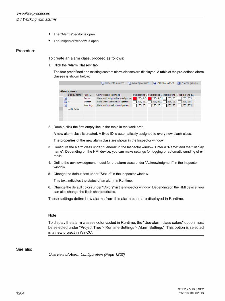
• The "Alarms" editor is open.
• The Inspector window is open.
ProcedureTo create an alarm class, proceed as follows:
1. Click the "Alarm Classes" tab.
The four predefined and existing custom alarm classes are displayed. A table of the pre-defined alarmclasses is shown below:
2. Double-click the first empty line in the table in the work area.
A new alarm class is created. A fixed ID is automatically assigned to every new alarm class.
The properties of the new alarm class are shown in the Inspector window.
3. Configure the alarm class under "General" in the Inspector window. Enter a "Name" and the "Displayname". Depending on the HMI device, you can make settings for logging or automatic sending of e-mails.
4. Define the acknowledgment model for the alarm class under "Acknowledgment" in the Inspectorwindow.
5. Change the default text under "Status" in the Inspector window.
This text indicates the status of an alarm in Runtime.
6. Change the default colors under "Colors" in the Inspector window. Depending on the HMI device, youcan also change the flash characteristics.
These settings define how alarms from this alarm class are displayed in Runtime.
Note
To display the alarm classes color-coded in Runtime, the "Use alarm class colors" option mustbe selected under "Project Tree > Runtime Settings > Alarm Settings". This option is selectedin a new project in WinCC.
See alsoOverview of Alarm Configuration (Page 1202)
Visualize processes8.4 Working with alarms
1204STEP 7 V10.5 SP202/2010, 00002013
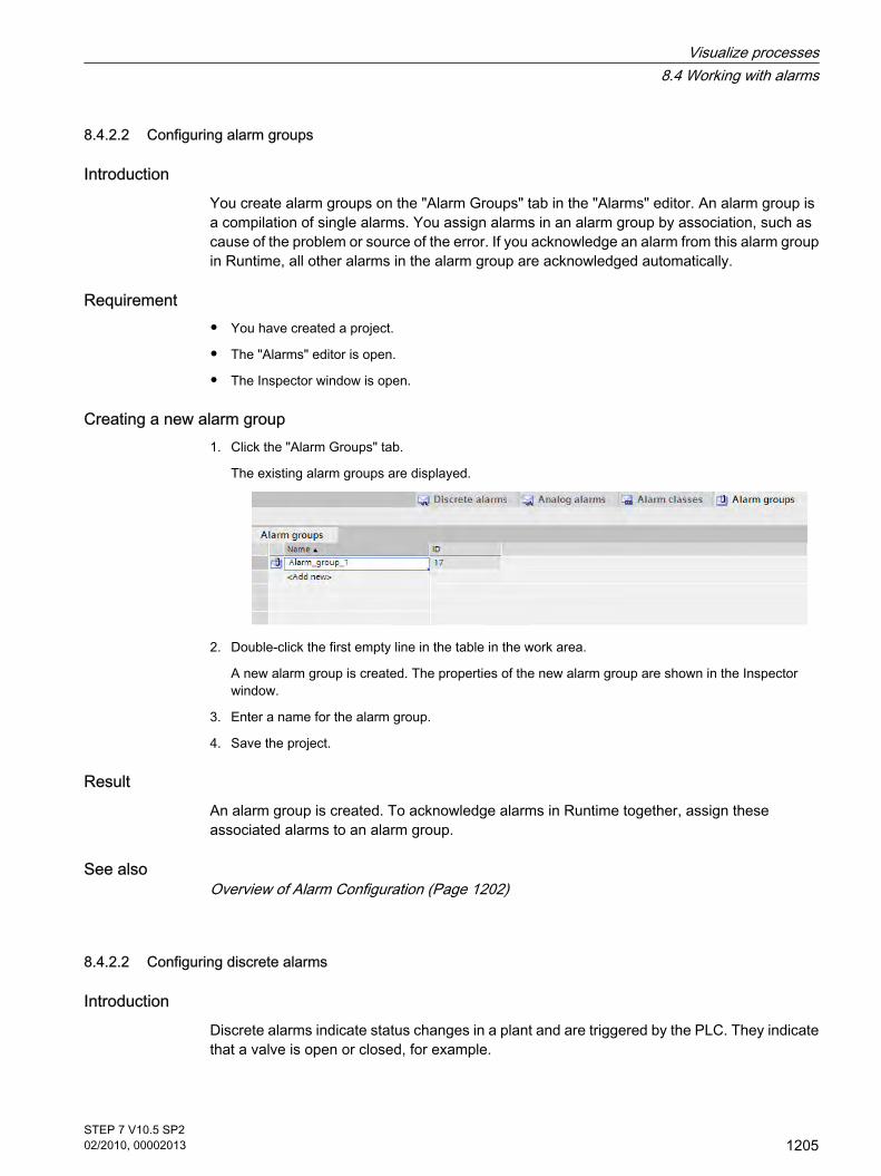
8.4.2.2 Configuring alarm groups
IntroductionYou create alarm groups on the "Alarm Groups" tab in the "Alarms" editor. An alarm group isa compilation of single alarms. You assign alarms in an alarm group by association, such ascause of the problem or source of the error. If you acknowledge an alarm from this alarm groupin Runtime, all other alarms in the alarm group are acknowledged automatically.
Requirement
• You have created a project.
• The "Alarms" editor is open.
• The Inspector window is open.
Creating a new alarm group1. Click the "Alarm Groups" tab.
The existing alarm groups are displayed.
2. Double-click the first empty line in the table in the work area.
A new alarm group is created. The properties of the new alarm group are shown in the Inspectorwindow.
3. Enter a name for the alarm group.
4. Save the project.
ResultAn alarm group is created. To acknowledge alarms in Runtime together, assign theseassociated alarms to an alarm group.
See alsoOverview of Alarm Configuration (Page 1202)
8.4.2.2 Configuring discrete alarms
IntroductionDiscrete alarms indicate status changes in a plant and are triggered by the PLC. They indicatethat a valve is open or closed, for example.
8.4.2.2 Configuring alarm groups8.4.2.2 Configuring discrete alarms
Visualize processes8.4 Working with alarms
STEP 7 V10.5 SP202/2010, 00002013
1205

The following paragraph describes the configuration process in the "Alarms" editor.Alternatively, you can configure discrete alarms in the "Tags" editor.
Requirement
• The "Alarms" editor is open.
• The Inspector window is open.
• The required alarm classes and alarm groups are created.
Procedure To configure a discrete alarm, proceed as follows:
1. Click the "Discrete alarms" tab.
2. To create a new discrete alarm, double-click in the first empty line of the table.
A new discrete alarm is created.
3. Configure the alarm under "General" in the Inspector window:
― If required, change the object name of the alarm.
― Select the alarm class and the alarm group, if necessary.
― Enter the alarm text and insert output fields in the alarm text, if needed.
4. In the Inspector window, select the tag and the bit that triggers the alarm under "Properties > Trigger".Note the following information:
― Use the data type "UShort" or "Short".
― Use trigger tag bits only for alarms.
― Do not use trigger tags for anything else.
― If you want to acknowledge the alarm via the PLC, use this tag as a PLC acknowledgment tag.
Note
If the specified trigger bit is already used as the trigger for other actions, the system does notcheck this multiple assignment until the next compilation.
Notice
Note the method used to count bits in the utilized PLC when specifying the bit. For moreinformation, refer to the section on "Communication" in the online Help for the PLC.
Note
If the object in the selection does not yet exist, create it directly in the object list and change itsproperties later.
Visualize processes8.4 Working with alarms
1206STEP 7 V10.5 SP202/2010, 00002013

ResultThe discrete alarm is created.
Status-related alarm textsConnect the value of a discrete alarm to text lists to output the relevant alarm texts for the twostates displayed by a discrete alarm.
Additional settings for discrete alarmsAssign discrete alarm to an alarm class
To assign the alarm to an alarm group, proceed as follows:
1. Select the discrete alarm.
2. Select the alarm group under "General" in the Inspector window.Creating info text
To assign the alarm to an info text, proceed as follows:
1. Select the discrete alarm.
2. Select "Properties > Info text" in the Inspector window and enter the required text.Configuring event-driven tasks
To configure event-driven tasks, proceed as follows:
1. Select the discrete alarm.
2. In the Inspector window, select "Events".
3. Configure a function list for the required event.
See alsoOverview of Alarm Configuration (Page 1202)
8.4.2.2 Configuring analog alarms
IntroductionAnalog alarms indicate limit violations. For example, if the speed of a motor drops below acertain value, an analog alarm is triggered.
Requirement
• The "Alarms" editor is open.
• The Inspector window is open.
• The required alarm classes and alarm groups are created.
Procedure To configure an analog alarm, proceed as follows:
1. Click the "Analog alarms" tab.
8.4.2.2 Configuring analog alarms
Visualize processes8.4 Working with alarms
STEP 7 V10.5 SP202/2010, 00002013
1207

2. To create a new analog alarm, double-click in the first empty line of the table.
A new analog alarm is created.
3. Configure the alarm under "General" in the Inspector window:
― If required, change the object name of the alarm.
― Select the alarm class and the alarm group, if necessary.
4. Enter the alarm text.
5. You can format the alarm text on a character-by-character basis, and insert output fields for tag valuesor text lists in the text.
6. In the Inspector window, select the tag that triggers the alarm under "Properties > Trigger". Do notuse trigger tags for anything else.
Configure limit values for an analog alarm1. Select the analog alarm.
2. To use a constant as the limit, click the left button
button under "Trigger > Value" in the Inspector window, and select the "String" option.
3. Enter the required limit value.
4. To use a tag as the limit, click the left button
under "Trigger > Value" in the Inspector window, and select the "Tag" option.
The right button
appears.
5. Use this button to select the tag you want to use.
"Synchronize" indicates whether the limits are synchronized with the limits for this alarm that wereconfigured in the "Tags" editor.
6. Select the trigger mode:
― "High limit": The alarm is triggered when the limit is exceeded.
Visualize processes8.4 Working with alarms
1208STEP 7 V10.5 SP202/2010, 00002013

― "Low limit": The alarm is triggered when the limit is undershot.
Note
If the object included in the selection does not yet exist, create it in the object list and changeits properties later.
Optional settings for analog alarmsSetting the delay time
To set the delay time, proceed as follows:
1. In the Inspector window, select "Properties > Trigger".
2. Enter a time period under "Delay". The alarm is only triggered when the trigger condition is still presentafter the delay time has elapsed.
Setting the hysteresis
Note
If a process value fluctuates around the limit, the alarm associated with this fault may betriggered multiple times. In this case, configure a hysteresis or delay time.
To enter the hysteresis, proceed as follows:
1. In the Inspector window, select "Properties > Trigger".
2. Under "Hysteresis > Mode", select the change in alarm status for which the hysteresis is to be takeninto account.
3. Enter a constant value under "Hysteresis > Value".
4. To define the hysteresis value as a percentage of the limit, enable the "%" check box.Automatic reporting
1. Select the analog alarm.
2. In the Inspector window, select "Properties > Process", and enable "Report". If "Report" is enabledunder the alarm settings, this alarm will be recorded in an alarm report.
NoteBasic Panels
Reporting is not available for Basic Panels.Creating info text
1. Select the analog alarm.
2. Select "Properties > Info text" in the Inspector window and enter the required text.Configuring event-driven tasks
Visualize processes8.4 Working with alarms
STEP 7 V10.5 SP202/2010, 00002013
1209

1. Select the analog alarm.
2. Select "Events" in the Inspector window and configure a new list of functions for the desired event.
See alsoOverview of Alarm Configuration (Page 1202)
8.4.2.2 Adding an output field to alarm text
IntroductionIn WinCC, you can add selection fields to the alarm text. These fields display the content oftext lists or tags.
Requirement
• The "Alarms" editor is open.
• An alarm has been created.
Procedure To add an output field to an alarm text, proceed as follows:
1. Select the alarm that you want to edit.
2. Place the cursor at the required position in the alarm text.
3. To output the value of a tag directly, select the "Insert tag output field" command from the shortcutmenu.
The "Insert tag output field" dialog box opens.
4. Select the required tag from the "Tag" field. Select the format under "Display format" and the textlength of the output field under "Length".
5. Click
to accept your input.
6. To output the value of a tag symbolically using a text list, select "Enter text list output field" from theshortcut menu.
The "Enter text list output field" dialog box opens.
8.4.2.2 Adding an output field to alarm text
Visualize processes8.4 Working with alarms
1210STEP 7 V10.5 SP202/2010, 00002013

7. Select the desired text list under "Text list" and the desired tag under "Tag". Define the length of theoutput field under "Length".
8. Click
to accept your input.
Note
The sequence of output fields for tags in the alarm text depends on the language. The sequenceof the runtime language is used for logging alarms in a CSV log.
Changing the tag of an output field in one language causes the modified output field to appearat the end of the alarm text in all other languages. This changes the order of the output fieldsin the log.Basic Panels
Logging is not available for Basic Panels.
See alsoOverview of Alarm Configuration (Page 1202)
8.4.2.2 Formatting alarm text
Requirement
• The "Alarms" editor is open.
• Discrete or analog alarms have been created.
ProcedureTo format an alarm text, proceed as follows:
1. Select the part of the alarm text to be formatted in the Inspector window.
2. Select "Format" from the shortcut menu of the alarm text.
3. Activate the formatting required for the alarm text.
8.4.2.2 Formatting alarm text
Visualize processes8.4 Working with alarms
STEP 7 V10.5 SP202/2010, 00002013
1211

ResultThe alarm text will be displayed in Runtime with the formatting you have selected.
See alsoOverview of Alarm Configuration (Page 1202)
8.4.2.2 Configuring loop-in alarm
IntroductionA Loop-In-Alarm is configured in order to change to a screen containing relevant informationon an alarm received.
Requirement
• You have created a project.
• The screen to be called by the Loop-In-Alarm has been created.
• The "Alarms" editor is open.
ProcedureTo configure a Loop-In-Alarm for an alarm, proceed as follows:
1. Click the tab that contains the alarm for which you want to configure the Loop-In-Alarm.
2. Select the alarm.
3. In the Inspector window, select "Events > Loop-In-Alarm"".
4. Select the "ActivateScreen" system function.
5. Select the screen to be called by the Loop-In-Alarm as its parameter.
8.4.2.2 Configuring loop-in alarm
Visualize processes8.4 Working with alarms
1212STEP 7 V10.5 SP202/2010, 00002013

Note
If you want to configure the Loop-In-Alarm for an alarm view with an "alarm line" form, usethe "EditAlarm" system function to trigger the "Loop-In-Alarm" event. The alarm line has nobuttons.
ResultIf an alarm is displayed in runtime and you click the "Loop-In-Alarm" button for the alarm view,it opens a screen containing information about the error that occurred.
See alsoOverview of Alarm Configuration (Page 1202)
8.4.2.2 Alarms in the "Tags" Editor
8.4.2.2 Configuring discrete alarms in the "Tags" editor
IntroductionIn WinCC, you can create and edit discrete and analog alarms together with the trigger tags inthe "Tags" editor.
Note
If you delete, move or copy in the "Tags" editor, the changes also take effect in the "Alarms"editor.
RequirementThe "HMI alarms" tab is open in the "Tags" editor.
Procedure To configure a discrete alarm in the "Tags" editor, proceed as follows:
1. Click the first line of the table at the top of the work area.
A tag is created.
2. Configure an internal or external tag with the data type ULong or UShort as required.
3. Select the tag, and click the "Discrete alarms" tab at the bottom of the work area.
4. Double-click on the first free line of the table.
A new discrete alarm is created for the tag. If you have selected the wrong data type, the tag will beselected in the discrete alarm.
8.4.2.2 Alarms in the "Tags" Editor8.4.2.2 Configuring discrete alarms in the "Tags" editor
Visualize processes8.4 Working with alarms
STEP 7 V10.5 SP202/2010, 00002013
1213

5. Enter the alarm text under "Properties > Text" in the Inspector window.
6. You can also add output fields to the alarm text.
7. Select an alarm class.
8. In the Inspector window, select the trigger bit of the tag that triggers the discrete alarm under"Properties > Trigger".
9. To create other discrete alarms for monitoring the tags, repeat the above configuration steps.
Note
A tag is only monitored using one alarm procedure. You should therefore create eitheranalog alarms or discrete alarms for a tag.
ResultThe configured discrete alarms are created in the "Tags" editor and are displayed in the"Alarms" and "Tags" editors.
See alsoConfiguring analog alarms in the "Tags" editor (Page 1214)Overview of Alarm Configuration (Page 1202)
8.4.2.2 Configuring analog alarms in the "Tags" editor
IntroductionIn WinCC, you can create and edit discrete and analog alarms together with the trigger tags inthe "Tags" editor. You can create up to four limits for a tag. You monitor these limits with analogalarms.
NoteAvailability for specific devices
You can configure up to two limits for Basic Panels.
RequirementThe "HMI alarms" tab is open in the "Tags" editor.
Procedure To configure an analog alarm in the "Tags" editor, proceed as follows:
1. Click the first line of the table at the top of the work area.
A tag is created.
8.4.2.2 Configuring analog alarms in the "Tags" editor
Visualize processes8.4 Working with alarms
1214STEP 7 V10.5 SP202/2010, 00002013

2. Configure an internal or external tag as required.
3. In the Inspector window, click "Properties > Columns".
4. Select the desired limit, "Constant" or "HMITag". The object list opens if you selected "HMI tag". Selectthe tag you want to use.
5. Enable "Create analog alarm" for this limit.
6. Repeat the last two configuration steps for the required limits.
7. Click the "Analog Alarms" tab at the bottom of the work area.
Analog alarms are created for the selected limits.
8. Select an analog alarm.
9. Enter the alarm text under "Properties" in the Inspector window.
You can also add output fields to the alarm text.
10.
Select an alarm class. The default alarm class is "Error".
Note
Please note the following points:
― A tag is only monitored using one alarm procedure. You should therefore create either analogalarms or discrete alarms for a tag.
― If you delete, move or copy in the "Tags" editor, the changes also take effect in the "Alarms" editor.
― When you create the analog alarms in the Inspector window of the tags, the limits are synchronizedwith the "Alarms" editor.
ResultThe configured analog alarms are created in the "Tags" editor and are displayed in the "Alarms"and "Tags" editors.
See alsoConfiguring discrete alarms in the "Tags" editor (Page 1213)
Visualize processes8.4 Working with alarms
STEP 7 V10.5 SP202/2010, 00002013
1215

8.4.2.3 Configuring alarm output
8.4.2.3 Overview of configuring alarm output
Steps to configure the alarm output You configure the alarm output in WinCC in the following steps:
1. Create alarm view
Use the display and control objects in the "Screens" editor to display alarms in Runtime. You can alsoconfigure an alarm view for logged alarms.
2. Configure acknowledgment
In the "Screens" editor, you can set the operator action that will trigger the acknowledgment.
3. Configure reporting
You can create reports in the "Reports" editor to print alarms in Runtime. In the "Scheduler", "Screens","Alarms" or "Tags" editors, you define when and how the printing of a report is triggered.
NoteBasic Panels
Reporting and logging are not available for Basic Panels.
Additional configuration tasksAdditional tasks may be necessary for configuring alarm views, depending on the requirementsof your project:
1. Setting up authorizations
To make sure only authorized operators process the alarms, assign authorizations for the alarm viewand the function keys of the HMI device.
2. Configuring the filtering of the alarm view
You configure the filtering of the alarms in Runtime in the "Screens" editor. You can also configurealarm views that only display selected alarms.
3. Configure operator input alarms
Configure the operator input alarms on the operator controls of the HMI device in the "Screens" editor.A preconfigured operator input alarm is output for an operator action. Operator actions includeacknowledgment, disabling, and suppression of alarm display.
See alsoAlarm components and properties (Page 1201)Displaying alarms (Page 1217)Configuring an alarm view (Page 1218)Configuring an alarm window (Page 1220)Configuring an alarm indicator (Page 1221)
8.4.2.3 Configuring alarm output8.4.2.3 Overview of configuring alarm output
Visualize processes8.4 Working with alarms
1216STEP 7 V10.5 SP202/2010, 00002013

8.4.2.3 Displaying alarms
Options for displaying alarms on the HMI deviceWinCC offers the following options for displaying alarms on the HMI device:
• Alarm view
The alarm view is configured in a screen. More than one alarm can be displayed simultaneously,depending on the configured size. You can configure multiple alarm views with different contents.
• Alarm window
The Alarm window is configured in the "Global screen" editor. The alarm window can display multiplealarms at the same time, depending on the configured size. An event can trigger closing and reopeningof the alarm window. To hide it during configuration, create an alarm window on its own level.
Additional signals
• Alarm indicator
The alarm indicator is a configurable, graphical icon. When an alarm comes in, the alarm indicator isdisplayed on the HMI device. You configure the alarm indicator in the "Global Elements" editor.
The alarm indicator has two states:
― Flashing: At least one unacknowledged alarm is pending.
― Static: The alarms are acknowledged but at least one of them is not yet deactivated.
The alarm indicator also displays the number of pending alarms according to the HMI device.
• E-mail notification
To inform someone other than the operator, such as an engineer, when an alarm with a specific alarmclass arrives, assign the alarm class to an e-mail address.
NoteBasic Panels
E-mail notification is not available for Basic Panels.
• System functions
You can configure a list of functions for the event associated with an alarm. These functions must beexecuted in Runtime when the event occurs.
Use system functions for alarms in WinCC to control the alarm view or the alarm window other thanvia the toolbar.
Displaying the predefined alarm classes in Runtime The following table shows the symbols used to display the predefined alarm classes in thealarm view:
Alarm class Displayed icon
Diagnostic alarm S7
8.4.2.3 Displaying alarms
Visualize processes8.4 Working with alarms
STEP 7 V10.5 SP202/2010, 00002013
1217

Alarm class Displayed icon
Error !
System $
Warnings <No symbol>
NoteBasic Panels
Diagnostic alarms are not available for Basic Panels.
See alsoOverview of configuring alarm output (Page 1216)
8.4.2.3 Configuring an alarm view
IntroductionCurrent alarms or alarms from the alarm log are displayed in the "Alarm view" display andcontrol object. An alarm view displays alarms from all alarm classes.
NoteBasic Panels
The alarm log is not available for Basic Panels.
Requirement
• A screen is open in the "Screen" editor.
• The "Tools" task card is open.
• The project tree is open.
Configuring alarms for the alarm view To specify the alarms that will be shown in the alarm view, proceed as follows:
1. Under "Controls" on the "Tools" task card, add an alarm view to the screen.
2. Select the alarm view.
3. Under "General > Display" in the Inspector window, decide whether you want to display alarm classes,alarm events or an alarm log.
8.4.2.3 Configuring an alarm view
Visualize processes8.4 Working with alarms
1218STEP 7 V10.5 SP202/2010, 00002013

4. Under "Alarm classes", enable the alarm classes to be displayed in the alarm view.
5. In the Inspector window, click "Display".
6. Under "Control tag for display area", define the tag that returns the date from which the alarms will bedisplayed.
NoteBasic Panels
The "Control tag for display area" property is not available for Basic Panels.
Configuring the layout of the alarm viewTo specify how the alarms are shown in the alarm view, proceed as follows.
1. Click "Layout" in the project tree.
2. Under "Lines per alarm", specify the number of lines to display for each alarm.
3. In the "Display" area, enable the control elements that are available on the HMI device.
4. In the Inspector window, click "Properties > Columns".
Visualize processes8.4 Working with alarms
STEP 7 V10.5 SP202/2010, 00002013
1219

5. Under "Visible columns" select the columns to be output in the alarm view.
6. Under "Sort", select the sort order of the alarms.
7. Under "Properties Column", define the properties of the columns.
Note
Select the "Edit" command in the shortcut menu for the alarm view to activate the alarmview. You can set the column width and position in active mode. To enable the alarm view,set the zoom factor to 100 %.
ResultAlarms of various alarm classes are output in the alarm view during runtime.
See alsoOverview of configuring alarm output (Page 1216)
8.4.2.3 Configuring an alarm window
IntroductionThe alarm window displays current alarms. The alarm window is configured in the "GlobalScreen" editor and opens regardless of the current screen. The HMI device can still be used,even if alarms are pending and displayed. An alarm window is displayed and configured likean alarm view.
To hide an alarm window during configuration, create it on its own level.
Requirement
• The "Global Screen" editor is open.
• The "Tools" task card is displayed.
• The Inspector window is open.
8.4.2.3 Configuring an alarm window
Visualize processes8.4 Working with alarms
1220STEP 7 V10.5 SP202/2010, 00002013

Procedure Proceed as follows to configure an alarm window:
1. Insert the "Alarm window" object into the template from the "Controls" group on the "Tools" task card.
2. Configure the alarm window like an alarm view.
3. Under "Mode > Window" in the Inspector window, select how the alarm window reacts and is operatedin Runtime.
4. Enable "Modal > Enabled".
If you have enabled this option, the alarm window retains the focus in Runtime after a screen change.This option is important, as switching back and forth between the screen and different windows with<Ctrl+TAB> is not supported.
ResultDuring runtime, the alarms of the selected alarm class are displayed in the alarm window.
See alsoOverview of configuring alarm output (Page 1216)
8.4.2.3 Configuring an alarm indicator
IntroductionThe alarm indicator uses a warning triangle to indicate that alarms are pending or requireacknowledgement. If an alarm of the configured alarm class occurs, the alarm indicator isdisplayed.
The alarm indicator has two states:
• Flashing: At least one unacknowledged alarm is pending.
• Static: At least one of the acknowledged alarms has not yet been deactivated.
You can configure Runtime to open an alarm window when the user operates the alarmindicator.
Requirement
• The "Global Screen" editor is open.
• The "Tools" task card is open.
• The Inspector window is open.
ProcedureProceed as follows to configure the alarm indicator:
1. Drag the "Alarm indicator" object into the work area from the "Controls" group on the "Tools" task card.
2. Select the alarm indicator.
8.4.2.3 Configuring an alarm indicator
Visualize processes8.4 Working with alarms
STEP 7 V10.5 SP202/2010, 00002013
1221
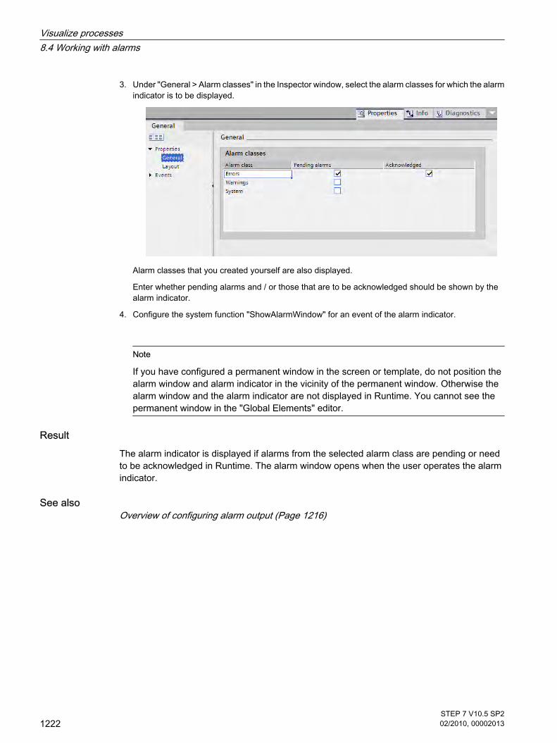
3. Under "General > Alarm classes" in the Inspector window, select the alarm classes for which the alarmindicator is to be displayed.
Alarm classes that you created yourself are also displayed.
Enter whether pending alarms and / or those that are to be acknowledged should be shown by thealarm indicator.
4. Configure the system function "ShowAlarmWindow" for an event of the alarm indicator.
Note
If you have configured a permanent window in the screen or template, do not position thealarm window and alarm indicator in the vicinity of the permanent window. Otherwise thealarm window and the alarm indicator are not displayed in Runtime. You cannot see thepermanent window in the "Global Elements" editor.
ResultThe alarm indicator is displayed if alarms from the selected alarm class are pending or needto be acknowledged in Runtime. The alarm window opens when the user operates the alarmindicator.
See alsoOverview of configuring alarm output (Page 1216)
Visualize processes8.4 Working with alarms
1222STEP 7 V10.5 SP202/2010, 00002013

8.4.2.4 Acknowledging alarms
8.4.2.4 Configuring acknowledgment of alarms using the message class
IntroductionUse the alarm class to define whether all and how the alarms of the alarm class should beacknowledged. When you assign an alarm to an alarm class, you define whether the alarmmust be acknowledged.
Requirement
• The "Alarms" editor is open.
• The required alarm class has been created.
• The required alarm has been created.
Selecting the acknowledgment model for an alarm classThe acknowledgment model for a predefined alarm class has already been set. You can onlyset the acknowledgment model for custom alarm classes. To do this, proceed as follows:
1. In the "Alarms" editor, click the "Alarm Class" tab and select the required alarm class.
2. Select the required acknowledgment model under "Acknowledgment > Settings" in the Inspectorwindow.
Assign alarms to an alarm class requiring acknowledgmentProceed as follows to assign an alarm to an alarm class requiring acknowledgment.
1. In the "Alarms" editor, click the tab for the required alarm type, and select the required alarm.
2. Under "General" in the Inspector window, select the alarm class to which the alarm is to belong.
See alsoAlarm components and properties (Page 1201)Configuring the acknowledgment of alarms (Page 1223)
8.4.2.4 Configuring the acknowledgment of alarms
IntroductionYou always specify the acknowledgment requirement for an alarm using the alarm class. Thefollowing options are also available for acknowledgment:
• Acknowledging an alarm via a system function
• Acknowledgment of a Discrete Alarm by the PLC
• Sending alarm acknowledgment to the PLC
8.4.2.4 Acknowledging alarms8.4.2.4 Configuring acknowledgment of alarms using the message class8.4.2.4 Configuring the acknowledgment of alarms
Visualize processes8.4 Working with alarms
STEP 7 V10.5 SP202/2010, 00002013
1223

• Configuring a button to acknowledge an alarm
Requirement
• The "Alarms" editor is open.
• The required alarm class has been created.
• The required alarm has been created.
Acknowledging an alarm via a system functionTo have an alarm acknowledged by a system function, proceed as follows:
1. Select the required alarm in the "Alarms" editor.
2. Click the "Incoming" event under "Events" in the Inspector window.
The function list opens.
3. Set the "SetBit" system function for the "Incoming" event in the "Function list" dialog.
4. Enter the acknowledgment tag of the "BOOL" data type as the "Variable (In/Out)" parameter.
Additional information is available in the "Working with system functions" section.
Acknowledgment of a Discrete Alarm by the PLC1. In the "Alarms" editor, click the "Discrete Alarm" tab and select the required discrete alarm.
2. In the Inspector window, select "Properties > Acknowledgment".
3. Under "PLC", select the tag and the bit that the PLC will use use to acknowledge the alarm.
Sending alarm acknowledgment to the PLCTo send the acknowledgment of an alarm to the PLC, proceed as follows:
1. In the "Alarms" editor, click the "Discrete Alarm" tab and select the required discrete alarm.
2. In the Inspector window, select "Properties > Acknowledgment".
3. Under "HMI", select the tag and the bit to be set by the alarm acknowledgment.
Visualize processes8.4 Working with alarms
1224STEP 7 V10.5 SP202/2010, 00002013

Configuring a button to acknowledge an alarmTo configure a button for acknowledging an alarm, proceed as follows:
1. Select the button or function key.
2. Set the "AlarmViewAcknowledgeAlarm" system function for the "Click" event.
You can find more detailed information in the "Working with Screens" section.
See alsoConfiguring acknowledgment of alarms using the message class (Page 1223)
8.4.3 Operating alarms in Runtime
8.4.3.1 Alarms in Runtime
Alarms Alarms indicate events and states on the HMI device which have occurred in the system, in theprocess or on the HMI device itself. A status is reported when it is received.
An alarm could trigger one of the following alarm events:
• Incoming
• Outgoing
• Acknowledge
• Loop-in-alarm
The configuration engineer defines which alarms must be acknowledged by the user.
An alarm may contain the following information:
• Date
• Time
• Alarm text
• Location of fault
• Status
• Alarm class
• Alarm number
• Alarm group
Alarm classes Alarms are assigned to various alarm classes.
• Warning
8.4.3 Operating alarms in Runtime8.4.3.1 Alarms in Runtime
Visualize processes8.4 Working with alarms
STEP 7 V10.5 SP202/2010, 00002013
1225

Alarms of this class usually indicate states of a plant such as "Motor switched on." Alarms in this classdo not require acknowledgment.
• Error
Alarms in this class must always be acknowledged. Error alarms normally indicate critical errors withinthe plant such as "Motor temperature too high."
• System
System alarms indicate states or events which occur on the HMI device.
System alarms provide information on occurrences such as operator errors or communication faults.
• Custom alarm classes
The properties of this alarm class must be defined in the configuration.
Alarm bufferAlarm events are saved to an internal, volatile buffer. The size of this alarm buffer depends onthe HMI device type.
Alarm viewThe alarm view shows selected alarms or alarm events from the alarm buffer. Whether alarmevents have to be acknowledged or not is specified in your configuration.
Alarm windowAn alarm window shows all pending alarms or alarms awaiting acknowledgement of a particularalarm class. The alarm window is displayed as soon as a new alarm occurs.
You can configure the order in which the alarms are displayed. You can choose to display thealarms in ascending or descending order of their occurrence. The alarm window can also beset to indicate the exact location of the fault, including the date and time of the alarm event. Bymeans of configuration, the display can be filtered in such a way that only alarms that containa specific character string will be shown.
Alarm indicatorThe alarm indicator is a graphic icon that is displayed on the screen when an alarm of thespecified alarm class is activated.
The alarm indicator can assume one of two states:
• Flashing: At least one unacknowledged alarm is pending.
• Static: The alarms are acknowledged but at least one of them is not yet deactivated. The numberdisplayed indicates the number of pending alarms.
See alsoAlarm system in WinCC (Page 1191)Simple alarm view, simple alarm window in runtime (Page 1227)Alarm Indicator in Runtime (Page 1229)Acknowledging alarms (Page 1229)
Visualize processes8.4 Working with alarms
1226STEP 7 V10.5 SP202/2010, 00002013

8.4.3.2 Simple alarm view, simple alarm window in runtime
Application The simple alarm view shows selected alarms or alarm events from the alarm buffer or alarmlog. The layout and operation of the simple alarm window correspond to that of the simple alarmview.
Note
The "Single alarm view" object cannot be operated dynamically with a script.
In the Engineering System you can dynamically control the visibility of an object, for example,in the "Animations" group of the Inspector window. In Runtime, the "Simple alarm view" doesnot support animations. If you have configured an animation, and, for example, want to carryout a consistency check on the project, an error message is output in the output window.
NoteBasic Panels
Logging is not available for Basic Panels.
Layout Depending on the configuration, in the alarm view different columns with information regardingan alarm or an alarm event are displayed.
To differentiate between the different alarm classes, the first column in the alarm view containsan icon:
Icon Alarm class
! Error
8.4.3.2 Simple alarm view, simple alarm window in runtime
Visualize processes8.4 Working with alarms
STEP 7 V10.5 SP202/2010, 00002013
1227

Icon Alarm class
empty Warning
depends on the configuration Custom alarm classes
$ System
OperationYou use the alarm view as follows, depending on how it is configured:
• Acknowledging alarms
• Editing alarms
Control elementsThe buttons have the following functions:
Button Function
Acknowledge alarm.
Edit alarm.
Show Infotext for an alarm.
Displays the full text of the selected alarm in a separate window - the alarm text window.In the alarm text window, you can view alarm text that requires more space than isavailable in the Alarm view. Close the alarm text window with the the
button.
Scrolls one alarm up.
Scrolls one page up in the alarm view.
Scrolls one page down in the alarm view.
Scrolls one alarm down.
Format of the control elements
On the operating panels OP 73micro and TP 177micro the simple alarm view has a button thatdisplays the message text in a separate window. This button is not displayed during theconfiguration of the simple alarm in the engineering system.
The display of the buttons for using the simple alarm view depends on the configured size. Youshould therefore check on the HMI device whether all the required buttons are available.
Visualize processes8.4 Working with alarms
1228STEP 7 V10.5 SP202/2010, 00002013
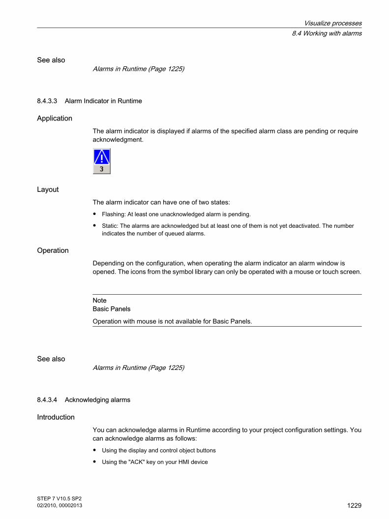
See alsoAlarms in Runtime (Page 1225)
8.4.3.3 Alarm Indicator in Runtime
Application The alarm indicator is displayed if alarms of the specified alarm class are pending or requireacknowledgment.
Layout The alarm indicator can have one of two states:
• Flashing: At least one unacknowledged alarm is pending.
• Static: The alarms are acknowledged but at least one of them is not yet deactivated. The numberindicates the number of queued alarms.
Operation Depending on the configuration, when operating the alarm indicator an alarm window isopened. The icons from the symbol library can only be operated with a mouse or touch screen.
NoteBasic Panels
Operation with mouse is not available for Basic Panels.
See alsoAlarms in Runtime (Page 1225)
8.4.3.4 Acknowledging alarms
IntroductionYou can acknowledge alarms in Runtime according to your project configuration settings. Youcan acknowledge alarms as follows:
• Using the display and control object buttons
• Using the "ACK" key on your HMI device
8.4.3.3 Alarm Indicator in Runtime8.4.3.4 Acknowledging alarms
Visualize processes8.4 Working with alarms
STEP 7 V10.5 SP202/2010, 00002013
1229

• Using individually-configured function keys or buttons
If an operator authorization is configured for an individual control, the alarms can only beacknowledged by authorized users.
To automatically acknowledge alarms in Runtime, use the system functions and scripts, plusthe "Acknowledgment by the PLC" option.
NoteBasic Panels
Scripts are not available for Basic Panels.
Acknowledgment variantsYou acknowledge individual alarms or multiple alarms together in Runtime. They aredistinguished as follows:
• Single acknowledgment
Acknowledgment of an alarm using a button or a function key.
• Acknowledge alarm groups
Acknowledgment of all the alarms of an alarm group using a button or a function key.
Requirement
• An alarm is displayed on the HMI device.
ProcedureTo acknowledge an alarm, proceed as follows:
1. Select the alarm.
2. If you are using an alarm view or an alarm window, click the
button.
3. If you are using a simple alarm view or a simple alarm window, click the
button.
4. Press the "ACK" button on your HMI device to acknowledge an alarm in an alarm line.
NoteBasic Panels
Only the simple alarm view and simple alarm window are available for Basic Panels.
Visualize processes8.4 Working with alarms
1230STEP 7 V10.5 SP202/2010, 00002013

ResultThe alarm status changes to "Acknowledged". If the condition for triggering an alarm no longerapplies, the alarm status also changes to "Outgoing", and it is no longer displayed on the HMIdevice.
See alsoAlarms in Runtime (Page 1225)
8.4.4 Reference
8.4.4.1 System functions and events for alarms
System functionsSystem functions are predefined functions you can use to implement many tasks in runtime,even with no programming knowledge. You use system functions in a function list or in a script.
NoteBasic Panels
Scripts are not available for Basic Panels.
The table shows all the system functions available for displaying and editing alarms.
System function Effect
EditAlarm Triggers the Loop-In-Alarm event for all selectedalarms.
ClearAlarmBuffer Deletes alarms from the alarm buffer on the HMIdevice.
ClearAlarmBufferProtoolLegacy Function like "ClearAlarmBuffer". This systemfunction has been retained to ensure compatibilityand uses the old ProTool numbering.
AlarmViewEditAlarm Triggers the event Loop-In-Alarm for all alarmsselected in the specified alarm view.
AlarmViewAcknowledgeAlarm Acknowledges the alarms that are selected in thespecified alarm view.
AlarmViewShowOperatorNotes Displays the configured info text for the alarmselected in the specified alarm screen.
8.4.4 Reference8.4.4.1 System functions and events for alarms
Visualize processes8.4 Working with alarms
STEP 7 V10.5 SP202/2010, 00002013
1231

System function Effect
AcknowledgeAlarm Acknowledges all selected alarms.
SetAlarmReportMode Switches the automatic reporting of alarms on theprinter on or off.
ShowAlarmWindow Hides or shows the alarm window on the HMIdevice.
ShowSystemAlarm Displays the value of the delivered parameter as asystem alarm on the HMI device.
NoteBasic Panels
The "SetAlarmReportMode" and "ShowSystemAlarm" system functions are not available forBasic Panels.
For details on system functions, see the "Visualizing Processes > Working with SystemFunctions > Reference > System Functions" section.Events for alarms and their display and control objects
In runtime, the following events occur in response to alarms and their display and controlobjects. You can configure a function list for every event.
Object Configurable events
Alarms Incoming Outgoing Acknowledge Loop-In-Alarm
Alarm view Enable Disable Establish Alarm number changed
Alarm indicator Click Click when flashing
NoteBasic Panels
The "Establish" and "Alarm number changed" events are not available for Basic Panels.
For details on events, see the "Visualizing Processes > Working with System Functions >Reference > System Functions > Events" section.
Visualize processes8.4 Working with alarms
1232STEP 7 V10.5 SP202/2010, 00002013

See alsoAlarm system in WinCC (Page 1191)System alarms (Page 1233)
8.4.4.2 System alarms
IntroductionSystem alarms on the HMI device provide information about internal states of the HMI deviceand PLC.
The following overview illustrates when a system alarm occurs and how to eliminate the causeof error.
NoteAvailability for specific HMI devices
Some of the system alarms described in this section apply to the individual HMI devices basedon their scope of functions.
Note
System alarms are output in an alarm view. System alarms are output in the language currentlyset on your HMI device.
System alarm parameters
System alarms may contain encrypted parameters. The parameters of relevance whentroubleshooting because they provide a reference to the source code of the Runtime software.These parameters are output after the "Error code:" text.
Meaning of the system alarmsThe following table contains all the system alarms. The system alarms are divided into differentranges:
8.4.4.2 System alarms
Visualize processes8.4 Working with alarms
STEP 7 V10.5 SP202/2010, 00002013
1233

Table8-2 10000 - Printer alarms
Number Effect/cause Remedy
10000 The print job could not be started or was canceleddue to an unknown error. Faulty printer setup. Or: Noauthorization is available for accessing the networkprinter. Power supply failure during data transfer.
Check the printer settings, cable connections and thepower supply. Set up the printer once again. Obtain a network printerauthorization. If the error persists, contact the Hotline!
10001 No printer is installed or a default printer has not beenset up.
Install a printer and/or select it as the default printer.
10002 Overflow of the graphics buffer for printing. Up to twoimages are buffered.
After a print job, wait before you trigger further print jobs.
10003 Images can now be buffered again. --
10004 Overflow of the buffer for printing lines in text mode(e.g. alarms). Up to 1000 lines are buffered.
After a print job, wait before you trigger further print jobs.
10005 Text lines can now be buffered again. --
10006 The Windows printing system reports an error. Referto the output text and the error ID to determine thepossible causes. Nothing is printed or the print isfaulty.
Repeat the action.
Table8-3 20000 - Global script alarms
Number Effect/causes Remedy
20010 An error has occurred in the specified script line.Execution of the script was therefore aborted. Notethe system alarm that may have occurred prior tothis.
Select the specified script line in the configuration.Ensure that the tags used are of the allowed types. Withsystem functions, check that the number and types ofparameter are correct.
20011 An error has occurred in a script that was called bythe specified script. Execution of the script was therefore aborted in thecalled script. Note the system alarm that may have occurred priorto this.
In the configuration, select the script that has been calleddirectly or indirectly by the specified script. Ensure that the tags used are of the allowed types. With system functions, check that the number and typesof parameter are correct.
20012 The project data are inconsistent. The script couldtherefore not be generated.
Recompile the configuration.
20013 The scripting component of WinCC Runtime is notcorrectly installed. Therefore, no scripts can beexecuted.
Reinstall WinCC Runtime on your PC. Rebuild your project with "Project > Generator >Generate" and download the project to the HMI device.
20014 The system function returns a value that is not writtenin any return tag.
Select the specified script in the configuration. Check whether the script name has been assigned avalue.
Visualize processes8.4 Working with alarms
1234STEP 7 V10.5 SP202/2010, 00002013

Number Effect/causes Remedy
20015 Too many successive scripts have been triggered inshort intervals. When more than 20 scripts arequeued for processing, any subsequent scripts arerejected. In this case, the script indicated in the alarmis not executed.
Check what is triggering the scripts. Extend the times,e.g. the polling time of the tags which trigger the scripts.
Table8-4 30000 - Alarms for IFwSetValue: SetValue()
Number Effect/causes Remedy
30010 The tag could not accept the function result, e.g.when it has exceeded the value range.
Check the data type of the system function parameters.
30011 A system function could not be executed because thefunction was assigned an invalid value or type in theparameter.
Check the parameter value and data type of the invalidparameter. If a tag is used as a parameter, check itsvalue.
30012 A system function could not be executed because thefunction was assigned an invalid value or type in theparameter.
Check the parameter value and data type of the invalidparameter. If a tag is used as a parameter, check itsvalue.
Table8-5 40000 - Linear scaling alarms
Number Effect/causes Remedy
40010 The system function could not be executed becausethe parameters could not be converted to a commondata type.
Check the parameter types in the configuration.
40011 The system function could not be executed becausethe parameters could not be converted to a commondata type.
Check the parameter types in the configuration.
Table8-6 50000 - Data server alarms
Number Effect/causes Remedy
50000 The HMI device is receiving data faster than it iscapable of processing. Therefore, no further data isaccepted until all current data have been processed.Data exchange then resumes.
--
50001 Data exchange has been resumed. --
Table8-7 60000 - Win32 function alarms
Number Effect/causes Remedy
60000 This alarm is generated by the“DisplaySystemAlarms” function. The text to bedisplayed is transferred to the function as aparameter.
--
Visualize processes8.4 Working with alarms
STEP 7 V10.5 SP202/2010, 00002013
1235

Number Effect/causes Remedy
60010 The file could not be copied in the direction definedbecause one of the two files is currently open or thesource/target path is not available. It is possible that the Windows user has no accessrights to one of the two files.
Restart the system function or check the paths of thesource/target files. Using Windows NT/2000/XP: Theuser who is running the WinCC Runtime must be grantedaccess rights for the files.
60011 An attempt was made to copy a file to itself. It is possible that the Windows user has no accessrights to one of the two files.
Check the path of the source/target file. Using Windows NT/2000/XP with NTFS: The user whois running the WinCC Runtime must be granted accessrights for the files.
Table8-8 70000 - Win32 function alarms
Number Effect/causes Remedy
70010 The application could not be started because it couldnot be found in the path specified or there isinsufficient memory space.
Check whether the application exists on the specifiedpath or close other applications.
70011 The system time could not be modified. The error alarm only appears in connection with areapointer "Date/time PLC". Possible causes:
• An invalid time was transferred in the job mailbox.
• The Windows user has no right to modify thesystem time.
If the first parameter in the system alarm is displayedwith the value 13, the second parameter indicates thebyte containing the incorrect value.
Check the time which is to be set. Using Windows NT/2000/XP: The user who is runningthe WinCC Runtime have the right to change the systemtime of the operating system.
70012 An error occurred when executing the function"StopRuntime" with the option "Runtime andoperating system". Windows and WinCC flexible Runtime are notclosed. One possible cause is that other programs cannot beclosed.
Close all programs currently running. Then close Windows.
70013 The system time could not be modified because aninvalid value was entered. Incorrect separators mayhave been used.
Check the time which is to be set.
70014 The system time could not be modified. Possiblecauses:
• An invalid time was transferred.
• The Windows user has no right to modify thesystem time.
Windows rejects the setting request.
Check the time which is to be set. Using Windows NT/2000/XP: The user who is runningthe WinCC Runtime have the right to change the systemtime of the operating system.
70015 The system time could not be read becauseWindows rejects the reading function.
--
Visualize processes8.4 Working with alarms
1236STEP 7 V10.5 SP202/2010, 00002013

Number Effect/causes Remedy
70016 An attempt was made to select a screen by meansof a system function or job. This is not possiblebecause the screen number specified does notexist. Or: A screen could not be generated due toinsufficient system memory.Or: The screen is blocked.Or: Screen selection has not been executedcorrectly.
Compare the screen number in the system function or inthe job against the configured screen numbers. Assign the number to a screen.Check the details for the screen selection and whetherthe screen is blocked for specific users.
70017 Date/time is not read from the area pointer becausethe address set in the PLC is either not available orhas not been set up.
Change the address or set up the address in the PLC.
70018 Acknowledgment that the password list has beensuccessfully imported.
--
70019 Acknowledgment that the password list has beensuccessfully exported.
--
70020 Acknowledgment for activation of alarm reporting. --
70021 Acknowledgment for deactivation of alarm reporting. --
70022 Acknowledgment to starting the Import PasswordList action.
--
70023 Acknowledgment to starting the Export PasswordList action.
--
70024 The value range of the tag has been exceeded in thesystem function. The calculation of the system function is notperformed.
Check the desired calculation and correct it.
70025 The value range of the tag has been exceeded in thesystem function. The calculation of the system function is notperformed.
Check the desired calculation and correct it.
70026 No other screens are stored in the internal screenmemory. No other screens can be selected.
--
70027 The backup of the RAM file system has been started. --
70028 The files from the RAM have been copied in the Flashmemory. The files from the RAM have been copied in the Flashmemory. Following a restart, these saved files arecopied back to the RAM file system.
--
70029 Backup of the RAM file system has failed. No backup copy of the RAM file system has beenmade.
Check the settings in the "Control Panel > OP" dialog.Use the "Save Files" button on the "Persistent Storage"tab to save the RAM file system.
Visualize processes8.4 Working with alarms
STEP 7 V10.5 SP202/2010, 00002013
1237
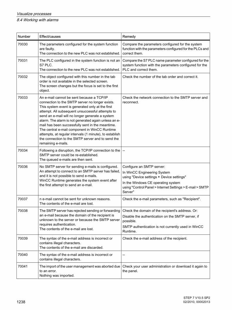
Number Effect/causes Remedy
70030 The parameters configured for the system functionare faulty. The connection to the new PLC was not established.
Compare the parameters configured for the systemfunction with the parameters configured for the PLCs andcorrect them.
70031 The PLC configured in the system function is not anS7 PLC. The connection to the new PLC was not established.
Compare the S7 PLC name parameter configured for thesystem function with the parameters configured for thePLC and correct them.
70032 The object configured with this number in the taborder is not available in the selected screen. The screen changes but the focus is set to the firstobject.
Check the number of the tab order and correct it.
70033 An e-mail cannot be sent because a TCP/IPconnection to the SMTP server no longer exists. This system event is generated only at the firstattempt. All subsequent unsuccessful attempts tosend an e-mail will no longer generate a systemalarm. The alarm is not generated again unless an e-mail has been successfully sent in the meantime. The central e-mail component in WinCC Runtimeattempts, at regular intervals (1 minute), to establishthe connection to the SMTP server and to send theremaining e-mails.
Check the network connection to the SMTP server andreconnect.
70034 Following a disruption, the TCP/IP connection to theSMTP server could be re-established. The queued e-mails are then sent.
--
70036 No SMTP server for sending e-mails is configured.An attempt to connect to an SMTP server has failed,and it is not possible to send e-mails. WinCC Runtime generates the system event afterthe first attempt to send an e-mail.
Configure an SMTP server:In WinCC Engineering System using "Device settings ▶ Device settings"In the Windows CE operating system using "Control Panel > Internet Settings > E-mail > SMTPServer"
70037 n e-mail cannot be sent for unknown reasons. The contents of the e-mail are lost.
Check the e-mail parameters, such as "Recipient".
70038 The SMTP server has rejected sending or forwardingan e-mail because the domain of the recipient isunknown to the server or because the SMTP serverrequires authentication. The contents of the e-mail are lost.
Check the domain of the recipient's address. Or:Disable the authentication on the SMTP server, ifpossible.SMTP authentication is not currently used in WinCCRuntime.
70039 The syntax of the e-mail address is incorrect orcontains illegal characters. The contents of the e-mail are discarded.
Check the e-mail address of the recipient.
70040 The syntax of the e-mail address is incorrect orcontains illegal characters.
--
70041 The import of the user management was aborted dueto an error. Nothing was imported.
Check your user administration or download it again tothe panel.
Visualize processes8.4 Working with alarms
1238STEP 7 V10.5 SP202/2010, 00002013

Number Effect/causes Remedy
70042 The value range for the tags has been exceededwhile executing the system function.The system function calculation has not been carriedout.
Check the desired calculation and correct it.
70043 The value range for the tags has been exceededwhile executing the system function.The system function calculation has not been carriedout.
Check the desired calculation and correct it.
Table8-9 80000 - Archive alarms
Number Effect/causes Remedy
80001 The log specified is filled to the size defined (inpercent) and must be stored elsewhere.
Store the file or table by executing a ‘move’ or ‘copy’function.
80002 A line is missing in the specified log. --
80003 The copying process for logging was notsuccessful. In this case, it is advisable to check any subsequentsystem alarms, too.
--
80006 Since logging is not possible, this causes apermanent loss of the functionality.
For databases, check whether the relevant data sourceexists and restart the system.
80009 A copying action has been completed successfully. --
80010 The storage location was incorrectly entered inWinCC, so this causes a permanent loss offunctionality.
Reconfigure the storage location for the log and restartthe system if the full functionality is required.
80012 Log entries are stored in a buffer. If the values areread to the buffer faster than they can be physicallywritten (using a hard disk, for example), overloadingmay occur and recording is then stopped.
Archive fewer values. Or: Increase the logging cycle.
80013 The overload status no longer applies. Archivingresumes the recording of all values.
--
80014 The same action was triggered twice in quicksuccession. Since the process is already inoperation, the action is only carried out once.
--
80015 This system alarm is used to report DOS or databaseerrors to the user.
--
80016 The logs are separated by the system function"CloseAllLogs" and the incoming entries exceed thedefined buffer size. All entries in the buffer are deleted.
Reconnect the logs.
Visualize processes8.4 Working with alarms
STEP 7 V10.5 SP202/2010, 00002013
1239

Number Effect/causes Remedy
80017 The number of incoming events cause a bufferoverflow. This situation can be caused, for example,when several copy jobs are activated at the sametime. All copy jobs in the buffer will be deleted.
Stop the copy action.
80019 The connection between WinCC and all logs wasdropped after running the "CloseAllLogs" systemfunction, for example. Entries are written to the buffer and are then writtento the logs when a connection is re-established. There is no connection to the storage location andthe storage medium may be replaced.
--
80020 The maximum number of simultaneous copy jobshas been exceeded. Copying is not executed.
Wait until the current copy jobs have been completed,then restart the last copy job.
80021 An attempt was made to delete a log that is stillcopying. Deletion has not been executed.
Wait until the current copy job is complete, then restartthe last action.
80022 An attempt was made to use the system function"StartSequenceLog" to start a log segment for a logwhich is not configured as a segmented circular log.No log segment file is created.
In your project, check the following:
• Was the "StartSequenceLog" system functionconfigured correctly?
• Were the tag parameters correctly supplied with dataon the HMI device?
80023 An attempt was made to copy a log to itself. The log is not copied.
In your project, check the following:
• Was the "CopyLog" system function configuredcorrectly?
• Were the tag parameters correctly supplied with dataon the HMI device?
80024 The "CopyLog" system function does not allowcopying when the target log already contains data("Mode" parameter). The log is not copied.
Edit the "CopyLog" system function in your configuration.Before you initiate the system function, delete thedestination log file.
80025 You have canceled the copy job. Data written up to this point will be retained. Thedestination log file (if configured) is not deleted. The cancellation is reported by an error entry$RT_ERR$ at the end of the destination log.
--
80026 This alarm is output after all logs are initialized.Values are written to the logs from then on. Prior tothis, no entries are written to the logs, even thoughWinCC Runtime is running.
--
80027 The internal Flash memory has been specified as thestorage location for a log. This is not permissible. No values are written to this log and the log file is notcreated.
Configure a memory card or a network path as thestorage location.
80028 The alarm returns a status report indicating that thelogs are currently being initialized. No values arelogged until the alarm 80026 is output.
--
Visualize processes8.4 Working with alarms
1240STEP 7 V10.5 SP202/2010, 00002013

Number Effect/causes Remedy
80029 The number of logs specified in the alarm could notbe initialized. The logs are initialized. The faulty log files are not available for logging jobs.
Evaluate the additional system alarms associated withthis alarm. Check the configuration, the ODBC (OpenDatabase Connectivity) and the specified drive.
80030 The structure of the existing log file does not matchthe expected structure. Logging is stopped for this log.
Delete the existing log data manually, in advance.
80031 The log in CSV format is corrupt. The log can no longer be used.
Delete the faulty file.
80032 Logs can be assigned events. These are triggered assoon as the log is full. If WinCC Runtime is startedand the log is already full, the event would never betriggered. The specified log will no longer log data because it isfull.
Exit WinCC Runtime. Delete the log and restart WinCCRuntime. Or: Configure a button which contains the same actions asthe event. Click the button.
80033 "System Defined" is set in the data log file as the datasource name. This causes an error. No data is writtento the database logs, whereas logging to the CSVlogs works.
Reinstall MSDE.
80034 An error has occurred in the initialization of the logs.An attempt has been made to create the tables as abackup. This action was successful. A backup hasbeen made of the tables of the corrupted log file andthe cleared log was restarted.
Save or delete the backups to free up the memory.
80035 An error has occurred in the initialization of the logs.An attempt has been made to create backups of thetables and this has failed. No logging or backup hasbeen performed.
Save or delete the backups to free up the memory.
80044 The export of a log was interrupted because Runtimewas closed or due to a power failure. It was detectedthat the export needed to be resume when Runtimerestarted.
The export resumes automatically.
80045 The export of a log was interrupted due to an error inthe connection to the server or at the server itself.
The export is repeated automatically. Check thefollowing:
• Is the connection to the server intact?
• Is the server running?
• Is there enough free space on the server?
80046 The destination file or associated folder could not becreated on the server.
Check whether there is enough space on the server andwhether you have the necessary authorization to savethe log file.
80047 The log could not be read while exporting it. Check whether the storage medium is correctly inserted.
80049 The log could not be renamed while preparing toexport it. The job can not be completed."
Check whether the storage medium is correctly insertedand if there is sufficient space on the medium.
Visualize processes8.4 Working with alarms
STEP 7 V10.5 SP202/2010, 00002013
1241

Number Effect/causes Remedy
80050 The log which shall be exported is not closed. The job can not be completed.
Make sure the "CloseAll Logs" system function is calledbefore using the "ExportLog" system function. Changethe configuration as required.
Table8-10 90000 - FDA alarms
Number Effect/causes Remedy
90024 No operator actions can be logged due to lack ofspace on the storage medium for log. The operatoraction will therefore not be executed.
Make more space available by inserting an emptystorage medium or swapping out the log files on theserver using "ExportLog".
90025 No user actions can be logged because of error stateof the archive. Therefore the user action will not beexecuted.
Check whether the storage medium is correctly inserted.
90026 No operator actions can be logged because the logis closed. The operator action will therefore not beexecuted.
Before performing any other actions, open the log againusing the "OpenAllLogs" system function. Change theconfiguration as required.
90028 The password is incorrect. Enter the correct password.
90029 Runtime was closed during ongoing operation(perhaps due to a power failure) or a storagemedium in use is incompatible with Audit Trail. AnAudit Trail is not suitable if it belongs to anotherproject or has already been archived.
Ensure that you are using the correct storage medium.
90030 Runtime was closed during ongoing operation(perhaps due to a power failure).
--
90031 Runtime was closed during ongoing operation(perhaps due to a power failure).
--
90032 Running out of space on the storage medium for log. Make more space available, either by inserting an emptystorage medium or by saving the log files on the serverusing the "ExportLog" system function.
90033 No more space on the storage medium for log. As ofnow, no more operator actions requiring logging willbe executed.
To free up memory, save the log files on the server usingthe "ExportLog" system function.Or:Insert a blank storage medium.
90039 You do not have the necessary authorization toperform this action.
Adapt or upgrade your authorizations.
90040 Audit Trail is switched off because of a forced useraction.
Activate the "Audit Trail" again using the "StartLog"system function.
90041 A user action which has to be logged has beenexecuted without a logged on user.
A user action requiring logging should only be possiblewith permission. Change the configuration by configuringan authorization for the operating object.
90044 A user action which has to be confirmed wasblocked, because there is another user actionpending.
Repeat the user action if necessary.
Visualize processes8.4 Working with alarms
1242STEP 7 V10.5 SP202/2010, 00002013

Table8-11 110000 - Offline function alarms
Number Effect/causes Remedy
110000 The operating mode was changed. "Offline" mode isnow set.
--
110001 The operating mode was changed. "Online" mode isnow set.
--
110002 The operating mode was not changed. Check the connection to the PLCs. Check whether the address range for the “Coordination"area pointer is present in the PLC.
110003 The operating mode of the specified PLC waschanged by the system function"SetConnectionMode". The operating mode is now "offline".
--
110004 The operating mode of the specified PLC has beenchanged by the system function"SetConnectionMode". The operating mode is now "online".
--
110005 An attempt was made to use the system functionSetConnectionMode to switch the specified PLC to"online" mode, although the entire system is in"offline" mode. This changeover is not allowed. ThePLC remains in "offline" mode.
Switch the complete system to "online" mode, thenexecute the system function again.
110006 The content of the "project ID" area pointer does notmatch the project ID configured in WinCC. That iswhy WinCC Runtime closes.
Check:
• Is the project ID entered on the PLC correct?
• Is the project ID entered in WinCC correct?
Table8-12 120000 - Trend alarms
Number Effect/causes Remedy
120000 The trend is not displayed because you configuredan incorrect axis to the trend or an incorrect trend.
Change the configuration.
120001 The trend is not displayed because you configuredan incorrect axis to the trend or an incorrect trend.
Change the configuration.
120002 The trend is not displayed because the tag assignedattempts to access an invalid PLC address.
Check:
• Does the data area exist for the tags in the PLC?
• Is the configured address correct?
• Is the range of values for the tags correct?
Table8-13 130000 - System information alarms
Number Effect/causes Remedy
130000 The action was not executed. Close all other programs. Delete files no longer required from the hard disk.
130001 The action was not executed. Delete files no longer required from the hard disk.
Visualize processes8.4 Working with alarms
STEP 7 V10.5 SP202/2010, 00002013
1243

Number Effect/causes Remedy
130002 The action was not executed. Close all other programs. Delete files no longer required from the hard disk.
130003 No data medium found. The operation is canceled. Check:
• Was the correct data medium accessed?
• Is the data medium inserted?
130004 The data medium is write-protected. The operationis canceled.
Check:
• Was the correct data medium accessed?
• Is the file write-protected?
130005 The file is read only. The operation is canceled. Check whether the correct file was accessed. Change thefile attributes if necessary.
130006 Access to file failed. The operation is canceled. Check:
• Was the correct file accessed?
• Does the file exist?
• Is another action preventing access to the file at thesame time?
130007 The network connection is interrupted. Records cannot be saved or read over the networkconnection.
Check the network connection and eliminate the causeof error.
130008 The memory card is not available. Records cannot be saved to / read from the memorycard.
Insert the memory card.
130009 The specified folder does not exist on the memorycard. Any files saved to this folder are not backed up whenyou switch off the HMI device.
Insert the memory card.
130010 The maximum nesting depth can be exhaustedwhen, for example, a value change in a script resultsin the call of another script and the second script inturn has a value change that results in the call of yeta further script etc. The configured functionality is not supported.
Check the configuration.
Table8-14 140000 - Connection alarms: chns7: Connection + device
Number Effect/causes Remedy
140000 An online connection to the PLC is established. --
140001 The online connection to the PLC was shut down. --
140003 No tag updating or writing is executed. Check the connection and if the PLC is switched on. Check the parameter definitions in the Control Panelusing "Set PG/PC interface". Restart the system.
Visualize processes8.4 Working with alarms
1244STEP 7 V10.5 SP202/2010, 00002013

Number Effect/causes Remedy
140004 No tag update or write operations are executedbecause the access point or the moduleconfiguration is faulty.
Verify the connection and check whether the PLC isswitched on. Check the access point or the module configuration (MPI,PPI, PROFIBUS) in the Control Panel with "Set PG/PCinterface". Restart the system.
140005 No tag updating or writing is executed because theHMI device address is incorrect (possibly too high).
Use a different HMI device address. Verify the connection and check whether the PLC isswitched on. Check the parameter definitions in the Control Panelusing "Set PG/PC interface". Restart the system.
140006 No tag updating or writing is executed because thebaud rate is incorrect.
Select a different baud rate in WinCC (according tomodule, profile, communication peer, etc.).
140007 Tags are not updated or written because the busprofile is incorrect (see %1). The following parameters could not be written to theregistry: 1: Tslot 2: Tqui 3: Tset 4: MinTsdr 5: MaxTsdr 6: Trdy 7: Tid1 8: Tid2 9: Gap Factor 10: Retry Limit
Check the user-defined bus profile. Check the connection and if the PLC is switched on. Check the parameter definitions in the Control Panelusing "Set PG/PC interface". Restart the system.
140008 No tag updating or writing is executed because theproject data are incorrect. The following parameterscould not be written to the registry: 0: General error 1: Wrong version 2: Profile cannot be written to the registry. 3: The subnet type cannot be written to theregistry. 4: The Target Rotation Time cannot be written to theregistry. 5: Faulty Highest Address (HSA).
Check the connection and if the PLC is switched on. Check the parameter definitions in the Control Panelusing "Set PG/PC interface". Restart the system.
140009 Tags are not updated or written because the modulefor S7 communication was not found.
Reinstall the module in the Control Panel using "Set PG/PC interface".
140010 No S7 communication partner found because thePLC is shut down. DP/T: The option “PG/PC is the only master” is not set inthe Control Panel under “Set PG/PC interface.”
Switch the PLC on. DP/T: If only one master is connected to the network, disable"PG/PC is the only master" in "Set PG/PC interface". If several masters are connected to the network, enablethese. Do not change any settings, for this will cause buserrors.
Visualize processes8.4 Working with alarms
STEP 7 V10.5 SP202/2010, 00002013
1245

Number Effect/causes Remedy
140011 No tag updating or writing is executed becausecommunication is down.
Check the connection and that the communicationpartner is switched on.
140012 There is an initialization problem (when WinCCRuntime was closed in Task Manager). Or: Another application (e.g.STEP7) with different busparameters is active and the driver cannot be startedwith the new bus parameters (transmission rate, forexample).
Restart the HMI device. Or: Start WinCC Runtime first, then start your otherapplications.
140013 The MPI cable is disconnected and, thus, there is nopower supply.
Check the connections.
140014 The configured bus address is in already in use byanother application.
Change the HMI device address in the PLC configuration.
140015 Wrong transmission rate Or: Faulty bus parameters (e.g. HSA) Or: OP address > HSA or: Wrong interrupt vector(interrupt does not arrive at the driver)
Correct the relevant parameters.
140016 The hardware does not support the configuredinterrupt.
Change the interrupt number.
140017 The set interrupt is in use by another driver. Change the interrupt number.
140018 The consistency check was disabled by SIMOTIONScout. Only a corresponding note appears.
Enable the consistency check with SIMOTION Scout andonce again download the project to the PLC.
140019 SIMOTION Scout is downloading a new project tothe PLC. Connection to the PLC is canceled.
Wait until the end of the reconfiguration.
140020 The version in the PLC and that of the project (FWXfile) do not match. Connection to the PLC is canceled.
The following remedies are available:Download the current version to the PLC usingSIMOTION Scout.Regenerate the project using WinCC ES, close WinCCRuntime, and restart with a new configuration.
Table8-15 150000 - Connection alarms: chnAS511: Connection
Number Effect/causes Remedy
150000 No more data is read or written. Possible causes:
• The cable is defective.
• The PLC does not respond, is defective, etc.
• The wrong port is used for the connection.
• System overload
Ensure that the cable is plugged in, the PLC isoperational, the correct port is being used. Restart the system if the system alarm persists.
150001 Connection is up because the cause of theinterruption has been eliminated.
--
Visualize processes8.4 Working with alarms
1246STEP 7 V10.5 SP202/2010, 00002013

Table8-16 160000 - Connection alarms: IVar (WinLC) / OPC: Connection
Number Effect/causes Remedy
160000 No more data is read or written. Possible causes:
• The cable is defective.
• The PLC does not respond, is defective, etc.
• The wrong port is used for the connection.
• System overload
Ensure that the cable is plugged in, the PLC isoperational, the correct port is being used. Restart the system if the system alarm persists.
160001 Connection is up because the cause of theinterruption has been eliminated.
--
160010 No connection to the server because the serveridentification (CLS-ID) cannot be determined. Values cannot be read or written.
Check access rights.
160011 No connection to the server because the serveridentification (CLS-ID) cannot be determined. Values cannot be read or written.
Check:
• Is the server name correct?
• Is the computer name correct?
• Is the server registered?
160012 No connection to the server because the serveridentification (CLS-ID) cannot be determined. Values cannot be read or written.
Check, for example, if
• The server name is correct.
• The computer name is correct.
• The server is registered.Note for advanced users: Interpret the value from HRESULT.
160013 The specified server was started as InProc server.This has not been released and may lead toundefined behavior because the server is running inthe same process area as WinCC Runtime.
Configure the server as OutProc Server or Local Server.
160014 Only one OPC server project can be started on a PC/MP. An alarm is output when an attempt is made tostart a second project. The second project has no OPC server functionalityand cannot be located as an OPC server by externalsources.
Do not start a second project with OPC serverfunctionality on the computer.
Table8-17 170000 - S7 dialog alarms
Number Effect/causes Remedy
170000 S7 diagnostics events are not indicated because itis not possible to log on to the S7 diagnosticsfunctions at this device. The service is notsupported.
--
170001 The S7 diagnostics buffer cannot be viewedbecause communication with the PLC is shut down.
Set the PLC to online mode.
Visualize processes8.4 Working with alarms
STEP 7 V10.5 SP202/2010, 00002013
1247

Number Effect/causes Remedy
170002 The S7 diagnostics buffer cannot be viewedbecause reading of the diagnostics buffer (SSL) wascanceled with error.
--
170003 An S7 diagnostics event cannot be visualized. Thesystem returns internal error %2.
--
170004 An S7 diagnostics event cannot be visualized. Thesystem returns an internal error of error class %2,error number %3.
--
170007 It is not possible to read the S7 diagnostics buffer(SSL) because this operation was canceled with aninternal error of class %2 and error code %3.
--
Table8-18 180000 - Misc/common alarms
Number Effect/causes Remedy
180000 A component/OCX received project data with aversion ID which is not supported.
Install a newer component.
180001 System overload because too many actions runningin parallel. Not all the actions can be executed, someare rejected.
Several remedies are available:
• Generate the alarms at a slower rate (polling).
• Initiate scripts and functions at greater intervals.If the alarm appears more frequently: Restart the HMI device.
180002 The screen keyboard could not be activated.Possible causes:"TouchInputPC.exe" was not registered due to afaulty Setup.
Reinstall WinCC Runtime.
Table8-19 190000 - Tag alarms
Number Effect/causes Remedy
190000 It is possible that the tag is not updated. --
190001 The tag is updated after the cause of the last errorhas been eliminated (return to normal operation).
--
190002 The tag is not updated because communication withthe PLC is down.
Select the system function "SetOnline" to go online.
190004 The tag is not updated because the configured tagaddress does not exist.
Check the configuration.
190005 The tag is not updated because the configured PLCtype does not exist for this tag.
Check the configuration.
190006 The tag is not updated because it is not possible tomap the PLC type in the data type of the tag.
Check the configuration.
Visualize processes8.4 Working with alarms
1248STEP 7 V10.5 SP202/2010, 00002013

Number Effect/causes Remedy
190007 The tag value is not modified because theconnection to the PLC is interrupted or the tag isoffline.
Set online mode or reconnect to the PLC.
190008 The threshold values configured for the tag havebeen violated, for example, by
• A value entered
• A system function
• A script
Observe the configured or current threshold values of thetag.
190009 An attempt was made to assign a value to this tagthat is outside the value range approved for this datatype.Example:"260" for a tag of the type "Byte""-3" for a tag of the type "String"
Observe the range of values for the data type of the tags.
190010 Too many values are written to the tag (for example,in a loop triggered by a script). Values are lost because only up to 100 actions aresaved to the buffer.
The following remedies are available:
• Increase the time interval between multiple writeactions.
• Do not use an array tag longer than 6 words when youconfigure an acknowledgment on the HMI deviceusing "Acknowledgment HMI".
190011 Possible cause 1:The value entered could not be written to theconfigured PLC tag because the high or low limit wasexceeded.The system discards the entry and restores theoriginal value.Possible cause 2:The connection to the PLC was interrupted.
Make sure that the value entered lies within the range ofvalues of the control tags.
Check the connection to the PLC.
190012 It is not possible to convert a value from a sourceformat to a target format, for example:An attempt is being made to assign a value to acounter that is outside the valid, PLC-specific valuerange.A tag of the type Integer should be assigned a valueof the type String.
Check the range of values or the data type of the tags.
190013 The user has entered a string that is longer than thetag. The string is automatically shortened to thepermitted length.
Only enter strings that do not exceed the permitted taglength.
Visualize processes8.4 Working with alarms
STEP 7 V10.5 SP202/2010, 00002013
1249

Table8-20 190100 - Area pointer alarms
Number Effect/causes Remedy
190100 The area pointer is not updated because the addressconfigured for this pointer does not exist. Type 1 Warnings 2 Errors 3 PLC acknowledgment 4 HMI device acknowledgment 5 LED mapping 6 Trend request 7 Trend transfer 1 8 Trend transfer 2 No.: Consecutive number displayed in WinCC ES.
Check the configuration.
190101 The area pointer is not updated because it is notpossible to map the PLC type to the area pointertype. Parameter type and no.: see alarm 190100
--
190102 The area pointer is updated after the cause of thelast error has been eliminated (return to normaloperation). Parameter type and no.: See alarm190100.
--
Table8-21 200000 - PLC coordination alarms
Number Effect/causes Remedy
200000 Coordination is not executed because the addressconfigured in the PLC does not exist/is not set.
Change the address or set up the address in the PLC.
200001 Coordination is canceled because the write accessto the address configured in the PLC is not possible.
Change the address or set the address in the PLC at anarea which allows write access.
200002 Coordination is not carried out at the momentbecause the address format of the area pointer doesnot match the internal storage format.
Internal error
200003 Coordination can be executed again because thelast error is eliminated (return to normal operation).
--
200004 The coordination may not be executed. --
200005 No more data is read or written. Possible causes:
• The cable is defective.
• The PLC does not respond, is defective, etc.
• System overload
Ensure that the cable is plugged in and the PLC isoperational. Restart the system if the system alarm persists.
Visualize processes8.4 Working with alarms
1250STEP 7 V10.5 SP202/2010, 00002013

Table8-22 200100 - PLC user version alarms
Number Effect/causes Remedy
200100 Coordination is not executed because theaddress configured in the PLC does not exist/isnot set.
Change the address or set up the address in the PLC.
200101 Coordination is canceled because the writeaccess to the address configured in the PLC isnot possible.
Change the address or set the address in the PLC atan area which allows write access.
200102 Coordination is not carried out at the momentbecause the address format of the area pointerdoes not match the internal storage format.
Internal error
200103 Coordination can be executed again because thelast error is eliminated (return to normaloperation).
--
200104 The coordination may not be executed. --
200105 No more data is read or written. Possible causes:
• The cable is defective.
• The PLC does not respond, is defective, etc.
• System overload
Ensure that the cable is plugged in and the PLC isoperational. Restart the system if the system alarm persists.
Table8-23 210000 - PLC job alarms
Number Effect/causes Remedy
210000 Jobs are not processed because the addressconfigured in the PLC does not exist/has notbeen set up.
Change the address or set up the address in the PLC.
210001 Jobs are not processed because read/writeaccess to the address configured in the PLC isnot possible.
Change the address or set up the address in the PLCin an area which allows read/write access.
210002 Jobs are not executed because the addressformat of the area pointer does not match theinternal storage format.
Internal error
210003 The job buffer is processed again because thelast error has been eliminated (return to normaloperation).
--
210004 It is possible that the job buffer will not beprocessed.
--
210005 A control request with an illegal number wasinitiated.
Check the PLC program.
210006 An error occurred while attempting to execute thecontrol request. As a result, the control request isnot executed. Observe the next/previous systemalarms.
Check the parameters of the control request.Recompile the configuration.
Visualize processes8.4 Working with alarms
STEP 7 V10.5 SP202/2010, 00002013
1251

Table8-24 220000 - WinCC channel adapter alarms
Number Effect/causes Remedy
220001 The tag is not downloaded because theassociated communication driver / HMI devicedoes not support the download of Boolean/discrete data types.
Change the configuration.
220002 The tag is not downloaded because theassociated communication driver / HMI devicedoes not support write access to the data typeBYTE.
Change the configuration.
220003 The communication driver cannot be loaded. Thedriver may not be installed.
Install the driver by reinstalling WinCC Runtime.
220004 Communication is down and no update data istransferred because the cable is not connectedor defective etc.
Check the connection.
220005 Communication is up. --
220006 The connection between the specified PLC andthe specified port is active.
--
220007 The connection to the specified PLC isinterrupted at the specified port.
Check whether
• The cable is plugged in
• The PLC is OK
• The correct port is used.
• Your configuration is OK (port parameters,protocol settings, PLC address).
Restart the system if the system alarm persists.
220008 The communication driver cannot access or openthe specified port. The port may be in use byanother application or the port used is notavailable on the target system. There is no communication with the PLC.
Close all the applications which access this port andrestart the computer. Use another port of the system.
Table8-25 230000 - View alarms
Number Effect/causes Remedy
230000 The value entered could not be accepted. Thesystem discards the entry and restores theprevious value. Either
• The value range has been exceeded
• Illegal characters have been entered
• The maximum permitted number of users hasbeen exceeded.
Enter a practical value or delete any unneeded users.
230002 The currently logged in user has not the requiredauthorization. The system therefore discards theinput and restored the previous value.
Log on as a user with appropriate authorization.
Visualize processes8.4 Working with alarms
1252STEP 7 V10.5 SP202/2010, 00002013

Number Effect/causes Remedy
230003 Changeover to the specified screen failedbecause the screen is not available/configured.The current screen remains selected.
Configure the screen and check the screen selectionfunction.
230005 The value range of the tag has been exceeded inthe I/O field. The original value of the tag is retained.
Observe the range of values for the tag when enteringa value.
230100 During navigation in the Web browser, thesystem returned a message which may be ofinterest to the operator. The Web browser continues to run but may not(fully) show the new page.
Navigate to another page.
230200 The connection to the HTTP channel wasinterrupted due to an error. This error is explainedin detail by another system alarm. Data is no longer exchanged.
Check the network connection. Check the server configuration.
230201 The connection to HTTP channel wasestablished. Data is exchanged.
--
230202 WININET.DLL has detected an error. This errorusually occurs when an attempt to connect to theserver fails or the server refuses to connectbecause the client lacks the properauthorization. An unknown server certificate may also be thecause if the connection is encrypted by means ofSSL. The alarm text provides details. This text is always in the language of theWindows installation because it is returned by theWindows OS. Process values are no longer exchanged.
Depending on the cause:When an attempt to connect fails or a timeout erroroccurs:
• Check the network connection and the network.
• Check the server address.
• Check whether the WebServer is actually runningon the destination station.
Faulty authorization:
• The configured user name and/or password do notmatch those on the server. Establish consistency
When the server certificate is rejected: Certificate signed by an unknown CA ( ):
• Either ignore this item in your project or
• Install a certificate that has been signed with a rootcertificate known to the client computer.
The date of the certificate is invalid:
• Either ignore this item in your project or
• Install a certificate with a valid date on the server.Invalid CN (Common Name or Computer Name):
• Either ignore this item in your project or
• Install a certificate with a name that correspondsto that of the server address.
Visualize processes8.4 Working with alarms
STEP 7 V10.5 SP202/2010, 00002013
1253

Number Effect/causes Remedy
230203 Although a connection can be made to the server,the HTTP server refuses to connect because
• WinCC Runtime is not running on the server,or
• The HTTP channel is not supported (503Service unavailable).
Other errors can only occur if the Webserverdoes not support the HTTP channel. Thelanguage of the alarm text depends on theWebserver. Data is not exchanged.
Error 503 Service unavailable:Check that WinCC Runtime is running on the serverand the HTTP channel is supported.
230301 An internal error has occurred. An English textexplains the error in more detail. This may becaused by insufficient memory. OCX does not work.
--
230302 The name of the remote server cannot beresolved. The attempt to connect failed.
Check the configured server address. Check if the DNS service is available on the network.
230303 The remote server is not running on theaddressed computer. Wrong server address. The attempt to connect failed.
Check the configured server address. Check whether the remote server is running on thetarget computer.
230304 The remote server on the addressed computer isincompatible with VNCOCX. The attempt to connect failed.
Use a compatible remote server.
230305 The authentication has failed because thepassword is incorrect. The attempt to connect failed.
Configure the correct password.
230306 Error in the connection to the remote server. Thissituation may be the result of networkproblems. Connection has failed.
Check whether
• the bus cable is plugged in.
• There are network problems.
230307 The connection to the remote server was shutdown because
• The remote server was shut down, or
• The user instructed the server to close allconnections.
The connection is closed.
--
230308 This alarm provides information on theconnection status. An attempt is made to connect.
--
Visualize processes8.4 Working with alarms
1254STEP 7 V10.5 SP202/2010, 00002013

Table8-26 240000 - Authorization alarms
Number Effect/causes Remedy
240000 WinCC Runtime is running in demo mode. You have no authorization or your authorizationis incorrect.
Install the authorization.
240001 WinCC Runtime is running in demo mode. Too many tags are configured for the installedversion.
Load an adequate authorization / powerpack.
240002 WinCC Runtime is running with a time-limitedemergency authorization.
Restore the full authorization.
240004 Error while reading the emergencyauthorization. WinCC Runtime is running in demo mode.
Restart WinCC Runtime, install the authorization orrepair the authorization (see CommissioningInstructions for Software Protection).
240005 The Automation License Manager has detectedan internal system fault. Possible causes:
• A corrupt file
• A defective installation
• No free space for the Automation LicenseManager etc.
Reboot the HMI device or PC. If this does not solve theproblem, remove the Automation License Managerand install it again.
Table8-27 250000 - S7 Force alarms
Number Effect/causes Remedy
250000 The tag in the specified line in "Status Force" isnot updated because the address configured forthis tag is not available.
Check the set address and then verify that the addressis set up in the PLC.
250001 The tag in the specified line in "Status Force" isnot updated because the PLC type configured forthis tag does not exist.
Check the set address.
250002 The tag in the specified line in "Status Force" isnot updated because it is not possible to map thePLC type in the data type.
Check the set address.
250003 An attempt to connect to the PLC failed. The tagsare not updated.
Check the connection to the PLC. Check that the PLCis switched on and is online.
Table8-28 260000 - Password alarms
Number Effect/causes Remedy
260000 An unknown user or an unknown password hasbeen entered in the system. The current user is logged off from the system.
Log on to the system as a user with a valid password.
260001 The logged in user does not have sufficientauthorization to execute the protected functionson the system.
Log on to the system as a user with sufficientauthorization.
Visualize processes8.4 Working with alarms
STEP 7 V10.5 SP202/2010, 00002013
1255

Number Effect/causes Remedy
260002 This alarm is triggered by the system function"TrackUserChange".
--
260003 The user has logged off from the system. --
260004 The user name entered into the user view alreadyexists in the user management.
Select another user name because user names haveto be unique in the user management.
260005 The entry is discarded. Enter a shorter user name.
260006 The entry is discarded. Use a shorter or longer password.
260007 The logon timeout value entered is outside thevalid range of 0 to 60 minutes. The new value is discarded and the original valueis retained.
Enter a logon timeout value between 0 and 60minutes.
260008 An attempt was made to read a PTProRun.pwlfile created with ProTool V 6.0 in WinCC. Reading the file was canceled due toincompatibility of the format.
--
260009 You have attempted to delete the user "Admin"or "PLC User". These users are fixedcomponents of the user management and cannotbe deleted.
If you need to delete a user, because perhaps youhave exceeded the maximum number permitted,delete another user.
260012 The passwords entered in the "ChangePassword" dialog and the confirmation field arenot identical. The password has not been changed. User willbe logged off.
You have to log on to the system again. Then enter theidentical password twice to be able to change thepassword.
260013 The password entered in the "Change Password"dialog is invalid because it is already in use. The password has not been changed. User willbe logged off.
You have to log on to the system again. Then enter anew password that has not been used before.
260014 You have tried unsuccessfully to log on threetimes in succession. You will be locked out and assigned to Group No.0.
You can log on to the system with your correctpassword. Only an administrator can change theassignment to a group.
260023 The password you have entered does not meetthe necessary password guidelines.
Enter a password that contains at least one number.
260024 The password you have entered does not meetthe necessary password guidelines.
Enter a password that contains at least one character.
260025 The password you have entered does not meetthe necessary password guidelines.
Enter a password that contains at least one specialcharacter.
Visualize processes8.4 Working with alarms
1256STEP 7 V10.5 SP202/2010, 00002013

Number Effect/causes Remedy
260028 The system attempts to access the SIMATICLogon Server upon Runtime startup, an attemptto log on or when trying to change the passwordof a SIMATIC Logon user.If attempting to log on, the new user is not loggedin. If a different user was logged on before, thenthis user is logged off.
Check the connection to the SIMATIC Logon Serverand its configuration; for example:1. Port number2. IP address3. Server name4. Functional transfer cableOr use a local user.
260029 The SIMATIC Logon user is not associated to anyor several groups.The new user is not logged in. If a different userwas logged on before, then this user is logged off.
Check the user data on the SIMATIC Logon Serverand the configuration in your project. A user may onlybe assigned to one group.
260030 The SIMATIC Logon user could not change hispassword on the SIMATIC Logon Server. Thenew password may not comply with the passwordguidelines on the server or the user does nothave the right to change the password.The old password remains and the user is loggedoff.
Log in again and choose a different password. Checkthe password guidelines on the SIMATIC LogonServer.
260031 It was not possible to log the user on to theSIMATIC Logon Server. The user name or thepassword could be incorrect or the user does nothave sufficient rights to log on.The new user is not logged in. If a different userwas logged on before, then this user is logged off.
Try again. If necessary, check the password data onthe SIMATIC Logon Server.
260032 It was not possible to log the user on to theSIMATIC Logon Server as his account isblocked.The new user is not logged in. If a different userwas logged on before, then this user is logged off.
Check the user data on the SIMATIC Logon Server.
260033 The action change password or log on user couldnot be carried out.
Check the configuration of the SIMATIC Logon Server.
260034 The last logon operation has not yet ended. Auser action or a logon dialog can therefore not becalled.The logon dialog is not opened. The user actionis not executed.
Wait until the procedure is complete.
260035 The last attempt to change the password was notcompleted. A user action or a logon dialog cantherefore not be called.The logon dialog is not opened. The user actionis not executed.
Wait until the procedure is complete.
260036 There are insufficient licenses on the SIMATICLogon Sever. The logon is not authorized.
Check the licensing on the SIMATIC Logon Server.
Visualize processes8.4 Working with alarms
STEP 7 V10.5 SP202/2010, 00002013
1257

Number Effect/causes Remedy
260037 There is no license on the SIMATIC Logon Sever.A logon is not possible.It is not possible to log on via the SIMATIC LogonServer, only via a local user.
Check the licensing on the SIMATIC Logon Server.
Table8-29 270000 - System events
Number Effect/causes Remedy
270000 A tag is not indicated in the alarm because itattempts to access an invalid address in the PLC.
Check whether the data area for the tag exists in thePLC, the configured address is correct and the valuerange for the tag is correct.
270001 There is a device-specific limit as to how manyalarms may be queued for output (see theoperating instructions). This limit has beenexceeded. The view no longer contains all the alarms. However, all alarms are written to the alarmbuffer.
--
270002 The view shows alarms of a log for which thereis no data in the current project. Wildcards are output for the alarms.
Delete older log data if necessary.
270003 The service cannot be set up because too manydevices want to use this service. A maximum of four devices may execute thisaction.
Reduce the number of HMI devices which want to usethe service.
270004 Access to persistent buffer is not possible.Alarms cannot be restored or saved.
If the problems persist at the next startup, contactCustomer Support (delete Flash).
270005 Persistent buffer damaged: Alarms cannot berestored.
If the problems persist at the next startup, contactCustomer Support (delete Flash).
270006 Project modified: Alarms cannot be restored fromthe persistent buffer.
The project was generated and downloaded again tothe HMI device; The error should no longer occur thenext time you start the device.
270007 A configuration problem is preventing the restore(a DLL is missing, a folder is unknown, etc.).
Update the operating system and then download yourproject again to the HMI device.
Table8-30 280000 - DPHMI alarms Connection
Number Effect/causes Remedy
280000 Connection is up because the cause of theinterruption has been eliminated.
--
Visualize processes8.4 Working with alarms
1258STEP 7 V10.5 SP202/2010, 00002013

Number Effect/causes Remedy
280001 No more data is read or written. Possible causes:
• The cable is defective
• The PLC does not respond, is defective, etc.
• The wrong port is used for the connection
• System overload
Check whether
• The cable is plugged in
• The PLC is OK
• The correct port is usedRestart the system if the system alarm persists.
280002 The connection used requires a function block inthe PLC. The function block has responded.Communication is now enabled.
--
280003 The connection used requires a function block inthe PLC. The function block has not responded.
Check whether
• The cable is plugged in
• The PLC is OK
• The correct port is usedRestart the system if the system alarm persists. Remedy depends on the error code:1: The function block must set the COM bit in theresponse container. 2: The function block must not set the ERROR bit inthe response container. 3: The function block must respond within thespecified time (timeout). 4: Go online to the PLC.
280004 The connection to the PLC is interrupted. Thereis no data exchange at present.
Check the connection parameters in WinCC. Ensure that the cable is plugged in, the PLC isoperational, and the correct port is being used. Restart the system if the system alarm persists.
Table8-31 290000 - Recipe system events
Number Effect/causes Remedy
290000 The recipe tag could not be read or written. It isassigned the start value. The alarm can be entered in the alarm buffer forup to four more failed tags if necessary. After that,alarm 290003 is output.
Check in the configuration that the address has beenset up in the PLC.
290001 An attempt has been made to assign a value toa recipe tag which is outside the value rangepermitted for this type. The alarm can be entered in the alarm buffer forup to four more failed tags if necessary. After that,alarm 290004 is output.
Observe the value range for the data type.
Visualize processes8.4 Working with alarms
STEP 7 V10.5 SP202/2010, 00002013
1259

Number Effect/causes Remedy
290002 It is not possible to convert a value from a sourceformat to a target format. The alarm can be entered in the alarm buffer forup to four more failed recipe tags if necessary.After that, alarm 290005 is output.
Check the value range or type of the tag.
290003 This alarm is output when alarm number 290000is triggered more than five times. In this case, no further alarms are generated.
Check in the configuration that the tag addresses havebeen set up in the PLC.
290004 This alarm is output when alarm number 290001is triggered more than five times. In this case, no further alarms are generated.
Observe the value range for the data type.
290005 This alarm is output when alarm number 290002is triggered more than five times. In this case, no further alarms are generated.
Check the value range or type of the tag.
290006 The threshold values configured for the tag havebeen violated by values entered.
Observe the configured or current threshold values ofthe tag.
290007 There is a difference between the source andtarget structure of the recipe currently beingprocessed. The source structure contains anadditional data recipe tag which is not availablein the target structure and therefore cannot beassigned. The value is rejected.
Remove the specified data recipe tag in the specifiedrecipe from the project.
290008 There is a difference between the source andtarget structure of the recipe currently beingprocessed. The target structure contains anadditional data recipe tag which is not availablein the source structure. The data recipe tag specified is assigned its startvalue.
Insert the specified data recipe tag in the sourcestructure.
290010 The storage location configured for the recipe isnot permitted. Possible causes: Illegal characters, write protection, data carrierout of space or does not exist.
Check the configured storage location.
290011 The record with the specified number does notexist.
Check the source for the number (constant or tagvalue).
290012 The recipe with the specified number does notexist.
Check the source for the number (constant or tagvalue).
290013 An attempt was made to save a record under arecord number which already exists. The action is not executed.
The following remedies are available:
• Check the source for the number (constant or tagvalue).
• First, delete the record.
• Change the "Overwrite" function parameter.
Visualize processes8.4 Working with alarms
1260STEP 7 V10.5 SP202/2010, 00002013

Number Effect/causes Remedy
290014 The file specified to be imported could not befound.
Check:
• The file name
• Ensure that the file is in the specified folder.
290020 Alarm reporting that the download of recordsfrom the HMI device to the PLC has started.
--
290021 Alarm reporting that the download of recordsfrom the HMI device to the PLC was completed.
--
290022 Alarm reporting that the download of recordsfrom the HMI device to the PLC was canceleddue to an error.
Check in the configuration whether:
• The tag addresses are configured in the PLC
• The recipe number exists
• The record number exists
• The "Overwrite" function parameter is set
290023 Alarm reporting that the download of recordsfrom the PLC to the HMI device has started.
--
290024 Alarm reporting that the download of recordsfrom the PLC to the HMI device was completed.
---
290025 Alarm reporting that the download of recordsfrom the PLC to the HMI device was canceleddue to an error.
Check in the configuration whether:
• The tag addresses are configured in the PLC
• The recipe number exists
• The record number exists
• The "Overwrite" function parameter is set
290026 An attempt has been made to read/write a recordalthough the record is not free at present. This error may occur in the case of recipes forwhich downloading with synchronization hasbeen configured.
Set the record status to zero.
290027 Unable to connect to the PLC at present. As aresult, the record can neither be read norwritten. Possible causes: No physical connection to the PLC (no cableplugged in, cable is defect) or the PLC is switchedoff.
Check the connection to the PLC.
290030 This alarm is output after you selected screenwhich contains a recipe view in which a record isalready selected.
Reload the record from the storage location or retainthe current values.
290031 While saving, it was detected that a record withthe specified number already exists.
Overwrite the record or cancel the action.
290032 While exporting records it was detected that a filewith the specified name already exists.
Overwrite the file or cancel the process.
290033 Confirmation request before deleting records. --
Visualize processes8.4 Working with alarms
STEP 7 V10.5 SP202/2010, 00002013
1261

Number Effect/causes Remedy
290040 A record error with error code %1 that cannot bedescribed in more detail occurred. The action is canceled. It is possible that the record was not installedcorrectly on the PLC.
Check the storage location, the record, the "Datarecord" area pointer and if necessary, the connectionto the PLC. Restart the action after a short time. If the error persists, contact Customer Support.Forward the relevant error code to Customer Support.
290041 A record or file cannot be saved because thestorage location is full.
Delete files no longer required.
290042 An attempt was made to execute several recipeactions simultaneously. The last action was notexecuted.
Trigger the action again after waiting a short period.
290043 Confirmation request before storing records. --
290044 The data store for the recipe has been destroyedand is deleted.
--
290050 Alarm reporting that the export of records hasstarted.
--
290051 Alarm reporting that the export of records wascompleted.
--
290052 Alarm reporting that the export of records wascanceled due to an error.
Ensure that the structure of the records at the storagelocation and the current recipe structure on the HMIdevice are identical.
290053 Alarm reporting that the import of records hasstarted.
--
290054 Alarm reporting that the import of records wascompleted.
--
290055 Alarm reporting that the import of records wascanceled due to an error.
Ensure that the structure of the records at the storagelocation and the current recipe structure on the HMIdevice are identical.
290056 Error when reading/writing the value in thespecified line/column. The action was canceled.
Check the specified line/column.
290057 The tags of the recipe specified were toggledfrom "offline" to "online" mode. Each change of a tag in this recipe is nowimmediately downloaded to the PLC.
--
290058 The tags of the specified recipe were toggledfrom "offline" to "online" mode. Modifications to tags in this recipe are no longerimmediately transferred to the PLC but must betransferred there explicitly by downloading arecord.
--
290059 Alarm reporting that the specified record wassaved.
--
Visualize processes8.4 Working with alarms
1262STEP 7 V10.5 SP202/2010, 00002013

Number Effect/causes Remedy
290060 Alarm reporting that the specified record memorywas cleared.
--
290061 Alarm reporting that clearing of record memorywas canceled due to an error.
--
290062 The record number is above the maximum of65536. This record cannot be created.
Select another number.
290063 This occurs with the system function"ExportDataRecords" when the parameter"Overwrite" is set to No. An attempt has been made to save a recipeunder a file name which already exists. The export is canceled.
Check the "ExportDataRecords" system function.
290064 Alarm reporting that the deletion of records hasstarted.
--
290065 Alarm reporting that the deletion of records hassuccessfully completed.
--
290066 Confirmation request before deleting records. --
290068 Security request to confirm if all records in therecipe should be deleted.
--
290069 Security request to confirm if all records in therecipe should be deleted.
--
290070 The record specified is not in the import file. Check the source of the record number or record name(constant or tag value).
290071 During the editing of record values, a value wasentered which exceeded the low limit of therecipe tag. The entry is discarded.
Enter a value within the limits of the recipe tag.
290072 When editing record values, a value was enteredwhich exceeds the high limit of the recipe tag. The entry is discarded.
Enter a value within the limits of the recipe tag.
290073 An action (e.g. saving a record) failed due to anunknown error. The error corresponds to the status alarmIDS_OUT_CMD_EXE_ERR in the large recipeview.
--
290074 While saving, it was detected that a record withthe specified number already exists but underanother name.
Overwrite the record, change the record number orcancel the action.
290075 A record with this name already exists. The record is not saved.
Please select a different record name.
290110 The default values could not be set due to anerror.
--
Visualize processes8.4 Working with alarms
STEP 7 V10.5 SP202/2010, 00002013
1263

Number Effect/causes Remedy
290111 The Recipes subsystem cannot be used. Recipeviews have no content and recipe-specificfunctions will not be performed.Possible causes:
• An error occurred while loading the recipes.
• The recipe structure was changed in ES.When the project was downloaded again, therecipes were not transferred with it. Thismeans that the new project data is not beingtransferred to the old recipes on the device.
Download the project to the device again, includingrecipes (select the corresponding option in the dialog).
Table8-32 300000 - Alarm_S alarms
Number Effect/causes Remedy
300000 Faulty configuration of process monitoring (e.g.using PDiag or S7-Graph): More alarms arequeued than specified in the specifications of theCPU. No further ALARM_S alarms can bemanaged by the PLC and reported to the HMIdevices.
Change the PLC configuration.
300001 ALARM_S is not registered on this PLC. Select a controller that supports the ALARM_Sservice.
Table8-33 310000 - Report system events
Number Effect/causes Remedy
310000 An attempt is being made to print too manyreports in parallel. Only one log file can be output to the printer at agiven time; the print job is therefore rejected.
Wait until the last active log was printed. Repeat the print job, if necessary.
310001 An error occurred on triggering the printer. Thereport is either not printed or printed with errors.
Evaluate the additional system alarms related to thisalarm. Repeat the print job if necessary.
Table8-34 320000 - Alarms
Number Effect/causes Remedy
320000 The movements have already been indicated byanother device. The movements can no longer be controlled.
Deselect the movements on the other display unitsand select the motion control screen on the requireddisplay unit.
320001 The network is too complex. The faulty addresses cannot be indicated.
View the network in STL.
Visualize processes8.4 Working with alarms
1264STEP 7 V10.5 SP202/2010, 00002013

Number Effect/causes Remedy
320002 No diagnosable alarm message (error)selected. The unit associated with the alarm messagecould not be selected.
Select a diagnostics alarm from the ZP_ALARM alarmscreen.
320003 No alarm message (error) exists for the selectedunit. The detail view cannot visualize anynetworks.
Select the defective unit from the overview screen.
320004 The required signal states could not be read bythe PLC. The faulty addresses cannot be found.
Check the consistency between the configuration onthe HMI device unit and the downloaded PLCprogram.
320005 The project contains ProAgent elements whichare not installed. ProAgent diagnostic functionscannot be performed
In order to run the project, install the optional ProAgentpackage.
320006 You have attempted to execute a function whichis not supported in the current constellation.
Check the type of the selected unit.
320007 No error-triggering addresses were found on thenetworks. ProAgent cannot indicate any faulty addresses.
Switch the detail screen to STL layout mode and checkthe status of the addresses and exclusion addresses.
320008 The diagnostic data stored in the configurationare not synchronized with those in the PLC. ProAgent can only indicate the diagnostic units.
Download the project to the HMI device again.
320009 The diagnostic data stored in the configurationare not synchronized with those in the PLC. Thediagnostic screens can be operated as usual. ProAgent may be unable to show all diagnostictexts.
Download the project to the HMI device again.
320010 The diagnostic data stored in the configurationare not synchronized with those in STEP7. The ProAgent diagnostics data is not up-to-date.
Download the project to the HMI device again.
320011 A unit with the corresponding DB number and FBnumber does not exist. The function cannot be executed.
Check the parameters of the "SelectUnit" function andthe units selected in the project.
320012 The "Step sequence mode" dialog is no longersupported.
Use the ZP_STEP step sequence screen from thecorresponding standard project for your project.Instead of calling theOverview_Step_Sequence_Mode function, call the"FixedScreenSelection" function using ZP_STEP asthe screen name.
320014 The selected PLC cannot be evaluated forProAgent. The Alarm view assigned to the"EvaluateAlarmDisplayFault" system functioncould not be found.
Check the parameters of the"EvaluateAlarmDisplayFault" system function.
Visualize processes8.4 Working with alarms
STEP 7 V10.5 SP202/2010, 00002013
1265
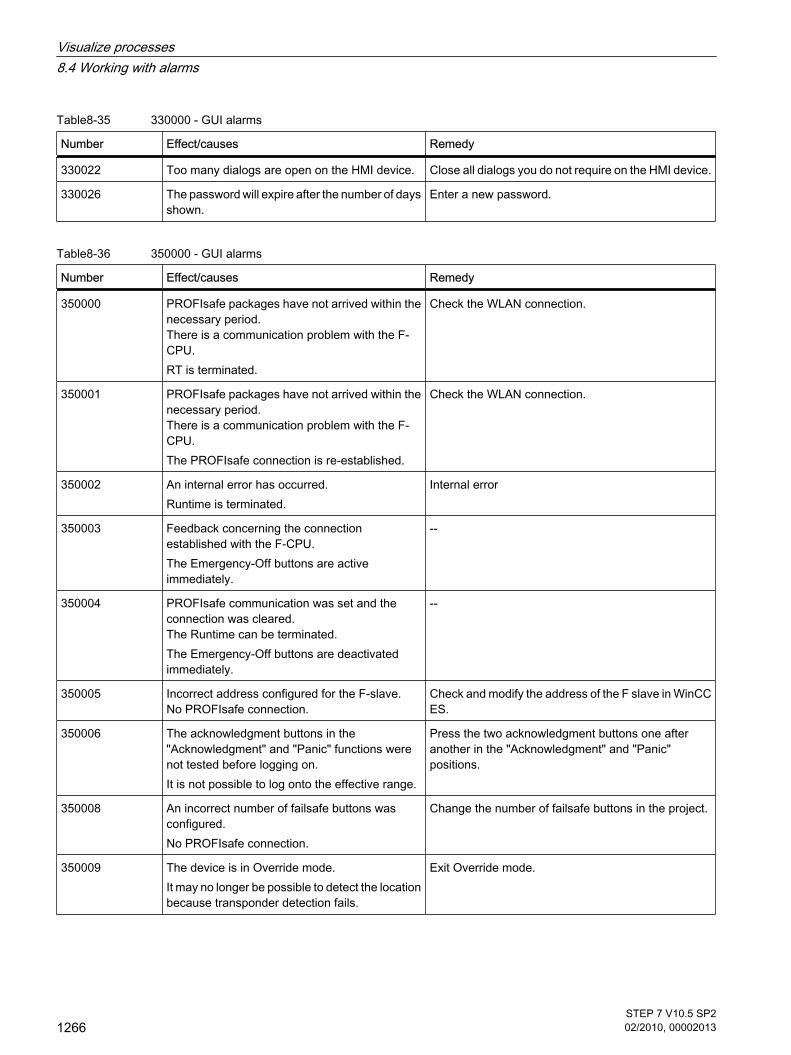
Table8-35 330000 - GUI alarms
Number Effect/causes Remedy
330022 Too many dialogs are open on the HMI device. Close all dialogs you do not require on the HMI device.
330026 The password will expire after the number of daysshown.
Enter a new password.
Table8-36 350000 - GUI alarms
Number Effect/causes Remedy
350000 PROFIsafe packages have not arrived within thenecessary period. There is a communication problem with the F-CPU.RT is terminated.
Check the WLAN connection.
350001 PROFIsafe packages have not arrived within thenecessary period. There is a communication problem with the F-CPU.The PROFIsafe connection is re-established.
Check the WLAN connection.
350002 An internal error has occurred.Runtime is terminated.
Internal error
350003 Feedback concerning the connectionestablished with the F-CPU.The Emergency-Off buttons are activeimmediately.
--
350004 PROFIsafe communication was set and theconnection was cleared. The Runtime can be terminated.The Emergency-Off buttons are deactivatedimmediately.
--
350005 Incorrect address configured for the F-slave. No PROFIsafe connection.
Check and modify the address of the F slave in WinCCES.
350006 The acknowledgment buttons in the"Acknowledgment" and "Panic" functions werenot tested before logging on.It is not possible to log onto the effective range.
Press the two acknowledgment buttons one afteranother in the "Acknowledgment" and "Panic"positions.
350008 An incorrect number of failsafe buttons wasconfigured.No PROFIsafe connection.
Change the number of failsafe buttons in the project.
350009 The device is in Override mode.It may no longer be possible to detect the locationbecause transponder detection fails.
Exit Override mode.
Visualize processes8.4 Working with alarms
1266STEP 7 V10.5 SP202/2010, 00002013

Number Effect/causes Remedy
350010 Internal error: The device has no failsafe buttons. Send the device back.Worldwide contact person
See alsoSystem functions and events for alarms (Page 1231)
8.5 Working with recipes
8.5.1 Basics
8.5.1.1 Basics on recipes
IntroductionRecipes are collections of data that belongs together, for example machine parameter settingsor production data.
Examples:
• Machine parameter settings that are needed to convert production to a different product variant.
• Product components that result in different compositions for different end products.
A recipe has a fixed data structure. The structure of a recipe is defined once at the configurationstage. A recipe contains recipe data records. These differ in terms of their values, but not theirstructure. Recipes are stored on the HMI device or on an external storage medium. If, forexample, production data is stored on a server in a database, you can import the productiondata via a CSV file at runtime.
NoteBasic Panels
It is not possible to export or import the recipes for Basic Panels. There is no external storagemedium.
A recipe data record is transferred in full between the HMI device, and PLC in a single step.
Using recipesRecipes can be used in the following situations:
8.5 Working with recipes8.5.1 Basics8.5.1.1 Basics on recipes
Visualize processes8.5 Working with recipes
STEP 7 V10.5 SP202/2010, 00002013
1267

• Manual production
You select the required recipe data and display it on the HMI device. You modify the recipe data asrequired and save it on the HMI device. You transfer the recipe data to the PLC.
• Automatic production
The control program starts transfer of the recipe data between the PLC and HMI device. You can alsostart the transfer from the HMI device. Production is then implemented automatically. It is not essentialto display or modify the data.
• Teach-in mode
You optimize production data that was optimized manually on the system, e.g. axis positions or fillingvolumes. The values thus determined are transferred to the HMI device and saved in a recipe datarecord. You can then transfer the saved recipe data back to the PLC at a later date.
Entering and modifying the recipe dataYou enter the data in the individual recipe data records, and modify it as required. The followingoptions are available:
• Data entry during configuration
If the production data exists already, you enter the data in the "Recipes" editor during recipeconfiguration.
• Data entry during runtime
If you have to frequently modify production data, you can do this directly in Runtime as follows:
― Enter the data directly on the HMI device.
― Set the parameters directly on the machine. You then transfer the data from the PLC to the HMIdevice, and save it in the recipe.
See also"Recipes" editor (Page 1273)Simple recipe view (Page 1276)General configuration procedure (Page 1279)Description of the simple recipe view (Basic, Advanced) (Page 1289)Examples for using recipes (Page 1268)Structure of recipes (Page 1269)Displaying recipes (Page 1270)Flow of data for recipes (Page 1271)Synchronization of recipe data records with the PLC (Page 1272)
8.5.1.2 Examples for using recipes
Recipes are used in the manufacturing industry and mechanical engineering, for example. Thefollowing examples illustrate typical applications that you can implement with the recipefunctionality of the WinCC Engineering System:
• Machine parameter assignment
8.5.1.2 Examples for using recipes
Visualize processes8.5 Working with recipes
1268STEP 7 V10.5 SP202/2010, 00002013

One field of application for recipes is the assignment of machine parameters in the manufacturingindustry: A machine cuts wooden boards to specified dimensions, and drills holes. The guide rails anddrill have to be moved to new positions according to the board size. The required position data arestored as data records in a recipe. You reassign the machine parameters using "Teach in" mode if,for example, a new board size is to be processed. You transfer the new position data directly from thePLC to the HMI device and save it as a new data record.
• Batch production
Batch production in the food processing industry represents another field of application for recipes: Afilling station in a fruit juice plant produces juice, nectar, and fruit drinks in a variety of flavors. Theingredients are always the same, differing only in their mixing ratios. Each flavor corresponds to arecipe. Each mixing ratio corresponds to a data record. All of the required data for a mixing ratio canbe transferred to the machine control at the touch of a button.
See alsoBasics on recipes (Page 1267)
8.5.1.3 Structure of recipes
IntroductionThe basic structure of a recipe is illustrated with reference to the filling station in a fruit juiceplant.
There may be several different recipes in an HMI device. A recipe can be compared to an indexcard box that contains several index cards. The index card box contains several variants formanufacturing a product family. All the data for each manufacturing variant is contained on asingle index card.
Example:
In a soft drinks production plant, a recipe is needed for different flavors. Drink variants includefruit juice drink, juice and nectar.
RecipeThe recipe contains all the recipe data records for the different drink variants.
8.5.1.3 Structure of recipes
Visualize processes8.5 Working with recipes
STEP 7 V10.5 SP202/2010, 00002013
1269

Recipe data recordsEach index card represents a recipe data record needed to manufacture a product variant.
Recipe entriesEach index card in a drawer has the same structure. All the index cards contain fields for thedifferent ingredients. Each field corresponds to a recipe entry. All the records of a recipe thuscontain the same entries. The records differ, however, in the value of the individual entries.
Example:
All the drinks contain the following ingredients:
• Water
• Concentrate
• Sugar
• Flavoring
The records for juice drink, fruit juice or nectar differ, however, in the quantity of sugar used inproduction.
See alsoBasics on recipes (Page 1267)
8.5.1.4 Displaying recipes
IntroductionYou need to configure the recipe view to display recipes. You can change the values of a recipein the recipe view and thereby influence the manufacturing process or a machine.
8.5.1.4 Displaying recipes
Visualize processes8.5 Working with recipes
1270STEP 7 V10.5 SP202/2010, 00002013

Recipe view The recipe view is an off-the-shelf WinCC display and operator control for managing recipedata records. The recipe view is always part of a screen. The recipe view shows recipe datarecords in tabular form. You adapt the appearance and the possible operations to suit yourspecific needs.
If you are editing recipes with a recipe view in your project, the values are saved in recipe datarecords. The values are not transferred between the HMI device and PLC until you use therelevant operator control.
See alsoBasics on recipes (Page 1267)
8.5.1.5 Flow of data for recipes
Interaction between the componentsThere is interaction between the following components at runtime:
• Recipe view
Recipes are displayed and edited in the recipe view on the HMI device.
The recipe data records from the internal memory of the HMI device are displayed and edited in therecipe view.
• HMI device recipe memory
Recipes are saved in the form of recipe data records in the HMI device's recipe memory.
• Recipe tags
The recipe tags contain recipe data.
Overview of the flow of dataThe following figure illustrates the flow of data in recipes:
8.5.1.5 Flow of data for recipes
Visualize processes8.5 Working with recipes
STEP 7 V10.5 SP202/2010, 00002013
1271

To transfer recipe data records to the PLC, use the "To PLC" button in the recipe view or anoperator control with the system function "RecipeViewSetDataRecordToPLC".
See alsoBasics on recipes (Page 1267)
8.5.1.6 Synchronization of recipe data records with the PLC
OverviewWhen recipe data records are transferred between the HMI device and PLC, bothcommunication peers access common communication areas on the other peer.
Recipe data records are always transferred directly. The values of the tags are written directlyto or read directly from the configured addresses without being placed on the clipboard.
Data transfer typesThere are two ways to transfer recipe data records between the HMI device and PLC:
• Transfer without synchronization
• Transfer with synchronization via the "Data record" area pointer.
NoteTransfer with synchronization
Transfer with synchronization is used to prevent the uncontrolled overwriting of data in eitherdirection in your control program.
8.5.1.6 Synchronization of recipe data records with the PLC
Visualize processes8.5 Working with recipes
1272STEP 7 V10.5 SP202/2010, 00002013

Requirements for transfer with synchronizationRequirements for transfer with synchronization:
• The "Data record" area pointer must be set up for the required connection in the "Communication >Connections" editor.
• The PLC with which the HMI device synchronizes the transfer is specified in the recipe properties inthe "Recipes" editor.
Transfer with synchronizationIn the case of synchronous transfer, both the PLC and the HMI device set status bits in theshared data compartment.
Synchronous data record transfer can be a useful solution, for example, when:
• The PLC is the "active partner" for the transfer of recipe data records.
• The PLC evaluates information about the recipe number and name, as well as the recipe data recordnumber and name.
• The transfer of recipe data records is started by the following PLC jobs:
― "Set_data_record_in_PLC"
― "Get_data_record_from_PLC"
See alsoBasics on recipes (Page 1267)
8.5.2 Elements and basic settings
8.5.2.1 "Recipes" editor
IntroductionYou can create, configure and edit recipes, recipe entries and recipe data records in the"Recipes" editor. The "Recipes" editor also allows you to enter values in recipe data records.
Structure of the "Recipes" editorYou create recipes in the top part of the table editor. You can also configure them there or inthe Inspector window.
The bottom part of the table editor has the following tabs:
• Elements
Define the elements of the selected recipe using the table cells provided here.
• Data records
8.5.2 Elements and basic settings8.5.2.1 "Recipes" editor
Visualize processes8.5 Working with recipes
STEP 7 V10.5 SP202/2010, 00002013
1273

Define the values of the data records of the selected recipe using the table cells provided here.
You can then configure the selected recipe, the recipe element or the recipe data record in theInspector window. You will find further notes on configuring the components of a recipe under"Configuring Recipes".
Recipe settingsThe following settings are available for recipes:
Setting Description
Recipe name This is a unique identification for the recipe within the HMI device.
Display name Appears in the recipe view, for example, in Runtime. You can configure displaynames in multiple languages. Enter meaningful names or designations whichyou can assign directly to a product, such as "Fruit_juice_Orange".
Recipe number This is a unique identification for the recipe within the HMI device.
Version Displays information with regard to the recipe. The date and time of the lastchange to the recipe is set by default.
Path Defines the storage location for recipes.
Infotext Infotext about the recipe element that the operator sees in Runtime.
NoteBasic Panels
The "Path" setting is not available for Basic Panels.
Recipe element settingsYou can make the following settings on the "Elements" tab:
Visualize processes8.5 Working with recipes
1274STEP 7 V10.5 SP202/2010, 00002013

Setting Description
Recipe element name Identifies a recipe element uniquely within the recipe. Enter meaningful namesor labels that you can allocate uniquely, such as axis labels on a machine oringredients such as "Flavoring".
Display name Appears in the recipe view, for example, in Runtime. You can configure displaynames in multiple languages. Enter meaningful names or designations whichyou can assign directly to a product, such as "Fruit_juice_Orange".
Assigned tag Every recipe element is assigned a recipe tag in which the value of the recipedata record will be stored in Runtime.
Text list Text is assigned to a value or range of values in a text list. You can displaythis text in an output field, for example.The tag assigned must be of the type "integer" to allow the use of text lists inrecipe elements. The tag value must be within the range of values of the textlist.
Default value This is used as the default entry when you create a new recipe data record.
Decimal point Determines the number of decimal places used to display the value of therecipe data record in Runtime.
Recipe data record settingsYou can make the following settings on the "Data records" tab:
Setting Description
Recipe data recordname
Identifies a recipe data record uniquely within the recipe.
Display name Appears in the recipe view, for example, in Runtime. You can configure displaynames in multiple languages. Enter meaningful names or labels that you canassign directly to a product, such as "Product_numbers".
Recipe data recordnumber
Identifies a recipe data record uniquely within the recipe.
Entered values You can enter values in a recipe data record during configuration. The recipedata records are included when you download the project to the HMI device.If there are data records on the HMI device already, a prompt will appear andthe records will be overwritten according to the download settings.
Comment Comment about the recipe data record
See alsoBasics on recipes (Page 1267)
Visualize processes8.5 Working with recipes
STEP 7 V10.5 SP202/2010, 00002013
1275

8.5.3 Displaying and editing recipes in Runtime
8.5.3.1 Simple recipe view
Recipe view The simple recipe view is a ready-made display element and operator control that is used tomanage recipe data records. The recipe view shows recipe data records in tabular form.
The operator control of the simple recipe view is configurable.
The values displayed or entered in the recipe view are saved in recipe data records. The recipedata records are exchanged with the PLC via system functions.
Layout of the display The simple recipe view consists of three areas:
• Recipe list
• Data record list
• Element list
In the simple recipe view, each area is shown separately on the HMI device. Depending on theconfiguration, the simple recipe view starts with the recipe list.
The figure below shows an example of the data record list.
Display of values
NoticeChanging the recipe data record in the background
Applies to the processing of a recipe data record: If values of the corresponding recipe data record are changed by a control job, the recipe viewis not updated automatically.
To update the recipe view, reselect the respective recipe data record.
See alsoBasics on recipes (Page 1267)Configuration options of the simple recipe view (Page 1277)Behavior of the recipe view in Runtime (Page 1278)
8.5.3 Displaying and editing recipes in Runtime8.5.3.1 Simple recipe view
Visualize processes8.5 Working with recipes
1276STEP 7 V10.5 SP202/2010, 00002013

8.5.3.2 Configuration options of the simple recipe view
You can define the behavior of the recipe view and the recipes that are displayed in the recipeview Inspector window.
Displaying recipe data record values onlyTo display the recipe data in a recipe view for checking only, proceed as follows:
1. Deselect "Edit mode" in the "General" group.
It is now not possible to edit recipe data records.
Configuring an event on the recipe view To configure an event for the recipe view, proceed as follows:
1. Select the recipe view that was added to the screen in the "Screens" editor.
The properties of the recipe view are shown in the Inspector window.
2. In the Inspector window, click the event you want to configure under "Properties > Events".
The "Function list" dialog box opens.
3. Configure a function list for the selected event.
The function list is processed when the configured event occurs.
NoteHMI device dependency
You can only configure events for the OP 77A and TP 177A HMI devices for the simple recipeview.
8.5.3.2 Configuration options of the simple recipe view
Visualize processes8.5 Working with recipes
STEP 7 V10.5 SP202/2010, 00002013
1277

Constraints on the simple recipe view
Note
The "Simple recipe view" object cannot be operated dynamically with a script.
In the Engineering System you can dynamically control the visibility of an object, for example,in the "Animations" group of the Inspector window. In Runtime, the "Simple recipe view" doesnot support animations. If you have configured an animation and, for example, wish to performa consistency check of the project, then an error alarm is issued in the Output window.
The following functions are not possible in the simple recipe view:
• Synchronize tags
• Save recipe and data record to a tag or read from a tag
See alsoSimple recipe view (Page 1276)
8.5.3.3 Behavior of the recipe view in Runtime
Screen changeIf you change to another screen and have not yet saved changes to the recipe data in the recipeview, you will be prompted to save the recipe data. The recipe name and the name of the recipedata record are displayed to show which recipe data have not been saved yet.
When you switch to a screen that contains a recipe view with loaded recipe data, the recipedata will be automatically updated.
Create, change, copy or delete recipe data recordsIf you attempt to create a new recipe data record and a recipe data record already exists, asystem alarm will appear on screen.
Operating the recipe view with function keysThe Recipe view can be operated with function keys, e.g. if the HMI device does not have touchfunctionality. You can assign functions such as "SaveDataRecord" to the function keys on theHMI device.
Display after import of recipe dataIf you open the recipe view during the import of recipe data, only the recipe data that is alreadycompletely imported will be displayed. The recipe view is not automatically updated with a dataimport. In order to have a complete view of all the recipe data, do not open the recipe view until
8.5.3.3 Behavior of the recipe view in Runtime
Visualize processes8.5 Working with recipes
1278STEP 7 V10.5 SP202/2010, 00002013
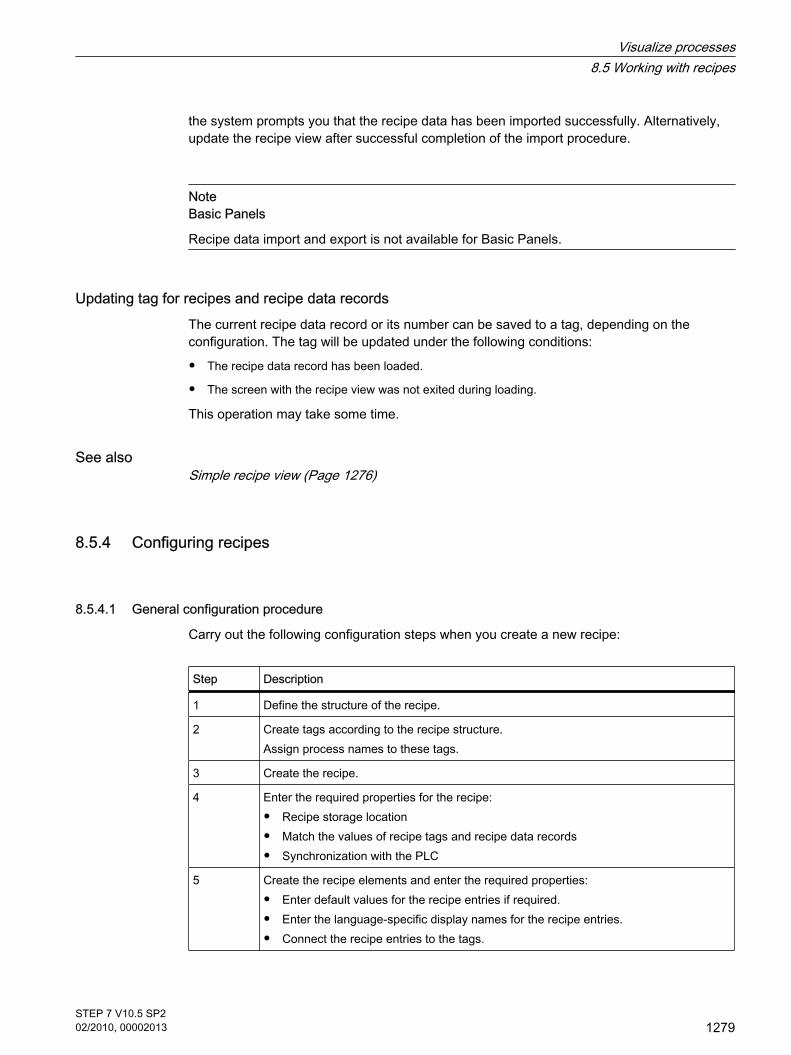
the system prompts you that the recipe data has been imported successfully. Alternatively,update the recipe view after successful completion of the import procedure.
NoteBasic Panels
Recipe data import and export is not available for Basic Panels.
Updating tag for recipes and recipe data recordsThe current recipe data record or its number can be saved to a tag, depending on theconfiguration. The tag will be updated under the following conditions:
• The recipe data record has been loaded.
• The screen with the recipe view was not exited during loading.
This operation may take some time.
See alsoSimple recipe view (Page 1276)
8.5.4 Configuring recipes
8.5.4.1 General configuration procedure
Carry out the following configuration steps when you create a new recipe:
Step Description
1 Define the structure of the recipe.
2 Create tags according to the recipe structure.Assign process names to these tags.
3 Create the recipe.
4 Enter the required properties for the recipe:
• Recipe storage location
• Match the values of recipe tags and recipe data records
• Synchronization with the PLC
5 Create the recipe elements and enter the required properties:
• Enter default values for the recipe entries if required.
• Enter the language-specific display names for the recipe entries.
• Connect the recipe entries to the tags.
8.5.4 Configuring recipes8.5.4.1 General configuration procedure
Visualize processes8.5 Working with recipes
STEP 7 V10.5 SP202/2010, 00002013
1279

Step Description
6 Create the recipe data records.Enter the language-specific display names for the recipe data records.
7 Configure a screen with recipe view or a recipe screen.
NoteBasic Panels
The selection of the storage location is not available for Basic Panels. The recipes are alwaysstored in the recipe memory.
The recipe screen is not available for Basic Panels.
See alsoBasics on recipes (Page 1267)Creating a new recipe (Page 1282)Configuring the simple recipe view (Page 1280)
8.5.4.2 Configuring the display of recipes
8.5.4.2 Configuring the simple recipe view
Requirement
• You have created the recipe.
• The "Screens" editor is open.
• The screen has been created and opened.
ProcedureTo configure a simple recipe view, proceed as follows:
1. Paste the recipe view into the screen. You will find the recipe view under "Controls" in the "Tools" taskcard.
2. Select "Simple view" under "General > Display type".
8.5.4.2 Configuring the display of recipes8.5.4.2 Configuring the simple recipe view
Visualize processes8.5 Working with recipes
1280STEP 7 V10.5 SP202/2010, 00002013

3. If you want to display only the recipe data records of a specific recipe in the recipe view, select therecipe under "Recipe".
4. If you only want to display the recipe data in the recipe view, deselect "Edit mode" in the "Data record"area.
5. You can define additional options for the recipe view under "Properties > Appearance" and "Properties> Layout".
6. Select "Properties > Simple view" to select the position, the field length, and the number of linesrequired.
Select "Position > Top" to display the recipe value in the first line of the recipe entry.
Select "Position > Bottom" to display the recipe value in the last line of the recipe entry.
7. Under "Properties" > "Buttons", specify which menu commands are to be available in the recipe viewin Runtime.
Visualize processes8.5 Working with recipes
STEP 7 V10.5 SP202/2010, 00002013
1281

ResultThe simple recipe view is configured. You can use the recipe view to display and edit recipedata during runtime.
See alsoGeneral configuration procedure (Page 1279)
8.5.4.3 Creating and Editing Recipes
8.5.4.3 Creating a new recipe
IntroductionTo create a complete recipe, start by creating a new recipe, assign the corresponding recipeelements and then define the associated values in a recipe data record.
Requirement
• The tags for the recipe have been created.
• The "Recipes" editor is open.
Create recipeCreate a recipe as follows:
1. Click "Add" in the first free row of the table in the "Recipes" editor.
The new recipe is created and displayed on a line.
2. Enter a descriptive name for the recipe under "Name".
This name identifies the recipe unambiguously within the project.
3. Select "Display name" to enter the language-specific name to be displayed in runtime.
8.5.4.3 Creating and Editing Recipes8.5.4.3 Creating a new recipe
Visualize processes8.5 Working with recipes
1282STEP 7 V10.5 SP202/2010, 00002013

4. Select a recipe number in "Number".
The number identifies the recipe unambiguously within the HMI device.
The recipe is automatically assigned a version that indicates the date and time of the last change. Asan alternative, you can enter specific information relating to the recipe.
5. Specify the storage location for recipe data records in "Data medium". The options offered depend onthe specific HMI device used.
NoteBasic Panels
The "Data storage" category is not available for Basic Panels. The recipe data records arestored in the internal flash memory.
6. Enter an info text that the operator will see in runtime.
7. To match recipe tags configured in I/O fields with the recipe view in runtime, select "Synchronize tags"under "Properties > Options" in the Inspector window.
8. Disable "Offline tags" to specify that the recipe tags should be automatically transferred to the PLCwhen editing the I/O fields.
NoteBasic Panels
Since the recipe tags cannot be additionally used in I/O fields in screens with Basic Panels,the "Options" category is not available.
9. Enable "Synchronization" under "Properties > Download " to monitor the recipe data download duringruntime using area pointers.
10.
Select the relevant PLC under "Synchronize with ...".
Visualize processes8.5 Working with recipes
STEP 7 V10.5 SP202/2010, 00002013
1283

Create recipe elementTo create recipe elements, proceed as follows:
1. Click the "Elements" tab.
2. Click "Add" in the first free line of the table editor.
A new recipe element is created.
3. Enter a descriptive name for the element under "Name".
The name identifies the element uniquely within the recipe.
4. Enter a language-specific display name for the element under "Display name".
The display name appears in the recipe view, for example, in runtime.
5. Select the tag you want to link to the recipe element under "Tag".
The value of the recipe data record is saved in this tag in runtime.
6. Enter an info text.
The info text is displayed to the operator in runtime.
7. Under "Default value", enter the value that you want to use as the default entry when you create anew recipe data record.
8. To assign text to a value or range of values, select the relevant text list here.
The tag assigned must be of the type "integer" to allow the use of text lists in recipe elements. Thetag value must be within the range of values of the text list.
The text stored in the text list is displayed in an output field, for example, in runtime.
9. The exact number of decimal places of the data record values displayed at runtime is set in the"Decimal places" column.
Visualize processes8.5 Working with recipes
1284STEP 7 V10.5 SP202/2010, 00002013

10.
Create as many recipe entries as needed for the recipe. The maximum number of recipe entriespossible depends on the HMI device being used.
Create recipe data record with known recipe valuesTo create recipe elements, proceed as follows:
1. Click the "Data records" tab.
2. Click "Add" in the first free line of the table editor.
A new recipe data record is created. The recipe data record has a separate column for every recipeelement created in the recipe.
3. Enter a descriptive name under "Name".
The name identifies the data record uniquely within the recipe.
4. Enter a language-specific name under "Display name".
The display name appears in the recipe view, for example, in runtime.
5. Enter a recipe data record number under "Number".
The recipe data record number identifies the recipe data record uniquely within the recipe.
6. If you already know the recipe values at the configuration stage, you can enter the relevant value foreach recipe element.
7. Create as many data records as needed for the recipe.
Visualize processes8.5 Working with recipes
STEP 7 V10.5 SP202/2010, 00002013
1285

Enter the values in runtimeThe following options are available for entering values in the recipe data records at runtime:
• Transfer data directly from the PLC (Teach-in mode)
• Import of values from a CSV file
• Input values on the HMI device
NoteBasic Panels
Importing of values is not available for Basic Panels.
ResultThe complete recipe is configured.
Recipe data records with date or time stampIf you specify dates or times in recipes, the following must agree:
• System settings for time and date on the configuration computer
• System settings for time and date on the target system
After downloading to the target system, check the recipes with date or time stamps on the targetsystem.
See alsoGeneral configuration procedure (Page 1279)Editing a recipe (Page 1286)Managing recipes (Page 1287)
8.5.4.3 Editing a recipe
PurposeYou want to modify, extend or delete parts of a recipe.
8.5.4.3 Editing a recipe
Visualize processes8.5 Working with recipes
1286STEP 7 V10.5 SP202/2010, 00002013

Requirement
• You have created at least one recipe.
• The "Recipes" editor is open.
Changing recipe settingsTo change the recipe settings, proceed as follows:
1. Select the recipe that you want to change in the "Recipes" editor.
The Inspector window opens.
2. Change the recipe configuration in the Inspector window.
You change recipe elements and recipe data records in the same way.
Change recipe valuesTo change recipe values, proceed as follows:
1. Select the recipe whose values you want to change.
2. Click the "Data records" tab.
3. Enter the new values in the value columns.
Adding a recipe elementTo add more recipe elements to a recipe, proceed as follows:
1. Select the recipe to which you want to add more elements in the "Recipes" editor.
2. Click the "Elements" tab.
3. Click "Add" in the first free line.
The recipe element is created.
4. Configure the recipe element.
You add recipe data records in the same way.
See alsoCreating a new recipe (Page 1282)
8.5.4.3 Managing recipes
Requirement
• You have created a recipe with recipe elements and recipe data record.
• The "Recipes" editor is open.
Renaming recipesWe distinguish between internal names and display names for recipes, recipe entries andrecipe data records.
8.5.4.3 Managing recipes
Visualize processes8.5 Working with recipes
STEP 7 V10.5 SP202/2010, 00002013
1287

To rename recipe elements, proceed as follows:
1. Select the recipe that you want to rename.
The Inspector window opens.
2. Select the "Rename" command from the shortcut menu.
3. Enter the new name.
You rename recipe elements and recipe data records on the relevant tab in the same way.
Note
You can also change the display names of recipes and recipe data records by selecting"Language support > Project texts". This option applies, for example, if you have alreadymade configuration settings in several languages.
Copying and pasting recipesTo copy and paste recipes, proceed as follows:
1. Select the recipe that you want to copy.
2. Select the "Copy" command from the shortcut menu.
3. Select the "Paste" command from the shortcut menu in the first free table row.
The copied recipe is pasted into the table.
You copy recipe elements and recipe data records on the relevant tab in the same way.
If a recipe data record with the same name already exists, a digit will be appended to the nameof the copied recipe data record. This ensures that the name is unique. Recipe data recordscan only be copied or pasted within the same recipe.
Deleting a recipeTo delete a recipe, proceed as follows:
1. Select the recipe that you want to delete.
2. Select the "Delete" command from the shortcut menu.
The recipe is deleted.
You delete recipe elements and recipe data records on the relevant tab in the same way.
Note
When a recipe is deleted, the recipe data records contained in the recipe are also deleted.
Visualize processes8.5 Working with recipes
1288STEP 7 V10.5 SP202/2010, 00002013

Note
When you delete a recipe element, the associated values in the recipe data records are alsodeleted. The assigned tags are retained.
See alsoCreating a new recipe (Page 1282)
8.5.5 Using recipes in Runtime
8.5.5.1 Using the simple recipe view
8.5.5.1 Description of the simple recipe view
LayoutThe simple recipe view consists of the following display areas:
• Recipe list
• Data record list
• Element list
This application is illustrated below:
In the simple recipe view, each area is shown separately on the HMI device. You can use theshortcut menu to operate each of these display areas.
The simple recipe view always begins with the recipe list.
OperationYou have the following options for using the simple recipe view, according to the configuration:
• Create, change, copy or delete recipe data records
• Read recipe data records from the PLC or transfer to the PLC
Using the display area and shortcut menuToggle between the display areas and the shortcut menus to operate the simple recipe views.
8.5.5 Using recipes in Runtime8.5.5.1 Using the simple recipe view8.5.5.1 Description of the simple recipe view
Visualize processes8.5 Working with recipes
STEP 7 V10.5 SP202/2010, 00002013
1289

The table below shows the operation of the display area.
Button Key Function
<Enter> The next lowest display area is opened, i.e. the data recordlist or the element list.
<Esc> The previous display area opens.
<Right> The shortcut menu of the display area opens.
<Up>/<Down> Selects the previous/next entry.
<Pg Up>/<Pg Down> Moves the display up or down one page.
<Home>/<End> Selects the first/last entry. The first/last entry is selected.
The table below shows the operation of the shortcut menu:
Button Key Function
<Esc> The menu is closed. The display area opens.
Input of the number ofthe menu command
The menu command is executed.
Shortcut menus of the simple recipe viewYou can click the
button in each display area to call up a selection of commands. The command selection liststhose commands that are available in the current display area. A number is assigned to eachcommand. The command is executed when you enter this number. Shortcut menus in the recipe list
Menu command Function
New A new recipe data record is created for the selected recipe. If a start value is configured, it is displayed in the input field.
Displaying infotext Displays the infotext configured for the simple recipe view.
Open The record list of the selected recipe opens.
Shortcut menus in the data record list
Visualize processes8.5 Working with recipes
1290STEP 7 V10.5 SP202/2010, 00002013

Menu command Function
New Creates a new recipe data record. If a start value is configured, it is displayed in the input field.
Deleting The displayed record is deleted.
Save as The selected data record is saved under a different name. A dialog box openswhere you can enter the name.
Rename Renames the selected data record. A dialog box opens where you can enterthe name.
Open The element list of the selected data record opens.
Previous The recipe list opens.
Shortcut menus in the element list
Menu command Function
Save The selected record is renamed.
To PLC The displayed values of the selected data record are transferred from the HMIdevice to the PLC.
From PLC The recipe values from the PLC are displayed in the recipe view of the HMIdevice.
Save as The data record is saved under a new name. A dialog box opens where youcan enter the name.
Press the <ESC> key to open the data record list.
NoteHMI device dependency
The following menu commands can also be configured on the TP 177A and OP 77A HMIdevices and all Basic Panels:
Shortcut menus in the data record list
Menu command Function
To PLC The displayed values of the selected data record are transferred from the HMIdevice to the PLC.
From PLC The recipe values from the PLC are displayed in the recipe view of the HMIdevice.
Displaying infotext Displays the infotext configured for the simple recipe view.
Visualize processes8.5 Working with recipes
STEP 7 V10.5 SP202/2010, 00002013
1291

Shortcut menus in the element list
Menu command Function
Displaying infotext Displays the infotext configured for the simple recipe view.
Rename Renames the selected data record. A dialog box opens where you can enterthe name.
Previous The data record list opens.
See alsoBasics on recipes (Page 1267)Managing recipe data records (Basic, Advanced) (Page 1292)Reading a recipe data record from the PLC (Basic, Advanced) (Page 1294)Transferring a recipe data record to the PLC (Basic, Advanced) (Page 1294)
8.5.5.1 Managing recipe data records
Recipe data record administrationYou have the following options for managing the simple recipe view, according to theconfiguration:
• Creating new recipe data records
• Copy recipe data records
• Edit recipe data records
• Delete recipe data records
Creating new recipe data recordsTo create a new recipe data record, proceed as follows:
1. Select the recipe on the HMI device in which you want to create a new recipe data record.
2. Select the "New" command from the shortcut menu for the recipe list.
A new data record with the next available number will be created.
The element list of the new recipe data record opens.
3. Enter values for the elements of the recipe data record.
The configuration data may already contain default values for the recipe data record.
4. Select the "Save" command from the shortcut menu for the element list.
The dialog "Save as" opens.
5. Enter the name and number of the recipe data record.
6. Click the "OK" button.Result
8.5.5.1 Managing recipe data records
Visualize processes8.5 Working with recipes
1292STEP 7 V10.5 SP202/2010, 00002013

The new recipe data records will be saved to the selected recipe. If the recipe data recordsalready exists, a system alarm will be output to the screen.
Copying a recipe data recordTo copy a recipe data record, proceed as follows:
1. Select the recipe on the HMI device in which you want to copy an existing recipe data record.
2. On the HMI device, select the recipe data record of which you want to save a copy.
3. Select the "Save As" command from the shortcut menu for the data record list.
The dialog "Save as" opens. The recipe data record is automatically given the next free recipe datarecord number.
4. Under name, enter the name of the record.
5. Click the "OK" button.Result
The recipe data record is stored under the new name.
Modify recipe data recordTo change a recipe data record, proceed as follows:
1. Select the recipe on the HMI device in which you want to edit an existing recipe data record.
2. Select the recipe data record that you want to edit on the HMI device.
3. Select the recipe data record.
The element list of the recipe data record is displayed.
4. Replace the old values with new ones.
5. Select the "Save" command from the shortcut menu for the element list.Result
The modified values are applied to the recipe data record.
Deleting a recipe data recordTo delete a recipe data record, proceed as follows:
1. Select the recipe on the HMI device from which you want to delete an existing recipe data record.
2. Select the recipe data record that you want to delete on the HMI device.
3. Select the "Delete" command from the shortcut menu for the data record list.
4. Confirm this security prompt to delete the data record.Result
The recipe data record is deleted.
See alsoDescription of the simple recipe view (Basic, Advanced) (Page 1289)
Visualize processes8.5 Working with recipes
STEP 7 V10.5 SP202/2010, 00002013
1293

8.5.5.1 Reading a recipe data record from the PLC
IntroductionIn Runtime, you can change values directly in the plant that are also stored in recipes in theHMI device. This applies if a valve was opened further directly in the plant than was specifiedin the recipe. The values of the recipe data records saved in the HMI device possibly no longermatch the values in the PLC.
You can read the values of the recipe tags from the PLC and write them to a recipe data record.
The read values are written to the recipe data record that is currently displayed on the HMIdevice.
ProcedureTo read a recipe data record from the PLC, proceed as follows:
1. Open the recipe on the HMI device.
The data record list opens.
2. Select the element list of the recipe data record to which you want to apply the values from the PLC.
3. Select the "From PLC" command from the shortcut menu for the element list.
The values are read from the PLC and displayed in the current recipe data record.
4. If you want to save the values, select the "Save" or "Save As" command.
ResultThe values are read from the PLC, visualized on the HMI device and saved to the recipe datarecord.
NoteBasic Panels
With Basic Panels, the "From PLC" menu command can also be configured for the data recordlist: In this case, you can also select the "From PLC" menu command in the data record list.
See alsoDescription of the simple recipe view (Basic, Advanced) (Page 1289)
8.5.5.1 Transferring a recipe data record to the PLC
IntroductionFor the values of a data record that was changed in the recipe view to take effect, you musttransfer the values to the PLC.
8.5.5.1 Reading a recipe data record from the PLC8.5.5.1 Transferring a recipe data record to the PLC
Visualize processes8.5 Working with recipes
1294STEP 7 V10.5 SP202/2010, 00002013

The values displayed in the recipe view are always transferred to the PLC.
ProcedureTo transfer a recipe data record to the PLC, proceed as follows:
1. Open the recipe you want to use.
The data record list opens.
2. Select the element list of the recipe data record whose values you want to transfer to the PLC.
3. Select the "To PLC" command from the shortcut menu for the element list.
ResultThe values of the recipe data record are transferred to the PLC.
NoteBasic Panels
With Basic Panels, the "To PLC" menu command can also be configured for the data recordlist: In this case, you can also select the "To PLC" menu command in the data record list.
See alsoDescription of the simple recipe view (Basic, Advanced) (Page 1289)
8.6 Working with the user administration
8.6.1 Field of application of the user administration
PrincipleThe access protection controls access to data and functions in Runtime. This feature protectsyour applications against unauthorized operation. Safety-related operations are already limitedto specific user groups when a project is being created. To this purpose you set up users anduser groups that you equip with characteristic access rights, so-called authorizations. You thenconfigure the authorizations required for operation of safety-related objects. Operators onlyhave access, for example, to specific operator controls. Commissioners, for example, haveunlimited access in Runtime.
DefinitionYou administer users, user groups and authorizations centrally in the user administration ofWinCC. You transfer users and user groups together with the project to the HMI device. Theusers and passwords are managed on the HMI device in the User view.
8.6 Working with the user administration8.6.1 Field of application of the user administration
Visualize processes8.6 Working with the user administration
STEP 7 V10.5 SP202/2010, 00002013
1295

Application exampleYou configure the "Service" authorization so that only service technicians have access to theconfiguration parameters. You assign the authorization to the "Service technician" user group.This allows all members of this group to set the protected configuration parameters.
Caution
Access protection does not protect against incorrect operations. It is your job to ensure thatonly authorized personnel with appropriate training will design, commission, operate andmaintain plants and machines.
Access protection is not suitable for defining work routines and monitoring their observance.
See alsoUsers work area (Page 1298)Basics on user administration (Page 1302)Objects with access protection (Page 0 )Example: Configuring a button with logon dialog box (Page 1321)Form of the user administration (Page 1296)Example: Structure of user management (Page 1322)
8.6.2 Form of the user administration
IntroductionIn case of a project in manufacturing engineering, the environment at the equipmentmanufacturer has to be differentiated from the environment at the end customer as plantoperator.
The equipment manufacturer allows users, for example Mr. Foreman, a specific access withinthe application or HMI device. However, a user Foreman does not exist at the end customer.On the other hand, the OEM cannot know the users at the end customer and their jobs duringthe configuration. The final users are usually set after commissioning at the end customer.
8.6.2 Form of the user administration
Visualize processes8.6 Working with the user administration
1296STEP 7 V10.5 SP202/2010, 00002013

PrincipleTo minimize the work required for management, authorizations are assigned via user groupsand not directly to individual users.
A user group assembles configured authorizations according to common jobs. For example,all permissions required for a service job are collected in a "Service technician" group. Whenyou create a user who should be responsible for servicing, you simply assign him to the "Servicetechnician" group.
The User display is provided to manage users in Runtime; it is linked to the configuration in theapplication or HMI device. The User display enables you to create and delete users, and assignauthorizations to them.
The user administration separates the administration of the users from the configuration of theauthorizations. This ensures flexibility at the access protection.
Defaults can be set for the user administration during the configuration phase in the EngineeringSystem.
See alsoField of application of the user administration (Page 1295)Example: Configuring a button with logon dialog box (Page 1321)Example: Structure of user management (Page 1322)
Visualize processes8.6 Working with the user administration
STEP 7 V10.5 SP202/2010, 00002013
1297

8.6.3 Elements and basic settings
8.6.3.1 Users work area
IntroductionThe "Users" work area lists the users and user groups in table form. You administrate the usersand assign them to a user group.
PrincipleThe work area consists of the "Users" and "Groups" tables.
The "Users" table shows the existing users. When you select a user in this table, the "Memberof" column in the "Groups" table displays the user group to which the user belongs.
See alsoField of application of the user administration (Page 1295)User groups work area (Page 1298)"Users" user administration (Page 1299)"User groups" user administration (Page 1300)Settings for the user administration (Page 1301)Example: Configuring a button with logon dialog box (Page 1321)Example: Structure of user management (Page 1322)
8.6.3.2 User groups work area
IntroductionThe "User groups" work area shows a table of the groups and their authorizations. Youadminister the user groups and assign authorizations to them.
8.6.3 Elements and basic settings8.6.3.1 Users work area8.6.3.2 User groups work area
Visualize processes8.6 Working with the user administration
1298STEP 7 V10.5 SP202/2010, 00002013

PrincipleThe work area consists of the "Groups" and "Authorizations" tables.
The "Groups" table shows the existing user groups. When you select a user group in this table,the "Active" column of the "Authorizations" table shows the authorizations which were assignedto the user group.
The number of the user group and of the authorization is assigned by the user administration.The designations and descriptions are assigned by you.
The number of predefined authorizations are fixed. Authorizations you have created yourselfcan be freely edited, although you should ensure they always have unique numbers.
See alsoUsers work area (Page 1298)Example: Configuring a button with logon dialog box (Page 1321)Example: Structure of user management (Page 1322)
8.6.3.3 "Users" user administration
IntroductionYou can create users in the "Users" tab of the "Runtime user administration" editor and assignthem to user groups. The "Users" tab is part of the user administration in WinCC.
OpenTo open the "Users" tab, double-click "Runtime user administration" in the project window.
Menu barThe menu bar contains all commands required for operating WinCC.Toolbar
8.6.3.3 "Users" user administration
Visualize processes8.6 Working with the user administration
STEP 7 V10.5 SP202/2010, 00002013
1299

The toolbars contain the most important commands from the menus.Work area
The users are managed in the work area:
• You create or delete users.
• You assign users to user groups.
Note
You can assign a user to exactly one user group.Inspector window
When you have selected a user, you can change the password in the "General" group. In the"Automatic logoff" group, specify if the user is to be logged off automatically from the HMIdevice.
See alsoUsers work area (Page 1298)Example: Configuring a button with logon dialog box (Page 1321)Example: Structure of user management (Page 1322)
8.6.3.4 "User groups" user administration
IntroductionYou can create users and authorizations in the "User groups" tab of the "User Administration"editor. The "User groups" tab is part of the user administration in WinCC.
OpenDouble-click the "User administration" in the project window. Open the "User groups" tab.
Menu barThe menu bar contains all commands required for operating WinCC. If shortcuts are available,they are displayed next to the menu command.Toolbar
The toolbars contain the most important commands from the menus.Work area
The user groups and authorizations are managed in the work area:
• You create new user groups and authorizations or delete them.
• You assign the authorizations to the user groups.Property window
When a user group or an authorization is selected, you can edit the name in the "General"group. You can also enter a brief description in the "Comment" group.
8.6.3.4 "User groups" user administration
Visualize processes8.6 Working with the user administration
1300STEP 7 V10.5 SP202/2010, 00002013

See alsoUsers work area (Page 1298)Example: Configuring a button with logon dialog box (Page 1321)Example: Structure of user management (Page 1322)
8.6.3.5 Settings for the user administration
IntroductionIn the "Runtime settings > User administration" editor, configure the security settings for usersand their passwords in runtime.
OpenDouble-click the "Runtime settings" editor in the project window. Click "User administration."
Work areaYou carry out the settings for the validity of passwords in runtime in the work area. Youdetermine the complexity of the password, for example.
Effects in runtimeThe security settings have the following effects in runtime, depending on the configuration.
• "Runtime services" group
― "Enable limit for logon attempts" check box selected
The number entered in the "Number of incorrect logon attempts" field defines the number of loginattempts a user is allowed before being assigned to the "Unauthorized" group.
"Enable limit for logon attempts" check box not selected
The user has an unlimited number of logon attempts in runtime.
― "Number of incorrect logon attempts" field
If you enter "4" in the field, for example, and the fourth logon attempt fails, the user is automaticallyassigned to the "Unauthorized" group.
Enter 1 to 9 attempts.
― "Logon only with password" check box
When the check box is selected, the user is authenticated by the password. The user name is notrequired.
To match users to passwords, you cannot configure passwords more than once.
• "Hierarchy level" group
― "Group-specific rights for user administration" check box
When this check box is selected, administrators only manage users whose group number is lessthan or equal to their own.
8.6.3.5 Settings for the user administration
Visualize processes8.6 Working with the user administration
STEP 7 V10.5 SP202/2010, 00002013
1301

For example, an administrator whose group number is 5 can only manage users whose groupnumber is less than or equal to 5. This means that the administrator can assign users only togroups with a group number less than or equal to 5.
• "Password" group
― "Enable password aging" checkbox selected
The password expires after the number of days set in the "Validity of the password (days)" field.
The "Password aging" column is selected in the "User groups" editor. This enables you to specifygroup-by-group, if the passwords should expire or if the password generations should be saved.Passwords never expire for groups for which password aging is not enabled.
― "Pre-warning time (days)" field
The user is informed that the password will expire the specified number of days before thepassword expires.
― "Password generations" field
If the user changes the password, the new password must be different from the specified numberof previous passwords. The number of password generations ranges from 1 to 5.
• "Password complexity" group
― "Must include special characters" check box selected
The user must enter a password containing at least one special character, at any position.
― "Must include number" check box selected
The user must enter a password containing at least one digit, at any position.
― "Minimum password length" field
The user must enter a password with a minimum length, as specified in the "Minimum passwordlength" field.
The minimum length of the password is 3 characters.
See alsoUsers work area (Page 1298)Example: Configuring a button with logon dialog box (Page 1321)Example: Structure of user management (Page 1322)
8.6.4 Setting up the user administration
8.6.4.1 Basics on user administration
PrincipleThis section addresses four target groups. The topics are organized correspondingly. Thetarget groups serve as examples for different groups of persons who use the useradministration.
8.6.4 Setting up the user administration8.6.4.1 Basics on user administration
Visualize processes8.6 Working with the user administration
1302STEP 7 V10.5 SP202/2010, 00002013

1. Administrator OEM
2. Administrator RT
3. Planners
4. Operator
As Administrator OEM you create the user groups, users and authorizations for Runtime in theEngineering System of, for example, an equipment manufacturer.
As Administrator RT you administer users in Runtime by means of the "User view."
As the project engineer you assign the authorizations to the user groups in the EngineeringSystem. In addition, you configure the authorizations for objects.
As Operator you log on in runtime. You can only access a protected object if you have therequired authorization.
Note
The Administrator RT target group already exists in the Runtime user administration as thepredefined user group "Administrator group." For a better understanding the predefined usergroups and authorizations are not used below.
See alsoField of application of the user administration (Page 1295)Creating an authorization (Page 1303)Users in Runtime (Page 1310)Access protection (Page 1319)Example: Configuring a button with logon dialog box (Page 1321)Example: Structure of user management (Page 1322)
8.6.4.2 Administering users for Runtime
8.6.4.2 Creating an authorization
IntroductionYou create an authorization and assign it to one or more user groups.
RequirementsThe "User groups" work area is open.
Procedure1. Double-click "Add..." in the "Authorizations" table.
8.6.4.2 Administering users for Runtime8.6.4.2 Creating an authorization
Visualize processes8.6 Working with the user administration
STEP 7 V10.5 SP202/2010, 00002013
1303

2. Enter "Archive data" as the name of the authorization.
3. Enter a brief description as the "Comment."
See alsoBasics on user administration (Page 1302)Creating a user group (Page 1304)Assigning an authorization (Page 1305)Creating users (Page 1305)Assigning a user to a user group (Page 1307)User administration (Page 1307)Managing user groups (Page 1309)Example: Configuring a button with logon dialog box (Page 1321)Example: Structure of user management (Page 1322)
8.6.4.2 Creating a user group
IntroductionUser groups are created so that you do not have to assign an authorization to every singleuser. You create a user group, allocate authorizations and assign users to it.
Note
The name of the user group has to be unique within the project. Otherwise the input is notaccepted.
RequirementsThe "User groups" work area is open.
Procedure1. Double-click "Add..." in the "Groups" table.
2. Enter "Operators" as the name of the user group.
3. Enter a brief description as the "Comment."
Note
The name of the user group is language-dependent. You specify the designation in severallanguages and switch between languages in runtime.
See alsoCreating an authorization (Page 1303)Example: Configuring a button with logon dialog box (Page 1321)
8.6.4.2 Creating a user group
Visualize processes8.6 Working with the user administration
1304STEP 7 V10.5 SP202/2010, 00002013

Example: Structure of user management (Page 1322)
8.6.4.2 Assigning an authorization
IntroductionWhen you allocate an authorization to a user group, all assigned users have this authorization.
Requirements
• An "Archive data" authorization has been created.
• An "Operators" user group has been created.
• The "User groups" work area is open.
Procedure1. Click on the "Operators" user group in the "Groups" table. The "Authorizations" table shows all
authorizations.
2. Activate the "Archive data" authorization in the "Authorizations" table.
Notice
The "Archive data" authorization is only a designation and does not having any relation tothe function "Archiving." You have to establish this relation yourself. To do so, configure the"StartArchiving" system functions at a control button and select "Archive data" as the"Authorization."
See alsoCreating an authorization (Page 1303)Example: Configuring a button with logon dialog box (Page 1321)Example: Structure of user management (Page 1322)
8.6.4.2 Creating users
IntroductionYou create a user so that users can log on under the user name in Runtime once the projecthas been transferred.
As an alternative, you can create and change users by means of the "User view" in Runtime.
The logon is successful when the user name entered during the logon matches a user inRuntime. In addition, the entered password must agree with the stored password of the user.
8.6.4.2 Assigning an authorization8.6.4.2 Creating users
Visualize processes8.6 Working with the user administration
STEP 7 V10.5 SP202/2010, 00002013
1305

Note
Pay attention to capitalization on HMI devices with Runtime Professional.
Note
The user name must be unique within the project. Otherwise the input is not accepted.
Notice
In order for a created user to have authorizations you have to assign him to a user group andallocate authorizations to the user group.
RequirementsThe "Users" work area is open.
Procedure1. Double-click "Add..." in the "Users" table.
2. Enter "Foreman" as the user name.
3. Click the
button in the "Password" column. A dialog box for entering the password is displayed.
4. Enter the password of the user.
5. To confirm the password enter it a second time in the lower field.
6. Close the dialog box by using the
icon.
7. If a user is to be logged off after a specific time period, activate "Automatic logoff".
8. Click in the "Logoff time" column. The preset value for "Logoff time" is 5 minutes.
9. Enter a brief description as the "Comment".
See alsoCreating an authorization (Page 1303)Example: Configuring a button with logon dialog box (Page 1321)Example: Structure of user management (Page 1322)
Visualize processes8.6 Working with the user administration
1306STEP 7 V10.5 SP202/2010, 00002013

8.6.4.2 Assigning a user to a user group
IntroductionWhen you assign a user to a user group, the user has the authorizations of the user group.
Note
You have to assign a user to exactly one user group. The assignment is checked during theconsistency check and generation of the project.
Requirements
• The user "Foreman" has been created.
• An "Operators" user group has been created.
• The "Users" work area is open.
Procedure1. Click on the "Foreman" user in the "Users" table. The "Groups" table shows all user groups.
2. Activate the "Operators" user group in the "Groups" table.
See alsoCreating an authorization (Page 1303)Example: Configuring a button with logon dialog box (Page 1321)Example: Structure of user management (Page 1322)
8.6.4.2 User administration
IntroductionIn the work area, you can administer users and assign them to user groups.
RequirementsThe "Users" work area is open.
Changing the name of the user1. In the "Users" table, double-click the field in the "Name" column to change the user name.
2. Change the user name.
3. Confirm your entry with <Return>.
As an alternative, select the user in the work area; the properties of the user are then displayedin the Inspector window. In the "Properties" tab, select the "General" group. Change the username in the "Name" field.
8.6.4.2 Assigning a user to a user group8.6.4.2 User administration
Visualize processes8.6 Working with the user administration
STEP 7 V10.5 SP202/2010, 00002013
1307
Changing the password of the user1. Click the
button in the "Password" column of the "Users" table. A dialog for entering the password opens.
2. In the "Enter password" field, enter the new password.
3. Reenter the new password in the "Confirm password" field.
4. Confirm your entry with <Return>.
As an alternative, select the user in the work area; the properties of the user are then displayedin the Inspector window. In the "Properties" tab, select the "General" group. Change thepassword in the "Password" area.
Displaying invisible columns1. Position the mouse cursor on the header of the "Users" table.
2. Open the shortcut menu with the right mouse button and enable, for example, the display of the "Logofftime" column.
Changing the logoff time of the user1. In the "Users" area, double-click on the field in the "Logoff time" column to change the logoff time.
2. Change the logoff time.
3. Confirm your entry with <Return>.
As an alternative, select the user in the work area; the properties of the user are then displayedin the Inspector window. In the "Properties" tab, select the "Automatic logoff" group. Changethe logoff time in the "Logoff time" field.
Deleting a user1. Select the line of the user to be deleted.
2. Open the shortcut menu with the right mouse button and select the "Delete" command.
Note
Predefined users cannot be deleted.
See alsoCreating an authorization (Page 1303)Example: Configuring a button with logon dialog box (Page 1321)Example: Structure of user management (Page 1322)
Visualize processes8.6 Working with the user administration
1308STEP 7 V10.5 SP202/2010, 00002013

8.6.4.2 Managing user groups
IntroductionIn the workplace you administer user groups and assign authorizations for use in runtime.
RequirementsThe "User groups" work area is open.
Changing the name of the user group1. In the "Groups" table, double-click the field in the "Name" column to change the name of the user
group.
2. Change the name of the user group.
3. Confirm your entry with <Return>.
As an alternative, select the user group in the work area; the properties of the user group arethen displayed in the Properties window. In the Properties window, select the "General" group.Change the name in the "Name" field.
Note
Predefined user groups cannot be deleted.
Displaying invisible columns1. Position the mouse cursor on the header of the "Users" table.
2. Open the shortcut menu with the right mouse button and enable, for example, the display of the"Display name" column.
Changing the displayed name of the user group1. In the "Groups" table, double-click the field in the "Display name" column to change the display name
of the user group.
2. Change the displayed name of the user group.
3. Confirm your entry with <Return>.
As an alternative, select the user group in the work area; the properties of the user group arethen displayed in the Properties window. In the Properties window, select the "General" group.Change the displayed name in the "Display name" field.
Deleting a user group1. Mark the line of the user group to be deleted.
2. Open the shortcut menu with the right mouse button and select the "Delete" command.
8.6.4.2 Managing user groups
Visualize processes8.6 Working with the user administration
STEP 7 V10.5 SP202/2010, 00002013
1309

Note
Predefined user groups cannot be deleted.
Changing the name of the authorization1. In the "Authorizations" table, double-click the field in the "Name" column to change the name of the
authorization.
2. Change the name of the authorization.
3. Confirm your entry with <Return>.
As an alternative, select the authorization in the work area; the properties of the authorizationare displayed in the Properties view. In the Properties window, select the "General" group.Changing the name of the authorization in the "Display name" field.
Deleting authorizations1. Mark the line of the authorization to be deleted.
2. Open the shortcut menu with the right mouse button and select the "Delete" command.
Note
Predefined authorizations cannot be deleted.
See alsoCreating an authorization (Page 1303)Example: Configuring a button with logon dialog box (Page 1321)Example: Structure of user management (Page 1322)
8.6.4.3 Managing users in Runtime
8.6.4.3 Users in Runtime
PrincipleYou create users and user groups and allocate authorizations to them the engineering system.You configure objects with authorizations. After download to the HMI device, all objects whichwere configured with an authorization are protected against unauthorized access in Runtime.
User viewWhen you configure a user view in the Engineering System, you administer users in this userview following download to the HMI device.
8.6.4.3 Managing users in Runtime8.6.4.3 Users in Runtime
Visualize processes8.6 Working with the user administration
1310STEP 7 V10.5 SP202/2010, 00002013

Caution
Changes in the user view are effective immediately in Runtime. Changes in Runtime are notupdated in the Engineering System. When downloaded from the Engineering System to theHMI device, all changes in the user view are overwritten after a user prompt and based on thedownloading settings.
Some HMI devices do not support the user view. These HMI devices only support the functions"Log on" and "Log off": The only user "Administrator" is logged on and logged off. The"Administrator" is assigned to the only user group "Administrators group."
Exporting and importing user dataThe users and passwords existing at an HMI device are exported and imported to a differentoperator panel by means of a system function. This ensures that the user administrations ofthe different HMI devices have the same status.
See alsoBasics on user administration (Page 1302)User view (Page 1311)Configuring a user view (Page 1313)Creating users (Page 1314)Managing users in Runtime (Page 1315)Unlocking users (Page 1317)Logging on as a user (Page 1317)Example: Configuring a button with logon dialog box (Page 1321)Example: Structure of user management (Page 1322)
8.6.4.3 User view
PurposeYou configure a user view in the engineering system to also administer the users in Runtime.
IntroductionYou create the users and user groups in the Engineering System and download them to theHMI device. Users who have a "User Management" authorization have unlimited access to theuser view. This allows them to administer all users. Any other user has only limited access tothe user view for self administration.
8.6.4.3 User view
Visualize processes8.6 Working with the user administration
STEP 7 V10.5 SP202/2010, 00002013
1311

Caution
Changes in the user view are effective immediately in Runtime. Changes in Runtime are notupdated in the Engineering System.
When the user management is downloaded to the HMI device, all changes in the user view areoverwritten.
StructureThe user view shows the following in each line:
• The user
• The encrypted password
• The corresponding user group
• The logoff time
Note
If no user is logged on, the user view is empty. The content of the individual fields is displayedafter logon.
User view of an administrator
Visualize processes8.6 Working with the user administration
1312STEP 7 V10.5 SP202/2010, 00002013

Figure8-1
When an administrator is logged on, the user view shows all the users. The administratorchanges the user name and the password. The administrator creates new users and assignsthem to an existing user group.User view of a user
Figure8-1
When no administrator is logged on, the user view shows only the logged-on user. Users canchange their own passwords. The user has to be logged on as an administrator to change thename.
See alsoUsers in Runtime (Page 1310)Example: Configuring a button with logon dialog box (Page 1321)Example: Structure of user management (Page 1322)
8.6.4.3 Configuring a user view
IntroductionYou configure a user view in the Engineering System to also administer users in Runtime.
8.6.4.3 Configuring a user view
Visualize processes8.6 Working with the user administration
STEP 7 V10.5 SP202/2010, 00002013
1313

RequirementsA screen has been created.
Procedure1. Select the "User view" object from the "Controls" category in the toolbox.
2. Drag-and-drop the "User view" object into the screen.
3. Click on the "General" group in the properties window of the "User view."
4. Specify the appearance of the "User view." Select, for example, the "Number of lines" and "Font."
See alsoUsers in Runtime (Page 1310)Example: Configuring a button with logon dialog box (Page 1321)Example: Structure of user management (Page 1322)
8.6.4.3 Creating users
IntroductionYou create a user so that users can log on under their user name in runtime.
As an alternative, you can create users in the engineering system and download them to theHMI device.
The logon is successful only when the user name entered during the logon matches a user inruntime. In addition, the password entered at logon has to match that of the user.
Note
Pay attention to capitalization on HMI devices with Runtime Professional.
You assign the user to a user group. The user then has the authorizations of the user group.
Notice
Runtime users must be assigned to a user group. The user group is created in the EngineeringSystem. The designation of the user group is language-dependent.
Requirements
• The user view is open.
• A "Group 2" user group has been created.
8.6.4.3 Creating users
Visualize processes8.6 Working with the user administration
1314STEP 7 V10.5 SP202/2010, 00002013

Procedure1. Click "<New User>" in the user view. A dialog opens.
2. Enter "Foreman" as the user name.
3. Press the <Return> button.
4. Click "Password."
5. Enter the password of the user.
6. Press the <Return> button. The password is hidden.
7. Click in the "Group" column.
8. Select "Group 2" as the "Group".
9. Press the <Return> button.
10.
Click in the "Logoff time" column.
11.
Enter the time after which the user is logged off automatically.
See alsoUsers in Runtime (Page 1310)Example: Configuring a button with logon dialog box (Page 1321)Example: Structure of user management (Page 1322)
8.6.4.3 Managing users in Runtime
IntroductionIf you have configured a user view in the engineering system, the users and user groups canbe managed in runtime.
Caution
Changes in the user view are effective immediately in runtime. Changes in runtime are notupdated in the engineering system. When downloading from the engineering system to the HMIdevice, all changes in the user view are overwritten after a user prompt and based on thedownload settings.
Requirements
• Runtime is activated.
• The user view is open.
• You have the predefined "User administration" authorization.
8.6.4.3 Managing users in Runtime
Visualize processes8.6 Working with the user administration
STEP 7 V10.5 SP202/2010, 00002013
1315

Notice
If you do not have a "User administration" authorization, you can only change your ownpassword and your logoff time.
Changing the name of the user1. Enter a new user name in the "Users" column in the user display.
2. Confirm your entry with <Return>.
Notice
The user can then no longer log on with his previous password in runtime. If you delete thename and press <Return>, the user is deleted.
Changing the user password in basic user display1. Enter a new password in the "Password" column in the user display.
2. Confirm your entry with <Return>.
Notice
The user can then no longer log on with his previous password in runtime.
If you delete the password in the basic user view and press <Return>, a message will begenerated. The message specifies that the password does not lie within the defined limits.
Changing the user password in complex user displayAvailability of complex user display in selected devices only.
1. Enter a new password in the "Password" column in the user display.
2. Confirm your entry with <Return>.
Notice
The user can then no longer log on with his previous password in runtime.
If you delete the password in the complex user view and press <Return>, the user will bedeleted.
Changing the logoff time of the user1. Enter a new logoff time in the "Logoff time" column in the user display.
2. Confirm your entry with <Return>.
Deleting a user1. Click the name of the user to be deleted.
Visualize processes8.6 Working with the user administration
1316STEP 7 V10.5 SP202/2010, 00002013

2. Delete the name.
3. Press the <Return> button.
Notice
The user can no longer log on in runtime.
Assigning a user to a different user group1. Activate the user group field for the corresponding user.
2. Select a user group.
3. Confirm your selection with <Return>.
See alsoUsers in Runtime (Page 1310)Example: Configuring a button with logon dialog box (Page 1321)Example: Structure of user management (Page 1322)
8.6.4.3 Unlocking users
Enable locked out usersThe check box "Activate limit for login attempts" is activated in the "Runtime settings > Useradministration". The number 3 is entered in the field "Number of invalid login attempts".
If users have three failed attempts at login, e.g. by entering an incorrect password, they areassigned to the "Unauthorized" group. The user loses all authorizations. The user can still logon, but no longer has any authorizations. Only a user with administrator rights re-assigns theunauthorized user to a user group.
See alsoUsers in Runtime (Page 1310)Example: Configuring a button with logon dialog box (Page 1321)Example: Structure of user management (Page 1322)
8.6.4.3 Logging on as a user
IntroductionAs a rule you log-on as a user by means of a special button. The logon dialog box is displayedto this purpose.
The system always opens the logon dialog on OP 73micro, TP 177micro, OP 73, OP 77A andTP 177A HMI devices when you operate an access protected button:
8.6.4.3 Unlocking users8.6.4.3 Logging on as a user
Visualize processes8.6 Working with the user administration
STEP 7 V10.5 SP202/2010, 00002013
1317

Note
The logon dialog box is displayed by default during access to a protected object if
• No user is logged on in Runtime.
• The logged-on user does not have the required authorization.
Requirements
• Under "Runtime settings > User administration" the
― "Enable limit for logon attempts" check box has been selected.
― The number 3 is entered in the field "Number of invalid login attempts".
• The "ShowLogonDialog" system function is configured on a button called "Logon".
Procedure1. Click the "Logon" button. The logon dialog box is displayed.
Figure8-1
2. Enter your user name as it was specified in the user management, for example "Foreman".
If a user has logged on before you, his user name is displayed.
3. Enter the corresponding password. The input is concealed.
4. Click "OK" to close the dialog box.
Logon was successfulIf you have entered the user name "Foreman" and the entered password corresponds with thestored password, you are logged on as the user "Foreman" in Runtime. You have theauthorizations of the user "Foreman".
When the user "Foreman" accesses a protected object, access to this protected object isauthorized only if the user "Foreman" has the required authorization. The programmed functionis executed immediately.
If you do not have the required authorization after the successful log-on, a corresponding errormessage is displayed. However, you remain logged on in Runtime.
Logon was unsuccessfulAn error message is displayed.
Visualize processes8.6 Working with the user administration
1318STEP 7 V10.5 SP202/2010, 00002013

In order to maintain security, you or the user logged-on before you no longer has anyauthorizations. However, access to unprotected objects remains possible. The user view doesnot, however, show any entries. The user view and the authorizations change after the nextsuccessful log-on.
If the third login attempt has failed, the user will be assigned to the "Unauthorized" group. Forthis reason, do not configure a user group with this display name.
If the "Log off" function is called up or the logoff time of the user has expired, the user is loggedoff.
See alsoUsers in Runtime (Page 1310)Example: Configuring a button with logon dialog box (Page 1321)Example: Structure of user management (Page 1322)
8.6.4.4 Configuring access protection
8.6.4.4 Access protection
IntroductionYou configure an authorization at an object in order to protect it against access. All logged-onusers who have this authorization can then access the object. If a user does not haveauthorization to operate an object, the logon dialog is displayed automatically.
Note
Several system functions are available under "User administration" so that user, password, anduser group can be edited, for example, in the PLC.
See alsoBasics on user administration (Page 1302)Objects with access protection (Page 0 )Example: Configuring a button with logon dialog box (Page 1321)Example: Structure of user management (Page 1322)
8.6.4.4 Objects with access protection
IntroductionThe following objects can be configured with an authorization:
8.6.4.4 Configuring access protection8.6.4.4 Access protection8.6.4.4 Objects with access protection
Visualize processes8.6 Working with the user administration
STEP 7 V10.5 SP202/2010, 00002013
1319

• Date/time field
• I/O field
• Graphic I/O field
• Recipe view
• Switch
• Button
• Symbolic I/O field
See alsoField of application of the user administration (Page 1295)Example: Configuring a button with logon dialog box (Page 1321)Example: Structure of user management (Page 1322)
8.6.5 Reference
8.6.5.1 Objects with access protection
IntroductionThe following objects can be configured with an authorization:
• Date/time field
• I/O field
• Graphic I/O field
• Recipe view
• Switch
• Button
• Symbolic I/O field
See alsoField of application of the user administration (Page 1295)Example: Configuring a button with logon dialog box (Page 1321)Example: Structure of user management (Page 1322)
8.6.5 Reference8.6.5.1 Objects with access protection
Visualize processes8.6 Working with the user administration
1320STEP 7 V10.5 SP202/2010, 00002013
8.6.6 Examples
8.6.6.1 Example: Configuring a button with logon dialog box
TaskIn the following example you configure the function "ShowLogonDialog" at a button. A differentuser can then, for example, log on in runtime when the shift changes. In the process the userpreviously logged on is logged off.
Note
In runtime the logon dialog box is not displayed by default until you access a protected object.Either no user is logged on or the logged-on user does not have the required authorization.
Requirements
• A screen has been created.
• A button has been created in the screen.
Procedure1. Click in the screen on the button.
2. Click on "Release" in the Inspector window of the "Properties" tab in the "Events" group.
3. Click the entry "No function" in the first line of the "Function list" table.
4. Select the system function "ShowLogonDialog" from the "User Management" group.
ResultIf the user clicks on the button in runtime, the function "ShowLogonDialog" is called up. Whenthe function "ShowLogonDialog" is called up, the logon dialog box is displayed. The user logson with his user name and password.
See alsoField of application of the user administration (Page 1295)Example: Structure of user management (Page 1322)Example: Logging the logon and logoff events (Page 1322)
8.6.6 Examples8.6.6.1 Example: Configuring a button with logon dialog box
Visualize processes8.6 Working with the user administration
STEP 7 V10.5 SP202/2010, 00002013
1321

8.6.6.2 Example: Logging the logon and logoff events
TaskIn the following example you configure the function "TraceUserChange" to the event "Userchange."
PrincipleWhen a user logs on or off, the "TraceUserChange" function is called up. When a function iscalled up, a system message with information about the corresponding user is output.
This system message can be archived. When archiving, the system message is provided witha date stamp and time stamp. This ensures that you can track which user was logged on at theHMI device at which time and for how long.
Requirements
• You have created an HMI device with Runtime Advanced.
Procedure1. Double-click the "Scheduler" in the Project view.
2. Double-click "Add..." in the table of the field of activities.
3. Enter "Logon-Protocol" as the "Name".
4. Select "User change" as the "Event."
5. Click the entry "No function" in the first line of the "Function list" table.
6. Select the system function "TraceUserChange" from the "User Management" group.
ResultA system message is output when a user logs on or logs off.
See alsoExample: Configuring a button with logon dialog box (Page 1321)Example: Structure of user management (Page 1322)
8.6.6.3 Example of user management
8.6.6.3 Example: Structure of user management
TaskIn the following example you set up a user administration for different users and user groups.The example orientates itself to a typical requirement profile from manufacturing engineering.
8.6.6.2 Example: Logging the logon and logoff events8.6.6.3 Example of user management8.6.6.3 Example: Structure of user management
Visualize processes8.6 Working with the user administration
1322STEP 7 V10.5 SP202/2010, 00002013

PrincipleCompletely different groups of persons are involved in a plant or project. Each group of personsprotects its respective data and functions against access by others. For this purpose, users arecreated and assigned to a user group.
You can reproduce different views through user groups.
Example:
• Organizational view: Commissioners, Operators, Shift I, Shift II
• Technological view: Axis control, Tool changers, Plant North, Plant South
The following example orientates itself to the organizational view.
Every user group has characteristic requirements regarding access protection: A user grouphas operating authorizations for specific application cases. A programmer changes, forexample, recipe data records.
In the example the users Miller, Group Smith and Foreman are created and assigned to differentuser groups.
Ms. Miller works as a programmer in the engineering system. The Group Smith arecommissioners. Mr. Foreman is an operator.
Requirements
• A new project has been created.
• The "Runtime user administration" editor is opened.
Procedures overviewWorking with user administration has the following procedure in the example:
1. Creating authorizations The planner specifies which authorizations are required for access protection.
2. Configuring authorizations: The planner specifies which objects may be operated and which functionsmay be executed.
3. Creating user groups and allocating authorizations: The administrator creates the user groupstogether with the planner. The planner uses the authorizations to specify who may operate objectsand change parameters.
4. Creating users and assigning them to a user group: The administrator administers the users.
ResultThe aim is the following structure of the user administration of users, user groups andauthorizations:
Users User groups Authorizations
Miller Smith Foreman Roles Changingreciperecords
Changingsystemparameters
Changingprocessparameters
Managing
Administrator group x
Visualize processes8.6 Working with the user administration
STEP 7 V10.5 SP202/2010, 00002013
1323

Users User groups Authorizations
Miller Smith Foreman Roles Changingreciperecords
Changingsystemparameters
Changingprocessparameters
Managing
X Programmer X
X Commissioningengineers
X X X
X Operators x
The user "Foreman" who belongs to the "Operators" user group has access to the configured"To Recipe view" button.
Note
Alternatively you can create several users as "Operators" with different operatingauthorizations, for example Operator Level 1, Operator Level 2.
See alsoExample: Configuring a button with logon dialog box (Page 1321)Example: Creating and configuring authorizations (Page 1324)Example: Configuring a button with access protection (Page 1325)Example: Creating user groups and assigning authorizations: (Page 1327)Example: Creating users and assigning them to a user group (Page 1328)Example: Logging the logon and logoff events (Page 1322)
8.6.6.3 Example: Creating and configuring authorizations
TaskThe following example shows you how to create the authorizations
Procedure1. Open the "User groups" work area.
2. Double-click "Add..." in the "Authorizations" table.
3. Enter "Change recipe data records" as the "Name" of the authorization.
4. Repeat steps 2 and 3 to create additional authorizations: "Change system parameters", "Changeprocess parameters".
8.6.6.3 Example: Creating and configuring authorizations
Visualize processes8.6 Working with the user administration
1324STEP 7 V10.5 SP202/2010, 00002013

Result
See alsoExample: Structure of user management (Page 1322)
8.6.6.3 Example: Configuring a button with access protection
TaskIn the following example you use a system function to create a button for a screen change. Youprotect the "To Recipe view" button against unauthorized operation. To do so, you configurethe "Change recipe data records" authorization at the "To Recipe view" button.
Requirements
• A "Change recipe data records" authorization has been created.
• A "Recipes" screen has been created.
• A "Start" screen has been created and opened.
• A button has been created and marked in the "Start" screen.
Procedure1. Select the "Properties" group in the properties window, then click "General."
2. Enter "To Recipe view" as the text.
3. Click "Click" in the "Events" group of the Properties view.
4. Click the entry "No function" in the first line of the "Function list" table.
5. Select the "ActivateScreen" system function in the "Screens" group.
8.6.6.3 Example: Configuring a button with access protection
Visualize processes8.6 Working with the user administration
STEP 7 V10.5 SP202/2010, 00002013
1325

6. Click the
button in the "Screen name" field. A dialog box for selecting the screen opens.
7. Select the "Recipes" screen and use the
button to close the dialog box.
8. Select the "Properties" group in the properties view, then click "Security."
9. Select "Change recipe data records" as the "Authorization."
Result
Figure8-1
Access to the "To Recipe view" button is protected. If, for example, the user "Smith" clicks thebutton in Runtime, the function "Recipe view" screen is called up. Prerequisite is that the user"Smith" has logged on correctly and has the required authorization. The "Recipes" screencontains a recipe view and other screen objects.
If the logged-on user does not have the required authorization or if no user is logged on, the"Logon dialog box" is displayed.
See alsoExample: Structure of user management (Page 1322)
Visualize processes8.6 Working with the user administration
1326STEP 7 V10.5 SP202/2010, 00002013

8.6.6.3 Example: Creating user groups and assigning authorizations:
TaskIn the following example you create the user groups and assign authorizations to them.
Procedure1. Open the "User groups" work area.
2. Double-click "Add..." in the "Groups" table.
3. Enter "Programmer" as the "Name".
4. Repeat steps 2 and 3 to create the "Commissioner" and "Operator" user groups.
5. Click "Administrator" in the "Groups" table.
6. Activate the "Change system parameters" authorization in the "Authorizations" table.
Interim result
Figure8-1
Procedure
1. Click "Operator" in the "Groups" table.
2. Activate the "Change recipe data records" authorization in the "Authorizations" table.
3. Click "Commissioner" in the "Groups" table.
4. Activate the authorizations "Change recipe data records", "Change system parameters" and "Changeprocess parameters" in the "Authorizations" table.
5. Click "Programmer" in the "Groups" table.
6. Activate the "Change recipe data records" authorization in the "Authorizations" table.
8.6.6.3 Example: Creating user groups and assigning authorizations:
Visualize processes8.6 Working with the user administration
STEP 7 V10.5 SP202/2010, 00002013
1327

Result
See alsoExample: Structure of user management (Page 1322)
8.6.6.3 Example: Creating users and assigning them to a user group
TaskIn the following example you create the users and assign user groups to them. The users aresorted alphabetically immediately after the name has been entered.
Procedure1. Open the "Users" work area.
2. Double-click "Add..." in the "User" table.
3. Enter "Miller" as the user name.
4. Click the
button in the "Password" column. The dialog box for entering the password is displayed.
5. Enter "miller" as the password.
6. To confirm the password enter it a second time in the lower field.
7. Close the dialog box by using the
icon.
8. Activate the "Programmer" user group in the "Groups" table.
8.6.6.3 Example: Creating users and assigning them to a user group
Visualize processes8.6 Working with the user administration
1328STEP 7 V10.5 SP202/2010, 00002013

Intermediate result
Figure8-1
Procedure1. Double-click "Add..." in the "User" table.
2. Enter "Smith" as the user name.
3. Click the
button in the "Password" column. The dialog box for entering the password is displayed.
4. Enter "smith" as the password.
5. To confirm the password enter it a second time in the lower field.
6. Close the dialog box by using the
icon.
7. Activate the "Commissioner" user group in the "Groups" table.
8. Repeat steps 2 to 6 for the user "Foreman."
9. Activate the "Operators" user group in the "Groups" table.
Visualize processes8.6 Working with the user administration
STEP 7 V10.5 SP202/2010, 00002013
1329

Result
See alsoExample: Structure of user management (Page 1322)
8.7 Working with system functions
8.7.1 Basics
8.7.1.1 System functions
IntroductionSystem functions are pre-defined functions you use to implement many tasks in Runtime evenwithout having any programming knowledge, for example:
• Calculations, e.g. increasing a tag value by a specific or variable amount.
• Logging functions, e.g. starting a process value log.
• Settings, for instance changing the PLC or setting a bit in the PLC.
• Alarms, e.g after a different user logs on.
ApplicationYou use system functions in a function list. System functions are predefined functions andcannot be changed.
When configuring a function list, select the system functions from a selection list that is sortedby categories:
8.7 Working with system functions8.7.1 Basics8.7.1.1 System functions
Visualize processes8.7 Working with system functions
1330STEP 7 V10.5 SP202/2010, 00002013

Each system function in WinCC is logically linked with an object and an event. As soon as theevent occurs, the system function is triggered.
Language dependencyThe names of the system functions are dependent on the set project language. The functionalitycan then be recognized immediately by the project planner.
AvailabilityYou only configure system functions within a function list which are supported by the selectedHMI device. If you use a project for several operating units, the system functions that are notsupported by a operating unit are marked in color.
EventsThe object and the selected function determine which events can be defined as triggers forexecuting a system function.
For example, the "Change value", "Low limit violated" and "Upper limit exceeded" events areassociated with the "Tag" object. The "Loaded" and "Cleared" events are associated with the"Screen" object.
See alsoChanging the operating mode on the HMI device with the current display (Page 1338)Use of system functions (Page 1332)Basics on dynamizing (Page 1097)Device-based dependency of system functions (Page 1341)System functions (Page 1344)
Visualize processes8.7 Working with system functions
STEP 7 V10.5 SP202/2010, 00002013
1331

8.7.1.2 Use of system functions
IntroductionA function list is processed when a configured event occurs in runtime. The operator can triggeran event, for instance by pressing a function key on the HMI device. The system could alsotrigger an event if a process value falls below a specified limit, for example.
ApplicationsYou can configure system functions on all the objects that are able to react to an event. Youcan use system functions directly in function lists and thereby control the sequence.
• Function lists for WinCC Runtime
The system functions will be processed one line at a time in a function list. To avoid wait times, systemfunctions in WinCC Runtime with a longer running time are executed simultaneously. For instance, asubsequent system function can already be performed even though the previous system function hasnot yet been completed.
An example for the configuration of a function list can be found under "Changing the operatingmode on the HMI device with the current display (Page 1338) ".
See alsoSystem functions (Page 1330)Changing the operating mode on the HMI device with the current display (Page 1338)
8.7.2 Working with function lists
8.7.2.1 Basic of the functions list
IntroductionWhen the configured event occurs, several system functions can be performed with the functionlist.
PrincipleThe function list is configured for an event of an object, e.g. a screen object or a tag. The eventswhich are available depend on the selected object and the HMI device.
8.7.1.2 Use of system functions8.7.2 Working with function lists8.7.2.1 Basic of the functions list
Visualize processes8.7 Working with system functions
1332STEP 7 V10.5 SP202/2010, 00002013

Events occur only when the project is in Runtime. Events include:
• Value changes of a tag
• Pressing of a button
• Activation of Runtime
You can configure exactly one function list for each event.
Note
The choice of configurable system functions in a function list depends on the HMI devicechosen.
See alsoProperties of a function list (Page 1334)Configuring a function list (Page 1334)Editing a function list (Page 1336)Executing a function list in Runtime (Page 1337)Changing the operating mode on the HMI device with the current display (Page 1338)Device-based dependency of system functions (Page 1341)
Visualize processes8.7 Working with system functions
STEP 7 V10.5 SP202/2010, 00002013
1333

8.7.2.2 Properties of a function list
Availability for specific HMI devicesYou can use a project for different HMI devices. When you change the HMI device in a project,all system functions which are not supported by the selected HMI device are marked in yellow.The system functions that are not supported are not executed in runtime.
Status informationDuring configuration the project data is tested in the background. A status information returnsin each function list the status of the respective system functions.
The status information has the following meaning:
• Orange: Function list is not performed in runtime because at least one system function has not beensupplied completely with parameters.
• Yellow: Function list is performed in runtime. However, the function list contains at least one systemfunction which is not supported by the HMI device (e.g. due to the change of device type).
Executing system functionsSystem functions in a function list are executed in runtime sequentially from top to bottom. Inorder to avoid waiting times, system functions with a longer running time (for instance fileoperations) are processed simultaneously. For instance, a subsequent system function canalready be performed even though the previous system function has not yet been completed.
To avoid programming sequential and conditional procedures, use a script with loops,conditional statements and cancellation requirements.
NoteAvailability for specific devices
Scripts are not available on Basic Panels.
See alsoBasic of the functions list (Page 1332)Changing the operating mode on the HMI device with the current display (Page 1338)
8.7.2.3 Configuring a function list
IntroductionYou can configure a function list by selecting system functions from a drop-down list. Thesystem functions are arranged in the drop-down list according to categories.
8.7.2.2 Properties of a function list8.7.2.3 Configuring a function list
Visualize processes8.7 Working with system functions
1334STEP 7 V10.5 SP202/2010, 00002013

RequirementObject has at least one configurable event.
ProcedureProceed as follows to configure a function list:
1. Open the editor in WinCC in which the object is located.
2. Select the object.
3. Click the event at which you want to configure the function list under "Events" in the Inspector window.
4. Select the "<No Function>" entry in the drop-down list of the Inspector window.
5. Select the required system function in the drop-down list.
6. You can also enter the name of the system function.
The system function is entered in the function list.
7. If the system function has parameters, specify the values for the parameters.
Visualize processes8.7 Working with system functions
STEP 7 V10.5 SP202/2010, 00002013
1335

8. If you want to add other system functions or functions to the function list, then repeat steps four toseven.
ResultThe function list is configured. In addition, to the configured event, the status of the function listis displayed in the Inspector window. When the configured event occurs in Runtime, the functionlist is completed from top to bottom.
See alsoEditing a function list (Page 1336)Basic of the functions list (Page 1332)Changing the operating mode on the HMI device with the current display (Page 1338)
8.7.2.4 Editing a function list
IntroductionA function list can be edited as follows:
• Changing the order of execution for system functions
• Removing a system function
For additional information, refer to "Configuring a function list (Page 1334) ".
RequirementThe function list is configured.
ProcedureProceed as follows to edit a function list:
1. Open the editor in WinCC in which the object is located.
2. Select the object.
3. Click the event whose function list you want to edit under "Events" in the Inspector window.
4. Select the system function in the drop-down list to change the order of execution in the function list.
5. In the Inspector window, keep clicking the corresponding arrow until you have moved the systemfunction to the desired position.
8.7.2.4 Editing a function list
Visualize processes8.7 Working with system functions
1336STEP 7 V10.5 SP202/2010, 00002013

6. To remove a system function from the function list, select the respective system function and then usethe "Delete" command in the shortcut menu.
Alternative procedure
If you want to move several system functions at once, select them together in the function list.Press and hold <Ctrl> while selecting the desired system functions.
You can also use the drag-and-drop function to move.
See alsoBasic of the functions list (Page 1332)Changing the operating mode on the HMI device with the current display (Page 1338)
8.7.2.5 Executing a function list in Runtime
PrincipleIn runtime a function list is completed from top to bottom. A distinction is made betweensynchronous completion and asynchronous completion, so that no waiting periods ensueduring completion. The distinction is made by the system by evaluating the different runtimesof the system functions. Scripts are always processed synchronously independent of theruntime. If a system function returns an error status, the completion of the function list iscancelled.
Synchronous completionDuring synchronous completion, the system functions in a function list are performed one afteranother. The previous system function must be finished before the next system function canbe performed.
Asynchronous completionSystem functions, which perform file operations such as storing and reading, have a longerruntime than system functions which, for example, set a tag value.
8.7.2.5 Executing a function list in Runtime
Visualize processes8.7 Working with system functions
STEP 7 V10.5 SP202/2010, 00002013
1337

Therefore, system functions with longer runtimes are performed asynchronously. While asystem function writes to a storage medium, e.g. a recipe record, the next system function isalready being performed. Due to the parallel completion of system functions, waiting periodsat the HMI device are avoided.
See alsoBasic of the functions list (Page 1332)Changing the operating mode on the HMI device with the current display (Page 1338)
8.7.3 Example
8.7.3.1 Changing the operating mode on the HMI device with the current display
TaskIn this example, use the system function "SetDeviceMode" to switch between the operatingmodes "online" and "offline" on the HMI device. You also display the current set operating modeon the HMI device.
RequirementsA screen has been created.
SettingsFor this example you require a tag and a text list with the following settings:
Tag:
Name PLC connection Type
Operating mode No Bool
Text list:
Name Contains Values
Show operating mode Boolean (0/1) 1: Operating mode: "Online"0: Operating mode: "Offline"
Procedure1. Create the above-named tag "OperatingMode".
8.7.3 Example8.7.3.1 Changing the operating mode on the HMI device with the current display
Visualize processes8.7 Working with system functions
1338STEP 7 V10.5 SP202/2010, 00002013

2. Create the above-named text list "ShowOperatingMode".
3. Open the process screen and add a button with which you can configure the operating mode changeto "online".
4. Click "Press" in the "Events" group of the Inspector window.
5. Configure the system function "SetDeviceMode" on the event "Press". The system function is foundin the selection list under "Settings".
6. Select the entry "online" from the selection list for the parameter "Mode".
7. Configure the system function "SetBit" on the event "Press". The system function is found in theselection list under "Bit processing".
8. Select the tag "Operating mode" from the selection list for the parameter "Tag".
9. Add a button in the process screen with which you can configure the operating mode change to"offline".
Visualize processes8.7 Working with system functions
STEP 7 V10.5 SP202/2010, 00002013
1339

10.
Repeat steps four to seven. Select the entry "Offline" from the selection list for the parameter "Mode".Configure the system function "ResetBit" in place of the system function "SetBit."
Interim resultYou can toggle the operating mode of the HMI device with the two buttons.
You want to display the current set operating mode in an output field on the HMI device.
Procedure1. In the process screen, create a "Symbolic I/O field" and make the following settings in the "General"
tab of the Inspector window.
― Select "Output" as the "Mode".
― Select the text list "Show operating mode" as "Text list".
― Select "Operating mode" as "Tag".
Visualize processes8.7 Working with system functions
1340STEP 7 V10.5 SP202/2010, 00002013

ResultWhen you change the operating mode with the buttons, the currently set operating mode onthe HMI device is always shown.
See alsoSystem functions (Page 1330)Basic of the functions list (Page 1332)Device-based dependency of system functions (Page 1341)
8.7.4 Reference
8.7.4.1 Device-based dependency of system functions
Availability of system functionsThe following tables show the availability of the system functions and scripts on the HMIdevices.
Technical data subject to change.
Basic Panels
KTP400mono PN
KTP600 monoPN
KTP600 colorPN
KTP1000 PN TP1500 PN
Scripts No No No No No
Logoff (Page 1344) Yes Yes Yes Yes Yes
AdjustContrast (Page 1344) Yes Yes No Yes Yes
ActivateScreen (Page 1345) Yes Yes Yes Yes Yes
ActivateScreenByNumber (Page 1346) Yes Yes Yes Yes Yes
ActivateCleanScreen (Page 1346) Yes Yes Yes Yes Yes
ActivatePreviousScreen (Page 1347) Yes Yes Yes Yes Yes
UpdateTag (Page 1348) Yes Yes Yes Yes Yes
Logon (Page 1348) Yes Yes Yes Yes Yes
EditAlarm (Page 1349) Yes Yes Yes Yes No
ScreenObjectCursorDown (Page 1350) Yes Yes Yes Yes Yes
ScreenObjectCursorUp (Page 1349) Yes Yes Yes Yes Yes
ScreenObjectPageDown (Page 1351) Yes Yes Yes Yes Yes
ScreenObjectPageUp (Page 1350) Yes Yes Yes Yes Yes
8.7.4 Reference8.7.4.1 Device-based dependency of system functions
Visualize processes8.7 Working with system functions
STEP 7 V10.5 SP202/2010, 00002013
1341

KTP400mono PN
KTP600 monoPN
KTP600 colorPN
KTP1000 PN TP1500 PN
IncreaseFocusedValue (Page 1352) Yes Yes Yes Yes No
IncreaseTag (Page 1352) Yes Yes Yes Yes Yes
GoToHome (Page 1353) Yes Yes Yes Yes No
GoToEnd (Page 1353) Yes Yes Yes Yes No
InvertBit (Page 1354) Yes Yes Yes Yes Yes
InverseLinearScaling (Page 1354) Yes Yes Yes Yes Yes
CalibrateTouchScreen (Page 1355) Yes Yes Yes Yes Yes
TrendViewScrollForward (Page 1356) Yes Yes Yes Yes Yes
TrendViewScrollBack (Page 1356) Yes Yes Yes Yes Yes
TrendViewExtend (Page 1357) Yes Yes Yes Yes Yes
TrendViewCompress (Page 1357) Yes Yes Yes Yes Yes
TrendViewRulerForward (Page 1358) Yes Yes Yes Yes Yes
TrendViewRulerBackward (Page 1358) Yes Yes Yes Yes Yes
TrendViewSetRulerMode (Page 1359) Yes Yes Yes Yes Yes
TrendViewStartStop (Page 1360) Yes Yes Yes Yes Yes
TrendViewBackToBeginning (Page 1360) Yes Yes Yes Yes Yes
GetUserName (Page 1361) Yes Yes Yes Yes Yes
GetGroupNumber (Page 1361) Yes Yes Yes Yes Yes
GetPassword (Page 1362) Yes Yes Yes Yes Yes
LinearScaling (Page 1362) Yes Yes Yes Yes Yes
ClearAlarmBuffer (Page 1363) Yes Yes Yes Yes Yes
ClearAlarmBufferProtoolLegacy (Page1364)
Yes Yes Yes Yes Yes
AlarmViewEditAlarm (Page 1364) Yes Yes Yes Yes Yes
AlarmViewAcknowledgeAlarm (Page1365)
Yes Yes Yes Yes Yes
AlarmViewShowOperatorNotes (Page1366)
Yes Yes Yes Yes Yes
AcknowledgeAlarm (Page 1366) Yes Yes Yes Yes No
RecipeViewNewDataRecord (Page 1367) Yes Yes Yes Yes Yes
RecipeViewGetDataRecordFromPLC(Page 1367)
Yes Yes Yes Yes Yes
RecipeViewDeleteDataRecord (Page1368)
Yes Yes Yes Yes Yes
Visualize processes8.7 Working with system functions
1342STEP 7 V10.5 SP202/2010, 00002013

KTP400mono PN
KTP600 monoPN
KTP600 colorPN
KTP1000 PN TP1500 PN
RecipeViewMenu (Page 1369) Yes Yes Yes Yes Yes
RecipeViewOpen (Page 1369) Yes Yes Yes Yes Yes
RecipeViewSetDataRecordToPLC (Page1370)
Yes Yes Yes Yes Yes
RecipeViewSaveDataRecord (Page1370)
Yes Yes Yes Yes Yes
RecipeViewSaveAsDataRecord (Page1371)
Yes Yes Yes Yes Yes
RecipeViewRenameDataRecord (Page1371)
Yes Yes Yes Yes Yes
RezepturanzeigeZeigeHilfetext (Page1372)
Yes Yes Yes Yes Yes
RecipeViewBack (Page 1373) Yes Yes Yes Yes Yes
ResetBit (Page 1373) Yes Yes Yes Yes Yes
ButtonPress (Page 1374) Yes Yes Yes Yes No
ButtonRelease (Page 1374) Yes Yes Yes Yes No
ShiftAndMask (Page 1375) Yes Yes Yes Yes Yes
PageDown (Page 1377) Yes Yes Yes Yes No
PageUp (Page 1376) Yes Yes Yes Yes No
SetDeviceMode (Page 1377) Yes Yes Yes Yes Yes
SetBit (Page 1378) Yes Yes Yes Yes Yes
SetBitWhileKeyPressed (Page 1378) Yes Yes Yes Yes No
SetLanguage (Page 1379) Yes Yes Yes Yes Yes
SetConnectionMode (Page 1381) Yes Yes Yes Yes Yes
SetTag (Page 1380) Yes Yes Yes Yes Yes
SimulateSystemKey (Page 1382) Yes Yes Yes Yes No
SimulateTag (Page 1382) Yes Yes Yes Yes Yes
StopRuntime (Page 1383) Yes Yes Yes Yes Yes
TraceUserChange (Page 1384) Yes Yes Yes Yes Yes
DecreaseFocusedValue (Page 1384) Yes Yes Yes Yes No
DecreaseTag (Page 1384) Yes Yes Yes Yes Yes
ChangeConnection (Page 1385) Yes Yes Yes Yes Yes
ShowLogonDialog (Page 1386) Yes Yes Yes Yes Yes
ShowOperatorNotes (Page 1387) Yes Yes Yes Yes Yes
Visualize processes8.7 Working with system functions
STEP 7 V10.5 SP202/2010, 00002013
1343

KTP400mono PN
KTP600 monoPN
KTP600 colorPN
KTP1000 PN TP1500 PN
ShowAlarmWindow (Page 1388) Yes Yes Yes Yes Yes
See alsoSystem functions (Page 1330)Basic of the functions list (Page 1332)Changing the operating mode on the HMI device with the current display (Page 1338)
8.7.4.2 System functions
8.7.4.2 Logoff
ApplicationLogs off the current user on the HMI device.
SyntaxLogoff
Useable in script: yes (Logoff), if the configured device supports scripts. Additional informationis available under Device-based dependency of system functions (Page 1341) .
Parameters--
8.7.4.2 AdjustContrast
ApplicationChanges the contrast of the display one level on the HMI device.
SyntaxAdjustContrast (Adjust)
Useable in script: yes (AdjustContrast), if the configured device supports scripts. Additionalinformation is available under Device-based dependency of system functions (Page 1341) .
ParametersAdjust
8.7.4.2 System functions8.7.4.2 Logoff8.7.4.2 AdjustContrast
Visualize processes8.7 Working with system functions
1344STEP 7 V10.5 SP202/2010, 00002013

Specifies how the contrast is changed:
0 (hmiDecrease) = Decrease: Decreases the contrast one level.
1 (hmiIncrease) = Increase: Increases the contrast one level.
Application exampleObjective
One button each for increasing and decreasing the screen contrast is desired.Notes on configuring
Configure two buttons and configure the "AdjustContrast" system function on the "Press" event.The parameters "Increase" and "Decrease" are allocated.Procedure on HMI device
When one of the two buttons is pressed in runtime, the contrast is increased or decreased onelevel.
8.7.4.2 ActivateScreen
ApplicationPerforms a screen change to the given screen.
Use the "ActivateScreenByNumber" system function to change from the root screen to thepermanent window or vice versa.
SyntaxActivateScreen (Screen name, Object number)
Useable in script: yes (ActivateScreen), if the configured device supports scripts. Additionalinformation is available under Device-based dependency of system functions (Page 1341) .
ParametersScreen name
Name of the screen to which you want to change.Object number
The operator control element which receives the focus in the given screen after the screenchange. The number of the operator control element is to be determined using the tabulatorsequence during configuration.
When "0" is specified:
If the focus is in the permanent window when the system function is called up, the permanentwindow maintains the focus.
If the focus is in the root screen when the system function is called up, the first operator controlelement in the given screen receives the focus.
8.7.4.2 ActivateScreen
Visualize processes8.7 Working with system functions
STEP 7 V10.5 SP202/2010, 00002013
1345

Note
If the "Reach margin" event is assigned to the "ActivateScreen" system function, only the value"0" is valid for the "Object number" parameter. The active object is not defined by the objectnumber, but rather by the X position it had prior to the screen change.
8.7.4.2 ActivateScreenByNumber
ApplicationPerforms a screen change to a screen based on a tag value.
The screen is identified by its screen number.
SyntaxActivateScreenByNumber (Screen number, Object number)
Useable in script: yes (ActivateScreenByNumber), if the configured device supports scripts.Additional information is available under Device-based dependency of system functions (Page1341) .
ParametersScreen number
Tag which contains the screen number of the destination screen.
When a change from the root screen to the permanent window is desired, "0" or "-1" is specified:
0 = Change from root screen to permanent window
-1 = Change from permanent window to root screenObject number
The number of the screen object which receives the focus in the given screen after the screenchange. The number of the operator control element is to be determined using the tabulatorsequence during configuration.
When "0" is specified:
• If the focus is in the permanent window when the system function is called up, the permanent windowmaintains the focus.
• If the focus is in the root screen when the system function is called up, the first operator control elementin the given screen receives the focus.
8.7.4.2 ActivateCleanScreen
ApplicationActivates the clean screen on the HMI device. The display of the HMI device is disabled for thegiven time period.
8.7.4.2 ActivateScreenByNumber8.7.4.2 ActivateCleanScreen
Visualize processes8.7 Working with system functions
1346STEP 7 V10.5 SP202/2010, 00002013

When the display of the HMI device is deactivated, it can be cleaned without triggering touchfunctions by mistake.
SyntaxActivateCleanScreen (Time period)
Useable in script: No
ParametersTime period
Time period for which the display is disabled. The time remaining is displayed as a progressbar.
Value range in seconds from 10 through 300.
Note
The system function ActivateCleanScreen cannot be simulated.
See alsoDevice-based dependency of system functions (Page 1341)
8.7.4.2 ActivatePreviousScreen
ApplicationPerforms a screen change to the screen which was activated before the current screen. Thescreen change is not performed if no screen was activated beforehand.
The last 10 screens that were called up are saved. A system alarm is output when you changeto a screen which is no longer saved.
Note
If you want to use the function, the screen change has to be used in the navigation structure.
SyntaxActivatePreviousScreen
8.7.4.2 ActivatePreviousScreen
Visualize processes8.7 Working with system functions
STEP 7 V10.5 SP202/2010, 00002013
1347

Useable in script: yes (ActivatePreviousScreen), if the configured device supports scripts.Additional information is available under Device-based dependency of system functions (Page1341) .
Parameters--
8.7.4.2 UpdateTag
ApplicationReads the current value of the tag with the specified Update ID from the PLC. .
SyntaxUpdateTag (Update ID)
Useable in script: No
ParametersUpdate ID
Update ID assigned to the tag that will be updated.
See alsoDevice-based dependency of system functions (Page 1341)
8.7.4.2 Logon
ApplicationLogs on the current user on the HMI device.
SyntaxLogon (Password, User name)
Useable in script: yes (Logon), if the configured device supports scripts. Additional informationis available under Device-based dependency of system functions (Page 1341) .
ParametersPassword
The tag from which the password for the user logging on is read.
If the user is logged on, the password in the tag is deleted.User name
The tag from which the user name for the user logging on is read.
8.7.4.2 UpdateTag8.7.4.2 Logon
Visualize processes8.7 Working with system functions
1348STEP 7 V10.5 SP202/2010, 00002013

8.7.4.2 EditAlarm
ApplicationTriggers the "Edit" event for all selected alarms.
If the alarms to be edited have not yet been acknowledged, the acknowledgment takes placeautomatically when this system function is called up.
The system function can be used for the following function keys:
SyntaxEditAlarm
Useable in script: yes (EditAlarm), if the configured device supports scripts. Additionalinformation is available under Device-based dependency of system functions (Page 1341) .
Parameters--
8.7.4.2 ScreenObjectCursorUp
ApplicationPerforms the key function <Up> in the given screen object.
This system function is used when the integrated buttons of the screen object should not beused. The system function can be used for the following screen objects:
• User view
• Alarm view
• Recipe view
SyntaxScreenObjectCursorUp (Screen object)
Useable in script: No
ParametersScreen object
Name of the screen object in which the key function is triggered.
Note
The HMI devices listed below do not support this function for the screen object: OP 73, OP73micro, OP 77A, TP 177A, TP 177micro.
8.7.4.2 EditAlarm8.7.4.2 ScreenObjectCursorUp
Visualize processes8.7 Working with system functions
STEP 7 V10.5 SP202/2010, 00002013
1349

See alsoDevice-based dependency of system functions (Page 1341)
8.7.4.2 ScreenObjectCursorDown
ApplicationPerforms the key function <Down> in the given screen object.
This system function is used when the integrated buttons of the screen object should not beused. The system function can be used for the following screen objects:
• User view
• Alarm view
• Recipe view
SyntaxScreenObjectCursorDown (Screen object)
Useable in script: No
ParametersScreen object
Name of the screen object in which the key function is triggered.
Note
The HMI devices listed below do not support this function for the screen object: OP 73, OP73micro, OP 77A, TP 177A, TP 177micro.
See alsoDevice-based dependency of system functions (Page 1341)
8.7.4.2 ScreenObjectPageUp
ApplicationPerforms the key function <Up> in the given screen object.
This system function is used when the integrated buttons of the screen object should not beused. The system function can be used for the following screen objects:
• User view
• Alarm view
8.7.4.2 ScreenObjectCursorDown8.7.4.2 ScreenObjectPageUp
Visualize processes8.7 Working with system functions
1350STEP 7 V10.5 SP202/2010, 00002013

• Recipe view
SyntaxScreenObjectPageUp (Screen object)
Useable in script: No
ParametersScreen object
Name of the screen object in which the key function is triggered.
Note
The HMI devices listed below do not support this function for the screen object: OP 73, OP73micro, OP 77A, TP 177A, TP 177micro.
See alsoDevice-based dependency of system functions (Page 1341)
8.7.4.2 ScreenObjectPageDown
ApplicationPerforms the key function <Down> in the given screen object.
This system function is used when the integrated buttons of the screen object should not beused. The system function can be used for the following screen objects:
• User view
• Alarm view
• Recipe view
SyntaxScreenObjectPageDown (Screen object)
Useable in script: No
ParametersScreen object
Name of the screen object in which the key function is triggered.
8.7.4.2 ScreenObjectPageDown
Visualize processes8.7 Working with system functions
STEP 7 V10.5 SP202/2010, 00002013
1351

Note
The HMI devices listed below do not support this function for the screen object: OP 73, OP73micro, OP 77A, TP 177A, TP 177micro.
See alsoDevice-based dependency of system functions (Page 1341)
8.7.4.2 IncreaseFocusedValue
ApplicationAdds the given value to the value of the tag which is connected to the input field (drop-downlist, graphic selection list, slider bar) which has the current focus.
SyntaxIncreaseFocusedValue (Value)
Useable in script: No
ParametersValue
The value which is added to the tag value.
8.7.4.2 IncreaseTag
ApplicationAdds the given value to the value of the tags.
X = X + a
Note
The system function uses the same tag as input and output values. Work with an auxiliary tagif you want to use this system function to convert a value. The auxiliary tags can be assignedto the tag value with the "SetTag" system function.
If you configure the function on the events of an alarm and the tag is not being used in thecurrent screen, it is not ensured that the actual value of the tags is being used in the PLC. Youcan improve the situation by setting the "Cyclic continuous" acquisition mode.
8.7.4.2 IncreaseFocusedValue8.7.4.2 IncreaseTag
Visualize processes8.7 Working with system functions
1352STEP 7 V10.5 SP202/2010, 00002013

SyntaxIncreaseTag (Tag, Value)
Useable in script: yes (IncreaseTag), if the configured device supports scripts. Additionalinformation is available under Device-based dependency of system functions (Page 1341) .
ParametersTag
The tag to which the given value is added.Value
The value which is added.
8.7.4.2 GoToHome
ApplicationExecutes the key function <Home> on the HMI device.
This system function is used when the HMI device does not have this functionality by default.
The system function can be used for the following function keys:
SyntaxGoToHome
Useable in script: yes (GoToHome), if the configured device supports scripts. Additionalinformation is available under Device-based dependency of system functions (Page 1341) .
Parameters--
8.7.4.2 GoToEnd
ApplicationExecutes the key function <End> on the HMI device:
This system function is used when the HMI device does not have this functionality by default.
The system function can be used for the following function keys:
SyntaxGoToEnd
Useable in script: yes (GoToEnd), if the configured device supports scripts. Additionalinformation is available under Device-based dependency of system functions (Page 1341) .
8.7.4.2 GoToHome8.7.4.2 GoToEnd
Visualize processes8.7 Working with system functions
STEP 7 V10.5 SP202/2010, 00002013
1353

Parameters--
8.7.4.2 InvertBit
ApplicationInverts the value of the given tag of the "Bool" type:
• If the tag has the value of 1 (TRUE), it will be set to 0 (FALSE).
• If the tag has the value of 0 (FALSE), it will be set to 1 (TRUE).
SyntaxInvertBit (Tag)
Useable in script: yes (InvertBit), if the configured device supports scripts. Additionalinformation is available under Device-based dependency of system functions (Page 1341) .
ParametersTag
The tag whose bit is set.
8.7.4.2 InverseLinearScaling
ApplicationAssigns a value to the tag X, which is calculated from the value of the given tag Y using thelinear function X = (Y - b) / a.
The tags X and Y must not be identical. This system function is the inverse of the"LinearScaling" system function.
Note
The tags X and Y must not be identical. If a tag is to be converted into itself, a auxiliary tagmust be used.
The "SetTag" system function can be used to assign the value of the tags to be converted tothe auxiliary tags.
SyntaxInverseLinearScaling (X, Y, b, a)
8.7.4.2 InvertBit8.7.4.2 InverseLinearScaling
Visualize processes8.7 Working with system functions
1354STEP 7 V10.5 SP202/2010, 00002013

Useable in script: yes (InverseLinearScaling), if the configured device supports scripts.Additional information is available under Device-based dependency of system functions (Page1341) .
ParametersX
The tag which is assigned the value calculated from the linear equation.Y
The tag whose value is used for the calculation.b
The value which is subtracted.a
The value through which is divided.
8.7.4.2 CalibrateTouchScreen
ApplicationCalls up a program for calibrating the touch screen.
During the calibration process, there is a prompt to touch five positions on the screen display.Touch the screen display within 30 seconds, to confirm the calibration process. If the calibrationis not completed within this time span, the calibration settings are discarded. The user promptis in English.
Use this system function the first time you start the HMI device.
SyntaxCalibrateTouchScreen
Useable in script: yes (CalibrateTouchScreen), if the configured device supports scripts.Additional information is available under Device-based dependency of system functions (Page1341) .
Parameters--
Note
The CalibrateTouchScreen system function cannot be simulated.
8.7.4.2 CalibrateTouchScreen
Visualize processes8.7 Working with system functions
STEP 7 V10.5 SP202/2010, 00002013
1355

8.7.4.2 TrendViewScrollForward
ApplicationScrolls forward one display width in the Trend view.
SyntaxTrendViewScrollForward (Screen object)
Useable in script: No
ParametersScreen object
Name of the trend view in which is scrolled forward.
Note
The TP 177A and TP 177micro HMI devices do not support this function for the screen object.
See alsoDevice-based dependency of system functions (Page 1341)
8.7.4.2 TrendViewScrollBack
ApplicationScrolls back one display width to the left in the trend view.
SyntaxTrendViewScrollBack (Screen object)
Useable in script: No
ParametersScreen object
Name of the trend view in which is scrolled back.
Note
The TP 177A and TP 177micro HMI devices do not support this function for the screen object.
8.7.4.2 TrendViewScrollForward8.7.4.2 TrendViewScrollBack
Visualize processes8.7 Working with system functions
1356STEP 7 V10.5 SP202/2010, 00002013

See alsoDevice-based dependency of system functions (Page 1341)
8.7.4.2 TrendViewExtend
ApplicationReduces the time period which is displayed in the trend view.
SyntaxTrendViewExtend (Screen object)
Useable in script: No
ParametersScreen object
Name of the trend view in which the displayed time period is reduced.
Note
The TP 177A and TP 177micro HMI devices do not support this function for the screen object.
See alsoDevice-based dependency of system functions (Page 1341)
8.7.4.2 TrendViewCompress
ApplicationIncreases the time period which is displayed in the trend view.
SyntaxTrendViewCompress (Screen object)
Useable in script: No
ParametersScreen object
Name of the trend view in which the displayed time period is increased.
8.7.4.2 TrendViewExtend8.7.4.2 TrendViewCompress
Visualize processes8.7 Working with system functions
STEP 7 V10.5 SP202/2010, 00002013
1357
Note
The TP 177A and TP 177micro HMI devices do not support this function for the screen object.
See alsoDevice-based dependency of system functions (Page 1341)
8.7.4.2 TrendViewRulerForward
ApplicationMoves the read-line forwards (to the right) in the trend view.
Note
In order to be able to move the read-line, the read-line must have been switched on. This isdone using the "TrendViewSetRulerMode" system function.
SyntaxTrendViewRulerForward (Screen object)
Useable in script: No
ParametersScreen object
Name of the trend view in which the read-line is moved forward.
Note
The TP 177A and TP 177micro HMI devices do not support this function for the screen object.
See alsoDevice-based dependency of system functions (Page 1341)
8.7.4.2 TrendViewRulerBackward
ApplicationMoves the read-line backwards (to the left) in the trend view.
8.7.4.2 TrendViewRulerForward8.7.4.2 TrendViewRulerBackward
Visualize processes8.7 Working with system functions
1358STEP 7 V10.5 SP202/2010, 00002013

Note
In order to be able to move the read-line, the read-line must have been switched on. This isdone using the "TrendViewSetRulerMode" system function.
SyntaxTrendViewRulerBackward (Screen object)
Useable in script: No
ParametersScreen object
Name of the trend view in which the read-line is moved backwards.
Note
The TP 177A and TP 177micro HMI devices do not support this function for the screen object.
See alsoDevice-based dependency of system functions (Page 1341)
8.7.4.2 TrendViewSetRulerMode
ApplicationHides or shows the read-line in the trend view. The read-line displays the Y value belonging tothe X value.
SyntaxTrendViewSetRulerMode (Screen object)
Useable in script: No
ParametersScreen object
Name of the trend view in which the read-line is hidden or shown.
Note
The TP 177A and TP 177micro HMI devices do not support this function for the screen object.
8.7.4.2 TrendViewSetRulerMode
Visualize processes8.7 Working with system functions
STEP 7 V10.5 SP202/2010, 00002013
1359

See alsoDevice-based dependency of system functions (Page 1341)
8.7.4.2 TrendViewStartStop
ApplicationStops the trend recording or continues the trend recording in the trend view.
SyntaxTrendViewStartStop (Screen object)
Useable in script: No
ParametersScreen object
Name of the trend view in which the recording of the trend is started or stopped.
Note
The TP 177A and TP 177micro HMI devices do not support this function for the screen object.
See alsoDevice-based dependency of system functions (Page 1341)
8.7.4.2 TrendViewBackToBeginning
ApplicationScrolls back to the beginning of the trend recording in the trend view. The start values of thetrend recording are displayed there.
SyntaxTrendViewBackToBeginning (Screen object)
Useable in script: No
ParametersScreen object
Name of the trend view in which the displayed time period is increased.
8.7.4.2 TrendViewStartStop8.7.4.2 TrendViewBackToBeginning
Visualize processes8.7 Working with system functions
1360STEP 7 V10.5 SP202/2010, 00002013

Note
The TP 177A and TP 177micro HMI devices do not support this function for the screen object.
See alsoDevice-based dependency of system functions (Page 1341)
8.7.4.2 GetUserName
ApplicationWrites the user name of the user currently logged on to the HMI device in the given tag.
If the given tag has a control connection, the user name is also available in the PLC. This systemfunction makes it possible, for example, to implement a user-dependent release of certainfunctionalities.
SyntaxGetUserName (Tag)
Useable in script: yes (GetUserName), if the configured device supports scripts. Additionalinformation is available under Device-based dependency of system functions (Page 1341) .
ParametersTag
The tag to which the user name is written.
8.7.4.2 GetGroupNumber
ApplicationReads the number of the group to which the user logged on to the HMI device belongs, andwrites it to the given tag.
SyntaxGetGroupNumber (Tag)
Useable in script: yes (GetGroupNumber), if the configured device supports scripts. Additionalinformation is available under Device-based dependency of system functions (Page 1341) .
ParametersTag
The tag to which the number of the group is written.
8.7.4.2 GetUserName8.7.4.2 GetGroupNumber
Visualize processes8.7 Working with system functions
STEP 7 V10.5 SP202/2010, 00002013
1361

8.7.4.2 GetPassword
ApplicationWrites the password of the user currently logged on to the HMI device in the given tag.
Note
Make sure that the value of the given tag is not displayed in another place in the project.
Note
The passwords of SIMATIC Logon users cannot be read.
SyntaxGetPassword (Tag)
Useable in script: yes (GetPassword), if the configured device supports scripts. Additionalinformation is available under Device-based dependency of system functions (Page 1341) .
ParametersTag
The tag to which the result is written.
8.7.4.2 LinearScaling
ApplicationAssigns a value to the tag Y, which is calculated from the value of the given tag X using thelinear function Y= (a *X) + b.
The inverse of this function is the "InverseLinearScaling" system function.
Note
The tags X and Y must not be identical. If a tag is to be converted into itself, a auxiliary tagmust be used.
The "SetTag" system function can be used to assign the value of the tags to be converted tothe auxiliary tags.
8.7.4.2 GetPassword8.7.4.2 LinearScaling
Visualize processes8.7 Working with system functions
1362STEP 7 V10.5 SP202/2010, 00002013

SyntaxLinearScaling (Y, X, a, b)
Useable in script: yes (LinearScaling), if the configured device supports scripts. Additionalinformation is available under Device-based dependency of system functions (Page 1341) .
ParametersY
The tag which is assigned the value calculated from the linear equation.X
The tag whose value is used for the calculation.a
The value with which is multiplied.b
The value which is added.
8.7.4.2 ClearAlarmBuffer
ApplicationDeletes alarms from the alarm buffer on the HMI device.
Note
Alarms which have not yet been acknowledged are also deleted.
SyntaxClearAlarmBuffer (Alarm class number)
Useable in script: yes (ClearAlarmBuffer), if the configured device supports scripts. Additionalinformation is available under Device-based dependency of system functions (Page 1341) .
ParametersAlarm class number
Determines which alarms are to be deleted from the alarm buffer:
0 (hmiAll) = All alarms/events
1 (hmiAlarms) = Errors
2 (hmiEvents) = Warnings
3 (hmiSystem) = System events
4 (hmiS7Diagnosis) = S7 diagnostic alarms
8.7.4.2 ClearAlarmBuffer
Visualize processes8.7 Working with system functions
STEP 7 V10.5 SP202/2010, 00002013
1363

NoteAvailability for specific devices
S7 diagnostic alarms are not available on Basic Panels.
8.7.4.2 ClearAlarmBufferProtoolLegacy
ApplicationThe system function exists to ensure compatibility.
It has the same functionality as the "ClearAlarmBuffer" system function, but uses the oldProTool numbering.
SyntaxClearAlarmBufferProtoolLegacy (Alarm class number)
Useable in script: yes (ClearAlarmBufferProtoolLegacy), if the configured device supportsscripts. Additional information is available under Device-based dependency of system functions(Page 1341) .
ParametersAlarm class number
Alarm class number whose messages are to be deleted:
-1 (hmiAllProtoolLegacy) = All alarms/events
0 (hmiAlarmsProtoolLegacy) = Errors
1 (hmiEventsProtoolLegacy) = Warnings
2 (hmiSystemProtoolLegacy) = System events
3 (hmiS7DiagnosisProtoolLegacy) = S7 diagnostic alarms
NoteAvailability for specific devices
S7 diagnostic alarms are not available on Basic Panels.
8.7.4.2 AlarmViewEditAlarm
ApplicationTriggers the event "Edit" for all alarms selected in the given alarm screen.
8.7.4.2 ClearAlarmBufferProtoolLegacy8.7.4.2 AlarmViewEditAlarm
Visualize processes8.7 Working with system functions
1364STEP 7 V10.5 SP202/2010, 00002013
This system function is used when the integrated buttons of the ActiveX control should not beused.
A system function can in turn be configured on the "Edit" event. For example, it is possible tochange to the process screen in which the alarm appeared.
Note
If the alarms to be edited have not yet been acknowledged, the acknowledgment takes placeautomatically when this system function is called up.
SyntaxAlarmViewEditAlarm (Screen object)
Useable in script: No
ParametersScreen object
Name of the alarm screen in which the event is triggered.
Note
The HMI devices listed below do not support this function for the screen object: OP 73, OP73micro, OP 77A, TP 177A, TP 177micro.
See alsoDevice-based dependency of system functions (Page 1341)
8.7.4.2 AlarmViewAcknowledgeAlarm
ApplicationAcknowledges the alarms selected in the given alarm view.
This system function is used when the integrated buttons of the ActiveX control should not beused.
SyntaxAlarmViewAcknowledgeAlarm (Screen object)
Useable in script: No
8.7.4.2 AlarmViewAcknowledgeAlarm
Visualize processes8.7 Working with system functions
STEP 7 V10.5 SP202/2010, 00002013
1365
ParametersScreen object
Name of the alarm screen in which the event is triggered.
Note
The HMI devices listed below do not support this function for the screen object: OP 73, OP73micro, OP 77A, TP 177A, TP 177micro.
See alsoDevice-based dependency of system functions (Page 1341)
8.7.4.2 AlarmViewShowOperatorNotes
ApplicationDisplays the configured operator notes of the alarm selected in the given alarm screen.
SyntaxAlarmViewShowOperatorNotes (Screen object)
Useable in script: No
ParametersScreen object
Name of the alarm screen in which the event is triggered.
Note
The HMI devices listed below do not support this function for the screen object: OP 73, OP73micro, OP 77A, TP 177A, TP 177micro.
See alsoDevice-based dependency of system functions (Page 1341)
8.7.4.2 AcknowledgeAlarm
ApplicationAcknowledges all selected alarms.
8.7.4.2 AlarmViewShowOperatorNotes8.7.4.2 AcknowledgeAlarm
Visualize processes8.7 Working with system functions
1366STEP 7 V10.5 SP202/2010, 00002013

This system function is used when the HMI device does not have an ACK key or when theintegrated key of the alarm screen should not be used.
The system function can be used for the following function keys:
SyntaxAcknowledgeAlarm
Useable in script: No
Parameters--
8.7.4.2 RecipeViewNewDataRecord
ApplicationCreates a new data record in the given recipe view.
SyntaxRecipeViewNewDataRecord (Screen object)
Useable in script: No
ParametersScreen object
Name of the recipe view in which the new recipe data record is created.
Note
The OP 77A and TP 177A HMI devices do not support this function for the screen object.
See alsoDevice-based dependency of system functions (Page 1341)
8.7.4.2 RecipeViewGetDataRecordFromPLC
ApplicationTransfers the data record that is currently loaded in the PLC to the HMI device and displays itin the recipe view.
8.7.4.2 RecipeViewNewDataRecord8.7.4.2 RecipeViewGetDataRecordFromPLC
Visualize processes8.7 Working with system functions
STEP 7 V10.5 SP202/2010, 00002013
1367

SyntaxRecipeViewGetDataRecordFromPLC (Screen object)
Useable in script: No
ParametersScreen object
Name of the recipe view in which the recipe data record from the PLC is displayed.
Note
The OP 77A and TP 177A HMI devices do not support this function for the screen object.
See alsoDevice-based dependency of system functions (Page 1341)
8.7.4.2 RecipeViewDeleteDataRecord
ApplicationDeletes the data record which is currently displayed in the recipe view.
SyntaxRecipeViewDeleteDataRecord (Screen object)
Useable in script: No
ParametersScreen object
Name of the recipe view in which the displayed recipe data record is deleted.
Note
The OP 77A and TP 177A HMI devices do not support this function for the screen object.
See alsoDevice-based dependency of system functions (Page 1341)
8.7.4.2 RecipeViewDeleteDataRecord
Visualize processes8.7 Working with system functions
1368STEP 7 V10.5 SP202/2010, 00002013

8.7.4.2 RecipeViewMenu
ApplicationOpens the menu of the specified simple recipe view.
Only use this system function at a simple recipe view.
SyntaxRecipeViewMenu (Screen object)
Useable in script: No
ParametersScreen object
Name of the recipe view in which the menu is to be opened.
Note
The OP 77A and TP 177A HMI devices do not support this function for the screen object.
See alsoDevice-based dependency of system functions (Page 1341)
8.7.4.2 RecipeViewOpen
ApplicationDisplays the data record values in the given recipe view. The system function is not performedif the recipe data record values are already displayed on the HMI device.
This system function is used when a simple recipe view has been configured. In the simplerecipe view, only one selection list is displayed at a time on the HMI device. The"RecipeViewBack" system function is used to display the previous selection list.
SyntaxRecipeViewOpen (Screen object)
Useable in script: No
ParametersScreen object
Name of the recipe view in which the recipe data record is displayed.
8.7.4.2 RecipeViewMenu8.7.4.2 RecipeViewOpen
Visualize processes8.7 Working with system functions
STEP 7 V10.5 SP202/2010, 00002013
1369

Note
The OP 77A and TP 177A HMI devices do not support this function for the screen object.
See alsoDevice-based dependency of system functions (Page 1341)
8.7.4.2 RecipeViewSetDataRecordToPLC
ApplicationTransfers the recipe data record which is currently displayed in the recipe view to the PLC.
SyntaxRecipeViewSetDataRecordToPLC (Screen object)
Useable in script: No
ParametersScreen object
Name of the recipe view from which the recipe data record is transferred to the connected PLC.
Note
The OP 77A and TP 177A HMI devices do not support this function for the screen object.
See alsoDevice-based dependency of system functions (Page 1341)
8.7.4.2 RecipeViewSaveDataRecord
ApplicationSaves the recipe data record which is currently displayed in the recipe view.
SyntaxRecipeViewSaveDataRecord (Screen object)
Useable in script: No
8.7.4.2 RecipeViewSetDataRecordToPLC8.7.4.2 RecipeViewSaveDataRecord
Visualize processes8.7 Working with system functions
1370STEP 7 V10.5 SP202/2010, 00002013

ParametersScreen object
Name of the recipe view in which the recipe data record is saved.
Note
The OP 77A and TP 177A HMI devices do not support this function for the screen object.
See alsoDevice-based dependency of system functions (Page 1341)
8.7.4.2 RecipeViewSaveAsDataRecord
ApplicationSaves the data record currently being displayed in the recipe view under a new name.
SyntaxRecipeViewSaveAsDataRecord (Screen object)
Useable in script: No
ParametersScreen object
Name of the recipe view in which the recipe data record is saved under a new name.
Note
The OP 77A and TP 177A HMI devices do not support this function for the screen object.
See alsoDevice-based dependency of system functions (Page 1341)
8.7.4.2 RecipeViewRenameDataRecord
ApplicationRenames the selected data record in the given recipe view.
Only use this system function at a simple recipe view.
8.7.4.2 RecipeViewSaveAsDataRecord8.7.4.2 RecipeViewRenameDataRecord
Visualize processes8.7 Working with system functions
STEP 7 V10.5 SP202/2010, 00002013
1371

SyntaxRecipeViewRenameDataRecord (Screen object)
Useable in script: No
ParametersScreen object
Name of the recipe view in which the recipe data record is renamed.
Note
The OP 77A and TP 177A HMI devices do not support this function for the screen object.
See alsoDevice-based dependency of system functions (Page 1341)
8.7.4.2 RezepturanzeigeZeigeHilfetext
ApplicationDisplays the configured infotext of the given recipe view.
SyntaxRecipeViewShowOperatorNotes (Screen object)
Useable in script: No
ParametersScreen object
Name of the recipe view whose configured help text is displayed.
Note
The OP 77A and TP 177A HMI devices do not support this function for the screen object.
See alsoDevice-based dependency of system functions (Page 1341)
8.7.4.2 RezepturanzeigeZeigeHilfetext
Visualize processes8.7 Working with system functions
1372STEP 7 V10.5 SP202/2010, 00002013
8.7.4.2 RecipeViewBack
ApplicationReturns to the previous selection list in the given recipe view.
The system function has no effect if the selection field for the recipe is displayed on the HMIdevice. Operation sequence of the selection lists in runtime:
• Recipe name
• Data record name
• RecipeDataRecordValues
This system function is used when a simple recipe view has been configured. In the simplerecipe view, only one selection list is displayed at a time on the HMI device. The"RecipeViewOpen" system function is used to display the recipe data record values.
SyntaxRecipeViewBack (Screen object)
Useable in script: No
ParametersScreen object
Name of the recipe view in which the command is triggered.
Note
The OP 77A and TP 177A HMI devices do not support this function for the screen object.
See alsoDevice-based dependency of system functions (Page 1341)
8.7.4.2 ResetBit
ApplicationSets the value of a "Bool" type tag at 0 (FALSE).
SyntaxResetBit (Tag)
Useable in script: yes (ResetBit), if the configured device supports scripts. Additionalinformation is available under Device-based dependency of system functions (Page 1341) .
8.7.4.2 RecipeViewBack8.7.4.2 ResetBit
Visualize processes8.7 Working with system functions
STEP 7 V10.5 SP202/2010, 00002013
1373

ParametersTag
The BOOL type tag which is set to 0 (FALSE).
8.7.4.2 ButtonPress
ApplicationTriggers the event "Press" on the given screen object.
This system function is used, for example when you want to operate a screen button using afunction key of the HMI device.
Note
The "ButtonPress" and "ButtonRelease" system functions must always be configured together.Thus, if the "ButtonPress" system function is configured on the "Press" event for a function key,then the "ButtonRelease" system function is configured on the "Release" event for the samefunction key.
SyntaxButtonPress (Screen object)
Useable in script: No
ParametersScreen object
Name of the screen object on which the event is triggered.
See alsoDevice-based dependency of system functions (Page 1341)
8.7.4.2 ButtonRelease
ApplicationTriggers the event "Release" on the given screen object.
This system function is used, for example when you want to operate a screen button using afunction key of the HMI device.
8.7.4.2 ButtonPress8.7.4.2 ButtonRelease
Visualize processes8.7 Working with system functions
1374STEP 7 V10.5 SP202/2010, 00002013

Note
The "ButtonPress" and "ButtonRelease" system functions must always be configured together.Thus, if the "ButtonPress" system function is configured on the "Press" event for a function key,then the "ButtonRelease" system function is configured on the "Release" event for the samefunction key.
SyntaxButtonRelease (Screen object)
Useable in script: No
ParametersScreen object
Name of the screen object on which the event is triggered.
See alsoDevice-based dependency of system functions (Page 1341)
8.7.4.2 ShiftAndMask
ApplicationThis system function converts the input bit pattern of the source tags into an output bit patternof the target tags. This involves bit shifting and masking.
Note
If the source and target tag have a different number of bits, using the system function in thetarget tag can result in a violation of the value range.
SyntaxShiftAndMask (Source tag, Target tag, Bits to shift, Bits to mask)
Useable in script: yes (ShiftAndMask), if the configured device supports scripts. Additionalinformation is available under Device-based dependency of system functions (Page 1341) .
ParametersSource tag
The tag includes the input bit pattern. Integer-type tags, e.g. "Byte", "Char", "Int", "UInt", "Long"and "ULong" are permitted.
Example: The actual value 72 is set at the 16-bit integer source tag: 0000000001001000.
8.7.4.2 ShiftAndMask
Visualize processes8.7 Working with system functions
STEP 7 V10.5 SP202/2010, 00002013
1375

Bits to shift
Number of bits by which the input bit pattern is shifted right. A negative value shifts the inputbit pattern to the left.
Example: "Bits to shift" has the value "+3". The input bit pattern is shifted right by three bitswhen the system function is called: 0000000000001001. Bits to the left are padded with "0". Three bits are truncated on the right. The new decimal valueis "9".
Note
The left bit is "1" in a source tag of the data type with negative signed integer. This sign bit ispadded with "0" when the bits are shifted right. The sign changes to "+".
Bits to mask
An integer serves as bit mask. The bit pattern is used to multiply the shifted input bit pattern.Example: Integer "2478" with the bit pattern "0000100110101110".
You can enter the bit mask in three different ways:
• Hexadecimal: First enter the prefix "0h" or "0H", followed by an optional space for better readability.Then group the bit pattern in blocks of four (0000)(1001)(1010)(1110) and set each block inhexadecimal code: (0)(9)(A)(E). Only the characters 0-9, A-F, a-f are allowed: "0h 09AE".
• Binary: First enter the prefix "0h" or "0H", followed by an optional space for better readability. Thengroup the binary bit pattern into blocks of four 0000 1001 1010 1110 with spaces in between as acheck. Only the characters "0" or "1" are allowed: "0b 0000 1001 1010 1110".
• Decimal: Enter the value "2478" directly, without a prefix.Target tag (output)
The output bit pattern is saved in the tag. Integer-type tags, e.g. "Byte", "Char", "Int", "UInt","Long" and "ULong" are permitted.
Example: The shifted input bit pattern is multiplied by the bit mask, with bit-by-bit logical ANDoperation: 0000000000001001. The resultant decimal value "8" is saved to the target tag.
Please note the following:
• The source and target tags have the same number of bits.
• The number of bits to shift is less than the number of bits in the source tag and target tag.
• Bits to mask does not have more bits than the source tag and the target tag.
8.7.4.2 PageUp
ApplicationExecutes the key function <PageUp> on the HMI device.
8.7.4.2 PageUp
Visualize processes8.7 Working with system functions
1376STEP 7 V10.5 SP202/2010, 00002013

The system function can be used for the following function keys:
SyntaxPageUp
Useable in script: yes (PageUp), if the configured device supports scripts. Additionalinformation is available under Device-based dependency of system functions (Page 1341) .
Parameters-
8.7.4.2 PageDown
ApplicationExecutes the key function <Pagedown> on the HMI device.
The system function can be used for the following function keys:
SyntaxPageDown
Useable in script: yes (PageDown), if the configured device supports scripts. Additionalinformation is available under Device-based dependency of system functions (Page 1341) .
Parameters-
8.7.4.2 SetDeviceMode
ApplicationToggles the operating mode on the HMI device. The following types of operation are possible:"Online", "Offline" and "Transfer."
SyntaxSetDeviceMode (Operating mode)
Useable in script: yes (SetDeviceMode), if the configured device supports scripts. Additionalinformation is available under Device-based dependency of system functions (Page 1341) .
ParametersOperating mode
Determines the operating mode of the HMI device:
8.7.4.2 PageDown8.7.4.2 SetDeviceMode
Visualize processes8.7 Working with system functions
STEP 7 V10.5 SP202/2010, 00002013
1377

0 (hmiOnline) = Online: The connection to the PLC is established.
1 (hmiOffline) = Offline: The connection to the PLC is disconnected.
2 (hmiTransfer) = Transfer: A project can be transferred from the configuration computer to theHMI device.
Note
If a PC is used as an HMI device, when toggling the operating mode after the transfer theruntime software is exited.
8.7.4.2 SetBit
ApplicationSets the value of a "Bool" type tag to 1 (TRUE).
SyntaxSetBit (Tag)
Useable in script: yes (SetBit), if the configured device supports scripts. Additional informationis available under Device-based dependency of system functions (Page 1341) .
ParametersTag
The BOOL type tag which is set to 1 (TRUE).
8.7.4.2 SetBitWhileKeyPressed
ApplicationSets the bit of the given tag to 1 (TRUE) as long as the user keeps the configured key pressed.
After changing the given bit, the system function transfers the entire tag back to the PLC. It isnot checked whether In the meantime, other bits in the tags have changed. Operator and PLCmay only read the tag until it is transferred back to the PLC. You should only access tag of thetype BOOL with this function in order to avoid problems with overlapping accesses to the sametag.
8.7.4.2 SetBit8.7.4.2 SetBitWhileKeyPressed
Visualize processes8.7 Working with system functions
1378STEP 7 V10.5 SP202/2010, 00002013

Note
All functions on the event "Release" are performed immediately by means of a screen changeconfigured for a key, even if the key is kept pressed.
If the "SetBitWhileKeyPressed" system function is configured for a function key, the bit is resetimmediately following the screen change. This action is necessary since the key assignmentschange after the screen change.
If the PLC supports BOOL tags, do not use this system function. Use the "SetBit" systemfunction instead.
SyntaxSetBitWhileKeyPressed (Tag, Bit)
Useable in script: no
ParametersTag
The tag in which a bit is temporarily set to 1 (TRUE). Use only tags of the type BOOL, as faras allowed by the PLC.Bit
The number of the bit that is temporarily set to 1 (TRUE).
Note
The guaranteed update of the tags used with actual process values is absolutely conditionalin terms of reliable functionality. You should therefore configure the tag in an IO field, or assignthe function to a screen element such as a button.
If you configured a short event such as the activation of an alarm for the function you can onlyaccess the actual process values by setting the tag for continuous reading.
8.7.4.2 SetLanguage
ApplicationToggles the language on the HMI device. All configured text and system events are displayedon the HMI device in the newly set language.
SyntaxSetLanguage (Language)
Useable in script: yes (SetLanguage), if the configured device supports scripts. Additionalinformation is available under Device-based dependency of system functions (Page 1341) .
8.7.4.2 SetLanguage
Visualize processes8.7 Working with system functions
STEP 7 V10.5 SP202/2010, 00002013
1379

ParametersLanguage
Determines which language is set on the HMI device. The following specifications are possible:
• -1 (hmiToggle) = Toggle: Changes to the next language. The sequence is determined duringconfiguration in the "Project languages" editor.
• Number which you have specified in the "Project languages" editor under "Order for languageswitching": Changes to the language with the given number.
• Language abbreviation in accordance with the VBScript5 reference: This changes to the languagecorresponding to the specified language code, e.g. "de-DE" for German (Germany) or "en-US" forEnglish (United States of America).
An overview of the language abbreviations is available in the basic information of VBScript under thetopic "Area diagram-ID (LCID) Diagram".
8.7.4.2 SetTag
ApplicationAssigns a new value to the given tag.
Note
This system function can be used to assign strings and numbers, depending on the type of tag.
SyntaxSetTag (Tag, Value)
Useable in script: yes (SetTag), if the configured device supports scripts. Additional informationis available under Device-based dependency of system functions (Page 1341) .
ParametersTag
The tag to which the given value is assigned.Value
The value which the given tag is assigned.
Note
The "SetTag" system function is only executed after a connection has been established.
8.7.4.2 SetTag
Visualize processes8.7 Working with system functions
1380STEP 7 V10.5 SP202/2010, 00002013

8.7.4.2 SetConnectionMode
ApplicationConnects or disconnects the given connection.
Note
A connection to the PLC cannot be established until the operating mode ONLINE has been seton the HMI device. This is done using the "SetDeviceMode" system function.
SyntaxSetConnectionMode (Mode, Connection)
Useable in script: yes (SetConnectionMode), if the configured device supports scripts.Additional information is available under Device-based dependency of system functions (Page1341) .
ParametersMode
Determines whether a connection to the PLC is established or disconnected:
0 (hmiOnline) = Online: Connection is established.
1 (hmiOffline) = Offline: Connection is disconnected.Connection
The PLC to which the HMI device is connected. You specify the name of the PLC in theconnection editor.
Multiple use of the system function in a scriptIf you use the "SetConnectionMode" system function in a script for different connections, it maynot be possible to execute all the functions correctly. Proceed as follows to prevent thissituation:
1. Create a "BOOL" type tag with the start value "0".
2. Configure the "SetConnectionMode" function on the "Value change" event for the tags. If, for example,you wish to disconnect 3 connections, then you must configure the function three times.
3. In the script, apply the "InvertBit" function to the tag.
Application exampleTwo typical application examples for this system function are as follows:
• Test
As long as no PLC is connected to the HMI device, no error messages will be output during the teston the HMI device. If the HMI device is connected to a PLC, the connection to the PLC can beestablished by pressing a key.
8.7.4.2 SetConnectionMode
Visualize processes8.7 Working with system functions
STEP 7 V10.5 SP202/2010, 00002013
1381

• Start up
Several PLCs are to be configured for a system. At first, all PLCs except one are configured "Offline".After start up of the first PLC, the connection to each of the other PLCs is established by pressing akey. In this way, the other PLCs are started up one after another.
8.7.4.2 SimulateSystemKey
ApplicationSimulates the behavior of a System Key. Use this system function if a system key, such as the"ACK" key, "Input" key or the number pad is not available on the HMI device.
SyntaxSimulateSystemKey (System key)
Useable in script: No
ParametersSystem Key
System Key, the behavior for which is to be simulated.
See alsoDevice-based dependency of system functions (Page 1341)
8.7.4.2 SimulateTag
ApplicationSimulates the behavior of tags and dynamic objects such as text lists, without having the HMIdevice connected to a PLC.
This system function is used, for example, to demonstrate the functionality of a project.
Notice
Only tags of the data type Integer can be used for simulation. Tags of the data types Integerand Double integer can be used with OP 73, OP 73 micro, OP 77A, TP 177A and TP 177micro,however.
SyntaxSimulateTag (Tag, Cycle, Maximum value, Minimum value, Value)
Useable in script: No
8.7.4.2 SimulateSystemKey8.7.4.2 SimulateTag
Visualize processes8.7 Working with system functions
1382STEP 7 V10.5 SP202/2010, 00002013

ParametersTag
The tag whose value is changed.Cycle
The factor by which the basic cycle of 200 milliseconds is multiplied. The cycle defines whenthe tag value is changed by the specified value. Possible cycles between 1 and 32767.Maximum value
The maximum value that the tag can assume during simulation. The maximum value must begreater than the minimum value, but less than or equal to 32767. If the maximum value isreached, the tag value is set to the minimum value after the next update cycle.Minimum value
The minimum value that the tag can assume during simulation. The minimum value must beless than the maximum value, but greater than or equal to -32768. If the minimum value isreached, the tag value is set to the maximum value after the next update cycle.Value
The value by which the tag value is changed during each cycle. A negative value reduces thetag value. Possible values between -32768 and 32767.
See alsoDevice-based dependency of system functions (Page 1341)
8.7.4.2 StopRuntime
ApplicationExits the runtime software and thereby the project running on the HMI device.
SyntaxStopRuntime (Mode)
Useable in script: yes (StopRuntime), if the configured device supports scripts. Additionalinformation is available under Device-based dependency of system functions (Page 1341) .
ParametersMode
Determines whether the operating system is shut down after exiting runtime.
0 (hmiStopRuntime) = Runtime: Operating system is not shut down
1 (hmiStopRuntimeAndOperatingSystem) = Runtime and operating system: The operatingsystem is shut down (not possible with WinCE)
8.7.4.2 StopRuntime
Visualize processes8.7 Working with system functions
STEP 7 V10.5 SP202/2010, 00002013
1383

8.7.4.2 TraceUserChange
ApplicationOutputs a system event that shows which user is currently logged in on the HMI device.
This system function can only be used in the Scheduler.
SyntaxTraceUserChange
Useable in script: No
Parameters--
8.7.4.2 DecreaseFocusedValue
ApplicationSubtracts the given value from the value of the tag which is connected to the input field or tothe drop-down list, graphic selection list, slider bar which has the current focus.
SyntaxDecreaseFocusedValue (Value)
Useable in script: No
ParametersValue
The value which is subtracted from the tag value.
8.7.4.2 DecreaseTag
ApplicationSubtracts the given value from the tag values.
X = X - a
Note
The system function uses the same tag as input and output values. Work with an auxiliary tagif you want to use this system function to convert a value. The auxiliary tags can be assignedto the tag value with the "SetTag" system function.
8.7.4.2 TraceUserChange8.7.4.2 DecreaseFocusedValue8.7.4.2 DecreaseTag
Visualize processes8.7 Working with system functions
1384STEP 7 V10.5 SP202/2010, 00002013

If you configure the function on the events of an alarm and the tag is not being used in thecurrent screen, it is not ensured that the actual value of the tags is being used in the PLC. Youcan improve the situation by setting the "Cyclic continuous" acquisition mode.
SyntaxDecreaseTag (Tag, Value)
Useable in script: yes (DecreaseTag), if the configured device supports scripts. Additionalinformation is available under Device-based dependency of system functions (Page 1341) .
ParametersTag
The tag from which the given value is subtracted.Value
The value which is subtracted.
8.7.4.2 ChangeConnection
ApplicationDisconnects the connection to the currently used PLC in use and establishes a connection toa PLC with another address.
Note
When changing to another address, ensure that the address is not already being used byanother HMI device.
The following address types are supported:
• IP address
The following PLC types are supported:
• SIMATIC S7 1200
SyntaxChangeConnection (Connection, Address, Slot, Rack)
Useable in script: yes (ChangeConnection), if the configured device supports scripts. Additionalinformation is available under Device-based dependency of system functions (Page 1341) .
ParametersConnection
8.7.4.2 ChangeConnection
Visualize processes8.7 Working with system functions
STEP 7 V10.5 SP202/2010, 00002013
1385

Name of the connection to be disconnected. The name is set during configuration, for example,in the "Connections" editor.Address
IP address of the PLC to which the connection is to be established.
Note
Use a tag to specify the address. The object list shows you tags of all data types. Only selecttags of the following data types:
• Ethernet connection: "String" data type
Slot
Slot of the PLC to which the connection is to be established.Rack
Rack of the PLC to which the connection is to be established.
Application exampleObjective
You want to operate one HMI device on several machines. Configure the necessary PLCs inthe project, to which you want to change by pressing a key. When changing the PLC, theconnection to the PLC in use is disconnected. Then the connection to the new PLC with otheraddress parameters is reestablished. To be able to access the values of the new PLC, thesame tags are to be configured for the PLC used.
The PLC which was given when creating the project is used as default.
1. Enter the name and address of the PLC in the "Connections" editor.
2. Configure a button in the process screen.
3. Configure the "ChangeConnection" system function on the "Press" event.
4. Enter the name of the connection and address of the PLC as parameters.
8.7.4.2 ShowLogonDialog
ApplicationOpens a dialog on the HMI device with which the user can log on to the HMI device.
SyntaxShowLogonDialog
Useable in script: No
8.7.4.2 ShowLogonDialog
Visualize processes8.7 Working with system functions
1386STEP 7 V10.5 SP202/2010, 00002013

Parameters--
See alsoDevice-based dependency of system functions (Page 1341)
8.7.4.2 ShowOperatorNotes
ApplicationDisplays the configured info text of the selected object.
If the function is configured on a funktion key, the help text for the screen object that currentlyhas the focus is displayed. If operator notes are configured for the screen itself, you can switchto this text by pressing <Enter> or by double-clicking on the help window.
If the function is configured on a button, only the help text for the current screen is displayed.If a help text is configured on the button itself, initially only the help text for the button will bedisplayed. You can press <Enter> or double-click on the help window to switch to the operatornotes for the current screen.
Note
No other screen object can be used while the help window is open. To use the screen object,close the help window.
Closing the help windowYou can close the help window in the following ways:
Using the keys:
• By pressing the <HELP> key again
• By pressing the <ESC> key
Using the touch screen:
• By pressing the
button
SyntaxShowOperatorNotes (Display mode)
Useable in script: yes (ShowOperatorNotes), if the configured device supports scripts.Additional information is available under Device-based dependency of system functions (Page1341) .
8.7.4.2 ShowOperatorNotes
Visualize processes8.7 Working with system functions
STEP 7 V10.5 SP202/2010, 00002013
1387

ParametersDisplay mode
Determines whether the configured help text is hidden or shown:
0 (hmiOff) = Off: Configured help text is hidden
1 (hmiOn) = On: Configured help text is shown
-1 (hmiToggle) = Toggle: Toggles between the two modes
8.7.4.2 ShowAlarmWindow
ApplicationHides or shows the alarm window on the HMI device.
SyntaxShowAlarmWindow (Object name, Display mode)
Useable in script: yes (ShowAlarmWindow), if the configured device supports scripts. Additionalinformation is available under Device-based dependency of system functions (Page 1341) .
ParametersObject name
Name of the alarm screen which is hidden or shown.Display mode
Determines whether the alarm window is hidden or shown:
0 (hmiOff) = Off: Alarm screen is hidden
1 (hmiOn) = On: Alarm screen is shown
-1 (hmiToggle) = Toggle: Toggles between the two modes
8.7.4.3 Events
8.7.4.3 Cleared
DescriptionOccurs when the active screen on the HMI device is cleared.
8.7.4.2 ShowAlarmWindow8.7.4.3 Events8.7.4.3 Cleared
Visualize processes8.7 Working with system functions
1388STEP 7 V10.5 SP202/2010, 00002013

Note
Please note that the availability of the event is dependent upon the HMI device and object type.
8.7.4.3 Loaded
DescriptionOccurs when all configured display and operating objects are loaded in the active screen aftera screen change.
Note
Please note that the availability of the event is dependent upon the HMI device and object type.
Note
Enable a screen change to ensure that the connection with the control is established afterswitch-on.
8.7.4.3 Enable
DescriptionOccurs when the user selects a display or operating object using the configured tab sequence.
Note
Please note that the availability of the event is dependent upon the HMI device and object type.
Note
If the user e.g. clicks a button with the mouse, the "Click" event is triggered. Users wishing totrigger the "Enable" event must select the button using the tab key.
8.7.4.3 Loaded8.7.4.3 Enable
Visualize processes8.7 Working with system functions
STEP 7 V10.5 SP202/2010, 00002013
1389

8.7.4.3 Adjust
DescriptionOccurs if the status of a display and operator control object changes.
The status of an object changes if, for example, the user presses the key.
Note
Please note that the availability of the event depends on the HMI device and object type.
8.7.4.3 When dialog is opened
DescriptionThe event is triggered when a modal dialog opens.
Note
Please note that the availability of the event depends on the HMI device and object type.
8.7.4.3 When dialog is closed
DescriptionThe event is triggered when a modal dialog closes.
Note
Please note that the availability of the event depends on the HMI device and object type.
8.7.4.3 User change
DescriptionOccurs when a user logs off at an HMI device or another user logs on at the HMI device.
8.7.4.3 Adjust8.7.4.3 When dialog is opened8.7.4.3 When dialog is closed8.7.4.3 User change
Visualize processes8.7 Working with system functions
1390STEP 7 V10.5 SP202/2010, 00002013

Note
Please note that the availability of the event is dependent upon the HMI device and object type.
8.7.4.3 Screen change
DescriptionOccurs when all configured display and operating objects are loaded in the screen after ascreen change.
Use the "Loaded" event if you want to perform other system functions during a screen changeto a certain screen.
Note
Please note that the availability of the event is dependent upon the HMI device and object type.
8.7.4.3 Disabling
DescriptionOccurs when the user takes the focus from a display and operating object.
A screen object can be disabled using the configured tab order or by performing another actionwith the mouse.
Note
Please note that the availability of the event is dependent upon the HMI device and object type.
Note
System functions or scripts on the "Deactivate" event of a screen are not executed when ascreen is being closed.
8.7.4.3 Pressing
DescriptionOccurs when the user clicks on a button with the left mouse button, presses <RETURN> or<SPACE>.
8.7.4.3 Screen change8.7.4.3 Disabling8.7.4.3 Pressing
Visualize processes8.7 Working with system functions
STEP 7 V10.5 SP202/2010, 00002013
1391
Occurs when the user right-clicks on an object from the symbol library.
Note
Please note that the availability of the event is dependent upon the HMI device and object type.
8.7.4.3 Outgoing
DescriptionOccurs when an alarm is deactivated.
Note
Please note that the availability of the event depends on the HMI device and object type.
8.7.4.3 Incoming
DescriptionOccurs when an alarm is triggered and displayed in the alarm view.
Note
Please note that the availability of the event depends on the HMI device and object type.
8.7.4.3 Limit "high limit error" violated
DescriptionOccurs when the limit "high limit error" of a tag is exceeded.
Note
Please note that the availability of the event is dependent upon the HMI device and object type.
8.7.4.3 Outgoing8.7.4.3 Incoming8.7.4.3 Limit "high limit error" violated
Visualize processes8.7 Working with system functions
1392STEP 7 V10.5 SP202/2010, 00002013

8.7.4.3 Limit "low limit error" violated
DescriptionOccurs when the limit "low limit error" of a tag is violated.
Note
Please note that the availability of the event is dependent upon the HMI device and object type.
8.7.4.3 Click
DescriptionOccurs if the user clicks a display and operating object with the mouse or touches the touchdisplay with a finger.
In case you click the incorrect object, prevent processing of configured function list as follows:
• Move the mouse pointer away from the object while keeping the mouse button pressed. Release themouse button as soon as the mouse pointer leaves the object. The function list will then not becompleted.
• On touch displays, the display must be touched with the finger until a reaction occurs, e.g. a screenchange.
Note
Please note that the availability of the event is dependent upon the HMI device and objecttype.
8.7.4.3 Loop-in alarm
DescriptionOccurs as soon as the user selects an alarm in the alarm view and then clicks on the "Loop-In-Alarm" button or double clicks on the alarm.
Using the event "Loop-In-Alarm" you can configure a system function, e.g. you change to ascreen in which the alarm has occurred.
Note
Please note that the availability of the event depends on the HMI device and object type.
8.7.4.3 Limit "low limit error" violated8.7.4.3 Click8.7.4.3 Loop-in alarm
Visualize processes8.7 Working with system functions
STEP 7 V10.5 SP202/2010, 00002013
1393

8.7.4.3 Releasing
DescriptionOccurs when the user releases a button.
This even does not occur, as long as the button remains pressed.
Note
Please note that the availability of the event is dependent upon the HMI device and object type.
8.7.4.3 Alarm buffer overflow
DescriptionOccurs when the configured size of the alarm buffer is reached.
Note
Please note that the availability of the event is dependent upon the HMI device and object type.
8.7.4.3 Acknowledging
DescriptionOccurs when the user acknowledges an alarm.
Note
Please note that the availability of the event is dependent upon the HMI device and object type.
8.7.4.3 Runtime stop
DescriptionOccurs when the user exits the runtime software on the HMI device.
Note
Please note that the availability of the event is dependent upon the HMI device and object type.
8.7.4.3 Releasing8.7.4.3 Alarm buffer overflow8.7.4.3 Acknowledging8.7.4.3 Runtime stop
Visualize processes8.7 Working with system functions
1394STEP 7 V10.5 SP202/2010, 00002013

Note
No script may be configured on the "Runtime Stop" event.
8.7.4.3 Pressing the key
DescriptionOccurs when the user presses a key on the keyboard.
The keys <F10> and <ALT+PRINT> are not used by the operator for process operations.
Note
Please note that the availability of the event is dependent upon the HMI device and object type.
8.7.4.3 Releasing the key
DescriptionOccurs when the user releases a key on the keyboard.
The keys <F10> and <ALT+PRINT> are not used by the operator for process operations.
Note
Please note that the availability of the event is dependent upon the HMI device and object type.
8.7.4.3 Switching
DescriptionOccurs when the user toggles a display and operating object, e.g. a switch from "ON" to "OFF".
8.7.4.3 Pressing the key8.7.4.3 Releasing the key8.7.4.3 Switching
Visualize processes8.7 Working with system functions
STEP 7 V10.5 SP202/2010, 00002013
1395

Note
Please note that the availability of the event is dependent upon the HMI device and object type.
8.7.4.3 Value change
DescriptionOccurs when the value of an object or the value of an array element changes.
The value change of a tag is triggered by the PLC or by the user, e.g. when a new value isentered.
Note
Please note that the availability of the event is dependent upon the HMI device and object type.
8.8 Working with the Scheduler
8.8.1 Field of application of the Scheduler
DefinitionYou can use the Scheduler to configure tasks to be run in the background. You create tasksby linking system functions to a trigger. When the triggering event occurs, the linked functionis executed.
Application exampleThe Scheduler is used to execute event-controlled tasks automatically. For example, you canuse a task to automate the monitoring of user actions.
See alsoWorking with tasks and triggers (Page 1396)Scheduler (Page 1397)Example: Update user following change of user (Page 1401)
8.8.2 Working with tasks and triggers
IntroductionA task consists of a trigger and a task type.
8.7.4.3 Value change8.8 Working with the Scheduler8.8.1 Field of application of the Scheduler8.8.2 Working with tasks and triggers
Visualize processes8.8 Working with the Scheduler
1396STEP 7 V10.5 SP202/2010, 00002013

Figure8-1
Starting a taskControlled by a trigger, the Scheduler starts the task linked to the trigger.
See alsoField of application of the Scheduler (Page 1396)Example: Update user following change of user (Page 1401)
8.8.3 Elements and basic settings
8.8.3.1 Scheduler
IntroductionIn the Scheduler, you plan a task by configuring a task type with a trigger.Open
Double-click on "Scheduler" to open it in the project view.
Work areaThe work area shows the planned tasks.
See alsoWork area of the "Scheduler" editor (Page 1398)Planning tasks with event triggers (Page 1400)Field of application of the Scheduler (Page 1396)Function list (Page 1399)
8.8.3 Elements and basic settings8.8.3.1 Scheduler
Visualize processes8.8 Working with the Scheduler
STEP 7 V10.5 SP202/2010, 00002013
1397

Triggers (Page 1399)Example: Update user following change of user (Page 1401)
8.8.3.2 Work area of the "Scheduler" editor
IntroductionThe work area shows the planned tasks, which consist of the trigger and the task type, suchas the function list.
StructureThe work area consists of the table of tasks, the "Scheduler" area and the function list.
The table of tasks shows specified tasks with their properties, such as triggers. You select atask type and a trigger. You assign a name and a comment to the task. The Scheduler compilesa description of the task.
The "Scheduler" area also shows the task along with the trigger. The "Scheduler" area differsdepending on the trigger selected.
Use the function list to configure the system functions that will be executed in the task.
Note
The compiled description provides a written summary of the task including the timing for thetask. You can obtain more detailed information about the elements of the user interface usingthe tooltips. To do this, move the mouse pointer over the selected element.
8.8.3.2 Work area of the "Scheduler" editor
Visualize processes8.8 Working with the Scheduler
1398STEP 7 V10.5 SP202/2010, 00002013

See alsoScheduler (Page 1397)Example: Update user following change of user (Page 1401)System functions (Page 1344)
8.8.3.3 Function list
Function listA trigger starts the function list. The function list is executed line-for-line. Each line contains asystem function. You can configure exactly one function list for each task.
Note
The choice of configurable system functions in a function list is dependent on the selected HMIdevice.
See alsoScheduler (Page 1397)Example: Update user following change of user (Page 1401)
8.8.3.4 Triggers
IntroductionA trigger is linked to a task and forms the triggering event for a task. The task is executed whenthe trigger occurs.
Event triggerWhen a task is linked to a system event, the task will be triggered by the event. A runtime stopis a system event, for example. Deactivated task
Tasks associated with this trigger are temporarily disabled, for example, during reconfiguration.You disable a task in the engineering system and not in runtime.
You also use this trigger to make a previously configured system event available. Example:Task "A" is planned with the system event "Shutdown". This system event is then no longeravailable for another task "B". Select "Disabled" as the trigger for task "A" to make the "Runtimestop" system event available again.
8.8.3.3 Function list8.8.3.4 Triggers
Visualize processes8.8 Working with the Scheduler
STEP 7 V10.5 SP202/2010, 00002013
1399

Note
The system events and triggers available to you depend on the HMI device in use.
See alsoEvents (Page 1388)Scheduler (Page 1397)Example: Update user following change of user (Page 1401)
8.8.3.5 Planning tasks with event triggers
IntroductionYou plan a task that generates a screen change when the user changes.
Requirements
• The "Scheduler" work area is open.
• You have created the "Start" screen.
Procedure1. Click "<Add>" in the table of the task area.
2. Enter "Screen change at user change" as the "Name."
3. Select "User change" as the "Trigger."
4. Click the entry "<Add function>" in the first line of the "Function list" table.
5. Select "Screens/ActivateScreen" as the function.
6. Select the "Start" screen in the screen name field.
ResultThe task is executed with the "User change" event. When a new user logs on successfully, the"Start" screen is called up.
See alsoScheduler (Page 1397)Example: Update user following change of user (Page 1401)
8.8.3.5 Planning tasks with event triggers
Visualize processes8.8 Working with the Scheduler
1400STEP 7 V10.5 SP202/2010, 00002013

8.8.4 Examples
8.8.4.1 Example: Update user following change of user
TaskConfigure an I/O field which displays the logged on user. Configure a task which updates theI/O field when the logged on user changes.
Requirements
• You have created an HMI device with Runtime Advanced and Panels.
• A "CurrentUser" tag of the "String" type is created.
• A screen has been created and opened.
• An I/O field is created in the screen.
Procedure1. Click on the "I/O field" object.
2. Click the "General" group of the "Properties" tab in the Inspector window.
― Select "Character string" as the "Display format."
― Select "CurrentUser" as the "Variable."
― Select "Output" as the mode.
3. Change to the work area of the Scheduler.
4. Click "Add..." in the table of the task area.
5. Enter "CurrentUser" as the "Name".
6. Select "User change" as the "Trigger."
7. Click the entry "No function" in the first line of the "Function list" table.
8. Select the system function "ReadUserName" from the "User Management" group.
9. Select "CurrentUser" as the "Variable."
ResultWhen a new user logs on successfully, the "ReadUserChange" function is called up. The"CurrentUser" tag is updated and displayed in the I/O field of the newly logged on user.
If a user does not log on successfully, the logged on user is logged off. The I/O field continuesto display the user previously logged on until a new user logs on successfully.
See alsoWorking with tasks and triggers (Page 1396)Field of application of the Scheduler (Page 1396)Scheduler (Page 1397)
8.8.4 Examples8.8.4.1 Example: Update user following change of user
Visualize processes8.8 Working with the Scheduler
STEP 7 V10.5 SP202/2010, 00002013
1401

Work area of the "Scheduler" editor (Page 1398)Function list (Page 1399)Triggers (Page 1399)Planning tasks with event triggers (Page 1400)
8.9 Working with connections
8.9.1 Basics
8.9.1.1 Basics of communication
IntroductionThe data exchange between two communication partners is known as communication. Thecommunication partners can be interconnected via direct cable connection or network.
Communication partners A communication partner can be any node which is capable of communicating and exchangingdata with other nodes on the network. In the WinCC environment, the following nodes can becommunication partners:
• Central modules and communication modules in the automation system
• HMI devices and communication processors in the PC
Data transferred between the communication partners may serve different purposes:
• process control
• process data acquisition
• reporting states in a process
See alsoPrinciples of communication (Page 1403)SNMP and MIB on HMIs (Page 1404)Configuring a connection (Page 1405)Area pointers for connections (Page 1411)Commissioning components (Page 1432)Networking devices (Page 1404)
8.9 Working with connections8.9.1 Basics8.9.1.1 Basics of communication
Visualize processes8.9 Working with connections
1402STEP 7 V10.5 SP202/2010, 00002013

8.9.1.2 Principles of communication
IntroductionWinCC controls communication between the HMI device and the PLC using tags and areapointers.
Communication using tagsIn WinCC, tags are centrally managed in the "Tag" editor. There are external and internal tags.External tags are used for communication and represent the image of defined memory locationson the PLC. The HMI and the PLC both have read and write access to this storage location.Those read and write operations may cyclic or event-triggered.
In your configuration, create tags that point to specific PLC addresses. The HMI reads the valuefrom the defined address, and then displays it. The operator may also enter values on the HMIdevice which is then written to the relevant PLC address.
Communication using area pointersThe area pointers are managed centrally in the "Connections" editor. Area pointers are usedto exchange data of specific user data areas. Area pointers are parameter fields. In Runtime,WinCC receives information about the location and size of data areas in the PLC from theseparameter fields. During communication, the PLC and the HMI device alternately access thosedata areas for read and write operations. Based on the evaluation of data stored in the dataareas, the PLC and HMI device trigger defined actions.
WinCC uses the following area pointers:
• Data record
• Date/time
• Coordination
• Control request
• Date/time PLC
• Project ID
• Screen number
The availability of the various area pointers is determined by the HMI used.
Communication between WinCC and automation systemsIndustrial communication using WinCC means that data are exchanged using tags and areapointers. To acquire the data, the HMI sends request messages to the automation system usinga communication driver. The automation system (AS) returns the requested data to the HMI ina response frame.
8.9.1.2 Principles of communication
Visualize processes8.9 Working with connections
STEP 7 V10.5 SP202/2010, 00002013
1403

Communication driversA communication driver is a software component that develops a connection between anautomation system and an HMI device. The communication driver hence enables the tags inWinCC to be supplied with process values.
You can select the interface, the profile, and the transmission speed depending on theemployed HMI device and the connected communication partner.
See alsoBasics of communication (Page 1402)
8.9.1.3 SNMP and MIB on HMIs
SNMPThe SNMP (Simple Network Management Protocol) is the Internet standard protocol formonitoring network components or terminals, for example HMI devices. SNMP is part of theTCP/IP protocol suite and works in accordance with the client / server model.
SNMP was developed by the Internet Engineering Task Force (IETF). HMI devices supportVersion 1 (SNMPv1) and community-based SNMP Version 2 (SNMPv2c).
HMI devices have SNMP agents. The SNMP agents give information about the deviceconfiguration. This information is managed in a data structure, the Management InformationBase (MIB). MIB
The MIB is a standardized data structure made up of different SNMP tags. The devices useMIB II (RFC1213).
The "public" community is supported for the reading and writing of SNMP tags on HMI devices.
See alsoBasics of communication (Page 1402)
8.9.2 Working with connections
8.9.2.1 Networking devices
IntroductionThe "Devices & Networks" editor is provided for configuring connections. You can networkdevices in the editor. You can also configure and assign parameters to devices and interfaces.You then configure the required connections between the networked devices.
8.9.1.3 SNMP and MIB on HMIs8.9.2 Working with connections8.9.2.1 Networking devices
Visualize processes8.9 Working with connections
1404STEP 7 V10.5 SP202/2010, 00002013

Networking devicesThe "Devices & Networks" editor provides a graphics area and a tabular area for networkconfiguration. You can use the graphics area to network the devices in the project with drag-and-drop. The tabular area provides an overview of the devices and their components.
The required subnet is created automatically when networking the devices. Consistent addressparameters are set automatically for the interfaces.
The network of devices is represented by green lines. The name of the employed subnet isdisplayed.
See the "Networking devices (Page 220) " section for additional details.
See alsoNetworking devices (Page 220)Configuring a connection (Page 1405)Basics of communication (Page 1402)
8.9.2.2 Configuring a connection
IntroductionYou can configure a connection to a communication partner in the "Devices & Networks" editor.The devices you want to connect must feature the same type of interface.
Requirement
• A project has been created in WinCC and is open.
• The communication partners are inserted into the project.
8.9.2.2 Configuring a connection
Visualize processes8.9 Working with connections
STEP 7 V10.5 SP202/2010, 00002013
1405

Procedure1. Double-click on the "Devices & Networks" item in the project tree. The editor with this name opens.
2. The available communication partners in the project are displayed graphically in the network view.
3. Click the "Connections" tab. The devices available for connection are highlighted in color.
4. Place the mouse pointer on the green square of the first communication partner, hold down the leftmouse button and drag a connection to the desired communication partner. The connection is created,the corresponding subnet and the parameters suitable for the connection are created automatically.The connection contains a local connection name as an identifier for unique identification of theconnection.
Visualize processes8.9 Working with connections
1406STEP 7 V10.5 SP202/2010, 00002013
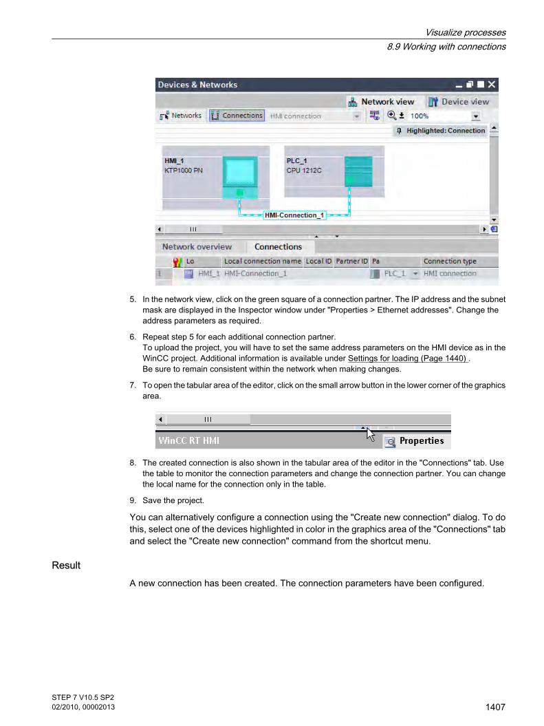
5. In the network view, click on the green square of a connection partner. The IP address and the subnetmask are displayed in the Inspector window under "Properties > Ethernet addresses". Change theaddress parameters as required.
6. Repeat step 5 for each additional connection partner. To upload the project, you will have to set the same address parameters on the HMI device as in theWinCC project. Additional information is available under Settings for loading (Page 1440) . Be sure to remain consistent within the network when making changes.
7. To open the tabular area of the editor, click on the small arrow button in the lower corner of the graphicsarea.
8. The created connection is also shown in the tabular area of the editor in the "Connections" tab. Usethe table to monitor the connection parameters and change the connection partner. You can changethe local name for the connection only in the table.
9. Save the project.
You can alternatively configure a connection using the "Create new connection" dialog. To dothis, select one of the devices highlighted in color in the graphics area of the "Connections" taband select the "Create new connection" command from the shortcut menu.
ResultA new connection has been created. The connection parameters have been configured.
Visualize processes8.9 Working with connections
STEP 7 V10.5 SP202/2010, 00002013
1407

CautionEthernet communication
In Ethernet-based communication, the end user is responsible for the security of his datanetwork. The proper functioning of the device cannot be guaranteed in all circumstances;targeted attacks, for example, can lead to overload of the device.
See alsoAutomatic creation of a connection (Page 1408)Optimizing the configuration (Page 1410)Networking devices (Page 1404)
8.9.2.3 Automatic creation of a connection
IntroductionYou can automatically create and configure a connection between an HMI device and PLC withWinCC.
Requirement
• You have created a WinCC project.
• You have opened the project.
• The project contains a SIMATIC PLC.
Creating a connection using the device wizard1. In the portal view, click "Start > Visualization" and then click the
button to open the "Add new device" dialog.
2. Select the desired HMI device and select the "Start Device Wizard" option.
3. Click "OK." The device wizard opens.
8.9.2.3 Automatic creation of a connection
Visualize processes8.9 Working with connections
1408STEP 7 V10.5 SP202/2010, 00002013

4. Open the selection dialog on the "PLC connections" page and select the SIMATIC PLC.
5. Confirm the selection of the PLC. The connection between the devices is created.
6. Make additional settings in the device wizard as required and click "Finish". The settings from the device wizard are applied to the project.
Creating a connection using a PLC tagIf a PLC tag is available in the project, you can use it to automatically create a connection in ascreen.
1. Open the desired screen in the "Screens" editor.
2. Select the "PLC tags" folder in the project tree. The existing PLC tags are shown in the Details view.
3. Drag the PLC tag from the Details view into the open screen. An I/O field is created in the screen and linked to the PLC tag via an HMI tag. A connection is alsoautomatically created between the HMI device and PLC.
See alsoConfiguring a connection (Page 1405)
Visualize processes8.9 Working with connections
STEP 7 V10.5 SP202/2010, 00002013
1409

8.9.2.4 Optimizing the configuration
Acquisition cycle and update timeThe acquisition cycles for the "Area pointers" and tags defined in the engineering software aredecisive factors for the update times which can actually be achieved.
The update time is equivalent to the acquisition cycle + transmission time + processing time.
To achieve optimum update times, remember the following points during configuration:
• Set up the minimum and maximum size of the various data areas to suit requirements.
• Define associated data areas. You can improve the update time by setting up one large data areainstead of several small areas.
• If the acquisition cycles you select are too short, this is detrimental to the overall performance. Set theacquisition cycle to suit the rate of change of the process values. The rate of temperature changes ata furnace, for example, is significantly slower compared to the speed rate of an electrical drive.Guideline value of the acquisition cycle: approx. 1 s.
• To improve update times, you could do without the cyclic transfer of large numbers of tags. Enter "Onrequest" as the acquisition cycle. Instead of the cyclic transfer, use a deliberate, spontaneous, event-controlled transfer of tags (Job mailbox).
• Write the tags of an alarm or a screen without gaps to a single data area.
• To allow changes in the PLC to be recognized reliably, the changes must be available at least duringthe actual acquisition cycle.
• Set the transmission rate to the highest possible value.Screens
The actually feasible update rate of screens depends on the data type and volume to bevisualized.
Configure short acquisition cycles only for objects which actually require shorter refresh cycles.Trends
When using bit-triggered trends, if the group bit is set in the "Trend transfer area", the HMIdevice always updates all the trends whose bit is set in this area. It then resets the bits.
The group bit in the S7 program can only be set again after all bits have been reset by the HMI.
NoteAvailability for specific devices
Bit-triggered trends are not available on Basic Panels.
Job mailboxes
A large transfer volume of job mailboxes transferred rapidly and in succession, may cause anoverload in the communication between the HMI and the PLC.
The HMI device confirms acceptance of the Job mailbox by entering the value zero in the firstdata word of the job mailbox. The HMI now processes the job, for which it requires further time.
8.9.2.4 Optimizing the configuration
Visualize processes8.9 Working with connections
1410STEP 7 V10.5 SP202/2010, 00002013

If a new job is entered again immediately in the job mailbox, it may take some time before theHMI device can process the next job. The next Job mailbox will not be accepted unless thesystem provides sufficient computing capacity.Timeout response with TCP/IP (Ethernet)
Due to the use of the TCP/IP protocol, the breakdown of a connection is detected at the earliestafter approximately one minute. Communication failure cannot be reliably detected if no tagsare requested, for example, no output tags in the current screen.
Configure area pointer coordination for each PLC. This ensures that a communication failureis recognized after approximately two minutes, even in the aforementioned scenario.
See alsoConfiguring a connection (Page 1405)
8.9.3 User data area
8.9.3.1 Area pointers for connections
IntroductionUsing the "Area pointer" tab of the "Connections" editor, you can configure the usage of theavailable area pointers.
To configure the area pointers, open the "Connections" editor and open the "Area pointer" tab.
8.9.3 User data area8.9.3.1 Area pointers for connections
Visualize processes8.9 Working with connections
STEP 7 V10.5 SP202/2010, 00002013
1411

StructureThe "Area pointer" tab contains two tables of area pointers. The top part of the table containsthe area pointers you can create and enable separately for each available connection.
The "Global area pointers of HMI device" table contains the area pointers which are createdonly once in the project and can be used for only one connection.
See "General information on area pointers (Page 1414) " for additional information.
See alsoBasics of communication (Page 1402)Configuring area pointers (Page 1412)
8.9.3.2 Configuring area pointers
IntroductionYou use the area pointer to access a data area in the PLC. The data area is saved in the PLC.Set up the data area as tag array in a global data block or an instance data block for areapointers with a length >= 1. You have the option to use a PLC tag for area pointers with a length= 1. The configuration of the tags in a data block is based on the length of the area pointer youwant to use. The unit for the length of an area pointer is a 16-bit word. If, for example, you wantto use an area pointer with a length of "5", you need to create an array of 5 array elements inthe data block. See "Programming data blocks" in the "Programming the PLC" section foradditional details.
Requirement
• The project contains a PLC.
• A connection is configured between the PLC and the HMI device.
• The PLC program contains a global data block.
ProcedureTo configure an area pointer, proceed as follows:
8.9.3.2 Configuring area pointers
Visualize processes8.9 Working with connections
1412STEP 7 V10.5 SP202/2010, 00002013

1. Expand the view of the PLC in the project tree, open the "Program blocks" folder and double-click onthe global data block. The data block opens.
2. Enter a tag name in the "Name" column.
3. Select "Array[lo .. hi] of type" as the data type in the "Data type" column. Replace the "lo" and "hi"entries in the brackets with the high and low values for the dimensions of the array.
Example: If you configure an area pointer with the length "4", enter the value "0" for "lo" in the bracketsand the value "3" for "hi".
4. Replace the "type" designation with the "word" data type. The full data type for an array of 4 tagsappears as follows: "Array[0 .. 3] of word".
The tag array is created after the entry is confirmed.
5. Select the PLC in the project tree and select the "Compile > Software" command in the shortcut menu.The data block is compiled. Following compilation, the tag array is available for further use in theproject.
6. Expand the view of the HMI device in the project tree and double-click the "Connections" entry. The"Connections" editor opens.
7. Open the "Area pointer" tab and enable the desired area pointer. A global area pointer is enabled byselecting the connection in the "Connection" field.
Visualize processes8.9 Working with connections
STEP 7 V10.5 SP202/2010, 00002013
1413

8. Click the navigation button in the "PLC tag" field. The object list opens. Navigate to the data block inthe object list and select the tag in the right window.
You do not need an array tag to configure an area pointer with the length of "1". Select the"Word" data type to create the tag in the data block.
Set additional parameters, such as the acquisition cycle, during the configuration.
ResultThe area pointer is enabled and linked to the PLC tag in the global data block.
See alsoArea pointers for connections (Page 1411)
8.9.3.3 Area pointer
8.9.3.3 General information on area pointers
Introduction You use the area pointer to access a data area in the PLC. The PLC and the HMI deviceinteractively communicate read and write data for these data areas . The PLC and the HMIdevice trigger defined interactions based on the evaluation of stored data.
The Basic Panels support the following area pointers:
• Job mailbox
• Project ID
• Screen number
• Data record
• Date/time
• Date/time PLC
8.9.3.3 Area pointer8.9.3.3 General information on area pointers
Visualize processes8.9 Working with connections
1414STEP 7 V10.5 SP202/2010, 00002013

• Coordination
ApplicationConfigure and enable the area pointer in "Connections ▶ Area Pointer" before you put it intouse.
• Active
Enables the area pointer.
• Display name
Name of the area pointer specified by WinCC.
• Control variable
This is where you select the PLC tag of the tag array that you have configured as the data area forthe area pointer.
• Address
No address is entered into this field because of the symbolic access.
• Length
WinCC specifies the length of the area pointer.
• Acquisition cycle
Define an acquisition cycle in this field to allow cyclic reading of the area pointer by the HMI device.An extremely short acquisition time may have a negative impact on HMI device performance.
• Comment
Save a comment, for example, to describe the purpose of the area pointer.Accessing data areas
The table shows how the PLC and HMI device handle read (R) and write (W) access to thedata areas.
Data area Required for HMI device PLC
Screen number Evaluation by the PLC in order to determine the active screen. W R
Data record Transfer of data records with synchronization R/W R/W
Visualize processes8.9 Working with connections
STEP 7 V10.5 SP202/2010, 00002013
1415
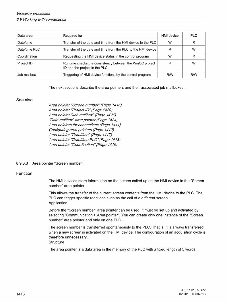
Data area Required for HMI device PLC
Date/time Transfer of the date and time from the HMI device to the PLC W R
Date/time PLC Transfer of the date and time from the PLC to the HMI device R W
Coordination Requesting the HMI device status in the control program W R
Project ID Runtime checks the consistency between the WinCC projectID and the project in the PLC.
R W
Job mailbox Triggering of HMI device functions by the control program R/W R/W
The next sections describe the area pointers and their associated job mailboxes.
See alsoArea pointer "Screen number" (Page 1416)Area pointer "Project ID" (Page 1420)Area pointer "Job mailbox" (Page 1421)"Data mailbox" area pointer (Page 1424)Area pointers for connections (Page 1411)Configuring area pointers (Page 1412)Area pointer "Date/time" (Page 1417)Area pointer "Date/time PLC" (Page 1418)Area pointer "Coordination" (Page 1419)
8.9.3.3 Area pointer "Screen number"
Function The HMI devices store information on the screen called up on the HMI device in the "Screennumber" area pointer.
This allows the transfer of the current screen contents from the HMI device to the PLC. ThePLC can trigger specific reactions such as the call of a different screen.Application
Before the "Screen number" area pointer can be used, it must be set up and activated byselecting "Communication ▶ Area pointer". You can create only one instance of the "Screennumber" area pointer and only on one PLC.
The screen number is transferred spontaneously to the PLC. That is, it is always transferredwhen a new screen is activated on the HMI device. The configuration of an acquisition cycle istherefore unnecessary.Structure
The area pointer is a data area in the memory of the PLC with a fixed length of 5 words.
8.9.3.3 Area pointer "Screen number"
Visualize processes8.9 Working with connections
1416STEP 7 V10.5 SP202/2010, 00002013

15 14 13 12 11 10 9 8 7 6 5 4 3 2 1 0
1. Word Current screen type
2. Word Current screen number
3. Word Reserved
4th word Current field number
5. Word Reserved
• Current screen type
"1" for root screen or "4" for permanent window
• Current screen number
1 to 32767
• Current field number
1 to 32767
NoteAvailability for specific devices
Permanent windows are not available on Basic Panels.
See alsoGeneral information on area pointers (Page 1414)
8.9.3.3 Area pointer "Date/time"
Function This area pointer is used to transfer the date and time from the HMI device to the PLC.
The PLC writes the control job "41" to the job mailbox.
When it evaluates the control job, the HMI device writes its current date and the time in thedata area configured in the "Date/time" area pointer.
Use data type "DTL" with communication driver S7 1200. A tag of the "DTL" data type has alength of 12 bytes and saves information on date and time in a predefined structure.
The "DTL" data type has the following structure:
8.9.3.3 Area pointer "Date/time"
Visualize processes8.9 Working with connections
STEP 7 V10.5 SP202/2010, 00002013
1417

Byte Component Data type Value range
0 Year UINT 1970 to 2554
1
2 Month USINT 0 to 12
3 Tag USINT 1 to 31
4 Day of week USINT 1(Sunday) to 7(Saturday)The weekday is not considered in the value entry.
5 Hour USINT 0 to 23
6 Minute USINT 0 to 59
7 Second USINT 0 to 59
8 Nanoseconds UDINT 0 to 999 999 999
9
10
11
See alsoGeneral information on area pointers (Page 1414)
8.9.3.3 Area pointer "Date/time PLC"
Function This area pointer is used to transfer the date and time from the PLC to the HMI device. Usethis area pointer if the PLC is the time master.
The PLC loads the data area of the area pointer.
The HMI device reads the data cyclically within the configured acquisition cycle andsynchronizes itself.
Note
Set an acquisition cycle of sufficient length for the date/time area pointer PLC to avoid anynegative impact on HMI device performance. Recommended: Acquisition cycle of 1 minute, if the process allows this.
Date/time PLC is a global area pointer and can be configured only once in a project.
8.9.3.3 Area pointer "Date/time PLC"
Visualize processes8.9 Working with connections
1418STEP 7 V10.5 SP202/2010, 00002013

Use data type "DTL" with communication driver S7 1200. A tag of the "DTL" data type has alength of 12 bytes and saves information on date and time in a predefined structure.
The "DTL" data type has the following structure:
Byte Component Data type Value range
0 Year UINT 1970 to 2554
1
2 Month USINT 0 to 12
3 Tag USINT 1 to 31
4 Day of week USINT 1(Sunday) to 7(Saturday)The weekday is not considered in the value entry.
5 Hour USINT 0 to 23
6 Minute USINT 0 to 59
7 Second USINT 0 to 59
8 Nanoseconds UDINT 0 to 999 999 999
9
10
11
The HMI devices do not support the use of nanoseconds. Values in the nanosecond range willbe ignored during processing in Runtime.
See alsoGeneral information on area pointers (Page 1414)
8.9.3.3 Area pointer "Coordination"
Function The "Coordination" area pointer is used to implement the following functions:
• Detecting the startup of the HMI device in the control program
• Detecting the current operating mode of the HMI device in the control program
• Detecting whether the HMI device is ready to communicate in the control program
The "Coordination" area pointer has a length of one word.Application
8.9.3.3 Area pointer "Coordination"
Visualize processes8.9 Working with connections
STEP 7 V10.5 SP202/2010, 00002013
1419

Note
Each time the area pointer is updated by the HMI device, the entire coordination area is alwayswritten. For this reason, the PLC program must not make any changes in the coordination area.
Assignment of the bits in the "Coordination" area pointer
Startup bit
The startup bit is set briefly to "0" by the HMI device during startup. After startup, the bit is setpermanently to "1".Operating mode
As soon as the HMI device is switched offline by the user, the operating mode bit is set to 1.In normal operation of the HMI device, the state of the operating mode bit is "0". You can findout the current operating mode of the HMI device by querying this bit.Life bit
The life bit is inverted by the HMI device at intervals of approximately one second. By queryingthis bit in the PLC program, you can check whether or not the connection to the HMI devicestill exists.
Processing in the PLCFor a simpler evaluation in the PLC program, use a Bool array for this area pointer when usingthe SIMATIC S7 1200 communication driver. You will have to map the complete 16-bit word ofthe area pointer. Configure a tag of the data type "Array [0 .. 15] of bool" for this purpose.
See alsoGeneral information on area pointers (Page 1414)
8.9.3.3 Area pointer "Project ID"
Function When runtime starts it can check to see if the HMI device is connected to the correct PLC. Thischeck is important when operating with several HMI devices.
8.9.3.3 Area pointer "Project ID"
Visualize processes8.9 Working with connections
1420STEP 7 V10.5 SP202/2010, 00002013

The HMI device compares a value stored on the PLC with the value specified in theconfiguration data. This ensures the compatibility of the configuration data and the PLCprogram.
A missing compatibility results in a corresponding alarm and Runtime will not be started.Application
In order to use this area pointer you must set up the following during the configuration:
• Specify the version of the configuration data. Possible values between 1 and 255.
Enter the version in the "Device settings ▶ Screens" editor under "Project ID".
• This is where you select the PLC tag or the tag array that you have configured as the data area forthe area pointer.
Connection failure
A connection failure to a device on which the "project ID" area pointer is configured results inall the other connections in the project being switched to "offline".
This behavior has the following requirements:
• You have several connections configured in a project.
• You are using the "project ID" area pointer in at least one connection.
Causes which may set connections "offline":
• The PLC is not available.
• The connection has been switched to offline in the engineering system.
See alsoGeneral information on area pointers (Page 1414)
8.9.3.3 Area pointer "Job mailbox"
Function The PLC can use the job mailbox to transfer jobs to the HMI device to trigger correspondingactions on the HMI device. These functions include, for example:
• Display screen
• Set date and timeData structure
The first word of the job mailbox contains the job number. Depending on the job mailbox, upto three parameters can be transferred.
Word Most significant byte Least significant byte
n+0 0 Job number
n+1 Parameter 1
8.9.3.3 Area pointer "Job mailbox"
Visualize processes8.9 Working with connections
STEP 7 V10.5 SP202/2010, 00002013
1421

Word Most significant byte Least significant byte
n+2 Parameter 2
n+3 Parameter 3
The HMI device evaluates the job mailbox if the first word of this job is unequal to zero. Thismeans that the parameters must be entered in the job mailbox first, followed by the job number.
When the HMI device accepts the job mailbox, the first word is set to 0 again. The executionof the job mailbox is generally not completed at this point in time.Job mailboxes
All job mailboxes and their parameters are listed below. The "No." column contains the jobnumber of the job mailbox. Job mailboxes can only be triggered by the PLC when the HMIdevice is online.
No. Function
14 Set time (BCD-coded)
Parameter 1 Left byte: - Right byte: hours (0-23)
Parameter 2 Left byte: minutes (0-59) Right byte: seconds (0-59)
Parameter 3 -
15 Set date (BCD-coded)
Parameter 1 Left byte: - Right byte: weekday (1-7: Sunday-Saturday)
Parameter 2 Left byte: day (1-31) Right byte: month (1-12)
Parameter 3 Left byte: year
23 User login
Logs the user on with the name "PLC user" at the HMI device with the group number transferredin parameter 1. The logon is possible only when the transferred group number exists in the project.
Parameter 1 Group number 1 - 255
Parameter 2, 3 -
24 User logoff
Logs off the currently logged on user. The function corresponds to the "logoff" system function)
Parameter 1, 2, 3 -
40 Transferring date/time to PLC
Visualize processes8.9 Working with connections
1422STEP 7 V10.5 SP202/2010, 00002013

No. Function
14 Set time (BCD-coded)
An interval of at least 5 seconds must be maintained between successive jobs to prevent overloadof the HMI device.
Parameter 1, 2, 3 -
41 Transferring date/time to PLC
An interval of at least 5 seconds must be maintained between successive jobs to prevent overloadof the HMI device.
Parameter 1, 2, 3 -
46 Updating tags
Causes the HMI device to read the current value of the tags from the PLC whose update ID matchesthe value transferred in parameter 1. (Function corresponds to the "UpdateTag" system function.)
Parameter 1 1 - 100
49 Clear event buffer
Parameter 1, 2, 3 -
50 Clear error alarm buffer
Parameter 1, 2, 3 -
51 Display selection
Parameter 1 Screen number
Parameter 2 -
Parameter 3 Field number
69 Reading data record from PLC 1)
Parameter 1 Recipe number (1-999)
Parameter 2 Data record number (1-65535)
Parameter 3 0: Do not overwrite existing data record1: Overwrite existing data record
70 Writing data record from PLC 1)
Parameter 1 Recipe number (1-999)
Parameter 2 Data record number (1-65535)
Parameter 3 -
See alsoGeneral information on area pointers (Page 1414)
Visualize processes8.9 Working with connections
STEP 7 V10.5 SP202/2010, 00002013
1423

8.9.3.3 Area pointer "Data record"
8.9.3.3 "Data mailbox" area pointer
FunctionWhen data records are transferred between the HMI device and PLC, both partners accesscommon communications areas on the PLC.Data transfer types
There are two ways of transferring data records between the HMI device and PLC:
• Transfer without synchronization
• Transfer with synchronization over the data record
Data records are always transferred directly. That is, the tag values are read from an addressor written to an address configured for this tag directly, without redirecting the values by meansof interim memory.Initiating the transfer of data records
There are three ways of triggering the transfer:
• Operator input in the recipe view
• Job mailboxes
The transfer of data records can also be triggered by the PLC.
• Triggering by configured functions
If the transfer of data records is triggered by a job mailbox, the data in the recipe view will beupdated as well. Avoid operating the recipe view while PLC jobs for transfer of data recordsare being triggered. If you have already started editing a data record and a PLC job is triggeredfor transfer of data records, then this PLC job will be rejected.
See alsoGeneral information on area pointers (Page 1414)Transfer without synchronization (Page 1424)Transfer with synchronization (Page 1425)Sequence of a transfer started by the operator in the recipe display (Page 1426)Sequence of the transfer triggered by a job mailbox SIMATIC S7 (Page 1428)Sequence of the transfer when triggered by a configured function (Page 1429)Possible causes of error when transferring data records (Page 1430)
8.9.3.3 Transfer without synchronization
If you select asynchronous transfer of data records between the HMI device and PLC, there isno coordination over the common data areas. It is therefore unnecessary to set up a data areaduring configuration.
Asynchronous data record transfer can be a useful alternative, for example, when:
8.9.3.3 Area pointer "Data record"8.9.3.3 "Data mailbox" area pointer8.9.3.3 Transfer without synchronization
Visualize processes8.9 Working with connections
1424STEP 7 V10.5 SP202/2010, 00002013

• The system is capable of excluding the risk of uncontrolled overwriting of data by the communicationpeer.
• The PLC does not require information about the recipe number and data record number.
• The transfer of data records is triggered by the operator of the HMI device.
Reading valuesWhen a read job is triggered, the values are read from the PLC addresses and transferred tothe HMI device.
• Triggering by the operator in the recipe view:
The values are downloaded to the HMI device. You can then process, edit, or save these values, forexample.
• Triggering by a function or PLC job:
The values are saved immediately to the data volume.Writing values
When a write job is triggered, the values are written to the PLC addresses.
• Triggering by the operator in the recipe view:
The current values are written to the PLC.
• Triggering by a function or PLC job:
The current values are written to the PLC from the data medium.
See also"Data mailbox" area pointer (Page 1424)
8.9.3.3 Transfer with synchronization
If you select synchronous transfer, both communication partners set status bits in the commondata area. Use this mechanism to prevent uncontrolled overwriting of data in either directionof your control program.
ApplicationSynchronous data record transfer can be a useful solution, for example, when:
• The PLC is the "active partner" in the transfer of data records.
• The PLC evaluates the information about the recipe number and data record number.
• The transfer of data records is triggered by means of a Job mailbox.Requirements
In order to synchronize transfer of data records between the HMI device and the PLC, thefollowing requirements must be met during configuration:
• An area pointer has been set up: "Connections ▶ Area pointer" editor.
• The PLC with which the HMI device synchronizes transfer of data records is specified in the recipe:"Recipes" editor, properties view of the recipe in the Inspector window, "Properties ▶ Download" group.
8.9.3.3 Transfer with synchronization
Visualize processes8.9 Working with connections
STEP 7 V10.5 SP202/2010, 00002013
1425

Structure of the data area
The data area has a fixed length of 5 words. Structure of the data area:
15 0
1. Word Current recipe number (1 - 999)
2. Word Current data record number (0 - 65535)
3. Word Reserved
4. Word Status (0, 2, 4, 12)
5. Word Reserved
• Status
The status word (word 4) can adopt the following values:
Value Meaning
Decimal Binary
0 0000 0000 Transfer permitted, data record free
2 0000 0010 Transfer is busy
4 0000 0100 Transfer completed without error
12 0000 1100 Transfer completed with error
See also"Data mailbox" area pointer (Page 1424)
8.9.3.3 Sequence of a transfer started by the operator in the recipe display
Reading from the PLC started by the operator in the recipe display
Step Action
1 Check: Status word = 0?
Yes No
2 The HMI device enters the recipe number to be read and the status"Transfer active" in the data record and sets the data record numberto 0.
Abort with systemalarm.
8.9.3.3 Sequence of a transfer started by the operator in the recipe display
Visualize processes8.9 Working with connections
1426STEP 7 V10.5 SP202/2010, 00002013

Step Action
3 The HMI device reads the values from the PLC and displays them inthe recipe display.If the recipes have synchronized tags, the values from the PLC arealso written to the tags.
4 The HMI device sets the status "Transfer completed."
5 The control program must reset the status word to zero in order toenable further transfers.
Writing to the PLC started by the operator in the recipe display
Step Action
Check: Status word = 0?
1 Yes No
The HMI device enters the recipe and data record number to be writtenand the status "Transfer active" in the data record.
Abort with systemalarm.
2 The HMI device writes the current values to the PLC.If the recipes have synchronized tags, the changed values aresynchronized between the recipe display and tags and then written tothe PLC.
3 The HMI device sets the status "Transfer completed."
4 If required, the control program can now evaluate the transferred data.
5 The control program must reset the status word to zero in order toenable further transfers.
Note
The status word may only be set by the HMI device. The PLC may only reset the status wordto zero.
Note
The PLC may only evaluate the recipe and data record numbers when data inconsistency isdetected if one of the conditions outlined below has been met:
• The data mailbox status is set to "Transfer completed".
• The data mailbox status is set to "Transfer completed with error".
See also"Data mailbox" area pointer (Page 1424)
Visualize processes8.9 Working with connections
STEP 7 V10.5 SP202/2010, 00002013
1427

8.9.3.3 Sequence of the transfer triggered by a job mailbox SIMATIC S7
The transfer of data records between the HMI device and the PLC can be initiated by eitherone of these stations.
The two PLC jobs No. 69 and No. 70 are available for this type of transfer.
No. 69: Read data mailbox from PLC ("PLC → DAT")Job mailbox no. 69 transfers data mailboxes from the PLC to the HMI device. The job mailboxis structured as follows:
Most significant byte Least significant byte
Word 1 0 69
Word 2 Recipe number (1-999)
Word 3 Data mailbox number (1-65,535)
Word 4 Do not overwrite existing data mailbox: 0 Overwrite existing data mailbox: 1
No. 70: Write data mailbox to PLC ("DAT → PLC")
Job mailbox no. 70 transfers data mailboxes from the HMI device to the PLC. The job mailboxis structured as follows:
Most significant byte Least significant byte
Word 1 0 70
Word 2 Recipe number (1-999)
Word 3 Data mailbox number (1-65,535)
Word 4 —
Sequence when reading from the PLC with job mailbox "PLC → DAT" (no. 69)
Step Action
1 Check: Status word = 0?
Yes No
2 The HMI device enters the recipe and data mailbox number specifiedin the job and the status "Transfer active" in the data mailbox.
Abort without returnmessage.
3 The HMI device reads the values and stores the values in the datamailbox specified in the job mailbox.
8.9.3.3 Sequence of the transfer triggered by a job mailbox SIMATIC S7
Visualize processes8.9 Working with connections
1428STEP 7 V10.5 SP202/2010, 00002013

Step Action
4 • If "Overwrite" was selected in the job, an existing data mailbox isoverwritten without any prompt for confirmation.The HMI device sets the status "Transfer completed".
• If "Do not overwrite" was selected in the job, and the data mailboxalready exists, the HMI device aborts the job and enters 0000 1100in the status word of the data mailbox.
5 To allow further transfers, the PLC program must set the status wordto 0 again.
Sequence writing to the PLC with job mailbox "DAT → PLC" (no. 70)
Step Action
1 Check: Status word = 0?
Yes No
2 The HMI device enters the recipe and data mailbox number specifiedin the job and the status "Transfer active" in the data mailbox.
Abort without returnmessage.
3 The HMI device fetches the values of the data mailbox specified in thejob from the data medium and writes the values to the PLC.
4 The HMI device sets the status "Transfer completed".
5 The PLC program can now evaluate the transferred data. To allow further transfers, the PLC program must set the status wordto 0 again.
See also"Data mailbox" area pointer (Page 1424)
8.9.3.3 Sequence of the transfer when triggered by a configured function
Reading from the PLC using a configured function
Step Action
1 Check: Status word = 0?
Yes No
2 The HMI device enters the recipe and data record numberspecified in the function and the status "Transfer active" in thedata record.
Abort with systemalarm.
8.9.3.3 Sequence of the transfer when triggered by a configured function
Visualize processes8.9 Working with connections
STEP 7 V10.5 SP202/2010, 00002013
1429

Step Action
3 The HMI device reads the values from the PLC and stores themin the data record specified in the function.
4 • If "Yes" was selected for the "Overwrite" function, an existingdata record is overwritten without any prompt for confirmation.The HMI device sets the status "Transfer completed."
• If "No" was selected for the "Overwrite" function and the datarecord already exists, the HMI device aborts the job andenters 0000 1100 in the status word of the data record.
5 The control program must reset the status word to zero in orderto enable further transfers.
Writing to the PLC by means of configured function
Step Action
1 Check: Status word = 0?
Yes No
2 The HMI device enters the recipe and data record numberspecified in the function and the status "Transfer active" in thedata record.
Abort with systemalarm.
3 The HMI device fetches the values of the data record specified inthe function from the data medium and transfers the values to thePLC.
4 The HMI device sets the status "Transfer completed."
5 The control program can now evaluate the transferred data.The control program must reset the status word to zero in orderto enable further transfers.
See also"Data mailbox" area pointer (Page 1424)
8.9.3.3 Possible causes of error when transferring data records
Possible causes of errorThe section below shows possible error causes which lead to the cancellation of data recordtransfer:
• Tag address not set up on the PLC
• Overwriting data records not possible
8.9.3.3 Possible causes of error when transferring data records
Visualize processes8.9 Working with connections
1430STEP 7 V10.5 SP202/2010, 00002013

• Recipe number does not exist
• Data record number does not exist
Note
The status word may only be set by the HMI device. The PLC may only reset the statusword to zero.
Note
The PLC may only evaluate the recipe and data record numbers when data inconsistencyis detected if one of the conditions outlined below has been met:
― The data mailbox status is set to "Transfer completed".
― The data mailbox status is set to "Transfer completed with error".
Reaction to an aborted transfer due to errors
If the transfer of data records is aborted due to errors, the HMI device reacts as follows:
• Triggering by the operator in the recipe display
Information in the status bar of the recipe view and output of system alarms
• Triggered by function
Output of system alarms
• Triggering by PLC job
No feedback message on the HMI device
You can nonetheless evaluate the status of the transfer by querying the status word in the datarecord.
NoteAvailability for specific devices
Notes in the status bar of the recipe view are not available in Basic Panels.
See also"Data mailbox" area pointer (Page 1424)
Visualize processes8.9 Working with connections
STEP 7 V10.5 SP202/2010, 00002013
1431

8.9.4 Commissioning components
8.9.4.1 Commissioning components
Transferring the PLC program to the PLC 1. Interconnect the PC with the CPU using the appropriate cable.
2. Download the program files to the CPU.
3. Then set the CPU to RUN.Transferring the project to the HMI device
1. The HMI device must be in transfer mode in order to accept the project transfer.
Possible scenarios:
― Initial startup
The HMI device does not yet contain any configuration data in the initial startup phase. The projectdata and runtime software required for operation must be transferred from the configurationcomputer to the device: The HMI device automatically changes to transfer mode. The message "Transfer mode" appears on the HMI device.
― Recommissioning
Recommissioning means that you overwrite existing project data on the HMI device.
For corresponding detailed instructions, refer to the HMI device manual.
2. Check if the alarm settings in your WinCC project meet your requirements.
3. Check the download settings before transferring the project to the HMI device. Additional informationis available under Settings for loading (Page 1440) .
4. To transfer the project to the HMI device, open the shortcut menu in the project tree of the HMI deviceand select the command "Download to device > Software.
― The project is compiled automatically.
― in the "Load preview" window you can specify if the existing user data should be overwritten.
5. Click "Download". The download is performed.
You will see a message following the download on the configuration computer.
The start screen appears on the HMI device.Interconnecting the PLC with the HMI device
1. Interconnect the PLC with the HMI device using a suitable cable.
2. The connection message appears on the HMI device. Note that users can edit the system event textsin WinCC.
8.9.4 Commissioning components8.9.4.1 Commissioning components
Visualize processes8.9 Working with connections
1432STEP 7 V10.5 SP202/2010, 00002013

Notice
Always observe the safety-related information in the HMI device manual whencommissioning the device.
RF radiation emitted from devices such as mobile phones may cause unwanted operatingstates.
See alsoBasics of communication (Page 1402)
8.10 Importing and exporting project data
8.10.1 Importing and exporting project data
IntroductionWinCC enables you to export data from a project and import it into another project.
You export or import the following project data:
• Recipes
Exporting and importing reduces the workload. Instead of creating new data records in recipes,for example, you use the data you have already created in previous projects.
Exporting project dataWhen data is exported, all information is stored in a CSV file.
You can set the options for the export and determine, for example, the list separators.
Editing project dataYou can edit the import file in Excel or a text editor.
Start Excel and select "Open" from the "File" menu. Select the type of "Text files (*.prn; *.txt;*csv)" from the "File type" list. Do not open the import file in Excel by double-clicking it, becausethis will corrupt its data structure and prevent its import.
Open the file in a simple text editor to check that the file has the correct format.
Importing project dataWhen project data is imported, the data are displayed on an HMI device.
You can set the options for the import and determine, for example, the list separators.
The syntax of the import file is checked during import of csv files. The meaning of the propertiesor dependencies between the properties is not checked. Errors are reported during compiling.
8.10 Importing and exporting project data8.10.1 Importing and exporting project data
Visualize processes8.10 Importing and exporting project data
STEP 7 V10.5 SP202/2010, 00002013
1433

See alsoExporting recipes (Basic, Advanced) (Page 1434)Importing recipes (Basic, Advanced) (Page 1435)
8.10.2 Importing and exporting recipes
8.10.2.1 Exporting recipes
IntroductionWinCC features an export function for exporting data records from recipes.
Requirements
• The WinCC project to be exported is open.
• Recipes have been created in a project.
• The "Recipes" editor is open.
Exporting recipes1. In the "Recipes" editor, select the recipe with the data records you want to export.
2. Click
.
The "Export" dialog box opens.
8.10.2 Importing and exporting recipes8.10.2.1 Exporting recipes
Visualize processes8.10 Importing and exporting project data
1434STEP 7 V10.5 SP202/2010, 00002013

The selected recipe is shown under "Recipe selection".
3. Under "Content selection", specify if all or only selected data records are to be exported.
4. Under "File selection", specify the file in which the recipe data records should be stored.
5. Specify the list separator and decimal separator under "Data separation".
6. Click "Export."
The export starts.
ResultThe exported data has been written to a CSV file. The CSV file is stored in the specified folder.
See alsoImporting recipes (Basic, Advanced) (Page 1435)Format of recipe data (Basic, Advanced) (Page 1437)
8.10.2.2 Importing recipes
IntroductionRecipes are identified by their name. This means recipe names have to be unique. Specifywhether or not existing data records should be overwritten by records with the same nameduring the import.
8.10.2.2 Importing recipes
Visualize processes8.10 Importing and exporting project data
STEP 7 V10.5 SP202/2010, 00002013
1435

Requirements
• A CSV file containing at least one recipe has been created.
• The WinCC project to be imported is open.
• The "Recipes" editor is open with at least one recipe.
Importing a recipe1. In the "Recipes" editor, select the recipe with the data records you want to import.
2. Click
.
The "Import" dialog box opens.
The selected recipe is shown under "Recipe selection".
3. Select the file you want to import under "File selection".
4. Under "Strategy", specify if existing data records should be overwritten by records of the same name.
5. Under "Data separation", select the list separator and the decimal separator to use in the CSV file.
6. Click "Import."
The import starts.
Visualize processes8.10 Importing and exporting project data
1436STEP 7 V10.5 SP202/2010, 00002013

ResultThe data records are created in the selected recipe. Depending on the setting for "Strategy",existing data records are overwritten by records with the same name from the CSV file.
See alsoExporting recipes (Basic, Advanced) (Page 1434)Format of recipe data (Basic, Advanced) (Page 1437)
8.10.2.3 Format of recipe data
IntroductionThis section describes the required format of the file for the import of recipes. The file containingthe data of the recipes must be available in "*.csv" format. :
Structure of recipe dataThe structure of the import file is fixed. The following example shows the structure for a recipecontaining two recipe elements each with two data records each containing two values in turn:
List separator=<List separator>
Decimal symbol=<Decimal separator><List separator>
<Name of the recipe><List separator><List separator><Line break>
LANGID_<ID of the language><List separator>
<Name data record 1><List separator>
<Name data record 2><List separator><Line break>
<Number recipe><List separator>
<Number data record 1><List separator>
<Number data record 2><List separator><Line break>
<Tag recipe element 1><List separator>
<Value data record 1><List separator>
<Value data record 2><List separator><Line break>
<Tag recipe element 2><List separator>
<Value data record 1><List separator>
<Value data record 2><List separator><Line break>
ID of the languageUse the "Windows language ID" in decimal notation, e.g. "1033" for English. Additionalinformation is available in the documentation for the Windows operating system.
8.10.2.3 Format of recipe data
Visualize processes8.10 Importing and exporting project data
STEP 7 V10.5 SP202/2010, 00002013
1437

8.11 Compiling and loading
8.11.1 Compiling and loading projects
8.11.1.1 Overview of compiling and loading projects
OverviewThe project is compiled in the background even as you are configuring it in WinCC. Compilingresults in a file that can be run on the corresponding HMI device.
If an error occurs during compilation, WinCC provides support in locating and correcting it.
Once you have corrected any problems, you load the compiled project to the HMI devices onwhich the project is to run.
Before you start productive operation with your project, compile the project completely usingthe command "Compile > Software (complete compilation)" in the shortcut menu of the HMIdevice. If you are using HMI tags that are connected to the control tags in your project, compileall modified blocks with the command "Compile > Software" in the shortcut menu before youcompile the HMI device.
To reduce the amount of time required for delta compilation during active configuration, werecommend using the command "Compile > Software (complete compilation)" from time totime.
8.11.1.2 Compiling a project
IntroductionBefore a project can run on an HMI device, it must first be compiled. You then load the compiledproject on one or more HMI devices.
The changes made to the project are compiled in the background even as you are configuringa project in WinCC. A project is automatically compiled each time you load a project. Thisensures that the latest version of the project is loaded at all times.
Note
The ongoing compilation in the background is interrupted as long as Runtime is running on theEngineering Station.
You can also start compilation of a project manually, if necessary.
8.11 Compiling and loading8.11.1 Compiling and loading projects8.11.1.1 Overview of compiling and loading projects8.11.1.2 Compiling a project
Visualize processes8.11 Compiling and loading
1438STEP 7 V10.5 SP202/2010, 00002013

WinCC checks consistency of the project during compilation. The error locations in the projectare listed in the Inspector window. You can jump directly to the source of the error from theentry in the Inspector window. Check the errors found and correct them.
Scope of the compilationInitial compilation covers the entire project. Only the changes made to the project are compiledafter initial compilation.
However, you can always run a complete compilation of the project.
Requirement
• A project is open.
ProcedureProceed as follows to compile a project:
1. If you want to compile a project for several HMI devices at the same time, select all desired HMIdevices with a multiple selection in the project tree.
2. Select the "Compile > Software" command in the shortcut menu of the HMI device.
3. If you want to compile the entire project: Select the "Compile > Software (compile all)" command inthe shortcut menu.
ResultThe project is compiled for all selected HMI devices. Any errors that occur during compilationare shown in the Inspector window.
8.11.1.3 Loading projects
8.11.1.3 Overview for loading of projects
OverviewDelta data of the project is automatically compiled before you load it to one or several HMIdevices. This always ensures that the latest version of the project is transferred. You canactivate the option "Overwrite all" before you start the loading process.
Define the load settings in the properties of each HMI device.
Before you start productive operation with your project, compile the project completely usingthe command "Compile > Software (complete compilation)" in the shortcut menu of the HMIdevice. If you are using HMI tags that are connected to the control tags in your project, compileall modified blocks with the command "Compile > Software" in the shortcut menu before youcompile the HMI device.
8.11.1.3 Loading projects8.11.1.3 Overview for loading of projects
Visualize processes8.11 Compiling and loading
STEP 7 V10.5 SP202/2010, 00002013
1439

To reduce the amount of time required for delta compilation during active configuration, werecommend using the command "Compile > Software (complete compilation)" from time totime.
8.11.1.3 Settings for loading
IntroductionYou make the settings for loading in the properties of every HMI device.
RequirementYou have created an HMI device in the project.
ProcedureProceed as follows to make the settings for loading a project:
1. Select the "Properties" command in the shortcut menu of the HMI device.
2. Click "Load" in the properties of the HMI device.
The settings for loading are displayed.
3. Select the same interface set on the HMI device.
4. Set the parameters for the connection. The displayed parameters depend on the interface selected.
5. Check the setting for the "Load names" check box. The "Load names" check box is activated bydefault. The names of the configured objects are compiled and loaded with the project in this case. Ifyou disable the check box, the compile project requires less space on the HMI device.
6. Specify whether or not the user management data and recipes already on the HMI device should beoverwritten.
You can change both settings under "Load preview" before each load.
ResultThe settings for loading are specified. The settings are put into effect the next time the projectis loaded on the respective HMI device.
8.11.1.3 Loading a project
IntroductionBefore a project can run on an HMI device, it first must be loaded to the HMI device.
Actions performed before the data is actually loaded:
• The project is compiled. Any errors that occur during compilation are shown in the Inspector window.WinCC opens the invalid configuration in the corresponding editor if you double-click on the errormessage.
8.11.1.3 Settings for loading8.11.1.3 Loading a project
Visualize processes8.11 Compiling and loading
1440STEP 7 V10.5 SP202/2010, 00002013

Clear all errors displayed before you reload the project.
• A load preview is displayed after compilation was successfully completed. The preview shows youthe following information, separated by HMI device:
― The individual steps for loading
― Presettings that take effect at loading. You can edit those settings once before you start the nextload operation or edit the settings directly in the preview.
― Any warnings that may occur. The project can be compiled and loaded even if warnings occur fora project. The functionality may be restricted in Runtime.
― Any errors that may occur. The project is not compiled and loaded if errors occurred with it.
Before you start productive operation with your project, compile the project completely usingthe command "Compile > Software (complete compilation)" in the shortcut menu of the HMIdevice. If you are using HMI tags that are connected to the control tags in your project, compileall modified blocks with the command "Compile > Software" in the shortcut menu before youcompile the HMI device.
Requirement
• You have created an HMI device in the project.
• The HMI device is connected to the Engineering Station. The connection corresponds to the "Load"group settings.
ProcedureProceed as follows to load a project:
1. If you want to load a project to several HMI devices at one time, select all desired HMI devices witha multiple selection in the project tree.
2. Select the "Load to target system > Software" command in the shortcut menu of the HMI device.
The project is compiled.
If errors are shown: Double-click on a listed error to correct it. The cause of the error is shown in theconfiguration. Restart loading after you cleared all errors.
The "Load preview" dialog opens after compilation was successfully completed.
3. Check the displayed presettings and change them as necessary.
4. Click the "Update" button to see how the changes affect the loading process. The preview is updated.
If the preview indicates that the loading can be performed successfully, click "Load" to load the projectto the selected HMI device.
ResultThe project is loaded to all selected HMI devices. Any existing project will be updated in theprocess.
If errors or warnings occur during loading, appropriate alarms are shown in the Inspectorwindow under "Load".
The project can be executed on the HMI device after it was successfully loaded.
Visualize processes8.11 Compiling and loading
STEP 7 V10.5 SP202/2010, 00002013
1441

8.11.1.3 Error messages during loading of projects
8.11.1.3 Updating the operating system of an HMI device
IntroductionWhen you transfer a WinCC project to an HMI device, WinCC checks if the HMI deviceoperating system version matches the one used in the project. If the operating system versionsdo not match, you will see a warning before the loading starts.
If the wrong operating system version is detected, you are given the opportunity of updatingthe operating system.
Notice
If you update the operating system, all recipes and user data on the HMI device will beirretrievably lost.
Perform a backup beforehand to save these data.
RequirementThe HMI device is connected to the configuration computer.
The interface between the configuration computer and the HMI device is correctly configured.
Updating the operating system during the loading process1. If the HMI device operating system version does not match the configuration, you will see a message
in the "Load" dialog during the loading process. This dialog allows you to update the operating systemimmediately. To start the update, click "Yes" in the "Load" dialog. The update of the operating system starts. When the update is complete, the project is loaded to theHMI device.
2. Recipes, user data, and some system parameters will be deleted during the update. Cancel the updateto retain the data. Click "No" in the "Load" dialog to cancel. The update of the operating system andthe loading process are canceled.
After canceling the update, you can backup the specified data and then update the operatingsystem of the HMI device.
Backing up recipes and user data1. Select the WinCC project in the project tree.
2. Select the menu command "Online > Device maintenance > Backup". The "SIMATIC ProSave" dialogbox opens.
3. Select "Recipes" from the "Data type" box.
4. In the "Save as" box, enter the destination or navigate to the desired location using the dialog.
8.11.1.3 Error messages during loading of projects8.11.1.3 Updating the operating system of an HMI device
Visualize processes8.11 Compiling and loading
1442STEP 7 V10.5 SP202/2010, 00002013

5. Click the "Start Backup" button. The recipe data are backed up.
6. Repeat the procedure to back up user data. Select "User administration" from the "Data type" box.
Updating the operating system after data backup1. Select the desired HMI device in the project tree.
2. Select the menu command "Online > Load to device". The "Load" dialog opens and the loading process starts. In the "Load" dialog you are asked if you want to update the operating system.
3. Confirm the prompt for updating the operating system by clicking "Yes". The operating system is updated. When the update is complete, the project is loaded to the HMIdevice.
Restoring backed up recipes and user dataAfter you have updated the operating system and loaded the project to the HMI device, restorethe backed up data.
1. Select the WinCC project in the project tree.
2. Select the menu command "Online > Device maintenance > Restore". The "SIMATIC ProSave" dialogbox opens.
3. Click the navigation button in the "Opening" box and navigate to the location of the desired data in thedialog that opens.
4. Select the file with the backed up recipe data and click "Open".
5. Click "Start Restore" in the "SIMATIC ProSave" dialog. The restoration starts.
6. Repeat the procedure to restore the user data.
8.11.1.3 Adapting the project for another HMI device
IntroductionWhen you transfer a WinCC project to an HMI device, WinCC checks if the HMI device iscompatible with the type of HMI device used in the project. If the types of HMI device do notmatch, you will see a message before the download starts.
The download is aborted.
Adapting the project for the HMI deviceYou need to adapt the project accordingly to be able to download the project to the connectedHMI device.
• Add a new HMI device in the project tree. Select the correct type of HMI device from the HMI deviceselection.
• Copy the configured components from the previously used HMI device into the newly created HMIdevice. You can copy many of the components directly in the project tree and detail view.
8.11.1.3 Adapting the project for another HMI device
Visualize processes8.11 Compiling and loading
STEP 7 V10.5 SP202/2010, 00002013
1443
For example, you can copy the complete "Screens" folder using the shortcut menu in the screensfolder of the new HMI device.
• Use the detail view to copy entries in the project tree for which the "Copy" command is not availablein the shortcut menu.
• Select the "Recipes" entry in the project tree, for example. The recipes are displayed in the detail view.
• Select the recipes in the detail view and drag them to the "Recipes" entry of the new HMI device. Therecipes are copied. You can also select multiple objects in the detail view.
• Configure those components you cannot copy, such as connections, area pointers, and alarms.
• Save the project at various points in time.
• Compile the full project.
• When the compilation is successfully completed, download the project to the HMI device.
Linking referencesReferences to linked objects are included in the copying. The references are linked again oncethe linked objects are copied.
Example:
You copy a screen in which objects are linked to tags. The tag names are entered at theindividual objects after the screen is added to the new HMI device. The tag names are markedin red because the references are open. When you then copy the tags and insert them into thenew HMI device, the open references are closed. The red marking for the tag namesdisappears.
For complete references to connected objects in the PLC, you first need to configure aconnection to the PLC.
Using the information areaWhen you compile the project for the HMI device, errors and warnings are displayed in the"Info" tab of the Inspector window. You can use the shortcut menu command "Go to" to godirectly to the location where the error or warning can be corrected.
Work through the list of errors and warnings from top to bottom.
When the compilation is successfully completed, download the project to the HMI device.
8.11.1.3 Establishing a connection to the HMI device
IntroductionTo load a WinCC project to an HMI device, a connection needs to be established between theconfiguration computer and the HMI device and the connection needs to be correctlyconfigured. If no connection can be made, the loading process is aborted.
8.11.1.3 Establishing a connection to the HMI device
Visualize processes8.11 Compiling and loading
1444STEP 7 V10.5 SP202/2010, 00002013

Establishing a connection between the configuration computer and HMI device1. Check the cable connection between the HMI device and configuration computer.
2. Open the "Devices & Networks" editor in WinCC and start the network view.
3. Select the subnet in the network view and check the settings for the subnet.
4. Select the interface of the HMI device in the network view or device view and check the connectionparameters in the Inspector window.
5. Switch on the HMI device and press the "Control Panel" button in the loader. The Control Panel opens.
6. Press "Transfer" twice in the Control Panel. The "Transfer Settings" dialog box opens.
7. Check the settings and then press "Advanced". The "Profibus Settings" dialog box opens.
8. Check the advanced settings and close the dialog with "OK".
Important settingsCarefully check the following parameters when reviewing the connection settings:
• Network addresses or station addresses
• Selected transmission rate
• Master on the bus, only one master is permitted.
If you use a configurable adapter for the connection, check the settings for it as well, forexample, transfer rate, master on the bus.
8.11.1.4 Runtime start
8.11.1.4 Starting Runtime on the Engineering Station
IntroductionYou can start your project in Runtime at the engineering station while performing theconfiguration in WinCC. However, this so-called online configuration is subject to certainlimitations.
The project cannot be compiled in the background while Runtime is active on the EngineeringStation. The delta data of the project is compiled automatically when you load the project to anHMI device after having closed Runtime. You can also start compilation manually.
When the project is started in Runtime, the settings you have stored in your project for the HMIdevice in the "Configuration" editor take effect.
RequirementA project is open on the Engineering Station.
8.11.1.4 Runtime start8.11.1.4 Starting Runtime on the Engineering Station
Visualize processes8.11 Compiling and loading
STEP 7 V10.5 SP202/2010, 00002013
1445

ProcedureProceed as follows to start Runtime on the Engineering Station:
1. Select the desired HMI device in the project tree.
2. Select the menu command "Online > Start Runtime".
3. If you want to edit project data after Runtime was started on the Engineering Station, select the"Compile > Software" command in the shortcut menu of the HMI device.
The updated project is displayed in the Runtime on the Engineering Station.
8.11.1.4 Starting Runtime on the HMI device
IntroductionYou can start the project in Runtime as soon as it is loaded to an HMI device.
When the project is started in Runtime, the settings you have stored in your project for the HMIdevice in the "Configuration" editor take effect.
RequirementWinCC Runtime is installed on the HMI device.
Runtime start on a Basic PanelThe loaded project starts automatically on a Basic Panel after a delay specified by theconfiguration.
If you want to start the project manually on a Basic Panel, press the "Start" button in the Loaderof the HMI device.
The Loader is displayed when the HMI device is switched on.
8.11.2 Simulating projects
8.11.2.1 Simulation basics
IntroductionUse the simulator to test configuration performance on the engineering station based ondefined tag values. This allows you to quickly locate any logical configuration errors beforeproductive operation.
You can start the simulator in two different ways:
• Menu command "Online > Simulate Runtime"
• Menu command "Start > Programs > Siemens Automation > Simulation"
8.11.1.4 Starting Runtime on the HMI device8.11.2 Simulating projects8.11.2.1 Simulation basics
Visualize processes8.11 Compiling and loading
1446STEP 7 V10.5 SP202/2010, 00002013

RequirementThe Simulation/Runtime component must be installed on the engineering station for simulation.
Field of applicationYou can use the simulator to test the following functions of the HMI system, for example:
• Checking limit levels and alarm outputs
• Consistency of interrupts
• Configured interrupt simulation
• Configured warnings
• Configured error messages
• Check of status displays
• Digital and analog I/O:
― Setting defaults
― Reading
― Modifying
How it worksYou use the simulator to simulate the tag assignments in your project with a variety of values.
The process values and alarm are saved to a simulation log. The data generated is deletedfrom this log when you exit simulation mode.
8.11.2.2 Simulating a project
IntroductionYou simulate your project with one of the following two methods:
• Without a connected PLC
You change the value of area pointers and tags in a simulation table that is read for the simulation ofWinCC Runtime.
• With a connected PLC without a running process
You simulate your project by running it directly in Runtime. The tags and area pointers become active.This allows you to create an authentic simulation of your configured HMI device in Runtime.
RequirementA project has been created with tags and area pointers.
Simulating a project for the first timeProceed as follows to simulate a project using the simulation table:
8.11.2.2 Simulating a project
Visualize processes8.11 Compiling and loading
STEP 7 V10.5 SP202/2010, 00002013
1447

1. Open the project.
2. Select the menu command "Online > Simulate Runtime > With tag simulator".
When you simulate the project for the first time, the simulator is started with a new, empty simulationtable.
The project opens in Runtime at the same time:
You can toggle between the simulation table and Runtime with the <Alt + Tab> keys.
3. Click on the cells in the "Tag" column in the simulation table and select a tag configured in thesimulation table from the drop-down list. You can select all the tags you want to simulate this way.
The drop-down list contains all configured tags. You create a new tag in the "Tags" editor in WinCC.
You can simulate up to 300 tags with the simulator.
4. In the drop-down list, select the desired simulation mode in the "Simulation" column.
Visualize processes8.11 Compiling and loading
1448STEP 7 V10.5 SP202/2010, 00002013

5. Change the value of tags and area pointers in the respective columns.
6. Activate the "Start" check box to start the simulation for this tag.
7. Observe how the changed value effects your project.
This way you simulate each individual tag or several tags at the same time.
8. Save the settings for the simulation using the menu command "File > Save". Enter a name to savethe file. The file is automatically given the *.six extension.
Note
You cannot simulate the following system functions:
― CalibrateTouchScreen
― ActivateCleanScreen
Managing simulator dataIf you have saved data from a previous simulation, you can open the file at a later point in timeand simulate your project again. This requires that the tags and area pointers in the simulationtable are still in the project.
Proceed as follows to open a simulation file:
1. Select the menu command "Online > Simulate Runtime > With tag simulator".
2. In the simulation table, select the menu command "File > Open".
3. Select the corresponding simulation table and click "Open".
The simulator loads the stored data.
Enabling and disabling tagsYou can start and stop the simulation for each individual tag to enable a bumpless transitionfrom the offline configuration to online configuration. To do so, activate the "Start" check box.
When a tag is enabled, the values of the simulation are calculated and passed to the WinCCsimulator.
Deleting a tagProceed as follows to delete a tag from the simulation table:
1. Select the name of the tag.
2. Select the menu command "Edit > Cut".
Visualize processes8.11 Compiling and loading
STEP 7 V10.5 SP202/2010, 00002013
1449

The deleted tag is removed from the table.
8.11.2.3 Working with the tag simulator
Notes on the simulation tableThe simulation table has the following columns:
Column Description
Tag Specifies the tags for the simulation.
Data type Shows the data type of the selected tag
Current value Shows the simulated value of the defined tags
Format Specifies the selected format in which the values of the tags are simulated:
• Decimal (1, 2, 3, 4, ...)
• Hexadecimal (03CE, 01F3, ...)
• Binary (0 and 1)
Write cycle Specifies the selected time interval in which the current values of the tags aresimulated. If you enter a value of 2, the current value of the tag is shown every 2seconds.
Simulation Shows the method by which the values of the tags are processed during thesimulation.
Set value Sets the selected value for the respective tag. The simulation start with the specifiedvalue.
minWert and maxWert
Specifies the value range of the tag. You set a minimum and maximum value for thisrange. The default values are -32767 for the minimum and 32767 for the maximum.
Period Contains the period in which the value of the tag is repeated for the "Increment" and"Decrement" simulation modes.
Start Starts simulation of the tag based on the previously entered information.
Simulation modesThe simulator has six different simulation modes. The configured tags are supplied with nearlyrealistic values during the simulation.
Simulation mode Description
Sinusoidal Changes the value of the tag to form a sinusoidal curve. The value is visualizedas a periodic, non-linear function.
Random Provides randomly generated values. The tag value is changed by means of arandom function.
8.11.2.3 Working with the tag simulator
Visualize processes8.11 Compiling and loading
1450STEP 7 V10.5 SP202/2010, 00002013

Simulation mode Description
Increment Increases the value of the tag continuously up to a specified maximum value.Begins again at the minimum after the maximum has been reached. The valuetrend corresponds to a positive saw-tooth curve.
Decrement Decreases the value of the tag continuously down to a specified minimum value.Begins again at the maximum after the minimum has been reached. The valuecurve corresponds to a negative saw-tooth curve.
Shift bit Shifts a set bit continuously by one position. The previous position is always reset.This allows you to test the alarms for an HMI device, for example.
<Display> The current tag value is displayed statically.
Example: Simulate tags with the "Shift bit" simulation modeProceed as follows to simulate tags with the "Shift bit" simulation mode:
1. Open the project you want to simulate.
2. Select the menu command "Online > Simulate Runtime > With tag simulator".
The simulation table opens.
3. In the "Tag" column, select a tag from your project.
4. Select "Bin" in the "Format" column.
5. Enter the value "1" in the "Write cycle" column.
6. Select the "Shift bit" simulation mode in the "Simulation" column.
7. Enter the value "1" in the "Set value" column.
8. Enable the tag with the "Start" check box.
ResultThe simulator tests the selected tag bit-by-bit as follows:
Simulation values Byte for alarms
Set start value 00000001
1. Simulation values 00000010
2. Simulation values 00000100
3. Simulation values 00001000
.... ...
In Runtime you see if the desired alarm is output at a given value.
Visualize processes8.11 Compiling and loading
STEP 7 V10.5 SP202/2010, 00002013
1451

8.11.3 Servicing the HMI device
8.11.3.1 ProSave
IntroductionThe ProSave service tool is supplied with WinCC. The functions of ProSave are integrated inthe WinCC user interface on the engineering station.
ProSave can also be installed as a separate program ("stand-alone mode") on a computerwithout a WinCC installation.
Functional scopeProSave provides all of the functions needed to transfer files to the HMI device.
• Data backup and restoration of backed-up data
• Operating system update
• Communication settings
Integrated operation on the engineering stationProSave is installed by default on the engineering station by WinCC Setup. The entire rangeof functions from ProSave is integrated in the menu "Online > Device maintenance" withinWinCC.
Stand-alone operation on a computerProSave can also be installed from the WinCC CD on a computer and without a WinCCinstallation, for servicing purposes, for example. In this case, in the "Communication settings"you need to specify which HMI device you want to transfer to or from and the mode to use forfile transfer.
For example, with ProSave you can save a project from the original HMI device and restore iton a replacement device without a WinCC installation.
If you use ProSave outside WinCC, you have the option of changing the language of the userinterface. To select a language, use the "Language" menu command in ProSave. ProSavemust be restarted for the language switch to take effect.
8.11.3.2 Backup of HMI device data
IntroductionBackup the data of an HMI device at regular intervals.
A data backup allows you to quickly resume operation after a system failure or when a devicewas replaced. The backed up data are simply transferred to the new HMI device and the originalstate is thus restored.
8.11.3 Servicing the HMI device8.11.3.1 ProSave8.11.3.2 Backup of HMI device data
Visualize processes8.11 Compiling and loading
1452STEP 7 V10.5 SP202/2010, 00002013

Data backup with WinCC or ProSaveWorking from the engineering station to which an HMI device is connected, you can backupand restore the data of this HMI device using WinCC.
You have the option of conveniently performing a central data backup using ProSave on acomputer without WinCC installation.
Scope of data backupThe backup and restore operation depends on the type of HMI device and can include thefollowing project data:
• Full backup (depending on the HMI device: Runtime, firmware, operating system image, configuration,recipes, passwords)
• Recipes only
• Passwords only
A backup file with the extension *.psb is generated when you backup the HMI data.
The backup can be performed to any storage medium, such as a data server, as long as thereis an appropriate connection between the HMI device and the storage medium.
Note
Only use the restore function for project data on operating devices configured using the sameconfiguration software.
Note
Note the following when performing a complete data backup and restore operation:
• When a complete data restoration is carried out, all of the data previously on the device and theoperating system are irrevocably deleted.
• If the restoration of the data is interrupted, the operating system first needs to be reloaded with "Resetto factory settings" to the HMI device before the restore can be triggered again.
8.11.3.3 Backing up and restoring data of the HMI device
IntroductionBackup the data of an HMI device at regular intervals.
Working from the engineering station to which an HMI device is connected, you can backupand restore the data of this HMI device using WinCC.
8.11.3.3 Backing up and restoring data of the HMI device
Visualize processes8.11 Compiling and loading
STEP 7 V10.5 SP202/2010, 00002013
1453

You have the option of conveniently performing a central data backup using ProSave on acomputer without WinCC installation.
Requirement
• The HMI device is interconnected with the Engineering Station or the computer is connected withProSave.
• The HMI device whose data should be backed up or restored is selected in the project tree.
• The settings for loading are correctly set in the properties of the HMI device.
• When using a special storage medium, such as a data server: The HMI device is connected to thestorage medium.
ProcedureProceed as follows to back up the data:
1. Select the "Backup" command from the "Online > Device maintenance" menu.
2. Select the scope of the backup: "Complete backup," "Recipes," or "User administration."
3. Click "...", select the storage location in the "Select backup file" dialog, and specify a file name.
4. Click "OK."
This starts the data backup. The backup can take some time.
Procedure for restoring data1. Select the "Restore" command from the "Online > Device maintenance" menu.
2. Click "...", and select the storage location and file in the "Open" dialog.
The "Content" area indicates which HMI device is the origin of the data backup and the scope of thedata backup.
3. Click "OK."
This starts the restoration. This process can take some time.
8.11.3.4 Updating the operating system
IntroductionIf the operating system of an HMI device has a version that is incompatible with theconfiguration, loading of the configuration is aborted. An alarm appears indicating the operatingsystem must be updated.
Updating the operating systemThe operating system of an HMI device that is interconnected with an engineering station canbe update using WinCC on the engineering station.
You have the option of updating the operating system of the HMI device using ProSave on aPC without WinCC installation.
8.11.3.4 Updating the operating system
Visualize processes8.11 Compiling and loading
1454STEP 7 V10.5 SP202/2010, 00002013

When an operating system is updated, all of the data on the target system are deleted.
If you want to use the user data (such as passwords and recipes) stored on the internal Flashmemory after updating the operating system, export them to an external data medium beforeyou start the update. Import the data back to the HMI device after performing the update.
"Reset to factory settings"If the operating system update was terminated prematurely, an operating system is no longeravailable on the HMI device. The only way to load an operating system then is "Reset to factorysettings".
Communication between the engineering station and the HMI device for operating systemupdates is controlled by the operating system of the HMI device. With "Reset to factorysettings", the Engineering Station will communicate with the boot loader of the HMI deviceinstead.
This process can take some time.
Switch the HMI device off and on again after performing the "Reset to factory settings" inWinCC. This way you make contact with the HMI device via the boot loader.
Note
Before you reset the factory settings via Ethernet, you will need the MAC address of the HMIdevice and a PG/PC interface on the configuration PC set to Ethernet TCP/IP.
You alter the settings of the PG/PC interface via "Start > System Control > Set PG/PCinterface". Select" "S7ONLINE (STEP7) -> TCP/IP" in the "Access point of application" field.
8.11.4 Reference
8.11.4.1 Error messages during loading of projects
Possible problems during loadingWhen a project is being loaded to the HMI device, status messages regarding the progress ofthe loading process are displayed in the output window.
Any problems developing when a project is being loaded to the HMI device are usually causedby incorrect transmission rates or by simultaneous use of other drivers on the EngineeringStation (if connected to a network, for example).
The most common loading failure cases are listed below.
The serial transfer is terminated.Possible remedy: Select a lower transmission rate.
8.11.4 Reference8.11.4.1 Error messages during loading of projects
Visualize processes8.11 Compiling and loading
STEP 7 V10.5 SP202/2010, 00002013
1455

The transfer is terminated, and a compatibility conflict alarm is issued.
Possible cause Remedy
Conflict between versions of the configurationsoftware and the operating system of the HMIdevice.
Synchronize the operating system of the HMIdevice with the version of the configurationsoftware.Use the "Device maintenance > Update operatingsystem" command in the "Online" menu to updatethe operating system.For additional information, refer to the operatinginstructions for the HMI device.Alternatively, you can use the "ProSave" servicetool to update the operating system. For additionalinformation, refer to the online Help for ProSave.
The configuration computer is connected to anillegal device (such as a PLC).
Check and correct cabling and communicationparameters.
The transfer operation does not take place
Possible cause Remedy
Connection to the HMI device cannot beestablished (alarm in the output window)
Check the physical connection between theconfiguration computer and the HMI device. TheHMI device must also be in transfer mode (exceptin the case of remote control).
The default communication driver is not listed in theWindows Device Manager.
Check the device status of the COM connection inthe properties window of the Device Manager.
MPI/DP download is not functioning.
Possible cause Remedy
The CP to be used for the download is set to"configured mode" (for example, when SIMATICNET CD 7/2001 is used).
Go to the "Set PC station" tool and set the CP to"PG mode."Check the network parameters (transmission rate,MPI address).Perform the download from WinCC ES.Set the CP back to "configured mode."
Visualize processes8.11 Compiling and loading
1456STEP 7 V10.5 SP202/2010, 00002013

Possible cause Remedy
In the programming device/PC panel, theS7ONLINE access point is not on a physical device(such as CP5611 (MPI)). This can occur, forexample, when the SIMATIC NET CD 7/2001 isinstalled.
Go to the "PG/PC panel" tool or, when the SIMATICNET CD 7/2001 is being used, the "Set PC station"tool, and place the S7ONLINE access point to yourrequired device.Check the network parameters (transmission rate,MPI address).Perform the download from WinCC ES.Reposition the S7ONLINE access point back to theoriginal device.
Complexity of the configuration is too great
Possible cause Remedy
The configuration contains too many differentobjects and options for the device selected.
Clear all objects of a type (e.g. all graphicindicators).
8.12 Operation in Runtime
8.12.1 Basics
8.12.1.1 Overview
Configuration and process control phases HMI devices are used to operate and monitor tasks in process and production automation. Theplant screens on the HMI devices provide a clear overview of active processes. The HMI deviceproject, which includes the plant screens, is created during the configuration phase.
Transfer the project to the HMI device for the process control phase. Another requirement forthe process control phase is that the HMI device must be connected online to a PLC. Theprocess control phase, operator control, and monitoring can then be carried out during anongoing work process.
8.12 Operation in Runtime8.12.1 Basics8.12.1.1 Overview
Visualize processes8.12 Operation in Runtime
STEP 7 V10.5 SP202/2010, 00002013
1457

Figure8-1 Configuration and process control phases
Downloading the project to the HMI device The following procedures are available to download a project to an HMI device:
• Downloading from the configuration PC
• Restore the project from a PC using ProSave
In this case, an archived project is downloaded from a PC to the HMI device. The configurationsoftware need not be installed on this PC.
These procedures are available for commissioning and recommissioning a project.
Commissioning and Recommissioning
• When the HMI device is commissioned there is no project at first.
The HMI device is also in this state after the operating system has been updated.
• When recommissioning, any project on the HMI device is replaced.
See alsoSettings in the Runtime software (Page 1460)Overview of operator control over a project (Page 1469)Bar (Page 1479)Overview (Page 1494)Overview (Page 1502)Structure of a recipe (Page 1512)Tags in Runtime (Page 1459)System functions in Runtime (Page 1459)
Visualize processes8.12 Operation in Runtime
1458STEP 7 V10.5 SP202/2010, 00002013

8.12.1.2 Tags in Runtime
DefinitionTags correspond to defined memory areas on the HMI device, to which values are written and/or from which values are read. This action can be initiated by the PLC, or by the operator atthe HMI device.
See alsoOverview (Page 1457)
8.12.1.3 System functions in Runtime
ApplicationSystem functions are used in Runtime for the following purposes:
• To control the process.
• To utilize the properties of the HMI device.
• To configure system setting on the HMI device in online mode.
Each system function in WinCC is logically linked with an object and an event. As soon as theevent occurs, the system function is triggered.
System functionsThese default system functions are used to implement many tasks in Runtime, such as:
• Calculations, e.g. increasing a tag value by a specific or variable amount.
• Logging functions, e.g. starting a process value log.
• Settings, e.g. PLC changes, or setting a bit in the PLC.
• Alarms, e.g after a different user logs on.
EventsThe object and the selected function determine the event that can be defined as a trigger forexecuting a system function.
For example, the "Change value", "Low limit violated" and "Upper limit exceeded" events areassociated with the "Tag" object. The "Loaded" and "Cleared" events are associated with the"Screen" object.
See alsoOverview (Page 1457)
8.12.1.2 Tags in Runtime8.12.1.3 System functions in Runtime
Visualize processes8.12 Operation in Runtime
STEP 7 V10.5 SP202/2010, 00002013
1459

8.12.2 Commissioning projects
8.12.2.1 Settings in the Runtime software
Open the WinCC configuration software and make the following settings for the runtimesoftware:Display on the PLC
In WinCC, configure the visual representation of the generated project in runtime. The screenresolution is fixed for Basic Panels. If the picture is bigger than the configured screen resolution,scroll bars appear.
To switch the taskbar off, select the Start menu command "Settings > Taskbar". In the"Properties of the Taskbar" dialog, disable the options "Always on top" and "Auto hide".Dialog fonts
The dialog text is shown in the standard font. Define the default font by selecting "Language &Font" in the "Device Settings" editor.Disabling program switching
You lock program switching to prevent operators from calling other applications in runtime.
Click "Window" in the "Device Settings" editor and select the option "Disable programswitching". Also hide the Windows taskbar.
NoteStop runtime
Always configure a softkey or button for calling the "StopRuntime" system function if you lockprogram switching. Otherwise, you cannot close runtime or Windows.
Screen saver
A screensaver is no longer required for most modern screens and can, in fact, even causedamage. These monitors switch to hibernate mode as soon as the video signal has not changedfor a specified time. A conventional screensaver would prevent this and thus reduce the servicelife of your monitor.
NoteApproved screensavers
If you do want to use a screensaver, note that only the standard Windows screensavers areapproved for use in runtime.
Make sure that the correct time zone is set on the PC on which the runtime software is installed.To set the time zone in Windows, select Start > Settings > Control Panel > Date and Time.
8.12.2 Commissioning projects8.12.2.1 Settings in the Runtime software
Visualize processes8.12 Operation in Runtime
1460STEP 7 V10.5 SP202/2010, 00002013
See alsoOverview (Page 1457)Loading projects (Page 1461)Closing a project (Page 1464)
8.12.2.2 Loading projects
OverviewVarious scenarios are possible for loading the project:
• The Runtime software is installed on the same system as the configuration software.
• The Runtime software and the configuration software are installed on different systems. The projectmust be loaded from the configuration computer to the target system. The HMI devices must beconnected to the configuration PC for the transfer. Another requirement is that the transfer mode mustmatch on the HMI devices and in WinCC.
Note
Security prompts may appear during the loading process, depending on the configuration.The recipe data and password list on the HMI device are overwritten following a prompt.
The configuration software and the Runtime software are installed on the same systemIf the configuration software and the Runtime software are installed on the same system,proceed as follows:
1. Create and compile your project.
2. Start Runtime directly from the active configuration software. Select the "Start Runtime" commandfrom the "Online" menu.
3. You may test and operate the project online with the controller if you have configured thecorresponding communication.
The configuration software and the Runtime software are installed on different systemsIf the configuration software and the Runtime software are installed on different systems,proceed as follows:
1. Create and compile your project. For additional information, refer to "Compiling a project (Page1438) ".
2. To download the file via cable:
Connect the HMI device to the configuration computer using a standard cable to match the desiredtransfer mode and then switch on the HMI device.
3. Set the HMI device to transfer mode.
To start transfer mode, press the "Transfer" button in the Loader. You can also assign the systemfunction "SetDeviceMode" to an operator control.
8.12.2.2 Loading projects
Visualize processes8.12 Operation in Runtime
STEP 7 V10.5 SP202/2010, 00002013
1461

4. Load the project from the configuration computer to your target device. For further information, referto "Loading projects (Page 1440) ".
Note
If the HMI device is a PC, you can transfer the compiled file without using the loader, forexample, via Ethernet. Double-click the corresponding file on your PC to start Runtime.
See alsoSettings in the Runtime software (Page 1460)Changing the operating mode on the HMI device with the current display (Page 1338)
8.12.2.3 Starting Runtime on the Engineering Station
IntroductionYou can start your project in Runtime at the engineering station while performing theconfiguration in WinCC. However, this so-called online configuration is subject to certainlimitations.
The project cannot be compiled in the background while Runtime is active on the EngineeringStation. The delta data of the project is compiled automatically when you load the project to anHMI device after having closed Runtime. You can also start compilation manually.
When the project is started in Runtime, the settings you have stored in your project for the HMIdevice in the "Configuration" editor take effect.
RequirementA project is open on the Engineering Station.
ProcedureProceed as follows to start Runtime on the Engineering Station:
1. Select the desired HMI device in the project tree.
2. Select the menu command "Online > Start Runtime".
3. If you want to edit project data after Runtime was started on the Engineering Station, select the"Compile > Software" command in the shortcut menu of the HMI device.
The updated project is displayed in the Runtime on the Engineering Station.
8.12.2.4 Starting Runtime on the HMI device
IntroductionYou can start the project in Runtime as soon as it is loaded to an HMI device.
8.12.2.3 Starting Runtime on the Engineering Station8.12.2.4 Starting Runtime on the HMI device
Visualize processes8.12 Operation in Runtime
1462STEP 7 V10.5 SP202/2010, 00002013

When the project is started in Runtime, the settings you have stored in your project for the HMIdevice in the "Configuration" editor take effect.
RequirementWinCC Runtime is installed on the HMI device.
Runtime start on a Basic PanelThe loaded project starts automatically on a Basic Panel after a delay specified by theconfiguration.
If you want to start the project manually on a Basic Panel, press the "Start" button in the Loaderof the HMI device.
The Loader is displayed when the HMI device is switched on.
8.12.2.5 Testing a project
IntroductionYou have the following options for testing a WinCC project:Testing projects on the configuration computer.
• Simulator
The Simulator is used to test WinCC projects with internal tags and process tags. For additionalinformation, refer to "Simulating a project (Page 1447) ".
The simulator enables you to test the following:
― Offline testing of a configuration without connection to a PLC.
― Online testing of a configuration with connection to a PLC and inactive process.
― Implementation of a demo project.Testing projects on the HMI device
• Offline testing of the project on the HMI device
Offline testing means that communication between the HMI device and the PLC is down for theduration of the test. You can operate the HMI device, but you cannot exchange data with the PLC andvice versa. Set the "Offline" mode on the HMI device by assigning the system function"SetDeviceMode (Page 1377) " to an operator control.
• Online testing of the project on the HMI device
Online testing means that communication between the HMI device and the PLC is up for the durationof the test. You control the plant using the HMI device based on the configuration. Set the "Online"mode on the HMI device by assigning the system function "SetDeviceMode" to an operator control.
ProcedureProceed as follows to simulate a project without a PLC connection to the configuration PC:
1. Create a project as it is going to be run later with an interconnected PLC.
8.12.2.5 Testing a project
Visualize processes8.12 Operation in Runtime
STEP 7 V10.5 SP202/2010, 00002013
1463
2. Save and compile the project.
3. Start the Simulator directly from the active configuration software. Select the menu command "Online> Simulate Runtime > With tag simulator".
When you simulate the project for the first time, the simulator is started with a new, empty simulationtable. If you have already created a simulation table for your project, it is opened.
The simulation table "*.six" contains all the settings required for the simulation. For additionalinformation, refer to "Working with the tag simulator (Page 1450) ".
4. Make any changes to the tags and area pointers of your project in the simulation table.
Toggle between the simulation table and Runtime using the <ALT+TAB> key shortcut.
Save the settings for the simulation using the menu command "File > Save." Enter a name to savethe file.. The file name is automatically assigned the extension "*.six".
8.12.2.6 Closing a project
IntroductionYou define the steps in closing Runtime in the user program:
ProcedureExit Runtime as follows:
1. When Runtime is running, you can close it using the close symbol or the Task Manager.
2. When Runtime is running, press the relevant button to close Runtime. The close of Runtime isespecially configured.
See alsoSettings in the Runtime software (Page 1460)
8.12.2.7 Backing up and restoring data of the HMI device
IntroductionBackup the data of an HMI device at regular intervals.
Working from the engineering station to which an HMI device is connected, you can backupand restore the data of this HMI device using WinCC.
You have the option of conveniently performing a central data backup using ProSave on acomputer without WinCC installation.
Requirement
• The HMI device is interconnected with the Engineering Station or the computer is connected withProSave.
• The HMI device whose data should be backed up or restored is selected in the project tree.
8.12.2.6 Closing a project8.12.2.7 Backing up and restoring data of the HMI device
Visualize processes8.12 Operation in Runtime
1464STEP 7 V10.5 SP202/2010, 00002013

• The settings for loading are correctly set in the properties of the HMI device.
• When using a special storage medium, such as a data server: The HMI device is connected to thestorage medium.
ProcedureProceed as follows to back up the data:
1. Select the "Backup" command from the "Online > Device maintenance" menu.
2. Select the scope of the backup: "Complete backup," "Recipes," or "User administration."
3. Click "...", select the storage location in the "Select backup file" dialog, and specify a file name.
4. Click "OK."
This starts the data backup. The backup can take some time.
Procedure for restoring data1. Select the "Restore" command from the "Online > Device maintenance" menu.
2. Click "...", and select the storage location and file in the "Open" dialog.
The "Content" area indicates which HMI device is the origin of the data backup and the scope of thedata backup.
3. Click "OK."
This starts the restoration. This process can take some time.
8.12.3 Languages in runtime
8.12.3.1 Languages in runtime
Using multiple runtime languagesYou can decide which project languages are to be used in runtime on a particular HMI device.The number of runtime languages that can be available at one time on the HMI device dependson the device. To enable the operator to switch between languages during runtime, you mustconfigure a corresponding operator control.
When runtime starts, the project is displayed according to the most recent language setting.When runtime starts the first time, the language with the lowest number in the "Language order"is displayed.
Setting runtime languages during configurationYou can specify the following in the "Language and Font" editor:
• The project languages available as runtime languages for the HMI device.
• The order in which the languages are switched.
8.12.3 Languages in runtime8.12.3.1 Languages in runtime
Visualize processes8.12 Operation in Runtime
STEP 7 V10.5 SP202/2010, 00002013
1465

See alsoSetting a runtime language (Page 1466)Setting the font for a runtime language (Page 1467)Configuring language switching (Page 1468)Specific features of Asian and Eastern languages in runtime (Page 1468)
8.12.3.2 Setting a runtime language
IntroductionThe "Language & Font" editor shows all project languages available in the project. You canselect the project languages to be available as runtime languages on the HMI device. Inaddition, you specify the order in which the languages will be switched.
RequirementMultiple languages are enabled in the "Project languages" editor.
Procedure1. Open the "Language & Font" editor under "Device settings".
2. In the "Runtime language" column, select the the languages to be used when runtime first starts.
The selected language is assigned the number "0" in the "Language order" column.
3. In the "Runtime language" column, select the language to be activated next when the language isswitched.
The selected language is assigned the number "1" in the "Language order" column.
4. Select additional languages in the order in which they are to be activated when the language isswitched.
If the number of languages selected exceeds the number that can be loaded on the HMI device, thetable background changes in color.
5. If you want to change the order of a language, select the desired row and then select the shortcutmenu command "Move up" or "Move down".
8.12.3.2 Setting a runtime language
Visualize processes8.12 Operation in Runtime
1466STEP 7 V10.5 SP202/2010, 00002013

ResultThe enabled runtime languages are transferred with the compiled project to the HMI device.
When runtime starts the first time, the project is displayed in the language with the lowestnumber in the "Language order."
If language switching by means of the "SetLanguage" system function has been configured,the specified number sequence determines the order in which the languages are switched.
8.12.3.3 Setting the font for a runtime language
IntroductionYou can specify the font used to display the texts for each runtime language on the HMI devicein the "Language & Font" editor. The default font is used in all texts if you cannot define aspecific font.
WinCC offers only fonts supported by the HMI device.
The default font is also used for the representation of dialogs in the operating system of theHMI device. Select a smaller font as default if the full length of the dialog texts or headers isnot displayed.
RequirementMultiple languages are enabled in the "Project languages" editor.
Procedure1. Open the "Language & Font" editor under "Device settings".
2. Enable the languages to be displayed on the HMI device in the "Runtime language" column.
In the "Fixed font 0" column, WinCC shows the fonts used by default in runtime.
3. In the "Configured font 0" column, select another font for each language you want to have availableduring configuration.
These fonts are transferred to the HMI device during a transfer operation.
4. In the "Standard font" column, select the font to be used by default if a font cannot be selected for atext.
8.12.3.3 Setting the font for a runtime language
Visualize processes8.12 Operation in Runtime
STEP 7 V10.5 SP202/2010, 00002013
1467

ResultThe project texts for the selected language are displayed in the selected font on the HMI device.
8.12.3.4 Configuring language switching
IntroductionYou need to configure language switching if you want to have multiple runtime languagesavailable on the HMI device. This is necessary to enable the operator to switch between thevarious runtime languages.
Methods for language switchingYou can configure the following methods for language switching:
• Direct language selection
Each language is set by means of a separate button. In this case, you create a button for each runtimelanguage. Configure the "SetLanguage" system function for each font with the number of the languageor the language ID as a parameter.
• Language switching
The operator toggles through all languages using a button.
Configure "SetLanguage" system function for the button with the "Toggle" parameter. The languageis enabled in the order you have specified in the "Language & Font" editor.
Regardless of the method used, the button names must be translated into each of thelanguages used. You can also configure an output field that displays the current languagesetting.
8.12.3.5 Specific features of Asian and Eastern languages in runtime
IntroductionWhen configuring for Asian languages some specific features should be observed for operationin runtime.
Note
You can only use Asian fonts supported by your configuration computer during configuration.
Memory requirement for Asian character setsThe memory requirement is of course greater when using Asian languages. Therefore, payattention to any error messages when compiling the project.
8.12.3.4 Configuring language switching8.12.3.5 Specific features of Asian and Eastern languages in runtime
Visualize processes8.12 Operation in Runtime
1468STEP 7 V10.5 SP202/2010, 00002013

Inputting Eastern and Asian characters (not ANSI)You cannot enter Eastern and Asian characters in runtime on the Basic Panels.
Interpretation of Asian charactersWhen using Sm@rtAcess and Sm@rtService, only the characters known on the HMI devicecan be used. To be able to use Asian characters, these must be configured in the engineeringsystem. Additionally configured characters require additional memory on the HMI device. Payattention to the amount of available memory on the HMI device.
Font size for Asian character setsUse at least a font size of 10 points to display the text of projects created for Asian languagesin runtime. Asian characters will become illegible if smaller font sizes are used. This also appliesto the default font used in the "Language & Font" editor.
Text field length for Asian languagesMake allowances for an appropriate length of the text fields when working on multilingualprojects with Asian languages. Field contents may be partially hidden, depending on the fontand the font size.
1. Open the "Properties > Appearance" text box in the Inspector window.
2. Under "Fit to size", disable the "Auto-size" option.
3. Verify the proper display in runtime.
8.12.4 Operating projects
8.12.4.1 Basics
8.12.4.1 Overview of operator control over a project
All Basic HMI devices feature a touch screen. Certain Basic HMI devices feature function keys.Use the touch screen and function keys to operate the Control Panel or the project running onyour HMI device.
DangerIncorrect operation
A project can contain certain operations that require in-depth knowledge about the specificplant on the part of the operator.
Ensure that only trained professional personnel operate the plant.
8.12.4 Operating projects8.12.4.1 Basics8.12.4.1 Overview of operator control over a project
Visualize processes8.12 Operation in Runtime
STEP 7 V10.5 SP202/2010, 00002013
1469

Operating the touch screen
CautionDamage to the touch screen
Pointed or sharp objects can damage the plastic surface of the touch screen.
Always operate the touch screen with your fingers or with a touch pen only.Triggering unintended actions
Touching several operator controls at the same time can trigger unintended actions.
Touch only one operator control on the screen at a time.
Operator controls are touch-sensitive symbols on the screen of the HMI device.
They are basically operated in the same way as mechanical keys. You activate operatorcontrols by touching them with your finger.
Note
The HMI device returns a visual feedback as soon as it detects that an operator control hasbeen touched.
The visual feedback is independent of any communication with the PLC. The visual feedbacksignal therefore does not indicate whether or not the relevant action is actually executed.
Examples of operator controls:
• Buttons
Buttons can assume the following states:
"Untouched" "Touched"
• Invisible buttons
The focus of invisible buttons is by default not indicated following selection. No optical operationfeedback is provided in this case.
The configuration engineer may, however, configure invisible buttons so that their outline appears aslines when touched. This outline remains visible until you select another operator control.
• I/O fields
Visualize processes8.12 Operation in Runtime
1470STEP 7 V10.5 SP202/2010, 00002013

A screen keyboard appears as visual feedback after you touched an I/O field, for example, to enter apassword.
Depending on the HMI device and the configured operator control, the system displays different screenkeyboards for entering numerical or alphanumerical values.
The screen keyboard is automatically hidden again when input is complete.
Operating function keysThe function keys can be assigned global or local functions:
• Function keys with global function assignment
A function key with global function assignment always triggers the same action on the HMI device orin the PLC, regardless of the currently displayed screen. The activation of a screen or the closing analarm window, for example, is such an action.
• Function keys with local function assignment
A function key with local function assignment is screen-specific and is therefore only effective withinthe active screen.
The function assigned to a function key can vary from screen to screen.
The function key could be assigned only a single function within a screen only, that is, either aglobal or a local function. Local function assignments override global function assignments.
See alsoOverview (Page 1457)General functions of the screen keyboard (Page 1471)Entering data on the KTP400 Basic (Page 1472)Entering data on the KTP600, KTP1000, TP1500 Basic (Page 1475)Displaying infotext (Page 1477)Setting the project language (Page 1478)
8.12.4.1 General functions of the screen keyboard
The following keys are available on the screen keyboard of all Basic HMI devices:
Cursor left
Cursor right
Deleting a character
Cancel input
Confirm input
8.12.4.1 General functions of the screen keyboard
Visualize processes8.12 Operation in Runtime
STEP 7 V10.5 SP202/2010, 00002013
1471

Displaying infotext. This key only appears when an infotext has been configured for theoperator control.
See alsoOverview of operator control over a project (Page 1469)
8.12.4.1 Entering data on the KTP400 Basic
Due to the small display, the screen keyboard and the input concept of the KTP400 Basic differscompared to other Basic HMI devices.
The screen keyboard appears on the HMI device touch screen when you touch an operatorcontrol that requires input.
The screen keyboard of the KTP400 features four views. You can change the view while makingentries using the buttons in the fourth row of the screen keyboard:
Button Changes to the view
Entering text, characters "A" to "M"
8.12.4.1 Entering data on the KTP400 Basic
Visualize processes8.12 Operation in Runtime
1472STEP 7 V10.5 SP202/2010, 00002013

Button Changes to the view
Entering text, characters "N" to "Z"
Entering numbers, "0" to "9," signed or unsigned and with or without decimal places
Entering special characters
Entering text, shift to lower case letters
NoteJob mailbox has no effect
PLC job 51 "Select screen" has no effect while the screen keyboard is open.Key assignment
The alphanumerical keyboard layout is monolingual. A language change within the project does not have any effect on the layout of thealphanumerical screen keyboard.
Visualize processes8.12 Operation in Runtime
STEP 7 V10.5 SP202/2010, 00002013
1473

Entering alphanumerical values
1. Touch the desired operator control on thescreen.The alphanumerical screen keyboard opens.
2. Enter the value. Depending on the settings, theHMI device outputs an audible signal.You can change the view of the screenkeyboard using the keys <N‑Z> and <A‑M>.Use the <Shift> key to enter lower-case letters.
3. Press <Return> key to confirm your entries, orcancel them with <ESC>.Either action closes the screen keyboard.
Entering numerical values
1. Touch the desired operator control on thescreen.The numerical screen keyboard opens.
2. Enter the value. Depending on the settings, theHMI device outputs an audible signal.You can change the view of the screenkeyboard for entering numbers withhexadecimal notation using the <N‑Z> and<A‑M> keys.
3. Press <Return> key to confirm your entries, orcancel them with <ESC>.Either action closes the screen keyboard.
Visualize processes8.12 Operation in Runtime
1474STEP 7 V10.5 SP202/2010, 00002013

Checking numerical value limitsTags can be assigned limit values. Any entry of a value outside this limit is rejected. If an alarmview is configured, a system event is triggered and the original value is displayed again.
Decimal places of numerical valuesThe configuration engineer can define the number of decimal places for a numerical text box.The number of decimal places is checked when you enter a value in this type of I/O field.
• Decimal places that exceed the limit are ignored.
• Unused decimal places are padded with "0" entries.
See alsoOverview of operator control over a project (Page 1469)
8.12.4.1 Entering data on the KTP600, KTP1000, TP1500 Basic
Alphanumerical screen keyboard The screen keyboard appears on the HMI device touch screen when you touch an operatorcontrol that requires input.
NoteJob mailbox has no effect
PLC job 51 "Select screen" has no effect while the screen keyboard is open.Key assignment
The alphanumerical keyboard layout is monolingual. A language change within the project does not have any effect on the layout of thealphanumerical screen keyboard.
8.12.4.1 Entering data on the KTP600, KTP1000, TP1500 Basic
Visualize processes8.12 Operation in Runtime
STEP 7 V10.5 SP202/2010, 00002013
1475

Entering alphanumerical values
1. Touch the desired operatorcontrol on the screen.The alphanumerical screenkeyboard opens.
2. Enter the value. Depending onthe settings, the HMI deviceoutputs an audible signal.Use the <Shift> key to enterlower-case letters.
3. Press <Return> key to confirmyour entries, or cancel them with<ESC>.Either action closes the screenkeyboard.
Entering numerical values
1. Touch the desired operatorcontrol on the screen.The numerical screen keyboardopens.
2. Enter the value. Depending onthe settings, the HMI deviceoutputs an audible signal.
3. Press <Return> key to confirmyour entries, or cancel them with<ESC>.Either action closes the screenkeyboard.
Checking numerical value limitsTags can be assigned limit values. Any entry of a value outside this limit is rejected. If an alarmview is configured, a system event is triggered and the original value is displayed again.
Decimal places of numerical valuesThe configuration engineer can define the number of decimal places for a numerical text box.The number of decimal places is checked when you enter a value in this type of I/O field.
• Decimal places that exceed the limit are ignored.
Visualize processes8.12 Operation in Runtime
1476STEP 7 V10.5 SP202/2010, 00002013

• Unused decimal places are padded with "0" entries.
See alsoOverview of operator control over a project (Page 1469)
8.12.4.1 Displaying infotext
ApplicationThe configuration engineer uses info text to provide additional information and operatinginstructions. The configuration engineer can configure info text on screens and operatorcontrols.
The info text of an I/O field may contain, for example, information on the value to be entered.
Figure8-2 Info text for an I/O field, example
ProcedureProceed as follows to open the info text for operator controls:
1. Touch the required operator control.
The screen keyboard opens. You can see from the appearance of the
key whether info text has been configured for the operator control or the current screen.
2. Touch the
key on the screen keyboard.
The info text for the operator control is displayed. If there is no info text for the selected screen object,the info text for the current screen is displayed, if it has been configured.
You can scroll through the contents of long info text with
8.12.4.1 Displaying infotext
Visualize processes8.12 Operation in Runtime
STEP 7 V10.5 SP202/2010, 00002013
1477

and
.
NoteSwitching between displayed info text
The configuration engineer can configure info text for an I/O field and the associated screen.You can switch between two info texts by touching the info text window.
3. Close the displayed info text by pressing
.
Alternative procedureDepending on your configuration, info text can also be called via a configured operator control.
See alsoOverview of operator control over a project (Page 1469)
8.12.4.1 Setting the project language
IntroductionThe HMI device supports multilingual projects. You must have configured a correspondingoperating element which lets you change the language setting on the HMI device duringruntime.
The project always starts with the language set in the previous session.
Requirement
• The required language for the project must be available on the HMI device.
• The language switching function must be logically linked to a configured operating element such asa button.
Selecting a languageYou can change project languages at any time. Language-specific objects are immediatelyoutput to the screen in the new language when you switch languages.
The following options are available for switching the language:
• A configured operating element switches from one language to the next in a list.
• A configured operating element directly sets the desired language.
8.12.4.1 Setting the project language
Visualize processes8.12 Operation in Runtime
1478STEP 7 V10.5 SP202/2010, 00002013

See alsoOverview of operator control over a project (Page 1469)
8.12.4.2 Operating objects
8.12.4.2 Bar
ApplicationThe bar is a dynamic display object. The bar displays a value from the PLC as a rectangulararea. The bar allows you to recognize the following at a glance:
• The distance of the current value from the configured limit values
• Whether a set point value has been reached
The bar can display values such as fill levels or batch counts.
Layout
The layout of the bar depends on the configuration:
• The bar may feature a scale of values
• The configured limit values can be indicated by lines
• Color changes can signal when a limit value has been exceeded or has not been reached
See alsoOverview (Page 1457)Overview (Page 1485)Overview (Page 1490)Overview (Page 1491)Overview (Page 1492)
8.12.4.2 Operating objects8.12.4.2 Bar
Visualize processes8.12 Operation in Runtime
STEP 7 V10.5 SP202/2010, 00002013
1479

8.12.4.2 Date/time field
8.12.4.2 Overview
ApplicationA "Date / time box" may have the following runtime functions:
• Output of the date and time
• Combined input and output; here the operator can edit the output values so as to reset the date andtime.
LayoutThe appearance of the date/time field depends on the language set in the HMI device.
The date can be displayed in detail (e.g. Tuesday, 31 December 2003) or in short form(31.12.2003).
OperationDepending on the configuration, you can operate the date/time field in the following ways:
• Standard operation: Change date and time.
Runtime behaviorWhen the operator ignores the syntax when entering values, or enters illegal values, the systemrejects these. Instead, the original values (plus the time that has elapsed in the meantime)appears in the date/time field and a system alarm is displayed on the HMI device.
8.12.4.2 Touch and key operation
Touch operationProceed as follows to operate the date/time field:
1. Touch the date/time field on the touch screen of the HMI device. The on-screen keyboard is displayedautomatically.
2. Enter the required value using the on-screen keyboard.
3. Press <ENTER> to confirm your entry, or cancel it with <ESC>. The on-screen keyboard is clearedautomatically after you have confirmed or canceled your entries.
Key operationActivate the date/time field, for example, with one or several
8.12.4.2 Date/time field8.12.4.2 Overview8.12.4.2 Touch and key operation
Visualize processes8.12 Operation in Runtime
1480STEP 7 V10.5 SP202/2010, 00002013

according to the configured tab sequence. A color frame signals the selected state of the fieldcontent. Procedure
Proceed as follows to operate the date/time field:
1. Position the cursor using the cursor keys and enter the value.
2. Press
. The object changes to the special editing mode. Only one character at any time is marked in thefield.
― Use the cursor keys
/
to scroll a character table.
― The cursor keys
/
will take you to the next or previous cursor position.
3. Confirm your entry with
, or discard it with
.
8.12.4.2 I/O field
8.12.4.2 Overview
Application You enter numeric or alphanumeric values in an I/O field. For example, a numeric value couldbe the number 80 as a temperature reference; an alphanumeric value could be the text"Service" as a user name.
8.12.4.2 I/O field8.12.4.2 Overview
Visualize processes8.12 Operation in Runtime
STEP 7 V10.5 SP202/2010, 00002013
1481

Layout The appearance of the I/O field depends on the configuration:
• Numeric I/O field
For input of numbers in decimal, hexadecimal or binary format.
• Alphanumeric I/O field
For input of character strings.
• I/O field for date and time
For input of calendar dates or time information. The format depends on the set configuration.
• I/O field for password entry
For concealed entry of a password. The entered character string is displayed with placeholders (*).
Operation Depending on the configuration, you can operate the I/O field in the following ways:
• Standard operation: Enter a value in the I/O field.
• Event: An event is triggered when you operate the I/O field, for example, when you activate it. Theprocessing of a function list can be configured to the event.
Runtime behaviorLimit value test of numerical values
Tags can be assigned limit values. If you enter a value that lies outside of this limit, it will notbe accepted; for example, 80 with a limit value of 78. In this case the HMI device will deliver asystem alarm, if an alarm window is configured. The original value is displayed again. Decimal places for numerical values
The configuration engineer can define the number of decimal places for a numerical text box.The number of decimal places is checked when you enter a value in this type of I/O field.
• Decimal places in excess of the limit are ignored.
• Empty decimal places are filled with "0".Hidden input
A "*" is displayed for every character during hidden input. The data format of the value enteredcannot be recognized.Behavior when switching between input fields
When you change to another input field within the same screen, and the screen keyboardappears, the "Exit field" event is not executed for the previous field unless you close the screenkeyboard.
8.12.4.2 Touch and key operation
Touch operationProceed as follows to operate the IO field:
8.12.4.2 Touch and key operation
Visualize processes8.12 Operation in Runtime
1482STEP 7 V10.5 SP202/2010, 00002013

1. Touch the IO field on the touch screen of the HMI device. The on-screen keyboard is displayedautomatically.
2. Enter the required value using the on-screen keyboard.
3. Press <ENTER> to confirm your entry, or cancel it with <ESC>.
The on-screen keyboard is cleared automatically after you have confirmed or canceled yourentries.
Key operationActivate the IO field,for example, with one or several
according to the tab sequence configured. A color frame signals the selected state of the fieldcontent. Procedure
Proceed as follows to operate the IO field:
1. Position the cursor using
and a cursor key.
2. This step cancels the field content selection. Enter the desired value.
3. Press
. The object changes to the special editing mode. Only one character at any time is marked in thefield.
― Use the cursor keys
/
to scroll a character table.
― Use the cursor keys
/
to move the cursor to the next or previous input position.
4. Confirm your entry with
, or discard it with
.
Visualize processes8.12 Operation in Runtime
STEP 7 V10.5 SP202/2010, 00002013
1483

Note
Enable the input of hexadecimal characters "A" to "F" for numerical values by toggling theinput keys to character mode using the key
.
8.12.4.2 Graphic view
ApplicationThe graphic view displays graphics.
LayoutThe appearance of the graphic depends on the configuration. The graphic view, for example,adapts automatically to the size of the graphic.
Note
If you use bitmaps with the "Transparent color" setting in WinCC screens, requires high-performance display on the Panel HMI devices. Performance is enhanced by disabling the"Transparent color" setting in the properties of the respective graphic object. This restrictionapplies in particular when bitmaps are used as background image.
OperationThe graphic display is for display only and cannot be operated.
See alsoBar (Page 1479)
8.12.4.2 Graphic view
Visualize processes8.12 Operation in Runtime
1484STEP 7 V10.5 SP202/2010, 00002013

8.12.4.2 Graphic I/O field
8.12.4.2 Overview
ApplicationA graphic IO field can have the following Runtime functions:
• Output of graphic list entries
• Combined input and output
Example of its use as output field:
To indicate the Runtime status of a valve, the graphic IO field outputs the image of a closed oropen valve.
OperationDepending on the configuration, you can operate the graphic IO field in the following ways:
• Standard operation: Select an entry from the graphic list.
• Event: An event is triggered when you operate the graphic IO field, e.g. when you activate it. Theprocessing of a function list can be configured to the event.
Runtime behaviorIf the graphic IO field displays a cactus image, you have not defined a graphic to be output fora specific value in your project.
The contents of the graphic IO field change color to show that it is now activated.
The frame in 3D is only shown graphically in an output field.
See alsoBar (Page 1479)Touch and key operation (Page 1486)
8.12.4.2 Graphic I/O field8.12.4.2 Overview
Visualize processes8.12 Operation in Runtime
STEP 7 V10.5 SP202/2010, 00002013
1485

8.12.4.2 Touch and key operation
Touch operationTouch the graphic IO field on the touch screen of the HMI device. Selection mode is nowenabled.
Select the graphic object using the scroll bar.
Touch the selected graphic object to save it or discard the selection by touching a differentscreen object.
Key operationHow to use a graphic IO field on the keyboard device:
Step Procedure
1 Select the graphic IO field e.g. The graphic IO field is marked.
2 Enable the selection mode The selection mode is nowenabled.
3 Select an entry Moves the cursor by lines.
4 Accept selectionor
The entry selected is now valid.The selection mode is closed.
Cancel selection The original value is restored.
See alsoOverview (Page 1485)
8.12.4.2 Touch and key operation
Visualize processes8.12 Operation in Runtime
1486STEP 7 V10.5 SP202/2010, 00002013

8.12.4.2 Trend view
8.12.4.2 Overview
ApplicationThe trend view is a dynamic display object. The Trend view can display actual process dataand process data from a log continuously when it is supported by the HMI device.
LayoutThe layout of the trend view is based on the configuration. A trend view can show multiplecurves simultaneously to allow the user, for example, to compare different process sequences.If the displayed process value exceeds or falls below the configured limit values, the violationof the limit can be displayed by a change of color in the curve.
A ruler can also simplify the reading of the process values from the trend view. The ruler displaysthe Y-value that belongs to an X-value.
OperationDepending on the configuration you can:
• The displayed time section extends.
• The displayed time section reduces.
• Scroll back by one display width.
• Scroll forwards by one display width.
• Stop or continue the trend recording.
8.12.4.2 Trend view8.12.4.2 Overview
Visualize processes8.12 Operation in Runtime
STEP 7 V10.5 SP202/2010, 00002013
1487

Operator controlsThe buttons have the following functions:
Operator control Function
Scrolls back to the start of trend recording. The start values of the trend recording aredisplayed there.
Zooms the displayed time section
Zooms out of the displayed time section
Moves the ruler backwards (to the left).
Moves the ruler forward (to the right).
Scrolls back by one display width (to the left).
Scrolls forward by one display width (to the right).
Shows or hides the ruler. The ruler displays the X-value associated with a Y-value.
Stops or continues trend recording
See alsoBar (Page 1479)Touch and key operation (Page 1488)
8.12.4.2 Touch and key operation
ProcedureTouch the relevant operator controls of the trend view on the touch screen of the HMI device.
ProcedureSelect the trend view with the
key using the configured tab sequence.
The table below lists the key shortcuts available:
8.12.4.2 Touch and key operation
Visualize processes8.12 Operation in Runtime
1488STEP 7 V10.5 SP202/2010, 00002013

Keys Function
+
Scrolls back to the start of trend recording. The start values of the trendrecording are displayed there.
+
Enlarges the time section displayed.
+
Reduces the time section displayed.
+
+
Moves the ruler backwards (to the left).
+
+
Moves the ruler forward (to the right).
+
Scrolls back by one display width (to the left).
+
Scrolls forward by one display width (to the right).
See alsoOverview (Page 1487)
Visualize processes8.12 Operation in Runtime
STEP 7 V10.5 SP202/2010, 00002013
1489

8.12.4.2 Button
8.12.4.2 Overview
ApplicationA button is a virtual key on the screen of the HMI device that can have one or more functions.
LayoutThe layout of the button depends on the button type.
• Button with text: The text shown on the button gives information regarding the status of the button.
• Button with graphic: The graphic shown on the button gives information regarding the status of thebutton.
• Invisible: The button is not visible during Runtime.
OperationDepending on the configuration, you can operate the button in the following ways:
• Standard operation: Click the button.
• Event: An event is triggered when you operate the button, e.g. when you click it. The processing of afunction list can be configured to the event.
Runtime behaviorThe operation may be followed with a optical feedback. However, note that the optical feedbackonly indicates a completed operation and not whether the configured functions were actuallyexecuted.
See alsoBar (Page 1479)Touch and key operation (Page 1490)
8.12.4.2 Touch and key operation
ProcedureTouch the button on the touch screen of the HMI device.
ProcedureHow to operate a button on the keyboard device:
1. Select the button using a cursor key, e.g.
8.12.4.2 Button8.12.4.2 Overview8.12.4.2 Touch and key operation
Visualize processes8.12 Operation in Runtime
1490STEP 7 V10.5 SP202/2010, 00002013

2. Next, press the
or the
key.
See alsoOverview (Page 1490)
8.12.4.2 Switch
8.12.4.2 Overview
ApplicationThe switch is an operating element and display object with two states: "pressed" and "released."Switches can signal the state of a system component that cannot be seen from the HMI device,e.g. a motor. You can also change the state of that system component at the HMI device.
LayoutThe layout of the switch depends on the switch type.
• Switches: The switch has a slider. The position of this slider gives information about the status of theswitch.
• Switch with text: The text shown on the switch gives information regarding the status of the switch.
• Switch with graphic: The graphic shown on the switch gives information regarding the status of theswitch.
OperationDepending on the configuration, you can operate the switch in the following ways:
• Standard operation: Click the switch.
• Event: An event is triggered when you operate the switch, e.g. when you click it. The processing of afunction list can be configured to the event.
8.12.4.2 Switch8.12.4.2 Overview
Visualize processes8.12 Operation in Runtime
STEP 7 V10.5 SP202/2010, 00002013
1491

Runtime behaviorA switch has two stable states: When you activate the switch, it changes to the other state. Theswitch retains this state until the next operation.
See alsoBar (Page 1479)Touch and key operation (Page 1492)
8.12.4.2 Touch and key operation
Touch operationTouch operation of the switch differs, depending on its type:
• If a slider is displayed for the switch:
Drag the slider to the new position on the touch screen of the HMI device or double-click in the sliderrange.
• If only a text or graphic object is displayed for the switch:
Touch the switch on the touch screen of the HMI device.
Key operationHow to operate a switch on the keyboard device:
• Select the switch using a cursor key, e.g.
• Next, press the
or the
key.
See alsoOverview (Page 1491)
8.12.4.2 Symbolic I/O field
8.12.4.2 Overview
ApplicationA symbolic IO field can be assigned the following functions in Runtime:
8.12.4.2 Touch and key operation8.12.4.2 Symbolic I/O field8.12.4.2 Overview
Visualize processes8.12 Operation in Runtime
1492STEP 7 V10.5 SP202/2010, 00002013

• Output of text list entries
• Combined input and output
Example of its use as combination IO field:
You control a motor in Runtime by selecting the "Motor OFF" or "Motor ON" text from the textlist. The motor is started or stopped in accordance with the selection. The symbolic IO fieldvisualizes the current status of the motor.
OperationThe following options of operating the symbolic IO field are available, depending on theconfiguration:
• Standard operation: Select an entry from the text list.
• Event: You trigger an event by operating the symbolic IO field, e.g. by enabling it. The processing ofa function list can be configured to the event.
Runtime behaviorThe selection list of the symbolic IO field displays an empty text line if a corresponding entrywas not defined in project data. The active state is indicated on the HMI device by changingthe color of contents of the symbolic IO field.
See alsoBar (Page 1479)Touch and key operation (Page 1493)
8.12.4.2 Touch and key operation
Touch operationTouch the symbolic IO field on the touch screen of the HMI device. The selection list displaysthe default entries.
If the selection list displays a scroll bar: Touch the scroll bar on the touch screen of the HMIdevice. Touch the scroll bar and drag to the required position on the touch screen.
Select the entry and accept the corresponding tag value by touching the entry on the screen.The selection list closes and the entry is displayed. The focus is still set on the symbolic IOfield.
Key operationHow to operate a symbolic IO field on the keyboard device:
8.12.4.2 Touch and key operation
Visualize processes8.12 Operation in Runtime
STEP 7 V10.5 SP202/2010, 00002013
1493

Step Procedure
1 Select the symbolic IO field e.g. The symbolic IO field is marked.
2 Open selection list The drop down list box opens.
3 Select an entry Moves the cursor by lines.
4 Accept the selectionOr
The entry selected is now valid.The selection list is closed.
Canceling the selection The original value is restored. Theselection list is closed.
See alsoOverview (Page 1492)
8.12.4.3 Project security
8.12.4.3 Overview
Design of the security system The configuration engineer can protect the operation of a project by implementing a securitysystem.
The security system is based on authorizations, user groups and users.
If you use an operator control with access protection, the HMI device first requests that you logon. A logon screen is displayed in which you enter your user name and password. After loggingon, you can operate the operator controls for which you have the necessary authorizations.
The logon dialog can be set up by the configuration engineer via an individual operator control.
In the same way, the configuration engineer can set up an operator control to log off. Afterlogging off, objects assigned access protection can no longer be operated; to do so, log onagain.
8.12.4.3 Project security8.12.4.3 Overview
Visualize processes8.12 Operation in Runtime
1494STEP 7 V10.5 SP202/2010, 00002013

User groups and authorizations Project-specific user groups are created by the configuration engineer. The "Administrators"and "Users" groups are included in all projects by default. User groups are assignedauthorizations. Authorization required for an operation is specifically defined for each individualobject and function in the project.
Users and passwords Each user is assigned to exactly one user group.
The following people are allowed to create users and assign them passwords:
• The configuration engineer during configuration
• The administrator on the HMI device
• A user with user administration authorization on the HMI device
Irrespective of the user group, each user is allowed to change his own password.
Logoff times A logoff time is specified in the system for each user. If the time between any two user actions,such as entering a value or changing screens, exceeds this logoff time, the user is automaticallylogged off. The user must then log on again to continue to operate objects assigned accessprotection.
Backup and restore The user data is encrypted and saved on the HMI device to protect it from loss due to powerfailure.
The users, passwords, group assignments and logoff times set up on the HMI device can bebacked up and restored. This prevents you having to enter all of the data again on another HMIdevice.
Notice
The currently valid user data is overwritten in the following cases:
• Depending on settings for a new download of the project.
• Upon restore of a backed-up project
• Upon import of the user administration via an operator control. The newly downloaded or restoreduser data and passwords take effect immediately.
See alsoOverview (Page 1457)Simple user view (Page 1496)User logon (Page 1497)User logoff (Page 1498)
Visualize processes8.12 Operation in Runtime
STEP 7 V10.5 SP202/2010, 00002013
1495

Creating users (Page 1499)Changing the user (Page 1500)Deleting a user (Page 1501)
8.12.4.3 Simple user view
ApplicationOn HMI devices with a small display, the simple user view is used to display users on the HMIdevice.
Note
The "simple user view" object cannot be operated dynamically with a script.
LayoutThe appearance depends on the authorizations.
• All users on the HMI device system are displayed in the User view to the administrator or to a userwith administrator authorizations.
• When user administration authorization is lacking, only the personal user entry is displayed.
OperationDepending on the configuration you can:
• Manage users, e.g. create, delete.
• Change existing user data.
• Export or import user data.
8.12.4.3 Simple user view
Visualize processes8.12 Operation in Runtime
1496STEP 7 V10.5 SP202/2010, 00002013

Note
An HMI device supports up to 100 users. This restriction does not apply to PCs. On a PC,the maximum number of users is restricted by the physical memory.
See alsoOverview (Page 1494)
8.12.4.3 User logon
Logon dialogUse the logon dialog to log on to the security system of the HMI device. Enter your user nameand password in the logon dialog.
The logon dialog opens in the following cases:
• You use an operator control with access protection.
• You press an operator control that was configured for displaying the logon dialog.
• Select the "<ENTER>" entry in the simple user view.
• Select a blank entry in the extended user view.
• The logon dialog will be automatically displayed when the project is started, depending on theconfiguration.
RequirementThe logon dialog is open.
Procedure for touch operationProceed as follows:
1. Enter the user name and password.
Touch the corresponding text box. The alphanumerical on-screen keyboard is displayed.
2. Select "OK" to confirm logon.
Procedure for key operationProceed as follows:
8.12.4.3 User logon
Visualize processes8.12 Operation in Runtime
STEP 7 V10.5 SP202/2010, 00002013
1497
1. Select the "User" input field within the logon dialog by pressing the
key.
2. Enter the user name using the system keys.
Switch the numerical keypad to alphabetic mode using the key
to enter letters.
3. Use the
key to select the "Password" input field.
4. Enter the password using the system keys.
5. Confirm your entries with "OK."
Note
The user name is not case-sensitive.
The password is case-sensitive.
ResultAfter successful logon to the security system, you can execute functions on the HMI devicewhich are access protected and for which you have authorization.
An alarm is output if an incorrect password has been entered and if an alarm view wasconfigured.
See alsoOverview (Page 1494)
8.12.4.3 User logoff
RequirementYou have logged into the security system of the HMI device.
ProcedureYou have the following options for logging off:
• You press an operator control that was configured for logoff.
• You will be logged off automatically if you are not operating the project and if the logoff time has beenexceeded.
You will also be automatically logged off if you enter an incorrect password.
8.12.4.3 User logoff
Visualize processes8.12 Operation in Runtime
1498STEP 7 V10.5 SP202/2010, 00002013

ResultYou are no longer logged into the project. In order to use an operator control with accessprotection, you first have to log on again.
See alsoOverview (Page 1457)Overview (Page 1494)
8.12.4.3 Creating users
Requirement
• The user view is open.
• You are either authorized for user administration or you are an administrator.
• A user group has been created.
Notice
Runtime users must be assigned to a user group. The user group is created in theEngineering System. The designation of the user group is language-dependent.
Notice
The following characters cannot be used in passwords:
― Blanks
― Special characters * ? . % / \ ' "
Creating users in the simple user viewProceed as follows:
1. Click the "<New user>" entry in the user view. A dialog opens.
8.12.4.3 Creating users
Visualize processes8.12 Operation in Runtime
STEP 7 V10.5 SP202/2010, 00002013
1499

2. Enter the desired user name and password.
Touch the corresponding text box. The alphanumerical on-screen keyboard is displayed.
3. Click on the text box of the group. A dialog opens.
4. Assign the user to a group. Select
and
to scroll the selection list.
5. Touch the required entry in the drop down list box.
The selected entry is accepted as input.
6. Touch the text box "Logoff time". The on-screen keyboard is displayed.
7. Enter a logoff time between 0 and 60 minutes. The value 0 stands for "no automatic logoff."
8. Confirm your entries with "OK."
ResultThe new user is created.
See alsoOverview (Page 1494)
8.12.4.3 Changing the user
RequirementThe user view is open.
Your authorization level determines the data you can change:
• You are an administrator or a user with user administration authorization. In these cases you areallowed to change the data for all the users on the HMI device in the user view:
― User name
― Group assignment
― Password
― Logoff time
• You are a user without user management authorization. In this case you are only allowed to changeyour personal user data:
― Password
― Logoff time, if configured
8.12.4.3 Changing the user
Visualize processes8.12 Operation in Runtime
1500STEP 7 V10.5 SP202/2010, 00002013

Note
You can only change the logoff time and password for the "Admin" user.
You can only change the logoff time for the "PLC_User". This user is used for loggingon via the PLC.
Notice
Changes in the user view are effective immediately in Runtime. Changes in Runtime arenot updated in the Engineering System.
When the user management is downloaded to the HMI device, all changes in the userview are overwritten.
Changing user data in the simple user viewProceed as follows:
1. In the user view, touch the user whose user data you want to change.
2. When entering the data, use exactly the same procedure as for creating a user.
Changing user data in the advanced user viewProceed as follows:
1. In the user view, touch the user whose user data you want to change.
2. When entering the data, use exactly the same procedure as for creating a user.
ResultUser data have been changed.
See alsoOverview (Page 1494)
8.12.4.3 Deleting a user
Requirement
• You have opened a screen that contains the user view.
• You must be logged on with administrator rights or be authorized for user management to delete users.
8.12.4.3 Deleting a user
Visualize processes8.12 Operation in Runtime
STEP 7 V10.5 SP202/2010, 00002013
1501

Notice
Changes in the user view are effective immediately in Runtime. Changes in Runtime arenot updated in the Engineering System.
When the user management is downloaded to the HMI device, all changes in the user vieware overwritten.
Procedure for touch operationProceed as follows:
1. Touch the user to be deleted in the user view.
2. Delete the user name.
Procedure for key operationProceed as follows:
1. Select the user view using the
key or the cursor keys.
2. Select the user in the user view by means of cursor keys.
3. Press
to delete the user.
ResultThe user has been deleted and may no longer log onto the project.
See alsoOverview (Page 1494)
8.12.4.4 Operating alarms
8.12.4.4 Overview
Alarms Alarms indicate events and states on the HMI device which have occurred in the system, in theprocess or on the HMI device itself. A status is reported when it is received.
An alarm could trigger one of the following alarm events:
• Incoming
• Outgoing
8.12.4.4 Operating alarms8.12.4.4 Overview
Visualize processes8.12 Operation in Runtime
1502STEP 7 V10.5 SP202/2010, 00002013

• Acknowledge
The configuration engineer defines which alarms must be acknowledged by the user.
An alarm may contain the following information:
• Date
• Time
• Alarm text
• Event text
• Location of fault
• Status
• Alarm class
• Alarm number
• Alarm group
• Supports diagnostics
Alarm classes Alarms are assigned to various alarm classes. The selection depends on the HMI device.
• Warning
Alarms of this class usually indicate states of a plant such as "Motor switched on." Alarms in this classdo not require acknowledgment.
• Error
Alarms in this class must always be acknowledged. Alarms normally indicate critical errors within theplant such as "Motor temperature too high".
• System
System alarms indicate states or events which occur on the HMI device.
System alarms provide information on occurrences such as operator errors or communication faults.
• Diagnostic alarm
SIMATIC diagnostic alarms show states and events in the SIMATIC S7 controllers.
NoteAvailability for specific devices
Diagnostic alarms are not available for Basic Panels.
• STEP 7 alarm classes
The alarm classes configured in STEP 7 are also available to the HMI device.
Visualize processes8.12 Operation in Runtime
STEP 7 V10.5 SP202/2010, 00002013
1503

NoteAvailability for specific devices
STEP 7 alarm classes are not available for Basic Panels.
• Custom alarm classes
The properties of this alarm class must be defined in the configuration.
Alarm bufferAlarm events are saved to an internal, volatile buffer. The size of this alarm buffer depends onthe HMI device type.
Alarm logWhen alarm logging is enabled, alarm events are output directly to the printer.
You can set the logging function separately for each alarm. The system outputs "Incoming" and"Outgoing" alarm events to the printer.
The output of alarms of the "System" class to a printer must be initiated by means of thecorresponding alarm buffer. This outputs the content of the alarm buffer to the printer. To beable to initiate this print function, you need to configure a corresponding control object in theproject.
NoteAvailability for specific devices
Alarm logs are not available for Basic Panels.
Alarm logAlarm events are stored in an alarm log, provided this log file is configured. The capacity of thelog file is limited by the storage medium and system limits.
NoteAvailability for specific devices
Alarm logs are not available for Basic Panels.
Alarm viewThe alarm view shows selected alarms or events from the alarm buffer or alarm log. Whetheralarm events have to be acknowledged or not is specified in your configuration. By means ofconfiguration, the display can be filtered in such a way that only alarms that contain a specificcharacter string will be shown.
Visualize processes8.12 Operation in Runtime
1504STEP 7 V10.5 SP202/2010, 00002013

Alarm windowIf configured, an alarm window shows all pending alarms or alarms awaiting acknowledgmentof a particular alarm class. The alarm window is displayed as soon as a new alarm occurs.
You can configure the order in which the alarms are displayed. Either the current alarm or theoldest alarm is displayed. The alarm window can also be set to indicate the exact location ofthe fault, including the date and time of the alarm event. By means of configuration, the displaycan be filtered in such a way that only alarms that contain a specific character string will beshown.
Alarm indicatorThe alarm indicator is a graphic icon that is displayed on the screen when an alarm of thespecified alarm class is activated.
The alarm indicator can assume one of two states:
• Flashing: At least one unacknowledged alarm is pending.
• Static: The alarms are acknowledged but at least one of them is not yet deactivated. The numberdisplayed indicates the number of pending alarms.
See alsoOverview (Page 1457)Detecting pending alarms (Page 1507)Display infotext for alarm (Page 1508)Acknowledge alarm (Page 1509)Editing an alarm (Page 1510)Simple alarm view, alarm window (Page 1505)
8.12.4.4 Simple alarm view, alarm window
Application The simple alarm view shows selected alarms or alarm events from the alarm buffer or alarmlog. The layout and operation of the simple alarm window correspond to that of the simple alarmview.
Note
The "Single alarm view" object cannot be operated dynamically with a script.
In the Engineering System you can, for example, dynamically control the visibility of an objectin the "Animations" group of the properties window. In Runtime, the "Simple alarm view" doesnot support animations. If you have configured an animation and, for example, wish to performa consistency check of the project, then an error alarm is issued in the output window.
8.12.4.4 Simple alarm view, alarm window
Visualize processes8.12 Operation in Runtime
STEP 7 V10.5 SP202/2010, 00002013
1505

Layout Depending on the configuration, in the alarm view different columns with information regardingan alarm or an alarm event are displayed.
To differentiate between the different alarm classes, the first column in the alarm view containsan icon:
Symbol Alarm class
! Error
(empty) Warning
(depends on the configuration) Custom alarm classes
$ System
OperationDepending on the configuration you can:
• Acknowledge alarms
• Editing alarms
Operator controlsThe buttons have the following functions:
Button Function
Acknowledge alarm
Edit alarm
Display info text for an alarm
Visualize processes8.12 Operation in Runtime
1506STEP 7 V10.5 SP202/2010, 00002013

Button Function
Shows the full text of the selected alarm in a separate window, the alarm text window.In the alarm text window, you can view alarm text that requires more space than isavailable in the Alarm view. Close the alarm text window with
.
Scrolls one alarm up
Scrolls one page up in the alarm view
Scrolls one page down in the alarm view
Scrolls one alarm down
Layout of the operator controls
The appearance of the buttons for using the simple alarm view depends on the configured size.You should therefore check if all the necessary buttons are available on the HMI device.
See alsoOverview (Page 1502)
8.12.4.4 Detecting pending alarms
IntroductionYou can recognize the presence of alarms which must be acknowledged by the following:
• For an HMI device with keys: The LED of the key
is lit.
• Depending on the configuration: An alarm indicator is displayed on screen.
The configuration determines whether an alarm has to be acknowledged or not. This is alsodefined by the alarm class which an alarm belongs to.
LED in the "ACK" key An LED is integrated in the
key on HMI devices with keyboard. The LED is lit if there are alarms requiring acknowledgmentwhich must still be acknowledged.
The LED goes out when you acknowledge all alarms requiring acknowledgment.
8.12.4.4 Detecting pending alarms
Visualize processes8.12 Operation in Runtime
STEP 7 V10.5 SP202/2010, 00002013
1507

Alarm indicator The alarm indicator is a graphic symbol indicating pending alarms or alarms requiringacknowledgment, depending on the configuration.
Figure8-3 Alarm indicator with three pending alarms
LayoutThe alarm indicator can assume one of two states:
• Flashing:
The alarm indicator flashes as long as alarms are pending for acknowledgment. The number displayedindicates the number of pending alarms. The project engineer can configure specific functions to beexecuted by operating the alarm indicator.
• Static: The alarms are acknowledged but at least one of them is not yet deactivated.
Runtime behaviorDisplaying dialogs
The displayed alarm indicator view is covered, for example, by the logon dialog, help dialog oralarm text windows. The alarm indicator is visible once you close these dialogs.
See alsoOverview (Page 1502)
8.12.4.4 Display infotext for alarm
Procedure for touch operationProceed as follows to display the info text:
1. Touch the relevant alarm in the alarm view or in the alarm window.
The alarm is selected.
2. Touch the
button in the simple alarm view or
in the advanced alarm view.
If configured, the info text assigned to this alarm is displayed.
3. Close the screen for displaying the Info text by means of the
button.
8.12.4.4 Display infotext for alarm
Visualize processes8.12 Operation in Runtime
1508STEP 7 V10.5 SP202/2010, 00002013

Procedure for key operationProceed as follows to display the info text:
1. Select the desired alarm in the alarm view.
2. Press the key
.
If configured, the info text assigned to this alarm is displayed.
3. Close the info text by pressing the
key.
See alsoOverview (Page 1502)
8.12.4.4 Acknowledge alarm
RequirementThe alarm to be acknowledged is displayed in the alarm window or the alarm view.
Procedure for touch operationTo acknowledge an alarm, proceed as follows:
1. Touch the relevant alarm in the alarm view or in the alarm window.
The alarm is selected.
2. Touch the
button in the simple alarm view or
in the advanced alarm view.
Procedure for key operationThe alarm view and the alarm window have a tab sequence with which you can select operatorcontrols and the last selected alarm using the keyboard.
To acknowledge an alarm, proceed as follows:
1. Select the desired alarm view or alarm window using the
key.
2. Select the desired alarm. Use the
8.12.4.4 Acknowledge alarm
Visualize processes8.12 Operation in Runtime
STEP 7 V10.5 SP202/2010, 00002013
1509

,
,
or
keys accordingly.
3. Press the key
.
Alternative operationDepending on the configuration, you can also acknowledge an alarm with a function key.
ResultThe alarm is acknowledged. If the alarm belongs to an alarm group, all the alarms of theassociated group are acknowledged.
See alsoOverview (Page 1502)
8.12.4.4 Editing an alarm
IntroductionThe configuration engineer can assign additional functions to each alarm. These functions areexecuted when the alarm is processed.
Note
When you edit an unacknowledged alarm, it is acknowledged automatically.
RequirementThe alarm to be edited is displayed in the alarm window or the alarm view.
Procedure for touch operationProceed as follows to edit an alarm:
1. Touch the relevant alarm in the alarm view or in the alarm window. The alarm is selected.
8.12.4.4 Editing an alarm
Visualize processes8.12 Operation in Runtime
1510STEP 7 V10.5 SP202/2010, 00002013

2. Touch the
button in the simple alarm view or
in the enhanced alarm view.
Procedure for key operationProceed as follows to edit an alarm:
1. Select the desired alarm view or alarm window with
.
2. Select the desired alarm. Use the
,
,
or
keys.
3. Continue to press the key
until the button
is selected in the simple alarm view or
in the extended alarm view.
4. Confirm your entry by pressing the key
.
ResultThe system executes the additional functions of the alarm. Additional information on this topicmay be available in your plant documentation.
See alsoOverview (Page 1502)
Visualize processes8.12 Operation in Runtime
STEP 7 V10.5 SP202/2010, 00002013
1511

8.12.4.5 Operating recipes
8.12.4.5 Structure of a recipe
RecipesThe recipe collection for the production of a product family can be compared to a file cabinet.A recipe which is used to manufacture a product corresponds to a drawer in a file cabinet.
Example:
In a plant for producing fruit juice, recipes are required for different flavors. There is a recipe,for example, for the flavors orange, grape, apple and cherry.
① File cabinet Recipe collection Recipes for a fruit juice plant
② Drawer Recipe Orange flavored drinks
③ Drawer Recipe Grape flavored drinks
④ Drawer Recipe Apple flavored drinks
⑤ Drawer Recipe Cherry flavored drinks
Recipe data recordsThe drawers of the file cabinet are filled with suspension folders. The suspension folders in thedrawers represent records required for manufacturing various product variants.
Example:
Product variants of the flavor apple might be a soft drink, a juice or nectar, for example.
8.12.4.5 Operating recipes8.12.4.5 Structure of a recipe
Visualize processes8.12 Operation in Runtime
1512STEP 7 V10.5 SP202/2010, 00002013

① Drawer Recipe Product variants of apple flavored drinks
② Suspensionfolder
Recipe data record Apple drink
③ Suspensionfolder
Recipe data record Apple nectar
④ Suspensionfolder
Recipe data record Apple juice
ElementsIn the figure showing the file cabinet, each suspension folder contains the same number ofsheets. Each sheet in the suspension folder corresponds to an element of the recipe datarecord. All the records of a recipe contain the same elements. The records differ, however, inthe value of the individual elements.
Example:
All drinks contain the same components: water, concentrate, sugar and flavoring. The recordsfor soft drink, fruit juice or nectar differ, however, in the quantity of sugar used in production.
See alsoOverview (Page 1457)Recipes in the project (Page 1513)Simple recipe view (Page 1515)Creating a recipe data record (Page 1519)Editing a recipe data record (Page 1519)Deleting a recipe data record (Page 1520)Reading a recipe data record from the PLC (Page 1521)Transferring a recipe data record to the PLC (Page 1522)
8.12.4.5 Recipes in the project
OverviewIf recipes are used in a project, the following components interact:
• HMI device recipe memory
8.12.4.5 Recipes in the project
Visualize processes8.12 Operation in Runtime
STEP 7 V10.5 SP202/2010, 00002013
1513

Recipes are saved in the form of data records in the HMI device recipe memory.
• Recipe view / recipe screen
On the HMI device, recipes are displayed and edited in the recipe view or in a recipe screen.
― The recipe data records from the internal memory of the HMI device are displayed and edited inthe recipe view.
― The values of the recipe tags are displayed and edited in the recipe screen.
Note
The same recipe tags can be configured in a variety of recipes. If you modify the valueof a recipe tag, the synchronization changes the value of the recipe tag in all recipes.
• Recipe tags
The recipe tags contain recipe data. When you edit recipes in a recipe screen, the recipe values arestored in recipe tags. The point at which the recipe tag values are exchanged with the PLC dependson the configuration.
Data flowThe following figure shows the data flow in a project with recipes:
① Editing, saving or deleting a recipe data record
② Display recipe data record
③ Synchronize or do not synchronize recipe tags
④ Display and edit recipe tags in the recipe screen
Visualize processes8.12 Operation in Runtime
1514STEP 7 V10.5 SP202/2010, 00002013

⑤ Write records from the recipe view to the PLC or read records from the PLC and display themin the recipe view.
⑥ Recipe tags are to the PLC online or offline
⑦ Export or import recipe data record to memory card
See alsoStructure of a recipe (Page 1512)
8.12.4.5 Simple recipe view
LayoutThe simple recipe view consists of three areas:
• Recipe list
• Data record list
• Element list
Figure8-4 Simple recipe view - example with data record list
In the simple recipe view, each area is shown separately on the HMI device. You can use theshortcut menu to operate each of these display areas.
The simple recipe view always begins with the recipe list.
Operation You can use the simple recipe view as follows, depending on the configuration:
• Create, change, copy or delete recipe data records
• Read recipe data records from the PLC or transfer to the PLC
Operator controls of the simple recipe viewToggle between the display areas and the shortcut menus to operate the simple recipe views.
The table below shows the operation of the display area.
8.12.4.5 Simple recipe view
Visualize processes8.12 Operation in Runtime
STEP 7 V10.5 SP202/2010, 00002013
1515

Key Function
Touching an entry The next lowest display area is opened, i.e. the data record list orthe element list.
The previous display area opens.
The shortcut menu of the display area opens.
The table below shows the operation of the shortcut menu:
Key Function
The menu is closed. The display area opens.
Touching the menucommand
Input of the number ofthe menu command
The menu command is executed.
Shortcut menus of the simple recipe view A shortcut menu can be called for each view area by pressing the
button or the
key. The shortcut menu lists the commands that are available in the active view area. A numberis assigned to each command. You execute the command by entering its number. You canalso use the system keys to execute certain commands.
The scope depends on the HMI device.
• Recipe list
No. Menu command Keys Function
0 New
+
A new recipe data record is created for the selectedrecipe. If a start value is configured, it is displayed in the input field.
1 Displaying infotext Displays the infotext configured for the simple recipe view.
2 Open The record list of the selected recipe opens.
• Data record list
Visualize processes8.12 Operation in Runtime
1516STEP 7 V10.5 SP202/2010, 00002013

Menu command Keys Function
New
+
Creates a new recipe data record. If a start value is configured, it is displayed in the input field.
Deleting The displayed record is deleted.
Save as The selected data record is saved under a different name. Adialog box opens where you can enter the name.
Rename Renames the selected data record. A dialog box openswhere you can enter the name.
Open The element list of the selected data record opens.
Previous The recipe list opens.
To PLC The displayed values of the selected data record aretransferred from the HMI device to the PLC.
From PLC The recipe values from the PLC are displayed in the recipeview of the HMI device.
Displaying infotext Displays the infotext configured for the simple recipe view.
• Element list
Menu command Keys Function
Save The selected record is renamed.
To PLC The displayed values of the selected data record aretransferred from the HMI device to the PLC.
From PLC The recipe values from the PLC are displayed in the recipeview of the HMI device.
Save as The data record is saved under a new name. A dialog boxopens where you can enter the name.
Displaying infotext Displays the infotext configured for the simple recipe view.
Rename Renames the selected data record. A dialog box openswhere you can enter the name.
Previous The data record list opens.
Mouse control or touchscreen control of the simple recipe view1. Select the desired recipe from the recipe view.
Visualize processes8.12 Operation in Runtime
STEP 7 V10.5 SP202/2010, 00002013
1517

2. Click on the
button.
The shortcut menu is opened.
3. Select the desired menu command.
The menu command is executed.
4. Alternatively, open the desired recipe in the recipe view.
The data record list is displayed.
5. Open the desired data record. You could also use the
button to open the shortcut menu and select a menu command.
The menu command is executed.
Using the keyboard with the simple recipe view1. Press the
key as many times as required to select the simple recipe view.
2. Select the desired recipe with the cursor keys.
3. Press the
key.
The shortcut menu is opened.
4. Press the
cursor key as many times as required to select the menu command.
5. Confirm the menu command by pressing the key
.
6. Alternatively, press the number of the desired menu command.
The menu command is executed.
See alsoStructure of a recipe (Page 1512)
Visualize processes8.12 Operation in Runtime
1518STEP 7 V10.5 SP202/2010, 00002013

8.12.4.5 Creating a recipe data record
IntroductionCreate a new recipe data record in the recipe list or in the record list. Then enter the values forthe new record in the element list and save the record.
RequirementA screen with a simple recipe view is displayed.
ProcedureProceed as follows to create a recipe data record:
1. If the recipe list contains several recipes: Select the recipe for which you want to create a new recipedata record.
2. Open the recipe list menu.
3. Select the "0 new" menu command.
Creates a new record.
The element list of the new record opens.
4. Enter values for the data record elements.
The tags of the record can be assigned default values depending on the configuration.
5. Open the menu of the element list and select the "0 Save" menu command.
6. Enter a name for the new record.
7. Confirm your entries.
An existing data record is overwritten if you assign its number to a new data record.
ResultThe new recipe data record is saved to the selected recipe.
See alsoStructure of a recipe (Page 1512)
8.12.4.5 Editing a recipe data record
Introduction Edit the values of the recipe data records and save them to a recipe view.
Synchronization with the PLC To display the current recipe values from the PLC in the simple recipe view, you first have toread the actual values in the element list from the PLC using menu command "2 From PLC".
8.12.4.5 Creating a recipe data record8.12.4.5 Editing a recipe data record
Visualize processes8.12 Operation in Runtime
STEP 7 V10.5 SP202/2010, 00002013
1519

Values changed in the recipe view are only activated after you transferred the modified datarecord to the PLC by means of menu command "1 To PLC".
RequirementA screen with a recipe view is displayed.
ProcedureProceed as follows to copy a recipe data record:
1. If the recipe list contains several recipes: Select the recipe which contains the relevant recipe datarecord.
2. Open the data record list.
3. Select the recipe data record you want to edit.
4. Open the element list.
5. Edit the element values as required.
6. Save your changes using menu command "0 Save".
ResultThe edited recipe data record is saved to the selected recipe.
See alsoStructure of a recipe (Page 1512)
8.12.4.5 Deleting a recipe data record
IntroductionYou can delete all the data records which are not required.
RequirementA screen with a simple recipe view is displayed.
Procedure for touch operationProceed as follows to delete a new recipe data record:
1. If the recipe list contains several recipes: Select the recipe which contains the relevant recipe datarecord.
2. Open the data record list.
3. Select the data record you want to delete.
4. Open the menu.
5. Select the menu command "1 Delete".
8.12.4.5 Deleting a recipe data record
Visualize processes8.12 Operation in Runtime
1520STEP 7 V10.5 SP202/2010, 00002013

Procedure for key operationProceed as follows to delete a new recipe data record:
1. If the recipe list contains several recipes: Select the recipe which contains the relevant recipe datarecord.
2. Open the data record list.
3. Select the data record you want to delete.
4. Press
.
ResultThe data record is deleted.
See alsoStructure of a recipe (Page 1512)
8.12.4.5 Reading a recipe data record from the PLC
Introduction The values of recipe elements are exchanged with the PLC via tags.
You can edit values which were saved to the recipes in the HMI device directly at plant levelwithin the active project; this may be the case if a valve in the plant opens more than is indicatedin the recipe. The values of the tags on the HMI device possibly no longer match the values inthe PLC.
Read the values from the PLC and output these to the recipe view to synchronize the recipevalues.
RequirementA screen with a simple recipe view is displayed.
ProcedureTo transfer a recipe data record to the PLC, proceed as follows:
1. If the recipe list contains several recipes: Select the recipe which contains the relevant recipe datarecord.
2. Select the element list of the recipe data record to which you want to apply the values from the PLC.
3. Open the menu.
4. Select menu command "2 From PLC".
The values are read from the PLC.
5. Save the displayed values to the HMI device using menu command "0 Save".
8.12.4.5 Reading a recipe data record from the PLC
Visualize processes8.12 Operation in Runtime
STEP 7 V10.5 SP202/2010, 00002013
1521

ResultThe values were read from the PLC, are visible on the HMI device and were saved to theselected recipe data record.
NoteBasic Panels
With Basic Panels, the "From PLC" menu command can also be configured for the data recordlist: In this case, you can also select the "From PLC" menu command in the data record list.
See alsoStructure of a recipe (Page 1512)
8.12.4.5 Transferring a recipe data record to the PLC
IntroductionYou must transfer the values to the PLC to activate a changed recipe data record for theprocess.
The values displayed in the recipe view are transferred to the PLC.
RequirementA screen with a simple recipe view is displayed.
ProcedureTo transfer a recipe data record to the PLC, proceed as follows:
1. If the recipe list contains several recipes: Select the recipe which contains the relevant recipe datarecord.
2. Select the element list of the recipe data record whose values you want to transfer to the PLC.
3. Open the menu.
4. Select menu command "1 To PLC".
ResultThe values of the recipe data record were transferred to the PLC and are active in the process.
8.12.4.5 Transferring a recipe data record to the PLC
Visualize processes8.12 Operation in Runtime
1522STEP 7 V10.5 SP202/2010, 00002013

NoteBasic Panels
With Basic Panels, the "To PLC" menu command can also be configured for the data recordlist: In this case, you can also select the "To PLC" menu command in the data record list.
See alsoStructure of a recipe (Page 1512)
8.13 Performance features
8.13.1 Engineering system
Engineering systemConfiguration in the engineering system is limited by main memory resources. WinCC uses upto 2 GB of RAM, depending on the operating system.
It is nonetheless useful to install more than 2 GB of RAM on the PC if running many applicationswith high memory requirements in parallel.
The configurations shown below have a heavy impact on main memory load:
• high number of animations
• use of large graphic objects
• several devices within a project configuration
Performance specifications of the HMI devicesThe following tables provide assistance in estimating whether or not your project meets theperformance specifications of the HMI device.
Basic Panel (Page 1523)
8.13.2 Basic Panel
IntroductionThe following table provides assistance in estimating whether or not your project meets theperformance specifications of the HMI device.
The specified maximum values are not additive. The operation of configurations running at thefull system limits cannot be guaranteed on the devices.
8.13 Performance features8.13.1 Engineering system8.13.2 Basic Panel
Visualize processes8.13 Performance features
STEP 7 V10.5 SP202/2010, 00002013
1523

In addition to the limitations specified, allowances must be made for restrictions in configurationmemory resources.
Basic Panel
KTP400 Basic KTP600 Basic KTP1000 Basic TP1500 Basic
Tags
Number of tags in the project 128 128 256 256
Number of PowerTags -- -- -- --
Number of elements per array 100 100 100 100
Number of local tags -- -- -- --
Alarms
Number of alarm classes 32 32 32 32
Number of discrete alarms 200 200 200 200
Number of analog alarms 15 15 15 15
Character length of an alarm 80 80 80 80
Number of process values per alarm 8 8 8 8
Size of the alarm buffer 256 256 256 256
Number of queued alarm events 64 64 64 64
Screens
Number of screens 50 50 50 50
Number of fields per screen 30 30 30 30
Number of tags per screen 30 30 30 30
Number of complex objects per screen 5 5 5 5
Recipes
Number of recipes 5 5 5 5
Number of elements per recipe 20 20 20 20
User data length in bytes per data record -- -- -- --
Number of data records per recipe 20 20 20 20
Number of recipe elements in the project -- -- -- --
Reserved memory for data records in theinternal Flash
40 KB 40 KB 40 KB 40 KB
Logs
Number of logs -- -- -- --
Number of entries per log file (including alllog segments) 1)
-- -- -- --
Visualize processes8.13 Performance features
1524STEP 7 V10.5 SP202/2010, 00002013

KTP400 Basic KTP600 Basic KTP1000 Basic TP1500 Basic
Number of log segments -- -- -- --
Cyclical trigger for tag logging -- -- -- --
Number of tags that can be logged 4) -- -- -- --
Trends
Number of trends 25 25 25 25
Text lists and graphic lists
Number of graphics lists 100 100 100 100
Number of text lists 150 150 150 150
Total number of lists 150 150 150 150
Number of entries per text or graphics list 30 30 30 30
Number of graphic objects 500 500 500 500
Number of text elements 500 500 500 500
Scripts
Number of scripts -- -- -- --
Communication
Number of connections 4 4 4 4
Number of connections based on the"SIMATIC HMI http Protocol"
-- -- -- --
Help system
Number of characters in a help text 320 320 320 320
Languages
Number of runtime languages 5 5 5 5
Scheduler
Tasks -- -- -- --
User administration
User groups 50 50 50 50
Authorizations 32 32 32 32
Passwords 50 50 50 50
Project
Size of the project file "*.fwx" 512 KB 512 KB 1024 KB 1024 KB
1) The number of entries for all segmented circular logs is valid for the "segmented circular log"logging method. The product derived from the number of circular logs times the number of datarecords in this log may not be exceeded.
Visualize processes8.13 Performance features
STEP 7 V10.5 SP202/2010, 00002013
1525

See alsoEngineering system (Page 1523)
8.14 Displaying cross-references
8.14.1 General information about cross references
Introduction The cross-reference list provides an overview of the use of objects within the project.
Uses of cross-referencesThe cross-reference list offers you the following advantages:
• When creating and changing a program, you retain an overview of the objects, tags, and alarms etc.you have used.
• From the cross-references, you can jump directly to the object location of use.
• You can learn the following when debugging:
― The objects used in a specific screen.
― The alarms and recipes shown in a specific display.
― The tags used in a specific alarm or object.
• As part of the project documentation, the cross-references provide a comprehensive overview of allobject, alarms, recipes, tags and screens.
• You can display the object location of use, for example to modify or delete it.
• You can display the points of use for deleted objects and adapt them.
8.14.2 Displaying the cross-reference list
RequirementYou have created a project.
IntroductionYou can show cross-references for the following objects in the project view:
• HMI device
• All folders
• All editors
8.14 Displaying cross-references8.14.1 General information about cross references8.14.2 Displaying the cross-reference list
Visualize processes8.14 Displaying cross-references
1526STEP 7 V10.5 SP202/2010, 00002013

Displaying cross-references Proceed as follows to display cross-references:
1. In the project view, select the desired entry and select the shortcut menu command "Cross-reference".
The cross-reference list is displayed.
2. Click the "Used by" button to display where the objects shown in the cross-reference list are used.
3. Click the "Uses" button to view the users of the objects displayed in the cross-reference list.
4. You can perform the following actions using the buttons in the toolbar:
― Update cross-reference list
― Making settings for the cross-reference list
― Collapse entries
― Expand entries
5. You can sort the entries in the "Object" column in ascending or descending order by clicking on thecorresponding column title.
6. To go to the location of use for a specific object, click on the displayed link.
8.14.3 Structure of the cross-reference list
Views of the cross-reference list There are two views of the cross-reference list. The difference between the two views is in theobjects displayed in the first column:
• Used by:
Display of the referenced objects. Here, you can see where the object is used.
• Used:
Display of the referencing objects. The users of the object are shown here.
The assigned tool tips provide additional information about each object.
Structure of the cross-reference listThe cross-reference list has the following structure:
Column Content/meaning
Object Name of the object that uses the lower-level objects or that is beingused by the lower-level objects.
Numbers Number of uses
Location of use Each location of use, for example an object or event
Property Function of the referenced objects, for example tag for data record orprocess value
8.14.3 Structure of the cross-reference list
Visualize processes8.14 Displaying cross-references
STEP 7 V10.5 SP202/2010, 00002013
1527

Column Content/meaning
Connected to PLC tag with which the object is connected.
Type Type of object
Path Path of object
Depending on the installed products, additional columns or different columns are displayed forthe cross-references.
Settings in the cross-reference listYou can make the following settings using the icons in the toolbar for the cross-reference list:
• Update cross-reference list
Updates the current cross-reference list.
• Making settings for the cross-reference list
Here, you specify whether all used, all unused, all defined or all undefined objects will be displayed.If the "Undefined objects" option is enabled, references to previously deleted objects are alsodisplayed.
• Collapse entries
Reduces the entries in the current cross-reference list by closing the lower-level objects.
• Expand entries
Expands the entries in the current cross-reference list by opening the low-level objects.
Sorting in the cross-reference listYou can sort the entries in the "Object" column in ascending or descending order. Click on thecolumn header to do this.
8.14.4 Displaying cross-references in the Inspector window
IntroductionThe Inspector window displays cross-reference information about an object you have selectedin the "About > Cross-reference" tab. This tab displays the instances where a selected objectis being used and the other objects using it.
StructureThe Inspector window displays the cross-reference information in tabular format. Each columncontains specific and detailed information on the selected object and its application. The tablebelow shows the additional information listed in the "About > Cross-reference" tab:
8.14.4 Displaying cross-references in the Inspector window
Visualize processes8.14 Displaying cross-references
1528STEP 7 V10.5 SP202/2010, 00002013

Column Meaning
Object Name of the object that uses the lower-levelobjects or that is being used by the lower-levelobjects.
Numbers Number of uses
Location of use Each location of use, for example an object orevent
Property Function of the referenced objects, for example tagfor data record or process value
Connected to PLC tag with which the object is connected.
Type Type of object
Path Path of object
Depending on the installed products, additional columns or different columns are displayed forthe cross-references.
Visualize processes8.14 Displaying cross-references
STEP 7 V10.5 SP202/2010, 00002013
1529

Visualize processes8.14 Displaying cross-references
1530STEP 7 V10.5 SP202/2010, 00002013

Using online and diagnostics functions 99.1 General information about online mode
Online modeIn online mode, there is an online connection between your programming device / PC and oneor more devices.
An online connection between the programming device / PC and the device is required forloading programs and configuration data to the device as well as for activities such as thefollowing:
• Testing user programs
• Displaying and changing the operating mode of the CPU
• Displaying and setting the date and time of day of the CPU
• Displaying module information
• Comparing online and offline blocks
• Hardware diagnostics
Before you can establish an online connection, the programming device / PC and the devicemust be connected via the Industrial Ethernet interface. You can then access the data on thedevice in the online and diagnostics view, or using the "Online tools" task card. The currentonline status of a device is indicated by an icon to the right next to the device in the projecttree. You will find the meaning of the individual status icons in the relevant tooltip.
Note
Some online functions depend on the range of the installed software or whether a project isopen.
Online displaysAfter the online connection has been established successfully, the user interface changes asfollows:
• The title bar of the active window now has an orange background.
9 Using online and diagnostics functions9.1 General information about online mode
STEP 7 V10.5 SP202/2010, 00002013
1531

• The title bars of inactive windows for the relevant station now have an orange line below them.
• An orange bar appears at the right-hand edge of the status bar.
• The objects for the associated operating mode or diagnostics symbols for the station are shown in theproject tree.
• The "Diagnostics > Device information" area is brought to the foreground in the Inspector window.
9.2 Online access
Online access of the projectIn the "Online access" area of the project tree, you will find all of the available network accessesof your programming device / PC for establishing online connections to connected targetsystems.
Each interface icon provides you with information on the status of the interface. You can alsodisplay the accessible devices and can display and edit the properties of the interface.
Status display The current status of an interface is indicated by an icon to the right of the name. You can seethe meaning of the icon in the tooltip.
Displaying or updating accessible devicesYou have the following options if you want to display all devices accessible online on yourprogramming device / PC:
• Display of the accessible devices on a single interface of the programming device / PC in the projecttree. In the project tree, you can also display additional information about the individual accessibledevices.
• Display of the accessible devices of all interfaces in a list.
Properties of an interfaceFor each interface, you can display and, in some cases, modify properties, for example thenetwork type, address, and status.
See alsoDisplaying accessible devices (Page 1533)Opening the properties of an interface (Page 1534)
9.2 Online access
Using online and diagnostics functions9.2 Online access
1532STEP 7 V10.5 SP202/2010, 00002013

9.3 Displaying accessible devices
Accessible devicesAccessible devices are all devices connected to an interface of the programming device / PCand that are turned on. Devices that allow only restricted configuration using the currentlyinstalled products or that cannot be configured at all can also be displayed.
Displaying accessible devices on an interface of the programming device / PC in the project tree To display accessible devices on a single interface of the programming device / PC, followthese steps:
1. Open the "Online access" folder in the project tree.
2. Click on the arrow to the left of the interface to show all the objects arranged below the interface.
3. Double-click on the "Update accessible devices" command below the interface.
All devices that are accessible over this interface are displayed in the project tree.
Displaying accessible devices in a list To display the accessible devices on all available interfaces in an overview list, follow thesesteps:
1. Select the "Accessible devices" command in the "Online" menu.
The "Accessible devices" dialog is displayed.
2. If your programming device / PC has multiple interfaces, choose the interface you require, for exampleEthernet, in the "PG/PC interface to show accessible devices for:" box.
If no devices are available on an interface, the connecting line between the programming device / PCand the device is displayed as broken. If devices are accessible, the connecting line is shown notbroken and the devices accessible on the selected interface of the programming device / PC aredisplayed in a list.
3. If you have installed a new device, click the "Refresh" button.
4. To go to a device in the project tree, select the device from the list of accessible devices and click the"Show in project tree" button.
The interface to which the selected device is connected is shown as selected in the project tree.
Displaying additional information about the accessible devices in the project treeTo display additional information on the accessible devices in the project tree, follow thesesteps:
1. Click on the arrow to the left of one of the accessible devices in the project tree.
All data available online, for example blocks and system data, are displayed for known devices.
9.3 Displaying accessible devices
Using online and diagnostics functions9.3 Displaying accessible devices
STEP 7 V10.5 SP202/2010, 00002013
1533

9.4 Opening the properties of an interface
Introduction For each interface, you can display and, in some cases, modify properties, for example thenetwork type, address, and status.
ProcedureTo open the properties, follow these steps:
1. Right-click on the required interface below "Online access" in the project tree.
2. Select the "Properties" command from the shortcut menu.
The "Properties" dialog opens. On the left of the dialog, you will see the area navigation. You can viewthe current parameter settings in the individual entries in the area navigation and, if necessary, changethem.
9.5 Setting parameters for the Ethernet interface
9.5.1 Setting parameters for the Industrial Ethernet interface
Options in the parameter settings for the Industrial Ethernet interface When setting parameters for the Industrial Ethernet interface, you have the following options:
• Parameters dependent on the operating system
The Industrial Ethernet interface has parameters that are set in the operating system and are valid forall connected devices. These parameter settings are only displayed here, they can, however, bechanged in the network settings of the operating system.
• Parameters that can be set in the software
Note
Note that changes to interface parameters have a direct influence on the operating systemand the programming device / PC. Remember that some parameter settings can only bechanged if you have adequate user rights.
Parameters for the Industrial Ethernet interface The following table contains an overview of the parameters of the Industrial Ethernet interfacethat are set by the operating system and can be changed by the user.
9.4 Opening the properties of an interface9.5 Setting parameters for the Ethernet interface9.5.1 Setting parameters for the Industrial Ethernet interface
Using online and diagnostics functions9.5 Setting parameters for the Ethernet interface
1534STEP 7 V10.5 SP202/2010, 00002013

Parameter settings that cannot be changed Parameters that can be set
MAC address Fast acknowledge at the IE-PG access and forTCP/IP
DHCP server activated/deactivated Timeout at the IE-PG access and for TCP/IP
APIPA activated/deactivated LLDP
IP address Additional, dynamic IP addresses for the networkadapter
Subnet mask
DNS addresses
DHCP addresses
See alsoDisplaying operating system parameters (Page 1535)Connecting the PG/PC interface to a subnet (Page 1536)Setting parameters for the Ethernet interface (Page 1536)Assigning a temporary IP address (Page 1537)Managing temporary IP addresses (Page 1538)Influence of user rights (Page 111)
9.5.2 Displaying operating system parametersThe Ethernet interface is part of the operating system. All parameters of the network adaptercan therefore be adapted in the network settings of the operating system.
You can display the following parameters in the software:
• Physical address of the network adapter
• Assignment of the IP address by a DHCP server activated or deactivated
• Assignment of a private IP address by the operating system activated or deactivated
• Current static IP address
• Assigned subnet mask
• DNS addresses
• DHCP addresses
If you want to modify the parameter settings, please refer to the documentation of the operatingsystem or the network adapter.
Displaying current parameters of the Ethernet interface To display the current parameters of the Ethernet interface, follow these steps:
1. Select the Ethernet interface in the project tree in "Online access".
9.5.2 Displaying operating system parameters
Using online and diagnostics functions9.5 Setting parameters for the Ethernet interface
STEP 7 V10.5 SP202/2010, 00002013
1535

2. Select the "Properties" command in the shortcut menu of the interface.
The dialog for configuring the interface opens.
3. Select "Configurations > Industrial Ethernet" in the area navigation.
See alsoSetting parameters for the Ethernet interface (Page 1536)
9.5.3 Connecting the PG/PC interface to a subnetIf you have created several subnets, you can specify the subnet to which the Ethernet interfaceis connected.
ProcedureTo select the subnet to which the Ethernet interface is connected, follow these steps:
1. Select the Ethernet interface in the project tree in "Online access".
2. Select the "Properties" command in the shortcut menu of the interface.
The dialog for configuring the interface opens.
3. Go to "General > Assignment" and select the subnet to which you want to connect the Ethernetinterface of the programming device / PC in the "Connection to subnet" drop-down list.
4. Close the dialog with "OK".
9.5.4 Setting parameters for the Ethernet interfaceYou can adapt some parameter settings relating to the network protocol directly in the software.
RequirementYou must have adequate user rights.
See also: Influence of user rights (Page 111) .
Procedure To change parameter settings relating to the network protocol, follow these steps:
1. Select the Ethernet interface in the project tree in "Online access".
2. Select the "Properties" command in the shortcut menu of the interface.
The dialog for configuring the interface opens.
3. Select "Configurations > IE-PG access" to adapt the protocol settings relevant to networkmanagement.
― Select the "Fast acknowledge" check box to achieve faster reaction times with smaller networkpackets.
9.5.3 Connecting the PG/PC interface to a subnet9.5.4 Setting parameters for the Ethernet interface
Using online and diagnostics functions9.5 Setting parameters for the Ethernet interface
1536STEP 7 V10.5 SP202/2010, 00002013

― From the "Timeout" drop-down list, select the maximum time that can elapse before a networknode is detected.
4. To activate the LLDP protocol and discover the network topology more accurately, set the "LLDPactive" check box in "Configurations > LLDP".
5. Select "Configurations > TCP/IP" to adapt the TCP/IP protocol for network traffic during runtime.
― Select the "Fast acknowledge" check box to achieve faster reaction times with smaller networkpackets.
― From the "Timeout" drop-down list, select the maximum time that can elapse before there is atimeout during communication with a network node.
See alsoInfluence of user rights (Page 111)Displaying operating system parameters (Page 1535)
9.5.5 Assigning a temporary IP address
Adding a dynamic IP address If the IP address of a device is located in a different subnet from the IP address of the networkadapter, you will first need to assign an additional IP address with the same subnet addressas the device. Only then is communication between the device and the programming device /PC possible.
The assignment of an additional temporary IP address is also proposed automatically if youwant to perform an online action and the current IP address of the programming device/PC isnot yet in the correct subnet.
A temporarily assigned IP address remains valid until the next time the programming device/PC is restarted or until you delete it manually.
Note
You require adequate permissions to be able to assign a temporary IP address.
See also: Influence of user rights (Page 111)
See alsoManaging temporary IP addresses (Page 1538)
9.5.5 Assigning a temporary IP address
Using online and diagnostics functions9.5 Setting parameters for the Ethernet interface
STEP 7 V10.5 SP202/2010, 00002013
1537

9.5.6 Managing temporary IP addressesIf the IP address of a device is located in a different subnet from the current static IP addressof the network adapter, you can assign a suitable dynamic IP address from the subnet of thedevice.
You can display all temporarily assigned addresses and delete them.
RequirementTo delete, you require adequate permissions.
Procedure To display and delete temporarily assigned addresses, follow these steps:
1. Select the Ethernet interface in the project tree in "Online access".
2. Select the "Properties" command in the shortcut menu of the interface.
The dialog for configuring the interface opens.
3. Select "Configurations > IE-PG access".
A table with the assigned IP addresses is displayed.
4. Click the "Delete project-specific IP addresses" button to delete all the IP addresses at one time.
See alsoInfluence of user rights (Page 111)
9.6 Establishing and canceling an online connection
Requirement
• At least one PG/PC interface is installed and is physically connected to a device, for example with anEthernet cable.
• The IP address of the device must be in the same subnet as the IP address of the programmingdevice / PC.
Going online To establish an online connection, follow these steps:
1. In the project tree, select the device to which you want an online connection to be established.
2. Select the "Go online" command in the "Online" menu.
If the device was already connected to a specific PG/PC interface, the online connection isautomatically established to the previous PG/PC interface. If there was no previous connection, the"Go online" dialog opens.
3. If necessary, select the interface on which you want to connect to the device from the "PG/PC interfaceto go online with" drop-down list in the "Go online" dialog.
9.5.6 Managing temporary IP addresses9.6 Establishing and canceling an online connection
Using online and diagnostics functions9.6 Establishing and canceling an online connection
1538STEP 7 V10.5 SP202/2010, 00002013

All the devices that can be accessed via the selected interface are displayed under "Accessibledevices in target subnet".
4. Optional: Click the "Update" button to redisplay the list of accessible devices.
5. Optional: Click the "Flash LED" button on the left of the graphic to run an LED flash test. With thisfunction, you can check that you have selected the correct device. The LED flash test is not supportedby all devices.
6. Select the node and click the "Go online" button.
The online connection to the selected target device is established.
Result After the online connection has been established, the title bars of the editors change to orange.An orange activity bar is also shown in the title bar of an editor and in the status bar.
The connection path is stored for future connection attempts. It is no longer necessary to openthe "Go online" dialog unless you want to select a new connection path.
Note
If no accessible device is displayed, select a different network access for the PG/PC interfaceor check the settings of the interface.
Canceling an online connection To disconnect the existing online connection, follow these steps:
1. Select the device you want to disconnect from in the project tree.
2. Select the "Go offline" command in the "Online" menu.
See alsoAssigning a temporary IP address (Page 1537)Influence of user rights (Page 111)
Using online and diagnostics functions9.6 Establishing and canceling an online connection
STEP 7 V10.5 SP202/2010, 00002013
1539

Using online and diagnostics functions9.6 Establishing and canceling an online connection
1540STEP 7 V10.5 SP202/2010, 00002013

Source documents 10List of all documents used.
• STEP 7 V10.5 SP2 (12/2009, en-US)
10 Source documents
STEP 7 V10.5 SP202/2010, 00002013
1541

Source documents
1542STEP 7 V10.5 SP202/2010, 00002013

Index
*
*.bmp, 1065*.emf, 1065*.gif, 1065*.ico, 1065*.jpeg, 1065*.jpg, 1065*.tif, 1065*.wmf, 1065
A
Ability to read back connection parameters, 304ABS, 728, 863Absolute value
Forming, 728, 863Access protection, 1319, 1320
Configuring, 1325ACK, 1507Acknowledge, 1195, 1394
Alarm, 1509Error alarm, 1509
AcknowledgeAlarm, 1366Acknowledgment, 1198
Configuring, 1223, 1224Acknowledgment model, 1200ACOS, 746, 880Acquisition cycle
Tag, 1177, 1183, 1188Acquisition mode
Tag, 1177Activate
Symbolic access, 364ActivateCleanScreen, 1346ActivatePreviousScreen, 1347ActivateScreen, 1345ActivateScreenByNumber, 1346Adapting a project
For a different HMI device, 1443ADD, 609, 620, 717, 851Add, 609, 620, 717, 851ADD instruction
EN/ENO protective circuit, 360
AddingObjects to the group, 1071
Address rangeChanging, 257
AddressesAssigning, 258
Addressing, 322Addressing tags indirectly, 1181Changing, 257General, 256Multiplexing, 1181Symbolic, 1167
Adjust, 1390AdjustContrast, 1344Admin, 1501Alarm
Acknowledge, 1509Components, 1201Configuring, 1207, 1213Displaying, 1148Editing, 1510Event, 1232In runtime, 1225, 1502Inspector window, 56System function, 1231
Alarm bufferIn runtime, 1226, 1504
Alarm buffer overflow, 1394Alarm class, 1201
In runtime, 1225, 1503Layout, 1227, 1506
Alarm classes, 1197Custom, 1197Predefined, 1197Project-wide, 1197Use, 1197
Alarm eventAcknowledge, 1195Incoming, 1195Outgoing, 1195
Alarm group, 1200, 1202Configuring, 1205Creating, 1205
Alarm indicator, 55, 1042, 1153, 1217, 1229, 1508Alarm classes, 1154
STEP 7 V10.5 SP202/2010, 00002013
1543

Application, 1229Configuring, 1221Events, 1154In runtime, 1226, 1505Layout, 1153, 1229Operation, 1229
Alarm logIn runtime, 1504
Alarm number, 1202Alarm status, 1202
Acknowledged, 1195Incoming, 1195Outgoing, 1195
Alarm system, 1191Alarm text, 1202
Formatting, 1211Output fields, 58Special characters, 58
Alarm types, 1193Alarm view, 55, 1042, 1148, 1151, 1217, 1228, 1507
Alarm text window, 1228, 1507Column, 1150Configuring, 1218Control element, 1149, 1152Layout, 1149, 1152, 1227, 1506Operation, 1228, 1507
Alarm window, 55, 1217Configuring, 1221In runtime, 1226, 1505
AlarmViewAcknowledgeAlarm, 1365AlarmViewEditAlarm, 1364AlarmViewShowOperatorNotes, 1366Alignment
Object flush, 1055Analog alarm, 1193, 1194
Configuring, 1207, 1214Limit value exceeded, 1175
Analog alarm types, 1193Analog alarms
Configuring, 1202AND, 778, 913
AND-before-OR logic operation, 802Logic operation, 613, 614, 621, 799, 913
Animation, 1097Configuring, 1099
AnimationsCut, 1100Deleting, 1100for object groups, 1105Inserting, 1100Multiple selection, 1105
AppearanceDynamization of an object, 1100
ApplicationAlarm indicator, 1229Bar, 1136
Button, 1157, 1490Circle, 1145Date/time field, 1138, 1480Ellipse, 1141Graphic I/O field, 1144Graphic IO field, 1485Graphic view, 1142, 1484I/O field, 1139IO field, 1481Line, 1148Recipe view, 1155Rectangle, 1154Simple alarm view, 1227simple alarm view, 1505simple alarm window, 1227, 1505Simple user view, 1496Switch, 1156, 1491Symbolic I/O field, 1158Symbolic IO field, 1492Text field, 1160Trend view, 1487User view, 1137
ArccosineForm arccosine value, 746, 880Form arccosine value, 746, 880
ArcsineForm arcsine value, 744, 879
ArctangentForm arctangent value, 747, 882
Area of unplugged modules, 209Area pointer, 1414
Connections editor, 1412Coordination, 1419Data record, 1273, 1424Date/time, 59, 1417, 1418Date/time PLC, 59Job mailbox, 1421Project ID, 1420Screen number, 1416
ArrangeObject in the screen, 1046Objects in the screen, 1057
ARRAYData access, 466, 497Declaration in global data blocks, 514Declaration in the block interface, 437Example, 385Format, 384Using as parameter, 466, 497
Array, 58, 384, 1184, 1186Creating, 1186Indirect addressing, 1181, 1184see ARRAY, 437, 514See STRUCT, 514
Array elementLocation of use of HMI tag, 57
Index
1544STEP 7 V10.5 SP202/2010, 00002013

Name, 57Array elements, 1184Array tag, 1184
Char, 58ASCII code table, 307ASCII TSAP, 307Asian characters
Input on the HMI device, 1469Interpretation, 1469Memory requirements, 1468
Asian languagesConfiguration, 1469Font size, 1469Text field length, 1469
ASIN, 744, 879Assign symbol, 258Assigning
a function to a function key, 1111a graphic to a function key, 1114Function key, 1106, 1109, 1110Object of a layer, 1119User group, 1307, 1328
Assigning an IP address, 20Assigning parameters
Hardware, 203Assignment, 616, 621, 670, 806
Authorization, 1305, 1327Negate, 807
Assignment listEnabling the display of retentive bit memories,546
Assignment list Defining filter, 543Delete filter, 543Displaying, 541Example for displaying bit memories, 540Example for displaying inputs and outputs, 540Filter options, 543Filtering, 544Introduction, 539Layout, 540Meaning of symbols, 540Setting view options, 542
AsynchronousTransferring data, 1424
ATAN, 747, 882ATTACH, 992Authorization, 1495
Assignment, 1305, 1327Changing the name, 1310create, 1303Creating, 1324Deleting, 1310Managing, 1309
AutomaticReporting, 1209
Automation License Manager, 64Availability for specific devices
of screens, 1027
B
Background colorDynamization, 1100
Backing up, 1495HMI device data, 1452, 1453, 1464
Bar, 1042, 1479Application, 1136Color transition, 1136Display limit lines, 1136Layout, 1136
Bar segmentDefining, 1137
Basic mode, 573Basic Panel
Runtime start, 1446, 1463Behavior
Button, 1490Date/time field, 1480Graphic IO field, 1485IO field, 1482Recipe view, 1278Simple recipe view, 1290, 1516Switch, 1492Symbolic IO field, 1493
Binary inputInserting, 804
Binary valueNegate, 805
Bit fieldResetting, 676, 811Setting, 675, 810
Bit logic instructionAND logic operation, 613, 614, 621Assignment, 616, 621Normally closed contact, 605, 606, 610Normally open contact, 605, 606, 610OR logic operation, 613Output coil, 606, 610Query positive signal edge of an operand, 605,614Reset output, 605, 613, 614Set output, 605, 613, 614
Bit logic operationsAND logic operation, 799AND-before-OR logic operation, 802Assignment, 806EXCLUSIVE OR logic operation, 803Insert binary input, 804Invert result of logic operation, 670
Index
STEP 7 V10.5 SP202/2010, 00002013
1545

Negate assignment, 807Negate binary value, 805Negated coil, 671Normally closed contact, 668Normally open contact, 667OR logic operation, 801OR-before-AND logic operation, 802Output coil, 670Reset bit field, 676Reset IEC timer, 28, 29Reset output, 672, 808Reset set flip-flop, 678, 813, 814Scan negative signal edge at operand, 680, 816Scan positive signal edge at operand, 679, 815Set bit field, 675, 810, 811Set operand on negative signal edge, 682, 683,819Set operand on positive signal edge, 818Set output, 673, 809Set output at negative signal edge, 685Set output on negative signal edge, 821Set output on positive signal edge, 684, 820Set reset flip-flop, 677
Bit memoriesEnabling the display of retentive bit memories,546
Bit numberRead, 785, 921
BlockActive symbolic access, 364Closing, 419Comparing, 150Comparison, 521Compiling in project tree, 526Compiling in the program editor, 527Consistency check, 551, 556, 557Consistency check in the call structure, 551Copying, 410, 411Deleting offline, 420Deleting online, 420Displaying properties, 415Downloading blocks to a memory card, 534Downloading blocks to an accessible node, 533Downloading to device, 528, 529Editing properties, 415Entering a comment, 412Entering a title, 412Fill uninterruptible, 758, 893Filling, 756, 891Inserting, 410, 411Move operation, 888Move uninterruptible, 754, 890Moving, 753Properties, 414Renaming, 419Saving, 419
Symbolic access, 363Symbolic declaration, 363Types, 336Upload from device, 528, 534Uploading blocks from a memory card, 535Using a library, 409
Block callBasics, 348Calling as single instance or multi-instance, 350Correcting the call type, 460, 492Inserting, 456, 488Multi-instance, 351Nesting depth, 349Order, 349Single instance, 350Updating, 525
Block commentHiding, 428Showing, 428
Block comparisonBasics, 521Changing the block, 525Comparison editor, 148Detailed comparison, 522Making, 150Navigation, 524Representation of the detailed comparison, 523Running a detailed comparison, 151Showing and hiding identical objects, 151Specifying actions, 152Synchronize scrolling, 524Synchronizing comparison actions, 153Updating comparison results, 152
Block consistencyChecking, 551Checking in the dependency structure, 557
Block folder, 21, 406Block interface
Automatically filling in cells, 405Changing data type, 439Changing the initial value, 439Declaring tags, 435Definition, 432Deleting a tag, 404, 442, 520Function, 423Hiding, 428Inserting a row, 405, 442, 520Purpose of tag declaration, 433Showing, 428Sorting rows, 405
Block parameters, 413Basics, 416Block interface, 432
Block propertyDisplaying, 415Editing, 415
Index
1546STEP 7 V10.5 SP202/2010, 00002013

Function, 413Overview, 414
BOOL, 375Branch
Closing, 470Definition, 468Disconnecting, 470, 501Inserting, 469, 501
Button, 1042, 1146, 1490Application, 1157, 1490Behavior, 1490Configuring, 1321, 1325Define hotkey, 1158Graphic, 1158Layout, 1157, 1490Operation, 1490Text, 1158Type, 1157
ButtonPress, 1374ButtonRelease, 1374BYTE, 375Bytes
Swap, 759, 895
C
CalibrateTouchScreen, 1355Call hierarchy
Nesting depth, 349Order, 349
Call structureMeaning of the icons, 575
Call structure , 546Displaying, 549Introduction, 546Layout, 548Meaning of symbols, 548Setting view options, 550
CAN_DINT, 995Cancel
Group, 1071CEIL, 764, 899Change
Arrangement of bytes, 759, 895Change operating mode and display operating mode(example), 1338ChangeConnection, 1385Changing
Displayed name of user group, 1309Logoff time in runtime, 1316Object size, 1052Password, 1308Password in runtime, 1316User group in runtime, 1317Users, 1316, 1500
Changing axis configuration, 42Changing the name
Authorization, 1310User group, 1309Users, 1307
CHAR, 381Char
Array tag, 58Character, 381Character string, 383Checking
Invalidity of a floating-point number, 716, 850Invalidity of a floating-point number, 716, 850Validity of a floating-point number, 715, 849
Circle, 1042Application, 1145Layout, 1145Radius, 1145
ClearAlarmBuffer, 1363ClearAlarmBufferProtoolLegacy, 1364cleared, 1388Click, 1393Clock, 1042Clock memory, 274Closing
Runtime, 1464Coil
Jump in block if 0 (conditionally), 774Jump in block if 1 (conditionally), 773Negated coil, 671Output coil, 606, 670Reset IEC timer, 28, 29Reset output, 672Set operand on negative signal edge, 683Set operand on positive signal edge, 682Set output, 673
Color transitionBar, 1136
ColumnAlarm view, 1150
CommissioningHMI device, 1458
CommunicationEstablish connection, 958, 965Receiving data, 972Sending data, 970Terminate connection, 958, 968using area pointers, 1403using tags, 1403
Communication drivers, 1404Communication partners, 1402
Networking, 1405Communications
Cycle load, 254Communications load, 254
Index
STEP 7 V10.5 SP202/2010, 00002013
1547

Communications modules, 266Properties, 267
Communications portConfiguring, 267
Communications protocolDefining, 269Overview, 269
ComparatorGreater than or equal to, 616Less than or equal to, 616
Comparator operationsCheck invalidity, 716, 850Check validity, 715, 849Equal, 703, 837Greater or equal, 706, 840Greater than, 709, 843Less or equal, 707, 842Less than, 711, 845Not equal, 704, 839Value outside range, 714, 848Value within range, 712, 846Value within range, 712, 846
Comparing blocks, 105Compiling
Address parameters, 60Correcting compilation errors, 528Project, 1438Software, 525, 526, 527User program, 525, 526, 527With disabled pulse generator, 21
Complex data typeOverview, 382
ComponentsAlarm, 1201
ConfigurationHardware, 203Tag, 1172
Configuration phase, 1457Configured
Loop-in-alarm, 1212Configuring, 1207, 1216, 1313
Access protection, 1325Acknowledgment alarm, 1223, 1224Alarm group, 1205Alarm view, 1218Analog alarm, 1207, 1214Analog alarms, 1202Animation, 1099Button, 1321, 1325Discrete alarm, 1206, 1213Discrete alarms, 1202Event, 1277Event-driven tasks, 1209Logon dialog, 1321Multiple tags, 1173
PLC alarms, 1202Recipe view, 1280Rectangle, 1079Screen, 1033System alarms, 1202Trend view for values from the PLC, 1189User view, 1313
Configuring the network with Ethernet, 227Creating private subnets, 229Linking networks, 229Relationship between IP address and subnet mask,228Setting the IP address, 228Setting the subnet mask, 228
connectingHMI device with PLC, 1432
Connection, 239Creating, 236Deleting, 238offline, 1421
Connection descriptionChanging parameter values, 304Data block, 301Structure, 301
Connection ID, 19Connection parameter assignment
Connection parameters, 233General, 231Overview, 231Starting, 235
Connection resource, 239Consistency
Slot rules, 204Consistency check, 551, 556, 557
Introduction, 551, 556Constants
Basics, 372Structure of the PLC tag table, 394
Context filter, 204Control element
Alarm view, 1149, 1152Recipe view, 1155Simple alarm view, 1228Trend view, 1146
ConversionData types, 391
CONVERT, 761, 896Convert, 896
Values, 761Converter
Convert, 896Convert value, 761Generate next higher integer from floating-pointnumber, 764, 899Generate next lower integer from floating-pointnumber, 765, 901
Index
1548STEP 7 V10.5 SP202/2010, 00002013

Normalize, 771, 906Round numerical value, 762, 898Scale, 768, 904Truncate numerical value, 767, 902
CopyAlarm indicator, 55Alarm view, 55Alarm window, 55Block, 753, 888Block uninterruptible, 754Screen, 1034Tag, 1172Template, 1040Value, 751
CopyingHardware component, 215
Corner X radius, 1154Corner Y radius, 1154COS, 741, 876Cosine
Form cosine value, 741, 876Counter
Count up and down, 606, 616Counter input, 262Counter mode, 262Counter operations
Control high-speed counters, 700, 835Count down, 696, 831Count up, 694, 829Count up and down, 697, 832High-speed counters, 700, 835
Counter, high-speed, 261Counting
Down, 696, 831Up, 694, 829Up and Down, 606, 616Up and down, 697, 832Up and down, 697, 832
CPUChanging to STOP mode with STP, 953Displaying the current LED status, 287Fill level of all types of memory, 288Inserting a signal board, 218Properties, 249Reading out a diagnostics buffer, 289Selecting from the hardware catalog, 247Switching operating mode, 293
CPU control panelDisplay area, 287
CPU memory areaDisplaying, 560
CPU modeDisplaying, 105
CPU properties, 250
CreateAlarm group, 1205
createAuthorization, 1303
Create project, 78Creating, 1282
Array, 1186Authorization, 1324External tag, 1167Folder link, 1065Group, 1069Info text, 1207, 1209Internal tag, 1168Recipe, 1282Recipe data record, 1519Recipe data record on the HMI device, 1292,1293Screen, 1033Template, 1040User group, 1304, 1327Users, 1305, 1328, 1497, 1499
Creating a function (FC), 407Creating a print preview, 158Creating a watch table, 571Creating in runtime
Users, 1314Crossing
Definition, 471Deleting, 472Inserting, 471rearranging, 472
Cross-referenceInspector window, 56
Cross-reference list, 561, 1527Displaying, 563, 1527Overview, 563, 1527Settings, 561, 1527Sorting columns, 561, 1527Structure, 561, 1527Views, 561, 1527
Cross-referencesDisplaying, 563, 1527Introduction, 561, 1526Uses, 561, 1526
CSV file, 1434, 1435CTD, 696, 831CTRL_HSC, 700, 835CTRL_PWM, 1014CTU, 694, 829CTUD, 606, 616, 697, 832Custom alarm classes, 1197Cut
Animation, 1100Cycle load, 254Cycle monitoring time, violation of, 20Cycle time, 20, 253
Index
STEP 7 V10.5 SP202/2010, 00002013
1549

display configured, 285display measured, 286
CyclicContinuous, 1178In operation, 1178
Cyclic interrupt OBAssigning parameters, 418Description, 342
Cyclic OBDescription, 338
Cyclic program executionOptions for interrupting, 338Programming, 338
D
DataReceive, 972Send, 958
Data backupHMI device, 1452, 1453, 1464
Data bit (DBX), 318Data block
Creating, 408, 512Declaration table, 511Declaring ARRAY, 514Declaring STRUCT, 514Global data block, 347, 510Instance data block, 510Monitoring data values online, 511, 519Monitoring data values online, 511, 519Programming, 510, 513, 516
Data block declarationInserting a row, 405, 442, 520Inserting table rows at the end, 443, 521
Data block editorSorting rows, 405
Data byte (DBB), 318Data double word (DBD), 318Data flow, 1514Data flow control, 268Data mailbox
For recipes, 1273Data object, 373Data record
Reading, 1294Transfer, 1294
Data record list, 1276Data type
ARRAY, 384BOOL, 375BYTE, 375Changing, 439CHAR, 381
Compatibility of data types, 391Complex, 382Conversion, 391DINT, 379DTL, 382DWORD, 376Elementary, 374INT, 378Internal tag, 1163Introduction, 373LREAL, 23, 27Notes on conversion, 22Parameter type, 386REAL, 380SINT, 376STRING, 383STRUCT, 386TIME, 381UDINT, 380UINT, 378USINT, 377VARIANT, 387VOID, 387WORD, 375
Data typesMigration, 1023
Data word (DBW), 318Date/time
Area pointer, 1417Date/time field, 1042
Application, 1138, 1480Behavior, 1480Display system time, 1139Format, 1139Layout, 1139, 1480Operation, 1480Using tags, 1139
Deactivate, 1391DEC, 727, 861Decimal places, 1475, 1476
Get, 748Getting, 883
DeclarationDeclaring ARRAY, 437, 514Declaring STRUCT, 438STRUCT, 514Symbolic declaration of tags, 363
DECO, 784, 919Decode, 784, 919DecreaseFocusedValue, 1384DecreaseTag, 1384Decrement, 727, 861Default font, 1467Defective devices, 279Define hotkey, 1158
Index
1550STEP 7 V10.5 SP202/2010, 00002013

DefiningBar segment, 1137For the assignment list, 543Reference object, 1053
Delay timeSetting, 1209
DeletingAnimation, 1100Authorization, 1310Filter in the assignment list, 543Hardware component, 214Object, 1049Recipe data record, 1520Screen, 1034Tag, 1172Template, 1040User group, 1309Users, 1308, 1501Users in runtime, 1316
Dependency structure, 552Layout, 553
Dependency structure Displaying, 555Introduction, 552Meaning of symbols, 554Setting view options, 555
DETACH, 993Details view, 127Determine diagnostics status, 289Determining time of day, 294Device
Adding to a hardware configuration, 210Copying, 215Defective devices, 279Deleting, 214Moving, 216
Device address, 256Device information, 279Device overview, 207
Address range, 256Device view, 81
Area of unplugged modules, 209Device overview, 207Editing parameters, 83, 219Editing properties, 83, 219Hardware editor, 194Inserting a signal board, 217Inserting module, 82, 211Racks, 206Table view, 207
DevicesNetworking, 1405
Devices & networksPortal, 73
Diagnostic error interrupt OB, 344
Diagnosticsmodule-specific, 292
Diagnostics bufferBasics, 296, 321Organization, 296
Diagnostics text, 19Digital input, 41DINT, 379DIS_AIRT, 996Discrete alarm, 1193, 1194
Configuring, 1206, 1213Discrete alarm types, 1193Discrete alarms
Configuring, 1202Display
Limit lines on the bar, 1136Display system time, 1139Display the memory types of a CPU, 288Displaying
Assignment list , 541Call structure , 549CPU memory area, 560Cross-references, 563, 1527Dependency structure , 555Info text, 1477Load memory, 560Maximum load memory available, 560Program information, 538
Displaying a communications interface, 18Displaying accessible devices, 105Displaying the online status, 1539Displaying values
As a trend, 1189Distributing
Objects evenly, 1055DIV, 609, 620, 722, 856Divide, 609, 620, 722, 856Documentation settings, 158Double word, 376Download
Project, 1458Recipe, 1286
DownloadingBlocks in the device, 529, 531Downloading blocks to a memory card, 534Downloading blocks to an accessible node, 533
Downloading data to the PLCError message, 60
DTL, 382DTL data type
Restriction, 59DWORD, 376
Note, 22Dynamization, 1097
Appearance of an object, 1100
Index
STEP 7 V10.5 SP202/2010, 00002013
1551

Color of an object, 1100Flashing, 1100Movement of an object, 1102Object property, 1097
E
Eastern charactersInput on the HMI device, 1469
EdgeQuery positive signal edge of an operand, 605,614Scan negative signal edge at operand, 680, 816Scan positive signal edge at operand, 679, 815Set operand on negative signal edge, 683, 819Set operand on positive signal edge, 682, 818Set operand on positive signal edge, 682, 818Set output at negative signal edge, 685Set output on negative signal edge, 821Set output on positive signal edge, 684, 820
EditAlarm, 1349Editing
Alarm, 1510Folder link, 1065Function list, 1336Group, 1069Objects within a group, 1073Recipe data record, 1519
Editing languageSpecifying, 172Switchover, 19Use, 170
Editing networkingCopying a subnet, 227Copying subnets and devices, 227Disconnecting from a network, 226
Editing print templates, 158Effects in runtime
Settings for the user administration in runtime,1301
Element list, 1276Elementary data type, 374Ellipse, 1042
Application, 1141Layout, 1141Radius X, 1142Radius Y, 1142
E-mail notification, 1217Empty box
Inserting a LAD element, 453Inserting an FBD element, 485
EN/ENO mechanism, 359EN_AIRT, 996enable, 1389ENCO, 785, 921
Encode, 785, 921Engineering system
Performance features, 1523Equal, 703, 837Error alarm
Acknowledge, 1509Error handling
Local error handling, 508System reactions, 507
Error ID, 957Error information, 508, 954Error message
Downloading data to the PLC, 60Transfer, 1455
EthernetConfiguring devices, 295
Ethernet interfaceDisplaying parameters, 1535
EventAcknowledge, 1394Adjust, 1390Alarm buffer overflow, 1394cleared, 1388Click, 1393Configuring, 1277Deactivate, 1391Enable, 1389For function lists, 1182Incoming, 1392Inspector window, 56Limit, 1392, 1393Loop-in alarm, 1393Outgoing, 1392Press, 1391Press key, 1395release, 1394Runtime Stop, 1394Screen change, 1391Tags, 1182Toggle, 1395User change, 1390Value change, 1396When dialog is closed, 1390When dialog is opened, 1390
Event-driven tasksConfiguring:event-driven tasks, 1207
ExampleApplication for alarm classes, 1197Change operating mode and display operatingmode, 1338For displaying bit memories in the assignment list,540For displaying inputs and outputs in the assignmentlist, 540
Index
1552STEP 7 V10.5 SP202/2010, 00002013

For the entry of force values in the watch table,580For the entry of modify values in the watch table,578System alarm, 1194
Example:Discrete alarm, 1194
Example:analog alarm, 1194Examples
Calculating an equation using mathematicfunctions, 609, 620Controlling a conveyor belt using bit logicinstructions, 603, 613Controlling room temperature using timer and bitlogic instructions, 610, 621Detecting the direction of a conveyor belt using bitlogic instructions, 605, 614Detecting the fill level of a storage area usingcounter and comparison instructions, 606, 616FBD instructions, 612Ladder Logic instructions, 602
EXCLUSIVE ORLogic operation, 916
EXP, 739, 874Expanded mode, 573Exponential value
Forming, 739, 874Exponentiate, 750, 885Export
Recipe, 1434User data, 1311
EXPT, 750, 885Extended instructions, 97
ATTACH, 992CAN_DINT, 995CTRL_PWM, 1014DETACH, 993DIS_AIRT, 996EN_AIRT, 996LEFT, 948LEN, 946PORT_CFG, 976RCV_PTP, 988RIGHT, 948S_CONV, 940SEND_CFG, 978SEND_PTP, 986SGN_GET, 990SGN_SET, 991SRT_DINT, 994STP, 953STRG_VAL, 942TCON, 965TDISCON, 968TRCV, 972TRCV_C, 961
TSEND, 970TSEND_C, 958VAL_STRG, 944Warm restart with RE_TRIGR, 953
External image fileCreating a folder link, 1064Editing the folder link, 1064Managing, 1046Removing the folder link, 1064Renaming the folder link, 1064Storing in the image browser, 1066
F
FAQs, 200Favorites
Function, 424Hiding, 428Program editor, 455, 456, 487, 488Showing, 428
FB, 346FB1030, 329FB1031, 329FB1071, 329FB1072, 329FB1073, 329FB1081, 329FB1082, 329FB1100, 329FB1101, 329FB1102, 329FB1103, 329FB1104, 329FB1105, 329FB1107, 329FB1108, 329FB1130, 329FBD, 477FBD element
Copying, 493Cutting, 493Deleting, 493Inserting, 484, 485Inserting and editing an operand, 495Paste, 493Replacing, 492Rules for inserting, 484
FBD instructionsExamples, 612
FBD networkBranch, 500Disconnecting a branch, 501Inserting a block call, 456, 488Inserting a branch, 501
Index
STEP 7 V10.5 SP202/2010, 00002013
1553

Inserting elements from supplied global libraries,458, 490Program status, 569Rules for branches, 500
FBT1, 329FBT1083, 329FBT2, 329FC, 346FC1070, 329FC1080, 329Field of application
Scheduler, 1396User administration, 1295
FillBlock, 756, 891Block uninterruptible, 758, 893
FILL_BLK, 756, 891Filter
Defining for the assignment list, 543Delete, 543Hardware catalog, 204In the assignment list, 543Selecting, 544
FiltersAssignment list , 544
Find and replace, 161Additional options for searching, 162Replacing search keys, 163Start search, 162Using the search function, 162
First steps, 74Create project, 78Portal and Project view, 72
Flashing, 1100Flip
Object, 1046Flip-flop
Reset set, 814Set reset, 677, 678, 813
Floating-point number, 27, 380Check invalidity, 716, 850Check validity, 715, 849Generate next higher integer from floating-pointnumber, 899Generate next lower integer from floating-pointnumber, 901
FLOOR, 765, 901Flow control, 19Folder link
Creating, 1065Editing, 1065Removing, 1065Renaming, 1065Updating, 1064
FontMissing fonts, 52
Font sizeAsian languages, 1469
Force valuePermitted operands, 580
Foreground colorDynamization, 1100
FormAbsolute value, 728, 863Arccosine value, 746, 880Arcsine value, 744, 879Arctangent value, 747, 882Cosine value, 741, 876Exponential value, 739, 874Natural logarithm, 738, 872Sine value, 740, 875Square, 735, 869Tangent value, 743, 878
Format, 1139Formatting
Alarm text, 1211FRAC, 748, 883Free-form comments
Deleting, 476, 505Editing, 475, 504Inserting, 475, 504Introduction, 475, 504
FunctionAssigning to a function key, 1111
Function (FC), 346Function block (FB)
Creating, 407Definition, 346Initial value, 346Instance data block, 346Output parameters, 354
Function Block Diagram, 477Function key, 57, 1106
Assigning a function, 1111Assigning a graphic, 1114Global assignment, 57, 1109Local assignment, 57, 1110protect with password, 1112used for screen navigation, 1115
Function ListCompletion in runtime, 1337Synchronous completion, 1337
Function list, 1182, 1332, 1399Asynchronous completion, 1338Availability for specific HMI devices, 1334Execution, 1334Property, 1334Script, 1334Status information, 1334System function, 1334
Index
1554STEP 7 V10.5 SP202/2010, 00002013

Function listsEditing, 1336
Functional scopeProSave, 1452
FunctionsUpdating tag value, 1165
G
Gauge, 1042General slot rules, 203Generate pulse, 687, 822Get
Decimal places, 748, 883Limit value, 733, 867Maximum, 731, 866Minimum, 730, 864
GET_ERROR, 508GET_ERRORID, 508GetError, 954
Error information, 954GetErrorID, 957GetGroupNumber, 1361GetPassword, 1362GetUserName, 1361Global assignment
Function key, 57Of a function key, 1106, 1109
Global data block, 347Retentive behavior, 517Setting retentive behavior, 517Symbolic access, 517
Global librariesNote, 22
Global library, 458, 490, 1124Adding elements, 185Basics, 182Closing, 184Creating, 182Creating folders, 185Deleting, 184Editing elements, 186Opening, 183opening, 1134Removing elements, 188Save, 183, 1133Shared work, 182Using a supplied global library, 188Using elements, 185Using filter view, 181, 189Using the element and parts view, 177
Global softkey, 1109Global tag, 394GoToEnd, 1353GoToHome, 1353
GraphicAssigning to a function key, 1114Button, 1158Graphic view, 1142Inserting, 1047managing, 1064Stretching, 1143Using from the graphic browser, 1063With transparent background, 1064
Graphic browser, 1066Using graphic, 1063
Graphic I/O field, 1042Layout, 1144Mode, 1144
Graphic IO field, 1485Application, 1485Behavior, 1485Operation, 1485
Graphic object, 1042Graphic view, 1042, 1484
Application, 1142, 1484Graphic, 1142Layout, 1142, 1484Operation, 1484Stretch graphic, 1143transparent color, 1143
Graphics listBasis, 1089Outputting configuration data, 1096
Greater or equal, 706, 840Greater than, 709, 843Greater than or equal to, 616Group
Adding objects, 1071Cancel, 1071Creating, 1069Editing, 1069Removing an object, 1072Ungroup, 1071
GroupingObject, 1069
H
Handshaking, 269Hardware
Configuring and assigning parameters, 203Detection, 20Editing parameters, 83, 219Editing properties, 83, 219
Hardware and network editor, 80Hardware catalog, 81
Adding device, 211Browsing, 204Selecting the hardware component, 247
Index
STEP 7 V10.5 SP202/2010, 00002013
1555

Task card, 198Hardware configuration
Adding device, 210Adding module, 211Adding modules, 82
Hardware diagnostics, 278Hardware editor
Components, 191Device view, 194Function, 191Hardware catalog, 198Inspector window , 197
Hardware ID, 256Hardware interrupt OB
Assigning parameters, 417Description, 343
Hardware limit switch, 41Hardware-controlled data flow control, 268Harmonizing
Object size, 1056Help
Full-text search, 139Identification of Help topics, 77, 137Navigation, 139Open, 139Printing information, 141Search, 139
Help indicator, 1042Hibernate, 14Hidden input, 1141Hidden parameters, 467, 499High-speed counter
Configuring, 264Diagnostics data, 20General, 261How it works, 261
HMI connection, 239HMI device, 80
Available system functions, 1341Changing the device type, 1443Commissioning, 1458commissioning, 1432Data backup, 1452, 1453, 1464Performance features, 1524Recommissioning, 1458Restoring data, 1452, 1453, 1464System limits, 1524Transferring the project, 1432with the PLC, 1432
HMI device typeChanging, 1443
HMI screen, 99HSC, 261HTML browser, 1042Hysteresis
Setting, 1209
I
I address, 256I/O
Immediate read, 467, 498Immediate write, 467, 498
I/O access error, 320I/O address, 256, 322I/O field, 1042
Application, 1139Data format, 1140Hidden input, 1141Layout, 1140Mode, 1140
I/O input, 318I/O output, 318IEC Check
Function, 391Setting, 393
IEC checkNote, 22
IEC time, 381IEC timer
Resetting, 28, 29Image file
Storing in the image browser, 1066Image format, 1066Import
Recipe, 1435Structure of recipe data, 1437User data, 1311
Importing a recipeStructure for the import, 1437
IN_RANGE, 712, 846INC, 726, 860Incoming, 1195, 1392IncreaseFocusedValue, 1352IncreaseTag, 1352Increment, 726, 860Index tag, 1181Indirect addressing, 1181Info text
Creating, 1207, 1209Displaying, 1477
Information systemComponents of the information system, 136Roll-out, 137Tooltip, 138
Infotext, 1202Initial value
Changing, 439see initial value, 439
Inputremove, 462, 494
Input (I), 318
Index
1556STEP 7 V10.5 SP202/2010, 00002013

Input byte (IB), 318Input word (IW), 318Insert input, 462, 494Inserting
Animation, 1100Input, 462, 494Inserting an object, 1046, 1047Inserting graphics, 1047Library object, 1131Object, 1061Output, 462, 494Output fields, 1210Rectangle, 1079
Inspector windowCross-reference, 56Event, 56Layout, 123
Inspector window , 76Diagnostics tab, 279Hardware and network editor, 197
Installation, 15ProSave, 59
Instance data blockCreating, 347Definition, 347Retentive behavior, 518Setting retentive behavior, 519
Instruction windowEnlarging the work area, 428Function, 427
INT, 378Integer, 376, 377, 378, 380
16-bit, 37832-bit, 379, 3808-bit, 376, 377Creating, 767Generate next higher integer from floating-pointnumber, 764, 899Generate next lower integer from floating-pointnumber, 765, 901Truncating, 902
Interrupt-driven program execution, 340INV, 782, 918InverseLinearScaling, 1354InvertBit, 1354IO field, 1481
Application, 1481Behavior, 1482Changing between input fields, 1482IO field, 1483Layout, 1482Operation, 1482Touch operation, 1483
IP addressAssigning, 295
ISO-on-TCPCharacteristics, 300TSAP, 305
J
JMP, 773, 908JMPN, 774, 910Job mailbox
Transferring data, 1428Jump label, 775, 911Jumps
Jump in block if 0 (conditionally), 774, 910Jump in block if 1 (conditionally), 773, 908Jump label, 775, 911Return, 776, 912
K
Key operationDate/time field, 1481IO field, 1483
Keyboard shortcutsEditing texts, 135Project editing, 132Project tree, 133Tables, 134Window, 133
Keywords, 366Know-how protection, 536
Disable, 537Setting up, 537
L
LABEL, 775, 911LAD, 443LAD element
Copying, 461Cutting, 461Deleting, 461Inserting, 452, 453, 461Inserting and editing an operand, 463Replacing, 460Rules for inserting, 451
LAD networkBranch, 468Closing a branch, 470Crossing, 471Deleting a crossing, 472Disconnecting a branch, 470Inserting, 455, 487
Index
STEP 7 V10.5 SP202/2010, 00002013
1557

Inserting a block call, 456, 488Inserting a branch, 469Inserting a crossing, 471Inserting elements from supplied global libraries,458, 490Program status, 568Prohibited interconnections, 452Rearranging a crossing, 472Rules for simultaneous branches, 469
Ladder Logic, 443Ladder Logic instructions
Examples, 602Language behavior
Screen keyboard, 60Language of the user interface, 129Language switching, 1468
ProSave, 1452Layer
Assigning objects to a layer, 1119rename, 1122
LayoutAlarm indicator, 1153, 1229Alarm view, 1148, 1149, 1151, 1152, 1227, 1506Bar, 1136Button, 1157, 1490Call structure , 548Circle, 1145Date/time field, 1139, 1480Ellipse, 1141Graphic I/O field, 1144Graphic view, 1142, 1484I/O field, 1140IO field, 1482Line, 1148Recipe view, 1155Rectangle, 1154Simple recipe view, 1289, 1515Simple user view, 1496Switch, 1156, 1491Symbolic I/O field, 1159Text field, 1160Trend view, 1146, 1487User view, 1138
LED ACK, 1507LEFT, 948LEN, 946Less or equal, 707, 842Less than, 711, 845Less than or equal to, 616Libraries, 89Library, 1124
Adding and using a block, 409Basics, 174Global libraries, 182opening, 1134Project library, 178
Save, 1133Storing an object, 1130Task card, 175Types, 174Using filter view, 181, 189Using the element and parts view, 177Version control, 1133
Library object, 1124Inserting, 1131
Library objects, 1125Licenses, 64LIMIT, 733, 867Limit, 1392, 1393Limit range
Tag, 1175Limit value
Getting, 733, 867Tag, 1175
Limit value check, 1475, 1476Limit value exceeded
Analog alarm, 1175Line, 1042
Application, 1148Layout, 1148Line end, 1148Line start, 1148Line style, 1148
Line endLine, 1148
Line startLine, 1148
Line styleLine, 1148
Linear programming, 335LinearScaling, 1362LN, 738, 872Load
Specifying a setting, 1440Load memory, 317, 557
Displaying, 560Loading, 156
Loading blocks on a device, 277Project data, 103
Loading project data to the devices, 103Local assignment
Function key, 57Of a function key, 1106, 1110
Local dataBlock interface, 432
Local data bit (L), 318Local data byte (LB), 318Local data double word (LD), 318Local data word (LW), 318Local error handling, 508
Error information, 508
Index
1558STEP 7 V10.5 SP202/2010, 00002013

GetError, 954GetErrorID, 957Instructions, 508Priorities, 509
Local tagDefinition, 365Properties, 441
locked out usersEnable, 1317
LogarithmForm natural logarithm, 738, 872
Logic operationby AND, 778, 913by EXCLUSIVE OR, 781, 916by OR, 779, 915
Logic pathDeleting, 503Inserting, 503Use, 502
LogOff, 1344Logoff, 1344
Users, 1498Logoff time, 1495
Changing in runtime, 1316Logon, 1348
Reporting, 1322unsuccessful, 1318Users, 1317
Logon dialogConfiguring, 1321
Loop-in alarm, 1393Loop-in-alarm
Configured, 1212LREAL, 23, 27
M
ManagingUser group, 1309Users, 1307Users in runtime, 1315
managingGraphic, 1064
Manuals, 201Math functions
Add, 717, 851Create twos complement, 725, 859Decrement, 727, 861Divide, 722, 856Exponentiate, 750, 885Form absolute value, 728, 863Form arccosine value, 746, 880Form arcsine value, 744, 879Form arctangent value, 747, 882
Form cosine value, 741, 876Form exponential value, 739, 874Form natural logarithm, 738, 872Form sine value, 740, 875Form square, 735, 869Form square root, 736, 871Form tangent value, 743, 878Get limit value, 867Get maximum, 731, 866Get minimum, 730, 864Increment, 726, 860Multiply, 720, 854Return fraction, 748, 883Return remainder of division, 723, 857Set limit value, 733Subtract, 719, 853
Mathematic functionsAdd, 609, 620Divide, 609, 620Multiply, 609, 620
MAX, 731, 866Maximum
Get, 731Getting, 866
Maximum cycle time, 253RE_TRIGR, 953
Maximum lengthTag, 60
Maximum load memory availableDisplaying, 560
Memory areaLoad memory, 317Retentive memory areas, 319Work memory, 317
Memory bit (M), 318Memory byte (MB), 318Memory card
Accessing, 165Adding a card reader, 164Introduction, 163Selecting a card type, 165Showing properties, 166
Memory double word (MD), 318Memory reset
Basics, 316Making, 293
Memory word (MW), 318Menu command
Simple recipe view, 1290, 1516Message
Sending, 272Specifying the end, 51, 273Specifying the start, 272
MIB, 1404
Index
STEP 7 V10.5 SP202/2010, 00002013
1559

MigrationAdaptations beforehand, 1018Displaying a log file, 161Displaying history, 160Introduction, 1017Migrating projects, 1022of external tags, 1023
MIN, 730, 864Minimum
Get, 730Getting, 864
Minimum cycle time, 253Missing fonts, 52Mnemonics
Changing, 23MOD, 723, 857Mode
Graphic I/O field, 1144I/O field, 1140Symbolic I/O field, 1159
ModifyHigh-speed counters, 700, 835
Modify valuePermitted operands, 578
ModuleAddressing, 256Configuring and assigning, 18Copying, 215Deleting, 214Determine diagnostics status, 289Inserting, 212, 213Inserting, 212, 213Moving, 216Replacing, 217Selecting, 207Time of day on a module, 294
Module addressing, 322Module information
Displaying, 105Module titles, 206Monitoring
"Monitor all" command, 584"Monitor once and now" command, 585
Motion Control, 97Motion control
Calling instructions, 42Error acknowledgement via MC_Reset, 40ErrorIDs and ErrorInfos, 43Reaction times of the control panel, 40
MOVE, 751, 886Move
Fill block, 756, 891Fill block uninterruptible, 758, 893Move block, 753Move block uninterruptible, 754, 890
Move value, 751, 886Screen, 1034Swap, 759Template, 1040
Move operationBlock uninterruptible, 890Move block, 888Swap, 895Value, 886
MOVE_BLK, 753, 888Moving
Hardware components, 216Moving, signal board, 22MUL, 609, 620, 720, 854Multi-instance
Correcting the call type, 460, 492Definition, 351Note, 21
Multiple selection, 207, 1053Multiplex, 788, 924Multiplexing, 1181Multiply, 609, 620, 720, 854MUX, 788, 924
N
N, 680, 683, 816, 819N_TRIG, 685, 821Name
Array element, 57NEG, 725, 859Network
Closing, 449, 482Copying, 449, 481Deleting, 449, 482Entering a comment, 450, 483Entering a title, 450, 483Inserting, 447, 449, 480, 481Opening, 449, 482Selecting, 448, 481Using, 447, 480
Network access, 1532Opening the properties, 1534
Network commentsHiding, 428Showing, 428
Network editorComponents, 191Function, 191Hardware catalog, 198Inspector window , 197Network view, 192
Network overviewBasic functions, 223
Index
1560STEP 7 V10.5 SP202/2010, 00002013

Basic functions for editing the network overviewtable, 224
Network view, 81Adding device, 211Network editor, 192
NetworkingCommunication partners, 1405
Networking devicesBasics of configuring networks, 220Editing interface parameters, 225Editing network parameters, 225Networking several interfaces at the same time,221Networking with an existing subnet, 223Networking without an existing subnet, 87, 221Networks within a project, 220Requirements, 225Types of communication, 220
Networking in the device viewNetworking options, 224Procedure, 224
NORM_X, 771, 906Normalize, 771, 906Normally closed contact, 605, 606, 610, 668Normally open contact, 603, 605, 606, 610, 667NOT, 670, 807Not equal, 704, 839NOT OK, 716, 850
O
OB 1, 338OB 80, 20, 345OB 82, 344Object
Access protection, 1319, 1320Arrange, 1046, 1057Assigning to a layer, 1119Creating a new OLE object, 1046Creating an OLE object from a file, 1046Customizing default properties, 1046Deleting, 1049Dynamic movement, 1102Dynamization of the appearance, 1100editing within a group, 1073Evenly distributing, 1055Flip, 1046Flush alignment, 1055Grouping, 1069Inserting, 1046, 1047Inserting of the same type, 1046Inserting several times, 1061Multiplying, 1061Repositioning and resizing multiple objects, 1046,1062
Repositioning objects, 1046, 1050Resizing, 1046, 1052Rotate, 1046, 1059Selecting multiple objects, 1046, 1053Storing in a library, 1130Tab order, 1046
Object groupEditing objects within a group, 1073Removing an object, 1072
Object listTag, 1168
Object propertiesDynamization, 1097
Object sizeHarmonizing, 1056
Obtaining user rightsLogging on to the operating system withadministrator privileges, 112Obtaining temporarily, 112With Windows user account control, 112
Off delay, 690, 826OK, 715, 849OLE object
create from a file, 1046Recreate, 1046Storing in the image browser, 1066
On delay, 688, 824On request, 1178Ones complement
Creating, 782, 918Online & Diagnostics
Portal, 73Online access, 1532Online and diagnostics view, 278
Inputs and outputs, 20Language, 20
Online connection, 1531Online displays
Orange color, 282Online functions, 104Online mode, 104, 1531
Canceling an online connection, 1539Displaying accessible devices on an interface,1533Displaying all accessible devices as a list, 1533Going online, 1538
Online operation, 18Online Tools, 278, 284Open
Global library, 1134Open User Communication
Ability to read back, 304Changing parameter values, 304Connection description, 301Connection establishment, 230
Index
STEP 7 V10.5 SP202/2010, 00002013
1561

Connection parameter assignment, 231Connection parameters, 233Creating a connection, 236Deleting an interconnection, 238General, 230Instructions, 230Port numbers, 303Protocols used, 299Starting connection parameter assignment, 235TCON_Param, 301TSAP, 305
OperandEditing, 463, 495Inserting, 463, 465, 495, 497Scan negative signal edge at operand, 680, 816Scan positive signal edge at operand, 679, 815Set on negative signal edge, 683, 819Set on positive signal edge, 682, 818
Operand area, 318Operand selection, 465, 497Operating behavior
Using clock memory, 274Using time-of-day functions, 260
Operating modeIntroduction, 311RUN, 316STARTUP, 313STOP, 316Transitions, 312
Operating recipesCreating a recipe data record, 1292, 1293Read recipe data record, 1294Transfer data record, 1294
Operating system, 334Updating on HMI device, 1454
OperationAlarm indicator, 1229Button, 1490Date/time field, 1480Graphic IO field, 1485Graphic view, 1484IO field, 1482Simple alarm view, 1228simple alarm view, 1506Simple recipe view, 1289, 1515Simple user view, 1496Switch, 1491Symbolic IO field, 1493Trend view, 1487
Operator controlsimple alarm view, 1506Trend view, 1488
Operator input in the recipe viewTransferring data, 1426
Optimizing the configurationSIMATIC S7, 1410
OR, 779, 915Logic operation, 613, 801, 915OR-before-AND logic operation, 802
Organization block, 337Call, 337Creating, 406Function, 337Start information, 337
OUT_RANGE, 714, 848Outgoing, 1195, 1392Output
Inserting, 462, 494remove, 462, 494Resetting, 605, 613, 614, 672, 808Set on negative signal edge, 685, 821Set on positive signal edge, 684, 820Setting, 605, 613, 614, 673, 809
Output (O), 318Output byte (QB), 318Output coil, 610, 670Output double word (QD), 318Output fields
Inserting, 1210Multiplex tag, 58
Output word (QW), 318Overlay icon, 281Overview of the cross-reference list, 563, 1527
P
P, 605, 614, 679, 682, 815, 818P_TRIG, 684, 820PageDown, 1377PageUp, 1377Parameter
For CPU, 250Hidden parameters, 467, 499
Parameter transfer, 353, 355Rules, 355
Parameter typeIntroduction, 373Overview, 386VARIANT, 387VOID, 387
parametersAssigning, 354Output parameters, 354
Password, 536, 1495Backing up, 1495Changing, 537, 1308Changing in runtime, 1316for function key, 1112Hierarchy levels, 1301Password complexity, 1302Protecting blocks, 536
Index
1562STEP 7 V10.5 SP202/2010, 00002013

Restoring, 1495Password list, 1495Performance features
Engineering system, 1523HMI device, 1524
Permanent window, 1038Permitted characters
User view, 60PG/PC interface
Connecting online, 1539PID_Compact, 40Planning tasks, 1397PLC
Reading recipe data record, 1521Tag, 1180Transferring recipe data record, 1522
PLC alarm, 1193PLC alarms
Configuring, 1202System-defined, 1193
PLC programmingPortal, 73
PLC tagChanging, 399, 400Copying, 403Declaring, 398Definition, 365Deleting, 404, 442Inserting a table row, 405, 442, 520Monitor, 403Permissible addresses and data types, 396PLC tag table, 396Properties, 402Retentive behavior, 401Rewiring, 399Rules, 396, 397Setting retentive behavior, 401Sorting rows, 405Structure of the PLC tag table, 394
PointerVARIANT, 387
Point-to-point communication (PtP), 266Freeport protocol, 266
Polygon, 1042Polyline, 1042Port numbers, 303PORT_CFG, 976Portal view, 72, 116Position
an object, 1046Editing multiple objects, 1062Of objects, 1050
Possible cause of errorTransferring data, 1430
Predefined alarm classes, 1197
Press, 1391Press key, 1395Printing
Form of printout, 197Printing device view, 196Printing network view, 196Scope of print, 196
Printing a project, 159Printing of alarms
Configuring:printing of alarms, 1216Priorities
Local error handling, 509Priority class, 337Process control phase, 1457Process data area
Module addressing, 322Module start address, 322
Process image, 322Basics, 320I/O access error, 320Updating, 320
Product support, 200Enabling, 201
ProgramStart settings, 114Start view, 114Storage locations, 115
Program controlJump in block if 0 (conditionally), 910Jump in block if 1 (conditionally), 908Jump label, 911Return, 776, 912
Program control operationsJump in block if 0 (conditionally), 774Jump in block if 1 (conditionally), 773
Program editor, 88"Instructions" task card, 424Block interface, 423Favorites, 424Function, 421General settings, 430Instruction window, 427Structure, 421Testing task card, 426Toolbar, 422Using the keyboard, 429
Program executionCyclic, 338Interrupt-driven, 340
Program informationDisplaying, 538In the assignment list, 539In the call structure, 546In the dependency structure, 552in the tab, 557
Index
STEP 7 V10.5 SP202/2010, 00002013
1563
Views, 538Program status
Editing blocks, 567FBD, 569Function, 565LAD, 568Modify tag, 568Note, 22Switching off, 566Switching on, 566
Programming, 393Linear, 335Structured, 335
Programming languageChanging, 506FBD, 477LAD, 443Rules for changing, 506
Programming languages, 88Project
Basics, 145Closing, 147Comparing, 150Comparison editor, 148Compiling, 1438Compiling project data, 154Creating, 145Defining actions for comparisons, 152Deleting, 147Download, 1458Loading project data, 156Migrating, 1022multiple connections, 1421Opening, 146Protecting blocks, 536Running a detailed comparison, 151Saving, 146Showing and hiding identical objects of acomparison, 151Synchronizing comparison actions, 153Updating comparison results, 152
Project dataCompiling, 154Exporting a recipe, 1434Information on compiling, 153Information on loading, 155Loading, 156Loading to an accessible device, 157
Project languagesSpecifying, 172Use, 171
Project library, 1124Adding elements, 178Basics, 178Creating folders, 178Editing elements, 180
Removing elements, 181Using elements, 179Using filter view, 181, 189Using the element and parts view, 177
Project textsDisplaying reference text, 173Translating individual texts, 173Translation into project languages, 170
Project tree, 75Adding device, 210Function, 119Hiding, 428Keyboard shortcuts, 133Showing, 428
Project view, 74, 118Project-wide alarm classes, 1197Properties (CPU), 250Property
Function list, 1334ProSave, 1452
Installation, 59Language switching, 1452
ProtectFunction key with password, 1112
Protection concept, 189Protection level, 275Pulse generator
Compiling hardware, 21Diagnostics data, 20Disabling, 1014enable, 1014Limits, 41
Q
Q address, 256
R
R, 603, 605, 613, 614, 672, 808Racks, 206
Device overview, 207Inserting a module, 212Table view, 207
Radius, 1145Radius X, 1142Radius Y, 1142Range
Value outside range, 714, 848Value within range, 712, 846
RCV_CFG, 51, 980RCV_PTP, 988RD_SYS_T, 936RE_TRIGR, 953
Index
1564STEP 7 V10.5 SP202/2010, 00002013

Read continuouslyTag, 1178
Reading outRecipe data record, 1521
Reading out a diagnostics buffer, 289REAL, 380
Note, 22Real-time clock, 294Recipe, 1267, 1269, 1437, 1512
Application example: Machine parameterassignment, 1268Application example:Batch production, 1269Basics, 1267, 1269Control, 1513Creating new, 1282Data flow, 1514Data record, 1270, 1512Entry, 1270Exporting, 1434Importing, 1435Use, 1268Use of text lists, 1275
Recipe data recordCreating, 1519Creating new, 1282Creating on the HMI device, 1292, 1293Deleting, 1520Editing, 1519Reading from PLC, 1521Synchronize with PLC, 1519Transferring the project, 61Transferring to PLC, 1522Use of text lists, 1275
Recipe elementCreating new, 1282
Recipe list, 1276Recipe view, 1042, 1276
Application, 1155Behavior, 1278Behavior with screen change, 1278Configurable events, 1277Configuring, 1280Control element, 1155Displaying values only, 1277Layout, 1155Operation using the function key, 1278Recipe data record, 1271, 1279Simple, 1276Updating, 1276
RecipeViewBack, 1373RecipeViewDeleteDataRecord, 1368RecipeViewGetDataRecordFromPLC, 1367RecipeViewMenu, 1369RecipeViewNewDataRecord, 1367RecipeViewOpen, 1369RecipeViewRenameDataRecord, 1371
RecipeViewSaveAsDataRecord, 1371RecipeViewSaveDataRecord, 1370RecipeViewSetDataRecordToPLC, 1370Recommissioning
HMI device, 1458Rectangle, 1042
Application, 1154Configuring, 1079Corner X radius, 1154Corner Y radius, 1154Inserting, 1079Inserting and configuring, 1078Layout, 1154
Reference objectDefining, 1053
Reference point switch, 41release, 1394Remainder of division
Returning, 723, 857Removing, 15
Folder link, 1065Object from the group, 1072
RenameLayer, 1122Screen, 1034Tag, 1171Template, 1040
ReplacingModule, 217
ReportingLogon, 1322
ResetBit field, 676IEC timer, 28, 29Output, 613, 672
Reset output, 603Reset to factory settings
Operating system, 1455RESET_BF, 676, 811ResetBit, 1373Resetting
Bit field, 811Resources, 557
Introduction, 557Load memory, 557Retentive memory, 557Retentive memory data, 557Work memory, 557
Resources tabStructure, 559
Restoring, 1495HMI device data, 1452, 1453, 1464
Restoring dataHMI device, 1452, 1453, 1464
Restrictions due to user rights, 111, 112
Index
STEP 7 V10.5 SP202/2010, 00002013
1565

Recognizing, 111Result of logic operation
Invert, 670RET, 776, 912Retentive behavior
Global data block, 517Instance data block, 518PLC tag, 401Setting, 401, 517, 519
Retentive bit memoriesEnabling the display, 546
Retentive memory, 557Retentive on delay, 610, 621Retentivity, 319
Note, 21Rewiring
PLC tag, 399RezepturanzeigeZeigeHilfetext, 1372RIGHT, 948ROL, 797, 933ROR, 795, 931Rotate
Object, 1046, 1059Rotate left, 797, 933Rotate right, 795, 931
ROUND, 762, 898Round
Round numerical value, 762, 898RS, 678, 814RS-232/PPI multi-master cable, 270RT, 28, 29Rules
Changing the programming language, 506RUN, 316Rung
Deleting, 474Inserting, 474Use, 473
RuntimeCompletion of the function list, 1337Simulating, 1446Start screen, 1035User administration, 1295
Runtime language, 1465Font, 1467Selecting, 1466
Runtime settingsUser administration, 1301
Runtime startBasic Panel, 1446, 1463
Runtime Stop, 1394
S
S, 603, 605, 613, 614, 673, 809S_CONV, 940S7 CPU
Load memory, 317Operand area, 318Work memory, 317
Safety guidelines, 142Safety instruction
Recipe data record in background, 1276Switching info text, 1478
SaveExternal image, 1066Global library, 1133
Scale, 768, 904SCALE_X, 768, 904Scaling
Tag, linear scaling, 1178, 1179Scheduler
Deactivated task, 1399Event trigger, 1399, 1400Field of application, 1396Function list, 1399Triggers, 1399Work area, 1398
ScreenAvailability for specific devices, 1027Configuring, 1033Copy, 1034Creating, 1033Deleting, 1034Font, 1027Inserting, 1034Move, 1034Rename, 1034Working steps in creating, 1032Zooming, 1031
Screen change, 1391Screen keyboard, 135
Alphanumerical, 1474, 1476Key assignment, 1473, 1475KTP400 Basic, 1472KTP600, KTP1000, TP1500 Basic, 1475Language behavior, 60Numerical, 1474, 1476
Screen object, 99Screen saver, 14Screen template, 1109ScreenObjectCursorDown, 1350ScreenObjectCursorUp, 1349ScreenObjectPageDown, 1351ScreenObjectPageUp, 1350Script
In function lists, 1334
Index
1566STEP 7 V10.5 SP202/2010, 00002013

SD cardAccessing, 165Adding a card reader, 164Introduction, 163Selecting a card type, 165
SearchHardware catalog, 204
Security system, 1494SEL, 787, 922Select, 787, 922Selecting
Multiple objects, 1046, 1053SEND_CFG, 978SEND_PTP, 986Service & Support, 200
Enabling, 201Set
Bit field, 675, 810Output, 613, 673Set operand on negative signal edge, 683, 819Set operand on positive signal edge, 682, 818Set output at negative signal edge, 685Set output on negative signal edge, 821Set output on positive signal edge, 684, 820
Set output, 603SET_BF, 675, 810SetBit, 1378SetBitWhileKeyPressed, 1378SetConnectionMode, 1381SetDeviceMode, 1377SetLanguage, 1379SetTag, 1380Setting
Delay time, 1209Hysteresis, 1209Language, 1478View options for the assignment list, 542View options for the dependency structure, 555
Setting language, 1478Setting parameters for the Ethernet interface, 1536
Adding a dynamic IP address, 1537Connecting to a subnet, 1536Deleting dynamic IP addresses, 1538Modifiable parameters, 1534Options in the parameter settings, 1534
Setting the mnemonics, 443Settings
Changing, 431, 447, 479FBD, 446, 479General, 430LAD, 446, 479
Settings for the user administration in runtime, 1301SFB100, 329SFB101, 329SFB102, 329SFB103, 329
SFB110, 329SFB111, 329SFB112, 329SFB113, 329SFB114, 329SFB115, 329SFB116, 329SFB117, 329SFB122, 329SFC151, 329SFC154, 329SFC156, 329SFC157, 329SFC158, 329SFC159, 329SFC192, 329SFC193, 329SFC198, 329SFC199, 329SFC200, 329SFC201, 329SFC202, 329SFC204, 329SFC205, 329SFC206, 329SFC208, 329SFC210, 329SFC211, 329SFC212, 329SFC214, 329SFC215, 329SFC216, 329SFC218, 329SFC32, 329SFC33, 329SFC41, 329SFC42, 329SFC43, 329SFC46, 329SGN_GET, 990SGN_SET, 991Shift
Shift left, 793, 929Shift right, 791, 926
SHL, 793, 929ShowAlarmWindow, 1388ShowLogonDialog, 1386ShowOperatorNotes, 1387SHR, 791, 926Shutting down Windows XP, 14Signal board, 217
Inserting, 218Signal board, moving, 22Simatic PLC, 79SIMATIC S7
Optimizing the configuration, 1410Simple alarm view, 1227
Index
STEP 7 V10.5 SP202/2010, 00002013
1567

Application, 1227Control element, 1228Operation, 1228
simple alarm view, 1505Application, 1505Operation, 1506Operator control, 1506
simple alarm windowApplication, 1227, 1505
Simple recipe view, 1276Behavior, 1290, 1516Constraints, 1278Layout, 1289, 1515Menu command, 1290, 1515, 1516Operation, 1289, 1515
Simple user view, 1496Application, 1496Layout, 1496Operation, 1496
SimulateTag, 1382Simulation, 61
PLC connection, 61Runtime, 1446
SIN, 740, 875Sine
Form sine value, 740, 875Single alarm with incoming acknowledgment, 1200Single alarm without acknowledgment, 1200Single instance
Correcting the call type, 460, 492Definition, 350Example, 350
SINT, 376Size
An object, 1046Editing multiple objects, 1062
Slider, 1042Slot
Assignment, 207Racks, 206Selecting, 207
Slot rulesGeneral, 203
SmartClient display, 1042SNMP, 1404Softkey, 1106, 1110
global, 1109Software-controlled data flow control, 269Special characters
Alarm text, 58Specifying
Setting for loading, 1440SQR, 735, 869SQRT, 736, 871
SquareForming, 735, 869
Square rootForming, 736, 871
SR, 677, 813SRT_DINT, 994Stamping, 1061Standby Mode, 14Start address, 256, 322Start information, 337Start portal, 73Start screen, 1035Start settings, 114Start the online and diagnostics view, 282Start value
Tag, 1176, 1177Start view, 114Start.exe, 15Starting installation, 64Starting to uninstall, 66STARTUP
Function, 313STARTUP activities, 314Warm restart, 314
StartupOrganization blocks, 338
Startup OBDescription, 338
Start-up parameters, 315Startup program, 338Station
Copying, 215Deleting, 214Moving, 216
StatusDetermine and display online, 280Module defective, 289
Status force, 1042Status information
Function list, 1334STOP, 316StopRuntime, 1383Storage locations, 115Storing
Object in the library, 1130STP, 953STRG_VAL, 942STRING, 383STRUCT
Data access, 466, 498Declaration in global data blocks, 514Declaration in the block interface, 438Structure, 386Using as parameter, 466, 498
Structure, 386, 1322
Index
1568STEP 7 V10.5 SP202/2010, 00002013

of the cross-reference list, 561, 1527Of the dependency structure, 553Resources tab, 559
Structured programming, 335SUB, 719, 853Subtract, 719, 853SWAP, 759, 895Switch, 1042, 1491
Application, 1491Behavior, 1492Layout, 1156, 1491Operation, 1491Type, 1156
Switching between basic mode and expanded mode,574Switching operating mode, 293Switchover time, 271Symbol
Alarm classes, 1217For comparison, 281For diagnostics, 280for operating mode, 282Overlay icon, 281
Symbol library, 1042Symbolic
Addressing, 1167Symbolic access, 1165
activate, 364Advantages, 1166Global data block, 517Restrictions, 1166
Symbolic constants, 22Symbolic I/O field, 1042
Layout, 1159Mode, 1159Text list, 1159
Symbolic IO field, 1492Application, 1492Behavior, 1493Operation, 1493
Symbolic programmingDisplaying absolute addresses, 363Overview, 361
SymbolsIn the assignment list, 540In the call structure, 548In the dependency structure, 554
Symbols in the call structure, 575Synchronization
With PLC, 1273Synchronous
Transferring data, 1425System alarm, 1193, 1194
Parameters, 1233System alarms
Configuring, 1202
System function, 1330Application, 1330, 1332Function list, 1334In function list, 1332in script, 1332Use, 1332
System functionsAcknowledgeAlarm, 1366ActivateCleanScreen, 1346ActivatePreviousScreen, 1347ActivateScreen, 1345ActivateScreenByNumber, 1346AdjustContrast, 1344AlarmViewAcknowledgeAlarm, 1365AlarmViewEditAlarm, 1364AlarmViewShowOperatorNotes, 1366Available, 1341ButtonPress, 1374ButtonRelease, 1374CalibrateTouchScreen, 1355ChangeConnection, 1385ClearAlarmBuffer, 1363ClearAlarmBufferProtoolLegacy, 1364DecreaseFocusedValue, 1384DecreaseTag, 1384EditAlarm, 1349GetGroupNumber, 1361GetPassword, 1362GetUserName, 1361GoToEnd, 1353GoToHome, 1353IncreaseFocusedValue, 1352IncreaseTag, 1352InverseLinearScaling, 1354InvertBit, 1354LinearScaling, 1362Logoff, 1344Logon, 1348PageDown, 1377PageUp, 1377RecipeViewBack, 1373RecipeViewDeleteDataRecord, 1368RecipeViewGetDataRecordFromPLC, 1367RecipeViewMenu, 1369RecipeViewNewDataRecord, 1367RecipeViewOpen, 1369RecipeViewRenameDataRecord, 1371RecipeViewSaveAsDataRecord, 1371RecipeViewSaveDataRecord, 1370RecipeViewSetDataRecordToPLC, 1370ResetBit, 1373RezepturanzeigeZeigeHilfetext, 1372ScreenObjectCursorDown, 1350ScreenObjectCursorUp, 1349ScreenObjectPageDown, 1351ScreenObjectPageUp, 1350SetBit, 1378
Index
STEP 7 V10.5 SP202/2010, 00002013
1569

SetBitWhileKeyPressed, 1378SetConnectionMode, 1381SetDeviceMode, 1377SetLanguage, 1379SetTag, 1380ShowAlarmWindow, 1388ShowLogonDialog, 1386ShowOperatorNotes, 1387SimulateTag, 1382StopRuntime, 1383TraceUserChange, 1384TrendViewBackToBeginning, 1360TrendViewCompress, 1357TrendViewExtend, 1357TrendViewRulerBackward, 1358TrendViewRulerForward, 1358TrendViewScrollBack, 1356TrendViewScrollForward, 1356TrendViewSetRulerMode, 1359TrendViewStartStop, 1360UpdateTag, 1348
System limitsHMI device, 1524
System memoryDiagnostics buffer, 296, 321Operand areas, 318process image input/output, 320
System-defined PLC alarms, 1193System-defined text lists
Editing, 169Modifying texts, 170
System-relevant informationManufacturer information, 284Module information, 284
T
T_ADD, 938T_CONV, 937T_DIFF, 939Table
Adapting, 131Keyboard shortcuts, 134
TagAcquisition cycle, 1177, 1183, 1188Acquisition mode, 1177Addressing, 1167Changing the PLC, 1180Comment, 1168Configuration, 1172Configuring several tags, 1173Connection to PLC, 1167Copy, 1172Creating external tags, 1167Creating internal tags, 1168
Data type, 1168Declaring ARRAY, 437Declaring STRUCT, 438Deleting, 1172Displaying values, 1189Event, 1182External tag, 1164In runtime, 1177Index tag, 1181Indirect addressing, 1181Internal tag, 1163Length, 1168Limit range, 1175Limit value, 1175Linear scaling, 1179linear scaling, 1178Maximum length, 60Multiplexing, 1181Name, 1167, 1168Object list, 1168Overview, 365PLC tags and local tags, 365Read continuously, 1178Rename, 1171Retentive behavior, 401Setting retentive behavior, 401Start value, 1176, 1177Updating, 1178, 1183
Tag declarationAutomatically filling in cells, 405Block interface, 432Changing data type, 439Changing the initial value, 439Declaring tags, 435Deleting a tag, 404, 442, 520Inserting a table row, 405, 442, 520Inserting table rows at the end, 443, 521Purpose of tag declaration, 433Reserved key words, 366Sorting rows, 405
Tag listIndirect addressing, 1181
Tag valueOutput, 1189
TagsMigration, 1023Monitor all, 584Monitor once and now, 585
TAN, 743, 878Tangent
Form tangent value, 743, 878Task, 1396
Deactivate, 1399Task Card
Online Tools, 284Task card, 75, 1028
Index
1570STEP 7 V10.5 SP202/2010, 00002013

Function, 125Hardware catalog, 198
TCON, 965TCON_Param, 301TCP
Characteristics, 300Port numbers, 303
TDISCON, 968Technological object, 95Template, 1039, 1106
Copy, 1040Creating, 1040Deleting, 1040Inserting, 1040Move, 1040Rename, 1040
TextButton, 1158Text field, 1160
Text field, 1042Application, 1160Layout, 1160Size, 1160Text, 1160
Text field lengthAsian languages, 1469
Text listSymbolic I/O field, 1159
Text listsIntroduction, 167System-defined, 167Use in recipe data records, 1275User-defined, 167
TIA Portal, 69Exiting, 113Starting, 113
TIME, 381Time accumulator, 827Time error interrupt OB, 18, 20, 345Time of day
Setting the time of day in the online and diagnosticsview, 294
Time stamp, 1202Time-delay interrupt
Cancel, 995Time-delay interrupt OB, 340Time-of-day function
Basics, 260Clock parameters, 260Reading the time of day, 260Setting the time of day, 260Time-of-day format, 260
Timer instructionsRetentive on delay, 610, 621
Timer operationsGenerate pulse, 687, 822Off delay, 690, 826On delay, 688, 824Time accumulator, 692, 827
TOF, 690, 826Toggle, 1395
Between runtime languages, 1468TON, 688, 824TONR, 610, 621, 692, 827Toolbar, 422
Order, 1046, 1057Touch operation
IO field, 1483TP, 687, 822TraceUserChange, 1384Transfer
Error message, 1455Transferring
Recipe data record, 1522Transferring data
Area pointer, 1414Area pointer screen number, 1416Coordination area pointer, 1419Data record are pointer, 1424Date/time area pointer, 1417, 1418Job mailbox, 1428Job mailbox area pointer, 1421Operator input in the recipe view, 1426Possible cause of error, 1430Project ID area pointer, 1420Triggering by means of a configured function,1429With synchronization, 1425Without synchronization, 1424
Transferring the projectHMI device, 61, 1432Recipe data record, 61
TransparencyIn graphic, 1064
transparent color, 1143Display on the panel HMI, 1143, 1484
TRCV, 972TRCV_C, 961Trend view, 1042, 1487
Application, 1146, 1487Button, 1146Configuring for values from the PLC, 1189Layout, 1146, 1487Operation, 1487Operator control, 1488
TrendViewBackToBeginning, 1360TrendViewCompress, 1357TrendViewExtend, 1357TrendViewRulerBackward, 1358TrendViewRulerForward, 1358
Index
STEP 7 V10.5 SP202/2010, 00002013
1571

TrendViewScrollBack, 1356TrendViewScrollForward, 1356TrendViewSetRulerMode, 1359TrendViewStartStop, 1360Triggering by means of a configured function
Transferring data, 1429Triggers, 1399
Event trigger, 1399TRUNC, 767, 902TSAP
ASCII code table, 307Structure, 305
TSAP assignmentExamples, 307
TSEND, 970TSEND_C, 958Twos complement
Creating, 725, 859Type, 1157
U
UART data transmission, 266UDINT, 380UDT1001, 329UDT65, 329UDT651, 329UDT652, 329UDT653, 329UDT654, 329UFILL_BLK, 758, 893UINT, 378UMOVE_BLK, 754, 890Unattended mode, 15Unauthorized, 1319Ungroup
Group, 1071unlock
Users, 1317Unplugged module, 209Unspecified CPU, 298Update cycle, 1188UpdateTag, 1348Updating, 1401
Operating system on the HMI device, 1454Tag, 1178, 1183Update user following change of user, 1401
Use, 1268Of recipes, 1268Screen navigation function keys, 1115System function, 1332
User administration, 1295, 1322Field of application, 1295
User change, 1390, 1401
User dataArea, 322Backing up, 1495Export, 1311Import, 1311Restoring, 1495
User group, 1495Administer authorizations, 1309Assigning, 1328Change displayed name, 1309Changing in runtime, 1317Changing the name, 1309Creating, 1304, 1327Deleting, 1309Managing, 1309Unauthorized, 1319
User interfaceAdapting tables, 131Details view, 127Inspector window, 123Language, 129Portal view, 116Project tree, 119Project view, 118Task card, 125Views, 116Work area, 122
User interface language, 129User program
Finding errors, 505Function, 334
User view, 1042, 1310, 1311, 1313Application, 1137Configuring, 1313Layout, 1138Number of lines, 1138Permitted characters, 60
User-defined text listsCreating, 168Editing, 169Editing value ranges and texts, 169
Users, 1401, 1495Admin, 1501Assign user groups, 1307Assigning a user group, 1307Changing, 1316Changing the name, 1307Changing, touch operation, 1500Creating, 1305, 1328, 1497Creating in runtime, 1314Creating, touch operation, 1497, 1499Deleting, 1308, 1501Deleting in runtime, 1316Enable, 1317Logoff, 1498Logon, 1317
Index
1572STEP 7 V10.5 SP202/2010, 00002013

Managing, 1307, 1315Updating after change of user, 1401
Using tags, 1139Using the keyboard
Program editor, 429Using the sample project, 17USINT, 377
V
VAL_STRG, 944Value change, 1396Values
Converting, 761Move operation, 886Moving, 751
VARIANT, 387View options
For the assignment list, 542Setting the call structure, 550Setting the dependency structure, 555
Views of the cross-reference list, 561, 1527Visualization
Portal, 73VOID, 387
W
Warm restart, 314Watch table
Basic mode, 573Basic procedure, 573Copying, 572Creating, 571Example of filling out a watch table, 576Expanded mode, 573Layout, 573Loading data blocks during an active control job,39Meaning of the columns, 573Modify with trigger, 39Multiple access to the same CPU, 39Overview, 573Overview of the test options, 570Permitted operands for force values, 580
Permitted operands for modify values, 578Possible applications, 570Rounding floating-point numbers, 39Switching between basic mode and expandedmode, 574Syntax check, 576Testing wiring, 570
When dialog is closed, 1390When dialog is opened, 1390WinCC flexible project
Migrating, 1022WinCC flexible Runtime
Closing, 1464Wiring tests, 570WORD, 375Word logic operations
AND logic operation, 778, 913Create ones complement, 782, 918Decode, 784, 919Encode, 785, 921EXCLUSIVE OR logic operation, 781, 916Multiplex, 788, 924OR logic operation, 779, 915Select, 922
Work area, 75Adapting, 130Function, 122Scheduler, 1398
Work memory, 317, 557Working step
to create screens, 1032WR_SYS_T, 935
X
XE \* MERGEFORMAT, 980XOFF, 19XON, 19XOR, 781, 803, 916
Z
ZoomingScreen, 1031
Index
STEP 7 V10.5 SP202/2010, 00002013
1573