RDR-GXD310/HXD710/HXD910 - Recherche de manuels
144
SERVICE MANUAL DVD RECORDER SPECIFICATIONS RDR-GXD310/HXD710/HXD910 RMT-D221P/D222P UK Model System Laser: Semiconductor laser Transmission standards: DVB-T Channel coverage: UHF channels B21 - B69 The above channel coverage merely ensures the channel reception within these ranges. It does not guarantee the ability to receive signals in all circumstances. Aerial out: 75-ohm asymmetrical aerial socket Video recording format: MPEG Video Audio recording format/applicable bit rate: Dolby Digital 2 ch/256 kbps Inputs and outputs LINE 2 OUT (AUDIO): Phono jack/2 Vrms/10 kilohms (VIDEO): Phono jack/1.0 Vp-p (S VIDEO): 4-pin mini DIN/Y:1.0 Vp-p, C: 0.3 Vp-p (PAL) LINE 2 IN/LINE 4 IN (AUDIO): Phono jack/2 Vrms/more than 22 kilohms (VIDEO): Phono jack/1.0 Vp-p (S VIDEO): 4-pin mini DIN/Y:1.0 Vp-p, C: 0.3 Vp-p (PAL) LINE 1 – TV: 21-pin CVBS IN/OUT S-Video/RGB OUT (upstream) LINE 3: 21-pin CVBS IN/OUT S-Video/RGB IN S-Video OUT (downstream) DV IN (RDR-HXD710/HXD910 only): 4-pin/i.LINK S100 DIGITAL OUT (OPTICAL): Optical output jack/ –18 dBm (wave length: 660 nm) DIGITAL OUT (COAXIAL): Phono jack/ 0.5 Vp-p/75 ohms COMPONENT VIDEO OUT (Y, PB/CB, PR/CR): Phono jack/Y: 1.0 Vp-p, PB/CB: 0.7 Vp-p, PR/CR: 0.7 Vp-p HDMI OUT (RDR-HXD910 only): Type A (19-pin) General Power requirements: 220-240 V AC, 50/ 60 Hz Power consumption: RDR-HXD710:57 W RDR-GXD310:35 W RDR-HXD910:60 W Dimensions (approx.): 430 ⋅ 75 ⋅ 328 mm (width/height/depth) incl. projecting parts Hard disk drive capacity: RDR-HXD710: 160 GB RDR-HXD910: 250 GB Mass (approx.): RDR-HXD710: 5.2 Kg RDR-GXD310: 4.4 Kg RDR-HXD910: 5.3 Kg Operating temperature: 5ºC to 35ºC Operating humidity: 25% to 80% Supplied accessories: Audio/video cord (1) Mains lead (1) Aerial cable (1) Remote commander (remote) (1) R6 (size AA) batteries (2) Specifications and design are subject to change without notice. Compatible colour systems This recorder is designed to record using the PAL colour system and play back using the PAL or NTSC colour systems. PHOTO: RDR-HXD910 : RMT-D222P
-
Upload
khangminh22 -
Category
Documents
-
view
1 -
download
0
Transcript of RDR-GXD310/HXD710/HXD910 - Recherche de manuels

SERVICE MANUAL
DVD RECORDER
SPECIFICATIONS
RDR-GXD310/HXD710/HXD910RMT-D221P/D222P
UK Model
SystemLaser: Semiconductor laserTransmission standards: DVB-T
Channel coverage: UHF channels B21 - B69
The above channel coverage merely ensures thechannel reception within these ranges. It does notguarantee the ability to receive signals in allcircumstances.
Aerial out: 75-ohm asymmetrical aerial socketVideo recording format: MPEG VideoAudio recording format/applicable bit
rate: Dolby Digital 2 ch/256 kbps
Inputs and outputsLINE 2 OUT(AUDIO): Phono jack/2 Vrms/10 kilohms(VIDEO): Phono jack/1.0 Vp-p(S VIDEO): 4-pin mini DIN/Y:1.0 Vp-p,
C: 0.3 Vp-p (PAL)LINE 2 IN/LINE 4 IN(AUDIO): Phono jack/2 Vrms/more than
22 kilohms(VIDEO): Phono jack/1.0 Vp-p(S VIDEO): 4-pin mini DIN/Y:1.0 Vp-p,
C: 0.3 Vp-p (PAL)LINE 1 – TV: 21-pin
CVBS IN/OUT S-Video/RGB OUT (upstream)
LINE 3: 21-pin CVBS IN/OUT S-Video/RGB IN S-Video OUT (downstream)
DV IN (RDR-HXD710/HXD910 only): 4-pin/i.LINK S100
DIGITAL OUT (OPTICAL): Optical output jack/–18 dBm (wave length: 660 nm)
DIGITAL OUT (COAXIAL): Phono jack/0.5 Vp-p/75 ohms
COMPONENT VIDEO OUT (Y, PB/CB, PR/CR): Phono jack/Y: 1.0 Vp-p, PB/CB: 0.7 Vp-p, PR/CR: 0.7 Vp-p
HDMI OUT (RDR-HXD910 only): Type A (19-pin)
GeneralPower requirements: 220-240 V AC, 50/
60 HzPower consumption:
RDR-HXD710:57 WRDR-GXD310:35 W
RDR-HXD910:60 WDimensions (approx.): 430 ⋅ 75 ⋅ 328 mm
(width/height/depth) incl. projecting partsHard disk drive capacity:
RDR-HXD710: 160 GBRDR-HXD910: 250 GB
Mass (approx.):
RDR-HXD710: 5.2 KgRDR-GXD310: 4.4 Kg
RDR-HXD910: 5.3 KgOperating temperature: 5ºC to 35ºCOperating humidity: 25% to 80%Supplied accessories:
Audio/video cord (1)Mains lead (1) Aerial cable (1) Remote commander (remote) (1) R6 (size AA) batteries (2)
Specifications and design are subject to change without notice.
Compatible colour systemsThis recorder is designed to record using the PALcolour system and play back using the PAL orNTSC colour systems.
PHOTO: RDR-HXD910 : RMT-D222P

— 2 —
SAFETY-RELATED COMPONENT WARNING!!
COMPONENTS IDENTIFIED BY MARK 0 OR DOTTED LINE WITHMARK 0 ON THE SCHEMATIC DIAGRAMS AND IN THE PARTSLIST ARE CRITICAL TO SAFE OPERATION. REPLACE THESECOMPONENTS WITH SONY PARTS WHOSE PART NUMBERSAPPEAR AS SHOWN IN THIS MANUAL OR IN SUPPLEMENTSPUBLISHED BY SONY.
1. Check the area of your repair for unsoldered or poorly-solderedconnections. Check the entire board surface for solder splashesand bridges.
2. Check the interboard wiring to ensure that no wires are"pinched" or contact high-wattage resistors.
3. Look for unauthorized replacement parts, particularlytransistors, that were installed during a previous repair. Pointthem out to the customer and recommend their replacement.
4. Look for parts which, through functioning, show obvious signsof deterioration. Point them out to the customer andrecommend their replacement.
5. Check the B+ voltage to see it is at the values specified.6. Flexible Circuit Board Repairing
• Keep the temperature of the soldering iron around 270˚Cduring repairing.
• Do not touch the soldering iron on the same conductor of thecircuit board (within 3 times).
• Be careful not to apply force on the conductor when solderingor unsoldering.
SAFETY CHECK-OUT
After correcting the original service problem, perform the following
safety checks before releasing the set to the customer.
CAUTIONUse of controls or adjustments or performance of proceduresother than those specified herein may result in hazardous radiationexposure.
WARNING!!
WHEN SERVICING, DO NOT APPROACH THE LASER EXIT WITHTHE EYE TOO CLOSELY. IN CASE IT IS NECESSARY TOCONFIRM LASER BEAM EMISSION, BE SURE TO OBSERVEFROM A DISTANCE OF MORE THAN 25 cm FROM THE SURFACEOF THE OBJECTIVE LENS ON THE OPTICAL PICK-UP BLOCK.
CAUTION:The use of optical instrument with this product will increase eyehazard.
Unleaded solderBoards requiring use of unleaded solder are printed with the lead-free mark (LF) indicating the solder contains no lead.(Caution: Some printed circuit boards may not come printed withthe lead free mark due to their particular size.)
: LEAD FREE MARKUnleaded solder has the following characteristics.• Unleaded solder melts at a temperature about 40°C higher than
ordinary solder.Ordinary soldering irons can be used but the iron tip has to beapplied to the solder joint for a slightly longer time.Soldering irons using a temperature regulator should be set toabout 350°C.Caution: The printed pattern (copper foil) may peel away if theheated tip is applied for too long, so be careful!
• Strong viscosityUnleaded solder is more viscous (sticky, less prone to flow) thanordinary solder so use caution not to let solder bridges occur suchas on IC pins, etc.
• Usable with ordinary solderIt is best to use only unleaded solder but unleaded solder mayalso be added to ordinary solder.

— 3 —
TABLE OF CONTENTS
SERVICE NOTE1. DISK REMOVAL PROCEDURE IF THE TRAY
CANNOT BE EJECTED (FORCED EJECTION) ············ 52. BOARDS CONNECTION ················································· 5
1. GENERALImportant Information ···························································1-1WARNING ············································································1-1Precautions ·············································································1-1Ways to Use Your DVD Recorder ········································· 1-1Quick Guide to Disc Types ····················································1-2Recordable and playable discs ···············································1-2Playable discs ········································································1-2
Hookups and Settings ································································1-3Hooking Up the Recorder ······················································1-3Connecting a VCR or Similar Device ····································1-6Connecting to a Satellite or Digital Tuner ···························· 1-6
Seven Basic Operations — Getting to Know Your DVDRecorder ··········································································1-6
Inserting and Formatting a DVD Disc (Disc Info) ················1-6Recording a Programme ························································1-7Playing the Recorded Programme (Title List) ·······················1-7Displaying the Playing Time and Play Information ··············1-8Changing the Name of a Recorded Programme ····················1-8Labelling and Protecting a Disc ·············································1-9Playing the Disc on Other DVD Equipment (Finalize) ·········1-9
Guide to Digital Services ···························································1-9EPG (Electronic Programme Guide) ·····································1-9Programme information ·······················································1-10Viewing a digital text service ···············································1-10Favourites ·············································································1-10Index ····················································································1-11
Timer Recording ······································································1-11Before Recording ·································································1-11Timer Recording (Standard/EPG) ·······································1-11Checking/Changing/Cancelling Timer Settings (EPG) ·······1-13Checking/Changing/Cancelling Timer Settings(Timer List) ··········································································1-13Recording From Connected Equipment ······························1-14
Playback ··················································································1-14Playing ·················································································1-14Searching for a Title/Chapter/Track, etc ······························1-16Playing MP3 Audio Tracks or JPEG Image Files ··············· 1-16
Erasing and Editing ································································ 1-17Before Editing ····································································· 1-17Erasing and Editing a Title ················································· 1-17Creating and Editing a Playlist ············································1-18
Dubbing (HDD y DVD) ······················································1-19Before Dubbing ·································································· 1-19Dubbing ···············································································1-19
DV Dubbing ············································································1-20Before DV Dubbing ·····························································1-20Recording an Entire DV Format Tape (One TouchDubbing) ··············································································1-21Program Edit ········································································1-21
Settings and Adjustments ························································1-21Clock and Language Settings (Settings) ······························1-21Digital TV Settings (DTV Settings) ····································1-22Video Settings (Video) ························································ 1-23Audio Settings (Audio) ························································1-23Recording and Parental Control Settings (Features) ···········1-24Parental Control (password) ················································1-24Disc and Remote Control Settings/Factory Settings(Options) ············································································· 1-24Easy Setup (Resetting the Recorder) ···································1-25
Additional Information ····························································1-25Troubleshooting ·································································· 1-25Self-diagnosis Function (When letters/numbers appear in thedisplay) ··············································································· 1-26Notes About This Recorder ·················································1-27About i.LINK (RDR-HX710/HX910 only) ·························1-27Guide to Parts and Controls ·················································1-27Glossary ···············································································1-28Language Code List ·····························································1-29Area Code ············································································1-29Digital TV Channel List ······················································1-29
2. DISASSEMBLY2-1. CASE BLOCK ASSEMBLY ··········································2-22-2. TRAY COVER ASSEMBLY ··········································2-22-3. FRONT PANEL SECTION ·············································2-32-4. SLIDE DOOR ·································································2-32-5. FL-150 BOARD, FR-232 BOARD ·································2-42-6. HARD DISK SECTION (HXD710/HXD910) ···············2-42-7. HARD DISK SECTION (HXD710/HXD910) ···············2-52-8. DVD SECTION ·······························································2-52-9. DVD DRIVE ···································································2-62-10. MI-056 BOARD (HXD910) ············································2-62-11. DE-001 BOARD ·····························································2-72-12. ER-036 BOARD ······························································2-72-13. POWER SUPPLY BLOCK ·············································2-82-14. A-004 BOARD ································································2-82-15. RD-058 BOARD ·····························································2-92-16. AV-096 BOARD ····························································2-102-17. D.C. FAN ·······································································2-112-18. CIRCUIT BOARDS LOCATION ··································2-11
3. BLOCK DIAGRAMS3-1. OVERALL BLOCK DIAGRAM ····································3-13-2. AV-096, FR-232, FL-150 BOARD
BLOCK DIAGRAM ·······················································3-33-3. RD-058 BLOCK DIAGRAM (1/2) ·································3-53-4. RD-058 BLOCK DIAGRAM (2/2) ·································3-73-5. A-004 BOARD BLOCK DIAGRAM ·····························3-93-6. ER-036, DE-001 BOARD BLOCK DIAGRAM ··········3-113-7. MI-056 BOARD BLOCK DIAGRAM ·························3-133-8. POWER BLOCK DIAGRAM (1/2) ······························3-153-9. POWER BLOCK DIAGRAM (2/2) ······························3-17
4. SCHEMATIC DIAGRAMS ANDPRINTED WIRING BOARDS
4-1. FRAME SCHEMATIC DIAGRAM ································4-14-2. SCHEMATIC DIAGRAMS ············································4-3
WAVEFORMS ································································4-3• A-004 (1/3) (27MHz CLOCK GENERATOR)
SCHEMATIC DIAGRAM ······························4-5• A-004 (2/3) (NAND FLASH MEMORY, DDR SDRAM,STRAP RESISTPORS)
SCHEMATIC DIAGRAM ······························4-7• A-004 (3/3) (VIDEO/AUDIO/RESET IC POWER &CONNECTORS)
SCHEMATIC DIAGRAM ······························4-9• AV-096 (1/8) (POWER & FAN)
SCHEMATIC DIAGRAM ····························4-11• AV-096 (2/8) (AUDIO IN)
SCHEMATIC DIAGRAM ····························4-13• AV-096 (3/8) (AUDIO OUT DIGITAL OUT)
SCHEMATIC DIAGRAM ····························4-15• AV-096 (4/8) (DIGITAL TUNER)
SCHEMATIC DIAGRAM ····························4-17

— 4 —
• AV-096 (5/8) (CONECTORS)SCHEMATIC DIAGRAM ····························4-19
• AV-096 (6/8) (SYSTEM CONTROL)SCHEMATIC DIAGRAM ····························4-21
• AV-096 (7/8) (VIDEO IN)SCHEMATIC DIAGRAM ····························4-23
• AV-096 (8/8) (VIDEO OUT)SCHEMATIC DIAGRAM ····························4-25
• DE-001 (DIGITAL CONVERTER)SCHEMATIC DIAGRAM ····························4-27
• ER-036 (VIDEO/AUDIO I/O INTERFACE)SCHEMATIC DIAGRAM ····························4-29
• FL-150 (INDICATOR DRIVE)SCHEMATIC DIAGRAM ····························4-31
• FR-232 (LED DRIVE, FUNCTION KEY)SCHEMATIC DIAGRAM ····························4-33
• MI-056 (1/3) (IP CONV. SDRAM)SCHEMATIC DIAGRAM ····························4-35
• MI-056 (2/3) (HDMI TH)SCHEMATIC DIAGRAM ····························4-37
• MI-056 (3/3) (HDMI CONTROL)SCHEMATIC DIAGRAM ····························4-39
• RD-058 (1/14) (CPU)SCHEMATIC DIAGRAM ····························4-41
• RD-058 (2/14) (NAND-F, FLASH ROM, ICECN)SCHEMATIC DIAGRAM ····························4-43
• RD-058 (3/14) (BUFFER)SCHEMATIC DIAGRAM ····························4-45
• RD-058 (4/14) (GRIPS(HOST GLUE))SCHEMATIC DIAGRAM ····························4-47
• RD-058 (5/14) (CARIB POWER)SCHEMATIC DIAGRAM ····························4-49
• RD-058 (6/14) (CARIB DDR)SCHEMATIC DIAGRAM ····························4-51
• RD-058 (7/14) (NAZCA2)SCHEMATIC DIAGRAM ····························4-53
• RD-058 (8/14) (NAZCA2 DDR)SCHEMATIC DIAGRAM ····························4-55
• RD-058 (9/14) (PLL)SCHEMATIC DIAGRAM ····························4-57
• RD-058 (10/14) (VDEC)SCHEMATIC DIAGRAM ····························4-59
• RD-058 (11/14) (DV)SCHEMATIC DIAGRAM ····························4-61
• RD-058 (12/14) (AV CONNECTOR, HDMI-IF)SCHEMATIC DIAGRAM ····························4-63
• RD-058 (13/14) (JTAG)SCHEMATIC DIAGRAM ····························4-65
• RD-058 (14/14) (DTT-IF)SCHEMATIC DIAGRAM ····························4-65
• SWITCHING REGULATOR (SRV1794EK)SCHEMATIC DIAGRAM ····························4-67
4-3. PRINTED WIRING BOARDS• A-004 PRINTED WIRING BOARD ·························4-69• DE-001 PRINTED WIRING BOARD ·······················4-69• RD-058 (SIDE-A)
PRINTED WIRING BOARD ······················4-71• RD-058 (SIDE-B)
PRINTED WIRING BOARD ······················4-73
5. IC PIN FUNCTION DESCRIPTION5-1. IT CONTROL IC (IC604: M306H3MC-065U2
(AV-096 BOARD)) ··························································5-15-2. CPU (IC104: HD6417306BL200AV
(RD-058 BOARD)) ·························································5-4
6. SERVICE MODE6-1. Checking Item ·································································6-16-2. Screen Transition in the Service Mode ····························6-26-3. Service Mode Menu Items and Description ····················6-36-4. Device Check Menu (1/2) ···············································6-36-5. Device Check Menu (2/2) ···············································6-36-6. Path Check Menu ····························································6-36-7. Screen Transition in the TEST Mode ······························6-46-8. Hard Disk Check Menu ···················································6-56-9. Path Individual Check (Pasted Screen Check (visual check)
and data check (digital video data auto-check)) ScreenTransition ·········································································6-5
7. ADJUSTMENT7-1. Video System Adjustment ···············································7-17-2. S-Video Output S-Y Check ·············································7-17-3. S-Video Output S-C Level Check ···································7-27-4. Component Video Output Y Check ·································7-27-5. Component Video Output B-Y Chec ·······························7-27-6. Component Video Output R-Y Check ·····························7-2
8. REPAIR PARTS LIST8-1. EXPLODED VIEWS8-1-1.OVERALL SECTION ·····················································8-18-1-2.CHASSIS SECTION-1 ···················································8-28-1-3.CHASSIS SECTION-2 ···················································8-38-2. ELECTRICAL PARTS LIST ··········································8-4

— 5 —
SERVICE NOTE
1. DISK REMOVAL PROCEDURE IF THE TRAY CANNOT BE EJECTED (FORCED EJECTION)1. Remove the upper case.2. Insert the stiff wire in the hole and eject the tray.
2. BOARDS CONNECTION
Open the tray.
The stiff wire.
Hole
Fig. 1
Fig. 2
Connector (CN1701)
Connector (CN1702)
Connector (CN501)
Two RD51-AV extension flexible flat cables
DE-001 board
Extension board (AV-096~DE-001)
Two RD51-AV relay boards
RD-58 board
A-004 board
Two RD51-AV relay boards
Connector (CN502)
MI-056 board, MI pwb bracket
HXD910
HXD710/HXD910
CN2101
CN464
CN1901
CN462
CN461
CN3001
CN460
CN603
CN602

MEMO
— 6 —

1-1
SECTION 1GENERAL
RDR-GXD310/HXD710/HXD910This section is extracted from instruction manual.(RDR-HX710/HXD910 : 2-636-511-11 (2))
2
Important InformationShould you experience a problem with this recorder, please refer to the trouble shooting section on page 104.If you are unable to rectify the problem, contact the Sony Customer Information Centre on
08705 111 999(Monday-Friday from 8:30am to 6:00pm)
Please ensure you have the following information available before calling the helpline:
Notes:• You can check the signal strength
and signal quality using the menu system of this recorder.Page 90 explains how to display the main menu on screen, and page 93 explains how to obtain the signal strength display.The serial number and the model number are located on the rear of the recorder.
• This recorder is only designed for use in the United Kingdom.Compliance with digital terrestrial TV broadcast standards in other countries is not guaranteed.
WARNINGTo prevent fire or shock hazard, do not expose the unit to rain or moisture.To avoid electrical shock, do not open the cabinet. Refer servicing to qualified personnel only.The mains lead must only be changed at a qualified service shop.
This appliance is classified as a CLASS 1 LASER product. The CLASS 1 LASER PRODUCT MARKING is located on the laser protective housing inisde the enclosure.
Disposal of Old Electrical & Electronic Equipment (Applicable in the European Union and other European countries with separate collection systems)This symbol on the product or on its packaging indicates that this product shall not be treated as household waste. Instead it shall be handed over to the applicable collection point for the recycling of electrical and electronic equipment. By ensuring this product is disposed of correctly, you will help prevent potential negative consequences for the environment and human health, which could otherwise be caused by inappropriate waste handling of this product. The recycling of materials will help to conserve natural resources. For more detailed information about recycling of this product, please contact your local Civic Office, your household waste disposal service or the shop where you purchased the product.
CAUTIONThe use of optical instruments with this product will increase eye hazard. As the laser beam used in this DVD recorder is harmful to eyes, do not attempt to disassemble the cabinet.Refer servicing to qualified personnel only.
This label is located on the laser protective housing inside the enclosure.
Notice for customers in the United Kingdom and Republic of IrelandA moulded plug complying with BS1363 is fitted to this equipment for your safety and convenience.Should the fuse in the plug supplied need to be replaced, a 5 AMP fuse approved by ASTA or BSI to BS1362, (i.e., marked with or mark) must be used.If the plug supplied with this equipment has a detachable fuse cover, be sure to attach the fuse cover after you change the fuse. Never use the plug without the fuse cover. If you should lose the fuse cover, please contact your nearest Sony service station.
Precautions• This unit operates on 220 – 240 V
AC, 50/60 Hz. Check that the unit’s operating voltage is identical with your local power supply.
To prevent fire or shock hazard, do not place objects filled with liquids, such as vases, on the apparatus.
Date of purchase:
Serial number:
Model number:
Post code:
Detailed fault description:
Signal strength and signal quality:
3
PrecautionsThis equipment has been tested and found to comply with the limits set out in the EMC Directive using a connection cable shorter than 3 metres.
On safetyShould any solid object or liquid fall into the cabinet, unplug the recorder and have it checked by qualified personnel before operating it any further.
About the hard disk driveThe hard disk has a high storage density, which enables long recording durations and quick access to the written data. However, it can easily be damaged by shock, vibration or dust, and should be kept away from magnets. To avoid losing important data, observe the following precautions.• Do not apply a strong shock to the
recorder.• Do not place the recorder in a
location subject to mechanical vibrations or in an unstable location.
• Do not place the recorder on top of a hot surface, such as a VCR or amplifier (receiver).
• Do not use the recorder in a place subject to extreme changes in temperature (temperature gradient less than 10 °C/hour).
• Do not move the recorder with its mains lead connected.
• Do not disconnect the mains lead while the power is on.
• When disconnecting the mains lead, turn off the power and make sure that the hard disk drive is not operating (the clock is displayed in the front panel display and all recording or dubbing has stopped).
• Do not move the recorder for one minute after you have unplugged the mains lead.
• Do not attempt to replace or upgrade the hard disk by yourself, as this may result in malfunction.
If the hard disk drive should malfunction, you cannot recover lost data. The hard disk drive is only a temporary storage space.
About repairing the hard disk drive• The contents of the hard disk drive
may be checked in case of repair or inspection during a malfunction or modification. However, the contents will not be backed up or saved by
Sony.• If the hard disk needs to be formatted
or replaced, it will be done at the discretion of Sony. All contents of the hard disk drive will be erased, including contents that violate copyright laws.
On power sources• The recorder is not disconnected
from the AC power source (mains) as long as it is connected to the wall outlet, even if the recorder itself has been turned off.
• If you are not going to use the recorder for a long time, be sure to disconnect the recorder from the wall outlet. To disconnect the AC power cord (mains lead), grasp the plug itself; never pull the cord.
• Before disconnecting the AC power cord (mains lead), check that the recorder’s hard disk is not operating (recording or dubbing) on the front panel display.
On placement• Place the recorder in a location with
adequate ventilation to prevent heat build-up in the recorder.
• Do not place the recorder on a soft surface such as a rug that might block the ventilation holes.
• Do not place the recorder in a confined space such as a bookshelf or similar unit.
• Do not place the recorder in a location near heat sources, or in a place subject to direct sunlight, excessive dust, or mechanical shock.
• Do not place the recorder in an inclined position. It is designed to be operated in a horizontal position only.
• Keep the recorder and discs away from equipment with strong magnets, such as microwave ovens, or large loudspeakers.
• Do not place heavy objects on the recorder.
On recording• Note that the contents of the
recording cannot be compensated for under any and all conditions, including conditions that may arise due to a malfunction of this unit.
• Make trial recordings before making the actual recording.
Copyrights• Television programmes, films, video
tapes, discs, and other materials may be copyrighted. Unauthorized recording of such material may be contrary to the provisions of the
copyright laws. Also, use of this recorder with cable television transmission may require authorization from the cable television transmitter and/or programme owner.
• This product incorporates copyright protection technology that is protected by U.S. patents and other intellectual property rights. Use of this copyright protection technology must be authorized by Macrovision, and is intended for home and other limited viewing uses only unless otherwise authorized by Macrovision. Reverse engineering or disassembly is prohibited.
Copy guard functionSince the recorder has a copy guard function, programmes received through an external tuner (not supplied) may contain copy protection signals (copy guard function) and as such may not be recordable, depending on the type of signal.
If you have any questions or problems concerning your recorder, please consult your nearest Sony dealer.
About this manual
• In this manual, the internal hard disk drive is written as “HDD,” and “disc” is used as a general reference for the HDD, DVDs, or CDs unless otherwise specified by the text or illustrations.
• Instructions in this manual describe the controls on the remote. You can
IMPORTANT NOTICECaution: This recorder is capable of holding a still video image or on-screen display image on your television screen indefinitely. If you leave the still video image or on-screen display image displayed on your TV for an extended period of time you risk permanent damage to your television screen. Plasma display panels and projection televisions are especially susceptible to this.
Check your model nameThe instructions in this manual are for 2 models: RDR-HXD710 and RDR-HXD910. Check your model name by looking at the front panel of the recorder.
,continued
4
also use the controls on the recorder if they have the same or similar names as those on the remote.
• The on-screen display illustrations used in this manual may not match the graphics displayed on your TV screen.
• RDR-HXD710/HXD910 are used for illustration purposes.
• The explanations regarding DVDs in this manual refer to DVDs created on this recorder. The explanations do not apply to DVDs that are created on other recorders and played back on this recorder.
9
Ways to Use Your DVD Recorder
Recording/Playback Compatible media and reference pages
Quick access to recorded titles – Title List , “3. Playing the Recorded Programme (Title List)” on
page 32
Play the beginning of a title while it is being recorded – Chasing Playback
, “Playing from the beginning of the programme you are recording (Chasing Playback)” on page 65
Watching one title while recording another – Simultaneous Rec and Play
,“Playing a previous recording while making another (Simultaneous Rec and Play)” on page 66
HDD +RW -RWVR -RWVideo +R -R
HDD -RWVR
HDD +RW -RWVR -RWVideo +R -RVCD CD DATA CDDATA DVD
Dubbing/Editing Compatible media and reference pages
Creating your own programme – Playlist ,
“Creating and Editing a Playlist” on page 77
Copying a recorded title to and from the HDD – Dubbing (HDD y DVD)
,“Dubbing (HDD y DVD)” on page 79
Automatic dubbing of DV tapes – DV Dubbing ,
“DV Dubbing” on page 84
HDD -RWVR
HDD +RW -RWVR -RWVideo +R -R
HDD +RW -RWVR -RWVideo +R -R
A list of recordable and playable discs is on page 10.

1-2
10
Quick Guide to Disc Types
Usable disc versions (as of March 2005)• 8x-speed or slower DVD+RWs• 6x-speed or slower DVD-RWs (Ver.1.1, Ver.1.2
with CPRM*1)• 16x-speed or slower DVD+Rs• 16x-speed or slower DVD-Rs (Ver.2.0, Ver.2.1)• 2.4x-speed DVD+R DL (Double Layer) discs
“DVD+RW,” “DVD-RW,” “DVD+R,” “DVD+R DL,” and “DVD-R” are trademarks.
*1 CPRM (Content Protection for Recordable Media) is a coding technology that protects copyrights for images.
*2 This logo applies to 4x and 6x speed DVD-RW discs.
Recordable and playable discs
Type Disc Logo Icon used in this manual
Formatting (new discs)
Compatibility with other DVD players (finalising)
Hard disk drive (internal)
(Formatting unnecessary)
Dub HDD contents to a DVD to play on other DVD players
DVD+RWAutomatically formatted in +VR mode
Playable on DVD+RW compatible players (automatically finalised)
DVD-RW
VR mode
Format in VR mode (page 29)
Playable only on VR mode compatible players (finalisation unnecessary)
Video mode
Format in Video mode
(page 29)
Playable on most DVD players (finalisation necessary) (page 39)
DVD+R
Automatically formatted
Playable on most DVD players (finalisation necessary) (page 39)
DVD+R DL
DVD-R Automatically formatted
Playable on most DVD players (finalisation necessary) (page 39)
HDD
+RW
*2
-RWVR
-RWVideo
+R
-R
11
Discs that cannot be recorded on• 8 cm discs• DVD-Rs in VR mode (Video Recording format)
*3 Only if the recording mode is LSP, SP, HSP, or HQ.*4 Erasing titles does not free up disc space.
Recording Features Editing Features
Rewrite (page 48)
Auto Chapter (page 99)
Manual Chapter (page 76)
Record 16:9 sizes (page 53)
Change title name (page 73)
Delete title (page 75)
A-B Erase (page 74)
Playlist (page 77)
Yes Yes Yes Yes Yes Yes Yes Yes
Yes Yes No No Yes Yes Yes No
Yes Yes Yes Yes Yes Yes Yes Yes
Yes Yes No Yes*3 Yes Yes No No
No Yes No No Yes Yes*4 No No
No Yes No Yes*3 Yes Yes*4 No No
,continued
12
“DVD VIDEO” and “CD” are trademarks.
Discs that cannot be played• PHOTO CDs• CD-ROMs/CD-Rs/CD-RWs that are not
recorded in music CD or Video CD format, or do not contain MP3 or JPEG files
• Data part of CD-Extras• DVD-ROMs that do not contain JPEG files or
are not in DVD Video format• DVD Audio discs• DVD-RAMs• HD layer on Super Audio CDs• DVD VIDEOs with a different region code
(page 13)• DVD-Rs recorded in VR mode (Video
Recording format)
Playable discs
Type Disc LogoIcon used in this manual
Characteristics
DVD VIDEODiscs such as movies that can be purchased or rented
VIDEO CD VIDEO CDs or CD-Rs/CD-RWs in VIDEO CD/Super VIDEO CD format
CD Music CDs or CD-Rs/CD-RWs in music CD format that can be purchased
DATA DVD —DVD+RWs/DVD+Rs/DVD-RWs/DVD-Rs/DVD-ROMs containing JPEG image files
DATA CD —CD-ROMs/CD-Rs/CD-RWs containing MP3 audio tracks or JPEG image files
8 cm DVD+RW/DVD-RW/DVD-R
— —
8 cm DVD+RW, DVD-RW, and DVD-R recorded with a DVD video camera.(Still images recorded with a DVD video camera cannot be played.)
DVD
VCD
CD
DATA DVD
DATA CD
13
Maximum recordable number of titles
* The maximum length for each title is eight hours.
Note on playback operations of DVD VIDEOs/VIDEO CDsSome playback operations of DVD VIDEOs/VIDEO CDs may be intentionally set by software producers. Since this recorder plays DVD VIDEOs/VIDEO CDs according to the disc contents the software producers designed, some playback features may not be available. Also, see the instructions supplied with the DVD VIDEOs/VIDEO CDs.
Region code (DVD VIDEO only)Your recorder has a region code printed on the rear of the unit and will only play DVD VIDEOs (playback only) labelled with identical region codes. This system is used to protect copyrights.DVD VIDEOs labelled will also play on this recorder.If you try to play any other DVD VIDEO, the message “Playback prohibited by region code.” will appear on the TV screen. Depending on the DVD VIDEO, no region code indication may be labelled even though playing the DVD VIDEO is prohibited by area restrictions.
Music discs encoded with copyright protection technologiesThis product is designed to play back discs that conform to the Compact Disc (CD) standard.Recently, various music discs encoded with copyright protection technologies are being marketed by some record companies. Please be aware that among those discs, there are some that do not conform to the CD standard and may not be playable by this product.
Note on DualDiscsA DualDisc is a two sided disc product which mates DVD recorded material on one side with digital audio material on the other side.However, since the audio material side does not conform to the Compact Disc (CD) standard, playback on this product is not guaranteed.
b Notes• Some DVD+RWs/DVD+Rs, DVD-RWs/DVD-Rs, or
CD-RWs/CD-Rs cannot be played on this recorder due to the recording quality or physical condition of the disc, or the characteristics of the recording device and authoring software. The disc will not play if it has not been correctly finalised. For more information, see the operating instructions for the recording device.
• You cannot mix VR mode and Video mode on the same DVD-RW. To change the disc’s format, reformat the disc (page 29). Note that the disc’s contents will be erased after reformatting.
• You cannot shorten the time required for recording even with high-speed discs.
• It is recommended that you use discs with “For Video” printed on their packaging.
• You cannot add new recordings to DVD+Rs, DVD-Rs, or DVD-RWs (Video mode) that contain recordings made on other DVD equipment.
• In some cases, you may not be able to add new recordings to DVD+RWs that contain recordings made on other DVD equipment. If you do add a new recording, note that this recorder will rewrite the DVD menu.
• You cannot edit recordings on DVD+RWs, DVD-RWs (Video mode), DVD+Rs, or DVD-Rs that are made on other DVD equipment.
• If the disc contains PC data unrecognizable by this recorder, the data may be erased.
• You may not be able to record on some recordable discs, depending on the disc.
Disc Number of titles*
HDD 300
DVD-RW/DVD-R 99
DVD+RW/DVD+R 49
DVD+R DL 49
ALL
RDR–XXXX
00V 00Hz00W NO.
0-000-000-00
X Region code

1-3
14
Hookups and Settings
Hooking Up the RecorderFollow steps 1 to 7 to hook up and adjust the settings of the recorder.
b Notes• Plug cords securely to prevent unwanted noise.• Refer to the instructions supplied with the components to be connected.• You cannot connect this recorder to a TV that does not have a SCART or video input jack.• Be sure to disconnect the mains lead of each component before connecting.
Step 1: UnpackingCheck that you have the following items:• Audio/video cord (phono plug × 3 y phono plug × 3) (1)• Mains lead (1)• Aerial cable (1)• Remote commander (remote) (1)• R6 (size AA) batteries (2)
15
Hookups and Settings
Step 2: Connecting the Aerial CableConnect the aerial cable by following the steps below. Do not connect the mains lead until you reach “Step 5: Connecting the Mains Lead” on page 21.
1 Disconnect the aerial cable from your TV and connect it to AERIAL IN on the rear panel of the recorder.
2 Connect AERIAL OUT of the recorder to the aerial input of your TV, using the supplied aerial cable.
AERIAL
~ AC IN
IN
OUTCOMPONENTVIDEO OUT
PB/CB
Y
PR/CR
LINE2
OUT
LINE4IN
LINE 1 - TV
VIDEO-AUDIO S VIDEOR L
VIDEO-AUDIO S VIDEOR L
DIGITAL OUT
HDMI OUT
COAXIAL
OPTICAL
PCM/DTS/MPEG/DOLBY DIGITAL
LINE 3
AERIAL
IN
OUT
DVD recorder
TV
to AERIAL OUT
to AERIAL IN
Aerial cable (supplied)
: Signal flow
16
Step 3: Connecting the Video Cords/HDMI CordsSelect one of the following patterns A through E, according to the input jack on your TV monitor, projector, or AV amplifier (receiver). This will enable you to view pictures.
A Connecting to a SCART input jackWhen you set “Line1 Output” to “S Video” or “RGB” in “Easy Setup” (page 25), use a SCART cord that conforms to the selected signal.
B Connecting to a video input jackYou will enjoy standard quality images.
C Connecting to an S VIDEO input jackYou will enjoy high quality images.
D Connecting to component video input jacks (Y, PB/CB, PR/CR)You will enjoy accurate colour reproduction and high quality images.If your TV accepts progressive 525p/625p format signals, you must use this connection and set “Component Out” in “Video” setup to “On” (page 95). Then press PROGRESSIVE on the remote to send progressive video signals. For details, see “Using the PROGRESSIVE button” on page 19.
E Connecting to an HDMI input jack (RDR-HXD910 only*)Use a certified HDMI cord (not supplied) to enjoy high quality digital picture and sound through the HDMI OUT jack.
17
Hookups and Settings
When playing “wide screen” imagesSome recorded images may not fit your TV screen. To change the picture size, see page 94.
If you are connecting to a VCRConnect your VCR to the LINE 3 jack on the recorder (page 26).
b Notes• Do not connect more than one type of video cord
between the recorder and your TV at the same time.• You cannot use the PROGRESSIVE button with the
connections B and C.• When you connect the recorder to your TV via the
SCART jacks, the TV’s input source is set to the recorder automatically when you start playback. If necessary, press t TV/VIDEO to return the input to the TV.
• For correct SMARTLINK connection, you will need a SCART cord that has the full 21 pins. Refer to your TV’s instruction manual as well for this connection.
• If you connect this recorder to a TV with SMARTLINK, set “Line1 Output” to “Video” in “Easy Setup.”
• You cannot connect the HDMI OUT jack (connection E) to DVI jacks that are not HDCP compliant (e.g., DVI jacks on PC displays).
* This DVD recorder is based on version 1.1 of High-Definition Multimedia Interface Specifications.
This DVD recorder incorporates High-Definition Multimedia Interface (HDMI™) technology.
HDMI, the HDMI logo and High-Definition Multimedia Interface are trademarks or registered trademarks of HDMI Licensing LLC.
AERIAL
~ AC IN
IN
OUTCOMPONENTVIDEO OUT
PB/CB
Y
PR/CR
LINE2
OUT
LINE4IN
LINE 1 - TV
VIDEO-AUDIO S VIDEOR L
VIDEO-AUDIO S VIDEOR L
DIGITAL OUT
HDMI OUT
COAXIAL
OPTICAL
PCM/DTS/MPEG/DOLBY DIGITAL
LINE 3
VIDEO
AUDIO
INPUT
L
R
INPUT
S VIDEO
PR/CR
PB/CB
Y
COMPONENTVIDEO IN
IN
CB
D
AE
Audio/video cord (supplied)
Component video cord (not supplied)
(yellow)
TV, projector, or AV amplifier (receiver)
TV, projector, or AV amplifier (receiver)
(green)
S-video cord (not supplied)
TV, projector, or AV amplifier (receiver)
(red) (blue)
(green)
(blue)
(red)
: Signal flow
to COMPONENT VIDEO OUT
to LINE 2 OUT (VIDEO) to LINE 2 OUT (S VIDEO)
SCART cord (not supplied)
to i LINE 1 – TV
DVD recorder
TV
HDMI cord (not supplied)
to HDMI OUT(RDR-HXD910 only)
TV, projector, or AV amplifier (receiver)
,continued

1-4
18
If the connected TV (or other connected equipment such as a set top box) complies with SMARTLINK, NexTView Link*3, MEGALOGIC*1, EASYLINK*2, CINEMALINK*2, Q-Link*3, EURO VIEW LINK*4, or T-V LINK*5, this recorder automatically runs the SMARTLINK function after you complete the connection pattern A on page 16 (the SMARTLINK indicator lights up when you turn on your TV). You can enjoy the following SMARTLINK features.• TV Direct Rec
You can easily record what you are watching on your TV (page 31).
• One Touch PlayYou can turn on the recorder and TV, set the TV’s input to the recorder, and start playback with one touch of the H (play) button (page 61).
• One Touch MenuYou can turn on the recorder and TV, set the TV to the recorder’s channel, and display the Title List menu with one touch of the TITLE LIST button (page 61).
• One Touch TimerYou can turn on the recorder and TV, set the TV to the recorder’s channel, and display the timer programming menu with one touch of the [TIMER] button (page 50).
• Automatic Power OffThe recorder will turn off automatically if the recorder is not used after you turn off the TV.
• One Touch EPGYou can turn on the recorder and TV, set the TV to the recorder’s channel, and display the Electronic Programme Guide screen with one touch of the (GUIDE) button on the remote (page 41).
• EPG Title DownloadThe recorder will automatically download and set the title of the programme being recorded from LINE 1 according to the title name displayed in the EPG of the connected TV or STB.
*1 “MEGALOGIC” is a registered trademark of Grundig Corporation.
*2 “EASYLINK” and “CINEMALINK” are trademarks of Philips Corporation.
*3 “Q-Link” and “NexTView Link” are trademarks of Panasonic Corporation.
*4 “EURO VIEW LINK” is a trademark of Toshiba Corporation.
*5 “T-V LINK” is a trademark of JVC Corporation.
z HintSMARTLINK also works with TVs or other equipment having EPG Timer Control, EPG Title Download, and Now Recording functions. For details, refer to the operating instructions supplied with your TV or other equipment.
b Notes• The SMARTLINK features are available only when
“Video” is selected in “Line1 Output.”• The SMARTLINK features are not available for
devices connected via the DVD recorder’s LINE 3 jack.
• The SMARTLINK features are not available when “Power Save” is set to “On” (page 102).
• Not all TVs respond to the functions above.
About the SMARTLINK features (for SCART connections only)
19
Hookups and Settings
By using the PROGRESSIVE button, you can select the signal format in which the recorder outputs video signals: interlace or progressive.
1 Connect the recorder using the COMPONENT VIDEO OUT jacks (pattern D on page 16).
2 Set “Component Out” in “Video” setup to “On” (page 95).
3 Press the PROGRESSIVE button.“PROGRESSIVE” appears in the front panel display when the recorder outputs progressive signals.
ProgressiveSelect this when:– your TV accepts progressive signals, and,– the TV is connected to the COMPONENT
VIDEO OUT jacks. Note that the pictures will not be clear or no picture will appear if you select progressive signal output when either of the above conditions is not met.
InterlaceSet to this position when:– your TV does not accept progressive signals, or,– your TV is connected to jacks other than the
COMPONENT VIDEO OUT jacks (LINE 2 OUT (VIDEO or S VIDEO)).
z HintWhen you select progressive signal output, you can fine-tune the signal according to the type of software you are watching (page 95).
Using the PROGRESSIVE button
20
Step 4: Connecting the Audio CordsSelect one of the following patterns A or B, according to the input jack on your TV monitor, projector, or AV amplifier (receiver). This will enable you to listen to sound.
A Connecting to audio L/R input jacksThis connection will use your TV’s or stereo amplifier’s (receiver’s) two speakers for sound. You can enjoy the following surround effects (page 64).• TV: Dynamic, Wide, Night• Stereo amplifier (receiver): Standard, Night
B Connecting to a digital audio input jackIf your AV amplifier (receiver) has a Dolby*1 Digital, DTS*2, or MPEG audio decoder and a digital input jack, use this connection. You can enjoy Dolby Digital (5.1ch), DTS (5.1ch), and MPEG audio (5.1ch) surround effects.
* The yellow plug is used for video signals (page 16).
AERIAL
~ AC IN
IN
OUTCOMPONENTVIDEO OUT
PB/CB
Y
PR/CR
LINE2
OUT
LINE4IN
LINE 1 - TV
VIDEO-AUDIO S VIDEOR L
VIDEO-AUDIO S VIDEOR L
DIGITAL OUT
HDMI OUT
COAXIAL
OPTICAL
PCM/DTS/MPEG/DOLBY DIGITAL
LINE 3
VIDEO
AUDIO
INPUT
L
R
LINE2
OUT
VIDEO-AUDIO S VIDEOR L
B
A
DIGITAL OUT COAXIAL
OPTICAL
PCM/DTS/MPEG/DOLBY DIGITAL
HDMI OUT
AV amplifier (receiver) with a decoder
(red)
TV, projector, or AV amplifier (receiver)
Audio/video cord (supplied)
: Signal flow
Coaxial digital cord (not supplied)
to DIGITAL OUT (COAXIAL or OPTICAL)
to LINE 2 OUT (R-AUDIO-L)
Optical digital cord (not supplied)
Rear (L)
DVD recorder
(white)
(yellow)*
(yellow)
(white)
(red)
[Speakers]
Front (L)
[Speakers]
to coaxial or optical/HDMI digital input
Rear (R)
Front (R)
Subwoofer
or
Centre
HDMI cord (not supplied)
to HDMI OUT(RDR-HXD910 only)
21
Hookups and Settings
z HintFor correct speaker location, see the operating instructions supplied with the connected components.
b Notes• Do not connect your TV’s audio output jacks to the
LINE IN (R-AUDIO-L) jacks at the same time. This will cause unwanted noise to come from your TV’s speakers.
• In the connection A, do not connect the LINE IN (R-AUDIO-L) and LINE 2 OUT (R-AUDIO-L) jacks to your TV’s audio output jacks at the same time. This will cause unwanted noise to come from your TV’s speakers.
• In the connection B, after you have completed the connection, make the appropriate settings under “Audio Connection” in “Easy Setup” (page 25). Otherwise, no sound or a loud noise will come from your speakers.
• With the connection B, the surround sound effects of this recorder cannot be used.
• When you connect the recorder to an AV amplifer (receiver) using an HDMI cord (RDR-HXD910 only), you will need to do one of the following:
– Connect the AV amplifier (receiver) to the TV with the HDMI cord.
– Connect the recorder to the TV with a video cord other than HDMI cord (component video cord, SVIDEO cord, or audio/video cord).
*1 Manufactured under license from Dolby Laboratories.“Dolby,” and the double-D symbol are trademarks of Dolby Laboratories.
*2 “DTS” and “DTS Digital Out” are trademarks of Digital Theater Systems, Inc.
Step 5: Connecting the Mains LeadConnect the supplied mains lead to the AC IN terminal of the recorder. Then plug the recorder and TV mains leads (power cords) into the mains. After you connect the mains lead, you must wait for a short while before operating the recorder. You can operate the recorder once the front panel display lights up and the recorder enters standby mode.If you connect additional equipment to this recorder (page 26), be sure to connect the mains lead after all connections are complete.
~ AC IN
to mains
to AC IN1
2

1-5
22
Step 6: Preparing the RemoteYou can control the recorder using the supplied remote. Insert two R6 (size AA) batteries by matching the 3 and # ends on the batteries to the markings inside the battery compartment. When using the remote, point it at the remote sensor on the recorder.
b Notes• If the supplied remote interferes your other Sony DVD
recorder or player, change the command mode number for this recorder (page 24).
• Use the batteries correctly to avoid possible leakage and corrosion. Do not touch the liquid with bare hands should leakage occur. Observe the following:– Do not use a new battery with an old battery, or
batteries of different manufacturers.– Do not attempt to recharge the batteries.– If you do not intend to use the remote for an extended
period of time, remove the batteries.– If battery leakage occurs, wipe out any liquid inside
the battery compartment, and insert new batteries.• Do not expose the remote sensor (marked on the
front panel) to strong light, such as direct sunlight or lighting apparatus. The recorder may not respond to the remote.
You can adjust the remote’s signal to control your TV.If you connected the recorder to an AV amplifier (receiver), you can use the supplied remote to control the AV amplifier’s (receiver’s) volume.
b Notes• Depending on the connected unit, you may not be able
to control your TV or AV amplifier (receiver) with some or all of the buttons below.
• If you enter a new code number, the code number previously entered will be erased.
• When you replace the batteries of the remote, the code number may be reset to the default setting. Set the appropriate code number again.
1 Slide the TV/DVD switch to TV.
2 Hold down [/1.
3 Enter your TV’s manufacturer code (see “Code numbers of controllable TVs” below) using the number buttons.
Controlling TVs with the remote
1 2 3
4 5 6
7 8 9
0
TV/DVD switch
[/1
2 +/–
Number buttons, SET, -/--
t TV/DVD
PROG +/–
23
Hookups and Settings
4 Release [/1.When the TV/DVD switch is set to TV, the remote performs the following:
* If you use the number buttons to select the TV’s programme position, press -/-- followed by the number buttons for two-digit numbers.
To operate the t TV/DVD button (for SCART connections only)When the TV/DVD switch is set to DVD, the t TV/DVD button switches between the recorder and the last input source selected on the TV. Point your remote at the recorder when using this button.When you connect the recorder to the TV via the SCART jacks, the input source for the TV is set to the recorder automatically when you start playback. To watch another source, press the t TV/DVD button to switch the TV’s input source.
Code numbers of controllable TVsIf more than one code number is listed, try entering them one at a time until you find the one that works with your TV.
1 Slide the TV/DVD switch to DVD.
2 Hold down [/1, and enter the manufacturer code (see the table below) for your AV amplifier (receiver) using the number buttons.
3 Release [/1.The 2 (volume) +/– buttons control the AV amplifier’s volume.If you want to control the TV’s volume, slide the TV/DVD switch to TV.
z HintIf you want to control the TV’s volume even when the TV/DVD switch is set to DVD, repeat the steps above and enter the code number 90 (default).
Buttons Operations
[/1 Turns your TV on or off
2 (volume) +/– Adjusts the volume of your TV
PROG +/– Selects the programme position on your TV
t TV/DVD Switches your TV’s input source
Number buttons and SET, -/--*
Selects the programme position on your TV
Manufacturer Code number
Sony 01 (default)
Aiwa 01 (default)
Grundig 11
Hitachi 23, 24, 72
Loewe 06, 45
Nokia 15, 16, 69, 73
Panasonic 17, 49
Philips 06, 07, 08, 23, 45, 72
Saba 12, 13, 36, 43, 74, 75
Samsung 06, 22, 23, 71, 72
Sanyo 25
Sharp 29
Telefunken 12, 13, 36, 43, 74, 75
Thomson 12, 13, 43, 74, 75
Toshiba 38
LG 06
JVC 33
Controlling the volume of your AV amplifier (receiver) with the remote
Manufacturer Code number
1 2 3
4 5 6
7 8 9
0
TV/DVD switch
[/1
2 +/–Number buttons
,continued
24
Code numbers of controllable AV amplifiers (receivers)If more than one code number is listed, try entering them one at a time until you find the one that works with your AV amplifier (receiver).
If the supplied remote interferes with your other Sony DVD recorder or player, set the command mode number for this recorder and the supplied remote to one that differs from the other Sony DVD recorder or player.The default command mode setting for this recorder and the supplied remote is DVD3.
1 Press SYSTEM MENU.The System Menu appears.
2 Select “SETUP,” and press ENTER.
3 Select “Options,” and press ENTER.
4 Select “Command Mode,” and press ENTER.
5 Select the Command mode (DVD1, DVD2, or DVD3), and press ENTER.
6 Slide the COMMAND MODE switch on the remote so it matches the mode you selected above.
To return to the previous stepPress O RETURN.
Manufacturer Code number
Sony 78, 79, 80, 91
Denon 84, 85, 86
Kenwood 92, 93
Onkyo 81, 82, 83
Pioneer 99
Sansui 87
Technics 97, 98
Yamaha 94, 95, 96
If you have a Sony DVD player or more than one Sony DVD recorder
1 2 3
4 5 6
7 8 9
0
SYSTEM MENU
M/m, ENTER
COMMAND MODE switch
O RETURN
Check that the command mode switch on the remote is set to the default setting of DVD3 before you try to change the command mode for the recorder. If the command mode for the remote is changed to DVD1 or DVD2, you may be unable to operate this recorder.
SETUP
Settings
DTV Settings
Video
Audio
Features
Password
Options
Easy Setup
Clock
Language
SETUP
Settings
DTV Settings
Video
Audio
Features
Password
Options
Easy Setup
Format DVD-RW :
Dimmer :
Power Save :
Auto Display :
Command Mode :
Factory Setup
VR
Normal
Off
On
DVD3
SETUP
Settings
DTV Settings
Video
Audio
Features
Password
Options
Easy Setup
Format DVD-RW :
Dimmer :
Power Save :
Auto Display :
Command Mode :
Factory Setup
VR
Normal
Off
On
DVD3DVD1
DVD3
DVD2
25
Hookups and Settings
Step 7: Easy SetupMake the basic adjustments by following the on-screen instructions in “Easy Setup.”
1 Turn on the recorder and switch the input selector on your TV so that the signal from the recorder appears on your TV screen.The message about the initial settings appears.• If this message does not appear, select “Easy
Setup” from “SETUP” in the System Menu to run “Easy Setup” function (“Settings and Adjustments” on page 89).
2 Press ENTER.Follow the on-screen instructions to make the following settings.
Auto TuneThe recorder will automatically capture and store the available TV and Radio channels.
ClockThe recorder will automatically search for a clock signal. If a clock signal cannot be found, set the clock manually using </M/m/,, and press ENTER.
TV TypeIf you have a wide-screen TV, select “16:9.” If you have a standard TV, select either “4:3 Letter Box” (shrink to fit) or “4:3 Pan Scan” (stretch to fit). This will determine how “wide-screen” images are displayed on your TV.
Component OutIf you are using the COMPONENT VIDEO OUT jack, select “On.”
Line1 OutputTo output video signals, select “Video.”To output S video signals, select “S Video.”To output RGB signals, select “RGB.”Select “Video” to enjoy the SMARTLINK features.• If you set “Component Out” to “On,” you
cannot select “RGB.”
Audio ConnectionIf you connected an AV amplifier (receiver) using either a digital optical or coaxial cord, select “Yes: DIGITAL OUT” and set the digital output signal (page 97).
3 Press ENTER when “Finish” appears.“Easy Setup” is finished.
To return to the previous stepPress O RETURN.
z Hints• If your AV amplifier (receiver) has an MPEG audio
decoder, set “MPEG” to “MPEG” (page 97).• If you want to run “Easy Setup” again, select “Easy
Setup” from “SETUP” in the System Menu (page 103).
1 2 3
4 5 6
7 8 9
0
[/1
</M/m/,, ENTERO RETURN
PROG +/–

1-6
26
Connecting a VCR or Similar DeviceAfter disconnecting the recorder’s mains lead from the mains, connect a VCR or similar recording device to the LINE IN jacks of this recorder. Use the DV IN jack on the front panel if the equipment has a DV output jack (i.LINK jack) (page 84).See also the instruction manual supplied with the connected equipment.To record on this recorder, see “Recording from connected equipment without a timer” on page 59.
Connect a VCR or similar recording device to the LINE 3 jack of this recorder.
b Notes• Pictures containing copy protection signals that prohibit any copying cannot be recorded.• If you pass the recorder signals via the VCR, you may not receive a clear image on your TV screen.
Be sure to connect your VCR to the DVD recorder and your TV in the order shown below. To watch video tapes, watch the tapes through a second line input on your TV.
• The SMARTLINK features are not available for devices connected via the DVD recorder’s LINE 3 jack.• When you record to a VCR from this DVD recorder, do not switch the input source to TV by pressing the t TV/
VIDEO button on the remote.• If you disconnect the recorder’s mains lead, you will not be able to view the signals from the connected VCR.
Connecting to the LINE 3 jack
AERIAL
~ AC IN
IN
OUTCOMPONENTVIDEO OUT
PB/CB
Y
PR/CR
LINE2
OUT
LINE4IN
LINE 1 - TV
VIDEO-AUDIO S VIDEOR L
VIDEO-AUDIO S VIDEOR L
DIGITAL OUT
HDMI OUT
COAXIAL
OPTICAL
PCM/DTS/MPEG/DOLBY DIGITAL
LINE 3
TV
DVD recorder
to i LINE 1 – TV
VCR
to i LINE 3
SCART cord (not supplied)
to SCART input
VCRDVD recorder TV
VCR DVD recorder TV
Line input 1
Line input 2
27
Hookups and Settings
Connect a VCR or similar recording device to the LINE 2 IN or LINE 4 IN jacks of this recorder. If the equipment has an S-video jack, you can use an S-video cord instead of an audio/video cord.
z HintWhen the connected equipment outputs only monaural sound, connect only the L (MONO) and VIDEO input jackson the front of the recorder. Do not connect the R input jack.
b Notes• Do not connect the yellow LINE IN (VIDEO) jack when using an S-video cord.• Do not connect the output jack of this recorder to another equipment’s input jack with the other equipment’s output
jack connected to the input jack of this recorder. Noise (feedback) may result.• Do not connect more than one type of video cord between the recorder and your TV at the same time.
Connecting to the LINE 2 IN or LINE 4 IN jacks
AERIAL
~ AC IN
IN
OUTCOMPONENTVIDEO OUT
PB/CB
Y
PR/CR
LINE2
OUT
LINE4IN
LINE 1 - TV
VIDEO-AUDIO S VIDEOR L
VIDEO-AUDIO S VIDEOR L
DIGITAL OUT
HDMI OUT
COAXIAL
OPTICAL
PCM/DTS/MPEG/DOLBY DIGITAL
LINE 3
OUTPUT
S VIDEO AUDIO
L R
VIDEO
VCR, etc.
Audio/video cord (not supplied)
S-video cord (not supplied)
to LINE 2 INDVD recorder (front)
: Signal flow
(rear)
to LINE 4 IN
VCR, etc.
28
Connecting to a Satellite or Digital TunerConnect a satellite or digital tuner to this recorder using the LINE 3 jack. Disconnect the recorder’s mains lead from the mains when connecting the tuner.To use the Synchro-Rec function, see below.
If the satellite tuner can output RGB signalsThis recorder accepts RGB signals. If the satellite tuner can output RGB signals, connect the TV SCART connector on the satellite tuner to the LINE 3 jack, and set “Line3 Input” of “Scart Setting” to “Video/RGB” in “Video” setup (page 95). Note that this connection and setup disable the SMARTLINK function. If you want to use the SMARTLINK function with a compatible set top box, see the instructions supplied with the set top box.
If you want to use the Synchro Rec functionThis connection is necessary to use the Synchro-Recording function. See “Recording from connected equipment with a timer (Synchro Rec)” on page 58.
Set “Line3 Input” of “Scart Setting” in “Video” setup (page 95) according to the specifications of your satellite tuner. See your satellite tuner’s instructions for more information.If you are using a B Sky B tuner, be sure to connect the tuner’s VCR SCART jack to the LINE 3 jack. Then set “Line3 Input” of “Scart Setting” according to the specifications of the VCR SCART jack on your satellite tuner.
b Notes• Synchro-Recording does not work with some tuners.
For details, see the tuner’s operating instructions.• If you disconnect the recorder’s mains lead, you will
not be able to view the signals from the connected tuner.
AERIAL
~ AC IN
IN
OUTCOMPONENTVIDEO OUT
PB/CB
Y
PR/CR
LINE2
OUT
LINE4IN
LINE 1 - TV
VIDEO-AUDIO S VIDEOR L
VIDEO-AUDIO S VIDEOR L
DIGITAL OUT
HDMI OUT
COAXIAL
OPTICAL
PCM/DTS/MPEG/DOLBY DIGITAL
LINE 3
TV
to SCART input
SCART cord (not supplied)
Satellite tuner, etc.
to i LINE 1 – TV to i LINE 3
DVD recorder
29
Seven Basic Operations —
Gettin
g to
Kn
ow
Yo
ur D
VD
Reco
rder
Seven Basic Operations— Getting to Know Your DVD Recorder
1. Inserting and Formatting a DVD Disc (Disc Info)
1 Press DVD.
2 Press Z (open/close), and place a disc on the disc tray.
3 Press Z (open/close) to close the disc tray.Wait until “LOAD” disappears from the front panel display.Unused DVDs are formatted automatically.
New discs are automatically formatted when inserted. If necessary, you can manually re-format a DVD+RW or DVD-RW disc to make a blank disc. For DVD-RWs, you can select a recording format (VR mode or Video mode) according to your needs (page 10).
1 Insert a disc.See “Inserting a Disc” on page 29.
2 Press TOOLS.The TOOLS menu appears.
The TOOLS menu displays options applicable to the entire disc (e.g. disc protection), recorder (e.g. audio settings during recording), or multiple items on a list menu (e.g. erasing multiple titles). The displayed options differ depending on the situation and disc type.
Inserting a Disc+R DVD
VCD CD DATA CD
-RWVR -RWVideo+RW -R
DATA DVD
1 2 3
4 5 6
7 8 9
0
Z
DVD
With the recording/playing side facing down
Formatting a DVD disc (Disc Info)
-RWVR -RWVideo+RW
1 2 3
4 5 6
7 8 9
0
TOOLS
</M/m/,, ENTER
Close
Play
Record
Line Audio Input
Disc Info
Options for the disc or picture
,continued

1-7
30
3 Move the cursor down the TOOLS menu until “Disc Info” is selected, and press ENTER.Example: When a DVD-RW (VR mode) is inserted.
1 “Disc Name” (DVD only)
2 “Media”: Disc type
3 “Format”: Recording format type (DVD-RW only)
4 “On”/“Off”: Indicates whether protection is set (DVD-RW in VR mode only)
5 “Title no.”: Total number of titles
6 “Date”: Dates of when the oldest and the most recent titles were recorded (DVD only)
7 “Continuous Rem. Time”/“Remainder” (approximate)• The remaining recording time in each of the
recording modes• Disc space bar• Remaining disc space/total disc space
8 Disc setting buttons“Disc Name” (page 38)“Protect Disc” (page 38)“Finalise”/“Unfinalise” (page 39)“Erase All” (page 76)“Format”
Available settings differ depending on the disc type.
4 Select “Format,” and press ENTER.
5 Select “OK,” and press ENTER.For DVD-RWs, select “VR” or “Video,” and press ENTER.All contents on the disc are erased.
z Hints• By reformatting, you can change the recording format
on DVD-RWs, or record again on DVD-RWs that have been finalised.
• For DVD+RWs and DVD-RWs (Video mode), you can check free space and title location on the disc using the Disc Map display (page 76).
b NoteOn this model, 1 GB (read “gigabyte”) is equivalent to 1 billion bytes. The larger the number, the larger the disc space.
Format
Disc Name
Disc Information
DiscName Movie
Media DVD-RW Format VR
Title no. 2
Date Off13.10.2005 ~ 28.10.2005
HQ : 0H30M HSP : 0H45M SP : 1H00MLSP : 1H15M LP : 1H30M EP : 2H00MSLP : 3H00M SEP : 4H00M
2. 3 / 4. 7
Remainder
Close
Erase All
Finalise
Protect DiscOriginal 3 / Playlist
GB
31
Seven Basic Operations —
Gettin
g to
Kn
ow
Yo
ur D
VD
Reco
rder
2. Recording a Programme
This section introduces the basic operation to record the current TV programme to the hard disk (HDD) or to a disc (DVD). For an explanation of how to make timer recordings, see page 48.
1 Press HDD or DVD.When you record to a DVD, insert a recordable DVD (see “Inserting a Disc” on page 29).
2 Press PROG +/– to select the programme position or input source you want to record.
3 Press REC MODE repeatedly to select the recording mode.Each time you press the button, the display on the TV screen changes as follows:
For more details about the recording mode, see page 48.
4 Press z REC.Recording starts.Recording stops automatically after 8 hours of continuous recording or when the HDD or DVD is full.
To stop recordingPress x REC STOP located beneath the remote control cover.Note that it may take a few seconds for recorder to stop recording.
To pause recordingPress X REC PAUSE located beneath the remote control cover. To restart recording, press the button again.
To watch another TV programme while recordingIf your TV is connected to the LINE 1 – TV jack, set your TV to the TV input using the t TV/DVD button and select the programme you want to watch. If your TV is connected to the LINE OUT or COMPONENT VIDEO OUT jacks, set the TV to TV input using the t TV/DVD button (page 22).
TV Direct RecIf you use the SMARTLINK connection, you can easily record what you are watching on your TV.When the TV is turned on or in standby mode, press z REC. The recorder automatically turns on and starts recording what you are watching on the TV.
z HintIf you do not want to watch TV while recording, you can turn off the TV.
b Notes• If “TV” appears in the front panel display, you cannot
turn off the TV or change the programme position during TV Direct Rec. To turn off the function, set “TV Direct Rec” to “Off” in “Features” setup (page 99).
• After pressing z REC, it may take a short while to start recording.
• You cannot change the recording mode while recording or during recording pause.
• If there is a power failure, the programme you are recording may be erased.
• To use the TV Direct Rec function, you must first set the recorder’s clock correctly.
+RW -RWVR -RWVideo -R+RHDD
1 2 3
4 5 6
7 8 9
0
PROG +/–
REC MODE
HDD
DVD
x REC STOPz REC
t TV/DVD
X REC PAUSE
DISPLAY
HQ SPHSP LSP
SEP EPSLP LP
,continued
32
You can check the recording information such as recording time or disc type.
Press DISPLAY twice during recording.The recording information appears.
A Disc type/format
B Recording status
C Recording mode
D Recording time
Press DISPLAY to turn off the display.
3. Playing the Recorded Programme (Title List)
To play a recorded title, select the title from the Title List.
1 Press HDD or DVD.If you select DVD, insert a DVD (see “Inserting a Disc” on page 29).Playback starts automatically depending on the disc.
2 Press TITLE LIST.To show the extended Title List, press TOOLS to select “Display List,” and press ENTER.
Checking the disc status while recording
+RW -RWVR -RWVideo -R+RHDD
1 2 3
4 5 6
7 8 9
0
TOOLS
H/X/x
M/m, ENTER
HDDDVD
TITLE LIST
/
m/M
33
Seven Basic Operations —
Gettin
g to
Kn
ow
Yo
ur D
VD
Reco
rder
Title List with Thumbnail Images (Example: DVD-RW in VR mode)
Extended Title List
A Disc type:Displays a media type, HDD or DVD.Also displays the title type (Original or Playlist) for DVD-RWs (VR mode).
B Disc space (remainder/total)
C Title information:Displays the title number, title name, and recording date. Title size is shown in the Thumbnail title list.z (red): Indicates that the title is currently being recorded.
: Indicates that the title is currently being dubbed.
: Indicates the protected title.“NEW” (or N): Indicates that the title is newly recorded (not played back) (HDD only).
: Indicates that the Update function is set (HDD only) (page 50).
: Indicates titles containing “Copy-Once” copy protection signals (HDD only) (page 80).
D Scroll bar:Appears when all of the titles do not fit on the list. To view the hidden titles, press M/m.
E Title’s thumbnail pictureThe still images for each title are displayed.
3 Select a title, and press ENTER.The sub-menu appears.The sub-menu displays options applicable only to selected item. The displayed options differ depending on the model, situation, and disc type.
4 Select “Play,” and press ENTER.Playback starts from the selected title.
To stop playbackPress x.
To scroll the list display by page (Page mode)Press / while the list display is turned on. Each time you press / , the entire Title List changes to the previous/next page of titles.
About the Title List for HDD/DVD-RWs (VR mode)You can switch the Title List to show Original or Playlist.While the Title List menu is turned on, press TOOLS to select either “Original” or “Playlist,” and press ENTER. For details, see “Edit options for the HDD and DVD-RWs (VR mode)” on page 72.
To change the title order (Sort)While the Title List menu is turned on, press TOOLS to select “Sort Titles.” Press M/m to select the item, and press ENTER.
12
11
10
9
AAB
TITLE LIST ORIGINAL GB4.3 / 4.7
World Sports
Mystery
Travel
28.10. 2005 13:00 (0H30M) LSP GB0.9
DEF
AAB
GHI
Tennis
26.10. 2005 20:00 (0H30M) SEP
25.10. 2005 9:00 (1H00M) SLP
19.10. 2005 20:00 (1H00M) SEPWed
Tue
Wed
Fri
GB0.3
GB0.8
GB0.6
m
12
11
10
9
8
7
6
5
Tennis 28.10
26.10
25.10
19.10
17.10
15.10
14.10
13.10
Fri
TITLE LIST ORIGINAL
Thu
Fri
Sat
Mon
Wed
Tue
Wed
Weather
News
Nature
Family
World Sports
Mystery
Travel
4.3 / 4.7GB
Order Sorted
By Date in order of when the titles were recorded. The title that is recorded most recently is listed at the top.
By Title in alphabetical order.
By Number in order of recorded title number.
GB4.3 / 4.7
World Sports
Mystery
Travel
Tennis
Wed
Tue
Wed
FriAAB
12
11
10
9
(0H30M) LSP GB0.9
DEF
AAB
GHI
(0H30M) SEP
(1H00M) SLP
(1H00M) SEP
GB0.3
GB0.8
GB0.6
TITLE LIST ORIGINAL
Close
A-B Erase
Delete Chapter
Title Name
Dubbing
Visual Search
Protect
Erase
Play Beginning
Play 28.10. 2005 13:00
26.10. 2005 20:00
25.10. 2005 9:00
19.10. 2005 20:00
Sub-menu
,continued

1-8
34
To change a title thumbnail picture (Thumbnail) (HDD/DVD-RW in VR mode only)You can select a favourite scene for the thumbnail picture shown in the Title List menu.
1 Press TITLE LIST in stop mode.
2 Select a title whose thumbnail picture you want to change, and press ENTER.The sub-menu appears.
3 Select “Set Thumbnail,” and press ENTER.The selected title starts to play in the background.
4 While watching the playback picture, press H, X, or m/M to select the scene you want to set for a thumbnail picture, and press ENTER.The display asks for confirmation.
5 Select “OK,” and press ENTER.The scene is set for the title’s thumbnail picture.
To turn off the Title ListPress TITLE LIST.
z Hints• After recording, the first scene of the recording (the
title) is automatically set as the thumbnail picture.• You can select “TITLE LIST” from the System Menu.
b Notes• The title names may not appear for DVDs created on
other DVD recorders.• The letters that cannot be displayed are replaced with
“*.”• It may take a few seconds for the thumbnail pictures to
be displayed.• After editing, the title thumbnail picture may change to
the first scene of the recording (title).• After dubbing, the title thumbnail picture set on the
source recording is cancelled.
4. Displaying the Playing Time and Play Information
You can check the playing time and remaining time of the current title, chapter, or track. Also, you can check the disc name recorded on the DVD/CD.
Press DISPLAY repeatedly.Each time you press the button, the display changes as follows:
Display 1 t Display 2 t Display off
The displays differ depending on the disc type or playing status.
Display 1Example: When playing a DVD VIDEO
A Title number/name(Shows either track number, track name, scene number, or file name for CDs, VIDEO CDs, DATA DVDs, or DATA CDs.)
Unseen Title (HDD only)
in order of when the titles were recorded. The title that is recorded most recently and not played back is listed at the top. Playlist titles are not displayed.
Order Sorted
+RDVD VCD CD DATA CD
-RWVR -RWVideo+RW -RHDD
DATA DVD
1 2 3
4 5 6
7 8 9
0
TIME/TEXTDISPLAY
Title
2/0Angle
1
3(5) 1 : DolbyDigitalEnglish
35
Seven Basic Operations —
Gettin
g to
Kn
ow
Yo
ur D
VD
Reco
rder
B Available functions for DVD VIDEOs ( angle/ audio/ subtitle, etc.), or playback data for DATA DVDs and DATA CDs
C The current selected function or audio setting (appears only temporarily)Example: Dolby Digital 5.1 ch
D The current selected angle
Display 2Example: When playing a DVD-RW (VR mode)
A Disc type*1/format (page 10)
B Title type (only appears for Playlists) (page 72)
C Play mode
D Recording mode (page 48)
E Playing status bar*2
F Title number (chapter number*3) (page 67)(Shows either track number, scene number, album number*3, or file number for CDs, VIDEO CDs, DATA DVDs, or DATA CDs.)
G Album name appears for CDs with CD text, DATA DVDs or DATA CDs when you press TIME/TEXT repeatedly.
H Playing time (remaining time*3)
*1 Displays Super VIDEO CDs as “SVCD,” DATA CDs as “CD” and DATA DVDs as “DVD.”
*2 Does not appear with VIDEO CDs, DATA DVDs, and DATA CDs.
*3 Displayed when you press TIME/TEXT repeatedly.
z Hints• If “DTS” is set to “Off” in “Audio” setup, the DTS
track selection option will not appear on the screen even if the disc contains DTS tracks (page 97).
• When “Auto Display” is set to “On” (default) in “Options” setup (page 102), playback information automatically appears when the recorder is turned on, etc.
b NoteThe letters or symbols that cannot be displayed are replaced with “*.”
You can view the playing or time information displayed on the TV screen and the front panel display.
Press TIME/TEXT repeatedly.The displays differ depending on the disc type or playing status.
Front panel displayExample: When playing a DVD
Example: When dubbing a DVD
3/2.11 : English DolbyDigital
Rear (L/R)
Front (L/R) + Centre LFE (Low Frequency Effect)
Checking the playing/remaining time
Playing time and number of the current title
Remaining time of the current title
Playing time and number of the current chapter
Remaining time of the current chapter
Remaining time of dubbing in progress
,continued
36
Example: When playing a VIDEO CD
Example: When playing a CDTrack playing time and the current track/index number
mRemaining time of the current track
mPlaying time of the disc
mRemaining time of the disc
mCD text (when available)
Example: When playing an MP3 audio trackPlaying time and number of the current track
mCurrent album number
Example: When viewing a JPEG imageCurrent file number and total number of files in the current album
mCurrent album number and total number of albums
b Notes• The recorder can only display the first level of a CD’s
text, such as the disc name.• The letters or symbols that cannot be displayed are
replaced with “*.”• Playing time of MP3 audio tracks may not be displayed
correctly.
5. Changing the Name of a Recorded ProgrammeYou can label a DVD, title, or program by entering characters. You can enter up to 64 characters for a title or disc name, but the actual number of characters displayed in the menus such as the Title List will vary. The steps below explain how to change the name of the recorded programme.
1 Press TITLE LIST.
2 Select a title, and press ENTER.The sub-menu appears.
3 Select “Title Name,” and press ENTER.The display for entering characters appears.
4 Press </M/m/, to move the cursor to the right of the screen and select “A” (upper-case), “a” (lower-case), or “Symbol,” and press ENTER.The characters of the selected type are displayed.
Playing time and number of the current scene or track
1 2 3
4 5 6
7 8 9
0
</M/m/,, ENTER
Number buttons, SET
TITLE LIST
37
Seven Basic Operations —
Gettin
g to
Kn
ow
Yo
ur D
VD
Reco
rder
5 Press </M/m/, to select the character you want to enter, and press ENTER.The selected character appears at the top of the display.Example: Input Title Name
6 Repeat steps 4 and 5 to enter the remaining characters.
To erase a character, move the cursor to the right of the character at the input row. Select “Back” and press ENTER.To insert a character, move the cursor to the right of the point where you want to insert the character. Select the character and press ENTER.To erase all of the characters, select “Clear All” and press ENTER.
7 Select “Finish,” and press ENTER.To cancel the setting, select “Cancel.”
To use the number buttonsYou can also use the number buttons to enter characters.
1 In step 5 above, press a number button repeatedly to select a character.Example:Press the number 3 button once to enter “D.”Press the number 3 button three times to enter “F.”
2 Press SET and select the next character.
3 Select “Finish” and press ENTER.
z Hints• You can erase all displayed characters by pressing and
holding CLEAR for 2 seconds or more.• You can switch between “A” (upper-case), “a” (lower-
case), or “Symbol” even if you press INPUT SELECT.
"A"
Cancel
Finish
Space
Clear All
Back
1
2
3
4
5
6
7
8
9
0
Input Title Name
Symbol
"a"
Cancel
Finish
1
2
3
4
5
6
7
8
9
0
Input Title Name
-
c
f
"A"
Symbol
"a"
Space
Clear All
Back
Input row

1-9
38
6. Labelling and Protecting a DiscYou can execute options effective for the entire disc using the Disc Information display.
1 Insert a disc.See “Inserting a Disc” on page 29.
2 Press TOOLS to select “Disc Info,” and press ENTER.Example: When the inserted disc is a DVD-RW (VR mode).
3 Select “Disc Name,” and press ENTER.Enter the disc name in the “Input Disc Name” display (page 36).
b NoteYou can enter up to 64 characters for a DVD’s disc name. The disc name may not appear when the disc is played on other DVD equipment.
1 Insert a disc.See “Inserting a Disc” on page 29.
2 Press TOOLS to select “Disc Info,” and press ENTER.
3 Select “Protect Disc,” and press ENTER.
4 Select “Protect,” and press ENTER.
To cancel the protectionSelect “Don’t Protect” in step 4.
z HintYou can set protection for individual titles (page 73).
Labelling a disc
1 2 3
4 5 6
7 8 9
0
TOOLS
</M/m/,, ENTER
+RW -RWVR -RWVideo -R+R
Off
Format
Disc Name
Disc Information
DiscName
Media DVD-RW Format VR
Title no. / Playlist 2
2. 3 / 4. 7
Close
Erase All
Finalise
HQ : 0H30M HSP : 0H45M SP : 1H00MLSP : 1H15M LP : 1H30M EP : 2H00MSLP : 3H00M SEP : 4H00M
Remainder
Date 13.10.2005 ~ 28.10.2005
Original 3
GB
Protect Disc
Protecting a disc
-RWVR
Off
Format
Disc Name
Disc Information
DiscName
Media DVD-RW Format VR
Title no. / Playlist 2
2. 3 / 4. 7
Close
Erase All
Finalise
HQ : 0H30M HSP : 0H45M SP : 1H00MLSP : 1H15M LP : 1H30M EP : 2H00MSLP : 3H00M SEP : 4H00M
Remainder
Date 13.10.2005 ~ 28.10.2005
Original 3
GB
Protect Disc
39
Seven Basic Operations —
Gettin
g to
Kn
ow
Yo
ur D
VD
Reco
rder
7. Playing the Disc on Other DVD Equipment (Finalise)
Finalising is necessary when you play discs recorded with this recorder on other DVD equipment.When you finalise a DVD+RW, DVD-RW (Video mode), DVD+R, or DVD-R, a DVD menu will be automatically created, which can be displayed on other DVD equipment.Before finalising, check the differences between the disc types in the table below.
Differences between the disc types 1 Insert a disc.See “Inserting a Disc” on page 29.
2 Press TOOLS to select “Disc Info,” and press ENTER.The “Disc Information” display appears.
3 Select “Finalise,” and press ENTER.The display shows the approximate time required for finalising and asks for confirmation.
4 Select “OK,” and press ENTER.The recorder starts finalising the disc.
z HintYou can check whether the disc has been finalised or not. If you cannot select “Finalise” in step 3 above, the disc has already been finalised.
b Notes• Depending on the condition of the disc, recording, or
the DVD equipment, discs may not play even if the discs are finalised.
• The recorder may not be able to finalise the disc if it was recorded on another recorder.
Discs are automatically finalised when removed from the recorder. However, you may need to finalise the disc for certain DVD equipment, or if the recording time is short. You can edit or record on the disc even after finalising.
Finalising is unnecessary when playing a disc on VR format compatible equipment.Even if your other DVD equipment is VR format compatible, you may need to finalise the disc, especially if the recording time is short. You can edit or record on the disc even after finalising.
Finalising is necessary when playing on any equipment other than this recorder. After finalising, you cannot edit or record on the disc. If you want to record on it again, unfinalise or reformat the disc (page 29). However, if you reformat the disc, all recorded contents will be erased.
Finalising is necessary when playing on any equipment other than this recorder. After finalising, you cannot edit or record on the disc.
+RW -RWVR -RWVideo -R+R
+RW
-RWVR
-RWVideo
+R
-R
1 2 3
4 5 6
7 8 9
0
TOOLS
</M/m/,, ENTER
Finalise
About xx min. is needed for finalise this disc.
OK Cancel
This operation cannot be aborted.Do you still wish to proceed?
,continued
40
For DVD-RWs (Video mode)DVD-RW (Video mode) that have been finalised to prohibit additional recording or editing can be unfinalised to allow further recording or editing.
For DVD-RWs (VR mode)If you cannot record or edit on a DVD-RW (VR mode) that has been finalised with other DVD equipment, “This disc was finalised. Unfinalise it.” may appear.
b NoteThe recorder is not able to unfinalise DVD-RWs (Video mode) that have been finalised on another recorder.
1 Insert a disc.See “Inserting a Disc” on page 29.
2 Press TOOLS to select “Disc Info,” and press ENTER.The “Disc Information” display appears.
3 Select “Unfinalise,” and press ENTER.The recorder starts unfinalising the disc.Unfinalising may take several minutes.
Unfinalising a disc-RWVR -RWVideo
41
Guide to Digital Services
Guide to Digital Services
b NoteDigital Services availability depends on the broadcaster.Digital Services are not instantly available when the recorder is first turned on.
EPG (Electronic Programme Guide)The EPG provides a quick and easy way to:• View a complete list of all available channels.• View a channel list related to a chosen category.• Set a programme to be recorded (page 51).
1 Press the button to display the EPG.This display consists of an information box and a ten channel programme list covering a two hour period.
Example of EPG Display:
A Indicates the TV or Radio mode. The Radio mode is indicated by a Radio icon
B Indicates the Local Channel Number and the Channel name of the programme that is currently highlighted in the list
C Indicates the currently highlighted programme and allows you to move around the list
D Channel name
E Indicates the currently viewed programme
F Indicates if a timer recording is associated with the event (page 52)
G Coloured Control buttons
H Truncated programme title in case the name is too long to be displayed in the cell
I Event bar (e.g. Indicates a timer recording has been set during this time)
J Time slot
K Icon tray. Depending on the channel and programme settings some icons may appear in the display:
: Either the channel or the programme is locked (page 90)
: Timer event icons (page 52)
L Indicates the current time and date
Viewing a list of available channels
1 2 3
4 5 6
7 8 9
0
</M/m/,, ENTER
Coloured control buttons
Number buttons, SET
O RETURN
CLEAR
/
DDE NEWS 15
NCE
J9
CMY
AAC
NCE 1
EFF News
Channel J
HGF
NCE 5
DDE News
Live from Prague
No Event Information
No Event Information
Opening...
John's...
EFF News
Weather
No Event Information
City
DDE News
Foreign Markets - Mor...
Hobbies and Interests
Family
Houses
DDE News
No Event...
Fabulous...
EFF News
Tennis
NCE News
Drive in ...
No Event...
Thu 27 Oct
040 DDE NEWS 15
10:30 11:00 11:30 12:00
All Programmes Thu 27 Oct 10:32
Category 30 min View + 24H
,continued

1-10
42
2 Press the </M/m/, buttons or enter a channel number using the number buttons to move around the list.If you press the , button after highlighting the last programme on the right, the schedule for the next two hours is displayed (depending on availability from the broadcaster).
3 Press the GREEN button to toggle the display between the 2 hours schedule viewing (half hour time slots) and the 30 minutes schedule viewing (15 minutes time slots).
4 Press the / buttons to display the previous/next ten channels.
5 Press the BLUE/YELLOW buttons to view the next or previous 24 hours programme schedule.
6 Select a programme you wish to view. Once highlighted, press the ENTER button.The full screen dialog appears with the description of the programme displayed in the information box.
7 Select “View Channel,”and press ENTER to view the programme.
z Hints• The time range can be moved up to 8 days from the
current time.• In step 2 above, you can access directly the desired
channel position by using the numbered buttons on the remote control.
This feature allows you to search for programmes related to a particular topic. For example, if you select ‘News’ from the category pop-up list, then only programmes related to News will be shown in the EPG.
b NoteThe category of each programme is determined by the broadcaster.
1 Press the button to display the EPG.
2 Press the RED button. The category pop-up list appears.
3 Press the M/m buttons to highlight the category you want, then press the ENTER button. The chosen category is displayed in a title bar at the top of the EPG display and only programmes related to that category will be shown in the list.
DDE NEWS 15
NCE
J9
CMY
AAC
NCE 1
EFF News
Channel J
HGF
NCE 5
DDE News
Live from Prague
No Event Information
No Event Information
Opening...
John's...
EFF News
Weather
No Event Information
City
DDE News
Foreign Markets - Mor...
Hobbies and Interests
Family
Houses
DDE News
No Event...
Fabulous...
EFF News
Tennis
NCE News
Drive in ...
No Event...
Thu 27 Oct
040 DDE NEWS 15
10:30 11:00 11:30 12:00
All Programmes Thu 27 Oct 10:32
Category 30 min View + 24H
Viewing programmes related to a specific category.
1 2 3
4 5 6
7 8 9
0
M/m, ENTER
Coloured control buttons
O RETURN
/
DDE NEWS 15
NCE
J9
CMY
AAC
NCE 1
EFF News
Channel J
HGF
NCE 5
DDE News
Live from Prague
No Event Information
No Event Information
Opening...
John's...
EFF News
Weather
No Event Information
City
DDE News
Foreign Markets - Mor...
Hobbies and Interests
Family
Houses
DDE News
No Event...
Fabulous...
EFF News
Tennis
NCE News
Drive in ...
No Event...
Thu 27 Oct
040 DDE NEWS 15
10:30 11:00 11:30 12:00
All Programmes Thu 27 Oct 10:32
Back
All Programmes
Favourite List 1
Favourite List 2
Favourite List 3
Favourite List 4
43
Guide to Digital Services
Some examples of category types are as follows:All Programmes: This gives a complete channel list.Favourite List 1: Displays the favourite channels you have stored in the Favourite list 1 folder (page 45).Films: Displays movies available for viewing.News: Displays all news channels.Entertainment: Displays all entertainment channels.Sports: Displays all sports channels.Kids: Displays all children’s channels.Music: Displays all music channels.
4 Press the M/m buttons to highlight a current time broadcasted programme you wish to view, then press the ENTER button.The sub menu appears with the description of the programme displayed in the information box.
5 Select “View Channel,”and press ENTER to view the programme.
To scroll the Category display by page (Page mode)Press / while the Category display is turned on to change to the previous/next Category page.
z HintIn Step 4 above, the EPG application also allows you to set a timer recording, see page 52 for more details.
Programme informationThe programme information display provides a quick and easy way to:• View descriptions of the programmes being
broadcast now and next on the current channel.• View descriptions of the programmes being
broadcast now and next on the other channels.• Switch between TV and RADIO channels.
1 Press the button to display the programme information screen. The Information display appears showing a description of the current programme on view.
2 Press the </, buttons to toggle the display between a description of the current programme and the next programme on that channel.
Displaying the programme information
1 2 3
4 5 6
7 8 9
0
</M/m/,, ENTER
Number buttons, SET
O RETURN
CLEARTV/RADIO
/
J9
NCE
DDE NEWS 15
CMY
AAC
NCE 1
EFF News
Channel J
040
051
001
005
007
012
023
032
Information Thu 27 Oct 10:32
001 DDE NEWS 15 Current Event
DDE News 10:30-11:00
News with reports from Britain an arround the world.
,continued
44
3 Press the M/m buttons or enter a channel number using the number buttons to display programme information on other channels.
4 Press the TV/RADIO button to switch between the TV and Radio channels
5 When viewing information for the currently highlighted channel, press the ENTER button to exit the information display and view the programme.
To scroll the Information display by page (Page mode)Press / while the Information display is turned on to change to the previous/next page.
z HintPress the button while the Information screen is turned on to toggle only the channels registered in the latest displayed Favourite List, see “Moving to a different favourite list” on page 46.
Viewing a digital text serviceMany digital TV channels broadcast information via their text service. This digital service includes high quality digital text and graphics along with advanced navigation options. Additionally, this recorder has access to dedicated text channels transmitted by the broadcasters.
b NoteThe appearance, content and navigation methods of all digital text services are decided by the broadcaster.
1 Select a dedicated channel that is broadcasting digital text. If you do not know the number of a dedicated digital text channel, you can use the ‘Electronic Programme Guide’ by pressing the button to find one (page 41).
2 Once the text page is displayed (this may take some time), follow the on-screen instructions to obtain your required selection.On some pages the TV programme may also be displayed on the text screen. On-screen instructions will inform you how to change the displayed programme.
Selecting digital text from dedicated digital teletext channels
1 2 3
4 5 6
7 8 9
0
</M/m/,, ENTER
Coloured control buttons
PROG +/–Number buttons, SET
CLEAR
45
Guide to Digital Services
3 If you are instructed to press ‘OK’ or ‘Select’ when viewing the text pages, press the ENTER button.
4 When you have finished viewing the text service, follow the on screen instructions, or press the PROG +/- button to exit.
Digital text services may also be available on other digital channels. This is sometimes indicated by a small symbol on your TV screen, superimposed on the programme you are watching.
1 Select a channel.
2 Press the (Text) button or RED button or the button indicated on screen by the broadcaster.
3 Once the text information is displayed, you can access required information by using the </M/m/, buttons, the coloured buttons and/or the numbered buttons on the remote control. If you are instructed to press ‘OK’ or ‘Select’ when viewing the text pages, press the ENTER button on your remote control.
4 When you have finished viewing the text service displays, follow the on screen instructions, or press the PROG +/- button to exit.
FavouritesThe Favourite application gives you the option to:• Store your favourite channels into one of four
TV or four Radio lists.• Add or delete channels to the Favourites List.• Quickly display a favourite channel on screen.
1 Press SYSTEM MENU.The System Menu Display appears.
2 Select “SETUP,” and press ENTER.The Setup Display appears.
3 Select “DTV Settings,” and press ENTER.
Selecting digital text from other channels Setting a favourite list
1 2 3
4 5 6
7 8 9
0
SYSTEM MENU
</M/m/,, ENTER
Coloured control buttons
Number buttons, SET
O RETURN
CLEARTV/RADIO
SETUP
Settings
DTV Settings
Video
Audio
Features
Password
Options
Easy Setup
Favourites
Parental Lock
Tuning
Technical information
,continued

1-11
46
4 Select “Favourites,” and press ENTERThe DTV Settings- Favourites List 1 display appears.
This display shows all the TV or Radio channels available to you.
5 Press the TV/RADIO button to display either your favourite TV or favourite Radio channels at any time.The Radio mode is indicated by the presence of a Radio icon in the Favourite List panel.
6 Press the M/m buttons or enter a channel number to highlight a channel you want to add as a favourite, then press the ENTER button.
If you do not wish to choose from one of the five channels in the display, press the RED or GREEN button to view the previous or next five channels available.
Deleting a favourite channelA channel selected as a favourite is identified by an icon next to the programme number. In Step 6 above press the M/m buttons to highlight the channel you want to delete from your Favourite List, then press ENTER: the icon next to the programme number disappears.
z Hints• Press the BLUE button to view the list showing only
your favourite channels.• Press the BLUE button once again when you wish to
return to the previous favourite channel setting display.
1 While a Favourite List is displayed, press repeatedly the YELLOW button on the remote control until the favourite list you want to view is displayed.
2 To add a channel to this new list, press the M/m buttons to highlight the channel you wish to add and press the ENTER button.
3 When you have stored all your favourite channels, press the RETURN button repeatedly to come back to normal operation.
1 While in normal operation mode, press the button on the remote control. A Favourite List display appears.
Favourites List 1
Page Up Page Down Next List Show Fav
Service
DDE News
AAC
NCE 5
Channel J
Digital Teletext
Programme
001
002
003
004
005
Favourites List 1
Page Up Page Down Next List Show Fav
Service
DDE News
AAC
NCE 5
Channel J
Digital Teletext
Programme
001
002
003
004
005
Moving to a different favourite list
Watching or listening to a favourite channel
Favourites List 3
Page Up Page Down Next List Show Fav
Service
DDE News
AAC
NCE 5
Channel J
Digital Teletext
Programme
001
002
003
004
005
1 2 3
4 5 6
7 8 9
0
</M/m/,, ENTER
Coloured control buttons
Number buttons, SET
O RETURN
CLEARTV/RADIO
/
47
Guide to Digital Services
Each favourite list is represented by a coloured button.
2 Press the TV/RADIO button to display either your favourite TV or favourite Radio channels at any time.The Radio mode is indicated by the presence of a Radio icon in the Favourite List panel.
3 Press the coloured buttons on the remote control that represents the desired list to be displayed.
4 Press the M/m button to highlight the channel you wish to view or listen to, then press the ENTER button.
To scroll the Favourite List display by page (Page mode)Press / while the Favourite List display is turned on to change to the previous/next page.
z HintIf you wish, the currently viewed channel can be added to the favourite list. Simply press the coloured button indicated in the display to add it to the list.
IndexThe Index application is an easy way to display a scrollable list of all the tuned channels, including your favourites channel lists, and allows one of these to be selected.
1 While in normal operation mode, press the ENTER button on the remote control. The Index display appears.
2 Press the TV/RADIO button to display either the TV or the Radio channels at any time.The Radio mode is indicated by the presence of a Radio icon in the Index panel.
3 Press the coloured buttons on the remote control if you wish to display your Favourites Lists.
4 Press the M/m buttons to highlight the desired channel, then press the ENTER button to exit the index menu and view the selected channel.
To scroll the Index display by page (Page mode)Press / while the Index display is turned on to change to the previous/next page.
NCE Live from Prague
J9 No Event Information
CMY Opening
AAC News
NCE 1 Weather
001
003
010
022
025
10:12 - 12:00
09:35 - 10:45
10:00 - 11:00
10:10 - 10:50
10:30 - 10:37
040 DDE NEWS 15
Favourite List 1 Thu 27 Oct 10:32
Add to List 1 List 2 List 3 List 4
CMY Opening
010 10:00 - 11:00
Indicates the currently viewed channel
1 2 3
4 5 6
7 8 9
0
</M/m/,, ENTER
Coloured control buttons
Number buttons, SET
O RETURN
CLEARTV/RADIO
/
NCE Live from Prague
J9 No Event Information
CMY Opening
AAC News
NCE 1 Weather
001
003
010
022
025
10:12 - 12:00
09:35 - 10:45
10:00 - 11:00
10:10 - 10:50
10:30 - 10:37
040 DDE NEWS 15
Channel List Thu 27 Oct 10:32
List 1 List 2 List 3 List 4
CMY Opening
010 10:00 - 11:00
48
*
Timer Recording
Before RecordingBefore you start recording…• This recorder can record on various discs. Select
the disc type according to your needs (page 10).• Check that the disc has enough available space
for the recording (page 29). For HDD, DVD+RWs, and DVD-RWs, you can free up disc space by erasing titles (page 76).
• Adjust the recording picture quality and picture size if necessary (page 53).
z HintTimer recordings will be made regardless whether or not the recorder is turned on. You can turn off the recorder without affecting the recording even after recording starts.
b Notes• If any digital teletext is operated while recording, it’s
contents will be recorded on the disc. • If the subtitles are displayed while recording, they will
be recorded on the disc.• To play a recorded disc on other DVD equipment,
finalise the disc (page 39).
Like the SP or LP recording mode of VCRs, this recorder has eight different recording modes.Select a recording mode according to the time and picture quality you need. For example, if picture quality is your top priority, select the High Quality mode (HQ). If recording time is your priority, Super Extended Play mode (SEP) can be a possible choice. Note that recording times in the following table are approximate and the actual times may differ. Note also that the maximum continuous recording time for a single title is eight hours. Contents beyond this time will not be recorded.
Press REC MODE repeatedly to switch the recording modes.
* The recording time for DVD+R DL (Double Layer) discs is as follows:HQ: 1 hour 48 minutesHSP: 2 hours 42 minutesSP: 3 hours 37 minutesLSP: 4 hours 31 minutesLP: 5 hours 25 minutesEP: 7 hours 14 minutesSLP: 10 hours 51 minutesSEP: 14 hours 28 minutes
“HQ+” recording mode“HQ+” records pictures in higher quality than HQ on the HDD. Set “HQ Setting” in “Features” setup to “HQ+” (page 100). Maximum recording time is 21 hours for RDR-HXD710, or 34 hours for RDR-HXD910. “HQ” appears in the display.
b NoteSituations below may cause slight inaccuracies with the recording time.– Recording a programme with poor reception, or a
programme or video source of low picture quality– Recording on a disc that has already been edited– Recording only a still picture or just sound
Recording mode
Recording mode
Recording time (hours)
HDD DVD*
RDR-HXD710
RDR-HXD910
HQ (High quality)
33 53 1
HSP R 51 81 1 hr.30 min.
SP (Standard mode)
67 107 2
LSP r 85 135 2 hr.30 min.
LP r 103 164 3
EP r 137 217 4
SLP r 204 325 6
SEP (Long duration)
269 428 8
49
Timer R
ecording
Pictures with copy protection cannot be recorded on this recorder.When the recorder receives a copy guard signal, the recorder continues to record but only a blank, grey coloured screen will be recorded.
* The recorded disc can be played only on CPRM compatible equipment (page 10).
Timer Recording (Standard/EPG)
You can set the timer for a total of 30 programmes up to one month in advance. There are two methods to set the timer: the standard method and EPG method.• Standard: Set the date, time, and programme
position of the programme manually. • EPG: Set a programme to be recorded based on
the information provided by the EPG (Electronic Programme Guide) (page 51). This method allows you to set the timer up to 8 days from the current time (depending on programme availability from the broadcaster).
1 Press [TIMER].
Unrecordable pictures
Copy control signals
Recordable discs
Copy-Free
Copy-Once
(CPRM*)
Copy-Never None (a blank screen is recorded)
+RW -RWVR
-RWVideo -R+R
HDD
HDD
-RWVR
Setting the timer manually (Standard)
+RW -RWVR -RWVideo -R+RHDD
1 2 3
4 5 6
7 8 9
0
</M/m/,, ENTER
[TIMER]
x REC STOP
TOOLS
Timer - Standard
Set the timer manually.
Cancel
OK
Details
- -SPMode: Update:
Date
Today
Source MediaProg.Start
:
Stop
:
,continued

1-12
50
2 Select an item using </, and adjust using M/m.“Date”: Sets the date.The item changes as follows:Today y Tomorrow y …… y Thu 28.10 (1 month later) y Sun (every Sunday) y …… y Sat (every Saturday) y Mon-Fri (Monday to Friday) y Mon-Sat (Monday to Saturday) y Sun-Sat (Sunday to Saturday) y Today
“Start”: Sets the start time.“Stop”: Sets the stop time.“Source”: Selects the input source as follows:TV y Line (External input) y Radio y TV“Prog.”: Selects the TV/Radio programme position or input line.“Media”: Selects the media, HDD or DVD.• If you want to change the setting for the
Mode or Update functions, select “Details” and press ENTER. Select an item using </, and set using M/m.
“Mode”: Selects the recording mode (page 48).“Update” (HDD only): Automatically records over a previously recorded programme that is set to be recorded daily or weekly.To return to the Timer programming menu, select “Previous” and ENTER.• If you make a mistake, select the item and
change the setting.
3 Select “OK,” and press ENTER.The Timer List (page 56) appears. The TIMER REC indicator lights up on the front panel and the recorder is ready to start recording.Unlike a VCR, there is no need to turn off the recorder before the timer recording starts.
To stop recording during timer recordingOpen the remote’s cover and press x REC STOP. Note that it may take a few seconds for the recorder to stop recording.
Rec Mode Adjust If there is not enough available disc space for the recording, the recorder automatically adjusts the recording mode to enable the entire programme to be recorded. This function is normally set to “On.”
To cancel this function, press TOOLS while the Timer List is displayed. Select “Rec Mode Adjust” and press ENTER. Select “Off” and press ENTER.
If the timer settings overlapOverlapped timer settings are shown as follows.
To store the setting as shown, select “OK.” The programme that starts first has priority and the second programme starts recording only after the first programme has finished (page 57). To cancel the overlapped setting, select “Cancel.”
To confirm, change, or cancel timer recording See “Checking/Changing/Cancelling Timer Settings (Timer List)” on page 56.
To extend the recording duration time while recording
1 Press TOOLS during recording to select “Extend Rec,” and press ENTER.
2 Press M/m to select the duration time.You can set the duration in increments of 10 minutes, for a maximum of 60 minutes.
3 Select “OK” and press ENTER.
One Touch TimerIf you use the SMARTLINK connection, you can easily display the timer programming menu.When the TV is turned on or in standby mode, press [TIMER]. The recorder automatically turns on and the TV’s input is switched to the recorder. The Timer programming menu appears.
Timer
These timer settings overlap.
Wed 21:00-22:00 AAB DVD SP
Wed
29.10
29.10 20:30-22:00 DEF DVD SP
OK Cancel
Do you want to continue?
Extend Rec. Time
Set the timer extend function.
Wed
OK
Cancel
Extend Time
Off
Media: HDD Mode:SP
28.9 10:00-11:30 AAB
51
Timer R
ecording
z HintYou can play the recorded programme by selecting the programme title in the Title List.
b Notes• If a message indicating that the disc is full appears on
the screen, change the disc, or make available space for the recording (HDD/DVD+RW/DVD-RW only) (page 75).
• Check that the clock is correctly set before setting the timer recording. If not, the timer recording cannot be made. To record a satellite programme, turn on the satellite tuner and select the satellite programme you want to record. Leave the satellite tuner turned on until the recorder finishes recording. If you connect equipment with a timer function, you can use the Synchro Rec function (page 58).
• Even if the timer is set for the same daily or weekly programme, the timer recording cannot be made if it overlaps with a programme that has priority. “ ” will appear next to the overlapped setting in the Timer List. Check the priority order of the settings.
• Even if the timer is set, timer recordings cannot be made while recording a programme that has priority.
• The Rec Mode Adjust function only works with a timer recording. It does not function with Quick Timer or Synchro Rec. In addition, the Rec Mode Adjust function does not work when recording to the HDD while “Auto Title Erase” is set to “On.”
The EPG application is a feature that simplifies setting the timer. Just select the programme you wish to record in the EPG display. The date, time, and channel of that programme are set automatically.
1 Press HDD or DVD.When you record to a DVD, insert a recordable DVD (see “Inserting a Disc” on page 29).
2 Press the button to display the EPG.
3 Press the </M/m/, buttons or enter a channel number using the number buttons to move around the list.
To know more about the navigation options in the EPG application, see page 41.
Recording TV programmes using the EPG application
1 2 3
4 5 6
7 8 9
0
</M/m/,, ENTER
Coloured control buttons
Number buttons, SET
O RETURN
CLEAR
x REC STOP
/
HDD
DVD
DDE NEWS 15
NCE
J9
CMY
AAC
NCE 1
EFF News
Channel J
HGF
NCE 5
DDE News
Live from Prague
No Event Information
No Event Information
Opening...
John's...
EFF News
Weather
No Event Information
City
DDE News
Foreign Markets - Mor...
Hobbies and Interests
Family
Houses
DDE News
No Event...
Fabulous...
EFF News
Tennis
NCE News
Drive in ...
No Event...
Thu 27 Oct
040 DDE NEWS 15
10:30 11:00 11:30 12:00
All Programmes Thu 27 Oct 10:32
Category 30 min View + 24H
,continued
52
4 Select a current time TV/radio broadcast or a future programme you wish to record. Once highlighted, press the ENTER button.The sub menu appears with the description of the programme displayed in the information box.
In case is displayed: Indicates that the programme is age limited (page 90).
5 Select “Timer,” and press ENTER.The Timer setting confirmation display appears
“Modify,” allows you to adjust the timer setting, see page 55.
6 Select “OK,” and press ENTER.• In case of a current TV/radio broadcast timer
setting, your recorder will immediately start recording.
• In case of a future programme timer setting, you can see that an event bar and a new icon appears in the EPG display indicating that a timer event is associated to that programme.
Your recorder will automatically begin recording when the programme starts.
Some examples of timer event icon types are as follows:
(red): Indicates the programme is set as timer and whole programme can be recorded.
(grey): Indicates the programme is set as timer but only a part of the programme can be recorded. (e.g. because of timer setting overlap).
(red): Indicates the programme is now recording.
To scroll the EPG display by page (Page mode)Press / while the EPG display is turned on to display the previous/next ten channels.
To stop recording during timer recordingOpen the remote’s cover and press x REC STOP. Note that it may take a few seconds for the recorder to stop recording.
If the timer settings overlapSee page 50.
To confirm, change, or cancel timer recordingSee “Checking/Changing/Cancelling Timer Settings (EPG)” (page 55).
z HintThe Rec Mode Adjust function also works with this timer method (page 50).
b Notes• It is not possible to extend the recording duration time
of the timer recording set using the EPG application timer setting.
• This recorder is featured with an EPG timer auto extend functionality that allows EPG timer recordings to be made in case of broadcast early start (before the scheduled start time) or broadcast late finishing (after the scheduled end time).
• The EPG programme start and end time are determined by the broadcaster.
Event Action
Select an action for this event Timer
Cancel
Check Overlap
View Channel
Erase
ModifyHobbies and InterestsThu 27.10 11:00-12:00 NCE 1 SP 2.7GB
Today's Hint: How to make finger puppets.
Timer
Do you want to record this event?
OK Cancel Modify
Hobbies and InterestsThu 27.10 11:00-12:00 NCE 1Media:HDD Mode:SP
DDE NEWS 15
NCE
J9
CMY
AAC
NCE 1
EFF News
Channel J
HGF
NCE 5
DDE News
Live from Prague
No Event Information
No Event Information
Opening...
John's...
EFF News
Weather
No Event Information
City
DDE News
Foreign Markets - Mor...
Hobbies and Interests
Family
Houses
DDE News
No Event...
Fabulous...
EFF News
Tennis
NCE News
Drive in ...
No Event...
Thu 27 Oct
040 DDE NEWS 15
10:30 11:00 11:30 12:00
All Programmes Thu 27 Oct 10:32
Category 30 min View + 24H
53
Timer R
ecording
You can set the recorder to record in 30-minute increments.
Press z REC repeatedly to set the duration.Each press advances the time in 30-minute increments. The maximum duration is six hours.
The time counter decreases minute by minute to 0:00, then the recorder stops recording (power does not turn off). Even if you turn off the recorder during recording, the recorder continues to record until the time counter runs out.Note that the Quick Timer function does not work if “TV Direct Rec” is set to “On” in “Features” setup (page 99).
To cancel the Quick TimerPress z REC repeatedly until the counter appears in the front panel display. The recorder returns to normal recording mode.
You can adjust the recording picture quality and picture size.
1 Before recording starts, press TOOLS to select “Rec Settings,” and press ENTER.
2 Select the item you want to adjust, and press ENTER.The adjustment display appears.Example: Rec NR
“Rec Mode”: Selects the recording mode for the desired recording time and picture quality. For more information, see “Recording mode” on page 48.
“HDD Line Rec. Picture Size”: Sets the picture size of the programme to be recorded on the HDD.• 4:3: Sets the picture size to 4:3.• 16:9: Sets the picture size to 16:9 (wide
mode).• Auto (default): Automatically selects the
actual picture size.
Using the Quick Timer function
0:30 1:00 5:30 6:00 (normal recording)
Adjusting the recording picture quality and size
1 2 3
4 5 6
7 8 9
0
</M/m/,, ENTER
TOOLS
Rec. Settings
Select the item you want to change.
Rec Mode : SP
Rec Video Equalizer
Rec NR :
DVD Line Rec. Picture Size:
HDD Line Rec. Picture Size: Auto
16 : 9
2
1 2 3Off
Rec NR
,continued

1-13
54
“DVD Line Rec. Picture Size”: Sets the picture size of the programme to be recorded on the DVD.• 4:3: Sets the picture size to 4:3.• 16:9 (default): Sets the picture size to 16:9
(wide mode).
“DVD Line Rec. Picture Size” works with DVD-Rs and DVD-RWs (Video mode) when the recording mode is set to HQ, HSP, SP, or LSP. For all other recording modes, the screen size is fixed at “4:3.”For DVD-RWs (VR mode), the actual picture size is recorded regardless of the setting. For example, if a 16:9 size picture is received, the disc records the picture as 16:9 even if “DVD Line Rec. Picture Size” is set to “4:3.” For DVD+RWs/DVD+Rs, the screen size is fixed at “4:3.”
“Rec NR” (noise reduction): Reduces noise contained in the video signal.
“Rec Video Equalizer”: Adjusts the picture in greater detail.Press M/m to select the item you want to adjust, then press ENTER.• Contrast: Changes the contrast.• Brightness: Changes the overall brightness.• Colour: Makes the colours deeper or lighter.
3 Adjust the setting using </M/m/,, and press ENTER.The default setting is underlined.“Rec NR”: (weak) Off 1 ~ 2 ~ 3 (strong)“Rec Video Equalizer”:• Contrast: (weak) –3 ~ 0 ~ 3 (strong)• Brightness: (dark) –3 ~ 0 ~ 3 (bright)• Colour: (light) –3 ~ 0 ~ 3 (deep)Repeat steps 2 and 3 to adjust any other items.
b Notes• If one programme contains two picture sizes, the
selected size is recorded. However, if the 16:9 signal cannot be recorded as 16:9, it is recorded as 4:3.
• Remnants of images may appear on your screen when using “Rec NR.”
• “Rec Video Equalizer” does not affect the input of the DV IN jack and does not work with RGB signals.
The recorder can automatically divide a recording (a title) into chapters by inserting chapter marks during recording. To disable this function, set “Auto Chapter” in “Features” setup to “Off” (page 99).
When recording on the HDD or a DVD-RW (VR mode)The recorder detects changes in the picture and sound and automatically inserts chapter marks. You can also insert and erase chapter marks manually (page 76).
When recording on other recordable discsChapter marks are inserted at approximately 6-minute intervals during recording.
b NoteWhen dubbing (page 79), the chapter marks in the dubbing source are not retained in the dubbed title.
Creating chapters in a title
55
Timer R
ecording
Checking/Changing/Cancelling Timer Settings (EPG)
You can check, change, or cancel timer settings using the EPG menu.
1 Press the button to display the EPG.A timer setting can be identified thanks to the event bar and the timer event icon displayed in the EPG screen. For details, see page 51.
2 Press the </M/m/, buttons to select a future timer event you want to check/change/cancel. Once highlighted, press the ENTER button.The Event Action menu appears.
3 Press the M/m buttons to select the options. Once highlighted, press the ENTER button.The sub menu appears:
“Modify”: Changes the timer setting. Select an item using </, and adjust using M/m. Select “OK” and press ENTER.
b NoteIf you set “Record every” to an other option than “Off”, then your EPG timer recording will be converted into a standard timer recording: the timer event icon disappears from the EPG display.
“Erase”: Erases the timer setting. Select “OK” and press ENTER.
“Check Overlap”: Checks for overlapped settings.
Select “Close” to return to the EPG screen.To change or cancel the setting, repeat steps 2 and 3 above.
-RWVR+RW -R+R-RWVideo +RHDD
1 2 3
4 5 6
7 8 9
0
</M/m/,, ENTER
Coloured control buttons
Number buttons, SET
O RETURN
CLEAR
DDE NEWS 15
NCE
J9
CMY
AAC
NCE 1
EFF News
Channel J
HGF
NCE 5
DDE News
Live from Prague
No Event Information
No Event Information
Opening...
John's...
EFF News
Weather
No Event Information
City
DDE News
Foreign Markets - Mor...
Hobbies and Interests
Family
Houses
DDE News
No Event...
Fabulous...
EFF News
Tennis
NCE News
Drive in ...
No Event...
Thu 27 Oct
040 DDE NEWS 15
10:30 11:00 11:30 12:00
All Programmes Thu 27 Oct 10:32
Category 30 min View + 24H
Event Action
Select an action for this event Timer
Cancel
Check Overlap
View Channel
Erase
ModifyHobbies and InterestsThu 27.10 11:00-12:00 HDD NCE 1 SP 2.7GB
Today's Hint: How to make finger puppets.
Modify
Modify the timer setting.
Hobbies and Interests
Thu 27.10 11:00-12:00 NCE 1
OKMode
SP
Record every
Off
Update
- -Cancel
Media
HDD
Erase
Are you sure you want to erase this timer setting?
OK Cancel
Hobbies and InterestsThu 27.10 11:00-12:00 NCE 1 Media:HDD Mode:SP
Check OverlapThese timer settings overlap.
Close
Thu 27.10 11:00-12:00 Hobbies and Intere
Thu 27.10 11:30-14:00 News
HDD SP
HDD LP
,continued
56
Checking/Changing/Cancelling Timer Settings (Timer List)
You can check, change, or cancel timer settings using the Timer List.
1 Press SYSTEM MENU.The System Menu appears.
2 Select “TIMER LIST,” and press ENTER.The Timer List appears.
Timer information displays the recording date, time, recording mode, etc.
: Indicates that the setting is overlapped by another setting.
(green): Indicates the setting can be recorded.z (red): Indicates the setting currently being recorded.a (grey): Indicates that the setting cannot be recorded in the selected recording mode.
: Indicates the setting being recorded on the HDD.
: Indicates the setting being recorded on a DVD.
: Indicates the setting that the Update function is set for.
When all of the timer settings do not fit on the list, scroll bar appears.To view the hidden timer settings, press M/m.
3 Select the timer setting you want to check/change/cancel, and press ENTER.The sub-menu appears.
4 Select one of the options, and press ENTER.“Modify”: Changes the timer setting. Select an item using </, and adjust using M/m. For the recording Mode or Update functions, select “Details” and change the settings (page 50). Select “OK,” and press ENTER.
“Erase”: Erases the timer setting. Select “OK,” and press ENTER.
“Check Overlap”: Checks for overlapped settings.
Select “Close” to return to the Timer List.
-RWVR+RW -R+R-RWVideo +RHDD
1 2 3
4 5 6
7 8 9
0
</M/m/,, ENTERO RETURN
SYSTEM MENU
TOOLS/
10:30TIMER LIST
22:00-22:15 AAB
DEF
GHI
DEF
SP
SP
SLP
SLP16:00-17:00
21:00-22:00
20:30-21:30
Mon-Sat
Fri 29.10
Fri 29.10
Sat 30.10
Modify
Modify the timer setting.
OK
Cancel
Details
OnSPMode: Update:
Date
Mon-Sat
Source MediaProg.Start
00:
Stop
15 TV AAB HDD:22 22
22:00-22:15 AABMon-SatMedia:HDD Mode:SP
Erase
Are you sure you want to erase this timer setting?
OK Cancel
Check OverlapThese timer settings overlap.
29.10 20:30-21:30 DEF DVD SP
Close
29.10 21:00-22:00 GHI
Fri
Fri DVD SLP
57
Timer R
ecording
“Info”: Displays the timer setting information box along with the disc space required to record the whole programme (according to the selected recording mode).
Press O RETURN to come back to the Timer List.
To change or cancel the setting, repeat steps 3 and 4 above.
When the timer settings overlapThe programme that starts first has priority and the second programme starts recording only after the first programme has finished.
When the recordings start at the same timeThe programme that is set last has priority. In this example, timer setting B is set after A, so the first part of timer setting A will not be recorded.
When the end time of one recording and the start time of another are the sameAfter finishing the previous recording, the other recording may be delayed.
To scroll the list display by page (Page mode)Press / while the list display is turned on. Each time you press / , the entire Timer List changes to the previous/next page of timer settings.
To turn off the Timer ListPress TIMER LIST or O RETURN.
z HintWhile recording, you cannot modify the timer setting for the current recording, but you can extend the recording duration of the recording time (page 50).
b Notes• Even if the timer is set, timer recordings cannot be
made while recording a programme that has priority.• Even if the timer is set for the same daily or weekly
programme, the timer recording cannot be made if it overlaps with a programme that has priority. “ ” will appear next to the overlapped setting in the Timer List. Check the priority order of the settings.
If there is not enough space for a timer recording, the recorder automatically erases old titles recorded on the HDD. The oldest, played title is erased. The protected titles are not erased.
1 Press TIMER LIST.The Timer List appears.
2 Press TOOLS to select “Auto Title Erase,” and press ENTER.
3 Select “On,” and press ENTER.The default setting is “Off.”
Information
Mon-Sat 22:30-22:15 AAB Media:HDD Mode:SP 1.4GB
7:00 8:00 9:00 10:00
A
Bwill be cut off
7:00 8:00
A
B
9:00 10:00
7:00 9:00 10:00
A
B
Automatically erasing old titles (Auto Title Erase)
HDD

1-14
58
Recording From Connected Equipment
You can set the recorder to automatically record programmes from connected equipment that has a timer function (such as a satellite tuner). Connect the equipment to the LINE 3 jack of the recorder (page 28).When the connected equipment turns on, the recorder starts recording a programme from the LINE 3 jack.
1 Before recording, select HDD or DVD. If you select DVD, insert a recordable DVD (see “Inserting a Disc” on page 29).
2 Set “Synchro Rec” in “Features” setup to “Record to HDD” or “Record to DVD” (page 100).
3 Press INPUT SELECT repeatedly to select “L3.”
4 Select the line input audio when recording a bilingual programme on DVD-RWs (VR mode).Press TOOLS to select “Line Audio Input,” and press ENTER. Then select “Bilingual,” and press ENTER.
5 Press REC MODE repeatedly to select the recording mode.For details about the recording mode, see page 48.
6 Set the timer on the connected equipment to the time of the programme you want to record, and turn it off.
7 Press SYNCHRO REC.The SYNCHRO REC indicator lights up on the front panel. The recorder is ready to start Synchro-Recording.The recorder automatically starts recording when it receives an input signal from the connected equipment. The recorder stops recording when the connected equipment turns off.
To stop recordingPress x REC STOP or SYNCHRO REC.
To cancel Synchro RecPress SYNCHRO REC. The SYNCHRO REC indicator on the recorder turns off.
b Notes• The recorder starts recording only after detecting the
video signal from the connected equipment. The beginning of the programme may not be recorded regardless of whether or not the recorder’s power is on or off.
• During Synchro-Recording, other operations such as normal recording cannot be done.
• To use the connected equipment while the recorder is standing by for Synchro-Recording, cancel Synchro-Recording by pressing SYNCHRO REC. Be sure to turn off the connected equipment and press SYNCHRO REC to reset Synchro-Recording before the timer recording starts.
• The Synchro Rec function does not work with some tuners. For details, see the tuner’s operating instructions.
Recording from connected equipment with a timer (Synchro Rec)
-RWVR-RWVR+RW -R+R-RWVideo +RHDD
REC MODE
</M/m/,, ENTER
x REC STOP
SYNCHRO REC
INPUT SELECT
1 2 3
4 5 6
7 8 9
0
DVDHDD
X REC PAUSE
TOOLS
59
Timer R
ecording
• While the recorder is standing by for Synchro-Recording, the Auto Clock Set function (page 89) does not work.
If the timer settings of a Synchro-Recording and another timer recording overlapRegardless of whether or not the programme is a Synchro Rec programme, the programme that starts first has priority and the second programme starts recording only after the first programme has finished.
You can record from a connected VCR or similar device. To connect a VCR or similar device, see “Connecting a VCR or Similar Device” on page 26. Use the DV IN jack on the front panel if the equipment has a DV output jack (i.LINK jack).
1 Press HDD or DVD.If you select DVD, insert a recordable DVD (see “Inserting a Disc” on page 29).
2 Press INPUT SELECT to select an input source according to the connection you made.The front panel display changes as follows:
3 Select the line input audio when recording a bilingual programme on DVD-RWs (VR mode).Press TOOLS to select “Line Audio Input,” and press ENTER. Then select “Bilingual,” and press ENTER.
4 Press REC MODE repeatedly to select the recording mode.For details about the recording mode, see page 48.
5 Press X REC PAUSE to set this recorder to record pause.
6 Insert the source tape into the connected equipment and set to playback pause.
7 At the same time, press X REC PAUSE on this recorder and the pause or play button on the connected equipment.Recording starts.To stop recording, press x REC STOP on this recorder.
If you connect a digital video camera with a DV IN jackSee “DV Dubbing” on page 84 for an explanation of how to record from the DV IN jack.
z HintYou can adjust the settings for the recording picture before recording. See “Adjusting the recording picture quality and size” on page 53.
b Notes• When recording a video game image, the screen may
not be clear.• Any programme that contains a Copy-Never copy
guard signal cannot be recorded. The recorder continues to record, but a blank screen will be recorded.
Recording from connected equipment without a timer
7:00 8:00 9:00 10:00First programme
will be cut off
Second programme
L2L1 L4L3 DV programme position
60
Playback
Playing
1 Press HDD or DVD.• If you select DVD, insert a disc (see
“Inserting a Disc” on page 29).• If you insert a DVD VIDEO, VIDEO CD, or
CD, press H. Playback starts.
2 Press TITLE LIST.For details about the Title List, see “3. Playing the Recorded Programme (Title List)” on page 32.
Example: DVD-RW (VR mode)
3 Select the title, and press ENTER.The sub-menu appears.
4 Select “Play,” and press ENTER.Playback starts from the selected title.
To use the DVD’s MenuWhen you play a DVD VIDEO, or a finalised DVD+RW, DVD-RW (Video mode), DVD+R, or DVD-R, you can display the disc’s menu by pressing TOP MENU or MENU.
To play VIDEO CDs with PBC functionsPBC (Playback Control) allows you to play VIDEO CDs interactively using the menu on your TV screen.When you start playing a VIDEO CD with PBC functions, the menu appears.Select an item using the number buttons and press ENTER. Then, follow the instructions in the menu (press H when “Press SELECT” appears).The PBC function of Super VIDEO CDs does not work with this recorder. Super VIDEO CDs are played in continuous play mode only.
To stop playbackPress x.
To playback quickly with sound (Scan Audio)When you press M during playback of a title recorded in the HDD, you can play quickly with dialogue or sound (“x1.5” appears).No sound is output when you press M two or more times to change search speed.
+RDVD VCD CD DATA CD
-RWVR -RWVideo+RW -RHDD
DATA DVD
1 2 3
4 5 6
7 8 9
0
>
H/X/x
Z
TITLE LIST
</M/m/,, ENTER
TOOLSMENU
PROGRESSIVE
TOP MENU
/
/
.
INPUT SELECT
HDDDVD
PROG +/–
12
11
10
9
AAB
TITLE LIST ORIGINAL GB4.3 / 4.7
World Sports
Mystery
Travel
28.10. 2005 13:00 (0H30M) LSP GB0.9
DEF
AAB
GHI
Tennis
26.10. 2005 20:00 (0H30M) SEP
25.10. 2005 9:00 (1H00M) SLP
19.10. 2005 20:00 (1H00M) SEPWed
Tue
Wed
Fri
GB0.3
GB0.8
GB0.6
61
Playback
To resume playback from the point where you stopped (Resume Play)When you press H again after you stop playback, the recorder resumes playback from the point where you pressed x.To start from the beginning, press TOOLS to select “Play Beginning,” and press ENTER. Playback starts from the beginning of the title/track/scene.
The point where you stopped playing is cleared when:– you open the disc tray (except for HDD).– you play another title (except for HDD).– you switch the Title List menu to Original or
Playlist (HDD/DVD-RW in VR mode only).– you edit the title after stopping playback.– you change the settings on the recorder.– you turn off the recorder (VIDEO CD/CD/
DATA DVD/DATA CD only).– you make a recording (except for HDD/DVD-
RWs in VR mode).– you switch between JPEG and MP3.
b NoteYou cannot resume playback during TV Pause.
To play restricted DVDs (Parental Control)If you play a restricted DVD, the message “Do you want temporarily change parental control to *?” appears on your TV screen.
1 Select “OK” and press ENTER. The display for entering your password appears.
2 Enter your four-digit password using the number buttons.
3 Press ENTER to select “OK.”The recorder starts playback.
To register or change the password, see “Parental Control (DVD VIDEO only)” on page 99.
To lock the disc tray (Child Lock)You can lock the disc tray to prevent children from ejecting the disc.When the recorder is turned on, hold down x until “LOCKED” appears in the front panel display. The Z (open/close) button does not work while the Child Lock is set.
To unlock the disc tray, hold down x until “UNLOCKED” appears in the front panel display when the recorder is turned on.
One Touch PlayIf you use the SMARTLINK connection, you can easily start playing.Press H. The recorder and your TV automatically turn on and the TV’s input is switched to the recorder. Playback starts automatically.
One Touch MenuIf you use the SMARTLINK connection, you can easily display the Title List.Press TITLE LIST. The recorder and your TV automatically turn on and the TV’s input is switched to the recorder. The Title List appears.
z Hints• You can also use the H button in step 3 (page 60) to
start playback.• Even if you select “Factory Setup” in “Options” setup
(page 102), the Child Lock remains set.
,continued

1-15
62
To check the position of the buttons below, see the illustration on page 60.
To resume normal playback, press H.
Playback options
Buttons Operations
(audio) Selects one of the audio tracks recorded on the disc when pressed repeatedly.
: Selects the language.
: Selects the main or sub sound.
: Selects stereo or monaural audio tracks.
(subtitle) Selects a subtitle language when pressed repeatedly.
(angle) Selects an angle when pressed repeatedly.If various angles (multi-angles) for a scene are recorded on the disc, “ ” appears in the front panel display.
PROGRESSIVE Switches the type of video output signal to interlace or progressive format (page 19).
/ (instant replay/instant advance)
Replays the scene/briefly fast forwards the scene.
. (previous)/> (next)
Goes to the beginning of the previous/next title/chapter/scene/track.For the HDD, you cannot go to the beginning of the previous/next title.
(fast reverse/fast forward)
Fast reverses/fast forwards the disc when pressed during playback.Search speed changes as follows:
fast reverse fast forwardm1 T t 1M*1
m2 T T t t 2Mm3*2 T T T t t t 3M*2
When you press and hold the button, fast forward/fast reverse continues at the selected speed until you release the button.*1 When you press M once during playback of a title recorded in the HDD, you
can play quickly with sound (“x1.5” appears).*2 m3 and 3M are only available for the HDD and DVDs.
(slow, freeze frame)
* Playback direction only
Plays in slow motion when pressed for more than one second in pause mode.Plays one frame at a time when pressed briefly in pause mode.
X (pause) Pauses playback.
-RWVR DVD
VCD CD
HDD DVD
-RWVRHDD
CDVCD
DVD
DVD
-RWVR
-RWVideo
+RW
-R+R
VCDDVD
+RWHDD
-RWVR
-RWVideo
HDD-R+R
DVD
+RW
-RWVR
-RWVideo
+RW
-R+R
VCDDVD *
+RWHDD
63
Playback
b Notes• Angles and subtitles cannot be changed with titles
recorded on this recorder.• 96 kHz PCM audio and DTS audio do not have
surround effects.• The surround effects do not work while performing
playback quickly with sound.
Notes on playing DTS sound tracks on a CD• When playing DTS-encoded CDs, excessive noise will
be heard from the analogue stereo jacks. To avoid possible damage to the audio system, the consumer should take proper precautions when the analogue stereo jacks of the recorder are connected to an amplification system. To enjoy DTS Digital Surround™ playback, an external 5.1-channel decoder system must be connected to the digital jack of the recorder.
• Set the sound to “Stereo” using the (audio) button when you play DTS sound tracks on a CD (page 62).
Notes on playing DVDs with a DTS sound trackDTS audio signals are output only through the DIGITAL OUT (COAXIAL or OPTICAL) jack.When you play a DVD with DTS sound tracks, set “DTS” to “On” in “Audio” setup (page 97).
1 Press TOOLS during playback to select “Video Settings,” and press ENTER.
2 Select an item, and press ENTER.The adjustment display appears.“Y NR” (luminance noise reduction): Reduces noise contained in the luminance element of the video signal.“C NR” (chroma noise reduction): Reduces noise contained in the colour element of the video signal.“BNR” (block noise reduction): Reduces “block noise” or mosaic like patterns in the picture.“MNR” (mosquito noise reduction): Reduces the faint noise appearing around the outlines of the images. The noise reduction effects are automatically adjusted within each setting range according to the video bit rate and other factors.“DVE” (digital video enhancer): Sharpens the outlines of the images.“PB Video Equalizer” (Playback video equalizer): Adjusts the picture in greater detail.Select an item and press ENTER.• Contrast: changes the contrast.• Brightness: changes the overall brightness.• Colour: makes the colours deeper or lighter.• Hue: changes the colour balance.
3 Press </, to adjust the setting, and press ENTER.The default settings are underlined.“Y NR”: (weak) Off 1 2 3 (strong)“C NR”: (weak) Off 1 2 3 (strong)“BNR”: (weak) Off 1 2 3 (strong)“MNR”: (weak) Off 1 2 3 (strong)“DVE”*: (weak) Off 1 2 3 (strong)
Adjusting the picture quality
+RDVD VCD
-RWVR -RWVideo+RW -RHDD
Video Settings
Select the item you want to change.
Y NR : 2
2
2
1
PB Video Equalizer
DVE :
MNR :
BNR :
C NR :
Off
,continued
64
“PB Video Equalizer”:• Contrast: (weak) –3 ~ 0 ~ 3 (strong)• Brightness: (dark) –3 ~ 0 ~ 3 (bright)• Colour: (light) –3 ~ 0 ~ 3 (deep)• Hue: (red) –3 ~ 0 ~ 3 (green)Repeat steps 2 and 3 to adjust any other items.* “1” softens the outlines of the images. “2”
enhances the outlines and “3” enhances them more than “2.”
b Notes• If the outlines of the images on your screen become
blurred, set “BNR” and/or “MNR” to “Off.”• Depending on the disc or the scene being played, the
above BNR, MNR, Y NR, or C NR effects may be hard to discern. And, these functions may not work with some screen sizes.
• When using the DVE function, noise found in the title may become more apparent. In this case, it is recommended that you use the BNR function with the DVE function. If the condition still does not improve, set the DVE level to “1” or “Off.”
1 Press TOOLS during playback to select “Audio Settings,” and press ENTER.
2 Select an item, and press ENTER.“Surround” (TVS): Selects one of the surround modes. TVS* (TV Virtual Surround) lets you enjoy virtual surround sound effects created from the front left and right speakers. The selected setting is displayed in the front panel display for a few seconds.• Off: No surround effect• Dynamic: Creates one set of virtual rear
speakers.• Wide: Creates five sets of virtual rear
speakers.• Night: Creates five sets of virtual rear
speakers. Effective at low volume. • Standard: Creates three sets of virtual rear
speakers. Effective when you use two separate front speakers.
*TVS was developed by Sony to produce home surround sound with just a stereo TV.
“Audio Filter”: Selects the digital filter to reduce noise above 22.05 kHz (Fs* is 44.1 kHz), 24 kHz (Fs is 48 kHz), or 48 kHz (Fs is above 96 kHz).• Sharp(default): Provides a wide frequency
range and spatial feeling.• Slow: Provides smooth and warm sound.“AV SYNC”: When the video is delayed, this function delays the audio for synchronization with the video (0 to 120 milliseconds). Larger numbers indicate a longer audio delay for synchronization with the video. When dubbing to a VCR or other video recording equipment, be sure to return this setting to 0 ms (default).* Sampling frequency of audio source. This
function only adjusts the output signals from the LINE 1 – TV, LINE 3, or LINE 2 OUT (AUDIO L/R).
3 Press </M/m/, to select the option, and press ENTER.
b Notes• There may be little effect by changing the Audio Filter
depending on the disc or playback environment.• To enjoy the surround TVS modes, set “Digital Out” to
“On” and “Dolby Digital” to “D-PCM” and “MPEG” to “PCM” in “Audio” setup.
• The volume may be reduced when surround effects are set.
• When the playback signal does not contain a signal for the rear speakers, the surround effects will be difficult to hear.
• In addition, the surround effects may also be difficult to hear depending on the title being played and the environment where the recorder is being used.
• When you select one of the surround modes, turn off the surround settings of the connected TV or amplifier (receiver).
• Make sure that your listening position is between and at an equal distance from your speakers, and that the speakers are located in similar surroundings.
• When you use the DIGITAL OUT (COAXIAL) jack to listen to MPEG audio signals and set “MPEG” to “MPEG” in “Audio” setup, no sound will come from your speakers if you select one of the TVS modes.
• The surround effects do not work while performing playback quickly with sound.
Adjusting the sound quality
+RDVD VCD
-RWVR -RWVideo+RW -RHDD
CD DATA CD
65
Playback
You can pause a current TV broadcast, and then continue watching the programme at a later time. This is useful when you receive an unexpected phone call or visitor while watching TV.
1 While viewing a TV broadcast with this recorder, press X.The picture pauses. You can pause the picture for up to three hours.
2 Press X or H again to resume watching the programme.
b Notes• Paused titles are not saved to the HDD.• This function is cancelled when:
– x (stop) is pressed.– PROG +/– is pressed.– DVD is pressed.– Z (open/close) is pressed.– TITLE LIST is pressed.– INPUT SELECT is pressed.– (Electronic Programme Guide) is pressed.– the recorder is turned off.– a timer recording or Synchro Recording is started.– DV dubbing or regular dubbing is started.
• It may take a few seconds to resume playback of the paused programme.
• Even if you fast forward the recorded programme, there will always be a time difference of about one minute or more between the recorded programme and the current TV broadcast.
“Chasing Playback” allows you to view the recorded part of a programme while the recording is being made. You do not need to wait until the recording finishes.
Press TOOLS while recording to select “Chasing Playback,” and press ENTER.Playback starts from the beginning of the programme you are recording.When you fast forward to the point that you are recording, Chasing Playback returns to normal playback.
b Notes• For DVD-RWs (VR mode), this function does not
work when recording:– on a 1x-speed DVD-RW.– in the HQ or HSP recording mode.
• The DVD’s picture on your TV screen freezes for a few seconds when you fast forward/fast reverse or instant replay/advance the recording.
• Chasing Playback is possible from one minute or more after recording starts.
• Even if you fast forward the recorded programme, there will always be a time difference of about one minute or more between the recorded programme and the current TV broadcast.
Pausing a TV Broadcast (TV Pause)
News ABCD 9
Stereo
TV pause
Playing from the beginning of the programme you are recording (Chasing Playback)
HDD -RWVR

1-16
66
“Simultaneous Rec and Play” allows you to view a previously recorded programme while recording programmes. Playback continues even if a timer recording starts. Use this function as follows:• While recording to the HDD:
Play another title on the HDD.Play a previously recorded programme on a DVD by pressing DVD.
• While recording to a DVD: Play a previously recorded programme on the HDD by pressing HDD.
• While recording to a DVD-RW (VR mode)*1: Play another title on the same DVD-RW (VR mode) disc.*2
*1 Simultaneous Rec and Play function does not work when you record:– on a 1x-speed DVD-RW.– in the HQ or HSP recording mode.
*2 Picture noise may appear depending upon the condition of the recording, or when playing a title recorded in the HQ or HSP recording mode. The picture freezes for a few seconds when you use fast forward/fast reverse or instant replay/advance.
You can also play a DVD VIDEO, VIDEO CD, Super VIDEO CD, CD, DATA DVD, or DATA CD while recording on the HDD.
Example: Play another title on the HDD while recording to the HDD.
1 While recording, press TITLE LIST to display the HDD Title List.
2 Select the title you want to play, and press ENTER.
3 Select “Play” from the sub-menu, and press ENTER.Playback starts from the selected title.
Example: Play a DVD while recording to the HDD.
1 While recording, press DVD and insert the DVD into the recorder.
2 Press TITLE LIST to display the DVD Title List.
3 Select the title you want to play, and press ENTER.
4 Select “Play” from the sub-menu, and press ENTER.Playback starts from the selected title.
b NoteYou cannot play a DVD or VIDEO CD recorded in the NTSC colour system while recording on the HDD. When playing a VIDEO CD, be sure to set “Colour System” to “PAL” (page 100).
Playing a previous recording while making another (Simultaneous Rec and Play)
+RDVD
-RWVR -RWVideo+RW -RHDD
VCD CD DATA CDDATA DVD
67
Playback
Searching for a Title/Chapter/Track, etc.
Each chapter is displayed as a thumbnail. You can search for the desired scene visually.
1 Press TOOLS during playback to select “Visual Search,” and press ENTER.
2 Select a scene using </,, and press ENTER.Playback of the selected scene is started.
You can search a disc by title, chapter, scene or track. As titles and tracks are assigned individual numbers, select the title or track by entering its number. You can also search for a scene using the time code.
1 Press TOOLS during playback to select a search method, and press ENTER.“Title Search” (for DVDs)“Chapter Search” (for HDD/DVDs)“Track Search” (for CDs/DATA CDs)“Search” (for VIDEO CDs)“Album Search” (for DATA DVDs/DATA CDs)“Time Search” (for HDD/DVDs): Searches for a starting point by entering the time code.“File Search” (for DATA DVDs/DATA CDs)
The display for entering the number appears.Example: Title Search
The number in parentheses indicates the total number of titles, tracks, etc.
2 Press the number buttons to select the number of the title, chapter, track, time code, etc., you want.For example: Time SearchTo find a scene at 2 hours, 10 minutes, and 20 seconds, enter “21020.”If you make a mistake, press CLEAR to cancel the number, then select another number.
3 Press SET.The recorder starts playback from the selected number.
b Note“Title Search” is not applicable to the HDD.
Searching by Thumbnail (Visual Search)
1 2 3
4 5 6
7 8 9
0
TOOLS
Number buttons, SET
CLEAR
</M/m/,, ENTER
+R-RWVR -RWVideo+RW -RHDD
9 World SportsVISUAL SEARCH
4(30)0:12:45Chapter
Searching by title number or time code
+RDVD VCD CD DATA CD
-RWVR -RWVideo+RW -RHDD
DATA DVD
: -- (21)Title
68
Playing MP3 Audio Tracks or JPEG Image Files
You can play MP3 audio tracks and JPEG image files on DATA CDs (CD-ROMs/CD-Rs/CD-RWs) or JPEG image files on DATA DVDs (DVD-ROMs/DVD+RWs/DVD+Rs/DVD-RWs/DVD-Rs).
1 Insert a disc.See “Inserting a Disc” on page 29.
2 Press H.For MP3 discs, playback starts from the first MP3 audio track on the disc. For JPEG files, a slideshow of the pictures on the disc begins. If the DATA CD contains both MP3 audio tracks and JPEG image files, playback starts from the JPEG image files the first time H is pressed.
1 Press TITLE LIST.The album list appears. To change the page, press / .
2 Select an album, and press ENTER.The sub-menu appears.
3 Select “View Album,” and press ENTER.The track list appears.To change the page, press / .
4 Select a track, and press ENTER.“Play”: Plays the track.“Play Beginning”: Plays the beginning of the track.“Track Data”: Shows data about the track such as artist and album name.
To stop playbackPress x.
To fast review or forward a trackPress m/M during playback.
To go to the previous or next MP3 audio trackPress . or > during playback. If you repeatedly press . or >, you will go to the previous or next album.
To go to the previous or next albumPress / during playback.
z HintPress the (audio) button to switch between stereo or monaural audio tracks.
DATA CDDATA DVD
1 2 3
4 5 6
7 8 9
0
TITLE LIST
.
</M/m/,, ENTER
TOOLS
Hx
>
m/M
/
DISPLAY TIME/TEXT
Selecting an MP3 album or track
TITLE LIST
Music Album
Pop music
Dance
Jazz
Pop music
Classic
Classic
Jazz
Pop music
1
2
3
4
5
6
7
8
Samba
Live
My heart
Opera
Symphony
Piano
The Best
Paradise
1 01 Holiday
2 02 Lonely
3 03 Candy
4 04 Rainy day
5 05 Station
6 06 Magic
7 07 Moon
8 08 Butterfly
8 The Best
TITLE LIST
69
Playback
1 Press TITLE LIST.The album list appears. To change the page, press / .
2 Select an album, and press ENTER.The sub-menu appears.
3 Select “View Album,” and press ENTER.The image list appears.To change the page, press / .
4 Select an image, and press ENTER.“View Image”: Shows the image on the entire screen.“Slideshow”: Shows the images in the album as a slideshow.“Image Data”: Shows data about when the picture was taken.
To stop viewing the JPEG imagePress x.
To view the previous or next picturePress ./> while the picture is displayed.
To rotate a picturePress TOOLS while the image is displayed to select “Rotate Right” or “Rotate Left,” and press ENTER.
To change the slideshow speedPress TOOLS while the album list or image list is displayed to select “Slideshow Speed,” and press ENTER. Then select the speed from “Fast” (quick), “Normal,” and “Slow.”
To go to the previous or next albumPress / while the JPEG image is displayed.
z Hints• If you are playing a DATA CD that has both MP3 and
JPEG files, you can switch between photo and music albums by using the </, buttons when the album list is displayed.
• You can rotate a JPEG image by using the </, buttons when the image is displayed.
• Press DISPLAY repeatedly to show information about the JPEG album or image on your TV screen. Then press TIME/TEXT to toggle between the current selected image number and album number.
b Notes• If the DVD disc, such as a disc from a DVD video
camera, contains both video and JPEG images, only the video can be played back.
• Some JPEG files, especially files of three million pixels or more, may lengthen the slideshow interval.
• Rotated JPEG images will not be saved when you press x or switch to another folder.
• Images larger than 720 × 480 will be reduced to 720 × 480 when displayed.
• Images larger than 4 mega bytes cannot be displayed.• Progressive JPEG images cannot be displayed.• When you attempt to play a broken file or a file that
does not satisfy the play conditions, appears but the recorder cannot play the file.
Selecting a JPEG album or image
TITLE LIST
Photo Album
ROOT
Summer2 Aquarium
1 Flowers
Summer
Summer
Winter
Winter
Summer6 Zoo
8 Party
7 Consert
Summer3 Festival
5 Tennis match
4 Hiking
TITLE LIST
6 Zoo
DSC00029 25.11.2005 15:50
1
5
9
2
6
10
3
7
11
4
8
12

1-17
70
MP3 is audio compression technology that satisfies certain ISO/MPEG regulations. JPEG is image compression technology.You can play MP3 (MPEG1 Audio Layer 3) format audio tracks and JPEG image files on DATA CDs (CD-ROMs/CD-Rs/CD-RWs) or JPEG image files on DATA DVDs (DVD-ROMs/DVD+RWs/DVD+Rs/DVD-RWs/DVD-Rs). DATA CDs discs must be recorded according to ISO9660 Level 1, Level 2 or Joliet format for the recorder to recognize the MP3 tracks. DATA DVDs must be recorded in Universal Disc Format (UDF). You can also play discs recorded in MultiSession. See the instructions supplied with the CD-R/CD-RW/DVD-R/DVD-RW drives and the recording software (not supplied) for details on the recording format.
Note on MultiSession/Border discsIf MP3 audio tracks or JPEG image files are recorded in the first session/border, the recorder will also play MP3 audio tracks or JPEG image files in other sessions/borders. If audio tracks and images in Music CD format or Video CD format are recorded in the first session/border, only the first session/border will be played back.
b NoteThe recorder may not be able to play some DATA CDs/DATA DVDs created in the Packet Write format.
The recorder can play the following tracks and files:– MP3 audio tracks with the extension “.MP3,”
“.mp3,” or “Mp3.”– JPEG image files with the extension “.JPEG,”
“.jpg,” “.JPG,” “.Jpg,” “.jpeg,” or “.Jpeg.”– JPEG image files that conform to the DCF*
image file format.* “Design rule for Camera File system”: Image standards
for digital cameras regulated by JEITA (Japan Electronics and Information Technology Industries Association).
b Notes• The recorder will play any data with the extension
“.MP3,” “.mp3,” “Mp3,” “.JPEG,” “.jpg,” “.JPG,” “.Jpg,” “.jpeg,” or “.Jpeg” even if they are not in MP3 or JPEG format. Playing these data may generate a loud noise which could damage your speaker system.
• The recorder does not conform to audio tracks in mp3PRO format.
• Some files cannot be played.• The letters that cannot be displayed are replaced with
“*.”
About MP3 audio tracks and JPEG image files
MP3 audio tracks or JPEG image files that the recorder can play
71
Playback
Albums play in the following order:
Structure of disc contents
When you insert a DATA CD/DATA DVD and press H, the numbered tracks (or files) are played sequentially, from 1 through 7. For JPEG image file, press to go to the next album. (For instance, when you want to go from 1 to 2.)Any sub-albums/tracks (or files) contained within a currently selected album take priority over the next album in the same tree. (Example: C contains D so 4 is played before 5.) When you press TITLE LIST and the list of album names appears (page 35), the album names are arranged in the following order: A t B t C t D t F t G. Albums that do not contain tracks (or files) (such as album E) do not appear in the list.
z Hints• If you add numbers (01, 02, 03, etc.) to the front of the
track/file names when you store the tracks (or files) in a disc, the tracks and files will be played in that order.
• Since a disc with many trees takes longer to start playback, it is recommended that you create albums with no more than two trees.
b Notes• Depending on the software you use to create the DATA
DVD/DATA CD, the playback order may differ from the above illustration.
• No more than a total of 199 individual folders can be played. (Folders that do not contain JPEG/MP3 files are counted as well.)
• No more than a total of 999 folders and files can be played. (Files other than JPEG/MP3 files, and folders that do not contain JPEG/MP3 files are counted as well.)
• No more than 200 folders and files can be recognized in a single folder. (Folders that do not contain JPEG/MP3 files are counted as well.)
• Proceeding to the next or another album may take some time.
• This recorder supports MP3 audio bit rates up to 160 kbps.
About playback order of albums, tracks, and files
ROOT
Tree 1 Tree 2 Tree 3 Tree 4 Tree 5
Album MP3 audio track/JPEG image file
72
Erasing and Editing
Before EditingThis recorder offers various edit options for various disc types. Before you edit, check the disc type in the front panel display, and select the option available for your disc (page 10).
b Notes• You may lose the edited contents if you remove the disc
or a timer recording starts while editing.• DVD discs created by DVD video cameras cannot be
edited on this recorder.
You can enjoy advanced edit functions. First you have two options for the HDD and DVD-RWs (VR mode): editing either the original recording (called the “original”), or the playback information created from the original (called a “Playlist”). Since each is different in nature and offers different merits, read the following and select the one that better suits your needs.
To edit original titlesEdits made to the original titles are final. If you plan to retain an unaltered original recording, create and edit a Playlist (see below). The edit functions available for original titles are:– Labelling a title (page 73).– Setting protection against erasure (page 73).– Erasing a title (page 73).– Erasing multiple titles (page 75).– Erasing a section of a title (A-B Erase) (page 74).– Erasing all titles on the disc (page 76).– Erasing a chapter (page 74).– Dividing one title into two titles (HDD only)
(page 75).
To create and edit Playlist titlesA Playlist is a group of Playlist titles created from the original title for editing purposes. When you create a Playlist, only the control information necessary for playback, such as the playback order, is stored on the disc. Since the original titles are left unaltered, Playlist titles can be re-edited.
Example: You have recorded the final few matches of a football tournament on a DVD-RW(VR mode). You want to create a digest with the goal scenes and other highlights, but you also want to keep the original recording.
In this case, you can compile highlight scenes as a Playlist title. You can even rearrange the scene order within the Playlist title (“Creating and Editing a Playlist” on page 77).The advanced edit functions available for Playlist titles are:– Setting protection against erasure (HDD only)
(page 73).– Labelling a title (page 73).– Erasing a title (page 73).– Erasing multiple titles (page 75).– Erasing a section of a title (A-B Erase) (page 74).– Rearranging the title order (page 78).– Dividing a title into multiple titles (page 75).– Combining multiple titles into one title
(page 78).– Erasing a chapter (page 74).
z HintYou can display the disc’s Playlist titles in the Title List (Playlist), or the original titles in the Title List (Original). To switch the two Title Lists, press TOOLS while a Title List is displayed, and select “Original” or “Playlist.”
Edit options for the HDD and DVD-RWs (VR mode)
-RWVRHDD
Original
Playlist
73
Erasing and Editing
b Notes• The Playlist title calls up data from the original titles for
playback. When an original title is used for a Playlist title, the original title cannot be erased.
• If a message appears and indicates that the disc’s control information is full, erase or edit unnecessary titles.
• Playlist titles containing titles recorded with the “Copy-Once” copy protection signal cannot be dubbed or moved (page 80).
You can perform simple edits. Since Video mode titles are actual recordings on the disc, you cannot undo any edits you make. The edit functions available for Video mode titles are:– Setting protection against erasure (page 73).– Labelling a title (page 73).– Erasing a title (page 73).– Erasing multiple titles (page 75).– Erasing a section of a title (A-B Erase)
(DVD+RWs only) (page 74).– Erasing all titles on the disc (page 76).– Erasing titles to open up disc space (Disc Map)
(DVD+RWs and DVD-RWs (Video mode) only) (page 76).
b Notes• When editing a DVD+R or DVD-R, finish all editing
before finalising the disc. You cannot edit a finalised disc.
• The available disc space does not increase even when you erase titles for DVD+Rs and DVD-Rs.
• If a message appears and indicates that the disc’s control information is full, erase or edit unnecessary titles.
Erasing and Editing a Title
This section explains the basic edit functions. Note that editing is irreversible. To edit the HDD or DVD-RWs (VR mode) without changing the original recordings, create a Playlist title (page 77).
1 Press TITLE LIST.For HDD titles or DVD-RWs in VR mode, press TOOLS and select “Original” or “Playlist” from the TOOLS menu to switch the Title Lists, if necessary.
2 Select a title, and press ENTER.The sub-menu appears.
3 Select an option, and press ENTER.You can make the following edits to the title.“Erase”: Erases the selected title. Select “OK” when asked for confirmation. “Protect”: Protects the title. Select “On” when the Protection display appears. “ ” appears next to the protected title. To cancel the protection, select “Off.”“Title Name”: Allows you to enter or re-enter a title name (page 36).“Set Thumbnail”: Changes the title’s thumbnail picture that appears in the Title List (page 34).
Edit options for DVD+RWs/DVD-RWs (Video mode)/DVD+Rs/DVD-Rs
-RWVideo+RW -R+R
-RWVR -RWVideo+RW -R+RHDD
1 2 3
4 5 6
7 8 9
0
</M/m/,, ENTERTOOLS
TITLE LIST
.
CHAPTER MARK ERASE
CHAPTER MARK
X
>
m/M
,continued

1-18
74
“A-B Erase”: Erases a section of the title (page 74).“Delete Chapter”: Erases chapter units of the title while viewing thumbnails (see below). “Divide”: Divides a title into two titles (page 75).
z Hints• You can erase multiple titles at one time (page 75), or
erase all of the titles on the disc at once (page 76).• You can automatically erase titles that have already
played.• You can label or re-label DVDs (page 38).
b NoteDVD-RW (VR mode) playlist titles cannot be protected.
Thumbnails are displayed for each chapter. You can easily select and erase a section in a title.Note that erasing a chapter cannot be undone.
1 After step 2 of “Erasing and Editing a Title,” select “Delete Chapter,” and press ENTER.
2 Select a thumbnail of the chapter using </,, and press ENTER.
• To cancel the selection, press ENTER again.• To erase multiple chapters, repeat step 2.• To reset all selections, select “Reset All.”
3 Select “OK,” and press ENTER.The display asks for confirmation.
4 Select “Yes,” and press ENTER.
You can select a section (scene) in a title and erase it. Note that erasing scenes in a title cannot be undone.
1 After step 2 of “Erasing and Editing a Title,” select “A-B Erase” and press ENTER.The display for setting point A appears.• To return to the beginning of the title, press
X and then press ..
2 Select point A by pressing m/M, and press ENTER.The display for setting point B appears.
3 Select point B by pressing m/M, and press ENTER.The display asks for confirmation. • To reset either point A or B, select “Change
A” or “Change B,” and go to step 2 or 3.• To preview the title without scenes to be
erased, select “Preview” (except for DVD+RWs).
4 Select “OK,” and press ENTER.The scene is erased, and the display asks whether to erase another scene. • To continue, select “Yes,” and repeat from
step 2. • To finish, select “No.”
z HintA chapter mark is inserted after the scene was erased. The chapter mark divides the title into separate chapters on either side of the mark.
Erasing a chapter (Delete Chapter)
-RWVRHDD
Delete Selected Chapters 9 World Sports
OK Cancel Reset All
4(30)0:12:45Chapter
Erasing a section of a title (A-B Erase)
+RW -RWVRHDD
A–B Erase (Set point A) 5 Weather
Playback point
75
Erasing and Editing
b Notes• Images or sound may be momentarily interrupted at the
point where you erase a section of a title.• Sections shorter than five seconds may not be erased.• For DVD+RWs, the erased section may be slightly
different from the points you selected.
You can select and erase more than one title at one time using the TOOLS menu.
1 Press TITLE LIST.
2 Press TOOLS to select “Erase Titles,” and press ENTER.The display for selecting titles to be erased appears.
3 Select a title, and press ENTER.A check mark appears in the check box next to the selected title. • To clear the check mark, press ENTER
again. • To clear all of check marks, select “Reset
All.”
4 Repeat step 3 to select all of the titles you want to erase.
5 When you finish selecting titles, select “OK,” and press ENTER.The list of the titles to be erased appears for confirmation. • To change the selection, select “Change,”
and repeat from step 3.
6 Select “OK” and press ENTER.The titles are erased.
If you want to dub a long title to a disc but do not want to reduce the picture quality, divide the title into two shorter titles. Note that dividing a title cannot be undone.* Only playlist titles can be divided for DVD-RW (VR
mode).
1 Press TITLE LIST. Press TOOLS and select “Playlist” from the TOOLS menu to switch the Title Lists, if necessary.
2 Select a title, and press ENTER.The sub-menu appears.
3 Select “Divide,” and press ENTER.The display for setting the dividing point appears. The title starts to play in the background.• To return to the beginning of the title, press
X and then press ..
4 Select the dividing point by pressing m/M, and press ENTER.The display asks for confirmation. • To change the dividing point, select
“Change.”
5 Select “OK,” and press ENTER.The display for entering the title name appears. • To use the same title name as before, select
“No.”
6 Select “Yes,” and press ENTER to enter a new name. Follow the explanations on page 36. After you enter a new name, the title is divided in two.
Erasing multiple titles (Erase Titles)
-RWVR -RWVideo+RW -R+RHDD
12
11
10
9
8
Tennis
Travel
Mystry
World Sports
Family
28.10
26.10
25.10
19.10
17.10
Erase TitlesSelect the titles to erase. OK
Cancel
Reset All
Dividing a title (Divide)
-RWVRHDD *
Divide 1 Vacation
,continued
76
1 Press TOOLS to select “Disc Info,” and press ENTER.The “Disc Information” display appears.
2 Select “Erase All,” and press ENTER.
3 Select “OK,” and press ENTER.All titles on the disc are erased (except the protected titles).
When recording on a DVD+RW or DVD-RW (Video mode), the recorder searches for the largest open space and records there. Before you start, check the disc status by using Disc Map, and erase titles to create a space large enough for the recording.
1 Insert a disc and press TITLE LIST.
2 Press TOOLS to select “Disc Map,” and press ENTER.The “Disc Map” display appears. • To check the open space, select the space by
pressing </,.
• When b or B appears on either side of the screen, you can scroll sideways by pressing </,.
3 Select a title by pressing </,, and press ENTER.The display for selecting titles to be erased appears. • To cancel the selection, press ENTER again.• To erase more titles, repeat step 3.
4 Select “Erase,” and press ENTER.The display asks for confirmation.
5 Select “OK,” and press ENTER.The selected titles are erased, freeing up disc space.• To change the selection, select “Change.”
You can manually insert a chapter mark at any point you like during playback or recording.
Press CHAPTER MARK at the point where you want to divide the title into chapters.Each time you press the button, “Marking...” appears on the screen and the scenes to the left and right of the mark become separate chapters.
To erase chapter marksYou can combine two chapters by erasing the chapter mark during playback.Press ./> to search for a chapter number, and while displaying the chapter containing the chapter mark you want to erase, press CHAPTER MARK ERASE.The current chapter combines with the previous chapter.
b Notes• When dubbing, any chapter marks you enter will be
erased.• To insert a chapter mark manually during recording, set
“Auto Chapter” in “Features” setup to “Off.”
Erasing all titles on the disc
Erasing titles to open up disc space (Disc Map)
+RW -RWVR -RWVideo -R+RHDD
-RWVideo+RW
GBHQ: 0H30MLP : 1H30M
HSP: 0H45MEP : 2H00M
SP : 1H00MSLP: 3H00M
LSP: 1H15MSEP: 4H00M
Disc Map
Empty Title
Erase Cancel
2.3
Creating chapters manually
Erase Cancel
Disc Map
2 Journey
17.9.2004 20:00 (1H00M) GBFri SP 0.6
Selected title
-RWVRHDD
77
Erasing and Editing
Creating and Editing a Playlist
Playlist edit allows you to edit or re-edit without changing the actual recordings. You can create up to 97 Playlist titles.
b NoteOnce you create a Playlist title from original titles, you will be unable to erase or edit the original titles.
1 Press TITLE LIST.
2 Press TOOLS to select “Create Playlist,” and press ENTER.
3 Select the title you want to include in the Playlist title, and press ENTER.The sub-menu appears.“Capture”: Adds a section of the title to the Playlist title as one scene.“Capture All”: Adds the entire title to the Playlist title as one scene. After capturing the title, go to step 8.
4 Select “Capture,” and press ENTER.The display for setting the start point (IN) appears. The title starts to play in the background.• To return to the beginning of the title, press
X and then press ..
5 Select the IN point by pressing m/M, and press ENTER.The display for setting the end point (OUT) appears, and the title continues to play in the background.
6 Select the OUT point by pressing m/M, and press ENTER.The display asks for confirmation. To reset the IN or OUT point, select “Change IN” or “Change OUT” and repeat step 5 or 6. To view the selected scene, select “Preview.”
7 Select “OK,” and ENTER.The Scene List menu appears with all of the selected scenes.
• To add more scenes, select “Add” and go to step 3.
• To preview all of the captured scenes in the listed order, select “Preview.”
8 Select the scene you want to re-edit, and press ENTER.The sub-menu appears.“Move”: Changes the scene order.“Erase”: Erases the scene. The selection is cancelled.“Preview”: Displays thumbnail pictures of the scenes. “Change IN”: Allows you to change the IN point, and repeat from step 5.“Change OUT”: Allows you to change the OUT point, and repeat from step 6.
9 When you finish editing the Scene List, select “OK,” and press ENTER.The display for entering the title name appears. To enter a new name, select “Enter” (page 36).
10 Select “OK” to use the default name, and press ENTER.
-RWVRHDD
Scene List
Cancel
Create Playlist
Select a title to start capturing.
ORIGINAL
12
11
10
9
8
7
Tennis
Travel
Mystry
World Sports
Family
Nature
28.10
26.10
25.10
19.10
17.10
15.10
Capture(Set IN point) 9 World Sports
1
OK
Quit
Add
Preview
0:13:19 1Scene List
World Sports
0:10:26 - 0:23:45
Total Scenes
Total number of scenesTotal duration of the selected sceneTotal duration of the selected scene
,continued

1-19
78
To play the Playlist titlePress TOOLS while the Title List menu is turned on. Then, select “Playlist” and press ENTER. When the Title List (Playlist) menu appears, select a title and press H.
z HintWhen a Playlist title is created, the IN and OUT points will become chapter marks, and each scene will become a chapter.
b NoteThe picture may pause when the edited scene is played.
You can change the Playlist title order within the Title List (Playlist).
1 Press TITLE LIST to turn on the Title List (Playlist) menu.If the Title List (Original) menu appears, press TOOLS and select “Playlist.”
2 Select the title you want to move, and press ENTER.The sub-menu appears.
3 Select “Change Order,” and press ENTER.
4 Select a new location for the title by pressing M/m, and press ENTER.The title moves to the new location.
1 Press TITLE LIST to turn on the Title List (Playlist) menu. If the Title List (Original) menu appears, press TOOLS and select “Playlist.”
2 Press TOOLS to select “Combine,” and press ENTER.The display for selecting titles appears.
3 Select a title, and press ENTER.A number indicating the order in which you selected the title appears. To cancel the selection, press ENTER again.
4 Repeat step 3 to select all of the titles you want to combine.To cancel all of the selections, select “Reset All.”
5 Select “OK,” and press ENTER.The list of titles to be combined appears. To change the selection, select “Change” and go to step 3.
6 Select “OK,” and press ENTER.The display for selecting a title name from among the selected titles appears. To enter a new name, select “Enter Text,” and follow the explanations on page 36. To change the selection, select “Change” and go to step 3.
7 Select a name, and press ENTER.The titles are combined.
b NoteWhen the number of chapters in the title to be combined exceeds the limit, the chapters at the end are combined into a single chapter.
You can divide a Playlist title. For operations, see page 75.
Moving a Playlist title (Change Order)
Combining multiple Playlist titles (Combine)
-RWVR
Cancel1 Vacation
2 Journey
Where do you want to move this title?
15.9
17.9
Change Order
-RWVRHDD
Dividing a Playlist title (Divide)
4 Yacht 25. 9
3 Cruising 25. 9
2 Journey 17. 9
1 Vacation 15. 9
CombineSelect the titles to combine.
Cancel
Reset All
OK
1
4 Yacht 25. 9
3 Cruising 25. 9
CombineCombine the titles in the following order.
OK Change Cancel
2
1
-RWVRHDD
79
Dubbing (H
DD y
DVD)
Dubbing (HDD y DVD)
Before Dubbing
In this section, “dubbing” refers to “copying a recorded title on the internal hard disk drive (HDD) to another disc, or vice versa.” You can select to dub one title at a time (Title Dubbing – see “Dubbing a single title (Title Dub)” on page 81), or multiple titles all at once (Multiple Title Dubbing – see “Dubbing multiple titles (Dub Selected Titles)” on page 82).Before you start, read the following precautions, which are common to both dubbing methods.
If you want to record from a digital video camera connected to the DV IN jack, see “DV Dubbing” on page 84. To record from equipment connected to the LINE IN jacks, see “Recording from connected equipment without a timer” on page 59.
Before you start…• Select the disc type according to your needs
(page 10). This recorder can record on various discs.
• You cannot record both the main and sub sound on a DVD+RW, DVD-RW (Video mode), DVD+R, or DVD-R. You can only record the main sound.
• Timer recordings and Synchro-Recording do not start during dubbing. Before you start, check the Timer List menu to see if there is any timer recording due to start during dubbing.
• When “Auto Chapter” of “Features” setup is set to “On,” chapter marks are automatically inserted at approximately 6-minute intervals while dubbing from the HDD to a DVD, or when the recorder detects picture and sound changes while dubbing from a DVD to the HDD. The chapter marks in the dubbing source are not retained in the dubbed title.
• For a title whose picture size (16:9 or 4:3) is mixed:– When dubbed from the HDD to DVD-RW
(Video mode) or DVD-R, the picture size is determined by the setting in “DVD Line Rec. Picture Size” (page 53).
– When dubbed from HDD to DVD+RW or DVD+R, the picture size is always 4:3.
– When dubbed from HDD to DVD-RW (VR mode), the originally recorded picture size is retained.
z Hints• When you dub a Playlist title, it is recorded as an
Original title.• When dubbed from a DVD to the HDD, the picture size
and the sound types originally recorded are retained.
b Notes• To play a dubbed disc on other DVD equipment,
finalise the disc (page 39).• The recorder may not function as described depending
on the disc status. Follow the instructions that appear on the screen.
• You cannot dub from DVD VIDEOs to the HDD.• Thumbnails that you have set for the originally
recorded title (page 34) will not be retained in the dubbed title.
With this recorder, the recording mode for dubbing is displayed as “Dub Mode.” Two dubbing method are available: High-speed Dubbing and Rec Mode Conversion Dubbing. Read the following and select according to the required time, disc space, and picture quality.
Dubbing at high-speed (High-speed Dubbing) , / / / /
Allows you to dub what you have stored in the HDD to a high-speed DVD (8x-speed DVD+RWs/6x-speed DVD-RWs/16x-speed DVD+Rs/16x-speed DVD-Rs, or slower versions of each disc type), without changing the recording mode. Set “Dub Mode” to “Fast” in “Title Dub” or “Dub Selected Titles” display (page 81). You cannot select “Fast” when titles that cannot be dubbed at high speed are selected (such as the titles displayed in “Notes” below). The minimum required time is as follows (approximate).
-RWVR -RWVideo+RW +RHDD -R
About “Dub Mode”
HDD +RW -RWVR -RWVideo +R-R
,continued
80
Required times for High-speed Dubbing from HDD to DVD (for 60-minute programme)*1
*1 The values in the above table are for reference only. Actual times for dubbing also require time for creating disc’s control information and other data.
*2 This is the maximum recording speed of this recorder. The value may vary depending on the disc condition. Also, this recorder may be unable to record at the maximum speed for discs that support recording speeds exceeding the maximum value.
*3 The maximum drive speed of this recorder is 6x when using 6x-speed or faster DVD+RWs.
*4 The maximum drive speed of this recorder is 8x when using 8x-speed or faster DVD+Rs/DVD-Rs.
*5 High-speed dubbing is not available when dubbing titles recorded in SLP and SEP mode to DVD+RWs and DVD+Rs.
b Notes• High-speed Dubbing is not available for the following
titles:– Titles recorded in HQ+.– Titles that contain both main and sub sounds (except
DVD-RWs (VR mode)).– Titles recorded in mixed picture size (4:3 and 16:9
etc.), (except DVD-RWs (VR mode)).• When dubbed to a DVD-RW (Video mode)/
DVD+RW/DVD+R/DVD-R, remnants of edited titles may remain on the disc. If you edit a title, use the Rec Mode Conversion Dubbing method. This will smooth out the pauses between the scenes.
• When dubbing to a DVD+R DL disc, the video may be momentarily interrupted at the point where the layers switch.
Rec Mode Conversion Dubbing n / / / /
Allows you to dub from the HDD to a DVD or vice versa, in a dubbing mode that differs from the original recordings. For example, when you dub an HQ title (data size is large) in SP mode, you can reduce the data size, saving more titles using less space.Select a mode different from the original recording in “Dub Mode” in the steps of “Dubbing a single title (Title Dub)” on page 81 or “Dubbing multiple titles (Dub Selected Titles)” on page 82.When a title recorded to HDD in HQ or HQ+ mode is converted to another mode, the recorder automatically assigns an appropriate bit rate, thus retaining the original picture quality as much as possible.
b NoteThe picture quality will not improve even if a title is converted to a recording mode of better picture quality.
Dubbing restrictionYou cannot dub movies and other DVD Videos to the HDD. Also, when dubbing from a DVD to the HDD, a gray, blank screen will be recorded for scenes that contain a copy protection signal.
* CPRM-compatible DVD-RWs (VR mode) onlyCPRM (Content Protection for Recordable Media) is a coding technology that protects copyrights for images.
Speed*2 6x 6x*3 8x*4 8x*4 2.4x
Rec.mode
High-speed DVD-RW
High-speed DVD+RW
High-speed DVD-R
High-speed DVD+R
DVD+R(Double Layer)
HQ 10 min. 10 min. 8 min. 8 min. 25 min.
HSP 6 min.40 sec.
6 min.40 sec.
5 min. 5 min. 16 min. 40 sec.
SP 5 min. 5 min. 3 min.45 sec.
3 min.45 sec.
12 min. 30 sec.
LSP 4 min. 4 min. 3 min. 3 min. 10 min.
LP 3 min.20 sec.
3 min.20 sec.
2 min.30 sec.
2 min.30 sec.
8 min. 20 sec.
EP 2 min.30 sec.
2 min.30 sec.
2 min. 2 min. 6 min. 15 sec.
SLP 1 min.40 sec.
60 min.*5
1 min.15 sec.
60 min.*5
60 min.*5
SEP 1 min.15 sec.
60 min.*5
56 sec. 60 min.*5
60 min.*5
Copy protection signals
Dubbing
Copy-Free(No copy protection signal)
Copy-Once
HDD +RW -RWVR -RWVideo +R-R
HDD,,
-RWVR
-RWVideo
+RW
-R
+R
HDD , -RWVR *
81
Dubbing (H
DD y
DVD)
Move ,
Titles containing “Copy-Once” copy protection signals can be moved only from HDD to DVD-RW (VR mode)* (after the title is moved, the original title in the HDD is erased). The “Move” function is performed using the same procedure as dubbing (page 81). Titles containing “Copy-Once” copy protection signals are indicated with
.
b Notes• The following titles in the HDD cannot be moved.
– Protected titles– Playlist titles– Original titles referenced from the playlist
• If the move operation is stopped before completion, the title in the HDD is not erased.
* CPRM-compatible DVD-RWs (VR mode) only.
Dubbing
1 Insert the DVD that you are going to dub to or from.
2 Press HDD or DVD to select the source.
3 Press TITLE LIST to turn on the Title List menu.
4 Select a title, and press ENTER.The sub-menu appears.
5 Select “Dubbing,” and press ENTER.The display for selecting the dubbing mode appears.If a title with (page 81) is selected in the title list, a confirmation screen is displayed. To “Move,” select “Yes.”
A Size of the title (approximate)
B Direction of dubbing
C Available space on the disc to be dubbed (approximate)
D Information about the title to be dubbed
E Dubbing mode and the space that remains after dubbing (approximate)
6 Select “Dub Mode.”
HDD -RWVR
Dubbing a single title (Title Dub)
-RWVR -RWVideo+RW +RHDD -R
Dub Mode
Title Dub
This title will be dubbed. Set the dub mode.
GB GB
GB
1 World Cup Final SP
CancelStart
2.0 2.6
Rec Mode:
SP 2.0
,continued

1-20
82
7 Select a dubbing mode by pressing M/m.
* Appears when High-speed Dubbing is available for the title (page 79).
8 Select “Start,” and press ENTER.The dubbing indication appears in the front panel display (page 35).
To automatically adjust the dubbing mode (Auto Dub Mode)If there is not enough available space on the target disc, the recorder automatically selects a dubbing mode with lower picture quality according to the available space. If there is insufficient disc space in the selected dubbing mode, the following display appears after step 8.
Select “Auto Dub Mode” and press ENTER to start dubbing. To manually select another dubbing mode, select “Reset,” and go to step 7.
To stop dubbingPress TOOLS to select “Stop Dubbing,” and press ENTER. When asked for confirmation, select “Yes,” and press ENTER.
z Hints• If disc space is still insufficient for the selected dubbing
mode, erase unnecessary parts of the title, or free up disc space by erasing titles on the disc (page 76).
• You can turn off the recorder during dubbing. The recorder completes dubbing even after being turned off.
A maximum of 30 selected titles can be dubbed at once. You can select the dubbing mode for each title.
1 Insert the DVD that you are going to dub to or from.
2 Press HDD or DVD to select the source.
3 Press TITLE LIST to turn on the Title List menu.
4 Press TOOLS to select “Dub Selected Titles,” and press ENTER.
5 Select titles in the order you want to dub, and press ENTER.The titles are numbered in the selected order. To cancel the selection, press ENTER again.If a title with (page 81) is selected in the title list, a confirmation screen is displayed. To “Move,” select “Yes.”
6 Repeat step 5 to select all of the titles you want to dub.To make adjustments for each of the titles, select “Settings” (see “To adjust the settings for each title” below). To cancel all of the selections, select “Reset,” and go to step 5.
7 Select “Start,” and press ENTER.The dubbing indication appears in the front panel display (page 35).
HQ SPHSP LSP
LPEPSLPSEP
Fast*
Reset CancelAuto Dub Mode
Title Dub
There is not enough memory for the dubbing.Select "Auto Dub Mode" or adjust the mode.
Dubbing multiple titles (Dub Selected Titles)
GB GBDub Selected TitlesSelect title(s) in the order you want to dub them.
Cancel
Reset
Start
Settings
0.0 4.6
25.6
20.6
18.6
11.6
World Tour – Asia 3
World Cup Final
World Tour – Asia 2
World Tour – Asia 1
ORIGINAL
4
3
2
1
83
Dubbing (H
DD y
DVD)
To adjust the settings for each titleYou can make detailed settings for each of the selected titles during Multiple Title Dubbing.
1 In step 6 of “Dubbing multiple titles (Dub Selected Titles)” on page 82, select “Settings” and press ENTER.The following display for making the adjustments appears. To re-select titles, select “Change,” and go to step 5 of “Dubbing multiple titles (Dub Selected Titles)” above. To have the recorder adjust the dubbing mode so all of the selected titles fit in, select “Auto mode.”
1 Total size of the selected titles
2 Direction of dubbing
3 Available space on the disc to be dubbed (approximate)
4 Information about the title to be dubbed (title name, original recording mode, dubbing mode, and data size after dubbing)
5 Order of dubbing
2 Select the title which you want to adjust, and press ENTER.The sub-menu appears.“Dub Mode”: Selects the dubbing mode for each title (page 79).“Change Order”: Moves the title to change the dubbing order. Press M/m to select a new location, and press ENTER.“Cancel”: Cancels the title selection. The title is excluded from dubbing.
3 Select an option, and press ENTER.
4 When you finish making adjustments, select “Start,” and press ENTER.
To automatically adjust the dubbing mode (Auto Dub Mode)If there is not enough available space on the target disc, the recorder automatically selects a dubbing mode with lower picture quality according to the available space. The same dubbing mode is set for all of the titles. If disc space is insufficient for the selected dubbing mode, the following display appears after step 7 of “Dubbing multiple titles (Dub Selected Titles)” on page 82.
Select “Auto Dub Mode” and press ENTER. If you have selected only one title, select “OK.”
To stop dubbingPress TOOLS to select “Stop Dubbing,” and press ENTER. When asked for confirmation, select “Yes,” and press ENTER.
z Hints• You can turn off the recorder during dubbing. The
recorder completes dubbing even after being turned off.• You can start Multiple Title Dubbing by selecting
“DUBBING” from the System Menu.
GB 4.6
Start
Cancel
Auto mode
Change
World Tour – Asia 1
World Tour – Asia 2
World Tour – Asia 3
World Cup Final
11.6
18.6
25.6
20.6
1
2
3
4
Dub Selected TitlesAdjust the settings for the dubbing here.
2.1 GB
Dub Mode:Rec Mode: SP Fast GB0.3
Dub Mode:Rec Mode: SP Fast GB0.3
Dub Mode:Rec Mode: SP Fast GB0.3
Dub Mode:Rec Mode: SP Fast GB1.2
Change CancelAuto Dub Mode
Dub Selected Titles
There is not enough memory. Select "Auto Dub Mode" or change the selection.
84
DV Dubbing
Before DV DubbingThis section explains dubbing with a digital video camera via the DV IN jack on the front panel. If you want to dub by way of the LINE IN jacks, see “Recording from connected equipment without a timer” on page 59.
To record from the DV IN jackThe DV IN jack on this recorder conforms to the i.LINK standard. You can connect any other equipment that has an i.LINK (DV) jack, and record digital signals.Follow the instructions in “Preparing for DV dubbing,” and then move on to the section on dubbing. For more information about i.LINK, see “About i.LINK” on page 112.
z HintIf you plan to do additional editing on a disc after the initial dub, use the DV IN jack and record on a DVD-RW (VR mode) or HDD.
You can connect a digital video camera to the DV IN jack on the recorder to record or edit from a DV/Digital 8 format tape. Operation is straightforward because the recorder will fast forward and rewind the tape for you – you do not need to operate your digital video camera. Do the following to start using the “DV Edit” functions of this recorder. See the instruction manual supplied with the digital video camera as well before connecting.
b Notes• The DV IN jack is for input only. It will not output
signals.• You cannot use the DV IN jack when:
– your digital video camera does not work with this recorder. Connect the camera to the LINE IN jack and follow the instructions of “Recording from connected equipment without a timer” on page 59.
– the input signal is not in DVC-SD format. Do not connect a MICRO MV format digital video camera even if it has an i.LINK jack.
– the images on the tape contain copy protection signals, which limit recording.
• If you want to play the disc on other DVD equipment, finalise the disc (page 39).
Hookups
1 Press HDD or DVD to select the recording destination.If you select DVD, insert a disc (see “Inserting a Disc” on page 29).
2 Insert the source DV/Digital 8 format tape into your digital video camera.For the recorder to record or edit, your digital video camera must be set to video playback mode.
Preparing for DV dubbing
DVD recorder
to DV IN
i.LINK cable (not supplied)
DV output
Digital video camera
: Signal flow
85
DV D
ubbing
3 Press INPUT SELECT on the remote repeatedly to select “DV.”The front panel display changes as follows:
4 Press REC MODE on the remote repeatedly to select the recording mode.The recording mode changes as follows:
For details about the recording mode, see page 48.
5 Press TOOLS on the remote to select “DV Audio Input,” and press ENTER. Then, select the setting for the audio input.“Stereo1” (default): Records original sound only. Normally select this when dubbing a DV format tape.“Mix”: Records both stereo 1 and 2.“Stereo2”: Records additional audio only.Select “Mix” or “Stereo2” only if you have added a second audio channel when recording with your digital video camera.You are ready to start dubbing. Select one of the dubbing methods on the following pages.
z Hints• You can turn off the recorder during dubbing. The
recorder completes dubbing even after being turned off.
• You can adjust the settings for the recording picture before recording. See “Adjusting the recording picture quality and size” on page 53.
b Notes• You cannot connect more than one piece of digital
video equipment to the recorder.• You cannot control the recorder using another device
or another recorder of the same model.• You cannot record date, time, or the contents of the
cassette memory onto the disc.• If you record from a DV/Digital 8 format tape that is
recorded in multiple sound tracks, such as a tape with multiple sampling frequencies (48 kHz, 44.1 kHz, or 32 kHz), no sound or an unnatural sound will be output when playing back the sampling frequency switch point on the disc.
• In order to use this recorder’s “Auto Chapter” setting (page 86), be sure to correctly set the clock on your digital video camera before shooting.
• The recorded picture may be momentarily affected if the picture size of the source image changes, or if there is nothing recorded on the tape.
L2L1 L4L3 DVProgramme position
HQ SPHSP LSP
SEP EPSLP LP

1-21
86
Recording an Entire DV Format Tape (One Touch Dubbing)
You can record the entire contents of a DV/Digital 8 format tape onto a disc with a single press of the ONE-TOUCH DUB button on the recorder. The recorder controls the digital video camera for the whole process, and completes the recording.
How chapters are createdThe contents dubbed to the HDD or DVD become a single title. When “Auto Chapter” of “Features” setup is set to “On,” this title is divided into chapters. When dubbing to the HDD or a DVD-RW (VR mode), each shooting session on the tape becomes a chapter on the disc. For other discs, the recorder divides the title into chapters at approximately 6-minute intervals.
Follow steps 1 to 5 of “Preparing for DV dubbing” on page 84, and press ONE-TOUCH DUB on the recorder.The recorder rewinds the tape and then starts recording the tape contents.When the recording is finished, the recorder rewinds the tape in the digital video camera.
To stop during recording Open the remote’s cover and press x REC STOP. Note that it may take a few seconds for the recorder to stop recording.
z Hints• If you set “Finalise Disc” of “One Touch Dubbing” to
“Auto” in “Features” setup (page 100), the recorded disc (except DVD-RW (VR mode)) will automatically be finalised after recording is finished.
• You can play back a previously recorded title on the HDD while One Touch Dubbing is in progress.
b Notes• When a blank space between the recordings on the tape
continues for more than five minutes, One Touch Dubbing ends automatically.
• The recorder records a blank for five minutes before it stops dubbing. To stop the blank recording, press x REC STOP.
Program Edit
You can select scenes from a DV/Digital 8 format tape, and then automatically record selected scenes to the HDD or a DVD.
To use this function, you will do the following:
m
Using the recorder’s remote control, fast forward or rewind the tape to select the scenes. At this point, the selected scenes are not copied to the disc. The recorder only remembers the IN and OUT points of the scenes that you selected for dubbing. You can also reset, erase, or change the order of the scenes.m
After you have selected the scenes, the recorder will fast forward and rewind the tape automatically and record the scenes to the HDD or a DVD.
How chapters are createdThe contents dubbed to the HDD or DVD become a single title. When “Auto Chapter” of “Features” setup is set to “On,” this title is divided into chapters. When dubbing to the HDD or a DVD-RW (VR mode), each shooting session on the tape becomes a chapter on the disc. For other discs, the recorder divides the title into chapters at approximately 6-minute intervals.
1 Follow steps 1 to 5 of “Preparing for DV dubbing” on page 84, and press SYSTEM MENU.
-RWVR -RWVideo+RW -R+RHDD
Connect your digital video camera and prepare for recording
Select and edit the scenes you want to dub
Dub the selected scenes
-RWVR -RWVideo+RW -R+RHDD
87
DV D
ubbing
2 Select “DV EDIT,” and press ENTER.The display asks if you want to start selecting scenes.
• If you have previously saved a programme, the display asks if you want to edit an existing programme or to create a new programme. To resume editing the existing programme, select “Saved Data,” and go to step 6.
3 Select “Start,” and press ENTER.The display for setting the IN point (start of the scene) appears. The scene starts to play in the background.
4 Select the IN point by pressing m/M, and press ENTER.The display for setting the OUT point (end of the scene) appears. The scene starts to play in the background from the IN point.
5 Select the OUT point by pressing m/M, and press ENTER.The display asks if you want to add the selected scene to the Scene List menu. To preview the scene, select “Preview.” To reset either the IN or OUT point, select “Change IN” or “Change OUT,” and repeat from step 4.
6 Select “OK,” and press ENTER.A new Scene List menu appears with the selected scene.To add a scene, select “Add.”
A Thumbnail picture
B Time information
C Total duration of the program
D Total number of scenes
7 When you finish adding scenes, select the scene you want to edit, and press ENTER.The sub-menu appears.“Move”: Changes the scene order. Follow the explanations on the screen to change the order by pressing M/m and ENTER.“Erase”: Erases the scene. When asked for confirmation, select “OK.” “Preview”: Plays the selected scene.“Change IN”: Changes the start of the scene. Repeat from step 4.“Change OUT”: Changes the end of the scene. Repeat from step 5.
8 When you finish editing the Scene List, select “OK,” and press ENTER.The display for entering the title name appears. To enter a new name, select “Enter,” and follow the explanations on page 36.
Scenes Selection
Do you want to select a scene?
Start Cancel
Select scene(Set IN point)
Controlling...
Scenes Selection
OK Cancel
Preview Change IN Change OUT
Do you want to capture the scene0:00:30between IN and OUT 0:00:52?
0:00:30-0:00:521
DV EDIT SCENE LIST Total
OK
Quit
Add
10:00:22
Scenes
0H00M22S
Title Name
Enter the title name.
11.10.03 13:30 - 12.11.03 16:46
OK Enter
DV
,continued
88
9 Select “OK,” and press ENTER.The default title name is fixed, and the display asks if you want to start recording. To change the disc media, select “Media” and press M/m. To change the dubbing mode, select “Dub Mode” and press M/m.
10 Select “Start,” and press ENTER.The recorder starts recording the tape contents as programmed.• If the recording does not fit due to the
dubbing mode you selected, the display asks if you want to continue. To change the dubbing mode, select “Reset” and repeat from step 9. To have the recorder adjust the dubbing mode, select “Auto Dub Mode.”
• If there is not enough disc space even after changing the dubbing mode, the display asks if you want to record halfway. To continue, select “OK.”
To stop during recording Open the remote’s cover and press x REC STOP. Note that it may take a few seconds for the recorder to stop recording.
b Notes• Contents recorded to the HDD or a DVD may not be
recorded as programmed if the tape’s time code is not sequential or there are blanks between the recordings on the tape. In this case, see “Recording from connected equipment without a timer” on page 59.
• The start and end points of a programme may be different from what you have set if the source DV/Digital 8 format tape is in any of the following conditions:– Recording mode was changed during the recording.– There is a blank space in the recorded portion of the
tape.• If you set the beginning of the tape as the IN point and
the end point as the OUT point, the IN and OUT points may move slightly during dubbing.
• You cannot set a scene to be shorter than one second.
2.6
DVD GB
Change the dubbing mode if necessary.
Cancel
Start
DV Dubbing
Media Dub Mode
Select "Start" to start dubbing.
SP 0.8
GB
Data capacity required for the dubbing.
89
Settings and Adjustments
Settings and Adjustments
Clock and Language Settings (Settings)The “Settings” setup helps you to make clock and language settings for the recorder.
1 Press SYSTEM MENU while the recorder is in stop mode.
2 Select “SETUP,” and press ENTER.
3 Select “Settings,” and press ENTER.The Settings display appears with the following options.
Normally the clock is set automatically thanks to the time and date information broadcasted by the local network package.If the recorder does not receive a time signal from any service, you may set the clock manually. Therefore, please proceed as follows.
To set the clock manually
1 After step 3 above, select “Clock,” and press ENTER.
2 Select “Present Time,” and press ENTER.
3 Press M/m to set the day, and press ,.Set the month, year, hour, and minutes in sequence. Press </, to select the item to be set, then press M/m to set the numbers. The day of the week is set automatically.
To change the numbers, press < to return to the item to be changed, and press M/m.
4 Press ENTER to start the clock.
5 Press the O button to come back to the Settings display.
DVD Menu (DVD VIDEO only)Switches the language for the DVD menu.
AudioSwitches the language of the sound track.When you select “Original,” the language given priority in the disc (DVD VIDEO only) or broadcasted by a digital channel is selected.
SubtitleSwitches the language of the subtitles recorded on the disc (DVD VIDEO only) or broadcasted by a digital channel (when available).When you select “Audio Follow,” the subtitle language changes according to the language you selected for the sound track.
z HintIf you select “Others” in “DVD Menu,” “Subtitle,” or “Audio,” select and enter a language code from “Language Code List” on page 119 using the number buttons.
b NoteIf you select a language in “DVD Menu,” “Subtitle,” or “Audio” that is not recorded on the DVD VIDEO, one of the recorded languages will be automatically selected.
Clock
SETUP
Settings
DTV Settings
Video
Audio
Features
Password
Options
Easy Setup
Clock
Language
Settings - Clock
Present Time : Sat 1. 1. 2005 0:00
Clock - Present Time
Set the time and date manually.
0 00:1 2005Sat 1
Language

1-22
90
Digital TV settings (DTV Settings)The DTV Settings Setup enables you to take full advantage of Digital TV Broadcasting services such as favourites channels setting or to prevent children’s viewing unsuitable channels and programmes.
1 Press SYSTEM MENU while the recorder is in stop mode.
2 Select “SETUP,” and press ENTER.
3 Select “DTV Settings,” and press ENTER.The DTV Settings Setup Display appears with the following options.
The Favourite Display allows you to store and organize your favourite channels into one of four TV or four Radio lists.Please refer to page 45 for detailed Favourites Channels settings.
The Parental Lock Display enables you to lock certain channels you consider unsuitable and to set an age limit so that any programme classed above that age by the broadcaster is restricted.
1 After step 3 above, select “Parental Lock,” and press ENTER.• When you have already registered a
password, the display for entering the password appears.
• If you have not yet registered a password, the display for registering a new password appears.
2 Enter your four-digit password using the M/m buttons or the number buttons, then select “OK” and press ENTER.
The Parental Lock menu appears
b NoteIf you forget your password, you will have to reset it by selecting “Password” under “Factory Setup” in Options Setup (page 102).
To lock channels
1 Once the Parental Lock menu displayed, select “Lock Channels,” and press ENTER.
The DTV Settings- Lock Channels display appears.
This display shows all the TV channels available to you.
2 Press the M/m buttons or enter a channel number to highlight a channel you want to lock, then press the ENTER button.
A locked channel is identified by the icon next to the programme number
Favourites
Parental Lock
SETUP
Favourites
Parental Lock
Tuning
Technical information
Settings
DTV Settings
Video
Audio
Features
Password
Options
Easy Setup
DTV Settings - Parental Lock
Enter a new password.
OK
Cancel
DTV Settings - Parental Lock
Lock Channels
Set Age Limit
Lock Channels
Page Up Page Down Show Locked
Service
DDE News
AAC
NCE 5
Channel J
Digital Teletext
Programme
001
002
003
004
005
91
Settings and Adjustments
If you do not wish to lock one of the five channels in the display, press the RED or GREEN button to view the previous or next five channels available.
3 Press the O button to come back to the Parental Lock menu.
To unlock channels
1 In Step 2 above press the M/m buttons to highlight the channel you want to unlock, then press ENTER: the icon next to the programme number disappears.
2 Press the O button to come back to the Parental Lock menu.
z Hints• Press the BLUE button to view the list showing only
the locked channels.• Press the BLUE button once again when you wish to
return to the previous channel list display.• Press / while the Lock Channels display is
turned on to change to the previous/next page.
To set the Age Limit
1 Once the Parental Lock menu displayed, select “Set Age Limit,” and press ENTER.
2 Press the M/m buttons to set the desired age limit and press ENTER.
b Notes• To operate correctly, this feature relies on the
broadcaster sending the correct age classification for each programme.
• If you select the Parental Lock channel activated, “This channel has been locked” appears on the gray screen and it is recorded.
The Tuning Display allows you to tune your recorder automatically or to hide unused or unwanted programmes and also change the order of the programmes on display. During these procedures you may be requested to enter your password. Refer to page 90 for information.
Follow steps 1 to 3 of “Digital TV settings (DTV Settings)” on page 90, then select “Tuning,” and press ENTER.The DTV Settings - Tuning menu appears.
Auto TuneThis option enables you to capture and store automatically all available channels.
1 Once the DTV Settings - Tuning menu displayed, select “Auto Tune,” and press ENTER.The Auto Tune Start Display appears.
2 Select “Yes” in the menu option and press ENTER.The Auto Tune display appears showing a tuning progress bar and the number of channels found.
Lock Channels
Page Up Page Down Show Locked
Service
DDE News
AAC
NCE 5
Channel J
Digital Teletext
Programme
001
002
003
004
005
Set Age Limit
An event will be locked when it is rated as
unsuitable for children below the following age:
Age:
Tuning
Tuning
Auto Tune
Programme Hide
Programme Sort
Auto Tune
Do you want to start auto tuning ?
Yes No
Auto Tune
Number of channels found:
Searching ...
32
,continued
92
When Auto Tune has ended, a completion display appears indicating the number of TV and Radio channels that have been found and stored.
3 Press the ENTER button to remove the display and view the first channel captured.
Programme HideThis option allows you to hide (disable) unused or unwanted channels.The hidden programmes will be skipped when you press PROG +/– and will not appear in the EPG applications.
1 Once the DTV Settings - Tuning menu displayed, select “Programme Hide,” and press ENTER.The DTV Settings- Programme Hide display appears showing all the TV or Radio channels available to you.
2 Press the TV/RADIO button to display either the TV or Radio channels.The Radio mode is indicated by the presence of a Radio icon in the display.
3 Press the M/m buttons or enter a channel number to highlight a channel you want to hide, then press the ENTER button.
If you do not wish to choose from one of the five channels in the display, press the RED or
GREEN button to view the previous or next five channels available.
4 Once you have hidden the unwanted channels as desired, press the O button repeatedly to return to the main menu.
Restoration of hidden programmesHidden channels are identified by an icon next to the programme number. In Step 3 above press the M/m buttons to highlight the channel you want to restore, then press ENTER: the icon next to the programme number disappears.
z Hints• Press the BLUE button to view the list showing only
the hidden channels.• Press the BLUE button once again when you wish to
return to the standard programme hide display.
Programme SortThis option allows you to change the channel order in the on-screen programme list.
1 Once the DTV Settings - Tuning menu displayed, select “Programme Sort,” and press ENTER.The Programme Sort Display appears showing the list of all tuned channels.
2 Press the M/m buttons or enter a programme number to highlight the channel you wish to move, then press the ENTER button. A tick icon appears next to the selected programme number and a Swap option appears in the display.
If you do not wish to choose from one of the five channels in the display, press the RED or
Auto Tune
Tuning has sucessfully completed
Number of channels found: 50
Number of Radio Channels: 20
Number of TV Channels: 30
Programme Hide
Page Up Page Down Show Hidden
Service
DDE News
AAC
NCE 5
Channel J
Digital Teletext
Programme
001
002
003
004
005
Programme Hide
Page Up Page Down Show Hidden
Service
DDE News
AAC
NCE 5
Channel J
Digital Teletext
Programme
001
002
003
004
005
Programme Sort
Service
DDE News
AAC
NCE 5
Channel J
Digital Teletext
Programme
001
002
003
004
005
Page Up Page Down
Programme Sort
Swap
Service
DDE News
AAC
NCE 5
Channel J
Digital Teletext
Programme
001
002
003
004
005
Page Up Page Down
93
Settings and Adjustments
GREEN button to view the previous or next five channels available.
3 Press the M/m buttons to highlight the programme number you wish your selected channel to appear on.
4 Press the BLUE button to swap channel position. Your selected channel appears on the programme number selected in step 3.
5 Repeat this procedure to move other channels.
6 Once you have moved all channels as desired, press the O button repeatedly to return to the main menu.
Follow steps 1 to 3 of “Digital TV settings (DTV Settings)” on page 90, then select “Technical Information,” and press ENTER.The DTV Settings - Technical Information menu appears.
Manufacturer InformationThis information screen shows you the current version of software installed in your recorder.
1 Once the DTV Settings - Technical Information displayed, select “Manufacturer Information,” and press ENTER.
2 After viewing the information displayed, press the O button to come back to the Technical Information menu.
Signal StrengthThis information screen shows the signal strength of the broadcast you are watching.
1 Select “Signal Strength,” in the DTV Settings - Technical Information display and press ENTER.The Signal Strength display appears with the selected channel on view in the background.
The Signal Strength display coloured bars correspondences are as follows:
2 Press the PROG +/– buttons to check the signal strength of the other tuned channels.
3 After viewing the information displayed, press the O button to come back to the Technical Information menu.
Digital Software UpgradePeriodically Sony will issue upgrades for the software that was initially installed in your recorder. These upgrades will automatically be received and enabled. If desired, you can disable this option as follows:
1 Select “Digital Software Upgrade,” in the DTV Settings - Technical Information display and press ENTER.
The Digital Software Upgrade menu option appears
2 Press the M/m buttons to highlight “Off,” and press ENTER.
b Notes• Sony recommend that you always leave this option set
to “On”.• To receive the upgrade, the unit must be powered on
and watching a BBC channel. It will take up 30 minutes to upgrade the unit. The new software will be available once the unit has been placed into standby, and then back to normal operating mode.
Technical Information
Programme Sort
Swap
Service
DDE News
AAC
NCE 5
Channel J
Digital Teletext
Programme
001
002
003
004
005
Page Up Page Down
Technical Information
Manufacturer Information
Signal Strength
Digital Software Upgrade : On
Signal Strength
Signal Strength Good
Signal Quality Average
Good: (Green) Average: (Yellow) Poor: (Red)
Technical Information
Manufacturer Information
Signal Strength
Digital Software Upgrade : OnOn
Off

1-23
94
Video Settings (Video)Video settings will adjust items related to the image, such as size and colour.Choose the settings according to the type of TV or tuner connected to the DVD recorder.
1 Press SYSTEM MENU while the recorder is in stop mode.
2 Select “SETUP,” and press ENTER.
3 Select “Video,” and press ENTER.The “Video” setup appears with the following options. The default settings are underlined.
TV TypeSets the picture size when playing back a title recorded from 16:9 size video (page 53) or a 16:9 size commercial DVD video. Select the playback picture size according to the type of connected TV (wide-screen/wide mode TV or conventional 4:3 screen TV).
b NoteDepending on the disc, “4:3 Letter Box” may be selected automatically instead of “4:3 Pan Scan” or vice versa.
HDMI Resolution (RDR-HXD910 only)Selects the type of video signals output from the HDMI OUT jack. When you select “Auto” (default), the recorder outputs video signals of the highest resolution acceptable for your TV. If the picture is not clear, natural or to your satisfaction, try another option that suits the disc and your TV/projector, etc. For details, refer also to the instruction manual supplied with the TV/projector, etc.
b NoteEven when a setting other than “Auto” is selected and the connected TV cannot accept the resolution, the recorder automatically adjusts the video signals that are suitable for the TV.
16:9 Select this when connecting to a wide-screen TV or TV with a wide mode function.
4:3 Letter Box
Select this when connecting to a 4:3 screen TV. Displays a wide picture with bands on the upper and lower portions of the screen.
4:3 Pan Scan
Select this when connecting to a 4:3 screen TV. Automatically displays a wide picture on the entire screen and cuts off the portions that do not fit.
SETUP
TV Type :
HDMI Resolution :
Pause Mode :
4:3 Output :
Component Out :
Progressive Mode :
Scart Setting
Line4 Input :
16 : 9
Auto
Auto
Full
Off
Auto
Video
Settings
DTV Settings
Video
Audio
Features
Password
Options
Easy Setup
Auto Normally, select this.
1920x1080i Sends 1920x1080i video signals.
1280x720p Sends 1280x720p video signals.
720x480/ 576p
Sends 720x480/576p video signals.
16:9
4:3 Letter Box
4:3 Pan Scan
95
Settings and Adjustments
Pause Mode (HDD/DVDs only)Selects the picture quality in pause mode.
4:3 Output (RDR-HXD910 only)This setting is effective only when you set “TV Type” in “Video” to “16:9.” Note that this setting is effective only for HDMI connection.
Component OutSelects whether or not to output video signals from the COMPONENT VIDEO OUT jacks.
b Notes• When you set “Line1 Output” to “RGB,” you cannot
set “Component Out” to “On.”• When you connect the recorder to a monitor or
projector via only the COMPONENT VIDEO OUT jacks, do not select “Off.” If you select “Off” in this case, the picture may not appear.
Progressive ModeDVD software can be divided into two types: film based software and video based software. Video based software is derived from TV, such as dramas and sit-coms, and displays images at 30 frames/60 fields (25 frames/50 fields) per second. Film based software is derived from film and displays images at 24 frames per second. Some DVD software contains both Video and Film.In order for these images to appear natural on your screen when output in PROGRESSIVE mode (50 or 60 frames per second), the progressive video signal needs to be converted to match the type of DVD software that you are watching.You can fine-tune the progressive 525p/625p video signal that is output when you press PROGRESSIVE (“PROGRESSIVE” lights up). Note that you must connect to a progressive format TV using the COMPONENT VIDEO OUT jacks (page 16).
Scart SettingSets the method of inputting/outputting signals from the SCART jacks on the rear panel of the recorder. Select an option for each of the items below according to the combination of jacks and methods that you are going to use.
Line1 OutputSelects a method of outputting video signals for the LINE 1 – TV jack.
b Notes• If your TV does not accept S-video or RGB signals, no
picture appears on the TV screen even if you select “S Video” or “RGB.” See the instructions supplied with your TV.
• You cannot select “RGB” when “Component Out” above is set to “On.”
• SMARTLINK is available only when “Video” is selected.
Auto The picture, including subjects that move dynamically, is output with no jitter. Normally select this position.
Frame The picture, including subjects that do not move dynamically, is output in high resolution.
Full Select this when you can change the aspect ratio on your TV.
Normal Select this when you cannot change the aspect ratio on your TV. Shows a 16:9 aspect ratio signal with black bands on left and right sides of the image.
On Outputs the component video signals. Select this when you want to view progressive signals.
Off Outputs no signals.
16:9 aspect ratio TV
Auto Automatically detects the software type (Film-based or Video-based) and selects the appropriate conversion mode. Normally select this position.
Video Fixes the conversion mode to the mode for Video-based software.
RGB Outputs RGB signals.
Video Outputs video signals.
S Video Outputs S-video signals.
,continued
96
Line3 InputSelects a method of inputting video signals for the LINE 3 jack. The picture will not be clear if this setting does not match the type of video input signal.
Line3 OutputSelects a method of outputting video signals for the LINE 3 jack.
Line4 InputSelects a method of inputting video signals for the LINE 4 IN jack on the rear panel of the recorder.
Audio Settings (Audio)The “Audio” setup allows you to adjust the sound according to the playback and connection conditions.
1 Press SYSTEM MENU while the recorder is in stop mode.
2 Select “SETUP,” and press ENTER.
3 Select “Audio,” and press ENTER.The “Audio” setup appears with the following options. The default settings are underlined.
Audio ATT (attenuation)If the playback sound is distorted, set this item to “On.” The recorder reduces the audio output level.This function affects the output of the following jacks:– LINE 2 OUT R-AUDIO-L jacks– LINE 1 – TV jack– LINE 3 jack
Audio DRC (Dynamic Range Control) (DVDs only)Makes the sound clear when the volume is turned down when playing a DVD that conforms to “Audio DRC.” This affects the output from the following jacks:– LINE 2 OUT R-AUDIO-L jacks– LINE 1 – TV jack– LINE 3 jack– DIGITAL OUT (OPTICAL or COAXIAL)/
HDMI OUT (RDR-HXD910 only) jack only when “Dolby Digital” is set to “D-PCM” (page 97).
Video/RGB
Inputs video signals or RGB signals.
S Video Inputs S-video signals.
Video Outputs video signals.
S Video Outputs S-video signals.
Video Inputs video signals.
S Video Inputs S-video signals.
On Select this when the playback sound from the speakers is distorted.
Off Normally select this position.
SETUP
OffAudio ATT :Settings
DTV Settings
Video
Audio
Features
Password
Options
Easy Setup
Audio Connection
Downmix :
Audio DRC :
Dolby Surround
Standard
97
Settings and Adjustments
Downmix (DVDs only)Switches the method for mixing down to two channels when you play a DVD which has rear sound elements (channels) or is recorded in Dolby Digital format. For details on the rear signal components, see “4. Displaying the Playing Time and Play Information” on page 34. This function affects the output of the following jacks:– LINE 2 OUT R-AUDIO-L jacks– LINE 1 – TV jack– LINE 3 jack– DIGITAL OUT (OPTICAL or COAXIAL)/
HDMI OUT (RDR-HXD910 only) jack when “Dolby Digital” is set to “D-PCM” (page 97).
Audio ConnectionThe following setup items switch the method of outputting audio signals when you connect a component such as an amplifier (receiver) with a digital input jack.For connection details, see “Step 4: Connecting the Audio Cords” on page 20.Select “Dolby Digital,” “MPEG,” “DTS,” “48kHz/96kHz PCM,” and “Audio(HDMI)” (RDR-HXD910 only) after setting “Digital Out” to “On.”
If you connect a component that does not accept the selected audio signal, a loud noise (or no sound) will come out from the speakers, and may affect your ears or cause speaker damage.
1 Select “Audio Connection” in “Audio,” and press ENTER.
2 Select “Digital Out,” and press ENTER.
3 Select “On,” and press ENTER.
4 Set the digital output signal.
• Dolby Digital (HDD/DVDs only)Selects the type of Dolby Digital signal.
b NoteIf the HDMI OUT jack (RDR-HXD910 only) is connected to equipment not compatible with DOLBY DIGITAL signals, the “D-PCM” signals will be automatically output even when you select “Dolby Digital.”
• MPEG (DVD VIDEO only)Selects the type of MPEG audio signal.
Standard Normally select this position.
TV Mode Makes low sounds clear even if you turn the volume down.
Wide Range
Gives you the feeling of being at a live performance.
Dolby Surround
Normally select this position.Multi-channel audio signals are output to two channels for enjoying surround sounds.
Normal Multi-channel audio signals are downmixed to two channels for use with your stereo.
On Normally select this position.
Off The influence of the digital circuit upon the analogue circuit is minimal.
D-PCM Select this when the recorder is connected to an audio component lacking a built-in Dolby Digital decoder. The surround effects of output signals are determined by the “Downmix” setting item in “Audio” setup.
Dolby Digital
Select this when the recorder is connected to an audio component with a built-in Dolby Digital decoder.
PCM Select this when the recorder is connected to an audio component without a built-in MPEG decoder. If you play MPEG audio sound tracks, the recorder outputs stereo signals via the DIGITAL OUT (COAXIAL or OPTICAL) jack.
MPEG Select this when the recorder is connected to an audio component with a built-in MPEG decoder.
Audio - Audio Connection
Digital Out : On
Dolby Digital :
48kHz/96kHz PCM : 48kHz/16bit
Audio(HDMI) : Auto
DTS :
MPEG : PCM
Off
D-PCM
,continued

1-24
98
b NoteIf the HDMI OUT jack (RDR-HXD910 only) is connected to equipment not compatible with MPEG audio signals, the “PCM” signals will be automatically output even when you select “MPEG.”
• DTS (DVD VIDEO only)Selects whether or not to output DTS signals.
b NoteWhen HDMI output (RDR-HXD910 only) is performed to equipment not compatible with DTS signals, the signals will not be output regardless of the “DTS” setting.
• 48kHz/96kHz PCM (DVD VIDEO only)Selects the sampling frequency of the audio signal.
b Notes• “48kHz/96kHz PCM” setting has no effect when audio
signals are output from the LINE 2 OUT (R-AUDIO-L) jacks. If the sampling frequency is 96kHz, signals are simply converted to 96kHz analog signals and output.
• When you use the DIGITAL OUT (COAXIAL or OPTICAL) jack to listen to MPEG audio signals and set “MPEG” to “MPEG” in “Audio” setup, no sound will come from your speakers if you select one of the Surround TVS modes.
• If the HDMI OUT jack (RDR-HXD910 only) is connected to equipment not compatible with 96 kHz signals, 48kHz PCM will be automatically output even when you select “96kHz/24bit.”
• Audio (HDMI) (RDR-HXD910 only)Selects the type of audio signal output from the HDMI OUT jack.
b Notes• A loud noise (or no sound) will be output if you connect
the recorder to a TV that is not compatible with DOLBY DIGITAL/DTS signals and “Auto” is selected. In this case, select “PCM.”
• Set “Digital Out” to “On” when outputting compressed audio signals to an HDMI compatible TV.
On Select this when the recorder is connected to an audio component with a built-in DTS decoder.
Off Select this when the recorder is connected to an audio component without a built-in DTS decoder.
48kHz/16bit
The DVD video audio signal is converted to 48kHz/16bit and output.
96kHz/24bit
All signals containing 96kHz/24bit are output without conversion. However, the signals are output at 48kHz/16bit if copyright-protected signals are contained.
AUTO Normally, select this position. Outputs the optimum audio signal that can be received by the TV based on the “Digital Out” settings (page 97).
PCM Converts Dolby Digital or 96 kHz PCM signals to 48kHz/16 bit PCM.
99
Settings and Adjustments
Recording and Parental Control Settings (Features)The “Features” setup allows you to adjust recording and parental control settings.
1 Press SYSTEM MENU while the recorder is in stop mode.
2 Select “SETUP,” and press ENTER.
3 Select “Features,” and press ENTER.The “Features” setup appears with the following options. The default settings are underlined.
TV Direct Rec (HDD/DVD+RW/DVD-RW/DVD+R/DVD-R only)
Auto ChapterSelects whether to automatically divide a recording (a title) into chapters during recording or dubbing.
b Notes• The actual chapter mark interval may vary depending
on the amount of information contained in the video to be recorded.
• Chapter marks are automatically inserted where the recordings start on the tape when “Auto Chapter” is set to “On” during DV dubbing to the HDD or a DVD-RW (VR mode).
Parental Control (DVD VIDEO only)Playback of some DVD VIDEOs can be limited according to a predetermined level, such as the age of the users. Scenes may be blocked or replaced with different scenes.
1 Select “Parental Control” in “Features,” and press ENTER.• If you have not entered a password, the
display for registering a new password appears.
• When you have already registered a password, the display for entering the password appears.
2 Enter your four-digit password using the number buttons, then select “OK” and press ENTER.
3 Select “Standard,” and press , or ENTER.The selection items for “Standard” are displayed.
On Allows you to easily record what you are watching on the TV using SMARTLINK.
Off Turns off the TV Direct Rec function.
On For the HDD or a DVD-RW (VR mode), the recorder detects changes in the picture and sound and automatically inserts chapter marks.For other recordable discs, the recorder inserts chapter marks at approximately 6-minute intervals.
Off No chapter mark is inserted.
TV Direct Rec :
SETUP
On
On
Record to HDD
Settings
DTV Settings
Video
Audio
Features
Password
Options
Easy Setup Screen Saver
Colour System
HQ Setting
Synchro Rec
One Touch Dubbing
Parental Control
Auto Chapter :
On
PAL
HQ
Features - Parental Control
Enter a new password.
OK
Cancel
Features - Parental Control
OK
Cancel
Enter your password.
Features - Parental Control
Level : Off
Standard : USA
Features - Parental Control
Level : Off
Standard : USAUSA
Others
,continued
100
4 Select a geographic area as the playback limitation level, and press ENTER.The area is selected.• When you select “Others,” press the number
buttons to select and enter an area code in the table (page 119). Then select “OK” and press ENTER.
5 Select “Level,” and press ENTER.The selection items for “Level” are displayed.
The lower the value, the stricter the limitation.Discs rated higher than the selected level will be restricted.
6 Select the level, and press ENTER.The Parental Control setting is complete.
To cancel the Parental Control setting for the disc, set “Level” to “Off” in step 6.To change the password, you will have to set it in the Password Setup Display (page 101).
b Notes• If you forget your password, you will have to reset it by
selecting “Parental Control” of “Factory Setup” in “Options” setup (page 102).
• When you play discs which do not have the Parental Control function, playback cannot be limited on this recorder.
• Depending on the disc, you may be asked to change the Parental Control level while playing the disc. In this case, enter your password, then change the level.
One Touch DubbingDisplays the following options for the One Touch Dub function.
Finalise Disc (for all recordable discs except DVD-RW in VR mode)Selects whether or not to finalise the disc automatically following One Touch Dubbing (page 86).
Synchro RecSelects the recording destination used for Synchro-Recording (page 58).
HQ Setting (HDD only)Selects the HQ mode used for recording on the HDD (page 48).
Colour SystemSelects the colour system when playing VIDEO CDs (including Super VIDEO CDs).
Screen SaverThe screen saver image appears when you do not use the recorder for more than 10 minutes while an on-screen display, such as the System Menu, is displayed on your TV screen. The screen saver image helps prevent your display device from becoming damaged (ghosting).
Auto Automatically finalises the disc following One Touch Dubbing.
Manual Allows you to finalise the disc manually.
Features - Parental Control
Level :
Standard :
Off
8
7
6
5
4
Record to HDD
Records to the HDD.
Record to DVD
Records to DVDs.
HQ+ Records in higher quality (approximate 15 Mbps).
HQ Records in the standard HQ mode.
PAL Plays a disc in PAL colour system.
NTSC Plays a disc in NTSC colour system.
On Turns on the screen saver function.
Off Turns off the function.
101
Settings and Adjustments
Parental Control (Password)This “Password” Setup allow you to set or to modify the password that gives access to Parental Control settings.
1 Press SYSTEM MENU while the recorder is in stop mode.
2 Select “SETUP,” and press ENTER.
3 Select “Password,” and press ENTER.The Password Setup Display appears
• If you have not yet set a password, the display for registering a new password appears.
• When you have already registered a password, the display for entering the password appears.
If you wish to change your password, first enter your current password using the number buttons, then select “OK” and press ENTER.The display for registering a new password appears.
4 Enter your new four-digit password using the number buttons, then select “OK” and press ENTER.
b NoteIf you forget your password, you will have to reset it by selecting “Parental Control” of “Factory Setup” in “Options” setup (page 102).
Disc and Remote Control Settings/Factory Settings (Options)The “Options” setup allows you to set up other operational settings.
1 Press SYSTEM MENU while the recorder is in stop mode.
2 Select “SETUP,” and press ENTER.
3 Select “Options,” and press ENTER.The “Options” setup appears with the following options. The default settings are underlined.
Format DVD-RW (DVD-RW only)The recorder automatically starts formatting in VR mode or Video mode, whichever is selected below, when a new, unformatted DVD-RW is inserted.
Dimmer Adjusts the lighting of the front panel display.
b NoteWhen “Power Save” in “Options” setup is set to “On,” the front panel display is turned off during standby regardless of this setting.
Password
Enter a new password.
OK
Cancel
Password
OK
Cancel
Enter your password.
VR Automatically formats the disc in VR mode.
Video Automatically formats the disc in Video mode.
Normal Bright lighting.
Power Save
Low lighting. Turns off the lighting when the power is off.
SETUP
Format DVD-RW : VRSettings
DTV Settings
Video
Audio
Features
Password
Options
Easy Setup
Command Mode :
Factory Setup
Auto Display :
Power Save :
Dimmer :
DVD3
On
Off
Normal
,continued

1-25
102
Power SaveSelects whether this recorder is in power save mode when the power is turned off (standby).
b Notes• Power Save mode does not function when a Synchro
Recording is set, even when “Power Save” is set to “On.”
• The SMARTLINK features are not available when “Power Save” is set to “On.”
• The (Electronic Programme Guide) button located on the front panel is invalid when “Power Save” is set to “On” and the recorder is turned to off.
Auto Display
Command ModeChanges the Command Mode of the recorder if other DVD equipment is assigned the same Command Mode. Be sure to match the Command Mode switch on the remote to the setting made here. For details, see “If you have a Sony DVD player or more than one Sony DVD recorder” on page 24.
Factory SetupAllows you to select the setup settings by group, and return them to their default settings. Note that all of your previous settings will be lost.
1 Select “Factory Setup” in “Options,” and press , or ENTER.
The display for selecting a group of settings appears.
2 Select the group of settings you want to return to default from “Settings,” “DTV Settings,” “Video,” “Audio,” “Features,” “Password,” “Options,” and “All,” and press , or ENTER.
3 Select “Start,” and press ENTER.The selected settings return to their default settings.
4 Press ENTER when “Finish” appears.
On Sets to power save mode. The front panel display is off when the recorder is in standby.
Off Does not set to power save mode. Normally, select this.
On Automatically displays information on the screen when the recorder is turned on, etc.
Off Displays information only when DISPLAY is pressed.
DVD1 Select this if the default Command Mode conflicts with other DVD equipment.
DVD2 Select this if the default Command Mode conflicts with other DVD equipment.
DVD3 The default Command Mode of the recorder.
103
Settings and Adjustments
Easy Setup (Resetting the Recorder)Select this to run the “Easy Setup” programme.
1 Press SYSTEM MENU while the recorder is in stop mode.
2 Select “SETUP,” and press ENTER.
3 Select “Easy Setup,” and press ENTER.
4 Press ENTER.
5 Select “Start.”
6 Follow the instructions for “Easy Setup” (page 25) from step 2.
SETUP
Easy Setup
Settings
DTV Settings
Video
Audio
Features
Password
Options
Easy Setup
104
Additional Information
TroubleshootingIf you experience any of the following difficulties while using the recorder, use this troubleshooting guide to help remedy the problem before requesting repairs. Should any problem persist, contact the Sony Customer Information Centre on
08705 111 999(Monday-Friday from 8:30am to 6:00pm)
The power does not turn on., Check that the mains lead is connected securely.
The channel is not found or stored or missed., Make sure that your aerial is properly connected
to the recorder., Confirm with your dealer that you are in an area
that can receive a digital signal. , Check your aerial installation.
There is no picture., Re-connect all connecting cords securely., The connecting cords are damaged., Check the connection to your TV (page 15)., Switch the input selector on your TV (such as to
“VCR”) so that the signal from the recorder appears on the TV screen.
, Check that “Scart Setting” in “Video” setup is set to the appropriate item that conforms to your system (page 95).
, If you connect the recorder to your TV via only the COMPONENT VIDEO OUT jacks, set “Component Out” in “Video” setup to “On” (page 95).
, This recorder cannot record NTSC signals., A scrambled channel is selected., When playing a double-layer DVD, the video
and audio may be momentarily interrupted at the point where the layers switch.
Picture noise appears., If the picture output signal from your recorder
passes through your VCR to get to your TV, or if you are connected to a combination TV/VIDEO player, the copy-protection signal applied to some DVD programmes could affect picture quality. If you still experience this problem even when you connect your recorder directly to your TV, try connecting your recorder to your TV’s S VIDEO input.
, You have set the recorder to progressive format (the PROGRESSIVE indicator lights up) even though your TV cannot accept the progressive signal. In this case, press PROGRESSIVE until the PROGRESSIVE indicator turns off.
, Even if your TV is compatible with progressive format (525p/625p) signals, the image may be affected when you set the recorder to progressive format. In this case, disconnect first the HDMI cord from the recorder (RDR-HXD910 only) and press PROGRESSIVE so that the PROGRESSIVE indicator turns off and the recorder is set to normal (interlace) format.
, You are playing a DVD recorded in a colour system that is different from your TV.
, Noises may appear in the pictures recorded on the HDD, which is due to the characteristics of HDD, and is not a malfunction.
, When playing a double-layer DVD, the video and audio may be momentarily interrupted at the point where the layers switch.
There is no picture or the picture noise appears when connected to the HDMI OUT jack (RDR-HXD910 only)., Try the following: 1Turn the recorder off and
on again. 2Turn the connected equipment off and on again. 3Disconnect and then connect the HDMI cord again.
, If the HDMI OUT jack is used for video output, changing the “HDMI Resolution” setting in the “Video” setup may solve the problem (page 94).Connect the TV and the recorder using a video jack other than the HDMI OUT, and switch the TV’s input to the connected video input so that you can see the on-screen displays. Change the “HDMI Resolution” setting in the “Video” setup, and switch the TV’s input back to HDMI. If the picture still does not appear, repeat the steps and try other options.
, The recorder is connected to an input device that is not HDCP compliant (page 16).
Power
Tuner
Picture
105
Additional Information
TV programme reception does not fill the screen., Select the correct source using the INPUT
SELECT button, or select a channel of any TV programme using the PROG +/– buttons.
Picture break up, Signal strength low., Check aerial installation.
TV programme pictures are distorted., Reorient or upgrade the TV aerial., Adjust the picture (see the TV’s instruction
manual)., Place the recorder and TV farther apart., Place the TV and any bunched aerial cables
farther apart., The RF cable is connected to the AERIAL OUT
jack on the recorder. Connect the cable to the AERIAL IN jack.
TV channels cannot be changed., The channel is hidden (page 92)., A timer recording started, which changed the
channels., The Parental Lock is activated (page 90).
The picture from equipment connected to the recorder’s input jack does not appear on the screen., If the equipment is connected to the LINE 1 – TV
jack, select “L1” in the front panel display by pressing PROG +/– or INPUT SELECT.If the equipment is connected to the LINE 2 IN jacks, select “L2” in the front panel display by pressing PROG +/– or INPUT SELECT.If the equipment is connected to the LINE 4 IN jacks, select “L4” in the front panel display by pressing PROG +/– or INPUT SELECT.If the equipment is connected to the LINE 3 jack, select “L3” in the front panel display by pressing PROG +/– or INPUT SELECT.If the equipment is connected to the DV IN jack, (this is usually for a digital video camera connection), select “DV” in the front panel display by pressing PROG +/– or INPUT SELECT.
, When an S video cable is connected to the recorder’s LINE 4 IN jack, set “Line4 Input” in “Video” setup to “S Video” (page 96).
The playback picture or TV programme from the equipment connected through the recorder is distorted., If the playback picture output from a DVD
player, VCR, or tuner goes through your recorder before reaching your TV, the copy-protection signal applied to some programmes could affect picture quality. Disconnect the playback equipment in question and connect it directly to your TV.
The picture does not fill the screen., Set “TV Type” in “Video” setup in accordance
with the screen size of your TV (page 94).
The picture does not fill the screen, even though the picture size is set in “TV Type” in “Video” setup., The picture size of the title is fixed.
The picture is black and white., Check that “Line1 Output” of “Scart Setting” in
“Video” setup is set to the appropriate item that conforms to your system (page 95).
, If you are using a SCART cord, be sure to use one that is fully wired (21 pins).
There is no sound., Re-connect all connections securely., The connecting cord is damaged., The input source setting on the amplifier or the
connection to the amplifier is incorrect., The recorder is in reverse play, fast-forward,
slow motion, or pause mode., If the audio signal does not come through the
DIGITAL OUT (OPTICAL or COAXIAL)/HDMI OUT (RDR-HXD910 only) jacks, check the “Audio Connection” settings in “Audio” setup (page 97).
, A scrambled channel is selected.
No sound is output from the HDMI OUT jack (RDR-HXD910 only)., Try the following: 1Turn the recorder off and
on again. 2Turn the connected equipment off and on again. 3Disconnect and then connect the HDMI cord again.
, The HDMI OUT jack is connected to a DVI device (DVI jacks do not accept audio signals).
Sound
,continued

1-26
106
, The equipment connected to the HDMI OUT jack does not conform to the audio signal format, in this case set “Audio(HDMI)” of “Audio Connection” in “Audio” setup to “PCM” (page 98).
Sound distortion occurs., Set “Audio ATT” in “Audio” setup to “On”
(page 96).
Sound is noisy., When playing a CD with DTS sound tracks,
noise will come from the LINE 2 OUT R-AUDIO-L jacks, LINE 1 – TV jack, or LINE 3 jack (page 63).
The sound volume is low., The sound volume is low on some DVDs.
The sound volume may improve if you set “Audio DRC” in “Audio” setup to “TV Mode” (page 96).
, Set “Audio ATT” in “Audio” setup to “Off” (page 96).
, One of the Surround TVS effects is selected (page 64).
An alternate audio track cannot be recorded., When recording from connected equipment, set
“Line Audio Input” in TOOLS menu to “Bilingual” (page 59).
, Any discs other than DVD-RWs (VR mode) cannot be used for recording both main and sub sounds.
, If you have connected an AV amplifier to the DIGITAL OUT (OPTICAL or COAXIAL) jacks and want to change the audio track for a DVD-RW (VR mode) during playback, set “Dolby Digital” of “Audio Connection” in “Audio” setup to “D-PCM” (page 97).
Sound break up, Signal strength low., Check aerial installation.
The recorder does not play any type of disc (except HDD)., The disc is upside down. Insert the disc with the
labelled side facing up., The disc is not correctly inserted.
, Moisture has condensed inside the recorder. Remove the disc and leave the recorder turned on for about half an hour until the moisture evaporates.
, If the disc was recorded on another recorder, the recorder cannot play the disc if it was not finalised (page 39).
The recorder does not start playback from the beginning., Resume play was activated (page 61)., You have inserted a DVD whose Title menu or
DVD menu automatically appears on the TV screen when it is first inserted. Use the menu to start playback.
The recorder starts playing automatically., The DVD VIDEO features an auto playback
function.
Playback stops automatically., If the DVD has an auto pause signal, the recorder
stops playback at the auto pause signal.
Some functions such as Stop, Search, or Slow-motion Play cannot be performed., Depending on the DVD, you may not be able to
do some of the operations above. See the instruction manual supplied with the disc.
The language for the sound track cannot be changed., Multilingual tracks are not recorded on the DVD
being played., The DVD VIDEO prohibits the changing of the
language for the sound track., Try changing the language using the DVD
VIDEO’s menu.
The subtitle language cannot be changed or turned off., Multilingual subtitles are not recorded on the
DVD VIDEO., The DVD VIDEO prohibits changing of the
subtitles., Try changing the subtitle using the DVD
VIDEO’s menu., The subtitles cannot be changed for the titles
recorded on this recorder.
Playback
107
Additional Information
The angles cannot be changed., Multi-angles are not recorded on the DVD
VIDEO being played., You are trying to change the angles when “ ”
does not appear on the TV screen (page 62)., The DVD VIDEO prohibits changing angles., Try changing the angle using the DVD VIDEO’s
menu., The angles cannot be changed for the titles
recorded on this recorder.
The MP3 audio tracks do not play., The MP3 audio tracks are not recorded in a
format that the recorder can play (page 70).
The JPEG image files do not play., The JPEG image files are not recorded in a
format that the recorder can play (page 70)., Progressive JPEG images cannot be played.
TV Pause does not work., You are recording to the HDD or the HDD is full.
The programme position cannot be changed from the programme position you are recording., Set the TV’s input source to “TV.”
Recording does not start immediately after you press z REC., Operate the recorder only after “LOAD,”
“FORMAT,” or “INFOWRITE” disappears from the front panel display.
Nothing was recorded even though you set the timer setting correctly., There was a power failure during recording., The recorder’s internal clock stopped due to a
power failure that lasted for more than 1 hour. Reset the clock (page 89).
, The channel was hidden after the timer recording was set. See “Programme Hide” on page 92.
, Disconnect the mains lead from the mains, and connect it again.
, The programme contains copy protection signals that restrict copying.
, Other timer setting overlapped the timer setting (page 57).
, There is no DVD inside the recorder., There is not enough disc space for the recording., The recorder was in the process of DV Dubbing., A scrambled channel is selected., The Channel activated Parental Lock is selected.
Recording does not stop immediately after you press x REC STOP., It will take a few seconds for the recorder to input
disc data before recording can stop.
Recording does not stop after you press x., Open the remote’s cover and press x REC STOP.
Timer recording is not complete or did not start from the beginning., There was a power failure during recording. If
the power recovers when there is a timer recording, the recorder resumes recording.Should the power failure continue for more than 1 hour, reset the clock (page 89).
, Other timer setting overlapped the timer setting (page 57).
, Disc space was not enough.
Contents previously recorded were erased., Data that has been recorded on a DVD with a PC
will be erased from the disc when the disc is inserted.
, “Auto Title Erase” in the TOOLS menu (appears when you press TOOLS while the Timer List menu is turned on) is set to “On” (page 57).
, The title was updated and recorded over (page 50).
Nothing was recorded even though you set the Synchro-Rec setting correctly., You forgot to turn off the connected equipment.
Turn off the connected equipment and set the recorder to Synchro-Rec standby mode (page 58).
, The recorder was not set to the Synchro-Recording standby mode. Press SYNCHRO REC to have the recorder stand by for recording. Make sure the SYNCHRO REC indicator lights up on the front panel (page 58).
, The recorder is connected to the TV output jack of the connected equipment.
Recording/Timer recording/Editing
Recording from the equipment with a timer
,continued
108
Synchro-Recording does not complete., The timer setting for the connected equipment
overlapped the recorder’s timer setting (page 59).
, There was a power failure during the recording.
The recorder automatically starts recording when the satellite receiver is turned on., The Synchro-Rec function was activated. Turn
off the satellite receiver and cancel the Synchro-Rec function (page 58).
The clock has stopped., Set the clock again (page 89)., The clock stopped due to a power failure that
lasted for more than 1 hour. Reset the clock (page 89).
The TIMER REC indicator is flashing., The disc does not have enough space., Insert a recordable disc inside the recorder.
The recording mode indication is incorrect., When the recording or dubbing is less than three
minutes, the recording mode indication may be displayed incorrectly. The actual recording itself is correctly made in the selected recording mode.
, After playing titles recorded in SLP and SEP mode, the recording mode indication may change depending on the recorded programme.
The clock does not appear in the front panel display., “Dimmer” in “Options” setup is set to “Power
Save” (page 101)., The “Power Save” in “Options” setup was set to
“On,” and the recorder is in standby (page 102).
The remote does not function., Batteries are weak., The remote is too far from the recorder., The remote’s manufacturer code returned to the
default setting when you replaced the batteries. Reset the code (page 22).
, Turn on the recorder.
, The remote is not pointed at the remote sensor on the recorder.
, Different command modes are set for the recorder and remote. Set the same command mode (page 24). The default command mode setting for this recorder and the supplied remote is DVD3.
, Set the TV/DVD switch to DVD (page 23).
Other Sony equipment responds to the remote., The same command mode is set for both the
equipment and recorder. Set a different command mode for the recorder (page 24).
The recorder does not operate properly., Restart the recorder. Press down [/1 on the
recorder for more than ten seconds until “WELCOME” appears in the front panel display.
, When static electricity, etc., causes the recorder to operate abnormally, turn off the recorder and wait until the clock appears in the front panel display. Then, unplug the recorder and after leaving it off for a while, plug it in again.
Five numbers or letters are displayed in the front panel display., The self-diagnosis function was activated (see
the table on page 109).
The disc tray does not open after you press Z (open/close)., It may take a few seconds for the disc tray to
open after you have recorded or edited a DVD. This is because the recorder is adding disc data to the disc.
The disc tray does not open and “TRAY LOCKED” appears in the front panel display., Contact your Sony dealer or local authorized
Sony service facility.
“RECOVERY” appears in the front panel display., The recorder’s recovery function was activated
when the recorder was turned on because the power was turned off or failed during recording. Leave the recorder on until “RECOVERY” disappears from the front panel display.
Display
Remote control
Others
109
Additional Information
“HDD ERROR” appears in the front panel display., The hard disk error occurred. Press down @/1 on
the recorder for ten seconds until “WELCOME” appears in the front panel display. If this does not resolve the problem, format the recorder’s HDD by pressing down the HDD button on the recorder for more than ten seconds until “FORMAT” appears in the front panel display. Note that all the contents recorded on the HDD will be erased. If this does not fix the problem, contact your nearest Sony dealer.
“FAN ERROR” appears in the front panel display., Check that the vent on the rear of the recorder is
not blocked. Then, immediately disconnect the mains lead. Leave the recorder off for a while, then re-connect the mains lead, and press [/1 on the recorder.
The Parental Lock does not work., Check the Parental Lock options settings
(page 90).
Mechanical sound is heard when the recorder is off., While the recorder is updating the EPG
information, operational noises (such as the internal fan) may be heard, even when the power is off. This is not a malfunction.
The disc tray does not open and you cannot remove the disc after you press Z (open/close)., Turn off the recorder. Once the clock appears in
the front panel display, disconnect the mains lead. Connect it again while pressing down A on the recorder, and release the button when the disc tray opens. Then, keep [/1 on the recorder pressed for about ten seconds until “WELCOME” appears in the front panel display.
“LOCKED” appears in the front panel display., The disc tray is locked. Cancel the Child Lock
(page 61).
Self-diagnosis Function (When letters/numbers appear in the display)When the self-diagnosis function is activated to prevent the recorder from malfunctioning, a five-character service number (e.g., C 13 00) with a combination of a letter and four numbers appears in the front panel display. In this case, check the following table.
First three characters of the service number
Cause and/or corrective action
C 13 There is a problem in the HDD., Contact your nearest Sony
dealer or local authorized service facility.
The DVD is dirty., Clean the disc with a soft
cloth.
C 31 The DVD/CD is not inserted correctly., Re-insert the disc correctly.
E XX(xx is a number)
To prevent a malfunction, the recorder has performed the self-diagnosis function., Contact your nearest Sony
dealer or local authorized Sony service facility and give the five-character service number.Example: E 61 10

1-27
110
Notes About This RecorderOn operation• If the recorder is brought directly from a cold to
a warm location, or is placed in a very damp room, moisture may condense on the lenses inside the recorder. Should this occur, the recorder may not operate properly. In this case, remove the disc and leave the recorder turned on for about half an hour until the moisture evaporates.
• When you move the recorder, take out any discs. If you don’t, the disc may be damaged.
On adjusting volumeDo not turn up the volume while listening to a section with very low level inputs or no audio signals. If you do, the speakers may be damaged when a peak level section is played.
On cleaningClean the cabinet, panel, and controls with a soft cloth slightly moistened with a mild detergent solution. Do not use any type of abrasive pad, scouring powder or solvent such as alcohol or benzine.
About repairing the hard disk drive• It may be necessary to access data stored on the
hard disk for testing purposes; there is no intention to copy or store the data, titles or any other information.
• If replacement or initialization (format) is required, the hard disk will be formatted at our discretion. In this case, please note that all of the contents recorded there will be erased (including any data found to violate copyright law).
On cleaning discsDo not use a commercially available cleaning disc. It may cause a malfunction.
Notes about the discs• To keep the disc clean, handle the disc by its
edge. Do not touch the surface. Dust, fingerprints, or scratches on the disc may cause it to malfunction.
• Do not expose the disc to direct sunlight or heat sources such as hot air ducts, or leave it in a car parked in direct sunlight as the temperature may rise considerably inside the car.
• After playing, store the disc in its case.• Clean the disc with a cleaning cloth. Wipe the
disc from the centre out.
• Do not use solvents such as benzine, thinner, commercially available disc/lens cleaners, or anti static spray intended for vinyl LPs.
• Do not use the following discs.– A disc that has a non-standard shape (e.g.,
card, heart).– A disc with a label or sticker on it.– A disc that has cellophane tape or sticker
adhesive on it.
112
About i.LINKThe DV IN jack on this recorder is an i.LINK-compliant DV IN jack. This section describes the i.LINK standard and its features.
What is i.LINK?i.LINK is a digital serial interface for handling digital video, digital audio and other data in two directions between equipment having the i.LINK jack, and for controlling other equipment.i.LINK-compatible equipment can be connected by a single i.LINK cable. Possible applications are operations and data transactions with various digital AV equipment. When two or more i.LINK-compatible equipment are connected to this recorder in a daisy chain, operations and data transactions are possible with not only the equipment that this recorder is connected to but also with other devices via the directly connected equipment.Note, however, that the method of operation sometimes varies according to the characteristics and specifications of the equipment to be connected, and that operations and data transactions are sometimes not possible on some connected equipment.
b NoteNormally, only one piece of equipment can be connected to this recorder by the i.LINK cable (DV connecting cable). When connecting this recorder to i.LINK-compatible equipment having two or more i.LINK jacks (DV jacks), see the instruction manual of the equipment to be connected.
i.LINK is a more familiar term for IEEE 1394 data transport bus proposed by SONY, and is a trademark approved by many corporations.IEEE 1394 is an international standard standardized by the Institute of Electrical and Electronics Engineers.
i.LINK’s maximum baud rate varies according to the equipment. Three maximum baud rates are defined:
S100 (approx. 100 Mbps*)S200 (approx. 200 Mbps)S400 (approx. 400 Mbps)
The baud rate is listed under “Specifications” in the instruction manual of each equipment. It is also indicated near the i.LINK jack on some equipment.The maximum baud rate of equipment on which it is not indicated such as this unit is “S100.”When units are connected to equipment having a different maximum baud rate, the baud rate sometimes differs from the indicated baud rate.
* What is Mbps?Mbps stands for megabits per second, or the amount of data that can be sent or received in one second. For example, a baud rate of 100 Mbps means that 100 megabits of data can be sent in one second.
For details on how to dub when this recorder is connected to other video equipment having DV jacks, see page 84.The DV jack on this recorder can only input DVC-SD signals. It cannot output signals. The DV jack will not accept MICRO MV signals from equipment such as a MICRO MV digital video camera with an i.LINK jack.For further precautions, see the notes on page 84.For details on precautions when connecting this recorder, also see the instruction manuals for the equipment to be connected.
Use the Sony i.LINK 4-pin-to-4-pin cable (during DV dubbing).
i.LINK and are trademarks.
About the name “i.LINK”
i.LINK baud rate
i.LINK functions on this recorder
Required i.LINK cable
113
Additional Information
Guide to Parts and ControlsFor more information, see the pages in parentheses.
Buttons with an orange dot next to them can be used with your TV when the TV/DVD switch is set to TV.
A TV/DVD switch (22)
B Z (open/close) button (29)
C [/1 (on/standby) button (25)
D HDD button (31) DVD button (29)
E t TV/VIDEO, TV/DVD button (22)
F PROG (programme) +/– buttons (31)The + button has a tactile dot*.
G Number buttons (51, 67)SET button (51)The number 5 button has a tactile dot*.
H CLEAR/-/-- (ten digit) button (51)
I 2 (volume) +/– buttons (22)
J Text button (45)
K TV/RADIO button (45)
L (audio) button (62)The button has a tactile dot*.
M [TIMER] button (49)
N Coloured multimedia applications & interactive services control buttons (41)
O SYSTEM MENU button (24, 86)TITLE LIST button (32, 60, 68, 73)
GUIDE (Electronic Programme Guide) button (41)
P </M/m/,/ENTER button (25)
Q INFO button (43)
R Favourite button (46)
S TOOLS button (29)
T O RETURN button (56)
U (instant replay)/ (instant advance) buttons (32, 68)
V TOP MENU button (60)
W MENU button (60)
X mc / CM (search) buttons (62)
Remote
1 2 3
4 5 6
7 8 9
0
,continued

1-28
114
Y ./> (previous/next) buttons (62)
Z H (play) button (60)X (pause) button (62)x (stop) button (60)The H button has a tactile dot*.
wj z REC button (31)X REC PAUSE button (31)x REC STOP button (31)
wk CHAPTER MARK/CHAPTER MARK ERASE buttons (76)
wl REC MODE button (31)
e; SYNCHRO REC button (58)
ea (subtitle) button (62)
es DISPLAY button (34)TIME/TEXT button (35)
ed (angle) button (62)
ef INPUT SELECT button (59, 85)
eg COMMAND MODE switch (DVD 1,2,3) (24)
eh PROGRESSIVE button (19)
* Use the tactile dot as a reference when operating the recorder.
RDR-HXD710/HXD910
A [/1 (on/standby) button (25)
B Front panel display (35, 115)
C Disc tray (29)
D A (open/close) button (29)
E TIMER REC indicator (50) SYNCHRO REC indicator (58)
F HDD button/indicator (31)DVD button/indicator (29)
G (remote sensor) (22)
H H (play) button (60)X (pause) button (62)x (stop) button (60)
I z REC button (31)X REC PAUSE button (31)x REC STOP button (31)
J DV IN jack (84)
K ONE-TOUCH DUB button (86)
L SYSTEM MENU button (24)TOOLS button (29)
M </M/m/,/ENTER button (25)
N O RETURN button (25)
O GUIDE (Electronic Programme Guide) button (41)
P ./> (previous/next) buttons (62)
Q PROGRAM +/– buttons (31)The + button has a tactile dot*.
R REC MODE button (48)INPUT SELECT button (59, 85)
S LINE 2 IN (S VIDEO/VIDEO/L(MONO) AUDIO R) jacks (27)
* Use the tactile dot as a reference when operating the recorder.
Front panel
115
Additional Information
A HDD/DVD indicatorsDisplays the selected media and the playing/recording/dubbing status.
B Disc type*/recording format
C Audio signal indicators (34)
D TV indicator (31)
E Displays the following (35):• Playing time/remaining time • Current title/chapter/track/index number• Recording time/recording mode• Clock• Programme position• TV Direct Rec indication (31): “TV”
appears in the right most two digits.
F (angle) indicator (62)
G SMARTLINK indicator (18)
H PROGRESSIVE indicator (19)* Displays DATA CDs as “CD.”
z HintYou can turn off the front panel display when the recorder is turned off by setting “Dimmer” to “Power Save” in “Options” setup (page 101).
Front panel display
HDD DVDDVD RW VCD TV
VR
PROGRESSIVESMARTLINK
,continued
116
RDR-HXD910
RDR-HXD710
A AERIAL IN/OUT jacks (15)
B HDMI OUT (high-definition multimedia interface out) jack (RDR-HXD910 only) (16)
C LINE 1 – TV jack (16)
D LINE 3 jack (26)
E COMPONENT VIDEO OUT (Y, PB/CB, PR/CR) jacks (16)
F AC IN terminal (21)
G LINE 2 OUT (S VIDEO) jack (16)
H LINE 2 OUT (R-AUDIO-L/VIDEO) jacks (16, 20)
I LINE 4 IN (S VIDEO) jack (27)
J LINE 4 IN (R-AUDIO-L/VIDEO) jacks (27)
K DIGITAL OUT (COAXIAL/OPTICAL) jacks (20)
Rear panel
AERIAL
~ AC IN
IN
OUTCOMPONENTVIDEO OUT
PB/CB
Y
PR/CR
LINE2
OUT
LINE4IN
LINE 1 - TV
VIDEO-AUDIO S VIDEOR L
VIDEO-AUDIO S VIDEOR L
DIGITAL OUT
HDMI OUT
COAXIAL
OPTICAL
PCM/DTS/MPEG/DOLBY DIGITAL
LINE 3
AERIAL
~ AC IN
IN
OUTCOMPONENTVIDEO OUT
PB/CB
Y
PR/CR
LINE2
OUT
LINE4IN
LINE 1 - TV
VIDEO-AUDIO S VIDEOR L
VIDEO-AUDIO S VIDEOR L
DIGITAL OUT
COAXIAL
OPTICAL
PCM/DTS/MPEG/DOLBY DIGITAL
LINE 3
117
Additional Information
GlossaryChapter (page 67)Sections of a picture or a music feature that are smaller than titles. A title is composed of several chapters. Depending on the disc, no chapters may be recorded.
Copy protection signals (page 49)Copy restriction set by copyright owners, etc. These signals are included in some software or TV programmes and restrict recording on this recorder.
Dolby Digital (page 97)Digital audio compression technology developed by Dolby Laboratories. This technology conforms to multi-channel surround sound. The rear channel is stereo and there is a discrete subwoofer channel in this format. Dolby Digital provides the same discrete channels of high quality digital audio found in “Dolby Digital” theater surround sound systems. Good channel separation is realized because all of the channel data is recorded discretely, and little deterioration occurs because all channel data processing is digital.
DTS (page 98)Digital audio compression technology by Digital Theater Systems, Inc. This technology conforms to multi-channel surround sound. The rear channel is stereo and there is a discrete subwoofer channel in this format. DTS provides the same discrete channels of high quality digital audio.Good channel separation is realized because all of the channel data is recorded discretely, and little deterioration occurs because all channel data processing is digital.
DVD+R (page 10)A DVD+R (read “plus R”) is a recordable disc that is the same size as a DVD VIDEO. Contents can be recorded only once to a DVD+R, and will have the same format as a DVD VIDEO.
DVD+RW (page 10)A DVD+RW (read “plus RW”) is a recordable and rewritable disc. DVD+RWs use a recording format that is comparable to the DVD VIDEO format.
DVD-R (page 10)A DVD-R is a recordable disc that is the same size as a DVD VIDEO. Contents can be recorded only once to a DVD-R, and will have the same format as a DVD VIDEO.
DVD-RW (page 10)A DVD-RW is a recordable and rewritable disc that is the same size as a DVD VIDEO. The DVD-RW has two different modes: VR mode and Video mode. DVDs created in Video mode have the same format as a DVD VIDEO, while discs created in VR (Video Recording) mode allow the contents to be programmed or edited.
DVD VIDEO (page 12)A disc that contains up to eight hours of moving pictures on a disc the same diameter as a CD.The data capacity of a single-layer and single-sided DVD is 4.7 GB (Giga Byte), which is 7 times that of a CD. The data capacity of a double-layer and single-sided DVD is 8.5 GB, a single-layer and double-sided DVD is 9.4 GB, and double-layer and double-sided DVD is 17 GB.The picture data uses the MPEG 2 format, which is a worldwide standard of digital compression technology. The picture data is compressed to about 1/40 (average) of its original size. The DVD also uses a variable rate coding technology that changes the data to be allocated according to the status of the picture. Audio information is recorded in a multi-channel format, such as Dolby Digital, allowing you to enjoy a more real audio presence.Furthermore, various advanced functions such as the multi-angle, multilingual, and Parental Control functions are provided on the DVD.
EPG (page 41)The Electronic Programme Guide is a guide showing programmes which can be displayed on a conventional television (via the Digital Terrestrial Television tuner included in this recorder) as the now and next programmes or the television schedule for a day or more at a time.
,continued

1-29
118
Hard disk drive (page 3)A hard disk drive is a whole mechanical system that consists of disks and drive. Disks are flat, circular, rigid plates coated with a thin magnetic media. Magnetic heads record data on the rapidly spinning disks, and this enables the speedy and efficient reading and writing of data.
HDMI (High-Definition Multimedia Interface) (page 16)HDMI is an interface that supports both video and audio on a single digital connection. The HDMI connection carries standard to high definition video signals and multi-channel audio signals to AV components such as HDMI equipped TVs, in digital form without degradation.The HDMI specification supports HDCP (High-bandwidth Digital Contents Protection), a copy protection technology that incorporates coding technology for digital video signals.
Interlace format (page 19)Interlace format shows every other line of an image as a single “field” and is the standard method for displaying images on television. The even number field shows the even numbered lines of an image, and the odd numbered field shows the odd numbered lines of an image.
MPEG Audio (page 97)International standard coding system used to compress audio digital signals authorized by ISO/IEC. MPEG 2, used on DVDs, conforms to up to 7.1-channel surround.
Original (page 72)Titles actually recorded on a HDD/DVD-RW (VR mode). Erasing original titles frees up disc space.
Playlist (page 72)Playback information created from the actual recordings on a HDD/DVD-RW (VR mode). A Playlist leaves the original titles as they are, and contains only the information needed to control playback. A Playlist title takes up very little disc space.
Progressive format (page 19)Compared to the Interlace format that alternately shows every other line of an image (field) to create one frame, the Progressive format shows the entire image at once as a single frame. This means that while the Interlace format can show 25-30 frames/50-60 fields in one second, the Progressive format can show 50/60 frames in one second. The overall picture quality increases and still images, text, and horizontal lines appear sharper.
Title (page 67)The longest section of a picture or music feature on a DVD, movie, etc., in video software, or the entire album in audio software.
Track (page 67)Sections of a music feature on a CD/VIDEO CD (the length of a song).
119
Additional Information
Language Code ListFor details, see page 89.The language spellings conform to the ISO 639: 1988 (E/F) standard.
Area CodeFor details, see page 100.
Code Area Code Area Code Area Code Area
2044 Argentina2047 Australia2046 Austria2057 Belgium2070 Brazil2079 Canada2090 Chile2092 China2115 Denmark
2165 Finland2174 France 2109 Germany2248 India2238 Indonesia2254 Italy2276 Japan2304 Korea2363 Malaysia
2362 Mexico2376 Netherlands2390 New Zealand2379 Norway2427 Pakistan2424 Philippines2436 Portugal2489 Russia2501 Singapore
2149 Spain2499 Sweden2086 Switzerland2528 Thailand2184 United
Kingdom
1027 Afar1028 Abkhazian1032 Afrikaans1039 Amharic1044 Arabic1045 Assamese1051 Aymara1052 Azerbaijani1053 Bashkir1057 Byelorussian1059 Bulgarian1060 Bihari1061 Bislama1066 Bengali;
Bangla1067 Tibetan1070 Breton1079 Catalan1093 Corsican1097 Czech1103 Welsh1105 Danish1109 German1130 Bhutani1142 Greek1144 English1145 Esperanto1149 Spanish1150 Estonian1151 Basque1157 Persian1165 Finnish1166 Fiji1171 Faroese1174 French1181 Frisian
1183 Irish1186 Scots Gaelic1194 Galician1196 Guarani1203 Gujarati1209 Hausa1217 Hindi1226 Croatian1229 Hungarian1233 Armenian1235 Interlingua1239 Interlingue 1245 Inupiak1248 Indonesian1253 Icelandic1254 Italian1257 Hebrew1261 Japanese1269 Yiddish1283 Javanese1287 Georgian1297 Kazakh1298 Greenlandic1299 Cambodian1300 Kannada1301 Korean1305 Kashmiri1307 Kurdish1311 Kirghiz1313 Latin1326 Lingala1327 Laothian1332 Lithuanian1334 Latvian; Lettish1345 Malagasy
1347 Maori1349 Macedonian1350 Malayalam1352 Mongolian1353 Moldavian1356 Marathi1357 Malay1358 Maltese1363 Burmese1365 Nauru1369 Nepali1376 Dutch1379 Norwegian1393 Occitan1403 (Afan)Oromo1408 Oriya1417 Punjabi1428 Polish1435 Pashto; Pushto1436 Portuguese1463 Quechua1481 Rhaeto- Romance1482 Kirundi1483 Romanian1489 Russian1491 Kinyarwanda1495 Sanskrit1498 Sindhi1501 Sangho1502 Serbo- Croatian1503 Singhalese1505 Slovak1506 Slovenian
1507 Samoan1508 Shona1509 Somali1511 Albanian1512 Serbian1513 Siswati1514 Sesotho1515 Sundanese1516 Swedish1517 Swahili1521 Tamil1525 Telugu1527 Tajik1528 Thai1529 Tigrinya1531 Turkmen1532 Tagalog1534 Setswana1535 Tonga1538 Turkish1539 Tsonga1540 Tatar1543 Twi1557 Ukrainian1564 Urdu1572 Uzbek1581 Vietnamese1587 Volap k1613 Wolof1632 Xhosa1665 Yoruba1684 Chinese1697 Zulu
1703
Code Language Code Language Code Language Code Language
Not specified
120
Digital TV Channel List
London & South EastBluebell Hill 59 24 27 45 42 39Crystal Palace 25 22 32 28 34 29Dover 68 61 55 58 57 60Heathfield 34 29 48 47 54 51Oxford 34 68 51 52 48 29
South -WestBeacon Hill 52 61 58 54 56 64Caradon Hill 34 31 48 21 24 27Huntshaw Cross 54 58 61 64 53 57Redruth 39 42 45 49 43 50Stockland Hill 22 28 25 32 30 34
Channel IslandsFremont Point No Digital Transmission
SouthHannington 50 43 40 46 44 41Midhurst 56 65 62 59 64 60Rowridge 23 28 30 32 26 33
WestMendip 59 55 62 65 56 67
EastSandy Heath 42 45 43 67 40 46Sudbury 49 68 48 39 54 50Tacolneston 63 60 53 58 61 64
Midlands (West)Ridge Hill 53 57 60 63 42 45Sutton Coldfield 41 44 47 51 52 55The Wrekin A 21 31 24 27 53 57
Midlands (East)Waltham 49 23 26 33 45 42
Northern IrelandBrougher Mountain 30 34 23 26 29 33Divis 29 33 23 26 48 34Limavady 67 58 53 57 60 63
NorthBelmont 30 48 68 66 60 57Emley Moor 52 40 43 46 50 49
North-WestWinter Hill 56 66 68 67 60 63
North-EastBilsdale 34 21 31 24 27 42Caldbeck 25 23 26 39 45 42Chatton 40 50 43 46 47 51Pontop Pike 48 55 59 62 65 53
ScotlandAngus 68 66 59 62 56 65Black Hill 41 47 44 51 55 65Sandale No Digital TransmissionBressayCraigkelly 33 29 23 26 42 39
21 24 27 31 66 68
Darvel 22 25 32 28 30 34Durris 30 34 52 51 41 44Eitshal 34 30 22 25 28 32Keelylang Hill 48 52 41 44 47 51Knock More 34 30 53 57 60 56Rosemarkie 47 51 41 44 46 50Rumster Forest 28 22 25 32 62 59Selkirk 53 57 60 63 66 56
WalesBlaenplwyf 28 22 25 32 29 33Carmel 55 65 59 62 68 66Llanddona 50 54 58 61 64 46Moel-y-Parc 54 58 61 64 30 34Presely 47 51 39 42 45 49Wenvoe 30 34 40 50 43 46
Only the main transmitters are listed. For further details or updates refer to the web sitehttp://www.bbc.co.uk/reception/transmitters/tv_trans/index.shtml
MAIN TRANSMITTERS BBC ITV&C4 SDN MuxB MuxC MuxD
9
3
44
41
40
25
24
23
4342
39
33
3734
453831
3235
30
28
49
27
48
46
5047
51
21 20
19
5
7 6
810
11
15
14
12
13
1
4
2
29
22
18
1716
26
12 3
4 5
6 789q;
qa
qsqdqf
qg
qhqjqk
qlw;wa
ws
wdwfwg
whwj
wk
wle;eaes
edefegehejekelr;rarsrdrfrg
rhrjrkrlt;ta
36

1-30E
MEMO

2-1
RDR-HXD910SECTION 2
DISASSEMBLY
NOTE: The following flow chart shows the disassembly procedure.
Set
Case block assembly(Page 2-2)
A-004 board(Page 2-8)
Hard disk section (HXD710/HXD910)
(Page 2-4)
DVD drive(Page 2-6)
RD-58 board(Page 2-9)
DE-001 board(Page 2-7)
ER-036 board(Page 2-7)
D. C. fan(Page 2-11)
AV-096 board(Page 2-10)
Tray coverassembly(Page 2-2)
DVD section(Page 2-5)
Slide door(Page 2-3)
FL-150 board, FR-232 board(Page 2-4)
Power supply block(Page 2-8)
MI-056 board (HXD910)(Page 2-6)
Hard disk(HXD710/HXD910)
(Page 2-5)
Front panel section(Page 2-3)
Set
HXD710/HXD910
GXD310
Case block assembly(Page 2-2)
A-004 board(Page 2-8)
DVD drive(Page 2-6)
RD-58 board(Page 2-9)
DE-001 board(Page 2-7)
ER-036 board(Page 2-7)
D. C. fan(Page 2-11)
AV-096 board(Page 2-10)
Tray coverassembly(Page 2-2)
DVD section(Page 2-5)
Slide door(Page 2-3)
FL-150 board, FR-232 board(Page 2-4)
Power supply block(Page 2-8)
Front panel section(Page 2-3)

2-2
2-1. CASE BLOCK ASSEMBLY
2-2. TRAY COVER ASSEMBLY
NOTE: Follow the disassembly procedure in the numerical order given.
1 Four tapping screws
3 Case block assembly
2 Three tapping screws (+BV 3 x 10)
4 Tray cover assembly
3 Two claws
2 Open the tray.
1 The stiff wire.
Hole

2-3
2-3. FRONT PANEL SECTION
2-4. SLIDE DOOR
2 Front panel section
1 Seven claws
1 Tapping screw (+B 2.6 x 6)
3 Tapping screw (+B 2.6 x 6)
6 Slide door
5 Four claws
4 Door (spring)
2 Door (spring)

2-4
2-6. HARD DISK SECTION (HXD710/HXD910)
2-5. FL-150 BOARD, FR-232 BOARD
(CN102)
(CN1301)
6 Flexible flat cable (FAF-001) (CN101)
1 Flexible flat cable (FFS-001)
4 FL sheet (GXD310), FL cover (HXD710/HXD910)
7 Connector (CN103)
3 Connector (CN1302)
0 FR-232 board
5 FL-150 board
9 Three tapping screws (+BV 3 x 8)
2 Two tapping screws (+BV 3 x 8)
8 Cursor
3 Flexible flat cable (FRH-002) (CN603)
1 Remove the harnesses in the direction of the arrow B.
4 Four Hard disk damper screws
2 Connector (CN1)
5 Remove the Hard disk section in the direction of the arrow A.
A
B

2-5
2-7. HARD DISK (HXD710/HXD910)
2-8. DVD SECTION
3 Flexible flat cable (FRD-001) (CN602)
4 Flexible flat cable (FRH-002) (CN603)
6 Remove the DVD section in the direction of the arrow A.
2 Connector (CN2)
1 Remove the harnesses in the direction of the arrow B.
5 Four tapping screws (+BV 3 x 8)
A
B
HXD710/HXD910
9 Flexible flat cable (FRH-002) (CN1802)
8 Two tapes
qa CN-243 board
0 Flexible cover
qs Hard disk
2 Four screws
6 Hard disk section
1 Connector
5 Hard disk base, Four dampers
7 Remove the HDD shield plate in the direction of the arrows A and B.
3 Ground spring (HDD)
4 Ground spring (HDD)
A
B

2-6
2-9. DVD DRIVE
2-10. MI-056 BOARD (HXD910)
5 Flexible flat cable (FRD-001)
6 Two screws (+B 3 x 3)
4 MD (L) bracket
7 MD (R) bracket
3 Two screws (+B 3 x 3)
2 Harnesses
0 DVD drive
1 Remove the harnesses in the direction of the arrow.
8 Flexible cover
9 Spacer (Drive)
HXD710/HXD910
1 Flexible flat cable (FFC-059) (CN101)
8 MI-056 board
6 Three tapping screws (+BV 3 x 8)
4 Screw (+B 3 x 3)
2 Tapping screw (+BV 3 x 8)
3 Two tapping screws (+BV 3 x10)
7 MI pwb bracket
5 Remove the MI-056 board, MI pwb bracket in the direction of the arrow.
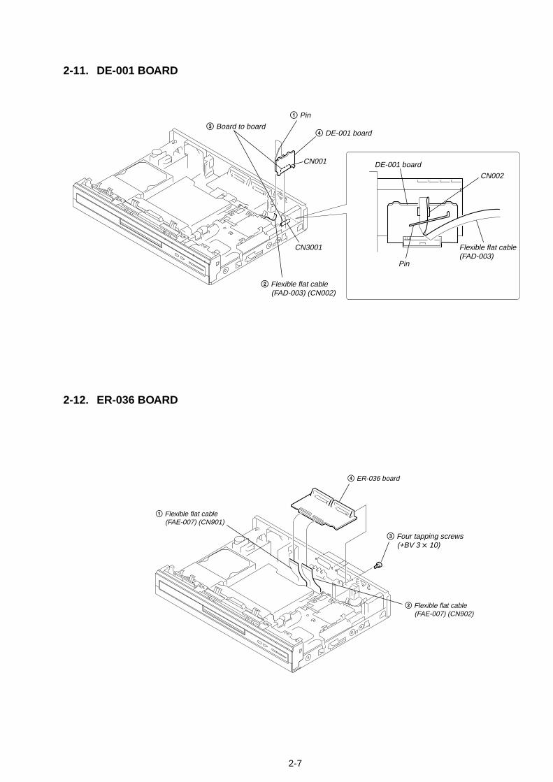
2-7
2-11. DE-001 BOARD
2-12. ER-036 BOARD
4 DE-001 board3 Board to board
1 Pin
2 Flexible flat cable (FAD-003) (CN002)
CN3001
CN001
CN002
DE-001 board
Flexible flat cable(FAD-003)
Pin
4 ER-036 board
1 Flexible flat cable (FAE-007) (CN901)
2 Flexible flat cable (FAE-007) (CN902)
3 Four tapping screws (+BV 3 x 10)

2-8
2-13. POWER SUPPLY BLOCK
2-14. A-004 BOARD
1 Connector (CN2)
4 Four tapping screws (+BV 3 x 8)
5 Remove the Power supply block in the direction of the arrow.
2 Connector (CN3)
3 Tapping screw (+P 3 x 8)
5 Two tapping screws (+BV 3 x 8)
6 A-004 board
3 Flexible flat cable (FVA-001) (CN461)
4 Flexible flat cable (FDA-003) (CN462)1 Flexible flat cable
(FRA-001) (CN460)
2 Connector (CN464)

2-9
2-15. RD-58 BOARD
qd RD-58 board qa Connector (CN1701)
qs Connector (CN1702)
0 Connector (CN1901)
7 Six tapping screws (+BV 3 x 8)
8 A-004 board, Bracket
6 Flexible flat cable (FAD-003) (CN462)
5 Flexible flat cable (FVA-001) (CN461)
3 Flexible flat cable (FRA-001) (CN460)
1 Flexible flat cable (FRH-002) (CN603)
9 Flexible flat cable (FFC-059) (CN2101)
RD-058 board
MI-056 board
4 Connector (CN464)
2 Flexible flat cable (FRD-001) (CN602)
HXD710/HXD910
HXD910

2-10
2-16. AV-096 BOARD
1 Two tapping screws (+BV 3 × 8)
2 RD bracket
9 Connector (CN1201)
qs Connector (CN3)
qd Three tapping screws (+BV 3 x 8)qf Remove the AV-096 board
in the direction of the arrow.
qa Six tapping screws (+BV 3 x 10)
0 Screw (+B 3 x 3)
6 Connector (CN701)
8 Flexible flat cable (FAE-007) (CN901)
7 Flexible flat cable (FAF-001) (CN602)
7 Flexible flat cable (FAE-007) (CN902)
5 Flexible flat cable (FVA-001) (CN3002)
4 Two pins3 Pin

2-11E
2-17. D.C. FAN
2-18. CIRCUIT BOARDS LOCATION
2 Connector (CN1201)
3 Two tapping screws (+BV 3 x 10)
4 Remove the D.C. fan in the direction of the arrow.
1 Pin
Power supply block
AV-096 board
DE-001 board
MI-056 board
A-004 board
HXD910
HXD710/HXD910
RD-58 board
FR-232 board
FL-150 board
CN-243 board
ER-036 board

RDR-GXD310/HXD710/HXD910SECTION 3
BLOCK DIAGRAMS
3-1. OVERALL BLOCK DIAGRAM
3-1 3-2
VIDEOINPUTSELECT
YC
V
CR/CB/Y
IC701
DV I/F
IC1901
SRC
IC1401
DV I/FCONTROL
IC1601
V DEC
IC1202
NAZCA2
IC802
ATA I/F
IC601
DDR SDRAM
IC901DDR SDRAM128M X 32
DDR SDRAM512M X 16
IC701
IC702AUDIOINPUT SELECTA/D CONV.
DIGITALTUNER
IC201
TU3001
LR
FA INLFA INR
TU L/RTU LI/RI
SDASCL
KEY1
KEY1-4
KEY1-4
FUNCTIONSWITCH
SIRCS SIRCS
V2Y2C2
RECVYRECCCR RECR,RECG,RECBCB,RECVY,RECCCR
SRC DATA
DAC DATA
TU SDATU SCL
LED DTLED CK
P CONT
LED DTLED CK
IF AGCIF1,IF2
TU SDATU SCL
I2CO SDAI2CO SCL
REC MCK 1-3PB MCK 1,2CARSYSCK27MNAZSYSCK27MDVSYSCK27MVIDSYSCK27M
I2CO SDAI2CO SCL
ADDAT1
EUAUIN L/R 1
VY ADL3RC
EUAUIN L/R 3
PDT0-7
PTA+,-PTB+,-
PTA+,-PTB+,-
SDRAM
IC1602
VIDCARV0-7 BUFCARV0-7
656B
UFV
0-7
NAZVIDV0-7 CARNAZV0-7
A-004BOARD
RD-058 BOARDDE-001BOARD
CN-243BOARD
AV-096 BOARD (1/2)
AV-096 BOARD (2/2)
HDDUNIT
DVDDRIVEUNIT
AT2 D0-D15 IDE D0-D15
AT2 A0-A4 IDE A0-A4
AT1 D0-D15 IDE D0-D15
AT1 A0-A4 IDE A0-A4
NAZVIDV0-7
IC104CPU
IC604IT CPU
IC101EEPROM
IC402128MNANDFLASHMEMORY
IC108IC109
256MSDRAM
IC201IC202
128MFLASHMEMORY
IC501HOST GLUE
P CONT
FAN ON
SCIF2 SDOSCIF2 SDISCIF2 SCK
XSHWE0-3XSHRDSHDCKCPUCK66XSHBSSHRW
XNAZWE0-3NZCRDXCARWE0-3SWCPCKBSCARRDXUNBSUNRW1XUNRD1,2XUNWE0,2
SCIF2 SDOSCIF2 SDISCIF2 SCK
SPDIF
SPDIF AV
YCBCR
LAOUTL +,-
AOUTR +,- AUDIOAMP
R
VIDEO VIDEO
YC
PO YPO PBPO PR
VO YC
VO YVO C
PO YPO PBPO PR
VO YC
DV DATA
DV DATA
HXD910, HXD710
SRC DATA
VO YVO C
FLD DRIVE
FLD
ND1301
IC1301
POWER
S1302
FR-232 BOARD
LED DRIVE
EEPROM
IC102
REMOTECOMMANDERRECEIVER
IC101
SYNCHRO RECTIMER RECHDDDVD
IC301
IC605
VIDEOAMP
IC802
IC1402AUDIOD/ACONV.
AOUTL +,-
AOUTR +,-
ITSDO5ITSDI5ITSCK5
ITSDO5ITSDI5ITSCK5
J802
S VIDEO
VIDEO
LINE 2 OUT
YC
Y
CB
CR
Y
PB/CB
PR/CR
COMPONENTVIDEO OUT
CN301
L
R
LEFT
RIGHT
DIGITAL OUT
CAXIAL
OPTICAL
Y2C2
V2
FA INL
FA INR
FL-150 BOARD
S VIDEO
VIDEO
J1301
LINE 2 IN
AUDIO LEFT
AUDIO RIGHT
S VIDEO
VIDEO
OUT
IN
J3702
L
RLINE 4 INAUDIO
LEFT
RIGHT
LINE 4 IN
FAN
IC1201FAN DRIVE
IC302,304
IC307,310
IC308,306
IC303,305
IC301,309
SHHD0-31
SHHA0-25
UNHD0-31
UNHA0-25
SWHD0-31
SWHD0-31
SWHA0-25
SWHA0-25
D0-31D0-31
D0-15
D0-15
DATA0-7
A0-11A0-11
A0-12
6
A0-11
IC1001PLLCLOCKGENERATOR
IC001DIGTALCONV
IC100D/A CONV
DIGITAL CONT
IC2300REC 656
BUFF
IC2301REC 656
BUFF
IC300AUDIO DAC
BUFF
4
UNSW12V
UNSW4V
UNSW6VB
UNSW6VA
UNSW-10V
SW12V
SW5V
SWITCHINGREGULATOR
AC IN
HXD710, HXD910
5
34
AERIAL
HDMIOUT
IC402HDMI CONT
IC202HDMI TX
IC10216M SDRAMA0-A11
C2-
C9
B0-
B7
Y0-
Y7
SMDDC-SCL/SDA
TMDS-DATA0/DATA1/DATA2/CLOCK
HPD
IC101IP CONV
&SCALER
D0-D15
SM
T S
CL/
SD
A
SM
DD
CS
CL/
SD
A
SCAL-V/H/CLK
HDMIA-DATA/BCK/LRCK
MI-056 BOARD
CN201
SM-SCL/SDA
I/O IF
AUDIO SW
ER-036 BOARDVY ADL3 BGRC
V, R, G, B IN
CN104
V/Y OUT
A(L/R) IN
A(L/R) OUT
A(L/R) IN
A(L/R) OUT
L3(L/R) IN
L1(L/R) IN
V IN
G OUTV/Y OUTR/C OUTBO/CI
ERV,ERY,ERC,ERR,ERG,ERB
TU SDA,TUSCL
IC105
IC106
IC103,104
LINE1-TV
CN103
LINE3/DECODER
HDMIY0-7
FEDATA0-7 DTTV0-7 656BUFV0-7
HD
MIY
0-7
EUAUIN L/R 1
EUAUIN L/R 3
CN104
DV IN
HXD910HXD710
J3801
LED STB / LED CK LED RST / LED DT

RDR-GXD310/HXD710/HXD910
3-3 3-4
3-2. AV-096, FR-232, FL-150 BOARD BLOCK DIAGRAM
46
17
7
169
141217
1
15
10
13
11
LED DIM
SIRCS
KEY1
KEY2
KEY3
KEY4
LED STBFLD CSLED CKLED DTLED RST
J1301
V2
Y2
C2
S2 SW
L2
R2
6
2
4
1
8
10
CN1301 CN102
KEY12
S1302
POWER
61626360
FLD CSLED CKLED DTLED RST4
573
6537
8
FL-150 BOARD
CN104
DV IN
4321
REC_PAUSE, RETURN,NEXTRIGHT,DOWN,LEFT,UP,ENTER
REMOTECOMMANDERRECEIVER
PLAY, PAUSE, STOP, REC STOP
S106-104,101
S121,103,107-110
HXD910HXD710
HXD910HXD710
SYS_MENUPPEV,REC_MODE
S122DUB
S114-116
S102,119,120,SW1-5
LED DRIVE
IC102
IC101
1098
11
1
LED STBLED CKLED DTLED RST
FR-232 BOARD
AV-096 BOARD
DIMMERSWITCH
SYNCHRO RECTIMER RECHDDDVD 2
356
Q101,102
D103,102D104,105
VIDEO
FLD DRIVE
IC1301
LINE IN 2
CN1302
AUDIOL(MONO)
AUDIO R
S VIDEO
IN
OUT
AERIAL
TU3001DIGITALTUNER
18
12
16
17
11
SWITCHINGREGULATOR
TORD-058BOARDCN1901
1
TOER-036BOARDCN106
8
AC IN
FLD
ND1301
CN103
TPA+TPA-TPB+TPB-
2345
CN101
P CONT
UNSW12V
UNSW4V
UNSW6VB
UNSW6VA
UNSW-10V
SW12V
SW5V
16
18
10
1
6
8
12
20
22
24
FSW
L3B
CN902
L3RC
VY-AD
AVLINK
L3G
EUAUINL3
EUAUINL1
EUAUINR3
EUAUINR1
EUAUINL3
R4
L4
EUAUINL1
EUAUINR3
EUAUINR1
OPEN/CLOSE, REC DUB,TOOLCH+, CH- INPUT_SEL
S112,113DVD,HDD L
L4
CR
L3RC
L3G RECG
RECR
RECRCB
L3B
CVBS/Cb
RECVYDTT_SEL
RECCR
VY-AD
CB
Y
Y2
C2
V2
CR
CB
Y
R
R4
S VIDEO
LINE 4 IN VIDEO
J3702
C
Y
TODE-001 BOARDCN001
4CN3001
9
8
6
4
3
SDA
SCL
IFAGC
IF2
IF1
SDA
SCL
IFAGC
IF
IF
INSEL1
EU_MUTE
INSEL2
INSEL_TU
V.SYNC
DTT_SEL
SYNCRO_DET
SCL
SPDIF_IN
SDA
XVMUTE
ERG
ERR
ERB
ERY
ERV
ERC
EUAUOUTR
EUAUOUTL
EURO_MUTE
XFLMRST5
XP_MUTE
XR_MUTE
27
25
23
19
17
13
11
9
7
5
4
2
TOER-036BOARDCN105
9
TORD-058BOARDCN1702
3
CN901
50
7
VIDEOINPUT
SELECTOR
38
40
IC701 42481319
44
4
5
25
21
23
30
39
35
36
41
9
AUDIOINPUT SELECTOR
A/D CONV.
IC201
CN3002
CN701
SIRCS
LED DIM
FLD CS
KEY2
KEY4 IC604IT CPU
2
21
6
96
52
50
9
10
14
12
3
80
11
615
6 60
27
91
92
93
51
97
99
4
98
83
88
87
76
95
94
75
73
78
18
38
39
40
49
48
47
45
101
24
26
28
29
89
90
17
109
82
CN602
IC3700SW
2
15
10
1
TUR
TUL
X60132.768kHz
X60210MHz
IC602RESET
Q611-614
LINK
IC605EEPROM
Q615
SW
Q703
BUFF
Q705
CN501
BUFF
8
6
15
11
7
5
27
20
24
16
14
28
29
30
19
23
1
42
38
37
33
34
41
Q605
SLICEV
Q604
BUFF
+-
-+3
2
IC301
5
67
1
28
24
20
16
12
8
10
32
41
33
31
36
37
38
39
34
CN502
15
3
VIDEOOUT
31
17
7
IC802
16
29
33
24
22
20
Q801
J3801
BUFF
BUFF
BUFF
BUFF
BUFF
BUFF
Q803
Q804
Q805
Q806
Q802
J802
Y
PB/CB
PR/CR
S VIDEO
VIDEO
L
R
LINE 2 OUT
COMPONENTOUT
Q801,802
MUTE
Q310A MUTE(L)
Q304,306,308
MUTE(L)
Q305,307,309
MUTE(R)
Q315,316
P CONT
Q311A MUTE(R)
DIGITAL OUT
CAXIAL
OPTICAL
1
IC1201FAN DRIVE
4
5SENS
FAN 12V3
2
Q313
BUFF
V.SYNC
RECCCR
RECVY
RECBCB
RECR
RECG
AWAKE_DONE
VO_YC
VO_C
VO_Y
Po_Y
Po_PB
PO_PR
XV_MUTE
AOUTL-
AOUTR+
AOUTL+
AOUTR-
XLMUTE
XAMUTE
XRMUTE
STATUS1
AOUTL+
VIDEO
CR/R
XVMUTE
AOUTL-
AOUTR+
AOUTR-
C_OUT
Y_OUT
VIDEO
PB/CB
PR/CR
AUDIO AMP
38
7
44
1
42
3
5
40
36
9
DTT_Cr
DTT_Cb
DTT_Y
DTT_L
DTT_R
Y2IN
C2IN
V2IN
S2SW
S2W
XP MUTE
DTT_PCONT
PCONT
WIDE
XNENTMUTE
FSW
TU_SCL
TU_SDA
L2IN
R2IN
LED_DT
KEY3
LED_CK
KEY1
LED_STB
LED_RST
6
8
12
CN1201 DC FAN
FAN ON
FAN HI
FAN DET
FAN ON
FAN HI
FAN DET
SPDIF_AV
FSW
STATUSO
XAWAKE
FLMRST
IT XRST
ITSCK
IT SOUT
ITSDI
ITREQ
XAWAKE5
IT_CON_TEMP
SHAWAKE_DONE
SHSTATUS1
SHSTATUS0
XFLMRST5
XITRST5
ITSCK5
ITSDO5
ITSDI5
ITREQ5
AI SDT
AI BCK
AI LRCK
256FS
AADXRST
ADSMUTE
TU_SCL
H_DET
TU_SDA
SYNCRO_DET
V.SYNC
INSEL_TU
INSEL_2
INSEL_1
ADMUTE
XSWGBRST
REC_MCK_1
ADLRCKI
ADBCKI
ADDATI
C
Y
Y/G
CB/B
TOA-004BOARDCN461
TORD-058BOARDCN1701(1/ 3)(2/ 3)(3/ 3)
2
AOUTL-
AOUTR+
AOUTL+
XNENT_MUTE
Y
AUOUTL2
AUOUTR2
WIDE
AOUTR-
TUL
TUR
6
8
10
4
2
2
4
10
6
1
8
17
11
6
5
4
3
2
1
9
8
7
30
29
28
27
25
24
23
22
21
6
(1/ 3)(2/ 3)(3/ 3)

RDR-GXD310/HXD710/HXD910
3-3. RD-058 BLOCK DIAGRAM (1/2)
3-5 3-6
IC1202V DEC
IC1402AUDIOD/ACONV.
AOUTL+, -
AOUTR+, -
AOUTL+, -
AOUTR+, -
IC1901
IC1604-1606
DVI/F
PLL
IC1601
DV I/FCONTROL
IC1001PLLCLOCKGENERATOR
IC1003BUFFER
IC1401SRC
IC1403
SELECT
SRC DATA
DV SEL
DV SELDV SEL
LRCKBCK
XSRCRSTSRMUTE
DATAB
A1
2
5
6
Y
XPHYRST
XPHYRST
REC MCK 3
REC MCK 1256FS
TPA+TPA-TPB+TPB-
CTL0,1SCLKLREQLPSLINKON
TPA+TPA-TPB+TPB-
CN1901
HXD910, HXD710
IC601ATA I/F
VIDCARHD,VIDCARVDVIDCARFD,VIDNAZCK BUF CAR HD,BUF CAR VD
BUF CAR FD,BUF CAR CK
656 BUF HD, 656 BUF VD656 BUF FD, 656 BUF CK
656 BUF HD656 BUF VD656 BUF FD656 BUF CK
CARNAZVCKCARNAZHDCARNAZVDCARNAZFD
FSW
DTT_VCKDTT_VCK
DTT_IC2_DDTT_I2C_C
I2C1_SDAI2C1_SCL
FSW
167
66878982
AB8AB9AB7AF3
161
156
154
150
RECBCB
RECCCR
RECR
RECG
RECVY72-7476-80
16
61
23
AC7,AD6,AE6AD5,AE5,AF5AE4,AF4
AE17,AF16AF17,AF18AE18
AF14,AE14,AC13AB12,AD,12,AF12AF11,AF10,AE10AD11,AE12,AC12AE13,AF13,AC14AD14
C13,A12,D13B13,A13,C14
B14,D14
K25,M24,L25M23,L26,M22M25,M24,N25
AD9,AE9,AD8AE8,AF8,AD7
AE7,AF7
IC802NAZCA2
D15A14C15B15
AF6AC11AB11AC10
D10,A8,B9C11,A9,D11B10,A10
F26,J24,G25J23,H24,J22
G26,K24
Q1201
RV801
BUFF
1112
I2C0 SDAI2C0 SCL
I2C0 SDAI2C0 SCL
DDRA A0-11
IC901
DDR SDRAM
18XVIDRST
63VIDSYSCK27M
DDT_RST
XDDT_OE
DDT_RST
14XVIDINT
RECVY
RECBCB
RECCCR
RECR
RECG
CN1701(1/3)
CN1702(2/3)
CN1701(2/3)
CN1702(1/3)
27MHzX1001 11
12
1 7
NAZVIDV0-7
NAZVIDVCK
VIDNAZVCK
DVVIDVCK
49
47
68
V1T3W2R3T2R4T1
A5 E9 E8E10 E7 D7 E6 D5A13
C5L5A6B6
L23
B12
E17E18E22E23F22
53-60
C12,B11D12,B12
CARNAZV0-7
XVDEC_OE
VIDCARV0-7
656 BUF V0-7
VID
CA
RV
0-7
CRB AT1D0-15 IDE D0-D15
AT1 AD0-4 IDE A0-A4
SW
HD
0-31
SWHD0-31
SWHA2-25
SWHD0-15 SWHD0-31
SWHD0-31
SWHA0-25
SWHA1-25
NAZSYSCK27M SWDACK0XCARCS0,1XCARRDXCARWE0-3SWCPCKB
I2C1 SDAI2C1 SCL
XCARCS0,1XCARRDXCARWE0-3SWCPCKB
XSWDREQ0CARRDYXCARINT0,1
XSWDREQ0CARRDYXCARINT0,1
AD15AF15AD17AF9
AT1 WEAT1 RDAT1 DACKAT1 RST
IDE WEIDE RD
IDE DACKIDE RST
IDE WEIDE RDIDE DACKIDE RST
AC15AE16AD16
AT1 DREQAT1 RDYAT1 INT
IDE DREQIDE RDYIDE INT
IDE DREQIDE RDYIDE INT
AC18,AD18AB18,AC17AB17
AB19,AF21,AB21AE22,AD23,AF23AD24,AF24,AE24AC23,AE23,AD22AC21,AC20,AB20AD20
CRB AT2 D0-D15
AT2 AD0-AD4
AE21AF20AD19AE25
AT2 WEAT2 RDAT2 DACKAT2 RST
AE20AC19AE19
AT2 DREQAT2 RDYAT2 INT
XNZCRDXNAZCSSWDACK1XNAZWE0-3
XNZCRDXNAZCSSWDACK1XNAZWE0-3
Y1Y2W3
T26
D25
B25
E26
A22
C20
A20
NAZRDYXSWDREQ1XNAZINT
NAZRDYXSWDREQ1XNAZINT
A12A10A11
SRC DATASRC LRCK
SRC BCK
SRC DATASRC LRCKSRC BCK
SRC LRCKSRC BCK
U24
DDRA DQ0-31
DDR A0-11
IC701
8
DDR DQ0-31
SDR A0-12
IC702
DDR SDRAM512M X 16
DDR SDRAM128M X 32
12
SDR DQ0-15
MAD0-12
IC1602
SDRAM4
MDT0-15
E11
SPDIF AV
SPDIF AV
D10
A14
PB MCLK 1
HXD910
PB MCK 3
SPDIF HDMI
CARSYSCK27M
C10REC MCK 2
46 |
43
1211
243
5 6 2635958 J13
P13R13
20197
465 24
25
152
E2,E3D1,D2D3,C1C2,C3
8, 911,1214,1517,18
F4E1F2F1G4G3
2
5
3533363837
3533363837
212731
2325291
201410
18161240
86|3
38|
23
212731
2325291
3335|
38
3|
18
PDTO-7M1,N4N3,N2N1,P4P3,P2
NAZVIDV0-7
NAZDWCKNAZDVVCK
DVSYSCK27M
XLMUTEXRMUTE
XLMUTEXRMUTE
1615
65
XDSRCSXSWGBRST
87
SCIF2 SDOSCIF2 SCK
A4
P1R15
APWMAFS1
T15J15
AMCLK
R3DVVIDVCK
PLL1FSELPLL2FSEL
PLL1FSELPLL2FSEL
REC MCK 3
PB MCK 1,2
CARSYSCK27M
NAZSYSCK27M
VIDSYSCK27M
REC MCK 1,2,3DV DATADV LRCKDV BCK
DV DATADV LRCKDV BCK
ADDATI
ADLRCKIADBCKI
AI SDT
AI LRCKAI BCK
XVIDRST
XVIDINT
XDSRCS
XSWGBRST
XSRCRSTSRMUTE
SRCINT
M16M17M14 C4
XSWWE0XSWRDXDVCCSXDVCRST
L16L17C14R14J14
313
1514
XDVCWTXDVCINTXDVP32DV AEMP1,2
XSWWE0XSWRDXDVCCSXDVCRST
XDVCWTXDVCINTXDVP32DV AMP1,2
R2
DTT_RSTXDTT_OEXVDEC_OE
SCIF2 SDOSCIF2 SCK
19
33
37
41
38
42
1
15
3441
3836
3739
CN2300
1
8
12
16
20
24
28
PO_PR
PO_PB
PO_Y
VO_Y
VO_C
VO_YC
11-1416-19
6
3,4
5
11 7
RD-058 BOARD (1/2) CN-243BOARD
DVDDRIVEUNIT
HDDUNIT
IDE A0-A4
IDE D0-D15
CN1802 CN1801CN602
CN603
TORD-058BOARD(2/2)
TOFR-232BOARDCN103
TOAV-096BOARDCN501
2
TOA-004BOARDCN460
7
TOAV-096BOARDCN502
3
TOAV-096BOARDCN502
3
1
11
2TOAV-096BOARDCN501
10 9
|
1314
24.576MHzX1901
22
23
55
18
18
4
6
PB_MCK3
SCIF2 SDI
SCIF2 SDI
SCIF2 SCK
SCIF2 SCKSCIF2 SDOXHDMICSXHDMIRST1HDMIDL
SCIF2 SDO
XHDMICS
XHDMIRST1
HDMIDL
HDMIABCK
HDMIALRCK
HDMIADATA
CN2101
MCK_3
HDMIY0
HDMIY7
HDMICK
SCIF2_SDI
SPDIF
SCIF2_SCK
SCIF2_SDO
XHDMICS
XHDMIRST1
HDMI_DL
HDMI_A_BCK
HDMI_LRCK
HDMI_DATA
1
1
27
12
10
75
2
19
24
21
23
25
22
15
14
17
16
TOMI-056BOARDCN101
10
IC606
BUF CAR V0-7
212731
232529 1
17,1513,119,75,34,68,1012,1416,18
17,1513,119,75,34,68,1012,1416,18
NAZHDMIV0-V7
NAZHDMIVCK
HDMIABCKHDMIALRCKHDMIADATA
SWHA1-10
IC2301REC 656 BUFF
36,3533,3230,2927,26
37384041
121198
242548
13,1416,1719,2022,23
656
BU
F V
0-7
IC2300REC 656 BUFF
36,3533,3230,2927,26
121198
242548
23,2220,1917,1614,13
41
DTT_V0-7DTT_V0-7
SW
HA
2-25
SRCINT
HXD910, HXD710
HXD910, HXD710
656 BUF V0-7
HXD910, HXD710
SPDIF HDMI
NAZHDMIVCK
Q801-806
BUFF

RDR-GXD310/HXD710/HXD910
3-4. RD-058 BOARD BLOCK DIAGRAM (2/2)
3-7 3-8
IC309
IC402
IC302,304
IC303,305
IC301
IC110IC107
IC104
IC105
IC105
XCARCS0,1
XCARRDXCARWE0-3SWCPCKB
XSWDREQ0CARRDY
XCARINT0,1
SCIF2 SDOSCIF2 SCK
XNAZCSSWDACK1
XNZCRDXNAZWE0-3
NAZRDYXSWDREQ1
XNAZINT
DV SEL
XVIDRST
XVIDINT
XSRCRSTSRMUTE
SRCINT
XDSRCS
XSWGBRST
XSWWE0XSWRD
XDVCCSXDVCRST
XDVCWTXDVCINTXDVP32DV AMP1,2
XPHYRST
I2C0 SDAI2C0 SCL
PLL1FSELPLL2FSEL
N20N19
B16A16
5 81113
M20
H2
A11A10
A13
N3
F20F19
C5B5
A8B8B9
34
CN101
CN1701(3/3)
128
46 3
(2/3)
CPU
IC501HOST GLUE
(1/3)
SH RXDSH TXD
ITREQ5SHAWAKE DONESHSTATUS0SHSTATUS1ITSDO527
3024
16202914
ADMUTEP CONTXAMUTEXVMUTE
CKIOCPUCK66G
ADMUTEP CONT
ITSCK5ITSDI5XAWAKE5XITRST5
XFLMRST5 XFLMRST3
XFLMRST5FLMRST
F2R3D6D8B12
29674
1811141316
IT SCKIT SDIXAWAKEIT XRST
IT REQSTATUS0IT SOUT
ADSMUTEP CONT
XAMUTEXVMUTE
AWAKE DONESTATUS1
AADXRST
VSYNC
B11B13F4B1 46
||||||
35
29 |32
41 |44
XSHWE0-3
XSHRD
K19D4L2M2
1413114
CLK
CLK
SRCINT
SWCPCKB
XCARWE0-3
3 6 91214
XSWWE0XNAZWE0-3
603940
XSRCRSTSRMUTE
DV SEL
XSHCS0-6
XGPSINTXGPSINT2SHRDY
XUNGBRSTSHDACK0,1
XSHDREQ0,1
P CONT
CPUCK66G
351011
14
XSWDREQ0CARRDY34
27
NAZRDYXSWDREQ126
32
DV AMP1,2XDVCWTXDVCINTXDVP32
1720251516
SWDACK0XCARCS0,1
442
XDVCCSXDVCRST
41XPHYRST
37XVIDRST
XSWHDGT0
XUNRD1XUNWE0,2
533
XNAZCSSWDACK1
323330373840442629
XUNWE0,2XUNRD1,2XUNBSUNRW1SWRW
XSHWE0,2XSHRDXSHBSSHRW
XSHWE0-3XSHRDXSHBSSH RW
128 |133
107108106
100 77 78
79 80
75
118
128MNANDFLASHMEMORY
IC101EEPROM
161718
XSWRDXCARRDXNZCRD
2
37
22
1Y10
56
7
F18F17
CPUCK665
6792
IC306 (2/2)
IC105
5
XNFLREXNFLCENFLCLENFLALE
XNFLWEXNFLWP
XFLMCS0
XFLMCS0
XNFLBUSY
15
(3/3)
823
CN1702(3/3)
3210
3331
28
34
6
27
29
E1,F1G1,J1K1,L1M1,P1
NFLDATA0-7
I2C1 SDAI2C1 SCL
WP
XSWGT0
XSWGT1
XUNHDGT
XSHCS0-2,3-6XGPSINTXGPSINT2SHRDY
XUNGBRSTSHDACK0,1
XSHDREQ0,1
F3,H1J3,K2N1,P2
M19 J2 C1
B14A18D19
E19E20
XSWHDGT0XUNHDGT
XUNRD2XUNWE0UNRW1XUNBS
XSWGT0,1
VSYNC3
140139
122121110120
103104
22
SCIF2 SDISCIF2 SDI
SCIF2 SCK
SCIF2 SDO
SCIF2 SCK
SCIF2 SDO
SHHD0-31
SHHA0-25 SWHA1-25
SHHA2-15
SWHA1-25
SWHD0-31
SHRWSHWE0-3
XSHRD
CKEXSHCS3XSHRAS
IC108IC109
256MSDRAM
IC201IC202
128MFLASHMEMORY
IC307,310
IC308,306
UNRW1
SWRW
XUNHDGT
XHDMICS
XHDMIRST1
HDMIDL
UNHD0-31
UNHD0-15
UNHA0-25
UNHA0-5,23-25
UNHD0-31
UNHA2-24
RD-058 BOARD (2/2)
W7 Y7
W14Y14 Y6 R2W6
TORD-058BOARD(1/2)
TOAV-096BOARDCN502
TOAV-096BOARDCN501
33MHzX102
DTT_RSTXDTT_OEXVDEC_OE
A1
A2
11
2
3
A15
SWHD0-31
17191211 523
20
63
44
43
A12
A10
A11
SHHA0-25
SHHA0-25
SHHD0-31
SHHD0-31
I2C1 SDA
I2C1 SCL
XHDMICS
XHDMIRST1
HDMIDL

RDR-GXD310/HXD710/HXD910
3-9 3-10
3-5. A-004 BOARD BLOCK DIAGRAM
63,61,83,8190,99,97,106
161,170,187,179115,163,150
41,43,26,253,254,214193,195,42,21,23,212
215,194,196,186
CN404
CN400
4,68,10
12,1416,1820,2224,2628,30
32
62,6466,6870,7274,7678,8082,8486,8890,92
3 FWEB
711151923
399596979835
5
FOEBGCS1BFCS0BDAMON_GRDYBGP_INTB
FWEB
FWEB
FOEB
FOEB
GCS1BFCS0B
DAMON_GRDYB
GP_INTB
GP_JIG_MODE
JIG_MODE
GP_JIG_MODE
TXD1B
TXD
TXD0BRXD1B
RXD
RXD0B
TXD1BTXD0BRXD1BRXD0B
SYS RESET
RESET
JIG_MODETXDRXD
RESET
FWEB
RADD0|
RADD14
RDATA0|
RADD15
RADD0-14
FEDATA0-7
57,76,56,7555,74,54,7335,15,36,1637,17,38,18
2,4,5,78,10,11,1354,56,57,5960,62,63,65
48,47,2646,5,627,7,8
29,28,9,30
29-3235-40
28,41,42
RDATA0-15
NOT USED
NOT USED
FOEBGCS1BFCS0B
DAMON_GRDYBGP_INTB
GP_JIG_MODETXD1BTXD0BRXD1BRXD0B
SYS RESET
16917713725510891
171
23625
25659
183126162
264113
263
GP_FE_RESETFE_VALIOFE_PACKET_SYNCFE_CLKSCL1SDA1
346
CN462
FE_PSYNCFE_VALIDFE_RESET
FE_DATA0|
FE_DATA7
FE_CLKDTT_SCL1DTT_SDA1
5 13
DQ0-
15
DADD
0-12
29-3241-44
8128M NAND FLASH18
IC206
DDR SDRAM 256MIC202
CLOCK
BUFF
Q360,361,304
X20027MHz
IC201
D/A CONVSYSTEM CONTROL
IC100
321
15|
1210|7
51718
149,151,138125,127,114
105,107VDO_D0-7
80244223
226
VDC_CLKSCLOSDAO
CN460
DTT_I2C_DDTT_I2C_CDTT_VCK
DTT_V0|
DTT_V7
DTT_RSTEMMA_RESET
181715
10|75|2
20
175,184,158176,159,168
60
AUDIODAC
IC300
RESETIC368
111
257
270CN461
DTT-YDTT-Y
DTT-Cb
DTT-Cr
VID-Y
DTT_LDTT_R
6
10
42
BUFF
Q364,365,311
272 DTT-CbVID-CB 8
BUFF
Q362,363,312
260 DTT-CrVID-CR
218 ADD
238 ABCK
237 ALRCKDTT_LDTT_R
258 AMCK
241 PMSBS
220 PMSSCLK
212 PMSINS
201 PMSDIO
P ON
Q460,461
221 PMSPON
SYSRESET Q366
CN4632 PMS_BS
PMS_SCKPMS_INSPMS_SDIO
NOT USED638
RDAT
A0-1
5
TODE-001BOARDCN002
5
TOAV-096BOARDCN3002
6
TOAV-058BOARDCN2300
7
A-004 BOARD

RDR-GXD310/HXD710/HXD910
3-11 3-12
3-6. ER-036, DE-001 BOARD BLOCK DIAGRAM
IC105
IC106
IC104
IC103
TOAV-096 BOARDCN901
TOAV-096 BOARDCN902
ER-036 BOARD
9
TOAV-096 BOARDCN3001
4TOA-004 BOARDCN462
5
8
DE-001 BOARD IC001
20
15
11
7
16
8
19
6
2
3
1
V IN
R IN
G IN
BI/CQ
BLAKING IN
LINE 3/DECODER
CN103
LINE 1 - TV
CN104
FUNCTION SW IN
V/Y OUT
A(L)IN
A(R)IN
A(L)OUT
A(R)OUT
20
19
11
15
7
16
10
8
6
2
3
1
13
17
19
21
23
R/C
GB
ALL MUTECVBS/Y OUT
FS2
FB
C OUT
AUXB
AUXG
AUX R/C
AUX CVBS/Y
LI CVBS
CVBS/Y OUT
R/C OUT
G OUT
B OUT
LI FB OUT
FS1
FS LI OUT
AUX L IN
AUX R IN
AUX L OUT
AUX R OUT
LI L IN
LI R IN
LI L OUT
LI R OUT
SCL
SDA
FSW
PARALLEL1
FS AUX
FSL1
ASW4
ASW3
ASW2
ASW1
ASW1
ASW2
ASW3
ASW4
FS L1IN
FS AUX IN
DA R IN
DA L IN
27
25
6
4
2
24
11
9
5
7
28
V IN
V/Y OUT
R/C OUT
G OUT
BO/CI
BLAKING OUT
FUNCTION SW OUT
AVLINK
BUFFER
A(L)IN
A(R)IN
A(L)OUT
A(R)OUT
27
50
28
29
30
32
24
36
31
51
34
44
42
40
38
5
15
17
21
23
3
7
52
47
46
41
14
108642
48
2220
18
22
20
21
23
14
16
15
17
24
1214
2
9 10
15
8
9
12
10
7
6
2
1
1214
2
9 10
15
Q104-109
L3BL3GL3RC
XVMUTE
SCL
SDA
EUAUOUTR
EUAUOUTL
VY AD
EUAUINL3
EUAUINR3
EUAUINL1
EUAUINR1
AVLINK
ERCERVERYERBERRERG
FSW
EURO MUTE
CN105
CN106
20
10
18
1612
22
63
FE_DATA0-7
FE_RESET
CN002
FE_CLK
FE_VALID
FE_PACKETSYNC
DTT_SCL1
DTT_SDA1
FE_RESET
FE_CLK
FE_VALID
FE_PSYNC
FE_DATA0-7
DTT_SCL1
DTT_SDA162
7
6
5
4 18
14
17
16
2
1
58
59
57
54
53
26
25
11|
18
4|79|
12
3
4
6
8
9
20.48MHzX001
IF1CN001
IF2
IFAGC
SCL
SDA
IF1
IF2
IFAGC
SCL
SDA

RDR-GXD310/HXD710/HXD910
3-13 3-14
3-7. MI-056 BOARD BLOCK DIAGRAM
MI-056 BOARD(HXD910)
IC202HDMI TX
43
44
20
19
42
17
36
35
33
30
29
10
11
12
5
6
67,65-6158,57
79-7570-6856-49
32
27
26
2
1
80
66
18
IC101IP CONV
&SCALER
6
5
8
148
136
135
10
134
83
CN201
HDMIOUT
12
1
3
4
6
7
9
10
15
16
19
98,96,94,9293,95,97,101103,105,102104
129,127,125123,119,117115,113,114116,118,120124,126,128130
23
30
21-2527-3220,19
2,3,5,6,89,11,1239,40,4243,45,4648,49
IC10216M
SDRAM
35
IC402HDMICONT
22
23
19
52
53
51
14
32
31
62
61
35
16
27
26
36
6261302120
CN401
NOT USED
3
4
6
7
CN101
TMDS DATA2+
TMDS DATA2-
TMDS DATA1+
TMDS DATA1-
TMDS DATA0+
TMDS DATA0-
TMDS CLOCK+
TMDS CLOCK-
SCL
SDA
HPD
CSCLX0
X1
RST
P32
NOM
DL
P33
P31
P60
PB_MCK_3
CSDA
DSCL
DSDA
RESET
INT
SDO
WS
SM_SCL
SM_T_SCL
SM_T_SDA
SM_DDC_SCL
SM_DDC_SDA
XTXRST
XTXINT
SM_SDA
HDMI_DL
SCK
SPDIF
MCLK
SCLSM_SCL
SDASM_SDA
NRSTXIPRST
27MHZ
TX2+P20
P21
P43
P42
P15
P62
P25
P26
P14
TX2-
TX1+
TX1-
TX0-
TX0+
TXC-
YSYNC
HSYNC
DE
IDCK
QCLK
QDE
QM
QV
MCLK
XEXRSTT
DLON
TXD
RXD
MCK_3
XHDMICS
XHDMIRST1
SCIF2_SDI
SCIF2_SDO
SCIF2_SCK
SPDIF
HDMI_LRCK
HDMI_DATA
HDMI_DL
HDMI_A_BCK
HDMICK
HDMIY0-Y7
HP
D
MO
D0
MO
D1
P22
TXC+
HPD
SCALV
SCALV
SCALH
SCALH
SCALDE
SCALDE
SCALCLK
SCALCLK
IPA0-IPA11
D0-D15 DQ0-DQ15
SC
ALC
2-C
9
SC
ALY
0-Y
7
SC
ALB
0-B
7
164-167170-173
151-154157-160
138-146
8MHzX401
S401
IC4017
1 2
YC0-C7
14
16
17
18
19
20
22
24
25
26
27
29
31|
3436|
39
PB_MCK_3
SPDIF_HDMI
HDMI_A_LRCK
SM
_DD
C_S
CL
SM
_DD
C_S
DA
HDMI_A_DATA
HDMI_A_BCK
SPDIF_HDMI
HDMI_A_LRCK
HDMI_A_DATA
HDMI_A_BCK
TORD-058BOARDCN2101
10
HDMICK
1
4
IC203

RDR-GXD310/HXD710/HXD910
3-15 3-16
3-8. POWER BLOCK DIAGRAM (1/2)
INLET LINE
INLET
LINE
L101,102
F101
CN101
SWITCHING REGULATOR(POWER BLOCK)
D101
FILTER
D301
D302 D303
T101CONVERTERTRANSFORMER L301 D304
SWITCHINGREGULATOR
D401
D501
PHOTOCOUPLER
D106
SHUNT REG
D601P602
5A
L103
L401
L501
RV501
SHUNT REG
L601
SW5V REG
P301 UNSW 12VCN3
UNSW 4V
UNSW 6VB
UNSW 6VA
UNSW -10V
UNSW -8V
P CONT
SW12
V
SW5V
CN2
D402
UNSW 12VCN1201
FAN
FAN 12V
ER-036 BOARD
DE-001 BOARD
KEY1
SIRCS 6V
SW-8V
CN102 CN101 CN602
FR6V
CN1301
PS6010.63A
Q616,617
Q606-608 PS6020.5A
FR P CONT
P FAIL
FL P CONT
VCC
VDD2VDD3
D605
UNSW-8V
SW-10V
UNSW12V
L302
Q301
UNSW6V
Q302,303AU12V
SWA5V
D302
FL3002
L300330VL3001
UNSW-8V L804
L701 L702
-5V
SW5V
P CONT
SW5V
UN SW5V
CN501
23
9
25
42
TORD-058BOARDCN1701
SW5VAV
SWA5V
RD 5V
SH SW3.3V
23
15
14
2
TOA-004
BOARDCN464
4
UNSW5V
SW1.8V
SW3.3V
SW2.5V
SH SW1.5V
911
24
135
TORD-058BOARDCN1702
1
27
D109
L105
L106
UNSW6V
P CONT
UNSW6V
PS1012A L101
D108
UNSW4V
P CONT
P CONT
L103Q104SWITHING
UNSW12V
UNSW6VA
CN101
UNSW6V
Q106,109
CN502
19
SW3.3V
DVDDRIVEUNIT
HDDUNIT
AV-096 BOARD
FL-150 BOARD FR-232 BOARD
AC IN
PC101
2.5A
2A
1A
P401
P501 2A
P502
0.8AP601
Q301
Q302
Q303
CN1
(HXD910 , HXD710)
2
1
IC101
IC501
IC301
IC502
1
23
67
13
12
4 1
IC1201FAN DRIVE
2 4 3
IC102
REMOTECOMMANDER
RECEIVER
IC101
LED DRIVE
Q1303,1304T1301
FLD DRIVE
INVERTERVFL
IC1301
FLD
ND1301
S1302POWER FAIL DET
57
77
IC602RESET
2 IC6012179
34
15
69106
IC604IT CPU
IC605EEPROM
RIPPLEFILTER
Q3151
P CONT
IC3025VREG
45
IC301AUDIO AMP
IC201AUDIOINPUT SELECTA/D CONV.
IC3001DC/DCCONV.
TU3001
7
4 9
8
DIGITALTUNER
IC80125 -5V REG
6
1
IC802VIDEOAMP
IC1025V
REG4
IC701VIDEO
INPUT SELECT
IC108
IC1061.8VREG
1.5VREG
5
IC1015V
REG2
SWITCHINGREG
1
5
3
4
IC1073.3VREG
IC105 6
3
IC111
3.3V REG1
1
2
3
15
16
14
15
3
2
4
8
9
4
8
9
4
UNSW6V
1
IC3151DTT3.3V REG
8 1
4
3
1
2
1
2
6
3
IC3152DTT1.5V
REG
1
2
6
3
IC3002FE1.8V
REG
5
8
6
3
89
1 2
4
POWER112
1
1
23
67
13
12
89
SW12
V
SW5V
4 1
CN3001 CN001
CN3101
AN3.3V
5DTT3.3V
DTT3.3V
DTT5V
DTT1.5V
DTT1.8V
7
4
6
1
0
12
11
1
12
11
1
F1,F2
IC3150DTT5V REG
6 4
1
1
PS31012A L3151 L3150
IC3700SW
L803
Q107,108
Q3001,3002
94
FB3151
3
KEY196
D603
FL3001
FB3150
CN901
18
15
20
14IC1015V REG
IC106AUDIO I/O IF
IC105VIDEO OUT
BUFFER
IC103IC104AUDIO SWITCH
CN105
UNSW12V
UNSW6V
UNSW-8V
L101
Q104-Q109
D101
L102
PS1032A
PS1012A
11
9
14
156
14
IC102-5V REG
2
56
1
IC001DIGTALCONV
L006
L004
L002

RDR-GXD310/HXD710/HXD910
3-17 3-18
3-9. POWER BLOCK DIAGRAM (2/2)
IC1201
IC104CPU
IC601ATA I/F
IC606
SW2.5V
HXD910
(HXD910)
IC802NAZCA2
IC1202V DEC
SW3.3V
PCONT
IC108IC109 IC101256M SDRAM
EEOROM
IC701DDR SDRAM128M X 32
IC901DDR SDRAM
IC1602SDRAM
IC1901DV I/F
BUFFER
Q1201
CN2101
IC1001PLL
IC1003BUFFER
IC110BUFFER
SW1.2VSW2.5V
SW3.3V
SW5VAV 3.3V
SW3.3V
IC1605IC1606
PLL
IC702DDR SDRAM512M X 16
IC201IC202
128M FLASH SDRAM
IC301-IC310
BUFFER
IC105BUFFER
IC501HOST GLUE
IC402128M
NAND FLASH
IC401MULTIPLEXER
IC107BUFFER
SH SW3.3V
SH SW5V
FL103
SH SW3.3V
SW3.3V
SH 3.3V
SH SW1.5VA
SW2.5V FL602
IC2300REC 656 BUFF
IC2301REC 656 BUFF
SW2.5VFL804
FL802
FL1001FL805
SW3.3V FL603
SW1.8V
SW3.3V
SW3.3V
D4
85
IC8013.3VREG
4
1
5
IC11021.2VREG
45
2
IC1601DV I/F
CONTROL
SW5VAV 3.3VIC16073.3VREG
4
1
5
REG1
SW3.3V
A5V
VID5V GR5V
UNSW6V
SW3.3VB
SW2.5VA
SW1.8VC
L1201
IC1604VCO
IC1401SRC
IC1403DV SEL
IC1402AUDIO
D/A CONV.
FL1401
FL101
SW2.5V
SW3.3V
SW3.3V
FL1602
SW1.8V
SW3.3V
UNSW6V
UNSW6V
SW2.5V L1101
P CONT
SW5V VID5V
CN1701
CN1702
SW5VAV
SWA5V A5V
RD 5V SH SW5V
SH SW1.5V
SH SW3.3V
UNSW 5VTU 5V
19
23
9
25
42
27
23
15
14
911
24
135
TOAV-096BOARDCN502
TOAV-096BOARDCN501
1
2
RD-058 BOARD
6
7
UN3.3V
UN5V
CN101
IC362DAC 3V3 REG
IC100D/A CONV
SYSTEM CONT
IC300AUDIO DAC
IC206128MB NAND
FLASH MEMORY
IC202256MB
DDR SDRAM
IC20127M CLOCK
RESET
CN464
CN404
CN400RESET
DTT5V
+3V3
5.0V
NOT USED
DTT1.5V
DTT3.3V
Q366
D363
4
333453619394
5758
6
5
6
7
6
1
4
IC363RESET
41
226 19
IC361DAC 2V5 REG
6
1
4
CN404SYS_RESET35
CN406SYS_RESET10
CN460DTT_RESET20
A-004 BOARD
MI-056 BOARD
IC205REG
IC101IP CONV&SCALER
IC202HDMI TX
UNSW6V
PVCC
+5V HDMIOUT
SW3.3VB
SW1.8VC
CN101
L101
PS1012A
L102
1
5 4
IC2075V REG
1
6 4
TOAV-096BOARDCN3101
4
FL501
FL601
FL803
FL1902
FL1601
39
38
37
36
35
34
33
32
2
3
4
5
6
7
8
9
FL105
FL105
FL203
CN201
FL204
FL20
2
FL20
1
18
+3.3V
CN401
2
IC10216M SDRAM
IC402HDMI CONT
FL107
FL401
HXD910HXD710
HXD910HXD710
HXD910HXD710
VIDEO BUFF(Y)
Q304,360,361 Q312,362,363 Q311,364,365
VIDEO BUFF(CR) VIDEO BUFF(CB)
L301

RDR-GXD310/HXD710/HXD910
4-1
SECTION 4SCHEMATIC DIAGRAMS AND PRINTED WIRING BOARDS
4-1. FRAME SCHEMATIC DIAGRAM
FRAME SCHEMATIC DIAGRAM
CN
2106
17P
1234567891011121314151617
9PCN102
1 IT_GND
2 IT_GND
3 LED_DT
4 FR_6V
5 LED_CK
6 FLD_CS
7 LED_RST
8 KEY1
9 SW-8V
9PCN1301
1SW-8V
2KEY1
3LED_RST
4FLD_CS
5LED_CK
6FR_6V
7LED_DT
8IT_GND
9IT_GND
10P
CN
1302
1S
2 S
W
2Y
2 IN
3A
N G
ND
4C
2 IN
5A
N G
ND
6V
2 IN
7A
N G
ND
8L2
IN
9A
U G
ND
10R
2 IN
Y C
G G
J3702
CN601 8P
1
2
3
4
5
6
7
8
CN
602
17P
1234567891011121314151617
CN
1201
3P
1G
ND
2S
ENS
3FA
N12
V
42P
CN
501
123456789101112131415161718192021222324252627282930313233343536373839404142
42PCN502
1
2
3
4
5
6
7
8
9
10
11
12
13
14
15
16
17
18
19
20
21
22
23
24
25
26
27
28
29
30
31
32
33
34
35
36
37
38
39
40
41
42
4PCN2
1 SW12V
2 DGND
3 DGND
4 SW5V
4PCN1
1 SW12V
2 DGND
3 DGND
4 SW5V
2PCN101
1 L
2 M
42P
CN
1701
123456789101112131415161718192021222324252627282930313233343536373839404142
42PCN1702
1
2
3
4
5
6
7
8
9
10
11
12
13
14
15
16
17
18
19
20
21
22
23
24
25
26
27
28
29
30
31
32
33
34
35
36
37
38
39
40
41
42
CN
603
40P
IDE_
RS
T1
GN
D2
IDE_
D7
3
IDE_
D8
4
IDE_
D6
5
IDE_
D9
6
IDE_
D5
7
IDE_
D10
8
IDE_
D4
9
IDE_
D11
10
IDE_
D3
11
IDE_
D12
12
IDE_
D2
13
IDE_
D13
14
IDE_
D1
15
IDE_
D14
16
IDE_
D0
17
IDE_
D15
18
GN
D19
NC
20
IDE_
DR
E021
GN
D22
IDE_
W23
GN
D24
IDE_
R25
GN
D26
IDE_
IOR
DY
27
CS
EL28
IDE_
DA
CK
29
GN
D30
IDE_
INT
31
IDE_
HD
1632
IDE_
A1
33
SAT
A_R
ST
34
IDE_
A0
35
IDE_
A2
36
IDE_
A4(
CS
0)37
IDE_
A3(
CS
1)38
DA
SP
39
GN
D40
40PCN602
1
2
3
4
5
6
7
8
9
10
11
12
13
14
15
16
17
18
19
20
21
22
23
24
25
26
27
28
29
30
31
32
33
34
35
36
37
38
39
40
6PC
N19
01
1G
ND
2TP
A+
3TP
A-
4TP
B+
5TP
B-
6G
ND
6PC
N10
3
1D
GN
D
2TP
A+
3TP
A-
4TP
B+
5TP
B-
6D
GN
D
10P
CN
701
1S
2 S
W
2Y
2 IN
3A
N G
ND
4C
2 IN
5A
N G
ND
6V
2 IN
7A
N G
ND
8L2
IN
9A
U G
ND
10R
2 IN
4PC
N10
4
1TP
B-
2TP
B+
3TP
A-
4TP
A+
13PCN3
1
2
3
4
5
6
7
8
9
10
11
12
13
13PCN102
1
2
3
4
5
6
7
8
9
10
11
12
13
CN
301
1D
IN
2V
CC
3G
ND
28P
CN
105
1N
.C.
2EU
RO
_MU
TE
3G
ND
4EU
AU
OU
TL
5A
UG
ND
6EU
AU
OU
TR
7A
UG
ND
8A
UG
ND
9U
NS
W-8
V
10ER
C
11U
NS
W12
V
12ER
V
13G
ND
14U
NS
W6V
15U
NS
W6V
16ER
Y
17G
ND
18ER
B
19G
ND
20ER
R
21G
ND
22ER
G
23G
ND
24X
VM
UTE
25S
DA
26IN
T
27S
CL
28EU
RO
PO
WER
28P
CN
902
1TU
R1
2A
DG
ND
3TU
L1
4A
DG
ND
5EU
AU
INL1
6A
DG
ND
7EU
AU
INR
1
8A
DG
ND
9EU
AU
INR
3
10A
DG
ND
11EU
AU
INL3
12A
DG
ND
13V
Y_A
D
14G
ND
15TU
DV
16G
ND
17L3
RC
18G
ND
19L3
G
20G
ND
21L3
B
22G
ND
23FS
W
24G
ND
25A
M
26TU
5V
27S
IF
28A
VLI
NK
CN
201
19P
TMD
S D
ATA
2 +
1
TMD
S D
ATA
2 S
HIE
LD2
TMD
S D
ATA
2 -
3
TMD
S D
ATA
1 +
4
TMD
S D
ATA
1 S
HIE
LD5
TMD
S D
ATA
1 -
6
TMD
S D
ATA
0 +
7
TMD
S D
ATA
0 S
HIE
LD8
TMD
S D
ATA
0 -
9
TMD
S C
LOC
K +
10
TMD
S C
LOC
K S
HIE
LD11
TMD
S C
LOC
K -
12
CEC
13
RES
ERV
ED14
SC
L15
SD
A16
DD
C/C
EC G
ND
17
+5V
PO
WER
18
HP
D19
CN
101
40P
GN
D1
6V2
6V3
SW
3.3V
B4
SW
3.3V
B5
SW
2.5V
A6
SW
2.5V
A7
SW
1.8V
C8
SW
1.8V
C9
I2C
N_S
CL
10
XH
DM
IIN
T111
I2C
N_S
DA
12
GN
D13
MC
K_3
(512
fs)
14
GN
D1516
XH
DM
ICS
SC
IF2_
SD
I17
SC
IF2_
SD
O18
XH
DM
IRS
T119
SC
IF2_
SC
K20
XH
DM
IRS
T221
SP
DIF
22
GN
D23
HD
MI_
A_L
AC
K24
HD
MI_
A_D
ATA
25
HD
MI_
DL
26
HD
MI_
A_B
CK
27
GN
D28
HD
MIC
K29
GN
D30
HD
MI_
Y0
31
HD
MI_
Y1
32
HD
MI_
Y2
33
HD
MI_
Y3
34
GN
D35
HD
MI_
Y4
36
HD
MI_
Y5
37
HD
MI_
Y6
38
HD
MI_
Y7
39
GN
D40
21P
CN
104
A(R
)OU
T1
A(R
)IN
2
A(L
)OU
T3
GN
D(A
)4
GN
D(E
)5
A(L
)IN
6
BO
/CI
7
FUN
CTI
ON
_SW
_OU
T8
GN
D(E
)9
AV
LIN
K10
G_O
UT
11
N.C
.12
GN
D(E
)13
GN
D(E
)14
R/C
_OU
T15
BLA
NK
ING
_OU
T16
GN
D(E
)17
GN
D(E
)18
V/Y
_OU
T19
V_I
N20
GN
D(E
)21
21P
CN
103
A(R
)OU
T1
A(R
)IN
2
A(L
)OU
T3
GN
D(A
)4
GN
D(E
)5
A(L
)IN
6
BI/
CO
7
FUN
CTI
ON
_SW
_IN
8
GN
D(E
)9
AV
LIN
K10
G_I
N11
N.C
.12
GN
D(E
)13
GN
D(E
)14
R_I
N15
BLA
NK
ING
_IN
16
GN
D(E
)17
GN
D(E
)18
V/Y
_OU
T19
V_I
N20
GN
D(E
)21
28P
CN
106
1TU
R1
2A
DG
ND
3TU
L1
4A
DG
ND
5EU
AU
INL1
6A
DG
ND
7EU
AU
INR
1
8A
DG
ND
9EU
AU
INR
3
10A
DG
ND
11EU
AU
INL3
12A
DG
ND
13V
Y_A
D
14G
ND
15TU
DV
16G
ND
17L3
RC
18G
ND
19L3
G
20G
ND
21L3
B
22G
ND
23FS
W
24G
ND
25A
M
26TU
5V
27S
IF
28A
VLI
NK
28P
CN
901
1N
.C.
2EU
RO
_MU
TE
3G
ND
4EU
AU
OU
TL
5A
UG
ND
6EU
AU
OU
TR
7A
UG
ND
8A
UG
ND
9U
NS
W-8
V
10ER
C
11U
NS
W12
V
12ER
V
13G
ND
14U
NS
W6V
15U
NS
W6V
16ER
Y
17G
ND
18ER
B
19G
ND
20ER
R
21G
ND
22ER
G
23G
ND
24X
VM
UTE
25S
DA
26IN
T
27S
CL
28EU
RO
PO
WER
CN2101 40P
GND 1
EPGHDMIV7 2
EPGHDMIV6 3
EPGHDMIV5 4
EPGHDMIV4 5
GND 6
EPGHDMIC3 7
EPGHDMIV2 8
EPGHDMIV1 9
EPGHDMIVO 10
GND 11
EPGHDMIVCK 12
GND 13
HDMI_A_BCK 14
HDMI_DL 15
16HDMI_DATA
HDMI_LRCK 17
GND 18
SPDIF 19
XHDMIRST2 20
SCIF2_SCK 21
XHDMIRST1 22
SCIF2_SDO 23
SCIF2_SDI 24
XHDMICS 25
GND 26
MCK_3(512fs) 27
GND 28
I2CN_SDA 29
XHDMIINT1 30
I2CN_SCL 31
SW1.8VC 32
SW1.8VC 33
SW2.5VA 34
SW2.5VA 35
SW3.3VB 36
SW3.3VB 37
UNSW6V 38
UNSW6V 39
GND 40
CN1802 40P
1
2
3
4
5
6
7
8
9
10
11
12
13
14
15
16
17
18
19
20
21
22
23
24
25
26
27
28
29
30
31
32
33
34
35
36
37
38
39
40
CN1801 40P
IDE_RST1
GND2
IDE_D73
IDE_D84
IDE_D65
IDE_D96
IDE_D57
IDE_D108
IDE_D49
IDE_D1110
IDE_D311
IDE_D1212
IDE_D213
IDE_D1314
IDE_D115
IDE_D1416
IDE_D017
IDE_D1518
GND19
NC20
IDE_DRE021
GND22
IDE_W23
GND24
IDE_R25
GND26
IDE_IORDY27
GND28
IDE_DACK29
GND30
IDE_INT31
IDE_HD1632
IDE_A133
N.C.34
IDE_A035
IDE_A236
IDE_A4(CS0)37
IDE_A3(CS1)38
DASP39
GND40
7PCN101
1 DIAG
2 RS_XEN
3 SH_RXD2
4 SH_TXD2
5 DGND
6 UN3.3V
7 UN5V
1
A
YC
GG
J3801
Y C
G G
J702
20P
CN
2300
1 2 3 4 5 6 7 8 9 10 11 12 13 14 15 16 17 18 19 20
14PCN3001
1
2
3
4
5
6
7
8
9
10
11
12
13
14
CN001 14P
1
2
3
4
5
6
7
8
9
10
11
12
13
14
18PCN002
1
2
3
4
5
6
7
8
9
10
11
12
13
14
15
16
17
18
7PC
N46
4
1234567
11P
CN
461
1234567891011
18P
CN
462
123456789101112131415161718
20P
CN
460
1 2 3 4 5 6 7 8 9 10 11 12 13 14 15 16 17 18 19 20
7PCN3101
1
2
3
4
5
6
7
11P
CN
3002
1 2 3 4 5 6 7 8 9 10 11
IT_G
ND
FLD
_CS
LED
_DIM
SIR
CS
KEY
2
LED
_RS
T
KEY
4
LED
_STB
KEY
3
LED
_CK
KEY
1
LED
_DT
IT_G
ND
IT_G
ND
SW
-8V
SIR
CS
_6V
FR_6
V
IT_GND
CNVSS
XIT_RST
M2
UN5V
CEVISCK5
SH_RXD2
SH_TXD2
SW
-8V
IT_G
ND
IT_G
ND
LED
_DT
KEY
1
LED
_CK
KEY
3
LED
_STB
KEY
4
LED
_RS
T
KEY
2
SIR
CS
LED
_DIM
FR_6
V
SIR
CS
_6V
FLD
_CS
IT_G
ND
DIGITAL OUT
UNSW4V
UNSW6VA
GND
UNSW4V
GND
UNSW6VA
GND
UNSW-8V
UNSW6VB
UNSW12V
P_CONT
UNSW6VB
GND
DC
FA
N
TU_5
V
IT_S
OU
T
DG
ND
IT_X
RS
T
AI_
BC
K
AD
SM
UTE
DG
ND
DG
ND
IT_R
EQ
IT_S
IN
FLM
RS
T
DG
ND
SP
DIF
_AV
DG
ND
AA
DX
RS
T
AI_
LRC
K
DG
ND
STA
TUS
0
EPG
VID
EO
P_C
ON
T
REC
VY
DG
ND
REC
G
FSW
EPG
GN
D
DG
ND
DG
ND
SW
5V
XA
WA
KE
REC
R
DG
ND
IT_S
CLK
REC
CC
R
256F
S
DG
ND
IT_C
ON
_TEM
P
Csy
nc
REC
BC
B
Vsy
nc
AI_
SD
T
DG
ND
BS
_SP
DIF
SW2.5V
C
UNSW6V
SW3.3V
Lch-
DGND
XVMUTE
Y
Lch+
SW5VAV
DGND
RCH+
CR/R
Y/G
RESERVE
DGND
DGND
AUGND
DGND
DGND
SW3.3V
DGND
SW1.8V
SH_SW5V
STATUS1
CB/B
SW2.5V
V
RCH-
RMUTE
DGND
AWAKE_DONE
SH-SW3.3V
SW1.8V
SWA5V
SH-SW1.5V
SW2.5V
LMUTE
DGND
DGND
AUGND
XAMUTE
UNSW6VB
GND
UNSW4V
GND
UNSW6VA
GND
P_CONT
UNSW4V
UNSW-8V
GND
UNSW6VA
UNSW12V
UNSW6VB
AC IN
AERIALIN/OUT
CHECK
DG
ND
AI_
LRC
K
AI_
BC
K
AD
SM
UTE
VID
5V
REC
CC
R
DG
ND
DG
ND
TU_5
V
256F
S
REC
BC
B
TEM
P
DG
ND
AI_
SD
T
DG
ND
EPG
GN
D
REC
VY
Csy
nc
FSW
AA
DX
RS
T
DG
ND
REC
R
Vsy
nc
EPG
VID
EO
DG
ND
DG
ND
DG
ND
REC
G
DG
ND
DG
ND
DG
ND
IT_X
RS
T
IT_S
CLK
IT_S
OU
T
N.C SP
DIF
_AV
IT_S
IN
IT_R
EQ
P_C
ON
T
FLM
RS
T
XA
WA
KE
STA
TUS
0
VO_YC
VO_C
VO_Y
PO_Y
DGND
PO_PB
XVMUTE
PO_PR
DGND
SW2.5V
DGND
SW1.8V
RCH-
Lch+
RESERVE
SW3.3V
RMUTE
SW1.8V
LMUTE
DGND
SW2.5V
SH-SW3.3V
SW2.5V
DGND
RCH+
XAMUTE
Lch-
DGND
DGND
SH-SW1.5V
AUGND
DGND
UNSW6V
SW5VAV
A5V
DGND
SW3.3V
DGND
SH_SW5V
AWAKE_DONE
AUGND
STATUS1
IDE_D14
IDE_D13
IDE_HD16
IDE_RST
GND
IDE_D9
NC
IDE_A2
IDE_INT
IDE_D0
IDE_D1
IDE_A1
IDE_D5
GND
IDE_D11
IDE_DREQ
IDE_A4(CS0)
GND
GND
IDE_A3(CS1)
IDE_W
IDE_D3
IDE_D8
CSEL
IDE_IORDY
GND
IDE_R
IDE_D10
DASP
NC
IDE_D6
IDE_DACK
IDE_D12
IDE_D7
IDE_D4
GND
IDE_D15
IDE_A0
IDE_D2
GND
DV IN
SWITCHINGREGULATOR
CN-243 BOARD
CHECK
HDD
TU30
01
FFS
-001
FFC
AL-071 HARNESS
PD-133 HARNESS
PH-074 HARNESS
B TO B
RV-001HARNESS
FRH-002 FFCB TO B
B TO B
COMPONENTVIDEO OUT
LINE 2 OUT LINE 4 IN
HDMI OUTLINE1-TV LINE 3/DECODER
MI-056 BOARD
ER-036 BOARD
FAE-007 FFCFAE-007 FFC
IDE_RST
IDE_D9
IDE_DACK
N.C
GND
IDE_A4(CS1)
IDE_D10
GND
IDE_D13
IDE_D1
GND
GND
GND
IDE_INT
IDE_D12
IDE_D15
IDE_IORDY
DASP
IDE_W
GND
IDE_D14
IDE_A2
IDE_DREQ
IDE_D11
IDE_D7
N.C
IDE_D3
IDE_HD16
IDE_D5
IDE_D4
IDE_D0
IDE_D8
N.C
IDE_D6
IDE_A1
IDE_D2
GND
IDE_R
IDE_A0
IDE_A4(CS0)
RD-058 BOARD
PH
-074
HA
RN
ESS
DVD
PD
-133
HA
RN
ESS
AV-096 BOARD
FL-150 BOARD
LINE 2 IN
FAF-001 FFC
FR-232 BOARD
242
G
K
5
E
M
17 19 23
Q
133
F
4
J
L
16
C
189
P
12
D
15
I
22
B
8
O
11 14 21
H
76
N
10 20
16
AU
DIO
R
AU
DIO
L
VID
EO
J802
DTT
_V1
DG
ND
DG
ND
DTT
_V7
DTT
_VC
K
DTT
_V6
DTT
_V3
DG
ND
DG
ND
DTT
_V4
DTT
_V5
DTT
_V0
DG
ND
DG
ND
DTT
_RS
T
DG
ND
DG
ND
DTT
_I2C
_DAT
A
DTT
_I2C
_CLK
DTT
_V2
HXD910HXD710
IF_AGC
DTT_SDA1
IF1
AN3.3
DTT3.3V
GND
DTT1.8V
SDA
DTT_SCL1
GND
SCL
GND
IF2
GND
DTT_SDA1
SDAFE_DATA[7]
FE_PACKETSYNC
FE_RESET
FE_DATA[2]
GND
DTT3.3V
FE_DATA[3]
AN3.3V
IF2GND
FE_DATA[6]
GND
FE_DATA[4]
DTT_SCL1
GND
IF1
GND
FE_DATA[1]
FE_VALIDDTT_SCL1
FE_DATA[0]
IFAGC
SCL
DTT_SDA1
GND
GND
DTT1.8VFE_CLK
FE_DATA[5]
GND
DE-001 BOARD
GN
D
DTT
_1.5
V
GN
D
DTT
_5V
GN
D
DTT
_3.3
V
DTT
_1.5
V
GN
D
DTT
_R
GN
D
DTT
_Y
GN
D
DTT
_Cb
GN
D
DTT
_Cr
GN
D
DTT
_L
GN
D
DTT
_V6
GN
D
FE_V
alid
DTT
_RS
T
DTT
_V4
FE_D
ATA
2
GN
D
GN
D
GN
D
GN
D
DTT
_I2C
_D
DTT
_VC
LK
FE_R
eset
DTT
_V5
FE_D
ATA
7
FE_D
ATA
4
FE_P
sync
GN
D
FE_D
ATA
0
I2C
_CLK
1
GN
D
FE_D
ATA
1
GN
D
GN
D
GN
D
DTT
_V2
DTT
_V3
FE_C
LK
DTT
_V0
FE_D
ATA
6
FE_D
ATA
3
GN
D
I2C
_DAT
1
DTT
_I2C
_C
GN
D
DTT
_V1
FE_D
ATA
5
DTT
_V7
DTT1.5V
DTT5V
GND
DTT3.3V
GND
DTT1.5V
GND
A-004 BOARD
GN
D
DTT
_Cr
DTT
_Cb
GN
D
DTT
_Y
DTT
_L
GN
D
GN
D
DTT
_R
GN
D
GN
D
B TO B
FAE-007 FFC
FAD-003 FFC
AV-071 HARNESS
FRA-001 FFC
FAE-007 FFC
AU
DIO
L
AU
DIO
R
VID
EO
HXD910
VID
EO
AU
DIO
L
AU
DIO
R
FVA-001 FFC
4-2

RDR-GXD310/HXD710/HXD910
WAVEFORMSAV-089/MI-054/UE-001
(For schematic diagrams)• All capacitors are in µF unless otherwise noted. pF : µµF.
50V or less are not indicated except for electrolytics andtantalums.
• All resistors are in ohms, 1/4 W (Chip resistors : 1 /10 W) un-lessotherwise specified.kΩ=1000Ω, MΩ=1000kΩ.
• Caution when replacing chip parts.New parts must be attached after removal of chip.Be careful not to heat the minus side of tantalum capacitor, be-cause it is damaged by the heat.
• All variable and adjustable resistors have characteristic curve B,unless otherwise noted.
• 2 : non flammable resistor• 5 : fusible resistor• C : panel designation• f : internal component.• C : adjustment for repair.• U : B+ Line• V : B– Line• Circled numbers refer to waveforms.• Voltages are dc between measurement point.• Readings are taken with a color-bar signals on DVD reference
disc.• Readings are taken with a digital multimeter (DC 10MW).• Voltage variations may be noted due to normal production toler-
ances.
THIS NOTE IS COMMON FOR SCHEMATIC DIAGRAMS(In addition to this, the necessary note is printed in each block)
When indicating parts by reference number, please includethe board name.
4-2. SCHEMATIC DIAGRAMS WAVEFORMS
Note :The components identified bymark 0 or dotted line with mark0 are critical for safety.Replace only with part numberspecified.
Note :Les composants identifiés parune marque 0 sont critiquespour la sécurité.Ne les remplacer que par unepièce portant le numéro spécifié.
AV-096 BOARD
30.5 µs
100 ns
H
H
H
H
H
H
1.2Vp-p
1.8Vp-p 4.2Vp-p
1.1 Vp-p
1.1 Vp-p
2.1 Vp-p
1 X601
2 X602
3 J3801 VIDEO OUT
4 J3801 S-VIDEO C OUT
5 J3801 S-VIDEO Y OUT
6 J802 Y OUT
7 J802 Cb OUT
8 J802 Cr OUT
1.4 Vp-p
1.8Vp-p
DE-001 BOARD
48.8ns
1.7Vp-p
1 X 001
A-004 BOARD
37ns
2.5Vp-p
1 X200
RD-058 BOARD
30.3 ns
37 ns
35.4 ns
78 ns
35.4 ns
40.7 ns
1.8 Vp-p
6.0 Vp-p
3.5 Vp-p
5.1 Vp-p
4.2 Vp-p
3.6 Vp-p
1 X10²
2 X1001
3 IC1604 4
4 IC1605 5
5 IC1606 3
6 X1901
4-3 4-4
ER-036 BOARD
H
H
2.0 Vp-p
2.0 Vp-p
1 CN103 ql
2 CN104 ql

RDR-GXD310/HXD710/HXD910
6.3V
C10047u
6.3V
C10147u
6.3V
C10247u
50V
470pB
C132
47R
103
47R107
47R130
47R105
47R115
100R113
100R108
100R102
10kR149
10kR148
R19210k
RB10510kx4
RB10010kx4
RB10247x4
4700R193
4700R194
100R196
100R197
RB103 47x4
10kR150
10kR151
10kx4RB113
47R198
10V
0.1uB
C108
10V
0.1uB
C127
10V
0.1uB
C106
10V
0.1uB
C134
10V
0.1uB
C112
10V
0.1uB
C121
10V
0.1uB
C120
10V
0.1uB
C125
10V
0.1uB
C115
10V
0.1uB
C131
10V
0.1uB
C123
10V
0.1uB
C136
10V
0.1uB
C118
10V
0.1uB
C107
10V
0.1uB
C126
10V
0.1uB
C129
10V
0.1uB
C133
10V
0.1uB
C122
10V
0.1uB
C128
10V
0.1uB
C111
10V
0.1uB
C124
10V
0.1uB
C130
10V
0.1uB
C117
10V
0.1uB
C119
10V
0.1uB
C135
10V
0.1uB
C116
10V
0.1uB
C113
JL101
JL114
JL11
9
JL100
JL109
JL11
1
JL10
5
JL108
JL104
JL112
JL11
0
JL11
6
JL11
8
JL117
JL113
JL121
JL120
JL12
2
CL100
CL101
CL104
CL1
16
CL109
CL1
05
CL1
10
CL113
CL1
11
CL108
CL112
CL117
JL126
CL130
JL13
1
JL13
2
CL1
31
CL1
32
JL13
3JL135
JL13
6
JL127
CL142
NAND_CLE
NAND_ALE
SPDIF
AMCK
GP_JIG_MODE
EMMA_RESET
ADO
ALRCK
ABCK
+2V5
FCS0B
+3V3
GCS1B
FCS1B
DAMON_GRDYB
+1V5
GP_INTB
NAND_R/BB
+1V5
DADD[0]
DADD[1]
DADD[2]
DADD[3]
DADD[4]
DADD[5]
DADD[6]
DADD[7]
DADD[8]
DADD[9]
DADD[10]
DADD[11]
DADD[12]
DQ[11]
DQ[8]
DQ[12]
DQ[1]
DQ[7]
DQ[5]
DQ[0]
DQ[6]
DQ[4]
DQ[3]
DQ[2]
DQ[9]
DQ[10]
DQ[15]
DQ[14]
DQ[13]
RDATA[7]
RDATA[0]
RDATA[6]
RDATA[2]
RDATA[5]
RDATA[4]
RDATA[1]
RDATA[3]
DVREF
DQS0
DWEB
DBA1
DQM1
DCSB
DBA0
DQM0
DCLKB
DCLK
DCASB
DQS1
DRASB
RADD[3]
RADD[2]
RADD[1]
RADD[4]
RADD[0]
RADD[5]
RADD[8]
RADD[7]
RADD[6]
RADD[9]
RADD[10]
RADD[11]
RADD[14]
RADD[12]
RADD[13]
GND
VID_CR
RDATA[8]
RDATA[9]
RDATA[10]
RDATA[11]
RDATA[12]
RDATA[13]
RDATA[14]
RDATA[15]
UPD61120AF1-100-JN1-AIC100
1
PP
OR
T24
2
PP
OR
T34
3
RX
D2B
4
PP
OR
T49
5
DA
DD
4
6
DA
DD
5
7
DA
DD
7
8
DA
DD
8
9
DA
DD
11
10
DR
AS
B
11
DC
LK
12
DQ
M0
13
DQ
S1
14
VD
D2
15
DQ
9
16
DQ
11
17
DQ
13
18
DQ
15
19
GN
D2
20
PP
OR
T46
21
RD
ATA
9/H
SD
1
22
RD
ATA
2
23
RD
ATA
10/H
SD
2
24
TXD
3B
25
TXD
0B
26
DA
DD
2
27
DA
DD
6
28
DA
DD
10
29
DA
DD
9
30
DA
DD
12
31
DC
AS
B
32
DQ
M1
33
DV
REF
34
VD
D2
35
DQ
8
36
DQ
10
53
DQ
S0
54
DQ
6
55
DQ
4
56
DQ
2
57
DQ
0
58
PP
OR
T44
59
RX
D0B
60
VD
O7
61
RA
DD
1
62
PP
OR
T36/
HS
DE
63
RA
DD
0
64
PK
TSTR
T
65
RX
D3B
66
VD
D3
67
GN
D2
68
VD
D2
69GND2
70VDD2
71GND2
72DWEB
73DQ7
74DQ5
75DQ3
76DQ1
77VFIELD
78PPORT42
79STPERRB
80VCK
81RADD3
82PPORT32
83RADD2
84PPORT33
85PPORT43
86VHS
87FCSB1
88PPORT35
89PPORT31
90RADD4
91GRDYB
92GND
93VDD1
94VVS
95AVDD1_6
96VRCLKIN
97RADD6
98PPORT28
99RADD5
100
VDD3
101
GND
102
AGND1_6
103
AGND1_266
104
MCLKIN
105
RADD24/STPDAT6
106
RADD7
107
RADD25/STPDAT7
108
FCSB0
109
VDD3
110
AVDD1_266
111
CLK27IN
112
AGND1_162
113
RADD15/STPCLK
114
RADD23/STPDAT5
115
RADD12
116
VDD1
117
VDD2
118
VDD1
119
VDD1
120
VDD1
121
VDD1
122
AVDD1_162
123
SYSCLKIN
124
EVCK
125
RADD21/STPDAT3
126
RADD16/STPEN
127
RADD22/STPDAT4
128
VDD1
129
GND
130
GND
131
GND
132
GND
133
GND
134
AVSYSCLKIN
135
AVDD1_16
136
AGND1_16
137
FEW
B
138
STP
DAT
2/R
AD
D20
139
PP
OR
T23
140
VD
D3
141
GN
D
142
GN
D
143
GN
D
144
GN
D
44
TXD
2B
52D
CLK
B43
RD
ATA
1
51D
CS
B42
RD
ATA
8/H
SD
0
50
DB
A0
41
RD
ATA
0
49
DB
A1
40
PP
OR
T45
48
DA
DD
0
39
GN
D2
47
DA
DD
1
38
DQ
14
46
DA
DD
3
37
DQ
12
45
PP
OR
T50
145
VD
D1
146
GN
D
147
AV
DD
1_18
148
AG
ND
1_18
149
RA
DD
18/S
TPD
AT0
150
RA
DD
14
151
RA
DD
19/S
TPD
AT1
152
VD
D1
153
GN
D
154
GN
D
155
GN
D
156
GN
D
157
VD
D1
158
VD
O3
159
VD
O5
160
AC
LKIN
161
RA
DD
8
162
RA
DD
17/S
TPS
TRT
163
RA
DD
13
164
GN
D
165
VD
D3
166
MM
OFF
HO
OK
167
VD
O2
168
VD
O6
169
PP
OR
T29
170
RA
DD
9
171
PP
OR
T30
172
VD
D3
173
VD
D3
174
PP
OR
T10
175
VD
O0
176
VD
O4
177
FOEB
178
SM
DAT
0
179
RA
DD
11
180
VD
D1
181
GN
D
182
VA
C
183
PP
OR
T11
184
VD
O1
185
GC
SB
0
186
RD
ATA
15/H
SD
7
187
RA
DD
10
188
PP
OR
T26
189
VAY
190
AG
ND
5
191
CB
PF
192
PP
OR
T12
193
RD
ATA
6
194
RD
ATA
13/H
SD
5
195
RD
ATA
7
196
RD
ATA
14/H
SD
6
197
NA
ND
_SEB
198
GN
D
199
GN
D
200
GN
D
201
DTR
1B/P
MS
DIO
202
VD
D3
203
VD
D1
204
JTC
K
205
VDD1
206
GND
207
GND
208
CBPC
209
CBPD
210
CBPE
211
AGND4
212
DSR1B/PMSINS
213
RDATA11/HSD3
214
RDATA5
215
RDATA12/HSD4
216
NAND_ALE
217
ATX
218
ADO
219
PPORT2
220
PPORT5/PMSSCLK
221
DCD1B/PMSPON22
2TEST
223
SDA0
224
JTDI
225
JTRST
226
RSTSWB
227
VAR
228
AVDD1
229
AGND2
230
AVDD3
231
AVDD4
232
AVDD5
233
OFF0
234
RDATA4
235
NAND_CLE
236
TXD1B
237
ALRCK
238
ABCK
239
PPORT1
240
PPORT4
241
RI1B/PMSBS
242
TMODE2
243
EDINT
244
SCL0
245
JTDO
246
NMI
247
EIVHS
248
AGND1
249
CBPB
250
AVDD0
251
VACOMP
252
AVDD2
253
RDATA3
254
NAND_R/BB
255
GCSB1
256
RXD1B
257
PWMOUT
258
AMCK
259
PPORT0
260
PPORT3
261
TMODE0
262
TMODE1
263
SDA1
264
SCL1
265
JTMS
266
RSTOUT
267
EIVVS
268
CBPA
269
AGND0
270
VAG
271
AGND3
272
VAB
EMMA_DAC_+3V3
0R172
0R173
CL170
CL1
71
JL173
JL171
JL170
10V
0.1uB
C114
6.3V47u
C170
GPIO1
CL184
CL185
CL188
CL189
UDZSTE-176.2BD460
JL423
JL426
0uHFB462
100R402
CL419
MA
133-
TXD
463
0R468
CN406 12P
1
2
3
4
5
6
7
8
9
10
11
12
100R465
CL470
JL435
0uHFB467
UN5211-TXQ460
JL434
100R404
CL435
0uHFB464
RB40410k
12
34
56
78
JL417
JL409
100R463
JL419
100R466
18PCN462
1
2
3
4
5
6
7
8
9
10
11
12
13
14
15
16
17
18
JL427
RB463100x4
0uHFB461
100R401
CL472
10kR400
JL467
JL411
JL407
4700R460
CL471
100R406
CL433
JL410
0uHFB466
JL406
47kR461
JL430
DTT_RST
JL418
RB464100x4
JL422
100R403
0uHFB463
JL421
MA
133-
TXD
46247
00R
462
JL420
JL424
100R464
100R469
FB4600uH
CL473
100R405
JL433
8PCN463
1
2
3
4
5
6
7
8
0uHFB465
MA
4Z08
2WA
-(TX
).S
OD
461]
JL431
CL411
JL408
20PCN460
1
2
3
4
5
6
7
8
9
10
11
12
13
14
15
16
17
18
19
20
JL425
2SB1462J-R(TX).SOQ461
RXD0B
TXD1B
TXD0B
RXD1B
STS_RESET
VID_Y
VID_CB
FOEB
FWEB
0.1uC206
10VB
47R237
50V
0.001uC207
B
50V
C203
CK1p
X20027MHz
50V
1pC202
CK
0.1uC208
10VB
IC201KA5SDKASO1TSL
1 XTB
2 N.C
3 VC
4 VSS 5Q0
6VDD
7N.C
8XT
10kR238
FB260
FWEB
FOEB
1
A
GND
RADD[3]
RADD[6]
RADD[5]
RADD[7]
RADD[12]
RA
DD
[14]
RA
DD
[8]
RA
DD
[13]
RA
DD
[11]
RA
DD
[10]
RA
DD
[0]
RA
DD
[1]
RADD[2]
RA
DD
[9]
DV
REF
JTCL
SCL0
NAND_CLE
NAND_R/BBFO
EB
FWEB
DQ[1]
DQ[3]
DQ[5]
DQ[7]
DWEB
DA
DD
[4]
DA
DD
[5]
DA
DD
[7]
DA
DD
[8]
DA
DD
[11]
DR
AS
B
DC
LK
DQ
M0
DQ
S1
DQ
[9]
DQ
[11]
DQ
[13]
DQ
[15]
DA
DD
[2]
DA
DD
[10]
DA
DD
[9]
DA
DD
[12]
DC
AS
B
DQ
M1
DQ
[8]
DQ
[10]
DQ
[12]
DQ
[14]
DA
DD
[3]
DA
DD
[1]
DA
DD
[0]
DB
A1
DB
A0
DC
SB
DC
LKB
DQ
S0
DQ
[6]
DQ
[4]
DQ
[2]
DQ
[0]
RD
ATA
[2]
RD
ATA
[0]
RD
ATA
[1]
RDATA[3]
RDATA[5]
RDATA[4]
RD
ATA
[7]
RD
ATA
[6]
FE_DATA[6]
FE_DATA[7]
FE_CLK
FE_DATA[5]
FE_DATA[3]
FE_VALID
FE_DATA[4]
FE_D
ATA
[0]
FE_D
ATA
[1]
FE_P
AC
KET
_SY
NC
PMSINS
PMSBS
FE_D
ATA
[2]
TXD
1B
DADD[0]
DADD[1]
DADD[2]
DADD[3]
DADD[4]
DADD[5]
DADD[6]
DADD[7]
DADD[8]
DADD[9]
DADD[10]
DADD[11]
DADD[12]
DQ[0]
DQ[2]
DQ[3]
DQ[4]
DQ[5]
DQ[6]
DQ[7]
DQ[8]
DQ[9]
DQ[10]
DQ[11]
DQ[12]
DQ[13]
DQ[14]
DQ[15]
RDATA[0]
RDATA[1]
RDATA[2]
RDATA[3]
RDATA[4]
RDATA[5]
RDATA[6]
RDATA[7]
DBA0
DBA1
DCASB
DCLK
DCLKB
DCSB
DQM0
DQM1
DQS0
DQS1
DRASB
DVREF
DWEB
RADD[1]
RADD[2]
RADD[3]
RADD[4]
RADD[5]
RADD[6]
RADD[7]
RADD[8]
RADD[9]
RADD[10]
RADD[11]
RADD[12]
RADD[13]
RADD[14]
VD
O_D
[6]
SCL1
PMSSCLK
VD
O_D
[1]
VD
O_D
[4]
VD
O_D
[0]
VD
O_D
[2]
VID_CB
VD
O_D
[7]
VD
O_D
[5]
VD
O_D
[3]
RDATA[8]
RDATA[9]
RDATA[10]
RDATA[11]
RDATA[12]
RDATA[13]
RDATA[14]
RDATA[15]
RD
ATA
[9]
RD
ATA
[10]
RD
ATA
[8]
RD
ATA
[14]
RD
ATA
[13]
RD
ATA
[15]
RDATA[11]
RDATA[12]
TXD
0B
JTDI
GP
_FE_
RES
ET
RADD[4]
VDO_CLK
VID_Y
GPIO1
FE_DATA[4]
SCL0
FE_DATA[3]
FE_DATA[2]
SCL1
JTDI
SDA1
VDO_CLK
VDO_D[0]
JTCL
PMSBS
FE_DATA[0]
FE_DATA[1]
GP_FE_RESET
JTRST
VDO_D[2]
FE_VALID
VDO_D[5]
FE_PACKET_SYNC
VDO_D[7]
VDO_D[6]
FE_CLK
VDO_D[4]
FE_DATA[7]
VDO_D[3]
FE_DATA[6]
VDO_D[1]
FE_DATA[5]
SDA0
RADD[0]
DA
DD
[6]
JTRST
SDA1
RX
D0B
RX
D1B
RXD1B
TXD0B
RXD0B
TXD1B
NAND_R/BB
GPIO1
NAND_CLE
VID_CB
VID_Y
FWEB
FOEB
PMSINS
PMSSCLK
DQ[1]
SDA0
DTT_V5
GND
I2C_DAT1
I2C_CLK1
DTT_V6
GND
DTT_V7
FE_DATA0
GND
FE_DATA1
DTT_VCLK
NC
FE_DATA2
JTCL
GND
JTMS
NC
FE_DATA3
JTDO
JTRST
DTT_I2C_C
GND
JTDI
DTT_I2C_D
FE_DATA4
3.3V
DTT_RST
FE_DATA5
JEDINT
GND
FE_DATA6
GND
SYS_RESET
FE_DATA7
GND
GND
PMS_BS
GND
GND
PMS_SCLK
FE_CLK
GND
GND
PMS_INS
DTT_V0
FE_Psync
GND
VCC
DTT_V1
FE_Valid
PMS_SDIO
GND
FE_Reset
DTT_V2
DTT_V3
GND
GND
DTT_V4
-REF.NO.: SERIES-XX MARK:NO MOUNT
27MHz CLOCK GENERATIORA-004 BOARD(1/3)
10
TO(3/3)
TODE-001BOARDCN002
TORD-058BOARDCN2300
(SEE PAGE 4-65)
(SEE PAGE 4-28)
15 TO(3/3)
11 TO(3/3)
TO(3/3)18
13 TO(3/3)
TO(2/3)12
3 TO(2/3)
TO(2/3)4
TO(2/3)5
CLOCK GENERATOR
IC201
IC100
MS
CO
NN
ECTO
R
17 TO(3/3)
JTA
G C
ON
NEC
TOR
1 TO(2/3)
TO(2/3, 3/3)
6
7 TO(3/3)
TO(3/3)14
8 TO(3/3)
TO(3/3)9
2 TO(2/3)
218
E
I
J
12 2015
K
6 10 1411
D
G
H
4
C
18163
N
5
F
17
M
L
197
B
132 9
16
P.CONT
SWITCH
B+
B+
B+
B+
B+
B+
:Voltage measurement of the CSP ICand the Transistors with mark,isnot possible.
CSP(CHIP SIZE PACKAGE)IC
3.3V
2.5V
1.5V
3.3V
1.7
3.3
1.7
1.8
1.7
1
NO MARK:REC/PB MODE
0
3.33.3
3.3
0
27MHz CLOCK GENERATORA-004 (1/3)4-5 4-6
For Schematic Diagram• Refer to page 4-69 for printed wiring board.• Refer to page 4-4 for waveforms.

RDR-GXD310/HXD710/HXD910
33R214
100R246100
R245
R2241k
10kR219
± 0.5%100
R244
RB2101kx4
RB2131kx4
RB2111kx4
RB2121kx4
RB208100x4
RB205100x4
RB209100x4
RB204100x4
RB203100x4
RB20233x4
RB20768x4
RB20168x4
RB20068x4
RB20668x4
R2181k
± 0.5%100R243
F
C215
10V
4.7u
10VF
4.7uC221
10V
0.1uB
C210
10V
0.1uB
C218
10V
0.1uB
C217
10V
0.1uB
C212
10VB
0.1uC200
10V
0.1uB
C213
10V
0.1uB
C211
10V
0.1uB
C201
10VB0.1uC222
JL200
JL202
JL201
CL202
NAND_R/BB
FOEB
SPDIF
GND
EMMA_RESET
GND
+2V5+3V3
NAND_ALE
FCS1B
FWEB
NAND_CLE
DQ[0]
DQ[1]
DQ[2]
DQ[3]
DQ[4]
DQ[5]
DQ[6]
DQ[7]
DQ[8]
DQ[9]
DQ[10]
DQ[11]
DQ[12]
DQ[13]
DQ[14]
DQ[15]
DADD[6]
DADD[1]
DADD[11]
DADD[7]
DADD[12]
DADD[8]
DADD[5]
DADD[9]
DADD[2]
DADD[3]
DADD[0]
DADD[4]
DADD[10]
DBA0
DBA1
DCASB
DCLK
DCLKB
DCSB
DQM0
DQM1
DQS0
DQS1
DRASB
DVREF
DWEB
RDATA[0]
RDATA[4]
RDATA[5]
RDATA[2]
RDATA[6]
RDATA[3]
RDATA[1]
RDATA[7]
RDATA[10]
RDATA[13]
RDATA[15]
RDATA[12]
RDATA[9]
RDATA[8]
RDATA[11]
RDATA[14]
K9F2808U0C-FIB0TIC206
NC1
NC2
DNU3
NC4
NC5
NC6
R/B7
RE8
CE9
DNU10
NC11
VCC12
VSS13
NC14
DNU15
CLE16
ALE17
WE18
WP19
NC20
NC21
DNU22
NC23
NC24 NC 25
NC 26
DNU 27
NC 28
I/O0 29
I/O1 30
I/O2 31
I/O3 32
NC 33
DNU 34
NC 35
VSS 36
VCC 37
NC 38
DNU 39
NC 40
I/O4 41
I/O5 42I/O6 43I/O7 44
NC 45
DNU 46
NC 47
NC 48
HYB25D256160CE-6IC202
1 VDD
2 DQ0
3 VDDQ
4 DQ1
5 DQ2
6 VSSQ
7 DQ3
8 DQ4
9 VDDQ
10 DQ5
11 DQ6
12 VSSQ
13 DQ7
14 NC
15 VDDQ
16 LDQS
17 NC
18 VDD
19 (DNU)
20 LDM
21 WE
22 CAS
23 RAS
24 CS
25 NC
26 BA0
27 BA1
28 A10/AP
29 A0
30 A1
31 A2
32 A3
33 VDD 34VSS
35A4
36A5
37A6
38A7
39A8
40A9
41A11
42A12
43NC
44CKE
45CK
46CK
47UDM
48VSS
49VREF
50(DNU)
51UDQS
52VSSQ
53NC
54DQ8
55VDDQ
56DQ9
57DQ10
58VSSQ
59DQ11
60DQ12
61VDDQ
62DQ13
63DQ14
64VSSQ
65DQ15
66VSS
10V
0.1uB
C209
GPIO1
1kR271
JL203
JL204
1
A
DQ[0]
DQ[4]
DQ[15]
DQ[11]
DADD[0]
DADD[12]
DADD[7]
DCSB
DWEB
DCLK
DCLKB
RDATA[3]
DQM0
DQS1DQM1
DQS0
RDATA[6]
RDATA[2]
RDATA[1]
RDATA[0]
RDATA[7]
RDATA[5]
RDATA[4]
DQ[1]
DQ[2]
DQ[3]
DQ[5]
DQ[6]
DCASB
DRASB
DBA0
DBA1
DADD[10]
DADD[1]
DADD[2]
DADD[3]
DQ[14]
DQ[13]
DQ[12]
DQ[10]
DQ[9]
DQ[8]
DADD[11]
DADD[9]
DADD[8]
DADD[6]
DADD[5]
DADD[4]
DQ[7]
DQ[0]
DQ[1]
DQ[2]
DQ[3]
DQ[4]
DQ[5]
DQ[6]
DQ[7]
DQ[8]
DQ[9]
DQ[10]
DQ[11]
DQ[12]
DQ[13]
DQ[14]
DQ[15]
DADD[0]
DADD[1]
DADD[2]
DADD[3]
DADD[4]
DADD[5]
DADD[6]
DADD[7]
DADD[8]
DADD[9]
DADD[10]
DADD[11]
DADD[12]
DBA0
DBA1
DCASB
DCLK
DCLKB
DCSB
DQM0
DQM1
DQS0
DQS1
DRASB
DVREF
DWEB
RDATA[0]
RDATA[1]
RDATA[2]
RDATA[3]
RDATA[4]
RDATA[5]
RDATA[6]
RDATA[7]
RDATA[8]
RDATA[9]
RDATA[10]
RDATA[11]
RDATA[12]
RDATA[13]
RDATA[14]
RDATA[15]
RDATA[0]
RDATA[1]
RDATA[2]
RDATA[3]
RDATA[4]
RDATA[5]
RDATA[6]
RDATA[7]
RDATA[8]
RDATA[9]
RDATA[10]
RDATA[11]
RDATA[12]
RDATA[13]
RDATA[14]
RDATA[15]
DVREF
TO(1/3, 3/3)
2
12 TO(1/3)
TO(1/3)1
TO(1/3, 3/3)
6
TO(3/3)19
TO(1/3)4
TO(1/3)3
16 TO(3/3)
5 TO(1/3)
XX MARK:NO MOUNT
A-004 BOARD(2/3)NAND FLASH MEMORY,DDR SDRAM,STRAP RESISTORS-REF.NO.:1000 SERIES-
8
E
12 156 10 1411
D
G
4
C
3 5
F
7
B
132 9
16
DDR SDRAM 256Mb
IC202
IC206NAND FLASH 128Mb
NO MARK:REC/PB MODE
2.5
1.5
2.5
1.4
1.4
1.5
1.5
2.5
1.5
1.4
1.4
2.5
0.7
2.5
1.4
2.5
2.4
2.5
2.4
1.0
0.9
2.3
0.1
0.1
0.7
1.4
2.5
1.4
1.3
1.4
2.5
1.4
1.5
1.5
1.5
2.5
1.5
0.7
1.3
1.4
1.2
1.3
2.5
0
0.1
0.1
1.1
1.4
1.3
1.4
1.5
3.3
0
0
3.3
3.3
0
3.3
0
3.3
3.3
3.3
3.3
3.3
0
3.3
0
3.3
NAND FLASH MEMORY, DDR SDRAM, STRAP RESISTORSA-004(2/3) 4-8
For Schematic Diagram• Refer to page 4-69 for printed wiring board.

RDR-GXD310/HXD710/HXD910
RDATA[14]
6PCN400
1
2
3
4
5
6
TXD1B
DAMON_GRDYB
JL454
FWEB
JL403
CL454
RADD[5]
RDATA[12]
RDATA[13]
RDATA[4]
RADD[8]
RXD0B
CL400
JL450
RADD[3]
JL453
JL402
RDATA[10]
TXD0B
RDATA[1]
JL400
RDATA[0]
JL401
GP_INTB
RADD[0]
RDATA[8]
RDATA[5]
RDATA[6]
RADD[1]
RDATA[9]
RDATA[7]
JL405
RADD[6]
RADD[13]
RADD[10]
RXD1B
RADD[12]
RDATA[15]RADD[14]
GP_JIG_MODE
RADD[9]
RDATA[2]
CL450
RDATA[3]
RADD[11]
JL452
RADD[4]
SYS_RESET
RADD[7]
JL451
RADD[2]
JL404
FCS0B
FOEB
RDATA[11]
GCS1B
CN404 100P
1
2
3
4
5
6
7
8
9
10
11
12
13
14
15
16
17
18
19
20
21
22
23
24
25
26
27
28
29
30
31
32
33
34
35
36
37
38
39
40
41
42
43
44
45
46
47
48
49
50
51
52
53
54
55
56
57
58
59
60
61
62
63
64
65
66
67
68
69
70
71
72
73
74
75
76
77
78
79
80
81
82
83
84
85
86
87
88
89
90
91
92
93
94
95
96
97
98
99
100
1SS355TE-17D363
MSB709-RT1Q361
Q304MSB709-RT1
1kR382
TK11
225C
MC
L-G
IC36
1
1
CO
NT
2
GN
D
3N
P
4
VO
UT
5
GN
D
6
VIN
CL304
16V0.01uC371
10V
0.1uB
C361
6.3V
C31747u
PS
T598
INR
IC36
3
1 2 3
45
1kR341MSB709-RT1
Q363
10V0.1uC375
180R364
CL310
10kR371
1kR311
16V0.01uC376
VID_CR
MSB709-RT1Q311
SYS_RESET
47kR379
10V
0.1uB
C363
MSB709-RT1Q365
6.3V47u
C364
CL311
EMMA_RESET
2200R344
10V
0.1uB
C365
10V1u
C377
MSB709-RT1Q312
1kR368
VID_Y
10kR360
1kR372
MSD601-RT1Q360
47kR383
10uHL302
1kR381
1kR367
DTT_RST
1kR373
1kR362
6.3V47u
C366
B0.1uC378
180R369
10V1u
C370
1kR384
MSD601-RT1Q362
MSB709-RT1Q366
50V
0.0022uB
C304
10kR361
10V1u
C372
2200R342
EMMA_DAC_+3V3
1kR340
VID_CB
6.3V
C37447u
1kR363
10VB
0.1uC381
C30047u6.3V
10V
0.1uB
C320
10kR370
10kR365
2520
L30110uH
2200R343
6.3V47u
C360
IC300SM5883AS-G-E2
1 DATA
2 BCKI
3 LRCI
4 CLK 5RO
6VSS
7VDD
8LO
MSD601-RT1Q364
6.3V47u
C362
10kR380
TK11
233C
MC
L-G
IC36
2
1
CO
NT
2
GN
D
3
NP
4
VO
UT
5
GN
D
6
VIN
10kR366
180R374
JL469
JL471
JL414
0R473
JL470
7PCN464
1
2
3
4
5
6
7
JL413
0R474
+1V5
0R472
11PCN461
1
2
3
4
5
6
7
8
9
10
11
AMCK
ADO
ABCK
ALRCK
+2V5
1
A
GND
+3V3
+3V3
GND
GND
GND
+2V5
+1V5
RDATA[1]
RDATA[2]
RDATA[3]
RDATA[4]
RDATA[5]
RDATA[6]
RDATA[7]
RDATA[0]
RDATA[1]
RDATA[2]
RDATA[3]
RDATA[4]
RDATA[5]
RDATA[6]
RDATA[7]
RADD[0]
RADD[1]
RADD[2]
RADD[3]
RADD[4]
RADD[5]
RADD[6]
RADD[7]
RADD[8]
RADD[9]
RADD[10]
RADD[11]
RADD[12]
RADD[13]
RADD[14]
RDATA[8]
RDATA[9]
RDATA[10]
RDATA[11]
RDATA[12]
RDATA[13]
RDATA[14]
RDATA[15]
RDATA[8]
RDATA[9]
RDATA[10]
RDATA[11]
RDATA[12]
RDATA[13]
RDATA[14]
RDATA[15]
RDATA[0]
RADD[0]
RADD[1]
RADD[2]
RADD[3]
RADD[4]
RADD[5]
RADD[6]
RADD[7]
RADD[8]
RADD[9]
RADD[10]
RADD[11]
RADD[13]
RADD[14]
RADD[12]
ADO
AMCK
ABCK
ALRCK
ADO
ALRCK
ABCK
AMCK
GND
3V3
TX
RX
JIG_MODE
RESET
N.C.
GND
RADD[8]
3.3V
RDATA[8]
5.0V
GND
GND
DAMON_GRDYB
GND
RDATA[5]
GND
RDATA[1]
N.C.
N.C.
GND
RDATA[14]
GND
N.C.
GND
RADD[10]
RADD[9]
RDATA[9]
GND
RADD[1]
RDATA[0]
GND
FCSOB
RDATA[4]
RXD1B
3.3V
GND
N.C.
N.C.
GND
GND
GND
RDATA[15]
GND
GP_JIG_MODE
GND
RADD[14]
GND
RDATA[11]
GND
RADD[2]
N.C.
GND
GCS1B
RADD[3]
RDATA[6]
TXD1B
GND
FOEB
N.C.
N.C.
N.C.
GND
GND
RDATA[13]
GND
SYS_RESET
GND
RADD[13]
RADD[5]
RDATA[10]
RADD[12]
3.3V
GND
5.0V
RDATA[3]
N.C.
GND
GND
GND
FWEB
N.C.
N.C.
3.3V
3.3V
RXD0B
N.C.
GND
RADD[7]
RDATA[12]
GND
GND
RADD[6]
RADD[4]
3.3V
RDATA[7]
RADD[11]
GND
RDATA[2]
N.C.
GND
N.C.
GP_INTB
RADD[0]
TXD0B
M/R
GN
DVcc
Vou
tS
ub
DTT_1.5V
DTT_3.3V
DTT_5V
GND
GND
DTT_R
GND
DTT_Y
GND
DTT_Cb
GND
GND
GND
DTT_Cr
GND
DTT_L
GND
DTT_1.5V
XX MARK:NO MOUNT-REF.NO.: SERIES-
VIDEO/AUDIO/RESET IC/POWER & CONNECTORS
16
A-004 BOARD(3/3)
13 TO(1/3)
TO(1/3)8
TO(1/3)11
SERIAL CONNECTOR
14 TO(1/3)
10 TO(1/3)TO(1/3,2/3)2
TO(1/3)9
TOAV-096BOARDCN3101
(SEE PAGE 4-12)
TOAV-096BOARDCN3002
TO(1/3)17
TO(1/3)14
6 TO(1/3, 2/3)
15 TO(1/3)
7 TO(1/3)
8
E
I
J
12
K
6 10 1411
D
G
H
4
C
3 5
F
M
L
7
B
132 9
IC300AUDIO DAC
IC362EMMA 3.3VA REG
DDR 2.5V REG
IC361
RESET
IC363
19 TO(2/3)
16 TO(2/3)
18 TO(1/3) SWITCH
BUFFER-2
BUFFER-1
BUFFER-3
BUFFER-2
BUFFER-1
BUFFER-3
BUFFER-1
BUFFER-2
BUFFER-3
NO
T U
SE
NO MARK:REC/PB MODE
2.5
3.3
3.3
1.3
3.3
5.0
5.0
1.3
0 2.5
5.01.7
1.7
2.52.4
3.3
3.3
0
3.3
3.3
0
5.0
2.2
4.4
2.5
1.9
2.2
2.8
5.0
4.4
2.2
1.9
2.5
2.2
2.8
1.9
2.5
2.2
4.4
5.0
2.8
2.2
(SEE PAGE 4-23)
4-9VIDEO/AUDIO/RESET IC/POWER & CONNECTORS
A-004 (3/3)
For Schematic Diagram• Refer to page 4-69 for printed wiring board.

RDR-GXD310/HXD710/HXD910
10V1500uC104
PQ070XZ02ZPHIC105
1
IN
2
CTL
3
OU
T
4
AD
J
5
GN
D
6
OU
T
4.7uHL105
4.7uHL106
UN2111-TXQ106
2SD1781K-T146-QRQ109
0R144
1/8W2200R150
1/8W2200R151
R131220
C1241000u25V 25V
47uC127
1200R134
4700R135
± 0.5%
1/10W± 0.5%
R1363300
1/10W10k
R152
25V47u
C126
25V47u
C129
25V47u
C12810V100uC120
10V100uC121
25V47u
C107
25V47u
C110
1/10W± 0.5%
100kR116
1/10W± 0.5%
5600R117
1/10W± 0.5%
33kR118
P_CONT
DGND
L10322uH
1uB
C115
4.7uHL101
25V47u
C101
1/10W± 0.5%
470R137
± 0.5%1500R138
1/10W± 0.5%
3300R139
25V47u
C111
25V47u
C133
PQ070XZ02ZPHIC106
1
IN
2
CTL
3
OU
T
4
AD
J
5
GN
D
6
OU
T
JL107
JL108
JL109
JL110
JL111
JL112
JL113
JL114
ET101
PQ033DZ01ZPHIC107
IN
1
CTL
2
OU
T
3
AD
J
4
GN
D
5
OU
T
6
PQ050DZ01ZPHIC101
1
VC
C
2
CTL
3O
UT
4
N.C
5
GN
D
6
OU
T
R1750
BA00BC0WFP-E2IC102
1
CTL
2
VC
C
6
GN
D
4
VO
5
AD
J
0.33uC108
10V1000uC116
Q104TPC6102(TE85R)
IC10
8P
Q1M
X55
M2S
PQ
123
4 5
D108CMS04-TE12R
0R177
0R178
0R179
0R180
± 0.5%330
R182
1/10W± 0.5%
4700R183
2APS101
± 0.5%1k
R185
1SR154-400TE-25D109
S-8520E25MC-BJKT2GIC111
1
CTL
2
GND
3
VOUT
4EXT
5VIN
50V4.7uC140
0R102
± 0.5%3300R188
25V47u
C3159
0uHFB3151
L3150POWER
JL3151
16V0.1u
C3163
± 0.5%5600
R3158
16V0.1u
C3161
0uHFB3150
L5973ADTRIC3151
1 OUT
2 SYNC
3 INH
4 COMP 5FB
6VREF
7GND
8VCC
9PAD
MUN2213T1Q3151
10uHL3151
16V1u
C3158
± 0.5%6800
R3160
± 0.5%5600
R3159
STP
S2L
25U
D31
50
TK11250CMCL-GIC3150
1 CONT
2 GND
3 NR 4VOUT
5GND
6VIN
25V0.01uC3157
PTZ-TE25-3.9BD3155
50V220p
C3155
10kR3156
25V0.022uC3156
25V10u
C3160
JL3155
JL3154
4700R3157
DTT_PCONT
2SB709A-QRS-TXQ108
22kR149
1/10W10k
R147
MUN2213T1Q107
4700R148
2APS3101
0R3161
0R3163
0R3162
0R3164
13PCN101
1
2
3
4
5
6
7
8
9
10
11
12
13
JL1204
25V
0.1uB
C1201
10kR1205
MUN2213T1Q1201
JL1202
± 0.5%6800
R1203
JL1201
25V
0.01uB
C1202
25V47u
C1203
BD7800FP-E2IC1201
CTL
1
IN
2
GN
D
6
OU
T
4
AD
J
5
JL1205
± 0.5%91k
R1202
JL1203
CN1201 3P
1 GND
2 SENS
3 FAN12V
± 0.5%3300
R1204
JL3156
16V150u
C3151 6.3V470u
C3162
7PCN3101
1
2
3
4
5
6
7
PQ070XZ01ZPHIC3152
1
VIN
2
VC
3
VO
4
VA
DJ
5
GN
D
6
VO
RB160L-40TE25D3156
EC10DA40-TE12D3157
EC10DA40-TE12D3158
0.1uB
C31640.1u
B
C3166
0R3180
0R
3181
220
R31
82
± 0.5%1k
R318325V47u
C3167
JL3157
25V220u
C3168
16V1u
C3152
FAN_ON
FAN_HI
SW5VAV
UNSW5V
FAN_DET
SW-10V
DGND
UNSW6V
UNSW-8V
SH_SW3.3V
DTT3.3V
UNSW12V
SW12V
SW2.5V
SW3.3V
SW1.8V
SH_SW1.5V
DGND
DGND
UNSW5V
SW5V
DGND
SW3.3V
UNSW6V
UNSW6V
DGND
SW5V
DGND
UNSW5V
SW5V
DGND
UNSW-8V
UNSW-8V
SW12V
UNSW6V
1
A
SW1.8V
SW2.5V
SH_SW1.5V
SW12V
FAN_HI
FAN_ON
SW-10V
UNSW5V
SW5VAV
UNSW12V
SW3.3V
UNSW6V
UNSW-8V
SH_SW3.3V
FAN_DET
FAN_HI
SW5VAV
FAN_ON
UNSW5V
FAN_DET
DTT3.3V
SH_SW3.3V
SW12V
SW3.3V
SW2.5V
SH_SW1.5V
UNSW6V
DGND
UNSW12V
UNSW-8V
DTT3.3V
SW-10V
SW1.8V
DGND
DGND
UNSW5V
SW5V
SW5V
DGND
SW3.3V
UNSW6V
UNSW6V
DGND
SW5V
DGND
UNSW5V
DGND
SW5V
UNSW-8V
UNSW-8V
SW12V
UNSW6V
DGND
VO
UT
VIN
GN
D
VC
NR
UNSW6VB
GND
UNSW4V
UNSW4V
P_CONT
UNSW-8V
UNSW6VA
GND
UNSW6VA
UNSW12V
GND
GND
UNSW6VB
GND
GND
DTT3.3V
DTT5V
DTT1.5V
GND
DTT1.5V
16
FAN DRIVE
IC12015V REG
IC101
IC102UNSW 5V REG
SW 2.5V REG
IC111
IC107SH_SW3.3V REG
SH_SW 1.5V REG
IC108
IC106SW 1.8V REG
SW 3.3V REG
IC105
DTT 3.3V REG
IC3151
DTT 5V REG
IC3150
IC3152DTT 1.5V REG
32 TO(3/8)
TO(2/8)33
TO(4/8)34
TO(5/8)35
TO(5/8)36
TO(6/8)37
TO(7/8)38
TO(8/8)39
TO(5/8)40
TO(6/8)20
TO FAN
TOA-004 BOARDCN464
TOSWITCHINGREGULATORCN3
(SEE PAGE 4-67)
TO(5/8)31
41 TO(5/8)
TO(4/8, 6/8)
23
POWER & FAN-REF.NO.: SERIES-
AV-096 BOARD(1/8)
XX MARK:NO MOUNT
B+
B+
B+
B-
B+
B+
B+
B+
B+
B+
B+
B+
B+
B+
B+
8
E
I
J
12 156 10 1411
D
G
H
4
C
163 5
F
7
B
132 9
SWITCH
SWITCH
SWITCH
VOLT-SIFT
P CONT
SWITCH
NO MARK:REC/PB MODE
0.8
5.0
12.0 7.6
0.2
0
2.5
1.6
2.5
1.2
12.0 11.9
11.3
04.9
-7.1
-7.8
-7.8
3.33.4
1.5
2.5
2.5
1.5
1.2
1.2
4.3
3.5
2.5
3.5
1.3
2.6
2.0
2.6
2.0
4.3
3.3
4.3
3.3
3.3 5.7
1.3 5.0
3.5
0 1.2
5.7
2.5
3.0
2.7
5.6
2.7
5.6
2.7
5.7
5.7
5.2
1.2
3.0
5.7
5.0
5.0
(SEE PAGE 4-9)
4-11 4-12POWER & FAN
AV-096 (1/8)

RDR-GXD310/HXD710/HXD910
REC_MCK_1
50V4.7uC212
25V47u
C205
AU3INL
FA_INL
JL201
25V47u
C208
EUAUINL1
100R239
25V47u
C218
22kR229
10kR237
50V2.2uC219
0.1uB
C217 JL219
50V10u
C222
22kR230
± 0.5%47k
R226
INSEL_2
ADLRCKI
ADDATI
ADBCKI
100R238
25V47u
C206
SW3.3V
22R240
SWA5V
0.1uB
C215
± 0.5%47k
R219
AU3INR
JL218
10kR236
JL206
JL20
7
22kR231
± 0.5%47k
R218
DTT_L
JL21
2
± 0.5%47k
R224
25V47u
C207
0.1uB
C220
DGND
25V47u
C211
± 0.5%47k
R217
XSWGBRST
22R233
AUGND
EUAUINR1
INSEL_TU
± 0.5%47k
R227
± 0.5%47k
R220
22R232
25V47u
C213
JL216
JL221
EUAUINL3
JL213
10kR235
JL217
JL220
50V4.7uC210
FA_INR
JL202
50V10u
C216
JL21
1
25V47u
C214
DTT_R
± 0.5%47k
R223
EUAUINR3
INSEL_1
ADMUTE
± 0.5%10k
R222
± 0.5%10k
R225
0.1uB
C22522
R245
0.01uC226
AK5366VQ-LIC201
LIN5
1
TEST1
2LIN4
3
TEST2
4
LIN3
5
TEST3
6
LIN2
7
TEST4
8
LIN1
9
LOPIN10
LOUT11
IPG
AL
12
IPG
AR
13
RO
UT
14
RO
PIN
15
AV
DD
16
AV
SS
17
VC
OM
18
DV
SS
19D
VD
D20
SD
TO
21
BIC
K
22
LRCK 23
MCLK 24
PDN 25
TVDD 26
SMUTE 27
SEL0 28
SEL1 29
SEL2 30
CDTI/SDA 31
CCLK/SCL 32
CSN/CAD1 33
I2C
34
M/S
35
RIN
1
36
TES
T5
37
RIN
2
38
TES
T6
39
RIN
3
40
TES
T7
41
RIN
4
42
TES
T8
43
RIN
5
44
16V BP10uC209
22kR221
16VBP
10uC221
± 0.5%22k
R228
JL203
JL204
AUGND
1
A
16B+
AUDIO
SIGNAL PATH
SIGNAL
REC
PB
B+
2 TO(5/8)
TO(7/8)1
TO(7/8)16
TO(3/8, 5/8)
27
TO(3/8)28
TO(1/8)33
TO(5/8)8
9 TO(6/8)
AV-096 BOARD(2/8)
XX MARK:NO MOUNT
AUDIO IN-REF.NO.: SERIES-
IC201AUDIO IN SELECTOR
8
E
6 10 11
D
G
4
C
3 5
F
7
B
2 9
NO MARK:REC/PB MODE
2.5
2.5
2.5
2.5
2.5
2.5
2.5
2.5
2.5
2.5
2.5
2.5
5.0
3.4
0
3.5
3.4
0.1
3.4
3.3
1.7
1.7
2.5
2.5
2.5
2.5
5.0
2.5
3.4
1.3
1.7
4-13 4-14AUDIO INAV-096 (2/8)

RDR-GXD310/HXD710/HXD910
JL305
5600R319
Q307DTC124TKA-T146
AUOUTL2
1500
R31
8
6.3V330uC302
16V
C32947u
4700R325
10kR333
XFLMRST5
02W
R357
25VB
0.01uC325
100R362
10kR330
DGND
UN2213-TXQ305
JL312
C32047u25V
AOUTR+
C328
B0.1u
2W0
R386
AOUTR-
68R358
JL317
10kR316
10kR363
D304DAP202K-T-146
C304
50V150p
220u16V
C308
220R389
MUN2213T1Q316
R33510k470
R302
JL302
47uHL301
TK11
150C
SC
L-G
IC30
2
1 2 3
45
1500R320
R3264700
2SD601A-QRS-TXQ302
10kR313
UNSW12V
HA
1755
8AFE
L-E
IC30
1
1234
5 6 7 8
C312
50V150p
JL304
25V47u
C319
8200R307
± 0.5%
C307
50V150p
JL301
DGND
C310
50V560p
1SR154-400TE-25D302
2SB1561T100QQ301
AOUTL+
16V
C318220u
0.1uC324
B
47kR332
02W
R365
R356470
1kR347 JL313
EUAUOUTR
JL303
DAN202K-T-146D301
02W
R367
25V47u
C301
25V47u
C334
JL309
JL314
16V47u
C323
10kR314
± 0.5%
1uC322
EUAUOUTL
JL316
8200R308
± 0.5%
Q3112SD1938(F)-T(TX).SO
470R328
R354470
10kR337
2SC2712-YG-TE85LQ313
XP_MUTE
10kR315
± 0.5%
AUGND
CN301
D OUT1
VCC2
GND3
100kR346
16V
C317220u
SWA5V
0.1uB
C327
10kR323
± 0.5%
AUOUTR2
JL311
DTC124TKA-T146Q306
SPDIF_AV
SW-10V
C314
50V150p
220kR311
25VB
0.01uC326
R3881k
2SB1561T100QQ303
R33647k
JL306
DAP202K-T-146D303
R33810k
10kR329
C309
50V560p
100kR317
JL308
50V1u
C321
JL307
AUGND
47uHL302
10kR341
Q3092SB709A-QRS-TX
25V47u
C341
2SB709A-QRS-TXQ308
1500R322
JL310
C335
50V100p
16V
0.1uB
C346
8200R309
± 0.5%
47kR331
AOUTL-
R345100k
10kR324
± 0.5%
8200R310
± 0.5%
1kR348
470R312
MUN2213T1Q304
2SB709A-QRS-TXQ315
4700R342
02W
R352
1500R321
470R327
Q3102SD1938(F)-T(TX).SO
1kR301
C336
50V100p
UNSW6V
47kR334
R3444700
XAMUTE
XRMUTE
XLMUTE
1
A
XLMUTE
XRMUTE
XAMUTE
XLMUTE
XRMUTE
XAMUTE
16
-REF.NO.: SERIES-
AV-096 BOARD(3/8)
XX MARK:NO MOUNT
AUDIO OUT DIGITAL OUT
11 TO(5/8)
TO(6/8)13
TO(6/8)12
32 TO(1/8)
28 TO(2/8)
27 TO(2/8,5/8)
10 TO(5/8)
OPTICAL
COAXIAL
DIGITALOUT
15 TO(5/8)
14 TO(8/8)
29 TO(5/8)
SIGNAL PATH
PB
REC
SIGNALAUDIO
B+
B+
B-
B+
B-
B+
B+
B+
B-
8
E
I
126 10 11
D
G
H
4
C
3 5
F
7
B
2 9
AUDIO AMP
IC301
MUTE-1
SWITCH5
SWITCH2
MUTE-L2
SWITCH1
MUTE-L1
MUTE-R1
MUTE-R2
SWITCH3
SWITCH4
MUTE-2
SWITCH6
SWITCH7
IC302SWA5V REG
1.4
1.4
0 12.0
-6.3 1.4 0
R1.
4P
1.4
NO MARK:REC/PB MODE R :REC MODE P :PB MODE
-6.2
0
-6.2
0
5.7
0
5.0
5.7
5.0
0
3.6
9.5
0
9.5
-6.29.5
0
3.6
0
9.5
9.5 -6.2
9.5
4.9
2.4
1.8
5.7
5.0
12.0 1.3
12.0 12.0
11.4
-6.8
-6.3
-6.9-7.8 -6.9
-7.5
4-15 4-16AUDIO OUT DIGITAL OUT
AV-096 (3/8)

RDR-GXD310/HXD710/HXD910
0
R3001
0uHFL3001
470kR3010
25V47u
C3015
MUN2211T1Q3001
50V0.01u
C3008
16V0.01uC3002
0R3019
0uHFB3004
JL3003
JL3012
25V47u
C3022
DTT3.3V 2SB1561T100QQ3002
SW12V
47uHL3001
JL3016
14PCN3001
1
2
3
4
5
6
7
8
9
10
11
12
13
14
JL3001
50V10u
C3018
1mHL3002
16V0.1u
C3020
JL3006
0uHFB3002
CL3002
25V47u
C3009
1kR3013
0.1uB
50V
C3013
JL3005
100kR3015
JL3010
TK11819MTLIC3001
1
V-IN
2
OSC
3
DK
4V-OUT
5GND
6T1
DGND0uH
FL3002
10kR3003
10kR3012
0R3005
DTT_PCONT
JL3011
50V33u
C3012
100R3007
JL3002
50V0.01uC3004
50V22pC3017
JL3022
JL3020
UDZS-TE17-33BD3001
0uHFB3005
16V0.01u
C3007
JL3017
0uHFB3001
10uHL3003
JL3019
0uHFB3003
16V0.1u
C3011
JL3007
1kR3004
JL3013
BTP
-DU
601
TU30
01
75V(SP)
85V
932V
10RF AGC
11SDA
12SCL
13AS
14NC
15ANALOG IF
16IF AGC
17IF
18IF
16V0.1u
C3006
25V47u
C3001
16V1u
C3021
47kR3014
UNSW5V
JL3004
25V47u
C3016
JL3008
JL3021
10kR3002
0.1uC3005
25V47u
C3014
CL3001
16V0.1u
C3010
100R3006
JL3015
JL3009
16V0.1u
C3019
16V0.01uC3003
470R3011
JL3018
MM1591JFBEGIC3002
1VOUT
2NC
3GND
4CN5 CONT
6 NC
7 NC
8 VIN
0.1uB
C3039
16V1u
C3023
1
A
DTT3.3V
GND
DTT1.8V
GND
SDA
SCL
IF_AGC
GND
IF2
IF1
GND
AN3.3
DTT_SCL1
DTT_SDA1
TO(1/8)34
23 TO(1/8, 6/8)
TODE-001BOARDCN001
(SEE PAGE4-28)
IN OUT
AERIAL
IC3001SW 32V REG
FE 1.8V REG
IC3002
DIGITAL TUNERAV-096 BOARD(4/8)
-REF.NO.: SERIES-XX MARK:NO MOUNT
8
E
126 10 11
D
4
C
3 5
F
7
B
2 9
16
Y/CHROMAYCHROMA
VIDEO SIGNAL
SIGNAL PATH
PB
REC
B+
B+
B+
B+
B+
B+
B+
P-CONT
SWITCH
NO MARK:REC/PB MODE
11.9
11.9
33.4 32.3
5.05.1
4.4
0.1
4.9
1.8
3.3
3.3
0.5
4-17 4-18DIGITAL TUNER
AV-096 (4/8)

RDR-GXD310/HXD710/HXD910
JL533
JL511
JL512
42PCN501
1
2
3
4
5
6
7
8
9
10
11
12
13
14
15
16
17
18
19
20
21
22
23
24
25
26
27
28
29
30
31
32
33
34
35
36
37
38
39
40
41
42
JL509
JL523
JL527
JL531
JL506
JL516
JL526
JL515
JL525
JL518
JL517
JL528
JL520
JL507
JL524
JL530
JL532
JL522
JL502
JL505
JL508
JL519
JL529
JL521
JL514
JL513
JL536
JL544
JL560
SW5VAV
JL542
JL543
JL534
JL559
JL554
JL541
JL561
SW2.5V
JL553
JL552
JL558
JL555
JL550
42PCN502
1
2
3
4
5
6
7
8
9
10
11
12
13
14
15
16
17
18
19
20
21
22
23
24
25
26
27
28
29
30
31
32
33
34
35
36
37
38
39
40
41
42
SWA5V
UNSW6V
JL538SW1.8V
XAMUTE
JL539
JL551
JL547
JL548
JL540
JL557
JL537
JL549
JL535
JL546
JL545
JL556
FSW
JL504
JL501
JL562
JL563
JL564
JL565
JL566
SPDIF_AV
CSYNC
RECVY
VSYNC
RECBCB
RECR
RECCCR
RECG
DGND
AUGND
SW3.3V
SH_SW3.3V
SH_SW1.5V
XLMUTE
AOUTL-
AOUTR+
AOUTL+
AOUTR-
XRMUTE
P_CONT
SW5V
JL910
JL903
JL902
JL905
UNSW6V
JL904
JL906
JL915
JL907
EUROPOWER
V
JL914
JL919
JL918
JL922
JL909
AUGND
EUAUOUTL
JL920
JL921
JL911
UNSW-8V
UNSW12V
JL912
JL913
JL916
28PCN901
1
2
3
4
5
6
7
8
9
10
11
12
13
14
15
16
17
18
19
20
21
22
23
24
25
26
27
28
Y
JL917
JL908
JL901
EURO_MUTE
JL923TU_SCL
CR/R
Y/G
XVMUTE
EUAUOUTR
C
DGND
TU_SDA
CB/B
28PCN902
1
2
3
4
5
6
7
8
9
10
11
12
13
14
15
16
17
18
19
20
21
22
23
24
25
26
27
28
AVLINK
EUAUINL1
L3RC
VY_AD
EUAUINR3
L3B
L3G
EUAUINR1
EUAUINL3
JL924
JL925
JL926
JL927
JL928
JL929
JL930
JL931
JL932
JL933
JL935
JL936
JL937
JL938
JL939
JL940
JL941
JL942
JL943
Y
XVMUTE
CB/B
CR/R
V
C
Y/G
RD_5V
SHSTATUS1
SHAWAKE_DONE
UNSW5V
ADLRCKI
REC_MCK_1
ADBCKI
XSWGBRST
ADDATI
ADMUTE
ITREQ5
ITSDI5
ITSDO5
SHSTATUS0
XAWAKE5
XITRST5
IT_CON_TEMP
XFLMRST5
ITSCK5
1
A
DGND
XITRST5
ITREQ5
ADBCKI
ADDATI
XSWGBRST
SHSTATUS0
ADMUTE
XFLMRST5
ITSDO5
ADLRCKI
ITSDI5
XAWAKE5
ITSCK5
V
SHAWAKE_DONE
Y
SHSTATUS1
RD_5V
CR/R
XVMUTE
CB/B
Y/G
IT_CON_TEMP
REC_MCK_1
C
Y
C
CR/R
XVMUTE
Y/G
CB/B
V
SHAWAKE_DONE
RD_5V
SHSTATUS1
ADMUTE
ADLRCKI
ADBCKI
ADDATI
REC_MCK_1
XSWGBRST
SHSTATUS0
XFLMRST5
ITSCK5
ITSDI5
XAWAKE5
IT_CON_TEMP
ITREQ5
ITSDO5
XITRST5
RECR
XAWAKE
P_CONT
DGND
DGND
AI_BCK
DGND
EPGGND
AI_SDT
IT_CON_TEMP
Vsync
STATUS0
SPDIF_AV
FLMRST
DGND
IT_XRST
ADSMUTE
RECVY
DGND
N.C.
RECG
TU_5V
IT_SCLK
SW5V
Csync
IT_SIN
DGND
DGND
RECCCR
IT_REQ
DGND
DGND
FSW
DGND
DGND
256FS
IT_SOUT
AADXRST
AI_LRCK
DGND
RECBCB
SW2.5V
C
UNSW6V
SW3.3V
Lch-
DGND
XVMUTE
Y
Lch+
SW5VAV
DGND
RCH+
CR/R
Y/G
RESERVE
DGND
DGND
AUGND
DGND
DGND
SW3.3V
DGND
SW1.8V
SH_SW5V
STATUS1
CB/B
SW2.5V
V
RCH-
RMUTE
DGND
AWAKE_DONE
SH-SW3.3V
SW1.8V
SWA5V
SH-SW1.5V
SW2.5V
LMUTE
DGND
DGND
AUGND
XAMUTE
N.C.
XVMUTE
AUGND
UNSW-8V
EURO_MUTE
GND
NC
SCL
EUROPOWER
SDA
ERC
ERY
AUGND
ERV
ERG
GND
UNSW6V
AUGND
NC
ERR
UNSW12V
GND
GND
ERB
GND
UNSW6V
GND
EUAUOUTL
EUAUOUTR
TUDV
L3RC
L3G
VY_AD
FSW
L3B
TULI
TURI
EUAUINR3
EUAUINR1
EUAUINL3
EUAUINL1
GND
GND
GND
GND
GND
AM
TU5V
SIF
GND
AVLINK
ADGND
ADGND
ADGND
ADGND
ADGND
ADGND
TORD-058BOARDCN1702
16
36 TO(1/8)
TO(3/8)11
TORD-058BOARDCN1701
19 TO(8/8)
TOER036BOARDCN106
(SEE PAGE 4-29)
TOER036BOARDCN105
TO(3/8)10
TO(2/8)8
TO(6/8)21
41 TO(1/8)
35 TO(1/8)
TO(6/8, 7/8)
6
4 TO(7/8)
31 TO(1/8)
TO(3/8)29
7 TO(6/8)
26 TO(6/8)
3 TO(7/8)
2 TO(2/8)
22 TO(6/8)
15 TO(3/8)
TO(1/8)40
19 TO(5/8, 8/8)
TO(6/8, 7/8)
17
25 TO(6/8)
TO(1/8)31
TO(3/8, 5/8)
29
B+
B+
B+
B+
B+
B+
B+
B+
B+
B-
B+
B+
AV-096 BOARD(5/8)
-REF.NO.: SERIES-XX MARK:NO MOUNT
CONNECTORS
8
E
I
126 10 11
D
G
H
4
C
3 5
F
7
B
132 9
REC
PB
Y
SIGNAL PATHVIDEO SIGNAL
Y/CHROMACHROMAAUDIO
SIGNAL
B+
TO(2/8, 3/8)
27
(SEE PAGE 4-29)
(SEE PAGE 4-64)
(SEE PAGE 4-64)
4-19 4-20CONNECTORS
AV-096 (5/8)

RDR-GXD310/HXD710/HXD910
UNSW6V
XITRST5
ITSDI5
ITREQ5
ITSDO5
ITSCK5
DGND
D605EC10DA40-TE12
2W0
R634
16V47u
C611
INSEL_TU
XP_MUTE
INSEL_1
INSEL_2
HDET
VSYNC
WIDE
25V
0.01uB
C614
470kR637
16V
0.1uB
C612
B
C654
25V
0.01u C65647u
IC605 S-24C04BFJ-TB
NC1
NC2
NC3
VSS4 SDA 5
SCL 6
WP 7
VCC 8
S2SW
MUN2113T1Q607
MUN2213T1Q606
2SD1766-T100-QRQ608
2200R640
10kR638
UNSW-8V
JL611
JL610
2200R675510
R671
25V
0.01uB
C627
16V
0.1uB
C633
50V
47pCH
C628
50V
47pCH
C634
100
R16
05
100
R16
06
100
R16
07
100
R16
10
100
R16
19
JL62
9
25V
0.01uB
C63525V
0.01uB
C639
16V
0.1uB
C652
0.01
uC
645 25
V
0.01
uC64
6 25V
0.01
uC
647 25
V
0.01
uC
648
25V
10kR69010k
R68910k
R68810k
R687
0.01uC643
25V
100R1643
2W0R1639
R163510k
100R1650
100R1651
10kR1654
JL63
0
JL63
1
0R
1617
100
R16
11
100
R16
12
0R
1608
100R669
100R670
JL617
R646100
470R650
R64410k
10kR665
16V0.1uC625
10kR657
330kR648
50V
22pCH
C618
50V
22pCH
C619
100R655
25V
0.01uB
C624
220kR1656
JL619
JL620
MSD601-RT1Q605
MSB709-RT1Q604
680kR632
470R629
50V
C6091u
50V
560pCH
C638
0R
681
470uC626
JL657
JL615
JL621
JL618
JL614
2W0R651
FAN_ON
FAN_HI
FAN_DET
TU_SDA
TU_SCL
2200R641
0.01uB
C606
100R652
10kR647
10kR676
10kR680
100
R69
4
100
R69
9
100R653
100R654
470
R69
6
100
R16
16
4700R661
4700R660
2200R1653
2200R1655
2W0
R1638
± 0.5%6800R630
± 0.5%1600R631
± 0.5%3300R678
± 0.5%10k
R677
2W0
R633
25V
0.01uB
C636
15kR686
CN601 8P
1
2
3
4
5
6
7
8
JL604
JL605
JL608
JL602
JL603
JL601
JL606
JL607
JL62
8
100R664
16V
0.1uB
C616
SYNCRO_DET
100R1641
JL62
5
10kR663
16V47u
C615
1SS355TE-17D606
IT_CON_TEMP
JL644
JL647
JL650
25V
0.01uB
C637
EUROPOWER
XFLMRST5
XAWAKE5
SHSTATUS1
SHSTATUS0
SHAWAKE_DONE
150kR1609
33kR1621
10kR679
10kR683UN2213-TX
Q611
10kR691
25V
0.01uB
C649
10kR1601
10kR1614
2SA1162-YG-TE85LQ612
22kR1613
MSD601-RT1Q615
MSD601-RT1Q614
MSD601-RT1Q613
1SS355TE-17D608
10kR682
JL622
CJ50V
3pC621
X60210MHz
CJ50V
3pC620
AVLINK
0R1642
FSW
16V
0.1uB
C630
2200R672
50V
47pCH
C631
100R668R656
10kR64247k
INSEL_PCONT
EURO_MUTE
2W0
R658
JL624
JL626
JL609
JL63
2
JL63
4
JL63
6
JL63
8
JL64
0
JL649
2SB1561T100QQ602
220R620
UDZSTE-176.2BD604
16V
0.1uB
C605
EC10DA40-TE12D603
4700R1657
330R1658
2SB1561T100QQ617
UN2211-TXQ616
16V
0.1uB
C658
10V
0.47uB
C640
100R1634
XNENTMUTE
2W0
R1636
X60132.768kHz
16V
0.1uB
C623
UN2211-TXQ619
1kR67410k
R673
0R
1664JL
651
JL65
2
JL653
RD_5V
JL670
JL663
JL673
JL661
JL667
JL662
JL668
JL664
JL666
JL665
JL672
JL660
JL671
JL669
JL674
10kR1670
10k
R16
72
16V
0.1uB
C662
IC602S-80928CNMC-G8YT2G
1 OUT
2 VDD
3 GND 4NC
5CD
IC601S-80852CNMC-B9DT2G
VOUT1
VDD2
GND3 N.C. 4
N.C. 5
16V
0.1uB
C663
MSB709-RT1Q618
CN602 17P
1
2
3
4
5
6
7
8
9
10
11
12
13
14
15
16
17
10kR614
TH00
1
0.63APS601
2200R1690
PS6020.5A
6.3V470uC667
10kR3601
10k
R36
02
JL3604 10kR3607
10kR3608
JL3605
10kR3610JL3607
R16
2210
k
JL3609
DTT_PCONT
JL36
10
10k
R36
11
R61210
D6021SS355TE-17
BZ601
R66610k
R36120
JL36
06
JL36
11
JL36
12
JL36
13
JL36
14
JL36
22
JL36
21
JL3619
JL3618
JL3617
JL3616
JL3620
JL3615
R16
2010
k
47kR636
5.5V0.22C651
IC604M306H3FCFP-065U2
ANEX0(GRADEt)1
TB4IN(SIRCSt)2
TB3IN(JUST_CLKt/AV_LINK_INt)3
TXD3(FLD_DATAT)4
RXD3(FLD_INt)5
CLK3(FLD_CLKT)6
BYTE7
CNVSS8
_XCIN9
XCOUT10
_RESET11
XOUT12
VSS13
XIN14
VCC15
_NMI16
_INT2(SYNC_Vt)17
_INT1(IT_REQt)18
_INT0(SLICEON_INt)19
P81(EUROPCONTT/BS_PCONTt)20
TA4OUT(DIMMERT)21
P77(SH_P_CONT)22
TA3OUT(BUZZERT)23
P75(STATUS0t)24
P74(RESET5VT)25
P73(STATUS1t)26
TA1OUT(AV_LINK_OUTT)27
SCL2(TU_SCL)28
SDA2(TU_SDA)29
VS
S2
30
LP2
31
LP3
32
LP4
33
VD
D2
34
TES
T1
35
M1
36
SLI
CEO
N
37
TXD
(IT_
SO
UTT
)
38
RX
D(I
T_S
INt
)
39
CLK
(IT_
CLKt
)
40
P64
(TX
T_ENT
)
41
SD
A0(
TXT_
SD
A)/
TXD
0(S
TB_T
XD
)
42
SC
L0(T
XT_
SC
L)/R
XD
0(S
TB_R
XD
)
43
P61
(STB
_CN
TT)
44
P60
(XA
WA
KE5T
)
45
P57
(CLK
OU
T)
46
P56
(AW
AK
E_D
ON
Et
)
47
P55
(XFL
MR
STT
)
48
P54
(IT_
XR
STT
)
49
P53
(FLD
_XR
ESETT
)
50
P52
(FLD
_CST
)
51
P51
(LED
_STBT
)
52
P50
(_C
ET)
53
P47
(AR
EA0)
54
P46
(AR
EA1)
55
P45
(IM
UTE
)
56
P44
(FL_
PC
ON
TT)
57
P43
(TU
_BS
T_C
2t)
58
P42(EEP_WPt) 59
P41(EEP_SCL) 60
P40(EEP_SDA) 61
P37(EXT_PCONTT) 62
P36(AREA2t) 63
P35(BS_BIT_SWT) 64
P34(BS_DECSWt) 65
P33(BS_C_DETT) 66
P32(BS_VOL_DETT) 67
P31(BS_CONV_CONTt) 68
VCC 69
P30(BS_BST_CONTt) 70
VSS 71
P27(TU_PCONTt) 72
P26(XNENTMUTEt) 73
P25(DSELt) 74
P24(WIDEt) 75
P23(S2SWT) 76
P22(FR_PCONTt) 77
P21(FSW) 78
P20(P_FAIL) 79
_INT5(AVLINK_IN_INTT) 80
_INT4(KEY2_INTt) 81
_INT3(DTT_SELt) 82
P14(EURO_MUTEt) 83
P13(AUTO_PRESETt) 84
P12(INSEL_PCONTt) 85
P11(H_DETT) 86
P10(SYNCRO_DETt) 87
P07
(IN
SEL
1t)
88
P06
(IN
SEL
2t)
89
P05
(IN
SEL
_TUt
)
90
P04
(FA
N_S
PEE
Dt
)
91
P03
(FA
N_O
NO
FFt
)
92
P02
(FA
N_D
ETT
)
93
P01
(DTT
_PC
ON
Tt)
94
P00
(XP
_MU
TEt
)
95
AN
7(K
EY1T
)
96
AN
6(K
EY2T
)
97
AN
5(K
EY3T
)
98
AN
4(K
EY4T
)
99
AN
3(K
EY5T
)
100
AN
2(IT
_CO
N_T
EMPT
)
101
AN
1(B
S_C
/N_D
ETT
)
102
AV
SS
103
AN
0(TU
_G_M
AXT
)
104
VR
EF
105
AV
CC
106
P97
(XL3
MU
TEt
)
107
STA
RT
108
SY
NC
IN
109
SV
REF
110
TES
T2
111
VD
D3
112
CV
IN1
113
VS
S3
114
FSC
IN
115
AN
EX1
(TU
_AFTT
)
116
10V
0.47uB
C641
DTT_SEL
XFLMRST5
SLICE_V
1
A
XITRST5
ITSDI5
ITREQ5
ITSDO5
ITSCK5
XP_MUTE
INSEL_1
INSEL_2
VSYNC
WIDE
FAN_ON
INSEL_TU
S2SW
IT_CON_TEMP
FAN_HI
FAN_DET
FAN
_ON
XIT
RS
T5
FLD
_RS
T
FLD
_CS
VSYNC
ITSDI5
LED
_STB
FLD_CLK
ITS
DI5
SYNCRO_DET
DIMMER
S2SW
SYNCRO_DET
ITSCK5
ITSDO5
INS
EL_1
INS
EL_2
INS
EL_T
U
FAN
_HI
XA
WA
KE5
XFLMRST5
SHSTATUS1
SHSTATUS0
XAWAKE5
SHAWAKE_DONE
SHSTATUS1
SHSTATUS0
SIRCS
INSEL_PCONT
EURO_MUTE
KEY
3
FAN
_DET
XP
_MU
TE
WIDE
XFL
MR
ST5
KEY
2
KEY
1
ITS
DO
5
ITS
CK
5
ITREQ5
XNENTMUTE
XNENTMUTE
KEY
4
FLD_DATA
KEY1
FLD_CLK
KEY3
LED_STB
KEY4
FLD_RST
KEY2
SIRCS
DIMMER
FLD_CS
FLD_DATA
SH
AW
AK
E_D
ON
E
DTT_SEL
INSEL_PCONT
INSEL_PCONT
XFLMRST5
DTT_SEL
EURO_MUTE
SLICE_V
SLICE_V
IT_C
ON
_TEM
P
UN5V
XIT_RST
IT_GND
SH_TXD2
SH_RXD2
CEVISCK5
M2
CNVSS
SW-8V
IT_GND
IT_GND
LED_DT
KEY1
LED_CK
KEY3
LED_STB
KEY4
LED_RST
KEY2
SIRCS
LED_DIM
FR_6V
SIRCS_6V
FLD_CS
IT_GND
SYSTEM CONTROL
IC604
IC602RESET
IC601P_fail
EEPROM
IC606
37 TO(1/8)
TO(5/8)25
TO(3/8)12
TO(5/8)7
TO(5/8)17
TO(3/8)13
23 TO(1/8,4/8)
9 TO(2/8)
6 TO(5/8,7/8)
18 TO(8/8)
20 TO(1/8)
21 TO(5/8)
24 TO(7/8)
22 TO(5/8)
5 TO(7/8)
26 TO(5/8)
B-
B+
B+
B+
B+
B+
B+
B+
B+
B+
B+
B+
B+
B-
XX MARK:NO MOUNT
SYSTEM CONTROL-REF.NO.: SERIES-
AV-096 BOARD(6/8)
8
E
I
J
12 15
K
6 10 1411
D
G
H
4
C
18163 5
F
17 197
B
132 9
16
NO
T U
SE
BUFFER
SWITCH
P.CONT
SLICE
P.CONT
SWITCH-2
SWITCH-1
SW -8V REG
P.CONT
SWITCH
TOFR-232BOARDCN101
(SEE PAGE 4-33)
5.0 5.0
4.3
0.1
5.0
0
5.1
4.9
0
4.8
4.9
0
0
5.0
4.9
0
5.0
5.0
0
0
0
0
0
5.0
5.0
5.0
4.9
1.8
5.0
1.2
1.8 0
5.0
4.9
4.9
3.5
4.9
4.9
4.9
4.9
4.9
4.9 0
5.0 0 0
5.0
0
4.9
4.9
0
0
5.0
0
0
0.6
0.8
4.8
1.8
2.1
5.0
5.0
4.1
0
0.3
5.0
5.0
0
0
0
0
4.6
4.6
1
2
1.8
1.7
2.0
5.0
2.7 0
0.3
0.7
R0.
6/P
0
4.8
5.0 0 0
4.9
5.0 0
4.9
5.0
5.0
5.0
4.7
5.0
NO MARK:REC/PB MODE R :REC MODE P :PB MODE
5.0
5.0
5.0
5.0
4.7
0
4.9
5.0
4.32.6
4.4
5.0
0
0
5.0
0
4.8
5.0
2.5
1.8
5.0
1.4
1.8
5.0
0.1
4.95.0
4.2
4.9
5.7
-7.7 -7.7 -5.6
-7.0 -6.2
4.5
0
5.05.0
4-21 4-22SYSTEM CONTROL
AV-096 (6/8)
For Schematic Diagram• Refer to page 4-3 for waveforms.

RDR-GXD310/HXD710/HXD910
100R742
50V10uC739
Q705BC857CE6327
22R736
UNSW5V
JL716
JL723
82R740
FA_INL
HZM
6.8Z
WA
1TL
D71
2
1
2
JL721
HZM
6.8Z
WA
1TL
D71
3
1
2
JL704
AU4INR
JL714
JL705
JL707
JL702
82R741
JL722
JL719
JL703
JL706
R739 82
JL701
JL717
FA_INR
AU4INL
BH7623KS2IC701
1
S1/
S2_
DET
2
2
C2
3
VC
C3
4
C3
5
S1/
S2_
DET
3
6
GN
D3
7
C4
8
VR
EF
9
C5
10G
ND
211
CV
BS
1
12
VC
C2
13
CV
BS
2
14GND1
15CVBS3
16TEST2
17CVBS4
18TEST1
19CVBS5
20VCC1
21Y/CVBS/Cy_OUT
22GND
23C/Cr_OUT
24SYN_VCC
25CVBS/Cb_OUT
26SSC1
33
SS
C2
34
DA
GN
D
35
SD
A
36
SC
L
37
DV
CC
38
Cb
39
SD
ETO
UT1
40 Y1/Cy
41 SDETOUT2
42 Y2
43 PD44 Y3
45 ADR
46 Y4
47 VCC
48 Y5
49 GND
50 C1/Cr
51 GND4
52 S1/S2_DET1
32
MM
T2
30
V_S
YN
C_O
UT
29
C_S
YN
C_O
UT
28
DET
C1
27
MM
T1
31
DET
C2
6.3V
1uB
C718
6.3V
1uB
C722
0.01uB
C727
0.01uB
C714
0.01uB
C710
0.01uB
C713
50V100pC724
50V100pC716
JL708
JL709
16V
0.033uB
C726
16V
0.03
3uB
C71
5
2W0R707
50V10u
C717
330kR711
330kR712
DGND
10uHL701
INSEL_PCONT
0.01uB
C705
0.01uB
C706
0.01uB
C707
0.01uB
C732
0.01uB
C735
TU_SDA
TU_SCL
Q703BC857CE6327
0R733
R725100
SLICE_V
RECVY
RECCCR
RECBCB
HDET
100kR706
C73810u
C7300.1u
25V
C73747u
L70210uH
SW5V
2W0
R703
B
C7110.01u
0.01uB
C719
B
C7250.01u
B
C7290.01u
VY_AD
0R744
47uC720
25V
RECR
L3RC
47uC721
25V
L3G
RECG
L3B
AUGND
JL734
JL735
2W0
R746
10PCN701
1 S2 SW
2 Y2 IN
3 AN GND
4 C2 IN
5 AN GND
6 V2 IN
7 AN GND
8 L2 IN
9 AU GND
10 R2 IN
470kR751
470kR752
R7500
0.01uB
C3701
0.01uB
C3703
0.01uB
C3702
DTT_SEL
22R722
B0.01uC734
B0.01uC3708
YC
GG
J3702
DTT_L
JL3023
11PCN3002
1
2
3
4
5
6
7
8
9
10
11
JL3027
JL3025
JL3024
JL3026
DTT_R
SYNCRO_DET
CSYNC
VSYNC
S2SW
JL37010.1u
B
C3704
CD74HCT4053PWRIC3700
1 1Y
2 0Y
3 1Z
4 ZC
5 0Z
6 INH
7 VEE
8 VSS 9C
10B
11A
120X
131X
14XC
15YC
16VDD
JL3700
1
A
VS
YN
C
CS
YN
C
Y2_IN
C2_IN
S2SW
SY
NC
RO
_DET
Y2_IN
C2_INVSYNC
CSYNC
SYNCRO_DET
S2SW
R
V
L
DTT_L
DGND
DGND
DGND
DTT_Y
DTT_CB
DGND
DGND
DTT_CR
DTT_R
DGND
VIDEO IN SENSOR
IC701
SWITCH
IC3700TO(6/8)17
24 TO(6/8)
TO(2/8)16
TOA-004BOARDCN461
TO(1/8)38
TO(5/8)3
30 TO(8/8)
TOFL-150BOARDCN1302
(SEE PAGE4-32)
1 TO(2/8)
LINE 4 IN
4 TO(5/8)
TO(5/8,6/8)6
TO(6/8)5
B+
B+
B+
CHROMA Y/CHROMA
VIDEO SIGNAL
SIGNAL PATH
PB
Y
REC
SIGNALAUDIO
AV-096 BOARD(7/8)
XX MARK:NO MOUNT
VIDEO IN-REF.NO.: SERIES-
8
E
126 10 1411
D
G
H
4
C
3 5
F
7
B
132 9
16
AN_GND
B+BUFFER
BUFFER
NO MARK:REC/PB MODE
1.8
5.1
1.3
4.9
1.3
5.1
1.8
5.1
1.3
3.0
0
0 2.9
5.1
4.5
4.5
0.8
0 0 4.1
4.7
2.8
2.1
0.8
0.8
5.1
2.4
1.8
5.1
1.3
1.3
1.3
5.1
2.9
2.9
2.9
5.1 1.32.9 1.6
0.92.4
3.1
0.8 4.9
0.90.9
0
(SEE PAGE4-9)
4-23 4-24VIDEO INAV-096 (7/8)

RDR-GXD310/HXD710/HXD910
J802
JL808
WIDE
XVMUTE
SW5V
HZM6.8ZWA1TLD808
1
2
AUOUTR2
JL813
AUOUTL2
JL812
JL805
JL810
3300R822
DGND
UNSW-8V
Q801MSD601-RT1
R80322
R8152200
B
C806
16V
0.1u
0.1uB
C805
16V
R80522
Q802MSD601-RT1R816
2200
Q803MSD601-RT1
R80722
R8172200
R8202200
R8192200
R80922
Q806MSD601-RT1
Q804MSD601-RT1
Q805MSD601-RT1
R8182200
R81122
R81322
V
C
Y
Y/G
CB/B
CR/R
JL801
JL803
MUN2113T1Q808
MUN2213T1Q807
25V47u
C811
25V47u
C810
6.3V470uC809
6.3V470uC812
F
C8130.47u
25V
10kR825
0.1uB
C815
16V 82R829
82R826
82R830
HZM6.8ZWA1TLD805
1
2
82R832
82R833
82R834 JL814
JL809
0R852
AUGND
25V
C80347u
25V
0.01uB
C802
16V
0.1uB
C808
IC802LA73056-TLM-E
12
34
56
78
910
1112
1314
1516
1718 19
2021
2223
2425
2627
2829
3031
3233
3435
36
DAP202K-T-146D812
XNENTMUTE22k
R853
47kR855
22uHL803
25V47u
C807
25V47u
C80425V
0.47uF
C816
100kR858
2W0
R856
2W
R8570
22uHL804
25V47u
C817
TK72250CMCL-GIC801
1
CO
NT
2
VEE
3
NP
4
GN
D
5
VEE
6
VO
UT
YC
GG
J3801
1
A
CR/R
CB/B
Y/G
Y
C
V
Y/G
CB/B
CR/R
C
Y
V
VIDEO_IN
DCCNT1
GND
C_IN
MUTE1
Y_IN
NC(DCCNT2)
NC(GND)
Y_IN(NC)
DCCNT2
GND
Cb_IN
MUTE2
Cr_IN
+5V
VIDEO_OUT
GND
C_OUT
(GND)NC
Y_OUT
-5V
(GND)NC
+5V(NC)
Y_OUT
GND
Cb_OUT
Cr_OUT
-5V
R
L
V
(GND)NC
-5V
NC(GND)
NC(GND)
(GND)NC
(GND)NC
NC(GND)
-5V
16
-5V REG
IC801
IC802VIDEO OUT
18 TO(6/8)
19 TO(5/8)
39 TO(1/8)
TO(3/8)14
30 TO(7/8)
LINE 2 OUT
P /CR R RRP /C Y
COMPONENTVIDEO OUT
B-
B+
B-
PB
SIGNAL PATH
Y/CHROMACHROMA
VIDEO SIGNAL
Y
REC
AUDIOSIGNAL
-REF.NO.: SERIES-
VIDEO OUT
XX MARK:NO MOUNT
AV-096 BOARD(8/8)
8
E
6 10 11
D
4
C
3 5
F
7
B
2 9
BUFFER
BUFFER
BUFFER
BUFFER
BUFFER
BUFFER
SWITCH-1
SWITCH-2
NO MARK:REC/PB MODE
-1.2
-7.7
2.9
-7.7
-5.0
5.0
1.2
0.6
0.6
5.0
1.2
0.4
5.0
1.0
5.0
0.4
1.0
5.0
0.6
1.2
1.0
0.4
5.0
0.4
0.5
0.6
3.2
0.4
0.9
0.4
0.9
0.6
3.5
0.6
-5.0
4.9
0.5
0.2
0.5
-5.0
-5.0
4.9
0.5
0.2
0.2
-5.0
4.9
4.9
00
3
4
5
6 7
8
4-25 4-26VIDEO OUT
AV-0096 (8/8)
For Schematic Diagram• Refer to page 4-3 for waveforms.

RDR-GXD310/HXD710/HXD910
For Schematic Diagram• Refer to page 4-69 for printed wiring board.• Refer to page 4-4 for waveforms.
10kR013
47R01
61kR002
2200R003
1uHL006
220R009
±0.
5%15
00R
015
0uHFB003
1uHL002
2200R005
1kR014
± 0.5%47kR011
JL009
X00120.48MHz
10kR008
± 0.5%47k
R012
JL011CXD1976R-T6
IC001
1
DV
SS
2
DV
DD
3
INTR
PTN
4
RES
ETN
5
TSC
LK
6
TSV
ALI
D
7
TSS
YN
C
8
TSER
R
9
CV
SS
10
CV
DD
11
TSD
ATA
0
12
TSD
ATA
1
13
TSD
ATA
2
14
TSD
ATA
3
15
TSD
ATA
4
16TS
DAT
A5
17 TSDATA6
18 TSDATA7
19 DVDD
20 DVSS
21 CVDD
22 CVSS
23 CVDD
24 CVSS
25 XTALI
26 XTALO
27 CVSS
28 CVDD
29 CVSS
30 CVDD
31 CVSS
32 CVDD
33
DV
SS
34
DV
DD
35
TDO
36
TDI
37
TMS
38
TCK
39
TRS
TN
40
CV
SS
41
CV
DD
42
REF
1VIN
43
VC
M
44
DA
REF
P
45
DA
REF
N
46
REX
T
47
AV
SS
48
AV
DD
49AVSS50AVDD
51AVDD
52AVSS
53AINP
54AINN
55CVDD
56CVSS
57IF AGC
58QSCLK
59QSDA
60RF AGC/GPO
61TESTMODE
62SDA
63SCL
64A04700R004
1MR027
JL010
0uHFB004
47R01
8
4700R001
470R028
0.47uHL001
47R
017
220R010
JL012
JL013
JL017
JL018
JL019
JL020
JL015
JL021
JL022
JL023
JL024
JL025
JL014
JL016
JL001
JL002
JL003
JL004
JL005
JL006
JL008
JL0071uHL004
47x4RB00147x4
RB002
18PCN002
1
2
3
4
5
6
7
8
9
10
11
12
13
14
15
16
17
18
6.3V47u
C032
6.3V47u
C033
6.3V47u
C034
CN001 14P
1
2
3
4
5
6
7
8
9
10
11
12
13
14
JL02
6
JL02
7
JL02
8
JL02
9
JL030
16V0.1uC013
16V0.1uC027
16V0.1uC029
16V0.1uC026
16V0.01uC020
16V0.1uC024
16V0.1uC012
50V0.001u
C008
16V0.01uC017
16V0.1uC015
50V0.001uC002
16V0.1uC023
50V27p
C031
50V0.001uC001
16V0.1uC022
16V0.1uC025
50V100pC010
50V27pC030
16V0.1uC028
16V0.1uC021
50V22pC003
50V82pC004
16V0.01uC019
50V82pC006
16V0.1uC014
50V0.001u
C007
16V0.01uC018
16V0.1u
C011
16V0.1uC009
50V22p
C005
1
A
FE_V
ALI
D
FE_C
LK
FE_R
ESET
FE_P
AC
KET
SY
NC
FE_CLK
FE_DATA[1]
FE_DATA[2]
FE_DATA[3]
FE_DATA[4]
FE_DATA[5]
FE_DATA[6]
FE_DATA[7]
FE_PACKETSYNC
FE_D
ATA
[0]
FE_D
ATA
[1]
FE_D
ATA
[2]
FE_D
ATA
[3]
FE_D
ATA
[4]
FE_D
ATA
[5]
FE_D
ATA
[6]
FE_D
ATA
[7]
FE_VALID
FE_RESET
FE_DATA[0]
DTT_SCL1
DTT_SDA1
DTT3.3V
GND
DTT1.8V
GND
SDA
SCL
IFAGC
GND
IF2
IF1
GND
AN3.3V
DTT_SDA1
DTT_SCL1
GND
FE_RESET
FE_VALID
GND
FE_PACKETSYNC
FE_CLK
GND
FE_DATA[0]
FE_DATA[1]
FE_DATA[2]
FE_DATA[3]
GND
FE_DATA[4]
FE_DATA[5]
FE_DATA[6]
FE_DATA[7]
16
8
E
6 10 11
D
4
C
3 5
F
7
B
2 9
-REF.NO.: SERIES-
DIGITAL CONVERTER
XX MARK:NO MOUNT
DE-001 BOARD
TOA-004 BOARDCN462
(SEE PAGE 4-6)
TOAV-096 BOARDCN3001
IC001DIGITAL CONVERTER
0.8
0.8
0.8
0.8
0.8
0.3
1.8
0.8
0.8
0.1
0 1.5
1.5
1.0
0.9
1.5
1.8
1.8
0.7
0.7
1.8
1.8
1.8
1.5
1.8
1.0
1.7
1.9
1.4
1.3
1.3
0
0
0
1.5
1.5
0
1.8
0
0
3.3
3.3
1
NO MARK:REC/PB MODE
(SEE PAGE 4-18)
4-27 4-28DIGITAL CONVERTER
DE-001

RDR-GXD310/HXD710/HXD910
For Schematic Diagram• Refer to page 4-4 for waveforms.
0.1uB
C114
0.1uB
C11116V47u
C109
82R176
/2R179
R18982
82R194
82R195
82R197
82R198
82R199
82R188
0.1uB
C144
16V47uC143
100kR196
100kR186
0.1uB
C124
16V47u
C123
75R
159
75R
157
BD3825FS-E2IC106
1 ASW1
2 ASW2
3 +5V
4 TU_R_IN
5 TU_L_IN
6 ASW3
7 ASW4
8 DA_R_IN
9 DA_L_IN
10 FS_L1_IN
11 -5V
12 FS_AUX_IN 13+12V
14AUX_R_OUT
15AUX_R_IN
16AUX_L_OUT
17AUX_L_IN
18FS_AUX_OUT
19GND
20L1_R_OUT
21L1_R_IN
22L1_L_OUT
23L1_L_IN
24FS_L1_OUT
82R173
R17
50
0uHFB105
0uHFB103
0uHFB104
21PCN103
A(R)OUT1
A(R)IN2
A(L)OUT3
GND(A)4
GND(E)5
A(L)IN6
BI/CO7
FUNCTION_SW_IN8
GND(E)9
AVLINK10
G_IN11
N.C.12
GND(E)13
GND(E)14
R_IN15
BLANKING_IN16
GND(E)17
GND(E)18
V/Y_OUT19
V_IN20
GND(E)21
UDZSTE-1713BD115
0uHFB110
21PCN104
A(R)OUT1
A(R)IN2
A(L)OUT3
GND(A)4
GND(E)5
A(L)IN6
BO/CI7
FUNCTION_SW_OUT8
GND(E)9
AVLINK10
G_OUT11
N.C.12
GND(E)13
GND(E)14
R/C_OUT15
BLANKING_OUT16
GND(E)17
GND(E)18
V/Y_OUT19
V_IN20
GND(E)21
UDZSTE-176.2BD116
0uHFB117
0uHFB112
100pC151
100pC152
100pC153
100pC158
100pC159
UDZSTE-176.2BD114
0uHFB116
100pC157
100pC161
0uHFB107
100pC155
0uHFB111
0uHFB120
0uHFB106
0uHFB121
UDZSTE-1713BD117
100pC162
0uHFB122
0uHFB108
0uHFB109
0uHFB102
0uHFB101
100pC160
UDZSTE-176.2BD125
0uHFB124
100pC154
0uHFB113
0uHFB118
0uHFB115
0uHFB114
0uHFB119
100pC156
100kR202
100kR208
100kR207
100kR201
0.1uB
C131
47kR169
47kR170
330R165
330R166
0.1uB
C133 0.1uB
C145
C142
16V47u
C141
16V47u
C140
16V47u
C139
16V47u
C150
16V47u
C149
16V47u
C148
16V47u
C147
16V47u
330R181
330R182
330R184
330R185
100kR204
100kR206
Q110RJK005N03-T146
1MR192
16V100uC121
47uHL101
47uHL102
16V100uC110
0.1uB
C112
100kR203
100kR205
C13
40.
1u B
C13
20.
1u B
0.1uC135
B
0.1uC117
B
0.1uC146
B
0.1uC116
B
0.1uC115
B
0.1u
C12
5
B
0.1uC118
B
C13
60.
1u B
0R187
100kR190
TK11250CMCL-GIC101
1 VCONT
2 GND
3 NP 4VOUT
5GND
6VIN
16V10u
C10516V
0.01uB
C101
0.1uB
C119
R14710k
10k
R17
1
1kR
153
1kR
154
0R155
330R180
CD74HCT4053PWRIC103
1
1Y
2
0Y
3
1Z
4
ZC
5
0Z
6
INH
7
VEE
8
VS
S
9
C
10
B
11
A
12
0X
13
1X
14
XC
15
YC
16
VD
D
JL15
7
220kR134
220kR130
JL15
8
220kR148
220k
R15
0
0.1uB
C120
CD74HCT4053PWRIC104
1
1Y
2
0Y
3
1Z
4
ZC
5
0Z
6
INH
7
VEE
8
VS
S
9
C
10
B
11
A
12
0X
13
1X
14
XC
15
YC
16
VD
D
0.1uB
C122
0.1uB
C113
0.1uB
C108
R17
40
BH7624KS2IC105
DGND
1
ENC_Y
2
FS_AUX
3
ENC_C
4
FSL1
5
ENC_R
6
PARALLEL1
7
ENC_G
8
VREF
9
ENC_B10
PARALLEL211
TU_CVBS12
PARALLEL313
CV
BS
/Y_O
UT_
to_I
NP
UT_
AD
14
AS
W4
15
for_
VP
S_P
DC
16
AS
W3
17
R/C
18
GN
D2
19
G
20
AS
W2
21
B
22
AS
W1
23
L1_C
VB
S
24
AD
R
25
L1_C
26
VCC2 33
C_OUT_to_AUX 34
VCC1 35
CVBS/Y_OUT_to_AUX 36
TEST1 37
AUX_CVBS/Y 38
GND1 39
AU
X_R
/C
40
ALL
_MU
TE
41
AU
X_G
42
PA
RA
LLEL
4
43
AU
X_B
44
INT
45
SC
L
46
SD
A
47
ENC
_CV
BS
48
VD
D
49
L1_F
B_O
UT
50
FB
51
FSW
52
CVBS/Y_OUT_to_L1 32
R/C_OUT_to_L1 30
G_OUT_to_L1 29
B_OUT_to_L1 28
FS1 27
FS2 31
10kR145
10kR146
0.1uB
C137
R10747k 16V
47uC107
16V0.01uB
C106
16V0.01uB
C103
0.1uB
C102100kR110
R1110
16V10u
C104
JL110
JL112
JL116
JL118
JL120
JL122
JL125
JL127
JL126
CL106
CL104
CL103
CL105
CL102
CL101
JL186
JL188
JL199
JL203
JL184
JL191
JL198
JL204
JL194
JL201
JL185
JL187
JL202
JL197
JL190
JL189
JL195
JL192
JL200
JL196
JL183
JL175
JL174
JL178
JL171
JL168
JL166
JL177
JL182
JL164
JL170
JL167
JL180
JL169
JL163
JL176
JL173
JL165
JL179
JL181
JL103
JL104
JL102
JL107
JL106
JL105
JL109
JL108
JL123
JL124
JL128
JL121
JL117
JL119
JL111
JL113
JL115
JL114
JL101
JL193
JL172
0R113
EC10DA40-TE12D101
JL159
JL160
JL161
JL162
0R221
0R222
0R114
PS1012A
0R116
R12622
R1372200
Q107MSD601-RT1
R1392200
Q109MSD601-RT1
R1382200
R1402200
Q108MSD601-RT1
R12222
R12022
Q106MSD601-RT1
R12422
Q104MSB709-RT1
R11822
R12822
0R226
TK72250CMCL-GIC102
1 CONT
2
VEE
3
NP
4GND5VEE
6VOUT
2AP
S10
3
28PCN105
1
2
3
4
5
6
7
8
9
10
11
12
13
14
15
16
17
18
19
20
21
22
23
24
25
26
27
28
0R228R230
0
HZM6.8ZWA1TLD127
12
3
HZM6.8ZWA1TLD128
12
3
HZM6.8ZWA1TLD129
12
3
HZM6.8ZWA1TLD130
12
3
HZM6.8ZWA1TLD131
12 3
HZM6.8ZWA1TLD132
12
3
HZM6.8ZWA1TLD133 1
2 3
HZM6.8ZWA1TLD134
12
3
HZM6.8ZWA1TLD135
12
3
HZM6.8ZWA1TLD136
12
3
HZM6.8ZWA1TLD137
12 3
HZM6.8ZWA1TLD138
12
3
HZM6.8ZWA1TLD139
12 3
HZM6.8ZWA1TLD140
12
3
HZM6.8ZWA1TLD141
12 3
HZM6.8ZWA1TLD142
12 3
HZM6.8ZWA1TLD143
12
3
HZM6.8ZWA1TLD144
12 3
0R232
0R225
C164
16V47u
JL135
JL145
JL136
JL144
JL152
JL154
JL137
JL156
JL134
JL149
JL150
JL143
JL147
JL142
JL12928PCN106
1
2
3
4
5
6
7
8
9
10
11
12
13
14
15
16
17
18
19
20
21
22
23
24
25
26
27
28
JL133
JL139
JL141
JL140
JL146
JL148
JL138
1
A
R1352200
R1362200
Q105MSD601-RT1
UNSW-8V
EUAUOUTR
AUGND
UNSW12V
GND
ERB
GND
UNSW6V
ERV
GND
EUROPOWER
UNSW6V
GND
AUGND
AUGND
GND
XVMUTE
ERY
ERG
EURO_MUTE
ERR
SCL
SDA
INT
ERC
GND
EUAUOUTL
NC
ADGND
ADGND
N.C.
EUAUINL3
EUAUINR3
L3RC
GND
N.C.
EUAUINR1
ADGND
GND
VY_AD
GND
N.C.
TULI
L3B
GND
ADGND
ADGND
TUDV
ADGND
AVLINK
TURI
GND
EUAUINL1
16
VIDEO/AUDIO I/O INTERFACE-REF.NO.:50,000 SERIES-
ER-036 BOARD
TOAV-096 BOARD(7/8)CN901
(SEE PAGE 4-19)
(SEE PAGE 4-19)
TOAV-096 BOARD(2/8)CN902
-5V REG
IC102
IC1015V REG
VIDEO I/O INTERFACE
IC105
AUDIO I/O INTERFACE
IC106
IC103,104SELECTOR
B-
B+
B+
B-
B-
B-
B+
B+
B+
B-
B+
B-
B+
B+
B+
LINE 3VDECODER
LINE1-TV
2
G
K
5
E
M
17 19133
F
4
J
L
16
C
189 12
D
15
I
B
8 11 14 21
H
76
N
10 20
3.2
-6.9
-1.2
-5.0
-6.9
5.7
1.3
5.6
5.0
1.0
5.0
0
5.0
0.5
0.5
5.0
0
5.0
0.5
0
5.0
0.5
0
1.7
0
2.1
R0/P4.9
1.5
0
1.7
2.8
1.6
0
1.7
0
0.7
0.1 0
0.8
0.8
R0/
P4.
9
0.8
R4.
9/P
0
1.3
2.1
0 0 0 5.0
1.7
4.5
4.4
0 1.3
4.9
1.3
5.0
1.3
1.3
R0.7P1.8
5.0
0
5.0
1.9
0
0.7
0.7
0.7
0
5.0
0 0 0 0 0
0
-5.0
0 005.0
0 0
0
-5.0
P0R4.9
P4.9R0
5.00
0
0
0
0
0
0
-5.0
0
0
0
0
12.0
0
0
0
0
0
0
REC
VIDEO SIGNAL
PB
AUDIOCHROMA
SIGNAL PATH
Y Y/CHROMA SIGNAL
NO MARK:REC/PB MODE R :REC MODE P :PB MODE
MUTE0
4.9
1
2
GND
FSW
L3G
5.0
1.0
0.4
4-29 4-30VIDEO/AUDIO I/O INTERFACE
ER-036

RDR-GXD310/HXD710/HXD910
39p
C13
11
3300
R13
20
JL1317
JL1328
JL1331
JL1329
JL1333
JL1334
JL1335
JL1332
JL1338
JL1343
JL1340
JL1341
JL1342
JL1336
JL1346
JL1345
JL1352
JL1351
JL1348
JL1350
JL1349
JL1347
JL1376
JL1377
JL1373
JL1380
JL1375
JL1374
JL1379
JL1378
JL1382
JL1383
JL1384
JL1381
S1302
50V
0.1uB
C1312
JL13
44
16V47u
C1307
25V
0.01uB
C1308
100
R13
16
100
R13
17
100
R13
18
100
R13
19
JL1330
JL13
37
JL13
39
JL1301
JL1303
JL1304
JL1305
JL1306
JL1307
JL1308
JL1316
JL1385
50V
0.1uB
C1318
50V22u
C1315
27kR1323
50V
0.1uB
C1314
JL1360
1SS355TE-17D1315
JL13592SC2411K-T-146-CR
Q1303
1
2
3
MM
3Z6V
2ST1
D13
17
1SS355TE-17D1314
16V100u
C1306
C1309
100V6800p
L1301100uH
1SS355TE-17D1312
2SC2411K-T-146-CRQ13041
23
3300R1314
1SS355TE-17D1313
JL1309
JL1302
T1301
1
2
3
4
5
6
7
8
9
10
JL132582
R1302
2W0R1304
82R1301
STZ6.8N-T146D1307
1
23
JL1320
C1303100p
YC
GG
J1301
2 CGND
1 YGND
4 C
3 Y
6 S1
5 S2
7 V
8 VGND
9 L
10LGND
11R
12RGND13RBR
14S3
15S4
STZ6.8N-T146D1304
1
23
STZ6.8N-T146D1308
1
23
JL1324
220kR1310
STZ6.8N-T146D1306 1
23
JL1318
JL1321
220kR1311
JL1323
STZ6.8N-T146D1305
1
23
JL1319
2W0R1305
2W0
R1303
JL1326
JL1322
C1304100p
STZ6.8N-T146D1303
1
23
82R1306
ND1301
2544
1726
456
1837
17
1938
138
2039
921
4010
2241
1411
2342
1512
2443
516
446
4748
4952
2W0R1324
2W0
R1325
2W
R13260
JL13
86
JL13
87
JL13
88
JL13
89
JL13
90
JL13
91
JL13
92JL
1393
JL13
94
JL13
95
JL13
96
JL13
97
JL13
98
JL13
99
JL14
00
JL14
01
JL14
02
IC1301ML9208-06MBZ03W
1 2 3 4 5 6 7 8 9 10 11 12 13 14 15 16 17 18 19 20 21 22 23 24 25 26 27 28 29 30 31 32
3334353637383940414243444546474849505152535455565758596061626364
10PCN1302
1
2
3
4
5
6
7
8
9
10
9PCN1301
1
2
3
4
5
6
7
8
9
0R1327
1
A
AD
2
AD
1
CO
M1
CO
M2
CO
M3
CO
M4
CO
M5
CO
M6
CO
M7
CO
M8
CO
M9
CO
M10
CO
M11
CO
M12
CO
M13
FLD
1_C
S
FLD
_SC
LK
FLD
_SO
UT
SEG
1
SEG
2
SEG
3
SEG
4
SEG
5
SEG
6
SEG
7
SEG
8
SEG
9
SEG
10
SEG
11
SEG
12
SEG
13
SEG
14
SEG
15
SEG
16
SEG
17
SEG
18
SEG
19
SEG
20
SEG
21
SEG6
SEG7
SEG8
SEG9
SEG10
SEG11
SEG12
SEG13
SEG14
SEG15
SEG16
SEG17
SEG18
SEG19
SEG20
SEG21
COM13
COM12
COM11
COM10
COM9
COM8
COM7
COM6
COM5
COM4
COM3
COM2
COM1
AD1
AD2
SEG1
SEG2
SEG3
SEG4
FLD
_RES
ET
SEG5
FLD_SOUT
FLD_SCLK
FLD1_CS
FLD_RESET
P1
P2
AD
2
AD
1
SEG
1
SEG
2
SEG
4
SEG
3
SEG
7
SEG
6
SEG
8
SEG
5
SEG
11
SEG
16
SEG
14
SEG
10
SEG
15
SEG
12
SEG
9
SEG
13
SEG
20
SEG
19
NC
SEG
18
NC
SEG
17
SEG
21
NC
CO
M1
CO
M2
CO
M3
CO
M4
CO
M5
CO
M8
CO
M7
CO
M6
NC
NC
NC
CO
M9
CO
M13
CO
M12
CO
M11
CO
M10VFL
GN
D
OS
C0
OS
C1
RES
ETCS
CP
DA
VD
D
F1
P13
P14
P16
P15
P18
P20
P17
P19
P22
P21
P23
13G
12G
10G
11G
6G
8G
9G
7G
5G
4G
3G
1G
2G
P3
P2
P1
P10
P9
P11
P4
P12
P8
P6
P5
P7
F2
LED_CK
LED_DT
FLD_CS
LED_RST
KEY1
FR_6V
SW-8V
IT_GND
NC
NC
NC
NC
NC
NC
NC
NC
NC
NC
NC
S2 SW
Y2 IN
AN GND
C2 IN
AN GND
V2 IN
AN GND
L2 IN
AU GND
R2 IN
IT_GND
FLUORESCENT TUBE
DC/DC CONVERTER TRANSFORMER
IC1301FLUORESCENT TUBE
DRIVEB-
B+TOFR-232 BOARDCN102
(SEE PAGE 4-34)
(SEE PAGE 4-24)
TOAV-096 BOARD(6/8)CN701
-REF.NO.:40,000 SERIES-
FL-150 BOARDINDICATOR DRIVE
2
D
8 11
F
H
5
16
B
6
I
E
G
12
C
93 74 10
5.0
0 5.1
4.7
5.1
2.1
2.1
-21.
2
-21.
2
-15.
1
-23.
2
0
-5.7
-5.7
0
-5.6
NO MARK:REC/PB MODE
-23.
2
AUDIO L(MONO)
S VIDEO
AUDIO R
LINE 2 IN
VIDEO
CHROMA SIGNAL
PB
AUDIOY/CHROMAY
VIDEO SIGNAL
REC
(POWER)
-21.
2
-21.
2
-21.
2
-21.
2
-21.
2
-21.
2
-21.
2
-21.
2
-21.
2
-21.
2
-21.
2
-21.
2
-23.
2
-23.
2
-23.
2
-23.
2
-23.
2
-23.
2
-23.
2
-23.
2
-23.
2
-23.
2
-23.
2
-23.
2
-23.
2
-23.
2
-23.
2
-23.
2
-23.
2
-23.
2
-23.
2
-23.
2
4-31 4-32INDICATOR DRIVE
FL-150

RDR-GXD310/HXD710/HXD910
S106
S105
S104
S101
2200R103
2200R104
3300R105
5600R106
D104EB3804X-TP-J555K
D105SLI-343YCT32WST
150R125
560R126
BU2050F-E2IC102
1 P3
2 P4
3 P5
4 VSS
5 P6
6 P7
7 P8 8DATA
9CLK
10XSTB
11XCLR
12P1
13P2
14VDD
0.01uB
C103
DTC114EKA-T146Q101
1
2
3
4700R114
2200R115
MSB709-RT1Q102
1
2
3
2W0
R124
3300R120
8200R122
2200R119
S114
S115
S116 5600R121
S113 2200R118
JL123
JL124
JL125
R1090
JL122
JL101
JL102
JL103
JL104
JL105
JL106
JL107
JL108
JL109
JL110
JL111
JL112
JL113
JL114
JL115
JL128
JL129
JL130
JL131
JL132
0.1uB
C104
JL134
IC101GP1UM27XK0SF
1 2 3
2W0
R1020.01u
B
C102
220R117
220R116
SLR-332VRT32D103
SLR-332VRT32D102
JL135
22kR112
S108
S110
8200R111
5600R110
S109
S107
S120
5600R131
22kR134
2200R129
3300R130
S119 8200R132
S112
JL118
JL116
R1010
JL121
JL119
JL117
CN104 4P
TPB- 1
TPB+ 2
TPA- 3
TPA+ 4JL120
2200R136
S121
S122
3300R137
6PCN103
1
2
3
4
5
6
JL136
JL137
JL138
JL140
JL139
CN101 17P
1
2
3
4
5
6
7
8
9
10
11
12
13
14
15
16
17
JL142
JL141
S123
1
2
3
4
5
6
9PCN102
1
2
3
4
5
6
7
8
9
2200R138
S103
2200R139
S102
1
A
S117 22kR123
LEDT
LECK
LESTB
HDD
DVD
LEDIM
LERSTLERST
LEDT
LECK
FLCS
LESTB
LEDIM
DVD
HDD
LEDT
FLCS
LERST
LECK
IT_GND
IT_GND
FLD_CS
LED_DIM
SIRCS
KEY2
LED_RST
KEY4
LED_STB
KEY3
LED_CK
KEY1
LED_DT
IT_GND
IT_GND
SW-8V
REC_STOP
PLAY
STOP
PAUSE
REC_MODE
SYS_MENU
HDD
DVD
DVD
HDD
SIRCS_6V
FR_6V
SYNCHRO REC
TIMER REC
INPUT_SEL
DUB
CH+
CH-
SW2
NEXT
ENTER
SW3 LEFT
RETURN
SW4 UP
RIGHTSW1
SW5
DOWNPPEV
DV IN
TOOL
OPEN/CLOSE
DGND
TPB-
TPB+
TPA-
TPA+
DGND
FR_6V
SW-8V
KEY1
IT_GND
LED_CK
LED_DT
LED_RST
FLD_CS
REC
REC_PAUSE
SWITCH
LED DRIVE
IC102
IC101REMOTE COMMANDER
RECEIVER
B+
B-
B+
B+
B-
TOAV-096 BOARD(5/8)CN602
(SEE PAGE 4-22)
TORD-058 BOARD(11/14)CN1901
(SEE PAGE 4-62)
(SEE PAGE 4-31)
TOFL-150 BOARDCN1301
FR-232 BOARDLED DRIVE,FUNCTION KEY-REF.NO.:40,000 SERIES-
H
F
3
16
12
C
9 134 11
D
7
B
5 1086
E
G
2
5.0
5.0
0.2
5.0
5.0
5.1
5.1
5.0
0
0
5.0
5.05.0
4.3
5.0
5.0
NO MARK:REC/PB MODEPWR SW
B+
HXD710/HXD910
HXD710/HXD910
TV_GUIDE
HXD710/HXD910
4-33 4-34LDE DRIVE, FUNCTION KEY
FR-232

RDR-GXD310/HXD710/HXD910
4-35 4-36IP CONV. SD RAM
MI-056 (1/3)
JL119
SCALB0
SCALB6
JL103
JL120
GND
CL109
UNSW6V
JL109
CL111
0.1uB
C101
SCALB2
SCALC7
22R108
C1270.1u
B
1W0
R110
1W0
R143
CL104
JL113
1W0
R137
SCALB1
XIPRST
22x4RB117
JL110
47x4
RB
116
22R106
0.1uB
C102
R122100
10R109
CL106
0x4RB111
22R105
0.1uB
C108
JL104
47x4
RB
114
JL115
SCALC8
JL112
SCALC5
2APS101
JL106 FL105
JL102
0.1uB
C103
100R107
JL105
47x4
RB
115
SCALC3
SCALB4
SCALB5
C1260.1u
B
SCALC6
0.1uB
C107
1W0
R111
SCALB3
SCALY4
JL101
JL118
82R101
SCALB7
SCALY2
CL108
SCALY1
SW1.8VC
SCALY5
FL106
0.1uB
C105
0x4RB112
SCALY6
FL107
JL117
0.1uB
C106
SCALY0
CL105
22x4RB118
IC102HY57V161610ETP-7DR
12
34
56
78
910
1112
1314
1516
1718
1920
2122
2324
252627
2829
3031
3233
3435
3637
3839
4041
4243
4445
4647
4849
50
SCALY7
47x4
RB
113
C1250.1u
B
JL107
JL114
CL107
C1140.1u
B
SCALC4
0.1uB
C104
22x4RB119
SCALY3
SCALC2
SCALC9
C11647u6.3V
JL116
0.1uB
C153
47u6.3V
C152
0R195
0.001uB
C154
0.01uB
C155
0.01uB
C1560.33u
B
C157
0.033uB
C158
1/10W3300R197
1/10W820
R198
JL135
JL136
JL137
JL138
0R199
0R102
0R103
0R104
0.01uB
C159
0.01uB
C160
0.01uB
C1610.01u
B
C1620.01u
B
C1630.01u
B
C164
JL13
9
JL14
0
JL14
1
47R
124
47R
125
0.01uB
C1650.01u
B
C1660.01u
B
C1670.01u
B
C168
0.01uB
C1696.3V47u
C170
R12610
0.01uB
C171
0.01uB
C172
0R131
0R132
0R133
0R134
0x4RB128
0x4RB129
0x4RB130
0x4RB131
0.01uB
C173
0.01uB
C174
0.01uB
C175
0.01uB
C176
0.01uB
C177
0.01uB
C178
0.01uB
C179
0.01uB
C180
0.01uB
C1810.01u
B
C1820.01u
B
C1830.01u
B
C1840.01u
B
C1850.01u
B
C186
0.01uB
C187
47x4
RB
132
47x4
RB
133
47R
135
CN101 40P
1
2
3
4
5
6
7
8
9
10
11
12
13
14
15
16
17
18
19
20
21
22
23
24
25
26
27
28
29
30
31
32
33
34
35
36
37
38
39
40
SCALCLK
SCALDE
SCALH
SCALV
22x4RB134
22x4RB135
22x4RB136
22x4RB137
CL112
100uHL101
100uHL102
0R140
CXD9866RIC101
TEST0
1
TEST1
2TEST2
3
ALSB
4
SDA
5
SCL
6
TEST3
7
NRST
8
TEST4
9
CLKI(27MHZ)10
TEST511
AVS112
AVD113
CPO14
VCI15
AVS216
AVD217
NTEST18
VI19
HI20
SI021
SI122
SI223
SI324
SI425
SI526
SI627
SI728
SI829
SI930
VSS31
VDDI32
VDDE33
CO934
CO835
CO736
CO637
CO538
CO439
CO340
CO241
CO142
CO043
VSS44
VD
DI
45
VD
DE
46
YO
9
47
YO
8
48
YO
7
49
YO
6
50
YO
5
51
YO
4
52
YO
3
53
YO
2
54
YO
1
55
YO
0
56
VS
S
57
VD
DI
58
CLK
O
59
VD
DE
60
SO
9
61
SO
8
62
SO
7
63
SO
6
64
SO
5
65
SO
4
66
SO
3
67
SO
2
68
SO
1
69
SO
0
70
TES
T6
71
HO
72
VO
73
FILM
74
VD
DI
75
VS
S
76
VD
DE
77
AV
SP
78
AV
DP
79
VS
S
80
VD
DE
81
VD
DI
82
MC
LK
83
VS
S
84
MD
19
85M
D18
86
MD
17
87
MD
16
88
VDDI 89
VSS 90
VDDE 91
MA3 92
MA4 93
MA2 94
MA5 95
MA1 96
MA6 97
MA0 98
VDDE 99
VSS
100
MA7
101
MA10
102
MA8
103
MA11
104
MA9
105
RAS
106
DQM
107
CAS
108
WE
109
VDDE
110
VSS
111
VDDI
112
MD7
113
MD8
114
MD6
115
MD9
116
MD5
117
MD10
118
MD4
119
MD11
120
VDDE
121
VSS
122
MD3
123
MD12
124
MD2
125
MD13
126
MD1
127
MD14
128
MD0
129
MD15
130
VDDI
131
VSS
132
VD
DE
133
QV
134
QM
135
QD
E
136
VS
S
137
QB
0
138
QB
1
139
QB
2
140
QB
3
141
VD
DE
142
QB
4
143
QB
5
144
QB
6
145
QB
7
146
VS
S
147
QC
LK
148
VD
DI
149
VD
DE
150
QG
0
151
QG
1
152
QG
2
153
QG
3
154
VS
S
155
VD
DE
156
QG
4
157
QG
5
158
QG
6
159
QG
7
160
VD
DI
161
VS
S
162
VD
DE
163
QR
0
164
QR
1
165
QR
2
166
QR
3
167
VS
S
168
VD
DE
169
QR
4
170
QR
5
171
QR
6
172
QR
7
173
VD
DI
174
VD
DE
175
VS
S
176
47x4
RB
138
47RB101
12345678
47RB102
12345678
SW3.3VB
GND
SW3.3VB
SCIF2_SDO
SCIF2_SCK
XHDMIINT1
SCIF2_SDI
XHDMICS
HDMI_DL
SM_SDA
SM_SCL
HDMI_A_BCK
SPDIF_HDMI
HDMI_A_LRCK
HDMI_A_DATA
PB_MCK_3
1
A XHDMIRST1
DQ4
DQ0
SCALC5
SCALC9
SCALY4
SCALY7
DQ1
SCALB7
DQ9
SCALC3
DQ10
SCALY0
IPA0
XHDMIINT1
SCALB6
HDMI_A_DATA
DQ12
HDMI_A_BCK
SCALC6
HDMI_A_LRCK
PB_MCK_3
SCIF2_SDI
HDMI_DL
XHDMICS
IPA2
DQ11
SCIF2_SDO
DQ2DQ13
IPA11
SM_SCL
IPA3
SCIF2_SCK
SM_SDA
IPA1
IPA10
SPDIF_HDMI
DQ3
SCALC7
DQ5
DQ14
SCALB2
IPA9
DQ15
SCALB4
SCALB0
SCALC4
SCALY6
SCALC2
SCALY5
SCALY1
SCALC8
SCALY3
SCALB1
SCALB5
SCALB3
DQ6
YC0
YC1
YC2
YC3
YC4
YC5
YC6
YC7
YC0
YC1
YC2
YC3
YC4
YC5
YC6
YC7
XIPRST
D1
D2
D3
D4
D5
D6
D7
D8
D9
D10
D11
D12
D13
D14
D15
D0
WE
CAS
DQM
RAS
IPA0
IPA1
IPA2
IPA3
IPA4
IPA5
IPA6
IPA7
IPA8
IPA9
IPA10
IPA11
SC
ALB
0
SC
ALB
1
SC
ALB
2
SC
ALB
3
SC
ALB
4
SC
ALB
5
SC
ALB
6
SC
ALB
7
SC
ALY
0
SC
ALY
1
SC
ALY
2
SC
ALY
3
SC
ALY
4
SC
ALY
5
SC
ALY
6
SC
ALY
7
SC
ALC
2
SC
ALC
3
SC
ALC
4
SC
ALC
5
SC
ALC
6
SC
ALC
7
SC
ALC
8
SC
ALC
9
DQ8
DQM
WE
CAS
DQ0
DQ1
DQ2
DQ3
DQ4
DQ5
DQ6
DQ7
DQ8
DQ9
DQ10
DQ11
DQ12
DQ13
DQ14
DQ15
D0
D1
D2
D3
D4
D5
D6
D7
D8
D9
D10
D11
D12
D13
D14
D15
SCALY2
SCALH
SCALV
SC
ALD
E
RAS
IPA4
IPA5
IPA6
IPA7
IPA8
SC
ALH
SC
ALV
XHDMIINT1
SCIF2_SCK
XHDMICS
HDMI_DL
SCIF2_SDO
SCIF2_SDI
XIPRST
SM_SCL
SM_SDA
HDMI_A_DATA
HDMI_A_LRCK
HDMI_A_BCK
SPDIF_HDMI
PB_MCK_3
SCALDE
XHDMIRST1
DQ7
VSSQ
RAS
SW2.5VA
SW1.8VC
A9
A1
DQ6
DQ0
A5
VCCQ
VSSQ
VSSQ
DQ5
A6
CKE
WE
HDMI_A_DATA
N.C.
A8
SW3.3VB
HDMI_Y0
HDMI_A_BCK
A2
HDMI_Y1
N.C.
A7
DQ4
N.C.
DQ9
A10/AP
VCCQ
CLK
HDMI_Y4
MCK_3(512fs)
HDMI_Y3
HDMI_Y5
6V
HDMICK
DQ7
VSS
XHDMIINT1
XHDMIRST1
HDMI_Y6
SPDIF
VCC
A0
VCCQ
SW3.3VB
DQ14
DQ12
HDMI_DL
DQ2
VCCQ
CS
HDMI_Y7
DQ15
A11(BA)
DQ11
DQML
SCIF2_SCK
VSS
SCIF2_SDO
XHDMICS
DQ10
N.C.
SW1.8VC
N.C.
6V
CAS
SW2.5VA
A4
HDMI_A_LRCK
VSSQ
VCC
DQ1
SCIF2_SDI
DQ13
DQMU
DQ3
DQ8
HDMI_Y2
A3
GND
GND
GND
GND
GND
GND
GND
GND
1 TO(2/3)
TO(3/3)3
TO R
D-0
58 B
OA
RD
(12
/14)
CN
2101
TO(3/3)4
IP CONV
IC101
16MBBIT SDRAM
IC102
TO(2/3)6
B+
B+
B+
B+B+
B+
B+ B+
B+
B+
B+
B+
B+
B+
B+B+
16
2
G
K
5
E
17 19133
F
4
J
L
16
C
189 12
D
15
I
B
8 11 14
H
76 10
MI-056 BOARD(1/3)
XX MARK:NO MOUNT
IP CONV.,SDRAM-REF.NO.:50,000 SERIES-
(SEE
PA
GE
4-X
X)
REC
VIDEO SIGNAL
CHROMA Y
PB
SIGNAL PATH
Y/CHROMA
3.5
1.9
0.4
0.2
0.3
2.6
1.6
3.2
3.2
3.4
0
3.5
1.4
1.8
2.0
3.5
1.4
1.8
3.5
P1.6R1.2
P1.7R0.7
R1.4P0.5
1.5
1.5
1.7
1.6
0.5
0.2
3.5
1.7
0
3.5
R1.5/P0.4
R1.5/P0.5
3.5
R1.4/P0.4
R1.4/P0.5
R1.3/P0.3
R2.4/P3.5
R1.1/P0.3
R1.5/P0.5
1.9
2.4
1.8
1.4
1.5
3.5
1.4
1.9
3.5
3.4
0
3.2
0.2
1.6
0.5
2.6
1.6
3.5
0.3
1.7
0.2
1.5
0.4
1.5
1.9
3.4
1.9
P1.8R1.4
R1.3P2.1R1.4P0.3R0.8P2.3
P0.4R1.5
P2.5R2.0
P0.3R1.5
P2.3R1.8
P0.4R1.5
P1.8R1.2
R1.4P0.3
R0P3.2
3.5
1.9
2.5
1.0
1.0
3.5
1.1
1.0
1.0
3.5
1.7
1.9
0.9
3.5
2.7
0.9
2.7
3.5
03.5
02.7
3.5
3.2
01.9
2.7
0 3.4
3.5
P1.
2R
1.0
P0.
7R
1.0
R0.
9P
0.7
P0.
8R
1.4
P2.
6R
2.1
P0.
9R
0.3
P0.
8R
1.0
P1.
3R
1.5
0
3.5
3.5
3.4
1.7
3.5
1.4
1.4
3.5
3.5
0
0
0
0
1.0
1.5
1.9
3.5
1.7
0.7
1.2
1.0
P0.2R1.2
P0.7R1.0
NO MARK:REC/PB MODE R :REC MODE P :PB MODE
1.9
3.5
1.9
3.5 0 0
1.9
1.9
3.5
3.5
1.9
1.7
Note :The components identified bymark 0 or dotted line with mark0 are critical for safety.Replace only with part numberspecified.
Note :Les composants identifiés parune marque 0 sont critiquespour la sécurité.Ne les remplacer que par unepièce portant le numéro spécifié.

RDR-GXD310/HXD710/HXD910
SCALY7
SCALV
SCALB4
SCALC4
SCALY2
SCALY0
SCALY4
SCALC7
SCALY6
SCALY5
SCALY1
SCALB5
SCALC5
0R273
PB_MCK_3
B
C2430.22u
SCALH
SCALDE
100R242
SCALY3
SPDIF_HDMI
SCALB2
10V
0.1uB
C202
10V
0.1uB
C205
R24410k
IC20
7TK
1125
0CM
CL-
G1
CO
NT
2
GN
D
3
NO
ISE
4
VO
UT
5
GN
D
6
VIN
SCALC8
SCALB3± 0.5%510R248
10V
0.1uB
C206
JL203
10V
0.1uB
C216
4700R252
GND
B
C2440.22u
SCALC9
0R274
SCALC2
10V
0.1uB
C215
0.001uB
C212
10V
0.1uB
C207
R2710
47kR251
10V
0.1uB
C208
SCALCLK
SCALC3
B0.01uC233
SCALC6
SW3.3VB
JL210
1800R269
1800R268
UNSW6V
SN74LVC1G08DCKRIC203
1
A
2B
3
G
4Y
5VB
C2420.01u
JL204
JL205
JL206
JL207
JL208
JL209
6.3V47u
C227
SII9030CTUIC202
1 2 3 4 5 6 7 8 9 10 11 12 13 14 15 16 17 18 19 20
2122
2324
2526
2728
2930
3132
3334
3536
3738
3940
4142434445464748495051525354555657585960
6162
6364
6566
6768
6970
7172
7374
7576
7778
7980
10V
0.1uB
C201
10V
0.1uB
C204
10V
0.1uB
C209
10V
0.1uB
C217
6.3V47u
C219
10V
0.1uB
C218
6.3V47u
C220
10V
0.1uB
C235
0.22uB
C236
0.22uB
C237
TK11133CSCL-GIC205
1
CONT
2
GND
3
NOISE
4
VOUT
5
VIN
SW1.8VC
R2760
XTXRST0R208
XTXINT0
R206
JL202
HDMI_A_DATA
HDMI_A_BCK
HDMI_A_LRCK
10kR247
0R
278
0R
279 0
R28
0
0R
281
0R
282
0R28610
R287
10R288
10R289
10R290
10R291
10R292
10R293
10R294
FL202
FL204
FL205
FL203
FL201
SM_DDC_SCL
SM_DDC_SDA
UDZSTE-176.2BD208
0R298
1kC
214
1kC
213
SM_T_SCL
SM_T_SDA
CN201
19P
TMDS DATA2 +1
TMDS DATA2 SHIELD2
TMDS DATA2 -3
TMDS DATA1 +4
TMDS DATA1 SHIELD5
TMDS DATA1 -6
TMDS DATA0 +7
TMDS DATA0 SHIELD8
TMDS DATA0 -9
TMDS CLOCK +10
TMDS CLOCK SHIELD11
TMDS CLOCK -12
CEC13
RESERVED14
SCL15
SDA16
DDC/CEC GND17
+5V POWER18
HPD19
SCALB1
SCALB0
SCALB7
SCALB6
VD
R20
1C
HIP
VD
R20
7C
HIP
VD
R20
2C
HIP
VD
R20
6C
HIP
VD
R20
3C
HIP
VD
R20
8C
HIP
VD
R20
5C
HIP
VD
R20
4C
HIP
VD
R20
9C
HIP
VD
R21
0C
HIP
R2720
1
A
SCALC9
SCALY0
SCALY5
SCALY1
SCALY2
SCALY3
SCALY4
SCALY6
SCALY7
SCALC2
SCALC3
SCALC4
SCALC5
SCALC6
SCALC7
SCALC8
SC
ALC
9
SC
ALC
8
SC
ALC
7
SC
ALC
6
SC
ALC
5
SC
ALC
3
SC
ALC
2
SC
ALY
7
SC
ALC
4
SCALY5
SC
ALY
6
SCALY4
SCALY3
SCALY2
SCALY1
SCALY0
SCALB3
SCALB2
SCALB1
SCALB0
SCALB5
SCALB4
SCALB3
SCALB2
SCALB0
SCALB1
SCALB6
SCALB7
SCALB5
SCALB4SCALB6
SCALB7
PGND1
CV
CC
18
CS
DA
IOV
CC
RES
ET#
DE
SD
3
D20
D10
HS
YN
C
D16
D7
AVCC
CG
ND
IOGND TX0-
AGND
D14
CI2
CA
PVCC1
CS
CL
IOG
ND
D0
MC
LK
D21
D11
PGND2
SD
0
D17
D8
IOG
ND
IOVCC
AGND
D3
TXC-
D15
DS
CL
TX0+
D1
CG
ND
EXT_SWING
SP
DIF
D22
D12
NC
SD
1
D18
IDCK
CG
ND
TX2+
IOV
CC
D5
TX1-
INT
D4
TXC+
DS
DA
D2
RSVDL
CG
ND
CV
CC
18
CV
CC
18
D23
D13
CVCC18
SD
2D
19
D9
VS
YN
C
AGND
SC
K
D6
TX1+
CV
CC
18
CGND AVCC
HP
D
TX2-
PVCC2
WS
1 TO(1/3)
IC2053.3V REG
IC2075V REG
IC203AND GATE
HDMI TX
IC202
TO(3/3)7
6 TO(1/3)
B+B+
B+
B+
B+
B+
B+
B+
B+
B+
HDMIOUT
16
2
G
5
E
133
F
4
C
9 12
D
I
B
8 11 14
H
76 10
MI-056 BOARD(2/3)
XX MARK:NO MOUNT
HDMI TH-REF.NO.:50,000 SERIES-
REC
VIDEO SIGNAL
PB
CHROMA
SIGNAL PATH
Y Y/CHROMA
Note:Resistors are mounted to the location where C213 and C214 are printed.
Not
e
Not
e
B+
B+
1.9
1.0
1.0
1.0
1.0
1.0
2.4
3.3
0.5
1.9
2.1
1.4
3.4
R0.
9P
1.3
P1.
2R
0.9
P0.
9R
1.1
P1.
3R
1.0
1.4
2.1
1.7
1.4
3.5
2.7
0
3.3
2.7
1.9
0
2.7
2.7
0
0
P1.3R0.3
P0.8R1.0
R0.9P1.3
3.3
0
0
3.3
0
0
0
3.3
0
0
0
3.3
3.3
3.2
3.4
1.9 0
1.8 0
1.8
1.7
3.3 0 0
1.9
3.3P0
R1.
3
0
3.33.3
0
1.3 3.5
5.0 5.7
5.7
3.3
3.5
1.3
NO MARK:REC/PB MODE R :REC MODE P :PB MODE
4-37 4-38HDMI THMI-056 (2/3)

RDR-GXD310/HXD710/HXD910
6.3V47u
C401
CL408
SCIF2_SCK
JL405
JL403
SM_DDC_SCL
4700R444
0R407
CL4
04
XHDMIRST1
CL406C
L414
CL4
25
CL4
12
CL409C
L402
SCIF2_SDO
CL4
20
R4660
CL4
26
TC7W32FU(TE12R)IC401
12
34 GND 5
67
8VCC
FL401
SM_T_SCL
S40
1
XHDMIINT1
10kR435
10k
R41
8
XIPRST
SM_SCL
10k
R42
6
10k
R42
2
HDMI_DL
SW3.3VB
JL406
1kR
455
10kR436
JL407
JL402
1kR458
X4018MHz
XTXRST
SM_SDA
SM_DDC_SDA
CL4
03
10kR413
CL4
13
CL4
05
JL404
1kR429
100R439
XTXINT
CL430
1kR
454
1800R443
CL407 JL401
10kR428
GND
1kR457
1kR430
8PCN401
1
2
3
4
5
6
7
8
CL431
CL401
10k
R42
4
JL408
SCIF2_SDI
CL4
11C
L410
XHDMICS
CL4
16
CL4
18
SM_T_SDA
16V
0.01uB
C404
16V
0.01uB
C403
50V
0.001uB
C405
16V
0.01uB
C402
MB89F538L-EURO001IC402
P46
/IN
T26/
U12
1
P47
/IN
T27/
MO
D2
2
P50
/AN
0
3
P51
/AN
1
4
P52
/AN
2
5
P53
/AN
3
6
P54
/AN
4
7
P55
/AN
5
8
P56
/AN
6
9
P57
/AN
7
10
AV
CC
11A
VR
12
AV
SS
13
P60
/IN
T10
14
P61
/IN
T11
15
P62
/IN
T12
16
P63/INT13/X0A 17
P64/X1A 18
RST 19
MOD0 20
MOD1 21
X0 22
X1 23
VSS 24
P27 25
P26 26
P25 27
P24 28
P23 29
P22/PPG02 30
P21/PPG01 31
P20/PWCK 32
P17
33
P16
34
P15
35
P14
36
P13
37
P12
38
P11
39
P10
40
P07
41
P06
42
P05
43
P04
44
P03
45
P02
46
P01
47
P00
48
C/N.C49
P30/PPG03/MCO50
P31/SCK1(UCK1)/LMCO51P32/SO1(UO1)52P33/SI1(UI1)53
P34/PTO254
P35/PWC55
VCC56
P36/WTO57
P37/PTO158
P40/INT20/EC59
P41/INT21/SCK260
P42/INT22/SO2/SDA61
P43/INT23/SI2/SCL62
P44/INT24/UCK263
P45/INT25/UO2
6410k
R434
1
A
TXD
RXD
DL
GND
+3.3V
NC
NOM
DLON
NC
XEXRST
OR GATE
IC401
IC402HDMI CONTROL
TO(1/3)4
3 TO(1/3)
7 TO(2/3)
NOT USE
B+ B+ B+
B+
XX MARK:NO MOUNT
HDMI CONTROLMI-056 BOARD(3/3)
-REF.NO.:50,000 SERIES-
16
2
G
5
E
3
F
4
C
9 12
D
B
8 1176 10
3.52.3
3.2 3.4
3.4
3.3
R0.1/P3.0
3.5
5.0
5.00.
1
0.1
0 0 3.4
3.4
0
1.4
2.0
0
0
3.5
3.5
1.5
1.3
0
0
3.3
0
0
0
3.5
3.5
2.5 0
3.3
1
NO MARK:REC/PB MODE
4-39 4-40HDMI CONTROL
MI-056 (3/3)

RDR-GXD310/HXD710/HXD910
4V47u
C110
4V47u
C104SH_SW3.3V
SH_SW1.5VA
DGND
XNAZINT
XCARINT0
XCARINT1
XGPSINT
0.1uB
C119
0.1uB
C121
0.1uB
C128
0.1u BC138
0.1u BC136
0.1u BC135
0.1uB
C132
0.1uB
C127
0.1uB
C126
RB10747x4
RB10847x4
RB11147x4
RB11247x4
33R3130
33R3131
RB11333x4
RB11433x4
RB11533x4
RB11633x4
RB11747x4
RB11847x4
RB11947x4
RB12047x4
RB10533x4
RB10656x4
SHHD3
SHHA12
SHHD26
SHHD27
SHHD13
SHHD22
SHHD11
SHHD1
SHHD7
SHHD5
SHHA15
SHHA6
SHHD6
SHHD30
SHHA13
SHHA20
SHHA25
SHHA22
SHHD8
SHHD28
SHHA0
SHHA18
SHHD0
SHHD9
SHHD19
SHHD29
SHHA4
SHHD24
SHHA23
SHHD21
SHHA16
SHHA1
SHHD10
SHHD16
SHHA8
SHHA3
SHHD12
SHHD4
SHHA19
SHHA24
SHHA7
SHHD15
SHHD17
SHHD2
SHHA5
SHHD14
SHHA21
SHHA2
SHHD31
SHHA10
SHHA17
SHHD23
SHHA9
SHHD20
SHHD18
SHHD25
SHHA14
SHHA11
XSHWE1
XSHWE3
CPUCK66
0.1uB
C143
XSHWE0
CPUCK66G
0.1uB
C141
XSHWE2
0.1uB
C144
0.1uB
C140
SHRW
10R3113
4700R3128
4700R3126
10R3115
10R3116
4700R3127
56R3109
4700R3122
4700R3123
56R3110
XSHRD
4700R3124
22R3111
33R3112
4700R3125
33R3114
4700R3129
XSHDREQ0
XSHDREQ1
P_CONT
XFLMRST3
SN74LVC541APWRIC105
1G1
2A1
3A2
4A3
5A4
6A5
7A6
8A7
9A8
10Vss11 Y8
12 Y7
13 Y6
14 Y5
15 Y4
16 Y3
17 Y2
18 Y1
19 G2
20 LVcc0.1uB
C124
10kR3052
100R3029
56R
3030
JL13
2
4700R156
4700R147
4700R157
4700R159
4700R148
10kR197
JL128
NFLDATA2
NFLDATA0
NFLDATA1
XVIDINT
NFLDATA3
NFLDATA4
NFLDATA5
NFLDATA6
NFLDATA7
SCIF2_SDO
PLL2FSEL
PLL1FSEL
SCIF2_SCK
SHDACK0
SHDACK1
10k
R30
57
10kR3040
47R3035
JL13
4
R17510k
10kR182
10kR183
JL14
1
JL14
2
JL14
4
JL14
3
JL11
9
2200R166
2200R162
2200R190
2200R178
SW3.3V
4700
R30
48
4700
R30
53
4700
R30
55
56R199
JL1260.1u
B
C117
0.1u
BC
129
56R
3061
56R
3063
56R
3068
56R
3070
56R
3078
JL14
5
JL14
6
JL14
7
JL14
8
JL13
8
JL13
9
10kR3079
10k
R30
71
10kR3064
16V10u
C113
10R184
10R164
10R165
16V10uC112
16V10u
C123
47R3132
I2C0_SDA
I2C0_SCL
56R
3056
56R3018
56R3017
56R191
47R3133
R17010k
100R172
56R173
XUNGBRST
56R3024
TC7WH157FK(TE85R)IC106
1
A
2
B
3
Y
4
GND
5Y
6A/B
7G
8VCC
10kR3074
0.1uB
C130
SCIF2_SDI
XSHBS
47R3015
JL120
JL121
XDSRCS
56R168
JL113
JL14
0
47R
3058
4700
R30
59
4700
R30
66
47R
3065
4700R3077
47R30
76
56R
3082
10k
R30
83
10k
R10
3
4700
R30
8147
R30
80
10kR3084
10k
R30
8968R
3088
4700
R30
9347
R30
92
10kR3095
56R30
94
0.1uB
C133
10k
R31
01
4700
R30
9947
R30
98
4700
R30
9747R
3096 56
R31
00
68R
3075
10kR3021
10kR194
XSWGBRST
HD6417306BL200AVIC104
A1
(A1)
EXTA
L
B1
(B1)
RES
ET
B2
(B2)
VS
S-C
PG
C1
(C1)
RD
Y
C2
(C2)
NF/
PJ7
C3
(C3)
VS
S-P
LL2
D1
(D1)
DC
K/P
J1
D2
(D2)
NF/
PJ4
D3
(D3)
NF/
PJ5
D4
(D4)
NF/
PJ2
E1
(E1)
PD
7/N
F/FL
-D0
E2
(E2)
NF/
IRQ
5/P
E0
E3
(E3)
CA
E4
(E4)
BR
EQ
F1
(F1)
PD
6/N
F/FL
-D1
F2
(F2)
PC
7
F3
(F3)
CS
0
F4
(F4)
NF/
IRQ
4/P
E1
G1
(G1)
PD
5/N
F/FL
-D2
G2
(G2)
PC
6
G3
(G3)
VD
D
G4
(G4)
VS
S
H1
(H1)
CS
1
H2
(H2)
PC
5/N
F/IR
Q6
H3
(H3)
VD
DQ
H4
(H4)
VS
SQ
J1
(J1)
PD
4/N
F/FL
-D3
J2
(J2)
PC
4/N
F/IR
Q7
J3
(J3)
CS
2
J4
(J4)
BA
CK
K1
(K1)
PD
3/N
F/FL
-D4
K2
(K2)
CS
4
K3
(K3)
PC
3/N
F/D
REQ
2
K4
(K4)
VS
SQ
L1
(L1)
PD
2/N
F/FL
-D5
L2
(L2)
PC
1/N
F/D
REQ
3
R3
(R3)
NF/
PE5
R4
(R4)
A0
T1
(T1)
NF/
PE2
T2
(T2)
NF/
PE3
T3
(T3)
D11
T4
(T4)
NF/
PE4
U1
(U1)
D15
U2
(U2)
D0
U3
(U3)
D3
V1
(V1)
D14
V2
(V2)
D1
W1
(W1)
D2
Y1D13(Y1)
Y2D12(Y2)
W2
VSSQ(W2)
Y3D5(Y3)
W3
D4(W3)
V3VDDQ(V3)
Y4D9(Y4)
W4
D6(W4)
V4D10(V4)
U4VDDQ(U4)
Y5D8(Y5)
W5
D7(W5)
V5VDDQ(V5)
U5VSSQ(U5)
Y6RD/CASS/FRAME(Y6)
W6
RD/WR(W6)
V6A2(V6)
U6CKE(U6)
Y7WE1/DQM1(Y7)
W7
WE0/DQM0/REG(W7)
V7VDD(V7)
U7VSS(U7)
Y8A3(Y8)
W8
A4(W8)
V8VDDQ(V8)
U8VSSQ(U8)
Y9A5(Y9)
W9
A6(W9)
V9A7(V9)
U9A17(U9)
Y10CKIO(Y10)
W10A8(W10)
V10VDDQ(V10)
U10VSSQ(U10)
Y11A9(Y11)
W11A10(W11)
V11VDDQ(V11)
U11VSSQ(U11)
Y12A11(Y12)
W12A12(W12)
V12VDDQ(V12)
U12VSSQ(U12)
Y13A13(Y13)
W13A14(W13)
V13A15(V13)
U13A18(U13)
Y14WE3/DQM3/ICIOWR(Y14)
W14WE2/DQM2/ICIORD(W14)
V14VDD(V14)
U14VSS(U14)
Y15CS3(Y15)
W15RAS(W15)
V15A16(V15)
U15A19(U15)
Y16D23(Y16)
W16D24(W16)
V16VDDQ(V16)
U16VSSQ(U16)
Y17D22(Y17)
W17D25(W17)
V17D21(V17)
Y18D26(Y18)
W18D27(W18)
Y19D19(Y19)
Y20
D18
(Y20
)
W20
D29
(W20
)
W19
VS
SQ
(W19
)
V20
D30
(V20
)
V19
D17
(V19
)
V18
VD
DQ
(V18
)
U20
D31
(U20
)
U19
D16
(U19
)
U18
D28
(U18
)
U17
D20
(U17
)
T20
NF/
AU
DAT
A[1
]/P
A2(
T20)
T19
NF/
AU
DAT
A[0
]/P
A5(
T19)
T18
A23
(T18
)
T17
A22
(T17
)
R20
NF/
AU
DAT
A[3
]/P
A3(
R20
)
R19
NF/
AU
DAT
A[2
]/P
A6(
R19
)
N2
(N2)
NF/
PE7
R2
(R2)
BS
N1
(N1)
CS
5
R1
(R1)
A1
M4
(M4)
VD
DQ
P4
(P4)
VD
D
M3
(M3)
A21
P3
(P3)
VS
S
M2
(M2)
PC
0/N
F/D
RA
K3/
DA
CK
3
P2
(P2)
CS
6
M1
(M1)
PD
1/N
F/FL
-D6
P1
(P1)
PD
0/N
F/FL
-D7
L4
(L4)
A20
N4(N
4)V
SS
QL3
(L3)
PC
2/N
F/D
RA
K2/
DA
CK
2
N3
(N3)
NF/
PE6
R18
A25
(R18
)
R17
A24
(R17
)
P20
NF/
AU
DS
YN
C/P
A4(
P20
)
P19
NF/
AU
DC
K/P
A7(
P19
)
P18
VD
D(P
18)
P17
VS
S(P
17)
N20
IRL0
(N20
)
N19
IRL1
(N19
)
N18
VD
DQ
(N18
)
N17
VS
SQ
(N17
)
M20
IRL2
(M20
)
M19
IRL3
(M19
)
M18
VD
DQ
(M18
)
M17
VS
SQ
(M17
)
L20
AN
0(L2
0)
L19
AN
1(L1
9)
L18
AN
2(L1
8)
L17
AN
3(L1
7)
K20
FWE/
AU
DAT
A[1
]/P
K5(
K20
)
K19
AD
TRG
/AU
DAT
A[0
]/P
K2(
K19
)
K18
AV
CC
_AD
C(K
18)
K17
AV
SS
_AD
C(K
17)
J20
FCE/
AU
DAT
A[3
]/P
K7(
J20)
J19
FCD
E/A
UD
ATA
[2]/
PK
6(J1
9)
J18
VD
DQ
(J18
)
J17
VS
SQ
(J17
)
H20
FSC
/AU
DS
YN
C/P
K3(
H20
)
H19
FOE/
AU
DC
K/P
K4(
H19
)
H18
MD
8(H
18)
H17
MD
7(H
17)
G20
MD
5/FR
B(G
20)
G19
MD
6/IO
IS16
(G19
)
G18
VD
D(G
18)
G17
VS
S(G
17)
F20
I2C
0_S
DA
(F20
)
F19
I2C
0_S
CL(
F19)
F18
I2C
1_S
DA
(F18
)
F17
I2C
1_S
CL(
F17)
E20
DR
EQ1(
E20)
E19
DR
EQ0(
E19)
E18
VD
DQ
(E18
)
E17
VS
SQ
(E17
)
D20
NF/
PH
0(D
20)
D19
DA
CK
1(D
19)
D18
DR
AK
1(D
18)
C20
NF(
Pul
l-D
own)
(C20
)
C19
VS
SQ
(C19
)
B20
VD
DQ
(B20
)
A20 (A20)PH2
A19 (A19)VDD-PLL3
B19 (B19)NF(Pull-Down)
A18 (A18)DACK0
B18 (B18)VSS-PLL3
C18 (C18)PH1
A17 (A17)MD4/CE2B
B17 (B17)MD3/CE2A
C17 (C17)DRAK0
D17 (D17)MD1
A16 (A16)SCIF0_TXD/PG5
B16 (B16)SCIF0_RXD/PG6
C16 (C16)MD2
D16 (D16)MD0
A15 (A15)SCIF0_CLK/PG7
B15 (B15)SCIF1_RTS/PG2
C15 (C15)TCK
D15 (D15)VSSQ
A14 (A14)SCIF2_RTS/PH5
B14 (B14)SCIF1_CTS/PG3
C14 (C14)VDD
D14 (D14)VSS
A13 (A13)SCIF2_CTS/PH6
B13 (B13)SCIF1_RXD/PG1
C13 (C13)VDDQ
D13 (D13)VSSQ
A12 (A12)SCIF2_RXD/PH4
B12 (B12)SCIF1_TXD/PG0
C12 (C12)TDO
D12 (D12)TDI
A11 (A11)SCIF2_TXD/PH3
B11 (B11)SCIF1_CLK/PG4
C11 (C11)VDDQ
D11 (D11)VSSQ
A10 (A10)SCIF2_CLK/PH7
B10 (B10)NMI
C10 (C10)TMS
D10 (D10)TRST
A9 (A9)CMT_CTR3/PB1
B9 (B9)CMT_CTR2/PB2
C9 (C9)VDDQ
D9 (D9)VSSQ
A8 (A8)CMT_CTR1/PB3
B8 (B8)CMT_CTR0/TCLK/PB4
C8 (C8)ASEBRK/BRKACK
D8 (D8)STATUS1
A7 (A7)SPI_CLK/PF1
B7 (B7)SPI_CS/PF0
C7 (C7)VDD
D7 (D7)VSS
A6 (A6)SPI_TX/PF3
B6 (B6)SPI_RX/PF2
C6 (C6)NF/PJ3
D6 (D6)STATUS0
A5 (A5)NF/BS2/PB7
B5 (B5)NF/PB6
C5 (C5)NF/PB5
D5 (D5)MRESET
A4 (A4)VDD-PLL1
B4 (B4)VSS-PLL1
C4 (C4)NF/PJ6
A3 (A3)VDD-CPG
B3 (B3)VDD-PLL2
A2 (A2)XTAL
JL12910k
R3019
7PCN101
1
2
3
4
5
6
7
100R114
100R113
100R112
10kR107
SH_SW5VA
JL125
10kR198
10kR3044
XSHRST
470R177
50V8p
C1168p
C115
50V
68R3014
10k
R10
5
RB10110kx4
12345678
RB1094700x4
RB1104700x4
RB1244700x4
RB1214700x4
RB1224700x4
RB1254700x4
RB1264700x4
RB1234700x4
0.1uB
C137
0.1uB
C139
0.1uB
C131
0.1u BC118
10kR119
B16V
0.01uC107
R300610k
JL101
JL102
JL103
JL104
JL106
JL107
68R3144
47R3025
47R3027
FTZ6.8E-T148D101
0.1uB
C122
0.1u BC120
0.1u BC114
JL105
RB102100x4
RB103100x4
0R158
56R3022
56R3023
47R192
RB10410kx4
JL127
R188 1k
0.1uB
C142
33R3141
33R3142
10kR185
10kR102
R117 10k
CDCVF2505PWRIC110
CLKIN1
1Y12
1Y03
GND4 1Y2 5
VDD 6
1Y3 7
CLKOUT 8
68R3143
EDS2516ADTA-75-EIC108
12
34
56
78
910
1112
1314
1516
1718
1920
2122
2324
2526
27 2829
3031
3233
3435
3637
3839
4041
4243
4445
4647
4849
5051
5253
54
EDS2516ADTA-75-EIC109
12
34
56
78
910
1112
1314
1516
1718
1920
2122
2324
2526
27 2829
3031
3233
3435
3637
3839
4041
4243
4445
4647
4849
5051
5253
54
X10233MHz
10kR3045
ITREQ5
ITSDO5
0.1uB
C134
10kR3106
10kR3107
10kR3108
SHAWAKE_DONE
SHSTATUS0
SHSTATUS1
56R167
56R163
56R3117
56R3118
56R3119
56R3120
56R3121
FL101
FL103
SN74AHCT541PWRIC107
1
OE1
2
A1
3
A2
4
A3
5
A4
6
A5
7
A6
8
A7
9
A8
10 GND 11Y8
12Y7
13Y6
14Y5
15Y4
16Y3
17Y2
18Y119OE2
20Vcc
SH3.3V
JL116
JL11
7
10kR161
10kR176
10kR3145
XSHCA
JL149
JL150
JL151
10kR3146
1W0
R3147
10kR3148
M24C32-WMN6T(B)IC101
A0
1
A1
2
A2
3
VSS
4 SDA 5
SCL 6
WP 7
VCC 8
47R3170
JL15
2
R31340 2WR152
02W
100p BC202
XSHCS1
ICE_MD
XSHCS4
XSHCS5
SHRDY
XGPSINT2
XSHCS6
XSHCS0 XVMUTE
XAMUTE
XAWAKE5
ITSDI5
ITSCK5
XITRST5
XFLMRST5
XNFLBUSY
XNFLWE
XNFLCE
NFLCLE
XNFLRE
NFLALE
XSATA_RST
1
A
XNFLWP
XSHCS2
SHDCK
ADMUTE
R316810k
R314910k
R31610
R3165 47
R316610k
XVDEC_OE
DTT_RST
XDTT_OE
I2C1_SDA
I2C1_SCL
XNAZINT
XGPSINT
XCARINT0
SHHA0
SHHA2SHHA3SHHA4SHHA5
SHHA6SHHA7
SHHA8
SHHA9SHHA10SHHA11SHHA12
SHHA13SHHA14SHHA15
SHHA16
SHHA17
SHHA18
SHHA19
SHHA20SHHA21
SH
HA
22S
HH
A23
SH
HA
24S
HH
A25
SHHD31
SHHA4
SHHD25
SHHD3
SHHD14
SHHA24
SHHD17
SHHA22
SHHD11
SHHD8
SHHD5
SHHA16
SHHD20
SHHD4
SHHA19
SHHD16
SHHD9
SHHA9
SHHD18
SHHA25
SHHD13
SHHD0
SHHD24
SHHA1
SHHD21
SHHA15
SHHD28
SHHA2
SHHA13
SHHD29
SHHD19
SHHD1
SHHD7
SHHA5
SHHA18
SHHA23
SHHA0
SHHA3
SHHA7
SHHD23
SHHA6
SHHA17
SHHD10
SHHD6
SHHA11
SHHD27
SHHD15
SHHD22
SHHD30
SHHA20
SHHA8
SHHD26
SHHA14
SHHD12
SHHA12
SHHA10
SHHD2
SHHA21
SHHA15
SHHD14
SHHA7
SHHA6
SHHA3
SHHD24
SHHA13
SHHD18
SHHA3
SHHA10
SHHD25
SHHD20
SHHA4
SHHD5
SHHA2
SHHD0
SHHA8
SHHD4
SHHA12
SHHD17
SHHD22
SHHD6
SHHD11
SHHD30
SHHD27
SHHA4
SHHD3
SHHD15
SHHA11
SHHA12
SHHA8
SHHD29
SHHA11
SHHD23
SHHD13
SHHA6
SHHD31
SHHA7
SHHD26SHHD21
SHHD16
SHHA10
SHHD19
SHHD2
SHHD10
SHHA5
SHHA9
SHHA13
SHHA9
SHHA2
SHHD12
SHHA5
SHHD7
SHHD28
SHHA15
SHHD9
SHHD1
SHHD8
SH
DC
K
NFL
_DAT
A4
NFL
_DAT
A5
NFL
_DAT
A6
NFL
CLE
NFL
ALE
ITR
EQ3
ITSDO3
NFL
_DAT
A3
NFL
_DAT
A2
XN
FLW
P
XS
HC
S4
XV
MU
TE
XS
HC
S5
SH
DIP
5
XS
HC
S6
XCARINT1
SHDIP3
NFL
_DAT
A0
NFL
_DAT
A1
NFL
_DAT
A7
SH
RD
Y
SH
DIP
3
SH
HD
18S
HH
D29
SH
HD
30S
HH
D17
SH
HD
31S
HH
D16
SH
HD
28S
HH
D20
SHHD19SHHD27SHHD26SHHD21
SHHD25SHHD22SHHD24SHHD23
SHHD7SHHD8
SHHD11SHHD10
SHHD6SHHD9SHHD4SHHD5
SHHD12SHHD13SHHD2SHHD1
SHHD14SHHD3SHHD0
SHHD15
AD
MU
TE
XC
AR
INT0
XG
PS
INT
XN
AZI
NT
XC
AR
INT1
ICE_
MD
ICE_
MD
XG
PS
INT2
XA
MU
TE
NFL_DATA7
NFL_DATA6
NFL_DATA5
NFL_DATA4
NFL_DATA3
NFL_DATA2
NFL_DATA1
NFL_DATA0
XN
FLB
US
Y
SHHA14
SHHA14
SHHA16
SHHA16
XAWAKE5
XFLMRST5
ITSDI5
ITSCK5
XITRST5
ITREQ3
ITSDO3
STATUS1
STATUS0
XS
ATA
_RS
T
XN
FLR
E
XN
FLC
E
XN
FLW
E
ICE_MD
XS
HC
S0
XS
HC
S1
SHRDY
XSHCS1
XSHCS0
XSHCS5
XGPSINT2
ICE_MD
XVMUTE
XSHCS6
XSHCS4
SHHA1
XAMUTE
STATUS1
STATUS0
XITRST5
ITSCK5
ITSDI5
XFLMRST5
XAWAKE5
XS
HC
S2
NFLCLE
XNFLCE
XNFLWE
XNFLBUSY
XNFLRE
NFLALE
XSATA_RST
SHDIP5
XNFLWP
XSHCS2
SHDCK
ADMUTE
VCCQ
DQ5
VSSQ
DQ9
BA1
VCC
DQML
VCC
VSSQ
A1
VCCQ
DQ6
A5
A4
DQ12
DQ13
VCCQ
DQ2
A2
VCCQ
CKE
DQ3
A11
VSSQ
A3
VSSQ
A12
A0
RAS
A7
DQ12
RAS
DQ9
DQ5
DQ4
CKE
DQ7
A12
VSSQ
DQ13
VCC
CS
DQ11
A10
VSS
DQ15
A9
VCCQ
DQ15
DQ6
VSSQ
A1
A11
CLK
DQ7
DQ14
VCC
DQ1
DQ1
DQ0
A2
CLK
A8
VCCQ
A9
A4
BA1
CAS
BA0
VSS
A0
VSS
VCCQ
DQMU
DQ4
VSSQ
A10
A6
DQMU
DQ8
DQ8
DQML
VCC
VSS
BA0
WE
DQ10
A7
DQ11
A6
A5
DQ3
A3
CS
VCCQ
NC
CAS
NC
DQ0
A8
VCC
DQ14
VSSQ
DQ2
VSS
WE
VSS
DQ10
UN3.3V
SH_RXD2
DGND
RS_XEN
SH_TXD2
DIAG
UN5V
1 TO(10/14)
2 TO(4/14)
TO(9/14)5
6 TO(5/14)
7 TO(2/14)
8 TO(13/14)
9 TO(9/14, 12/14)
TO(4/14,12/14)23
TO(4/13)14
TO(4/13)13
TO(9/14)12
TO(12/14)15
IC104CPU
SWITCH
IC106BUFFER
IC107
RESET
IC110
256M SDRAM
IC109
TO(3/14)22
24 TO(2/14)
256M SDRAM
IC108
EEPROM
IC101
BUFFER
IC105
16 TO(4/14)
TO(7/14)18
TO(5/14)17
TO(3/14)19
TO(2/14)20
TO(3/14)21
16
242
G
K
5
E
M
17 19 23133
F
4
J
L
16
C
189
P
12
D
15
I
22
B
8
O
11 14 21
H
76
N
10 20
RD-058 BOARD(1/14)CPU
XX MARK:NO MOUNT-REF.NO.:20,000 SERIES-
4 TO(9/14, 12/14)
TO(12/14)3
FOR
CH
ECK
11 TO(2/14)
CSP(CHIP SIZE PACKAGE)IC
:Voltage measurement of the CSP ICand the Transistors with mark,isnot possible.
10 TO(12/14)
NOT USE
B+
B+
B+
B+
B+
B+
B+
B+B+
B+
B+
B+B+B+
B+
B+
B+
B+
B+
B+
2.3
2.5
2.4
3.1
2.3
2.4
2.4
2.4
3.1
3.2
3.2
1.6
3.1
0.4
0.5
0.5
1.9
1.9
1.5
1.3
1.9
3.1
2.3
3.1
2.5
2.4
2.4
2.4
3.1
2.4
2.4
2.4
3.1
2.7
3.1
2.8
3.1
2.6
0.9
2.1
2.8
0.9
1.2
1.3
1.6
3.1
3.1
3.1
2.3
2.3
3.1
2.4
2.3
2.7
2.8
2.6
2.0
0.5
0.9
3.1
2.4
2.5
2.3
2.4
3.1
3.1
3.1
0.5
2.8
0.8
1.5
2.2
1.4
0.4
0.4
2.3
1.6
2.1
3.1
1.9
2.4
3.1
0.4
3.1
2.4
1.1
2.4
1.8
2.4
2.3
3.1
2.4
1.6
3.2
1.61.6
1.6
1.6
4.9
0
0
0
0
4.9
0
0
0
0
0
0
0
3.1
3.1
3.1
3.1
3.1
1.5V
1.5V
1.5V
1
3.3V
1.5V
5.0
5.0
0.8
4.8
3.1
3.1
0
5.0
3.1
3.1
0.4
3.0
3.1
3.1
3.1
3.1
3.0
3.1
3.1
3.1
NO MARK:REC/PB MODE
TO(14/14)98
4-41 4-42CPU
RD-058 (1/14)
For Schematic Diagram• Refer to page 4-71 for printed wiring board.

RDR-GXD310/HXD710/HXD910
B0.1uC205
B0.1uC206
XFLMCS0
XFLMRST3
SH_SW3.3V
UNHD0
UNHD1
UNHD2
UNHD3
UNHD4
UNHD5
UNHD6
UNHD7
UNHD8
UNHD9
UNHD10
UNHD12
UNHD11
UNHD14
UNHD15
UNHD13
UNHD23
UNHD22
UNHD17
UNHD19
UNHD20
UNHD18
UNHD16
UNHD21
UNHD28
UNHD24
UNHD29
UNHD30
UNHD27
UNHD25
UNHD31
UNHD26
UNHA2
UNHA3
UNHA4
UNHA5
UNHA6
UNHA7
UNHA8
UNHA9
UNHA10
UNHA11
UNHA12
UNHA13
UNHA14
UNHA15
UNHA16
UNHA17
UNHA18
UNHA19
UNHA20
UNHA21
UNHA22
UNHA23
1/16W10k
R232
4V47u
C203
B
C2040.1u
JL254
JL255
B0.1u
C208
B0.1u
C207
JL223
JL224
JL225
JL226
JL227
JL228
JL229
JL230
JL231
JL232
JL233
JL234
JL235
JL236
JL237
JL238
JL239
JL240
JL241
JL242
JL243
JL244
JL245
JL246
JL247
JL248
JL249
JL250
JL251
JL252
JL214UNHA24
JL215
JL216
JL217
JL218
JL219
JL220
JL221
JL222
JL257
JL258
1SS355TE-17D202
JL253
MBM29Z0003PCN-KE1IC201
12
34
56
78
910
1112
1314
1516
1718
1920
2122
2324
2526
2728 29
3031
3233
3435
3637
3839
4041
4243
4445
4647
4849
5051
5253
5455
56
MBM29Z0003PCN-KE1IC202
12
34
56
78
910
1112
1314
1516
1718
1920
2122
2324
2526
2728 29
3031
3233
3435
3637
3839
4041
4243
4445
4647
4849
5051
5253
5455
56
FL201
JL259
JL260 JL261 JL262 JL263 JL264 JL265
NFLDATA5
K9F2808U0C-PCB0TIC402
12
34
56
78
910
1112
1314
1516
1718
1920
2122
2324 25
2627
2829
3031
3233
3435
3637
3839
4041
4243
4445
4647
48
XNFLWE
NFLCLE
JL408
1kR404
JL404
NFLDATA7
JL416
0.1uB
C403
XNFLWP
XNFLBUSYJL403
JL413
JL411
TC7WH157FK(TE85R)IC401
1A
2B
3Y
4GND5
Y
6
A/B
7
G
8
VCC
RB40210kx4
12
34
56
78
JL417
SH3.3V
NFLDATA1
JL409
JL407
NFLDATA2
XNFLRE
0.1uB
C402
NFLDATA3
NFLALE
JL405
JL415
10kR402
NFLDATA0
NFLDATA4
JL402
NFLDATA6
JL406
JL401DGND
JL414
JL412
JL410
RB40110kx4
12
34
56
78
XNFLCE
0.1uB
C401
XUNWE0
XUNWE2
XUNRD1
1
A
16V10u
C209
UNHD8
UNHD0
UNHD11
UNHA7
UNHA19
UNHD14
UNHA6
UNHA12
UNHA16
UNHA4
UNHD3
UNHD15
UNHA15
UNHD5
UNHD1
UNHA22
UNHA8
UNHA13
UNHA9
UNHA18
UNHA2
UNHD9
UNHA5
UNHD7
UNHD2
UNHD6
UNHD12
UNHD10
UNHD13
UNHD4
UNHA10
UNHA17
UNHA14
UNHA20
UNHA3
UNHA11
UNHD28
UNHA13
UNHA8
UNHD31
UNHA9
UNHA16
UNHD17
UNHA11
UNHA7
UNHA20
UNHD29
UNHD21
UNHA10
UNHA3
UNHA22
UNHD24
UNHD30
UNHD18
UNHA5
UNHA17
UNHD25
UNHD22
UNHA18
UNHA6
UNHD19
UNHD27
UNHA15
UNHD23
UNHA4
UNHA12
UNHA14
UNHD26
UNHD20
UNHA19
UNHD16
UNHD0
UNHD1
UNHD2
UNHD3
UNHD4
UNHD5
UNHD6
UNHD7
UNHD8
UNHD9
UNHD10
UNHD11
UNHD12
UNHD13
UNHD14
UNHD15
UNHD16
UNHD17
UNHD18
UNHD19
UNHD20
UNHD21
UNHD22
UNHD23
UNHD24
UNHD25
UNHD26
UNHD27
UNHD28
UNHD29
UNHD30
UNHD31
UNHA2
UNHA3
UNHA4
UNHA5
UNHA6
UNHA7
UNHA8
UNHA9
UNHA10
UNHA11
UNHA12
UNHA13
UNHA14
UNHA15
UNHA16
UNHA17
UNHA18
UNHA19
UNHA20
UNHA21
UNHA22
UNHA23
XUNRD1
XUNWE2
UNHA24
UNHA24
UNHA24
UNHA2
UNHA23
UNHA21
UNHA23
UNHA21
NFLDATA2
NFLDATA0
NFLDATA1
NFLDATA4
NFLDATA7
NFLDATA1
NFLDATA5
NFLDATA6
NFLDATA6
NFLDATA0
NFLDATA7
NFLDATA3
NFLDATA5
NFLDATA2
NFLDATA4
NFLDATA3
XUNWE2
XUNWE0
XUNRD1
XUNWE0
A21
A19
A11
DQ10
BYTE
A7
A12
WE
OE
A0
DQ4
A18
A13
DQ0
A20
VCC
VSS
A15
DQ3
DQ6
A5
A6
DQ2
A8
DQ8
RESET
DQ1
DQ12
A14
A16
VSS
A9
A3
CE
DQ15
A1
A10 DQ14
DQ9A17
DQ11
DQ5
A4
A2
WP/ACC
DQ13
RY/BY
DQ7
A0
A2
RESET
DQ10
DQ9
A11
DQ8
A18
A9
VCC
A21
A15
DQ2
A13
DQ12
A16
A3
A12
A14
WE
A6
A17
A19
DQ4
DQ11
A7
A4
DQ13
DQ5
VSS
A5
A8
WP/ACC
CE
DQ6
DQ15
RY/BY
A20
DQ0
OE
A10
DQ1
DQ14
DQ7
BYTE
VSS
DQ3
A1
N.C
A22
N.C
N.C
N.C
N.C
N.C
VCCQ
N.C
N.C
N.C
N.C
VCCQ
N.C
N.C
A22
N.C.
ALE
N.C.
WP
VSS
RE
N.C.
CLE
VSS
N.C.
N.C.
I/O3
N.C.
I/O7
N.C.
I/O4
I/O6
N.C.
N.C.
N.C.
N.C.
N.C.
I/O5
N.C.
N.C.
N.C.
I/O2
VCC
N.C.
N.C.
N.C.
N.C.
I/O1
CE
N.C.
VCC
N.C.
WE
N.C.
N.C.
R/B
I/O8
N.C.
N.C.
GND
N.C.
N.C.
N.C.
TO(3/14, 4/14)
26
27 TO(3/14)
28 TO(3/14, 4/14)
29 TO(3/14)
31 TO(3/14, 4/14)
32 TO(4/14)
128M FLASH MEMORY
IC201
128M FLASH MEMORY
IC202
128M FLASH MEMORY
IC402
OR GATE
IC401
25 TO(5/14)
TO(1/14)24
20 TO(1/14)
TO(1/14)11
TO(1/14)7
-REF.NO.:20,000 SERIES-XX MARK:NO MOUNT
NAND-F,FLASH ROM,ICECNRD-058 BOARD(2/14)
2
G
5
E
133
F
4
J
C
9 12
D
I
B
8 11 14
H
76 10
16
B+
B+
B+
B+
B+ B+
0.2
3.2
2.9
3.2
2.9
2.9
2.9
2.9
2.9
2.8
2.9
3.2
2.9
2.9
2.9
2.9
2.9
2.9
2.9
2.9
2.8
2.8
0.5
0.5
0.5
2.2
0.9
0.6
0.6
2.8
0.6
2.0
2.0
2.2
2.7
3.1
2.2
3.1
1.7
0.7
2.1
1.9
1.5
1.5
0.8
1.4
0.8
0.5
0.5
2.2
0.9
0.6
0.6
2.8
0.6
2.0
2.0
2.2
2.7
3.1
2.2
3.1
1.7
0.7
2.1
1.9
1.5
1.5
1.4
0.8
0.8
0.2
3.2
2.9
2.9
2.9
2.9
2.9
2.9
2.9
2.8
2.9
3.2
2.9
2.9
2.9
2.9
2.9
2.9
2.8
2.9
2.8
0.5
3.2
NO MARK:REC/PB MODE
3.2
3.2
3.2
3.2
3.2
3.2
3.2
3.2
3.2
3.2
3.2
0
3.2
3.2
3.2
0
0
0
3.1
3.1
3.1
3.1
4-43 4-44NAND-F, FLASH ROM, ICECN
RD-058 (2/14)
For Schematic Diagram• Refer to page 4-71 for printed wiring board.

RDR-GXD310/HXD710/HXD910
SHHD9
SHHA4
SHHA7
SHHD23
SHHD26
SHHA20
SHHD27
SHHD0
SHHD4
SHHA5
SHHA15
SHHD20
SHHD3
SHHA9
SWHA25
SHHD31
SHHA22
SHHD19
SHHA16
SHHD18
SHHD13
SHHD6
SHHA1
SHHA14
SHHD17
SHHA8
SHHA10
SHHA3
SHHA23
SHHD30
SHHD14
SHHD15
SHHA13
SHHD29
SHHD12
SHHD2
SHHD1
SHHA18
SHHA0
SHHA6
SHHD10
SHHD5
SHHD28
SHHD22
SHHA19
SHHD21
SHHD16
SHHA12
SHHA11
SHHA2
SHHA21
SHHD24
SHHD11
SHHD8
SHHD7
SHHD25
SHHA17
DGND
XSWHDGT0
XUNHDGT
SW3.3V
SN74LVC16244ADGGRIC303
11OE1
21Y1
31Y2
4GND
51Y3
61Y4
7VCC
81Y5
91Y6
10GND
111Y7
121Y8
132Y1
142Y2
15GND
162Y3
172Y4
18VCC
192Y5
202Y6
21GND
222Y7
232Y8
242OE125 2OE2
26 2A8
27 2A7
28 GND
29 2A6
30 2A5
31 VCC
32 2A4
33 2A3
34 GND
35 2A2
36 2A1
37 1A8
38 1A7
39 GND
40 1A6
41 1A5
42 VCC
43 1A4
44 1A3
45 GND
46 1A2
47 1A1
48 1OE2
SN74LVC16245ADGGRIC304
11DIR
21B1
31B2
4GND
51B3
61B4
7VCC
81B5
91B6
10GND
111B7
121B8
132B1
142B2
15GND
162B3
172B4
18VCC
192B5
202B6
21GND
222B7
232B8
242DIR25 2OE
26 2A8
27 2A7
28 GND
29 2A6
30 2A5
31 VCC
32 2A4
33 2A3
34 GND
35 2A2
36 2A1
37 1A8
38 1A7
39 GND
40 1A6
41 1A5
42 VCC
43 1A4
44 1A3
45 GND
46 1A2
47 1A1
48 1OE
SN74LVC16244ADGGRIC305
11OE1
21Y1
31Y2
4GND
51Y3
61Y4
7VCC
81Y5
91Y6
10GND
111Y7
121Y8
132Y1
142Y2
15GND
162Y3
172Y4
18VCC
192Y5
202Y6
21GND
222Y7
232Y8
242OE125 2OE2
26 2A8
27 2A7
28 GND
29 2A6
30 2A5
31 VCC
32 2A4
33 2A3
34 GND
35 2A2
36 2A1
37 1A8
38 1A7
39 GND
40 1A6
41 1A5
42 VCC
43 1A4
44 1A3
45 GND
46 1A247 1A1
48 1OE2
SN74LVC16245ADGGRIC302
11DIR
21B1
31B2
4GND
51B3
61B4
7VCC
81B5
91B6
10GND
111B7
121B8
132B1
142B2
15GND
162B3
172B4
18VCC
192B5
202B6
21GND
222B7
232B8
242DIR25 2OE
26 2A8
27 2A7
28 GND
29 2A6
30 2A5
31 VCC
32 2A4
33 2A3
34 GND
35 2A2
36 2A1
37 1A8
38 1A7
39 GND
40 1A6
41 1A542 VCC
43 1A4
44 1A3
45 GND
46 1A2
47 1A1
48 1OE
SN74LVC16244ADGGRIC308
11OE1
21Y1
31Y2
4GND
51Y3
61Y4
7VCC
81Y5
91Y6
10GND
111Y7
121Y8
132Y1
142Y2
15GND
162Y3
172Y4
18VCC
192Y5
202Y6
21GND
222Y7
232Y8
242OE125 2OE2
26 2A8
27 2A7
28 GND
29 2A6
30 2A5
31 VCC
32 2A4
33 2A3
34 GND
35 2A2
36 2A1
37 1A8
38 1A7
39 GND
40 1A6
41 1A5
42 VCC
43 1A4
44 1A3
45 GND
46 1A2
47 1A1
48 1OE2
RB31156
RB31268
RB31356
SWHA1
SWHA2
SWHA3
SWHA4
SWHA5
SWHA6
SWHA7
SWHA8
SWHA9
SWHA10
SWHA11
SWHA12
SWHA13
SWHA14
SWHA15
SWHA16
SWHA17
SWHA18
SWHA19
SWHA20
SWHA21
SWHA22
SWHA23
RB33933x4
RB33733x4
RB34033x4
RB33833x4
XSWGT0
UNHA14
UNHA13
UNHA12
UNHA11
UNHA10
UNHA9
UNHA8
UNHA7
UNHA6
UNHA5
UNHA4
UNHA3
UNHA2
UNHA1
UNHA0
UNHD0
UNHD1
UNHD2
UNHD3
UNHD4
UNHD5
UNHD6
UNHD7
UNHD8
UNHD9
UNHD10
UNHD11
UNHD12
UNHD13
UNHD14
UNHD15
SWHD0
SWHD1
SWHD2
SWHD3
SWHD4
SWHD5
SWHD6
SWHD7
SWHD8
SWHD9
SWHD10
SWHD11
SWHD12
SWHD13
SWHD14
SWHD15
SWHD16
SWHD17
SWHD18
SWHD19
SWHD20
SWHD21
SWHD22
SWHD23
SWHD24
SWHD25
SWHD26
SWHD27
SWHD28
SWHD29
SWHD30
SWHD31
SHHA24
SHHA25
RB32668x4
RB32768x4
JL311
XUNRD2
XUNWE2
XUNWE0
33R362
UNHA17
UNHA18
UNHA15
UNHA16
UNHA19
UNHA23
UNHA24
UNHA22
UNHA25
UNHA21
UNHA20
UNHD17
UNHD16
UNHD18
UNHD19
UNHD21
UNHD24
UNHD20
UNHD27
UNHD26
UNHD23
UNHD28
UNHD29
UNHD22
UNHD25
UNHD31
UNHD30
SN74LVC16245ADGGRIC310
11DIR
21B1
31B2
4GND
51B3
61B4
7VCC
81B5
91B6
10GND
111B7
121B8
132B1
142B2
15GND
162B3
172B4
18VCC
192B5
202B6
21GND
222B7
232B8
242DIR25 2OE
26 2A8
27 2A7
28 GND
29 2A6
30 2A5
31 VCC
32 2A4
33 2A3
34 GND
35 2A2
36 2A1
37 1A8
38 1A7
39 GND
40 1A6
41 1A5
42 VCC
43 1A4
44 1A3
45 GND
46 1A2
47 1A1
48 1OE
0.1uB
C342
SN74LVC16244ADGGRIC306
11OE1
21Y1
31Y2
4GND
51Y3
61Y4
7VCC
81Y5
91Y6
10GND
111Y7
121Y8
132Y1
142Y2
15GND
162Y3
172Y4
18VCC
192Y5
202Y6
21GND
222Y7
232Y8
242OE125 2OE2
26 2A8
27 2A7
28 GND
29 2A6
30 2A5
31 VCC
32 2A4
33 2A3
34 GND
35 2A2
36 2A1
37 1A8
38 1A7
39 GND
40 1A6
41 1A5
42 VCC
43 1A4
44 1A3
45 GND
46 1A2
47 1A1
48 1OE2
RB32433x4
RB32533x4
47R375
CPUCK33UN
XSHBS
68R374
XUNBS
0.1uB
C344
56R347
56R348
47R367
33R363
47R364
33R365
RB32068x4
1 23 45 67 8
RB32168x4
1 23 45 67 8
RB32268x4
1 23 45 67 8
RB32368x4
1 23 45 67 8
RB30568x4
12345678
RB30668x4
12345678
RB30756x4
12345678
RB30856x4
12345678
10R361
33R366
SN74LVC16244ADGGRIC309
11OE1
21Y1
31Y2
4GND
51Y3
61Y4
7VCC
81Y5
91Y6
10GND
111Y7
121Y8
132Y1
142Y2
15GND
162Y3
172Y4
18VCC
192Y5
202Y6
21GND
222Y7
232Y8
242OE125 2OE2
26 2A8
27 2A7
28 GND
29 2A6
30 2A5
31 VCC
32 2A4
33 2A3
34 GND
35 2A2
36 2A1
37 1A8
38 1A7
39 GND
40 1A6
41 1A5
42 VCC
43 1A4
44 1A3
45 GND
46 1A2
47 1A1
48 1OE2
10kR339
SWHA24
SN74LVC16244ADGGRIC301
11OE1
21Y1
31Y2
4GND
51Y3
61Y4
7VCC
81Y5
91Y6
10GND
111Y7
121Y8
132Y1
142Y2
15GND
162Y3
172Y4
18VCC
192Y5
202Y6
21GND
222Y7
232Y8
242OE125 2OE2
26 2A8
27 2A7
28 GND
29 2A6
30 2A5
31 VCC
32 2A4
33 2A3
34 GND
35 2A2
36 2A1
37 1A8
38 1A7
39 GND
40 1A6
41 1A5
42 VCC
43 1A4
44 1A3
45 GND
46 1A2
47 1A1
48 1OE210k
R377
33R323
22R322
82R324
XSWRD
33R325
XSHRD
XSHWE0
XSHWE1
XSHWE2
XSHWE3
R35456
R35556
R35656
100R311
JL303
RB30110kx4
12
34
56
78
RB30310kx4
12
34
56
78
RB30410kx4
12
34
56
78
RB30210kx4
12
34
56
78
RB31810kx4
12
34
56
78
RB31610kx4
12
34
56
78
RB31910kx4
12
34
56
78
RB31710kx4
12
34
56
78
RB33110kx4
12
34
56
78
RB32910kx4
12
34
56
78
RB33010kx4
RB33210kx4
RB34610kx4
RB34410kx4
RB34710kx4
RB34510kx4
RB30910kx4
RB34310kx4
12
34
56
78
RB34210kx4
12
34
56
78
0.1uB
C3430.1u
B
C345
0.1uB
C3180.1uB
C3240.1u
B
C3140.1u
B
C308
0.1uB
C3170.1u
B
C3230.1u
B
C3130.1u
B
C307
0.1uB
C337
0.1uB
C338
0.1uB
C326
0.1uB
C3250.1u
B
C3030.1u
B
C311
0.1uB
C3120.1u
B
C304
0.1uB
C340
0.1uB
C339
0.1uB
C334
0.1uB
C328
0.1uB
C327
0.1uB
C309
0.1uB
C310
UNRW1
XUNRD1
R30456
R30633
R30756
R30868
R30968
XSWWE0
47R312
47R314
47R316
R32033
47R318
XSWGT1
82R340
33R341
JL310
JL313
RB33356x4
RB33456x4
RB33533x4
RB33633x4
RB34868x4
RB34968x4
RB35068x4
RB35168x4
0.1uB
C329
SN74LVC16245ADGGRIC307
11DIR
21B1
31B2
4GND
51B3
61B4
7VCC
81B5
91B6
10GND
111B7
121B8
132B1
142B2
15GND
162B3
172B4
18VCC
192B5
202B6
21GND
222B7
232B8
242DIR25 2OE
26 2A8
27 2A7
28 GND
29 2A6
30 2A5
31 VCC
32 2A4
33 2A3
34 GND
35 2A2
36 2A1
37 1A8
38 1A7
39 GND
40 1A6
41 1A5
42 VCC
43 1A4
44 1A3
45 GND
46 1A2
47 1A1
48 1OE
0.1uB
C3300.1u
B
C336
0.1uB
C335
22R369
RB34110kx4
12
34
56
78
JL312
JL301
1W0
R302
CPUCK66
SH_SW3.3V
100R313
100R315
82R317
82R319
10kR330
JL309
47R353
68R370
47R371
47R372
FL301
FL302
JL314
JL315
JL316
JL317
JL318
1W0R359
0.1uB
C322
0.1uB
C321
0.1uB
C332
0.1uB
C331
0.1uB
C305
0.1uB
C306
0.1uB
C319
0.1uB
C320
0.1uB
C333
RB31510kx4
12
34
56
78
RB31010kx4
12
34
56
78
56R326
56R327
56R328
1W
R3790
10kR337
VSYNC
VSYNC3
JL319
XGDCCS
SHRW
XCARWE2
XCARWE3
XCARWE1
SWCPCKB
XCARRD
XCARWE0
XNZCRD
XNAZWE2
XNAZWE0
XNAZWE1
XNAZWE3
1
A
10pCH
C302
SHDCK
SHHD3
SHHA10
SHHD0
SHHA0
SHHD19
SHHA7
SHHD9
SHHA17
SHHA19
SHHD26
SHHA22
SHHD16
SHHD2
SHHA6
SHHA23
SHHA4
SHHD15
SHHA21
SHHD13
SHHA16
SHHD8
SHHD30
SHHD6
SHHD25
SHHA14
SHHA8
SHHA15
SHHD5
SHHA13
SHHA1
SHHD24
SHHD22
SHHD17
SHHA11
SHHD10
SHHA2
SHHA9
SHHD20
SHHD11
SHHD18
SHHD4
SHHA18
SHHD31
SHHD27
SHHD1
SHHA5
SHHD28
SHHD14
SHHD7
SHHA20
SHHA3
SHHD29
SHHD12
SHHA12
SHHD23
SHHD21SHHD0
SHHD1
SHHD3
SHHD4
SHHD5
SHHD6
SHHD7
SHHD8
SHHD9
SHHD10
SHHD11
SHHD12
SHHD13
SHHD14
SHHD15
SHHD2
SHHD16
SHHD17
SHHD18
SHHD19
SHHD20
SHHD21
SHHD22
SHHD23
SHHD24
SHHD25
SHHD27
SHHD28
SHHD29
SHHD30
SHHD31
SHHD26
SHHA0
SHHA1
SHHA2
SHHA3
SHHA4
SHHA5
SHHA6
SHHA7
SHHA8
SHHA9
SHHA10
SHHA11
SHHA12
SHHA13
SHHA14
SHHA15
SHHA16
SHHA17
SHHA18
SHHA19
SHHA20
SHHA21
SHHA22
SHHA23
UNHA0
UNHA1
UNHA2
UNHA3
UNHA4
UNHA5
UNHA6
UNHA7
UNHA8
UNHA9
UNHA10
UNHA11
UNHA12
UNHA14
UNHA13
UNHA0
UNHA1
UNHA2
UNHA3
UNHA4
UNHA5
UNHA6
UNHA7
UNHA8
UNHA9
UNHA10
UNHA11
UNHA12
UNHA13
UNHA14
UNHD0
UNHD1
UNHD2
UNHD3
UNHD4
UNHD5
UNHD6
UNHD7
UNHD8
UNHD9
UNHD10
UNHD11
UNHD12
UNHD13
UNHD14
UNHD15
SWHD0
SWHD1
SWHD2
SWHD3
SWHD4
SWHD5
SWHD6
SWHD7
SWHD8
SWHD9
SWHD10
SWHD11
SWHD12
SWHD13
SWHD14
SWHD15
SWHD16
SWHD17
SWHD18
SWHD19
SWHD20
SWHD21
SWHD22
SWHD23
SWHD24
SWHD25
SWHD26
SWHD27
SWHD28
SWHD29
SWHD30
SWHD31
SHHA25
SHHA24
UNHA15
UNHA15
UNHA16
UNHA17
UNHA18
UNHA19
UNHA20
UNHA21
UNHA23
UNHA24
UNHA25
UNHD16
UNHD17
UNHD18
UNHD19
UNHD20
UNHD21
UNHD22
UNHD23
UNHD24
UNHD25
UNHD26
UNHD27
UNHD28
UNHD29
UNHD30
UNHA23
UNHA24
UNHA22
UNHA25
UNHA21
SHHD18
SHHA12
SHHA4
SHHD24
SHHD25
SHHD28
SHHD21
SHHD22
SHHD17
SHHD23
SHHD16
SHHD20
SHHA9
SHHA15
SHHA10
SHHA14
SHHA13
SHHA8
SHHA11
SHHA5
SHHA3
SHHA7
SHHA2
SHHA1
SHHA6
SHHA0
SHHA18
SHHA16
SHHA17
SWHD31
SWHD30
SWHD29
SWHD28
SWHD27
SWHD26
SWHD25
SWHD24
SWHD23
SWHD22
SWHD21
SWHD20
SWHD19
SWHD18
SWHD17
SWHD16
SHHA24
SHHA25
SWHD15
SWHD14
SWHD13
SWHD12
SWHD11
SWHD10
SWHD9
SWHD8
SWHD7
SWHD6
SWHD5
SWHD4
SWHD3
SWHD2
SWHD1
SWHD0
SHRW
XSHWE2
XSHWE0
SHHD6
SHHD0
SHHD5
SHHD12
SHHD11
SHHD10
SHHD2
SHHD14
SHHD3
SHHD9
SHHD7
SHHD13
UNHD15
UNHD14
UNHD13
UNHD12
UNHD11
UNHD10
UNHD9
UNHD8
UNHD7
UNHD6
UNHD5
UNHD4
UNHD3
UNHD2
UNHD1
UNHD0
UNHD31
UNHD30
UNHD29
UNHD28
UNHD27
UNHD26
UNHD25
UNHD24
UNHD23
UNHD22
UNHD21
UNHD20
UNHD19
UNHD18
UNHD17
UNHD16
SHHD15
SHHD8
SHHD4
SHHD1
SHHD31
SHHD29
SHHD30
SHHD26
SHHD27
SHHD19
SWCPCKB
XSHRD
XNZCRD
XCARRD
UNHA20
UNHA18
UNHA17
UNHA16
UNHA19
SHHA25
SHHA24
SHHA23
SHHA22
SHHA21
SHHA20
SHHA19
XNAZWE3
XCARWE3
XNAZWE2
XCARWE2
XNAZWE1
XCARWE1
XNAZWE0
XCARWE0
UNHA22
SHDCK
XGDCCS
SHHA1
SHHA2
UNHD31
XSWGT0
XSWGT1
XSWGT1
XGDCCS
SHRW
XSHWE0
XSHWE2
XSWGT0
XCARRD
XCARWE2
XCARWE3
XCARWE0
XCARWE1
SWCPCKB
XNZCRD
XNAZWE1
XNAZWE2
XNAZWE3
XNAZWE0
XSHRD
SHDCK
TO(4/14)33
TO(1/14)21
22 TO(1/14)
TO(1/14)19
34 TO(10/14)
71 TO(8/14)
TO(12/14)
39
TO(5/14)38
35 TO(5/14, 7/14)
TO(5/14, 7/14, 11/14)
36
37 TO(11/14)
40TO(5/14, 7/14, 11/14)
TO(5/14, 7/14)
41
TO(5/14, 7/14)
42
TO(2/14, 4/14)
26
27
TO(2/14)
43 TO(4/14)
TO(2/14,4/14)28
29 TO(2/14)
31 TO(2/14,4/14)
TO(4/14)44
IC302SW BUFFER
SW BUFFER
IC304
IC303SW BUFFER
SW BUFFER
IC301
UNSW BUFFER
IC306
SW BUFFER
IC305
IC309UNSW BUFFER
UNSW BUFFER
IC308
UNSW BUFFER
IC307 IC310UNSW BUFFER
BUFFER
XX MARK:NO MOUNT
RD-058 BOARD(3/14)
-REF.NO.:20,000 SERIES-
2
G
K
5
E
M
17 19133
F
4
J
L
16
C
189 12
D
15
I
22
B
8 11 14 21
H
76
N
10 20
16
NOT USE
B+
B+B+
B+
B+
B+
B+
B+
B+
B+B+
B+B+
B+
2.8
2.9
2.9
2.9
2.9
3.2
2.9
2.9
2.9
2.9
2.9
2.9
2.8
2.9
2.9
3.2
2.9
2.8
2.9
2.9
3.1
2.4
2.5
2.4
2.3
3.1
2.6
2.4
2.4
2.4
2.3
2.4
2.4
2.4
3.1
2.4
2.3
2.4
2.4
3.1
2.9
2.8
2.8
2.9
2.9
2.9
2.9
2.9
2.9
2.9
2.9
2.9
2.8
3.2
2.9
2.9
3.2
2.9
2.9
2.9
2.3
2.2
2.4
2.4
2.4
2.4
2.5
3.2
2.4
2.4
3.1
2.3
2.4
2.5
3.2
2.4
3.2
2.4
2.3
2.4
0.7
0.1
0
1.5
3.2
0.5
1.6
0.6
2.9
3.2
1.1
0.1
1.5
0 0
R0.4/P1.0
R0.3/P0.6
R0.4/P0.7
2.9
3.2
1.9
1.7
1.7
3.2
0.7
0.1
0.1
0
R0P1.0
P0.6R0.4
R2.2P2.0
R1.9P1.7
P1.5R2.1
R0P2.4
P0.6R0.4
P1.8R2.3
R0.6P1.8R1.2P1.5
R0.9P1.2
R0.9P1.2
3.2
0
0
2.8
2.8
2.9
3.2
2.8
2.8
2.9
2.9
2.8
3.2
1.6
3.2
2.9
3.2
2.9
0
3.2
3.2
3.2
2.8
3.2
2.8
2.8
1.6
2.8
2.9
2.9
2.9
2.9
3.2
3.2
0
3.2
3.1
3.1
3.2
3.2
3.2
3.1
3.2
3.2
3.2
3.2
3.2
3.2
3.2
3.2
3.2
3.2
3.2
3.2
3.2
3.1
2.4
2.4
2.4
2.3
3.2
2.4
2.4
2.4
2.4
2.4
2.4
2.4
2.3
3.2
2.4
2.4
2.5
2.4
3.2
2.3
2.4
2.4
3.2
3.2
2.5
2.4
2.5
2.3
3.2
2.3
2.4
2.4
2.3
2.4
2.3
2.4
3.2
2.4
2.3
3.2
3.1
3.2
3.2
3.2
3.2
3.2
3.2
3.2
3.2
3.2
3.2
3.2
3.2
3.2
3.2
3.1
3.2
3.2
3.2
0
1.0
0.2
0.7
2.9
3.1
0.7
1.9
1.9
1.6
1.5
1.7
1.6
1.1
3.2
1.0
0.8
0.1
0.2
0
0
0.6
0.4
0.3
2.8
3.2
0.5
2.0
1.9
1.7
0.8
2.0
1.6
0.8
3.2
0.7
0.4
0.1
0
0.3
3.2
0
2.1
0.2
0.2
1.8
3.2
0
2.3
1.8
0
0.4
2.2
2.4
0
3.2
2.3
0
0.2
3.2
2.2
1.9
0.2
0.5
2.2
0.3
2.3
1.9
0
0.5
2.1
0
0.6
2.1
0.4
3.2
0.1
3.2
3.2
4.1
3.2
2.2
0.8
1.9
0.6
2.2
2.4
2.0
2.3
2.3
0.4
2.6
2.4
0.7
3.2
3.2
0
0
0.6
0.5
2.4
3.2
3.2
2.8
2.8
2.8
2.8
2.8
2.8
1.6
2.8
3.2
2.8
2.8
0
2.8
2.8
0
2.8
2.8
3.2
0
2.8
2.8
2.8
2.8
2.8
2.8
2.8
2.8
2.8
2.8
3.2
2.8
2.9
2.8
0
1.6
0
NO MARK:REC/PB MODE R :REC MODE P :PB MODE
EXCEPT GXD310
EXCEPT GXD310
4-45 4-46BUFFER
RD-058 (3/14)
For Schematic Diagram• Refer to page 4-71 for printed wiring board.

RDR-GXD310/HXD710/HXD910
SH_SW3.3V
DGND
SW3.3V
0.1uB
C508
0.1uB
C511
0.1uB
C509
UNHA1
UNHA0
CPUCK66G
UNHA5
UNHA4
UNHA3
UNHA2
XHDMIINT1
100kR513
CARRDY
NAZRDY
XFLMCS0
XGPSINT
XUNGBRST
UNHD5
UNHD6
UNHD7
UNHD0
UNHD2
UNHD1
UNHD3
UNHD4
XSWDREQ1
XDVCCS
CL5
34
CL520
CL523 CL558
SHDACK0
XSWGT0
XSHDREQ1
XSHDREQ0
SHDACK1
XSWGT1
R53810
CL518
CL5
10
CL5
27
CL511
CL508
CL509
CL5
32
CL522
CL519
CL5
53
CL5
49
CL5
47
CL557
CL556
CL516
CL521
CL512
CL5
28
CL517
CL560
CL5
45
10kR525
CL5
25
CXD9830QIC501
12
34
56
78
910
1112
1314
1516
1718
1920
2122
2324
2526
2728
2930
3132
3334
3536
37 38 39 40 41 42 43 44 45 46 47 48 49 50 51 52 53 54 55 56 57 58 59 60 61 62 63 64 65 66 67 68 69 70 71 72
7374
7576
7778
7980
8182
8384
8586
8788
8990
9192
9394
9596
9798
9910
010
110
210
310
410
510
610
710
8
109110111112113114115116117118119120121122123124125126127128129130131132133134135136137138139140141142143144
CL5
46
CL5
51
CL5
52
DV_AEMP1
XDVCWT
XDVP32
XDVCINT
DV_AEMP2
CL5
44
SRCINT
XNAZCS
SWDACK1
XCARCS0
XCARCS1
XSWDREQ0
SWDACK0
UNHD15
UNHD14
UNHD13
UNHD12
UNHD11
UNHD10
UNHD9
UNHD8
10kR532
16VB
C5120.01u
ICE_MD
P_CONT
FL501
CL5
33
10kR571
JL50
1
CL513
CL514
10kR576
10kR537
10kR541
10kR584
10kR585
CL5
26
10kR509
0.1uB
C513
0.1u BC514
0.1uB
C515
0.1u BC516
0.1uB
C517
CL5
62
JL502
JL50
3
JL50
4
JL50
5
JL50
6
JL50
7
JL50
8
JL509
CL559
10kR536
10kR524
CL563
CL564
CL566
10kR515
10kR516
1/16W
R40110k
XGPSINT2
SHRDY
XUNBS
UNHA25
XUNRD2
UNRW1
VSYNC3
UNHA24
UNHA23
XUNWE0
XSHCS6
XSHCS1
XSHCS4
XSHCS0
XSHCS5
XSHCS2
XUNHDGT
XSWHDGT0
XGDCCS
XNAZRST2
XCARRST2
GPSTDI
JTAGTCK1
GPSTDO
JTAGTMS1
GPSTRST
XHDMIRST2
XDVCRST
XHDMICS
XPHYRST
SRMUTE
DVSEL
XSRCRST
XHDMIRST1
XVIDRST
HDMI_DL
1
A
R5980
R54610k
UN
HA
5
UN
HA
4
UN
HA
3
UN
HA
2
UN
HA
1
UN
HA
0
UNHA0
UNHA1
UNHA2
UNHA3
UNHA4
UNHA5
UN
HA
24
UN
HA
23
XU
NR
D2
XU
NW
E0
UNHD8
UNHD9
UNHD10
UNHD11
UNHD12
UNHD13
UNHD14
UNHD15
UNHD8
UNHD9
UNHD10
UNHD11
UNHD12
UNHD13
UNHD14
UNHD15
DV
SEL
XU
NB
S
UN
HA
25
XV
IDR
ST
UN
RW
1
XN
AZR
ST2
SR
MU
TE
GP
STR
ST
JTA
GTM
S1
GP
STD
I
GP
STD
O
XD
VC
RS
T
XP
HY
RS
T
XS
RC
RS
T
XS
WH
DG
T0
XU
NH
DG
T
XS
HC
S6
XS
HC
S5
XS
HC
S4
XS
HC
S2
XS
HC
S1
XS
HC
S0
XGDCCS
JTA
GTC
K1
XGPSINT2
SHRDY
XGPSINT2
SHRDY
XUNBS
XUNRD2
UNRW1
UNHA25
VSYNC3
VSYNC3
XUNWE0
UNHA24
UNHA23
XSHCS6
XSHCS0
XSHCS1
XSHCS5
XSHCS4
XSHCS2
XUNHDGT
XSWHDGT0
XGDCCS
XC
AR
RS
T2
XNAZRST2
GPSTRST
GPSTDI
JTAGTCK1
JTAGTMS1
GPSTDO
XCARRST2
XH
DM
ICS
XH
DM
IRS
T2
HD
MI_
DL
XH
DM
IRS
T1
XHDMIRST1
HDMI_DL
XHDMIRST2
XDVCRST
XHDMICS
DVSEL
SRMUTE
XSRCRST
XVIDRST
XPHYRST
VDD
XIC
ECS
XMSCS
XDVCCS
XNAZCS
XCARCS0
XCARCS1
XGDCCS
XEPGINT
VSS
XDVCINT
SRCINT
XDVP32
DVAEMP1
DVAEMP2
XHDMIINT1
XHDMIINT2
VDD
VSS
XMSINS
XMSINT
XDVCWT
NAZRDY
CARRDY
XMSDREQ
XMSDACK
XNAZDREQ
NAZDACK
VSS
XCARDREQ
CARDACK
MSPCONT
XM
SR
ST
XM
SR
D
SR
MU
TE
SR
CM
SS
EL
XP
HY
RS
T
XD
VC
RS
T
HD
MIP
CO
NT
XH
DM
IRS
T1
XH
DM
IRS
T2
XN
AZR
ST
XC
AR
RS
T
VS
S
MS
BS
MS
DT0
MS
DT1
MS
CK
O
VD
D
VS
S
VP
DX
GP
O0
XA
FCS
BS
MO
DE
GP
I1
GP
I0
VS
S
TRS
T
TMS
TCK
TDO
TDI
VDD
ICEMD
PCONT
XDBGWT
SHDACK0
SHDACK1
XSHDREQ0
XSHDREQ1
VSS
UNHD0
UNHD1
UNHD2
UNHD3
UNHD4
UNHD6
UNHD5
UNHD7
VSS
VDD
UNHD8
UNHD9
UNHD11
UNHD10
UNHD12
UNHD13
UNHD14
UNHD15
VDD
XUNGBRST
VSS
XSWGT0
XSWGT1
XGPSRW
XSHRDY
XGPSINT
XGPSINT2
XR
OM
CS
1
XR
OM
CS
0XDBGCS
XEPGCS
XS
WH
DG
T0
XU
NH
DG
T
VS
S
XFL
MC
S1
XFL
MC
S0
XFL
MH
DG
T
VD
D
XS
HC
S1
XS
HC
S0
VS
S
VD
D
UN
HA
23
UN
HA
24
UN
HA
25
XU
NR
D
XU
NW
E0
XU
NB
S
VS
S
CLK
66
VS
S
UN
HA
5
UN
RW
MS
DT2
MS
DT3
GP
O1
GP
O3
GP
O2
UN
HA
4
UN
HA
3
UN
HA
2
UN
HA
0
UN
HA
1
XS
HC
S2
XS
HC
S4
XS
HC
S6
XS
HC
S5
VSS
VDD
VDD
VD
D
VS
S
VS
S
TO(10/14)50
51 TO(9/14)
52 TO(11/14)
53 TO(12/14)
45 TO(9/14)
46 TO(11/14)
TO(7/14)47
48 TO(5/14)
49 TO(5/14)
32 TO(2/14)
TO(1/14)14
TO(2/14, 3/14)
31
TO(3/14)44
TO(1/14)16
TO(3/14)43
TO(2/14, 3/14)
28
TO(3/14)33
26 TO(2/14, 3/14)
TO(1/14)2
TO(13/14)54
TO(1/14)13
23 TO(1/14, 12/14)
IC501GRIPS
XX MARK:NO MOUNT-REF.NO.:20,000 SERIES-
RD-058 BOARD(4/14)GRIPS(HOST GLUE)
2
G
5
E
133
F
4
J
C
9 12
D
I
B
8 11 14
H
76 10
16
B+
B+
B+
B+ B+
3.2
3.2
3.2
3.2
0
3.2
3.2
0
3.2
0
0
0
3.2
0
3.2
3.5
3.2
3.4
0
0
3.2
3.2
0
0
3.5
3.5
3.2
2.8
2.8
3.2
3.2
3.2
3.2
3.2
3.2
2.8
3.2
0.3
0.1
0.1
0.8
1.7
P2.
5R
2.0
P1.
8R
1.6
P2.
6R
2.8
3.2
2.8
1.6
3.2
P1.
2R
0.8
R0.
8P
1.2
3.2
0
3.2
3.2
3.2
0.3
R0/
P3.
2
0 3.2
3.2
0 3.2
3.2
3.2
3.2
3.2
3.2
3.2
2.3
3.2
3.2
0
3.2
0
0
3.2
3.2
3.0
3.0
3.0
3.0
3.0
3.0
3.0
3.0
3.2
3.0
3.0
3.0
3.0
3.0
3.0
3.0
2.9
3.2
3.2
0
0
3.2
3.1
3.2
3.2
NO MARK:REC/PB MODE R :REC MODE P :PB MODE
EXCEPTGXD310
EXCEPTGXD310
HXD910 ONLY
4-47 4-48GRIPS(HOST GLUE)
RD-058 (4/14)
For Schematic Diagram• Refer to page 4-71 for printed wiring board.

RDR-GXD310/HXD710/HXD910
RB60422x4 12
345678
RB60522x4 12
345678
RB60622x4 12
345678
RB60122x4
SDR_A0SDR_A1SDR_A2SDR_A3
SDR_A4SDR_A5SDR_A6SDR_A7
SDR_A8SDR_A9
SDR_A10SDR_A11SDR_A12SDR_BA0SDR_BA1
RB62322x4
RB
624
22x4
RB
625
22x4
RB
626
0x4
RB
627
0x4
RB
628
0x4
RB
629
0x4
RB
630
0x4
RB
631
0x4
RB
632
0x4
RB
633
0x4
22R
686
22R
687
DD
R_D
M2
DD
R_D
M1
DD
R_D
M0
DD
R_C
KE
DD
R_W
ED
DR
_CS
DD
R_R
AS
DD
R_C
AS
DD
R_C
KN
DD
R_C
K
0.1u B
C61
5
0.1u B
C61
7
0.1uB
C620
0.1u B
C63
6
0.1u BC646
0.1u B
C63
8
0.1uB
C641
0.1uB
C643
0.1u B
C62
1
0.1uB
C645
0.1uB
C642
0.1u
BC
635
0.1uB
C614
0.1u B
C63
2
0.1uB
C626
0.1u BC611
0.1u BC609
0.1u BC610
0.1u BC613
0.1u B
C61
6
0.1u BC63
1
0.1u
BC
627
0.1u B
C62
9
0.1u B
C63
4
0.1u B
C63
3
0.1u B
C63
7
RB
622
0x4
22R
676
22R
675
DD
R_B
A0
DD
R_B
A1
DD
R_D
M3
DD
R_A
4
DD
R_A
7
DD
R_A
5
DD
R_A
10
DD
R_A
0
DD
R_A
8
DD
R_A
6
DD
R_A
11
DD
R_A
9
DD
R_A
2D
DR
_A1
DD
R_A
3
DD
R_D
Q15
DD
R_D
Q17
DD
R_D
Q16
DD
R_D
Q10
DD
R_D
Q11
DD
R_D
Q0
DD
R_D
Q20
DD
R_D
Q28
DD
R_D
Q14
DD
R_D
Q21
DD
R_D
Q12
DD
R_D
Q31
DD
R_D
Q19
DD
R_D
Q9
DD
R_D
Q13
DD
R_D
Q22
DD
R_D
Q25
DD
R_D
Q4
DD
R_D
Q29
DD
R_D
Q7
DD
R_D
Q26
DD
R_D
Q24
DD
R_D
Q30
DD
R_D
Q23
DD
R_D
Q3
DD
R_D
Q18
DD
R_D
Q6
DD
R_D
Q27
DD
R_D
Q1
DD
R_D
Q5
DD
R_D
Q8
DD
R_D
Q2
0.1uB
C606
16V10u
C6050.1u
B
C6020.1u
B
C604
16V10u
C603 0.1uB
C619
0.1uB
C630
16V10u
C628
0.1uB
C612
47R
688
47R
689
DD
R_D
QS
3D
DR
_DQ
S2
47R
691
47R
690
DD
R_D
QS
0D
DR
_DQ
S1
22R
677
22R
679
22R
681
22R
683
22R
685
22R
678
22R
680
22R
684
22R
682
SW
HA
2S
WH
A3
SW
HA
4S
WH
A5
SW
HA
6S
WH
A7
SW
HA
8S
WH
A9
SW
HA
10S
WH
A11
SW
HA
12S
WH
A13
SW
HA
14S
WH
A15
SW
HA
16S
WH
A17
SW
HA
18S
WH
A19
SW
HA
20
SW
HA
22S
WH
A21
SW
HA
23S
WH
A24
SW
HA
25
RB
621
0x4
RB
620
0x4
RB
619
0x4
RB
618
0x4
RB
617
56x4
RB
616
56x4
RB
615
56x4
RB
614
56x4
RB
613
56x4
RB
612
47x4
RB
611
47x4
RB
609
47x4
RB
610
47x4
SW
HD
31
SW
HD
29S
WH
D30
SW
HD
28
SW
HD
27S
WH
D26
SW
HD
25S
WH
D24
SW
HD
23S
WH
D22
SW
HD
21S
WH
D20
SW
HD
19S
WH
D18
SW
HD
17S
WH
D16
SW
HD
15S
WH
D14
SW
HD
13S
WH
D12
SW
HD
11S
WH
D10
SW
HD
9S
WH
D8
SW
HD
7S
WH
D6
SW
HD
5S
WH
D4
SW
HD
3S
WH
D2
SW
HD
1S
WH
D0
JL60
7
JL62
1
JL62
2
JL623
JL624
2200
R66
9
1W0
R667
0R
666
56R618
56R627
56R619
XSWDREQ0
XCARINT0XCARINT1
SWDACK0
XCARCS0
XC
AR
WE3
XC
AR
WE2
XC
AR
WE1
XC
AR
WE0
XC
AR
RD
XCARCS1
CARRDY
CA
RS
YS
CK
27M
SW
CP
CK
B
22R3620
22R363122
R3630
22R3619
1W0R3601JL606
22R660
22R661
22R662
1W0
R63768R616
1W0R615
1W0
R692
10kR3637
10k
R36
38
10k
R36
39
1W0
R647
CXD4702GBIC601
(A1)
VS
SO
A1
(E8)
HS
T_C
S1
E8(E
10)H
ST_
RD
E10
(D8)
HS
T_W
RD
8(E
7)H
ST_
WE0
E7(D
7)H
ST_
WE1
D7
(A15
)NC
A15
(E6)
HS
T_W
E2E6
(D5)
HS
T_W
E3D
5(L
5)H
ST_
RD
YL5
(A19
)VD
D25
OA
19(A
4)H
ST_
D0
A4
(A3)
HS
T_D
1A
3(A
2)H
ST_
D2
A2
(A22
)VD
D25
IA
22(B
4)H
ST_
D3
B4
(B3)
HS
T_D
4B
3(B
2)H
ST_
D5
B2
(A26
)VS
SO
A26
(B1)
HS
T_D
6B
1(C
3)H
ST_
D7
C3
(C1)
HS
T_D
8C
1(D
4)H
ST_
D9
D4
(D3)
HS
T_D
10D
3(D
2)H
ST_
D11
D2
(D1)
HS
T_D
12D
1(E
4)H
ST_
D13
E4(E
3)H
ST_
D14
E3(E
2)H
ST_
D15
E2(E
1)H
ST_
D16
E1(F
5)H
ST_
D17
F5(F
4)H
ST_
D18
F4(A
A26
)VD
D25
OA
A26
(F3)
HS
T_D
19F3
(F2)
HS
T_D
20F2
(F1)
HS
T_D
21F1
(G5)
HS
T_D
22G
5(G
4)H
ST_
D23
G4
(G3)
HS
T_D
24G
3(G
2)H
ST_
D25
G2
(AB
13)V
SS
CA
B13
(AB
14)V
SS
OA
B14
(AB
15)V
DD
CA
B15
(AB
16)V
DD
33O
AB
16(H
4)H
ST_
D26
H4
(H3)
HS
T_D
27H
3(H
2)H
ST_
D28
H2
(H1)
HS
T_D
29H
1(J
5)H
ST_
D30
J5(J
4)H
ST_
D31
J4(A
B22
)VD
DC
AB
22(A
B23
)NC
AB
23(J
3)H
ST_
A2
J3(J
2)H
ST_
A3
J2(J
1)H
ST_
A4
J1(K
4)H
ST_
A5
K4
(K3)
HS
T_A
6K
3(A
B5)
VD
DC
AB
5(K
2)H
ST_
A7
K2
(K1)
HS
T_A
8K
1(L
4)H
ST_
A9
L4(L
3)H
ST_
A10
L3(L
2)H
ST_
A11
L2(L
1)H
ST_
A12
L1(M
4)H
ST_
A13
M4
(M3)
HS
T_A
14M
3(M
2)H
ST_
A15
M2
(N4)
HS
T_A
16N
4(N
3)H
ST_
A17
N3
(N2)
HS
T_A
18N
2(N
1)H
ST_
A19
N1
(P4)
HS
T_A
20P
4(P
3)H
ST_
A21
P3
(P2)
HS
T_A
22P
2(P
1)H
ST_
A23
P1
(R2)
HS
T_A
24R
2(A
C22
)NC
AC
22(R
1)H
ST_
A25
R1
(AC
24)N
CA
C24
(AC
25)N
CA
C25
(K5)
HS
T_C
KK
5(C
12)S
YS
_PW
MC
12(B
12)X
RS
TB
12(A
14)S
YS
_CK
A14
(AC
6)V
DD
33I
AC
6(A
13)S
33_C
KA
13(A
C8)
VD
D33
IA
C8
(AC
9)V
DD
33O
AC
9(B
13)P
LA_C
KB
13(A
D10
)VD
D33
OA
D10
(D13
)PLA
_CN
D13
(C13
)PLA
_BP
C13
(AD
13)N
CA
D13
(E15
)PLA
_AV
DE1
5(A
16)P
LA_D
VD
A16
(E14
)PLA
_AV
SE1
4(B
16)P
LA_D
VS
B16
(M5)
HS
T_M
OD
EM
5(T
1)H
ST_
RD
PL
T1(R
4)S
TO_D
0R
4(R
3)S
TO_D
1R
3(A
D21
)VD
D33
IA
D21
(T3)
STO
_D2
T3(T
2)S
TO_D
3T2
(U2)
STO
_D4
U2
(U1)
STO
_D5
U1
(AD
26)N
CA
D26
(V2)
STO
_D6
V2
(V1)
STO
_D7
V1
(T4)
STO
_XR
EQT4
(W2)
STO
_STR
TW
2
STI_EN(T5)
T5
STI_CK(AB1)
AB1
VDD33O(AE11)
AE11
STI_XREQ(U5)
U5
STI_D0(V3)
V3
STI_D1(W4)
W4VDD33I(AE15) AE15
STI_D2(W3) W3STI_D3(Y3) Y3STI_D4(Y2) Y2
STI_D5(AA3) AA3STI_D6(AA2) AA2STI_D7(AA1) AA1
AT2_XRST(AE25) AE25AT2_DMARQ(AE20) AE20
AT2_DIOW(AE21) AE21AT2_DIOR(AF20) AF20
AT2_IORDY(AC19) AC19AT2_DMACK(AD19) AD19AT2_INTREQ(AE19) AE19
AT2_DA0(AC18) AC18AT2_DA1(AD18) AD18AT2_DA2(AB18) AB18
AT2_CSN0(AC17) AC17AT2_CSN1(AB17) AB17
AT2_OE(AF19) AF19VSSO(AF1) AF1
AT2_D0(AB19) AB19AT2_D1(AF21) AF21AT2_D2(AB21) AB21AT2_D3(AE22) AE22AT2_D4(AD23) AD23AT2_D5(AF23) AF23AT2_D6(AD24) AD24AT2_D7(AF24) AF24AT2_D8(AE24) AE24AT2_D9(AC23) AC23
AT2_D10(AE23) AE23AT2_D11(AD22) AD22AT2_D12(AC21) AC21AT2_D13(AC20) AC20AT2_D14(AB20) AB20AT2_D15(AD20) AD20
NET_CK(AF25) AF25VSSO(AF26) AF26
ATA_MODE(AF22) AF22AT1_XRST(AF9) AF9
AT1_DMARQ(AC15) AC15AT1_DIOW(AD15) AD15AT1_DIOR(AF15) AF15
AT1_IORDY(AE16) AE16AT1_DMACK(AD17) AD17AT1_INTREQ(AD16) AD16
VDD33I(B10) B10AT1_DA0(AE17) AE17AT1_DA1(AF16) AF16AT1_DA2(AF17) AF17
NC(B14) B14NC(B15) B15
AT1_CSN0(AF18) AF18VDD25I(B17) B17
AT1_CSN1(AE18) AE18AT1_OE(AC16) AC16AT1_D0(AF14) AF14AT1_D1(AE14) AE14AT1_D2(AC13) AC13AT1_D3(AB12) AB12AT1_D4(AD12) AD12AT1_D5(AF12) AF12AT1_D6(AF11) AF11AT1_D7(AF10) AF10AT1_D8(AE10) AE10AT1_D9(AD11) AD11
AT1_D10(AE12) AE12AT1_D11(AC12) AC12AT1_D12(AE13) AE13
VDD33O(B8) B8AT1_D13(AF13) AF13AT1_D14(AC14) AC14AT1_D15(AD14) AD14VDO_CKI(AB10) AB10VDO_CKO(AF6) AF6VDO_FID(AC10) AC10
NC(C14) C14VDO_VD(AB11) AB11VDO_HD(AC11) AC11
VDO_D0(AD9) AD9VDO_D1(AE9) AE9VDD25I(C19) C19
VDD33I(C2) C2VDO_D2(AD8) AD8VDO_D3(AE8) AE8VDD25O(C22) C22VDO_D4(AF8) AF8VDD25O(C24) C24VDO_D5(AD7) AD7VDO_D6(AE7) AE7VDO_D7(AF7) AF7VDD33O(C4) C4VDI_CK(AF3) AF3VDD33O(C6) C6
VDI_FID(AB7) AB7VDI_VD(AB9) AB9VDI_HD(AB8) AB8VDI_D0(AC7) AC7VDI_D1(AD6) AD6VDI_D2(AE6) AE6
NC(D12) D12
XFT
ST(
W5)
W5
FTS
TCK
(Y5)
Y5
RS
T_B
P(A
A4)
AA
4TS
T_D
0(A
C1)
AC
1TS
T_D
1(A
B2)
AB
2TS
T_D
2(A
B3)
AB
3TS
T_D
3(Y
4)Y
4TS
T_D
4(V
5)V
5D
DR
_DQ
0(A
B24
)A
B24
DD
R_D
Q1(
AC
26)
AC
26D
DR
_DQ
2(A
B25
)A
B25
DD
R_D
Q3(
AA
24)
AA
24V
DD
33I(
D6)
D6
DD
R_D
Q4(
AB
26)
AB
26D
DR
_DQ
5(A
A25
)A
A25
DD
R_D
Q6(
W23
)W
23D
DR
_DQ
7(Y
24)
Y24
DD
R_D
Q8(
W24
)W
24D
DR
_DQ
9(Y
26)
Y26
VD
DC
(E12
)E1
2V
SS
O(E
13)
E13
DD
R_D
Q10
(W25
)W
25D
DR
_DQ
11(U
23)
U23
NC
(E16
)E1
6D
DR
_DQ
12(V
24)
V24
VS
SC
(E18
)E1
8D
DR
_DQ
13(W
26)
W26
DD
R_D
Q14
(V25
)V
25D
DR
_DQ
15(U
24)
U24
DD
R_D
Q16
(U26
)U
26V
DD
C(E
22)
E22
DD
R_D
Q17
(R23
)R
23D
DR
_DQ
18(T
23)
T23
DD
R_D
Q19
(R24
)R
24D
DR
_DQ
20(R
25)
R25
DD
R_D
Q21
(P23
)P
23D
DR
_DQ
22(P
24)
P24
VD
DC
(E5)
E5D
DR
_DQ
23(R
26)
R26
DD
R_D
Q24
(N26
)N
26D
DR
_DQ
25(N
25)
N25
DD
R_D
Q26
(M26
)M
26D
DR
_DQ
27(N
24)
N24
DD
R_D
Q28
(N23
)N
23D
DR
_DQ
29(M
25)
M25
DD
R_D
Q30
(L26
)L2
6D
DR
_DQ
31(M
24)
M24
DD
R_D
QS
0(Y
25)
Y25
DD
R_D
QS
1(T2
5)T2
5D
DR
_DQ
S2(
P26
)P
26D
DR
_DQ
S3(
L25)
L25
DD
R_C
K(V
26)
V26
VD
D33
O(G
1)G
1D
DR
_CK
N(U
25)
U25
DD
R_V
REF
(R22
)R
22V
DD
25O
(G23
)G
23D
DR
_RA
S(G
25)
G25
DD
R_C
AS
(F26
)F2
6D
DR
_CS
(G24
)G
24D
DR
_WE(
G26
)G
26D
DR
_CK
E(F2
5)F2
5D
DR
_DM
0(E2
6)E2
6D
DR
_DM
1(F2
4)F2
4D
DR
_DM
2(E2
5)E2
5D
DR
_DM
3(D
26)
D26
DD
R_B
A0(
E24)
E24
VD
D25
O(H
24)
H24
DD
R_B
A1(
F23)
F23
DD
R_S
A0(
M23
)M
23D
DR
_SA
1(K
26)
K26
DD
R_S
A2(
K25
)K
25V
DD
33O
(H5)
H5
DD
R_S
A3(
J26)
J26
DD
R_S
A4(
L23)
L23
VD
D25
O(J
22)
J22
DD
R_S
A5(
K24
)K
24D
DR
_SA
6(J2
5)J2
5D
DR
_SA
7(H
26)
H26
DD
R_S
A8(
J24)
J24
DD
R_S
A9(
K23
)K
23D
DR
_SA
10(H
25)
H25
DD
R_S
A11
(H23
)H
23D
DR
_SA
12(J
23)
J23
PLB
_CK
(AE2
6)A
E26
VD
DC
(K22
)K
22P
LB_C
N(A
D25
)A
D25
PLB
_BP
(AA
22)
AA
22P
LB_A
VD
(V22
)V
22P
LB_D
VD
(Y22
)Y
22P
LB_A
VS
(W22
)W
22P
LB_D
VS
(AA
23)
AA
23TD
O(A
C2)
AC
2TR
ST(
AC
3)A
C3
TMS
(AD
1)A
D1
VS
SO
(L22
)L2
2TC
K(A
B4)
AB
4V
DD
25O
(L24
)L2
4TD
I(A
D2)
AD
2A
UIA
_DAT
(A12
)A
12A
UIA
_LR
CK
(A10
)A
10A
UIA
_BC
K(A
11)
A11
AU
IB_D
AT(D
11)
D11
VD
D33
I(M
1)M
1A
UIB
_LR
CK
(B11
)B
11N
C(M
22)
M22
(N22)NC
N22
(C10)AUOACK
C10
(D10)AUOBCK
D10
(E11)AUO_DO
E11
(B26)SDC_SA0
B26
(D25)SDC_SA1
D25
(C26)SDC_SA2
C26(N5)VSSCN5(D24)SDC_SA3D24(C25)SDC_SA4C25(P22)VSSCP22(F22)SDC_SA5F22(E23)SDC_SA6E23(P25)VDD25IP25(H22)SDC_SA7H22(G22)SDC_SA8G22(D23)SDC_SA9D23(P5)VSSOP5(C23)SDC_SA10C23(B25)SDC_SA11B25(B24)SDC_SA12B24(D22)SDC_BA0D22(E21)SDC_BA1E21(A24)SDC_CKA24(A25)SDC_CKNA25(E17)SDC_VREFE17(B22)SDC_RASB22(R5)VDDCR5(A21)SDC_CASA21(E20)SDC_CS0E20(T22)VDD25OT22(B23)SDC_CS1B23(T24)VDD25IT24(A20)SDC_WEA20(T26)VDD25OT26(A23)SDC_CKEA23(D21)SDC_DM0D21(C21)SDC_DM1C21(B21)SDC_DQS0B21(B20)SDC_DQS1B20(U22)NCU22(C20)SDC_DQ0C20(D20)SDC_DQ1D20(B19)SDC_DQ2B19(D19)SDC_DQ3D19(U3)VDD33OU3(E19)SDC_DQ4E19(D18)SDC_DQ5D18(D17)SDC_DQ6D17(C18)SDC_DQ7C18(B18)SDC_DQ8B18(V23)VDD25IV23(C17)SDC_DQ9C17(A17)SDC_DQ10A17(A18)SDC_DQ11A18(C16)SDC_DQ12C16(V4)VDD33IV4(D16)SDC_DQ13D16(D15)SDC_DQ14D15(C15)SDC_DQ15C15(AE2)IC1_TDOAE2(AB6)IC1_TDIAB6(AD3)IC1_TCKAD3(AF2)IC1_TMSAF2(AC4)IC1_BKTGAC4(AC5)IC2_TDOAC5(AE1)IC2_TDIAE1(AD4)IC2_TCKAD4(AA5)IC2_TMSAA5(AE3)IC2_BKTGAE3(C7)HST_PERRC7(Y23)VDD25IY23(A5)HST_DACKA5(B5)HST_SERRB5(C5)HST_DREQC5(A6)HST_INT0A6(B6)HST_INT1B6(E9)HST_CS0E9(L11)VSSC(THERMAL)L11(L12)VSSC(THERMAL)L12(L13)VSSC(THERMAL)L13(L14)VSSC(THERMAL)L14(L15)VSSC(THERMAL)L15(L16)VSSC(THERMAL)L16(M11)VSSC(THERMAL)M11(M12)VSSC(THERMAL)M12(M13)VSSC(THERMAL)M13(M14)VSSC(THERMAL)M14(M15)VSSC(THERMAL)M15(M16)VSSC(THERMAL)M16(N11)VSSC(THERMAL)N11(N12)VSSC(THERMAL)N12(N13)VSSC(THERMAL)N13(N14)VSSC(THERMAL)N14(N15)VSSC(THERMAL)N15(N16)VSSC(THERMAL)N16(P11)VSSC(THERMAL)P11(P12)VSSC(THERMAL)P12(P13)VSSC(THERMAL)P13(P14)VSSC(THERMAL)P14(P15)VSSC(THERMAL)P15(P16)VSSC(THERMAL)P16
(Y1)
STO
_EN
Y1
(W1)
STO
_CK
W1
(U4)
STI
_STR
TU
4
VDI_D3(AD5)
AD5
NC(D14)
D14
VDI_D4(AE5)
AE5
VDI_D5(AF5)
AF5
VDI_D6(AE4)
AE4
VDI_D7(AF4)
AF4
AU
IB_B
CK
(C11
)C
11A
UO
A_L
RC
K(A
9)A
9A
UO
A_B
CK
(B9)
B9
AU
OA
_CH
12(C
8)C
8A
UO
A_C
H34
(C9)
C9
AU
OA
_CH
56(D
9)D
9A
UO
B_D
AT(A
8)A
8A
UO
B_L
RC
K(A
7)A
7A
UO
B_B
CK
(B7)
B7
(R11)VSSC(THERMAL)R11(R12)VSSC(THERMAL)R12(R13)VSSC(THERMAL)R13(R14)VSSC(THERMAL)R14(R15)VSSC(THERMAL)R15(R16)VSSC(THERMAL)R16
(T11)VSSC(THERMAL)
T11
(T12)VSSC(THERMAL)
T12
(T13)VSSC(THERMAL)
T13
(T14)VSSC(THERMAL)
T14
(T15)VSSC(THERMAL)
T15
(T16)VSSC(THERMAL)
T16
SDR_DQS0SDR_DQS1
SDR_CLKSDR_CKNSDR_RAS
SDR_CASSDR_CSSDR_WE
SDR_CKE
JL61
9
JL62
0
1W0
R674
1W0
R672
0.1u BC644
22R609
22R620
22R610
22R621
22R61122R622
22R61222R623
22R613
22R624
22R614
RB60722x4
12345678
RB60822x4
12345678
RB60222x4
RB60322x4
SDR_DM0SDR_DM1
SDR_DQ2
SDR_DQ8
SDR_DQ14
SDR_DQ3
SDR_DQ9
SDR_DQ15
SDR_DQ4
SDR_DQ10
SDR_DQ5
SDR_DQ11
SDR_DQ0
SDR_DQ6
SDR_DQ12
SDR_DQ1
SDR_DQ7
SDR_DQ13
1W0R
671
REC_MCK_2
JL605JL604JL603JL602JL601
10kR654
SN74LVC08APWRIC606
1 1A
2 1B
3 1Y
4 2A
5 2B
6 2Y
7 GND 84Y
94B
104A
113Y
123B
133A
14VCC
0R631
R632 47SPDIF_HDMI
SPDIF_AV1W0R635
0.1uB
C607
4700R607
4700R608
33R603
33R604
33R605
33R606
PB_MCK_3
PB_MCK_1
4700R625
4700R626 33
R3650
0.1uB
C658
JL626
JL625
33R3657
CN603 40P
1
2
3
4
5
6
7
8
9
10
11
12
13
14
15
16
17
18
19
20
21
22
23
24
25
26
27
28
29
30
31
32
33
34
35
36
37
38
39
40
5600R3677
22R3662
150R3658
RB662220x4
RB65433x4
RB656220x4
10kR3674
10kR3676
1kR3672
220R3661
RB661220x4
RB659150x4
1kR3673
82R3664
22R3660
0.1uB
C656
RB663220x4
RB657220x4
5600R3675
82R3656
22R3655
33R3665
22R3663
220R3659
22R3654
RB660220x4
82R3653
0.1uB
C657
0.1uB
C655
22R3652
RB655220x4
82R3651
RB658220x4
SW2.5VB_DDR
FL602
FL603
FL601
0.1uB
C608
JL60
8JL
609
JL61
0JL
611
JL61
2JL
613
JL61
4JL
615
10kR3679
10k
R36
80
10k
R36
81
56R
3682
10k
R36
83
JL627
40PCN602
1
2
3
4
5
6
7
8
9
10
11
12
13
14
15
16
17
18
19
20
21
22
23
24
25
26
27
28
29
30
31
32
33
34
35
36
37
38
39
40
100pC660
DD
R_V
REF
4V47uC618
1W0
R66
8
CARTDO
DAC_LRCK
VDCTDO
DAC_DATA
JTAGTCK
SRC_BCK
SRC_DATA
SRC_LRCK
DAC_BCK
JTAGTMS
2W0
R1124
10uHL1101 ±
0.5%
10k
R11
05
_SW2.5V
_SH_SW1.5V
1uB
C1108
± 0.5%20k
R1106
0R1125
SW3.3V
DGND
4V100u
C1109
R11080
SW1.8V
1uB
C1107
0R
1119
BA00HC5FP-E2IC1102
1
AD
J
2
PV
CC
6
GN
D
4
VO
5
VC
C
SH_SW3.3V
UNSW6V
DGND
SW1.8V
DGND
SH_SW1.5VA
DGND
SW2.5V
SW3.3V
SW2.5V
SH_SW3.3V
DGND
SW3.3V
SW3.3V
UNSW6V
DGND
SH_SW3.3V
DGND
SW3.3V
DGND
SH_SW3.3V
SW2.5V
SW3.3V
DGND
DGND
SH_SW3.3V
SW3.3V
SH_SW3.3V
SW3.3V
SW1.8V
1
A
XCARRST2
SH_SW5VA
SH_SW5VA
R36
780
RB
2306
0x4
RB
2308
0x4
RB
2307
0x4
RB
2305
0x4
RB
2303
0x4
RB
2304
0x4
BU
FCA
RV
0B
UFC
AR
V1
BU
FCA
RV
2B
UFC
AR
V3
VID
CA
RV
4B
UFC
AR
V5
BU
FCA
RV
6B
UFC
AR
V7
BU
FCA
RH
DB
UFC
AR
FD
BU
FCA
RV
D
BU
FCA
RV
CK
R362968
R23110 RB636
22x4
RB63722x4
CA
RN
AZV
CK
CA
NN
AZH
D
SR
C_B
CK
SR
C_L
RC
KS
RC
_DAT
A
CARNAZVCK
DA
C_B
CK
DA
C_L
RC
K
DA
C_D
ATA
CA
RTD
O
JTA
GTM
S
VD
CTD
O
JTA
GTC
K
CRB_AT2_D1
CRB_AT1_D5
CRB_AT1_D0
CRB_AT1_D2
CRB_AT2_D15
CRB_AT2_D7
CRB_AT2_D13
CRB_AT1_D10
CRB_AT2_D3
CRB_AT1_D13
CRB_AT1_D1
CRB_AT1_D8
CRB_AT1_D11
CRB_AT1_D9
CRB_AT1_D3
CRB_AT1_D6
CRB_AT1_D12
CRB_AT2_D10
CRB_AT2_D5
CRB_AT2_D2
CRB_AT2_D6
CRB_AT2_D12
CRB_AT2_D11
CRB_AT2_D8
CRB_AT2_D4
CRB_AT2_D9
CRB_AT1_D4
CRB_AT1_D14
CRB_AT1_D7
CRB_AT1_D15
CRB_AT2_D0
CRB_AT2_D14
CRB_AT2_D15CRB_AT2_D14CRB_AT2_D13CRB_AT2_D12CRB_AT2_D11CRB_AT2_D10CRB_AT2_D9CRB_AT2_D8CRB_AT2_D7CRB_AT2_D6CRB_AT2_D5CRB_AT2_D4CRB_AT2_D3CRB_AT2_D2CRB_AT2_D1CRB_AT2_D0
AT2_INT
AT2_RDY
AT1_AD3
AT1_AD4
AT1_AD2
AT1_AD0
AT1_AD1
AT1_INT
AT1_DACK
AT1_RDY
AT1_RD
AT1_WE
AT1_DREQ
AT1_RST
CRB_AT1_D15CRB_AT1_D14CRB_AT1_D13
CRB_AT1_D11CRB_AT1_D10CRB_AT1_D9CRB_AT1_D8CRB_AT1_D7CRB_AT1_D6CRB_AT1_D5CRB_AT1_D4CRB_AT1_D3CRB_AT1_D2CRB_AT1_D1CRB_AT1_D0
AT1_AD4
AT1_AD3
AT1_AD2AT1_AD1AT1_AD0
AT1_DACKAT1_INT
AT1_RDAT1_RDY
AT1_WEAT1_DREQ
CRB_AT1_D12
AT1_RST
AT2_RST
AT2_DREQ
AT2_AD3
AT2_AD4
AT2_AD2
AT2_AD0
AT2_AD1
AT2_DACK
AT2_RD
AT2_WEAT2_AD3
AT2_AD1
AT2_INT
AT2_RDY
AT2_WE
AT2_RSTAT2_DREQ
AT2_RD
AT2_DACK
AT2_AD0
AT2_AD2
AT2_AD4
SRC_LRCK
JTAGTCK
SRC_BCK
SRC_DATA
VDCTDO
DAC_DATA
DAC_LRCK
DAC_BCK
JTAGTMS
CARTDO
XCARRST2
7 6 5 4 3 2 1 0 V H F VC
K
FV
3
210H
4567
VCK
70
50
40
30
10
20
60
00
70605040
30201000
CA
RN
AZV
CK
CANNAZHD
CA
NN
AZH
D
XC
AR
RS
T2
GND
DASP
IDE_A3(CS1)
IDE_A4(CS0)
IDE_A2
IDE_A0
NC
IDE_A1
IDE_HD16
IDE_INT
GND
IDE_DACK
CSEL
IDE_IORDY
GND
IDE_R
GND
IDE_W
GND
IDE_DREQ
NC
GND
IDE_D15
IDE_D0
IDE_D14
IDE_D1
IDE_D13
IDE_D2
IDE_D12
IDE_D3
IDE_D11
IDE_D4
IDE_D10
IDE_D5
IDE_D9
IDE_D6
IDE_D8
IDE_D7
GND
IDE_RST
GND
IDE_A3(CS1)
IDE_A1
IDE_D5
IDE_D12
IDE_D0
GND
CSEL
DASP
IDE_RST
SATA_RST
IDE_D9
IDE_D3
IDE_D14
IDE_DREQ
GND
IDE_DACK
IDE_HD16
GND
IDE_D6
IDE_A0
IDE_D11
IDE_D1
NC
IDE_R
IDE_D8
IDE_A2
IDE_D4
IDE_D13
GND
GND
IDE_INT
IDE_D7
IDE_A4(CS0)
IDE_D10
IDE_D2
IDE_D15
IDE_W
GND
IDE_IORDY
TO(12/14)55
59 TO(9/14)
TO(6/14)60
TO(13/14)57
TO(1/14)17
TO(4/14)48
TO(9/14)58
TO(6/14)61
TO(12/14)62
63 TO(7/14)
64 TO(11/14)
TO(12/14)65
TO(1/14)6
34 TO(3/14)
66TO(9/14, 10/14, 14/14)
TO(13/14)67
TO(2/14)25
49 TO(4/14)
68 TO(6/14)
TO(9/14)70TO(3/14, 7/14)
4235TO(3/14, 7/14)
36TO(3/14, 7/14, 11/14)
41 TO(3/14,7/14)40 TO(3/14,7/14,12/14)TO(3/14)38
IC601ATA I/F
BUFFER
IC606
IC11021.2V REG
B+
B+
B+
B+
B+
B+
B+
B+
B+
B+
2
G
K
5
E
M
17 19133
F
4
J
L
16
C
189 12
D
15
I
B
8 11 14 21
H
76
N
10 20
XX MARK:NO MOUNT
RD-058 BOARD(5/14)
-REF.NO.:20,000 SERIES-
CARIB,POWER
16
TO(12/14)91
CSP(CHIP SIZE PACKAGE)IC
:Voltage measurement of the CSP ICand the Transistors with mark,isnot possible.
TO(14/14)96TO(14/14)
97TO(7/14)93
DVDUNIT
HDDUNIT
B+
B+
B+
B+
B+
B+
B+
B+
B+
1.6
3.2
1.6
1.6
3.2
1.6
3.2
3.2
0
3.2
0
1.2V
2.6V
3.5V
NO MARK:REC/PB MODE
0.8
2.3
1.2
3.2
HXD910 ONLY
EXCEPT GXD310
4-49 4-50CARIB, POWER
RD-058 (5/14)
For Schematic Diagram• Refer to page 4-71 for printed wiring board.

RDR-GXD310/HXD710/HXD910
4-51 4-52CARIB DDR
RD-058 (6/14)
For Schematic Diagram• Refer to page 4-71 for printed wiring board.
DDR_DQ0
DDR_DQ1
DDR_DQ2
DDR_DQ3
DDR_DQ4
DDR_DQ5
DDR_DQ6
DDR_DQ7
DDR_DQ8
DDR_DQ9
DDR_DQ10
DDR_DQ11
DDR_DQ12
DDR_DQ13
DDR_DQ14
DDR_DQ15
DDR_DQ16
DDR_DQ17
DDR_DQ18
DDR_DQ19
DDR_DQ20
DDR_DQ21
DDR_DQ22
DDR_DQ23
DDR_DQ24
DDR_DQ25
DDR_DQ26
DDR_DQ27
DDR_DQ28
DDR_DQ29
DDR_DQ30
DDR_DQ31
DDR_DQS0
DDR_DQS1
DDR_DQS2
DDR_DQS3
DDR_DM0
DDR_DM1
DDR_DM2
DDR_DM3
DDR_A0
DDR_A1
DDR_A2
DDR_A3
DDR_A4
DDR_A5
DDR_A6
DDR_A7
DDR_A8
DDR_A9
DDR_A10
DDR_A11
DDR_BA0
DDR_BA1
DGND
SW2.5VB_DDR
EDD1232AABH-7A-EIC701
M11 (M11)CLK
M12 (M12)/CLK
N12 (N12)CKE
N2 (N2)/CS
M2
(M2)/RAS
L2 (L2)/CAS
L3 (L3)/WE
B2 (B2)DQS0
H13 (H13)DQS1
H2 (H2)DQS2
B13 (B13)DQS3
B3 (B3)DM0
H12 (H12)DM1
H3 (H3)DM2
B12 (B12)DM3
N4 (N4)BA0
M5
(M5)BA1
N5 (N5)A0
N6 (N6)A1
M6
(M6)A2
N7 (N7)A3
N8 (N8)A4
M9
(M9)A5
N9 (N9)A6
N10 (N10)A7
N11 (N11)A8/AP
M8
(M8)A9
L6 (L6)A10
M7
(M7)A11
C4 (C4)NC
C11 (C11)NC
H4 (H4)NC
H11 (H11)NC
L12
(L12)NC
L13
(L13)NC
M3
(M3)NC
M4
(M4)
NC
N3
(N3)
NC
L9
(L9)
NC
2
M10
(M10
)NC
3
B7
(B7)
DQ
0
C6
(C6)
DQ
1
B6
(B6)
DQ
2
B5
(B5)
DQ
3
C2
(C2)
DQ
4
D3
(D3)
DQ
5
D2
(D2)
DQ
6
E2
(E2)
DQ
7
K13
(K13
)DQ
8
K12
(K12
)DQ
9
J13
(J13
)DQ
10
J12
(J12
)DQ
11
G13
(G13
)DQ
12
G12
(G12
)DQ
13
F13
(F13
)DQ
14
F12
(F12
)DQ
15
F3
(F3)
DQ
16
F2
(F2)
DQ
17
G3
(G3)
DQ
18
G2
(G2)
DQ
19
J3
(J3)
DQ
20
J2
(J2)
DQ
21
K2
(K2)
DQ
22
K3
(K3)
DQ
23
E13
(E13
)DQ
24
D13
(D13
)DQ
25
D12
(D12
)DQ
26
C13
(C13
)DQ
27
B10
(B10
)DQ
28
B9
(B9)
DQ
29
C9
(C9)
DQ
30
B8(B
8)D
Q31
M13MCL,DSF(M13)
D7VDD(D7)
D8VDD(D8)
E4VDD(E4)
E11
VDD(E11)
L4VDD(L4)
L7VDD(L7)
L8VDD(L8)
L11
VDD(L11)
C3VDDQ(C3)
C5VDDQ(C5)
C7VDDQ(C7)
C8VDDQ(C8)
C10VDDQ(C10)
C12VDDQ(C12)
E3VDDQ(E3)
E12
VDDQ(E12)
F4VDDQ(F4)
F11
VDDQ(F11)
G4VDDQ(G4)
G11VDDQ(G11)
J4VDDQ(J4)
J11
VDDQ(J11)
K4VDDQ(K4)
K11VDDQ(K11)
N13VREF(N13)
E5VSS(E5)
E7VSS(E7)
E8VSS(E8)
E10
VSS(E10)
K6VSS(K6)
K7VSS(K7)
K8VSS(K8)
K9VSS(K9)
L5VSS(L5)
L10
VSS(L10)
F6
VS
S(T
HER
MA
L)(F
6)
F7
VS
S(T
HER
MA
L)(F
7)
F8
VS
S(T
HER
MA
L)(F
8)
F9
VS
S(T
HER
MA
L)(F
9)
G6
VS
S(T
HER
MA
L)(G
6)
G7
VS
S(T
HER
MA
L)(G
7)
G8
VS
S(T
HER
MA
L)(G
8)
G9
VS
S(T
HER
MA
L)(G
9)
H6
VS
S(T
HER
MA
L)(H
6)
H7
VS
S(T
HER
MA
L)(H
7)
H8
VS
S(T
HER
MA
L)(H
8)
H9
VS
S(T
HER
MA
L)(H
9)
J6
VS
S(T
HER
MA
L)(J
6)
J7
VS
S(T
HER
MA
L)(J
7)
J8
VS
S(T
HER
MA
L)(J
8)
J9
VS
S(T
HER
MA
L)(J
9)
B4
VS
SQ
(B4)
B11
VS
SQ
(B11
)
D4
VS
SQ
(D4)
D5
VS
SQ
(D5)
D6
VS
SQ
(D6)
D9
VS
SQ
(D9)
D10
VS
SQ
(D10
)
D11
VS
SQ
(D11
)
E6
VS
SQ
(E6)
E9
VS
SQ
(E9)
F5
VS
SQ
(F5)
F10
VS
SQ
(F10
)
G5
VS
SQ
(G5)
G10
VS
SQ
(G10
)
H5
VS
SQ
(H5)
H10
VS
SQ
(H10
)
J5
VS
SQ
(J5)
J10
VS
SQ
(J10
)
K5
VS
SQ
(K5)
K10
VS
SQ
(K10
)
SDR_DQ2
SDR_BA0
SDR_A11
SDR_A3
0.1uB
C726
SDR_A2
SDR_DQ4
SDR_DQ6
SDR_A1
SDR_DQ10
SDR_A9
SDR_A12
0.1uB
C727
SDR_CKE
SDR_CLK
SDR_A10
SDR_DQ1
SDR_DQ7
SDR_A0
SDR_DQ13
0.1uB
C720
0.1uB
C725
SDR_DQ12
0.1uB
C723
SDR_DQ14
SDR_DQ3
SDR_BA1
SDR_DQ9
SDR_DQ5
0.1uB
C721
SDR_DQ8
SDR_A8
0.1uB
C722
SDR_A7
SDR_A6
SDR_DQ15
SDR_A4
SDR_DQ0
SDR_A5
0.1uB
C724
SDR_DQ11
± 0.5%10k
R709
± 0.5%10k
R708
DDR_VREF
SDR_DM1
SDR_DQS1
SDR_CKN
0.1uB
C704
0.1uB
C705
0.1uB
C706
0.1uB
C707
0.1uB
C708
0.1uB
C709
0.1uB
C710
0.1uB
C711
0.1uB
C7130.1u
B
C712
0.1uB
C716
0.1uB
C714
0.1uB
C715
0.1uB
C717
CL702
CL703
CL704
CL705
CL706
CL707
CL708
CL709
CL710
CL711
CL712
CL713
CL714
CL715
CL716
CL7
17
CL7
18
CL7
19
CL7
20
CL7
21
CL7
22
CL7
23
CL7
24
JL701
1W0
R702
1W0R703
33R704
33R705
33R706
33R707
R71033
33R713
1W0R711
1W0R712
RB70933x4
12345678
RB71033x4
12345678
RB71133x4
1 23 45 67 8
RB71233x4
1 23 45 67 8
RB
701
33x4
12
34
56
78 R
B70
233
x4
RB
703
33x4
12
34
56
78 R
B70
433
x4
12
34
56
78 R
B70
533
x4
RB
706
33x4
RB
707
33x4
12
34
56
78 RB
708
33x4
12
34
56
78
0.01uB
C718
16V
0.01uB
C719
16V
CL701
220x4RB713
12
34
56
78
220x4RB714
12
34
56
78
220x4RB715
12
34
56
78
220x4RB716
12
34
56
78
220x4RB717
12
34
56
78
220x4RB718
12
34
56
78
220x4RB719
12
34
56
78
220x4RB720
12
34
56
78
EDD5116ADTA-7E-EIC702
VDD
1
DQ0
2
VDDQ
3
DQ1
4
DQ2
5
VSSQ
6
DQ3
7
DQ4
8
VDDQ
9
DQ510
DQ611
VSSQ12
DQ713
NC14
VDDQ15
LDQS16
NC17
VDD18
DNU19
LDM20
WE21
CAS22
RAS23
CS24
NC25
BA026
BA127
A10/AP28
A029
A130
A231
A332
VDD33 VSS 34
A4 35
A5 36
A6 37
A7 38
A8 39
A9 40
A11 41
A12 42
NC 43
CKE 44
CK 45
CK 46
UDM 47
VSS 48
VREF 49
DNU 50
UDQS 51
VSSQ 52
NC 53
DQ8 54
VDDQ 55
DQ9 56
DQ10 57
VSSQ 58
DQ11 59
DQ12 60
VDDQ 61
DQ13 62
DQ14 63
VSSQ 64
DQ15 65
VSS 66
DDR_CK
DDR_WE
DDR_CKE
DDR_RAS
DDR_CKN
DDR_CS
DDR_CAS
SDR_RAS
SDR_CAS
SDR_CS
SDR_DM0
SDR_WE
SDR_DQS0
1
A
DDR_DQ31
DDR_DQ30
DDR_DQ29
DDR_DQ28
DDR_DQ27
DDR_DQ26
DDR_DQ25
DDR_DQ24
DDR_DQ23
DDR_DQ22
DDR_DQ21
DDR_DQ20
DDR_DQ19
DDR_DQ18
DDR_DQ17
DDR_DQ16
DDR_DQ15
DDR_DQ14
DDR_DQ13
DDR_DQ12
DDR_DQ11
DDR_DQ10
DDR_DQ9
DDR_DQ8
DDR_DQ7
DDR_DQ6
DDR_DQ5
DDR_DQ4
DDR_DQ3
DDR_DQ2
DDR_DQ1
DDR_DQ0
DDR_DM0
DDR_DM1
DDR_DM2
DDR_DM3
DDR_DQS0
DDR_DQS1
DDR_DQS2
DDR_DQS3
DDR_A6
DDR_A7
DDR_A8
DDR_A9
DDR_A10
DDR_A11
DDR_BA1
DDR_A0
DDR_A1
DDR_A2
DDR_A3
DDR_A4
DDR_A5
DDR_BA0
DDR_BA0
DDR_BA1
DDR_A0
DDR_A1
DDR_A2
DDR_A3
DDR_A4
DDR_A5
DDR_A6
DDR_A7
DDR_A8
DDR_A9
DDR_A10
DDR_A11
DDR_DQS0
DDR_DQS1
DDR_DQS2
DDR_DQS3
DDR_DM0
DDR_DM1
DDR_DM2
DDR_DM3
DDR_WE
DDR_CAS
DDR_RAS
DDR_CS
DDR_CKE
DDR_CKN
DDR_CK
SDR_DQ15
SDR_DQ8
SDR_A10
SDR_A2
SDR_BA1
SDR_A8
SDR_DQ11
SDR_BA1
SDR_A5
SDR_A2
SDR_DQ2
SDR_A11
SDR_DQ13
SDR_A4
SDR_A1
SDR_DQ4
SDR_A10
SDR_A12
SDR_A6
SDR_A7
SDR_DQ5
SDR_A3
SDR_A0
SDR_DQ3
SDR_DQ14
SDR_BA0
SDR_A5
SDR_A11
SDR_DQ0
SDR_DQ12
SDR_A0
SDR_A9SDR_DQ9
SDR_A4
SDR_A8
SDR_A3
SDR_DQ6
SDR_A9
SDR_A1
SDR_A12
SDR_A6
SDR_BA0
SDR_A7
SDR_DQ7
SDR_DQ10
SDR_DQ1
SDR_DM1
SDR_DM0
SDR_WE
SDR_CKE
SDR_DQS0
SDR_DQS1
SDR_CKN
SDR_CLK
DD
R_D
Q0
DD
R_D
Q1
DD
R_D
Q2
DD
R_D
Q3
DD
R_D
Q4
DD
R_D
Q5
DD
R_D
Q6
DD
R_D
Q7
DD
R_D
Q8
DD
R_D
Q9
DD
R_D
Q10
DD
R_D
Q11
DD
R_D
Q12
DD
R_D
Q13
DD
R_D
Q14
DD
R_D
Q15
DD
R_D
Q16
DD
R_D
Q17
DD
R_D
Q18
DD
R_D
Q19
DD
R_D
Q20
DD
R_D
Q21
DD
R_D
Q22
DD
R_D
Q23
DD
R_D
Q24
DD
R_D
Q25
DD
R_D
Q26
DD
R_D
Q27
DD
R_D
Q28
DD
R_D
Q29
DD
R_D
Q30
DD
R_D
Q31
SDR_DQ0
SDR_DQ1
SDR_DQ2
SDR_DQ3
SDR_DQ7
SDR_DQ6
SDR_DQ5
SDR_DQ4
SDR_DQ15
SDR_DQ14
SDR_DQ13
SDR_DQ12
SDR_DQ8
SDR_DQ9
SDR_DQ10
SDR_DQ11
DDR_CKE
DDR_CKN
DDR_CK
DDR_CAS
DDR_RAS
DDR_CS
DDR_WE
SDR_RAS
SDR_DM0
SDR_WE
SDR_DQS0
SDR_CAS
SDR_CS
SDR_CAS
SDR_RAS
SDR_CS
SDR_CKN
SDR_CLK
SDR_CKE
SDR_DM1
SDR_DQS1
TO(5/14)68
TO(5/14)61
60 TO(5/14)
XX MARK:NO MOUNT
RD-058 BOARD(6/14)CARIB DDR-REF.NO.:20,000 SERIES-
2
G
5
E
17 19133
F
4
J
16
C
189 12
D
15
I
B
8 11 14
H
76 10
128MX32 DDR
IC701
512MX16 DDR
IC702
16
:Voltage measurement of the CSP ICand the Transistors with mark,isnot possible.
CSP(CHIP SIZE PACKAGE)IC
B+ B+ B+
B+B+
2.3
1.1
1.1
2.3
1.1
1.1
1.1
1.1
1.1
2.3
1.1
0
0.6
1.1
0
2.3
1.1
1.1
1.1
1.1
1.1
1.1R1.2P0.6
P*R1.1
2.3
1.1
1.1
2.3
1.1
2.3
1.1
1.1
2.3
1.2
1.1
1.1
0.6
1.1
2.3
2.3
2.3
2.3
2.3
0
1.2
0
0.1
0
2.2
2.3
R2.0P1.8
NO MARK:REC/PB MODE R :REC MODE P :PB MODE * :Cannot be measured

RDR-GXD310/HXD710/HXD910
4-53 4-54NAZCA2RD-058 (7/14)
For Schematic Diagram• Refer to page 4-71 for printed wiring board.
SW1.8V
VIDCARHD
VIDCARV6
VIDCARV2
VIDCARV4VIDCARV5
VIDCARV7
VIDCARV0
VIDNAZVCK
VIDCARV1
VIDCARVDVIDCARFD
VIDCARV3
SWHA2
SWHA3
SWHA4
SWHA7
SWHA6
SWHA5
SWHA10
SWHA9
SWHA13
SWHA12
SWHA11
SWHA8
SWHA16
SWHA19
SWHA15
SWHA18
SWHA17
SWHA14
SWHA22
SWHA21
SWHA25
SWHA24
SWHA23
SWHA20
SWHD0SWHD1SWHD2SWHD3SWHD4SWHD5SWHD6SWHD7SWHD8SWHD9
SWHD10SWHD11SWHD12SWHD13SWHD14SWHD15
SWHD26
SWHD23SWHD22
SWHD30SWHD31
SWHD18
SWHD29
SWHD24
SWHD16
SWHD21
SWHD25
SWHD27SWHD28
SWHD19SWHD20
SWHD17
JL80
8JL
807
JL83
5JL
836
JL839JL840
JL838
4V47u
C808
JL802
DGND
JL801
SW3.3V
0R
851
JL81
6
JL804
XNAZCS
SWDACK1
NAZRDY
XSWDREQ1
XNAZINT
JL82
5
22R880
33R3819
R38112200
R38102200 33
R3818
47R827
RB
807
56x4
RB
814
47x4
RB
813
47x4
RB
812
47x4
RB
811
47x4
RB
810
56x4
RB
809
56x4
RB
808
56x4
RB
806
56x4
RB
815
0x4
10k
R86
1
2200
R85
2
10kR3814
10kR843
JL803
10k
R86
4
0R3805
NAZSYSCK27M
56R
872
56R
874
56R
876
CXD4705GBIC802
C2
HS
T_A
5B
1V
DD
IC
1H
ST_
A4
D3
HS
T_A
3E3
HS
T_A
2C
3V
DD
ED
2V
SS
D4
HS
T_D
31D
1H
ST_
D30
E4V
DD
EE2
VS
SF5
VD
DI
F3H
ST_
D29
F4H
ST_
D28
E1H
ST_
D27
G4
HS
T_D
26F2
HS
T_D
25G
5V
DD
EF1
HS
T_D
24H
5V
SS
G3
HS
T_D
23H
4H
ST_
D22
G2
HS
T_D
21J5
VD
DE
G1
VS
SJ4
HS
T_D
20H
3H
ST_
D19
J3H
ST_
D18
H2
HS
T_D
17K
5V
DD
IH
1V
DD
EK
4V
SS
J2H
ST_
D16
K3
HS
T_D
15J1
HS
T_D
14L5
VS
SK
2H
ST_
D13
L4V
DD
EK
1H
ST_
D12
L3H
ST_
D11
L2H
ST_
D10
M5
VD
DE
L1V
SS
M4
HS
T_D
9M
2H
ST_
D8
M3
HS
T_D
7M
1H
ST_
D6
N5
VD
DI
N1
VD
DE
N4
VS
SN
2H
ST_
D5
N3
HS
T_D
4P
1H
ST_
D3
P5
VD
DE
P2
HS
T_D
2P
4V
SS
R1
HS
T_D
1P
3H
ST_
D0
R2
VS
SR
5V
DD
ET1
HS
T_W
E3R
4H
ST_
WE2
T2H
ST_
WE1
R3
HS
T_W
E0U
1H
ST_
CK
T5V
SS
U2
VD
DE
T4H
ST_
WR
V1
HS
T_R
DT3
HS
T_C
SV
2R
EG_C
KU
5V
DD
IW
1V
DD
EU
4V
SS
W2
HS
T_D
AC
KU
3V
SS
Y1
HS
T_R
DY
V5
VD
DE
W3
HS
T_IN
TV
4V
DD
EY
2H
ST_
DR
EQV
3H
ST_
DV
SL
AA
1H
ST_
PER
RW
5V
SS
Y3
HS
T_S
ERR
W4
VD
DE
AA
2D
LL_P
DY
4V
DD
P(D
LL2)
AB
1V
SS
P(D
LL2)
Y5
VS
SA
A3
DD
R_D
Q30
AA
5V
DD
IA
B2
DD
R_D
Q29
AB
4V
DD
QA
C1
VS
SA
A4
DD
R_D
Q31
AD
1D
DR
_DM
3A
E2V
DD
QA
B3
VS
SA
B5
DD
R_D
Q26
AC
2D
DR
_DQ
28A
C3
VD
DQ
AE1
VS
SA
D2
DD
R_D
QS
3A
F1D
DR
_DQ
27A
E3V
DD
QA
F2V
DD
IA
F3V
SS
AD
4D
DR
_DQ
25A
D5
DD
R_D
Q12
AD
3V
DD
QA
E4D
DR
_DQ
15A
C4
VS
SA
F4D
DR
_DQ
24A
C5
DD
R_D
Q14
AE5
VD
DQ
AB
6V
DD
IA
D6
VS
SA
C6
DD
R_D
M1
AF5
DD
R_D
Q13
AC
7V
DD
Q
AE6VSSAB7DDR_DQ10
AF6DDR_DQS1AB8VDDQ
AD7VSSAC8DDR_DQ8
AE7DDR_DQ11AB9VDDQ
AF7VSSAC9DDR_VREF1
AD8DDR_DQ9AD9VDDQ
AE8VSSAB10VDDI
AF8DDR_CKNAC10DDR_CK
AE9VDDQAD10VSS
AF9DDR_CKEAB11DDR_SA7
AE10VDDQAC11VSS
AF10DDR_SA8AD11DDR_SA6
AE11VDDQAB12VSS
AF11DDR_SA5AC12DDR_SA12
AE12VDDQAD12VSS
AF12DDR_SA9AB13VDDI
AF13DDR_SA11AC13VDDQ
AE13VSSAD13DDR_SA4
AF14DDR_SA2AB14VDDQ
AE14VSSAC14DDR_SA3
AF15DDR_SA10AD14VDDQ
AE15VSSAB15DDR_SA0
AF16DDR_BA1AC15VDDQ
AE16VSSAD15DDR_SA1
AF17DDR_WEAB16VDDQ
AE17VSSAC16DDR_BA0
AF18DDR_RASAD16VDDQ
AE18VSSAB17VDDI
AF19DDR_DQ22AC17DDR_CS
AE19VDDQAD17VSS
AF20DDR_DQS2AB18DDR_CAS
AD19VDDQAC18VSS
AE20DDR_DQ19AD18DDR_DQ23
AF21VDDQAB19VSS
AD20DDR_DQ20AC19DDR_DQ21
AE21VDDQAC20VSS
AF22DDR_DQ16AB20DDR_DM2
AD21VDDQAB21VDDI
AE22VSSAC22DDR_DQ18
AF23DDR_DQ6AC21VDDQ
AF24DDR_VREF0AE25VSS
AD22DDR_DQ7AB22DDR_DQ17
AE23VDDQAD23VSS
AF25DDR_DQS0AE24DDR_DQ4
AF26VDDQAD25VSS
AE26VDDIAD26DDR_DM0
AC24DDR_DQ2AB24VDDQ
AD24VSSAC25DDR_DQ3
AC23DDR_DQ5AC26VDDQ
AB23VSSAB25DDR_DQ1
AA22VDDIAA24DDR_DQ0
AA23VDDQAB26VSSP(DLL1)
Y23VDDP(DLL1)AA25I2C_SCL
Y22I2C_SDAAA26ICE_BKTG
W22VDDEY24VSS
W23VDDIY25ICE_TDO
V22ICE_TDIY26ICE_TCK
V23ICE_TMSW24ICE_BOOT
V24PLLS_SW25PLLS_CK
U22VDDIW26XDATEST
U23VSS
V25
TES
T_C
KU
24V
DD
EV
26S
YS
_CK
T22
VS
SU
25V
SS
P(P
LL_S
)T2
3V
DD
EU
26V
DD
P(P
LL_S
)T2
4V
SS
T25
PLL
S_L
R22
PLL
S_F
BT2
6D
O_C
K2
R23
DO
2_FI
DR
25D
O2_
VD
R24
DO
2_H
DR
26V
DD
EP
22V
DD
IP
26V
SS
P23
DO
2_D
12P
25D
O2_
D11
P24
DO
2_D
10N
26D
O2_
D9
N22
DO
2_D
8N
25D
O2_
D7
N23
VD
DE
M26
VS
SN
24D
O2_
D6
M25
VD
DI
M22
DO
2_D
5L2
6D
O2_
D4
M23
DO
2_D
3L2
5D
O2_
D2
M24
DO
2_D
1K
26V
DD
EL2
2V
SS
K25
DO
2_D
0L2
3D
O_C
K1
J26
DO
1_FI
DL2
4D
O1_
VD
J25
DO
1_H
DK
22V
DD
IH
26D
O1_
D7
K23
VD
DE
H25
VS
SK
24D
O1_
D6
G26
DO
1_D
5J2
2D
O1_
D4
H24
DO
1_D
3J2
3D
O1_
D2
G25
DO
1_D
1J2
4D
O1_
D0
F26
VD
DE
H22
PO
_VD
G24
PO
_HD
H23
VS
SF2
5A
VS
0G
23C
OM
P0
E26
PO
_YG
22V
RO
0F2
4A
VD
0F2
2V
REF
0E2
5C
OM
P1
E23
VR
EF1
D26
AV
D1
F23
VR
O1
C26
AV
S1
B25
PO
_PB
E24
CO
MP
2E2
2V
REF
2D
25P
O_P
RD
24V
RO
2B
26A
VD
2C
25A
VS
2A
26V
SS
B24
TDO
A25
VD
DI
A24
VD
DE
C23
TDI
C22
TCK
C24
TMS
B23
TRS
TD
23X
DLL
_TS
TA
23I_
VP
DD
22V
SS
B22
VD
DE
E21
VD
DI
C21
AV
D3
D21
CO
MP
3A
22V
O_Y
D20
VR
O3
B21
AV
S3
E20
VR
EF3
A21
AV
D4
E19
VR
O4
C20
VO
_CD
19C
OM
P4
B20
AV
S4
E18
VR
EF4
A20
VO
_YC
D18
VR
O5
C19
AV
D5
C18
CO
MP
5B
19A
VS
5E1
7V
REF
5A
19V
SS
D17
DLL
_EN
XB
18D
LL_W
L1C
17D
LL_W
L2A
18P
DT_
INE1
6V
SS
B17
VS
SP
(PLL
_V)
D16
PLL
V_S
A17
PLL
V_C
KC
16P
LLV
_LB
16P
LLV
_FB
E15
VD
DE
A16
VD
DP
(PLL
_V)
D15
DI1
_CK
B15
DI1
_FID
C15
DI1
_VD
A15
VS
SE1
4V
DD
I
A14 DI1_HDD14 DI1_D7
B14 DI1_D6C14 DI1_D5
A13 DI1_D4E13 VSS
B13 DI1_D3D13 DI1_D2
A12 DI1_D1C13 DI1_D0
B12 DI2_CKE12 VDDE
A11 VDDID12 DI2_FID
B11 DI2_VDC12 DI2_HD
A10 DI2_D7E11 VSS
B10 DI2_D6D11 DI2_D5
A9 DI2_D4C11 DI2_D3
B9 DI2_D2E10 VDDI
A8 DI2_D1D10 DI2_D0
B8 XFTESTC10 XRST
A7 HST_MODEE9 VDDE
C8 HST_RDPLD9 HST_A25
B7 HST_A24C9 HST_A23
A6 HST_A22E8 VSS
C7 HST_A21D8 HST_A20
B6 HST_A19D7 HST_A18
A5 HST_A17E7 VDDE
C6 HST_A16E6 VDDI
B5 HST_A15D5 HST_A14
A4 HST_A13D6 HST_A12
A3 HST_A11B2 HST_A10
C5 VDDIE5 VSS
B4 HST_A9C4 HST_A8
A2 HST_A7B3 HST_A6
A1 VSS(THERMAL)K10 VSS(THERMAL)
K11 VSS(THERMAL)K12 VSS(THERMAL)
K13 VSS(THERMAL)K14 VSS(THERMAL)
K15 VSS(THERMAL)K16 VSS(THERMAL)
K17 VSS(THERMAL)L10 VSS(THERMAL)
L11 VSS(THERMAL)L12 VSS(THERMAL)
L13 VSS(THERMAL)L14 VSS(THERMAL)
L15 VSS(THERMAL)L16 VSS(THERMAL)
L17 VSS(THERMAL)M10 VSS(THERMAL)
M11 VSS(THERMAL)M12 VSS(THERMAL)
M13 VSS(THERMAL)M14 VSS(THERMAL)
M15 VSS(THERMAL)M16 VSS(THERMAL)
M17 VSS(THERMAL)N10 VSS(THERMAL)
N11 VSS(THERMAL)N12 VSS(THERMAL)
N13 VSS(THERMAL)N14 VSS(THERMAL)
N15 VSS(THERMAL)N16 VSS(THERMAL)
N17 VSS(THERMAL)P10 VSS(THERMAL)
P11 VSS(THERMAL)P12 VSS(THERMAL)
P13 VSS(THERMAL)P14 VSS(THERMAL)
P15 VSS(THERMAL)P16 VSS(THERMAL)
P17 VSS(THERMAL)R10 VSS(THERMAL)
R11 VSS(THERMAL)R12 VSS(THERMAL)
R13 VSS(THERMAL)R14 VSS(THERMAL)
R15 VSS(THERMAL)R16 VSS(THERMAL)
R17 VSS(THERMAL)T10 VSS(THERMAL)
T11 VSS(THERMAL)T12 VSS(THERMAL)
T13 VSS(THERMAL)T14 VSS(THERMAL)
T15 VSS(THERMAL)T16 VSS(THERMAL)
T17 VSS(THERMAL)U10 VSS(THERMAL)
U11 VSS(THERMAL)U12 VSS(THERMAL)
U13 VSS(THERMAL)U14 VSS(THERMAL)
U15 VSS(THERMAL)U16
VSS(THERMAL)
U17
VSS(THERMAL)
RB817100x4
12345678
RB818100x4
12345678
RB819100x4
12345678
100R3839
100R3838
100R3837
DDRA_RAS
DDRA_CS
DDRA_CAS
100R3840
DDRA_WE
100R3842
DDRA_CK100
R3843
DDRA_CKN
100R3841
DDRA_CKE
R383133
DDRA_DQS0
DDRA_DQS147R3832
47R3833
DDRA_DQS2
47R3829
DDRA_DM0
DDRA_DM268R3830
100R3834
100R3835 DDRA_BA0
DDRA_BA1
DDRA_A8100R3828
DDRA_VREF
DDRA_A0DDRA_A10DDRA_A1DDRA_A2
DDRA_A3DDRA_A11DDRA_A4DDRA_A9
DDRA_A6DDRA_A5DDRA_A7
DDRA_A12
DDRA_DQ0DDRA_DQ1DDRA_DQ2DDRA_DQ3
DDRA_DQ4DDRA_DQ5DDRA_DQ6DDRA_DQ7
DDRA_DQ8DDRA_DQ9DDRA_DQ10DDRA_DQ11
DDRA_DQ12DDRA_DQ13DDRA_DQ14DDRA_DQ15
DDRA_DQ16DDRA_DQ17DDRA_DQ18DDRA_DQ19
DDRA_DQ20DDRA_DQ21DDRA_DQ22DDRA_DQ23
DDRA_DQ24DDRA_DQ25DDRA_DQ26DDRA_DQ27
DDRA_DQ28DDRA_DQ29DDRA_DQ30DDRA_DQ31
JL81
5
10kR846
4V47u
C850JL841
10kR881
JL83
0
4V47u
C809
RB82033x4
12345678
RB82133x4
12345678
RB82347x4
12345678
RB82247x4
12345678
RB82447x4
12345678
RB82547x4
12345678
RB82633x4
12345678
RB82733x4
12345678
33R3847
47R3846
68R3845
0R3836
DDRA_DM3
DDRA_DM1
DDRA_DQS3
JL82
9
JL83
4
JL83
7
10kR836
10kR829
JL82
4
JL82
6JL
827
JL82
8
R38170
FL803
FL804
FL802
JL84
2JL
843
10k
R38
0310
kR
384810
kR
3849
10kR3850
10x4
RB
829
10x4
RB
830
10kx4RB832
10kx4RB833
10kx4RB834
10k
R85
3
CL801
CL802
CL8
03
CL8
04
CL8
05C
L806
CL8
07C
L808
CL8
09
CL8
10C
L811
CL8
12
100kR3851
FL806
FL80
5
10V0.1u
B
C838
10V
0.1uB
C829
10V0.1u
C822
B
16V
0.01uB
C845
10V
0.1uB
C833
10V
0.1u B
C82
0
16V
0.01uB
C847
0.1uB
C853
10V
0.1uB
C846
10V0.1uC818
B
10V
0.1uB
C814
10V
0.1uB
C852
10V
0.1uB
C811
10V0.1u
B
C832
10V0.1uB
C839
10V
0.1uB
C830
10V0.1u
B
C843
10V
0.1u B
C81
7
10V
0.1uB
C816
10V0.1uB
C841
10V0.1uB
C840
10V
0.1uB
C849
10V
0.1uB
C815
10V
0.1uB
C834
10V
0.1uB
C835
10V0.1u
B
C842
10V
0.1uB
C810
0.1u
BC
831
10V
0.1uB
C824
10V0.1u
B
C844
10V0.1uB
C836
10V0.1u
B
C837
SW2.5V
NAZHDMIV5
NAZHDMIV6
NAZHDMIV2
NAZHDMIV3
NAZHDMIV0
NAZHDMIVCK
NAZHDMIV7
NAZHDMIV1
NAZHDMIV4
I2CN_SCL
I2CN_SDA
XNAZRST2
NAZTDO
JTAGTCK
CARTDO
JTAGTMS
XNZCRDXNAZWE3
XNAZWE0XNAZWE1XNAZWE2
DGND
SW2.5VA_DDR
1
A
R8320
C8180
C8220
CARNAZHD
CARNAZVCK
NAZDVVCKR856
0R3853
0
SW
HA
2S
WH
A3
SW
HA
4
SW
HD
0S
WH
D1
SW
HD
4S
WH
D5
SW
HD
8S
WH
D9
SW
HD
14S
WH
D15
SW
HD
17S
WH
D18
SW
HD
19
SW
HD
21S
WH
D22
SW
HD
23
SW
HD
25S
WH
D26
SW
HD
27
SW
HD
30S
WH
D31
SWHA2
SWHA3
SWHA4
SWHA5
SWHA6
SWHA7
SWHA8
SWHA9
SWHA10
SWHA11
SWHA12
SWHA13
SWHA14
SWHA15
SWHA16
SWHA17
SWHA18
SWHA19
SWHA20
SWHA21
SWHA22
SWHA23
SWHA24
SWHA25
SWHD0SWHD1SWHD2SWHD3SWHD4SWHD5SWHD6SWHD7SWHD8SWHD9
SWHD10SWHD11SWHD12SWHD13SWHD14SWHD15
SWHD16SWHD17SWHD18SWHD19SWHD20SWHD21SWHD22SWHD23SWHD24SWHD25SWHD26SWHD27SWHD28SWHD29SWHD30SWHD31
SW
HD
2
SW
HD
3
SW
HD
6S
WH
D7
SW
HD
10S
WH
D11
SW
HD
13
SW
HD
12
SW
HD
16
SW
HD
20
SW
HD
24
SW
HD
29S
WH
D28
SW
HA
5
XN
AZW
E0X
NA
ZWE1
XN
AZW
E2X
NA
ZWE3
DDRA-A0DDRA-A10DDRA-A1DDRA-A2
DDRA-A3DDRA-A11DDRA-A4DDRA-A9
DDRA-A6DDRA-A5DDRA-A7DDRA-A12
DDRA-DQ1DDRA-DQ2DDRA-DQ3
DDRA-DQ4DDRA-DQ5DDRA-DQ6DDRA-DQ7
DDRA-DQ8DDRA-DQ9DDRA-DQ10DDRA-DQ11
DDRA-DQ12DDRA-DQ13DDRA-DQ14DDRA-DQ15
DDRA-DQ16DDRA-DQ17DDRA-DQ18DDRA-DQ19
DDRA-DQ20DDRA-DQ21DDRA-DQ22DDRA-DQ23
DDRA-DQ24DDRA-DQ25DDRA-DQ26DDRA-DQ27
DDRA-DQ28DDRA-DQ29DDRA-DQ30DDRA-DQ31
DDRA-DQ0
DD
RA
-DQ
30
DD
RA
-DQ
29
DD
RA
-DQ
31
DD
RA
-DQ
26D
DR
A-D
Q28
DD
RA
-DQ
27
DD
RA
-DQ
25D
DR
A-D
Q12
DD
RA
-DQ
15
DD
RA
-DQ
24D
DR
A-D
Q14
DD
RA
-DQ
13
DDRA-DQ0
DDRA-DQ1
DDRA-DQ5DDRA-DQ3
DDRA-DQ2
DDRA-DQ4
DDRA-DQ17DDRA-DQ7
DDRA-DQ6DDRA-DQ18
DDRA-DQ16
DDRA-DQ21DDRA-DQ20
DDRA-DQ23DDRA-DQ19
DDRA-DQ22
DDRA-DQ9
DDRA-DQ11DDRA-DQ8
DDRA-DQ10
DDRA-A1
DDRA-A0
DDRA-A10DDRA-A3
DDRA-A2DDRA-A4
DDRA-A11
DDRA-A9
DDRA-A5
DDRA-A6DDRA-A8
DDRA-A7
DDRA-DM0
DDRA-DM0
DDRA-DQS0
DDRA-DQS0
DDRA-VREF
DDRA-DM2
DDRA-CAS
DDRA-CASDDRA-DQS2
DDRA-CS
DDRA-CS
DDRA-RAS
DDRA-RASDDRA-BA0
DDRA-WE
DDRA-WE
DDRA-BA1
DDRA-A8
DDRA-CKE
DDRA-CKE
DDRA-CK
DDRA-CKN
DDRA-CKDDRA-CKN
DDRA-DQS1
DD
RA
-DM
1
DD
RA
-DQ
S3
DD
RA
-DM
3
DDRA-DM1
DDRA-DM2
DDRA-DM3
DDRA-DQS1
DDRA-DQS2
DDRA-DQS3
DDRA-BA0
DDRA-BA1
DDRA-A12
XN
AZR
ST2
I2CN_SCLI2CN_SDA
NA
ZHD
MIV
1N
AZH
DM
IV2
NA
ZHD
MIV
3
NA
ZHD
MIV
6
NA
ZHD
MIV
5
NA
ZHD
MIV
7
JTA
GTM
SJT
AG
TCK
CA
RTD
O
NA
ZTD
O
NA
ZHD
MIV
CK
XN
ZCR
D
SWHA25SWHA24SWHA23SWHA22
SWHA21SWHA20SWHA19SWHA18SWHA17
SWHA16
SWHA15SWHA14SWHA13SWHA12SWHA11SWHA10
SWHA9SWHA8SWHA7SWHA6
DDRA-VREF
NAZHDMIV3
NAZHDMIVCK
NAZHDMIV2
NAZHDMIV4
NAZHDMIV5
NAZHDMIV6
NAZHDMIV1
NAZHDMIV7
NAZHDMIV0
NA
ZDV
VC
K
NA
ZHD
MIV
4
NA
ZHD
MIV
0
I2CN_SDA
I2CN_SCL
XNAZRST2
NAZTDO
CARTDO
JTAGTCK
JTAGTMS
XNZCRDXNAZWE3XNAZWE2XNAZWE1XNAZWE0
CA
RN
AZH
D
CA
RN
AZV
CK
CARNAZHD
CARNAZVCK
NAZDVVCK
TO(8/14)78
77 TO(9/14)
18 TO(1/14)
TO(4/14)47
72 TO(12/14)
76 TO(13/14)
TO(10/14, 14/14)
73
TO(3/14, 5/14)
42
35 TO(3/14, 5/14)
36TO(3/14, 5/14, 11/14)
TO(3/14, 5/14. 11/14)
40
41 TO(3/14, 5/14)
TO(10/14)74
TO(8/14)75
63 TO(5/14)
RD-058 BOARD(7/14)
XX MARK:NO MOUNT-REF.NO.:20,000 SERIES-
NAZCA2
2
G
K
5
E
M
17133
F
4
J
L
16
C
9 12
D
15
I
B
8 11 14
H
76 10
16
NAZCA2
IC802
71 TO(3/14)
CSP(CHIP SIZE PACKAGE)IC
:Voltage measurement of the CSP ICand the Transistors with mark,isnot possible.
Note Note
Note:Resistors are mounted to the location where C818 and C822 are printed.
TO(5/14)93
TO(11/14)
94
NOT USE
B+
B+
B+
B+
B+
B+B+
B+
B+
B+
1.7V
2.3V
1.7V
3.2V
1.7V
EXCEPTGXD310
EXCEPTGXD310

RDR-GXD310/HXD710/HXD910
4-55 4-56NAZCA2 DDR
RD-058 (8/14)
For Schematic Diagram• Refer to page 4-71 for printed wiring board.
EDD1232AABH7AEIC901
M11 CLK
M12 CLK
N12 CKE
N2 CS
M2
RASL2 CAS
L3 WE
B2 DQS0
H13 DQS1
H2 DQS2
B13 DQS3
B3 DM0
H12 DM1
H3 DM2
B12 DM3
N4 BA0
M5
BA1
N5 A0
N6 A1
M6
A2
N7 A3
N8 A4
M9
A5
N9 A6
N10 A7
N11 A8/AP
M8
A9
L6 A10
M7
A11
C4 NC
C11 NC
H4 NC
H11 NC
L12
NC
L13
NC
M3
NC
M4
NC
N3
NC
L9
NC
2
M10
NC
3
B7
DQ
0
C6
DQ
1
B6
DQ
2
B5
DQ
3
C2
DQ
4
D3
DQ
5
D2
DQ
6
E2
DQ
7
K13
DQ
8
K12
DQ
9
J13
DQ
10
J12
DQ
11
G13
DQ
12
G12
DQ
13
F13
DQ
14
F12
DQ
15
F3
DQ
16
F2
DQ
17
G3
DQ
18
G2
DQ
19
J3
DQ
20
J2
DQ
21
K2
DQ
22
K3
DQ
23
E13
DQ
24
D13
DQ
25
D12D
Q26
C13D
Q27
B10
DQ
28
B9
DQ
29
C9
DQ
30
B8
DQ
31
M13MCL_DSF
D7VDD
D8VDD
E4VDD
E11
VDD
L4VDD
L7VDD
L8VDD
L11
VDD
C3VDDQ
C5VDDQ
C7VDDQ
C8VDDQ
C10VDDQ
C12VDDQ
E3VDDQ
E12
VDDQ
F4VDDQ
F11
VDDQ
G4VDDQ
G11VDDQ
J4VDDQ
J11
VDDQ
K4VDDQ
K11VDDQ
N13VREF
E5VSS
E7VSS
E8VSS
E10
VSS
K6VSS
K7VSS
K8VSS
K9VSS
L5VSS
L10
VSS
F6
VS
S
F7
VS
S
F8
VS
S
F9
VS
S
G6
VS
S
G7
VS
S
G8
VS
S
G9
VS
S
H6
VS
S
H7
VS
S
H8
VS
S
H9
VS
S
J6
VS
S
J7
VS
S
J8
VS
S
J9
VS
S
B4
VS
SQ
B11
VS
SQ
D4
VS
SQ
D5
VS
SQ
D6
VS
SQ
D9
VS
SQ
D10
VS
SQ
D11
VS
SQ
E6
VS
SQ
E9
VS
SQ
F5
VS
SQ
F10
VS
SQ
G5
VS
SQ
G10
VS
SQ
H5
VS
SQ
H10
VS
SQ
J5
VS
SQ
J10
VS
SQ
K5
VS
SQ
K10
VS
SQ
0.1uB
C909
0.1uB
C910
0.1uB
C911
0.1uB
C912
0.1uB
C904
0.1uB
C907
0.1uB
C901
0.1uB
C902
0.1uB
C903
0.1uB
C905
0.1uB
C906
0.1uB
C908
RB
901
10x4
12
34
56
78
RB
902
10x4
12
34
56
78
RB
904
22x4
12
34
56
78
RB
903
22x4
12
34
56
78
RB
906
22x4
12
34
56
78
RB
905
22x4
12
34
56
78
RB
908
10x4
12
34
56
78
RB
907
10x4
12
34
56
78
DDRA_DQS0
DDRA_DM0
DDRA_WE
DDRA_CAS
DDRA_RAS
DDRA_CS
DDRA_BA0
DDRA_BA1
DDRA_CKE
DDRA_CK
DDRA_CKN
DDRA_DM1
DDRA_DQS1
1W0R906
1W0R909
1/10W10k
R907
1/10W10k
R908
DDRA_DM3
DDRA_DQS3
DGND
DDRA_DQ0
DDRA_DQ1
DDRA_DQ2
DDRA_DQ3
DDRA_DQ4
DDRA_DQ5
DDRA_DQ6
DDRA_DQ7
DDRA_DQ8
DDRA_DQ9
DDRA_DQ10
DDRA_DQ11
DDRA_DQ12
DDRA_DQ13
DDRA_DQ14
DDRA_DQ15
DDRA_DQ16
DDRA_DQ17
DDRA_DQ18
DDRA_DQ19
DDRA_DQ20
DDRA_DQ21
DDRA_DQ22
DDRA_DQ23
DDRA_DQ24
DDRA_DQ25
DDRA_DQ26
DDRA_DQ27
DDRA_DQ28
DDRA_DQ29
DDRA_DQ30
DDRA_DQ31
DDRA_DM2
DDRA_DQS2
DDRA_A0
DDRA_A1
DDRA_A2
DDRA_A3
DDRA_A4
DDRA_A5
DDRA_A6
DDRA_A7
DDRA_A8
DDRA_A9
DDRA_A10
DDRA_A11
10R903
22R901
10R904
22R902
CL902
SW2.5VA_DDR
DDRA_VREF
CL907
CL906
CL905
CL904
CL912
CL913
CL914
CL916
CL915
CL917
CL918
CL919
CL920
CL921
CL922
CL903
CL901
CL911
CL909
CL910
CL908
CL9
23
CL9
24
CL9
26
CL9
25
CL9
27
CL9
28
CL9
30
CL9
29
JL901
1
A
DDRA_DQ0
DDRA_DQ1
DDRA_DQ2
DDRA_DQ3
DDRA_DQ4
DDRA_DQ5
DDRA_DQ6
DDRA_DQ7
DDRA_DQ8
DDRA_DQ9
DDRA_DQ10
DDRA_DQ11
DDRA_DQ12
DDRA_DQ13
DDRA_DQ14
DDRA_DQ15
DDRA_DQ16
DDRA_DQ17
DDRA_DQ18
DDRA_DQ19
DDRA_DQ20
DDRA_DQ21
DDRA_DQ22
DDRA_DQ23
DDRA_DQ24
DDRA_DQ25
DDRA_DQ26
DDRA_DQ27
DDRA_DQ28
DDRA_DQ29
DDRA_DQ30
DDRA_DQ31
DD
RA
_DQ
1
DD
RA
_DQ
2
DD
RA
_DQ
3
DD
RA
_DQ
4
DD
RA
_DQ
5
DD
RA
_DQ
6
DD
RA
_DQ
7
DD
RA
_DQ
8
DD
RA
_DQ
9
DD
RA
_DQ
10
DD
RA
_DQ
11
DD
RA
_DQ
12
DD
RA
_DQ
13
DD
RA
_DQ
14
DD
RA
_DQ
15
DD
RA
_DQ
16
DD
RA
_DQ
17
DD
RA
_DQ
18
DD
RA
_DQ
19
DD
RA
_DQ
20
DD
RA
_DQ
21
DD
RA
_DQ
22
DD
RA
_DQ
23
DD
RA
_DQ
24
DD
RA
_DQ
25
DD
RA
_DQ
26
DD
RA
_DQ
27
DD
RA
_DQ
28
DD
RA
_DQ
29
DD
RA
_DQ
30
DD
RA
_DQ
31
DD
RA
_DQ
0
78 TO(7/14)
75 TO(7/14)
IC901NAZCA2 DDR
16
NAZCA2 DDR-REF.NO.:20,000 SERIES-
RD-058 BOARD(8/14)
XX MARK:NO MOUNT
2
G
5
E
3
F
4
C
9
D
I
B
8 11
H
76 10
:Voltage measurement of the CSP ICand the Transistors with mark,isnot possible.
CSP(CHIP SIZE PACKAGE)IC
B+
1.2V
2.3V

RDR-GXD310/HXD710/HXD910
4-57 4-58PLL
RD-058 (9/14)
SW3.3V
DGND
16V
C100110u
R100556
33R1006
330R1015
33R1017
33R1018*
33R1016
33R1019*
680R1011
X100127MHz
BU2357FV-E2IC1001
1 VDD
2 VSS
3 FSEL1
4 CLK27M1
5 VDD2
6 CLK27M2
7 CLK27M3
8 CLK27M4
9 AVDD
10 AVSS 11XTAL_IN
12XTAL_OUT
13FSEL2
14CLK512FS_2_2
15CLK512FS_2_1
16VSS1
17VDD1
18CLK512FS_1_2
19CLK512FS_1_1
20CLK256FS_1
33R1003
33R1004
PLL1FSEL
PLL2FSEL
REC_MCK_1
CARSYSCK27M
NAZSYSCK27M
VIDSYSCK27M
FL100156
R1025
4700R1023
1W0
R1022IC1003
SN74LVC2G08DCUR
1 1A
2 1B
3 2Y
4 GND 52A
62B
71Y
8VCC10V
0.1uB
C1002
10V
0.1uB
C1003
10V0.1u
B
C1004
10V
0.1uB
C1005
10V
0.1uB
C1006
50V10p
C1007
50V10p
C1008
10V
0.1uB
C1010
0.01uB
C1404 *
TC7WH157FU(TE12R)IC1403
1
A ADC
2
B DV
3
XY
4
GND
5Y OUT
6SELECT
7XST
8VCC
R1422 0SRC_BCK
0.01uB
C1407
JL1403
0R1411
R14510
HDMI_A_LRCK
XRMUTE
AUGND
DV_DATA
AD1895AYRSZRLIC1401
1 NC
2 MCLK_IN
3 MCLK_OUT
4 DATA_IN
5 BCK_IN
6 LRCK_IN
7 VDD
8 GND
9 BYPASS
10 SMODEIN0
11 SMODEIN1
12 SMODEIN2
13 RESET
14 MUTE_IN 15MUTE_OUT
16WLNGTH_OUT1
17WLNGTH_OUT0
18SMODE_OUT1
19SMODE_OUT0
20TDM_IN
21GND
22VDD_CORE
23DATA_OUT
24LRCK_OUT
25BCK_OUT26MMODE0
27MMODE1
28MMODE2
10V
0.1uB
C1405
R14500
AOUTL-
100R1419
C1412100u6.3V
0R1402
DVSEL
JL1405
2W0R1424 AOUTR-
AOUTR+
XLMUTE
DV_LRCK
A5V
0.01uB
C1402
R14520
0R1413
AK4385VT-E2IC1402
12
34
56
78 9
1011
1213
1415
16
100R1416
10V
0.1uB
C1403
0R1412
JL1404 JL1407
16V10u
C1401
1SS389(TPL3)D1402
JL1408
JL1402
47kR1408
FL1401
JL1406
SRMUTE
0.22uB
C1411
0R1410
ADDATI
XSRCRST
JL1401
HDMI_A_BCK
ADLRCKI
0R1409
0.01uB
C1408
C14060.001u
50VB
SRCINT
22R1415
ADBCKI
100R1417
MA2S111-TXD1401
HDMI_A_DATA
R1421 0
AOUTL+
100R1414
0R1420
SRC_DATA
DV_BCK
SRC_LRCK
DVSYSCK27M
PB_MCK_1
REC_MCK_2
DAC_DATA
DAC_LRCK
DAC_BCK
XDSRCS
XSWGBRST
SCIF2_SDO
SCIF2_SCK
1
A
R10290
R145410k
R14550
PB_MCK_1
REC_MCK_2REC_MCK_2
PB_MCK_1
DAC_DATA
DAC_BCK
DAC_LRCK
XSWGBRST
XDSRCS
SCIF2_SCK
SCIF2_SDO
DAC_LRCK
DAC_DATA
DAC_BCK
SCIF2_SCK
XSWGBRST
SCIF2_SDO
XDSRCS
SDTI
CDTI
AOUTR+CCLK
VDD
MCLK
AOUTR-
VSS
PDN
AOUTL-
DZFL
DZFR
AOUTL+
BICK
CSN
LRCK
5 TO(1/14)
TO(5/14)59
TO(5/14)70
77 TO(7/14)
TO(10/14)79
80 TO(11/14)
TO(5/14, 10/14, 14/14)
66
TO(1/14, 12/14)
9
12 TO(1/14)
4 TO(1/14)
TO(4/14)45
TO(4/14)51
81 TO(11/14)
82 TO(12/14)
83 TO(12/14)
TO(12/14)84
TO(12/14)85
TO(5/14)58
ADAC
IC1402
SELECTOR
IC1403SRC
IC1401
IC1003SELECTOR
PLL
IC1001
XX MARK:NO MOUNT
RD-058 BOARD(9/14)
-REF.NO.:20,000 SERIES-
PLL
2
G
5
E
3
F
4
C
9
D
B
8 1176 10
16
B+
B+
B+
B+
B+
2
5.0
5.0
5.0
2.5
2.5
2.5
2.5
3.5
1.7
1.7
1.7
1.7
1.7
3.2
1.7
1.7
3.5
3.2
1.8
3.5
1.8
1.8
1.8
3.5
3.2
1.6 3.2
1.6
1.7
1.7
1.3
1.7
3.2
3.2
3.1
3.0
3.2
0
1.2
1.3
1.0
1.8
1.8
0.9
3.5
0
1.8
3.5
3.5
3.5
3.5
3.3
0
NO MARK:REC/PB MODE
HXD910 ONLY
GXD310OMLY
EXCEPT GXD310
GXD310OMLY
For Schematic Diagram• Refer to page 4-71 for printed wiring board.• Refer to page 4-4 for waveforms.

RDR-GXD310/HXD710/HXD910
For Schematic Diagram• Refer to page 4-71 for printed wiring board.• Refer to page 4-4 for waveforms.
4-59 4-60VDEC
RD-058 (10/14)
0.1uB
C1202
1uB
C1203
4V47u
C1204
SW3.3V
DGND
2W0
R1201
4V47u
C1201
16V
0.01uB
C1209
16V
0.01uB
C1210
16V
0.01uB
C1214
16V
0.01uB
C1215
16V
0.01uB
C1221
16V
0.01uB
C1235
16V
0.01uB
C1234
16V
0.01uB
C1233
16V
0.01uB
C1232
16V
0.01uB
C1231
16V
0.01uB
C1230
0.1uB
C1223
16V
0.01uB
C122216V
0.01uB
C1218
16V
0.01uB
C1217
16V
0.01uB
C1213
16V
0.01uB
C1212
16V
0.01uB
C1211
16V
0.01uB
C1205
16V
0.01uB
C1206
16V
0.01uB
C1207
16V
0.01uB
C1208
16V0.01uB
C1219
4V47u
C1220
220
R12
33
10kR1216
0.1u
BC
1224
0.1uB
C1226
0.1uB
C12270.1uB
C1229
VDCTDO
JTAGTMS
VDCTDI
JTAGTCK
I2C0_SDA
I2C0_SCL
VIDSYSCK27M
XVIDINT
DVVIDVCK
1W0
R1203
1W0
R1205
FSW
22x4RB1204
22x4RB1205
VIDNAZVCK
1W0R12
34
1W0
R1235
1WR
1236
0
1W0
R1237
1W0
R1238
Q1201MSB709-RT1
470R1240
2200R1241
1kR1243
10uHL1201
16V
0.01uB
C1244
6.3V47u
C1241
4V47u
C1242VID5V
RECVY
RB12010x4
1 23 45 67 8
RB12030x4
1 23 45 67 8
RB12020x4
12345678
0R1208
22R1210
0R1207
22R1209
22R1211
JL1201
1W0
R1221
1W0
R1223
XVIDRST
1W0
R1248
MM1591JFBEGIC1201
12
345
67
8
1SS355TE-17D1201
0R1249
100kR1250
CXD3805RIC1202
AVD1
1
REFSEL
2
PCK
3
AVS1
4
HPLLO
5
AVS2
6
RPLLHD
78
910
1112
1314
1516
1718
1920
2122
2324
2526
2728
2930
3132
3334
3536
3738
3940
4142
4344
45
AV
S5
46
DC
K1
47
AV
S6
48
DC
K2
49
AV
D5
50
DIN
0
51
DIN
1
52
DIN
2
53
DIN
3
54
DIN
4
55
DIN
5
56
DIN
6
57
DIN
7
58
DIN
8
59
DIN
9
60
YS
61
AV
S7
62
FSC
K
63
VD
2
64
VS
2
65
CK
O1
66
AV
S8
67
CK
O2
68
AV
D6
69
DO
UT0
70
DO
UT1
71
DO
UT2
72
DO
UT3
73
DO
UT4
74
AV
S9
75
DO
UT5
76
DO
UT6
77
DO
UT7
78
DO
UT8
79D
OU
T980
AV
S10
81
FDO
82
AV
D7
83
VD
3
84
VS
3
85
AV
S11
86
HD
O
87
AV
S12
88
VDO 89
AVS13 90
AVD8 91
DQ0 92
DQ15 93
DQ1 94
DQ14 95
AVS14 96
DQ2 97
DQ13 98
DQ3 99
DQ12
100
AVS15
101
AVD9
102
DQ4
103
DQ11
104
DQ5
105
DQ10
106
AVS16
107
DQ6
108
DQ9
109
DQ7
110
DQ8
111
AVS17
112
VD4
113
VS4
114
DQM
115
XWE
116
XCAS
117
AVD10
118
AVS18
119
SDCK
120
AVS19
121
XRAS
122
CKE
123
XCS
124
AVD11
125
BA0
126
ADDR11
127
BA1
128
ADDR9
129
ADDR10
130
ADDR8
131
ADDR0
132
AV
S20
133
AD
DR
7
134
AD
DR
1
135
AD
DR
6
136
AD
DR
2
137
AD
DR
5
138
AD
DR
3
139
AD
DR
4
140
AV
S21
141
AV
D12
142
VD
5
143
VS
5
144
AV
SP
L2
145
VC
O
146
VC
I
147
AV
DP
L2
148
VR
T1
149
GIN
150
AV
SA
D1
151
VR
M1
152
AV
SA
D2
153
RIN
154
AV
DA
D1
155
CIN
156
AV
SA
D3
157
VR
B1
158
DV
DA
D
159
DV
SA
D
160
BIN
161
AV
SA
D4
162
VR
T2
163
AV
DA
D2
164
VR
M2
165
AV
SA
D5
166
CV
BS
IN
167
VR
B2
168
AV
DP
L1
169
AV
SP
L1
170
VD
6
171
VS
6
172
REF
CK
27
173
AV
S22
174
REF
CK
80
175
AV
S23
176
RECCCR
RECR
RECG
RECBCB
NAZVIDV3
NAZVIDV1
NAZVIDV6
NAZVIDV2
NAZVIDV0
NAZVIDV7
NAZVIDV4
NAZVIDV5
VIDCARV5
VIDCARFD
VIDCARVD
VIDCARHD
VIDCARV1
VIDCARV0
VIDCARV6
VIDCARV3
VIDCARV4
VIDCARV2
VIDCARV7
1
A
R18102200 JL1815
VIDCARVCK
VID
CA
RFD
VID
CA
RH
D
VID
CA
RV
D
REC
CC
R
REC
BC
B
REC
R
REC
G
VID
CA
RV
7
NA
ZVID
V7
NA
ZVID
V6
NA
ZVID
V5
NA
ZVID
V4
VID
CA
RV
5
VID
CA
RV
6
VID
CA
RV
4
VID
CA
RV
3
VID
CA
RV
2
VID
CA
RV
1
NA
ZVID
V1
NA
ZVID
V0
VID
CA
RV
0
VID
CA
RV
CK
NA
ZVID
V2
NA
ZVID
V3
RECG
RECCCR
RECBCB
RECR
NAZVIDV4
NAZVIDV3
NAZVIDV1
NAZVIDV7
NAZVIDV6
NAZVIDV2
NAZVIDV0
NAZVIDV5
VIDCARV5
VIDCARV7
VIDCARV3
VIDCARV0
VIDCARV4
VIDCARHD
VIDCARV6
VIDCARVD
VIDCARFD
VIDCARV1
VIDCARV2
VIDCARVCK
AVD3
AVS4
GRIN0
GRIN1
GRIN2
GRIN3
GRIN4
GRIN5
GRIN6
GRIN7
GRIN8
GR
IN9
GRCK
AVD4
SADSEL0
SADSEL1
SCL
SDA
VD1
VS1
NOSIGDET
XRST
INTR
MODE
IRAMSEL
IRAMWCK
TSTEN
TSTIN
TESTOUT0
TESTOUT1
XCE
TCK
TDI
TMS
TDO
AVS3
VOUT
NC
GND
CONT
NC
CN
NC
VIN
XTRST
16
86 TO(12/14)
79 TO(9/14)
TO(1/14)1
50 TO(4/14)
TO(13/14)87
89 TO(11/14)
TO(5/14, 9/14, 14/14)
66
TO(11/14)88
TO(7/14)74
TO(5/14, 7/14, 14/14)
73
IC1202VDEC
1.5V REG
IC1201
-REF.NO.:20,000 SERIES-
VDEC
XX MARK:NO MOUNT
RD-058 BOARD(10/14)
2
G
5
E
133
F
4
J
C
9 12
D
15
I
B
8 11 14
H
76 10
BUFFER
TO(14/14)92
B+
B+
B+
B+
B+
B+
B+ B+
B+
3.5
3.5
1.8
3.5
3.5
3.4
1.7
1.8
1.8
0.9
0.5
1.8
0.6
1.8
0.5
0.7
1.8
1.8
0.9
1.8
1.8
0.5
0.6
0.6
1.8
3.5
0
1.7 0
3.5
0.2
0.2
0.2
0.2
0.2
0.2
0.2
0.2 0
1.8
1.8
2.0
3.5
1.9
1.5
1.2
1.5
1.3
1.2
1.7
1.2
1.8
1.9
3.5
1.8
3.2
1.9
1.3
3.5
0
3.5
3.5
3.5
3.5
3.2
1.8
0
3.5
3.5
3.5
3.5
0
0
3.5
0
0
0
0
0
0
0
0
3.2
3.2
0.5
1.8
NO MARK:REC/PB MODE

RDR-GXD310/HXD710/HXD910
4-61 4-62DV
RD-058 (11/14)
For Schematic Diagram• Refer to page 4-71 for printed wiring board.
10k
R16
11
HSM88WK-TLD1601
JL1622
10kR1661
JL1612
10kR1658
JL1621
R167933
33R
1614
10k
R16
27
± 0.5%47k
R1640
DTC144EKA-T146Q1601
RB160768x4
± 0.5%
R1631220k
10kR1659
10k
R16
25
R167010k
10kR1605
10kR1602
JL1611
JL1616
JL16
24
10k
R16
3033
R16
28
KV1870STL-GD1602
1
23
47kR1635
JL1626
JL1620
JL1615
10kR1618
JL1601
JL1609
± 0.5%47k
R1639
100
R16
09
10kR1654
1W0R1673
33R
1624
R168010
01W
R1648
JL1627
JL1607
R165510k
SM8707EV-G-E2IC1606
12
34
56
78 9
1011
1213
1415
16
JL1605
JL1610
1W0
R1647
JL1614
10kR1660
16V10u
C1603
JL1604
± 0.5%
R1642270k
1W0
R1646
1W
R16100
JL1625
± 0.5%47k
R1638
1W0R1674
JL1602
10k
R16
29
10kR1617
IC42
S16
100-
7TG
IC16
02
1
VD
D
2
DQ
0
3
DQ
1
4
VS
SQ
5
DQ
2
6
DQ
3
7
VD
DQ
8
DQ
4
9
DQ
5
10
VS
SQ
11
DQ
6
12
DQ
7
13
VD
DQ
14
DQ
ML
15
WE
16
CA
S
17
RA
S
18
CS
19
BA
20
A10
21
A0
22
A1
23
A2
24
A3
25
VD
D
26
VS
S
27
A4
28
A5
29
A6
30
A7
31
A8
32
A9
33
NC
34
CK
E
35
CLK
36
DQ
MH
37
NC
38
VD
DQ
39
DQ
8
40
DQ
9
41
VS
SQ
42
DQ
10
43
DQ
11
44
VD
DQ
45
DQ
12
46
DQ
13
47
VS
SQ
48
DQ
14
49
DQ
15
50
VS
S
JL1603
10kR1664
R165610k
33R
1613
JL1606
1W0R1672
1W
R16410
16V10u
C1601
10kR1619
4V100u
C1628
JL1619
10kR1620
RB160668x4
JL1613
4700R1681
10kR1665
33R
1616
JL16
23
47kR1634
10kR1604
JL1608
33R
1626
33R
1615
33R1608
10kR1663
10kR1657
1W0
R1607
10kR1612
10kR1603
IC1605 TC7W74FU(TE12R)
1
CLK
2
D
3
XQ
4
GND
5Q
6XCLR
7XPR
8VCC
1W
R16770
10kR1662
SW3.3V
DGND
JL1618
JL1617SW2.5V
SWHA10
SWHA9
SWHA8
SWHA7
SWHA6
SWHA5
SWHA4
SWHA3
SWHA2
SWHA1
XSWWE0
XSWRD
SWHD0
SWHD1
SWHD2
SWHD3
SWHD4
SWHD5
SWHD6
SWHD7
SWHD8
SWHD9
SWHD10
SWHD11
SWHD12
SWHD13
SWHD14
SWHD15
NAZVIDV0
NAZVIDV1
NAZVIDV2
NAZVIDV3
NAZVIDV4
NAZVIDV5
NAZVIDV6
NAZVIDV7
DVVIDVCK
NAZDVVCK
DVSYSCK27M
DV_LRCK
DV_BCK
DV_DATA
10kx4RB1605
1 23 45 67 810kx4
RB1601
12
34
56
78
10kx4RB1603
12
34
56
78
10kx
4R
B16
08
10kx
4R
B16
09
10kx
4R
B16
10
12
34
56
78
10kx
4R
B16
13
12
34
56
78
RB161656x4
RB161756x4
RB161856x4
RB161956x4
R163610k
1.5uHL1601
RB16200x4
1 23 45 67 8
RB16210x4
1 23 45 67 8
FL1602
FL1601
SN
74LV
C2G
04D
CK
RIC
1604
1
1IN
2
GN
D
3
2IN
4
2OU
T
5
VC
C
6
1OU
T
1W0
R1649
0R1676
2W
47R1682
47R1683
47R1684
10kR1686
10kR1685
100kR1688
IC1607TK11133CSCL-G
12
345
R16890
R16900
SW5VAV
UPD72893BF1-FN3-AIC1601
RESETBC4
PHY_D7C3
PHY_D6C2
PHY_D5C1
3.3VD4
PHY_D4D3
PHY_D3D2
PHY_D2D1
GNDE4
PHY_D1E3
PHY_D0E2
CTL1E1
CTL0F4
2.5VF3
SCLKF2
LREQF1
LPSG4
LINKONG3
STREAM10G2
STREAM11G1
STREAM12H4
STREAM13H3
STREAM14H2
STREAM15H1
STREAM16J4
STREAM17J3
PACKETEN1J2
TSERROR1J1
TSRW1K4
SYNC1K3
3.3VK2
TSSUB1K1
PACKETEN2/VSYNCL4
TSERROR2/HSYNCL3
GNDL2
TSRW2/FLDL1
VP
WM
T1
MD
0
U1
MD
1
T2
GN
D
U2
MD
2
T3
MD
3
U3
MD
4
T4
MD
5
U4
MD
6
P5
MD
7
R5
3.3V
T5
MD
8
U5
MD
9
P6
MD
10
R6
2.5V
T6
GN
D
U6
MD
11
P7
MD
12
R7
MD
13
T7
MD
14
U7
MD
15
P8
MW
E
R8
MC
AS
T8
MR
AS
U8
MC
LK
P9
3.3V
R9
MA
D0
T9
MA
D1
U9
MA
D2
P10
GN
D
R10
MA
D3
T10
MA
D4
U10
MA
D5
P11
MA
D6
R11
MA
D7
T11
MA
D8
U11
MA
D9
P12
MA
D10
R12
GN
D
T12
MA
D11
U12
ALR
CK
P13
AB
CK
R13
3.3V
T13
PC
M1
U13
PC
M2
P14
AEM
P1
R14
GN
D
T14
AEM
P2
U14
AM
CLK
O
P15A
PW
MR15
AM
CLK
44T15
AM
CLK
48
U15
PSSEL0
U16
PSSEL1
U17
AD1
T16
AD2
T17
AD3
R16
AD4
R17
AD5
P16
AD6
P17
AD7
N14
AD8
N15
AD9
N16
AD10
N17
CS
M14
2.5V
M15
RWZ
M16
IOR
M17
IC(H)
L14
IC(O)
L15
IOCHRDY
L16
INT
L17
P_D0
K14
P_D1
K15
3.3V
K16
P_D2
K17
P_D3
J14
P_D4
J15
GND
J16
P_D5
J17
P_D6
H14
P_D7
H15
P_D8
H16
P_D9
H17
P_D10
G14
P_D11
G15
P_D12
G16
3.3V
G17
P_D13
F14
P_D14
F15
P_D15
F16
GND
F17
VD4N1
3.3VR1
VD3N2
VCLKOR2
VD2N3
VCLKIR3
VD1N4
AFS2R4
VD0M1
AFS1P1
GNDM2
VD7P2
TSSUB2M3
VD6P3
SYNC2M4
VD5P4
SO
E14
SI
E15
SCK
E16
GND
E17
TXD
D14
RXD
D15
SCS
D16
IC(PL)
D17
P32(DV_INT)
C14
IC(PL)
C15
BR_MON
C16
A1
C17
A2
B17
A3
A17
A4
B16
A5
A16
A6
B15
A7
A15
A8
B14
A9
A14
A10
D13
3.3V
C13
A11
B13
A12
A13
A13
D12
2.5V
C12
A14
B12
A15
A12
GN
D
D11
A16
C11
A17
B11
RD
Z
A11
WR
Z
D10
D0
C10
D1
B10
D2
A10
D3
D9
D4
C9
D5
B9
D6
A9
D7
D8
D8
C8
3.3V
B8
GN
D
A8
D9
D7
D10
C7
D11
B7
D12
A7
D13
D6
D14
C6
GN
D
B6
D15
A6
IC(L
)
D5
PLL
DV
DD
C5
PLL
DV
DA
B5
PLL
AG
ND
A5
PLL
DG
ND
B4
HS
_CLK
A4
IC(L
)
B3
P30
(IC
PL)
A3
IC(L
)
B2
IC(L
)
A2
IC(L
)
B1
IFIR
OM
E
A1
10kx
4R
B16
14
10kx
4R
B16
11
10kx4RB1612
10kx
4R
B16
15
0.01uB
C1615
0.01uB
C1613
0.01
uB
C16
08
0.01uB
C1627
0.01uB
C1617
0.01uB
C1631
0.01uB
C1607
0.01uB
C1616
0.01uB
C1626
0.1uB
C1618
10V
0.1uB
C1629
10V
0.1uB
C1614
0.1uB
C1619
0.01uB
C1610
10V
0.1uB
C1623
0.1uB
C1624
0.01uB
C1606
0.01uB
C1633
10V
0.1uB
C1632
0.01uB
C1612
0.01uB
C1611
0.01uB
C1602
10V
C16380.1u
0.01uB
C1609
0.1uB
C1620
0.01uB
C1630
0.01uB
C1604
0.01u BC1625
6PCN1901
1
2
3
4
5
6
± 0.5%5100
R1921
X19
0124
.576
MH
z
0.1uB
C1905
JL1905
JL1910
JL1908
10kR1905
JL1913
16V
0.01uB
C1915
10k
R19
09
10kR19110.1u
B
C1911
JL1907
0.1uB
C1904
0.1uB
C1912
0.1uB
C1906
JL1906
50V270p
C1917
10k
R19
10
JL1912
8pC1908
16V10u
C1901
± 0.5%9100
R1915
±0.
5%56
R19
17
R19010
2W
0.1u
BC
1914
JL1903
JL1902
10kR1913
0uHx4LF1901
1
2
3
4 5
6
7
8
± 0.5%56
R1920
0.1u B
C19
13
6.3V
1uB
C1916
FL1902
±0.
5%56
R19
16
0.1uB
C19098p
C1907
JL1901
IC1901EDD1232AABH-7E-E
1 DGND
2 SCLK
3 IC(DL)
4 DVDD
5 CTL0
6 CTL1
7 DGND
8 D0
9 D1
10 DVDD
11 D2
12 D3
13 DGND
14 D4
15 D5
16 DGND
17
D6
18
D7
19
SU
S/R
ES
20
DV
DD
21
DG
ND
22
XO
23
XI
24
AG
ND
25
AV
DD
26
PC
0
27
PC
1
28
PC
2
29
IC(A
L)
30
CM
C
31
AV
DD
32
CP
S
33AGND
34RI1
35AGND
36TpBOn
37TpB0p
38TpA0n
39TpA0p
40AVDD
41TpBIAS0
42AGND
43TpB1n
44TpB1p
45TpA1n
46TpA1p
47AVDD
48TpBIAS1
49
AG
ND
50
DIR
ECT
51
IC(A
L)
52
AG
ND
53
AG
ND
54
AV
DD
55
RES
ETB
56
DV
DD
57
DG
ND
58
LKO
N
59
LPS
60
DV
DD
61
SP
D
62
TES
T
63
LREQ
64
DG
ND
±0.
5%56
R19
19
JL1909
JL1914
JL19110.1u
B
C1903
10k
R19
08
10kR1912
JL1904
10kR1904
100
R19
07
10k
R16
69
XDVCINT
XDVCWT
XDVCCS
DV_AEMP1
DV_AEMP2
XDVP32
XDVCRST
XPHYRST
1
A
PDT6
MD
T5M
DT1
0
MA
D10
MD
T8
PDT3
MA
D5
MA
D7
MA
D6
MD
T14
CTL1
MA
D1
MD
T2
MA
D11
LPS
PDT2
MA
D0
MA
D4
MC
AS
MR
AS
MA
D1
PDT0
MD
T0
MA
D3
MA
D8
PDT7
MW
E
MD
T3
MD
T4
MD
T6
MD
T1
PDT4
CTL0
MD
T11
MD
T9
MA
D2
MA
D6
MA
D9
MA
D4
MD
T13
MA
D8
MD
T7
MA
D0
MD
T12
PDT1
MD
T15
MA
D3
MA
D10
MA
D2
LREQ
MA
D9
PDT5
MA
D7
MA
D5
MA
D11
LINKON
XDVCCS
DV_AEMP2
MD
T0
MD
T1
MD
T2
MD
T3
MD
T4
MD
T5
MD
T6
MD
T7
MD
T8
MD
T9
MD
T10
MD
T11
MD
T12
MD
T13
MD
T14
MD
T15
SCLK
XDVP32
PDT7
CTL1
LIN
KO
N
PDT0
PDT6
LPS
LREQ
SCLK
CTL0
PDT4
PDT3
PDT1
PDT2
PDT5
DV_AEMP1
MC
AS
MW
E
MR
AS
XDVCWT
XDVCINT
XDVCCS
XDVCINT
XDVCWT
DV_AEMP2
DV_AEMP1
XDVP32
XDVCRST XDVCRST
VSS
27-2OUT
VSS
FSEL
N.C
VDD
VDD
VSS
512-2OUT
27-1OUT
33-2OUT
XTI
33-1OUT
512-1OUT
XTO
VDD
TPA-
GND
TPB-
TPA+
TPB+
GND
16
80 TO(9/14)
89
TO(10/14)
TO(10/14)
88
64
TO(5/14)
TO(3/14,5/14,7/14)
40
TO(3/14)37
TO(3/14,5/14,7/14)
36
TO(9/14)81
TO(4/14)52
TO(4/14)46
IC1901DV INTERFACE
IC1605CLK
PLL
IC1606
IC16073.3V REG
IC1604UP CONV
SDRAM
IC1602
DV
IC1601
RD-058 BOARD(11/14)(EXCEPT GXD310)
XX MARK:NO MOUNT
DV-REF.NO.:20,000 SERIES-
2
G
K
5
E
M
17 19133
F
4
J
L
16
C
189 12
D
15
I
B
8 11 14 21
H
76
N
10 20
94
TO(7/14)
95 TO(12/14)
SWITCH
CSP(CHIP SIZE PACKAGE)IC
:Voltage measurement of the CSP ICand the Transistors with mark,isnot possible.
TO F
R-2
32 B
OA
RD
CN
103
(SEE
PA
GE
4-33
)
B+
B+
B+
B+
B+B+
B+
B+ B+
B+
B+
B+
3.2
3.2
3.2
1.7
1.6
1.6
1.6 4
3.2
3.2
1.6
3.2
3.2
1.7
0
3.2
53
1.3
3.5
3.3
5.0
1.6
1.6
1.6
3.3 1.7
3.2
3.2
3.2
3.2
3.2
3.2
3.2
3.2
3.2
3.2
0 1.5
3.2
0 0 0 0 0 0
3.2
3.2
3.2
3.2
3.2
3.2
3.2
3.2
3.2
3.2
3.2 0
3.2
3.2
3.2 0 0 0
3.20 00 0
2.6V
1.6
0
3.5
0
0
0
0
3.5
0
0
0
0 3.5
3.5
0 3.5
3.2
3.5
3.5
R1.
7P
0
3.5
3.5
3.5
3.5
0
0
R1.2/P0
3.5
0 0 0
3.5
R1.
7/P
3.5
3.5 0 0 0 0
3.5 0
R1.
6P
0.2
6
NO MARK:REC/PB MODE R :REC MODE P :PB MODE
B+

RDR-GXD310/HXD710/HXD910
4-63 4-64AV CONNECTOR, HDMI-IF
RD-058 (12/14)
For Schematic Diagram• Refer to page 4-71 for printed wiring board.
ADLRCKI
XSWGBRST
ADDATI
ADBCKI
FB1701REC_MCK_1
ADMUTE
RECVY
RECCCR
UNSW6V
SH_SW3.3V
SW3.3V
_SW2.5V
SW1.8V
SH_SW1.5V
SPDIF_AV
AOUTR+
XRMUTE
AOUTR-
0R1714
AOUTL+
AOUTL-
JL1703
JL1704
JL1705
JL1706
JL1707
JL1708
JL1709
JL1710
JL1711
JL1712
JL1713
JL1714
JL1715
JL1716
JL1717
JL1718
JL1720
JL1722
JL1723
JL1724
JL1725
JL1726
JL1727
JL1728
JL1729
JL1730
JL1731
JL1732
JL1733
JL1734
JL1736
JL1737
JL1738
JL1739
JL1741
JL1742
JL1743
JL1744
JL1747
JL1749
JL1750
JL1751
JL1752
JL1755
JL1756
JL1757
33R1701
33R1702
33R1703
RECBCB
FSW
RECR
RECG
16V
0.01uB
C1702
JL1763
SH_SW5VA
JL1764
JL1766
JL1767
JL1769
JL1770
JL1771
JL1773
VID5V
R17230
R17250
42PCN1701
1
2
3
4
5
6
7
8
9
10
11
12
13
14
15
16
17
18
19
20
21
22
23
24
25
26
27
28
29
30
31
32
33
34
35
36
37
38
39
40
41
42
42PCN1702
1
2
3
4
5
6
7
8
9
10
11
12
13
14
15
16
17
18
19
20
21
22
23
24
25
26
27
28
29
30
31
32
33
34
35
36
37
38
39
40
41
42
16V
0.01uB
C1701
JL1772
P_CONTJL1753
JL1754
JL1768
JL1746
50V100p
C1703
JL1783
JL1774
JL1775
JL1776
JL1777
JL1778
JL1779
JL1780
JL1781
JL1782
VSYNC
JL1786
DGND
10V
0.1uB
C2107
10V
0.1uB
C2108
0R2126
0R2107
0R2120
0R2108
10V
0.1uB
C2101
NAZHDMIV5
XHDMICS
RB210422x4
NAZHDMIV6
I2CN_SDA
JL2101
SW3.3V
JL2115
RB21030x4
SCIF2_SDO
XHDMIINT1
SCIF2_SDI
SW1.8V
FL2104
10R2111
0R2127
40PCN2101
1
2
3
4
5
6
7
8
9
10
11
12
13
14
15
16
17
18
19
20
21
22
23
24
25
26
27
28
29
30
31
32
33
34
35
36
37
38
39
40
NAZHDMIV0
FL2102
SPDIF_HDMI
SW2.5V
HDMI_A_DATA
XHDMIRST2
HDMI_DL
XHDMIRST1
10V
0.1uB
C2105
NAZHDMIV4
SCIF2_SCK
0R2124
0R2125
NAZHDMIVCK
JL2112
10V
0.1uB
C2102
FL2103
NAZHDMIV2
10V
0.1uB
C2103
33R2106
JL2116
10V
0.1uB
C2104
0R2122
UNSW6V
JL2111
0R2119
HDMI_A_BCK
JL2110
R21120
FL2101
NAZHDMIV7
I2CN_SCL
PB_MCK_3
NAZHDMIV1
HDMI_A_LRCK
JL2113
JL2114
NAZHDMIV3
10V
0.1uB
C2106
JL2117
JL1701
JL1765
ITREQ5
ITSDO5
ITSCK5
XITRST5
SHSTATUS0
XFLMRST5
XAWAKE5
ITSDI5
DGND
SHSTATUS1
XVMUTE
XAMUTE
SHAWAKE_DONE
XLMUTE
1
A
R17460
AUGND
A5V
SW5VAV
SHSTATUS1
SHAWAKE_DONE
ITREQ5
XITRST5
XAMUTE
XFLMRST5
XAWAKE5
SHSTATUS0
ITSCK5
ITSDI5
ITSDO5
ITREQ5
ITSCK5
ITSDI5
ITSDO5
XAWAKE5
XFLMRST5
XITRST5
SHSTATUS0
XVMUTE
XAMUTE
SHSTATUS1
SHAWAKE_DONE
XVMUTE
VO_YC
VO_C
VO_Y
PO_Y
DGND
PO_PB
XVMUTE
PO_PR
DGND
DGND
AI_LRCK
AI_BCK
ADSMUTE
VID5V
RECCCR
DGND
DGND
TU_5V
256FS
RECBCB
TEMP
DGND
AI_SDT
DGND
EPGGND
RECVY
Csync
FSW
AADXRST
DGND
RECR
Vsync
EPGVIDEO
DGND
DGND
DGND
RECG
DGND
DGND
DGND
IT_XRST
IT_SCLK
IT_SOUT
N.C
SPDIF_AV
IT_SIN
IT_REQ
SW2.5V
DGND
SW1.8V
RCH-
Lch+
RESERVE
SW3.3V
RMUTE
SW1.8V
LMUTE
DGND
SW2.5V
SH-SW3.3V
SW2.5V
DGND
RCH+
XAMUTE
Lch-
DGND
DGND
SH-SW1.5V
AUGND
DGND
UNSW6V
SW5VAV
A5V
DGND
SW3.3V
DGND
SH_SW5V
AWAKE_DONE
AUGND
STATUS1
P_CONT
FLMRST
XAWAKE
STATUS0
EPGHDMIV7
MCK_3(512fs)
XHDMICS
GND
SPDIF
HDMI_DATA
EPGHDMIV1
EPGHDMIV6
GND
HDMI_A_BCK
EPGHDMIV3
HDMI_DL
EPGHDMIV2
SW1.8VC
EPGHDMIV4
GND
GND
EPGHDMIVCK
SW1.8VC
GND
SW2.5VA
HDMI_LRCK
EPGHDMIV0
SCIF2_SDI
EPGHDMIV5
GND
SCIF2_SCK
SW2.5VA
XHDMIINT1
I2CN_SDA
SCIF2_SDO
XHDMIRST1
SW3.3VB
GND
SW3.3VB
UNSW6V
I2CN_SCL
GND
UNSW6V
XHDMIRST2
16
TOMI-056 BOARDCN101
TOAV-096 BOARD(8/8)CN501
TO(5/14)65
55 TO(5/14)
TO(9/14)83
TO(7/14)72
TO(1/14, 9/14)
4
53 TO(4/14)
TO(5/14)91
85TO(9/14)
9 TO(1/14, 9/14)
TO(9/14)82
23 TO(1/14, 4/14)
TO(10/14)86
TO(3/14)39
TOAV-096 BOARD(8/8)CN502
62 TO(5/14)
TO(9/14)
84
TO(1/14)15
B+
B+
B+
B+
B+
B+
B+
B+
B+
B+
XX MARK:NO MOUNT
RD-058 BOARD(12/14)AV CONNECTOR, HDMI-IF-REF.NO.:20,000 SERIES-
2
G
5
E
133
F
4
C
9 12
D
I
B
8 11
H
76 10
TO(1/14)3
10 TO(1/14)
(SEE PAGE 4-35) (SEE PAGE 4-20)
95 TO(11/14)
(SEE PAGE 4-20)
B+
B+
HXD910 ONLY

RDR-GXD310/HXD710/HXD910
VIDCARVCK
BUFCARVCK
VIDCARVD
VIDCARV0
100x4RB2308
XDTT_OE
DTT_RST
BUFCARV4
SN74LVC16244ADGGRIC2300
11OE1
21Y1
31Y2
4GND
51Y3
61Y4
7VCC
81Y5
91Y6
10GND
111Y7
121Y8
132Y1
142Y2
15GND
162Y3
172Y4
18VCC
192Y5
202Y6
21GND
222Y7
232Y8
242OE125 2OE2
26 2A8
27 2A7
28 GND
29 2A6
30 2A5
31 VCC
32 2A4
33 2A3
34 GND
35 2A2
36 2A1
37 1A8
38 1A7
39 GND
40 1A6
41 1A5
42 VCC
43 1A4
44 1A3
45 GND
46 1A2
47 1A1
48 1OE2
0RB2301
BUFCARFD
0.1u BC2306
R2303 0
VIDCARHD
0.1u BC2302
BUFCARV2
BUFCARV6
BUFCARV7
0.1u BC2300
I2C1_SDA
R23020
VIDCARV2
VIDCARV3
20PCN2300
1
2
3
4
5
6
7
8
9
10
11
12
13
14
15
16
17
18
19
20
0R2311
0.1u BC2310
VIDCARV7
0.1u BC2305
VIDCARV5
BUFCARV3
BUFCARV5
VIDCARV1
0.1u BC2304
I2C1_SCL
100x4RB2307
BUFCARV1
0.1u BC2303
0RB2300
DGND
VIDCARV6
0.1u BC2307
100x4RB2306
BUFCARV0
VIDCARFD
BUFCARVD
BUFCARHD
VIDCARV4
SW3.3V
XVDEC_OE
CL2301
CL2302
0R2301
SN74LVC16244ADGGRIC2301
11OE1
21Y1
31Y2
4GND
51Y3
61Y4
7VCC
81Y5
91Y6
10
GND
11
1Y7
12
1Y8
13
2Y1
14
2Y2
15
GND
16
2Y3
17
2Y4
18
VCC
19
2Y5
20
2Y6
21
GND
22
2Y7
23
2Y8
24
2OE1
25 2OE2
26
2A8
27
2A7
28
GND
29
2A6
30
2A5
31
VCC
32
2A4
33
2A3
34
GND
35
2A2
36
2A1
37
1A8
38
1A7
39
GND
40
1A6
41
1A5
42 VCC
43 1A4
44 1A3
45 GND
46 1A2
47 1A1
48 1OE2
1
A
BUFCARV1
BUFCARV2
656BUF_V0
VIDCARV2
656BUF_V1
656BUF_V6
VIDCARFD
BUFCARFD
656BUF_HD
VIDCARVD
VIDCARHD
DTT_V5
656BUF_CK
VIDCARV0
DTT_V6
VIDCARV1
VIDCARFD
656BUF_FD
VIDCARV7
656BUF_V4
VIDCARVD
VIDCARV6
656BUF_V2
BUFCARFD
656BUF_VD
VIDCARHD
VIDCARV5
BUFCARV0
BUFCARHDBUFCARVD
DTT_VCK
VIDCARV4
VIDCARV6
BUFCARV3
VIDCARV2
BUFCARV4
DTT_V0
VIDCARV3
BUFCARV5
BUFCARV7
DTT_V1
BUFCARV6
BUFCARV6
DTT_V2
656BUF_V5
BUFCARV7
BUFCARV5
656BUF_V7
DTT_V3
VIDCARV0
BUFCARV4
DTT_V4
BUFCARV3
VIDCARV1
656BUF_V3
BUFCARVD
BUFCARV2
BUFCARHD
BUFCARV1
BUFCARV0
VIDCARVCK
656BUF_V2
656BUF_V6
656BUF_VD
DTT_V7
DTT_V0
DTT_V1
DTT_V2
DTT_V3
DTT_V7
DTT_V6
DTT_V5
DTT_V4
DTT_VCK
656BUF_V7
656BUF_V5
656BUF_CK
VIDCARV3
VIDCARVCK
VIDCARV4
VIDCARV7
VIDCARV5
656BUF_V3
656BUF_FD
656BUF_V0
656BUF_V1
656BUF_HD
656BUF_V4
DTT_V0
DTT_V1
DTT_V2
DTT_V3
DTT_V4
DTT_V5
DTT_V6
DTT_V7
DGND
DGND
DGND
DGND
DTT_VCK
DGND
DGND
DGND
DGND
DTT_I2C_CLK
DTT_I2C_DATA
DTT_RST
16
IC2300REC 656 BUFFER
IC2301REC 656 BUFFER
66 TO(5/14,9/14,10/14)
TOA-004 BOARDCN460
(SEE PAGE 4-6)
98 TO(1/14)
73 TO(7/14, 10/14)
92 TO(10/14)
96 TO(5/14)
TO(5/14)97
RD-058 BOARD(14/14)DTT-IF
XX MARK:NO MOUNT-REF.NO.:20,000 SERIES-
D
5
G
4
F
E
H
I
B
6 72 3 8
C
3.2
1.6
1.3
1.3
0.3
3.3
0
1.3
0
1.3
1.6
3.3
3.2
3.2
1.6
1.0
1.2
1.7
3.4
1.2
1.1
1.3
1.3
3.1
3.3
1.8
1.8
3.3
0
1.6
0.9
1.1
1.6
3.1
1.1
1.0
1.1
1.4
2.9
3.1
1.7
1.6
3.1
0
1.6
0.9
1.1
1.6
3.1
1.1
1.0
1.1
1.4
2.9
3.1
1.7
1.8
3.1
0
NO MARK:REC/PB MODE
4-65 4-66JTAG/DTT-IF
RD-058 (13/14, 14/14)
For Schematic Diagram• Refer to page 4-71 for printed wiring board.
XSHCA
GPSTDO
VDCTDO
CARTDO
VDCTDO
JTAGTCK1
JTAGTCK
JTAGTCK
JTAGTMS1
JTAGTMS
JTAGTMS
GPSTRST
XCARRST2
1/16W
R18202200
1/16W10k
R1829
XSHRST
SH_SW3.3V
DGND
10kR1843
JL1821
JL1807
JL1806
JL1814
JL1823
JL1809
JL1808
JL1837
XNAZRST2
JTAGTMS
JTAGTCK
CARTDO
JL1811
JL1813
JL1825
JL1817
JL1816
JL1818
JL1819
NAZTDO
JL1824
JL1825
JL1830
JL1804
JL1803
XNAZRST2
JL1828
JL1827
XCARRST2
JL1810
JL1820
1/16W10k
R1845
1
A
GPSTDI
16
TO(5/14)57
87 TO(10/14)
76 TO(7/14)
54 TO(4/14)
8 TO(1/14)
67 TO(5/14)
B+
XX MARK:NO MOUNT-REF.NO.:20,000 SERIES-
RD-058 BOARD(13/14)JTAG
2 5
E
3 4
C
D
B

RDR-GXD310/HXD710/HXD910
4-67 4-68SRV1794EK
Z101
ERZV
100K
471
F1013.15A 250V
C1010.1u250V 1/2W
R1014.7M
C104100p
C103100p
C105150u400V
C1061000p1kV
D105PR1007
C10722p1kV
D10
4P
6KE2
20
C113100p1kV
C1100.1u
C10910u 1/10W
R11210
D107MTZJ7.5B
C10810u
L103 1/4W
R10510
D10
6D
1NL2
0U
L104 L105C112680p
C114680p
D301SF5LC20U
C3011000p
1kV
C30247035V
D30
2M
TZJ2
2V
D501FCQ08A04
D401FCQ08A04
D60121DQ10
C501
10V3900u
C601220u25V
P6025A
C401470u35V
L3013.7uH
C30347
35V
L5013.7uH
L60110uH
R50222
R5012.2k
D40
21S
S11
3 L40110Uh
R50468K
R5031K
C5020.1U
IC501TL431CLP R505
56K
1/4W
R301680
S
Q3012SJ438
1WR302
47u
1/4W
R30322k
R30482kD303
1SS113
R30512k
C402100u16V
C503
16V100u
C60247u35V
C30447u35V
D30411EQS06/10
P3011.25A
SQ302
2SJ525
Q303DTC114EKA
R30622k
R30710k C306
470u16V
4PCN1
1 SW12V
2 GND
3 GND
4 SW5V
4PCN2
1 SW12V
2 GND
3 GND
4 SW5V
P4012.5A
P5013.15A
13PCN3
1 UNSW12V
2 UNSW4V
3 UNSW4V
4 GND
5 GND
6 UNSW6VB
7 UNSW6VB
8 UNSW6VA
9 UNSW6VA
10 GND
11 GND
12 P.CONT
13 UNSW-10V
P5022A
P6010.8A
R5061k
C51347u35V
C512470u10VR507220
C7061u
1
A
Z102DSP-501N
1/2W
R102220
L101LFT
L102LFTCN101
ACINLET
D101S1WBA60B
IC101MIP-3E7
T101
STR
PC101PC123
IC501SHANT REG
PC101PHOTE COUPLER
IC301M5237ML
1 2
3 4
IC502
PQ05RD21
SW5V REG
IC502D
732 5
16
9 10
B
4 6
C
E
8
Q302,Q303
SW12V REG
VR50122k
UNSW6V ADJ
Q301
IC301
UNSW12V REG
DETECT
IPD
IC101
SWITCHING REGULATOR(SRV1794EK)
Note :The components identified bymark 0 or dotted line with mark0 are critical for safety.Replace only with part numberspecified.
Note :Les composants identifiés parune marque 0 sont critiquespour la sécurité.Ne les remplacer que par unepièce portant le numéro spécifié.

RDR-GXD310/HXD710/HXD910
• : Uses unleaded solder.
4-69 4-70 A-004/DE-001
1
23
17
28
16
2100
99 1121
1 2
120
111
11
8
181
7
28
17
28
581
4
1
1
2
2 3
3
12 3
12
78
12
78
12
78
12
78
12
78
12
78
12
7812
78
12
78
12
78
17
28
17
28
17
28
17
28
17
11
8
Q460
D364
Q461
CN400
CN404CN406
C202C203
C208
X200
C210
C212
CL10
0CL
101CL
104
C218CL
105
CL10
8
CL10
9
C221
C222
CL30
4
CL11
0
CL11
1CL
112
CL11
3
CL11
6CL
117
CL31
0
CL31
1
CL130
CL13
1CL
132
CN460
CN46
1
CN46
2
CN463
CN464
CL14
2
RB100
RB102
Q304 Q311 Q312
RB11
3
IC20
1
CL17
0
CL17
1CL
185
D461
D462
D463
C100
C101
C102
C300
CL20
2
C317
CL40
0
C130
C131
C133R364
R369
CL41
1
R374
CL41
9
CL43
3 CL435
C360
C362
RB20
0 C364
C170
RB20
1RB
202
C366
RB20
3RB
204
RB20
5
RB20
6RB
207
RB20
8RB
209
CL45
0
RB40
4
CL45
4
C374
RB21
2RB
213
CL47
2CL
473
D363
R466
R197
R464
R246
R465 R463
R196R245
R151
R238
R150
R219R400
R271
R340 R341
R218
R270
R311
R460
R193
R462
R194
R461
R343
R344
R342
R373
R363
R368
R103
R237
R105
R173
R174R175R172
R244 R243
R401
R402
R403
R405R4
06
CL18
9
CL18
8
IC100
RB46
4
R214
A
B
C
D
E
1 2 3 4 5 6 716
A-004 BOARD(SIDE A)
11
17
28
3
4
1
6
3
4
1
6
1 2 3
45
17
28
17
28
1 7
2 8
133 34
66
124 25
48
17
28
17
28
145
8
IC361IC362
IC363
C200
C201
C206
C207
C209
C211
C213
FB26
0C215
C217
JL20
0JL
201
JL20
2
JL20
3FB
460
JL20
4
C220
FB46
1FB
462
FB46
3FB
464
FB46
5
FB46
6
FB46
7FB
468
JL40
0
JL40
1
JL40
2
JL403JL404
JL40
5
JL40
6
JL40
7JL
408
JL40
9
JL41
0
JL41
1
JL41
3
JL41
4
JL417JL418
JL419
R472R473
R474
JL420JL421
JL422JL423
JL424JL425
JL426JL427
JL43
0JL
431
JL43
3 JL434
JL43
5
RB101
RB103
RB105
C464
C465 C466
C467
JL450L301
JL45
1
L302
JL45
2
JL45
3JL
454
IC20
2
IC206
JL467
JL46
9JL
470
CL18
4
JL47
1
Q360
Q361
Q362
Q363
Q364
Q365
Q366
D460
C106
C107
C108
C304
C111
C112
C113
C114
C115C116
C117
C118
C119
JL10
0
JL10
1JL
104
C120
JL10
5
C121
C122 C123
JL10
8
C124
JL10
9
C125C126
C127C128
C129
JL11
0
C320
JL11
1
JL11
2
JL11
3JL114JL11
6
C132
JL11
7
JL118
C134
JL11
9C1
35
C136
C137
JL12
0
JL121
JL12
2
JL12
6
JL12
7
JL13
1 JL13
2JL
133
JL13
5
JL13
6
C361C3
63
C365
C370C371
C372
RB21
0RB21
1
C375
C376
C377
C378
C379
IC30
0
JL17
0
C380
JL17
1
C381
JL17
3
CL47
0CL
471
R108
R102
R113
R469
R192R361
R365
R148
R380
R191
R366 R371R360R370
R149
R224
R382
R223
R367 R362
R384
R372
R381
R101
R100
R379
R383
R130
R107
R198
R115
R404
RB46
3
R468
A
B
C
D
E
7 6 5 4 3 2 116
A-004 BOARD(SIDE B)
11
1 18
17
32
16
3349
64
48
1
1728
1728
R018
CN001
CN002
C003
C005
C009
C010
C011
X001
C012
C013
C014
C015
C016
C017 C018
C019
C020C021
C022
C023
C024
C025
C026C027
C028C029
C032
C033C034
IC001
RB001
RB002
L002
L003
FB001
FB002
FB003FB004
R001
R002
R004
R006
R007
R008 R009
R010
R011
R012
R013
R014
R015
R017
C031
R028
R027
C030
A
B
C
1 2 3 4 516
DE-001 BOARD(SIDE A)
11
C001
C002
C004
C006
C007
C008
JL00
6
JL00
9
JL01
0JL0
11
JL014JL015
JL01
6
JL01
8JL
019
JL02
0JL
021
JL02
2
JL023JL02
4JL
025
L001
L004L006
JL004
JL00
5JL00
8
JL003
JL00
7
JL00
2
JL030
JL02
7
JL02
8JL
029
JL00
1JL013
JL012
JL02
6
JL01
7
R003
R005
R016
A
B
C
12345 16
DE-001 BOARD(SIDE B)
11
DE-001 BOARD (SIDE A)
CN001 A-3CN002 C-3
IC001 B-2
A-004 BOARD (SIDE A)
CN400 D-5CN404 E-3CN406 E-5CN460 A-2CN461 B-6CN462 C-6CN463 D-6CN464 A-5
D363 C-5D364 C-5D461 C-6D463 C-6
IC100 C-3IC201 B-2
Q304 B-5Q311 B-5Q312 B-5Q460 D-6Q461 D-6
A-004 BOARD (SIDE B)
D460 D-6
IC202 C-2IC206 D-5IC300 C-6IC361 B-3IC362 B-4IC363 D-5
Q360 B-5Q361 B-5Q362 B-6Q363 B-5Q364 B-5Q365 B-5Q366 C-5
4-3. PRINTED WIRING BOARDS

RDR-GXD310/HXD710/HXD910
• : Uses unleaded solder.
4-71 4-72RD-058(SIDE A)
RD-058 BOARD (SIDE A)
CN101 E-2CN102 E-5CN1901 D-8CN201 E-4CN2101 B-8CN2201 C-8CN2300 A-5CN2402 D-2CN401 E-1CN501 C-2CN601 A-3CN602 A-2CN603 A-1CN801 A-7
D102 D-5D103 C-5D1201 D-6D1401 B-8D1402 B-8D202 E-2D601 A-2D602 A-2D603 A-2D604 A-2D605 A-2D606 A-2
IC1001 C-5IC1002 C-5IC1004 D-5IC104 D-4IC110 D-3IC1103 C-5IC1202 D-6IC1204 D-6IC1401 C-8IC1402 A-4IC1601 D-7IC1604 C-7IC1607 C-7IC1901 D-7IC2300 A-4IC301 C-3IC303 C-4IC306 D-3IC308 D-3IC309 E-3IC402 D-5IC501 D-1IC601 B-3IC801 B-5IC802 B-6IC803 A-7IC901 B-7
Q1201 D-7Q1701 D-7Q501 C-1Q801 A-6Q802 A-5Q803 A-5Q804 A-5Q805 A-5Q806 B-5
1
20
10
11
CL2301CL2302
R380
3
ZU001
R303
5
R405
ZU002
R303
6
R406
R407
ZU003
R213
R408
ZU004
R214
R409
R215
RB654
R218
CN19
01
RB655
R219
C1701
RB656 RB657
C170
4
R410
R381
0
RB658
Q1701
R411
RB659
CN201
R304
1
C170
5R3
811
R412
R413
R304
3
R110
3
R304
4
JL2101
R381
5
R221
R381
6
R416
R110
7
R3817
R304
7
RB660
R381
8
R304
8
C1901
RB661R3819
RB662
R802
C190
3
RB663
IC11
03
R803
C1904
R610
R804
CN401
R805
C1906
R612
R806
R807
C1907
R808
R305
0
C1908
R809
R305
1
R111
2
R1113
R617
R3053
R382
4
R618
R111
5
R231
R363
1R6
19
R305
5
R1116
R305
6R233
R3828
R234
R810
C1911
R3829
R811
CN601
C1912
R236
CN602
R812
C191
3
CN603
R813
C191
4
R238
R814
R621
KA001
R815
KA002
R622
R816
R623
KA003
R817
R3830
R624
R112
0 R818
R3831
R1121
R819
R3061
C201
R3832
R1122
R3833
C203
R627
R3834
C204
R240
R112
4
R628
R3835
CN801
R241
R306
5
R3836
R3837
R3838R820
R3068
L1201
R3839
C209
R821
R822R823
R824
CN21
01
R825
C402
C403
R3840
R307
0
R634
R190
1
R3841
C405
R190
2
R3842 R3843
R365
0
R3845
R365
1
R639
R3846
R3847
CN2300
R384
8
R307
8
IC1901
C210
1
R831
R384
9
C210
2
R3656
C602
C210
3
C603
R365
7
C210
4
C604
R365
8
R640
C210
5
R365
9
C605
R641
R835
C2106
C606
R642
C210
7
R643
R837
C2108
R308
0
L160
1
R308
1R1912
R366
0
R648
R308
4
C230
0
R1915
R3661
C230
1
R366
2
R308
6
R366
3
R172
3
R308
7
R3664
C804
R308
8
C230
4
R3665
R308
9
C230
5
R1725
R3666
R842
C806
R3667
C807
R172
7
R3668
C808
R844
C809CL501
R3669
R172
9
CL502
JL1786
CL503
C618
CL504
R309
0
CL505
R309
1
R192
2
CL506
R309
2
CL507
CL50
8
R3670
CL50
9
R3671
R173
1
JL60
1
C812
JL60
2
R309
6
R367
3
R309
7
C813
JL60
3
R173
3
R367
4
R309
8
JL60
4
001
R3675
R309
9
JL60
5
R173
5
002R367
6
003
R3677
004
CL51
0
JL60
8
CL511
JL60
9
R3679
R173
9
CL51
2CL51
3
C628
CL51
4
R2101
R210
2
CL51
6
R210
3
CL51
7
CL518
JL610
R368
0
CL90
1
CL51
9
R3681
JL61
1
R669
CL90
2
R2106
JL612
CL90
3
R2107
JL61
3
R174
3
CL90
4
R210
8
R1744
JL61
4
JL808
CL90
5
R368
5
JL615
CL90
6
R368
6
R862
R1746
CL90
7
R1747
CL908
CL52
0
R174
8
R1749
CL909
CL52
1
R2301
R865
CL52
2
R230
2
CL52
3
R230
3
CL524
R2111
CL719
CL525CL526
R677
CL527
R1750
CL910
R2114
CL52
8
IC23
00
R175
1
CL911
R211
5
CL91
2
R175
2
CL91
3
R1753R1754
CL91
4
CL720
R1755
CL91
5
R2119
CL91
6
CL722
R872
CL91
7
CL723
JL627
CL91
8
CL724
024
R874
CL91
9
JL43
6
CL53
2
R876
CL53
3
R2120
CL53
4
R2122
D202
R2123CL92
0
R2124
CL92
1
R2125
RB101
CL92
2
R2126
JL82
6
R2127
JL82
7JL
828
RB105
RB106
RB107
C848
RB108
RB109
C656
C657
CL54
4
C658
Q501
CL54
5
CL54
6
CL54
7
C850
RB110
CL54
9
RB11
1RB
112
RB11
3RB
114
JL1001
FL19
01
D601
RB11
5
RB309
FL19
02
D602
RB11
6
D603
RB11
7
D604
RB11
8
CL551
D605
RB11
9
CL552
D606
CL55
3
RB310
RB311
FL10
1
CL55
6
RB312
CL55
7
RB313
FL103
CL55
8
RB12
0
CL55
9
RB315
RB121
RB12
2
RB12
3
RB124
RB70
1
RB125
RB12
6
RB703RB704
CL56
0
FL301
FL30
2
CL562
IC402
RB707
CL563
RB70
8
CL564
RB709 JL14
02
CL566
JL14
03JL
1404
RB32
4
RB901
JL14
05
RB32
5
RB902
RB903 RB904
RB710
RB905
FL501
IC601
RB711
RB906
FL502
RB712
RB907
RB908
RB71
4
JL16
01JL
1602
RB71
6
JL16
03
RB71
7
JL16
04
JL16
05
RB71
9
JL1606
JL16
07JL
1608
JL16
09
IC801
R310
5
IC802
IC803
RB33
7RB
338
FL2101
RB33
9
R3109
FL2102
FL2103
JL1610
FL2104
JL1611
C100
1
JL16
12
C100
2
JL16
13
C1003
RB34
0
R3110
C100
4
RB34
1
R3111
C1005
JL1616
RB34
2
R3112
C1006
RB34
3
R3113
C1007 C1008
R3114
C100
9
R3115R3116
R101
C1201
R102
R103
C1204
C120
5
Q1201
C1011
R105 C120
6
C1207 C1208
C120
9
R3122 R312
3
R312
4
C1401
R301
R312
5
C140
2
R302
C1403
R303
C1404
C121
0
R304
C121
1
C1212
C1406
R306
C121
3
C1407
R307
C1214
R308
R309
C1215
C121
7
R117
C121
8
R118
C160
1
R501
C121
9
C160
2
R502
C160
3
R503R504
C1605
R505
CN101
C141
1
R100
1
R311
R506
R1002R3
12
C141
2
CN102
R507
R313
R508
C1220
R314
R120
R509
R1005
R315
C122
1
R316
C1222 C1223
R317
R100
7
R318
R1008
R319
R100
9
D120
1
R125
IC1001
C122
6
R126
IC1002
R510
IC1004
R705
R511
C1229
R3141
R706
R512
R3142
R1203
R707
R513
R314
3
R514
R314
4
R101
0
R320
R515
R1011R516
R101
2
R322
R323
R120
7
R518
R324
R120
8
RB23
00
R130
C1230
R901
D140
1
R519
C123
1
R314
9RB
2301
R325
R120
9
X1901
R902
D140
2
IC1202
R326
C1232
R903
R327
C123
3
R904
IC1204
R710
R134
R328
C123
4
R905
R140
1
CN50
1
R329
C1235
R906
R140
2
C123
6
R136
RB2306
R1403
RB2307
R137
R140
4
R1210
R138
R3150
R909
R140
5
C162
1
R521
R315
1
R1211
R139
R1406
R522
R3152
R140
7
R1213
R523
R3153
R140
8
R524
R3154
R330
IC1401R3
31
R525
C101
R3155
R526
IC1402
R332
R3156
C102
R527
C1628
R528
R140C1
04R3
158
C124
1
R1601
C1629
R529
R141
C1242
R142
R337
R1604
C124
4
C108
R1028
R1605
L1101
PG001
R339
R145
R141
2
PG002
R146
PG003
R147
R530
R148
C1248
R1414
IC1601
R531
C301
R3161 C1249
R1415
R532
R3162
C302
R1416R1417
C303
R3164
IC1604
R534
R340
R122
4
C110
C304
R3165
R341
R535
C111
R1419
C305
R3166
X102
C306
C112
R3167
IC1607
R537
C113
R3168
R1610
C1638
R538
R1228
C1250
C114
R539
C115
R151
C1251
C309
R1612
C116
R152
C1252
R1613
C125
3
R1614
R154
C1254
R1615
C125
5
CN22
01
C502
C1256
R156
C125
7
C503
R157
R3170
R540
C504
C1258
C310C505
R541
R159
C311
C125
9
C506
R542
C312
R1232
C507
R543
R123
3
R1234
C508
C315
R545
C509
R546
C316
R547
R353
C123
R548
C126
0
R160
R354
S101
C126
1
C220
1
R355
R161
C319
CN24
02
C220
2
R356
R162
S102
R357
C704
C510
R164
C705
C511
JL30
1
R359
R165
C706
C512
R166
JL30
2
C707
C513
R124
0
C708
C514
C320
R124
1
C709
R551
C515
R169
L170
1
R1242
C516
R124
3
C517
R553
JL113
C518
R360
R1245
C901
R361
JL309R555
C902
R362
JL116
R557
C327
R363
JL117
C710
R364
C328
R170
C711
R365
R559
R1249R171
C712
R366
R172
C713
R367
C714
R174
R369
R175
R1636
R176
R163
7
JL31
3
R177
R560
JL31
4
R178
JL12
0
R561
JL12
1
C331
R562
C332
R1447
C333
R370 C334
R1448
R371
R1449
R372
R566
C142
C337
R567
C338
R374
JL12
8
R569
R375
C339
RV801
CL801
CL802
R182
CL803
R377
R1450
CL804
R184
R378
FL10
01
CL805
R1451
R1646
CL806
R1452
R1647
CL807
R187
R570
C340
R1454
CL808
R164
9
R2201
C341
CL809
R220
2
R572
JL13
2
R2203
R2204
JL13
4
R2205
R2206
R576
R382
R2207
R577
R383
R220
8
R384
R190
JL138
CL810
R1651
R385 JL13
9
CL811
R1652
R386
CL812
R165
3
R387
R1654
R388
R1655
R389
R1656
R165
7
R197
R165
8R1
659
R199
R584
R390
FL14
01
R585
JL145
D102
JL14
6
R587
D103
JL147
R1660
R588
JL14
8
R1661
R589
R166
3
R1664
R1665
R166
6
R1667
R1668
R590
R2414FL1601
R166
9
R591 R2415
R592
R2416
R593
R2417
R594
R241
8
R595
R2419
R596R597
R1670
R598LF1901
R167
1
KJ001
R599
KJ002
R167
2
KJ003
R167
3
KJ004
R2420
R167
5
R2421
R2422R2423R2424R2425
R242
6
R2427
RB403
R2428
RB404
R2429
IC104
R168
3
R168
4
R1685
RB12
01
RB601
Q801
RB12
02
R1686
RB602
Q802
RB12
03
R2433
RB603
Q803
RB60
4
R2434
RB1204
Q804
R168
9
RB605
FL20
1
R2435
Q805
IC301RB1205
RB606
R2436
RB12
06
Q806
FL20
2
R243
7
RB12
07
RB607
IC303
RB608
IC110
RB12
08
HA001
RB12
09
RB60
9
HA002
IC30
6
HA003
R1690
IC30
8
RB80
1
IC30
9
RB80
2
RB80
3
RB80
4
RB61
0
FL401
IC501
RB61
1
RB80
5
R244
2
RB80
6
RB61
2
RB12
12
R2443
RB80
7
RB61
3RB61
4
RB808 RB809
RB61
5 RB61
6 RB61
7
RB61
8
RB1601
RB61
9
RB1603
RB810
RB1605
FL601
RB811
RB1606
FL60
2
RB812
RB1607
RB813
FL60
3
RB16
08
RB62
0
R3008
RB814
RB16
09
RB62
1
R3009
RB815
RB62
2
RB81
7
RB62
3
RB81
8
RB62
4
RB81
9
RB62
5RB
626
RB62
7RB
628
RB16
11
IC901
RB62
9
R3011
RB16
12RB
1614
RB82
0
RB82
1
FL2201
RB16
15
R3015
RB82
2
RB1616
RB82
3
RB1617
R3017
RB82
4
RB1618
RB63
0
RB82
5
RB1619
RB63
1
X1001
RB82
6
RB63
2
RB63
3
RB82
7
RB829
C110
6
RB636RB637
R302
0
C1109
R3021
RB830
R302
4
R201
R202
R3026
C111
0
RB834
R205
C111
1
C111
2
R208
R209
1 2 3
45
54
12
3
1 458
16
210
5
142102030
5152535
40
210203040
1
515253539 1
39 11398
1
481
5
10
15
20
25
30
35
40
45
24
1
5
10
15
20
25
30
35
40
176
4445505560657075808588
89
95
100
105
110
115
120
125
133 140 145 150 155 160 165 170132
1
202140
41
60 61 80
1 7
82
17 20 25 32
49556064481
5
10
33
40
45
16
1 346
1 2 345
1 14
1528
1 5
43
2
1 9
8
15
2
11 12
1
6
4 5
1 8
1234 5
1510152024
4825 30 35 40 45
15
1015
2024
4825
3035
4045
1
8 5
4
1
210
515253545
210
1
22
15 521
5565758595
2030405060708090100110120
105115119
1
510
1520
24
4825
3035
4045
15
1015
2024
4825
3035
4045
1510152024
4825 30 35 40 45
17
1 27
282 10 20
5 15 1 5 10 15 20 24
48 2530354045
1 5 15
2 10
19
20
12
5
1112
136 30 25 20 15 10 53740
45
50
55
60
65
7273 80 85 90 95 100 105108109
115
120
125
130
135
140144
39 4030
2010
3525
155
1 2
3940
30
20
10
35
25
15
5
12
A
B
C
D
E
1 2 3 4 5 6 7 816
RD-058 BOARD (SIDE A)
111-867-772-
1
2 3
6

RDR-GXD310/HXD710/HXD910
RD-058 BOARD (SIDE B)
CN1701 D-6CN1702 A-5
D101 E-2D1601 C-7D1602 C-7
IC1003 C-5IC101 E-5IC102 E-6IC103 E-6IC105 D-5IC106 D-5IC107 D-5IC108 D-3IC109 D-3IC1201 D-6IC1203 D-6IC1205 C-6IC1403 B-8IC1602 C-8IC1605 D-7IC1606 D-7IC1801 C-5IC201 D-2IC202 E-2IC2301 B-4IC2303 A-3IC2401 D-1IC302 C-3IC304 C-4IC305 C-4IC307 D-3IC310 E-3IC401 E-5IC602 A-3IC603 A-3IC606 B-4IC701 B-1IC702 C-2IC804 A-7
Q1601 D-7
1
2
5
10
15
20
25
30
35
40 42
416
1 2 4 5
1
4
8
5
56 2935404550
1 5 10 15 20 25 28
56
29
35
40
45
50
15
10
15
20
2528
1 458
15 4
3 15 4
3
17 8
14
14
85
1 458
1
85
4
50
1
26
25
1
2827
54
4 5
1 8
12526
50
45
18
16 9
1 5 8
1
78
14
1 4
58
178
14
1 458
15
20
10 1115
145
8
1
20
10
11
28 30 35 40 45 50
27
54
1510152025
28 30 35 40 45 50
27
54
1510152025
25
24
48
148
15
5
10
10
15
15
20
2025 30
30
35
35
40
40
45
45 25
24
48
1 5 10 15 20
3035404524
48
15101520
25 30 35 40 45
24
2530
3540
45
24
4815
1015
20
2530
3540
45
24
4815
1015
20
66 344045505560
331 5 10 15 20 25 30
JL1728
R303
0
CN1701
JL1729
R401
R3032
CN1702
R3802
R402
R403
R404
R3804
R210
R3805
R211
R361
1
R3612
R212
R3613
R380
7
R3037
JL1730
R361
4
R3808
R3615R3809
JL17
31
R3039
R3616
R216
JL17
32
JL1733
R217
JL1734
R361
9
R601
JL1736
R602
C1702
C1703
R603
JL17
37R3
040
R604
JL17
38
JL17
39
R605
R304
2
R3812
R606
R1102
R607
R3813
R220
R362
0
R414
R3814
R608
R609
R304
5
R1105
R415
R1106
R222
R304
6
R223
R110
8
R224
JL17
41
R801
R225R226
JL17
42
JL17
43
JL17
44
C190
5
R611
R362
9
JL1746
R613
JL1747
R382
0
R1110
R614
C1909
R382
1
HB001
R615
JL1749
R3822
HB002
R616
R3052
R382
3
HB003JL2110
R1114
R363
0
R3825
JL2111
R3826
JL2112
R232
JL2113
RB2403
R111
7
R305
7
C1910
JL2114
RB2404
R305
8
JL1750
R111
8
JL2115
R235
RB2405
R1119
R3059
JL1751
JL2116
RB2406
JL1752
JL2117
R237
RB2407
R363
7
JL1753
R620
RB2408
JL1754
R363
8
C1915
R239
RB2409
R363
9
JL17
55
C1916
JL17
56
C1917
JL17
57
R306
0
R625
R626
R306
2
C202
R306
3
JL23
13
RB2410
R364
0
R3064
C205
RB2411
R629
R1701
R112
5
R242
C206
RB2412
R3066
R1702
C207
R243
RB2413
R3067
R1703
R244
C208
RB2414
R1704
R245
R3069
R246
R1706
JL17
63
R170
7
JL1764
R630
R170
8
JL1765
R631
R170
9
C401
R632
R826
JL1766
JL1767
R827
R633
R828
JL1768
JL1769
R635
R3071
R829 R6
36
R3072
R1903
R637
R307
3
R1904
R3074
R638
R171
0
R190
5
R171
1
R3075
R190
6
R365
2
R307
6
R1907
R365
3
R3077
R1714
R190
8
R365
4
JL1770
R830
R190
9
R365
5
JL1771
R307
9
R171
5
R832
JL1772
R1716
JL1773
R1717
R833
JL1774
R834
R1718
JL1775
TH1701
JL20
1
JL1776
JL20
2
R836
C607
JL20
3
JL17
77
R191
0
C608
JL20
4
JL17
78R3850
R838
R644
R1911
R3851
C609
R645
R839
JL20
5
JL1779
R3852
R308
2
JL20
6
R646
R1913
R3853
JL20
7
R647
R3083
R1914
R385
4
JL20
8
C801
JL20
9
R649
R1916
C802
C2302
R1917
C803
C2303
R1918
JL1780
R840 C610
R1919
R841
JL401
C611
JL1781 JL1782
JL40
2
C612
C2306
C613
JL40
3
JL1783
C2307
R843
JL40
4
C614
JL21
0
R650
C615
JL21
1
R651
R845
JL40
5
JL21
2
R652
JL40
6
C616
R846R847
R653
C617
JL40
7
JL21
3
R1920
JL21
4
R848
JL40
8
R654
R1921
JL215
C619
R849
JL40
9
JL21
6
JL217
R309
3
C810
JL21
8
C231
0
R3094
R658
C811
JL21
9
R309
5
R659
R3672
C2312
JL41
0
C620
R850
C814
CL701
C621
JL41
1
R851
C815
CL702
C622
JL60
6
JL41
2
C816
R852
CL703
JL41
3
R173
7
C623C817
JL607
R853
R854
CL704
JL22
0
C624
R660
C818
JL41
4
R367
8
CL705
JL22
1
C625
C819
JL41
5
R661
R856
CL706
JL22
2JL41
6
C626
R662
CL707
JL22
3
C627
JL41
7
R857
R663CL708
JL41
8
JL22
4
R858
R664
CL709
JL22
5
JL41
9
C629
JL80
1
R859
R665
JL22
6
R666
JL80
2
JL22
7
R667
JL80
3
JL22
8
R668
C820
JL80
4
JL22
9
C821
R174
1
R3682
C822
JL80
7
C823
R3683
CL710
JL42
0
C630
R368
4
C824
R860
CL711
JL42
1
C631
R1745
C825
R861 CL712
JL422
C826
JL61
6
C632
CL713
JL42
3
C633
C827
R863
JL61
7
CL714
JL42
4
JL23
0
C634
R230
0
R864R670
C828
CL715
JL425
JL23
1
R671
C829
JL61
9
C635
CL716
JL23
2
JL426
R672
C636
CL717
JL23
3
JL42
7
C637
R673
CL718
JL42
8
JL23
4
R674
C638
R675
JL42
9
JL23
5
C639
R2112
R676
JL23
6
JL81
2
R211
3
JL23
7
JL81
3
JL23
8
JL62
0
R678
C830
JL81
4
JL23
9
R679
IC2301
JL621
C831
R230
9
JL81
5
JL81
6
C832
JL622
IC2303
C833
JL62
3
JL43
0
JL624
C834
C640
CL721
JL43
1
JL625
C835
C641
JL43
2
JL626
C642
C836
C643
JL43
3
C837
R680
JL24
0
JL43
4
C644
C838
JL24
1
KB001
JL43
5
R681
025
C839
R231
1
C645
KB002
R682
JL24
2
C646
R683
JL24
3
KB003
R877
R684
JL24
4
R878
R685
JL24
5
R879
JL82
1
JL24
6
R686
JL82
2
JL24
7
R687
JL82
3
R688
JL248
C840
JL82
4
R689
JL24
9
JL82
5
C841
C842
RB10
2
CL923
C843
RB10
3
CL924
RB10
4
C844
R880
CL925
C845
R881
JL82
9CL926
C846
CL927
C847
CL928
R690
JL25
0
R884CL929
C849
R691
JL25
1
C655
JL25
2
R692
JL253
R693
JL25
4
R694
JL830
JL25
5
RB301
JL83
1
R695
C659
JL25
6
RB302
R696
JL83
2
JL25
7
JL83
3
RB303
R697
CL930
JL25
8
JL83
4
RB304
R698
JL259
RB305
JL83
5
R699
C851
RB306
C852JL
836
RB307
C853
JL83
7
C660
C854
RB308
JL83
8JL
839
JL26
0
JL261JL262
JL263
JL264
JL84
0
JL84
1
IC201
JL265
IC202
JL842JL843
JL844
JL845
JL1201
JL846
RB316
JL847
RB317
JL848
RB318
JL849
RB319
RB702
RB127RB128
RB705
IC401
RB706
JL850
RB320
JL851
JL14
01
RB321
JL852
RB322RB323
JL14
06
RB326
JL14
07
RB327
JL1408
RB32
9
IC602
RB71
3
IC603
RB71
5
IC606
RB33
0
RB71
8
R3100
RB33
1
R310
1
RB33
2
R310
2
RB33
3RB33
4RB
335
RB33
6
R3106R3107
IC804
R3108
RB72
0
JL18
01
JL18
03
JL18
04 JL18
05
JL18
06JL
1807
JL1614
JL18
08
JL1615
JL18
09
JL16
17
JL16
18
RB34
4
JL1619
RB34
5
RB34
6RB
347
R311
7
RB34
8
JL18
10
R311
8
JL18
11
RB34
9
R311
9
JL18
12
C120
2
JL18
13
C1203
JL18
14
JL1620
C1010
R104
JL18
15
JL1621
JL16
22
JL18
16
R106
JL1623
R107
JL18
17
JL1624
RB35
0
JL18
18
R312
0R1
08
JL1625
RB35
1
R3121
JL18
19
R109
JL1626JL1627
R312
6
R3127
R110
R312
8
JL18
20
JL18
21
C1405
R312
9
R111
JL18
22
R112
JL18
23
R113
C140
8
JL1824
R114
JL1825
R115
R116
JL18
27
R313
0
JL1828
R119
R3131
R3132
R3133
C1604
R3134
Q1601
C1606
C1607
R100
3
C160
8
R100
4
JL18
30
C160
9
R121
R122
R100
6
R123
C122
4
R124
C1801
R702
JL18
36
RB21
03
R703
R127
IC1003
JL18
37
C122
7
C1610
RB21
04
R704
R128
C161
1
R129
R1201
C1612
C1613
C161
4
R708
C1615
R709
R120
5
R314
5C1616
R3146
C161
7
R314
7
C1618
R3148
C1619
R1015
R131
IC1201
R101
6
R132
R101
7
R133
IC1203
RB2303
R101
8
RB2304
R711
R101
9
IC1205
R135
RB2305
R712
R907
R713
C123
7
C1620
R908
C123
8
RB2308
C123
9
R121
2
C162
3
R1214
C1624
R1020
R1215
D160
1
R1409
C1625
R102
1
R121
6
D160
2
C1626
R102
2
R1217
IC1403
C1627
C103
R102
3
R1218
R102
4
C124
0
R1219
FB17
01
R102
5
R315
9
R160
2
C106
R102
6
R160
3
R143
C107
R102
7
R1410
R144
R141
1
R1029C124
5
R160
6
C124
6
R160
7
R1413
C124
7
R1608
R1220
C1630C1631
R1221
R160
9
R149
C1632
R1222
IC1602
C1633
R1223
R1418
IC1605
R1225
R1801
IC1606
R536
R1802
R1226
C1637
R343
R1803
C307
R344
R1804
R150
C308
R1611
R180
5
R180
6
R180
7
R153
R347
C117
R1420
R180
8
R348
C118
R1421
R180
9
R155
C119
IC1801
R1616
R1422
R142
3
R1617R1618
R142
4
R158
R1230
R1619
JL10
1
R123
1
JL10
2
JL10
3
C313
R1810
JL10
4
C120
C314
JL10
5
C121
R1235
R1811
JL10
6
R1812
C122
R1236
JL10
7
R1237
C317
R1813
R1620
C124
C318
R1238
R1814
JL10
9
C125
R1815
R1239
R1816C1
26R1817
C127
R163
R1624
R181
8
C128
R358
R1625
R181
9
C129
R1626R1627
JL30
3
R167
R162
8
R168
JL11
0
R162
9
C321
JL11
1JL
112
C322 C323
R1244
R182
0
C130
JL11
4
C324
C131
JL115
C325 C326
C132
R124
6
R1822
C903
C2403
R1247
C133
R1823
C904
R1630
C2404
R1824
C134
R124
8
R1631
C905
R1825
C329
JL501
JL11
9
C135
C906
JL502
R1826
C136
R1633
C907
R1827
C2407
C137
R173
JL503
C908
R1634
C2408JL504
R1828
JL31
0
C138
C909
R163
5
C715
JL31
1
R1829
JL505
C139
C716
JL506
JL31
2
C717
JL507
R1250
R1638
C718
C330
JL508
R1639
C719
JL315
JL50
9
JL316JL317
C910
R183
0
C140
JL318
C911
JL701
JL12
5
C141
C335
C912
C336
R1832
JL12
6
C913
C143
JL12
7
R1833
C914
R164
0
C720
C144
R1834
R1641
C721
JL12
9
R1835
R164
2
C722
C723
R183
C724
R1838
C725
R379
R185
R1839
C726
R186
C727
R1648
C728
R188
JL901
C729
R571
R1455
C342
C343
C344
R1840R1841
C345
R184
2R1
843
R1844
FL1201
R191
R1845
R184
6
R192
FL1203
R193
R184
7
R194
R184
8
R195
R184
9
R196
R198
JL14
0JL
141
JL14
2JL
143
JL14
4
D101
IC2401
JL149
R1662
JL150
JL151JL152
FL16
02
R1674
R1676
R1677
R1679
RB401 RB402
IC101
IC102IC103
R1680R1681
IC105
R1682
IC106
IC107
IC108
IC109
R168
7
R1688
IC302IC304IC305
IC307
RB1210 RB1211
RB1213RB1214
IC310
L801
R300
3
IC701
R300
6
JL1701
JL1703
JL1704
JL1705 JL1706JL1707
RB16
10
JL1708
R3010
FL80
1
JL1709
FL80
2
R3012
FL80
3
RB16
13
FL80
4
R3014
JL1901
FL805
JL1902
FL80
6
JL1903JL1904
JL1710
R301
8
JL1905
JL1711
R3019
JL1906
JL1712
JL1907
JL1713
JL1908
JL1714
RB828
JL1909JL1715
JL1716
JL1717C1
107
RB16
20
C110
8
JL1718
RB16
21
R3022
R302
3
JL19
10
JL1911
R3601RB831
R3025
JL1912
R3602
RB832
JL1913
R3603
R3027
RB833
R203
JL1914
JL17
20
R204
R360
4
R360
5
R302
9
R360
6
R206
JL17
22
R360
7
JL17
23
R207
R3608
JL17
24
R3609
JL17
25
JL17
26
JL17
27
IC702
25
24
48
1 5 10 15 20
30354045
1
2
5
10
15
20
25
30
35
40 42
41
1-867-772- 11
A
B
C
D
E
168 7 6 5 4 3 2 1
RD-058 BOARD (SIDE B)
4
5
• : Uses unleaded solder.
4-73 4-74 RD-058(SIDE B)

5-1
RDR-GXD310/HXD710/HXD910
SECTION 5IC PIN FUNCTION DESCRIPTION
5-1. IT CONTROL IC (IC604: M306H3MC-065U2 (AV-096 BOARD))Pin No.
1
2
3
4
5
6
7
8
9
10
11
12
13
14
15
16
17
18
19
20
21
22
23
24
25
26
27
28
29
30
31
32
33
34
35
36
37
38
39
40
41
42
43
44
45
46
47
48
49
50
Pin Name
GRADE
SIRCS
AV_LINK_IN
FLD_DATA
FLD_IN
FLD_CLK
BYTE
CNVSS
XCIN
XCOUT
XRESET
XOUT
VSS
XIN
VCC
XNMI
SYNC_V
IT_REQ
SLICEON_IN
EUROPCONT
DIMMER
SH_P_CONT
BUZZER
STATUS0
RESET5V
STATUS1
AV_LINK_OUT
TU_SCL
TU_SDA
VSS2
LP2
LP3
LP4
VDD2
TEST1
M1
SLICEON
IT_SOUT
IT_SIN
IT_CLK
TXT_EN
TXT_SDA
TXT_SCL
STB_CNT
XAWAKE5
CLKOUT
AWAKE_DONE
XFLMRST
IT_XRST
FLD_XRESET
I/O
I
I
I
O
I
O
I
I
I
O
I
O
–
I
–
I
I
I
I
O
O
I/O
O
I
O
I
O
O
I/O
–
O
O
O
–
–
–
O
O
I
I
O
–
–
O
O
O
I
O
O
O
Function
Fixed at “L”
Remote control signal input
AV LINK signal input
Output of FLD data signal
Fixed at “L”
Output of FLD clock signal
Fixed at “L”
Not used
Clock signal input (32.768KHz)
Clock signal output (32.768KHz)
System reset signal input
Clock signal output (10MHz)
GND
Clock signal input (10MHz)
Power supply input (5V)
Fixed at “H” (5V)
Detection of Vsync signal
Input of communication request signal with host IC
Input of slicer operation detection
Not used (Open)
Output of LED power supply switch
Not used
BUZZER signal output
Status signal 0
Not used
Status signal 1
AV LINK output signal
IIC clock signal output
IIC data signal input / output
GND
Filter output 2 (For Fsc)
Filter output 3 (For VPS)
Filter output 4 (For PDC)
Power supply input (5 V)
Fixed at “L”
Fixed at “L”
Output of slicer operation detection
Output of communication data with host IC
Input of communication data with host IC
Input of communication clock with host IC
Not used
Not used
Not used
Not used
Fixed at “L”
Input of wake-up state
Output of communication reset with Flash memory IC
Output of communication reset with host IC
Output of communication reset with FLD drive

5-2
Pin No.
51
52
53
54
55
56
57
58
59
60
61
62
63
64
65
66
67
68
69
70
71
72
73
74
75
76
77
78
79
80
81
82
83
84
85
86
87
88
89
90
91
92
93
94
95
96
97
98
99
100
Pin Name
FLD_CS
LED_STB
_CE
AREA0
AREA1
IMUTE
FL_PCONT
TU_BST_C2
EEP_WP
EEP_SCL
EEP_SDA
EXT_PCONT
AREA2
BS_BIT_SW
BS_DECSW
BS_C_DET
BS_BOL_DET
BS_CONV_CONT
VCC
BS_BST_CONT
VSS
TU_PCONT
XNENTMUTE
DSEL
WIDE
S2SW
FR_PCONT
FSW
P_FAIL
AVLINK_IN_INT
KEY2_INT
DTT_SEL
EURO_MUTE
AUTO_PRESET
INSEL_PCONT
H_DET
SYNCRO_DET
INSEL1
INSEL2
INSEL_TU
FAN_SPEED
FAN_ONOFF
FAN_DET
DTT_PCONT
XP_MUTE
KEY1
KEY2
KEY3
KEY4
KEY5
I/O
O
O
O
O
O
O
I
O
O
I/O
I
O
I
O
I
I
O
–
O
–
O
O
O
O
I
O
I
–
I
O
O
O
O
O
I
O
O
O
O
O
O
I
I
O
I
I
I
I
I
Function
Output of FLD driver chip select signal
Output of stand-by signal
Fixed at “L”
Fixed at “H”
Not used
Output of FLD DC/DC converter power control signal
Not used
EEPROM writing protect signal input
Output of IIC clock signal with EEPROM
Input/output of IIC data signal with EEPROM
Fixed at “L”
Fixed at “L”
Fixed at “L”
Not used
Fixed at “L”
Fixed at “L”
Not used
Power supply input (5V)
Not used (Open)
Digital GND
Not used (Open)
VIDEO OUT mute signal
Not used (Open)
D terminal output aspect output signal (Wide Mode)
Detection of Line 2 S video signal
Output of FLD driver power control
To V DEC
Input of FALL power detection
AV LINK signal input
Not used (Open)
To select IC
To 21pin connector
Not used (Open)
Output of video signal select
Detection of H sync signal
Output of sync detect
Output switching signal of Line 1
Output switching signal of Line 2
Output switching signal of tuner
Fan direction speed switching signal
Fan ON/OFF signal output
Detect of Fan stopping
Pcont signal from CPU
Output muting of Audio signal
Input signal of control panel button (KEY1)
Input signal of control panel button (KEY2)
Input signal of control panel button (KEY3)
Input signal of control panel button (KEY4)
Digital GND

5-3
I/O
I
I
–
I
–
–
O
I
I
–
–
I
–
I
I
Pin No.
101
102
103
104
105
106
107
108
109
110
111
112
113
114
115
116
Pin Name
IT_CON_TEMP
BS_C/N_DET
AVSS
TU_G_MAX
VREF
AVCC
XL3MUTE
START
SYNCIN
SVREF
TEST2
VDD3
CVIN1
VSS3
FSCIN
TU_AFT
Function
Temperature control signal input
Not used (Open)
Analog GND
Tuner gain detect signal input
Power supply input (5V)
Power supply input (5V)
Not used (Open)
Oscillation selection input
Slice video input signal
Slice level of REF voltage
Digital GND
Power supply input (5V)
Slice video input signal
Analog GND
Not used (Open)
Tuner AFT control

5-4
Pin Name
EXTAL
RESET
VSS-CPG
RDY
NF/PJ7
VSS-PLL2
DCK/PJ 1
NF/PJ 4
NF/PJ 5
NF/PJ 2
PD7/NF/FL-D0
NF/IRQ5/PE0
CA
BREQ
PD6/NF/FL-D1
PC7
CS0
NF/IRQ4/PE1
PD5/NF/FL-D2
PC6
VDD
VSS
CS1
PC5/NF/IRQ6
VDDQ
VSSQ
PD4/NF/FL-D3
PC4/NF/IRQ7
CS2
BACK
PD3/NF/FL-D4
CS4
PC3/NF/DREQ2
VSSQ
PD2/NF/FL-D5
PC1/NF/DREQ3
PC2/NF/DRAK2/DACK2
A20
PD1/NF/FL-D6
PC0/NF/DRAK3/DACK3
A21
VDDQ
CS5
NF/PE7
NF/PE6
VSSQ
PD0/NF/FL-D7
CS6
VSS
VDD
I/O
I
O
-
O
-
-
O
-
-
O
O/I
-
I
-
O/I
O
O
I
O/I
O
-
-
O
I
-
-
O/I
I
O
-
O/I
O
O
-
O/I
O
-
I
O/I
O
I
-
O
O
O
-
O/I
O
-
-
Function
Crystal resonator (33MHz)
Reset
CPG GND
Bus ready (To IC105)
Not used (Pull-down)
PLL2 GND
Divide Ckio 1/1,1/2,1/3
Not used (Open)
Not used (Open)
No Function/Port(To P-Cont IC)
NAND flash data
Not used (Pull-up)
Chip active
Not used (Pull-up)
NAND flash data
Port (From IC107)
Chip select 0
Interrupt request 4/Port(From IC105)
NAND flash data
Port (From IC107)
VDD ( SH-SW1.5VA )
GND
Chip select 1
Interrupt request 6/Port(From V-DEC)
IO VDD ( SH-SW3.3V )
IO GND
NAND flash data
Interrupt request 7/Port(From GRIPS)
Chip select 2
Not used (Open)
NAND flash data
Chip select 4
Request from DMAC2 (To NAND flash)
IO GND
NAND flash data
Request from DMAC3 (To AV con-MUTE)
Not used (Pull-down)
Address (SHHA)
NAND flash data
To AV con-MUTE
Address (SHHA)
IO VDD ( SH-SW3.3V )
Chip select 5
To CN101-DIAG
To ADAC/SRC
IO GND
NAND flash data
Chip select 6
GND
VDD ( SH-SW1.5VA )
5-2. CPU (IC104: HD6417306BL200AV (RD-058 BOARD))Pin No.
A1
B1
B2
C1
C2
C3
D1
D2
D3
D4
E1
E2
E3
E4
F1
F2
F3
F4
G1
G2
G3
G4
H1
H2
H3
H4
J1
J2
J3
J4
K1
K2
K3
K4
L1
L2
L3
L4
M1
M2
M3
M4
N1
N2
N3
N4
P1
P2
P3
P4

5-5
Pin Name
A1
BS
NF/PE5
A0
NF/PE2
NF/PE3
D11
NF/PE4
D15
D0
D3
D14
D1
D2
D13
D12
VSSQ
D5
D4
VDDQ
D9
D6
D10
VDDQ
D8
D7
VDDQ
VSSQ
RD/CASS/FRAME
RD/WR
A2
CKE
WE1/DQM1
WE0/DQM0/REG
VDD
VSS
A3
A4
VDDQ
VSSQ
A5
A6
A7
A17
CKIO
A8
VDDQ
VSSQ
A9
A10
I/O
I
O
O
I
O
O
O/I
I
O/I
O/I
O/I
O/I
O/I
O/I
O/I
O/I
-
O/I
O/I
-
O/I
O/I
O/I
-
O/I
O/I
-
-
O
O
I
O
O
O
-
-
I
I
-
-
I
I
I
I
O
I
-
-
I
I
Function
Address (SHHA)
Bus start
To IC107
Address (SHHA)
Not used (Open)
Not used (Open)
Data (SHHD)
From EPG
Data (SHHD)
Data (SHHD)
Data (SHHD)
Data (SHHD)
Data (SHHD)
Data (SHHD)
Data (SHHD)
Data (SHHD)
IO GND
Data (SHHD)
Data (SHHD)
IO VDD ( SH-SW3.3V )
Data (SHHD)
Data (SHHD)
Data (SHHD)
IO VDD ( SH-SW3.3V )
Data (SHHD)
Data (SHHD)
IO VDD ( SH-SW3.3V )
IO GND
Read/CAS signal (To SDRAM)
Read/Write (To SDRAM)
Address (SHHA)
Clock output enable (To SDRAM)
D15-D8 select signal
D7-D0 select signal/REG signal
VDD ( SH-SW1.5VA )
GND
Address (SHHA)
Address (SHHA)
IO VDD ( SH-SW3.3V )
IO GND
Address (SHHA)
Address (SHHA)
Address (SHHA)
Address (SHHA)
Clock output (To IC110)
Address (SHHA)
IO VDD ( SH-SW3.3V )
IO GND
Address (SHHA)
Address (SHHA)
Pin No.
R1
R2
R3
R4
T1
T2
T3
T4
U1
U2
U3
V1
V2
W1
Y1
Y2
W2
Y3
W3
V3
Y4
W4
V4
U4
Y5
W5
V5
U5
Y6
W6
V6
U6
Y7
W7
V7
U7
Y8
W8
V8
U8
Y9
W9
V9
U9
Y10
W10
V10
U10
Y11
W11

5-6
Pin Name
VDDQ
VSSQ
A11
A12
VDDQ
VSSQ
A13
A14
A15
A18
WE3/DQM3/ICIOWR
WE2/DQM2/ICIORD
VDD
VSS
CS3
RAS
A16
A19
D23
D24
VDDQ
VSSQ
D22
D25
D21
D26
D27
D19
D18
D29
VSSQ
D30
D17
VDDQ
D31
D16
D28
D20
NF/AUDATA[1]/PA2
NF/AUDATA[0]/PA5
A23
A22
NF/AUDATA[3]/PA3
NF/AUDATA[2]/PA6
A25
A24
NF/AUDSYNC/PA4
NF/AUDCK/PA7
VDD
VSS
/O
-
-
I
I
-
-
I
I
I
I
O
O
-
-
O
O
I
I
O/I
O/I
-
-
O/I
O/I
O/I
O/I
O/I
O/I
O/I
O/I
-
O/I
O/I
-
O/I
O/I
O/I
O/I
O/I
O/I
I
I
O/I
O/I
I
I
I
O
-
-
Function
IO VDD ( SH-SW3.3V )
IO GND
Address (SHHA)
Address (SHHA)
IO VDD ( SH-SW3.3V )
IO GND
Address (SHHA)
Address (SHHA)
Address (SHHA)
Address (SHHA)
D31-D24 select signal
D23-D16 select signal
VDD ( SH-SW1.5VA )
GND
Chip select 3
RAS signal
Address (SHHA)
Address (SHHA)
Data (SHHD)
Data (SHHD)
IO VDD ( SH-SW3.3V )
IO GND
Data (SHHD)
Data (SHHD)
Data (SHHD)
Data (SHHD)
Data (SHHD)
Data (SHHD)
Data (SHHD)
Data (SHHD)
IO GND
Data (SHHD)
Data (SHHD)
IO VDD ( SH-SW3.3V )
Data (SHHD)
Data (SHHD)
Data (SHHD)
Data (SHHD)
Audio data /Port
Audio data /Port
Address (SHHA)
Address (SHHA)
Audio data /Port
Audio data /Port
Address (SHHA)
Address (SHHA)
Audio sync/Port
Audio clock/Port
VDD ( SH-SW1.5VA )
GND
Pin No.
V11
U11
Y12
W12
V12
U12
Y13
W13
V13
U13
Y14
W14
V14
U14
Y15
W15
V15
U15
Y16
W16
V16
U16
Y17
W17
V17
Y18
W18
Y19
Y20
W20
W19
V20
V19
V18
U20
U19
U18
U17
T20
T19
T18
T17
R20
R19
R18
R17
P20
P19
P18
P17

5-7
Pin Name
IRL0
IRL1
VDDQ
VSSQ
IRL2
IRL3
VDDQ
VSSQ
AN0
AN1
AN2
AN3
FWE/AUDATA[1]/PK5
ADTRG/AUDATA[0]/PK2
AVcc-ADC
AVss-ADC
FCE/AUDATA[3]/PK7
FCDE/AUDATA[2]/PK6
VDDQ
VSSQ
FSC/AUDSYNC/PK3
FOE/AUDCK/PK4
MD8
MD7
MD5/FRB
MD6/IOIS16
VDD
VSS
I2C0-SDA
I2C0-SCL
I2C1-SDA
I2C1-SCL
DREQ1
DREQ0
VDDQ
VSSQ
NF/PH0
DACK1
DRAK1
NF(Pull-down)
VSSQ
VDDQ
PH2
VDD-PLL3
NF(Pull-down)
DACK0
VSS-PLL3
PH1
MD4/CE2B
MD3/CE2A
/O
I
I
-
-
I
I
-
-
-
-
-
-
O
O
-
-
O/I
O/I
-
-
O
O
-
-
I
-
-
-
O/I
O
O/I
O
I
I
-
-
O
O
-
-
-
-
O
-
-
O
-
I
-
-
Function
Interrupt 0 (To CARIB)
Interrupt 1 (To CARIB)
IO VDD ( SH-SW3.3V )
IO GND
Interrupt 2 (From NAZCA2)
Interrupt 3 (From GRIPS)
IO VDD ( SH-SW3.3V )
IO GND
Not used (Open)
Not used (Open)
Not used (Open)
Not used (Open)
NAND flash WE
Audio-MUTE
A/D analog VCC ( 3.3V )
A/D analog GND
NAND flash CE/AUD data/Port
NAND flash CDE/AUD data/Port
IO VDD ( SH-SW3.3V )
IO GND
NAND flash SC/AUD sync/Port
NAND flash OE/AUD clock/Port
Not used (Open)
Not used (Open)
NAND flash RB
Not used (Open)
VDD ( SH-SW1.5VA )
GND
I2C0 data
I2C0 clock
I2C1 data
I2C1 clock
Request from DMAC1
Request from DMAC0
IO VDD ( SH-SW3.3V )
IO GND
To CARIB-RESET
To BUFF
Not used (Open)
Not used (Pull-down)
IO VDD ( SH-SW3.3V )
IO GND
Not used (Open)
Pull-up
Pull-down
To BUFF
PLL3-GND
From EPG
Not used (Pull-up)
Not used (Pull-up)
Pin No.
N20
N19
N18
N17
M20
M19
M18
M17
L20
L19
L18
L17
K20
K19
K18
K17
J20
J19
J18
J17
H20
H19
H18
H17
G20
G19
G18
G17
F20
F19
F18
F17
E20
E19
E18
E17
D20
D19
D18
C20
C19
B20
A20
A19
B19
A18
B18
C18
A17
B17

5-8
Pin Name
DRAK0
MD1
SCIF0-TXD/PG5
SCIF0-RXD/PG6
MD2
MD0
SCIF0-CLK/PG7
SCIF1-RTS/PG2
TCK
VSSQ
SCIF2-RTS/PH5
SCIF1-CTS/PG3
VDD
VSS
SCIF2-CTS/PH6
SCIF1-RXD/PG1
VDDQ
VSSQ
SCIF2-RXD/PH4
SCIF1-TXD/PG0
TDO
TDI
SCIF2-TXD/PH3
SCIF1-CLK/PG4
VDDQ
VSSQ
SCIF2-CLK/PH7
NMI
TMS
TRST
CMT-CTR3/PB1
CMT-CTR2/PB2
VDDQ
VSSQ
CMT-CTR1/PB3
CMT-CTR0/TCLK/PB4
ASEBRK/BRKACK
STATUS1
NF/PF1
NF/PF0
VDD
VSS
NF/PF3
NF/PF2
NF/PJ3
STATUS0
NF/BS2/PB7
NF/PB6
NF/PB5
MRESET
/O
-
-
O/I
O/I
-
-
O
O
O
-
O
O
-
-
O
O/I
-
-
O/I
O/I
-
-
O/I
O
-
-
O
I
-
-
-
O
-
-
O
O
-
O
O
O
-
-
O
I
-
O
-
O
O
-
Function
Not used (Open)
Not used (Pull-up)
SCIF0 transmit data/Port
SCIF0 recive data/Port
Not used (Pull-down)
Not used (Pull-down)
SCIF0 clock/Port
Not used (Open)
H-UDI clock
IO VDD ( SH-SW3.3V )
Not used (Open)
SCIF2 transmission request /Port
VDD ( SH-SW1.5VA )
GND
SCIF2 transmission enable /Port
SCIF1 receive data /Port
IO VDD ( SH-SW3.3V )
IO GND
SCIF2 receive data /Port
SCIF1 transmit data/Port
H-UDI data
H-UDI reset
SCIF2 transmit data/Port
SCIF2 clock/Port
IO VDD (SH-SW3.3V)
IO GND
SCIF2 clock/Port
From ICE
H-UDI mode
H-UDI reset
Not used (Pull-down)
To DTT-IF
IO VDD ( SH-SW3.3V )
IO GND
To DTT-IF
To DTT-IF
H-UDI pin break
To IC107
Not used (Open)
Not used (Open)
VDD ( SH-SW1.5VA )
GND
Not used (Open)
To EPG
Not used (Pull-down)
To IC107
Not used (Pull-up)
To PLL
To PLL
Not used (Pull-up)
Pin No.
C17
D17
A16
B16
C16
D16
A15
B15
C15
D15
A14
B14
C14
D14
A13
B13
C13
D13
A12
B12
C12
D12
A11
B11
C11
D11
A10
B10
C10
D10
A9
B9
C9
D9
A8
B8
C8
D8
A7
B7
C7
D7
A6
B6
C6
D6
A5
B5
C5
D5

5-9
Pin Name
VDD-PLL1
VSS-PLL1
NF/PJ6
VDD-CPG
VDD-PLL2
XTAL
/O
-
-
-
-
-
I
Function
PLL1 VDD
PLL1 GND
Not used (Pull-up)
CPG VDD ( SH-SW3.3V )
PLL2 VDD
Crystal resonator (33MHz)
Pin No.
A4
B4
C4
A3
B3
A2

MEMO
5-10E

6-1
RDR-GXD310/HXD710/HXD910SECTION 6
SERVICE MODE
This is the diagnostics to define the faulty position.The diagnostics can be executed using the remote commander (Remote Control Mode 3) and monitor.To execute the service mode, connect the VIDEO OUT (L2 OUT) connector to the monitor.Connect the AC power cord to the power outlet.A message, “WELCOME” appears on the display panel of the main unit.Keep holding down the “REC PAUSE”, “REC STOP” and “REC” keys, of the main unit (about 10 seconds) until the screen appears on themonitor display.Either “OK” or “NG” appears on the monitor screen while the diagnostics is in progress.You can judge the respective device or its peripheral from the message of either “OK” or “NG” on the monitor screen.When an abnormality is detected, the diagnostics is stopped at that moment and you can select to proceed the diagnostics or to stop it.Use the keys on the front panel of the main unit to operate the diagnostics.
6-1. Checking ItemWhen NG is displayed as the result of the DEVICE TEST, the IC orits peripheral is defective. When NG is displayed on the PATH TEST,defect exists in between ICs.
All parts are mounted on the RD-058 assembly board.
Checking item IC name REFGRIPS2 IC CXD9830Q IC501
NAZCA IC CXD4705GB IC802
CARIB IC CXD4702GB IC601
VIDEO DEC IC CXD 3805R IC1204
EEPROM IC CAT24WC32W IC101
NAND FLASH IC K9F2808U0C IC402
DV IC UPD72893BFI IC1601
Note: Do not execute 4) NAND Factory Setup in the 3)TEST MODE menu.(This item is dedicated for Factory use.)Otherwise, the memory data is deleted and the setting cannot berecovered.
Checking item IC name REFEMMA2L IC UPD61120AF1-100- IC100
JN1-A
This part is mounted on the A-004 assembly board.

6-2
6-2. Screen Transition in the Service Mode
<< MAIN MENU >>1) DEVICE TEST2) PATH TEST3) TEST
9) HDD MODE
MODEL ***SYSCON Version [ *** ]SONY ID [ *** ]HDD Serial ID [ *** ]
MODE
<< DEVICE TEST MENU 1/2 >>1) GRIPS2
t
2) NAZCA
Main menu
MENU 2
<< DEVICE TEST MENU 2/2 >>1) MS-IF2) GR
TMENU 1
<< PATH TEST MENU >> 1) NAZCA
•••
••
••
•••
2) CARIB-NAZCA PB
1< > T< t>>/ <
2< >
DEVICE TEST menu DEVICE TEST menu
PATH TEST menu
<< TEST MODE MENU >>1) Version No
TEST MODE menu
3< >
<RETURN>
<RETURN>
<< HDD MODE >>
EXCEPT RDR-GXD310
1) Indicate ID
HDD MODE menu
< 9 >
•••
••
•<RETURN>
<RETURN>
<RETURN>EXCEPT RDR-GXD310
Note: Do not execute 4) NAND Factory Setupin the 3)TEST MODE menu. (This itemis dedicated for Factory use.)Otherwise, the memory data is deletedand the setting cannot be recovered.

6-3
6-3. Service Mode Menu Items and Description1) When the key “1” is pressed down, the monitor display moves
to the device check menu screen.2) When the key “2” is pressed down, the monitor display moves
to the path check menu screen between deivces.3) When the key “3” is pressed down, the monitor display moves
to the version check screen.4) When the key “9” is pressed down, the monitor display moves
to the hard disk check screen.
6-4. Device Check Menu (1/2)1) When the key “1” is pressed down, the GRIPS2 device check
will be executed.2) When the key “2” is pressed down, the NAZCA device check
will be executed.3) When the key “3” is pressed down, the CARIB device check
will be executed.4) When the key “4” is pressed down, VIDEO DEC device check
will be executed.5) When the key “5” is pressed down, the EEPROM device check
will be executed .6) When the key “6” is pressed down, the NAND FLASH device
check will be executed.7) Key “7” is not used.8) Key “8” is not used.9) When the key “9” is pressed down, the DV device check will
be executed.10) When the key “t” is pressed down, the monitor display moves
to the next device check screen.
6-5. Device Check Menu (2/2)1) Key “1” is not used.2) Key “2” is not used.3) When the key “3” is pressed down, the EMMA2L device check
will be executed.4) When the key “T” is pressed down, the monitor display returns
previous device check screen.
6-6. Path Check Menu1) When the key “1” is pressed down, the NAZCA path check is
executed.2) When the key “2” is pressed down, the path check of PB
between CARIB to NAZCA will be executed.3) When the key “3” is pressed down, the path check of EE
between VDEC to NAZCA will be executed.4) Key “4” is not used.5) When the key “5” is pressed down, the path check of CARIB
ReEnc will be executed.6) When the key “6” is pressed down, the path check of EE
between CARIB Audio will be executed.7) When the key “7” is pressed down, the path check between
DV to VDEC to NAZCA will be executed.8) When the key “8” is pressed down, the path check between
EMMA2L to CARIB will be executed.
<< MAIN MENU >>1) DEVICE TEST2) PATH TEST3) TEST 9) HDD MODEMODEL ***SYSCON Version [ *** ]SONY ID [ *** ]HDD Serial ID [ *** ]
MODE(EXCEPT GXD310)
t [ ](GXD310)
<< DEVICE TEST MENU 1/2 >>1) GRIPS22) NAZCA3) CARIB4) VIDEO DEC5) EEPROM6) NAND FLASH7) EPG SLICER8) GEMSTAR
t
9) DV
T Not usedT Not used
MENU 2
<< DEVICE 2/2TEST MENU >>1) MS-IF2) GR
T MENU 1
T Not used
3) EMMA2L
T Not used
<< PATH TEST MENU >>1) NAZCA2) CARIB-NAZCA PB3) VDEC-NAZCA EE4) GR-VDEC-NAZCA EE5) CARIB ReEnc6) CARIB Audio EE7) DV-VDEC-NAZCA8) EMMA2L(REC656)-CARIB
T Not used

6-4
<< TEST MODE MENU >>1) Version No.2) Error History3) Command History4) NAND Factory Setup5) History Clear6) G-CODE OSD Setting7) Write HDMI
<< Version No. >>
TEST MODE menu
••••
<< Error History >>
••••
1< >
2< >
<RETURN>
<RETURN>
<< Command History >>
••••
< >
<RETURN>
<< NAND Factory Setup >>
••••
•••••••
< >
<RETURN>
3
4
<< Write HDMI >>
Write HDMI?
HXD710/HXD910 only
[ENTER] or [RETURN]
< >
<RETURN>
7
6-7. Screen Transition in the TEST Mode

6-5
6-8. Hard Disk Check Menu1) When the key “1” is pressed down, the ID check will be
executed.2) When the key “2” is pressed down, performance check will be
executed.3) When the key “3” is pressed down, WRITE ID will be executed.4) When the key “4” is pressed down, Format will be executed.5) When the key “9” is pressed down, Factory check will be
executed.6) When the “RETURN” key is pressed, the monitor display
moves to the menu screen.
6-9. Path Individual Check(Pasted Screen Check (visual check) anddata check (digital video data auto-check))Screen Transition
1) Select the NAZCA item from the menu.2) The device pasted screen (top of the color bar) is displayed.
(When visual check is required, the display does not move tothe judgement screen but remains displaying the picture.)
3) When the “ENTER” key is pressed, the monitor display movesto the judgement screen.
4) When the “RETURN” key is pressed on the judgement screen,the monitor display moves to the menu
screen.
Except RDR-GXD310
<< HDD MODE >>1) Indicate ID2) Performance Check3) Write ID4) Format9) Factory Check
<< PATH TEST MENU >>
1) NAZCA· · · ·
<< NAZCA >>GRAPHICS OK
<< OK >>
The device pasted screen(top of the color bar) is displayed.
<< PATH TEST MENU >>
1) NAZCA· · · ·

6-6E
MEMO

7-1
SECTION 7ADJUSTMENT
RDR-GXD310/HXD710/HXD910
7-1. Video System Adjustment
Preparing for Adjustment1. Equipments• Oscilloscope• Reference Disk
HLX-507 (PAL single layer disk) J-6090-077-AHLX-506 (PAL dual layer disk) J-6090-078-A
1. Video Level Adjustment (RD-058 Board)<Purpose>This adjustment is made to satisfy the PAL standard, If it is adjustedincorrectly, brightness will be too bright or too dark.
Mode Video level adjustment in test mode
Signal Color bars
Test point LINE OUT (VIDEO) connector(terminated in 75 Ω)
Instrument Oscilloscope
Adjusting element RV801
Specification 1.0 Vp-p
Adjusting method:1) Insert the reference disk and play back the 100% color bars.2) Adjust RV801 for 1.0 Vp-p.
Fig. 7-1.
7-2. S-Video Output S-Y Check<Purpose>This check confirms that the S-video output. If it adjusted incorrectly,color will be to dark or too thin.
Mode Video level adjustment in test mode
Signal Color bars
Test point S VIDEO OUT (S-Y) connector(terminated in 75 Ω)
Instrument Oscilloscope
Specification 1.0 ± 0.05Vp-p
Adjusting method:1) Insert the reference disk and play back the 100% color bars.2) Confirm that the S-Y level is 1.0 ± 0.05Vp-p.
1.0 Vp-p+ 0.04– 0.02
Fig. 7-2.
1.0 ± 0.05Vp-p

7-2E
7-3. S-Video Output S-C Level Check<Purpose>This check confirms that the S-video output S-C conforms to thePAL standard. If it is adjusted incorrectly, color will be too dark ortoo thin.
Mode Video level adjustment in test mode.
Signal Color bars
Test point S VIDEO OUT (S-C) connector(terminated in 75 Ω)
Instrument Oscilloscope
Specification 300 ± 50mVp-p (PAL)
Adjustment method :1) Insert the reference disk and play back the 100% color bars.2) Confirm that the burst signal level of S-C is 300 ± 50 mVp-p.
Fig. 7-3.
7-4. Component Video Output Y Check<Purpose>This check confirms that the Y signal output is correct. If this signallevel is not correct, brightness of the video signal will be too brightor too dark when the COMPONENT connector output signal isconnected to the projector having COMPONENT input.
Mode Video level adjustment in test mode
Signal Color bars
Test point COMPONENT VIDEO OUT (Y)
connector,D1/D2 VIDEO OUTconnector (terminated in 75 Ω)
Instrument Oscilloscope
Specification 1.0 ± 0.05Vp-p
Adjustment method:1) Insert the reference disk and play back the 100% color bars.2) Check that the Y level is 1.0 ± 0.05 Vp-p.
286 ± 30mVp-p
Fig. 7-4.
7-5. Component Video Output B-Y Check<Purpose>This check confirms that the B-Y signal of the component videooutput is correct. If this signal level is not correct, color of the videosignal will have different color when the COMPONENT connectoroutput signal is connected to the projector having COMPONENTinput.
Mode Video level adjustment in test mode
Signal Color bars
Test point COMPONENT VIDEO OUT(PB/CB)terminal (terminated in 75 Ω)
Instrument Oscilloscope
Specification 700 ± 50mVp-p
Adjustment method:1) Insert the reference disk and play back the 100% color bars.2) Confirm that the B-Y level is 700 ± 50 mVp-p.
1.0 ± 0.05Vp-p
Fig. 7-5.
7-6. Component Video Output R-Y Check<Purpose>This check confirms that the R-Y signal of the component videooutput is correct. If this signal level is not correct, color of the videosignal will have different color when the COMPONENT connectoroutput signal is connected to the projector having COMPONENTinput.
Mode Video level adjustment in test mode
Signal Color bars
Test point COMPONENT VIDEO OUT(PR/CR)connector (terminated in 75 Ω)
Instrument Oscilloscope
Specification 700 ± 50mVp-p
Adjustment method:1) Insert the reference disk and play back the 100% color bars.2) Confirm that the R-Y level is 700 ± 50 mVp-p.
Fig. 7-6.
700 ± 50 mVp-p
700 ± 50 mVp-p

8-1
RDR-HXD910
SECTION 8REPAIR PARTS LIST
8-1. EXPLODED VIEWSNOTE:• -XX, -X mean standardized parts, so they may
have some differences from the original one.• Items marked “*” are not stocked since they are
seldom required for routine service. Some delayshould be anticipated when ordering these items.
• The mechanical parts with no reference numberin the exploded views are not supplied.
The components identified by mark 0ordotted line with mark 0 are critical for safety.Replace only with part number specified.
Les composants identifiés par une marque0 sont critiques pour la sécurité.Ne les remplacer que par une pièce portantle numéro spécifié.
8-1-1. OVERALL SECTION
1 X-2067-104-1 COVER ASSY (1305), TRAY (GXD310)1 X-2067-105-1 COVER ASSY (1335), TRAY (HXD710)1 X-2067-103-1 COVER ASSY (1385), TRAY (HXD910)2 X-2067-092-1 PANEL ASSY, FRONT (1305) (GXD310)2 X-2067-093-1 PANEL ASSY, FRONT (1335) (HXD710)
2 X-2067-094-1 PANEL ASSY, FRONT (1395) (HXD910)3 7-685-533-14 SCREW +BTP 2.6X6 TYPE2 N-S0000004 2-187-643-31 DOOR (RW2), SLIDE (GXD310)4 2-187-643-41 DOOR (RW2), SLIDE (HXD710/HXD910)
* 5 A-1129-128-A FR-232 (CG) COMPL (GXD310)
* 5 A-1129-140-A FR-232 (AG) COMPL (HXD710/HXD910)6 3-077-331-01 +BV3 (3-CR)7 2-159-703-01 CURSOR
8 1-829-813-11 CABLE, FLEXIBLE FLAT (FFS-001)* 9 A-1129-138-A FL-150 (AG) COMPL
10 2-583-904-01 SHEET, FL (RDR-GXD310)10 2-189-250-11 COVER, FL (HXD710/HXD910)11 3-070-883-41 SCREW, TAPPING
12 A-1134-132-A CASE BLOCK ASSY (SERVICE USE)13 3-077-331-31 +BV3 (3-CR)14 1-479-362-11 REMOTE COMMANDER (RMT-D221P)
(GXD310)14 1-479-363-11 REMOTE COMMANDER (RMT-D222P)
(HXD710/HXD910)15 3-071-119-91 COVER, BATTERY
Ref. No. Part No. Description Remarks Ref. No. Part No. Description Remarks
not supplied
not supplied
not supplied
1
6
6
9
8
14
15
11
12
11
13
34
3
2
57
Chassis section-1, -2(See page 8-2, 8-3)10

8-2
* 51 A-1129-122-A RD-058 (CG) S COPML (HXD310)* 51 A-1129-130-A RD-058 (DG) S COPML (HXD710)* 51 A-1129-181-A RD-058 (EG) S COMPL (HXD910)
52 1-830-768-11 CABLE, FLEXIBLE FLAT (FRA-001)* 53 A-1129-260-A A-004 (AG) COMPL
8-1-2. CHASSIS SECTION-1
54 3-077-331-01 +BV3 (3-CR)55 1-830-769-11 CABLE, FLEXIBLE FLAT (FVA-001)
* 56 A-1129-149-A MI-056 (BG) COMPL (HXD910)57 3-088-023-01 +B3 (3-CR) (HXD910)58 3-077-331-31 +BV3 (3-CR) (HXD910)
59 1-830-770-11 CABLE, FLEXIBLE FLAT (FAD-003)60 1-830-772-11 CABLE, FLEXIBLE FLAT (FFC-059) (HXD910)
Ref. No. Part No. Description Remarks Ref. No. Part No. Description Remarks
51
52
53
55
59
54
54
56
54
54
54
57
58
Chassis section-2(See page 8-3)
not supplied
not supplied
not supplied
HXD910
60

8-3
8-1-3. CHASSIS SECTION-2
Ref. No. Part No. Description Remarks Ref. No. Part No. Description Remarks
101 3-086-778-01 FOOT102 3-077-331-01 +BV3 (3-CR)103 3-087-675-01 6-32UNCX5 (HXD710/HXD910)104 1-787-291-11 FAN, D.C105 3-089-380-01 DAMPER (HXD710/HXD910)
106 2-159-920-01 SCREW, HDD DAMPER (HXD710/HXD910)107 1-830-755-21 CABLE, FLEXIBLE FLAT (FRH-002)
(HXD710/HXD910)108 A-1082-555-A HDD (WD-XL80-2-160G) ASSY (HXD710)108 A-1082-743-A HDD (WD-XL80-2-250G) ASSY (HXD910)
0109 1-468-930-11 POWER SUPPLY BLOCK
110 1-797-247-11 DRIVE, DVD DRW-V35P111 3-088-023-01 +B3 (3-CR)112 2-159-921-21 COVER, FLEXIBLE (HXD710/HXD910)113 1-829-811-21 CABLE, FLEXIBLE FLAT (FRD-001)114 3-088-022-01 +P3 (B TYPE) (3-CR)
* 115 A-1129-136-A AV-096 (AG) COMPL116 1-829-815-11 CABLE, FLEXIBLE FLAT (FAF-001)118 3-077-331-31 +BV3 (3-CR)119 2-635-472-01 CUSHION (DRIVE-1380)120 1-830-443-11 CABLE, FLEXIBLE FLAT (FAE-007)
* 121 A-1129-142-A ER-036 (CG) COMPL* 122 A-1129-258-A DE-001 (AG) COMPL
TU3001 8-597-929-10 TUNER, FSS BTP-DU601
Note :The components identified bymark 0 or dotted line with mark0 are critical for safety.Replace only with part numberspecified.
Note :Les composants identifiés parune marque 0 sont critiquespour la sécurité.Ne les remplacer que par unepièce portant le numéro spécifié.
not supplied
not supplied
not supplied
not supplied
not supplied
not supplied
not supplied
not supplied
not supplied
not supplied
not supplied
104
105
107 110108
106
112
113
121120
109
115
114
101
103
102
102
102
116
118
111
111
102
122
111
not supplied
not supplied
TU3001
119
A
A
HXD710/HXD910HXD710/HXD910

8-2. ELECTRICAL PARTS LISTNOTE:• Due to standardization, replacements in the
parts list may be different from the partsspecified in the diagrams or the componentsused on the set.
• -XX, -X mean standardized parts, so they mayhave some difference from the original one.
• Items marked “*” are not stocked since theyare seldom required for routine service. Somedelay should be anticipated when ordering theseitems.
• CAPACITORS:uF: µF
• COILSuH: µH
• RESISTORSAll resistors are in ohms.METAL: metal-film resistorMETAL OXIDE: Metal Oxide-film resistorF: nonflammable
• SEMICONDUCTORSIn each case, u: µ, for example:uA...: µA... , uPA... , µPA... ,uPB... , µPB... , uPC... , µPC... ,uPD..., µPD...
When indicating parts by reference number,please include the board name.
The components identified by mark 0 ordotted line with mark 0 are critical for safety.Replace only with part number specified.
Les composants identifiés par une marque0 sont critiques pour la sécurité.Ne les remplacer que par une pièce portantle numéro spécifié.
Ref. No. Part No. Description Remarks Ref. No. Part No. Description Remarks
8-4
* A-1129-260-A A-004 (AG) BOARD, COMPLETE*************************
< CAPACITOR >
C100 1-165-708-11 ELECT CHIP 47uF 20% 6.3VC101 1-165-708-11 ELECT CHIP 47uF 20% 6.3VC102 1-165-708-11 ELECT CHIP 47uF 20% 6.3VC106 1-125-777-11 CERAMIC CHIP 0.1uF 10% 10VC107 1-125-777-11 CERAMIC CHIP 0.1uF 10% 10V
C108 1-125-777-11 CERAMIC CHIP 0.1uF 10% 10VC111 1-125-777-11 CERAMIC CHIP 0.1uF 10% 10VC112 1-125-777-11 CERAMIC CHIP 0.1uF 10% 10VC113 1-125-777-11 CERAMIC CHIP 0.1uF 10% 10VC114 1-125-777-11 CERAMIC CHIP 0.1uF 10% 10V
C115 1-125-777-11 CERAMIC CHIP 0.1uF 10% 10VC116 1-125-777-11 CERAMIC CHIP 0.1uF 10% 10VC117 1-125-777-11 CERAMIC CHIP 0.1uF 10% 10VC118 1-125-777-11 CERAMIC CHIP 0.1uF 10% 10VC119 1-125-777-11 CERAMIC CHIP 0.1uF 10% 10V
C120 1-125-777-11 CERAMIC CHIP 0.1uF 10% 10VC121 1-125-777-11 CERAMIC CHIP 0.1uF 10% 10VC122 1-125-777-11 CERAMIC CHIP 0.1uF 10% 10VC123 1-125-777-11 CERAMIC CHIP 0.1uF 10% 10VC124 1-125-777-11 CERAMIC CHIP 0.1uF 10% 10V
C125 1-125-777-11 CERAMIC CHIP 0.1uF 10% 10VC126 1-125-777-11 CERAMIC CHIP 0.1uF 10% 10VC127 1-125-777-11 CERAMIC CHIP 0.1uF 10% 10VC128 1-125-777-11 CERAMIC CHIP 0.1uF 10% 10VC129 1-125-777-11 CERAMIC CHIP 0.1uF 10% 10V
C130 1-125-777-11 CERAMIC CHIP 0.1uF 10% 10VC131 1-125-777-11 CERAMIC CHIP 0.1uF 10% 10VC132 1-164-935-11 CERAMIC CHIP 470PF 10% 50VC133 1-125-777-11 CERAMIC CHIP 0.1uF 10% 10VC134 1-125-777-11 CERAMIC CHIP 0.1uF 10% 10V
C135 1-125-777-11 CERAMIC CHIP 0.1uF 10% 10VC136 1-125-777-11 CERAMIC CHIP 0.1uF 10% 10VC170 1-165-708-11 ELECT CHIP 47uF 20% 6.3VC200 1-125-777-11 CERAMIC CHIP 0.1uF 10% 10VC201 1-125-777-11 CERAMIC CHIP 0.1uF 10% 10V
C202 1-164-840-11 CERAMIC CHIP 1PF 0.25PF 50VC203 1-164-840-11 CERAMIC CHIP 1PF 0.25PF 50VC206 1-125-777-11 CERAMIC CHIP 0.1uF 10% 10VC207 1-162-964-11 CERAMIC CHIP 0.001uF 10% 50VC208 1-125-777-11 CERAMIC CHIP 0.1uF 10% 10V
C209 1-125-777-11 CERAMIC CHIP 0.1uF 10% 10VC210 1-125-777-11 CERAMIC CHIP 0.1uF 10% 10VC211 1-125-777-11 CERAMIC CHIP 0.1uF 10% 10VC212 1-125-777-11 CERAMIC CHIP 0.1uF 10% 10VC213 1-125-777-11 CERAMIC CHIP 0.1uF 10% 10V
C215 1-117-720-11 CERAMIC CHIP 4.7uF 10VC217 1-125-777-11 CERAMIC CHIP 0.1uF 10% 10VC218 1-125-777-11 CERAMIC CHIP 0.1uF 10% 10VC221 1-117-720-11 CERAMIC CHIP 4.7uF 10VC222 1-125-777-11 CERAMIC CHIP 0.1uF 10% 10V
C300 1-165-708-11 ELECT CHIP 47uF 20% 6.3VC304 1-164-939-11 CERAMIC CHIP 0.0022uF 10% 50VC317 1-165-708-11 ELECT CHIP 47uF 20% 6.3VC320 1-125-777-11 CERAMIC CHIP 0.1uF 10% 10VC360 1-165-708-11 ELECT CHIP 47uF 20% 6.3V
C361 1-125-777-11 CERAMIC CHIP 0.1uF 10% 10VC362 1-165-708-11 ELECT CHIP 47uF 20% 6.3VC363 1-125-777-11 CERAMIC CHIP 0.1uF 10% 10VC364 1-165-708-11 ELECT CHIP 47uF 20% 6.3VC365 1-125-777-11 CERAMIC CHIP 0.1uF 10% 10V
C366 1-165-708-11 ELECT CHIP 47uF 20% 6.3VC370 1-165-908-11 CERAMIC CHIP 1uF 10% 10VC371 1-164-943-81 CERAMIC CHIP 0.01uF 10% 16VC372 1-165-908-11 CERAMIC CHIP 1uF 10% 10VC374 1-165-708-11 ELECT CHIP 47uF 20% 6.3V
C375 1-125-777-11 CERAMIC CHIP 0.1uF 10% 10VC376 1-164-943-81 CERAMIC CHIP 0.01uF 10% 16VC377 1-165-908-11 CERAMIC CHIP 1uF 10% 10VC378 1-125-777-11 CERAMIC CHIP 0.1uF 10% 10VC381 1-125-777-11 CERAMIC CHIP 0.1uF 10% 10V
< CONNECTOR >
CN400 1-573-806-21 PIN, CONNECTOR (1.5mm) (SMD) 6P* CN463 1-691-591-11 PIN, CONNECTOR (1.5mm) (SMD) 8P
CN464 1-580-756-21 PIN, CONNECTOR (SMD) 7P
< DIODE >
D363 8-719-988-61 DIODE 1SS355TE-17D460 8-719-069-56 DIODE UDZSTE-176.2BD461 8-719-045-87 DIODE MA4Z082WA-(TX).SOD462 8-719-421-69 DIODE MA133D463 8-719-421-69 DIODE MA133
< FERRITE BEAD >
FB260 1-469-083-21 INDUCTOR, FERRITE BEAD (1005)FB460 1-469-580-11 INDUCTOR, FERRITE BEAD (1005)FB461 1-469-580-11 INDUCTOR, FERRITE BEAD (1005)FB462 1-469-580-11 INDUCTOR, FERRITE BEAD (1005)FB463 1-469-580-11 INDUCTOR, FERRITE BEAD (1005)
FB464 1-469-580-11 INDUCTOR, FERRITE BEAD (1005)FB465 1-469-580-11 INDUCTOR, FERRITE BEAD (1005)FB466 1-469-580-11 INDUCTOR, FERRITE BEAD (1005)FB467 1-469-580-11 INDUCTOR, FERRITE BEAD (1005)
A-004

8-5
Ref. No. Part No. Description Remarks Ref. No. Part No. Description Remarks
< IC >
IC100 6-702-498-21 IC uPD61120AF1-100-JN1-AIC201 6-705-271-01 IC KA5SDKASO1TSLIC202 6-705-306-01 IC HYB25D256160CE-6IC300 6-705-286-01 IC SM5883AS-G-E2
IC361 6-704-261-01 IC TK11225CMCL-GIC362 6-704-470-01 IC TK11233CMCL-GIC363 6-705-418-01 IC PST598INR
< COIL >
L301 1-412-951-11 INDUCTOR 10uHL302 1-412-951-11 INDUCTOR 10uH
< TRANSISTOR >
Q304 8-729-010-05 TRANSISTOR MSB709-RT1Q311 8-729-010-05 TRANSISTOR MSB709-RT1Q312 8-729-010-05 TRANSISTOR MSB709-RT1Q360 8-729-010-25 TRANSISTOR MSD601-RT1Q361 8-729-010-05 TRANSISTOR MSB709-RT1
Q362 8-729-010-25 TRANSISTOR MSD601-RT1Q363 8-729-010-05 TRANSISTOR MSB709-RT1Q364 8-729-010-25 TRANSISTOR MSD601-RT1Q365 8-729-010-05 TRANSISTOR MSB709-RT1Q366 8-729-010-05 TRANSISTOR MSB709-RT1
Q460 8-729-015-76 TRANSISTOR UN5211Q461 8-729-037-86 TRANSISTOR 2SB1462J-R (TX).SO
< RESISTOR >
R102 1-218-941-81 RES-CHIP 100 5% 1/16WR103 1-218-937-11 RES-CHIP 47 5% 1/16WR105 1-218-937-11 RES-CHIP 47 5% 1/16WR107 1-218-937-11 RES-CHIP 47 5% 1/16WR108 1-218-941-81 RES-CHIP 100 5% 1/16W
R113 1-218-941-81 RES-CHIP 100 5% 1/16WR115 1-218-937-11 RES-CHIP 47 5% 1/16WR130 1-218-937-11 RES-CHIP 47 5% 1/16WR148 1-218-965-11 RES-CHIP 10K 5% 1/16WR149 1-218-965-11 RES-CHIP 10K 5% 1/16W
R150 1-218-965-11 RES-CHIP 10K 5% 1/16WR151 1-218-965-11 RES-CHIP 10K 5% 1/16WR172 1-218-990-81 SHORT CHIP 0R173 1-218-990-81 SHORT CHIP 0R192 1-218-965-11 RES-CHIP 10K 5% 1/16W
R193 1-218-961-11 RES-CHIP 4.7K 5% 1/16WR194 1-218-961-11 RES-CHIP 4.7K 5% 1/16WR196 1-218-941-81 RES-CHIP 100 5% 1/16WR197 1-218-941-81 RES-CHIP 100 5% 1/16WR198 1-218-937-11 RES-CHIP 47 5% 1/16W
R214 1-218-935-11 RES-CHIP 33 5% 1/16WR218 1-218-953-11 RES-CHIP 1K 5% 1/16WR219 1-218-965-11 RES-CHIP 10K 5% 1/16WR224 1-218-953-11 RES-CHIP 1K 5% 1/16WR237 1-218-937-11 RES-CHIP 47 5% 1/16W
R238 1-218-965-11 RES-CHIP 10K 5% 1/16WR243 1-218-941-11 RES-CHIP 100 5% 1/16WR244 1-218-941-11 RES-CHIP 100 5% 1/16WR245 1-218-941-81 RES-CHIP 100 5% 1/16WR246 1-218-941-81 RES-CHIP 100 5% 1/16W
R271 1-218-953-11 RES-CHIP 1K 5% 1/16WR311 1-218-953-11 RES-CHIP 1K 5% 1/16WR340 1-218-953-11 RES-CHIP 1K 5% 1/16WR341 1-218-953-11 RES-CHIP 1K 5% 1/16WR342 1-218-957-11 RES-CHIP 2.2K 5% 1/16W
R343 1-218-957-11 RES-CHIP 2.2K 5% 1/16WR344 1-218-957-11 RES-CHIP 2.2K 5% 1/16WR360 1-218-965-11 RES-CHIP 10K 5% 1/16WR361 1-218-965-11 RES-CHIP 10K 5% 1/16WR362 1-218-953-11 RES-CHIP 1K 5% 1/16W
R363 1-208-683-11 METAL CHIP 1K 0.5% 1/16WR364 1-218-829-11 METAL CHIP 180 0.5% 1/10WR365 1-218-965-11 RES-CHIP 10K 5% 1/16WR366 1-218-965-11 RES-CHIP 10K 5% 1/16WR367 1-218-953-11 RES-CHIP 1K 5% 1/16W
R368 1-208-683-11 METAL CHIP 1K 0.5% 1/16WR369 1-218-829-11 METAL CHIP 180 0.5% 1/10WR370 1-218-965-11 RES-CHIP 10K 5% 1/16WR371 1-218-965-11 RES-CHIP 10K 5% 1/16WR372 1-218-953-11 RES-CHIP 1K 5% 1/16W
R373 1-208-683-11 METAL CHIP 1K 0.5% 1/16WR374 1-218-829-11 METAL CHIP 180 0.5% 1/10WR379 1-218-973-11 RES-CHIP 47K 5% 1/16WR380 1-218-965-11 RES-CHIP 10K 5% 1/16WR381 1-218-953-11 RES-CHIP 1K 5% 1/16W
R382 1-218-953-11 RES-CHIP 1K 5% 1/16WR383 1-218-973-11 RES-CHIP 47K 5% 1/16WR384 1-218-953-11 RES-CHIP 1K 5% 1/16WR400 1-218-965-11 RES-CHIP 10K 5% 1/16WR401 1-218-941-81 RES-CHIP 100 5% 1/16W
R402 1-218-941-81 RES-CHIP 100 5% 1/16WR403 1-218-941-81 RES-CHIP 100 5% 1/16WR404 1-218-941-81 RES-CHIP 100 5% 1/16WR405 1-218-941-81 RES-CHIP 100 5% 1/16WR406 1-218-941-81 RES-CHIP 100 5% 1/16W
R460 1-218-961-11 RES-CHIP 4.7K 5% 1/16WR461 1-218-973-11 RES-CHIP 47K 5% 1/16WR462 1-218-961-11 RES-CHIP 4.7K 5% 1/16WR463 1-218-941-81 RES-CHIP 100 5% 1/16WR464 1-218-941-81 RES-CHIP 100 5% 1/16W
R465 1-218-941-81 RES-CHIP 100 5% 1/16WR466 1-218-941-81 RES-CHIP 100 5% 1/16WR468 1-218-990-81 SHORT CHIP 0R469 1-218-941-81 RES-CHIP 100 5% 1/16WR472 1-216-864-11 SHORT CHIP 0
R473 1-216-864-11 SHORT CHIP 0R474 1-216-295-91 SHORT CHIP 0
< COMPOSITION CIRCUIT BLOCK >
RB100 1-234-378-21 RES, NETWORK 10K (1005X4)RB102 1-234-371-21 RES, NETWORK 47 (1005X4)RB103 1-234-371-21 RES, NETWORK 47 (1005X4)RB105 1-234-378-21 RES, NETWORK 10K (1005X4)RB113 1-234-378-21 RES, NETWORK 10K (1005X4)
RB200 1-233-388-11 RES, NETWORK 68 (3216)RB201 1-233-388-11 RES, NETWORK 68 (3216)RB202 1-234-524-21 RES, CHIP NETWORK 33 (3216)RB203 1-233-576-11 RES, CHIP NETWORK 100 (3216)RB204 1-233-576-11 RES, CHIP NETWORK 100 (3216)
A-004

8-6
Ref. No. Part No. Description Remarks Ref. No. Part No. Description Remarks
RB205 1-233-576-11 RES, CHIP NETWORK 100 (3216)RB206 1-233-388-11 RES, NETWORK 68 (3216)RB207 1-233-388-11 RES, NETWORK 68 (3216)RB208 1-233-576-11 RES, CHIP NETWORK 100 (3216)RB209 1-233-576-11 RES, CHIP NETWORK 100 (3216)
RB210 1-234-375-21 RES, NETWORK 1K (1005X4)RB211 1-234-375-21 RES, NETWORK 1K (1005X4)RB212 1-234-375-21 RES, NETWORK 1K (1005X4)RB213 1-234-375-21 RES, NETWORK 1K (1005X4)RB404 1-234-378-21 RES, NETWORK 10K (1005X4)
RB463 1-234-372-21 RES, NETWORK 100 (1005X4)RB464 1-234-372-21 RES, NETWORK 100 (1005X4)
< VIBRATOR >
X200 1-813-307-11 QUARTZ CRYSTAL UNIT(27MHz)************************************************************
* A-1129-136-A AV-096 (AG) BOARD, COMPLETE***************************
< BUZZER >
BZ601 1-544-886-11 BUZZER
< CAPACITOR >
C101 1-126-947-11 ELECT 47uF 20% 35VC104 1-137-921-31 ELECT 1500uF 20% 10VC107 1-126-947-11 ELECT 47uF 20% 35VC108 1-110-501-11 CERAMIC CHIP 0.33uF 10% 16VC110 1-126-947-11 ELECT 47uF 20% 35V
C111 1-126-947-11 ELECT 47uF 20% 35VC115 1-107-682-11 CERAMIC CHIP 1uF 10% 16VC116 1-128-945-31 ELECT 1000uF 20% 10VC120 1-165-722-31 ELECT 100uF 20% 10VC121 1-165-722-31 ELECT 100uF 20% 10V
C124 1-126-942-61 ELECT 1000uF 20% 25VC126 1-126-947-11 ELECT 47uF 20% 35VC127 1-126-947-11 ELECT 47uF 20% 35VC128 1-126-947-11 ELECT 47uF 20% 35VC129 1-126-947-11 ELECT 47uF 20% 35V
C133 1-126-947-11 ELECT 47uF 20% 35VC140 1-126-963-11 ELECT 4.7uF 20% 50VC205 1-126-947-11 ELECT 47uF 20% 35VC206 1-126-947-11 ELECT 47uF 20% 35VC207 1-126-947-11 ELECT 47uF 20% 35V
C208 1-126-947-11 ELECT 47uF 20% 35VC209 1-107-714-11 ELECT 10uF 20% 50VC210 1-126-963-11 ELECT 4.7uF 20% 50VC211 1-126-947-11 ELECT 47uF 20% 35VC212 1-126-963-11 ELECT 4.7uF 20% 50V
C213 1-126-947-11 ELECT 47uF 20% 35VC214 1-126-947-11 ELECT 47uF 20% 35VC215 1-107-826-11 CERAMIC CHIP 0.1uF 10% 16VC216 1-126-964-11 ELECT 10uF 20% 50VC217 1-107-826-11 CERAMIC CHIP 0.1uF 10% 16V
C218 1-126-947-11 ELECT 47uF 20% 35VC219 1-126-961-11 ELECT 2.2uF 20% 50VC220 1-107-826-11 CERAMIC CHIP 0.1uF 10% 16VC221 1-107-714-11 ELECT 10uF 20% 50VC222 1-126-964-11 ELECT 10uF 20% 50V
C225 1-107-826-11 CERAMIC CHIP 0.1uF 10% 16VC226 1-165-883-11 CERAMIC CHIP 10000PF 10% 630VC301 1-126-947-11 ELECT 47uF 20% 35VC302 1-126-924-11 ELECT 330uF 20% 10VC304 1-164-217-11 CERAMIC CHIP 150PF 5% 50V
C307 1-164-217-11 CERAMIC CHIP 150PF 5% 50VC308 1-126-934-11 ELECT 220uF 20% 16VC309 1-164-739-11 CERAMIC CHIP 560PF 5% 50VC310 1-164-739-11 CERAMIC CHIP 560PF 5% 50VC312 1-164-217-11 CERAMIC CHIP 150PF 5% 50V
C314 1-164-217-11 CERAMIC CHIP 150PF 5% 50VC317 1-126-934-11 ELECT 220uF 20% 16VC318 1-126-934-11 ELECT 220uF 20% 16VC319 1-126-947-11 ELECT 47uF 20% 35VC320 1-126-947-11 ELECT 47uF 20% 35V
C321 1-126-960-11 ELECT 1uF 20% 50VC322 1-126-960-11 ELECT 1uF 20% 50VC323 1-126-786-11 ELECT 47uF 20% 16VC324 1-107-826-11 CERAMIC CHIP 0.1uF 10% 16VC325 1-162-970-11 CERAMIC CHIP 0.01uF 10% 25V
C326 1-162-970-11 CERAMIC CHIP 0.01uF 10% 25VC327 1-107-826-11 CERAMIC CHIP 0.1uF 10% 16VC328 1-107-826-11 CERAMIC CHIP 0.1uF 10% 16VC329 1-126-786-11 ELECT 47uF 20% 16VC334 1-126-947-11 ELECT 47uF 20% 35V
C335 1-162-927-11 CERAMIC CHIP 100PF 5% 50VC336 1-162-927-11 CERAMIC CHIP 100PF 5% 50VC341 1-126-947-11 ELECT 47uF 20% 35VC346 1-107-826-11 CERAMIC CHIP 0.1uF 10% 16VC605 1-107-826-11 CERAMIC CHIP 0.1uF 10% 16V
C606 1-162-970-11 CERAMIC CHIP 0.01uF 10% 25VC609 1-115-871-11 ELECT 1uF 20% 50VC611 1-126-786-11 ELECT 47uF 20% 16VC612 1-107-826-11 CERAMIC CHIP 0.1uF 10% 16VC614 1-162-970-11 CERAMIC CHIP 0.01uF 10% 25V
C615 1-126-786-11 ELECT 47uF 20% 16VC616 1-107-826-11 CERAMIC CHIP 0.1uF 10% 16VC618 1-162-919-11 CERAMIC CHIP 22PF 5% 50VC619 1-162-919-11 CERAMIC CHIP 22PF 5% 50VC620 1-162-908-11 CERAMIC CHIP 3PF 0.25PF 50V
C621 1-162-908-11 CERAMIC CHIP 3PF 0.25PF 50VC623 1-107-826-11 CERAMIC CHIP 0.1uF 10% 16VC624 1-162-970-11 CERAMIC CHIP 0.01uF 10% 25VC625 1-107-826-11 CERAMIC CHIP 0.1uF 10% 16VC626 1-104-655-91 ELECT 470uF 20% 6.3V
C627 1-162-970-11 CERAMIC CHIP 0.01uF 10% 25VC628 1-162-923-11 CERAMIC CHIP 47PF 5% 50VC630 1-107-826-11 CERAMIC CHIP 0.1uF 10% 16VC631 1-162-923-11 CERAMIC CHIP 47PF 5% 50VC633 1-107-826-11 CERAMIC CHIP 0.1uF 10% 16V
C634 1-162-923-11 CERAMIC CHIP 47PF 5% 50VC635 1-162-970-11 CERAMIC CHIP 0.01uF 10% 25VC636 1-162-970-11 CERAMIC CHIP 0.01uF 10% 25VC637 1-162-970-11 CERAMIC CHIP 0.01uF 10% 25VC638 1-164-739-11 CERAMIC CHIP 560PF 5% 50V
C639 1-162-970-11 CERAMIC CHIP 0.01uF 10% 25VC640 1-125-891-11 CERAMIC CHIP 0.47uF 10% 10VC641 1-125-891-11 CERAMIC CHIP 0.47uF 10% 10VC643 1-162-970-11 CERAMIC CHIP 0.01uF 10% 25VC645 1-162-970-11 CERAMIC CHIP 0.01uF 10% 25V
A-004 AV-096

8-7
Ref. No. Part No. Description Remarks Ref. No. Part No. Description Remarks
C646 1-162-970-11 CERAMIC CHIP 0.01uF 10% 25VC647 1-162-970-11 CERAMIC CHIP 0.01uF 10% 25VC648 1-162-970-11 CERAMIC CHIP 0.01uF 10% 25VC649 1-162-970-11 CERAMIC CHIP 0.01uF 10% 25VC651 1-115-456-21 DOUBLE LAYER 0.22F 5.5V
C652 1-107-826-11 CERAMIC CHIP 0.1uF 10% 16VC654 1-162-970-11 CERAMIC CHIP 0.01uF 10% 25VC656 1-126-786-11 ELECT 47uF 20% 16VC658 1-107-826-11 CERAMIC CHIP 0.1uF 10% 16VC662 1-107-826-11 CERAMIC CHIP 0.1uF 10% 16V
C663 1-107-826-11 CERAMIC CHIP 0.1uF 10% 16VC667 1-119-941-91 ELECT 470uF 20% 6.3VC705 1-162-970-11 CERAMIC CHIP 0.01uF 10% 25VC706 1-162-970-11 CERAMIC CHIP 0.01uF 10% 25VC707 1-162-970-11 CERAMIC CHIP 0.01uF 10% 25V
C710 1-162-970-11 CERAMIC CHIP 0.01uF 10% 25VC711 1-162-970-11 CERAMIC CHIP 0.01uF 10% 25VC713 1-162-970-11 CERAMIC CHIP 0.01uF 10% 25VC714 1-162-970-11 CERAMIC CHIP 0.01uF 10% 25VC715 1-164-677-11 CERAMIC CHIP 0.033uF 10% 16V
C716 1-162-927-11 CERAMIC CHIP 100PF 5% 50VC717 1-126-964-11 ELECT 10uF 20% 50VC718 1-125-837-91 CERAMIC CHIP 1uF 10% 6.3VC719 1-162-970-11 CERAMIC CHIP 0.01uF 10% 25VC720 1-126-947-11 ELECT 47uF 20% 35V
C721 1-126-947-11 ELECT 47uF 20% 35VC722 1-125-837-91 CERAMIC CHIP 1uF 10% 6.3VC724 1-162-927-11 CERAMIC CHIP 100PF 5% 50VC725 1-162-970-11 CERAMIC CHIP 0.01uF 10% 25VC726 1-164-677-11 CERAMIC CHIP 0.033uF 10% 16V
C727 1-162-970-11 CERAMIC CHIP 0.01uF 10% 25VC729 1-162-970-11 CERAMIC CHIP 0.01uF 10% 25VC730 1-107-826-11 CERAMIC CHIP 0.1uF 10% 16VC732 1-162-970-11 CERAMIC CHIP 0.01uF 10% 25VC734 1-162-970-11 CERAMIC CHIP 0.01uF 10% 25V
C735 1-162-970-11 CERAMIC CHIP 0.01uF 10% 25VC737 1-126-947-11 ELECT 47uF 20% 35VC738 1-126-964-11 ELECT 10uF 20% 50VC739 1-126-964-11 ELECT 10uF 20% 50VC802 1-162-970-11 CERAMIC CHIP 0.01uF 10% 25V
C803 1-126-947-11 ELECT 47uF 20% 35VC804 1-126-947-11 ELECT 47uF 20% 35VC805 1-107-826-11 CERAMIC CHIP 0.1uF 10% 16VC806 1-107-826-11 CERAMIC CHIP 0.1uF 10% 16VC807 1-126-947-11 ELECT 47uF 20% 35V
C808 1-107-826-11 CERAMIC CHIP 0.1uF 10% 16VC809 1-104-655-91 ELECT 470uF 20% 6.3VC810 1-126-947-11 ELECT 47uF 20% 35VC811 1-126-947-11 ELECT 47uF 20% 35VC812 1-104-655-91 ELECT 470uF 20% 6.3V
C813 1-164-005-11 CERAMIC CHIP 0.47uF 25VC815 1-107-826-11 CERAMIC CHIP 0.1uF 10% 16VC816 1-164-005-11 CERAMIC CHIP 0.47uF 25VC817 1-126-947-11 ELECT 47uF 20% 35VC1201 1-100-566-91 CERAMIC CHIP 0.1uF 10% 25V
C1202 1-162-970-11 CERAMIC CHIP 0.01uF 10% 25VC1203 1-126-947-11 ELECT 47uF 20% 35VC3001 1-126-947-11 ELECT 47uF 20% 35VC3002 1-107-726-91 CERAMIC CHIP 0.01uF 10% 16VC3003 1-107-726-91 CERAMIC CHIP 0.01uF 10% 16V
C3004 1-162-974-11 CERAMIC CHIP 0.01uF 50VC3005 1-107-826-11 CERAMIC CHIP 0.1uF 10% 16VC3006 1-107-826-11 CERAMIC CHIP 0.1uF 10% 16VC3007 1-107-726-91 CERAMIC CHIP 0.01uF 10% 16VC3008 1-162-974-11 CERAMIC CHIP 0.01uF 50V
C3009 1-126-947-11 ELECT 47uF 20% 35VC3010 1-107-826-11 CERAMIC CHIP 0.1uF 10% 16VC3011 1-107-826-11 CERAMIC CHIP 0.1uF 10% 16VC3012 1-126-966-11 ELECT 33uF 20% 50VC3013 1-115-339-11 CERAMIC CHIP 0.1uF 10% 50V
C3014 1-126-947-11 ELECT 47uF 20% 35VC3015 1-126-947-11 ELECT 47uF 20% 35VC3016 1-126-947-11 ELECT 47uF 20% 35VC3017 1-162-919-11 CERAMIC CHIP 22PF 5% 50VC3018 1-126-964-11 ELECT 10uF 20% 50V
C3019 1-107-826-11 CERAMIC CHIP 0.1uF 10% 16VC3020 1-107-826-11 CERAMIC CHIP 0.1uF 10% 16VC3021 1-127-573-11 CERAMIC CHIP 1uF 10% 16VC3022 1-126-947-11 ELECT 47uF 20% 35VC3023 1-127-573-11 CERAMIC CHIP 1uF 10% 16V
C3039 1-107-826-11 CERAMIC CHIP 0.1uF 10% 16VC3151 1-135-348-21 ELECT CHIP 150uF 20% 16VC3152 1-127-573-11 CERAMIC CHIP 1uF 10% 16VC3155 1-162-960-11 CERAMIC CHIP 220PF 10% 50VC3156 1-164-227-11 CERAMIC CHIP 0.022uF 10% 25V
C3157 1-162-970-11 CERAMIC CHIP 0.01uF 10% 25VC3158 1-127-573-11 CERAMIC CHIP 1uF 10% 16VC3159 1-126-947-11 ELECT 47uF 20% 35VC3160 1-135-960-91 CERAMIC CHIP 10uF 10% 25VC3161 1-107-826-11 CERAMIC CHIP 0.1uF 10% 16V
C3162 1-165-671-21 ELECT CHIP 470uF 20% 6.3VC3163 1-107-826-11 CERAMIC CHIP 0.1uF 10% 16VC3164 1-107-826-11 CERAMIC CHIP 0.1uF 10% 16VC3166 1-107-826-11 CERAMIC CHIP 0.1uF 10% 16VC3167 1-126-947-11 ELECT 47uF 20% 35V
C3168 1-128-952-31 ELECT 220uF 20% 25VC3701 1-162-970-11 CERAMIC CHIP 0.01uF 10% 25VC3702 1-162-970-11 CERAMIC CHIP 0.01uF 10% 25VC3703 1-162-970-11 CERAMIC CHIP 0.01uF 10% 25VC3704 1-107-826-11 CERAMIC CHIP 0.1uF 10% 16V
C3708 1-162-970-11 CERAMIC CHIP 0.01uF 10% 25V
< CONNECTOR >
CN101 1-778-317-11 CONNECTOR, BOARD TO BOARD 13PCN501 1-818-859-11 CONNECTOR, BOARD TO BOARD 42PCN502 1-818-859-11 CONNECTOR, BOARD TO BOARD 42PCN602 1-774-768-31 CONNECTOR, FFC/FPC 17P
* CN701 1-564-712-11 PIN, CONNECTOR (SMALL TYPE) 10P
CN901 1-784-327-41 CONNECTOR, FFC/FPC 28PCN902 1-784-327-41 CONNECTOR, FFC/FPC 28PCN1201 1-564-705-11 PIN, CONNECTOR (SMALL TYPE) 3PCN3001 1-573-846-11 BOARD TO BOARD CONNECTOR (PLUG) 14PCN3101 1-764-177-11 PIN, CONNECTOR (SMD) (1.5mm) 7P
< DIODE >
D108 6-500-451-01 DIODE CMS04-TE12RD109 8-719-053-18 DIODE 1SR154-400TE-25D301 8-719-914-43 DIODE DAN202KD302 8-719-053-18 DIODE 1SR154-400TE-25D303 8-719-914-44 DIODE DAP202K
AV-096

8-8
Ref. No. Part No. Description Remarks Ref. No. Part No. Description Remarks
D304 8-719-914-44 DIODE DAP202KD602 8-719-988-61 DIODE 1SS355TE-17D603 8-719-075-77 DIODE EC10DA40-TE12D604 8-719-069-56 DIODE UDZSTE-176.2BD605 8-719-075-77 DIODE EC10DA40-TE12
D606 8-719-988-61 DIODE 1SS355TE-17D608 8-719-988-61 DIODE 1SS355TE-17D712 8-719-071-15 DIODE HZM6.8ZWA1TLD713 8-719-071-15 DIODE HZM6.8ZWA1TLD805 8-719-071-15 DIODE HZM6.8ZWA1TL
D808 8-719-071-15 DIODE HZM6.8ZWA1TLD812 8-719-914-44 DIODE DAP202KD3001 8-719-083-87 DIODE UDZSTE-1733BD3150 6-501-060-01 DIODE STPS2L25UD3155 6-500-294-01 DIODE PTZ-TE25-3.9B
D3156 8-719-048-98 DIODE RB160L-40TE25D3157 8-719-075-77 DIODE EC10DA40-TE12D3158 8-719-075-77 DIODE EC10DA40-TE12
< TERMINAL >
* ET101 1-537-738-21 TERMINAL, EARTH
< FERRITE BEAD >
FB3001 1-469-869-21 INDUCTOR (EMI FERRITE) (2012)FB3002 1-469-869-21 INDUCTOR (EMI FERRITE) (2012)FB3003 1-469-869-21 INDUCTOR (EMI FERRITE) (2012)FB3004 1-469-669-21 INDUCTOR (EMI FERRITE) (2012)FB3005 1-469-669-21 INDUCTOR (EMI FERRITE) (2012)
FB3150 1-469-869-21 INDUCTOR (EMI FERRITE) (2012)FB3151 1-469-869-21 INDUCTOR (EMI FERRITE) (2012)
< FLUORESCENT INDICATOR TUBE >
FL3001 1-239-899-21 FILTER, CHIP EMIFL3002 1-239-899-21 FILTER, CHIP EMI
< IC >
IC101 6-703-758-01 IC PQ050DZ01ZPHIC102 6-706-740-01 IC BA00BC0WFP-E2IC105 6-706-725-01 IC PQ070XZ02ZPHIC106 6-706-725-01 IC PQ070XZ02ZPHIC107 6-706-726-01 IC PQ033DZ01ZPH
IC108 6-706-237-01 IC PQ1MX55M2SPQIC111 6-706-724-01 IC S-8520E25MC-BJKT2GIC201 6-707-181-01 IC AK5366VQ-LIC301 6-707-187-01 IC HA17558AFEL-EIC302 6-705-337-01 IC TK11150CSCL-G
IC601 6-706-673-01 IC S-80852CNMC-B9DT2GIC602 6-703-225-01 IC S-80928CNMC-G8YT2GIC604 6-708-540-01 IC M306H3MC-065FPU2IC605 8-759-679-19 IC S-24C04BFJ-TBIC701 6-706-723-01 IC BH7623KS2
IC801 6-706-743-01 IC TK72250CMCL-GIC802 6-704-839-01 IC LA73056-TLM-EIC1201 6-706-742-01 IC BD7800FP-E2IC3001 8-749-925-00 IC TK11819MTLIC3002 6-704-531-01 IC MM1591JFBEG
IC3150 6-705-338-01 IC TK11250CMCL-GIC3151 6-707-078-01 IC L5973ADTRIC3152 6-705-403-01 IC PQ070XZ01ZPHIC3700 6-704-276-01 IC CD74HCT4053PWR
< JACK >
J802 1-818-063-11 JACK, PIN (3P)J3702 1-818-363-11 JACK BLOCK, PINJ3801 1-818-363-11 JACK BLOCK, PIN
< COIL >
L101 1-414-740-21 INDUCTOR 4.7uHL103 1-456-918-11 INDUCTOR 22uHL105 1-412-521-31 INDUCTOR 4.7uHL106 1-412-521-31 INDUCTOR 4.7uHL301 1-412-062-11 INDUCTOR 47uH
L302 1-400-145-21 INDUCTOR 47uHL701 1-469-967-21 INDUCTOR 10uHL702 1-469-967-21 INDUCTOR 10uHL803 1-412-060-11 INDUCTOR 22uHL804 1-412-060-11 INDUCTOR 22uH
L3001 1-414-187-11 INDUCTOR 47uHL3002 1-414-858-31 INDUCTOR 1mHL3003 1-469-967-21 INDUCTOR 10uH
* L3150 1-424-924-21 COIL, POWERL3151 1-419-353-21 INDUCTOR 10uH
< IC LINK >
PS101 1-576-416-21 FUSE 2A/36VPS601 1-576-570-21 FUSE, MICRO (1608 TYPE)PS602 1-576-863-21 FUSE 0.5A/32VPS3101 1-576-416-21 FUSE 2A/36V
< TRANSISTOR >
Q104 8-729-056-58 TRANSISTOR TPC6102 (TE85R)Q106 8-729-424-08 TRANSISTOR UN2111Q107 8-729-421-19 TRANSISTOR UN2213Q108 8-729-424-02 TRANSISTOR 2SB709A-QRS-TXQ109 8-729-921-73 TRANSISTOR 2SD1781K-QR
Q301 8-729-045-17 TRANSISTOR 2SB1561T100QQ302 8-729-422-27 TRANSISTOR 2SD601A-QQ303 8-729-045-17 TRANSISTOR 2SB1561T100QQ304 8-729-421-19 TRANSISTOR UN2213Q305 8-729-421-19 TRANSISTOR UN2213
Q306 8-729-027-53 TRANSISTOR DTC124TKA-T146Q307 8-729-027-53 TRANSISTOR DTC124TKA-T146Q308 8-729-424-02 TRANSISTOR 2SB709A-QRS-TXQ309 8-729-424-02 TRANSISTOR 2SB709A-QRS-TXQ310 8-729-046-97 TRANSISTOR 2SD1938 (F) -T (TX).SO
Q311 8-729-046-97 TRANSISTOR 2SD1938 (F) -T (TX).SOQ313 8-729-230-49 TRANSISTOR 2SC2712-YGQ315 8-729-424-02 TRANSISTOR 2SB709A-QRS-TXQ316 8-729-421-19 TRANSISTOR UN2213Q602 8-729-045-17 TRANSISTOR 2SB1561T100Q
Q604 8-729-010-05 TRANSISTOR MSB709-RT1Q605 8-729-010-25 TRANSISTOR MSD601-RT1Q606 8-729-421-19 TRANSISTOR UN2213Q607 8-729-901-06 TRANSISTOR DTA144EKQ608 8-729-048-28 TRANSISTOR 2SD1766-T100-QR
Q611 8-729-421-19 TRANSISTOR UN2213Q612 8-729-216-22 TRANSISTOR 2SA1162-GQ613 8-729-010-25 TRANSISTOR MSD601-RT1Q614 8-729-010-25 TRANSISTOR MSD601-RT1Q615 8-729-010-25 TRANSISTOR MSD601-RT1
AV-096

8-9
Ref. No. Part No. Description Remarks Ref. No. Part No. Description Remarks
Q616 8-729-421-22 TRANSISTOR UN2211Q617 8-729-045-17 TRANSISTOR 2SB1561T100QQ618 8-729-010-05 TRANSISTOR MSB709-RT1Q619 8-729-421-22 TRANSISTOR UN2211Q703 6-550-280-01 TRANSISTOR BC857CE6327
Q705 6-550-280-01 TRANSISTOR BC857CE6327Q801 8-729-010-25 TRANSISTOR MSD601-RT1Q802 8-729-010-25 TRANSISTOR MSD601-RT1Q803 8-729-010-25 TRANSISTOR MSD601-RT1Q804 8-729-010-25 TRANSISTOR MSD601-RT1
Q805 8-729-010-25 TRANSISTOR MSD601-RT1Q806 8-729-010-25 TRANSISTOR MSD601-RT1Q807 8-729-421-19 TRANSISTOR UN2213Q808 8-729-901-06 TRANSISTOR DTA144EKQ1201 8-729-421-19 TRANSISTOR UN2213
Q3001 8-729-421-22 TRANSISTOR UN2211Q3002 8-729-045-17 TRANSISTOR 2SB1561T100QQ3151 8-729-421-19 TRANSISTOR UN2213
< RESISTOR >
R102 1-216-864-11 SHORT CHIP 0R116 1-218-895-11 METAL CHIP 100K 0.5% 1/10WR117 1-218-865-11 METAL CHIP 5.6K 0.5% 1/10WR118 1-218-883-11 METAL CHIP 33K 0.5% 1/10WR131 1-216-033-00 RES-CHIP 220 5% 1/10W
R134 1-218-849-11 METAL CHIP 1.2K 0.5% 1/10WR135 1-218-863-11 METAL CHIP 4.7K 0.5% 1/10WR136 1-218-859-11 METAL CHIP 3.3K 0.5% 1/10WR137 1-218-839-11 METAL CHIP 470 0.5% 1/10WR138 1-218-851-11 METAL CHIP 1.5K 0.5% 1/10W
R139 1-218-859-11 METAL CHIP 3.3K 0.5% 1/10WR144 1-216-295-91 SHORT CHIP 0R147 1-216-833-11 METAL CHIP 10K 5% 1/10WR148 1-216-829-11 METAL CHIP 4.7K 5% 1/10WR149 1-216-837-11 METAL CHIP 22K 5% 1/10W
R150 1-216-206-00 RES-CHIP 2.2K 5% 1/8WR151 1-216-206-00 RES-CHIP 2.2K 5% 1/8WR152 1-216-833-11 METAL CHIP 10K 5% 1/10WR175 1-216-295-91 SHORT CHIP 0R177 1-216-296-11 SHORT CHIP 0
R178 1-216-864-11 SHORT CHIP 0R179 1-216-864-11 SHORT CHIP 0R180 1-216-864-11 SHORT CHIP 0R182 1-218-835-11 METAL CHIP 330 0.5% 1/10WR183 1-218-863-11 METAL CHIP 4.7K 0.5% 1/10W
R185 1-218-847-11 METAL CHIP 1K 0.5% 1/10WR188 1-218-859-11 METAL CHIP 3.3K 0.5% 1/10WR217 1-218-887-11 METAL CHIP 47K 0.5% 1/10WR218 1-218-887-11 METAL CHIP 47K 0.5% 1/10WR219 1-218-887-11 METAL CHIP 47K 0.5% 1/10W
R220 1-218-887-11 METAL CHIP 47K 0.5% 1/10WR221 1-218-879-11 METAL CHIP 22K 0.5% 1/10WR222 1-218-871-11 METAL CHIP 10K 0.5% 1/10WR223 1-218-887-11 METAL CHIP 47K 0.5% 1/10WR224 1-218-887-11 METAL CHIP 47K 0.5% 1/10W
R225 1-218-871-11 METAL CHIP 10K 0.5% 1/10WR226 1-218-887-11 METAL CHIP 47K 0.5% 1/10WR227 1-218-887-11 METAL CHIP 47K 0.5% 1/10WR228 1-218-879-11 METAL CHIP 22K 0.5% 1/10WR229 1-216-837-11 METAL CHIP 22K 5% 1/10W
R230 1-216-837-11 METAL CHIP 22K 5% 1/10WR231 1-216-837-11 METAL CHIP 22K 5% 1/10WR232 1-216-801-11 METAL CHIP 22 5% 1/10WR233 1-216-801-11 METAL CHIP 22 5% 1/10WR235 1-216-833-11 METAL CHIP 10K 5% 1/10W
R236 1-216-833-11 METAL CHIP 10K 5% 1/10WR237 1-216-833-11 METAL CHIP 10K 5% 1/10WR238 1-216-809-11 METAL CHIP 100 5% 1/10WR239 1-216-809-11 METAL CHIP 100 5% 1/10WR240 1-216-801-11 METAL CHIP 22 5% 1/10W
R245 1-216-801-11 METAL CHIP 22 5% 1/10WR301 1-216-049-11 RES-CHIP 1K 5% 1/10WR302 1-216-041-00 RES-CHIP 470 5% 1/10WR307 1-218-869-11 METAL CHIP 8.2K 0.5% 1/10WR308 1-218-869-11 METAL CHIP 8.2K 0.5% 1/10W
R309 1-218-869-11 METAL CHIP 8.2K 0.5% 1/10WR310 1-218-869-11 METAL CHIP 8.2K 0.5% 1/10WR311 1-216-849-11 METAL CHIP 220K 5% 1/10WR312 1-216-817-11 METAL CHIP 470 5% 1/10WR313 1-216-833-11 METAL CHIP 10K 5% 1/10W
R314 1-218-871-11 METAL CHIP 10K 0.5% 1/10WR315 1-218-871-11 METAL CHIP 10K 0.5% 1/10WR316 1-216-833-11 METAL CHIP 10K 5% 1/10WR317 1-216-845-11 METAL CHIP 100K 5% 1/10WR318 1-216-823-11 METAL CHIP 1.5K 5% 1/10W
R319 1-216-830-11 METAL CHIP 5.6K 5% 1/10WR320 1-216-823-11 METAL CHIP 1.5K 5% 1/10WR321 1-216-823-11 METAL CHIP 1.5K 5% 1/10WR322 1-216-823-11 METAL CHIP 1.5K 5% 1/10WR323 1-218-871-11 METAL CHIP 10K 0.5% 1/10W
R324 1-218-871-11 METAL CHIP 10K 0.5% 1/10WR325 1-216-829-11 METAL CHIP 4.7K 5% 1/10WR326 1-216-829-11 METAL CHIP 4.7K 5% 1/10WR327 1-216-817-11 METAL CHIP 470 5% 1/10WR328 1-216-817-11 METAL CHIP 470 5% 1/10W
R329 1-216-833-11 METAL CHIP 10K 5% 1/10WR330 1-216-833-11 METAL CHIP 10K 5% 1/10WR331 1-216-841-11 METAL CHIP 47K 5% 1/10WR332 1-216-841-11 METAL CHIP 47K 5% 1/10WR333 1-216-833-11 METAL CHIP 10K 5% 1/10W
R334 1-216-841-11 METAL CHIP 47K 5% 1/10WR335 1-216-833-11 METAL CHIP 10K 5% 1/10WR336 1-216-841-11 METAL CHIP 47K 5% 1/10WR337 1-216-833-11 METAL CHIP 10K 5% 1/10WR338 1-216-833-11 METAL CHIP 10K 5% 1/10W
R341 1-216-833-11 METAL CHIP 10K 5% 1/10WR342 1-216-829-11 METAL CHIP 4.7K 5% 1/10WR344 1-216-829-11 METAL CHIP 4.7K 5% 1/10WR345 1-216-845-11 METAL CHIP 100K 5% 1/10WR346 1-216-845-11 METAL CHIP 100K 5% 1/10W
R347 1-216-821-11 METAL CHIP 1K 5% 1/10WR348 1-216-821-11 METAL CHIP 1K 5% 1/10WR352 1-216-864-11 SHORT CHIP 0R354 1-216-817-11 METAL CHIP 470 5% 1/10WR356 1-216-817-11 METAL CHIP 470 5% 1/10W
R357 1-216-864-11 SHORT CHIP 0R358 1-216-807-11 METAL CHIP 68 5% 1/10WR362 1-216-809-11 METAL CHIP 100 5% 1/10WR363 1-216-833-11 METAL CHIP 10K 5% 1/10WR365 1-216-864-11 SHORT CHIP 0
AV-096

8-10
Ref. No. Part No. Description Remarks Ref. No. Part No. Description Remarks
R367 1-216-864-11 SHORT CHIP 0R386 1-216-864-11 SHORT CHIP 0R388 1-216-821-11 METAL CHIP 1K 5% 1/10WR389 1-216-813-11 METAL CHIP 220 5% 1/10WR612 1-216-797-11 METAL CHIP 10 5% 1/10W
R614 1-216-833-11 METAL CHIP 10K 5% 1/10WR620 1-216-813-11 METAL CHIP 220 5% 1/10WR629 1-216-817-11 METAL CHIP 470 5% 1/10WR630 1-218-867-11 METAL CHIP 6.8K 0.5% 1/10WR631 1-218-852-11 METAL CHIP 1.6K 0.5% 1/10W
R632 1-216-855-11 METAL CHIP 680K 5% 1/10WR633 1-216-864-11 SHORT CHIP 0R634 1-216-864-11 SHORT CHIP 0R637 1-216-853-11 METAL CHIP 470K 5% 1/10WR638 1-216-833-11 METAL CHIP 10K 5% 1/10W
R640 1-216-057-00 RES-CHIP 2.2K 5% 1/10WR641 1-216-057-00 RES-CHIP 2.2K 5% 1/10WR642 1-216-841-11 METAL CHIP 47K 5% 1/10WR644 1-216-833-11 METAL CHIP 10K 5% 1/10WR646 1-216-809-11 METAL CHIP 100 5% 1/10W
R647 1-216-833-11 METAL CHIP 10K 5% 1/10WR648 1-216-851-11 METAL CHIP 330K 5% 1/10WR650 1-216-817-11 METAL CHIP 470 5% 1/10WR651 1-216-864-11 SHORT CHIP 0R652 1-216-809-11 METAL CHIP 100 5% 1/10W
R653 1-216-809-11 METAL CHIP 100 5% 1/10WR654 1-216-809-11 METAL CHIP 100 5% 1/10WR655 1-216-809-11 METAL CHIP 100 5% 1/10WR656 1-216-833-11 METAL CHIP 10K 5% 1/10WR657 1-216-833-11 METAL CHIP 10K 5% 1/10W
R658 1-216-864-11 SHORT CHIP 0R660 1-216-829-11 METAL CHIP 4.7K 5% 1/10WR661 1-216-829-11 METAL CHIP 4.7K 5% 1/10WR663 1-216-833-11 METAL CHIP 10K 5% 1/10WR664 1-216-809-11 METAL CHIP 100 5% 1/10W
R665 1-216-833-11 METAL CHIP 10K 5% 1/10WR666 1-216-833-11 METAL CHIP 10K 5% 1/10WR668 1-216-809-11 METAL CHIP 100 5% 1/10WR669 1-216-809-11 METAL CHIP 100 5% 1/10WR670 1-216-809-11 METAL CHIP 100 5% 1/10W
R671 1-218-289-11 METAL CHIP 510 5% 1/10WR672 1-216-825-11 METAL CHIP 2.2K 5% 1/10WR673 1-216-833-11 METAL CHIP 10K 5% 1/10WR674 1-216-821-11 METAL CHIP 1K 5% 1/10WR675 1-216-825-11 METAL CHIP 2.2K 5% 1/10W
R676 1-216-833-11 METAL CHIP 10K 5% 1/10WR677 1-218-871-11 METAL CHIP 10K 0.5% 1/10WR678 1-218-859-11 METAL CHIP 3.3K 0.5% 1/10WR679 1-216-833-11 METAL CHIP 10K 5% 1/10WR680 1-216-833-11 METAL CHIP 10K 5% 1/10W
R681 1-216-864-11 SHORT CHIP 0R682 1-216-833-11 METAL CHIP 10K 5% 1/10WR683 1-216-833-11 METAL CHIP 10K 5% 1/10WR686 1-218-875-11 METAL CHIP 15K 0.5% 1/10WR687 1-216-833-11 METAL CHIP 10K 5% 1/10W
R688 1-216-833-11 METAL CHIP 10K 5% 1/10WR689 1-216-833-11 METAL CHIP 10K 5% 1/10WR690 1-216-833-11 METAL CHIP 10K 5% 1/10WR691 1-216-833-11 METAL CHIP 10K 5% 1/10WR694 1-216-809-11 METAL CHIP 100 5% 1/10W
R696 1-216-817-11 METAL CHIP 470 5% 1/10WR699 1-216-809-11 METAL CHIP 100 5% 1/10WR703 1-216-864-11 SHORT CHIP 0R706 1-216-845-11 METAL CHIP 100K 5% 1/10WR707 1-216-864-11 SHORT CHIP 0
R711 1-216-851-11 METAL CHIP 330K 5% 1/10WR712 1-216-851-11 METAL CHIP 330K 5% 1/10WR722 1-216-801-11 METAL CHIP 22 5% 1/10WR725 1-216-809-11 METAL CHIP 100 5% 1/10WR733 1-216-864-11 SHORT CHIP 0
R736 1-216-801-11 METAL CHIP 22 5% 1/10WR739 1-216-808-11 METAL CHIP 82 5% 1/10WR740 1-216-808-11 METAL CHIP 82 5% 1/10WR741 1-216-808-11 METAL CHIP 82 5% 1/10WR742 1-216-809-11 METAL CHIP 100 5% 1/10W
R744 1-216-295-91 SHORT CHIP 0R746 1-216-864-11 SHORT CHIP 0R750 1-216-864-11 SHORT CHIP 0R751 1-216-853-11 METAL CHIP 470K 5% 1/10WR752 1-216-853-11 METAL CHIP 470K 5% 1/10W
R803 1-216-801-11 METAL CHIP 22 5% 1/10WR805 1-216-801-11 METAL CHIP 22 5% 1/10WR807 1-216-801-11 METAL CHIP 22 5% 1/10WR809 1-216-801-11 METAL CHIP 22 5% 1/10WR811 1-216-801-11 METAL CHIP 22 5% 1/10W
R813 1-216-801-11 METAL CHIP 22 5% 1/10WR815 1-216-825-11 METAL CHIP 2.2K 5% 1/10WR816 1-216-825-11 METAL CHIP 2.2K 5% 1/10WR817 1-216-825-11 METAL CHIP 2.2K 5% 1/10WR818 1-216-825-11 METAL CHIP 2.2K 5% 1/10W
R819 1-216-825-11 METAL CHIP 2.2K 5% 1/10WR820 1-216-825-11 METAL CHIP 2.2K 5% 1/10WR822 1-216-827-11 METAL CHIP 3.3K 5% 1/10WR825 1-216-833-11 METAL CHIP 10K 5% 1/10WR826 1-216-808-11 METAL CHIP 82 5% 1/10W
R829 1-216-808-11 METAL CHIP 82 5% 1/10WR830 1-216-808-11 METAL CHIP 82 5% 1/10WR832 1-216-808-11 METAL CHIP 82 5% 1/10WR833 1-216-808-11 METAL CHIP 82 5% 1/10WR834 1-216-808-11 METAL CHIP 82 5% 1/10W
R852 1-216-295-91 SHORT CHIP 0R853 1-216-837-11 METAL CHIP 22K 5% 1/10WR855 1-216-841-11 METAL CHIP 47K 5% 1/10WR856 1-216-295-91 SHORT CHIP 0R857 1-216-295-91 SHORT CHIP 0
R858 1-216-845-11 METAL CHIP 100K 5% 1/10WR1202 1-218-894-11 METAL CHIP 91K 0.5% 1/10WR1203 1-218-867-11 METAL CHIP 6.8K 0.5% 1/10WR1204 1-218-859-11 METAL CHIP 3.3K 0.5% 1/10WR1205 1-216-833-11 METAL CHIP 10K 5% 1/10W
R1601 1-216-833-11 METAL CHIP 10K 5% 1/10WR1605 1-216-809-11 METAL CHIP 100 5% 1/10WR1606 1-216-809-11 METAL CHIP 100 5% 1/10WR1607 1-216-809-11 METAL CHIP 100 5% 1/10WR1608 1-216-864-11 SHORT CHIP 0
R1609 1-216-847-11 METAL CHIP 150K 5% 1/10WR1610 1-216-809-11 METAL CHIP 100 5% 1/10WR1611 1-216-809-11 METAL CHIP 100 5% 1/10WR1612 1-216-809-11 METAL CHIP 100 5% 1/10WR1613 1-216-837-11 METAL CHIP 22K 5% 1/10W
AV-096

8-11
Ref. No. Part No. Description Remarks Ref. No. Part No. Description Remarks
R1614 1-216-833-11 METAL CHIP 10K 5% 1/10WR1616 1-216-809-11 METAL CHIP 100 5% 1/10WR1617 1-216-864-11 SHORT CHIP 0R1619 1-216-809-11 METAL CHIP 100 5% 1/10WR1620 1-216-833-11 METAL CHIP 10K 5% 1/10W
R1621 1-216-839-11 METAL CHIP 33K 5% 1/10WR1622 1-216-833-11 METAL CHIP 10K 5% 1/10WR1634 1-216-809-11 METAL CHIP 100 5% 1/10WR1635 1-216-833-11 METAL CHIP 10K 5% 1/10WR1636 1-216-864-11 SHORT CHIP 0
R1638 1-216-864-11 SHORT CHIP 0R1639 1-216-864-11 SHORT CHIP 0R1641 1-216-809-11 METAL CHIP 100 5% 1/10WR1642 1-216-864-11 SHORT CHIP 0R1643 1-216-809-11 METAL CHIP 100 5% 1/10W
R1650 1-216-809-11 METAL CHIP 100 5% 1/10WR1651 1-216-809-11 METAL CHIP 100 5% 1/10WR1653 1-216-825-11 METAL CHIP 2.2K 5% 1/10WR1654 1-216-833-11 METAL CHIP 10K 5% 1/10WR1655 1-216-825-11 METAL CHIP 2.2K 5% 1/10W
R1656 1-216-849-11 METAL CHIP 220K 5% 1/10WR1657 1-216-829-11 METAL CHIP 4.7K 5% 1/10WR1658 1-216-815-11 METAL CHIP 330 5% 1/10WR1664 1-216-864-11 SHORT CHIP 0R1670 1-216-833-11 METAL CHIP 10K 5% 1/10W
R1672 1-216-833-11 METAL CHIP 10K 5% 1/10WR1690 1-216-057-00 RES-CHIP 2.2K 5% 1/10WR3001 1-216-864-11 SHORT CHIP 0R3002 1-216-833-11 METAL CHIP 10K 5% 1/10WR3003 1-216-833-11 METAL CHIP 10K 5% 1/10W
R3004 1-216-821-11 METAL CHIP 1K 5% 1/10WR3005 1-216-295-91 SHORT CHIP 0R3006 1-216-809-11 METAL CHIP 100 5% 1/10WR3007 1-216-809-11 METAL CHIP 100 5% 1/10WR3010 1-216-853-11 METAL CHIP 470K 5% 1/10W
R3011 1-216-817-11 METAL CHIP 470 5% 1/10WR3012 1-216-833-11 METAL CHIP 10K 5% 1/10WR3013 1-216-821-11 METAL CHIP 1K 5% 1/10WR3014 1-216-841-11 METAL CHIP 47K 5% 1/10WR3015 1-216-845-11 METAL CHIP 100K 5% 1/10W
R3019 1-216-864-11 SHORT CHIP 0R3156 1-216-833-11 METAL CHIP 10K 5% 1/10WR3157 1-216-829-11 METAL CHIP 4.7K 5% 1/10WR3158 1-218-865-11 METAL CHIP 5.6K 0.5% 1/10WR3159 1-218-865-11 METAL CHIP 5.6K 0.5% 1/10W
R3160 1-218-867-11 METAL CHIP 6.8K 0.5% 1/10WR3161 1-216-296-11 SHORT CHIP 0R3162 1-216-864-11 SHORT CHIP 0R3163 1-216-864-11 SHORT CHIP 0R3164 1-216-864-11 SHORT CHIP 0
R3180 1-216-864-11 SHORT CHIP 0R3181 1-216-864-11 SHORT CHIP 0R3182 1-218-831-11 METAL CHIP 220 0.5% 1/10WR3183 1-218-847-11 METAL CHIP 1K 0.5% 1/10WR3601 1-216-833-11 METAL CHIP 10K 5% 1/10W
R3602 1-216-833-11 METAL CHIP 10K 5% 1/10WR3607 1-216-833-11 METAL CHIP 10K 5% 1/10WR3608 1-216-833-11 METAL CHIP 10K 5% 1/10WR3610 1-216-833-11 METAL CHIP 10K 5% 1/10WR3611 1-216-833-11 METAL CHIP 10K 5% 1/10W
R3612 1-216-864-11 SHORT CHIP 0
< THERMISTOR >
TH001 1-803-384-11 THERMISTOR (1608)
< TUNER UNIT >
TU3001 8-597-929-10 TUNER, FSS BTP-DU601
< VIBRATOR >
X601 1-781-913-11 VIBRATOR, CRYSTAL(32.768KHz)X602 1-813-436-11 VIBRATOR, CRYSTAL (SMD)(10MHz)
************************************************************
CN-243 (G) BOARD, COMPLETE(HXD710/HXD910)(NOTSUPPLIED)
**************************
< CONNECTOR >
CN1801 1-818-021-11 PIN, CONNECTOR 40PCN1802 1-818-005-61 CONNECTOR, FFC/FPC 40P
************************************************************
* A-1129-258-A DE-001 (AG) BOARD, COMPLETE***************************
< CAPACITOR >
C001 1-162-964-11 CERAMIC CHIP 0.001uF 10% 50VC002 1-162-964-11 CERAMIC CHIP 0.001uF 10% 50VC003 1-162-919-11 CERAMIC CHIP 22PF 5% 50VC004 1-162-926-11 CERAMIC CHIP 82PF 5% 50VC005 1-162-919-11 CERAMIC CHIP 22PF 5% 50V
C006 1-162-926-11 CERAMIC CHIP 82PF 5% 50VC007 1-162-964-11 CERAMIC CHIP 0.001uF 10% 50VC008 1-162-964-11 CERAMIC CHIP 0.001uF 10% 50VC009 1-107-826-11 CERAMIC CHIP 0.1uF 10% 16VC010 1-162-927-11 CERAMIC CHIP 100PF 5% 50V
C011 1-107-826-11 CERAMIC CHIP 0.1uF 10% 16VC012 1-107-826-11 CERAMIC CHIP 0.1uF 10% 16VC013 1-107-826-11 CERAMIC CHIP 0.1uF 10% 16VC014 1-107-826-11 CERAMIC CHIP 0.1uF 10% 16VC015 1-107-826-11 CERAMIC CHIP 0.1uF 10% 16V
C017 1-107-726-91 CERAMIC CHIP 0.01uF 10% 16VC018 1-107-726-91 CERAMIC CHIP 0.01uF 10% 16VC019 1-107-726-91 CERAMIC CHIP 0.01uF 10% 16VC020 1-107-726-91 CERAMIC CHIP 0.01uF 10% 16VC021 1-107-826-11 CERAMIC CHIP 0.1uF 10% 16V
C022 1-107-826-11 CERAMIC CHIP 0.1uF 10% 16VC023 1-107-826-11 CERAMIC CHIP 0.1uF 10% 16VC024 1-107-826-11 CERAMIC CHIP 0.1uF 10% 16VC025 1-107-826-11 CERAMIC CHIP 0.1uF 10% 16VC026 1-107-826-11 CERAMIC CHIP 0.1uF 10% 16V
C027 1-107-826-11 CERAMIC CHIP 0.1uF 10% 16VC028 1-107-826-11 CERAMIC CHIP 0.1uF 10% 16VC029 1-107-826-11 CERAMIC CHIP 0.1uF 10% 16VC030 1-162-920-11 CERAMIC CHIP 27PF 5% 50VC031 1-162-920-11 CERAMIC CHIP 27PF 5% 50V
C032 1-165-708-11 ELECT CHIP 47uF 20% 6.3VC033 1-165-708-11 ELECT CHIP 47uF 20% 6.3VC034 1-165-708-11 ELECT CHIP 47uF 20% 6.3V
DE-001AV-096 CN-243

8-12
Ref. No. Part No. Description Remarks Ref. No. Part No. Description Remarks
< CONNECTOR >
* CN001 1-573-828-11 BOARD TO BOARD CONNECTOR (RECEPTACLE)14P
< FERRITE BEAD >
FB003 1-400-244-11 BEAD, FERRITE (CHIP) (1608)FB004 1-400-244-11 BEAD, FERRITE (CHIP) (1608)
< IC >
IC001 8-753-212-44 IC CXD1976R-T6
< COIL >
L001 1-410-989-11 INDUCTOR 0.47uHL002 1-414-072-11 INDUCTOR 1uHL004 1-414-072-11 INDUCTOR 1uHL006 1-414-072-11 INDUCTOR 1uH
< RESISTOR >
R001 1-216-829-11 METAL CHIP 4.7K 5% 1/10WR002 1-216-821-11 METAL CHIP 1K 5% 1/10WR003 1-216-825-11 METAL CHIP 2.2K 5% 1/10WR004 1-216-829-11 METAL CHIP 4.7K 5% 1/10WR005 1-216-825-11 METAL CHIP 2.2K 5% 1/10W
R008 1-216-833-11 METAL CHIP 10K 5% 1/10WR009 1-216-813-11 METAL CHIP 220 5% 1/10WR010 1-216-813-11 METAL CHIP 220 5% 1/10WR011 1-218-887-11 METAL CHIP 47K 0.5% 1/10WR012 1-218-887-11 METAL CHIP 47K 0.5% 1/10W
R013 1-216-833-11 METAL CHIP 10K 5% 1/10WR014 1-216-821-11 METAL CHIP 1K 5% 1/10WR015 1-218-851-11 METAL CHIP 1.5K 0.5% 1/10WR016 1-216-805-11 METAL CHIP 47 5% 1/10WR017 1-216-805-11 METAL CHIP 47 5% 1/10W
R018 1-216-805-11 METAL CHIP 47 5% 1/10WR027 1-216-857-11 METAL CHIP 1M 5% 1/10WR028 1-216-817-11 METAL CHIP 470 5% 1/10W
< COMPOSITION CIRCUIT BLOCK >
RB001 1-234-371-21 RES, NETWORK 47 (1005X4)RB002 1-234-371-21 RES, NETWORK 47 (1005X4)
< VIBRATOR >
X001 1-813-547-11 QUARTZ CRYSTAL UNIT(20.48MHz)************************************************************
* A-1129-142-A ER-036 (CG) BOARD, COMPLETE***************************
< CAPACITOR >
C101 1-107-726-91 CERAMIC CHIP 0.01uF 10% 16VC102 1-107-826-11 CERAMIC CHIP 0.1uF 10% 16VC103 1-107-726-91 CERAMIC CHIP 0.01uF 10% 16VC104 1-124-779-00 ELECT CHIP 10uF 20% 16VC105 1-124-779-00 ELECT CHIP 10uF 20% 16V
C106 1-107-726-91 CERAMIC CHIP 0.01uF 10% 16VC107 1-126-204-11 ELECT CHIP 47uF 20% 16VC108 1-107-826-11 CERAMIC CHIP 0.1uF 10% 16VC109 1-126-204-11 ELECT CHIP 47uF 20% 16VC110 1-117-681-11 ELECT CHIP 100uF 20% 16V
C111 1-107-826-11 CERAMIC CHIP 0.1uF 10% 16VC112 1-107-826-11 CERAMIC CHIP 0.1uF 10% 16VC113 1-107-826-11 CERAMIC CHIP 0.1uF 10% 16VC114 1-107-826-11 CERAMIC CHIP 0.1uF 10% 16VC115 1-107-826-11 CERAMIC CHIP 0.1uF 10% 16V
C116 1-107-826-11 CERAMIC CHIP 0.1uF 10% 16VC117 1-107-826-11 CERAMIC CHIP 0.1uF 10% 16VC118 1-107-826-11 CERAMIC CHIP 0.1uF 10% 16VC119 1-107-826-11 CERAMIC CHIP 0.1uF 10% 16VC120 1-107-826-11 CERAMIC CHIP 0.1uF 10% 16V
C121 1-117-681-11 ELECT CHIP 100uF 20% 16VC122 1-107-826-11 CERAMIC CHIP 0.1uF 10% 16VC123 1-126-204-11 ELECT CHIP 47uF 20% 16VC124 1-107-826-11 CERAMIC CHIP 0.1uF 10% 16VC125 1-107-826-11 CERAMIC CHIP 0.1uF 10% 16V
C131 1-107-826-11 CERAMIC CHIP 0.1uF 10% 16VC132 1-107-826-11 CERAMIC CHIP 0.1uF 10% 16VC133 1-107-826-11 CERAMIC CHIP 0.1uF 10% 16VC134 1-107-826-11 CERAMIC CHIP 0.1uF 10% 16VC135 1-107-826-11 CERAMIC CHIP 0.1uF 10% 16V
C136 1-107-826-11 CERAMIC CHIP 0.1uF 10% 16VC137 1-107-826-11 CERAMIC CHIP 0.1uF 10% 16VC139 1-126-204-11 ELECT CHIP 47uF 20% 16VC140 1-126-204-11 ELECT CHIP 47uF 20% 16VC141 1-126-204-11 ELECT CHIP 47uF 20% 16V
C142 1-126-204-11 ELECT CHIP 47uF 20% 16VC143 1-126-204-11 ELECT CHIP 47uF 20% 16VC144 1-107-826-11 CERAMIC CHIP 0.1uF 10% 16VC145 1-107-826-11 CERAMIC CHIP 0.1uF 10% 16VC146 1-107-826-11 CERAMIC CHIP 0.1uF 10% 16V
C147 1-126-204-11 ELECT CHIP 47uF 20% 16VC148 1-126-204-11 ELECT CHIP 47uF 20% 16VC149 1-126-204-11 ELECT CHIP 47uF 20% 16VC150 1-126-204-11 ELECT CHIP 47uF 20% 16VC151 1-162-927-11 CERAMIC CHIP 100PF 5% 50V
C152 1-162-927-11 CERAMIC CHIP 100PF 5% 50VC153 1-162-927-11 CERAMIC CHIP 100PF 5% 50VC154 1-162-927-11 CERAMIC CHIP 100PF 5% 50VC155 1-162-927-11 CERAMIC CHIP 100PF 5% 50VC156 1-162-927-11 CERAMIC CHIP 100PF 5% 50V
C157 1-162-927-11 CERAMIC CHIP 100PF 5% 50VC158 1-162-927-11 CERAMIC CHIP 100PF 5% 50VC159 1-162-927-11 CERAMIC CHIP 100PF 5% 50VC160 1-162-927-11 CERAMIC CHIP 100PF 5% 50VC161 1-162-927-11 CERAMIC CHIP 100PF 5% 50V
C162 1-162-927-11 CERAMIC CHIP 100PF 5% 50VC164 1-126-204-11 ELECT CHIP 47uF 20% 16VC318 1-165-908-11 CERAMIC CHIP 1uF 10% 10VC319 1-165-908-11 CERAMIC CHIP 1uF 10% 10V
< CONNECTOR >
CN103 1-816-044-11 CONNECTOR, SQUARE TYPE 21PCN104 1-816-044-11 CONNECTOR, SQUARE TYPE 21PCN105 1-770-710-21 CONNECTOR, FFC/FPC 28PCN106 1-770-710-21 CONNECTOR, FFC/FPC 28P
ER-036DE-001

8-13
Ref. No. Part No. Description Remarks Ref. No. Part No. Description Remarks
< DIODE >
D101 8-719-075-77 DIODE EC10DA40-TE12D114 8-719-069-56 DIODE UDZSTE-176.2BD115 8-719-083-63 DIODE UDZSTE-1713BD116 8-719-069-56 DIODE UDZSTE-176.2BD117 8-719-083-63 DIODE UDZSTE-1713B
D125 8-719-069-56 DIODE UDZSTE-176.2BD127 8-719-071-15 DIODE HZM6.8ZWA1TLD128 8-719-071-15 DIODE HZM6.8ZWA1TLD129 8-719-071-15 DIODE HZM6.8ZWA1TLD130 8-719-071-15 DIODE HZM6.8ZWA1TL
D131 8-719-071-15 DIODE HZM6.8ZWA1TLD132 8-719-071-15 DIODE HZM6.8ZWA1TLD133 8-719-071-15 DIODE HZM6.8ZWA1TLD134 8-719-071-15 DIODE HZM6.8ZWA1TLD135 8-719-071-15 DIODE HZM6.8ZWA1TL
D136 8-719-071-15 DIODE HZM6.8ZWA1TLD137 8-719-071-15 DIODE HZM6.8ZWA1TLD138 8-719-071-15 DIODE HZM6.8ZWA1TLD139 8-719-071-15 DIODE HZM6.8ZWA1TLD140 8-719-071-15 DIODE HZM6.8ZWA1TL
D141 8-719-071-15 DIODE HZM6.8ZWA1TLD142 8-719-071-15 DIODE HZM6.8ZWA1TLD143 8-719-071-15 DIODE HZM6.8ZWA1TLD144 8-719-071-15 DIODE HZM6.8ZWA1TL
< FERRITE BEAD >
FB101 1-469-796-21 FERRITE, CHIPFB102 1-469-796-21 FERRITE, CHIPFB103 1-469-796-21 FERRITE, CHIPFB104 1-469-796-21 FERRITE, CHIPFB105 1-469-796-21 FERRITE, CHIP
FB106 1-469-796-21 FERRITE, CHIPFB107 1-469-796-21 FERRITE, CHIPFB108 1-469-796-21 FERRITE, CHIPFB109 1-469-796-21 FERRITE, CHIPFB110 1-469-796-21 FERRITE, CHIP
FB111 1-469-796-21 FERRITE, CHIPFB112 1-469-796-21 FERRITE, CHIPFB113 1-469-796-21 FERRITE, CHIPFB114 1-469-796-21 FERRITE, CHIPFB115 1-469-796-21 FERRITE, CHIP
FB116 1-469-796-21 FERRITE, CHIPFB117 1-469-796-21 FERRITE, CHIPFB118 1-469-796-21 FERRITE, CHIPFB119 1-469-796-21 FERRITE, CHIPFB120 1-469-796-21 FERRITE, CHIP
FB121 1-469-796-21 FERRITE, CHIPFB122 1-469-796-21 FERRITE, CHIPFB124 1-469-796-21 FERRITE, CHIP
< IC >
IC101 6-705-338-01 IC TK11250CMCL-GIC102 6-706-743-01 IC TK72250CMCL-GIC103 6-704-276-01 IC CD74HCT4053PWRIC104 6-704-276-01 IC CD74HCT4053PWRIC105 6-705-793-01 IC BH7624KS2
IC106 6-705-819-01 IC BD3825FS-E2
< COIL >
L101 1-400-145-21 INDUCTOR 47uHL102 1-419-368-11 INDUCTOR 47uH
< IC LINK >
PS101 1-576-416-21 FUSE 2A 36VPS103 1-576-416-21 FUSE 2A 36V
< TRANSISTOR >
Q104 8-729-010-25 TRANSISTOR MSD601-RT1Q105 8-729-010-25 TRANSISTOR MSD601-RT1Q106 8-729-010-25 TRANSISTOR MSD601-RT1Q107 8-729-010-25 TRANSISTOR MSD601-RT1Q108 8-729-010-25 TRANSISTOR MSD601-RT1
Q109 8-729-010-25 TRANSISTOR MSD601-RT1Q110 6-550-683-01 TRANSISTOR RJK005N03-T146
< RESISTOR >
R101 1-216-864-11 SHORT CHIP 0R102 1-216-864-11 SHORT CHIP 0R103 1-216-864-11 SHORT CHIP 0R104 1-216-864-11 SHORT CHIP 0R105 1-216-864-11 SHORT CHIP 0
R106 1-216-864-11 SHORT CHIP 0R107 1-216-841-11 METAL CHIP 47K 5% 1/10WR110 1-216-845-11 METAL CHIP 100K 5% 1/10WR111 1-216-864-11 SHORT CHIP 0R113 1-216-295-91 SHORT CHIP 0
R114 1-216-864-11 SHORT CHIP 0R116 1-216-864-11 SHORT CHIP 0R118 1-216-801-11 METAL CHIP 22 5% 1/10WR120 1-216-801-11 METAL CHIP 22 5% 1/10WR122 1-216-801-11 METAL CHIP 22 5% 1/10W
R124 1-216-801-11 METAL CHIP 22 5% 1/10WR126 1-216-801-11 METAL CHIP 22 5% 1/10WR128 1-216-801-11 METAL CHIP 22 5% 1/10WR130 1-216-849-11 METAL CHIP 220K 5% 1/10WR134 1-216-849-11 METAL CHIP 220K 5% 1/10W
R135 1-216-825-11 METAL CHIP 2.2K 5% 1/10WR136 1-216-825-11 METAL CHIP 2.2K 5% 1/10WR137 1-216-825-11 METAL CHIP 2.2K 5% 1/10WR138 1-216-825-11 METAL CHIP 2.2K 5% 1/10WR139 1-216-825-11 METAL CHIP 2.2K 5% 1/10W
R140 1-216-825-11 METAL CHIP 2.2K 5% 1/10WR145 1-216-833-11 METAL CHIP 10K 5% 1/10WR146 1-216-833-11 METAL CHIP 10K 5% 1/10WR147 1-216-833-11 METAL CHIP 10K 5% 1/10WR148 1-216-849-11 METAL CHIP 220K 5% 1/10W
R150 1-216-849-11 METAL CHIP 220K 5% 1/10WR153 1-216-821-11 METAL CHIP 1K 5% 1/10WR154 1-216-821-11 METAL CHIP 1K 5% 1/10WR155 1-216-864-11 SHORT CHIP 0R157 1-218-285-11 METAL CHIP 75 5% 1/10W
R159 1-218-285-11 METAL CHIP 75 5% 1/10WR165 1-216-815-11 METAL CHIP 330 5% 1/10WR166 1-216-815-11 METAL CHIP 330 5% 1/10WR169 1-216-841-11 METAL CHIP 47K 5% 1/10WR170 1-216-841-11 METAL CHIP 47K 5% 1/10W
ER-036

8-14
Ref. No. Part No. Description Remarks Ref. No. Part No. Description Remarks
R171 1-216-833-11 METAL CHIP 10K 5% 1/10WR173 1-216-808-11 METAL CHIP 82 5% 1/10WR174 1-216-864-11 SHORT CHIP 0R175 1-216-864-11 SHORT CHIP 0R176 1-216-808-11 METAL CHIP 82 5% 1/10W
R179 1-216-808-11 METAL CHIP 82 5% 1/10WR180 1-216-815-11 METAL CHIP 330 5% 1/10WR181 1-216-815-11 METAL CHIP 330 5% 1/10WR182 1-216-815-11 METAL CHIP 330 5% 1/10WR184 1-216-815-11 METAL CHIP 330 5% 1/10W
R185 1-216-815-11 METAL CHIP 330 5% 1/10WR186 1-216-845-11 METAL CHIP 100K 5% 1/10WR187 1-216-864-11 SHORT CHIP 0R188 1-216-808-11 METAL CHIP 82 5% 1/10WR189 1-216-808-11 METAL CHIP 82 5% 1/10W
R190 1-216-845-11 METAL CHIP 100K 5% 1/10WR192 1-216-857-11 METAL CHIP 1M 5% 1/10WR194 1-216-808-11 METAL CHIP 82 5% 1/10WR195 1-216-808-11 METAL CHIP 82 5% 1/10WR196 1-216-845-11 METAL CHIP 100K 5% 1/10W
R197 1-216-808-11 METAL CHIP 82 5% 1/10WR198 1-216-808-11 METAL CHIP 82 5% 1/10WR199 1-216-808-11 METAL CHIP 82 5% 1/10WR201 1-216-845-11 METAL CHIP 100K 5% 1/10WR202 1-216-845-11 METAL CHIP 100K 5% 1/10W
R203 1-216-845-11 METAL CHIP 100K 5% 1/10WR204 1-216-845-11 METAL CHIP 100K 5% 1/10WR205 1-216-845-11 METAL CHIP 100K 5% 1/10WR206 1-216-845-11 METAL CHIP 100K 5% 1/10WR207 1-216-845-11 METAL CHIP 100K 5% 1/10W
R208 1-216-845-11 METAL CHIP 100K 5% 1/10WR221 1-216-864-11 SHORT CHIP 0R222 1-216-864-11 SHORT CHIP 0R225 1-216-864-11 SHORT CHIP 0R226 1-216-864-11 SHORT CHIP 0
R228 1-216-864-11 SHORT CHIP 0R230 1-216-864-11 SHORT CHIP 0R232 1-216-864-11 SHORT CHIP 0
************************************************************
* A-1129-139-A FL-150 (AG) BOARD, COMPLETE**************************
< CAPACITOR >
C1303 1-162-927-11 CERAMIC CHIP 100PF 5% 50VC1304 1-162-927-11 CERAMIC CHIP 100PF 5% 50VC1306 1-125-972-91 ELECT 100uF 20% 16VC1307 1-124-589-11 ELECT 47uF 20% 16VC1308 1-162-970-11 CERAMIC CHIP 0.01uF 10% 25V
C1309 1-106-363-00 MYLAR 0.0068uF 5% 100VC1311 1-162-922-11 CERAMIC CHIP 39PF 5% 50VC1312 1-115-339-11 CERAMIC CHIP 0.1uF 10% 50VC1314 1-115-339-11 CERAMIC CHIP 0.1uF 10% 50VC1315 1-128-131-11 ELECT 22uF 20% 50V
C1318 1-115-339-11 CERAMIC CHIP 0.1uF 10% 50V
< CONNECTOR >
CN1302 1-774-729-21 PIN, CONNECTOR (PC BOARD) 10P
< DIODE >
D1303 8-719-067-40 DIODE STZ6.8N-T146D1304 8-719-067-40 DIODE STZ6.8N-T146D1305 8-719-067-40 DIODE STZ6.8N-T146D1306 8-719-067-40 DIODE STZ6.8N-T146D1307 8-719-067-40 DIODE STZ6.8N-T146
D1308 8-719-067-40 DIODE STZ6.8N-T146D1312 8-719-988-61 DIODE 1SS355TE-17D1313 8-719-988-61 DIODE 1SS355TE-17D1314 8-719-988-61 DIODE 1SS355TE-17D1315 8-719-988-61 DIODE 1SS355TE-17
D1317 8-719-069-56 DIODE UDZSTE-176.2B
< IC >
IC1301 6-706-722-01 IC ML9208-06MBZ03W
< JACK >
J1301 1-780-049-11 TERMINAL BOARD (S TERMINAL+3P)
< COIL >
L1301 1-412-537-31 INDUCTOR 100uH
< TRANSISTOR >
Q1303 8-729-901-88 TRANSISTOR 2SC2411K-CRQ1304 8-729-901-88 TRANSISTOR 2SC2411K-CR
< RESISTOR >
R1301 1-216-808-11 METAL CHIP 82 5% 1/10WR1302 1-216-808-11 METAL CHIP 82 5% 1/10WR1303 1-216-864-11 SHORT CHIP 0R1304 1-216-864-11 SHORT CHIP 0R1305 1-216-864-11 SHORT CHIP 0
R1306 1-216-808-11 METAL CHIP 82 5% 1/10WR1310 1-216-849-11 METAL CHIP 220K 5% 1/10WR1311 1-216-849-11 METAL CHIP 220K 5% 1/10WR1314 1-216-827-11 METAL CHIP 3.3K 5% 1/10WR1316 1-216-809-11 METAL CHIP 100 5% 1/10W
R1317 1-216-809-11 METAL CHIP 100 5% 1/10WR1318 1-216-809-11 METAL CHIP 100 5% 1/10WR1319 1-216-809-11 METAL CHIP 100 5% 1/10WR1320 1-216-827-11 METAL CHIP 3.3K 5% 1/10WR1323 1-216-838-11 METAL CHIP 27K 5% 1/10W
R1324 1-216-864-11 SHORT CHIP 0R1325 1-216-864-11 SHORT CHIP 0R1326 1-216-864-11 SHORT CHIP 0R1327 1-216-296-11 SHORT CHIP 0
< SWITCH >
S1302 1-771-410-21 SWITCH, TACTILE (POWER)
< TRANSFORMER >
T1301 1-443-502-11 TRANSFORMER, DC-DC CONVERTER************************************************************
* A-1129-140-A FR-232 (AG) BOARD, COMPLETE(HXD710/HXD910)
* A-1129-128-A FR-232 (CG) BOARD, COMPLETE(GXD310) (1305)
***************************
FL-150ER-036 FR-232

8-15
Ref. No. Part No. Description Remarks Ref. No. Part No. Description Remarks
< CAPACITOR >
C102 1-107-726-91 CERAMIC CHIP 0.01uF 10% 16V
C103 1-107-726-91 CERAMIC CHIP 0.01uF 10% 16VC104 1-107-826-11 CERAMIC CHIP 0.1uF 10% 16V
< CONNECTOR >
CN101 1-793-600-11 CONNECTOR, FFC/FPC (ZIF) 17PCN102 1-794-479-11 CONNECTOR, FPC/FFC 9P
* CN103 1-564-708-11 PIN, CONNECTOR (SMALL TYPE) 6P(HXD710/HXD910)
CN104 1-785-828-21 CONNECTOR, SQUARE TYPE 4P(HXD710/HXD910)
< DIODE >
D102 8-719-077-79 DIODE SLR-332VRT32D103 8-719-077-79 DIODE SLR-332VRT32D104 6-500-176-01 DIODE EB3804X-TP-J555K (HXD710/HXD910)D105 8-719-084-27 DIODE SLI-343YCT32WST (HXD710/HXD910)
< IC >
IC101 6-600-392-01 IC GP1UM27XK0SFIC102 6-706-783-01 IC BU2050F-E2
< JUMPER RESISTOR >
JR001 1-216-296-11 SHORT CHIP 0JR002 1-216-295-91 SHORT CHIP 0JR003 1-216-296-11 SHORT CHIP 0JR004 1-216-296-11 SHORT CHIP 0JR005 1-216-296-11 SHORT CHIP 0
JR006 1-216-296-11 SHORT CHIP 0JR007 1-216-296-11 SHORT CHIP 0JR008 1-216-295-91 SHORT CHIP 0JR009 1-216-296-11 SHORT CHIP 0JR010 1-216-295-91 SHORT CHIP 0
JR011 1-216-295-91 SHORT CHIP 0JR012 1-216-296-11 SHORT CHIP 0JR014 1-216-295-91 SHORT CHIP 0 (HXD710/HXD910)JR015 1-216-296-11 SHORT CHIP 0JR016 1-216-296-11 SHORT CHIP 0
JR017 1-216-296-11 SHORT CHIP 0JR018 1-216-295-91 SHORT CHIP 0JR019 1-216-296-11 SHORT CHIP 0JR020 1-216-296-11 SHORT CHIP 0JR021 1-216-295-91 SHORT CHIP 0 (HXD710/HXD910)
JR022 1-216-295-91 SHORT CHIP 0JR023 1-216-295-91 SHORT CHIP 0JR024 1-216-296-11 SHORT CHIP 0JR025 1-216-295-91 SHORT CHIP 0JR026 1-216-296-11 SHORT CHIP 0
JR027 1-216-295-91 SHORT CHIP 0JR029 1-216-295-91 SHORT CHIP 0JR030 1-216-295-91 SHORT CHIP 0JR031 1-216-295-91 SHORT CHIP 0 (HXD710/HXD910)JR032 1-216-295-91 SHORT CHIP 0
JR033 1-216-296-11 SHORT CHIP 0JR035 1-216-295-91 SHORT CHIP 0JR036 1-216-295-91 SHORT CHIP 0JR071 1-216-296-11 SHORT CHIP 0JR072 1-216-296-11 SHORT CHIP 0
JR073 1-216-295-91 SHORT CHIP 0JR074 1-216-295-91 SHORT CHIP 0JR075 1-216-295-91 SHORT CHIP 0JR077 1-216-295-91 SHORT CHIP 0JR078 1-216-296-11 SHORT CHIP 0
JR080 1-216-296-11 SHORT CHIP 0
< TRANSISTOR >
Q101 8-729-027-43 TRANSISTOR DTC114EKA-T146Q102 8-729-010-05 TRANSISTOR MSB709-RT1
< RESISTOR >
R101 1-216-295-91 SHORT CHIP 0 (HXD710/HXD910)R102 1-216-864-11 SHORT CHIP 0R103 1-216-825-11 METAL CHIP 2.2K 5% 1/10WR104 1-216-825-11 METAL CHIP 2.2K 5% 1/10WR105 1-216-827-11 METAL CHIP 3.3K 5% 1/10W
R106 1-216-830-11 METAL CHIP 5.6K 5% 1/10WR109 1-216-864-11 SHORT CHIP 0R110 1-216-830-11 METAL CHIP 5.6K 5% 1/10WR111 1-216-832-11 METAL CHIP 8.2K 5% 1/10WR112 1-216-837-11 METAL CHIP 22K 5% 1/10W
R114 1-216-829-11 METAL CHIP 4.7K 5% 1/10WR115 1-216-825-11 METAL CHIP 2.2K 5% 1/10WR116 1-216-813-11 METAL CHIP 220 5% 1/10WR117 1-216-813-11 METAL CHIP 220 5% 1/10WR118 1-216-825-11 METAL CHIP 2.2K 5% 1/10W
R119 1-216-825-11 METAL CHIP 2.2K 5% 1/10WR120 1-216-827-11 METAL CHIP 3.3K 5% 1/10WR121 1-216-830-11 METAL CHIP 5.6K 5% 1/10WR122 1-216-832-11 METAL CHIP 8.2K 5% 1/10WR123 1-216-837-11 METAL CHIP 22K 5% 1/10W
R124 1-216-864-11 SHORT CHIP 0 (HXD710/HXD910)R125 1-216-811-11 METAL CHIP 150 5% 1/10W
(HXD710/HXD910)R126 1-216-818-11 METAL CHIP 560 5% 1/10W
(HXD710/HXD910)R129 1-216-825-11 METAL CHIP 2.2K 5% 1/10WR130 1-216-827-11 METAL CHIP 3.3K 5% 1/10W
R131 1-216-830-11 METAL CHIP 5.6K 5% 1/10WR132 1-216-832-11 METAL CHIP 8.2K 5% 1/10WR134 1-216-837-11 METAL CHIP 22K 5% 1/10WR136 1-216-825-11 METAL CHIP 2.2K 5% 1/10WR137 1-216-827-11 METAL CHIP 3.3K 5% 1/10W
R138 1-216-825-11 METAL CHIP 2.2K 5% 1/10WR139 1-216-825-11 METAL CHIP 2.2K 5% 1/10W
< SWITCH >
S101 1-771-410-21 SWITCH, TACTILE (REC STOP)S102 1-771-410-21 SWITCH, TACTILE (REC PAUSE)S103 1-771-410-21 SWITCH, TACTILE (REC)S104 1-771-410-21 SWITCH, TACTILE (STOP)S105 1-771-410-21 SWITCH, TACTILE (PAUSE)
S106 1-771-410-21 SWITCH, TACTILE (PLAY)S107 1-771-410-21 SWITCH, TACTILE (TOOL)S108 1-771-410-21 SWITCH, TACTILE (CH+)S109 1-771-410-21 SWITCH, TACTILE (CH-)S110 1-771-410-21 SWITCH, TACTILE (INPUT SEL)
FR-232

8-16
Ref. No. Part No. Description Remarks Ref. No. Part No. Description Remarks
S112 1-771-410-21 SWITCH, TACTILE (DVD)(HXD710/HXD910)S113 1-771-410-21 SWITCH, TACTILE (HDD)(HXD710/HXD910)S114 1-771-410-21 SWITCH, TACTILE (SYSTEM MENU)S115 1-771-410-21 SWITCH, TACTILE (PPEV)S116 1-771-410-21 SWITCH, TACTILE (REC MODE)
S117 1-771-410-21 SWITCH, TACTILE (TV GUIDE)S119 1-771-410-21 SWITCH, TACTILE (RETURN)S120 1-771-410-21 SWITCH, TACTILE (NEXT)S121 1-771-410-21 SWITCH, TACTILE (OPEN/CLOSE)S122 1-771-410-21 SWITCH, TACTILE (DUB)(HXD710/HXD910)
S123 1-786-793-11 SWITCH, TACTILE(R/DN/L/UP/ENT)************************************************************
* A-1129-149-A MI-056 (BG) BOARD, COMPLETE(HXD910 ONLY)
***************************
< CAPACITOR >
C101 1-125-777-11 CERAMIC CHIP 0.1uF 10% 10VC102 1-125-777-11 CERAMIC CHIP 0.1uF 10% 10VC103 1-125-777-11 CERAMIC CHIP 0.1uF 10% 10VC104 1-125-777-11 CERAMIC CHIP 0.1uF 10% 10VC105 1-125-777-11 CERAMIC CHIP 0.1uF 10% 10V
C106 1-125-777-11 CERAMIC CHIP 0.1uF 10% 10VC107 1-125-777-11 CERAMIC CHIP 0.1uF 10% 10VC108 1-125-777-11 CERAMIC CHIP 0.1uF 10% 10VC114 1-125-777-11 CERAMIC CHIP 0.1uF 10% 10VC116 1-126-205-11 ELECT CHIP 47uF 20% 6.3V
C125 1-125-777-11 CERAMIC CHIP 0.1uF 10% 10VC126 1-125-777-11 CERAMIC CHIP 0.1uF 10% 10VC127 1-125-777-11 CERAMIC CHIP 0.1uF 10% 10VC152 1-126-205-11 ELECT CHIP 47uF 20% 6.3VC153 1-125-777-11 CERAMIC CHIP 0.1uF 10% 10V
C154 1-164-937-11 CERAMIC CHIP 0.001uF 10% 50VC155 1-164-943-81 CERAMIC CHIP 0.01uF 10% 16VC156 1-164-943-81 CERAMIC CHIP 0.01uF 10% 16VC157 1-128-934-61 CERAMIC CHIP 0.33uF 10% 10VC158 1-164-677-61 CERAMIC CHIP 0.033uF 10% 16V
C159 1-164-943-81 CERAMIC CHIP 0.01uF 10% 16VC160 1-164-943-81 CERAMIC CHIP 0.01uF 10% 16VC161 1-164-943-81 CERAMIC CHIP 0.01uF 10% 16VC162 1-164-943-81 CERAMIC CHIP 0.01uF 10% 16VC163 1-164-943-81 CERAMIC CHIP 0.01uF 10% 16V
C164 1-164-943-81 CERAMIC CHIP 0.01uF 10% 16VC165 1-164-943-81 CERAMIC CHIP 0.01uF 10% 16VC166 1-164-943-81 CERAMIC CHIP 0.01uF 10% 16VC167 1-164-943-81 CERAMIC CHIP 0.01uF 10% 16VC168 1-164-943-81 CERAMIC CHIP 0.01uF 10% 16V
C169 1-164-943-81 CERAMIC CHIP 0.01uF 10% 16VC170 1-126-205-11 ELECT CHIP 47uF 20% 6.3VC171 1-164-943-81 CERAMIC CHIP 0.01uF 10% 16VC172 1-164-943-81 CERAMIC CHIP 0.01uF 10% 16VC173 1-164-943-81 CERAMIC CHIP 0.01uF 10% 16V
C174 1-164-943-81 CERAMIC CHIP 0.01uF 10% 16VC175 1-164-943-81 CERAMIC CHIP 0.01uF 10% 16VC176 1-164-943-81 CERAMIC CHIP 0.01uF 10% 16VC177 1-164-943-81 CERAMIC CHIP 0.01uF 10% 16VC178 1-164-943-81 CERAMIC CHIP 0.01uF 10% 16V
C179 1-164-943-81 CERAMIC CHIP 0.01uF 10% 16VC180 1-164-943-81 CERAMIC CHIP 0.01uF 10% 16VC181 1-164-943-81 CERAMIC CHIP 0.01uF 10% 16VC182 1-164-943-81 CERAMIC CHIP 0.01uF 10% 16VC183 1-164-943-81 CERAMIC CHIP 0.01uF 10% 16V
C184 1-164-943-81 CERAMIC CHIP 0.01uF 10% 16VC185 1-164-943-81 CERAMIC CHIP 0.01uF 10% 16VC186 1-164-943-81 CERAMIC CHIP 0.01uF 10% 16VC187 1-164-943-81 CERAMIC CHIP 0.01uF 10% 16VC201 1-125-777-11 CERAMIC CHIP 0.1uF 10% 10V
C202 1-125-777-11 CERAMIC CHIP 0.1uF 10% 10VC204 1-125-777-11 CERAMIC CHIP 0.1uF 10% 10VC205 1-125-777-11 CERAMIC CHIP 0.1uF 10% 10VC206 1-125-777-11 CERAMIC CHIP 0.1uF 10% 10VC207 1-125-777-11 CERAMIC CHIP 0.1uF 10% 10V
C208 1-125-777-11 CERAMIC CHIP 0.1uF 10% 10VC209 1-125-777-11 CERAMIC CHIP 0.1uF 10% 10VC212 1-164-937-11 CERAMIC CHIP 0.001uF 10% 50VC213 1-218-953-11 RES-CHIP 1K 5% 1/16WC214 1-218-953-11 RES-CHIP 1K 5% 1/16W
C215 1-125-777-11 CERAMIC CHIP 0.1uF 10% 10VC216 1-125-777-11 CERAMIC CHIP 0.1uF 10% 10VC217 1-125-777-11 CERAMIC CHIP 0.1uF 10% 10VC218 1-125-777-11 CERAMIC CHIP 0.1uF 10% 10VC219 1-126-205-11 ELECT CHIP 47uF 20% 6.3V
C220 1-126-205-11 ELECT CHIP 47uF 20% 6.3VC227 1-126-205-11 ELECT CHIP 47uF 20% 6.3VC233 1-164-943-81 CERAMIC CHIP 0.01uF 10% 16VC235 1-125-777-11 CERAMIC CHIP 0.1uF 10% 10VC236 1-127-715-91 CERAMIC CHIP 0.22uF 10% 16V
C237 1-127-715-91 CERAMIC CHIP 0.22uF 10% 16VC242 1-164-943-81 CERAMIC CHIP 0.01uF 10% 16VC243 1-127-715-91 CERAMIC CHIP 0.22uF 10% 16VC244 1-127-715-91 CERAMIC CHIP 0.22uF 10% 16VC401 1-126-205-11 ELECT CHIP 47uF 20% 6.3V
C402 1-164-943-81 CERAMIC CHIP 0.01uF 10% 16VC403 1-164-943-81 CERAMIC CHIP 0.01uF 10% 16VC404 1-164-943-81 CERAMIC CHIP 0.01uF 10% 16VC405 1-164-937-11 CERAMIC CHIP 0.001uF 10% 50V
< CONNECTOR >
CN101 1-818-857-51 CONNECTOR, FFC/FPC 40PCN201 1-818-086-21 HDMI CONNECTOR
* CN401 1-691-591-11 PIN, CONNECTOR (1.5mm) (SMD) 8P
< DIODE >
D208 8-719-069-56 DIODE UDZSTE-176.2B
< FLUORESCENT INDICATOR TUBE >
FL105 1-234-867-11 FILTER, EMI REMOVAL (SMD)FL106 1-234-867-11 FILTER, EMI REMOVAL (SMD)FL107 1-234-867-11 FILTER, EMI REMOVAL (SMD)FL201 1-234-867-11 FILTER, EMI REMOVAL (SMD)FL202 1-234-867-11 FILTER, EMI REMOVAL (SMD)
FL203 1-234-867-11 FILTER, EMI REMOVAL (SMD)FL204 1-234-867-11 FILTER, EMI REMOVAL (SMD)FL205 1-234-867-11 FILTER, EMI REMOVAL (SMD)FL401 1-234-867-11 FILTER, EMI REMOVAL (SMD)
MI-056FR-232

8-17
Ref. No. Part No. Description Remarks Ref. No. Part No. Description Remarks
< IC >
IC101 6-708-021-01 IC CXD9866RIC102 6-705-992-11 IC HY57V161610ETP-7DRIC203 6-703-046-01 IC SN74LVC1G08DCKRIC205 6-702-302-01 IC TK11133CSCL-G
IC207 6-705-338-01 IC TK11250CMCL-GIC401 8-759-082-59 IC TC7W32FUIC402 6-805-771-01 IC MB89F538L-EURO001
< COIL >
L101 1-412-064-11 INDUCTOR 100uHL102 1-412-064-11 INDUCTOR 100uH
< IC LINK >
PS101 1-576-416-21 FUSE 2A 36V
< RESISTOR >
R101 1-218-940-11 RES-CHIP 82 5% 1/16WR102 1-218-990-81 SHORT CHIP 0R103 1-218-990-81 SHORT CHIP 0R104 1-218-990-81 SHORT CHIP 0R105 1-218-933-11 RES-CHIP 22 5% 1/16W
R106 1-218-933-11 RES-CHIP 22 5% 1/16WR107 1-218-941-81 RES-CHIP 100 5% 1/16WR108 1-218-933-11 RES-CHIP 22 5% 1/16WR109 1-218-929-11 RES-CHIP 10 5% 1/16WR110 1-218-990-81 SHORT CHIP 0
R111 1-218-990-81 SHORT CHIP 0R122 1-218-941-81 RES-CHIP 100 5% 1/16WR124 1-218-937-11 RES-CHIP 47 5% 1/16WR125 1-218-937-11 RES-CHIP 47 5% 1/16WR126 1-218-929-11 RES-CHIP 10 5% 1/16W
R131 1-218-990-81 SHORT CHIP 0R132 1-218-990-81 SHORT CHIP 0R133 1-218-990-81 SHORT CHIP 0R134 1-218-990-81 SHORT CHIP 0R135 1-218-937-11 RES-CHIP 47 5% 1/16W
R136 1-218-933-11 RES-CHIP 22 5% 1/16WR137 1-218-990-81 SHORT CHIP 0R140 1-216-295-91 SHORT CHIP 0R143 1-218-990-81 SHORT CHIP 0R195 1-218-990-81 SHORT CHIP 0
R197 1-216-827-11 METAL CHIP 3.3K 5% 1/10WR198 1-216-820-11 METAL CHIP 820 5% 1/10WR199 1-218-990-81 SHORT CHIP 0R206 1-218-990-81 SHORT CHIP 0R208 1-218-990-81 SHORT CHIP 0
R242 1-218-941-81 RES-CHIP 100 5% 1/16WR244 1-218-965-11 RES-CHIP 10K 5% 1/16WR247 1-218-965-11 RES-CHIP 10K 5% 1/16WR248 1-220-179-11 RES-CHIP 510 5% 1/16WR251 1-218-973-11 RES-CHIP 47K 5% 1/16W
R252 1-218-961-11 RES-CHIP 4.7K 5% 1/16WR268 1-218-956-11 RES-CHIP 1.8K 5% 1/16WR269 1-218-956-11 RES-CHIP 1.8K 5% 1/16WR271 1-218-990-81 SHORT CHIP 0R272 1-218-990-81 SHORT CHIP 0
R273 1-218-990-81 SHORT CHIP 0R274 1-218-990-81 SHORT CHIP 0R276 1-218-990-81 SHORT CHIP 0R278 1-218-990-81 SHORT CHIP 0R279 1-218-990-81 SHORT CHIP 0
R280 1-218-990-81 SHORT CHIP 0R281 1-218-990-81 SHORT CHIP 0R282 1-218-990-81 SHORT CHIP 0R286 1-218-990-81 SHORT CHIP 0R287 1-218-929-11 RES-CHIP 10 5% 1/16W
R288 1-218-929-11 RES-CHIP 10 5% 1/16WR289 1-218-929-11 RES-CHIP 10 5% 1/16WR290 1-218-929-11 RES-CHIP 10 5% 1/16WR291 1-218-929-11 RES-CHIP 10 5% 1/16WR292 1-218-929-11 RES-CHIP 10 5% 1/16W
R293 1-218-929-11 RES-CHIP 10 5% 1/16WR294 1-218-929-11 RES-CHIP 10 5% 1/16WR298 1-218-990-81 SHORT CHIP 0R407 1-218-990-81 SHORT CHIP 0R413 1-218-965-11 RES-CHIP 10K 5% 1/16W
R418 1-218-965-11 RES-CHIP 10K 5% 1/16WR422 1-218-965-11 RES-CHIP 10K 5% 1/16WR424 1-218-965-11 RES-CHIP 10K 5% 1/16WR426 1-218-965-11 RES-CHIP 10K 5% 1/16WR428 1-218-965-11 RES-CHIP 10K 5% 1/16W
R429 1-218-953-11 RES-CHIP 1K 5% 1/16WR430 1-218-953-11 RES-CHIP 1K 5% 1/16WR434 1-218-965-11 RES-CHIP 10K 5% 1/16WR435 1-218-965-11 RES-CHIP 10K 5% 1/16WR436 1-218-965-11 RES-CHIP 10K 5% 1/16W
R439 1-218-941-81 RES-CHIP 100 5% 1/16WR443 1-218-956-11 RES-CHIP 1.8K 5% 1/16WR444 1-218-961-11 RES-CHIP 4.7K 5% 1/16WR454 1-218-953-11 RES-CHIP 1K 5% 1/16WR455 1-218-953-11 RES-CHIP 1K 5% 1/16W
R457 1-218-953-11 RES-CHIP 1K 5% 1/16WR458 1-218-953-11 RES-CHIP 1K 5% 1/16WR466 1-218-990-81 SHORT CHIP 0
< COMPOSITION CIRCUIT BLOCK >
RB101 1-234-371-21 RES, NETWORK 47 (1005X4)RB102 1-234-371-21 RES, NETWORK 47 (1005X4)RB103 1-242-962-21 RES, NETWORK 82X4 (1005)RB104 1-242-962-21 RES, NETWORK 82X4 (1005)RB105 1-242-962-21 RES, NETWORK 82X4 (1005)
RB106 1-242-962-21 RES, NETWORK 82X4 (1005)RB111 1-234-400-21 CONDUCTOR, NETWORK (2010X4)RB112 1-234-400-21 CONDUCTOR, NETWORK (2010X4)RB113 1-234-371-21 RES, NETWORK 47 (1005X4)RB114 1-234-371-21 RES, NETWORK 47 (1005X4)
RB115 1-234-371-21 RES, NETWORK 47 (1005X4)RB116 1-234-371-21 RES, NETWORK 47 (1005X4)RB117 1-234-370-21 RES, NETWORK 22 (1005X4)RB118 1-234-370-21 RES, NETWORK 22 (1005X4)RB119 1-234-370-21 RES, NETWORK 22 (1005X4)
RB125 1-242-962-21 RES, NETWORK 82X4 (1005)RB126 1-242-962-21 RES, NETWORK 82X4 (1005)RB127 1-242-962-21 RES, NETWORK 82X4 (1005)RB128 1-234-400-21 CONDUCTOR, NETWORK (2010X4)RB129 1-234-400-21 CONDUCTOR, NETWORK (2010X4)
MI-056

8-18
Ref. No. Part No. Description Remarks Ref. No. Part No. Description Remarks
RB130 1-234-400-21 CONDUCTOR, NETWORK (2010X4)RB131 1-234-400-21 CONDUCTOR, NETWORK (2010X4)RB132 1-234-371-21 RES, NETWORK 47 (1005X4)RB133 1-234-371-21 RES, NETWORK 47 (1005X4)RB134 1-234-370-21 RES, NETWORK 22 (1005X4)
RB135 1-234-370-21 RES, NETWORK 22 (1005X4)RB136 1-234-370-21 RES, NETWORK 22 (1005X4)RB137 1-234-370-21 RES, NETWORK 22 (1005X4)RB138 1-234-371-21 RES, NETWORK 47 (1005X4)
< SWITCH >
S401 1-771-337-21 SWITCH, SLIDE
< VARISTOR >
VDR201 1-805-774-11 VARISTOR, CHIPVDR202 1-805-774-11 VARISTOR, CHIPVDR203 1-805-774-11 VARISTOR, CHIPVDR204 1-805-774-11 VARISTOR, CHIPVDR205 1-805-774-11 VARISTOR, CHIP
VDR206 1-805-774-11 VARISTOR, CHIPVDR207 1-805-774-11 VARISTOR, CHIPVDR208 1-805-774-11 VARISTOR, CHIPVDR209 1-805-774-11 VARISTOR, CHIPVDR210 1-805-774-11 VARISTOR, CHIP
< VIBRATOR >
X401 1-813-430-11 PIEZOELECTRIC OSCILLATOR(8MHz)************************************************************
* A-1129-122-A RD-058 (CG) BOARD, COMPLETE(GXD310)* A-1129-130-A RD-058 (DG) BOARD, COMPLETE(HXD710)* A-1129-181-A RD-058 (EG) BOARD, COMPLETE(HXD910)
***********************************
< CAPACITOR >
C104 1-126-208-21 ELECT CHIP 47uF 20% 4VC107 1-164-943-81 CERAMIC CHIP 0.01uF 10% 16VC110 1-126-208-21 ELECT CHIP 47uF 20% 4VC112 1-124-779-00 ELECT CHIP 10uF 20% 16VC113 1-124-779-00 ELECT CHIP 10uF 20% 16V
C114 1-125-777-11 CERAMIC CHIP 0.1uF 10% 10VC115 1-164-848-11 CERAMIC CHIP 8PF 0.5PF 50VC116 1-164-848-11 CERAMIC CHIP 8PF 0.5PF 50VC117 1-125-777-11 CERAMIC CHIP 0.1uF 10% 10VC118 1-125-777-11 CERAMIC CHIP 0.1uF 10% 10V
C119 1-125-777-11 CERAMIC CHIP 0.1uF 10% 10VC120 1-125-777-11 CERAMIC CHIP 0.1uF 10% 10VC121 1-125-777-11 CERAMIC CHIP 0.1uF 10% 10VC122 1-125-777-11 CERAMIC CHIP 0.1uF 10% 10VC123 1-124-779-00 ELECT CHIP 10uF 20% 16V
C124 1-125-777-11 CERAMIC CHIP 0.1uF 10% 10VC126 1-125-777-11 CERAMIC CHIP 0.1uF 10% 10VC127 1-125-777-11 CERAMIC CHIP 0.1uF 10% 10VC128 1-125-777-11 CERAMIC CHIP 0.1uF 10% 10VC129 1-125-777-11 CERAMIC CHIP 0.1uF 10% 10V
C130 1-125-777-11 CERAMIC CHIP 0.1uF 10% 10VC131 1-125-777-11 CERAMIC CHIP 0.1uF 10% 10VC132 1-125-777-11 CERAMIC CHIP 0.1uF 10% 10VC133 1-125-777-11 CERAMIC CHIP 0.1uF 10% 10VC134 1-125-777-11 CERAMIC CHIP 0.1uF 10% 10V
C135 1-125-777-11 CERAMIC CHIP 0.1uF 10% 10VC136 1-125-777-11 CERAMIC CHIP 0.1uF 10% 10VC137 1-125-777-11 CERAMIC CHIP 0.1uF 10% 10VC138 1-125-777-11 CERAMIC CHIP 0.1uF 10% 10VC139 1-125-777-11 CERAMIC CHIP 0.1uF 10% 10V
C140 1-125-777-11 CERAMIC CHIP 0.1uF 10% 10VC141 1-125-777-11 CERAMIC CHIP 0.1uF 10% 10VC142 1-125-777-11 CERAMIC CHIP 0.1uF 10% 10VC143 1-125-777-11 CERAMIC CHIP 0.1uF 10% 10VC144 1-125-777-11 CERAMIC CHIP 0.1uF 10% 10V
C202 1-164-874-11 CERAMIC CHIP 100PF 5% 50VC203 1-126-208-21 ELECT CHIP 47uF 20% 4VC204 1-125-777-11 CERAMIC CHIP 0.1uF 10% 10VC205 1-125-777-11 CERAMIC CHIP 0.1uF 10% 10VC206 1-125-777-11 CERAMIC CHIP 0.1uF 10% 10V
C207 1-125-777-11 CERAMIC CHIP 0.1uF 10% 10VC208 1-125-777-11 CERAMIC CHIP 0.1uF 10% 10VC209 1-124-779-00 ELECT CHIP 10uF 20% 16VC302 1-164-850-11 CERAMIC CHIP 10PF 0.5PF 50VC303 1-107-826-11 CERAMIC CHIP 0.1uF 10% 16V
C304 1-107-826-11 CERAMIC CHIP 0.1uF 10% 16VC305 1-107-826-11 CERAMIC CHIP 0.1uF 10% 16VC306 1-107-826-11 CERAMIC CHIP 0.1uF 10% 16VC307 1-107-826-11 CERAMIC CHIP 0.1uF 10% 16VC308 1-107-826-11 CERAMIC CHIP 0.1uF 10% 16V
C309 1-107-826-11 CERAMIC CHIP 0.1uF 10% 16VC310 1-107-826-11 CERAMIC CHIP 0.1uF 10% 16VC311 1-107-826-11 CERAMIC CHIP 0.1uF 10% 16VC312 1-107-826-11 CERAMIC CHIP 0.1uF 10% 16VC313 1-107-826-11 CERAMIC CHIP 0.1uF 10% 16V
C314 1-107-826-11 CERAMIC CHIP 0.1uF 10% 16VC317 1-107-826-11 CERAMIC CHIP 0.1uF 10% 16VC318 1-107-826-11 CERAMIC CHIP 0.1uF 10% 16VC319 1-107-826-11 CERAMIC CHIP 0.1uF 10% 16VC320 1-107-826-11 CERAMIC CHIP 0.1uF 10% 16V
C321 1-107-826-11 CERAMIC CHIP 0.1uF 10% 16VC322 1-107-826-11 CERAMIC CHIP 0.1uF 10% 16VC323 1-107-826-11 CERAMIC CHIP 0.1uF 10% 16VC324 1-107-826-11 CERAMIC CHIP 0.1uF 10% 16VC325 1-107-826-11 CERAMIC CHIP 0.1uF 10% 16V
C326 1-107-826-11 CERAMIC CHIP 0.1uF 10% 16VC327 1-107-826-11 CERAMIC CHIP 0.1uF 10% 16VC328 1-107-826-11 CERAMIC CHIP 0.1uF 10% 16VC329 1-107-826-11 CERAMIC CHIP 0.1uF 10% 16VC330 1-107-826-11 CERAMIC CHIP 0.1uF 10% 16V
C331 1-107-826-11 CERAMIC CHIP 0.1uF 10% 16VC332 1-107-826-11 CERAMIC CHIP 0.1uF 10% 16VC333 1-107-826-11 CERAMIC CHIP 0.1uF 10% 16VC334 1-107-826-11 CERAMIC CHIP 0.1uF 10% 16VC335 1-107-826-11 CERAMIC CHIP 0.1uF 10% 16V
C336 1-107-826-11 CERAMIC CHIP 0.1uF 10% 16VC337 1-107-826-11 CERAMIC CHIP 0.1uF 10% 16VC338 1-107-826-11 CERAMIC CHIP 0.1uF 10% 16VC339 1-107-826-11 CERAMIC CHIP 0.1uF 10% 16VC340 1-107-826-11 CERAMIC CHIP 0.1uF 10% 16V
C342 1-107-826-11 CERAMIC CHIP 0.1uF 10% 16VC343 1-107-826-11 CERAMIC CHIP 0.1uF 10% 16VC344 1-107-826-11 CERAMIC CHIP 0.1uF 10% 16VC345 1-107-826-11 CERAMIC CHIP 0.1uF 10% 16VC401 1-125-777-11 CERAMIC CHIP 0.1uF 10% 10V
RD-058MI-056

8-19
Ref. No. Part No. Description Remarks Ref. No. Part No. Description Remarks
C402 1-125-777-11 CERAMIC CHIP 0.1uF 10% 10VC403 1-125-777-11 CERAMIC CHIP 0.1uF 10% 10VC508 1-125-777-11 CERAMIC CHIP 0.1uF 10% 10VC509 1-125-777-11 CERAMIC CHIP 0.1uF 10% 10VC511 1-125-777-11 CERAMIC CHIP 0.1uF 10% 10V
C512 1-164-943-81 CERAMIC CHIP 0.01uF 10% 16VC513 1-125-777-11 CERAMIC CHIP 0.1uF 10% 10VC514 1-125-777-11 CERAMIC CHIP 0.1uF 10% 10VC515 1-125-777-11 CERAMIC CHIP 0.1uF 10% 10VC516 1-125-777-11 CERAMIC CHIP 0.1uF 10% 10V
C517 1-125-777-11 CERAMIC CHIP 0.1uF 10% 10VC602 1-125-777-11 CERAMIC CHIP 0.1uF 10% 10VC603 1-124-779-00 ELECT CHIP 10uF 20% 16VC604 1-125-777-11 CERAMIC CHIP 0.1uF 10% 10VC605 1-124-779-00 ELECT CHIP 10uF 20% 16V
C606 1-125-777-11 CERAMIC CHIP 0.1uF 10% 10VC607 1-125-777-11 CERAMIC CHIP 0.1uF 10% 10V
(HXD910)C608 1-125-777-11 CERAMIC CHIP 0.1uF 10% 10VC609 1-125-777-11 CERAMIC CHIP 0.1uF 10% 10VC610 1-125-777-11 CERAMIC CHIP 0.1uF 10% 10V
C611 1-125-777-11 CERAMIC CHIP 0.1uF 10% 10VC612 1-125-777-11 CERAMIC CHIP 0.1uF 10% 10VC613 1-125-777-11 CERAMIC CHIP 0.1uF 10% 10VC614 1-125-777-11 CERAMIC CHIP 0.1uF 10% 10VC615 1-125-777-11 CERAMIC CHIP 0.1uF 10% 10V
C616 1-125-777-11 CERAMIC CHIP 0.1uF 10% 10VC617 1-125-777-11 CERAMIC CHIP 0.1uF 10% 10VC618 1-126-208-21 ELECT CHIP 47uF 20% 4VC619 1-125-777-11 CERAMIC CHIP 0.1uF 10% 10VC620 1-125-777-11 CERAMIC CHIP 0.1uF 10% 10V
C621 1-125-777-11 CERAMIC CHIP 0.1uF 10% 10VC626 1-125-777-11 CERAMIC CHIP 0.1uF 10% 10VC627 1-125-777-11 CERAMIC CHIP 0.1uF 10% 10VC628 1-124-779-00 ELECT CHIP 10uF 20% 16VC629 1-125-777-11 CERAMIC CHIP 0.1uF 10% 10V
C630 1-125-777-11 CERAMIC CHIP 0.1uF 10% 10VC631 1-125-777-11 CERAMIC CHIP 0.1uF 10% 10VC632 1-125-777-11 CERAMIC CHIP 0.1uF 10% 10VC633 1-125-777-11 CERAMIC CHIP 0.1uF 10% 10VC634 1-125-777-11 CERAMIC CHIP 0.1uF 10% 10V
C635 1-125-777-11 CERAMIC CHIP 0.1uF 10% 10VC636 1-125-777-11 CERAMIC CHIP 0.1uF 10% 10VC637 1-125-777-11 CERAMIC CHIP 0.1uF 10% 10VC638 1-125-777-11 CERAMIC CHIP 0.1uF 10% 10VC641 1-125-777-11 CERAMIC CHIP 0.1uF 10% 10V
C642 1-125-777-11 CERAMIC CHIP 0.1uF 10% 10VC643 1-125-777-11 CERAMIC CHIP 0.1uF 10% 10VC644 1-125-777-11 CERAMIC CHIP 0.1uF 10% 10VC645 1-125-777-11 CERAMIC CHIP 0.1uF 10% 10VC646 1-125-777-11 CERAMIC CHIP 0.1uF 10% 10V
C655 1-125-777-11 CERAMIC CHIP 0.1uF 10% 10VC656 1-125-777-11 CERAMIC CHIP 0.1uF 10% 10VC657 1-125-777-11 CERAMIC CHIP 0.1uF 10% 10VC658 1-125-777-11 CERAMIC CHIP 0.1uF 10% 10VC660 1-164-874-11 CERAMIC CHIP 100PF 5% 50V
C704 1-125-777-11 CERAMIC CHIP 0.1uF 10% 10VC705 1-125-777-11 CERAMIC CHIP 0.1uF 10% 10VC706 1-125-777-11 CERAMIC CHIP 0.1uF 10% 10VC707 1-125-777-11 CERAMIC CHIP 0.1uF 10% 10VC708 1-125-777-11 CERAMIC CHIP 0.1uF 10% 10V
C709 1-125-777-11 CERAMIC CHIP 0.1uF 10% 10VC710 1-125-777-11 CERAMIC CHIP 0.1uF 10% 10VC711 1-125-777-11 CERAMIC CHIP 0.1uF 10% 10VC712 1-125-777-11 CERAMIC CHIP 0.1uF 10% 10VC713 1-125-777-11 CERAMIC CHIP 0.1uF 10% 10V
C714 1-125-777-11 CERAMIC CHIP 0.1uF 10% 10VC715 1-125-777-11 CERAMIC CHIP 0.1uF 10% 10VC716 1-125-777-11 CERAMIC CHIP 0.1uF 10% 10VC717 1-125-777-11 CERAMIC CHIP 0.1uF 10% 10VC718 1-164-943-81 CERAMIC CHIP 0.01uF 10% 16V
C719 1-164-943-81 CERAMIC CHIP 0.01uF 10% 16VC720 1-125-777-11 CERAMIC CHIP 0.1uF 10% 10VC721 1-125-777-11 CERAMIC CHIP 0.1uF 10% 10VC722 1-125-777-11 CERAMIC CHIP 0.1uF 10% 10VC723 1-125-777-11 CERAMIC CHIP 0.1uF 10% 10V
C724 1-125-777-11 CERAMIC CHIP 0.1uF 10% 10VC725 1-125-777-11 CERAMIC CHIP 0.1uF 10% 10VC726 1-125-777-11 CERAMIC CHIP 0.1uF 10% 10VC727 1-125-777-11 CERAMIC CHIP 0.1uF 10% 10VC803 1-164-943-81 CERAMIC CHIP 0.01uF 10% 16V
C804 1-126-205-11 ELECT CHIP 47uF 20% 6.3VC806 1-164-943-81 CERAMIC CHIP 0.01uF 10% 16VC807 1-126-209-11 ELECT CHIP 100uF 20% 4VC808 1-126-208-21 ELECT CHIP 47uF 20% 4VC809 1-126-208-21 ELECT CHIP 47uF 20% 4V
C810 1-125-777-11 CERAMIC CHIP 0.1uF 10% 10VC811 1-125-777-11 CERAMIC CHIP 0.1uF 10% 10VC812 1-164-943-81 CERAMIC CHIP 0.01uF 10% 16VC813 1-125-777-11 CERAMIC CHIP 0.1uF 10% 10VC814 1-125-777-11 CERAMIC CHIP 0.1uF 10% 10V
C815 1-125-777-11 CERAMIC CHIP 0.1uF 10% 10VC816 1-125-777-11 CERAMIC CHIP 0.1uF 10% 10VC817 1-125-777-11 CERAMIC CHIP 0.1uF 10% 10VC818 1-125-777-11 CERAMIC CHIP 0.1uF 10% 10VC819 1-125-777-11 CERAMIC CHIP 0.1uF 10% 10V
C820 1-125-777-11 CERAMIC CHIP 0.1uF 10% 10VC821 1-125-777-11 CERAMIC CHIP 0.1uF 10% 10VC822 1-125-777-11 CERAMIC CHIP 0.1uF 10% 10VC823 1-125-777-11 CERAMIC CHIP 0.1uF 10% 10VC824 1-125-777-11 CERAMIC CHIP 0.1uF 10% 10V
C825 1-125-777-11 CERAMIC CHIP 0.1uF 10% 10VC826 1-125-777-11 CERAMIC CHIP 0.1uF 10% 10VC827 1-125-777-11 CERAMIC CHIP 0.1uF 10% 10VC828 1-125-777-11 CERAMIC CHIP 0.1uF 10% 10VC829 1-125-777-11 CERAMIC CHIP 0.1uF 10% 10V
C830 1-125-777-11 CERAMIC CHIP 0.1uF 10% 10VC831 1-125-777-11 CERAMIC CHIP 0.1uF 10% 10VC832 1-125-777-11 CERAMIC CHIP 0.1uF 10% 10VC833 1-125-777-11 CERAMIC CHIP 0.1uF 10% 10VC834 1-125-777-11 CERAMIC CHIP 0.1uF 10% 10V
C835 1-125-777-11 CERAMIC CHIP 0.1uF 10% 10VC836 1-125-777-11 CERAMIC CHIP 0.1uF 10% 10VC837 1-125-777-11 CERAMIC CHIP 0.1uF 10% 10VC838 1-125-777-11 CERAMIC CHIP 0.1uF 10% 10VC839 1-125-777-11 CERAMIC CHIP 0.1uF 10% 10V
C840 1-125-777-11 CERAMIC CHIP 0.1uF 10% 10VC841 1-125-777-11 CERAMIC CHIP 0.1uF 10% 10VC842 1-125-777-11 CERAMIC CHIP 0.1uF 10% 10VC843 1-125-777-11 CERAMIC CHIP 0.1uF 10% 10VC844 1-125-777-11 CERAMIC CHIP 0.1uF 10% 10V
RD-058

8-20
Ref. No. Part No. Description Remarks Ref. No. Part No. Description Remarks
C845 1-164-943-81 CERAMIC CHIP 0.01uF 10% 16VC846 1-125-777-11 CERAMIC CHIP 0.1uF 10% 10VC847 1-164-943-81 CERAMIC CHIP 0.01uF 10% 16VC849 1-125-777-11 CERAMIC CHIP 0.1uF 10% 10VC850 1-126-208-21 ELECT CHIP 47uF 20% 4V
C852 1-125-777-11 CERAMIC CHIP 0.1uF 10% 10VC853 1-125-777-11 CERAMIC CHIP 0.1uF 10% 10VC901 1-125-777-11 CERAMIC CHIP 0.1uF 10% 10VC902 1-125-777-11 CERAMIC CHIP 0.1uF 10% 10VC903 1-125-777-11 CERAMIC CHIP 0.1uF 10% 10V
C904 1-125-777-11 CERAMIC CHIP 0.1uF 10% 10VC905 1-125-777-11 CERAMIC CHIP 0.1uF 10% 10VC906 1-125-777-11 CERAMIC CHIP 0.1uF 10% 10VC907 1-125-777-11 CERAMIC CHIP 0.1uF 10% 10VC908 1-125-777-11 CERAMIC CHIP 0.1uF 10% 10V
C909 1-125-777-11 CERAMIC CHIP 0.1uF 10% 10VC910 1-125-777-11 CERAMIC CHIP 0.1uF 10% 10VC911 1-125-777-11 CERAMIC CHIP 0.1uF 10% 10VC912 1-125-777-11 CERAMIC CHIP 0.1uF 10% 10VC1001 1-124-779-00 ELECT CHIP 10uF 20% 16V
C1002 1-125-777-11 CERAMIC CHIP 0.1uF 10% 10VC1003 1-125-777-11 CERAMIC CHIP 0.1uF 10% 10VC1004 1-125-777-11 CERAMIC CHIP 0.1uF 10% 10VC1005 1-125-777-11 CERAMIC CHIP 0.1uF 10% 10VC1006 1-125-777-11 CERAMIC CHIP 0.1uF 10% 10V
C1007 1-164-850-11 CERAMIC CHIP 10PF 0.5PF 50VC1008 1-164-850-11 CERAMIC CHIP 10PF 0.5PF 50VC1010 1-125-777-11 CERAMIC CHIP 0.1uF 10% 10V
(HXD710/HXD910)C1107 1-165-908-11 CERAMIC CHIP 1uF 10% 10VC1108 1-165-908-11 CERAMIC CHIP 1uF 10% 10V
C1109 1-126-209-11 ELECT CHIP 100uF 20% 4VC1201 1-126-208-21 ELECT CHIP 47uF 20% 4VC1202 1-125-777-11 CERAMIC CHIP 0.1uF 10% 10VC1203 1-165-908-11 CERAMIC CHIP 1uF 10% 10VC1204 1-126-208-21 ELECT CHIP 47uF 20% 4V
C1205 1-164-943-81 CERAMIC CHIP 0.01uF 10% 16VC1206 1-164-943-81 CERAMIC CHIP 0.01uF 10% 16VC1207 1-164-943-81 CERAMIC CHIP 0.01uF 10% 16VC1208 1-164-943-81 CERAMIC CHIP 0.01uF 10% 16VC1209 1-164-943-81 CERAMIC CHIP 0.01uF 10% 16V
C1210 1-164-943-81 CERAMIC CHIP 0.01uF 10% 16VC1211 1-164-943-81 CERAMIC CHIP 0.01uF 10% 16VC1212 1-164-943-81 CERAMIC CHIP 0.01uF 10% 16VC1213 1-164-943-81 CERAMIC CHIP 0.01uF 10% 16VC1214 1-164-943-81 CERAMIC CHIP 0.01uF 10% 16V
C1215 1-164-943-81 CERAMIC CHIP 0.01uF 10% 16VC1217 1-164-943-81 CERAMIC CHIP 0.01uF 10% 16VC1218 1-164-943-81 CERAMIC CHIP 0.01uF 10% 16VC1219 1-164-943-81 CERAMIC CHIP 0.01uF 10% 16VC1220 1-126-208-21 ELECT CHIP 47uF 20% 4V
C1221 1-164-943-81 CERAMIC CHIP 0.01uF 10% 16VC1222 1-164-943-81 CERAMIC CHIP 0.01uF 10% 16VC1223 1-125-777-11 CERAMIC CHIP 0.1uF 10% 10VC1224 1-125-777-11 CERAMIC CHIP 0.1uF 10% 10VC1226 1-125-777-11 CERAMIC CHIP 0.1uF 10% 10V
C1227 1-125-777-11 CERAMIC CHIP 0.1uF 10% 10VC1229 1-125-777-11 CERAMIC CHIP 0.1uF 10% 10VC1230 1-164-943-81 CERAMIC CHIP 0.01uF 10% 16VC1231 1-164-943-81 CERAMIC CHIP 0.01uF 10% 16VC1232 1-164-943-81 CERAMIC CHIP 0.01uF 10% 16V
C1233 1-164-943-81 CERAMIC CHIP 0.01uF 10% 16VC1234 1-164-943-81 CERAMIC CHIP 0.01uF 10% 16VC1235 1-164-943-81 CERAMIC CHIP 0.01uF 10% 16VC1241 1-126-205-11 ELECT CHIP 47uF 20% 6.3VC1242 1-126-208-21 ELECT CHIP 47uF 20% 4V
C1244 1-164-943-81 CERAMIC CHIP 0.01uF 10% 16VC1401 1-124-779-00 ELECT CHIP 10uF 20% 16V
(HXD710/HXD910)C1402 1-164-943-81 CERAMIC CHIP 0.01uF 10% 16V
(HXD710/HXD910)C1403 1-125-777-11 CERAMIC CHIP 0.1uF 10% 10V
(HXD710/HXD910)C1404 1-164-943-81 CERAMIC CHIP 0.01uF 10% 16V
(HXD710/HXD910)
C1405 1-125-777-11 CERAMIC CHIP 0.1uF 10% 10VC1406 1-164-937-11 CERAMIC CHIP 0.001uF 10% 50VC1407 1-164-943-81 CERAMIC CHIP 0.01uF 10% 16V
(HXD710/HXD910)C1408 1-164-943-81 CERAMIC CHIP 0.01uF 10% 16V
(HXD710/HXD910)C1411 1-127-715-91 CERAMIC CHIP 0.22uF 10% 16V
C1412 1-126-206-11 ELECT CHIP 100uF 20% 6.3VC1601 1-124-779-00 ELECT CHIP 10uF 20% 16V
(HXD710/HXD910)C1602 1-164-943-81 CERAMIC CHIP 0.01uF 10% 16V
(HXD710/HXD910)C1603 1-124-779-00 ELECT CHIP 10uF 20% 16V
(HXD710/HXD910)C1604 1-164-943-81 CERAMIC CHIP 0.01uF 10% 16V
(HXD710/HXD910)
C1606 1-164-943-81 CERAMIC CHIP 0.01uF 10% 16V(HXD710/HXD910)
C1607 1-164-943-81 CERAMIC CHIP 0.01uF 10% 16V(HXD710/HXD910)
C1608 1-164-943-81 CERAMIC CHIP 0.01uF 10% 16V(HXD710/HXD910)
C1609 1-164-943-81 CERAMIC CHIP 0.01uF 10% 16V(HXD710/HXD910)
C1610 1-164-943-81 CERAMIC CHIP 0.01uF 10% 16V(HXD710/HXD910)
C1611 1-164-943-81 CERAMIC CHIP 0.01uF 10% 16V(HXD710/HXD910)
C1612 1-164-943-81 CERAMIC CHIP 0.01uF 10% 16V(HXD710/HXD910)
C1613 1-164-943-81 CERAMIC CHIP 0.01uF 10% 16V(HXD710/HXD910)
C1614 1-125-777-11 CERAMIC CHIP 0.1uF 10% 10V(HXD710/HXD910)
C1615 1-164-943-81 CERAMIC CHIP 0.01uF 10% 16V (HXD710/HXD910)
C1616 1-164-943-81 CERAMIC CHIP 0.01uF 10% 16V(HXD710/HXD910)
C1617 1-164-943-81 CERAMIC CHIP 0.01uF 10% 16V(HXD710/HXD910)
C1618 1-125-777-11 CERAMIC CHIP 0.1uF 10% 10V(HXD710/HXD910)
C1619 1-125-777-11 CERAMIC CHIP 0.1uF 10% 10V(HXD710/HXD910)
C1620 1-125-777-11 CERAMIC CHIP 0.1uF 10% 10V(HXD710/HXD910)
RD-058

8-21
Ref. No. Part No. Description Remarks Ref. No. Part No. Description Remarks
C1623 1-125-777-11 CERAMIC CHIP 0.1uF 10% 10V(HXD710/HXD910)
C1624 1-125-777-11 CERAMIC CHIP 0.1uF 10% 10V(HXD710/HXD910)
C1625 1-164-943-81 CERAMIC CHIP 0.01uF 10% 16V(HXD710/HXD910)
C1626 1-164-943-81 CERAMIC CHIP 0.01uF 10% 16V(HXD710/HXD910)
C1627 1-164-943-81 CERAMIC CHIP 0.01uF 10% 16V(HXD710/HXD910)
C1628 1-126-209-11 ELECT CHIP 100uF 20% 4V(HXD710/HXD910)
C1629 1-125-777-11 CERAMIC CHIP 0.1uF 10% 10V(HXD710/HXD910)
C1630 1-164-943-81 CERAMIC CHIP 0.01uF 10% 16V(HXD710/HXD910)
C1631 1-164-943-81 CERAMIC CHIP 0.01uF 10% 16V(HXD710/HXD910)
C1632 1-125-777-11 CERAMIC CHIP 0.1uF 10% 10V(HXD710/HXD910)
C1633 1-164-943-81 CERAMIC CHIP 0.01uF 10% 16V(HXD710/HXD910)
C1638 1-125-777-11 CERAMIC CHIP 0.1uF 10% 10V(HXD710/HXD910)
C1701 1-164-943-81 CERAMIC CHIP 0.01uF 10% 16VC1702 1-164-943-81 CERAMIC CHIP 0.01uF 10% 16VC1703 1-164-874-11 CERAMIC CHIP 100PF 5% 50V
C1901 1-124-779-00 ELECT CHIP 10uF 20% 16V(HXD710/HXD910)
C1903 1-125-777-11 CERAMIC CHIP 0.1uF 10% 10V(HXD710/HXD910)
C1904 1-125-777-11 CERAMIC CHIP 0.1uF 10% 10V(HXD710/HXD910)
C1905 1-125-777-11 CERAMIC CHIP 0.1uF 10% 10V(HXD710/HXD910)
C1906 1-125-777-11 CERAMIC CHIP 0.1uF 10% 10V(HXD710/HXD910)
C1907 1-164-848-11 CERAMIC CHIP 8PF 0.5PF 50V(HXD710/HXD910)
C1908 1-164-848-11 CERAMIC CHIP 8PF 0.5PF 50V(HXD710/HXD910)
C1909 1-125-777-11 CERAMIC CHIP 0.1uF 10% 10V(HXD710/HXD910)
C1911 1-125-777-11 CERAMIC CHIP 0.1uF 10% 10V(HXD710/HXD910)
C1912 1-125-777-11 CERAMIC CHIP 0.1uF 10% 10V(HXD710/HXD910)
C1913 1-125-777-11 CERAMIC CHIP 0.1uF 10% 10V(HXD710/HXD910)
C1914 1-125-777-11 CERAMIC CHIP 0.1uF 10% 10V(HXD710/HXD910)
C1915 1-164-943-81 CERAMIC CHIP 0.01uF 10% 16V(HXD710/HXD910)
C1916 1-125-837-91 CERAMIC CHIP 1uF 10% 6.3V(HXD710/HXD910)
C1917 1-164-388-91 CERAMIC CHIP 270PF 5% 50V(HXD710/HXD910)
C2101 1-125-777-11 CERAMIC CHIP 0.1uF 10% 10V(HXD910)
C2102 1-125-777-11 CERAMIC CHIP 0.1uF 10% 10V(HXD910)
C2103 1-125-777-11 CERAMIC CHIP 0.1uF 10% 10V(HXD910)
C2104 1-125-777-11 CERAMIC CHIP 0.1uF 10% 10V(HXD910)
C2105 1-125-777-11 CERAMIC CHIP 0.1uF 10% 10V(HXD910)
C2106 1-125-777-11 CERAMIC CHIP 0.1uF 10% 10V(HXD910)
C2107 1-125-777-11 CERAMIC CHIP 0.1uF 10% 10V(HXD910)
C2108 1-125-777-11 CERAMIC CHIP 0.1uF 10% 10V(HXD910)
C2300 1-107-826-11 CERAMIC CHIP 0.1uF 10% 16VC2302 1-107-826-11 CERAMIC CHIP 0.1uF 10% 16V
C2303 1-107-826-11 CERAMIC CHIP 0.1uF 10% 16VC2304 1-107-826-11 CERAMIC CHIP 0.1uF 10% 16VC2305 1-107-826-11 CERAMIC CHIP 0.1uF 10% 16VC2306 1-107-826-11 CERAMIC CHIP 0.1uF 10% 16VC2307 1-107-826-11 CERAMIC CHIP 0.1uF 10% 16V
C2310 1-125-777-11 CERAMIC CHIP 0.1uF 10% 10V
< CONNECTOR >
CN101 1-764-177-11 PIN, CONNECTOR (SMD) (1.5mm) 7PCN602 1-818-857-51 CONNECTOR, FFC/FPC 40PCN603 1-818-857-51 CONNECTOR, FFC/FPC 40P (HXD710/HXD910)CN1701 1-818-858-11 CONNECTOR, BOARD TO BOARD 42PCN1702 1-818-858-11 CONNECTOR, BOARD TO BOARD 42P
CN1901 1-573-806-21 PIN, CONNECTOR (1.5mm) (SMD) 6P(HXD710/HXD910)
CN2101 1-818-857-51 CONNECTOR, FFC/FPC 40P (HXD910)
< DIODE >
D101 8-719-066-17 DIODE FTZ6.8E-T148D202 8-719-988-61 DIODE 1SS355TE-17D1201 8-719-988-61 DIODE 1SS355TE-17D1401 8-719-046-91 DIODE MA2S111 (HXD710/HXD910)D1401 8-719-056-23 DIODE MA2S111-(K8).SO (HXD710/HXD910)
D1402 8-719-083-15 DIODE 1SS389 (TPH3) (HXD710/HXD910)D1601 8-719-027-95 DIODE HSM88WK (HXD710/HXD910)D1602 8-719-081-96 DIODE KV1870STL-G (HXD710/HXD910)
< FERRITE BEAD >
FB1701 1-469-083-21 INDUCTOR, FERRITE BEAD (1005)
< FLUORESCENT INDICATOR TUBE >
FL101 1-234-867-11 FILTER, EMI REMOVAL (SMD)FL103 1-234-867-11 FILTER, EMI REMOVAL (SMD)FL201 1-234-867-11 FILTER, EMI REMOVAL (SMD)FL301 1-234-867-11 FILTER, EMI REMOVAL (SMD)FL302 1-234-867-11 FILTER, EMI REMOVAL (SMD)
FL501 1-234-867-11 FILTER, EMI REMOVAL (SMD)FL601 1-234-867-11 FILTER, EMI REMOVAL (SMD)FL602 1-234-867-11 FILTER, EMI REMOVAL (SMD)FL603 1-234-867-11 FILTER, EMI REMOVAL (SMD)FL802 1-234-867-11 FILTER, EMI REMOVAL (SMD)
RD-058

8-22
Ref. No. Part No. Description Remarks Ref. No. Part No. Description Remarks
FL803 1-234-867-11 FILTER, EMI REMOVAL (SMD)FL804 1-234-867-11 FILTER, EMI REMOVAL (SMD)FL805 1-234-867-11 FILTER, EMI REMOVAL (SMD)FL806 1-234-867-11 FILTER, EMI REMOVAL (SMD)FL1001 1-234-867-11 FILTER, EMI REMOVAL (SMD)
FL1401 1-234-867-11 FILTER, EMI REMOVAL (SMD)(HXD710/HXD910)
FL1601 1-234-867-11 FILTER, EMI REMOVAL (SMD)(HXD710/HXD910)
FL1602 1-234-867-11 FILTER, EMI REMOVAL (SMD)(HXD710/HXD910)
FL1902 1-234-867-11 FILTER, EMI REMOVAL (SMD)(HXD710/HXD910)
FL2101 1-234-867-11 FILTER, EMI REMOVAL (SMD)(HXD710/HXD910)
FL2102 1-234-867-11 FILTER, EMI REMOVAL (SMD)(HXD710/HXD910)
FL2103 1-234-867-11 FILTER, EMI REMOVAL (SMD)(HXD710/HXD910)
FL2104 1-234-867-11 FILTER, EMI REMOVAL (SMD)(HXD710/HXD910)
< IC >
IC101 6-704-573-01 IC M24C32-WMN6T (B)IC104 6-707-917-01 IC HD6417306BL200AVIC105 8-759-573-97 IC SN74LVC541APWRIC106 8-759-680-48 IC TC7WH157FK (TE85R)IC107 8-759-679-58 IC SN74AHCT541PWR
IC108 6-705-755-01 IC K4S561632E-UC75TIC108 6-706-007-01 IC HY57V561620CTP-HDRIC108 6-708-508-01 IC EDS2516ADTA-75-EIC109 6-705-755-01 IC K4S561632E-UC75TIC109 6-706-007-01 IC HY57V561620CTP-HDR
IC109 6-708-508-01 IC EDS2516ADTA-75-EIC110 6-703-875-01 IC CDCVF2505PWRIC201 6-705-297-01 IC MBM29Z0003PCN-KE1IC202 6-705-297-01 IC MBM29Z0003PCN-KE1IC301 6-701-025-01 IC SN74LVC16244ADGGR
IC302 8-759-392-81 IC SN74LVC16245ADGGRIC303 6-701-025-01 IC SN74LVC16244ADGGRIC304 8-759-392-81 IC SN74LVC16245ADGGRIC305 6-701-025-01 IC SN74LVC16244ADGGRIC306 6-701-025-01 IC SN74LVC16244ADGGR
IC307 8-759-392-81 IC SN74LVC16245ADGGRIC308 6-701-025-01 IC SN74LVC16244ADGGRIC309 6-701-025-01 IC SN74LVC16244ADGGRIC310 8-759-392-81 IC SN74LVC16245ADGGRIC401 8-759-680-48 IC TC7WH157FK (TE85R)
IC402 6-705-336-01 IC K9F2808UOC-PCBOTIC501 6-706-603-01 IC CXD9830QIC601 8-753-208-36 IC CXD4702GBIC606 8-759-679-55 IC SN74LVC08APWRIC701 6-706-691-01 IC EM6A9320BI-5MGD
IC701 6-706-784-01 IC HY5DU283222AFP-36IC701 6-708-783-01 IC EDD1232AABH-7A-EIC702 6-705-764-01 IC K4H511638B-UCB0TIC702 6-708-305-01 IC K4H511638C-UCB3TIC702 6-707-410-01 IC HY5DU121622BTP-JDR
IC801 6-702-302-01 IC TK11133CSCL-GIC802 8-753-217-76 IC CXD4705GBIC901 6-706-691-01 IC EM6A9320BI-5MGDIC901 6-706-784-01 IC HY5DU283222AFP-36IC901 6-708-783-01 IC EDD1232AABH-7A-E
IC1001 6-706-693-01 IC BU2357FV-E2IC1003 6-704-351-01 IC SN74LVC2G08DCUR (HXD710/HXD910)IC1102 6-706-741-01 IC BA00HC5FP-E2IC1201 6-704-531-01 IC MM1591JFBEGIC1202 8-753-217-41 IC CXD3805R
IC1401 6-703-644-01 IC AD1895AYRSZRL (HXD710/HXD910)IC1402 6-705-515-01 IC AK4385VT-E2IC1403 8-759-546-74 IC TC7WH157FU (TE12R) (HXD710/HXD910)IC1601 6-707-201-01 IC uPD72893BF1-FN3-A (HXD710/HXD910)IC1602 6-705-992-11 IC HY57V161610ETP-7DR (HXD710/HXD910)
* IC1604 6-703-108-01 IC SN74LVC2G04DCKR (HXD710/HXD910)IC1605 8-759-083-94 IC TC7W74FU (HXD710/HXD910)IC1606 6-701-877-01 IC SM8707EV-G-E2 (HXD710/HXD910)IC1607 6-702-302-01 IC TK11133CSCL-G (HXD710/HXD910)IC1901 6-706-365-01 IC uPD72852AGB-8EU-A (HXD710/HXD910)
IC2300 6-701-025-01 IC SN74LVC16244ADGGRIC2301 6-701-025-01 IC SN74LVC16244ADGGR
< COIL >
L801 1-400-145-21 INDUCTOR 47uHL1101 1-424-918-21 INDUCTOR 10uHL1201 1-412-951-11 INDUCTOR 10uHL1601 1-410-371-41 INDUCTOR 1.5uH (HXD710/HXD910)
< LINE FILTER >
LF1901 1-469-972-21 COIL,CHOKE (HXD710/HXD910)
< TRANSISTOR >
Q801 8-729-010-05 TRANSISTOR MSB709-RT1Q802 8-729-010-05 TRANSISTOR MSB709-RT1Q803 8-729-010-05 TRANSISTOR MSB709-RT1Q804 8-729-010-05 TRANSISTOR MSB709-RT1Q805 8-729-010-05 TRANSISTOR MSB709-RT1
Q806 8-729-010-05 TRANSISTOR MSB709-RT1Q1201 8-729-010-05 TRANSISTOR MSB709-RT1Q1601 1-801-806-11 TR DTC144EKA (HXD710/HXD910)
< RESISTOR >
R102 1-218-965-11 RES-CHIP 10K 5% 1/16WR103 1-218-965-11 RES-CHIP 10K 5% 1/16WR105 1-218-965-11 RES-CHIP 10K 5% 1/16WR107 1-218-965-11 RES-CHIP 10K 5% 1/16WR112 1-218-941-81 RES-CHIP 100 5% 1/16W
R113 1-218-941-81 RES-CHIP 100 5% 1/16WR114 1-218-941-81 RES-CHIP 100 5% 1/16WR117 1-218-965-11 RES-CHIP 10K 5% 1/16WR119 1-218-965-11 RES-CHIP 10K 5% 1/16WR147 1-218-961-11 RES-CHIP 4.7K 5% 1/16W
R148 1-218-961-11 RES-CHIP 4.7K 5% 1/16WR149 1-218-990-81 SHORT CHIP 0R150 1-218-990-81 SHORT CHIP 0R152 1-216-864-11 SHORT CHIP 0R154 1-218-990-81 SHORT CHIP 0
RD-058

8-23
Ref. No. Part No. Description Remarks Ref. No. Part No. Description Remarks
R156 1-218-961-11 RES-CHIP 4.7K 5% 1/16WR157 1-218-961-11 RES-CHIP 4.7K 5% 1/16WR158 1-218-990-81 SHORT CHIP 0R159 1-218-961-11 RES-CHIP 4.7K 5% 1/16WR161 1-218-965-11 RES-CHIP 10K 5% 1/16W
R162 1-218-957-11 RES-CHIP 2.2K 5% 1/16WR163 1-218-938-11 RES-CHIP 56 5% 1/16WR164 1-218-929-11 RES-CHIP 10 5% 1/16WR165 1-218-929-11 RES-CHIP 10 5% 1/16WR166 1-218-957-11 RES-CHIP 2.2K 5% 1/16W
R167 1-218-938-11 RES-CHIP 56 5% 1/16WR168 1-218-938-11 RES-CHIP 56 5% 1/16WR170 1-218-965-11 RES-CHIP 10K 5% 1/16WR172 1-218-941-81 RES-CHIP 100 5% 1/16WR173 1-218-938-11 RES-CHIP 56 5% 1/16W
R175 1-218-965-11 RES-CHIP 10K 5% 1/16WR176 1-218-965-11 RES-CHIP 10K 5% 1/16WR177 1-218-949-11 RES-CHIP 470 5% 1/16WR178 1-218-957-11 RES-CHIP 2.2K 5% 1/16WR182 1-218-965-11 RES-CHIP 10K 5% 1/16W
R183 1-218-965-11 RES-CHIP 10K 5% 1/16WR184 1-218-929-11 RES-CHIP 10 5% 1/16WR185 1-218-965-11 RES-CHIP 10K 5% 1/16WR188 1-218-953-11 RES-CHIP 1K 5% 1/16WR190 1-218-957-11 RES-CHIP 2.2K 5% 1/16W
R191 1-218-938-11 RES-CHIP 56 5% 1/16WR192 1-218-937-11 RES-CHIP 47 5% 1/16WR194 1-218-965-11 RES-CHIP 10K 5% 1/16WR197 1-218-965-11 RES-CHIP 10K 5% 1/16WR198 1-218-965-11 RES-CHIP 10K 5% 1/16W
R199 1-218-938-11 RES-CHIP 56 5% 1/16WR232 1-218-965-11 RES-CHIP 10K 5% 1/16WR302 1-218-990-81 SHORT CHIP 0R304 1-218-938-11 RES-CHIP 56 5% 1/16WR306 1-218-935-11 RES-CHIP 33 5% 1/16W
R307 1-218-938-11 RES-CHIP 56 5% 1/16WR308 1-218-939-11 RES-CHIP 68 5% 1/16WR309 1-218-939-11 RES-CHIP 68 5% 1/16WR311 1-218-941-81 RES-CHIP 100 5% 1/16WR312 1-218-937-11 RES-CHIP 47 5% 1/16W
R313 1-218-941-81 RES-CHIP 100 5% 1/16WR314 1-218-937-11 RES-CHIP 47 5% 1/16WR315 1-218-941-81 RES-CHIP 100 5% 1/16WR316 1-218-937-11 RES-CHIP 47 5% 1/16WR317 1-218-940-11 RES-CHIP 82 5% 1/16W
R318 1-218-937-11 RES-CHIP 47 5% 1/16WR319 1-218-940-11 RES-CHIP 82 5% 1/16WR320 1-218-935-11 RES-CHIP 33 5% 1/16W
(HXD710/HXD910)R322 1-218-933-11 RES-CHIP 22 5% 1/16WR323 1-218-935-11 RES-CHIP 33 5% 1/16W
R324 1-218-940-11 RES-CHIP 82 5% 1/16WR325 1-218-935-11 RES-CHIP 33 5% 1/16W
(HXD710/HXD910)R326 1-218-938-11 RES-CHIP 56 5% 1/16WR327 1-218-938-11 RES-CHIP 56 5% 1/16WR328 1-218-938-11 RES-CHIP 56 5% 1/16W
R330 1-218-965-11 RES-CHIP 10K 5% 1/16W(HXD710/HXD910)
R337 1-218-965-11 RES-CHIP 10K 5% 1/16W(HXD910)
R339 1-218-965-11 RES-CHIP 10K 5% 1/16WR340 1-218-940-11 RES-CHIP 82 5% 1/16WR341 1-218-935-11 RES-CHIP 33 5% 1/16W
R347 1-218-938-11 RES-CHIP 56 5% 1/16WR348 1-218-938-11 RES-CHIP 56 5% 1/16WR353 1-218-937-11 RES-CHIP 47 5% 1/16WR354 1-218-938-11 RES-CHIP 56 5% 1/16WR355 1-218-938-11 RES-CHIP 56 5% 1/16W
R356 1-218-938-11 RES-CHIP 56 5% 1/16WR359 1-218-990-81 SHORT CHIP 0R361 1-218-929-11 RES-CHIP 10 5% 1/16WR362 1-218-935-11 RES-CHIP 33 5% 1/16WR363 1-218-935-11 RES-CHIP 33 5% 1/16W
R364 1-218-937-11 RES-CHIP 47 5% 1/16WR365 1-218-935-11 RES-CHIP 33 5% 1/16WR366 1-218-935-11 RES-CHIP 33 5% 1/16WR367 1-218-937-11 RES-CHIP 47 5% 1/16WR369 1-218-933-11 RES-CHIP 22 5% 1/16W
R370 1-218-939-11 RES-CHIP 68 5% 1/16WR371 1-218-937-11 RES-CHIP 47 5% 1/16WR372 1-218-937-11 RES-CHIP 47 5% 1/16WR374 1-218-939-11 RES-CHIP 68 5% 1/16WR375 1-218-937-11 RES-CHIP 47 5% 1/16W
R377 1-218-965-11 RES-CHIP 10K 5% 1/16WR379 1-218-990-81 SHORT CHIP 0R402 1-218-965-11 RES-CHIP 10K 5% 1/16WR404 1-218-953-11 RES-CHIP 1K 5% 1/16WR407 1-218-965-11 RES-CHIP 10K 5% 1/16W
R509 1-218-965-11 RES-CHIP 10K 5% 1/16W(HXD910)
R513 1-218-977-11 RES-CHIP 100K 5% 1/16W(HXD710/HXD910)
R515 1-218-965-11 RES-CHIP 10K 5% 1/16WR516 1-218-965-11 RES-CHIP 10K 5% 1/16WR524 1-218-965-11 RES-CHIP 10K 5% 1/16W
R525 1-218-965-11 RES-CHIP 10K 5% 1/16WR532 1-218-965-11 RES-CHIP 10K 5% 1/16WR536 1-218-965-11 RES-CHIP 10K 5% 1/16WR537 1-218-965-11 RES-CHIP 10K 5% 1/16WR538 1-218-929-11 RES-CHIP 10 5% 1/16W
R541 1-218-965-11 RES-CHIP 10K 5% 1/16WR546 1-218-965-11 RES-CHIP 10K 5% 1/16WR571 1-218-965-11 RES-CHIP 10K 5% 1/16WR576 1-218-965-11 RES-CHIP 10K 5% 1/16W
(HXD710/HXD910)R584 1-218-965-11 RES-CHIP 10K 5% 1/16W
R585 1-218-965-11 RES-CHIP 10K 5% 1/16WR598 1-218-990-81 SHORT CHIP 0R601 1-218-990-81 SHORT CHIP 0R603 1-218-935-11 RES-CHIP 33 5% 1/16W
(HXD910)R604 1-218-935-11 RES-CHIP 33 5% 1/16W
(HXD910)
RD-058

8-24
Ref. No. Part No. Description Remarks Ref. No. Part No. Description Remarks
R605 1-218-935-11 RES-CHIP 33 5% 1/16W(HXD910)
R606 1-218-935-11 RES-CHIP 33 5% 1/16W(HXD910)
R607 1-218-961-11 RES-CHIP 4.7K 5% 1/16W(HXD910)
R608 1-218-961-11 RES-CHIP 4.7K 5% 1/16W(HXD910)
R609 1-218-933-11 RES-CHIP 22 5% 1/16W
R610 1-218-933-11 RES-CHIP 22 5% 1/16WR611 1-218-933-11 RES-CHIP 22 5% 1/16WR612 1-218-933-11 RES-CHIP 22 5% 1/16WR613 1-218-933-11 RES-CHIP 22 5% 1/16WR614 1-218-933-11 RES-CHIP 22 5% 1/16W
R615 1-218-990-81 SHORT CHIP 0R616 1-218-939-11 RES-CHIP 68 5% 1/16WR618 1-218-938-11 RES-CHIP 56 5% 1/16WR619 1-218-938-11 RES-CHIP 56 5% 1/16WR620 1-218-933-11 RES-CHIP 22 5% 1/16W
R621 1-218-933-11 RES-CHIP 22 5% 1/16WR622 1-218-933-11 RES-CHIP 22 5% 1/16WR623 1-218-933-11 RES-CHIP 22 5% 1/16WR624 1-218-933-11 RES-CHIP 22 5% 1/16WR625 1-218-961-11 RES-CHIP 4.7K 5% 1/16W
(HXD910)
R626 1-218-961-11 RES-CHIP 4.7K 5% 1/16W(HXD910)
R627 1-218-938-11 RES-CHIP 56 5% 1/16WR631 1-218-990-81 SHORT CHIP 0 (1395)R632 1-218-937-11 RES-CHIP 47 5% 1/16W
(HXD910)R635 1-218-990-81 SHORT CHIP 0
R637 1-218-990-81 SHORT CHIP 0R647 1-218-990-81 SHORT CHIP 0R654 1-218-965-11 RES-CHIP 10K 5% 1/16WR660 1-218-933-11 RES-CHIP 22 5% 1/16WR661 1-218-933-11 RES-CHIP 22 5% 1/16W
R662 1-218-933-11 RES-CHIP 22 5% 1/16WR666 1-218-990-81 SHORT CHIP 0R667 1-218-990-81 SHORT CHIP 0R668 1-218-990-81 SHORT CHIP 0R669 1-218-957-11 RES-CHIP 2.2K 5% 1/16W
R671 1-218-990-81 SHORT CHIP 0R672 1-218-990-81 SHORT CHIP 0R674 1-218-990-81 SHORT CHIP 0R675 1-218-933-11 RES-CHIP 22 5% 1/16WR676 1-218-933-11 RES-CHIP 22 5% 1/16W
R677 1-218-933-11 RES-CHIP 22 5% 1/16WR678 1-218-933-11 RES-CHIP 22 5% 1/16WR679 1-218-933-11 RES-CHIP 22 5% 1/16WR680 1-218-933-11 RES-CHIP 22 5% 1/16WR681 1-218-933-11 RES-CHIP 22 5% 1/16W
R682 1-218-933-11 RES-CHIP 22 5% 1/16WR683 1-218-933-11 RES-CHIP 22 5% 1/16WR684 1-218-933-11 RES-CHIP 22 5% 1/16WR685 1-218-933-11 RES-CHIP 22 5% 1/16WR686 1-218-933-11 RES-CHIP 22 5% 1/16W
R687 1-218-933-11 RES-CHIP 22 5% 1/16WR688 1-218-937-11 RES-CHIP 47 5% 1/16WR689 1-218-937-11 RES-CHIP 47 5% 1/16WR690 1-218-937-11 RES-CHIP 47 5% 1/16WR691 1-218-937-11 RES-CHIP 47 5% 1/16W
R692 1-218-990-81 SHORT CHIP 0R702 1-218-990-81 SHORT CHIP 0R703 1-218-990-81 SHORT CHIP 0R704 1-218-935-11 RES-CHIP 33 5% 1/16WR705 1-218-935-11 RES-CHIP 33 5% 1/16W
R706 1-218-935-11 RES-CHIP 33 5% 1/16WR707 1-218-935-11 RES-CHIP 33 5% 1/16WR708 1-208-911-11 METAL CHIP 10K 0.5% 1/16WR709 1-208-911-11 METAL CHIP 10K 0.5% 1/16WR710 1-218-935-11 RES-CHIP 33 5% 1/16W
R711 1-218-990-81 SHORT CHIP 0R712 1-218-990-81 SHORT CHIP 0R713 1-218-935-11 RES-CHIP 33 5% 1/16WR801 1-216-864-11 SHORT CHIP 0R802 1-218-957-11 RES-CHIP 2.2K 5% 1/16W
R803 1-218-957-11 RES-CHIP 2.2K 5% 1/16WR804 1-218-957-11 RES-CHIP 2.2K 5% 1/16WR805 1-218-957-11 RES-CHIP 2.2K 5% 1/16WR806 1-218-957-11 RES-CHIP 2.2K 5% 1/16WR807 1-218-957-11 RES-CHIP 2.2K 5% 1/16W
R808 1-218-953-11 RES-CHIP 1K 5% 1/16WR810 1-218-933-11 RES-CHIP 22 5% 1/16WR812 1-218-933-11 RES-CHIP 22 5% 1/16WR814 1-218-933-11 RES-CHIP 22 5% 1/16WR816 1-218-933-11 RES-CHIP 22 5% 1/16W
R818 1-218-933-11 RES-CHIP 22 5% 1/16WR820 1-218-933-11 RES-CHIP 22 5% 1/16WR821 1-218-949-11 RES-CHIP 470 5% 1/16WR822 1-208-860-81 METAL CHIP 75 0.5% 1/16WR823 1-208-860-81 METAL CHIP 75 0.5% 1/16W
R824 1-208-860-81 METAL CHIP 75 0.5% 1/16WR825 1-208-860-81 METAL CHIP 75 0.5% 1/16WR827 1-218-937-11 RES-CHIP 47 5% 1/16WR829 1-218-965-11 RES-CHIP 10K 5% 1/16WR831 1-208-860-81 METAL CHIP 75 0.5% 1/16W
R832 1-218-990-81 SHORT CHIP 0R835 1-208-860-81 METAL CHIP 75 0.5% 1/16WR836 1-218-965-11 RES-CHIP 10K 5% 1/16WR843 1-218-965-11 RES-CHIP 10K 5% 1/16WR846 1-218-965-11 RES-CHIP 10K 5% 1/16W
R848 1-218-958-11 RES-CHIP 2.7K 5% 1/16WR849 1-218-958-11 RES-CHIP 2.7K 5% 1/16WR850 1-218-958-11 RES-CHIP 2.7K 5% 1/16WR851 1-218-990-81 SHORT CHIP 0R852 1-218-957-11 RES-CHIP 2.2K 5% 1/16W
R853 1-218-965-11 RES-CHIP 10K 5% 1/16WR856 1-218-990-81 SHORT CHIP 0 (HXD710/HXD910)R857 1-218-958-11 RES-CHIP 2.7K 5% 1/16WR859 1-218-958-11 RES-CHIP 2.7K 5% 1/16WR860 1-218-958-11 RES-CHIP 2.7K 5% 1/16W
R861 1-218-965-11 RES-CHIP 10K 5% 1/16WR864 1-218-965-11 RES-CHIP 10K 5% 1/16WR872 1-218-938-11 RES-CHIP 56 5% 1/16WR874 1-218-938-11 RES-CHIP 56 5% 1/16WR876 1-218-938-11 RES-CHIP 56 5% 1/16W
R880 1-218-933-11 RES-CHIP 22 5% 1/16WR881 1-218-965-11 RES-CHIP 10K 5% 1/16WR901 1-218-933-11 RES-CHIP 22 5% 1/16WR902 1-218-933-11 RES-CHIP 22 5% 1/16WR903 1-218-929-11 RES-CHIP 10 5% 1/16W
RD-058

8-25
Ref. No. Part No. Description Remarks Ref. No. Part No. Description Remarks
R904 1-218-929-11 RES-CHIP 10 5% 1/16WR906 1-218-990-81 SHORT CHIP 0R907 1-218-871-11 METAL CHIP 10K 0.5% 1/10WR908 1-218-871-11 METAL CHIP 10K 0.5% 1/10WR909 1-218-990-81 SHORT CHIP 0
R1003 1-218-935-11 RES-CHIP 33 5% 1/16WR1004 1-218-935-11 RES-CHIP 33 5% 1/16WR1005 1-218-938-11 RES-CHIP 56 5% 1/16W
(HXD710/HXD910)R1006 1-218-935-11 RES-CHIP 33 5% 1/16WR1011 1-218-951-11 RES-CHIP 680 5% 1/16W
R1015 1-218-947-11 RES-CHIP 330 5% 1/16WR1016 1-218-935-11 RES-CHIP 33 5% 1/16WR1017 1-218-935-11 RES-CHIP 33 5% 1/16W
(HXD710/HXD910)R1018 1-218-935-11 RES-CHIP 33 5% 1/16WR1019 1-218-935-11 RES-CHIP 33 5% 1/16W
R1022 1-218-990-81 SHORT CHIP 0 (HXD710/HXD910)R1023 1-218-961-11 RES-CHIP 4.7K 5% 1/16W
(HXD710/HXD910)R1025 1-218-938-11 RES-CHIP 56 5% 1/16W
(HXD710/HXD910)R1029 1-218-990-81 SHORT CHIP 0 (HXD710/HXD910)R1105 1-218-871-11 METAL CHIP 10K 0.5% 1/10W
R1106 1-218-878-11 METAL CHIP 20K 0.5% 1/10WR1108 1-216-295-91 SHORT CHIP 0R1119 1-216-864-11 SHORT CHIP 0R1124 1-216-295-91 SHORT CHIP 0R1125 1-216-296-11 SHORT CHIP 0
R1201 1-216-864-11 SHORT CHIP 0R1203 1-218-990-81 SHORT CHIP 0 (HXD710/HXD910)R1205 1-218-990-81 SHORT CHIP 0R1207 1-218-990-81 SHORT CHIP 0R1208 1-218-990-81 SHORT CHIP 0
R1209 1-218-933-11 RES-CHIP 22 5% 1/16WR1210 1-218-933-11 RES-CHIP 22 5% 1/16WR1211 1-218-933-11 RES-CHIP 22 5% 1/16WR1213 1-218-977-11 RES-CHIP 100K 5% 1/16WR1216 1-218-965-11 RES-CHIP 10K 5% 1/16W
R1221 1-218-990-81 SHORT CHIP 0R1223 1-218-990-81 SHORT CHIP 0R1233 1-218-945-11 RES-CHIP 220 5% 1/16WR1234 1-218-990-81 SHORT CHIP 0R1235 1-218-990-81 SHORT CHIP 0
R1236 1-218-990-81 SHORT CHIP 0R1237 1-218-990-81 SHORT CHIP 0R1238 1-218-990-81 SHORT CHIP 0R1240 1-218-949-11 RES-CHIP 470 5% 1/16WR1241 1-218-957-11 RES-CHIP 2.2K 5% 1/16W
R1243 1-218-953-11 RES-CHIP 1K 5% 1/16WR1248 1-218-990-81 SHORT CHIP 0R1249 1-218-990-81 SHORT CHIP 0R1250 1-218-977-11 RES-CHIP 100K 5% 1/16WR1402 1-218-990-81 SHORT CHIP 0 (HXD710/HXD910)
R1408 1-218-973-11 RES-CHIP 47K 5% 1/16W(HXD710/HXD910)
R1409 1-218-990-81 SHORT CHIP 0 (HXD710/HXD910)R1410 1-218-990-81 SHORT CHIP 0 (HXD710/HXD910)R1411 1-218-990-81 SHORT CHIP 0 (HXD710/HXD910)R1412 1-218-990-81 SHORT CHIP 0 (HXD710/HXD910)
R1413 1-218-990-81 SHORT CHIP 0 (HXD710/HXD910)R1414 1-218-941-81 RES-CHIP 100 5% 1/16WR1415 1-218-933-11 RES-CHIP 22 5% 1/16WR1416 1-218-941-81 RES-CHIP 100 5% 1/16WR1417 1-218-941-81 RES-CHIP 100 5% 1/16W
R1419 1-218-941-81 RES-CHIP 100 5% 1/16WR1420 1-218-990-81 SHORT CHIP 0 (HXD710/HXD910)R1421 1-218-990-81 SHORT CHIP 0R1422 1-218-990-81 SHORT CHIP 0R1424 1-216-864-11 SHORT CHIP 0
R1450 1-218-990-81 SHORT CHIP 0 (HXD910)R1451 1-218-990-81 SHORT CHIP 0 (HXD910)R1452 1-218-990-81 SHORT CHIP 0 (HXD910)R1454 1-218-965-11 RES-CHIP 10K 5% 1/16WR1455 1-218-990-81 SHORT CHIP 0
R1602 1-218-965-11 RES-CHIP 10K 5% 1/16W(HXD710/HXD910)
R1603 1-218-965-11 RES-CHIP 10K 5% 1/16W(HXD710/HXD910)
R1604 1-218-965-11 RES-CHIP 10K 5% 1/16W(HXD710/HXD910)
R1605 1-218-965-11 RES-CHIP 10K 5% 1/16W(HXD710/HXD910)
R1607 1-218-990-81 SHORT CHIP 0 (HXD710/HXD910)
R1608 1-218-935-11 RES-CHIP 33 5% 1/16W(HXD710/HXD910)
R1609 1-218-941-81 RES-CHIP 100 5% 1/16W(HXD710/HXD910)
R1610 1-218-990-81 SHORT CHIP 0 (HXD710/HXD910)R1611 1-218-965-11 RES-CHIP 10K 5% 1/16W
(HXD710/HXD910)R1612 1-218-965-11 RES-CHIP 10K 5% 1/16W
(HXD710/HXD910)
R1613 1-218-935-11 RES-CHIP 33 5% 1/16W(HXD710/HXD910)
R1614 1-218-935-11 RES-CHIP 33 5% 1/16W(HXD710/HXD910)
R1615 1-218-935-11 RES-CHIP 33 5% 1/16W(HXD710/HXD910)
R1616 1-218-935-11 RES-CHIP 33 5% 1/16W(HXD710/HXD910)
R1617 1-218-965-11 RES-CHIP 10K 5% 1/16W(HXD710/HXD910)
R1618 1-218-965-11 RES-CHIP 10K 5% 1/16W(HXD710/HXD910)
R1619 1-218-965-11 RES-CHIP 10K 5% 1/16W(HXD710/HXD910)
R1620 1-218-965-11 RES-CHIP 10K 5% 1/16W(HXD710/HXD910)
R1624 1-218-935-11 RES-CHIP 33 5% 1/16W(HXD710/HXD910)
R1625 1-218-965-11 RES-CHIP 10K 5% 1/16W(HXD710/HXD910)
R1626 1-218-935-11 RES-CHIP 33 5% 1/16W(HXD710/HXD910)
R1627 1-218-965-11 RES-CHIP 10K 5% 1/16W(HXD710/HXD910)
R1628 1-218-935-11 RES-CHIP 33 5% 1/16W(HXD710/HXD910)
R1629 1-218-965-11 RES-CHIP 10K 5% 1/16W(HXD710/HXD910)
R1630 1-218-965-11 RES-CHIP 10K 5% 1/16W(HXD710/HXD910)
RD-058

8-26
Ref. No. Part No. Description Remarks Ref. No. Part No. Description Remarks
R1631 1-208-943-11 METAL CHIP 220K 0.5% 1/16W(HXD710/HXD910)
R1634 1-218-973-11 RES-CHIP 47K 5% 1/16W(HXD710/HXD910)
R1635 1-218-973-11 RES-CHIP 47K 5% 1/16W(HXD710/HXD910)
R1636 1-218-965-11 RES-CHIP 10K 5% 1/16W(HXD710/HXD910)
R1638 1-208-927-11 METAL CHIP 47K 0.5% 1/16W(HXD710/HXD910)
R1639 1-208-927-11 METAL CHIP 47K 0.5% 1/16W(HXD710/HXD910)
R1640 1-208-927-11 METAL CHIP 47K 0.5% 1/16W(HXD710/HXD910)
R1641 1-218-990-81 SHORT CHIP 0 (HXD710/HXD910)R1642 1-218-982-11 RES-CHIP 270K 5% 1/16W
(HXD710/HXD910)R1646 1-218-990-81 SHORT CHIP 0 (HXD710/HXD910)
R1647 1-218-990-81 SHORT CHIP 0 (HXD710/HXD910)R1648 1-218-990-81 SHORT CHIP 0 (HXD710/HXD910)R1649 1-218-990-81 SHORT CHIP 0 (HXD710/HXD910)R1654 1-218-965-11 RES-CHIP 10K 5% 1/16W
(HXD710/HXD910)R1655 1-218-965-11 RES-CHIP 10K 5% 1/16W
(HXD710/HXD910)
R1656 1-218-965-11 RES-CHIP 10K 5% 1/16W(HXD710/HXD910)
R1657 1-218-965-11 RES-CHIP 10K 5% 1/16W(HXD710/HXD910)
R1658 1-218-965-11 RES-CHIP 10K 5% 1/16W(HXD710/HXD910)
R1659 1-218-965-11 RES-CHIP 10K 5% 1/16W(HXD710/HXD910)
R1660 1-218-965-11 RES-CHIP 10K 5% 1/16W(HXD710/HXD910)
R1661 1-218-965-11 RES-CHIP 10K 5% 1/16W(HXD710/HXD910)
R1662 1-218-965-11 RES-CHIP 10K 5% 1/16WR1663 1-218-965-11 RES-CHIP 10K 5% 1/16W
(HXD710/HXD910)R1664 1-218-965-11 RES-CHIP 10K 5% 1/16W
(HXD710/HXD910)R1665 1-218-965-11 RES-CHIP 10K 5% 1/16W
(HXD710/HXD910)
R1669 1-218-965-11 RES-CHIP 10K 5% 1/16WR1670 1-218-965-11 RES-CHIP 10K 5% 1/16W
(HXD710/HXD910)R1672 1-218-990-81 SHORT CHIP 0 (HXD710/HXD910)R1673 1-218-990-81 SHORT CHIP 0 (HXD710/HXD910)R1674 1-218-990-81 SHORT CHIP 0 (HXD710/HXD910)
R1676 1-216-864-11 SHORT CHIP 0 (HXD710/HXD910)R1677 1-218-990-81 SHORT CHIP 0 (HXD710/HXD910)R1679 1-218-935-11 RES-CHIP 33 5% 1/16W
(HXD710/HXD910)R1680 1-218-929-11 RES-CHIP 10 5% 1/16W
(HXD710/HXD910)R1681 1-218-961-11 RES-CHIP 4.7K 5% 1/16W
(HXD710/HXD910)
R1682 1-218-937-11 RES-CHIP 47 5% 1/16W(HXD710/HXD910)
R1683 1-218-937-11 RES-CHIP 47 5% 1/16W(HXD710/HXD910)
R1684 1-218-937-11 RES-CHIP 47 5% 1/16W(HXD710/HXD910)
R1685 1-218-965-11 RES-CHIP 10K 5% 1/16WR1686 1-218-965-11 RES-CHIP 10K 5% 1/16W
R1688 1-218-977-11 RES-CHIP 100K 5% 1/16W(HXD710/HXD910)
R1689 1-218-990-81 SHORT CHIP 0 (HXD710/HXD910)R1690 1-218-990-81 SHORT CHIP 0 (HXD710/HXD910)R1701 1-218-935-11 RES-CHIP 33 5% 1/16WR1702 1-218-935-11 RES-CHIP 33 5% 1/16W
R1703 1-218-935-11 RES-CHIP 33 5% 1/16WR1714 1-218-990-81 SHORT CHIP 0R1723 1-216-295-91 SHORT CHIP 0R1725 1-216-295-91 SHORT CHIP 0R1746 1-216-864-11 SHORT CHIP 0
R1749 1-218-949-11 RES-CHIP 470 5% 1/16WR1810 1-218-957-11 RES-CHIP 2.2K 5% 1/16WR1820 1-218-957-11 RES-CHIP 2.2K 5% 1/16WR1829 1-218-965-11 RES-CHIP 10K 5% 1/16WR1843 1-218-965-11 RES-CHIP 10K 5% 1/16W
R1845 1-218-965-11 RES-CHIP 10K 5% 1/16WR1901 1-216-864-11 SHORT CHIP 0 (HXD710/HXD910)R1904 1-218-965-11 RES-CHIP 10K 5% 1/16W
(HXD710/HXD910)R1905 1-218-965-11 RES-CHIP 10K 5% 1/16W
(HXD710/HXD910)R1907 1-218-941-81 RES-CHIP 100 5% 1/16W
(HXD710/HXD910)
R1908 1-218-965-11 RES-CHIP 10K 5% 1/16W(HXD710/HXD910)
R1909 1-218-965-11 RES-CHIP 10K 5% 1/16W(HXD710/HXD910)
R1910 1-218-965-11 RES-CHIP 10K 5% 1/16W(HXD710/HXD910)
R1911 1-218-965-11 RES-CHIP 10K 5% 1/16W(HXD710/HXD910)
R1912 1-218-965-11 RES-CHIP 10K 5% 1/16W(HXD710/HXD910)
R1913 1-218-965-11 RES-CHIP 10K 5% 1/16W(HXD710/HXD910)
R1915 1-208-910-11 METAL CHIP 9.1K 0.5% 1/16W(HXD710/HXD910)
R1916 1-218-938-11 RES-CHIP 56 5% 1/16W(HXD710/HXD910)
R1917 1-218-938-11 RES-CHIP 56 5% 1/16W(HXD710/HXD910)
R1919 1-218-938-11 RES-CHIP 56 5% 1/16W(HXD710/HXD910)
R1920 1-218-938-11 RES-CHIP 56 5% 1/16W(HXD710/HXD910)
R1921 1-218-864-11 METAL CHIP 5.1K 0.5% 1/10W(HXD710/HXD910)
R2106 1-218-935-11 RES-CHIP 33 5% 1/16W(HXD910)
R2107 1-218-990-81 SHORT CHIP 0 (HXD910)R2108 1-218-990-81 SHORT CHIP 0 (HXD910)
RD-058

8-27
Ref. No. Part No. Description Remarks Ref. No. Part No. Description Remarks
R2111 1-218-929-11 RES-CHIP 10 5% 1/16W(HXD910)
R2112 1-218-990-81 SHORT CHIP 0 (HXD910)R2119 1-218-990-81 SHORT CHIP 0 (HXD910)R2120 1-218-990-81 SHORT CHIP 0 (HXD910)R2122 1-218-990-81 SHORT CHIP 0 (HXD910)
R2124 1-218-990-81 SHORT CHIP 0 (HXD910)R2125 1-218-990-81 SHORT CHIP 0 (HXD910)R2126 1-218-990-81 SHORT CHIP 0 (HXD910)R2127 1-218-990-81 SHORT CHIP 0 (HXD910)R2301 1-218-990-81 SHORT CHIP 0
R2302 1-218-990-81 SHORT CHIP 0R2303 1-218-990-81 SHORT CHIP 0R2311 1-218-990-81 SHORT CHIP 0R2443 1-218-990-81 SHORT CHIP 0R3006 1-218-965-11 RES-CHIP 10K 5% 1/16W
R3014 1-218-939-11 RES-CHIP 68 5% 1/16WR3015 1-218-937-11 RES-CHIP 47 5% 1/16WR3017 1-218-938-11 RES-CHIP 56 5% 1/16WR3018 1-218-938-11 RES-CHIP 56 5% 1/16WR3019 1-218-965-11 RES-CHIP 10K 5% 1/16W
R3021 1-218-965-11 RES-CHIP 10K 5% 1/16WR3022 1-218-938-11 RES-CHIP 56 5% 1/16WR3023 1-218-938-11 RES-CHIP 56 5% 1/16WR3024 1-218-938-11 RES-CHIP 56 5% 1/16WR3025 1-218-937-11 RES-CHIP 47 5% 1/16W
R3027 1-218-937-11 RES-CHIP 47 5% 1/16WR3029 1-218-941-81 RES-CHIP 100 5% 1/16WR3030 1-218-938-11 RES-CHIP 56 5% 1/16WR3035 1-218-937-11 RES-CHIP 47 5% 1/16WR3040 1-218-965-11 RES-CHIP 10K 5% 1/16W
R3044 1-218-965-11 RES-CHIP 10K 5% 1/16WR3045 1-218-965-11 RES-CHIP 10K 5% 1/16WR3048 1-218-961-11 RES-CHIP 4.7K 5% 1/16WR3052 1-218-965-11 RES-CHIP 10K 5% 1/16WR3053 1-218-961-11 RES-CHIP 4.7K 5% 1/16W
R3055 1-218-961-11 RES-CHIP 4.7K 5% 1/16WR3056 1-218-938-11 RES-CHIP 56 5% 1/16WR3057 1-218-965-11 RES-CHIP 10K 5% 1/16WR3058 1-218-937-11 RES-CHIP 47 5% 1/16WR3059 1-218-961-11 RES-CHIP 4.7K 5% 1/16W
R3061 1-218-938-11 RES-CHIP 56 5% 1/16WR3063 1-218-938-11 RES-CHIP 56 5% 1/16WR3064 1-218-965-11 RES-CHIP 10K 5% 1/16WR3065 1-218-937-11 RES-CHIP 47 5% 1/16WR3066 1-218-961-11 RES-CHIP 4.7K 5% 1/16W
R3068 1-218-938-11 RES-CHIP 56 5% 1/16WR3070 1-218-938-11 RES-CHIP 56 5% 1/16WR3071 1-218-965-11 RES-CHIP 10K 5% 1/16WR3074 1-218-965-11 RES-CHIP 10K 5% 1/16WR3075 1-218-939-11 RES-CHIP 68 5% 1/16W
R3076 1-218-937-11 RES-CHIP 47 5% 1/16WR3077 1-218-961-11 RES-CHIP 4.7K 5% 1/16WR3078 1-218-938-11 RES-CHIP 56 5% 1/16WR3079 1-218-965-11 RES-CHIP 10K 5% 1/16WR3080 1-218-937-11 RES-CHIP 47 5% 1/16W
R3081 1-218-961-11 RES-CHIP 4.7K 5% 1/16WR3082 1-218-938-11 RES-CHIP 56 5% 1/16WR3083 1-218-965-11 RES-CHIP 10K 5% 1/16WR3084 1-218-965-11 RES-CHIP 10K 5% 1/16WR3088 1-218-939-11 RES-CHIP 68 5% 1/16W
R3089 1-218-965-11 RES-CHIP 10K 5% 1/16WR3092 1-218-937-11 RES-CHIP 47 5% 1/16WR3093 1-218-961-11 RES-CHIP 4.7K 5% 1/16WR3094 1-218-938-11 RES-CHIP 56 5% 1/16WR3095 1-218-965-11 RES-CHIP 10K 5% 1/16W
R3096 1-218-937-11 RES-CHIP 47 5% 1/16WR3097 1-218-961-11 RES-CHIP 4.7K 5% 1/16WR3098 1-218-937-11 RES-CHIP 47 5% 1/16WR3099 1-218-961-11 RES-CHIP 4.7K 5% 1/16WR3100 1-218-938-11 RES-CHIP 56 5% 1/16W
R3101 1-218-965-11 RES-CHIP 10K 5% 1/16WR3106 1-218-965-11 RES-CHIP 10K 5% 1/16WR3107 1-218-965-11 RES-CHIP 10K 5% 1/16WR3108 1-218-965-11 RES-CHIP 10K 5% 1/16WR3109 1-218-938-11 RES-CHIP 56 5% 1/16W
R3110 1-218-938-11 RES-CHIP 56 5% 1/16WR3111 1-218-933-11 RES-CHIP 22 5% 1/16WR3112 1-218-935-11 RES-CHIP 33 5% 1/16WR3113 1-218-929-11 RES-CHIP 10 5% 1/16WR3114 1-218-935-11 RES-CHIP 33 5% 1/16W
R3115 1-218-929-11 RES-CHIP 10 5% 1/16WR3116 1-218-929-11 RES-CHIP 10 5% 1/16WR3117 1-218-938-11 RES-CHIP 56 5% 1/16WR3118 1-218-938-11 RES-CHIP 56 5% 1/16WR3119 1-218-938-11 RES-CHIP 56 5% 1/16W
R3120 1-218-938-11 RES-CHIP 56 5% 1/16WR3121 1-218-938-11 RES-CHIP 56 5% 1/16WR3122 1-218-961-11 RES-CHIP 4.7K 5% 1/16WR3123 1-218-961-11 RES-CHIP 4.7K 5% 1/16WR3124 1-218-961-11 RES-CHIP 4.7K 5% 1/16W
R3125 1-218-961-11 RES-CHIP 4.7K 5% 1/16WR3126 1-218-961-11 RES-CHIP 4.7K 5% 1/16WR3127 1-218-961-11 RES-CHIP 4.7K 5% 1/16WR3128 1-218-961-11 RES-CHIP 4.7K 5% 1/16WR3129 1-218-961-11 RES-CHIP 4.7K 5% 1/16W
R3130 1-218-935-11 RES-CHIP 33 5% 1/16WR3131 1-218-935-11 RES-CHIP 33 5% 1/16WR3132 1-218-937-11 RES-CHIP 47 5% 1/16WR3133 1-218-937-11 RES-CHIP 47 5% 1/16WR3134 1-216-864-11 SHORT CHIP 0
R3141 1-218-935-11 RES-CHIP 33 5% 1/16WR3142 1-218-935-11 RES-CHIP 33 5% 1/16WR3143 1-218-939-11 RES-CHIP 68 5% 1/16WR3144 1-218-939-11 RES-CHIP 68 5% 1/16WR3145 1-218-965-11 RES-CHIP 10K 5% 1/16W
R3146 1-218-965-11 RES-CHIP 10K 5% 1/16WR3147 1-218-990-81 SHORT CHIP 0R3148 1-218-965-11 RES-CHIP 10K 5% 1/16WR3149 1-218-965-11 RES-CHIP 10K 5% 1/16WR3161 1-218-990-81 SHORT CHIP 0
R3165 1-218-937-11 RES-CHIP 47 5% 1/16WR3166 1-218-965-11 RES-CHIP 10K 5% 1/16WR3168 1-218-965-11 RES-CHIP 10K 5% 1/16WR3170 1-218-937-11 RES-CHIP 47 5% 1/16WR3601 1-218-990-81 SHORT CHIP 0
R3619 1-218-933-11 RES-CHIP 22 5% 1/16WR3620 1-218-933-11 RES-CHIP 22 5% 1/16WR3629 1-218-939-11 RES-CHIP 68 5% 1/16WR3630 1-218-933-11 RES-CHIP 22 5% 1/16WR3631 1-218-933-11 RES-CHIP 22 5% 1/16W
RD-058

8-28
Ref. No. Part No. Description Remarks Ref. No. Part No. Description Remarks
R3637 1-218-965-11 RES-CHIP 10K 5% 1/16WR3638 1-218-965-11 RES-CHIP 10K 5% 1/16WR3639 1-218-965-11 RES-CHIP 10K 5% 1/16WR3650 1-218-935-11 RES-CHIP 33 5% 1/16WR3651 1-218-940-11 RES-CHIP 82 5% 1/16W
R3652 1-218-933-11 RES-CHIP 22 5% 1/16WR3653 1-218-940-11 RES-CHIP 82 5% 1/16WR3654 1-218-933-11 RES-CHIP 22 5% 1/16WR3655 1-218-933-11 RES-CHIP 22 5% 1/16WR3656 1-218-940-11 RES-CHIP 82 5% 1/16W
R3657 1-218-935-11 RES-CHIP 33 5% 1/16WR3658 1-218-943-11 RES-CHIP 150 5% 1/16W
(HXD710/HXD910)R3659 1-218-945-11 RES-CHIP 220 5% 1/16W
(HXD710/HXD910)R3660 1-218-933-11 RES-CHIP 22 5% 1/16W
(HXD710/HXD910)R3661 1-218-945-11 RES-CHIP 220 5% 1/16W
(HXD710/HXD910)
R3662 1-218-933-11 RES-CHIP 22 5% 1/16W(HXD710/HXD910)
R3663 1-218-933-11 RES-CHIP 22 5% 1/16W(HXD710/HXD910)
R3664 1-218-940-11 RES-CHIP 82 5% 1/16W(HXD710/HXD910)
R3665 1-218-935-11 RES-CHIP 33 5% 1/16W(HXD710/HXD910)
R3672 1-218-953-11 RES-CHIP 1K 5% 1/16W
R3673 1-218-953-11 RES-CHIP 1K 5% 1/16WR3674 1-218-965-11 RES-CHIP 10K 5% 1/16WR3675 1-218-962-11 RES-CHIP 5.6K 5% 1/16WR3676 1-218-965-11 RES-CHIP 10K 5% 1/16WR3677 1-218-962-11 RES-CHIP 5.6K 5% 1/16W
R3678 1-218-990-81 SHORT CHIP 0R3679 1-218-965-11 RES-CHIP 10K 5% 1/16WR3680 1-218-965-11 RES-CHIP 10K 5% 1/16WR3681 1-218-965-11 RES-CHIP 10K 5% 1/16WR3682 1-218-938-11 RES-CHIP 56 5% 1/16W
R3683 1-218-965-11 RES-CHIP 10K 5% 1/16WR3803 1-218-965-11 RES-CHIP 10K 5% 1/16WR3805 1-218-990-81 SHORT CHIP 0R3810 1-218-957-11 RES-CHIP 2.2K 5% 1/16WR3811 1-218-957-11 RES-CHIP 2.2K 5% 1/16W
R3814 1-218-965-11 RES-CHIP 10K 5% 1/16WR3817 1-218-990-81 SHORT CHIP 0R3818 1-218-935-11 RES-CHIP 33 5% 1/16WR3819 1-218-935-11 RES-CHIP 33 5% 1/16WR3828 1-218-941-81 RES-CHIP 100 5% 1/16W
R3829 1-218-937-11 RES-CHIP 47 5% 1/16WR3830 1-218-939-11 RES-CHIP 68 5% 1/16WR3831 1-218-935-11 RES-CHIP 33 5% 1/16WR3832 1-218-937-11 RES-CHIP 47 5% 1/16WR3833 1-218-937-11 RES-CHIP 47 5% 1/16W
R3834 1-218-941-81 RES-CHIP 100 5% 1/16WR3835 1-218-941-81 RES-CHIP 100 5% 1/16WR3836 1-218-990-81 SHORT CHIP 0R3837 1-218-941-81 RES-CHIP 100 5% 1/16WR3838 1-218-941-81 RES-CHIP 100 5% 1/16W
R3839 1-218-941-81 RES-CHIP 100 5% 1/16WR3840 1-218-941-81 RES-CHIP 100 5% 1/16WR3841 1-218-941-81 RES-CHIP 100 5% 1/16WR3842 1-218-941-81 RES-CHIP 100 5% 1/16WR3843 1-218-941-81 RES-CHIP 100 5% 1/16W
R3845 1-218-939-11 RES-CHIP 68 5% 1/16WR3846 1-218-937-11 RES-CHIP 47 5% 1/16WR3847 1-218-935-11 RES-CHIP 33 5% 1/16WR3848 1-218-965-11 RES-CHIP 10K 5% 1/16WR3849 1-218-965-11 RES-CHIP 10K 5% 1/16W
R3850 1-218-965-11 RES-CHIP 10K 5% 1/16WR3851 1-218-977-11 RES-CHIP 100K 5% 1/16WR3853 1-218-990-81 SHORT CHIP 0 (HXD710/HXD910)
< COMPOSITION CIRCUIT BLOCK >
RB101 1-234-378-21 RES, NETWORK 10K (1005X4)RB102 1-234-372-21 RES, NETWORK 100 (1005X4)RB103 1-234-372-21 RES, NETWORK 100 (1005X4)RB104 1-234-378-21 RES, NETWORK 10K (1005X4)RB105 1-242-963-21 RES, NETWORK 33 (1005X4)
RB106 1-234-714-11 RES, NETWORK 56 (1005X4)RB107 1-234-371-21 RES, NETWORK 47 (1005X4)RB108 1-234-371-21 RES, NETWORK 47 (1005X4)RB109 1-234-377-21 RES, NETWORK 4.7K (1005X4)RB110 1-234-377-21 RES, NETWORK 4.7K (1005X4)
RB111 1-234-371-21 RES, NETWORK 47 (1005X4)RB112 1-234-371-21 RES, NETWORK 47 (1005X4)RB113 1-242-963-21 RES, NETWORK 33 (1005X4)RB114 1-242-963-21 RES, NETWORK 33 (1005X4)RB115 1-242-963-21 RES, NETWORK 33 (1005X4)
RB116 1-242-963-21 RES, NETWORK 33 (1005X4)RB117 1-234-371-21 RES, NETWORK 47 (1005X4)RB118 1-234-371-21 RES, NETWORK 47 (1005X4)RB119 1-234-371-21 RES, NETWORK 47 (1005X4)RB120 1-234-371-21 RES, NETWORK 47 (1005X4)
RB121 1-234-377-21 RES, NETWORK 4.7K (1005X4)RB122 1-234-377-21 RES, NETWORK 4.7K (1005X4)RB123 1-234-377-21 RES, NETWORK 4.7K (1005X4)RB124 1-234-377-21 RES, NETWORK 4.7K (1005X4)RB125 1-234-377-21 RES, NETWORK 4.7K (1005X4)
RB126 1-234-377-21 RES, NETWORK 4.7K (1005X4)RB301 1-234-378-21 RES, NETWORK 10K (1005X4)RB302 1-234-378-21 RES, NETWORK 10K (1005X4)RB303 1-234-378-21 RES, NETWORK 10K (1005X4)RB304 1-234-378-21 RES, NETWORK 10K (1005X4)
RB305 1-234-702-11 RES, NETWORK 68 (1005X4)RB306 1-234-702-11 RES, NETWORK 68 (1005X4)RB307 1-234-714-11 RES, NETWORK 56 (1005X4)RB308 1-234-714-11 RES, NETWORK 56 (1005X4)RB309 1-234-378-21 RES, NETWORK 10K (1005X4)
RB310 1-234-378-21 RES, NETWORK 10K (1005X4)RB311 1-234-714-11 RES, NETWORK 56 (1005X4)RB312 1-234-702-11 RES, NETWORK 68 (1005X4)RB313 1-234-714-11 RES, NETWORK 56 (1005X4)RB315 1-234-378-21 RES, NETWORK 10K (1005X4)
RB316 1-234-378-21 RES, NETWORK 10K (1005X4)RB317 1-234-378-21 RES, NETWORK 10K (1005X4)RB318 1-234-378-21 RES, NETWORK 10K (1005X4)RB319 1-234-378-21 RES, NETWORK 10K (1005X4)RB320 1-234-702-11 RES, NETWORK 68 (1005X4)
RD-058

8-29
Ref. No. Part No. Description Remarks Ref. No. Part No. Description Remarks
RB321 1-234-702-11 RES, NETWORK 68 (1005X4)RB322 1-234-702-11 RES, NETWORK 68 (1005X4)RB323 1-234-702-11 RES, NETWORK 68 (1005X4)RB324 1-242-963-21 RES, NETWORK 33 (1005X4)RB325 1-242-963-21 RES, NETWORK 33 (1005X4)
RB326 1-234-702-11 RES, NETWORK 68 (1005X4)RB327 1-234-702-11 RES, NETWORK 68 (1005X4)RB329 1-234-378-21 RES, NETWORK 10K (1005X4)RB330 1-234-378-21 RES, NETWORK 10K (1005X4)RB331 1-234-378-21 RES, NETWORK 10K (1005X4)
RB332 1-234-378-21 RES, NETWORK 10K (1005X4)RB333 1-234-714-11 RES, NETWORK 56 (1005X4)RB334 1-234-714-11 RES, NETWORK 56 (1005X4)RB335 1-242-963-21 RES, NETWORK 33 (1005X4)RB336 1-242-963-21 RES, NETWORK 33 (1005X4)
RB337 1-242-963-21 RES, NETWORK 33 (1005X4)RB338 1-242-963-21 RES, NETWORK 33 (1005X4)RB339 1-242-963-21 RES, NETWORK 33 (1005X4)RB340 1-242-963-21 RES, NETWORK 33 (1005X4)RB341 1-234-378-21 RES, NETWORK 10K (1005X4)
RB342 1-234-378-21 RES, NETWORK 10K (1005X4)RB343 1-234-378-21 RES, NETWORK 10K (1005X4)RB344 1-234-378-21 RES, NETWORK 10K (1005X4)RB345 1-234-378-21 RES, NETWORK 10K (1005X4)RB346 1-234-378-21 RES, NETWORK 10K (1005X4)
RB347 1-234-378-21 RES, NETWORK 10K (1005X4)RB348 1-234-702-11 RES, NETWORK 68 (1005X4)RB349 1-234-702-11 RES, NETWORK 68 (1005X4)RB350 1-234-702-11 RES, NETWORK 68 (1005X4)RB351 1-234-702-11 RES, NETWORK 68 (1005X4)
RB401 1-234-378-21 RES, NETWORK 10K (1005X4)RB402 1-234-378-21 RES, NETWORK 10K (1005X4)RB601 1-234-370-21 RES, NETWORK 22 (1005X4)RB602 1-234-370-21 RES, NETWORK 22 (1005X4)RB603 1-234-370-21 RES, NETWORK 22 (1005X4)
RB604 1-234-370-21 RES, NETWORK 22 (1005X4)RB605 1-234-370-21 RES, NETWORK 22 (1005X4)RB606 1-234-370-21 RES, NETWORK 22 (1005X4)RB607 1-234-370-21 RES, NETWORK 22 (1005X4)RB608 1-234-370-21 RES, NETWORK 22 (1005X4)
RB609 1-234-371-21 RES, NETWORK 47 (1005X4)RB610 1-234-371-21 RES, NETWORK 47 (1005X4)RB611 1-234-371-21 RES, NETWORK 47 (1005X4)RB612 1-234-371-21 RES, NETWORK 47 (1005X4)RB613 1-234-714-11 RES, NETWORK 56 (1005X4)
RB614 1-234-714-11 RES, NETWORK 56 (1005X4)RB615 1-234-714-11 RES, NETWORK 56 (1005X4)RB616 1-234-714-11 RES, NETWORK 56 (1005X4)RB617 1-234-714-11 RES, NETWORK 56 (1005X4)RB618 1-234-400-21 CONDUCTOR, NETWORK (2010X4)
RB619 1-234-400-21 CONDUCTOR, NETWORK (2010X4)RB620 1-234-400-21 CONDUCTOR, NETWORK (2010X4)RB621 1-234-400-21 CONDUCTOR, NETWORK (2010X4)RB622 1-234-400-21 CONDUCTOR, NETWORK (2010X4)RB623 1-234-370-21 RES, NETWORK 22 (1005X4)
RB624 1-234-370-21 RES, NETWORK 22 (1005X4)RB625 1-234-370-21 RES, NETWORK 22 (1005X4)RB626 1-234-400-21 CONDUCTOR, NETWORK (2010X4)RB627 1-234-400-21 CONDUCTOR, NETWORK (2010X4)RB628 1-234-400-21 CONDUCTOR, NETWORK (2010X4)
RB629 1-234-400-21 CONDUCTOR, NETWORK (2010X4)RB630 1-234-400-21 CONDUCTOR, NETWORK (2010X4)RB631 1-234-400-21 CONDUCTOR, NETWORK (2010X4)RB632 1-234-400-21 CONDUCTOR, NETWORK (2010X4)RB633 1-234-400-21 CONDUCTOR, NETWORK (2010X4)
RB636 1-234-370-21 RES, NETWORK 22 (1005X4)RB637 1-234-370-21 RES, NETWORK 22 (1005X4)RB654 1-242-963-21 RES, NETWORK 33 (1005X4)RB655 1-234-373-21 RES, NETWORK 220 (1005X4)RB656 1-234-373-21 RES, NETWORK 220 (1005X4)
RB657 1-234-373-21 RES, NETWORK 220 (1005X4)RB658 1-234-373-21 RES, NETWORK 220 (1005X4)RB659 1-234-791-21 RES, NETWORK 150X4 (2010)
(HXD710/HXD910)RB660 1-234-373-21 RES, NETWORK 220 (1005X4)
(HXD710/HXD910)RB661 1-234-373-21 RES, NETWORK 220 (1005X4)
(HXD710/HXD910)
RB662 1-234-373-21 RES, NETWORK 220 (1005X4)(HXD710/HXD910)
RB663 1-234-373-21 RES, NETWORK 220 (1005X4)(HXD710/HXD910)
RB701 1-242-963-21 RES, NETWORK 33 (1005X4)RB702 1-242-963-21 RES, NETWORK 33 (1005X4)RB703 1-242-963-21 RES, NETWORK 33 (1005X4)
RB704 1-242-963-21 RES, NETWORK 33 (1005X4)RB705 1-242-963-21 RES, NETWORK 33 (1005X4)RB706 1-242-963-21 RES, NETWORK 33 (1005X4)RB707 1-242-963-21 RES, NETWORK 33 (1005X4)RB708 1-242-963-21 RES, NETWORK 33 (1005X4)
RB709 1-242-963-21 RES, NETWORK 33 (1005X4)RB710 1-242-963-21 RES, NETWORK 33 (1005X4)RB711 1-242-963-21 RES, NETWORK 33 (1005X4)RB712 1-242-963-21 RES, NETWORK 33 (1005X4)RB713 1-234-373-21 RES, NETWORK 220 (1005X4)
RB714 1-234-373-21 RES, NETWORK 220 (1005X4)RB715 1-234-373-21 RES, NETWORK 220 (1005X4)RB716 1-234-373-21 RES, NETWORK 220 (1005X4)RB717 1-234-373-21 RES, NETWORK 220 (1005X4)RB718 1-234-373-21 RES, NETWORK 220 (1005X4)
RB719 1-234-373-21 RES, NETWORK 220 (1005X4)RB720 1-234-373-21 RES, NETWORK 220 (1005X4)RB806 1-234-714-11 RES, NETWORK 56 (1005X4)RB807 1-234-714-11 RES, NETWORK 56 (1005X4)RB808 1-234-714-11 RES, NETWORK 56 (1005X4)
RB809 1-234-714-11 RES, NETWORK 56 (1005X4)RB810 1-234-714-11 RES, NETWORK 56 (1005X4)RB811 1-234-371-21 RES, NETWORK 47 (1005X4)RB812 1-234-371-21 RES, NETWORK 47 (1005X4)RB813 1-234-371-21 RES, NETWORK 47 (1005X4)
RB814 1-234-371-21 RES, NETWORK 47 (1005X4)RB815 1-234-400-21 CONDUCTOR, NETWORK (2010X4)RB817 1-234-372-21 RES, NETWORK 100 (1005X4)RB818 1-234-372-21 RES, NETWORK 100 (1005X4)RB819 1-234-372-21 RES, NETWORK 100 (1005X4)
RB820 1-242-963-21 RES, NETWORK 33 (1005X4)RB821 1-242-963-21 RES, NETWORK 33 (1005X4)RB822 1-234-371-21 RES, NETWORK 47 (1005X4)RB823 1-234-371-21 RES, NETWORK 47 (1005X4)RB824 1-234-371-21 RES, NETWORK 47 (1005X4)
RD-058

8-30E
Ref. No. Part No. Description Remarks Ref. No. Part No. Description Remarks
RB825 1-234-371-21 RES, NETWORK 47 (1005X4)RB826 1-242-963-21 RES, NETWORK 33 (1005X4)RB827 1-242-963-21 RES, NETWORK 33 (1005X4)RB829 1-234-369-21 RES, NETWORK 10 (1005X4) (HXD910)RB830 1-234-369-21 RES, NETWORK 10 (1005X4) (HXD910)
RB832 1-234-378-21 RES, NETWORK 10K (1005X4)RB833 1-234-378-21 RES, NETWORK 10K (1005X4)RB834 1-234-378-21 RES, NETWORK 10K (1005X4)RB901 1-234-369-21 RES, NETWORK 10 (1005X4)RB902 1-234-369-21 RES, NETWORK 10 (1005X4)
RB903 1-234-370-21 RES, NETWORK 22 (1005X4)RB904 1-234-370-21 RES, NETWORK 22 (1005X4)RB905 1-234-370-21 RES, NETWORK 22 (1005X4)RB906 1-234-370-21 RES, NETWORK 22 (1005X4)RB907 1-234-369-21 RES, NETWORK 10 (1005X4)
RB908 1-234-369-21 RES, NETWORK 10 (1005X4)RB1201 1-234-400-21 CONDUCTOR, NETWORK (2010X4)RB1202 1-234-400-21 CONDUCTOR, NETWORK (2010X4)RB1203 1-234-400-21 CONDUCTOR, NETWORK (2010X4)RB1204 1-234-370-21 RES, NETWORK 22 (1005X4)
RB1205 1-234-370-21 RES, NETWORK 22 (1005X4)RB1601 1-234-378-21 RES, NETWORK 10K (1005X4)
(HXD710/HXD910)RB1603 1-234-378-21 RES, NETWORK 10K (1005X4)
(HXD710/HXD910)RB1605 1-234-378-21 RES, NETWORK 10K (1005X4)
(HXD710/HXD910)RB1606 1-234-702-11 RES, NETWORK 68 (1005X4)
(HXD710/HXD910)
RB1607 1-234-702-11 RES, NETWORK 68 (1005X4)(HXD710/HXD910)
RB1608 1-234-378-21 RES, NETWORK 10K (1005X4)(HXD710/HXD910)
RB1609 1-234-378-21 RES, NETWORK 10K (1005X4)(HXD710/HXD910)
RB1610 1-234-378-21 RES, NETWORK 10K (1005X4)(HXD710/HXD910)
RB1611 1-234-378-21 RES, NETWORK 10K (1005X4)(HXD710/HXD910)
RB1612 1-234-378-21 RES, NETWORK 10K (1005X4)(HXD710/HXD910)
RB1613 1-234-378-21 RES, NETWORK 10K (1005X4)(HXD710/HXD910)
RB1614 1-234-378-21 RES, NETWORK 10K (1005X4)(HXD710/HXD910)
RB1615 1-234-378-21 RES, NETWORK 10K (1005X4)(HXD710/HXD910)
RB1616 1-234-714-11 RES, NETWORK 56 (1005X4)(HXD710/HXD910)
RB1617 1-234-714-11 RES, NETWORK 56 (1005X4)(HXD710/HXD910)
RB1618 1-234-714-11 RES, NETWORK 56 (1005X4)(HXD710/HXD910)
RB1619 1-234-714-11 RES, NETWORK 56 (1005X4)(HXD710/HXD910)
RB1620 1-234-400-21 CONDUCTOR, NETWORK (2010X4)(HXD710/HXD910)
RB1621 1-234-400-21 CONDUCTOR, NETWORK (2010X4)(HXD710/HXD910)
RB2103 1-234-372-21 RES, NETWORK 100 (1005X4) (HXD910)RB2104 1-234-372-21 RES, NETWORK 100 (1005X4) (HXD910)RB2300 1-234-400-21 CONDUCTOR, NETWORK (2010X4)RB2301 1-234-400-21 CONDUCTOR, NETWORK (2010X4)RB2306 1-234-372-21 RES, NETWORK 100 (1005X4)
RB2307 1-234-372-21 RES, NETWORK 100 (1005X4)RB2308 1-234-372-21 RES, NETWORK 100 (1005X4)
< VARIABLE RESISTOR >
RV801 1-223-583-41 RES, ADJ, CARBON (3 TYPE) 1K
< VIBRATOR >
X102 1-795-885-21 VIBRATOR, CRYSTAL (SMD)(33MHz)X1001 1-781-867-21 VIBRATOR, CRYSTAL(27MHz)X1901 1-795-886-21 VIBRATOR, CRYSTAL(24.576MHz)
(SMD)(HXD710/HXD910)************************************************************
1-468-930-11 POWER BLOCK (SRV1194EK)************************
< CAPACITOR >
0C101 METALLIZED 0.1uF 250V0C103 CERAMIC 100pF 50V0C104 CERAMIC 100pF 50V0C112 CERAMIC 680pF 50V0C114 CERAMIC 680pF 50V
< CONNECTOR >
0CN101 AC INLET
< FUSE >
0F101 FUSE T3.15A/250V
< IC >
0 IC101 MIP-3E7
< COIL >
0L101 LFT0L102 LFT
< CHIP FUSE >
0P301 CHIP 1.25A0P401 CHIP 2.5A0P601 CHIP 0.8A0P602 CHIP 5A0P501 CHIP 3.15A0P502 CHIP 2A
< PHOTO COUPLER >0PC101 PHOTO COUPLER PC123
< RESISTOR >
0R101 CARBON 4.7MΩ 1/2W
< TRANSFORMER >
0T101 SWITCHING TRANSFORMER
< VARISTOR >
0Z101 ERZV10DK471
ACCESSORIESRD-058
Note : The components identified by mark 0 or dottedline with mark 0 are critical for safety.Replace only with part number specified.

8-31E
Ref. No. Part No. Description Remarks
Note : The components identified by mark 0 or dottedline with mark 0 are critical for safety.Replace only with part number specified.
ACCESSORIES************
1-479-362-11 REMOTE COMMANDER (RMT-D221P)(GXD310)1-479-363-11 REMOTE COMMANDER (RMT-D222P)
(HXD710/HXD910)1-751-271-71 CORD, CONNECTION (AV)1-696-593-11 CORD, CONNECTION (PAL)
0 1-827-269-12 CORD, POWER
2-636-511-11 MANUAL, INSTRUCTION (HXD710/HXD910)2-636-510-11 MANUAL, INSTRUCTION (GXD310)
************************************************************

RDR-HXD910
— 190 —
Sony CorporationHome Electronics Network Company9-874-890-11
2005I1600-1 ©2005.9
Published by Quality Assurance Dept.

PRINTING THE SERVICE MANUAL
The PDF of this service manual is not designed to be printed from cover to cover. The pages vary in size, and must therefore be printed in sections based on page dimensions.
NON-SCHEMATIC PAGESData that does NOT INCLUDE schematic diagrams are formatted to 8.5 x 11 inches and can be printed on standard letter-size and/or A4-sized paper.
SCHEMATIC DIAGRAMSThe schematic diagram pages are provided in two ways, full size and tiled. The full-sized schematic diagrams are formatted on paper sizes between 8.5” x 11” and 18” x 30” depending upon each individual diagram size. Those diagrams that are LARGER than 11” x 17” in full-size mode have been tiled for your convience and can be printed on standard 11” x 17” (tabloid-size) paper, and reassembled.
TO PRINT FULL SIZE SCHEMATIC DIAGRAMS
If you have access to a large paper plotter or printer capable of outputting the full-sized diagrams, output as follows:
1) Note the page size(s) of the schematics you want to output as indicated in the middle window at the bottom of the viewing screen.
2) Go to the File menu and select Print Set-up. Choose the printer name and driver for your large format printer. Con fi rm that the printer settings are set to output the indicated page size or larger.
3) Close the Print Set Up screen and return to the File menu. Select “Print...” Input the page number of the schematic(s) you want to print in the print range window. Choose OK.
TO PRINT TILED VERSION OF SCHEMATICS
Schematic pages that are larger than 11” x 17” full-size are provided in a 11” x 17” printable tiled format near the end of the document. These can be printed to tabloid-sized paper and assembled to full-size for easy viewing.
If you have access to a printer capable of outputting the tabloid size (11” x 17”) paper, then output the tiled version of the diagram as follows:
1) Note the page number(s) of the schematics you want to output as indicated in the middle window at the bottom of the viewing screen.
2) Go to the File menu and select Print Set-up. Choose the printer name and driver for your printer. Con fi rm that the plotter settings are set to output 11” x 17”, or tabloid size paper in landscape ( ) mode.
3) Close the Print Set Up screen and return to the File menu. Select “Print...” Input the page number of the schematic(s) you want to print in the print range window. Choose OK.
TO PRINT SPECIFIC SECTIONS OF A SCHEMATIC
To print just a particular section of a PDF, rather than a full page, access the Graphics Select tool in the Acrobat Reader tool bar.
1) To view the Graphics Select Tool, press and HOLD the mouse button over the Text Select Tool which looks like: This tool will expand to reveal to additional tools. Choose the Graphics Select tool by placing the cursor over the button on of the far right that looks like:
2) After selecting the Graphics Select Tool, place your cursor in the document window and the cursor will change to a plus (+) symbol. Click and drag the cursor over the area you want to print. When you release the mouse button, a marquee (or dotted lined box) will be displayed outlining the area you selected.
3) With the marquee in place, go to the fi le menu and select the “Print...” option. When the print window appears, choose the option under the section called “Print Range” which says “Selected Graphic”.
Select OK and the output will print only the area that you outlined with the marquee.
(continued >)
T