Raypak TRITON Service and Training Manual R.4 0708
61
TRITON 80 & 100 Gallon Ultra-High Efficiency Water Heaters Service and Training Manual For use with the following models: GHE80SS, GHE80SU, GHE100SS, GHE100SU CATEGORY IV Models Fan Assisted Combustion SVC1020T; Revision 4; January 2020
-
Upload
khangminh22 -
Category
Documents
-
view
0 -
download
0
Transcript of Raypak TRITON Service and Training Manual R.4 0708

TRITON80 & 100 Gallon Ultra-High
Efficiency Water Heaters
Service and Training Manual
For use with the following models: GHE80SS, GHE80SU,
GHE100SS, GHE100SU CATEGORY IV Models Fan Assisted Combustion
SVC1020T; Revision 4; January 2020

Triton Service Manual SVC1020T ; Rev 4 80 and 100 gallon chassis
Table of Contents
INTRODUCTION………………………………………………………………….………………….4 SAFETY………………………………………………………………………………………....…….4 SPECIFICATIONS…………………………………………………………………..………………..5 SPEED TABLE ……………………………………………………………………….………….......6 COMPONENT PARTS…………………………………………………………….……….…….......7 WIRING DIAGRAM ……………………………………………….………………………….…….8 CONNECTION DIAGRAM………………………………………….………………………………9 TOP VIEW………………………….…………………………………………………….…………10 PARTS…………………………………………………………………………………….…………11 USER INTERFACE ………………………………………………………………………………….14
START-UP………………………………………………………………………………………14 TEMPERATURE ADJUSTMENT ..………….…………………………………………………..14 SETTING MENU ……………..……………………………………………………………….14 STATUS MENU ………………………………………………………………….…………....16 SERVICE MENU…………………………………………………………………………………16
DISPLAY MESSAGES ON CONTROLLER……………………………………………………….18 SEQUENCE OF EVENTS …………………………………………………………………………...19 SEQUENCE OF OPERATIONS ………………………………………..……………...………..…...22 SAFETY FUNCTIONS OF THE CONTROLS……………………………………………………….25
FLAME DETECTION… … … … … … … … … … … … … … … … … … … … … … … … … 25 ECO (ENERGY CUT-OFF) …...………….…………………………………………..………....25 PRESSURE SWITCHES ………..……………………………………………………………...…25 VENT TEMPERATURE (FLUE GAS) SENSOR………………………………………………………25 POWER OUTAGES ………………………………………………………………......................26 CONTROLLER RETRY AND IGNITION ATTEMPTS… … … … … … … … … … … … … … … … . 26 CONDENSATE REMOVAL TUBE …………………....………………………………………......26
ERROR CODES…………………………………………………………….……………...………….27 TROUBLESHOOTING ERROR CODES…………………………………………………………….31
ERROR A001 IGNITION LOCKOUT…………………………………………………………….31 ERROR A002 FLAME IS NOT STABLE...………….……………………………………………33 ERROR A003 INTAKE SWITCH OPEN…………………………………………………………33 ERROR A004 POF OPEN DURING HEATING…………………………………………………..34 ERROR A005 POF OPEN DURING PRE-PURGE……………..…………………………….........34 ERROR A006 POF OPEN DURING POST-PURGE…..…………………………….......................34 ERROR A007 EXHAUST PRESSURE SWITCH OPEN…………..……………………………..……..35 ERROR A008 POF/BLOWER MISMATCH……………………………………………………….35 ERROR A010 END OF LINE TEST FAILURE…..………………..……………………………....35 ERROR A016 ECO SWITCH IS OPEN…………………………………………………………….35ERROR A017 FLUE HIGH FLUE TEMP………….……………………………………………..36 ERROR A018 FLUE TEMP SENSOR OPEN ……………………………………………………..37 ERROR A019 FLUE TEMP SENSOR SHORTED………………………………………….………37 ERROR A022 UPPER TANK SENSOR IS OPEN…………..………………………………….…..37 ERROR A023 UPPER TANK TEMP TOO HOT……………………………………………….…..38 ERROR A024 UPPER TANK SENSOR SHORTED………………………………………………...38 ERROR A025 NO BLOWER RPM FEEDBACK………………………………………………….38 ERROR A026 BLOWER EXPECTED RPM/ACTUAL RPM MISMATCH…………………………..…38
2

Triton Service Manual SVC1020T ; Rev 4 80 and 100 gallon chassis
Table of Contents ERROR A027 FLAME PRESENT BEFORE IGNITION.........................................................................38 ERROR A028 FLAME PRESENT WITHOUT HEATING……………………………………..…………39 ERROR A029 FAILED IGNITION………………………………………………………………….39 ERROR A030 FLAME LOSS DURING HEATING…………………………………………………...39 ERROR A031 LOSS OF ANODE COMMUNICATION………………………………………………..39 ERROR A033-A043 COMMUNICATION ERRORS………..……………………………...................39 ERROR A044 PROCESSOR CLOCK/LINE FREQUENCY DISAGREE………………………..……..……39 ERROR A101 CONFIGURATION DATA RESTORE………………………………………….…..40 ERROR A102 TIME CLOCK NEEDS TO BE PROGRAMMED…………………………………………40 ERROR A103 TIME CLOCK NOT ADVANCING TIME PROPERLY………………………………….…..40 ERROR A104 WATER LEAK DETECTED…………………………………………………………..40 ERROR A108 IGNITION BOARD COMMUNICATION FAILURE…………………………………………40 ERROR A109 EXTERNAL CO SENSOR ALARM…………………………………………………….40 ERROR A110/A111 SHUT-OFF VALVE MONTHLY TEST CLOSE OPEN ERROR…………………….….40 ERROR A112 SHUT-OFF VALVE NOT OPEN…………………………………………………….....41 ERROR A121 NO WATER DETECTED IN TANK………………………………………………….....41 ERROR T009 NO GAS DETECTED………………………………………………………………….41 ERROR T020-T021 LOWER TANK SENSOR OPEN/SHORTED…….……………………………………41 ERROR T029 FAILED IGNITION-RETRYING…………………………………………………….….…42 ERROR T032 LOWER TANK TEMP A/D ERROR………………………………………………..….…42 ERROR T105 WATER LEAK SENSOR NOT INSTALLED………………………………………………..42 ERROR T113-T114 FLAME ROD DEGRADED…………………………………………………………42ERROR T115-T116 COMBUSTION HEALTH DEGRADED………………………………………….......42 ERROR T117-T120 PERIODIC MAINTENANCE……………………………………………………..…42 ERROR T122 NO COMM WITH POWERED ANODE CONTROLLER FOR >60 SECONDS…………….……43 ERROR T123-T137 ANODE ALERTS…………………………………………………………………43
GAS PRESSURE CHECKING PROCEDURE……………………….……………………………….….48GAS VALVE ADJUSTMENT PROCEDURE………………………………………………………….…49DISASSEMBLY AND REPAIR……………………………….………………………………………..…50BACNET CONFIGURATION………………………………………………………………………….…55LEAKGUARD ………………………………………………….………………………………………..60
Raypak, Inc. 2151 Eastman Ave. Oxnard, CA 93030
3
Website: www.raypak.com
Technical Support Line Phone: 805-278-5300 Fax: 805-278-5468
Order Center 805-278-5300
Before inspecting, diagnosing, repairing or operating any water heater, be sure to examine all of the safety and warning labels on the tank. Follow the instruction on these warning labels. Read and understand the Use and Care Manual that was shipped with the water heater. Failure to do so can result in unsafe operation of the water heater resulting in property damage, bodily injury, or death. Should you have any problems reading or following the instructions in the Use and Care Manual, seek the help of a licensed and qualified professional.Copyright 2020, Rheem Manufacturing Company, Water Heater Division.

WATER TEMPERATURE ADJUSTMENT Safety and energy conservation are factors to be considered when selecting the water temperature setting on the thermostat. Water temperatures above 1250F can cause severe burns or death from scalding. The chart shown here may be used as a guide in determining the proper water temperature for your application.
Introduction
The control system for the fully condensing 80 and 100 gallon Gas High Efficiency (GHE) Commercial Gas Water Heater is intended for use indoors. The control combines all operational functions needed for a water heater with a powered burner system into a single printed circuit board package. The control inputs are from a water temperature probe, pressure switches, flue gas temperature sensor, high temperature limit switch and flame sensor. The control provides outputs for a blower motor, spark igniter, gas valve, and has a nonvolatile storage of fault history. The system incorporates a liquid crystal display (LCD) as the interface for the customer to control heater function. The user interface consists of buttons for scroll through system menus, adjustment of settings and to provide additional operational status information.
Safety
ELECTRICAL SHOCK - Troubleshooting and repairing this water heater can expose you to electrical shock. Some of the diagnostic procedures require the presence of 120 volt AC electricity. Use extreme caution when performing these procedures. When replacing an unserviceable component, turn off all power to the water heater and check for the presence of power with a multi- meter or test lamp. The ignition cable carries more than 10,000 volts of electrical energy. Use extreme caution when diagnosing the Ultra High Efficiency Water Heater.
FLAMMABLE LIQUIDS AND VAPORS Gasoline, as well as other flammable material and liquids (adhesives, solvents, etc.), and vapors they produce are extremely dangerous. DO NOT handle, use or store gasoline or other flammable or combustible materials anywhere near or in the vicinity of a water heater. The spark ignition and burner assembly in the water heater controls can ignite these vapors. Failure to do so can result in property damage, bodily injury or death.
Triton Service Manual SVC1020T ; Rev 4 80 and 100 gallon chassis
4

Specifications of the TRITON
ModelsGHE (gas high efficiency gas) 80 and 100 gallon (tank capacity)
Powered direct vent; sealed combustion; fully condensing; ASME rating options on all inputs; power vent options on all inputs.
Fuel Type Natural and L.P. gas; thermal efficiency based on modelGallon Capacity 80 and 100 gallons
Rated Gas Input (Btu/Hr.) 130,000; 150,000; 160,000; 199,900; 250,000; 300,000; 350,000; 399,900
Ignition System Spark ignition to main burner; no pilot of any kind
Heat Exchanger Down fired, multi-pass heat exchanger
DiagnosticsNonvolatile storage of heater settings and fault history. Diagnostic codes provided
through an onboard LCD display consisting of information on power to the control, control status, fault codes and system settings.
Installation Indoor onlyGas Connection 1/2” and 3/4” NPT Female
Inlet Gas Pressure Natural Gas Min. 3.5" w.c. Max. 10.5" w.c. L.P. Gas Min. 11.0" w.c. Max. 13.0" w.c.
High Altitude Units rated to 8,999ft.
Water Connection 2” NPT inlet/outlet – side connect – front and rear 1.5” for top (Plugged from factory)
Vent Material Allowed
Polypropylene, PVC, ABS, CPVC plastic pipe options 130-160kbtu – 2” (, 3”, 4”, & 6” venting options
199kbtu – 2" (, 3", 4", & 6" venting options 250-399kbtu – 3”, 4” & 6” venting options
SEE USE AND CARE MANUAL
Maximum Vent Lengths SEE USE AND CARE MANUAL
Noise Level 60 db @ 15 feet (max) using test ANSI S12.34/ISO 3744
Water Temperature
Factory Setting 120°F
Digital Thermostat (adjustable)1 degree increments
85°F to 185°F
Temperature DifferentialFactory Setting of
User selectable from 1°F to 30°F
Electrical
Electrical Rating 120 VAC 50/60Hz, 7 AmpsWire 3 (three) wire (hot, neutral, ground)
Earth Ground Sensitive Yes
Polarity Sensitive Yes
Safety Devices
Temperature and Pressure Relief Valve – 150 PSI or 210°FVenting Over Temperature Switch; trips at 160°F; automatic reset
Energy Cut Off for high water temperature; trips at 205°F (auto reset) +- 3°FFlame Rectification - The presence of a flame is measured via a flame rod that points
into the flame. Control measures => 8.0 micro amp (uA)
Fuse protected main controller
Triton Service Manual SVC1020T ; Rev 4 80 and 100 gallon chassis
5

Speed Table
Triton Service Manual SVC1020T ; Rev 4 80 and 100 gallon chassis
6
MODEL NAME MODEL ID FUEL TYPE
COMBUSION BLOWER SPEED [RPM]PURGE TIMING
[SECONDS]Min. Speed Max. Speed Ignition Speed
MODEL NOT SELECTED
0 N/A N/A N/A N/A N/A
GHE80-130 1Natural Gas 3400 5400 3400
17Propane 3200 5400 3200
GHE80-160 2Natural Gas 3400 6600 3400
17Propane 3200 6600 3200
GHE80-200 3Natural Gas 3000 4800 3000
17Propane 3200 4900 3200
GHE80-250 4Natural Gas 3000 6300 3000
17Propane 3200 6300 3200
GHE80-300 5Natural Gas 3000 7400 3000
17Propane 3200 7500 3200
GHE100-130 6Natural Gas 3400 5400 3400
17Propane 3200 5400 3200
GHE100-160 7Natural Gas 3400 6600 3400
17Propane 3200 6600 3200
GHE100-200 8Natural Gas 3400 4900 3400
17Propane 3200 4900 3200
GHE100-250 9Natural Gas 3400 6300 3400
17Propane 3200 6300 3200
GHE100-300 10Natural Gas 3400 7400 3400
17Propane 3200 7600 3200
GHE100-350 11Natural Gas 3400 7800 3400
17Propane 3200 6900 3200
GHE100-400 12Natural Gas 3400 8700 3400
17Propane 3200 7900 3200
GHE119-500 13Natural Gas 3400 8700 3400
17Propane 3200 7900 3200

Component Parts of the TRITON
Triton Service Manual SVC1020T ; Rev 4 80 and 100 gallon chassis
7

Triton Service Manual SVC1020T ; Rev 4 80 and 100 gallon chassis
Wiring and Schematic Diagram
8

Triton Service Manual SVC1020T ; Rev 4 80 and 100 gallon chassis
Connection Diagram
9

Intake Pressure Switch
POF Switch
Gas Pressure Switch
Triton Service Manual SVC1020T ; Rev 4 80 and 100 gallon chassis
Gas Valve
Blower
Ignitor
Ignitor Wire
Leak Sensor
Powered Anode Control
Transformer
Ignition Control
Top View
Low Gas Pressure Switch Flame Rod Wire
Transformer (Inside View)
10

Part Name Description Picture
Blower
This is a variable speed blower that is matched to the Dungs gas valve. The speed and function of the blower is monitored by the main controller.
Gas Control Valve
The gas valve, by Honeywell, is matched to the blower motor. Their
functions are controlled by the primary controller.
Flue Gas Temperature Sensor – Exhaust
Measures the temperature of the combustion gases at the discharge
vent of the water heater.
This normally closed switch has a trip setting of 160°F.
Power Anode Controller
The power anode controller controls the current flowing through each anode.
The anode system is protecting the tank against corrosion. The power
anodes can be checked through menu options under “system” and check
“tank health” to see the power output of the anodes.
The closer to 100% power, the more bare metal there is in the tank.
Anode controller has LED flash code indicators to determine if there is
communication between the controller and anodes. Anodes can be unplugged if
anode or wiring is damaged.
Triton Service Manual SVC1020T ; Rev 4 80 and 100 gallon chassis
Parts
11

Condensate Trap (Includedin the Exhaust T)
With an efficiency of greater than 95%, this unit will create much
condensation inside the flue tubes. The condensate trap allows for the
controlled evacuation of the condensation to a local drain.
(See local codes)
Igniter and Flame ProbeProvides spark to burner and flame
rectification response to the controller.
Main Igniter Controller
The control provides outputs for a blower motor, high voltage spark igniter, gas valve, and nonvolatile
storage of fault history. The control receives inputs from temperature probe, pressure switches, Flue gas
temperature sensor, high temperature limit switches and
senses flame. The control makes 9 tries of 3 attempts (total of 27 tries)
for ignition. If no ignition, the control waits for one hour before
re-attempting ignition.
LCD Display and User Control Panel
Color LCD with touch sensitive overlay for user interface. Displays tank set point
temperature, operational state, and various other
operational characteristics of the water heater.
Triton Service Manual SVC1020T ; Rev 4 80 and 100 gallon chassis
Parts
12

Triton Service Manual SVC1020T ; Rev 4 80 and 100 gallon chassis
Proof of Fan (Pressure Switch) The PoF pressure switch confirms the blower motor is running. Each switch is available individually.
Blocked Outlet (Pressure Switch)The blocked outlet pressure switch is a normally
closed contact that opens with a rise in pressure. Each switch is available individually
Blocked Inlet (Pressure Switch)The blocked inlet pressure switch is a normally
closed contact that opens with a fall in pressure. Each switch is available individually
Water Temperature and ECO Probe
This probe provides the water temperature to the controller; and also provides an energy cut off in the
event the water gets too hot (>2000F).
Lower Temperature Probe This prove provides the lower tank temperature to the controller.
Leak Sensor
This sensor detects water when 2.5-5mL of water is present. It is installed in the bottom pan of the unit
and has a splash proof guard above it so tank condensation or sprayed water will not activate it. Unit can operate with sensor unplugged but the
display will flash an alert stating that the leak sensor is disconnected.
Factory setting for leak detection is to “Alert Only”. Can be changed to “Disable”(Shut down the unit if
a leak is detected.)
BurnerThe burner in a combustion chamber maintains a controlled flame by giving the flame a structure to
rest on.
Parts
13

Triton Service Manual SVC1020T ; Rev 4 80 and 100 gallon chassis
User Interface
14

Triton Service Manual SVC1020T ; Rev 4 80 and 100 gallon chassis
User Interface
15

Triton Service Manual SVC1020T ; Rev 4 80 and 100 gallon chassis
User Interface
16

Triton Service Manual SVC1020T ; Rev 4 80 and 100 gallon chassis
User Interface
17

Status Message Description
Water Heater Disabled
The water heater is disabled and not in any active mode.
Standby The water heater is in a non-active mode where the temperature of the water in the tank is within the set point limits.
Pre- Purge 17 seconds
An initial step in a heating cycle wherein the blower is energized to clear any potential by products of combustion from the heat exchanger.
Ignition The ignition system and gas valve are energized during this period. Igniter should be sparking and gas valve should be releasing fuel.
Heating This message appears when a call for heat is present and the burner is actively firing.
Post Purge When the call for heat is satisfied, the gas valve is de-energized while the blower remains energized to clear the heat exchanger.
Retry Test failed ignition and it is retrying
Recycle The water heater is in the 30 minute delay between retries
Fault The water heater is experiencing a malfunction and displaying an error code
Ign. Control Comm Error
The display is not communicating with the ignition control
Triton Service Manual SVC1020T ; Rev 4 80 and 100 gallon chassis
Display Messages on Control Board
18

Sequence of Events
Is the proof of fan switch
open?
The Triton ignition control periodically run self check routines for hardware faults. Any detected fault will lock out the unit and prevent combustion. It will check every ours and if the condition clears it will return to normal operation. A power cycle may also clear the condition. Hardware faults are detailed in the use and care manual
The presence of any “A0– series fault will prevent operation. If in a heating cycle when the alarm occurs combustion will be stopped and the unit will lock out until the condition is resolved.
Call for heat occurs when tank temperature is below the set point
by the differential amount
Pre-purge
Set A008 – PoF Switch/Blower
mismatch No
Yes
Is the proof of fan pressure switch closed
Set A005 – PoF error during pre-purge No
Pre purge is 17seconds
Yes
Open gas valve for 3.5 seconds
Is flame Current ≥0.5µA
Detected?
No
Set A027 – Flame present before heating (Requires power cycle
to reset)
Yes
A
DWhen the ignition control opens the gas valve it first closes Gas Valve Relay#1. If it does not sense the relay closed it will set T035 – Gas Relay #1 Stuck Open. The control will continue to try and close this relay to satisfy heat demand. Gas Valve Relay #1 must close before closure of Gas Valve Relay #2 is attempted. The T035 Alert will not prevent the combustion system from operating. Any other Gas Valve Relay alarms (A036, A037, A038) will cause a Fault condition and prevent combustion system operation
E
Concerning the proof of fan switch behavior, if the pressure switch remains open after the inducer has run 60 seconds, the control will de-energize the inducer for 30 seconds. After 30 seconds, the control verifies the pressure switch remains open and re-energizes the inducer. If the pressure switch was found closed, the control changes the fault code to stuck closed switch (A008) and waits indefinitely for the pressure switch to open. This 60 second run / 30 second off shall continue as long as a call for heat exists until the pressure switch is proven.
Does a heatdemand exist
Yes
No
19
The inlet pressure switch and the exhaust (flue) pressure switches are normally closed switches. If either switch opens (>4 seconds) at any time the ignition control will close the gas valve and stop combustion and set the appropriate alarm code (A003 – Intake Switch Open and A007 – Exhaust Switch Open). The blower will then run for 30 seconds. If the switch has closed the ignition control will initiate a call for heat (unless heat demand was satisfied). If the switch is still open after 30 seconds the blower is secured. If the switch closes and a heat demand exists the control will initiate a call for heat. All pressure switch operations require a 4 second persistency to be recognized by the control. The proof of fan pressure switch is ignored by the control during ignition
Apply spark for 2 seconds
Start the blower and ramp up to purge
speed

Triton Service Manual SVC1020T ; Rev 4 80 and 100 gallon chassis
Sequence of Events
20

Triton Service Manual SVC1020T ; Rev 4 80 and 100 gallon chassis
Sequence of Events
21

Upon application of power, the controls performs an internal check, retrieves and inspects relevant data from Electrically Erasable Programmable and Read Only Memory (EEPROM), and analyzes the 120 VAC power line for polarity and ground connections. After the control performs selected system diagnostic checks and if all checks are successfully passed, the control measures water temperature. Whenever the water temperature is less than the set point minus the differential, an internal call for heat is generated. The burner is then allowed to run until the “call for heat” is removed when the water temperature is equal to or greater than the set point.
Power ONWhen the control is powered, it should display the heater model, water temperature, operating setting temperature and heater status. (If temp is above 120°, a scald warning will appear)
If the control determines that the actual water temperature inside the tank is below the programmed temperature set point minus the differential, a call for heat is activated
Call for HeatOn a call for heat, the microprocessor runs its self-check routine and clears the retry counters. The control then performs selected system diagnostic checks. This includes confirming the proper state of the pressure switches, exhaust flue temperature, water temperature sensors and ECO high limit device.
.
Water temperature thermistor (thermostat) measures the water temperature inside the tank.
Checks to make sure the ECO is not tripped.
Checks to make sure that flue gas temperature is less than 190°F (normal state).
Checks to make sure the pressure switch (proof of fan) is OPEN (normal state) prior to activating blower.
The control will not initiate a call for heat while in any lockout condition.
Resolve any error codes in the LCD display.
Check that the ECO is not open; verify water temperature is below 2000F. If the ECO is tripped, you will get an error code of A016.
Check flue gas sensor. Resistance reading should be within the range in Chart on page 21. If the flue gas temperature exceeds 155°F, the controller will indicate an error code of A017
Check Proof of Fan pressure switch. Continuity indicates a closed or damaged switch. If POF switch is closed before activation of the blower, you will get an error code of A008.
The system will energize the blower once the pressure switch is detected open. If all checks are successfully passed; the combustion blower is energized for the pre-purge cycle.
Blower will operate at ignition speed for up to 30 seconds to close the Proof of Fan switch.
If Proof of Fan switch is open, pre- purge continues while control board checks if pressure switch closes. If POF switch is not open, you will get an error code of A008.
Triton Service Manual SVC1020T ; Rev 4 80 and 100 gallon chassis
22
Sequence of Operations

If the proof of fan pressure switch does not close, you will get an error code A006, post purge.
Ignition Activation PeriodThe igniter sparks for 2 seconds. During the trial for ignition, the gas valve will open allowing gas to enter the burner chamber. The word Ignition will be in the LCD display window.
Pre-purge lasting 5 seconds will check to make sure the venting is not blocked and any unfavorable combustion gases are expelled.
Gas valve relays are checked to make sure they are open.
The spark ignition circuit is activated. Blower is operating and there is power to the gas valve.
If controllers gas valve relay 1 is not OPEN you will get an error code of A036.
If the proof of fan pressure switch does not close, you will get an error code A005, pre-purge and A004 during the heating cycle.
Main burner is on. There is no pilot with this machine. It is A Direct Spark Ignition (DSI) burner.
Flame RectificationThe igniter is de-energized when flame is sensed (8.0 micro amps). If no flame is sensed within 3 seconds of the gas valve opening, the trial for ignition period ends and the unit recycles to a second and / or third ignition attempt.
The control will monitor the flame sense probe to confirm that a flame is present.
Main Burner OperationOnce a flame is confirmed, the control will enter the primary heating mode. The word Heating will be in the LCD display window.
End of Heating CycleOnce the set point is reached, the gas valve is closed and the control enters the post purge cycle.
Post Purge
The control will execute an inter- purge cycle if no flame is sensed. The inter-purge cycle blows out excess fuel from the combustion chamber.
Once flame is rectified, the spark igniter is de-activated.
Main burner is now in Heat Mode and the controls heat the water in the tank. It will continue heating the water in the tank until the set point temperature is reached.
Post purge expels latent heat and combustion gasses.
When the post purge cycle is complete, the blower is de-energized and will stop.
If a flame is not verified within 4 seconds the gas valve will be closed. If there is no proof of flame after the three ignition attempt cycles (total of 9 attempts), you will get an error code of A01 Max Ignition Attempts.
If flame exists for more than 4 seconds the retry counter is zeroed.
The control enters normal operating loop where all inputs are continuously checked. Combustion blower will accelerate to maximum speed based on BTU input.
If there is a presence of flame 10 seconds after the gas valve relays close, you will get an error code of A19 Flame Out To Late
The blower will run the post purge cycle to purge the burner and venting system of all combustion gases. The word Post Purge will be in the LCD display window.
If PS closes, then control board initiates the pre-ignition cycle. The pre ignition period verifies the controllers gas valve relays are open. The word pre-purge will be in the LCD display window.
Triton Service Manual SVC1020T ; Rev 4 80 and 100 gallon chassis
Sequence of Operations Pre-purge Cycle
23
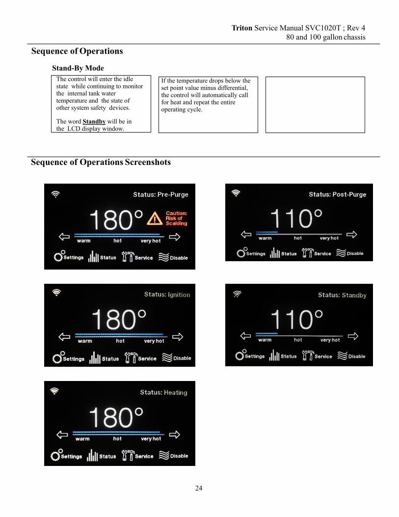
Sequence of Operations
Stand-By ModeThe control will enter the idle state while continuing to monitor the internal tank water temperature and the state of other system safety devices.
The word Standby will be in the LCD display window.
If the temperature drops below the set point value minus differential, the control will automatically call for heat and repeat the entire operating cycle.
Triton Service Manual SVC1020T ; Rev 4 80 and 100 gallon chassis
Sequence of Operations Screenshots
24

Safety Functions of the Controls
Flame Detection Proof of flame is accomplished by flame rectification via a burner sensor electrode and earth ground. The presence of a flame is measured via a flame rod that points into the flame. With the flame rod energized and a flame present to bridge the space between the flame rod and earth ground (the burner), the resultant flow of electrons (called the flame current) is monitored by the controller. The controller requires the flame current to attain a certain minimum value (0.5 micro amps) as a means to gauge the quality and stability of the flame. Absent of an acceptable flame current value, the controller will render the heater into an error condition A001/A029 during ignition and start up; or A002/A030 if the unit is in the middle of a heating cycle.
ECO (Energy Cut Off)
The ECO switch functions as a high limit switch responsive when the water temperature approaches 205° F. If the water temperature inside the tank reaches 203° F, the ECO switch (normally closed) will open. The controller will disable all heating functions and will render the heater into an error condition.
Pressure Switches Pressure switches are incorporated to provide proof of fan (blower) operation and to detect blocked inlet and outlet vent conditions. The controller monitors the status of the normally open or normally closed pressure switches and in the event of abnormal conditions, the controller will render the heater into an error condition.
Vent Temperature (Flue Gas) Sensor
A vent temperature switch is incorporated to detect excessive heat at the vent exhaust location. This protects the plastic PVC piping from damage. The controller monitors the status of the temperature switch and in the event of abnormal conditions (temperatures approaching 155oF decreases the RPM to lower flue temperatures) the controller will render the heater into an error condition.
Triton Service Manual SVC1020T ; Rev 4 80 and 100 gallon chassis
25

Condensate Removal Tube with Exhaust Tee Assembly
An important part of the Triton is the condensate removal tube that comes included in the exhaust T. During main burner, water vapor is created. As the heat is transferred into the water thru the flue bundles, this water vapor condenses and becomes a liquid. The removal tube provides a way to evacuate this liquid to a local floor drain.
Make sure the red clean out plug is downstream from the unit. Remove the red clean out plug on occasion to inspect the removal tube and clean out any foreign matter that has accumulated.
Triton Service Manual SVC1020T ; Rev 4 80 and 100 gallon chassis
Safety Functions of the Controls
Power Outages The controls will automatically resumes operations after power interruptions.
Controller Retry and Ignition Attempts If the first ignition cycle fails during a normal heating cycle sequence, the control will finish the sequence of the ignition and then de-energize the main gas valve. The blower remains energized and the system is purged for the inter-purge duration. After the inter purge time expires, the control turns the blower off, waits for the pressure switch to open, and performs a relay check on the gas valve. The blower is then turned on and waits for the pressure switch to close. Normal ignition sequence is started. Nine ignition cycles are attempted before soft lockout occurs. The control waits 30 minutes, then attempts ignition again. If unsuccessful, the control waits another 30 minutes, then attempts ignition again. The control will go directly to hard lockout after the third unsuccessful ignition cycle (27 attempts at ignition) and post purge.
26

Error Code Display Link to Troubleshooting
A001 A001 Ignition Lockout Page 31
A002 A002 Flame is not stable Page 33
A003 A003 Intake switch open Page 33
A004 A004 PoF Switch error H. Page 34
A005 A005 PoF Switch Error E. Page 34
A006 A006 PoF Switch error P. Page 34
A007 A007 Exhaust Switch Open. Page 35
A008 A008 PoF Switch/Blower mismatch. Page 35
A016 A016 High Tank Temperature. Page 35
A017 A017 High Flue Temp. Page 36
A018 A018 Flue Temp Sensor Open. Page 37
A019 A019 Flue Temp Sensor Shorted. Page 37
A022 A022 Upper Tank Sensor open. Page 37
A023 A023 Upper Tank temp. too hot. Page 38
A024 A024 Upper Tank sensor shorted. Page 38
A025 A025 No Blower RPM feedback. Page 38
A026 A026 Blower expected RPM vs actual RPM mismatch.
Page 38
Triton Service Manual SVC1020T ; Rev 4 80 and 100 gallon chassis
Error Codes Provided in the tables below are descriptions of ALL the error messages provided by the ignition control control. Errors can be divided into two groups, ALARM and ALERT.
ALERT errors are indicated by a “T” followed by numeric digits and a description of the error. Alerts disappear when the cause of the alert goes away (an auto-reset function);
ALARM errors are indicated by an “A” followed by numeric digits and a description of the error. Alarm errors cleared by pressing “Clear Alarms” in the “Current Alarms” section of the “Service” menu.
27

A027 A027 Flame present before ignit. Page 38
A028 A028 Flame present w/o heating. Page 39
A029 A029 Failed ignition. Retrying. Page 39
A030 A030 Flame lost during heating. Retrying. Page 39
A031 A031 Powered Anode Communication failure. Page 39
A033 A033 Flue sensor A/D error. Page 39
A034 A034 Upper Tank temp A/D error. Page 39
A035 A035 Gas Relay 1 stuck open. Page 39
A036 A036 Gas Relay 1 stuck closed. Page 39
A037 A037 Gas Relay 2 stuck open. Page 39
A038 A038 Gas Relay 2 stuck closed. Page 39
A039 A039 Flame sense cct fault. Page 39
A040 A040 Controller RAM fault. Page 39
A041 A041 Controller ROM fault. Page 39
A042 A042 Controller EEPROM fault. Page 39
A043 A043 IC Program execution fault. Page 39
A044 A044 Processor Clock/Line Frequency Disagree Page 39
A101 A101 Configuration Data Restore Failure Page 40
A102 A102 Time Clock needs to be programmed Page 40
A103 A103 Time Clock not advancing time properly Page 40
A104 A104 Water Leak Detected Page 40
A108 A108 Ignition Board Communication Failure Page 40
A109 A109 External CO Sensor Alarm Page 40
A110 A110 Shutoff Valve Test Close Error Page 40
Triton Service Manual SVC1020T ; Rev 4 80 and 100 gallon chassis
Error Codes
28

A111 A111 Shutoff Valve Test Open Error Page 40
A112 A112 Shutoff Valve Not Open Page 41
A121 A121 No Water Detected in Tank Page 41
T009 T009 No Gas Detected Page 41
T020 T020 Lower Tank Sensor Open. Page 41
T021 T021 Lower Tank Sensor shorted. Page 41
T029 T029 Failed ignition. Retrying. Page 42
T032 T032 Lower Tank temp A/D error. Page 42
T105 T105 Water Leak Sensor Not Installed Page 42
T113 T113 Flame Rod Degraded and Needs Servicing Page 42
T114 T114 Flame Rod Degraded and Needs Servicing Page 42
T115 T115 Combustion Health Degraded: Needs Service Page 42
T116 T116 Combustion Health Degraded. Needs Service Page 42
T117 T117 Time to Drain and Inspect Tank Page 42
T118 T118 Time to Check Venting for Debris Page 42
T119 T119 Time to Clean Out the Condensate Drain Trap Page 42
T120 T120 Time to Replace the Neutralizer Page 42
T122 T122 Powered Anode Control Comm Failure Page 43
A/T123 T123 Upper Anode Open Page 43
T124 T124 Upper Anode Mounting Error Page 43
T125 T125 Upper Anode Shorted Page 43
T126 T126 Upper Anode Overload Page 43
T127 T127 Upper Anode Pre-Overload Page 43
A/T128 T128 Middle Anode Open Page 43
T129 T129 Middle Anode Mounting Error Page 43
Triton Service Manual SVC1020T ; Rev 4 80 and 100 gallon chassis
Error Codes
29

T130 T130 Middle Anode Shorted Page 43
T131 T131 Middle Anode Overload Page 43
T132 T132 Middle Anode Pre-Overload. Page 43
A/T133 T133 Lower Anode Open Page 43
T134 T134 Lower Anode Mounting Error Page 43
T135 T135 Lower Anode Shorted Page 43
T136 T136 Lower Anode Overload Page 43
T137 T137 Lower Anode Pre-Overload Page 43
Triton Service Manual SVC1020T ; Rev 4 80 and 100 gallon chassis
N O T E S
Error Codes
30

Troubleshooting Error Codes
Error A001 Ignition Lockout This unit has failed ignition 27 consecutive cycles. The unit will fail nine times and give an A029. It will fail 9 more times and give an A029. On the 27th failure, the unit will lock out with an A001 code.
The only visible check is to look through the sight glass window into the combustion chamber. The sight glass is located on the mounting plate next to the igniter and flame rod. ANY flame, no matter how long, means the igniter and gas valve are both operational.
•Check for spark: Spark cannot be seen through the sight glass. When display shows “ignition” do you have flame? Yes – If flame is present then igniter does not need to be checked any further. If No – To verify spark at igniter, turn gas off, remove igniter, leave wires connected, recycle heater and look for spark at igniter rods. If no spark is present, confirm the spark gap is approximately 3/16th at tip of rods. Clean igniter rods with an abrasive material such as emery cloth, steel wool, etc. and repeat check for spark. If still getting no spark, disconnect igniter cable from main control board. Hold igniter cable approximately an 1/8th of an inch from spark terminal on the board. Cycle the unit back on and check for spark from board when the display showing "ignition." If no spark is present from the board to the cable, replace the ignition control board. If spark is present from board to cable, replace the igniter assembly. •Check for water in combustion chamber Remove igniter and flame rod, shine a light through one hole while looking through the other, or, remove only the igniter and use something (wire, copper tubing, a 1/2” tape measure will fit) to insert into the hole that will reach the bottom of the chamber (4ft deep or more). Insert till it stops, remove, is it wet? How many inches of the object is wet? Up to 6 inches of water could be a result of condensation forming from short cycling but all water must be removed for proper operation. Larger amounts of water may be suspect for tank leak. •Incorrect gas pressure: See page 47 for instructions on checking gas pressure. •Check condensate drain line: Condensate that is not draining properly will back up into the exhaust elbow, restricting the exhaust vent. Is the drain line configured per the Use & Care Manual? THERE SHOULD BE NO TRAP OR NEUTRALIZER KIT IN THE CONDENSATE RUN. Does condensate line maintain at least 1/4” per foot fall to drain? Runs than cannot maintain at least 1/4” per foot fall and/or are over 15ft in distance must utilize a condensate pump. If pump is being utilized, is it working? •Check venting: Are intake and exhaust vent runs within maximum allowances? Are there any horizontal runs that may be pitched incorrectly and holding water/debris to create restriction? Is exhaust vent pushed too far down into the grey exhaust tee? Venting should not go more than 2 inches into the tee. •Verify vent terminations: . If concentric vent kits is being used, remove intake vent from heater and recycle. If no error occurs with intake removed then issue is with the concentric vent kit. Common issues are: kit connected with intake and exhaust reversed, center pipe missing or loose, non-approved vent kit being used. •Flame recognition: If the unit fires and goes out then the board does not sense flame. Confirm flame rod wire is secure at board and wire is not damaged. Turn unit off, remove and clean flame rod with an abrasive material such as emery cloth, steel wool, etc. If possible, measure flame current (minimum flame current for board to sense flame is 0.5uA). If minimum flame current is present and code continues, replace control board. •Gas valve adjustment: MUST BE DONE WITH COMBUSTION ANALYZER. See page 48.
Triton Service Manual SVC1020T ; Rev 4 80 and 100 gallon chassis
31

Triton Service Manual SVC1020T ; Rev 4 80 and 100 gallon chassis
Troubleshooting Error Codes Error A001 Ignition Lockout (continued)
Gas Valve Checking Procedure • Cycle power and/or clear any alarms on the display. • Locate the large black wiring harness plugged into the top of the gas valve.
Loosen the Phillips head screw at the top of the connector, then disconnect it from the gas valve.
• With connector removed, cycle the power on, while display is showing “IGNITION” check voltage across pins 1 & 5 in the connector. Voltage reading should be between 10-15VAC. If the voltage reading is correct then the gas valve is being supplied power and should be operating. If you do not get 10-15VAC then we could have a faulty gas valve harness or faulty control board.
• Is the gas valve working? The best way to confirm the gas valve is operating is with a manometer. Reconnect all wiring, and connect a manometer to the inlet port of the gas valve. Cycle power and check for a pressure drop when the unit goes to “IGNITION”. If you have ANY drop at all, the gas valve is opening and allowing gas flow. (See page 47 for instructions)
• If you do not have a manometer available, a less accurate check can be done. With all wiring reconnected, cycle power on and hold your hand on top of the gas valve solenoid, when the unit goes to “IGNITION” you should feel a noticeable click.
• If you do not get any pressure drop with a manometer and/or do not feel the solenoid click, replace the gas valve.
Gas Valve Harness and Control Board Checks • Trace the wire harness from the gas valve backwards to P4 connector on the
ignition control board and Disconnect the Molex connector from the P4 connection.
• Cycle power and/or clear any alarms. When the display is showing “IGNITION”, measure for 24 across the outside pins on the P4 connector.
• If you get the 24V, then the control board is operating correctly. Replace the gas valve wiring harness.
• If you do not get the 24V, replace the ignition control board.
32

Triton Service Manual SVC1020T ; Rev 4 80 and 100 gallon chassis
Troubleshooting Error Codes Error A002 Flame is Not Stable This alarm code means the unit had flame rectification within one heating cycle; but lost the flame rectification signal three times within one call for heat. Causes of this issue are: Incorrect gas pressure or gas supply issues, incorrect vent terminations, restricted exhaust vent, dirty flame rod.
•Check for water in combustion chamber Remove igniter and flame rod, shine a light through one hole while looking through the other, or, remove only the igniter and use something (wire, copper tubing, a 1/2” tape measure will fit) to insert into the hole that will reach the bottom of the chamber (4ft deep or more). Insert till it stops, remove, is it wet? How many inches of the object is wet? Up to 6 inches of water could be a result of condensation forming from short cycling but all water must be removed for proper operation. Larger amounts of water may be suspect for tank leak. •Incorrect gas pressure: See page 47 for instructions on checking gas pressure. •Check condensate drain line: Condensate that is not draining properly will back up into the exhaust elbow, restricting the exhaust vent. Is the drain line configured per the Use & Care Manual? THERE SHOULD BE NO TRAP OR NEUTRALIZER KIT IN THE CONDENSATE RUN. Does condensate line maintain at least 1/4” per foot fall to drain? Runs than cannot maintain at least 1/4” per foot fall and/or are over 15ft in distance must utilize a condensate pump. If pump is being utilized, is it working? •Check venting: Are intake and exhaust vent runs within maximum allowances? Are there any horizontal runs that may be pitched incorrectly and holding water/debris to create restriction? Is exhaust vent pushed too far down into the grey exhaust tee? Venting should not go more than 2 inches into the tee. •Verify vent terminations: . If concentric vent kit is being used, remove intake vent from heater and recycle. If no error occurs with intake removed then issue is with the concentric vent kit. Common issues are: kit connected with intake and exhaust reversed, center pipe missing or loose, non-approved vent kit being used.
• Check gas valve adjustment: Should only be performed with a combustion analyzer. See page 47.
Error A003 Intake Switch Open The intake pressure switch is a normally closed switch. It should only open if there is a blockage/restriction in the intake venting. • Check wiring to the switch to ensure no wires have been broken, damaged or disconnected. • Confirm tubing from switch to the air intake is properly connected and not damaged. • With unit off, remove wires from intake switch and check for continuity. If continuity is not present, replace
the intake switch. • If continuity is present, cycle power back on and clear alarm code. If switch opens (loses continuity) with
blower running, then switch is operating normally and there is something causing vent restriction. • Remove the air intake pipe from the rubber fernco connector at blower, if unit will fire with venting
removed then issue is in venting. • If error persists with intake removed from blower, verify no debris in blower housing. If no debris found
and switch still opens with intake venting removed, replace the intake pressure switch.
33

Triton Service Manual SVC1020T ; Rev 4 80 and 100 gallon chassis
Troubleshooting Error Codes Error A004 PoF Open During Heating The Proof of Fan pressure switch is open during heating. You can clear this error code by pressing clear button on the current alarm screen. If problem persists a part replacement may be required. Check the following to see if the problem can be resolved. • Check wiring to the pressure switch to ensure no wires have been broken, damaged or disconnected. • Confirm tubing from switch to the blower mounting flange is properly connected and not damaged. • Confirm the rubber cap is covering the test port on the top of the pressure switch, if the cap is missing it will allow
air pressure to escape and could result in alarm to occur. • Check air intake for blockages and remove blockage if present. You can clear this error code by pressing clear button on the current alarm screen. If problem persists , replace the PoF pressure switch.
Error A005 PoF Open During Pre-Purge The Proof of Fan pressure switch is open during purge. The PoF switch is a normally open switch that closes from positive pressure from the blower. • Check wiring to the switch to ensure no wires have been broken, damaged or disconnected. • Confirm tubing from switch to the air intake is properly connected and not damaged. • Confirm the rubber cap is covering the test port on top of the pressure switch, if the cap is missing it will allow air
pressure to escape and could result in alarm to occur. • Check air intake for blockages and remove blockage if present • Remove air intake from blower, confirm no debris has been sucked into the blower housing. • Clear the alarm and confirm blower is running when display status shows “Pre-Purge”. If blower is not running
during “Pre-Purge”, replace the blower. • Check continuity to see if switch is open while the blower is running. If switch does not have continuity while the
blower is running then, replace PoF pressure switch. • If switch has continuity while fan is running but alarm persists, a board replacement may be required.
Error A006 PoF Open During Post Purge The Proof of Fan pressure switch is open during purge. Check the following to see if the problem can be resolved. • Check wiring to the switch to ensure no wires have been broken, damaged or disconnected. • Confirm tubing from switch to the air intake is properly connected and not damaged. • Confirm the rubber cap is covering the test port on the top of the pressure switch, if the cap is missing it will
allow air pressure to escape and could result in alarm to occur. • Check air intake for blockages and remove blockage if present. You can clear this error code by pressing clear button on the current alarm screen. If problem persists , replace the PoF pressure switch.
34

Triton Service Manual SVC1020T ; Rev 4 80 and 100 gallon chassis
Troubleshooting Error Codes
Error A007 Exhaust Pressure Switch Open The exhaust pressure switch is a normally closed switch. It will only open in the event of excess pressure in the exhaust venting. Check the following: • Check wiring to the switch to ensure no wires have been broken,
damaged or disconnected. • Confirm tubing from switch to the air intake is properly connected and not damaged. • With the unit off, check continuity on the pressure switch. If no continuity present, replace the exhaust
pressure switch. • Check exhaust vent for clogs and remove if present. • Check for condensate backing up into exhaust tee. You can clear this error code by pressing clear button on the current alarm screen. If problem persists a part replacement may be required.
Error A008 PoF/Blower Mismatch The Proof of Fan pressure switch is closed when the blower is off. Check the following to see if the problem can be resolved. • If the blower is running while, the alarm is present, follow troubleshooting for error A025. • If the blower is not running, check to ensure the PoF switch has not been jumped. If not, check continuity
to the switch. It should be open when the blower is off. If the switch is reading closed (has continuity) with the blower not running, replace the PoF switch.
• Clear the alarm and see if the A008 returns. If A008 returns and the pressure switch is reading open (no continuity), replace the ignition control board.
Error A010 End Of Line Test Failure This error should never present on a unit in the field. If this error should occur, replace the ignition control board.
Error A016 Energy Cut Off Switch Is Open The tank temperature has exceeded the allowable temperature. • Confirm water in unit is not above 200°F • Inspect wiring and connections on both the upper temperature probe and control. If
wiring is properly connected, try to clear alarm through display. • If alarm does not clear, cycle power off, and check the ECO using a multi-meter.
Disconnect wiring from ECO/Temp probe. Check for continuity across pins 3 & 4 of the probe. If no continuity found, replace ECO/Temp probe.
• If continuity is present through probe, reconnect wiring to ECO/Temp probe. Disconnect the P2 harness from the control board and check for continuity across the two orange wires. If no continuity is present through wiring, replace the wiring harness. If continuity is present through both the probe and wiring. Replace the control board.
• Replace ECO/Temp probe ONLY if it is OPEN but the display is reading a tank temperature of less than 200°F.
35

Temp °C Temp °F Resistance (Ω)
0 32 361005 41 2859010 50 2279015 59 1829020 68 1477025 77 1200030 86 9805
Temp °C Temp °F Resistance (Ω)
35 95 805540 104 665345 113 552450 122 460955 131 386360 140 325365 149 2752
Temp °C Temp °F Resistance (Ω)
70 158 233775 167 199480 176 170785 185 146790 194 126695 203 1096100 212 952
Triton Service Manual SVC1020T ; Rev 4 80 and 100 gallon chassis
Troubleshooting Error Codes
Error A017 Flue High Flue Temp This error code means the combustion gases at exhaust tee at the bottom of the tank are too hot. The sensor trips at 1600F and the alarm cannot be cleared until the sensor temperature is below 1550F . Things to check: • Make sure the white wires are attached to the sensor. • Check the PVC elbow for signs of disfigurement and/or discoloration
caused by heat. • Make sure the Molex at location P2 Pins 1 and 2 on the control board
is tight, all wires are secure, and the pins on the control board are not bent/broken.
• Disconnect the 2 white wires from the flue gas sensor and check the ohms reading across the two spade terminals on the sensor. Using the chart below, the temperature reading should be between ambient air temperature and no more than 160 degrees.
• If the ohms reading on sensor is within the required temperature range and the error will not clear, cycle power off to the unit. Reconnect the white wire back the flue sensor. Disconnect the P2 harness from the control board and check the ohms reading across the white wires. The reading should be about the same as reading you got on the sensor spade terminal. If the readings do not coincide, replace the control wiring harness.
• If all reading on sensor and wiring check good, replace the ignition control board. board.
• If the sensor is reading open or outside of specified temperature range, wait 5 minutes and recheck. If sensor is still outside of range, replace sensor.
36

Triton Service Manual SVC1020T ; Rev 4 80 and 100 gallon chassis
Troubleshooting Error Codes Error A018 Flue Temp Sensor Open This alarm means the control is sensing the flu temperature sensor as being open or disconnect. • Refer to A017 for troubleshooting.
Error A019 Flue Temp Sensor Shorted This alarm means the control board is sensing a short in the flue temperature sensor or wiring harness. • Refer to A017 for troubleshooting
Error A022 Upper Tank Sensor is Open This error code means the water temperature probe is not connected or the water temperature thermistor is damaged. Things to check: • Make sure the Molex connector to the ECO/temperature probe is connected,
harness is properly oriented so locking tab on Molex locks into ECO/temp probe, and wires are secure.
• Make sure the Molex at location P2 on the ignition control board is securely connected and oriented so the locking tab on the Molex locks onto the connector on the control board. Confirm all wires are secure in the harness, and the pins on the control board are not bent/broken.
• Disconnect wiring from the ECO/Temperature probe. Check the ohms reading across pins 1 & 2, as shown in the photo to the right, and compare to the chart below. The resistance should show about what the water temperature is inside the tank. Replace the temp probe if the circuit is open or the resistance value does not represent the water temperature in the tank.
• If ECO/Temp probe reading is correct, reconnect wiring to ECO/Temp probe. Disconnect the P2 wiring harness from the control board and measure the ohms reading across the blue wires in the harness. You should get about the same ohms reading as you had on the probe. If the reading is not close or circuit reads open, replace the wiring harness.
• If all readings are correct at probe and harness, replace the ignition control board.
Temp °C Temp °F Resistance (Ω)
0 32 361005 41 2859010 50 2279015 59 1829020 68 1477025 77 1200030 86 9805
37
Temp °C Temp 0F Resistance (Ω)
35 95 805540 104 665345 113 552450 122 460955 131 386360 140 325365 149 2752
Temp °C Temp 0F Resistance (Ω)
70 158 233775 167 199480 176 170785 185 146790 194 126695 203 1096100 212 952

Triton Service Manual SVC1020T ; Rev 4 80 and 100 gallon chassis
Troubleshooting Error Codes Error A023 Upper Tank Temp Too Hot This alarm means the ignition control board is sensing the upper tank temperature has exceeded 2050F. The programming on the control board should not allow this to happen and therefore we are dealing with either a bad ignition board, ECO/Temp Probe, or wiring harness. • Refer to troubleshooting steps for A022.
38
Error A024 Upper Tank Sensor Shorted The control board is detecting a short in the ECO/temperature probe or wiring. • Refer to troubleshooting steps for A022.
Error A025 No Blower RPM Feedback Control does not detect blower RPM. This is typically cause by a bad blower or wiring harness being disconnected. • Using a multimeter, check voltage to the blower from the board to ensure 120v of power to the blower. • If the blower is running while this error is present, confirm disconnect and reconnect both wiring harnesses from the
blower and make sure wiring harness from blower to board is secure at board. If blower continues to run with error present, replace the blower.
• If blower is not running, clear the alarm and see if blower comes on. If the blower does not come on, disconnect the wiring harness with black, white, red, and blue wires from blower. With the power turned on to the unit and this harness disconnected, the blower should run at full speed. If blower still does not come on or will only run at a very low speed then replace the blower.
Error A026 Blower Expected RPM vs Actual RPM mismatch Control board detects blower running at ≥300 RPM from desired RPM for > 1 minute. • Confirm wiring harness from control board to fan is secured at both ends and all wires are secure in the Molex
connectors. • Cycle power and clear alarm. If issue remains replace the blower.
Error A027 Flame Present Before Ignition This error code means that a flame was detected prior to ignition or the controller was detecting flame rectification before the gas valve was open. You can clear this error code by turning the unit off and on. Things to check: • Check for flame through the sight glass. If flame is present with this code, either the gas valve needs to be replaced or
gas pressure to unit is above maximum stated on rating label. • Make sure the heater has a solid earth ground at the electrical connection box on top of
the unit; and the electrical connection to the power supply has a solid earth ground. • Shut off the gas supply and cycle the water heater. If the error code returns, then replace the controller.

Triton Service Manual SVC1020T ; Rev 4 80 and 100 gallon chassis
Troubleshooting Error Codes
Error A028 Flame Present W/O Heating This alarm means the control board detected a flame signal 10 seconds after the gas valve had closed from the last heating cycle. • Check for flame through the sight glass. If flame is present with this code, either the gas valve needs to be replaced
or gas pressure to unit is above maximum stated on rating label. • Make sure the heater has a solid earth ground at the electrical connection box on top of
the unit; and the electrical connection to the power supply has a solid earth ground. • Remove and clean the igniter and flame rod then reinstall. Allow the unit to go through a heating cycle to see if the
error occurs again. If error occurs and no flame is visible through the sight glass, replace the flame rod. If flame rod is replaced and error continues, replace the ignition control board.
Error A029 Failed Ignition The unit will fail nine times and give an A029. It will fail 9 more times and give an A029. On the 27th failure, the unit will lock out with an A001 code. • Refer to Error A001 for troubleshooting. (See Page 31)
Error A030 Flame Lost During Heating This code means the unit lost flame signal during heating. The unit will attempt to heat 3 times in 3 consecutive cycles. After the 3rd try, the unit will lock out with a code A002 • Refer to Error Code A002 for troubleshooting.
Error A031 Loss of Anode Communication This error code means there is a loss of Anode communication. This will not disable the water heater or keep it from heating. • Check the connections between anode control and ignition control. • Check the harness for proper connections. • If error code is still present, replace the anode control • If error is still present after replacement, replace the ignition control board.
Error A033 through A043 Relay/Communication Errors All of these codes are related to ignition control failure. • Cycle power and attempt to clear alarm. If alarm does not clear, replace ignition control board.
Error A044 Processor Clock/Line Frequency Disagree If power line frequency is below 45 Hz or above 65 Hz for more than 5 seconds the control issues a fault code and cancels demand for heat. Operation resumes and fault clears when power line frequency returns within the range of 47 to 63Hz. • Cycle power and attempt to clear alarm. • If alarm does not clear, have electrician verify power supply Hertz rate is within the required 45-65 Hz range
39

Triton Service Manual SVC1020T ; Rev 4 80 and 100 gallon chassis
Troubleshooting Error Codes
Error A101 Configuration Data Restore • Cycle power and attempt to clear alarm. If alarm does not clear, replace display control.
Error A102 Time Clock Needs to be Programmed • Go to configurations and set the time and date.
Error A103 Time Clock Not Advancing Time Properly • Cycle power and attempt to clear alarm. If alarm does not clear, replace display control.
Error A104 Water Leak Detected The presence of water has been detected by the control. Make sure that the water heater doesn’t shut down without interactions from the customer and perform the following checks: • Visually inspect the unit for leaks • If no leaks are detected, check water leak sensor for water • If sensor is not wet, replace leak sensor or control if leak sensor has already been replaced. • If sensor is wet, proceed to steps for leak resolution
Error A108 Ignition Board Communication Failure Communication lost between the display board and the ignition control board. The ignition control board will continue to operate the heater using the last known configuration settings. • Check wiring between the display and P5 of the ignition control board. • If all wiring is secure and undamaged, replace ignition control board and/or display.
Error A109 External CO Sensor Alarm CO sensor detects carbon monoxide above the threshold limit. The unit does not come with a CO sensor. If the unit does not have one wired directly to it then the configuration setup could be causing a false alarm. • If there is an auxiliary CO Sensor connected to the unit, follow the sensor manufacturer’s instructions for
checking proper operation of the sensor. • Confirm there are no exhaust leaks from loose vent connections, • From the front display tap the “Settings” button. Then tap “configs”. From the “config. settings” screen make
sure the auxiliary input select is set to “Flow Sensor”. If this setting is “CO Sensor” with no sensor connect, it can produce a phantom A109 code.
Error A110 & A111 Shut-off Valve Monthly Test Close/Open Error These codes indicate that the monthly test of the automatic shut off valve (premium models only) was not completed properly. The valve did not close in the allotted time. Every 30 days, the unit shuts the valve and opens it. If it doesn’t see shut indication, these error codes will occur. • Drain the tank and remove the automatic shutoff valve. Clean any debris from inside valve body and manually rotate
the ball valve to ensure the motor is not seized up. • Reinstall the valve, fill the tank with water, and clear the alarm. If issue persists replace the automatic shutoff valve. • You can manually open and close the valve if the drive motor has failed. See page 59.
40

Triton Service Manual SVC1020T ; Rev 4 80 and 100 gallon chassis
Troubleshooting Error Codes
Error A112 Shutoff Valve Not Open • Confirm the Molex connectors from valve to water heater wiring is securely connected. • Confirm no wires are loose/damaged in Molex connectors from valve to water heater. • Manually open the shutoff valve (see page 59), clear the alarm. If the alarm persists, replace the automatic shutoff
valve.
Error A121 No Water Detected in Tank • Ensure tank is full and all air has been purged • If tank is full, check the current alarms to see if any other alert/alarm is present for an OPEN ANODE such as T123,
T128, or T133 (Certain software versions display these as A codes instead of T codes) • Follow diagnostic and troubleshooting steps for that code.
Error T009 No Gas Detected The gas pressure switch is open. You can clear this error code by pressing the clear button on the current alarm screen. Check the following to see if the problem can be resolved. • Check wiring to the switch for broken/damaged wires. • Check inlet gas pressure at unit. If gas pressure ever drops below 3.5” wc the T009 alert will occur. • If minimum gas pressure is present and wires are intact, replace the gas pressure switch.
Error T020 Lower Tank Sensor Open Control senses the lower tank temperature sensor open. This will not disable the unit or keep it from heating water. The alert will clear on its own when the issue is resolved. • Confirm wiring harness is securely connected to lower tank temperature sensor and confirm the wiring harness at the P2
connection on the control board is secure. • If no wiring is loose, disconnect wiring from lower temperature probe. Check ohms reading across the pins of the
sensor. A good sensor should read between 1K to 36K ohms. If sensor reads open, replace the sensor. • If sensor has a reading between 1K to 36K ohms, reconnecting the wiring to the sensor. Turn off power and disconnect
P2 harness from ignition control board and check the ohms reading across the 2 blue wires. Your reading should be about the same as the reading you got on the sensor. If not, replace the wiring harness. If readings match and error won’t clear then replace the ignition control board.
Error T021 Lower Tank Sensor Shorted The control board is detecting a short in the lower temperature probe wiring. This will not disable the unit or keep it from heating water. • Disconnect the wiring from lower temperature probe. If unit gives an alarm for T020, replace the lower
temperature probe. • If you do not get the T020, turn the unit off. Disconnect the lower temperature probe wiring and the P2 harness at
the ignition control board and check for continuity across the wires at the lower temperature probe. If you have continuity, there is a short in the wiring harness. Replace the wiring harness.
• If above checks determined no resolution, replace the ignition control board.
41

Triton Service Manual SVC1020T ; Rev 4 80 and 100 gallon chassis
Troubleshooting Error Codes Error T029 Failed Ignition. Retrying The unit will fail nine times and give an A029. It will fail 9 more times and give an A029. On the 27th failure, the unit will lock out with an A001 code. • Refer to Error A001 for troubleshooting. (See Page 31)
Error T032 Lower Tank Temp A/D Error The control board cannot convert the analog reading from sensor to digital reading to the display. This will not disable the unit or keep it from heating water. • Cycle power. If issue remains, replace the ignition control board.
Error T105 Water Leak Sensor Not Installed
• Check wiring for proper connection from wiring harness to control board, ensuring wiring is not damaged (4-wire, 2 blue/2 black)
• If wiring is properly connected, disconnect from wiring harness and check continuity across bottom terminals (If leads are too large, use a smaller metal item such as a paper clip to check for continuity(right)). The top terminals will only have continuity if the sensor is wet, which will cause an additional error code.
• If there is no continuity (open circuit) replace leak sensor.
Error T113 & T114 Flame Rod Degraded These alerts indicate the peak flame current reading has substantially decreased from the initial startup of the unit. This is indicative of a dirty flame rod and/or ignition/flame failures. These alerts will not keep the unit from heating nor can they be manually cleared. • Remove and clean the flame rod with an abrasive material such as emery cloth, steel wool, etc. • Allow at least 10 heating cycles for the unit to recognize the issue has been resolved and it will clear this alert on its
own. • If alert does no go away on its own, check alarm history for other Alarms/Alerts and troubleshoot based on those
alarms.
Error T115 & T116 Combustion Health Degraded These alerts cannot be manually cleared and are the result of periodic failed ignitions, flame loss, pressure switches errors during heating cycles, etc. • Check alarm history for any codes regarding pressure switches, failed ignitions, etc. Refer to troubleshooting for
those alarms/alerts. • If the only thing in the history is the T115/T116 codes then someone has tried to clear the alarm so many times
that it has erased any previous history. Best option is to let the unit operate for a full day without attempt to clear the T115/T116 alerts, then check the alarm history the next day.
Error T117 through T120 Periodic Maintenance All of these alerts regard routine maintenance. When you clear the alarm(s) the timer for the maintenance alert will automatically reset. Things to check during routine maintenance are the following: • Drain the tank and clean/remove any build up or debris through the hand hole cleanout. • Routine check of the venting to ensure no debris or buildup in vent runs. • Routine inspection of condensate line to ensure neutralizer rocks have not been depleted, no debris buildup in
exhaust tee, no clogs or debris in the condensate line.
42

Triton Service Manual SVC1020T ; Rev 4 80 and 100 gallon chassis
Troubleshooting Error Codes
Error T122 No Communication with Powered Anode Controller for >60 seconds. Locate the anode control module at the top of the unit. If the LED light on top of the module is GREEN then the anodes are still protecting the tank. • Confirm both wiring harnesses are securely connected to
anode control module and no signs of damage to wiring. • If both harnesses are secure and LED on anode module is
not green, anode module needs to be replaced. • If anode module LED is green, confirm wiring harness at
the P8 connector on ignition board is secure and no signs of damage. If this checks good, cycle power. If issue persists replace ignition control board.
T123 thru T137 Anode Alerts Anode locations indicated below. Refer to next 2 pages for troubleshooting instructions.
Upper Anode
43
Middle Anode
Lower Anode

Triton Service Manual SVC1020T ; Rev 4 80 and 100 gallon chassis
Troubleshooting Error Codes
• If you are getting any error code regarding anode(s), the first step is to disconnect anode rod power wire from the the UPPER, MIDDLE, or LOWER (dependent on the alert(s) given) anode(s) as shown in the photo to the right. NOTE: Leave water heater powered on.
• With anode rod power wire disconnected, the display should give an alarm of A121 or A123. If neither of these codes occurs after disconnecting the anode power wire, replace the anode control module.
• If either the A121 or A123 code appear after disconnecting the anode power lead, the next step is to make sure the retainer nut for the spade terminal connector is tightened down securely. Once secure, reconnect wiring, clear alarm and see if issue is resolved.
• If issue persists, proceed to next steps.
• NOTE: To check the anode rod, turn off power to the water heater.
• With power wire lead removed from anode, check for ohms reading by putting one meter lead to center stud of anode and the other meter lead to the hex head of the anode as show in the photos to the right.
• When checking the anode, you will need to do the ohms checking using both “polarities”. As shown to the right, check with black to stud and red to hex nut, then swap meter lead connection points and perform the check again.
• Ohms should only be sensed via one of the polarity tests. The other polarity should show no ohms (OL). If you get no resistance (“OL” reading) or ohms resistance on both polarities, replace the anode.
• NOTE: Meter should be set on a range between 200K to 600K. Test is not accurate when meter is set to check Mega ohms (MΩ)
• If no issue found with anode, proceed to next page.
44

• Disconnect the anode power lead harness from the anode control module.
• Insert your other meter lead into the molex connector location for the wire associated with the suspect anode as shown in bottom photo.
• Resistance reading should be less than 20 ohms. If reading is higher than 20 ohms replace wiring harness
NOTE: The anode rod power wire harness has 4 wires in the molex.
GREEN = GROUND
RED = UPPER ANODE BLUE = MIDDLE ANODE
ORANGE = LOWER ANODE
Troubleshooting Error Codes
Note: Turn off power to water heater.
• With anode power wire disconnected, insert one meter lead into the wire as shown.
• Locate the anode control module.
NOTE: If this is a new install, and no issues were found during anode “Overload” and/or “Pre-Overload” testing, see next page.
Triton Service Manual SVC1020T ; Rev 4 80 and 100 gallon chassis
45

Triton Service Manual SVC1020T ; Rev 4 80 and 100 gallon chassis
Notes
46

Triton Service Manual SVC1020T ; Rev 4 80 and 100 gallon chassis
400Kbtu Gas Valve
47
Gas Pressure Checking Procedures
Gas Pressure Checking Procedure
The Triton water heaters use a negative pressure gas valve so we do not check the manifold gas pressure. Our only checks are to confirm the inlet gas pressure is within minimum and maximum limits and verify the inlet pressure does not have more than a 1.5”w.c.
• Turn off the gas supply to the unit. • Loosen the inlet pressure port screw on the valve about 1.5 turns. DO NOT REMOVE THE
SCEW. (Inlet pressure port is labeled as “IN” See photos below) • Attach a manometer to the inlet side of the gas valve. • Turn gas supply back on and read the pressure while the heater is turned off. Confirm the pressure
is within 3.5” – 10.5” w.c. for natural gas, 11.0” – 13.0”w.c. for LP. • Turn the heater on, and wait for “Ignition” on the display. Any pressure drop at all confirms the
gas valve has opened and is operating. • During the “Ignition” and/or “Heating” status, if the pressure drops more than 1.5”w.c. from step
#2, then you do not have enough gas flow to the heater. An adjustment to the piping system may need to be evaluated. If the Inlet pressure does not drop more than 1.5”w.c. from step #2, then you have sufficient gas flow and gas pressure.

Triton Service Manual SVC1020T ; Rev 4 80 and 100 gallon chassis
Gas Valve Adjustment Procedure
1.Turn Triton OFF. 2.Locate the adjusting screw on the gas valve. (See pics below for reference) 3. Turn the Triton ON and demand heat. 4.If the unit does not go to main burner, turn unit OFF; turn the screw counterclockwise a 1/8 turn and restart the unit. 5. Continue this procedure until you have main burner; and the LCD says HEATING.
Next, you will need a combustion analyzer for CO² to fine tune the gas valve.
6.Following the instructions on your combustion analyzer, get a reading of the CO2 levels of the combustion gases. Easiest way to do this is to remove the pressure switch tubing from the exhaust pressure switch after the unit has been in “HEATING” status for at least 30 seconds. Insert your analyzer sensor into pressure switch tubing and check your CO² readings.
7.Once you have a consistent CO2 reading, we need to adjust the reading to 8.8-9.2% CO² (10.3- 10.8% for LP gas) If your reading is higher than 9.2%, then adjust the screw clockwise (-); if your reading is lower than 8.8%, then adjust the screw counterclockwise (+).
8. When final adjustments are complete, close and seal the tap hole.
• All adjustments must be done with a minimum 15 degree delta T (difference between actual tank temp and set temp) to ensure heater is in full fire mode.
• Excess gas valve adjustment will cause a cracked condensate pan. This will cause the heater to be replaced. Adjustments to the gas valve should be slow in 1/8 turn increments only.
400Kbtu Adjustment Screw (Requires Allen Head Wrench to Adjust)
130 to 350Kbtu Adjustment Screw (Requires Flat Head Screw DriverWrench to Adjust)
48

Triton Service Manual SVC1020T ; Rev 4 80 and 100 gallon chassis
Triton Disassembly and Repair
On the next few pages we have included instructions for replacing most repair parts on the Triton water heater. To further aid in the repair process we have also created some repair videos that can be accessed through the hyperlinks below.
Below is a list of currently available servicing video links with step by step walkthroughs of replacing each part.
Links are active in PDF Documents. If you have received this document as a paper copy, videos can be found by visiting Rheem’s YouTube channel at www.youtube.com/RheemMFG.
• Replacing the Burner Assembly
• Replacing the Gas Pressure Switch
• Replacing the Ignitor
• Replacing the POF Pressure Switch
• Replacing the Flame Sensor
• Replacing the Gas Valve Assembly
49

Triton Service Manual SVC1020T ; Rev 4 80 and 100 gallon chassis
Disassembly and Repair Ignition Control Board
1. Disconnect power to the water heater. 2.Remove all Molex connections to the control board. Wires are colored and the board locations have numbers to reconnect. See Wiring Diagram on page 8 of this document. 3. Remove the three Phillips screws holding the control board to the top of the water. 4. Remove the control and replace in reverse order.
LCD Display
1.Disconnect power to the water heater. 2.Drain the water in the tank to a point below the level of the water temp sensor. 3.Remove all wiring connections to the sensor assembly. 4.Remove the sensor assembly with a wrench. 5.Replace in reverse order.
1. Disconnect power to the water heater. 2.Disconnect the three Molex connections. One goes to the ignition control board. The other 2 pigtail to other wiring harness. 3. Remove the two Phillips screws holding the display assembly to the top of the water. 4.Remove the display assembly and replace in reverse order.
Water Temperature Sensor
Blower Motor
1. Disconnect power to the water heater. 2. Disconnect the 2 Molex connections. 3.Remove the two Phillips screws holding gas valve and venturi assembly blower motor. 4.Remove the 4 Phillips screws holding the blower the burner mounting flange. 5. Remove the blower and gasket from the burner mounting flange. 6.Replace parts in the reverse order making sure to use the new gaskets supplied with the blower. (There is a gasket for the blower/burner mounting flange and another gasket for where the gas valve and venturi assembly meets the blower.)
50

Triton Service Manual SVC1020T ; Rev 4 80 and 100 gallon chassis
Exhaust Gas Temperature Sensor 1. Disconnect power to the water heater. 2. Remove the two brown wires from the exhaust gas sensor. 3. Remove the sensor using a wrench. 4. Replace in reverse order.
Pressure Switches 1. Disconnect power to the water heater. 2.Remove all wiring connections and rubber tubing to the pressure switch. 3.Remove the two Phillips screws holding the pressure switch assembly in place. 4. Replace in reverse order.
Flame Sensor 1. Disconnect power to the water heater. 2. Remove the yellow wire to the flame rod. 3. Remove the two Phillips screws. 4.Remove the flame rod. You may need a small putty knife to get it started. 5. Clean all old gasket material from the burner assembly. 6. Replace in reverse order.
Disassembly and Repair Igniter 1. Disconnect power to the water heater. 2. Remove the green grounding wire. 3. Remove the two Phillips screws. 4. Remove the igniter assembly. You may need a small putty
knife to get it started. 5. Clean all old gasket material from burner assembly. 6. Replace igniter in reverse order.
51

Triton Service Manual SVC1020T ; Rev 4 80 and 100 gallon chassis
Triton Disassembly and Repair
Replacing a Burner The only tools necessary for this will be a ratchet with a ½ in. socket and a #2 Phillips head screwdriver. Please consult the Use and Care manual before performing any changes and be sure to follow any safety messages in the manuals and on the appliance. Always ensure the customer has read and obey all safety messages. 1. Remove the hose from the gas valve and from the bottom of
the blower. 2. Disconnect the leads to the igniter and to the flame rod sensor,
as well as the ground. 3. Undo the two harnesses from the blower 4. Disconnect the two leads connected to the low gas pressure
switch and remove the cable harness from the top of the gas valve using the Phillips head screwdriver.
5. Using the ratchet, remove the 5 bolts attaching the burner assembly to the top of the water heater.
6. Once the bolds are removed, remove the entire burner assembly.
7. You will now have to remove the blower from the burner by using the Phillips head screwdriver to remove the four screws
8. Remove the old burner and the gasket
52

Triton Service Manual SVC1020T ; Rev 4 80 and 100 gallon chassis
Triton Servicing: Burner Assembly
9. To replace the burner, take the new burner and gasket and attach using the screws provided.
10. Make sure to attach the blower to the burner in the same orientation as it had been attached previously. 11. Insert the burner assembly back into the top of the water heater making sure that the air intake and the gas
valve are pointing towards the back.
12. Bolt the burner assembly back into place and make sure to tighten all of the bolts using the ratchet and half inch socket.
53

Triton Service Manual SVC1020T ; Rev 4 80 and 100 gallon chassis
Triton Servicing: Burner Assembly
13. Reconnect the ground to the igniter and reconnect the lead to the control box
14. Reconnect the lead from the flame rod sensor to the control box.
15. Reconnect the two leads to the low gas pressure. (It does not matter which lead is connected to which tab.) 16. Reconnect the two harnesses to the front of the blower.
17. Reattach the cable harness to the top of the valve and secure it with the screw.
18. Reattach the intake hose to the front of the gas valve and the POF switch to the bottom of the blower.
54

Triton Service Manual SVC1020T ; Rev 4 80 and 100 gallon chassis
BACnet Configurations
BACnet and What to Know BACnet capability is ONLY available on premium models which come with the wiring connector needed to connect the unit to a BACnet network.
BACnet is a communications protocol for Building Automation and Control (BAC) networks that leverage the ASHRAE, ANSI, and ISO 16484-5 standard protocol.
BACnet was designed to allow communication of building automation and control systems for applications such as heating, ventilating, and air-conditioning control (HVAC), water heating, etc. The BACnet protocol provides mechanisms for computerized building automation devices to exchange information, regardless of the particular building service they perform.
It is important to understand that Raypak in no way supports BACnet itself. We are only able to provide direction within our product to the location for data input. For example, if a a BACnet Facilitator called needing to input their configurations, we would be asked to direct him or her to the location in our menu to enter their configurations. IF AN END USER CALLS REQUESTING BACNET SUPPORT, WE MUST DIRECT THEM TO THEIR BACNET FACILITATOR OR IT SPECIALIST.
Configurations
When speaking with a BACnet facilitator, walk the caller through how to access configuration settings in order to input their EXISTING network numbers. (We do not provide these…These come from their network/BACnet facilitator) • Before beginning, ensure heater has a network connection by verifying the WiFi symbol located in the
top left hand corner does NOT have a line through it, as pictured below.
• Verify that the caller has MSTP BACnet. If their network is not MSTP, our product will not be able to access the internet. Verify this by asking the caller if their network is MSTP BACnet. If they do not know, direct them to their BACnet Facilitator. WE DO NOT HAVE OR PROVIDE THIS INFORMATION.
• Before beginning, ensure heater has a network connection by verifying the WiFi symbol located in the top left hand corner does NOT have a line through it, as pictured below.
55

BACnet Configurations
Triton Service Manual SVC1020T ; Rev 4 80 and 100 gallon chassis
• To access the menu containing BACnet configurations, the caller will select the “settings” icon in the bottom left of their display screen as pictured below.
• From this screen he or she will select “BACnet” on the second row of icons
56

BACnet Configurations
57
Triton Service Manual SVC1020T ; Rev 4 80 and 100 gallon chassis
Where Do I Go to Input My Device Instance?

BACnet Configurations
Triton Service Manual SVC1020T ; Rev 4 80 and 100 gallon chassis
• This will open ‘BACnet Settings’ and will list the BACnet MAC address, Baud rate, BACnet Config, Max Master Address, and Device Instance
• Each item can be selected by touching the item on the screen. Once selected, changes can be made
The BACnet Facilitator will have the BACnet MAC Address. This does not come from us. If the caller is an end user, he/she will need to contact a BACnet Facilitator.
The Baud Rate should only in very rare circumstances be adjusted. Raypak support does NOT under any circumstances provide advice for this setting.
The BACnet config should always be left as MS/TP MASTER.
The Max Master Addr should always be left at 127 unless the BACnet Facilitator wants to change it. An end user should never change this and Raypak support should never suggest it.
The device instance will also come from the BACnet facilitator. If the DI is 4194303, it is defaulting and not connected to the network. The BACnet Facilitator will have to enter these numbers.
NOTE: Premium Triton units come with the wiring connector needed to connect unit to BACnet network. THIS IS ONLY INCLUDED WITH PREMIUM MODELS.
NOTE: WE SHOULD ONLY ADVISE CALLERS WHERE TO GO TO ENTER/ADJUST THESE SETTINGS, AND NEVER ATTEMPT TO PROVIDE THEM WITH THE CONFIGURATIONS.
58

BACnet Configurations
BACnet Quick Start Guide Note: This water heater is compatible with BACnet RS-485 physical layer only.
Pinout:
Triton Service Manual SVC1020T ; Rev 4 80 and 100 gallon chassis
Pin Number Description1 Ground (Optional)2 RS-485 Minus (D-)3 RS-485 Plus (D+)4 Common (100Ω resistor to ground)
Instructions: 1.Wire up the BACnet connections per the given pinout 2.Plug in the connector to the heater as shown. The connector plugs in to the top, green
connector to the left of the display. When connected properly, the screws will face the back of the water heater, and pin 4 will be to the top.
3.After connecting, select “Settings” and, then, “bacnet” on the display to modify the BACnet settings. See the below details on configuring the BACnet settings.
BACnet Settings Details:
BACnet Setting Default Value
Additional Information
BACnet MAC Address 1 Range: 0 to 127 for MS/TP Master and 0 to 254 for MS/TP Slave When possible, 0 should be avoided. Must be unique among all devices on a given BACnet network segment.
BACnet Baud Rate 38.4 kbps kbps: kilo-bits per second Options: 9.6 kbps, 19.2 kbps, 38.4 kbps, 57.6 kbps, 76.8 kbps, or 115.2 kbps
BACnet Config MS/TP Master
Options: MS/TP Master or MS/TP Slave
BACnet Max Master Address 127 Only applicable if BACnet Config is set to MS/TP Master. Range: 0 through 127
BACnet Device Instance 4,194,303 Range: 0 through 4,194,303 The default value indicates unassigned instance, and should not be used. Instance must be assigned for use. Must be unique across devices on all BACnet network segments of the BACnet internetwork.
59

Valve Indicator
Triton Service Manual SVC1020T ; Rev 4 80 and 100 gallon chassis
Leak Guard TM
What is LeakGuardTM
LeakGuard is a proprietary auto shut-off system that prevents catastrophic damage and allows no more than 24 ounces of water to escape the tank in a vacuum lock. This feature comes preinstalled on premium models. The modes of operation are generally set to Auto, which is preferred and are based on the hours of operation. LeakGuardTM is available on premium models only. The control is programmable to allow detection of leak to “Alarm Only” and allow the unit to continue to operate, or to “Disable” the unit and close the automatic shut-off valve. The valve exercises itself once a month (Sunday at 1am) to ensure it is in operation and to keep the valve from clogging up from sediments/debris. The unit WILL NOT heat if control board can not confirm valves as OPEN. Valve can be checked for the following error codes: A110 and A11 – Shut-off Valve Monthly Test Close/Open Error • Drain the tank and remove the automatic shutoff valve. Clean any debris from inside valve body
and manually rotate the ball valve to ensure the motor is not seized up. • Reinstall the valve, fill the tank with water, and clear the alarm. If issue occurs again next month
then the valve is defective or we have heavy amounts of sediment in the water supply and some form of water filtering system may need to be utilized to prevent buildup from occurring.
• If no sediments/debris are present in the valve but alarm keeps occurring, replace the automatic shutoff valve.
A112 – The control board is not seeing the valve as being “OPEN”. • Confirm the Molex connectors from valve to water heater wiring is securely connected. • Confirm no wires are loose/damaged in Molex connectors from valve to water heater. • Manually open the shutoff valve by rotating the Allen head screw on top of the valve actuator.
Clear the alarm. If the alarm persists, replace the automatic shutoff valve. • The control board will not allow the unit to heat water until the shut-off valve is confirmed
“OPEN”
• The red line on the valve indicator shows if the valve is open or closed. See photo below. If the valve is open, the red line will be straight in line with the water flow. If the valve is closed, the line will be horizontal to the water flow.
Auto Shut-off Valve Actuator
Ball Valve
60

Printed in the USA 01/2020 Form No SVC1020T; Rev 4.
Raypak, Inc. 2151 Eastman Ave. Oxnard, CA 93030
Website: www.raypak.com
Technical Support Line Phone: 805-278-5300 Fax: 805-278-5468
Order Center 805-278-5300
Raypak, Inc. 2151 Eastman Ave. Oxnard, CA 93030