Raymore-Peculiar R-II School District
280
Raymore-Peculiar R-II School District Peculiar, Missouri PROJECT MANUAL Project No. 15-117.B BUILDING PACKAGE – AV PACKAGE Raymore-Peculiar High School Additions and Renovations July 22, 2016 incite Design Studio, LLC 110 W 18 th Street Kansas City, MO 64108 (816) 979-3500
-
Upload
khangminh22 -
Category
Documents
-
view
0 -
download
0
Transcript of Raymore-Peculiar R-II School District
Raymore-Peculiar R-II School District Peculiar, Missouri PROJECT MANUAL Project No. 15-117.B
BUILDING PACKAGE – AV PACKAGE
Raymore-Peculiar High School Additions and Renovations July 22, 2016
incite Design Studio, LLC 110 W 18th Street Kansas City, MO 64108 (816) 979-3500
AIA®
Document A701TM – 1997 Instructions to Bidders
AIA Document A701™ – 1997. Copyright © 1970, 1974, 1978, 1987 and 1997 by The American Institute of Architects. All rights reserved. WARNING: This AIA® Document is protected by U.S. Copyright Law and International Treaties. Unauthorized reproduction or distribution of this AIA® Document, or any portion of it, may result in severe civil and criminal penalties, and will be prosecuted to the maximum extent possible under the law. This draft was produced by AIA software at 14:15:29 on 04/08/2016 under Order No.7866587541_1 which expires on 05/28/2016, and is not for resale. User Notes: (1984253048)
1
ADDITIONS AND DELETIONS: The author of this document has added information needed for its completion. The author may also have revised the text of the original AIA standard form. An Additions and Deletions Report that notes added information as well as revisions to the standard form text is available from the author and should be reviewed.
This document has important legal consequences. Consultation with an attorney is encouraged with respect to its completion or modification.
ELECTRONIC COPYING of any portion of this AIA® Document to another electronic file is prohibited and constitutes a violation of copyright laws as set forth in the footer of this document.
for the following PROJECT: (Name and location or address) «Raymore-Peculiar 2016 Bond Issue Projects» « » THE OWNER: (Name, legal status and address) «Raymore-Peculiar R-II School District»« » «21005 South School Road Peculiar, Missouri 64078» THE ARCHITECT: (Name, legal status and address) «incite Design Studio»«, Limited Liability Company» «110 West 18th Street Kansas City, Missouri 64108-1221» TABLE OF ARTICLES 1 DEFINITIONS 2 BIDDER'S REPRESENTATIONS 3 BIDDING DOCUMENTS 4 BIDDING PROCEDURES 5 CONSIDERATION OF BIDS 6 POST-BID INFORMATION 7 PERFORMANCE BOND AND PAYMENT BOND 8 FORM OF AGREEMENT BETWEEN OWNER AND CONTRACTOR
AIA Document A701™ – 1997. Copyright © 1970, 1974, 1978, 1987 and 1997 by The American Institute of Architects. All rights reserved. WARNING: This AIA® Document is protected by U.S. Copyright Law and International Treaties. Unauthorized reproduction or distribution of this AIA® Document, or any portion of it, may result in severe civil and criminal penalties, and will be prosecuted to the maximum extent possible under the law. This draft was produced by AIA software at 14:15:29 on 04/08/2016 under Order No.7866587541_1 which expires on 05/28/2016, and is not for resale. User Notes: (1984253048)
2
ARTICLE 1 DEFINITIONS § 1.1 Bidding Documents include the Bidding Requirements and the proposed Contract Documents. The Bidding Requirements consist of the Advertisement or Invitation to Bid, Instructions to Bidders, Supplementary Instructions to Bidders, the bid form, and other sample bidding and contract forms. The proposed Contract Documents consist of the form of Agreement between the Owner and Contractor, Conditions of the Contract (General, Supplementary and other Conditions), Drawings, Specifications and all Addenda issued prior to execution of the Contract. § 1.2 Definitions set forth in the General Conditions of the Contract for Construction, AIA Document A201, or in other Contract Documents are applicable to the Bidding Documents. § 1.3 Addenda are written or graphic instruments issued by the Architect prior to the execution of the Contract which modify or interpret the Bidding Documents by additions, deletions, clarifications or corrections. § 1.4 A Bid is a complete and properly executed proposal to do the Work for the sums stipulated therein, submitted in accordance with the Bidding Documents. § 1.5 The Base Bid is the sum stated in the Bid for which the Bidder offers to perform the Work described in the Bidding Documents as the base, to which Work may be added or from which Work may be deleted for sums stated in Alternate Bids. § 1.6 An Alternate Bid (or Alternate) is an amount stated in the Bid to be added to or deducted from the amount of the Base Bid if the corresponding change in the Work, as described in the Bidding Documents, is accepted. § 1.7 A Unit Price is an amount stated in the Bid as a price per unit of measurement for materials, equipment or services or a portion of the Work as described in the Bidding Documents. § 1.8 A Bidder is a person or entity who submits a Bid and who meets the requirements set forth in the Bidding Documents. § 1.9 A Sub-bidder is a person or entity who submits a bid to a Bidder for materials, equipment or labor for a portion of the Work. ARTICLE 2 BIDDER'S REPRESENTATIONS § 2.1 The Bidder by making a Bid represents that: § 2.1.1 The Bidder has read and understands the Bidding Documents or Contract Documents, to the extent that such documentation relates to the Work for which the Bid is submitted, and for other portions of the Project, if any, being bid concurrently or presently under construction. § 2.1.2 The Bid is made in compliance with the Bidding Documents. § 2.1.3 The Bidder has visited the site, become familiar with local conditions under which the Work is to be performed and has correlated the Bidder's personal observations with the requirements of the proposed Contract Documents. § 2.1.4 The Bid is based upon the materials, equipment and systems required by the Bidding Documents without exception. ARTICLE 3 BIDDING DOCUMENTS § 3.1 COPIES § 3.1.1 Bidders may obtain complete sets of the Bidding Documents from the issuing office designated in the Advertisement or Invitation to Bid in the number and for the deposit sum, if any, stated therein. The deposit will be refunded to Bidders who submit a bona fide Bid and return the Bidding Documents in good condition within ten days after receipt of Bids. The cost of replacement of missing or damaged documents will be deducted from the deposit. A Bidder receiving a Contract award may retain the Bidding Documents and the Bidder's deposit will be refunded.
AIA Document A701™ – 1997. Copyright © 1970, 1974, 1978, 1987 and 1997 by The American Institute of Architects. All rights reserved. WARNING: This AIA® Document is protected by U.S. Copyright Law and International Treaties. Unauthorized reproduction or distribution of this AIA® Document, or any portion of it, may result in severe civil and criminal penalties, and will be prosecuted to the maximum extent possible under the law. This draft was produced by AIA software at 14:15:29 on 04/08/2016 under Order No.7866587541_1 which expires on 05/28/2016, and is not for resale. User Notes: (1984253048)
3
§ 3.1.2 Bidding Documents will not be issued directly to Sub-bidders unless specifically offered in the Advertisement or Invitation to Bid, or in supplementary instructions to bidders. § 3.1.3 Bidders shall use complete sets of Bidding Documents in preparing Bids; neither the Owner nor Architect assumes responsibility for errors or misinterpretations resulting from the use of incomplete sets of Bidding Documents. § 3.1.4 The Owner and Architect may make copies of the Bidding Documents available on the above terms for the purpose of obtaining Bids on the Work. No license or grant of use is conferred by issuance of copies of the Bidding Documents. § 3.2 INTERPRETATION OR CORRECTION OF BIDDING DOCUMENTS § 3.2.1 The Bidder shall carefully study and compare the Bidding Documents with each other, and with other work being bid concurrently or presently under construction to the extent that it relates to the Work for which the Bid is submitted, shall examine the site and local conditions, and shall at once report to the Architect errors, inconsistencies or ambiguities discovered. § 3.2.2 Bidders and Sub-bidders requiring clarification or interpretation of the Bidding Documents shall make a written request which shall reach the Architect at least seven days prior to the date for receipt of Bids. § 3.2.3 Interpretations, corrections and changes of the Bidding Documents will be made by Addendum. Interpretations, corrections and changes of the Bidding Documents made in any other manner will not be binding, and Bidders shall not rely upon them. § 3.3 SUBSTITUTIONS § 3.3.1 The materials, products and equipment described in the Bidding Documents establish a standard of required function, dimension, appearance and quality to be met by any proposed substitution. § 3.3.2 No substitution will be considered prior to receipt of Bids unless written request for approval has been received by the Architect at least ten days prior to the date for receipt of Bids. Such requests shall include the name of the material or equipment for which it is to be substituted and a complete description of the proposed substitution including drawings, performance and test data, and other information necessary for an evaluation. A statement setting forth changes in other materials, equipment or other portions of the Work, including changes in the work of other contracts that incorporation of the proposed substitution would require, shall be included. The burden of proof of the merit of the proposed substitution is upon the proposer. The Architect's decision of approval or disapproval of a proposed substitution shall be final. § 3.3.3 If the Architect approves a proposed substitution prior to receipt of Bids, such approval will be set forth in an Addendum. Bidders shall not rely upon approvals made in any other manner. § 3.3.4 No substitutions will be considered after the Contract award unless specifically provided for in the Contract Documents. § 3.4 ADDENDA § 3.4.1 Addenda will be transmitted to all who are known by the issuing office to have received a complete set of Bidding Documents. § 3.4.2 Copies of Addenda will be made available for inspection wherever Bidding Documents are on file for that purpose. § 3.4.3 Addenda will be issued no later than four days prior to the date for receipt of Bids except an Addendum withdrawing the request for Bids or one which includes postponement of the date for receipt of Bids. § 3.4.4 Each Bidder shall ascertain prior to submitting a Bid that the Bidder has received all Addenda issued, and the Bidder shall acknowledge their receipt in the Bid.
AIA Document A701™ – 1997. Copyright © 1970, 1974, 1978, 1987 and 1997 by The American Institute of Architects. All rights reserved. WARNING: This AIA® Document is protected by U.S. Copyright Law and International Treaties. Unauthorized reproduction or distribution of this AIA® Document, or any portion of it, may result in severe civil and criminal penalties, and will be prosecuted to the maximum extent possible under the law. This draft was produced by AIA software at 14:15:29 on 04/08/2016 under Order No.7866587541_1 which expires on 05/28/2016, and is not for resale. User Notes: (1984253048)
4
ARTICLE 4 BIDDING PROCEDURES § 4.1 PREPARATION OF BIDS § 4.1.1 Bids shall be submitted on the forms included with the Bidding Documents. § 4.1.2 All blanks on the bid form shall be legibly executed in a non-erasable medium. § 4.1.3 Sums shall be expressed in both words and figures. In case of discrepancy, the amount written in words shall govern. § 4.1.4 Interlineations, alterations and erasures must be initialed by the signer of the Bid. § 4.1.5 All requested Alternates shall be bid. If no change in the Base Bid is required, enter "No Change." § 4.1.6 Where two or more Bids for designated portions of the Work have been requested, the Bidder may, without forfeiture of the bid security, state the Bidder's refusal to accept award of less than the combination of Bids stipulated by the Bidder. The Bidder shall make no additional stipulations on the bid form nor qualify the Bid in any other manner. § 4.1.7 Each copy of the Bid shall state the legal name of the Bidder and the nature of legal form of the Bidder. The Bidder shall provide evidence of legal authority to perform within the jurisdiction of the Work. Each copy shall be signed by the person or persons legally authorized to bind the Bidder to a contract. A Bid by a corporation shall further give the state of incorporation and have the corporate seal affixed. A Bid submitted by an agent shall have a current power of attorney attached certifying the agent's authority to bind the Bidder. § 4.2 BID SECURITY § 4.2.1 Each Bid shall be accompanied by a bid security in the form and amount required if so stipulated in the Instructions to Bidders. The Bidder pledges to enter into a Contract with the Owner on the terms stated in the Bid and will, if required, furnish bonds covering the faithful performance of the Contract and payment of all obligations arising thereunder. Should the Bidder refuse to enter into such Contract or fail to furnish such bonds if required, the amount of the bid security shall be forfeited to the Owner as liquidated damages, not as a penalty. The amount of the bid security shall not be forfeited to the Owner in the event the Owner fails to comply with Section 6.2. § 4.2.2 If a surety bond is required, it shall be written on AIA Document A310, Bid Bond, unless otherwise provided in the Bidding Documents, and the attorney-in-fact who executes the bond on behalf of the surety shall affix to the bond a certified and current copy of the power of attorney. § 4.2.3 The Owner will have the right to retain the bid security of Bidders to whom an award is being considered until either (a) the Contract has been executed and bonds, if required, have been furnished, or (b) the specified time has elapsed so that Bids may be withdrawn or (c) all Bids have been rejected. § 4.3 SUBMISSION OF BIDS § 4.3.1 All copies of the Bid, the bid security, if any, and any other documents required to be submitted with the Bid shall be enclosed in a sealed opaque envelope. The envelope shall be addressed to the party receiving the Bids and shall be identified with the Project name, the Bidder's name and address and, if applicable, the designated portion of the Work for which the Bid is submitted. If the Bid is sent by mail, the sealed envelope shall be enclosed in a separate mailing envelope with the notation "SEALED BID ENCLOSED" on the face thereof. § 4.3.2 Bids shall be deposited at the designated location prior to the time and date for receipt of Bids. Bids received after the time and date for receipt of Bids will be returned unopened. § 4.3.3 The Bidder shall assume full responsibility for timely delivery at the location designated for receipt of Bids. § 4.3.4 Oral, telephonic, telegraphic, facsimile or other electronically transmitted bids will not be considered. § 4.4 MODIFICATION OR WITHDRAWAL OF BID § 4.4.1 A Bid may not be modified, withdrawn or canceled by the Bidder during the stipulated time period following the time and date designated for the receipt of Bids, and each Bidder so agrees in submitting a Bid.
AIA Document A701™ – 1997. Copyright © 1970, 1974, 1978, 1987 and 1997 by The American Institute of Architects. All rights reserved. WARNING: This AIA® Document is protected by U.S. Copyright Law and International Treaties. Unauthorized reproduction or distribution of this AIA® Document, or any portion of it, may result in severe civil and criminal penalties, and will be prosecuted to the maximum extent possible under the law. This draft was produced by AIA software at 14:15:29 on 04/08/2016 under Order No.7866587541_1 which expires on 05/28/2016, and is not for resale. User Notes: (1984253048)
5
§ 4.4.2 Prior to the time and date designated for receipt of Bids, a Bid submitted may be modified or withdrawn by notice to the party receiving Bids at the place designated for receipt of Bids. Such notice shall be in writing over the signature of the Bidder. Written confirmation over the signature of the Bidder shall be received, and date- and time-stamped by the receiving party on or before the date and time set for receipt of Bids. A change shall be so worded as not to reveal the amount of the original Bid. § 4.4.3 Withdrawn Bids may be resubmitted up to the date and time designated for the receipt of Bids provided that they are then fully in conformance with these Instructions to Bidders. § 4.4.4 Bid security, if required, shall be in an amount sufficient for the Bid as resubmitted. ARTICLE 5 CONSIDERATION OF BIDS § 5.1 OPENING OF BIDS At the discretion of the Owner, if stipulated in the Advertisement or Invitation to Bid, the properly identified Bids received on time will be publicly opened and will be read aloud. An abstract of the Bids may be made available to Bidders. § 5.2 REJECTION OF BIDS The Owner shall have the right to reject any or all Bids. A Bid not accompanied by a required bid security or by other data required by the Bidding Documents, or a Bid which is in any way incomplete or irregular is subject to rejection. § 5.3 ACCEPTANCE OF BID (AWARD) § 5.3.1 It is the intent of the Owner to award a Contract to the lowest qualified Bidder provided the Bid has been submitted in accordance with the requirements of the Bidding Documents and does not exceed the funds available. The Owner shall have the right to waive informalities and irregularities in a Bid received and to accept the Bid which, in the Owner's judgment, is in the Owner's own best interests. § 5.3.2 The Owner shall have the right to accept Alternates in any order or combination, unless otherwise specifically provided in the Bidding Documents, and to determine the low Bidder on the basis of the sum of the Base Bid and Alternates accepted. ARTICLE 6 POST-BID INFORMATION § 6.1 CONTRACTOR'S QUALIFICATION STATEMENT Bidders to whom award of a Contract is under consideration shall submit to the Architect, upon request, a properly executed AIA Document A305, Contractor's Qualification Statement, unless such a Statement has been previously required and submitted as a prerequisite to the issuance of Bidding Documents. § 6.2 OWNER'S FINANCIAL CAPABILITY The Owner shall, at the request of the Bidder to whom award of a Contract is under consideration and no later than seven days prior to the expiration of the time for withdrawal of Bids, furnish to the Bidder reasonable evidence that financial arrangements have been made to fulfill the Owner's obligations under the Contract. Unless such reasonable evidence is furnished, the Bidder will not be required to execute the Agreement between the Owner and Contractor. § 6.3 SUBMITTALS § 6.3.1 The Bidder shall, as soon as practicable or as stipulated in the Bidding Documents, after notification of selection for the award of a Contract, furnish to the Owner through the Architect in writing:
.1 a designation of the Work to be performed with the Bidder's own forces;
.2 names of the manufacturers, products, and the suppliers of principal items or systems of materials and equipment proposed for the Work; and
.3 names of persons or entities (including those who are to furnish materials or equipment fabricated to a special design) proposed for the principal portions of the Work.
§ 6.3.2 The Bidder will be required to establish to the satisfaction of the Architect and Owner the reliability and responsibility of the persons or entities proposed to furnish and perform the Work described in the Bidding Documents.
AIA Document A701™ – 1997. Copyright © 1970, 1974, 1978, 1987 and 1997 by The American Institute of Architects. All rights reserved. WARNING: This AIA® Document is protected by U.S. Copyright Law and International Treaties. Unauthorized reproduction or distribution of this AIA® Document, or any portion of it, may result in severe civil and criminal penalties, and will be prosecuted to the maximum extent possible under the law. This draft was produced by AIA software at 14:15:29 on 04/08/2016 under Order No.7866587541_1 which expires on 05/28/2016, and is not for resale. User Notes: (1984253048)
6
§ 6.3.3 Prior to the execution of the Contract, the Architect will notify the Bidder in writing if either the Owner or Architect, after due investigation, has reasonable objection to a person or entity proposed by the Bidder. If the Owner or Architect has reasonable objection to a proposed person or entity, the Bidder may, at the Bidder's option, (1) withdraw the Bid or (2) submit an acceptable substitute person or entity with an adjustment in the Base Bid or Alternate Bid to cover the difference in cost occasioned by such substitution. The Owner may accept the adjusted bid price or disqualify the Bidder. In the event of either withdrawal or disqualification, bid security will not be forfeited. § 6.3.4 Persons and entities proposed by the Bidder and to whom the Owner and Architect have made no reasonable objection must be used on the Work for which they were proposed and shall not be changed except with the written consent of the Owner and Architect. ARTICLE 7 PERFORMANCE BOND AND PAYMENT BOND § 7.1 BOND REQUIREMENTS § 7.1.1 If stipulated in the Bidding Documents, the Bidder shall furnish bonds covering the faithful performance of the Contract and payment of all obligations arising thereunder. Bonds may be secured through the Bidder's usual sources. § 7.1.2 If the furnishing of such bonds is stipulated in the Bidding Documents, the cost shall be included in the Bid. If the furnishing of such bonds is required after receipt of bids and before execution of the Contract, the cost of such bonds shall be added to the Bid in determining the Contract Sum. § 7.1.3 If the Owner requires that bonds be secured from other than the Bidder's usual sources, changes in cost will be adjusted as provided in the Contract Documents. § 7.2 TIME OF DELIVERY AND FORM OF BONDS § 7.2.1 The Bidder shall deliver the required bonds to the Owner not later than three days following the date of execution of the Contract. If the Work is to be commenced prior thereto in response to a letter of intent, the Bidder shall, prior to commencement of the Work, submit evidence satisfactory to the Owner that such bonds will be furnished and delivered in accordance with this Section 7.2.1. § 7.2.2 Unless otherwise provided, the bonds shall be written on AIA Document A312, Performance Bond and Payment Bond. Both bonds shall be written in the amount of the Contract Sum. § 7.2.3 The bonds shall be dated on or after the date of the Contract. § 7.2.4 The Bidder shall require the attorney-in-fact who executes the required bonds on behalf of the surety to affix thereto a certified and current copy of the power of attorney. ARTICLE 8 FORM OF AGREEMENT BETWEEN OWNER AND CONTRACTOR Unless otherwise required in the Bidding Documents, the Agreement for the Work will be written on AIA Document A101, Standard Form of Agreement Between Owner and Contractor Where the Basis of Payment Is a Stipulated Sum.
AIA®
Document A201TM – 2007 General Conditions of the Contract for Construction
AIA Document A201™ – 2007. Copyright © 1911, 1915, 1918, 1925, 1937, 1951, 1958, 1961, 1963, 1966, 1970, 1976, 1987, 1997 and 2007 by The American Institute of Architects. All rights reserved. WARNING: This AIA® Document is protected by U.S. Copyright Law and International Treaties. Unauthorized reproduction or distribution of this AIA® Document, or any portion of it, may result in severe civil and criminal penalties, and will be prosecuted to the maximum extent possible under the law. This draft was produced by AIA software at 14:09:01 on 04/08/2016 under Order No.7866587541_1 which expires on 05/28/2016, and is not for resale. User Notes: (1716016493)
1
ADDITIONS AND DELETIONS: The author of this document has added information needed for its completion. The author may also have revised the text of the original AIA standard form. An Additions and Deletions Report that notes added information as well as revisions to the standard form text is available from the author and should be reviewed.
This document has important legal consequences. Consultation with an attorney is encouraged with respect to its completion or modification.
ELECTRONIC COPYING of any portion of this AIA® Document to another electronic file is prohibited and constitutes a violation of copyright laws as set forth in the footer of this document.
for the following PROJECT: (Name and location or address) «Raymore-Peculiar 2016 Bond Issue Projects» « » THE OWNER: (Name, legal status and address) «Raymore-Peculiar R-II School District»« » «21005 South School Road Peculiar, Missouri 64078» THE ARCHITECT: (Name, legal status and address) «incite Design Studio»«, Limited Liability Company» «110 West 18th Street Kansas City, Missouri 64108-1221» TABLE OF ARTICLES 1 GENERAL PROVISIONS 2 OWNER 3 CONTRACTOR 4 ARCHITECT 5 SUBCONTRACTORS 6 CONSTRUCTION BY OWNER OR BY SEPARATE CONTRACTORS 7 CHANGES IN THE WORK 8 TIME 9 PAYMENTS AND COMPLETION 10 PROTECTION OF PERSONS AND PROPERTY 11 INSURANCE AND BONDS 12 UNCOVERING AND CORRECTION OF WORK 13 MISCELLANEOUS PROVISIONS 14 TERMINATION OR SUSPENSION OF THE CONTRACT 15 CLAIMS AND DISPUTES
AIA Document A201™ – 2007. Copyright © 1911, 1915, 1918, 1925, 1937, 1951, 1958, 1961, 1963, 1966, 1970, 1976, 1987, 1997 and 2007 by The American Institute of Architects. All rights reserved. WARNING: This AIA® Document is protected by U.S. Copyright Law and International Treaties. Unauthorized reproduction or distribution of this AIA® Document, or any portion of it, may result in severe civil and criminal penalties, and will be prosecuted to the maximum extent possible under the law. This draft was produced by AIA software at 14:09:01 on 04/08/2016 under Order No.7866587541_1 which expires on 05/28/2016, and is not for resale. User Notes: (1716016493)
2
INDEX (Topics and numbers in bold are section headings.) Acceptance of Nonconforming Work 9.6.6, 9.9.3, 12.3 Acceptance of Work 9.6.6, 9.8.2, 9.9.3, 9.10.1, 9.10.3, 12.3 Access to Work 3.16, 6.2.1, 12.1 Accident Prevention 10 Acts and Omissions 3.2, 3.3.2, 3.12.8, 3.18, 4.2.3, 8.3.1, 9.5.1, 10.2.5, 10.2.8, 13.4.2, 13.7, 14.1, 15.2 Addenda 1.1.1, 3.11 Additional Costs, Claims for 3.7.4, 3.7.5, 6.1.1, 7.3.7.5, 10.3, 15.1.4 Additional Inspections and Testing 9.4.2, 9.8.3, 12.2.1, 13.5 Additional Insured 11.1.4 Additional Time, Claims for 3.2.4, 3.7.4, 3.7.5, 3.10.2, 8.3.2, 15.1.5 Administration of the Contract 3.1.3, 4.2, 9.4, 9.5 Advertisement or Invitation to Bid 1.1.1 Aesthetic Effect 4.2.13 Allowances 3.8, 7.3.8 All-risk Insurance 11.3.1, 11.3.1.1 Applications for Payment 4.2.5, 7.3.9, 9.2, 9.3, 9.4, 9.5.1, 9.6.3, 9.7, 9.10, 11.1.3 Approvals 2.1.1, 2.2.2, 2.4, 3.1.3, 3.10.2, 3.12.8, 3.12.9, 3.12.10, 4.2.7, 9.3.2, 13.5.1 Arbitration 8.3.1, 11.3.10, 13.1, 15.3.2, 15.4 ARCHITECT 4 Architect, Definition of 4.1.1 Architect, Extent of Authority 2.4, 3.12.7, 4.1, 4.2, 5.2, 6.3, 7.1.2, 7.3.7, 7.4, 9.2, 9.3.1, 9.4, 9.5, 9.6.3, 9.8, 9.10.1, 9.10.3, 12.1, 12.2.1, 13.5.1, 13.5.2, 14.2.2, 14.2.4, 15.1.3, 15.2.1 Architect, Limitations of Authority and Responsibility 2.1.1, 3.12.4, 3.12.8, 3.12.10, 4.1.2, 4.2.1, 4.2.2, 4.2.3, 4.2.6, 4.2.7, 4.2.10, 4.2.12, 4.2.13, 5.2.1, 7.4, 9.4.2, 9.5.3, 9.6.4, 15.1.3, 15.2
Architect’s Additional Services and Expenses 2.4, 11.3.1.1, 12.2.1, 13.5.2, 13.5.3, 14.2.4 Architect’s Administration of the Contract 3.1.3, 4.2, 3.7.4, 15.2, 9.4.1, 9.5 Architect’s Approvals 2.4, 3.1.3, 3.5, 3.10.2, 4.2.7 Architect’s Authority to Reject Work 3.5, 4.2.6, 12.1.2, 12.2.1 Architect’s Copyright 1.1.7, 1.5 Architect’s Decisions 3.7.4, 4.2.6, 4.2.7, 4.2.11, 4.2.12, 4.2.13, 4.2.14, 6.3, 7.3.7, 7.3.9, 8.1.3, 8.3.1, 9.2, 9.4.1, 9.5, 9.8.4, 9.9.1, 13.5.2, 15.2, 15.3 Architect’s Inspections 3.7.4, 4.2.2, 4.2.9, 9.4.2, 9.8.3, 9.9.2, 9.10.1, 13.5 Architect’s Instructions 3.2.4, 3.3.1, 4.2.6, 4.2.7, 13.5.2 Architect’s Interpretations 4.2.11, 4.2.12 Architect’s Project Representative 4.2.10 Architect’s Relationship with Contractor 1.1.2, 1.5, 3.1.3, 3.2.2, 3.2.3, 3.2.4, 3.3.1, 3.4.2, 3.5, 3.7.4, 3.7.5, 3.9.2, 3.9.3, 3.10, 3.11, 3.12, 3.16, 3.18, 4.1.2, 4.1.3, 4.2, 5.2, 6.2.2, 7, 8.3.1, 9.2, 9.3, 9.4, 9.5, 9.7, 9.8, 9.9, 10.2.6, 10.3, 11.3.7, 12, 13.4.2, 13.5, 15.2 Architect’s Relationship with Subcontractors 1.1.2, 4.2.3, 4.2.4, 4.2.6, 9.6.3, 9.6.4, 11.3.7 Architect’s Representations 9.4.2, 9.5.1, 9.10.1 Architect’s Site Visits 3.7.4, 4.2.2, 4.2.9, 9.4.2, 9.5.1, 9.9.2, 9.10.1, 13.5 Asbestos 10.3.1 Attorneys’ Fees 3.18.1, 9.10.2, 10.3.3 Award of Separate Contracts 6.1.1, 6.1.2 Award of Subcontracts and Other Contracts for Portions of the Work 5.2 Basic Definitions 1.1 Bidding Requirements 1.1.1, 5.2.1, 11.4.1 Binding Dispute Resolution 9.7, 11.3.9, 11.3.10, 13.1, 15.2.5, 15.2.6.1, 15.3.1, 15.3.2, 15.4.1 Boiler and Machinery Insurance 11.3.2 Bonds, Lien 7.3.7.4, 9.10.2, 9.10.3 Bonds, Performance, and Payment 7.3.7.4, 9.6.7, 9.10.3, 11.3.9, 11.4

AIA Document A201™ – 2007. Copyright © 1911, 1915, 1918, 1925, 1937, 1951, 1958, 1961, 1963, 1966, 1970, 1976, 1987, 1997 and 2007 by The American Institute of Architects. All rights reserved. WARNING: This AIA® Document is protected by U.S. Copyright Law and International Treaties. Unauthorized reproduction or distribution of this AIA® Document, or any portion of it, may result in severe civil and criminal penalties, and will be prosecuted to the maximum extent possible under the law. This draft was produced by AIA software at 14:09:01 on 04/08/2016 under Order No.7866587541_1 which expires on 05/28/2016, and is not for resale. User Notes: (1716016493)
3
Building Permit 3.7.1 Capitalization 1.3 Certificate of Substantial Completion 9.8.3, 9.8.4, 9.8.5 Certificates for Payment 4.2.1, 4.2.5, 4.2.9, 9.3.3, 9.4, 9.5, 9.6.1, 9.6.6, 9.7, 9.10.1, 9.10.3, 14.1.1.3, 14.2.4, 15.1.3 Certificates of Inspection, Testing or Approval 13.5.4 Certificates of Insurance 9.10.2, 11.1.3 Change Orders 1.1.1, 2.4, 3.4.2, 3.7.4, 3.8.2.3, 3.11, 3.12.8, 4.2.8, 5.2.3, 7.1.2, 7.1.3, 7.2, 7.3.2, 7.3.6, 7.3.9, 7.3.10, 8.3.1, 9.3.1.1, 9.10.3, 10.3.2, 11.3.1.2, 11.3.4, 11.3.9, 12.1.2, 15.1.3 Change Orders, Definition of 7.2.1 CHANGES IN THE WORK 2.2.1, 3.11, 4.2.8, 7, 7.2.1, 7.3.1, 7.4, 8.3.1, 9.3.1.1, 11.3.9 Claims, Definition of 15.1.1 CLAIMS AND DISPUTES 3.2.4, 6.1.1, 6.3, 7.3.9, 9.3.3, 9.10.4, 10.3.3, 15, 15.4 Claims and Timely Assertion of Claims 15.4.1 Claims for Additional Cost 3.2.4, 3.7.4, 6.1.1, 7.3.9, 10.3.2, 15.1.4 Claims for Additional Time 3.2.4, 3.7.4, 6.1.1, 8.3.2, 10.3.2, 15.1.5 Concealed or Unknown Conditions, Claims for 3.7.4 Claims for Damages 3.2.4, 3.18, 6.1.1, 8.3.3, 9.5.1, 9.6.7, 10.3.3, 11.1.1, 11.3.5, 11.3.7, 14.1.3, 14.2.4, 15.1.6 Claims Subject to Arbitration 15.3.1, 15.4.1 Cleaning Up 3.15, 6.3 Commencement of the Work, Conditions Relating to 2.2.1, 3.2.2, 3.4.1, 3.7.1, 3.10.1, 3.12.6, 5.2.1, 5.2.3, 6.2.2, 8.1.2, 8.2.2, 8.3.1, 11.1, 11.3.1, 11.3.6, 11.4.1, 15.1.4 Commencement of the Work, Definition of 8.1.2 Communications Facilitating Contract Administration 3.9.1, 4.2.4 Completion, Conditions Relating to 3.4.1, 3.11, 3.15, 4.2.2, 4.2.9, 8.2, 9.4.2, 9.8, 9.9.1, 9.10, 12.2, 13.7, 14.1.2 COMPLETION, PAYMENTS AND 9
Completion, Substantial 4.2.9, 8.1.1, 8.1.3, 8.2.3, 9.4.2, 9.8, 9.9.1, 9.10.3, 12.2, 13.7 Compliance with Laws 1.6, 3.2.3, 3.6, 3.7, 3.12.10, 3.13, 4.1.1, 9.6.4, 10.2.2, 11.1, 11.3, 13.1, 13.4, 13.5.1, 13.5.2, 13.6, 14.1.1, 14.2.1.3, 15.2.8, 15.4.2, 15.4.3 Concealed or Unknown Conditions 3.7.4, 4.2.8, 8.3.1, 10.3 Conditions of the Contract 1.1.1, 6.1.1, 6.1.4 Consent, Written 3.4.2, 3.7.4, 3.12.8, 3.14.2, 4.1.2, 9.3.2, 9.8.5, 9.9.1, 9.10.2, 9.10.3, 11.3.1, 13.2, 13.4.2, 15.4.4.2 Consolidation or Joinder 15.4.4 CONSTRUCTION BY OWNER OR BY SEPARATE CONTRACTORS 1.1.4, 6 Construction Change Directive, Definition of 7.3.1 Construction Change Directives 1.1.1, 3.4.2, 3.12.8, 4.2.8, 7.1.1, 7.1.2, 7.1.3, 7.3, 9.3.1.1 Construction Schedules, Contractor’s 3.10, 3.12.1, 3.12.2, 6.1.3, 15.1.5.2 Contingent Assignment of Subcontracts 5.4, 14.2.2.2 Continuing Contract Performance 15.1.3 Contract, Definition of 1.1.2 CONTRACT, TERMINATION OR SUSPENSION OF THE 5.4.1.1, 11.3.9, 14 Contract Administration 3.1.3, 4, 9.4, 9.5 Contract Award and Execution, Conditions Relating to 3.7.1, 3.10, 5.2, 6.1, 11.1.3, 11.3.6, 11.4.1 Contract Documents, Copies Furnished and Use of 1.5.2, 2.2.5, 5.3 Contract Documents, Definition of 1.1.1 Contract Sum 3.7.4, 3.8, 5.2.3, 7.2, 7.3, 7.4, 9.1, 9.4.2, 9.5.1.4, 9.6.7, 9.7, 10.3.2, 11.3.1, 14.2.4, 14.3.2, 15.1.4, 15.2.5 Contract Sum, Definition of 9.1 Contract Time 3.7.4, 3.7.5, 3.10.2, 5.2.3, 7.2.1.3, 7.3.1, 7.3.5, 7.4, 8.1.1, 8.2.1, 8.3.1, 9.5.1, 9.7, 10.3.2, 12.1.1, 14.3.2, 15.1.5.1, 15.2.5 Contract Time, Definition of 8.1.1
AIA Document A201™ – 2007. Copyright © 1911, 1915, 1918, 1925, 1937, 1951, 1958, 1961, 1963, 1966, 1970, 1976, 1987, 1997 and 2007 by The American Institute of Architects. All rights reserved. WARNING: This AIA® Document is protected by U.S. Copyright Law and International Treaties. Unauthorized reproduction or distribution of this AIA® Document, or any portion of it, may result in severe civil and criminal penalties, and will be prosecuted to the maximum extent possible under the law. This draft was produced by AIA software at 14:09:01 on 04/08/2016 under Order No.7866587541_1 which expires on 05/28/2016, and is not for resale. User Notes: (1716016493)
4
CONTRACTOR 3 Contractor, Definition of 3.1, 6.1.2 Contractor’s Construction Schedules 3.10, 3.12.1, 3.12.2, 6.1.3, 15.1.5.2 Contractor’s Employees 3.3.2, 3.4.3, 3.8.1, 3.9, 3.18.2, 4.2.3, 4.2.6, 10.2, 10.3, 11.1.1, 11.3.7, 14.1, 14.2.1.1 Contractor’s Liability Insurance 11.1 Contractor’s Relationship with Separate Contractors and Owner’s Forces 3.12.5, 3.14.2, 4.2.4, 6, 11.3.7, 12.1.2, 12.2.4 Contractor’s Relationship with Subcontractors 1.2.2, 3.3.2, 3.18.1, 3.18.2, 5, 9.6.2, 9.6.7, 9.10.2, 11.3.1.2, 11.3.7, 11.3.8 Contractor’s Relationship with the Architect 1.1.2, 1.5, 3.1.3, 3.2.2, 3.2.3, 3.2.4, 3.3.1, 3.4.2, 3.5, 3.7.4, 3.10, 3.11, 3.12, 3.16, 3.18, 4.1.3, 4.2, 5.2, 6.2.2, 7, 8.3.1, 9.2, 9.3, 9.4, 9.5, 9.7, 9.8, 9.9, 10.2.6, 10.3, 11.3.7, 12, 13.5, 15.1.2, 15.2.1 Contractor’s Representations 3.2.1, 3.2.2, 3.5, 3.12.6, 6.2.2, 8.2.1, 9.3.3, 9.8.2 Contractor’s Responsibility for Those Performing the Work 3.3.2, 3.18, 5.3, 6.1.3, 6.2, 9.5.1, 10.2.8 Contractor’s Review of Contract Documents 3.2 Contractor’s Right to Stop the Work 9.7 Contractor’s Right to Terminate the Contract 14.1, 15.1.6 Contractor’s Submittals 3.10, 3.11, 3.12.4, 4.2.7, 5.2.1, 5.2.3, 9.2, 9.3, 9.8.2, 9.8.3, 9.9.1, 9.10.2, 9.10.3, 11.1.3, 11.4.2 Contractor’s Superintendent 3.9, 10.2.6 Contractor’s Supervision and Construction Procedures 1.2.2, 3.3, 3.4, 3.12.10, 4.2.2, 4.2.7, 6.1.3, 6.2.4, 7.1.3, 7.3.5, 7.3.7, 8.2, 10, 12, 14, 15.1.3 Contractual Liability Insurance 11.1.1.8, 11.2 Coordination and Correlation 1.2, 3.2.1, 3.3.1, 3.10, 3.12.6, 6.1.3, 6.2.1 Copies Furnished of Drawings and Specifications 1.5, 2.2.5, 3.11 Copyrights 1.5, 3.17 Correction of Work 2.3, 2.4, 3.7.3, 9.4.2, 9.8.2, 9.8.3, 9.9.1, 12.1.2, 12.2 Correlation and Intent of the Contract Documents 1.2 Cost, Definition of 7.3.7
Costs 2.4, 3.2.4, 3.7.3, 3.8.2, 3.15.2, 5.4.2, 6.1.1, 6.2.3, 7.3.3.3, 7.3.7, 7.3.8, 7.3.9, 9.10.2, 10.3.2, 10.3.6, 11.3, 12.1.2, 12.2.1, 12.2.4, 13.5, 14 Cutting and Patching 3.14, 6.2.5 Damage to Construction of Owner or Separate Contractors 3.14.2, 6.2.4, 10.2.1.2, 10.2.5, 10.4, 11.1.1, 11.3, 12.2.4 Damage to the Work 3.14.2, 9.9.1, 10.2.1.2, 10.2.5, 10.4, 11.3.1, 12.2.4 Damages, Claims for 3.2.4, 3.18, 6.1.1, 8.3.3, 9.5.1, 9.6.7, 10.3.3, 11.1.1, 11.3.5, 11.3.7, 14.1.3, 14.2.4, 15.1.6 Damages for Delay 6.1.1, 8.3.3, 9.5.1.6, 9.7, 10.3.2 Date of Commencement of the Work, Definition of 8.1.2 Date of Substantial Completion, Definition of 8.1.3 Day, Definition of 8.1.4 Decisions of the Architect 3.7.4, 4.2.6, 4.2.7, 4.2.11, 4.2.12, 4.2.13, 15.2, 6.3, 7.3.7, 7.3.9, 8.1.3, 8.3.1, 9.2, 9.4, 9.5.1, 9.8.4, 9.9.1, 13.5.2, 14.2.2, 14.2.4, 15.1, 15.2 Decisions to Withhold Certification 9.4.1, 9.5, 9.7, 14.1.1.3 Defective or Nonconforming Work, Acceptance, Rejection and Correction of 2.3, 2.4, 3.5, 4.2.6, 6.2.5, 9.5.1, 9.5.2, 9.6.6, 9.8.2, 9.9.3, 9.10.4, 12.2.1 Definitions 1.1, 2.1.1, 3.1.1, 3.5, 3.12.1, 3.12.2, 3.12.3, 4.1.1, 15.1.1, 5.1, 6.1.2, 7.2.1, 7.3.1, 8.1, 9.1, 9.8.1 Delays and Extensions of Time 3.2, 3.7.4, 5.2.3, 7.2.1, 7.3.1, 7.4, 8.3, 9.5.1, 9.7, 10.3.2, 10.4, 14.3.2, 15.1.5, 15.2.5 Disputes 6.3, 7.3.9, 15.1, 15.2 Documents and Samples at the Site 3.11 Drawings, Definition of 1.1.5 Drawings and Specifications, Use and Ownership of 3.11 Effective Date of Insurance 8.2.2, 11.1.2 Emergencies 10.4, 14.1.1.2, 15.1.4 Employees, Contractor’s 3.3.2, 3.4.3, 3.8.1, 3.9, 3.18.2, 4.2.3, 4.2.6, 10.2, 10.3.3, 11.1.1, 11.3.7, 14.1, 14.2.1.1
AIA Document A201™ – 2007. Copyright © 1911, 1915, 1918, 1925, 1937, 1951, 1958, 1961, 1963, 1966, 1970, 1976, 1987, 1997 and 2007 by The American Institute of Architects. All rights reserved. WARNING: This AIA® Document is protected by U.S. Copyright Law and International Treaties. Unauthorized reproduction or distribution of this AIA® Document, or any portion of it, may result in severe civil and criminal penalties, and will be prosecuted to the maximum extent possible under the law. This draft was produced by AIA software at 14:09:01 on 04/08/2016 under Order No.7866587541_1 which expires on 05/28/2016, and is not for resale. User Notes: (1716016493)
5
Equipment, Labor, Materials or 1.1.3, 1.1.6, 3.4, 3.5, 3.8.2, 3.8.3, 3.12, 3.13, 3.15.1, 4.2.6, 4.2.7, 5.2.1, 6.2.1, 7.3.7, 9.3.2, 9.3.3, 9.5.1.3, 9.10.2, 10.2.1, 10.2.4, 14.2.1.1, 14.2.1.2 Execution and Progress of the Work 1.1.3, 1.2.1, 1.2.2, 2.2.3, 2.2.5, 3.1, 3.3.1, 3.4.1, 3.5, 3.7.1, 3.10.1, 3.12, 3.14, 4.2, 6.2.2, 7.1.3, 7.3.5, 8.2, 9.5.1, 9.9.1, 10.2, 10.3, 12.2, 14.2, 14.3.1, 15.1.3 Extensions of Time 3.2.4, 3.7.4, 5.2.3, 7.2.1, 7.3, 7.4, 9.5.1, 9.7, 10.3.2, 10.4, 14.3, 15.1.5, 15.2.5 Failure of Payment 9.5.1.3, 9.7, 9.10.2, 13.6, 14.1.1.3, 14.2.1.2 Faulty Work (See Defective or Nonconforming Work) Final Completion and Final Payment 4.2.1, 4.2.9, 9.8.2, 9.10, 11.1.2, 11.1.3, 11.3.1, 11.3.5, 12.3, 14.2.4, 14.4.3 Financial Arrangements, Owner’s 2.2.1, 13.2.2, 14.1.1.4 Fire and Extended Coverage Insurance 11.3.1.1 GENERAL PROVISIONS 1 Governing Law 13.1 Guarantees (See Warranty) Hazardous Materials 10.2.4, 10.3 Identification of Subcontractors and Suppliers 5.2.1 Indemnification 3.17, 3.18, 9.10.2, 10.3.3, 10.3.5, 10.3.6, 11.3.1.2, 11.3.7 Information and Services Required of the Owner 2.1.2, 2.2, 3.2.2, 3.12.4, 3.12.10, 6.1.3, 6.1.4, 6.2.5, 9.6.1, 9.6.4, 9.9.2, 9.10.3, 10.3.3, 11.2, 11.4, 13.5.1, 13.5.2, 14.1.1.4, 14.1.4, 15.1.3 Initial Decision 15.2 Initial Decision Maker, Definition of 1.1.8 Initial Decision Maker, Decisions 14.2.2, 14.2.4, 15.2.1, 15.2.2, 15.2.3, 15.2.4, 15.2.5 Initial Decision Maker, Extent of Authority 14.2.2, 14.2.4, 15.1.3, 15.2.1, 15.2.2, 15.2.3, 15.2.4, 15.2.5 Injury or Damage to Person or Property 10.2.8, 10.4 Inspections 3.1.3, 3.3.3, 3.7.1, 4.2.2, 4.2.6, 4.2.9, 9.4.2, 9.8.3, 9.9.2, 9.10.1, 12.2.1, 13.5 Instructions to Bidders 1.1.1 Instructions to the Contractor 3.2.4, 3.3.1, 3.8.1, 5.2.1, 7, 8.2.2, 12, 13.5.2
Instruments of Service, Definition of 1.1.7 Insurance 3.18.1, 6.1.1, 7.3.7, 9.3.2, 9.8.4, 9.9.1, 9.10.2, 11 Insurance, Boiler and Machinery 11.3.2 Insurance, Contractor’s Liability 11.1 Insurance, Effective Date of 8.2.2, 11.1.2 Insurance, Loss of Use 11.3.3 Insurance, Owner’s Liability 11.2 Insurance, Property 10.2.5, 11.3 Insurance, Stored Materials 9.3.2 INSURANCE AND BONDS 11 Insurance Companies, Consent to Partial Occupancy 9.9.1 Intent of the Contract Documents 1.2.1, 4.2.7, 4.2.12, 4.2.13, 7.4 Interest 13.6 Interpretation 1.2.3, 1.4, 4.1.1, 5.1, 6.1.2, 15.1.1 Interpretations, Written 4.2.11, 4.2.12, 15.1.4 Judgment on Final Award 15.4.2 Labor and Materials, Equipment 1.1.3, 1.1.6, 3.4, 3.5, 3.8.2, 3.8.3, 3.12, 3.13, 3.15.1, 4.2.6, 4.2.7, 5.2.1, 6.2.1, 7.3.7, 9.3.2, 9.3.3, 9.5.1.3, 9.10.2, 10.2.1, 10.2.4, 14.2.1.1, 14.2.1.2 Labor Disputes 8.3.1 Laws and Regulations 1.5, 3.2.3, 3.6, 3.7, 3.12.10, 3.13, 4.1.1, 9.6.4, 9.9.1, 10.2.2, 11.1.1, 11.3, 13.1, 13.4, 13.5.1, 13.5.2, 13.6, 14, 15.2.8, 15.4 Liens 2.1.2, 9.3.3, 9.10.2, 9.10.4, 15.2.8 Limitations, Statutes of 12.2.5, 13.7, 15.4.1.1 Limitations of Liability 2.3, 3.2.2, 3.5, 3.12.10, 3.17, 3.18.1, 4.2.6, 4.2.7, 4.2.12, 6.2.2, 9.4.2, 9.6.4, 9.6.7, 10.2.5, 10.3.3, 11.1.2, 11.2, 11.3.7, 12.2.5, 13.4.2 Limitations of Time 2.1.2, 2.2, 2.4, 3.2.2, 3.10, 3.11, 3.12.5, 3.15.1, 4.2.7, 5.2, 5.3, 5.4.1, 6.2.4, 7.3, 7.4, 8.2, 9.2, 9.3.1, 9.3.3, 9.4.1, 9.5, 9.6, 9.7, 9.8, 9.9, 9.10, 11.1.3, 11.3.1.5, 11.3.6, 11.3.10, 12.2, 13.5, 13.7, 14, 15 Loss of Use Insurance 11.3.3
AIA Document A201™ – 2007. Copyright © 1911, 1915, 1918, 1925, 1937, 1951, 1958, 1961, 1963, 1966, 1970, 1976, 1987, 1997 and 2007 by The American Institute of Architects. All rights reserved. WARNING: This AIA® Document is protected by U.S. Copyright Law and International Treaties. Unauthorized reproduction or distribution of this AIA® Document, or any portion of it, may result in severe civil and criminal penalties, and will be prosecuted to the maximum extent possible under the law. This draft was produced by AIA software at 14:09:01 on 04/08/2016 under Order No.7866587541_1 which expires on 05/28/2016, and is not for resale. User Notes: (1716016493)
6
Material Suppliers 1.5, 3.12.1, 4.2.4, 4.2.6, 5.2.1, 9.3, 9.4.2, 9.6, 9.10.5 Materials, Hazardous 10.2.4, 10.3 Materials, Labor, Equipment and 1.1.3, 1.1.6, 1.5.1, 3.4.1, 3.5, 3.8.2, 3.8.3, 3.12, 3.13, 3.15.1, 4.2.6, 4.2.7, 5.2.1, 6.2.1, 7.3.7, 9.3.2, 9.3.3, 9.5.1.3, 9.10.2, 10.2.1.2, 10.2.4, 14.2.1.1, 14.2.1.2 Means, Methods, Techniques, Sequences and Procedures of Construction 3.3.1, 3.12.10, 4.2.2, 4.2.7, 9.4.2 Mechanic’s Lien 2.1.2, 15.2.8 Mediation 8.3.1, 10.3.5, 10.3.6, 15.2.1, 15.2.5, 15.2.6, 15.3, 15.4.1 Minor Changes in the Work 1.1.1, 3.12.8, 4.2.8, 7.1, 7.4 MISCELLANEOUS PROVISIONS 13 Modifications, Definition of 1.1.1 Modifications to the Contract 1.1.1, 1.1.2, 3.11, 4.1.2, 4.2.1, 5.2.3, 7, 8.3.1, 9.7, 10.3.2, 11.3.1 Mutual Responsibility 6.2 Nonconforming Work, Acceptance of 9.6.6, 9.9.3, 12.3 Nonconforming Work, Rejection and Correction of 2.3, 2.4, 3.5, 4.2.6, 6.2.4, 9.5.1, 9.8.2, 9.9.3, 9.10.4, 12.2.1 Notice 2.2.1, 2.3, 2.4, 3.2.4, 3.3.1, 3.7.2, 3.12.9, 5.2.1, 9.7, 9.10, 10.2.2, 11.1.3, 12.2.2.1, 13.3, 13.5.1, 13.5.2, 14.1, 14.2, 15.2.8, 15.4.1 Notice, Written 2.3, 2.4, 3.3.1, 3.9.2, 3.12.9, 3.12.10, 5.2.1, 9.7, 9.10, 10.2.2, 10.3, 11.1.3, 11.3.6, 12.2.2.1, 13.3, 14, 15.2.8, 15.4.1 Notice of Claims 3.7.4, 10.2.8, 15.1.2, 15.4 Notice of Testing and Inspections 13.5.1, 13.5.2 Observations, Contractor’s 3.2, 3.7.4 Occupancy 2.2.2, 9.6.6, 9.8, 11.3.1.5 Orders, Written 1.1.1, 2.3, 3.9.2, 7, 8.2.2, 11.3.9, 12.1, 12.2.2.1, 13.5.2, 14.3.1 OWNER 2 Owner, Definition of 2.1.1
Owner, Information and Services Required of the 2.1.2, 2.2, 3.2.2, 3.12.10, 6.1.3, 6.1.4, 6.2.5, 9.3.2, 9.6.1, 9.6.4, 9.9.2, 9.10.3, 10.3.3, 11.2, 11.3, 13.5.1, 13.5.2, 14.1.1.4, 14.1.4, 15.1.3 Owner’s Authority 1.5, 2.1.1, 2.3, 2.4, 3.4.2, 3.8.1, 3.12.10, 3.14.2, 4.1.2, 4.1.3, 4.2.4, 4.2.9, 5.2.1, 5.2.4, 5.4.1, 6.1, 6.3, 7.2.1, 7.3.1, 8.2.2, 8.3.1, 9.3.1, 9.3.2, 9.5.1, 9.6.4, 9.9.1, 9.10.2, 10.3.2, 11.1.3, 11.3.3, 11.3.10, 12.2.2, 12.3, 13.2.2, 14.3, 14.4, 15.2.7 Owner’s Financial Capability 2.2.1, 13.2.2, 14.1.1.4 Owner’s Liability Insurance 11.2 Owner’s Relationship with Subcontractors 1.1.2, 5.2, 5.3, 5.4, 9.6.4, 9.10.2, 14.2.2 Owner’s Right to Carry Out the Work 2.4, 14.2.2 Owner’s Right to Clean Up 6.3 Owner’s Right to Perform Construction and to Award Separate Contracts 6.1 Owner’s Right to Stop the Work 2.3 Owner’s Right to Suspend the Work 14.3 Owner’s Right to Terminate the Contract 14.2 Ownership and Use of Drawings, Specifications and Other Instruments of Service 1.1.1, 1.1.6, 1.1.7, 1.5, 2.2.5, 3.2.2, 3.11, 3.17, 4.2.12, 5.3 Partial Occupancy or Use 9.6.6, 9.9, 11.3.1.5 Patching, Cutting and 3.14, 6.2.5 Patents 3.17 Payment, Applications for 4.2.5, 7.3.9, 9.2, 9.3, 9.4, 9.5, 9.6.3, 9.7, 9.8.5, 9.10.1, 14.2.3, 14.2.4, 14.4.3 Payment, Certificates for 4.2.5, 4.2.9, 9.3.3, 9.4, 9.5, 9.6.1, 9.6.6, 9.7, 9.10.1, 9.10.3, 13.7, 14.1.1.3, 14.2.4 Payment, Failure of 9.5.1.3, 9.7, 9.10.2, 13.6, 14.1.1.3, 14.2.1.2 Payment, Final 4.2.1, 4.2.9, 9.8.2, 9.10, 11.1.2, 11.1.3, 11.4.1, 12.3, 13.7, 14.2.4, 14.4.3 Payment Bond, Performance Bond and 7.3.7.4, 9.6.7, 9.10.3, 11.4 Payments, Progress 9.3, 9.6, 9.8.5, 9.10.3, 13.6, 14.2.3, 15.1.3 PAYMENTS AND COMPLETION 9
AIA Document A201™ – 2007. Copyright © 1911, 1915, 1918, 1925, 1937, 1951, 1958, 1961, 1963, 1966, 1970, 1976, 1987, 1997 and 2007 by The American Institute of Architects. All rights reserved. WARNING: This AIA® Document is protected by U.S. Copyright Law and International Treaties. Unauthorized reproduction or distribution of this AIA® Document, or any portion of it, may result in severe civil and criminal penalties, and will be prosecuted to the maximum extent possible under the law. This draft was produced by AIA software at 14:09:01 on 04/08/2016 under Order No.7866587541_1 which expires on 05/28/2016, and is not for resale. User Notes: (1716016493)
7
Payments to Subcontractors 5.4.2, 9.5.1.3, 9.6.2, 9.6.3, 9.6.4, 9.6.7, 14.2.1.2 PCB 10.3.1 Performance Bond and Payment Bond 7.3.7.4, 9.6.7, 9.10.3, 11.4 Permits, Fees, Notices and Compliance with Laws 2.2.2, 3.7, 3.13, 7.3.7.4, 10.2.2 PERSONS AND PROPERTY, PROTECTION OF 10 Polychlorinated Biphenyl 10.3.1 Product Data, Definition of 3.12.2 Product Data and Samples, Shop Drawings 3.11, 3.12, 4.2.7 Progress and Completion 4.2.2, 8.2, 9.8, 9.9.1, 14.1.4, 15.1.3 Progress Payments 9.3, 9.6, 9.8.5, 9.10.3, 13.6, 14.2.3, 15.1.3 Project, Definition of 1.1.4 Project Representatives 4.2.10 Property Insurance 10.2.5, 11.3 PROTECTION OF PERSONS AND PROPERTY 10 Regulations and Laws 1.5, 3.2.3, 3.6, 3.7, 3.12.10, 3.13, 4.1.1, 9.6.4, 9.9.1, 10.2.2, 11.1, 11.4, 13.1, 13.4, 13.5.1, 13.5.2, 13.6, 14, 15.2.8, 15.4 Rejection of Work 3.5, 4.2.6, 12.2.1 Releases and Waivers of Liens 9.10.2 Representations 3.2.1, 3.5, 3.12.6, 6.2.2, 8.2.1, 9.3.3, 9.4.2, 9.5.1, 9.8.2, 9.10.1 Representatives 2.1.1, 3.1.1, 3.9, 4.1.1, 4.2.1, 4.2.2, 4.2.10, 5.1.1, 5.1.2, 13.2.1 Responsibility for Those Performing the Work 3.3.2, 3.18, 4.2.3, 5.3, 6.1.3, 6.2, 6.3, 9.5.1, 10 Retainage 9.3.1, 9.6.2, 9.8.5, 9.9.1, 9.10.2, 9.10.3 Review of Contract Documents and Field Conditions by Contractor 3.2, 3.12.7, 6.1.3 Review of Contractor’s Submittals by Owner and Architect 3.10.1, 3.10.2, 3.11, 3.12, 4.2, 5.2, 6.1.3, 9.2, 9.8.2 Review of Shop Drawings, Product Data and Samples by Contractor 3.12
Rights and Remedies 1.1.2, 2.3, 2.4, 3.5, 3.7.4, 3.15.2, 4.2.6, 5.3, 5.4, 6.1, 6.3, 7.3.1, 8.3, 9.5.1, 9.7, 10.2.5, 10.3, 12.2.2, 12.2.4, 13.4, 14, 15.4 Royalties, Patents and Copyrights 3.17 Rules and Notices for Arbitration 15.4.1 Safety of Persons and Property 10.2, 10.4 Safety Precautions and Programs 3.3.1, 4.2.2, 4.2.7, 5.3, 10.1, 10.2, 10.4 Samples, Definition of 3.12.3 Samples, Shop Drawings, Product Data and 3.11, 3.12, 4.2.7 Samples at the Site, Documents and 3.11 Schedule of Values 9.2, 9.3.1 Schedules, Construction 3.10, 3.12.1, 3.12.2, 6.1.3, 15.1.5.2 Separate Contracts and Contractors 1.1.4, 3.12.5, 3.14.2, 4.2.4, 4.2.7, 6, 8.3.1, 12.1.2 Shop Drawings, Definition of 3.12.1 Shop Drawings, Product Data and Samples 3.11, 3.12, 4.2.7 Site, Use of 3.13, 6.1.1, 6.2.1 Site Inspections 3.2.2, 3.3.3, 3.7.1, 3.7.4, 4.2, 9.4.2, 9.10.1, 13.5 Site Visits, Architect’s 3.7.4, 4.2.2, 4.2.9, 9.4.2, 9.5.1, 9.9.2, 9.10.1, 13.5 Special Inspections and Testing 4.2.6, 12.2.1, 13.5 Specifications, Definition of 1.1.6 Specifications 1.1.1, 1.1.6, 1.2.2, 1.5, 3.11, 3.12.10, 3.17, 4.2.14 Statute of Limitations 13.7, 15.4.1.1 Stopping the Work 2.3, 9.7, 10.3, 14.1 Stored Materials 6.2.1, 9.3.2, 10.2.1.2, 10.2.4 Subcontractor, Definition of 5.1.1 SUBCONTRACTORS 5 Subcontractors, Work by 1.2.2, 3.3.2, 3.12.1, 4.2.3, 5.2.3, 5.3, 5.4, 9.3.1.2, 9.6.7 Subcontractual Relations 5.3, 5.4, 9.3.1.2, 9.6, 9.10, 10.2.1, 14.1, 14.2.1
AIA Document A201™ – 2007. Copyright © 1911, 1915, 1918, 1925, 1937, 1951, 1958, 1961, 1963, 1966, 1970, 1976, 1987, 1997 and 2007 by The American Institute of Architects. All rights reserved. WARNING: This AIA® Document is protected by U.S. Copyright Law and International Treaties. Unauthorized reproduction or distribution of this AIA® Document, or any portion of it, may result in severe civil and criminal penalties, and will be prosecuted to the maximum extent possible under the law. This draft was produced by AIA software at 14:09:01 on 04/08/2016 under Order No.7866587541_1 which expires on 05/28/2016, and is not for resale. User Notes: (1716016493)
8
Submittals 3.10, 3.11, 3.12, 4.2.7, 5.2.1, 5.2.3, 7.3.7, 9.2, 9.3, 9.8, 9.9.1, 9.10.2, 9.10.3, 11.1.3 Submittal Schedule 3.10.2, 3.12.5, 4.2.7 Subrogation, Waivers of 6.1.1, 11.3.7 Substantial Completion 4.2.9, 8.1.1, 8.1.3, 8.2.3, 9.4.2, 9.8, 9.9.1, 9.10.3, 12.2, 13.7 Substantial Completion, Definition of 9.8.1 Substitution of Subcontractors 5.2.3, 5.2.4 Substitution of Architect 4.1.3 Substitutions of Materials 3.4.2, 3.5, 7.3.8 Sub-subcontractor, Definition of 5.1.2 Subsurface Conditions 3.7.4 Successors and Assigns 13.2 Superintendent 3.9, 10.2.6 Supervision and Construction Procedures 1.2.2, 3.3, 3.4, 3.12.10, 4.2.2, 4.2.7, 6.1.3, 6.2.4, 7.1.3, 7.3.7, 8.2, 8.3.1, 9.4.2, 10, 12, 14, 15.1.3 Surety 5.4.1.2, 9.8.5, 9.10.2, 9.10.3, 14.2.2, 15.2.7 Surety, Consent of 9.10.2, 9.10.3 Surveys 2.2.3 Suspension by the Owner for Convenience 14.3 Suspension of the Work 5.4.2, 14.3 Suspension or Termination of the Contract 5.4.1.1, 14 Taxes 3.6, 3.8.2.1, 7.3.7.4 Termination by the Contractor 14.1, 15.1.6 Termination by the Owner for Cause 5.4.1.1, 14.2, 15.1.6 Termination by the Owner for Convenience 14.4 Termination of the Architect 4.1.3 Termination of the Contractor 14.2.2 TERMINATION OR SUSPENSION OF THE CONTRACT 14
Tests and Inspections 3.1.3, 3.3.3, 4.2.2, 4.2.6, 4.2.9, 9.4.2, 9.8.3, 9.9.2, 9.10.1, 10.3.2, 11.4.1, 12.2.1, 13.5 TIME 8 Time, Delays and Extensions of 3.2.4, 3.7.4, 5.2.3, 7.2.1, 7.3.1, 7.4, 8.3, 9.5.1, 9.7, 10.3.2, 10.4, 14.3.2, 15.1.5, 15.2.5 Time Limits 2.1.2, 2.2, 2.4, 3.2.2, 3.10, 3.11, 3.12.5, 3.15.1, 4.2, 5.2, 5.3, 5.4, 6.2.4, 7.3, 7.4, 8.2, 9.2, 9.3.1, 9.3.3, 9.4.1, 9.5, 9.6, 9.7, 9.8, 9.9, 9.10, 11.1.3, 12.2, 13.5, 13.7, 14, 15.1.2, 15.4 Time Limits on Claims 3.7.4, 10.2.8, 13.7, 15.1.2 Title to Work 9.3.2, 9.3.3 Transmission of Data in Digital Form 1.6 UNCOVERING AND CORRECTION OF WORK 12 Uncovering of Work 12.1 Unforeseen Conditions, Concealed or Unknown 3.7.4, 8.3.1, 10.3 Unit Prices 7.3.3.2, 7.3.4 Use of Documents 1.1.1, 1.5, 2.2.5, 3.12.6, 5.3 Use of Site 3.13, 6.1.1, 6.2.1 Values, Schedule of 9.2, 9.3.1 Waiver of Claims by the Architect 13.4.2 Waiver of Claims by the Contractor 9.10.5, 13.4.2, 15.1.6 Waiver of Claims by the Owner 9.9.3, 9.10.3, 9.10.4, 12.2.2.1, 13.4.2, 14.2.4, 15.1.6 Waiver of Consequential Damages 14.2.4, 15.1.6 Waiver of Liens 9.10.2, 9.10.4 Waivers of Subrogation 6.1.1, 11.3.7 Warranty 3.5, 4.2.9, 9.3.3, 9.8.4, 9.9.1, 9.10.4, 12.2.2, 13.7 Weather Delays 15.1.5.2 Work, Definition of 1.1.3 Written Consent 1.5.2, 3.4.2, 3.7.4, 3.12.8, 3.14.2, 4.1.2, 9.3.2, 9.8.5, 9.9.1, 9.10.2, 9.10.3, 11.4.1, 13.2, 13.4.2, 15.4.4.2 Written Interpretations 4.2.11, 4.2.12
AIA Document A201™ – 2007. Copyright © 1911, 1915, 1918, 1925, 1937, 1951, 1958, 1961, 1963, 1966, 1970, 1976, 1987, 1997 and 2007 by The American Institute of Architects. All rights reserved. WARNING: This AIA® Document is protected by U.S. Copyright Law and International Treaties. Unauthorized reproduction or distribution of this AIA® Document, or any portion of it, may result in severe civil and criminal penalties, and will be prosecuted to the maximum extent possible under the law. This draft was produced by AIA software at 14:09:01 on 04/08/2016 under Order No.7866587541_1 which expires on 05/28/2016, and is not for resale. User Notes: (1716016493)
9
Written Notice 2.3, 2.4, 3.3.1, 3.9, 3.12.9, 3.12.10, 5.2.1, 8.2.2, 9.7, 9.10, 10.2.2, 10.3, 11.1.3, 12.2.2, 12.2.4, 13.3, 14, 15.4.1
Written Orders 1.1.1, 2.3, 3.9, 7, 8.2.2, 12.1, 12.2, 13.5.2, 14.3.1, 15.1.2
AIA Document A201™ – 2007. Copyright © 1911, 1915, 1918, 1925, 1937, 1951, 1958, 1961, 1963, 1966, 1970, 1976, 1987, 1997 and 2007 by The American Institute of Architects. All rights reserved. WARNING: This AIA® Document is protected by U.S. Copyright Law and International Treaties. Unauthorized reproduction or distribution of this AIA® Document, or any portion of it, may result in severe civil and criminal penalties, and will be prosecuted to the maximum extent possible under the law. This draft was produced by AIA software at 14:09:01 on 04/08/2016 under Order No.7866587541_1 which expires on 05/28/2016, and is not for resale. User Notes: (1716016493)
10
ARTICLE 1 GENERAL PROVISIONS § 1.1 BASIC DEFINITIONS § 1.1.1 THE CONTRACT DOCUMENTS The Contract Documents are enumerated in the Agreement between the Owner and Contractor (hereinafter the Agreement) and consist of the Agreement, Conditions of the Contract (General, Supplementary and other Conditions), Drawings, Specifications, Addenda issued prior to execution of the Contract, other documents listed in the Agreement and Modifications issued after execution of the Contract. A Modification is (1) a written amendment to the Contract signed by both parties, (2) a Change Order, (3) a Construction Change Directive or (4) a written order for a minor change in the Work issued by the Architect. Unless specifically enumerated in the Agreement, the Contract Documents do not include the advertisement or invitation to bid, Instructions to Bidders, sample forms, other information furnished by the Owner in anticipation of receiving bids or proposals, the Contractor’s bid or proposal, or portions of Addenda relating to bidding requirements. § 1.1.2 THE CONTRACT The Contract Documents form the Contract for Construction. The Contract represents the entire and integrated agreement between the parties hereto and supersedes prior negotiations, representations or agreements, either written or oral. The Contract may be amended or modified only by a Modification. The Contract Documents shall not be construed to create a contractual relationship of any kind (1) between the Contractor and the Architect or the Architect’s consultants, (2) between the Owner and a Subcontractor or a Sub-subcontractor, (3) between the Owner and the Architect or the Architect’s consultants or (4) between any persons or entities other than the Owner and the Contractor. The Architect shall, however, be entitled to performance and enforcement of obligations under the Contract intended to facilitate performance of the Architect’s duties. § 1.1.3 THE WORK The term “Work” means the construction and services required by the Contract Documents, whether completed or partially completed, and includes all other labor, materials, equipment and services provided or to be provided by the Contractor to fulfill the Contractor’s obligations. The Work may constitute the whole or a part of the Project. § 1.1.4 THE PROJECT The Project is the total construction of which the Work performed under the Contract Documents may be the whole or a part and which may include construction by the Owner and by separate contractors. § 1.1.5 THE DRAWINGS The Drawings are the graphic and pictorial portions of the Contract Documents showing the design, location and dimensions of the Work, generally including plans, elevations, sections, details, schedules and diagrams. § 1.1.6 THE SPECIFICATIONS The Specifications are that portion of the Contract Documents consisting of the written requirements for materials, equipment, systems, standards and workmanship for the Work, and performance of related services. § 1.1.7 INSTRUMENTS OF SERVICE Instruments of Service are representations, in any medium of expression now known or later developed, of the tangible and intangible creative work performed by the Architect and the Architect’s consultants under their respective professional services agreements. Instruments of Service may include, without limitation, studies, surveys, models, sketches, drawings, specifications, and other similar materials. § 1.1.8 INITIAL DECISION MAKER The Initial Decision Maker is the person identified in the Agreement to render initial decisions on Claims in accordance with Section 15.2 and certify termination of the Agreement under Section 14.2.2. § 1.2 CORRELATION AND INTENT OF THE CONTRACT DOCUMENTS § 1.2.1 The intent of the Contract Documents is to include all items necessary for the proper execution and completion of the Work by the Contractor. The Contract Documents are complementary, and what is required by one shall be as binding as if required by all; performance by the Contractor shall be required only to the extent consistent with the Contract Documents and reasonably inferable from them as being necessary to produce the indicated results.
AIA Document A201™ – 2007. Copyright © 1911, 1915, 1918, 1925, 1937, 1951, 1958, 1961, 1963, 1966, 1970, 1976, 1987, 1997 and 2007 by The American Institute of Architects. All rights reserved. WARNING: This AIA® Document is protected by U.S. Copyright Law and International Treaties. Unauthorized reproduction or distribution of this AIA® Document, or any portion of it, may result in severe civil and criminal penalties, and will be prosecuted to the maximum extent possible under the law. This draft was produced by AIA software at 14:09:01 on 04/08/2016 under Order No.7866587541_1 which expires on 05/28/2016, and is not for resale. User Notes: (1716016493)
11
§ 1.2.2 Organization of the Specifications into divisions, sections and articles, and arrangement of Drawings shall not control the Contractor in dividing the Work among Subcontractors or in establishing the extent of Work to be performed by any trade. § 1.2.3 Unless otherwise stated in the Contract Documents, words that have well-known technical or construction industry meanings are used in the Contract Documents in accordance with such recognized meanings. § 1.3 CAPITALIZATION Terms capitalized in these General Conditions include those that are (1) specifically defined, (2) the titles of numbered articles or (3) the titles of other documents published by the American Institute of Architects. § 1.4 INTERPRETATION In the interest of brevity the Contract Documents frequently omit modifying words such as “all” and “any” and articles such as “the” and “an,” but the fact that a modifier or an article is absent from one statement and appears in another is not intended to affect the interpretation of either statement. § 1.5 OWNERSHIP AND USE OF DRAWINGS, SPECIFICATIONS AND OTHER INSTRUMENTS OF SERVICE § 1.5.1 The Architect and the Architect’s consultants shall be deemed the authors and owners of their respective Instruments of Service, including the Drawings and Specifications, and will retain all common law, statutory and other reserved rights, including copyrights. The Contractor, Subcontractors, Sub-subcontractors, and material or equipment suppliers shall not own or claim a copyright in the Instruments of Service. Submittal or distribution to meet official regulatory requirements or for other purposes in connection with this Project is not to be construed as publication in derogation of the Architect’s or Architect’s consultants’ reserved rights. § 1.5.2 The Contractor, Subcontractors, Sub-subcontractors and material or equipment suppliers are authorized to use and reproduce the Instruments of Service provided to them solely and exclusively for execution of the Work. All copies made under this authorization shall bear the copyright notice, if any, shown on the Instruments of Service. The Contractor, Subcontractors, Sub-subcontractors, and material or equipment suppliers may not use the Instruments of Service on other projects or for additions to this Project outside the scope of the Work without the specific written consent of the Owner, Architect and the Architect’s consultants. § 1.6 TRANSMISSION OF DATA IN DIGITAL FORM If the parties intend to transmit Instruments of Service or any other information or documentation in digital form, they shall endeavor to establish necessary protocols governing such transmissions, unless otherwise already provided in the Agreement or the Contract Documents. ARTICLE 2 OWNER § 2.1 GENERAL § 2.1.1 The Owner is the person or entity identified as such in the Agreement and is referred to throughout the Contract Documents as if singular in number. The Owner shall designate in writing a representative who shall have express authority to bind the Owner with respect to all matters requiring the Owner’s approval or authorization. Except as otherwise provided in Section 4.2.1, the Architect does not have such authority. The term “Owner” means the Owner or the Owner’s authorized representative. § 2.1.2 The Owner shall furnish to the Contractor within fifteen days after receipt of a written request, information necessary and relevant for the Contractor to evaluate, give notice of or enforce mechanic’s lien rights. Such information shall include a correct statement of the record legal title to the property on which the Project is located, usually referred to as the site, and the Owner’s interest therein. § 2.2 INFORMATION AND SERVICES REQUIRED OF THE OWNER § 2.2.1 Prior to commencement of the Work, the Contractor may request in writing that the Owner provide reasonable evidence that the Owner has made financial arrangements to fulfill the Owner’s obligations under the Contract. Thereafter, the Contractor may only request such evidence if (1) the Owner fails to make payments to the Contractor as the Contract Documents require; (2) a change in the Work materially changes the Contract Sum; or (3) the Contractor identifies in writing a reasonable concern regarding the Owner’s ability to make payment when due. The Owner shall furnish such evidence as a condition precedent to commencement or continuation of the Work or
AIA Document A201™ – 2007. Copyright © 1911, 1915, 1918, 1925, 1937, 1951, 1958, 1961, 1963, 1966, 1970, 1976, 1987, 1997 and 2007 by The American Institute of Architects. All rights reserved. WARNING: This AIA® Document is protected by U.S. Copyright Law and International Treaties. Unauthorized reproduction or distribution of this AIA® Document, or any portion of it, may result in severe civil and criminal penalties, and will be prosecuted to the maximum extent possible under the law. This draft was produced by AIA software at 14:09:01 on 04/08/2016 under Order No.7866587541_1 which expires on 05/28/2016, and is not for resale. User Notes: (1716016493)
12
the portion of the Work affected by a material change. After the Owner furnishes the evidence, the Owner shall not materially vary such financial arrangements without prior notice to the Contractor. § 2.2.2 Except for permits and fees that are the responsibility of the Contractor under the Contract Documents, including those required under Section 3.7.1, the Owner shall secure and pay for necessary approvals, easements, assessments and charges required for construction, use or occupancy of permanent structures or for permanent changes in existing facilities. § 2.2.3 The Owner shall furnish surveys describing physical characteristics, legal limitations and utility locations for the site of the Project, and a legal description of the site. The Contractor shall be entitled to rely on the accuracy of information furnished by the Owner but shall exercise proper precautions relating to the safe performance of the Work. § 2.2.4 The Owner shall furnish information or services required of the Owner by the Contract Documents with reasonable promptness. The Owner shall also furnish any other information or services under the Owner’s control and relevant to the Contractor’s performance of the Work with reasonable promptness after receiving the Contractor’s written request for such information or services. § 2.2.5 Unless otherwise provided in the Contract Documents, the Owner shall furnish to the Contractor one copy of the Contract Documents for purposes of making reproductions pursuant to Section 1.5.2. § 2.3 OWNER’S RIGHT TO STOP THE WORK If the Contractor fails to correct Work that is not in accordance with the requirements of the Contract Documents as required by Section 12.2 or repeatedly fails to carry out Work in accordance with the Contract Documents, the Owner may issue a written order to the Contractor to stop the Work, or any portion thereof, until the cause for such order has been eliminated; however, the right of the Owner to stop the Work shall not give rise to a duty on the part of the Owner to exercise this right for the benefit of the Contractor or any other person or entity, except to the extent required by Section 6.1.3. § 2.4 OWNER’S RIGHT TO CARRY OUT THE WORK If the Contractor defaults or neglects to carry out the Work in accordance with the Contract Documents and fails within a ten-day period after receipt of written notice from the Owner to commence and continue correction of such default or neglect with diligence and promptness, the Owner may, without prejudice to other remedies the Owner may have, correct such deficiencies. In such case an appropriate Change Order shall be issued deducting from payments then or thereafter due the Contractor the reasonable cost of correcting such deficiencies, including Owner’s expenses and compensation for the Architect’s additional services made necessary by such default, neglect or failure. Such action by the Owner and amounts charged to the Contractor are both subject to prior approval of the Architect. If payments then or thereafter due the Contractor are not sufficient to cover such amounts, the Contractor shall pay the difference to the Owner. ARTICLE 3 CONTRACTOR § 3.1 GENERAL § 3.1.1 The Contractor is the person or entity identified as such in the Agreement and is referred to throughout the Contract Documents as if singular in number. The Contractor shall be lawfully licensed, if required in the jurisdiction where the Project is located. The Contractor shall designate in writing a representative who shall have express authority to bind the Contractor with respect to all matters under this Contract. The term “Contractor” means the Contractor or the Contractor’s authorized representative. § 3.1.2 The Contractor shall perform the Work in accordance with the Contract Documents. § 3.1.3 The Contractor shall not be relieved of obligations to perform the Work in accordance with the Contract Documents either by activities or duties of the Architect in the Architect’s administration of the Contract, or by tests, inspections or approvals required or performed by persons or entities other than the Contractor.
AIA Document A201™ – 2007. Copyright © 1911, 1915, 1918, 1925, 1937, 1951, 1958, 1961, 1963, 1966, 1970, 1976, 1987, 1997 and 2007 by The American Institute of Architects. All rights reserved. WARNING: This AIA® Document is protected by U.S. Copyright Law and International Treaties. Unauthorized reproduction or distribution of this AIA® Document, or any portion of it, may result in severe civil and criminal penalties, and will be prosecuted to the maximum extent possible under the law. This draft was produced by AIA software at 14:09:01 on 04/08/2016 under Order No.7866587541_1 which expires on 05/28/2016, and is not for resale. User Notes: (1716016493)
13
§ 3.2 REVIEW OF CONTRACT DOCUMENTS AND FIELD CONDITIONS BY CONTRACTOR § 3.2.1 Execution of the Contract by the Contractor is a representation that the Contractor has visited the site, become generally familiar with local conditions under which the Work is to be performed and correlated personal observations with requirements of the Contract Documents. § 3.2.2 Because the Contract Documents are complementary, the Contractor shall, before starting each portion of the Work, carefully study and compare the various Contract Documents relative to that portion of the Work, as well as the information furnished by the Owner pursuant to Section 2.2.3, shall take field measurements of any existing conditions related to that portion of the Work, and shall observe any conditions at the site affecting it. These obligations are for the purpose of facilitating coordination and construction by the Contractor and are not for the purpose of discovering errors, omissions, or inconsistencies in the Contract Documents; however, the Contractor shall promptly report to the Architect any errors, inconsistencies or omissions discovered by or made known to the Contractor as a request for information in such form as the Architect may require. It is recognized that the Contractor’s review is made in the Contractor’s capacity as a contractor and not as a licensed design professional, unless otherwise specifically provided in the Contract Documents. § 3.2.3 The Contractor is not required to ascertain that the Contract Documents are in accordance with applicable laws, statutes, ordinances, codes, rules and regulations, or lawful orders of public authorities, but the Contractor shall promptly report to the Architect any nonconformity discovered by or made known to the Contractor as a request for information in such form as the Architect may require. § 3.2.4 If the Contractor believes that additional cost or time is involved because of clarifications or instructions the Architect issues in response to the Contractor’s notices or requests for information pursuant to Sections 3.2.2 or 3.2.3, the Contractor shall make Claims as provided in Article 15. If the Contractor fails to perform the obligations of Sections 3.2.2 or 3.2.3, the Contractor shall pay such costs and damages to the Owner as would have been avoided if the Contractor had performed such obligations. If the Contractor performs those obligations, the Contractor shall not be liable to the Owner or Architect for damages resulting from errors, inconsistencies or omissions in the Contract Documents, for differences between field measurements or conditions and the Contract Documents, or for nonconformities of the Contract Documents to applicable laws, statutes, ordinances, codes, rules and regulations, and lawful orders of public authorities. § 3.3 SUPERVISION AND CONSTRUCTION PROCEDURES § 3.3.1 The Contractor shall supervise and direct the Work, using the Contractor’s best skill and attention. The Contractor shall be solely responsible for, and have control over, construction means, methods, techniques, sequences and procedures and for coordinating all portions of the Work under the Contract, unless the Contract Documents give other specific instructions concerning these matters. If the Contract Documents give specific instructions concerning construction means, methods, techniques, sequences or procedures, the Contractor shall evaluate the jobsite safety thereof and, except as stated below, shall be fully and solely responsible for the jobsite safety of such means, methods, techniques, sequences or procedures. If the Contractor determines that such means, methods, techniques, sequences or procedures may not be safe, the Contractor shall give timely written notice to the Owner and Architect and shall not proceed with that portion of the Work without further written instructions from the Architect. If the Contractor is then instructed to proceed with the required means, methods, techniques, sequences or procedures without acceptance of changes proposed by the Contractor, the Owner shall be solely responsible for any loss or damage arising solely from those Owner-required means, methods, techniques, sequences or procedures. § 3.3.2 The Contractor shall be responsible to the Owner for acts and omissions of the Contractor’s employees, Subcontractors and their agents and employees, and other persons or entities performing portions of the Work for, or on behalf of, the Contractor or any of its Subcontractors. § 3.3.3 The Contractor shall be responsible for inspection of portions of Work already performed to determine that such portions are in proper condition to receive subsequent Work. § 3.4 LABOR AND MATERIALS § 3.4.1 Unless otherwise provided in the Contract Documents, the Contractor shall provide and pay for labor, materials, equipment, tools, construction equipment and machinery, water, heat, utilities, transportation, and other
AIA Document A201™ – 2007. Copyright © 1911, 1915, 1918, 1925, 1937, 1951, 1958, 1961, 1963, 1966, 1970, 1976, 1987, 1997 and 2007 by The American Institute of Architects. All rights reserved. WARNING: This AIA® Document is protected by U.S. Copyright Law and International Treaties. Unauthorized reproduction or distribution of this AIA® Document, or any portion of it, may result in severe civil and criminal penalties, and will be prosecuted to the maximum extent possible under the law. This draft was produced by AIA software at 14:09:01 on 04/08/2016 under Order No.7866587541_1 which expires on 05/28/2016, and is not for resale. User Notes: (1716016493)
14
facilities and services necessary for proper execution and completion of the Work, whether temporary or permanent and whether or not incorporated or to be incorporated in the Work. § 3.4.2 Except in the case of minor changes in the Work authorized by the Architect in accordance with Sections 3.12.8 or 7.4, the Contractor may make substitutions only with the consent of the Owner, after evaluation by the Architect and in accordance with a Change Order or Construction Change Directive. § 3.4.3 The Contractor shall enforce strict discipline and good order among the Contractor’s employees and other persons carrying out the Work. The Contractor shall not permit employment of unfit persons or persons not properly skilled in tasks assigned to them. § 3.5 WARRANTY The Contractor warrants to the Owner and Architect that materials and equipment furnished under the Contract will be of good quality and new unless the Contract Documents require or permit otherwise. The Contractor further warrants that the Work will conform to the requirements of the Contract Documents and will be free from defects, except for those inherent in the quality of the Work the Contract Documents require or permit. Work, materials, or equipment not conforming to these requirements may be considered defective. The Contractor’s warranty excludes remedy for damage or defect caused by abuse, alterations to the Work not executed by the Contractor, improper or insufficient maintenance, improper operation, or normal wear and tear and normal usage. If required by the Architect, the Contractor shall furnish satisfactory evidence as to the kind and quality of materials and equipment. § 3.6 TAXES The Contractor shall pay sales, consumer, use and similar taxes for the Work provided by the Contractor that are legally enacted when bids are received or negotiations concluded, whether or not yet effective or merely scheduled to go into effect. § 3.7 PERMITS, FEES, NOTICES AND COMPLIANCE WITH LAWS § 3.7.1 Unless otherwise provided in the Contract Documents, the Contractor shall secure and pay for the building permit as well as for other permits, fees, licenses, and inspections by government agencies necessary for proper execution and completion of the Work that are customarily secured after execution of the Contract and legally required at the time bids are received or negotiations concluded. § 3.7.2 The Contractor shall comply with and give notices required by applicable laws, statutes, ordinances, codes, rules and regulations, and lawful orders of public authorities applicable to performance of the Work. § 3.7.3 If the Contractor performs Work knowing it to be contrary to applicable laws, statutes, ordinances, codes, rules and regulations, or lawful orders of public authorities, the Contractor shall assume appropriate responsibility for such Work and shall bear the costs attributable to correction. § 3.7.4 Concealed or Unknown Conditions. If the Contractor encounters conditions at the site that are (1) subsurface or otherwise concealed physical conditions that differ materially from those indicated in the Contract Documents or (2) unknown physical conditions of an unusual nature, that differ materially from those ordinarily found to exist and generally recognized as inherent in construction activities of the character provided for in the Contract Documents, the Contractor shall promptly provide notice to the Owner and the Architect before conditions are disturbed and in no event later than 21 days after first observance of the conditions. The Architect will promptly investigate such conditions and, if the Architect determines that they differ materially and cause an increase or decrease in the Contractor’s cost of, or time required for, performance of any part of the Work, will recommend an equitable adjustment in the Contract Sum or Contract Time, or both. If the Architect determines that the conditions at the site are not materially different from those indicated in the Contract Documents and that no change in the terms of the Contract is justified, the Architect shall promptly notify the Owner and Contractor in writing, stating the reasons. If either party disputes the Architect’s determination or recommendation, that party may proceed as provided in Article 15. § 3.7.5 If, in the course of the Work, the Contractor encounters human remains or recognizes the existence of burial markers, archaeological sites or wetlands not indicated in the Contract Documents, the Contractor shall immediately suspend any operations that would affect them and shall notify the Owner and Architect. Upon receipt of such notice, the Owner shall promptly take any action necessary to obtain governmental authorization required to resume
AIA Document A201™ – 2007. Copyright © 1911, 1915, 1918, 1925, 1937, 1951, 1958, 1961, 1963, 1966, 1970, 1976, 1987, 1997 and 2007 by The American Institute of Architects. All rights reserved. WARNING: This AIA® Document is protected by U.S. Copyright Law and International Treaties. Unauthorized reproduction or distribution of this AIA® Document, or any portion of it, may result in severe civil and criminal penalties, and will be prosecuted to the maximum extent possible under the law. This draft was produced by AIA software at 14:09:01 on 04/08/2016 under Order No.7866587541_1 which expires on 05/28/2016, and is not for resale. User Notes: (1716016493)
15
the operations. The Contractor shall continue to suspend such operations until otherwise instructed by the Owner but shall continue with all other operations that do not affect those remains or features. Requests for adjustments in the Contract Sum and Contract Time arising from the existence of such remains or features may be made as provided in Article 15. § 3.8 ALLOWANCES § 3.8.1 The Contractor shall include in the Contract Sum all allowances stated in the Contract Documents. Items covered by allowances shall be supplied for such amounts and by such persons or entities as the Owner may direct, but the Contractor shall not be required to employ persons or entities to whom the Contractor has reasonable objection. § 3.8.2 Unless otherwise provided in the Contract Documents,
.1 Allowances shall cover the cost to the Contractor of materials and equipment delivered at the site and all required taxes, less applicable trade discounts;
.2 Contractor’s costs for unloading and handling at the site, labor, installation costs, overhead, profit and other expenses contemplated for stated allowance amounts shall be included in the Contract Sum but not in the allowances; and
.3 Whenever costs are more than or less than allowances, the Contract Sum shall be adjusted accordingly by Change Order. The amount of the Change Order shall reflect (1) the difference between actual costs and the allowances under Section 3.8.2.1 and (2) changes in Contractor’s costs under Section 3.8.2.2.
§ 3.8.3 Materials and equipment under an allowance shall be selected by the Owner with reasonable promptness. § 3.9 SUPERINTENDENT § 3.9.1 The Contractor shall employ a competent superintendent and necessary assistants who shall be in attendance at the Project site during performance of the Work. The superintendent shall represent the Contractor, and communications given to the superintendent shall be as binding as if given to the Contractor. § 3.9.2 The Contractor, as soon as practicable after award of the Contract, shall furnish in writing to the Owner through the Architect the name and qualifications of a proposed superintendent. The Architect may reply within 14 days to the Contractor in writing stating (1) whether the Owner or the Architect has reasonable objection to the proposed superintendent or (2) that the Architect requires additional time to review. Failure of the Architect to reply within the 14 day period shall constitute notice of no reasonable objection. § 3.9.3 The Contractor shall not employ a proposed superintendent to whom the Owner or Architect has made reasonable and timely objection. The Contractor shall not change the superintendent without the Owner’s consent, which shall not unreasonably be withheld or delayed. § 3.10 CONTRACTOR’S CONSTRUCTION SCHEDULES § 3.10.1 The Contractor, promptly after being awarded the Contract, shall prepare and submit for the Owner’s and Architect’s information a Contractor’s construction schedule for the Work. The schedule shall not exceed time limits current under the Contract Documents, shall be revised at appropriate intervals as required by the conditions of the Work and Project, shall be related to the entire Project to the extent required by the Contract Documents, and shall provide for expeditious and practicable execution of the Work. § 3.10.2 The Contractor shall prepare a submittal schedule, promptly after being awarded the Contract and thereafter as necessary to maintain a current submittal schedule, and shall submit the schedule(s) for the Architect’s approval. The Architect’s approval shall not unreasonably be delayed or withheld. The submittal schedule shall (1) be coordinated with the Contractor’s construction schedule, and (2) allow the Architect reasonable time to review submittals. If the Contractor fails to submit a submittal schedule, the Contractor shall not be entitled to any increase in Contract Sum or extension of Contract Time based on the time required for review of submittals. § 3.10.3 The Contractor shall perform the Work in general accordance with the most recent schedules submitted to the Owner and Architect.
AIA Document A201™ – 2007. Copyright © 1911, 1915, 1918, 1925, 1937, 1951, 1958, 1961, 1963, 1966, 1970, 1976, 1987, 1997 and 2007 by The American Institute of Architects. All rights reserved. WARNING: This AIA® Document is protected by U.S. Copyright Law and International Treaties. Unauthorized reproduction or distribution of this AIA® Document, or any portion of it, may result in severe civil and criminal penalties, and will be prosecuted to the maximum extent possible under the law. This draft was produced by AIA software at 14:09:01 on 04/08/2016 under Order No.7866587541_1 which expires on 05/28/2016, and is not for resale. User Notes: (1716016493)
16
§ 3.11 DOCUMENTS AND SAMPLES AT THE SITE The Contractor shall maintain at the site for the Owner one copy of the Drawings, Specifications, Addenda, Change Orders and other Modifications, in good order and marked currently to indicate field changes and selections made during construction, and one copy of approved Shop Drawings, Product Data, Samples and similar required submittals. These shall be available to the Architect and shall be delivered to the Architect for submittal to the Owner upon completion of the Work as a record of the Work as constructed. § 3.12 SHOP DRAWINGS, PRODUCT DATA AND SAMPLES § 3.12.1 Shop Drawings are drawings, diagrams, schedules and other data specially prepared for the Work by the Contractor or a Subcontractor, Sub-subcontractor, manufacturer, supplier or distributor to illustrate some portion of the Work. § 3.12.2 Product Data are illustrations, standard schedules, performance charts, instructions, brochures, diagrams and other information furnished by the Contractor to illustrate materials or equipment for some portion of the Work. § 3.12.3 Samples are physical examples that illustrate materials, equipment or workmanship and establish standards by which the Work will be judged. § 3.12.4 Shop Drawings, Product Data, Samples and similar submittals are not Contract Documents. Their purpose is to demonstrate the way by which the Contractor proposes to conform to the information given and the design concept expressed in the Contract Documents for those portions of the Work for which the Contract Documents require submittals. Review by the Architect is subject to the limitations of Section 4.2.7. Informational submittals upon which the Architect is not expected to take responsive action may be so identified in the Contract Documents. Submittals that are not required by the Contract Documents may be returned by the Architect without action. § 3.12.5 The Contractor shall review for compliance with the Contract Documents, approve and submit to the Architect Shop Drawings, Product Data, Samples and similar submittals required by the Contract Documents in accordance with the submittal schedule approved by the Architect or, in the absence of an approved submittal schedule, with reasonable promptness and in such sequence as to cause no delay in the Work or in the activities of the Owner or of separate contractors. § 3.12.6 By submitting Shop Drawings, Product Data, Samples and similar submittals, the Contractor represents to the Owner and Architect that the Contractor has (1) reviewed and approved them, (2) determined and verified materials, field measurements and field construction criteria related thereto, or will do so and (3) checked and coordinated the information contained within such submittals with the requirements of the Work and of the Contract Documents. § 3.12.7 The Contractor shall perform no portion of the Work for which the Contract Documents require submittal and review of Shop Drawings, Product Data, Samples or similar submittals until the respective submittal has been approved by the Architect. § 3.12.8 The Work shall be in accordance with approved submittals except that the Contractor shall not be relieved of responsibility for deviations from requirements of the Contract Documents by the Architect’s approval of Shop Drawings, Product Data, Samples or similar submittals unless the Contractor has specifically informed the Architect in writing of such deviation at the time of submittal and (1) the Architect has given written approval to the specific deviation as a minor change in the Work, or (2) a Change Order or Construction Change Directive has been issued authorizing the deviation. The Contractor shall not be relieved of responsibility for errors or omissions in Shop Drawings, Product Data, Samples or similar submittals by the Architect’s approval thereof. § 3.12.9 The Contractor shall direct specific attention, in writing or on resubmitted Shop Drawings, Product Data, Samples or similar submittals, to revisions other than those requested by the Architect on previous submittals. In the absence of such written notice, the Architect’s approval of a resubmission shall not apply to such revisions. § 3.12.10 The Contractor shall not be required to provide professional services that constitute the practice of architecture or engineering unless such services are specifically required by the Contract Documents for a portion of the Work or unless the Contractor needs to provide such services in order to carry out the Contractor’s responsibilities for construction means, methods, techniques, sequences and procedures. The Contractor shall not be
AIA Document A201™ – 2007. Copyright © 1911, 1915, 1918, 1925, 1937, 1951, 1958, 1961, 1963, 1966, 1970, 1976, 1987, 1997 and 2007 by The American Institute of Architects. All rights reserved. WARNING: This AIA® Document is protected by U.S. Copyright Law and International Treaties. Unauthorized reproduction or distribution of this AIA® Document, or any portion of it, may result in severe civil and criminal penalties, and will be prosecuted to the maximum extent possible under the law. This draft was produced by AIA software at 14:09:01 on 04/08/2016 under Order No.7866587541_1 which expires on 05/28/2016, and is not for resale. User Notes: (1716016493)
17
required to provide professional services in violation of applicable law. If professional design services or certifications by a design professional related to systems, materials or equipment are specifically required of the Contractor by the Contract Documents, the Owner and the Architect will specify all performance and design criteria that such services must satisfy. The Contractor shall cause such services or certifications to be provided by a properly licensed design professional, whose signature and seal shall appear on all drawings, calculations, specifications, certifications, Shop Drawings and other submittals prepared by such professional. Shop Drawings and other submittals related to the Work designed or certified by such professional, if prepared by others, shall bear such professional’s written approval when submitted to the Architect. The Owner and the Architect shall be entitled to rely upon the adequacy, accuracy and completeness of the services, certifications and approvals performed or provided by such design professionals, provided the Owner and Architect have specified to the Contractor all performance and design criteria that such services must satisfy. Pursuant to this Section 3.12.10, the Architect will review, approve or take other appropriate action on submittals only for the limited purpose of checking for conformance with information given and the design concept expressed in the Contract Documents. The Contractor shall not be responsible for the adequacy of the performance and design criteria specified in the Contract Documents. § 3.13 USE OF SITE The Contractor shall confine operations at the site to areas permitted by applicable laws, statutes, ordinances, codes, rules and regulations, and lawful orders of public authorities and the Contract Documents and shall not unreasonably encumber the site with materials or equipment. § 3.14 CUTTING AND PATCHING § 3.14.1 The Contractor shall be responsible for cutting, fitting or patching required to complete the Work or to make its parts fit together properly. All areas requiring cutting, fitting and patching shall be restored to the condition existing prior to the cutting, fitting and patching, unless otherwise required by the Contract Documents. § 3.14.2 The Contractor shall not damage or endanger a portion of the Work or fully or partially completed construction of the Owner or separate contractors by cutting, patching or otherwise altering such construction, or by excavation. The Contractor shall not cut or otherwise alter such construction by the Owner or a separate contractor except with written consent of the Owner and of such separate contractor; such consent shall not be unreasonably withheld. The Contractor shall not unreasonably withhold from the Owner or a separate contractor the Contractor’s consent to cutting or otherwise altering the Work. § 3.15 CLEANING UP § 3.15.1 The Contractor shall keep the premises and surrounding area free from accumulation of waste materials or rubbish caused by operations under the Contract. At completion of the Work, the Contractor shall remove waste materials, rubbish, the Contractor’s tools, construction equipment, machinery and surplus materials from and about the Project. § 3.15.2 If the Contractor fails to clean up as provided in the Contract Documents, the Owner may do so and Owner shall be entitled to reimbursement from the Contractor. § 3.16 ACCESS TO WORK The Contractor shall provide the Owner and Architect access to the Work in preparation and progress wherever located. § 3.17 ROYALTIES, PATENTS AND COPYRIGHTS The Contractor shall pay all royalties and license fees. The Contractor shall defend suits or claims for infringement of copyrights and patent rights and shall hold the Owner and Architect harmless from loss on account thereof, but shall not be responsible for such defense or loss when a particular design, process or product of a particular manufacturer or manufacturers is required by the Contract Documents, or where the copyright violations are contained in Drawings, Specifications or other documents prepared by the Owner or Architect. However, if the Contractor has reason to believe that the required design, process or product is an infringement of a copyright or a patent, the Contractor shall be responsible for such loss unless such information is promptly furnished to the Architect.
AIA Document A201™ – 2007. Copyright © 1911, 1915, 1918, 1925, 1937, 1951, 1958, 1961, 1963, 1966, 1970, 1976, 1987, 1997 and 2007 by The American Institute of Architects. All rights reserved. WARNING: This AIA® Document is protected by U.S. Copyright Law and International Treaties. Unauthorized reproduction or distribution of this AIA® Document, or any portion of it, may result in severe civil and criminal penalties, and will be prosecuted to the maximum extent possible under the law. This draft was produced by AIA software at 14:09:01 on 04/08/2016 under Order No.7866587541_1 which expires on 05/28/2016, and is not for resale. User Notes: (1716016493)
18
§ 3.18 INDEMNIFICATION § 3.18.1 To the fullest extent permitted by law the Contractor shall indemnify and hold harmless the Owner, Architect, Architect’s consultants, and agents and employees of any of them from and against claims, damages, losses and expenses, including but not limited to attorneys’ fees, arising out of or resulting from performance of the Work, provided that such claim, damage, loss or expense is attributable to bodily injury, sickness, disease or death, or to injury to or destruction of tangible property (other than the Work itself), but only to the extent caused by the negligent acts or omissions of the Contractor, a Subcontractor, anyone directly or indirectly employed by them or anyone for whose acts they may be liable, regardless of whether or not such claim, damage, loss or expense is caused in part by a party indemnified hereunder. Such obligation shall not be construed to negate, abridge, or reduce other rights or obligations of indemnity that would otherwise exist as to a party or person described in this Section 3.18. § 3.18.2 In claims against any person or entity indemnified under this Section 3.18 by an employee of the Contractor, a Subcontractor, anyone directly or indirectly employed by them or anyone for whose acts they may be liable, the indemnification obligation under Section 3.18.1 shall not be limited by a limitation on amount or type of damages, compensation or benefits payable by or for the Contractor or a Subcontractor under workers’ compensation acts, disability benefit acts or other employee benefit acts. ARTICLE 4 ARCHITECT § 4.1 GENERAL § 4.1.1 The Owner shall retain an architect lawfully licensed to practice architecture or an entity lawfully practicing architecture in the jurisdiction where the Project is located. That person or entity is identified as the Architect in the Agreement and is referred to throughout the Contract Documents as if singular in number. § 4.1.2 Duties, responsibilities and limitations of authority of the Architect as set forth in the Contract Documents shall not be restricted, modified or extended without written consent of the Owner, Contractor and Architect. Consent shall not be unreasonably withheld. § 4.1.3 If the employment of the Architect is terminated, the Owner shall employ a successor architect as to whom the Contractor has no reasonable objection and whose status under the Contract Documents shall be that of the Architect. § 4.2 ADMINISTRATION OF THE CONTRACT § 4.2.1 The Architect will provide administration of the Contract as described in the Contract Documents and will be an Owner’s representative during construction until the date the Architect issues the final Certificate for Payment. The Architect will have authority to act on behalf of the Owner only to the extent provided in the Contract Documents. § 4.2.2 The Architect will visit the site at intervals appropriate to the stage of construction, or as otherwise agreed with the Owner, to become generally familiar with the progress and quality of the portion of the Work completed, and to determine in general if the Work observed is being performed in a manner indicating that the Work, when fully completed, will be in accordance with the Contract Documents. However, the Architect will not be required to make exhaustive or continuous on-site inspections to check the quality or quantity of the Work. The Architect will not have control over, charge of, or responsibility for, the construction means, methods, techniques, sequences or procedures, or for the safety precautions and programs in connection with the Work, since these are solely the Contractor’s rights and responsibilities under the Contract Documents, except as provided in Section 3.3.1. § 4.2.3 On the basis of the site visits, the Architect will keep the Owner reasonably informed about the progress and quality of the portion of the Work completed, and report to the Owner (1) known deviations from the Contract Documents and from the most recent construction schedule submitted by the Contractor, and (2) defects and deficiencies observed in the Work. The Architect will not be responsible for the Contractor’s failure to perform the Work in accordance with the requirements of the Contract Documents. The Architect will not have control over or charge of and will not be responsible for acts or omissions of the Contractor, Subcontractors, or their agents or employees, or any other persons or entities performing portions of the Work.
AIA Document A201™ – 2007. Copyright © 1911, 1915, 1918, 1925, 1937, 1951, 1958, 1961, 1963, 1966, 1970, 1976, 1987, 1997 and 2007 by The American Institute of Architects. All rights reserved. WARNING: This AIA® Document is protected by U.S. Copyright Law and International Treaties. Unauthorized reproduction or distribution of this AIA® Document, or any portion of it, may result in severe civil and criminal penalties, and will be prosecuted to the maximum extent possible under the law. This draft was produced by AIA software at 14:09:01 on 04/08/2016 under Order No.7866587541_1 which expires on 05/28/2016, and is not for resale. User Notes: (1716016493)
19
§ 4.2.4 COMMUNICATIONS FACILITATING CONTRACT ADMINISTRATION Except as otherwise provided in the Contract Documents or when direct communications have been specially authorized, the Owner and Contractor shall endeavor to communicate with each other through the Architect about matters arising out of or relating to the Contract. Communications by and with the Architect’s consultants shall be through the Architect. Communications by and with Subcontractors and material suppliers shall be through the Contractor. Communications by and with separate contractors shall be through the Owner. § 4.2.5 Based on the Architect’s evaluations of the Contractor’s Applications for Payment, the Architect will review and certify the amounts due the Contractor and will issue Certificates for Payment in such amounts. § 4.2.6 The Architect has authority to reject Work that does not conform to the Contract Documents. Whenever the Architect considers it necessary or advisable, the Architect will have authority to require inspection or testing of the Work in accordance with Sections 13.5.2 and 13.5.3, whether or not such Work is fabricated, installed or completed. However, neither this authority of the Architect nor a decision made in good faith either to exercise or not to exercise such authority shall give rise to a duty or responsibility of the Architect to the Contractor, Subcontractors, material and equipment suppliers, their agents or employees, or other persons or entities performing portions of the Work. § 4.2.7 The Architect will review and approve, or take other appropriate action upon, the Contractor’s submittals such as Shop Drawings, Product Data and Samples, but only for the limited purpose of checking for conformance with information given and the design concept expressed in the Contract Documents. The Architect’s action will be taken in accordance with the submittal schedule approved by the Architect or, in the absence of an approved submittal schedule, with reasonable promptness while allowing sufficient time in the Architect’s professional judgment to permit adequate review. Review of such submittals is not conducted for the purpose of determining the accuracy and completeness of other details such as dimensions and quantities, or for substantiating instructions for installation or performance of equipment or systems, all of which remain the responsibility of the Contractor as required by the Contract Documents. The Architect’s review of the Contractor’s submittals shall not relieve the Contractor of the obligations under Sections 3.3, 3.5 and 3.12. The Architect’s review shall not constitute approval of safety precautions or, unless otherwise specifically stated by the Architect, of any construction means, methods, techniques, sequences or procedures. The Architect’s approval of a specific item shall not indicate approval of an assembly of which the item is a component. § 4.2.8 The Architect will prepare Change Orders and Construction Change Directives, and may authorize minor changes in the Work as provided in Section 7.4. The Architect will investigate and make determinations and recommendations regarding concealed and unknown conditions as provided in Section 3.7.4. § 4.2.9 The Architect will conduct inspections to determine the date or dates of Substantial Completion and the date of final completion; issue Certificates of Substantial Completion pursuant to Section 9.8; receive and forward to the Owner, for the Owner’s review and records, written warranties and related documents required by the Contract and assembled by the Contractor pursuant to Section 9.10; and issue a final Certificate for Payment pursuant to Section 9.10. § 4.2.10 If the Owner and Architect agree, the Architect will provide one or more project representatives to assist in carrying out the Architect’s responsibilities at the site. The duties, responsibilities and limitations of authority of such project representatives shall be as set forth in an exhibit to be incorporated in the Contract Documents. § 4.2.11 The Architect will interpret and decide matters concerning performance under, and requirements of, the Contract Documents on written request of either the Owner or Contractor. The Architect’s response to such requests will be made in writing within any time limits agreed upon or otherwise with reasonable promptness. § 4.2.12 Interpretations and decisions of the Architect will be consistent with the intent of, and reasonably inferable from, the Contract Documents and will be in writing or in the form of drawings. When making such interpretations and decisions, the Architect will endeavor to secure faithful performance by both Owner and Contractor, will not show partiality to either and will not be liable for results of interpretations or decisions rendered in good faith. § 4.2.13 The Architect’s decisions on matters relating to aesthetic effect will be final if consistent with the intent expressed in the Contract Documents.
AIA Document A201™ – 2007. Copyright © 1911, 1915, 1918, 1925, 1937, 1951, 1958, 1961, 1963, 1966, 1970, 1976, 1987, 1997 and 2007 by The American Institute of Architects. All rights reserved. WARNING: This AIA® Document is protected by U.S. Copyright Law and International Treaties. Unauthorized reproduction or distribution of this AIA® Document, or any portion of it, may result in severe civil and criminal penalties, and will be prosecuted to the maximum extent possible under the law. This draft was produced by AIA software at 14:09:01 on 04/08/2016 under Order No.7866587541_1 which expires on 05/28/2016, and is not for resale. User Notes: (1716016493)
20
§ 4.2.14 The Architect will review and respond to requests for information about the Contract Documents. The Architect’s response to such requests will be made in writing within any time limits agreed upon or otherwise with reasonable promptness. If appropriate, the Architect will prepare and issue supplemental Drawings and Specifications in response to the requests for information. ARTICLE 5 SUBCONTRACTORS § 5.1 DEFINITIONS § 5.1.1 A Subcontractor is a person or entity who has a direct contract with the Contractor to perform a portion of the Work at the site. The term “Subcontractor” is referred to throughout the Contract Documents as if singular in number and means a Subcontractor or an authorized representative of the Subcontractor. The term “Subcontractor” does not include a separate contractor or subcontractors of a separate contractor. § 5.1.2 A Sub-subcontractor is a person or entity who has a direct or indirect contract with a Subcontractor to perform a portion of the Work at the site. The term “Sub-subcontractor” is referred to throughout the Contract Documents as if singular in number and means a Sub-subcontractor or an authorized representative of the Sub-subcontractor. § 5.2 AWARD OF SUBCONTRACTS AND OTHER CONTRACTS FOR PORTIONS OF THE WORK § 5.2.1 Unless otherwise stated in the Contract Documents or the bidding requirements, the Contractor, as soon as practicable after award of the Contract, shall furnish in writing to the Owner through the Architect the names of persons or entities (including those who are to furnish materials or equipment fabricated to a special design) proposed for each principal portion of the Work. The Architect may reply within 14 days to the Contractor in writing stating (1) whether the Owner or the Architect has reasonable objection to any such proposed person or entity or (2) that the Architect requires additional time for review. Failure of the Owner or Architect to reply within the 14-day period shall constitute notice of no reasonable objection. § 5.2.2 The Contractor shall not contract with a proposed person or entity to whom the Owner or Architect has made reasonable and timely objection. The Contractor shall not be required to contract with anyone to whom the Contractor has made reasonable objection. § 5.2.3 If the Owner or Architect has reasonable objection to a person or entity proposed by the Contractor, the Contractor shall propose another to whom the Owner or Architect has no reasonable objection. If the proposed but rejected Subcontractor was reasonably capable of performing the Work, the Contract Sum and Contract Time shall be increased or decreased by the difference, if any, occasioned by such change, and an appropriate Change Order shall be issued before commencement of the substitute Subcontractor’s Work. However, no increase in the Contract Sum or Contract Time shall be allowed for such change unless the Contractor has acted promptly and responsively in submitting names as required. § 5.2.4 The Contractor shall not substitute a Subcontractor, person or entity previously selected if the Owner or Architect makes reasonable objection to such substitution. § 5.3 SUBCONTRACTUAL RELATIONS By appropriate agreement, written where legally required for validity, the Contractor shall require each Subcontractor, to the extent of the Work to be performed by the Subcontractor, to be bound to the Contractor by terms of the Contract Documents, and to assume toward the Contractor all the obligations and responsibilities, including the responsibility for safety of the Subcontractor’s Work, which the Contractor, by these Documents, assumes toward the Owner and Architect. Each subcontract agreement shall preserve and protect the rights of the Owner and Architect under the Contract Documents with respect to the Work to be performed by the Subcontractor so that subcontracting thereof will not prejudice such rights, and shall allow to the Subcontractor, unless specifically provided otherwise in the subcontract agreement, the benefit of all rights, remedies and redress against the Contractor that the Contractor, by the Contract Documents, has against the Owner. Where appropriate, the Contractor shall require each Subcontractor to enter into similar agreements with Sub-subcontractors. The Contractor shall make available to each proposed Subcontractor, prior to the execution of the subcontract agreement, copies of the Contract Documents to which the Subcontractor will be bound, and, upon written request of the Subcontractor, identify to the Subcontractor terms and conditions of the proposed subcontract agreement that may
AIA Document A201™ – 2007. Copyright © 1911, 1915, 1918, 1925, 1937, 1951, 1958, 1961, 1963, 1966, 1970, 1976, 1987, 1997 and 2007 by The American Institute of Architects. All rights reserved. WARNING: This AIA® Document is protected by U.S. Copyright Law and International Treaties. Unauthorized reproduction or distribution of this AIA® Document, or any portion of it, may result in severe civil and criminal penalties, and will be prosecuted to the maximum extent possible under the law. This draft was produced by AIA software at 14:09:01 on 04/08/2016 under Order No.7866587541_1 which expires on 05/28/2016, and is not for resale. User Notes: (1716016493)
21
be at variance with the Contract Documents. Subcontractors will similarly make copies of applicable portions of such documents available to their respective proposed Sub-subcontractors. § 5.4 CONTINGENT ASSIGNMENT OF SUBCONTRACTS § 5.4.1 Each subcontract agreement for a portion of the Work is assigned by the Contractor to the Owner, provided that
.1 assignment is effective only after termination of the Contract by the Owner for cause pursuant to Section 14.2 and only for those subcontract agreements that the Owner accepts by notifying the Subcontractor and Contractor in writing; and
.2 assignment is subject to the prior rights of the surety, if any, obligated under bond relating to the Contract.
When the Owner accepts the assignment of a subcontract agreement, the Owner assumes the Contractor’s rights and obligations under the subcontract. § 5.4.2 Upon such assignment, if the Work has been suspended for more than 30 days, the Subcontractor’s compensation shall be equitably adjusted for increases in cost resulting from the suspension. § 5.4.3 Upon such assignment to the Owner under this Section 5.4, the Owner may further assign the subcontract to a successor contractor or other entity. If the Owner assigns the subcontract to a successor contractor or other entity, the Owner shall nevertheless remain legally responsible for all of the successor contractor’s obligations under the subcontract. ARTICLE 6 CONSTRUCTION BY OWNER OR BY SEPARATE CONTRACTORS § 6.1 OWNER’S RIGHT TO PERFORM CONSTRUCTION AND TO AWARD SEPARATE CONTRACTS § 6.1.1 The Owner reserves the right to perform construction or operations related to the Project with the Owner’s own forces, and to award separate contracts in connection with other portions of the Project or other construction or operations on the site under Conditions of the Contract identical or substantially similar to these including those portions related to insurance and waiver of subrogation. If the Contractor claims that delay or additional cost is involved because of such action by the Owner, the Contractor shall make such Claim as provided in Article 15. § 6.1.2 When separate contracts are awarded for different portions of the Project or other construction or operations on the site, the term “Contractor” in the Contract Documents in each case shall mean the Contractor who executes each separate Owner-Contractor Agreement. § 6.1.3 The Owner shall provide for coordination of the activities of the Owner’s own forces and of each separate contractor with the Work of the Contractor, who shall cooperate with them. The Contractor shall participate with other separate contractors and the Owner in reviewing their construction schedules. The Contractor shall make any revisions to the construction schedule deemed necessary after a joint review and mutual agreement. The construction schedules shall then constitute the schedules to be used by the Contractor, separate contractors and the Owner until subsequently revised. § 6.1.4 Unless otherwise provided in the Contract Documents, when the Owner performs construction or operations related to the Project with the Owner’s own forces, the Owner shall be deemed to be subject to the same obligations and to have the same rights that apply to the Contractor under the Conditions of the Contract, including, without excluding others, those stated in Article 3, this Article 6 and Articles 10, 11 and 12. § 6.2 MUTUAL RESPONSIBILITY § 6.2.1 The Contractor shall afford the Owner and separate contractors reasonable opportunity for introduction and storage of their materials and equipment and performance of their activities, and shall connect and coordinate the Contractor’s construction and operations with theirs as required by the Contract Documents. § 6.2.2 If part of the Contractor’s Work depends for proper execution or results upon construction or operations by the Owner or a separate contractor, the Contractor shall, prior to proceeding with that portion of the Work, promptly report to the Architect apparent discrepancies or defects in such other construction that would render it unsuitable for such proper execution and results. Failure of the Contractor so to report shall constitute an acknowledgment that
AIA Document A201™ – 2007. Copyright © 1911, 1915, 1918, 1925, 1937, 1951, 1958, 1961, 1963, 1966, 1970, 1976, 1987, 1997 and 2007 by The American Institute of Architects. All rights reserved. WARNING: This AIA® Document is protected by U.S. Copyright Law and International Treaties. Unauthorized reproduction or distribution of this AIA® Document, or any portion of it, may result in severe civil and criminal penalties, and will be prosecuted to the maximum extent possible under the law. This draft was produced by AIA software at 14:09:01 on 04/08/2016 under Order No.7866587541_1 which expires on 05/28/2016, and is not for resale. User Notes: (1716016493)
22
the Owner’s or separate contractor’s completed or partially completed construction is fit and proper to receive the Contractor’s Work, except as to defects not then reasonably discoverable. § 6.2.3 The Contractor shall reimburse the Owner for costs the Owner incurs that are payable to a separate contractor because of the Contractor’s delays, improperly timed activities or defective construction. The Owner shall be responsible to the Contractor for costs the Contractor incurs because of a separate contractor’s delays, improperly timed activities, damage to the Work or defective construction. § 6.2.4 The Contractor shall promptly remedy damage the Contractor wrongfully causes to completed or partially completed construction or to property of the Owner or separate contractors as provided in Section 10.2.5. § 6.2.5 The Owner and each separate contractor shall have the same responsibilities for cutting and patching as are described for the Contractor in Section 3.14. § 6.3 OWNER’S RIGHT TO CLEAN UP If a dispute arises among the Contractor, separate contractors and the Owner as to the responsibility under their respective contracts for maintaining the premises and surrounding area free from waste materials and rubbish, the Owner may clean up and the Architect will allocate the cost among those responsible. ARTICLE 7 CHANGES IN THE WORK § 7.1 GENERAL § 7.1.1 Changes in the Work may be accomplished after execution of the Contract, and without invalidating the Contract, by Change Order, Construction Change Directive or order for a minor change in the Work, subject to the limitations stated in this Article 7 and elsewhere in the Contract Documents. § 7.1.2 A Change Order shall be based upon agreement among the Owner, Contractor and Architect; a Construction Change Directive requires agreement by the Owner and Architect and may or may not be agreed to by the Contractor; an order for a minor change in the Work may be issued by the Architect alone. § 7.1.3 Changes in the Work shall be performed under applicable provisions of the Contract Documents, and the Contractor shall proceed promptly, unless otherwise provided in the Change Order, Construction Change Directive or order for a minor change in the Work. § 7.2 CHANGE ORDERS § 7.2.1 A Change Order is a written instrument prepared by the Architect and signed by the Owner, Contractor and Architect stating their agreement upon all of the following:
.1 The change in the Work;
.2 The amount of the adjustment, if any, in the Contract Sum; and
.3 The extent of the adjustment, if any, in the Contract Time. § 7.3 CONSTRUCTION CHANGE DIRECTIVES § 7.3.1 A Construction Change Directive is a written order prepared by the Architect and signed by the Owner and Architect, directing a change in the Work prior to agreement on adjustment, if any, in the Contract Sum or Contract Time, or both. The Owner may by Construction Change Directive, without invalidating the Contract, order changes in the Work within the general scope of the Contract consisting of additions, deletions or other revisions, the Contract Sum and Contract Time being adjusted accordingly. § 7.3.2 A Construction Change Directive shall be used in the absence of total agreement on the terms of a Change Order. § 7.3.3 If the Construction Change Directive provides for an adjustment to the Contract Sum, the adjustment shall be based on one of the following methods:
.1 Mutual acceptance of a lump sum properly itemized and supported by sufficient substantiating data to permit evaluation;
.2 Unit prices stated in the Contract Documents or subsequently agreed upon;
.3 Cost to be determined in a manner agreed upon by the parties and a mutually acceptable fixed or percentage fee; or
AIA Document A201™ – 2007. Copyright © 1911, 1915, 1918, 1925, 1937, 1951, 1958, 1961, 1963, 1966, 1970, 1976, 1987, 1997 and 2007 by The American Institute of Architects. All rights reserved. WARNING: This AIA® Document is protected by U.S. Copyright Law and International Treaties. Unauthorized reproduction or distribution of this AIA® Document, or any portion of it, may result in severe civil and criminal penalties, and will be prosecuted to the maximum extent possible under the law. This draft was produced by AIA software at 14:09:01 on 04/08/2016 under Order No.7866587541_1 which expires on 05/28/2016, and is not for resale. User Notes: (1716016493)
23
.4 As provided in Section 7.3.7. § 7.3.4 If unit prices are stated in the Contract Documents or subsequently agreed upon, and if quantities originally contemplated are materially changed in a proposed Change Order or Construction Change Directive so that application of such unit prices to quantities of Work proposed will cause substantial inequity to the Owner or Contractor, the applicable unit prices shall be equitably adjusted. § 7.3.5 Upon receipt of a Construction Change Directive, the Contractor shall promptly proceed with the change in the Work involved and advise the Architect of the Contractor’s agreement or disagreement with the method, if any, provided in the Construction Change Directive for determining the proposed adjustment in the Contract Sum or Contract Time. § 7.3.6 A Construction Change Directive signed by the Contractor indicates the Contractor’s agreement therewith, including adjustment in Contract Sum and Contract Time or the method for determining them. Such agreement shall be effective immediately and shall be recorded as a Change Order. § 7.3.7 If the Contractor does not respond promptly or disagrees with the method for adjustment in the Contract Sum, the Architect shall determine the method and the adjustment on the basis of reasonable expenditures and savings of those performing the Work attributable to the change, including, in case of an increase in the Contract Sum, an amount for overhead and profit as set forth in the Agreement, or if no such amount is set forth in the Agreement, a reasonable amount. In such case, and also under Section 7.3.3.3, the Contractor shall keep and present, in such form as the Architect may prescribe, an itemized accounting together with appropriate supporting data. Unless otherwise provided in the Contract Documents, costs for the purposes of this Section 7.3.7 shall be limited to the following:
.1 Costs of labor, including social security, old age and unemployment insurance, fringe benefits required by agreement or custom, and workers’ compensation insurance;
.2 Costs of materials, supplies and equipment, including cost of transportation, whether incorporated or consumed;
.3 Rental costs of machinery and equipment, exclusive of hand tools, whether rented from the Contractor or others;
.4 Costs of premiums for all bonds and insurance, permit fees, and sales, use or similar taxes related to the Work; and
.5 Additional costs of supervision and field office personnel directly attributable to the change. § 7.3.8 The amount of credit to be allowed by the Contractor to the Owner for a deletion or change that results in a net decrease in the Contract Sum shall be actual net cost as confirmed by the Architect. When both additions and credits covering related Work or substitutions are involved in a change, the allowance for overhead and profit shall be figured on the basis of net increase, if any, with respect to that change. § 7.3.9 Pending final determination of the total cost of a Construction Change Directive to the Owner, the Contractor may request payment for Work completed under the Construction Change Directive in Applications for Payment. The Architect will make an interim determination for purposes of monthly certification for payment for those costs and certify for payment the amount that the Architect determines, in the Architect’s professional judgment, to be reasonably justified. The Architect’s interim determination of cost shall adjust the Contract Sum on the same basis as a Change Order, subject to the right of either party to disagree and assert a Claim in accordance with Article 15. § 7.3.10 When the Owner and Contractor agree with a determination made by the Architect concerning the adjustments in the Contract Sum and Contract Time, or otherwise reach agreement upon the adjustments, such agreement shall be effective immediately and the Architect will prepare a Change Order. Change Orders may be issued for all or any part of a Construction Change Directive. § 7.4 MINOR CHANGES IN THE WORK The Architect has authority to order minor changes in the Work not involving adjustment in the Contract Sum or extension of the Contract Time and not inconsistent with the intent of the Contract Documents. Such changes will be effected by written order signed by the Architect and shall be binding on the Owner and Contractor.

AIA Document A201™ – 2007. Copyright © 1911, 1915, 1918, 1925, 1937, 1951, 1958, 1961, 1963, 1966, 1970, 1976, 1987, 1997 and 2007 by The American Institute of Architects. All rights reserved. WARNING: This AIA® Document is protected by U.S. Copyright Law and International Treaties. Unauthorized reproduction or distribution of this AIA® Document, or any portion of it, may result in severe civil and criminal penalties, and will be prosecuted to the maximum extent possible under the law. This draft was produced by AIA software at 14:09:01 on 04/08/2016 under Order No.7866587541_1 which expires on 05/28/2016, and is not for resale. User Notes: (1716016493)
24
ARTICLE 8 TIME § 8.1 DEFINITIONS § 8.1.1 Unless otherwise provided, Contract Time is the period of time, including authorized adjustments, allotted in the Contract Documents for Substantial Completion of the Work. § 8.1.2 The date of commencement of the Work is the date established in the Agreement. § 8.1.3 The date of Substantial Completion is the date certified by the Architect in accordance with Section 9.8. § 8.1.4 The term “day” as used in the Contract Documents shall mean calendar day unless otherwise specifically defined. § 8.2 PROGRESS AND COMPLETION § 8.2.1 Time limits stated in the Contract Documents are of the essence of the Contract. By executing the Agreement the Contractor confirms that the Contract Time is a reasonable period for performing the Work. § 8.2.2 The Contractor shall not knowingly, except by agreement or instruction of the Owner in writing, prematurely commence operations on the site or elsewhere prior to the effective date of insurance required by Article 11 to be furnished by the Contractor and Owner. The date of commencement of the Work shall not be changed by the effective date of such insurance. § 8.2.3 The Contractor shall proceed expeditiously with adequate forces and shall achieve Substantial Completion within the Contract Time. § 8.3 DELAYS AND EXTENSIONS OF TIME § 8.3.1 If the Contractor is delayed at any time in the commencement or progress of the Work by an act or neglect of the Owner or Architect, or of an employee of either, or of a separate contractor employed by the Owner; or by changes ordered in the Work; or by labor disputes, fire, unusual delay in deliveries, unavoidable casualties or other causes beyond the Contractor’s control; or by delay authorized by the Owner pending mediation and arbitration; or by other causes that the Architect determines may justify delay, then the Contract Time shall be extended by Change Order for such reasonable time as the Architect may determine. § 8.3.2 Claims relating to time shall be made in accordance with applicable provisions of Article 15. § 8.3.3 This Section 8.3 does not preclude recovery of damages for delay by either party under other provisions of the Contract Documents. ARTICLE 9 PAYMENTS AND COMPLETION § 9.1 CONTRACT SUM The Contract Sum is stated in the Agreement and, including authorized adjustments, is the total amount payable by the Owner to the Contractor for performance of the Work under the Contract Documents. § 9.2 SCHEDULE OF VALUES Where the Contract is based on a stipulated sum or Guaranteed Maximum Price, the Contractor shall submit to the Architect, before the first Application for Payment, a schedule of values allocating the entire Contract Sum to the various portions of the Work and prepared in such form and supported by such data to substantiate its accuracy as the Architect may require. This schedule, unless objected to by the Architect, shall be used as a basis for reviewing the Contractor’s Applications for Payment. § 9.3 APPLICATIONS FOR PAYMENT § 9.3.1 At least ten days before the date established for each progress payment, the Contractor shall submit to the Architect an itemized Application for Payment prepared in accordance with the schedule of values, if required under Section 9.2, for completed portions of the Work. Such application shall be notarized, if required, and supported by such data substantiating the Contractor’s right to payment as the Owner or Architect may require, such as copies of requisitions from Subcontractors and material suppliers, and shall reflect retainage if provided for in the Contract Documents.
AIA Document A201™ – 2007. Copyright © 1911, 1915, 1918, 1925, 1937, 1951, 1958, 1961, 1963, 1966, 1970, 1976, 1987, 1997 and 2007 by The American Institute of Architects. All rights reserved. WARNING: This AIA® Document is protected by U.S. Copyright Law and International Treaties. Unauthorized reproduction or distribution of this AIA® Document, or any portion of it, may result in severe civil and criminal penalties, and will be prosecuted to the maximum extent possible under the law. This draft was produced by AIA software at 14:09:01 on 04/08/2016 under Order No.7866587541_1 which expires on 05/28/2016, and is not for resale. User Notes: (1716016493)
25
§ 9.3.1.1 As provided in Section 7.3.9, such applications may include requests for payment on account of changes in the Work that have been properly authorized by Construction Change Directives, or by interim determinations of the Architect, but not yet included in Change Orders. § 9.3.1.2 Applications for Payment shall not include requests for payment for portions of the Work for which the Contractor does not intend to pay a Subcontractor or material supplier, unless such Work has been performed by others whom the Contractor intends to pay. § 9.3.2 Unless otherwise provided in the Contract Documents, payments shall be made on account of materials and equipment delivered and suitably stored at the site for subsequent incorporation in the Work. If approved in advance by the Owner, payment may similarly be made for materials and equipment suitably stored off the site at a location agreed upon in writing. Payment for materials and equipment stored on or off the site shall be conditioned upon compliance by the Contractor with procedures satisfactory to the Owner to establish the Owner’s title to such materials and equipment or otherwise protect the Owner’s interest, and shall include the costs of applicable insurance, storage and transportation to the site for such materials and equipment stored off the site. § 9.3.3 The Contractor warrants that title to all Work covered by an Application for Payment will pass to the Owner no later than the time of payment. The Contractor further warrants that upon submittal of an Application for Payment all Work for which Certificates for Payment have been previously issued and payments received from the Owner shall, to the best of the Contractor’s knowledge, information and belief, be free and clear of liens, claims, security interests or encumbrances in favor of the Contractor, Subcontractors, material suppliers, or other persons or entities making a claim by reason of having provided labor, materials and equipment relating to the Work. § 9.4 CERTIFICATES FOR PAYMENT § 9.4.1 The Architect will, within seven days after receipt of the Contractor’s Application for Payment, either issue to the Owner a Certificate for Payment, with a copy to the Contractor, for such amount as the Architect determines is properly due, or notify the Contractor and Owner in writing of the Architect’s reasons for withholding certification in whole or in part as provided in Section 9.5.1. § 9.4.2 The issuance of a Certificate for Payment will constitute a representation by the Architect to the Owner, based on the Architect’s evaluation of the Work and the data comprising the Application for Payment, that, to the best of the Architect’s knowledge, information and belief, the Work has progressed to the point indicated and that the quality of the Work is in accordance with the Contract Documents. The foregoing representations are subject to an evaluation of the Work for conformance with the Contract Documents upon Substantial Completion, to results of subsequent tests and inspections, to correction of minor deviations from the Contract Documents prior to completion and to specific qualifications expressed by the Architect. The issuance of a Certificate for Payment will further constitute a representation that the Contractor is entitled to payment in the amount certified. However, the issuance of a Certificate for Payment will not be a representation that the Architect has (1) made exhaustive or continuous on-site inspections to check the quality or quantity of the Work, (2) reviewed construction means, methods, techniques, sequences or procedures, (3) reviewed copies of requisitions received from Subcontractors and material suppliers and other data requested by the Owner to substantiate the Contractor’s right to payment, or (4) made examination to ascertain how or for what purpose the Contractor has used money previously paid on account of the Contract Sum. § 9.5 DECISIONS TO WITHHOLD CERTIFICATION § 9.5.1 The Architect may withhold a Certificate for Payment in whole or in part, to the extent reasonably necessary to protect the Owner, if in the Architect’s opinion the representations to the Owner required by Section 9.4.2 cannot be made. If the Architect is unable to certify payment in the amount of the Application, the Architect will notify the Contractor and Owner as provided in Section 9.4.1. If the Contractor and Architect cannot agree on a revised amount, the Architect will promptly issue a Certificate for Payment for the amount for which the Architect is able to make such representations to the Owner. The Architect may also withhold a Certificate for Payment or, because of subsequently discovered evidence, may nullify the whole or a part of a Certificate for Payment previously issued, to such extent as may be necessary in the Architect’s opinion to protect the Owner from loss for which the Contractor is responsible, including loss resulting from acts and omissions described in Section 3.3.2, because of
.1 defective Work not remedied;
.2 third party claims filed or reasonable evidence indicating probable filing of such claims unless security acceptable to the Owner is provided by the Contractor;
AIA Document A201™ – 2007. Copyright © 1911, 1915, 1918, 1925, 1937, 1951, 1958, 1961, 1963, 1966, 1970, 1976, 1987, 1997 and 2007 by The American Institute of Architects. All rights reserved. WARNING: This AIA® Document is protected by U.S. Copyright Law and International Treaties. Unauthorized reproduction or distribution of this AIA® Document, or any portion of it, may result in severe civil and criminal penalties, and will be prosecuted to the maximum extent possible under the law. This draft was produced by AIA software at 14:09:01 on 04/08/2016 under Order No.7866587541_1 which expires on 05/28/2016, and is not for resale. User Notes: (1716016493)
26
.3 failure of the Contractor to make payments properly to Subcontractors or for labor, materials or equipment;
.4 reasonable evidence that the Work cannot be completed for the unpaid balance of the Contract Sum;
.5 damage to the Owner or a separate contractor;
.6 reasonable evidence that the Work will not be completed within the Contract Time, and that the unpaid balance would not be adequate to cover actual or liquidated damages for the anticipated delay; or
.7 repeated failure to carry out the Work in accordance with the Contract Documents. § 9.5.2 When the above reasons for withholding certification are removed, certification will be made for amounts previously withheld. § 9.5.3 If the Architect withholds certification for payment under Section 9.5.1.3, the Owner may, at its sole option, issue joint checks to the Contractor and to any Subcontractor or material or equipment suppliers to whom the Contractor failed to make payment for Work properly performed or material or equipment suitably delivered. If the Owner makes payments by joint check, the Owner shall notify the Architect and the Architect will reflect such payment on the next Certificate for Payment. § 9.6 PROGRESS PAYMENTS § 9.6.1 After the Architect has issued a Certificate for Payment, the Owner shall make payment in the manner and within the time provided in the Contract Documents, and shall so notify the Architect. § 9.6.2 The Contractor shall pay each Subcontractor no later than seven days after receipt of payment from the Owner the amount to which the Subcontractor is entitled, reflecting percentages actually retained from payments to the Contractor on account of the Subcontractor’s portion of the Work. The Contractor shall, by appropriate agreement with each Subcontractor, require each Subcontractor to make payments to Sub-subcontractors in a similar manner. § 9.6.3 The Architect will, on request, furnish to a Subcontractor, if practicable, information regarding percentages of completion or amounts applied for by the Contractor and action taken thereon by the Architect and Owner on account of portions of the Work done by such Subcontractor. § 9.6.4 The Owner has the right to request written evidence from the Contractor that the Contractor has properly paid Subcontractors and material and equipment suppliers amounts paid by the Owner to the Contractor for subcontracted Work. If the Contractor fails to furnish such evidence within seven days, the Owner shall have the right to contact Subcontractors to ascertain whether they have been properly paid. Neither the Owner nor Architect shall have an obligation to pay or to see to the payment of money to a Subcontractor, except as may otherwise be required by law. § 9.6.5 Contractor payments to material and equipment suppliers shall be treated in a manner similar to that provided in Sections 9.6.2, 9.6.3 and 9.6.4. § 9.6.6 A Certificate for Payment, a progress payment, or partial or entire use or occupancy of the Project by the Owner shall not constitute acceptance of Work not in accordance with the Contract Documents. § 9.6.7 Unless the Contractor provides the Owner with a payment bond in the full penal sum of the Contract Sum, payments received by the Contractor for Work properly performed by Subcontractors and suppliers shall be held by the Contractor for those Subcontractors or suppliers who performed Work or furnished materials, or both, under contract with the Contractor for which payment was made by the Owner. Nothing contained herein shall require money to be placed in a separate account and not commingled with money of the Contractor, shall create any fiduciary liability or tort liability on the part of the Contractor for breach of trust or shall entitle any person or entity to an award of punitive damages against the Contractor for breach of the requirements of this provision. § 9.7 FAILURE OF PAYMENT If the Architect does not issue a Certificate for Payment, through no fault of the Contractor, within seven days after receipt of the Contractor’s Application for Payment, or if the Owner does not pay the Contractor within seven days after the date established in the Contract Documents the amount certified by the Architect or awarded by binding dispute resolution, then the Contractor may, upon seven additional days’ written notice to the Owner and Architect,
AIA Document A201™ – 2007. Copyright © 1911, 1915, 1918, 1925, 1937, 1951, 1958, 1961, 1963, 1966, 1970, 1976, 1987, 1997 and 2007 by The American Institute of Architects. All rights reserved. WARNING: This AIA® Document is protected by U.S. Copyright Law and International Treaties. Unauthorized reproduction or distribution of this AIA® Document, or any portion of it, may result in severe civil and criminal penalties, and will be prosecuted to the maximum extent possible under the law. This draft was produced by AIA software at 14:09:01 on 04/08/2016 under Order No.7866587541_1 which expires on 05/28/2016, and is not for resale. User Notes: (1716016493)
27
stop the Work until payment of the amount owing has been received. The Contract Time shall be extended appropriately and the Contract Sum shall be increased by the amount of the Contractor’s reasonable costs of shut-down, delay and start-up, plus interest as provided for in the Contract Documents. § 9.8 SUBSTANTIAL COMPLETION § 9.8.1 Substantial Completion is the stage in the progress of the Work when the Work or designated portion thereof is sufficiently complete in accordance with the Contract Documents so that the Owner can occupy or utilize the Work for its intended use. § 9.8.2 When the Contractor considers that the Work, or a portion thereof which the Owner agrees to accept separately, is substantially complete, the Contractor shall prepare and submit to the Architect a comprehensive list of items to be completed or corrected prior to final payment. Failure to include an item on such list does not alter the responsibility of the Contractor to complete all Work in accordance with the Contract Documents. § 9.8.3 Upon receipt of the Contractor’s list, the Architect will make an inspection to determine whether the Work or designated portion thereof is substantially complete. If the Architect’s inspection discloses any item, whether or not included on the Contractor’s list, which is not sufficiently complete in accordance with the Contract Documents so that the Owner can occupy or utilize the Work or designated portion thereof for its intended use, the Contractor shall, before issuance of the Certificate of Substantial Completion, complete or correct such item upon notification by the Architect. In such case, the Contractor shall then submit a request for another inspection by the Architect to determine Substantial Completion. § 9.8.4 When the Work or designated portion thereof is substantially complete, the Architect will prepare a Certificate of Substantial Completion that shall establish the date of Substantial Completion, shall establish responsibilities of the Owner and Contractor for security, maintenance, heat, utilities, damage to the Work and insurance, and shall fix the time within which the Contractor shall finish all items on the list accompanying the Certificate. Warranties required by the Contract Documents shall commence on the date of Substantial Completion of the Work or designated portion thereof unless otherwise provided in the Certificate of Substantial Completion. § 9.8.5 The Certificate of Substantial Completion shall be submitted to the Owner and Contractor for their written acceptance of responsibilities assigned to them in such Certificate. Upon such acceptance and consent of surety, if any, the Owner shall make payment of retainage applying to such Work or designated portion thereof. Such payment shall be adjusted for Work that is incomplete or not in accordance with the requirements of the Contract Documents. § 9.9 PARTIAL OCCUPANCY OR USE § 9.9.1 The Owner may occupy or use any completed or partially completed portion of the Work at any stage when such portion is designated by separate agreement with the Contractor, provided such occupancy or use is consented to by the insurer as required under Section 11.3.1.5 and authorized by public authorities having jurisdiction over the Project. Such partial occupancy or use may commence whether or not the portion is substantially complete, provided the Owner and Contractor have accepted in writing the responsibilities assigned to each of them for payments, retainage, if any, security, maintenance, heat, utilities, damage to the Work and insurance, and have agreed in writing concerning the period for correction of the Work and commencement of warranties required by the Contract Documents. When the Contractor considers a portion substantially complete, the Contractor shall prepare and submit a list to the Architect as provided under Section 9.8.2. Consent of the Contractor to partial occupancy or use shall not be unreasonably withheld. The stage of the progress of the Work shall be determined by written agreement between the Owner and Contractor or, if no agreement is reached, by decision of the Architect. § 9.9.2 Immediately prior to such partial occupancy or use, the Owner, Contractor and Architect shall jointly inspect the area to be occupied or portion of the Work to be used in order to determine and record the condition of the Work. § 9.9.3 Unless otherwise agreed upon, partial occupancy or use of a portion or portions of the Work shall not constitute acceptance of Work not complying with the requirements of the Contract Documents. § 9.10 FINAL COMPLETION AND FINAL PAYMENT § 9.10.1 Upon receipt of the Contractor’s written notice that the Work is ready for final inspection and acceptance and upon receipt of a final Application for Payment, the Architect will promptly make such inspection and, when the
AIA Document A201™ – 2007. Copyright © 1911, 1915, 1918, 1925, 1937, 1951, 1958, 1961, 1963, 1966, 1970, 1976, 1987, 1997 and 2007 by The American Institute of Architects. All rights reserved. WARNING: This AIA® Document is protected by U.S. Copyright Law and International Treaties. Unauthorized reproduction or distribution of this AIA® Document, or any portion of it, may result in severe civil and criminal penalties, and will be prosecuted to the maximum extent possible under the law. This draft was produced by AIA software at 14:09:01 on 04/08/2016 under Order No.7866587541_1 which expires on 05/28/2016, and is not for resale. User Notes: (1716016493)
28
Architect finds the Work acceptable under the Contract Documents and the Contract fully performed, the Architect will promptly issue a final Certificate for Payment stating that to the best of the Architect’s knowledge, information and belief, and on the basis of the Architect’s on-site visits and inspections, the Work has been completed in accordance with terms and conditions of the Contract Documents and that the entire balance found to be due the Contractor and noted in the final Certificate is due and payable. The Architect’s final Certificate for Payment will constitute a further representation that conditions listed in Section 9.10.2 as precedent to the Contractor’s being entitled to final payment have been fulfilled. § 9.10.2 Neither final payment nor any remaining retained percentage shall become due until the Contractor submits to the Architect (1) an affidavit that payrolls, bills for materials and equipment, and other indebtedness connected with the Work for which the Owner or the Owner’s property might be responsible or encumbered (less amounts withheld by Owner) have been paid or otherwise satisfied, (2) a certificate evidencing that insurance required by the Contract Documents to remain in force after final payment is currently in effect and will not be canceled or allowed to expire until at least 30 days’ prior written notice has been given to the Owner, (3) a written statement that the Contractor knows of no substantial reason that the insurance will not be renewable to cover the period required by the Contract Documents, (4) consent of surety, if any, to final payment and (5), if required by the Owner, other data establishing payment or satisfaction of obligations, such as receipts, releases and waivers of liens, claims, security interests or encumbrances arising out of the Contract, to the extent and in such form as may be designated by the Owner. If a Subcontractor refuses to furnish a release or waiver required by the Owner, the Contractor may furnish a bond satisfactory to the Owner to indemnify the Owner against such lien. If such lien remains unsatisfied after payments are made, the Contractor shall refund to the Owner all money that the Owner may be compelled to pay in discharging such lien, including all costs and reasonable attorneys’ fees. § 9.10.3 If, after Substantial Completion of the Work, final completion thereof is materially delayed through no fault of the Contractor or by issuance of Change Orders affecting final completion, and the Architect so confirms, the Owner shall, upon application by the Contractor and certification by the Architect, and without terminating the Contract, make payment of the balance due for that portion of the Work fully completed and accepted. If the remaining balance for Work not fully completed or corrected is less than retainage stipulated in the Contract Documents, and if bonds have been furnished, the written consent of surety to payment of the balance due for that portion of the Work fully completed and accepted shall be submitted by the Contractor to the Architect prior to certification of such payment. Such payment shall be made under terms and conditions governing final payment, except that it shall not constitute a waiver of claims. § 9.10.4 The making of final payment shall constitute a waiver of Claims by the Owner except those arising from
.1 liens, Claims, security interests or encumbrances arising out of the Contract and unsettled;
.2 failure of the Work to comply with the requirements of the Contract Documents; or
.3 terms of special warranties required by the Contract Documents. § 9.10.5 Acceptance of final payment by the Contractor, a Subcontractor or material supplier shall constitute a waiver of claims by that payee except those previously made in writing and identified by that payee as unsettled at the time of final Application for Payment. ARTICLE 10 PROTECTION OF PERSONS AND PROPERTY § 10.1 SAFETY PRECAUTIONS AND PROGRAMS The Contractor shall be responsible for initiating, maintaining and supervising all safety precautions and programs in connection with the performance of the Contract. § 10.2 SAFETY OF PERSONS AND PROPERTY § 10.2.1 The Contractor shall take reasonable precautions for safety of, and shall provide reasonable protection to prevent damage, injury or loss to
.1 employees on the Work and other persons who may be affected thereby;
.2 the Work and materials and equipment to be incorporated therein, whether in storage on or off the site, under care, custody or control of the Contractor or the Contractor’s Subcontractors or Sub-subcontractors; and
.3 other property at the site or adjacent thereto, such as trees, shrubs, lawns, walks, pavements, roadways, structures and utilities not designated for removal, relocation or replacement in the course of construction.
AIA Document A201™ – 2007. Copyright © 1911, 1915, 1918, 1925, 1937, 1951, 1958, 1961, 1963, 1966, 1970, 1976, 1987, 1997 and 2007 by The American Institute of Architects. All rights reserved. WARNING: This AIA® Document is protected by U.S. Copyright Law and International Treaties. Unauthorized reproduction or distribution of this AIA® Document, or any portion of it, may result in severe civil and criminal penalties, and will be prosecuted to the maximum extent possible under the law. This draft was produced by AIA software at 14:09:01 on 04/08/2016 under Order No.7866587541_1 which expires on 05/28/2016, and is not for resale. User Notes: (1716016493)
29
§ 10.2.2 The Contractor shall comply with and give notices required by applicable laws, statutes, ordinances, codes, rules and regulations, and lawful orders of public authorities bearing on safety of persons or property or their protection from damage, injury or loss. § 10.2.3 The Contractor shall erect and maintain, as required by existing conditions and performance of the Contract, reasonable safeguards for safety and protection, including posting danger signs and other warnings against hazards, promulgating safety regulations and notifying owners and users of adjacent sites and utilities. § 10.2.4 When use or storage of explosives or other hazardous materials or equipment or unusual methods are necessary for execution of the Work, the Contractor shall exercise utmost care and carry on such activities under supervision of properly qualified personnel. § 10.2.5 The Contractor shall promptly remedy damage and loss (other than damage or loss insured under property insurance required by the Contract Documents) to property referred to in Sections 10.2.1.2 and 10.2.1.3 caused in whole or in part by the Contractor, a Subcontractor, a Sub-subcontractor, or anyone directly or indirectly employed by any of them, or by anyone for whose acts they may be liable and for which the Contractor is responsible under Sections 10.2.1.2 and 10.2.1.3, except damage or loss attributable to acts or omissions of the Owner or Architect or anyone directly or indirectly employed by either of them, or by anyone for whose acts either of them may be liable, and not attributable to the fault or negligence of the Contractor. The foregoing obligations of the Contractor are in addition to the Contractor’s obligations under Section 3.18. § 10.2.6 The Contractor shall designate a responsible member of the Contractor’s organization at the site whose duty shall be the prevention of accidents. This person shall be the Contractor’s superintendent unless otherwise designated by the Contractor in writing to the Owner and Architect. § 10.2.7 The Contractor shall not permit any part of the construction or site to be loaded so as to cause damage or create an unsafe condition. § 10.2.8 INJURY OR DAMAGE TO PERSON OR PROPERTY If either party suffers injury or damage to person or property because of an act or omission of the other party, or of others for whose acts such party is legally responsible, written notice of such injury or damage, whether or not insured, shall be given to the other party within a reasonable time not exceeding 21 days after discovery. The notice shall provide sufficient detail to enable the other party to investigate the matter. § 10.3 HAZARDOUS MATERIALS § 10.3.1 The Contractor is responsible for compliance with any requirements included in the Contract Documents regarding hazardous materials. If the Contractor encounters a hazardous material or substance not addressed in the Contract Documents and if reasonable precautions will be inadequate to prevent foreseeable bodily injury or death to persons resulting from a material or substance, including but not limited to asbestos or polychlorinated biphenyl (PCB), encountered on the site by the Contractor, the Contractor shall, upon recognizing the condition, immediately stop Work in the affected area and report the condition to the Owner and Architect in writing. § 10.3.2 Upon receipt of the Contractor’s written notice, the Owner shall obtain the services of a licensed laboratory to verify the presence or absence of the material or substance reported by the Contractor and, in the event such material or substance is found to be present, to cause it to be rendered harmless. Unless otherwise required by the Contract Documents, the Owner shall furnish in writing to the Contractor and Architect the names and qualifications of persons or entities who are to perform tests verifying the presence or absence of such material or substance or who are to perform the task of removal or safe containment of such material or substance. The Contractor and the Architect will promptly reply to the Owner in writing stating whether or not either has reasonable objection to the persons or entities proposed by the Owner. If either the Contractor or Architect has an objection to a person or entity proposed by the Owner, the Owner shall propose another to whom the Contractor and the Architect have no reasonable objection. When the material or substance has been rendered harmless, Work in the affected area shall resume upon written agreement of the Owner and Contractor. By Change Order, the Contract Time shall be extended appropriately and the Contract Sum shall be increased in the amount of the Contractor’s reasonable additional costs of shut-down, delay and start-up.
AIA Document A201™ – 2007. Copyright © 1911, 1915, 1918, 1925, 1937, 1951, 1958, 1961, 1963, 1966, 1970, 1976, 1987, 1997 and 2007 by The American Institute of Architects. All rights reserved. WARNING: This AIA® Document is protected by U.S. Copyright Law and International Treaties. Unauthorized reproduction or distribution of this AIA® Document, or any portion of it, may result in severe civil and criminal penalties, and will be prosecuted to the maximum extent possible under the law. This draft was produced by AIA software at 14:09:01 on 04/08/2016 under Order No.7866587541_1 which expires on 05/28/2016, and is not for resale. User Notes: (1716016493)
30
§ 10.3.3 To the fullest extent permitted by law, the Owner shall indemnify and hold harmless the Contractor, Subcontractors, Architect, Architect’s consultants and agents and employees of any of them from and against claims, damages, losses and expenses, including but not limited to attorneys’ fees, arising out of or resulting from performance of the Work in the affected area if in fact the material or substance presents the risk of bodily injury or death as described in Section 10.3.1 and has not been rendered harmless, provided that such claim, damage, loss or expense is attributable to bodily injury, sickness, disease or death, or to injury to or destruction of tangible property (other than the Work itself), except to the extent that such damage, loss or expense is due to the fault or negligence of the party seeking indemnity. § 10.3.4 The Owner shall not be responsible under this Section 10.3 for materials or substances the Contractor brings to the site unless such materials or substances are required by the Contract Documents. The Owner shall be responsible for materials or substances required by the Contract Documents, except to the extent of the Contractor’s fault or negligence in the use and handling of such materials or substances. § 10.3.5 The Contractor shall indemnify the Owner for the cost and expense the Owner incurs (1) for remediation of a material or substance the Contractor brings to the site and negligently handles, or (2) where the Contractor fails to perform its obligations under Section 10.3.1, except to the extent that the cost and expense are due to the Owner’s fault or negligence. § 10.3.6 If, without negligence on the part of the Contractor, the Contractor is held liable by a government agency for the cost of remediation of a hazardous material or substance solely by reason of performing Work as required by the Contract Documents, the Owner shall indemnify the Contractor for all cost and expense thereby incurred. § 10.4 EMERGENCIES In an emergency affecting safety of persons or property, the Contractor shall act, at the Contractor’s discretion, to prevent threatened damage, injury or loss. Additional compensation or extension of time claimed by the Contractor on account of an emergency shall be determined as provided in Article 15 and Article 7. ARTICLE 11 INSURANCE AND BONDS § 11.1 CONTRACTOR’S LIABILITY INSURANCE § 11.1.1 The Contractor shall purchase from and maintain in a company or companies lawfully authorized to do business in the jurisdiction in which the Project is located such insurance as will protect the Contractor from claims set forth below which may arise out of or result from the Contractor’s operations and completed operations under the Contract and for which the Contractor may be legally liable, whether such operations be by the Contractor or by a Subcontractor or by anyone directly or indirectly employed by any of them, or by anyone for whose acts any of them may be liable:
.1 Claims under workers’ compensation, disability benefit and other similar employee benefit acts that are applicable to the Work to be performed;
.2 Claims for damages because of bodily injury, occupational sickness or disease, or death of the Contractor’s employees;
.3 Claims for damages because of bodily injury, sickness or disease, or death of any person other than the Contractor’s employees;
.4 Claims for damages insured by usual personal injury liability coverage;
.5 Claims for damages, other than to the Work itself, because of injury to or destruction of tangible property, including loss of use resulting therefrom;
.6 Claims for damages because of bodily injury, death of a person or property damage arising out of ownership, maintenance or use of a motor vehicle;
.7 Claims for bodily injury or property damage arising out of completed operations; and
.8 Claims involving contractual liability insurance applicable to the Contractor’s obligations under Section 3.18.
§ 11.1.2 The insurance required by Section 11.1.1 shall be written for not less than limits of liability specified in the Contract Documents or required by law, whichever coverage is greater. Coverages, whether written on an occurrence or claims-made basis, shall be maintained without interruption from the date of commencement of the Work until the date of final payment and termination of any coverage required to be maintained after final payment, and, with respect to the Contractor’s completed operations coverage, until the expiration of the period for correction
AIA Document A201™ – 2007. Copyright © 1911, 1915, 1918, 1925, 1937, 1951, 1958, 1961, 1963, 1966, 1970, 1976, 1987, 1997 and 2007 by The American Institute of Architects. All rights reserved. WARNING: This AIA® Document is protected by U.S. Copyright Law and International Treaties. Unauthorized reproduction or distribution of this AIA® Document, or any portion of it, may result in severe civil and criminal penalties, and will be prosecuted to the maximum extent possible under the law. This draft was produced by AIA software at 14:09:01 on 04/08/2016 under Order No.7866587541_1 which expires on 05/28/2016, and is not for resale. User Notes: (1716016493)
31
of Work or for such other period for maintenance of completed operations coverage as specified in the Contract Documents. § 11.1.3 Certificates of insurance acceptable to the Owner shall be filed with the Owner prior to commencement of the Work and thereafter upon renewal or replacement of each required policy of insurance. These certificates and the insurance policies required by this Section 11.1 shall contain a provision that coverages afforded under the policies will not be canceled or allowed to expire until at least 30 days’ prior written notice has been given to the Owner. An additional certificate evidencing continuation of liability coverage, including coverage for completed operations, shall be submitted with the final Application for Payment as required by Section 9.10.2 and thereafter upon renewal or replacement of such coverage until the expiration of the time required by Section 11.1.2. Information concerning reduction of coverage on account of revised limits or claims paid under the General Aggregate, or both, shall be furnished by the Contractor with reasonable promptness. § 11.1.4 The Contractor shall cause the commercial liability coverage required by the Contract Documents to include (1) the Owner, the Architect and the Architect’s consultants as additional insureds for claims caused in whole or in part by the Contractor’s negligent acts or omissions during the Contractor’s operations; and (2) the Owner as an additional insured for claims caused in whole or in part by the Contractor’s negligent acts or omissions during the Contractor’s completed operations. § 11.2 OWNER’S LIABILITY INSURANCE The Owner shall be responsible for purchasing and maintaining the Owner’s usual liability insurance. § 11.3 PROPERTY INSURANCE § 11.3.1 Unless otherwise provided, the Owner shall purchase and maintain, in a company or companies lawfully authorized to do business in the jurisdiction in which the Project is located, property insurance written on a builder’s risk “all-risk” or equivalent policy form in the amount of the initial Contract Sum, plus value of subsequent Contract Modifications and cost of materials supplied or installed by others, comprising total value for the entire Project at the site on a replacement cost basis without optional deductibles. Such property insurance shall be maintained, unless otherwise provided in the Contract Documents or otherwise agreed in writing by all persons and entities who are beneficiaries of such insurance, until final payment has been made as provided in Section 9.10 or until no person or entity other than the Owner has an insurable interest in the property required by this Section 11.3 to be covered, whichever is later. This insurance shall include interests of the Owner, the Contractor, Subcontractors and Sub-subcontractors in the Project. § 11.3.1.1 Property insurance shall be on an “all-risk” or equivalent policy form and shall include, without limitation, insurance against the perils of fire (with extended coverage) and physical loss or damage including, without duplication of coverage, theft, vandalism, malicious mischief, collapse, earthquake, flood, windstorm, falsework, testing and startup, temporary buildings and debris removal including demolition occasioned by enforcement of any applicable legal requirements, and shall cover reasonable compensation for Architect’s and Contractor’s services and expenses required as a result of such insured loss. § 11.3.1.2 If the Owner does not intend to purchase such property insurance required by the Contract and with all of the coverages in the amount described above, the Owner shall so inform the Contractor in writing prior to commencement of the Work. The Contractor may then effect insurance that will protect the interests of the Contractor, Subcontractors and Sub-subcontractors in the Work, and by appropriate Change Order the cost thereof shall be charged to the Owner. If the Contractor is damaged by the failure or neglect of the Owner to purchase or maintain insurance as described above, without so notifying the Contractor in writing, then the Owner shall bear all reasonable costs properly attributable thereto. § 11.3.1.3 If the property insurance requires deductibles, the Owner shall pay costs not covered because of such deductibles. § 11.3.1.4 This property insurance shall cover portions of the Work stored off the site, and also portions of the Work in transit. § 11.3.1.5 Partial occupancy or use in accordance with Section 9.9 shall not commence until the insurance company or companies providing property insurance have consented to such partial occupancy or use by endorsement or
AIA Document A201™ – 2007. Copyright © 1911, 1915, 1918, 1925, 1937, 1951, 1958, 1961, 1963, 1966, 1970, 1976, 1987, 1997 and 2007 by The American Institute of Architects. All rights reserved. WARNING: This AIA® Document is protected by U.S. Copyright Law and International Treaties. Unauthorized reproduction or distribution of this AIA® Document, or any portion of it, may result in severe civil and criminal penalties, and will be prosecuted to the maximum extent possible under the law. This draft was produced by AIA software at 14:09:01 on 04/08/2016 under Order No.7866587541_1 which expires on 05/28/2016, and is not for resale. User Notes: (1716016493)
32
otherwise. The Owner and the Contractor shall take reasonable steps to obtain consent of the insurance company or companies and shall, without mutual written consent, take no action with respect to partial occupancy or use that would cause cancellation, lapse or reduction of insurance. § 11.3.2 BOILER AND MACHINERY INSURANCE The Owner shall purchase and maintain boiler and machinery insurance required by the Contract Documents or by law, which shall specifically cover such insured objects during installation and until final acceptance by the Owner; this insurance shall include interests of the Owner, Contractor, Subcontractors and Sub-subcontractors in the Work, and the Owner and Contractor shall be named insureds. § 11.3.3 LOSS OF USE INSURANCE The Owner, at the Owner’s option, may purchase and maintain such insurance as will insure the Owner against loss of use of the Owner’s property due to fire or other hazards, however caused. The Owner waives all rights of action against the Contractor for loss of use of the Owner’s property, including consequential losses due to fire or other hazards however caused. § 11.3.4 If the Contractor requests in writing that insurance for risks other than those described herein or other special causes of loss be included in the property insurance policy, the Owner shall, if possible, include such insurance, and the cost thereof shall be charged to the Contractor by appropriate Change Order. § 11.3.5 If during the Project construction period the Owner insures properties, real or personal or both, at or adjacent to the site by property insurance under policies separate from those insuring the Project, or if after final payment property insurance is to be provided on the completed Project through a policy or policies other than those insuring the Project during the construction period, the Owner shall waive all rights in accordance with the terms of Section 11.3.7 for damages caused by fire or other causes of loss covered by this separate property insurance. All separate policies shall provide this waiver of subrogation by endorsement or otherwise. § 11.3.6 Before an exposure to loss may occur, the Owner shall file with the Contractor a copy of each policy that includes insurance coverages required by this Section 11.3. Each policy shall contain all generally applicable conditions, definitions, exclusions and endorsements related to this Project. Each policy shall contain a provision that the policy will not be canceled or allowed to expire, and that its limits will not be reduced, until at least 30 days’ prior written notice has been given to the Contractor. § 11.3.7 WAIVERS OF SUBROGATION The Owner and Contractor waive all rights against (1) each other and any of their subcontractors, sub-subcontractors, agents and employees, each of the other, and (2) the Architect, Architect’s consultants, separate contractors described in Article 6, if any, and any of their subcontractors, sub-subcontractors, agents and employees, for damages caused by fire or other causes of loss to the extent covered by property insurance obtained pursuant to this Section 11.3 or other property insurance applicable to the Work, except such rights as they have to proceeds of such insurance held by the Owner as fiduciary. The Owner or Contractor, as appropriate, shall require of the Architect, Architect’s consultants, separate contractors described in Article 6, if any, and the subcontractors, sub-subcontractors, agents and employees of any of them, by appropriate agreements, written where legally required for validity, similar waivers each in favor of other parties enumerated herein. The policies shall provide such waivers of subrogation by endorsement or otherwise. A waiver of subrogation shall be effective as to a person or entity even though that person or entity would otherwise have a duty of indemnification, contractual or otherwise, did not pay the insurance premium directly or indirectly, and whether or not the person or entity had an insurable interest in the property damaged. § 11.3.8 A loss insured under the Owner’s property insurance shall be adjusted by the Owner as fiduciary and made payable to the Owner as fiduciary for the insureds, as their interests may appear, subject to requirements of any applicable mortgagee clause and of Section 11.3.10. The Contractor shall pay Subcontractors their just shares of insurance proceeds received by the Contractor, and by appropriate agreements, written where legally required for validity, shall require Subcontractors to make payments to their Sub-subcontractors in similar manner. § 11.3.9 If required in writing by a party in interest, the Owner as fiduciary shall, upon occurrence of an insured loss, give bond for proper performance of the Owner’s duties. The cost of required bonds shall be charged against proceeds received as fiduciary. The Owner shall deposit in a separate account proceeds so received, which the
AIA Document A201™ – 2007. Copyright © 1911, 1915, 1918, 1925, 1937, 1951, 1958, 1961, 1963, 1966, 1970, 1976, 1987, 1997 and 2007 by The American Institute of Architects. All rights reserved. WARNING: This AIA® Document is protected by U.S. Copyright Law and International Treaties. Unauthorized reproduction or distribution of this AIA® Document, or any portion of it, may result in severe civil and criminal penalties, and will be prosecuted to the maximum extent possible under the law. This draft was produced by AIA software at 14:09:01 on 04/08/2016 under Order No.7866587541_1 which expires on 05/28/2016, and is not for resale. User Notes: (1716016493)
33
Owner shall distribute in accordance with such agreement as the parties in interest may reach, or as determined in accordance with the method of binding dispute resolution selected in the Agreement between the Owner and Contractor. If after such loss no other special agreement is made and unless the Owner terminates the Contract for convenience, replacement of damaged property shall be performed by the Contractor after notification of a Change in the Work in accordance with Article 7. § 11.3.10 The Owner as fiduciary shall have power to adjust and settle a loss with insurers unless one of the parties in interest shall object in writing within five days after occurrence of loss to the Owner’s exercise of this power; if such objection is made, the dispute shall be resolved in the manner selected by the Owner and Contractor as the method of binding dispute resolution in the Agreement. If the Owner and Contractor have selected arbitration as the method of binding dispute resolution, the Owner as fiduciary shall make settlement with insurers or, in the case of a dispute over distribution of insurance proceeds, in accordance with the directions of the arbitrators. § 11.4 PERFORMANCE BOND AND PAYMENT BOND § 11.4.1 The Owner shall have the right to require the Contractor to furnish bonds covering faithful performance of the Contract and payment of obligations arising thereunder as stipulated in bidding requirements or specifically required in the Contract Documents on the date of execution of the Contract. § 11.4.2 Upon the request of any person or entity appearing to be a potential beneficiary of bonds covering payment of obligations arising under the Contract, the Contractor shall promptly furnish a copy of the bonds or shall authorize a copy to be furnished. ARTICLE 12 UNCOVERING AND CORRECTION OF WORK § 12.1 UNCOVERING OF WORK § 12.1.1 If a portion of the Work is covered contrary to the Architect’s request or to requirements specifically expressed in the Contract Documents, it must, if requested in writing by the Architect, be uncovered for the Architect’s examination and be replaced at the Contractor’s expense without change in the Contract Time. § 12.1.2 If a portion of the Work has been covered that the Architect has not specifically requested to examine prior to its being covered, the Architect may request to see such Work and it shall be uncovered by the Contractor. If such Work is in accordance with the Contract Documents, costs of uncovering and replacement shall, by appropriate Change Order, be at the Owner’s expense. If such Work is not in accordance with the Contract Documents, such costs and the cost of correction shall be at the Contractor’s expense unless the condition was caused by the Owner or a separate contractor in which event the Owner shall be responsible for payment of such costs. § 12.2 CORRECTION OF WORK § 12.2.1 BEFORE OR AFTER SUBSTANTIAL COMPLETION The Contractor shall promptly correct Work rejected by the Architect or failing to conform to the requirements of the Contract Documents, whether discovered before or after Substantial Completion and whether or not fabricated, installed or completed. Costs of correcting such rejected Work, including additional testing and inspections, the cost of uncovering and replacement, and compensation for the Architect’s services and expenses made necessary thereby, shall be at the Contractor’s expense. § 12.2.2 AFTER SUBSTANTIAL COMPLETION § 12.2.2.1 In addition to the Contractor’s obligations under Section 3.5, if, within one year after the date of Substantial Completion of the Work or designated portion thereof or after the date for commencement of warranties established under Section 9.9.1, or by terms of an applicable special warranty required by the Contract Documents, any of the Work is found to be not in accordance with the requirements of the Contract Documents, the Contractor shall correct it promptly after receipt of written notice from the Owner to do so unless the Owner has previously given the Contractor a written acceptance of such condition. The Owner shall give such notice promptly after discovery of the condition. During the one-year period for correction of Work, if the Owner fails to notify the Contractor and give the Contractor an opportunity to make the correction, the Owner waives the rights to require correction by the Contractor and to make a claim for breach of warranty. If the Contractor fails to correct nonconforming Work within a reasonable time during that period after receipt of notice from the Owner or Architect, the Owner may correct it in accordance with Section 2.4.
AIA Document A201™ – 2007. Copyright © 1911, 1915, 1918, 1925, 1937, 1951, 1958, 1961, 1963, 1966, 1970, 1976, 1987, 1997 and 2007 by The American Institute of Architects. All rights reserved. WARNING: This AIA® Document is protected by U.S. Copyright Law and International Treaties. Unauthorized reproduction or distribution of this AIA® Document, or any portion of it, may result in severe civil and criminal penalties, and will be prosecuted to the maximum extent possible under the law. This draft was produced by AIA software at 14:09:01 on 04/08/2016 under Order No.7866587541_1 which expires on 05/28/2016, and is not for resale. User Notes: (1716016493)
34
§ 12.2.2.2 The one-year period for correction of Work shall be extended with respect to portions of Work first performed after Substantial Completion by the period of time between Substantial Completion and the actual completion of that portion of the Work. § 12.2.2.3 The one-year period for correction of Work shall not be extended by corrective Work performed by the Contractor pursuant to this Section 12.2. § 12.2.3 The Contractor shall remove from the site portions of the Work that are not in accordance with the requirements of the Contract Documents and are neither corrected by the Contractor nor accepted by the Owner. § 12.2.4 The Contractor shall bear the cost of correcting destroyed or damaged construction, whether completed or partially completed, of the Owner or separate contractors caused by the Contractor’s correction or removal of Work that is not in accordance with the requirements of the Contract Documents. § 12.2.5 Nothing contained in this Section 12.2 shall be construed to establish a period of limitation with respect to other obligations the Contractor has under the Contract Documents. Establishment of the one-year period for correction of Work as described in Section 12.2.2 relates only to the specific obligation of the Contractor to correct the Work, and has no relationship to the time within which the obligation to comply with the Contract Documents may be sought to be enforced, nor to the time within which proceedings may be commenced to establish the Contractor’s liability with respect to the Contractor’s obligations other than specifically to correct the Work. § 12.3 ACCEPTANCE OF NONCONFORMING WORK If the Owner prefers to accept Work that is not in accordance with the requirements of the Contract Documents, the Owner may do so instead of requiring its removal and correction, in which case the Contract Sum will be reduced as appropriate and equitable. Such adjustment shall be effected whether or not final payment has been made. ARTICLE 13 MISCELLANEOUS PROVISIONS § 13.1 GOVERNING LAW The Contract shall be governed by the law of the place where the Project is located except that, if the parties have selected arbitration as the method of binding dispute resolution, the Federal Arbitration Act shall govern Section 15.4. § 13.2 SUCCESSORS AND ASSIGNS § 13.2.1 The Owner and Contractor respectively bind themselves, their partners, successors, assigns and legal representatives to covenants, agreements and obligations contained in the Contract Documents. Except as provided in Section 13.2.2, neither party to the Contract shall assign the Contract as a whole without written consent of the other. If either party attempts to make such an assignment without such consent, that party shall nevertheless remain legally responsible for all obligations under the Contract. § 13.2.2 The Owner may, without consent of the Contractor, assign the Contract to a lender providing construction financing for the Project, if the lender assumes the Owner’s rights and obligations under the Contract Documents. The Contractor shall execute all consents reasonably required to facilitate such assignment. § 13.3 WRITTEN NOTICE Written notice shall be deemed to have been duly served if delivered in person to the individual, to a member of the firm or entity, or to an officer of the corporation for which it was intended; or if delivered at, or sent by registered or certified mail or by courier service providing proof of delivery to, the last business address known to the party giving notice. § 13.4 RIGHTS AND REMEDIES § 13.4.1 Duties and obligations imposed by the Contract Documents and rights and remedies available thereunder shall be in addition to and not a limitation of duties, obligations, rights and remedies otherwise imposed or available by law. § 13.4.2 No action or failure to act by the Owner, Architect or Contractor shall constitute a waiver of a right or duty afforded them under the Contract, nor shall such action or failure to act constitute approval of or acquiescence in a breach there under, except as may be specifically agreed in writing.
AIA Document A201™ – 2007. Copyright © 1911, 1915, 1918, 1925, 1937, 1951, 1958, 1961, 1963, 1966, 1970, 1976, 1987, 1997 and 2007 by The American Institute of Architects. All rights reserved. WARNING: This AIA® Document is protected by U.S. Copyright Law and International Treaties. Unauthorized reproduction or distribution of this AIA® Document, or any portion of it, may result in severe civil and criminal penalties, and will be prosecuted to the maximum extent possible under the law. This draft was produced by AIA software at 14:09:01 on 04/08/2016 under Order No.7866587541_1 which expires on 05/28/2016, and is not for resale. User Notes: (1716016493)
35
§ 13.5 TESTS AND INSPECTIONS § 13.5.1 Tests, inspections and approvals of portions of the Work shall be made as required by the Contract Documents and by applicable laws, statutes, ordinances, codes, rules and regulations or lawful orders of public authorities. Unless otherwise provided, the Contractor shall make arrangements for such tests, inspections and approvals with an independent testing laboratory or entity acceptable to the Owner, or with the appropriate public authority, and shall bear all related costs of tests, inspections and approvals. The Contractor shall give the Architect timely notice of when and where tests and inspections are to be made so that the Architect may be present for such procedures. The Owner shall bear costs of (1) tests, inspections or approvals that do not become requirements until after bids are received or negotiations concluded, and (2) tests, inspections or approvals where building codes or applicable laws or regulations prohibit the Owner from delegating their cost to the Contractor. § 13.5.2 If the Architect, Owner or public authorities having jurisdiction determine that portions of the Work require additional testing, inspection or approval not included under Section 13.5.1, the Architect will, upon written authorization from the Owner, instruct the Contractor to make arrangements for such additional testing, inspection or approval by an entity acceptable to the Owner, and the Contractor shall give timely notice to the Architect of when and where tests and inspections are to be made so that the Architect may be present for such procedures. Such costs, except as provided in Section 13.5.3, shall be at the Owner’s expense. § 13.5.3 If such procedures for testing, inspection or approval under Sections 13.5.1 and 13.5.2 reveal failure of the portions of the Work to comply with requirements established by the Contract Documents, all costs made necessary by such failure including those of repeated procedures and compensation for the Architect’s services and expenses shall be at the Contractor’s expense. § 13.5.4 Required certificates of testing, inspection or approval shall, unless otherwise required by the Contract Documents, be secured by the Contractor and promptly delivered to the Architect. § 13.5.5 If the Architect is to observe tests, inspections or approvals required by the Contract Documents, the Architect will do so promptly and, where practicable, at the normal place of testing. § 13.5.6 Tests or inspections conducted pursuant to the Contract Documents shall be made promptly to avoid unreasonable delay in the Work. § 13.6 INTEREST Payments due and unpaid under the Contract Documents shall bear interest from the date payment is due at such rate as the parties may agree upon in writing or, in the absence thereof, at the legal rate prevailing from time to time at the place where the Project is located. § 13.7 TIME LIMITS ON CLAIMS The Owner and Contractor shall commence all claims and causes of action, whether in contract, tort, breach of warranty or otherwise, against the other arising out of or related to the Contract in accordance with the requirements of the final dispute resolution method selected in the Agreement within the time period specified by applicable law, but in any case not more than 10 years after the date of Substantial Completion of the Work. The Owner and Contractor waive all claims and causes of action not commenced in accordance with this Section 13.7. ARTICLE 14 TERMINATION OR SUSPENSION OF THE CONTRACT § 14.1 TERMINATION BY THE CONTRACTOR § 14.1.1 The Contractor may terminate the Contract if the Work is stopped for a period of 30 consecutive days through no act or fault of the Contractor or a Subcontractor, Sub-subcontractor or their agents or employees or any other persons or entities performing portions of the Work under direct or indirect contract with the Contractor, for any of the following reasons:
.1 Issuance of an order of a court or other public authority having jurisdiction that requires all Work to be stopped;
.2 An act of government, such as a declaration of national emergency that requires all Work to be stopped;
AIA Document A201™ – 2007. Copyright © 1911, 1915, 1918, 1925, 1937, 1951, 1958, 1961, 1963, 1966, 1970, 1976, 1987, 1997 and 2007 by The American Institute of Architects. All rights reserved. WARNING: This AIA® Document is protected by U.S. Copyright Law and International Treaties. Unauthorized reproduction or distribution of this AIA® Document, or any portion of it, may result in severe civil and criminal penalties, and will be prosecuted to the maximum extent possible under the law. This draft was produced by AIA software at 14:09:01 on 04/08/2016 under Order No.7866587541_1 which expires on 05/28/2016, and is not for resale. User Notes: (1716016493)
36
.3 Because the Architect has not issued a Certificate for Payment and has not notified the Contractor of the reason for withholding certification as provided in Section 9.4.1, or because the Owner has not made payment on a Certificate for Payment within the time stated in the Contract Documents; or
.4 The Owner has failed to furnish to the Contractor promptly, upon the Contractor’s request, reasonable evidence as required by Section 2.2.1.
§ 14.1.2 The Contractor may terminate the Contract if, through no act or fault of the Contractor or a Subcontractor, Sub-subcontractor or their agents or employees or any other persons or entities performing portions of the Work under direct or indirect contract with the Contractor, repeated suspensions, delays or interruptions of the entire Work by the Owner as described in Section 14.3 constitute in the aggregate more than 100 percent of the total number of days scheduled for completion, or 120 days in any 365-day period, whichever is less. § 14.1.3 If one of the reasons described in Section 14.1.1 or 14.1.2 exists, the Contractor may, upon seven days’ written notice to the Owner and Architect, terminate the Contract and recover from the Owner payment for Work executed, including reasonable overhead and profit, costs incurred by reason of such termination, and damages. § 14.1.4 If the Work is stopped for a period of 60 consecutive days through no act or fault of the Contractor or a Subcontractor or their agents or employees or any other persons performing portions of the Work under contract with the Contractor because the Owner has repeatedly failed to fulfill the Owner’s obligations under the Contract Documents with respect to matters important to the progress of the Work, the Contractor may, upon seven additional days’ written notice to the Owner and the Architect, terminate the Contract and recover from the Owner as provided in Section 14.1.3. § 14.2 TERMINATION BY THE OWNER FOR CAUSE § 14.2.1 The Owner may terminate the Contract if the Contractor
.1 repeatedly refuses or fails to supply enough properly skilled workers or proper materials;
.2 fails to make payment to Subcontractors for materials or labor in accordance with the respective agreements between the Contractor and the Subcontractors;
.3 repeatedly disregards applicable laws, statutes, ordinances, codes, rules and regulations, or lawful orders of a public authority; or
.4 otherwise is guilty of substantial breach of a provision of the Contract Documents. § 14.2.2 When any of the above reasons exist, the Owner, upon certification by the Initial Decision Maker that sufficient cause exists to justify such action, may without prejudice to any other rights or remedies of the Owner and after giving the Contractor and the Contractor’s surety, if any, seven days’ written notice, terminate employment of the Contractor and may, subject to any prior rights of the surety:
.1 Exclude the Contractor from the site and take possession of all materials, equipment, tools, and construction equipment and machinery thereon owned by the Contractor;
.2 Accept assignment of subcontracts pursuant to Section 5.4; and
.3 Finish the Work by whatever reasonable method the Owner may deem expedient. Upon written request of the Contractor, the Owner shall furnish to the Contractor a detailed accounting of the costs incurred by the Owner in finishing the Work.
§ 14.2.3 When the Owner terminates the Contract for one of the reasons stated in Section 14.2.1, the Contractor shall not be entitled to receive further payment until the Work is finished. § 14.2.4 If the unpaid balance of the Contract Sum exceeds costs of finishing the Work, including compensation for the Architect’s services and expenses made necessary thereby, and other damages incurred by the Owner and not expressly waived, such excess shall be paid to the Contractor. If such costs and damages exceed the unpaid balance, the Contractor shall pay the difference to the Owner. The amount to be paid to the Contractor or Owner, as the case may be, shall be certified by the Initial Decision Maker, upon application, and this obligation for payment shall survive termination of the Contract. § 14.3 SUSPENSION BY THE OWNER FOR CONVENIENCE § 14.3.1 The Owner may, without cause, order the Contractor in writing to suspend, delay or interrupt the Work in whole or in part for such period of time as the Owner may determine.
AIA Document A201™ – 2007. Copyright © 1911, 1915, 1918, 1925, 1937, 1951, 1958, 1961, 1963, 1966, 1970, 1976, 1987, 1997 and 2007 by The American Institute of Architects. All rights reserved. WARNING: This AIA® Document is protected by U.S. Copyright Law and International Treaties. Unauthorized reproduction or distribution of this AIA® Document, or any portion of it, may result in severe civil and criminal penalties, and will be prosecuted to the maximum extent possible under the law. This draft was produced by AIA software at 14:09:01 on 04/08/2016 under Order No.7866587541_1 which expires on 05/28/2016, and is not for resale. User Notes: (1716016493)
37
§ 14.3.2 The Contract Sum and Contract Time shall be adjusted for increases in the cost and time caused by suspension, delay or interruption as described in Section 14.3.1. Adjustment of the Contract Sum shall include profit. No adjustment shall be made to the extent
.1 that performance is, was or would have been so suspended, delayed or interrupted by another cause for which the Contractor is responsible; or
.2 that an equitable adjustment is made or denied under another provision of the Contract. § 14.4 TERMINATION BY THE OWNER FOR CONVENIENCE § 14.4.1 The Owner may, at any time, terminate the Contract for the Owner’s convenience and without cause. § 14.4.2 Upon receipt of written notice from the Owner of such termination for the Owner’s convenience, the Contractor shall
.1 cease operations as directed by the Owner in the notice;
.2 take actions necessary, or that the Owner may direct, for the protection and preservation of the Work; and
.3 except for Work directed to be performed prior to the effective date of termination stated in the notice, terminate all existing subcontracts and purchase orders and enter into no further subcontracts and purchase orders.
§ 14.4.3 In case of such termination for the Owner’s convenience, the Contractor shall be entitled to receive payment for Work executed, and costs incurred by reason of such termination, along with reasonable overhead and profit on the Work not executed. ARTICLE 15 CLAIMS AND DISPUTES § 15.1 CLAIMS § 15.1.1 DEFINITION A Claim is a demand or assertion by one of the parties seeking, as a matter of right, payment of money, or other relief with respect to the terms of the Contract. The term “Claim” also includes other disputes and matters in question between the Owner and Contractor arising out of or relating to the Contract. The responsibility to substantiate Claims shall rest with the party making the Claim. § 15.1.2 NOTICE OF CLAIMS Claims by either the Owner or Contractor must be initiated by written notice to the other party and to the Initial Decision Maker with a copy sent to the Architect, if the Architect is not serving as the Initial Decision Maker. Claims by either party must be initiated within 21 days after occurrence of the event giving rise to such Claim or within 21 days after the claimant first recognizes the condition giving rise to the Claim, whichever is later. § 15.1.3 CONTINUING CONTRACT PERFORMANCE Pending final resolution of a Claim, except as otherwise agreed in writing or as provided in Section 9.7 and Article 14, the Contractor shall proceed diligently with performance of the Contract and the Owner shall continue to make payments in accordance with the Contract Documents. The Architect will prepare Change Orders and issue Certificates for Payment in accordance with the decisions of the Initial Decision Maker. § 15.1.4 CLAIMS FOR ADDITIONAL COST If the Contractor wishes to make a Claim for an increase in the Contract Sum, written notice as provided herein shall be given before proceeding to execute the Work. Prior notice is not required for Claims relating to an emergency endangering life or property arising under Section 10.4. § 15.1.5 CLAIMS FOR ADDITIONAL TIME § 15.1.5.1 If the Contractor wishes to make a Claim for an increase in the Contract Time, written notice as provided herein shall be given. The Contractor’s Claim shall include an estimate of cost and of probable effect of delay on progress of the Work. In the case of a continuing delay, only one Claim is necessary. § 15.1.5.2 If adverse weather conditions are the basis for a Claim for additional time, such Claim shall be documented by data substantiating that weather conditions were abnormal for the period of time, could not have been reasonably anticipated and had an adverse effect on the scheduled construction.
AIA Document A201™ – 2007. Copyright © 1911, 1915, 1918, 1925, 1937, 1951, 1958, 1961, 1963, 1966, 1970, 1976, 1987, 1997 and 2007 by The American Institute of Architects. All rights reserved. WARNING: This AIA® Document is protected by U.S. Copyright Law and International Treaties. Unauthorized reproduction or distribution of this AIA® Document, or any portion of it, may result in severe civil and criminal penalties, and will be prosecuted to the maximum extent possible under the law. This draft was produced by AIA software at 14:09:01 on 04/08/2016 under Order No.7866587541_1 which expires on 05/28/2016, and is not for resale. User Notes: (1716016493)
38
§ 15.1.6 CLAIMS FOR CONSEQUENTIAL DAMAGES The Contractor and Owner waive Claims against each other for consequential damages arising out of or relating to this Contract. This mutual waiver includes
.1 damages incurred by the Owner for rental expenses, for losses of use, income, profit, financing, business and reputation, and for loss of management or employee productivity or of the services of such persons; and
.2 damages incurred by the Contractor for principal office expenses including the compensation of personnel stationed there, for losses of financing, business and reputation, and for loss of profit except anticipated profit arising directly from the Work.
This mutual waiver is applicable, without limitation, to all consequential damages due to either party’s termination in accordance with Article 14. Nothing contained in this Section 15.1.6 shall be deemed to preclude an award of liquidated damages, when applicable, in accordance with the requirements of the Contract Documents. § 15.2 INITIAL DECISION § 15.2.1 Claims, excluding those arising under Sections 10.3, 10.4, 11.3.9, and 11.3.10, shall be referred to the Initial Decision Maker for initial decision. The Architect will serve as the Initial Decision Maker, unless otherwise indicated in the Agreement. Except for those Claims excluded by this Section 15.2.1, an initial decision shall be required as a condition precedent to mediation of any Claim arising prior to the date final payment is due, unless 30 days have passed after the Claim has been referred to the Initial Decision Maker with no decision having been rendered. Unless the Initial Decision Maker and all affected parties agree, the Initial Decision Maker will not decide disputes between the Contractor and persons or entities other than the Owner. § 15.2.2 The Initial Decision Maker will review Claims and within ten days of the receipt of a Claim take one or more of the following actions: (1) request additional supporting data from the claimant or a response with supporting data from the other party, (2) reject the Claim in whole or in part, (3) approve the Claim, (4) suggest a compromise, or (5) advise the parties that the Initial Decision Maker is unable to resolve the Claim if the Initial Decision Maker lacks sufficient information to evaluate the merits of the Claim or if the Initial Decision Maker concludes that, in the Initial Decision Maker’s sole discretion, it would be inappropriate for the Initial Decision Maker to resolve the Claim. § 15.2.3 In evaluating Claims, the Initial Decision Maker may, but shall not be obligated to, consult with or seek information from either party or from persons with special knowledge or expertise who may assist the Initial Decision Maker in rendering a decision. The Initial Decision Maker may request the Owner to authorize retention of such persons at the Owner’s expense. § 15.2.4 If the Initial Decision Maker requests a party to provide a response to a Claim or to furnish additional supporting data, such party shall respond, within ten days after receipt of such request, and shall either (1) provide a response on the requested supporting data, (2) advise the Initial Decision Maker when the response or supporting data will be furnished or (3) advise the Initial Decision Maker that no supporting data will be furnished. Upon receipt of the response or supporting data, if any, the Initial Decision Maker will either reject or approve the Claim in whole or in part. § 15.2.5 The Initial Decision Maker will render an initial decision approving or rejecting the Claim, or indicating that the Initial Decision Maker is unable to resolve the Claim. This initial decision shall (1) be in writing; (2) state the reasons therefor; and (3) notify the parties and the Architect, if the Architect is not serving as the Initial Decision Maker, of any change in the Contract Sum or Contract Time or both. The initial decision shall be final and binding on the parties but subject to mediation and, if the parties fail to resolve their dispute through mediation, to binding dispute resolution. § 15.2.6 Either party may file for mediation of an initial decision at any time, subject to the terms of Section 15.2.6.1. § 15.2.6.1 Either party may, within 30 days from the date of an initial decision, demand in writing that the other party file for mediation within 60 days of the initial decision. If such a demand is made and the party receiving the demand fails to file for mediation within the time required, then both parties waive their rights to mediate or pursue binding dispute resolution proceedings with respect to the initial decision.
AIA Document A201™ – 2007. Copyright © 1911, 1915, 1918, 1925, 1937, 1951, 1958, 1961, 1963, 1966, 1970, 1976, 1987, 1997 and 2007 by The American Institute of Architects. All rights reserved. WARNING: This AIA® Document is protected by U.S. Copyright Law and International Treaties. Unauthorized reproduction or distribution of this AIA® Document, or any portion of it, may result in severe civil and criminal penalties, and will be prosecuted to the maximum extent possible under the law. This draft was produced by AIA software at 14:09:01 on 04/08/2016 under Order No.7866587541_1 which expires on 05/28/2016, and is not for resale. User Notes: (1716016493)
39
§ 15.2.7 In the event of a Claim against the Contractor, the Owner may, but is not obligated to, notify the surety, if any, of the nature and amount of the Claim. If the Claim relates to a possibility of a Contractor’s default, the Owner may, but is not obligated to, notify the surety and request the surety’s assistance in resolving the controversy. § 15.2.8 If a Claim relates to or is the subject of a mechanic’s lien, the party asserting such Claim may proceed in accordance with applicable law to comply with the lien notice or filing deadlines. § 15.3 MEDIATION § 15.3.1 Claims, disputes, or other matters in controversy arising out of or related to the Contract except those waived as provided for in Sections 9.10.4, 9.10.5, and 15.1.6 shall be subject to mediation as a condition precedent to binding dispute resolution. § 15.3.2 The parties shall endeavor to resolve their Claims by mediation which, unless the parties mutually agree otherwise, shall be administered by the American Arbitration Association in accordance with its Construction Industry Mediation Procedures in effect on the date of the Agreement. A request for mediation shall be made in writing, delivered to the other party to the Contract, and filed with the person or entity administering the mediation. The request may be made concurrently with the filing of binding dispute resolution proceedings but, in such event, mediation shall proceed in advance of binding dispute resolution proceedings, which shall be stayed pending mediation for a period of 60 days from the date of filing, unless stayed for a longer period by agreement of the parties or court order. If an arbitration is stayed pursuant to this Section 15.3.2, the parties may nonetheless proceed to the selection of the arbitrator(s) and agree upon a schedule for later proceedings. § 15.3.3 The parties shall share the mediator’s fee and any filing fees equally. The mediation shall be held in the place where the Project is located, unless another location is mutually agreed upon. Agreements reached in mediation shall be enforceable as settlement agreements in any court having jurisdiction thereof. § 15.4 ARBITRATION § 15.4.1 If the parties have selected arbitration as the method for binding dispute resolution in the Agreement, any Claim subject to, but not resolved by, mediation shall be subject to arbitration which, unless the parties mutually agree otherwise, shall be administered by the American Arbitration Association in accordance with its Construction Industry Arbitration Rules in effect on the date of the Agreement. A demand for arbitration shall be made in writing, delivered to the other party to the Contract, and filed with the person or entity administering the arbitration. The party filing a notice of demand for arbitration must assert in the demand all Claims then known to that party on which arbitration is permitted to be demanded. § 15.4.1.1 A demand for arbitration shall be made no earlier than concurrently with the filing of a request for mediation, but in no event shall it be made after the date when the institution of legal or equitable proceedings based on the Claim would be barred by the applicable statute of limitations. For statute of limitations purposes, receipt of a written demand for arbitration by the person or entity administering the arbitration shall constitute the institution of legal or equitable proceedings based on the Claim. § 15.4.2 The award rendered by the arbitrator or arbitrators shall be final, and judgment may be entered upon it in accordance with applicable law in any court having jurisdiction thereof. § 15.4.3 The foregoing agreement to arbitrate and other agreements to arbitrate with an additional person or entity duly consented to by parties to the Agreement shall be specifically enforceable under applicable law in any court having jurisdiction thereof. § 15.4.4 CONSOLIDATION OR JOINDER § 15.4.4.1 Either party, at its sole discretion, may consolidate an arbitration conducted under this Agreement with any other arbitration to which it is a party provided that (1) the arbitration agreement governing the other arbitration permits consolidation, (2) the arbitrations to be consolidated substantially involve common questions of law or fact, and (3) the arbitrations employ materially similar procedural rules and methods for selecting arbitrator(s). § 15.4.4.2 Either party, at its sole discretion, may include by joinder persons or entities substantially involved in a common question of law or fact whose presence is required if complete relief is to be accorded in arbitration, provided that the party sought to be joined consents in writing to such joinder. Consent to arbitration involving an
AIA Document A201™ – 2007. Copyright © 1911, 1915, 1918, 1925, 1937, 1951, 1958, 1961, 1963, 1966, 1970, 1976, 1987, 1997 and 2007 by The American Institute of Architects. All rights reserved. WARNING: This AIA® Document is protected by U.S. Copyright Law and International Treaties. Unauthorized reproduction or distribution of this AIA® Document, or any portion of it, may result in severe civil and criminal penalties, and will be prosecuted to the maximum extent possible under the law. This draft was produced by AIA software at 14:09:01 on 04/08/2016 under Order No.7866587541_1 which expires on 05/28/2016, and is not for resale. User Notes: (1716016493)
40
additional person or entity shall not constitute consent to arbitration of any claim, dispute or other matter in question not described in the written consent. § 15.4.4.3 The Owner and Contractor grant to any person or entity made a party to an arbitration conducted under this Section 15.4, whether by joinder or consolidation, the same rights of joinder and consolidation as the Owner and Contractor under this Agreement.
Raymore-Peculiar School District High School Additions and Renovations
Phase 2 - AV Package Project No. 15-117.B
Television Distribution Systems 274133-1
SECTION 274133 - TELEVISION DISTRIBUTION SYSTEMS
PART 1 - GENERAL
1.1 SUMMARY
A. Provide a complete functioning Television Distribution System that can distribute CATV, satellite, internally-generated video, video-on-demand service, and/or IP video over twisted pair/Category cable. 1. The system shall utilize Category 6 cabling for horizontal cabling up to 295 feet, and shall be
capable of delivering video Channels and IP Video. 2. The system shall utilize backbone cabling that supports bi-directional RF transmission.
a. Utilize RG-6 Coaxial cable for lengths up to 400’. b. Utilize RG-11 Coaxial cable for lengths up to 600’. c. Utilize 1/2” Coaxial cable for lengths up to 1050’. d. Utilize singlemode fiber (per requirements as stated in Related Documents in Part 1 of
this section) for lengths greater than 1050’. 3. The system shall distribute Owner’s video service signals, which includes coordinating with
Owner's selected service provider and any internally-generated video by the owner for con-nection into the distribution system. Obtain signal levels, and noise and distortion character-istics from service provider and owner at the point of departure for system layout and final equipment selection.
4. The System shall employ Active Automatic Gain Control Electronics to adjust the video signal levels to each TV and shall be capable of supporting up to 2,000 connected devices. a. Deliver at outlets monochrome and NTSC color television signals without introducing
noticeable effect on picture and color fidelity or sound. Signal levels and performance shall meet or exceed the minimums specified in Part 76 of the FCC Rules and Regula-tions.
b. Provide reception quality at each outlet equal to or better than that received in the area with individual antennas. Deliver at television outlets a minimum 0 dBmv and maximum of +15 (analog equivalent) dBmv for each channel at each outlet.
5. The system shall include amplifiers, power supplies, cables, outlets, attenuators, hubs, bal-uns, adaptors, transceivers, and other parts necessary for the reception and distribution of the local CATV signals.
1. Hardware shall comply with IEEE 802.7 and result in performance parameters specified in this Section. System shall be capable of distributing television channels according to EIA 542.
6. The system shall include a web-based monitoring program, which is to include monitoring of power status, RF levels, port functionality and balun condition.
B. Refer to TA drawings for locations of headend equipment and video hubs.
C. Refer to T drawings for locations of television outlets.
1.2 RELATED DOCUMENTS
A. Division 27 Section “General Communications Requirements” details general requirements that work under this section shall follow.
Raymore-Peculiar School District High School Additions and Renovations
Phase 2 - AV Package Project No. 15-117.B
Television Distribution Systems 274133-2
B. Division 27 Section “Common Work Results for Communications” details general grounding and bonding, pathways, outlet boxes, firestopping, access panel, and identification requirements that work under this section shall follow.
C. All Category 6 and fiber cabling and termination work shall be provided in accordance with Divi-sion 27 Section “Structured Cabling System”.
D. FCC Part 76
1.3 DEFINITIONS
A. Agile Receiver – A broadband receiver that can be tuned to any desired channel.
B. Balun – Balanced/Unbalanced signal converter.
C. Carrier – A pure-frequency signal that is modulated to carry information. In the process of modu-lation, it is spread out over a wider band. For purposes of this section, carrier refers to the visual carrier, or the frequency at which the visual carrier of an analog channel would be.
D. Channel – A 6 MHz frequency range capable of containing a single analog NTSC, ATSC or QAM modulated signal or multiple digital modulated signals. Each channel frequency range receives a numerical value equating to the specific channel.
E. CATV – Community antenna television; a communication system that simultaneously distributes several different channels of broadcast programs and other information to customers via a coaxial cable.
F. CEA – Consumer Electronics Association.
G. dBmV – Decibels relative to 1 mV across 75 ohms. Zero dBmV is defined as 1 mV across 75 ohms. dBmV = 20 log 10(V1/V2) where V1 is the measurement of voltage at a point having identical impedance to V2 (0.001 V across 75 ohms).
H. Forward Path – Direction of the transmission path from the signal source (System Head End) to the output device (Signal Outlet).
I. Forward Path System Bandwidth – Capable frequency range of the Forward Path portion of the system. For the purposes of any references within this section, the Forward Path System Band-width has a lowermost frequency of 54 MHz and an uppermost frequency of the upper limit of the System Bandwidth, as defined below.
J. Headend – The control center of the master antenna television system, where incoming signals are amplified, converted, processed, and combined into a common cable along with any locally originated television signals, for transmission to user-interface points. It is also called the "Central Retransmission Facility."
K. MATV – Master antenna television; a small television antenna distribution system usually re-stricted to one or two buildings.
L. RF – Radio frequency.
M. Return Path – Lower band of frequencies with direction of transmission from the output device back to the signal source. Also referred to as sub-band, or “T” channels.
Raymore-Peculiar School District High School Additions and Renovations
Phase 2 - AV Package Project No. 15-117.B
Television Distribution Systems 274133-3
N. Return Path System Bandwidth – Capable frequency range of the Return Path portion of the system. For the purposes of any references within this section, the Return Path System Band-width has a lowermost frequency of 5 MHz and an uppermost frequency of 42 MHz.
O. System Bandwidth – Capable frequency range of the system, measured from the center fre-quency of the lowermost channel to the center frequency of the uppermost channel. For the purposes of any references within this section, the System Bandwidth is defined as 5 MHz to 1000 MHz.
1.2 CODES, STANDARDS, AND GUIDELINES
A. Codes 1. Refer to Division 27 “General Communications Requirements”.
B. Standards 1. ANSI/NEMA WC 63.2-1996 (R2003) – Performance Standard for Coaxial Premise Data
Communications Cables 2. ANSI/NECA 1-2006 – Standard for Good Workmanship in Electrical Contracting 3. Refer to Division 27 “General Communications Requirements” for additional standards.
C. Guidelines 1. BICSI Information Transport Systems Installation Manual 2. BICSI Telecommunications Distribution Methods Manual
1.4 QUALITY ASSURANCE
D. Electrical Components, Devices, and Accessories: Listed and labeled as defined in NFPA 70, Article 100, by a testing agency acceptable to authorities having jurisdiction, and marked for in-tended use.
E. Comply with NECA 1.
F. Comply with NFPA 70.
G. All Equipment shall be “FCC Regulations, part, 15 compliant”
H. All Equipment shall be UL/CSA Listed
I. Contractor Qualifications and Responsibilities: 1. Equipment shall be furnished and installed by a certified technician with proven experience
in the design and installation of television distribution systems of this type. Installer shall be certified by the system manufacturer.
2. Provide a list of projects (no less than 2) of similar size, scope and type in which the Bidder has performed in a capacity comparable to the size, scope and type outlined in these Con-struction Documents. Provide the project name, relevant project information for comparison evaluation, and contact names with telephone numbers of each such project.
3. Periodically inspect portions of the system installed by other contractors to minimize potential interference problems.
4. Provide and maintain a Project Manager whom is a BICSI Registered Certified Technician Level 2 Installer in good standing on site at all times. This project manager shall attend all scheduled project meetings.
Raymore-Peculiar School District High School Additions and Renovations
Phase 2 - AV Package Project No. 15-117.B
Television Distribution Systems 274133-4
a. Project Manager shall be responsible for all aspects of the television distribution system: assuring that all cables, equipment, television signal quality and programming are pro-vided for installation prior to substantial completion.
1.5 SUBMITTALS
A. Refer to requirements in Division 27 Section “General Communications Requirements”.
B. Include the following items: 1. Pre-bid
a. Product substitution requests 2. Bid
b. Contractor Qualifications c. Personnel Qualifications
3. Pre-Construction a. Equipment List b. Manufacturers’ Cut-sheets
1) Cable cut-sheets shall also contain the following information: a) Nominal OD. b) Minimum bending radius. c) Maximum pulling tension.
c. Shop Drawings 1) Floor plans, at not less than 1/8" scale, showing routing of Communications con-
duits, cable trays, and wireways, including surface-mounted raceways and pull-boxes. Also show the routing of cables supported by "J-hooks", or similar means, if and where such installation practices are allowed by the Contract Documents. a) Outlet locations shall be identified with jack/module type and proposed label
number/designation. Coordinate labeling scheme with Owner prior to submit-ting.
2) Riser Diagram showing types, quantities and schematic routing of all television distribution backbone cabling and active equipment.
d. Design Calculations - Calculate signal attenuation budget and show calculated line and equipment losses for the system based on the functional riser diagram, to show that proposed system layout can be expected to perform to specification. Calculate signal strength from sources to headend input points for each antenna and CATV grouping. Allowable losses between components and User Interface shall be used to determine size and type of coaxial cable.
4. Project Completion a. Record Drawings b. Operation and Maintenance Data c. Cable Database and Test Reports
1) For Category 6 and fiber optic cables, submit database and test reports as stated in Related Documents in Part 1 of this section.
2) For coaxial cables, submit test reports in accordance with Part 3 of this section. d. Warranty Certificate e. Submit for Category 6 and fiber optic work as stated in Related Documents in Part 1 of
this section.
1.6 WARRANTY
A. All components of this specification shall be warranted for a minimum period of 1 years from the date of final acceptance against defects in materials, equipment and workmanship. This warranty shall also include the performance of these systems. This warranty shall include transmission
Raymore-Peculiar School District High School Additions and Renovations
Phase 2 - AV Package Project No. 15-117.B
Television Distribution Systems 274133-5
requirements as specified in applicable ANSI/TIA/EIA/IEC/ISO standards for each cable system specified. This warranty shall also include all current and future applications designed for and becomes available under warranty for each cable system.
B. Category 6 and fiber optic cables shall be installed as stated in Related Documents in Part 1 of this section and shall be subject to same Warranty conditions as stated therein.
C. The Contractor shall visit the job just prior to the end of the warranty period to check all equipment for proper system operation. Any defective equipment found shall be replaced or repaired under the terms of the system warranty.
PART 2 - PRODUCTS
2.1 GENERAL
A. Requirements 1. Hardware Requirements: Use modular, plug-in, solid-state electronic components. Rack
mounted equipment shall be installed in standard 19-inch rack complying with EIA 310. 2. Environmental Limitations: System components shall be equipped and rated for the envi-
ronments where installed. 3. Cable System Power Supplies: Plug-in modular construction, with surge, short circuit, and
overload protection. 4. Components: Modular plug-in, heavy-duty, industrial- or commercial-grade units. 5. Terminating Resistors: Enclosed units rated 0.5 W and matched for coaxial impedance.
2.2 CABLE AND CONNECTORS
A. CATEGORY CABLE 1. Refer to Division 27 specification section “Structured Cabling System” for category cable
requirements.
B. COAXIAL CABLE 5. Requirements
a. Cable Characteristics: Broadband type, recommended by cable manufacturer specifi-cally for broadband RF distribution applications. Coaxial cable and accessories shall have 75-ohm nominal impedance with a return loss of 20 dB minimum over the full System Bandwidth, and shall be listed to comply with NFPA 70, Articles 810 and 820.
1. RG-6 Coax Cable, Plenum-Rated Indoor Distribution Cable (Hub backbone as described above and/or drop cables up to 200’): a. No. 18 AWG, solid, copper conductor. b. Suitable for indoor installations c. NFPA 70, Type CATVP or CMP d. Maximum Outside Diameter 0.275 inches e. Suitable for Broadband Video/Video Distribution and MATV/CATV applications f. Manufacturer shall be:
1) Belden 1695A 2) Commscope 2275V 3) Gepco VSD2001TS 4) West Penn 25Q841 5) Or approved equivalent
2. RG-11 Coax Cable, Plenum-Rated for Indoor Backbone Distribution and Hub backbone as described above and/or drop cables over 200’ (up to 300’)
Raymore-Peculiar School District High School Additions and Renovations
Phase 2 - AV Package Project No. 15-117.B
Television Distribution Systems 274133-6
a. No. 14 AWG, solid, copper conductor b. Suitable for indoor applications c. Maximum Outside Diameter 0.400 inches d. Suitable for Broadband Video/Video Distribution and MATV/CATV applications e. Manufacturer shall be:
1) Belden 7732A 2) Commscope 2285K 3) Gepco VHD1100TK 4) West Penn 25Q821 5) Or approved equivalent
3. 1/2” Hardline Coax Cable, Plenum-Rated for Indoor Backbone Distribution a. Solid, copper conductor b. Suitable for indoor applications c. Maximum Outside Diameter 0.600 inches d. Suitable for Broadband Video/Video Distribution and MATV/CATV applications e. Manufacturer shall be:
1) Commscope 2312K 4. Wet-rated Coaxial Cables
a. Required where any part of cable is routed outside the footprint of the building or in or below slab-on-grade concrete
b. Conduit these cables are installed in shall stub up directly into serving Communications Room. If that is not practical, conduit shall stub into a dual-gang junction box installed in accessible ceiling space, and cable shall transition (via coupler) to a plenum-rated indoor cable for distribution back to the serving Communications Room.
c. RG-6 Coax Cable 1) Commscope 2) Gepco VSD2001PEF 3) West Penn AQC841 4) Or approved equivalent
d. RG-11 Coax Cable 1) Commscope 2) Gepco VHD1100PEF 3) Or approved equivalent
e. ½” Hardline 1) Commscope 5202503 2) Or approved equivalent
C. CATEGORY CONNECTORS 1. Refer to Division 27 specification section “Structured Cabling System” for category connector
requirements.
D. COAXIAL CONNECTORS 1. Requirements
a. 75 ohms b. Installation type shall be compression connector for drop cables. c. Hex crimp connectors are unacceptable for drop cables (RG-6), but are acceptable for
Hard-line Coax. d. Twist-on connectors are unacceptable for all cable types. e. Connector shall be installed using the connector manufacturer’s approved tool. f. Size connectors to each type of coaxial cable per Manufacturer recommendations.
2. RG-6 a. F-type b. Manufacturer shall be:
1) Belden; model number FS6PL2 2) Gepco; model number FS6PL2
Raymore-Peculiar School District High School Additions and Renovations
Phase 2 - AV Package Project No. 15-117.B
Television Distribution Systems 274133-7
3) Thomas and Betts; series LRC Snap-n-Seal (RG6) 4) West Penn; model number CN-F6MCV 5) Or approved equivalent
3. RG-11 a. F-type b. Manufacturer shall be:
1) Belden; model number 716SNS1P11HPLA 2) Gepco; model number FS11PL 3) Thomas and Betts; series LRC Snap-n-Seal (RG11) 4) West Penn; model number CN-FS11V 5) Or approved equivalent
4. 1/2” Hardline a. Manufacturer shall be:
1) Thomas and Betts; series LRC Connector 500P3 2) Or approved equivalent
E. FACEPLATES 1. Refer to outlet requirements as stated in Related Documents in Part 1 of this section. 2. Outlets may be co-located with data / Category 5e/6 outlet. Coordinate faceplate and con-
nectors with Structured Cabling (Telecommunications) specifications/contractor.
2.3 COAXIAL CABLE DISTRIBUTION COMPONENTS
A. COAXIAL RF AMPLIFIER 1. Signal flow reference: “Broadband Amplifier (frequency range)-(mount configuration)(gain)”
where mount configuration is “W” for wall-mount and “R” for rack-mount. 2. Requirements
a. Silicon-based, solid-state, integrated circuit device b. Forward Path Frequency Range: full Forward Path System Bandwidth c. Return Path Frequency Range: full Return Path System Bandwidth d. Gain: 30, 43, 50 dB (depending on required gain) e. 75-ohm
3. Manufacturer shall be: a. Blonder Tongue; series BIDA b. Drake; series DA c. Pico Digital; series PIDA d. Toner Cable; series TIBA e. Or approved equivalent
B. IN-LINE ATTENUATORS 1. Requirements
a. 75-ohm b. F-type connector, in-line c. Frequency Range: full System Bandwidth d. -1 to -20dB fixed values
2. Manufacturer shall be: a. Blonder Tongue; series FAM b. Drake; series 100273X c. Pico Digital; series FAM d. Toner Cable; series FAM e. Or approved equivalent
C. SPLITTERS 1. Requirements
Raymore-Peculiar School District High School Additions and Renovations
Phase 2 - AV Package Project No. 15-117.B
Television Distribution Systems 274133-8
a. 75-ohm b. F-type connector c. Multi-port splitter d. Frequency Range: full System Bandwidth e. SCTE compliant f. Soldered cover back sealed g. Tin plated diecast housing
2. Product shall be: a. Blonder Tongue; series SXRS b. Toner Cable; series XGHS c. Pico Digital; series TSB d. Or approved equivalent
D. TERMINATING RESISTORS 1. Requirements
a. Unused ports of splitters, directional couplers, combiners, and taps shall be terminated with a 75-ohm line terminator.
b. This contractor shall be responsible for providing the correct quantities. 2. Manufacturer shall be:
a. Blonder Tongue; part number BTF-TP b. Pico Digital; part number SGLR-01 c. Toner Cable; part number F59-T d. Or approved equivalent
2.4 RF VIDEO DISTRIBUTION SYSTEM - CATEGORY CABLE TRANSMISSION
A. GENERAL 1. The RF High Definition Video Distribution System shall consist of user-configurable and
auto-configuring components, which facilitate simple modifications and additions to the Sys-tem. The System shall allow cascading of units up to four levels deep. All passive and active electronic components of the System shall be FCC certified to operate on a Category 5e/6/7 cable plant, shall be compliant with “FCC Regulations, Part 15,” and shall be UL/CSA listed. Additionally, the components shall be designed with passive circuitry to simultaneously allow transmission of IP Voice, IP Video, data or other low voltage signal types on the pairs of the Category 5e/6/7 cable which are unused by the System.
2. System RF Characteristics a. Input level to RF broadband high definition video distribution hub
1) +23 dBmV flat NTSC 2) +17 dBmV flat ATSC or QAM 3) +20 dBmV flat QAM for cable box only applications
b. Output level at RJ-45 outlet 10-100 meter in distance 1) For Analog: 0 to +15 dBmV 2) Digital: -10 to +10 dBmV 3) Max Slope: 12 dB positive or negative
c. Composite Triple Beat (CTB): 50 dB (134 channel loading) d. Composite Second Order (CSO): 51dB (134 channel loading) e. Modulation Error Rate (MER): greater than 32 dB f. Carrier-to-Noise (C/N): greater than 43 dB
3. Environmental a. Operating Temperature: 0 to 55C b. BTU/HR: Approx. 200
B. RF BROADBAND HIGH DEFINITION VIDEO DISTRIBUTION HUB (“HD GigaBUD”) 1. Requirements
Raymore-Peculiar School District High School Additions and Renovations
Phase 2 - AV Package Project No. 15-117.B
Television Distribution Systems 274133-9
a. Power: 90to 264 VAC at 47 to 63 HZ at 2 AMPS (Auto Sensing) b. Provides a method of distributing up to 134 RF modulated NTSC, ATSC or QAM chan-
nels and seven sub-channels (T7-T13) over Category 5e/6/7 in a TIA/EIA 568 horizontal cabling infrastructure. The “HD GigaBUD” requires a 23dBmV CATV flat NTSC signal input for maximum performance. The optimum ATSC/QAM input signal level is 17dBmv for (Digital) and 20dBmV (Digital) for cable box applications.
c. The “HD GigaBUD” shall be self-configuring and plug-and-play so as to easily accom-modate adds, moves and changes, and maintains proper signal level and slope to all drops.
d. The “HD GigaBUD” shall combine, split, amplify and equalize the signals so as to achieve a high picture quality and to be in compliance with “FCC Regulation, Part 15”.
e. The “R” series “HD GigaBUD” shall have Return Video channels T7 - T13 & channels 2 - 6 available; the Standard unit provides Return Video channels on T7 - T13 only.
f. The “HD GigaBUD” shall cascade up to four levels deep and accommodate up to 14,000 outlets.
g. The maximum distances between the cascaded “HD GigaBUDs” are: 400’ with RG-6 coaxial cable, 600’ with RG-11, and 1050’ with .500 semi-flex coax. These shall reflect an attenuation budget of 12.5 dB at 240 MHz. Single mode fiber up to 25km may be used to cascade “HD GigaBUDs”.
h. Category 6/7 cable and hardware shall have the ability to transport NTSC, ASTC and or QAM signals up to 860 MHz and a distance of 100 meters.
i. Category 5e cable and hardware shall have the ability to transport NTSC, ATSC or QAM signals up to 750 MHz and a distance of 100 meters, or 860 MHz of NTSC, ATSC or QAM signals up to a distance of 70 meters.
2. Product shall be a. 24 Port – Z-Band HZ 6001-1 b. 12 Port – Z-Band HZ 6001-2
C. INTELLIGENT/REMOTELY POWERED HIGH DEFINITION RF VIDEO BALUN (“HD GigaBOB”) 1. Requirements
a. Power: (8 VDC, ½ Watt) remotely self-powered b. The “HD GigaBOB” shall facilitate interactive software control via 10/100 Ethernet (with-
out diplexer) and FSK or DOCSIS (with diplexer) c. The “HD GigaBOB” shall provide an F-Connector for output to a device with a
NTSC/ATSC/QAM RF tuner (TV, Cable Box, PC with Tuner Card) labeled “TO TV”. d. The “HD GigaBOB” shall provide a Modular Jack to connect to the RJ-45 outlet in the
workspace labeled “TO WALL”. e. The “HD GigaBOB” shall provide a second Modular Jack for auxiliary services such as
10/100 Ethernet labeled “TO AUX”. f. The “HD GigaBOB” shall provide LED distance indicators. (Red-short, Yellow-medium,
Orange-long, Orange Green-Extra Long) 2. Product shall be
a. Free Hanging with diplexer - Z-Band HZ 5002-2
1.3 ENTRANCE PROTECTION
A. General 1. Fully protect each end of all incoming conductors which are considered to have lightning
exposure in accordance with NEC chapter 8. a. Exception – incoming Service Provider cables shall be protected by the Service Pro-
vider
B. Coaxial Surge Protection 1. Wall-mount / Cable Protectors
Raymore-Peculiar School District High School Additions and Renovations
Phase 2 - AV Package Project No. 15-117.B
Television Distribution Systems 274133-10
a. Manufacturer shall be: 1) Emerson Edco CATV-145A 2) Commscope Surge Arrestors 3) Or approved equal
1.4 AC POWER
A. All active (powered) equipment shall be connected to a surge-protected Power Strip.
B. Surge-Protected Power Strip 1. 15 or 20 Amp power rating 2. A minimum of (4) NEMA 5-15P plugs/outlets 3. Surge Protection 4. Wall-mountable 5. Manufacturer shall be:
a. Chatsworth 12850-702 b. Middle Atlantic PDT-615C c. Or approved equal
PART 3 - EXECUTION
1.5 GENERAL
A. Examine pathway elements intended for cable installation. Check raceways, cables, trays, and other elements for compliance with accessibility for installation and maintenance, and other con-ditions affecting installation.
B. Examine walls, floors, roofs, equipment bases, and roof supports for suitable conditions where television equipment is to be installed.
C. Proceed with installation only after unsatisfactory conditions have been corrected.
A. Wiring Method 1. Unless otherwise noted, all cables shall be routed through the building cable tray/conduit/sur-
face-mounted raceway system. Refer to the drawings for layout of cable tray. a. Horizontal cables installed in Wet or Damp locations as defined by the NEC or in these
construction documents (such as conduits embedded or routed below a ground floor slab) shall be suitable for installation in such environments and follow the installation requirements for outside plant cables as specified herein. 1) Wherever unlisted (outside plant) cables enter the building in a room other than
the Headend/Equipment/Communications Room, transition the unlisted cable to plenum or riser rated (depending on environment) cable for continuation.
b. Use of J-hooks is allowed above accessible ceilings only; no cable shall be visible in exposed ceilings. Coordinate with Division 27 “Common Work Results for Communica-tions” Contractor to provide appropriately-sized overhead conduit for Television Distri-bution cabling above inaccessible ceilings and in exposed ceilings; indicate proposed routing and conduit size on Shop Drawings.
B. Wiring in Telecommunication Rooms: Bundle, lace, and train conductors to terminal points with no excess and without exceeding manufacturer's limitations on bending radii.
Raymore-Peculiar School District High School Additions and Renovations
Phase 2 - AV Package Project No. 15-117.B
Television Distribution Systems 274133-11
C. Splices, Taps, and Terminations: For power and control wiring, use numbered terminal strips in junction, pull, and outlet boxes; terminal cabinets; and equipment enclosures.
D. Grounding: According to recommendations in IEEE 142 and IEEE 1100.
E. Existing amplifiers being adjusted by the contractor shall be re-setup per manufacturer instruc-tions prior to any adjustment.
F. Cable products shall be sweep tested at the factory before shipping at frequencies from 5 MHz to 1 GHz. Sweep test shall test the frequency response, or attenuation over frequency, of a cable by generating a voltage whose frequency is varied through the specified frequency range and graphing the results.
G. Provide CATV components to meet the requirements for signal strength at the new and existing work areas.
H. Protect signal cables and connected components against transient-voltage surges by suppres-sors and absorbers designed specifically for the purpose.
I. Provide ac-powered equipment with integral surge suppressors, complying with UL 1449.
J. RF and Video Impedance Matching: Signal-handling components, including connecting cable, shall have end-to-end impedance-matched signal paths.
K. Coordinate size and location of raceway system, and provisions for electrical power to equipment of this Section.
L. Coordinate work of this Section with requirements of service provider.
1.6 TELEVISION DISTRIBUTION SYSTEM INSTALLATION
A. Terminate all unused ports.
B. Ensure that the installed system is in accordance with the FCC guidelines to ensure minimal RF signal leakage.
C. Final checkout shall be coordinated with the local cable company to ensure system conforms to cumulative leakage index (CLI).
D. Coordinate selection of modulator channels with selected Channel Elimination Filters (CEF) - verify with Owner’s Representative and local cable company. Selected filters and subsequent deleted cable channels shall be provided in written form to the Owner’s Representative, construc-tion team, Architect, and AV Consultant.
E. Coordinate exact location of each television outlet. This includes coordination of associated AC power receptacle. This coordination shall occur in a timely fashion to not impede the progress of construction. Any additional costs due to the failure of the Contractor to coordinate the location of the receptacles shall be borne by the Contractor.
F. Provide suitable AC power surge protection device(s) for all active electronic devices in the sys-tem.
Raymore-Peculiar School District High School Additions and Renovations
Phase 2 - AV Package Project No. 15-117.B
Television Distribution Systems 274133-12
G. Provide a fully operating system. The drawings indicate specific products and values. However, verify all values and make adjustments where necessary to provide specified performance at each outlet.
1.7 COAXIAL CABLE INSTALLATION
A. When routing trunk cable in Communications Room, provide 10 feet of coiled slack on the wall, U.O.N by owner. Provide a coupler at trunk cable and transition to an RG-6 cable for supplying CATV signal to telecommunications rack splitters.
B. Cold-Weather Installation: Bring cable to room temperature before dereeling. Heat lamps may not be used for heating.
C. Cable may not be installed in same raceway with power cable.
D. Coaxial cable termination locations shall be documented and adhere to drawings.
E. Do not use cable pulling lubricants.
F. Do not exceed manufacturer's recommended minimum bending radii.
G. Pulling Cable: Do not exceed manufacturer's recommended pulling tensions. Do not install bruised, kinked, scored, deformed, or abraded cable. Do not splice cable between termination, tap, or junction points. Remove and discard cable if damaged during installation and replace it with new cable.
H. J-hook-supported Cable: Install parallel to building lines, follow surface contours, and support cable according to manufacturer's written instructions.
I. Cable Support: Install supports (J-hooks) at intervals recommended in writing by cable manufac-turer. Install supports within 6 inches of connector so no weight of cable is carried by connector. Use no staples or wire ties, pull tie-wrap snug, and do not over tighten.
J. Signal Equalization: Where system performance may be degraded in certain operating modes, revise component connections and install distribution amplifiers and attenuators as required, providing a balanced signal across the system.
K. Label both ends of coax cable.
1.8 FIELD QUALITY CONTROL
A. Inspection: Verify that units and controls are properly installed, connected, and labeled, and that interconnecting wires and terminals are identified.
B. Test Schedule: Schedule tests after pretesting has successfully been completed and system has been in normal functional operation for at least 14 days. Provide a minimum of 10 days' notice of test schedule.
C. Operational Tests: Perform operational system tests to verify that system complies with Specifi-cations. Include all modes of system operation. Test equipment for proper operation in all func-tional modes.
Raymore-Peculiar School District High School Additions and Renovations
Phase 2 - AV Package Project No. 15-117.B
Television Distribution Systems 274133-13
3.1 DISTRIBUTION SYSTEM ACCEPTANCE TESTS
A. Minimum acceptable visual carrier signal level at the subscriber terminal/building service entrance based on FCC Part 76 shall be 0 dBmV (1000 mV). If this situation is not the case, please contact cable provider to correct the issue.
B. Field-Strength Instrument: Rated for minus 40-dBmV measuring sensitivity and a frequency range of the full Forward Path System Bandwidth, minimum. Provide documentation of recent calibration against recognized standards.
C. Signal Level and Picture Quality: Use a field-strength meter or spectrum analyzer, and a standard TV receiver to measure signal levels and check picture quality at all User-interface outlets. 1. Analog Channels
a. Test visual carrier signal level (peak envelope power) in dBmV over the full Forward Path System Bandwidth at user interface outlets.
b. Acceptable visual carrier signal level range at the user interface outlets over the entire frequency range, equal to the full Forward Path System Bandwidth, shall be between 3 and 15 dBmV. Contractor shall amplify or attenuate as required to meet acceptable signal level range at no cost to the owner.
2. Digital Channels a. Test average power signal level in dBmV over the full Forward Path System Bandwidth
at user interface outlets. b. Acceptable average power signal level range at the user interface outlets over the entire
frequency range, equal to the full Forward Path System Bandwidth, shall be between -3 and 9 dBmV. Contractor shall amplify or attenuate as required to meet acceptable signal level range at no cost to the owner.
3. Distribution system shall not be source of causing cross-channel intermodulation, ghost im-ages, or beat interference at the television receiver. If these issues occur, the contractor shall rectify the situation at no cost to the owner.
D. Signal-to-Noise-Ratio Test: Use a field-strength meter to make a sequence of measurements at the output of the last distribution amplifier or of another agreed-on location in system. With system operating at normal levels, tune meter to the picture carrier frequency of each of the designated channels in turn and record the level. With signal removed and input to corresponding headend amplifier terminated at 75 ohms, measure the level of noise at same tuning settings. With meter correction factor added to last readings, differences from first set must not be less than 43 dB for analog channels and 35 dB for digital channels.
D. Record test results in electronic spreadsheet file (i.e. Microsoft Excel) with column headings rep-resenting various tests performed and row labels identifying test location (i.e. outlet location).
E. Retest: Correct deficiencies identified by tests and observations and retest until requirements specified in Part 1 are met.
1.9 DEMONSTRATION
A. Conduct a minimum of one hours' training to Owner's employees on how to adjust, operate, and maintain RF Distribution equipment. 1. Train Owner's maintenance personnel on procedures and schedules for troubleshooting,
servicing, and maintaining equipment.
Raymore-Peculiar School District High School Additions and Renovations
Phase 2 - AV Package Project No. 15-117.B
Television Distribution Systems 274133-14
1.10 MAINTENANCE SERVICE
A. After substantial completion, provide the following: 1. Approximately 3 to 6 months after substantial completion, revisit the site and adjust the sys-
tem as required for optimum system performance. 2. Just prior to the end of the 1-year warranty period, revisit the site to check all equipment for
proper system operation. Any defective equipment found shall be replaced or repaired under the terms of the system warranty.
END OF SECTION 274133
Raymore-Peculiar School District High School Additions and Renovations
Phase 2 – AV Package Project No. 15-117.B
Audio Video Systems Equipment 274116-1
SECTION 274116 - AUDIO VIDEO SYSTEMS EQUIPMENT
PART 1 - GENERAL
1.1 SUMMARY
A. These specifications and the associated TA-series drawings describe the requirements for the sound and audio-visual (AV) system (hereafter referred to as the “Technical System”).
B. Refer to Division 27 Section “Audio Video Systems” for additional information.
1.2 RELATED DOCUMENTS
A. Drawings and general provisions of the Contract, including General and Supplementary Conditions and Division 1 Specification Sections, apply to this Section, as do the following: 1. Division 27 Section “General Communications Requirements”. 2. Division 27 Section “Common Work Results for Communications”. 3. Division 27 “Audio Video Systems”.
B. All Category 5e/6 and fiber optic cabling and terminations shall adhere to the Division 27 Section “Telecommunications Requirements for Audio Video Systems”.
1.3 QUALITY ASSURANCE
A. Refer to Division 27 “Audio Video Systems” for quality assurance requirements with the following modifications: 1. Contractor General Qualifications:
a. Active membership in InfoComm. Authorized dealer for major components of Technical System. Major components include: loudspeakers, video projectors, control systems, power amplifiers, and Digital Signal Processors.
2. Contractor Personnel Qualifications: a. Minimum of one full-time staff member who has attended technical system engineering
courses taught by Syn-Aud-Con in the past 10 years. b. Minimum of one InfoComm CTS-I (Certified Technology Specialist - Installation)
systems technician. c. Minimum of one full-time staff member who has a minimum of three (3) years direct
experience with and is factory-certified on the most recent version of the selected Digital Signal Processor (DSP) software and technology. This individual shall be responsible for the implementation of the DSP system including software. This individual shall be the same throughout the execution of the work unless illness, loss of personnel, or other reasonable circumstances intervene.
d. Minimum of one full-time staff member who has a minimum of three (3) years direct experience with network based-AV transport and is factory-certified on the most recent version of the selected AV transport technology. The individual shall hold a current manufacturer’s certification (i.e., Crestron DMC-E). This individual shall be responsible for the implementation and preliminary commissioning of the AV transport system. This individual shall be the same throughout the execution of the work unless illness, loss of personnel, or other reasonable circumstances intervene.
Raymore-Peculiar School District High School Additions and Renovations
Phase 2 – AV Package Project No. 15-117.B
Audio Video Systems Equipment 274116-2
e. Minimum of one full-time staff member who has a minimum of three (3) years direct experience and is a factory certified Master Level Programmer on the most recent version of the AV control system software and technology. This individual shall be the same throughout the execution of the work unless illness or loss of personnel intervenes. A factory authorized independent programmer (i.e., Crestron Master CAIP) will also be accepted, providing the programmer meets the criteria identified in this paragraph.
1.4 SUBMITTALS
A. Refer to requirements in Division 27 Section “General Communications Requirements”.
B. Refer to Division 27 Section “Audio Video Systems” for submittal requirements with the following alterations and additions: 1. Pre-Construction
a. Schedule specific items include: 1) Off-site: touch screen layouts, DSP configuration 2) On-site under scope: projector installation, projection screen installation, flat panel
display/television installation, loudspeaker installation 3) On-site other scope: completion and securable millwork/control booth
b. Signal Flow Shop Drawings – One-line diagrams indicating full intended system configuration. Any generic diagrams found within the Construction Documents shall be drawn to specific requirements. Alterations from basis of design found within the Construction Documents shall be reflected and identified.
c. Special Shop Drawings – Custom mounting or installation details as called out in the project plans. Provide dimensioned plan, section, and axonometric views.
d. DSP Signal Flow - DSP signal flow configuration (submitted within sufficient review time prior to system first use).
e. AV Control System - AV control system panel/screen layouts suitable for the Owner’s Representative to understand the operation and flow (submitted within sufficient review time prior to system first use).
2. Project Completion a. Refer to Division 27 Section “General Communications Requirements” and the
Operation and Maintenance Data section in Part 3 of this section for additional requirements.
1.5 EXISTING AND/OR OWNER-FURNISHED EQUIPMENT
A. Refer to Division 27 Section “Audio Video Systems” for general Existing and/or Owner-Furnished Equipment requirements.
PART 2 - PRODUCTS
2.1 GENERAL
A. Refer to Division 27 Section “Audio Video Systems” for general product requirements.
B. All major components of technical system equipment shall be provided and installed by a qualified contractor as outlined in Part 1 of this section.
Raymore-Peculiar School District High School Additions and Renovations
Phase 2 – AV Package Project No. 15-117.B
Audio Video Systems Equipment 274116-3
C. All electronic audio devices shall have electronic or transformer balanced inputs and outputs except for specific program source equipment and specific mixing console inputs and/or outputs. If an electronic device specified or furnished has an unbalanced input and/or output, make provisions to balance said input/output (i.e., active signal balancing device as approved) unless other arrangements have been agreed upon with the Design Consultant.
2.2 COMMON EQUIPMENT
A. Refer to Division 27 Section “Audio Video Systems” for common equipment and components.
2.3 MICROPHONES - INSTALLED
A. Microphone – Stereo Recording: Cardioid condenser stereo recording microphone. Mount microphone from ceiling over conductor position directed toward acoustic source. Suspend as required (one required in Vocal Room, one required in Band Room): 1. Audio Technica BP4025; or 2. Approved equal.
2.4 MICROPHONES – PORTABLE
A. Microphone – Wired Dynamic: handheld microphone, dynamic, supercardioid. Furnish wired microphones from the same manufacturer as wireless microphones (two required in Vocal Room, two required in Band Room, two required in new Gymnasium): 1. Shure BETA 58A with A58WS windscreen; or 2. Sennheiser e935 with MZW 1 windscreen; or 3. Approved equal.
B. Microphone – Lapel: omnidirectional lapel microphone with clip (one required for each wireless beltpack furnished): 1. Sennheiser MKE 2 Gold; or 2. Shure Microflex MX150 B/O-TQG; or 3. Approved equal.
2.5 MICROPHONE ACCESSORIES – INSTALLED
A. Microphone Pole Mount – Ceiling: Microphone ceiling mount. Extension pole is detachable from ceiling flange. Variable extension length 33.8” - 61.4”. Black. (one required for each installed stereo recording microphone): 1. Konig & Meyer 22160; or 2. Approved equal.
2.6 MICROPHONE ACCESSORIES – PORTABLE
A. Microphone Stand – TB/SHA: heavy-duty microphone floor stand, tripod base - with single hand height adjustment, (one required for each wired handheld microphone furnished): 1. Quicklok A-497; or 2. Ultimate Live-T; or 3. Approved equal.
Raymore-Peculiar School District High School Additions and Renovations
Phase 2 – AV Package Project No. 15-117.B
Audio Video Systems Equipment 274116-4
B. Microphone Stand Boom: telescoping boom attaches to microphone stand (one required for each wired handheld microphone furnished ): 1. Atlas PB21XEB (ebony); or 2. K&M 21140; or 3. Ultimate Ulti-Boom - Telescoping; or 4. Approved equal.
2.7 WIRELESS MICROPHONE SYSTEMS
A. Furnish complete UHF diversity wireless microphone system(s) including the following components (select components from one manufacturer listed below):
B. Wireless Microphone Receiver: furnish single models with rack mount kits as required to achieve the number of receiver channels as shown on the drawings: 1. Shure QLXD4 single channel digital wireless receiver with encryption capability (encryption
must be off when one receiver shares more than one transmitter) with included rack mount kit; or
2. Approved equal.
C. Wireless Beltpack Transmitter: furnish beltpack transmitter with lapel microphone (one required for each receiver furnished): 1. Shure QLXD1 with lapel microphone as specified elsewhere; or 2. Approved equal.
D. Wireless Handheld Transmitter – Dynamic (one required for each receiver furnished): 1. Shure QLXD2 with RPW118 (Beta 58A) head, 95T9279 microphone clip (included), and
A58WS windscreen; or 2. Approved equal.
E. Wireless Passive RF Split: passive antenna splitter/combiner: 1. Shure UA221 passive antenna splitter/combiner kit; or 2. Approved equal.
F. Wireless Remote Antenna: omnidirectional ½-wave remote mounted antenna: 1. Shure UA8 Omni-directional Antenna; or 2. Approved equal.
G. Wireless rechargeable battery system – main position: including batteries, chargers, and power supplies to charge all transmitters simultaneously. Label each battery using a logical scheme so batteries can be tracked as they are shuffled among transmitters. Document labels into a spreadsheet which will become a portion of the Operation & Maintenance manuals described in Part 3 of these specifications. Secure chargers to base of drawer using Velcro™ (one rechargeable battery and associated charging slot required for each transmitter furnished): 1. Shure SBC-900 battery, SBC-900-8 battery (eight pack), SBC200-US dual charger with
power supply, SBC200 dual charger expansion, SBC800 Eight Battery Charging Station; or 2. Approved equal.
H. Provide all connections and components necessary for proper operation of the wireless systems described above.
I. Coordinate the selection of transmitter/receiver frequencies to be free of interference from outside sources or interference between wireless systems. Select the frequency from an unused channel between (470 - 698 MHz) per FCC regulations Part 74, subpart H.
Raymore-Peculiar School District High School Additions and Renovations
Phase 2 – AV Package Project No. 15-117.B
Audio Video Systems Equipment 274116-5
J. Label each receiver/transmitter combination as noted on the drawings. See Labeling and Placards section in this specification for additional labeling requirements.
2.8 PROGRAM SOURCE EQUIPMENT
A. Some of the program source equipment specified is consumer-grade equipment. Upon award of a contract, endeavor to procure these items as soon as possible to avoid delays caused by searching for discontinued product(s).
B. Rack-mount kit for equipment that requires rack mounting but is not provided with rack mount ears or optional rack mount kit: 1. Lowell RMK series; or 2. Middle Atlantic Products RSH series; or 3. Approved equal.
C. For each portable item of program source equipment, furnish one set of input/output cables (6-foot minimum length) and adapters (as required) to allow connection to technical system inputs/outputs.
D. Media Player: plays CD-DA, MP3, WAV, and AAC files from compact disc, USB, SD/SDHC, or Bluetooth; AM/FM tuner, single rack space, balanced and unbalanced outputs, wireless handheld control: 1. Denon DN-300Z; or 2. Approved equal.
E. Audio Interface Wall Plate Mono: single gang Decora style wall plate with 1/8” and dual RCA inputs, mono transformer-isolated line level output, passive: 1. Radio Design Labs D*-CIJ3 (color approval required) with optional matching cover plate; or 2. Approved equal.
F. Audio Interface Wall Plate Stereo: single gang Decora style wall plate with 1/8” and dual RCA inputs, stereo transformer-isolated line level outputs, passive: 1. Radio Design Labs D*-CIJ3D (color approval required) with optional matching cover plate;
or 2. Approved equal.
G. Solid State Recorder: records mp3 or wave to SD/SDHC cards, single rack space, balanced inputs and unbalanced outputs, RS-232 control: 1. Denon DN-500R; or 2. Approved equal.
H. Document Camera – Ceiling: Flush mount, 1/3 CCD 1.3Mpixel, 18x optical zoom, two piece system with CAT5 cable between devices, DVI-D/HDMI output: 1. Vaddio CeilingVIEW HD-18 DocCAM with Quick-Connect USB and optional Recessed
Ceiling Installation Kit for drywall or hard ceilings; or 2. Approved equal.
I. PTZ Camera - HD Manual: high definition, 1.3 megapixel, manual PTZ adjustment, RS-232 control: 1. Vaddio WideSHOT HD; or 2. Approved equal.
Raymore-Peculiar School District High School Additions and Renovations
Phase 2 – AV Package Project No. 15-117.B
Audio Video Systems Equipment 274116-6
J. PTZ Camera Assembly Receiver – HD: high definition, video transport receiver for use with HD PTZ assemblies: 1. Vaddio Quick-Connect USB receiver with optional RJ-45 to DB-9 adapter (part #998-1001-
232); or 2. Approved equal.
2.9 MIXING CONSOLES – ANALOG
A. Mixer - Portable AM6/4/0/2, small, with balanced inputs and balanced outputs: 1. Allen & Heath ZED-14; or 2. Mackie 1402-VLZ4 with one 1/4" TRS to male XLR adapter for each output; or 3. Approved equal.
2.10 MODULAR AUDIO PROCESSING DEVICES
A. Balancing Converter, unbalanced to balanced amplifier with left/right line-level inputs and left/right line-level outputs: 1. Radio Design Labs FP-UBC2; or 2. Approved equal.
B. Unbalancing Converter, balanced to unbalanced amplifier with left/right line-level inputs and left/right line-level outputs: 1. Radio Design Labs FP-BUC2; or 2. Approved equal.
C. Power supplies; furnish power supply(ies) quantity and size as required for amplifier load and for each amplifier’s floating (bipolar) ground vs. ground-referenced connections (Caution: Do not connect “floating-ground” modules and “ground-referenced” modules to same power supply): 1. Radio Design Labs PS-24A, 400mA; or 2. Radio Design Labs PS-24K, 1000mA; or 3. Approved equal.
D. Individual mounting method for line amplifiers: 1. Mount amplifier high inside of rack at accessible location to allow adjustments and access
to connections when rack is open; provide sufficient wire length to allow removal of operating amplifier from rack for close examination and servicing; and clearly label amplifier input and output wiring and the amplifier itself as to function.
2.11 AUDIO TRANSFORMERS - INSTALLED
A. Transformer – Summing, passive, dual unbalanced line level inputs on RCA connectors passively summed and then transformer balanced to one balanced mono line level output on a Phoenix connector or screw terminal, in a self-contained enclosure: 1. Extron ASA 141 (male RCAs on 24” cables); or 2. Radio Design Labs TX-J2 (female RCAs in a self-contained enclosure); or 3. Approved equal.
Raymore-Peculiar School District High School Additions and Renovations
Phase 2 – AV Package Project No. 15-117.B
Audio Video Systems Equipment 274116-7
2.12 DIGITAL SIGNAL PROCESSING (DSP)
A. The AC power cord of the DSP shall be connected to a rack-mount uninterruptible power supply (UPS). Refer to the AC Power section for specific models. The UPS shall be connected to an unswitched (unsequenced) AC power circuit.
B. Create all schematics for the DSP and submit as a shop drawing.
C. Provide one computer with mouse and system features as recommended and approved by the manufacturer of the DSP system for use during commissioning. 1. If a computer is provided under this specification section for use as a system operation and
configuration device, DSP software should be loaded and computer should be operational during system commissioning.
2. Furnish a wireless 802.11n router and laptop computer configured to allow for wireless control of the DSP during system testing and commissioning if applicable to the facility. Retain ownership of the router and laptop computer.
D. Password protection shall be included. One password shall be provided to allow operator access to select functions. Another password shall be provided for technical staff to access all aspects of the software.
E. Furnish all components for a fully functioning digital signal processing system.
F. DSP system basis of design is shown on the signal flows. Unterminated IO cards should be provided as indicated on the signal flows for future use or additional requirements.
G. Substitutes to the basis of design will be considered if all features and functionality of the system requirements are met. IO requirements should meet or exceed the quantity of the basis of design. Processing requirements should meet or exceed the basis of design to ensure proper operation of the system. The following manufacturers are pre-approved substitutes to the basis of design found on the signal flows: 1. Biamp Tesira with:
a. The most recent Tesira software; or 2. BSS Soundweb London with:
a. The most recent London Architect software; or 3. QSC Q-Sys with:
a. The most recent Q-Sys Designer software; or 4. Symetrix Radius with:
a. The most recent SymNet Composer.
2.13 POWER AMPLIFIERS
A. Power amplifiers in this section shall be by one manufacturer and operated in multi-channel mode to provide a minimum of two amplifier channels within one chassis unless noted otherwise.
B. All power amplifiers shall have either electronic or transformer balanced inputs, and shall have either stepped input level attenuators or control via software.
C. Provide perforated metal security cover (type as specified herein) for each amplifier, to cover all front panel controls and AC power switches. Security cover shall not block air-flow for amplifier internal cooling system.
Raymore-Peculiar School District High School Additions and Renovations
Phase 2 – AV Package Project No. 15-117.B
Audio Video Systems Equipment 274116-8
D. All power amplifiers shall have standby/sleep mode functionality. This functionality should be implemented on a system wide scale to provide a fully controlled power sequencing system. Preferred solution is networked based; if amplifier does not have necessary features via network control, contact closure solution should be utilized. Contact closure solution shall utilize a control system for triggering power state. 1. Upon system shutdown, power amplifiers shall enter standby/sleep mode per manufacturer’s
functionality.
E. Power amplifiers are listed by series, with the basis of design model shown on the signal flows. Deviation from the basis of design to an approved substitute will be allowed as follows: 1. Power rating for high impedance (70V) operation shall meet or exceed the basis of design
load requirement on the channel. Load shall be calculated based on total watts (addition of all loudspeaker tap values) plus 50% head room.
2. Power rating for low impedance operation shall meet or exceed the basis of design load requirement on the channel. Load shall be as indicated on the signal flows.
3. Channel count per chassis should produce most efficient solution of maximum channels vs appropriate power rating.
4. Proposed substitute should take into account alterations of audio network requirements, as applicable. Alterations may include the need for additional network infrastructure, including network switches.
5. Proposed substitute should take into account alterations of audio system requirements, as applicable. Alterations may include the need for additional digital signal processing infrastructure.
6. Proposed substitute should take into account standby/sleep mode functionality. Alterations may include the need for additional network infrastructure or control system infrastructure.
7. Proposed substitute should take into account all other parameters, including but not limited to rack requirements and environmental considerations (AC power, thermal dissipation, etc.).
F. Power Amplifier – Type (###(v))(x)r/(#): power amplifier, high (70V) or low impedance operation, 1 rack unit, with the following characteristics as shown on signal flows: 1. Crown ComTech DriveCore Series
a. ###, minimum power rating listed at 8-ohm load b. r, 1 rack unit c. /#, number of channels per chassis
2. Extron XPA Series a. ###, minimum power rating listed at 8-ohm load b. ###v, minimum power rating listed at 70V load c. r, 1 rack unit d. /#, number of channels per chassis
3. Labgruppen E Series a. ###x, minimum power rating listed at 8-ohm load, also capable of providing high
impedance (70V) operation b. r, 1 rack unit c. /#, number of channels per chassis
G. Power Amplifier – Type (###)(v)m/#(N)(D): miniature form factor power amplifier, high (70V) or low impedance operation, network control, audio network capabilities, with the following characteristics required as shown on signal flows: 1. Extron MPA Series
a. ###, minimum power rating listed at 8-ohm load b. v, minimum power rating listed at 70V load c. m, miniature form factor d. /#, number of channels per chassis
2. Stewart Audio AV Series
Raymore-Peculiar School District High School Additions and Renovations
Phase 2 – AV Package Project No. 15-117.B
Audio Video Systems Equipment 274116-9
a. ###, minimum power rating listed at 8-ohm load b. v, minimum power rating listed at 70V load c. m, miniature form factor d. /#, number of channels per chassis e. N, network control f. D, Dante
H. Power Amplifier/Volume Control – Type 40W/1: single-gang wall plate combination amplifier, source select, and volume control; 40W 4-ohm amplifier, 1/8” stereo inputs on front, terminal inputs on rear: 1. Nuvo (Legrand) NV-WA40W-AMP; or 2. Approved equal.
2.14 LOUDSPEAKERS – INSTALLED
A. General loudspeaker requirements: 1. Loudspeaker, and related mounting bracket(s) where appropriate, color shall be as selected
by the Architect from the available color selection offered from each loudspeaker manufacturer.
2. Utilize the most recent manufacturer-recommended DSP settings if available.
B. Loudspeaker C70-4”, ceiling, four-inch loudspeaker, complete with enclosure, and integrated 70 volt transformer, switchable to 8 ohm: 1. Community C4; or 2. JBL Control 14C/T; or 3. QSC AD-CI42T; or 4. SoundTube CM400i; or 5. Approved equal.
C. Loudspeaker C70-8”, ceiling, eight-inch loudspeaker, complete with enclosure, and integrated 70 volt transformer, switchable to 8 ohm: 1. Community D8; or 2. Martin Audio C8.1T; or 3. Tannoy CMS 801 DC; or 4. Approved equal.
D. Loudspeaker P70-6”, pendant mount, six-inch loudspeaker, integrated 70 volt transformer, switchable to 8 ohm, furnish hanging method: 1. Community CP6; or 2. SoundTube RS600i; or 3. Tannoy OCV 6; or 4. TOA PE-304; or 5. Approved equal.
E. Loudspeaker P70-8”, pendant mount, eight-inch loudspeaker, integrated 70 volt transformer, switchable to 8 ohm, furnish hanging method: 1. Community DP8; or 2. Approved equal.
F. Loudspeaker SM/CM8-8”, surface mount, corner coverage, 8-ohm, single eight-inch, furnish mounting method: 1. Martin CDD8; or 2. Approved equal.
Raymore-Peculiar School District High School Additions and Renovations
Phase 2 – AV Package Project No. 15-117.B
Audio Video Systems Equipment 274116-10
G. Loudspeaker FL/S8-12”, front loaded, single twelve-inch subwoofer, 8 ohm, furnish mounting method: 1. Martin CSX112; or 2. Approved equal.
2.15 LOUDSPEAKERS – NOT INSTALLED
A. Loudspeaker PORT12”-94: portable twelve-inch loudspeaker, 8 ohm with 90x40 dispersion and with integrated tripod stand socket (two required): 1. Electro-Voice TX1122; or 2. JBL MRX512M; or 3. Renkus Heinz CFX121.
2.16 PROJECTOR MOUNTS & ACCESSORIES
A. Unless noted otherwise, provide the appropriate mount for each projector furnished. Mount color as selected by Architect. Match mount to the projector and the mounting surface.
B. Full assembly (projector, mount, and all associated connections/equipment) shall be adequately supported with the appropriate safety factor to building structure. Appropriate structural support shall be provided. No mounts shall fasten directly to the roof deck. Refer to submittal requirements.
C. Furnish all components to provide a complete installation, including fastening systems suitable for the mounting surface.
D. All recessed or built-in projectors require shop drawings showing the surrounding architecture to ensure proper fit and ventilation requirements.
E. Mount selection shall not be finalized before receiving make and model information for Owner-furnished projectors.
F. Projector Short Throw Wall Mount: short throw projector mount, fully adjustable, sized for projector as required: 1. Chief WM1 with RPAU; or 2. Peerless PSTA-600; or 3. Approved equal.
G. Projector Isolation Mount: video projector anti-vibration isolating pole adapter, sized for projector as required (one required for Media Center south projector): 1. Nigel B Design NB-UIM Series; or 2. Approved equal.
H. Projector Pole Mount: video projector mount, fully adjustable, sized for projector as required: 1. Chief RPAU; or 2. Chief VCMU; (Heavy Duty Universal), or 3. Peerless PRG Series; or 4. Premier Mounts PDS-PLUS-W S; or 5. Approved equal.
I. Suspended Ceiling Mount Kit: video projector mounting kit with pan that rests on T-bar above suspended ceiling, supported from structure by aircraft cable, sized for projector as required:
Raymore-Peculiar School District High School Additions and Renovations
Phase 2 – AV Package Project No. 15-117.B
Audio Video Systems Equipment 274116-11
1. Chief Suspended Ceiling Kit; or 2. Peerless CMJ453 Variable Position Suspended Ceiling Kit; or 3. Premier Mounts PP-FCTA-QL Hidden False Ceiling Adapter; or 4. Approved equal.
J. Plenum Storage Box: video projector plenum rated box for equipment storage above a suspended ceiling: 1. Chief CMA 470 Above-Tile Storage Accessory; or 2. Peerless PB-1; or 3. Premier Mounts GB-AVSTOR series Equipment Storage for above false ceilings; or 4. Approved equal.
2.17 FLAT PANEL DISPLAY MOUNTS
A. Refer to Division 27 Section “Audio Video Systems” for flat panel display mounts.
2.18 FRONT PROJECTION SCREENS – INSTALLED
A. All projection screens specified in this section shall have the following features or options included, unless noted otherwise for specific screens: 1. High-contrast gray screen surface, 0.8 gain 2. Black backing on screen surface 3. Extra drop to allow for bottom of screen image to reach height shown on Drawings
a. Screen fabric shall be fully deployed when at the specified height 4. 16:10 aspect ratio 5. Motorized screen and concealment door, if applicable
B. Projection screens are specified by series. Refer to drawings for exact screen size required per screen. Size listed as: (height in inches)-(width in inches). Deviance from basis of design size allowed +/-2”.
C. Coordinate final mounting position with appropriate parties. Ensure screen is mounted such that screen drop is not impeded by wall mounted devices, including any electrical devices or marker boards and trays. Screen drop shall not impact wall during deployment.
D. Ceiling mounted screens shown directly parallel to a wall surface without a given dimension are intended to be mounted such that the deployed screen surface is no more than 12” off the wall surface. If mounting conditions necessitate violation of this dimension, approval is required on an individual basis.
E. Projection Screen - ###-###-P/T: motorized tab-tensioned ceiling mounted projection screen. Image viewing area as listed on drawings (H” x W”): 1. Da-Lite Tensioned Advantage Deluxe Electrol or Tensioned Large Advantage Deluxe
Electrol (large format) Series; or 2. Draper Ultimate Access/Series V or Ultimate Access XL/Series V (large format) Series; or 3. Stewart Filmscreen Cima Above Ceiling Series; or 4. Stewart Filmscreen Visionary or Visionary Grande (large format) Series; or 5. Approved equal.
F. Projection Screen - ###-###-P/T/S: motorized tensioned surface mounted projection screen. Image viewing area as listed on drawings (H” x W”):
Raymore-Peculiar School District High School Additions and Renovations
Phase 2 – AV Package Project No. 15-117.B
Audio Video Systems Equipment 274116-12
1. Da-Lite Tensioned Cosmopolitan Electrol or Tensioned Large Cosmopolitan Electrol (large format) Series; or
2. Draper Silhouette/Series V Series; or 3. Stewart Filmscreen Cima Below Ceiling Series; or 4. Stewart Filmscreen Luxus Model A Series; or 5. Approved equal.
2.19 A/V CONTROL SYSTEM – EQUIPMENT
A. The AC power cord of the Control System Processor shall be connected to a rack-mount uninterruptible power supply (UPS). Refer to the AC Power section for specific models. The UPS shall be connected to an unswitched (unsequenced) AC power circuit.
B. Control system equipment shall be furnished from one manufacturer only. Program the system to provide acceptable operation by the Design Consultant and/or Owner’s Representative.
C. Select equipment that can be fully controlled by the control system furnished.
D. The drawings reflect a specific system manufacturer. If a different system manufacturer is furnished, shop drawings are required indicating proposed wiring configuration, control panel layouts, and equipment used. All of the features shown for the system on the drawings shall be maintained with the substitute system including coordination and costs related to back boxes, electrical, and other associated items.
E. All systems shall be accessible remotely via the Owner’s LAN as directed by the Owner’s Representative.
F. All control equipment necessary shall be furnished to provide a complete operating system. The equipment listed below is for reference only and represents major components: 1. Digital Multimedia Presentation System
a. Crestron DMPS3-300-C; or b. AMX equivalent
2. Digital Media Transmitter – 2-Gang a. Crestron DM-TX-200-C-2G; or b. AMX equivalent
3. Digital Media Receiver – Room Controller Scaler a. Crestron DM-RMC-Scaler-C; or b. AMX equivalent
4. Touch Screen – W5” a. Crestron TSW-552; or b. AMX equivalent
5. Control System – Processor a. Crestron CP3; or b. AMX equivalent
2.20 A/V CONTROL SYSTEM – GENERAL PROGRAMMING REQUIREMENTS
A. Refer to Division 27 Section “Audio Video Systems” for general programming requirements with the following revisions and additions: 1. Media Center
a. Control System shall allow operation in separate or combined modes as described below.
Raymore-Peculiar School District High School Additions and Renovations
Phase 2 – AV Package Project No. 15-117.B
Audio Video Systems Equipment 274116-13
b. Normal Operation - north area equipment and south area equipment shall operate independently although Digital Media Presentation System is shared. Touch panel shall show only sources in its area (north or south).
c. Combined Operation - selected source shall be routed to all loudspeakers and video displays. Touch panel shall show all sources in combined system.
2.21 CABLES – FACTORY TERMINATED – PORTABLE
A. Factory terminated cable assemblies in this section are approved for portable use only.
B. Portable cable assembly quantities are identified in parenthesis and are required to be furnished in addition to those required for system installation. Portable cable lengths are a minimum not to exceed the maximum acceptable length identified in the cable descriptions below.
C. All cable assemblies must be factory tested and certified.
D. Microphone Cable – Microphone cables shall be black with colored boot or ring on the male connector as a color code to identify length (colors as identified for each length below). Custom print “RAY-PEC HS” and cover with clear heat shrink tubing approximately 6-inches from the male connector or use custom engraving on the male connector. Microphone cable part numbers are custom products.
E. Microphone Cable – 15’, fifteen foot microphone extension cable (yellow) (two required in Vocal Room, two required in Band Room, two required in new Gymnasium): 1. ProCo AQ-15M4F0PLM; or 2. Whirlwind MKQ15-WSR-YEL.
F. Microphone Cable – 25’, twenty-five foot microphone extension cable (red) (two required in Vocal Room, two required in Band Room, two required in new Gymnasium): 1. ProCo AQ-25M2F0PLM; or 2. Whirlwind MKQ25-WSR-RED.
G. Microphone Cable – 50’, fifty foot microphone extension cable (blue) (two required in new Gymnasium): 1. ProCo AQ-50M6F0PLM; or 2. Whirlwind MKQ50-WSR-BLU.
H. Loudspeaker Cable 10’, portable loudspeaker cables with speakON 4-conductor connectors on each end of a rubber/neoprene (SO) jacketed 14 AWG minimum two conductor cable, minimum length of ten feet (two required): 1. Hosa SKT-410; or 2. Proco Sound S14NN-10; or 3. Whirlwind SK510G12.
I. Loudspeaker Cable 25’, portable loudspeaker cables with speakON 4-conductor connectors on each end of a rubber/neoprene (SO) jacketed 14 AWG minimum two conductor cable, minimum length of twenty-five feet (two required): 1. Hosa SKT-425; or 2. Proco Sound S14NN-25; or 3. Whirlwind SK525G12.
J. HDMI Cable, version 1.4 or higher compliant, male HDMI to male HDMI, Acceptable lengths: 1’-16’ (one 10’ portable required in each conference room with HDMI wall plate and in Vocal Room,
Raymore-Peculiar School District High School Additions and Renovations
Phase 2 – AV Package Project No. 15-117.B
Audio Video Systems Equipment 274116-14
Band Room and Media Center; two 10’ portable required in Lecture Hall; one 16’ portable required in Media Center): 1. Comprehensive Pro AV/IT Series; or 2. Extron HDMI Pro Series; or 3. Gepco HDX/HDMI Series; or 4. Approved Equal.
K. VGA-VGA Cable, laptop computer interface cable with 1/8” stereo audio breakout each end, male VGA DB-15 to male VGA DB-15, Acceptable lengths: 1’-25’ (one 10’ portable required in each conference room with VGA wall plate and in Vocal Room, Band Room and Media Center; two 10’ portable required in Lecture Hall; one 16’ portable required in Media Center): 1. Canare A1VGA Series (1meter, 2meter, 3meter, 5meter); or 2. Comprehensive Pro AV/IT with Audio Series (3’, 6’, 12’, 15’, 25’); or 3. Extron VGA-A M-M MD Series (6’, 12’, 25’); or 4. Approved equal.
2.22 CABLE ADAPTERS – PORTABLE
A. All unbalanced adapters requiring assembly shall be wired pin 2/tip "hot" and pin 3/ring tied to the shield. XLR adapters shall not have pin 1 connected to case ground.
B. Audio Adapter – XLRF to TRS1/4, female XLR connector to 3 conductor 1/4" male connector (two required for each portable mixer furnished): 1. HOSA GXP-143; or 2. Neutrik NA3FP; or 3. ProCo NA3FP; or 4. Switchcraft 386A.
C. Audio Adapter – XLRM to TRS1/4, male XLR connector to 3 conductor 1/4" male connector (two required for each portable mixer furnished): 1. HOSA GXP-246; or 2. Neutrik NA3MP; or 3. ProCo NA3MP/W; or 4. Switchcraft 387A.
D. Audio Adapter – TRS1/4F to XLRM, female 3 conductor 1/4" connector to male XLR connector (two required for each portable mixer furnished): 1. HOSA GXJ-235 or 2. Neutrik NA3MJ; or 3. Rapco 384A; or 4. Switchcraft 384A.
E. Audio Adapter – RCA to TS1/4, female RCA connector to two conductor 1/4" male connector (two required for each portable mixer furnished): 1. HOSA GPR-101; or 2. ProCo 345A-PC; or 3. Switchcraft 345A.
F. Audio Adapter – TRS1/8 to 2RCA 6’, three conductor 1/8" male connector to dual RCA connectors with six foot cable (one required in each conference room with audio wall plate and in Vocal Room and Band Room; two required in Lecture Hall and Media Center): 1. HOSA CMR-206; or 2. ProCo IPMB2R-5.
Raymore-Peculiar School District High School Additions and Renovations
Phase 2 – AV Package Project No. 15-117.B
Audio Video Systems Equipment 274116-15
G. Audio Adapter – TRS1/8 to TRS1/8 6’, three conductor 1/8" male connector to three conductor 1/8" male connector with six foot cable (one required in each conference room with audio wall plate and in Vocal Room and Band Room; two required in Lecture Hall and Media Center): 1. Hosa CMM Series; or 2. Comprehensive MPS-MPS-*ST Series; or 3. Approved equal.
H. Loudspeaker Adapter – S-S, loudspeaker cable coupler, adapts two speakON cable connectors (allows mating of two loudspeaker extension cables) (two required): 1. Neutrik NL4MMX.
I. Video Adapter – DisplayPort to HDMI female (six required): 1. Dell 330-1271; or 2. Extron DP-HDMIF.
J. Video Adapter – HDMI Universal (one required): 1. Liberty Wire and Cable DL-AR.
2.23 AUDIO INTERFACE EQUIPMENT – PORTABLE
A. Multi-Adapter Box - Line, adapter box that accepts various stereo or mono line level sources and outputs a single, balanced XLR line level signal on a cable. Volume control provides between 6dB and 100dB of attenuation (one required): 1. Emtech Electronics, model EJ-8L.
2.24 PORTABLE ACCESSORIES
A. Stereo Audio Headphones, 75-ohms impedance minimum each receiver, noise-isolating, coiled cord, and 1/4-inch stereo phone plug (one required in Vocal Room and Band Room): 1. AKG K-271; or 2. Audio-technica ATH-M40fs; or 3. Sennheiser HD25 SP II.
B. Loudspeaker Stand, tripod loudspeaker stand. Ensure that stand furnished properly mates with and supports the portable loudspeakers furnished (two required): 1. QuikLok SP-180; or 2. Ultimate Support Systems TS-80B.
C. Work Light, clip-on work light (one required for each equipment rack, sound console turret, mobile cart turret, and mobile stage monitor case furnished): 1. Lowell RL-1; or 2. Middle Atlantic model WL-60; or 3. Hardware store style with small (nominal 6-inch diameter) aluminum reflector, 60-watt "rough
service" bulb, and 6-foot cord.
D. SD (Secure Digital) Memory Card, for recorder, 8 GB of storage (four required for each solid state recorder): 1. Kingston SDHC 8 GB card; or 2. PNY SDHC 8 GB card; or 3. SanDisk SDHC 8 GB card.
Raymore-Peculiar School District High School Additions and Renovations
Phase 2 – AV Package Project No. 15-117.B
Audio Video Systems Equipment 274116-16
E. Audio Test CD, with audio test signals including pink noise, 1-KHz tone, and pure 1/3-octave band-limited pink noise (one required): 1. Japan Audio Society model CD-1 available from DB Systems (274116) or Amazon.
F. Cable ties (seventy ties required): 1. Toleeto Fasteners International Cord Lox 307-C, 1"x7"; or 2. Hosa WTI-148G (pkg of 5); or 3. Rip-Tie EconoWrap Slip-on 1” wide.
G. Cable Tester, cable tester with ability to test each individual wire in a variety of common cable types. Tests XLR, 1/8”, 1/4”, speakON, BNC, Ethernet. Furnish batteries for tester (one required): 1. Ebtech 6-in-1 Cable Tester and Greenlee Cable Check – Data Link ID; or 2. Hosa CBT-500; or 3. Whirlwind MCT-9 and SC48RJ.
2.25 STANDBY EQUIPMENT
A. The following equipment shall be on-hand at the time of system commissioning and system first-use for possible replacement of defective equipment or for field conditions noted. Maintain ownership of this standby equipment. However, if any item of this standby equipment is used to replace defective equipment, the installed item of standby equipment becomes Owner’s property. Assume ownership of the defective equipment: 1. Amplifier/Volume Control Type 40W/1 (four required). 2. Loudspeaker C70-4” (eight required). 3. Backup software for programmable devices. 4. Laptop computer for all programmable devices.
B. Allowances for overnight shipping of critical components should be included and utilized if component failure is essential to Owner’s initial operation or first-use requirements.
PART 3 - EXECUTION
3.1 COMMON REQUIREMENTS
A. Refer to Division 27 Section “Audio Video Systems” for common requirements.
END OF SECTION 274116
Raymore-Peculiar School District High School Additions and Renovations
Phase 2 – AV Package Project No. 15-117.B
Telecommunications Requirements for Audio Video Systems 274110-1
SECTION 274110 - TELECOMMUNICATIONS REQUIREMENTS FOR AUDIO VIDEO SYSTEMS
PART 1 - GENERAL
1.1 SUMMARY
A. Provide a Telecommunications Structured Cabling System to support a complete and functioning Audio Video System. Elements of the work include, but are not limited to, materials, labor, supervision, supplies, tools, equipment, and transport to provide the following: 1. Shielded Category 6 Horizontal Cabling 2. Category 6 Faceplates & Shielded Connectors 3. Modular Category 6 Patch Panels 4. Shielded Category 6 Patch Cables 5. Optical Fiber Cabling 6. Optical Fiber Connectors, Adapters, & Rack-Mount Enclosures 7. Optical Fiber Patch Cables
B. All Category 6 and fiber optic components provided under this section shall comply with Warranty requirements as defined within this section and shall be installed and tested by a certified contractor of the warranty provider. Refer to the Quality Assurance and Warranty paragraphs of this specification for more information on this requirement.
1.2 RELATED SECTIONS INCLUDE THE FOLLOWING
A. Except as modified by governing codes and by the Contract Documents, comply with the applicable provisions, requirements, and recommendations in Division 27 Section “General Communications Requirements”
B. Work under this section shall follow Division 27 Section “Common Work Results for Communications” for general pathway, firestopping, access panel, identification, and other requirements.
C. Refer to Division 27 section Structured Cabling System for approved Telecommunications System manufacturers.
D. Refer to Division 27 “Audio Video Systems” and related sections and drawings for additional requirements and coordination items. Coordinate all work with Division 27 “Audio Video Systems” Contractor.
1.3 CODES, STANDARDS, AND GUIDELINES
A. In addition to all applicable codes, standards, and guidelines listed in Division 27 Sections “General Communications Requirements” and “Audio Video Systems”, follow the most recent editions of the following: 1. NFPA 70 – National Electrical Code (NEC) 2. IEEE National Electrical Safety Code (NESC) 3. ANSI/EIA/TIA 455 50B, Light Launch Conditions For Long-Length Graded-Index Optical
Fiber Spectral Attenuation Measurements 4. ANSI/TIA/EIA-455-59A, Measurement of Fiber Point Discontinuities Using an OTDR.
Raymore-Peculiar School District High School Additions and Renovations
Phase 2 – AV Package Project No. 15-117.B
Telecommunications Requirements for Audio Video Systems 274110-2
5. ANSI/TIA/EIA 455 60A, Measurement of Fiber or Cable Length Using an OTDR. 6. ANSI/TIA/EIA 455 61A, Measurement of Fiber or Cable Attenuation Using an OTDR. 7. ANSI/TIA/EIA 526 7, Optical Power Loss Measurements of Installed Singlemode Fiber Cable
Plant. 8. ANSI/TIA 526 14 B, Optical Power Loss Measurements of Installed Multimode Fiber Cable
Plant; IEC 61280-4-1 edition 2, Fibre-Optic Communications Subsystem Test Procedure- Part 4-1: Installed cable plant- Multimode attenuation measurement.
9. TIA-TSB-140 – Additional Guidelines for Field-Testing Length, Loss and Polarity of Optical Fiber Cabling Systems
10. ANSI/TIA-568-C.O - Generic Telecommunications Cabling for Customer Premises 11. ANSI/TIA-568-C.1 - Commercial Building Telecommunications Cabling Standard Part 1:
General Requirements 12. ANSI/TIA-568-C.2 - Balanced Twisted-Pair Telecommunications Cabling and Components
Standards 13. ANSI/TIA-568-C.3 - Optical Fiber Cabling Components Standards 14. ANSI TIA-569-C – Commercial Building Standard for Telecommunications Pathways and
Spaces 15. ANSI TIA-606-B – Administration Standard for Commercial Telecommunications
Infrastructure 16. ANSI Z136.2, ANS For Safe Use Of Optical Fiber Communication Systems Utilizing Laser
Diode And LED Sources 17. BICSI - Telecommunications Distribution Methods Manual 18. BICSI – Information Technology Systems Installation Methods Manual
1.4 DEFINITIONS
A. Contractor – in regards to this section only, the contractor responsible for providing a complete Telecommunications Structured Cabling System for Audio Video Systems.
B. Direct Attach Method – as defined in ANSI/BICSI 005-2013, the horizontal cabling on the remote device end directly attaching (or connecting) to the device through a connectorized cable or hard-wired termination, eliminating the workstation outlet, jack and equipment cord.
C. Horizontal Cabling 1. Horizontal cable and its connecting hardware provide the means of transporting signals
between the telecommunications outlet/connector and the horizontal cross-connect located at the equipment rack. This cabling and its connecting hardware are called "permanent link," a term that is used in the testing protocols. a. Horizontal cabling shall contain no more than one transition point or consolidation point
between the horizontal cross-connect and the telecommunications outlet/connector b. Bridged taps and splices shall not be installed in the horizontal cabling c. Splitters shall not be installed as part of the optical fiber cabling
2. The maximum allowable horizontal cable length for Category copper cable is 295 feet (90 meters), which includes total cable length (including vertical routing and slack). Horizontal cables longer than 295 feet shall be optical fiber.
D. Structured Cabling / Telecommunications System – a fully-functional passive telecommunications system (infrastructure), that includes permanently installed category copper and fiber optic cable terminated onto a patch panel or outlet.
E. Technical System Ground – the isolated ground system provided specifically for the Technical (AV) System, as specified in Division 27 section “Audio Video Systems”.
Raymore-Peculiar School District High School Additions and Renovations
Phase 2 – AV Package Project No. 15-117.B
Telecommunications Requirements for Audio Video Systems 274110-3
F. Wet Location - as defined in the NEC, installations underground or in concrete slabs or masonry in direct contact with the earth; in locations subject to saturation with water or other liquids, such as vehicle washing areas; and in unprotected locations exposed to weather.
1.5 QUALITY ASSURANCE
A. Personnel Qualifications 1. The person(s) conducting the testing for all Telecommunications cabling shall be a current
BICSI Certified Level II Commercial Installer or higher. a. Submit certificates with pre-construction submittals.
2. Any additional personnel that will be physically installing any part of the Telecommunications Infrastructure covered by this Section shall, at a minimum, be a BICSI Certified Level 1 Commercial Installer in good standing or have equivalent manufacturer training.
3. These requirements are provided as a minimum level of qualification. Any additional or more stringent requirements by the specific manufacturer chosen to provide the proper level or term of warranty as specified in this division shall be met.
4. Alternate qualifications may be considered if requested alternates are provided in accordance with the Substitution instructions in Division 27 Section “General Communications Requirements”.
1.6 SUBMITTALS
A. Follow the requirements for submittals in Division 27 Sections “General Communications Requirements” and “Audio Video Systems”.
B. Pre-construction - Follow exact Division 27 Section “Audio Video System” submittal requirements, with additional requirements as noted: 1. Manufacturers’ Cut-sheets – Additional requirements as follows:
a. Product data on cabling shall contain the following: 1) Manufacturers name and logo 2) Cable outside diameter 3) Number of conductors/strands in each cable 4) Gauge or strand thickness 5) Minimum transmission performance rating 6) Cable jacket material and rating 7) Maximum pulling tension 8) Jacket/Sheath color 9) Minimum bend radius
a) During installation and post installation, if different b. Product data on faceplates, modules, connectors, patch panels, and enclosures shall
contain the following: 1) Manufacturers name and logo 2) Material type 3) Performance rating 4) Physical Dimensions 5) Color
2. Shop Drawings a. Scaled enlarged rack elevation drawings showing the locations of patch panels and
Rack-Mount Enclosures. b. Unless otherwise required by these specifications, it is permissible to show Work in this
section on Division 27 “Audio Video Systems” shop drawings. 3. Warranty Information
Raymore-Peculiar School District High School Additions and Renovations
Phase 2 – AV Package Project No. 15-117.B
Telecommunications Requirements for Audio Video Systems 274110-4
a. Subject to Warranty paragraph, provide sample warranty certificate for the Warranty, indicating manufacturer and their terms/conditions
b. Proof that Contractor is certified with the manufacturer
C. Project Completion - Follow exact Division 27 Section “Audio Video Systems” submittal requirements, with additional requirements as noted: 1. As part of Division 27 Audio Video Systems – Operation & Maintenance Data submittal, also
include the following documentation: a. Warranty Certificates (if applicable) b. Test Results, in PDF, spreadsheet and original test equipment format c. Delivery confirmation of spare Patch Cables delivered to Owner
1) Refer to Division 27 “Audio Video Systems” and herein for quantities
1.7 COORDINATION
A. Review pathways and other Work, as installed per Division 27 section “Common Work Results for Communications”, prior to performing any Work under this section for conformance to all referenced codes, standards, and guidelines. 1. While Division 27 section “Common Work Results for Communications” is being installed,
the Project Manager of this section and the Project Manager of Division 27 “Audio Video Systems” contractor shall make weekly inspections and report any issues to the Prime Contractor for correction prior to installation of any cabling. a. Example – Conduit for Category 6 data outlets shall not contain more than two 90
degree bends between pull points.
B. For projects with other Division 27 telecommunications work, coordinate with Division 27 Telecommunications Contractor(s) prior to bid – similar products shall be by the same manufacturer. 1. This includes:
a. Horizontal and backbone cabling b. Copper connectivity c. Fiber connectivity
C. Coordinate with Division 27 “Audio Video Systems” contractor for all Work in AV equipment racks.
1.8 WARRANTY
A. The Telecommunications Structured Cabling System (as specified in this Section) requires a standard one-year Warranty. An Advanced System Warranty (as often specified as a portion of a cabling system and typically 20-years in length) is not required. Contractor shall submit product cut-sheets indicating product meets one-year minimum warranty period. Warranty certificates are not required. Comply with Quality Assurance and all testing requirements.
PART 2 - PRODUCTS AND MATERIALS
2.1 GENERAL REQUIREMENTS
A. All cabling shall be from a single manufacturer.
B. All connectivity shall be from a single manufacturer.
Raymore-Peculiar School District High School Additions and Renovations
Phase 2 – AV Package Project No. 15-117.B
Telecommunications Requirements for Audio Video Systems 274110-5
1. Exception: Certain broadcast and faceplate connections/components as specified.
2.2 SHIELDED CATEGORY 6 HORIZONTAL CABLING
A. All products in this category shall be from a single reputable manufacturer and comply with Coordination and Warranty requirements per Part 1 of this Section unless otherwise noted.
B. Horizontal cables for dry environments 1. Requirements
a. Minimum performance specifications: Cable shall meet requirements for Category 6 of TIA-568-C.
b. Aluminum Foil Tape Shield (F/UTP) c. Four pairs of 23 AWG copper conductors with drain wire d. Cable jacket color(s) shall be
1) Purple e. Cable jacket marking: Shall be legible and shall contain the following information:
1) Manufacturer’s name 2) Copper Conductor Gauge 3) Pair Count 4) UL and CSA listing 5) Manufacturer’s trade mark 6) Category rating 7) Sequential distance markings, in one foot increments
f. Individually insulated conductors under a common sheath g. Where all cables are to be installed in conduit from outlet box to AV Equipment Rack,
cable shall be riser (CMR or MPR) rated. Where any portion of any cable is routed in an air plenum space, cable shall be plenum (CMP) rated.
2. Manufacturer shall be: a. From the following list, subject to Coordination and Warranty requirements:
1) Superior Essex CAT 6+ ScTP 2) Belden DataTwist 2400 3) Berk-Tek LANMARK-6 FTP 4) Hitachi Shielded Category 6 Cable 5) Hubbell Speedchannel FTP Cable, Category 6 6) Mohawk Category 6 F/UTP 7) Panduit TX6000 Shielded Copper Cable
C. Horizontal cables for wet environments in ducts/conduits 1. Requirements
a. To be used for pathways in or below slab-on-grade, or where any part of pathway is external to the building or in a Wet or Damp Location (as defined by the NEC). 1) Pathway shall enter the building (where it stubs up out of the slab) in the AV
Equipment Room, or within 50’ of AV Equipment Room. Coordinate this requirement with Division 27 section “Common Work Results for Communications”.
b. Suitable to be in contact with standing water. c. Cable construction shall be consistent with manufacturer’s specifications to comply with
Warranty requirements. d. Minimum performance specifications: Cable shall meet requirements for Category 6 of
TIA-568-C. e. Four pairs of 23 AWG solid copper conductors f. Aluminum Tape Shield (F/UTP) g. Cable shall be wet-rated / OSP-rated.
Raymore-Peculiar School District High School Additions and Renovations
Phase 2 – AV Package Project No. 15-117.B
Telecommunications Requirements for Audio Video Systems 274110-6
1) And shall transition to a listed cable (plenum or riser rated as appropriate) where it enters the building.
2) This transition is not needed if the conduit stubs up directly into the Communications Room.
h. Cable jacket marking: Shall be legible and shall contain the following information: 1) Manufacturer’s name 2) Copper Conductor Gauge 3) Pair Count 4) UL and CSA listing 5) Manufacturer’s trade mark 6) Category rating 7) Sequential distance markings, in one foot increments
2. Manufacturer shall be: a. From the following list, subject to Coordination and Warranty requirements:
1) Superior Essex OSP Broadband Category 6 2) Or Approved Equivalent
2.3 CATEGORY 6 CONNECTIVITY
A. All products in this category shall be from a single reputable manufacturer and comply with Coordination and Warranty requirements per Part 1 of this Section unless otherwise noted.
B. Connectors / Jacks 1. General Requirements
a. Outlets shall meet requirements for Category 6 of TIA-568-C. b. All 8-position modular jacks are to be wired according to the TIA T568B pin/pair
assignments. c. Outlet hardware shall be UL listed.
2. Female RJ-45 Shielded Category 6 Jack a. For installation with shielded Category 6 cable into:
1) Dedicated AV LAN faceplates (where no other type of AV connectors are needed) 2) Rack-mounted Patch Panels
b. Manufacturer shall be from the following list, subject to Coordination and Warranty requirements: 1) Ortronics TracJack 2) Belden Key Connect 3) Hubbell UDX 4) Leviton QuickPort 5) Panduit Mini-Com
3. Male RJ-45 Shielded Category 6 connector a. For installation onto far end of shielded Category 6 cable at the following locations only:
1) In-wall Touch Panels 2) Crestron DM Transmitters & Receivers 3) Other locations where it is not practical to terminate cabling onto a faceplate or into
a small Surface Mount (Biscuit) Box. b. Manufacturer shall be from the following list, subject to Coordination and Warranty
requirements: 1) Ortronics TracJack 2) Belden Key Connect 3) Hubbell UDX 4) Leviton QuickPort 5) Panduit Mini-Com
4. EtherCON Female RJ-45 Shielded Category 6 connector a. For installation in custom AV faceplates where other types of AV connectors are needed
Raymore-Peculiar School District High School Additions and Renovations
Phase 2 – AV Package Project No. 15-117.B
Telecommunications Requirements for Audio Video Systems 274110-7
b. Manufacturer shall be: 1) Refer to Division 27 Section “Audio Video Systems”
C. Faceplates – where only AV LAN connectors are needed, such as behind a TV 1. Requirements
a. Stainless Steel with number of ports to allow all modular jacks to be installed as required, and as indicated on the drawings.
b. Color shall be matched to electrical, U.O.N. by Owner c. Single gang or double gang, as noted on the drawings or required to provide a complete
and functioning system 2. Product shall be as follows, subject to Coordination and Warranty requirements:
a. From the following list: 1) Belden Key Connect 2) Hubbell UDX 3) Leviton QuickPort 4) Ortronics TracJack 5) Panduit Mini-Com 6) Or Approved Equivalent
b. Decora-style inserts 1) Provide as necessary per drawings/details 2) Color shall match faceplate or electrical, or as directed by the architect
c. Blank inserts 1) Provide blank modules to fill any unused openings in faceplates 2) Color shall match other jack colors
D. Surface mount (“Biscuit”) box – for installation as needed in junction/back box, projector lift, etc. where installation of a faceplate is not practical. 1. Requirements
a. Thermoplastic surface-mount style box with number of ports to allow all jacks to be installed as required, and as indicated on the drawings.
2. Product shall be as follows, subject to Coordination and Warranty requirements: a. From the following list:
1) Belden KeyConnect Side-Entry Box 2) Hubbell iStation Surface Mount Box 3) Leviton QuickPort Surface-Mount Box 4) Ortronics TracJack Surface Mount Box 5) Panduit Mini-Com Surface Mount Box
E. Modular Category 6 Patch Panels 1. Requirements
a. Be of a modular metal design with snap in frames for individual jacks/connectors. b. Ports and panels shall be easy to identify with label holders for machine-printed and
color-coded labels. Rack mountable patch panels shall mount to standard 19" wide racks.
c. Comply with referenced standards. Cables shall be terminated with connecting hardware of same category or higher.
d. Patch panels shall be provided complete with all mounting hardware, modular jacks, retainers, wire guides, designation strips, etc.
e. Provide enough patch panels for the number of cables terminated on the patch panel, plus 10 percent spare. Provide modular jacks to fill each panel completely. Do not leave any blank openings.
2. Product shall be as follows, subject to Coordination and Warranty requirements: a. From the following list:
1) Belden KeyConnect Modular Patch Panels 2) Hubbell UDX Panels
Raymore-Peculiar School District High School Additions and Renovations
Phase 2 – AV Package Project No. 15-117.B
Telecommunications Requirements for Audio Video Systems 274110-8
3) Leviton QuickPort Patch Panels 4) Ortronics OR-PHDPJU24 5) Panduit Mini-Com Modular Patch Panels
2.4 SHIELDED CATEGORY 6 PATCH CABLES/CORDS
A. All products in this category shall be from a single reputable manufacturer and comply with Coordination and Warranty requirements per Part 1 of this Section unless otherwise noted.
B. Requirements 1. Factory-terminated and tested 2. Shall meet requirements for Category 6 of TIA-568-C 3. Shielded 4. Provide quantities and lengths as necessary for a complete Audio Video System; coordinate
requirements with Division 27 “Audio Video Systems” contractor. 5. In the AV Equipment Room/Rack, Color shall correspond to the following VLANs:
a. Crestron/AMX/Extron AV distribution/control – black b. IP / Control connections – purple c. Audio Networks – blue d. HDBaseT distribution – grey
6. For all far-end connections, color shall be black.
C. Product shall be from the same manufacturer as the patch panel manufacturer: 1. From the following list:
a. Belden b. Hubbell c. Leviton d. Ortronics e. Panduit
2.5 COPPER ENTRANCE PROTECTION
A. General 1. Fully protect each end of all incoming conductors which are considered to have lightning
exposure in accordance with NEC chapter 8.
B. Category 6 Surge Protection 1. General
a. Shall meet UL 497 b. Shall exceed TIA/EIA 568 Category 6 performance standards c. Shall be capable of being used with POE+ applications
2. Wall-mount Protectors – for single cables, where quantity of cables in Equipment Room needing protection is 6 or less a. Manufacturer shall be:
1) Emerson Edco CAT6-POE 2) ITWLinx SurgeGate Series CAT6-75
3. Rack-mount Protectors – where more than 6 cables in an Equipment Room require surge protection a. Shall be rack-mountable in 19” wide equipment rack b. Provide quantity of Category 6 protectors/modules required for install, plus 25% spare c. Manufacturer shall be:
1) APC ProtectNet Chassis (PRM24) with Cat 6 Surge Modules (PNETR6) 2) Emerson Edco RM-CAT6-**POE
Raymore-Peculiar School District High School Additions and Renovations
Phase 2 – AV Package Project No. 15-117.B
Telecommunications Requirements for Audio Video Systems 274110-9
4. Far-end Protection – exterior Category 6 outlets should have integral protection against power surges and transients. Where AV equipment does not have integral protection, provide the following at the far-end of each exterior Category 6 outlet:
1) Blackbox CAT6 In-Line Surge Protector 2) Emerson CAT6-5POE-FF
2.6 OPTICAL FIBER BACKBONE CABLING
A. All fiber cables shall be from a single reputable manufacturer and comply with Coordination and Warranty requirements per Part 1 of this Section unless otherwise noted.
B. Manufacturer shall be: 1. From the following list, subject to Coordination and Warranty requirements:
a. Superior Essex b. Belden c. Berk-Tek d. Hitachi e. Hubbell f. Mohawk g. Panduit
C. Requirements: 1. Cable shall meet the transformation performance and physical specifications of
ANSI/TIA/EIA-568. 2. Type shall be Singlemode (SM) 3. Refer to drawings for strand counts and locations - minimum strand count of 12 and in
multiples of 12 strands. 4. Cable jacket marking: Shall be legible and shall contain the following information:
a. Manufacturer’s name and trade mark b. Fiber size c. Fiber Grade d. UL listing (Shall be suitable for the application) e. Sequential length markings
D. Backbone cables for dry environments 1. Requirements
a. Tight-buffered construction b. Cable shall have an overall armor of steel or aluminum c. Where all backbone cables are to be installed in conduit from AV Equipment
Rack/Room to AV Equipment Rack/Room, cable shall be riser (CMR or MPR) rated. Where any portion of any backbone cable is routed in an air plenum space, all backbone cable shall be plenum (CMP) rated.
2. Manufacturer shall be: a. Submit product data
E. Backbone cables for Wet Locations and Environments 1. Requirements
a. Cable jacket shall be suitable for installation in standing water. b. Where backbone conduits do not enter building directly in AV Equipment Room, cable
jacket shall carry additional rating based on pathway conditions: 1) If pathway is via a return air plenum – additionally plenum rated jacket. 2) If pathway is not via a return air plenum – additionally riser rated jacket.
c. Cable shall have an overall armor of steel or aluminum. d. Tight-buffered or loose-tube construction.
Raymore-Peculiar School District High School Additions and Renovations
Phase 2 – AV Package Project No. 15-117.B
Telecommunications Requirements for Audio Video Systems 274110-10
2. Manufacturer a. Submit product data
2.7 OPTICAL FIBER HORIZONTAL CABLING
A. All fiber cables shall be from a single reputable manufacturer and comply with Coordination and Warranty requirements per Part 1 of this Section unless otherwise noted.
B. Manufacturer shall be: 1. From the following list, subject to Coordination and Warranty requirements:
a. Superior Essex b. Belden c. Berk-Tek d. Hitachi e. Hubbell f. Mohawk g. Panduit
C. Requirements: 1. Cable shall meet the transformation performance and physical specifications of
ANSI/TIA/EIA-568. 2. Type shall be Singlemode (SM) or OM3/OM4 Multimode (MM) as identified on the drawings 3. A minimum of 2 strands as identified on the drawings 4. Cable jacket marking: Shall be legible and shall contain the following information:
a. Manufacturer’s name and trade mark b. Fiber size c. Fiber Grade d. UL listing (Shall be suitable for the application) e. Sequential length markings
5. Cable shall have an overall armor of steel or aluminum
D. Horizontal cables for dry environments 1. Requirements
a. Cable jacket shall be at a minimum riser (OFNR | OFCR) rated. Where any portion of the cable is routed in an air plenum space, cable jacket shall be plenum (OFNP | OFCP) rated.
2. Cable jacket color shall be: a. Yellow for singlemode fiber optic cable b. Aqua for OM3 fiber optic cable c. Violet for OM4 fiber optic cable
3. Manufacturer a. Submit product data
E. Horizontal cables for Wet Environments 1. Requirements
a. Cable jacket shall be suitable for installation in such environments as follows: 1) Where pathway enters building in the AV Equipment Room or within 50’ of AV
Equipment Room - outside plant only. 2) Where pathway enters building and does not travel in an air plenum space –
indoor/outdoor riser. 3) Where pathway enters building and travels in an air plenum space – indoor/outdoor
plenum. b. Cable jacket rating shall be consistent with manufacturer’s requirements to be covered
under warranty specified.
Raymore-Peculiar School District High School Additions and Renovations
Phase 2 – AV Package Project No. 15-117.B
Telecommunications Requirements for Audio Video Systems 274110-11
2. Manufacturer a. Submit product data
3. optical fiber Connectivity
F. General Requirements: 1. All products in this category shall be from a single reputable manufacturer and comply with
Coordination and Warranty requirements per Part 1 of this Section unless otherwise noted. 2. Refer to drawings for faceplate and connector locations and types. 3. All strands shall be terminated/spliced, with any unused strands labeled as “SPARE”.
G. Rack-mount Fiber Enclosure (Patch Panel) 1. Requirements:
a. Refer to drawings for enclosure locations. b. Height shall be as indicated on the drawings c. Shall fit into a standard 19 inch-wide equipment rack d. Front and rear access e. Complete with all necessary cable clamps, couplings and connector bulkheads. f. Integral flip-down translucent front cover, with space reserved for labels g. Include splice trays in back of enclosure. Quantity of trays to support the quantity of all
horizontal and backbone cable strands entering enclosure, including un-used/dark strands.
2. Manufacturer shall be from the following list, subject to Coordination and Warranty requirements: a. Belden FiberExpress Series b. Corning Cable Systems CCH Series c. Hubbell OptiChannel Series d. Leviton Opt-X 1000i Series e. Ortronics OptiMo FC Series Fiber Patch and Splice Cabinets f. Panduit Opticom Series
H. Adapters / Modules 1. Requirements:
a. Shall fit into Rack-Mount Fiber Enclosure b. Shall include factory-terminated pigtails (2 meters in length) c. Fiber connector type shall be as coordinated with Owner d. Connector quantity shall support the quantity of all horizontal and backbone cable
strands entering enclosure, including un-used/dark strands. e. Quantity of Adapters / Modules shall support all required connector quantity.
2. Manufacturer a. Shall be same manufacturer as Fiber Enclosure b. Submit product data
2.8 OPTICAL FIBER PATCH CABLES/CORDS
A. Requirements 1. Factory-terminated 2. Shall meet requirements of TIA-568-C 3. Provide quantities and lengths as necessary for a complete Audio Video System
B. Product shall be: 1. Manufacturer shall be the same as the rack-mount enclosure manufacturer.
Raymore-Peculiar School District High School Additions and Renovations
Phase 2 – AV Package Project No. 15-117.B
Telecommunications Requirements for Audio Video Systems 274110-12
2.9 COPPER TESTING EQUIPMENT
A. The following Test Equipment is Conditionally Approved for Contractor use.
B. Category 6 Cable Tester 1. Available Manufacturers. Contractor may submit other cable testers that meet specification
requirements. a. Category 6 Cable Tester
1) Fluke www.flukenetworks.com 2) Greenlee www.greenlee.com 3) Ideal www.idealindustries.com 4) JDSU www.jdsu.com
2. Requirements a. The field tester shall be a level III or greater. b. The field tester shall meet the requirements of TIA-568.
2.10 FIBER TESTING EQUIPMENT
A. The following Test Equipment is Conditionally Approved for Contractor use.
B. Optical Time Domain Reflectometer (OTDR) 1. Available Manufacturers. Contractor may submit other cable testers that meet specification
requirements. a. Fluke b. Ideal c. JDSU
2. Requirements a. An OTDR shall be used to provide Tier Two testing, which shall provide information
regarding attenuation, connector location and insertion loss, splice location and splice loss, and any other power loss events that may have been created during installation.
b. The OTDR shall be utilized from both ends of the fiber strand to better isolate any potential problems.
C. Optical Power Measurement Meter 1. Available Manufacturers. Contractor may submit other cable testers that meet specification
requirements. a. Fluke b. Ideal c. JDSU
2. Requirements a. An Optical Loss Test Set (OLTS) shall be used to provide Tier One testing, which shall
provide information regarding link attenuation, continuity, and polarity of the installed fiber optic cable.
b. The OLTS shall be used with the appropriate adapters to allow connectivity to the optical fiber link.
c. The OLTS shall meet the launch requirements of ANSI/TIA-455-78B.
D. Optical Fiber Inspection Scope 1. Available Manufacturers. Contractor may submit other cable testers that meet specification
requirements. a. Fluke b. Ideal c. JDSU
2. Requirements
Raymore-Peculiar School District High School Additions and Renovations
Phase 2 – AV Package Project No. 15-117.B
Telecommunications Requirements for Audio Video Systems 274110-13
a. An Optical Fiber Inspection Scope shall be utilized to examine all ends of fiber optic strands prior to splicing or termination.
b. The Optical Fiber Inspection Scope shall have a minimum of 400x magnification. If the cable and/or connectivity manufacturer requires greater magnification to meet their installation requirements, the more restrictive standard shall apply.
PART 3 - EXECUTION
3.1 CABLE INSTALLATION
A. General 1. Install each cable as an uninterrupted conductor section between the designated termination
points, unless otherwise directed by the cable installation specifications. a. There shall be no splices or mechanical couplers installed between the cable points of
origin and termination except as shown on the Drawings and/or specified herein. b. No horizontal Category 6 cables shall exceed the allowed maximum distance of 295
feet (90 meters) by TIA-568-C. 2. Unless otherwise noted, all cables shall be routed through the building cable
tray/conduit/surface-mounted raceway system. Refer to the Telecommunications drawings for layout of cable tray. a. All horizontal cables shall be suitable for installation in their environment, either plenum
(CMP, MPP, OFNP, or OFCP) or riser (CMR, MPR, OFNR, or OFCR) rated, unless otherwise noted.
b. Horizontal cables installed in Wet Locations as defined by the NEC or in these construction documents (such as conduits embedded or routed below a ground floor slab) shall be suitable for installation in such environments and follow the installation requirements for outside plant cables as specified herein.
3. Cables shall remain unattached to pathways or other cables and shall simply lay at rest on the supports provided by its pathway (including cable trays, wire basket, j-hooks, conduit, etc.). Wire ties, velcro straps, electrical tape or any other method shall not be used to attach cables to cable supports or to create cable bundles. a. Except when supported by ladder racking within each AV Equipment Room/Rack, UON.
4. At the same time horizontal cables are pulled into a conduit also install a pull cord to facilitate future cable pulls along those. Use polypropylene or monofilament plastic line with not less than 200 lb (90.72 kg) tensile strength. Leave at least 12 inches (304.8 mm) of slack at each end of pull cord.
5. Do not install kinked, scored, deformed, or abraded cable. Remove and discard cable if damaged during installation and replace it with new cable
6. Comply with all referenced standards and guidelines. 7. Cables shall be masked, covered, or otherwise protected from being painted or coming in
contact with any other substance that may degrade the performance or physical characteristics of the cable jacket or insulation over time.
8. Where distance allows all horizontal cables shall be provided with slack/service loops at each end of the cable, one at the device (if not in conduit) and one at the equipment room/enclosure. Each slack/service loop shall be: a. A minimum of 8 feet (2.44 meter) in length, UNO b. Configured in a loosely formed figure eight configuration (ie. not coiled)
9. Use of any cable pulling lubricants is prohibited. a. Where lubricant is deemed necessary by the contractor to facilitate installation of cable
in conduit, submit RFI with explanation, effected conduit run, proposed lubricant type, letter from cable manufacturer indicating proposed lubricant will not damage or degrade cable, and a letter from the manufacturer providing the Advanced System Warranty (if
Raymore-Peculiar School District High School Additions and Renovations
Phase 2 – AV Package Project No. 15-117.B
Telecommunications Requirements for Audio Video Systems 274110-14
applicable) that the use of this lubricant will not exclude that cable run from the required warranty.
B. Outside plant cable installation: for cables placed in Wet or Damp Locations (as defined by the NEC) or as required by these construction documents. (I.e. all cables which extend beyond the footprint/envelope of the building or pathways leading to floor-boxes embedded in a ground floor slab) 1. Coordinate installation of conduit serving Wet Locations so conduit stubs up directly into
Equipment Room, if practical. 2. If conduit serving Wet Locations cannot be installed so conduit stubs up directly into
Equipment Room, utilize IMC or RMC conduit to within 50 feet (15.24 meter) of the cable termination point.
3. No portion of outdoor only (unlisted) cables may be installed with the cable jacket exposed in any plenum or other air handling space nor shall they be allowed to transition between different levels of the building.
4. Where specifically allowed by these construction documents cable jackets rated for dual use by a NRTL, such as an indoor/outdoor rated cable may be used. a. These cables may be installed in locations within the building in which the cable jacket
is appropriately rated to meet all applicable building codes. 5. All cables which extend beyond the envelope/footprint of the building or serving
outlets/devices on external walls or roofs shall be installed with entrance protectors in accordance with this section.
C. Fiber Splices 1. In general, optical fiber cables shall not to be spliced except where indicated otherwise in
the Drawings and Specifications. 2. Where splicing is indicated in the Drawings and Specifications, multi-mode and single-mode
optical fiber cable splicing shall be fusion spliced. 3. In the Communications Room / at the Equipment Rack, instead of field terminating the optical
fiber cables onto appropriate type connectors, splice the optical fiber cables near their termination points to connectors that have been factory pre-terminated with optical fiber pig-tails. The following requirements apply to the use of this termination approach: a. All Multi-mode and single-mode optical fiber strands shall be spliced to factory pre-
terminated pig-tails with matching fiber type/diameter. b. Rack mounted splice tray enclosures shall be by the same manufacturer as the optical
fiber connector panels. c. Trays shall be used to hold all splices. d. Optical fiber cables shall be labeled at the splice trays.
3.2 CONNECTOR INSTALLATION
A. Furnish and install all cable connectors as shown on the Drawings.
B. Provide number of connectors as required by the Drawings and as required by these documents, where the number of connectors required does not fill the entire faceplate provide blank inserts so that no opening is left.
C. The provision and termination of connectors from each cable shall be done as follows: 1. Where connector types are identified on the applicable drawings or in the specifications,
furnish and install the specified connectors on the specified cables. Installation of the connectors shall be in accordance with the manufacturer’s printed instructions.
2. All installed connectors, regardless of type, method of procurement or permanency, shall be adequately protected during and after installation.
Raymore-Peculiar School District High School Additions and Renovations
Phase 2 – AV Package Project No. 15-117.B
Telecommunications Requirements for Audio Video Systems 274110-15
D. Copper F/UTP Connector Installation 1. Terminate all four pairs of each cable on one outlet jack. Ensure shield/foil and drain wire
are properly installed according to manufacturer’s instructions. 2. Furnish and install all cable connectors as shown on the Drawings or as indicated herein,
unless otherwise noted. 3. The provision and termination of connectors for each cable shall be done as follows:
a. Where connector types are identified on the applicable drawings or in the specifications, Furnish and install the specified connectors on the specified cables. Installation of the connectors shall be in accordance with the manufacturer’s printed instructions.
b. All installed connectors, regardless of type, method of procurement or permanency, shall be adequately protected during and after installation.
E. Fiber Optic Connector Installation 1. In the Equipment Room, all fiber optic cable strands shall be fusion-spliced to factory-
terminated pigtailed adapters. 2. At device end, terminate/splice all fiber optic cable strands as shown on the Drawings. 3. All fiber optic connectors shall be installed with dust caps/covers.
3.3 FACEPLATE INSTALLATION
A. Furnish and install all faceplates in locations as shown on the Drawings. 1. Where co-located on AV faceplates, coordinate installation with Division 27 “Audio Video
Systems” contractor.
3.4 CABLE IDENTIFICATION
A. Label all cabling with machine-printed labels according to the labeling scheme identified on the drawings. If the drawings do not address labeling scheme, submit RFI through appropriate channels requesting labeling scheme. 1. Shop drawings shall include floor plan that indicates proposed cable/outlet identification for
each outlet.
B. Cables shall be labeled within 6” at each end.
C. All cable labels shall be thermal-transfer type and utilize self-adhesive labels. The following are approved manufacturers: 1. Brady, IDXPERT 2. Hellermann Tyton, Spirit 2100 3. Panduit LS9 4. Or Approved Equivalent
3.5 ENTRANCE PROTECTION INSTALLATION
A. Install grounding wire as straight as possible from protector to the Technical System Ground.
B. Grounding and bonding 1. Bond all metallic shields and armored jacketing material for all incoming cables as close as
practicable to the entry into the building. 2. Bonding conductors shall be connected to the Technical System Ground and in accordance
with NEC chapter 8.
Raymore-Peculiar School District High School Additions and Renovations
Phase 2 – AV Package Project No. 15-117.B
Telecommunications Requirements for Audio Video Systems 274110-16
3.6 GENERAL CABLE TESTING
A. Pre-installation testing: 1. Visually inspect all cables, cable reels/boxes, and shipping cartons to detect cable damage
incurred during shipping and transport. Return visibly damaged items to the manufacturer. 2. Mark reels or boxes as tested/inspected. 3. Do not install any cable with less than the manufacturer’s guaranteed number of serviceable
conductors. 4. The field-test instruments shall be within the calibration period recommended by the
manufacturer and shall contain the most recent software and firmware provided by the manufacturer prior to testing.
B. Post-installation testing: 1. Conduct cable testing as described below upon completion of installation. Test fully
completed systems only. Piecemeal testing is not acceptable. 2. Provide testing in accordance with manufacturer’s requirements for a fully warrantied cabling
system(s) as required by these Contract Documents. 3. All outlets, cables, patch panels, and associated components shall be fully assembled and
labeled prior to field testing. 4. Invite the Owner and Design Consultant to witness, review, or both witness and review field-
testing. a. The Owner and the Design Consultant shall be notified of the testing start date (2)
weeks before testing commences. 5. Remove all defective cables from pathway systems. 6. All cables that fail testing are to be corrected prior to substantial completion and acceptance
by owner. Replace entire cable if bad pair or conductor is found. Do not abandon cables in place.
C. All test results and corrective procedures are to be documented and submitted to the Design Consultant as part of the Project Completion submittal(s) and the Contractor’s Testing and Adjustment requirements of Division 27 Section “Audio Video Systems”. 1. Submit updated Record Drawings along with completed Test Results. Record Drawings shall
have final outlet labels that correspond to the identification used in the Test Results. 2. Format of test results shall be:
a. Electronic Database Test Results - Abbreviated results, in PDF and Excel/CVS file formats, shown in numerical / alphabetical order in a spreadsheet which depicts the following: 1) Project Name 2) Date of Preparation 3) ID of Work Area Outlet / connector being tested 4) Date of test 5) Contractor’s Name 6) Media Type 7) Make, Model and Serial Number of test equipment used 8) Date of Last Calibration 9) Names of Test Crew 10) Serving Communications Room Number
a) All tests shall be submitted in numerical / alphabetical order by Communications / Equipment Room.
11) Category of cable being tested 12) Abbreviated Test Results depicting Pass, Fail status
b. Full Test Results – test results saved within the field-test instrument and then transferred into a Windows-based database utility that allows for the maintenance, inspection, and archiving of the test records, shown in numerical / alphabetical order in the file format of the tester (example: .mdb file, and unaltered.

Raymore-Peculiar School District High School Additions and Renovations
Phase 2 – AV Package Project No. 15-117.B
Telecommunications Requirements for Audio Video Systems 274110-17
1) Project Name 2) Date of Preparation 3) ID of Work Area Outlet / connector being tested 4) Date of test 5) Contractor’s Name 6) Media Type 7) Make, Model and Serial Number of test equipment used 8) Date of Last Calibration 9) Names of Test Crew 10) Serving Telecommunications Room Number
a) All tests shall be listed in numerical / alphabetical order by Communications / Equipment Room.
11) Category of cable being tested 12) Full Test Result data
3.7 COPPER CABLE TESTING
A. Perform all manufacturer recommended and required test calibration procedures prior to testing any cables.
B. Four-Pair Cables: 1. After terminating both ends of all 4-pair cables, but before any cross-connects are installed,
test these cables for the following: a. Category 6 F/UTP
1) Wire map 2) Length 3) Insertion loss 4) Near-end crosstalk (NEXT) loss. 5) Power sum near-end crosstalk (PSNEXT) 6) Equal-level far-end crosstalk (ELFEXT) 7) Power sum equal-level far-end crosstalk (PSELFEXT) 8) Return loss 9) Propagation delay 10) Delay skew
C. All installed cabling Permanent Links shall be field-tested and pass the test requirements and analysis above. Any Permanent Link or Modified Permanent Link that fails these requirements shall be diagnosed and corrected. Any corrective action that must take place shall be documented and followed with a new test to prove that the corrected Permanent Link meets performance requirements. The final and passing result of the tests for all Permanent Links shall be provided in the test results documentation.
3.8 OPTICAL FIBER CABLE INSTALLATION
A. General: 1. Place all optical fiber cabling in accordance with these specifications, and as indicated on
the Drawings. 2. Splices between optical fiber cables are permitted only at those locations indicated on the
Drawings.
B. Comply with all referenced standards and guidelines.
C. Pre-installation testing:
Raymore-Peculiar School District High School Additions and Renovations
Phase 2 – AV Package Project No. 15-117.B
Telecommunications Requirements for Audio Video Systems 274110-18
1. Optical fiber cables: Perform visible light continuity check on each fiber. If one end is not accessible: perform OTDR test to assure fiber continuity.
3.9 OPTICAL FIBER CABLE TESTING
A. Post-installation Optical Loss testing: 1. After installation of connectors, visually inspect each fiber end-face at 50X magnification.
Refinish fibers with visible defects and/or striations in the core area. 2. Perform end-to-end, bi-directional attenuation (loss) test for each fiber strand at 850nm and
1300nm. Conduct tests in accordance with EIA/TIA-526-14, Method B and with test instrument manufacturer’s printed instructions.
3. Perform end-to-end, bi-directional attenuation (loss) test for each fiber strand at 1310 and 1550 (single mode) wavelengths. Conduct tests in accordance with EIA/TIA-526-7, Method A.1 and with test instrument manufacturer’s printed instructions.
4. Demonstrate that measured link loss does not exceed the “worst case” allowable attenuation loss. Calculate worst case allowable attenuation loss by: a. Utilizing the following formulas as specified in ANSI/TIA-568-C.0:
1) Link Attenuation (dB) = Cable_Attn (dB) + Connector_Attn (dB) + Splice_Attn (dB) 2) Cable_Attn (dB) = Attenuation_Coefficient (dB/km) * Length (km) 3) Connector_Attn (dB) = number_of_connector_pairs * connector_loss (dB) 4) Maximum allowable connector_loss = 0.75 dB 5) Splice_Attn (dB) = number_of_splices * splice_loss (dB) 6) Maximum allowable splice_loss = 0.3 dB 7) The values for the Attenuation_Coefficient (dB/km) are listed in the table below:
Type of Optical Fiber Wavelength (nm)
Attenuation coefficient (dB/km)
Wavelength (nm)
Attenuation coefficient (dB/km)
Multimode 62.5/125 µm 850 3.5 1300 1.5
Multimode 50/125 µm 850 3.5 1300 1.5
Single-mode (Inside plant) 1310 1.0 1550 1.0
Single-mode (Outside plant) 1310 0.5 1550 0.5
5. Strands whose measured attenuation fall outside the acceptable range shall be subject to
further inspection and testing to determine the nature of the fault. At a minimum, the OTDR shall be used to: determine the true loss for each connector pair, the exact length of the fiber and to identify the presence of any core damage.
6. Faults related to fiber being connectorized shall be corrected, and the fiber re-tested as described above, until acceptable attenuation measurements are recorded.
7. Where defects are found to be inherent in the fiber itself: replace any cable having fewer than the manufacturer’s guaranteed number of serviceable fibers.
8. Dust caps shall be placed on fiber endfaces or adapters for each optical fiber link after all testing is complete on the fiber link.
B. Testing jumpers used shall remain connected at the test equipment for the entire duration of testing. If at any time the jumper becomes loose or removed, for any reason, the jumper shall be reinstalled and re-referenced. This procedure shall be documented each time it is performed to indicate date, time and who performed the procedure. This log shall accompany test reports submitted.
C. All test results and corrective procedures are to be documented and submitted to the Owner and Design Consultant a minimum of 1 week prior to the Final Acceptance Review / Design Consultant Commissioning Trip (as specified in Division 27 Section “Audio Video Systems”).
Raymore-Peculiar School District High School Additions and Renovations
Phase 2 – AV Package Project No. 15-117.B
Telecommunications Requirements for Audio Video Systems 274110-19
3.10 ACCEPTANCE
A. All Work in this section is subject to the Project Completion and Schedule requirements of Division 27 section “Audio Video Systems”.
B. After Final Acceptance Review: 1. Complete all Punch List items. 2. Retest effected cables. 3. Among other requirements, submit updated and complete Record Drawings/Test Results as
part of Division 27 Audio Video Systems – Operation and Maintenance Data Submittal.
END OF SECTION 274110
Raymore-Peculiar School District High School Additions and Renovations
Phase 2 - AV Package Project No. 15-117.B
Audio Video Systems 274100-1
SECTION 274100 - AUDIO VIDEO SYSTEMS
PART 1 - GENERAL
1.1 SUMMARY
A. These specifications and the associated TA-series drawings describe the sound and audio-visual (AV) system (hereafter referred to as the “Technical System”) to be furnished and installed in this facility.
B. System(s) are intended for classroom and meeting use.
C. Work includes all such work indicated in all of the Contract Documents, including, but not limited to: Instructions to Bidders; Proposal Form; General Conditions; Supplementary General Conditions; Architectural, Structural, Communications, Fire Alarm and Electronic Safety and Security Drawings and Specifications; and Addenda.
D. Work under this section of the specifications includes all labor, equipment, and installation as required to provide a complete technical system in compliance with the contract documents.
E. Employ the services of a qualified structural engineer to review all overhead mounting, suspension, and rigging details of the technical system equipment. All mounting and rigging schemes indicated on the drawings are shown for concept only. Submit shop drawings stamped by a structural engineer of all details and weights for review by the project’s Architect, Structural Engineer, and Design Consultant.
F. The work in this section shall be coordinated with other work to determine installation scope for conduit, outlet boxes, junction boxes, pull boxes, terminal cabinets, 120-volt AC power circuits, and insulated ground cables required for the technical system.
1.2 RELATED DOCUMENTS
A. Drawings and general provisions of the Contract, including General and Supplementary Conditions and Division 1 Specification Sections, apply to this Section, as do the following: 1. Division 27 Section “General Communications”. 2. Division 27 Section “Common Work Results for Communications”.
B. All Category 5e/6 and fiber optic cabling and terminations shall adhere to the Division 27 Section “Telecommunications Requirements for Audio Video Systems”.
C. This section is a parent section to all sections numbered 274101 thru 274199. Requirements found in this section shall apply to all child sections unless otherwise noted. 1. Exception: Division 27 “Television Distribution Systems” is a stand-alone section.
1.3 EXAMINATION OF SITE
A. This project is an existing facility undergoing renovation.
Raymore-Peculiar School District High School Additions and Renovations
Phase 2 - AV Package Project No. 15-117.B
Audio Video Systems 274100-2
B. Prior to submitting a bid personally examine the site of the proposed work and verify the conditions which involve his work.
C. By the act of submitting a bid, the contractor will be deemed to have made reasonable allowances for site examinations, site conditions, and included all costs in his proposal. Failure to verify these conditions will not be considered a basis for the granting of additional compensation.
1.4 MATERIAL AND WORKMANSHIP
A. All equipment shall be new and in proper operating condition. All workmanship shall be of the finest quality by experienced installation technicians.
B. Contact the Architect, in writing, regarding the selection of colors for all exposed equipment.
C. In addition to a complete set of the system project drawings and specifications, maintain at the job site a complete set of manufacturer's original operation, instruction, installation, and service manuals for each equipment item, for reference.
1.5 ORDINANCE AND CODES
A. Comply with all applicable national and local codes and ordinances, and obtain all required permits. Assume responsibility for any violations of the law within the scope of his work.
1.6 DEFINITIONS
A. Structured Cabling System – the physical infrastructure installed to support information technology/transport for voice and data applications, commonly referred to as a Telecommunications System. This includes, but is not limited to: Category 3/5e/6/6A copper cabling, terminations/blocks, modules, faceplates, etc., and optical fiber cabling, terminations, modules, etc.
1.7 QUALITY ASSURANCE
A. Contractor General Qualifications: 1. Compliance with the requirements of Division 1. 2. Licensed to perform work of this type in the project jurisdiction. 3. At least five (5) years of verifiable direct experience with the devices, equipment and systems
of the type and scope specified herein. 4. Prior successful experience of projects of similar size, scope and type as outlined in the
Construction Documents. 5. Active membership in InfoComm. 6. Fully staffed and equipped maintenance and repair facility. 7. Factory-authorized dealer for the major components specified.
B. Contractor Personnel Qualifications: 1. Skilled workers thoroughly trained and experienced in the necessary crafts and completely
familiar with the specified requirements and the methods needed for proper performance of the work in this section. The workers shall have at least three (3) years direct experience in similar work, evidence of which shall be verified in writing with appropriate references.
Raymore-Peculiar School District High School Additions and Renovations
Phase 2 - AV Package Project No. 15-117.B
Audio Video Systems 274100-3
2. Supervisor with at least five (5) years direct experience in similar work. The supervisor shall be present for and in responsible charge of all work in the fabrication shop and on the project site during all phases of the installation and testing of the system(s). To assure continuity, this supervisor shall be the same individual throughout the execution of the work unless illness, loss of personnel, or other reasonable circumstances intervene. This personal shall act as the Technical System Project manager, and shall attend all scheduled project meetings.
C. Provide additional information as required for review by the Owner’s Representative, Architect, and Design Consultant to aid in proving acceptability.
1.8 SUBSTITUTIONS
A. Substitutions of equipment/materials will be considered for approval. The contractor shall bear the “burden of proof” for demonstrating substitute equipment/materials’ equivalency and suitability.
B. Requests for substitution of equipment/materials shall comply with Division 01 regarding the proposed substitute item(s), specifications, and front/rear views (if applicable).
C. In the absence of Division 01 specifications on substitutions, information regarding substitution of equipment/materials shall be presented in writing to the Owner’s Representative, Architect, and Design Consultant for review. This written request shall contain copies of complete manufacturer's literature regarding the proposed substitute item(s), specifications, and front/rear views (if applicable).
D. Submission of substitute equipment/materials (including any associated software) may be required for evaluation by the Design Consultant, at his discretion, prior to acceptance, and subject to evaluation fees. Contractor shall be responsible for the substituted equipment/materials and for all related shipping costs and evaluation fees.
E. Replace any and all approved, installed substitute equipment/materials if, within the contracted warranty period, an unforeseen defect appears, or if operational characteristics do not fulfill the design intent of the system.
1.9 SUBMITTALS
A. Refer to requirements in Division 27 Section “General Communications Requirements”.
B. Include the following items: 1. Bid
a. Contractor Qualifications b. Personnel Qualifications
2. Pre-Construction a. Equipment List b. Product substitutions, in accordance with Division 1 for discontinued products only c. Manufacturers’ Cut-sheets
1) Minor pieces of equipment that are not visible and inconsequential to system operation may be included on Equipment List and no cut-sheet is required.
d. Schedule 1) Include quiet time on-site for system Commissioning.
Raymore-Peculiar School District High School Additions and Renovations
Phase 2 - AV Package Project No. 15-117.B
Audio Video Systems 274100-4
e. Structural Details – For hung equipment, provide details showing mounting, suspension, and rigging, including weights of supported equipment and mounting/suspension materials, approved and stamped by a licensed structural engineer.
f. Equipment Rack Shop Drawings - Equipment rack front elevation showing equipment and panel layout.
g. Panel, Patch Panel, and Plate Shop Drawings - All panel, patch panel, and plate layouts indicating locations of connectors, engraving, nomenclature, panel material, and finish. Include Structured Cabling Work required by the technical system.
h. Refer to child sections for additional requirements. 3. Project Completion
a. Refer to Division 27 Section “General Communications Requirements” and the Record Drawings and Operation and Maintenance Data sub-sections in Part 3 of this section for requirements.
b. Preliminary Testing Documentation Package – Provide preliminary results of system testing as described in Part 3 of this section for review prior to Commissioning. Include final results with Closeout Documentation.
c. Refer to child sections for additional requirements.
1.10 ELECTRONIC FILE SHARING
A. Refer to Division 27 Section “General Communications Requirements” for information on obtaining electronic versions of the construction drawings.
1.11 PROTECTION OF WORK
A. Protect all work, materials and equipment from damage due to any cause. Provide for the safety and new condition of the equipment and materials until final acceptance by the Owner’s Representative. Replace all damaged or defective materials and/or equipment as directed by the Architect or Design Consultant.
B. Equipment racks, cabling racks, junction boxes, termination boxes, and other exposed equipment shall be kept covered and protected from airborne contaminates. Clean all debris from the equipment room(s)/location(s) and control areas, and clean all equipment and the interior rack floor, prior to system commissioning activities.
1.12 EXISTING AND/ OR OWNER FURNISHED EQUIPMENT
A. Certain technical system equipment is to be Owner provided for use with the new technical system as indicated on the drawings and in these specifications. Any equipment not specifically noted as owner furnished shall be new, and shall be provided.
B. Obtain this equipment from the Owner’s Representative in a timely manner as required to coordinate with the project schedule. Verify all model numbers, quantities, sizes, and connector types as necessary to coordinate with system requirements. The Owner’s Representative may elect to substitute other equipment in lieu of that listed prior to the submission of shop drawings.
C. Examine the equipment and perform normal operational checks to verify that the equipment is in good condition and is operating normally. Should any equipment defects be found (physical, electrical, or otherwise), identify, in writing to the Owner’s Representative: a) defects found; and b) the estimated cost of any proposed repairs versus cost of replacement.
Raymore-Peculiar School District High School Additions and Renovations
Phase 2 - AV Package Project No. 15-117.B
Audio Video Systems 274100-5
D. Where required for rack-mounting, furnish rack-mounting hardware or shelf for equipment not already having rack-mounting flanges. Also furnish security covers for existing equipment where such covers are required per the specifications.
E. Proper operation and maintenance of such existing equipment remains the responsibility of the Owner’s Representative.
1.13 EXISTING WIRING
A. Comply with NEC (National Electrical Code) requirements regarding removal of all existing wiring that is not re-used with the system(s) defined herein.
1.14 TEMPORARY TECHNICAL SYSTEM
A. Provide and operate a temporary technical system of reasonably equivalent function as determined by the Design Consultant if the work in this section, as a failure of the contractor, is incomplete or found not in conformance with the contract documents. The temporary system shall remain in use until acceptance of the permanent system.
1.15 WARRANTY
A. Warrant all work executed under this contract, including all in-shop and onsite material, parts and labor, for a period of twelve months after the date of final acceptance. 1. Existing or any other Owner-furnished equipment shall not be included in this warranty. 2. For equipment that has an advertised manufacturer’s warranty longer than 12 months,
include end date of warranty period.
B. The warranty services are limited to normal business hours, unless additional agreements are made between the Owner’s Representative and the contractor.
C. Warranty work relating to technically complex equipment and/or programming such as for codecs, digital signal processing, control systems, and video projectors shall be performed by a factory authorized technician.
D. Damage to the system resultant from improper use or adjustment by others, negligence, acts of nature, or other causes which are beyond the contractor’s control shall be excluded from the warranty.
E. Refer to General Conditions for additional requirements.
PART 2 - PRODUCTS
2.1 GENERAL
A. Unless otherwise designated, provide all of one type of equipment from one manufacturer; for example, microphones of one type by one manufacturer, data switches of one type by one manufacturer, cabling of one type by one manufacturer, or loudspeakers of one type by one manufacturer.
Raymore-Peculiar School District High School Additions and Renovations
Phase 2 - AV Package Project No. 15-117.B
Audio Video Systems 274100-6
B. Equipment and wiring shown on the drawings represents the basis of design. Ensure similar or better performance is achieved by the use of equipment other than that shown.
C. All major components of technical system equipment shall be provided and installed by a qualified contractor as outlined in Part 1 of this section.
D. All equipment shall be new and of professional quality.
E. Some items listed in these specifications are custom-made products. Ensure when pricing and ordering equipment that the exact part number called out is used. If there is a discrepancy, contact the Design Consultant for clarification.
F. Each software programmable device furnished (i.e. Digital Signal Processor, control system, etc.) shall include most recent software and appropriate computer interface cable - minimum 25' (device to PC). Cable, software, source (uncompiled) code and all related aspects of all software-controlled equipment shall become the property of the Owner and will be furnished as a portion of the Operation & Maintenance (O&M) manuals (see Operation & Maintenance Manuals near the end of Part 3).
G. The quantities of each item of portable or mobile equipment (and other portable or loose accessories), as well as those items associated with Alternates, are indicated in parenthesis. Such equipment is intended to be shared between rooms having technical systems, except where noted for use in one specific room.
2.2 ETHERNET SWITCHES & ACCESSORIES
A. Ethernet switches shall be as recommended by the manufacturer(s) of the connected technical system equipment. These devices shall also be coordinated with the Owner’s Representatives IT department to maintain common products. Each shall be labeled as shown on the technical system drawings and as required to match the Owner’s Representatives IT labeling standard. Products listed in this portion of the specifications are representative – furnish the most recent product.
B. Ethernet switches shall have IPv4 and IPv6 routing, multicast routing, advanced quality of service (QoS), and security features in hardware. Disabling of power saving features and other blocking features shall be available for proper signal traffic.
C. Ethernet switches shall be provided with all licensing requirements, product activation requirements, etc. for proper operation.
D. Ethernet switches shall be configured for proper operation of the system. Configuration shall comply with Owner’s network standards.
E. Ethernet Switch – (##)(M)(P)(G)(R)(-L3): Ethernet switch with SFP uplink capabilities and the following characteristics required as shown on the signal flows: 1. Cisco 2960 Series; or HP 2530 Series; or Extreme Networks Summit Series; or approved
equal. a. ##, minimum number of ports b. M, managed (minimum unmanaged if not included) c. P, PoE (non-PoE if not included) d. G, gigabit 10/100/1000baseT (minimum 10/100baseT if not included) e. R, rack mount (rack mounting optional if not included)
Raymore-Peculiar School District High School Additions and Renovations
Phase 2 - AV Package Project No. 15-117.B
Audio Video Systems 274100-7
2. Cisco 3560 Series; or HP 5120 Series; or Extreme Networks Summit Series; or approved equal. a. ##, minimum number of ports b. M, managed (minimum unmanaged if not included) c. P, PoE (non-PoE if not included) d. G, gigabit 10/100/1000baseT (minimum 10/100baseT if not included) e. R, rack mount (rack mounting optional if not included) f. –L3, layer 3 required (minimum layer 2 if not included)
3. Extreme Networks Summit X430 or X440 Series. a. ##, minimum number of ports b. M, managed (minimum unmanaged if not included) c. P, PoE (non-PoE if not included) d. G, gigabit 10/100/1000baseT (minimum 10/100baseT if not included) e. R, rack mount (rack mounting optional if not included) f. –L3, layer 3 required (minimum layer 2 if not included)
2.3 DATA PATCH PANELS & ACCESSORIES
A. Data Patch Panels are acceptable for use in Ethernet, audio network, AVLAN, and digital multimedia network applications as required to provide a complete technical system.
B. All Category copper and fiber optic cabling (of the acceptable applications listed above) entering a technical system rack shall be terminated to a Data Patch Panel. Rack inter- and intra-connect cabling utilizing factory-terminated cable assemblies are not required to pass thru a Data Patch Panel unless shown otherwise.
C. Data Patch Panels shall be labeled per specification part 3 of this section.
D. Category 6 Patch Panels – 1. Refer to Division 27 Section “Telecommunications Requirements for Audio Video Systems”
for product information and additional installation requirements.
E. Fiber Optic Patch Panels & Enclosures – 1. Refer to Division 27 Section “Telecommunications Requirements for Audio Video Systems”
for product information and additional installation requirements.
F. Horizontal Cable Management – 19” wide horizontal patch cable management system, 1 rack unit, with pass-through opening to allow patch cables access to rear of rack (one required per 24 port patch panel / switch): 1. Chatsworth Velocity 13930-701 2. Cooper B-Line RCM+ SB87019S1 3. Panduit NetManager NMF1 4. Or approved equal
2.4 FLAT PANEL DISPLAY/TELEVISION MOUNTS
A. Unless noted otherwise, provide the appropriate mount for each display furnished. Mount color as selected by Architect. Match mount to the display and the mounting surface.
B. Full assembly (display, mount, and all associated connections/equipment) shall be adequately supported with the appropriate safety factor to building structure. Appropriate structural
Raymore-Peculiar School District High School Additions and Renovations
Phase 2 - AV Package Project No. 15-117.B
Audio Video Systems 274100-8
backing/support shall be provided. No mounts shall fasten directly to the roof deck. Refer to submittal requirements.
C. Furnish all components to provide a complete installation, including fastening systems suitable for the mounting surface.
D. All recessed or built-in displays/televisions require shop drawings showing the surrounding architecture to ensure proper fit and ventilation requirements.
E. Mount selection shall not be finalized before receiving make and model information for Owner-furnished displays.
F. Tilt Flat Panel Wall Mount: tilt mount, fully adjustable, lockable, sized for display as required (for use when supporting electronics, i.e., digital signage player, are required at display location): 1. Chief FUSION *TM Series; or 2. Peerless ST Series; or 3. Premier Mounts P****T Series.
G. Tilt Flat Panel Wall Mount: tilt mount, low profile, fully adjustable, lockable, sized for display as required (for use when no supporting electronics, i.e., digital signage player, are required at display location): 1. Chief FUSION *TT; or 2. Peerless Ultra Slim SUT Series; or 3. Premier Mounts Low-Profile P****T Series.
H. Flat Panel Ceiling Mount: ceiling mounts one display from 1.5” pipe, fully adjustable, locking, sized for display as required: 1. Chief FUSION CM Series; or 2. Peerless PLCM Series; or 3. Premier Mounts CTM Series.
2.5 A/V CONTROL SYSTEM – GENERAL PROGRAMMING REQUIREMENTS
A. Touch screen control interfaces shall follow the guidelines outlined in the “Dashboard for Controls” documents created on behalf of InfoComm International. Reference the Design Guide, Design Reference, and Integrators Guide for this project. Documents are available for download on the InfoComm web site.
B. Participate in planning meeting (web/phone) with Design Consultant and Owner’s Representative to review programming concepts and requirements before commencement of work.
C. Panel layout and navigational flow concepts shall be developed during planning meeting(s) with Design Consultant and Owner’s Representative.
D. Refer to submittal requirements for additional information.
E. This specification describes the initial touch screen programming concepts and requirements. Account for four man hours over two months for revisions requested by the Owner’s Representative after the system is substantially complete.
F. Touch screen and keypad overall user interfaces shall comply with the following minimum requirements:
Raymore-Peculiar School District High School Additions and Renovations
Phase 2 - AV Package Project No. 15-117.B
Audio Video Systems 274100-9
1. A common theme shall be employed and used with consistency throughout the layouts. Theme shall be discussed with the Client and the Client’s standard theme template shall be used if available.
2. Where client logos or colors are used, client branding guidelines shall be followed. Trademarks shall be used appropriately. Official graphical representations (logos, word marks, logotypes, etc.) may not be altered. Client colors shall utilize official and exact color (Pantone, CMYK, RGB, hex, etc.) as provided by the client, visual matching is not allowed. Content shall be obtained from an official and authorized source, e.g., the use of content from Google images is not appropriate. Client branding is encouraged where appropriate; however, proper use and compliance remains the responsibility of the contractor.
3. The use of a password shall be employed as directed by the Client as they deem appropriate. 4. Power ON/OFF sequence shall control all applicable devices. Sequence time shall be the
required time for all controlled devices to cycle. Projector lamp warm-up and cool-down period shall be taken into account. Shutdown shall utilize two-step verification.
5. Animated activity indicators (spinning ring, progress bar, etc.) shall be utilized to provide visual feedback for background processing and tasks. This will prohibit multiple button presses by the user and show feedback that the control system is processing the request. Relevant text shall be utilized where appropriate, e.g., “Please wait while the system shuts down.”
6. Source selection shall be available for all devices. Sources shall be laid out and grouped in a logical manner. A ‘blank source’ or ‘projector blanking’ feature shall be utilized where relevant.
7. Button presses shall show instant visual feedback that they have been engaged. 8. Current system status shall be visible at all times and be consistent across all adjoined
screens. Buttons shall show current status (engaged or disengaged) via color, illumination, outline, greyscale, etc. as relevant. Sliders and level indicators shall show current and true system status (i.e. show true level based on system feedback, not status based on last touch screen input) via color, knob location, percentage, etc. as relevant.
9. All program source devices (Blu-ray players, CD players, codecs, etc.) shall have the control screens emulate the appearance and functionality of all operational controls of the handheld remote control or user interface furnished with each device. The furnished handheld remote control and control system shall be interoperable allowing either to be used simultaneously without causing any lockups, inconsistencies, or false control system visual status. The use of (properly vetted) manufacturer control system modules is recommended.
10. Volume control of wired microphones, wireless microphones, and/or AV system program volume levels shall be discrete and shall be properly interfaced with the DSP (where applicable). The use of a master volume control or the like is prohibited.
11. Where applicable, show the current operation mode. For example, in the case where two rooms combine/separate, the word “Combined” or “Separated” would be displayed on each applicable screen.
12. Room combining/separating shall utilize an image of the floor plan of the associated spaces with a button residing on the operable wall which will toggle “Combined” (green) and “Separated” (red). When combined, all touch screens shall operate in unison providing full control/selection of all aspects of the combined rooms as if they were one.
13. Control of other building systems shall be coordinated with appropriate parties. Lighting and shading systems may be controlled via presets.
2.6 CABLE - BULK
A. The products in this section have been approved for use in the project as necessary to facilitate a complete and working system. Inclusion in this section does not indicate a requirement for use.
B. Product must be procured from the original cable manufacturer.
Raymore-Peculiar School District High School Additions and Renovations
Phase 2 - AV Package Project No. 15-117.B
Audio Video Systems 274100-10
C. AWG wire sizes indicated herein or on the drawings are the minimum size conductors required. Larger size conductors (i.e., smaller AWG number) are permitted assuming no impact on the project will occur (such as the resulting need for larger or additional conduit, cable trays, chases, etc.) to accommodate such cable.
D. Where cable is run exposed (such as in ceiling plenums, cable trays, chases, or below accessible floors): 1. Verify which locations do and do not require plenum-rated cable. 2. Furnish the appropriate cable type. 3. Obtain written authorization from the Architect (or the Architect’s designated Engineer) in
this regard.
E. Category cabling:
1. Refer to Division 27 Section “Telecommunications Requirements for Audio Video Systems” for product information and additional installation requirements.
F. Fiber Optic cabling:
2. Refer to Division 27 Section “Telecommunications Requirements for Audio Video Systems” for product information and additional installation requirements.
G. 22 AWG/NP, microphone, intercom, or line-level circuits installed in conduit or equipment racks, 22 AWG, 2-conductor shielded, PVC jacket – not plenum rated: 1. Belden 8451 or Gepco SAHS122R; or 2. Belden 9451 or Gepco 61801EZ; or 3. Belden 5500FE or Gepco SSS222R; or 4. Belden 9451D (dual) or Gepco D61801EZGF (dual); or 5. Belden 8422 or 8412 (20AWG); or 6. West Penn 291 or Gepco SSS222R; or 7. West Penn 452; or 8. West Penn 454 or Gepco SAPS122R.
H. 22 AWG/P, microphone, intercom, or line-level circuits installed in a return-air plenum without conduit, 22 AWG, 2-conductor shielded, plenum rated: 1. Belden 9451P or Gepco 61801HS; or 2. Belden 6500FC; or 3. Belden 9451DP (dual); or 4. West Penn 25291B or Gepco SSS222P.
I. 8 AWG/NP, loudspeaker cable installed in conduit or other non-plenum interior locations: 1. Gepco SSU082R.
J. 10 AWG/NP, loudspeaker cable installed in conduit or other non-plenum interior locations: 1. Belden 1313A or; 2. Belden 5T00UP or Gepco SSU102R; or 3. West Penn HA210.
K. 12 AWG/NP, loudspeaker cable installed in conduit or other non-plenum interior locations: 1. Belden 1311A or 8477; or 2. Belden 5000UE or Gepco SSU122R; or 3. West Penn 227 or C207.
L. 14 AWG/NP, loudspeaker cable installed in conduit or other non-plenum interior locations: 1. Belden 1309A or 8473; or
Raymore-Peculiar School District High School Additions and Renovations
Phase 2 - AV Package Project No. 15-117.B
Audio Video Systems 274100-11
2. Belden 5100UE or Gepco SSU14R; or 3. West Penn 226.
M. 16 AWG/NP, loudspeaker cable installed in conduit or other non-plenum interior locations: 1. Belden 1307A or 8471; or 2. Belden 5200UE or Gepco SSU162R; or 3. West Penn 225.
N. 18 AWG/NP, loudspeaker cable installed in conduit or other non-plenum interior locations: 1. Belden 9740 or 5300U1; or 2. Belden 5300UE or 8461 or Gepco SSU182R; or 3. West Penn 224.
O. 8 AWG/P, loudspeaker cable installed in a return-air plenum without conduit, plenum rated: 1. Gepco SSU082P.
P. 10 AWG/P, loudspeaker cable installed in a return-air plenum without conduit, plenum rated: 1. Belden 6T00UP or Gepco SSU102P; or 2. West Penn 25272B.
Q. 12 AWG/P, loudspeaker cable installed in a return-air plenum without conduit, plenum rated: 1. Belden 1860A; or 2. Belden 6000UE or Gepco SSU122P; or 3. West Penn 25227B.
R. 14 AWG/P, loudspeaker cable installed in a return-air plenum without conduit, plenum rated: 1. Belden 1861A; or 2. Belden 6100UE or Gepco SSU142P; or 3. West Penn 25226B.
S. 16 AWG/P, loudspeaker cable installed in a return-air plenum without conduit, plenum rated: 1. Belden 1862A; or 2. Belden 6200UE or Gepco SSU162P; or 3. West Penn 25225B.
T. 18 AWG/P, loudspeaker cable installed in a return-air plenum without conduit, plenum rated: 1. Belden 1863A or 6300UE; or 2. Belden 82740 or Gepco SSU182P; or 3. West Penn 25224B.
U. 10 AWG/EXT, loudspeaker cable with sunlight resistance, approved for exterior use and direct burial applications: 1. Belden 1313A; or 2. Gepco SSU102P; or 3. West Penn C210.
V. 12 AWG/EXT, loudspeaker cable with sunlight resistance, approved for exterior use and direct burial applications: 1. Belden 1311A; or 2. Gepco SSUB122 (2 conductor) or Gepco SSUB124 (4 conductor); or 3. West Penn AQ227. (moisture blocking)
W. 14 AWG/EXT, loudspeaker cable with sunlight resistance, approved for exterior use and direct burial applications: 1. Belden 1309A; or
Raymore-Peculiar School District High School Additions and Renovations
Phase 2 - AV Package Project No. 15-117.B
Audio Video Systems 274100-12
2. Gepco SSUB142 (2 conductor) or Gepco SSUB144 (4 conductor); or 3. West Penn AQ226.
X. 16 AWG/EXT, loudspeaker cable with sunlight resistance, approved for exterior use and direct burial applications: 1. Belden 1307A; or 2. Gepco SSUB162 (2 conductor) or Gepco SSUB164 (4 conductor); or 3. West Penn AQ225.
Y. RG-59/NP, single 75-ohm coax cable, RG-59U, precision video cable installed in conduit, equipment racks, or other non-plenum spaces, not plenum rated: 1. Belden 1505A; or 2. Gepco VPM2000; or 3. West Penn 819.
Z. RG-59/P, single 75-ohm coax cable, RG-59U, precision installed in return-air plenum without conduit, plenum rated: 1. Belden 1506A; or 2. Gepco VPM2000TS; or 3. West Penn 25819.
AA. RG-59/Flex, single 75-ohm coax cable, RG-59U, flexible, for digital video for use with portable cables, exposed, or other locations where cable movement can or does occur: 1. Belden 1505F; or 2. Gepco VHD2000M.
BB. RG-6/NP, single 75-ohm precision coax cable, RG-6/U, installed in conduit, equipment racks, or other non-plenum spaces, not plenum rated: 1. Belden 1694A or Gepco VSD2001; or 2. Belden 1694wb (outdoor water block); or 3. West Penn 6350.
CC. RG-6/P, single 75-ohm precision coax cable, RG-6/U, installed in return-air plenum without conduit, plenum rated: 1. Belden 1695A; or 2. Gepco VSD2001TS; or 3. West Penn 256350.
DD. RG-11/NP, single 75-ohm precision coax cable, RG-11/U, installed in conduit, equipment racks, or other non-plenum spaces, not plenum rated: 1. Belden 7731A; or 2. Gepco VHD1100; or 3. West Penn 1135.
EE. RG-11/P, single 75-ohm precision coax cable, RG-11/U, installed in return-air plenum without conduit, plenum rated: 1. Belden 7732A; or 2. Gepco VHD1100TK.
FF. RG-59/TV-NP, TV distribution branch cable installed in conduit, equipment racks, or other non-plenum spaces, RG-59, not plenum rated: 1. Belden 1505A; or 2. Gepco VPM2000; or 3. West Penn 819.
Raymore-Peculiar School District High School Additions and Renovations
Phase 2 - AV Package Project No. 15-117.B
Audio Video Systems 274100-13
GG. RG-59/TV-P, TV distribution branch cable installed in return-air plenum, RG-59, plenum rated: 1. Belden 1506A; or 2. Gepco VPM2000TS; or 3. West Penn 25819.
HH. RG-6/TV-NP, TV distribution branch cable installed in conduit, equipment racks, or other non-plenum spaces, RG-6, not plenum rated: 1. Belden 7915A; or 2. Belden 5399B5; or 3. West Penn 841.
II. RG-6/TV-P, TV distribution branch cable installed in return-air plenum, RG-6, plenum rated: 1. Belden 6339Q8 (quad shield); or 2. Carol C3525 (quad shield); or 3. West Penn 25841 (dual shield); or 4. Carol C3525 (dual shield).
JJ. RG-11/TV-NP, TV distribution branch cable installed in conduit, equipment racks, or other non-plenum spaces, RG-11, not plenum rated: 1. Belden 1523A; or 2. Carol 495027; or 3. West Penn 821.
KK. RG-11/TV-P, TV distribution branch cable installed in return-air plenum, RG-11, plenum rated: 1. Belden 1153A; or 2. Carol 395029; or 3. West Penn 25821.
LL. RG-11/TV-DB, TV distribution cable for direct burial, RG-11/U: 1. Belden 1525A or 9764; or 2. West Penn 1110.
MM. Control cable - NP, power and control in one jacket, one unshielded 18 AWG pair, one shielded 22 AWG pair, not plenum rated: 1. Belden 1502R or Gepco 18/22AXL; or 2. Crestron CRESNET-NP; or 3. West Penn 77350.
NN. Control cable - P, power and control in one jacket, one unshielded 18 AWG pair, one shielded 22 AWG pair, plenum rated: 1. Belden 1502P or Gepco 18/22AXLP; or 2. Crestron CRESNET-P; or 3. West Penn D25350.
OO. RG-58/NP, single 50-ohm coax, installed in conduit or other non-plenum interior locations, not plenum rated: 1. Belden 7806R; or 2. West Penn 812.
PP. RG-58/P, single 50-ohm coax, installed in return-air plenum, plenum rated: 1. Belden 82240 or 88240; or 2. West Penn 25812.
QQ. RG-8X/NP, single 50-ohm coax, installed in conduit or other non-plenum interior locations, not plenum rated.
Raymore-Peculiar School District High School Additions and Renovations
Phase 2 - AV Package Project No. 15-117.B
Audio Video Systems 274100-14
1. Belden 7808R or 9258; or 2. Gepco V5020; or 3. West Penn 807.
RR. RG-8X/P, single 50-ohm coax, install in return-air plenum, plenum rated: 1. West Penn 25810.
SS. RG-8/U/NP, single 50-ohm coax, installed in conduit or other non-plenum interior locations, not plenum rated: 1. Belden 9913; or 2. West Penn 810.
TT. RG-8/U/P, single 50-ohm coax, installed in return-air plenum, plenum rated: 1. Belden 89913; or 2. West Penn 25812.
UU. RG-213/NP, single 50-ohm coax, installed in conduit or other non-plenum interior locations, not plenum rated: 1. Belden 8267.
VV. RS-232, non-plenum, low capacitance computer cable for EIA RS-232/422, 24 AWG, 4-conductor, shielded, minimum conductor-to-conductor capacitance: 22pF/ft, PVC jacket: 1. Belden 8102.
WW. RS-232, plenum, low capacitance computer cable for EIA RS-232/422, 24 AWG, 4-conductor, shielded, minimum conductor-to-conductor capacitance: 22pF/ft, PVC jacket: 1. Belden 88102.
2.7 CABLE – MODULAR SYSTEMS
A. The products in this section have been approved for use in the project as necessary to facilitate a complete and working system. Inclusion in this section does not indicate a requirement for use.
B. Product must be procured from the original cable manufacturer.
C. AWG wire sizes indicated herein or on the drawings are the minimum size conductors required. Larger size conductors (i.e., smaller AWG number) are permitted assuming no impact on the project will occur (such as the resulting need for larger or additional conduit, cable trays, chases, etc.) to accommodate such cable.
D. Where cable is run exposed (such as in ceiling plenums, cable trays, chases, or below accessible floors): 1. Verify which locations do and do not require plenum-rated cable. 2. Furnish the appropriate cable type. 3. Obtain written authorization from the Architect (or the Architect’s designated Engineer) in
this regard.
E. Category cabling:
3. Refer to Division 27 Section “Telecommunications Requirements for Audio Video Systems” for product information and additional installation requirements.
F. Fiber Optic cabling:
Raymore-Peculiar School District High School Additions and Renovations
Phase 2 - AV Package Project No. 15-117.B
Audio Video Systems 274100-15
4. Refer to Division 27 Section “Telecommunications Requirements for Audio Video Systems” for product information and additional installation requirements.
G. Trunk Cable - Copper, Designed for in-wall audio/video installations. Optimized for high density, multi-format signal applications over a single cable, Used with pre-terminated break-out and wall plates to provide connections for all types of equipment, with no field terminations. PVC jacket – not plenum rated (provide length as necessary from selections below): 1. Cables-To-Go Rapid Run 3’ (P/N: 60074); or 2. Cables-To-Go Rapid Run 6’ (P/N: 60000); or 3. Cables-To-Go Rapid Run 10’ (P/N: 60001); or 4. Cables-To-Go Rapid Run 15’ (P/N: 60002); or 5. Cables-To-Go Rapid Run 25’ (P/N: 60003); or 6. Cables-To-Go Rapid Run 35’ (P/N: 60004); or 7. Cables-To-Go Rapid Run 50’ (P/N: 60005); or 8. Cables-To-Go Rapid Run 75’ (P/N: 60006); or 9. Cables-To-Go Rapid Run 100’ (P/N: 60007); or 10. Cables-To-Go Rapid Run 125’ (P/N: 60008); or 11. Cables-To-Go Rapid Run 150’ (P/N: 60009); or 12. Approved equal.
H. Trunk Cable - Optical, Designed for in-wall audio/video installations. Optimized for HDMI or DVI signal transmission. Used with pre-terminated break-out and wall plates to provide connections for digital equipment, with no field terminations. Plenum rated. (provide length as necessary from selections below): 1. Cables-To-Go Rapid Run 35’ (P/N: 60118); or 2. Cables-To-Go Rapid Run 50’ (P/N: 60119); or 3. Cables-To-Go Rapid Run 65’ (P/N: 60120); or 4. Cables-To-Go Rapid Run 80’ (P/N: 60121); or 5. Cables-To-Go Rapid Run 100’ (P/N: 60122); or 6. Cables-To-Go Rapid Run 125’ (P/N: 60123); or 7. Cables-To-Go Rapid Run 150’ (P/N: 60124); or 8. Cables-To-Go Rapid Run 175’ (P/N: 60125); or 9. Cables-To-Go Rapid Run 200’ (P/N: 60126); or 10. Cables-To-Go Rapid Run 500’ (P/N: 60127); or 11. Cables-To-Go Rapid Run 750’ (P/N: 60128); or 12. Cables-To-Go Rapid Run 1000’ (P/N: 60129); or 13. Approved equal.
I. Breakout Cable - Copper, Designed to transition multiple AV signals from Modular Cable Systems copper trunk cables to any source requiring configurations including VGA, 3.5mm audio, composite video, and stereo audio. Used with trunk and wall plates to provide connections for AV equipment, with no field terminations Not plenum rated. Provide as necessary from selections below: 1. Cables-To-Go Rapid Run Multi-Format (P/N: 60018); or 2. Cables-To-Go Rapid Run VGA (P/N: 60048); or 3. Approved equal.
J. Breakout Cable - Optical, Designed to transition digital signals from Modular Cable Systems optical trunk cables to any source requiring an HDMI connection. Used with trunk and wall plates to provide connections for digital equipment, with no field terminations. Not plenum rated. Provide as necessary from selections below: 1. Cables-To-Go Rapid Run HDMI Transmitter (P/N: 60130); or 2. Cables-To-Go Rapid Run HDMI Receiver (P/N: 60131); or 3. Cables-To-Go Rapid Run DVI-D Transmitter (P/N: 60132); or 4. Cables-To-Go Rapid Run DVI-D Receiver (P/N: 60133); or
Raymore-Peculiar School District High School Additions and Renovations
Phase 2 - AV Package Project No. 15-117.B
Audio Video Systems 274100-16
K. Wall Plate - Optical, Used with trunk and breakout cables to provide connections for AV equipment, with no field terminations. Provide as necessary from selections below: 1. Cables-To-Go Rapid Run Optical Plate with VGA (P/N: 60135); or 2. Approved equal.
APPROVED EQUAL
2.8 CABLES – FACTORY TERMINATED – IN RACK
A. The products in this section have been approved for use in the project as necessary to facilitate a complete and working system. Inclusion in this section does not indicate a requirement for use.
B. Factory terminated cable assemblies specified in this subsection are only permitted for use within racks or between devices external to racks. Not permitted for use in conduit unless specifically noted as such. Permitted for rack inter-connect when racks are in close proximity (same room) and may pass thru conduit if necessary in this situation. Required for rack intra-connect where applicable.
C. Factory terminated cable assemblies shall be the minimum length needed to accomplish the connection. Portable cable assemblies are specified elsewhere in this section and are required to be furnished in addition to those required for system installation.
D. All cable assemblies must be factory tested and certified.
E. Category cabling:
5. Refer to Division 27 Section “Telecommunications Requirements for Audio Video Systems” for product information and additional installation requirements.
F. Fiber Optic cabling:
6. Refer to Division 27 Section “Telecommunications Requirements for Audio Video Systems” for product information and additional installation requirements.
G. DisplayPort, version 1.1a or higher, Acceptable lengths: 1’-25’: 1. Comprehensive DisplayPort Standard Series (3’, 6’, 10’, 15’, 25’); or 2. Extron DisplayPort M-M Series (3’, 6’, 12’, 25’); or 3. Approved Equal.
H. DVI, Dual Link DVI-D cable, Acceptable lengths: 1’-16’: 1. Comprehensive Pro AV/IT Series (3’, 6’, 10’, 15’); or 2. Extron DVID DL Pro Series (3’, 6’, 12’); or 3. West Penn CN-E08 Series (6’, 10’, 15’); or 4. Approved Equal.
I. DVI-Flex, Flexible Single Link DVI-D cable, Acceptable lengths: 1’-16’: 1. Comprehensive MicroFlex Low Profile Series (1.5’, 3’, 6’, 10’, 15’); or 2. Extron DVID SL Ultra Series (1.5’, 3’, 6’, 9’, 12’); or 3. Approved Equal.
J. HDMI Locking Cable, version 1.4 or higher compliant, locking connectors, male HDMI to male HDMI, Acceptable lengths: 1’-16’:
Raymore-Peculiar School District High School Additions and Renovations
Phase 2 - AV Package Project No. 15-117.B
Audio Video Systems 274100-17
1. Perfect Path 700 Series (2’, 4’, 8’, 16’); or 2. Belden HD2000 Series (1 meter, 2 meter, 3 meter, 4 meter, 7 meter); or 3. Approved Equal.
K. USB, Type B male (device = square) to Type A male (computer = flat) or Type A male to Type A male USB 2.0 compliant, Acceptable lengths: 1’-25’: 1. Cables Unlimited Inc.; or 2. Comprehensive; or 3. Extron; or 4. Approved Equal.
L. Video Cable BNC, RG-59 BNC to BNC, 75 ohm, Acceptable lengths: 1’-25’: 1. Canare VAC Series (3’, 5’, 25’); or 2. Comprehensive Pro AV/IT Series (3’, 6’, 10’, 25’); or 3. Hosa BNC-59-1 Series (3’, 5’, 25’); or 4. Whirlwind VID BNC3 Series (5’, 25’); or 5. Approved Equal.
M. VGA-VGA Cable, laptop computer interface cable with 1/8” stereo audio breakout each end, male VGA DB-15 to male VGA DB-15, Acceptable lengths: 1’-25’: 1. Canare A1VGA Series (1meter, 2meter, 3meter, 5meter); or 2. Comprehensive Pro AV/IT with Audio Series (3’, 6’, 12’, 15’, 25’); or 3. Extron VGA-A M-M MD Series (6’, 12’, 25’); or 4. Approved Equal.
2.9 CONNECTORS
A. The products in this section have been approved for use in the project as necessary to facilitate a complete and working system. Inclusion in this section does not indicate a requirement for use.
B. All XLR receptacles located outdoors, in boxes that are located outdoors, in natatoriums, or in areas where moisture or other corrosive materials are present shall have gold plated contact pins.
C. XLR Cable Connector, cable mounted connector for line-level, microphone level, and intercom circuits: 1. Neutrik X-series; or 2. Switchcraft E Series Q-G.
D. XLR Panel Connector, panel mounted audio connector for line-level, microphone level, and intercom circuits, color shall match plate color where possible: 1. Neutrik D-Series; or 2. Switchcraft standard AAA Series Q-G with metal handle.
E. XLR Combo Connector, female XLR and 1/4" TRS receptacle in one chassis-mount connector: 1. Neutrik NCJ6FI-S.
F. 1/4" TRS Cable Connector, three-conductor (Tip Ring Sleeve) connector with a metal barrel and solder lugs: 1. Canare F-16; or 2. Neutrik NP3C; or 3. Switchcraft 267.
Raymore-Peculiar School District High School Additions and Renovations
Phase 2 - AV Package Project No. 15-117.B
Audio Video Systems 274100-18
G. 1/4" TS Cable Connector, two-conductor (Tip Sleeve) connector with a metal barrel and solder lugs: 1. Canare F-15 plug; or 2. Neutrik NP2C plugs; or 3. Switchcraft 250.
H. 1/4" TRS Panel Connector, three-conductor (Tip Ring Sleeve) connector with the sleeve contact isolated from the panel or plate to which it is mounted: 1. Neutrik NJ3FP6C; or 2. Switchcraft E112BL.
I. 1/8” TRS Cable Connector, 1/8” (3.5mm) three-conductor mini-plugs which have a metal barrel and solder lugs: 1. Canare F-12; or 2. Neutrik NTP3RC; or 3. Switchcraft 35HDNN plug.
J. Locking LS Cable Connector, twist-lock cable mount male loudspeaker connector, minimum 2-two conductors. Coordinate connector with associated intended panel mount connector, including those on loudspeakers: 1. Neutrik speakON NL2FC (two conductor); or 2. Neutrik speakON NL4FC (four conductor); or 3. Neutrik speakON NL8FC (eight conductor).
K. Locking LS Panel Receptacle, twist-lock chassis mount female loudspeaker connector, minimum two conductors. Coordinate receptacle with associated intended cable connector: 1. Neutrik speakON NL2MP (two conductor); or 2. Neutrik speakON NL4MP. Male connector (four conductor); or 3. Neutrik speakON NL8MPR-BAG (eight conductor)
L. RJ45 Panel (Faceplate) Connector-6, data connector rated for shielded Category 6 cable: 1. Neutrik etherCON NE8FDY-C6* with SCDX cover
*Division 27 “Telecommunications Requirements for Audio Video Systems” Contractor shall terminate horizontal cable onto etherCON connector installed in custom faceplate.
M. BNC Cable Connector, 75-ohm BNC, compression fitting for coaxial cable furnished: 1. Liberty CM-RG-BNC series; or 2. West Penn CN-CS-BNC and CN-FS-BNC series.
N. BNC Panel Connector, 75-ohm BNC, pass-through, D-style mounting: 1. Neutrik NBB75DFI; or 2. Approved Equal.
O. Terminator, RF or SDI terminator plug: 1. Extron T-BNC series; or 2. Pomonoa 3840 series; or 3. Trompeter TNA series.
P. Captive Screw Terminal Block, modular terminal blocks for mounting on DIN rails: 1. Entrelec Screw Clamp series; or 2. Approved Equal.
Raymore-Peculiar School District High School Additions and Renovations
Phase 2 - AV Package Project No. 15-117.B
Audio Video Systems 274100-19
2.10 EQUIPMENT RACKS
A. Furnish complete equipment racks including all top, bottom, and sides as necessary.
B. Furnish all necessary accessories including ganging hardware, blank plates (to fill all unoccupied space), vent panels (as applicable), shelves, security covers, mounting screws, trim kits, lacing bars, cable management, leveling feet, casters, etc. to provide a complete solution which complies with “best practice” guidelines. 1. Full-solution accessories are not detailed in this specification. They shall be provided as
needed and shall be approved by the manufacturer for use with the intended rack series (i.e. Middle Atlantic casters must be used with a Middle Atlantic rack).
C. Furnish all required components for a complete thermal management solution. 1. Rack fans shall achieve a quiet operating condition, such as the Middle Atlantic QFAN. 2. Thermostatic fan control shall be utilized where appropriate.
D. Furnish all required components for a complete rack ground isolation solution. 1. Racks shall be isolated from the floor by the use of isolated leveling feet (such as Middle
Atlantic LF-ISO) or an isolation pad/system (such as Middle Atlantic ISO-1).
E. Equipment racks and all associated blank panels located in equipment rooms shall be factory finished semi-gloss black. Equipment racks and associated blank panels located in control booths or other visible locations shall be factory-finished color as selected by the Architect.
F. Furnish locking storage drawers, hinged security covers, and racks with locking doors all keyed alike. Furnish four keys total.
G. Equipment rack specification indicates the system basis of design. Verify equipment layout, rack size, and number of equipment racks required for equipment furnished.
H. Wall Rack – Floor Base, pivoting wall mounted rack with captive base, rack section hinges out for access to rear of equipment, height as required (xx denotes rack height in part number), minimum 27” depth: 1. Lowell LWBR-xx28 series; or 2. Middle Atlantic Products SR-xx-28 series.
I. Rolling Rack – SA, stand alone rack with casters, integrated rack sides and back, height as shown on drawings (xx denotes rack height in part number), minimum depth 32”: 1. Atlas Sound RXxx-25SFD; or 2. Lowell LPR-xx22; or 3. Middle Atlantic PTRK-xx series.
J. Above Ceiling Rack, 4RU, 25lb capacity, for 2’ x 2’ suspended ceilings, with smart AC and fan: 1. FSR CB-224S.
2.11 EQUIPMENT RACK ACCESSORIES
A. The following equipment rack accessories shall be provided as indicated on the rack elevations or within this section.
B. Logo rack panel, single vertical rack space, labeled with contact information for the contractor and Design Consultant. Panel specified is custom and already has the information for the Design
Raymore-Peculiar School District High School Additions and Renovations
Phase 2 - AV Package Project No. 15-117.B
Audio Video Systems 274100-20
Consultant; the contractor shall coordinate their logo/information with the panel manufacturer (shop drawing required). One required to be installed at the top of each bank of equipment racks: 1. Liberty Wire and Cable model HEI-RHIM-TEMPLATE.
C. Storage Drawer – 3, rack drawer, 5.25" high (3RU), approximately 16" deep, color to match adjacent rack-mounting panels: 1. Atlas Sound SD3-14; or 2. Middle Atlantic D3; or 3. Chief SDR-3.
D. Storage Drawer – 2, rack drawer, 3.5" high (2RU), approximately 16" deep, color to match adjacent rack-mounting panels: 1. Atlas Sound SD2-14; or 2. Middle Atlantic D2; or 3. Chief SDR-2.
E. Equipment rack pull-out shelf, requires rear rack rails, approximately 1.75” high (1RU), color to match equipment rack: 1. Atlas Sound VTD1-16; or 2. Middle Atlantic SS; or 3. Chief SLS-1.
2.12 STANDBY EQUIPMENT
A. The following equipment shall be on-hand at the time of system commissioning and system first-use for possible replacement of defective equipment or for field conditions noted. Maintain ownership of this standby equipment. However, if any item of this standby equipment is used to replace defective equipment, the installed item of standby equipment becomes Owner’s property. Assume ownership of the defective equipment: 1. Backup software for programmable devices. 2. Laptop computer for all programmable devices.
B. Allowances for overnight shipping of critical components should be included and utilized if component failure is essential to Owner’s initial operation or first-use requirements.
2.13 AC POWER
A. Furnish a multi-receptacle power strip for each AC circuit within the equipment rack(s). Furnish a minimum of 4 spare receptacles (beyond that required for connected equipment, rack fan, etc.) within each equipment rack. Each equipment rack shall contain a minimum of 2 un-switched AC power receptacles. All power strips shall maintain integrity of technical system grounding requirements. All power strips shall comply with power sequencing requirements as describedelsewhere.
B. All equipment shall be connected so that maximum rated performance can be obtained without exceeding the AC circuit capability.
C. UPS – 1RU: uninterruptable power supply, single rack space, 750 VA power rating, 15A input, minimum of four output receptacles: 1. APC Smart-UPS 750VA part number SUA750RM1U (?” min, 25” max); or 2. Eaton (Powerware) 5115 RM part number 103003269-6591 (22.8”); or 3. Middle Atlantic UPS-1000R (20” min, 32” max); or
Raymore-Peculiar School District High School Additions and Renovations
Phase 2 - AV Package Project No. 15-117.B
Audio Video Systems 274100-21
4. TrippLite SmartPro part number SMART750RM1U (16.8”).
D. UPS – 2RU, uninterruptable power supply, dual rack space, 1650 VA power rating, web control, individually switched outputs: 1. Middle Atlantic UPS-2200R-8IP.
PART 3 - EXECUTION
3.1 PREPARATION
A. Coordinate locations and sizes of junction boxes, outlets, and conduit with the work of other trades. Field verify compliance with the construction documents.
B. Carefully inspect areas where equipment will be installed. Notify the Architect of any conditions that would adversely affect the installation and subsequent operation of the system.
3.2 PHYSICAL INSTALLATION
A. In addition to any spare cabling shown on drawings, utilize industry best practice to pull additional spare cabling in conduit where logical. Neatly bundle a usable length of cable at each end of each spare circuit. All spare circuits shall be labeled and noted on the field drawings for inclusion into the record drawings.
B. Install any floor-mounted receptacles so that release buttons (for both receptacles and cable connectors) are easily accessible when cable connectors are installed.
C. Blank panels and/or vent panels shall be installed in unused rack spaces. Ensure that air flow within the rack is maintained (i.e. cool air can enter the rack and hot air can exit the rack).
D. Equipment racks and other exposed equipment shall be kept covered and protected from airborne contaminates. Clean all equipment racks and the interior rack floor, prior to system commissioning activities.
E. For racks installed in credenzas, fasten carpet tiles or low friction sliders to the bottom of the rack to protect the finish of the furniture.
F. Where the design location requires that products, materials, or equipment are visible to the public, no manufacturer's logos shall be visible. Unless otherwise directed, neatly remove or permanently paint out such logos.
G. Furnish all equipment with factory finish where possible using the standard available factory color(s) as selected by the Architect. Notify the Architect regarding color options of relevant equipment prior to ordering equipment from each manufacturer.
3.3 CABLE MANAGEMENT AND TERMINATION
A. Install all rack-mounted equipment without IEC removable power cords so that the power cords are dressed using removable fasteners such as Velcro and there are no obstructions to the item being pulled out from the front of the rack.
Raymore-Peculiar School District High School Additions and Renovations
Phase 2 - AV Package Project No. 15-117.B
Audio Video Systems 274100-22
B. When dressing cables within the rack, do not tighten tie wraps so that the cable is deformed.
C. Use Velcro tie wraps for all laced or bound UTP cables, hand tightened and spaced at various inconsistent distance intervals. Do not use zip ties for UTP cables or any in-rack cables.
D. Refer to Division 27 Section “Telecommunications Requirements for Audio Video Systems” for all work associated with data-related cabling such as CAT5e, CAT6, and/or fiber.
E. All data-related cabling entering a rack shall be terminated to a Data Patch Panel. Rack inter- and intra-connect cabling utilizing factory-terminated cable assemblies are not required to pass thru a Data Patch Panel.
F. Factory terminated cable assemblies are only permitted for use within racks, between devices external to racks, or as portable equipment. Not permitted for use in conduit unless specifically noted as such. Permitted for rack inter-connect when racks are in close proximity (same room) and may pass thru conduit if necessary in this situation. Required for rack intra-connect where applicable. Cable assemblies shall be the minimum length needed to accomplish the connection.
G. Dress cables so that terminations are free from stress due to gravity acting on the cabling. Use cable supports as required depending on the size and stiffness of the cable.
H. Do not violate the minimum cable bend radius as specified by the cable manufacturer.
I. Terminate cables with sufficient service loop to allow for at least one re-termination without having to open a cable bundle or pathway.
J. Terminate all unused RF and SDI outputs with impedance matching terminators.
K. All audio circuits shall be separated according to function. Where audio and video circuits are installed in conduit or other raceway, separate conduits are required for the various circuit functions.
L. Refer to “Conduit/Circuit Group Divisions” and “Conduit Routing and Separation” schedules for additional information.
M. Where circuits are exposed in the equipment racks or large junction or pull boxes, the circuits shall be bundled according to function.
N. All solder connections shall be made with soldering iron and rosin core solder. All solder connections shall be checked for "cold" solder joints.
O. All audio circuits terminating to screw-type connectors shall be installed with non-insulated brazed seam spade lugs of the proper size for wire and screw connection.
P. Circuits shall not be spliced.
Q. Circuits requiring parallel connection as indicated on signal flows shall be extended via approved termination in an appropriately sized junction box and shall conform to the following guidelines: 1. Approved connections include DIN mounted terminal blocks as specified in Part 2. 2. Field splicing techniques such as wire nuts, “twist and solder”, etc. are not allowed. 3. Any circuit requiring parallel connection shall be permanently labelled on every cable as
defined herein. 4. Care must be taken to maintain appropriate protection and shielding of circuits in order to
maintain a fully functional system.
Raymore-Peculiar School District High School Additions and Renovations
Phase 2 - AV Package Project No. 15-117.B
Audio Video Systems 274100-23
R. Circuits requiring extension (non-data) due to field conditions such as excessive conduit bends, etc., shall be extended via approved termination in an appropriately sixed junction box and shall conform to the following guidelines: 1. Extension of circuits is to be avoided if at all possible. 2. Contact the Design Consultant via documented project communication. Inform the Design
Consultant of the circumstances regarding the desired extension. Contractor and Design Consultant will coordinate to determine the most appropriate course of action.
3. Approved connections include DIN mounted terminal blocks as specified in Part 2. 4. Field splicing techniques such as wire nuts, “twist and solder”, etc. are not allowed. 5. Any circuit requiring extension shall be permanently labelled on every cable as defined
herein. 6. Care must be taken to maintain appropriate protection and shielding of circuits in order to
maintain a fully functional system.
S. Install rack equipment so that it can be pulled out for repair or replacement without hindrance. If there are obstructions prohibiting the disconnection of terminations on the back side of the technical equipment, there must be sufficient cabling to permit the equipment to be pulled from the front allowing for easy disconnection.
T. If equipment is removed or replaced for service, ensure that the proper cable termination points are apparent when the equipment is re-installed.
3.4 LABELING
A. All labeling of equipment shall be via permanent asset tag. Approved labelling systems include: 1. Brother P-touch EDGE with HGeS2***PK labels; or 2. Brady Equipment Identification Labels.
B. All labeling of cables within equipment racks shall be clearly legible with unambiguous identifying labels. Identify all cables clearly with permanent labels wrapped about the full circumference within one (1) inch of each connection. Assign wire or cable designations consistently throughout a given system. Each wire or cable shall carry the same labeled designation over its entire run, regardless of intermediate terminations. Document all cable labels for record drawings.
C. Cable labels shall be located near both ends of the termination and shall be visible without system disassembly (i.e. not hidden within a cable bundle). Labels shall be permanent and non-slipping. Use clear heat shrink tubing if needed to protect cable labels.
D. All labeling of exposed cables, such as those found at the rear of a mixing console, shall be printed to match the labels shown on the drawings. The label shall be covered with clear heat shrink tubing near the termination.
E. All equipment in equipment racks shall be labeled front and rear for ease of identification. Equipment shall be labeled as indicated on drawings. Labels shall be of a contrasting color with that of equipment color to promote visibility.
F. Install permanent labeling on the front of each equipment rack in a row of racks identifying the rack designation (number).
G. Refer to Division 27 Section “Telecommunications Requirements for Audio Video Systems” for all labeling requirements associated with data-related cabling such as CAT6, and/or fiber.
Raymore-Peculiar School District High School Additions and Renovations
Phase 2 - AV Package Project No. 15-117.B
Audio Video Systems 274100-24
H. All labels for input/output plates, touch panels, and other control panels shall be consistent with the final room numbering for the facility.
I. Label each end of each AC power cable for each device. Label shall be clearly visible at both ends.
J. Within each rack and at other remote locations for technical system equipment, label all associated AC power receptacles reflecting the appropriate circuit breaker. Ensure that the circuit breakers are labeled as to the rack or remote equipment location.
3.5 POWER AND GROUNDING
A. Equipment rack ground shall be only via the insulated technical ground system provided per Division 26 for technical system ground. Equipment racks shall be isolated from other ground paths such as building steel, floor, and from ground via conduit.
B. Each equipment rack within a row of racks and each row of racks within a room shall be electrically bonded to each other. Bonding shall be via copper ground bus. Any bolts shall fasten to unpainted sheet metal.
C. All technical system equipment shall be connected to the appropriate circuits of the technical power system.
D. AC power switches located on the front panel of equipment mounted in the racks shall be covered by a security covers or utilize front panel lockout features. Exclusions from this list are items requiring user interface such as compact disc players, DVD players, tuners, and wireless microphone receivers.
3.6 AUDIO EQUIPMENT TERMINATION
A. Audio circuit termination shall observe the methods set forth in “Sound System Interconnection” RaneNote 110, © 2011 by Rane Corporation. This reference document may be obtained at: 274100
B. Key methods include, but are not limited to the following: 1. All audio circuits shall be balanced two-wire circuits, with a separate grounding shield
conductor, unless noted otherwise. All circuits shall have either the red or white wires as the "high" or “+” side of the line and connect to pin 2 of microphone-type XLR audio connectors and the tip of 3-conductor phone connectors. The black wire of the two-wire circuit shall be the "low" or “-“ side of the line and connect to pin 3 of microphone connectors and the ring of 3-conductor phone connectors. The shield conductor shall connect to pin 1 of microphone connectors or to the sleeve of phone connectors.
2. Shield conductors shall be connected at each end of each wire to the pin 1 of each XLR, shield connection for each electronic device, etc. No shield wires shall be left unconnected except where noted on the drawings, nor shall any shield come in contact with conduit, pull boxes, or other building steel. Audio line-level circuit shield wires shall be grounded to rack sheet metal only via rack-mounted equipment. Shields shall be electrically isolated in multi-conductor cables. Shields for audio line-level circuits connected to audio transformers shall be connected to transformer electro-static shields and case ground.
3. In the case of an unbalanced source feeding into a balanced input and the cable run is short (i.e. less than fifteen feet), connect the signal connection of the unbalanced connector to the “high” side of the balanced input. Connect the “ground” connection of the unbalanced line
Raymore-Peculiar School District High School Additions and Renovations
Phase 2 - AV Package Project No. 15-117.B
Audio Video Systems 274100-25
to the “low” side of the balanced connector. Connect the cable shield to the shield connection of the balanced input but do not connect it to the unbalanced connector. If the cable run is longer than fifteen feet, balance the line at the unbalanced source using specified balancing devices.
4. In the case of a balanced source feeding into an unbalanced input and the cable run is short (i.e. less than fifteen feet), connect the “high” side of the balanced output to the signal input of the unbalanced connection. Connect the “shield” of the balanced connection to the “ground” of the unbalanced connection. Leave the “low” side of the balanced output floating.
3.7 LOUDSPEAKER TERMINATION
A. Loudspeakers in the same acoustic space shall all be wired to produce consistent polarity with a mono input signal. They shall also be polarized such that a positive acoustic pressure on a microphone results in a positive acoustic pressure at all loudspeakers.
B. Loudspeakers shall be installed such that they do not produce or cause mechanical rattles in the surrounding structure. There shall be no audible vibration or noise caused by improper mechanical installation or defective components.
3.8 VIDEO EQUIPMENT INSTALLATION
A. Compression fittings shall be used for all BNC and F connector terminations.
B. Coordinate structural backing required for wall mounted flat panel displays prior to the installation of drywall or other wall materials.
C. Neatly dress all cables behind a flat panel display. Cables and connections should not be visible from the viewing locations. Power cables for displays shall not be bundled with signal cables.
D. For fixed projector or pole mounted flat panel display installations, signal cables shall be routed within the mounted pipe. Signal cables shall not be tied to the outside of the pipe. Bundle excess cable above the ceiling, not at the device. Ensure that the minimum bend radius for the cables is observed.
3.9 SOFTWARE, FIRMWARE, AND OPERATING SYSTEMS
A. Furnish, install, and configure the most recent approved, non-beta, software for each device or system. This includes software identified in other areas of these specifications or on the drawings. This also includes software not specifically identified but is required to allow for system operation and/or to allow for more efficient system configuration and setup.
B. Ensure the firmware for each device is the most recent, installed, and operational.
C. Ensure the operating system for each device is the most recent, installed, and fully operational.
D. The software, firmware, and operating system must be approved by the associated equipment manufacturer(s). The operating system must be approved by the Owner’s IT representative. Coordinate and take responsibility for these approvals.
Raymore-Peculiar School District High School Additions and Renovations
Phase 2 - AV Package Project No. 15-117.B
Audio Video Systems 274100-26
3.10 NETWORK CABLING, TESTING, AND DOCUMENTATION
A. Coordinate all aspects of the technical system network, including configuration and connection with the Owner’s LAN. Utilize Owner’s designated configuration style.
B. All technical system devices with an Ethernet port shall be connected to the associated network.
C. Document the IP and MAC addresses of all IP capable equipment for inclusion with the Operation & Maintenance Manuals.
D. Secure the entire network, documenting all passwords. Coordinate this with the Owner’s Representative.
E. Refer to Division 27 Section “Telecommunications Requirements for Audio Video Systems” for testing requirements of data-related cabling such as Category 6 and/or fiber. Include test results in Operation and Maintenance Data submittal.
3.11 CONTRACTOR'S TESTING AND ADJUSTMENT
A. At the completion of the installation, perform the following tests on the system to ensure proper installation and operation. The technical system shall be fully tested with all equipment on site, installed, connected, and fully operational.
B. The completed Preliminary Testing Documentation package shall include: 1. Results of the tests detailed herein; and 2. Digital photographs of primary systems, sub-systems and components; and 3. Written notice to the Design Consultant that the systems(s) are ready for commissioning.
C. The Testing Documentation package shall be transmitted to the Consultant in a timely fashion to allow the Consultant appropriate time for review and comment prior to final commissioning. The Consultant cannot visit the site or begin the commissioning phase until the package has been transmitted and reviewed.
D. All test equipment used for these tests shall be on site during the system commissioning activities should verification of submitted measurements be required.
E. Utilize the technical support services offered by the manufacturers of the various technical system components to ensure optimum performance.
F. Tests shall include the following: 1. Measure and record the impedance of all loudspeaker circuits at the output of each amplifier.
During this process, also check each loudspeaker circuit for shorts to ground. 2. Recommended impedance measuring equipment includes the following:
a. Dayton Audio DATS b. NTI Minirator MR-PRO c. Sennheiser ZP-3 d. Terrasonde/Sencore Audio Toolbox
3. Unacceptable measurement devices for loudspeaker impedance include the following: 1) Digital Multimeter (DMM) 2) TOA ZM-104 3) TOA ZM-104A
4. Verify each loudspeaker is connected to the respective power amplifier and test each loudspeaker throughout its usable frequency range using 1/3-octave bands of pink noise to
Raymore-Peculiar School District High School Additions and Renovations
Phase 2 - AV Package Project No. 15-117.B
Audio Video Systems 274100-27
ensure loudspeaker does not rattle. Recommended 1/3-octave band pink noise sources include: a. Terrasonde/Sencore Audio-Toolbox b. Japan Audio Society CD-1 test compact disc c. NTI Minirator MR-PRO.
5. Ensure all inputs and outputs are wired to the appropriate devices per construction documents.
6. Test all system audio electronic components for uniform frequency response from input to power amplifier output.
7. Verify subjectively that each loudspeaker is issuing full spectrum signal (both woofer and tweeter/horn are operating) using full spectrum pink noise at sufficient level.
8. Perform audio system equalization per ANSI/InfoComm 1M-2009 for all ancillary audio systems, e.g., lobby, restroom, concourse, club, board/meeting rooms, etc. Provide documentation to Design Consultant with preliminary test results.
9. Verify that all microphone and line level cabling is installed with Pins 1, 2, and 3 wired properly and there are no shorts to ground. Recommended test equipment includes: a. Αlphaton ACT-100 Remote Tester b. NTI Minirator MR-PRO with Cable Test Adapter c. A microphone is NOT an acceptable measurement device for cable tests.
10. Verify that all intercom level cabling is installed with pins 1, 2, and 3 wired properly and there are no shorts to ground. Ensure production system intercom power supply is disconnected for these tests.
11. Verify that all coax video cables pass a DC continuity cable test and contain no electrical shorts. Recommended test equipment includes: a. Fluke MicroScanner2 b. Test-Um CX200 c. Triplett 8-Way WireMaster Coax
12. Verify that all coax video cables pass a frequency sweep test for the bandwidth of intended use. Recommended test equipment includes: a. Tektronix 2247A
13. Video cabling intended for use in SDI signals shall be tested to allow system conformance with SMPTE 424M. Recommended test equipment includes: a. Phabrix SxE
14. Setup and calibrate each visual display using current edition of Spears & Munsil High Definition Benchmark Disc. Perform calibration with environmental lighting set to level representative of the system while in use. Verify the each source and variety of resolutions. For projector/screen combinations, the screen drop shall be set to maximize observation from all seats and the image shall fill the available space on the screen.
15. Verify performance of the Control System including the operation of all control features. 16. Setup and configure each wireless microphone system using the software provided by the
manufacturer of the wireless microphone system. The following tasks are required: a. Utilize wireless microphone management system if applicable, e.g., Shure Wireless
Workbench, to perform an RF spectrum sweep. b. Perform frequency coordination with Owner. Take into account existing wireless
microphone system(s). c. Perform frequency assignment of all transmitters/receivers per the results of the
frequency coordination and RF spectrum sweep. d. Verify all receivers are set to maximum line level audio output. e. Set all handheld wireless transmitter microphone sensitivity settings to allow high level
voice output without AF over modulation. All transmitters should be set the same. f. Set all body pack wireless transmitter microphone sensitivity settings to allow high level
voice output without AF over modulation. All transmitters should be set the same. g. Using subjective listening, adjust the body pack settings to match the audio level of the
handheld transmitters.
Raymore-Peculiar School District High School Additions and Renovations
Phase 2 - AV Package Project No. 15-117.B
Audio Video Systems 274100-28
h. Walk the entire performance coverage area using speech as the program material to verify signal performance. Utilize wireless microphone management system if applicable, e.g., Shure Wireless Workbench, to perform a QOS test.
17. Setup and configure the assistive listening system. Verify proper input signal level. Walk the entire coverage area using speech as the program material to verify signal performance.
18. Functional tests of all equipment and software. The functional tests shall include operational tests of all program source equipment (record and playback), wireless microphone system, mixing console, system inputs and outputs, all patch panel receptacles, intercom system, video routing, video distribution, operational controls, AC power sequencing, operation of software, and all system electronics. Functional tests include examination for hum, buzz, hiss, ghosts, hum bars, oscillation, thumps, unintended reception of other signals such as AM or FM radio, TV, CB, ham radio, cell phones, or any other unwanted signals through the system.
19. Verify that all microphone connectors, extension cables, and microphones are wired properly and in polarity.
20. Ensure that all equipment is on the job-site and fully operational. This includes portable (not installed) items and other loose equipment. Remove all devices from shipping or packaging containers, ready for use, and place in equipment storage cabinet.
21. Where a system computer is furnished, load and configure all necessary control software. Examples include but are not limited to the following as applicable: wireless microphone management, amplification management, projector/display management, audio console configuration/control, DSP configuration/management, and active loudspeaker management.
22. Repair or replace any defects or malfunctions found prior to the commencement of commissioning activities by the Design Consultant.
23. Contact the Design Consultant should problems or concerns arise during the testing activities.
G. Record all products used, wire numbers, connection numbers, and any changes to the systems accurately mapping the system installation, including the data network components. This information shall be used for inclusion with the system record drawings as described later in the specifications.
H. Should the Design Consultant be required to invest time performing some or all of the tests, the Contractor will compensate the Design Consultant for all associated costs.
3.12 COMMISSIONING
A. After completion of the system installation and after the preliminary tests and adjustments are complete, the contractor shall perform on-site commissioning of the technical system. This process shall consist of random verification of preliminary tests, system check-out, and tailoring of the technical system's frequency response to the facility's acoustical environment. The video system shall be observed for proper image display and corrected as required. Functionality of the control system shall be observed and corrected as required.
B. At the completion of the final commissioning period, the Contractor shall compile all system configuration settings (files) with copies as required for inclusion in the O&M manuals described later in these specifications.
C. After the technical system is operational, the contractor shall provide verbal instruction to designated Owner’s Representative as to proper methods of system operation. Video record the instruction class and provide the recording in a usable digital format to the Owner’s Representative.
Raymore-Peculiar School District High School Additions and Renovations
Phase 2 - AV Package Project No. 15-117.B
Audio Video Systems 274100-29
D. Provide operational assistance for the first major use of the completed system as directed by the Owner’s Representative, including being present for: one prior rehearsal associated with the event (if applicable); a technical-check immediately prior to the event; and the event itself.
3.13 OPERATION AND MAINTENANCE DATA
A. At the completion of the project, compile thorough copies of the Operation and Maintenance Data per Division 27 Section “General Communications Requirements”.
B. As applicable, save full digital version to the system computer.
3.14 WARRANTY CHECK
A. Visit the job two weeks prior to the end of the warranty period to check all equipment for proper system operation. Any defective equipment found shall be replaced or repaired under the terms of the system warranty.
B. Refer to General Conditions for additional requirements.
C. Update Record Drawings and Operation and Maintenance Data to reflect work done during Warranty period.
END OF SECTION 274100
Raymore-Peculiar School District iDS #15-117.B High School Additions and Renovations Phase 2 - AV Package
DEMONSTRATION AND TRAINING 017900 - 1/4
SECTION 017900-DEMONSTRATION AND TRAINING
PART 1 - GENERAL
1.01 RELATED DOCUMENTS
A. Drawings and general provisions of the Contract, including General and Supplementary Conditions and other Division 01 Specification Sections, apply to this Section.
1.02 SUMMARY
A. Section includes administrative and procedural requirements for instructing Owner's personnel, including the following:
1. Demonstration of operation of systems, subsystems, and equipment. 2. Training in operation and maintenance of systems, subsystems, and equipment.
1.03 INFORMATIONAL SUBMITTALS
A. Instruction Program: Submit outline of instructional program for demonstration and training, including a list of training modules and a schedule of proposed dates, times, length of instruction time, and instructors' names for each training module. Include learning objective and outline for each training module.
1. Indicate proposed training modules using manufacturer-produced demonstration and training video recordings for systems, equipment, and products in lieu of video recording of live instructional module.
B. Qualification Data: For instructor.
C. Attendance Record: For each training module, submit list of participants and length of instruction time.
1.04 QUALITY ASSURANCE
A. Facilitator Qualifications: A firm or individual experienced in training or educating maintenance personnel in a training program similar in content and extent to that indicated for this Project, and whose work has resulted in training or education with a record of successful learning performance.
B. Instructor Qualifications: A factory-authorized service representative, complying with requirements in Section 014000 "Quality Requirements," experienced in operation and maintenance procedures and training.
C. Videographer Qualifications: A professional videographer who is experienced photographing demonstration and training events similar to those required.
1.05 COORDINATION
A. Coordinate instruction schedule with Owner's operations. Adjust schedule as required to minimize disrupting Owner's operations and to ensure availability of Owner's personnel.
B. Coordinate instructors, including providing notification of dates, times, length of instruction time, and course content.
Raymore-Peculiar School District iDS #15-117.B High School Additions and Renovations Phase 2 - AV Package
DEMONSTRATION AND TRAINING 017900 - 2/4
C. Coordinate content of training modules with content of approved emergency, operation, and maintenance manuals. Do not submit instruction program until operation and maintenance data has been reviewed and approved by Architect.
PART 2 - PRODUCTS
2.01 INSTRUCTION PROGRAM
A. Program Structure: Develop an instruction program that includes individual training modules for each system and for equipment not part of a system, as required by individual Specification Sections.
B. Training Modules: Develop a learning objective and teaching outline for each module. Include a description of specific skills and knowledge that participant is expected to master. For each module, include instruction for the following as applicable to the system, equipment, or component:
1. Basis of System Design, Operational Requirements, and Criteria: Include the following:
a. System, subsystem, and equipment descriptions. b. Performance and design criteria if Contractor is delegated design responsibility. c. Operating standards. d. Regulatory requirements. e. Equipment function. f. Operating characteristics. g. Limiting conditions. h. Performance curves.
2. Documentation: Review the following items in detail:
a. Emergency manuals. b. Operations manuals. c. Maintenance manuals. d. Project record documents. e. Identification systems. f. Warranties and bonds. g. Maintenance service agreements and similar continuing commitments.
3. Emergencies: Include the following, as applicable:
a. Instructions on meaning of warnings, trouble indications, and error messages. b. Instructions on stopping. c. Shutdown instructions for each type of emergency. d. Operating instructions for conditions outside of normal operating limits. e. Sequences for electric or electronic systems. f. Special operating instructions and procedures.
4. Operations: Include the following, as applicable:
a. Startup procedures. b. Equipment or system break-in procedures. c. Routine and normal operating instructions. d. Regulation and control procedures. e. Control sequences. f. Safety procedures. g. Instructions on stopping.
Raymore-Peculiar School District iDS #15-117.B High School Additions and Renovations Phase 2 - AV Package
DEMONSTRATION AND TRAINING 017900 - 3/4
h. Normal shutdown instructions. i. Operating procedures for emergencies. j. Operating procedures for system, subsystem, or equipment failure. k. Seasonal and weekend operating instructions. l. Required sequences for electric or electronic systems. m. Special operating instructions and procedures.
5. Adjustments: Include the following:
a. Alignments. b. Checking adjustments. c. Noise and vibration adjustments. d. Economy and efficiency adjustments.
6. Troubleshooting: Include the following:
a. Diagnostic instructions. b. Test and inspection procedures.
7. Maintenance: Include the following:
a. Inspection procedures. b. Types of cleaning agents to be used and methods of cleaning. c. List of cleaning agents and methods of cleaning detrimental to product. d. Procedures for routine cleaning e. Procedures for preventive maintenance. f. Procedures for routine maintenance. g. Instruction on use of special tools.
8. Repairs: Include the following:
a. Diagnosis instructions. b. Repair instructions. c. Disassembly; component removal, repair, and replacement; and reassembly
instructions. d. Instructions for identifying parts and components. e. Review of spare parts needed for operation and maintenance.
PART 3 - EXECUTION
3.01 PREPARATION
A. Assemble educational materials necessary for instruction, including documentation and training module. Assemble training modules into a training manual organized in coordination with requirements in Section 017823 "Operation and Maintenance Data."
B. Set up instructional equipment at instruction location.
3.02 INSTRUCTION
A. Facilitator: Engage a qualified facilitator to prepare instruction program and training modules, to coordinate instructors, and to coordinate between Contractor and Owner for number of participants, instruction times, and location.
Raymore-Peculiar School District iDS #15-117.B High School Additions and Renovations Phase 2 - AV Package
DEMONSTRATION AND TRAINING 017900 - 4/4
B. Engage qualified instructors to instruct Owner's personnel to adjust, operate, and maintain systems, subsystems, and equipment not part of a system.
1. Architect will furnish an instructor to describe basis of system design, operational requirements, criteria, and regulatory requirements.
2. Owner will furnish Contractor with names and positions of participants.
C. Scheduling: Provide instruction at mutually agreed on times. For equipment that requires seasonal operation, provide similar instruction at start of each season.
1. Schedule training with Owner, through Architect, with at least seven days' advance notice.
D. Training Location and Reference Material: Conduct training on-site in the completed and fully operational facility using the actual equipment in-place. Conduct training using final operation and maintenance data submittals.
E. Cleanup: Collect used and leftover educational materials and remove from Project site. Remove instructional equipment. Restore systems and equipment to condition existing before initial training use.
END OF SECTION 017900
Raymore-Peculiar School District iDS #15-117.B High School Additions and Renovations Phase 2 - AV Package
PROJECT RECORD DOCUMENTS 017839 - 1/4
SECTION 017839-PROJECT RECORD DOCUMENTS
PART 1 - GENERAL
1.01 RELATED DOCUMENTS
A. Drawings and general provisions of the Contract, including General and Supplementary Conditions and other Division 01 Specification Sections, apply to this Section.
1.02 SUMMARY
A. Section includes administrative and procedural requirements for project record documents, including the following:
1. Record Drawings. 2. Record Specifications. 3. Record Product Data. 4. Miscellaneous record submittals.
B. Related Requirements:
1. Section 017300 "Execution" for final property survey. 2. Section 017700 "Closeout Procedures" for general closeout procedures. 3. Section 017823 "Operation and Maintenance Data" for operation and maintenance manual
requirements.
1.03 CLOSEOUT SUBMITTALS
A. Record Drawings: Comply with the following:
1. Number of Copies: Submit one set(s) of marked-up record prints.
B. Record Specifications: Submit annotated PDF electronic files of Project's Specifications, including addenda and contract modifications.
C. Record Product Data: Submit annotated PDF electronic files and directories of each submittal.
1. Where record Product Data are required as part of operation and maintenance manuals, submit duplicate marked-up Product Data as a component of manual.
D. Miscellaneous Record Submittals: See other Specification Sections for miscellaneous record-keeping requirements and submittals in connection with various construction activities. Submit annotated PDF electronic files and directories of each submittal.
E. Reports: Submit written report weekly indicating items incorporated into project record documents concurrent with progress of the Work, including revisions, concealed conditions, field changes, product selections, and other notations incorporated.
PART 2 - PRODUCTS
2.01 RECORD DRAWINGS
A. Record Prints: Maintain one set of marked-up paper copies of the Contract Drawings and Shop Drawings, incorporating new and revised drawings as modifications are issued.
Raymore-Peculiar School District iDS #15-117.B High School Additions and Renovations Phase 2 - AV Package
PROJECT RECORD DOCUMENTS 017839 - 2/4
1. Preparation: Mark record prints to show the actual installation where installation varies from that shown originally. Require individual or entity who obtained record data, whether individual or entity is Installer, subcontractor, or similar entity, to provide information for preparation of corresponding marked-up record prints.
a. Give particular attention to information on concealed elements that would be difficult to identify or measure and record later.
b. Accurately record information in an acceptable drawing technique. c. Record data as soon as possible after obtaining it. d. Record and check the markup before enclosing concealed installations. e. Cross-reference record prints to corresponding archive photographic documentation.
2. Content: Types of items requiring marking include, but are not limited to, the following:
a. Dimensional changes to Drawings. b. Revisions to details shown on Drawings. c. Depths of foundations below first floor. d. Locations and depths of underground utilities. e. Revisions to routing of piping and conduits. f. Revisions to electrical circuitry. g. Actual equipment locations. h. Duct size and routing. i. Locations of concealed internal utilities. j. Changes made by Change Order or Construction Change Directive. k. Changes made following Architect's written orders. l. Details not on the original Contract Drawings. m. Field records for variable and concealed conditions. n. Record information on the Work that is shown only schematically.
3. Mark the Contract Drawings and Shop Drawings completely and accurately. Use personnel proficient at recording graphic information in production of marked-up record prints.
4. Mark record sets with erasable, red-colored pencil. Use other colors to distinguish between changes for different categories of the Work at same location.
5. Mark important additional information that was either shown schematically or omitted from original Drawings.
6. Note Construction Change Directive numbers, alternate numbers, Change Order numbers, and similar identification, where applicable.
B. Record Digital Data Files: Immediately before inspection for Certificate of Substantial Completion, review marked-up record prints with Architect. When authorized, prepare a full set of corrected digital data files of the Contract Drawings, as follows:
1. Format: Annotated PDF electronic file with comment function enabled. 2. Incorporate changes and additional information previously marked on record prints. Delete,
redraw, and add details and notations where applicable. 3. Refer instances of uncertainty to Architect for resolution. 4. Architect will furnish Contractor one set of digital data files of the Contract Drawings for use
in recording information.
a. See Section 013300 "Submittal Procedures" for requirements related to use of Architect's digital data files.
b. Architect will provide data file layer information. Record markups in separate layers.
C. Format: Identify and date each record Drawing; include the designation "PROJECT RECORD DRAWING" in a prominent location.
Raymore-Peculiar School District iDS #15-117.B High School Additions and Renovations Phase 2 - AV Package
PROJECT RECORD DOCUMENTS 017839 - 3/4
1. Record Prints: Organize record prints and newly prepared record Drawings into manageable sets. Bind each set with durable paper cover sheets. Include identification on cover sheets.
2. Format: Annotated PDF electronic file with comment function enabled. 3. Record Digital Data Files: Organize digital data information into separate electronic files that
correspond to each sheet of the Contract Drawings. Name each file with the sheet identification. Include identification in each digital data file.
4. Identification: As follows:
a. Project name. b. Date. c. Designation "PROJECT RECORD DRAWINGS." d. Name of Architect. e. Name of Contractor.
2.02 RECORD SPECIFICATIONS
A. Preparation: Mark Specifications to indicate the actual product installation where installation varies from that indicated in Specifications, addenda, and contract modifications.
1. Give particular attention to information on concealed products and installations that cannot be readily identified and recorded later.
2. Mark copy with the proprietary name and model number of products, materials, and equipment furnished, including substitutions and product options selected.
3. Record the name of manufacturer, supplier, Installer, and other information necessary to provide a record of selections made.
4. For each principal product, indicate whether record Product Data has been submitted in operation and maintenance manuals instead of submitted as record Product Data.
5. Note related Change Orders, record Product Data, and record Drawings where applicable.
B. Format: Submit record Specifications as annotated PDF electronic file.
2.03 RECORD PRODUCT DATA
A. Preparation: Mark Product Data to indicate the actual product installation where installation varies substantially from that indicated in Product Data submittal.
1. Give particular attention to information on concealed products and installations that cannot be readily identified and recorded later.
2. Include significant changes in the product delivered to Project site and changes in manufacturer's written instructions for installation.
3. Note related Change Orders, record Specifications, and record Drawings where applicable.
B. Format: Submit record Product Data as annotated PDF electronic file.
1. Include record Product Data directory organized by Specification Section number and title, electronically linked to each item of record Product Data.
2.04 MISCELLANEOUS RECORD SUBMITTALS
A. Assemble miscellaneous records required by other Specification Sections for miscellaneous record keeping and submittal in connection with actual performance of the Work. Bind or file miscellaneous records and identify each, ready for continued use and reference.
B. Format: Submit miscellaneous record submittals as PDF electronic file.
Raymore-Peculiar School District iDS #15-117.B High School Additions and Renovations Phase 2 - AV Package
PROJECT RECORD DOCUMENTS 017839 - 4/4
1. Include miscellaneous record submittals directory organized by Specification Section number and title, electronically linked to each item of miscellaneous record submittals.
PART 3 - EXECUTION
3.01 RECORDING AND MAINTENANCE
A. Recording: Maintain one copy of each submittal during the construction period for project record document purposes. Post changes and revisions to project record documents as they occur; do not wait until end of Project.
B. Maintenance of Record Documents and Samples: Store record documents and Samples in the field office apart from the Contract Documents used for construction. Do not use project record documents for construction purposes. Maintain record documents in good order and in a clean, dry, legible condition, protected from deterioration and loss. Provide access to project record documents for Architect's reference during normal working hours.
END OF SECTION 017839
Raymore-Peculiar School District iDS #15-117.B High School Additions and Renovations Phase 2 - AV Package
OPERATION AND MAINTENANCE DATA 017823 - 1/7
SECTION 017823-OPERATION AND MAINTENANCE DATA
PART 1 - GENERAL
1.01 RELATED DOCUMENTS
A. Drawings and general provisions of the Contract, including General and Supplementary Conditions and other Division 01 Specification Sections, apply to this Section.
1.02 SUMMARY
A. Section includes administrative and procedural requirements for preparing operation and maintenance manuals, including the following:
1. Operation and maintenance documentation directory. 2. Emergency manuals. 3. Operation manuals for systems, subsystems, and equipment. 4. Product maintenance manuals. 5. Systems and equipment maintenance manuals.
B. Related Requirements:
1. Section 013300 "Submittal Procedures" for submitting copies of submittals for operation and maintenance manuals.
1.03 DEFINITIONS
A. System: An organized collection of parts, equipment, or subsystems united by regular interaction.
B. Subsystem: A portion of a system with characteristics similar to a system.
1.04 CLOSEOUT SUBMITTALS
A. Manual Content: Operations and maintenance manual content is specified in individual Specification Sections to be reviewed at the time of Section submittals. Submit reviewed manual content formatted and organized as required by this Section.
1. Architect will comment on whether content of operations and maintenance submittals are acceptable.
2. Where applicable, clarify and update reviewed manual content to correspond to revisions and field conditions.
B. Format: Submit operations and maintenance manuals in the following format:
1. PDF electronic file. Assemble each manual into a composite electronically indexed file. Submit on digital media acceptable to Architect.
a. Name each indexed document file in composite electronic index with applicable item name. Include a complete electronically linked operation and maintenance directory.
b. Enable inserted reviewer Comments on draft submittals.
C. Final Manual Submittal: Submit each manual in final form prior to requesting inspection for Substantial Completion and at least 15 days before commencing demonstration and training. Architect will return copy with comments.
Raymore-Peculiar School District iDS #15-117.B High School Additions and Renovations Phase 2 - AV Package
OPERATION AND MAINTENANCE DATA 017823 - 2/7
1. Correct or revise each manual to comply with Architect’s comments. Submit copies of each corrected manual within 15 days of receipt of Architect’s comments and prior to commencing demonstration and training.
PART 2 - PRODUCTS
2.01 OPERATION AND MAINTENANCE DOCUMENTATION DIRECTORY
A. Directory: Prepare a single, comprehensive directory of emergency, operation, and maintenance data and materials, listing items and their location to facilitate ready access to desired information. Include a section in the directory for each of the following:
1. List of documents. 2. List of systems. 3. List of equipment. 4. Table of contents.
B. List of Systems and Subsystems: List systems alphabetically. Include references to operation and maintenance manuals that contain information about each system.
C. List of Equipment: List equipment for each system, organized alphabetically by system. For pieces of equipment not part of system, list alphabetically in separate list.
D. Tables of Contents: Include a table of contents for each emergency, operation, and maintenance manual.
E. Identification: In the documentation directory and in each operation and maintenance manual, identify each system, subsystem, and piece of equipment with same designation used in the Contract Documents. If no designation exists, assign a designation according to ASHRAE Guideline 4, "Preparation of Operating and Maintenance Documentation for Building Systems."
2.02 REQUIREMENTS FOR EMERGENCY, OPERATION, AND MAINTENANCE MANUALS
A. Organization: Unless otherwise indicated, organize each manual into a separate section for each system and subsystem, and a separate section for each piece of equipment not part of a system. Each manual shall contain the following materials, in the order listed:
1. Title page. 2. Table of contents. 3. Manual contents.
B. Title Page: Include the following information:
1. Subject matter included in manual. 2. Name and address of Project. 3. Name and address of Owner. 4. Date of submittal. 5. Name and contact information for Contractor. 6. Name and contact information for Commissioning Authority. 7. Names and contact information for major consultants to the Architect that designed the
systems contained in the manuals. 8. Cross-reference to related systems in other operation and maintenance manuals.
C. Table of Contents: List each product included in manual, identified by product name, indexed to the content of the volume, and cross-referenced to Specification Section number in Project Manual.
Raymore-Peculiar School District iDS #15-117.B High School Additions and Renovations Phase 2 - AV Package
OPERATION AND MAINTENANCE DATA 017823 - 3/7
1. If operation or maintenance documentation requires more than one volume to accommodate data, include comprehensive table of contents for all volumes in each volume of the set.
D. Manual Contents: Organize into sets of manageable size. Arrange contents alphabetically by system, subsystem, and equipment. If possible, assemble instructions for subsystems, equipment, and components of one system into a single binder.
E. Manuals, Electronic Files: Submit manuals in the form of a multiple file composite electronic PDF file for each manual type required.
1. Electronic Files: Use electronic files prepared by manufacturer where available. Where scanning of paper documents is required, configure scanned file for minimum readable file size.
2. File Names and Bookmarks: Enable bookmarking of individual documents based on file names. Name document files to correspond to system, subsystem, and equipment names used in manual directory and table of contents. Group documents for each system and subsystem into individual composite bookmarked files, then create composite manual, so that resulting bookmarks reflect the system, subsystem, and equipment names in a readily navigated file tree. Configure electronic manual to display bookmark panel on opening file.
2.03 EMERGENCY MANUALS
A. Content: Organize manual into a separate section for each of the following:
1. Type of emergency. 2. Emergency instructions. 3. Emergency procedures.
B. Type of Emergency: Where applicable for each type of emergency indicated below, include instructions and procedures for each system, subsystem, piece of equipment, and component:
1. Fire. 2. Flood. 3. Gas leak. 4. Water leak. 5. Power failure. 6. Water outage. 7. System, subsystem, or equipment failure. 8. Chemical release or spill.
C. Emergency Instructions: Describe and explain warnings, trouble indications, error messages, and similar codes and signals. Include responsibilities of Owner's operating personnel for notification of Installer, supplier, and manufacturer to maintain warranties.
D. Emergency Procedures: Include the following, as applicable:
1. Instructions on stopping. 2. Shutdown instructions for each type of emergency. 3. Operating instructions for conditions outside normal operating limits. 4. Required sequences for electric or electronic systems. 5. Special operating instructions and procedures.
2.04 OPERATION MANUALS
A. Content: In addition to requirements in this Section, include operation data required in individual Specification Sections and the following information:
Raymore-Peculiar School District iDS #15-117.B High School Additions and Renovations Phase 2 - AV Package
OPERATION AND MAINTENANCE DATA 017823 - 4/7
1. System, subsystem, and equipment descriptions. Use designations for systems and equipment indicated on Contract Documents.
2. Performance and design criteria if Contractor has delegated design responsibility. 3. Operating standards. 4. Operating procedures. 5. Operating logs. 6. Wiring diagrams. 7. Control diagrams. 8. Piped system diagrams. 9. Precautions against improper use. 10. License requirements including inspection and renewal dates.
B. Descriptions: Include the following:
1. Product name and model number. Use designations for products indicated on Contract Documents.
2. Manufacturer's name. 3. Equipment identification with serial number of each component. 4. Equipment function. 5. Operating characteristics. 6. Limiting conditions. 7. Performance curves. 8. Engineering data and tests. 9. Complete nomenclature and number of replacement parts.
C. Operating Procedures: Include the following, as applicable:
1. Startup procedures. 2. Equipment or system break-in procedures. 3. Routine and normal operating instructions. 4. Regulation and control procedures. 5. Instructions on stopping. 6. Normal shutdown instructions. 7. Seasonal and weekend operating instructions. 8. Required sequences for electric or electronic systems. 9. Special operating instructions and procedures.
D. Systems and Equipment Controls: Describe the sequence of operation, and diagram controls as installed.
E. Piped Systems: Diagram piping as installed, and identify color-coding where required for identification.
2.05 PRODUCT MAINTENANCE MANUALS
A. Content: Organize manual into a separate section for each product, material, and finish. Include source information, product information, maintenance procedures, repair materials and sources, and warranties and bonds, as described below.
B. Source Information: List each product included in manual, identified by product name and arranged to match manual's table of contents. For each product, list name, address, and telephone number of Installer or supplier and maintenance service agent, and cross-reference Specification Section number and title in Project Manual and drawing or schedule designation or identifier where applicable.
C. Product Information: Include the following, as applicable:
1. Product name and model number. 2. Manufacturer's name.
Raymore-Peculiar School District iDS #15-117.B High School Additions and Renovations Phase 2 - AV Package
OPERATION AND MAINTENANCE DATA 017823 - 5/7
3. Color, pattern, and texture. 4. Material and chemical composition. 5. Reordering information for specially manufactured products.
D. Maintenance Procedures: Include manufacturer's written recommendations and the following:
1. Inspection procedures. 2. Types of cleaning agents to be used and methods of cleaning. 3. List of cleaning agents and methods of cleaning detrimental to product. 4. Schedule for routine cleaning and maintenance. 5. Repair instructions.
E. Repair Materials and Sources: Include lists of materials and local sources of materials and related services.
F. Warranties and Bonds: Include copies of warranties and bonds and lists of circumstances and conditions that would affect validity of warranties or bonds.
1. Include procedures to follow and required notifications for warranty claims.
2.06 SYSTEMS AND EQUIPMENT MAINTENANCE MANUALS
A. Content: For each system, subsystem, and piece of equipment not part of a system, include source information, manufacturers' maintenance documentation, maintenance procedures, maintenance and service schedules, spare parts list and source information, maintenance service contracts, and warranty and bond information, as described below.
B. Source Information: List each system, subsystem, and piece of equipment included in manual, identified by product name and arranged to match manual's table of contents. For each product, list name, address, and telephone number of Installer or supplier and maintenance service agent, and cross-reference Specification Section number and title in Project Manual and drawing or schedule designation or identifier where applicable.
C. Manufacturers' Maintenance Documentation: Manufacturers' maintenance documentation including the following information for each component part or piece of equipment:
1. Standard maintenance instructions and bulletins. 2. Drawings, diagrams, and instructions required for maintenance, including disassembly and
component removal, replacement, and assembly. 3. Identification and nomenclature of parts and components. 4. List of items recommended to be stocked as spare parts.
D. Maintenance Procedures: Include the following information and items that detail essential maintenance procedures:
1. Test and inspection instructions. 2. Troubleshooting guide. 3. Precautions against improper maintenance. 4. Disassembly; component removal, repair, and replacement; and reassembly instructions. 5. Aligning, adjusting, and checking instructions. 6. Demonstration and training video recording, if available.
E. Maintenance and Service Schedules: Include service and lubrication requirements, list of required lubricants for equipment, and separate schedules for preventive and routine maintenance and service with standard time allotment.
1. Scheduled Maintenance and Service: Tabulate actions for daily, weekly, monthly, quarterly, semiannual, and annual frequencies.
2. Maintenance and Service Record: Include manufacturers' forms for recording maintenance.
Raymore-Peculiar School District iDS #15-117.B High School Additions and Renovations Phase 2 - AV Package
OPERATION AND MAINTENANCE DATA 017823 - 6/7
F. Spare Parts List and Source Information: Include lists of replacement and repair parts, with parts identified and cross-referenced to manufacturers' maintenance documentation and local sources of maintenance materials and related services.
G. Maintenance Service Contracts: Include copies of maintenance agreements with name and telephone number of service agent.
H. Warranties and Bonds: Include copies of warranties and bonds and lists of circumstances and conditions that would affect validity of warranties or bonds.
1. Include procedures to follow and required notifications for warranty claims.
PART 3 - EXECUTION
3.01 MANUAL PREPARATION
A. Operation and Maintenance Documentation Directory: Prepare a separate manual that provides an organized reference to emergency, operation, and maintenance manuals.
B. Emergency Manual: Assemble a complete set of emergency information indicating procedures for use by emergency personnel and by Owner's operating personnel for types of emergencies indicated.
C. Product Maintenance Manual: Assemble a complete set of maintenance data indicating care and maintenance of each product, material, and finish incorporated into the Work.
D. Operation and Maintenance Manuals: Assemble a complete set of operation and maintenance data indicating operation and maintenance of each system, subsystem, and piece of equipment not part of a system.
1. Engage a factory-authorized service representative to assemble and prepare information for each system, subsystem, and piece of equipment not part of a system.
2. Prepare a separate manual for each system and subsystem, in the form of an instructional manual for use by Owner's operating personnel.
E. Manufacturers' Data: Where manuals contain manufacturers' standard printed data, include only sheets pertinent to product or component installed. Mark each sheet to identify each product or component incorporated into the Work. If data include more than one item in a tabular format, identify each item using appropriate references from the Contract Documents. Identify data applicable to the Work and delete references to information not applicable.
1. Prepare supplementary text if manufacturers' standard printed data are not available and where the information is necessary for proper operation and maintenance of equipment or systems.
F. Drawings: Prepare drawings supplementing manufacturers' printed data to illustrate the relationship of component parts of equipment and systems and to illustrate control sequence and flow diagrams. Coordinate these drawings with information contained in record Drawings to ensure correct illustration of completed installation.
1. Do not use original project record documents as part of operation and maintenance manuals.
2. Comply with requirements of newly prepared record Drawings in Section 017839 "Project Record Documents."
G. Comply with Section 017700 "Closeout Procedures" for schedule for submitting operation and maintenance documentation.
Raymore-Peculiar School District iDS #15-117.B High School Additions and Renovations Phase 2 - AV Package
OPERATION AND MAINTENANCE DATA 017823 - 7/7
END OF SECTION 017823
Raymore-Peculiar School District iDS #15-117.B High School Additions and Renovations Phase 2 - AV Package
CLOSEOUT PROCEDURES 017700 - 1/5
SECTION 017700-CLOSEOUT PROCEDURES
PART 1 - GENERAL
1.01 RELATED DOCUMENTS
A. Drawings and general provisions of the Contract, including General and Supplementary Conditions and other Division 01 Specification Sections, apply to this Section.
1.02 SUMMARY
A. Section includes administrative and procedural requirements for contract closeout, including, but not limited to, the following:
1. Substantial Completion procedures. 2. Final completion procedures. 3. Warranties. 4. Final cleaning. 5. Repair of the Work.
B. Related Requirements:
1. Section 013233 "Photographic Documentation" for submitting final completion construction photographic documentation.
2. Section 017300 "Execution" for progress cleaning of Project site. 3. Section 017823 "Operation and Maintenance Data" for operation and maintenance manual
requirements. 4. Section 017839 "Project Record Documents" for submitting record Drawings, record
Specifications, and record Product Data. 5. Section 017900 "Demonstration and Training" for requirements for instructing Owner's
personnel.
1.03 ACTION SUBMITTALS
A. Product Data: For cleaning agents.
B. Contractor's List of Incomplete Items: Initial submittal at Substantial Completion.
C. Certified List of Incomplete Items: Final submittal at Final Completion.
1.04 CLOSEOUT SUBMITTALS
A. Certificates of Release: From authorities having jurisdiction.
B. Certificate of Insurance: For continuing coverage.
1.05 MAINTENANCE MATERIAL SUBMITTALS
A. Schedule of Maintenance Material Items: For maintenance material submittal items specified in other Sections.

Raymore-Peculiar School District iDS #15-117.B High School Additions and Renovations Phase 2 - AV Package
CLOSEOUT PROCEDURES 017700 - 2/5
1.06 SUBSTANTIAL COMPLETION PROCEDURES
A. Contractor's List of Incomplete Items: Prepare and submit a list of items to be completed and corrected (Contractor's punch list), indicating the value of each item on the list and reasons why the Work is incomplete.
B. Submittals Prior to Substantial Completion: Complete the following a minimum of 10 days prior to requesting inspection for determining date of Substantial Completion. List items below that are incomplete at time of request.
1. Certificates of Release: Obtain and submit releases from authorities having jurisdiction permitting Owner unrestricted use of the Work and access to services and utilities. Include occupancy permits, operating certificates, and similar releases.
2. Submit closeout submittals specified in other Division 01 Sections, including project record documents, operation and maintenance manuals, final completion construction photographic documentation, damage or settlement surveys, property surveys, and similar final record information.
3. Submit closeout submittals specified in individual Sections, including specific warranties, workmanship bonds, maintenance service agreements, final certifications, and similar documents.
4. Submit maintenance material submittals specified in individual Sections, including tools, spare parts, extra materials, and similar items, and deliver to location designated by Architect. Label with manufacturer's name and model number where applicable.
a. Schedule of Maintenance Material Items: Prepare and submit schedule of maintenance material submittal items, including name and quantity of each item and name and number of related Specification Section. Obtain Architect's signature for receipt of submittals.
5. Submit test/adjust/balance records. 6. Submit changeover information related to Owner's occupancy, use, operation, and
maintenance.
C. Procedures Prior to Substantial Completion: Complete the following a minimum of 10 days prior to requesting inspection for determining date of Substantial Completion. List items below that are incomplete at time of request.
1. Advise Owner of pending insurance changeover requirements. 2. Make final changeover of permanent locks and deliver keys to Owner. Advise Owner's
personnel of changeover in security provisions. 3. Complete startup and testing of systems and equipment. 4. Perform preventive maintenance on equipment used prior to Substantial Completion. 5. Instruct Owner's personnel in operation, adjustment, and maintenance of products,
equipment, and systems. Submit demonstration and training video recordings specified in Section 017900 "Demonstration and Training."
6. Advise Owner of changeover in heat and other utilities. 7. Participate with Owner in conducting inspection and walkthrough with local emergency
responders. 8. Terminate and remove temporary facilities from Project site, along with mockups,
construction tools, and similar elements. 9. Complete final cleaning requirements, including touchup painting. 10. Touch up and otherwise repair and restore marred exposed finishes to eliminate visual
defects.
D. Inspection: Submit a written request for inspection to determine Substantial Completion a minimum of 10 days prior to date the work will be completed and ready for final inspection and tests. On receipt of request, Architect will either proceed with inspection or notify Contractor of unfulfilled requirements. Architect will prepare the Certificate of Substantial Completion after inspection or will
Raymore-Peculiar School District iDS #15-117.B High School Additions and Renovations Phase 2 - AV Package
CLOSEOUT PROCEDURES 017700 - 3/5
notify Contractor of items, either on Contractor's list or additional items identified by Architect, that must be completed or corrected before certificate will be issued.
1. Reinspection: Request reinspection when the Work identified in previous inspections as incomplete is completed or corrected.
2. Results of completed inspection will form the basis of requirements for final completion.
1.07 FINAL COMPLETION PROCEDURES
A. Submittals Prior to Final Completion: Before requesting final inspection for determining final completion, complete the following:
1. Submit a final Application for Payment according to Section 012900 "Payment Procedures." 2. Certified List of Incomplete Items: Submit certified copy of Architect's Substantial Completion
inspection list of items to be completed or corrected (punch list), endorsed and dated by Architect. Certified copy of the list shall state that each item has been completed or otherwise resolved for acceptance.
3. Certificate of Insurance: Submit evidence of final, continuing insurance coverage complying with insurance requirements.
4. Submit pest-control final inspection report.
B. Inspection: Submit a written request for final inspection to determine acceptance a minimum of 10 days prior to date the work will be completed and ready for final inspection and tests. On receipt of request, Architect will either proceed with inspection or notify Contractor of unfulfilled requirements. Architect will prepare a final Certificate for Payment after inspection or will notify Contractor of construction that must be completed or corrected before certificate will be issued.
1. Reinspection: Request reinspection when the Work identified in previous inspections as incomplete is completed or corrected.
1.08 LIST OF INCOMPLETE ITEMS (PUNCH LIST)
A. Organization of List: Include name and identification of each space and area affected by construction operations for incomplete items and items needing correction including, if necessary, areas disturbed by Contractor that are outside the limits of construction. [Use CSI Form 14.1A.]
1. Organize list of spaces in sequential order, starting with exterior areas first and proceeding from lowest floor to highest floor.
2. Organize items applying to each space by major element, including categories for ceiling, individual walls, floors, equipment, and building systems.
3. Include the following information at the top of each page:
a. Project name. b. Date. c. Name of Architect. d. Name of Contractor. e. Page number.
1.09 SUBMITTAL OF PROJECT WARRANTIES
A. Time of Submittal: Submit written warranties on request of Architect for designated portions of the Work where commencement of warranties other than date of Substantial Completion is indicated, or when delay in submittal of warranties might limit Owner's rights under warranty.
Raymore-Peculiar School District iDS #15-117.B High School Additions and Renovations Phase 2 - AV Package
CLOSEOUT PROCEDURES 017700 - 4/5
B. Partial Occupancy: Submit properly executed warranties within 15 days of completion of designated portions of the Work that are completed and occupied or used by Owner during construction period by separate agreement with Contractor.
C. Organize warranty documents into an orderly sequence based on the table of contents of Project Manual.
1. Bind warranties and bonds in heavy-duty, three-ring, vinyl-covered, loose-leaf binders, thickness as necessary to accommodate contents, and sized to receive 8-1/2-by-11-inchpaper.
2. Provide heavy paper dividers with plastic-covered tabs for each separate warranty. Mark tab to identify the product or installation. Provide a typed description of the product or installation, including the name of the product and the name, address, and telephone number of Installer.
3. Identify each binder on the front and spine with the typed or printed title "WARRANTIES," Project name, and name of Contractor.
4. Warranty Electronic File: Scan warranties and bonds and assemble complete warranty and bond submittal package into a single indexed electronic PDF file with links enabling navigation to each item. Provide bookmarked table of contents at beginning of document.
D. Provide additional copies of each warranty to include in operation and maintenance manuals.
PART 2 - PRODUCTS
2.01 MATERIALS
A. Cleaning Agents: Use cleaning materials and agents recommended by manufacturer or fabricator of the surface to be cleaned. Do not use cleaning agents that are potentially hazardous to health or property or that might damage finished surfaces.
PART 3 - EXECUTION
3.01 FINAL CLEANING
A. General: Perform final cleaning. Conduct cleaning and waste-removal operations to comply with local laws and ordinances and Federal and local environmental and antipollution regulations.
B. Cleaning: Employ experienced workers or professional cleaners for final cleaning. Clean each surface or unit to condition expected in an average commercial building cleaning and maintenance program. Comply with manufacturer's written instructions.
1. Complete the following cleaning operations before requesting inspection for certification of Substantial Completion for entire Project or for a designated portion of Project:
a. Clean Project site, yard, and grounds, in areas disturbed by construction activities, including landscape development areas, of rubbish, waste material, litter, and other foreign substances.
b. Sweep paved areas broom clean. Remove petrochemical spills, stains, and other foreign deposits.
c. Rake grounds that are neither planted nor paved to a smooth, even-textured surface. d. Remove tools, construction equipment, machinery, and surplus material from Project
site. e. Remove snow and ice to provide safe access to building.
Raymore-Peculiar School District iDS #15-117.B High School Additions and Renovations Phase 2 - AV Package
CLOSEOUT PROCEDURES 017700 - 5/5
f. Clean exposed exterior and interior hard-surfaced finishes to a dirt-free condition, free of stains, films, and similar foreign substances. Avoid disturbing natural weathering of exterior surfaces. Restore reflective surfaces to their original condition.
g. Remove debris and surface dust from limited access spaces, including roofs, plenums, shafts, trenches, equipment vaults, manholes, attics, and similar spaces.
h. Sweep concrete floors broom clean in unoccupied spaces. i. Vacuum carpet and similar soft surfaces, removing debris and excess nap; clean
according to manufacturer's recommendations if visible soil or stains remain. j. Clean transparent materials, including mirrors and glass in doors and windows.
Remove glazing compounds and other noticeable, vision-obscuring materials. Polish mirrors and glass, taking care not to scratch surfaces.
k. Remove labels that are not permanent. l. Wipe surfaces of mechanical and electrical equipment, elevator equipment, and
similar equipment. Remove excess lubrication, paint and mortar droppings, and other foreign substances.
m. Clean plumbing fixtures to a sanitary condition, free of stains, including stains resulting from water exposure.
n. Replace disposable air filters and clean permanent air filters. Clean exposed surfaces of diffusers, registers, and grills.
o. Clean ducts, blowers, and coils if units were operated without filters during construction or that display contamination with particulate matter on inspection.
p. Clean light fixtures, lamps, globes, and reflectors to function with full efficiency. q. Leave Project clean and ready for occupancy.
C. Construction Waste Disposal: Comply with waste disposal requirements in Section 015000 "Temporary Facilities and Controls."
3.02 REPAIR OF THE WORK
A. Complete repair and restoration operations before requesting inspection for determination of Substantial Completion.
B. Repair or remove and replace defective construction. Repairing includes replacing defective parts, refinishing damaged surfaces, touching up with matching materials, and properly adjusting operating equipment. Where damaged or worn items cannot be repaired or restored, provide replacements. Remove and replace operating components that cannot be repaired. Restore damaged construction and permanent facilities used during construction to specified condition.
1. Remove and replace chipped, scratched, and broken glass, reflective surfaces, and other damaged transparent materials.
2. Touch up and otherwise repair and restore marred or exposed finishes and surfaces. Replace finishes and surfaces that that already show evidence of repair or restoration.
a. Do not paint over "UL" and other required labels and identification, including mechanical and electrical nameplates. Remove paint applied to required labels and identification.
3. Replace parts subject to operating conditions during construction that may impede operation or reduce longevity.
4. Replace burned-out bulbs, bulbs noticeably dimmed by hours of use, and defective and noisy starters in fluorescent and mercury vapor fixtures to comply with requirements for new fixtures.
END OF SECTION 017700
Raymore-Peculiar School District iDS #15-117.B High School Additions and Renovations Phase 2 - AV Package
EXECUTION 017300 - 1/9
SECTION 017300-EXECUTION
PART 1 - GENERAL
1.01 RELATED DOCUMENTS
A. Drawings and general provisions of the Contract, including General and Supplementary Conditions and other Division 01 Specification Sections, apply to this Section.
1.02 SUMMARY
A. Section includes general administrative and procedural requirements governing execution of the Work including, but not limited to, the following:
1. Construction layout. 2. Field engineering and surveying. 3. Installation of the Work. 4. Cutting and patching. 5. Coordination of Owner-installed products. 6. Progress cleaning. 7. Starting and adjusting. 8. Protection of installed construction.
B. Related Requirements:
1. Section 011000 "Summary" for limits on use of Project site. 2. Section 013300 "Submittal Procedures" for submitting surveys. 3. Section 017700 "Closeout Procedures" for submitting final property survey with Project
Record Documents, recording of Owner-accepted deviations from indicated lines and levels, and final cleaning.
1.03 DEFINITIONS
A. Cutting: Removal of in-place construction necessary to permit installation or performance of other work.
B. Patching: Fitting and repair work required to restore construction to original conditions after installation of other work.
1.04 INFORMATIONAL SUBMITTALS
A. Qualification Data: For land surveyor.
B. Certificates: Submit certificate signed by land surveyor certifying that location and elevation of improvements comply with requirements.
C. Cutting and Patching Plan: Submit plan describing procedures at least 10 days prior to the time cutting and patching will be performed. Include the following information:
1. Extent: Describe reason for and extent of each occurrence of cutting and patching. 2. Changes to In-Place Construction: Describe anticipated results. Include changes to
structural elements and operating components as well as changes in building appearance and other significant visual elements.
Raymore-Peculiar School District iDS #15-117.B High School Additions and Renovations Phase 2 - AV Package
EXECUTION 017300 - 2/9
3. Products: List products to be used for patching and firms or entities that will perform patching work.
4. Dates: Indicate when cutting and patching will be performed. 5. Utilities and Mechanical and Electrical Systems: List services and systems that cutting and
patching procedures will disturb or affect. List services and systems that will be relocated and those that will be temporarily out of service. Indicate length of time permanent services and systems will be disrupted.
a. Include description of provisions for temporary services and systems during interruption of permanent services and systems.
D. Final Property Survey: Submit 10 copies showing the Work performed and record survey data.
1.05 QUALITY ASSURANCE
A. Land Surveyor Qualifications: A professional land surveyor who is legally qualified to practice in jurisdiction where Project is located and who is experienced in providing land-surveying services of the kind indicated.
B. Cutting and Patching: Comply with requirements for and limitations on cutting and patching of construction elements.
1. Structural Elements: When cutting and patching structural elements, notify Architect of locations and details of cutting and await directions from Architect before proceeding. Shore, brace, and support structural elements during cutting and patching. Do not cut and patch structural elements in a manner that could change their load-carrying capacity or increase deflection
2. Operational Elements: Do not cut and patch operating elements and related components in a manner that results in reducing their capacity to perform as intended or that results in increased maintenance or decreased operational life or safety. Operational elements include the following:
a. Primary operational systems and equipment. b. Fire separation assemblies. c. Air or smoke barriers. d. Fire-suppression systems. e. Mechanical systems piping and ducts. f. Control systems. g. Communication systems. h. Fire-detection and -alarm systems. i. Conveying systems. j. Electrical wiring systems. k. Operating systems of special construction.
3. Other Construction Elements: Do not cut and patch other construction elements or components in a manner that could change their load-carrying capacity, that results in reducing their capacity to perform as intended, or that results in increased maintenance or decreased operational life or safety. Other construction elements include but are not limited to the following:
a. Water, moisture, or vapor barriers. b. Membranes and flashings. c. Exterior curtain-wall construction. d. Sprayed fire-resistive material. e. Equipment supports. f. Piping, ductwork, vessels, and equipment. g. Noise- and vibration-control elements and systems.
Raymore-Peculiar School District iDS #15-117.B High School Additions and Renovations Phase 2 - AV Package
EXECUTION 017300 - 3/9
4. Visual Elements: Do not cut and patch construction in a manner that results in visual evidence of cutting and patching. Do not cut and patch exposed construction in a manner that would, in Architect's opinion, reduce the building's aesthetic qualities. Remove and replace construction that has been cut and patched in a visually unsatisfactory manner.
C. Manufacturer's Installation Instructions: Obtain and maintain on-site manufacturer's written recommendations and instructions for installation of products and equipment.
PART 2 - PRODUCTS
2.01 MATERIALS
A. General: Comply with requirements specified in other Sections.
B. In-Place Materials: Use materials for patching identical to in-place materials. For exposed surfaces, use materials that visually match in-place adjacent surfaces to the fullest extent possible.
1. If identical materials are unavailable or cannot be used, use materials that, when installed, will provide a match acceptable to Architect for the visual and functional performance of in-place materials.
PART 3 - EXECUTION
3.01 EXAMINATION
A. Existing Conditions: The existence and location of underground and other utilities and construction indicated as existing are not guaranteed. Before beginning sitework, investigate and verify the existence and location of underground utilities, mechanical and electrical systems, and other construction affecting the Work.
1. Before construction, verify the location and invert elevation at points of connection of sanitary sewer, storm sewer, and water-service piping; underground electrical services, and other utilities.
2. Furnish location data for work related to Project that must be performed by public utilities serving Project site.
B. Examination and Acceptance of Conditions: Before proceeding with each component of the Work, examine substrates, areas, and conditions, with Installer or Applicator present where indicated, for compliance with requirements for installation tolerances and other conditions affecting performance. Record observations.
1. Examine roughing-in for mechanical and electrical systems to verify actual locations of connections before equipment and fixture installation.
2. Examine walls, floors, and roofs for suitable conditions where products and systems are to be installed.
3. Verify compatibility with and suitability of substrates, including compatibility with existing finishes or primers.
C. Written Report: Where a written report listing conditions detrimental to performance of the Work is required by other Sections, include the following:
1. Description of the Work. 2. List of detrimental conditions, including substrates. 3. List of unacceptable installation tolerances. 4. Recommended corrections.
Raymore-Peculiar School District iDS #15-117.B High School Additions and Renovations Phase 2 - AV Package
EXECUTION 017300 - 4/9
D. Proceed with installation only after unsatisfactory conditions have been corrected. Proceeding with the Work indicates acceptance of surfaces and conditions.
3.02 PREPARATION
A. Existing Utility Information: Furnish information to local utility that is necessary to adjust, move, or relocate existing utility structures, utility poles, lines, services, or other utility appurtenances located in or affected by construction. Coordinate with authorities having jurisdiction.
B. Field Measurements: Take field measurements as required to fit the Work properly. Recheck measurements before installing each product. Where portions of the Work are indicated to fit to other construction, verify dimensions of other construction by field measurements before fabrication. Coordinate fabrication schedule with construction progress to avoid delaying the Work.
C. Space Requirements: Verify space requirements and dimensions of items shown diagrammatically on Drawings.
D. Review of Contract Documents and Field Conditions: Immediately on discovery of the need for clarification of the Contract Documents caused by differing field conditions outside the control of Contractor, submit a request for information to Architect according to requirements in Section 013100 "Project Management and Coordination."
3.03 CONSTRUCTION LAYOUT
A. Verification: Before proceeding to lay out the Work, verify layout information shown on Drawings, in relation to the property survey and existing benchmarks. If discrepancies are discovered, notify Architect promptly.
B. General: Engage a land surveyor to lay out the Work using accepted surveying practices.
1. Establish benchmarks and control points to set lines and levels at each story of construction and elsewhere as needed to locate each element of Project.
2. Establish limits on use of Project site. 3. Establish dimensions within tolerances indicated. Do not scale Drawings to obtain required
dimensions. 4. Inform installers of lines and levels to which they must comply. 5. Check the location, level and plumb, of every major element as the Work progresses. 6. Notify Architect when deviations from required lines and levels exceed allowable tolerances. 7. Close site surveys with an error of closure equal to or less than the standard established by
authorities having jurisdiction.
C. Site Improvements: Locate and lay out site improvements, including pavements, grading, fill and topsoil placement, utility slopes, and rim and invert elevations.
D. Building Lines and Levels: Locate and lay out control lines and levels for structures, building foundations, column grids, and floor levels, including those required for mechanical and electrical work. Transfer survey markings and elevations for use with control lines and levels. Level foundations and piers from two or more locations.
E. Record Log: Maintain a log of layout control work. Record deviations from required lines and levels. Include beginning and ending dates and times of surveys, weather conditions, name and duty of each survey party member, and types of instruments and tapes used. Make the log available for reference by Architect.
Raymore-Peculiar School District iDS #15-117.B High School Additions and Renovations Phase 2 - AV Package
EXECUTION 017300 - 5/9
3.04 FIELD ENGINEERING
A. Reference Points: Locate existing permanent benchmarks, control points, and similar reference points before beginning the Work. Preserve and protect permanent benchmarks and control points during construction operations.
1. Do not change or relocate existing benchmarks or control points without prior written approval of Architect. Report lost or destroyed permanent benchmarks or control points promptly. Report the need to relocate permanent benchmarks or control points to Architect before proceeding.
2. Replace lost or destroyed permanent benchmarks and control points promptly. Base replacements on the original survey control points.
B. Benchmarks: Establish and maintain a minimum of two permanent benchmarks on Project site, referenced to data established by survey control points. Comply with authorities having jurisdiction for type and size of benchmark.
1. Record benchmark locations, with horizontal and vertical data, on Project Record Documents.
2. Where the actual location or elevation of layout points cannot be marked, provide temporary reference points sufficient to locate the Work.
3. Remove temporary reference points when no longer needed. Restore marked construction to its original condition.
C. Final Property Survey: Engage a land surveyor to prepare a final property survey showing significant features (real property) for Project. Include on the survey a certification, signed by land surveyor, that principal metes, bounds, lines, and levels of Project are accurately positioned as shown on the survey.
1. Show boundary lines, monuments, streets, site improvements and utilities, existing improvements and significant vegetation, adjoining properties, acreage, grade contours, and the distance and bearing from a site corner to a legal point.
2. Recording: At Substantial Completion, have the final property survey recorded by or with authorities having jurisdiction as the official "property survey."
3.05 INSTALLATION
A. General: Locate the Work and components of the Work accurately, in correct alignment and elevation, as indicated.
1. Make vertical work plumb and make horizontal work level. 2. Where space is limited, install components to maximize space available for maintenance
and ease of removal for replacement. 3. Conceal pipes, ducts, and wiring in finished areas unless otherwise indicated. 4. Maintain minimum headroom clearance of 96 inches in occupied spaces and 90 inches in
unoccupied spaces.
B. Comply with manufacturer's written instructions and recommendations for installing products in applications indicated.
C. Install products at the time and under conditions that will ensure the best possible results. Maintain conditions required for product performance until Substantial Completion.
D. Conduct construction operations so no part of the Work is subjected to damaging operations or loading in excess of that expected during normal conditions of occupancy.
E. Sequence the Work and allow adequate clearances to accommodate movement of construction items on site and placement in permanent locations.
F. Tools and Equipment: Do not use tools or equipment that produce harmful noise levels.
Raymore-Peculiar School District iDS #15-117.B High School Additions and Renovations Phase 2 - AV Package
EXECUTION 017300 - 6/9
G. Templates: Obtain and distribute to the parties involved templates for work specified to be factory prepared and field installed. Check Shop Drawings of other work to confirm that adequate provisions are made for locating and installing products to comply with indicated requirements.
H. Attachment: Provide blocking and attachment plates and anchors and fasteners of adequate size and number to securely anchor each component in place, accurately located and aligned with other portions of the Work. Where size and type of attachments are not indicated, verify size and type required for load conditions.
1. Mounting Heights: Where mounting heights are not indicated, mount components at heights directed by Architect.
2. Allow for building movement, including thermal expansion and contraction. 3. Coordinate installation of anchorages. Furnish setting drawings, templates, and directions for
installing anchorages, including sleeves, concrete inserts, anchor bolts, and items with integral anchors, that are to be embedded in concrete or masonry. Deliver such items to Project site in time for installation.
I. Joints: Make joints of uniform width. Where joint locations in exposed work are not indicated, arrange joints for the best visual effect. Fit exposed connections together to form hairline joints.
J. Hazardous Materials: Use products, cleaners, and installation materials that are not considered hazardous.
3.06 CUTTING AND PATCHING
A. Cutting and Patching, General: Employ skilled workers to perform cutting and patching. Proceed with cutting and patching at the earliest feasible time, and complete without delay.
1. Cut in-place construction to provide for installation of other components or performance of other construction, and subsequently patch as required to restore surfaces to their original condition.
B. Existing Warranties: Remove, replace, patch, and repair materials and surfaces cut or damaged during installation or cutting and patching operations, by methods and with materials so as not to void existing warranties.
C. Temporary Support: Provide temporary support of work to be cut.
D. Protection: Protect in-place construction during cutting and patching to prevent damage. Provide protection from adverse weather conditions for portions of Project that might be exposed during cutting and patching operations.
E. Adjacent Occupied Areas: Where interference with use of adjoining areas or interruption of free passage to adjoining areas is unavoidable, coordinate cutting and patching according to requirements in Section 011000 "Summary."
F. Existing Utility Services and Mechanical/Electrical Systems: Where existing services/systems are required to be removed, relocated, or abandoned, bypass such services/systems before cutting to [minimize][prevent] interruption to occupied areas.
G. Cutting: Cut in-place construction by sawing, drilling, breaking, chipping, grinding, and similar operations, including excavation, using methods least likely to damage elements retained or adjoining construction. If possible, review proposed procedures with original Installer; comply with original Installer's written recommendations.
1. In general, use hand or small power tools designed for sawing and grinding, not hammering and chopping. Cut holes and slots neatly to minimum size required, and with minimum disturbance of adjacent surfaces. Temporarily cover openings when not in use.
2. Finished Surfaces: Cut or drill from the exposed or finished side into concealed surfaces.
Raymore-Peculiar School District iDS #15-117.B High School Additions and Renovations Phase 2 - AV Package
EXECUTION 017300 - 7/9
3. Concrete and Masonry: Cut using a cutting machine, such as an abrasive saw or a diamond-core drill.
4. Excavating and Backfilling: Comply with requirements in applicable Sections where required by cutting and patching operations.
5. Mechanical and Electrical Services: Cut off pipe or conduit in walls or partitions to be removed. Cap, valve, or plug and seal remaining portion of pipe or conduit to prevent entrance of moisture or other foreign matter after cutting.
6. Proceed with patching after construction operations requiring cutting are complete.
H. Patching: Patch construction by filling, repairing, refinishing, closing up, and similar operations following performance of other work. Patch with durable seams that are as invisible as practicable. Provide materials and comply with installation requirements specified in other Sections, where applicable.
1. Inspection: Where feasible, test and inspect patched areas after completion to demonstrate physical integrity of installation.
2. Exposed Finishes: Restore exposed finishes of patched areas and extend finish restoration into retained adjoining construction in a manner that will minimize evidence of patching and refinishing.
a. Clean piping, conduit, and similar features before applying paint or other finishing materials.
b. Restore damaged pipe covering to its original condition.
3. Floors and Walls: Where walls or partitions that are removed extend one finished area into another, patch and repair floor and wall surfaces in the new space. Provide an even surface of uniform finish, color, texture, and appearance. Remove in-place floor and wall coverings and replace with new materials, if necessary, to achieve uniform color and appearance.
a. Where patching occurs in a painted surface, prepare substrate and apply primer and intermediate paint coats appropriate for substrate over the patch, and apply final paint coat over entire unbroken surface containing the patch. Provide additional coats until patch blends with adjacent surfaces.
4. Ceilings: Patch, repair, or rehang in-place ceilings as necessary to provide an even-plane surface of uniform appearance.
5. Exterior Building Enclosure: Patch components in a manner that restores enclosure to a weathertight condition and ensures thermal and moisture integrity of building enclosure.
I. Cleaning: Clean areas and spaces where cutting and patching are performed. Remove paint, mortar, oils, putty, and similar materials from adjacent finished surfaces.
3.07 OWNER-INSTALLED PRODUCTS
A. Site Access: Provide access to Project site for Owner's construction personnel.
B. Coordination: Coordinate construction and operations of the Work with work performed by Owner's construction personnel.
1. Construction Schedule: Inform Owner of Contractor's preferred construction schedule for Owner's portion of the Work. Adjust construction schedule based on a mutually agreeable timetable. Notify Owner if changes to schedule are required due to differences in actual construction progress.
2. Preinstallation Conferences: Include Owner's construction personnel at preinstallation conferences covering portions of the Work that are to receive Owner's work. Attend preinstallation conferences conducted by Owner's construction personnel if portions of the Work depend on Owner's construction.
Raymore-Peculiar School District iDS #15-117.B High School Additions and Renovations Phase 2 - AV Package
EXECUTION 017300 - 8/9
3.08 PROGRESS CLEANING
A. General: Clean Project site and work areas daily, including common areas. Enforce requirements strictly. Dispose of materials lawfully.
1. Comply with requirements in NFPA 241 for removal of combustible waste materials and debris.
2. Do not hold waste materials more than seven days during normal weather or three days if the temperature is expected to rise above 80 deg F.
3. Containerize hazardous and unsanitary waste materials separately from other waste. Mark containers appropriately and dispose of legally, according to regulations.
a. Use containers intended for holding waste materials of type to be stored.
B. Site: Maintain Project site free of waste materials and debris.
C. Work Areas: Clean areas where work is in progress to the level of cleanliness necessary for proper execution of the Work.
1. Remove liquid spills promptly. 2. Where dust would impair proper execution of the Work, broom-clean or vacuum the entire
work area, as appropriate.
D. Installed Work: Keep installed work clean. Clean installed surfaces according to written instructions of manufacturer or fabricator of product installed, using only cleaning materials specifically recommended. If specific cleaning materials are not recommended, use cleaning materials that are not hazardous to health or property and that will not damage exposed surfaces.
E. Concealed Spaces: Remove debris from concealed spaces before enclosing the space.
F. Exposed Surfaces in Finished Areas: Clean exposed surfaces and protect as necessary to ensure freedom from damage and deterioration at time of Substantial Completion.
G. Waste Disposal: Do not bury or burn waste materials on-site. Do not wash waste materials down sewers or into waterways. Comply with waste disposal requirements in Section 015000 "Temporary Facilities and Controls."
H. During handling and installation, clean and protect construction in progress and adjoining materials already in place. Apply protective covering where required to ensure protection from damage or deterioration at Substantial Completion.
I. Clean and provide maintenance on completed construction as frequently as necessary through the remainder of the construction period. Adjust and lubricate operable components to ensure operability without damaging effects.
J. Limiting Exposures: Supervise construction operations to assure that no part of the construction, completed or in progress, is subject to harmful, dangerous, damaging, or otherwise deleterious exposure during the construction period.
3.09 STARTING AND ADJUSTING
A. Coordinate startup and adjusting of equipment and operating components with requirements in Section 019113 "General Commissioning Requirements."
B. Start equipment and operating components to confirm proper operation. Remove malfunctioning units, replace with new units, and retest.
C. Adjust equipment for proper operation. Adjust operating components for proper operation without binding.
D. Test each piece of equipment to verify proper operation. Test and adjust controls and safeties. Replace damaged and malfunctioning controls and equipment.
Raymore-Peculiar School District iDS #15-117.B High School Additions and Renovations Phase 2 - AV Package
EXECUTION 017300 - 9/9
E. Manufacturer's Field Service: Comply with qualification requirements in Section 014000 "Quality Requirements."
3.10 PROTECTION OF INSTALLED CONSTRUCTION
A. Provide final protection and maintain conditions that ensure installed Work is without damage or deterioration at time of Substantial Completion.
B. Comply with manufacturer's written instructions for temperature and relative humidity.
END OF SECTION 017300
Raymore-Peculiar School District iDS #15-117.B High School Additions and Renovations Phase 2 - AV Package
PRODUCT REQUIREMENTS 016000 - 1/4
SECTION 016000-PRODUCT REQUIREMENTS
PART 1 - GENERAL
1.01 RELATED DOCUMENTS
A. Drawings and general provisions of the Contract, including General and Supplementary Conditions and other Division 01 Specification Sections, apply to this Section.
1.02 SUMMARY
A. Section includes administrative and procedural requirements for selection of products for use in Project; product delivery, storage, and handling; manufacturers' standard warranties on products; special warranties; and comparable products.
B. Related Requirements:
1. Section 014200 "References" for applicable industry standards for products specified.
1.03 DEFINITIONS
A. Products: Items obtained for incorporating into the Work, whether purchased for Project or taken from previously purchased stock. The term "product" includes the terms "material," "equipment," "system," and terms of similar intent.
1. Named Products: Items identified by manufacturer's product name, including make or model number or other designation shown or listed in manufacturer's published product literature, that is current as of date of the Contract Documents.
2. New Products: Items that have not previously been incorporated into another project or facility. Products salvaged or recycled from other projects are not considered new products.
3. Comparable Product: Product that is demonstrated and approved through submittal process to have the indicated qualities related to type, function, dimension, in-service performance, physical properties, appearance, and other characteristics that equal or exceed those of specified product.
B. Basis-of-Design Product Specification: A specification in which a specific manufacturer's product is named and accompanied by the words "basis-of-design product," including make or model number or other designation, to establish the significant qualities related to type, function, dimension, in-service performance, physical properties, appearance, and other characteristics for purposes of evaluating comparable products of additional manufacturers named in the specification.
1.04 ACTION SUBMITTALS
A. Comparable Product Requests: Submit request for consideration of each comparable product. Identify product or fabrication or installation method to be replaced. Include Specification Section number and title and Drawing numbers and titles.
1. Include data to indicate compliance with the requirements specified in "Comparable Products" Article.
2. Architect's Action: If necessary, Architect will request additional information or documentation for evaluation within one week of receipt of a comparable product request. Architect will notify Contractor of approval or rejection of proposed comparable product request within 15 days of receipt of request, or seven days of receipt of additional information or documentation, whichever is later.
Raymore-Peculiar School District iDS #15-117.B High School Additions and Renovations Phase 2 - AV Package
PRODUCT REQUIREMENTS 016000 - 2/4
a. Form of Approval: As specified in Section 013300 "Submittal Procedures." b. Use product specified if Architect does not issue a decision on use of a comparable
product request within time allocated.
B. Basis-of-Design Product Specification Submittal: Comply with requirements in Section 013300 "Submittal Procedures." Show compliance with requirements.
1.05 QUALITY ASSURANCE
A. Compatibility of Options: If Contractor is given option of selecting between two or more products for use on Project, select product compatible with products previously selected, even if previously selected products were also options.
1. Each contractor is responsible for providing products and construction methods compatible with products and construction methods of other contractors.
2. If a dispute arises between contractors over concurrently selectable but incompatible products, Architect will determine which products shall be used.
1.06 PRODUCT DELIVERY, STORAGE, AND HANDLING
A. Deliver, store, and handle products using means and methods that will prevent damage, deterioration, and loss, including theft and vandalism. Comply with manufacturer's written instructions.
B. Delivery and Handling:
1. Schedule delivery to minimize long-term storage at Project site and to prevent overcrowding of construction spaces.
2. Coordinate delivery with installation time to ensure minimum holding time for items that are flammable, hazardous, easily damaged, or sensitive to deterioration, theft, and other losses.
3. Deliver products to Project site in an undamaged condition in manufacturer's original sealed container or other packaging system, complete with labels and instructions for handling, storing, unpacking, protecting, and installing.
4. Inspect products on delivery to determine compliance with the Contract Documents and to determine that products are undamaged and properly protected.
C. Storage:
1. Store products to allow for inspection and measurement of quantity or counting of units. 2. Store materials in a manner that will not endanger Project structure. 3. Store products that are subject to damage by the elements, under cover in a weathertight
enclosure above ground, with ventilation adequate to prevent condensation. 4. Protect foam plastic from exposure to sunlight, except to extent necessary for period of
installation and concealment. 5. Comply with product manufacturer's written instructions for temperature, humidity,
ventilation, and weather-protection requirements for storage. 6. Protect stored products from damage and liquids from freezing. 7. Provide a secure location and enclosure at Project site for storage of materials and
equipment by Owner's construction forces. Coordinate location with Owner.
1.07 PRODUCT WARRANTIES
A. Warranties specified in other Sections shall be in addition to, and run concurrent with, other warranties required by the Contract Documents. Manufacturer's disclaimers and limitations on product warranties do not relieve Contractor of obligations under requirements of the Contract Documents.
Raymore-Peculiar School District iDS #15-117.B High School Additions and Renovations Phase 2 - AV Package
PRODUCT REQUIREMENTS 016000 - 3/4
1. Manufacturer's Warranty: Written warranty furnished by individual manufacturer for a particular product and specifically endorsed by manufacturer to Owner.
2. Special Warranty: Written warranty required by the Contract Documents to provide specific rights for Owner.
B. Special Warranties: Prepare a written document that contains appropriate terms and identification, ready for execution.
1. Manufacturer's Standard Form: Modified to include Project-specific information and properly executed.
2. See other Sections for specific content requirements and particular requirements for submitting special warranties.
C. Submittal Time: Comply with requirements in Section 017700 "Closeout Procedures."
PART 2 - PRODUCTS
2.01 PRODUCT SELECTION PROCEDURES
A. General Product Requirements: Provide products that comply with the Contract Documents, are undamaged and, unless otherwise indicated, are new at time of installation.
1. Provide products complete with accessories, trim, finish, fasteners, and other items needed for a complete installation and indicated use and effect.
2. Standard Products: If available, and unless custom products or nonstandard options are specified, provide standard products of types that have been produced and used successfully in similar situations on other projects.
3. Owner reserves the right to limit selection to products with warranties not in conflict with requirements of the Contract Documents.
4. Where products are accompanied by the term "as selected," Architect will make selection. 5. Descriptive, performance, and reference standard requirements in the Specifications
establish salient characteristics of products. 6. Or Equal: For products specified by name and accompanied by the term "or equal," or "or
approved equal," or "or approved," comply with requirements in "Comparable Products" Article to obtain approval for use of an unnamed product.
B. Product Selection Procedures:
1. Products:
a. Restricted List: Where Specifications include a list of names of both manufacturers and products, provide one of the products listed that complies with requirements. Comparable products or substitutions for Contractor's convenience will not be considered unless otherwise indicated.
2. Manufacturers:
a. Restricted List: Where Specifications include a list of manufacturers' names, provide a product by one of the manufacturers listed that complies with requirements. Comparable products or substitutions for Contractor's convenience will not be considered unless otherwise indicated.
3. Basis-of-Design Product: Where Specifications name a product, or refer to a product indicated on Drawings, and include a list of manufacturers, provide the specified or indicated product or a comparable product by one of the other named manufacturers. Drawings and Specifications indicate sizes, profiles, dimensions, and other characteristics that are based
Raymore-Peculiar School District iDS #15-117.B High School Additions and Renovations Phase 2 - AV Package
PRODUCT REQUIREMENTS 016000 - 4/4
on the product named. Comply with requirements in "Comparable Products" Article for consideration of an unnamed product by one of the other named manufacturers.
2.02 COMPARABLE PRODUCTS
A. Conditions for Consideration: Architect will consider Contractor's request for comparable product when the following conditions are satisfied. If the following conditions are not satisfied, Architect may return requests without action, except to record noncompliance with these requirements:
1. Evidence that the proposed product does not require revisions to the Contract Documents, that it is consistent with the Contract Documents and will produce the indicated results, and that it is compatible with other portions of the Work.
2. Detailed comparison of significant qualities of proposed product with those named in the Specifications. Significant qualities include attributes such as performance, weight, size, durability, visual effect, and specific features and requirements indicated.
3. Evidence that proposed product provides specified warranty. 4. List of similar installations for completed projects with project names and addresses and
names and addresses of architects and owners, if requested. 5. Samples, if requested.
PART 3 - EXECUTION (Not Used)
END OF SECTION 016000
Raymore-Peculiar School District iDS #15-117.B High School Additions and Renovations Phase 2 - AV Package
TEMPORARY FACILITIES AND CONTROLS 015000 - 1/9
SECTION 015000-TEMPORARY FACILITIES AND CONTROLS
PART 1 - GENERAL
1.01 RELATED DOCUMENTS
A. Drawings and general provisions of the Contract, including General and Supplementary Conditions and other Division 01 Specification Sections, apply to this Section.
1.02 SUMMARY
A. Section includes requirements for temporary utilities, support facilities, and security and protection facilities.
B. Related Requirements:
1. Section 011000 "Summary" for work restrictions and limitations on utility interruptions.
1.03 USE CHARGES
A. General: Installation and removal of and use charges for temporary facilities shall be included in the Contract Sum unless otherwise indicated. Allow other entities to use temporary services and facilities without cost, including, but not limited to, Owner's construction forces, Architect, occupants of Project, testing agencies, and authorities having jurisdiction.
B. Sewer Service: Owner will pay sewer-service use charges for sewer usage by all entities for construction operations.
C. Water and Sewer Service from Existing System: Water from Owner's existing water system is available for use without metering and without payment of use charges. Provide connections and extensions of services as required for construction operations.
D. Electric Power Service from Existing System: Electric power from Owner's existing system is available for use without metering and without payment of use charges. Provide connections and extensions of services as required for construction operations.
E. Sewer, Water, and Electric Power Service: Use charges are specified in Section 011200 "Multiple Contract Summary."
1.04 INFORMATIONAL SUBMITTALS
A. Site Plan: Show temporary facilities, utility hookups, staging areas, and parking areas for construction personnel.
B. Fire-Safety Program: Show compliance with requirements of NFPA 241 and authorities having jurisdiction. Indicate Contractor personnel responsible for management of fire-prevention program.
C. Moisture-Protection Plan: Describe procedures and controls for protecting materials and construction from water absorption and damage.
1. Describe delivery, handling, and storage provisions for materials subject to water absorption or water damage.
2. Indicate procedures for discarding water-damaged materials, protocols for mitigating water intrusion into completed Work, and replacing water-damaged Work.
3. Indicate sequencing of work that requires water, such as sprayed fire-resistive materials, plastering, and terrazzo grinding, and describe plans for dealing with water from these
Raymore-Peculiar School District iDS #15-117.B High School Additions and Renovations Phase 2 - AV Package
TEMPORARY FACILITIES AND CONTROLS 015000 - 2/9
operations. Show procedures for verifying that wet construction has dried sufficiently to permit installation of finish materials.
D. Dust- and HVAC-Control Plan: Submit coordination drawing and narrative that indicates the dust- and HVAC-control measures proposed for use, proposed locations, and proposed time frame for their operation. Identify further options if proposed measures are later determined to be inadequate. Include the following:
1. Locations of dust-control partitions at each phase of work. 2. HVAC system isolation schematic drawing. 3. Location of proposed air-filtration system discharge. 4. Waste handling procedures. 5. Other dust-control measures.
1.05 QUALITY ASSURANCE
A. Electric Service: Comply with NECA, NEMA, and UL standards and regulations for temporary electric service. Install service to comply with NFPA 70.
B. Tests and Inspections: Arrange for authorities having jurisdiction to test and inspect each temporary utility before use. Obtain required certifications and permits.
C. Accessible Temporary Egress: Comply with applicable provisions in the U.S. Architectural & Transportation Barriers Compliance Board's ADA-ABA Accessibility Guidelines and ICC/ANSI A117.1.
1.06 PROJECT CONDITIONS
A. Temporary Use of Permanent Facilities: Engage Installer of each permanent service to assume responsibility for operation, maintenance, and protection of each permanent service during its use as a construction facility before Owner's acceptance, regardless of previously assigned responsibilities.
PART 2 - PRODUCTS
2.01 MATERIALS
A. Portable Chain-Link Fencing: Minimum 2-inch, 0.148-inch-thick, galvanized-steel, chain-link fabric fencing; minimum 6 feethigh with galvanized-steel pipe posts; minimum 2-3/8-inch-OD line posts and 2-7/8-inch-OD corner and pull posts, with 1-5/8-inch-OD top and bottom rails. Provide galvanized-steel bases for supporting posts.
B. Dust-Control Adhesive-Surface Walk-off Mats: Provide mats minimum 36 by 60 inches.
C. Insulation: Unfaced mineral-fiber blanket, manufactured from glass, slag wool, or rock wool; with maximum flame-spread and smoke-developed indexes of 25 and 50, respectively.
2.02 TEMPORARY FACILITIES
A. Field Offices, General: Prefabricated or mobile units with serviceable finishes, temperature controls, and foundations adequate for normal loading.
B. Common-Use Field Office: Of sufficient size to accommodate needs of Owner, Architect, and construction personnel office activities and to accommodate Project meetings specified in other Division 01 Sections. Keep office clean and orderly. Furnish and equip offices as follows:
Raymore-Peculiar School District iDS #15-117.B High School Additions and Renovations Phase 2 - AV Package
TEMPORARY FACILITIES AND CONTROLS 015000 - 3/9
1. Furniture required for Project-site documents including file cabinets, plan tables, plan racks, and bookcases.
2. Conference room of sufficient size to accommodate meetings of [10]<Insert number> individuals. Provide electrical power service and 120-V ac duplex receptacles, with no fewer than one receptacle on each wall. Furnish room with conference table, chairs, and 4-foot-
square tack and marker boards. 3. Drinking water and private toilet. 4. Coffee machine and supplies. 5. Heating and cooling equipment necessary to maintain a uniform indoor temperature of 68 to
72 deg F. 6. Lighting fixtures capable of maintaining average illumination of 20 fcat desk height.
C. Storage and Fabrication Sheds: Provide sheds sized, furnished, and equipped to accommodate materials and equipment for construction operations.
1. Store combustible materials apart from building.
2.03 EQUIPMENT
A. Fire Extinguishers: Portable, UL rated; with class and extinguishing agent as required by locations and classes of fire exposures.
B. HVAC Equipment: Unless Owner authorizes use of permanent HVAC system, provide vented, self-contained, liquid-propane-gas or fuel-oil heaters with individual space thermostatic control.
1. Use of gasoline-burning space heaters, open-flame heaters, or salamander-type heating units is prohibited.
2. Heating Units: Listed and labeled for type of fuel being consumed, by a qualified testing agency acceptable to authorities having jurisdiction, and marked for intended location and application.
3. Permanent HVAC System: If Owner authorizes use of permanent HVAC system for temporary use during construction, provide filter with MERV of 8 at each return-air grille in system and remove at end of construction and clean HVAC system as required in Section 017700 "Closeout Procedures"
C. Air-Filtration Units: Primary and secondary HEPA-filter-equipped portable units with four-stage filtration. Provide single switch for emergency shutoff. Configure to run continuously.
PART 3 - EXECUTION
3.01 INSTALLATION, GENERAL
A. Locate facilities where they will serve Project adequately and result in minimum interference with performance of the Work. Relocate and modify facilities as required by progress of the Work.
B. Provide each facility ready for use when needed to avoid delay. Do not remove until facilities are no longer needed or are replaced by authorized use of completed permanent facilities.
3.02 TEMPORARY UTILITY INSTALLATION
A. General: Install temporary service or connect to existing service.
1. Arrange with utility company, Owner, and existing users for time when service can be interrupted, if necessary, to make connections for temporary services.
B. Sewers and Drainage: Provide temporary utilities to remove effluent lawfully.

Raymore-Peculiar School District iDS #15-117.B High School Additions and Renovations Phase 2 - AV Package
TEMPORARY FACILITIES AND CONTROLS 015000 - 4/9
1. Connect temporary sewers to municipal system as directed by authorities having jurisdiction.
C. Water Service: Connect to Owner's existing water service facilities. Clean and maintain water service facilities in a condition acceptable to Owner. At Substantial Completion, restore these facilities to condition existing before initial use.
D. Sanitary Facilities: Provide temporary toilets, wash facilities, and drinking water for use of construction personnel. Comply with requirements of authorities having jurisdiction for type, number, location, operation, and maintenance of fixtures and facilities.
1. Toilets: Use of Owner's existing toilet facilities will be permitted, as long as facilities are cleaned and maintained in a condition acceptable to Owner. At Substantial Completion, restore these facilities to condition existing before initial use.
E. Heating: Provide temporary heating required by construction activities for curing or drying of completed installations or for protecting installed construction from adverse effects of low temperatures or high humidity. Select equipment that will not have a harmful effect on completed installations or elements being installed.
F. Isolation of Work Areas in Occupied Facilities: Prevent dust, fumes, and odors from entering occupied areas.
1. Prior to commencing work, isolate the HVAC system in area where work is to be performed according to coordination drawings.
a. Disconnect supply and return ductwork in work area from HVAC systems servicing occupied areas.
b. Maintain negative air pressure within work area using HEPA-equipped air-filtration units, starting with commencement of temporary partition construction, and continuing until removal of temporary partitions is complete.
2. Maintain dust partitions during the Work. Use vacuum collection attachments on dust-producing equipment. Isolate limited work within occupied areas using portable dust-containment devices.
3. Perform daily construction cleanup and final cleanup using approved, HEPA-filter-equipped vacuum equipment.
G. Ventilation and Humidity Control: Provide temporary ventilation required by construction activities for curing or drying of completed installations or for protecting installed construction from adverse effects of high humidity. Select equipment that will not have a harmful effect on completed installations or elements being installed. Coordinate ventilation requirements to produce ambient condition required and minimize energy consumption.
1. Provide dehumidification systems when required to reduce substrate moisture levels to level required to allow installation or application of finishes.
H. Electric Power Service: Connect to Owner's existing electric power service. Maintain equipment in a condition acceptable to Owner.
I. Lighting: Provide temporary lighting with local switching that provides adequate illumination for construction operations, observations, inspections, and traffic conditions.
1. Install and operate temporary lighting that fulfills security and protection requirements without operating entire system.
2. Install lighting for Project identification sign.
J. Telephone Service: Provide temporary telephone service in common-use facilities for use by all construction personnel. Install [one]<Insert number> telephone line(s) for each field office.
1. At each telephone, post a list of important telephone numbers.
Raymore-Peculiar School District iDS #15-117.B High School Additions and Renovations Phase 2 - AV Package
TEMPORARY FACILITIES AND CONTROLS 015000 - 5/9
a. Police and fire departments. b. Ambulance service. c. Contractor's home office. d. Contractor's emergency after-hours telephone number. e. Owner's office. f. Principal subcontractors' field and home offices.
2. Provide superintendent with cellular telephone or portable two-way radio for use when away from field office.
K. Electronic Communication Service: Provide a desktop computer in the primary field office adequate for use by Architect and Owner to access Project electronic documents and maintain electronic communications. Equip computer with not less than the following:
1. Processor: Intel Pentium D or Intel CoreDuo, 3.0 GHz processing speed. 2. Memory: 4 gigabyte. 3. Disk Storage: 300 gigabyte hard-disk drive and combination DVD-RW/CD-RW drive. 4. Display: 22-inchLCD monitor with 256-Mb dedicated video RAM. 5. Full-size keyboard and mouse. 6. Network Connectivity: 02/110 BaseT Ethernet. 7. Operating System: Microsoft Windows XP Professional or Microsoft Windows Vista
Business. 8. Productivity Software:
a. Microsoft Office Professional, XP or higher, including Word, Excel, and Outlook. b. Adobe Reader 7.0 or higher. c. WinZip 7.0 or higher.
9. Printer: "All-in-one" unit equipped with printer server, combining color printing, photocopying, scanning, and faxing, or separate units for each of these three functions.
10. Internet Service: Broadband modem, router and ISP, equipped with hardware firewall, providing minimum 384 Kbps upload and 1 Mbps download speeds at each computer.
11. Internet Security: Integrated software, providing software firewall, virus, spyware, phishing, and spam protection in a combined application.
12. Backup: External hard drive, minimum 40 gigabyte, with automated backup software providing daily backups.
3.03 SUPPORT FACILITIES INSTALLATION
A. General: Comply with the following:
1. Provide construction for temporary offices, shops, and sheds located within construction area or within 30 feetof building lines that is noncombustible according to ASTM E 136. Comply with NFPA 241.
2. Maintain support facilities until Architect schedules Substantial Completion inspection. Remove before Substantial Completion. Personnel remaining after Substantial Completion will be permitted to use permanent facilities, under conditions acceptable to Owner.
B. Temporary Roads and Paved Areas: Construct and maintain temporary roads and paved areas adequate for construction operations. Locate temporary roads and paved areas [as indicated][within construction limits indicated] on Drawings.
1. Provide dust-control treatment that is nonpolluting and nontracking. Reapply treatment as required to minimize dust.
C. Temporary Use of Permanent Roads and Paved Areas: Locate temporary roads and paved areas in same location as permanent roads and paved areas. Construct and maintain temporary roads
Raymore-Peculiar School District iDS #15-117.B High School Additions and Renovations Phase 2 - AV Package
TEMPORARY FACILITIES AND CONTROLS 015000 - 6/9
and paved areas adequate for construction operations. Extend temporary roads and paved areas, within construction limits indicated, as necessary for construction operations.
1. Coordinate elevations of temporary roads and paved areas with permanent roads and paved areas.
2. Prepare subgrade and install subbase and base for temporary roads and paved areas according to Section 312000 "Earth Moving."
3. Delay installation of final course of permanent hot-mix asphalt pavement until immediately before Substantial Completion. Repair hot-mix asphalt base-course pavement before installation of final course according to Section 321216 "Asphalt Paving."
D. Traffic Controls: Comply with requirements of authorities having jurisdiction.
1. Protect existing site improvements to remain including curbs, pavement, and utilities. 2. Maintain access for fire-fighting equipment and access to fire hydrants.
E. Parking: Provide temporary parking areas for construction personnel.
F. Dewatering Facilities and Drains: Comply with requirements of authorities having jurisdiction. Maintain Project site, excavations, and construction free of water.
1. Dispose of rainwater in a lawful manner that will not result in flooding Project or adjoining properties or endanger permanent Work or temporary facilities.
2. Remove snow and ice as required to minimize accumulations.
G. Project Signs: Provide Project signs. Unauthorized signs are not permitted.
1. Identification Signs: Provide Project identification signs at location determined at the preconstruction meeting.
a. Signage shall be full color graphic sign including project rendering, design and construction team names and logo, and school district information.
b. Sign shall be 60”x120”.
c. Sign shall laminated as required for ongoing outdoor exposure to a substrate capable of providing a straight and structural sound support for the sign through the duration of the project.
2. Temporary Signs: Provide other signs as indicated and as required to inform public and individuals seeking entrance to Project.
a. Provide temporary, directional signs for construction personnel and visitors.
3. Maintain and touchup signs so they are legible at all times.
H. Waste Disposal Facilities: Provide waste-collection containers in sizes adequate to handle waste from construction operations. Comply with requirements of authorities having jurisdiction. Comply with progress cleaning requirements in Section 017300 "Execution."
I. Lifts and Hoists: Provide facilities necessary for hoisting materials and personnel.
1. Truck cranes and similar devices used for hoisting materials are considered "tools and equipment" and not temporary facilities.
J. Temporary Elevator Use: Use of elevators is not permitted.
K. Temporary Stairs: Until permanent stairs are available, provide temporary stairs where ladders are not adequate.
L. Temporary Use of Permanent Stairs: Use of new stairs for construction traffic will be permitted, provided stairs are protected and finishes restored to new condition at time of Substantial Completion.
Raymore-Peculiar School District iDS #15-117.B High School Additions and Renovations Phase 2 - AV Package
TEMPORARY FACILITIES AND CONTROLS 015000 - 7/9
3.04 SECURITY AND PROTECTION FACILITIES INSTALLATION
A. Protection of Existing Facilities: Protect existing vegetation, equipment, structures, utilities, and other improvements at Project site and on adjacent properties, except those indicated to be removed or altered. Repair damage to existing facilities.
B. Environmental Protection: Provide protection, operate temporary facilities, and conduct construction as required to comply with environmental regulations and that minimize possible air, waterway, and subsoil contamination or pollution or other undesirable effects.
1. Comply with work restrictions specified in Section 011000 "Summary."
C. Temporary Erosion and Sedimentation Control: Comply with [requirements of 2003 EPA Construction General Permit or authorities having jurisdiction, whichever is more stringent and] requirements specified in Section 311000 "Site Clearing."
D. Stormwater Control: Comply with requirements of authorities having jurisdiction. Provide barriers in and around excavations and subgrade construction to prevent flooding by runoff of stormwater from heavy rains.
E. Tree and Plant Protection: Comply with requirements specified in Section 015639 "Temporary Tree and Plant Protection."
F. Pest Control: Engage pest-control service to recommend practices to minimize attraction and harboring of rodents, roaches, and other pests and to perform extermination and control procedures at regular intervals so Project will be free of pests and their residues at Substantial Completion. Perform control operations lawfully, using environmentally safe materials.
G. Site Enclosure Fence: Before construction operations begin, furnish and install site enclosure fence in a manner that will prevent people and animals from easily entering site except by entrance gates.
1. Extent of Fence: As required to enclose entire Project site or portion determined sufficient to accommodate construction operations.
2. Maintain security by limiting number of keys and restricting distribution to authorized personnel. Furnish one set of keys to Owner.
H. Barricades, Warning Signs, and Lights: Comply with requirements of authorities having jurisdiction for erecting structurally adequate barricades, including warning signs and lighting.
I. Temporary Egress: Maintain temporary egress from existing occupied facilities as indicated and as required by authorities having jurisdiction.
J. Temporary Enclosures: Provide temporary enclosures for protection of construction, in progress and completed, from exposure, foul weather, other construction operations, and similar activities. Provide temporary weathertight enclosure for building exterior.
1. Where heating or cooling is needed and permanent enclosure is incomplete, insulate temporary enclosures.
K. Temporary Partitions: Provide floor-to-ceiling dustproof partitions to limit dust and dirt migration and to separate areas occupied by Owner from fumes and noise.
1. Construct dustproof partitions with gypsum wallboard with joints taped on occupied side, and fire-retardant-treated plywood on construction operations side.
2. Where fire-resistance-rated temporary partitions are indicated or are required by authorities having jurisdiction, construct partitions according to the rated assemblies.
3. Insulate partitions to control noise transmission to occupied areas. 4. Seal joints and perimeter. Equip partitions with gasketed dustproof doors and security locks
where openings are required. 5. Protect air-handling equipment. 6. Provide walk-off mats at each entrance through temporary partition.
Raymore-Peculiar School District iDS #15-117.B High School Additions and Renovations Phase 2 - AV Package
TEMPORARY FACILITIES AND CONTROLS 015000 - 8/9
L. Temporary Fire Protection: Install and maintain temporary fire-protection facilities of types needed to protect against reasonably predictable and controllable fire losses. Comply with NFPA 241; manage fire-prevention program.
1. Prohibit smoking in construction areas. 2. Supervise welding operations, combustion-type temporary heating units, and similar sources
of fire ignition according to requirements of authorities having jurisdiction. 3. Develop and supervise an overall fire-prevention and -protection program for personnel at
Project site. Review needs with local fire department and establish procedures to be followed. Instruct personnel in methods and procedures. Post warnings and information.
4. Provide temporary standpipes and hoses for fire protection. Hang hoses with a warning sign stating that hoses are for fire-protection purposes only and are not to be removed. Match hose size with outlet size and equip with suitable nozzles.
3.05 MOISTURE AND MOLD CONTROL
A. Contractor's Moisture-Protection Plan: Avoid trapping water in finished work. Document visible signs of mold that may appear during construction.
B. Partially Enclosed Construction Phase: After installation of weather barriers but before full enclosure and conditioning of building, when installed materials are still subject to infiltration of moisture and ambient mold spores, protect as follows:
1. Do not load or install drywall or other porous materials or components, or items with high organic content, into partially enclosed building.
2. Keep interior spaces reasonably clean and protected from water damage. 3. Periodically collect and remove waste containing cellulose or other organic matter. 4. Discard or replace water-damaged material. 5. Do not install material that is wet. 6. Discard, replace, or clean stored or installed material that begins to grow mold. 7. Perform work in a sequence that allows any wet materials adequate time to dry before
enclosing the material in drywall or other interior finishes.
C. Controlled Construction Phase of Construction: After completing and sealing of the building enclosure but prior to the full operation of permanent HVAC systems, maintain as follows:
1. Control moisture and humidity inside building by maintaining effective dry-in conditions. 2. Use permanent HVAC system to control humidity. 3. Comply with manufacturer's written instructions for temperature, relative humidity, and
exposure to water limits.
a. Hygroscopic materials that may support mold growth, including wood and gypsum-based products, that become wet during the course of construction and remain wet for 48 hours are considered defective.
b. Measure moisture content of materials that have been exposed to moisture during construction operations or after installation. Record readings beginning at time of exposure and continuing daily for 48 hours. Identify materials containing moisture levels higher than allowed. Report findings in writing to Architect.
c. Remove materials that can not be completely restored to their manufactured moisture level within 48 hours.
3.06 OPERATION, TERMINATION, AND REMOVAL
A. Supervision: Enforce strict discipline in use of temporary facilities. To minimize waste and abuse, limit availability of temporary facilities to essential and intended uses.
B. Maintenance: Maintain facilities in good operating condition until removal.
Raymore-Peculiar School District iDS #15-117.B High School Additions and Renovations Phase 2 - AV Package
TEMPORARY FACILITIES AND CONTROLS 015000 - 9/9
1. Maintain operation of temporary enclosures, heating, cooling, humidity control, ventilation, and similar facilities on a 24-hour basis where required to achieve indicated results and to avoid possibility of damage.
C. Temporary Facility Changeover: Do not change over from using temporary security and protection facilities to permanent facilities until Substantial Completion.
D. Termination and Removal: Remove each temporary facility when need for its service has ended, when it has been replaced by authorized use of a permanent facility, or no later than Substantial Completion. Complete or, if necessary, restore permanent construction that may have been delayed because of interference with temporary facility. Repair damaged Work, clean exposed surfaces, and replace construction that cannot be satisfactorily repaired.
1. Materials and facilities that constitute temporary facilities are property of Contractor. Owner reserves right to take possession of Project identification signs.
2. Remove temporary roads and paved areas not intended for or acceptable for integration into permanent construction. Where area is intended for landscape development, remove soil and aggregate fill that do not comply with requirements for fill or subsoil. Remove materials contaminated with road oil, asphalt and other petrochemical compounds, and other substances that might impair growth of plant materials or lawns. Repair or replace street paving, curbs, and sidewalks at temporary entrances, as required by authorities having jurisdiction.
3. At Substantial Completion, repair, renovate, and clean permanent facilities used during construction period. Comply with final cleaning requirements specified in Section 017700 "Closeout Procedures."
END OF SECTION 015000
Raymore-Peculiar School District iDS #15-117.B High School Additions and Renovations Phase 2 - AV Package
REFERENCES 014200 - 1/7
SECTION 014200-REFERENCES
PART 1 - GENERAL
1.01 RELATED DOCUMENTS
A. Drawings and general provisions of the Contract, including General and Supplementary Conditions and other Division 01 Specification Sections, apply to this Section.
1.02 DEFINITIONS
A. General: Basic Contract definitions are included in the Conditions of the Contract.
B. "Approved": When used to convey Architect's action on Contractor's submittals, applications, and requests, "approved" is limited to Architect's duties and responsibilities as stated in the Conditions of the Contract.
C. "Directed": A command or instruction by Architect. Other terms including "requested," "authorized," "selected," "required," and "permitted" have the same meaning as "directed."
D. "Indicated": Requirements expressed by graphic representations or in written form on Drawings, in Specifications, and in other Contract Documents. Other terms including "shown," "noted," "scheduled," and "specified" have the same meaning as "indicated."
E. "Regulations": Laws, ordinances, statutes, and lawful orders issued by authorities having jurisdiction, and rules, conventions, and agreements within the construction industry that control performance of the Work.
F. "Furnish": Supply and deliver to Project site, ready for unloading, unpacking, assembly, installation, and similar operations.
G. "Install": Unload, temporarily store, unpack, assemble, erect, place, anchor, apply, work to dimension, finish, cure, protect, clean, and similar operations at Project site.
H. "Provide": Furnish and install, complete and ready for the intended use.
I. "Project Site": Space available for performing construction activities. The extent of Project site is shown on Drawings and may or may not be identical with the description of the land on which Project is to be built.
1.03 INDUSTRY STANDARDS
A. Applicability of Standards: Unless the Contract Documents include more stringent requirements, applicable construction industry standards have the same force and effect as if bound or copied directly into the Contract Documents to the extent referenced. Such standards are made a part of the Contract Documents by reference.
B. Publication Dates: Comply with standards in effect as of date of the Contract Documents unless otherwise indicated.
1.04 ABBREVIATIONS AND ACRONYMS
A. Industry Organizations: Where abbreviations and acronyms are used in Specifications or other Contract Documents, they shall mean the recognized name of the entities in the following list. This information is subject to change and is believed to be accurate as of the date of the Contract Documents.
Raymore-Peculiar School District iDS #15-117.B High School Additions and Renovations Phase 2 - AV Package
REFERENCES 014200 - 2/7
1. AABC - Associated Air Balance Council; www.aabc.com. 2. AAMA - American Architectural Manufacturers Association; www.aamanet.org. 3. AAPFCO - Association of American Plant Food Control Officials; www.aapfco.org. 4. AASHTO - American Association of State Highway and Transportation Officials;
www.transportation.org. 5. AATCC - American Association of Textile Chemists and Colorists; www.aatcc.org. 6. ABMA - American Bearing Manufacturers Association; www.americanbearings.org. 7. ACI - American Concrete Institute; (Formerly: ACI International); www.concrete.org. 8. ACPA - American Concrete Pipe Association; www.concrete-pipe.org. 9. AEIC - Association of Edison Illuminating Companies, Inc. (The); www.aeic.org. 10. AF&PA - American Forest & Paper Association; www.afandpa.org. 11. AGA - American Gas Association; www.aga.org. 12. AHAM - Association of Home Appliance Manufacturers; www.aham.org. 13. AHRI - Air-Conditioning, Heating, and Refrigeration Institute (The); www.ahrinet.org. 14. AI - Asphalt Institute; www.asphaltinstitute.org. 15. AIA - American Institute of Architects (The); www.aia.org. 16. AISC - American Institute of Steel Construction; www.aisc.org. 17. AISI - American Iron and Steel Institute; www.steel.org. 18. AITC - American Institute of Timber Construction; www.aitc-glulam.org. 19. AMCA - Air Movement and Control Association International, Inc.; www.amca.org. 20. ANSI - American National Standards Institute; www.ansi.org. 21. AOSA - Association of Official Seed Analysts, Inc.; www.aosaseed.com. 22. APA - APA - The Engineered Wood Association; www.apawood.org. 23. APA - Architectural Precast Association; www.archprecast.org. 24. API - American Petroleum Institute; www.api.org. 25. ARI - Air-Conditioning & Refrigeration Institute; (See AHRI). 26. ARI - American Refrigeration Institute; (See AHRI). 27. ARMA - Asphalt Roofing Manufacturers Association; www.asphaltroofing.org. 28. ASCE - American Society of Civil Engineers; www.asce.org. 29. ASCE/SEI - American Society of Civil Engineers/Structural Engineering Institute; (See
ASCE). 30. ASHRAE - American Society of Heating, Refrigerating and Air-Conditioning Engineers;
www.ashrae.org. 31. ASME - ASME International; (American Society of Mechanical Engineers); www.asme.org. 32. ASSE - American Society of Safety Engineers (The); www.asse.org. 33. ASSE - American Society of Sanitary Engineering; www.asse-plumbing.org. 34. ASTM - ASTM International; (American Society for Testing and Materials International);
www.astm.org. 35. ATIS - Alliance for Telecommunications Industry Solutions; www.atis.org. 36. AWEA - American Wind Energy Association; www.awea.org. 37. AWI - Architectural Woodwork Institute; www.awinet.org. 38. AWMAC - Architectural Woodwork Manufacturers Association of Canada; www.awmac.com. 39. AWPA - American Wood Protection Association; (Formerly: American Wood-Preservers'
Association); www.awpa.com. 40. AWS - American Welding Society; www.aws.org. 41. AWWA - American Water Works Association; www.awwa.org. 42. BHMA - Builders Hardware Manufacturers Association; www.buildershardware.com. 43. BIA - Brick Industry Association (The); www.gobrick.com. 44. BICSI - BICSI, Inc.; www.bicsi.org. 45. BIFMA - BIFMA International; (Business and Institutional Furniture Manufacturer's
Association); www.bifma.com. 46. BISSC - Baking Industry Sanitation Standards Committee; www.bissc.org. 47. BOCA - BOCA; (Building Officials and Code Administrators International Inc.); (See ICC). 48. BWF - Badminton World Federation; (Formerly: International Badminton Federation);
www.bwfbadminton.org. 49. CDA - Copper Development Association; www.copper.org. 50. CEA - Canadian Electricity Association; www.electricity.ca.

Raymore-Peculiar School District iDS #15-117.B High School Additions and Renovations Phase 2 - AV Package
REFERENCES 014200 - 3/7
51. CEA - Consumer Electronics Association; www.ce.org. 52. CFFA - Chemical Fabrics & Film Association, Inc.; www.chemicalfabricsandfilm.com. 53. CFSEI - Cold-Formed Steel Engineers Institute; www.cfsei.org. 54. CGA - Compressed Gas Association; www.cganet.com. 55. CIMA - Cellulose Insulation Manufacturers Association; www.cellulose.org. 56. CISCA - Ceilings & Interior Systems Construction Association; www.cisca.org. 57. CISPI - Cast Iron Soil Pipe Institute; www.cispi.org. 58. CLFMI - Chain Link Fence Manufacturers Institute; www.chainlinkinfo.org. 59. CPA - Composite Panel Association; www.pbmdf.com. 60. CRI - Carpet and Rug Institute (The); www.carpet-rug.org. 61. CRRC - Cool Roof Rating Council; www.coolroofs.org. 62. CRSI - Concrete Reinforcing Steel Institute; www.crsi.org. 63. CSA - Canadian Standards Association; www.csa.ca. 64. CSA - CSA International; (Formerly: IAS - International Approval Services); www.csa-
international.org. 65. CSI - Construction Specifications Institute (The); www.csinet.org. 66. CSSB - Cedar Shake & Shingle Bureau; www.cedarbureau.org. 67. CTI - Cooling Technology Institute; (Formerly: Cooling Tower Institute); www.cti.org. 68. CWC - Composite Wood Council; (See CPA). 69. DASMA - Door and Access Systems Manufacturers Association; www.dasma.com. 70. DHI - Door and Hardware Institute; www.dhi.org. 71. ECA - Electronic Components Association; www.ec-central.org. 72. ECAMA - Electronic Components Assemblies & Materials Association; (See ECA). 73. EIA - Electronic Industries Alliance; (See TIA). 74. EIMA - EIFS Industry Members Association; www.eima.com. 75. EJMA - Expansion Joint Manufacturers Association, Inc.; www.ejma.org. 76. ESD - ESD Association; (Electrostatic Discharge Association); www.esda.org. 77. ESTA - Entertainment Services and Technology Association; (See PLASA). 78. EVO - Efficiency Valuation Organization; www.evo-world.org. 79. FIBA - Federation Internationale de Basketball; (The International Basketball Federation);
www.fiba.com. 80. FIVB - Federation Internationale de Volleyball; (The International Volleyball Federation);
www.fivb.org. 81. FM Approvals - FM Approvals LLC; www.fmglobal.com. 82. FM Global - FM Global; (Formerly: FMG - FM Global); www.fmglobal.com. 83. FRSA - Florida Roofing, Sheet Metal & Air Conditioning Contractors Association, Inc.;
www.floridaroof.com. 84. FSA - Fluid Sealing Association; www.fluidsealing.com. 85. FSC - Forest Stewardship Council U.S.; www.fscus.org. 86. GA - Gypsum Association; www.gypsum.org. 87. GANA - Glass Association of North America; www.glasswebsite.com. 88. GS - Green Seal; www.greenseal.org. 89. HI - Hydraulic Institute; www.pumps.org. 90. HI/GAMA - Hydronics Institute/Gas Appliance Manufacturers Association; (See AHRI). 91. HMMA - Hollow Metal Manufacturers Association; (See NAAMM). 92. HPVA - Hardwood Plywood & Veneer Association; www.hpva.org. 93. HPW - H. P. White Laboratory, Inc.; www.hpwhite.com. 94. IAPSC - International Association of Professional Security Consultants; www.iapsc.org. 95. IAS - International Approval Services; (See CSA). 96. ICBO - International Conference of Building Officials; (See ICC). 97. ICC - International Code Council; www.iccsafe.org. 98. ICEA - Insulated Cable Engineers Association, Inc.; www.icea.net. 99. ICPA - International Cast Polymer Alliance; www.icpa-hq.org. 100. ICRI - International Concrete Repair Institute, Inc.; www.icri.org. 101. IEC - International Electrotechnical Commission; www.iec.ch. 102. IEEE - Institute of Electrical and Electronics Engineers, Inc. (The); www.ieee.org.
Raymore-Peculiar School District iDS #15-117.B High School Additions and Renovations Phase 2 - AV Package
REFERENCES 014200 - 4/7
103. IES - Illuminating Engineering Society; (Formerly: Illuminating Engineering Society of North America); www.ies.org.
104. IESNA - Illuminating Engineering Society of North America; (See IES). 105. IEST - Institute of Environmental Sciences and Technology; www.iest.org. 106. IGMA - Insulating Glass Manufacturers Alliance; www.igmaonline.org. 107. IGSHPA - International Ground Source Heat Pump Association; www.igshpa.okstate.edu. 108. ILI - Indiana Limestone Institute of America, Inc.; www.iliai.com. 109. Intertek - Intertek Group; (Formerly: ETL SEMCO; Intertek Testing Service NA);
www.intertek.com. 110. ISA - International Society of Automation (The); (Formerly: Instrumentation, Systems, and
Automation Society); www.isa.org. 111. ISAS - Instrumentation, Systems, and Automation Society (The); (See ISA). 112. ISFA - International Surface Fabricators Association; (Formerly: International Solid Surface
Fabricators Association); www.isfanow.org. 113. ISO - International Organization for Standardization; www.iso.org. 114. ISSFA - International Solid Surface Fabricators Association; (See ISFA). 115. ITU - International Telecommunication Union; www.itu.int/home. 116. KCMA - Kitchen Cabinet Manufacturers Association; www.kcma.org. 117. LMA - Laminating Materials Association; (See CPA). 118. LPI - Lightning Protection Institute; www.lightning.org. 119. MBMA - Metal Building Manufacturers Association; www.mbma.com. 120. MCA - Metal Construction Association; www.metalconstruction.org. 121. MFMA - Maple Flooring Manufacturers Association, Inc.; www.maplefloor.org. 122. MFMA - Metal Framing Manufacturers Association, Inc.; www.metalframingmfg.org. 123. MHIA - Material Handling Industry of America; www.mhia.org. 124. MIA - Marble Institute of America; www.marble-institute.com. 125. MMPA - Moulding & Millwork Producers Association; (Formerly: Wood Moulding & Millwork
Producers Association); www.wmmpa.com. 126. MPI - Master Painters Institute; www.paintinfo.com. 127. MSS - Manufacturers Standardization Society of The Valve and Fittings Industry Inc.;
www.mss-hq.org. 128. NAAMM - National Association of Architectural Metal Manufacturers; www.naamm.org. 129. NACE - NACE International; (National Association of Corrosion Engineers International);
www.nace.org. 130. NADCA - National Air Duct Cleaners Association; www.nadca.com. 131. NAIMA - North American Insulation Manufacturers Association; www.naima.org. 132. NBGQA - National Building Granite Quarries Association, Inc.; www.nbgqa.com. 133. NCAA - National Collegiate Athletic Association (The); www.ncaa.org. 134. NCMA - National Concrete Masonry Association; www.ncma.org. 135. NEBB - National Environmental Balancing Bureau; www.nebb.org. 136. NECA - National Electrical Contractors Association; www.necanet.org. 137. NeLMA - Northeastern Lumber Manufacturers Association; www.nelma.org. 138. NEMA - National Electrical Manufacturers Association; www.nema.org. 139. NETA - InterNational Electrical Testing Association; www.netaworld.org. 140. NFHS - National Federation of State High School Associations; www.nfhs.org. 141. NFPA - NFPA; (National Fire Protection Association); www.nfpa.org. 142. NFPA - NFPA International; (See NFPA). 143. NFRC - National Fenestration Rating Council; www.nfrc.org. 144. NHLA - National Hardwood Lumber Association; www.nhla.com. 145. NLGA - National Lumber Grades Authority; www.nlga.org. 146. NOFMA - National Oak Flooring Manufacturers Association; (See NWFA). 147. NOMMA - National Ornamental & Miscellaneous Metals Association; www.nomma.org. 148. NRCA - National Roofing Contractors Association; www.nrca.net. 149. NRMCA - National Ready Mixed Concrete Association; www.nrmca.org. 150. NSF - NSF International; (National Sanitation Foundation International); www.nsf.org. 151. NSPE - National Society of Professional Engineers; www.nspe.org. 152. NSSGA - National Stone, Sand & Gravel Association; www.nssga.org.
Raymore-Peculiar School District iDS #15-117.B High School Additions and Renovations Phase 2 - AV Package
REFERENCES 014200 - 5/7
153. NTMA - National Terrazzo & Mosaic Association, Inc. (The); www.ntma.com. 154. NWFA - National Wood Flooring Association; www.nwfa.org. 155. PCI - Precast/Prestressed Concrete Institute; www.pci.org. 156. PDI - Plumbing & Drainage Institute; www.pdionline.org. 157. PLASA - PLASA; (Formerly: ESTA - Entertainment Services and Technology Association);
www.plasa.org. 158. RCSC - Research Council on Structural Connections; www.boltcouncil.org. 159. RFCI - Resilient Floor Covering Institute; www.rfci.com. 160. RIS - Redwood Inspection Service; www.redwoodinspection.com. 161. SAE - SAE International; (Society of Automotive Engineers); www.sae.org. 162. SCTE - Society of Cable Telecommunications Engineers; www.scte.org. 163. SDI - Steel Deck Institute; www.sdi.org. 164. SDI - Steel Door Institute; www.steeldoor.org. 165. SEFA - Scientific Equipment and Furniture Association; www.sefalabs.com. 166. SEI/ASCE - Structural Engineering Institute/American Society of Civil Engineers; (See
ASCE). 167. SIA - Security Industry Association; www.siaonline.org. 168. SJI - Steel Joist Institute; www.steeljoist.org. 169. SMA - Screen Manufacturers Association; www.smainfo.org. 170. SMACNA - Sheet Metal and Air Conditioning Contractors' National Association;
www.smacna.org. 171. SMPTE - Society of Motion Picture and Television Engineers; www.smpte.org. 172. SPFA - Spray Polyurethane Foam Alliance; www.sprayfoam.org. 173. SPIB - Southern Pine Inspection Bureau; www.spib.org. 174. SPRI - Single Ply Roofing Industry; www.spri.org. 175. SRCC - Solar Rating and Certification Corporation; www.solar-rating.org. 176. SSINA - Specialty Steel Industry of North America; www.ssina.com. 177. SSPC - SSPC: The Society for Protective Coatings; www.sspc.org. 178. STI - Steel Tank Institute; www.steeltank.com. 179. SWI - Steel Window Institute; www.steelwindows.com. 180. SWPA - Submersible Wastewater Pump Association; www.swpa.org. 181. TCA - Tilt-Up Concrete Association; www.tilt-up.org. 182. TCNA - Tile Council of North America, Inc.; (Formerly: Tile Council of America);
www.tileusa.com. 183. TEMA - Tubular Exchanger Manufacturers Association, Inc.; www.tema.org. 184. TIA - Telecommunications Industry Association; (Formerly: TIA/EIA - Telecommunications
Industry Association/Electronic Industries Alliance); www.tiaonline.org. 185. TIA/EIA - Telecommunications Industry Association/Electronic Industries Alliance; (See TIA). 186. TMS - The Masonry Society; www.masonrysociety.org. 187. TPI - Truss Plate Institute; www.tpinst.org. 188. TPI - Turfgrass Producers International; www.turfgrasssod.org. 189. TRI - Tile Roofing Institute; www.tileroofing.org. 190. UBC - Uniform Building Code; (See ICC). 191. UL - Underwriters Laboratories Inc.; www.ul.com. 192. UNI - Uni-Bell PVC Pipe Association; www.uni-bell.org. 193. USAV - USA Volleyball; www.usavolleyball.org. 194. USGBC - U.S. Green Building Council; www.usgbc.org. 195. USITT - United States Institute for Theatre Technology, Inc.; www.usitt.org. 196. WASTEC - Waste Equipment Technology Association; www.wastec.org. 197. WCLIB - West Coast Lumber Inspection Bureau; www.wclib.org. 198. WCMA - Window Covering Manufacturers Association; www.wcmanet.org. 199. WDMA - Window & Door Manufacturers Association; www.wdma.com. 200. WI - Woodwork Institute; (Formerly: WIC - Woodwork Institute of California);
www.wicnet.org. 201. WMMPA - Wood Moulding & Millwork Producers Association; (See MMPA). 202. WSRCA - Western States Roofing Contractors Association; www.wsrca.com. 203. WPA - Western Wood Products Association; www.wwpa.org.
Raymore-Peculiar School District iDS #15-117.B High School Additions and Renovations Phase 2 - AV Package
REFERENCES 014200 - 6/7
B. Code Agencies: Where abbreviations and acronyms are used in Specifications or other Contract Documents, they shall mean the recognized name of the entities in the following list. This information is believed to be accurate as of the date of the Contract Documents.
1. DIN - Deutsches Institut fur Normung e.V.; www.din.de. 2. IAPMO - International Association of Plumbing and Mechanical Officials; www.iapmo.org. 3. ICC - International Code Council; www.iccsafe.org. 4. ICC-ES - ICC Evaluation Service, LLC; www.icc-es.org.
C. Federal Government Agencies: Where abbreviations and acronyms are used in Specifications or other Contract Documents, they shall mean the recognized name of the entities in the following list. Information is subject to change and is up-to-date as of the date of the Contract Documents.
1. COE - Army Corps of Engineers; www.usace.army.mil. 2. CPSC - Consumer Product Safety Commission; www.cpsc.gov. 3. DOC - Department of Commerce; National Institute of Standards and Technology;
www.nist.gov. 4. DOD - Department of Defense; http://dodssp.daps.dla.mil. 5. DOE - Department of Energy; www.energy.gov. 6. EPA - Environmental Protection Agency; www.epa.gov. 7. FAA - Federal Aviation Administration; www.faa.gov. 8. FG - Federal Government Publications; www.gpo.gov. 9. GSA - General Services Administration; www.gsa.gov. 10. HUD - Department of Housing and Urban Development; www.hud.gov. 11. LBL - Lawrence Berkeley National Laboratory; Environmental Energy Technologies Division;
http://eetd.lbl.gov. 12. OSHA - Occupational Safety & Health Administration; www.osha.gov. 13. SD - Department of State; www.state.gov. 14. TRB - Transportation Research Board; National Cooperative Highway Research Program;
www.trb.org. 15. USDA - Department of Agriculture; Agriculture Research Service; U.S. Salinity Laboratory;
www.ars.usda.gov. 16. USDA - Department of Agriculture; Rural Utilities Service; www.usda.gov. 17. USDJ - Department of Justice; Office of Justice Programs; National Institute of Justice;
www.ojp.usdoj.gov. 18. USP - U.S. Pharmacopeia; www.usp.org. 19. USPS - United States Postal Service; www.usps.com.
D. Standards and Regulations: Where abbreviations and acronyms are used in Specifications or other Contract Documents, they shall mean the recognized name of the standards and regulations in the following list. This information is subject to change and is believed to be accurate as of the date of the Contract Documents.
1. CFR - Code of Federal Regulations; Available from Government Printing Office; www.gpo.gov/fdsys.
2. DOD - Department of Defense; Military Specifications and Standards; Available from Department of Defense Single Stock Point; http://dodssp.daps.dla.mil.
3. DSCC - Defense Supply Center Columbus; (See FS). 4. FED-STD - Federal Standard; (See FS). 5. FS - Federal Specification; Available from Department of Defense Single Stock Point;
http://dodssp.daps.dla.mil.
a. Available from Defense Standardization Program; www.dsp.dla.mil. b. Available from General Services Administration; www.gsa.gov. c. Available from National Institute of Building Sciences/Whole Building Design Guide;
www.wbdg.org/ccb.
Raymore-Peculiar School District iDS #15-117.B High School Additions and Renovations Phase 2 - AV Package
REFERENCES 014200 - 7/7
6. MILSPEC - Military Specification and Standards; (See DOD). 7. USAB - United States Access Board; www.access-board.gov. 8. USATBCB - U.S. Architectural & Transportation Barriers Compliance Board; (See USAB).
E. State Government Agencies: Where abbreviations and acronyms are used in Specifications or other Contract Documents, they shall mean the recognized name of the entities in the following list. This information is subject to change and is believed to be accurate as of the date of the Contract Documents.
1. CBHF - State of California; Department of Consumer Affairs; Bureau of Electronic Appliance and Repair, Home Furnishings and Thermal Insulation; www.bearhfti.ca.gov.
2. CCR - California Code of Regulations; Office of Administrative Law; California Title 24 Energy Code; www.calregs.com.
3. CDHS - California Department of Health Services; (See CDPH). 4. CDPH - California Department of Public Health; Indoor Air Quality Program; www.cal-
iaq.org. 5. CPUC - California Public Utilities Commission; www.cpuc.ca.gov. 6. SCAQMD - South Coast Air Quality Management District; www.aqmd.gov. 7. TFS - Texas Forest Service; Forest Resource Development and Sustainable Forestry;
http://txforestservice.tamu.edu.
PART 2 - PRODUCTS (Not Used)
PART 3 - EXECUTION (Not Used)
END OF SECTION 014200
Raymore-Peculiar School District iDS #15-117.B High School Additions and Renovations Phase 2 - AV Package
QUALITY REQUIREMENTS 014000 - 1/8
SECTION 014000-QUALITY REQUIREMENTS
PART 1 - GENERAL
1.01 RELATED DOCUMENTS
A. Drawings and general provisions of the Contract, including General and Supplementary Conditions and other Division 01 Specification Sections, apply to this Section.
1.02 SUMMARY
A. Section includes administrative and procedural requirements for quality assurance and quality control.
B. Testing and inspecting services are required to verify compliance with requirements specified or indicated. These services do not relieve Contractor of responsibility for compliance with the Contract Document requirements.
1. Specific quality-assurance and -control requirements for individual construction activities are specified in the Sections that specify those activities. Requirements in those Sections may also cover production of standard products.
2. Specified tests, inspections, and related actions do not limit Contractor's other quality-assurance and -control procedures that facilitate compliance with the Contract Document requirements.
3. Requirements for Contractor to provide quality-assurance and -control services required by Architect, Owner, Commissioning Authority, or authorities having jurisdiction are not limited by provisions of this Section.
1.03 DEFINITIONS
A. Quality-Assurance Services: Activities, actions, and procedures performed before and during execution of the Work to guard against defects and deficiencies and substantiate that proposed construction will comply with requirements.
B. Quality-Control Services: Tests, inspections, procedures, and related actions during and after execution of the Work to evaluate that actual products incorporated into the Work and completed construction comply with requirements. Services do not include contract enforcement activities performed by Architect.
C. Mockups: Full-size physical assemblies that are constructed on-site. Mockups are constructed to verify selections made under Sample submittals; to demonstrate aesthetic effects and, where indicated, qualities of materials and execution; to review coordination, testing, or operation; to show interface between dissimilar materials; and to demonstrate compliance with specified installation tolerances. Mockups are not Samples. Unless otherwise indicated, approved mockups establish the standard by which the Work will be judged.
1. Integrated Exterior Mockups: Mockups of the exterior envelope erected separately from the building but on Project site, consisting of multiple products, assemblies, and subassemblies.
D. Preconstruction Testing: Tests and inspections performed specifically for Project before products and materials are incorporated into the Work, to verify performance or compliance with specified criteria.
Raymore-Peculiar School District iDS #15-117.B High School Additions and Renovations Phase 2 - AV Package
QUALITY REQUIREMENTS 014000 - 2/8
E. Product Testing: Tests and inspections that are performed by an NRTL, an NVLAP, or a testing agency qualified to conduct product testing and acceptable to authorities having jurisdiction, to establish product performance and compliance with specified requirements.
F. Source Quality-Control Testing: Tests and inspections that are performed at the source, e.g., plant, mill, factory, or shop.
G. Field Quality-Control Testing: Tests and inspections that are performed on-site for installation of the Work and for completed Work.
H. Testing Agency: An entity engaged to perform specific tests, inspections, or both. Testing laboratory shall mean the same as testing agency.
I. Installer/Applicator/Erector: Contractor or another entity engaged by Contractor as an employee, Subcontractor, or Sub-subcontractor, to perform a particular construction operation, including installation, erection, application, and similar operations.
1. Use of trade-specific terminology in referring to a trade or entity does not require that certain construction activities be performed by accredited or unionized individuals, or that requirements specified apply exclusively to specific trade(s).
J. Experienced: When used with an entity or individual, "experienced" means having successfully completed a minimum of [five]<Insert number> previous projects similar in nature, size, and extent to this Project; being familiar with special requirements indicated; and having complied with requirements of authorities having jurisdiction.
1.04 CONFLICTING REQUIREMENTS
A. Referenced Standards: If compliance with two or more standards is specified and the standards establish different or conflicting requirements for minimum quantities or quality levels, comply with the most stringent requirement. Refer conflicting requirements that are different, but apparently equal, to Architect for a decision before proceeding.
B. Minimum Quantity or Quality Levels: The quantity or quality level shown or specified shall be the minimum provided or performed. The actual installation may comply exactly with the minimum quantity or quality specified, or it may exceed the minimum within reasonable limits. To comply with these requirements, indicated numeric values are minimum or maximum, as appropriate, for the context of requirements. Refer uncertainties to Architect for a decision before proceeding.
1.05 ACTION SUBMITTALS
A. Shop Drawings: For integrated exterior mockups, provide plans, sections, and elevations, indicating materials and size of mockup construction.
1. Indicate manufacturer and model number of individual components. 2. Provide axonometric drawings for conditions difficult to illustrate in two dimensions.
1.06 INFORMATIONAL SUBMITTALS
A. Contractor's Quality-Control Plan: For quality-assurance and quality-control activities and responsibilities.
B. Contractor's Statement of Responsibility: When required by authorities having jurisdiction, submit copy of written statement of responsibility sent to authorities having jurisdiction before starting work on the following systems:
1. Seismic-force-resisting system, designated seismic system, or component listed in the designated seismic system quality-assurance plan prepared by Architect.
Raymore-Peculiar School District iDS #15-117.B High School Additions and Renovations Phase 2 - AV Package
QUALITY REQUIREMENTS 014000 - 3/8
2. Main wind-force-resisting system or a wind-resisting component listed in the wind-force-resisting system quality-assurance plan prepared by Architect.
C. Testing Agency Qualifications: For testing agencies specified in "Quality Assurance" Article to demonstrate their capabilities and experience. Include proof of qualifications in the form of a recent report on the inspection of the testing agency by a recognized authority.
D. Schedule of Tests and Inspections: Prepare in tabular form and include the following:
1. Specification Section number and title. 2. Entity responsible for performing tests and inspections. 3. Description of test and inspection. 4. Identification of applicable standards. 5. Identification of test and inspection methods. 6. Number of tests and inspections required. 7. Time schedule or time span for tests and inspections. 8. Requirements for obtaining samples. 9. Unique characteristics of each quality-control service.
1.07 CONTRACTOR'S QUALITY-CONTROL PLAN
A. Quality-Control Plan, General: Submit quality-control plan within 10 days of Notice to Proceed, and not less than five days prior to preconstruction conference. Submit in format acceptable to Architect. Identify personnel, procedures, controls, instructions, tests, records, and forms to be used to carry out Contractor's quality-assurance and quality-control responsibilities. Coordinate with Contractor's construction schedule.
B. Quality-Control Personnel Qualifications: Engage qualified full-time personnel trained and experienced in managing and executing quality-assurance and quality-control procedures similar in nature and extent to those required for Project.
1. Project quality-control manager may also serve as Project superintendent.
C. Submittal Procedure: Describe procedures for ensuring compliance with requirements through review and management of submittal process. Indicate qualifications of personnel responsible for submittal review.
D. Testing and Inspection: In quality-control plan, include a comprehensive schedule of Work requiring testing or inspection, including the following:
1. Contractor-performed tests and inspections including subcontractor-performed tests and inspections. Include required tests and inspections and Contractor-elected tests and inspections.
2. Special inspections required by authorities having jurisdiction and indicated on the "Statement of Special Inspections."
3. Owner-performed tests and inspections indicated in the Contract Documents.
E. Continuous Inspection of Workmanship: Describe process for continuous inspection during construction to identify and correct deficiencies in workmanship in addition to testing and inspection specified. Indicate types of corrective actions to be required to bring work into compliance with standards of workmanship established by Contract requirements and approved mockups.
F. Monitoring and Documentation: Maintain testing and inspection reports including log of approved and rejected results. Include work Architect has indicated as nonconforming or defective. Indicate corrective actions taken to bring nonconforming work into compliance with requirements. Comply with requirements of authorities having jurisdiction.
Raymore-Peculiar School District iDS #15-117.B High School Additions and Renovations Phase 2 - AV Package
QUALITY REQUIREMENTS 014000 - 4/8
1.08 REPORTS AND DOCUMENTS
A. Test and Inspection Reports: Prepare and submit certified written reports specified in other Sections. Include the following:
1. Date of issue. 2. Project title and number. 3. Name, address, and telephone number of testing agency. 4. Dates and locations of samples and tests or inspections. 5. Names of individuals making tests and inspections. 6. Description of the Work and test and inspection method. 7. Identification of product and Specification Section. 8. Complete test or inspection data. 9. Test and inspection results and an interpretation of test results. 10. Record of temperature and weather conditions at time of sample taking and testing and
inspecting. 11. Comments or professional opinion on whether tested or inspected Work complies with the
Contract Document requirements. 12. Name and signature of laboratory inspector. 13. Recommendations on retesting and reinspecting.
B. Manufacturer's Technical Representative's Field Reports: Prepare written information documenting manufacturer's technical representative's tests and inspections specified in other Sections. Include the following:
1. Name, address, and telephone number of technical representative making report. 2. Statement on condition of substrates and their acceptability for installation of product. 3. Statement that products at Project site comply with requirements. 4. Summary of installation procedures being followed, whether they comply with requirements
and, if not, what corrective action was taken. 5. Results of operational and other tests and a statement of whether observed performance
complies with requirements. 6. Statement whether conditions, products, and installation will affect warranty. 7. Other required items indicated in individual Specification Sections.
C. Factory-Authorized Service Representative's Reports: Prepare written information documenting manufacturer's factory-authorized service representative's tests and inspections specified in other Sections. Include the following:
1. Name, address, and telephone number of factory-authorized service representative making report.
2. Statement that equipment complies with requirements. 3. Results of operational and other tests and a statement of whether observed performance
complies with requirements. 4. Statement whether conditions, products, and installation will affect warranty. 5. Other required items indicated in individual Specification Sections.
D. Permits, Licenses, and Certificates: For Owner's records, submit copies of permits, licenses, certifications, inspection reports, releases, jurisdictional settlements, notices, receipts for fee payments, judgments, correspondence, records, and similar documents, established for compliance with standards and regulations bearing on performance of the Work.
1.09 QUALITY ASSURANCE
A. General: Qualifications paragraphs in this article establish the minimum qualification levels required; individual Specification Sections specify additional requirements.
Raymore-Peculiar School District iDS #15-117.B High School Additions and Renovations Phase 2 - AV Package
QUALITY REQUIREMENTS 014000 - 5/8
B. Manufacturer Qualifications: A firm experienced in manufacturing products or systems similar to those indicated for this Project and with a record of successful in-service performance, as well as sufficient production capacity to produce required units.
C. Fabricator Qualifications: A firm experienced in producing products similar to those indicated for this Project and with a record of successful in-service performance, as well as sufficient production capacity to produce required units.
D. Installer Qualifications: A firm or individual experienced in installing, erecting, or assembling work similar in material, design, and extent to that indicated for this Project, whose work has resulted in construction with a record of successful in-service performance.
E. Professional Engineer Qualifications: A professional engineer who is legally qualified to practice in jurisdiction where Project is located and who is experienced in providing engineering services of the kind indicated. Engineering services are defined as those performed for installations of the system, assembly, or product that are similar in material, design, and extent to those indicated for this Project.
F. Testing Agency Qualifications: An NRTL, an NVLAP, or an independent agency with the experience and capability to conduct testing and inspecting indicated, as documented according to ASTM E 329; and with additional qualifications specified in individual Sections; and, where required by authorities having jurisdiction, that is acceptable to authorities.
1. NRTL: A nationally recognized testing laboratory according to 29 CFR 1910.7. 2. NVLAP: A testing agency accredited according to NIST's National Voluntary Laboratory
Accreditation Program.
G. Manufacturer's Technical Representative Qualifications: An authorized representative of manufacturer who is trained and approved by manufacturer to observe and inspect installation of manufacturer's products that are similar in material, design, and extent to those indicated for this Project.
H. Factory-Authorized Service Representative Qualifications: An authorized representative of manufacturer who is trained and approved by manufacturer to inspect installation of manufacturer's products that are similar in material, design, and extent to those indicated for this Project.
I. Preconstruction Testing: Where testing agency is indicated to perform preconstruction testing for compliance with specified requirements for performance and test methods, comply with the following:
1. Contractor responsibilities include the following:
a. Provide test specimens representative of proposed products and construction. b. Submit specimens in a timely manner with sufficient time for testing and analyzing
results to prevent delaying the Work. c. Provide sizes and configurations of test assemblies, mockups, and laboratory
mockups to adequately demonstrate capability of products to comply with performance requirements.
d. Build site-assembled test assemblies and mockups using installers who will perform same tasks for Project.
2. Testing Agency Responsibilities: Submit a certified written report of each test, inspection, and similar quality-assurance service to Architect and Commissioning Authority, with copy to Contractor. Interpret tests and inspections and state in each report whether tested and inspected work complies with or deviates from the Contract Documents.
J. Mockups: Before installing portions of the Work requiring mockups, build mockups for each form of construction and finish required to comply with the following requirements, using materials indicated for the completed Work:

Raymore-Peculiar School District iDS #15-117.B High School Additions and Renovations Phase 2 - AV Package
QUALITY REQUIREMENTS 014000 - 6/8
1. Build mockups in location and of size indicated or, if not indicated, as directed by Architect. 2. Notify Architect seven days in advance of dates and times when mockups will be
constructed. 3. Employ supervisory personnel who will oversee mockup construction. Employ workers that
will be employed during the construction at Project. 4. Demonstrate the proposed range of aesthetic effects and workmanship. 5. Obtain Architect’s approval of mockups before starting work, fabrication, or construction.
a. Allow seven days for initial review and each re-review of each mockup.
6. Maintain mockups during construction in an undisturbed condition as a standard for judging the completed Work.
K. Integrated Exterior Mockups: Construct integrated exterior mockup as indicated on Drawings. Coordinate installation of exterior envelope materials and products for which mockups are required in individual Specification Sections, along with supporting materials.
1.10 QUALITY CONTROL
A. Owner Responsibilities: Where quality-control services are indicated as Owner's responsibility, Owner will engage a qualified testing agency to perform these services.
1. Owner will furnish Contractor with names, addresses, and telephone numbers of testing agencies engaged and a description of types of testing and inspecting they are engaged to perform.
2. Costs for retesting and reinspecting construction that replaces or is necessitated by work that failed to comply with the Contract Documents will be charged to Contractor, and the Contract Sum will be adjusted by Change Order.
B. Contractor Responsibilities: Tests and inspections not explicitly assigned to Owner are Contractor's responsibility. Perform additional quality-control activities required to verify that the Work complies with requirements, whether specified or not.
1. Unless otherwise indicated, provide quality-control services specified and those required by authorities having jurisdiction. Perform quality-control services required of Contractor by authorities having jurisdiction, whether specified or not.
2. Where services are indicated as Contractor's responsibility, engage a qualified testing agency to perform these quality-control services.
a. Contractor shall not employ same entity engaged by Owner, unless agreed to in writing by Owner.
3. Notify testing agencies at least 24 hours in advance of time when Work that requires testing or inspecting will be performed.
4. Where quality-control services are indicated as Contractor's responsibility, submit a certified written report, in duplicate, of each quality-control service.
5. Testing and inspecting requested by Contractor and not required by the Contract Documents are Contractor's responsibility.
6. Submit additional copies of each written report directly to authorities having jurisdiction, when they so direct.
C. Manufacturer's Field Services: Where indicated, engage a factory-authorized service representative to inspect field-assembled components and equipment installation, including service connections. Report results in writing as specified in Section 013300 "Submittal Procedures."
D. Manufacturer's Technical Services: Where indicated, engage a manufacturer's technical representative to observe and inspect the Work. Manufacturer's technical representative's services include participation in preinstallation conferences, examination of substrates and conditions,
Raymore-Peculiar School District iDS #15-117.B High School Additions and Renovations Phase 2 - AV Package
QUALITY REQUIREMENTS 014000 - 7/8
verification of materials, observation of Installer activities, inspection of completed portions of the Work, and submittal of written reports.
E. Retesting/Reinspecting: Regardless of whether original tests or inspections were Contractor's responsibility, provide quality-control services, including retesting and reinspecting, for construction that replaced Work that failed to comply with the Contract Documents.
F. Testing Agency Responsibilities: Cooperate with Architect, Commissioning Authority and Contractor in performance of duties. Provide qualified personnel to perform required tests and inspections.
1. Notify Architect, Commissioning Authority, and Contractor promptly of irregularities or deficiencies observed in the Work during performance of its services.
2. Determine the location from which test samples will be taken and in which in-situ tests are conducted.
3. Conduct and interpret tests and inspections and state in each report whether tested and inspected work complies with or deviates from requirements.
4. Submit a certified written report, in duplicate, of each test, inspection, and similar quality-control service through Contractor.
5. Do not release, revoke, alter, or increase the Contract Document requirements or approve or accept any portion of the Work.
6. Do not perform any duties of Contractor.
G. Associated Services: Cooperate with agencies performing required tests, inspections, and similar quality-control services, and provide reasonable auxiliary services as requested. Notify agency sufficiently in advance of operations to permit assignment of personnel. Provide the following:
1. Access to the Work. 2. Incidental labor and facilities necessary to facilitate tests and inspections. 3. Adequate quantities of representative samples of materials that require testing and
inspecting. Assist agency in obtaining samples. 4. Facilities for storage and field curing of test samples. 5. Delivery of samples to testing agencies. 6. Preliminary design mix proposed for use for material mixes that require control by testing
agency. 7. Security and protection for samples and for testing and inspecting equipment at Project site.
H. Coordination: Coordinate sequence of activities to accommodate required quality-assurance and -control services with a minimum of delay and to avoid necessity of removing and replacing construction to accommodate testing and inspecting.
1. Schedule times for tests, inspections, obtaining samples, and similar activities.
I. Schedule of Tests and Inspections: Prepare a schedule of tests, inspections, and similar quality-control services required by the Contract Documents as a component of Contractor's quality-control plan. Coordinate and submit concurrently with Contractor's construction schedule. Update as the Work progresses.
1. Distribution: Distribute schedule to Owner, Architect, Commissioning Authority, testing agencies, and each party involved in performance of portions of the Work where tests and inspections are required.
1.11 SPECIAL TESTS AND INSPECTIONS
A. Special Tests and Inspections: Conducted by a qualified special inspector as required by authorities having jurisdiction, as indicated in individual Specification Sections, and as follows:
Raymore-Peculiar School District iDS #15-117.B High School Additions and Renovations Phase 2 - AV Package
QUALITY REQUIREMENTS 014000 - 8/8
1. Verifying that manufacturer maintains detailed fabrication and quality-control procedures and reviews the completeness and adequacy of those procedures to perform the Work.
2. Notifying Architect, Commissioning Authority, and Contractor promptly of irregularities and deficiencies observed in the Work during performance of its services.
3. Submitting a certified written report of each test, inspection, and similar quality-control service to Architect and Commissioning Authority with copy to Contractor and to authorities having jurisdiction.
4. Submitting a final report of special tests and inspections at Substantial Completion, which includes a list of unresolved deficiencies.
5. Interpreting tests and inspections and stating in each report whether tested and inspected work complies with or deviates from the Contract Documents.
6. Retesting and reinspecting corrected work.
PART 2 - PRODUCTS (Not Used)
PART 3 - EXECUTION
3.01 TEST AND INSPECTION LOG
A. Test and Inspection Log: Prepare a record of tests and inspections. Include the following:
1. Date test or inspection was conducted. 2. Description of the Work tested or inspected. 3. Date test or inspection results were transmitted to Architect. 4. Identification of testing agency or special inspector conducting test or inspection.
B. Maintain log at Project site. Post changes and revisions as they occur. Provide access to test and inspection log for Architect's, Commissioning Authority's, reference during normal working hours.
3.02 REPAIR AND PROTECTION
A. General: On completion of testing, inspecting, sample taking, and similar services, repair damaged construction and restore substrates and finishes.
1. Provide materials and comply with installation requirements specified in other Specification Sections or matching existing substrates and finishes. Restore patched areas and extend restoration into adjoining areas with durable seams that are as invisible as possible. Comply with the Contract Document requirements for cutting and patching in Section 017300 "Execution."
B. Protect construction exposed by or for quality-control service activities.
C. Repair and protection are Contractor's responsibility, regardless of the assignment of responsibility for quality-control services.
END OF SECTION 014000
Raymore-Peculiar School District iDS #15-117.B High School Additions and Renovations Phase 2 - AV Package
SUBMITTAL PROCEDURES 013300 - 1/8
SECTION 013300-SUBMITTAL PROCEDURES
PART 1 - GENERAL
1.01 RELATED DOCUMENTS
A. Drawings and general provisions of the Contract, including General and Supplementary Conditions and other Division 01 Specification Sections, apply to this Section.
1.02 SUMMARY
A. Section includes requirements for the submittal schedule and administrative and procedural requirements for submitting Shop Drawings, Product Data, Samples, and other submittals.
B. Related Requirements:
1. Section 012900 "Payment Procedures" for submitting Applications for Payment and the schedule of values.
2. Section 013200 "Construction Progress Documentation" for submitting schedules and reports, including Contractor's construction schedule.
3. Section 017823 "Operation and Maintenance Data" for submitting operation and maintenance manuals.
4. Section 017839 "Project Record Documents" for submitting record Drawings, record Specifications, and record Product Data.
5. Section 017900 "Demonstration and Training" for submitting video recordings of demonstration of equipment and training of Owner's personnel.
1.03 DEFINITIONS
A. Action Submittals: Written and graphic information and physical samples that require Architect’s responsive action. Action submittals are those submittals indicated in individual Specification Sections as "action submittals."
B. File Transfer Protocol (FTP): Communications protocol that enables transfer of files to and from another computer over a network and that serves as the basis for standard Internet protocols. An FTP site is a portion of a network located outside of network firewalls within which internal and external users are able to access files.
C. Portable Document Format (PDF): An open standard file format licensed by Adobe Systems used for representing documents in a device-independent and display resolution-independent fixed-layout document format.
1.04 ACTION SUBMITTALS
A. Submittal Schedule: Submit a schedule of submittals, arranged in chronological order by dates required by construction schedule. Include time required for review, ordering, manufacturing, fabrication, and delivery when establishing dates. Include additional time required for making corrections or revisions to submittals noted by Architect and additional time for handling and reviewing submittals required by those corrections.
1. Coordinate submittal schedule with list of subcontracts, the schedule of values, and Contractor's construction schedule.
2. Initial Submittal: Submit concurrently with startup construction schedule. Include submittals required during the first 60 days of construction. List those submittals required to maintain
Raymore-Peculiar School District iDS #15-117.B High School Additions and Renovations Phase 2 - AV Package
SUBMITTAL PROCEDURES 013300 - 2/8
orderly progress of the Work and those required early because of long lead time for manufacture or fabrication.
3. Final Submittal: Submit concurrently with the first complete submittal of Contractor's construction schedule.
a. Submit revised submittal schedule to reflect changes in current status and timing for submittals.
4. Format: Arrange the following information in a tabular format:
a. Scheduled date for first submittal. b. Specification Section number and title. c. Submittal category: Action; informational. d. Name of subcontractor. e. Description of the Work covered. f. Scheduled date for Architect's final release or approval. g. Scheduled date of fabrication.
1.05 SUBMITTAL ADMINISTRATIVE REQUIREMENTS
A. Architect's Digital Data Files: Electronic digital data files of the Contract Drawings will be provided by Architect for Contractor's use in preparing submittals.
1. Architect will furnish Contractor one set of digital data drawing files of the Contract Drawings for use in preparing Shop Drawings.
a. Architect makes no representations as to the accuracy or completeness of digital data drawing files as they relate to the Contract Drawings.
b. Digital Drawing Software Program: The Contract Drawings are available in AutoCAD 2014.
c. Contractor and Subcontractor that utilize the documents shall execute a data licensing agreement in the form of Agreement form acceptable to Owner and Architect.
d. The following digital data files will by furnished for each appropriate discipline:
1) Floor plans. 2) Reflected ceiling plans.
B. Coordination: Coordinate preparation and processing of submittals with performance of construction activities.
1. Coordinate each submittal with fabrication, purchasing, testing, delivery, other submittals, and related activities that require sequential activity.
2. Submit all submittal items required for each Specification Section concurrently unless partial submittals for portions of the Work are indicated on approved submittal schedule.
3. Submit action submittals and informational submittals required by the same Specification Section as separate packages under separate transmittals.
4. Coordinate transmittal of different types of submittals for related parts of the Work so processing will not be delayed because of need to review submittals concurrently for coordination.
a. Architect reserves the right to withhold action on a submittal requiring coordination with other submittals until related submittals are received.
C. Processing Time: Allow time for submittal review, including time for resubmittals, as follows. Time for review shall commence on Architect's receipt of submittal. No extension of the Contract Time will be authorized because of failure to transmit submittals enough in advance of the Work to permit processing, including resubmittals.
Raymore-Peculiar School District iDS #15-117.B High School Additions and Renovations Phase 2 - AV Package
SUBMITTAL PROCEDURES 013300 - 3/8
1. Initial Review: Allow 15 days for initial review of each submittal. Allow additional time if coordination with subsequent submittals is required. Architect will advise Contractor when a submittal being processed must be delayed for coordination.
2. Intermediate Review: If intermediate submittal is necessary, process it in same manner as initial submittal.
3. Resubmittal Review: Allow 15 days for review of each resubmittal. 4. Sequential Review: Where sequential review of submittals by Architect's consultants, Owner,
or other parties is indicated, allow 21 days for initial review of each submittal.
D. Electronic Submittals: Identify and incorporate information in each electronic submittal file as follows:
1. Assemble complete submittal package into a single indexed file incorporating submittal requirements of a single Specification Section and transmittal form with links enabling navigation to each item.
2. Name file with submittal number or other unique identifier, including revision identifier.
a. File name shall use project identifier and Specification Section number followed by a decimal point and then a sequential number (e.g., LNHS-061000.01). Resubmittals shall include an alphabetic suffix after another decimal point (e.g., LNHS-061000.01.A).
3. Provide means for insertion to permanently record Contractor's review and approval markings and action taken by Architect.
4. Transmittal Form for Electronic Submittals: Use electronic form acceptable to Owner,containing the following information:
a. Project name. b. Date. c. Name and address of Architect. d. Name of Contractor. e. Name of firm or entity that prepared submittal. f. Names of subcontractor, manufacturer, and supplier. g. Category and type of submittal. h. Submittal purpose and description. i. Specification Section number and title. j. Specification paragraph number or drawing designation and generic name for each of
multiple items. k. Drawing number and detail references, as appropriate. l. Location(s) where product is to be installed, as appropriate. m. Related physical samples submitted directly. n. Indication of full or partial submittal. o. Transmittal number, numbered consecutively. p. Submittal and transmittal distribution record. q. Other necessary identification. r. Remarks.
5. Metadata: Include the following information as keywords in the electronic submittal file metadata:
a. Project name. b. Number and title of appropriate Specification Section. c. Manufacturer name. d. Product name.
E. Options: Identify options requiring selection by Architect.
Raymore-Peculiar School District iDS #15-117.B High School Additions and Renovations Phase 2 - AV Package
SUBMITTAL PROCEDURES 013300 - 4/8
F. Deviations and Additional Information: On an attached separate sheet, prepared on Contractor's letterhead, record relevant information, requests for data, revisions other than those requested by Architect on previous submittals, and deviations from requirements in the Contract Documents, including minor variations and limitations. Include same identification information as related submittal.
G. Resubmittals: Make resubmittals in same form and number of copies as initial submittal.
1. Note date and content of previous submittal. 2. Note date and content of revision in label or title block and clearly indicate extent of revision. 3. Resubmit submittals until they are marked with approval notation from Architect's action
stamp.
H. Distribution: Furnish copies of final submittals to manufacturers, subcontractors, suppliers, fabricators, installers, authorities having jurisdiction, and others as necessary for performance of construction activities. Show distribution on transmittal forms.
I. Use for Construction: Retain complete copies of submittals on Project site. Use only final action submittals that are marked with approval notation from Architect's action stamp.
PART 2 - PRODUCTS
2.01 SUBMITTAL PROCEDURES
A. General Submittal Procedure Requirements: Prepare and submit submittals required by individual Specification Sections. Types of submittals are indicated in individual Specification Sections.
1. Post electronic submittals as PDF electronic files directly to Project Web site specifically established for Project.
a. Architect will return annotated file. Annotate and retain one copy of file as an electronic Project record document file.
2. Certificates and Certifications Submittals: Provide a statement that includes signature of entity responsible for preparing certification. Certificates and certifications shall be signed by an officer or other individual authorized to sign documents on behalf of that entity.
a. Provide a digital signature with digital certificate on electronically submitted certificates and certifications where indicated.
b. Provide a notarized statement on original paper copy certificates and certifications where indicated.
B. Product Data: Collect information into a single submittal for each element of construction and type of product or equipment.
1. If information must be specially prepared for submittal because standard published data are not suitable for use, submit as Shop Drawings, not as Product Data.
2. Mark each copy of each submittal to show which products and options are applicable. 3. Include the following information, as applicable:
a. Manufacturer's catalog cuts. b. Manufacturer's product specifications. c. Standard color charts. d. Statement of compliance with specified referenced standards. e. Testing by recognized testing agency. f. Application of testing agency labels and seals.
Raymore-Peculiar School District iDS #15-117.B High School Additions and Renovations Phase 2 - AV Package
SUBMITTAL PROCEDURES 013300 - 5/8
g. Notation of coordination requirements. h. Availability and delivery time information.
4. For equipment, include the following in addition to the above, as applicable:
a. Wiring diagrams showing factory-installed wiring. b. Printed performance curves. c. Operational range diagrams. d. Clearances required to other construction, if not indicated on accompanying Shop
Drawings.
5. Submit Product Data before or concurrent with Samples. 6. Submit Product Data in the following format:
a. PDF electronic file.
C. Shop Drawings: Prepare Project-specific information, drawn accurately to scale. Do not base Shop Drawings on reproductions of the Contract Documents or standard printed data, unless submittal based on Architect's digital data drawing files is otherwise permitted.
1. Preparation: Fully illustrate requirements in the Contract Documents. Include the following information, as applicable:
a. Identification of products. b. Schedules. c. Compliance with specified standards. d. Notation of coordination requirements. e. Notation of dimensions established by field measurement. f. Relationship and attachment to adjoining construction clearly indicated. g. Seal and signature of professional engineer if specified.
2. Sheet Size: Except for templates, patterns, and similar full-size drawings, submit Shop Drawings on sheets at least 8-1/2 by 11 inches, but no larger than 30 by 42 inches and printed at a scale that is defined on the drawing and also shown by way of a graphic scale.
3. Submit Shop Drawings in the following format:
a. PDF electronic file.
D. Samples: Submit Samples for review of kind, color, pattern, and texture for a check of these characteristics with other elements and for a comparison of these characteristics between submittal and actual component as delivered and installed.
1. Transmit Samples that contain multiple, related components such as accessories together in one submittal package.
2. Identification: Attach label on unexposed side of Samples that includes the following:
a. Generic description of Sample. b. Product name and name of manufacturer. c. Sample source. d. Number and title of applicable Specification Section. e. Specification paragraph number and generic name of each item.
3. For projects where electronic submittals are required, provide corresponding electronic submittal of Sample transmittal, digital image file illustrating Sample characteristics, and identification information for record.

Raymore-Peculiar School District iDS #15-117.B High School Additions and Renovations Phase 2 - AV Package
SUBMITTAL PROCEDURES 013300 - 6/8
4. Disposition: Maintain sets of approved Samples at Project site, available for quality-control comparisons throughout the course of construction activity. Sample sets may be used to determine final acceptance of construction associated with each set.
5. Samples for Initial Selection: Submit manufacturer's color charts consisting of units or sections of units showing the full range of colors, textures, and patterns available.
a. Number of Samples: Submit one full set(s) of available choices where color, pattern, texture, or similar characteristics are required to be selected from manufacturer's product line. Architect will return submittal with options selected.
6. Samples for Verification: Submit full-size units or Samples of size indicated, prepared from same material to be used for the Work, cured and finished in manner specified, and physically identical with material or product proposed for use, and that show full range of color and texture variations expected. Samples include, but are not limited to, the following: partial sections of manufactured or fabricated components; small cuts or containers of materials; complete units of repetitively used materials; swatches showing color, texture, and pattern; color range sets; and components used for independent testing and inspection.
a. Number of Samples: Submit three sets of Samples. Architect will retain two Sample sets; remainder will be returned. Mark up and retain one returned Sample set as a project record sample.
1) Submit a single Sample where assembly details, workmanship, fabrication techniques, connections, operation, and other similar characteristics are to be demonstrated.
2) If variation in color, pattern, texture, or other characteristic is inherent in material or product represented by a Sample, submit at least three sets of paired units that show approximate limits of variations.
E. Product Schedule: As required in individual Specification Sections, prepare a written summary indicating types of products required for the Work and their intended location. Include the following information in tabular form:
1. Type of product. Include unique identifier for each product indicated in the Contract Documents or assigned by Contractor if none is indicated.
2. Manufacturer and product name, and model number if applicable. 3. Number and name of room or space. 4. Location within room or space. 5. Submit product schedule in the following format:
a. PDF electronic file.
F. Coordination Drawing Submittals: Comply with requirements specified in Section 013100 "Project Management and Coordination."
G. Contractor's Construction Schedule: Comply with requirements specified in Section 013200 "Construction Progress Documentation."
H. Application for Payment and Schedule of Values: Comply with requirements specified in Section 012900 "Payment Procedures."
I. Test and Inspection Reports and Schedule of Tests and Inspections Submittals: Comply with requirements specified in Section 014000 "Quality Requirements."
J. Closeout Submittals and Maintenance Material Submittals: Comply with requirements specified in Section 017700 "Closeout Procedures."
K. Maintenance Data: Comply with requirements specified in Section 017823 "Operation and Maintenance Data."
Raymore-Peculiar School District iDS #15-117.B High School Additions and Renovations Phase 2 - AV Package
SUBMITTAL PROCEDURES 013300 - 7/8
L. Qualification Data: Prepare written information that demonstrates capabilities and experience of firm or person. Include lists of completed projects with project names and addresses, contact information of architects and owners, and other information specified.
M. Welding Certificates: Prepare written certification that welding procedures and personnel comply with requirements in the Contract Documents. Submit record of Welding Procedure Specification and Procedure Qualification Record on AWS forms. Include names of firms and personnel certified.
N. Installer Certificates: Submit written statements on manufacturer's letterhead certifying that Installer complies with requirements in the Contract Documents and, where required, is authorized by manufacturer for this specific Project.
O. Manufacturer Certificates: Submit written statements on manufacturer's letterhead certifying that manufacturer complies with requirements in the Contract Documents. Include evidence of manufacturing experience where required.
P. Product Certificates: Submit written statements on manufacturer's letterhead certifying that product complies with requirements in the Contract Documents.
Q. Material Certificates: Submit written statements on manufacturer's letterhead certifying that material complies with requirements in the Contract Documents.
R. Material Test Reports: Submit reports written by a qualified testing agency, on testing agency's standard form, indicating and interpreting test results of material for compliance with requirements in the Contract Documents.
S. Product Test Reports: Submit written reports indicating that current product produced by manufacturer complies with requirements in the Contract Documents. Base reports on evaluation of tests performed by manufacturer and witnessed by a qualified testing agency, or on comprehensive tests performed by a qualified testing agency.
T. Research Reports: Submit written evidence, from a model code organization acceptable to authorities having jurisdiction, that product complies with building code in effect for Project. Include the following information:
1. Name of evaluation organization. 2. Date of evaluation. 3. Time period when report is in effect. 4. Product and manufacturers' names. 5. Description of product. 6. Test procedures and results. 7. Limitations of use.
U. Preconstruction Test Reports: Submit reports written by a qualified testing agency, on testing agency's standard form, indicating and interpreting results of tests performed before installation of product, for compliance with performance requirements in the Contract Documents.
V. Compatibility Test Reports: Submit reports written by a qualified testing agency, on testing agency's standard form, indicating and interpreting results of compatibility tests performed before installation of product. Include written recommendations for primers and substrate preparation needed for adhesion.
W. Field Test Reports: Submit written reports indicating and interpreting results of field tests performed either during installation of product or after product is installed in its final location, for compliance with requirements in the Contract Documents.
X. Design Data: Prepare and submit written and graphic information, including, but not limited to, performance and design criteria, list of applicable codes and regulations, and calculations. Include list of assumptions and other performance and design criteria and a summary of loads. Include load diagrams if applicable. Provide name and version of software, if any, used for calculations. Include page numbers.
Raymore-Peculiar School District iDS #15-117.B High School Additions and Renovations Phase 2 - AV Package
SUBMITTAL PROCEDURES 013300 - 8/8
2.02 DELEGATED-DESIGN SERVICES
A. Performance and Design Criteria: Where professional design services or certifications by a design professional are specifically required of Contractor by the Contract Documents, provide products and systems complying with specific performance and design criteria indicated.
1. If criteria indicated are not sufficient to perform services or certification required, submit a written request for additional information to Architect.
B. Delegated-Design Services Certification: In addition to Shop Drawings, Product Data, and other required submittals, submit [digitally signed PDF electronic file], [three], [and] <Insert number> paper copies of certificate, signed and sealed by the responsible design professional, for each product and system specifically assigned to Contractor to be designed or certified by a design professional.
1. Indicate that products and systems comply with performance and design criteria in the Contract Documents. Include list of codes, loads, and other factors used in performing these services.
PART 3 - EXECUTION
3.01 CONTRACTOR'S REVIEW
A. Action and Informational Submittals: Review each submittal and check for coordination with other Work of the Contract and for compliance with the Contract Documents. Note corrections and field dimensions. Mark with approval stamp before submitting to Architect.
B. Project Closeout and Maintenance Material Submittals: See requirements in Section 017700 "Closeout Procedures."
C. Approval Stamp: Stamp each submittal with a uniform, approval stamp. Include Project name and location, submittal number, Specification Section title and number, name of reviewer, date of Contractor's approval, and statement certifying that submittal has been reviewed, checked, and approved for compliance with the Contract Documents.
3.02 ARCHITECT'S ACTION
A. Informational Submittals: Architect will review each submittal and will not return it, or will return it if it does not comply with requirements. Architect will forward each submittal to appropriate party.
B. Partial submittals prepared for a portion of the Work will be reviewed when use of partial submittals has received prior approval from Architect.
C. Incomplete submittals are unacceptable, will be considered nonresponsive, and will be returned for resubmittal without review.
D. Submittals not required by the Contract Documents may be returned by the Architect without action.
END OF SECTION 013300
Raymore-Peculiar School District iDS #15-117.B High School Additions and Renovations Phase 2 - AV Package
PHOTOGRAPHIC DOCUMENTATION 013233 - 1/2
SECTION 013233-PHOTOGRAPHIC DOCUMENTATION
PART 1 - GENERAL
1.01 RELATED DOCUMENTS
A. Drawings and general provisions of the Contract, including General and Supplementary Conditions and other Division 01 Specification Sections, apply to this Section.
1.02 SUMMARY
A. Section includes administrative and procedural requirements for the following:
1. Preconstruction photographs. 2. Periodic construction photographs. 3. Final completion construction photographs.
B. Related Requirements:
1. Section 013300 "Submittal Procedures" for submitting photographic documentation. 2. Section 017700 "Closeout Procedures" for submitting photographic documentation as
project record documents at Project closeout. 3. Section 017900 "Demonstration and Training" for submitting video recordings of
demonstration of equipment and training of Owner's personnel. 4. Section 024119 "Selective Structure Demolition" for photographic documentation before
selective demolition operations commence. 5. Section 311000 "Site Clearing" for photographic documentation before site clearing
operations commence.
1.03 INFORMATIONAL SUBMITTALS
A. Key Plan: Submit key plan of Project site and building with notation of vantage points marked for location and direction of each photograph. Indicate elevation or story of construction. Include same information as corresponding photographic documentation.
B. Digital Photographs: Submit image files within three days of taking photographs.
1. Digital Camera: Minimum sensor resolution of 8 megapixels. 2. Format: Minimum 3200 by 2400 pixels, in unaltered original files, with same aspect ratio as
the sensor, uncropped, date and time stamped, in folder named by date of photograph, accompanied by key plan file.
3. Identification: Provide the following information with each image description in file metadata tag:
a. Name of Project. b. Name and contact information for photographer. c. Name of Architect. d. Name of Contractor. e. Date photograph was taken. f. Description of vantage point, indicating location, direction (by compass point), and
elevation or story of construction. g. Unique sequential identifier keyed to accompanying key plan.
Raymore-Peculiar School District iDS #15-117.B High School Additions and Renovations Phase 2 - AV Package
PHOTOGRAPHIC DOCUMENTATION 013233 - 2/2
PART 2 - PRODUCTS
2.01 PHOTOGRAPHIC MEDIA
A. Digital Images: Provide images in JPG format, produced by a digital camera with minimum sensor size of 8 megapixels, and at an image resolution of not less than 3200 by 2400 pixels.
PART 3 - EXECUTION
3.01 CONSTRUCTION PHOTOGRAPHS
A. General: Take photographs using the maximum range of depth of field, and that are in focus, to clearly show the Work. Photographs with blurry or out-of-focus areas will not be accepted.
1. Maintain key plan with each set of construction photographs that identifies each photographic location.
B. Digital Images: Submit digital images exactly as originally recorded in the digital camera, without alteration, manipulation, editing, or modifications using image-editing software.
1. Date and Time: Include date and time in file name for each image. 2. Field Office Images: Maintain one set of images accessible in the field office at Project site,
available at all times for reference. Identify images in the same manner as those submitted to Architect.
C. Preconstruction Photographs: Before starting construction, take photographs of Project site and surrounding properties, including existing items to remain during construction, from different vantage points, as directed by Architect.
1. Flag excavation areas before taking construction photographs. 2. Take 20 photographs to show existing conditions adjacent to property before starting the
Work. 3. Take 20 photographs of existing buildings either on or adjoining property to accurately
record physical conditions at start of construction. 4. Take additional photographs as required to record settlement or cracking of adjacent
structures, pavements, and improvements.
D. Periodic Construction Photographs: Take 20 photographs weekly, with timing each month adjusted to coincide with the cutoff date associated with each Application for Payment. Select vantage points to show status of construction and progress since last photographs were taken.
END OF SECTION 013233
Raymore-Peculiar School District iDS #15-117.B High School Additions and Renovations Phase 2 - AV Package
CONSTRUCTION PROGRESS DOCUMENTATION 013200 - 1/6
SECTION 013200-CONSTRUCTION PROGRESS DOCUMENTATION
PART 1 - GENERAL
1.01 RELATED DOCUMENTS
A. Drawings and general provisions of the Contract, including General and Supplementary Conditions and other Division 01 Specification Sections, apply to this Section.
1.02 SUMMARY
A. Section includes administrative and procedural requirements for documenting the progress of construction during performance of the Work, including the following:
1. Startup construction schedule. 2. Contractor's construction schedule. 3. Construction schedule updating reports. 4. Daily construction reports. 5. Material location reports. 6. Site condition reports. 7. Special reports.
B. Related Requirements:
1. Section 011200 "Multiple Contract Summary" for preparing a combined Contractor's construction schedule.
2. Section 013300 "Submittal Procedures" for submitting schedules and reports. 3. Section 014000 "Quality Requirements" for submitting a schedule of tests and inspections.
1.03 DEFINITIONS
A. Activity: A discrete part of a project that can be identified for planning, scheduling, monitoring, and controlling the construction project. Activities included in a construction schedule consume time and resources.
1. Critical Activity: An activity on the critical path that must start and finish on the planned early start and finish times.
2. Predecessor Activity: An activity that precedes another activity in the network. 3. Successor Activity: An activity that follows another activity in the network.
1.04 INFORMATIONAL SUBMITTALS
A. Format for Submittals: Submit required submittals in the following format:
1. Working electronic copy of schedule file, where indicated. 2. PDF electronic file.
B. Startup construction schedule.
C. Startup Network Diagram: Of size required to display entire network for entire construction period. Show logic ties for activities.
D. Contractor's Construction Schedule: Initial schedule, of size required to display entire schedule for entire construction period.
Raymore-Peculiar School District iDS #15-117.B High School Additions and Renovations Phase 2 - AV Package
CONSTRUCTION PROGRESS DOCUMENTATION 013200 - 2/6
1. Submit a working electronic copy of schedule, using software indicated, and labeled to comply with requirements for submittals. Include type of schedule (initial or updated) and date on label.
E. Construction Schedule Updating Reports: Submit with Applications for Payment.
F. Daily Construction Reports: Submit at monthly intervals.
G. Material Location Reports: Submit at monthly intervals.
H. Site Condition Reports: Submit at time of discovery of differing conditions.
I. Special Reports: Submit at time of unusual event.
1.05 QUALITY ASSURANCE
A. Prescheduling Conference: Conduct conference at Project site to comply with requirements in Section 013100 "Project Management and Coordination." Review methods and procedures related to the preliminary construction schedule and Contractor's construction schedule, including, but not limited to, the following:
1. Review software limitations and content and format for reports. 2. Verify availability of qualified personnel needed to develop and update schedule. 3. Discuss constraints, including phasing, work stages, area separations, and interim
milestones. 4. Review delivery dates for Owner-furnished products. 5. Review schedule for work of Owner's separate contracts. 6. Review submittal requirements and procedures. 7. Review time required for review of submittals and resubmittals. 8. Review requirements for tests and inspections by independent testing and inspecting
agencies. 9. Review time required for Project closeout and Owner startup procedures, including
commissioning activities. 10. Review and finalize list of construction activities to be included in schedule. 11. Review procedures for updating schedule.
1.06 COORDINATION
A. Coordinate preparation and processing of schedules and reports with performance of construction activities and with scheduling and reporting of separate contractors.
B. Coordinate Contractor's construction schedule with the schedule of values, list of subcontracts, submittal schedule, progress reports, payment requests, and other required schedules and reports.
1. Secure time commitments for performing critical elements of the Work from entities involved. 2. Coordinate each construction activity in the network with other activities and schedule them
in proper sequence.
PART 2 - PRODUCTS
2.01 CONTRACTOR'S CONSTRUCTION SCHEDULE, GENERAL
A. Time Frame: Extend schedule from date established for the Notice of Award to date of final completion.
1. Contract completion date shall not be changed by submission of a schedule that shows an early completion date, unless specifically authorized by Change Order.
Raymore-Peculiar School District iDS #15-117.B High School Additions and Renovations Phase 2 - AV Package
CONSTRUCTION PROGRESS DOCUMENTATION 013200 - 3/6
B. Activities: Treat each story or separate area as a separate numbered activity for each main element of the Work. Comply with the following:
1. Activity Duration: Define activities so no activity is longer than 20 days, unless specifically allowed by Architect.
2. Procurement Activities: Include procurement process activities for the following long lead items and major items, requiring a cycle of more than 60 days, as separate activities in schedule. Procurement cycle activities include, but are not limited to, submittals, approvals, purchasing, fabrication, and delivery.
3. Submittal Review Time: Include review and resubmittal times indicated in Section 013300 "Submittal Procedures" in schedule. Coordinate submittal review times in Contractor's construction schedule with submittal schedule.
4. Startup and Testing Time: Include no fewer than 15 days for startup and testing. 5. Substantial Completion: Indicate completion in advance of date established for Substantial
Completion, and allow time for Architect's administrative procedures necessary for certification of Substantial Completion.
6. Punch List and Final Completion: Include not more than 30 days for completion of punch list items and final completion.
C. Constraints: Include constraints and work restrictions indicated in the Contract Documents and as follows in schedule, and show how the sequence of the Work is affected.
1. Phasing: Arrange list of activities on schedule by phase. 2. Products Ordered in Advance: Include a separate activity for each product. Include delivery
date indicated in Section 011000 "Summary." Delivery dates indicated stipulate the earliest possible delivery date.
3. Owner-Furnished Products: Include a separate activity for each product. Include delivery date indicated in Section 011000 "Summary." Delivery dates indicated stipulate the earliest possible delivery date.
4. Work Restrictions: Show the effect of the following items on the schedule:
a. Coordination with existing construction. b. Limitations of continued occupancies. c. Uninterruptible services. d. Partial occupancy before Substantial Completion. e. Use of premises restrictions. f. Provisions for future construction. g. Seasonal variations. h. Environmental control.
5. Work Stages: Indicate important stages of construction for each major portion of the Work, including, but not limited to, the following:
a. Submittals. b. Mockups. c. Deliveries. d. Installation. e. Tests and inspections. f. Adjusting. g. Startup and placement into final use and operation.
D. Milestones: Include milestones indicated in the Contract Documents in schedule, including, but not limited to, the Notice to Proceed, Substantial Completion, and final completion[.][, and the following interim milestones:]
1. Temporary enclosure and space conditioning.
Raymore-Peculiar School District iDS #15-117.B High School Additions and Renovations Phase 2 - AV Package
CONSTRUCTION PROGRESS DOCUMENTATION 013200 - 4/6
E. Upcoming Work Summary: Prepare summary report indicating activities scheduled to occur or commence prior to submittal of next schedule update. Summarize the following issues:
1. Unresolved issues. 2. Unanswered Requests for Information. 3. Rejected or unreturned submittals. 4. Notations on returned submittals. 5. Pending modifications affecting the Work and Contract Time.
F. Recovery Schedule: When periodic update indicates the Work is [14]<Insert number> or more calendar days behind the current approved schedule, submit a separate recovery schedule indicating means by which Contractor intends to regain compliance with the schedule. Indicate changes to working hours, working days, crew sizes, and equipment required to achieve compliance, and date by which recovery will be accomplished.
G. Computer Scheduling Software: Prepare schedules using current version of a program that has been developed specifically to manage construction schedules.
2.02 STARTUP CONSTRUCTION SCHEDULE
A. Bar-Chart Schedule: Submit startup, horizontal, bar-chart-type construction schedule within seven days of date established for the Notice to Proceed.
B. Preparation: Indicate each significant construction activity separately. Identify first workday of each week with a continuous vertical line. Outline significant construction activities for first 90 days of construction. Include skeleton diagram for the remainder of the Work and a cash requirement prediction based on indicated activities.
2.03 CONTRACTOR'S CONSTRUCTION SCHEDULE (GANTT CHART)
A. Gantt-Chart Schedule: Submit a comprehensive, fully developed, horizontal, Gantt-chart-type, Contractor's construction schedule within 30 days of date established for the Notice of Award. Base schedule on the startup construction schedule and additional information received since the start of Project.
B. Preparation: Indicate each significant construction activity separately. Identify first workday of each week with a continuous vertical line.
1. For construction activities that require three months or longer to complete, indicate an estimated completion percentage in 10 percent increments within time bar.
2.04 REPORTS
A. Daily Construction Reports: Prepare a daily construction report recording the following information concerning events at Project site:
1. List of subcontractors at Project site. 2. List of separate contractors at Project site. 3. Approximate count of personnel at Project site. 4. Equipment at Project site. 5. Material deliveries. 6. High and low temperatures and general weather conditions, including presence of rain or
snow. 7. Accidents. 8. Meetings and significant decisions. 9. Unusual events (see special reports). 10. Stoppages, delays, shortages, and losses.
Raymore-Peculiar School District iDS #15-117.B High School Additions and Renovations Phase 2 - AV Package
CONSTRUCTION PROGRESS DOCUMENTATION 013200 - 5/6
11. Meter readings and similar recordings. 12. Emergency procedures. 13. Orders and requests of authorities having jurisdiction. 14. Change Orders received and implemented. 15. Construction Change Directives received and implemented. 16. Services connected and disconnected. 17. Equipment or system tests and startups. 18. Partial completions and occupancies. 19. Substantial Completions authorized.
B. Material Location Reports: At monthly intervals, prepare and submit a comprehensive list of materials delivered to and stored at Project site. List shall be cumulative, showing materials previously reported plus items recently delivered. Include with list a statement of progress on and delivery dates for materials or items of equipment fabricated or stored away from Project site. Indicate the following categories for stored materials:
1. Material stored prior to previous report and remaining in storage. 2. Material stored prior to previous report and since removed from storage and installed. 3. Material stored following previous report and remaining in storage.
C. Site Condition Reports: Immediately on discovery of a difference between site conditions and the Contract Documents, prepare and submit a detailed report. Submit with a Request for Information. Include a detailed description of the differing conditions, together with recommendations for changing the Contract Documents.
2.05 SPECIAL REPORTS
A. General: Submit special reports directly to Owner within one day(s) of an occurrence. Distribute copies of report to parties affected by the occurrence.
B. Reporting Unusual Events: When an event of an unusual and significant nature occurs at Project site, whether or not related directly to the Work, prepare and submit a special report. List chain of events, persons participating, response by Contractor's personnel, evaluation of results or effects, and similar pertinent information. Advise Owner in advance when these events are known or predictable.
PART 3 - EXECUTION
3.01 CONTRACTOR'S CONSTRUCTION SCHEDULE
A. Scheduling Consultant: Engage a consultant to provide planning, evaluation, and reporting using CPM scheduling.
1. In-House Option: Owner may waive the requirement to retain a consultant if Contractor employs skilled personnel with experience in CPM scheduling and reporting techniques. Submit qualifications.
2. Meetings: Scheduling consultant shall attend all meetings related to Project progress, alleged delays, and time impact.
B. Contractor's Construction Schedule Updating: At monthly intervals, update schedule to reflect actual construction progress and activities. Issue schedule one week before each regularly scheduled progress meeting.
1. Revise schedule immediately after each meeting or other activity where revisions have been recognized or made. Issue updated schedule concurrently with the report of each such meeting.
Raymore-Peculiar School District iDS #15-117.B High School Additions and Renovations Phase 2 - AV Package
CONSTRUCTION PROGRESS DOCUMENTATION 013200 - 6/6
2. Include a report with updated schedule that indicates every change, including, but not limited to, changes in logic, durations, actual starts and finishes, and activity durations.
3. As the Work progresses, indicate final completion percentage for each activity.
C. Distribution: Distribute copies of approved schedule to Architect Owner, separate contractors, testing and inspecting agencies, and other parties identified by Contractor with a need-to-know schedule responsibility.
1. Post copies in Project meeting rooms and temporary field offices. 2. When revisions are made, distribute updated schedules to the same parties and post in the
same locations. Delete parties from distribution when they have completed their assigned portion of the Work and are no longer involved in performance of construction activities.
END OF SECTION 013200
Raymore-Peculiar School District iDS #15-117.B High School Additions and Renovations Phase 2 - AV Package
PROJECT MANAGEMENT AND COORDINATION 013100 - 1/10
SECTION 013100-PROJECT MANAGEMENT AND COORDINATION
PART 1 - GENERAL
1.01 RELATED DOCUMENTS
A. Drawings and general provisions of the Contract, including General and Supplementary Conditions and other Division 01 Specification Sections, apply to this Section.
1.02 SUMMARY
A. Section includes administrative provisions for coordinating construction operations on Project including, but not limited to, the following:
1. General coordination procedures. 2. Coordination drawings. 3. Requests for Information (RFIs). 4. Project Web site. 5. Project meetings.
B. Each contractor shall participate in coordination requirements. Certain areas of responsibility are assigned to a specific contractor.
C. Related Requirements:
1. Section 011200 "Multiple Contract Summary" for a description of the division of work among separate contracts and responsibility for coordination activities not in this Section.
2. Section 013200 "Construction Progress Documentation" for preparing and submitting Contractor's construction schedule.
3. Section 017300 "Execution" for procedures for coordinating general installation and field-engineering services, including establishment of benchmarks and control points.
4. Section 017700 "Closeout Procedures" for coordinating closeout of the Contract. 5. Section 019113 "General Commissioning Requirements" for coordinating the Work with
Owner's Commissioning Authority.
1.03 DEFINITIONS
A. RFI: Request from Owner, Architect, or Contractor seeking information required by or clarifications of the Contract Documents.
1.04 INFORMATIONAL SUBMITTALS
A. Subcontract List: Prepare a written summary identifying individuals or firms proposed for each portion of the Work, including those who are to furnish products or equipment fabricated to a special design. Use CSI Form 1.5A. Include the following information in tabular form:
1. Name, address, and telephone number of entity performing subcontract or supplying products.
2. Number and title of related Specification Section(s) covered by subcontract. 3. Drawing number and detail references, as appropriate, covered by subcontract.
B. Key Personnel Names: Within 15 days of starting construction operations, submit a list of key personnel assignments, including superintendent and other personnel in attendance at Project site. Identify individuals and their duties and responsibilities; list addresses and telephone numbers,
Raymore-Peculiar School District iDS #15-117.B High School Additions and Renovations Phase 2 - AV Package
PROJECT MANAGEMENT AND COORDINATION 013100 - 2/10
including home, office, and cellular telephone numbers and e-mail addresses. Provide names, addresses, and telephone numbers of individuals assigned as alternates in the absence of individuals assigned to Project.
1. Post copies of list in project meeting room, in temporary field office, on Project Web site, and by each temporary telephone. Keep list current at all times.
1.05 GENERAL COORDINATION PROCEDURES
A. Coordination: Each contractor shall coordinate its construction operations with those of other contractors and entities to ensure efficient and orderly installation of each part of the Work. Each contractor shall coordinate its operations with operations, included in different Sections, that depend on each other for proper installation, connection, and operation.
1. Schedule construction operations in sequence required to obtain the best results where installation of one part of the Work depends on installation of other components, before or after its own installation.
2. Coordinate installation of different components with other contractors to ensure maximum performance and accessibility for required maintenance, service, and repair.
3. Make adequate provisions to accommodate items scheduled for later installation.
B. Prepare memoranda for distribution to each party involved, outlining special procedures required for coordination. Include such items as required notices, reports, and list of attendees at meetings.
1. Prepare similar memoranda for Owner and separate contractors if coordination of their Work is required.
C. Administrative Procedures: Coordinate scheduling and timing of required administrative procedures with other construction activities and activities of other contractors to avoid conflicts and to ensure orderly progress of the Work. Such administrative activities include, but are not limited to, the following:
1. Preparation of Contractor's construction schedule. 2. Preparation of the schedule of values. 3. Installation and removal of temporary facilities and controls. 4. Delivery and processing of submittals. 5. Progress meetings. 6. Preinstallation conferences. 7. Project closeout activities. 8. Startup and adjustment of systems.
D. Conservation: Coordinate construction activities to ensure that operations are carried out with consideration given to conservation of energy, water, and materials. Coordinate use of temporary utilities to minimize waste.
1. Salvage materials and equipment involved in performance of, but not actually incorporated into, the Work. See other Sections for disposition of salvaged materials that are designated as Owner's property.
1.06 COORDINATION DRAWINGS
A. Coordination Drawings, General: Prepare coordination drawings as follows.
1. Content: Project-specific information, drawn accurately to a scale large enough to indicate and resolve conflicts. Do not base coordination drawings on standard printed data. Include the following information, as applicable:
Raymore-Peculiar School District iDS #15-117.B High School Additions and Renovations Phase 2 - AV Package
PROJECT MANAGEMENT AND COORDINATION 013100 - 3/10
a. Use applicable Drawings as a basis for preparation of coordination drawings. Prepare sections, elevations, and details as needed to describe relationship of various systems and components.
b. Coordinate the addition of trade-specific information to the coordination drawings by multiple contractors in a sequence that best provides for coordination of the information and resolution of conflicts between installed components before submitting for review.
c. Indicate functional and spatial relationships of components of architectural, structural, civil, mechanical, and electrical systems.
d. Indicate space requirements for routine maintenance and for anticipated replacement of components during the life of the installation.
e. Show location and size of access doors required for access to concealed dampers, valves, and other controls.
f. Indicate required installation sequences. g. Indicate dimensions shown on the Drawings. Specifically note dimensions that appear
to be in conflict with submitted equipment and minimum clearance requirements. Provide alternate sketches to Architect indicating proposed resolution of such conflicts. Minor dimension changes and difficult installations will not be considered changes to the Contract.
B. Coordination Drawing Organization: Organize coordination drawings as follows:
1. Floor Plans and Reflected Ceiling Plans: Show architectural and structural elements, and mechanical, plumbing, fire-protection, fire-alarm, and electrical Work. Show locations of visible ceiling-mounted devices relative to acoustical ceiling grid. Supplement plan drawings with section drawings where required to adequately represent the Work.
2. Plenum Space: Indicate subframing for support of ceiling and wall systems, mechanical and electrical equipment, and related Work. Locate components within ceiling plenum to accommodate layout of light fixtures indicated on Drawings. Indicate areas of conflict between light fixtures and other components.
3. Mechanical Rooms: Provide coordination drawings for mechanical rooms showing plans and elevations of mechanical, plumbing, fire-protection, fire-alarm, and electrical equipment.
4. Structural Penetrations: Indicate penetrations and openings required for all disciplines. 5. Slab Edge and Embedded Items: Indicate slab edge locations and sizes and locations of
embedded items for metal fabrications, sleeves, anchor bolts, bearing plates, angles, door floor closers, slab depressions for floor finishes, curbs and housekeeping pads, and similar items.
6. Mechanical and Plumbing Work: Show the following:
a. Sizes and bottom elevations of ductwork, piping, and conduit runs, including insulation, bracing, flanges, and support systems.
b. Dimensions of major components, such as dampers, valves, diffusers, access doors, cleanouts and electrical distribution equipment.
c. Fire-rated enclosures around ductwork.
7. Electrical Work: Show the following:
a. Runs of vertical and horizontal conduit 1-1/4 inches in diameter and larger. b. Light fixture, exit light, emergency battery pack, smoke detector, and other fire-alarm
locations. c. Panel board, switch board, switchgear, transformer, busway, generator, and motor
control center locations. d. Location of pull boxes and junction boxes, dimensioned from column center lines.
8. Fire-Protection System: Show the following:
a. Locations of standpipes, mains piping, branch lines, pipe drops, and sprinkler heads.
Raymore-Peculiar School District iDS #15-117.B High School Additions and Renovations Phase 2 - AV Package
PROJECT MANAGEMENT AND COORDINATION 013100 - 4/10
9. Review: Architect will review coordination drawings to confirm that the Work is being coordinated, but not for the details of the coordination, which are Contractor's responsibility. If Architect determines that coordination drawings are not being prepared in sufficient scope or detail, or are otherwise deficient, Architect will so inform Contractor, who shall make changes as directed and resubmit.
C. Coordination Digital Data Files: Prepare coordination digital data files according to the following requirements:
1. File Preparation Format: Same digital data software program, version, and operating system as original Drawings.
2. File Submittal Format: Submit or post coordination drawing files using Portable Data File (PDF) format.
3. Architect will furnish Contractor one set of digital data files of Drawings for use in preparing coordination digital data files.
a. Architect makes no representations as to the accuracy or completeness of digital data files as they relate to Drawings.
b. Digital Data Software Program: Drawings are available in AutoCAD 2014. c. Contractor shall execute a data licensing agreement in the form of Agreement form
acceptable to Owner and Architect.
1.07 REQUESTS FOR INFORMATION (RFIs)
A. General: Immediately on discovery of the need for additional information or interpretation of the Contract Documents, Contractor shall prepare and submit an RFI in the form specified.
1. Architect will return RFIs submitted to Architect by other entities controlled by Contractor with no response.
2. Coordinate and submit RFIs in a prompt manner so as to avoid delays in Contractor's work or work of subcontractors.
B. Content of the RFI: Include a detailed, legible description of item needing information or interpretation and the following:
1. Project name. 2. Project number. 3. Date. 4. Name of Contractor. 5. Name of Architect. 6. RFI number, numbered sequentially. 7. RFI subject. 8. Specification Section number and title and related paragraphs, as appropriate. 9. Drawing number and detail references, as appropriate. 10. Field dimensions and conditions, as appropriate. 11. Contractor's suggested resolution. If Contractor's suggested resolution impacts the Contract
Time or the Contract Sum, Contractor shall state impact in the RFI. 12. Contractor's signature. 13. Attachments: Include sketches, descriptions, measurements, photos, Product Data, Shop
Drawings, coordination drawings, and other information necessary to fully describe items needing interpretation.
a. Include dimensions, thicknesses, structural grid references, and details of affected materials, assemblies, and attachments on attached sketches.
C. RFI Forms: AIA Document G716.
Raymore-Peculiar School District iDS #15-117.B High School Additions and Renovations Phase 2 - AV Package
PROJECT MANAGEMENT AND COORDINATION 013100 - 5/10
1. Attachments shall be electronic files in Adobe Acrobat PDF format.
D. Architect's Action: Architect will review each RFI, determine action required, and respond. Allow seven working days for Architect's response for each RFI. RFIs received by Architect after 1:00 p.m. will be considered as received the following working day.
1. The following Contractor-generated RFIs will be returned without action:
a. Requests for approval of submittals. b. Requests for approval of substitutions. c. Requests for approval of Contractor's means and methods. d. Requests for coordination information already indicated in the Contract Documents. e. Requests for adjustments in the Contract Time or the Contract Sum. f. Requests for interpretation of Architect's actions on submittals. g. Incomplete RFIs or inaccurately prepared RFIs.
2. Architect's action may include a request for additional information, in which case Architect's time for response will date from time of receipt of additional information.
3. Architect's action on RFIs that may result in a change to the Contract Time or the Contract Sum may be eligible for Contractor to submit Change Proposal according to Section 012600 "Contract Modification Procedures."
a. If Contractor believes the RFI response warrants change in the Contract Time or the Contract Sum, notify Architect in writing within [10]<Insert number> days of receipt of the RFI response.
E. RFI Log: Prepare, maintain, and submit a tabular log of RFIs organized by the RFI number. Submit log weekly. Include the following:
1. Project name. 2. Name and address of Contractor. 3. Name and address of Architect. 4. RFI number including RFIs that were returned without action or withdrawn. 5. RFI description. 6. Date the RFI was submitted. 7. Date Architect’s response was received.
F. On receipt of Architect's action, update the RFI log and immediately distribute the RFI response to affected parties. Review response and notify Architect within seven days if Contractor disagrees with response.
1. Identification of related Minor Change in the Work, Construction Change Directive, and Proposal Request, as appropriate.
2. Identification of related Field Order, Work Change Directive, and Proposal Request, as appropriate.
1.08 PROJECT WEB SITE - "OpCenter" by DrexelTech.com
A. Use Owner's Project Web site for purposes of hosting and managing project communication and documentation until Final Completion. Project Web site shall include the following functions:
1. Project directory. 2. Meeting minutes. 3. Contract modifications forms and logs. 4. RFI forms and logs. 5. Task and issue management. 6. Photo documentation.
Raymore-Peculiar School District iDS #15-117.B High School Additions and Renovations Phase 2 - AV Package
PROJECT MANAGEMENT AND COORDINATION 013100 - 6/10
7. Schedule and calendar management. 8. Submittals forms and logs. 9. Payment application forms. 10. Drawing and specification document hosting, viewing, and updating. 11. Online document collaboration. 12. Reminder and tracking functions. 13. Archiving functions.
B. On completion of Project, provide one complete archive copy(ies) of Project Web site files to Owner and to Architect in a digital storage format acceptable to Architect.
C. Contractor, subcontractors, and other parties granted access by Contractor to Project Web site shall execute a data licensing agreement in the form of Agreement acceptable to Owner and Architect.
1.09 PROJECT MEETINGS
A. General: Schedule and conduct meetings and conferences at Project site unless otherwise indicated.
1. Attendees: Inform participants and others involved, and individuals whose presence is required, of date and time of each meeting. Notify Owner and Architect of scheduled meeting dates and times.
2. Agenda: Prepare the meeting agenda. Distribute the agenda to all invited attendees. 3. Minutes: Entity responsible for conducting meeting will record significant discussions and
agreements achieved. Distribute the meeting minutes to everyone concerned, including Owner and Architect, within three days of the meeting.
B. Preconstruction Conference: Architect will schedule and conduct a preconstruction conference before starting construction, at a time convenient to Owner and Architect, but no later than 15 days after execution of the Agreement.
1. Conduct the conference to review responsibilities and personnel assignments. 2. Attendees: Authorized representatives of Owner, Owner's Commissioning Authority,
Architect, and their consultants; Contractor and its superintendent; major subcontractors; suppliers; and other concerned parties shall attend the conference. Participants at the conference shall be familiar with Project and authorized to conclude matters relating to the Work.
3. Agenda: Discuss items of significance that could affect progress, including the following:
a. Tentative construction schedule. b. Phasing. c. Critical work sequencing and long-lead items. d. Designation of key personnel and their duties. e. Lines of communications. f. Procedures for processing field decisions and Change Orders. g. Procedures for RFIs. h. Procedures for testing and inspecting. i. Procedures for processing Applications for Payment. j. Distribution of the Contract Documents. k. Submittal procedures. l. Preparation of record documents. m. Use of the premises and existing building. n. Work restrictions. o. Working hours. p. Owner's occupancy requirements. q. Responsibility for temporary facilities and controls. r. Procedures for moisture and mold control.
Raymore-Peculiar School District iDS #15-117.B High School Additions and Renovations Phase 2 - AV Package
PROJECT MANAGEMENT AND COORDINATION 013100 - 7/10
s. Procedures for disruptions and shutdowns. t. Construction waste management and recycling. u. Parking availability. v. Office, work, and storage areas. w. Equipment deliveries and priorities. x. First aid. y. Security. z. Progress cleaning.
4. Minutes: Entity responsible for conducting meeting will record and distribute meeting minutes.
C. Preinstallation Conferences: Conduct a preinstallation conference at Project site before each construction activity that requires coordination with other construction.
1. Attendees: Installer and representatives of manufacturers and fabricators involved in or affected by the installation and its coordination or integration with other materials and installations that have preceded or will follow, shall attend the meeting. Advise Architect, and Owner's Commissioning Authority of scheduled meeting dates.
2. Agenda: Review progress of other construction activities and preparations for the particular activity under consideration, including requirements for the following:
a. Contract Documents. b. Options. c. Related RFIs. d. Related Change Orders. e. Purchases. f. Deliveries. g. Submittals. h. Review of mockups. i. Possible conflicts. j. Compatibility requirements. k. Time schedules. l. Weather limitations. m. Manufacturer's written instructions. n. Warranty requirements. o. Compatibility of materials. p. Acceptability of substrates. q. Temporary facilities and controls. r. Space and access limitations. s. Regulations of authorities having jurisdiction. t. Testing and inspecting requirements. u. Installation procedures. v. Coordination with other work. w. Required performance results. x. Protection of adjacent work. y. Protection of construction and personnel.
3. Record significant conference discussions, agreements, and disagreements, including required corrective measures and actions.
4. Reporting: Distribute minutes of the meeting to each party present and to other parties requiring information.
5. Do not proceed with installation if the conference cannot be successfully concluded. Initiate whatever actions are necessary to resolve impediments to performance of the Work and reconvene the conference at earliest feasible date.
Raymore-Peculiar School District iDS #15-117.B High School Additions and Renovations Phase 2 - AV Package
PROJECT MANAGEMENT AND COORDINATION 013100 - 8/10
D. Project Closeout Conference: Schedule and conduct a project closeout conference, at a time convenient to Owner and Architect, but no later than 90 days prior to the scheduled date of Substantial Completion.
1. Conduct the conference to review requirements and responsibilities related to Project closeout.
2. Attendees: Authorized representatives of Owner, Owner's Commissioning Authority, Architect, and their consultants; Contractor and its superintendent; major subcontractors; suppliers; and other concerned parties shall attend the meeting. Participants at the meeting shall be familiar with Project and authorized to conclude matters relating to the Work.
3. Agenda: Discuss items of significance that could affect or delay Project closeout, including the following:
a. Preparation of record documents. b. Procedures required prior to inspection for Substantial Completion and for final
inspection for acceptance. c. Submittal of written warranties. d. Requirements for preparing operations and maintenance data. e. Requirements for delivery of material samples, attic stock, and spare parts. f. Requirements for demonstration and training. g. Preparation of Contractor's punch list. h. Procedures for processing Applications for Payment at Substantial Completion and for
final payment. i. Submittal procedures. j. Coordination of separate contracts. k. Owner's partial occupancy requirements. l. Installation of Owner's furniture, fixtures, and equipment. m. Responsibility for removing temporary facilities and controls.
4. Minutes: Entity conducting meeting will record and distribute meeting minutes.
E. Progress Meetings: Conduct progress meetings at biweekly intervals.
1. Coordinate dates of meetings with preparation of payment requests. 2. Attendees: In addition to representatives of Owner, Owner's Commissioning Authority and
Architect, each contractor, subcontractor, supplier, and other entity concerned with current progress or involved in planning, coordination, or performance of future activities shall be represented at these meetings. All participants at the meeting shall be familiar with Project and authorized to conclude matters relating to the Work.
3. Agenda: Review and correct or approve minutes of previous progress meeting. Review other items of significance that could affect progress. Include topics for discussion as appropriate to status of Project.
a. Contractor's Construction Schedule: Review progress since the last meeting. Determine whether each activity is on time, ahead of schedule, or behind schedule, in relation to Contractor's construction schedule. Determine how construction behind schedule will be expedited; secure commitments from parties involved to do so. Discuss whether schedule revisions are required to ensure that current and subsequent activities will be completed within the Contract Time.
1) Review schedule for next period.
b. Review present and future needs of each entity present, including the following:
1) Interface requirements. 2) Sequence of operations. 3) Status of submittals.
Raymore-Peculiar School District iDS #15-117.B High School Additions and Renovations Phase 2 - AV Package
PROJECT MANAGEMENT AND COORDINATION 013100 - 9/10
4) Deliveries. 5) Off-site fabrication. 6) Access. 7) Site utilization. 8) Temporary facilities and controls. 9) Progress cleaning. 10) Quality and work standards. 11) Status of correction of deficient items. 12) Field observations. 13) Status of RFIs. 14) Status of proposal requests. 15) Pending changes. 16) Status of Change Orders. 17) Pending claims and disputes. 18) Documentation of information for payment requests.
4. Minutes: Entity responsible for conducting the meeting will record and distribute the meeting minutes to each party present and to parties requiring information.
a. Schedule Updating: Revise Contractor's construction schedule after each progress meeting where revisions to the schedule have been made or recognized. Issue revised schedule concurrently with the report of each meeting.
F. Coordination Meetings: Conduct Project coordination meetings at biweekly intervals. Project coordination meetings are in addition to specific meetings held for other purposes, such as progress meetings and preinstallation conferences.
1. Attendees: In addition to representatives of Owner, Owner's Commissioning Authority and Architect, each contractor, subcontractor, supplier, and other entity concerned with current progress or involved in planning, coordination, or performance of future activities shall be represented at these meetings. All participants at the meetings shall be familiar with Project and authorized to conclude matters relating to the Work.
2. Agenda: Review and correct or approve minutes of the previous coordination meeting. Review other items of significance that could affect progress. Include topics for discussion as appropriate to status of Project.
a. Combined Contractor's Construction Schedule: Review progress since the last coordination meeting. Determine whether each contract is on time, ahead of schedule, or behind schedule, in relation to combined Contractor's construction schedule. Determine how construction behind schedule will be expedited; secure commitments from parties involved to do so. Discuss whether schedule revisions are required to ensure that current and subsequent activities will be completed within the Contract Time.
b. Schedule Updating: Revise combined Contractor's construction schedule after each coordination meeting where revisions to the schedule have been made or recognized. Issue revised schedule concurrently with report of each meeting.
c. Review present and future needs of each contractor present, including the following:
1) Interface requirements. 2) Sequence of operations. 3) Status of submittals. 4) Deliveries. 5) Off-site fabrication. 6) Access. 7) Site utilization. 8) Temporary facilities and controls. 9) Work hours.
Raymore-Peculiar School District iDS #15-117.B High School Additions and Renovations Phase 2 - AV Package
PROJECT MANAGEMENT AND COORDINATION 013100 - 10/10
10) Hazards and risks. 11) Progress cleaning. 12) Quality and work standards. 13) Change Orders.
3. Reporting: Record meeting results and distribute copies to everyone in attendance and to others affected by decisions or actions resulting from each meeting.
PART 2 - PRODUCTS (Not Used)
PART 3 - EXECUTION (Not Used)
END OF SECTION 013100
Raymore-Peculiar School District iDS #15-117.B High School Additions and Renovations Phase 2 - AV Package
PAYMENT PROCEDURES 012900 - 1/4
SECTION 012900-PAYMENT PROCEDURES
PART 1 - GENERAL
1.01 RELATED DOCUMENTS
A. Drawings and general provisions of the Contract, including General and Supplementary Conditions and other Division 01 Specification Sections, apply to this Section.
1.02 SUMMARY
A. Section includes administrative and procedural requirements necessary to prepare and process Applications for Payment.
B. Related Requirements:
1. Section 012600 "Contract Modification Procedures" for administrative procedures for handling changes to the Contract.
2. Section 013200 "Construction Progress Documentation" for administrative requirements governing the preparation and submittal of the Contractor's construction schedule.
1.03 DEFINITIONS
A. Schedule of Values: A statement furnished by Contractor allocating portions of the Contract Sum to various portions of the Work and used as the basis for reviewing Contractor's Applications for Payment.
1.04 SCHEDULE OF VALUES
A. Coordination: Coordinate preparation of the schedule of values with preparation of Contractor's construction schedule.
1. Coordinate line items in the schedule of values with other required administrative forms and schedules, including the following:
a. Application for Payment forms with continuation sheets. b. Submittal schedule. c. Items required to be indicated as separate activities in Contractor's construction
schedule.
2. Submit the schedule of values to Architect at earliest possible date, but no later than seven days before the date scheduled for submittal of initial Applications for Payment.
3. Subschedules for Separate Design Contracts: Where the Owner has retained design professionals under separate contracts who will each provide certification of payment requests, provide subschedules showing values coordinated with the scope of each design services contract as described in Section 011000 "Summary."
B. Format and Content: Use Project Manual table of contents as a guide to establish line items for the schedule of values. Provide at least one line item for each Specification Section.
1. Identification: Include the following Project identification on the schedule of values:
a. Project name and location. b. Name of Architect.
Raymore-Peculiar School District iDS #15-117.B High School Additions and Renovations Phase 2 - AV Package
PAYMENT PROCEDURES 012900 - 2/4
c. Architect's project number. d. Contractor's name and address. e. Date of submittal.
2. Arrange schedule of values consistent with format of AIA Document G703. 3. Arrange the schedule of values in tabular form with separate columns to indicate the
following for each item listed:
a. Related Specification Section or Division. b. Description of the Work. c. Name of subcontractor. d. Name of manufacturer or fabricator. e. Name of supplier. f. Change Orders (numbers) that affect value. g. Dollar value of the following, as a percentage of the Contract Sum to nearest one-
hundredth percent, adjusted to total 100 percent.
1) Labor. 2) Materials. 3) Equipment.
4. Provide a breakdown of the Contract Sum in enough detail to facilitate continued evaluation of Applications for Payment and progress reports. Coordinate with Project Manual table of contents. Provide multiple line items for principal subcontract amounts in excess of five percent of the Contract Sum.
a. Include separate line items under [Contractor and] principal subcontracts for Project closeout requirements in an amount totaling five percent of the Contract Sum and subcontract amount.
5. Round amounts to nearest whole dollar; total shall equal the Contract Sum. 6. Provide a separate line item in the schedule of values for each part of the Work where
Applications for Payment may include materials or equipment purchased or fabricated and stored, but not yet installed.
a. Differentiate between items stored on-site and items stored off-site. If required, include evidence of insurance.
7. Provide separate line items in the schedule of values for initial cost of materials, for each subsequent stage of completion, and for total installed value of that part of the Work.
8. Allowances: Provide a separate line item in the schedule of values for each allowance. Show line-item value of unit-cost allowances, as a product of the unit cost, multiplied by measured quantity. Use information indicated in the Contract Documents to determine quantities.
9. Each item in the schedule of values and Applications for Payment shall be complete. Include total cost and proportionate share of general overhead and profit for each item.
a. Temporary facilities and other major cost items that are not direct cost of actual work-in-place may be shown either as separate line items in the schedule of values or distributed as general overhead expense, at Contractor's option.
10. Schedule Updating: Update and resubmit the schedule of values before the next Applications for Payment when Change Orders or Construction Change Directives result in a change in the Contract Sum.
Raymore-Peculiar School District iDS #15-117.B High School Additions and Renovations Phase 2 - AV Package
PAYMENT PROCEDURES 012900 - 3/4
1.05 APPLICATIONS FOR PAYMENT
A. Each Application for Payment following the initial Application for Payment shall be consistent with previous applications and payments as certified by Architect and paid for by Owner.
1. Initial Application for Payment, Application for Payment at time of Substantial Completion, and final Application for Payment involve additional requirements.
B. Payment Application Times: The date for each progress payment is indicated in the Agreement between Owner and Contractor. The period of construction work covered by each Application for Payment is the period indicated in the Agreement.
C. Application for Payment Forms: Use AIA Document G702 and AIA Document G703 as form for Applications for Payment.
D. Application Preparation: Complete every entry on form. Notarize and execute by a person authorized to sign legal documents on behalf of Contractor. Architect will return incomplete applications without action.
1. Entries shall match data on the schedule of values and Contractor's construction schedule. Use updated schedules if revisions were made.
2. Include amounts for work completed following previous Application for Payment, whether or not payment has been received. Include only amounts for work completed at time of Application for Payment.
3. Include amounts of Change Orders and Construction Change Directives issued before last day of construction period covered by application.
4. Indicate separate amounts for work being carried out under Owner-requested project acceleration.
E. Stored Materials: Include in Application for Payment amounts applied for materials or equipment purchased or fabricated and stored, but not yet installed. Differentiate between items stored on-site and items stored off-site.
1. Provide certificate of insurance, evidence of transfer of title to Owner, and consent of surety to payment, for stored materials.
2. Provide supporting documentation that verifies amount requested, such as paid invoices. Match amount requested with amounts indicated on documentation; do not include overhead and profit on stored materials.
3. Provide summary documentation for stored materials indicating the following:
a. Value of materials previously stored and remaining stored as of date of previous Applications for Payment.
b. Value of previously stored materials put in place after date of previous Application for Payment and on or before date of current Application for Payment.
c. Value of materials stored since date of previous Application for Payment and remaining stored as of date of current Application for Payment.
F. Transmittal: Submit three signed and notarized original copies of each Application for Payment to Architect by a method ensuring receipt within 24 hours. One copy shall include waivers of lien and similar attachments if required.
1. Transmit each copy with a transmittal form listing attachments and recording appropriate information about application.
G. Waivers of Mechanic's Lien: With each Application for Payment, submit waivers of mechanic's liens from subcontractors, sub-subcontractors, and suppliers for construction period covered by the previous application.
1. Submit partial waivers on each item for amount requested in previous application, after deduction for retainage, on each item.
Raymore-Peculiar School District iDS #15-117.B High School Additions and Renovations Phase 2 - AV Package
PAYMENT PROCEDURES 012900 - 4/4
2. When an application shows completion of an item, submit conditional final or full waivers. 3. Owner reserves the right to designate which entities involved in the Work must submit
waivers. 4. Submit final Application for Payment with or preceded by conditional final waivers from every
entity involved with performance of the Work covered by the application who is lawfully entitled to a lien.
5. Waiver Forms: Submit executed waivers of lien on forms, acceptable to Owner.
H. Initial Application for Payment: Administrative actions and submittals that must precede or coincide with submittal of first Application for Payment include the following:
1. List of subcontractors. 2. Schedule of values. 3. Contractor's construction schedule (preliminary if not final). 4. Schedule of unit prices. 5. Submittal schedule (preliminary if not final). 6. Copies of building permits. 7. Copies of authorizations and licenses from authorities having jurisdiction for performance of
the Work. 8. Initial progress report. 9. Report of preconstruction conference. 10. Certificates of insurance and insurance policies. 11. Performance and payment bonds. 12. Data needed to acquire Owner's insurance.
I. Application for Payment at Substantial Completion: After Architect issues the Certificate of Substantial Completion, submit an Application for Payment showing 100 percent completion for portion of the Work claimed as substantially complete.
1. Include documentation supporting claim that the Work is substantially complete and a statement showing an accounting of changes to the Contract Sum.
2. This application shall reflect Certificate(s) of Substantial Completion issued previously for Owner occupancy of designated portions of the Work.
J. Final Payment Application: After completing Project closeout requirements, submit final Application for Payment with releases and supporting documentation not previously submitted and accepted, including, but not limited, to the following:
1. Evidence of completion of Project closeout requirements. 2. Insurance certificates for products and completed operations where required and proof that
taxes, fees, and similar obligations were paid. 3. Updated final statement, accounting for final changes to the Contract Sum. 4. AIA Document G706, "Contractor's Affidavit of Payment of Debts and Claims." 5. AIA Document G706A, "Contractor's Affidavit of Release of Liens." 6. AIA Document G707, "Consent of Surety to Final Payment." 7. Evidence that claims have been settled. 8. Final liquidated damages settlement statement.
PART 2 - PRODUCTS (Not Used)
PART 3 - EXECUTION (Not Used)
END OF SECTION 012900
Raymore-Peculiar School District iDS #15-117.B High School Additions and Renovations Phase 2 - AV Package
CONTRACT MODIFICATION PROCEDURES 012600 - 1/3
SECTION 012600-CONTRACT MODIFICATION PROCEDURES
PART 1 - GENERAL
1.01 RELATED DOCUMENTS
A. Drawings and general provisions of the Contract, including General and Supplementary Conditions and other Division 01 Specification Sections, apply to this Section.
1.02 SUMMARY
A. Section includes administrative and procedural requirements for handling and processing Contract modifications.
B. Related Requirements:
1. Section 012500 "Substitution Procedures" for administrative procedures for handling requests for substitutions made after the Contract award.
1.03 MINOR CHANGES IN THE WORK
A. Architect will issue supplemental instructions authorizing minor changes in the Work, not involving adjustment to the Contract Sum or the Contract Time, on AIA Document G710, "Architect's Supplemental Instructions."
1.04 PROPOSAL REQUESTS
A. Owner-Initiated Proposal Requests: Architect will issue a detailed description of proposed changes in the Work that may require adjustment to the Contract Sum or the Contract Time. If necessary, the description will include supplemental or revised Drawings and Specifications.
1. Work Change Proposal Requests issued by Architect are not instructions either to stop work in progress or to execute the proposed change.
2. Within 20 days, when not otherwise specified, after receipt of Proposal Request, submit a quotation estimating cost adjustments to the Contract Sum and the Contract Time necessary to execute the change.
a. Include a list of quantities of products required or eliminated and unit costs, with total amount of purchases and credits to be made. If requested, furnish survey data to substantiate quantities.
b. Indicate applicable taxes, delivery charges, equipment rental, and amounts of trade discounts.
c. Include costs of labor and supervision directly attributable to the change. d. Include an updated Contractor's construction schedule that indicates the effect of the
change, including, but not limited to, changes in activity duration, start and finish times, and activity relationship. Use available total float before requesting an extension of the Contract Time.
e. Quotation Form: Use CSI Form 13.6D, "Proposal Worksheet Summary," and Form 13.6C, "Proposal Worksheet Detail."
B. Contractor-Initiated Proposals: If latent or changed conditions require modifications to the Contract, Contractor may initiate a claim by submitting a request for a change to Architect.
Raymore-Peculiar School District iDS #15-117.B High School Additions and Renovations Phase 2 - AV Package
CONTRACT MODIFICATION PROCEDURES 012600 - 2/3
1. Include a statement outlining reasons for the change and the effect of the change on the Work. Provide a complete description of the proposed change. Indicate the effect of the proposed change on the Contract Sum and the Contract Time.
2. Include a list of quantities of products required or eliminated and unit costs, with total amount of purchases and credits to be made. If requested, furnish survey data to substantiate quantities.
3. Indicate applicable taxes, delivery charges, equipment rental, and amounts of trade discounts.
4. Include costs of labor and supervision directly attributable to the change. 5. Include an updated Contractor's construction schedule that indicates the effect of the
change, including, but not limited to, changes in activity duration, start and finish times, and activity relationship. Use available total float before requesting an extension of the Contract Time.
6. Comply with requirements in Section 012500 "Substitution Procedures" if the proposed change requires substitution of one product or system for product or system specified.
7. Proposal Request Form: Use CSI Form 13.6A, "Change Order Request (Proposal)," with attachments CSI Form 13.6D, "Proposal Worksheet Summary," and Form 13.6C, "Proposal Worksheet Detail."
1.05 ADMINISTRATIVE CHANGE ORDERS
A. Allowance Adjustment: See Section 012100 "Allowances" for administrative procedures for preparation of Change Order Proposal for adjusting the Contract Sum to reflect actual costs of allowances.
B. Unit-Price Adjustment: See Section 012200 "Unit Prices" for administrative procedures for preparation of Change Order Proposal for adjusting the Contract Sum to reflect measured scope of unit-price work.
1.06 CHANGE ORDER PROCEDURES
A. On Owner's approval of a Work Changes Proposal Request, Architect will issue a Change Order for signatures of Owner and Contractor on AIA Document G701.
1.07 CONSTRUCTION CHANGE DIRECTIVE
A. Construction Change Directive: Architect may issue a Construction Change Directive on AIA Document G714. Construction Change Directive instructs Contractor to proceed with a change in the Work, for subsequent inclusion in a Change Order.
1. Construction Change Directive contains a complete description of change in the Work. It also designates method to be followed to determine change in the Contract Sum or the Contract Time.
B. Documentation: Maintain detailed records on a time and material basis of work required by the Construction Change Directive.
1. After completion of change, submit an itemized account and supporting data necessary to substantiate cost and time adjustments to the Contract.
Raymore-Peculiar School District iDS #15-117.B High School Additions and Renovations Phase 2 - AV Package
CONTRACT MODIFICATION PROCEDURES 012600 - 3/3
PART 2 - PRODUCTS (Not Used)
PART 3 - EXECUTION (Not Used)
END OF SECTION 012600
Raymore-Peculiar School District iDS #15-117.B High School Additions and Renovations Phase 2 - AV Package
SUBSTITUTION PROCEDURES 012500 - 1/3
SECTION 012500-SUBSTITUTION PROCEDURES
PART 1 - GENERAL
1.01 RELATED DOCUMENTS
A. Drawings and general provisions of the Contract, including General and Supplementary Conditions and other Division 01 Specification Sections, apply to this Section.
1.02 SUMMARY
A. Section includes administrative and procedural requirements for substitutions.
B. Related Requirements:
1. Section 016000 "Product Requirements" for requirements for submitting comparable product submittals for products by listed manufacturers.
1.03 DEFINITIONS
A. Substitutions: Changes in products, materials, equipment, and methods of construction from those required by the Contract Documents and proposed by Contractor.
1. Substitutions for Cause: Changes proposed by Contractor that are required due to changed Project conditions, such as unavailability of product, regulatory changes, or unavailability of required warranty terms.
1.04 ACTION SUBMITTALS
A. Substitution Requests: Submit three copies of each request for consideration. Identify product or fabrication or installation method to be replaced. Include Specification Section number and title and Drawing numbers and titles.
1. Substitution Request Form: Use CSI Form 13.1A. 2. Documentation: Show compliance with requirements for substitutions and the following, as
applicable:
a. Statement indicating why specified product or fabrication or installation cannot be provided, if applicable.
b. Coordination information, including a list of changes or revisions needed to other parts of the Work and to construction performed by Owner and separate contractors, that will be necessary to accommodate proposed substitution.
c. Detailed comparison of significant qualities of proposed substitution with those of the Work specified. Include annotated copy of applicable Specification Section. Significant qualities may include attributes such as performance, weight, size, durability, visual effect, sustainable design characteristics, warranties, and specific features and requirements indicated. Indicate deviations, if any, from the Work specified.
d. Product Data, including drawings and descriptions of products and fabrication and installation procedures.
e. Samples, where applicable or requested. f. Certificates and qualification data, where applicable or requested. g. List of similar installations for completed projects with project names and addresses
and names and addresses of architects and owners.
Raymore-Peculiar School District iDS #15-117.B High School Additions and Renovations Phase 2 - AV Package
SUBSTITUTION PROCEDURES 012500 - 2/3
h. Material test reports from a qualified testing agency indicating and interpreting test results for compliance with requirements indicated.
i. Research reports evidencing compliance with building code in effect for Project, from ICC-ES.
j. Detailed comparison of Contractor's construction schedule using proposed substitution with products specified for the Work, including effect on the overall Contract Time. If specified product or method of construction cannot be provided within the Contract Time, include letter from manufacturer, on manufacturer's letterhead, stating date of receipt of purchase order, lack of availability, or delays in delivery.
k. Cost information, including a proposal of change, if any, in the Contract Sum. l. Contractor's certification that proposed substitution complies with requirements in the
Contract Documents except as indicated in substitution request, is compatible with related materials, and is appropriate for applications indicated.
m. Contractor's waiver of rights to additional payment or time that may subsequently become necessary because of failure of proposed substitution to produce indicated results.
3. Architect's Action: If necessary, Architect will request additional information or documentation for evaluation within seven days of receipt of a request for substitution. Architect will notify Contractor of acceptance or rejection of proposed substitution within 15 days of receipt of request, or seven days of receipt of additional information or documentation, whichever is later.
a. Forms of Acceptance: Change Order, Construction Change Directive, or Architect's Supplemental Instructions for minor changes in the Work.
b. Use product specified if Architect does not issue a decision on use of a proposed substitution within time allocated.
1.05 QUALITY ASSURANCE
A. Compatibility of Substitutions: Investigate and document compatibility of proposed substitution with related products and materials. Engage a qualified testing agency to perform compatibility tests recommended by manufacturers.
1.06 PROCEDURES
A. Coordination: Revise or adjust affected work as necessary to integrate work of the approved substitutions.
PART 2 - PRODUCTS
2.01 SUBSTITUTIONS
A. Substitutions for Cause: Submit requests for substitution immediately on discovery of need for change, but not later than 15 days prior to time required for preparation and review of related submittals.
1. Conditions: Architect will consider Contractor's request for substitution when the following conditions are satisfied. If the following conditions are not satisfied, Architect will return requests without action, except to record noncompliance with these requirements:
a. Requested substitution is consistent with the Contract Documents and will produce indicated results.
Raymore-Peculiar School District iDS #15-117.B High School Additions and Renovations Phase 2 - AV Package
SUBSTITUTION PROCEDURES 012500 - 3/3
b. Requested substitution provides sustainable design characteristics that specified product provided.
c. Substitution request is fully documented and properly submitted. d. Requested substitution will not adversely affect Contractor's construction schedule. e. Requested substitution has received necessary approvals of authorities having
jurisdiction. f. Requested substitution is compatible with other portions of the Work. g. Requested substitution has been coordinated with other portions of the Work. h. Requested substitution provides specified warranty. i. If requested substitution involves more than one contractor, requested substitution
has been coordinated with other portions of the Work, is uniform and consistent, is compatible with other products, and is acceptable to all contractors involved.
B. Substitutions for Convenience: Not allowed.
PART 3 - EXECUTION (Not Used)
END OF SECTION 012500

Raymore-Peculiar School District iDS #15-117.B High School Additions and Renovations Phase 2 - AV Package
MULTIPLE CONTRACT SUMMARY 011200 - 1/5
SECTION 011200-MULTIPLE CONTRACT SUMMARY
PART 1 - GENERAL
1.01 RELATED DOCUMENTS
A. Drawings and general provisions of the Contract, including General and Supplementary Conditions and other Division 01 Specification Sections, apply to this Section.
1.02 SUMMARY
A. Section includes a summary of each contract, including responsibilities for coordination and temporary facilities and controls.
B. Specific requirements for Work of each contract are also indicated in individual Specification Sections and on Drawings.
C. Related Requirements:
1. Section 011000 "Summary" for the Work covered by the Contract Documents, restrictions on use of Project site, phased construction, coordination with occupants, and work restrictions.
2. Section 013100 "Project Management and Coordination" for general coordination requirements.
1.03 DEFINITIONS
A. Permanent Enclosure: As determined by Architect, the condition at which roofing is insulated and weathertight; exterior walls are insulated and weathertight; and all openings are closed with permanent construction or substantial temporary closures equivalent in weather protection to permanent construction.
1.04 COORDINATION ACTIVITIES
A. Coordination activities of Project coordinator include, but are not limited to, the following:
1. Provide overall coordination of the Work. 2. Coordinate shared access to workspaces. 3. Coordinate product selections for compatibility. 4. Provide overall coordination of temporary facilities and controls. 5. Coordinate, schedule, and approve interruptions of permanent and temporary utilities,
including those necessary to make connections for temporary services. 6. Coordinate construction and operations of the Work with work performed by each Contract
and Owner's construction forces and separate contracts. 7. Prepare coordination drawings in collaboration with each contractor to coordinate work by
more than one contract. 8. Coordinate sequencing and scheduling of the Work. Include the following:
a. Initial Coordination Meeting: At earliest possible date, arrange and conduct a meeting with contractors for sequencing and coordinating the Work; negotiate reasonable adjustments to schedules.
b. Prepare a combined contractors' construction schedule for entire Project. Base schedule on preliminary construction schedule. Secure time commitments for performing critical construction activities from contractors. Show activities of each

Raymore-Peculiar School District iDS #15-117.B High School Additions and Renovations Phase 2 - AV Package
MULTIPLE CONTRACT SUMMARY 011200 - 2/5
contract on a separate sheet. Prepare a simplified summary sheet indicating combined construction activities of contracts.
1) Submit schedules for approval. 2) Distribute copies of approved schedules to contractors.
9. Provide photographic documentation. 10. Provide quality-assurance and quality-control services specified in Section 014000 "Quality
Requirements." 11. Coordinate sequence of activities to accommodate tests and inspections, and coordinate
schedule of tests and inspections. 12. Provide information necessary to adjust, move, or relocate existing utility structures affected
by construction. 13. Locate existing permanent benchmarks, control points, and similar reference points, and
establish permanent benchmarks on Project site. 14. Provide field surveys of in-progress construction and site work and final property survey. 15. Provide progress cleaning of common areas and coordinate progress cleaning of areas or
pieces of equipment where more than one contractor has worked. 16. Coordinate cutting and patching. 17. Coordinate protection of the Work. 18. Coordinate firestopping. 19. Coordinate completion of interrelated punch list items. 20. Coordinate preparation of Project record documents if information from more than one
contractor is to be integrated with information from other contractors to form one combined record.
21. Print and submit record documents if installations by more than one contractor are indicated on the same contract drawing or shop drawing.
22. Collect record Specification Sections from contractors, collate Sections into numeric order, and submit complete set.
23. Coordinate preparation of operation and maintenance manuals if information from more than one contractor is to be integrated with information from other contractors to form one combined record.
1.05 GENERAL REQUIREMENTS OF CONTRACTS
A. Extent of Contract: Unless the Agreement contains a more specific description of the Work of each Contract, requirements indicated on Drawings and in Specification Sections determine which contract includes a specific element of Project.
1. Unless otherwise indicated, the work described in this Section for each contract shall be complete systems and assemblies, including products, components, accessories, and installation required by the Contract Documents.
2. Trenches and other excavation for the work of each contract shall be the work of each contract for its own work.
3. Blocking, backing panels, sleeves, and metal fabrication supports for the work of each contract shall be the work of the General Construction Contract.
4. Furnishing of access panels for the work of each contract shall be the work of each contract for its own work. Installation of access panels shall be the work of the General Construction Contract.
5. Equipment pads for the work of each contract shall be the work of the General Construction Contract.
6. Roof-mounted equipment curbs for the work of each contract shall be the work of the General Construction Contract.
7. Painting for the work of each contract shall be the work of the General Construction Contract.
8. Cutting and Patching: Provided under each contract for its own work.
Raymore-Peculiar School District iDS #15-117.B High School Additions and Renovations Phase 2 - AV Package
MULTIPLE CONTRACT SUMMARY 011200 - 3/5
9. Through-penetration firestopping for the work of each contract shall be provided by the General Construction Contract.
10. Contractors' Startup Construction Schedule: Within five working days after startup horizontal bar-chart-type construction schedule submittal has been received from Project coordinator, submit a matching startup horizontal bar-chart schedule showing construction operations sequenced and coordinated with overall construction.
B. Substitutions: Each contractor shall cooperate with other contractors involved to coordinate approved substitutions with remainder of the work.
1. The General Construction Contract shall coordinate substitutions.
C. Temporary Facilities and Controls: In addition to specific responsibilities for temporary facilities and controls indicated in this Section and in Section 015000 "Temporary Facilities and Controls," each contractor is responsible for the following:
1. Installation, operation, maintenance, and removal of each temporary facility necessary for its own normal construction activity, and costs and use charges associated with each facility, except as otherwise provided for in this Section.
2. Plug-in electric power cords and extension cords, supplementary plug-in task lighting, and special lighting necessary exclusively for its own activities.
3. Its own field office, complete with necessary furniture, utilities, and telephone service. 4. Its own storage and fabrication sheds. 5. Temporary enclosures for its own construction activities. 6. Staging and scaffolding for its own construction activities. 7. General hoisting facilities for its own construction activities, up to 2 tons. 8. Waste disposal facilities, including collection and legal disposal of its own hazardous,
dangerous, unsanitary, or other harmful waste materials. 9. Progress cleaning of work areas affected by its operations on a daily basis. 10. Secure lockup of its own tools, materials, and equipment. 11. Construction aids and miscellaneous services and facilities necessary exclusively for its own
construction activities.
D. Temporary Heating, Cooling, and Ventilation: The General Construction Contract is responsible for temporary heating, cooling, and ventilation before weathertight enclosure of building is complete. The General Construction Contract is responsible for temporary heating, cooling, and ventilation after permanent enclosure of building is complete and Owner will pay utility-use charges.
E. Use Charges: Comply with the following:
1. Sewer Service: Include the cost for sewer service use by all parties engaged in construction activities at Project site in the General Construction Contract.
2. Water Service: Include the cost for water service, whether metered or otherwise, for water used by all entities engaged in construction activities at Project site in the General Construction Contract.
3. Electric Power Service: Include the cost for electric power service, whether metered or otherwise, for electricity used by all entities engaged in construction activities at Project site in the General Construction Contract.
1.06 SITE DEVELOPMENT CONTRACT - PHASE 1
A. Work in the General Construction Contract includes, but is not limited to, the following:
1. Site preparation, including clearing, building demolition and relocations, and earthwork. 2. Site improvements, including roadways, parking lots, pedestrian paving, site development
furnishings and equipment, and landscaping. 3. Slabs-on-grade pad preparation, including earthwork, excavation, backfill and compaction in
accordance with the geotechnical report.
Raymore-Peculiar School District iDS #15-117.B High School Additions and Renovations Phase 2 - AV Package
MULTIPLE CONTRACT SUMMARY 011200 - 4/5
B. Temporary facilities and controls in the General Construction Contract include, but are not limited to, the following:
1. Sediment and erosion control. 2. Unpiped sewers and drainage, including drainage ditches, dry wells, stabilization ponds, and
containers. 3. Stormwater control. 4. Unpiped temporary toilet fixtures, wash facilities, and drinking water facilities, including
disposable supplies. 5. Dewatering facilities and drains. 6. Excavation support and protection, unless required solely for the Work of another contract. 7. General waste disposal facilities. 8. Barricades, warning signs, and lights. 9. Site enclosure fence.
1.07 BUILDING ADDITION AND RENOVATION CONTRACT - PHASE 2 (BUILDING PACKAGE CONTRACT)
A. Work in the General Construction Contract includes, but is not limited to, the following:
1. Remaining work not identified as work under other contracts. 2. Selective demolition. 3. Foundations, including footings, foundation walls. 4. Slabs-on-grade, subdrainage systems, and insulation. 5. Below-grade building construction, including excavation, backfill, and thermal and moisture
protection. 6. Superstructure, including floor and roof construction board fire protection. 7. Exterior closure, including walls, parapets, doors, windows, and louvers. 8. Roofing, including coverings, flashings roof specialties and glazed openings. 9. Interior construction, including partitions, doors, interior glazed openings, and fittings. 10. Fire-protection specialties. 11. Stairs, including railings and finishes. 12. Interior finishes architectural woodwork and built-in casework. 13. Miscellaneous items, including concrete equipment bases and painting of mechanical and
electrical work. 14. Conveying systems, including elevators and wheelchair lifts. 15. Equipment, including the following:
a. Projection screens. b. Foodservice equipment. c. Residential appliances. d. Laboratory fume hoods.
16. Furnishings, including casework, window treatments, floor grilles and mats, and seating.
B. Temporary facilities and controls in the Building Package Contract include, but are not limited to, the following:
1. Temporary facilities and controls that are not otherwise specifically assigned to the Site Development Contract.
2. Sediment and erosion control following the completion of Site Development Contract. 3. Unpiped sewers and drainage, including drainage ditches, dry wells, stabilization ponds, and
containers following the completion of Site Development Contract. 4. Stormwater control following the completion of Site Development Contract. 5. Unpiped temporary toilet fixtures, wash facilities, and drinking water facilities, including
disposable supplies following the completion of Site Development Contract.
Raymore-Peculiar School District iDS #15-117.B High School Additions and Renovations Phase 2 - AV Package
MULTIPLE CONTRACT SUMMARY 011200 - 5/5
6. Temporary enclosure for building exterior, except as indicated. 7. Dewatering facilities and drains following the completion of Site Development Contract. 8. Excavation support and protection, unless required solely for the Work of another contract. 9. Special or unusual hoisting requirements for construction activities, including hoisting loads
in excess of 2 tons, hoisting material or equipment into spaces below grade, and hoisting requirements outside building enclosure.
10. Project identification and temporary signs. 11. General waste disposal facilities. 12. Pest control. 13. Temporary stairs. 14. Temporary fire-protection facilities. 15. Barricades, warning signs, and lights. 16. Site enclosure fence. 17. Covered walkways. 18. Security enclosure and lockup. 19. Environmental protection. 20. Restoration of Owner's existing facilities used as temporary facilities.
PART 2 - PRODUCTS (Not Used)
PART 3 - EXECUTION (Not Used)
END OF SECTION 011200
Raymore-Peculiar School District iDS #15-117.B High School Additions and Renovations Phase 2 - AV Package
SUMMARY 011000 - 1/4
SECTION 011000-SUMMARY
PART 1 - GENERAL
1.01 RELATED DOCUMENTS
A. Drawings and general provisions of the Contract, including General and Supplementary Conditions and other Division 01 Specification Sections, apply to this Section.
1.02 SUMMARY
A. Section Includes:
1. Project information. 2. Work covered by Contract Documents. 3. Phased construction. 4. Work under separate contracts. 5. Owner-furnished products. 6. Access to site. 7. Coordination with occupants. 8. Work restrictions. 9. Specification and drawing conventions. 10. Miscellaneous provisions.
B. Related Requirements:
1. Section 015000 "Temporary Facilities and Controls" for limitations and procedures governing temporary use of Owner's facilities.
1.03 PROJECT INFORMATION
A. Project Identification: Raymore-Peculiar School District - High School Additions and Renovations.
1. Project Location: 20801 S School Rd, Peculiar, Missouri.
B. Owner: Raymore-Peculiar School District.
C. Architect: incite Design Studio.
D. Architect's Consultants: The Architect has retained the following design professionals who have prepared designated portions of the Contract Documents:
1. Technology: Collective Tech
E. Project Web Site: A project Web site administered by Architect will be used for purposes of managing communication and documents during the construction stage.
1. See Section 013100 "Project Management and Coordination." for requirements for establishing using the Project Web site.
1.04 WORK COVERED BY CONTRACT DOCUMENTS
A. The Work of Project is defined by the Contract Documents and consists of the following:
1. Phase 1 – Site Package – Complete Early August
Raymore-Peculiar School District iDS #15-117.B High School Additions and Renovations Phase 2 - AV Package
SUMMARY 011000 - 2/4
2. Phase 2 – Building Package - generally consists a new two-story building addition directly north of the of the existing building, a one story addition with mezzanine to the northwest of the existing facility, and a ICC-500 compliant storm shelter located to the east of the existing facility. The existing facility will also have portions that include both heavy renovation and updated finishes.
3. Phase 2 – AV Package – generally consists of AV and other technology infrastructure installation in correlation with the work that is on-going in Phase 2 – Building Package
B. Type of Contract:
1. Project will be constructed under coordinated, concurrent multiple contracts. See Section 011200 "Multiple Contract Summary" for a description of work included under each of the multiple contracts and for the responsibilities of Project coordinator. Contracts for this Project include the following:
a. SITE DEVELOPMENT CONTRACT - PHASE 1.
1) Awarded to J.A. Lillig
b. BUILDING PACKAGE CONTRACT - PHASE 2
1) Awarded to Crossland Construction
1.05 WORK UNDER SEPARATE CONTRACTS
A. General: Cooperate fully with separate contractors so work on those contracts may be carried out smoothly, without interfering with or delaying work under this Contract or other contracts. Coordinate the Work of this Contract with work performed under separate contracts.
B. Preceding Work: Owner will award separate contract(s) for the following construction operations at Project site. Those operations are scheduled to be substantially complete before work under this Contract begins.
1.06 OWNER-FURNISHED PRODUCTS
A. Owner will furnish products indicated. The Work includes receiving, unloading, handling, storing, protecting, and installing Owner-furnished products and making building services connections.
B. Owner-Furnished Products:
1. As indicated in the specifications and drawings.
1.07 ACCESS TO SITE
A. General: Contractor shall have limited use of Project site for construction operations as indicated on Drawings by the Contract limits and as indicated by requirements of this Section.
B. Use of Site: Limit use of Project site to areas within the Contract limits indicated. Do not disturb portions of Project site beyond areas in which the Work is indicated.
1. Driveways, Walkways and Entrances: Keep driveways loading areas, and entrances serving premises clear and available to Owner, Owner's employees, and emergency vehicles at all times. Do not use these areas for parking or storage of materials.
a. Schedule deliveries to minimize use of driveways and entrances by construction operations.
b. Schedule deliveries to minimize space and time requirements for storage of materials and equipment on-site.

Raymore-Peculiar School District iDS #15-117.B High School Additions and Renovations Phase 2 - AV Package
SUMMARY 011000 - 3/4
C. Condition of Existing Building: Maintain portions of existing building affected by construction operations in a weathertight condition throughout construction period. Repair damage caused by construction operations.
1.08 COORDINATION WITH OCCUPANTS
A. Partial Owner Occupancy: Owner will occupy the premises during entire construction period, with the exception of areas under construction. Cooperate with Owner during construction operations to minimize conflicts and facilitate Owner usage. Perform the Work so as not to interfere with Owner's operations. Maintain existing exits unless otherwise indicated.
1. Maintain access to existing walkways, corridors, and other adjacent occupied or used facilities. Do not close or obstruct walkways, corridors, or other occupied or used facilities without written permission from Owner and authorities having jurisdiction.
2. Provide not less than 72 hours' notice to Owner of activities that will affect Owner's operations.
1.09 WORK RESTRICTIONS
A. Work Restrictions, General: Comply with restrictions on construction operations.
1. Comply with limitations on use of public streets and with other requirements of authorities having jurisdiction.
B. On-Site Work Hours: Limit work in the existing building to normal business working hours of 7am a.m. to 5pm p.m., Monday through Friday, unless otherwise indicated.
1. Weekend Hours: Coordinate with Owner. Same hours as M-F.. 2. Early Morning Hours: Coordinate with Owner and Authority Having Jurisdiction. 3. Hours for Utility Shutdowns: Coordinate with Owner. Shutdowns shall be limited to times
outside of school hours.. 4. Hours for Core Drilling: Coordinate with Owner. Work shall be performed outside of school
hours..
C. Existing Utility Interruptions: Do not interrupt utilities serving facilities occupied by Owner or others unless permitted under the following conditions and then only after providing temporary utility services according to requirements indicated:
1. Notify Owner not less than two days in advance of proposed utility interruptions. 2. Obtain Owner's written permission before proceeding with utility interruptions.
D. Noise, Vibration, and Odors: Coordinate operations that may result in high levels of noise and vibration, odors, or other disruption to Owner occupancy with Owner.
1. Notify Owner not less than two days in advance of proposed disruptive operations. 2. Obtain Owner's written permission before proceeding with disruptive operations.
E. Nonsmoking Campus: Smoking is not permitted on the premises.
F. Controlled Substances: Use of tobacco products and other controlled substances on Project site is not permitted.
G. Employee Identification: Provide identification tags for Contractor personnel working on Project site. Require personnel to use identification tags at all times.
H. Employee Screening: Comply with Owner's requirements for drug and background screening of Contractor personnel working on Project site.
Raymore-Peculiar School District iDS #15-117.B High School Additions and Renovations Phase 2 - AV Package
SUMMARY 011000 - 4/4
1. Maintain list of approved screened personnel with Owner's representative.
1.10 SPECIFICATION AND DRAWING CONVENTIONS
A. Specification Content: The Specifications use certain conventions for the style of language and the intended meaning of certain terms, words, and phrases when used in particular situations. These conventions are as follows:
1. Imperative mood and streamlined language are generally used in the Specifications. The words "shall," "shall be," or "shall comply with," depending on the context, are implied where a colon (:) is used within a sentence or phrase.
2. Specification requirements are to be performed by Contractor unless specifically stated otherwise.
B. Division 01 General Requirements: Requirements of Sections in Division 01 apply to the Work of all Sections in the Specifications.
C. Drawing Coordination: Requirements for materials and products identified on Drawings are described in detail in the Specifications. One or more of the following are used on Drawings to identify materials and products:
1. Terminology: Materials and products are identified by the typical generic terms used in the individual Specifications Sections.
2. Abbreviations: Materials and products are identified by abbreviations published as part of the U.S. National CAD Standard and scheduled on Drawings.
3. Keynoting: Materials and products are identified by reference keynotes referencing Specification Section numbers found in this Project Manual.
PART 2 - PRODUCTS (Not Used)
PART 3 - EXECUTION (Not Used)
END OF SECTION 011000

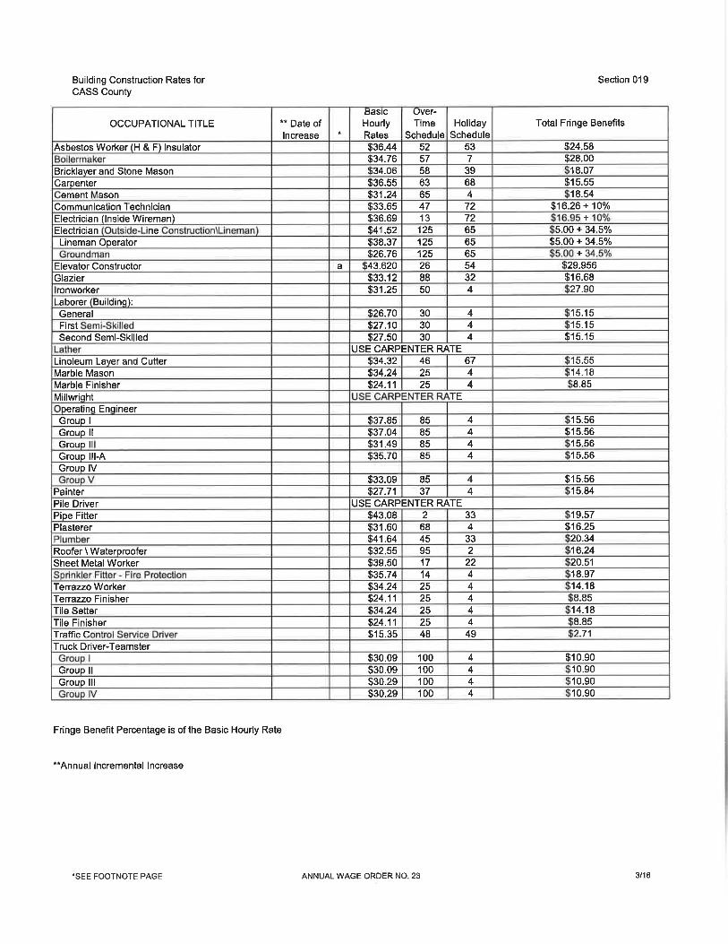
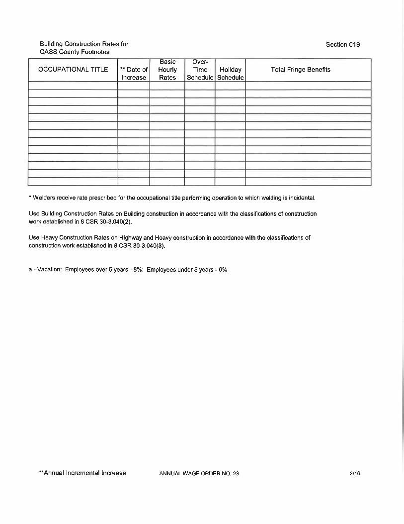
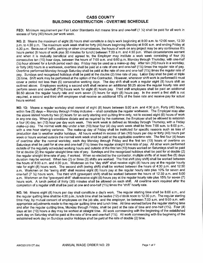
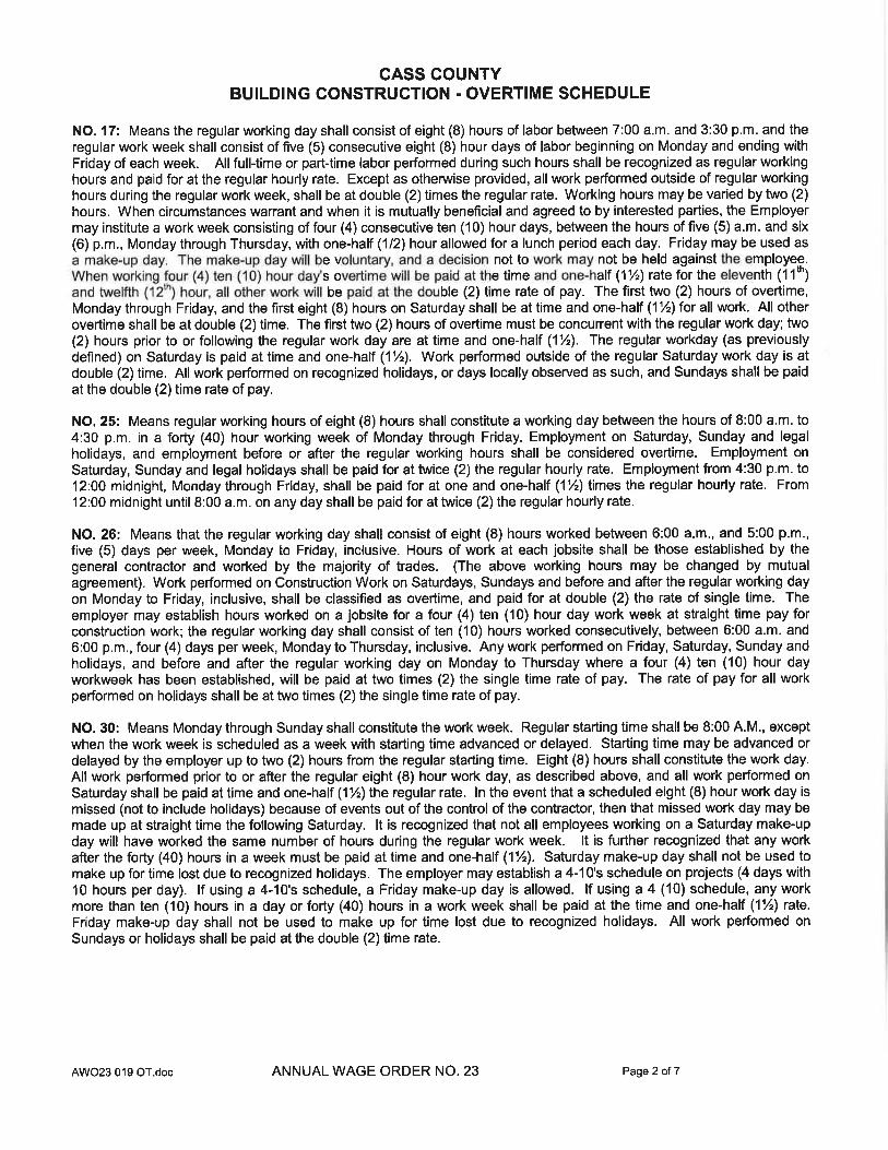
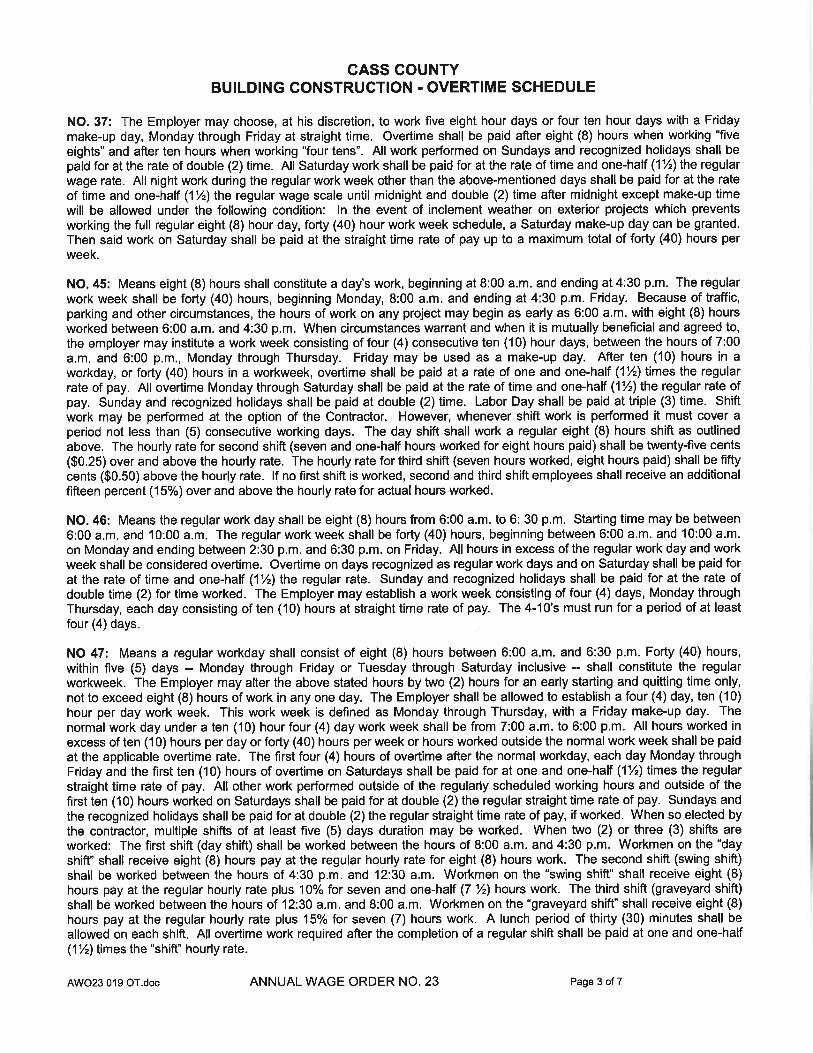
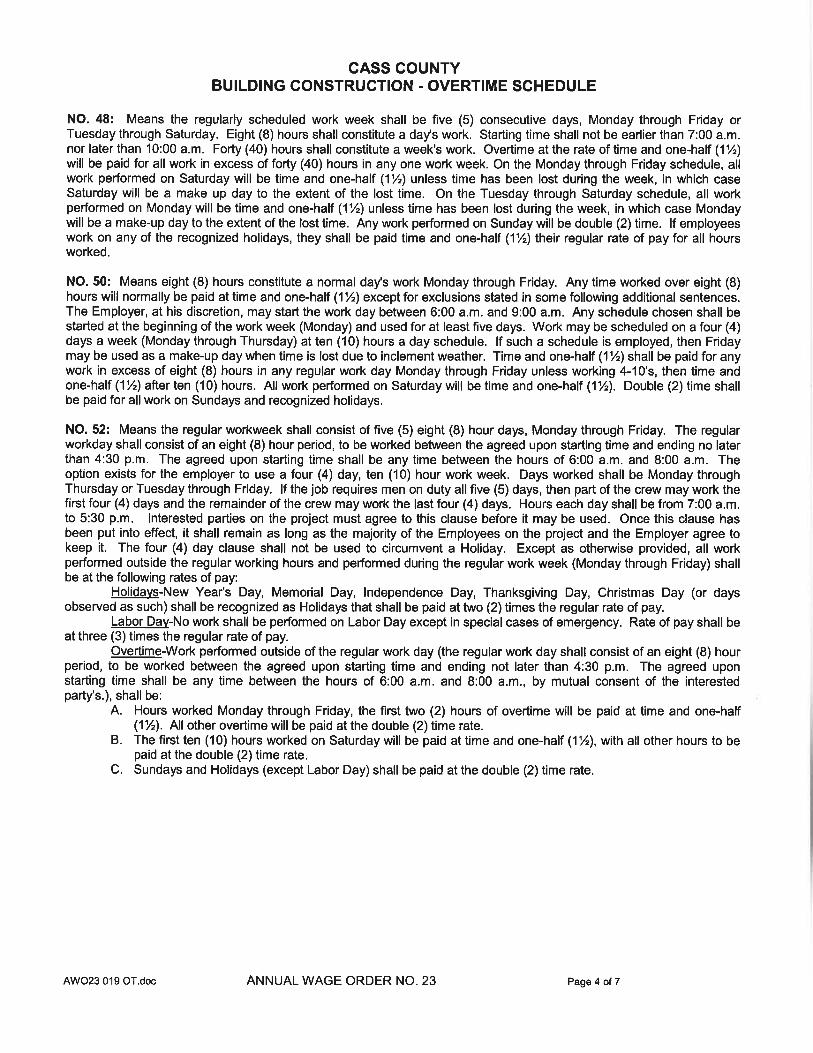
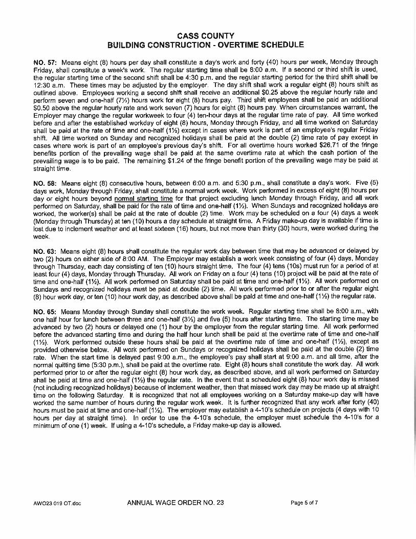
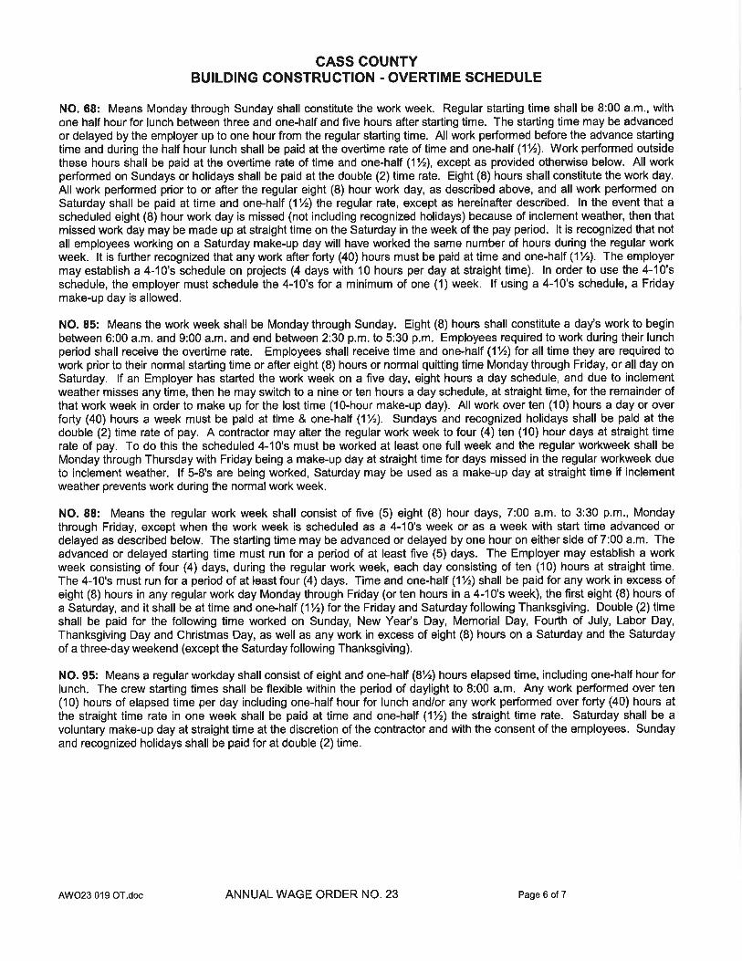
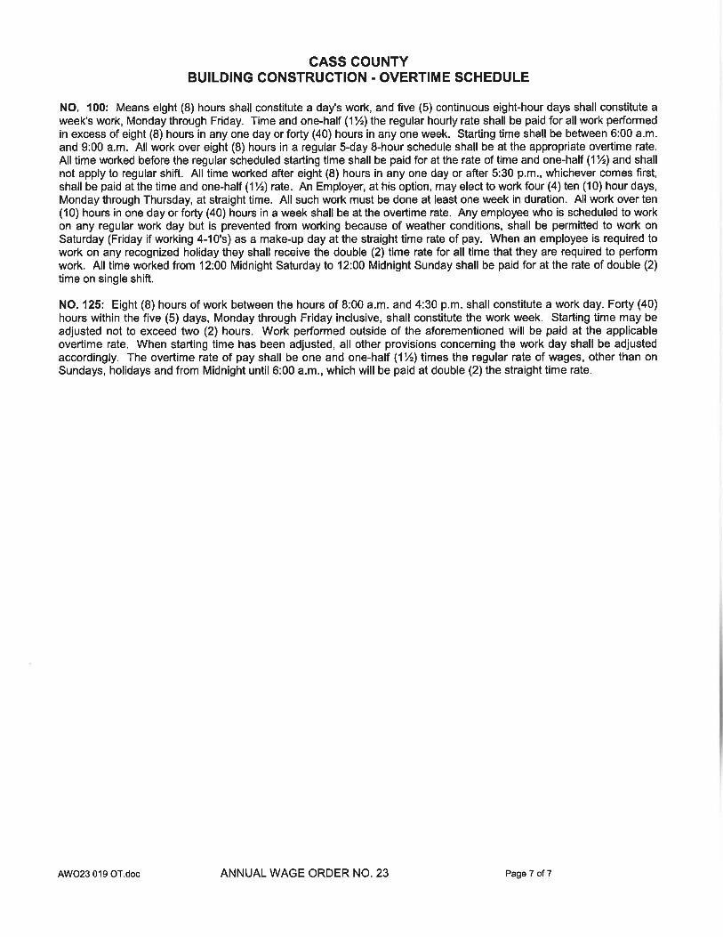
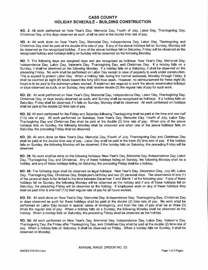
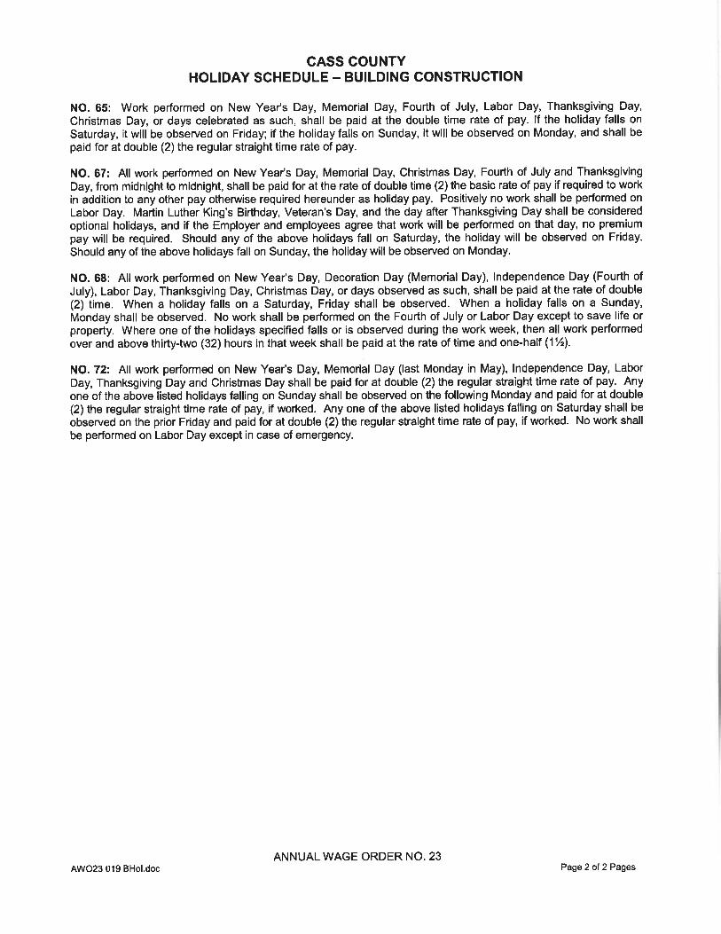
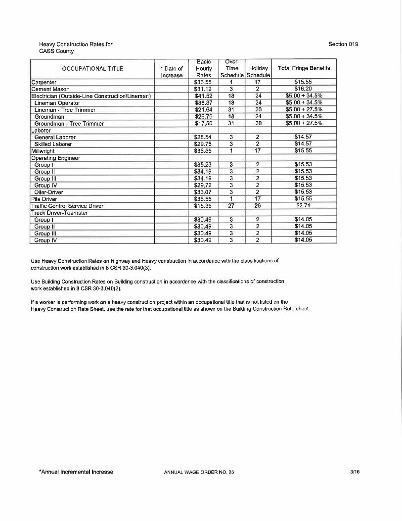
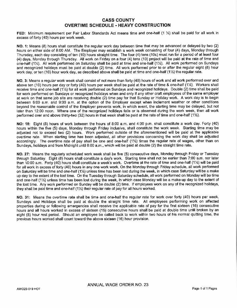


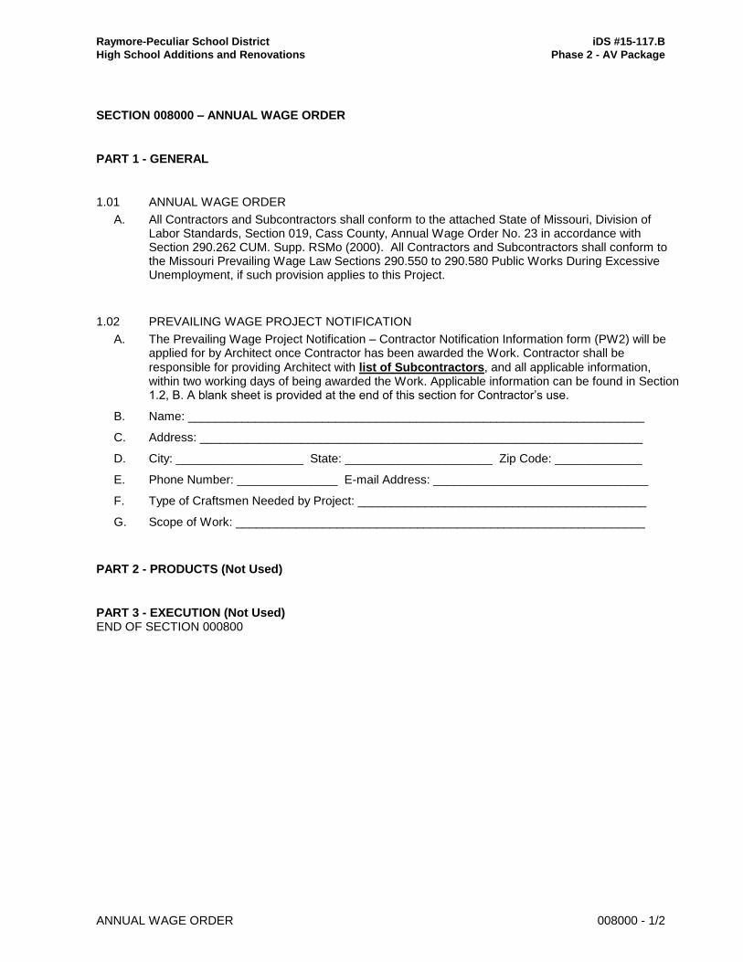
Raymore-Peculiar School District iDS #15-117.B
High School Additions and Renovations Phase 2 - AV Package
ANNUAL WAGE ORDER 008000 - 1/2
SECTION 008000 – ANNUAL WAGE ORDER
PART 1 - GENERAL
1.01 ANNUAL WAGE ORDER
A. All Contractors and Subcontractors shall conform to the attached State of Missouri, Division of Labor Standards, Section 019, Cass County, Annual Wage Order No. 23 in accordance with Section 290.262 CUM. Supp. RSMo (2000). All Contractors and Subcontractors shall conform to the Missouri Prevailing Wage Law Sections 290.550 to 290.580 Public Works During Excessive Unemployment, if such provision applies to this Project.
1.02 PREVAILING WAGE PROJECT NOTIFICATION
A. The Prevailing Wage Project Notification – Contractor Notification Information form (PW2) will be applied for by Architect once Contractor has been awarded the Work. Contractor shall be
responsible for providing Architect with list of Subcontractors, and all applicable information, within two working days of being awarded the Work. Applicable information can be found in Section 1.2, B. A blank sheet is provided at the end of this section for Contractor’s use.
B. Name: ____________________________________________________________________
C. Address: __________________________________________________________________
D. City: ___________________ State: ______________________ Zip Code: _____________
E. Phone Number: _______________ E-mail Address: ________________________________
F. Type of Craftsmen Needed by Project: ___________________________________________
G. Scope of Work: _____________________________________________________________
PART 2 - PRODUCTS (Not Used)
PART 3 - EXECUTION (Not Used) END OF SECTION 000800
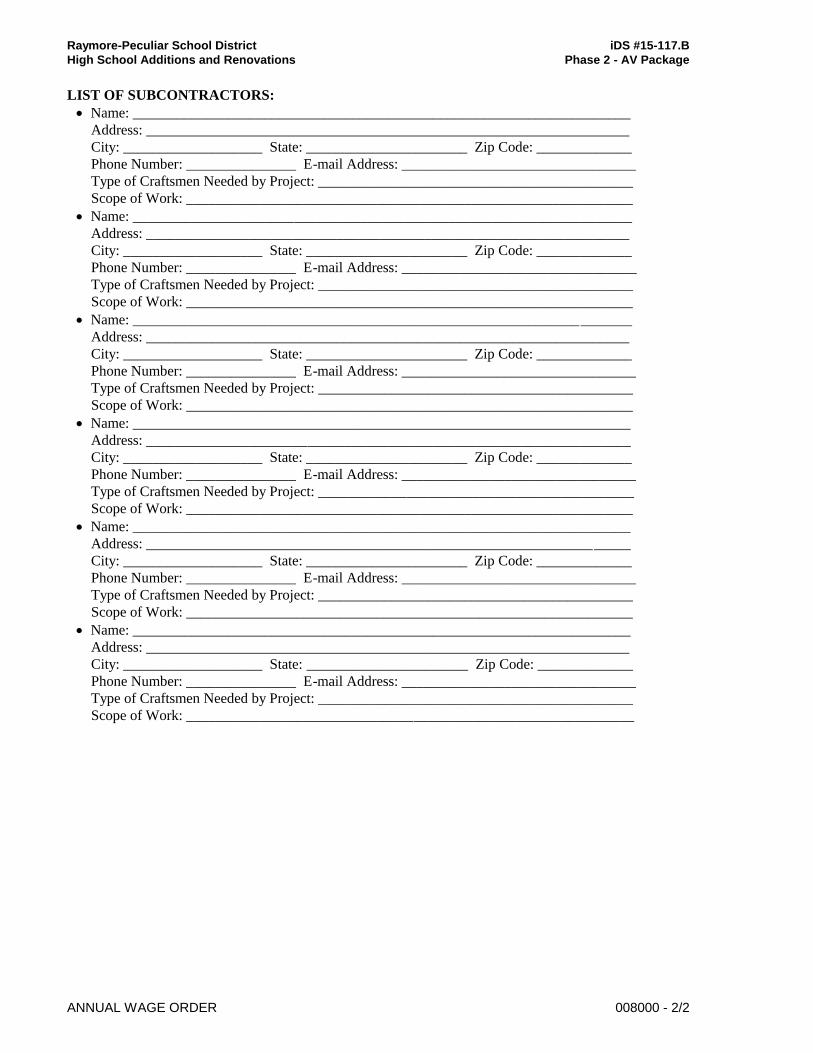
Raymore-Peculiar School District iDS #15-117.B
High School Additions and Renovations Phase 2 - AV Package
ANNUAL WAGE ORDER 008000 - 2/2
LIST OF SUBCONTRACTORS:
Name: ____________________________________________________________________
Address: __________________________________________________________________
City: ___________________ State: ______________________ Zip Code: _____________
Phone Number: _______________ E-mail Address: ________________________________
Type of Craftsmen Needed by Project: ___________________________________________
Scope of Work: _____________________________________________________________
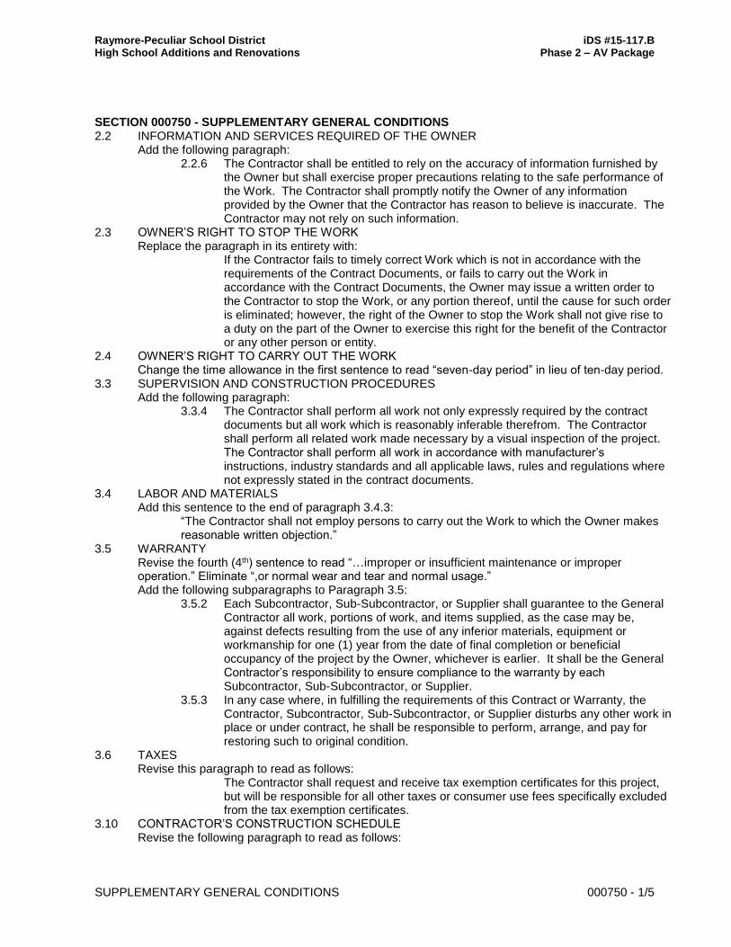
Raymore-Peculiar School District iDS #15-117.B High School Additions and Renovations Phase 2 – AV Package
SUPPLEMENTARY GENERAL CONDITIONS 000750 - 1/5
SECTION 000750 - SUPPLEMENTARY GENERAL CONDITIONS 2.2 INFORMATION AND SERVICES REQUIRED OF THE OWNER Add the following paragraph:
2.2.6 The Contractor shall be entitled to rely on the accuracy of information furnished by the Owner but shall exercise proper precautions relating to the safe performance of the Work. The Contractor shall promptly notify the Owner of any information provided by the Owner that the Contractor has reason to believe is inaccurate. The Contractor may not rely on such information.
2.3 OWNER’S RIGHT TO STOP THE WORK Replace the paragraph in its entirety with:
If the Contractor fails to timely correct Work which is not in accordance with the requirements of the Contract Documents, or fails to carry out the Work in accordance with the Contract Documents, the Owner may issue a written order to the Contractor to stop the Work, or any portion thereof, until the cause for such order is eliminated; however, the right of the Owner to stop the Work shall not give rise to a duty on the part of the Owner to exercise this right for the benefit of the Contractor or any other person or entity.
2.4 OWNER’S RIGHT TO CARRY OUT THE WORK Change the time allowance in the first sentence to read “seven-day period” in lieu of ten-day period. 3.3 SUPERVISION AND CONSTRUCTION PROCEDURES Add the following paragraph:
3.3.4 The Contractor shall perform all work not only expressly required by the contract documents but all work which is reasonably inferable therefrom. The Contractor shall perform all related work made necessary by a visual inspection of the project. The Contractor shall perform all work in accordance with manufacturer’s instructions, industry standards and all applicable laws, rules and regulations where not expressly stated in the contract documents.
3.4 LABOR AND MATERIALS Add this sentence to the end of paragraph 3.4.3:
“The Contractor shall not employ persons to carry out the Work to which the Owner makes reasonable written objection.”
3.5 WARRANTY Revise the fourth (4th) sentence to read “…improper or insufficient maintenance or improper operation.” Eliminate “,or normal wear and tear and normal usage.” Add the following subparagraphs to Paragraph 3.5:
3.5.2 Each Subcontractor, Sub-Subcontractor, or Supplier shall guarantee to the General Contractor all work, portions of work, and items supplied, as the case may be, against defects resulting from the use of any inferior materials, equipment or workmanship for one (1) year from the date of final completion or beneficial occupancy of the project by the Owner, whichever is earlier. It shall be the General Contractor’s responsibility to ensure compliance to the warranty by each Subcontractor, Sub-Subcontractor, or Supplier.
3.5.3 In any case where, in fulfilling the requirements of this Contract or Warranty, the Contractor, Subcontractor, Sub-Subcontractor, or Supplier disturbs any other work in place or under contract, he shall be responsible to perform, arrange, and pay for restoring such to original condition.
3.6 TAXES Revise this paragraph to read as follows:
The Contractor shall request and receive tax exemption certificates for this project, but will be responsible for all other taxes or consumer use fees specifically excluded from the tax exemption certificates.
3.10 CONTRACTOR’S CONSTRUCTION SCHEDULE Revise the following paragraph to read as follows:
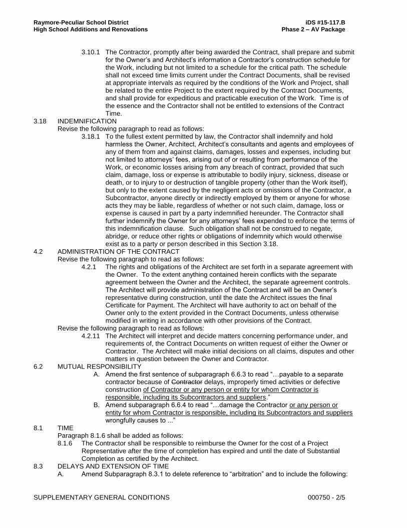
Raymore-Peculiar School District iDS #15-117.B High School Additions and Renovations Phase 2 – AV Package
SUPPLEMENTARY GENERAL CONDITIONS 000750 - 2/5
3.10.1 The Contractor, promptly after being awarded the Contract, shall prepare and submit for the Owner’s and Architect’s information a Contractor’s construction schedule for the Work, including but not limited to a schedule for the critical path. The schedule shall not exceed time limits current under the Contract Documents, shall be revised at appropriate intervals as required by the conditions of the Work and Project, shall be related to the entire Project to the extent required by the Contract Documents, and shall provide for expeditious and practicable execution of the Work. Time is of the essence and the Contractor shall not be entitled to extensions of the Contract Time.
3.18 INDEMNIFICATION Revise the following paragraph to read as follows:
3.18.1 To the fullest extent permitted by law, the Contractor shall indemnify and hold harmless the Owner, Architect, Architect’s consultants and agents and employees of any of them from and against claims, damages, losses and expenses, including but not limited to attorneys’ fees, arising out of or resulting from performance of the Work, or economic losses arising from any breach of contract, provided that such claim, damage, loss or expense is attributable to bodily injury, sickness, disease or death, or to injury to or destruction of tangible property (other than the Work itself), but only to the extent caused by the negligent acts or omissions of the Contractor, a Subcontractor, anyone directly or indirectly employed by them or anyone for whose acts they may be liable, regardless of whether or not such claim, damage, loss or expense is caused in part by a party indemnified hereunder. The Contractor shall further indemnify the Owner for any attorneys’ fees expended to enforce the terms of this indemnification clause. Such obligation shall not be construed to negate, abridge, or reduce other rights or obligations of indemnity which would otherwise exist as to a party or person described in this Section 3.18.
4.2 ADMINISTRATION OF THE CONTRACT Revise the following paragraph to read as follows:
4.2.1 The rights and obligations of the Architect are set forth in a separate agreement with the Owner. To the extent anything contained herein conflicts with the separate agreement between the Owner and the Architect, the separate agreement controls. The Architect will provide administration of the Contract and will be an Owner’s representative during construction, until the date the Architect issues the final Certificate for Payment. The Architect will have authority to act on behalf of the Owner only to the extent provided in the Contract Documents, unless otherwise modified in writing in accordance with other provisions of the Contract.
Revise the following paragraph to read as follows: 4.2.11 The Architect will interpret and decide matters concerning performance under, and
requirements of, the Contract Documents on written request of either the Owner or Contractor. The Architect will make initial decisions on all claims, disputes and other matters in question between the Owner and Contractor.
6.2 MUTUAL RESPONSIBILITY A. Amend the first sentence of subparagraph 6.6.3 to read “…payable to a separate
contractor because of Contractor delays, improperly timed activities or defective construction of Contractor or any person or entity for whom Contractor is responsible, including its Subcontractors and suppliers.”
B. Amend subparagraph 6.6.4 to read “…damage the Contractor or any person or entity for whom Contractor is responsible, including its Subcontractors and suppliers wrongfully causes to ...”
8.1 TIME Paragraph 8.1.6 shall be added as follows: 8.1.6 The Contractor shall be responsible to reimburse the Owner for the cost of a Project
Representative after the time of completion has expired and until the date of Substantial Completion as certified by the Architect.
8.3 DELAYS AND EXTENSION OF TIME A. Amend Subparagraph 8.3.1 to delete reference to “arbitration” and to include the following:
Raymore-Peculiar School District iDS #15-117.B High School Additions and Renovations Phase 2 – AV Package
SUPPLEMENTARY GENERAL CONDITIONS 000750 - 3/5
If an extension of time is granted to the Contractor under the terms of the Contract Documents, the Contractor shall absorb all costs for General Conditions and General Requirements during the time extension.
B. Amend the first sentence of Subparagraph 8.3.1 to read “…by labor disputes not involving Subcontractors or Sub-Subcontractors retained by Contractor, fire, unusual delay…”
C. Add the following paragraph: 8.3.4 The Contractor shall have no claim for damages against either the Owner or the
Architect by reason of delay if the date of Substantial Completion of the work is within the Contract Time as defined in Subparagraph 8.1.5.
9.5 DECISIONS TO WITHHOLD PAYMENT Delete the word “repeatedly” from sub-paragraph 7 of paragraph 9.5.1
9.6 PROGRESS PAYMENTS A. Add Subparagraph 9.6.8 to define Progress Payment Percentages, as follows:
A9.6.8 With respect to Work, 5% Retainage shall be withheld from all construction work until the Work is 100% complete. Retainage on account of Work shall be released upon Substantial Completion of the Work, less 200% of the value of any uncompleted Work or Punch list items and the Owner’s estimate of any post-Substantial Completion damages payable under Paragraph 8.1.5 of the Supplementary General Conditions. All Retainage shall be fully released within thirty (30) Days of Final Completion of the Work. No interest will be paid for payments due and unpaid under the Contract Documents.
9.10 COMPLETION AND FINAL PAYMENT A. Add the following to Paragraph 9.10.2:
Liens and/or Encumbrances – The Contractor shall satisfy immediately any lien or encumbrance which, because of any act or default of the Contractor or any person or entity for whom Contractor is responsible, including its suppliers and subcontractors, is filed against the premises, and shall indemnify and save the Owner harmless against all resulting loss and expenses, including attorney’s fees. The Contractors shall provide Final Lien Waiver from all subcontractors and material suppliers before project closeout.
B. Delete the word “or” from subparagraph 2 of paragraph 9.10.4 and add “, or” to the end of subparagraph 3. Add the following subparagraph to paragraph 9.10.4:
.4 the Contractor’s indemnification obligations as set forth in §3.18.1 and §3.18.2. 10.3 HAZARDOUS MATERIALS
Insert the following paragraph after 10.2.2 and renumber subsequent paragraphs that follow as necessary:
10.2.3 Nothing contained in §16.2.2 shall be construed as a waiver of the Owner’s sovereign or governmental immunity, by whatever name, as set forth in RSMo § 537.600 et seq., or otherwise provided by law. The Owner shall have no obligation to indemnify the Contractor for any claims for which it would otherwise have immunity.
11.1 CONTRACTOR’S LIABILITY INSURANCE Add the following to Paragraph 11.1.2: Insurance required to be furnished by the Contractor with the premium included in the Proposal Sum, shall be maintained during the life of this contract and shall be written to a minimum of the following limits:
(1) Workmen’s Compensation Insurance to the Statutory limits required by State Law, and Employer’s Liability Insurance covering liability under the common law for injuries or death to any such employee or employees that, for whatsoever reasons, are not less than $100,000.00 for all damages arising out of bodily injury to or death of employees in any one accident.
(2) Comprehensive General Liability insurance providing for a limit of not less than $1,000,000.00 for all damages arising out of bodily injury to or the death of one person (and subject to that limit for each person), not less than $2,000,000.00 for damages arising out of bodily injury to or the death of two or more persons in any one occurrence, and not less than $1,000,000.00 for all damages arising out of injury to or destruction of property in any one occurrence. Said insurance policy
Raymore-Peculiar School District iDS #15-117.B High School Additions and Renovations Phase 2 – AV Package
SUPPLEMENTARY GENERAL CONDITIONS 000750 - 4/5
shall contain no exclusions whatsoever relative to blasting, explosion, demolition, injury to any building or structure due to excavation, pile driving, shoring or underpinning (sometimes knows as X, C, and U Exclusions).
(3) Automobile Public Liability (Bodily Injury) and Property Damage Liability Insurance, to include coverage of all vehicles hired by Contractor, owned by Contractor’s employees and used in his business, and/or owned by the Contractor, providing for a limit of not less than $1,000,000.00 for all damages arising out of bodily injury to or the death of one person (and subject to that limit for each person), not less than $1,000,000.00 for all damages arising out of bodily injury to or the death of two or more persons in any one occurrence and not less than $5,000,000.00 for all damages arising out of injury to or destruction of property in any one occurrence.
11.2 OWNER’S LIABILITY INSURANCE Add the following to Paragraph 11.2 as follows:
The Owner preserves all immunities recognized at law. Nothing herein shall be construed as a waiver of sovereign immunity or governmental immunity by whatever name as set forth in Mo. Rev. Stat. §§ 537.600 et seq. Any insurance purchased by the Contractor hereto is not intended to act as a waiver, nor is it a waiver of any defense available to the Owner and its employees by statute or at common law.
11.3. PROPERTY INSURANCE A. Add “To the extent permitted by their respective insurance carriers and applicable laws, the”
before the first sentence of paragraph 11.3.7 B. Amend Subparagraph 11.3.10 by deleting all remaining wording after “resolution in the
Agreement.” 11.4 PERFORMANCE AND PAYMENT BOND Revise the following paragraph to read:
11.4.1 The Contractor shall furnish bonds covering faithful performance of the Contract and payment of obligations arising thereunder as stipulated in bidding requirements or specifically required in the Contract Documents or by applicable law on the date of execution of the Contract.
13.1 MISCELLANEOUS PROVISIONS A. Revise the following paragraph to read: 13.1 The Contract shall be governed by the State of Missouri. B. Add the following paragraphs to the end of Article 13 Miscellaneous Provisions:
§13.8 This Agreement shall be based upon the required payment by the Contractor of not less than the prevailing hourly rate of wages for each craft or type of workmen required to execute the Contract determined by the Department of Labor and Industrial Relations of Missouri.
§13.9 Prior to commencement of the Work, Contractor shall provide to Owner a sworn affidavit and other sufficient documentation to affirm its enrollment and participation in a federal work authorization program with respect to the employees working in connection with this Contract. Contractor shall also provide Owner a sworn affidavit affirming that it does not knowingly employ any person who is an unauthorized alien in connection with the contracted services.
§13.10 As a condition of the Contract, Contractor must provide a 10-hour Occupational Safety and Health Administration (OSHA) Construction Safety Program (“Program”) for Contractor’s on-site employees as mandated by RSMo § 292.675. Said Program must include a course in construction safety and health approved by OSHA or a similar program approved by the Missouri Department of Labor and Industrial Relations. This requirement includes the following:
13.10.1 All of Contractors’ on-site employees must complete the Program within 60 days of beginning work on the Project;
13.10.2 Any employee found on the work site subject to this requirement without documentation of the successful completion of the Program will be given 20 days to produce such documentation before being subject to removal from the Project;
13.10.3 Contractor’s failure to comply with these requirements will subject it to penalties. Contractor shall forfeit as a penalty to the Owner $2,500.00 plus $100.00 for each
Raymore-Peculiar School District iDS #15-117.B High School Additions and Renovations Phase 2 – AV Package
SUPPLEMENTARY GENERAL CONDITIONS 000750 - 5/5
employee employed by Contractor or Contractor’s Subcontractor, for each calendar day, or portion thereof, such employee is employed to do work pursuant to this Contract without the required training. Said penalty shall not begin to accrue until the time period in subsections 1 and 2 have elapsed. Contractor will be subject to said penalties notwithstanding any other provision to the contrary in this Construction Contract.
13.10.4 Contractor shall require its contracts with all Subcontractors to contain these provisions. Contractor shall be responsible for penalties to Owner due to any Subcontractor’s employees’ failure to be able to produce documentary evidence of training in the required Program. Contractor may withhold all sums necessary to cover any penalty Owner has withheld or been paid. Contractor may recover any penalties from Subcontractor by filing a lawsuit in the circuit court of the county in which the project is located.
§13.11 Every transient employer, as defined in Section 285.230, RSMo, must post in a prominent and easily accessible place at the worksite a clearly legible copy of the following: (1) a notice of registration for employer withholding issued to such transient employer by the Director of Revenue; (2) proof of coverage for workers compensation insurance or self-insurance signed by the transient employer and verified by the Department of Revenue through the records of the Division of Workers Compensation; and (3) the notice of registration for unemployment insurance issued to such transient employer by the Division of Employment Security. Any transient employer failing to comply with these laws shall, under Section 285.234, RSMo, be liable for a penalty of $500.00 per day until the notices required by this Section are posted as required by that Statute.
§13.12 Contractor shall provide documentation proving that all of its employees working on the Project have passed all applicable criminal background checks required by Owner before entering the Owner’s premises. Contractor shall require all subcontractors to comply with this requirement.
§13.13 This Contract is to be governed by the laws of the State of Missouri. Venue of any lawsuit filed regarding the Project or arising out of this Contract will be in the Circuit Court of Cass County, Missouri.
§13.14 Contractor shall submit all names and other required information of employee’s and employees of their subcontractors that will enter the campus to the owner for background check. No person shall be granted access to the grounds without approval of the owner based on the results of the background check. The contractor shall be responsible to control all entry and to verify that all badges/passes distributed to employees and subcontractor employees. Owner will run background checks and cover all associated costs.
14.4 TERMINATION BY THE OWNER FOR CONVENIENCE Revise the following paragraph to read:
14.4.3 The Owner may, at any time, terminate the Contract for the Owner’s convenience and without cause. The Contractor shall be entitled to receive payment for Work executed, and costs incurred by reason of such termination.
15.2 INITIAL DECISION Delete paragraph 15.2.8 in its entirety 15.3 Mediation Delete this article in its entirety including all paragraphs 15.4 ARBITRATION Delete this article in its entirety including all paragraphs END OF SECTION 000750

Raymore-Peculiar School District iDS #15-117.B High School Additions and Renovations Phase 2 - AV Package
FORMS 006000 - 1/1
DOCUMENT 006000 - FORMS
1.01 FORM OF AGREEMENT AND GENERAL CONDITIONS
A. The following form of Owner/Contractor Agreement and form of the General Conditions shall be used for Project:
1. AIA Document A101 as amended, "Standard Form of Agreement between Owner and Contractor, Stipulated Sum."
a. The General Conditions for Project are AIA Document A201, "General Conditions of the Contract for Construction."
2. The General Conditions are included in the Project Manual. 3. The Supplementary Conditions for Project are incorporated into a modified copy of the
General Conditions included in the Project Manual.
1.02 ADMINISTRATIVE FORMS
A. Administrative Forms: Additional administrative forms are specified in Division 01 General Requirements.
B. Copies of AIA standard forms may be obtained from the American Institute of Architects; http://www.aia.org/contractdocs/purchase/index.htm; [email protected]; (800) 942-7732.
C. Preconstruction Forms:
1. Form of Performance Bond and Labor and Material Bond: AIA Document A312, "Performance Bond and Payment Bond."
2. Form of Certificate of Insurance: AIA Document G715, "Supplemental Attachment for ACORD Certificate of Insurance 25-S."
D. Information and Modification Forms:
1. Form for Requests for Information (RFIs): AIA Document G716, "Request for Information (RFI)."
2. Form of Request for Proposal: AIA Document G709, "Work Changes Proposal Request." 3. Change Order Form: AIA Document G701, "Change Order." 4. Form of Architect's Memorandum for Minor Changes in the Work: AIA Document G707,
"Architect's Supplemental Instructions." 5. Form of Change Directive: AIA Document G714, "Construction Change Directive."
E. Payment Forms:
1. Schedule of Values Form: AIA Document G703, "Continuation Sheet." 2. Payment Application: AIA Document G702/703, "Application and Certificate for Payment and
Continuation Sheet." 3. Form of Contractor's Affidavit: AIA Document G706, "Contractor's Affidavit of Payment of
Debts and Claims." 4. Form of Affidavit of Release of Liens: AIA Document G706A, "Contractor's Affidavit of
Payment of Release of Liens." 5. Form of Consent of Surety: AIA Document G707, "Consent of Surety to Final Payment."
END OF DOCUMENT 006000
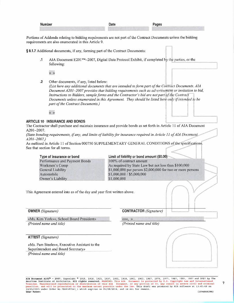

Raymore-Peculiar School District iDS #15-117.B High School Additions and Renovations Phase 2 - AV Package
STANDARD FORM OF AGREEMENT BETWEEN OWNER & CONTRACTOR 000520 - 1/1
SECTION 000520 - STANDARD FORM OF AGREEMENT BETWEEN OWNER & CONTRACTOR
PART 1 - GENERAL
1.01 APPLICABLE DOCUMENTS
A. The American Institute of Architects Document A101 “Standard Form of Agreement between
Owner and Contractor”, 2007 Edition, as edited, that is bound herein, shall be executed by the
successful Bidder with the Owner.
B. Exhibits as may be necessary for the complete execution of this agreement, shall be created after
Acceptance of Bid (Award) by the Owner and shall be included in the executed agreement.
PART 2 - PRODUCTS (Not Used)
PART 3 - EXECUTION (Not Used)
END OF SECTION 000520
Raymore-Peculiar School District iDS #15-117.B High School Additions and Renovations Phase 2 - AV Package
BID SUBMITTAL CHECKLIST 004393 - 1/1
DOCUMENT 004393 - BID SUBMITTAL CHECKLIST
1.01 BIDDER'S CHECKLIST
A. In an effort to assist the Bidder in properly completing all documentation required, the following checklist is provided for the Bidder's convenience. The Bidder is solely responsible for verifying compliance with bid submittal requirements.
B. Attach this completed checklist to the outside of the Submittal envelope.
1. Used the Bid Form provided in the Project Manual. 2. Prepared the Bid Form as required by the Instructions to Bidders. 3. Indicated on the Bid Form the Addenda received. 4. Attached to the Bid Form: Bidder’s Qualification Form. 5. Attached to the Bid Form: Bid Bond OR a certified check for the amount required. 6. Bid envelope shows name and address of the Bidder. 7. Bid envelope shows the Bidder's Contractor's License Number. 8. Bid envelope shows name of Project being bid. 9. Bid envelope shows name of Prime Contract being bid, if applicable. 10. Bid envelope shows time and day of Bid Opening. 11. Verified that the Bidder can provide executed Performance Bond and Labor and Material
Bond. 12. Verified that the Bidder can provide Certificates of Insurance in the amounts indicated.
END OF DOCUMENT 004393
Raymore-Peculiar School District iDS #15-117.B High School Additions and Renovations Phase 2 - AV Package
PROPOSED SCHEDULE OF VALUES FORM 004373 - 1/1
DOCUMENT 004373 - PROPOSED SCHEDULE OF VALUES FORM
1.01 BID FORM SUPPLEMENT
A. A completed Proposed Schedule of Values form is required to be submitted 2 days after notification of apparent low bid and will be required to be included in the executed construction agreement.
1.02 PROPOSED SCHEDULE OF VALUES FORM
A. Proposed Schedule of Values Form: Provide a breakdown of the bid amount, including alternates, in enough detail to facilitate continued evaluation of bid. Coordinate with the Project Manual table of contents. Provide multiple line items for principal material and subcontract amounts in excess of five percent of the Contract Sum.
B. Arrange schedule of values consistent with format of AIA Document G703.
1. Copies of AIA standard forms may be obtained from the American Institute of Architects; http://www.aia.org/contractdocs/purchase/index.htm; [email protected]; (800) 942-7732.
END OF DOCUMENT 004373
Raymore-Peculiar School District iDS #15-117.B High School Additions and Renovations Phase 2 - AV Package
BIDDER’S QUALIFICATIONS FORMS 0004314 - 1/1
SECTION 0004314 - BIDDER’S QUALIFICATIONS FORMS
PART 1 - GENERAL
1.01 APPLICABLE DOCUMENTS
A. The American Institute of Architects Document A305 “Contractor’s Qualifications Statement”, 1986
Edition, and is bound herein.
B. Samples of the Bidder’s Qualifications Form may be obtained from the American Institute of
Architects, 1801 McGee #100, Kansas City, Missouri 64105, 816-221-3485, or AIA Kansas, 700
Jackson Street, Suite 209, Topeka, Kansas 66603, 785-357-5308.
C. A properly executed form is required to be submitted with each copy of the Bid.
D. Form shall include contact name, address, phone number, and e-mail address.
PART 2 - PRODUCTS (Not Used)
PART 3 - EXECUTION (Not Used)
END OF SECTION 000455
Raymore-Peculiar School District iDS #15-117.B High School Additions and Renovations Phase 2 - AV Package
BID SECURITY FORMS 004313 - 1/1
DOCUMENT 004313 - BID SECURITY FORMS
1.01 BID FORM SUPPLEMENT
A. A completed bid bond form is required to be attached to the Bid Form.
1.02 BID BOND FORM
A. AIA Document A310, "Bid Bond," is the recommended form for a bid bond. A bid bond acceptable to Owner, or other bid security as described in the Instructions to Bidders, is required to be attached to the Bid Form as a supplement.
B. Copies of AIA standard forms may be obtained from The American Institute of Architects; www.aia.org/contractdocs/purchase/index.htm; email: [email protected]; (800) 942-7732.
END OF DOCUMENT 004313
Raymore-Peculiar School District iDS #15-117.B High School Additions and Renovations Phase 2 - AV Package
BID FORM - STIPULATED SUM (SINGLE-PRIME CONTRACT) 004113 - 1/2
DOCUMENT 004113 - BID FORM - STIPULATED SUM (SINGLE-PRIME CONTRACT)
1.01 BID INFORMATION
A. Bidder: ____________________________________________________.
B. Project Name: Raymore-Peculiar School District High School Additions and Renovations.
C. Project Location: 20801 South School Road, Peculiar, MO
D. Owner: Raymore-Peculiar School District.
E. Owner Project Number: Raymore-Peculiar School District.
F. Architect: Incite Design Studio, LLC.
G. Architect Project Number: 15-117.B.
1.02 CERTIFICATIONS AND BASE BID
A. Base Bid, Single-Prime (All Trades) Contract: The undersigned Bidder, having carefully examined the Procurement and Contracting Requirements, Conditions of the Contract, Drawings, Specifications, and all subsequent Addenda, as prepared by incite Design Studio and Architect's consultants, having visited the site, and being familiar with all conditions and requirements of the Work, hereby agrees to furnish all material, labor, equipment and services, including all scheduled allowances, necessary to complete the construction of the above-named project, according to the requirements of the Procurement and Contracting Documents, for the stipulated sum of:
1. ________________________________________________ Dollars ($______________).
1.03 BID GUARANTEE
A. The undersigned Bidder agrees to execute a contract for this Work in the above amount and to furnish surety as specified within 10 days after a written Notice of Award, if offered within 60 days after receipt of bids, and on failure to do so agrees to forfeit to Owner the attached cash, cashier's check, certified check, U.S. money order, or bid bond, as liquidated damages for such failure, in the following amount constituting five percent (5%) of the Base Bid amount above:
1. ________________________________________________ Dollars ($______________).
B. In the event Owner does not offer Notice of Award within the time limits stated above, Owner will return to the undersigned the cash, cashier's check, certified check, U.S. money order, or bid bond.
1.04 TIME OF COMPLETION
A. The undersigned Bidder proposes and agrees hereby to commence the Work of the Contract Documents on a date specified in a written Notice to Proceed to be issued by Architect, and shall fully complete the Work within the dates outlined in the attached project timeline.
1.05 ACKNOWLEDGEMENT OF ADDENDA
A. The undersigned Bidder acknowledges receipt of and use of the following Addenda in the preparation of this Bid:
1. Addendum No. 1, dated ____________________. 2. Addendum No. 2, dated ____________________.
Raymore-Peculiar School District iDS #15-117.B High School Additions and Renovations Phase 2 - AV Package
BID FORM - STIPULATED SUM (SINGLE-PRIME CONTRACT) 004113 - 2/2
1.06 BID SUPPLEMENTS
A. The following supplements are a part of this Bid Form and are attached hereto.
1. Bid Form Supplement - Bid Bond Form (AIA Document A310). 2. Bidder’s Qualification Form
1.07 CONTRACTOR'S LICENSE
A. The undersigned further states that it is a duly licensed contractor, for the type of work proposed, in Peculiar, MO, and that all fees, permits, etc., pursuant to submitting this proposal have been paid in full.
1.08 SUBMISSION OF BID
A. Respectfully submitted this ____ day of ____________, 2016.
B. Submitted By:_______________________________________(Name of bidding firm or corporation).
C. Authorized Signature:___________________________________(Handwritten signature).
D. Signed By:______________________________________________(Type or print name).
E. Title:__________________________________(Owner/Partner/President/Vice President).
F. Witness By:___________________________________________(Handwritten signature).
G. Attest:_______________________________________________(Handwritten signature).
H. By:___________________________________________________(Type or print name).
I. Title:________________________________(Corporate Secretary or Assistant Secretary).
J. Street Address:___________________________________________________________.
K. City, State, Zip:__________________________________________________________.
L. Phone:_________________________________________________________________.
M. License No.:____________________________________________________________.
N. Federal ID No.:____________________________________(Affix Corporate Seal Here).
END OF DOCUMENT 004113
Raymore-Peculiar School District iDS #15-117.B High School Additions and Renovations Phase 2 - AV Package
EXISTING CONDITION INFORMATION 003119 - 1/1
DOCUMENT 003119 - EXISTING CONDITION INFORMATION
1.01 EXISTING CONDITION INFORMATION
A. This Document with its referenced attachments is part of the Procurement and Contracting Requirements for Project. They provide Owner's information for Bidders' convenience and are intended to supplement rather than serve in lieu of the Bidders' own investigations. They are made available for Bidders' convenience and information, but are not a warranty of existing conditions. This Document and its attachments are not part of the Contract Documents.
B. Existing drawings that include information on existing conditions including previous construction at Project site are available for viewing at the office of Architect and access to electronic copies can be made available upon request.
C. Related Requirements:
1. Document 002113 "Instructions to Bidders" for the Bidder's responsibilities for examination of Project site and existing conditions.
END OF DOCUMENT 003119
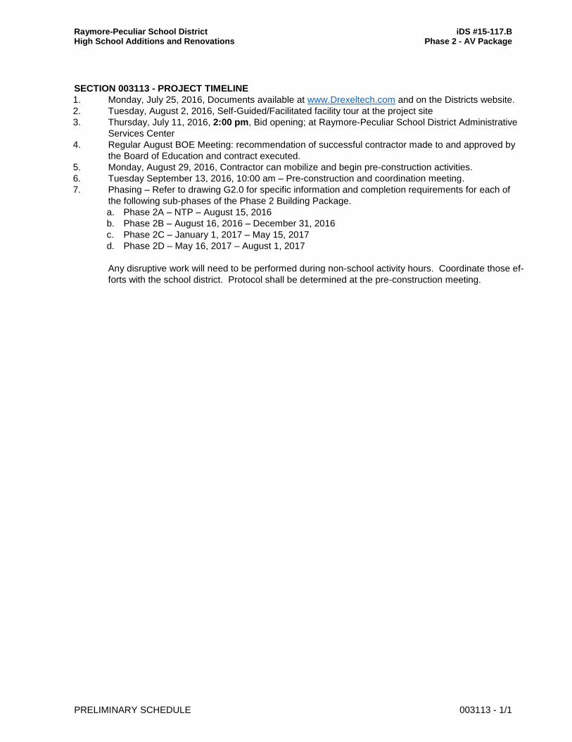
Raymore-Peculiar School District iDS #15-117.B High School Additions and Renovations Phase 2 - AV Package
PRELIMINARY SCHEDULE 003113 - 1/1
SECTION 003113 - PROJECT TIMELINE
1. Monday, July 25, 2016, Documents available at www.Drexeltech.com and on the Districts website.
2. Tuesday, August 2, 2016, Self-Guided/Facilitated facility tour at the project site
3. Thursday, July 11, 2016, 2:00 pm, Bid opening; at Raymore-Peculiar School District Administrative
Services Center
4. Regular August BOE Meeting: recommendation of successful contractor made to and approved by
the Board of Education and contract executed.
5. Monday, August 29, 2016, Contractor can mobilize and begin pre-construction activities.
6. Tuesday September 13, 2016, 10:00 am – Pre-construction and coordination meeting.
7. Phasing – Refer to drawing G2.0 for specific information and completion requirements for each of
the following sub-phases of the Phase 2 Building Package.
a. Phase 2A – NTP – August 15, 2016
b. Phase 2B – August 16, 2016 – December 31, 2016
c. Phase 2C – January 1, 2017 – May 15, 2017
d. Phase 2D – May 16, 2017 – August 1, 2017
Any disruptive work will need to be performed during non-school activity hours. Coordinate those ef-
forts with the school district. Protocol shall be determined at the pre-construction meeting.
Raymore-Peculiar School District iDS #15-117.B High School Additions and Renovations Phase 2 - AV Package
PROCUREMENT SUBSTITUTION PROCEDURES 002600 - 1/2
DOCUMENT 002600 - PROCUREMENT SUBSTITUTION PROCEDURES
1.01 DEFINITIONS
A. Procurement Substitution Requests: Requests for changes in products, materials, equipment, and methods of construction from those indicated in the Procurement and Contracting Documents, submitted prior to receipt of bids.
B. Substitution Requests: Requests for changes in products, materials, equipment, and methods of construction from those indicated in the Contract Documents, submitted following Contract award. See Section 012500 "Substitution Procedures" for conditions under which Substitution requests will be considered following Contract award.
1.02 QUALITY ASSURANCE
A. Compatibility of Substitutions: Investigate and document compatibility of proposed substitution with related products and materials. Engage a qualified testing agency to perform compatibility tests recommended by manufacturers.
1.03 PROCUREMENT SUBSTITUTIONS
A. Procurement Substitutions, General: By submitting a bid, the Bidder represents that its bid is based on materials and equipment described in the Procurement and Contracting Documents, including Addenda. Bidders are encouraged to request approval of qualifying substitute materials and equipment when the Specifications Sections list materials and equipment by product or manufacturer name.
B. Procurement Substitution Requests will be received and considered by Owner when the following conditions are satisfied, as determined by Architect; otherwise requests will be returned without action:
1. Extensive revisions to the Contract Documents are not required. 2. Proposed changes are in keeping with the general intent of the Contract Documents,
including the level of quality of the Work represented by the requirements therein. 3. The request is fully documented and properly submitted.
1.04 SUBMITTALS
A. Procurement Substitution Request: Submit to Architect. Procurement Substitution Request must be made in writing in compliance with the following requirements:
1. Requests for substitution of materials and equipment will be considered if received no later than 5 days prior to date of bid opening.
2. Submittal Format: Submit 1 electronic copy of each written Procurement Substitution Request, using CSI Substitution Request Form 1.5C.
3. Submittal Format: Submit Procurement Substitution Request, using format provided on Project Web site.
a. Identify the product or the fabrication or installation method to be replaced in each request. Include related Specifications Sections and drawing numbers.
b. Provide complete documentation on both the product specified and the proposed substitute, including the following information as appropriate:
Raymore-Peculiar School District iDS #15-117.B High School Additions and Renovations Phase 2 - AV Package
PROCUREMENT SUBSTITUTION PROCEDURES 002600 - 2/2
1) Point-by-point comparison of specified and proposed substitute product data, fabrication drawings, and installation procedures.
2) Copies of current, independent third-party test data of salient product or system characteristics.
3) Samples where applicable or when requested by Architect. 4) Detailed comparison of significant qualities of the proposed substitute with
those of the Work specified. Significant qualities may include attributes such as performance, weight, size, durability, visual effect, sustainable design characteristics, warranties, and specific features and requirements indicated. Indicate deviations, if any, from the Work specified.
5) Material test reports from a qualified testing agency indicating and interpreting test results for compliance with requirements indicated.
6) Research reports, where applicable, evidencing compliance with building code in effect for Project, from ICC-ES.
7) Coordination information, including a list of changes or modifications needed to other parts of the Work and to construction performed by Owner and separate contractors, which will become necessary to accommodate the proposed substitute.
c. Provide certification by manufacturer that the substitute proposed is equal to or superior to that required by the Procurement and Contracting Documents, and that its in-place performance will be equal to or superior to the product or equipment specified in the application indicated.
d. Bidder, in submitting the Procurement Substitution Request, waives the right to additional payment or an extension of Contract Time because of the failure of the substitute to perform as represented in the Procurement Substitution Request.
B. Architect's Action:
1. Architect may request additional information or documentation necessary for evaluation of the Procurement Substitution Request. Architect will notify all bidders of acceptance of the proposed substitute by means of an Addendum to the Procurement and Contracting Documents.
C. Architect's approval of a substitute during bidding does not relieve Contractor of the responsibility to submit required shop drawings and to comply with all other requirements of the Contract Documents.
END OF DOCUMENT 002600
Raymore-Peculiar School District iDS #15-117.B High School Additions and Renovations Phase 2 - AV Package
SUPPLEMENTARY INSTRUCTIONS TO BIDDERS 002213 - 1/4
DOCUMENT 002213 - SUPPLEMENTARY INSTRUCTIONS TO BIDDERS
1.01 INSTRUCTIONS TO BIDDERS
A. Instructions to Bidders for Project consist of the following:
1. AIA Document A701, "Instructions to Bidders," a copy of which is bound in this Project Manual.
2. The following Supplementary Instructions to Bidders that modify and add to the requirements of the Instructions to Bidders.
1.02 SUPPLEMENTARY INSTRUCTIONS TO BIDDERS, GENERAL
A. The following supplements modify AIA Document A701, "Instructions to Bidders." Where a portion of the Instructions to Bidders is modified or deleted by these Supplementary Instructions to Bidders, unaltered portions of the Instructions to Bidders shall remain in effect.
1.03 ARTICLE 2 - BIDDER'S REPRESENTATIONS
A. Add Section 2.1.3.1:
1. 2.1.3.1 - The Bidder has investigated all required fees, permits, and regulatory requirements of authorities having jurisdiction and has properly included in the submitted bid the cost of such fees, permits, and requirements not otherwise indicated as provided by Owner.
B. Add Section 2.1.5:
1. 2.1.5 - The Bidder is a properly licensed Contractor according to the laws and regulations of Peculiar, MO and meets qualifications indicated in the Procurement and Contracting Documents.
C. Add Section 2.1.6:
1. 2.1.6 - The Bidder has incorporated into the Bid adequate sums for work performed by installers whose qualifications meet those indicated in the Procurement and Contracting Documents.
1.04 ARTICLE 3 - BIDDING DOCUMENTS
A. 3.2 - Interpretation or Correction of Procurement and Contracting Documents:
1. Add Section 3.2.2.1:
a. 3.2.2.1 - Submit Bidder's Requests for Interpretation using form bound in the Project Manual.
2. Add Section 3.2.4:
a. 3.2.4 - In the case of an ambiguity, inconsistency or error in the Bidding Documents not clarified by Addendum, the higher quality, more expensive options and/or greater quantity of Work shall be provided in accordance with the Contractor’s interpretations. Failure of Bidder to notify the Architect of a known ambiguity, inconsistency or error in the Bidding Documents will waive the Bidder’s right to seek additional compensation for such ambiguity, inconsistency, or error.
Raymore-Peculiar School District iDS #15-117.B High School Additions and Renovations Phase 2 - AV Package
SUPPLEMENTARY INSTRUCTIONS TO BIDDERS 002213 - 2/4
B. 3.4 - Addenda:
1. Delete Section 3.4.3 and replace with the following:
a. 3.4.3 - Addenda may be issued at any time prior to the receipt of bids.
2. Add Section 3.4.4.1:
a. 3.4.4.1 - Owner may elect to waive the requirement for acknowledging receipt of 3.4.4 Addenda as follows:
1) 3.4.4.1.1 - Information received as part of the Bid indicates that the Bid, as submitted, reflects modifications to the Procurement and Contracting Documents included in an unacknowledged Addendum.
2) 3.4.4.1.2 - Modifications to the Procurement and Contracting Documents in an unacknowledged Addendum do not, in the opinion of Owner, affect the Contract Sum or Contract Time.
1.05 ARTICLE 4 - BIDDING PROCEDURES
A. 4.1 - Preparation of Bids:
1. Add Section 4.1.1.1:
a. 4.1.1.1 - Printable electronic Bid Forms and related documents are available from Architect.
2. Add Section 4.1.8:
a. 4.1.8 - The Bid shall include unit prices when called for by the Procurement and Contracting Documents. Owner may elect to consider unit prices in the determination of award. Unit prices will be incorporated into the Contract.
3. Add Section 4.1.9:
a. 4.1.9 - Owner may elect to disqualify a bid due to failure to submit a bid in the form requested, failure to bid requested alternates or unit prices, failure to complete entries in all blanks in the Bid Form, or inclusion by the Bidder of any alternates, conditions, limitations or provisions not called for.
B. 4.3 - Submission of Bids:
1. Add Section 4.3.1.2:
a. 4.3.1.2 - Include Bidder's Contractor License Number applicable in Project jurisdiction on the face of the sealed bid envelope.
C. 4.4 - Modification or Withdrawal of Bids:
1. Add the following sections to 4.4.2:
a. 4.4.2.1 - Such modifications to or withdrawal of a bid may only be made by persons authorized to act on behalf of the Bidder. Authorized persons are those so identified in the Bidder's corporate bylaws, specifically empowered by the Bidder's charter or similar legally binding document acceptable to Owner, or by a power of attorney, signed and dated, describing the scope and limitations of the power of attorney. Make
Raymore-Peculiar School District iDS #15-117.B High School Additions and Renovations Phase 2 - AV Package
SUPPLEMENTARY INSTRUCTIONS TO BIDDERS 002213 - 3/4
such documentation available to Owner at the time of seeking modifications or withdrawal of the Bid.
b. 4.4.2.2 - Owner will consider modifications to a bid written on the sealed bid envelope by authorized persons when such modifications comply with the following: the modification is indicated by a percent or stated amount to be added to or deducted from the Bid; the amount of the Bid itself is not made known by the modification; a signature of the authorized person, along with the time and date of the modification, accompanies the modification. Completion of an unsealed bid form, awaiting final figures from the Bidder, does not require power of attorney due to the evidenced authorization of the Bidder implied by the circumstance of the completion and delivery of the Bid.
D. 4.5 - Break-Out Pricing Bid Supplement:
1. Add Section 4.5:
a. 4.5 - Provide detailed cost breakdowns no later than two business days following Architect's request.
E. 4.6 - Subcontractors, Suppliers, and Manufacturers List Bid Supplement:
1. Add Section 4.6:
a. 4.6 - Provide list of major subcontractors, suppliers, and manufacturers furnishing or installing products no later than two business days following Architect's request. Include those subcontractors, suppliers, and manufacturers providing work totaling three percent or more of the Bid amount. Do not change subcontractors, suppliers, and manufacturers from those submitted without approval of Architect.
1.06 ARTICLE 5 - CONSIDERATION OF BIDS
A. 5.2 - Rejection of Bids:
1. Add Section 5.2.1:
a. 5.2.1 - Owner reserves the right to reject a bid based on Owner's and Architect's evaluation of qualification information submitted following opening of bids. Owner's evaluation of the Bidder's qualifications will include: status of licensure and record of compliance with licensing requirements, record of quality of completed work, record of Project completion and ability to complete, record of financial management including financial resources available to complete Project and record of timely payment of obligations, record of Project site management including compliance with requirements of authorities having jurisdiction, record of and number of current claims and disputes and the status of their resolution, and qualifications of the Bidder's proposed Project staff and proposed subcontractors.
1.07 ARTICLE 6 - POSTBID INFORMATION
A. 6.1 - Contractor's Qualification Statement:
1. Add Section 6.1.1:
a. 6.1.1 - Submit Contractor's Qualification Statement no later than two business days following Architect's request.
B. 6.3 - Submittals:
Raymore-Peculiar School District iDS #15-117.B High School Additions and Renovations Phase 2 - AV Package
SUPPLEMENTARY INSTRUCTIONS TO BIDDERS 002213 - 4/4
1. Add Section 6.3.1.4:
a. 6.3.1.4 - Submit information requested in Sections 6.3.1.1, 6.3.1.2, and 6.3.1.3 no later than two business days following Architect's request.
1.08 ARTICLE 7 - PERFORMANCE BOND AND PAYMENT BOND
A. 7.1 - Bond Requirements:
1. Add Section 7.1.1.1:
a. 7.1.1.1 - Both a Performance Bond and a Payment Bond will be required, each in an amount equal to 100 percent of the Contract Sum.
B. 7.2 - Time of Delivery and Form of Bonds:
1. Delete the first sentence of Section 7.2.1 and insert the following:
a. The Bidder shall deliver the required bonds to Owner no later than 10 days after the date of Notice of Intent to Award and no later than the date of execution of the Contract, whichever occurs first. Owner may deem the failure of the Bidder to deliver required bonds within the period of time allowed a default.
2. Delete Section 7.2.3 and insert the following:
a. 7.2.3 - Bonds shall be executed and be in force on the date of the execution of the Contract.
1.09 ARTICLE 8 - FORM OF AGREEMENT BETWEEN OWNER AND CONTRACTOR
A. Form of agreement between owner and contractor shall be the attached A101 Contract Between Owner and Contractor including all amendments.
1.10 ARTICLE 9 - EXECUTION OF THE CONTRACT
A. Add Article 9:
1. 9.1.1 - Subsequent to the Notice of Intent to Award, and within 10 days after the prescribed Form of Agreement is presented to the Awardee for signature, the Awardee shall execute and deliver the Agreement to Owner through Architect, in such number of counterparts as Owner may require.
2. 9.1.2 - Owner may deem as a default the failure of the Awardee to execute the Contract and to supply the required bonds when the Agreement is presented for signature within the period of time allowed.
3. 9.1.3 - Unless otherwise indicated in the Procurement and Contracting Documents or the executed Agreement, the date of commencement of the Work shall be the date of the executed Agreement.
4. 9.1.4 - In the event of a default, Owner may declare the amount of the Bid security forfeited and elect to either award the Contract to the next responsible bidder or re-advertise for bids.
END OF DOCUMENT 002213
Raymore-Peculiar School District iDS #15-117.B High School Additions and Renovations Phase 2 - AV Package
INSTRUCTIONS TO BIDDERS 002113 - 1/1
DOCUMENT 002113 - INSTRUCTIONS TO BIDDERS
1.01 INSTRUCTIONS TO BIDDERS
A. AIA Document A701, "Instructions to Bidders," is hereby incorporated into the Procurement and Contracting Requirements by reference.
1. A copy of AIA Document A701, "Instructions to Bidders," is bound in this Project Manual.
END OF DOCUMENT 002113
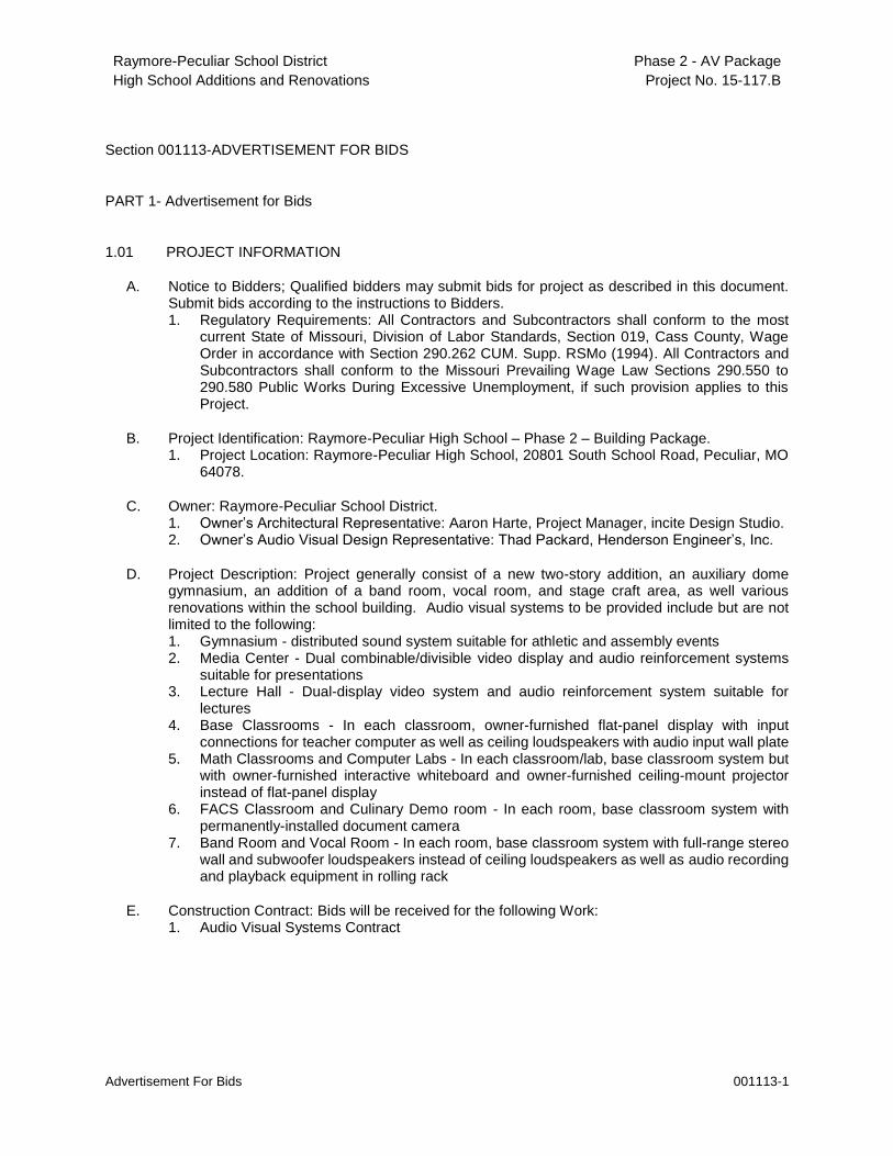
Raymore-Peculiar School District
High School Additions and Renovations
Phase 2 - AV Package
Project No. 15-117.B
Advertisement For Bids 001113-1
Section 001113-ADVERTISEMENT FOR BIDS
PART 1- Advertisement for Bids
1.01 PROJECT INFORMATION
A. Notice to Bidders; Qualified bidders may submit bids for project as described in this document. Submit bids according to the instructions to Bidders. 1. Regulatory Requirements: All Contractors and Subcontractors shall conform to the most
current State of Missouri, Division of Labor Standards, Section 019, Cass County, Wage Order in accordance with Section 290.262 CUM. Supp. RSMo (1994). All Contractors and Subcontractors shall conform to the Missouri Prevailing Wage Law Sections 290.550 to 290.580 Public Works During Excessive Unemployment, if such provision applies to this Project.
B. Project Identification: Raymore-Peculiar High School – Phase 2 – Building Package. 1. Project Location: Raymore-Peculiar High School, 20801 South School Road, Peculiar, MO
64078.
C. Owner: Raymore-Peculiar School District. 1. Owner’s Architectural Representative: Aaron Harte, Project Manager, incite Design Studio. 2. Owner’s Audio Visual Design Representative: Thad Packard, Henderson Engineer’s, Inc.
D. Project Description: Project generally consist of a new two-story addition, an auxiliary dome gymnasium, an addition of a band room, vocal room, and stage craft area, as well various renovations within the school building. Audio visual systems to be provided include but are not limited to the following: 1. Gymnasium - distributed sound system suitable for athletic and assembly events 2. Media Center - Dual combinable/divisible video display and audio reinforcement systems
suitable for presentations 3. Lecture Hall - Dual-display video system and audio reinforcement system suitable for
lectures 4. Base Classrooms - In each classroom, owner-furnished flat-panel display with input
connections for teacher computer as well as ceiling loudspeakers with audio input wall plate 5. Math Classrooms and Computer Labs - In each classroom/lab, base classroom system but
with owner-furnished interactive whiteboard and owner-furnished ceiling-mount projector instead of flat-panel display
6. FACS Classroom and Culinary Demo room - In each room, base classroom system with permanently-installed document camera
7. Band Room and Vocal Room - In each room, base classroom system with full-range stereo wall and subwoofer loudspeakers instead of ceiling loudspeakers as well as audio recording and playback equipment in rolling rack
E. Construction Contract: Bids will be received for the following Work: 1. Audio Visual Systems Contract
Raymore-Peculiar School District
High School Additions and Renovations
Phase 2 - AV Package
Project No. 15-117.B
Advertisement For Bids 001113-2
1.02 BID SUBMITTAL AND OPENING
A. Owner will receive sealed lump sum bids until the bid time and date at the location given below. Owner will consider bids prepared in compliance with the Instructions to Bidders issued by Owner, and delivered as follows: 1. Bid Date: August 11th, 2016 2. Bid Time: 2:00 p.m. local time. 3. Location: RPSD Administrative Services Center, 21005 South School Road, Peculiar, MO
64078.
B. Bids will be thereafter publicly opened and read aloud.
1.03 BID SECURITY
A. Bid Security shall be submitted with each bid in the amount of 5 percent of the bid amount. No bids may be withdrawn for a period of 60 days after opening of bids. Owner reserves the right to reject any and all bids and to waive informalities and irregularities.
1.04 SELF-GUIDED FACILITY TOURS
A. There will be opportunity to visit the Facility for Self-Guided Tours at the Job-Site located at 21008 South School Road, Peculiar, MO 64078 on August 2nd, 2016 at 10:00 am., local time.
1.05 DOCUMENTS
A. Online Procurement and Contracting Documents: Drawings and Specifications can be found at http://www.raypec.k12.mo.us/bids.aspx.
1.06 TIME OF COMPLETION AND LIQUIDATED DAMAGES
A. Successful bidder shall begin the Work on receipt of the Notice of Proceed and shall complete the Work within the Contract Time. Work is subject to liquidated damages.
1.07 BIDDER’S QUALIFICATIONS
A Bidders must be properly licensed under the laws governing their respective trades and be able obtain insurance and bonds required for the Work. A Performance Bond, separate Labor and Material Payment Bond, and Insurance in a form acceptable to Owner will be required of the successful Bidder.
END OF SECTION 001113

Raymore-Peculiar School District iDS #15-117.B High School Additions and Renovations Phase 2 - AV Package
LIST OF DRAWING SHEETS 000115 - 1/1
DOCUMENT 000115 - LIST OF DRAWING SHEETS
1.01 LIST OF DRAWINGS
A. Drawings: Drawings consist of the Contract Drawings and other drawings listed on the Table of Contents page of the separately bound drawing set titled Phase 2 – AV Package, dated July 22, 2016, as modified by subsequent Addenda and Contract modifications.
END OF DOCUMENT 000115
Raymore-Peculiar School District iDS #15-117.B High School Additions and Renovations Phase 2 - AV Package
PROJECT TITLE PAGE 000101 - 1/1
DOCUMENT 000101 - PROJECT TITLE PAGE
1.01 PROJECT MANUAL
A. Raymore-Peculiar School District High School Additions and Renovations.
B. 20801 South School Road, Peculiar, MO
C. Raymore-Peculiar School District.
D. Architect Project No. 15-117.B – AV Package
E. Incite Design Studio, LLC.
F. 110 W 18th Street
G. Kansas City, MO 64108
H. Phone: 816-979-3500.
I. Copyright (2016 incite Design Studio, LLC). All rights reserved.
END OF DOCUMENT 000101
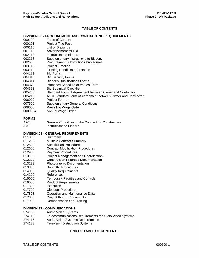
Raymore-Peculiar School District iDS #15-117.B High School Additions and Renovations Phase 2 - AV Package
TABLE OF CONTENTS 000100-1
TABLE OF CONTENTS
DIVISION 00 - PROCUREMENT AND CONTRACTING REQUIREMENTS 000100 Table of Contents 000101 Project Title Page 000115 List of Drawings 001113 Advertisement for Bid 002113 Instructions to Bidders 002213 Supplementary Instructions to Bidders 002600 Procurement Substitutions Procedures 003113 Project Timeline 003119 Existing Condition Information 004113 Bid Form 004313 Bid Security Forms 004314 Bidder’s Qualifications Forms 004373 Proposed Schedule of Values Form 004393 Bid Submittal Checklist 005200 Standard Form of Agreement between Owner and Contractor 005210 A101 Standard Form of Agreement between Owner and Contractor 006000 Project Forms 007500 Supplementary General Conditions 008000 Prevailing Wage Order 008000a Annual Wage Order FORMS A201 General Conditions of the Contract for Construction A701 Instructions to Bidders DIVISION 01 - GENERAL REQUIREMENTS 011000 Summary 011200 Multiple Contract Summary 012500 Substitution Procedures 012600 Contract Modification Procedures 012900 Payment Procedures 013100 Project Management and Coordination 013200 Construction Progress Documentation 013233 Photographic Documentation 013300 Submittal Procedures 014000 Quality Requirements 014200 References 015000 Temporary Facilities and Controls 016000 Product Requirements 017300 Execution 017700 Closeout Procedures 017823 Operation and Maintenance Data 017839 Project Record Documents 017900 Demonstration and Training DIVISION 27 - COMMUNICATIONS 274100 Audio Video Systems 274110 Telecommunications Requirements for Audio Video Systems 274116 Audio Video Systems Requirements 274133 Television Distribution Systems END OF TABLE OF CONTENTS