
radar bullet seminar report - baixardoc
10
Landmine Detection using RADAR BULLET 2014-2015 CHAPTER 1 INTRODUCTION Radar bullet is a relatively new discovery that was invented in the US. It was developed by International Research Centre for Telecommunications-Transmission and RADAR (IRCTR). It is used for detecting land mines. And this discovery finds a very important prospect as about 139 countries signed a treaty in favor of banning anti- personal mines. This treaty was signed during the second week of March 1999 in Ottawa Canada. Anti -personal mines claims seventy new victims every day. This weapon is particularly cruel on children whose bodies being smaller and closer to the blast. Are more likely to sustain serious injury. The severe disabilities and psychological trauma that follow the blast mean these children will have to be looked after for many year. A child injured at the age of ten will need about 25 artificial limbs during their life time. The cost is at 3000, a huge sum to pay in countries where people earn as little as $10 a month between 1979 and 19960, the red cross fitted over 70,000 amputees with artificial limbs. And the landmines problem is still growing. Therefore considering these factors the discovery of radar bullet is really a big boost to our world as we launches into the 21' t century. The countries known to have severe landmine problems are Afghanistan, Bosnia, Cambodia, Ethiopia, Vietnam, Iraq, Kuwait, Laos, Egypt, Eritrea, Chevalier, China. Unfortunately India, Pakistan, Srilanka, Myanmar are in the list of less mine affected countries besides other 100 countries. Dept of ECE, VIT Page 1
-
Upload
khangminh22 -
Category
Documents
-
view
1 -
download
0
Transcript of radar bullet seminar report - baixardoc
Landmine Detection using RADAR BULLET2014-2015
CHAPTER 1
INTRODUCTION
Radar bullet is a relatively new discovery that was invented in the US. It was
developed by International Research Centre for Telecommunications-Transmission and
RADAR (IRCTR). It is used for detecting land mines. And this discovery finds a very
important prospect as about 139 countries signed a treaty in favor of banning anti-
personal mines. This treaty was signed during the second week of March 1999 in
Ottawa Canada.
Anti -personal mines claims seventy new victims every day. This weapon is
particularly cruel on children whose bodies being smaller and closer to the blast. Are
more likely to sustain serious injury. The severe disabilities and psychological trauma
that follow the blast mean these children will have to be looked after for many year.
A child injured at the age of ten will need about 25 artificial limbs during their
life time. The cost is at 3000, a huge sum to pay in countries where people earn as little
as $10 a month between 1979 and 19960, the red cross fitted over 70,000 amputees with
artificial limbs. And the landmines problem is still growing. Therefore considering these
factors the discovery of radar bullet is really a big boost to our world as we launches
into the 21't century.
The countries known to have severe landmine problems are Afghanistan,
Bosnia, Cambodia, Ethiopia, Vietnam, Iraq, Kuwait, Laos, Egypt, Eritrea, Chevalier,
China. Unfortunately India, Pakistan, Srilanka, Myanmar are in the list of less mine
affected countries besides other 100 countries.
Dept of ECE, VIT Page 1
Landmine Detection using RADAR BULLET2014-2015
CHAPTER 2
LAND MINE
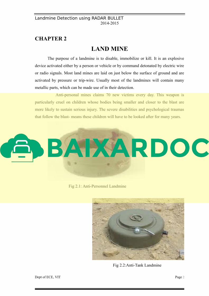
The purpose of a landmine is to disable, immobilize or kill. It is an explosive
device activated either by a person or vehicle or by command detonated by electric wire
or radio signals. Most land mines are laid on just below the surface of ground and are
activated by pressure or trip-wire. Usually most of the landmines will contain many
metallic parts, which can be made use of in their detection.
Anti-personal mines claims 70 new victims every day. This weapon is
particularly cruel on children whose bodies being smaller and closer to the blast are
more likely to sustain serious injury. The severe disabilities and psychological traumas
that follow the blast- means these children will have to be looked after for many years.
Fig 2.1: Anti-Personnel Landmine
Fig 2.2:Anti-Tank Landmine
Dept of ECE, VIT Page 2

Landmine Detection using RADAR BULLET2014-2015
Landmines In this discussion we deal with buried anti-tank (AT) and anti-
personnel (AP) landmines which require close approach or contact to activate. AT mines
range from about 15 to 35 cm in size. They are typically buried up to 40cm deep, but
they can also be deployed on the surface of a road to block a column of machinery. AP
mines range from about 5 to 15cm in size. AT mines which are designed to impede the
progress of destroy vehicles and AP mines which are designed to kill and maim people
A child injured at the age of 10 will need about 25 critical limbs during there life
time. This cost in 3000 Dollars a huge sum to pay in countries where people earn as
little as 10 dollar a month. . Between 1979 of 1996 the red crores fitted over 70,000
Amputees with critical limbs and the land mine problem in still growing. There for
considering these factors the discovery of radar bullet is really a big boost to our world
as we launches to 21st century.
Dept of ECE, VIT Page 3

Landmine Detection using RADAR BULLET2014-2015
CHAPTER 3
PRINCIPLES USED TO DETECT LANDMINES
1. Metal detection
2. Explosive detection
3.1. Metal Detection
Essentially the two most common components of landmines are metals and
explosives. Manufactured mines have casting made from a variety of materials
including wood, metals, Plastic metal or other synthetic materials. From the detection
standpoint, metal is the easier component to detect.
Fig 3.1: Metal Detection
Metal detectors (commonly referred to as mine detectors) are now capable of
signaling the presence of minute piece of metal. However some mines are metal free on
certain virtually non-metal. These non-metals challenge the capacity of current metal
detectors.
4.2. Explosive Detection
The explosives are one common ingredient that is found in all mines. Detecting
explosives however is a complicated process. Modem airports have explosive detecters,
which can detect small traces of explosives in suitcases and other containers. Locating
traces or the order of explosives is an open field demands technology that can operate in
Dept of ECE, VIT Page 4

Landmine Detection using RADAR BULLET2014-2015
an unlimited variety of environmental conditions that are subjected to wind, water and
soil changes and variations.
Explosive detection under field conditions has recently become the preview of
mine detection dogs. A dog’s nose has proven to be a very sophisticated and reliable
sensor, however handling maid detection dog teams and ensuring consistent behaviour
in varied hazard scenarios is a complicated and demanding tasks.
Fig 3.2: Explosive Detection
In all the above said methods mine detection in conducted in close proximity.
That is detection is conducted after going very near to the mine. This method can prove
to be dangerous in many occations. So it is not considered to be the safest method. A
preferred method is to use detection devices that locate land mines at a safe distance
from the deminer. Using detection devices that pinpoint land mines exploded from a
distance either overhead on at ground level in the best possible way to determine the
actual location of individual land mines. Ones the threat is located, that is mines are pin
pointed, we can deactivate it safely. This is where the importance of mine detection
using radar bullet comes.
Dept of ECE, VIT Page 5

Landmine Detection using RADAR BULLET2014-2015
CHAPTER 4
RADAR BULLET
The radar bullet is a special type of bullet. The main use of radar bullet is to find
landmines without setting foot on the ground. This consists of firing a special bullet in
to the ground from a helicopter, which could pin point buried land mines.
The bullet units a radar pulse as it grounds to a halt. This pulse strikes the mine
and its image gets available on the computer in the helicopter, offering a safe and
efficient way of finding land mines. Landmines In this discussion we deal with buried
anti-tank (AT) and anti-personnel (AP) landmines which require close approach or
contact to activate. AT mines range from about 15 to 35 cm in size. They are typically
buried up to 40cm deep, but they can also be deployed on the surface of a road to block
a column of machinery. AP mines range from about 5 to 15cm in size. AT mines which
are designed to impede the progress of destroy vehicles and AP mines which are
designed to kill and maim people.
Inside the bullet is a metal cylinder, surrounded by a tightly wounded coin of
wire. As the bullet leaves the gun, there is a battery generating a magnetic field in the
cylinder.
Battery bullet casing
Metallic cylinder
Fig 4: Radar Bullet
Dept of ECE, VIT Page 6

Landmine Detection using RADAR BULLET2014-2015
CHAPTER 5
RADAR PRINCIPLE
Radar is Radio detection and ranging. Radar is a sensor. Radar makes use of
radio waves to detect and locate objects. The purpose is to provide estimates of certain
characteristics of its surroundings most commonly the presence, position and motion of
aircrafts, ships and other vehicles.
Radar operates by transmitting electro magnetic energy into the surroundings
and detecting energy reflected by object. If a narrow beam of this energy is transmitted
by the directive antenna, the direction from which reflections come and hence the
bearing of object may be estimated. .The distance to the reflecting object in estimated
by measuring the period between the transmission of radar pulse and reception of echo.
In radar bullet principle the change of medium by the waves must be taken into
consideration.
Fig 5: Principle of RADAR
Radars have generally from principal parts, the transmitter antenna receiver, and
display. The transmitter will transmit an electro magnetic signal through the antenna,
Dept of ECE, VIT Page 7
Landmine Detection using RADAR BULLET2014-2015
which will hit the target and reflects back. The same antenna and the time difference
between the signal transmission and reception is calculated, which will help up to
measure the distance of the target from the radar.
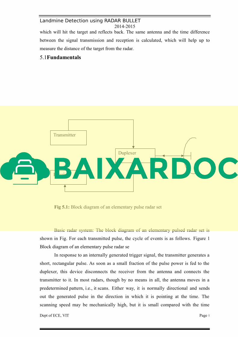
5.1Fundamentals
Fig 5.1: Block diagram of an elementary pulse radar set
Basic radar system: The block diagram of an elementary pulsed radar set is
shown in Fig. For each transmitted pulse, the cycle of events is as follows. Figure 1
Block diagram of an elementary pulse radar se
In response to an internally generated trigger signal, the transmitter generates a
short, rectangular pulse. As soon as a small fraction of the pulse power is fed to the
duplexer, this device disconnects the receiver from the antenna and connects the
transmitter to it. In most radars, though by no means in all, the antenna moves in a
predetermined pattern, i.e., it scans. Either way, it is normally directional and sends
out the generated pulse in the direction in which it is pointing at the time. The
scanning speed may be mechanically high, but it is small compared with the time
Dept of ECE, VIT Page 8
Transmitter
Receiver
Duplexer

Landmine Detection using RADAR BULLET2014-2015
taken by pulses to return from a normal range of targets. Thus, when such echoes are
received, the antenna still points in the right direction to collect them.
As soon as the transmitted pulse terminates, the duplexer disconnects the
transmitter from the antenna. The duplexer also reconnects the receiver to the antenna,
allowing the returning echoes to be correctly processed. The received pulses are
amplified and demodulated by the receiver. The pulses from the returning echoes (and
noise, of course) are then fed to the device on which they are to be displayed, as will
be described. The cycle is complete, and the set is once again ready for the
transmission of the next pulse and the succeeding ones, while the antenna scans along
its predetermined path
The radar set is able to show the position of the target, because information
about the azimuth (horizontal direction) and the elevation (vertical direction) of the
antenna is available. In addition, the distance to the target may transmitter output
tubes, and the first stage of the receiver is often a diode mixer. The antenna generally
uses a parabolic reflector of some form, as will be mentioned in Sec.
Development of radar from its inception, radar has used a system of sending
short, powerful pulses of radio energy and then analyzing the returned echoes to
determine the position, distance and possibly velocity of the target. However, the
methods of doing so have evolved and become far more refined and sophisticated as
time has gone by. The primary incentive as in so many other things was the imminence
of war. Radar was made possible by a technology, which, at the time war broke out, was
just beginning to show promise. This technology itself took great strides forward to
meet the new challenges imposed by war.
The first radars worked at much lower frequencies than present systems (as loq
as 60MHz for the original British coastal air-warning radar because of a lack of
sufficiently powerful transmitting tubes at higher frequencies. This was changed in 1940
with the appearance of the cavity magnetron, and the stage was then set for the
development of modern radar. As can be appreciated, one of the prime requirements of a
radar system is that it should have a fair degree of accuracy in its indication of target
direction. This is possible only if the antennas used are narrow beam ones, i.e., have
dimensions of several wavelengths. That requirement cannot be fulfilled satisfactorily
unless the wavelengths themselves are fairly short, corresponding to the upper UHF or
microwave frequencies.
Dept of ECE, VIT Page 9
Landmine Detection using RADAR BULLET2014-2015
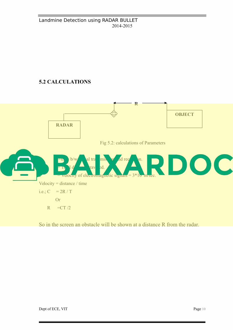
5.2 CALCULATIONS
Fig 5.2: calculations of Parameters
T =time b/w signal transmission and reception.
2R = Total distance traveled.
c = Velocity of electromagnetic signals = 3*108 m/sec.
Velocity = distance / time
i.e.; C = 2R / T
Or
R =CT /2
So in the screen an obstacle will be shown at a distance R from the radar.
Dept of ECE, VIT Page 10
OBJECT
RADAR
R