
R718IJK Wireless Multi-Sensor Interface for 0-24V ADC, Dry ...
13
Model:R718IJK Wireless Multi-Sensor Interface for 0-24V ADC, Dry Contact and 4-20mA Sensors Wireless Multi-Sensor Interface for 0-24V ADC, Dry Contact and 4-20mA Sensors R718IJK User Manual Copyright©Netvox Technology Co., Ltd. This document contains proprietary technical information which is the property of NETVOX Technology. It shall be maintained in strict confidence and shall not be disclosed to other parties, in whole or in part, without written permission of NETVOX Technology. The specifications are subject to change without prior notice.
-
Upload
khangminh22 -
Category
Documents
-
view
2 -
download
0
Transcript of R718IJK Wireless Multi-Sensor Interface for 0-24V ADC, Dry ...

Model:R718IJK
Wireless Multi-Sensor Interface for 0-24V ADC, Dry Contact and 4-20mA Sensors
Wireless Multi-Sensor Interface for
0-24V ADC, Dry Contact and 4-20mA
Sensors
R718IJK
User Manual
Copyright©Netvox Technology Co., Ltd.
This document contains proprietary technical information which is the property of NETVOX Technology. It shall be maintained in strict
confidence and shall not be disclosed to other parties, in whole or in part, without written permission of NETVOX Technology. The
specifications are subject to change without prior notice.

1
Table of Content 1. Introduction ....................................................................................................................................................................... 2
2. Appearance ........................................................................................................................................................................ 2
3. Main Feature ...................................................................................................................................................................... 3
4. Set Up Instruction .............................................................................................................................................................. 4
5. Data Report ........................................................................................................................................................................ 5
6. Installation ......................................................................................................................................................................... 8
7. Information about Battery Passivation ............................................................................................................................ 11
7.1 To determine whether a battery requires activation ................................................................................................. 11
7.2 How to activate the battery ...................................................................................................................................... 11
8. Important Maintenance Instruction ................................................................................................................................. 12

2
1. Introduction R718IJK is a multi interface detection device that is a Class A device based on the LoRaWAN open protocol and is compatible with the
LoRaWAN protocol. The device is suitable for detecting 4mA to 20mA current, 0V to 24V voltage, and dry contact detection.
R718IJK is compatible with LoRaWAN protocol.
LoRa Wireless Technology:
LoRa is a wireless communication technology famous for its long-distance transmission and low power consumption. Compared with
other communication methods, LoRa spread spectrum modulation technique greatly extend the communication distance. It can be widely
used in any use case that requires long-distance and low-data wireless communications. For example, automatic meter reading, building
automation equipment, wireless security systems, industrial monitoring. It has features like small size, low power consumption, long
transmission distance, strong anti-interference ability and so on.
LoRaWAN:
LoRaWAN uses LoRa technology to define end-to-end standard specifications to ensure interoperability between devices and gateways
from different manufacturers.
2. Appearance

3
3. Main Feature
Adopt SX1276 wireless communication module
2 sections of ER14505 battery in parallel (AA SIZE 3.6V / section)
0V to 24V voltage detection
4mA to 20mA current detection
Dry contact detection
Protection level IP65/ IP67 (optional)
Compatible with LoRaWANTM Class A
Frequency hopping spread spectrum
Configuring parameters and reading data via third-party software platforms, and set alarms via SMS text and email (optional)
Applicable to third-party platforms: Actility/ThingPark, TTN, MyDevices/Cayenne
Low power consumption and long battery life
Battery Life:
⁻ Please refer to web: http://www.netvox.com.tw/electric/electric_calc.html
⁻ At this website, users can find battery life time for variety models at different configurations.
1. Actual range may vary depending on environment.
2. Battery life is determined by sensor reporting frequency and other variables.

4
4.Set Up Instruction
On/Off
Power on Insert batteries (user may need a screwdriver to open)
Turn on Press and hold the function key for 3 seconds till the green indicator flashes once
Turn off (Restore to factory setting) Press and hold the function key for 5 seconds till green indicator flashes 20 times
Power off Remove Batteries
Note
1. Remove and insert the battery, and the device is in turn-off state by default
2. On/off interval is suggested to be about 10 seconds to avoid the interference of capacitor
inductance and other energy storage components
3. In the first 5 seconds after power on, the device is in engineering test mode
Network Joining
Never join the network
Turn on the device to search the network.
The green indicator stays on for 5 seconds: success
The green indicator remains off: fail
Had joined the network
(Not restore to the factory setting)
Turn on the device to search the previous network.
The green indicator stays on for 5 seconds: success
The green indicator remains off: fail
Fail to Join the Network Suggest to check the device verification information on the gateway or consult your platform
server provider.
Function Key
Press and hold for 5 seconds
Restore to factory setting / Turn off
The green indicator flashes 20 times: success
The green indicator remains off: fail
Press once The device is in the network: green indicator flashes once and sends a report
The device is not in the network: green indicator remains off
Sleeping Mode
The device is on and in the
network
Sleeping period: Min Interval
When the reportchange exceeds setting value or the state changes, the device send a data
report according to Min Interval.
Low Voltage Warning
Low Voltage 3.2V

5
The device will immediately send a version packet report and the data of attribute report.
The device sends data according to the default configuration before any other configuring.
Default Setting:
MaxTime: Max Interval = 15 min = 900s
MinTime: Max Interval = 15 min = 900s (By default, the current voltage is detected every Min Interval.)
BatteryVoltageChange = 0x01 (0.1v)
ADC Raw Value Change = 0x64 (100 mV) // configuration need to greater than 0x50 (80 mV)
Current Change ---- 0x02 (2 mA)
Note:
1. The cycle of the device sending the data report is according to the default.
2. The interval between two reports must be the MinTime.
3. If there are special customized shipments, the setting will be changed according to customer’s requirements.)
Please refer Netvox LoRaWAN Application Command document and Netvox Lora Command Resolver
http://www.netvox.com.cn:8888/page/index to resolve uplink data.
5. Data Report
Data report configuration and sending period are as following:
Min Interval
(Unit: second)
Max Interval
(Unit: second) Reportable Change
Current Change≥
Reportable Change
Current Change<
Reportable Change
Any number between
1~65535
Any number between
1~65535 Can not be 0
Report
per Min Interval
Report
per Max Interval

6
Example of ConfigureCmd
(1) Configure R718IJK device parameter
MinTime = 1min, MaxTime = 1min, BatteryChange = 0.1v, ADC Raw Value Change=100mV, Current Change =2mA
Downlink: 015C003C003C0100640200
Device Return:
815C000000000000000000 (configuration success)
815C010000000000000000 (configuration failure)
(2) Read R718IJK device parameter
Downlink: 025C000000000000000000
Device Return: 825C003C003C0100640200 (device current parameter)
Example for MinTime/MaxTime logic:
Example#1 based on MinTime = 1 Hour, MaxTime= 1 Hour, Reportable Change i.e. BatteryVoltageChange=0.1V MaxTime MaxTime Sleeping(MinTime) Sleeping(MinTime)
Note: MaxTime=MinTime. Data will only be report according to MaxTime (MinTime) duration regardless BatteryVoltageChange value.
Description Device Cmd ID
Device Type NetvoxPayLoadData
Config ReportReq
R718IJK
0x01
0x5C
MinTime (2bytes Unit: s)
MaxTime (2bytes Unit: s)
BatteryChange (1byte Unit:0.1v)
ADCRawValue Change
(2byte Unit: 1mV)
CurrentChange (1byte Unit:
1mA)
Reserved (4Bytes,
Fixed0x00)
Config ReportRsp 0x81 Status
(0x00_success) Reserved
(8Bytes, Fixed 0x00)
ReadConfigReportReq 0x02 Reserved
(9Bytes, Fixed 0x00)
ReadConfigReportRsp 0x82 MinTime
(2bytes Unit: s) MaxTime
(2bytes Unit: s)
BatteryChange (1byte
Unit: 0.1v)
ADCRawValue Change
(2byte Unit: 1mV)
CurrentChange (1byte Unit:
1mA)
Reserved (4Bytes, Fixed
0x00)
Wake up and collects data REPORTS 3.6V
Wakes up and collects data REPORTS 3.6V
Wakes up and collects data REPORTS 3.6V
7
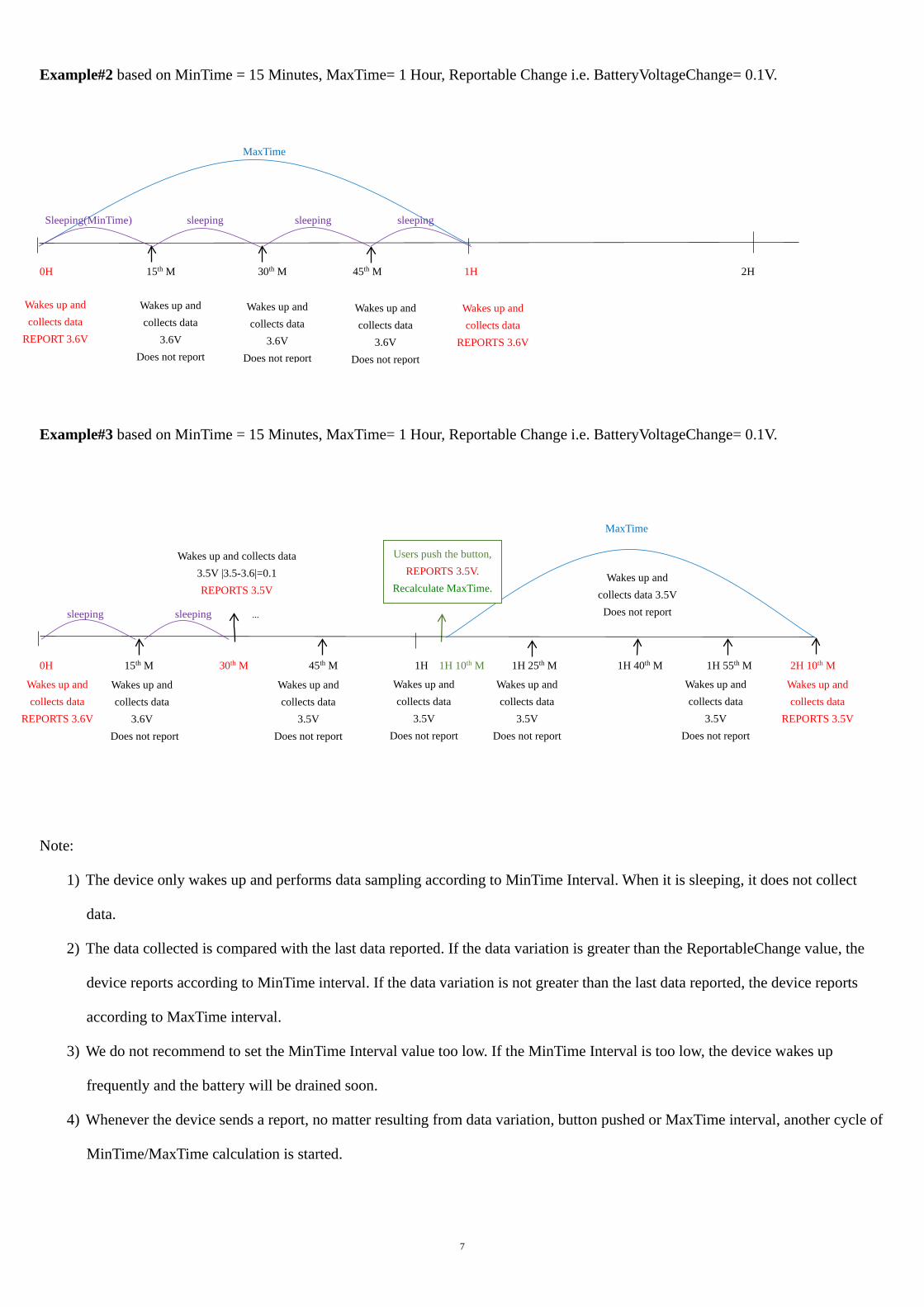
Example#2 based on MinTime = 15 Minutes, MaxTime= 1 Hour, Reportable Change i.e. BatteryVoltageChange= 0.1V. MaxTime
Sleeping(MinTime) sleeping sleeping sleeping 0H 15th M 30th M 45th M 1H 2H
Example#3 based on MinTime = 15 Minutes, MaxTime= 1 Hour, Reportable Change i.e. BatteryVoltageChange= 0.1V.
MaxTime sleeping sleeping ... 0H 15th M 30th M 45th M 1H 1H 10th M 1H 25th M 1H 40th M 1H 55th M 2H 10th M
Note:
1) The device only wakes up and performs data sampling according to MinTime Interval. When it is sleeping, it does not collect
data.
2) The data collected is compared with the last data reported. If the data variation is greater than the ReportableChange value, the
device reports according to MinTime interval. If the data variation is not greater than the last data reported, the device reports
according to MaxTime interval.
3) We do not recommend to set the MinTime Interval value too low. If the MinTime Interval is too low, the device wakes up
frequently and the battery will be drained soon.
4) Whenever the device sends a report, no matter resulting from data variation, button pushed or MaxTime interval, another cycle of
MinTime/MaxTime calculation is started.
Wakes up and collects data
3.6V Does not report
Wakes up and collects data
3.6V Does not report
Wakes up and collects data
3.6V Does not report
Wakes up and collects data
REPORTS 3.6V
Wakes up and collects data
REPORT 3.6V
Wakes up and collects data
REPORTS 3.6V
Wakes up and collects data 3.5V |3.5-3.6|=0.1 REPORTS 3.5V
Wakes up and collects data
3.5V Does not report
Wakes up and collects data
3.5V Does not report
Wakes up and collects data
3.5V Does not report
Wakes up and collects data 3.5V Does not report
Wakes up and collects data
3.5V Does not report
Wakes up and collects data
REPORTS 3.5V
Wakes up and collects data
3.6V Does not report
Users push the button, REPORTS 3.5V.
Recalculate MaxTime.
8
6. Installation
The dry contact function of R718IJK can be used in the
following scenarios:
Various switches and buttons
Dry contact output of sensor
The operating status of the equipment
Door and window condition monitoring for home or business
The occasion is necessary to judge the sensor state by dry
contact signal.
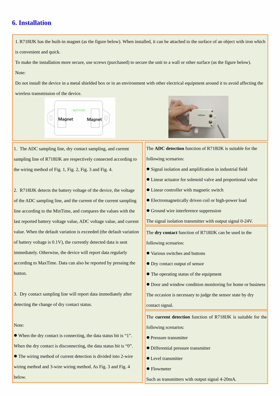
1. R718IJK has the built-in magnet (as the figure below). When installed, it can be attached to the surface of an object with iron which
is convenient and quick.
To make the installation more secure, use screws (purchased) to secure the unit to a wall or other surface (as the figure below).
Note:
Do not install the device in a metal shielded box or in an environment with other electrical equipment around it to avoid affecting the
wireless transmission of the device.
The ADC detection function of R718IJK is suitable for the
following scenarios:
Signal isolation and amplification in industrial field
Linear actuator for solenoid valve and proportional valve
Linear controller with magnetic switch
Electromagnetically driven coil or high-power load
Ground wire interference suppression
The signal isolation transmitter with output signal 0-24V.
The current detection function of R718IJK is suitable for the
following scenarios:
Pressure transmitter
Differential pressure transmitter
Level transmitter
Flowmeter
Such as transmitters with output signal 4-20mA.
1. The ADC sampling line, dry contact sampling, and current
sampling line of R718IJK are respectively connected according to
the wiring method of Fig. 1, Fig. 2, Fig. 3 and Fig. 4.
2. R718IJK detects the battery voltage of the device, the voltage
of the ADC sampling line, and the current of the current sampling
line according to the MinTime, and compares the values with the
last reported battery voltage value, ADC voltage value, and current
value. When the default variation is exceeded (the default variation
of battery voltage is 0.1V), the currently detected data is sent
immediately. Otherwise, the device will report data regularly
according to MaxTime. Data can also be reported by pressing the
button.
3. Dry contact sampling line will report data immediately after
detecting the change of dry contact status.
Note:
When the dry contact is connecting, the data status bit is “1”.
When the dry contact is disconnecting, the data status bit is “0”.
The wiring method of current detection is divided into 2-wire
wiring method and 3-wire wiring method. As Fig. 3 and Fig. 4
below.

9
Fig. 1. ADC (0-24V) Detection Wiring Diagram
Fig. 2. Dry Contact Wiring Diagram
Wired Smoke Sensor
(4mA-20mA) Current Detection
Dry Contact
External
Power
Supply
High Current
Output Signal
Isolation Module ADC (0-24V)
R718IJK
R718IJK
Dry Contact
ADC (0-24V)
Current Detection (4mA-20mA)

10
Fig. 3. Current Detection 2-Wire Wiring Diagram
Fig. 4. Current Detection 3-Wire Wiring Diagram
R718IJK
R718IJK
Current Detection
(4mA-20mA)
ADC (0-24V)
ADC (0-24V)
Current Detection (4mA-20mA)
Dry Contact
Dry Contact
External
Power
Supply
DC 24V
Connect to Positive Pole of the Transmitter
4-20mA Signal
Pressure Transmitter
Connect to Transmitter Signal Port
External
Power
Supply
DC 24V
Pressure Transmitter
4-20mA Signal
Connect to Positive Pole of the Transmitter
GND
Connect to Transmitter Signal Port

11
Note:
Please do not disassemble the device unless it is required to replace the batteries.
Do not touch the waterproof gasket, LED indicator light, function keys when replacing the batteries. Please use suitable screwdriver to
tighten the screws (if using an electric screwdriver, it is recommended to set the torque as 4kgf) to ensure the device is impermeable.
7. Information about Battery Passivation
Many of Netvox devices are powered by 3.6V ER14505 Li-SOCl2 (lithium-thionyl chloride) batteries that offer many advantages
including low self-discharge rate and high energy density.
However, primary lithium batteries like Li-SOCl2 batteries will form a passivation layer as a reaction between the lithium anode and
thionyl chloride if they are in storage for a long time or if the storage temperature is too high. This lithium chloride layer prevents
rapid self-discharge caused by continuous reaction between lithium and thionyl chloride, but battery passivation may also lead to
voltage delay when the batteries are put into operation, and our devices may not work correctly in this situation.
As a result, please make sure to source batteries from reliable vendors, and the batteries should be produced within the last three
months.
If encountering the situation of battery passivation, users can activate the battery to eliminate the battery hysteresis.
7.1 To determine whether a battery requires activation
Connect a new ER14505 battery to a 68ohm resistor in parallel, and check the voltage of the circuit.
If the voltage is below 3.3V, it means the battery requires activation.
7.2 How to activate the battery
a. Connect a battery to a 68ohm resistor in parallel
b. Keep the connection for 6~8 minutes
c. The voltage of the circuit should be ≧3.3V

12
8. Important Maintenance Instruction
Kindly pay attention to the following in order to achieve the best maintenance of the product:
• Keep the equipment dry. Rain, moisture and various liquids or water may contain
minerals that can corrode electronic circuits. In case the device is wet, please dry it completely.
• Do not use or store in dusty or dirty areas. This way can damage its detachable parts and electronic components.
• Do not store in excessive heat place. High temperatures can shorten the life of
electronic devices, destroy batteries, and deform or melt some plastic parts.
• Do not store in excessive cold place. Otherwise, when the temperature rises to
normal temperature, moisture will form inside which will destroy the board.
• Do not throw, knock or shake the device. Treating equipment roughly can destroy internal circuit boards
and delicate structures.
• Do not wash with strong chemicals, detergents or strong detergents.
• Do not paint the device. Smudges can make debris block detachable parts up and affect normal operation.
• Do not throw the battery into the fire to prevent the battery from exploding. Damaged batteries may also explode.
All the above suggestions apply equally to your device, batteries and accessories.
If any device is not operating properly.
Please take it to the nearest authorized service facility for repairing.