QUICK START GUIDE - Dover Flexo Electronics
20
(603) 332-6150 5 Year Warranty www.dfe.com THE TENSION CONTROL SPECIALISTS Model TA500-EIP EtherNet/IP™ Tension Amplifier QUICK START GUIDE
-
Upload
khangminh22 -
Category
Documents
-
view
0 -
download
0
Transcript of QUICK START GUIDE - Dover Flexo Electronics

(603) 332-6150 5 Year Warranty www.dfe.com
T H E T E N S I O N C O N T R O L S P E C I A L I S T S
Model TA500-EIPEtherNet/IP™ Tension Amplifier
QUICK START GUIDE

Dover Flexo Electronics307 Pickering Road
Rochester, NH 03867- 4630U.S.A.
FOR ASSISTANCE:
TECHNICAL SERVICE - Installations, Start-Up, Troubleshooting, Repairs, Field Service or Returns. Call (603) 332-6150 and ask for Technical Support or email us at: [email protected] CUSTOMER SERVICE - Replacement Parts, Individual Products, Questions about Orders, Manuals. Call (603) 332-6150 and ask for Customer Service or email us at: [email protected]
SALES - Product Information, System Application Questions or Placing Orders, Please e-mail us at: [email protected] or call (603) 332-6150 and ask for Sales.
Telephone: (603) 332-6150 Fax: (603) 332-3758E-mail: [email protected] Internet: www.dfe.com
©2021 Dover Flexo Electronics, Inc. All rights reserved. Dover Flexo Electronics has made reasonable effort to ensure accuracy of this document. However, NO WARRANTY, whether expressed or implied, is given regarding the completeness or correctness of information in this document. Dover Flexo Electronics shall not be liable for damages of any kind arising from the use or misuse of this document. Dover Flexo Electronics reserves the right to make changes, additions, and deletions to this document without notice and without obligation.

SAFETY
This label indicates: “Read the Manual”
Make sure you read and understand all instructions and safety precautions listed in this manual before installing or operating your TA500-EIP Tension Amplifier. If you have any questions concerning the operation of your device or the information in this manual, please contact us.
Email: [email protected]: (603) 332-6150
• Observe all warning labels. • Never remove warning labels.
WARNING: If this equipment is not connected or operated in the manner specified, the operating safety of this unit or of connected equipment cannot be guaranteed.
WARNING: When working with TA500-EIP follow the instructions below and read the manual carefully to protect yourself from injury and the TA500-EIP from damage.
WARNING: Do not open the housing.

WARNING: Protect the TA500-EIP from shocks and vibrations.
WARNING: The TA500-EIP may become warm during normal use. Always allow adequate ventilation around the TA500-EIP and use care when handling.
WARNING: Do not operate the TA500-EIP adjacent to heat sources and do not expose it to unnecessary thermal radiation. Ensure an ambient temperature as specified in the technical data.
DOCUMENT CONVENTIONS NOTES - Highlight important concepts, decisions you must make, or the implications of those decisions.
CAUTIONS - Tell you when equipment may be damaged if the procedure is not followed properly.
WARNINGS - Tell you when people may be injured, or equipment may be damaged if the procedure is not followed properly.
Numbered lists indicate tasks that should be carried out in sequence: 1. First do this 2. Then do this
Bulleted lists are used for: • Tasks that can be carried out in any order • Itemized information

1GENERAL DESCRIPTION
Dimensions:
The TA500-EIP is a Tension Amplifier with Quik-Cal™ push-button zero and calibration. In addition, this tension amplifier provides a tension transducer interface with an Ether-net connection. It can be used with any DFE tension transducer (load cell) to monitor tension in any zone on web or filament processing machinery. This device accepts commands and allows tension monitoring using the EtherNet/IP™ protocol.

2 HARDWARE IDENTIFICATION
Status LEDS
Amplifier Status Information is useful for determining the condition of the tension amplifier and its network and module operational state. Three bi-colored LEDs located on the front of the TA500-EIP provided this information.
Amplifier Status LED
The Amplifier Status LED is a bi-color red/green LED. The state of the LED depends on the state of the amplifier module. Wiring faults and/or overload conditions of transducer loadcells are indicated and can be decoded using the table below. During normal operation, the status LED is showing a solid steady green. The amplifier status information is also available of the data interface.
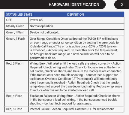
OFF Power off.
Steady Green Normal operation.
Green, 1 Flash Device not calibrated.
Green, 2 Flash Over Range Condition: Once calibrated the TA500-EIP will indicate an over range or under range condition by setting the error code to ‘Outside Cal Range’. The error is active once -20% or 120% tension is exceeded - Action Required: To clear this error the tension must be brought back into range, or a new calibration will need to be performed to do so.
Red, 3 Flash Wiring Error: Will alert until the load cells are wired correctly - Action Required: Check wiring and retry. Check for loose wires at the termi-nal blocks, check for shorts, and be sure the load cells are connected. If the transducers need trouble shooting – contact tech support for assistance. Overload Condition (LT Transducer): Will intermittently alert if overload is reached - Action Required: Check that the tension range does not exceed the transducer load rating. Reduce wrap angle to reduce effective net force exerted on load cell.
Red, 4 Flash Excitation Failure or Wiring Error - Action Required: Check for shorts in the transducer / load cell wiring. If the transducers need trouble shooting – contact tech support for assistance.
Red, 5 Flash Internal Failure - Action Required: Contact DFE for replacement.
STATUS LED STATE DEFINITION
3HARDWARE IDENTIFICATION

OFF Power off.
Steady Green Device in operation.
Flashing Green Standby device, not configured, no IP address assigned.
Flashing Red Major recoverable fault.
Steady Red Major unrecoverable fault, device not operational.
Flashing Green/Red
Self-test at power on.
MS LED STATE DEFINITION
4 HARDWARE IDENTIFICATION
Network Status (NS) LEDThe Network Status LED is a bi-color red/green LED. The state of the LED depends on status of the CIP (Common Industrial Protocol) connection.
Module Status (MS) LEDThe Module Status LED is a bi-color red/green LED. The state of the LED depends on the state of the network adapter module.

5HARDWARE IDENTIFICATION
OFF Power off or no IP address configured.
Flashing Green Device not connected: An IP address is configured, but no CIP connections are established.
Steady Green Device connected: An IP address is configured, at least one CIP connection is established.
Steady Red Error: The device has detected that its IP address is already in use.
Flashing Red One or more connections timed out (CIP Class 1 or 3)
Flashing Green/Red
Self-test at power on.
NS LED STATE DEFINITION

6 INITIAL UNBOXING AND MOUNTING
The unit is DIN rail mountable, compatible with 35mm DIN rails. To install snap on to DIN rail. To remove from the DIN rail, use a screwdriver and release the clamp at bottom of the unit as shown below.

7INITIAL UNBOXING AND MOUNTING
TA500 devices shall be vertically mounted and spacing of 1 inch should be allowed between devices. Zero stacking (No clearance between units) is not allowed due to heating consideration. Care should be taken to observe the ambient operation conditions as well as not to subject the unit to adjacent excessive heat sources and/or do not expose it to unnecessary thermal radiation. Ensure an ambient temperature as specified in the technical data for proper operation.
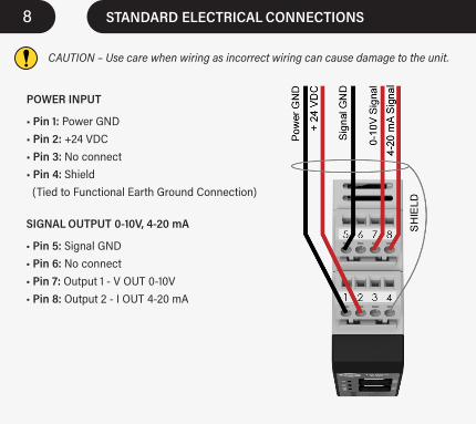
STANDARD ELECTRICAL CONNECTIONS8
POWER INPUT • Pin 1: Power GND• Pin 2: +24 VDC• Pin 3: No connect• Pin 4: Shield (Tied to Functional Earth Ground Connection)
SIGNAL OUTPUT 0-10V, 4-20 mA
• Pin 5: Signal GND• Pin 6: No connect• Pin 7: Output 1 - V OUT 0-10V• Pin 8: Output 2 - I OUT 4-20 mA
CAUTION – Use care when wiring as incorrect wiring can cause damage to the unit.

9STANDARD ELECTRICAL CONNECTIONS
TRANSDUCER LOAD CELL CONNECTIONS
• Pin 9: - SIGNAL• Pin 10: - EXCITATION• Pin 11: + EXCITATION• Pin 12: Shield (Tied to Functional Earth Ground Connection)• Pin 13: + SIGNAL•Pin 14: + EXCITATION• Pin 15: - EXCITATION• Pin 16: Shield (Tied to Functional Earth Ground Connection)

10 STANDARD ELECTRICAL CONNECTIONS
TA500-EIP meets the European Union's Low Voltage Directive and EMC Directive only when installation is done correctly. To meet the EMC Directive, a proper transducer installation, including shielded cables must be used.

11
A functional earth connection is provided to make contact with the DIN rail. Functional earth is a current path of low impedance between current circuits and earth, which is used to increase the interference immunity.
Connect the mounting rail to functional earth potential. Please note that the impedance of the connecting cable has to be kept low.
FUNCTIONAL EARTH CONNECTIONS

12 ETHERNET PORT 1 & 2 CONNECTIONS
Non-DLR Applications:Ethernet connections are made to the Ethernet interface via RJ45 connections. Two ports are available in order to support DLR (Device Level Ring). The TA500-EIP unit has two Ethernet ports with a built-in Ethernet switch connecting the two. In non-DLR applications, either port can be used to attach the unit to the network. The remaining port can be used to extend the network to another device if this would reduce wiring costs.
DLR Applications:In Device Level Ring applications, the TA500-EIP unit functions as a Beacon-Based Ring Node. In these applications, both ports are used when wiring the ring, daisy chaining from one unit in the ring to the next.
Port1 & Port2 Ethernet Interface RJ45 connectors Details:The Ethernet interface capability is 10/100Mbit, full or half duplex operation. Ethernet Cord set is recommended to be CAT-5 cable, shielded (STP). The pinout connection is standard and is provided below for reference.

13CALIBRATION
A calibration process must be performed before your amplifier is ready to indicate tension. The following should already be completed prior to calibration.
• Attach power connection to the unit • Attached the transducer (load cell) connections • Attached the analog signal output connection if used • Attached the ethernet data connection if used • Power the unit • Status indication of the unit should indicate no status errors, however it may indicate that the device is not calibrated or is in an overloaded condition if the device was previously calibrated – see status LEDs The TA500-EIP can be used as an amplifier with or without an EtherNet/IP™ connection established.
There are three methods to calibrate the TA500-EIP
• Traditional Push Button Calibration• Calibration through the web interface• Calibration through the EtherNet/IP™ interface
All three of the above methods require zeroing the amplifier with no weight or load on the transducer load cells. Once zeroed, a calibration weight or load can be applied equal to 10% or 25% of the full range desired.

14 TRADITIONAL PUSH BUTTON CALIBRATION
This calibration process is easy and produces a unitless proportional 2-point calibra-tion. An appropriate calibration weight will need to be selected. The weight deter-mines the value of web tension that will be produced at full output of the TA500-EIP. The TA500-EIP allows calibration to be performed with 10% or 25% of the full range desired.
For example: A 15 lb weight will result in a scaled range of 0-150 lbs of tension if a 10% calibration is performed. Analog output values of tension are always unitless and proportional to tension.
1. ZERO: Ensure nothing is hanging on or pressing on the transducer roll (including the calibration rope). Press the ZERO pushbutton on the unit front panel for at least 1 second. The unit will automatically adjust and store the tension zero value one second after the button is pressed. The unit will rapidly flash the green status LED to indicate the zero has been stored. Release the button. The Output1 will read 0 VDC and Output2 will read 4 mA.
2. CALIBRATE: Hang weight as indicated below. Wait for weight to stop swinging.

15TRADITIONAL PUSH BUTTON CALIBRATION
WEB PAGE INTERFACE CALIBRATIONSee Manual for instructions.
CALIBRATION USING THE EITHERNET/IP™ INTERFACEEDS file can be found on the product web page,
see Manual for instructions.
To calibrate at 10%: Push and Hold the Cal Button (About 1 Second) until confirmation blinks, then release the button. The output will read 10% of full scale after calibration.
To calibrate at 25%: Push and Hold Cal Button (About 5 Seconds) until you see two sets of confirmation blinks. Then release the button. The output will read 25% of full scale after calibration. (If no confirmation blink occurs, inadequate calibration weight may have been used)
After calibration: Remove the weight and observe the output. It should read 0 VDC or 4 mA with nothing touching the tension sensing roller.
Once calibrated, tension data is also available over the network connection, however it should be noted that the calibration performed can be considered unitless and rangeless unless the value in the CalRange Register and the CalUnits register at calibration was valid. In this case the TENSION_P may be the most desirable tension register. See Accessing Tension Data for more information.

Engineered • SupportedMade in the USA
©2021 Dover Flexo Electronics, Inc.All Rights Reserved
0920 Doc 801-2579 R1
307 Pickering Rd, Rochester, NH 03867 USAPhone: (603) 332-6150 • FAX: (603) 332-3758 • Email: [email protected] • Website: www.dfe.com
T H E T E N S I O N C O N T R O L S P E C I A L I S T S
DOVER FLEXO ELECTRONICS, INC.
To view or download the TA500 Instruction Manual go to:
https://dfe.com/products/tension-amplifiers/ta500-eip-tension-amplifier-2/
Please call Technical Support if you need assistance.
E-mail: [email protected]