Bicarbonate-enhanced transformation of phenol upon irradiation of hematite, nitrate, and nitrite

QUANTIFICATION OF HEMATITE AND GOETHITE CONCENTRATIONS IN
KAOLIN USING DIFFUSE REFLECTANCE SPECTROSCOPY:
A NEW APPROACH TO KUBELKA-MUNK THEORY
ITALO GOMES GONCALVES*, CARLOS OTAVIO PETTER, AND JAQUELINE LEPKOSKI MACHADO
Laboratorio de Processamento Mineral, Departamento de Engenharia de Minas, Universidade Federal do Rio Grande do Sul,Porto Alegre, Rio Grande do Sul, Brazil
Abstract—Kaolin ores are usually contaminated by some Fe-bearing minerals, the strong colors of whichdegrade the quality of the final product. A spectroscopic technique is sought to quantify the content ofhematite and goethite, the main contaminant minerals in the kaolin from Capim River in Brazil, was thefocus of this study. The total Fe content obtained through X-ray fluorescence showed a poor correlationwith the brightness of kaolin, due to the inability to differentiate between the Fe contained in the(oxyhydr)oxides and the Fe present in the crystalline structure of kaolinite, especially when the Fe-bearingminerals occur in small quantities. Here, a new generic technique to quantify Fe (oxyhydr)oxides in kaolin,based on the Kubelka-Munk theory, is presented. A new interpretation of the theory was made that enablesits use without the need to measure thin layers of material. The results with synthetic goethite and hematitewere very positive (R2
pred & 0.99) and experiments with contaminants from the mine are already underway.
Key Words—Brightness, Diffuse Reflectance, Goethite, Hematite, Kaolin, Kubelka-Munk Theory.
INTRODUCTION
For most industrial minerals, color is associated
directly with economic value. In terms of physics, the
principal property that defines the term ‘color’ is the
intensity of light reflected (or transmitted) by an object
over the visible band, between 400 and 700 nm. This
reflectance spectrum serves as the starting point for a
variety of color-describing factors, the most common in
the mineral industry being the brightness (TAPPI, 1977,
1986) and the L*a*b* system (HunterLab, 2008).
Quality specifications for mineral products are usually
based on these colorimetric parameters.
This market is becoming more selective and demand-
ing in terms of the quality of raw materials and,
alongside the traditionally controlled characteristics
such as particle-size distribution and chemical composi-
tion, a trend now exists toward the establishment of
increasingly stricter specifications for the optical proper-
ties of these materials. The new trend is occurring
because most operations consuming these industrial
minerals incorporate them into products in which the
visual appearance is controlled. For these operations,
which are mostly manufacturers of plastics, paper,
paints, and ceramics, variations in the color of mineral
materials result in difficulties in achieving the right
color in the final product.
Strict specifications for colorimetric parameters such
as whiteness and yellowness, as well as colorimetric
coordinates such as L*, a*, and b*, are now being set.
For the manufacturer of industrial minerals, the new
specifications translate into problems simply because
many of these parameters are alien to the tradition of the
mining industry.
The main quality parameter in the kaolin industry is
brightness, which is a weighted average of reflectance
values over the range of 400�510 nm (TAPPI, 1977).
Because of the lack of a better property, producers tend
to also use brightness to assess the quality of the in situ
ore and during the processing operations. Unprocessed
kaolin is often accompanied by ‘contaminant’ minerals,
however. For Brazilian kaolins, which are the object of
the present study, the most notable contaminants are
hematite (Fe2O3), goethite (FeOOH), and anatase
(TiO2).
Each of these contaminant minerals has a distinct
color and each behaves differently during processing of
the kaolin ore. Hematite and goethite, in particular, are
particularly strong pigmenting agents and at concentra-
tions as low as 100 ppm they can make the difference
between a high-quality white pigment product for paper
coating and waste material. As each Fe-bearing con-
taminant has a different color and responds differently to
processing operations (e.g. magnetic separation, chemi-
cal bleaching, selective flocculation, and/or flotation in
the case of kaolin), the in situ brightness tends to show a
poor correlation with the brightness of the final product.
Brightness measurements are sometimes complemen-
ted with X-ray fluorescence (XRF) analysis of Fe and Ti,
but the total oxide content provided by XRF is also
poorly correlated with product quality because Fe may
be in the form of goethite or hematite, or found within
the crystalline structure of kaolinite. Thus, a more robust
* E-mail address of corresponding author:
DOI: 10.1346/CCMN.2012.0600504
Clays and Clay Minerals, Vol. 60, No. 5, 473–483, 2012.

technique capable of distinguishing each mineral phase
is desirable.
Diffuse reflectance spectroscopy (DRS) has been
used to analyze iron (oxyhydr)oxide content both
qualitatively (Torrent and Barron, 2003; Liu et al.,
2011) and quantitatively (Ji et al., 2002, 2006). These
authors correlated slopes and inflection points at
characteristic absorption bands with (oxyhydr)oxide
content in natural soils.
Iron (oxyhydr)oxides are very common at the surface
of Mars and their reflectance spectra spanning the
ultraviolet�visible�near infrared range have been stu-
died by several authors (Sherman et al., 1982; Morris et
al., 1985; Sherman and Waite, 1985; Morris and Lauer,
1990; Bishop and Murad, 1996; Scheinost et al., 1998)
for remote sensing and geologic characterization. These
authors describe how the color of these minerals relates
to their chemical composition and crystalline structure.
The approach presented here involves extensive use
of the Kubelka-Munk (K-M) theory, which has been
used for color matching (Schabbach et al., 2009 and
2011) and particle-size determination (Otsuka, 2004) in
a simplified version. Unfortunately, the scattering
constant, S, is very difficult to measure for dry powders,
because the equations require a thin layer of material.
Attempts have been made (Goncalves and Petter, 2007;
Goncalves, 2009) but the experimental errors tend to be
large.
The present study, therefore, aimed to develop a tool
for the quantification of contaminant minerals in kaolin
based on K-M theory without resorting to measurements
of thin layers. Two techniques were tested: the one-
constant simplified K-M theory, which uses information
from one different wavelength per pigment in a mixture
(Kortum, 1969), and a new, two-constant approach,
which takes into account differences in scattering
between materials over the whole measured spectrum.
Both techniques were tested with the same experimental
dataset, which consisted of the reflectance spectra of
mixtures between a bleached kaolin and synthetic Fe
pigments.
THEORY AND BACKGROUND
The following sections describe the spectral behavior
of kaolin ore at Capim River, Brazil, its relation to the
brightness-quality parameter, and how K-M theory can
be used to determine mineral concentrations from
reflectance spectra.
The reflectance spectrum and brightness
The color of a kaolin sample is influenced directly by
the optical properties of its most abundant minerals
which are, in the case of the Capim River deposits,
hematite, goethite, anatase, and kaolinite. The physical
property that defines color is the reflectance spectrum in
the visible region, regarded as being between 400 and
700 nm. Typical reflectance spectra of in situ kaolins
(Figure 1) reveal that the sample color largely tends
toward red or yellow (as reflectance increases with
wavelength), with a few grayish (a somewhat flat curve)
and purple samples (a slight decrease toward 550 nm,
and then an increase).
The final kaolin product is needed to be as white as
possible. One of the most common ways of quantifying
whiteness is the ISO brightness measure (TAPPI, 1977),
which is a weighted average of reflectance values in the
400�510 nm region (Figure 1). In the case of kaolin,
mineral impurities have a significant impact on bright-
ness, as they have greater absorption power in this
region.
Brightness is a simple and efficient parameter for
comparing different white mineral products. As a
quality-control parameter, however, brightness is ineffi-
cient. Each contaminant has a different impact on a
sample’s color, and brightness cannot distinguish
Figure 1. Typical reflectance spectra of Capim River deposits (full lines) and weights used to calculate brightness (dotted line). The
weights favor the blue region of the spectrum (400�510 nm), where the contaminants absorb the most energy, hence the high
sensitivity of the kaolin’s brightness to contaminant content.
474 Goncalves, Petter, and Machado Clays and Clay Minerals

between them. Furthermore, each contaminant responds
differently to the processing operations, resulting in a
poor correlation between the brightness of the in situ
material and the final product (Figure 2). The Fe and Ti
contents measured using XRF are sometimes used as a
complement to brightness measurements, but they also
fail to accurately assess a sample’s quality (Figure 3).
Although XRF itself is a very accurate technique, it is
not capable of distinguishing between the structural Fe
and the Fe contained in (oxyhydr)oxides. For samples
with high brightness, the structural Fe content can be
greater than the Fe contained in the contaminants. A
highly absorptive contaminant at a concentration with
the same order of magnitude of detection limit of XRF
(usually 0.01�0.05%) can have a great impact on a
sample’s brightness. Because of factors such as particle
size, aggregation of particles, element substitution, etc.,
two samples with the same Fe and Ti concentrations may
have very different reflectance spectra.
The reflectance spectra and brightness of samples
treated with the pigments studied (Figure 4) revealed
that the color of the mixture proved to be very sensitive
to the pigments, especially hematite, even at low
concentrations. This highlights the need for a technique
capable of identifying each colorant’s concentration
instead of the bulk-element contents.
The Kubelka-Munk theory
The K-M theory is largely used in industries such as
paper (the biggest consumer of kaolin from Capim
Figure 2. Scatterplot of brightness of the in situmaterial (after sieving to <44 mm) and after simulated processing in laboratory. The
processing consisted of centrifugation (to control particle size), magnetic separation, and bleaching with sodium dithionite. The low
correlation is due to variations in the proportions between the contaminant minerals.
Figure 3. Scatterplot of sample brightness vs. Fe and Ti contents determined by XRF. Although the data show a general trend, factors
such as variability of contaminant content, particle size, and structural Fe prevent the establishment of a useful correlation.
Vol. 60, No. 5, 2012 Spectroscopic quantification of iron oxides in kaolin 475

River), paint, and textile where color is an important
property. Equations 1 and 2 were described by Kortum
(1969) in his compilation of the deductions of Kubelka
and Munk:
F ¼ KS¼ ð1� R1Þ2
2R1ð1Þ
Sd ¼ 1b
coth�11� aR0
bR0ð2Þ
where K is the absorption coefficient per unit length, S is
the scattering coefficient per unit length, R? is the
reflectance of an opaque layer, R0 is the reflectance of a
thin layer over a black background, a = 0.5(1/R? + R?),
b = H(a2 � 1), d is the layer thickness, and F is the value
of the K-M remission function (which is dimensionless).
Equation 1 is applicable in the opaque case (i.e. the layer
is thick enough so that transmittance is null) and
equation 2 works for a transparent thin layer. As
d ? ?, R0 tends to R? and equation 2 tends to
equation 1. Using both equations, one can calculate the
constants K and S of a given material for a given
wavelength, l.In some cases the preparation of a homogeneous thin
layer of material and measurement of its thickness is
difficult, especially so for dry powders. According to
equation 2, the greater a given material’s scattering, the
thinner the layer must be so that R0 and R? will have
enough contrast to enable the calculation of constants
with a good accuracy. Goncalves (2009) managed to
Figure 4. Reflectance spectra of binary mixtures of kaolin with hematite (upper) and goethite (lower). The concentration of pigment
and the resulting brightness (B) are displayed alongside each curve. The greater the concentration, the more the resulting curve
resembles that of the pure pigment.
476 Goncalves, Petter, and Machado Clays and Clay Minerals
obtain kaolin layers 30�50 mm thick but homogeneity
was not guaranteed, and those layers did not reproduce
the conditions in which the kaolin is found during
brightness measurements.
Kortum (1969) proposed a simplification of the
theory for these cases. In a mixture of pigments the
value of F is given by a weighted average of each
pigment’s K and S, with the weights being their relative
concentrations
F ¼Pm
i¼1 KiciPmi¼1 Sici
ð3Þ
Considering a white substratum with high scattering
and colored pigments in low concentrations, the
substratum’s scattering is said to dominate the system,
so equation 3 may be simplified to:
F ¼ F0 þXmi¼1
Kici ð4Þ
where F0 is K/S of the substratum and Ki and ci are the
absorption coefficient and concentration of pigment i,
respectively. Mixing each pigment at a time with the
substratum at different concentrations enables the
calculation of each Ki (Figures 5, 6). When measuring
reflectance at a number of wavelengths equal to the
number of pigments, solving a system of equations to
calculate each ci is possible.
Unfortunately, the concentration of (oxyhydr)oxides
in kaolin reaches values beyond the validity range of this
simplification (Figure 7). For hematite, the validity
threshold was ~1 wt.%. Also, if the substratum changes,
the constants Ki are no longer valid (Petter, 1994;
Goncalves and Petter, 2007). In practice the kaolin’s
reflectance is expected to change from one point of the
deposit to another, and also during the processing
operations, due to different particle-size distributions.
Thus, a new methodology is necessary in order to
deal with kaolin and its contaminants using the full K-M
theory, but also avoiding the experimental errors
associated with thin layers of powdered materials.
The new approach
The formulation described below is based on the
opaque case only, and is generic enough to be tested in
other applications of the K-M theory.
Scattering ratio. Consider equation 3, in the special case
of a binary mixture between a reference material (R),
usually but not necessarily a white substratum, and a
material of interest (M) at a given wavelength:
F ¼ KRcR þ KMcM
SRcR þ SMcMð5Þ
cR + cM = 1, so equation 5 may be written in terms of
cM:
F ¼ KR þ ðKM � KRÞcM
SR þ ðSM � SRÞcMð6Þ
Figure 5. F values obtained for low pigment concentrations at
500 nm (equation 1). According to the simplified K-M theory,
the line slope is the absorption power of each pigment at this
wavelength.
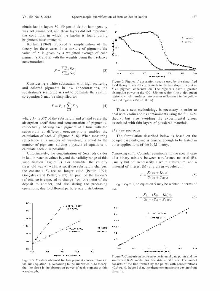
Figure 6. Pigments’ absorption spectra used by the simplified
K-M theory. Each dot corresponds to the line slope of a plot of
F vs. pigment concentration. The pigments have a greater
absorption power in the 400�550 nm region (the violet–green
region), which translates into greater reflectance in the yellow
and red regions (550�700 nm).
Figure 7. Comparison between experimental data points and the
simplified K-M model for hematite at 500 nm. The model
consists of the line formed by the points with concentrations
<0.5 wt. %. Beyond that, the phenomenon starts to deviate from
linearity.
Vol. 60, No. 5, 2012 Spectroscopic quantification of iron oxides in kaolin 477

Taking the first derivative with respect to cM, one
finds
@F@cM¼ KMSR � KRSM
½SR þ ðSM � SRÞcM�2ð7Þ
Using the derivative to apply the linear approxima-
tion to equation 6 at the point where cM = 0, one obtains
F ¼ KR
SRþ KMSR � KRSM
S2R
cM ð8Þ
The simplified theory’s dependence on the substra-
tum, as the line slope (previously considered to be
simply the pigment’s absorption; Figure 5) actually
depends on both K and S of the pigment and the
substratum, is explained in equation 8. Taking this line
slope (denoted by F’) along with equation 1, one finds:
SM
SR¼ F 0
FM � FR¼ aMR ð9Þ
The ratio SM/SR is defined as the ‘scattering ratio’ of
the material of interest over the reference, or aMR.
Unlike the constants K and S, the scattering ratio is
measured easily, because it depends on FM and FR only
(obtained through the reflectance of each material in a
pure state), and F’, which is obtained experimentally
(measuring the reflectance of mixtures with low
concentrations, similarly to the simplified theory). The
scattering ratio also has the following properties:
aij ¼1aji
aik = aijajk (10)
aii = 1
with i, j, and k being different kinds of pigments.
Connection-line method. Sometimes measuring directly
the value of FM is impossible, due to the unavailability
of a pure sample or experimental difficulties. Samples
with very low reflectance tend to produce large
photometric errors when applying equation 1 (as R?
and F are inversely proportional). For these cases, the
following methodology is proposed.
Using equations 1 and 9, equation 6 may be written in
terms of the scattering ratio:
F ¼ F þ ðaMRFM � FRÞcM
1þ ðaMR � 1ÞcMð11Þ
Note that the constant SR is canceled out. This
function will have a positive concavity if aMR <1, a
negative concavity if aMR >1, and will be a straight line
if aMR = 1. Let L be defined as the slope of the line
connecting any point in the equation above with the
reference point (0, FR) (Figure 8):
L ¼ F � FR
cMð12Þ
L has the value FM – FR when cM = 1 and tends to F’when cM ? 0. Using equations 9, 11, and 12 one obtains:
1L¼ 1
F 0þ ðaMR � 1ÞcM
F 0ð13Þ
This equation is of the type y = a0 + a1x. Fitting a line
to the values of L calculated from the experimental data
yields the coefficients a0 and a1. The model’s constants
are given by
aMR ¼a1a0þ 1 ð14Þ
FM ¼1
a0 þ a1þ FR ð15Þ
The scattering ratio of the synthetic pigments was
calculated using this methodology (Figure 9). One
advantage of equation 13 is that it retains its linear
behavior for any concentration.
Determination of concentrations. For a given wave-
length, l, consider the generic case of equation 11, a
mixture of a base material (0) with any number of
pigments (1, 2, ... m):
F ¼ a0RF0 þPm
i¼1ðaiRFi � F0Þcia0R þ
Pmi¼1ðaiR � 1Þci
ð16Þ
The base material does not necessarily have to be
the same reference material used for calibration. In
general, reflectance is measured over a range of n
wavelengths and n > m. Manipulating the equation
above so that each ci appears only once yields the linear
equation relating all constants with the measured F for
the jth wavelength:
Figure 8. Experimental data points obtained for mixtures
between kaolin and hematite at 500 nm. Each point is connected
to the reference point (0, FR) through a line with a different slope
(equation 12).
478 Goncalves, Petter, and Machado Clays and Clay Minerals

Xmi¼1
gijci ¼ g0j ð17Þ
where
gij = a(iR)j(Fij � Fj) + g0jg0j = a(0R)j(Fj � F0j)
One such equation exists for each measured wave-
length. In matrix form this system has n rows and m
columns:
g11 g12 . . . g1mg21 g22 . . . g2m... ..
. . .. ..
.
gn1 gn2 . . . gnm
26664
37775
c1c2...
cm
26664
37775 ¼
g10g20...
gn0
26664
37775 ð18Þ
As n > m for most cases, this system has more rows than
columns. In order to use the whole spectral range
measured, the least-squares method is employed:P
g21jP
g1jg2j . . .P
g1jgmjPg2jg1j
Pg22j . . .
Pg2jgmj
..
. ... . .
. ...
Pgmjg1j
Pgmjg2j . . .
Pg2mj
266664
377775
c1c2...
cm
26664
37775 ¼
Pg1jg0jPg2jg0j...
Pgmjg0j
26664
37775
ð19Þ
The solution to this system is the vector of
concentration values which provides the best fit to the
measured spectrum. When the experimental error in
calibration and measurement is small, simple least
squares provides a good solution. When the experi-
mental error is large or when trying to match a spectrum
containing pigments which are not part of the system, a
Figure 9. Connection line method for the estimation of constants at 500 nm. The equations fitted for each pigment correspond to
equation 13. The values of 1/L are obtained through equation 12.
Figure 10. Particle-size distribution of the materials studied. The kaolin sample has a broad distribution, ranging from 20 to <1 mm.
The synthetic pigments are much finer, with a narrower distribution.
Vol. 60, No. 5, 2012 Spectroscopic quantification of iron oxides in kaolin 479

non-negative least squares (NNLS) solution is necessary
in order to avoid negative concentrations.
MATERIALS AND METHODS
In order to test and exemplify the two techniques, a
synthetic hematite (d50 = 0.23 mm) and a synthetic
goethite (d50 = 0.21 mm) were mixed systematically with
a white base. The white base consisted of a soft kaolin
sample from the Capim River deposits (d50 = 4.2 mm)
which was processed in the laboratory in order to obtain
a material with the greatest brightness possible (90.3
ISO). The processing consisted of magnetic separation
and bleaching with sodium dithionite (3 kg/t, dry basis).
Particle sizes were measured with a laser granulometer
CILAS 1064 (CILAS, Orleans, France), with d50 being
the median of the particle-size distribution obtained
(Figure 10). All reflectance measurements were per-
formed using a Technidyne ColorTouch 2 spectro-
photometer (Technidyne Corporation, New Albany,
Indiana, USA) over the range of 400�700 nm with a
5 nm interval. Following the standard procedure for
sample preparation in the kaolin industry (TAPPI, 1986),
dry samples were pulverized for 30 s in a Technidyne
Anglo pulverizer, which also served as a mixing
instrument, and tablets of 40 mm diameter were then
pressed manually (~250 KPa) and taken to the spectro-
photometer.
Hematite and goethite were mixed separately with
kaolin at different concentrations in order to calibrate
the model (Table 1). Mixtures with low concentrations
(<2000 ppm) were used to obtain the constants of the
simplified K-M theory. The same data were used to
calculate constants using the new approach, along with
the more concentrated mixtures. Fifteen mixtures of both
pigments in kaolin were also prepared in order to
validate the formulation, in the range 0�25,000 ppm.
The results obtained were also used as examples to
illustrate the application of the techniques presented. For
the sake of simplicity, the examples either present a
general spectral result or focus on the wavelength of
500 nm, where the two pigments have a good contrast.
RESULTS AND DISCUSSION
Calibration results for the pigments studied
(Figures 11�13) found that the new model fitted the
data well, even for large concentrations, because it takes
into account the non-linearity of the phenomenon. As
both pigments are much finer than the kaolin, they are
expected to have a scattering ratio >1. Hematite has
greater scattering power in the red region of the
spectrum, while goethite showed a somewhat more
complex behavior. The estimated reflectance spectra
were consistent with the pigments’ colors (red for
hematite, yellow for goethite), with the inflection points
matching those found by other authors for natural
(oxyhydr)oxides (Scheinost et al., 1998; Torrent and
Barron, 2003).
A slight difference exists between the calculated and
measured reflectance spectra of the pigments (1�2%;
data not shown) due to a different physical arrangement
of the particles in the pressed tablet (degree of packing,
covering of bigger particles by smaller ones, etc.). For
low reflectance values, this difference has a great impact
on the remission function, F, so the calculated values
were chosen as the basis for this work, as the mixtures
Figure 11. Model fit at 500 nm highlighting high (left) and low concentrations (right). The lines follow equation 11, using the
constants a and F obtained for each pigment. The functions at 100% concentration correspond to the F values of the pure pigments.
Table 1. Concentrations (ppm) of the binary mixturesbetween pigment and kaolin.
Hematite Goethite
0 0117 558325 1556625 8641966 834712203 1743794215 33417188287168385333494
480 Goncalves, Petter, and Machado Clays and Clay Minerals

always have more kaolin than pigment and follow its
general configuration.
Both the standard simplified model and the new
methodology were validated, using 15 tertiary mixtures
prepared in the range 0�25,000 ppm. The raw reflectance
spectra for these tertiary mixtures (Figure 14) were
transformed to F (equation 1) and the concentrations of
pigment were calculated. Following the new methodol-
ogy, the calculations were performed using the simple
least-squares method, which uses the whole spectral range
from 400 to 700 nm (equation 19; NNLS gave the same
results in this case). For the simplification, the reflectance
values at 450 and 550 nm were chosen to form a linear
system using equation 4 (this decision is somewhat
arbitrary; in this case, 550 nm was chosen because of
the great difference between the pigments’ absorption
constants and 450 nm was chosen due to goethite’s
distinct spectral behavior in this vicinity). Both models
worked well, with a maximum absolute error of ~1800
ppm for the new model and 3000 ppm for the simplified
model (Table 2). The model has shown good accuracy
even for extremely small brightness values (35�50).A threshold of 5000 ppm (0.5 wt. %) was stipulated
in order to compare the two models for small and large
concentrations. For small concentrations, the simplified
model performed slightly better than the new model in
the determination of hematite, but showed a much larger
root mean square error (RMSE) for large concentrations
(Table 3). For the determination of goethite, the new
model performed slightly better over the whole range of
concentrations tested.
The simplified model is expected to fail for large
concentrations because it assumes a linear behavior for
any concentration which, according to equations 6 and
11, is not true. The model deviates more quickly from
linearity for hematite, which explains the greater error.
Figure 12. Scattering ratio of the materials studied relative to the kaolin. Hematite shows an increase in scattering toward the red
region of the spectrum, while goethite has scattering peaks distributed throughout the visible range.
Figure 13. Reflectance spectra of the materials studied. The spectra of hematite and goethite were transformed back from the
estimated F values using equation 1.
Vol. 60, No. 5, 2012 Spectroscopic quantification of iron oxides in kaolin 481

CONCLUSIONS
Diffuse reflectance spectroscopy has shown the
potential to be a quick, inexpensive, and accurate
method for the determination of hematite and goethite
concentrations in kaolin based on measurements of
pressed tablets only, which is a common procedure in
this industry. Unlike the more usual techniques, it allows
the quantification of each mineral phase in small
quantities, providing more information about the quality
and ‘processability’ of the kaolin ore.
The new approach using K-M theory presented here
has shown better results than the simplified theory,
especially for (oxyhydr)oxide concentrations of
>5000 ppm, which are very common in Capim River
deposits. With the option of determining any (oxyhydr)-
oxide concentration possible, this model may be used as
an auxiliary tool for mine planning and process control
without forcing the kaolin producer to rely on brightness
measurements or XRF analysis alone.
In order to implement this technique in industrial
practice, the actual contaminants from the mine must be
studied, taking into account the variations in particle
size.
When measuring in the opaque condition, the
absolute constants K and S may be substituted by F
(easily measured or estimated) and the relative constant
a, thus avoiding measurements in the transparent
condition.
The formulation presented is generic and usable in
any application in which the original theory is valid.
Figure 14. Reflectance spectra of the 15 mixtures between kaolin and the two pigments.
Table 2. Comparison between the actual concentrations (ppm) of hematite and goethite and concentrations calculated throughboth models.
—— Actual —— – New approach – Simplified K-MMixture Brightness Hematite Goethite Hematite Goethite Hematite Goethite
1 85.0 233 108 277 113 262 1322 76.2 516 1505 533 1439 497 14833 74.9 1023 765 1118 780 1054 8304 71.4 972 2160 1026 2084 965 21275 60.3 2624 4163 2874 4426 2690 44756 65.5 3098 174 3561 249 3329 4267 70.9 166 3553 198 3664 180 36998 51.1 4692 9155 4786 8989 4395 90259 50.8 8805 5585 7681 4334 7007 473810 37.7 18567 8907 17739 8876 15537 1015711 36.1 11678 25155 11385 24551 9797 2402612 50.8 7192 8766 6164 6941 5595 723013 49.4 9463 3069 9311 3201 8520 367714 55.9 3184 7077 3310 6982 3059 702015 66.1 1884 2100 2160 2346 2031 2388
482 Goncalves, Petter, and Machado Clays and Clay Minerals

Measurements in a broader spectrum (ultra-violet and
infrared) may improve the accuracy of the technique.
ACKNOWLEDGMENTS
The authors acknowledge CAPES (Coordenacao deAperfeicoamento de Pessoal de Nıvel Superior) and ImerysPigments for Paper and Packaging.
REFERENCES
Bishop, J.L. and Murad, E. (1996) Schwertmannite in Mars?Spectroscopic analyses of schwertmannite, its relationshipto other ferric minerals, and its possible presence in thesurface material on Mars. Pp. 337�358 in: Mineral
Spectroscopy: A Tribute to Roger G. Burns (M.D. Dyar,C. McCammon, and M.W. Schaefer, editors). SpecialPublication 5, The Geochemical Society, St. Louis,Missouri, USA.
Goncalves, I.G. (2009) Determinacao da concentracao decontaminantes no caolim atraves da teoria de Kubelka-Munk. MSc Dissertation, Universidade Federal do RioGrande do Sul, Porto Alegre, Brazil, 68 pp.
Goncalves, I.G. and Petter, C.O. (2007) Kubelka-Munk theoryapplied to industrial minerals: prediction of impurity contentin kaolin. Revista Escola de Minas, 60, 491�496.
HunterLab (2008) CIE L*a*b* color scale. Insight on Color, 8,4 pp.
Ji, J., Balsam, W., Chen, J., and Liu, L. (2002) Rapid andquantitative measurement of hematite and goethite in theChinese loess-paleosol sequence by diffuse reflectancespectroscopy. Clays and Clay Minerals, 50, 208�216.
Ji, J., Zhao, L., Balsam, W., Chen, J., Wu, T., and Liu, L.(2006) Detecting chlorite in the Chinese loess sequence bydiffuse reflectance spectroscopy. Clays and Clay Minerals,54, 266�276.
Kortum, G. (1969) Reflectance Spectroscopy. Springer-Verlag,Berlin.
Liu, Q.S., Torrent, J., Barron, V., Duan, Q.Z., and Bloemendal,J. (2011) Quantification of hematite from the visible diffusereflectance spectrum: effects of aluminium substitution andgrain morphology. Clay Minerals, 46, 137�147.
Morris, R.V. and Lauer, H.V. (1990) Matrix effects forreflectivity spectra of dispersed nanophase (superparamag-netic) hematite with application to Martian spectral data.
Journal of Geophysical Research, 95, 5101�5109.Morris, R.V., Lauer, H.V., Lawson, C.A., Gibson, E.K., Nace,
G.A., and Stewart, C. (1985) Spectral and other physico-chemical properties of submicron powders of hematite (a-Fe2O3), maghemite (g-Fe2O3), magnetite (Fe3O4), goethite(a-FeOOH) and lepidocrocite (g-FeOOH). Journal of
Geophysical Research, 90, 3126�3144.Otsuka, M. (2004) Comparative particle size determination of
phenacetin bulk powder by using Kubelka-Munk theory andprincipal component regression analysis based on near-infrared spectroscopy. Powder Technology, 141, 244�250.
Petter, C.O. (1994) Contribution a l’etude de la valorisation dekaolins pour l’industrie papetiere: mise au point d’unemethodologie colorimetrique, application a la selectiviteminiere. PhD thesis, Ecole des Mines de Paris, France.
Schabbach, L.M., Bondioli, F., Ferrari, A.M, Petter, C.O., andFredel, M.C. (2009) Efficiency of Kubelka-Munk model inglazes with a black pigment and opacifier. Journal of the
European Ceramic Society, 29, 2685�2690.Schabbach, L.M., Bondioli, F., and Fredel, M.C. (2011)
Colouring of opaque ceramic glaze with zircon pigments:Formulation with simplified Kubelka-Munk model. Journalof the European Ceramic Society, 31, 659�664.
Scheinost, A.C., Chavernas, A., Barron, V., and Torrent, J.(1998) Use and limitations of second-derivative diffusereflectance spectroscopy in the visible to near-infrared rangeto identify and quantify Fe oxide minerals in soils. Claysand Clay Minerals, 46, 528�536.
Sherman, D.M. and Waite, T.D. (1985) Electronic spectra ofFe3+ oxides and oxide hydroxides in the near IR to near UV.American Mineralogist, 70, 1262�1269.
Sherman, D.M., Burns, R.G., and Burns, V.M. (1982) Spectralcharacteristics of the iron oxides with application to theMartian bright region mineralogy. Journal of Geophysical
Research, 87, 10169�10180.TAPPI (1977) Brightness of pulp, paper and paperboard
(directional reflectance at 457 nm). Technical standard.TAPPI (1986) Brightness of clay and other mineral pigments
(d/0 diffuse). Technical standard.Torrent, J. and Barron, V. (2003) The visible diffuse
reflectance in relation to the color and crystal propertiesof hematite. Clays and Clay Minerals, 51, 309�317.
(Received 23 January 2012; revised 15 October 2012; Ms
647; AE; J. Stucki)
Table 3. Root mean square error of the two models for low and high concentrations (values in ppm).
——— New approach ——— —— Simplified K-M ——Hematite Goethite Hematite Goethite
Under 5000 ppm 198 139 136 267Over 5000 ppm 789 940 1969 994Overall 484 604 1142 662
Vol. 60, No. 5, 2012 Spectroscopic quantification of iron oxides in kaolin 483
Copyright © 2022 FDOKUMEN