
PumpDrive - KSB Web-Shop
164
Operating Instructions 4070.81/7--10 PumpDrive Self--cooling, motor-independent frequency inverter Suitable for: Motor mounting (MM) Wall mounting (WM) Cabinet mounting (CM) Works No.: _________________________ Serial No. _________________________ These operating instructions contain important information and precautions. Please read the manual thoroughly prior to installation of unit, connection to the power supply and commissioning. These operating instructions refer exclusively to the PumpDrive frequency inverter. Other operating instructions of driven units, e.g. pumps, must also be complied with. Hazardous voltage when the drive is connected to the mains. Improper installation or unauthorised opening of terminal boxes can cause equipment failure and serious or even fatal personal injuries. The technical data and information provided in these operating instructions have been compiled to the best of our knowledge. Ho- wever, as the products are constantly being improved, KSB AG reserves the right to implement any such modifications without prior notice. The operating instructions do not cover all design details and variants, nor do they cover all scenarios and situations that may arise during installation, operation or maintenance. The device must only be operated by skilled, properly trained personnel (see EN 50110-1). The manufacturer shall not accept any liability if you fail to comply with the information in these operating instructions. Operation and use of PumpDrive shall be in compliance with EN 50110-1.
-
Upload
khangminh22 -
Category
Documents
-
view
2 -
download
0
Transcript of PumpDrive - KSB Web-Shop

Operating Instructions4070.81/7--10 PumpDrive
Self--cooling,motor-independentfrequency inverter
Suitable for:Motor mounting (MM)Wall mounting (WM)
Cabinet mounting (CM)
Works No.: _________________________
Serial No. _________________________
These operating instructions contain important information and precautions. Please read the manual thoroughly prior toinstallation of unit, connection to the power supply and commissioning. These operating instructions refer exclusively tothe PumpDrive frequency inverter. Other operating instructions of driven units, e.g. pumps, must also be complied with.
Hazardous voltage when the drive is connected to the mains. Improper installation or unauthorised opening of terminal boxes cancause equipment failure and serious or even fatal personal injuries.
The technical data and information provided in these operating instructions have been compiled to the best of our knowledge. Ho-wever, as the products are constantly being improved, KSB AG reserves the right to implement any such modifications withoutprior notice.
The operating instructions do not cover all design details and variants, nor do they cover all scenarios and situations that may ariseduring installation, operation or maintenance.
The device must only be operated by skilled, properly trained personnel (see EN 50110-1).The manufacturer shall not accept any liability if you fail to comply with the information in these operating instructions.Operation and use of PumpDrive shall be in compliance with EN 50110-1.

PumpDrive
2
Konformitätserklärung
EC declaration of conformity
Déclaration »CE« de conformit
Hiermit erklären wir, daß das elektrische/elektronische ProduktWe herewith declare that the electric/electronic productPar la présente, nous déclarons que le type le produit électrique/électronique
PumpDrive
folgenden einschlägigen Bestimmungen in der jeweils gültigen Fassung entspricht:complies with the following relevant provisions as applicable in their current version:correspond aux dispositions pertinentes suivantes dans la version respective en vigueur:
EU-Richtlinie 2004/108/EC ”Elektromagnetische Verträglichkeit”EU-Richtlinie 2006/95/EC ”Niederspannungsrichtlinie”
Electromagnetic compatibility directive 2004/108/EECEC directive on low-voltage equipment 2006/95/EEC
directive »CE« relative à la compatibilité électromagnétique 2004/108/CEdirective »CE« relative à la basse tension 2006/95/CE
Angewendete harmonisierte Normen, insbesondereApplied harmonised standards, in particularNormes harmonisées utilisées, notamment
2004/108/EC: EN 61800-3,≤7.5 kW: EN 61000-6-3,>7.5 kW: EN 61000-6-2,EN 55011 +/A1 +/A2, EN 61000-3-2, -3, -11, EN 61000-6-1, -4
2006/95/EC: EN 60204-1, 61800-5-1, EN 50178
Angewendete nationale technische Normen und Spezifikationen, insbesondereApplied national technical standards and specifications, in particularNormes et spécifications techniques nationales qui ont été utilisées, notamment
DIN EN 60034 (VDE 0530)
Frankenthal, 14 November 2007
KSB AktiengesellschaftDr. Joachim Schullerer
Head of Product Development Automation
KSB Aktiengesellschaft, Johann-Klein-Str. 9, D-67225 Frankenthal
PumpDrive
3
Contents
Page
EC declaration of conformity 2. . . . . . . . . . . . . . . . . . . . . . . . . . . . . . . . . . . . . . . . . . . . . . . . . . . . . . . . . . . . . . . . . . . . . . . . . . . . . .
1 General 9. . . . . . . . . . . . . . . . . . . . . . . . . . . . . . . . . . . . . . . . . . . . . . . . . . . . . . . . . . . . . . . . . . . . . . . . . . . . . . . . . . . . . . . . . .1.1 CE conformity marking 9. . . . . . . . . . . . . . . . . . . . . . . . . . . . . . . . . . . . . . . . . . . . . . . . . . . . . . . . . . . . . . . . . . . . . . . . . . . . . .1.2 Electromagnetic compatibility 9. . . . . . . . . . . . . . . . . . . . . . . . . . . . . . . . . . . . . . . . . . . . . . . . . . . . . . . . . . . . . . . . . . . . . . . .1.2.1 Requirements to EN 61800-3 – RFI emission 9. . . . . . . . . . . . . . . . . . . . . . . . . . . . . . . . . . . . . . . . . . . . . . . . . . . . . . . . . .1.2.2 Requirements to EN 61000-3-2 – Line harmonics 9. . . . . . . . . . . . . . . . . . . . . . . . . . . . . . . . . . . . . . . . . . . . . . . . . . . . . . .
2 Safety 10. . . . . . . . . . . . . . . . . . . . . . . . . . . . . . . . . . . . . . . . . . . . . . . . . . . . . . . . . . . . . . . . . . . . . . . . . . . . . . . . . . . . . . . . . . . .2.1 Symbols used in these operating instructions 10. . . . . . . . . . . . . . . . . . . . . . . . . . . . . . . . . . . . . . . . . . . . . . . . . . . . . . . . . . .2.2 Personnel qualification and training 10. . . . . . . . . . . . . . . . . . . . . . . . . . . . . . . . . . . . . . . . . . . . . . . . . . . . . . . . . . . . . . . . . . .2.3 Non-compliance with safety instructions 10. . . . . . . . . . . . . . . . . . . . . . . . . . . . . . . . . . . . . . . . . . . . . . . . . . . . . . . . . . . . . . .2.4 Safety awareness 10. . . . . . . . . . . . . . . . . . . . . . . . . . . . . . . . . . . . . . . . . . . . . . . . . . . . . . . . . . . . . . . . . . . . . . . . . . . . . . . . . .2.5 Safety information for the operator/user 10. . . . . . . . . . . . . . . . . . . . . . . . . . . . . . . . . . . . . . . . . . . . . . . . . . . . . . . . . . . . . . . .2.6 Safety information for maintenance, inspection and installation work 10. . . . . . . . . . . . . . . . . . . . . . . . . . . . . . . . . . . . . . .2.7 Unauthorised modification and manufacture of spare parts 10. . . . . . . . . . . . . . . . . . . . . . . . . . . . . . . . . . . . . . . . . . . . . . .2.8 Software changes/warranty 11. . . . . . . . . . . . . . . . . . . . . . . . . . . . . . . . . . . . . . . . . . . . . . . . . . . . . . . . . . . . . . . . . . . . . . . . . .2.9 Unauthorised modes of operation 11. . . . . . . . . . . . . . . . . . . . . . . . . . . . . . . . . . . . . . . . . . . . . . . . . . . . . . . . . . . . . . . . . . . .2.10 Unintentional start--up 11. . . . . . . . . . . . . . . . . . . . . . . . . . . . . . . . . . . . . . . . . . . . . . . . . . . . . . . . . . . . . . . . . . . . . . . . . . . . . .2.11 Capacitor discharge time 11. . . . . . . . . . . . . . . . . . . . . . . . . . . . . . . . . . . . . . . . . . . . . . . . . . . . . . . . . . . . . . . . . . . . . . . . . . . .2.12 Environment 11. . . . . . . . . . . . . . . . . . . . . . . . . . . . . . . . . . . . . . . . . . . . . . . . . . . . . . . . . . . . . . . . . . . . . . . . . . . . . . . . . . . . . . .
3 Transport and temporary storage 12. . . . . . . . . . . . . . . . . . . . . . . . . . . . . . . . . . . . . . . . . . . . . . . . . . . . . . . . . . . . . . . . . . .3.1 Transport 12. . . . . . . . . . . . . . . . . . . . . . . . . . . . . . . . . . . . . . . . . . . . . . . . . . . . . . . . . . . . . . . . . . . . . . . . . . . . . . . . . . . . . . . . .3.1.1 Transport of Etaline/Etabloc PumpDrive 12. . . . . . . . . . . . . . . . . . . . . . . . . . . . . . . . . . . . . . . . . . . . . . . . . . . . . . . . . . . . . . .3.1.2 Transport of Etanorm/CPKN/Multitec PumpDrive 12. . . . . . . . . . . . . . . . . . . . . . . . . . . . . . . . . . . . . . . . . . . . . . . . . . . . . . . .3.1.3 Transport of Movitec PumpDrive 13. . . . . . . . . . . . . . . . . . . . . . . . . . . . . . . . . . . . . . . . . . . . . . . . . . . . . . . . . . . . . . . . . . . . .3.2 Temporary storage 13. . . . . . . . . . . . . . . . . . . . . . . . . . . . . . . . . . . . . . . . . . . . . . . . . . . . . . . . . . . . . . . . . . . . . . . . . . . . . . . . .
4 Product description 13. . . . . . . . . . . . . . . . . . . . . . . . . . . . . . . . . . . . . . . . . . . . . . . . . . . . . . . . . . . . . . . . . . . . . . . . . . . . . . .4.1 Designation 13. . . . . . . . . . . . . . . . . . . . . . . . . . . . . . . . . . . . . . . . . . . . . . . . . . . . . . . . . . . . . . . . . . . . . . . . . . . . . . . . . . . . . . .4.2 Product features 14. . . . . . . . . . . . . . . . . . . . . . . . . . . . . . . . . . . . . . . . . . . . . . . . . . . . . . . . . . . . . . . . . . . . . . . . . . . . . . . . . . .4.3 Models and functions 14. . . . . . . . . . . . . . . . . . . . . . . . . . . . . . . . . . . . . . . . . . . . . . . . . . . . . . . . . . . . . . . . . . . . . . . . . . . . . . .4.3.1 Basic and Advanced 14. . . . . . . . . . . . . . . . . . . . . . . . . . . . . . . . . . . . . . . . . . . . . . . . . . . . . . . . . . . . . . . . . . . . . . . . . . . . . . . .4.3.2 Functions 15. . . . . . . . . . . . . . . . . . . . . . . . . . . . . . . . . . . . . . . . . . . . . . . . . . . . . . . . . . . . . . . . . . . . . . . . . . . . . . . . . . . . . . . . .4.4 Technical data 16. . . . . . . . . . . . . . . . . . . . . . . . . . . . . . . . . . . . . . . . . . . . . . . . . . . . . . . . . . . . . . . . . . . . . . . . . . . . . . . . . . . . .4.5 Mounting variants 17. . . . . . . . . . . . . . . . . . . . . . . . . . . . . . . . . . . . . . . . . . . . . . . . . . . . . . . . . . . . . . . . . . . . . . . . . . . . . . . . . .4.5.1 Power range 18. . . . . . . . . . . . . . . . . . . . . . . . . . . . . . . . . . . . . . . . . . . . . . . . . . . . . . . . . . . . . . . . . . . . . . . . . . . . . . . . . . . . . .4.5.2 Dimensions and weights 18. . . . . . . . . . . . . . . . . . . . . . . . . . . . . . . . . . . . . . . . . . . . . . . . . . . . . . . . . . . . . . . . . . . . . . . . . . . .
5 Operation / Monitoring 19. . . . . . . . . . . . . . . . . . . . . . . . . . . . . . . . . . . . . . . . . . . . . . . . . . . . . . . . . . . . . . . . . . . . . . . . . . . . .5.1 Standard control panel 19. . . . . . . . . . . . . . . . . . . . . . . . . . . . . . . . . . . . . . . . . . . . . . . . . . . . . . . . . . . . . . . . . . . . . . . . . . . . . .5.1.1 LEDs: 19. . . . . . . . . . . . . . . . . . . . . . . . . . . . . . . . . . . . . . . . . . . . . . . . . . . . . . . . . . . . . . . . . . . . . . . . . . . . . . . . . . . . . . . . . . . .5.1.2 LED bar graph display 20. . . . . . . . . . . . . . . . . . . . . . . . . . . . . . . . . . . . . . . . . . . . . . . . . . . . . . . . . . . . . . . . . . . . . . . . . . . . . .5.1.3 Setting keys 20. . . . . . . . . . . . . . . . . . . . . . . . . . . . . . . . . . . . . . . . . . . . . . . . . . . . . . . . . . . . . . . . . . . . . . . . . . . . . . . . . . . . . . .5.1.4 Operating keys 21. . . . . . . . . . . . . . . . . . . . . . . . . . . . . . . . . . . . . . . . . . . . . . . . . . . . . . . . . . . . . . . . . . . . . . . . . . . . . . . . . . . .5.1.5 Service interface 21. . . . . . . . . . . . . . . . . . . . . . . . . . . . . . . . . . . . . . . . . . . . . . . . . . . . . . . . . . . . . . . . . . . . . . . . . . . . . . . . . . .5.2 Graphical control panel 22. . . . . . . . . . . . . . . . . . . . . . . . . . . . . . . . . . . . . . . . . . . . . . . . . . . . . . . . . . . . . . . . . . . . . . . . . . . . .5.2.1 LEDs: 22. . . . . . . . . . . . . . . . . . . . . . . . . . . . . . . . . . . . . . . . . . . . . . . . . . . . . . . . . . . . . . . . . . . . . . . . . . . . . . . . . . . . . . . . . . . .5.2.2 Function keys 23. . . . . . . . . . . . . . . . . . . . . . . . . . . . . . . . . . . . . . . . . . . . . . . . . . . . . . . . . . . . . . . . . . . . . . . . . . . . . . . . . . . . .5.2.3 Navigation keys 23. . . . . . . . . . . . . . . . . . . . . . . . . . . . . . . . . . . . . . . . . . . . . . . . . . . . . . . . . . . . . . . . . . . . . . . . . . . . . . . . . . . .5.2.4 Operating keys 23. . . . . . . . . . . . . . . . . . . . . . . . . . . . . . . . . . . . . . . . . . . . . . . . . . . . . . . . . . . . . . . . . . . . . . . . . . . . . . . . . . . .5.2.5 Display 24. . . . . . . . . . . . . . . . . . . . . . . . . . . . . . . . . . . . . . . . . . . . . . . . . . . . . . . . . . . . . . . . . . . . . . . . . . . . . . . . . . . . . . . . . . .5.2.6 Service interface 24. . . . . . . . . . . . . . . . . . . . . . . . . . . . . . . . . . . . . . . . . . . . . . . . . . . . . . . . . . . . . . . . . . . . . . . . . . . . . . . . . . .5.2.7 Menu structure 25. . . . . . . . . . . . . . . . . . . . . . . . . . . . . . . . . . . . . . . . . . . . . . . . . . . . . . . . . . . . . . . . . . . . . . . . . . . . . . . . . . . .5.2.8 Access levels 26. . . . . . . . . . . . . . . . . . . . . . . . . . . . . . . . . . . . . . . . . . . . . . . . . . . . . . . . . . . . . . . . . . . . . . . . . . . . . . . . . . . . . .5.2.9 Displaying and changing parameters 26. . . . . . . . . . . . . . . . . . . . . . . . . . . . . . . . . . . . . . . . . . . . . . . . . . . . . . . . . . . . . . . . . .5.2.10 Monitoring 27. . . . . . . . . . . . . . . . . . . . . . . . . . . . . . . . . . . . . . . . . . . . . . . . . . . . . . . . . . . . . . . . . . . . . . . . . . . . . . . . . . . . . . . .
6 Installation 32. . . . . . . . . . . . . . . . . . . . . . . . . . . . . . . . . . . . . . . . . . . . . . . . . . . . . . . . . . . . . . . . . . . . . . . . . . . . . . . . . . . . . . .6.1 Installation location 32. . . . . . . . . . . . . . . . . . . . . . . . . . . . . . . . . . . . . . . . . . . . . . . . . . . . . . . . . . . . . . . . . . . . . . . . . . . . . . . . .6.2 Ambient conditions 32. . . . . . . . . . . . . . . . . . . . . . . . . . . . . . . . . . . . . . . . . . . . . . . . . . . . . . . . . . . . . . . . . . . . . . . . . . . . . . . . .

PumpDrive
4
6.3 Installation 33. . . . . . . . . . . . . . . . . . . . . . . . . . . . . . . . . . . . . . . . . . . . . . . . . . . . . . . . . . . . . . . . . . . . . . . . . . . . . . . . . . . . . . . .6.3.1 Motor-mounted model 33. . . . . . . . . . . . . . . . . . . . . . . . . . . . . . . . . . . . . . . . . . . . . . . . . . . . . . . . . . . . . . . . . . . . . . . . . . . . . .6.3.2 Wall-mounted model 33. . . . . . . . . . . . . . . . . . . . . . . . . . . . . . . . . . . . . . . . . . . . . . . . . . . . . . . . . . . . . . . . . . . . . . . . . . . . . . . .6.3.3 Cabinet-mounted model 33. . . . . . . . . . . . . . . . . . . . . . . . . . . . . . . . . . . . . . . . . . . . . . . . . . . . . . . . . . . . . . . . . . . . . . . . . . . . .6.4 Connection to power supply 34. . . . . . . . . . . . . . . . . . . . . . . . . . . . . . . . . . . . . . . . . . . . . . . . . . . . . . . . . . . . . . . . . . . . . . . . .6.4.1 General 34. . . . . . . . . . . . . . . . . . . . . . . . . . . . . . . . . . . . . . . . . . . . . . . . . . . . . . . . . . . . . . . . . . . . . . . . . . . . . . . . . . . . . . . . . . .6.4.2 Selecting the power supply cables 34. . . . . . . . . . . . . . . . . . . . . . . . . . . . . . . . . . . . . . . . . . . . . . . . . . . . . . . . . . . . . . . . . . . .6.4.3 Maximum motor cable lengths 34. . . . . . . . . . . . . . . . . . . . . . . . . . . . . . . . . . . . . . . . . . . . . . . . . . . . . . . . . . . . . . . . . . . . . . .6.4.4 Residual current device (RCD) 35. . . . . . . . . . . . . . . . . . . . . . . . . . . . . . . . . . . . . . . . . . . . . . . . . . . . . . . . . . . . . . . . . . . . . . .6.4.5 Electromagnetic compatibility 35. . . . . . . . . . . . . . . . . . . . . . . . . . . . . . . . . . . . . . . . . . . . . . . . . . . . . . . . . . . . . . . . . . . . . . . .6.4.6 Power supply and motor wiring 36. . . . . . . . . . . . . . . . . . . . . . . . . . . . . . . . . . . . . . . . . . . . . . . . . . . . . . . . . . . . . . . . . . . . . . .6.4.7 Ground connection 38. . . . . . . . . . . . . . . . . . . . . . . . . . . . . . . . . . . . . . . . . . . . . . . . . . . . . . . . . . . . . . . . . . . . . . . . . . . . . . . . .6.4.8 Connecting the control terminals 39. . . . . . . . . . . . . . . . . . . . . . . . . . . . . . . . . . . . . . . . . . . . . . . . . . . . . . . . . . . . . . . . . . . . .6.4.9 Multiple pump configuration 42. . . . . . . . . . . . . . . . . . . . . . . . . . . . . . . . . . . . . . . . . . . . . . . . . . . . . . . . . . . . . . . . . . . . . . . . . .6.4.10 Control panel 47. . . . . . . . . . . . . . . . . . . . . . . . . . . . . . . . . . . . . . . . . . . . . . . . . . . . . . . . . . . . . . . . . . . . . . . . . . . . . . . . . . . . . .6.4.11 Installing the field bus module 49. . . . . . . . . . . . . . . . . . . . . . . . . . . . . . . . . . . . . . . . . . . . . . . . . . . . . . . . . . . . . . . . . . . . . . . .6.4.12 Installing line chokes 49. . . . . . . . . . . . . . . . . . . . . . . . . . . . . . . . . . . . . . . . . . . . . . . . . . . . . . . . . . . . . . . . . . . . . . . . . . . . . . .
7 Commissioning / Start-up 50. . . . . . . . . . . . . . . . . . . . . . . . . . . . . . . . . . . . . . . . . . . . . . . . . . . . . . . . . . . . . . . . . . . . . . . . . .7.1 Single--pump operation 51. . . . . . . . . . . . . . . . . . . . . . . . . . . . . . . . . . . . . . . . . . . . . . . . . . . . . . . . . . . . . . . . . . . . . . . . . . . . .7.1.1 Setting motor parameters 51. . . . . . . . . . . . . . . . . . . . . . . . . . . . . . . . . . . . . . . . . . . . . . . . . . . . . . . . . . . . . . . . . . . . . . . . . . .7.1.2 Matching PumpDrive to the pump (for PumpDrive Advanced only) 52. . . . . . . . . . . . . . . . . . . . . . . . . . . . . . . . . . . . . . . . .7.2 Manual mode via control panel 53. . . . . . . . . . . . . . . . . . . . . . . . . . . . . . . . . . . . . . . . . . . . . . . . . . . . . . . . . . . . . . . . . . . . . . .7.3 Open-loop control mode 54. . . . . . . . . . . . . . . . . . . . . . . . . . . . . . . . . . . . . . . . . . . . . . . . . . . . . . . . . . . . . . . . . . . . . . . . . . . .7.3.1 Setpoint specification/Setpoint unit 54. . . . . . . . . . . . . . . . . . . . . . . . . . . . . . . . . . . . . . . . . . . . . . . . . . . . . . . . . . . . . . . . . . . .7.3.2 Open-loop control mode using external standard signal 55. . . . . . . . . . . . . . . . . . . . . . . . . . . . . . . . . . . . . . . . . . . . . . . . . .7.3.3 Open-loop control mode using the control panel 56. . . . . . . . . . . . . . . . . . . . . . . . . . . . . . . . . . . . . . . . . . . . . . . . . . . . . . . .7.3.4 Open--loop control mode using field bus 56. . . . . . . . . . . . . . . . . . . . . . . . . . . . . . . . . . . . . . . . . . . . . . . . . . . . . . . . . . . . . . .7.3.5 Open-loop control mode using a digital potentiometer (key function) 56. . . . . . . . . . . . . . . . . . . . . . . . . . . . . . . . . . . . . . .7.3.6 Open-loop control mode at fixed speed 57. . . . . . . . . . . . . . . . . . . . . . . . . . . . . . . . . . . . . . . . . . . . . . . . . . . . . . . . . . . . . . . .7.4 Closed-loop control mode 58. . . . . . . . . . . . . . . . . . . . . . . . . . . . . . . . . . . . . . . . . . . . . . . . . . . . . . . . . . . . . . . . . . . . . . . . . . .7.4.1 Setpoint specification 59. . . . . . . . . . . . . . . . . . . . . . . . . . . . . . . . . . . . . . . . . . . . . . . . . . . . . . . . . . . . . . . . . . . . . . . . . . . . . . .7.4.2 Sensor signal 59. . . . . . . . . . . . . . . . . . . . . . . . . . . . . . . . . . . . . . . . . . . . . . . . . . . . . . . . . . . . . . . . . . . . . . . . . . . . . . . . . . . . . .7.4.3 Controller types 61. . . . . . . . . . . . . . . . . . . . . . . . . . . . . . . . . . . . . . . . . . . . . . . . . . . . . . . . . . . . . . . . . . . . . . . . . . . . . . . . . . . .7.4.4 Unit of setpoint and actual value 61. . . . . . . . . . . . . . . . . . . . . . . . . . . . . . . . . . . . . . . . . . . . . . . . . . . . . . . . . . . . . . . . . . . . . .7.4.5 Closed-loop control mode using an external setpoint signal 61. . . . . . . . . . . . . . . . . . . . . . . . . . . . . . . . . . . . . . . . . . . . . . .7.4.6 Closed-loop control mode using control panel 62. . . . . . . . . . . . . . . . . . . . . . . . . . . . . . . . . . . . . . . . . . . . . . . . . . . . . . . . . .7.4.7 Closed-loop control using field bus 62. . . . . . . . . . . . . . . . . . . . . . . . . . . . . . . . . . . . . . . . . . . . . . . . . . . . . . . . . . . . . . . . . . . .7.4.8 Controller optimisation 63. . . . . . . . . . . . . . . . . . . . . . . . . . . . . . . . . . . . . . . . . . . . . . . . . . . . . . . . . . . . . . . . . . . . . . . . . . . . . .7.5 Multiple pump configuration 64. . . . . . . . . . . . . . . . . . . . . . . . . . . . . . . . . . . . . . . . . . . . . . . . . . . . . . . . . . . . . . . . . . . . . . . . . .7.5.2 Configuration example 68. . . . . . . . . . . . . . . . . . . . . . . . . . . . . . . . . . . . . . . . . . . . . . . . . . . . . . . . . . . . . . . . . . . . . . . . . . . . . .7.5.3 Closed-loop control mode in a multiple pump system 68. . . . . . . . . . . . . . . . . . . . . . . . . . . . . . . . . . . . . . . . . . . . . . . . . . . .7.5.4 Open-loop control mode in a multiple pump system 69. . . . . . . . . . . . . . . . . . . . . . . . . . . . . . . . . . . . . . . . . . . . . . . . . . . . .7.6 PumpDrive protective functions 70. . . . . . . . . . . . . . . . . . . . . . . . . . . . . . . . . . . . . . . . . . . . . . . . . . . . . . . . . . . . . . . . . . . . . .7.6.1 Thermal motor protection 70. . . . . . . . . . . . . . . . . . . . . . . . . . . . . . . . . . . . . . . . . . . . . . . . . . . . . . . . . . . . . . . . . . . . . . . . . . . .7.6.2 Electrical motor protection by overvoltage / undervoltage monitoring 70. . . . . . . . . . . . . . . . . . . . . . . . . . . . . . . . . . . . . . .7.6.3 Dynamic overload protection by speed limitation 70. . . . . . . . . . . . . . . . . . . . . . . . . . . . . . . . . . . . . . . . . . . . . . . . . . . . . . . .7.6.4 Current limitation 70. . . . . . . . . . . . . . . . . . . . . . . . . . . . . . . . . . . . . . . . . . . . . . . . . . . . . . . . . . . . . . . . . . . . . . . . . . . . . . . . . . .7.6.5 Tripping at phase failure and short circuit 70. . . . . . . . . . . . . . . . . . . . . . . . . . . . . . . . . . . . . . . . . . . . . . . . . . . . . . . . . . . . . .7.6.6 Cable integrity monitoring (live zero) 71. . . . . . . . . . . . . . . . . . . . . . . . . . . . . . . . . . . . . . . . . . . . . . . . . . . . . . . . . . . . . . . . . .7.6.7 Suppressing a frequency range 71. . . . . . . . . . . . . . . . . . . . . . . . . . . . . . . . . . . . . . . . . . . . . . . . . . . . . . . . . . . . . . . . . . . . . .7.6.8 Protection against dry running and hydraulic blockages (Advanced function) 72. . . . . . . . . . . . . . . . . . . . . . . . . . . . . . . .7.6.9 Characteristic curve control (Advanced function) 73. . . . . . . . . . . . . . . . . . . . . . . . . . . . . . . . . . . . . . . . . . . . . . . . . . . . . . . .7.7 Flow rate estimation 74. . . . . . . . . . . . . . . . . . . . . . . . . . . . . . . . . . . . . . . . . . . . . . . . . . . . . . . . . . . . . . . . . . . . . . . . . . . . . . . .7.8 Individual monitoring functions 76. . . . . . . . . . . . . . . . . . . . . . . . . . . . . . . . . . . . . . . . . . . . . . . . . . . . . . . . . . . . . . . . . . . . . . .7.9 Energy efficiency 78. . . . . . . . . . . . . . . . . . . . . . . . . . . . . . . . . . . . . . . . . . . . . . . . . . . . . . . . . . . . . . . . . . . . . . . . . . . . . . . . . . .7.9.1 Dynamic differential pressure setpoint compensation 78. . . . . . . . . . . . . . . . . . . . . . . . . . . . . . . . . . . . . . . . . . . . . . . . . . . .7.9.2 Standby mode (sleep mode) 82. . . . . . . . . . . . . . . . . . . . . . . . . . . . . . . . . . . . . . . . . . . . . . . . . . . . . . . . . . . . . . . . . . . . . . . . .7.9.3 V/f characteristic 84. . . . . . . . . . . . . . . . . . . . . . . . . . . . . . . . . . . . . . . . . . . . . . . . . . . . . . . . . . . . . . . . . . . . . . . . . . . . . . . . . . .7.10 Start and stop ramps 85. . . . . . . . . . . . . . . . . . . . . . . . . . . . . . . . . . . . . . . . . . . . . . . . . . . . . . . . . . . . . . . . . . . . . . . . . . . . . . .7.11 Digital / analog inputs and outputs 86. . . . . . . . . . . . . . . . . . . . . . . . . . . . . . . . . . . . . . . . . . . . . . . . . . . . . . . . . . . . . . . . . . . .7.11.1 Digital inputs 86. . . . . . . . . . . . . . . . . . . . . . . . . . . . . . . . . . . . . . . . . . . . . . . . . . . . . . . . . . . . . . . . . . . . . . . . . . . . . . . . . . . . . .7.11.2 Relay output 86. . . . . . . . . . . . . . . . . . . . . . . . . . . . . . . . . . . . . . . . . . . . . . . . . . . . . . . . . . . . . . . . . . . . . . . . . . . . . . . . . . . . . . .7.11.3 Analog inputs 87. . . . . . . . . . . . . . . . . . . . . . . . . . . . . . . . . . . . . . . . . . . . . . . . . . . . . . . . . . . . . . . . . . . . . . . . . . . . . . . . . . . . . .7.11.4 Analog output 88. . . . . . . . . . . . . . . . . . . . . . . . . . . . . . . . . . . . . . . . . . . . . . . . . . . . . . . . . . . . . . . . . . . . . . . . . . . . . . . . . . . . .7.12 Restoring the factory settings 88. . . . . . . . . . . . . . . . . . . . . . . . . . . . . . . . . . . . . . . . . . . . . . . . . . . . . . . . . . . . . . . . . . . . . . . .
8 Field bus 89. . . . . . . . . . . . . . . . . . . . . . . . . . . . . . . . . . . . . . . . . . . . . . . . . . . . . . . . . . . . . . . . . . . . . . . . . . . . . . . . . . . . . . . . .8.1 LON set of accessories 89. . . . . . . . . . . . . . . . . . . . . . . . . . . . . . . . . . . . . . . . . . . . . . . . . . . . . . . . . . . . . . . . . . . . . . . . . . . . .

PumpDrive
5
8.2 Profibus set of accessories 89. . . . . . . . . . . . . . . . . . . . . . . . . . . . . . . . . . . . . . . . . . . . . . . . . . . . . . . . . . . . . . . . . . . . . . . . . .
9 Maintenance and servicing 90. . . . . . . . . . . . . . . . . . . . . . . . . . . . . . . . . . . . . . . . . . . . . . . . . . . . . . . . . . . . . . . . . . . . . . . .9.1 General 90. . . . . . . . . . . . . . . . . . . . . . . . . . . . . . . . . . . . . . . . . . . . . . . . . . . . . . . . . . . . . . . . . . . . . . . . . . . . . . . . . . . . . . . . . . .9.2 Servicing / inspection 90. . . . . . . . . . . . . . . . . . . . . . . . . . . . . . . . . . . . . . . . . . . . . . . . . . . . . . . . . . . . . . . . . . . . . . . . . . . . . . .9.3 Dismantling 90. . . . . . . . . . . . . . . . . . . . . . . . . . . . . . . . . . . . . . . . . . . . . . . . . . . . . . . . . . . . . . . . . . . . . . . . . . . . . . . . . . . . . . .9.3.1 Important instructions and recommendations 90. . . . . . . . . . . . . . . . . . . . . . . . . . . . . . . . . . . . . . . . . . . . . . . . . . . . . . . . . . .9.3.2 Preparations for dismantling 90. . . . . . . . . . . . . . . . . . . . . . . . . . . . . . . . . . . . . . . . . . . . . . . . . . . . . . . . . . . . . . . . . . . . . . . . .
10 Trouble-shooting 91. . . . . . . . . . . . . . . . . . . . . . . . . . . . . . . . . . . . . . . . . . . . . . . . . . . . . . . . . . . . . . . . . . . . . . . . . . . . . . . . . .10.1 Trouble-shooting 91. . . . . . . . . . . . . . . . . . . . . . . . . . . . . . . . . . . . . . . . . . . . . . . . . . . . . . . . . . . . . . . . . . . . . . . . . . . . . . . . . . .10.2 Alerts 92. . . . . . . . . . . . . . . . . . . . . . . . . . . . . . . . . . . . . . . . . . . . . . . . . . . . . . . . . . . . . . . . . . . . . . . . . . . . . . . . . . . . . . . . . . . . .10.3 Warnings 95. . . . . . . . . . . . . . . . . . . . . . . . . . . . . . . . . . . . . . . . . . . . . . . . . . . . . . . . . . . . . . . . . . . . . . . . . . . . . . . . . . . . . . . . .
11 Accessories 97. . . . . . . . . . . . . . . . . . . . . . . . . . . . . . . . . . . . . . . . . . . . . . . . . . . . . . . . . . . . . . . . . . . . . . . . . . . . . . . . . . . . . .11.1 Line chokes 97. . . . . . . . . . . . . . . . . . . . . . . . . . . . . . . . . . . . . . . . . . . . . . . . . . . . . . . . . . . . . . . . . . . . . . . . . . . . . . . . . . . . . . .11.2 Output filter 97. . . . . . . . . . . . . . . . . . . . . . . . . . . . . . . . . . . . . . . . . . . . . . . . . . . . . . . . . . . . . . . . . . . . . . . . . . . . . . . . . . . . . . . .11.3 Differential pressure transducer 98. . . . . . . . . . . . . . . . . . . . . . . . . . . . . . . . . . . . . . . . . . . . . . . . . . . . . . . . . . . . . . . . . . . . . .11.4 Pressure transducer 99. . . . . . . . . . . . . . . . . . . . . . . . . . . . . . . . . . . . . . . . . . . . . . . . . . . . . . . . . . . . . . . . . . . . . . . . . . . . . . . .11.4.1 WIKA Type OC--1 99. . . . . . . . . . . . . . . . . . . . . . . . . . . . . . . . . . . . . . . . . . . . . . . . . . . . . . . . . . . . . . . . . . . . . . . . . . . . . . . . . .11.4.2 WIKA Type S--10 99. . . . . . . . . . . . . . . . . . . . . . . . . . . . . . . . . . . . . . . . . . . . . . . . . . . . . . . . . . . . . . . . . . . . . . . . . . . . . . . . . . .11.4.3 WIKA Type S--11 100. . . . . . . . . . . . . . . . . . . . . . . . . . . . . . . . . . . . . . . . . . . . . . . . . . . . . . . . . . . . . . . . . . . . . . . . . . . . . . . . . . .11.4.4 Welded nozzle 101. . . . . . . . . . . . . . . . . . . . . . . . . . . . . . . . . . . . . . . . . . . . . . . . . . . . . . . . . . . . . . . . . . . . . . . . . . . . . . . . . . . . .11.5 Measuring resistor 101. . . . . . . . . . . . . . . . . . . . . . . . . . . . . . . . . . . . . . . . . . . . . . . . . . . . . . . . . . . . . . . . . . . . . . . . . . . . . . . . .11.6 Potential isolator 101. . . . . . . . . . . . . . . . . . . . . . . . . . . . . . . . . . . . . . . . . . . . . . . . . . . . . . . . . . . . . . . . . . . . . . . . . . . . . . . . . . .11.7 Profibus switch 102. . . . . . . . . . . . . . . . . . . . . . . . . . . . . . . . . . . . . . . . . . . . . . . . . . . . . . . . . . . . . . . . . . . . . . . . . . . . . . . . . . . .11.8 Screw-in resistance thermometer WIKA Type TR10--C with multiple--section protective well Type TW35 103. . . . . . . .11.9 WIKA Type LS--10 level sensor for fill level and liquid level measurement 104. . . . . . . . . . . . . . . . . . . . . . . . . . . . . . . . . . .
12 Recycling 104. . . . . . . . . . . . . . . . . . . . . . . . . . . . . . . . . . . . . . . . . . . . . . . . . . . . . . . . . . . . . . . . . . . . . . . . . . . . . . . . . . . . . . . .
13 Annex 105. . . . . . . . . . . . . . . . . . . . . . . . . . . . . . . . . . . . . . . . . . . . . . . . . . . . . . . . . . . . . . . . . . . . . . . . . . . . . . . . . . . . . . . . . . . .13.1 Parameter lists 105. . . . . . . . . . . . . . . . . . . . . . . . . . . . . . . . . . . . . . . . . . . . . . . . . . . . . . . . . . . . . . . . . . . . . . . . . . . . . . . . . . . . .13.2 Selection lists 120. . . . . . . . . . . . . . . . . . . . . . . . . . . . . . . . . . . . . . . . . . . . . . . . . . . . . . . . . . . . . . . . . . . . . . . . . . . . . . . . . . . . . .13.3 Connection examples 121. . . . . . . . . . . . . . . . . . . . . . . . . . . . . . . . . . . . . . . . . . . . . . . . . . . . . . . . . . . . . . . . . . . . . . . . . . . . . . .13.3.1 Open-loop control mode 121. . . . . . . . . . . . . . . . . . . . . . . . . . . . . . . . . . . . . . . . . . . . . . . . . . . . . . . . . . . . . . . . . . . . . . . . . . . .13.3.2 Closed-loop control mode 122. . . . . . . . . . . . . . . . . . . . . . . . . . . . . . . . . . . . . . . . . . . . . . . . . . . . . . . . . . . . . . . . . . . . . . . . . . .13.3.3 Multiple pump configuration 123. . . . . . . . . . . . . . . . . . . . . . . . . . . . . . . . . . . . . . . . . . . . . . . . . . . . . . . . . . . . . . . . . . . . . . . . . .13.4 Technical data sheets 127. . . . . . . . . . . . . . . . . . . . . . . . . . . . . . . . . . . . . . . . . . . . . . . . . . . . . . . . . . . . . . . . . . . . . . . . . . . . . . .13.4.1 Technical data: Output filter type FN 5010 127. . . . . . . . . . . . . . . . . . . . . . . . . . . . . . . . . . . . . . . . . . . . . . . . . . . . . . . . . . . . .13.4.2 Technical data: Output filter type RWK 305 130. . . . . . . . . . . . . . . . . . . . . . . . . . . . . . . . . . . . . . . . . . . . . . . . . . . . . . . . . . . . .13.4.3 Technical data: Output filter type FOVT 133. . . . . . . . . . . . . . . . . . . . . . . . . . . . . . . . . . . . . . . . . . . . . . . . . . . . . . . . . . . . . . . .13.4.4 Technical data sheet SP 08.06 for differential pressure measuring transducer type 890.09.2190 135. . . . . . . . . . . . . . .13.4.5 Data sheet PE 81.41 for pressure transmitter, type OC--1 137. . . . . . . . . . . . . . . . . . . . . . . . . . . . . . . . . . . . . . . . . . . . . . . .13.4.6 Fiche technique PE 81.41 pour convertisseur de mesure de pression type OC--1 137. . . . . . . . . . . . . . . . . . . . . . . . . . . .13.4.7 Technical data sheet PE 81.01 for pressure transducers type S--10 and S--11 141. . . . . . . . . . . . . . . . . . . . . . . . . . . . . . .13.4.8 Technical data sheet TE 60.03 for screw-in resistance thermometer type TR10-C 145. . . . . . . . . . . . . . . . . . . . . . . . . . . .13.4.9 Technical data sheet PE 81.09 for level sensor for fill level and liquid level measurement type LS--10 und LH--10 151.13.4.10 Data sheet 10/63--6.40 DE for Profibus switch, Profibus DP 155. . . . . . . . . . . . . . . . . . . . . . . . . . . . . . . . . . . . . . . . . . . . . .13.4.11 Data sheet for UTL 2.00 isolation amplifier 156. . . . . . . . . . . . . . . . . . . . . . . . . . . . . . . . . . . . . . . . . . . . . . . . . . . . . . . . . . . . .
PumpDrive Commissioning Report 159. . . . . . . . . . . . . . . . . . . . . . . . . . . . . . . . . . . . . . . . . . . . . . . . . . . . . . . . . . . . . . . . . . . . . . . .

PumpDrive
6
FiguresPage
Fig. 1: PumpDrive rating plate (example) 9. . . . . . . . . . . . . . . . . . . . . . . . . . . . . . . . . . . . . . . . . . . . . . . . . . . . . . . . . . . . . . . . .Fig. 2: Transport of Etaline/Etabloc PumpDrive 12. . . . . . . . . . . . . . . . . . . . . . . . . . . . . . . . . . . . . . . . . . . . . . . . . . . . . . . . . . . .Fig. 3: Transport of Etanorm/CPKN/Multitec PumpDrive 12. . . . . . . . . . . . . . . . . . . . . . . . . . . . . . . . . . . . . . . . . . . . . . . . . . . .Fig. 4: Transport of Movitec PumpDrive 13. . . . . . . . . . . . . . . . . . . . . . . . . . . . . . . . . . . . . . . . . . . . . . . . . . . . . . . . . . . . . . . . . .Fig. 5: Mounting variants 17. . . . . . . . . . . . . . . . . . . . . . . . . . . . . . . . . . . . . . . . . . . . . . . . . . . . . . . . . . . . . . . . . . . . . . . . . . . . . . .Fig. 6: Dimensions and weights 18. . . . . . . . . . . . . . . . . . . . . . . . . . . . . . . . . . . . . . . . . . . . . . . . . . . . . . . . . . . . . . . . . . . . . . . . .Fig. 7: Standard control panel 19. . . . . . . . . . . . . . . . . . . . . . . . . . . . . . . . . . . . . . . . . . . . . . . . . . . . . . . . . . . . . . . . . . . . . . . . . . .Fig. 8: PumpDrive graphical control panel 22. . . . . . . . . . . . . . . . . . . . . . . . . . . . . . . . . . . . . . . . . . . . . . . . . . . . . . . . . . . . . . . .Fig. 9: Display for the selected menu option 24. . . . . . . . . . . . . . . . . . . . . . . . . . . . . . . . . . . . . . . . . . . . . . . . . . . . . . . . . . . . . . .Fig. 10: Power supply and motor wiring for sizes A & B and size C 36. . . . . . . . . . . . . . . . . . . . . . . . . . . . . . . . . . . . . . . . . . . . .Fig. 11: Power supply and motor wiring of size D 37. . . . . . . . . . . . . . . . . . . . . . . . . . . . . . . . . . . . . . . . . . . . . . . . . . . . . . . . . . .Fig. 12: Removing the covers 37. . . . . . . . . . . . . . . . . . . . . . . . . . . . . . . . . . . . . . . . . . . . . . . . . . . . . . . . . . . . . . . . . . . . . . . . . . . .Fig. 13: Correct ground connection 38. . . . . . . . . . . . . . . . . . . . . . . . . . . . . . . . . . . . . . . . . . . . . . . . . . . . . . . . . . . . . . . . . . . . . . .Fig. 14: Removing the cover for the control cable 39. . . . . . . . . . . . . . . . . . . . . . . . . . . . . . . . . . . . . . . . . . . . . . . . . . . . . . . . . . .Fig. 15: Input/output control terminals 40. . . . . . . . . . . . . . . . . . . . . . . . . . . . . . . . . . . . . . . . . . . . . . . . . . . . . . . . . . . . . . . . . . . . .Fig. 16: KSB local bus wiring for master / slave and auxiliary master / slave operation 43. . . . . . . . . . . . . . . . . . . . . . . . . . . .Fig. 17: Wiring of digital inputs for master / slave operation and master / auxiliary master / slave operation 44. . . . . . . . . .Fig. 18: Example of the connection of a 3-wire sensor and a 2-wire sensor in a master / auxiliary master system 45. . . . .Fig. 19: Example of the connection of two separate sensors in a master / auxiliary master system 46. . . . . . . . . . . . . . . . . .Fig. 20: Control panel versions 47. . . . . . . . . . . . . . . . . . . . . . . . . . . . . . . . . . . . . . . . . . . . . . . . . . . . . . . . . . . . . . . . . . . . . . . . . . .Fig. 21: Standard control panel 47. . . . . . . . . . . . . . . . . . . . . . . . . . . . . . . . . . . . . . . . . . . . . . . . . . . . . . . . . . . . . . . . . . . . . . . . . . .Fig. 22: Rear of the control panel (without CPU module) 48. . . . . . . . . . . . . . . . . . . . . . . . . . . . . . . . . . . . . . . . . . . . . . . . . . . . .Fig. 23: CPU module inserted in slot 2 48. . . . . . . . . . . . . . . . . . . . . . . . . . . . . . . . . . . . . . . . . . . . . . . . . . . . . . . . . . . . . . . . . . . . .Fig. 24: Connecting the standard control panel 49. . . . . . . . . . . . . . . . . . . . . . . . . . . . . . . . . . . . . . . . . . . . . . . . . . . . . . . . . . . . .Fig. 25: PumpDrive with field bus module, example: LON bus 49. . . . . . . . . . . . . . . . . . . . . . . . . . . . . . . . . . . . . . . . . . . . . . . . .Fig. 26: Total setpoint 54. . . . . . . . . . . . . . . . . . . . . . . . . . . . . . . . . . . . . . . . . . . . . . . . . . . . . . . . . . . . . . . . . . . . . . . . . . . . . . . . . . .Fig. 27: Closed-loop control mode example 58. . . . . . . . . . . . . . . . . . . . . . . . . . . . . . . . . . . . . . . . . . . . . . . . . . . . . . . . . . . . . . . .Fig. 28: Closed-loop control block diagram 58. . . . . . . . . . . . . . . . . . . . . . . . . . . . . . . . . . . . . . . . . . . . . . . . . . . . . . . . . . . . . . . . .Fig. 29: Total setpoint 59. . . . . . . . . . . . . . . . . . . . . . . . . . . . . . . . . . . . . . . . . . . . . . . . . . . . . . . . . . . . . . . . . . . . . . . . . . . . . . . . . . .Fig. 30: Setting the proportional gain 63. . . . . . . . . . . . . . . . . . . . . . . . . . . . . . . . . . . . . . . . . . . . . . . . . . . . . . . . . . . . . . . . . . . . . .Fig. 31: Setting the integral term 63. . . . . . . . . . . . . . . . . . . . . . . . . . . . . . . . . . . . . . . . . . . . . . . . . . . . . . . . . . . . . . . . . . . . . . . . . .Fig. 32: Characteristic curves for defining the start and stop limits in a multiple pump system (permissible area is
shaded) 67. . . . . . . . . . . . . . . . . . . . . . . . . . . . . . . . . . . . . . . . . . . . . . . . . . . . . . . . . . . . . . . . . . . . . . . . . . . . . . . . . . . . . . .Fig. 33: Limit value curves for detecting dry running and hydraulic blockage 72. . . . . . . . . . . . . . . . . . . . . . . . . . . . . . . . . . . .Fig. 34: Pump characteristic curves 73. . . . . . . . . . . . . . . . . . . . . . . . . . . . . . . . . . . . . . . . . . . . . . . . . . . . . . . . . . . . . . . . . . . . . . .Fig. 35: Dynamic pressure setpoint compensation (example) 78. . . . . . . . . . . . . . . . . . . . . . . . . . . . . . . . . . . . . . . . . . . . . . . . .Fig. 36: Time characteristics of parameters for stand-by mode 83. . . . . . . . . . . . . . . . . . . . . . . . . . . . . . . . . . . . . . . . . . . . . . . .Fig. 37: V/f characteristic 84. . . . . . . . . . . . . . . . . . . . . . . . . . . . . . . . . . . . . . . . . . . . . . . . . . . . . . . . . . . . . . . . . . . . . . . . . . . . . . . .Fig. 38: Start and stop ramps 85. . . . . . . . . . . . . . . . . . . . . . . . . . . . . . . . . . . . . . . . . . . . . . . . . . . . . . . . . . . . . . . . . . . . . . . . . . . .Fig. 39: Connection example for open-loop control mode 121. . . . . . . . . . . . . . . . . . . . . . . . . . . . . . . . . . . . . . . . . . . . . . . . . . . .Fig. 40: Connection example for closed-loop control mode 122. . . . . . . . . . . . . . . . . . . . . . . . . . . . . . . . . . . . . . . . . . . . . . . . . . .Fig. 41: Connection example for multiple pump configuration: PumpDrive 1 Master 123. . . . . . . . . . . . . . . . . . . . . . . . . . . . . .Fig. 42: Connection example for multiple pump configuration: PumpDrive 2 Aux Master 124. . . . . . . . . . . . . . . . . . . . . . . . . .Fig. 43: Connection example for multiple pump configuration: PumpDrive 3 Slave 125. . . . . . . . . . . . . . . . . . . . . . . . . . . . . . .Fig. 44: Connection example for multiple pump configuration: PumpDrive 4 Slave 126. . . . . . . . . . . . . . . . . . . . . . . . . . . . . . .

PumpDrive
7
TablesPage
Table 1: Requirements to EN 61800-3 – RFI emission 9. . . . . . . . . . . . . . . . . . . . . . . . . . . . . . . . . . . . . . . . . . . . . . . . . . . . . .Table 2: Functions 15. . . . . . . . . . . . . . . . . . . . . . . . . . . . . . . . . . . . . . . . . . . . . . . . . . . . . . . . . . . . . . . . . . . . . . . . . . . . . . . . . . . .Table 3: Technical data 16. . . . . . . . . . . . . . . . . . . . . . . . . . . . . . . . . . . . . . . . . . . . . . . . . . . . . . . . . . . . . . . . . . . . . . . . . . . . . . . .Table 4: Power range 17. . . . . . . . . . . . . . . . . . . . . . . . . . . . . . . . . . . . . . . . . . . . . . . . . . . . . . . . . . . . . . . . . . . . . . . . . . . . . . . . .Table 5: Dimensions and weights 18. . . . . . . . . . . . . . . . . . . . . . . . . . . . . . . . . . . . . . . . . . . . . . . . . . . . . . . . . . . . . . . . . . . . . . .Table 6: Parameters for setting the operating key functions 23. . . . . . . . . . . . . . . . . . . . . . . . . . . . . . . . . . . . . . . . . . . . . . . . .Table 7: Display for the selected menu option 24. . . . . . . . . . . . . . . . . . . . . . . . . . . . . . . . . . . . . . . . . . . . . . . . . . . . . . . . . . . . .Table 8: Menu structure 25. . . . . . . . . . . . . . . . . . . . . . . . . . . . . . . . . . . . . . . . . . . . . . . . . . . . . . . . . . . . . . . . . . . . . . . . . . . . . . . .Table 9: Operating values for operation 28. . . . . . . . . . . . . . . . . . . . . . . . . . . . . . . . . . . . . . . . . . . . . . . . . . . . . . . . . . . . . . . . . .Table 10: Operating values for the motor 28. . . . . . . . . . . . . . . . . . . . . . . . . . . . . . . . . . . . . . . . . . . . . . . . . . . . . . . . . . . . . . . . . .Table 11: Operating values for process signals 28. . . . . . . . . . . . . . . . . . . . . . . . . . . . . . . . . . . . . . . . . . . . . . . . . . . . . . . . . . . . .Table 12: Operating values for input and output signals 28. . . . . . . . . . . . . . . . . . . . . . . . . . . . . . . . . . . . . . . . . . . . . . . . . . . . . .Table 13: Warnings 30. . . . . . . . . . . . . . . . . . . . . . . . . . . . . . . . . . . . . . . . . . . . . . . . . . . . . . . . . . . . . . . . . . . . . . . . . . . . . . . . . . . .Table 14: Alerts 31. . . . . . . . . . . . . . . . . . . . . . . . . . . . . . . . . . . . . . . . . . . . . . . . . . . . . . . . . . . . . . . . . . . . . . . . . . . . . . . . . . . . . . . .Table 15: Adapters for mounting PumpDrive on Siemens motors 33. . . . . . . . . . . . . . . . . . . . . . . . . . . . . . . . . . . . . . . . . . . . . .Table 16: Adapters for mounting PumpDrive on Cantoni motors and Wonder motors 33. . . . . . . . . . . . . . . . . . . . . . . . . . . . .Table 17: Wall-mounting kits 33. . . . . . . . . . . . . . . . . . . . . . . . . . . . . . . . . . . . . . . . . . . . . . . . . . . . . . . . . . . . . . . . . . . . . . . . . . . . .Table 18: Cabinet-mounting kit 33. . . . . . . . . . . . . . . . . . . . . . . . . . . . . . . . . . . . . . . . . . . . . . . . . . . . . . . . . . . . . . . . . . . . . . . . . . .Table 19: Motor cable length 34. . . . . . . . . . . . . . . . . . . . . . . . . . . . . . . . . . . . . . . . . . . . . . . . . . . . . . . . . . . . . . . . . . . . . . . . . . . .Table 20: Power supply and motor wiring 36. . . . . . . . . . . . . . . . . . . . . . . . . . . . . . . . . . . . . . . . . . . . . . . . . . . . . . . . . . . . . . . . . .Table 21: Max. cable cross-sections to be connected to control terminals 39. . . . . . . . . . . . . . . . . . . . . . . . . . . . . . . . . . . . . .Table 22: Control terminal assignment 41. . . . . . . . . . . . . . . . . . . . . . . . . . . . . . . . . . . . . . . . . . . . . . . . . . . . . . . . . . . . . . . . . . . .Table 23: Scope of supply of DPM set of accessories 42. . . . . . . . . . . . . . . . . . . . . . . . . . . . . . . . . . . . . . . . . . . . . . . . . . . . . . .Table 24: KSB local bus 43. . . . . . . . . . . . . . . . . . . . . . . . . . . . . . . . . . . . . . . . . . . . . . . . . . . . . . . . . . . . . . . . . . . . . . . . . . . . . . . .Table 25: Digital inputs 44. . . . . . . . . . . . . . . . . . . . . . . . . . . . . . . . . . . . . . . . . . . . . . . . . . . . . . . . . . . . . . . . . . . . . . . . . . . . . . . . .Table 26: Parameters for language and access levels 50. . . . . . . . . . . . . . . . . . . . . . . . . . . . . . . . . . . . . . . . . . . . . . . . . . . . . . .Table 27: Motor parameters 51. . . . . . . . . . . . . . . . . . . . . . . . . . . . . . . . . . . . . . . . . . . . . . . . . . . . . . . . . . . . . . . . . . . . . . . . . . . . .Table 28: Parameters for matching PumpDrive to the pump 52. . . . . . . . . . . . . . . . . . . . . . . . . . . . . . . . . . . . . . . . . . . . . . . . . .Table 29: Open-loop control mode 54. . . . . . . . . . . . . . . . . . . . . . . . . . . . . . . . . . . . . . . . . . . . . . . . . . . . . . . . . . . . . . . . . . . . . . . .Table 30: Parameters for setpoint specification in open-loop control mode 54. . . . . . . . . . . . . . . . . . . . . . . . . . . . . . . . . . . . . .Table 31: Units for setpoint specification 54. . . . . . . . . . . . . . . . . . . . . . . . . . . . . . . . . . . . . . . . . . . . . . . . . . . . . . . . . . . . . . . . . . .Table 32: Parameters for open-loop control mode using external standard signal 55. . . . . . . . . . . . . . . . . . . . . . . . . . . . . . . .Table 33: Parameterising analog input 1 (example) 55. . . . . . . . . . . . . . . . . . . . . . . . . . . . . . . . . . . . . . . . . . . . . . . . . . . . . . . . .Table 34: Parameters for open-loop control mode using the control panel 56. . . . . . . . . . . . . . . . . . . . . . . . . . . . . . . . . . . . . .Table 35: Digital inputs for open-loop control mode via digital potentiometer function 56. . . . . . . . . . . . . . . . . . . . . . . . . . . . .Table 36: Parameters for open-loop control mode via digital potentiometer function 57. . . . . . . . . . . . . . . . . . . . . . . . . . . . . .Table 37: Parameters for open-loop control mode at fixed speed 57. . . . . . . . . . . . . . . . . . . . . . . . . . . . . . . . . . . . . . . . . . . . . .Table 38: Fixed speeds when digital inputs are connected 57. . . . . . . . . . . . . . . . . . . . . . . . . . . . . . . . . . . . . . . . . . . . . . . . . . .Table 39: Closed-loop control mode 59. . . . . . . . . . . . . . . . . . . . . . . . . . . . . . . . . . . . . . . . . . . . . . . . . . . . . . . . . . . . . . . . . . . . . .Table 40: Parameters for setpoint specification in closed-loop control mode 59. . . . . . . . . . . . . . . . . . . . . . . . . . . . . . . . . . . .Table 41: Parameters für sensor signal 60. . . . . . . . . . . . . . . . . . . . . . . . . . . . . . . . . . . . . . . . . . . . . . . . . . . . . . . . . . . . . . . . . . . .Table 42: Controller type parameters 61. . . . . . . . . . . . . . . . . . . . . . . . . . . . . . . . . . . . . . . . . . . . . . . . . . . . . . . . . . . . . . . . . . . . .Table 43: Parameters for unit of setpoint and actual value 61. . . . . . . . . . . . . . . . . . . . . . . . . . . . . . . . . . . . . . . . . . . . . . . . . . . .Table 44: Parameters for closed-loop control mode using an external setpoint signal 62. . . . . . . . . . . . . . . . . . . . . . . . . . . . .Table 45: Parameters for closed-loop control using the control panel 62. . . . . . . . . . . . . . . . . . . . . . . . . . . . . . . . . . . . . . . . . .Table 46: Definition of terms for a multiple pump configuration 64. . . . . . . . . . . . . . . . . . . . . . . . . . . . . . . . . . . . . . . . . . . . . . . .Table 47: Parameters for role assignment upon voltage supply 65. . . . . . . . . . . . . . . . . . . . . . . . . . . . . . . . . . . . . . . . . . . . . . .Table 48: Parameters for role assignment in a multiple pump configuration 65. . . . . . . . . . . . . . . . . . . . . . . . . . . . . . . . . . . . .Table 49: Start and stop parameters in a multiple pump system 67. . . . . . . . . . . . . . . . . . . . . . . . . . . . . . . . . . . . . . . . . . . . . . .Table 50: Multiple pump configuration example 68. . . . . . . . . . . . . . . . . . . . . . . . . . . . . . . . . . . . . . . . . . . . . . . . . . . . . . . . . . . . .Table 51: Multiple pump configuration example: PumpDrive 1 68. . . . . . . . . . . . . . . . . . . . . . . . . . . . . . . . . . . . . . . . . . . . . . . .Table 52: Multiple pump configuration example: PumpDrive 3 68. . . . . . . . . . . . . . . . . . . . . . . . . . . . . . . . . . . . . . . . . . . . . . . .Table 53: Multiple pump configuration example: PumpDrive 2 68. . . . . . . . . . . . . . . . . . . . . . . . . . . . . . . . . . . . . . . . . . . . . . . .Table 54: Parameter for thermial motor protection 70. . . . . . . . . . . . . . . . . . . . . . . . . . . . . . . . . . . . . . . . . . . . . . . . . . . . . . . . . . .Table 55: Parameter for overload protection by speed limitation 70. . . . . . . . . . . . . . . . . . . . . . . . . . . . . . . . . . . . . . . . . . . . . . .Table 56: Parameters for current limitation 70. . . . . . . . . . . . . . . . . . . . . . . . . . . . . . . . . . . . . . . . . . . . . . . . . . . . . . . . . . . . . . . . .Table 57: Parameters for cable integrity monitoring 71. . . . . . . . . . . . . . . . . . . . . . . . . . . . . . . . . . . . . . . . . . . . . . . . . . . . . . . . .Table 58: Parameters for suppressing a frequency range 71. . . . . . . . . . . . . . . . . . . . . . . . . . . . . . . . . . . . . . . . . . . . . . . . . . . .

PumpDrive
8
Table 59: Parameters for protection against dry running and hydraulic blockage 72. . . . . . . . . . . . . . . . . . . . . . . . . . . . . . . . .Table 60: Parameters for characteristic curve control 74. . . . . . . . . . . . . . . . . . . . . . . . . . . . . . . . . . . . . . . . . . . . . . . . . . . . . . . .Table 61: Parameters for analog inputs used for flow rate estimation 74. . . . . . . . . . . . . . . . . . . . . . . . . . . . . . . . . . . . . . . . . .Table 62: Parameterisation for differential pressure sensor connection 74. . . . . . . . . . . . . . . . . . . . . . . . . . . . . . . . . . . . . . . . .Table 63: Parameterisation for suction-side pressure sensor connection 74. . . . . . . . . . . . . . . . . . . . . . . . . . . . . . . . . . . . . . .Table 64: Parameters for flow rate estimation 75. . . . . . . . . . . . . . . . . . . . . . . . . . . . . . . . . . . . . . . . . . . . . . . . . . . . . . . . . . . . . .Table 65: Parameterisation for flow rate estimation 75. . . . . . . . . . . . . . . . . . . . . . . . . . . . . . . . . . . . . . . . . . . . . . . . . . . . . . . . . .Table 66: Parameters for restart behaviour after limit value violation 76. . . . . . . . . . . . . . . . . . . . . . . . . . . . . . . . . . . . . . . . . . .Table 67: Parameters for monitoring the motor current and output frequency 76. . . . . . . . . . . . . . . . . . . . . . . . . . . . . . . . . . . .Table 68: Parameters for monitoring analog inputs 1 and 2 77. . . . . . . . . . . . . . . . . . . . . . . . . . . . . . . . . . . . . . . . . . . . . . . . . . .Table 69: Parameters for monitoring the setpoint and actual value 77. . . . . . . . . . . . . . . . . . . . . . . . . . . . . . . . . . . . . . . . . . . .Table 70: Parameters for the setpoint compensation function on a PumpDrive Basic model,
using flow rate estimation based on the speed 79. . . . . . . . . . . . . . . . . . . . . . . . . . . . . . . . . . . . . . . . . . . . . . . . . . . . .Table 71: Parameterisation for the setpoint compensation function on a PumpDrive Basic model,
using flow rate estimation based on the speed 79. . . . . . . . . . . . . . . . . . . . . . . . . . . . . . . . . . . . . . . . . . . . . . . . . . . . .Table 72: Parameter for differential pressure setpoint compensation function on a PumpDrive
Basic model using flow rate measurement via a sensor 79. . . . . . . . . . . . . . . . . . . . . . . . . . . . . . . . . . . . . . . . . . . . .Table 73: Parameterisation for differential pressure setpoint compensation function on a PumpDrive
Basic model using flow rate measurement via a sensor 79. . . . . . . . . . . . . . . . . . . . . . . . . . . . . . . . . . . . . . . . . . . . .Table 74: Parameters for the setpoint compensation function on a PumpDrive Advanced model, using flow rate
estimation based on the speed 80. . . . . . . . . . . . . . . . . . . . . . . . . . . . . . . . . . . . . . . . . . . . . . . . . . . . . . . . . . . . . . . . . .Table 75: Parameterisation for the setpoint compensation function on a PumpDrive Advanced model,
using flow rate estimation based on the speed 80. . . . . . . . . . . . . . . . . . . . . . . . . . . . . . . . . . . . . . . . . . . . . . . . . . . . .Table 76: Parameterisation for the setpoint compensation function on a PumpDrive Advanced model,
using flow rate estimation based on the power 80. . . . . . . . . . . . . . . . . . . . . . . . . . . . . . . . . . . . . . . . . . . . . . . . . . . . .Table 77: Parameters for the setpoint compensation function on a PumpDrive Advanced model, using flow rate
estimation based on the differential pressure 81. . . . . . . . . . . . . . . . . . . . . . . . . . . . . . . . . . . . . . . . . . . . . . . . . . . . . .Table 78: Parameterisation for the setpoint compensation function on a PumpDrive Advanced model,
using flow rate estimation based on the differential pressure 81. . . . . . . . . . . . . . . . . . . . . . . . . . . . . . . . . . . . . . . . .Table 79: Parameterisation of analog inputs for connection of a differential pressure sensor 81. . . . . . . . . . . . . . . . . . . . . . .Table 80: Parameterisation of analog inputs for connection of a suction pressure sensor 81. . . . . . . . . . . . . . . . . . . . . . . . .Table 81: Parameter for differential pressure setpoint compensation function on a PumpDrive
Advanced model using flow rate measurement via a sensor 82. . . . . . . . . . . . . . . . . . . . . . . . . . . . . . . . . . . . . . . . .Table 82: Parameters for stand-by mode 83. . . . . . . . . . . . . . . . . . . . . . . . . . . . . . . . . . . . . . . . . . . . . . . . . . . . . . . . . . . . . . . . . .Table 83: Parameters for the V/f characteristic 84. . . . . . . . . . . . . . . . . . . . . . . . . . . . . . . . . . . . . . . . . . . . . . . . . . . . . . . . . . . . .Table 84: Parameters for the start and stop ramps 85. . . . . . . . . . . . . . . . . . . . . . . . . . . . . . . . . . . . . . . . . . . . . . . . . . . . . . . . . .Table 85: Parameters for the digital inputs 86. . . . . . . . . . . . . . . . . . . . . . . . . . . . . . . . . . . . . . . . . . . . . . . . . . . . . . . . . . . . . . . . .Table 86: Parameters for the relay output 86. . . . . . . . . . . . . . . . . . . . . . . . . . . . . . . . . . . . . . . . . . . . . . . . . . . . . . . . . . . . . . . . . .Table 87: Parameters for analog input 1 87. . . . . . . . . . . . . . . . . . . . . . . . . . . . . . . . . . . . . . . . . . . . . . . . . . . . . . . . . . . . . . . . . . .Table 88: Parameters for analog input 2 87. . . . . . . . . . . . . . . . . . . . . . . . . . . . . . . . . . . . . . . . . . . . . . . . . . . . . . . . . . . . . . . . . . .Table 89: Analog output source 88. . . . . . . . . . . . . . . . . . . . . . . . . . . . . . . . . . . . . . . . . . . . . . . . . . . . . . . . . . . . . . . . . . . . . . . . . .Table 90: Parameters for analog output 88. . . . . . . . . . . . . . . . . . . . . . . . . . . . . . . . . . . . . . . . . . . . . . . . . . . . . . . . . . . . . . . . . . .Table 91: Faults / malfunctions 91. . . . . . . . . . . . . . . . . . . . . . . . . . . . . . . . . . . . . . . . . . . . . . . . . . . . . . . . . . . . . . . . . . . . . . . . . . .Table 92: Alerts 94. . . . . . . . . . . . . . . . . . . . . . . . . . . . . . . . . . . . . . . . . . . . . . . . . . . . . . . . . . . . . . . . . . . . . . . . . . . . . . . . . . . . . . . .Table 93: Warnings 96. . . . . . . . . . . . . . . . . . . . . . . . . . . . . . . . . . . . . . . . . . . . . . . . . . . . . . . . . . . . . . . . . . . . . . . . . . . . . . . . . . . .Table 94: Line chokes 97. . . . . . . . . . . . . . . . . . . . . . . . . . . . . . . . . . . . . . . . . . . . . . . . . . . . . . . . . . . . . . . . . . . . . . . . . . . . . . . . . .Table 95: Output filter (protection type IP21) 98. . . . . . . . . . . . . . . . . . . . . . . . . . . . . . . . . . . . . . . . . . . . . . . . . . . . . . . . . . . . . . .Table 96: Connections and ident. numbers of the differential pressure transducers 98. . . . . . . . . . . . . . . . . . . . . . . . . . . . . .Table 97: Connections and ID numbers of WIKA pressure transducers, type OC--1 99. . . . . . . . . . . . . . . . . . . . . . . . . . . . . .Table 98: Connections and ident. numbers of WIKA Type S--10 pressure transducers 100. . . . . . . . . . . . . . . . . . . . . . . . . . . .Table 99: Connections and ident. numbers of WIKA Type S--11 pressure transducers 101. . . . . . . . . . . . . . . . . . . . . . . . . . . .Table 100: Connection and ID number of the welded nozzle 101. . . . . . . . . . . . . . . . . . . . . . . . . . . . . . . . . . . . . . . . . . . . . . . . . . .Table 101: Measuring range and ID number of the measuring resistor 101. . . . . . . . . . . . . . . . . . . . . . . . . . . . . . . . . . . . . . . . . .Table 102: ID numbers of the potential isolators 101. . . . . . . . . . . . . . . . . . . . . . . . . . . . . . . . . . . . . . . . . . . . . . . . . . . . . . . . . . . . .Table 103: ID numbers of the Profibus switches 102. . . . . . . . . . . . . . . . . . . . . . . . . . . . . . . . . . . . . . . . . . . . . . . . . . . . . . . . . . . . .Table 104: Connection and ID number of the WIKA screw--in resistance thermometer, type TR10--C,
with TW35 multiple--section protective well 103. . . . . . . . . . . . . . . . . . . . . . . . . . . . . . . . . . . . . . . . . . . . . . . . . . . . . . . .Table 105: Connections and ID numbers of the WIKA level probe, type LS--10 104. . . . . . . . . . . . . . . . . . . . . . . . . . . . . . . . . . .Table 106: Parameter lists 119. . . . . . . . . . . . . . . . . . . . . . . . . . . . . . . . . . . . . . . . . . . . . . . . . . . . . . . . . . . . . . . . . . . . . . . . . . . . . . . .Table 107: Selection lists 120. . . . . . . . . . . . . . . . . . . . . . . . . . . . . . . . . . . . . . . . . . . . . . . . . . . . . . . . . . . . . . . . . . . . . . . . . . . . . . . . .

PumpDrive
9
1 GeneralThis KSB product has been developed using state--of--the--art technology; it is manufactured with the utmost care and subject tocontinuous quality control.These operating instructions are intended to help you familiarise yourself with the device and its intended use.They contain important information for reliable, safe, proper and efficient operation. Compliance with the operating instructionsis of vital importance to ensure reliability and a long service life of the device, as well as to avoid potential hazards.These operating instructions do not take into account local regulations; the operator must ensure that such regulations are obser-ved by all, including the personnel called in for installation.
The values specified in the technical product literature for mains voltage, rated mains frequency, ambient temperature andmotor rating must not be exceeded. Make sure that operation is in accordance with the information given in the operatinginstructions.
The name plate indicates the type series/size, the main operating data, the serial number and the ident. number. Please quotethis information in all queries and repeat orders and, in particular, if you are ordering spare parts.
Ident. numberSerial number
EnclosureType series/size
Fig. 1: PumpDrive rating plate (example)
If you need any additional information or instructions or if the device is damaged contact KSB’s nearest customer service centre.
1.1 CE conformity markingPumpDrive is CE-marked and meets the requirements specified in the EC directive on low-voltage equipment (2006/95/EC) andthe electromagnetic compatibility directive (2004/108/EC). Compliance with these directives is certified by a declaration of confor-mity.
1.2 Electromagnetic compatibilityThe EMC directive sets out the requirements concerning the interference immunity and the RFI emissions of electrical equipment.TheEN61800-3 EMCproduct standard is relevant for electric variable speed drives such as PumpDrive. It describes all the criteriaand methods required to comply with the EMC directive.
1.2.1 Requirements to EN 61800-3 – RFI emissionPumpDrivemeets the requirements laid down in DIN EN 61800-3 for the “first environment” (residential environment) with “restric-ted distribution”.
Conducted RFI emissions Radiated RFI emissions
Drives≤ 7.5 kW Unrestricted distributionLimits to EN 55011 class B
Restricted distributionLimits to EN 55011 class A1
Drives> 7.5 kW Restricted distributionLimits to EN 55011 class A1
Restricted distributionLimits to EN 55011 class A1
Table 1: Requirements to EN 61800-3 – RFI emission
The following warning applies (to EN 61800-3/A11: 2000-01 Section 6.3:PumpDrive is a product with restricted distribution.This product may cause radio interference in the domestic environment; in this case, the user / company operating thedevice may have to take appropriate preventive measures.
1.2.2 Requirements to EN 61000-3-2 – Line harmonicsPumpDrive is a device for professional applications in accordance with EN 61000-3-2. If devices with a power rating of≤ 1000W are connected to the public low-voltagemains, appropriate measuresmust be taken or a connection approval be obtai-ned from the local energy supply company. For drives > 1000 W and drives which are connected to an industrial power supplynetwork a connection approval is not required.Responsibility for observance and implementation of the above information and instructions lies with the user/operator.
PumpDrive
10
2 SafetyThese operating instructions contain important information which must be observed when installing, operating and maintainingthe device to ensure safe, proper and efficient operation, reliability and a long service life of the device, as well as to avoid potentialhazards. For this reason, they must be read and understood by the installing personnel and the responsible technical staff/opera-tors before the device is installed and commissioned. They must always be kept available at the place of installation of the devicefor future reference.
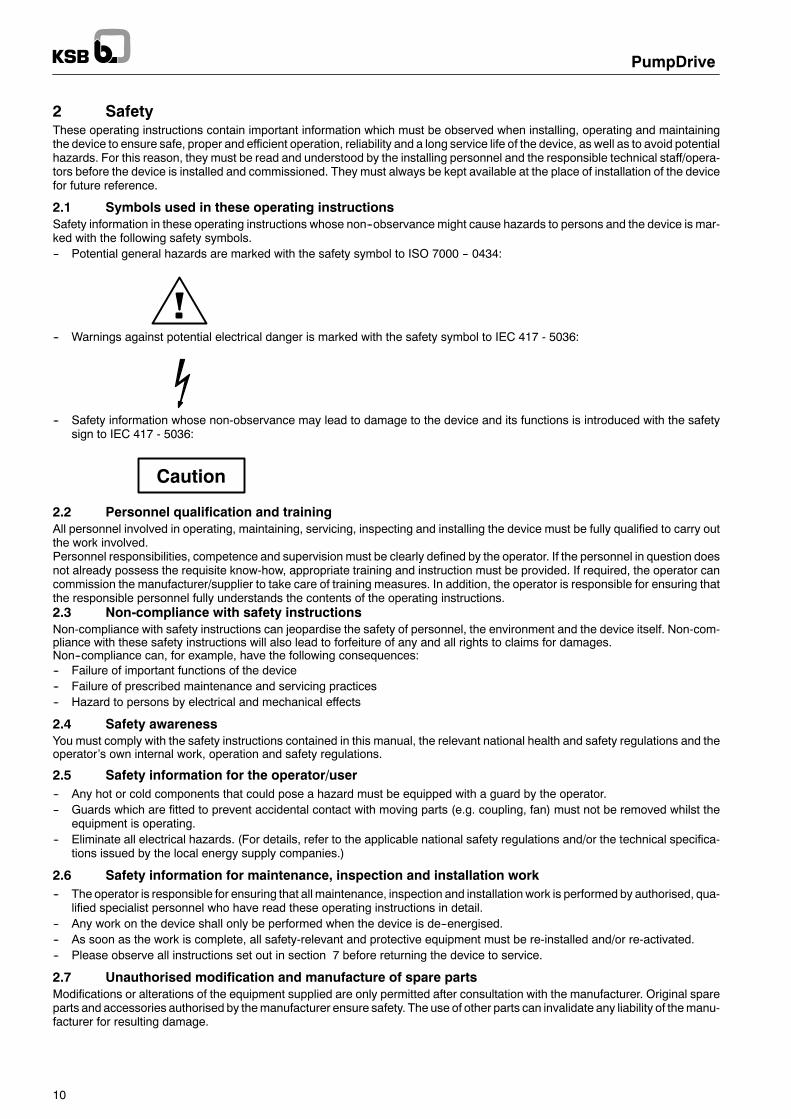
2.1 Symbols used in these operating instructionsSafety information in these operating instructions whose non--observance might cause hazards to persons and the device is mar-ked with the following safety symbols.-- Potential general hazards are marked with the safety symbol to ISO 7000 -- 0434:
-- Warnings against potential electrical danger is marked with the safety symbol to IEC 417 - 5036:
-- Safety information whose non-observance may lead to damage to the device and its functions is introduced with the safetysign to IEC 417 - 5036:
Caution
2.2 Personnel qualification and trainingAll personnel involved in operating, maintaining, servicing, inspecting and installing the device must be fully qualified to carry outthe work involved.Personnel responsibilities, competence and supervision must be clearly defined by the operator. If the personnel in question doesnot already possess the requisite know-how, appropriate training and instruction must be provided. If required, the operator cancommission the manufacturer/supplier to take care of training measures. In addition, the operator is responsible for ensuring thatthe responsible personnel fully understands the contents of the operating instructions.2.3 Non-compliance with safety instructionsNon-compliance with safety instructions can jeopardise the safety of personnel, the environment and the device itself. Non-com-pliance with these safety instructions will also lead to forfeiture of any and all rights to claims for damages.Non--compliance can, for example, have the following consequences:-- Failure of important functions of the device-- Failure of prescribed maintenance and servicing practices-- Hazard to persons by electrical and mechanical effects
2.4 Safety awarenessYou must comply with the safety instructions contained in this manual, the relevant national health and safety regulations and theoperator’s own internal work, operation and safety regulations.
2.5 Safety information for the operator/user-- Any hot or cold components that could pose a hazard must be equipped with a guard by the operator.-- Guards which are fitted to prevent accidental contact with moving parts (e.g. coupling, fan) must not be removed whilst the
equipment is operating.-- Eliminate all electrical hazards. (For details, refer to the applicable national safety regulations and/or the technical specifica-
tions issued by the local energy supply companies.)
2.6 Safety information for maintenance, inspection and installation work-- The operator is responsible for ensuring that all maintenance, inspection and installation work is performed by authorised, qua-
lified specialist personnel who have read these operating instructions in detail.-- Any work on the device shall only be performed when the device is de--energised.-- As soon as the work is complete, all safety-relevant and protective equipment must be re-installed and/or re-activated.-- Please observe all instructions set out in section 7 before returning the device to service.
2.7 Unauthorised modification and manufacture of spare partsModifications or alterations of the equipment supplied are only permitted after consultation with the manufacturer. Original spareparts and accessories authorised by themanufacturer ensure safety. The use of other parts can invalidate any liability of themanu-facturer for resulting damage.

PumpDrive
11
2.8 Software changes/warrantyThe PumpDrive software has been specially created for this device and thoroughly tested. Changes or additions to the softwareor parts of the software can affect functioning of the device. As KSB has no influence on software changes or add--ons and cannottest these, they are not permitted.This does not, however, apply to software updates supplied by KSB. See also section 2.7 Unauthorisedmodification andmanufac-ture of spare parts.
2.9 Unauthorised modes of operationThe warranty relating to the operating reliability and safety of the device supplied is only valid if the device is used in accordancewith its intended use as described in the following sections.The limit values specified in the product literature must not be exceeded under any circumstances.
2.10 Unintentional start--up-- Note that hazardous current peaks can occur when the motor is started.-- Fast-acting fusesmust be installed in the power supply cable for the PumpDrive. They do not, however, offer sufficient protection
for personnel or the machines if the motor is started unintentionally.-- If the motor is not started properly, this can cause current surges that could endanger personnel.
Before supplying power to PumpDrive:-- Make sure that there is no hazard to personnel and machinery; the mains voltage matches the rated motor voltage stated on
the motor rating plate; and the supply and control cables are connected properly.Before starting PumpDrive:-- Make sure that the inputs and outputs are configured properly; the motor parameter settings are in accordance with the speci-
fications on the rating plate; and the function parameters have been set to suit the drive application.-- All connections and parameter settings must be carried out by trained specialist personnel.-- The line currentmust be limited to the required load current. If more than one drive is used, each onemust be checked to ensure
that it can be controlled. If there is more than one PumpDrive, one of the PumpDrives must be started up and motor controlmust be tested.
-- The drive inputs/outputs must be configured to suit the selected application.-- If required, special functions (e.g. PI controller) must be configured.-- If variable parameters are changed, this can affect the automatic drive start--up function, which could cause the drive to start
accidentally.
Service work-- Work onPumpDrive shall be performed byKSBService personnel only. Before starting anywork, remove themains fuses from
PumpDrive, then disconnect the system from the power supply and secure it against inadvertent start--up.-- After the system has been switched off, wait 5 minutes until hazardous voltages have discharged.
2.11 Capacitor discharge timeHigh--voltage capacitors are installed in the PumpDrive power section. If you need to carry out maintenance work on the drive,disconnect the drive from the power supply and wait for the voltage in the DC link to discharge.-- Once you have switched off the power supply, wait at least 5 minutes before starting work.-- Non--compliance with these instructions may cause personal injury and damage to property, for which KSB accepts no liability
whatsoever.
Warning: Contact with live parts can cause potentially fatal injury – evenafter separation from the mains voltage. Wait at least 5 minutes!
2.12 EnvironmentThe standard PumpDrivemodel has an IP 55 enclosure and is suitable for cabinet mounting (CM), motor mounting (MM) and wallmounting (WM).-- PumpDrives which are installed outdoors must be provided with suitable protection to prevent condensation on the electronic
equipment and exposure to excessive sunlight.-- PumpDrive must only be used in environments for which its enclosure provides adequate protection.

PumpDrive
12
3 Transport and temporary storage3.1 TransportThe device must be transported properly and in its original packaging.Prior to dispatch, the device was tested and inspected to ensure full compliance with specifications. Consequently, the deviceshould be in perfect electrical andmechanical conditionwhen received. Youare advised to inspect the device for in--transit damageimmediately upon receipt. If there are any complaints or objections, the recipient and carrier must jointly draw up a damage report.
3.1.1 Transport of Etaline/Etabloc PumpDrive
Fig. 2: Transport of Etaline/Etabloc PumpDrive
3.1.2 Transport of Etanorm/CPKN/Multitec PumpDrive
Fig. 3: Transport of Etanorm/CPKN/Multitec PumpDrive

PumpDrive
13
3.1.3 Transport of Movitec PumpDrive
Fig. 4: Transport of Movitec PumpDrive
3.2 Temporary storageThe device must be stored under dry and vibration-free conditions, if possible in its original packaging.The ambient temperature during storage must be between --10 _C and +70 _C.Make sure that the relative humidity does not exceed 85% and that the electric components are not exposed to condensation (oxi-dation protection).Avoid major fluctuations in ambient humidity.
4 Product description4.1 DesignationThe PumpDrive type code is structured as follows and is printed on the rating plate on the housing.
2 018K50 AH P SI 2
Installation2 = Cabinet mounting3 = Wall mounting5 = Motor mounting (factory-set)
PowerFor example:000K55 = 0.55 kW018K50 = 18.5 kW045K00 = 45 kW
Functions / Control panelAH = Advanced with graphical control panelB0 = Basic with standard control panelBH = Basic with graphical control panel
Field bus moduleL = LONP = Profibus0 = none
Parameterisation: motorSI = for Siemens motorCA = for Cantoni motorWO= for Wonder motor00 = No factory parameterisation
Parameterisation: number of poles2 = 2 poles4 = 4 poles0 = No factory parameterisation

PumpDrive
14
4.2 Product featuresPumpDrive is a modular, self-cooling frequency inverter. It allows the speed of standardised IEC frame motors to be varied bymeans of analog standard signals, a field bus or the control panel.PumpDrive has been specially designed for operating centrifugal pumps smoothly and efficiently. PumpDrive’s open-loop and clo-sed-loop control, switching and monitoring functions enable efficient motor control for the most common pumping applications.These also include multiple pump configurations.As PumpDrive is self--cooling, it can be mounted on a motor (MM), on the wall (WM) or in a cabinet (CM).PumpDrive is a modular, self-cooling frequency inverter (sizes 1.5 kW and above come with an external fan).PumpDrive is a compact device with an IP 55 enclosure.PumpDrives which are installed outdoors must be provided with suitable protection to prevent condensation on the electronicequipment and exposure to excessive sunlight.
4.3 Models and functions4.3.1 Basic and AdvancedPumpDrive is available in two versions (for a functional overview, see Table 2):D BasicD AdvancedFurther models can be configured in combination with the control panel:D Basic with standard control panelD Basic with graphical control panelD Advanced with graphical control panelThe control panel features a screen and keys that allow you to set parameters as well as perform monitoring and manual controltasks. If this feature is not required, a blanking plate is available as an accessory.

PumpDrive
15
4.3.2 Functions
Functions PumpDrive ...
Basic Advanced
Protective functions
Thermal motor protection by PTC thermistors H H
Electrical motor protection by overvoltage/undervoltage monitoring H H
Dynamic overload protection by speed limitation (i2t control) H H
Dry running protection (sensorless) H
Dry running protection (external control signal) H H
Characteristic curve control H 1) H 2)
Open-loop control
Open-loop operation via setpoint setting H H
User-definable speed (0 to 70 Hz) H H
Stand--by mode (stop at minimum speed after a defined period of time) H H
Programmable start and stop ramps H H
Slave in multiple pump configuration with up to 6 pumps H H
Master in multiple pump configuration with up to 6 pumps H
Dual pump configuration with built--in redundancy (by means of DPM mo-dule)3)
Accessories
Closed-loop control
Closed-loop operation via integrated, adjustable PI controller H H
Differential pressure control H H
Level control H H
Temperature control H H
Flow control H H
Dynamic pressure setpoint compensation H H
Commissioning
Plug & Run 4) H H
Automatic sensor recognition (when frequency inverter is started) H H
Operation
Blanking plate (no operating option) Accessories
Standard control panel, rotatable 180_ H
Graphical control panel, rotatable 180_ optional H
Monitoring
Status information via “traffic light” signals (OK, warning, alert) H H
Information on operating data (speed, current, actual value, etc.) H H
Fault history H H
Energy meter (kWh) H H
Operating hours counter (motor, FI) H H
Information on current flow rate -- sensorless H 5)
Communication
Profibus field bus system optional optional
LON field bus system optional optional
RS 232 service interface H H
RS 485 service interface on request
Table 2: Functions
1) Based on monitoring of the effective motor power2) Based on the pump input power (for multiple pump configuration)3) Only in combination with the standard control panel4) For open-loop control mode or non-optimised closed-loop control mode of single pumps5) Based on an estimate of the pump input power or via a differential pressure measurement

PumpDrive
16
4.4 Technical dataMains voltage1): 3~ 380 VAC --10% to 480 VAC +10%Voltage difference between the three phases: 2% of the supply voltageMains frequency: 50 -- 60 Hz 2%FI output frequency:PWM carrier frequency2)3):
0 -- 70 HzRange: 1--8 kHz, in 0.5 kHz stepsPumpDrive sizes A and B: 4 kHzPumpDrive sizes C and D: 2.5 kHz
Phase rate of rise dv/dt 4) Max. 5000 V/μs (depending on the PumpDrive size)Peak voltages: 2 · 1.41 · VeffEfficiency: 98% -- 95% (average value for all load cases)5)
Noise emissions: Sound pressure level of the pumps used + 2.5 dB6)
Enclosure7)8): IP 55In--service ambient temperature range: 0°C to +40°CIn--storage ambient temperature range --10°C to +70°CRel. humidity: Operation: max. 85%, non-condensing
Storage: 5% to 95%Transport: max. 95%
Altitude requirements: < 1000 m above MSL,or 1% power derating per additional 100 m
Vibration resistance: Max. 16.7 m/s2 to EN 60068-2-64:1994RFI suppression to DIN EN 55011: Class B for motor ratings≤7.5 kW, cable length < 5 m
Class A for motor ratings>7.5 kW, cable length < 50 mMains feedback9): Integrated line chokesInternal power supply unit: 24 V 10% / max. 80 mA DCNumber of parameterisable analog inputs: 2Voltage input: 0/2 -- 10 V DC
Input resistance Ri: 22 kΩCurrent input: 0/4 -- 20 mA DC
Input resistance Ri: 500 ΩResolution: 10 bitNumber of parameterisable analog outputs: 1 (switching between 4 output values)Voltage output: 0 -- 10 V / max. 5 mA DCNumber of digital inputs: 6 in total, 4 of these can be parameterised as requiredNumber of parameterisable relay outputs: 2x NO contactsMaximum contact rating: 250 V AC / 1 A
Table 3: Technical data
1) If the mains voltage is low, the rated torque of the motor will be reduced.
2) Take into account the dependency on the cable capacity.
3) Power derating for increased carrier frequency:
-- Sizes A and B (at PWM carrier frequency > 4 kHz):Inom(PWM)= Inom ⋅ 1− [fPWM− 4kHz] ⋅ 2, 5%
-- Sizes C and D (at PWM carrier frequency > 2.5 kHz):Inom(PWM)= Inom ⋅ 1− [fPWM− 2, 5kHz] ⋅ 3, 5%
4) Cables with a high stray capacitance can cause voltage to double.
5) The maximum power loss across all load cases is 5% of the nominal power. The power loss is reduced when the nominalpower is increased, meaning efficiency levels improve up to 98%.
6) This is an approximate value. The above value only applies at the nominal duty point (50 Hz). See also the specific noisevalues of the pump. These are also documented for nominal operation. Deviating values can occur during regulation.
7) PumpDrives which are installed outdoors must be provided with suitable protection to prevent condensation on the electronicequipment and exposure to excessive sunlight.
8) Power derating for higher ambient temperature: The max. ambient temperature of 50°C must not be exceeded!
Inom(temp)= Inom ⋅ 1− [Tambient−40oC] ⋅ 3%
9) Note the information on the use of line chokes provided in the “Accessories and optional equipment” section!

PumpDrive
17
Power range
2- and 4-pole motorsSize Power1) [kW] Irated2) [A] MM WM CM
0.55 1.8 H H H
0.75 2.5 H H H
A1.1 3.5 H H H
A1.5 4.8 H H H
2.2 6.0 H H H
3.0 8.0 H H H
4.0 10.0 H H H
B 5.5 13.0 H H HB7.5 16.5 H H H
11.0 25.0 H H H
C15.0 31.0 H H H
C18.5 39.0 H H H
22.0 45.0 H H H
30.0 65.0 H H H
D 37.0 80.0 H H HD45.0 93.0 H H H
Table 4: Power range
1) For information on power derating refer to section 4.4, Table 3.
2) At a max. ambient temperature of 40°CPWM carrier frequency-- Sizes A and B: 4 kHz-- Sizes C and D: 2.5 kHz
4.5 Mounting variants
Wall mounting (WM) Cabinet mounting (CM)Motor mounting (MM)
Fig. 5: Mounting variants

PumpDrive
18
4.5.1 Power range4.5.2 Dimensions and weightsDimensions and weights refer exclusively to PumpDrive without motor for motor mounting (MM), wall mounting (WM) and cabinetmounting (CM).
Fig. 6: Dimensions and weights
PumpDrive Size Power[kW]
Dimensions Mounting holes Weight[k ]
p[kW]
A [mm] B [mm] C [mm] D [mm] E [mm] F [mm] G [mm]
g[kg]
.. 000K55 .. 0.55
.. 000K75 .. 0.757
A.. 001K10 .. 1.1 260
190158
65164 242 4xM6
7
A.. 001K50 .. 1.5
260(312) 1) 190
158(168) 1) 65
164(164) 1)
242(292) 1)
4xM69 mm
.. 002K20 .. 2.29
.. 003K00 .. 39
.. 004K00 .. 4325 170 224 307 4 M6
10
B .. 005K50 .. 5.5 325(377) 1) 250
170(180) 1) 65
224(224) 1)
307(357) 1)
4xM69 mm 10 5
.. 007K50 .. 7.5(377) 1) (180) 1) (224) 1) (357) 1) 9 mm 10.5
.. 011K00 .. 1123
C.. 015K00 .. 15 420
320235
125283 396 4xM8
23
C.. 018K50 .. 18.5
420(482) 1) 320
235(245) 1) 125
283(283) 1)
396(458) 1)
4xM812 mm
30.. 022K00 .. 22
30
.. 030K00 .. 30600 290 410 573 4 M10 48
D .. 037K00 .. 37 600(659) 1)
450 290(300) 1)
125 410(410) 1)
573(635) 1)
4xM1012 mm
48
.. 045K00 .. 45(659) 1) (300) 1) (410) 1) (635) 1) 12 mm
50
1) Dimensions given in parentheses apply to the wall-mounted (WM) and cabinet-mounted (CM) models only. All the dimensional data, i.e. both the sizes and thedistances between the mounting holes, refer to PumpDrive including the wall mounting brackets.
Table 5: Dimensions and weights
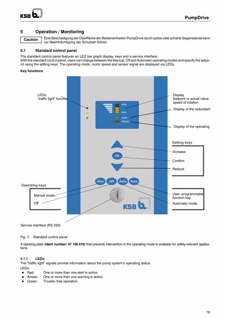
Caution
PumpDrive
19
5 Operation / MonitoringEineBeschädigung derOberfläche der Bedieneinheiten PumpDrive durch spitze oder scharfeGegenstände kannzur Beeinträchtigung der Schutzart führen.
5.1 Standard control panelThe standard control panel features an LED bar graph display, keys and a service interface.With the standard control panel, users can change between theManual, Off andAutomatic operatingmodes and specify the setpo-int using the setting keys. The operating mode, motor speed and sensor signal are displayed via LEDs.
Key functions
DisplaySetpoint or actual value,speed of rotation
LEDs:“traffic light” function
Service interface (RS 232)
Reduce
Increase
Setting keys
Manual mode
Off
User--programmablefunction key
Automatic mode
Operating keys
Confirm
Display of the redundant
Display of the operating
Fig. 7: Standard control panel
A blanking plate (ident number: 47 106 619) that prevents intervention in the operating mode is available for safety-relevant applica-tions.
5.1.1 LEDs:The “traffic light” signals provide information about the pump system’s operating status.LEDs:D Red: One or more than one alert is activeD Amber: One or more than one warning is activeD Green: Trouble--free operation

PumpDrive
20
5.1.2 LED bar graph displayThe LED bar graph display can display three different colours. The colours represent the following operating parameters:D Red: Motor frequencyD Amber: Actual value sensor signalD Green: Setpoint
The current values of these three operating parameters are shown as percentages by means of the five individual LEDs. EachLED represents a particular percentage range of the operating parameter selected:D Min. LED: 0--19%D 2. LED: 20--39%D 3. LED: 40--59%D 4. LED: 60--79%D Max. LED: 80--100%
The end value of 100% represents:
-- The maximum motor frequency (e. g. 50 Hz≙ 100%)
-- The full-scale value of the sensor (e.g. 6 bar≙ 100%)
-- The specified setpoint in open-loop control mode (e.g. 50 Hz≙100% setpoint)
-- The specified setpoint in closed-loop control mode (full-scale value of the sensor≙ 100% setpoint)
DPM LEDThis LED shows the function assigned to the PumpDrive:D Green: Master PumpDrive in a multiple pump systemD Flashing green Aux. Master PumpDrive in a multiple pump systemD No display. PumpDrive used as single--pump drive
Mode LEDThis LED shows the current operating mode of the PumpDrive:D Red: Off mode, switched offD Amber: Automatic modeD Green: Manual mode
5.1.3 Setting keys
5.1.3.1 Operating parameter display (monitoring)This function is only available in manual or automatic mode. The actual value can only be displayed if a sensor is connected.
Up Arrow key:D Pressing key once:
The motor frequency is displayed (red LEDs of the bar graph display)D Pressing key twice:
The actual value is displayed (amber LEDs of the bar graph display)D Pressing key three times:
The setpoint is displayed (green LEDs of the bar graph display)
Down Arrow key:The operating parameters are selected in reverse order to the Up Arrow key.
5.1.3.2 Setpoint specification-- Use the or keys to switch to the setpoint display (green LEDs).-- Press OK key.
The green LEDs of the LED bar graph display start flashing.-- Use the or keys to increase / reduce the setpoint.
Each time a key is pressed, the valuewill be changed by an increment of 0.25 Hz or 0.5%. If the keys are pressed continuously,the setpoint is increased / reduced continuously.
-- Press OK key again.The LED bar graph display returns to operating parameter display mode, i.e. the LEDs are steadily lit.

PumpDrive
21
5.1.4 Operating keysYou can use the operating keys to select the Automatic, Manual or Off operating modes.The parameterisable Func key is only available in Manual or Automatic mode.
OK key - also serves as alert reset key
Manual mode
OffIf the drive is in Manual mode when the voltage supply is interrupted, the drive will switch to the Offmode once the voltage supply is restored.
Automatic mode
Parameterisable function keyThe dynamic pressure compensation function is activated when this key is pressed (see section 7.9.1).When the OK key is pressed, the percentage of the setpoint compensation of the dynamic pressure compen-sation function is displayed in the bar graph display by flashing amber LEDs.When the parameterisable function key is pressed again, the display of the setpoint compensation is deacti-vated.
5.1.5 Service interfaceThe service interface allows aPC /Notebook to be connected via a special cable (USB -RS232). ThePumpDriveServiceSoftwarecan be used to configure and parameterise the pump system if you do not have access to a control panel.You cannot implement a software update for PumpDrive with the standard control panel. The customer version of the Service Soft-ware for parameterisation and data back--up can be ordered under ident No.: 47 121 211.

PumpDrive
22
5.2 Graphical control panelThe graphical control panel features a back-lit display, as well as function, navigation and operation keys, LEDs and an accesspoint for the service interface.The display shows important information for pump system operation. Data can be displayed in plain text and parameters can beset.The Language parameter (3--1--1--1) is used to select the language of the text displayed.
Display(plain text)
Information
Settings
LEDs:“traffic light” function
Operation
Diagnosis
Up
Escape key
Service interface
Down OK key
Help key
Navigation keys
Function keys
Manual mode
Off
Parameterisablefunction key
Automatic mode
Operating keys
Fig. 8: PumpDrive graphical control panel
5.2.1 LEDs:The “traffic light” signals provide information about the pump system’s operating status.LEDs:D Red: One or more than one alert is activeD Amber: One or more than one warning is activeD Green: Trouble--free operationD Green Trouble--free operation
Flashing: Indicates that an Advanced control panel is being used

PumpDrive
23
5.2.2 Function keysYou can use the function keys to access the elements at the first menu level directly: Operation, Diagnosis, Settings and Informa-tion.
Operation Settings
Diagnosis Information
5.2.3 Navigation keysThe navigation keys are used for navigating in the menu and for confirming settings.
Up or DownD Move up / down through the menu options orD Increase / reduce a value when you are entering numerals
Escape keyD Delete/reset entry (the entry is not saved)D Return to the previous menu level
OK keyD Confirm a settingD Confirm a menu selectionD Move to the next digit when you are entering numeralsHelp keyD Displays a help text for each selected menu option
5.2.4 Operating keysYou can use the operating keys to select the Automatic, Manual or Off operating modes.Theoperating keys for selecting theManual (Man) andOff (Off) operatingmodes canbe disabled. This prevents improper or unau-thorised intervention in the operating mode of PumpDrive.
OK key also serves as alert reset key Automatic mode
Manual mode User-parameterisable function key
Off
The Func operating key can be parameterised and can, among other functions, be used to start a multiple pump system (SystemStart/Stop). In this case, the drive will stop themultiple pump systemwhen the voltage supply has been interrupted and is restored(Auto Stop operating mode).Alternatively, a multiple pump system can be started using Digital Input 2 (DI2) (terminals P4:13, P4:15, see section 6.4.9.3).
Parameter Description Setting range / options Fact.Set
3--1--4--1 Enable / disable Man key 1 – Disabled 23--1--4--2 Enable / disable Off key 2 – Enabled 23--1--4--3 Assign Func key 1 – No Function
2 – Sleep Mode3 – PI Mode4 – Trip Reset5 – Change Pump6 – System Start/Stop
1
Table 6: Parameters for setting the operating key functions

PumpDrive
24
5.2.5 DisplayThe six--line display contains the following information:
Parameter No.
Parameter selection list
Operating mode Operating status
Model / Selected pump
Main menu selection
Fig. 9: Display for the selected menu option
Display Description
Parameter No. Displays the selected parameter No.Model
or
A -- HMI -- CA A = Advanced or B = BasicHMI With control panelC Customer access level
Selected pump Pump 1, Pump 2 ... Pump 6
Main menu selection OperationDiagnosisSettingsInformation
Parameter selection list List of selectable parametersOperating mode Man, Off, AutoOperating status Run, Stop
Table 7: Display for the selected menu option
The number of the current menu or parameter is displayed at the top left of the screen. This four--part number indicates the paththrough the the menu levels and thus enables you to quickly locate parameters (see section 5.2.9 Displaying and changing para-meters).The PumpDrive model or selected pump is displayed at the top right of the screen.The current operating mode of the PumpDrive currently selected is displayed at the bottom left of the screen: Man/Auto/Off.The current operating status of the PumpDrive currently selected is displayed at the bottom right of the screen.If a fault or malfunction occurs, this is displayed in the bottom line instead of the operating mode and status.
5.2.6 Service interfaceThe service interface allows a PC / Notebook to be connected via a special cable (USB - RS232). The PumpDrive service softwarecan be used to configure and parameterise the pump system if you do not have access to a control panel.A PumpDrive software update can also be implemented via this interface, if PumpDrive is equipped with a graphical control panel.The customer version of the service software can be ordered under ident No.: 47 121 211.

PumpDrive
25
5.2.7 Menu structureLevel 1 Level 2 Level 3 Level 4
1 Operation 1--1 Operation 1--1--1 Operation
1--2 Motor 1--2--1 Motor
1--3 Signals 1--3--1 Process
1--3--2 Inputs & Outputs
1--4 PumpDrive 1--4--1 Status
1--4--2 Local Bus
1--4--3 Diagnosis Bus
1--5 Pump 1--5--1 Flow Rate Meas *
1--5--2 Power Measurmnt *
1--5--3 Pump Status *
1--6 LON Module 1--6--1 LON Input Netw
1--6--2 LON Output Netw
1--6 LON Config
2 Diagnosis 2--1 Alert History 2--1--1 Alert History
2--2 Warnings 2--2--1 Warnings
2--3 Alerts 2--3--1 Alerts
2--4 Op Logger 2--4--1 PumpDrive
2--4--2 Process Timer
3 Settings 3--1 Panel 3--1--1 Basic Settings
3--1--2 Set-up
3--1--3 Display Config.
3--1--4 Keypad
3--1--5 Panel Commands
3--1--6 Password
3--1--7 Network Config
3--2 PumpDrive 3--2--1 Basic Settings
3--2--2 Units
3--2--3 Set-up
3--3 Load and Motor 3--3--1 V/f Settings
3--3--2 Motor Data
3--3--4 Start Adjust
3--3--5 Motor Temp Parameterlevel
3--3--6 Rampslevel
3--3--7 Res Freq BypassF d i3--4 Spec Pump Sett 3--4--1 Q/p Measurement For a descrip-tion of the pa-
3--4--2 Setpoint Comption of the pa-rameters, see
3--4--3 Sleep Moderameters, seesections 7
3--5 Setpoint 3--5--1 General Settngs
3--5--2 Preset Setpoint
3--5--3 Prset Out Freq1
3--5--4 Setpoint Source
3--6 Limits&Warns 3--6--1 Motor Limits
3--6--2 Motor Warnings
3--6--3 Analog IN Wrn
3--6--4 Load Warnings
3--6--5 Setpoint Warns
3--6--6 Feedback Warn
3--7 Digital IN/OUT 3--7--1 Digital IN 2--5
3--7--2 Digital OUT 1
3--7--3 Digital OUT 2
3--8 Analog IN/OUT 3--8--1 Analog IO Mode
3--8--2 Analog IN 1
3--8--3 Analog IN 2
3--8--4 Analog OUT 1
3--9 PI Controller 3--9--1 Process PI Ctrl
3--9--2 Feedback Source
3--10 Communication 3--10--1 General Settngs
3--11 Add Settings 3--11--1 Inverter Switch
3--11--2 Trip
3--11--3 Crrnt Lim Ctrl
3--11--4 Max Output
3--11--5 PDrive Settings
3--12 Adv Pump Ctrl 3--12--1 Flow Rate Meas *
3--12--2 Low Q Limit *
3--12--3 H / P / Q Curves *
3--12--4 Pump Protection *
3--12--5 MultipumpConfig *
4 Information 4--1 PDrive Info 4--1--1 PDrive ID/LON Identificat
4--2 Panel 4--2--1 Panel Ident
* = PumpDrive Advanced only
Table 8: Menu structure

PumpDrive
26
5.2.8 Access levels
Various access levels have been defined to prevent accidental or unauthorised access to PumpDrive parameters.Access levels:StandardUnless users log on to one of these access levels, they will only have limited access to parameters.CustomerAccess level for suitably trained users. This level enables access to all the parameters required for commissioning. You have toenter a password using 3-1-6-1 Login. You can change your password using 3-1-6-4Customer Passwd after you have entered0000 (factory password). If you deactivate password protection via parameter 3-1-6-5, this access level becomes the defaultaccess level. This applies to the factory settings.ServiceAccess level for service personnel. You have to enter a password using 3-1-6-2 Login.FactoryAccess level for the manufacturer only.
Note: If no keys are pressed for ten minutes, the system will automatically return to the default access level.
5.2.9 Displaying and changing parametersThe parameter numbers identify the navigation path, which helps you find a particular parameter quickly and easily.The first digit of the parameter number indicates the first menu level, which can be called up directly via the four function keys.
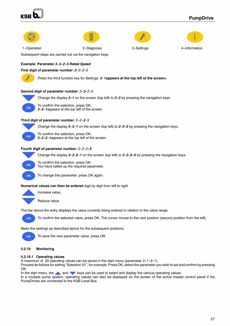
PumpDrive
27
1--Operation 2--Diagnosis 3--Settings 4--Information
Subsequent steps are carried out via the navigation keys.
Example: Parameter 3-3-2-5 Rated Speed
First digit of parameter number: 3--3--2--5
Press the third function key for Settings. 3-1appears at the top left of the screen≥
Second digit of parameter number: 3--3--2--5
Change the display 3-1 on the screen (top left) to 3-3 by pressing the navigation keys.
To confirm the selection, press OK.3-3-1appears at the top left of the screen.
Third digit of parameter number: 3--3--2--5
Change the display 3-3-1 on the screen (top left) to 3-3-2 by pressing the navigation keys.
To confirm the selection, press OK.3-3-2-1appears at the top left of the screen.
Fourth digit of parameter number: 3--3--2- 5
Change the display 3-3-2-1 on the screen (top left) to 3-3-2-5 by pressing the navigation keys.
To confirm the selection, press OK.You have called up the required parameter.
To change this parameter, press OK again.
Numerical values can then be entered digit by digit from left to right.
Increase value.
Reduce value.
The bar above the entry displays the value currently being entered in relation to the value range.
To confirm the selected value, press OK. The cursor moves to the next position (second position from the left).
Make the settings as described above for the subsequent positions.
To save the new parameter value, press OK.
5.2.10 Monitoring
5.2.10.1 Operating valuesA maximum of 20 operating values can be saved in the start menu (parameter 3--1--3--1).Proceed as follows for setting ”Selection 01”, for example: Press OK, select the parameter youwish to set and confirm by pressingOK.In the start menu, the and keys can be used to select and display the various operating values.In a multiple pump system, operating values can also be displayed on the screen of the active master control panel if thePumpDrives are connected to the KSB Local Bus.

PumpDrive
28
1--1 Operation
Parameter Description
1--1--1--1 Total period of power supply [h]1--1--1--2 Operating hours counter [h]1--1--1--3 Energy meter [kWh]1--1--1--4 Number of starts1--1--1--5 Reset energy meterTable 9: Operating values for operation
1--2 Motor
Parameter Description
1--2--1--1 Power [kW]1--2--1--2 Power [HP]1--2--1--3 Motor voltage [V]1--2--1--4 Frequency [Hz]1--2--1--5 Motor current [A]1--2--1--6 Speed [1/min]Table 10: Operating values for the motor
1--3--1 Process signals
Parameter Description
1--3--1--1 Actual value without unit1--3--1--2 Actual value in %1--3--1--3 Setpoint without unit1--3--1--4 Setpoint in %1--3--1--5 Analog input 1 without unit1--3--1--6 Analog input 2 without unit1--3--1--7 Pressure P11--3--1--8 Pressure P21--3--1--9 Flow rate without unit1--3--1--10 Flow rate in %1--3--1--11 TemperatureTable 11: Operating values for process signals
1--3--2 Input and output signalsThe status of the digital inputs / relay outputs is displayed as follows via the Input and Output Signals (1--3--2) parameter:
Reading Description
1 hex Digital input 1 active2 hex Digital input 2 active4 hex Digital input 3 active8 hex Digital input 4 active16 hex Digital input 5 active32 hex Digital input 6 active256 hex Relay 1 active512 hex Relay 2 activeTable 12: Operating values for input and output signals
If several inputs / relays are active, the readings are added up. Example:-- Relay 1 active 256 hex-- Dig IN 1 active 1 hex-- Dig IN 5 active 16 hexThe reading will then be 273 hex.

PumpDrive
29
5.2.10.2 MessagesAll monitoring and protective functions (see section 7) trigger warnings or alerts. These are signalled via the amber or red LED.A flashing message is output in the last line of the control panel display. If more than one message is output, the last one is dis-played. Alerts have priority over warnings.
To display current messages, choose the Diagnosis menu and thenWarnings (2-2-1) or Alerts (2-3-1).
Active warnings and alerts can also be connected to the relay outputs (see section 7.8).
5.2.10.3 Resetting and acknowledging alertsYou can acknowledge alerts once the cause has been rectified. Alerts can be acknowledged individually in the alert list in the Dia-gnosis menu under 2--1. When the system is reset, this causes all the alerts to be reset too. The reset can be carried out via thecontrol panel using the OK key (only possible in the start menu). You may have to press the ESC key several times to return tothe start menu. The reset can also be carried out via a digital input. Digital input 4 is defaulted for this purpose (see section 7.11).
When you reset alerts, you may have to restart the system.
In some cases, alerts are reset automatically (parameter Trip Reset Mode 3--11--2--1). This parameter is defaulted to automaticreset (see section Table 66, page 76).
Motor will restart after automatic fault reset.
5.2.10.4 Alert history
You can display the alert history in the Diagnosis menu under 2--1--1. The last eight alerts are listed here.
You can use the navigation keys and
the OK key to select an entry from the list.Information about when the alert has come and gone is then displayed.
Display Description
C: HHHH:MM Hours (H) and minutes (M) since alert has come
G: HHHH:MM Hours (H) and minutes (M) since alert has gone

PumpDrive
30
5.2.10.5 Warnings and alerts – Overview
Warnings
Basic
Advanced
Message Description Drive control response
x x Current limitation Impermissible overcurrent Speed reductionx x Out Freq Low Output frequency below lower limit See section 7.8x x Out Freq High Output frequency exceeds upper limit See section 7.8x x Out Curr Low Output current below lower limit See section 7.8x x Out Curr High Output current exceeds upper limit See section 7.8x x Feedback Low Actual value below lower limit See section 7.8x x Feedback High Actual value exceeds upper limit See section 7.8x x Setpoint Low Setpoint below lower limit See section 7.8x x Setpoint High Setpoint exceeds upper limit See section 7.8x x Power Low Power below lower limit See section 7.8x x Power High Power exceeds upper limit See section 7.8x x Analog IN1 Low Signal on analog input 1 below lower limit See section 7.8x x Analog IN1 High Signal on analog input 1 exceeds upper limit See section 7.8x x Analog IN2 Low Signal on analog input 2 below lower limit See section 7.8x x Analog IN2 High Signal on analog input 2 exceeds upper limit See section 7.8x x Live Zero AI1 Broken wire detected on analog input 1 See section 7.8x x Live Zero AI2 Broken wire detected on analog input 2 See section 7.8x x Ctrl Timeout Actual value takes too long to arrive (for actual value
via field bus only)--
x x No MainPump Wiring error (multiple pump configuration only) Service requiredx x Network Error Network Error Service requiredx x Motor i2t Impermissible overcurrent Speed reductionx x IGBT Temperature Power electronics overtemperature Trippingx x Housing Temp Impermissible heat sink temperature Tripping
x Q High Limit Impermissible hydraulic overload See section 7.8x Q Low Limit Impermissible hydraulic part load (low flow) See section 7.8
x x No KSB Local Bus ID KSB local bus ID query could not be processed Service requiredx Q Estimate The pump is operated outside the limits of the set H/Q
sampling points or P/Q sampling points, or thesampling points have been entered incorrectly.
Warning only
Table 13: Warnings
For trouble--shooting information refer to section 10.

PumpDrive
31
Alerts
Basic
Advanced
Message Description Drive control response
x x Short Circuit Short circuit monitoring Trippingx x Therm Overload PTC has tripped Trippingx x Low 24 V Fault of internal 24V supply Trippingx x Drive overtemperature Drive overtemperature Trippingx x Undervoltage Impermissible line--side undervoltage Trippingx x Overvoltage Impermissible line--side overvoltage Trippingx x Overcurrent Impermissible overcurrent See section 7.8x x Braking Resistor
OvercurrentInternal overcurrent (for example, if the ramp is toosteep)
Tripping
x x Stop & Trip A fault resulting in Stop & Trip has occurred Stop and Tripx x Internal temperature not
permittedControl electronics overtemperature Tripping
x x No BinFile No binary file Service requiredx Dry Running Dry running of pump See section 7.8
x x Hydr. Blockage Impeller blocked See section 7.8x x KSB Local Bus Init Error KSB local bus initialisation error Service requiredx x Duplicate Node Two nodes with the same ID on the KSB local bus Service requiredx x Upload Failed Error when reading the binary files Service requiredx x Download Failed Error when downloading a parameter set Service requiredx x Too Many BinF Insufficient storage capacity Service requiredx x Download Failed Error when writing data Service required
Table 14: Alerts
For trouble--shooting information refer to section 10.
Caution
Caution
PumpDrive
32
6 Installation6.1 Installation locationThe installation location should be well ventilated and not be exposed to direct sunlight, heat or other environmental influences.Enough space is to be provided for dismantling and ventilation.
Make sure to prevent that exhaust air, either from the equipment itself or other electrical equipment installed closeby, circulates back into the equipment’s air intake.
6.2 Ambient conditionsPumpDrive can be used in a temperature range from 0_C to +50_C max.. The optimum temperature range is between 0_C and+40_C.The service life of PumpDrive is reduced, if an average temperature of +35_C/24 h is exceeded, or if PumpDrive is operated attemperatures below 0_C or above +40_C. In addition, the power rating is reduced.PumpDrive switches off automatically if excessively high temperatures occur.The standard PumpDrivemodel has an IP 55 enclosure and is suitable for cabinet mounting (CM), motor mounting (MM), and wallmounting (WM).PumpDrive must only be used in environments for which its enclosure provides adequate protection.The device must be protected against environmental influences, in particular:-- Dust-- Oil--containing air or corrosive substances-- Dust particles, which can block the ventilation channels-- Chemical or organic substances that could damage internal insulation-- Gas vapours-- Electrically conductive materials which can affect the operating properties of the electric circuits-- Warm and moist environments, which cause condensation to form on cooled components-- Seawater environmentTo prevent condensation if the PumpDrive is installed in an air--conditioned control cabinet (CM), you must switch off the mainssupply and wait until the temperature has equalised before opening the control cabinet.Make sure that the air for the cooling system does not come into direct contact with the module PCBs.
Moisture condenses in places at which the temperature decreases rapidly. If cooling air comes into contact withthe PCBs, this would cause condensation and impair the function of the drive system.
To prevent damage to components, the drive must be handled with care.The drive system must be protected against damage caused by high temperatures, condensation, impacts, etc.PumpDrives which are installed outdoors must be provided with suitable protection to prevent condensation on the electronicequipment and exposure to excessive sunlight.

PumpDrive
33
6.3 InstallationDepending on the selected installation variant, an adapter or installation kit is required.
6.3.1 Motor-mounted modelPumpDrive version MM is delivered with the frequency inverter already installed on a standardised IEC frame motor by meansof an adapter. The motors of existing pumping systems can be retrofitted with PumpDrive using the following adapters. A suitableadapter (for Siemens or Cantoni motors) is to be selected based on the motor size and type of construction used. The adaptersare suitable for use on Eff1 and Eff2 motors (apart from motor sizes 180M and 200L).
Siemens motor size Ident. numberType of construction V1 / V15 Type of construction B3
71 47 117 519 4711751980 47 117 520 On request90 47 117 521 47 117 522100 47 117 511 47 117 515112M 47 117 512 47 117 512132S 47 117 513 47 117 513160 47 117 514 47 117 514
180M Eff1 01 153 610 01 153 610180M Eff2 47 117 516 47 117 516200L Eff1 10 153 609 10 153 609200L Eff2 47 117 517 47 117 517225M 47 117 518 47 117 518
Table 15: Adapters for mounting PumpDrive on Siemens motors
Cantoni motor size Ident. numberType of construction V1 / V15
Wonder motor size Ident. number
1,1 kW 47 121 167 0,37 / 0,55 kW 01 206 5853,0 kW 47 121 166 0,75 / 1,10 kW 01 206 5864,0 kW 47 121 165 1,50 / 2,20 / 3,00 / 4,00 kW 47 115 3927,5 kW 47 121 164 5,50 / 7,50 kW 47 115 39322 kW 47 121 16337 kW 47 121 162
Table 16: Adapters for mounting PumpDrive on Cantoni motors and Wonder motors
6.3.2 Wall-mounted modelThe wall-mounted model (WM) is supplied with the installation kit required for wall mounting as a standard.PumpDrive should rest flush against the wall so that the air flow is directed through the heat sink.
PumpDrive size Ident. number of installation kitA + B 47 118 186C + D 47 118 187
Table 17: Wall-mounting kits
6.3.3 Cabinet-mounted modelThe cabinet-mounted model (CM) is supplied with the installation kit required for cabinet mounting as a standard.
PumpDrive size Ident. number of installation kitA + B 47 118 186C + D 47 118 187
Table 18: Cabinet-mounting kit
Make sure to prevent exhaust air produced by other equipment from entering the device’s air intake in order to ensure adequatecooling of the device. The following minimum distances must be observed:
Minimum distance above and below PumpDrive: 100 mmMinimum distance from the PumpDrive side walls: 20 mmThe PumpDrive’s leakage power converted to heat totals 5% of the rated power (max.).

Caution
PumpDrive
34
6.4 Connection to power supply6.4.1 General
The user and / or electrical fitter must ensure that the unit is properly grounded and fused in accordance with the valid andapplicable national and local standards and regulations.
A motor protection switch is not required because the drive has its own safety devices (e.g. electronic overcurrent trip).If motor protection switches are fitted, these should be set to a minimum of 1.4 times the rated current.The direction of rotation of the motor can be changed using the graphical control panel.Use only the available cable gland holes (if necessary, in combination with double cable glands) for establishing the cable connec-tions.Any additional drilling would generate metal chips and damage the equipment.
When the drive is connected to the mains power, this applies power to the components of the power section.
Once you have switched off the power supply, wait at least 5 minutes (capacitor discharge time) before starting any workon live parts.
The drive is equipped with electronic safety devices, which in case of a disturbance or malfunction trip and de-energise the motor,causing it to stop.
Warning against inadvertent starting. Depending on the combination of settings, the drive could conceivably restart auto-matically after acknowledgement / reset or when the cause of failure has been eliminated.
Never open the housing cover. Any contact with live parts within the housing may cause personal injury. In addition, non--compliance with this safety information will result in forfeiture of any and all warranty claims.
The insulation on the motor and motor supply cables cannot be checked until the connections have been removed fromPumpDrive. Do not perform dielectric strength tests on the FI components.
Youmust not connect severalmotors in parallel at thePumpDrive output.Donot establish adirect input / outputconnection between the mains and motor connection terminals (bypass).
6.4.2 Selecting the power supply cablesThe type of cable you choose depends on various factors such as, for example, the connection method.Cables must not be routed across or near hot surfaces (unless they have been designed for this kind of application).When using mobile drive control devices, elastic or highly elastic cables must be employed.The cables must be used in accordance with their intended use, and the manufacturer specifications regarding rated voltages,current ratings, operating temperatures and thermal effects must be observed.The cables used for connections to fixed devices should be as short as possible and properly connected to these devices.-- The mains supply cables must be designed with a cross--section suitable for the input current (see Table 20).-- In the mains supply line to PumpDrive, three fast-acting fuses must be installed. The fuse size must be in accordance with the
PumpDrive input currents.-- Use shielded cables for the control cables with a minimum cross--section of 0.5 mm2.
The maximum cable cross-section that can be connected to control terminal strip P4 is 0.75 mm2. The maximum cable cross-section that can be connected to control terminal strip P7 is 1.5 mm2.
-- PumpDrive must be grounded.-- Establish ground connections, keeping the cables as short as possible. Different ground bus bars should be used for control
and power cables.-- If a mains contactor is used, this must be configured for an AC1 duty rating; the rated current values of the PumpDrives used
are added and the result is increased by 15%.-- Do not install the contactor between the motor and drive control.
6.4.3 Maximum motor cable lengthsIf PumpDrive is not mounted on the motor, longer motor connection cables may be required. The stray capacitance of the powercables may result in high--frequency discharge currents flowing to ground. The sum of the discharge current and motor currentmay exceed the output--side rated current of PumpDrive. PumpDrive will in this case be deactivated by its protective equipment.KSB recommends to use the following motor connection cables depending on the PumpDrive’s output class:
PumpDrive ≤ 7.5kW (Class B) PumpDrive > 7.5kW (Class A1)Maximum cable length: 5 m 50 mStray capacitance of cable: ≤ 5 nF ≤ 5 nFTable 19: Motor cable length
If longer cables than those listed above are required or the stray capacitance value exceeds the above values, we recommendto install a suitable output filter between PumpDrive and the motor to be controlled (see accessories). These filters reduce thevoltage ramp-up time of the PumpDrive output voltages and limit their peaks.

Caution
PumpDrive
35
6.4.4 Residual current device (RCD)According toDINVDE0160 three-phase frequency invertersmust be connected via universalAC /DCsensitive residual currentdevices (RCDs), as potential direct-current components may cause standard AC sensitive RCDs to either fail to respond or re-spond erroneously. If fixed connections and appropriate supplementary earthing are used (cf. DIN VDE 0160), RCDs are not man-datory.Residual current devices with a rated current of 150 mA must be used for PumpDrive sizes A and B.Residual current devices with a rated current of 300 mA must be used for PumpDrives sizes C and D.Onaccount of thehigher discharge / leakagecurrent (>3.5mA) apermanent, fixed installation and reinforcedprotectiveearthingon the drive are mandatory.
6.4.5 Electromagnetic compatibility
Shielded cables and cable ducts:The interference emitted by the inverter is generally conducted through the motor connection cables.Two RFI suppression options are suggested:-- For cable lengths >70 cm: use shielded connection cables.-- Use metal cable ducts (if shielded cables cannot be used); use a one--part cable duct with min. 80% cover. The side next to
the drive must be connected to the ground bus bar in the control cabinet and the power signals disconnected from the controlcables.
The first option is recommended if you are using deviceswith a lower output (small cable cross--section). The second option shouldbe used in all other cases.The shielded cable ensures that the high--frequency current, which normally flows as a discharge current from the motor housingto ground or between the individual conductors, now flows through the shielding.In particular, note the following:-- The shield on the connection cable must consist of a single piece and be grounded at both ends either just on the appropriate
grounding terminal or on the ground bus bar (do not connect it to the ground bus bar in the control cabinet or to the controlground bus bar).
-- When routing the control cables you should observe a minimum distance of 0.3 m to the power cables (motor or PumpDrivepower supply). Separate cable ducts must be used for control and power cables.
-- If you cannot avoid crossing control and power supply cables, you should cross them at 90_ to each other.-- The shield for the control cables – connection on drive side only – also serves as protection against radiated emission. The
shield must be connected to the signal ground.-- A minimum distance of 0.3 m between the cabling and the drive must be observed.-- For more effective shielding, install PumpDrive in a metal cabinet.-- When installing the power components in the control cabinet, make sure they are not too close to the control and monitoring
devices.-- In applications with long shieldedmotor cables, additional reactive resistors or drive output filters must be fitted to compensate
the capacitive stray current to ground and reduce the rate of voltage rise on the motor. These measures help reduce radiointerference further.
Using just ferrite rings or reactive resistors does not ensure compliance with the limit values defined in the EMCdirective.
-- If you are using a long shielded cable for the FI / motor connection, the residual current monitoring device may be triggeredby the discharge current that flows to ground (triggered by the carrier frequency). To remedy this, replace the RCD or lowerthe response limit.
If you are using shielded cables that are longer than 10m, check the stray capacitance to ensure that the diffusion betweenthe phases or to ground is not excessive, which could cause PumpDrive to stop.
The shielded cables must be connected by means of a clamping plate or clip near the electrical connection.

PumpDrive
36
6.4.6 Power supply and motor wiring
PumpDrive is available in sizes A, B, C, and D. The cables must be selected in accordance with the specifications in Table 20.
PumpDrivesize
Power[kW]
Cable gland for Input current1)[A]
Max.cable
psize [kW]
Mains powersupply cable
Sensorcable
Motor cable PTCthermistor
p[A] cable
cross-sec-tion [mm2]
.. 000K55 .. 0.55 1.9
.. 000K75 .. 0.75 2.6
A.. 001K10 .. 1.1
M25 M16 M25 M163.7
2 5A.. 001K50 .. 1.5
M25 M16 M25 M165
2.5
.. 002K20 .. 2.2 6.3
.. 003K00 .. 3 8.5
.. 004K00 .. 4 10.5
B .. 005K50 .. 5.5 M25 M16 M25 M16 13.7 2.5B.. 007K50 .. 7.5
M25 M16 M25 M1617.3
2.5
.. 011K00 .. 11 26.5
C.. 015K00 .. 15
M32 M16 M32 M1632.6
10C.. 018K50 .. 18.5
M32 M16 M32 M1641
10
.. 022K00 .. 22 47.3
.. 030K00 .. 30 68.3
D .. 037K00 .. 37 M40 M16 M40 M16 84 35D.. 045K00 .. 45
M40 M16 M40 M1697.7
35
1) Observe the information on the use of line chokes provided in the “Accessories and optional equipment” section.
Table 20: Power supply and motor wiring
The terminals and connectors of the brake resistormust not be opened or touched. Non--compliancewith these instructionsmay cause personal injury and damage to property.
Sensor & PTC sensor
+24VIN 0
PTC
PE L1 L2 L3
PE
L1L2L3N
1 2 3 4 5 6 U V W
M3~
Analoginput 2
Brake resistor
Sensor & PTC sensor
+24VIN 0
PTC
PE L1 L2 L3
PE
L1L2L3N
1 2 3 4 5 6U V W
M3~
Analoginput 2
Brake resistor
A & B C
Fig. 10: Power supply and motor wiring for sizes A & B and size C
The connections of the motor temperature sensors have to be effected in accordance with IEC 664. This means that thelive parts at the motor and sensor must have double or reinforced isolation at the terminals for the PTC connection. Thisreinforced isolation includes a creepage and clearance of 8 mm for 400/500 V AC devices. In the connection cannot beeffected as specified, proceed as follows:
-- All the other terminals for inputs and outputs have to be protected against shock hazard. Connection to other devices is notpermitted.
or
-- The temperature sensor must be electrically isolated from the terminals by means of a thermistor relay.
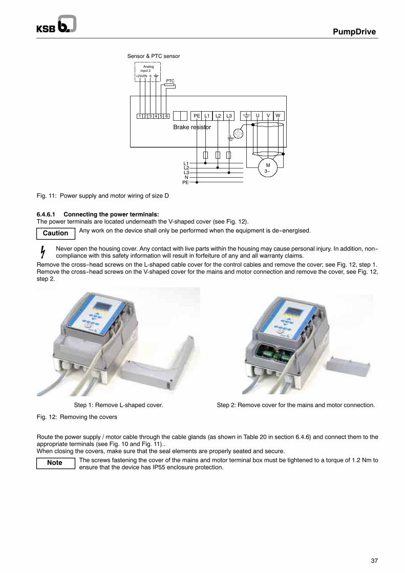
Caution
Note
PumpDrive
37
Sensor & PTC sensor
+24VIN 0
PTC
PE L1 L2 L3
PE
L1L2L3N
1 2 3 4 5 6 U V W
M3~
Analoginput 2
Brake resistor
Fig. 11: Power supply and motor wiring of size D
6.4.6.1 Connecting the power terminals:The power terminals are located underneath the V-shaped cover (see Fig. 12).
Any work on the device shall only be performed when the equipment is de--energised.
Never open the housing cover. Any contact with live parts within the housing may cause personal injury. In addition, non--compliance with this safety information will result in forfeiture of any and all warranty claims.
Remove the cross--head screws on the L-shaped cable cover for the control cables and remove the cover; see Fig. 12, step 1.Remove the cross--head screws on the V-shaped cover for the mains and motor connection and remove the cover, see Fig. 12,step 2.
Step 1: Remove L-shaped cover. Step 2: Remove cover for the mains and motor connection.
Fig. 12: Removing the covers
Route the power supply / motor cable through the cable glands (as shown in Table 20 in section 6.4.6) and connect them to theappropriate terminals (see Fig. 10 and Fig. 11)..When closing the covers, make sure that the seal elements are properly seated and secure.
The screws fastening the cover of the mains and motor terminal box must be tightened to a torque of 1.2 Nm toensure that the device has IP55 enclosure protection.

PumpDrive
38
6.4.6.2 Connecting the PTC / external sensorThecontrol cables for anexternal sensor and/or PTC thermistor are connected to the terminal strips via the twomiddle cable glands(see Fig. 10 and Fig. 11).If the sensor signal is transmitted to the drive from a higher--level control system or a PLC,make sure that all the signals are electri-cally isolated.On option, the sensor can be connected to control terminal strip P7 (also see section 6.4.9.4).Parallel wiring of these two connection points is not permitted.
6.4.7 Ground connectionPumpDrive must be properly grounded.If you are installing more than one PumpDrive, the star configuration is recommended (see Fig. 13).
.
Fig. 13: Correct ground connection
The following should also be taken into account:1. To ensure greater interference immunity, a wide contact face is required for the different ground connections.2. In the case of cabinetmounting, two separate copper groundbus bars (mains supply and control connection bar) with a suitable
size and cross--section must be used for grounding the drive. All the ground connections for the control and power cables areconnected to these. The bars are connected to the grounding system via one point only. The control cabinet is then groundedvia the mains grounding system.
The following must be connected to the mains supply ground bus bar:-- Motor grounding connections-- Drive housing-- Shielding for the power supply cables, etc.The following must be connected to the control ground bus bar:-- Shielding for the analog control connections-- Shielding for the sensor cablesThe control ground bus bars must not be affected by currents from the power circuits since this could be a source of interference.

Caution
Note
PumpDrive
39
6.4.8 Connecting the control terminals
Any work on the device shall only be performed when the equipment is de-energised.
Never open the housing cover. Any contact with live parts within the housing may cause personal injury. In addition, non--compliance with this safety information will result in forfeiture of any and all warranty claims.
The control terminals are located underneath the control panel or blanking plate. These must be removed as follows.Remove the cross--head screws on the L-shaped cover for the control cables and remove the cover (see Fig. 14).
Fig. 14: Removing the cover for the control cable
Remove the cross--head screws at the control panel or blanking plate and remove the control panel or blanking plate.The screws fastening the control panel or blanking plate must be tightened to a torque of 0.5 Nm to ensure thatthe device has IP55 enclosure protection.
The control terminal assignment is shown in Fig. 15 or Table 22.The maximum cable cross-sections (wire size) which can be connected to the control terminals of terminal strip P4 and terminalstrip P7 are:
Control terminals Rigid andflexible cables
Flexible cable with wire end sleeve
Terminal strip P4 0.2--1.5 mm2 0.75 mm2
Terminal strip P7 0.2--2.5 mm2 0.25--1.5 mm2
Table 21: Max. cable cross-sections to be connected to control terminals

PumpDrive
40
P7
P4
GND P4
DI1DI2DI3DI4DI5DI6
DI1+24VAGNDAN OUTSB1--GNDSB1+SB1--
SB1--GNDSB1+SB1--SB1Z--SB1Z+
AIN1
AGND P7
GND
AIN2
NO2
COM2
NO1
COM1
+24V
20
20
19181716151413121110987654321
10
9
8
7
6
5
4
3
2
1
Fig. 15: Input/output control terminals

PumpDrive
41
Terminal strip P4 Terminal strip P7
Terminal Signal Description Terminal Signal Description
20 0V Ground for +24 V 10 0V--AN Ground for AIN1/2
19 DIG IN6 Digital input (15/28 V DC) 9 AN1--IN Programmable analog input 1*Factory setting: setpoint source 0--10 V
or 0--20 mA
18 DIG--IN5 Digital input (15/28 V DC) 8 PE(GROUND)
Ground
17 DIG--IN4 Digital input (15/28 V DC) 7 0V Ground for +24 V
16 DIG--IN3 Digital input (15/28 V DC) 6 AN2--IN Programmable analog input 2*Factory setting: actual value source
0--10 V or 0--20 mA
15 DIG--IN2 Digital input (15/28 V DC) 5 +24 V +24 V DC voltage sourceMax. load 200 mA
14 DIG--IN1 Digital input (15/28 V DC) 4 NO2 NO contact ”NO” No. 2 (250 V AC, 1 A)
13 +24 V +24 V DC voltage sourceMax. load 200 mA
3 COM2 NO contact ”NO” No. 2 (250 V AC, 1 A)
12 0V--AN Ground for AN OUT 2 NO1 NO contact ”NO” No. 1 (250 V AC, 1 A)
11 AN OUT Analog output 0--10 V.Max. load 5 mA
1 COM1 NO contact ”COM” No. 1 (250 V AC, 1A)
10 SB1--GND Ground for KSB local bus
9 SB1 + KSB local bus signal
8 SB1 -- KSB local bus signal
7 PE(GROUND)
Ground
6 PE(GROUND)
Ground
5 SB1--GND Ground for KSB local bus
4 SB1 + KSB local bus signal
3 SB1 -- KSB local bus signal
2 SB1Z-- Bus terminator for KSB local bus
1 SB1Z+ Bus terminator for KSB local bus
Table 22: Control terminal assignment
*) Analog signals from a higher--level control station should be electrically isolated when they are transmitted to PumpDrive, for example by using buffer amplifiers.
6.4.8.1 Digital inputs
Terminal strip P4, terminals 13 to 20 (see Fig. 15)PumpDrive is equipped with 6 digital inputs. The functions of digital inputs 2 to 5 can be parameterised as required. Digital inputs1 and 6 are factory-defaulted.To connect the inputs, use terminal P4:13 (+24 V DC). If an external 24 V DC source is used, the neutral conductor of this sourcemust be connected to terminal P4:20.
6.4.8.2 Relay outputs
Terminal strip P7, terminals 1 to 4 (see Fig. 15)The function of the two volt-free relays (NO) can be parameterised via the control panel.
6.4.8.3 Analog inputs
Terminal strip P7, terminals 5 to 10 (see Fig. 15)Analog signals fromahigher--level control station should beelectrically isolatedwhen they are transmitted toPumpDrive, for exam-ple by using buffer amplifiers.If an external voltage or current source is used for the analog inputs, the ground of the setpoint or sensor sources is applied toterminal P7:10. The 24 V DC voltage source (terminals P7:5 and P7:7) is used as the power supply for the actual value sensorif PumpDrive is in closed-loop control mode. Alternatively, analog input 2 can be connected to the mains / motor / PTC terminalstrip. In this case, do not assign the input on terminal strip P7:6.
6.4.8.4 Analog output
Terminal strip P4, terminals 11 and 12 (see Fig. 15)PumpDrive is equipped with an analog output whose output value can be parameterised via the control panel depending on thedigital inputs.

PumpDrive
42
6.4.9 Multiple pump configuration
6.4.9.1 DPM set of accessoriesThe DPM set of accessories is available for controlling redundant variable--speed twin pumps (e.g. Etaline Z PumpDrive) or twoidentical variable--speed pumps operating in parallel. The dual pump module (DPM) is available as a separate accessory/sparepart.The dual pumpmodule can only be used in combination with the standard control panel for the PumpDrive Basic model. It cannotbe used in combination with the blanking plate of the graphical control panel.
Control panel
Pump Drive Blanking plate Standard Graphical
Basic XAdvanced n.a. n.a.n.a. = not available
Scope of supply of DPM (01 131 684) set of accessories:
Qty. Component Use Ident. number Sparepart
2 Dual pump module (DPM) Communication module to transfer data via KSB localbus
47 121 257 X
1 CAN bus cable (purple) Data transfer between the two PumpDrives via KSBlocal bus
01 131 429 X
1 Control cable (grey) Transmission of the measurement signal of thedifferential pressure sensor to the second PumpDrive
01 131 430 X
1 Resistance 500 Ω Conversion of the 4--20 mA (current) measurementsignal of the differential pressure signal into
0--10 V DC voltage values
11 270 044 X
2 Wire jumper Wiring of digital inputs DI1 and DI6 with 24 V DC atboth PumpDrives
11 314 428 X
3 Cable tie 01 114 5781 PumpDrive DPM operating
instructionsSee productliterature
Table 23: Scope of supply of DPM set of accessories

PumpDrive
43
6.4.9.2 KSB local busIn amultiple pump system, the PumpDrives must be connected via an internal KSB local bus. In this way, the drives can communi-cate via this bus, and the active master control panel controls the connected drives. The maximum number of PumpDrives in amultiple pump configuration is limited to six.The KSB local bus comprises three signal cables: SB1--, SB1+ and SB1-GND. These signal cables are looped through from onePumpDrive to another.The KSB local bus in the first and last PumpDrivemust be terminated via a resistor. This is implemented bymeans of a wire jumperbetween terminals 1 and 2 on terminal strip P4 (see Fig. 16).If a graphical control panel is used on the first or last PumpDrive, the wire jumper is not required.The two DIP switches on the rear of the graphical control panel (PumpDrive 2) must be set to ”Off” to deactivate the terminatingresistor of the KSB local bus.A 3-core (minimum), shielded, twisted pair cable must be used as a connection cable.
Terminal strip P4, terminals 1 to 10 (see Fig. 15)
Wiring the connection cable Terminal strip:Terminal
Signal
SB1-- P4: 3 and 8 KSB local bus signalSB1+ P4: 4 and 9 KSB local bus signalSB1--GND P4: 5 and 10 KSB local bus signal
Table 24: KSB local bus
10987654321
PumpDrive 1
PumpDrive 2
PumpDrive 3
SB1+SB1--
SB1_GNDSB1+SB1--
SB1Z--SB1Z+
(without graphical
(with Advancedgraphical control panel)
(without graphical
SB1_GND
10987654321
SB1+SB1--
SB1_GNDSB1+SB1--
SB1Z--SB1Z+
SB1_GND
10987654321
SB1+SB1--
SB1_GNDSB1+SB1--
SB1Z--SB1Z+
SB1_GND
P4
P4
P4
control panel)
control panel)
10987654321
PumpDrive 1
PumpDrive 2
PumpDrive 3
SB1+SB1--
SB1_GNDSB1+SB1--SB1Z--
(with Advancedgraphical control panel)
(without graphical
SB1_GND
10987654321
SB1+SB1--
SB1_GNDSB1+SB1--
SB1_GND
10987654321
SB1+SB1--
SB1_GNDSB1+SB1--
SB1_GND
(with Advancedgraphical control panel)
P4
P4
P4
control panel)
SB1Z+
SB1Z--SB1Z+
SB1Z--SB1Z+
Master / Slave(1 main pump, 2 slave pumps)
Master / Aux. Master / Slave(1 main pump, 1 auxiliary pump, 1
slave pump)
Fig. 16: KSB local bus wiring for master / slave and auxiliary master / slave operation

Caution
Note
PumpDrive
44
6.4.9.3 Digital inputsThe pumps will run once digital input 2 has 24 V applied to it and the PumpDrives are set to automatic mode.
Digital inputs 1 and 6must have 24 V applied to them on all the PumpDrives in a multiple pump system. In order to start a multiplepump system, digital input 2 of the PumpDrive fitted with the Advanced control panel must have 24 V applied to it with an externalNO contact.The two DIP switches on the rear of the graphical control panel (PumpDrive 2) must be set to ”Off” to deactivate the terminatingresistor of the KSB local bus.
Inmultiple pumpsystems, the ”SystemStart/Stop” function of theFunc key canbeusedas analternative to systemstart via digital input 2.
Terminal strip P4, terminals 13 to 19 (see Fig. 15)
Connection Terminal strip:Terminal
Signal
Digital input 1 P4:14 24 VDigital input 6 P4:19 24 VDigital input 2 P4:15 24 V to start24V P4:13 --
Table 25: Digital inputs
20191817161514131211
20191817161514131211
20191817161514131211
PumpDrive 1
PumpDrive 2
PumpDrive 3
GNDDI6DI5DI4DI3DI2DI1
+24VAGND
AN--OUT
System start
GNDDI6DI5DI4DI3DI2DI1
+24VAGND
AN--OUT
GNDDI6DI5DI4DI3DI2DI1
+24VAGND
AN--OUT
(without graphical
(with Advancedgraphical control panel)
(without graphical
P4
P4
P4
control panel)
control panel)
20191817161514131211
20191817161514131211
20191817161514131211
PumpDrive 1
PumpDrive 2
PumpDrive 3
GNDDI6DI5DI4DI3DI2DI1
+24VAGND
AN--OUT
System star
System star
GNDDI6DI5DI4DI3DI2DI1
+24VAGND
AN--OUT
GNDDI6DI5DI4DI3DI2DI1
+24VAGND
AN--OUT
(with Advancedgraphical control panel)
(without graphical
P4
P4
P4
(with Advancedgraphical controlpanel)
control panel)
Master / Slave(1 main pump, 2 slave pumps)
Master / Aux. Master / Slave(1 main pump, 1 auxiliary pump, 1
slave pump)
Fig. 17: Wiring of digital inputs for master / slave operation and master / auxiliary master / slave operation

PumpDrive
45
6.4.9.4 Master / auxiliary master sensor connectionIf the sensor signal is transmitted to the drive from a higher--level control system or a PLC,make sure that all the signals are electri-cally isolated.If the active master control panel fails, the aux. master control panel takes over the function of controlling the system. For this pur-pose, the sensor must therefore be connected in parallel to the two PumpDrives in order to ensure power supply to the sensorwhen the main pump fails. If a sensor with a 4..20 mA signal is used, a 500--Ohm resistor has to be installed between terminalsP7:6 and 7.
10987654321
ABNG P7AIN1
GNDAIN2+24VNO2
COM2NO1
COM1
PumpDrive 1
PumpDrive 2
PumpDrive 3
(with Advancedgraphical control panel)
(without graphical
10987654321
ABNG P7AIN1
GNDAIN2+24VNO2
COM2NO1
COM1
10987654321
ABNG P7AIN1
GNDAIN2+24VNO2
COM2NO1
COM1
(with Advancedgraphical control panel)
P7
P7
P7
3 wiresensor4--20 mA
500 Ω
control panel)
10987654321
ABNG P7AIN1
GNDAIN2+24VNO2
COM2NO1
COM1
PumpDrive 1
PumpDrive 2
PumpDrive 3
(with Advancedgraphical control panel)
(without graphical
10987654321
ABNG P7AIN1
GNDAIN2+24VNO2
COM2NO1
COM1
10987654321
ABNG P7AIN1
GNDAIN2+24VNO2
COM2NO1
COM1
(with Advancedgraphical control panel)
P7
P7
P7
2 wiresensor4--20 mA
500 Ω
control panel)
3-wire sensor 2-wire sensor
Fig. 18: Example of the connection of a 3-wire sensor and a 2-wire sensor in a master / auxiliary master system

PumpDrive
46
10987654321
ABNG P7AIN1
GNDAIN2+24VNO2
COM2NO1
COM1
PumpDrive 1
PumpDrive 2
PumpDrive 3
(with Advancedgraphical control panel)
(without graphical
10987654321
ABNG P7AIN1
GNDAIN2+24VNO2
COM2NO1
COM1
10987654321
ABNG P7AIN1
GNDAIN2+24VNO2
COM2NO1
COM1
(with Advancedgraphical control panel)
P7
P7
P7
Sensor 10(2)--10V
Sensor 2
control panel)
Fig. 19: Example of the connection of two separate sensors in a master / auxiliary master system

Caution
PumpDrive
47
6.4.10 Control panel
The control panelmust only be removed or fittedwhile the system is disconnected from the power supply(de--energised).
The control panel contains electrostatic--sensitive components. Before starting work, personnel must ensure that they are freeof electrostatic charges.The control panel can be rotated depending on the required mounting position.
Control panel versions
Standard Control panel rotated 180°
Fig. 20: Control panel versionsUnscrew the cross--head screws on the control panel and remove the control panel.The CPU module is inserted as standard in slot 1, which is on the rear of the control panel (see Fig. 21).If the control panel is to be rotated 180°, the CPU module must be inserted in slot 2 (Fig. 23).
Slot 1
Slot 2
CPU
Fig. 21: Standard control panel
The CPU module can be removed when the screws have been unscrewed.

PumpDrive
48
Slot 1
Slot 2
Fig. 22: Rear of the control panel (without CPU module)
The CPU module is rotated 180° and inserted in slot 2.
Slot 1
Slot 2
CPU
Fig. 23: CPU module inserted in slot 2
Now that the control panel has been rotated 180°, it can be mounted on the PumpDrive.
6.4.10.1 Mounting the standard control panelBefore installing the standard control panel make sure that the following connections are available: 24 V, GND.Make sure that PumpDrive is switched off and secured against restarting.Then loosen the screws of the blanking plate / graphical control panel and remove the blanking plate / control panel.Connect the loose cable ends of the standard control panel to the PumpDrive terminal strips as follows:-- Red cable 24 V (terminal P4:13)-- Black cable GND (terminal P4:20)Then connect the control panel’s mini-USB connection to the PumpDrive mini-USB connection (see Fig. 24).Place the standard control panel onto the housing and tighten the screws.

PumpDrive
49
Mini-USB connection
Fig. 24: Connecting the standard control panel
6.4.11 Installing the field bus moduleThe field bus module must only be removed or fitted while the system is disconnected from the power supply (de--energised).The field bus module is inserted in the lower slot (see Fig. 25) in the PumpDrive.The procedure for installing the field bus module is identical for all types (LON, Profibus).
Field busmodule
Fig. 25: PumpDrive with field bus module, example: LON bus
To ensure radio frequency shielding, use shielded cables for LONand Profibus and install these in accordancewith the EMCdirec-tive.The following cable type can be used:min. 0.5 mm and AWG 24 (e.g. G–Y(st) Y 2x2x0.8 mm2)Aminimumdistance of 200mm is recommendedbetween such cables andother electric conductors. Conductors carryingdifferentvoltages must not be routed in a single cable (e.g. 230 V alert and 24 V start).Observe relevant local regulations.
6.4.12 Installing line chokesThe line input currents In indicated in Table 20 are for orientation purposes only; they refer to operation of the drive at nominalrating. These currents may vary depending on the actual line impedance. In low--impedance mains, higher currents may occur.To limit the line input current, external line chokes can be used alongside the line chokes already integrated in PumpDrive (in thepower range up to and including 45 kW). These must be selected in accordance with Table 94, page 97.Line chokes also serve to reduce mains feedback and improve the power factor.The scope of DIN EN 61000-3-2 must be heeded.

Caution
PumpDrive
50
7 Commissioning / Start-upPrior to commissioning and before applying mains power to the device make sure that the following prerequisites have been com-plied with.
Danger of death through electrical voltage!
-- The device must be properly disconnected from the power supply and secured before starting any mechanical or electricalwork.
-- The control panel must only be removed or fitted when the system is disconnected from the power supply.-- The device must be de--energised and secured against inadvertent re--starting before carrying out any dielectric tests on the
motor and cables.-- Do not carry out any dielectric strength tests on the device.-- When measuring voltage always use a measuring device with sufficient insulation and scale limitation.
Incorrect use can cause damage to property!
-- Always make sure that-- The pump has been primed and deaerated.-- Flow through the pump is in the design direction specified (in order to avoid generator operation of the device).-- A sudden start--up of the motor or pump unit does not result in personal injury or damage to property.-- No capacitive loads, for example for reactive current compensation, are connected to the outputs of the device.-- The mains voltage is in the range approved for the device.-- The power and control cables for the device are properly connected and wired. All connections must be established and anyrequired parameter settings made by trained personnel.
-- All enable and start commands that start the PumpDrive are deactivated (digital input 1 for single--pump operation and digitalinputs 1 and 2 for multiple pump operation).
-- No voltage is applied to the power supply module of the device.-- The outputs of the device are not connected in parallel.-- The inputs and outputs are not directly connected.
-- The device and/or the pump unit must not be loaded above the permissible rated power.-- If the device is to be used for a multiple pump system, sections 6.4.9 and 6.4.9.4 as well as section 7.5 should be read prior
to commissioning and start-up.
To highlight relationships, the interaction between individual parameters is shown.If a parameter’s access level is not explicitly specified, the parameter is always assigned the customer access level. Informationabout access and passwords is available in section 5.2.8 “Access levels”.List of parameters for the language and access levels:
Parameter Description Setting range /options
Access Fact.Set.
3--1--1--1 Display language Customer
3--1--6--1 Enter customer password for login Standard3--1--6--2 Enter service password for login Standard3--1--6--4 Password for customer access level Custome
r3--1--6--5 Password-protected access to customer parameters 1 -- Disabled
2 -- EnabledStandard 1
Table 26: Parameters for language and access levels

PumpDrive
51
7.1 Single--pump operation
7.1.1 Setting motor parameters
Motor-mounted PumpDrive model (MM):The motor parameters have been set at the factory.
Cabinet-mounted (CM) or wall-mounted (WM) PumpDrive model:The factory--set motor parameters must be compared with the data provided on the motor rating plate and adjusted, if required.When leaving the factory PumpDrive’s default settings are suitable for operation with a 4-pole Siemens motor.
Parameter Description Setting range /options
Reference to Fact. Set.
3--3--2--1 Rated power 0.55..45 [kW] Size--depen3--3--2--2 Rated voltage 342..528 [V]
pdent
3--3--2--3 Rated frequency 45..65 [Hz]3--3--2--4 Rated current 0.1..999 [A]3--3--2--5 Rated speed 300..3600 [1/min]3--3--2--6 Rated Cos phi3--3--5--1 Enable / disable motor thermal protection (PTC) 1 -- No protection
2 -- PTC protection2
3--6--1--1 Direction of motor rotation 1 -- Clockwise2 -- Anti-clockwise
1
3--6--1--2 Low motor frequency limit 0..100 [%] 3--11--4--1 503--6--1--3 High motor frequency limit 0..100 [%] 3--11--4--1 1003--5--3--4 Output frequency for manual mode 0..100 [%] 3--11--4--1 03--11--4--1 Maximum output frequency 1..70 [Hz] 50
Table 27: Motor parameters
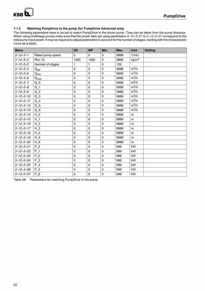
PumpDrive
52
7.1.2 Matching PumpDrive to the pump (for PumpDrive Advanced only)The following parameters have to be set to match PumpDrive to the driven pump. They can be taken from the pump literature.When using multistage pumps make sure that the power data set using parameters 3--12--3--21 to 3--12--3--27 correspond to thetotal pump input power. It may be required to adjust parameters to account for the number of stages, startingwith the characteristiccurve as a basis.
Menu SD MP Min. Max. Unit Setting
3--12--3--1 Rated pump speed 0 0 0 9999 1/min3--12--3--2 Rho 10 1000 1000 0 9999 kg/m3
3--12--3--3 Number of stages 1 1 0 1003--12--3--4 Qopt 0 0 0 9999 m3/h3--12--3--5 Qmin 0 0 0 9999 m3/h3--12--3--6 Qmax 0 0 0 9999 m3/h3--12--3--7 Q_0 0 0 0 9999 m3/h3--12--3--8 Q_1 0 0 0 9999 m3/h3--12--3--9 Q_2 0 0 0 9999 m3/h3--12--3--10 Q_3 0 0 0 9999 m3/h3--12--3--11 Q_4 0 0 0 9999 m3/h3--12--3--12 Q_5 0 0 0 9999 m3/h3--12--3--13 Q_6 0 0 0 9999 m3/h3--12--3--14 H_0 0 0 0 9999 m3--12--3--15 H_1 0 0 0 9999 m3--12--3--16 H_2 0 0 0 9999 m3--12--3--17 H_3 0 0 0 9999 m3--12--3--18 H_4 0 0 0 9999 m3--12--3--19 H_5 0 0 0 9999 m3--12--3--20 H_6 0 0 0 9999 m3--12--3--21 P_0 0 0 0 999 kW3--12--3--22 P_1 0 0 0 999 kW3--12--3--23 P_2 0 0 0 999 kW3--12--3--24 P_3 0 0 0 999 kW3--12--3--25 P_4 0 0 0 999 kW3--12--3--26 P_5 0 0 0 999 kW3--12--3--27 P_6 0 0 0 999 kW
Table 28: Parameters for matching PumpDrive to the pump

PumpDrive
53
7.2 Manual mode via control panelThe control panel keys have the following functions.After a power failure, manual mode must be reactivated.Standard control panel
The drive is operated at the lower motor frequency limit value if it was previously in the OFF or Auto Stop status. Ifthe drive is in the Auto Run status before the key is pressed, it continues to operate with the current speed. Forinformation on setting the speed, see section 5.1.3.2.
The drive stops.
Drive is in automatic mode.
Graphical control panelThe drive is operated at the lower motor frequency limit value (3--6--1--2) if it was previously in the OFF or AutoStop status. If the drive is in the Auto Run status before the key is pressed, it continues to operate with the currentspeed.
The display changes to the output frequency in manual operation. The current value can also be displayed by cal-ling up the Preset Man Out parameter (3--5--3--4). The current output frequency of the PumpDrive is displayed asa percentage referred to 50 Hz.
Change parameters. When doing so, note that the speed can only be changed between the set minimum speedand the maximum speed.
The drive stops.
Drive is in automatic mode.

PumpDrive
54
7.3 Open-loop control modeIn open-loop control mode, PumpDrive translates the specified setpoint into the correspondingmotor speed. The process control-ler is deactivated.The drive starts up in automatic mode if digital input 1 is supplied with 24 V DC (terminal strip P4:13/14).The wiring diagram is provided in section 13.3 (connection examples).
Function Device Specification Control range
Setpointspecification
Terminal strip P7 Analog input 1 (P7:9/10) 5--10 V DC≙ 25--50 Hzspecification
Graphical control panel Preset setpoint (3--5--2--1) 50--100%≙ 25--50 HzStandard control panel For information on settings see section
5.1.3.250--100%≙ 25--50 Hz
Field bus Siehe field bus module literature
Start command Terminal strip P4 Digital input 1 (P4:13/14) Start in automatic modeGraphical control panelStandard control panelField bus Siehe field bus module literature
Table 29: Open-loop control mode
7.3.1 Setpoint specification/Setpoint unitUp to 3 setpoint sources canbeused simultaneously as the setpoint specification. The total across all the setpoint sources is calcu-lated internally (1--3--1--4 ”Setpoint total” = 100%max. of setpoint). This total setpoint valuemakes it possible to use analog input 1,the control panel or the field bus as the setpoint source, without having to parameterise this beforehand. Only one setpoint sourceis required in most applications.
++
+
TotalSetpoint
TotalSetpoint
Min Setpoint(3--5--1--2)
Max Setpoint(3--5--1--3)
Min Setpoint(3--5--1--2)
* =
—
—
Setpoint(1--3--1--4)
3--5--4--1 Source Setpoint 1
3--5--4--2 Source Setpoint 2
3--5--4--3 Source Setpoint 3
Fig. 26: Total setpoint
The unit of the setpoint is defaulted to percentage (%) when delivered. The setpoint range 0--100% is referred to an output fre-quency of 0--50 Hz in open--loop control mode, and to 0--60 Hz or 0--70 Hz in over--synchronous operation.The minimum output frequency Frequency Lo (3--6--1--2) is set to 25 Hz (50%) in the factory, i.e. the setting range for the setpointvalue is 50--100% (e.g. 5--10 V, 12--20 mA). If a setpoint below 50% is specified, the drive always operates at its minimum fre-quency of 25 Hz (50%).
Parameter Description Setting range / options Fact. Set.3--5--4--1 Source of setpoint 1 1 – No operation
2 – Analog IN 12
3--5--4--2 Source of setpoint 22 Analog IN 13 – Analog IN 24 – Preset Setpoint
4
3--5--4--3 Source of setpoint 34 Preset Setpoint5 – Remote Setpoint6 – RS232 Setpoint
5
3--5--1--2 Minimum setpoint 0..100 [%] 0%3--5--1--3 Maximum setpoint 0..100 [%] 100%1--3--1--4 Display of the setpoint total as a percentage [%] -- --
Table 30: Parameters for setpoint specification in open-loop control mode
The following settings have to be changed to specify the setpoint value in a particular unit (e.g. Hz or 1/min):
Parameter Description Unit
3--2--2--1 Setpoint unit Hz / 1/min instead of %3--5--1--3 Maximum setpoint 50 Hz
3000 1/min (for 2-pole motors)1500 1/min (for 4-pole motors) instead of 100%
Table 31: Units for setpoint specification
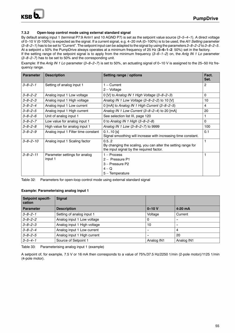
PumpDrive
55
7.3.2 Open-loop control mode using external standard signalBy default analog input 1 (terminal P7:9 AnIn1 and 10 AGND P7) is set as the setpoint value source (3--5--4--1). A direct voltageof 0--10 V (0-100%) is expected as the signal. If a current signal, e.g. 4--20 mA (0--100%) is to be used, the Al1 Setting parameter(3--8--2--1) has to be set to “Current”. The setpoint input can be adapted to the signal by using the parameters 3--8--2--2 to 3--8--2--5.At a setpoint ≤ 50% the PumpDrive always operates at a minimum frequency of 25 Hz (3--6--1--2: 50%) set in the factory.If the setting range of the setpoint signal is to apply from the minimum frequency (3--6--1--2) on, the Anlg IN 1 Lo parameter(3--8--2--7) has to be set to 50% and the corresponding unit.Example: If the Anlg IN 1 Lo parameter (3--8--2--7) is set to 50%, an actuating signal of 0--10 V is assigned to the 25--50 Hz fre-quency range.
Parameter Description Setting range / options Fact.Set.
3--8--2--1 Setting of analog input 1 1 – Current2 – Voltage
2
3--8--2--2 Analog input 1 Low voltage 0 [V] to Analog IN 1 High Voltage (3--8--2--3) 03--8--2--3 Analog input 1 High voltage Analog IN 1 Low Voltage (3--8--2--2) to 10 [V] 103--8--2--4 Analog input 1 Low current 0 [mA] to Analog IN 1 High Current (3--8--2--5) 43--8--2--5 Analog input 1 High current Analog IN 1 Low Current (3--8--2--4) to 20 [mA] 203--8--2--6 Unit of analog input 1 See selection list III, page 120 13--8--2--7 Low value for analog input 1 0 to Analog IN 1 High (3--8--2--8) 03--8--2--8 High value for analog input 1 Analog IN 1 Low (3--8--2--7) to 9999 1003--8--2--9 Analog input 1 Filter time constant 0.1..10 [s]
Signal smoothing will increase with increasing time constant.0.1
3--8--2--10 Analog input 1 Scaling factor 0.5..2By changing the scaling, you can alter the setting range forthe input signal by the required factor.
1
3--8--2--11 Parameter settings for analoginput 1
1 – Process2 – Pressure P13 – Pressure P24 – Q5 – Temperature
1
Table 32: Parameters for open-loop control mode using external standard signal
Example: Parameterising analog input 1
Setpoint specifi-cation
Signal
Parameter Description 0--10 V 4-20 mA
3--8--2--1 Setting of analog input 1 Voltage Current3--8--2--2 Analog input 1 Low voltage 0 --3--8--2--3 Analog input 1 High voltage 10 --3--8--2--4 Analog input 1 Low current -- 43--8--2--5 Analog input 1 High current -- 203--5--4--1 Source of Setpoint 1 Analog IN1 Analog IN1
Table 33: Parameterising analog input 1 (example)
A setpoint of, for example, 7.5 V or 16 mA then corresponds to a value of 75%/37.5 Hz/2250 1/min (2-pole motor)/1125 1/min(4-pole motor).

PumpDrive
56
7.3.3 Open-loop control mode using the control panel
Graphical control panelThe speed setpoint can also be specified using the control panel. For this purpose the Setp Source 2 parameter (3--5--4--2)mustbe set to ”Preset Setpoint” (factory setting).The setpoint is specified using thePreset Setpoint parameter (3--5--2--1). The setpoint unit is set using theSetpoint Unit (3--2--2--1)and Max Setpoint (3--5--1--3) parameters (see section 7.3.1).
ExampleA 2-pole motor is to run with a speed of 2500 1/min:
nsetnmax− nmin (Setmax− Setmin)= Set[%]
2500 1min
3000 1min− 1500
1min
(100%− 50%)= 83, 33%
Parameter Settings Fact. Set.
% Hz 1/min
3--5--4--2 Preset setpoint (programmable) %3--2--2--1 % Hz 1/min 13--5--1--3 100% 50 Hz 3000 1/min 1003--5--2--1 83.33% 41.67 Hz 2500 1/min 0
Table 34: Parameters for open-loop control mode using the control panel
Standard control panelThe setpoint can also be specified using the standard control panel (see section 5.1.3.2).
7.3.4 Open--loop control mode using field busIf the setpoint is specified using a field bus (e.g. LON, Profibus), the Setpoint Source 3 parameter (3--5--4--3) has already beenset to ”Remote Setpoint” for this purpose. However, the bus module needs to be enabled after installation by using the Field BusEnable parameter (3--2--1--5), so that the setpoint can be read in.The setpoint specifications have to be taken from the relevant technical literature of the bus module, but need to be matched withthe basic settings of the PumpDrive
7.3.5 Open-loop control mode using a digital potentiometer (key function)This function can be activated on single--pump drives at any time as soon as the parameterised digital inputs are connected.This function can be used to adjust the speed via external keys or pulses. Two digital inputs are used for this purpose:
Parameter Description Setting Input
3--7--1--4 Function of digital input 4 Preset Setpt + Digital input 4 (terminal P4:17)3--7--1--3 Function of digital input 3 Preset Setpt -- Digital input 3 (terminal P4:16)
Table 35: Digital inputs for open-loop control mode via digital potentiometer function
The Prset Setp Step parameter (3--5--2--2) defines the percentage by which the setpoint is to be increased or decreased per pulseat the digital input. Speed adjustment will be effected within the parameterised frequency range.If the set speed is not changed for 10 minutes, the value will be saved and used as the basic value when the system is startedagain.If the digital inputs are activated for an extended period of time (max. pulse duration > 1 s), the setpoint will move continuouslyto the upper or lower setpoint range.

PumpDrive
57
Parameter Description Setting range / options Fact.Set.
3--7--1--2 Function of digital input 2 See selection list I, page 120 73--7--1--3 Function of digital input 3
, p g10
3--7--1--4 Function of digital input 4 93--7--1--5 Function of digital input 5 23--5--4--1 Source of setpoint 1 – No operation
2 – Analog IN 13 – Analog IN 24 – Preset Setpoint5 – Remote Setpoint6 – RS232 Setpoint
4
3--5--1--1 Scaling factor for the setpoint 13--5--1--2 Minimum setpoint 0 to Max Setpoint (3--5--1--3) in Setpoint Unit (3--2--2--1)
(physical unit of setpoint)0
3--5--1--3 Maximum setpoint Min Setpoint (3--5--1--2) to 9999 in Setpoint Unit (3--2--2--1)(physical unit of setpoint)
100
3--5--2--1 Current setpoint selected for manualmode
Min Setpoint (3--5--1--2) to Max Setpoint (3--5--1--3) inSetpoint Unit (3--2--2--1) (physical unit of setpoint)
0
3--5--2--2 In/decrement for manual setpointfrequency
0..9999 in Setpoint Unit (3--2--2--1) (physical unit ofsetpoint)
0,1
3--2--2--1 Physical unit for setpoint See selection list III, page 120 1
Table 36: Parameters for open-loop control mode via digital potentiometer function
7.3.6 Open-loop control mode at fixed speedThis function can be used to change the current speed of the PumpDrive by specifying a fixed speed. Two digital inputs are usedfor this purpose. This function can be activated on single--pump drives at any time once the digit inputs have been parameterisedand connected. Depending on the connection of the digital inputs, 3 fixed speeds can be selected. The function of the selecteddigital inputs has to be set to ”Pset OutF Bit 0” and ”Pset Out F Bit 1”.If none of the digital inputs has been connected in open-loop control mode, PumpDrive will use the specified setpoint as outputfrequency.
Parameter Description Setting range / options Referenceto
Fact.Set.
3--7--1--2 Function of digital input 2 See selection list I, page 120 73--7--1--3 Function of digital input 3
, p g10
3--7--1--4 Function of digital input 4 93--7--1--5 Function of digital input 5 23--5--3--1 Fixed frequency, selection via digital inputs 0..100 [%] 3--11--4--1 1003--5--3--2 Fixed frequency, selection via digital inputs 0..100 [%] 3--11--4--1 753--5--3--3 Fixed frequency, selection via digital inputs 0..100 [%] 3--11--4--1 503--11--4--1 Maximum output frequency 1..70 [Hz] 50
Table 37: Parameters for open-loop control mode at fixed speed
Table 38 lists the fixed speeds that can be used. Parameters Prset Out Frq1 (3--5--3--1) to Prset Out Frq3 (3--5--3--3) can be usedto change the fixed speeds within the set frequency range from Frequency Lo (3--6--1--2) to Frequency Hi (3--6--1--3).
Bit 1 Bit 0 Output frequency of PumpDrive
0 V 0 V Frequency in accordance with setpoint specification (e.g. via analog input)0 V 24 V Frequency in accordance with parameter 3--5--3--124 V 0 V Frequency in accordance with parameter 3--5--3--224 V 24 V Frequency in accordance with parameter 3--5--3--3
Table 38: Fixed speeds when digital inputs are connected

PumpDrive
58
7.4 Closed-loop control modePumpDrive features an integrated process controller (PI controller). An external sensor supplies the controller with the actual value(feedback) signal from the process. Current changes in consumption are identified by comparison with the setpoint and then com-pensated by adjusting the speed.In addition, two analog inputs are available, which enables a second sensor to be connected. A maximum or minimum analysisand a mean value calculation or substraction operation can then be set by means of parameters.PumpDrive has been set at the factory so that it will automatically recognise a sensor connected to analog input 2 and will thenautomatically activate closed-loop control mode in the following cases:-- A sensor has been connected to analog input 2 and has been recognised (P7:6/7).-- A 4--20 mAcurrent signal is applied to thePTCsensor terminals andhasbeen recognised (terminals 1/2 in themains andmotor
terminal box).By default, the setpoint is read at analog input 1 (0--10 V standard signal). All units and setting ranges are converted to percentages(%), while the setpoints and actual values can be displayed in a different unit on option (see section 7.4.4).In closed--loop control mode, digital input 1 (terminal strip P4:14) has to be connected to the 24 VDC supply (terminal strip P4:13).If digital input 1 has 24 VDC applied to it and PumpDrive is set to automatic mode, the frequency inverter will start. In the caseof a PumpDrive with blanking plate the drive will start as soon as a voltage of 24 VDC is applied to digital input 1.In a multiple pump system the settings for closed--loop control mode have to be made using the active master control panel onthe main pump.If the drive (single--pump drive) is in closed-loop control mode and has been set to operation at fixed speed (see section 7.3.6),the drive will respond as follows:-- If none of the digital inputs (configured for fixed speed) is connected, the drive will control pump operation in line with the given
process variables.-- Once the digital inputs (configured for fixed speed) are connected, the drive will switch from closed-loop control mode to opera-
tion at fixed speed. The PumpDrive output frequency will then correspond to the values in accordance with parameters PrsetOut Frq1 (3--5--3--1) to Prset Out Frq3 (3--5--3--3).
-- Once the digital inputs are disconnected, the drive will switch back to closed-loop control mode.
Heat generator Differentialpressure sensor
ConsumerSetpoint(internal /external).
PumpDrive
Fig. 27: Closed-loop control mode example
PumpDrive
∆pSetp ∆p ∆pSetp
Processcontroller
(PI controller)
Speed controller(PI controller) Controlled system
∆pActual
∆pActual
U[V,f]
Fig. 28: Closed-loop control block diagram

PumpDrive
59
Function Device Specification Control range
Setpointspecification
Terminal strip P7 Analog input 1 (P7:9/10) 0--10 VDC≙ sensor range
Graphical control panel Preset setpoint (3--5--2--1) 0--100%≙ sensor rangeStandard control panel For information on settings see
section 5.1.3.20--100%≙ sensor range
Field bus Siehe field bus module literatureStart command Terminal strip P4 Digital input 1 (P4:13/14) Start in automatic mode
Graphical control panelStandard control panelField bus Siehe field bus module literature
Table 39: Closed-loop control mode
The wiring diagram is provided in section 13.3 (connection examples).
7.4.1 Setpoint specificationUp to 3 setpoint sources can be used simultaneously for setpoint specification. The total across all the setpoint sources is calcula-ted internally (Setpoint Total (1--3--1--4) = 100%max. of setpoint). This total setpoint valuemakes it possible to use analog input 1,the control panel or the field bus as the setpoint source, without having to parameterise the source beforehand. Only one setpointsource is required in most applications.
3--5--4--1 Source Setpoint 1
3--5--4--2 Source Setpoint 2
3--5--4--3 Source Setpoint 3
++
+
TotalSetpoint
TotalSetpoint
Min Setpoint(3--5--1--2)
Max Setpoint(3--5--1--3)
Min Setpoint(3--5--1--2)
* =
—
—
Setpoint(1--3--1--4)
Fig. 29: Total setpoint
Parameter Description Setting range / options WE
3--5--4--1 Source of setpoint 1 1 – No operation2 – Analog IN 1
2
3--5--4--2 Source of setpoint 22 Analog IN 13 – Analog IN 24 – Preset Setpoint
4
3--5--4--3 Source of setpoint 34 Preset Setpoint5 – Remote Setpoint6 – RS232 Setpoint
5
3--5--1--2 Min Setpoint 0..100 [%] 0%3--5--1--3 Max Setpoint 0..100 [%] 100%1--3--1--4 Display of the setpoint total as a per-
centage [%]-- --
Table 40: Parameters for setpoint specification in closed-loop control mode
7.4.2 Sensor signalBy default analog input 2 (terminals P7:6 AIN2 and 10 AGND P7) is parameterised to receive a 4--20 mA current signal. Whenthe sensor is connected, PumpDrive will automatically switch from open-loop to closed-loop control mode after a restart.The PI Mode parameter (3--9--1--1) is then enabled. This automatic sensor recognition function can be deactivated by using thePI Auto parameter (3--9--1--6). If required, PumpDrive can always be switched to closed-loop control mode by using the PI Modeparameter (3--9--1--1).If no 4--20 mA sensor signal is used, analog input 2 has to be reparameterised accordingly.The actual value source can be changed using the Feedbk Source parameter (3--9--2--1). In addition, it is possible to read in 2 si-gnals via An IN 1 and An IN 2 in order to sample these signals for the following criteria:-- Difference of the two signal values DIFF(AI1, AI2)-- Minimum of the two signal values DIFF(AI1, AI2)-- Maximum of the two signal values DIFF(AI1, AI2)-- Mean value of the two signal values DIFF(AI1, AI2)In this case the setpoint has to be specified by means of the control panel or field bus. If the actual value is read via the field bus,the source has to be reset to Remote Actual Value.

PumpDrive
60
Parameter Description Setting range / options Referenceto
Fact.Set.
3--6--1--2 Low motor frequency limit 0..100 [%] 3--11--4--1 503--6--1--3 High motor frequency limit 0..100 [%] 3--11--4--1 1003--8--3--1 Setting of analog input 2 1 – Current
2 – Voltage1
3--8--3--2 Analog input 2 Low voltage 0 [V] to Analog IN 2 High voltage(3--8--3--3)
0
3--8--3--3 Analog input 2 High voltage Analog IN 2 Low voltage (3--8--3--2) to 10[V]
10
3--8--3--4 Analog input 2 Low current 0 [mA] to Analog IN 2 High current(3--8--3--5)
4
3--8--3--5 Analog input 2 High current Analog IN 2 Low current (3--8--3--4) to 20[mA]
20
3--8--3--6 Unit of analog input 2 See selection list III, page 120 13--8--3--7 Low value for analog input 2 0 to High value for Analog IN 2 (3--8--3--8)
in Analog IN 2 Unit (3--8--3--6)0
3--8--3--8 High value for analog input 2 Low value for Analog IN 2 (3--8--3--7) to9999 in Analog IN 2 Unit (3--8--3--6)
100
3--8--3--9 Analog input 2 Filter time constant 0.1..10 [s] 0.13--8--3--10 Analog input 2 Scaling factor 0.5..2 13--8--3--11 Parameter settings for analog input 2 1 – Process
2 – Pressure P13 – Pressure P24 – Q5 – Temperature
1
3--9--1--1 Enable / disable PI controller 1 – Disabled2 – Enabled
1
3--9--1--2 PI proportional gain – kp 13--9--1--3 PI integral time 0..60 [s] 13--9--1--4 Process PI sense 1 – Negative
2 – Positive1
3--9--1--5 Process type of PI control 1 – Const Pressure2 – Variable Press3 – Constant Flow4 – Other Setpoint
2
3--9--1--6 PI automatic recognition function (PIAuto Detect)
1 – Disabled2 – Enabled
2
3--9--2--1 Selection of feedback (actual value)source
1 – Analog IN 12 – Analog IN 23 – DIFF(AI1, AI2)4 – MIN(AI1, AI2)5 – MAX(AI1, AI2)6 – AVE(AI1, AI2)7 – Rem Feedback
2
3--11--4--1 Maximum output frequency 0..70 [Hz] 50
Table 41: Parameters für sensor signal

PumpDrive
61
7.4.3 Controller typesIn most applications, the system or process is controlled to a differential pressure or an absolute pressure. For this reason, thePI Process Type parameter (3--9--1--5) is defaulted to ”Variable Pressure” at the factory. If a different controller type is required,change the selection to suit requirements. The ”Variable Pressure” process type activates the dynamic pressure compensationfunction (see section 7.9.1).
Parameter Description Setting range / options Referenceto
Fact.Set.
3--9--1--1 Enable / disable PI controller 1 – Disabled2 – Enabled
1
3--9--1--2 PI proportional gain – kp 13--9--1--3 PI integral time 0..60 [s] 13--9--1--4 Process PI sense*) 1 – Negative
2 – Positive1
3--9--1--5 Process type of PI control 1 – Const Pressure2 – Variable Press3 – Constant Flow4 – Other Setpoint
2
3--9--1--6 PI automatic recognition function (PIAuto Detect)
1 – Disabled2 – Enabled
2
3--6--1--2 Low motor frequency limit 0..100 [%] 3--11--4--1 503--6--1--3 High motor frequency limit 0..100 [%] 3--11--4--1 1003--11--4--1 Maximum output frequency 0..70 [Hz] 50
Table 42: Controller type parameters
*) If set to a negative direction of control action, PumpDrive reduces the speed when the actual value exceeds the setpoint. Thus, for example, the process sensehas to be set to ”positive” if the level in a feed tank has to be controlled.
7.4.4 Unit of setpoint and actual valueThe units set for the setpoint and actual value must be identical to prevent errors in the control function. The sensor measuringrange determines the setting values for the setpoint and actual value. If, for example, a pressure sensor with a range of 0--6 baris used, this range corresponds to an actual value signal range of 0--100%. If the required setpoint is, for example, 4.5 bar, a setpo-int of 75% would have to be specified.The unit of setpoint and actual value is defaulted to 50%.
Parameter Description Factory setting Setting range / options
3--2--2--1 Physical unit for setpoint 1 See selection list III, page 1203--2--2--2 Physical unit for flow rate (Q) 29
, p g
3--2--2--3 Physical unit for pressure 13--5--1--3 Maximum setpoint 100 If unit is %: select 100%
If unit is bar, m, m3/h,...: set to the full--scale va-lue of the sensor, e.g. 6 bar
3--8--3--6 Unit of analog input 2 1 See selection list III, page 1203--8--3--8 High value for analog input 2 100 100% or full--scale value of the sensor, e.g. 6 bar
Table 43: Parameters for unit of setpoint and actual value
7.4.5 Closed-loop control mode using an external setpoint signalBy default analog input 1 (terminal P7:9 AnIn1 and 10 AGND P7) is set as the setpoint value source (3--5--4--1). A direct voltageof 0--10 V (0-100%) is expected as the signal. If a current signal, e.g. 4--20 mA (0--100%) is to be used, the Al1 Setting parameter(3--8--2--1) has to be changed accordingly. ParametersAnalog IN 1 LowVoltage (3--8--2--2) toAnalog IN 1High Voltage (3--8--2--5)can be used to match the setpoint input to the signal received.

PumpDrive
62
Parameter Description Setting range / options Fact.Set.
3--8--2--1 Setting of analog input 1 1 – Current2 – Voltage
2
3--8--2--2 Analog input 1 Low voltage 0 [V] to Analog IN 1 High Voltage (3--8--2--3) 03--8--2--3 Analog input 1 High voltage Analog IN 1 Low Voltage (3--8--2--2) to 10 [V] 103--8--2--4 Analog input 1 Low current 0 [mA] to Analog IN 1 High Current (3--8--2--5) 43--8--2--5 Analog input 1 High current Analog IN 1 Low Current (3--8--2--4) to 20 [mA] 203--8--2--6 Unit of analog input 1 See selection list III, page 120 13--8--2--7 Low value for analog input 1 0 to Analog IN 1 High (3--8--2--8) in Analog IN 2 Unit
(3--8--2--6)0
3--8--2--8 High value for analog input 1 Analog IN 1 Low (3--8--2--7) to 9999 in Analog IN 1 Unit(3--8--2--6)
100
3--8--2--9 Analog input 1 Filter time constant 0.1..10 [s]If signal smoothing is required, the signal can be filtered bylengthening the time constants. This has the same effect asa low--pass filter.
0.1
3--8--2--10 Analog input 1 Scaling factor 0.5..2By changing the scaling the input signal can be multipliedby the required factor, e.g.:Analog IN 1 Scaling Factor (3--8--2--10) : 2
⇒ 5 V≙ 100%
1
3--8--2--11 Parameter settings for analog input 1 1 – Process2 – Pressure P13 – Pressure P24 – Q5 – Temperature
1
Table 44: Parameters for closed-loop control mode using an external setpoint signal
7.4.6 Closed-loop control mode using control panelThe setpoint can also be specified using the control panel. The setpoint source Setp Source 2 (3--5--4--2) is defaulted to ”PresetSetpoint”, corresponding to setpoint specification by means of the control panel.Theactual setpoint is specified usingPreset Setpoint (3--5--2--1). Depending on the settings of parametersSetpoint Unit (3--2--2--1)and Max Setpoint (3--5--1--3) (see section 7.3.1), the setpoint is specified using %, Hz, 1/min or m3/h as the unit.
Example: Differential pressure control, sensor full--scale value 10 bar, required setpoint 6.7 bar
Parameter Description Setting range / options Fact.Set.
3--5--4--1 Source of setpoint 1 1 – No Operation2 – Analog IN 13 – Analog IN 24 – Preset Setpoint5 – Remote Setpoint6 – RS232 Setpoint
2
3--2--2--1 Physical unit for setpoint bar % 13--2--2--3 Physical unit for pressure bar % 13--5--1--3 Maximum setpoint 10 bar 100% 1003--8--3--6 Unit of analog input 2 bar % 13--8--3--8 High value for analog input 2 10 bar 100% 1003--5--2--1 Current setpoint control panel 6,7 bar 67% 0
Table 45: Parameters for closed-loop control using the control panel
7.4.7 Closed-loop control using field busIf the setpoint is specified using a field bus (e.g. LON, Profibus), the Setpoint Source 3 parameter (3--5--4--3) has already beenset to ”Remote Setpoint” for this purpose. However, the bus module needs to be enabled after installation by using the Field BusEnable parameter (3--2--1--5), so that the setpoint can be read in.The setpoint specifications have to be taken from the relevant technical literature of the bus module, but need to be matched withthe basic settings of the PumpDrive

PumpDrive
63
7.4.8 Controller optimisationAttenuation and response speed of the closed control loop can be optimised using the PI Prop Gain (3--9--1--2) and PI IntegralTm (3--9--1--3) parameters.When beginning to optimise the controller the values for PI Prop Gain (3--9--1--2) and PI Integral Tm (3--9--1--3) should only beadjusted in small increments.Depending on its value, the proportional gain of the controllerPIPropGain (3--9--1--2) has the following effect on the control charac-teristics:D Low value selected for PI Prop Gain (3--9--1--2): moderate controller response speed and small overshoot.D High value selected for PI Prop Gain (3--9--1--2): Faster response of controller and, consequently, larger overshoot.The controller’s integral term (integration over time) ensures steady--state accuracy in controlled systemswith compensation func-tion. Once the controlled variable has reached its steady--state value, the offset will be zero, provided parameterisation is correct.Depending on its value, the integral termof the controllerPI Integral Tm (3--9--1--3) has the followingeffect on the control characteri-stics:D Low value selected for PI Integral Tm (3--9--1--3): faster elimination of offset, if any. This may, however, cause the value of the
controlled variable to oscillate around the setpoint and result in control process instability.D High value selected for PI Integral Tm (3--9--1--3): considerably reduces the controller’s response speed.
Actualvalue
Setpoint
3--9--1--2Value too high
3--9--1--2Optimumvalue
3--9--1--2Value too low
TimePoint in time at which a suddenchange in setpoint occurs (dashed line)
Fig. 30: Setting the proportional gain
Actualvalue
Setpoint
3--9--1--3Value too high
3--9--1--3Optimumvalue
3--9--1--3Value too low
TimePoint in time at which a suddenchange in setpoint occurs (dashed line)
Fig. 31: Setting the integral term

Caution
Note
Note
PumpDrive
64
7.5 Multiple pump configuration
Terms and definitionsThe following terms are defined for a multiple pump configuration:
Term Definition
Active master control panel D Advanced control panelD All Advanced control panels are configured to act as an auxiliary master control panel.
When the system is started, one of the Advanced control panels is assigned the role ofactive master control panel, as described below.
D Controls all the PumpDrives in a multiple pump systemD Can parameterise all the PumpDrives in a multiple pump system
Auxiliary master control panel(Aux. Master)
D Advanced control panelD All Advanced control panels are configured to act as an auxiliary master control panel.
When the system is started, one of the Advanced control panels is assigned the role ofactive master control panel, as described below.
D Controls all the PumpDrives in amultiple pump system if the activemaster control panelfails (becomes the active master control panel).
D Can only parameterise thePumpDrive onwhich theAdvanced control panel is installed.
Main pump D PumpDrive with sensor connections and active master control panelAuxiliary main pump D PumpDrive with sensor connections
D Takes over as the main pump if the main pump fails.Slave pump D PumpDrive without sensor connection
Table 46: Definition of terms for a multiple pump configuration
When PumpDrive is supplied ready-mounted on the motor (motor-mounted model MM), the motor parametershave already been set at the factory. If PumpDrive is to be mounted on the wall (WM) or in a cabinet (CM), check
whether the factory--set motor parameters agree with the specifications on the motor rating plate and adjust, if necessary.For application-specific wiring diagram refer to section 13.3.3, Seite 123.In multiple pump configurations, digital inputs 1 and 6 of all PumpDrives have to be connected to a 24 V supply. Digital input 1:enables the PumpDrive. If digital input 1 is not connected to 24 V, the relevant PumpDrive in a multiple pump configuration willnot be used as active frequency inverter, i.e. this device will not be activated. Digital input 6: multiple pump operation.Every main pump and auxiliary main pump requires a start signal at digital input 2. Start signals for different PumpDrives haveto be connected by electrically isolated contacts. Before commissioning ensure that the enable functions and the system start func-tion are deactivated so that the system does not start in an undefined condition.D Make sure that all PumpDrives in the multiple pump system are set to automatic mode.D It is basically possible to parameterise and to control (e.g. manual mode, Off) all PumpDrives connected to the KSB local bus
with the active master control panel.
Role assignment when voltage is appliedThe active and auxiliary master control panel are assigned their roles automatically when voltage is applied (power is supplied).The PumpDrive Advanced model that is first supplied with voltage automatically takes over the role of the active master controlpanel; the connected pump is assigned the role of main pump. Every PumpDrive Advanced model connected in addition will as-sume the role of an auxiliarymaster control panel; the connected pumpwill have the function of an auxiliarymain pump. It is advisa-ble to first switch on the PumpDrive which is intended to be the active master and after that the PumpDrives that are to serve asauxiliary masters.If time--delayed voltage supply to the PumpDrives is possible, power has to be applied in the following sequence:D Master control panel / main pumpD Aux. master control panel / auxiliary main pumpD PumpDrive slaveIf all the PumpDrives are switched on simultaneously for the first time (for example, by a master switch), the Advanced controlpanel which will assume the active master function is not determined. The active master control panel is the control panel whoseLED is flashing.The Aux Main Guard Tm (3--10--1--3) and Backup Guard Tm (3--1--7--4) parameters must be set for each PumpDrive (Advancedcontrol panel only). Setting these time values defines that Pump 1 will become the main pump with active master control panelwhen voltage is supplied simultaneously to all drives in the system. If Pump 2 is also equipped with an Advanced control panel,this pump will be the auxiliary main pump and its PumpDrive will assume the function of auxiliary master control panel.
If PumpDrives with higher time values are cut in before PumpDrives with lower time values, these assume thefunction of active master control panel controlling the main pump. This means that the position of the main pump
and active master control panel can change and that there is no longer a fixed local arrangement if the PumpDrives are cut in atdifferent points in time.
Make sure that sensors are only connected to PumpDrives equipped with an Advanced control panel.

PumpDrive
65
Parameter Description Setting range / options Fact.S t
p
PumpDrive 1
PumpDrive 2
PumpDrive 3
PumpDrive 4
PumpDrive 5
PumpDrive 6
Set.
3--10--1--3 Aux Main Guard Tm 2.5 2.6 2.7 2.8 2.9 3.0 0.5
Time value for identifying thePumpDrive controlling themain pump
The PumpDrive with the lowest time value is defined as controllingthe main pump when voltage is applied.A higher time value has to be entered for each further PumpDrive.This also applies to PumpDrives used as slaves.
3--1--7--4 Backup Guard Tm 1.0 1.2 1.4 1.6 1.8 2.0 1,0
Time value for identifying thePumpDrive as the active ma-ster control panel
ThePumpDriveAdvancedmodel with the lowest time value is definedas the active master control panel when voltage is applied.A higher time value has to be entered for each further PumpDriveAdvanced.
Table 47: Parameters for role assignment upon voltage supply
Identification of the active master control panelWhen voltage is first applied, the LED of the active master control panel flashes.The active master control panel can be identified by the fact that the PumpDrive ID parameter (3--1--1--4) displays the IDs ofall the PumpDrives connected to the KSB local bus.On the auxiliary master or the Basic control panel, only the ID of the PumpDrive equipped with the Advanced control panelis shown under this parameter.
Parameterisation sequence for activating a multiple pump system:Parameterisation of the PumpDrives has to be carried out with the active master control panel via the KSB local bus. Parametergroups Panel (3--1) and Adv Pump Ctrl (3--12) have to be parameterised individually for each Advanced control panel. All globalparameters entered using the master control panel are written to all PumpDrives in the multiple pump system.1. After voltage has been applied, you must first check which Advanced control panel has assumed the active master function.2. ID Selec PDrive (3--1--1--4): The active master control panel can be used to select the PumpDrive to which the control panel
is connected. At the beginning of parameterisation 0 is displayed for all the PumpDrive IDs, as no PumpDrive IDs have beenassigned yet.When a PumpDrive is selected, its LED flashes. This allows you to identify the PumpDrive to which the active master controlpanel is connected.
3. PumpDrive ID (3--2--1--2): Assignment of the PumpDrive ID. KSB rule: Define the pump on the left--hand side (active mastercontrol panel and main pump) as number 1; then number consecutively from left to right. To do so, use ID Selec PDrive(3--1--1--4) to switch to the relevant PumpDrive and then use PumpDrive ID (3--2--1--2) to assign the relevant ID. Repeat thesesteps until an ID has been assigned to every PumpDrive. After the IDs have been assigned, switch to PumpDrive 1 so thatthe LED of the active master control panel flashes.
4. MultiPump Role (3--2--1--1): This parameter defines the role of the respective PumpDrive in the multiple pump system. Thesystem automatically defines which PumpDrive becomes the main drive.Make sure that all PumpDrives which are not connected to sensors have the Standard Slave role assigned to them.
Parameter Description Setting range / options
3--2--1--1 Role in multiple pump configuration:This parameter defines the role of the respective PumpDrive in themultiple pump system.
1 -- Standard Slave2 -- Aux Main Pump
3--1--1--4 Selection of a PumpDrive from the multiple pump system: Display of the PumpDrive IDs
Table 48: Parameters for role assignment in a multiple pump configuration
5. BackupGuard Tm (3--1--7--4): This parameter is used to definewhich Advanced control panel assumes the activemaster func-tion after voltage is supplied simultaneously (see Table 47). The lowest time value that has been set activates the respectiveAdvanced control panel to be the activemaster control panel if all the PumpDrives in the system are cut in simultaneously. Thistime value has to be set on Pump 1 (active master control panel and main pump). Any further Advanced control panels mustthen have a higher time value assigned to them in accordance with Table 47. The other Advanced control panels are thus defi-ned as auxiliary master control panels in the sequence given by the time frames and voltage supply.
6. Aux Main Guard Tm (3--10--1--3): This parameter is used to define which PumpDrive assumes the role of the main pump driveafter voltage has been applied simultaneously. The lowest time value set activates the respectivePumpDrive as themain pumpdrive. This time value has to be set on Pump 1. The remaining PumpDrives have to be assigned a higher time value in accor-dance with Table 47.The other PumpDrive Advanced units are thus defined as auxiliary main pumps in the sequence given by the time frames.

Note
PumpDrive
66
7. Max Pps Run (3--12--5--1): This parameter (max. number of pumps running) defines the number of PumpDrives which can runsimultaneously in the multiple pump system. The maximum permissible number of PumpDrives equals the number ofPumpDrives connected to the KSB local bus. If there is a stand--by pump, the maximum number of pumps has to be reducedby one.This parameter has to be set to the same value on every Advanced control panel in themultiple pump system, since it is a localparameter of the individual control panels.
8. Enable Pps Chg (3--12--5--5): If this parameter is enabled, pump changeover will take place regularly after 24 hours of opera-tion. A pump changeover is also effected upon every change in the system start. Stand-by pumps are included in the pumpchangeover cycle.This parameter has to be set to the same value on every Advanced control panel in themultiple pump system, since it is a localparameter of the individual control panels.
9. Dig In 2 Function (3--7--1--2): The function of digital input 2 has to be set to ”System Start” on the PumpDrive equipped withactive master control panel/main pump, as well as on the PumpDrive equipped with auxiliary master control panel/auxiliarymain pump. When digital input 2 is activated, the system starts.
10.System Reboot (3--1--5--6): Restarting the multiple pump system.After parameterisation has been completed, the multiple pump system has to be restarted via the active master control panelusing the System Reboot (3--1--5--6) parameter so that all the set parameters are accepted.
General parameterisation of the multiple pump systemIn a multiple pump system the digital inputs, relay outputs and analog outputs have to be parameterised individually for eachPumpDrive.Activation of the warnings for the analog inputs has to be enabled separately for each PumpDrive. Limits and time delays for theanalog inputs have an identical value for all the PumpDrives in the system and therefore have to be exclusively set via the activemaster control panel.
7.5.1 Start and stop parameter settings in a multiple pump systemD In a multiple pump system a pump is started when the power input of a pump exceeds a defined value.D In a multiple pump system a pump is stopped when the power input of a pump drops below a defined value.The following parameters have to be set in order to specify the limits.If the High Load Function (3--6--4--5) and Low Load Function (3--6--4--10) parameters are set to ”Warning”, the option of startingand stopping PumpDrives in a multiple pump system is enabled. High load and low load warnings cause pumps to be started andstopped in the system as required.The speed range of the pump is defined by means of the low motor frequency limit Freqency Lo (3--6--1--2) (e.g. 25 Hz) and thehighmotor frequency limit Freqency Hi (3--6--1--3) (e.g. 50 Hz). The power parameters required for starting and stopping,3--6--4--1/ 3--6--4--2 / 3--6--4--6 / 3--6--4--7, are referred to the rated motor power and define at which power level, referenced to the speed,the high load or low load warning is output. This warning corresponds to the start and stop command.Depending on the pump size and pump type, the parameters for the speed and power may have to be adapted in order to achievestarting and stopping in the system.The Tm Cons Add Pum (3--12--5--3) and Tm Stop Pump (3--12--5--4) parameters (time constants for pump start/stop) allow timedelays to be set for starting and stopping pumps in the system.The time specifications are referenced to the last time when PumpDrives were started or stopped. If, for example, the Tm ConsAdd Pum (3--12--5--3) parameter is set to 5 s, a further pump is started after 5 seconds when another pump was started in thesystem beforehand and the ”High Load” warning remains active.If the multiple pump system is operated under low flow conditions, the pumps are stopped at the time intervals set for the TmStopPump (3--12--5--4) parameter if the ”Low Load” warning is active. This routing is repeated until only one pump is running.
The TmCons Add Pum (3--12--5--3) and Tm Stop Pump (3--12--5--4) parameters have to be set to the same valueon each Advanced control panel in themultiple pump system, as they are local parameters of the individual control
panels.

PumpDrive
67
Pmax@3--6--1--3 (3--6--4--2)
Pmax@3--6--1--3 (3--6--4--7)
Pmax@3--6--1--2 (3--6--4--1)Pmax@3--6--1--2 (3--6--4--6)
Freq Low(3--6--1--2)
Freq High(3--6--1--3)
Fig. 32: Characteristic curves for defining the start and stop limits in a multiple pump system (permissible area is shaded
The following parameters have to be entered for the main pump only: If PumpDrive is supplied on its own, the factory settings aresuitable for operation of a 4-pole Siemens motor.
Parameter Description Setting range / options Refe-rence to
Fact. Set.
3--6--4--1 High load at low motor frequency 0..100 [%] 3--3--2--1 603--6--4--2 High load at high motor frequency 0..100 [%] 3--3--2--1 903--6--4--3 High load profile 1 -- Linear
2 -- Square3 -- Cube
1
3--6--4--4 High load time delay 0..30 [s] 53--6--4--5 High load function 1 -- No function
2 -- Warning3 -- Stop & Trip
1
3--6--4--6 Low load at low motor frequency 0..100 [%] 3--3--2--1 303--6--4--7 Low load at high motor frequency 0..100 [%] 3--3--2--1 603--6--4--8 Low load profile 1 -- Linear
2 -- Square3 -- Cube
1
3--6--4--9 Low load time delay 0..30 [s] 103--6--4--10 Low load function 1 -- No function
2 -- Warning3 -- Stop & Trip
1
3--3--2--1 Rated motor power 0.55..45 [kW] Size--dependent
3--6--1--2 Low motor frequency limit 0 [%] to Frequency High (3--6--1--3) 3--11--4--1 503--6--1--3 High motor frequency limit Frequency Low (3--6--1--2) to 100 [%] 3--11--4--1 1003--11--4--1 Maximum output frequency 1..70 [Hz] 50
Table 49: Start and stop parameters in a multiple pump system

PumpDrive
68
7.5.2 Configuration exampleThe following parameterisation example applies to a multiple pump system with a main pump, an auxiliary main pump and a slavepump. The PumpDrives used are equipped as follows:
PumpDrive Role Control panel
1 Main pump with active master control panel Advanced2 Auxiliary main pump with auxiliary master control panel Advanced3 Slave pump StandardTable 50: Multiple pump configuration example
The parameter settings of the individual PumpDrives have to be made/checked as follows:
1. Parameterise PumpDrive 1 with active master control panel
Parameter Description Value
3--1--7--4 Time value for identifying the control panel as the active master control panel 1.0 s3--2--1--1 Role in multiple pump configuration Auxiliary main pump3--2--1--2 PumpDrive ID 13--7--1--2 Function of digital input 2 System start3--10--1--3 Time value for identifying the PumpDrive as the main pump drive 2.5 s3--12--5--1 Maximum number of pumps running simultaneously 23--12--5--5 Pump changeover Enabled
Table 51: Multiple pump configuration example: PumpDrive 1
2. Parameterising PumpDrive 3 using the active master control panel of PumpDrive 1:
Parameter Description Value
3--1--1--4 Selection of a PumpDrive from the multiple pump system Pumpe 33--2--1--1 Role in multiple pump configuration Standard slave3--2--1--2 PumpDrive ID 33--10--1--3 Time value for identifying the PumpDrive as the main pump drive 2.7 s
Table 52: Multiple pump configuration example: PumpDrive 3
3. Parameterise PumpDrive 2 using active master control panelParameter groups 3--1 and 3--12 also have to be set on the auxiliary master control panel.
Parameter Description Value
3--1--1--4 Selection of a PumpDrive from the multiple pump system Pump 23--1--7--4 Time value for identifying the control panel as the active master control panel 1.2 s3--2--1--1 Role in multiple pump configuration Auxiliary main pump3--2--1--2 PumpDrive ID 23--7--1--2 Function of digital input 2 System start3--10--1--3 Time value for identifying the PumpDrive as the main pump drive 2.6 s3--12--5--1 Maximum number of pumps running simultaneously 23--12--5--5 Pump changeover Enabled
Table 53: Multiple pump configuration example: PumpDrive 2
7.5.3 Closed-loop control mode in a multiple pump systemPumpDrive is suitable for multiple pump operation with up to 6 PumpDrives of the same power. For this purpose the drives areinterconnected bymeans of the KSB local bus (see section 6.4.9.2). Amultiple pump configuration enables demand-based controlof thePumpDrives connected to theKSB local bus. Pumps of the same type and samepower can be started in parallel and stoppeddepending on the motor input power.The multiple pump system is controlled by an Advanced control panel (active master). If simple redundancy is to be provided forthe active master control panel, an additional Advanced control panel has to be installed in the system.For proper implementation of the control function the required parameters must be set as described in section 7.4. In particular,the PI Mode parameter (3--9--1--1) must be set to ”Enabled”.

Note
PumpDrive
69
7.5.4 Open-loop control mode in a multiple pump systemPumpDrive is suitable for multiple pump operation with up to 6 PumpDrives of the same power. For this purpose the drives areinterconnected bymeans of the KSB local bus (see section 6.4.9.2). Amultiple pump configuration enables demand-based controlof thePumpDrives connected to theKSB local bus. Pumps of the same type and samepower can be started in parallel and stoppeddepending on the motor input power.The multiple pump system is controlled by an Advanced control panel (active master). If simple redundancy is to be provided forthe active master control panel, an additional Advanced control panel has to be installed in the system.Open-loop control mode is activated in a multiple pump system in the following cases:D The PI Mode parameter (3--9--1--1) has been set to ”Enabled”, before the multiple pump system is started using the System
Start function. In this case, all pumps in the systemwill run in open-loop controlmodebasedonacommonsetpoint. Thesetpointcan be specified as described in section 7.3.1.
D Fixed speed operation has been activated (see section 7.3.6), before or after the multiple pump system is started via the Sy-stemStart function. TheAdvanced control panel (activemaster) polls the digital inputs of themain pumpor auxiliarymain pumpand checks whether fixed speed operation has been parameterised. If fixed speed operation is activated while the multiplepump system is in closed-loop control mode (PI Mode parameter (3--9--1--1) ”Enabled”), the multiple pump system will switchto open-loop control mode (PI Mode parameter (3--9--1--1) ”Disabled”). The drives’ output frequency will then correspond tothe values in accordance with parameters Prset Out Frq1 (3--5--3--1) to Prset Out Frq3 (3--5--3--3).
Open-loop control mode is activated in a multiple pump system only when both setpoint sources Bit 0 and Bit 1have been parameterised for digital selection of a fixed speed at the digital inputs (see section 7.3.6).
Fixed speed operationmode only needs to be parameterised andwired on themain pump and the auxiliary main pump. The digitalinputs (DIG IN 2 to DIG IN 5) of the slave pumps are not processed for this purpose.

PumpDrive
70
7.6 PumpDrive protective functionsIf the Advanced control panel fails, the Advanced protective functions can no longer be ensured.
7.6.1 Thermal motor protection
The motor temperature sensor connections have to be implemented in accordance with IEC 664 standards: This meansthat the live parts of themotor and sensormust have double or reinforced insulation at the terminals for the PTCconnection.This reinforced insulation includes a leakage distance and clearance of 8 mm for 400/500--VAC devices. If the connectioncannot be effected as specified, proceed as follows:
-- All other terminals for inputs and outputs have to be protected to as not to pose a shock hazard. Connection to other devicesis not permitted.or
-- The temperature sensor must be electrically isolated against the terminals by means of a thermistor relay.
The factory setting of the stop threshold applies tomonitoringwith aPTCsensor or a thermal circuit breaker. If other thermocouplesare used, the value has to be set by KSB Service.Thermal overload results in immediate tripping and an alert message is output. Restarting will only be possible after the motor hascooled down sufficiently (check Stop & Trip parameter).
Parameter Description Setting range / options Fact.Set.
3--3--5--1 Enable / disable motor thermal protection 1 – No Protection2 – PTC Protection
2
Table 54: Parameter for thermial motor protection
7.6.2 Electrical motor protection by overvoltage / undervoltage monitoringThe drive monitors the mains voltage. If it falls below 380 V -- 10% or exceeds 480 V + 10%, this results in tripping and an alertmessage is output. The alert must be acknowledged before the drive can be switched back on.
7.6.3 Dynamic overload protection by speed limitationPumpDrive is equipped with current sensors, which record and limit the motor current. When a current that exceeds the rated cur-rent IN (3--3--2--4) is measured, the square of the overcurrent is totalled over time. If the total reaches an upper limit value,PumpDrive responds by reducing the speed until the current consumption of the connected motor is lower than the rated currentagain. Thedrive can thenno longer reach the setpoint, but itmaintains operationat a lower speed. Thedynamic overloadprotectionfunction takes into account that motor heat--up varies as the square of the motor current. Low overcurrent can flow for a relativelylong time, while a high overcurrent results in a rapid reduction in speed.The upper limit value for i2t control, which depends on the rated current IN, is (2 x IN)2 x 10 sec and is designed for standardmotors.The dynamic overload protection function can be made to respond more quickly by reducing the rated current. When a motor--mounted drive is delivered, this parameter is defaulted for the relevant motor.
Parameter Description Setting range / options Fact. Set.
3--3--2--4 Rated current of motor 0.1..999 [A] Size--dependent
Table 55: Parameter for overload protection by speed limitation
7.6.4 Current limitationIf the current limit value defined in the MotMod Curr Lim parameter (3--6--1--4) is exceeded, PumpDrive reduces the speed untilthe limit value is no longer violated. Unlike with dynamic overload protection, the speed is reduced without delay. When a motor--mounted drive is delivered, this parameter is defaulted for the relevant motor.
Parameter Description Setting range / options Access Reference to
Fact. Set.
3--6--1--4 Motor mode current limit 0..100 [%] Customer
3--11--4--2 75
3--11--4--2 Maximum output current 0..500 [A] Factory Size--dependent
Table 56: Parameters for current limitation
7.6.5 Tripping at phase failure and short circuitPhase failure and short circuit result in direct tripping (without stop ramp). This protective function does not need to be parameteri-sed.
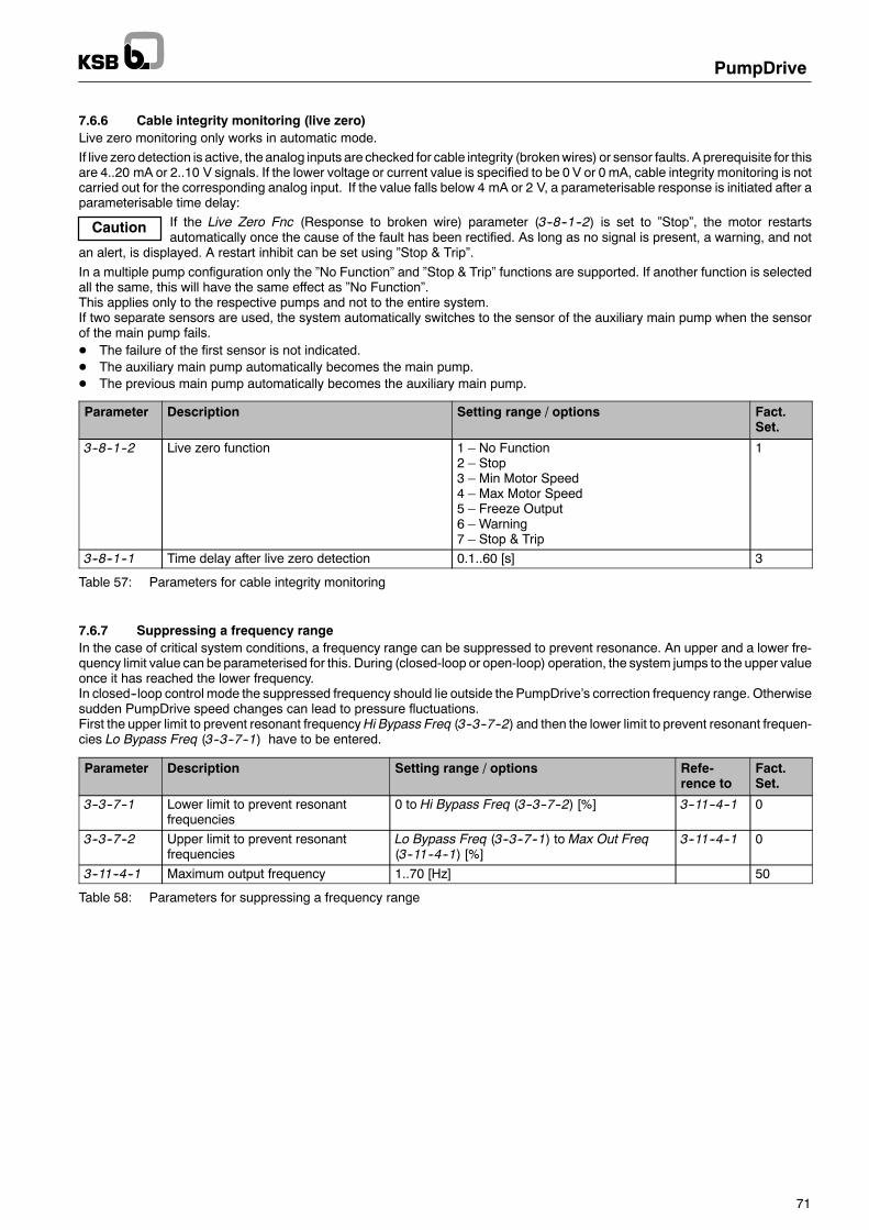
Caution
PumpDrive
71
7.6.6 Cable integrity monitoring (live zero)Live zero monitoring only works in automatic mode.If live zero detection is active, the analog inputs are checked for cable integrity (brokenwires) or sensor faults. A prerequisite for thisare 4..20 mA or 2..10 V signals. If the lower voltage or current value is specified to be 0 V or 0 mA, cable integrity monitoring is notcarried out for the corresponding analog input. If the value falls below 4 mA or 2 V, a parameterisable response is initiated after aparameterisable time delay:
If the Live Zero Fnc (Response to broken wire) parameter (3--8--1--2) is set to ”Stop”, the motor restartsautomatically once the cause of the fault has been rectified. As long as no signal is present, a warning, and not
an alert, is displayed. A restart inhibit can be set using ”Stop & Trip”.In a multiple pump configuration only the ”No Function” and ”Stop & Trip” functions are supported. If another function is selectedall the same, this will have the same effect as ”No Function”.This applies only to the respective pumps and not to the entire system.If two separate sensors are used, the system automatically switches to the sensor of the auxiliary main pump when the sensorof the main pump fails.D The failure of the first sensor is not indicated.D The auxiliary main pump automatically becomes the main pump.D The previous main pump automatically becomes the auxiliary main pump.
Parameter Description Setting range / options Fact.Set.
3--8--1--2 Live zero function 1 – No Function2 – Stop3 – Min Motor Speed4 – Max Motor Speed5 – Freeze Output6 – Warning7 – Stop & Trip
1
3--8--1--1 Time delay after live zero detection 0.1..60 [s] 3
Table 57: Parameters for cable integrity monitoring
7.6.7 Suppressing a frequency rangeIn the case of critical system conditions, a frequency range can be suppressed to prevent resonance. An upper and a lower fre-quency limit value can be parameterised for this. During (closed-loop or open-loop) operation, the system jumps to the upper valueonce it has reached the lower frequency.In closed--loop control mode the suppressed frequency should lie outside the PumpDrive’s correction frequency range. Otherwisesudden PumpDrive speed changes can lead to pressure fluctuations.First the upper limit to prevent resonant frequencyHi Bypass Freq (3--3--7--2) and then the lower limit to prevent resonant frequen-cies Lo Bypass Freq (3--3--7--1) have to be entered.
Parameter Description Setting range / options Refe-rence to
Fact.Set.
3--3--7--1 Lower limit to prevent resonantfrequencies
0 to Hi Bypass Freq (3--3--7--2) [%] 3--11--4--1 0
3--3--7--2 Upper limit to prevent resonantfrequencies
Lo Bypass Freq (3--3--7--1) to Max Out Freq(3--11--4--1) [%]
3--11--4--1 0
3--11--4--1 Maximum output frequency 1..70 [Hz] 50
Table 58: Parameters for suppressing a frequency range

Caution
PumpDrive
72
7.6.8 Protection against dry running and hydraulic blockages (Advanced function)Before the learning curve is recorded, you must make sure that the discharge-side gate valve is closed and that all PumpDrivesin a multiple pump configuration are switched to ”Off”. External enable commands and start commands have to be deactivated.Do not press any keys on the control panel while the learning function is in progress. After the learning process has been comple-ted, all PumpDrives are set to ”Off” and have to be reset to ”Auto”.The data required for tripping in the event of dry running or hydraulic blockages must be ”taught” to the drive at minimum load forthe system it is installed in. To start the learning process, choose menu option 3--12--2--1: You have to confirm by pressing ”OK”that all PumpDrives that are part of the system are switched off and that all the gate valves are closed. The drive now reducesits speed within permissible limits and saves a speed--dependent load curve. This process will take a few minutes. The drive thenswitches to Stop. The load curve is saved in parameters 3--12--2--2 to 3--12--2--9. Protection against dry running and hydraulicblockages is now activated automatically.To de--activate the function, all the values in the load curve (parameters 3--12--2--2 to 3--12--2--9) must be set to zero.The Learn Time parameter (3--12--2--10) specifies for how long the PumpDrive will record measured values per speed. If thesemeasured values are outside the tolerance range (Learn Meas Err 3--12--2--11), the PumpDrive aborts the learning function. Thelearning time can be increased in order reduce measuring errors.Dry runningFor dry running detection, the above-mentioned load curve is reduced via parameter 3--12--4--9 (see Fig. 33). If the current poweris less than the reduced load curve, the drive trips with a delay (parameter 3--12--4--10) and the ”Dry Running” alert is output (seeFig. 33).Hydraulic blockage (Advanced function)For hydraulic blockage detection, the above-mentioned load curve is reduced via parameter 3--12--4--7 (see Fig. 33). If the current poweris less than the reduced load curve, the drive outputs the ”Blockage” warning after a delay (parameter 3--12--4--8).If dry running protection is deactivated via parameter 3--12--4--11, the drive already trips in the event of a hydraulic blockage andan appropriate alert is output.
During the learning process, the drive runs up to the maximum speed (parameter 3--6--1--3) or up to the load limit,irrespective of the setpoint setting.
Frequency
3--12--4--7
Power
3--12--4--9
Saved load curve
Hydraulic blockage
Dry running
Fig. 33: Limit value curves for detecting dry running and hydraulic blockage
Parameter Description Setting range / options Fact. Set.
3--12--2--1 Start learning profile 1 – OFF2 – Start
1
3--12--2--2 P% @ 30% fmax 0 03--12--2--3 P% @ 40% fmax 0 03--12--2--4 P% @ 50% fmax 0 03--12--2--5 P% @ 60% fmax 0 03--12--2--6 P% @ 70% fmax 0 03--12--2--7 P% @ 80% fmax 0 03--12--2--8 P% @ 90% fmax 0 03--12--2--9 P% @ 100% fmax 0 03--12--2--10 Learning time 0..1000 [s] 30 s3--12--2--11 Learning measurement error 0..100% 5%3--12--4--7 Load curve reduction for hydraulic blockage (100% – No
reduction)0..100% 85
3--12--4--8 Time-out for hydraulic blockage 0..1000 [s] 103--12--4--9 Load curve reduction for dry running (100% – No reduction) 0..100% 703--12--4--10 Time-out for dry running 0..1000 [s] 53--12--4--11 Enable / Disable dry running function 1 – Disabled
2 – Enabled2
Table 59: Parameters for protection against dry running and hydraulic blockage

PumpDrive
73
7.6.8.1 Dry running protection (PumpDrive Basic)In the Basic version, dry running protection can be implemented by logically interconnecting a liquid level signal with the start com-mand signal (digital input 1).
7.6.9 Characteristic curve control (Advanced function)Characterististic curve control provides effective protection of the pump against hydraulic overload or low load on the basis of thecurrent flow rate. The current flow rate can be determined by two methods:D Using a flow rate sensorD Using the H/Q or P/Q characteristic curves (for details on parameterising pump characteristic curves see section 7.1.2 and
section 7.7)
If impermissible operating conditions are detected, PumpDrive can, after a specified time delay, respond either with a warning orby tripping (Stop&Trip) or not respond at all.In order to prevent starting and stopping of pumps in a multiple pump configuration via flow rate estimation within the scope ofcharacteristic curve control, the Q Hi Timeout Fn (3--12--4--3) and Q Lo Timeout Fn (3--12--4--6) parameters must be set to ”NoFunction” in a multiple pump configuration, as otherwise the control quality will be impaired.
Fig. 34: Pump characteristic curves
A: Dry running, see section 7.6.8 Q1: Qmin Q4: Qopt
B: Hydraulic blockage, see section 7.6.8 Q2: QLow Flow Q5: QHigh Flow
C: Low flow Q3: Q<opt Q6: Qmax
D: Continuously permissible rangeE: High flowFor characteristic curve control the following parameters must always be set, irrespective of the method used to determine theflow rate: the H/Q sampling points, Qmin, Q Lim Low Flow, Qopt, Q Lim High Flow and Qmax for the driven pump. Q Lim Low Flowmust not be lower than Qmin and Q Lim High Flow must not be higher than Qmax.

Note
PumpDrive
74
Parameter Description Setting range / options Fact.Set.
3--12--4--1 Q high flow (overload) limit 0..150 [%] 100 [%]3--12--4--2 Q Hi Timeout Time (time delay to detect high flow) 0..120 [s] 20 [s]3--12--4--3 Q High flow timeout function 1 – No Function
2 – Warning3 – Stop & Trip
1
3--12--4--4 Q Low flow limit 0..150 [%] 100 [%]3--12--4--5 Q Lo Timeout Tm (time delay to detect low flow) 0..120 [s] 20 [s]3--12--4--6 Q Low flow timeout function 1 – No Function
2 – Warning3 – Stop & Trip
1
Table 60: Parameters for characteristic curve control
All the above parameters have to be set in accordance with the pump characteristic curve, the data sheet and the system require-ments, or the default factory parameter settings have to be checked and adjusted as required.
7.7 Flow rate estimationThe flow rate can be estimated using two methods:D Flow rate estimation based on the power (on PumpDrive Advanced only)D Flow rate estimation based on the differential pressure (on PumpDrive Advanced only)
To display the current flow rate based on an estimate using the pump input power or a differential pressuremeasurement, the sam-pling points of the H/Q curve and the P/Q curve have to be set (see section 7.1.2, page 52). Whether the estimate is made usingthe power or the differential pressure as a basis, is determined – provided a differential pressure sensor is connected – in operationby taking into account themaximum accuracy that can be achieved with either method under the circumstances. The best methodfor the purpose is selected.The differential pressure measurement can either be effected by a differential pressure sensor or two pressure sensors in the di-scharge-side and suction-side piping. Therefore the following parameters are required for defining the analog inputs:
Parameter Description Setting range / options Fact.Set.
3--8--2--11 AI1 Descriptor 1 – Process2 – Pressure P13 Pressure P2
1
3--8--3--11 AI2 Descriptor3 – Pressure P24 – Q5 – Temperature
1
Table 61: Parameters for analog inputs used for flow rate estimationThe differential pressure sensor, if used, is always connected to analog input 2:
Parameter Description Setting
3--8--2--11 AI1 Descriptor Process3--8--3--11 AI2 Descriptor Pressure P2
Table 62: Parameterisation for differential pressure sensor connection
The AI 1 Descriptor parameter (3--8--2--11) must not be set to ”Pressure P1”.
Connection of a suction pressure sensor to analog input 1 and a discharge pressure sensor to analog input 2:
Parameter Description Setting
3--8--2--11 AI1 Descriptor Pressure P13--8--3--11 AI2 Descriptor Pressure P2
Table 63: Parameterisation for suction-side pressure sensor connection

PumpDrive
75
The following additional parameters are required for complete parameterisation of the flow rate estimation function:
Parameter Description Setting range / options Fact.Set.
3--2--2--1 Setpoint unit See selection list III, page 120 13--2--2--2 Unit for flow rate (Q)
, p g29
3--2--2--3 Pressure unit 13--5--1--2 Minimum setpoint 0 to Max Setpoint (3--5--1--3) in Setpoint Unit (3--2--2--1) 03--5--1--3 Maximum setpoint Min Setpoint (3--5--1--3) to 9999 in Setpoint Unit (3--2--2--1) 1003--8--2--6 Unit for analog input 1 See selection list III, page 120 13--8--2--7 Analog input 1 Low 0 to AN IN 1 High (3--8--8--8) in AN IN 1 Unit (3--8--2--6) 03--8--2--8 Analog input 1 High AN IN 1 Low (3--8--2--7) to 9999 in AN IN 1 Unit (3--8--2--6) 1003--8--3--6 Unit for analog input 2 See selection list III, page 120 13--8--3--7 Analog input 2 Low 0 to AN IN 2 High (3--8--3--8) in AN IN 1 Unit (3--8--2--6) 03--8--3--8 Analog input 2 High AN IN 2 Low (3--8--3--7) to 9999 in AN IN 1 Unit (3--8--2--6) 100
Table 64: Parameters for flow rate estimation
The following parameters must be set for proper functioning of flow rate estimation:
Parameter Description Setting
3--2--2--1 Setpoint unit These parameters must be set to an identical unit for the3--2--2--3 Pressure unit
ppressure value.
3--8--2--6 Unit for analog input 13--8--3--6 Unit for analog input 23--4--1--1 Flow rate (Q) measurement / estimation Measured3--12--1--1 Flow rate measurement P/Q calculated
Table 65: Parameterisation for flow rate estimation
If flow rate estimation is to be used in a multiple pump system, make sure that the maximum number of pumps running simulta-neously 3--12--5--1 is set properly to match requirements (see section 7.5).In addition the following parameters have to be set for flow rate estimation:
The flow rate estimation results can be displayed on the control panel using the following parameters:D Parameter Sys Flow Rate (1--5--1--1) -- Single-pump operation and multiple pump operationD Parameters Flow Rate Pump1 (1--5--1--2) to Flow Rate Pump6 (1--5--1--7) -- Multiple pump operation only
If the driven pump is operated outside the limits given by the set H/Q sampling points and P/Q sampling points of if the samplingpoints have not been specified correctly (see section 7.1.2), the PumpDrive control panel will display a ”Q Estimate” warning.
The calculated flow rate value is also used for characteristic curve control (see section 7.6.9). The following must be kept in mind:D The flow rate value cannot be output via the analog output.D The flow rate estimation accuracy depends on the slope of the characteristic curves that have been specified and can, there-
fore, not be given in general values across the board.D The P andH values should be strictly monotonically rising (P) or falling (H) with increasing flow rateQ to be able to obtain accu-
rate flow rate estimates across the entire speed range.D If fluids with a density other than 1000 kg/m3 are pumped, the applicable coefficient must be set using parameter 3--12--3--2.D Additional hydraulic losses between the measuring points for the suction and discharge pressure (e.g. caused by swing check
valves, long pipelines or fittings), which are not covered by the pump’s H/Q curve, will reduce the accuracy of flow rate estima-tion.
D Flow rate estimation is not possible for simultaneous operation of twin pumps, such as for example KSB’s Etaline Z, becauseof the undefined position of the changeover flap.
D The flow rate estimation algorithm implemented inPumpDrive (if equippedwith anAdvancedcontrol panel) has beenoptimisedfor radial flow pumps. If axial flow pumps are used, flow rate estimationwill, depending on the pump characteristic curve, supplyunusable flow rate values.

PumpDrive
76
7.8 Individual monitoring functionsIn a multiple pump system the digital inputs, relay outputs and analog outputs have to be parameterised individually for eachPumpDrive.Activation of the warningmessages for the analog inputs has to be enabled separately for themain pump and any redundant auxi-liary main pump. Limits and time delays for the analog inputs have an identical value for all the PumpDrives in the system and,therefore, have to be exclusively set via the active master control panel.
The parameters listed in Table 67 to Table 69 enable limit value monitoring for the following variables:-- Motor current and output frequency-- Signal for analog inputs 1 and 2-- Setpoint and actual value-- Effective power (off--design operating conditions of pump)Monitoring is defined via upper and lower limit values, as well as via a time delay before responding to limit value violations. Theresponse to limit value violations can be defined for each individual variable. The following options are available:
No function:Limit value monitoring is deactivated.
Warning:When a limit value is violated, the amber LED lights up and the associated message flashes on the display. The information aboutthe current limit value violation can also be output via a digital output (parameter 3--7--2--1 or 3--7--3--1; see section 7.11 Digitaloutputs).
Stop and trip:When a limit value is violated, the speed is reduced along the ramp function until the unit comes to a stop. The red LED lights upand the associated message flashes on the display. The restart behaviour depends on the trip reset mode (parameter 3--11--2--1)(see trip reset mode). The information about the current limit value violation can also be output via a digital output (parameter3--7--2--1 or 3--7--3--1; see section 7.11 Digital outputs).
Parameter Description Setting range / options Fact.Set.
3--11--2--1 Trip Reset Mode 1 – Manual Reset2 -- 10 s, 60 s, 5 min3 – Reset @ 5m4 – 10 s, 60 s, 5 min, 1 h5 -- Reset @ 15m
2
Table 66: Parameters for restart behaviour after limit value violation
Monitoring the motor current and output frequency
Parameter Description Setting range / options Refe-rence to
Fact. Set.
3--6--2--1 Low current warning limit 0..100 [%] 3--11--4--2 03--6--2--2 High current warning limit 0..100 [%] 3--11--4--2 1003--6--2--3 Current warning time delay 0..60 [s] 53--6--2--4 Current warning function 1 – No Function
2 – Warning3 – Stop & Trip
1
3--6--2--5 Low output frequency warning limit 0..100 [%] 3--11--4--1 03--6--2--6 High output frequency warning limit 0..100 [%] 3--11--4--1 1003--6--2--7 Output frequency warning time delay 0..60 [s] 53--6--2--8 Output frequency warning function 1 – No Function
2 – Warning3 – Stop & Trip
1
3--11--4--1 Maximum output frequency 1..600 [Hz] 503--11--4--2 Maximum output current 0..500 [A]
Access: FactorySize-dependent
Table 67: Parameters for monitoring the motor current and output frequency

PumpDrive
77
Monitoring analog inputs 1 and 2
Parameter Description Setting range / options Fact.Set.
3--6--3--1 Lower limit Analog input 1 Analog IN 1 Low (3--8--2--7) to Analog IN 1 High (3--8--2--8) 03--6--3--2 Upper limit Analog input 1
g ( ) g g ( )in Analog IN 1 Unit (3--8--2--6) 100
3--6--3--3 Time delay Analog input 1 0..60 [s]Access: Standard
5
3--6--3--4 Function Analog input 1 monitoring 1 – No Function2 – Warning3 – Stop & Trip
1
3--6--3--5 Lower limit Analog input 2 Analog IN 2 Low (3--8--3--7) to Analog IN 2 High (3--8--3--8) 03--6--3--6 Upper limit Analog input 2
g ( ) g g ( )in Analog IN 2 Unit (3--8--3--6) 100
3--6--3--7 Time delay Analog input 2 0..60 [s]Access: Standard
5
3--6--3--8 Function Analog input 2 monitoring 1 – No Function2 – Warning3 – Stop & Trip
1
3--8--2--6 Unit of analog input 1 See selection list III, page 120 13--8--2--7 Low value for analog input 1 0 to Analog IN 1 High (3--8--2--8) in Analog IN 1 Unit
(3--8--2--6)0
3--8--2--8 High value for analog input 1 Analog IN 1 Low (3--8--2--7) to 9999 in Analog IN 1 Unit(3--8--2--6)
100
3--8--3--6 Unit of analog input 2 See selection list III, page 120 13--8--3--7 Low value for analog input 2 0 to Analog IN 2 High (3--8--3--8) in Analog IN 2 Unit
(3--8--3--6)0
3--8--3--8 High value for analog input 2 Analog IN 2 Low (3--8--3--7) to 9999 in Analog IN 2 Unit(3--8--3--6)
100
Table 68: Parameters for monitoring analog inputs 1 and 2
Monitoring the setpoint and actual value
Parameter Description Setting range / options Fact.Set.
3--6--5--1 Minimum setpoint 0 to Max Setpoint (3--5--1--3) in Setpoint Unit (3--2--2--1)(physical unit of setpoint)
0
3--6--5--2 Maximum setpoint Min Setpoint (3--5--1--2) to 100 in Setpoint Unit (3--2--2--1)(physical unit of setpoint)
100
3--6--5--3 Setpoint warning time delay 0..60 [s] 53--6--5--4 Setpoint warning function 1 – No Function
2 – Warning3 – Stop & Trip
1
3--6--6--1 Low limit feedback 0 to Feedbk Hi Limit (3--6--6--2) in Setpoint Unit (3--2--2--1)(physical unit of setpoint)
0
3--6--6--2 High limit feedback Feedbk Lo Limit (3--6--6--2) to 9999 in Setpoint Unit(3--2--2--1) (physical unit of setpoint)
100
3--6--6--3 Feedback warning time delay 0..60 [s] 53--6--6--4 Feedback warning function 1 – No Function
2 – Warning3 – Stop & Trip
1
3--5--1--2 Minimum setpoint 0 to Max Setpoint (3--5--1--3) in Setpoint Unit (3--2--2--1)(physical unit of setpoint)
0
3--5--1--3 Maximum setpoint Min Setpoint (3--5--1--2) to 25,397.46 cm Setpoint Unit(3--2--2--1) (physical unit of setpoint)
100
3--2--2--1 Physical unit for setpoint See selection list III, page 120Access: Service
1
Table 69: Parameters for monitoring the setpoint and actual value

PumpDrive
78
Monitoring the effective power (pump off--design conditions)Parameters 3--6--4--1 to 3--6--4--10 and parameters 3--6--1--2 and 3--6--1--3 can be used to define frequency-dependent power limitvalues in order to protect the pump(s) against impermissible low flow and high flow (overload) conditions and limit the speed range.The frequency dependency of the upper / lower limit value is described via two points in the frequency / power diagram which canbe derived directly from the H/Q selection chart. A linear, quadratic, or cubic limit value characteristic curve can be selected bet-ween these points via parameters 3--6--4--3 and 3--6--4--8 (see Fig. 32 and Table 49, page 67).
7.9 Energy efficiency7.9.1 Dynamic differential pressure setpoint compensationThis function provides dynamic differential pressure setpoint compensation. As a result, pipe friction losses – which need to beconsidered when the differential pressure sensor is installed close to the pump – can be compensated. This ensures a virtuallyconstant pressure at the consumer (e.g. heater) almost regardless of the flow. In open piping systems, a virtually constant pressurecan also be provided at the piping end, even if the differential pressure sensor is installed close to the pump.
Heat generator
Consumer
PumpDrive
Setpoint(internal /external).
Differentialpressure sensor
Long
piping
system
with
pipe
frictionlosses
Setpoint increase (3--4--2--2)in unit [3--2--2--1]
Volumeflowrate (3--4--2--1) [%]0 100
9999
0
Fig. 35: Dynamic pressure setpoint compensation (example)
ThePumpDrivemust be suppliedwith the signal of a pressure or differential pressure sensor and the current flow rate as referenceinput variables for the dynamic differential pressure setpoint compensation function. The flow rate can be determined using twomethods:D Flow rate estimation based on the speedD Flow rate estimation based on the power (on PumpDrive Advanced only)D Flow rate estimation based on the differential pressure (on PumpDrive Advanced only)D Flow rate measured by flow rate sensor via analog input
The method used for determining the flow rate for setpoint compensation depends on the PumpDrive model (Basic/Advanced)and its parameterisation:-- For details on parameterising the differential pressure setpoint compensation function on aPumpDriveBasicmodel read sec-
tion 7.9.1.1.-- For details on parameterising the differential pressure setpoint compensation function on aPumpDriveAdvancedmodel read
section 7.9.1.2.
7.9.1.1 Parameterisation of the differential pressure setpoint compensation function on PumpDrive BasicThe following parameters are required for parameterisation of the differential pressure setpoint compensation function on aPumpDrive Basic model, using flow rate estimation based on the speed:

PumpDrive
79
Parameter Description Setting range / options Fact.Set.
3--2--2--1 Physical unit for setpoint See selection list III, page 120 13--2--2--2 Physical unit for flow rate (Q)
, p g29
3--2--2--3 Physical unit for pressure 13--9--1--5 Process type of PI control 1 – Const Pressure
2 – Variable Press3 – Constant Flow4 – Other Setpoint
1
3--4--1--1 Flow rate (Q) measurement / estimation 1 – Estimated2 – Measured
1
3--4--1--3 Calibration for flow rate measurementp-100% value
0..9999 in Pressure Unit (3--2--2--3) (physical unit ofpressure)
0
3--4--2--1 Flow compensation point 0..100 [%] 1003--4--2--2 Setpoint compensation 0..9999 in Setpoint Unit (3--2--2--1) (physical unit of
setpoint)0
Table 70: Parameters for the setpoint compensation function on a PumpDrive Basic model, using flow rate estimation basedon the speed
The settings for universal closed-loop control mode are described in Section 8.4.The parameters listed in Table 70 for parameterisation of the differential pressure setpoint compensation function on a PumpDriveBasic model, using flow rate estimation based on the speed, must be set as follows:
Parameter Description Setting
3--9--1--5 Process type of PI control Variable pressure3--4--1--1 Flow rate (Q) measurement / estimation Estimated3--4--1--3 Calibration for flow rate measurement p-100%
valueFull-scale value of pressure / differential pressure sensor
3--4--2--1 Flow compensation point As required by the system conditions (see Fig. 35)3--4--2--2 Setpoint compensation
q y y ( g )
Table 71: Parameterisation for the setpoint compensation function on a PumpDrive Basic model, using flow rate estimation ba-sed on the speed
In addition to the parameters listed in Table 70, the following parameter is required for parameterisation of the differential pressuresetpoint compensation function on a PumpDrive Basic model using flow rate measurement via a sensor:
Parameter Description Setting range / options Fact.Set.
3--4--1--2 Calibration for flow rate measurement Q-100%value
0..9999 in Q Unit (3--2--2--2) (physical unit of flowrate)
0
Table 72: Parameter for differential pressure setpoint compensation function on a PumpDrive Basic model using flow rate mea-surement via a sensor
The parameters listed in Table 70 for parameterisation of the differential pressure setpoint compensation function on a PumpDriveBasic model using flow rate measurement via a sensor must be set as follows:
Parameter Description Setting
3--9--1--5 Process type of PI control Variable pressure3--4--1--1 Flow rate (Q) measurement / estimation Measured3--4--1--2 Calibration for flow rate measurement Q-100%
valueFull-scale value of flow rate sensor
3--4--1--3 Calibration for flow rate measurement p-100%value
Full-scale value of pressure / differential pressure sensor
3--4--2--1 Flow compensation point As required by the system conditions (see Fig. 35)3--4--2--2 Setpoint compensation
q y y ( g )
Table 73: Parameterisation for differential pressure setpoint compensation function on aPumpDriveBasicmodel using flow ratemeasurement via a sensor

PumpDrive
80
7.9.1.2 Parameterisation of the differential pressure setpoint compensation function on PumpDrive AdvancedIf the differential pressure setpoint compensation function is to be used in a multiple pump system, make sure that the maximumnumber of pumps running simultaneously 3--12--5--1 is set properly to match requirements (see section 7.5).
The following parameters are required for parameterisation of the differential pressure setpoint compensation function on aPumpDrive Advanced model, using flow rate estimation based on the speed or the power:
Parameter Description Setting range / options Fact.Set.
3--2--2--1 Physical unit for setpoint See selection list III, page 120 13--2--2--2 Physical unit for flow rate (Q)
, p g29
3--2--2--3 Physical unit for pressure 13--9--1--5 Process type of PI control 1 – Const Pressure
2 – Variable Press3 – Constant Flow4 – Other Setpoint
1
3--4--1--1 Flow rate (Q) measurement / estimation 1 – Estimated2 – Measured
1
3--12--1--1 Flow rate measurement 1 – Measured2 -- P/Q calculated
1
3--4--1--2 Calibration for flow rate measurementQ-100% value
0..9999 in Q Unit (3--2--2--2) (physical unit of flow rate) 0
3--4--1--3 Calibration for flow rate measurementp-100% value
0..9999 in Pressure Unit (3--2--2--3) (physical unit ofpressure)
0
3--4--2--1 Flow compensation point 0..100 [%] 1003--4--2--2 Setpoint compensation 0..9999 in Setpoint Unit (3--2--2--1) (physical unit of
setpoint)0
Table 74: Parameters for the setpoint compensation function on a PumpDrive Advanced model, using flow rate estimation ba-sed on the speed
The parameters listed in Table 74 for parameterisation of the differential pressure setpoint compensation function on a PumpDriveAdvanced model, using flow rate estimation based on the speed, must be set as follows:
Parameter Description Setting
3--9--1--5 Process type of PI control Variable pressure3--4--1--1 Flow rate (Q) measurement / estimation Estimated3--12--1--1 Flow rate measurement Measured3--4--1--2 Calibration for flow rate measurement Q-100%
valueMaximum flow rate in accordance with characteristic curve(Qmax)
3--4--1--3 Calibration for flow rate measurement p-100%value
Full-scale value of pressure / differential pressure sensor
3--4--2--1 Flow compensation point As required by the system conditions (see Fig. 35)3--4--2--2 Setpoint compensation
q y y ( g )
Table 75: Parameterisation for the setpoint compensation function on a PumpDrive Advancedmodel, using flow rate estimationbased on the speed
Parameters 3--12--3--7 to 3--12--3--13 and parameters 3--12--3--21 to 3--12--3--27 for the pump’s P/Q curve described in section7.1.2 must be set for parameterisation of the setpoint compensation function on a PumpDrive Advanced model, using flow rateestimation based on the power. Also read the information given in section 7.7 for parameterisation of the flow rate estimation func-tion. The parameters listed in Table 74 must be set as follows:
Parameter Description Setting
3--9--1--5 Process type of PI control Variable pressure3--4--1--1 Flow rate (Q) measurement / estimation Measured3--12--1--1 Flow rate measurement P/Q calculated3--4--1--3 Calibration for flow rate measurement p-100%
valueFull-scale value of pressure / differential pressure sensor
3--4--2--1 Flow compensation point As required by the system conditions (see Fig. 35)3--4--2--2 Setpoint compensation
q y y ( g )
Table 76: Parameterisation for the setpoint compensation function on a PumpDrive Advancedmodel, using flow rate estimationbased on the power
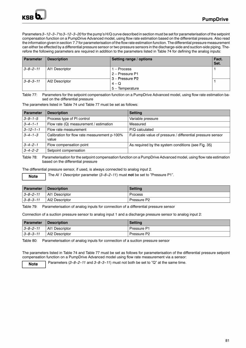
Note
Note
PumpDrive
81
Parameters3--12--3--7 to3--12--3--20 for the pump’sH/Q curve described in sectionmust be set for parameterisation of the setpointcompensation function on a PumpDrive Advanced model, using flow rate estimation based on the differential pressure. Also readthe informationgiven in section 7.7 for parameterisationof the flow rate estimation function. Thedifferential pressuremeasurementcan either be effected by a differential pressure sensor or two pressure sensors in the discharge-side and suction-side piping. The-refore the following parameters are required in addition to the parameters listed in Table 74 for defining the analog inputs:
Parameter Description Setting range / options Fact.Set.
3--8--2--11 AI1 Descriptor 1 – Process2 – Pressure P13 Pressure P2
1
3--8--3--11 AI2 Descriptor3 – Pressure P24 – Q5 – Temperature
1
Table 77: Parameters for the setpoint compensation function on a PumpDrive Advanced model, using flow rate estimation ba-sed on the differential pressure
The parameters listed in Table 74 und Table 77 must be set as follows:
Parameter Description Setting
3--9--1--5 Process type of PI control Variable pressure3--4--1--1 Flow rate (Q) measurement / estimation Measured3--12--1--1 Flow rate measurement P/Q calculated3--4--1--3 Calibration for flow rate measurement p-100%
valueFull-scale value of pressure / differential pressure sensor
3--4--2--1 Flow compensation point As required by the system conditions (see Fig. 35)3--4--2--2 Setpoint compensation
q y y ( g )
Table 78: Parameterisation for the setpoint compensation function on a PumpDrive Advancedmodel, using flow rate estimationbased on the differential pressure
The differential pressure sensor, if used, is always connected to analog input 2.The AI 1 Descriptor parameter (3--8--2--11) must not be set to ”Pressure P1”.
Parameter Description Setting
3--8--2--11 AI1 Descriptor Process3--8--3--11 AI2 Descriptor Pressure P2
Table 79: Parameterisation of analog inputs for connection of a differential pressure sensor
Connection of a suction pressure sensor to analog input 1 and a discharge pressure sensor to analog input 2:
Parameter Description Setting
3--8--2--11 AI1 Descriptor Pressure P13--8--3--11 AI2 Descriptor Pressure P2
Table 80: Parameterisation of analog inputs for connection of a suction pressure sensor
The parameters listed in Table 74 and Table 77 must be set as follows for parameterisation of the differential pressure setpointcompensation function on a PumpDrive Advanced model using flow rate measurement via a sensor:
Parameters (3--8--2--11 and 3--8--3--11) must not both be set to ”Q” at the same time.

Note
PumpDrive
82
Parameter Description Setting
3--9--1--5 Process type of PI control Variable pressure3--4--1--1 Flow rate (Q) measurement / estimation Measured3--12--1--1 Flow rate measurement Measured3--4--1--2 Calibration for flow rate measurement Q-100%
valueFull-scale value of flow rate sensor
3--4--1--3 Calibration for flow rate measurement p-100%value
Full-scale value of pressure / differential pressure sensor
3--4--2--1 Flow compensation point As required by the system conditions (see Fig. 35)3--4--2--2 Setpoint compensation
q y y ( g )
For connection of the flow rate sensor to analog input 1:3--8--2--11 AI1 Descriptor QFor connection of the flow rate sensor to analog input 2:3--8--3--11 AI2 Descriptor Q
Table 81: Parameter for differential pressure setpoint compensation function on a PumpDrive Advanced model using flow ratemeasurement via a sensor
7.9.2 Standby mode (sleep mode)
In stand--by mode the PumpDrive may start up without any warning if the actual pressure exceeds the definedhysteresis for closed--loop control (3--4--3--2).
In a pressure control application, PumpDrive can detect whether the flow rate supplied is actually used. Stand--by mode can beactivated via parameter 3--4--3--1.
The following information refers to Fig. 36.When the system has reached its steady state (the actual value has reached the setpoint within the programmed hysteresisfor pressure fluctuations¤), PumpDrive increases the setpoint by a value¢ (test pulse) for a period of time©.If the flow rate is zero, this pressure increase will continue to be applied. PumpDrive reduces the speed to the set minimum outputfrequency (3--6--1--2). If the pressure increase continues to be applied for the period of time ¦ measured from the momentat which the speed drops below the minimum speed before stopping ¥, the PumpDrive will stop the pump subsequently. Thedrive remains in stand--by mode.If the flow rate consumed rises again, the pressure in the system drops and PumpDrive starts the pump again after the delay time§ when the cut--in hysteresis £ has been reached.If the motor speed drops below the value of parameter 3--4--3--4 ¥, PumpDrive switches the pump to stand--by mode after thedelay time without carrying out a test pulse cycle through setpoint compensation ( , ).

PumpDrive
83
The time characteristic of this process is illustrated below and can be parameterised accordingly:
1
2
87
6
5
4
3 ¡Waiting time until activation [Parameter : 3--4--3--6]© Duration of test pulse [Parameter: 3--4--3--9]¢ Setpoint increase / pulse [Parameter: 3--4--3--8]£ Hysteresis for closed-loop control [Parameter: 3--4--3--2]¤ Hysteresis for pressure variations [Parameter: 3--4--3--7]¥ Minimum speed before stopping [Parameter : 3--4--3--4]¦Waiting time before stopping [Parameter : 3--4--3--5]§Waiting time before system start-up [Parameter : 3--4--3--3]
Pressuresetpoint
Pressureactual value
Speed
Fig. 36: Time characteristics of parameters for stand-by mode
Parameter Description Setting range / options Refe-rence to
Fact.Set.
3--4--3--1 Enable / disable sleep mode 1 – Disabled2 – Enabled
1
3--4--3--2 Difference between feedback and setpointto start
0..9999 in Setpoint Unit (3--2--2--1)(physical unit of setpoint)
0
3--4--3--3 Time delay between signal on digital inputand start of motor
0.1..60 [s] 1
3--4--3--4 Frequency limit to enter sleep mode Frequency Low (3--6--1--2) toFrequency High (3--6--1--3) [%]
3--11--4--1 60
3--4--3--5 Time delay to stop PumpDrive 0.1..30 [s] 103--4--3--6 Time delay after detection of minimum flow
(min. Q) level45..360 [s]Access: Service
60
3--4--3--7 Difference between feedback and setpointto start test pulses
0..9999 in Setpoint Unit (3--2--2--1)(physical unit of setpoint)Access: Service
2
3--4--3--8 Test pulse amplitude 0..9999 in Setpoint Unit (3--2--2--1)(physical unit of setpoint)Access: Service
2
3--4--3--9 Pulse time 3..30 [s]Access: Service
10
3--2--2--1 Physical unit for setpoint See selection list III, page 120Access: Service
1
3--6--1--2 Low motor frequency limit 0..100 [%] 3--11--4--1 503--6--1--3 High motor frequency limit 0..100 [%] 3--11--4--1 1003--11--4--1 Maximum output frequency 1..70 [Hz] 50
Table 82: Parameters for stand-by mode

PumpDrive
84
7.9.3 V/f characteristicThe PumpDrive V/f characteristic can be parameterised as required via parameters 3--3--1--1 to 3--3--1--9 (four sampling points).By optimising the V/f characteristic in accordance with the pump characteristic, the motor current can be adjusted in line with therequired load torque. This can save a significant amount of energy in the medium speed range. If the values of all the samplingpoints are set to zero, the drive operateswith a linear V/f characteristic. By default, the PumpDrive is set to a parabolic V/f characte-ristic.
Fig. 37: V/f characteristic
Parameter Description Setting range / options Referenceto
Fact. Set.
3--3--1--1 Boost voltage for voltage V0 0..15 [%] 3--3--2--2 23--3--1--2 Voltage sampling point V1 0..100 [%] 3--3--2--2 43--3--1--3 Frequency sampling point f1 0..100 [%] 3--3--2--3 203--3--1--4 Voltage sampling point V2 0..100 [%] 3--3--2--2 163--3--1--5 Frequency sampling point f2 0..100 [%] 3--3--2--3 403--3--1--6 Voltage sampling point V3 0..100 [%] 3--3--2--2 643--3--1--7 Frequency sampling point f3 0..100 [%] 3--3--2--3 803--3--1--8 Voltage sampling point V4 0..100 [%] 3--3--2--2 1003--3--1--9 Frequency sampling point f4 0..100 [%] 3--3--2--3 1003--3--2--2 Motor rated voltage Size-dependent Size-depen3--3--2--3 Motor rated frequency
p pdent
Table 83: Parameters for the V/f characteristic

Caution
Note
PumpDrive
85
7.10 Start and stop rampsStarting and stopping is effected by means of ramps with two sections each (see Fig. 38). The gradient of a rampsection is defined by a length of time (parameters 3--3--6--1 to 3--3--6--5) and a frequency change. This frequency
change corresponds to the maximum output frequency (3--11--4--1). For the start-up procedure, a switchover from ramp 0 toramp 1 is made when the frequency defined in parameter 3--3--6--6 is reached. For the stop procedure, a switchover from ramp 1to ramp 0 is made when the frequency defined in parameter 3--3--6--7 is reached.The start procedure along the ramp sections ends when the setpoint frequency (open- and closed-loop control mode) or outputfrequency (manual mode) is reached (parameter 3--5--3--4).Ramp 2 only needs to be parameterised for multiple pump operation: The first pump is started via ramp 0 and ramp 1. Each subse-quent pump is started via ramp 0 and ramp 2. When the pumps are stopped, the process is reversed (i.e. all pumps but the finalone are stopped via ramp 2 and ramp 0).
Fig. 38: Start and stop ramps
To prevent overcurrent tripping, a minimum total start / stop time of 2.5 seconds is recommended.
Parameter Description Setting range /options
Referenceto
Fact.Set.
3--3--4--1 Start delay 0..60 [s] 0.13--3--4--2 Start output frequency 0..10 [%] 3--11--4--1 03--3--6--1 Defines, together with 3--11--4--1, the gradient of ramp 0
Up/Down0.5..600 [s] 3
3--3--6--2 Defines, together with 3--11--4--1, the gradient of ramp 1Up
0.5..600 [s] 3
3--3--6--3 Defines, together with 3--11--4--1, the gradient of ramp 1Down
0.5..600 [s] 3
3--3--6--4 Defines, together with 3--11--4--1, the gradient of ramp 2Up
0.5..600 [s] 3
3--3--6--5 Defines, together with 3--11--4--1, the gradient of ramp 2Down
0.5..600 [s] 3
3--3--6--6 Frequency to change from ramp 0 Up to ramp 1/2 Up 0..100 [%] 3--11--4--1 503--3--6--7 Frequency to change from ramp 1/2 Down to ramp 0
Down0..100 [%] 3--11--4--1 50
3--5--3--4 Output frequency for manual mode 0..100 [%] 3--11--4--1 03--11--4--1 Maximum output frequency 1..70 [Hz] 50
Table 84: Parameters for the start and stop ramps

PumpDrive
86
7.11 Digital / analog inputs and outputsIn a multiple pump system the digital inputs, relay outputs and analog outputs have to be parameterised individually for eachPumpDrive.
7.11.1 Digital inputsPumpDrive is equipped with six digital inputs (24 V process level). Inputs 1 and 6 are assigned a fixed function:-- Digital input 1: Start/Stop command for single--pump drive, enable command in multiple pump configuration-- Digital input 2: Start/Stop command in multiple pump configuration (has to be set manually)-- Digital input 6: Changeover to multiple pump operationThe functions of inputs 2 to 5 are user-definable:
Parameter Description Setting range / options Fact.Set.
3--7--1--2 Function of digital input 2 See selection list I, page 120 73--7--1--3 Function of digital input 3
, p g10
3--7--1--4 Function of digital input 4 93--7--1--5 Function of digital input 5 2
Table 85: Parameters for the digital inputs
PumpDrive functions of the digital inputs:D Fixed frequencies via digital inputs (see section 7.3.6)D Open-loop control via digital potentiometer function (see section 7.3.5)D Selection of the output variable for the analog output (see section 7.11.4)
7.11.2 Relay outputOperating status information can be queried at the two volt--free contacts (NO relays) of PumpDrive (the corresponding warningshave to be activated beforehand (see Section 7.8)):
Parameter Description Setting range / options Fact.Set.
3--7--2--1 Function of digital output 1 See selection list II, page 120 293--7--2--2 Time delay between event and response (On time
delay)3..30 [time delay factor*] 3
3--7--2--3 Time delay between event and response (Off timedelay)
3..30 [time delay factor*] 3
3--7--3--1 Function of digital output 2 See selection list II, page 120 43--7--3--2 Time delay between event and response (On time
delay)3..30 [time delay factor*] 3
3--7--3--3 Time delay between event and response (Off timedelay)
3..30 [time delay factor*] 3
Table 86: Parameters for the relay output
* Approximate time delay factor in unit [s]

PumpDrive
87
7.11.3 Analog inputs
Parameters for analog input 1
Parameter Description Setting range / options Fact.Set.
3--8--2--1 Setting of analog input 1 1 – Current2 – Voltage
2
3--8--2--2 Analog input 1 Low voltage 0 [V] to Analog IN 1 High Voltage (3--8--2--3) 03--8--2--3 Analog input 1 High voltage Analog IN 1 Low voltage (3--8--2--2) to 10 [V] 103--8--2--4 Analog input 1 Low current 0 to Analog IN 1 High Current (3--8--2--5) [mA] 43--8--2--5 Analog input 1 High current Analog IN 1 Low Current (3--8--2--4) to 20 [mA] 203--8--2--6 Unit of analog input 1 See selection list III, page 120 13--8--2--7 Low value for analog input 1 0 to Analog IN 1 High (3--8--2--8) in Analog IN 1 Unit (3--8--2--6) 03--8--2--8 High value for analog input 1 Analog IN 1 Low (3--8--2--7) to 9999 in Analog IN 1 Unit
(3--8--2--6)100
3--8--2--9 Analog input 1 Filter timeconstant
0.1..10 [s]If signal smoothing is required, the signal can be filtered bylengthening the time constants. This has the same effect as alow-pass filter.
0,1
3--8--2--10 Analog input 1 Scaling factor 0.5..2By changing the scaling, you can alter the setting range for theinput signal by the required factor.
1
3--8--2--11 Parameter settings for analoginput 1
1 – Process2 – Pressure P13 – Pressure P24 – Q5 – Temperature
1
Table 87: Parameters for analog input 1
Parameters for analog input 2:
Parameter Description Setting range / options Fact.Set.
3--8--3--1 Setting of analog input 2 1 – Current2 – Voltage
2
3--8--3--2 Analog input 2 Low voltage 0 [V] to Analog IN 2 High Voltage (3--8--2--3) 03--8--3--3 Analog input 2 High voltage Analog IN 2 Low voltage (3--8--2--2) to 10 [V] 103--8--3--4 Analog input 2 Low current 0 to Analog IN 2 High Current (3--8--2--5) [mA] 43--8--3--5 Analog input 2 High current Analog IN 2 Low Current (3--8--2--4) to 20 [mA] 203--8--3--6 Unit of analog input 2 See selection list III, page 120 13--8--3--7 Low value for analog input 2 0 to Analog IN 2 High (3--8--2--8) in Analog IN 2 Unit (3--8--2--6) 03--8--3--8 High value for analog input 2 Analog IN 2 Low (3--8--2--7) to 9999 in Analog IN 2 Unit
(3--8--2--6)100
3--8--3--9 Analog input 2 Filter timeconstant
0.1..10 [s] 0.1
3--8--3--10 Analog input 2 Scaling factor 0,5..2 13--8--3--11 Parameter settings for analog
input 21 – Process2 – Pressure P13 – Pressure P24 – Q5 – Temperature
1
Table 88: Parameters for analog input 2
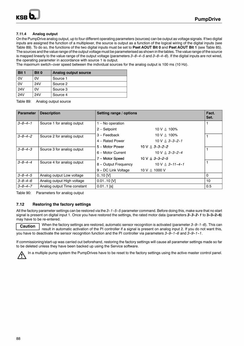
Caution
PumpDrive
88
7.11.4 Analog outputOn thePumpDrive analog output, up to four different operating parameters (sources) can be output as voltage signals. If two digitalinputs are assigned the function of a multiplexer, the source is output as a function of the logical wiring of the digital inputs (seeTable 89). To do so, the functions of the two digital inputs must be set to Pset AOUT Bit 0 and Pset AOUT Bit 1 (see Table 85).The sources and the value rangeof the output voltagemust be parameterised as shown in the tables. The value rangeof the sourceis mapped linearly to the value range of the output voltage (parameters 3--8--4--5 and 3--8--4--6). If the digital inputs are not wired,the operating parameter in accordance with source 1 is output.The maximum switch--over speed between the individual sources for the analog output is 100 ms (10 Hz).
Bit 1 Bit 0 Analog output source
0V 0V Source 10V 24V Source 224V 0V Source 324V 24V Source 4
Table 89: Analog output source
Parameter Description Setting range / options Fact.Set.
3--8--4--1 Source 1 for analog output 1 – No operation
2 – Setpoint 10 V≙ 100%
1
3--8--4--2 Source 2 for analog output 3 -- Feedback 10 V≙ 100%
4 – Rated Power 10 V≙ 3--3--2--1
5 Motor Power 10 V≙ 3 3 2 2
1
3--8--4--3 Source 3 for analog output5 -- Motor Power 10 V≙ 3--3--2--2
6 -- Motor Current 10 V≙ 3--3--2--4
7 -- Motor Speed 10 V≙ 3--3--2--5
1
3--8--4--4 Source 4 for analog output7 -- Motor Speed 10 V≙ 3--3--2--5
8 -- Output Frequency 10 V≙ 3--11--4--1
9 -- DC Link Voltage 10 V≙ 1000 V
1
3--8--4--5 Analog output Low voltage 0..10 [V] 03--8--4--6 Analog output High voltage 0.01..10 [V] 103--8--4--7 Analog output Time constant 0.01..1 [s] 0.5
Table 90: Parameters for analog output
7.12 Restoring the factory settingsAll the factory parameter settings can be restored via the 3--1--5--5 parameter command. Before doing this, make sure that no startsignal is present on digital input 1. Once you have restored the settings, the rated motor data (parameters 3-3-2-1 to 3--3--2--6)may have to be re-entered.
When the factory settings are restored, automatic sensor recognition is activated (parameter 3--9--1--6). This canresult in automatic activation of the PI controller if a signal is present on analog input 2. If you do not want this,
you have to deactivate the sensor recognition function and the PI controller via parameters 3--9--1--6 and 3--9--1--1.
If commissioning/start-up was carried out beforehand, restoring the factory settings will cause all parameter settings made so farto be deleted unless they have been backed up using the Service software.
In a multiple pump system the PumpDrives have to be reset to the factory settings using the active master control panel.

Note
Note
PumpDrive
89
8 Field bus8.1 LON set of accessoriesIdent. No. 01 131 432Scope of supply of LON set of accessories:-- 1 LON module for PumpDrive-- 1 set of operating instructions 4052.8012, LON Profile 0.93 for PumpDrive (German)-- 1 set of operating instructions 4052.8012--10, LON Profile 0.93 for PumpDrive (English)-- 1 set of operating instructions 4052.8012--20, LON Profile 0.93 for PumpDrive (French)-- 1 CD--ROM containing operating instructions and softwareThe plug-on LON interface module is connected to an available on-site LON network.The LON interface is equipped with a FTT-10A Transceiver (Free Topology Transceiver).The following parameters, for example, can be transferred:-- Start -- Pump status-- Stop -- Pump fault or malfunction-- Setpoint -- Operating hours-- Actual value -- Energy input-- Speed -- Pump input power-- Pressure (if connected to sensor)
Further details and parameters can be found in the LON literature for PumpDrive; refer to the Product Catalogue on the KSB website.The LON literature is based on the LONMARKFunctional Profile PumpController V 0.93 - SFPTpumpController standard. If required,the HVAC Profile 1.0 can be supported.The LON interface is put into service on site.For installation of the LON module refer to section 6.4.11.
PumpDrives used as single--pump drives can be monitored and controlled by a LON bus. A multiple pumpconfiguration can only be monitored via LON; each PumpDrive then needs to be equipped with a LON module.
8.2 Profibus set of accessoriesIdent. No. 01 131 431Scope of supply of Profibus set of accessories:-- 1 Profibus module for PumpDrive-- 1 set of operating instructions 4070.84, PumpDrive Profibus Module (German)-- 1 set of operating instructions 4070.84-10, PumpDrive Profibus Module (English)-- 1 set of operating instructions 4070.84-20, PumpDrive Profibus Module (French)-- 1 CD--ROM containing operating instructions and softwareThe plug-on Profibus interface module is connected to an available on-site Profibus network.The Profibus module is a Profibus DPV0 Slave.The following parameters, for example, can be transferred:-- Start -- Motor frequency-- Stop -- Motor power-- Setpoint -- Motor current-- Actual value -- Alerts-- Speed -- Warnings
Further details and parameters can be found in the Profibus literature for PumpDrive; refer to the Product Catalogue on the KSBweb site.The Profibus interface is put into service on site.For installation of the Profibus module refer to section 6.4.11.
Single--pump drives and multiple pump configurations can be monitored and controlled with just one Profibusmodule. It is not possible to use additional, redundant Profibus modules.

Achtung
PumpDrive
90
9 Maintenance and servicing9.1 GeneralThe operator is responsible for ensuring that all maintenance, inspection and installationwork is performed by authorised, qualifiedspecialist personnel who have read these operating instructions in detail.
Work on the equipment must only be carried out with the electrical connections disconnected. Make sure that PumpDrivecannot be switched on accidentally (disconnect from power supply!).
9.2 Servicing / inspectionPumpDrive must run quietly and free from vibration at all times.Adequate cooling must be ensured for PumpDrive.In dirty environments, clean the air vents and housing surface regularly.
9.3 Dismantling
9.3.1 Important instructions and recommendationsIf the equipment is damaged or has failed, please contact the nearest KSB customer service centre.For customer service centres, please refer to the list of addresses provided with the pump.
9.3.2 Preparations for dismantling1. Disconnect the power supply.
Cancelling the start command does not interrupt the power supply.
2. Wait 5 minutes.Even when all the phases have been disconnected from the power supply, you must not open the terminal box or touchthe line and control connections/cables until after at least 5 minutes because the DC link capacitors could still contain dan-gerous voltages.
3. Disconnect the drive from the power supply.4. Disconnect the drive.

PumpDrive
91
10 Trouble-shooting
10.1 Trouble-shooting
Repeatedfailureofmains
fuse
Motordoes
notstart
Motorrunningunevenly
Max.speed
notreached
Driverunningatmin.speed
Driverunningatmax.speed
No24
Vsupply
Wrong
directionofrotationofmotor
Faultmessage
/protectivetripping
Possible causes Remedy 1) 2)
F F -- No voltage -- Check the mains voltage; check the mains fuses.
F -- No enable -- Insert jumper / enable via field bus.
F F -- Mains supply cable not properly connec-ted/Fault in supply lead
-- Check the wiring
F -- Mains fuse rating too small for PumpDriveinput current
-- Note the information in Table 20 in section 6.4.6.
F F -- No setpoint signal (internal / external) -- Check the setpoint signal (internal / external).
F F F -- Permissible voltage range undershot / ex-ceeded
-- Check themains voltage; supply the drivewith the specifiedvoltage (via transformer, if necessary)
F -- Wrong direction of rotation set -- Change the direction of rotation.
F F F F F -- Motor is overloaded -- Reduce the power input by lowering the speed; check themotor / pump for blockages.
F F F -- Short circuit on control cables -- Check / replace the control cable / connections.
F F -- Pump blocked -- Remove the blockage manually.
F F F -- Temperature of power electronics or motorwinding too high (particularly with high tor-que and low speed)
-- Reduce the ambient temperature by improving ventilation.Improve cooling by cleaning the cooling fins.Make sure that the intake opening for the motor fan is notblocked.Make sure that the motor fan is working properly.Reduce thepower input by changing theoperating point (sy-stem-specific).Check the permissible load and, if necessary, use externalcooling.
F F -- 24 V supply overloaded -- Disconnect the voltage from the drive and eliminate thecause of overload.
F -- Pump running dry -- Check the hydraulic system. Rectify the fault on the drive.
F F F F -- Sensor (signal) fault -- Check the sensor and sensor cable.
F -- Phase failure --
1) To rectify faults on current-carrying components, disconnect the drive from the power supply. Observe the safety information.2) Restore the drive default settings.
Table 91: Faults / malfunctions

PumpDrive
92
10.2 Alerts
Alert Possible causes Remedy 1) 2)
Short Circuit -- Motor short-circuited (defective motor winding) -- Check motor winding; perform dielectric test.Note: Disconnect PumpDrive from the motor for this pur-pose!
-- Test for a seized motor
-- Power supply connected incorrectly -- Check the cabling; connect themains power supply to L1,L2, L3, PE.
-- Parallel operation of motors -- Impermissible operating range
-- Motor terminal board wired incorrectly (delta/star) -- Wire motor terminal board correctly.
-- Motor cable short-circuited -- Check motor cable.
-- Sensor cable shielding connected incorrectly -- Connect sensor cable shielding to PE on one end only.
-- 24 VDC cabling short-circuited -- Check the cabling.
Thermal Overload -- PTC sensor connected incorrectly -- Check PTC sensor connection.
-- Incorrect motor data set (3--3--2) -- Match motor data settings to motor used.
-- Wrong direction of rotation of the pump -- Change thedirectionof rotation of themotor via thephasesequence.
-- Hydraulic overload (high flow) -- Reduce the hydraulic load.
-- Pump blocked mechanically / runs sluggishly -- Check pump.
-- Motor terminal board wired incorrectly (delta/star) -- Wire motor terminal board correctly.
-- PumpDrive power% motor power oroutput current% motor current
-- Wrong device ordered; mount larger PumpDrive model.
-- FI carrier frequency (inverter switch) (3--11--1--1)set too high
-- Set carrier frequency to permissible range (see sec-tion 4.4).
-- PumpDrive ambient temperature:& 40°C -- Impermissible operating range; note information onpower derating (see section 4.4).
-- Fluctuating DC link voltage (1--4--1--1) when pumpis not running
-- Check mains voltage quality.
-- Fluctuating DC link voltage (1--4--1--1) when pumpoperates at rated values
-- Check mains voltage quality.
-- Incorrect motor current measurement (1--2--1--5) -- Measure current using suitable snap--on ammeter andcompare with (1--2--1--5).Note: 10% tolerance is permissible.
-- Pump runs in reverse when motor is not suppliedwith current
-- Check swing check valve.
-- PumpDrive output current set too low -- (Slightly increase 3--6--1--4) to enable higher PumpDriveoutput current.
-- Motor voltage output is too low at rated load,(1--2--1--3) < 380V at rated load
-- Check line input voltage; enter motor current at 380 Vmains voltage; fit larger--sized motor.
Low 24 V -- DC voltage at the control terminals% 20 V DC -- Check line input voltagewith all consumers being discon-nected.
-- Overload of 24 V DC voltage supply -- Reduce current input to 24 V DC; compare the number ofelectrical connectionswith themaximumpermissible cur-rent load of the 24 V DC supply (see section 4.4).
-- Short circuit of consumers connected to 24 V DCvoltage supply
-- Disconnect defective 24 V DC consumers.
-- Control terminal wiring errors (DigIn, AnIn) -- Re--wire properly.

PumpDrive
93
Remedy 1) 2)Possible causesAlert
PumpDrive overtem-perature
-- PumpDrive ambient temperature:& 40°C -- Impermissible operating range; note information onpower derating (see section 4 4)perature
-- PumpDrive ambient temperature:& 0°C
power derating (see section 4.4).
-- Dirt in external fans -- Clean fans.
-- Heat sink / cooling fins dirty -- Clean heat sink / cooling fins.
-- FI carrier frequency (3--11--1--1) set too high -- Set carrier frequency to permissible range (see sec-tion 4.4).
-- PumpDrive power% motor power oroutput current% motor current
-- Wrong device ordered; mount larger PumpDrive model.
-- PumpDrive mounted incorrectly -- External fans must point upwards; on the wall-mountedmodel the back of the heat sink must be closed.
Undervoltage -- Line input voltage too low -- Check the mains voltage.
-- Fluctuating DC link voltage (1--4--1--1) when pumpis not running
-- Check mains voltage quality.
-- Fluctuating DC link voltage (1--4--1--1) when pumpoperates at rated values
-- Check mains voltage quality.
-- Mains fuse has tripped -- Fit new mains fuse.
-- Brief interruption of mains voltage -- Check the mains voltage.
-- Overload of 24 V DC voltage supply -- Reduce current input to 24 V DC; compare the number ofelectrical connectionswith themaximumpermissible cur-rent load of the 24 V DC supply (see section 4.4).
Overvoltage -- Line input voltage too high -- Check the mains voltage.
-- Fluctuating DC link voltage (1--4--1--1) when pumpis not running
-- Check mains voltage quality.
-- Fluctuating DC link voltage (1--4--1--1) when pumpoperates at rated values
-- Check mains voltage quality.
-- Mains fuse has tripped -- Fit new mains fuse.
-- Braking resistor defective -- Replace PumpDrive.
-- External voltage supplied to DigIn/AnIn -- Check wiring; re--wire properly.
-- Ramp times too short -- Select longer ramp times.
-- Pump runs in reverse when motor is not suppliedwith current
-- Check swing check valve.
-- Operation with motor running idle (no load) -- Restore load to motor.

PumpDrive
94
Remedy 1) 2)Possible causesAlert
Overcurrent -- Mains power supply connected incorrectly -- Connect mains power supply to L1, L2, L3, PE.
-- Motor terminal board wired incorrectly (delta/star) -- Wire motor terminal board correctly.
-- Incorrect motor data set (3--3--2) -- Match motor data settings to motor used.
-- Parallel operation of motors -- This mode of operation is not permissible.
-- Sensor cable shielding connected incorrectly -- Connect sensor cable shielding to PE on one end only.
-- PumpDrive power% motor power oroutput current% motor current
-- Wrong device ordered; mount larger PumpDrive model.
-- Motor voltage too low -- Change V/f characteristic to ”Linear” (see section 7.9.3)
-- Ramp times too short -- Select longer ramp times.
-- Wrong direction of rotation of the pump -- Change thedirectionof rotation of themotor via thephasesequence.
-- Pump blocked mechanically / runs sluggishly -- Check pump
-- FI carrier frequency (3--11--1--1) set too high -- Set carrier frequency to permissible range (see sec-tion 4.4)
-- Incorrect motor current measurement (1--2--1--5) -- Measure current using suitable snap--on ammeter andcompare with (1--2--1--5).Note: 10% tolerance is permissible.
-- Pump runs in reverse when motor is not suppliedwith current
-- Check swing check valve.
OvercurrentBraking resistor
-- Stop ramp time too short -- Increase ramp timeBraking resistor(break overcurrent) -- Pump runs in reverse when motor is not supplied
with current-- Check swing check valve.
-- Operation with motor running idle -- Restore load to motor.
-- Generator operation of pump -- Impermissible operating range
Internal temperaturenot permitted
-- PumpDrive ambient temperature:& 40°C -- Impermissible operating range; note information onpower derating (see section 4 4)not permitted
-- PumpDrive ambient temperature:& 0°C
power derating (see section 4.4).
-- Dirt in external fans -- Clean fans.
-- Heat sink / cooling fins dirty -- Clean heat sink / cooling fins.
-- FI carrier frequency (3--11--1--1) set too high -- Set carrier frequency to permissible range (see sec-tion 4.4)
-- PumpDrive power% motor power oroutput current% motor current
-- Wrong device ordered; mount larger PumpDrive model.
-- PumpDrive mounted incorrectly -- External fans must point upwards; on the wall-mountedmodel the back of the heat sink must be closed.
Duplicate Node -- Several AdvancedHMI orPumpDrives are connec-ted via KSB local bus, but the digital inputs 6 of thePumpDrives are not connected.
-- Connect digital input 6 to 24 V DC; check systemconfigu-ration.
Stop & Trip -- An event has been classified as Stop & Trip event. -- Check setting in accordance with section 7.1; read alerthistory.
Dry Running -- Dry running of pump -- Check piping.Check the p mp al es
Hydraulic blockage -- Piping clogged-- Check the pump valves.
1) To rectify faults on current-carrying components, disconnect the drive from the power supply. Observe the safety information.2) Restore the drive default settings.
Table 92: Alerts

PumpDrive
95
10.3 Warnings
Warning Possible causes Remedy 1) 2)
Current limitation/Motor I2t
-- Incorrect motor data set (3--3--2) -- Match motor data settings to motor used.Motor I2t
-- Wrong direction of rotation of the pump -- Change thedirectionof rotation of themotor via thephasesequence.
-- Hydraulic Overload -- Reduce the hydraulic load.
-- Pump blocked mechanically / runs sluggishly -- Check pump
-- Motor terminal board wired incorrectly (delta/star) -- Wire motor terminal board correctly.
-- PumpDrive power% motor power oroutput current% motor current
-- Wrong device ordered; mount larger PumpDrive model.
-- FI carrier frequency (3--11--1--1) set too high -- Set carrier frequency to permissible range (see sec-tion 4.4)
-- PumpDrive ambient temperature:& 40°C -- Impermissible operating range; note information onpower derating (see section 4.4).
-- Fluctuating DC link voltage (1--4--1--1) when pumpis not running
-- Check mains voltage quality.
-- Fluctuating DC link voltage (1--4--1--1) when pumpoperates at rated values
-- Check mains voltage quality.
-- Incorrect motor current measurement (1--2--1--5) -- Measure current using suitable snap--on ammeter andcompare with (1--2--1--5).Note: 10% tolerance is permissible.
-- Pump runs in reverse when motor is not suppliedwith current
-- Check swing check valve.
-- PumpDrive output current set too low -- (Slightly increase 3--6--1--4) to enable higher PumpDriveoutput current.
-- Motor voltage output is too low at rated load,(1--2--1--3) < 380V at rated load
-- Check line input voltage; enter motor current at 380 Vmains voltage; fit larger--sized motor.
-- Motor voltage too low -- Change V/f characteristic to ”Linear” (see section 7.9.3);take motor rated voltage into account; check mains vol-tage.
Network Error -- KSB local bus wired incorrectly (interruption, shortcircuit)
-- Re--wire properly.
-- Sensor connected incorrectly -- Connect sensor properly; check whether (3--9--1--1) hasbeen enabled.
-- No main pump recognised in system -- (Set 3--2--1--1) to ”AuxMainpump” on main pump withsensor
Ctrl Timeout -- PI mode (3--9--1--1); sensor has not been recogni-sed
-- Connect sensor properly; check whether (3--9--1--1) hasbeen enabled.
-- Live zeromonitoring in amultiple pump system hasbeen triggered
-- Replace defective sensor with new one.
-- Advanced HMI in a multiple pump system has fai-led
-- Replace defective Advanced HMI with new one.

PumpDrive
96
Remedy 1) 2)Possible causesWarning
IGBT Temperature -- PumpDrive ambient temperature:& 40°C -- Impermissible operating range; note information onpower derating (see section 4.4).
-- Internal / external fans do not work -- (1--4--1--3)& 50°C→ External fans must run.
-- Heat sink / cooling fins dirty -- Clean heat sink / cooling fins.
-- FI carrier frequency (3--11--1--1) set too high -- Set carrier frequency to permissible range (see sec-tion 4.4)
Housing Temp -- PumpDrive ambient temperature:& 40°C -- Impermissible operating range; note information onpower derating (see section 4.4).
-- Internal / external fans do not work -- (1--4--1--3)& 50°C→ External fans must run.
-- Heat sink / cooling fins dirty -- Clean heat sink / cooling fins.
-- FI carrier frequency (3--11--1--1) set too high -- Set carrier frequency to permissible range (see sec-tion 4.4)
Dev Not Active -- Main pump failure -- Check main pump.
-- KSB local bus connection interrupted -- Check KSB local bus.
MAN Sleep -- Stand--by mode active in manual mode -- Press the Off key and then the Man key to activate ma-nual mode
Q Estimate -- The pump is operated outside the limits of the setH/Q sampling points or P/Q sampling points.
-- Impermissible operating range; operate the pump withinthe permissible range.
-- The H/Q sampling points or P/Q sampling pointshave been entered incorrectly.
-- Check the H/Q sampling points and P/Q sampling points(also see information on page 75.
1) To rectify faults on current-carrying components, disconnect the drive from the power supply. Observe the safety information.2) Restore the drive default settings.
Table 93: Warnings

PumpDrive
97
11 Accessories
11.1 Line chokesLine chokes connected in series in the line to the consumer ensure that the typical requirement of a short circuit voltage of 4%to the mains is complied with and reduce the mains feedback (in the form of harmonics) that may cause problems in the publicpower supply mains.Another benefit is the limitation of the charge currents of the DC link capacitors, which will increase the service life of these primarycomponents. Line chokes also reduce the reactive power component and thus contribute to a significantly improved effectivepower factor.The scope of DIN EN 61000-3-2 must be taken into account.
PumpDrive Three-phase (3 ~) line choke: IP 00 enclosure; thermal class F; max.ambient temperature 40°C
Size Power[kW]
InductanceLn [mH]
Ratedcurrent In
[A]
MaximumcurrentIsat
L[mm]
B[mm]
H[mm]
Weight[kg]
Ident. No.
.. 000K55 .. 0.55
.. 000K75 .. 0.75
.. 001K10 .. 1.102 0 11 1 5 I 150 85 150 3 6 01 093 105
.. 001K50 .. 1.502.0 11 1.5 In 150 85 150 3.6 01 093 105
.. 002K20 .. 2.20
.. 004K00 .. 4.00
.. 005K50 .. 5.50
.. 007K50 .. 7.50 1.1 28 1.5 In 180 120 178 8.3 01 093 106
.. 011K00 .. 11.00n
.. 015K00 .. 15.00
.. 018K50 .. 18.50 0.5 51 1.5 In 180 135 178 10.5 01 093 107
.. 022K00 .. 22.00n
.. 030K00 .. 30,00
.. 037K00 .. 37.00 0.1 100 1.5 In 180 180 180 10.8 01 093 108
.. 045K00 .. 45.00n
Table 94: Line chokes
11.2 Output filterThe maximum cable lengths specified in the ”Connection to power supply” section must be observed to meet RFI suppressionrequirements to DIN EN 55011. Output filters are required if longer cables are used.IGBT switchgear is ideal for achieving high power, although this can result in faults due to the rapid switching operations, particu-larly if you are using long motor / drive control cables:-- Electromagnetic faults-- Damage to the motor winding insulation-- Voltage peaks due to high stray capacitance on the cable connections-- Damage to the short-circuit protective equipmentOutput filters can be used to remedy these situations:When a filter is used, the voltage peak (V_peak) and its rate of rise (dv/dt) is reduced.The voltage peaks can also be seen as a function of the stray capacitance induced by the power circuit.The stray capacitance for PumpDrive sizes A, B, C, and D must be below 5 nF.If long cables are required for installation reasons, for example formounting variants ”WM” (wall-mounted) or ”CM” (cabinet-moun-ted), and the stray capacitance value exceeds the maximum permissible value, a dv/dt limiting filter or sine filter must be installed.The filter must be connected to the PumpDrive output. It protects the drive against excessive discharge / leakage currents andprevents the protective equipment from being deactivated as a result.Output filter available on request.
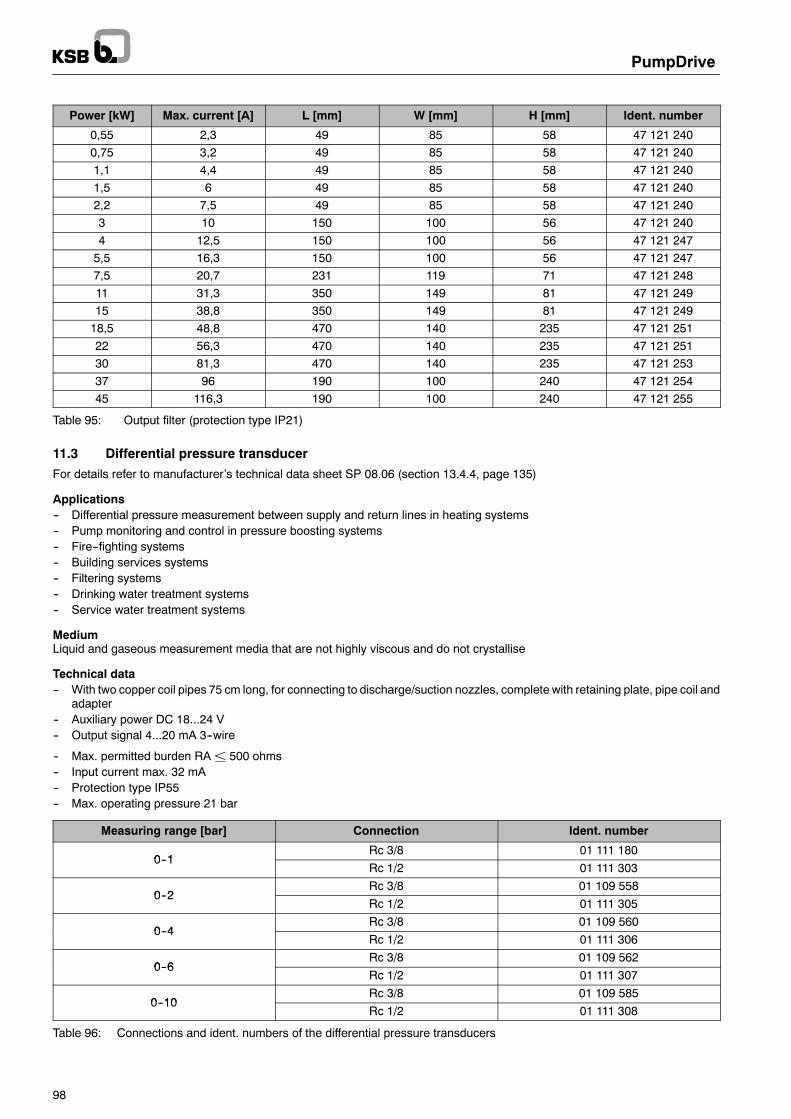
PumpDrive
98
Power [kW] Max. current [A] L [mm] W [mm] H [mm] Ident. number
0,55 2,3 49 85 58 47 121 2400,75 3,2 49 85 58 47 121 2401,1 4,4 49 85 58 47 121 2401,5 6 49 85 58 47 121 2402,2 7,5 49 85 58 47 121 2403 10 150 100 56 47 121 2404 12,5 150 100 56 47 121 2475,5 16,3 150 100 56 47 121 2477,5 20,7 231 119 71 47 121 24811 31,3 350 149 81 47 121 24915 38,8 350 149 81 47 121 24918,5 48,8 470 140 235 47 121 25122 56,3 470 140 235 47 121 25130 81,3 470 140 235 47 121 25337 96 190 100 240 47 121 25445 116,3 190 100 240 47 121 255
Table 95: Output filter (protection type IP21)
11.3 Differential pressure transducerFor details refer to manufacturer’s technical data sheet SP 08.06 (section 13.4.4, page 135)
Applications-- Differential pressure measurement between supply and return lines in heating systems-- Pump monitoring and control in pressure boosting systems-- Fire--fighting systems-- Building services systems-- Filtering systems-- Drinking water treatment systems-- Service water treatment systems
MediumLiquid and gaseous measurement media that are not highly viscous and do not crystallise
Technical data-- With two copper coil pipes 75 cm long, for connecting to discharge/suction nozzles, complete with retaining plate, pipe coil and
adapter-- Auxiliary power DC 18...24 V-- Output signal 4...20 mA 3--wire
-- Max. permitted burden RA± 500 ohms-- Input current max. 32 mA-- Protection type IP55-- Max. operating pressure 21 bar
Measuring range [bar] Connection Ident. number
0 1Rc 3/8 01 111 180
0--1Rc 1/2 01 111 303
0 2Rc 3/8 01 109 558
0--2Rc 1/2 01 111 305
0 4Rc 3/8 01 109 560
0--4Rc 1/2 01 111 306
0 6Rc 3/8 01 109 562
0--6Rc 1/2 01 111 307
0 10Rc 3/8 01 109 585
0--10Rc 1/2 01 111 308
Table 96: Connections and ident. numbers of the differential pressure transducers

PumpDrive
99
11.4 Pressure transducerFor details refer to manufacturer’s technical data sheet PE 81.01 (section 13.4.6, page 141)
11.4.1 WIKA Type OC--1
Applications-- General applications in building automation, process engineering, plant and machine construction
MediumFor gaseous and liquid media from --20 °C to +85 °C
Technical data-- Protection type: IP65-- Output signal 4...20 mA 2--wire, supply voltage 8...30 V DC-- Measuring accuracy: < 1% of the measuring range-- Process connection G1/4-- Brass casing-- For details, see also the data sheet from the manufacturer (sect. 13.4.5, p. 137)
Measuring range [bar] Connection Ident. number
0 to 2 G 1/4 01 152 0230 to 5 G 1/4 01 152 0240 to 10 G 1/4 01 073 8080 to 20 G 1/4 01 152 0250 to 50 G 1/4 01 152 026
Table 97: Connections and ID numbers of WIKA pressure transducers, type OC--1
11.4.2 WIKA Type S--10
Applications-- Process engineering systems-- Static and dynamic applications in the mechanical engineering sector-- Hydraulic applications-- Pneumatic applications-- Building services
MediumSuitable for liquid and gaseous media.
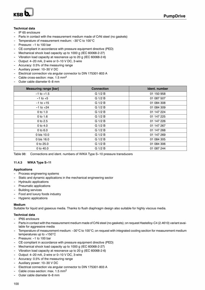
PumpDrive
100
Technical data-- IP 65 enclosure-- Parts in contact with the measurement medium made of CrNi steel (no gaskets)-- Temperature of measurement medium: --30°C to 100°C-- Pressure: --1 to 100 bar-- CE-compliant in accordance with pressure equipment directive (PED)-- Mechanical shock load capacity up to 1000 g (IEC 60068-2-27)-- Vibration load capacity at resonance up to 20 g (IEC 60068-2-6)-- Output: 4--20 mA, 2-wire or 0--10 V DC, 3-wire-- Accuracy: 0.5% of the measuring range-- Auxiliary power: 10--30 V DC-- Electrical connection via angular connector to DIN 175301-803 A-- Cable cross-section: max. 1.5 mm2
-- Outer cable diameter 6--8 mm
Measuring range [bar] Connection Ident. number
--1 to +1.5 G 1/2 B 01 150 958--1 to +5 G 1/2 B 01 087 507--1 to +15 G 1/2 B 01 084 308--1 to +24 G 1/2 B 01 084 3090 to 1.0 G 1/2 B 01 147 2240 to 1.6 G 1/2 B 01 147 2250 to 2.5 G 1/2 B 01 147 2260 to 4.0 G 1/2 B 01 147 2670 to 6.0 G 1/2 B 01 147 2680 bis 10.0 G 1/2 B 01 147 2690 bis 16.0 G 1/2 B 01 084 3050 to 25.0 G 1/2 B 01 084 3060 to 40.0 G 1/2 B 01 087 244
Table 98: Connections and ident. numbers of WIKA Type S--10 pressure transducers
11.4.3 WIKA Type S--11
Applications-- Process engineering systems-- Static and dynamic applications in the mechanical engineering sector-- Hydraulic applications-- Pneumatic applications-- Building services-- Food and luxury foods industry-- Hygienic applications
MediumSuitable for liquid and gaseous media. Thanks to flush diaphragm design also suitable for highly viscous media.
Technical data-- IP65 enclosure-- Parts in contact with themeasurementmediummade of CrNi steel (no gaskets); on request Hastelloy-C4 (2.4610) variant avai-
lable for aggressive media-- Temperature of measurement medium: --30°C to 100°C; on request with integrated cooling section for measurement medium
temperatures up to +150°C-- Pressure: --1 to 100 bar-- CE-compliant in accordance with pressure equipment directive (PED)-- Mechanical shock load capacity up to 1000 g (IEC 60068-2-27)-- Vibration load capacity at resonance up to 20 g (IEC 60068-2-6)-- Output: 4--20 mA, 2-wire or 0--10 V DC, 3-wire-- Accuracy: 0.5% of the measuring range-- Auxiliary power: 10--30 V DC-- Electrical connection via angular connector to DIN 175301-803 A-- Cable cross-section: max. 1.5 mm2
-- Outer cable diameter 6--8 mm

PumpDrive
101
Weld-in socket for pressure transducer with flush diaphragm-- Material: CrNi steel 1.4571 or 316L for G1/2 B measuring transducer connection-- Outer diameter: 50 mm-- Order no.: WIKA 11 92 299
Measuring range [bar] Connection Ident. number
--1 to +1.5 G 1/2 B 01 087 506--1 to +5 G 1/2 B 01 084 307--1 to +15 G 1/2 B 01 084 307--1 bis +24 G 1/2 B 01 084 3120 bis 1.0 G 1/2 B 01 147 2700 to 1.6 G 1/2 B 01 147 2710 to 2.5 G 1/2 B 01 147 2720 to 4.0 G 1/2 B 01 147 2730 to 6.0 G 1/2 B 01 147 2740 to 10.0 G 1/2 B 01 147 2750 to 16.0 G 1/2 B 01 084 3100 to 25.0 G 1/2 B 01 084 3110 bis 40.0 G 1/2 B 01 087 246
Table 99: Connections and ident. numbers of WIKA Type S--11 pressure transducers
11.4.4 Welded nozzle-- For WIKA pressure transmitters, type S--10 and type S--11-- Material: CrNi steel (1.4571), outer diameter 50 mm
Connection Ident. number
G 1/2 B 01 149 296
Table 100: Connection and ID number of the welded nozzle
11.5 Measuring resistor-- 500--ohm measuring resistor for connecting the analogue inputs to convert the signal with multiple pumps in operation
Measuring range [500 Ohm] Ident. number
0--10 V DC / 0--20 mA 01 127 044
Table 101: Measuring range and ID number of the measuring resistor
11.6 Potential isolator-- To safeguard the analogue inputs of the PumpDrive-- Galvanic isolation between the signal source and the analogue inputs of the PumpDrive-- Top--hat rail assembly-- Casing IP40, terminals IP20-- WxHxD = 22.5x82x118.2 mm
Version Ident. number
24 V DC 01 085 905230 V AC 01 086 963
Table 102: ID numbers of the potential isolators

PumpDrive
102
11.7 Profibus switch-- Enables the Profibus to be operated without interruption when a Profibus module is exchanged-- PumpDrive connected to the main Profibus string by means of a stub
Connection to the stub using an M12 plug--in connection or EMC cable gland-- External earth connection-- Pressure balancing element-- EMC cable gland-- Tension spring connection
Version Ident. number
Without bus termination 01 150 961With bus termination and power supply 01 150 962
Table 103: ID numbers of the Profibus switches

PumpDrive
103
11.8 Screw-in resistance thermometer WIKA Type TR10--C with multiple--section protective well TypeTW35
For details refer to manufacturer’s technical data sheet TE 60.03 (section 13.4.7, page 145)
Applications-- Mechanical engineering applications-- Plant engineering-- Container / tank construction-- Energy engineering and power stations-- Chemical industry-- Food and beverages processing industries-- Building services
FluidSuitable for liquid and gaseous media.
Technical data of thermometer-- Temperature of measurement medium: --200°C to 600°C-- Replaceable, spring-loaded sensor well-- Sensor wiring: 3-wire-- Sensor tolerance: Class B to DIN EN 60751-- Connecting head:
-- Type BSZ-- Material : aluminium-- IP65 enclosure
-- Sensor well:-- Diameter 6 mm-- Length: 245 mm
Technical data of TW35--4 protective well-- Multiple section, G1/2 B thread, made of CrNi steel 1.4571-- Connection with thermometer: M24 × 1.,5 rotatable-- Drill diameter: 6.1 mm-- Installation length: 110 mm-- Total length with stem: 255 mm
Technical data of analog head transmitter T19 (technical data sheet TE 19.03)-- Input: 1 × Pt100, 3-wire system-- Measuring range configured to: 0°C to 150°C-- Output: 4--20 mA, 2-wire-- Auxiliary power 10--30 V DC
-- Accuracy to DIN EN 60770 0.5%
Measuring range Connection Ident. number
0°C to 150°C G 1/2 B 01 149 295
Table 104: Connection and ID number of theWIKA screw--in resistance thermometer, type TR10--C, with TW35multiple--sectionprotective well

PumpDrive
104
11.9 WIKA Type LS--10 level sensor for fill level and liquid level measurementFor details refer to manufacturer’s technical data sheet PE 81.C9 (section 13.4.8, page 151).
ApplicationsFill level measurement in containers, tanks, watercourses, drinking water wells, boreholes and waste water systems
MediumSuitable for liquid fluids.
Technical data-- IP68 enclosure-- Parts in contact with the measurement medium made of CrNi steel, PUR, PA-- Temperature of measurement medium: --10°C to 50°C-- CE-compliant to EN 61326-- Output: 4--20 mA, 2-wire-- Accuracy: 0.5% of the measuring range-- Auxiliary power: 10--30 V DC-- Electrical connection by PUR cable
Measuring range [bar] Connection Ident. number
0 to 0.25 G 1/2 B 01 149 4090 to 0.6 G 1/2 B 01 149 4100 to 1.0 G 1/2 B 01 149 4110 to 1.6 G 1/2 B 01 149 4120 to 2.5 G 1/2 B 01 149 4130 to 4.0 G 1/2 B 01 149 414
Table 105: Connections and ID numbers of the WIKA level probe, type LS--10
12 RecyclingPumpDrive contains some highly toxic components and, therefore, it must be treated as hazardous waste.It can, however, be broken down into the following recyclable components:D Aluminium heat sinkD Plastic cover (recyclable plastic)D Line chokes with copper windingsD Copper cable for internal wiringPCBs, power electronics, capacitors, and electronic components are all hazardous waste.

PumpDrive
105
13 Annex
13.1 Parameter lists-- SD Factory setting for single--pump drive-- MP Factory setting for multiple pump system-- Min. Minimum setting value-- Max. Maximum setting value-- Access Access level-- Selection list See section 13.2, page 120-- bg Size-dependent
Menu SD MP Min. Max. Unit Access Selection list Setting
1 Operation
1--1 Operation
1--1--1 Operation
1--1--1--1 Tot Hrs Volt S 0 0 0 0 h Anyone
1--1--1--2 Operating Hours 0 0 0 0 h Anyone
1--1--1--3 kWh Counter 0 0 0 0 kWh Anyone
1--1--1--4 No of Power--ups 0 0 0 0 Anyone
1--1--1--5 Rst kWh Counter 1 1 Cus-tomer
1–Do Not Reset2–Reset
1--1--1--6 Rst Op Hours 1 1 Service 1–Do Not Reset2–Reset
1--2 Motor
1--2--1 Motor
1--2--1--1 Power [kW] 0 0 0 0 kW Anyone
1--2--1--2 Power [HP] 0 0 0 0 HP Anyone
1--2--1--3 Motor Voltage 0 0 0 0 V Anyone
1--2--1--4 Frequency 0 0 0 0 Hz Anyone
1--2--1--5 Motor Current 0 0 0 0 A Anyone
1--2--1--6 Speed [RPM] 0 0 0 0 1/min Anyone
1--3 Signals
1--3--1 Process
1--3--1--1 Feedback [Unit] 0 0 0 0 3--2--2--1 Anyone
1--3--1--2 Feedback % 0 0 0 0 % Anyone
1--3--1--3 Setpoint [Unit] 0 0 0 0 3--2--2--1 Anyone
1--3--1--4 Setpoint % 0 0 0 0 % Anyone
1--3--1--5 Anlg IN1 [Unit] 0 0 0 0 3--8--2--6 Anyone
1--3--1--6 Anlg IN2 [Unit] 0 0 0 0 3--8--3--6 Anyone
1--3--1--7 Pressure P1 0 0 0 0 3--2--2--3 Anyone
1--3--1--8 Pressure P2 0 0 0 0 3--2--2--3 Anyone
1--3--1--9 Q [Unit] 0 0 0 0 3--2--2--2 Anyone
1--3--1--101) Q % 0 0 0 0 % Anyone
1--3--1--11 Temperature 0 0 0 0 ˚C Anyone
1--3--2 Inputs&Outputs
1--3--2--1 Digital I/O 0 0 0 0 hex Anyone
1--3--2--2 Analog IN 1 0 0 0 0 % Anyone
1--3--2--3 Analog IN 2 0 0 0 0 % Anyone
1--3--2--4 Analog OUT 1 0 0 0 0 % Anyone
1) Selection is inactive

PumpDrive
106
Menu SD MP Min. Max. Unit Access Selection list Setting
1--4 PumpDrive
1--4--1 Status
1--4--1--1 DC Link Voltage 0 0 0 0 V Anyone
1--4--1--2 Heat Sink Temp 0 0 0 0 ˚C Anyone
1--4--1--3 PCB Temp 0 0 0 0 ˚C Anyone
1--4--2 Local Bus
1--4--2--1 System Setpoint 0 0 0 0 Factory
1--4--3 Bus Readout
1--4--3--1 Control Word 0 0 0 0 hex Cus-tomer
1--4--3--2 Alert Word 0 0 0 0 hex Cus-tomer
1--4--3--3 Warning Word 0 0 0 0 hex Cus-tomer
1--4--3--4 Status Word 0 0 0 0 hex Cus-tomer
1--5 Pump
1--5--1 Flow Rate Meas
1--5--1--1 Sys Flow Rate 0 0 0 0 m3/h Anyone
1--5--1--2 Flow Rate Pump1 0 0 0 0 m3/h Anyone
1--5--1--3 Flow Rate Pump2 0 0 0 0 m3/h Anyone
1--5--1--4 Flow Rate Pump3 0 0 0 0 m3/h Anyone
1--5--1--5 Flow Rate Pump4 0 0 0 0 m3/h Anyone
1--5--1--6 Flow Rate Pump5 0 0 0 0 m3/h Anyone
1--5--1--7 Flow Rate Pump6 0 0 0 0 m3/h Anyone
1--5--2 Power Measurmnt
1--5--2--1 Total Sys Power 0 0 0 0 kW Anyone
1--5--2--2 Power Pump 1 0 0 0 0 kW Anyone
1--5--2--3 Power Pump 2 0 0 0 0 kW Anyone
1--5--2--4 Power Pump 3 0 0 0 0 kW Anyone
1--5--2--5 Power Pump 4 0 0 0 0 kW Anyone
1--5--2--6 Power Pump 5 0 0 0 0 kW Anyone
1--5--2--7 Power Pump 6 0 0 0 0 kW Anyone
1--5--3 Pump Status
1--5--3--1 Status Pump 1 0 0 0 0 hex Anyone
1--5--3--2 Status Pump 2 0 0 0 0 hex Anyone
1--5--3--3 Status Pump 3 0 0 0 0 hex Anyone
1--5--3--4 Status Pump 4 0 0 0 0 hex Anyone
1--5--3--5 Status Pump 5 0 0 0 0 hex Anyone
1--5--3--6 Status Pump 6 0 0 0 0 hex Anyone
2 Diagnosis
2--1 Alert History
2--1--1 Alarmhistorie
2--1--1--2 Alert History 0 0 Anyone
2--2 Warnings
2--2--1 Warnings
2--2--1--1 Warning 0 0 Anyone
2--3 Alerts
2--3--1 Alerts
2--3--1--1 Alert 0 0 Anyone

PumpDrive
107
SettingSelection listAccessUnitMax.Min.MPSDMenu
2--4 Op Logger
2--4--1 PumpDrive
2--4--1--1 PD Temp High 0 0 0 0 h Anyone
2--4--1--2 Line Volt High 0 0 0 0 h Anyone
2--4--1--3 Line Volt Low 0 0 0 0 h Anyone
2--4--1--4 Mot Current Hi 0 0 0 0 h Anyone
2--4--1--5 Mot Current Lo 0 0 0 0 h Anyone
2--4--1--6 Mot Power High 0 0 0 0 h Anyone
2--4--1--7 Mot Power Low 0 0 0 0 h Anyone
2--4--2 Process Timers
2--4--2--1 Setpoint High 0 0 0 0 h Anyone
2--4--2--2 Setpoint Low 0 0 0 0 h Anyone
2--4--2--3 Feedback High 0 0 0 0 h Anyone
2--4--2--4 Feedback Low 0 0 0 0 h Anyone
2--4--2--5 Analog IN1 High 0 0 0 0 h Anyone
2--4--2--6 Analog IN1 Low 0 0 0 0 h Anyone
2--4--2--7 Analog IN2 High 0 0 0 0 h Anyone
2--4--2--8 Analog IN2 Low 0 0 0 0 h Anyone
3 Settings
3--1 Panel
3--1--1 Basic Settings
3--1--1--1 Language 0 0 Cus-tomer
3--1--1--2 Backlighting 3 3 Cus-tomer
1–Off2–On3–Auto
3--1--1--3 Backlight Time 30 30 5 1000 s Cus-tomer
3--1--1--4 ID Selec PDrive 0 0 Cus-tomer
3--1--2 Set--up
3--1--2--1 Set--up Version 1.01 0 1 99.99 Cus-tomer
3--1--3 Display Config
3--1--3--1 User Config 0 0 Cus-tomer
3--1--4 Keypad
3--1--4--1 [Man] Key 2 2 Cus-tomer
1–Disabled2–Enabled
3--1--4--2 [Off] Key 2 2 Cus-tomer
1–Disabled2–Enabled
3--1--4--3 [Func] Key 1 1 Cus-tomer
1–No Function2–Sleep Mode3–PI Mode4–Trip Reset5–Pump Change6–Sys Start / Stop
3--1--5 Panel Commands
3--1--5--1 PDrive --> HMI 1 1 Cus-tomer
1–Off2–Start
3--1--5--2 HMI --> PDrive 1 1 Cus-tomer
1–Off2–Start

PumpDrive
108
SettingSelection listAccessUnitMax.Min.MPSDMenu
3--1--5--3 Trip Reset 1 1 Anyone 1–Off2–Start
3--1--5--4 Upload BIN File 1 1 Cus-tomer
1–Off2–Start
3--1--5--5 Back Fac Settgs 1 1 Cus-tomer
1–Off2–Start
3--1--5--6 System Reboot 1 1 Cus-tomer
1–Off2–Start
3--1--5--7 Pump Start 1 1 Anyone 1–Off2–Start
3--1--5--8 Pump Stop 1 1 Anyone 1–Off2–Start
3--1--5--9 HMI --> all PDrive 1 1 Cus-tomer
1–Off2–Start
3--1--5--10 System Stop 1 1 Anyone 1–Off2–Start
3--1--5--11 System Start 1 1 Anyone 1–Off2–Start
3--1--5--12 Pp Changeover 1 1 Anyone 1–Off2–Start
3--1--6 Password
3--1--6--1 Login 0 0 Anyone
3--1--6--2 Service Login 0 0 Service
3--1--6--3 Factory Login 0 0
3--1--6--4 Customer Passwd 0 0 0 9999 Cus-tomer
3--1--6--5 Enable Protect 1 1 Cus-tomer
1–Disabled2–Enabled
3--1--6--6 Service--Passwd 0 9999 Service
3--1--6--7 Factory Passwd 0 9999 Factory
3--1--7 Network Config
3--1--7--1 Network Manager 2 2 Cus-tomer
1–Disabled2–Enabled
3--1--7--2 Server Guard Tm 3.5 3.5 2 4 s Cus-tomer
3--1--7--3 Backup Adv--HMI 1 1 Cus-tomer
1–Disabled2–Enabled
3--1--7--4 Backup Guard Tm 1 1 0.1 10 s Cus-tomer
3--2 PumpDrive
3--2--1 Basic Settings
3--2--1--1 MultiPump Role 1 2 Cus-tomer
1–Standard Slave2–Aux Main Pump
3--2--1--2 PumpDriveID 0 0 0 6 Cus-tomer
3--2--1--3 Local Bus ID 0 0 0 0 Cus-tomer
3--2--1--4 Curr Pump Role 1 1 Cus-tomer
1–Single pump2–Standard Slave3–Aux Main Pump
3--2--1--5 Fieldbus Enable 1 1 Cus-tomer
1–Disabled2–Enabled
3--2--2 Units

PumpDrive
109
SettingSelection listAccessUnitMax.Min.MPSDMenu
3--2--2--1 Setpoint Unit 1 1 Cus-tomer
***
3--2--2--2 Q Unit 29 29 Cus-tomer
***
3--2--2--3 Pressure Unit 1 1 Cus-tomer
***
3--2--3 Set--up
3--2--3--1 Active Set--up 1 1 Anyone 1–Setup 12–Setup 2
3--2--3--2 Set--up Version 1 1 0 99.99 Cus-tomer
3--3 Load and Motor
3--3--1 V/f Settings
3--3--1--1 V/f Voltage 0 2 2 0 15 % Cus-tomer
3--3--1--2 V/f Voltage 1 4 4 0 100 % Cus-tomer
3--3--1--3 V/f Frequency 1 20 20 0 100 % Cus-tomer
3--3--1--4 V/f Voltage 2 16 16 0 100 % Cus-tomer
3--3--1--5 V/f Frequency 2 40 40 0 100 % Cus-tomer
3--3--1--6 V/f Voltage 3 64 64 0 100 % Cus-tomer
3--3--1--7 V/f Frequency 3 80 80 0 100 % Cus-tomer
3--3--1--8 V/f Voltage 4 100 100 0 100 % Cus-tomer
3--3--1--9 V/f Frequency 4 100 100 0 100 % Cus-tomer
3--3--2 Motor Data
3--3--2--1 Rated Power bg bg 0.55 45 kW Cus-tomer
3--3--2--2 Rated Voltage bg bg 342 528 V Cus-tomer
3--3--2--3 Rated Freq bg bg 45 65 Hz Cus-tomer
3--3--2--4 Rated Current bg bg 0.1 999 A Cus-tomer
3--3--2--5 Rated Speed bg bg 300 3600 1/min Cus-tomer
3--3--2--6 Rated Cosphi bg bg 0.1 0.99 Cus-tomer
3--3--2--7 Rated I2t 100 100 100 150 Factory
3--3--4 Start Adjust
3--3--4--1 Start Delay 0.1 0.1 0 60 s Cus-tomer
3--3--4--2 Start Out Freq 0 0 0 10 % Cus-tomer
3--3--5 Motor Temp
3--3--5--1 Thermal Protect 2 2 Cus-tomer
1--No protection2--PTC Protection

PumpDrive
110
SettingSelection listAccessUnitMax.Min.MPSDMenu
3--3--5--2 Thermal Limit 83.5 83.5 0 100 % Service
3--3--6 Ramps
3--3--6--1 Ramp 0 Up/Down 3 3 0.5 600 s Cus-tomer
3--3--6--2 Ramp 1 Up Tm 3 3 0.5 600 s Cus-tomer
3--3--6--3 Ramp 1 Down Tm 3 3 0.5 600 s Cus-tomer
3--3--6--4 Ramp 2 Up Tm 3 10 0.5 600 s Cus-tomer
3--3--6--5 Ramp 2 Down Tm 3 10 0.5 600 s Cus-tomer
3--3--6--6 R1/2 Start Freq 50 50 0 100 % Cus-tomer
3--3--6--7 R1/2 Stop Freq 50 50 0 100 % Cus-tomer
3--3--7 Res Freq Bypass
3--3--7--1 Lo Bypass Freq 0 0 0 3--3--7--2 % Cus-tomer
3--3--7--2 Hi Bypass Freq 0 0 3--3--7--1 100 % Cus-tomer
3--4 Spec Pump Settg
3--4--1 Q/p Measurement
3--4--1--1 Flow Rate Meas 1 1 Cus-tomer
1–Estimated2–Measured
3--4--1--2 Q 100% Value 0 0 0 9999 3--2--2--2 Cus-tomer
3--4--1--3 p 100% Value 0 0 0 9999 3--2--2--3 Cus-tomer
3--4--2 Setpoint Comp
3--4--2--1 Q Compensation 100 100 0 100 % Cus-tomer
3--4--2--2 Setpoint Comp 0 0 0 9999 3--2--2--1 Cus-tomer
3--4--3 Sleep Mode
3--4--3--1 Sleep Mode 1 1 Cus-tomer
1–Disabled
2 – Enabled
3--4--3--2 Diff to Restart 0 0 0 9999 3--2--2--1 Cus-tomer
3--4--3--3 Start Delay 1 1 0.1 60 s Cus-tomer
3--4--3--4 Freq Stop Lim 60 60 3--6--1--2 3--6--1--3 % Cus-tomer
3--4--3--5 Stop Cnd Tm 10 10 0.1 60 s Cus-tomer
3--4--3--6 Low Q Det Tm 60 60 45 360 s Cus-tomer
3--4--3--7 Diff Start Puls 2 2 0 9999 3--2--2--1 Cus-tomer
3--4--3--8 Pulse Ampl 2 2 0 9999 3--2--2--1 Cus-tomer

PumpDrive
111
SettingSelection listAccessUnitMax.Min.MPSDMenu
3--4--3--9 Pulse Time 10 10 3 30 s Cus-tomer
3--5 Setpoint
3--5--1 General Settngs
3--5--1--1 Setpoint Scale 1 1 0.5 2 Cus-tomer
3--5--1--2 Min Setpoint 0 0 0 3--5--1--3 3--2--2--1 Cus-tomer
3--5--1--3 Max Setpoint 100 100 3--5--1--2 9999 3--2--2--1 Cus-tomer
3--5--1--4 Control Mode 2 2 Factory 1–Off2–Auto3–Manual
3--5--2 Preset Setpoint
3--5--2--1 Preset Setpoint 0 0 3--5--1--2 3--5--1--3 3--2--2--1 Anyone
3--5--2--2 Prset Setp Step 0.1 0.1 0 9999 3--2--2--1 Cus-tomer
3--5--3 Prset OutFrq
3--5--3--1 Prset OutFrq1 100 100 0 100 % Cus-tomer
3--5--3--2 Prset OutFrq2 75 75 0 100 % Cus-tomer
3--5--3--3 Prset OutFrq3 50 50 0 100 % Cus-tomer
3--5--3--4 Preset Man Out 0 0 0 100 % Cus-tomer
3--5--4 Setpoint Source
3--5--4--1 Setp Source 1 2 2 Cus-tomer
1–No Operation2–Analog IN 13–Analog IN 24–Preset Setpoint5–Remote Setpoint6–RS232 Setpoint
3--5--4--2 Setp Source 2 4 4 Cus-tomer
1–No Operation2–Analog IN 13–Analog IN 24–Preset Setpoint5–Remote Setpoint6–RS232 Setpoint
3--5--4--3 Setp Source 3 5 5 Cus-tomer
1–No Operation2–Analog IN 13–Analog IN 24–Preset Setpoint5–Remote Setpoint6–RS232 Setpoint
3--6 Limits&Warns
3--6--1 Motor Limits
3--6--1--1 Direc Mot Rot 1 1 Cus-tomer
1–Clockwise2–Counterclockwise
3--6--1--2 Frequency Lo 50 50 0 3--6--1--3 % Cus-tomer
3--6--1--3 Frequency Hi 100 100 3--6--1--2 100 % Cus-tomer

PumpDrive
112
SettingSelection listAccessUnitMax.Min.MPSDMenu
3--6--1--4 MotMod Curr Lim 75 75 50 100 % Cus-tomer
3--6--1--5 GenMod Curr Lim 30 30 0 100 % Factory
3--6--2 Motor Warnings
3--6--2--1 Lo Curr Wrn Lim 0 0 0 3--6--2--2 % Cus-tomer
3--6--2--2 Hi Curr Wrn Lim 100 100 3--6--2--1 100 % Cus-tomer
3--6--2--3 Curr Wrn Tm Dly 5 5 0 60 s Cus-tomer
3--6--2--4 Curr Wrn Func 1 1 Cus-tomer
1–No Function2–Warning3–Stop&Trip
3--6--2--5 Lo Out Freq Wrn 0 0 0 3--6--2--6 % Cus-tomer
3--6--2--6 Hi Out Freq Wrn 100 100 3--6--2--5 100 % Cus-tomer
3--6--2--7 Freq Wrn Tm Dly 5 5 0 60 s Cus-tomer
3--6--2--8 Freq Wrn Fnc 1 1 Cus-tomer
1–No Function2–Warning3–Stop&Trip
3--6--3 Analog IN Wrn
3--6--3--1 An IN 1 Low 0 0 3--8--2--7 3--8--2--8 3--8--2--6 Cus-tomer
3--6--3--2 An IN 1 High 100 100 3--8--2--7 3--8--2--8 3--8--2--6 Cus-tomer
3--6--3--3 An IN1 Wrn TDly 5 5 0 60 s Cus-tomer
3--6--3--4 An IN 1 Wrn Fnc 1 1 Cus-tomer
1–No Function2–Warning3–Stop&Trip
3--6--3--5 An IN 2 Low 0 0 3--8--3--7 3--8--3--8 3--8--3--6 Cus-tomer
3--6--3--6 An IN 2 High 100 100 3--8--3--7 3--8--3--8 3--8--3--6 Cus-tomer
3--6--3--7 An IN2 Wrn TDly 5 5 0 60 s Cus-tomer
3--6--3--8 An IN 2 Wrn Fnc 1 1 Cus-tomer
1–No Function2–Warning3–Stop&Trip
3--6--4 Load Warnings
3--6--4--1 Hi Ld @ Lo Mo F 60 60 0 3--6--4--2 % Cus-tomer
3--6--4--2 Hi Ld @ Hi Mo F 90 90 3--6--4--1 100 % Cus-tomer
3--6--4--3 Hi Load Profile 1 1 Cus-tomer
1–Linear2–Square3–Cube
3--6--4--4 Hi Load Tm Dly 5 5 0 30 s Cus-tomer
3--6--4--5 High Load Fnc 1 5 Cus-tomer
1–No Function2–Warning3–Stop&Trip
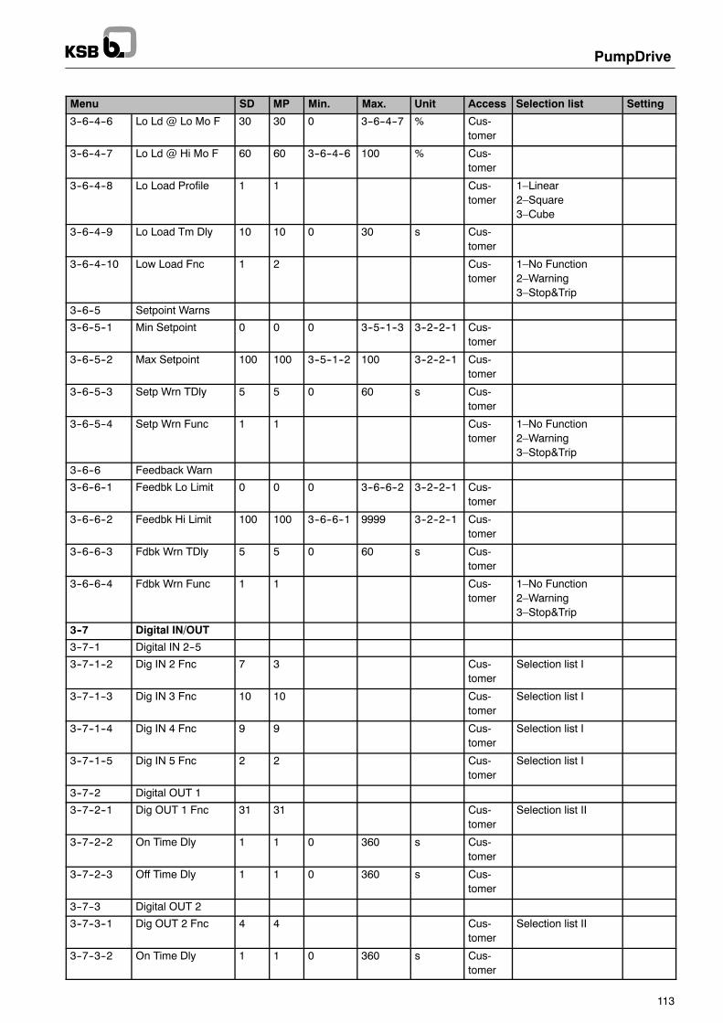
PumpDrive
113
SettingSelection listAccessUnitMax.Min.MPSDMenu
3--6--4--6 Lo Ld @ Lo Mo F 30 30 0 3--6--4--7 % Cus-tomer
3--6--4--7 Lo Ld @ Hi Mo F 60 60 3--6--4--6 100 % Cus-tomer
3--6--4--8 Lo Load Profile 1 1 Cus-tomer
1–Linear2–Square3–Cube
3--6--4--9 Lo Load Tm Dly 10 10 0 30 s Cus-tomer
3--6--4--10 Low Load Fnc 1 2 Cus-tomer
1–No Function2–Warning3–Stop&Trip
3--6--5 Setpoint Warns
3--6--5--1 Min Setpoint 0 0 0 3--5--1--3 3--2--2--1 Cus-tomer
3--6--5--2 Max Setpoint 100 100 3--5--1--2 100 3--2--2--1 Cus-tomer
3--6--5--3 Setp Wrn TDly 5 5 0 60 s Cus-tomer
3--6--5--4 Setp Wrn Func 1 1 Cus-tomer
1–No Function2–Warning3–Stop&Trip
3--6--6 Feedback Warn
3--6--6--1 Feedbk Lo Limit 0 0 0 3--6--6--2 3--2--2--1 Cus-tomer
3--6--6--2 Feedbk Hi Limit 100 100 3--6--6--1 9999 3--2--2--1 Cus-tomer
3--6--6--3 Fdbk Wrn TDly 5 5 0 60 s Cus-tomer
3--6--6--4 Fdbk Wrn Func 1 1 Cus-tomer
1–No Function2–Warning3–Stop&Trip
3--7 Digital IN/OUT
3--7--1 Digital IN 2--5
3--7--1--2 Dig IN 2 Fnc 7 3 Cus-tomer
Selection list I
3--7--1--3 Dig IN 3 Fnc 10 10 Cus-tomer
Selection list I
3--7--1--4 Dig IN 4 Fnc 9 9 Cus-tomer
Selection list I
3--7--1--5 Dig IN 5 Fnc 2 2 Cus-tomer
Selection list I
3--7--2 Digital OUT 1
3--7--2--1 Dig OUT 1 Fnc 31 31 Cus-tomer
Selection list II
3--7--2--2 On Time Dly 1 1 0 360 s Cus-tomer
3--7--2--3 Off Time Dly 1 1 0 360 s Cus-tomer
3--7--3 Digital OUT 2
3--7--3--1 Dig OUT 2 Fnc 4 4 Cus-tomer
Selection list II
3--7--3--2 On Time Dly 1 1 0 360 s Cus-tomer

PumpDrive
114
SettingSelection listAccessUnitMax.Min.MPSDMenu
3--7--3--3 Off Time Dly 1 1 0 360 s Cus-tomer
3--8 Analog IN/OUT
3--8--1 Analog IO Mode
3--8--1--1 Live Zero TmDly 3 3 0.1 60 s Cus-tomer
3--8--1--2 Live Zero Fnc 1 1 Cus-tomer
1–No Function2–Stop3–Min Motor Speed4–Max Motor Speed5–Freeze Output6–Warning7–Stop&Trip
3--8--2 Analog IN 1
3--8--2--1 AI1 Setting 2 2 Cus-tomer
1–Current2–Voltage
3--8--2--2 AI1 Lo Voltage 0 0 0 3--8--2--3 V Cus-tomer
3--8--2--3 AI1 Hi Voltage 10 10 3--8--2--2 10 V Cus-tomer
3--8--2--4 AI1 Lo Current 4 4 0 3--8--2--5 mA Cus-tomer
3--8--2--5 AI1 Hi Current 20 20 3--8--2--4 20 mA Cus-tomer
3--8--2--6 AI 1 Unit 1 1 Cus-tomer
Selection list III
3--8--2--7 Anlg IN 1 Lo 0 0 0 3--8--2--8 3--8--2--6 Cus-tomer
3--8--2--8 Anlg IN 1 Hi 100 100 3--8--2--7 9999 3--8--2--6 Cus-tomer
3--8--2--9 AI1 Filter Tm 0.1 0.1 0.1 10 s Cus-tomer
3--8--2--10 AI1 Unit 1 1 0.5 2 Cus-tomer
3--8--2--11 AI1 Descriptor 1 1 Cus-tomer
1–Process2–Pressure P13–Pressure P24–Q5–Temperature
3--8--3 Analog IN 2
3--8--3--1 AI2 Setting 1 2 Cus-tomer
1–Current2–Voltage
3--8--3--2 AI2 Lo Voltage 0 0 0 3--8--3--3 V Cus-tomer
3--8--3--3 AI2 Hi Voltage 10 10 3--8--3--2 10 V Cus-tomer
3--8--3--4 AI2 Lo Current 4 4 0 3--8--3--5 mA Cus-tomer
3--8--3--5 AI2 Hi Current 20 20 3--8--3--4 20 mA Cus-tomer
3--8--3--6 AI 2 Unit 1 1 Cus-tomer
Selection list III
3--8--3--7 Anlg IN 2 Lo 0 0 0 3--8--3--8 3--8--3--6 Cus-tomer

PumpDrive
115
SettingSelection listAccessUnitMax.Min.MPSDMenu
3--8--3--8 Anlg IN 2 Hi 100 100 3--8--3--7 9999 3--8--3--6 Cus-tomer
3--8--3--9 AI2 Filter Tm 0.1 0.1 0.1 10 s Cus-tomer
3--8--3--10 AI2 Unit 1 1 0.5 2 Cus-tomer
3--8--3--11 AI2 Descriptor 1 1 Cus-tomer
1–Process2–Pressure P13–Pressure P24–Q5–Temperature
3--8--4 Analog OUT 1
3--8--4--1 AO Source 1 8 8 Cus-tomer
1–None2–Setpoint3–Feedback4–Rated Power5–Motor Voltage6–Motor Current7–Motor Speed8–Output Freq9–DC Link Voltage
3--8--4--2 AO Source 2 1 1 Cus-tomer
1–None2–Setpoint3–Feedback4–Rated Power5–Motor Voltage6–Motor Current7–Motor Speed8–Output Freq9–DC Link Voltage
3--8--4--3 AO Source 3 1 1 Cus-tomer
1–None2–Setpoint3–Feedback4–Rated Power5–Motor Voltage6–Motor Current7–Motor Speed8–Output Freq9–DC Link Voltage
3--8--4--4 AO Source 4 1 1 Cus-tomer
1–None2–Setpoint3–Feedback4–Rated Power5–Motor Voltage6–Motor Current7–Motor Speed8–Output Freq9–DC Link Voltage
3--8--4--5 AO Lo Voltage 0 0 0 10 V Cus-tomer
3--8--4--6 AO Hi Voltage 10 10 0.01 10 V Cus-tomer
3--8--4--7 AO Time Const 0.5 0.5 0.01 1 s Cus-tomer

PumpDrive
116
SettingSelection listAccessUnitMax.Min.MPSDMenu
3--9 PI Controller
3--9--1 Process PI Ctrl
3--9--1--1 PI Mode 1 2 Cus-tomer
1–Disabled2–Enabled
3--9--1--2 PI Prop Gain 1 1 0 10 Cus-tomer
3--9--1--3 PI Integral Tm 1 1 0 60 s Cus-tomer
3--9--1--4 PI Sense 0 0 Cus-tomer
3--9--1--5 PI Type 1 1 Cus-tomer
1–Const Pressure2–Variable Press3–Constant Flow4–Other Setpoint
3--9--1--6 PI Auto 1 0 Cus-tomer
3--9--2 Feedbk Source
3--9--2--1 Feedbk Source 1 1 Cus-tomer
3--10 Communication
3--10--1 General Setting
3--10--1--1 Ctrl Guard Tm 4 4 2 10 s Cus-tomer
3--10--1--2 Ctrl Wd Wrn Fnc 1 1 Service
3--10--1--3 Aux Main Grd Tm 0.5 0.5 0.02 10 s Cus-tomer
3--11 Add Settings
3--11--1 Inverter Switch
3--11--1--1 Inverter Switch bg bg Service Selection list V
3--11--1--2 PWM Random 6 6 Service Selection list IV
3--11--2 Trip
3--11--2--1 Trip Reset Mode 2 2 Cus-tomer
1–Manual Reset2–10s, 60s, 5m3–Inf Reset @ 5m4–10s, 60s, 5m, 15–Inf Reset @ 15m
3--11--3 Crrnt Lim Ctrl
3--11--3--1 Prop Const 10 10 0 100 Factory
3--11--3--2 Integral Const 2 2 0 100 Factory
3--11--4 Max Output
3--11--4--1 Max Out Freq 50 50 25 70 Hz Cus-tomer
3--11--4--2 Max Out Current 0 0 0 500 A Cus-tomer
3--11--5 PD Settings
3--11--5--1 PDrive Size 3 3 1 16 Cus-tomer
3--11--5--2 Offset DC Link 350 350 200 365 V Factory

PumpDrive
117
SettingSelection listAccessUnitMax.Min.MPSDMenu
3--12 Adv Pump Ctrl
3--12--1 Flow Rate Meas
3--12--1--1 Flow Rate Meas 1 1 Cus-tomer
1–Measured2–P/Q Calculated
3--12--2 Low Q Limit
3--12--2--1 Start Learn Prf 1 1 Cus-tomer
1–Off2–Start
3--12--2--2 P % @ 30% fmax 0 0 0 110 kW Cus-tomer
3--12--2--3 P % @ 40% fmax 0 0 0 110 kW Cus-tomer
3--12--2--4 P % @ 50% fmax 0 0 0 110 kW Cus-tomer
3--12--2--5 P % @ 60% fmax 0 0 0 110 kW Cus-tomer
3--12--2--6 P % @ 70% fmax 0 0 0 110 kW Cus-tomer
3--12--2--7 P % @ 80% fmax 0 0 0 110 kW Cus-tomer
3--12--2--8 P % @ 90% fmax 0 0 0 110 kW Cus-tomer
3--12--2--9 P % @ 100% fmax 0 0 0 110 kW Cus-tomer
3--12--2--10 Learn Time 30 30 30 500 s Cus-tomer
3--12--2--11 Learn Meas Err 5 5 2 20 % Cus-tomer
3--12--3 Q/P/H Curves
3--12--3--1 Rated P Speed 0 0 0 9999 1/min Cus-tomer
3--12--3--2 Rho 1000 1000 0 9999 kg/m3 Cus-tomer
3--12--3--3 No of Stages 1 1 0 100 Cus-tomer
3--12--3--4 Qopt 0 0 0 9999 m3/h Cus-tomer
3--12--3--5 Qmin 0 0 0 9999 m3/h Cus-tomer
3--12--3--6 Qmax 0 0 0 9999 m3/h Cus-tomer
3--12--3--7 Q_0 0 0 0 9999 m3/h Cus-tomer
3--12--3--8 Q_1 0 0 0 9999 m3/h Cus-tomer
3--12--3--9 Q_2 0 0 0 9999 m3/h Cus-tomer
3--12--3--10 Q_3 0 0 0 9999 m3/h Cus-tomer
3--12--3--11 Q_4 0 0 0 9999 m3/h Cus-tomer
3--12--3--12 Q_5 0 0 0 9999 m3/h Cus-tomer

PumpDrive
118
SettingSelection listAccessUnitMax.Min.MPSDMenu
3--12--3--13 Q_6 0 0 0 9999 m3/h Cus-tomer
3--12--3--14 H_0 0 0 0 9999 m Cus-tomer
3--12--3--15 H_1 0 0 0 9999 m Cus-tomer
3--12--3--16 H_2 0 0 0 9999 m Cus-tomer
3--12--3--17 H_3 0 0 0 9999 m Cus-tomer
3--12--3--18 H_4 0 0 0 9999 m Cus-tomer
3--12--3--19 H_5 0 0 0 9999 m Cus-tomer
3--12--3--20 H_6 0 0 0 9999 m Cus-tomer
3--12--3--21 P_0 0 0 0 999 kW Cus-tomer
3--12--3--22 P_1 0 0 0 999 kW Cus-tomer
3--12--3--23 P_2 0 0 0 999 kW Cus-tomer
3--12--3--24 P_3 0 0 0 999 kW Cus-tomer
3--12--3--25 P_4 0 0 0 999 kW Cus-tomer
3--12--3--26 P_5 0 0 0 999 kW Cus-tomer
3--12--3--27 P_6 0 0 0 999 kW Cus-tomer
3--12--4 Pump Protection
3--12--4--1 Q Lim High Flow 100 100 0 150 % Cus-tomer
3--12--4--2 Q Hi Timeout Tm 20 20 0 120 s Cus-tomer
3--12--4--3 Q Hi Timeout Fn 1 1 Cus-tomer
1–No Function2–Warning3–Stop&Trip
3--12--4--4 Q Lim Low Flow 100 100 0 150 % Cus-tomer
3--12--4--5 Q Lo Timeout Tm 20 20 0 120 s Cus-tomer
3--12--4--6 Q Lo Timeout Fn 1 1 Cus-tomer
1–No Function2–Warning3–Stop&Trip
3--12--4--7 Hyd Blk Factor 85 85 0 100 % Cus-tomer
3--12--4--8 Hyd Blck Tmout 10 10 0 1000 s Cus-tomer
3--12--4--9 Dry Run Factor 70 70 0 100 % Cus-tomer
3--12--4--10 Dry Run Timeout 5 5 0 1000 s Cus-tomer

PumpDrive
119
SettingSelection listAccessUnitMax.Min.MPSDMenu
3--12--4--11 Dry Run Enable 2 2 Cus-tomer
1–Disabled2–Enabled
3--12--5 Multipump Conf
3--12--5--1 Max Pps Run 1 1 1 6 Cus-tomer
3--12--5--2 No of Standby 0 0 0 6 Factory
3--12--5--3 Tm Cons Add Pum 10 10 3 500 s Cus-tomer
3--12--5--4 Tm Stop Pump 20 20 10 500 s Cus-tomer
3--12--5--5 Enable Pps Chg 2 2 Cus-tomer
1–Disabled2–Enabled
3--13 LON Module
3--14 Profibus Module
4 Information
4--1 PDrive Info
4--1--1 PDrive ID
4--1--1--1 Device Ser No 0 0 Anyone
4--1--1--2 SW Version 0 0 Anyone
4--1--1--3 Device Type 0 0 Anyone
4--1--1--4 Dev Type Code 0 0 0 0 Anyone
4--1--1--5 Bin File Vers 0 0 0 0 Service
4--1--1--6 Prog Lang 1 0 0 Cus-tomer
4--1--1--7 Prog Lang 2 0 0 Cus-tomer
4--1--1--8 Bin File Chksum 0 0 0 65535 Service
4--1--1--9 Bin File Length 0 0 0 65535 Service
4--2 Panel
4--2--1 Panel Ident
4--2--1--1 Device Ser No 0 0 Anyone
4--2--1--2 SW Version 0 0 Anyone
4--2--1--3 Device Type 0 0 Anyone
4--2--1--4 Dev Type Code 0 0 0 0 Anyone
4--2--1--5 Bin File Vers 0 0 0 0 Service
4--2--1--6 Prog Lang 1 0 0 Service
4--2--1--7 Prog Lang 2 0 0 Service
4--2--1--8 Bin File Chksum 0 0 0 65535 Service
4--2--1--9 Bin File Length 0 0 0 65535 Service
Table 106: Parameter lists

PumpDrive
120
13.2 Selection lists
Selection list I Description
1 – No Function No function
2 – Reset Reset after alert; CAUTION: possibly restart
3 – System Start System start for multiple pump system
4 – Start Pump start in automatic mode
5 – Ramp Select Selection of ramp 1 or 2
6 – No Function No function
7 – Pset OutF Bit 0 Bit 0 for digital selection of fixed speed
8 – Pset OutF Bit 1 Bit 1 for digital selection of fixed speed
9 – Preset Setpt + Setpoint increase via digital pulses
10 – Preset Setpt -- Setpoint decrease via digital pulses
11 – No Function No function
12 – Pset AOUT Bit 0 Bit 0 for selecting the output variable on the analog output
13 – Pset AOUT Bit 1 Bit 1 for selecting the output variable on the analog output
Selection list II Selection list III Selection list IV Selection list V
1–No Operation 1--% 27--m3/s 1–Off 1--1.0 kHz
2–PDrive Ready 2-- 28--m3/min 2--2.5% 2--1.5 kHz
3–Enable/No Warn 3--Hz 29--m3/h 3--5% 3--2.0 kHz
4–Running 4--kW 30--GPM 4--7.5% 4--2,5 kHz
5–Running/No Warn 5--kWh 31--gal/s 5--10% 5--3.0 kHz
6–Setpt/No Warn 6--hex 32--gal/min 6--12.5% 6--3.5 kHz
7–Alert 7--mA 33--gal/h 7--15% 7--4.0 kHz
8–Alert or Wrn 8--A 34--lb/s 8--17.5% 8--4.5 kHz
9--At Current Lim 9--V 35--lb/min 9--20% 9--5.0 kHz
10--Current Range 10--s 36--lb/h 10--22.5% 10--5.5 kHz
11–High Current 11--h 37--CFM 11--25% 11--6.0 kHz
12–Low Current 12--˚C 38--ft3/s 12--6.5 kHz
1–Frequency Range 13--K 39--ft3/min 13--7.0 kHz
14–High Frequency 14--1/min 40--ft3/h 14--7.5 kHz
15–Low Frequency 15--m 41--mbar 15--8.0 kHz
16--Power Range 16--ft 42--bar
17–High Power 17--HP 43--Pa
18–Low Power 18--W/m2 44--kPa
19–An IN1 Range 19--m/s 45--m Ws
20–High An IN1 20--ft/s 46--m Hg
21–Low An IN1 21--l/s 47--in Hg
22–An IN2 Range 22--l/min 48--ft Hg
23–High An IN2 23--l/h 49--psi
24–Low An IN2 24--kg/s 50--lb/in
25–Thermal Warn 25--kg/min 51--kg/m3
26–Rdy/No Temp Wrn 26--kg/h 52--W
27–Rdy/No Line Wrn
28–Rdy/V Range OK
29–No Alert
30–Drive MAN Mode
31–Drive MAN Mode
32–Setpoint OK
33–Feedback OK
34–Sleep, Stand--By1)
35–ON>maxP,OFF<min
1) Selection is inactive
Table 107: Selection lists

PumpDrive
121
13.3 Connection examples
13.3.1 Open-loop control mode
Fig. 39: Connection example for open-loop control mode
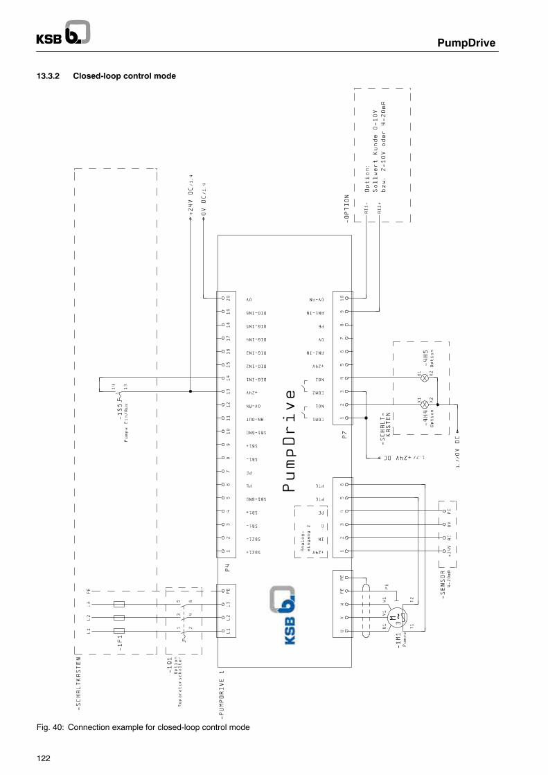
PumpDrive
122
13.3.2 Closed-loop control mode
Fig. 40: Connection example for closed-loop control mode

PumpDrive
123
13.3.3 Multiple pump configuration
Fig. 41: Connection example for multiple pump configuration: PumpDrive 1 Master

PumpDrive
124
Fig. 42: Connection example for multiple pump configuration: PumpDrive 2 Aux Master

PumpDrive
125
Fig. 43: Connection example for multiple pump configuration: PumpDrive 3 Slave

PumpDrive
126
Fig. 44: Connection example for multiple pump configuration: PumpDrive 4 SlaveJumper 1--2 at terminal P4 used only when slave does not have HMI → CAN bus terminator

127
13.4 Technical data sheets
13.4.1 Technical data: Output filter type FN 5010

128

129

130
13.4.2 Technical data: Output filter type RWK 305

131

132

133
13.4.3 Technical data: Output filter type FOVT

134

135
13.4.4 Technical data sheet SP 08.06 for differential pressure measuringtransducer type 890.09.2190

136

137
13.4.5 Data sheet PE 81.41 for pressure transmitter, type OC--1

138
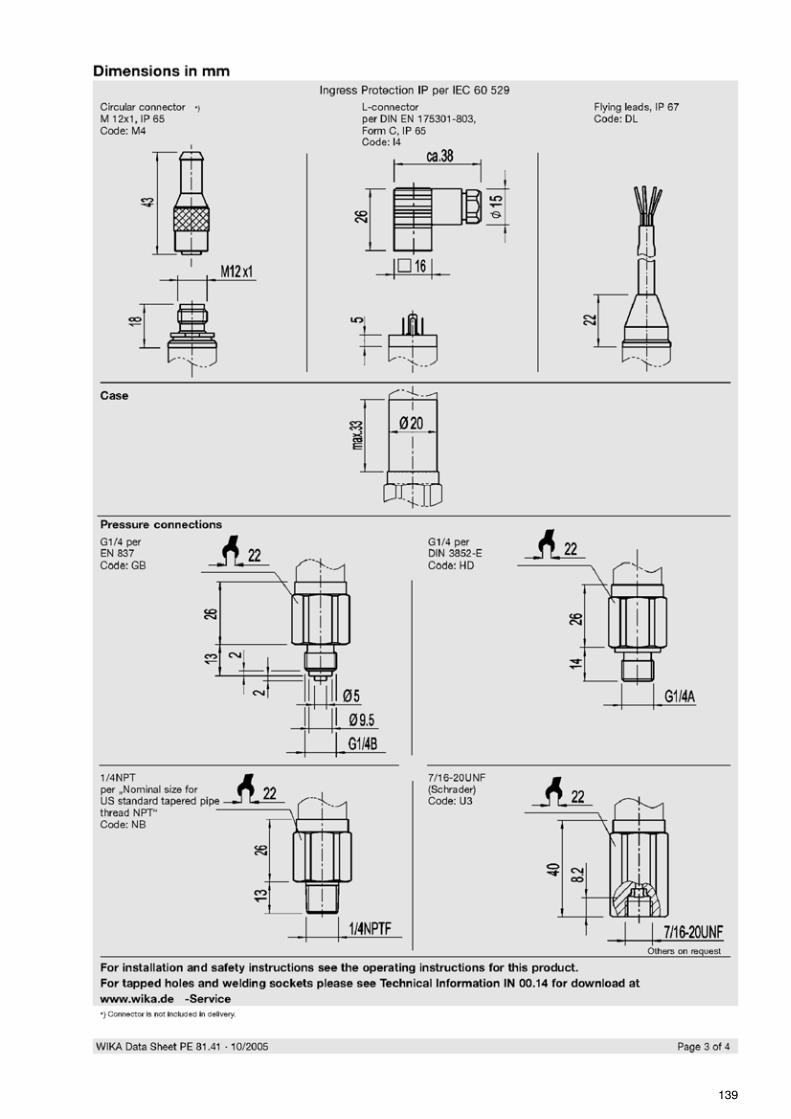
139

140

141
13.4.6 Technical data sheet PE 81.01 for pressure transducers type S--10 andS--11

142

143

144

145
13.4.7 Technical data sheet TE 60.03 for screw-in resistance thermometer typeTR10-C

146

147
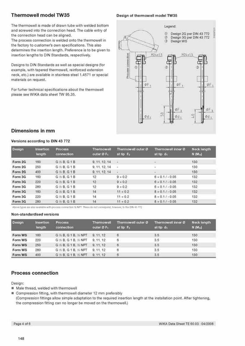
148

149

150

151
13.4.8 Technical data sheet PE 81.09 for level sensor for fill level and liquidlevel measurement type LS--10 und LH--10

152

153

154

155
13.4.9 Data sheet 10/63--6.40 DE for Profibus switch, Profibus DP
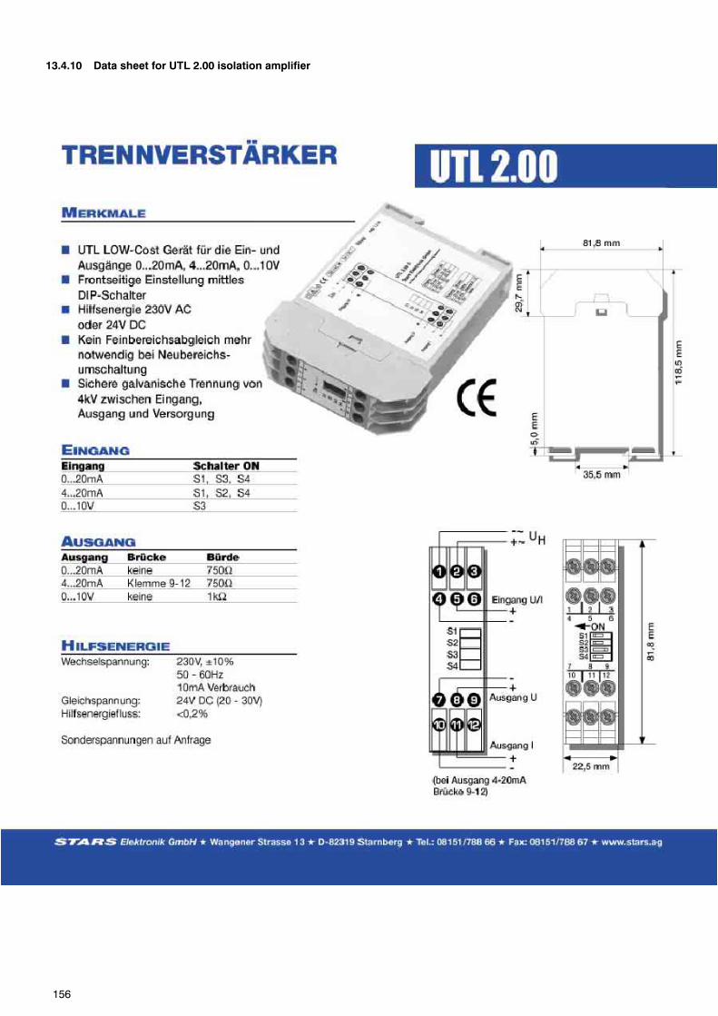
156
13.4.10 Data sheet for UTL 2.00 isolation amplifier

PumpDrive
157
Index
AAccess levels, 26
Customer, 26Service, 26
Accessories, 97DPM, 42LON, 89Profibus, 89
Alert reset, 23, 29Alerts, 29, 31, 92Ambient conditions, 32Ambient temperature, 13Analog input, 87Analog output, 41, 88Automatic mode, 23Aux. master, 45
CCabinet-mounted model, 33Cable integrity monitoring, 71Cable lengths, 34Capacitor discharge time, 11CE conformity marking, 9Changing parameters, 26Characteristic curve control, 73Closed-loop control mode, 58
Connection example, 122Connecting the motor, 36Connection example
Closed-loop control mode, 122Multiple pump configuration, 123Open-loop control mode, 121
Connection to power supply, 34Control panel, 22, 47
’Graphical, 22Standard, 19
Control terminals, 39Controller optimisation, 63Controller types, 61CPU module, 47Current limitation, 70
DDesignation, 13Diagnosis, 23Differential pressure control, 78Differential pressure transducer, 98Digital input, 41, 44, 86Digital output, 86Dimensions, 18Dismantling, 90Display, 24Display language, 22Displaying parameters, 26DPM set of accessories, 42Dry running protection, 72
EElectromagnetic compatibility, 9, 35Energy efficiency, 78Entering numerical values, 27Entering the password, 26Escape, 23External sensor, 38
FFactory reset, 88Faults / malfunctions, 91Field bus module, 49Fixed speed, 57Flow rate estimation, 74, 75, 78Frequency range, 71Function keys, 23Functions, 15
GGeneral, 9Grounding, 38
HH/Q curve, 73Help, 23Hydraulic blockage, 72
IInformation, 23Inputs
Analog, 41, 87Digital, 41, 44, 86
Inspection, 90Installation, 33Installation location, 32
KKey functions, 19KSB local bus, 43
LLEDs
Graphical, 22Standard, 19
Limit value monitoring, 76Line choke, 49Line chokes, 97Live zero monitoring, 71Local bus, 43LON set of accessories, 89
MMains connection, 36Maintenance, 90Manual mode, 23, 53Master / auxiliary master sensor connection, 45Master control panel, 64Measuring resistor, 101Menu structure, 25Models, 14Monitoring functions, 76Motor cable length, 34Motor parameters, 51Motor protection, 70Mounting variants, 17Multiple pump configuration, 64
Closed-loop control mode, 68Connection examples, 123Open-loop control mode, 69
NNavigation keys, 23

PumpDrive
158
OOpen-loop control mode, 54
Connection example, 121Operating keys
Graphical, 23Standard, 21
Operating values, 27Operation, 23Output filter, 97Outputs
Analog, 41, 88Digital, 41, 86
Overload (high flow) operation, 78Overload protection, 70
PP/Q curve, 73Parameter, 105Parameter number, 26Phase failure, 70Potentiometer function, 56Power range, 18Power terminals, 37Pressure transducer, 99Process signals, 28Product features, 14Profibus set of accessories, 89PTC sensor, 38PTC thermistor, 38PumpDrive Advanced functions, 15PumpDrive Basic functions, 15
RRamp, 85Rating plate, 9Recycling, 104Relay outputs, 41Residual current device -- Rate of voltage rise, 35
SSafety, 10Safety symbols, 10Selection lists, 120Sensor, 38, 45Service interface, 21, 24Setpoint compensation, 78Setting keys, 20Settings, 23Short circuit, 70Sleep mode, 82Software changes/warranty, 11Standard signal, 55Start ramp, 85Stop ramp, 85
TTechnical data, 16Technical data sheets, 127Temporary storage, 13Terminal strip P4, 41Terminal strip P7, 41Transducer, 98, 99Transport, 12Trouble-shooting, 91Type code, 13
UUnauthorised modes of operation, 11Unintentional start--up, 11
VV/f characteristic, 84
WWall-mounted model, 33Warnings, 30, 95Weights, 18

PumpDrive
PumpDrive Commissioning Report
Report Number: ______________________
1. Client
Order Number ____________________________________________________________________________________
Customer ____________________________________________________________________________________
Installation location _____________________________________________________________________
Contact ____________________________________________________________________________________
2. Product
Pump type ____________________________________________________________________________________
Pump works number 1.____________________________ 2._____________________________
3.____________________________ 4._____________________________
5.____________________________ 6._____________________________
Motor data __________ [kW] __________ [A] _________ [V] __________ [cos phi] _________ [1 / min]
PumpDrive type code 1.____________________________ 2._____________________________
(e.g. 3018K50BH0SI2) 3.____________________________ 4._____________________________
5.____________________________ 6._____________________________
PumpDrive serial number 1.____________________________ 2._____________________________
(Rating plate) 3.____________________________ 4._____________________________
5.____________________________ 6._____________________________
3. Operating mode
o Manual mode Application Pressure / Differential pressure / Flow rate / Temperature
o Open--loop control Setpoint _________________ [Source] _______ [Unit] ___________ [Value]
o Closed--loop control Sensor _________________ [Sensor full--scale value]
o Multiple pump operation Number of PumpDrives ____ [piece(s)]Number of HMIs ____ [piece(s)]
o Aux. Master Number of Aux. Masters ____ [piece(s)]
o Bus interface LON / PB – monitoring / control Number of modules ____ [piece(s)]
4. Comments
____________________________________________________________________________________________________
____________________________________________________________________________________________________
_________________________________________ _________________________________________KSB Customer Service / Name Client / Name
_________________________________________ _________________________________________Place, date, signature Place, date, signature

PumpDrive

PumpDrive
Notes:

PumpDrive
Notes:

PumpDrive
Notes:

KSB Aktiengesellschaft67225 Frankenthal • Johann-Klein-Str. 9 • 67227 Frankenthal (Germany)Tel. +49 6233 86-0 • Fax +49 6233 86-3401 • www.ksb.com
4070.81/7--10
19.03.2010
Subjecttotechnicalm
odificationwithoutpriornotice.
PumpDrive
Technical SupportHotline for automation productsTel. +49 06233 86--2042