
PumpDrive 2 / PumpDrive 2 Eco - KSB Web-Shop
40
Self-cooling, Motor-independent Frequency Inverter PumpDrive 2 / PumpDrive 2 Eco Type Series Booklet
-
Upload
khangminh22 -
Category
Documents
-
view
0 -
download
0
Transcript of PumpDrive 2 / PumpDrive 2 Eco - KSB Web-Shop

Self-cooling, Motor-independentFrequency Inverter
PumpDrive 2 /PumpDrive 2 Eco
Type Series Booklet

Legal information/Copyright
Type Series Booklet PumpDrive 2 / PumpDrive 2 Eco
All rights reserved. The contents provided herein must neither be distributed, copied, reproduced,edited or processed for any other purpose, nor otherwise transmitted, published or made available to athird party without the manufacturer's express written consent.
Subject to technical modification without prior notice.
© KSB SE & Co. KGaA, Frankenthal 04/11/2020

Contents
Pump Control Systems...................................................................................................................................... 4Variable Speed Systems ............................................................................................................................................................. 4
PumpDrive 2 / PumpDrive 2 Eco.......................................................................................................................................... 4Main applications........................................................................................................................................................... 4General description........................................................................................................................................................ 4Designation .................................................................................................................................................................... 4Materials ......................................................................................................................................................................... 6Power range and sizes ................................................................................................................................................... 6Mounting options .......................................................................................................................................................... 7Applications.................................................................................................................................................................... 7Technical data ................................................................................................................................................................ 7PumpDrive 2, motor-mounted / wall-mounted / cabinet-mounted models (enclosure IP55) ................................... 9PumpDrive 2 Eco, motor-mounted / wall-mounted / cabinet-mounted models (enclosure IP55) .......................... 10Optional components .................................................................................................................................................. 10Functions....................................................................................................................................................................... 12Control panel................................................................................................................................................................ 15Dimensions and weights.............................................................................................................................................. 15Project planning information...................................................................................................................................... 18Accessories .................................................................................................................................................................... 23
PumpMeter......................................................................................................................................................................... 35General description...................................................................................................................................................... 35Main applications......................................................................................................................................................... 35Technical data .............................................................................................................................................................. 35Materials ....................................................................................................................................................................... 36Product benefits ........................................................................................................................................................... 36Functions....................................................................................................................................................................... 36Design variants ............................................................................................................................................................. 38Electrical connections................................................................................................................................................... 38PumpMeter................................................................................................................................................................... 38
Contents
3

Pump Control SystemsVariable Speed Systems
4 PumpDrive 2 / PumpDrive 2 Eco
4074
.5/0
6-EN
Pump Control Systems
Variable Speed Systems
PumpDrive 2 / PumpDrive 2Eco
Main applications
PumpDrive 2▪ Air-conditioning systems
▪ Heat generation / heat distribution
▪ Water supply systems
▪ Water extraction / water withdrawal
▪ Water treatment / water conditioning
▪ Water distribution / water transport
▪ Refrigeration / cooling distribution
▪ Heat generation / heat distribution
▪ Fluid transport
▪ Cooling lubricant distribution
▪ Service water supply
▪ Tank drainage
▪ Waste water transport
PumpDrive 2 Eco▪ Air-conditioning systems
▪ Heat generation / heat distribution
▪ Water supply systems
General descriptionModular self-cooling frequency inverter that enablescontinuously variable speed control of asynchronous andsynchronous reluctance motors by means of analog standardsignals, a field bus or the control panel. As PumpDrive is self-cooling, it can be mounted on a motor, on the wall or in acontrol cabinet. Up to six pumps can be controlled withoutneeding an additional controller.
Designation
Designation example
Position
1 2 3 4 5 6 7 8 9 10 11 12 13 14 15 16 17 18 19 20 21 22 23 24 25 26 27 28 29 30
P D R V 2 I - 0 1 1 K 0 0 M _ K S U P B E 5 P 2 _ O O O O O
Designation key
Position Code Description
MyF
low
Dri
ve
Pum
pD
rive
2 E
co
Pum
pD
rive
2
1-5 Product generationPDRV2 PumpDrive 2 ✘ ✘ ✘
6 DesignE PumpDrive 2 Eco - ✘ -I MyFlow Drive ✘ - -- PumpDrive 2 - - ✘
7 Product certifications- CE ✘1) ✘ -
R UR and CE ✘2) - ✘
1 Available only for sizes ≤ 11 kW2 Available only for sizes 15 kW to 45 kW

Pump Control SystemsVariable Speed Systems
5PumpDrive 2 / PumpDrive 2 Eco
4074
.5/0
6-EN
Position Code Description
MyF
low
Dri
ve
Pum
pD
rive
2 E
co
Pum
pD
rive
2
7 L UL and CE - - ✘3)
8-13 PowerA 000K37 = 0,37 kW - ✘ ✘
000K55 = 0,55 kW ✘ ✘ ✘000K75 = 0,75 kW ✘ ✘ ✘001K10 = 1,1 kW ✘ ✘ ✘001K50 = 1,5 kW ✘ ✘ ✘
B 002K20 = 2,2 kW ✘ ✘ ✘003K00 = 3 kW ✘ ✘ ✘004K00 = 4 kW ✘ ✘ ✘
C 005K50 = 5,5 kW ✘ ✘ ✘007K50 = 7,5 kW ✘ ✘ ✘011K00 = 11 kW ✘ ✘ ✘
D 015K00 = 15 kW ✘ - ✘018K50 = 18,5 kW ✘ - ✘022K00 = 22 kW ✘ - ✘030K00 = 30 kW ✘ - ✘
E 037K00 = 37 kW ✘ - ✘045K00 = 45 kW ✘ - ✘055K00 = 55 kW - - ✘
14 Mounting optionM Motor mounting ✘ ✘ ✘W Wall mounting - ✘ ✘C Cabinet mounting - ✘ ✘
16 Motor manufacturerK KSB ✘ ✘ ✘S Siemens - ✘ ✘C Cantoni - ✘ ✘W Wonder - ✘ ✘
17-20 Motor type1LE1 Siemens 1LE1/ KSB 1PC3 - ✘ ✘1LA7 Siemens 1LA7/ KSB 1LA7 - ✘ ✘1LA9 Siemens 1LA9/ KSB 1LA9 - ✘ ✘1LG6 Siemens 1LG6/ KSB 1LG6 - ✘ ✘SUPB KSB SuPremE B ✘ ✘ ✘DMC KSB(DM) Cantoni - ✘ ✘DMW KSB(DM) Wonder - ✘ ✘
21-22 Efficiency classE1 IE1 - ✘ ✘E2 IE2 - ✘ ✘E3 IE3 - ✘ ✘E4 IE4 ✘ ✘ ✘E5 IE5 ✘ ✘ ✘
23-24 Number of motor polesP2 2 poles ✘ ✘ ✘P4 4 poles ✘ ✘ ✘P6 6 poles - ✘ ✘
26 M12 moduleO None ✘ ✘ ✘M M12 module - ✘ ✘
27 Field bus moduleO None ✘ ✘ ✘L LON - - ✘
3 Available on request only

Pump Control SystemsVariable Speed Systems
6 PumpDrive 2 / PumpDrive 2 Eco
4074
.5/0
6-EN
Position Code Description
MyF
low
Dri
ve
Pum
pD
rive
2 E
co
Pum
pD
rive
2
27 P Profibus DP - - ✘M Modbus RTU ✘4) ✘ ✘B BACnet MS / TP - ✘ ✘N Profinet - ✘ ✘
28 Optional component 1O None ✘ ✘ ✘I I/O extension board - - ✘
29 Optional component 2O None ✘ ✘ ✘R Bluetooth module - ✘ ✘
30 Optional component 3O None ✘ ✘ ✘M Master switch - - ✘
Materials
Housing materials
Description PumpDrive 2 PumpDrive 2 Eco
Housing cover Die-cast aluminium Polyamide, glass-fibre reinforcedControl panel Polyamide, glass-fibre reinforced Polyamide, glass-fibre reinforcedHeat sink Die-cast aluminium Die-cast aluminiumSlot covers Polyamide, glass-fibre reinforced Polyamide, glass-fibre reinforcedCable glands Polyamide Polyamide
The parts of the frequency inverter housing which are in contact with the atmosphere are free from paint-wetting impairmentsubstances.
Power range and sizes
Power range5) for 2-pole (3000 rpm), 4-pole (1500 rpm) and 6-pole (1000 rpm) asynchronous motors and KSB SuPremE
Size Nominal electrical power Nominal output current Mains input current
[kW] [A] [A]
A 0,37 1,3 1,50,55 1,8 20,75 2,5 2,71,10 3,5 3,71,50 4,9 5,2
B 2,2 6 6,33,0 8 8,44,0 10 10,4
C 5,5 14 14,67,5 18 18,711 25 25,9
D 15 34,5 35,718,5 44 45,422 51 52,430 68 69,7
E 37 84 85,945 101 103,155 120 122,4
4 Consult the manufacturer.5 The power ranges specified apply in full to all mounting options.

Pump Control SystemsVariable Speed Systems
7PumpDrive 2 / PumpDrive 2 Eco
4074
.5/0
6-EN
Mounting optionsThe frequency inverter is identical in design and configurationfor all 3 mounting options. PumpDrive 2 can be motor-mounted for the entire power range from 0.37 kW to 55 kW.
Motor mounting: The frequency inverter is mounted to themotor with an adapter or to the pump for the Movitecconfiguration. Adapters for subsequent conversion to themotor mounting configuration for existing pump systems areavailable as accessories.
Wall / control cabinet mounting: Installation kits forsubsequent conversion to the wall / control cabinet mountingconfiguration for existing pump systems are available asaccessories.
Applications
Possible combinations of pump and frequency inverter
Pump Motor manufacturer Motor-mounted model(with suitable adapters)
Wall-mounted model Cabinet-mounted model
Amarex KRT KSB - ✘ ✘Etaline ▪ KSB SuPremE B2/C2 motor IE4/
IE5
▪ Siemens motor, IE2, IE3
✘ ✘ ✘Etaline-R ✘ ✘ ✘Etaline Z ✘ ✘ ✘Etabloc ✘ ✘ ✘Etanorm ✘ ✘ ✘Etachrom ✘ ✘ ✘HPK-L ✘ ✘ ✘MegaCPK ✘ ✘ ✘Multitec ✘ ✘ ✘Omega ✘ ✘ ✘Sewatec ✘ ✘ ✘Sewabloc - ✘ ✘Vitachrom ✘ ✘ ✘Movitec KSB (DM)
▪ Cantoni motor
▪ Wonder motor (up to 7.5 kW)
▪ Siemens motor (11 kW andabove with thrust bearinghousing), IE2, IE3
✘6) ✘ ✘
UPA KSB - ✘ ✘
Motor-independent frequency inverter
Motor manufacturer Motor-mounted model (with suitable adapters) Wall-mounted model Cabinet-mounted model
Supplier-neutral7) Mounted on the motor on request as it must bechecked whether the available motor adapters fit.
✘ ✘
Technical data
Technical data
Characteristic PumpDrive 2 Eco PumpDrive 2
Mains supply
Mains voltage8) 1~: 230 V AC +/- 15 % (0.55 and1.1 kW)
3 ~: 380 V AC -10 % to 480 V AC+10 % (0.37 to 11.0 kW)
3 ~ 380 V alternating current-10 % to 480 V alternatingcurrent +10 %
Voltage difference between the three phases ±2 % of the supply voltageMains frequency 50 - 60 Hz ± 2 %Mains types TN-S, TN-CS, TN-C, TT and IT mains (to IEC/EN 60364)
Output dataFrequency inverter output frequency 0 - 70 Hz for asynchronous motors
0 - 140 Hz for KSB SuPremEPWM carrier frequency Range: 2 - 8 kHz
(Factory setting: 4 kHz)
6 Frequency inverter is mounted on pump flange.7 Standard asynchronous motors to IEC 60072/ IEC 60034. (The motor used must be suitable for use with a frequency inverter).8 If the mains voltage is low, the nominal torque of the motor will be lower.

Pump Control SystemsVariable Speed Systems
8 PumpDrive 2 / PumpDrive 2 Eco
4074
.5/0
6-EN
Characteristic PumpDrive 2 Eco PumpDrive 2
Phase rate of rise dv/dt9) 5000 V/µs maximum, depending on the size of the frequencyinverter
Peak voltages 2×1,41×Veff
Electric cables with a high current-carrying capacity can cause thevoltage to increase up to double the value.
Frequency inverter dataEfficiency 98 % - 95 %10)
Noise emissions Sound pressure level of pump used + 2.5 dB11)
EnvironmentEnclosure IP55 (to EN 60529)In-service ambient temperature -10 °C to +50 °CIn-storage ambient temperature -10 °C to +70 °CRelative humidity In service: 5 % to 85 %, non-condensing
Storage: 5 % to 95 %
Transport: 95 % max.Installation altitude ▪ < 1000 m above MSL, or 1 % power derating per additional
100 m
▪ Maximum installation altitude 2000 m above MSL
Vibration resistance 16.7 m/s2 max. (to EN 60068-2-64)
Fluid temperature12) -90 °C to +140 °C
EMC Frequency inverter ≤ 11 kW EN 61800-3 C1 / EN 55011 Class B / cable length ≤ 5 mFrequency inverter > 11 kW EN 61800-3 C2 / EN 55011 Class A, Group 1 / cable length ≤ 50 mMains feedback Integrated line chokes
Inputs and outputsInternal power supply unit 24 V ± 10 %Maximum load 600 mA DC max., short-circuit-proof and overload-proofResidual ripple < 1 %
Analog inputs Number of parameterisable analog inputs 2 (configurable for current or voltage input)Input type Not differential DifferentialMaximum voltage (with reference to GND) +10 V ± 10 VCurrent input 0/4...20 mA
Input impedance 500 ΩAccuracy 1 % of full-scale valueSignal delay < 10 msResolution 12 bit
Voltage input 0/2...10 VInput impedance Approx. 160 kOhm Approx. 40 kOhmAccuracy 1 % of full-scale valueSignal delay < 10 msResolution 12 Bit
Reverse polarity protection Not provided Positive and negativepolarity reversal possible
Analog outputs Number of parameterisable analog outputs 1 (toggling 4 output values)Current output 4...20 mAMaximum external working resistance 850 ΩOutput PNP transistorAccuracy 2 % of full-scale valueSignal delay < 10 msReverse polarity protection Provided
9 The phase rate of rise (dv/dt) depends on the line capacity.10 The efficiency at the nominal point of the frequency inverter varies between 98 % for high power outputs and 95 % for low
outputs, depending on the inverter's nominal power.11 The values are for orientation purposes only. The value refers to the nominal duty point (50 Hz) only. Also refer to the pump’s
noise characteristics. They, too, are documented for nominal duty operation. Other values may occur during variable speedoperation.
12 Provided the specified ambient temperature limits are complied with.

Pump Control SystemsVariable Speed Systems
9PumpDrive 2 / PumpDrive 2 Eco
4074
.5/0
6-EN
Characteristic PumpDrive 2 Eco PumpDrive 2
Short-circuit protection and overload protection Provided
Digital inputs Number of digital inputs 4 in total, 3 of which can be
parameterised6 in total, 5 of which can be
parameterisedON level 15...30 VOFF level 0...3 VInput impedance Approx. 2 kOhmGalvanic isolation Provided, isolation voltage: 500 V ACDelay < 10 msReverse polarity protection Provided
Relay outputs Number of parameterisable relay outputs 2 NO contacts 2 changeover contactsMaximum contact rating AC: max. 250 V AC/0.25 A
DC: max. 30 V DC/2 A
PWM carrier frequencyPower derating for increased carrier frequency
(at PWM carrier frequency > 4 kHz): INominal motor current (PWM) = INominal motor current × (1 - [fPWM - 4 kHz] × 2.5 %)
PumpDrive 2, motor-mounted / wall-mounted / cabinet-mounted models (enclosure IP55)
PumpDrive 2, motor-mounted / wall-mounted / cabinet-mounted models (enclosure IP55)
Housing type PN PumpDrive (parameters not pre-set) + controlpanel (graphical)
[kW] Mat. No. [kg]13)
A 0,37 01608493 5A 0,55 01608494 5A 0,75 01608495 5A 1,10 01608496 5A 1,50 01608497 5
B 2,20 01608498 6,5B 3,00 01608499 6,5B 4,00 01608500 6,5
C 5,50 01608501 12,6C 7,50 01608502 12,6C 11,00 01608503 12,6
D 15,00 01608504 27,6D 18,50 01608505 36D 22,00 01608506 36D 30,00 01608508 36
E 37,00 01608509 57,6E 45,00 01608510 60E 55,00 01608511 60
Optional
▪ M12 module
▪ Profibus DP
▪ LON
▪ BACnet MS / TP
▪ Profinet
▪ Modbus RTU
▪ Bluetooth module
▪ Integrated master switch
▪ I/O extension board
13 Without motor adapter
Pump Control SystemsVariable Speed Systems
10 PumpDrive 2 / PumpDrive 2 Eco
4074
.5/0
6-EN
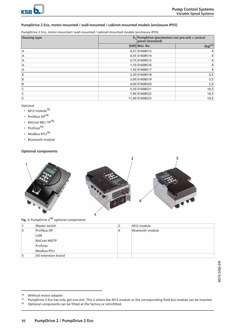
PumpDrive 2 Eco, motor-mounted / wall-mounted / cabinet-mounted models (enclosure IP55)
PumpDrive 2 Eco, motor-mounted / wall-mounted / cabinet-mounted models (enclosure IP55)
Housing type PN PumpDrive (parameters not pre-set) + controlpanel (standard)
[kW] Mat. No. [kg]14)
A 0,37 01608513 4A 0,55 01608514 4A 0,75 01608515 4A 1,10 01608516 4A 1,50 01608517 4
B 2,20 01608518 5,5B 3,00 01608519 5,5B 4,00 01608520 5,5
C 5,50 01608521 10,5C 7,00 01608522 10,5C 11,00 01608523 10,5
Optional
▪ M12 module15)
▪ Profibus DP15)
▪ BACnet MS / TP15)
▪ Profinet15)
▪ Modbus RTU15)
▪ Bluetooth module
Optional components
1
2 5
4
3Fig. 1: PumpDrive 216) optional components
1 Master switch 2 M12 module3 Profibus DP
LON
BACnet MS/TP
Profinet
Modbus RTU
4 Bluetooth module
5 I/O extension board
14 Without motor adapter15 PumpDrive 2 Eco has only got one slot. This is where the M12 module or the corresponding field bus module can be inserted.16 Optional components can be fitted at the factory or retrofitted.

Pump Control SystemsVariable Speed Systems
11PumpDrive 2 / PumpDrive 2 Eco
4074
.5/0
6-EN
1 2
Fig. 2: PumpDrive 2 Eco16) optional components
1 M12 module
or
Modbus RTU
Profibus DP
BACnet MS/TP
Profinet
2 Bluetooth module
M12 module▪ Connection of several PumpDrive 2 (for dual-pump configuration / multiple pump configuration) via M12 module
▪ PumpMeter connection to PumpDrive 2 via Modbus using the M12 module
▪ Can be retrofitted
▪ Internal T-connector (bus looped through); uninterruptible even in the event of a frequency inverter power failure
▪ Pre-configured cables (ð Page 23)
Bluetooth module▪ For communication with a smartphone/tablet (Android or iOS)
▪ Can be retrofitted
▪ Bluetooth 2.0 (range approx. 10 m, compatible from iOS 8)
▪ Installation in control panels of PumpDrive 2 / PumpDrive 2 Eco
Basic functions of the KSB FlowManager app17):
▪ Operation and monitoring
▪ Commissioning wizard
▪ Management of data records
▪ Updating software
Field bus module▪ Field bus modules (plug-in modules) for Profibus DP, Modbus RTU, LON, BACnet MS/TP and Profinet
▪ Can be retrofitted
▪ Internal T-connector (bus looped through), uninterruptible18) even in the event of a frequency inverter power failure
17 The KSB FlowManager app is available for download from the App Store and Google Play Store free of charge.18 This function does not apply when the Profinet module is connected in a bus topology.

Pump Control SystemsVariable Speed Systems
12 PumpDrive 2 / PumpDrive 2 Eco
4074
.5/0
6-EN
Master switch (optional)
Continuous current, master switch by size
Size Continuous current, masterswitch
[A]
A 10B 16C 40D 80E 160
▪ Can be locked
▪ Retrofit kit comprising master switch, housing components with master switch cutout and installation accessories
▪ Voltage 400 V
I/O extension board (optional)▪ Installation at the factory or retrofittable as accessory
▪ Installation in the frequency inverter
Additional inputs / outputs:
▪ 1 analog input
▪ 1 analog output
▪ 3 digital inputs
▪ 2 digital outputs
▪ 1 changeover contact relay
▪ 5 NO contact relays
Functions
Overview of functions
Functions / firmware PumpDrive 2 PumpDrive 2 Eco
Protective functionsThermal motor protection ✘ ✘Mains voltage monitoring ✘ ✘Phase failure, motor side ✘ ✘Short-circuit monitoring, motor side (phase to phase and phase to earth) ✘ ✘Dynamic overload protection by speed limitation (i2t control) ✘ ✘Resonant frequency suppression ✘ ✘Broken wire detection (live zero) ✘ ✘Protection against dry running and hydraulic blockage (sensorless due to learningfunction)
✘ ✘
Dry running protection (external control signal) ✘ ✘Operating point estimation and characteristic curve control ✘ ✘Open-loop controlOpen-loop control mode ✘ ✘Closed-loop controlClosed-loop control mode via integrated PID controller ✘ ✘Pressure control / differential pressure control (∆p const) ✘ ✘Pressure control / differential pressure control with dynamic pressure compensation(∆p var)
✘ ✘
Flow rate control ✘ ✘Sensorless differential pressure control (∆p const) in a single-pump configuration ✘ ✘Sensorless differential pressure control with dynamic pressure compensation(∆p var) in a single-pump configuration
✘ ✘
Sensorless flow rate control ✘ ✘Level control ✘ ✘Temperature control ✘ ✘Alternative setpoint ✘ -Operation and monitoring (display)

Pump Control SystemsVariable Speed Systems
13PumpDrive 2 / PumpDrive 2 Eco
4074
.5/0
6-EN
Functions / firmware PumpDrive 2 PumpDrive 2 Eco
Measured value display (pressure, head, speed, electric power, motor voltage,motor current, torque)
✘ ✘
Fault history ✘ ✘Operating hours counter ✘ ✘Fault reporting via relay ✘ ✘Frequency inverter functionsProgrammable start ramps and stop ramps ✘ ✘Field-oriented control (vector control), V/f control ✘ ✘Configurable motor control method (asynchronous motor, KSB SuPremE) ✘ ✘Automatic motor adaptation (AMA) ✘ ✘Motor standstill heater ✘ ✘Manual-0-automatic mode ✘ ✘External OFF ✘ ✘External minimum speed ✘ ✘Sleep mode (stand-by mode) ✘ ✘Energy savings meter ✘ -Pump functionsFlow rate estimation ✘ ✘M12 module with PumpMeter bus connection ✘ ✘M12 module for dual-pump configuration ✘ ✘M12 module for multiple pump configuration with up to 6 pumps ✘ ✘Functional check run ✘ ✘Deragging ✘ ✘Integrated dual-pump configuration (1×100 % with redundant pump or 2×50 %without redundant pump)
✘ ✘
Multiple pump configuration with up to 6 pumps ✘ ✘Waste water function: start-up at maximum speed ✘ -Waste water function: rinsing function ✘ -OperationControl panel ✘ ✘19)
Commissioning wizard ✘ ✘20)
Favourites list ✘ -Service interface ✘ ✘
Protective functionsSensorless protection against dry running and hydraulic blockageDry running of the pump is detected and the pump set is stopped before components are damaged.
Hydraulic blockage is also detected and initially a warning is displayed. If the blockage persists for a prolonged period of time, thepump set is stopped. These protective functions do not require sensors. They are based on an automatic learning function whichneeds to be run once during commissioning.
Dynamic overload protection by speed limitation (I2t control) The frequency inverter is equipped with current sensors that record the motor current and enable motor current limitation. Whenthe defined load limit or temperature limit is reached, the speed is lowered in order to reduce the power (I2t control). Thefrequency inverter then no longer operates in closed-loop control mode but maintains the operative function at a lower speed.
Characteristic curve controlThe frequency inverter indicates continuous operation outside the permissible range, such as extremely low flow or extremeoverload. The frequency inverter monitors the current operating point on the basis of the motor input power and the speed. Inthe case of extremely low flow or overload, a message is output and, depending on the settings, the pump set is switched off asrequired.
Open-loop and Closed-loop ControlSensorless differential pressure control for single-pump configurationsThe configurable differential pressure is kept almost constant over a broad operating range without the need for sensors. This canalso be achieved using the dynamic pressure compensation function. The speed is adjusted as a function of the power input sothat the required differential pressure is maintained.
Dynamic pressure/differential pressure compensationThe dynamic pressure/differential pressure compensation function compensates for pipe friction losses, which need to beconsidered if the pressure/differential pressure sensor is installed close to the pump or if sensorless differential pressure control isused. This ensures a virtually constant pressure/differential pressure at the consumer (e.g. heating) regardless of the flow. The
19 Some functions can only be parameterised and/or displayed using the KSB ServiceTool (see operating manual).20 Only available via KSB ServiceTool or app

Pump Control SystemsVariable Speed Systems
14 PumpDrive 2 / PumpDrive 2 Eco
4074
.5/0
6-EN
dynamic pressure compensation function requires signals from two pressure sensors or one differential pressure sensor.Alternatively, sensorless dynamic differential pressure compensation can be used. The differential pressure setpoint is increased asa function of the (estimated or measured) flow rate or the speed.
Operation and monitoringDisplayVarious physical data, such as the pressure, flow rate, speed, motor voltage, motor current, electric power, torque and others, canbe displayed using the control panel or the service software.
Message historyThe last 100 messages of the frequency inverter can be viewed. All messages are provided with a time stamp (real-time clock).
Statistics functionThe frequency inverter generates utilisation statistics on the operating hours to date, runtime and number of starts.
Frequency inverter functionsAutomatic motor adaptationAutomatic motor adaptation (AMA) is a method for measuring the electric parameters of the motor with the motor at a standstill.The frequency inverter's motor control method is optimised to ensure optimum motor performance and efficiency.
Motor control methodThe frequency inverter's motor control method can be set for either an asynchronous motor or the KSB SuPremE motor.
Stand-by mode (sleep mode)Sleep mode allows the single or multiple pump system to be started and stopped in line with demand. If sleep mode is activated,the frequency inverter stops the pump in the case of low flow rates, i.e. when the low flow limit or stop speed is reached. Inpressure control applications, an accumulator can be filled during brief operation with an increased setpoint prior to stopping. If adrop in pressure and, thus, a flow rate requirement are detected, the pump restarts.
Pump functionsDirect connection to PumpMeterPumpMeter can be connected to the M12 module of the frequency inverter via the Modbus interface using the M12 connector.Once they are connected, the frequency inverter and PumpMeter can automatically exchange all the data required forinitialisation (pump characteristic curve, sensor data, etc.). This enables easy and straightforward commissioning, even in retrofitapplications.
DeraggingIf fluids with a high solids content are handled, deposits may form that may in turn impair pump operation or prevent start-up ofthe pump. The Deragging function serves to prevent deposits from forming in the pump, thus ensuring reliable operation. To thisend, the pump is operated in the opposite direction to its normal direction of rotation at regular intervals in order to clean thehydraulic system.
Dual-pump configuration The dual-pump configuration serves to control two pumps of identical design. Two operating modes can be set:
▪ In "1 pump" operating mode, the dual pump system is designed to achieve the setpoint with one pump operating at ratedvalues (1 x 100 %).
▪ In "2 pumps" operating mode, the system's rated operating point is achieved with both pumps operating at rated values (2 x50 %).
Both frequency inverters are quickly and easily connected to the respective M12 modules by way of pre-configured cables. ThePumpMeter sensor signal can also be redundantly connected to the second frequency inverter as an option using a pre-configured"PumpMeter Crosslink" bus cable.
Multiple pump configurationUp to six PumpDrives can be operated in parallel in a multiple pump configuration. One frequency inverter is used as master andcontrols all other available frequency inverters as slaves so that the operating point is as close as possible to the best efficiencypoint. If the master fails or malfunctions, the role of master can be assumed by one of the other frequency inverters. This requires,however, that the appropriate signals be made available in parallel at each frequency inverter. As with dual-pump operation, in amultiple pump configuration, the frequency inverters are quickly and easily connected to the M12 modules using pre-configuredcables.
Energy-efficient pump starting and stoppingPumps operated in a dual-pump or multiple pump configuration are started and stopped with a view to optimal efficiency. Basedon the current operating point and the pump characteristic curves, the frequency inverter automatically decides when anadditional pump should be started or stopped to ensure that the multiple pump system is operated as efficiently as possible.

Pump Control SystemsVariable Speed Systems
15PumpDrive 2 / PumpDrive 2 Eco
4074
.5/0
6-EN
Control panel
OK
MAN
ESC ?
AUTO FUNC OFF
2
31
3
4
5
6
1
3
6
5
2AUTO
1/min
PumpDrive 2: Graphical control panel PumpDrive 2 Eco: Standard control panel
Description of standard control panel
Position Description Function
1 Service interface PumpDrive configuration and parameterisation via PC/notebook.2 LED traffic light function The traffic light function provides information about the pump system's
operating status.3 Display PumpDrive 2 Eco: Standard control panel
Display of the operating status, motor speed, setpoint and actual value viaLEDs
PumpDrive 2: Graphical control panelDisplay of the operating values, alerts and parameters in different nationallanguages
4 Menu keys Change to the elements of the first menu level5 Navigation keys Setpoint specification, parameter selection and confirmation6 Operating keys Toggling operating modes
Dimensions and weights
PumpDrive 2 Eco
a
b c d
e
F
f
Fig. 3: PumpDrive 2 Eco dimensions

Pump Control SystemsVariable Speed Systems
16 PumpDrive 2 / PumpDrive 2 Eco
4074
.5/0
6-EN
Dimensions and weightsH
ou
sin
gty
pe
PN Motor-mounted model Wall-mounted/cabinet-mounted model21)
Fastening screws/bolts [kg]22)
a b c d e a b c d f F
[kW] [mm] -
A 0,37 260 171 144 140 141 343 171 144 140 333 M4 × 10 4A 0,55 260 171 144 140 141 343 171 144 140 333 M4 × 10 4A 0,75 260 171 144 140 141 343 171 144 140 333 M4 × 10 4A 1,10 260 171 144 140 141 343 171 144 140 333 M4 × 10 4A 1,50 260 171 144 140 141 343 171 144 140 333 M4 × 10 4
B 2,20 290 186 144 155 121 328 186 144 155 318 M4 × 10 5,5B 3,00 290 186 144 155 121 328 186 144 155 318 M4 × 10 5,5B 4,00 290 186 144 155 121 328 186 144 155 318 M4 × 10 5,5
C 5,50 330 255 185 219 205 401 255 185 219 387 M6 × 12 10,5C 7,00 330 255 185 219 205 401 255 185 219 387 M6 × 12 10,5C 11,00 330 255 185 219 205 401 255 185 219 387 M6 × 12 10,5
PumpDrive 2
a
b
c
d
e f
F
Fig. 4: PumpDrive 2 dimensions
Dimensions and weights
Ho
usi
ng
typ
e
PN Motor-mounted model Wall-mounted/cabinet-mounted model23)
Fastening screws/bolts [kg]24)
a b c d e a b c d f F
[kW] [mm] -
A 0,37 260 190 166 140 141 343 190 166 140 333 M4 × 10 5A 0,55 260 190 166 140 141 343 190 166 140 333 M4 × 10 5A 0,75 260 190 166 140 141 343 190 166 140 333 M4 × 10 5A 1,10 260 190 166 140 141 343 190 166 140 333 M4 × 10 5A 1,50 260 190 166 140 141 343 190 166 140 333 M4 × 10 5
B 2,20 290 211 166 155 121 328 211 166 155 318 M4 × 10 6,5B 3,00 290 211 166 155 121 328 211 166 155 318 M4 × 10 6,5B 4,00 290 211 166 155 121 328 211 166 155 318 M4 × 10 6,5
C 5,50 330 280 210 219 205 401 280 210 219 387 M6 × 12 12,6C 7,50 330 280 210 219 205 401 280 210 219 387 M6 × 12 12,6C 11,00 330 280 210 219 205 401 280 210 219 387 M6 × 12 12,6
21 The dimensions provided refer to the frequency inverter including the wall-mounting brackets.22 Without motor adapter23 The dimensions provided refer to the frequency inverter including the wall-mounting brackets.24 Without motor adapter

Pump Control SystemsVariable Speed Systems
17PumpDrive 2 / PumpDrive 2 Eco
4074
.5/0
6-EN
Ho
usi
ng
typ
ePN Motor-mounted model Wall-mounted/
cabinet-mounted model23)Fastening screws/bolts [kg]24)
a b c d e a b c d f F
[kW] [mm] -
D 15,00 460 350 290 280 309 582 350 290 280 565 M8 × 14 27,6D 18,50 460 350 290 280 309 582 350 290 280 565 M8 × 14 36D 22,00 460 350 290 280 309 582 350 290 280 565 M8 × 14 36D 30,00 460 350 290 280 309 582 350 290 280 565 M8 × 14 36
E 37,00 700 455 340 375 475 819 455 340 375 800 M8 × 14 57,6E 45,00 700 455 340 375 475 819 455 340 375 800 M8 × 14 60E 55,00 700 455 340 375 475 819 455 340 375 800 M8 × 14 60
Pump Control SystemsVariable Speed Systems
18 PumpDrive 2 / PumpDrive 2 Eco
4074
.5/0
6-EN
Project planning information
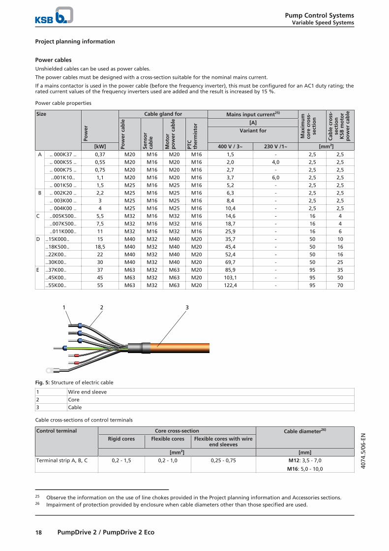
Power cablesUnshielded cables can be used as power cables.
The power cables must be designed with a cross-section suitable for the nominal mains current.
If a mains contactor is used in the power cable (before the frequency inverter), this must be configured for an AC1 duty rating; therated current values of the frequency inverters used are added and the result is increased by 15 %.
Power cable properties
Size
Pow
er
Cable gland for Mains input current25)
Max
imu
mco
re c
ross
-se
ctio
n
Cab
le c
ross
-se
ctio
nK
SB m
oto
rp
ow
er c
able
Pow
er c
able
Sen
sor
cab
le
Mo
tor
po
wer
cab
le
PTC
ther
mis
tor [A]
Variant for
[kW] 400 V / 3~ 230 V /1~ [mm²]
A .. 000K37 .. 0,37 M20 M16 M20 M16 1,5 - 2,5 2,5.. 000K55 .. 0,55 M20 M16 M20 M16 2,0 4,0 2,5 2,5.. 000K75 .. 0,75 M20 M16 M20 M16 2,7 - 2,5 2,5..001K10.. 1,1 M20 M16 M20 M16 3,7 6,0 2,5 2,5.. 001K50 .. 1,5 M25 M16 M25 M16 5,2 - 2,5 2,5
B .. 002K20 .. 2,2 M25 M16 M25 M16 6,3 - 2,5 2,5.. 003K00 .. 3 M25 M16 M25 M16 8,4 - 2,5 2,5.. 004K00 .. 4 M25 M16 M25 M16 10,4 - 2,5 2,5
C ..005K500.. 5,5 M32 M16 M32 M16 14,6 - 16 4..007K500.. 7,5 M32 M16 M32 M16 18,7 - 16 4..011K000.. 11 M32 M16 M32 M16 25,9 - 16 6
D ..15K000.. 15 M40 M32 M40 M20 35,7 - 50 10..18K500.. 18,5 M40 M32 M40 M20 45,4 - 50 16..22K00.. 22 M40 M32 M40 M20 52,4 - 50 16..30K00.. 30 M40 M32 M40 M20 69,7 - 50 25
E ..37K00.. 37 M63 M32 M63 M20 85,9 - 95 35..45K00.. 45 M63 M32 M63 M20 103,1 - 95 50..55K00.. 55 M63 M32 M63 M20 122,4 - 95 70
1 2 3
Fig. 5: Structure of electric cable
1 Wire end sleeve2 Core3 Cable
Cable cross-sections of control terminals
Control terminal Core cross-section Cable diameter26)
Rigid cores Flexible cores Flexible cores with wireend sleeves
[mm²] [mm]
Terminal strip A, B, C 0,2 - 1,5 0,2 - 1,0 0,25 - 0,75 M12: 3,5 - 7,0
M16: 5,0 - 10,0
25 Observe the information on the use of line chokes provided in the Project planning information and Accessories sections.26 Impairment of protection provided by enclosure when cable diameters other than those specified are used.
Pump Control SystemsVariable Speed Systems
19PumpDrive 2 / PumpDrive 2 Eco
4074
.5/0
6-EN
Length of motor power cableIf the frequency inverter is not mounted on the motor to be controlled, longer motor power cables may be required. The straycapacitance of the connection cables may result in high-frequency discharge currents flowing to ground. The sum of the dischargecurrents and motor current may exceed the output-side rated current of the frequency inverter. This will activate the frequencyinverter's protection equipment and the motor will be stopped. The following motor power cables are recommended dependingon the power range:
Length of motor power cable
Power range Cable length Stray capacitance
Max.
[kW] [m] [nF]
≤ 11 (Class B) 5 ≤ 5≥ 15 (Class A, Group 1) 50 ≤ 5
Output filtersDv/dt output filters can be used in conjunction with an asynchronous motor and a KSB SuPremE motor. Sine filters can only beused in conjunction with an asynchronous motor. If the length or stray capacitance of the power cable exceed the valuesindicated, we recommend installing a suitable output filter between the frequency inverter and the motor to be controlled. Thesefilters reduce the voltage ramp-up time of the frequency inverter output voltages and limit their peaks. (ð Page 21)
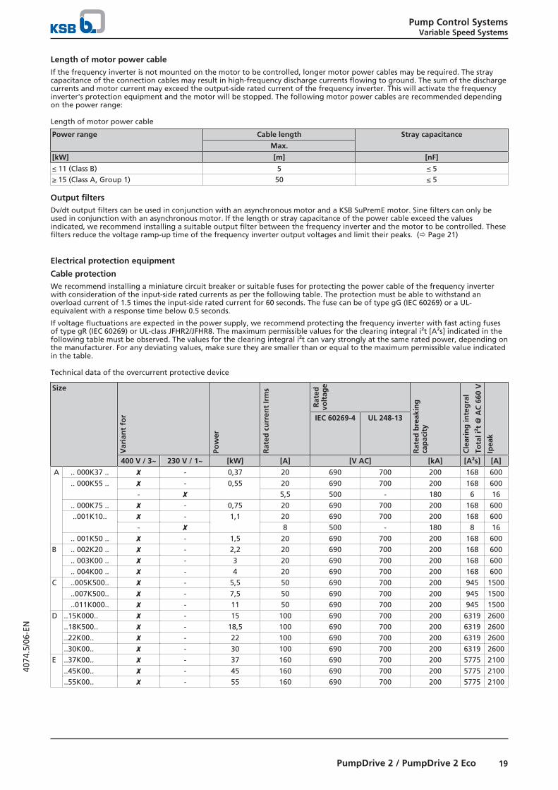
Electrical protection equipment
Cable protectionWe recommend installing a miniature circuit breaker or suitable fuses for protecting the power cable of the frequency inverterwith consideration of the input-side rated currents as per the following table. The protection must be able to withstand anoverload current of 1.5 times the input-side rated current for 60 seconds. The fuse can be of type gG (IEC 60269) or a UL-equivalent with a response time below 0.5 seconds.
If voltage fluctuations are expected in the power supply, we recommend protecting the frequency inverter with fast acting fusesof type gR (IEC 60269) or UL-class JFHR2/JFHR8. The maximum permissible values for the clearing integral i²t [A²s] indicated in thefollowing table must be observed. The values for the clearing integral i²t can vary strongly at the same rated power, depending onthe manufacturer. For any deviating values, make sure they are smaller than or equal to the maximum permissible value indicatedin the table.
Technical data of the overcurrent protective device
Size
Var
ian
t fo
r
Pow
er
Rat
ed c
urr
ent
Irm
s
Rat
edvo
ltag
e
Rat
ed b
reak
ing
cap
acit
y
Cle
arin
g in
teg
ral
Tota
l i²t
@ A
C 6
60 V
Ipea
k
IEC 60269-4 UL 248-13
400 V / 3~ 230 V / 1~ [kW] [A] [V AC] [kA] [A²s] [A]
A .. 000K37 .. ✘ - 0,37 20 690 700 200 168 600.. 000K55 .. ✘ - 0,55 20 690 700 200 168 600
- ✘ 5,5 500 - 180 6 16.. 000K75 .. ✘ - 0,75 20 690 700 200 168 600..001K10.. ✘ - 1,1 20 690 700 200 168 600
- ✘ 8 500 - 180 8 16.. 001K50 .. ✘ - 1,5 20 690 700 200 168 600
B .. 002K20 .. ✘ - 2,2 20 690 700 200 168 600.. 003K00 .. ✘ - 3 20 690 700 200 168 600.. 004K00 .. ✘ - 4 20 690 700 200 168 600
C ..005K500.. ✘ - 5,5 50 690 700 200 945 1500..007K500.. ✘ - 7,5 50 690 700 200 945 1500..011K000.. ✘ - 11 50 690 700 200 945 1500
D ..15K000.. ✘ - 15 100 690 700 200 6319 2600..18K500.. ✘ - 18,5 100 690 700 200 6319 2600..22K00.. ✘ - 22 100 690 700 200 6319 2600..30K00.. ✘ - 30 100 690 700 200 6319 2600
E ..37K00.. ✘ - 37 160 690 700 200 5775 2100..45K00.. ✘ - 45 160 690 700 200 5775 2100..55K00.. ✘ - 55 160 690 700 200 5775 2100

Pump Control SystemsVariable Speed Systems
20 PumpDrive 2 / PumpDrive 2 Eco
4074
.5/0
6-EN
Motor protection switchSeparate motor protection is not required because the frequency inverter has its own safety devices (e.g. electronic overcurrenttrip). Available motor protection switches must be rated for 1.4 times the nominal motor current.
Residual current deviceIf fixed connections and appropriate supplementary earthing are used (to DIN VDE 0160), RCDs are not mandatory for frequencyinverters.
If residual current devices (RCDs) are used, three-phase frequency inverters must in accordance with DIN VDE 0160 be connectedvia universal AC/DC sensitive residual current devices (RCDs), as potential direct-current components may cause standard ACsensitive RCDs to either fail to respond or respond erroneously.
Residual current device to be selected
Size Rated current [mA]
A, B and C 150D and E 300
If you are using a long shielded cable for the mains connection / motor connection, the residual-current monitoring device may betriggered by the discharge current that flows to earth (triggered by the carrier frequency). Remedies: Replace the RCD (residualcurrent device) or lower the response limit.
Compensation systemsIf the frequency inverter is operated on power supply networks with compensation systems, these systems must be designed bythe manufacturer for operation in conjunction with a frequency inverter.
Information on electromagnetic compatibilityElectromagnetic interference from other electrical devices canaffect the frequency inverter. Interference can also be emittedby the frequency inverter itself, however.
The interference emitted by the frequency inverter is generallyconducted through the motor power cables. The followingmeasures are proposed for RFI suppression:
▪ Shielded motor power cables for line lengths > 70 cm(especially recommended for frequency inverters with lowpower ratings)
▪ Made from a single piece of formed metal cable ductingwith a minimum coverage of 80 % (if shielded connectioncables cannot be used)
Use different earth bus bars for the control cable and mainspower/motor power cables.
The shield on the power cable/connection cable must consist ofa single piece and be earthed at both ends either just on theappropriate earth terminal or on the earth bus bar (do notconnect it to the earth bus bar in the control cabinet).
The shielded cable ensures that the high-frequency current,which normally flows as a discharge current from the motorhousing to earth or between the individual conductors, flowsthrough the shielding.
The shield for the control cable (connection on the frequencyinverter side only) also serves as protection against radiatedemission.
If using shielded cables, use a wide contact face for thedifferent earth connections to ensure greater interferenceimmunity.
In applications with long shielded motor cables, provideadditional reactive resistors or output filters to compensate thecapacitive stray current to earth and reduce the rate of voltagerise on the motor. These measures help reduce radiointerference further. Using just ferrite rings or reactive resistorsdoes not ensure compliance with the limit values defined inthe EMC directive.
NOTE! If you are using shielded cables that are longer than10 m, check the stray capacitance to ensure that the diffusionbetween the phases or to earth is not excessive, which couldcause the frequency inverter to stop.Route control cable and mains power/motor power cables inseparate cable ducts.
When routing the control cable observe a minimum distance of0.3 metres between the control cable and the mains power/motor power cables.
If you cannot avoid crossing control and mains power/motorpower cables, you should cross them at 90 degrees to eachother.
Earth connectionThe frequency inverter must be properly earthed.
To ensure greater interference immunity, a wide contact face isrequired for the different earth connections.
In the case of cabinet mounting, use two separate copperearth bus bars (mains power connection / motor connectionand control connection bar) with a suitable size and cross-section for earthing the frequency inverter. All the earthconnections are connected to these.
The bars are connected to the earthing system at one pointonly.
The control cabinet is earthed via the mains earthing system.
Output filter
L1L2L3
L CX
CY R'
R
PE
Fig. 6: Installing line choke and output filters
TransformerL
PE
CX
CY R'
R Dv/dt output filters(suitable forasynchronous motorand KSB SuPremEmotor)
or
Sine filter (only suitablefor asynchronousmotor)
Line choke Motor

Pump Control SystemsVariable Speed Systems
21PumpDrive 2 / PumpDrive 2 Eco
4074
.5/0
6-EN
The maximum cable lengths must be observed in order to meetRFI suppression requirements to DIN 55011. Output filters arerequired if the maximum cable lengths are exceeded.
IGBT switchgear is suitable for achieving high power. This,however, can result in faults due to the rapid switchingoperations, particularly if you are using long motor cables /drive control cables:
▪ Electromagnetic interference
▪ Damage to the motor winding insulation
▪ Voltage peaks due to high stray capacitance on the cableconnections
▪ Damage to the short-circuit protective devices
Output filters can be used to remedy these situations:
When a filter is used, the voltage peak (Vpeak) and its rate ofrise (dv/dt) can be reduced. The peak voltages can also be seenas a function of the stray capacitance induced by the powercircuits. The stray capacitance must be below 5 nF. If longcables are required for installation reasons, for example, forwall or control cabinet mounting, and the stray capacitancevalue exceeds the maximum permissible value, a dv/dt limitingfilter or sine filter must be installed. Connect the filter at theoutput of the frequency inverter. The filter protects thefrequency inverter against excessive discharge currents andprevents the protective equipment from being deactivated as aresult.
Overview of output filters for PumpDrive 2
Output filters for motor power cables 50 m / 80 m
Freq
uen
cy in
vert
erp
ow
er
No
min
al o
utp
ut
curr
ent
Freq
uen
cy in
vert
er
Output filter
No
min
al c
urr
ent
at50
°C
No
min
al c
urr
ent
at40
°C
dv/dt filter for
Max
imu
m m
oto
rfr
equ
ency
Max
imu
m m
oto
rp
ow
er c
able
len
gth L B H Mat. No.
Asy
nch
ron
ou
sm
oto
rs
KSB SuPremE
[kW] [A] [A] [A] 1500 rpm 3000 rpm [Hz] [m] [mm] [mm] [mm] [kg]
0,37 1,3 6,1 - FOVT-008B 140 50 49 85 58 47121240 1,60,55 1,80,75 2,51,1 3,51,5 4,92,2 63 8 12,1 - FOVT-016B 140 50 150 100 56 47121247 2,24 10
5,5 14 18,9 - FOVT-025B 140 50 231 119 71 47121248 4,57,5 18
11 25 27,3 - FOVT-036B 140 50 350 149 81 47121249 5,815 34,5 34,5 - FOVT-036B FOVT-036B - 70 50 350 149 81 47121249 5,8
66 - - - FN510-66-34 200 50 470 235 140 47121253 2218,5 44 50 - FN-510-50-34 FN-510-50-34 - 200 50 470 235 140 47121251 2122 51 66 - FN-510-66-34 FN-510-66-34 - 200 50 470 235 140 47121253 2230 68 - 90 RWK-305-90-KL RWK-305-90-KL - 60 80 190 115 225 47121254 7,437 85,945 101 - 124 RWK-305-124-KS RWK-305-124-KS - 60 80 190 180 160 01665521 7,5755 120 - 156 RWK 305-156-KS RWK 305-156-KS - 60 80 190 180 160 01665522 9,5
Output filters for motor power cables up to 160 m
Freq
uen
cy in
vert
erp
ow
er
No
min
al o
utp
ut
curr
ent
Freq
uen
cy in
vert
er
Output filter
No
min
al c
urr
ent
at45
°C27
)
dv/dt filter for
Max
imu
m m
oto
rfr
equ
ency
Max
imu
m m
oto
rp
ow
er c
able
len
gth L B H Mat. No.
Asy
nch
ron
ou
sm
oto
rs
KSB SuPremE
[kW] [A] [A] 1500 rpm 3000 rpm [Hz] [m] [mm] [mm] [mm] [kg]
0,37 1,3 8,4 FN 5060-12-84 ≤140 160 125 85,5 104 01686772 10,55 1,80,75 2,51,1 3,5
27 Including derating

Pump Control SystemsVariable Speed Systems
22 PumpDrive 2 / PumpDrive 2 Eco
4074
.5/0
6-EN
Freq
uen
cy in
vert
erp
ow
er
No
min
al o
utp
ut
curr
ent
Freq
uen
cy in
vert
er
Output filter
No
min
al c
urr
ent
at45
°C27
)
dv/dt filter for
Max
imu
m m
oto
rfr
equ
ency
Max
imu
m m
oto
rp
ow
er c
able
len
gth L B H Mat. No.
Asy
nch
ron
ou
sm
oto
rs
KSB SuPremE
[kW] [A] [A] 1500 rpm 3000 rpm [Hz] [m] [mm] [mm] [mm] [kg]
1,5 4,9 8,4 FN 5060-12-84 ≤140 160 125 85,5 104 01686772 12,2 63 84 10 16,8 FN 5060-24-84 ≤140 160 140 96 113 01686773 1,6
5,5 147,5 18 21 FN 5060-30-99 ≤140 160 240 109 151 01686774 5,8511 25 31,5 FN 5060-45-99 ≤140 160 240 110 151 01686775 6,415 34,5 43,2 FN 5060-45-99 FN 5060-45-99 - ≤70 160 240 110 151 01686775 6,4
42 - - FN 5060-60-99 ≤140 160 240 110 181 01686776 718,5 44 57,6 FN 5060-60-99 - - ≤70 160 240 110 181 01686776 7
49 - - FN 5060-70-99 ≤140 160 240 121 222 01686857 8,5222 51 57,6 FN 5060-60-99 - - ≤70 160 240 110 181 01686776 7
63 - - FN 5060-90-99 ≤140 160 240 130 221 01686858 10,530 68 63 - - FN 5060-90-99 ≤70 160 240 130 221 01686858 10,5
77 - - FN 5060-110-99 ≤140 160 240 136 221 01686859 11,3537 85,9 86,4 - - FN 5060-90-99 ≤70 160 240 130 221 01686858 10,5
105 - - FN 5060-150-99 ≤140 160 240 141,5 254 01686860 14,4745 101 105,6 - - FN 5060-110-99 ≤70 160 240 136 221 01686859 11,35
105 - - FN 5060-150-99 ≤140 160 240 141,5 254 01686860 14,4755 120 144 - - FN 5060-150-99 ≤70 160 240 141,5 254 01686860 14,47
126 - - FN 5060-180-99 ≤140 160 240 142,5 310 01686861 17,3
Line chokesThe line input currents indicated in the selection information are for orientation purposes only; they refer to operation at nominalrating. These currents may vary depending on the actual line impedance. In low-impedance mains, higher currents may occur. Theinput current can be limited by using external line chokes in addition to the integrated line chokes (in the power range up to andincluding 45 kW). Line chokes reduce mains feedback and improve the power factor.
Line chokes connected in series in the line to the consumer installation ensure that the required short circuit voltage of 4 % to themains is complied with and reduce mains feedback. Mains feedback occurring in the form of harmonics may cause problems in thepublic power supply mains. The charge currents of the DC link capacitors can be limited, which will increase the service life ofthese primary components. Line chokes reduce the reactive power component and thus improve the effective power factor. Thescope of DIN EN 61000-3-2 must be heeded.
Three-phase line choke:
▪ Enclosure IP00
▪ Thermal class F
▪ Maximum ambient temperature 40 °C
Overview of line chokes for asynchronous motors and SuPremE motors
Size Rating
Lin
e ch
oke
ind
uct
ance
l n No
min
alcu
rren
t I N
om
inal
mo
tor
curr
ent
Max
imu
mcu
rren
tI sa
t
L W H Mat. No.
[kW] [mH] [A] [mm] [mm] [mm] [kg]
A ..000K37.. 0,37 7,0 6,0 1,5 In 150 85 155 01665518 3,6..000K55.. 0,55..000K75.. 0,75..001K10.. 1,1..001K50.. 1,5
B ..002K20.. 2,2 2,0 11 1,5 In 150 85 150 01093105 3,6..003K00.. 3..004K00.. 4
C ..005K50.. 5,5 1,1 28 1,5 In 180 120 178 01093106 8,3
Pump Control SystemsVariable Speed Systems
23PumpDrive 2 / PumpDrive 2 Eco
4074
.5/0
6-EN
Size Rating
Lin
e ch
oke
ind
uct
ance
l n No
min
alcu
rren
t I N
om
inal
mo
tor
curr
ent
Max
imu
mcu
rren
tI sa
t
L W H Mat. No.
[kW] [mH] [A] [mm] [mm] [mm] [kg]
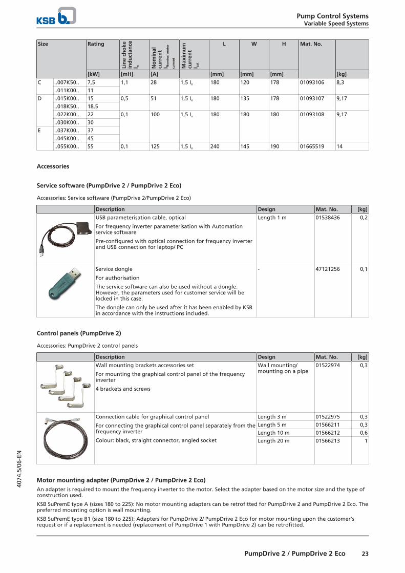
C ..007K50.. 7,5 1,1 28 1,5 In 180 120 178 01093106 8,3..011K00.. 11
D ..015K00.. 15 0,5 51 1,5 In 180 135 178 01093107 9,17..018K50.. 18,5..022K00.. 22 0,1 100 1,5 In 180 180 180 01093108 9,17..030K00.. 30
E ..037K00.. 37..045K00.. 45..055K00.. 55 0,1 125 1,5 In 240 145 190 01665519 14
Accessories
Service software (PumpDrive 2 / PumpDrive 2 Eco)
Accessories: Service software (PumpDrive 2/PumpDrive 2 Eco)
Description Design Mat. No. [kg]
USB parameterisation cable, optical
For frequency inverter parameterisation with Automationservice software
Pre-configured with optical connection for frequency inverterand USB connection for laptop/ PC
Length 1 m 01538436 0,2
Service dongle
For authorisation
The service software can also be used without a dongle.However, the parameters used for customer service will belocked in this case.
The dongle can only be used after it has been enabled by KSBin accordance with the instructions included.
- 47121256 0,1
Control panels (PumpDrive 2)
Accessories: PumpDrive 2 control panels
Description Design Mat. No. [kg]
Wall mounting brackets accessories set
For mounting the graphical control panel of the frequencyinverter
4 brackets and screws
Wall mounting/mounting on a pipe
01522974 0,3
Connection cable for graphical control panel
For connecting the graphical control panel separately from thefrequency inverter
Colour: black, straight connector, angled socket
Length 3 m 01522975 0,3Length 5 m 01566211 0,3Length 10 m 01566212 0,6Length 20 m 01566213 1
Motor mounting adapter (PumpDrive 2 / PumpDrive 2 Eco)An adapter is required to mount the frequency inverter to the motor. Select the adapter based on the motor size and the type ofconstruction used.
KSB SuPremE type A (sizes 180 to 225): No motor mounting adapters can be retrofitted for PumpDrive 2 and PumpDrive 2 Eco. Thepreferred mounting option is wall mounting.
KSB SuPremE type B1 (size 180 to 225): Adapters for PumpDrive 2/ PumpDrive 2 Eco for motor mounting upon the customer’srequest or if a replacement is needed (replacement of PumpDrive 1 with PumpDrive 2) can be retrofitted.
Pump Control SystemsVariable Speed Systems
24 PumpDrive 2 / PumpDrive 2 Eco
4074
.5/0
6-EN
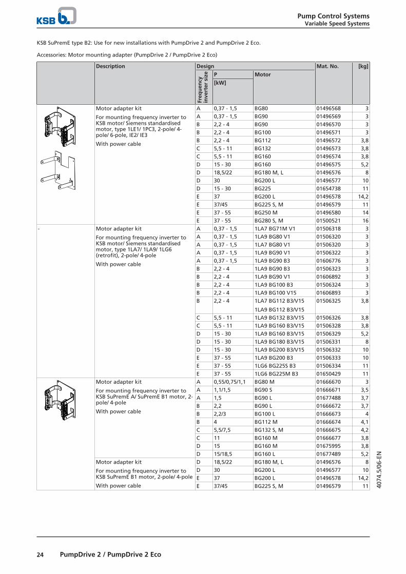
KSB SuPremE type B2: Use for new installations with PumpDrive 2 and PumpDrive 2 Eco.
Accessories: Motor mounting adapter (PumpDrive 2 / PumpDrive 2 Eco)
Description Design Mat. No. [kg]
Freq
uen
cyin
vert
er s
ize P Motor
[kW]
Motor adapter kit
For mounting frequency inverter toKSB motor/ Siemens standardisedmotor, type 1LE1/ 1PC3, 2-pole/ 4-pole/ 6-pole, IE2/ IE3
With power cable
A 0,37 - 1,5 BG80 01496568 3A 0,37 - 1,5 BG90 01496569 3B 2,2 - 4 BG90 01496570 3B 2,2 - 4 BG100 01496571 3B 2,2 - 4 BG112 01496572 3,8C 5,5 - 11 BG132 01496573 3,8C 5,5 - 11 BG160 01496574 3,8D 15 - 30 BG160 01496575 5,2D 18,5/22 BG180 M, L 01496576 8D 30 BG200 L 01496577 10D 15 - 30 BG225 01654738 11E 37 BG200 L 01496578 14,2E 37/45 BG225 S, M 01496579 11E 37 - 55 BG250 M 01496580 14E 37 - 55 BG280 S, M 01500521 16
- Motor adapter kit
For mounting frequency inverter toKSB motor/ Siemens standardisedmotor, type 1LA7/ 1LA9/ 1LG6(retrofit), 2-pole/ 4-pole
With power cable
A 0,37 - 1,5 1LA7 BG71M V1 01506318 3A 0,37 - 1,5 1LA9 BG80 V1 01506320 3A 0,37 - 1,5 1LA7 BG80 V1 01506320 3A 0,37 - 1,5 1LA9 BG90 V1 01506322 3A 0,37 - 1,5 1LA9 BG90 B3 01606776 3B 2,2 - 4 1LA9 BG90 B3 01506323 3B 2,2 - 4 1LA9 BG90 V1 01606892 3B 2,2 - 4 1LA9 BG100 B3 01506324 3B 2,2 - 4 1LA9 BG100 V15 01606893 3B 2,2 - 4 1LA7 BG112 B3/V15
1LA9 BG112 B3/V15
01506325 3,8
C 5,5 - 11 1LA9 BG132 B3/V15 01506326 3,8C 5,5 - 11 1LA9 BG160 B3/V15 01506328 3,8D 15 - 30 1LA9 BG160 B3/V15 01506329 5,2D 15 - 30 1LA9 BG180 B3/V15 01506331 8D 15 - 30 1LA9 BG200 B3/V15 01506332 10E 37 - 55 1LA9 BG200 B3 01506333 10E 37 - 55 1LG6 BG225S B3 01506334 11E 37 - 55 1LG6 BG225M B3 01650429 11
Motor adapter kit
For mounting frequency inverter toKSB SuPremE A/ SuPremE B1 motor, 2-pole/ 4-pole
With power cable
A 0,55/0,75/1,1 BG80 M 01666670 3A 1,1/1,5 BG90 S 01666671 3,5A 1,5 BG90 L 01677488 3,7B 2,2 BG90 L 01666672 3,7B 2,2/3 BG100 L 01666673 4B 4 BG112 M 01666674 4,1C 5,5/7,5 BG132 S, M 01666675 4,2C 11 BG160 M 01666677 3,8D 15 BG160 M 01675995 3,8D 15/18,5 BG160 L 01677489 5,2
Motor adapter kit
For mounting frequency inverter toKSB SuPremE B1 motor, 2-pole/ 4-pole
With power cable
D 18,5/22 BG180 M, L 01496576 8D 30 BG200 L 01496577 10E 37 BG200 L 01496578 14,2E 37/45 BG225 S, M 01496579 11

Pump Control SystemsVariable Speed Systems
25PumpDrive 2 / PumpDrive 2 Eco
4074
.5/0
6-EN
Accessories: Power/connection cable (PumpDrive 2)
Description Design Mat. No. [kg]
Cable connector, shielded ≤ 4 kW: 4 × 2,5² + PTC...XM 01538433 0,9
Blanking plate including screws to replaceremoved motor connector
- 01595759 0,1
1200M8
300220
200
1320
60
220
M8
60200
900
160 20
M5
12020M6
40
940
40
740
Ferrit
20 100 100
30
700
30
120 20
M4
M4
M4
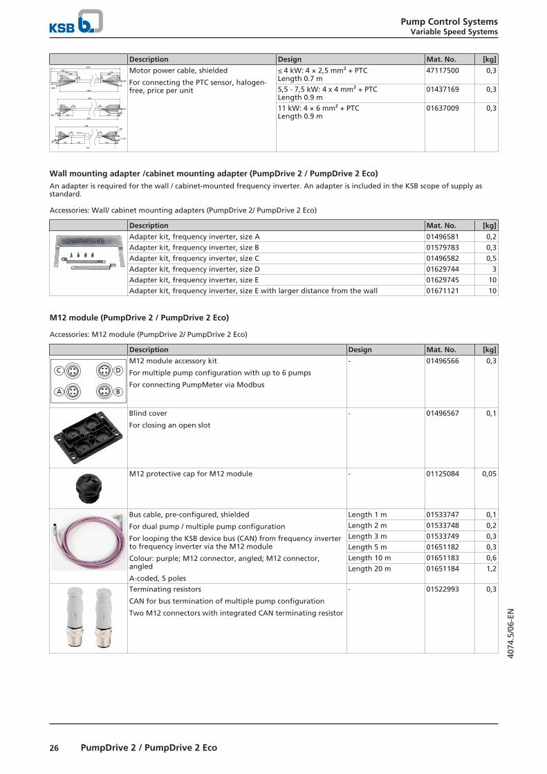
Motor power cable, shielded
For connecting the PTC sensor, halogen-free, price per unit
≤ 4 kW: 4 × 2,5 mm² + PTC Length 0.7 m
47117500 0,3
5,5 - 7,5 kW: 4 x 4 mm² + PTC Length 0.9 m
01437169 0,3
11 kW: 4 × 6 mm² + PTC Length 0.9 m
01637009 0,3
15 kW: 4 × 10 mm² + PTC Length 0.9 m
47117506 0,8
18,5 - 22 kW: 4 × 16 mm² + PTC Length 1.15 m
01466746 1
30 kW: 4 × 25 mm² + PTC Length 1.2 m
47117509 1,7
37 kW: 4 × 35 mm² + PTC Length 1.4 m
01641614 2
45 kW: 4 × 50 mm² + PTC Length 1.5 m
01641615 2,4
55 kW: 4 × 70 mm² + PTC Length 1.6 m
01641616 3,3
Accessories: Power cable (PumpDrive 2 Eco)
Description Design Mat. No. [kg]
Cable connector, shielded ≤ 4 kW: 4 × 2,5² + PTC...XM 01538433 0,9
Ferrite core, motor power cable - 47117922 0,3
Blanking plate including screws to replaceremoved motor connector
- 01595759 0,1
Pump Control SystemsVariable Speed Systems
26 PumpDrive 2 / PumpDrive 2 Eco
4074
.5/0
6-EN
Description Design Mat. No. [kg]
1200M8
300220
200
1320
60
220
M8
60200
900
160 20
M5
12020M6
40
940
40
740
Ferrit
20 100 100
30
700
30
120 20
M4
M4
M4
Motor power cable, shielded
For connecting the PTC sensor, halogen-free, price per unit
≤ 4 kW: 4 × 2,5 mm² + PTCLength 0.7 m
47117500 0,3
5,5 - 7,5 kW: 4 x 4 mm² + PTCLength 0.9 m
01437169 0,3
11 kW: 4 × 6 mm² + PTCLength 0.9 m
01637009 0,3
Wall mounting adapter /cabinet mounting adapter (PumpDrive 2 / PumpDrive 2 Eco)An adapter is required for the wall / cabinet-mounted frequency inverter. An adapter is included in the KSB scope of supply asstandard.
Accessories: Wall/ cabinet mounting adapters (PumpDrive 2/ PumpDrive 2 Eco)
Description Mat. No. [kg]
Adapter kit, frequency inverter, size A 01496581 0,2Adapter kit, frequency inverter, size B 01579783 0,3Adapter kit, frequency inverter, size C 01496582 0,5Adapter kit, frequency inverter, size D 01629744 3Adapter kit, frequency inverter, size E 01629745 10Adapter kit, frequency inverter, size E with larger distance from the wall 01671121 10
M12 module (PumpDrive 2 / PumpDrive 2 Eco)
Accessories: M12 module (PumpDrive 2/ PumpDrive 2 Eco)
Description Design Mat. No. [kg]
DC
BA
M12 module accessory kit
For multiple pump configuration with up to 6 pumps
For connecting PumpMeter via Modbus
- 01496566 0,3
Blind cover
For closing an open slot
- 01496567 0,1
M12 protective cap for M12 module - 01125084 0,05
Bus cable, pre-configured, shielded
For dual pump / multiple pump configuration
For looping the KSB device bus (CAN) from frequency inverterto frequency inverter via the M12 module
Colour: purple; M12 connector, angled; M12 connector,angled
A-coded, 5 poles
Length 1 m 01533747 0,1Length 2 m 01533748 0,2Length 3 m 01533749 0,3Length 5 m 01651182 0,3Length 10 m 01651183 0,6Length 20 m 01651184 1,2
Terminating resistors
CAN for bus termination of multiple pump configuration
Two M12 connectors with integrated CAN terminating resistor
- 01522993 0,3

Pump Control SystemsVariable Speed Systems
27PumpDrive 2 / PumpDrive 2 Eco
4074
.5/0
6-EN
Description Design Mat. No. [kg]
PumpMeter cross-link bus cable, pre-configured, shielded
For redundantly connecting PumpMeter via Modbus
For looping the PumpMeter Modbus from frequency inverterto frequency inverter via the M12 module
For analog sensors 4 - 20 mA
Colour: black; M12 connector, angled; M12 connector, angled
A-coded, 5 poles
Length 1 m 01533769 0,1Length 2 m 01533770 0,2Length 3 m 01533771 0,2Length 5 m 01533772 0,3Length 10 m 01533773 0,6Length 20 m 01533774 1,2
M12 bus cable, PumpMeter, pre-configured, shielded
For connecting PumpMeter to M12 module via Modbus
Colour: black; M12 socket, straight; M12 connector, angled
A-coded, 5 poles
Length 1 m 01533775 0,2Length 2 m 01533776 0,2Length 3 m 01533777 0,3Length 5 m 01533778 0,3Length 10 m 01670718 0,445Length 20 m 01670719 1,2
5
3 4
12M12 connector for M12 module, for self-assembly
For multiple pump configuration
For connecting PumpMeter via Modbus
Not suitable for direct connection of a PumpMeter sensor (novent pin 5)
Angled connector, A-coded, 5-pole
Screw terminal connection with shield ring, shieldable,
Connection cross-section: Max. 0.75 mm² (max. AWG 20)
Cable passage: 4 - 6 / 5 - 8 / 6 - 8 / 6.5 - 8.5 [mm]
Enclosure IP67
- 01523004 0,1
Optional components (PumpDrive 2 / PumpDrive 2 Eco)
Optional modules for retrofitting (PumpDrive 2)
Description Design Mat. No. [kg]
Master switch retrofit kit28)
Master switch, adapted C cover, protective cover for themaster switch, wire harness
Voltage 400 V
Size A0,37 - 1,5 kW
01500522 1,4
Size B2,2 - 4 kW
01500523 1,7
Size C5,5 - 11 kW
01500524 2,8
Size D15 - 30 kW
01500525 5,5
Size E37 - 55 kW
01500526 14,5
I/O extension board
Additional inputs and outputs:
1 analog input, 1 analog output, 3 digital inputs, 2 digitaloutputs, 1 changeover contact relay, 5 NO contact relays
Sizes A, B, C, D, E 01537900 0,2
Modbus RTU field bus module
For connecting the frequency inverter to Modbus networks
Monitoring, open-loop control, closed-loop control offrequency inverter in single-pump configuration and multiplepump configuration with Modbus module only
Field bus cable connection looped through from 1 x M12connector, B-coded, 5-pole, to 1 x M12 socket, B-coded, 5-pole
Sizes A, B, C, D, E 01551016 0,3
28 Optional master switch up to 400 V AC +10 %

Pump Control SystemsVariable Speed Systems
28 PumpDrive 2 / PumpDrive 2 Eco
4074
.5/0
6-EN
Description Design Mat. No. [kg]
BACnet MS/TP module field bus module
For connecting the frequency inverter to BACnet network
Monitoring, open-loop control, closed-loop control offrequency inverter in single-pump and multiple-pumpconfiguration with BACnet module only
Sizes A, B, C, D, E 01551014 0,3
LON field bus module
For connecting the frequency inverter to LON network
Monitoring, open-loop control, closed-loop control of eachfrequency inverter in single-pump configuration and multiplepump configuration only with one LON module each
Field bus cable connection looped through from 1 x M12connector, A-coded, 4-pole, to 1 x M12 socket, A-coded, 4-pole
Sizes A, B, C, D, E 01551015 0,3
Profibus field bus module
For connecting the frequency inverter to Profibus networks
Monitoring, open-loop control, closed-loop control of eachfrequency inverter in single-pump configuration and multiplepump configuration only with one Profibus module each
Field bus cable connection looped through from 1 x M12connector, B-coded, 5-pole, to 1 x M12 socket, B-coded, 5-pole
Sizes A, B, C, D, E 01551037 0,3
Profinet module field bus module
For connecting the frequency inverter to Profinet network
Monitoring, open-loop control, closed-loop control of eachfrequency inverter in single-pump configuration and multiplepump configuration only with one Profinet module each
Sizes A, B, C, D, E 01551038 0,3
12
5
3 4
M12 connector for self-assembly
For Modbus , BACnet and Profibus
Angled connector, B-coded, 5 poles, screw terminalconnection, with shield ring, shieldable
Connection cross-section: Max. 0.75 mm² (max. AWG 20)
Cable passage: 4 - 6 / 5 - 8 / 6 - 8 / 6.5 - 8.5 [mm]
Enclosure: IP67
- 01651264 0,1
12
5
3 4
M12 socket for self-assembly
For Modbus , BACnet and Profibus
Angled socket, B-coded, 5 poles, screw terminal connection,with shield ring, shieldable
Connection cross-section: Max. 0.75 mm² (max. AWG 20)
Cable passage: 4 - 6 / 5 - 8 / 6 - 8 / 6.5 - 8.5 [mm]
Enclosure: IP67
- 01651298 0,1
Bus cable CAN, BACnet and Modbus
Cut to length for self-assembly, shielded, twisted pair, cable 2× 2 × 0.22 mm²
Length 1 m 01111184 0,2Length 5 m 01304511 0,4Length 10 m 01304512 0,7Length 20 m 01304513 1,4
Pump Control SystemsVariable Speed Systems
29PumpDrive 2 / PumpDrive 2 Eco
4074
.5/0
6-EN
Description Design Mat. No. [kg]
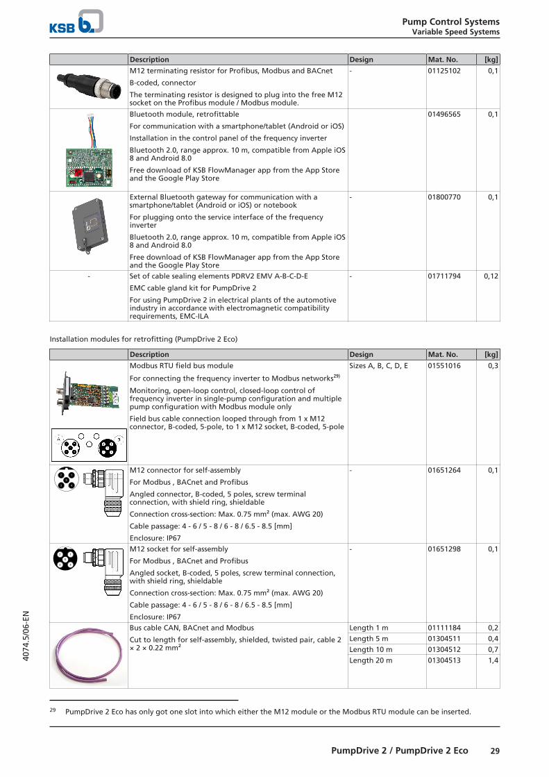
M12 terminating resistor for Profibus, Modbus and BACnet
B-coded, connector
The terminating resistor is designed to plug into the free M12socket on the Profibus module / Modbus module.
- 01125102 0,1
Bluetooth module, retrofittable
For communication with a smartphone/tablet (Android or iOS)
Installation in the control panel of the frequency inverter
Bluetooth 2.0, range approx. 10 m, compatible from Apple iOS8 and Android 8.0
Free download of KSB FlowManager app from the App Storeand the Google Play Store
01496565 0,1
External Bluetooth gateway for communication with asmartphone/tablet (Android or iOS) or notebook
For plugging onto the service interface of the frequencyinverter
Bluetooth 2.0, range approx. 10 m, compatible from Apple iOS8 and Android 8.0
Free download of KSB FlowManager app from the App Storeand the Google Play Store
- 01800770 0,1
- Set of cable sealing elements PDRV2 EMV A-B-C-D-E
EMC cable gland kit for PumpDrive 2
For using PumpDrive 2 in electrical plants of the automotiveindustry in accordance with electromagnetic compatibilityrequirements, EMC-ILA
- 01711794 0,12
Installation modules for retrofitting (PumpDrive 2 Eco)
Description Design Mat. No. [kg]
Modbus RTU field bus module
For connecting the frequency inverter to Modbus networks29)
Monitoring, open-loop control, closed-loop control offrequency inverter in single-pump configuration and multiplepump configuration with Modbus module only
Field bus cable connection looped through from 1 x M12connector, B-coded, 5-pole, to 1 x M12 socket, B-coded, 5-pole
Sizes A, B, C, D, E 01551016 0,3
12
5
3 4
M12 connector for self-assembly
For Modbus , BACnet and Profibus
Angled connector, B-coded, 5 poles, screw terminalconnection, with shield ring, shieldable
Connection cross-section: Max. 0.75 mm² (max. AWG 20)
Cable passage: 4 - 6 / 5 - 8 / 6 - 8 / 6.5 - 8.5 [mm]
Enclosure: IP67
- 01651264 0,1
12
5
3 4
M12 socket for self-assembly
For Modbus , BACnet and Profibus
Angled socket, B-coded, 5 poles, screw terminal connection,with shield ring, shieldable
Connection cross-section: Max. 0.75 mm² (max. AWG 20)
Cable passage: 4 - 6 / 5 - 8 / 6 - 8 / 6.5 - 8.5 [mm]
Enclosure: IP67
- 01651298 0,1
Bus cable CAN, BACnet and Modbus
Cut to length for self-assembly, shielded, twisted pair, cable 2× 2 × 0.22 mm²
Length 1 m 01111184 0,2Length 5 m 01304511 0,4Length 10 m 01304512 0,7Length 20 m 01304513 1,4
29 PumpDrive 2 Eco has only got one slot into which either the M12 module or the Modbus RTU module can be inserted.

Pump Control SystemsVariable Speed Systems
30 PumpDrive 2 / PumpDrive 2 Eco
4074
.5/0
6-EN
Description Design Mat. No. [kg]
M12 terminating resistor for Profibus, Modbus and BACnet
B-coded, connector
The terminating resistor is designed to plug into the free M12socket on the Profibus module / Modbus module.
- 01125102 0,1
Bluetooth module, retrofittable
For communication with a smartphone/tablet (Android or iOS)
Installation in the control panel of the frequency inverter
Bluetooth 2.0, range approx. 10 m, compatible from Apple iOS8 and Android 8.0
Free download of KSB FlowManager app from the App Storeand the Google Play Store
- 01496565 0,1
External Bluetooth gateway for communication with asmartphone/tablet (Android or iOS) or notebook
For plugging onto the service interface of the frequencyinverter
Bluetooth 2.0, range approx. 10 m, compatible from Apple iOS8 and Android 8.0
Free download of KSB FlowManager app from the App Storeand the Google Play Store
- 01800770 0,1
- Cable sealing set PDRV2 ECO EMC A-B-C
EMC cable gland kit for PumpDrive 2 ECO
For using PumpDrive 2 ECO in electrical plants of theautomotive industry in accordance with electromagneticcompatibility requirements, EMC-ILA
- 01711792 0,1
Sensors (PumpDrive 2 / PumpDrive 2 Eco)
Accessories: Pressure measurement (PumpDrive 2 / PumpDrive 2 Eco)
Description Design Mat. No. [kg]
PumpMeter
Intelligent pressure transmitter for pumps with on-site displayof measured values and operating data, parameterised at thefactory in line with pump-specific requirements, selection viaKSB EasySelect
Pump-specific - 0,1
Differential pressure transducer
With two copper-spiralled pipe sections measuring 75 cm inlength for connection to the discharge nozzle / suction nozzle,complete with retaining plate, spiralled pipe section andadapter, output 4 - 20 mA, 3-wire power supply, supplyvoltage 18 - 30 V DC, 2.5 m connection cable
Ambient temperature -10 to +50 °C
Temperature of measured medium -10 to +80 °C
0 - 1 bar, RC3/8 01111180 0,30 - 2 bar, RC3/8 01109558 0,30 - 4 bar, RC3/8 01109560 0,30 - 6 bar, RC3/8 01109562 0,30 - 10 bar, RC3/8 01109585 0,30 - 1 bar, RC1/2 01111303 0,30 - 2 bar, RC1/2 01111305 0,30 - 4 bar, RC1/2 01111306 0,30 - 6 bar, RC1/2 01111307 0,30 - 10 bar, RC1/2 01111308 0,30 - 1 bar, RC 1/4 01558789 0,30 - 2 bar, RC 1/4 01558790 0,30 - 4 bar, RC 1/4 01558791 0,30 - 6 bar, RC 1/4 01558792 0,30 - 10 bar, RC 1/4 01558793 0,3
A-10 pressure transducer
For general applications, for liquid and gaseous fluids0 to +80 °C, measuring accuracy smaller than or equal to 1 %,2.5 % max. (at 80 °C), G1/4B process connection with Cu jointring, IP67, 2-wire output 4 - 20 mA
0 - 2 bar 01152023 0,070 - 5 bar 01152024 0,070 - 10 bar 01210880 0,40 - 16 bar 01073808 0,1280 - 20 bar 01152025 0,070 - 50 bar 01152026 0,07
Pump Control SystemsVariable Speed Systems
31PumpDrive 2 / PumpDrive 2 Eco
4074
.5/0
6-EN
Description Design Mat. No. [kg]
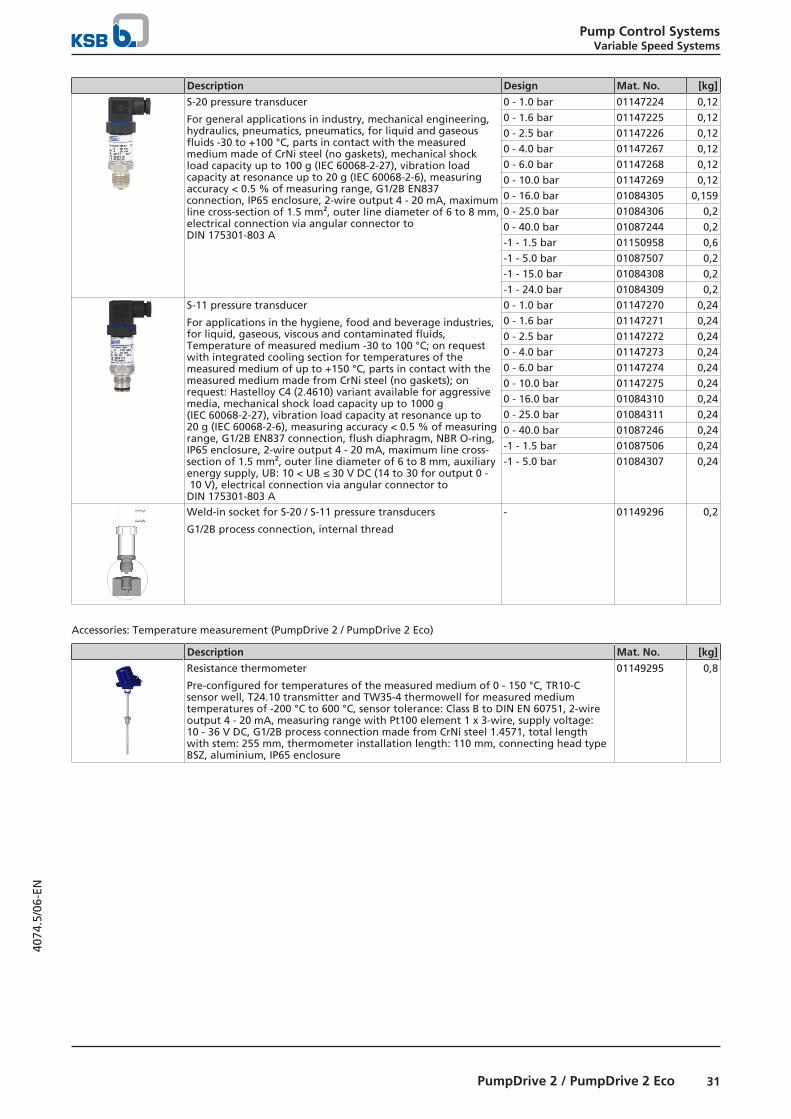
S-20 pressure transducer
For general applications in industry, mechanical engineering,hydraulics, pneumatics, pneumatics, for liquid and gaseousfluids -30 to +100 °C, parts in contact with the measuredmedium made of CrNi steel (no gaskets), mechanical shockload capacity up to 100 g (IEC 60068-2-27), vibration loadcapacity at resonance up to 20 g (IEC 60068-2-6), measuringaccuracy < 0.5 % of measuring range, G1/2B EN837connection, IP65 enclosure, 2-wire output 4 - 20 mA, maximumline cross-section of 1.5 mm², outer line diameter of 6 to 8 mm,electrical connection via angular connector toDIN 175301-803 A
0 - 1.0 bar 01147224 0,120 - 1.6 bar 01147225 0,120 - 2.5 bar 01147226 0,120 - 4.0 bar 01147267 0,120 - 6.0 bar 01147268 0,120 - 10.0 bar 01147269 0,120 - 16.0 bar 01084305 0,1590 - 25.0 bar 01084306 0,20 - 40.0 bar 01087244 0,2-1 - 1.5 bar 01150958 0,6-1 - 5.0 bar 01087507 0,2-1 - 15.0 bar 01084308 0,2-1 - 24.0 bar 01084309 0,2
S-11 pressure transducer
For applications in the hygiene, food and beverage industries,for liquid, gaseous, viscous and contaminated fluids,Temperature of measured medium -30 to 100 °C; on requestwith integrated cooling section for temperatures of themeasured medium of up to +150 °C, parts in contact with themeasured medium made from CrNi steel (no gaskets); onrequest: Hastelloy C4 (2.4610) variant available for aggressivemedia, mechanical shock load capacity up to 1000 g(IEC 60068-2-27), vibration load capacity at resonance up to20 g (IEC 60068-2-6), measuring accuracy < 0.5 % of measuringrange, G1/2B EN837 connection, flush diaphragm, NBR O-ring,IP65 enclosure, 2-wire output 4 - 20 mA, maximum line cross-section of 1.5 mm², outer line diameter of 6 to 8 mm, auxiliaryenergy supply, UB: 10 < UB ≤ 30 V DC (14 to 30 for output 0 - 10 V), electrical connection via angular connector toDIN 175301-803 A
0 - 1.0 bar 01147270 0,240 - 1.6 bar 01147271 0,240 - 2.5 bar 01147272 0,240 - 4.0 bar 01147273 0,240 - 6.0 bar 01147274 0,240 - 10.0 bar 01147275 0,240 - 16.0 bar 01084310 0,240 - 25.0 bar 01084311 0,240 - 40.0 bar 01087246 0,24-1 - 1.5 bar 01087506 0,24-1 - 5.0 bar 01084307 0,24
Weld-in socket for S-20 / S-11 pressure transducers
G1/2B process connection, internal thread
- 01149296 0,2
Accessories: Temperature measurement (PumpDrive 2 / PumpDrive 2 Eco)
Description Mat. No. [kg]
Resistance thermometer
Pre-configured for temperatures of the measured medium of 0 - 150 °C, TR10-Csensor well, T24.10 transmitter and TW35-4 thermowell for measured mediumtemperatures of -200 °C to 600 °C, sensor tolerance: Class B to DIN EN 60751, 2-wireoutput 4 - 20 mA, measuring range with Pt100 element 1 x 3-wire, supply voltage:10 - 36 V DC, G1/2B process connection made from CrNi steel 1.4571, total lengthwith stem: 255 mm, thermometer installation length: 110 mm, connecting head typeBSZ, aluminium, IP65 enclosure
01149295 0,8

Pump Control SystemsVariable Speed Systems
32 PumpDrive 2 / PumpDrive 2 Eco
4074
.5/0
6-EN
Accessories: Flow measurement (PumpDrive 2 / PumpDrive 2 Eco)
Description Mat. No. [kg]
Flow sensor
3 … 300 cm/s for filter loss compensation control, cost-effective flow control,measuring range 3 - 300 cm/s, process connection with internal thread, output 4 - 20 mA, Effector 300 transmitter
01150960 0,3
Plug connector with cable for Effector 300 transmitter
Cable socket M12/angled/4-core/5 m/PUR, compatible with cable drag chains, free ofhalogen and silicone
01473177 0,2
Accessories: Connection cable (PumpDrive 2 / PumpDrive 2 Eco)
Description Mat. No. [kg]
Connection cable for sensors
Cable 2 × 2 × 0.5 mm², shielded, for connecting sensors to frequency inverter, priceper metre
01083890 0,1
Connection cable for redundant sensor connection
5-core cable, halogen-free, type Ölflex 110CH, length approx. 1 m, pre-configured,for forwarding a sensor signal to a second frequency inverter for redundantoperation (e.g. DPM)
01131430 0,3
Control cabinet mounting (PumpDrive 2 / PumpDrive 2 Eco)
Accessories: Potential separator (PumpDrive 2 / PumpDrive 2 Eco)
Description Design Mat. No. [kg]
Potential separator
For volt-free signal transmission betweenthe frequency inverter and externalcontrol systems.
Differences in potential can damageanalog and digital inputs.
Top hat rail mounting, external supplyvoltage 24 V DC, IP40 housing, IP20terminals, 22.5 × 82 × 118.2 mm (W × H ×D)
01085905 1,2
Top hat rail mounting, external supplyvoltage 230 V AC, IP40 housing, IP20terminals, 22.5 × 82 × 118.2 mm (W × H ×D)
01086963 1,2

Pump Control SystemsVariable Speed Systems
33PumpDrive 2 / PumpDrive 2 Eco
4074
.5/0
6-EN
Accessories: Mains filter30) (PumpDrive 2 / PumpDrive 2 Eco)
Description Design Mat. No. [kg]
Line choke for frequency inverter forpreventing mains feedback
IP00 enclosure
Protection of frequency inverter frompeak voltages
0,37 - 1,5 kW 01665518 3,62,2 - 4 kW 01093105 3,65,5 - 11 kW 01093106 8,315 - 18,5 kW 01093107 9,1722 - 37 kW 01093108 9,1745 - 55 kW 01665519 14
Accessories: Output filter, 400 V / 3~ variant (PumpDrive 2 / PumpDrive 2 Eco)
Description PN Design
Asy
nch
ron
ou
s m
oto
r KSB SuPremE Mat. No. [kg]
Freq
uen
cyin
vert
er
1500
3000
[kW] - [rpm]
Output filters dv/dt formotor power cables up to160 m, IP00 enclosure
Line chokes for reducingelectromagnetic interferenceemissions
Reduction of peak currentsin long motor power cables
0,37 -3,00
FN 5060-12-84 ✘ ✘ ✘ 01686772 1
4,00 -5,50
FN 5060-24-84 ✘ ✘ ✘ 01686773 1,6
7,50 FN 5060-30-99 ✘ ✘ ✘ 01686774 5,8511,00 FN 5060-45-99 ✘ ✘ ✘ 01686775 6,415,00 FN 5060-45-99 ✘ ✘ - 01686775 6,415,00 FN 5060-60-99 - - ✘ 01686776 718,50 FN 5060-60-99 ✘ ✘ - 01686776 718,50 FN 5060-70-99 - - ✘ 01686857 8,5222,00 FN 5060-60-99 ✘ ✘ - 01686776 722,00 FN 5060-90-99 - - ✘ 01686858 10,530,00 FN 5060-90-99 ✘ ✘ - 01686858 10,530,00 FN 5060-110-99 - - ✘ 01686859 11,3537,00 FN 5060-90-99 ✘ ✘ - 01686858 10,537,00 FN 5060-150-99 - - ✘ 01686860 14,4745,00 FN 5060-110-99 ✘ ✘ - 01686859 11,3545,00 FN 5060-150-99 - - ✘ 01686860 14,4755,00 FN 5060-150-99 ✘ - - 01686860 14,47
30 When using the 230 V / 1~ variant, mains filters are not necessary. This variant has an integrated PFC module.

Pump Control SystemsVariable Speed Systems
34 PumpDrive 2 / PumpDrive 2 Eco
4074
.5/0
6-EN
Accessories: Output filter, 230 V / 1~ variant (PumpDrive 2 Eco)
Description PN Design
Asy
nch
ron
ou
s m
oto
r KSB SuPremE Mat. No. [kg]
Freq
uen
cyin
vert
er
1500
3000
[kW] - [rpm]
Output filters dv/dt formotor power cables up to160 m, IP00 enclosure
Line chokes for reducingelectromagnetic interferenceemissions
Reduction of peak currentsin long motor power cables
0,5 -1,1
FN 5060-12-84 ✘ - - 01686772 1

Pump Control SystemsVariable Speed Systems
35PumpMeter
4074
.5/0
6-EN
PumpMeter
General descriptionThe PumpMeter device is designed for monitoring pumpoperation. It is an intelligent pressure transmitter for pumps,with on-site display of measured values and operating data.
It records the load profile of the pump in order to indicate anypotential for optimising energy efficiency and availability. Thedevice comprises two pressure sensors and a display unit.
PumpMeter is supplied completely assembled andparameterised for the pump it is used with. It is ready foroperation as soon as the M12 plug connector is plugged in.
Main applicationsIndustry:
▪ Air-conditioning systems
▪ Cooling circuits
▪ Heating systems
▪ Water treatment
▪ Cooling lubricant distribution
▪ Water extraction
▪ Service water supply
Water:
▪ Water supply systems
▪ Water treatment / water conditioning
▪ Water distribution / water transport
Building services:
▪ Air-conditioning systems
▪ Heating systems
▪ Water supply systems
Technical data
Technical data of the display unit
Characteristic Value
Power supply +24 V DC ±15 %Current input 150 mAAnalog signal output 4 - 20 mA, 3-wireDigital connection RS485, Modbus RTU (Slave)Enclosure IP6531)
Service interface RS232Storage temperature -30 °C to +80 °COperating temperature -10 °C to +60 °C
Technical data of the sensors
Characteristic Value
Signal 4 - 20 mAEnclosure IP6732)
Fluid temperature -30 °C to +140 °CFluid temperature (with insulated sensors) -30 °C to +80 °CInstallation torque 10 NmAmbient temperature -10 °C to +60 °C
Sensor pressure limits
Sensor measuring range Overpressure limit Burst pressure
Min. Max.
[bar] [bar] [bar] [bar]
-1 3 40 60-1 10 40 60-1 16 40 60-1 25 50 75
31 Provided that the connectors are connected correctly32 Provided that the connectors are connected correctly
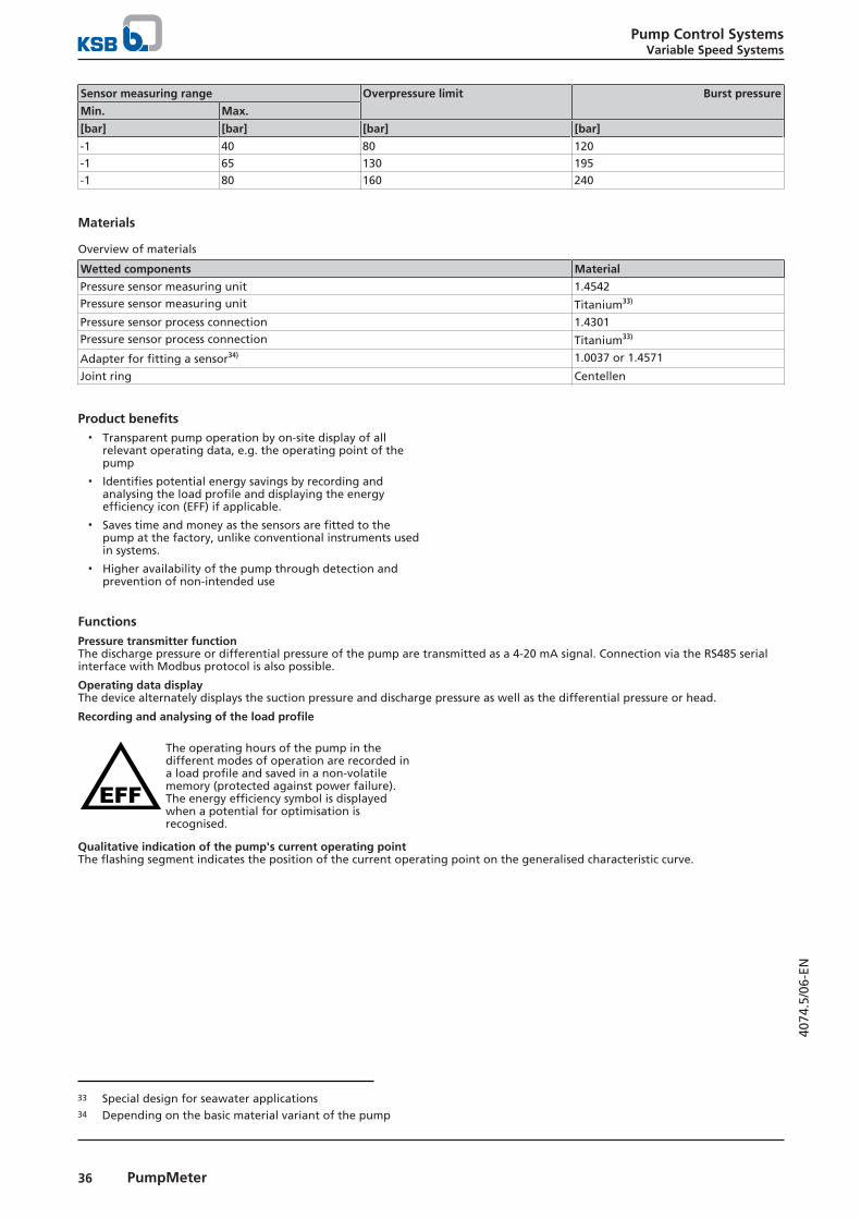
Pump Control SystemsVariable Speed Systems
36 PumpMeter
4074
.5/0
6-EN
Sensor measuring range Overpressure limit Burst pressure
Min. Max.
[bar] [bar] [bar] [bar]
-1 40 80 120-1 65 130 195-1 80 160 240
Materials
Overview of materials
Wetted components Material
Pressure sensor measuring unit 1.4542Pressure sensor measuring unit Titanium33)
Pressure sensor process connection 1.4301Pressure sensor process connection Titanium33)
Adapter for fitting a sensor34) 1.0037 or 1.4571
Joint ring Centellen
Product benefits▪ Transparent pump operation by on-site display of all
relevant operating data, e.g. the operating point of thepump
▪ Identifies potential energy savings by recording andanalysing the load profile and displaying the energyefficiency icon (EFF) if applicable.
▪ Saves time and money as the sensors are fitted to thepump at the factory, unlike conventional instruments usedin systems.
▪ Higher availability of the pump through detection andprevention of non-intended use
FunctionsPressure transmitter functionThe discharge pressure or differential pressure of the pump are transmitted as a 4-20 mA signal. Connection via the RS485 serialinterface with Modbus protocol is also possible.
Operating data displayThe device alternately displays the suction pressure and discharge pressure as well as the differential pressure or head.
Recording and analysing of the load profile
The operating hours of the pump in thedifferent modes of operation are recorded ina load profile and saved in a non-volatilememory (protected against power failure).The energy efficiency symbol is displayedwhen a potential for optimisation isrecognised.
Qualitative indication of the pump's current operating pointThe flashing segment indicates the position of the current operating point on the generalised characteristic curve.
33 Special design for seawater applications34 Depending on the basic material variant of the pump

Pump Control SystemsVariable Speed Systems
37PumpMeter
4074
.5/0
6-EN
Qualitative indication of the pump's current operating point
Operating range Segment display Description
Operation in extreme part loadconditions35)
First quarter flashing (1) ▪ Pump possibly not operated in accordancewith its intended use
▪ Increased load on the components
Operation in moderate part loadconditions35)
Second quarter flashing (2) ▪ Operation with potential for optimisingenergy efficiency
Operation near BEP Third quarter flashing (3) ▪ Operation within intended operating range.Optimum energy efficiency
Operation in overload conditions Fourth quarter flashing (4) ▪ Limit of the intended operating range
▪ Possibly overload of pump and/or motor
35 For some pump characteristics, no differentiation is made between the part load operating conditions in the curve's first twoquarters (both flashing simultaneously).

Pump Control SystemsVariable Speed Systems
38 PumpMeter
4074
.5/0
6-EN
Design variants▪ Adapter:
Depending on thread type and size of the pump's pressuregauge connections
▪ Cable length:600 mm, 1200 mm or 1800 mm, depending on the pumpsize
▪ Measuring ranges of the pressure sensors:The measuring ranges are selected as a function of themaximum pump inlet pressure specified (suction-sidesensor) and the maximum pump discharge pressure atzero flow (discharge-side sensor). If no maximum inletpressure is specified, calculation is based on a maximuminlet pressure of 5 bar.
Available measuring ranges
Label colour ofsensor
Colour code Measuring range [bar]
Minimum Maximum
- Red -1 3- Blue -1 10- Light grey -1 16- Green -1 25- Black -1 40Silver None -1 65Yellow None -1 80
Electrical connections
1
1 2 3 4
2
34
1 2
34
Fig. 7: Connections at the device
1 IN1 / port for the suction-side pressure sensor2 IN2 / port for the discharge-side pressure sensor3 Service interface4 EXT / external port for energy supply and signal output
PumpMeter50,8
M8 × 1,25
7,5
19
Fig. 8: Dimensions of sensor, measuring range up to 40 bar
92
35
22
1812
42
26
G1/2 A
Fig. 9: Dimensions of sensor, measuring range 65 bar andabove
Fig. 10: Dimensions of the display unit


KSB SE & Co. KGaAJohann-Klein-Straße 9 • 67227 Frankenthal (Germany)Tel. +49 6233 86-0www.ksb.com
4074
.5/0
6-EN
04/1
1/20
20