Protocols and techniques for characterising sites with subsurface petroleum hydrocarbons
65
G.B. Davis, N. Merrick and R. McLaughlan Protocols and techniques for characterising sites with subsurface petroleum hydrocarbons – a review technical report 2 no. CRC for Contamination Assessment and Remediation of the Environment
Transcript of Protocols and techniques for characterising sites with subsurface petroleum hydrocarbons

G.B. Davis, N. Merrick and R. McLaughlan
Protocols and techniques for characterising sites with subsurface petroleum hydrocarbons – a review
technicalreport
2no.
CRC for Contamination Assessment and Remediation of the Environment

G.B. Davis1, N. Merrick2 and R. McLaughlan2
1CSIRO Land and Water
2University of Technology, Sydney
October 2006

CRC CARE Technical Report no. 2 Protocols and techniques for characterising sites with subsurface petroleum hydrocarbons – a review
Cooperative Research Centre for Contamination Assessment and Remediation of the Environment, Technical Report series, no. 2
October 2006
Copyright © CRC CARE Pty Ltd, 2006
This report is copyright. Except as permitted under the Australian Copyright Act 1968 (Commonwealth) and subsequent amendments, no part of this
publication may be reproduced, stored or transmitted in any form or by any means, electronic or otherwise, without the specific written permission of
the copyright owner.
ISBN: 978-1-921431-01-2 (electronic)
978-1-921431-10-4 (print)
Enquiries and additional copies:
CRC CARE, P.O. Box 486, Salisbury South, South Australia, Australia 5106
Tel: +61 (0) 8 8302 5038
Fax: +61 (0) 8 8302 3124
www.crccare.com
This report should be cited as:
Davis, GB, Merrick, N & McLaughlan, R 2006, Protocols and techniques for characterising sites with subsurface petroleum hydrocarbons – a review,
CRC CARE Technical Report no. 2, CRC for Contamination Assessment and Remediation of the Environment, Adelaide, Australia.
Disclaimer:
This publication is provided for the purpose of disseminating information relating to scientific and technical matters. Participating organisations of CRC
CARE do not accept liability for any loss and/or damage, including financial loss, resulting from the reliance upon any information, advice or
recommendations contained in this publication. The contents of this publication should not necessarily be taken to represent the views of the
participating organisations.
Acknowledgement:
CRC CARE acknowledges the contribution made by Greg Davis of CSIRO Land and Water, and Noel Merrick and Robert McLaughlan of University
of Technology, Sydney, towards the writing and compilation of this technical report.
Front cover image: © istockphoto.com/JoeGough

CRC CARE Technical Report no. 2 Protocols and techniques for characterising sites with subsurface petroleum hydrocarbons – a review i
Table of contents
Acknowledgements v
Executive summary vii
1. Introduction 11.1 Background 1
1.2 Project aims and fit with the overall site characterisation scope 1
1.3 The review team 1
2. Properties and typical behaviour of hydrocarbons 32.1 Properties of oils, fuels and hydrocarbon compounds 4
2.2 NAPL distributions 4
2.3 Dissolved phase plumes 5
2.4 Vapour phase 6
2.5 Fuel additives 6
2.5.1 Methyl-tertiary-butyl ether (MTBE) 6
2.5.2 Tertiary-butyl alcohol (TBA) 7
2.5.3 1,2 dichloroethane (EDC) and 1,2 dibromoethane (EDB) 7
2.5.4 Diisopropyl ether (DIPE) 7
2.5.5 Ethanol and methanol 7
3. Site characterisation strategies 113.1 Introduction and rationale 11
3.2 Traditional approach: phased investigations 11
3.2.1 Preliminary Phase 1 investigation 11
3.2.2 Initial or Phase 2 field investigation 12
3.2.3 Further site investigation 12
3.3 Accelerated site characterisation 12
3.3.1 Background 12
3.3.2 The Triad approach 13
3.3.3 Advantages and QC implications of Triad 13
3.3.4 Additional information and implications of Triad 14
4. Guidance and protocol documentation 154.1 Australian guidance and standards 15
4.1.1 National guidance – the NEPM 15
4.1.2 NSW Department of Environment and Conservation (NSW DEC) 16
4.1.3 Queensland Department of Environment (Qld DoE) 17
4.1.4 South Australian EPA 17
4.1.5 Victoria EPA 17
4.1.6 Western Australian Department of Environment and Conservation (WA DEC) 17
4.1.7 Australian Standards 18

CRC CARE Technical Report no. 2 Protocols and techniques for characterising sites with subsurface petroleum hydrocarbons – a reviewii
Table of contents
4.2 Overseas guidance, standards and information 18
4.2.1 US EPA 18
4.2.2 ASTM 19
4.2.3 United Kingdom 19
4.2.4 Europe and NICOLE 20
4.2.5 New Zealand Ministry for the Environment (NZ MfE) 21
4.3 Industry guidance and procedures 24
4.3.1 American Petroleum Institute (API) 24
4.3.2 Company A 25
4.3.3 Company B 25
4.3.4 Company C 26
4.3.5 Company D 26
5. Sampling and investigation technologies 275.1 Rapid site characterisation 27
5.1.1 Direct push techniques 27
5.1.2 Geophysics 27
5.1.3 Soil gas surveys 28
5.1.4 On-site and field analytical methods 28
5.2 New and not-so-new approaches 30
5.2.1 Depth-specific sampling 30
5.2.2 Purging boreholes 30
5.2.3 Sampling for organic compounds 31
5.2.4 NAPL characterisation 31
5.2.5 Flux estimation 32
5.2.6 Capillary fringe 32
5.2.7 Combined technologies 33
5.2.8 Directional and alternate drilling 33
5.2.9 Coupled reactive transport modelling 33
5.2.10 In situ or passive techniques 33
6. Synthesis and conclusions 356.1 Guidance documents 35
6.1.1 Purposeful 35
6.1.2 Adequate 35
6.1.3 Representative 36
6.2 Final observations 36
7. References 39
Appendices
Appendix A. Summary responses to the NEPM Issues Paper (used with permission) 47

CRC CARE Technical Report no. 2 Protocols and techniques for characterising sites with subsurface petroleum hydrocarbons – a review iii
Table of contents
Tables
Table 1. Chemical and physical properties of some hydrocarbon compounds 8
Table 2. Industry, government and other site assessment protocols 22
Table 3. Table 1 from van Ree, D & Carlon, C 2003, ‘New technologies and future developments –
How much truth is there in site characterisation and monitoring?’, Land Contamination and
Reclamation 11(1), 37-48. Reproduced with permission 29
Figures
Figure 1. A petroleum leakage scenario leading to groundwater and vadose zone contamination, and
potential exposures 3
Figure 2. Depth profile of gasoline NAPL in soil from coring in a sandy profile, also showing possible
vapour and groundwater partitioning, and pathways of chemical mass flux 5
Figure 3. Depth profiles of gasoline vapour concentrations (TPH – soil gas) and major gases above an
NAPL-impacted zone 2.25–3.25 m below ground 6
Figure 4. Depth profile of BTEX and naphthalene concentrations and EC measurements in groundwater
near the source of a plume (right panel) and 40 m down hydraulic gradient (left panel) 31

CRC CARE Technical Report no. 2 Protocols and techniques for characterising sites with subsurface petroleum hydrocarbons – a reviewiv
CRC CARE Technical Report no. 2 Protocols and techniques for characterising sites with subsurface petroleum hydrocarbons – a review v
Special thanks to BP Australia, Shell, ExxonMobil and Rio Tinto for providing their site investigation protocols, in
particular Andrew King, Eleanor Carswell, Perry Buckland and Stuart Rhodes. The NEPC Service Corporation (Bruce
Kennedy) is acknowledged for allowing publication of extracts from Review of the National Environment Protection
(Assessment of Site Contamination) Measure: Summary of Submissions received in relation to the Issues Paper for
the Review of the Assessment of Site Contamination NEPM. Discussions with Suresh Rao (Purdue University), Mike
Annable (University of Florida), Thomas Ptak (University of Tübingen), Christian End (URS), and colleagues at CSIRO
(Colin Johnston, Trevor Bastow) are appreciated. Thanks to the CSIRO Floreat Librarian Bernadette Waugh for
providing documents and books so rapidly and cheerfully. Also thanks to Dr Bradley Patterson (CSIRO) for carefully
reviewing the draft document.
Acknowledgements

CRC CARE Technical Report no. 2 Protocols and techniques for characterising sites with subsurface petroleum hydrocarbons – a reviewvi

CRC CARE Technical Report no. 2 Protocols and techniques for characterising sites with subsurface petroleum hydrocarbons – a review vii
Characterisation and monitoring of petroleum-impacted
sites can be costly. Poor characterisation can lead to
uncertain mapping of the mass and distribution of
petroleum hydrocarbons in subsurface environments.
This in turn can lead to poor decisions which may
compromise human or environmental health or can
increase costs where remediation is prolonged, misapplied
or not well targeted due to lack of appropriate data.
From discussions between regulators, oil companies,
consultants, CSIRO, CRC CARE and other researchers
a scope of work related to site characterisation was
developed. CRC CARE agreed to a review stage project
proposal developed by CSIRO. The review stage is a first
step in a larger project to document techniques and
protocols that are used nationally and internationally,
to bring greater unity and improved approaches to
contaminated site assessment for petroleum impacts
in soil and groundwater environments of importance
to Australia.
This report:
1. documents typical properties of hydrocarbon
compounds and fuel/oil behaviours
2. provides an overview of traditional staged and
accelerated site characterisation strategies including
a discussion of the Triad approach
3. summarises available guidance, protocol and
standards documentation from state government
agencies and the NEPC, from industry, and from
overseas (United States, United Kingdom, Europe,
New Zealand)
4. documents some standard and not so standard
sampling and investigation techniques, and
5. provides summary comment.
Important issues, protocols and technologies related
to petroleum hydrocarbons in soil and groundwater
environments are highlighted.
The review provides an introduction to the multiphase
behaviour of petroleum hydrocarbons and the need to
address gas, liquid and solid phases (air, water and soil)
as well as the released non-aqueous phase liquid (NAPL)
in site assessments – and to address both the vadose
zone and groundwater. Fuels and oils are highly complex
mixtures that change their composition over time. The
intensity of investigative effort required in each phase is
somewhat dictated by environmental and jurisdictional
drivers, but also by typical properties of some petroleum
hydrocarbons, which govern the likely distribution of the
hydrocarbon product and individual compounds in the
subsurface. A limited discussion of fuel additives is
also given.
The importance of having site characterisation goals in
a risk-based framework is emphasised – what is the
overall goal and what is to be achieved at a site, what is
the compliance point, and what phase is dominant? To
assist with this, it is important to have a well developed
conceptual site model, along with a targeted program
of activity to improve the three-dimensional spatial and
temporal understanding of petroleum contamination
distributions in the subsurface. Such a program would
be developed out of a full conceptualisation of the site
model – inclusive of hydrogeology and soil strata, primary
fuel/compound types, the presence of additives,
compliance boundaries, principal transport mechanisms
in each phase, the proximity of receptors, etc. The intensity
of effort can be refined using data quality objectives,
where ‘data quality’ may more generally refer to data that
adequately represents the site conditions. It is concluded
that an investigation program needs to be purposeful,
adequate and representative to achieve its aims (i.e.
on PAR).
The traditional staged approach to site characterisation
(Phase 1 and Phase 2 environmental site assessments –
ESAs) is compared with accelerated site characterisation
(ASC) and in particular the so-called ‘Triad’ approach,
which links systematic planning and dynamic work
strategies with on-line and on-site measurement
techniques to enable site characterisation in a (hoped for)
single mobilisation. No implementation of ASC techniques
is apparent in Australia, despite savings estimates of up
to 40–50% for some applications in the United States
of America.
Information on some of the standard and more novel
site characterisation technologies is reviewed, including
direct push technologies, geophysics, on-site analytical
techniques, NAPL characterisation, capillary fringe and
vadose zones, combined technologies, directional and
alternate drilling, flux estimation techniques, passive and
on-line sampling/monitoring devices, and reactive
Executive summary

CRC CARE Technical Report no. 2 Protocols and techniques for characterising sites with subsurface petroleum hydrocarbons – a reviewviii
Executive summary
transport modelling. Further development, validation and
combination of technologies is required if rapid and cost-
effective site characterisation is to have greater adoption
in Australia.
Summary observations from the review include:
1. A risk-based approach should be taken as the starting
point for site characterisation, since this forces
consideration of the regulatory regime, exposure
pathways, and focuses effort on establishing a robust
conceptual model – with field investigations that
target the improvement and modification of this model.
2. A clear information objective is important –
embodying data quality objectives and achieving
representative sampling of a site.
3. Important to any site characterisation is the derivation
of a site conceptual model that integrates what is
already known about a site, and identifies both what
still needs to be discovered, and how that information
should be used.
4. Choices of site investigation approaches should
be made on the basis of improvement of the site
conceptual model. The site conceptual model
also serves as the basis for risk assessment and
remediation. The information needed for risk
assessment and remediation planning is not
necessarily the same.
5. Site characterisation plans need to be flexible and
adaptable to allow feedback on possibly real-time
results. This kind of dynamic approach to site
characterisation needs to be considered as a part
of overall site investigation strategy, before site
characterisation mobilisation. It also impinges on
the reliance on conventional sample-to-laboratory
systems, as laboratory data can take longer to be
generated. Dynamic approaches may also need
to encompass remediation planning.
6. If representivity is to be emphasised, perhaps the
analytical precision of conventional laboratory (off-
site) analyses could be traded off against greater
data intensity on-site, especially when comparing
sources of error from sampling, and sources of
uncertainty from site heterogeneity and variability.
7. For groundwater investigations, guidance
documents generally promote a minimum of three
or four boreholes. In practice, on average a greater
number of sampling boreholes is used. Greater use
could be made of statistical sampling theory, statistical
tests of significance, and geostatistical analysis to
handle aquifer and geochemical heterogeneity.
8. Site investigation data needs to be assessed over
time, as well as in space, so that trends in contaminant
behaviour can be assessed. The depth dimension is
often neglected in air, water and soil phases. Whilst
depth sampling of soils/sediments (whether in the
vadose zone or groundwater) is mentioned in several
guidance documents, it has not been formalised.
Depth-discrete sampling of groundwater is mostly
ignored.
9. A variety of site characterisation techniques are
available for on-site analyses, from on-site sensors to
geophysical techniques. Validation and improvement
is required to avoid false negative and positive
outcomes, and to build reliability and confidence into
rapid assessment practices.
10. Development of new tools for on-site use in site
characterisation is increasing – but if ASC or Triad
is to be pursued, further development of new or
novel sensor and site characterisation techniques
should be pursued, especially those that would
allow rapid on-site decision making and achieve
reliable outcomes at reduced cost. Combining
‘continuously available’ data with models on-line
could also be pursued. This is near readily available
for groundwater flow. However, where geochemistry
and reactive transport is important, on-line real-time
linkages between data collection and models is
problematic due to the computational intensity of
such codes.
11. The use of ‘direct push’ tools as opposed to
conventional drilling, and a variety of attachments
and sensors which can be used with these direct
push tools to collect site investigation information
is desirable. This allows more real-time information
gathering and implementation of dynamic site
characterisation strategies. Innovation in this area
should be encouraged.
12. In Australia, implementation of Triad would require
upskilling of all elements of site characterisation
(planning, on-site interpretation including sophisticated
modelling, and technology availability and deployment)
in consulting agencies and/or industry, and integration
of these skills with the regulatory approvals process –
possibly on-site.
13. Harmonisation of the regulation of site characterisation
through NEPM or other mechanisms may assist the
practice of site characterisation, but reduced flexibility
needs to be avoided to allow for continued innovation.

CRC CARE Technical Report no. 2 Protocols and techniques for characterising sites with subsurface petroleum hydrocarbons – a review ix
14. Greater guidance on the use and application of
numerical models to integrate site characterisation
data could be useful. The Murray-Darling Basin
Commission issued guidelines for water resource
groundwater flow modelling in 2000. Prommer et al.
(2003) provided an initial basis for petroleum plumes
in groundwater. There are no Australian guidelines
for modelling multiphase hydrocarbon behaviour.
15. There is a need to continue to facilitate knowledge
transfer across regulators, contaminated site owners,
service providers and the academic community.
16. The scalability of site investigation plans and
technologies should be assessed – from UST and
service station scale, to depot and terminal scale
and perhaps refinery or multiple source complex
mega-site scale.
17. US documentation (ASTM, API, etc.) includes
management as part of guidance in many instances,
whilst the NEPM does not. Interestingly, the NSW
EPA Service Station Guidelines did include remediation
options as part of the guidance. A perceived difficulty
in embedding management options in such guidance
is the lack of stability in the range of technologies
on offer.
18. Research and innovation is needed to quantify and
optimise the value of gathering additional data so
as to minimise uncertainty during assessment – to
provide more precise definition of risks and costs
for clean-up applications. For example, whilst the
multiphase behaviour of petroleum hydrocarbons is
recognised, the value of extra data in any one phase
in reducing uncertainties in risk assessment or the
selection of remedial options is not well defined.
A number of challenges remain – none the least of these
is maintaining flexibility to adopt new ideas and technologies
and, where needed, change the regulatory and industry
norm to allow alternative assessments, whilst maintaining
protection of human health and the environment.
Executive summary

CRC CARE Technical Report no. 2 Protocols and techniques for characterising sites with subsurface petroleum hydrocarbons – a reviewx

1.1 BackgroundCharacterisation and monitoring of petroleum-impacted
sites can be costly. Poor characterisation can lead to
uncertain mapping of the mass and distribution of
petroleum hydrocarbons in subsurface environments.
This in turn can lead to conservative decision making
and increased costs where remediation is prolonged,
misapplied or not well targeted due to lack of appropriate
data. In addition, incorrect or incomplete data can lead
to poor decisions which may compromise human or
environmental health.
From discussions between oil companies, regulators,
CSIRO, other researchers and CRC CARE, a scope of
work and project proposal related to site characterisation
was developed. CRC CARE agreed to a project scope
developed by CSIRO in conjunction with UTS. This review
is the first step in a larger project to document techniques
and protocols that are used nationally and internationally,
and within industry, consultants and regulators – to bring
greater unity and improved approaches to contaminated
site assessment for petroleum spills in soil and groundwater
environments of importance to Australia.
1.2 Project aims and fit with theoverall site characterisationscope
This review has as its aim to produce a review of current
practices and protocols.
Several stages of the overall site characterisation project
were envisaged and presented to the Policy Advisory
Group in CRC CARE on 20 October 2005. These included:
1. Selection panel to appoint a Project Manager.
2. Appoint a single point of accountability (SPA) –
Project Manager.
3. Review international, national and industry
practice/guidance.
4. Establish a Project Advisory Group (PAG) (regulator,
industry, researcher, PL, SPA) – Gatekeepers.
5. Workshop issues (e.g. vertical delineation, spatial
and temporal density, new techniques, risk definition
versus targeted remediation, soil versus groundwater
sampling, pathways, land use).
6. Review existing data sets and link exposure
pathway/end-use scenarios to data capture intensity.
7. Review outputs of Steps 3–6, as input to Step 8.
8. Scope and build an expert system – risk pathways
versus remediation, conceptual model of site – to
give a recommended sampling plan.
9. Build a guidance document.
10. Make the expert system and guidance web-enabled
(value proposition).
This review targets the completion of Stage 3 of this
scope – that is the review of national and international
approaches, and regulatory and industry practices.
There is a large amount of literature (papers, guidance
documents, protocols) and experience regarding site
characterisation. This includes planning, guidance, QA/QC,
standards for sampling, risk-based decision making,
sampling statistics, sample collection and handling,
investigation techniques, and field and laboratory
analytical techniques and protocols. In this review it is not
possible to review or synthesise all the information. Here
we will limit discussion to immediate concerns around
the guidance documentation, types of techniques used
to collect samples from soil, water and gas phases, the
advantages and disadvantages of some techniques, and
some aspects of non-standard techniques available to
investigate sites.
Details of additional research that may be required to be
carried out are not given here – these will come from the
workshop indicated as Step 5 in the list above.
1.3 The review team The review stage of the project has been led by CSIRO
(collation, interpretation, reporting) with UTS providing
the review of this document. Other subsequent stages of
the project as outlined in Section 1.2 may be led by others.
1. Introduction
CRC CARE Technical Report no. 2 Protocols and techniques for characterising sites with subsurface petroleum hydrocarbons – a review 1

CRC CARE Technical Report no. 2 Protocols and techniques for characterising sites with subsurface petroleum hydrocarbons – a review2

CRC CARE Technical Report no. 2 Protocols and techniques for characterising sites with subsurface petroleum hydrocarbons – a review 3
Common sources of hydrocarbons are crude oil, petroleum
fuels such as gasoline, diesel, kerosene and aviation fuel,
other specific blends, and single-component hydrocarbon
liquids that are used as solvents (such as benzene).
Hydrocarbons are also used in the manufacture of many
other products.
Petroleum fuels and crude oil are mixtures of hundreds of
hydrocarbon compounds, and greater or lesser amounts
of other compounds, and in some cases specific additives
such as methyl-tertiary-butyl ether (MTBE). Components
of fuels and oil partition to air, water, soil and biological
phases, and can exist as separate phase liquids (or non-
aqueous phase liquids – NAPLs). As such they can be
distributed in multiple phases in the subsurface – each
of which has its own primary transport and attenuation
processes (e.g. advection, diffusion, dispersion, sorption,
biodegradation), and ultimately these govern the
distribution and potential risks posed by hydrocarbons
in the subsurface. To add complexity, petroleum
compounds biodegrade and transform to alter the
composition of NAPL, plumes and vapour phases,
creating new compounds and different risk profiles
over time.
Such complexity requires careful attention to the objectives
and goals of any investigation and site characterisation
campaign. In this section we provide detail on petroleum
hydrocarbon properties, and some description of their
behaviour and characteristics in each phase. These are
important to be able to design investigations that will
yield meaningful outcomes, and to assess the level of
effort required in each potentially impacted phase. In
particular, we give some general description of petroleum
behaviours in the context of a spill of organic liquid and
how that liquid may potentially present risks via a variety
of phases and exposure pathways – depicted simply
in Figure 1.
2. Properties and typical behaviour of hydrocarbons
Figure 1. A petroleum leakage scenario leading to groundwater and vadose zonecontamination, and potential exposures. The ‘accumulated product’ and ‘residualcontamination’ in the schematic are non-aqueous phase liquids (or NAPLs), whichcan contain soluble and volatile contaminants that can partition into gas, aqueous,aquifer sediment and biological or other organic phases in the subsurface.
CRC CARE Technical Report no. 2 Protocols and techniques for characterising sites with subsurface petroleum hydrocarbons – a review4
Also, there are a range of chemicals and compounds
that have been added to fuels, or remain at residual
levels in the source oils. These include:
• methyl-t-butyl ether (MTBE)
• tertiary butyl alcohol (TBA)
• 1,2 dichloroethane (EDC)
• 1,2 dibromoethane (EDB)
• diisopropyl ether (DIPE)
• ethanol
• methanol
• lead
• vanadium.
Significant detail is not provided on these compounds,
although some discussion is contained in Section 2.5.
In addition, while the primary chemicals are of concern
at a release site, other analytes may be important. For
example, for a natural attenuation assessment the oxic
status of the soil/aquifer, or the abundance of other
electron acceptors such as sulfate may be important to
assess, to enable a more complete conceptual model of
hydrocarbon fate and likely behaviour to be developed.
2.1 Properties of oils, fuels andhydrocarbon compounds
Typically oils and refined products would be categorised
as (API 1996):
• crude oils
• gasolines
• middle distillates – such as diesel, kerosene, jet fuels
and lighter fuel oils
• heavier fuel oils and lubricating oils
• asphalts and tars
• coke.
Gasoline is primarily made up of a range of aliphatic
compounds (e.g. ethane, propane, hexane) and aromatic
compounds (e.g. benzene, toluene, ethylbenzene,
xylenes). Middle distillate fuels are made up of a range
of compounds, similar to gasoline, but with a range of
compounds that are more dense, less volatile, less mobile
and less water soluble. They contain low concentrations
of aromatic compounds. Heavier fuel oils have a larger
mole fraction of higher carbon number compounds and
as such, these fuels have greater viscosities and low
mobility in the subsurface.
The principal fluid properties controlling mobility are
viscosity and density. Of course, the properties of the
aquifer sediments and soils, and water and air in contact
with the oils or fuels play a role in the overall mobility of
the oils and oil products. Crude oil may have viscosities
ranging from 5–180 centipoise but more typically 10–100
centipoise, at 15°C. Gasoline has a viscosity of less than
one centipoise, diesel has a value of 2–3 centipoise, while
water has a viscosity of 1.14 centipoise at this temperature.
Densities are 0.998 g/mL for water, 0.832–0.914 g/mL
for crude oils, approximately 0.73 g/mL for gasoline and
0.83–0.84 g/mL for middle distillates. As such, oils and
refined products are less mobile than water, being more
viscous and less dense.
Table 1 is a compilation of some properties of a range
of individual hydrocarbon compounds, additives and
weathering products found in fuels and oils. Many of
the compounds are highly volatile and most are
sparingly soluble.
2.2 NAPL distributionsFree hydrocarbons, free product, liquid hydrocarbon,
phase-separated hydrocarbons (PSH) and free phase
hydrocarbons are all terms used to denote light non-
aqueous phase liquid (or LNAPL). LNAPL hydrocarbons
are less dense than water (hence light), and can infiltrate
through the unsaturated zone and often accumulate
across the zone of fluctuation of the water table
(CONCAWE 1979). Under groundwater gradients and
NAPL heads, NAPL will then move across the top of the
saturated zone. Seasonal and other oscillations of the
water table produce vertical movement of LNAPL, which
can smear the LNAPL across the zone of oscillation
(Steffy et al. 1995). Thus LNAPL at residual (non-mobile)
soil concentrations can occur both above and below the
water table. Residual concentrations vary depending on
the nature of the porous media. In some sands and finer
materials, this can amount to saturations of 0.01–0.3
(Johnston & Adamski 2005; Johnston & Patterson 1994).
NAPLs are mobile depending on aquifer properties
(hydraulic permeability) and NAPL properties (e.g.
viscosity, interfacial tension), but are much less mobile
than dissolved or gaseous phase hydrocarbons.
The extent of vertical movement of an NAPL, and a spills
potential to reach groundwater, will depend on the
amount and type of NAPL available for percolation, and
the nature of the porous medium (e.g. air and water-filled
porosity). Where pore spaces are interconnected (e.g.
sands), CONCAWE (1979) and others (Johnston 1997)
2. Properties and typical behaviour of hydrocarbons

CRC CARE Technical Report no. 2 Protocols and techniques for characterising sites with subsurface petroleum hydrocarbons – a review 5
2. Properties and typical behaviour of hydrocarbons
provide some measures of the depth to which a given
volume of oil can penetrate the ground.
NAPL properties and its composition change over time,
due to partitioning of hydrocarbon components to the
various water, air and soil phases, and weathering
processes. Initially fresh diesel may be relatively mobile,
with the majority of soluble material being aromatic
compounds, but upon weathering the majority of the
soluble material may be a vast number of polar compounds
which are highly soluble, but only representing a small
fraction of the mass of the remaining NAPL phase.
The distribution of a spilt NAPL in a sandy aquifer may
vary from a few centimetres thick to several metres,
depending on the zone of water table fluctuation and
other layering features within the aquifer strata. Figure 2
shows a typical depth profile for gasoline in the sand
aquifer in Perth (see Davis et al. 2005). In this case, the
NAPL gasoline is distributed over a vertical depth interval
of up to 2 m with the majority of the mass over a depth
interval of 1 m. The peak concentration is nearly 90,000
mg/kg residing in the vicinity of the capillary fringe. Note
that a second peak appears below the water table.
Johnston and Patterson (1994) describe diesel NAPL
distributions in a similar sandy profile.
In fractured aquifers or heavier soils the distribution of
petroleum NAPL may be quite different. In tight clays,
coarse conduits may provide pathways for NAPL
movement (Johnston & Adamski 2005), and in fractures
the distributions may be even more complex depending
on interconnectivity of fractures etc.
2.3 Dissolved phase plumesContact of LNAPL and groundwater gives rise to
leaching of soluble constituents from the NAPL which
move with groundwater to create groundwater plumes.
Of the components leaching from petroleum fuel NAPLs,
branched or straight chain alkanes are sparingly soluble,
and solubilities decrease with increasing carbon number
and molecular weight. Mono-aromatic compounds and
polynuclear aromatic hydrocarbons (PAHs) are more
soluble and prevalent in gasoline (cf. diesel) fuels, and are
considered to produce adverse effects on groundwater
quality (Davis et al. 1993). In addition, as mentioned
above, LNAPL composition changes with time and so
do the soluble fractions leaching into groundwater. In
particular, it has been noted for weathered diesel that
high concentrations of polar compound can occur in
groundwater in contact with the diesel. In some cases
this can give an equivalent dissolved total petroleum
hydrocarbon (TPH) concentration in groundwater that
is higher for an older diesel source (50 years old)
compared to fresh diesel.
Of the mono-aromatics (benzene, toluene, ethylbenzene,
xylene isomers or BTEXs) benzene is a known carcinogen
and can be persistent under some anoxic conditions
which prevail around oil spillages (e.g. see the investigation
of Thierrin et al. 1993). Microbial activity in groundwater
environments gives rise to biodegradation of the petroleum
hydrocarbons, given that electron acceptors are available
to the microbial communities – electron acceptors
include oxygen, nitrate, iron oxides, manganese oxides,
sulfate or carbon dioxide. Benzene has been reported to
be degraded under anoxic conditions (Edwards & Grbic-
Galic 1992; Wilson et al. 1989), although this does not
seem to be ubiquitous (Davis et al. 1999), unlike
degradation of toluene and the xylene isomers (Thierrin
et al. 1993). Johnson et al. (2003) provide a review of the
anaerobic biodegradation of benzene. All the BTEX
compounds are readily degraded under aerobic conditions.
A summary of trends of typical natural biodegradation
Figure 2. Depth profile of gasoline NAPL in soil fromcoring in a sandy profile, also showing possiblevapour and groundwater partitioning, and pathwaysof chemical mass flux.

of fuels is found in Wiedemeier et al. (1999), and a more
recent review is being prepared under the Natural
Attenuation Petroleum Issues Scope of CRC CARE.
2.4 Vapour phasePartitioning of organic chemicals into the air phase can
occur either from the NAPL, from adsorbed sources in
the soil profile, or from groundwater in the subsurface.
Hydrocarbon vapours have the potential to migrate from
the subsurface source zones through the soil profile to
the ground surface. The rate and extent of movement
depends on a range of factors – including chemical and
soil properties. Movement of the organic vapours is
primarily governed by diffusion in the soil gas, although
local wind (and other) conditions can also induce advective
movement in the shallow subsurface. Whether the vapours
discharge to the atmosphere will depend on ground
surface conditions, the relative magnitudes of transport
processes and biodegradation, and in particular, the
presence of built structures at the ground surface.
For a gasoline spill in a shallow sand profile Davis et al.
(2005) report hydrocarbon vapour depth profiles and
biodegradation processes. Davis et al. (2004) published
a review of the assessment, behaviour and exposures
posed by vapours in the subsurface. They include some
discussion of investigative techniques. A summary of
typical vapour behaviours was published in Davis et al.
(2006).
A typical vertical profile is shown in Figure 3. This shows
the movement of vapour TPH from a gasoline NAPL
zone at a depth of 2.25–3.25 m with decreasing
concentrations to a depth of 1.25 m below the ground
surface. Oxygen concentrations decrease from the
atmosphere to the same depth, largely due to aerobic
biodegradation at the interface where TPH vapour and
oxygen concentrations decrease to zero.
2.5 Fuel additives
2.5.1 Methyl-tertiary-butyl ether (MTBE)
MTBE is a fuel oxygenate – it was used extensively in the
US as a lead replacement in gasoline, to ensure cleaner
burning of fuel to minimise air pollution. In Australia, MTBE
was not added in significant quantities to fuels. Imported
fuels may have had higher concentrations of MTBE, but
from 2004 in Australia MTBE was restricted to levels of
1% or less by volume (DEH 2004). This restriction was
in recognition of the possible impacts of MTBE on
groundwater quality.
CRC CARE Technical Report no. 2 Protocols and techniques for characterising sites with subsurface petroleum hydrocarbons – a review6
2. Properties and typical behaviour of hydrocarbons
Figure 3. Depth profiles of gasoline vapourconcentrations (TPH – soil gas) and major gases abovean NAPL-impacted zone 2.25–3.25 m below ground.The vertical axis is depth below ground surface.

CRC CARE Technical Report no. 2 Protocols and techniques for characterising sites with subsurface petroleum hydrocarbons – a review 7
2. Properties and typical behaviour of hydrocarbons
MTBE can be a significant potential groundwater
contaminant due to its mobility, recalcitrant nature and
potential toxicity. MTBE is highly soluble – 40,000–50,000
mg/L for single phase solubility. Where MTBE makes up
10% of a gasoline, this can lead to concentrations in a
water phase (e.g. groundwater) of 5000 mg/L. In contrast,
where MTBE is not present the typical total concentration
of soluble gasoline components might be 100–150 mg/L.
MTBE sorbs only weakly to aquifer materials, therefore,
sorption will not significantly retard MTBE's transport
relative to groundwater movement. In addition, MTBE
can be resistant to degradation in groundwater although
studies have shown that biodegradation can occur under
a range of conditions, albeit perhaps more slowly than
some BTEX biodegradation (see US EPA 2001).
2.5.2 Tertiary-butyl alcohol (TBA)
TBA is a fuel oxygenate – used as an octane booster
in gasoline – but is also an impurity in MTBE and a
degradation product of MTBE. TBA can be a significant
potential groundwater contaminant due to its mobility,
recalcitrant nature and potential toxicity.
2.5.3 1,2 dichloroethane (EDC) and 1,2 dibromoethane (EDB)
EDB and EDC were both added to gasoline fuels as lead
scavengers – the extent of use in Australia is uncertain.
Since leaded gasoline is now banned, EDC and EDB are
no longer used for this purpose, and as a result were
phased out some time ago.
2.5.4 Diisopropyl ether (DIPE)
DIPE is another of the possible ether oxygenates that
can or have been added to fuels to provide cleaner air
emissions. In some cases DIPE was substituted or part-
substituted for MTBE in fuels. No data was found to
indicate its use in Australian fuels – although the fuels
standard imposes a 1% by volume upper limit.
2.5.5 Ethanol and methanol
Ethanol and methanol and other bio-fuels are being
increasingly viewed favourably as blends or alternatives
to traditional petroleum fuels. Ethanol was restricted to a
maximum of 10% in Australian fuels in 2004 (DEH 2004).
Niven (2005) provides a critical review of the use of ethanol
in fuels and there has been increasing research and
interest in the environmental consequences of such shifts
to bio-fuel use. Niven (2005) points out that increased
ethanol use in fuel blends can increase the solubility of
other fuel constituents (such as the BTEX) by 30–210%
(Corseuil et al. 2004), and the presence of ethanol in a
fuel spilled into groundwater may inhibit the biodegradation
of the petroleum hydrocarbons (see e.g. LLNL 2001, and
references in Niven 2005). This may result in the extension
of plumes of the BTEX compounds in groundwater.

2. Properties and typical behaviour of hydrocarbons
CRC CARE Technical Report no. 2 Protocols and techniques for characterising sites with subsurface petroleum hydrocarbons – a review8
Table 1. C
hemical and
physical p
ropertie
s of some hydrocarbon co
mpoun
ds
Compoun
dCAS
Molecu
lar
Den
sity
Aque
ous Hen
ry’s Law
Hen
ry’s Law
Octan
ol-water
Vapour
Vapour
number
weight
(g cm
-3)
solubility co
nstant, H
cco
nstant at
partitioning
pressure
den
sity
(g m
ol-1)
(mg L
-1)
(kPa m
3mol-1)
25 0C, K
gw
coefficient (K
ow)
(kPa)
relative to
(dimen
sionless)
(dimen
sionless)
air (air =1)
eth
ane
74-8
4-0
30.0
70
.54
46
i5
7.0
i5
0.6
i2
0.4
--
1.0
5 e
eth
ene
74-8
5-1
28.0
50
.56
78
i1
34
.0 i
21
.1 i
8.5
2-
-0.9
7 e
pro
pane
74-9
8-6
44.1
00
.49
3 i
67
.1 i
71
.6 i
28
.9-
-1.5
5 e
pro
pene
115-0
7-1
42.0
80
.50
5 i
20
1 i
21
.3 i
8.6
0-
-1.4
8 e
penta
ne
109-6
6-0
72.1
50
.62
64
0.0
f1
28
c5
6.3
2450
d68.4
f2.5
e
hexane
110-5
4-3
86.1
80
.65
51
2.4
f1
31
c5
7.6
7940 d
20.2
f3.0
e
cyc
lohexane
110-8
2-7
84.1
60
.77
95
7.5
f1
9.5
c8
.58
2750 d
12.7
f2.9
e
benze
ne
71-4
3-2
78
.12
0.8
78
71
79
0 a
0.5
64
c0
.22
5138 a
11.7
g2.7
7 e
tolu
ene
108-8
8-3
92
.15
0.8
66
94
69
a0
.64
4 c
0.2
57
436 a
3.7
5 g
3.1
4 e
eth
ylb
enze
ne
100-4
1-4
10
6.1
70
.86
71
40
a0
.81
5 c
0.3
25
1480 a
1.3
0 g
-
m-x
ylene
108-3
8-3
10
6.1
70
.86
42
19
7 b
0.6
75
c0
.26
91100 b
1.1
3 g
3.6
6 e
p-x
ylene
106-4
2-3
10
6.1
70
.86
11
19
8 h
0.6
14
c0
.27
01410
1.1
9 g
3.6
6 e
o-x
ylene
95-4
7-6
106
.17
0.8
80
21
76
b0
.42
4 c
0.1
69
1100 b
0.9
12 g
3.6
6 e
1,3
,5-t
rim
eth
ylb
enze
ne
108-6
7-8
120
.20
.86
52
97
.5 b
0.8
03
c0
.32
02880 b
0.3
45 g
4.1
5 e
sty
rene
100-4
2-5
104
.15
0.9
06
0 i
25
1 i
0.3
i0
.12
11120 i
3.6
e
nap
hth
ale
ne
91-2
0-3
12
8.1
91
.02
53
29
.4 a
0.1
25
c0
.04
96
2090 a
0.0
11 g
4.4
2 e
phenanth
rene
85-0
1-8
178
.22
91
.06
31
.10
.00
32
4
1-m
eth
ylnap
hth
ale
ne
90-1
2-0
14
2.2
01
.02
02
28
.4 a
0.0
36
5 c
0.0
14
56610 a
0.0
08 g
-
2-m
eth
ylnap
hth
ale
ne
91-5
7-6
14
2.1
97
1.0
05
82
50
.05
1
1,5
-dim
eth
ylnap
hth
ale
ne
571-6
1-9
15
6.2
23
3.1
0.0
36
1-e
thyl
nap
hth
ale
ne
1127-7
6-0
15
6.2
23
1.0
08
10
.10
.03
9
n-C
18
593-4
5-3
254
.49
50
.77
70
.00
6
1-o
cta
decanol
112-9
2-5
270
.49
40
.81
20
.11
1-d
ecanol
112-3
0-1
15
8.2
80
.82
93
7

2. Properties and typical behaviour of hydrocarbons
CRC CARE Technical Report no. 2 Protocols and techniques for characterising sites with subsurface petroleum hydrocarbons – a review 9
Table 1. (co
nt.)Che
mical and
physical p
ropertie
s of some hydrocarbon co
mpoun
ds
Compoun
dCAS
Molecu
lar
Den
sity
Aque
ous Hen
ry’s Law
Hen
ry’s Law
Octan
ol-water
Vapour
Vapour
number
weight
(g cm
-3)
solubility co
nstant, H
cco
nstant at
partitioning
pressure
den
sity
(g m
ol-1)
(mg L
-1)
(kPa m
3mol-1)
25 0C, K
gw
coefficient (K
ow)
(kPa)
relative to
(dimen
sionless)
(dimen
sionless)
air (air =1)
2-m
eth
ylcyc
lohexanone
583-6
0-8
112
.16
90
.94
22
50
0
meth
anol
67-5
6-1
32.0
42
0.7
91
mis
cib
le-
0.0
00
11
--
-
eth
anol
64-1
7-5
46.0
69
0.7
89
mis
cib
le-
0.0
00
21
--
--
0.0
00
26
meth
yl t
ert
iary
-buty
l eth
er
1634-0
404
88
.14
90
.74
14
3,0
00
--
0.0
23
-0.1
2-
--
(MTB
E)
54
,00
0
tert
iary
-buty
l alc
ohol (
TB
A)
75-6
5-0
74.1
22
0.7
86
mis
cib
le-
0.0
00
48
--
--
0.0
00
59
diis
op
rop
yl e
ther
(DIP
E)
108-2
0-3
10
2.1
80
.72
42
,00
0-
-0
.19
5-0
.41
--
-
9,0
00
1,2
dic
hlo
roeth
ane (E
DC
)107-0
6-2
98
.96
1.2
35
1i
75
79
i0
.14
i0
.04
-0.0
57
30.2
i10.5
i3.4
e
1,2
dib
rom
oeth
ane (E
DB
)106-9
3-4
187
.86
2.2
-2.7
34
,00
00
.01
33
1.5
6.5
aM
ulle
r and
Kle
in 1
992
bS
uzu
ki 1
991
cYaw
s e
t al.
1991
dS
RC
Phys
Pro
p D
ata
base 2
004
eC
hem
Fin
der
2004
fM
acka
y and
Shiu
1981
gM
acka
y et
al.
1992
hH
ine a
nd
Mooke
rjee 1
975
iLid
e 2
000

CRC CARE Technical Report no. 2 Protocols and techniques for characterising sites with subsurface petroleum hydrocarbons – a review10

3.1 Introduction and rationaleThere are a number of activities that can trigger the need
for site characterisation and/or sampling. These can
include:
• site re-development
• regulatory or industry review
• community complaint or concern
• remediation design or validation.
The extent of investigation and site characterisation will
depend on the objective of the required action. It may be
a need for a once-off investigation or sampling of existing
wells, the quantification of risk at a site, a specified tier
assessment, determination of contaminant distributions
as input to remedial option selection, or the establishment
of long-term monitoring at a site, perhaps for monitored
natural attenuation or for other purposes. In addition, the
level of effort will depend on the environmental phases
(air, water, soil, biota, NAPL) that may require investigation,
and the variety of techniques required and available to
achieve the objectives of the investigation. Overall, the
aim of a site characterisation should be to provide a high
quality conceptual site model (CSM) that can support
decisions about exposure to contaminants, possible site
clean-up and re-use, and long-term monitoring, taking
account of the partitioning and other hydrocarbon
behaviours discussed in Section 2.
Here the focus is on ‘adequate’ site characterisation – to
achieve reduced uncertainty on hydrocarbon mass and
distribution in the subsurface, to allow decisions about
potential exposure and remedial design. It is recognised
that a site investigation would typically be carried out in
stages or phases, although increasingly accelerated
minimal stage investigations are being promoted (see
Section 3.3).
3.2 Traditional approach: phasedinvestigations
Traditionally, several stages or phases of investigation are
performed at contaminated sites. It is common for a site
characterisation effort to include:
• a preliminary or Phase I environmental site
assessment (ESA) investigation – perhaps a site visit
and a desk-top study including the collation of existing
data and information
• a field campaign or Phase II ESA – to collect additional
site data at a level of intensity to satisfy initial regulatory
and site assessment questions (possibly following a
tiered assessment)
• a more intensive field campaign that would better
quantify masses and distributions of chemicals in
several phases – to satisfy next level tier assessments
or for remedial design.
Often such steps in an investigation will be interspersed
with data interpretation, modelling, regulatory submission
and discussion and agreement for subsequent stages
of investigation. As such the process of site assessment
is often cyclic, with multiple excursions to the field and
periods of data synthesis, interpretation and reporting.
Over the last decade, the level of characterisation or
assessment is increasingly risk-based and a tiered
approach to site assessment is often carried out. This
was somewhat formalised in the United States via ASTM
(1995), which was specifically designed for petroleum-
impacted sites.
In addition, rapid site assessment techniques have also
been increasingly investigated to achieve cost savings
and allow for single or minimal field excursions. This is
discussed in a subsequent section.
3.2.1 Preliminary Phase I investigation
For a preliminary Phase I investigation, commonly, the
aim is to develop a conceptual model of the site and
an understanding of the likely drivers of risk and action.
This entails an understanding of the site conditions,
including:
• locale (regional and local setting), vicinity of dwellings,
water bodies, groundwater bores
• soil type, stratigraphy, geology, hydrogeology, bore
locations and use
• history of the site – land use, fuel and other chemical
storage, spill history
• chemical properties
• site infrastructure (above and below ground), design
drawings
CRC CARE Technical Report no. 2 Protocols and techniques for characterising sites with subsurface petroleum hydrocarbons – a review 11
3. Site characterisation strategies

• visual state of the site – soil and vegetation
• likely or potential receptors.
The outcome of a preliminary investigation would be a
report summarising the key data and information, and
development of the conceptual site model, including
schematics of distributions and possible hydrocarbon
transport, and a recommended investigation plan.
Although preliminary, it is a critical phase and should be
carried out thoroughly to ensure plans and objectives for
the subsequent phase of investigation are fully developed.
Various guidance documents provide greater detail on
this (see Section 4), and one or two texts are available
(see e.g. Hess 1998).
3.2.2 Initial or Phase 2 fieldinvestigation
This may be the only phase or stage of active field-based
investigation of a site, or the precursor to additional
stages of investigation depending on the complexity of the
site and the regulatory and remedial demands of a site.
Often the scope of this phase will attempt to:
• fill data gaps identified in the preliminary investigation
• validate and improve the site conceptual model
• provide adequate data to satisfy regulatory requirements
• provide adequate data to determine likely exposures
and to carry out a risk assessment
• provide data that would allow input to mitigation
strategies, if feasible or warranted at this stage.
At a minimum, this would typically require sampling of
soils on-site and/or sampling groundwater from existing
wells if present. However, this phase is likely to involve
a broader range of additional field activities, possibly
including drilling, geoprobing, coring, soil sampling, test
pits, NAPL sampling, soil gas sampling, geophysical
techniques, spear probing, and possibly other new
investigation techniques depending on the complexity
of the site, the questions needing to be answered, and
whether they are deemed to add value.
The output from this phase is an improved conceptual
site model and maybe a predictive model, possibly a risk
assessment, and an assessment of site conditions
relative to threshold values and regulatory drivers.
3.2.3 Further site investigation
It is not uncommon to have cyclic field mobilisations.
Data from earlier field excursions, modelling and discussion
with regulators, preliminary costings on remedial options,
etc. may require additional characterisation work.
Subsequent phases of investigation may be required to:
• further refine the site conceptual model
• validate or refine a numerical model of the site
• validate or assist with design of remediation if required
• provide additional data for risk assessment.
These may be required where data gaps and uncertainties
still exist, where the areal extent of impact is much
greater than initially assumed, the site is overly complex
and where regulatory requirements need to be met.
3.3 Accelerated sitecharacterisation
3.3.1 Background
In the early 1990s, it was recognised that many site
investigations that progressed in multiple stages were
often prolonged and costly, and perhaps not yielding
optimal results. Various agencies, mostly in the United
States (e.g. U.S. Department of Energy (DOE)), saw the
need to expedite site investigations (Burton 1993). A focus
of the multistage approach was carefully documented
analytical procedures which became standards, and
that were legally defensible. The multistage approach
spawned valuable high-end analytical procedures and
documentation, as well as high quality data in many
cases. However, it was increasingly recognised that the
approach also led to delays and added expense in
resolving contaminated site issues.
A number of government, academic and private sector
institutions contributed to further strategic and practical
considerations related to accelerated site characterisation
(ASC) (e.g. Robbat 1997). European academic and
government institutions pursued similar initiatives
(referred to as ‘Network Oriented Risk Investigation
for Site Characterization’, or ‘NORISC’). NORISC
emphasised early and active stakeholder involvement in
the establishment of clean-up goals and placed strong
emphasis upon the use of on-site analysis software. The
US EPA coordinated efforts in the US with other Federal
and State agencies to further develop and organise
resources that would support the ASC approach. ASTM
3. Site characterisation strategies
CRC CARE Technical Report no. 2 Protocols and techniques for characterising sites with subsurface petroleum hydrocarbons – a review12

(1998) and others (US EPA 1997) developed standardised
guidance on utilising accelerated (single mobilisation)
approaches for petroleum release sites. Primarily these
revolved around technologies that could be utilised to
carry out ASC, including:
• geophysical techniques
• soil gas surveys
• direct push technologies
• field methods for analysis of petroleum hydrocarbons.
These will be discussed later in the report.
In the USA the ASC approach was further refined and
formalised to include more of the strategic and dynamic
planning required to achieve a single mobilisation site
characterisation. One form of it has been termed the
Triad approach. Recently, the Triad Resource Center
was set up to resource and promote the approach (see
http://www.triadcentral.org/index.cfm).
3.3.2 The Triad approach
Simply, the Triad approach has as its goal to manage
(reduce) decision making uncertainty using improved
planning and technology, resulting in accelerated
schedules, reduced project costs, and ultimately improved
remedial outcomes. As indicated earlier, for any site
characterisation strategy the overall aim is to provide
a high quality conceptual site model (CSM) that can
support decisions about exposure to contaminants, site
clean-up and re-use, and long-term monitoring – but
Triad seeks to deliver this with minimal mobilisations.
The Triad approach has three key components:
1. systematic planning
2. dynamic work strategies, and
3. on-site techniques and real-time data gathering and
interpretation capabilities.
Systematic planning seeks to ensure that the level of
detail in project planning matches the intended use of the
data being collected. Systematic planning is undertaken
so that the project uses resources effectively, and is
technically sound and defensible to reach defined clean-
up goals. A team of multidisciplinary, experienced technical
staff is required to translate project goals into realistic
technical objectives. The CSM is the planning tool that
integrates the information that is already known about
the site, and helps identify additional information that
must be obtained. The systematic planning process ties
project goals to individual activities necessary to reach
these goals by identifying data gaps in the CSM. The
CSM is then used to direct the gathering of needed
information, to develop and improve the CSM as work
progresses and data is gathered.
A dynamic work strategy requires flexibility, on-ground
expertise in a number of technical areas and relies on
real-time data to reach decision points. Prior to a field
excursion the logic for decision making needs to be
identified and responsibilities, authority and lines of
communication need to be clearly established. Dynamic
work strategy implementation relies on timely project
decisions needed to reach investigation goals. It uses
a decision-tree and real-time uncertainty management
practices to reach critical decision points in as few
mobilisations as possible. Success of a dynamic approach
depends on the presence of experienced staff in the field
who can make decisions based on the decision logic and
their capability to deal with new data and unexpected
issues as they arise. Field staff need to maintain close
communication with regulators or others overseeing the
project during implementation of dynamic work plans.
On-site analytical tools, rapid sampling platforms, and
on-site interpretation and management of data make
dynamic work strategies possible. Real-time measurement
tools are among the key streamlined site investigation
tools because they provide the data that are used for on-
site decision making. The tools are a broad category of
analytical methods and equipment that can be applied at
the site. They include methods that can be used outdoors
with hand-held, portable equipment, as well as more
rigorous methods that require the controlled environments
of a mobile laboratory (transportable). During the planning
process the type, rigour, and quantity of data needed
to answer the questions raised by the CSM need to be
identified. Those decisions then guide the design of the
sampling and the selection of analytical techniques.
Linking these in real time during a single site investigation
is the key to success with the Triad approach.
3.3.3 Advantages and QC implicationsof Triad
The Triad approach controls decision uncertainty by
targeting the principal components of data uncertainty –
including the sampling, analytical and relational
uncertainties produced by data collection efforts – but
attempts to do so cost-effectively. The claimed key
benefits for managers include reduced project costs,
expedited schedules, enhanced stakeholder concurrence,
CRC CARE Technical Report no. 2 Protocols and techniques for characterising sites with subsurface petroleum hydrocarbons – a review 13
3. Site characterisation strategies

3. Site characterisation strategies
CRC CARE Technical Report no. 2 Protocols and techniques for characterising sites with subsurface petroleum hydrocarbons – a review14
and improved site decision making. It is claimed that cost
savings of up to 50% can be achieved using Triad, and
that the savings increase with the complexity of the site.
This is attributed to a clearer articulation of the goals and
decision logic so that the dynamic work strategy can
reduce the number of site visits – thus reducing targeted
uncertainties at reduced cost.
It should be emphasised that the Triad approach cannot
compromise on quality data collection or interpretation
as the data needs to satisfy regulatory requirements, and
support decisions on remediation and exposures. In that
sense the goals of Triad quality control (QC) components
are the same as those of more traditional programs, to
generate data of known quality whose quality
characteristics are documented, verifiable, and technically
defensible, and to identify in a timely manner issues or
problems that will adversely affect performance and that
require attention. In addition, Triad-based programs may
require QC in the field that is perhaps more rigorous and
indeed flexible. The intensity and frequency of QC
activities may change over time. It is likely that at the start
of the mobilisation high intensity QC data (e.g. duplicates,
calibration checks) are collected allowing less QC once
uncertainties and performance measures are better
understood. Or indeed, when field data show changed
conditions (e.g. increased soil moisture) or multiple zeros,
additional or changed QC sampling and procedures may
be required.
3.3.4 Additional information andimplications of Triad
References and documentation relating to the Triad
approach can be found at:
• The Triad Resource Center –
http://www.triadcentral.org/index.cfm
• ITRC 2003, Technical/Regulatory Guidelines: Technical
and Regulatory Guidance for the Triad Approach: A
New Paradigm for Environmental Project Management.
The Interstate Technology & Regulatory Council (ITRC)
Sampling, Characterization and Monitoring (SCM) Team
has prepared a guidance document for the Triad approach.
It introduces the Triad approach as an integrated
package of concepts leading to improved practices for
how contaminated site work can be conducted.
Implementation of the Triad approach requires:
• clear regulatory or agency goals
• detailed conceptual site model (so an initial desk-top
study would be required)
• extensive and thorough planning prior to mobilisation
• transparency amongst operators, agencies and staff
involved in the mobilisation.
Such an approach would challenge the norm in
Australia, demand excellence in planning, interpretation
and technique deployment, and would demand close
interaction between regulatory, industry, consultant,
contractor and associated staff to achieve the
best outcomes.
Of course a number of the components of Triad could
be (and perhaps should be) utilised in any site
characterisation or mobilisation campaign to improve
multistage investigations. Improved strategic and
dynamic planning, along with better, validated and on-
site or real-time techniques, would always add value.

CRC CARE Technical Report no. 2 Protocols and techniques for characterising sites with subsurface petroleum hydrocarbons – a review 15
Many site assessment guidance documents exist at
state, national and international levels, and within industry,
and many journal and conference papers are available.
All the literature is not reviewed here. A number of
documents are listed in the references.
Some industry and government organisations were
approached to supply their standard site investigation
procedures, including BP, Shell, Caltex, ExxonMobil, Rio
Tinto and the Department of Defence. Protocols provided
and others available through the NEPC or otherwise are
listed in Table 2.
There is a range of international and Australian
documentation that could be considered. The guidance
and protocols most recognised and acknowledged
internationally are those produced by the United States
Environment Protection Agency. Australia’s national
guidance is embodied in the National Environmental
Protection (Assessment of Site Contamination) Measure
promulgated in 1999 (NEPC 1999a), and there are some
standards available. A number of the states of Australia
also have guidance documentation – some of these
are more or less specific to petroleum hydrocarbon-
impacted sites.
Most Australian guidance documentation on
contaminated site characterisation necessarily covers
the broad spectrum of chemical types used in Australia,
not just petroleum hydrocarbons. Also, in the past the
primary focus of guidance has often been soil
contamination, rather than groundwater impacts or indeed
vapour phase pathways. Few guidance documents
had considered in detail the multiphase behaviour of
petroleum hydrocarbons, or the complex mixture of the
many compounds that they represent. Exceptions were
those produced by the oil industry themselves, such as
the American Petroleum Institute (API).
Here we provide a brief description of some of the
guidance and protocol documentation available.
4.1 Australian guidance andstandards
4.1.1 National guidance – the NEPM
The ANZECC/NHMRC Guidelines for the Assessment
and Management of Contaminated Sites were released
in January 1992 (ANZECC/NHMRC 1992). These were
subsequently reviewed, updated and incorporated within
the NEPM (Assessment of Site Contamination) which
was formed in December 1999 (NEPC 1999a). This is
currently under review. It has specific sections devoted
to the investigation of petroleum hydrocarbon-
impacted sites.
The NEPM includes two schedules – Schedule A which
gives a general strategy for site investigation, and
Schedule B which provides particular sub-schedules
containing detailed guidance for site assessment.
Schedule A indicates that site assessment should
progress (as discussed earlier) in a staged way – from a
preliminary investigation involving data quality objectives,
site history, review of local geology and hydrogeology,
and establishing a sampling strategy and sampling pattern
for soil and groundwater etc., to a detailed investigation
which is required when the preliminary investigation
yields insufficient data for adequate site management.
Schedule B includes guidance on investigation levels,
data collection and sampling, laboratory analysis,
ecological and health risk assessments, community
consultation and more.
Schedule B(2) documents guidelines for data collection,
in particular sample design and reporting for soil and
groundwater. For soil sampling, reference is made to the
Australian Standard (AS 4482.1, 1997 – now AS 2005),
and to the need to consider ‘hot spot’ detection, site
history and other local factors. A weighting towards
shallow soil sampling is advised where ecological and
health risk assessments are required. Deeper sampling
to determine the nature and potential longevity of a
source of vapours moving through the soil profile is noted,
and deeper soil sampling may be required to appraise
the risks to groundwater. However, no specific guidance
or minimum set of samples is given. It is noted that
composite sampling is not recommended for health risk
assessments – a description of composite sampling is
4. Guidance and protocol documentation

4. Guidance and protocol documentation
CRC CARE Technical Report no. 2 Protocols and techniques for characterising sites with subsurface petroleum hydrocarbons – a review16
provided in AS (2005), and it is described briefly below.
TPH carbon fraction analysis is recommended, and
separation into aliphatic and aromatic fractions is
suggested where site-specific quantitative health risk
assessment is required.
Schedule B(2) and Schedule B(6) describe groundwater
characterisation procedures, the latter related to a risk-
based assessment of groundwater contamination.
Schedule B(2) indicates that monitoring wells should be
installed to delineate the plume, but that delineation does
not necessarily mean defining the outer contour of the
plume – rather that downgradient wells show acceptably
low concentrations relative to near-source concentrations.
Vertical sampling is only mentioned in relation to targeting
the relevant zone for remediation, rather than for
compliance or risk assessment.
Under the current 2005–07 review of the NEPM,
specific issues were identified that related to petroleum
hydrocarbons. These issues are deemed to need
additional effort and investigation to provide updated
material for the revised NEPM document. Some of the
issues are listed below (NEPC 2006):
1. 2.3 Specific Substances:
2.3.1 Total Petroleum Hydrocarbons (TPH) –
Schedule B(1)
2.3.2 Fuel components – Schedule B(1)
2.3.5 Assessment of Impacts from Volatile
Substances – Schedule B(7a) & B(7b)
2. 2.4 Site Assessment:
2.4.1 Data Quality Objectives and Poor
Quality Site Investigations, including
Lack of Vertical Delineation and
Characterisation of Contamination –
Schedule B(2)
2.4.2 Groundwater assessment – Schedule
B(2) & B(6)
2.4.3 Assessment of fuel storage sites –
Schedule B(2)
3. 2.5 Laboratory methods and techniques:
2.5.1 Laboratory methods and techniques –
Schedule B(3)
Public and summary comment on the issues is available
in the NEPC (2006) document – but those related to
petroleum hydrocarbons are also reproduced in Appendix
A of this report.
4.1.2 NSW Department of Environmentand Conservation (NSW DEC)
Recognising the particular nature of petroleum
hydrocarbon fuels when released to the environment,
in 1994 the NSW EPA developed specific guidance for
assessing service station sites (NSW EPA 1994). This
guidance was developed in recognition of the increased
rationalisation of the number of service station sites by
the oil industry across Australia at the time. In the 1970s
the total number of operating service station sites was
estimated to be 20,000, and estimates in 1994 were that
the number of operating sites would be 6500 by the year
2000. The guidance was developed to be followed prior
to decommissioning of these sites and ultimate release
of the land for re-use.
The document provides overview guidance on
assessment, remediation and validation of the remediation
effort. It documents a minimum soil and groundwater
sampling protocol (numbers and locations), sampling and
handling procedures, analytes and analytical methods
required, and threshold concentrations for soil and
waters for particular analytes. The guidance also itemises
the costs of assessing and remediating a site, including
the additional costs based on the implementation of the
new guidance requirements – this amounted to an
increased cost of nearly 60%.
Whilst research and understanding has progressed
significantly since this time, within Australia the 1994
guidance was pioneering in providing explicit advice
related to petroleum spills at service station sites.
Minimum soil sampling included two samples per
underground storage tank (UST), two samples per UST
pit soils, one per pump station, one per fuel feed line,
two per below ground waste oil tanks and one sample
per 25 m2 for each above ground tank, spent battery
storage and waste disposal area, and one sample per
100 m2 for imported fill. Minimum groundwater sampling
included the installation of one borehole per contaminated
area on-site, one borehole downgradient and adjacent to
the site perimeter to check for off-site migration, and one
borehole upgradient and adjacent to the site perimeter
to act as a control location. The guidance indicates that
the sampling depth should be dictated by the
hydrogeological conditions.
NSW DEC (2004) also developed draft guidelines for
the assessment and management of groundwater
contamination.

4.1.3 Queensland Department ofEnvironment (Qld DoE)
The Queensland Department of Environment developed
draft guidelines for the assessment of contaminated sites
in May 1998 (Qld DoE 1998). This was immediately prior
to the development of the NEPM.
The main body of the guidelines largely provided an
overview of the legislation, governmental and other
responsibilities, notification and registration procedures,
and land assessment and remediation discussion. In
appendices some detail was provided on staged
investigations, and technical guidelines for site assessment
and remediation. The latter provided typical general
guidance on sampling and analysis and precautions that
should be taken to gain reliable data and understanding
for regulatory and remedial decision making. No specified
sampling density was indicated – the guidance relied on
the Australian Standards and suggested that:
‘The sampling programs should be designed on the
basis of site history investigations and site conditions.
Professional experience and judgment should be used
to ensure adequate coverage. Section 6, Design of
the Soil Sampling Strategy and Section 7, Sample
Collection, of Australian Standard AS4482 or the
equivalent NEPM guideline on data collection are
important references for sampling methodology.’
4.1.4 South Australian EPA
The South Australian EPA also developed guidance
related to the assessment of USTs (SA EPA 2005),
based on Cattlin and Fanning (2003). This recognised
the programs developed in the USA, and the ubiquitous
nature of underground storage systems (USS) across
Australia. The guidance promoted the NEPM approach
and referenced Australian Standard (AS4482.1 – AS
2005). They encouraged consideration of the entire site,
not just the UST/USS, and assessment of all past use
of a UST/USS, not just petroleum hydrocarbon storage.
They recognised the complexity of stipulating the number
of samples required. They suggest that the traditional
number of soil samples to be recovered – such as two
samples per pit floor, and one sample per wall of
excavation – may be adequate for smaller excavations,
but not for large pits or for hotspot identification. The
guide indicated that soils should be taken from (i)
immediately above any current or historic groundwater
level within the excavation, (ii) the intersection of the
backfill with the natural soil, (iii) the base of the tank pit
excavation, and (iv) beneath the USS to determine deeper
penetration of hydrocarbons. Interestingly the guide
requires that samples not be recovered (and presumably
bulked) from a depth interval greater than 100 mm.
The guide suggests before assessment of groundwater
for contamination that the following should be investigated:
(i) the products stored at the site and breakdown products,
(ii) mobility, (iii) site hydrogeology, (iv) potential for
preferential flow, (v) potential for groundwater mounding
and radial flow, (vi) bedrock type, (vii) potential infiltration
to deeper aquifers, (vii) plunging groundwater plumes,
and (viii) potential for the presence of either light or dense
NAPL. It could be argued that these be considered in an
initial site conceptual model and before any initial soil or
groundwater investigation is undertaken.
Nonetheless, the delineation of the lateral and vertical
extent of the contamination was required.
4.1.5 Victoria EPA
EPA Victoria (2003) provides guidelines on the design,
installation and management for underground petroleum
storage systems (UPSS). However, this provides no
detailed site assessment guidance for petroleum
hydrocarbon-impacted sites. EPA Victoria (2002) includes
descriptions related to petroleum-related pollution and
NAPLs. EPA Victoria (2002) provides overview direction
on the need to characterise groundwater impacts to
assess the nature, extent and degree of pollution. The
note suggests collecting data to define geology and
hydrogeology, including spatial and temporal variations
in flow parameters, and spatial and temporal distributions
of the extent and nature of contaminant distributions –
including partitioning between groundwater, aquifer
materials and gas and contaminant transformation
processes and transformation rates and sorption
capacities. The practicability of clean-up of polluted
groundwater is also discussed in this bulletin, which takes
account of technical, logistical and financial considerations.
4.1.6 Western Australian Department of Environment and Conservation(WA DEC)
The Western Australian Department of Environmental
Protection (now the Department of Environment and
Conservation or DEC) produced guidance on the
Development of Sampling and Analysis Programs in
December 2001. This embodied previously developed
4. Guidance and protocol documentation
CRC CARE Technical Report no. 2 Protocols and techniques for characterising sites with subsurface petroleum hydrocarbons – a review 17

4. Guidance and protocol documentation
CRC CARE Technical Report no. 2 Protocols and techniques for characterising sites with subsurface petroleum hydrocarbons – a review18
guidelines entitled the Guideline for the Assessment of
Sites Incorporating Underground Storage Tanks and
Contaminated Site Assessment Guidelines for the
Development of Sampling and Analysis Programs. WA
DEP (2001) promotes a staged approach: Stage 1 –
Preliminary Site Investigation (PSI); Stage 2 – Detailed
Site Investigation (DSI); Stage 3 – Site Management Plan
(SMP) and Stage 4 – Remediation Validation and Ongoing
Management. It sought to integrate knowledge and
understanding at the time, and provided specific guidance
related to the design of a soil, sediment and groundwater
sampling and analysis program, QA/QC, and validation
sampling design. It suggests the number and likely
location of soil and groundwater sampling.
For soils at a UST it specifies that a minimum of two
samples be recovered per tank, five per UST pit, plus
three per additional UST in the same pit, 1–2 around
pumps and fuel lines, and ‘some’ for imported fill and
stockpiled material. In addition, for soils it specifies that
determining the vertical extent of contamination is
important and that soil samples should be collected from
more than one depth – especially to delineate the furthest
depth of penetration of impact. No total minimum
number of samples is stipulated. For groundwater, a
minimum of three wells are recommended to be drilled
to triangulate groundwater flow directions local to the
site. Additional bores are recommended so the ‘areal
extent of the pollution plume can be identified’.
4.1.7 Australian Standards
There are three main Australian Standards that relate
to contaminated site characterisation. These are:
• Guide to the investigation and sampling of sites with
potentially contaminated soil. Part 1: Non-volatile and
semi-volatile compounds, AS 4482.1-2005 (AS 2005)
• Guide to the sampling and investigation of potentially
contaminated soil. Part 2: Volatile substances,
AS 4482.2-1999 (AS 1999)
• Water quality – Sampling. Part 11: Guidance on
sampling of groundwaters, AS/NZS 5667.11:1998
(ISO 56667-11:1993) (AS/NZS 1998).
AS (2005) provides a general framework and techniques
for sampling soils – including some discussion of data
quality objectives (US EPA 2006). It describes the process
by which a soil investigation should be developed and
reported, and provides some general guidance on
sampling strategies to capture uncertain distributions of
contaminants. This standard also describes a procedure
for composite sampling of soils – that is mixing soil
samples taken from multiple locations at a site prior to
sub-sampling for analysis. It is recommended that the
investigation or threshold limit be divided by the number
of soil samples that are included in the mix.
AS (1999) provides more detail on the precautions that
may be necessary for reliable sampling of volatile
compounds in soils, including soil gas and soil sampling
protocols. The standard cautions against contact of
samples with atmospheric air, and outlines zero headspace
and solvent extraction procedures.
AS/NZS (1998) provides guidance on the sampling of
groundwater to determine groundwater quality. It describes
the types of boreholes and sampling techniques, and
refers to guidance on sample handling and preservation.
Some comment is provided on the need for the optimal
number of bores to satisfy the sampling objectives but
no information is provided to determine the number or
location, although reference is given to ISO 5667-1 which
provides a description of the application of statistical
techniques to define sampling density. Depth profiling
within the groundwater is described as desirable
(‘provision should be made for sampling from a range
of depths’) and preference is noted to have at least one
borehole screened across the water table to capture
shallow contaminant impacts. Particular needs for
dispersed sources versus point sources of contamination
are described.
For petroleum contamination all three standards would
be applicable, although no particular Australian standard
seems to be available for sampling volatiles in groundwater.
The soil standards do not provide guidance on depth
profiling of soil contamination, which may be important
where petroleum hydrocarbons have penetrated to
significant depths through the vadose zone or where the
NAPL smear zone is large due to water table fluctuations.
4.2 Overseas guidance,standards and information
4.2.1 US EPA
The US EPA Code of Federal Regulations (CFR)
embodies a broad range of regulations and 40 CFR Parts
280 and 281 cover most of the regulations related to
underground storage tanks (USTs), although information
related to state and territorial programs is found elsewhere
in 40 CFR, as is a list of hazardous substances.

Subpart F of US EPA 40 CFR 280 documents the
required release response and corrective action for UST
systems containing petroleum or hazardous substances.
This provides a process by which an operator or owner
of a site must respond to the occurrence of a petroleum
hydrocarbon release or presence on their site. It does not
specify what type of samples to recover or methods to
adopt to achieve good site characterisation, nor does it
give references to guidelines or procedures. Nonetheless,
it provides overview guidance and forms part of mandatory
response needs in such circumstances.
Additionally, the US EPA has developed a broad range
of guidance documentation on sampling and assessment
techniques and technologies – one example is a
compilation of site characterisation techniques (see
US EPA 2003).
Additionally the US EPA developed guidance on expedited
site assessment tools for underground storage tank sites
(US EPA 1997).
4.2.2 ASTM
ASTM (1995) is the US standard guide for risk-based
corrective action applied at petroleum release sites
(RBCA). It was developed by the American Society for
Testing and Materials (ASTM) in response to the need to
prioritise action at an overwhelming number of petroleum
release sites. The guidance sought to establish a tiered
approach to site characterisation and possible remediation
based on the use of threshold values that may dictate
additional or no further action at a petroleum-impacted site.
The approach sought to account for all potential
exposures and risks, and so eliminate some sites from
further investigation while focusing efforts where threshold
values and risks were exceeded and unacceptable. This
was termed risk-based corrective action (RBCA) – since
the risk became the driver of the decision for further action
and possibly remediation rather than default values for
soils and groundwater. In essence the approach required
the development of alternative and more specific
(although not necessarily site-specific) threshold values
for action based on modelled exposure pathways, default
parameters, aquifer/soil type, land use and other
assumptions.
ASTM (1998 and re-approved in 2004) is the standard
guide for accelerated site characterisation for confirmed
or suspected petroleum releases and was developed by
ASTM in response to the need to accelerate and expedite
site characterisation. The standard emphasises the need
to integrate rapid sampling and field analysis techniques
with on-site interpretation and iteration of field data to
update and improve the site conceptual model as
characterisation proceeds – with the ultimate aim to
improve the process to allow a single mobilisation for site
characterisation. The standard provides a description
of the overall approach – some of the field sampling and
analytical techniques and importantly provides some
examples of its application for Tier 1 and 2 assessments.
No significant detail is provided on preferred techniques
that should be used in an ASC program.
4.2.3 United Kingdom
There does not seem to be specific guidance available
for the UK on petroleum-impacted land. Instead there
is a hierarchy of documentation from changes to the
Contaminated Land Act, to management procedures for
regulators, through to British Standards. In September
2006, the updated Contaminated Land portion of the
United Kingdom Environmental Protection Act 1990;
Part 2A (DEFRA 2006) came into being. This was the
culmination of a long process to ensure liability and
accountability was attributable for contaminated land
issues, although it seems a form of the Act was in place
in 2000.
The Contaminated Land part of the Act was risk-based
and indicates that the risks on each site are to be
assessed, and the controls are triggered only where
there is significant harm, or a significant possibility of it,
or actual or likely pollution of controlled waters. The
extent of the risk on any particular land depends upon
a number of site-specific factors including the following:
• the characteristics of the substances in the land
• the local geology and hydrogeology
• the nature and presence of receptors
• the use of the land, or of adjacent land
• the nature of the land, in terms of whether pathways
might exist or be created
• what measures exist, if any, to reduce or limit the risk.
Two technical guidance documents were released by
UK EA (2000a, 2000b), and there is a British Standard
(BSI 2001) which outlines the code of practice for the
investigation of potentially contaminated sites. In
addition, UK EA (2004) was published to provide a
technical framework for structured decision making
related to land contamination. These and others provide
a general cluster of general technical guidance related
to land contamination. There seems to be no one location
4. Guidance and protocol documentation
CRC CARE Technical Report no. 2 Protocols and techniques for characterising sites with subsurface petroleum hydrocarbons – a review 19
4. Guidance and protocol documentation
CRC CARE Technical Report no. 2 Protocols and techniques for characterising sites with subsurface petroleum hydrocarbons – a review20
where all documentation can be obtained at once – it is
distributed between the Department of Environment, Food
and Rural Affairs (DEFRA), the UK Environment Agency
(UK EA) and previous agencies, and British Standards.
The UK EA (2000a, 2000b) documents are intended
to provide guidance to EA staff who are involved in the
management of site investigation projects. As such these,
and UK EA (2004) to some extent, deal with higher level
issues of structured decision making and consultant/
contractor management. These documents primarily
relate to the assessment of greater levels of detail in risk
definition and progress from risk identification, hazard
assessment, to risk estimation and evaluation. These
deal with the conceptual model, information
requirements, degree of confidence and uncertainties,
and criteria for judging the acceptability of risks. UK EA
(2004) proposes:
• preliminary risk assessment which may involve desk
study, site reconnaissance, additional desk study
or exploration
• generic quantitative risk assessment which may involve
use of generic criteria, intrusive site investigations,
supplementary site investigations and review, and
• detailed quantitative risk assessment which involves
site-specific assessment criteria derived from site-
specific information on the behaviour of contaminants,
pathways and receptors, and relevant criteria related
to ‘harm’ or unacceptable risk.
These three ‘risk definition’ steps use a different language
but largely parallel tiered approaches as defined by others.
BS (2001) contains technical advice on the design and
implementation of site characterisation (including intrusive
site investigation) activities for contaminated land. It
focuses on the selection and use of different field sampling
and monitoring techniques, collection, handling and
transport of samples, and reporting of field observations
and related data. Much of the underlying guidance on
sampling and handling of samples for analysis is contained
in other referenced standards, e.g. BS 6068-6.11
provides guidance on the sampling of groundwaters. Note
that BS 6068-6.11, ISO 5667-11:1993, and AS/NZS
5667.11:1998 (AS/NZS 1998) are technically equivalent
and have been reproduced from each other.
In BS (2001) the usual stages of investigation are proposed
– preliminary, main and supplementary investigations.
Possible sampling strategies are described, along with the
advantages and disadvantages of a range of investigation
techniques. The standard notes the ‘averaging’ nature of
soil gas and groundwater samples in comparison to soil
samples which may be more variable at point scale due
to soil heterogeneity. The standard suggests soil
sampling densities from 20–25 m to 50–100 m centres,
with vertical resolution from ground surface, 0.1 m, 0.5 m
and other depths up to 1 m intervals in natural ground.
The standard notes that these spacings will depend on
site contamination circumstances and the intent of the
investigation. The standard recommends that composite
sampling not be carried out – in contrast to the Australian
Standard (AS 2005). For groundwater investigations, BS
(2001) advises a preference for at least one borehole to
be screened across the water table to capture LNAPL
if present – and then advises reference to BS 6068-6:11
(equivalent to AS/NZS 1998 – summary comment on
AS/NZS (1998) was given earlier). BS (2001) also has a
sizeable discussion on soil gas sampling, density, depths
and its uses – and a section on the use of soil gas
sampling for VOCs.
4.2.4 Europe and NICOLE
Ferguson et al. (1998), Ferguson and Kasamas (1999)
and Ferguson (1999) summarise risk assessment policy
and procedures for contaminated sites in Europe, under
the CARACAS and CLARINET program of activity (see
http://www.clarinet.at/). CLARINET was the Contaminated
Land Rehabilitation Network for Environmental Technologies
in Europe, which ceased active work in June 2001.
CARACAS was the Concerted Action Initiative on Risk
Assessment for Contaminated Sites, active from 1996–98.
The books by Ferguson contain a section on site
investigation and analysis as practised across Europe
at that time. Most countries’ policies reviewed indicated
a staged approach to site investigations – and some
indicated the importance of a site conceptual model to
guide field investigations. In nearly all cases a risk-based
approach had been adopted, and investigation or trigger
value concentrations for soils in particular were being
developed to determine the need for further investigation
and assessment. Details on preferred site investigation
technologies could not be sourced easily.
For groundwater, the regulations were also largely
concentration based (e.g. Bundes-Bodenschutz- und
Altlastenverordnung (BBodSchV) in Germany). A notable
exception may be the state of Baden-Wurttemburg –
when characterising the monitored natural attenuation
potential of a groundwater plume, both concentration
and mass flux are taken into consideration
(Gemeinsame Verwaltungsvorschrift des Ministeriums für
Umwelt und Verkehr und des Sozialministeriums über
Orientierungswerte für die Bearbeitung von Altlasten und
Schadensfällen). In this case, assessment may target the
distribution of concentrations within a groundwater plume
to ensure compliance, but alternatively could target the
mass flux into the receiving environment or beyond some
compliance point to satisfy regulatory requirements.
NICOLE (Network for Industrially Contaminated Land
in Europe) was set up in 1995 to promote cooperation
between industry and academia on all aspects of
contaminated land in Europe. In April 2002 and May
2006 NICOLE convened workshops focused on site
characterisation, and in particular it looked at how site
characterisation might be made more efficient (NICOLE
2002) and how it supported conceptual site model
improvement (NICOLE 2006).
The 2002 meeting sought to balance the cost of
acquiring additional data against the depth of knowledge
necessary to manage contamination risks. It recognised
that insufficient site characterisation could ultimately lead
to higher overall site management costs due to poor risk
management and planning. Conversely it noted that
excessive site characterisation may add unnecessary
costs for what might be redundant additional information.
Legislation was seen as a pressure that drove the cost
curve upwards, while technical innovation to enhance the
efficiency of site characterisation was seen as a pressure
that could drive the cost curve downwards. Van Ree and
Carlon (2003) summarised some elements of the meeting.
NICOLE (2006) was focused on data collection activities
that are required to develop a good conceptual site model.
The workshop supported the conclusions from NICOLE
(2002) and also noted apparent barriers to technology
uptake. They indicated a need to develop ‘mechanisms’
to move site investigation technology from the theoretical
development stage, through the pioneering study stage
to acceptance on an industry-wide scale. The latter may
be, for example, the provision of guidance. They proposed
several possible courses of action:
• initiate dialogue with industry and regulatory bodies
with a view to developing a framework for technology
testing and approval
• support an effective monitoring and testing program
for new technologies that is widely accepted by all
interested parties
• support the development of monitoring guidelines for
the comparison of technologies so that appropriate
technology can be selected on a fitness for purpose
and cost-effectiveness basis
• emphasise the importance not only of improved data
quality (in terms of cost, speed and ease of use) but
also of improved use of data in terms of developing
good quality site conceptual models
• support training in and dissemination of advances
in site characterisation techniques amongst service
providers and regulators.
4.2.5 New Zealand Ministry for theEnvironment (NZ MfE)
New Zealand has a number of guidance documents –
some of which are specific to the assessment and
management of petroleum-impacted sites, e.g. NZ MfE
(1999a, 1999b). NZ MfE (1999a) provides specific draft
guidance on the sampling protocols and analytical
methods for determining petroleum products in soil and
water. NZ MfE (1999b) consists of seven modules (or
documents) that relate to a Tier 1 assessment of soils
and groundwater impacted by petroleum hydrocarbons,
and the development of site-specific acceptance criteria
where needed. One module provides guidance on
suitable methods of site investigation, including information
on the design of a sampling program, the suitability
of various types of investigation equipment, sampling
techniques, and quality assurance. This includes the
general strategies of conducting a desk study, site
reconnaissance, building the conceptual model, and
design and implementation of a more detailed investigation
program. This module tabulates a recommended
minimum number of soil samples for a site – and includes
collecting five samples per underground storage tank pit,
one per bowser island, one per 5 m of underground line,
one per 10 m of above ground fuel line, one per 25 m2 in
drum storage and cleaning areas, one per 25 m2 in used
battery storage area, one per 25 m2 in waste disposal
areas, one per 25 m2 of wall areas in general excavations,
and for general borehole drilling collect five per borehole
at fixed intervals (e.g. 0.3 to 1.5 metres), and at any
change in lithology, and any other depth at which impact
is observed or measured.
For groundwater investigations a minimum of three wells
is proposed to triangulate flows and for sampling, but the
‘sampling plan may need to be modified to include
additional sampling points to determine the extent of the
contamination’. No additional specific guidance is offered
related to sampling with depth – although it is stated that
‘well locations and completion depths must be selected
to ensure that all probable petroleum hydrocarbon flow
paths are monitored’. Quarterly or semi-annual monitoring
4. Guidance and protocol documentation
CRC CARE Technical Report no. 2 Protocols and techniques for characterising sites with subsurface petroleum hydrocarbons – a review 21

4. Guidance and protocol documentation
CRC CARE Technical Report no. 2 Protocols and techniques for characterising sites with subsurface petroleum hydrocarbons – a review22
is proposed in the first year in recognition of the potential
variations in groundwater conditions due to seasonal
trends and recharge events.
Similar guidance to NZ MfE (1999b) in an Australian
context was reported by AIP (1999) and Cerneaz (1999).
NZ MfE (2004) describes the principles of how to plan
and conduct investigations, and sets out best practice
that should be followed for sampling and analysing soils
on sites where hazardous substances are present or
suspected. It discusses the importance of the site
conceptual model and data quality objectives (DQOs)
when planning an investigation. It provides specific
guidance related to volatiles in soils. Strategies for
planning the sample density and number of samples are
given, depending on investigation objectives and likely
site contamination.
Table 2. Industry, government and other site assessment protocols
Agency Title Comment
Australian
NEPC National Environmental Protection (Assessment of Site Contamination) This is currently
Measure 1999. under review
NSW DEC NSW EPA, Guidelines for assessing service station sites, 1994, 30 pp. Specific to USTs
NSW DEC, Draft guidelines for the assessment and management of
groundwater contamination, December 2004, 48 pp.
Qld DoE Draft Guidelines for the Assessment and Management of Contaminated Developed prior
Land in Queensland, May 1998, 80 pp. to the NEPM
SA EPA EPA 580/05, Assessment of Underground Storage Systems, February Specific to USTs
2005, 10 pp.
Vic EPA EPA Victoria, Guidelines on the Design, Installation and Management for Specific to petroleum
Underground Petroleum Storage Systems (UPSS), Publication 888, 2003, UST design and
Environment Protection Authority, Melbourne. leak detection
EPA Victoria, The clean up and management of polluted groundwater,
Publication 840, April 2002, 16 pp.
WA DEC Department of Environmental Protection. Development of Sampling and
Analysis Programs (Guideline for the Assessment of Sites Incorporating
Underground Storage Tanks and Contaminated Site Assessment Guidelines
for the Development of Sampling and Analysis Programs as amended),
Contaminated Sites Management Series, December 2001, 77 pp.
Standards AS 4482.1-2005: Guide to the investigation and sampling of sites with
Australia potentially contaminated soil. Part 1: Non-volatile and semi-volatile compounds.
AS 4482.2-1999: Guide to the sampling and investigation of potentially
contaminated soil. Part 2: Volatile substances.
AS/NZS 5667.11:1998 (ISO 56667-11:1993): Water quality – Sampling.
Part 11: Guidance on sampling of groundwaters.
Overseas
ASTM ASTM E1739-95: Standard guide for risk-based corrective action applied Specific to petroleum
at petroleum release sites (RBCA). USTs
ASTM E1912-98 (re-approved in 2004): Standard guide for accelerated site
characterization for confirmed or suspected petroleum releases.

CRC CARE Technical Report no. 2 Protocols and techniques for characterising sites with subsurface petroleum hydrocarbons – a review 23
4. Guidance and protocol documentation
Agency Title Comment
Overseas (cont.)
US EPA US EPA Code of Federal Regulations (CFR) – Part 280 (40 CFR 280): Specific to USTs
Technical standards and corrective action requirements for owners and
operators of underground storage tanks (UST).
US EPA Code of Federal Regulations (CFR) – Part 281 (40 CFR 281): Specific to USTs
Approval of state underground storage tank programs.
EPA 510-B-97-001: Expedited site assessment tools for underground Specific to USTs
storage tank sites – a guide for regulators.
Numerous additional published materials are available from US EPA –
especially through the Office of Underground Storage Tanks within the
Office of Solid Waste and Emergency Response (OSWER).
UK UK Department of Environment, Food and Rural Affairs, Environmental
Protection Act 1990, Part 2A Contaminated Land. DEFRA Circular
01/2006, September 2006, 200 pp.
UK EA, Technical aspects of site investigation. Volume I (of II): Overview,
Research and Development: Technical Report P5-065/TR, UK Environment
Agency (JE Steeds, NJ Slade and MW Reed), 2000, 101 pp.
UK EA, Technical aspects of site investigation. Volume II (of II): Text
supplements, Research and Development: Technical Report P5-065/TR, UK
Environment Agency (JE Steeds, NJ Slade and MW Reed), 2000, 181 pp.
British Standard, Investigation of potentially contaminated sites, Code
of Practice, BS 10175: 2001, 82 pp.
UK EA, Model Procedures for the Management of Land Contamination.
Contaminate Land Report 11, September 2004, 203 pp.
Europe Ferguson, CC, Darmendrail, D, Freier, K, Jensen, BK, Jensen, J, Kasamas,
(General) H, Urzelai, A & Vegter, J (eds) 1998, Risk Assessment for Contaminated Sites
in Europe. Volume 1 – Scientific Basis. LQM Press, Nottingham.
Ferguson, C & Kasamas, H (eds) 1999, Risk Assessment for Contaminated
Sites in Europe, Volume 2 – Policy Frameworks. LQM Press, Nottingham.
NICOLE 2002, Cost-effective site characterisation – dealing with uncertainties,
innovation, legislation constraints, Summary of Nicole Workshop, 18-19 April
2002, CNR, Pisa, Italy.
NICOLE 2006, Data acquisition for a good conceptual site model, Report
of the NICOLE Workshop, 10-12 May 2006, Carcassonne, France, 42 pp.
New Zealand NZ MfE, Guidelines for Assessing and Managing Petroleum Hydrocarbon Specific to petroleum
Ministry for the Contaminated Sites in New Zealand, New Zealand Ministry for the
Environment Environment, 1999.
NZ MfE, Contaminated Land Management Guidelines No.5: Site Investigation
and Analysis of Soils, February 2004, ME497, 93 pp.
NZ MfE, Draft Sampling Protocols and Analytical Methods for Determining Specific to petroleum
Petroleum Products in Soil and Water, May 1999, Ref. ME613, 59 pp.
Table 2. (cont.) Industry, government and other site assessment protocols

4. Guidance and protocol documentation
CRC CARE Technical Report no. 2 Protocols and techniques for characterising sites with subsurface petroleum hydrocarbons – a review24
4.3 Industry guidance andprocedures
4.3.1 American Petroleum Institute(API)
API has published two main guidelines related to the
characterisation and corrective action for petroleum
release sites, namely API Publication 1628 and 1629
(API 1993 and API 1996 respectively). API (1996) was
published as a second edition in 1989 and as a third
edition in 1996. API (1993) has had only one edition.
API (1993) focuses solely on soils, and provides companion
information for API (1996). In particular it provides a
summary of:
• the interaction of hydrocarbons with soils
• emergency response procedures
• site assessment procedures
• sampling and analysis techniques
• corrective action options, including a summary
of a range of remediation options.
API (1996) takes a more holistic view of a petroleum
release including assessment and remedial options for
a petroleum release to both groundwater and soil
environments. It includes:
• an overview of soil/aquifer and hydrocarbon properties
• a discussion of the ASTM RBCA approach
• initial emergency response procedures for a spill
• methods used to assess the distribution and potential
migration of the phases
• risk assessment principles, and
• control and remediation options.
API (1996) provides information and technologies for (i)
soil sampling, (ii) LNAPL thickness monitoring and analysis,
(iii) dissolved phase investigations, and (iv) vapour phase
investigations.
The rationale as to the number and location of soil
samples is given in API (1993). Where the approximate
location of the source is known, it is recommended that
samples be taken from near the source and at successive
distances away from the source until background
conditions are found. Of course the direction of movement
Agency Title Comment
Industry
Company A Remediation Management Asia Pacific Guidelines, Revision C, June 2005, A compendium of
151 pp. inter-related guidelines
Company B 1.Technical Specification: Module 2 – Phase 1 Environmental Site Assessment,
June 2006, 39 pp.
2. Environmental Site Assessment specification: Module 3 – Phase 2
Environmental Site Assessment, June 2006, 124 pp.
Company C Specification for Environmental Site Investigation Services (ESIS), June 2003,
84 pp.
Company D Environmental Standards Hazardous Material and Contamination Control,
September 2003, 3 pp.
Environmental Standards – Contaminated Land Assessment & Remediation
Guidance Note: Version 2.1, September 2004, 35 pp.
American API Publication 1628: A Guide to the Assessment and Remediation of No updates seem to
Petroleum Underground Petroleum Releases, Third Edition, July 1996, 119 pp. be available since
Institute 1996
API Publication 1629: Guideline for Assessing and Remediating Petroleum No updates seem to
Hydrocarbons in Soils, First Edition, October 1993, 81 pp. be available since
1993
Table 2. (cont.) Industry, government and other site assessment protocols
Two modules
depending on the
level of assessment
required

and extent are rarely known a priori. Where the source
location is unknown then regular grid sampling is
described as an option with samples to be recovered at
3–30 m spacings. The vertical interval for soil sampling
is given as 1.5 m through the vadose zone until ground-
water is reached or hydrocarbon concentrations decrease
to background. No detail or statistical analysis is provided
as guidance on actual spacings and numbers of samples
(cf., for example, AS 2005). API (1996) provides no
additional information on the soil sampling strategy.
API (1996) provides a traditional view of the number of
groundwater wells – a minimum number of three wells
to establish a groundwater flow gradient and at least
one of these being upgradient. It is noted that additional
locations may be required to delineate any plume that
is present, and depth issues are recognised as needing
consideration based on hydrogeology and other issues,
but no further guidance on the number and frequency
of sampling is given.
Despite this, both of the API documents indicate the
need to delineate the distribution of hydrocarbons in all
phases adequately, and explicitly states the need for
delineation in three dimensions for some phases.
Although a little dated, the API documents provide an
extensive amount of useful information, including fuel and
oil properties, drilling techniques for different geological
environments, sampling and analytical techniques, and
a description of some remedial options. Interestingly,
both guidance documents include a description of and
guidance on remediation options.
4.3.2 Company A
Company A (2005) provides a cluster of readable guidance
documents – arranged as discrete guidance notes – and
largely designed for internal Company A use. These are
then referenced or grouped for tackling larger tasks as
part of a site characterisation. The guidance manual (i)
states that it ‘shall only be used by professionals who have
experience in the field of contaminated site assessment
and remediation’, (ii) is only a minimum set of standards
for Company A, and (iii) recognises that legislation,
guidelines and standards will change.
Company A (2005) divides sites into two broad
categories – low impact potential (LIP) sites and high
impact potential (HIP) sites – based on significant impact.
The guidelines describe a minimal sampling regime that
will be carried out at sites, and if significant impact is
determined at a LIP category site, this then is placed in
the HIP category for further assessment. Assessment of
HIP category sites may be pursued via accelerated site
characterisation protocols (ASTM 1998), the aim being
to gather data in a single mobilisation for such sites.
Guidance is provided for soil, NAPL and water phases.
Vapour assessment is targeted at potential exposures
and risks to human health, rather than as a tool for
remote detection of subsurface contamination. Minimum
soil sampling locations includes one per UST, one per
line trench, one per dispenser, two per above ground
storage tank, one per storage location and one background
location. The guidance also provides some comment on
sampling related to the scale of the site – it provides a
tabulation of the recommended number of sampling
points for variable size sites. For example, for a 0.05 ha
site a minimum number of sample locations is five based
on detecting a 12 m diameter hotspot, whereas for a 5 ha
site it is recommended that a minimum of 55 locations
be sampled to detect a hotspot of diameter 36 m or
greater. Groundwater is to be monitored at a minimum of
three locations (one upgradient and two downgradient of
potential on-site sources) where groundwater is present
within 8 m of the site surface, or where beneficial use of
groundwater occurs within 1 km of the site. Additional
wells should be installed to ensure delineation of impact,
where high levels of impact are detected.
The guideline also tabulates soil assessment/threshold
values for New South Wales, Western Australia,
Queensland and national values found in the NEPM,
and water quality assessment criteria. Possible remedial
strategies are listed without discussion of the relative
advantage or disadvantage of any one technology.
4.3.3 Company B
Company B (2006a, 2006b) provide specifications for
environmental site assessment for Phase 1 environmental
site assessment (Company B 2006a) and Phase 2
environmental site assessment (Company B 2006b).
Phase 1 consists primarily of collation of site background,
its setting, historic data and a receptor survey. This provides
input into the Phase 2 assessment which proceeds to
field investigations. The specifications emphasise the
need to consider data quality objectives as described
in AS (2005) – i.e. an assessment of the need for, and
purpose of, any and all data collected.
Company B (2006b) provides a tabulation of soil borings,
soil gas sampling, and groundwater wells required –
and these are separately itemised based on land
4. Guidance and protocol documentation
CRC CARE Technical Report no. 2 Protocols and techniques for characterising sites with subsurface petroleum hydrocarbons – a review 25

4. Guidance and protocol documentation
CRC CARE Technical Report no. 2 Protocols and techniques for characterising sites with subsurface petroleum hydrocarbons – a review26
transaction or operational issues (e.g. divestment,
acquisition, lease or operational). At one level, one
sample per bore is suggested where there is no field
evidence of contamination, but where contamination is
present soil samples are to be taken within, above and
below the impacted zone to map its vertical extent –
from 0–0.1 m, 0.5 m, 1m (and every metre to 8 m) and
then every 2 m beyond that. The number of soil boring
locations may range from 2.5 to 10 per 0.1 ha.
Four groundwater investigation wells are suggested –
with one upgradient and three targeting the source areas.
In many cases, site-specific numbers and quantities are
suggested. Soil gas sampling is proposed to assist with
contamination mapping. NAPL baildown tests are
mentioned as a means of characterising mobile NAPL
and refers to Gruszczenski (1987).
Soil assessment guidelines/criteria are listed from NSW
EPA (1994), NEPC (1999a), ANZECC/ARMCANZ (2000)
and AIP (1999), and it is noted that some states may
require different analyses on samples.
4.3.4 Company C
Company C (2003) describes specifications for
environmental site investigation services (ESIS). The
specifications are largely designed for joint Company
C/contractor involvement in the stages of investigation,
compared to say Company A (2005) which is largely
for internal Company A use. As such, in places the
Company C (2003) specification is more directive toward
required tasks (‘shall’), or provides advice to consultants
(‘should’), or provides options (‘may’).
The specifications are based on a staged approach, and
have a strong focus on the conceptual site model (CSM).
The stated objective of the field program is to validate
and/or improve the CSM.
Soil, soil gas and groundwater sampling is proposed. No
minimum spacing/density of soil sampling is specified,
but the specification provides some overall guidance and
indicates that sampling from impacted zones (laterally
or vertically) is to be continued at a site until no impact
is determined. No sample composting (see AS 2005) is
recommended for samples for VOC or SVOC analyses.
Minimum groundwater well installations are stated as
one well in the highest soil impacted zone, one well in an
upgradient location, and two wells near site boundaries
in the inferred downgradient flow direction. Soil gas
sampling as proposed in the specification is to assist
with source zone identification and possible pathway
exposure – but is not to be used for quantitative health
risk assessment purposes.
4.3.5 Company D
Company D’s guidance documentation is not specific
to petroleum hydrocarbons, and does not seek to list
details of the preferred techniques and methods to use
in site characterisation. Company D (2003) provides
a concise list of obligations that are seen as needing
compliance related to hazardous material control.
Company D (2004) provides greater detail and examples
on how to meet the obligations related to assessment
and remediation of contaminated land as outlined in
Company D (2003). Other guidance notes deal with
obligations related to hazardous materials handling,
non-mineral waste management, etc.
Company D (2004) includes a requirement to carry out
a screening and ranking of sites under a risk-based
assessment process as part of an ongoing planning
phase; as part of this, to maintain a contaminated sites
register; to carry out site assessments under a tiered
approach where the potential for contamination has been
identified; to develop and implement site management
plans where unacceptable impacts have been determined;
and by monitoring performance to ensure remediation
goals are being met.
The guidelines emphasise the need for the development
of risk profiles for chemicals of concern so as to prioritise
the allocation of resources for management and the tiered
risk-based approach. The guidance recognises that for
larger, more complex sites increasingly detailed levels
of investigation may be required separated by decision
points to evaluate the need for further investigation.
The Guidance Note includes a recommended general
risk assessment process for site contamination including
a trigger for assessment, a preliminary investigation,
a detailed site investigation, a modified risk-based corrective
action (RBCA) flowchart, and a proforma exposure
pathway analysis. Examples are given on the use of the
Guidance Note – related to petroleum hydrocarbon-
impacted sites and metals in fill/soil.

An abbreviated listing and discussion of some relevant
technology areas is given here, primarily focused on
rapid site characterisation technologies and those that
are somewhat new or non-standard. See also the many
resources available through the US EPA (e.g. US EPA
2003), ASTM (e.g. ASTM 1994) and other agencies, and
many textbooks (e.g. Boulding & Ginn 2004; Sara 2003).
5.1 Rapid site characterisationRapid or accelerated site characterisation tools include
direct push techniques, geophysics, soil gas surveys,
and improved on-line or on-site monitoring or analytics.
Van Ree and Carlon (2003) summarise the capabilities
and advantages and disadvantages of a number of
characterisation techniques. Their tabulation is
reproduced (with permission) in Table 3.
5.1.1 Direct push techniques
Direct push rigs are sometimes termed geoprobes or
cone penetrometers. Where site conditions allow direct
pushing of spear rods into the ground, a number of
measurement devices and increasingly on-board field
analysis can be simultaneously employed to aid with
rapid site characterisation. Such rigs can be used for soil
coring, soil gas and groundwater sampling, geophysical
measurements (e.g. friction (piezocone), conductivity,
nuclear logging), and sometimes deployed with
chemical sensors.
One example of combined techniques is the membrane
interface geoprobe – whereby the cone of the push rod
houses a semi-permeable membrane in a heating block.
Heating of the membrane induces volatile compounds in
the soil to rapidly diffuse across the membrane to an
internal gas phase which carries the analyte to an on-line
detector for measurement. The most commonly used
detectors include photoionisation detector (PID), electron
capture detector (ECD) and the flame ionisation detector
(FID). The detector type used will depend on the type
of volatile compound being investigated.
In situ measurement of organic compounds dissolved
in groundwater has also been accomplished using fibre
optic chemical sensors (Klainer et al. 1988; Milanovich
1986). These sensors pass light of an appropriate
wavelength to the measurement point by optical fibre.
The fibre is terminated with a chemical sensor; interaction
of the sensor with a target organic molecule changes
fluorescence, absorption or reflectance. Optical couplers
at the surface are able to separate reflected light from
excitation light, and this is analysed using a spectrometer
at the surface. Complex mixtures can be problematic for
fibre optic chemical sensors.
For either situation, as the probe is pushed the geoprobe
provides the potential to determine stratigraphic changes
from on-board probe geophysics, but can also capture
changes in chemistry with depth.
A good reference on cone penetrometer testing is Lunne
et al. (1997), which includes a chapter on environmental
geoprobing.
5.1.2 Geophysics
Surface geophysical techniques can be deployed and
interpreted quickly – if sophisticated software/hardware
capabilities are also available. The breadth of techniques
and possible applications is large, and many references
on method operation, selection and usefulness are
available. Greenhouse and Monier-Williams (1985) itemised
important considerations when selecting a geophysical
technique for a task, Boulding (1993a) provides systematic
information on potential applications with comparative
advantages and disadvantages, and Boulding (1993b)
provides a compilation of journal and conference paper
citations that have specific applications of methods.
Common techniques include ground-penetrating radar,
metal detection (transient electromagnetics or TEM),
magnetometry and electromagnetic methods, which have
been used for locating buried objects at sites. Seismic
refraction, electromagnetic methods, ground-penetrating
radar and electrical resistivity have been used for assessing
geological, hydrogeological and sometimes groundwater
contamination conditions – refer to Barber et al. (1991) and
Merrick (1997) for TEM and resistivity. Ground-penetrating
radar (GPR) and electrical resistivity have been used for
delineating residual or floating product – refer to Kelly
and Acworth (1994) for GPR. Downhole or direct push
technologies also incorporate geophysics (as indicated
above) and this is being increasingly utilised. Although
other downhole geophysics is commonly used this may
CRC CARE Technical Report no. 2 Protocols and techniques for characterising sites with subsurface petroleum hydrocarbons – a review 27
5. Sampling and investigation technologies

not be ‘rapid’, as pre-drilling of purpose-built piezometers
may be required.
There continues to be significant activity related to the
potential use of geophysics to map dense non-aqueous
phase liquids (DNAPLS) in the subsurface. These may also
be applicable for LNAPLs. A method that holds significant
promise is complex resistivity, which has discriminatory
information content in its phase spectrum (Borner et al.
1993; Olhoeft 1985). Laboratory detection seems to be
validated, but field detection is not convincing (Brown
et al. 2003; Olhoeft & Fiore 1999). Tomographic complex
resistivity could be more definitive for successful field
application, but then the method would no longer be
rapid (Daily & Ramirez 1995; Ramirez et al. 1996).
On occasion, electrical and electromagnetic methods
may not be applicable at contaminated sites because
they are sensitive to electrical interference from power
lines, metal pipes and grounded metal structures.
5.1.3 Soil gas surveys
Soil gas surveys are sometimes promoted to expedite
investigations to map the occurrence or distribution of
deeper hydrocarbon contamination. The strategy is to
push a spear probe into the shallow soil surface, withdraw
a soil gas sample and determine the concentration of the
sample in the field or at the laboratory. Although used
successfully, unfortunately this technique can also
provide false negative results (i.e. zero concentrations) if
contamination is present and resides at a depth beneath
finer soil layers or high moisture bands (see e.g. Barber
et al. 1990b). Where shallow impacts are suspected in
more uniform aquifer/soil materials, soil gas surveying
may indeed provide a useful technique to determine
regions of impact – especially where NAPL is present in
the shallow subsurface. Of course, as depicted in Figure
3, the depth at which a soil gas sample is taken may be
critical to establishing if contamination is below. In the
case depicted in Figure 3, a gas sample would need
to be taken from below 1.25 m to detect hydrocarbon
vapours in the sample and to indicate contamination
is present. However, a shallower sample would yield a
non-detectable concentration and indicate the absence
of contamination if relied upon alone, yet residual NAPL
gasoline is actually present in the deeper soil profile near
the water table.
5.1.4 On-site and field analyticalmethods
Analysis of soil, soil gas, and groundwater samples in the
field is an essential element of a rapid site assessment.
To allow sound on-site decisions, field measurement
techniques for petroleum hydrocarbons and indicator
chemistry need to be not only qualitative but quantitatively
reliable. Such techniques have undergone ongoing
improvement over the last few decades. Techniques
include detector tubes, fibre optical chemical sensors,
colorimetric test kits, total organic vapour analytical
methods with FID and PID detectors, turbidimetric test
kits, immunoassay test kits, portable infrared detectors
and field gas detectors, and even more recently portable
GC/MS. On-line and real-time oxygen and volatile
hydrocarbon probes were developed by Patterson et al.
(2000), but these were largely developed for longer term
monitoring rather than rapid site assessment.
Field instrumentation and detectors may respond
differently to a volatile sample, depending on sensors type,
calibration stability, contact time and other environmental
parameters (e.g. humidity). Caution is required to ensure
false negative and positive results are not routinely
determined – especially where screening may lead to
misleading risk or remediation assessments. Additional
capabilities are shown in Table 3.
On-line and field analytical tools should not be solely
relied upon – laboratory confirmation is important. For
rapid site characterisation to be successful and adopted,
significant improvement in on-site sampling, measurement
and analytical capabilities is required.
5. Sampling and investigation technologies
CRC CARE Technical Report no. 2 Protocols and techniques for characterising sites with subsurface petroleum hydrocarbons – a review28
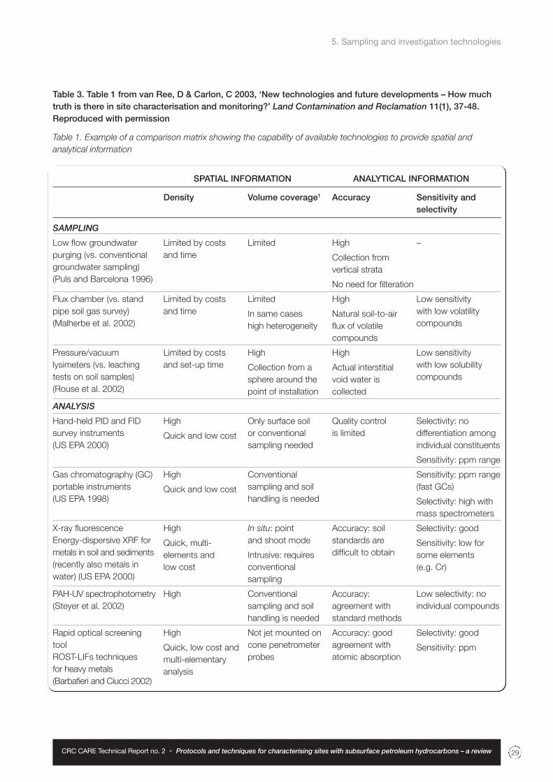
5. Sampling and investigation technologies
CRC CARE Technical Report no. 2 Protocols and techniques for characterising sites with subsurface petroleum hydrocarbons – a review 29
Table 3. Table 1 from van Ree, D & Carlon, C 2003, ‘New technologies and future developments – How muchtruth is there in site characterisation and monitoring?’ Land Contamination and Reclamation 11(1), 37-48.Reproduced with permission
Table 1. Example of a comparison matrix showing the capability of available technologies to provide spatial and
analytical information
SPATIAL INFORMATION ANALYTICAL INFORMATION
Density Volume coverage1 Accuracy Sensitivity and selectivity
SAMPLING
Low flow groundwater
purging (vs. conventional
groundwater sampling)
(Puls and Barcelona 1996)
Flux chamber (vs. stand
pipe soil gas survey)
(Malherbe et al. 2002)
Pressure/vacuum
lysimeters (vs. leaching
tests on soil samples)
(Rouse et al. 2002)
ANALYSIS
Hand-held PID and FID
survey instruments
(US EPA 2000)
Gas chromatography (GC)
portable instruments
(US EPA 1998)
X-ray fluorescence
Energy-dispersive XRF for
metals in soil and sediments
(recently also metals in
water) (US EPA 2000)
PAH-UV spectrophotometry
(Steyer et al. 2002)
Rapid optical screening
tool
ROST-LIFs techniques
for heavy metals
(Barbafieri and Ciucci 2002)
–
Low sensitivity
with low volatility
compounds
Low sensitivity
with low solubility
compounds
Selectivity: no
differentiation among
individual constituents
Sensitivity: ppm range
Sensitivity: ppm range
(fast GCs)
Selectivity: high with
mass spectrometers
Selectivity: good
Sensitivity: low for
some elements
(e.g. Cr)
Low selectivity: no
individual compounds
Selectivity: good
Sensitivity: ppm
High
Collection from
vertical strata
No need for filteration
High
Natural soil-to-air
flux of volatile
compounds
High
Actual interstitial
void water is
collected
Quality control
is limited
Accuracy: soil
standards are
difficult to obtain
Accuracy:
agreement with
standard methods
Accuracy: good
agreement with
atomic absorption
Limited
Limited
In same cases
high heterogeneity
High
Collection from a
sphere around the
point of installation
Only surface soil
or conventional
sampling needed
Conventional
sampling and soil
handling is needed
In situ: point
and shoot mode
Intrusive: requires
conventional
sampling
Conventional
sampling and soil
handling is needed
Not jet mounted on
cone penetrometer
probes
Limited by costs
and time
Limited by costs
and time
Limited by costs
and set-up time
High
Quick and low cost
High
Quick and low cost
High
Quick, multi-
elements and
low cost
High
High
Quick, low cost and
multi-elementary
analysis

5. Sampling and investigation technologies
CRC CARE Technical Report no. 2 Protocols and techniques for characterising sites with subsurface petroleum hydrocarbons – a review30
5.2 New and not-so-newapproaches
There is a wide range of possible techniques, tools and
strategies that could be used to characterise a petroleum-
impacted site – these include, for example, depth-
specific sampling, the use of isotopes, flux estimation
techniques, directional drilling, and reactive transport
modelling. Some ‘new’ and old approaches to site
investigation were reviewed some time ago (e.g. Davis
et al. 1992), as were standard operating protocols
(e.g. Barber 1996). They reported on the value of depth
profiles for defining groundwater contamination, the
need for purging of boreholes to achieve representative
sampling, the complications when sampling volatile
organics, and some new ideas in the use of passive
samplers (e.g. diffusion cells and dialysis cells). Some
of the lessons and techniques reported then remain
issues today or have not been adopted for use. Of
course, many organisations are currently taking steps
to improve procedures and guidance (e.g. Davis 2005;
NEPC 2006). We revisit some of these issues below,
and discuss others.
5.2.1. Depth-specific sampling
Multi-level sampling has been commonly employed
by researchers for some time (Davis et al. 1992, 1999;
Ronen et al. 1986) but less so in routine site
assessments. More recently, this has become more
SPATIAL INFORMATION ANALYTICAL INFORMATION
Density Volume coverage1 Accuracy Sensitivity and selectivity
Rapid optical screening
tool
ROST-LIFs techniques
for petroleum hydrocarbons
(Bujewski and Rutherford
1996)
Membrane interface probes
(MIP) for semi-volatile
organic carbon
Cone penetrometer
based – FID or PID
detectors (Fugro 2002)
Immunoassay kits (total
PAHs, PCBs, BTEX, etc.)
(US EPA 2000)
Geophysical methods in
general: e.g. electro-
magnetic and geoelectric,
magnetometry, GPR,
seismic reflection and
refraction methods, remote
sensing (van Deen 2002)
1 Investigated volume per unit measurement
Table 3. (cont.) Table 1 from van Ree, D & Carlon, C 2003, ‘New technologies and future developments – How much truth is there in site characterisation and monitoring?’ Land Contamination and Reclamation11(1), 37-48. Reproduced with permission
High
Low costs
High (up to 80
metres of probing
per day)
High
Low cost and time
High
Mounted on cone
penetrometer: real
time analysis, affords
nearly continuous
spatial data along
the profile
Near-continuous
spatial data along
the profile
Conventional
sampling and soil
handling is needed
High
Accuracy: good
agreement (80%)
and low (5%) false
negatives for detect/
non-detect data
Accuracy: semi-
quantitative
technique
Accuracy: semi-
quantitative analysis
In some cases
identification of
contaminant
hot spots
Selectivity: it does not
allow for the direct
quantification of
individual constituents
Selectivity: does not
allow for the direct
quantification of
individual constituents
Selectivity: they do
not differentiate
among individual
constituents
Sensitivity: good
No

5. Sampling and investigation technologies
CRC CARE Technical Report no. 2 Protocols and techniques for characterising sites with subsurface petroleum hydrocarbons – a review 31
acceptable for site investigations, although the analytical
costs can increase due to the increased number of
sampling locations. However, large uncertainties in
contaminant mobility, risk assessment and the target
dimensions for active remediation may remain where
depth-specific data is not obtained. Barber (1996) gave
a specific example of this for petroleum hydrocarbon
plume, where he compared data from multi-level depth
samplers and data from more conventional short-
screened boreholes. He found that data from the
conventional boreholes implied much greater dispersion
and much less plume movement than the multi-depth
samplers, indicating a lower risk profile than was actually
the case.
The reluctance to adopt depth profiling is understandable
if conventional approaches are taken. It may mean drilling
individual boreholes to separate depths, so adding
expense, and then every additional screened depth
means not only additional drilling costs but also
additional sampling and analytical expense. Where
appropriate three or four standard 40–50 mm diameter
short-screened piezometers could be installed in the one
drilled borehole, or where greater resolution is required,
narrow diameter tubing could be used with bundles of
access tubes and screens. This style of installation has
been used at numerous research locations and some
industry locations in Australia where the depth to the
water table is less than say 8 m (e.g. Davis et al. 1999);
for those cases syringes were used to purge and sample
each of the ports of the bundle tubes/screens. Figure 4
provides examples of such depth profiles, which were
sampled for hydrocarbons, inorganics and ‘well head’
parameters using plastic and glass syringes.
Figure 4. Depth profile of BTEX and naphthalene concentrations and EC measurementsin groundwater near the source of a plume (right panel) and 40 m down hydraulicgradient (left panel). The water table was about 0 m AHD. The depth profiles arelocated close to where groundwater is discharging to a marine environment, andshow increased EC at depth nearer the ocean, indicating the likely location of the‘saline wedge’ interface. The significant reduction in hydro-carbon concentrationsover the 40 m travel distance also indicates the potential for natural attenuation.

5.2.2. Purging boreholes
Recovering samples that are representative of aquifer
conditions is a prime goal of groundwater sampling.
Barber and Davis (1987a) and others stressed the need
for purging boreholes of 3–5 well volumes and/or allowing
well head parameters (e.g. DO, pH, EC, temperature, Eh)
to stabilise prior to taking a groundwater sample for
analysis. Micro-purging/pumping (also called low-flow
sampling or minimal drawdown sampling) has become
popular (see e.g. ASTM 2002; Puls & Barcelona 1996).
It was largely initiated by the need to reduce colloidal
movement into wells and thus avoid potential bias when
analysing groundwater samples for metal constituents.
Additionally, it allowed for greatly reduced volumes of
potentially contaminated water to be handled and
disposed to waste, and notionally reduced the potential
for changes in redox conditions in wells during purging.
The criteria set for minimal drawdown sampling is that
well head parameters stabilise prior to recovery of a
sample. If stabilisation is prolonged the protocol suggests
that 3–6 well volumes be extracted before sampling,
which is the established standard for conventional
groundwater sampling.
Increasingly, low-flow sampling has been adopted for a
wider range of chemicals in groundwater including organic
compounds, such as petroleum hydrocarbons. Low flow
sampling is not applicable if NAPL is resident in a well,
nor does it obviate the need to ensure samples are not
exposed to air or polymer materials. For example, low
flow purging and sampling is sometimes carried out using
a peristaltic pump, but this is only valid if the groundwater
sample is taken prior to contact with any of the flexible
tubing used in the pump, to avoid sorption onto the tubing
from the pumped groundwater stream.
5.2.3 Sampling for organic compounds
The hazards of sampling and handling samples
containing volatile and other organic compounds typical
of those found in petroleum hydrocarbon oils and fuels
have long been known (Barcelona et al. 1984, 1985;
Holm et al. 1998; Reynolds et al. 1990). Methods were
developed to overcome some of these sampling and
analytical difficulties (e.g. Davis et al. 1992; Pankow et al.
1984; Patterson et al. 1993).
In short, samples should be recovered to avoid contact
with the atmosphere to minimise volatile loss from and
oxygen ingress to the sample, and in addition samples
should be stored to minimise contact with plastic or
polymer materials to minimise sorption losses from the
sample. In some studies, all materials other than
borosilicate glass were observed to remove volatile
compounds from a water sample. Because of these
potential handling and storage issues, and because
organic compounds can biodegrade, samples should
be analysed as soon as possible after recovery, and
certainly well within the standard holding times for
samples prior to analysis.
5.2.4 NAPL characterisation
Although present in part, surprisingly few of the guidance
documents target the NAPL phase for measurement,
quantification or analysis separate from the soil,
groundwater or air phases. Certainly, the importance
of LNAPL is alluded to in many documents and
measurement in soils is common, but few provide detail
on LNAPL thickness monitoring, on whole oil analysis
for fingerprinting and confirmation of oil/fuel type, on
baildown or other well NAPL tests that would provide an
indication of NAPL mobility in the aquifer, the API (1996)
guide being an exception.
Huntley (2000) and others (e.g. Johnston et al. 2002)
provide theoretical and practical application of the use of
baildown tests on the NAPL phase in wells to determine
NAPL transmissivity. Such information assists in the
assessment of the mobility of the NAPL and its ultimate
recoverability if remediation is required.
Compositional changes in NAPL also can lead to
changed risk profiles due to altered partitioning to soil
gas (vapour) and dissolved groundwater phases, and
due to new compounds being formed during weathering
and biodegradation. The API (1996) guide notes this
possibility. Whole oil analysis also allows fingerprinting
of NAPL product to assist with identification of product
type and possible ownership.
5.2.5 Flux estimation
Many of the guidance documents seek to characterise
sites with respect to soil or water concentration threshold
values. This is to be expected given that regulation is
primarily based on concentration thresholds. However,
contaminant mass discharge (mass/time) across a control
plane is also a measure of potential receptor loading.
There are increasing efforts to determine and measure
flux/discharge/mass loading rates – both (i) downgradient
of suspected source zones, which gives source
discharge/fluxes, and (ii) contaminant discharge across
a compliance control plane as an estimate of receptor
exposure or off-site discharge. Point and integral flux
estimation techniques have been developed.
5. Sampling and investigation technologies
CRC CARE Technical Report no. 2 Protocols and techniques for characterising sites with subsurface petroleum hydrocarbons – a review32

5. Sampling and investigation technologies
CRC CARE Technical Report no. 2 Protocols and techniques for characterising sites with subsurface petroleum hydrocarbons – a review 33
Point flux estimates
Contaminant mass discharge can be estimated from
contaminant fluxes measured by the passive flux meter
(PFM), an innovative technology developed at the
University of Florida (e.g. Annable et al. 2005; Hatfield
et al. 2004). This is a point scale measurement involving
the deployment of socks of tracer-laden sorbent into the
screened section of pre-drilled boreholes for some period
of time, after which the socks are removed. The mass
removed over the time period is measured along with
the mass of sorbed contaminant. From this, the flux
of groundwater past the sock/borehole and flux of
contaminant to the borehole is determined. If deployed
across the cross-section of a plume or source zone, for
example, the PFM technique provides a total mass flux
estimate of water and contaminant moving in groundwater
beyond that point. A disadvantage of this technique is
the point-scale nature of the measurement. Analytical
costs may also be a disadvantage if fine scale measures
are taken or multiple deployments are required, say
before and after a treatment strategy.
Integral flux estimation
Other techniques are also used to establish net
groundwater contaminant flux. Teutsch et al. (2000),
Ptak et al. (2003), Bayer-Raich et al. (2004) and others
from that group developed an integral pumping test.
The test involves pumping groundwater from a bore or
series of boreholes across the groundwater flow direction
downgradient of a source at a contaminated site, and
recovering a time series of samples from the pumped
effluent of the boreholes. During pumping, as the capture
zones of the pumping bores increase, the concentration
of groundwater contaminants is measured as a function
of time at each of the pumping wells. Based on the
time series of groundwater quality data and modelling
inversion, the flux of contamination moving in groundwater
is determined. An advantage of this technique is that it
integrates data over a much larger volume of the aquifer,
rather than providing point source estimates. A
disadvantage of this technique is the large volumes of
contaminated effluent water that would need to be
collected and disposed of.
5.2.6 Capillary fringe
LNAPLs, being less dense than water, pool on the water
table or reside within the zone of water table fluctuation.
As indicated earlier, hydrocarbon components partition
to the soil gas and groundwater phases. Few
characterisation techniques have a consistent strategy
for sampling/monitoring with depth continuously across
the capillary fringe, apart from recovery of gas samples
above this zone and water samples below this zone,
or perhaps recovery of soil material across this zone.
Suction lysimeters have been used in the vadose zone
to recover soil moisture for analysis. Commonly this is
carried out for inorganic chemical species of interest
rather than volatile compounds (see e.g. Capuano and
Johnson 1996).
Diffusion cells were developed specifically to determine
volatile hydrocarbon concentrations (e.g. benzene) and
gases (e.g. methane, oxygen) across the capillary fringe
and in water saturated or vadose zone conditions. Initially
these were developed by Barber and Briegel (1987).
Diffusion cells consist of coiled teflon tubing installed
in backfilled boreholes with nylon access lines to the
ground surface. Cells can be purged with inert gas which
equilibrates with groundwater when passing through the
cell. Examples are given of the use of diffusion cells by
Barber and Davis (1987b), Barber et al. (1990a), Davis et
al. (1992) and more recently they have been automated
for oxygen and volatile organic compounds (Davis et al.
1995; Patterson et al. 2000).
5.2.7 Combined technologies
There is an increasing trend toward combining
technologies to accelerate programs of investigation.
This is most evident in the programs and activities
espousing accelerated site characterisation or the Triad
approaches. Further development in this area adds
value and potentially reduces costs. For example, cone
penetrometers that allow downhole geophysics, and
on-line sampling/analysis at multiple elevations in the one
hole give stratigraphy and water/soil/vadose zone quality
data in one pass. Such combined technology has been
routinely available overseas, but less so in Australia.
Another example is the combination of field analytics and
sensors, with web sites for data collation and presentation
to facilitate real-time characterisation. This, combined
further with models of site conditions, would provide a
powerful tool for site application. Few, if any, of these
combined systems appear available in Australia. Whilst
research is underway internationally, further development
in Australia seems needed.
5.2.8 Directional and alternate drilling
Infrastructure on sites impedes access to the subsurface
– directional drilling is becoming more commonly available

CRC CARE Technical Report no. 2 Protocols and techniques for characterising sites with subsurface petroleum hydrocarbons – a review34
and can be used to provide greater coverage where
infrastructure and hardpan are evident on a site. This
rarely seems to be used in Australia and there appears
to be no suggestion for its use in the guidance available.
A challenge may be to provide similar multipurpose
capability in directional drilling equipment that is currently
available for ‘push-rod’ type rigs.
Additionally, increasingly sonic or vibration rigs are being
made available. These provide the opportunity, depending
on the technique available, to recover more intact and
detailed core, to drill more quickly to depth, and to
produce less spoil or waste. This is especially the case
for unconsolidated materials, but vibration rigs are also
becoming available for consolidated aquifer and
soil materials.
5.2.9 Coupled reactive transportmodelling
Increasingly, coupled reactive transport models are being
developed and utilised. Holistic incorporation of transport
processes, dispersion processes, and the relevant
biodegradation pathways is rarely available. PHT3D (see
Prommer et al. 2002, 2003) is a recently developed code
that embodies these processes. These models allow
consideration of fringing processes along plume boundaries
where electron acceptors are only available external to
a hydrocarbon plume, but also allow consideration of
plume-core reactive processes where oxidised mineral
phases are present (e.g. iron oxides, manganese oxides)
and methanogenesis may be active. These considerations
are increasingly required in modern assessments of
plume behaviour and such tools need to be made user-
friendly and efficient so as to be routinely available for
application where rapid assimilation and integration of
data is needed in site assessments.
5.2.10 In situ or passive techniques
In situ (passive) monitoring or measurement devices
(Barber & Briegel 1987; Ronen et al. 1986) can provide
greater representativeness of in-ground conditions – for
example to overcome pumping and purging difficulties in
the field, sorption/desorption issues with hydrocarbons
and polymer materials, and losses of volatile compounds
during sampling. In situ monitoring devices have numerous
advantages: sampling can be rapid and efficient, and
since no pumping is required little disturbance of
groundwater occurs during monitoring. In situ sampling
can also provide the opportunity to obtain detailed
information on the vertical stratification of groundwater
quality. Some additional examples of in situ techniques
are given below to illustrate these advantages. The
diffusion cell was presented earlier as a technique that
could be used to target the capillary fringe.
Dialysis cells consist of small vials of distilled water
capped with a permeable membrane which allows ion
transfer from groundwater into an aqueous phase within
the vial until chemical equilibrium is achieved. Ronen et
al. (1986) used a string of dialysis cells within a cased
borehole to obtain vertical profiles of inorganics and
dissolved oxygen in groundwater. Davis et al. (1992)
reported on the results of field trials comparing the
performance of dialysis cells with bundled short-
screened piezometers in monitoring nutrient accessions
to groundwater under urban parkland areas. The dialysis
cells provided groundwater quality data which had the
same overall depth and time trends as the more
conventional and more time-consuming multi-level
sampling using piezometer bundles. Dialysis cells might
be more appropriate for inorganic parameters rather than
hydrocarbons and organic compounds, but could be
used to determine electron acceptor/donor parameters
during natural attenuation assessments.
Karp (1993) developed a diffusive sampler to provide a
passive in situ method for long-term monitoring of volatile
organic compounds (VOCs) in groundwater. The sampler
was constructed of a sorbent tube that fits inside a
specially designed sampling chamber equipped with a
diffusional membrane that is not permeable to water but
has a high permeability rate for organic vapours. VOCs
in the groundwater, having relatively high Henry's Law
constants, enter the chamber by molecular diffusion
and are collected by the sorbent. After a predetermined
exposure period, the sorbent is retrieved for
laboratory analyses.
As mentioned earlier, diffusion cells developed by Barber
and Briegel (1987) have been automated for on-line
monitoring of oxygen and volatile organic compounds in
subsurface environments (Davis et al. 1995, Patterson et
al. 1995, Patterson, Davis & Johnston 1999, Patterson,
Davis & McKinley 2000). The VOC probes measure total
concentrations of volatile organic compounds and avoid
sampling and analysis issues and costs. They have been
applied to sites for monitoring VOC fate and also where
monitoring of active remediation is required, e.g. during
air sparging.
5. Sampling and investigation technologies

CRC CARE Technical Report no. 2 Protocols and techniques for characterising sites with subsurface petroleum hydrocarbons – a review 35
6.1 Guidance documentsOverall the guidance documents provide structure and
direction for improved site characterisation. At one level,
these provide a mechanistic set of ‘rules’ to follow to
achieve an end – and this is needed where expertise is
lacking and the end point is clear. Others are structured
as optional strategies to achieve the best outcome –
perhaps where the intent of the investigative effort is clear
and the skill/expertise base is good. At another level the
documentation becomes over prescriptive or tome-like,
making its use inefficient or difficult to assimilate – perhaps
assuming the end point or intent of the investigation is
unclear and where step-wise instruction is warranted.
Examples of each of these are evident in the guidance
documents reviewed.
Several aspects seem essential – that the investigation
at minimum meets PAR – i.e. is purposeful, adequate
and representative.
6.1.1 Purposeful
A site investigation needs to be purposeful – that is,
purpose-driven. Data quality objectives (DQOs) appear
in some guidelines (see e.g. AS 2005; US EPA 2006),
and were developed to be a trigger for serious thought
around the purpose of investigations and hence each
of the planned individual tasks that make up a site
characterisation effort. It is argued by some (e.g. Crumbling
2002) that the emphasis has been too much on ‘data
quality’ and not enough on the ‘objectives’ when utilising
the DQO approach.
A challenge is defining the purpose (or objectives). For a
site investigation to be precisely planned all stakeholders
may need to be active in defining the purpose. Recognising,
for other than simple sites, that removal of all mass from
a contaminated site may not be practicable, the setting
of the purpose becomes a critical aspect of the
characterisation. Is the purpose:
• to keep total hydrocarbon exposures from all phases
below a threshold, and if so, how is this to be
allocated amongst the phases?
• to avoid off-site discharge of a plume of hydrocarbons?
• to establish the stability of a plume?
• to establish no vapour exposure?
• to ensure NAPL thicknesses in all wells remain below
a sheen?
Or perhaps it is a combination of some of these, and
others. Agreeing this with stakeholders becomes a fruitful
first step, albeit somewhat resource- and time-intensive
to achieve.
The argument is a little cyclic, in that to establish a
stakeholder-agreed purpose requires a sound conceptual
site model (CSM), if not a predictive model for the site,
and to have a negotiated position on threshold values.
This is not always possible – but such an approach
would require discussion between regulators, site
owners and consultants, bringing benefit to a site
characterisation strategy.
6.1.2 Adequate
A site investigation needs to be adequate – that is,
adequate in extent and quality to meet the purpose
of the investigation. For adequate coverage, how many
samples are required at what locations and in which
phases? This needs to be much more driven by the
purpose (Section 6.1.1). Crumbling et al. (2001) argue
that using field analytical technologies in the context
of a dynamic work plan, and careful management of
sampling, analytical and decision uncertainties, can
significantly bring down the costs of contaminated site
investigations and clean-ups, while improving confidence
in project decisions.
Whilst many of the documents refer to the need to
provide sufficient supporting data to determine the
contamination status of a site with an acceptable level
of confidence (see e.g. AS 4482.1-2005), rarely is the
level of acceptability or level of confidence defined. The
challenge is to find an acceptable level of confidence
agreeable between site owners and regulators, to meet
end point objectives of the characterisation to provide
‘adequate’ data. This needs to be balanced against
the uncertainties in risk assessments, and the cost-
effectiveness of remediation strategies, given a set or
limited quantum of data.
6. Synthesis and conclusions

6.1.3 Representative
A site investigation needs to be representative – that is,
sampling and investigation strategies and techniques
must provide data that are representative of the
subsurface environment and site conditions. Crumbling
(2002) asserts that data representativeness is fundamental
to data quality. The data quality model for contaminant
data can sometimes remain focused on analytical data
quality methods to the neglect of strategies to
accommodate sampling from a heterogeneous
environment. Crumbling (2002) argues that for the same
overall cost, a greater spread of samples across a site
with (even greater) reduced analytical certainty from
laboratory or field screening will have a lower uncertainty,
and therefore be more representative than fewer samples
analysed to a high degree of accuracy. Development of
the ASC- and Triad-based technologies (e.g. rapid soil
and groundwater sampling tools, field-portable analytical
instrumentation, decision-support software) has moved
site characterisation in this direction – with a greater
potential to provide cost-effective, high density, adaptive
sampling needed to assure data representativeness.
Combined with dynamic management and decision
making, this offers to support a next generation data quality
model that explicitly manages sampling uncertainties,
allowing greater representativeness.
6.2 Final observations1. A risk-based approach should be taken as the
starting point for site characterisation, since this
forces consideration of the regulatory regime and
exposure pathways, and focuses effort on
establishing a robust conceptual model – with field
investigations that target the improvement and
modification of this model.
2. A clear information objective is important, embodying
data quality objectives and achieving representative
sampling of a site.
3. Important to any site characterisation is the
derivation of a site conceptual model that integrates
what is already known about a site, and identifies
both what still needs to be discovered, and how that
information should be used.
4. Choices of site investigation approaches should
be made on the basis of improvement of the site
conceptual model. The site conceptual model also
serves as the basis for risk assessment and
remediation. The information needed for risk
assessment and remediation planning is not
necessarily the same.
5. Site characterisation plans need to be flexible and
adaptable to allow feedback on possibly real-time
results. This kind of dynamic approach to site
characterisation needs to be considered as a part
of overall site investigation strategy, before site
characterisation mobilisation. It also impinges on
the reliance on conventional sample-to-laboratory
systems, as laboratory data can take longer to be
generated. Dynamic approaches may also need
to encompass remediation planning.
6. If representivity is to be emphasised, perhaps the
analytical precision of conventional laboratory (off-
site) analyses could be traded off against greater
data intensity on-site, especially when comparing
sources of error from sampling, and sources of
uncertainty from site heterogeneity and variability.
7. For groundwater investigations, guidance
documents generally promote a minimum of three
or four boreholes. In practice, on average a greater
number of sampling boreholes is used. Greater
use could be made of statistical sampling theory,
statistical tests of significance, and geostatistical
analysis to handle aquifer and geochemical
heterogeneity.
8. Site investigation data needs to be assessed over
time, as well as in space, so that trends in
contaminant behaviour can be assessed. The depth
dimension is often neglected in air, water and soil
phases. Whilst depth sampling of soils/sediments
(whether in the vadose zone or groundwater) is
mentioned in several guidance documents, it has
not been formalised. Depth-discrete sampling of
groundwater is mostly ignored.
9. A variety of site characterisation techniques are
available for on-site analyses, from on-site sensors
to geophysical techniques. Validation and
improvement is required to avoid false negative
and positive outcomes, and to build reliability and
confidence into rapid assessment practices.
6. Synthesis and conclusions
CRC CARE Technical Report no. 2 Protocols and techniques for characterising sites with subsurface petroleum hydrocarbons – a review36

6. Synthesis and conclusions
CRC CARE Technical Report no. 2 Protocols and techniques for characterising sites with subsurface petroleum hydrocarbons – a review 37
10. Development of new tools for on-site use in site
characterisation is increasing, but if ASC or Triad is
to be pursued, further development of new or novel
sensor and site characterisation techniques should
be pursued – especially those that would allow
rapid on-site decision making and achieve reliable
outcomes at reduced cost. Combining ‘continuously
available’ data with models on-line could also be
pursued. This is near readily available for groundwater
flow, however, where geochemistry and reactive
transport is important on-line real-time linkages
between data collection and models is problematic
due to the computational intensity of such codes.
11. The use of ‘direct push’ tools as opposed to
conventional drilling, and a variety of attachments
and sensors which can be used with these direct
push tools to collect site investigation information,
is desirable. This allows more real-time information
gathering and implementation of dynamic site
characterisation strategies. Innovation in this area
should be encouraged.
12. In Australia, implementation of Triad would require
upskilling of all elements of site characterisation
(planning, on-site interpretation including sophisticated
modelling, and technology availability and
deployment) in consulting agencies and/or industry,
and integration of these skills with the regulatory
approvals process – possibly on-site.
13. Harmonisation of the regulation of site characterisation
through NEPM or other mechanisms may assist the
practice of site characterisation, but reduced flexibility
needs to be avoided to allow for continued innovation.
14. Greater guidance on the use and application of
numerical models to integrate site characterisation
data could be useful. The Murray-Darling Basin
Commission issued guidelines for water resource
groundwater flow modelling in 2000. Prommer et al.
(2003) provided an initial basis for petroleum plumes
in groundwater. There are no Australian guidelines
for modelling multiphase hydrocarbon behaviour.
15. There is a need to continue to facilitate knowledge
transfer across regulators, contaminated site owners,
service providers and the academic community.
16. The scalability of site investigation plans and
technologies should be assessed – from UST and
service station scale, to depot and terminal scale
and perhaps refinery or multiple source complex
mega-site scale.
17. US documentation (ASTM, API, etc.) includes
management as part of guidance in many instances,
whilst the NEPM does not. Interestingly, the NSW EPA
Service Station Guidelines did include remediation
options as part of the guidance. A perceived difficulty
in embedding management options in such guidance
is the lack of stability in the range of technologies
on offer.
18. Research and innovation is needed to quantify and
optimise the value of gathering additional data so
as to minimise uncertainty during assessment – to
provide more precise definition of risks and costs
for clean-up applications. For example, whilst the
multiphase behaviour of petroleum hydrocarbons is
recognised, the value of extra data in any one phase
in reducing uncertainties in risk assessment or the
selection of remedial options is not well defined.

CRC CARE Technical Report no. 2 Protocols and techniques for characterising sites with subsurface petroleum hydrocarbons – a review38

AIP 1999, ‘Guidelines for the management of petroleum
hydrocarbon impacted land: Volume I – Site classification
and tier 1 look-up tables (131 pp). Volume II – Supporting
information (7 chapters)’. Final draft issued for practice
review. Australian Institute of Petroleum, AOIEWG
(Australian Oil Industry Environmental Working Group)
Melbourne, Australia.
Annable, MD, Hatfield, K, Cho, J, Klammler, H, Parker, B,
Cherry, C & Rao, PSC 2005, ‘Field-scale evaluation of
the passive flux meter for simultaneous measurement
of groundwater and contaminant fluxes’, Environmental
Science and Technology 39(18), 7194-7201.
ANZECC/ARMCANZ 2000, Australian and New Zealand
guidelines for fresh and marine water quality, Paper no. 4
of the National Water Quality Management Strategy.
ANZECC/NHMRC 1992, Guidelines for the Assessment
and Management of Contaminated Sites.
API 1993, Guideline for Assessing and Remediating
Petroleum Hydrocarbons in Soils, American Petroleum
Institute Publication 1629, October 1993, 81 pp.
API 1996, A Guide to the Assessment and Remediation
of Underground Petroleum Releases, American Petroleum
Institute Publication 1628, July 1996, 119 pp.
AS 1999, Guide to the sampling and investigation of
potentially contaminated soil. Part 2: Volatile substances,
Standards Australia, AS 4482.2-1999.
AS 2005, Guide to the investigation and sampling of sites
with potentially contaminated soil. Part 1: Non-volatile
and semi-volatile compounds, Standards Australia, AS
4482.1-2005.
AS/NZS 1998, Water quality – Sampling. Part 11:
Guidance on sampling of groundwaters, Standards
Australia, AS/NZS 5667.11:1998 (ISO 56667-11:1993).
ASTM 1994, ASTM Standards on Ground Water and
Vadose Zone Investigations, 2nd edition, American
Society for Testing and Materials.
ASTM 1995, Standard guide for risk based corrective
action applied at petroleum release sites, Public no.
E1739-95, American Society for Testing and Materials.
ASTM 1998, Standard Guide for Accelerated Site
Characterization for Confirmed or Suspected Petroleum
Releases, Public no. E1912, American Society for
Testing and Materials.
ASTM 2002, Standard Practice for Low-Flow Purging
and Sampling for Wells and Devices Used for Ground-
Water Quality Investigations, Public No. D6771-02,
American Society for Testing and Materials.
Barbafieri, M & Ciucci, A 2002, ‘Rapid optical screening
tools for site characterisation’, in Proc. Nicole Network
Meeting on Cost-Effective Site Characterisation, 18-19
April, Pisa, Italy.
Barber, C 1996, ‘Investigation and remediation of
contaminated soil and groundwater: A review and
evaluation of standard operating procedures’, in A
Langley, B Markey & H Hill (eds), Proceedings of the
Third National Workshop on the Health Risk Assessment
and Management of Contaminated Sites, Contaminated
Sites Monograph Series, no. 5, 427-439.
Barber, C & Briegel, D 1987, ‘A method for the in-situ
determination of dissolved methane in groundwater in
shallow aquifers’, Journal of Contaminant Hydrology
2: 51-60.
Barber, C & Davis, GB 1987a, ‘Representative sampling
of groundwater from short-screened boreholes’, Ground
Water 25(5), 581-587.
Barber, C & Davis, GB 1987b, ‘Volatilisation of methane
from groundwater; laboratory simulation and field
investigations in a sand aquifer’ in Groundwater Systems
Under Stress. AWRC Conf. Series no. 13, 157-164.
Barber, C, Davis, GB, Briegel, D & Ward, JK 1990b,
‘Factors controlling the concentration of methane and
other volatiles in groundwater and soil-gas around a
waste site’, Journal Contaminant Hydrology 5, 155-169.
Barber, C, Davis, GB, Buselli, G & Height, MI 1991,
‘Remote monitoring of groundwater pollution using
geoelectric techniques in undulating sandy terrain,
Western Australia’, International Journal of Environment
and Pollution 1(1/2), 97-112.
CRC CARE Technical Report no. 2 Protocols and techniques for characterising sites with subsurface petroleum hydrocarbons – a review 39
7. References
7. References
CRC CARE Technical Report no. 2 Protocols and techniques for characterising sites with subsurface petroleum hydrocarbons – a review40
Barber, C, Davis, GB & Farrington, P 1990a, ‘Sources
and sinks for dissolved oxygen in groundwater in an
unconfined sand aquifer, Western Australia’, in Durrance
et al. (eds), Geochemistry of Gaseous Elements and
Compounds, Theophrastus Publications SA, Athens,
353-368.
Barcelona, MJ, Helfrich, JA & Garske, EE 1985, ‘Sample
tubing effects on groundwater samples’, Analytical
Chemistry 57, 460-464.
Barcelona, MJ, Helfrich, JA, Garske, EE & Gibb, JP
1984, ‘A laboratory evaluation of ground water sampling
mechanisms’, Ground Water Monitoring Review 4(2),
32-41.
Bayer-Raich, M, Jarsjö, J, Liedl, R, Ptak, T & Teutsch, G
2004, ‘Average contaminant concentration and mass
flow in aquifers from time dependent pumping well data:
analytical framework’, Water Resources Research, 40,
W08303, doi:10.1029/2004WR003095.
Borner, F, Gruhne, M & Schon, J 1993, ‘Contamination
indications derived from electrical properties in the low
frequency range’, Geophysical Prospecting 41, 83-98.
Boulding, JR 1993a, Subsurface characterisation and
monitoring techniques: a desk reference guide. Vol. 1
Solids and groundwater, EPA/625/R-93/003a.
Boulding, JR 1993b, Use of airborne, surface and
borehole geophysical techniques at contaminated sites:
a reference guide, EPA/625/R-92/007.
Boulding, JR & Ginn, JS 2004, Practical Handbook of
Soil, Vadose Zone and Ground Water Contamination:
Assessment, Prevention and Remediation, 2nd edition,
Lewis Publishers, Boca Raton.
Brown, SR, Lesmes, D, Fourkas, J & Sorenson, JR
2003, Complex electrical resistivity for monitoring DNAPL
contamination, Final Report, U.S. Department of Energy,
Project Number: 70012, 30 pp.
BS 2001, Investigation of potentially contaminated sites,
Code of Practice, British Standard BS 10175: 2001,
82 pp.
Bujewski, G & Rutherford, B 1996, The rapid optical
screening tool (RST) laser-induced fluourescence (LIF)
system for screening petroleum hydrocarbons in
subsurface soils, Innovative Technology Verification
Report, Sandia National Laboratory, US EPA Nevada.
Burton, JC 1993, ‘Expedited site characterization:
a rapid, cost-effective process for preremedial site
characterization’, in Superfund XIV, Vol. II, Hazardous
Materials Research and Control Institute, pp. 809–26.
Capuano, RM & Johnson, MA 1996, ‘Geochemical
reactions during biodegradation vapor-extraction
remediation of petroleum contamination in the vadose
zone’, Ground Water 34 (1), 31-40.
Cattlin, L & Fanning, M 2003, ‘Assessment of
underground storage systems’, in A Langley, M Gilbey &
B Kennedy (eds), Health and Environmental Assessment
of Site Contamination (Proceedings of the Fifth National
Workshop on the Assessment of Site Contamination),
Adelaide 13-15 May 2002. Published by the Australian
Environmental Protection and Heritage Council (EPHC)
incorporating the National Environmental Protection
Council (NEPC), 121-132.
Cerneaz, K 1999, ‘Benefits of the application of the
Australian Oil Industry Environmental Working Group’s
“Guidelines for Management of Hydrocarbon Impacted
Land”’, in CD Johnston (ed), Contaminated Site
Remediation: Challenges Posed by Urban and Industrial
Contaminants – Proc. 1999 Contaminated Site
Remediation Conference, Fremantle, Western Australia,
21-25 March 1999, 751-758.
ChemFinder 2004, URL:
http://chemfinder.cambridgesoft.com/
Company A 2005, Remediation Management Asia
Pacific Guidelines, Revision C, June 2005, 151 pp.
Company B 2006a, Technical Specification: Module 2 –
Phase 1 Environmental Site Assessment, June 2006,
39 pp.
Company B 2006b, Environmental Site Assessment
specification: Module 3 – Phase 2 Environmental Site
Assessment, June 2006, 124 pp.
Company C 2003, Specification for Environmental Site
Investigation Services (ESIS), June 2003, 84 pp.
Company D 2003, Environmental Standards –
Hazardous Material and Contamination Control,
September 2003, 3 pp.
Company D 2004, Environmental Standards –
Contaminated Land Assessment & Remediation
Guidance Note: Version 2.1, September 2004, 35 pp.

CONCAWE 1979, Protection of groundwater from oil
pollution. CONCAWE Report No, 3/79, The Hague,
Netherlands.
Corseuil, HX, Kaipper, BIA & Fernandes, M 2004,
‘Cosolvency effect in subsurface systems contaminated
with petroleum hydrocarbons and ethanol’, Water
Research 38(6),1449–56.
Crumbling, DM 2002, ‘In search of representativeness:
evolving the environmental data quality model’, Quality
Assurance 9, 179-190.
Crumbling, DM, Groenjes, C, Lesnik, B, Lynch, K,
Shockley, J, van Ee, J, Howe, R, Keith, L & McKenna, J
2001, ‘Managing uncertainty in environmental decisions’,
Environmental Science and Technology, 35(19),
404A-409A.
Daily, W & Ramirez, A 1995, ‘Electrical resistance
tomography during in-situ trichloroethylene remediation
at the Savannah River Site’, Journal of Applied
Geophysics 33(4), 239-249.
Davis, GB 2005, Review of ‘A standard protocol for
sampling ground waters in New Zealand’, CSIRO Land
and Water Report for the Institute of Geological and
Nuclear Sciences Limited, New Zealand.
Davis, GB, Barber, C, Briegel, D, Power, TR & Patterson,
BM 1992, ‘Sampling groundwater quality for inorganics
and organics: some old and new ideas’, Drill '92, Aust
Drilling Ind Assoc Conf, Perth, Oct 1992, 24.1-24.9.
Davis, GB, Barber, C, Power, TR, Thierrin, J, Patterson,
BM, Rayner, JL & Qinglong, Wu 1999, ‘The variability
and intrinsic remediation of a BTEX plume in anaerobic
sulphate-rich groundwater’, Journal of Contaminant
Hydrology 36(3/4), 265-290.
Davis, GB, Johnston, CD, Thierrin, J, Power, TR &
Patterson, BM 1993, ‘Characterising the distribution of
dissolved and residual NAPL petroleum hydrocarbons in
unconfined aquifers to effect remediation’, AGSO Journal
of Australian Geology & Geophysics 14(2/3), 243-248.
Davis, GB, Patterson, BM & Trefry, MG 2006, ‘Typical
behaviour of petroleum and solvent vapours: updating
our understanding from Australian field investigations’, in
Enviro06: Managing Contaminated Land and Groundwater,
Melbourne, Australia, 9-11 May 2006, 8 pp.
Davis, GB, Rayner, JL, Trefry, MG, Fisher, SJ & Patterson,
BM 2005, ‘Measurement and modelling of temporal
variations in hydrocarbon vapor behavior in a layered soil
profile’, Vadose Zone Journal 4, 225-239.
Davis, GB, Trefry, MG & Patterson, BM 2004, Petroleum
and solvent vapours: quantifying their behaviour,
assessment and exposure, CSIRO Land and Water Report
to the Western Australian Department of Environment.
DEFRA 2006, Environmental Protection Act 1990; Part
2A Contaminated Land, UK Department of Environment,
Food and Rural Affairs Circular 01/2006, September
2006, 200 pp.
DEH 2004, Operation of the Fuel Quality Standards Act
2000, Department of the Environment and Heritage
Annual Report 2003-2004, 601-609.
Edwards, EA & Grbic-Galic, D 1992, ‘Complete
mineralisation of benzene by aquifer microorganisms
under strictly anaerobic conditions’, Applied and
Environmental Microbiology, 58(8), 2663-2666.
EPA Victoria 2002, The clean up and management of
polluted groundwater, Environment Protection Authority
Victoria, Publication 840, April 2002, 16 pp.
EPA Victoria 2003, Guidelines on the Design, Installation
and Management for Underground Petroleum Storage
Systems (UPSS), Environment Protection Authority
Victoria, Melbourne, Publication 888.
Ferguson, CC 1999, Assessing risks from contaminated
sites: policy and practice in 16 European countries, Land
Contamination & Reclamation 7 (2), 33 pp.
Ferguson, CC, Darmendrail, D, Freier, K, Jensen, BK,
Jensen, J, Kasamas, H, Urzelai, A & Vegter, J (eds) 1998,
Risk Assessment for Contaminated Sites in Europe.
Volume 1 – Scientific Basis, LQM Press, Nottingham.
Ferguson, CC & Kasamas, H (eds) 1999, Risk Assessment
for Contaminated Sites in Europe. Volume 2 – Policy
Frameworks, LQM Press, Nottingham.
Fugro Ltd 2002, ‘MIP probe for delineation of semivolatile
organic carbon contamination’, in Proc. Nicole Network
Meeting on Cost-Effective Site Characterisation, 18-19
April, Pisa, Italy.
Greenhouse, JP & Monier-Williams, M 1985,
‘Geophysical monitoring of ground water contamination
around waste disposal sites’, Ground Water Monitoring
Review 5(4), 63-69.
7. References
CRC CARE Technical Report no. 2 Protocols and techniques for characterising sites with subsurface petroleum hydrocarbons – a review 41

7. References
CRC CARE Technical Report no. 2 Protocols and techniques for characterising sites with subsurface petroleum hydrocarbons – a review42
Gruszczenski, TS 1987, ‘Determination of a realistic
estimate of the actual formation product thickness using
monitor wells: A field bailout test’, Proceedings Conference
on Petroleum Hydrocarbons and Organic Chemicals in
Ground Water – Prevention, Detection,and Restoration,
National Ground Water Association, Dublin, OH, 300-304.
Hatfield, K, Annable, MD, Cho, J, Rao, PSC, Klammler,
H 2004, ‘A direct passive method for measuring water
and contaminant fluxes in porous media’, Journal of
Contaminant Hydrology 75(3-4), 155-181.
Hess, K 1998, Environmental Site Assessment. Phase I:
A Basic Guide, 2nd edition, Lewis Publishers, Boca Raton.
Hine, J & Mookerjee, K 1975, ‘The intrinsic hydrophilic
character of organic compounds. Correlations in terms
of structural contributions’, Journal of Organic Chemistry
40(3), 292-298.
Holm, TR, George, GK & Barcelona, MJ 1988,
‘Oxygen transfer through flexible tubing and its effect
on groundwater sampling results’, Ground Water
Monitoring Review 8(3), 83-89.
Huntley, D 2000, ‘Analytic determination of hydrocarbon
transmissivity from baildown tests’, Ground Water 38,
46-52.
ITRC 2003, The Triad Approach: A New Paradigm for
Environmental Project Management, Interstate Technology
& Regulatory Council, December 2003, 64 pp. plus
appendices.
Johnson, SJ, Woolhouse, KJ, Prommer, H, Barry, DA,
& Christofi, N 2003, ‘Contribution of anaerobic microbial
activity to natural attenuation of benzene in groundwater’,
Engineering Geology 70, 343-349.
Johnston CD 1997, Sharp-front modelling of the infiltration
of diesel to a shallow water table, Centre for Groundwater
Studies, CSIRO Land and Water Consultancy Report
no. 97-29.
Johnston, CD & Adamski, M 2005, ‘Relationship
between initial and residual LNAPL saturation for different
soil types’, in Proceedings of the 2005 Petroleum
Hydrocarbons and Organic Chemicals in Groundwater:
Prevention, Assessment, and Remediation Conference,
17-19 August, Costa Mesa, 15 pp.
Johnston, CD & Patterson, BM 1994, ‘Distribution of
nonaqueous phase liquid in a layered sandy aquifer’, in
RE Hinchee, BC Alleman, RE Hoeppel & RN Miller (eds),
Hydrocarbon Bioremediation, Lewis Publishers, Boca
Raton, 431-437.
Johnston, CD, Innes, N & Rayner, JL 2002, Evaluation of
NAPL recovery methods: NAPL baildown testing during
the filed trial at the BP Kwinana Refinery, 2001, CSIRO
Land and Water consultancy report to BP (commercial-
in-confidence).
Karp, KE 1993, ‘A diffusive sampler for passive monitoring
of volatile organic-compounds in-ground water’, Ground
Water 31 (5), 735-739.
Kelly, BFJ & Acworth, RI 1994, ‘Detection of light non-
aqueous phase liquid in a shallow sandy aquifer with
ground penetrating radar’, in Water Down Under ’94,
25th Congress of the International Association of
Hydrogeologists, 6 pp.
Klainer, SM, Koutsandreas, JD & Lawrence, A 1988,
Monitoring groundwater and soil contamination by
remote fibre spectroscopy, ASTM Special Technical
Publication 963, pp 370-380.
Lide, DR 2000, Handbook of Chemistry and Physics,
81st Edition (Hardcover), CRC Press.
LLNL 2001, Environmental assessment of the use of
ethanol as a fuel oxygenate: subsurface fate and
transport of gasoline containing ethanol, Lawrence
Livermore National Laboratory, Report to the California
State Water Resources Control Board, Sacramento,
CA, UCRL-AR-145380, chapters 1–6.
Lunne, T, Robertson, PK & Powell, JJM 1997, Cone
Penetrometer Testing in Geotechnical Practice, E&FN
Spon, NY.
Mackay, D & Shiu, WY 1981, ‘A critical review of Henry’s
Law constants of environmental interest’, Journal of
Physical and Chemical Reference Data 10(4) 1175-1199.
Mackay, D, Shiu, WY & Ma, K 1992, Illustrated Handbook
of Physical-chemical Properties and Environmental Fate
for Organic Chemicals, Vol 1, Lewis Publishers, Michigan.
Malherbe, L, Hulot, C, Pokryszka, Z & Pouil, L 2002,
‘Characterising soil-to-air emissions from a contaminated
site’, in Proc. Nicole Network Meeting on Cost-Effective
Site Characterisation, 18-19 April, Pisa, Italy.
Merrick, NP 1997, ‘An experiment in geophysical
monitoring of a contaminated site’, in J. Chilton et al. (eds),
Proceedings of the XXVII IAH Congress on Groundwater
in the Urban Environment, Volume 1: Problems, Processes
and Management. Nottingham, UK, A A Balkema,
Rotterdam, pp 487-490.

7. References
CRC CARE Technical Report no. 2 Protocols and techniques for characterising sites with subsurface petroleum hydrocarbons – a review 43
Milanovich, FP 1986, ‘Detecting chloroorganics in
groundwater’, Environmental Science & Technology
20(5): 441-442.
Muller, M & Klein, W 1992, ‘Comparative evaluation
of methods predicting water solubility for organic
compounds’, Chemosphere 25, 782-796.
NEPC 1999a, National Environment Protection
(Assessment of Site Contamination) Measure (NEPM),
National Environmental Protection Council (NEPC).
NEPC 1999b, Guideline on Laboratory Analysis of
Potentially Contaminated Soils (Schedule B (3) of the
National Environment Protection (Assessment of Site
Contamination) Measure), published by the National
Environment Protection Council,
http://www.ephc.gov.au/pdf/cs/cs_03_lab_analysis.pdf
NEPC 2006, Review of the National Environment
Protection (Assessment of Site Contamination) Measure:
Summary of Submissions received in relation to the
Issues Paper for the Review of the Assessment of Site
Contamination NEPM, NEPC Service Corporation.
NICOLE 2002, Cost-effective Site Characterisation –
Dealing with uncertainties, innovation, legislation
constraints, Summary of Nicole Workshop, 18-19 April
2002, CNR, Pisa, Italy.
NICOLE 2006, Data Acquisition for a Good Conceptual
Site Model, Report of the NICOLE Workshop, 10-12 May
2006, Carcassonne, France (compiled by Antony
Chapman, and Paul Bardos), 42 pp.
Niven, RK 2005, ‘Ethanol in gasoline: environmental
impacts and sustainability, review article’, Renewable
and Sustainable Energy Reviews 9(6), 535-555.
NSW DEC 2004, Draft guidelines for the assessment
and management of groundwater contamination, New
South Wales Department of Environment and
Conservation, 48 pp.
NSW EPA 1994, Guidelines for assessing service station
sites, New South Wales Environment Protection
Authority, 30 pp.
NZ MfE 1999a, Guidelines for Assessing and Managing
Petroleum Hydrocarbon Contaminated Sites in New
Zealand, New Zealand Ministry for the Environment.
NZ MfE 1999b, Draft Sampling Protocols and Analytical
Methods for Determining Petroleum Products in Soil
and Water, Prepared by the Oil Industry Environmental
Working Group for the New Zealand Ministry for the
Environment, May 1999, ME613, 59 pp.
NZ MfE 2004, Contaminated Land Management
Guidelines no.5: Site Investigation and Analysis of Soils,
New Zealand Ministry for the Environment, February
2004, ME497, 93 pp.
Olhoeft, GR 1985, ‘Low-frequency electrical properties’,
Geophysics 50, 2492–2503.
Olhoeft, GR & Fiore, R 1999, Geophysical monitoring of
DNAPL at the parts per billion level, Geological Society
of America, 1999 annual general meeting, Denver, CO,
United States, October 25-28, Abstracts with Programs
– Geological Society of America, V31, N7, pp.143.
Pankow, JF, Isabelle, LM, Hewetson, JP & Cherry, JA
1984, ‘A syringe and cartridge method for downhole
sampling for trace organics in groundwater’, Ground
Water 22(3), 330-339.
Patterson, BM, Power, TR & Barber, C 1993, ‘Comparison
of two integrated methods for collection and analysis
of volatile organic compounds in groundwater’, Ground
Water Monitoring Review 13(3), 118-123.
Patterson, BM, Power, TR, Davis, GB & Barber, C 1995,
An in situ device to measure oxygen in the vadose zone
and in groundwater: laboratory testing and field evaluation
to determine oxygen usage rate coefficients, CSIRO
Division of Water Resources Divisional Report no. 95/0
(confidential).
Patterson, BM, Davis, GB & Johnston, CD 1999,
‘Automated in situ devices for monitoring of VOCs and
oxygen in water and soil environments’, in CD Johnston
(ed), Contaminated Site Remediation: Challenges Posed
by Urban and Industrial Contaminants – Proc. 1999
Contaminated Site Remediation Conference, Fremantle,
Western Australia, 21-25 March 1999, 227-234.
Patterson, BM, Davis, GB & McKinley, AJ 2000, ‘Volatile
organic compounds in groundwater, probes for the
analysis of’, in RA Meyers (ed), Encyclopedia of Analytical
Chemistry: Instrumentation and Application, John Wiley
and Sons Ltd, 3515-3526.

7. References
CRC CARE Technical Report no. 2 Protocols and techniques for characterising sites with subsurface petroleum hydrocarbons – a review44
Prommer, H, Barry, DA & Davis, GB 2002, ‘Modelling of
physical and reactive processes during biodegradation
of a hydrocarbon plume under transient groundwater
flow conditions’, Journal of Contaminant Hydrology 59,
113-131.
Prommer, H, Davis, GB, Barry, DA & Miller, CT 2003,
‘Modelling the fate of petroleum hydrocarbons in
groundwater’, in A Langley, M Gilbey & B Kennedy
(eds), Health and Environmental Assessment of Site
Contamination (Proceedings of the Fifth National
Workshop on the Assessment of Site Contamination),
Adelaide 13-15 May 2002, Published by the Australian
Environmental Protection and Heritage Council (EPHC)
incorporating the National Environmental Protection
Council (NEPC), 21-45.
Ptak, T, Ertel, T & Teutsch, G 2003, ‘An integral approach
for the quantification of subsurface contamination’, in
GJ Annokkée, F Arendt & O Uhlmann (eds), ConSoil
2003, Wissenschaftliche Berichte, FZKA 6943,
Forschungszentrum Karlsruhe in der Helmholtz-
Gemeinschaft, 3322-3329, ISSN 0947-8620.
Puls, RW & Barcelona, MJ 1996, Low-flow (minimal
drawdown) ground-water sampling procedure,
EPA/540/S-95/504, 12 pp.
Qld DoE 1998, Draft Guidelines for the Assessment and
Management of Contaminated Land in Queensland,
Queensland Department of Environment, May 1998,
80 pp.
Ramirez, A, Daily, W & LeBrecque, D 1996, Complex
electrical tomography of a subsurface PCE plume,
Lawrence Livermore National Laboratory, Report Number
UCRL-JC-122874; CONF-960477-5, 10 pp.
Reynolds, GW, Hoff, JT & Gillham, RW 1990, ‘Sampling
bias caused by materials used to monitor halocarbons
in groundwater’, Environmental Science & Technology
24(1), 135-142.
Robbat, A 1997, A Guideline for Dynamic Workplans
and Field Analytics: The Keys to Cost-Effective Site
Characterization and Cleanup, Environmental Technology
Initiative, US EPA, Washington, D.C.
Ronen, D, Magaritz, M & Itzhak, L 1986, ‘A multilayer
sampler for the study of detailed hydrochemical profiles
in groundwater’, Water Research 20(3), 311-315.
Rouse, J, Cremonesi, M & Bluestone, S 2002, ‘Use of
pressure/vacuum lysimeters as an alternative to core
sampling and leach protocols for determination of
contaminant mobility’, in Proc. Nicole Network Meeting
on Cost-Effective Site Characterisation, 18-19 April,
Pisa, Italy.
SA EPA 2005, Assessment of Underground Storage
Systems, South Australian Environment Protection
Authority, EPA 580/05, February 2005, 10 pp.
Sara, MN 2003, Site Assessment and Remediation
Handbook, 2nd edition, Lewis Publishers, Boca Raton.
SRC PhysProp Database 2004, URL
http://www.syrres.com/esc/physdemo.htm
Steffy, DA, Johnston, CD & Barry, DA 1995, ‘A field study
of the vertical immiscible displacement of LNAPL
associated with a fluctuating water table’, in Int. Conf.
On Groundwater Quality: Remediation and Protection
(GQ95, IAHS) Prague, Czech Republic, 15-18 May 1995.
Steyer, E, Belkessam, L, Laboudigue, A, Dengis, P &
Copin, A 2002, ‘On site analytical tools for PAHs pollution
diagnosis’, in Proc. Nicole Network Meeting on Cost-
Effective Site Characterisation, 18-19 April, Pisa, Italy.
Suzuki, T 1991, ‘Development of an automatic estimation
system for both the partition coefficient and aqueous
solubility’, Journal of Computer-Aided Molecular Design
5, 149-166.
Teutsch, G, Ptak, T, Schwarz, R & Holder, T 2000, ‘Ein
neues integrales Verfahren zur Quantifizierung der Grund-
wasserimmission: I. Beschreibung der Grundlagen’,
Grundwasser 4(5), 170-175.
Thierrin, J, Davis, GB, Barber, C, Patterson, BM, Pribac,
F, Power, TR & Lambert, M 1993, ‘Natural degradation
rates of BTEX compounds and naphthalene in a sulphate
reducing groundwater environment’, Hydrological
Sciences Journal 38(4), 309-322.
UK EA 2000a, Technical aspects of site investigation.
Volume I (of II): Overview. Research and Development:
Technical Report P5-065/TR, UK Environment Agency,
(edited by JE Steeds, NJ Slade and MW Reed), 2000,
101 pp.
UK EA 2000b, Technical aspects of site investigation,
Volume II (of II): Text supplements, Research and
Development: Technical Report P5-065/TR, UK
Environment Agency (edited by JE Steeds, NJ Slade
and MW Reed), 2000, 181 pp.

UK EA 2004, Model Procedures for the Management of
Land Contamination, Contaminated Land Report 11, UK
Environment Agency, September 2004, 203 pp.
US EPA 1997, Expedited Site Assessment Tools for UST
Sites: A Guide for Regulators, EPA 510-B-97-001.
US EPA 1998, Environmental technology verification
report, field portable GC-MS, Infincon HAPSITE, Report
Number EPA-600-R-98-142, US EPA Office of Research
and Development, Washington DC.
US EPA 2000, Field based technologies training program,
Excerpts from Volume 1 (technologies) and Volume 2
(strategies), CERCLA Educational Center Technology
Innovation Office.
US EPA 2001, Summary of Workshop on Biodegradation
of MTBE, Workshop Sponsored by the U.S. Environmental
Protection Agency and American Petroleum Institute,
1-3 February 2000, EPA/625/R-01/001A, 44 pp.
US EPA 2003, Subsurface Characterization and Monitoring
Techniques: A Desk Reference Guide-Vols I and II, EPA
625/R-93/003a and b.
US EPA 2006, Guidance on Systematic Planning Using
the Data Quality Objectives Process, EPA QA/G-4,
EPA/240/B-06/001.
van Deen, JK 2002, ‘Non-destructive techniques in
environmental surveying. It’s fine … but what to see?’,
in Proc. Nicole Network Meeting on Cost-Effective Site
Characterisation, 18-19 April, Pisa, Italy.
van Ree, D & Carlon, C 2003, ‘New technologies and
future developments – How much truth is there in site
characterisation and monitoring?’, Land Contamination
and Reclamation 11(1), 37-48.
WA DEP 2001, Development of Sampling and Analysis
Programs (Guideline for the Assessment of Sites
Incorporating Underground Storage Tanks and
Contaminated Site Assessment Guidelines for the
Development of Sampling and Analysis Programs as
amended), Contaminated Sites Management Series,
Western Australian Department of Environmental
Protection, December 2001, 77 pp.
Wiedemeier, TH, Rifai, HS, Newell, CJ & Wilson, JT
1999, Natural Attenuation of Fuels and Chlorinated
Solvents in the Subsurface, John Wiley and Sons, Inc,
New York.
Wilson, JT, Henson, JM, Piwoni, MD, Wilson, BH &
Banerijee, P 1989, Biodegradation and sorption of
organic solvents and hydrocarbon fuel constituents in
subsurface environments, US EPA Report ESL-TR-87-52.
Yaws, C, Yang, H & Pan, X 1991, ‘Henry's law constants
for 362 organic compounds in water’, Chemical
Engineering 98(11), 179-185.
7. References
CRC CARE Technical Report no. 2 Protocols and techniques for characterising sites with subsurface petroleum hydrocarbons – a review 45

CRC CARE Technical Report no. 2 Protocols and techniques for characterising sites with subsurface petroleum hydrocarbons – a review46

CRC CARE Technical Report no. 2 Protocols and techniques for characterising sites with subsurface petroleum hydrocarbons – a review 47
Extract of the document Review of the National
Environment Protection (Assessment of Site Contamination)
Measure: Summary of Submissions received in relation
to the Issues Paper for the Review of the Assessment
of Site Contamination NEPM available from the National
Environmental Protection Council (NEPC) and copyright
NEPC Service Corporation (used with permission).
2.3.1 Total Petroleum Hydrocarbons(TPH) – Schedule B(1)
Issue 15
Is there a need for nationally adopted investigationlevels for TPH in soils and waters, and by whatprocess should they be developed?
Submissions
In commenting on this issue, the majority of submissions
(including 3, 4, 6, 7, 8, 9, 11, 13, 14, 16, 19, 20 and 23)
supported the adoption of nationally-endorsed
Investigation Levels for Total Petroleum Hydrocarbons.
Submissions 7 and 12 highlighted that there are already
Investigation Levels for non-volatile fractions, but not for
volatile fractions. Submissions 1 and 12 highlighted the
existence of Guideline Values adopted in NSW, although
submission 1 commented on the apparent inconsistency
between these, guidelines used in Qld and the NEPM.
No submission argued that these Investigation Levels
weren’t required.
Several submissions advocated the adoption as
Investigation Levels of criteria already developed.
These include:
• those from the TPH Submissions 3, 6, 16
Working Group
• unspecified ‘overseas Submission 14
health (only) values’
• those under development Submission 14
by ISO TC/190
• Indoor Vapour Submission 23
Intrusion Model
Other submissions commented on the approach to be
used in developing Investigation Levels without specifying
any existing set of guideline values. These included:
• sensitive species distribution Submission 4
approach
• consideration of relevant Submission 9
international research
and risk-based standards…
suitably adapted to Australian
conditions
• screening level guidelines Submission 12
based on low cost total
analysis methods with
fractionation between aliphatic
and aromatic
• derivation based on aliphatic Submission 12
and aromatic fractionation
• appropriate research Submission 13
to fill knowledge gaps and
stakeholder consultation
• consideration of factors other Submission 16
than health (including volatility,
flammability and aesthetics.
A tiered approach.
In keeping with the comments about fractionation of TPH,
Submission 13 stated that a more careful definition of
TPH is required (see Issues Paper discussion of Issue 18).
Response
TPH is a very complex issue and the NEPM review will
need to consider the practicality of developing a validated
model or adopting an existing set of investigation levels.
Given the level of response to this issue, the review will
consider this a priority issue.
APPENDIX A. Summary responses to the NEPM IssuesPaper (used with permission)

Issue 16
Are there guideline levels currently being used for theassessment of TPH in soils and waters which couldusefully be adopted in the NEPM as interim levels, inorder to give national consistency in site assessment?
Submissions
Several submission suggested guideline levels, already
developed, which could be used, as detailed below.
• those from the TPH Submissions 3, 6, 16
Working Group
• US EPA or the Dutch Submissions 4, 13
Guidelines
• Queensland EPA Submission 11
• Industry-derived TPH Submissions 9,12, 13
guidelines, AIP, Australian
Oil Industry Guidelines
• NSW EPA Submission 23
• Western Australian Submission 13
• Turzcynowicz, Fifth National Submission 14
Workshop on the Assessment
of Site Contamination
Response
This information will be useful during the possible
development of a national approach on this issue.
Issue 17
What are the issues involved with the adoption of aninterim set of HILs/EILs for TPH/aliphatic and aromatichydrocarbons? For example:
• are the impacts of these compounds sufficientlywell understood to justify such an approach?
• which set(s) of levels would be chosen forconsideration?
Submissions
Notwithstanding the submissions on Issue 16, two
submissions (1, 9) argued against the adoption of an
interim set of guidelines, preferring to see long-term
solutions developed straight away.
Some submissions (3, 6, 16) contended that the impacts
of TPH/aliphatic and aromatic hydrocarbons are well
understood to justify an interim set of HILs/EILS. One
submission (7) stated there are sufficient toxicology and
indoor measurement data to indicate that TPHs present
a serious issue to human health.
A number of submissions identified fractionation of
aliphatic and aromatic hydrocarbons as an important
issue, and that there was a need to extend the range
of MAHs for which Investigation Levels are available to
include those beyond the BTEX group (7, 12, 13, 19).
One submission (15) recognised that various components
of TPH have different environmental health impacts, and
this needs to be accounted for. One submission (1) argues
for Investigation Levels relevant to the components of
common mixtures such as kerosene, diesel and aviation
fuels. One submission (12) refers to the inclusion
of toxicologically relevant compounds in lists of
Investigation Levels.
One submission (7) highlights that the toxic effects of
these compounds seem well understood, but that only
one exposure scenario has been properly modelled in
the Australian context.
Recommendations on the adoption of specific criteria
reflected the comments made in response to Issue 16,
as discussed above.
Response
This information will be considered during the possible
development of a national approach on this issue.
Issue 18
What are the possible benefits of differentiating TPH fractions, based on aliphatic and aromatichydrocarbons, and developing new measurementmethodologies? By what mechanism(s) could suchmethodologies be developed?
Submissions
Four of the submissions mentioned the greater toxicity of
aromatic hydrocarbons compared to aliphatic (7, 13, 14,
23), and there was a recognition that differentiating TPH
fractions would allow for a better understanding of the
risks posed by petroleum components as contaminants
(3, 6, 9, 13, 16). In addition, one submission (23) stated
that differentiation would allow appropriate threshold
criteria to be applied and one submission (19) suggested
that it may assist in understanding bioavailability.
Four submissions (3, 6, 9, 16) suggested that CRC
CARE was the appropriate avenue for developing the
necessary methodologies.
One submission (7) pointed out that international working
groups have provided guidance on analytical differentiation
methodologies which was put forward during TPH HIL
CRC CARE Technical Report no. 2 Protocols and techniques for characterising sites with subsurface petroleum hydrocarbons – a review48
APPENDIX A. Summary responses to the NEPM Issues Paper

APPENDIX A. Summary responses to the NEPM Issues Paper
CRC CARE Technical Report no. 2 Protocols and techniques for characterising sites with subsurface petroleum hydrocarbons – a review 49
development work in 1998. One submission (6) referred
to a method for differentiating between TPH fractions
based on solvent exchange. This had been put forward
by the TPH Working Group.
Response
This issue will need to be considered carefully as it may
have a significant economic impact on site assessments.
2.3.2 Fuel components – Schedule B(1)
Issue 19
Under what circumstances should fuel additives and their degradation products be assessed at fuelstorage sites? Should a small number of indicatoradditives be identified which can be used as initialscreening substances for the presence of additivesin the subsurface?
Submissions
Seven submissions (1, 3, 6, 13, 16, 19, 23) raised that
fuel additives and their degradation products should be
assessed where the site history reveals or suspects they
have been used, stored or disposed of at the site being
investigated: for example, at sites where imported fuel is
being used (3, 6, 16). One submission (23) felt that a
specific GCMS scan should be the preferred approach
as it is likely to pick up contaminants of concern. Two
submissions (7, 14) raised the issue that there is a lack of
data on the subject to answer the question and suggested
further research and a needs analysis be conducted.
Three submissions (3, 6, 16) raised that a risk assessment
should be done on different additives to assess whether
there is potential human health or ecological risk at the
levels at which they are added in fuel.
Response
This information will be considered during the possible
development of a national approach on this issue. Given
this issue is linked with fuel products, it is appropriate
that it be considered with petroleum hydrocarbon issues.
Issue 20
Should investigation levels for fuel additives bedeveloped for soils and groundwaters/surface waters?
Submissions
Most submissions (3, 16, 16, 7, 11, 13, 14, 23, 1) gave
qualified support to the development of ILs for fuel
additives based on a needs analysis and risk assessment.
One submission (23) clarified that investigation levels
should be developed for fuel additives if they are ‘risk
drivers’.
Response
Further development should be considered when
addressing the comments raised at issue six. Given this
issue is linked with fuel products, it is appropriate that it
be considered with petroleum hydrocarbon issues.
2.3.5 Assessment of Impacts fromVolatile Substances – ScheduleB(7a) & B(7b)
Issue 25
Should the NEPM provide more information andguidance on assessment of the impacts and risks fromvolatile substances, given the rapid developments inthis field of science? If so, what further informationand guidance should be provided in the NEPM?
Submissions
Most submissions (1, 3, 6, 7, 9, 11, 12, 13, 14, 16, 20,
22, 23) called for more guidance and models on the
assessment of impacts and risks from volatiles. There
were additional comments (14, 9) also made on the
analytical approaches and field methods to be employed
in risk assessment.
Two submissions (7, 23) raised the need for a validated
model on the movement of volatiles into buildings in
Australian conditions.
Response
These views are supported. The review process will
examine the options. Final guidance on these issues will
depend on the availability of validated models and the
practicability of their application.

2.4 SITE ASSESSMENT
2.4.1 Data Quality Objectives and PoorQuality Site Investigations, includingLack of Vertical Delineation andcharacterisation of Contamination –Schedule B(2)
Issue 28
Is more guidance required on the application of DQO processes?
Submissions
Eight submissions (1, 3, 9, 10, 11, 16, 18, 23) raised that
more guidance was needed on the application of DQO
processes. Two submissions (14, 22) commented that
further guidance was not needed. Two submissions (12,
14) raised that the NEPM approach to DQO should be
linked with the AS4482.1. One submission (23) raised
that NEPC may consider adopting the DQO section of
the Draft Guidelines for the NSW Site Auditor Scheme
into the NEPM.
Response
There is a general consensus that improvements to
DQO processes would be appropriate. This issue will
be considered for development during the review.
Issue 29
What further guidance should the NEPM provide on the collection of field parameters? For example,would it be useful if the guidance is provided in theform of checklists?
Submissions
Four submissions (3, 6, 10, 16) raised that further
guidance on the collection of field parameters should be
provided. The majority of submissions (1, 3, 6, 7, 8, 9,
10, 11, 20, 23) agreed that checklists would be useful
and some cited Australian Standards and US EPA
publications as examples. Four submissions (11, 12, 18,
19) raised that the NEPM should concentrate on guidance
on principles rather than prescribing specific tools such
as checklists.
Response
The review will consider giving relevant guidance on
this issue.
Issue 30
What guidance should be provided so that verticaland lateral delineation and characterisation ofcontamination can be satisfactorily achieved?
Submissions
Three submissions (3, 6, 16) raised that vertical and
lateral delineation of contamination should be conducted
to establish a ‘criteria’ boundary. A number of submissions
(12, 19, 1, 20) suggested that reference to existing
guidelines should be included. Other submissions (13….)
supported the need for guidance. One submission (14)
sought guidance on the maximum general depth at
which most contaminants will not pose a health risk for
typical land uses.
Three submissions (1, 12, 19) raised the DQO process
as a means to achieve improved outcomes on this issue.
Response
The review will consider giving relevant guidance on
this issue.
2.4.2 Groundwater assessment –Schedule B(2) & B(6)
Issue 31
Should further guidance be provided on the technicalaspects of groundwater assessment, and if so, whatshould be the scope and content of this guideline?
Submissions
Ten submissions (3, 16, 7, 6, 9, 11, 23, 12, 19, 13)
supported the provision of further guidance on the
technical aspects of groundwater assessment. One
submission (14) recommended further interaction with
Standards Australia. Seven submissions (3, 6, 16, 12, 1,
19, 18) suggested that this be done by reference to or
incorporation of existing guidance.
Response
Some of the submissions contained detailed information
about the desirable requirements. These comments will
be useful in reviewing the current guidelines.
CRC CARE Technical Report no. 2 Protocols and techniques for characterising sites with subsurface petroleum hydrocarbons – a review50
APPENDIX A. Summary responses to the NEPM Issues Paper

2.4.3 Assessment of fuel storage sites –Schedule B(2)
Issue 32
Is it appropriate to develop additional guidance forsites with fuel storage uses, given that genericguidance already exists under the NEPM such assampling design, data collection, and assessment of groundwater contamination?
Submissions
Six submissions (3, 6, 11, 16, 14, 13) supported the
need for additional guidance for sites with fuel storage.
Six submissions (9, 12, 1, 18, 19, 23) did not support
the need for additional guidance. One submission (7)
suggested that evaluation and assessment of the
limitations of current techniques should be undertaken
prior to deciding on providing further guidance.
One submission (12) suggested jurisdictions could
develop their own guidance if they did not consider the
current guidance adequate.
Response
There are differing views on the provision of specific
guidance. This issue will be considered in the prioritisation
of the overall review.
Issue 33
Should a guideline specify protocols for theassessment of sites involving fuel storage? For example:
• what standard sampling approaches should beused that will enable proper assessment of currentand former tank areas, in ground pipework andbowser areas?
• what should be the linear separation of samples in open pits and at what depths below surfaceshould they be taken?
• how should soil stockpiles be sampled andmanaged to prevent environmental harm?
Submissions
Five submissions (3, 6, 13, 16, 17) supported specific
protocols, whereas one submission (19) did not support
a descriptive approach.
Sampling
Three submissions (3, 6, 16) supported a prescriptive
standard sampling approach. One (22) suggested
adopting national best practice. One (23) suggested that
good record keeping on the part of site occupiers would
enhance the development of appropriate sampling
strategies based on the information.
Linear separation
One submission (23) referred to the NSW service station
guidelines. Four (3, 6, 16, 22) suggested that this was
too site-specific to be able to prescribe guidelines.
Stockpiles
Two submissions (3, 6) provided a formula for sampling
per unit volume with composites. One (7) emphasised
the importance of relevant stakeholders in making a
determination. One (12) did not think that it was a high
priority. Three submissions (13, 22, 23) supported
additional guidance for sampling of stockpiles.
Response
There is a number of complex technical issues raised in
the submissions and will be considered in greater detail
during the review.
CRC CARE Technical Report no. 2 Protocols and techniques for characterising sites with subsurface petroleum hydrocarbons – a review 51
APPENDIX A. Summary responses to the NEPM Issues Paper

Petroleum Vapour Model Comparison: Interim Report for CRC CARE
Established and supported under the Australian Government’s Cooperative Research Centres Programme
Tel: +61 (0) 8 8302 5038Fax: +61 (0) 8 8302 3124Email: [email protected]: www.crccare.com
CRC CARE Pty LtdACN 113 908 044University of South AustraliaMawson LakesSouth Australia 5095
P.O. Box 486Salisbury SouthSA 5106Australia