Proposed Modifications to API 579-1/ASME FFS-1 2007 ...
13
PROPOSED MODIFICATIONS TO API 579-1/ASME FFS-1 2007 FITNESS-FOR-SERVICE David A. Osage The Equity Engineering Group, Inc. Shaker Heights, Ohio USA [email protected] Brian Macejko The Equity Engineering Group, Inc. Shaker Heights, Ohio USA [email protected] Robert G. Brown The Equity Engineering Group, Inc. Shaker Heights, Ohio USA [email protected] ABSTRACT The first edition of API 579 Recommended Practice for Fitness-For-Service was published in 2000, and subsequently recognized as the de facto international fitness-for-Service stan- dard in the refining and petrochemical industry. The second edition of this document, API 579-1/ASME FFS-1 Fitness- For-Service, was published in 2007 as a joint standard of the American Petroleum Institute (API) and the American Society of Mechanical Engineers (ASME). The second edition included fitness-for-service assessment procedures applicable to other in- dustries including fossil utility and pulp and paper. Work on the third edition of API 579-1/ASME FFS-1 has begun with many planned technical improvements to further address indus- try needs. These improvements include the edition of a new part on fatigue evaluation, updates to the assessment procedures for crack-like flaws and remaining life assessments for compo- nents operating at elevated temperatures, and a rewrite of resid- ual stress solutions for use in the evaluation of crack-like flaws based on the latest state-of-the-art approaches. In addition, the third edition will be reorganized where by technical information currently placed in separate annexes that currently appear after all of the parts will be re-deployed as annexes to specific parts with a similar topic. This new organization will facilitate use and also simplify future updates to the document. An overview of proposed improvements to fitness-for-service technologies is provided along with a description of the new organization of API 579-1/ASME FFS-1. INTRODUCTION The ASME and API design codes and standards for pres- surized equipment provide rules for the design, fabrication, in- spection, and testing of new pressure vessels, piping systems, and storage tanks. These codes typically do not provide as- sessment procedures to evaluate degradation due to in-service environmentally-induced damage, or flaws from original fabrica- tion that may be found during subsequent inspections. Fitness- For-Service (FFS) assessments are quantitative engineering eval- uations that are performed to demonstrate the structural integrity of an in-service component containing a flaw or damage. The first edition of API 579 Recommended Practice for Fitness-For- Service [1] published in 2000 (API 579 2000) was developed to provide guidance for conducting FFS assessments of flaws com- monly encountered in the refining and petrochemical industry that occur in pressure vessels, piping, and tankage. In 1995, the ASME Board on Pressure Technology Codes and Standards (BPTCS) formed the Post Construction Commit- tee (PCC) with the intent to extend FFS technology to flaws and damage encountered in other industries such as the pulp and pa- per industry, fossil electric power industry, and nuclear indus- try. In order to streamline development efforts, pool resources, and promote widespread regulatory acceptance, API and ASME agreed to form a joint API and ASME committee to produce a single FFS standard that can be used for pressure-containing equipment for all industries. Oversight of this committee is un- dertaken by the API Committee on Refinery Equipment (CRE) and ASME Board on Pressure Technology Codes and Standards. The first meeting of the Joint API/ASME FFS Committee (FF- SJC) took place in February, 2002. The FFSJC produced a new FFS standard entitled API 579- 1/ASME FFS-1 2007 Fitness-For-Service [2] that was released in June 2007. This new standard was based on the technology in Proceedings of the ASME 2014 Pressure Vessels & Piping Conference PVP2014 July 20-24, 2014, Anaheim, California, USA PVP2014-28451 1 Copyright © 2014 by ASME Downloaded From: http://proceedings.asmedigitalcollection.asme.org/ on 11/25/2014 Terms of Use: http://asme.org/terms
-
Upload
khangminh22 -
Category
Documents
-
view
0 -
download
0
Transcript of Proposed Modifications to API 579-1/ASME FFS-1 2007 ...

PROPOSED MODIFICATIONS TO API 579-1/ASME FFS-1 2007FITNESS-FOR-SERVICE
David A. OsageThe Equity Engineering Group, Inc.
Shaker Heights, Ohio [email protected]
Brian MacejkoThe Equity Engineering Group, Inc.
Shaker Heights, Ohio [email protected]
Robert G. BrownThe Equity Engineering Group, Inc.
Shaker Heights, Ohio [email protected]
ABSTRACTThe first edition of API 579 Recommended Practice for
Fitness-For-Service was published in 2000, and subsequentlyrecognized as the de facto international fitness-for-Service stan-dard in the refining and petrochemical industry. The secondedition of this document, API 579-1/ASME FFS-1 Fitness-For-Service, was published in 2007 as a joint standard of theAmerican Petroleum Institute (API) and the American Societyof Mechanical Engineers (ASME). The second edition includedfitness-for-service assessment procedures applicable to other in-dustries including fossil utility and pulp and paper. Work onthe third edition of API 579-1/ASME FFS-1 has begun withmany planned technical improvements to further address indus-try needs. These improvements include the edition of a newpart on fatigue evaluation, updates to the assessment proceduresfor crack-like flaws and remaining life assessments for compo-nents operating at elevated temperatures, and a rewrite of resid-ual stress solutions for use in the evaluation of crack-like flawsbased on the latest state-of-the-art approaches. In addition, thethird edition will be reorganized where by technical informationcurrently placed in separate annexes that currently appear afterall of the parts will be re-deployed as annexes to specific partswith a similar topic. This new organization will facilitate useand also simplify future updates to the document. An overviewof proposed improvements to fitness-for-service technologies isprovided along with a description of the new organization of API579-1/ASME FFS-1.
INTRODUCTIONThe ASME and API design codes and standards for pres-
surized equipment provide rules for the design, fabrication, in-spection, and testing of new pressure vessels, piping systems,and storage tanks. These codes typically do not provide as-sessment procedures to evaluate degradation due to in-serviceenvironmentally-induced damage, or flaws from original fabrica-tion that may be found during subsequent inspections. Fitness-For-Service (FFS) assessments are quantitative engineering eval-uations that are performed to demonstrate the structural integrityof an in-service component containing a flaw or damage. Thefirst edition of API 579 Recommended Practice for Fitness-For-Service [1] published in 2000 (API 579 2000) was developed toprovide guidance for conducting FFS assessments of flaws com-monly encountered in the refining and petrochemical industrythat occur in pressure vessels, piping, and tankage.
In 1995, the ASME Board on Pressure Technology Codesand Standards (BPTCS) formed the Post Construction Commit-tee (PCC) with the intent to extend FFS technology to flaws anddamage encountered in other industries such as the pulp and pa-per industry, fossil electric power industry, and nuclear indus-try. In order to streamline development efforts, pool resources,and promote widespread regulatory acceptance, API and ASMEagreed to form a joint API and ASME committee to producea single FFS standard that can be used for pressure-containingequipment for all industries. Oversight of this committee is un-dertaken by the API Committee on Refinery Equipment (CRE)and ASME Board on Pressure Technology Codes and Standards.The first meeting of the Joint API/ASME FFS Committee (FF-SJC) took place in February, 2002.
The FFSJC produced a new FFS standard entitled API 579-1/ASME FFS-1 2007 Fitness-For-Service [2] that was releasedin June 2007. This new standard was based on the technology in
Proceedings of the ASME 2014 Pressure Vessels & Piping Conference PVP2014
July 20-24, 2014, Anaheim, California, USA
PVP2014-28451
1 Copyright © 2014 by ASME
Downloaded From: http://proceedings.asmedigitalcollection.asme.org/ on 11/25/2014 Terms of Use: http://asme.org/terms

API 579 2000 and also included new parts covering FFS assess-ment procedures that address unique damage mechanisms expe-rienced by other industries.
OVERVIEW OF API 579-1/ASME FFS-1 2007 EditionApplicable Codes
API 579-1/ASME FFS-1 2007 provides guidelines for per-forming FFS assessments that can be used in conjunction withthe applicable in-service inspection code to determine the suit-ability for continued operation. The assessment procedures inthis recommended practice can be used for FFS assessmentsand/or rerating of components designed and constructed to thedesign codes shown below.
• ASME B&PV Code, Section VIII, Division 1• ASME B&PV Code, Section VIII, Division 2• ASME B&PV Code, Section I• ASME B31.3 Piping Code• ASME B31.1 Piping Code• API 650• API 620
The assessment procedures in API 579-1/ASME FFS-12007 may also be applied to pressure-containing equipment con-structed to other recognized codes and standards including in-ternational and internal corporate standards. API 579-1/ASMEFFS-1 2007 has broad application since the assessment proce-dures are based on allowable stress based methods or plastic col-lapse analysis for non-crack-like flaws, and FAD-based assess-ment procedures for crack-like flaws.
OrganizationAPI 579-1/ASME FFS-1 2007 is a highly structured doc-
ument designed to facilitate use by practitioners and to facili-tate future enhancements and modifications by the FFSJC. Thestandard contains 13 Parts and 11 Annexes that are summarizedin Table 1. Part 1 of the document covers: introduction andscope; responsibilities of the Owner-User, Inspector, and Engi-neer; qualification requirements for the Inspector and Engineer;and references to other codes and standards. An outline of theoverall FFS assessment methodology that is common to all as-sessment procedures included in API 579-1/ASME FFS-1 is pro-vided in Part 2 of the document. The organization of Part 2 isshown in Table 2. This same organization is utilized in all subse-quent parts that contain FFS assessment procedures. In addition,the eight step procedure introduced in Part 2 for performing aFFS assessment is summarized in Table 3.
Starting with Part 3, a catalogue of FFS assessment proce-dures organized by damage mechanism is provided in API 579-1/ASME FFS-1. When assessment procedures are developed fora new damage mechanism, they will be added as a self-contained
part to maintain the structure of the document. Annexes are pro-vided with technical information that can be used with the partsof API 579-1/ASME FFS-1 that provide FFS assessment proce-dures. The majority of the information in the appendices cov-ers stress analysis techniques, material property data, and otherpertinent information that is required when performing a FFS as-sessment.
Assessment Levels
Three levels of assessment are provided in API 579-1/ASME FFS-1 for each flaw and damage type. In general, eachassessment level provides a balance between conservatism, theamount of information required for the evaluation, the skill ofthe practitioner performing the assessment, and the complexityof analysis being performed. Level 1 is the most conservativeand the easiest to use. Practitioners usually proceed sequentiallyfrom a Level 1 to a Level 3 assessment (unless otherwise di-rected by the assessment techniques) if the current assessmentlevel does not provide an acceptable result or a clear course ofaction cannot be determined.
It should be noted that the definitions of assessment levelsin API 579-1/ASME FFS-1 are significantly different than thoseused in other standards. A general overview of each assessmentlevel and its intended use is described below.
• Level 1 – The assessment procedures included in this levelare intended to provide conservative screening criteria thatcan be utilized with a minimum amount of inspection orcomponent information. The Level 1 assessment proceduresmay be used by either plant inspection or engineering per-sonnel.• Level 2 – The assessment procedures included in this levelare intended to provide a more detailed evaluation that pro-duces results that are less conservative than those from aLevel 1 assessment. In a Level 2 assessment, inspection in-formation similar to that required for a Level 1 assessment isrequired; however, more detailed calculations are used in theevaluation. Level 2 assessments are typically conducted byplant engineers or engineering specialists experienced andknowledgeable in performing FFS assessments.• Level 3 – The assessment procedures included in this levelare intended to provide the most detailed evaluation andproduce results that are less conservative than those froma Level 2 assessment. In a Level 3 assessment, the mostdetailed inspection and component information is typicallyrequired. The recommended analysis is based on numeri-cal techniques such as the finite element method. The Level3 assessment procedures are primarily intended to be usedby engineering specialists experienced and knowledgeablein performing FFS evaluations.
2 Copyright © 2014 by ASME
Downloaded From: http://proceedings.asmedigitalcollection.asme.org/ on 11/25/2014 Terms of Use: http://asme.org/terms

Remaining Life and ReratingThe FFS assessment procedures in API 579-1/ASME FFS-1
cover both the present integrity of the component given a currentstate of damage and the projected remaining life. If the resultsof a FFS assessment indicate that the equipment is suitable forthe current operating conditions, the equipment can continue tobe operated at these conditions if a suitable inspection programis established. If the results of the FFS assessment indicate thatthe equipment is not suitable for the current operating conditions,calculation methods are provided in API 579-1/ASME FFS-1 torerate the component. For pressurized components (e.g. pressurevessels and piping) these calculation methods can be used to finda reduced maximum allowable working pressure and/or coinci-dent temperature. For tank components (i.e., shell courses) thecalculation methods can be used to determine a reduced maxi-mum fill height.
In API 579-1/ASME FFS-1, the remaining life calculationis used to establish an appropriate inspection interval in conjunc-tion with the applicable in-service inspection code, provide infor-mation for an in-service monitoring plan, or to establish the needfor remediation. API 579-1/ASME FFS-1 emphasizes the needfor remediation where the remaining life cannot be established.Remediation can be in the form of altering the process stream, orisolating the process stream from the pressurized component byinstallation of a coating or lining, or application of weld overlay.API 579-1/ASME FFS-1 also emphasizes the need for monitor-ing and inspection to validate the assumptions made about con-tinuing damage.
Example Problem ManualA comprehensive set of example problems to illustrate the
use of the assessment procedures in API 579-1/ASME FFS-1was published as API 579-2/ASME FFS-2 Example ProblemManual, First Edition [3] in 2009 as a separate document. Ex-ample problems are provided for all calculation procedures inboth SI and US Customary units. A complete set of exampleproblems is crucial to the deployment of any standard becausethese problems not only demonstrate proper use of the rules inthe document but also provide a means to benchmark computerprograms developed to automate assessment procedures.
Relationship to Other FFS StandardsThe FFSJC members agreed that alternate FFS approaches
may be appropriate for use by more advanced practitioners.Therefore, the Level 3 assessment in API 579-1/ASME FFS-1permits the use of alternative FFS assessment methodologies.For example, the Level 3 assessment in Part 9 covering crack-like flaws provides references to Nuclear Electric R-6 [4], BS7910 [5], SAQ/FoU-Report 96/08 [6], WES 2805 [7], EPRI J-Integral Methodology [8], and A16 [9]. The European Commu-nity sponsored a project known as FITNET to review the existingFFS procedures and develop an updated, unified and verified Eu-
ropean FITNET FFS Procedure [10] to cover structural integrityanalysis to avoid failures due to fracture, fatigue, creep and cor-rosion.
NEW DEVELOPMENTS FOR API 579-1/ASME FFS-1The new developments being incorporated into API 579-
1/ASME FFS-1 are summarized below. These new developmentswere made based on feedback from the API 579 User communityand input from the FFSJC.
• Reorganization of the document to facilitate use and up-dates,• Expanded code coverage introduced in Part 1,• Recommendations for establishing an allowable Remain-ing Strength Factor (RSF),• Updated Level 1 assessment method for local thin areas inPart 5,• Re-write of residual stress solutions for use in the assess-ment of crack-like flaws,• Updated assessment procedures for the assessment ofcreep damage, and• Development of a new Part 14 covering the assessment offatigue damage.
The current schedule for the release of the next edition ofAPI 579-1/ASME FFS-1 is 2014. The new organization of API579-1/ASME FFS-1 2014 Edition is shown in Table 4. Note thatall annexes have been re-deployed as Annexs to Parts in with asimilar topic. This further simplifies use and updates. Cover-age of piping systems constructed to ASME B31.4 and ASMEB31.8 has been added. Note that the last edition of ASME B31Gpublished in 2010 now provides a direct reference to API 579-1/ASME FFS-1 2014.
In a new annex to Part 2, guidelines for establishing anallowable Remaining Strength Factor will be provided basedon the design margins in the original construction code. Theguidelines are based on recommendations presented by Janellein WRC Bulletin 505 [11]. This will enable the user to effec-tively perform FFS assessments on equipment constructed to in-ternational codes and standards that have different design mar-gins. The Level 1 criteria for evaluating the circumferential ex-tent of a Local Thin Area (LTA) have been simplified. The newscreening criteria is based on the assumptions that internal pres-sure is the only acting load and that supplemental loading fromweight, wind, earthquake, thermal expansion, and support dis-placements, as applicable is negligible.
The flaw interaction criteria in Part 9 are updated to be inaccordance with the ASME Section XI. This update will re-move conservatism in the currently interaction criteria.The resid-ual stress solutions used in the evaluation of crack-like flaws havebeen re-written. The residual stress distributions presented arebased on a comprehensive review of past editions of API 579-1/ASME FFS-1, other relevant standards and practices such as
3 Copyright © 2014 by ASME
Downloaded From: http://proceedings.asmedigitalcollection.asme.org/ on 11/25/2014 Terms of Use: http://asme.org/terms

R6 [4], BS 7910 [5], and FITNET [10], and supplemental numer-ical analysis. The recommended stress distributions presented re-flect the most accurate or defensible guidance from these sourcesat this time. Due to the scatter in the reported results and rec-ommended guidance, and the uncertainty inherent to residualstresses due to welding, the residual stress distributions representan upper bound solution. In addition, methods for weld simula-tion to determine residual stresses are provided using the guid-ance contained in AWS A9.5:2013 [12].
The creep damage assessment procedures have been updatedto include methods for numerical computation and incorporateASME Code Case 2605. This Section VIII, Division 2 Casepermits the use of 2 1/4 Cr-1 Mo-V for operating temperaturesgreater than 371◦C (700◦F) and less than or equal to 454◦C(850◦F) using a new creep-fatigue interaction design criteria. Inaddition, the rules for creep buckling have been updated. Guide-lines for carrying out the metallurgical investigations and me-chanical testing to assess the degradation of materials exposedto elevated temperatures during a fire event are provided. Themetallurgical investigations and mechanical testing are intendedto cover metallic materials in process units, specifically carbonsteel, low alloy steels, and stainless steels. Investigation tech-niques described in this Annex include replication or in-situ fieldmetallography evaluation, laboratory metallographic evaluation,hardness test, tensile test, impact test, etc.
A new Part 14 pertaining to the assessment of fatigue dam-age from variable amplitude loading has been developed. Thefatigue rules are taken from ASME Section VIII, Division 2. As-sessment methods for fatigue and the associated fatigue curvesare typically presented in two forms: fatigue assessment methodand curves that are based on smooth bar test specimens and fa-tigue assessment method and curves that are based on test speci-mens that include weld details of the quality consistent with codeconstruction. The assessment procedures for fatigue in Part 14may be summarized as follows.
• Smooth bar fatigue assessment methods and curves maybe used for components with or without welds. The weldedjoint fatigue assessment method and curves shall only beused for welded joints.• The smooth bar fatigue assessment methods and curves areapplicable up to the maximum number of cycles given on thecurves. The welded joint fatigue assessment methods andcurves do not exhibit an endurance limit and are acceptablefor all cycles.• If welded joint fatigue assessment methods and curvesare used in the evaluation and thermal transients result in athrough-thickness stress difference at any time that is greaterthan the steady state difference, then the number of designcycles shall be determined as the smaller of the number ofcycles for the base metal established using smooth bar fa-tigue method and for the weld established using the weldedjoint fatigue method.
TECHNICAL BASIS AND VALIDATION OF API 579 FFSASSESSMENT METHODS
The technical basis and experimental validation of the FFSassessment procedures are summarized in Annex H of API 579-1/ASME FFS-1 and are published in a series of WRC Bulletins,see Table 5. The FFSJC is committed to publishing in the publicdomain the technical background to all FFS assessment proce-dures utilized in API 579-1/ASME FFS-1. It is hoped that otherFFS standards writing committees adopt the same policy as it iscrucial that FFS knowledge remains at the forefront of technol-ogy on an international basis to facilitate adoption by jurisdic-tional authorities.
CONCLUSIONSFFS assessments are quantitative engineering evaluations
which are performed to demonstrate the structural integrity ofan in-service component containing a flaw or damage. TheAPI/ASME FFSJC is working to produce the next edition ofthe de facto International Standard FFS standard API 579-1/ASMEFFS-1 Fitness-For-Service with a planned publicationdate of 2014. The new edition has been re-organized to facili-tate use and updates and contains many updates including newmethods for determining residual stress distributions for use inthe evaluation of crack-like flaws and a new Part 14 covering theassessment of fatigue damage.
REFERENCES[1] API, 2000. API 579 Recommended Practice for Fitness-
For-Service. American Petroleum Institute, Washington,D.C.
[2] API, 2007. API 579-1/ASME FFS-1 2007 Fitness-For-Service. American Petroleum Institute, Washington, D.C.
[3] API, 2007. API 579-1/ASME FFS-1 2009 Example Prob-lem Manual. American Petroleum Institute, Washington,D.C.
[4] Nuclear Electric, 1998. Assessment of the Integrity ofStructures Containing Defects, Nuclear Electric R-6.
[5] BSI, 1999. Guide on Methods for Assessing the Accept-ability of Flaws in Structures, BS 7910. British StandardsInstitute.
[6] SAQ/FoU, 1997. A Procedure for Safety Assessment ofComponents with Cracks Handbook, SAQ/FoU-Report96/08. SAQ/FoU.
[7] JWES, 1997. Method of Assessment for Flaws in FusionWelded Joints with Respect to Brittle Fracture and FatigueCrack Growth, WES 2805. The Japan Welding EngineeringSociety.
[8] Kumar, V., German, M., and Shih, C., 1981. An Engineer-ing Approach For Elastic-Plastic Fracture Analysis, EPRIReport NP-1931. EPRI, Palo Alto, CA.
[9] CEA, 1997. A16: A French Proposal for Fracture As-
4 Copyright © 2014 by ASME
Downloaded From: http://proceedings.asmedigitalcollection.asme.org/ on 11/25/2014 Terms of Use: http://asme.org/terms

sessment Methods at Elevated Temperature, CEA ReportDMT/97/394. CEA.
[10] Kocak, M., 2005. “Fitness For Service Analysis of Struc-tures Using the FITNET Procedure: An Overview”. InOMAE2005, 24th International Conference on OffshoreMechanics and Arctic Engineering (OMAE 2005).
[11] Janelle, J., and Osage, D., 2006. An Overview and Valida-tion of the Fitness-For-Service Assessment Procedures forLocal Thin Areas in API 579, WRC Bulletin 505. WeldingResearch Council, New York.
[12] AWS, 2013. A9.5:2013, Guide for Verification and Valida-tion in Computational Weld Mechanics. American WeldingSociety, USA.
5 Copyright © 2014 by ASME
Downloaded From: http://proceedings.asmedigitalcollection.asme.org/ on 11/25/2014 Terms of Use: http://asme.org/terms

Table 1 – Organization of API 579-1/ASME FFS-1 2007 Fitness-For-Service, 2007 EditionPart or Annex Overview
Part 1 – Introduction
Provides an introduction and definition of Fitness-For-Service (FFS) and scope ofcoverage by direct listing of design codes for pressurized equipment. Defines the re-sponsibilities and qualifications of the Owner-User, Inspector and Engineer for perfor-mance of an FFS Assessment. Provides definitions of terms and references to designcodes and standards.
Part 2 – Fitness-For-ServiceEngineering Assessment Procedure
Provides an overview of the FFS Assessment procedures that are organized by flaw ordamage type, which can be used to evaluate pressurized components containing flawsor damage. The results from the assessment procedure can be used to make run-repairor replace decisions. Defines the general Fitness-For-Service assessment procedureused for all flaw types and damage mechanisms see Table 2.
Part 3 – Brittle FractureAssessment procedures are provided to evaluate the resistance to brittle fracture of in-service carbon and low alloy steel pressure vessels, piping, and storage tanks. Criteriaare provided to evaluate normal operating, start-up, upset, and shutdown conditions.
Part 4 – General Metal Loss
Assessment procedures are provided to evaluate general corrosion. Thickness dataused for the assessment can be either point thickness readings or detailed thicknessprofiles. A methodology is provided to guide the practitioner to the Local Metal Lossassessment procedures based on the type and variability of thickness data recordedduring an inspection.
Part 5 – Local Metal Loss
Assessment techniques are provided to evaluate single and networks of Local ThinAreas (LTAs) and groove-like flaws in pressurized components. Detailed thicknessprofiles are required for the assessment. The assessment procedures can also be uti-lized to evaluate blisters.
Part 6 – Pitting Corrosion
Assessment procedures are provided to evaluate widely scattered pitting, localizedpitting, pitting which occurs within a region of local metal loss, and a region of lo-calized metal loss located within a region of widely scattered pitting. The assessmentprocedures can also be utilized to evaluate a network of closely spaced blisters. Theassessment procedures utilize Part 5 for Local Metal Loss.
Part 7 – Hydrogen Blisters, HICand SOHIC Damage
Assessment procedures are provided to evaluate damage resulting from blisters, HICdamage, and SOHIC damage. The assessment guidelines include provisions for dam-age located at weld joints and structural discontinuities such as shell transitions, stiff-ening rings, and nozzles.
Part 8 – Weld Misalignment andShell Distortions
Assessment procedures are provided to evaluate stresses resulting from geometric dis-continuities in shell type structures including weld misalignment and shell distortions(e.g. out-of-roundness, bulges, and dents).
Part 9 – Crack-Like Flaws Assessment procedures are provided to evaluate crack-like flaws. Recommendationsfor evaluating crack growth including environmental concerns are also covered.
Part 10 – High TemperatureOperation and Creep
Assessment procedures are provided to determine the remaining life of componentsoperating in the creep regime.
Part 11 – Fire Damage
Assessment procedures are provided to evaluate equipment subject to fire damageusing a methodology to rank and screen components for evaluation based on the heatexposure experienced during the fire. The assessment procedures of the other parts ofAPI 579 are utilized to evaluate component damage.
Part 12 – Dent And Dent-GougeCombinations
Assessment procedures are provided to evaluate dent, gouges, and dent-gouge combi-nations in pressure containing components.
6 Copyright © 2014 by ASME
Downloaded From: http://proceedings.asmedigitalcollection.asme.org/ on 11/25/2014 Terms of Use: http://asme.org/terms

Table 1 – Organization of API 579-1/ASME FFS-1 2007 Fitness-For-Service, 2007 EditionPart or Annex Overview
Part 13 – Laminations Assessment procedures will be provided to evaluate laminations in pressure containingcomponents.
Annex A – Thickness, MAWP AndMembrane Stress Equations for a
FFS Assessment
Equations for the thickness, MAWP, and membrane stress are given for most of thecommon pressurized components. These equations are provided to assist internationalpractitioners who may not have access to the ASME Code and who need to determineif the local design code is similar to the ASME Code for which the FFS assessmentprocedures were primarily designed.
Annexes B1, B2, B3, B4 – StressAnalysis Overview for a FFS
Assessment
Recommendations for stress analysis techniques that can be used to perform an FFSassessment are provided including guidelines for finite element analysis.
Annex C – Compendium of StressIntensity Factor Solutions
A compendium of stress intensity factor solutions for common pressurized compo-nents (i.e. cylinders, spheres, nozzle, etc.) is given. These solutions are used for theassessment of crack-like flaws. The solutions presented represent the latest technologyand have been re-derived using the finite element method in conjunction with weightfunctions.
Annex D – Compendium ofReference Stress Solutions
A compendium of reference stress solutions for common pressurized components (i.e.cylinders, spheres, nozzle, etc.) is given. These solutions are used for the assessmentof crack-like flaws.
Annex E – Residual Stresses in aFitness-For-Service Evaluation
Procedures to estimate the through-wall residual stress fields for different weld ge-ometries are provided; this information is required for the assessment of crack-likeflaws.
Annex F – Material Properties for aFFS Assessment
Material properties required for all FFS assessments are provided including:
• Strength Parameters (Yield and Tensile Stress)• Physical Properties (i.e. Young’s Modulus, etc.)• Fracture Toughness• Data for Fatigue Crack Growth Calculations• Fatigue Curves (Initiation)• Material Data for Creep Analysis including remaining life and creep crackgrowth
Annex G – Deterioration andFailure Modes
An overview of the types of flaws and damage mechanisms that can occur is provided,concentrating on service-induced degradation mechanisms. This annex provides anabridged overview on damage mechanisms.
Annex H – Validation An overview of the research work used to validate the general and local metal loss,and the crack-like flaw assessment procedures are provided.
Annex I – Glossary of Terms andDefinitions
Definitions for common terms used throughout the parts and annexes of API 579 aregiven.
Annex J – Technical Inquiries Currently not used
Annex K – Crack Opening AreasThe equations for the Crack Opening Areas (COA) in this annex have been derivedfor both elastic and plastic conditions for cylinders and spheres with membrane and/orbending stresses.
7 Copyright © 2014 by ASME
Downloaded From: http://proceedings.asmedigitalcollection.asme.org/ on 11/25/2014 Terms of Use: http://asme.org/terms

Table 2 – Organization of Part 2 and Each Part Containing a FFS Assessment Procedure in API 579-1/ASME FFS-1Fitness-For-Service, 2007 and 2014 Editions
Paragraph Overview
1 – General The scope and overall requirements for an FFS assessment are provided.
2 – Applicability and Limitationsof the FFS Assessment Procedures
The applicability and limitations for each FFS assessment procedure are indicated;these limitations are stated in the front of each part for quick reference.
3 – Data Requirements
The data requirements for the FFS assessment are outlined; these data requirementsinclude:
• Original equipment design data• Maintenance and operational history• Data/measurements for a FFS assessment• Recommendations for inspection technique and sizing requirements
4 – Assessment Techniques andAcceptance Criteria
Detailed assessment rules are provided for three levels of assessment: Level 1, Level2, and Level 3. A discussion of these assessment levels is covered in the body of thispaper.
5 – Remaining Life Evaluation Guidelines for performing a remaining life estimate are provided for the purpose ofestablishing an inspection interval in conjunction with the governing inspection code.
6 – RemediationGuidelines are presented on methods to mitigate and/or control future damage. Inmany cases, changes can be made to the component or to the operating conditions tomitigate the progression of damage.
7 – In-Service Monitoring
Guidelines for monitoring damage while the component is in-service are provided.These guidelines are useful if a future damage rate cannot be estimated easily or theestimated remaining life is short. In-service monitoring is one method whereby futuredamage or conditions leading to future damage can be assessed or confidence in theremaining life estimate can be increased.
8 – DocumentationGuidelines for documentation for an assessment are provided. The general rule is thata practitioner should be able to repeat the analysis from the documentation withoutconsulting an individual originally involved in the FFS assessment.
9 – References A comprehensive list of technical references used in the development of the FFS as-sessment procedures is provided. References to codes and standards are provided.
10 – Tables and Figures Tables and figures including logic diagrams are used extensively in each part to clarifyassessment rules and procedures.
8 Copyright © 2014 by ASME
Downloaded From: http://proceedings.asmedigitalcollection.asme.org/ on 11/25/2014 Terms of Use: http://asme.org/terms

Table 3 – The General Fitness-For-Service Assessment Procedure in API 579-1/ASME FFS-1 Fitness-For-Service, 2007 and2014 Editions
Step Overview
1
Flaw and Damage Mechanism Identification: The first step in a Fitness-For-Serviceassessment is to identify the flaw type and cause of damage. The original designand fabrication practices, the material of construction, and the service history andenvironmental conditions can be used to ascertain the likely cause of the damage.Once the flaw type is identified, the appropriate Part of this Standard can be selectedfor the assessment.
2Applicability and Limitations of the FFS Assessment Procedures: The applicabilityand limitations of the assessment procedure are described in each Part, and a decisionon whether to proceed with an assessment can be made.
3
Data Requirements: The data required for a FFS assessment depend on the flaw type ordamage mechanism being evaluated. Data requirements may include: original equip-ment design data, information pertaining to maintenance and operational history, ex-pected future service, and data specific to the FFS assessment such as flaw size, stateof stress in the component at the location of the flaw, and material properties. Datarequirements common to all FFS assessment procedures are covered in this Part. Datarequirements specific to a damage mechanism or flaw type are covered in the Partcontaining the corresponding assessment procedures.
4Assessment Techniques and Acceptance Criteria: Assessment techniques and accep-tance criteria are provided in each Part. If multiple damage mechanisms are present,more than one Part may have to be used for the evaluation.
5
Remaining Life Evaluation: An estimate of the remaining life or limiting flaw sizeshould be made for establishing an inspection interval. The remaining life is estab-lished using the FFS assessment procedures with an estimate of future damage. Theremaining life can be used in conjunction with an inspection code to establish an in-spection interval.
6Remediation: Remediation methods are provided in each Part based on the damagemechanism or flaw type. In some cases, remediation techniques may be used to controlfuture damage associated with flaw growth and/or material deterioration.
7
In-Service Monitoring: Methods for in-service monitoring are provided in each Partbased on the damage mechanism or flaw type. In-service monitoring may be usedfor those cases where a remaining life and inspection interval cannot adequately beestablished because of the complexities associated with the service environment.
8
Documentation: Documentation should include a record of all information and de-cisions made in each of the previous steps to qualify the component for continuedoperation. Documentation requirements common to all FFS assessment proceduresare covered in this Part. Documentation requirements specific to a damage mecha-nism or flaw type are covered in the Part containing the corresponding assessmentprocedures.
9 Copyright © 2014 by ASME
Downloaded From: http://proceedings.asmedigitalcollection.asme.org/ on 11/25/2014 Terms of Use: http://asme.org/terms

Table 4 – Organization of API 579-1/ASME FFS-1 2007 Fitness-For-Service, 2014 EditionPart or Annex Overview
Part 1 – Introduction
Provides an introduction and definition of Fitness-For-Service (FFS) and scope ofcoverage by direct listing of design codes for pressurized equipment. Defines the re-sponsibilities and qualifications of the Owner-User, Inspector and Engineer for perfor-mance of an FFS Assessment. Provides definitions of terms and references to designcodes and standards.
• Annex 1A – Glossary of Terms and Definitions
Part 2 – Fitness-For-ServiceEngineering Assessment Procedure
Provides an overview of the FFS Assessment procedures that are organized by flaw ordamage type, which can be used to evaluate pressurized components containing flawsor damage. The results from the assessment procedure can be used to make run-repairor replace decisions. Defines the general Fitness-For-Service assessment procedureused for all flaw types and damage mechanisms see Table 2.
• Annex 2A – Technical Basis and Validation• Annex 2B – Damage Mechanisms• Annex 2C – Thickness, MAWP and Stress Equations for a FFS Assessment• Annex 2D – Stress Analysis Overview for a FFS Assessment• Annex 2E – Material Properties for Stress Analysis• Annex 2F – Recommendations for Setting an Allowable RSF
Part 3 – Brittle Fracture
Assessment procedures are provided to evaluate the resistance to brittle fracture of in-service carbon and low alloy steel pressure vessels, piping, and storage tanks. Criteriaare provided to evaluate normal operating, start-up, upset, and shutdown conditions.
• Annex 3A – Technical Basis and Validation: Assessment of Existing Equipmentfor Brittle Fracture
Part 4 – General Metal Loss
Assessment procedures are provided to evaluate general corrosion. Thickness dataused for the assessment can be either point thickness readings or detailed thicknessprofiles. A methodology is provided to guide the practitioner to the Local Metal Lossassessment procedures based on the type and variability of thickness data recordedduring an inspection.
• Annex 4A – Technical Basis and Validation: Assessment of General Metal Loss
Part 5 – Local Metal Loss
Assessment techniques are provided to evaluate single and networks of Local ThinAreas (LTAs) and groove-like flaws in pressurized components. Detailed thicknessprofiles are required for the assessment. The assessment procedures can also be uti-lized to evaluate blisters.
• Annex 5A – Technical Basis and Validation: Assessment of Local Metal Loss
Part 6 – Pitting Corrosion
Assessment procedures are provided to evaluate widely scattered pitting, localizedpitting, pitting which occurs within a region of local metal loss, and a region of lo-calized metal loss located within a region of widely scattered pitting. The assessmentprocedures can also be utilized to evaluate a network of closely spaced blisters. Theassessment procedures utilize Part 5 for Local Metal Loss.
• Annex 6A – Technical Basis and Validation: Assessment of Pitting Corrosion
10 Copyright © 2014 by ASME
Downloaded From: http://proceedings.asmedigitalcollection.asme.org/ on 11/25/2014 Terms of Use: http://asme.org/terms

Table 4 – Organization of API 579-1/ASME FFS-1 2007 Fitness-For-Service, 2014 EditionPart or Annex Overview
Part 7 – Hydrogen Blisters, HICand SOHIC Damage
Assessment procedures are provided to evaluate damage resulting from blisters, HICdamage, and SOHIC damage. The assessment guidelines include provisions for dam-age located at weld joints and structural discontinuities such as shell transitions, stiff-ening rings, and nozzles.
• Annex 7A – Technical Basis and Validation: Assessment of Hydrogen Blistersand Hydrogen Damage Associated with HIC and SOHIC
Part 8 – Weld Misalignment andShell Distortions
Assessment procedures are provided to evaluate stresses resulting from geometric dis-continuities in shell type structures including weld misalignment and shell distortions(e.g. out-of-roundness, bulges, and dents).
• Annex 8A – Technical Basis and Validation: Assessment of Weld Misalignmentand Shell Distortions
Part 9 – Crack-Like Flaws
Assessment procedures are provided to evaluate crack-like flaws. Recommendationsfor evaluating crack growth including environmental concerns are also covered.
• Annex 9A – Technical Basis and Validation: Assessment of Crack-Like Flaws• Annex 9B – Compendium of Stress Intensity Factor Solutions• Annex 9C – Compendium of Reference Stress Solutions• Annex 9D – Residual Stresses in a Fitness-For-Service Evaluation• Annex 9E – Crack Opening Areas• Annex 9F – Fracture Toughness• Annex 9G – Stress Analysis Overview for Crack-Like Flaws
Part 10 – High TemperatureOperation and Creep
Assessment procedures are provided to determine the remaining life of componentsoperating in the creep regime.
• Annex 10A – Technical Basis and Validation: Assessment of Components Op-erating in the Creep Range• Annex 10B – Material Data for Creep Analysis
Part 11 – Fire Damage
Assessment procedures are provided to evaluate equipment subject to fire damageusing a methodology to rank and screen components for evaluation based on the heatexposure experienced during the fire. The assessment procedures of the other parts ofAPI 579 are utilized to evaluate component damage.
• Annex 11A – Technical Basis and Validation: Assessment of Fire Damage• Annex 11B – Metallurgical Investigation and Evaluation of Mechanical Prop-erties in Fire Damage Assessment
Part 12 – Dent And Dent-GougeCombinations
Assessment procedures are provided to evaluate dent, gouges, and dent-gouge combi-nations in pressure containing components.
• Annex 12A – Technical Basis and Validation: Assessment of Dents, Gouges,and Dent-Gouge combinations
11 Copyright © 2014 by ASME
Downloaded From: http://proceedings.asmedigitalcollection.asme.org/ on 11/25/2014 Terms of Use: http://asme.org/terms
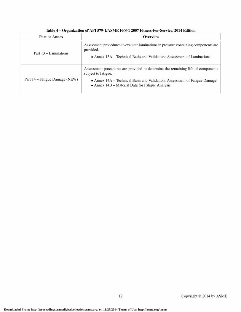
Table 4 – Organization of API 579-1/ASME FFS-1 2007 Fitness-For-Service, 2014 EditionPart or Annex Overview
Part 13 – Laminations
Assessment procedures to evaluate laminations in pressure containing components areprovided.
• Annex 13A – Technical Basis and Validation: Assessment of Laminations
Part 14 – Fatigue Damage (NEW)
Assessment procedures are provided to determine the remaining life of componentssubject to fatigue.
• Annex 14A – Technical Basis and Validation: Assessment of Fatigue Damage• Annex 14B – Material Data for Fatigue Analysis
12 Copyright © 2014 by ASME
Downloaded From: http://proceedings.asmedigitalcollection.asme.org/ on 11/25/2014 Terms of Use: http://asme.org/terms

Table 5 – References Covering Validation Work for API 579-1/ASME FFS-1 2007 Fitness-For-ServiceWRC Bulletin Subject
WRC Bulletins Published
WRC 430 Review of Existing Fitness-For-Service Criteria for Crack-Like Flaws
WRC 465Technologies for the Evaluation of Non-Crack-Like Flaws in Pressurized Components- Erosion/Corrosion, Pitting, Blisters, Shell Out-of-Roundness, Weld Misalignment,Bulges, and Dents in Pressurized Components.
WRC 471 Development of Stress Intensity Factor Solutions for Surface and Embedded Cracksin API 579
WRC 478 Stress Intensity and Crack Growth Opening Area Solutions for Through-wall Cracksin Cylinders and Spheres
WRC 455 Recent Progress in Analysis of Welding Residual Stresses
WRC 476 Recommendations for Determining Residual Stresses in Fitness-For-Service Assess-ments
WRC 474 Master S-N Curve Method for Fatigue Evaluation of Welded Components
WRC 505 An Overview and Validation of The Fitness-For-Service Assessment Procedures forLocally Thin Areas in API 579
WRC Bulletins in Preparation
— An Overview of The Fitness-For-Service Assessment Procedures for Pitting Damagein API 579-1/ASME FFS-1
— Compendium of Temperature-Dependent Physical Properties for Pressure Vessel Ma-terials
— An Overview and validation of the Fitness-For-Service Rules for the Assessment ofHIC/SOHIC Damage in API 579-1/ASME FFS-1
— An Overview of the Fitness-For-Service Assessment Procedures for Weld Misalign-ment and Shell Distortions in API 579-1/ASME FFS-1
— An Overview and Validation of the Fitness-For-Service Assessment Procedures forCrack-Like Flaws in API 579-1/ASME FFS-1
— An Overview and Validation of Residual Stress Distributions for Use in the Assess-ment Procedures of Crack-Like Flaws in API 579-1/ASME FFS-1
— MPC Project Omega and Procedures for Assessment of Creep Damage in API 579-1/ASME FFS-1
— Development of a Local Strain Criteria Based on the MPC Universal Stress-StrainEquation
— Update on the Master S-N Curve Method for Fatigue Evaluation of Welded Compo-nents
— Development of Partial Safety Factors for Use in the Assessment of Crack-Like FlawsUsing API 579-1/ASME FFS-1
— Development of Fitness-For-Service Assessment procedures for HIC/SOHIC Damagein API 579-1/ASME FFS-1
Note: WRC Bulletins are available from: forengeineers.org.
13 Copyright © 2014 by ASME
Downloaded From: http://proceedings.asmedigitalcollection.asme.org/ on 11/25/2014 Terms of Use: http://asme.org/terms