PROPOSAL - NYSDOT - NY.gov
310
PROPOSAL D263747 F.A. PROJECT Book 2 of 2 Submitted in accordance with the Highway Law and the Standard Specifications officially finalized and adopted on May 1, 2018 as posted on the Department's website. US CUSTOMARY UNITS Proposal Description: Enhancement Project on the Arthur Sheridan Expressway (I-895). Letting of 6/20/2018 @ 10:30 A.M. 50 Wolf Road, Albany, NY 12232
-
Upload
khangminh22 -
Category
Documents
-
view
2 -
download
0
Transcript of PROPOSAL - NYSDOT - NY.gov

PROPOSAL
D263747F.A. PROJECT
Book 2 of 2
Submitted in accordance with the Highway Law and the Standard Specifications officially finalized and adopted on May 1, 2018 as posted on the Department's website.
US CUSTOMARY UNITS
Proposal Description:
Enhancement Project on the Arthur Sheridan Expressway (I-895).
Letting of 6/20/2018 @ 10:30 A.M.
50 Wolf Road, Albany, NY 12232

IMPORTANT BIDDER INFORMATION
0790 1 of 1
L09/01/17 Contracts/Legal 6/22/17
1. Familiarize Yourself with the Standard Specifications. NYSDOT currently uses the Standard Specifications specified on
the front cover of this Project Proposal. The applicable Standard Specifications may be accessed at:
https://www.dot.ny.gov/main/business-center/engineering/specifications/busi-e-standards-usc . Be certain you access the
correct edition of the Standard Specifications. .
2. Upcoming Projects/ Letting Results/Contract Documents. Advertisements are available at: www.dot.ny.gov/doing-
business/opportunities/const-highway and Letting Results are at: www.dot.ny.gov/doing-business/opportunities/const-results.
Contract documents may be accessed at: www.dot.ny.gov/doing-business/opportunities/const-notices.
3. Procurement Lobbying Law. www.dot.ny.gov/main/business-center/contractors/contractors-repository/lobbylaw.pdf.
NYS Finance Law restricts communication with NYSDOT personnel on procurements and contact can only be made with
designated persons. Contact with non-designated persons or other involved Agencies will be considered a serious matter and
may result in disqualification. Project-related technical questions or comments must be submitted through the Construction
Contracting Section on the NYSDOT website at: www.dot.ny.gov/doing-business/opportunities/const-notices. Contract
administration or procurement questions may either be submitted through the website or directed to Robert Kitchen or the
Assistant Director/Director of the Contract Management Bureau, (518) 457-2124.
4. D/M/WBE Goals. www.dot.ny.gov/main/business-center/contractors/construction-division/construction-civil-
rights/ebo. Projects may have one goal for participation by Disadvantaged Business Enterprises (DBE) when Federally
funded, or two separate goals for participation by Minority Business Enterprises (MBEs) and Women’s Business Enterprises
(WBE), when Non-Federally funded. If the project has (a) D/M/WBE goal(s), you must document your good faith efforts to
obtain D/M/WBE participation. Solicitation of D/M/WBEs must begin prior to the submission of your bid. For projects with
goals, the Pre-Award Utilization Package must be submitted to the Office of Construction within 7 calendar days after Letting,
in accordance with §102-12 D/M/WBE Utilization, using the current version of NYSDOT approved Civil Rights reporting
software.
5. Bonds. Statutes require that a low bidder file both a Performance Bond and a Labor and Material Bond for the full amount
of the contract. Arrangements should be made with a Surety prior to submitting a bid. Failure to secure bonding could result in
the loss of your bid deposit. See §103-03 Contract Bonds.
6. Bid Security. Every bid must be accompanied by a bid bond, certified check or bank cashier's check payable to the State of
New York. Bid Express bids must include an electronic bid bond. Bonds must be on form CONR 391 and in the sum of 25% of
the total bid. Checks must be in the amount specified in the proposal.
7. New York State Can Help You Secure Surety Bonding. The NYS Surety Bond Assistance Program (NYSBAP) provides
technical and financial assistance to help New York State small business or MWBE contractors secure surety bonding.
Contractors may be eligible to receive a guarantee of up to 30% to secure a surety bond line, bid bond or a performance and
payment bond on State projects. Training is also available to contractors requiring technical support on how to become bond-
ready. For more information visit esd.ny.gov/BusinessPrograms/BondingAssistance.html or contact Ms. Huey-Min Chuang at
Empire State Development at 212-803-3238 or [email protected].
8. Do Not Alter the Bid Proposal Unless Directed to Do So by Amendment. Unauthorized alterations could lead to your bid
being declared informal. See §102-05 Proposal Submission.
9. The Contractor is responsible for ensuring that all Amendments have been incorporated into its bid. Amendments are
posted at: www.dot.ny.gov/doing-business/opportunities/const-notices.
10. Bid on All Items and Sign the Bid. If it is your intent to bid "0", use the numeric symbol. Leaving blank spaces can render
your bid informal. See §102-05 Proposal Submission.
11. Bids Should Be Submitted through Bid Express or in a Sealed Envelope prominently labeled “BID ENCLOSED”,
addressed to NYSDOT, Contract Management Bureau, 50 Wolf Road, First Floor, Suite 1CM, Albany NY 12232 and
delivered during normal business hours(Monday through Friday, 7:00 am to 4:00 pm). Clearly identify the Contractor
Name, Address, Federal Identification Number, Project Number and Project Description on the envelope. The same
Federal Identification number should be used on both the envelope and the Planholders List. Low bidders must have a current
NYS Vendor Responsibility Questionnaire For-Profit Construction (CCA-2) on file or submit one within 10 days of receipt of
the contract. Questionnaires are available at: www.dot.ny.gov/bids-and-lettings/construction-contractors/general-info. Please
call (518) 457-2421 if a reasonable accommodation is needed to participate in the Letting.
D263747

0800 Per DQAB 2100
L05/07/15
Page 1 of 1
REQUIRED CONTRACT PROVISIONS Buy American EEO Goals D/M/WBE Goals Ensuring Pay Equity Form CONR 9k Electronic Bidding Federal Aid Contract Provisions Insurance Coverage List of Additional Insured Railroad Insurance New York State Uniform Contracting Questionnaire NOTE: This form was developed for repetitive use throughout all contract proposals and may identify items not applicable to this specific project.
D263747 59

BUY AMERICA
0815 1 of 1 per Construction L9/1/17
106-11 BUY AMERICA. In accordance with 23 USC 313, 23 CFR 635.410 and Section 146 of the State
Finance Law permanently incorporated predominantly steel and/or iron products materials shall be
domestically produced, regardless of the percentage they comprise in a manufactured product, or form they
take.
For Federal-Aid contracts, the Contractor may permanently incorporate in the construction of this
contract a minimal amount of foreign steel and/or iron materials that are subject to Buy America
requirements, if the combined cost of such materials does not exceed one-tenth of one percent (0.1 %) of
the total contract cost or $2,500, whichever is greater. The combined cost of foreign steel and/or iron
materials will be the value of the materials as they are delivered to the contract, documented by invoice or
bill of sale to the Contractor.
To qualify as domestic, all manufacturing processes, including manufacture, fabrication, grinding,
drilling, welding, finishing, and coating of any product containing steel and/or iron materials, must have
been performed in the United States. To further define the coverage, a domestic product is a manufactured
steel and/or iron materials construction material that was produced in one of the 50 States, the District of
Columbia, Puerto Rico, or in the territories and possessions of the United States. Raw materials used in the
steel and/or iron materials may be imported. Raw materials are materials such as iron ore, limestone, waste
products, etc., which are used in the manufacturing process to produce the steel and/or iron materials
products. Waste products include scrap; i.e., steel no longer useful in its present form from old automobiles,
machinery, pipe, railroad rail, steel trimmings from mills or product manufacturing, and the like. Extracting,
crushing, and handling the raw materials which are customary to prepare them for transporting are exempt
from Buy America. The use of foreign source steel or iron billets is not acceptable under Buy America.
For non Federal-Aid contracts, the Contractor shall provide structural steel, reinforcing steel and/or
other major steel items to be permanently incorporated in the work produced or made in whole or substantial
part in the United States. The combined cost of foreign steel and/or iron materials will be the value of the
materials as they are delivered to the contract, documented by invoice or bill of sale to the Contractor.
A. Control of Materials. All items, regardless of origin, shall comply with their individual
specification requirements and with the requirements stated elsewhere in this subsection. In the event
the contract is awarded based on using only domestic steel and/or iron materials, the Contractor shall
supply only domestic steel and/or iron materials and will be paid the domestic bid prices. The
Contractor shall ensure the domestic steel and/or iron materials are supplied in conformance with the
above referenced laws. The Contractor shall inform all affected Subcontractors and material suppliers
of these specific requirements and ascertain that steel and/or iron materials being supplied is in
conformance with these requirements.
B. Waivers. Waivers to the Buy America requirement may be requested by the Contractor if it can
be demonstrated that the use of domestic steel and/or iron materials would be inconsistent with the
public interest, such materials and products are not produced in the United States in sufficient and
reasonably available quantities and of satisfactory quality.
Provided one or more of the above requirements are met, the Contractor may submit a request for
a waiver to the Engineer. The request shall include copies of all documentation verifying the
unavailability of the material or product, and/or justification of the application for a waiver.
For Federal-Aided contracts, the Department will submit approved waiver requests to the FHWA
for review. The Contractor shall investigate and respond to any public comments made to the FHWA
Office of Program Administration, indicating that a domestic supplier can provide the material for
which a waiver has been requested. Final approval of the Buy America Waiver request will be made
by the Administrator, Federal Highway Administration. The waiver will be effective when it is posted
in the Federal Register.
For non-Federal-Aid contracts, upon final approval of the affected Department program areas,
notification and approval of the Buy America Waiver request will be made by the Deputy Chief
Engineer, Construction (DCEC).
D26374760

GOALS FOR EQUAL EMPLOYMENT OPPORTUNITY (EEO) PARTICIPATION
0820 Page 1 of 1 Per Construction EI 17-006
The Contractor shall follow the requirements of §102-11 Equal Employment Opportunity Requirements. The goals for minority and female participation, expressed in percentage terms for the Contractor’s aggregate workforce in each trade on all construction work in the covered area, which is the county or counties in which the work is located, are as follows:
GOALS FOR PARTICIPATION OF MINORITIES COUNTY % COUNTY % COUNTY % Albany 3.2 Herkimer 2.1 Richmond Table Allegany 6.3 Jefferson 2.5 Rockland 22.6 Broome 1.1 Kings Table St. Lawrence 2.5 Bronx Table Lewis 2.5 Saratoga 3.2 Cattaraugus 6.3 Livingston 5.3 Schenectady 3.2 Cayuga 2.5 Madison 3.8 Schoharie 2.6 Chautauqua 6.3 Monroe 5.3 Schuyler 1.2 Chemung 2.2 Montgomery 3.2 Seneca 5.9 Chenango 1.2 Nassau 5.8 Steuben 1.2 Clinton 2.6 New York Table Suffolk 5.8 Columbia 2.6 Niagara 7.7 Sullivan 17.0 Cortland 2.5 Oneida 2.1 Tioga 1.1 Delaware 1.2 Onondaga 3.8 Tompkins 1.2 Dutchess 6.4 Ontario 5.3 Ulster 17.0 Erie 7.7 Orange 17.0 Warren 2.6 Essex 2.6 Orleans 5.3 Washington 2.6 Franklin 2.5 Oswego 3.8 Wayne 5.3 Fulton 2.6 Otsego 1.2 Westchester 22.6 Genesee 5.9 Putnam 22.6 Wyoming 6.3 Greene 2.6 Queens Table Yates 5.9 Hamilton 2.6 Rensselaer 3.2
(45 FR 65976 – 10/3/1980)
GOALS FOR PARTICIPATION OF MINORITIES BRONX, KINGS, NEW YORK, QUEENS AND RICHMOND COUNTIES
Electricians 9.0 to 10.2 Bricklayers 13.4 to 15.5 Carpenters 27.6 to 32.0 Asbestos workers 22.8 to 28.0 Steam fitters 12.2 to 13.5 Roofers 6.3 to 7.5 Metal lathers 24.6 to 25.6 Iron workers (ornamental) 22.4 to 23.0 Painters 26.0 to 28.6 Cement masons 23.0 to 27.0 Operating engineers 25.6 to 26.0 Glaziers 16.0 to 20.0 Plumbers 12.0 to 14.5 Plasterers 15.8 to 18.0 Iron workers (structural) 25.9 to 32.0 Teamsters 22.0 to 22.5 Elevator constructors 5.5 to 6.5 Boilermakers 13.0 to 15.5
All others 16.4 to 17.5
GOAL FOR PARTICIPATION OF WOMEN
The goal for the participation of women is 6.9%. (43 FR 14888 – 4/7/1978) These goals are applicable to all the Contractor's construction work (whether or not it is Federal or federally assisted). If the Contractor performs construction work outside of New York State, it shall apply the goals established for the covered area where the work is actually performed.
D263747 61

GOALS FOR DISADVANTAGED/MINORITY/WOMEN’S BUSINESS ENTERPRISE
(D/M/WBE) PARTICIPATION
0821 Page 1 of 1 Per Construction 11/29/17 L 05/01/18 or earlier
The Department has established the following utilization goal(s) for this contract, expressed as a
percentage of the total contract bid amount.
NOTE: ‘D/M/WBE’ is a general term. The DBE program applies to Federal-Aid contracts; the MBE
and WBE programs apply to non-Federal-Aid contracts. For more information see Standard
Specifications §102-12 or call the Office of Construction Pre-Award Unit at (518) 457-6472.
Disadvantaged Business Enterprise (DBE) Utilization Goal % (Federal-Aid Only)
Minority Business Enterprise (MBE) Utilization Goal % (Non Federal-Aid Only)
Women's Business Enterprise (WBE) Utilization Goal % (Non Federal-Aid Only)
The NYSUCP DBE Directory is located at: https://nysucp.newnycontracts.com/
The NYS M/WBE Directory is located at: https://ny.newnycontracts.com/
12
D26374762

Ensuring Pay Equity by State Contractors
0825 Page 1 of 1 06/15/17
L07/13/17
In accordance with Executive Order 162, issued on January 9, 2017, the Contractor shall provide to the Department – on a monthly basis – detailed workforce utilization reports of the Contractor and each subcontractor that include, in addition to equal employment opportunity information, the job title and salary of each employee directly performing work on a State contract. If the Contractor cannot identify the individuals working directly on a State contract, then the Contractor shall provide such information of each employee in the Contractor’s and each subcontractor’s entire workforce. The reporting period shall be defined as each calendar month, beginning and ending on the first and last day of each such month, respectively. The reporting requirement shall begin on the effective date of the contract and continue for the duration of the contract term. Reports shall be submitted within 15 calendar days from the end of each reporting period. This provision is in effect for the reporting period beginning December 1, 2017, or the effective date of the contract, whichever date is later. This provision shall not relieve the Contractor’s responsibility to submit payroll certification as elsewhere required. If information within the Contractor’s payroll certification is sufficient to fulfill the requirements of Executive Order 162, additional information shall not be required. Detailed workforce utilization reports, as required above, shall be submitted in such form, in such manner, and in such timeframe as shall be required by the Department. The Contractor shall include this provision in every subcontract so that such provision shall be binding upon each subcontractor.
D263747 63

CONR9 (01/02/18)
SUPPLEMENTAL INFORMATION AVAILABLE TO BIDDERSThe information checked in the “Digital” column on this form is available at the Contract Documents tab within theConstruction Contracting section of the Business Center on the Department’s web site. The information checked inthe “Inspection Only” column on this form is available at the Regional Office having jurisdiction for this project, asidentified in the advertisement for bids, for inspection and review prior to the letting date. The bidder’s signature onthis proposal certifies that they have made themselves aware of the availability of the information indicated below:
THERE IS NO SUPPLEMENTAL INFORMATION AVAILABLE FOR THIS CONTRACT:
INFORMATION Digital1 Inspection Only
1. Unsealed Layered or 3D PDF Files
2. CADD Information
a. MicroStation DGN
b. InRoads DTM and XML format
c. InRoads ALG and XML format
3. Cross Sections in ADOBE PDF format
4. Quantity Work-ups2
5. Record Plans
6. Rock Cores (available for inspection only)
7. Sign Face Layouts in ADOBE PDF format
8. Stormwater Pollution Prevention Plan (SWPPP)
9. Subsurface Information
a. Subsurface Exploration Logs
b. Undisturbed Sample Logs
c. Laboratory Test Data from Soil Samples
d. Tabulated Results of Probing
e. Tabulated Depth to Bedrock
f. Rock Core Evaluation Logs
g. Compression Test Data from Rock Samples
h. Rock Outcrop Maps
i. Granular Materials Resource Survey Reports
j. Terrain Reconnaissance Reports
10. Subsurface Information - Other Information
a. Subsurface information from outside sources
b. Source Information - Granular Material and aggregates
c. Special Subsurface Reports
11. Anticipated Construction Schedule
12. Asbestos Information
a. Asbestos Blanket Variances
b. Asbestos Report
13. Special Reports or Other Information:
a. Permits
b. Design Approval Document
c. Survey Control Report
d. Wetland Compensation Report
1 – All digital material is provided in ADOBE (PDF) format, unless noted above.2 – Required for all projects.
D26374764

NYSDOT Electronic Bidding - AASHTOWare Project Bids and Bid Express
0850 1 of 2 Contract Management
L01/19/17 12/05/16
Project Bids allows bidders to receive electronic proposal bid item information from the
Department's web site and Bid Express to produce an electronic bid. Project Bids is provided
free of charge, and can be used on almost any Windows-compatible PC. Benefits may include:
Project Bids computes item and overall bid totals as estimators work through the list, and
alerts estimators if an item is accidentally omitted.
Electronic files of item bid data will be posted to the NYSDOT website and Bid Express
to coincide with advertising and contract document publication dates.
When an amended item bid data is downloaded, recognition of changes is automatic.
Electronic bids are processed faster than paper bids, decreasing the time needed for
verification of bids by NYSDOT.
Bid Express allows secure, encrypted bid submittal over the internet. It integrates with Project
Bids and includes electronic bid bond verification. Bid Express is a fee-based service. Benefits
may include:
Real-time bid submittal from any location.
No concerns about driving bids to Albany or mail services arriving after the deadline.
The ability to submit a "safety bid" early while continuing to solicit better quotes from
subs and suppliers and to overwrite the safety bid with a new bid right up to the
submission deadline.
As data accumulates on Bid Express, there is the ability to search and analyze bids on
prior contracts for specific work items, and/or by specific competitors, etc.
The ability to solicit and receive quotes from subcontractors through the Small Business
Network on Bid Express.
Contractors who use Bid Express do not submit a paper bid.
First time electronic bidders should:
Allow at least seven business days to obtain a digital ID and password for bidding
through Bid Express.
Follow the procedures in "Download AASHTOWare Project Bids", which are posted at
http://www.dot.ny.gov/bids-and-lettings/construction-contractors/electronic-bid-system
Enter the Agency as NYSDOT.
Use the appropriate Federal-ID and firm name. Federal-ID must be in the format 12-
3456789. Joint ventures must create a new digital ID. Joint ventures must also send
evidence of the authority of the agent or attorney-in-fact for the joint venturers to act on
behalf of all joint venturers to the Contract Management Bureau prior to the Letting.
All electronic bidders should:
Enter prices for all bid items in the Schedule of Items.
Enter days for the B portion(s) of A + B bids on the A+B Days tab (if applicable).
Enter the required info in the JURAT and Disclosure of Lobbying Activity folders.
Complete the Contract Document Bid-Ability Survey (optional).
D263747 65

NYSDOT Electronic Bidding - AASHTOWare Project Bids and Bid Express
0850 2 of 2 Contract Management
L01/19/17 12/05/16
Enter the required info in the Bid Bond folder if submitting bid through Bid Express and
click Verify to verify the bid bond.
All bids submitted through Bid Express should be 100% complete as noted at the top of
the page. Submitting a bid that is less than 100% complete through Bid Express could
lead to the bid being declared informal.
Paper Bid Documents: NYSDOT recommends and encourages contractors to bid electronically
with Bid Express because of its many advantages, but contractors are not required to bid
electronically. If NYSDOT receives both a Bid Express bid and a paper bid from the same
contractor, the Bid Express bid will prevail.
Bidders who do not use Bid Express are encouraged to submit an electronic bid file on a
CD included with their paper bid. NYSDOT will not accept electronic bids on CD without
a paper bid. If there is any discrepancy between an electronic file submitted with the paper
bid and the paper bid, the paper bid will prevail.
When submitting an electronic bid file with your paper bid, include only one .ebsx (Project Bids)
file on the CD. Do not include any other bid items on the CD. The CD must be labeled with the
following information:
Firm name
Letting date
D number
A statement as to whether the paper bid does or does not include any handwritten
changes from the electronic bid file. Do not mix partial printouts with differing date-time
groups.
Amendments: Contractors are solely responsible for recognizing and responding to changes by
amendment. If an amendment involves changes to item bid data, an amended Project Bids file
will be posted to the Department's website and to Bid Express. This file must be applied to your
electronic bid. If there is any discrepancy in the itemized proposals published in paper and
electronic formats, in either the contract pay items or quantities, the Department will evaluate the
bids based only on that portion that is common to all formats. For example, if an item is missing
from any format, the bids will be evaluated excluding that item and if item quantities are
different in any format, the bids will be evaluated using the lowest item quantity.
Please notify the Department at 518-457-2124 or 518-457-3583 if you find any such
discrepancies. However, not all amendments will involve changes to item bid data.
For assistance:
NYSDOT 518-457-2124 or 518-457-3583
Bid Express Help Desk (888) 352-2439 or (352) 381-4888
Third-party Software - Contact the vendor of the software. The Department is neither
authorized nor able to assist with any software package.
D26374766

FHWA-1273 -- Revised May 1, 2012
REQUIRED CONTRACT PROVISIONS FEDERAL-AID CONSTRUCTION CONTRACTS
I. General II. NondiscriminationIII. Nonsegregated FacilitiesIV. Davis-Bacon and Related Act ProvisionsV. Contract Work Hours and Safety Standards Act
ProvisionsVI. Subletting or Assigning the ContractVII. Safety: Accident PreventionVIII. False Statements Concerning Highway ProjectsIX. Implementation of Clean Air Act and Federal Water
Pollution Control ActX. Compliance with Governmentwide Suspension and
Debarment RequirementsXI. Certification Regarding Use of Contract Funds for
Lobbying
ATTACHMENTS
A. Employment and Materials Preference for Appalachian Development Highway System or Appalachian Local Access Road Contracts (included in Appalachian contracts only)
I. GENERAL
1. Form FHWA-1273 must be physically incorporated in eachconstruction contract funded under Title 23 (excluding emergency contracts solely intended for debris removal). The contractor (or subcontractor) must insert this form in each subcontract and further require its inclusion in all lower tier subcontracts (excluding purchase orders, rental agreements and other agreements for supplies or services).
The applicable requirements of Form FHWA-1273 are incorporated by reference for work done under any purchase order, rental agreement or agreement for other services. The prime contractor shall be responsible for compliance by any subcontractor, lower-tier subcontractor or service provider.
Form FHWA-1273 must be included in all Federal-aid design-build contracts, in all subcontracts and in lower tier subcontracts (excluding subcontracts for design services, purchase orders, rental agreements and other agreements for supplies or services). The design-builder shall be responsible for compliance by any subcontractor, lower-tier subcontractor or service provider.
Contracting agencies may reference Form FHWA-1273 in bid proposal or request for proposal documents, however, the Form FHWA-1273 must be physically incorporated (not referenced) in all contracts, subcontracts and lower-tier subcontracts (excluding purchase orders, rental agreements and other agreements for supplies or services related to a construction contract).
2. Subject to the applicability criteria noted in the followingsections, these contract provisions shall apply to all work performed on the contract by the contractor's own organization and with the assistance of workers under the contractor's immediate superintendence and to all work performed on the contract by piecework, station work, or by subcontract.
3. A breach of any of the stipulations contained in theseRequired Contract Provisions may be sufficient grounds for withholding of progress payments, withholding of final payment, termination of the contract, suspension / debarment or any other action determined to be appropriate by the contracting agency and FHWA.
4. Selection of Labor: During the performance of this contract,the contractor shall not use convict labor for any purpose within the limits of a construction project on a Federal-aid highway unless it is labor performed by convicts who are on parole, supervised release, or probation. The term Federal-aid highway does not include roadways functionally classified as local roads or rural minor collectors.
II. NONDISCRIMINATION
The provisions of this section related to 23 CFR Part 230 are applicable to all Federal-aid construction contracts and to all related construction subcontracts of $10,000 or more. The provisions of 23 CFR Part 230 are not applicable to material supply, engineering, or architectural service contracts.
In addition, the contractor and all subcontractors must comply with the following policies: Executive Order 11246, 41 CFR 60, 29 CFR 1625-1627, Title 23 USC Section 140, the Rehabilitation Act of 1973, as amended (29 USC 794), Title VI of the Civil Rights Act of 1964, as amended, and related regulations including 49 CFR Parts 21, 26 and 27; and 23 CFR Parts 200, 230, and 633.
The contractor and all subcontractors must comply with: the requirements of the Equal Opportunity Clause in 41 CFR 60-1.4(b) and, for all construction contracts exceeding $10,000, the Standard Federal Equal Employment Opportunity Construction Contract Specifications in 41 CFR 60-4.3.
Note: The U.S. Department of Labor has exclusive authority to determine compliance with Executive Order 11246 and the policies of the Secretary of Labor including 41 CFR 60, and 29 CFR 1625-1627. The contracting agency and the FHWA have the authority and the responsibility to ensure compliance with Title 23 USC Section 140, the Rehabilitation Act of 1973, as amended (29 USC 794), and Title VI of the Civil Rights Act of 1964, as amended, and related regulations including 49 CFR Parts 21, 26 and 27; and 23 CFR Parts 200, 230, and 633.
The following provision is adopted from 23 CFR 230, Appendix A, with appropriate revisions to conform to the U.S. Department of Labor (US DOL) and FHWA requirements.
1. Equal Employment Opportunity: Equal employmentopportunity (EEO) requirements not to discriminate and to take affirmative action to assure equal opportunity as set forth under laws, executive orders, rules, regulations (28 CFR 35, 29 CFR 1630, 29 CFR 1625-1627, 41 CFR 60 and 49 CFR 27) and orders of the Secretary of Labor as modified by the provisions prescribed herein, and imposed pursuant to 23 U.S.C. 140 shall constitute the EEO and specific affirmative action standards for the contractor's project activities under
REQUIRED CONTRACT PROVISIONS FOR FEDERAL AID CONTRACTS
2140 L09/06/12Page 1 of 11
D263747 67

this contract. The provisions of the Americans with Disabilities Act of 1990 (42 U.S.C. 12101 et seq.) set forth under 28 CFR 35 and 29 CFR 1630 are incorporated by reference in this contract. In the execution of this contract, the contractor agrees to comply with the following minimum specific requirement activities of EEO:
a. The contractor will work with the contracting agency and the Federal Government to ensure that it has made every good faith effort to provide equal opportunity with respect to all of its terms and conditions of employment and in their review of activities under the contract.
b. The contractor will accept as its operating policy the following statement:
"It is the policy of this Company to assure that applicants are employed, and that employees are treated during employment, without regard to their race, religion, sex, color, national origin, age or disability. Such action shall include: employment, upgrading, demotion, or transfer; recruitment or recruitment advertising; layoff or termination; rates of pay or other forms of compensation; and selection for training, including apprenticeship, pre-apprenticeship, and/or on-the-job training."
2. EEO Officer: The contractor will designate and make known to the contracting officers an EEO Officer who will have the responsibility for and must be capable of effectively administering and promoting an active EEO program and who must be assigned adequate authority and responsibility to do so.
3. Dissemination of Policy: All members of the contractor's staff who are authorized to hire, supervise, promote, and discharge employees, or who recommend such action, or who are substantially involved in such action, will be made fully cognizant of, and will implement, the contractor's EEO policy and contractual responsibilities to provide EEO in each grade and classification of employment. To ensure that the above agreement will be met, the following actions will be taken as a minimum:
a. Periodic meetings of supervisory and personnel office employees will be conducted before the start of work and then not less often than once every six months, at which time the contractor's EEO policy and its implementation will be reviewed and explained. The meetings will be conducted by the EEO Officer.
b. All new supervisory or personnel office employees will be given a thorough indoctrination by the EEO Officer, covering all major aspects of the contractor's EEO obligations within thirty days following their reporting for duty with the contractor.
c. All personnel who are engaged in direct recruitment for the project will be instructed by the EEO Officer in the contractor's procedures for locating and hiring minorities and women.
d. Notices and posters setting forth the contractor's EEO policy will be placed in areas readily accessible to employees, applicants for employment and potential employees.
e. The contractor's EEO policy and the procedures to implement such policy will be brought to the attention of employees by means of meetings, employee handbooks, or other appropriate means.
4. Recruitment: When advertising for employees, the contractor will include in all advertisements for employees the notation: "An Equal Opportunity Employer." All such advertisements will be placed in publications having a large circulation among minorities and women in the area from which the project work force would normally be derived.
a. The contractor will, unless precluded by a valid bargaining agreement, conduct systematic and direct recruitment through public and private employee referral sources likely to yield qualified minorities and women. To meet this requirement, the contractor will identify sources of potential minority group employees, and establish with such identified sources procedures whereby minority and women applicants may be referred to the contractor for employment consideration.
b. In the event the contractor has a valid bargaining agreement providing for exclusive hiring hall referrals, the contractor is expected to observe the provisions of that agreement to the extent that the system meets the contractor's compliance with EEO contract provisions. Where implementation of such an agreement has the effect of discriminating against minorities or women, or obligates the contractor to do the same, such implementation violates Federal nondiscrimination provisions.
c. The contractor will encourage its present employees to refer minorities and women as applicants for employment. Information and procedures with regard to referring such applicants will be discussed with employees.
5. Personnel Actions: Wages, working conditions, and employee benefits shall be established and administered, and personnel actions of every type, including hiring, upgrading, promotion, transfer, demotion, layoff, and termination, shall be taken without regard to race, color, religion, sex, national origin, age or disability. The following procedures shall be followed:
a. The contractor will conduct periodic inspections of project sites to insure that working conditions and employee facilities do not indicate discriminatory treatment of project site personnel.
b. The contractor will periodically evaluate the spread of wages paid within each classification to determine any evidence of discriminatory wage practices.
c. The contractor will periodically review selected personnel actions in depth to determine whether there is evidence of discrimination. Where evidence is found, the contractor will promptly take corrective action. If the review indicates that the discrimination may extend beyond the actions reviewed, such corrective action shall include all affected persons.
d. The contractor will promptly investigate all complaints of alleged discrimination made to the contractor in connection with its obligations under this contract, will attempt to resolve such complaints, and will take appropriate corrective action within a reasonable time. If the investigation indicates that the discrimination may affect persons other than the complainant, such corrective action shall include such other persons. Upon completion of each investigation, the contractor will inform every complainant of all of their avenues of appeal.
6. Training and Promotion:
a. The contractor will assist in locating, qualifying, and increasing the skills of minorities and women who are
REQUIRED CONTRACT PROVISIONS FOR FEDERAL AID CONTRACTS
00860 L09/06/12Page 2 of 11
D26374768

applicants for employment or current employees. Such efforts should be aimed at developing full journey level status employees in the type of trade or job classification involved.
b. Consistent with the contractor's work force requirements and as permissible under Federal and State regulations, the contractor shall make full use of training programs, i.e., apprenticeship, and on-the-job training programs for the geographical area of contract performance. In the event a special provision for training is provided under this contract, this subparagraph will be superseded as indicated in the special provision. The contracting agency may reserve training positions for persons who receive welfare assistancein accordance with 23 U.S.C. 140(a).
c. The contractor will advise employees and applicants for employment of available training programs and entrance requirements for each.
d. The contractor will periodically review the training and promotion potential of employees who are minorities and women and will encourage eligible employees to apply for such training and promotion.
7. Unions: If the contractor relies in whole or in part upon unions as a source of employees, the contractor will use good faith efforts to obtain the cooperation of such unions to increase opportunities for minorities and women. Actions by the contractor, either directly or through a contractor's association acting as agent, will include the procedures set forth below:
a. The contractor will use good faith efforts to develop, in cooperation with the unions, joint training programs aimed toward qualifying more minorities and women for membership in the unions and increasing the skills of minorities and women so that they may qualify for higher paying employment.
b. The contractor will use good faith efforts to incorporate an EEO clause into each union agreement to the end that such union will be contractually bound to refer applicants without regard to their race, color, religion, sex, national origin, age or disability.
c. The contractor is to obtain information as to the referral practices and policies of the labor union except that to the extent such information is within the exclusive possession of the labor union and such labor union refuses to furnish such information to the contractor, the contractor shall so certify to the contracting agency and shall set forth what efforts have been made to obtain such information.
d. In the event the union is unable to provide the contractor with a reasonable flow of referrals within the time limit set forth in the collective bargaining agreement, the contractor will, through independent recruitment efforts, fill the employment vacancies without regard to race, color, religion, sex, national origin, age or disability; making full efforts to obtain qualified and/or qualifiable minorities and women. The failure of a union to provide sufficient referrals (even though it is obligated to provide exclusive referrals under the terms of a collective bargaining agreement) does not relieve the contractor from the requirements of this paragraph. In the event the union referral practice prevents the contractor from meeting the obligations pursuant to Executive Order 11246, as amended, and these special provisions, such contractor shall immediately notify the contracting agency.
8. Reasonable Accommodation for Applicants / Employees with Disabilities: The contractor must be familiar
with the requirements for and comply with the Americans with Disabilities Act and all rules and regulations established there under. Employers must provide reasonable accommodation in all employment activities unless to do so would cause an undue hardship.
9. Selection of Subcontractors, Procurement of Materials and Leasing of Equipment: The contractor shall not discriminate on the grounds of race, color, religion, sex, national origin, age or disability in the selection and retention of subcontractors, including procurement of materials and leases of equipment. The contractor shall take all necessary and reasonable steps to ensure nondiscrimination in the administration of this contract.
a. The contractor shall notify all potential subcontractors and suppliers and lessors of their EEO obligations under thiscontract.
b. The contractor will use good faith efforts to ensure subcontractor compliance with their EEO obligations.
10. Assurance Required by 49 CFR 26.13(b):
a. The requirements of 49 CFR Part 26 and the State -approved DBE program are incorporated by
reference.
b. The contractor or subcontractor shall not discriminate on the basis of race, color, national origin, or sex in the performance of this contract. The contractor shall carry out applicable requirements of 49 CFR Part 26 in the award and administration of DOT-assisted contracts. Failure by the contractor to carry out these requirements is a material breach of this contract, which may result in the termination of this contract or such other remedy as the contracting agencydeems appropriate.
11. Records and Reports: The contractor shall keep such records as necessary to document compliance with the EEO requirements. Such records shall be retained for a period of three years following the date of the final payment to the contractor for all contract work and shall be available at reasonable times and places for inspection by authorized representatives of the contracting agency and the FHWA.
a. The records kept by the contractor shall document the following:
(1) The number and work hours of minority and non-minority group members and women employed in each work classification on the project;
(2) The progress and efforts being made in cooperation with unions, when applicable, to increase employment opportunities for minorities and women; and
(3) The progress and efforts being made in locating, hiring, training, qualifying, and upgrading minorities and women;
b. The contractors and subcontractors will submit an annual report to the contracting agency each July for the duration of the project, indicating the number of minority, women, and non-minority group employees currently engaged in each work classification required by the contract work. This information is to be reported on Form FHWA-1391. The staffing data should represent the project work force on board in all or any part of the last payroll period preceding the end of July. If on-the-job training is being required by special provision, the contractor
REQUIRED CONTRACT PROVISIONS FOR FEDERAL AID CONTRACTS
00860 L09/06/12Page 3 of 11
D263747 69

will be required to collect and report training data. The employment data should reflect the work force on board during all or any part of the last payroll period preceding the end of July.
III. NONSEGREGATED FACILITIES
This provision is applicable to all Federal-aid construction contracts and to all related construction subcontracts of $10,000 or more.
The contractor must ensure that facilities provided for employees are provided in such a manner that segregation on the basis of race, color, religion, sex, or national origin cannot result. The contractor may neither require such segregated use by written or oral policies nor tolerate such use by employee custom. The contractor's obligation extends further to ensure that its employees are not assigned to perform their services at any location, under the contractor's control, where the facilities are segregated. The term "facilities" includes waiting rooms, work areas, restaurants and other eating areas, time clocks, restrooms, washrooms, locker rooms, and other storage or dressing areas, parking lots, drinking fountains, recreation or entertainment areas, transportation, and housing provided for employees. The contractor shall provide separate or single-user restrooms and necessary dressing or sleeping areas to assure privacy between sexes.
IV. DAVIS-BACON AND RELATED ACT PROVISIONS
This section is applicable to all Federal-aid construction projects exceeding $2,000 and to all related subcontracts and lower-tier subcontracts (regardless of subcontract size). The requirements apply to all projects located within the right-of-way of a roadway that is functionally classified as Federal-aid highway. This excludes roadways functionally classified as local roads or rural minor collectors, which are exempt. Contracting agencies may elect to apply these requirements to other projects.
The following provisions are from the U.S. Department of
FHWA-1273 format and FHWA program requirements.
1. Minimum wages
a. All laborers and mechanics employed or working upon the site of the work, will be paid unconditionally and not less often than once a week, and without subsequent deduction or rebate on any account (except such payroll deductions as are permitted by regulations issued by the Secretary of Labor under the Copeland Act (29 CFR part 3)), the full amount of wages and bona fide fringe benefits (or cash equivalents thereof) due at time of payment computed at rates not less than those contained in the wage determination of the Secretary of Labor which is attached hereto and made a part hereof, regardless of any contractual relationship which may be alleged to exist between the contractor and such laborers and mechanics.
Contributions made or costs reasonably anticipated for bona fide fringe benefits under section 1(b)(2) of the Davis-Bacon Act on behalf of laborers or mechanics are considered wages paid to such laborers or mechanics, subject to the provisions
of paragraph 1.d. of this section; also, regular contributions made or costs incurred for more than a weekly period (but not less often than quarterly) under plans, funds, or programs which cover the particular weekly period, are deemed to be constructively made or incurred during such weekly period. Such laborers and mechanics shall be paid the appropriate wage rate and fringe benefits on the wage determination for the classification of work actually performed, without regard to skill, except as provided in 29 CFR 5.5(a)(4). Laborers or mechanics performing work in more than one classification may be compensated at the rate specified for each classification for the time actually worked therein: Provided, That the employer's payroll records accurately set forth the time spent in each classification in which work is performed. The wage determination (including any additional classification and wage rates conformed under paragraph 1.b. of this section) and the Davis-Bacon poster (WH 1321) shall be posted at all times by the contractor and its subcontractors at the site of the work in a prominent and accessible place where it can be easily seen by the workers.
b.(1) The contracting officer shall require that any class of laborers or mechanics, including helpers, which is not listed in the wage determination and which is to be employed under the contract shall be classified in conformance with the wage determination. The contracting officer shall approve an additional classification and wage rate and fringe benefits therefore only when the following criteria have been met:
(i) The work to be performed by the classification requested is not performed by a classification in the wage determination; and
(ii) The classification is utilized in the area by the construction industry; and
(iii) The proposed wage rate, including any bona fide fringe benefits, bears a reasonable relationship to the wage rates contained in the wage determination.
(2) If the contractor and the laborers and mechanics to be employed in the classification (if known), or their representatives, and the contracting officer agree on the classification and wage rate (including the amount designated for fringe benefits where appropriate), a report of the action taken shall be sent by the contracting officer to the Administrator of the Wage and Hour Division, Employment Standards Administration, U.S. Department of Labor, Washington, DC 20210. The Administrator, or an authorized representative, will approve, modify, or disapprove every additional classification action within 30 days of receipt and so advise the contracting officer or will notify the contracting officer within the 30-day period that additional time is necessary.
(3) In the event the contractor, the laborers or mechanics to be employed in the classification or their representatives, and the contracting officer do not agree on the proposed classification and wage rate (including the amount designated for fringe benefits, where appropriate), the contracting officer shall refer the questions, including the views of all interested parties and the recommendation of the contracting officer, to the Wage and Hour Administrator for determination. The Wage and Hour Administrator, or an authorized representative, will issue a determination within 30 days of receipt and so advise the contracting officer or
REQUIRED CONTRACT PROVISIONS FOR FEDERAL AID CONTRACTS
00860 L09/06/12Page 4 of 11
D26374770

will notify the contracting officer within the 30-day period that additional time is necessary.
(4) The wage rate (including fringe benefits where appropriate) determined pursuant to paragraphs 1.b.(2) or 1.b.(3) of this section, shall be paid to all workers performing work in the classification under this contract from the first day on which work is performed in the classification.
c. Whenever the minimum wage rate prescribed in the contract for a class of laborers or mechanics includes a fringe benefit which is not expressed as an hourly rate, the contractor shall either pay the benefit as stated in the wage determination or shall pay another bona fide fringe benefit or an hourly cash equivalent thereof.
d. If the contractor does not make payments to a trustee or other third person, the contractor may consider as part of the wages of any laborer or mechanic the amount of any costs reasonably anticipated in providing bona fide fringe benefits under a plan or program, Provided, That the Secretary of Labor has found, upon the written request of the contractor, that the applicable standards of the Davis-Bacon Act have been met. The Secretary of Labor may require the contractor to set aside in a separate account assets for the meeting of obligations under the plan or program.
2. Withholding
The contracting agency shall upon its own action or upon written request of an authorized representative of the Department of Labor, withhold or cause to be withheld from the contractor under this contract, or any other Federal contract with the same prime contractor, or any other federally-assisted contract subject to Davis-Bacon prevailing wage requirements, which is held by the same prime contractor, so much of the accrued payments or advances as may be considered necessary to pay laborers and mechanics, including apprentices, trainees, and helpers, employed by the contractor or any subcontractor the full amount of wages required by the contract. In the event of failure to pay any laborer or mechanic, including any apprentice, trainee, orhelper, employed or working on the site of the work, all or part of the wages required by the contract, the contracting agency may, after written notice to the contractor, take such action as may be necessary to cause the suspension of any further payment, advance, or guarantee of funds until such violations have ceased.
3. Payrolls and basic records
a. Payrolls and basic records relating thereto shall be maintained by the contractor during the course of the work and preserved for a period of three years thereafter for all laborers and mechanics working at the site of the work. Such records shall contain the name, address, and social security number of each such worker, his or her correct classification, hourly rates of wages paid (including rates of contributions or costs anticipated for bona fide fringe benefits or cash equivalents thereof of the types described in section 1(b)(2)(B) of the Davis-Bacon Act), daily and weekly number of hours worked, deductions made and actual wages paid. Whenever the Secretary of Labor has found under 29 CFR 5.5(a)(1)(iv) that the wages of any laborer or mechanic include the amount of any costs reasonably anticipated in providing benefits under a plan or program described in section 1(b)(2)(B) of the Davis-
Bacon Act, the contractor shall maintain records which show that the commitment to provide such benefits is enforceable, that the plan or program is financially responsible, and that the plan or program has been communicated in writing to the laborers or mechanics affected, and records which show the costs anticipated or the actual cost incurred in providing such benefits. Contractors employing apprentices or trainees under approved programs shall maintain written evidence of the registration of apprenticeship programs and certification of trainee programs, the registration of the apprentices and trainees, and the ratios and wage rates prescribed in the applicable programs.
b.(1) The contractor shall submit weekly for each week in which any contract work is performed a copy of all payrolls to the contracting agency. The payrolls submitted shall set out accurately and completely all of the information required to be maintained under 29 CFR 5.5(a)(3)(i), except that full social security numbers and home addresses shall not be included on weekly transmittals. Instead the payrolls shall only need to include an individually identifying number for each employee ( e.g. , the last four digits of the employee's social security number). The required weekly payroll information may be submitted in any form desired. Optional Form WH 347 is available for this purpose from the Wage and Hour Division Web site at http://www.dol.gov/esa/whd/forms/wh347instr.htm or its successor site. The prime contractor is responsible for the submission of copies of payrolls by all subcontractors. Contractors and subcontractors shall maintain the full social security number and current address of each covered worker, and shall provide them upon request to the contracting agency for transmission to the State DOT, the FHWA or the Wage and Hour Division of the Department of Labor for purposes of an investigation or audit of compliance with prevailing wage requirements. It is not a violation of this section for a prime contractor to require a subcontractor to provide addresses and social security numbers to the prime contractor for its own records, without weekly submission to the contracting agency..
(2) Each payroll submitted shall be accompanied by a
subcontractor or his or her agent who pays or supervises the payment of the persons employed under the contract and shall certify the following:
(i) That the payroll for the payroll period contains the information required to be provided under §5.5 (a)(3)(ii) of Regulations, 29 CFR part 5, the appropriate information is being maintained under §5.5 (a)(3)(i) of Regulations, 29 CFR part 5, and that such information is correct and complete;
(ii) That each laborer or mechanic (including each helper, apprentice, and trainee) employed on the contract during the payroll period has been paid the full weekly wages earned, without rebate, either directly or indirectly, and that no deductions have been made either directly or indirectly from the full wages earned, other than permissible deductions as set forth in Regulations, 29 CFR part 3;
(iii) That each laborer or mechanic has been paid not less than the applicable wage rates and fringe benefits or cash equivalents for the classification of work performed, as specified in the applicable wage determination incorporated into the contract.
REQUIRED CONTRACT PROVISIONS FOR FEDERAL AID CONTRACTS
00860 L09/06/12Page 5 of 11
D263747 71

(3) The weekly submission of a properly executed certification set forth on the reverse side of Optional Form WH 347 shall satisfy the requirement for submission of the
this section.
(4) The falsification of any of the above certifications maysubject the contractor or subcontractor to civil or criminal prosecution under section 1001 of title 18 and section 231 of title 31 of the United States Code.
c. The contractor or subcontractor shall make the records required under paragraph 3.a. of this section available for inspection, copying, or transcription by authorized representatives of the contracting agency, the State DOT, the FHWA, or the Department of Labor, and shall permit such representatives to interview employees during working hours on the job. If the contractor or subcontractor fails to submit the required records or to make them available, the FHWA may, after written notice to the contractor, the contracting agency or the State DOT, take such action as may be necessary to cause the suspension of any further payment, advance, or guarantee of funds. Furthermore, failure to submit the required records upon request or to make such records available may be grounds for debarment action pursuant to 29 CFR 5.12.
4. Apprentices and trainees
a. Apprentices (programs of the USDOL).
Apprentices will be permitted to work at less than the predetermined rate for the work they performed when they are employed pursuant to and individually registered in a bona fide apprenticeship program registered with the U.S. Department of Labor, Employment and Training Administration, Office of Apprenticeship Training, Employer and Labor Services, or with a State Apprenticeship Agency recognized by the Office, or if a person is employed in his or her first 90 days of probationary employment as an apprentice in such an apprenticeship program, who is not individually registered in the program, but who has been certified by the Office of Apprenticeship Training, Employer and Labor Services or a State Apprenticeship Agency (where appropriate) to be eligible for probationary employment as an apprentice.
The allowable ratio of apprentices to journeymen on the job site in any craft classification shall not be greater than the ratio permitted to the contractor as to the entire work force under the registered program. Any worker listed on a payroll at an apprentice wage rate, who is not registered or otherwise employed as stated above, shall be paid not less than the applicable wage rate on the wage determination for the classification of work actually performed. In addition, any apprentice performing work on the job site in excess of the ratio permitted under the registered program shall be paid not less than the applicable wage rate on the wage determination for the work actually performed. Where a contractor is performing construction on a project in a locality other than that in which its program is registered, the ratios and wage rates (expressed in percentages of the journeyman's hourly rate) specified in the contractor's or subcontractor's registered program shall be observed.
Every apprentice must be paid at not less than the rate specified in the registered program for the apprentice's level of progress, expressed as a percentage of the journeymen hourly
rate specified in the applicable wage determination. Apprentices shall be paid fringe benefits in accordance with the provisions of the apprenticeship program. If the apprenticeship program does not specify fringe benefits, apprentices must be paid the full amount of fringe benefits listed on the wage determination for the applicable classification. If the Administrator determines that a different practice prevails for the applicable apprentice classification, fringes shall be paid in accordance with that determination.
In the event the Office of Apprenticeship Training, Employer and Labor Services, or a State Apprenticeship Agency recognized by the Office, withdraws approval of an apprenticeship program, the contractor will no longer be permitted to utilize apprentices at less than the applicable predetermined rate for the work performed until an acceptable program is approved.
b. Trainees (programs of the USDOL).
Except as provided in 29 CFR 5.16, trainees will not be permitted to work at less than the predetermined rate for the work performed unless they are employed pursuant to and individually registered in a program which has received prior approval, evidenced by formal certification by the U.S. Department of Labor, Employment and Training Administration.
The ratio of trainees to journeymen on the job site shall not be greater than permitted under the plan approved by the Employment and Training Administration.
Every trainee must be paid at not less than the rate specified in the approved program for the trainee's level of progress, expressed as a percentage of the journeyman hourly rate specified in the applicable wage determination. Trainees shall be paid fringe benefits in accordance with the provisions of the trainee program. If the trainee program does not mention fringe benefits, trainees shall be paid the full amount of fringe benefits listed on the wage determination unless the Administrator of the Wage and Hour Division determines that there is an apprenticeship program associated with the corresponding journeyman wage rate on the wage determination which provides for less than full fringe benefits for apprentices. Any employee listed on the payroll at a trainee rate who is not registered and participating in a training plan approved by the Employment and Training Administration shall be paid not less than the applicable wage rate on the wage determination for the classification of work actually performed. In addition, any trainee performing work on the job site in excess of the ratio permitted under the registered program shall be paid not less than the applicable wage rate on the wage determination for the work actually performed.
In the event the Employment and Training Administration withdraws approval of a training program, the contractor will no longer be permitted to utilize trainees at less than the applicable predetermined rate for the work performed until an acceptable program is approved.
c. Equal employment opportunity. The utilization of apprentices, trainees and journeymen under this part shall be in conformity with the equal employment opportunity requirements of Executive Order 11246, as amended, and 29 CFR part 30.
REQUIRED CONTRACT PROVISIONS FOR FEDERAL AID CONTRACTS
00860 L09/06/12Page 6 of 11
D26374772

d. Apprentices and Trainees (programs of the U.S. DOT).
Apprentices and trainees working under apprenticeship and skill training programs which have been certified by the Secretary of Transportation as promoting EEO in connection with Federal-aid highway construction programs are not subject to the requirements of paragraph 4 of this Section IV. The straight time hourly wage rates for apprentices and trainees under such programs will be established by the particular programs. The ratio of apprentices and trainees to journeymen shall not be greater than permitted by the terms of the particular program.
5. Compliance with Copeland Act requirements. The contractor shall comply with the requirements of 29 CFR part 3, which are incorporated by reference in this contract.
6. Subcontracts. The contractor or subcontractor shall insert Form FHWA-1273 in any subcontracts and also require thesubcontractors to include Form FHWA-1273 in any lower tier subcontracts. The prime contractor shall be responsible for the compliance by any subcontractor or lower tier subcontractor with all the contract clauses in 29 CFR 5.5.
7. Contract termination: debarment. A breach of the contract clauses in 29 CFR 5.5 may be grounds for termination of the contract, and for debarment as a contractor and a subcontractor as provided in 29 CFR 5.12.
8. Compliance with Davis-Bacon and Related Act requirements. All rulings and interpretations of the Davis-Bacon and Related Acts contained in 29 CFR parts 1, 3, and 5 are herein incorporated by reference in this contract.
9. Disputes concerning labor standards. Disputes arising out of the labor standards provisions of this contract shall not be subject to the general disputes clause of this contract. Such disputes shall be resolved in accordance with the procedures of the Department of Labor set forth in 29 CFR parts 5, 6, and 7. Disputes within the meaning of this clause include disputes between the contractor (or any of its subcontractors) and the contracting agency, the U.S. Department of Labor, or the employees or their representatives.
10. Certification of eligibility.
a. By entering into this contract, the contractor certifies that neither it (nor he or she) nor any person or firm who has an interest in the contractor's firm is a person or firm ineligible to be awarded Government contracts by virtue of section 3(a) of the Davis-Bacon Act or 29 CFR 5.12(a)(1).
b. No part of this contract shall be subcontracted to any person or firm ineligible for award of a Government contract by virtue of section 3(a) of the Davis-Bacon Act or 29 CFR 5.12(a)(1).
c. The penalty for making false statements is prescribed in the U.S. Criminal Code, 18 U.S.C. 1001.
V. CONTRACT WORK HOURS AND SAFETY STANDARDS ACT
The following clauses apply to any Federal-aid construction contract in an amount in excess of $100,000 and subject to the overtime provisions of the Contract Work Hours and Safety Standards Act. These clauses shall be inserted in addition to the clauses required by 29 CFR 5.5(a) or 29 CFR 4.6. As used in this paragraph, the terms laborers and mechanics include watchmen and guards.
1. Overtime requirements. No contractor or subcontractor contracting for any part of the contract work which may require or involve the employment of laborers or mechanics shall require or permit any such laborer or mechanic in any workweek in which he or she is employed on such work to work in excess of forty hours in such workweek unless such laborer or mechanic receives compensation at a rate not less than one and one-half times the basic rate of pay for all hours worked in excess of forty hours in such workweek.
2. Violation; liability for unpaid wages; liquidated damages. In the event of any violation of the clause set forth in paragraph (1.) of this section, the contractor and any subcontractor responsible therefor shall be liable for the unpaid wages. In addition, such contractor and subcontractor shall be liable to the United States (in the case of work done under contract for the District of Columbia or a territory, to such District or to such territory), for liquidated damages. Such liquidated damages shall be computed with respect to each individual laborer or mechanic, including watchmen and guards, employed in violation of the clause set forth in paragraph (1.) of this section, in the sum of $10 for each calendar day on which such individual was required or permitted to work in excess of the standard workweek of forty hours without payment of the overtime wages required by the clause set forth in paragraph (1.) of this section.
3. Withholding for unpaid wages and liquidated damages.The FHWA or the contacting agency shall upon its own action or upon written request of an authorized representative of the Department of Labor withhold or cause to be withheld, from any moneys payable on account of work performed by the contractor or subcontractor under any such contract or any other Federal contract with the same prime contractor, or any other federally-assisted contract subject to the Contract Work Hours and Safety Standards Act, which is held by the same prime contractor, such sums as may be determined to be necessary to satisfy any liabilities of such contractor or subcontractor for unpaid wages and liquidated damages as provided in the clause set forth in paragraph (2.) of this section.
4. Subcontracts. The contractor or subcontractor shall insert in any subcontracts the clauses set forth in paragraph (1.)through (4.) of this section and also a clause requiring the subcontractors to include these clauses in any lower tier subcontracts. The prime contractor shall be responsible for compliance by any subcontractor or lower tier subcontractor with the clauses set forth in paragraphs (1.) through (4.) of this section.
REQUIRED CONTRACT PROVISIONS FOR FEDERAL AID CONTRACTS
00860 L09/06/12Page 7 of 11
D263747 73
VI. SUBLETTING OR ASSIGNING THE CONTRACT
This provision is applicable to all Federal-aid construction contracts on the National Highway System.
1. The contractor shall perform with its own organization contract work amounting to not less than 30 percent (or a greater percentage if specified elsewhere in the contract) of the total original contract price, excluding any specialty items designated by the contracting agency. Specialty items may be performed by subcontract and the amount of any such specialty items performed may be deducted from the totaloriginal contract price before computing the amount of work required to be performed by the contractor's own organization (23 CFR 635.116).
a. Theto workers employed or leased by the prime contractor, and equipment owned or rented by the prime contractor, with or without operators. Such term does not include employees or equipment of a subcontractor or lower tier subcontractor, agents of the prime contractor, or any other assignees. The term may include payments for the costs of hiring leased employees from an employee leasing firm meeting all relevant Federal and State regulatory requirements. Leased employees may only be included in this term if the prime contractor meets all of the following conditions:
(1) the prime contractor maintains control over the supervision of the day-to-day activities of the leased employees;
(2) the prime contractor remains responsible for the quality of the work of the leased employees;
(3) the prime contractor retains all power to accept or exclude individual employees from work on the project; and
(4) the prime contractor remains ultimately responsible for the payment of predetermined minimum wages, the submission of payrolls, statements of compliance and all other Federal regulatory requirements.
b. "Specialty Items" shall be construed to be limited to work that requires highly specialized knowledge, abilities, or equipment not ordinarily available in the type of contracting organizations qualified and expected to bid or propose on the contract as a whole and in general are to be limited to minor components of the overall contract.
2. The contract amount upon which the requirements set forth in paragraph (1) of Section VI is computed includes the cost of material and manufactured products which are to be purchased or produced by the contractor under the contract provisions.
3. The contractor shall furnish (a) a competent superintendent or supervisor who is employed by the firm, has full authority to direct performance of the work in accordance with the contract requirements, and is in charge of all construction operations (regardless of who performs the work) and (b) such other of its own organizational resources (supervision, management, and engineering services) as the contracting officer determines is necessary to assure the performance of the contract.
4. No portion of the contract shall be sublet, assigned or otherwise disposed of except with the written consent of the contracting officer, or authorized representative, and such consent when given shall not be construed to relieve the contractor of any responsibility for the fulfillment of the contract. Written consent will be given only after the contracting agency has assured that each subcontract is
evidenced in writing and that it contains all pertinent provisions and requirements of the prime contract.
5. The 30% self-performance requirement of paragraph (1) is not applicable to design-build contracts; however, contracting agencies may establish their own self-performance requirements.
VII. SAFETY: ACCIDENT PREVENTION
T h i s p r o v i s i o n i s applicable to all Federal-aid construction contracts and to all related subcontracts.
1. In the performance of this contract the contractor shall comply with all applicable Federal, State, and local laws governing safety, health, and sanitation (23 CFR 635). The contractor shall provide all safeguards, safety devices and protective equipment and take any other needed actions as it determines, or as the contracting officer may determine, to be reasonably necessary to protect the life and health of employees on the job and the safety of the public and to protect property in connection with the performance of the work covered by the contract.
2. It is a condition of this contract, and shall be made a condition of each subcontract, which the contractor enters into pursuant to this contract, that the contractor and any subcontractor shall not permit any employee, in performance of the contract, to work in surroundings or under conditions which are unsanitary, hazardous or dangerous to his/her health or safety, as determined under construction safety and health standards (29 CFR 1926) promulgated by the Secretary of Labor, in accordance with Section 107 of the Contract Work Hours and Safety Standards Act (40 U.S.C. 3704).
3. Pursuant to 29 CFR 1926.3, it is a condition of this contract that the Secretary of Labor or authorized representative thereof, shall have right of entry to any site of contract performance to inspect or investigate the matter of compliance with the construction safety and health standards and to carry out the duties of the Secretary under Section 107 of the Contract Work Hours and Safety Standards Act (40 U.S.C.3704).
VIII. FALSE STATEMENTS CONCERNING HIGHWAY PROJECTS
T h i s p r o v i s i o n i s applicable to all Federal-aid construction contracts and to all related subcontracts.
In order to assure high quality and durable construction in conformity with approved plans and specifications and a high degree of reliability on statements and representations made by engineers, contractors, suppliers, and workers on Federal-aid highway projects, it is essential that all persons concerned with the project perform their functions as carefully, thoroughly, and honestly as possible. Willful falsification, distortion, or misrepresentation with respect to any facts related to the project is a violation of Federal law. To prevent any misunderstanding regarding the seriousness of these and similar acts, Form FHWA-1022 shall be posted on each Federal-aid highway project (23 CFR 635) in one or more places where it is readily available to all persons concerned with the project:
18 U.S.C. 1020 reads as follows:
REQUIRED CONTRACT PROVISIONS FOR FEDERAL AID CONTRACTS
00860 L09/06/12Page 8 of 11
D26374774

"Whoever, being an officer, agent, or employee of the United States, or of any State or Territory, or whoever, whether a person, association, firm, or corporation, knowingly makes any false statement, false representation, or false report as to the character, quality, quantity, or cost of the material used or to be used, or the quantity or quality of the work performed or to be performed, or the cost thereof in connection with the submission of plans, maps, specifications, contracts, or costs of construction on any highway or related project submitted for approval to the Secretary of Transportation; or
Whoever knowingly makes any false statement, false representation, false report or false claim with respect to the character, quality, quantity, or cost of any work performed or to be performed, or materials furnished or to be furnished, in connection with the construction of any highway or related project approved by the Secretary of Transportation; or
Whoever knowingly makes any false statement or false representation as to material fact in any statement, certificate, or report submitted pursuant to provisions of the Federal-aid Roads Act approved July 1, 1916, (39 Stat. 355), as amended and supplemented;
Shall be fined under this title or imprisoned not more than 5 years or both."
IX. IMPLEMENTATION OF CLEAN AIR ACT AND FEDERAL WATER POLLUTION CONTROL ACT
This provision is applicable to all Federal-aid construction contracts and to all related subcontracts.
By submission of this bid/proposal or the execution of this contract, or subcontract, as appropriate, the bidder, proposer, Federal-aid construction contractor, or subcontractor, as appropriate, will be deemed to have stipulated as follows:
1. That any person who is or will be utilized in the performance of this contract is not prohibited from receiving an award due to a violation of Section 508 of the Clean Water Act or Section 306 of the Clean Air Act.
2. That the contractor agrees to include or cause to be included the requirements of paragraph (1) of this Section X in every subcontract, and further agrees to take such action as the contracting agency may direct as a means of enforcing such requirements.
X. CERTIFICATION REGARDING DEBARMENT, SUSPENSION, INELIGIBILITY AND VOLUNTARY EXCLUSION
This provision is applicable to all Federal-aid construction contracts, design-build contracts, subcontracts, lower-tier subcontracts, purchase orders, lease agreements, consultant contracts or any other covered transaction requiring FHWA approval or that is estimated to cost $25,000 or more as defined in 2 CFR Parts 180 and 1200.
1. Instructions for Certification – First Tier Participants:
a. By signing and submitting this proposal, the prospective first tier participant is providing the certification set out below.
b. The inability of a person to provide the certification set out below will not necessarily result in denial of participation in this
covered transaction. The prospective first tier participant shall submit an explanation of why it cannot provide the certification set out below. The certification or explanation will be considered in connection with the department or agency's determination whether to enter into this transaction. However, failure of the prospective first tier participant to furnish a certification or an explanation shall disqualify such a person from participation in this transaction.
c. The certification in this clause is a material representation of fact upon which reliance was placed when the contracting agency determined to enter into this transaction. If it is later determined that the prospective participant knowingly rendered an erroneous certification, in addition to other remedies available to the Federal Government, the contracting agency may terminate this transaction for cause of default.
d. The prospective first tier participant shall provide immediate written notice to the contracting agency to whom this proposal is submitted if any time the prospective first tier participant learns that its certification was erroneous when submitted or has become erroneous by reason of changed circumstances.
e. The terms "covered transaction," "debarred," "suspended," "ineligible," "participant," "person," "principal," and "voluntarily excluded," as used in this clause, are defined in 2 CFR Parts 180 and 1200.
grantee or subgrantee of Federal funds and a participant (such
the participant who has entered into a covered transaction with a grantee or subgrantee of Federal
covered transaction with a First Tier Participant or other Lower Tier Participants (such as subcontractors and suppliers).
f. The prospective first tier participant agrees by submitting this proposal that, should the proposed covered transaction be entered into, it shall not knowingly enter into any lower tier covered transaction with a person who is debarred, suspended, declared ineligible, or voluntarily excluded from participation in this covered transaction, unless authorized by the department or agency entering into this transaction.
g. The prospective first tier participant further agrees by submitting this proposal that it will include the clause titled "Certification Regarding Debarment, Suspension, Ineligibility and Voluntary Exclusion-Lower Tier Covered Transactions," provided by the department or contracting agency, entering into this covered transaction, without modification, in all lower tier covered transactions and in all solicitations for lower tier covered transactions exceeding the $25,000 threshold.
h. A participant in a covered transaction may rely upon a certification of a prospective participant in a lower tier covered transaction that is not debarred, suspended, ineligible, or voluntarily excluded from the covered transaction, unless it knows that the certification is erroneous. A participant is responsible for ensuring that its principals are not suspended, debarred, or otherwise ineligible to participate in covered transactions. To verify the eligibility of its principals, as well as the eligibility of any lower tier prospective participants, each participant may, but is not required to, check the Excluded Parties List System website (https://www.epls.gov/), which is compiled by the General Services Administration.
REQUIRED CONTRACT PROVISIONS FOR FEDERAL AID CONTRACTS
00860 L09/06/12Page 9 of 11
D263747 75

i. Nothing contained in the foregoing shall be construed to require the establishment of a system of records in order to render in good faith the certification required by this clause. The knowledge and information of the prospective participant is not required to exceed that which is normally possessed by a prudent person in the ordinary course of business dealings.
j. Except for transactions authorized under paragraph (f) of these instructions, if a participant in a covered transaction knowingly enters into a lower tier covered transaction with a person who is suspended, debarred, ineligible, or voluntarily excluded from participation in this transaction, in addition to other remedies available to the Federal Government, the department or agency may terminate this transaction for cause or default.
* * * * *
2. Certification Regarding Debarment, Suspension, Ineligibility and Voluntary Exclusion – First Tier Participants:
a. The prospective first tier participant certifies to the best of its knowledge and belief, that it and its principals:
(1) Are not presently debarred, suspended, proposed for debarment, declared ineligible, or voluntarily excluded fromparticipating in covered transactions by any Federal department or agency;
(2) Have not within a three-year period preceding this proposal been convicted of or had a civil judgment rendered against them for commission of fraud or a criminal offense in connection with obtaining, attempting to obtain, or performing a public (Federal, State or local) transaction or contract under a public transaction; violation of Federal or State antitrust statutes or commission of embezzlement, theft, forgery, bribery, falsification or destruction of records, making false statements, or receiving stolen property;
(3) Are not presently indicted for or otherwise criminally or civilly charged by a governmental entity (Federal, State or local) with commission of any of the offenses enumerated in paragraph (a)(2) of this certification; and
(4) Have not within a three-year period preceding this application/proposal had one or more public transactions (Federal, State or local) terminated for cause or default.
b. Where the prospective participant is unable to certify to any of the statements in this certification, such prospective participant shall attach an explanation to this proposal.
2. Instructions for Certification - Lower Tier Participants:
(Applicable to all subcontracts, purchase orders and other lower tier transactions requiring prior FHWA approval or estimated to cost $25,000 or more - 2 CFR Parts 180 and 1200)
a. By signing and submitting this proposal, the prospective lower tier is providing the certification set out below.
b. The certification in this clause is a material representation of fact upon which reliance was placed when this transaction was entered into. If it is later determined that the prospective lower tier participant knowingly rendered an erroneous certification, in addition to other remedies available to the Federal Government, the department, or agency with which
this transaction originated may pursue available remedies, including suspension and/or debarment.
c. The prospective lower tier participant shall provide immediate written notice to the person to which this proposal is submitted if at any time the prospective lower tier participant learns that its certification was erroneous by reason of changed circumstances.
d. The terms "covered transaction," "debarred," "suspended," "ineligible," "participant," "person," "principal," and "voluntarily excluded," as used in this clause, are defined in 2 CFR Parts 180 and 1200. You may contact the person to which this proposal is submitted for assistance in obtaining a copy of those regulations.refers to any covered transaction between a grantee or subgrantee of Federal funds and a participant (such as the
refers to any covered transaction under a First Tier Covered
refers to the participant who has entered into a covered transaction with a grantee or subgrantee of Federal funds
covered transaction with a First Tier Participant or other Lower Tier Participants (such as subcontractors and suppliers).
e. The prospective lower tier participant agrees by submitting this proposal that, should the proposed covered transaction be entered into, it shall not knowingly enter into any lower tier covered transaction with a person who is debarred, suspended, declared ineligible, or voluntarily excluded from participation in this covered transaction, unless authorized by the department or agency with which this transaction originated.
f. The prospective lower tier participant further agrees by submitting this proposal that it will include this clause titled "Certification Regarding Debarment, Suspension, Ineligibility and Voluntary Exclusion-Lower Tier Covered Transaction," without modification, in all lower tier covered transactions and in all solicitations for lower tier covered transactions exceeding the $25,000 threshold.
g. A participant in a covered transaction may rely upon a certification of a prospective participant in a lower tier covered transaction that is not debarred, suspended, ineligible, or voluntarily excluded from the covered transaction, unless it knows that the certification is erroneous. A participant is responsible for ensuring that its principals are not suspended, debarred, or otherwise ineligible to participate in covered transactions. To verify the eligibility of its principals, as well as the eligibility of any lower tier prospective participants, each participant may, but is not required to, check the Excluded Parties List System website (https://www.epls.gov/), which is compiled by the General Services Administration.
h. Nothing contained in the foregoing shall be construed to require establishment of a system of records in order to render in good faith the certification required by this clause. The knowledge and information of participant is not required to exceed that which is normally possessed by a prudent person in the ordinary course of business dealings.
i. Except for transactions authorized under paragraph e of these instructions, if a participant in a covered transaction knowingly enters into a lower tier covered transaction with a person who is suspended, debarred, ineligible, or voluntarily excluded from participation in this transaction, in addition to other remedies available to the Federal Government, the
REQUIRED CONTRACT PROVISIONS FOR FEDERAL AID CONTRACTS
00860 L09/06/12Page 10 of 11
D26374776

department or agency with which this transaction originated may pursue available remedies, including suspension and/or debarment.
* * * * *
Certification Regarding Debarment, Suspension, Ineligibility and Voluntary Exclusion--Lower Tier Participants:
1. The prospective lower tier participant certifies, by submission of this proposal, that neither it nor its principals is presently debarred, suspended, proposed for debarment, declared ineligible, or voluntarily excluded from participating incovered transactions by any Federal department or agency.
2. Where the prospective lower tier participant is unable to certify to any of the statements in this certification, such prospective participant shall attach an explanation to this proposal.
* * * * *
XI. CERTIFICATION REGARDING USE OF CONTRACT FUNDS FOR LOBBYING
This provision is applicable to all Federal-aid construction contracts and to all related subcontracts which exceed $100,000 (49 CFR 20).
1. The prospective participant certifies, by signing and submitting this bid or proposal, to the best of his or her knowledge and belief, that:
a. No Federal appropriated funds have been paid or will be paid, by or on behalf of the undersigned, to any person for influencing or attempting to influence an officer or employee of any Federal agency, a Member of Congress, an officer or employee of Congress, or an employee of a Member of Congress in connection with the awarding of any Federal contract, the making of any Federal grant, the making of any Federal loan, the entering into of any cooperative agreement, and the extension, continuation, renewal, amendment, or modification of any Federal contract, grant, loan, or cooperative agreement.
b. If any funds other than Federal appropriated funds have been paid or will be paid to any person for influencing or attempting to influence an officer or employee of any Federal agency, a Member of Congress, an officer or employee of Congress, or an employee of a Member of Congress in connection with this Federal contract, grant, loan, or cooperative agreement, the undersigned shall complete and submit Standard Form-LLL, "Disclosure Form to Report Lobbying," in accordance with its instructions.
2. This certification is a material representation of fact upon which reliance was placed when this transaction was made or entered into. Submission of this certification is a prerequisite for making or entering into this transaction imposed by 31 U.S.C. 1352. Any person who fails to file the required certification shall be subject to a civil penalty of not less than $10,000 and not more than $100,000 for each such failure.
3. The prospective participant also agrees by submitting its bid or proposal that the participant shall require that the language of this certification be included in all lower tier subcontracts, which exceed $100,000 and that all such recipients shall certify and disclose accordingly.
REQUIRED CONTRACT PROVISIONS FOR FEDERAL AID CONTRACTS
00860 L09/06/12Page 11 of 11
D263747 77

0864 Page 1 of 1 L 09/01/16
Use of United States-flag vessels:
The contractor agrees-
(1) To utilize privately owned United States-flag commercial vessels to ship at least 50 percent of the gross tonnage (computed separately for dry bulk carriers, dry cargo liners, and tankers) involved, whenever shipping any equipment, material, or commodities pursuant to this contract, to the extent such vessels are available at fair and reasonable rates for United States-flag commercial vessels.
(2) To furnish within 20 days following the date of loading for shipments originating within the United States or within 30 working days following the date of loading for shipments originating outside the United States, a legible copy of a rated, 'on-board' commercial ocean bill-of-lading in English for each shipment of cargo described in paragraph (b) (1) of this section to both the Contracting Officer (through the prime contractor in the case of subcontractor bills-of-lading) and to the Division of National Cargo, Office of Market Development, Maritime Administration, Washington, DC 20590.
(3) To insert the substance of the provisions of this clause in all subcontracts issued pursuant to this contract.
D26374778
Page 1 of 1
SPECIAL NOTE
INSURANCE COVERAGE
By virtue of the scope, location, type, and/or estimated value, the following types ofinsurance, listed in the Standard Specifications §107-06B. do not apply to this projectand the Contractor is under no obligation to furnish proof of such insurance.
Professional Liability/ Errors and Omissions is not required unless theContractor intends to include professional services requiring the signature,stamp or certification of a licensed professional, including, without limitation,erection plans, demolition plans, containment plans, coffer dams, andtemporary sheeting.Railroad Protective Liability Insurance is not required because the projectscope does not require work affecting any Railroads as described in §105-09.Marine Protection & Indemnity Insurance is not required because the projectscope does not require any Work performed on a navigable waterway usingbarges or other watercraft.Pollution Liability Insurance is not required because the Contractor will notemploy mobile equipment or tanks or facilities for fueling vehicles orequipment on-site. The Contractor will only use licensed and registered vehiclesthat are covered by a Commercial Automobile Policy, or provide the PollutionLiability Insurance.
BUILDERS’ RISKS INSURANCE
Builders’ Risks Insurance is not required for this contract.
D263747 79

List of Additional Insured Parties – Special Note
The following is a list of additional parties for whom the Contractor must secure additionalinsured status under the liability/excess insurance required in Section 107-06 of theStandard Specifications, as applicable to this project.
The State of New YorkThe New York State Department of TransportationThe City of New YorkThe New York City Department of TransportationThe New York City Department of Parks & RecreationThe New York City Department of Environmental Protection
Coverage must also be provided for any consultant inspecting engineer or inspector (and theiragents) working for or on the project.
The above listing supplements Section 107-06 INSURANCE of the Standard Specifications.
A copy of the insurance certificate is to be forwarded to the following:
Mr. Jay Jaber, Assistant CommissionerNYC Department of Transportation55 Water St., 7th FloorNew York, NY 10041
Attn.: Mr. Ed CampbellDeputy Director, OCMC
D26374780

1100 1 of 1 Per Contracts
L01/10/13 8/30/12
New York State Uniform Contracting Questionnaire (CCA-2)
In accordance with §103-01 of the Standard Specifications, the NYS Department of
Transportation requires that a review of a firm's responsibility be performed prior to the award of
a contract or approval of a subcontract. A New York State Uniform Contracting
Questionnaire (CCA-2) is the primary tool used to perform this review. A completed CCA-2
must be on file with NYSDOT to be considered for the award of a contract or for the approval of
a subcontract. An approved CCA-2 covers NYSDOT work for 12 months from date of receipt.
Any low bidder who does not have a completed CCA-2 on file within ten days of receipt of a
contract for execution may be subject to the forfeiture of the amount of the bid deposit pursuant
to §103-02 of the Standard Specifications.
There are three CCA-2 options available on the NYSDOT website https://www.dot.ny.gov/bids-
and-lettings/construction-contractors/general-info: online filing (VendRep), a Rich Text fillable
form, and an Adobe Acrobat fillable form. No previous versions of the form will be accepted.
If a firm chooses to file online at http://osc.state.ny.us/vendrep/popups/vendor_construction.htm
(site of the Office of the New York State Comptroller’s VendRep repository), please note that
the online VendRep System is only a repository of information with the Office of the State
Comptroller (OSC). Although there is a certification completed in VendRep, it is only an
electronic signature. This certification does NOT mean the CCA-2 has been reviewed and
approved by any Agency. The firm must notify [email protected] by sending
an e-mail stating that the online filing has been completed. This notification will initiate the
review process. The firm cannot begin work for NYSDOT until a responsibility determination
has been made by the Contract Management Bureau.
If choosing one of the other options, a firm must print out and MAIL its original, notarized
CCA-2 to NYSDOT’s Contract Management Bureau. Whichever format is used, all Attachments
must be completed. A firm may use its own spreadsheets, but must provide all of the information
requested. Either of the following may be substituted for an Attachment C: the firm’s corporate
balance sheet (including any Accountant’s Notes or Reports referenced), or a copy of the
Schedule L filed with its IRS Form 1120. Once all of the completed paperwork has been
received, the approval process will begin. All responsibility checks must be completed by
NYSDOT before a firm is approved to begin work.
Questions regarding the CCA-2 may be directed to the Contract Management Bureau, Vendor
Responsibility Unit at (518) 457-1564.
D263747 81

3400 Per DQAB
L09/04/14
Page 1 of 1
SPECIAL NOTES Location Maps Landscape Development Notes R.O.W. Thruway Canal Funding Asphalt and Fuel Price Adjustments Specialty Items Other Special Notes Other Project Special Notes NOTE: This form was developed for repetitive use throughout all contract proposals and may identify items not applicable to this specific project.
D26374782

3402 Page 1 of 2 12/01/17
L 05/01/18 or earlier
SPECIAL NOTE
SPECIAL CONTRACT REQUIREMENTS FOR A PRIORITY AWARD
This contract has been selected for a priority award. The following requirements apply to all
Bidders. Some of these may require the Bidder to take action in advance of the proposal due date,
especially if the Bidder has not recently had contracts with NYSDOT.
Failure to meet the requirements may result in the bid being rejected as non-responsive.
Prior to Letting Date:
Bidders shall have a current CCA-2 New York State Vendor Responsibility Questionnaire
For-Profit Construction on file with the Department, or submit a complete questionnaire
with the bid. www.dot.ny.gov/bids-and-lettings/construction-contractors/general-info
Bidders shall have Active Corporation Status with the New York State Department of State
(NYSDOS).
Bidders shall complete the required solicitation of Disadvantaged/Minority/Women’s
Business Enterprise (D/M/WBEs) prior to the Letting.
Refer to the Goals for Disadvantaged/Minority/Women’s Business Enterprise
(D/M/WBE) Participation note for the contract-specific goals.
‘D/M/WBE’ is a general term. The DBE program applies to Federal-Aid contracts;
the MBE and WBE programs apply to non-Federal-Aid contracts. For more
information see §102-12 or call the Office of Construction Pre-Award Unit at (518)
457-6472.
The NYSUCP DBE Directory is located at: https://nysucp.newnycontracts.com/
The NYS M/WBE Directory is located at: https://ny.newnycontracts.com/
Bidders shall have an active EBO (the Standard Civil Rights Reporting software) account
with the Department.
Bidders shall ensure all D/M/WBEs to be utilized and included in the Pre-Award
commitments have an active EBO account.
Bidders shall complete the Jurat in its entirety, including the contact information.
Post-Letting Date:
The contract agreement package will be e-mailed to the Low Bidder. The Low Bidder
shall return the executed contract agreement and bonds to the Department within five (5)
business days from receipt.
The Low Bidder shall provide the required insurance documentation to the Department
within five (5) business days from receipt of the contract agreement package.
D263747 83

3402 Page 2 of 2 12/01/17
L 05/01/18 or earlier
The Low Bidder shall submit to the Office of Construction a complete D/M/WBE
utilization package in accordance with §102-12.H - D/M/WBE Pre-Award Utilization
Package within one (1) business day of receipt of notification that EBO has been
initialized.
The Low Bidder shall ensure the D/M/WBEs promptly acknowledge commitments within
one (1) business day of the Low Bidder assigning the items to the D/M/WBEs.
Best Value Contracts For contracts designated for assignment by the Best Value selection process, the following
additional requirements apply: Bid Submission:
Bidders shall submit the following information in a separate envelope along with their
Best Value bid submission:
A completed Form LDB – List of Proposed DBEs (Table 1 must be completed,
and Table 2 completed as necessary).
A completed Form AAP 10 - D/M/WBE Solicitation Log.
This information shall be provided in both paper and electronic (on CD) formats, and the
envelope shall be sealed and clearly labeled with the title “Proposed D/M/WBE
Utilization”, the contract number, and the letting date. This is a proposed approach; the
complete D/M/WBE utilization package as defined in §102-12.H - D/M/WBE Pre-Award
Utilization Package will be submitted as stated in the third bullet of the Post Letting Date
section above. These forms are available at: https://www.dot.ny.gov/main/business-
center/contractors/construction-division/forms-manuals-computer-applications-general-
information/civil-rights
D26374784

SPECIAL NOTE TEMPORARY LANE/SHOULDER CLOSURE RESTRICTIONS FOR MAJOR
HOLIDAYS
EI 17-010 Page 1 of 1 L 05/01/18 or earlier 3408
There shall be no temporary lane/shoulder closures on roadway facilities owned and/or maintained by NYSDOT on the major holidays listed below. Construction activities that will result in temporary lane/shoulder closures shall be suspended to minimize travel delays associated with road work for major holidays as follows:
Exceptions can only be made under the following conditions:
Emergency work. Work within long-term stationary lane/shoulder closures. Safety work that does not adversely impact traffic mobility and has been authorized by
the Regional Traffic Engineer. Note: The Department reserves the right to cancel any work operations, including lane closures and/or total road closures, that would create traffic delays by unforeseen events. The Contractor would be notified at least seven (7) calendar days prior to the proposed work.
Holiday Falls on Temporary lane closures are NOT allowed from
New Year’s Day Independence Day Christmas Day
Sunday or Monday 6:00 AM Friday before to 6:00 AM Tuesday after
Tuesday 6:00 AM Saturday before to 6:00 AM Wednesday after (starting at 6:00 AM Friday before to 6:00 AM Wednesday after for Christmas Day)
Wednesday 6:00 AM Tuesday before to 6:00 AM Thursday after (starting at 6:00 AM Saturday before to 6:00 AM Thursday after for Christmas Day)
Thursday 6:00 AM Thursday to 6:00 AM Monday after (starting at 6:00 AM Wednesday before to 6:00 AM Monday after for Christmas Day)
Friday or Saturday 6:00 AM Thursday before to 6:00 AM Monday after
Holiday Falls on Temporary lane closures are NOT allowed from
Memorial Day Labor Day Monday 6:00 AM Friday before to 6:00 AM Tuesday after
Thanksgiving Day Thursday 6:00 AM Wednesday before to 6:00 AM Monday after
D263747 85

SPECIAL NOTES
GREEN CONSTRUCTION REQUIREMENTS
3411 Page 1 of 3 EI 09-009
L09/03/09
ULTRA LOW SULFUR DIESEL FUEL
In order to reduce diesel emissions, the Contractor shall use Ultra Low Sulfur Diesel (ULSD) fuel to operate all
diesel engines used to complete the work that will operate for 10 hours or more on the contract site. ULSD fuel
requirements shall apply to:
All diesel engines/equipment.
Stationary and mobile equipment.
Owned, leased and rented equipment.
The hours the piece of equipment is used to complete the work is defined as the actual time the engine is running.
The time may be continuous or discontinuous and includes warm-up periods idling, in traffic periods, etc.
The term “Contractor” is intended to mean both Prime Contractors and Subcontractors. Materials delivery vehicles
not owned by the Contactor/Subcontractor are exempt from this requirement, but should minimize idling time at
construction sites when ever possible.
The Contractor will be notified when any diesel powered construction equipment is in non-compliance. Non-
compliance shall be corrected within a 24-hour period.
D26374786

SPECIAL NOTES
GREEN CONSTRUCTION REQUIREMENTS
3411 Page 2 of 3 EI 09-009
L09/03/09
CONTROLLING EXPOSURE TO DIESEL EXHAUST
The Contractor shall exercise measures to protect “Sensitive Receptors” from the impacts of diesel exhaust fumes.
Sensitive Receptors include, but are not limited to: hospitals, schools, daycare facilities, building fresh air or
ventilation intakes, elderly housing or convalescent facilities. The Contractor shall ensure that diesel powered
engines are located away from building air conditioners and windows.
The goal is to minimize exposure of Sensitive Receptors in close proximity to diesel exhaust, in terms of both
concentration and time. In general, close proximity is defined as within 15 meters of a Sensitive Receptor.
Mitigation techniques include positioning stationary equipment exhausts greater than 15 meters from Sensitive
Receptors, extension of equipment exhausts through the use of flexible tubing; protecting building air intakes; and
the use of moving operations.
Idling time for diesel powered equipment shall be limited to three consecutive minutes for delivery and dump
trucks and all other diesel powered equipment except as follows:
When a “mobile source” (vehicle) is forced to remain motionless because of traffic conditions or
mechanical difficulties over which the operator has no control.
When it is necessary to operate a loading, unloading or processing device.
When the outdoor temperature is less than - 3°C (27°F).
When the “mobile source” is being repaired.
Arrow panels and portable variable message signs shall be solar powered wherever possible or practical.
Whenever possible and practicable, the Contractor shall establish staging areas for diesel powered vehicles waiting
to load or unload materials at the work site. Such areas shall be located where diesel emissions have the least
impact on Sensitive Receptors and the general public.
D263747 87

SPECIAL NOTES
GREEN CONSTRUCTION REQUIREMENTS
3411 Page 3 of 3 EI 09-009
L09/03/09
DUST CONTROL
The Contractor shall minimize dust from disturbed soil surfaces or other materials that can cause off-site damage,
health hazards and traffic safety problems. Dusty conditions resulting from the Contractor's operations shall be
corrected at no additional cost to the State. Buffer areas of vegetation should be left where practical. Water quality
shall be considered when selecting materials for dust control. An approved dust palliative may be used in
conformance with applicable conditions placed on its use. A list of acceptable dust palliatives is available at:
www.nysdot.gov/divisions/engineering/technical-services/geotechnical-engineering-bureau/dust-palliatives .
For areas not subject to traffic, products and materials may be applied or placed on soil surfaces to prevent airborne
migration of soil particles, including:
Vegetative Cover –provides the most practical method of dust control.
Mulch (including rolled erosion control products) –provides a fast, effective method of dust control.
Spray Adhesives –Generally composed of polymers in a liquid or solid form mixed with water to form an
emulsion that is sprayed on the soil surface. The mixing ratios and application rates will be in accordance
with the manufacturer’s recommendations for the specific soils on the site. Adhesives shall not be applied
to wet soils or if there is a probability of precipitation within 48 hours.
For areas subject to traffic (traveling public or construction traffic) products and materials may be applied or placed
on soil surfaces to prevent airborne migration of soil particles, including:
Water Sprinkling – The site may be sprayed with water until the surface is wet. This is especially effective
on haul roads and access routes.
Polymer Additives –Polymers shall be mixed with water and applied to the driving surface using mixing
ratios and application rates in accordance with the manufacturer’s recommendations. No application of the
polymer will be made if there is a probability of precipitation within 48 hours of its proposed use. Any
polymers must be used in accordance with the NYSDEC issued “Conditions for Use” and “Application
Instructions.” This information can be obtained from the NYSDEC website.
Barriers – Woven geotextiles or stone can be placed on the driving surface to effectively reduce dust throw
and particle migration on haul roads.
Windbreak – A silt fence or similar barrier can control air currents at horizontal intervals equal to ten times
the barrier height. Preserve existing vegetation that acts as a wind barrier as much as practical.
Wheel Washing – Mechanical or manual wet-method cleaning of on-road construction vehicle tires prior to
leaving site.
D26374788

SPECIAL NOTE OPTIONAL USE OF WARM MIX ASPHALT (WMA) TECHNOLOGIES
3430 Page 1 of 1 EI12008
L09/06/12
The contractor has the option of using an Approved WMA Technology in the production of all
402, Hot Mix Asphalt (HMA) items, except SUPERPAVE HMA with Ice Retardant items,
Waterproofing Bridge Deck HMA items, and Paver-Placed Surface Treatment items, at no
additional cost to the State.
If the contractor chooses to use a WMA technology, the provisions of §401 and §402 shall apply
including the following:
Use an approved technology appearing on the Approved List for Technologies for Warm Mix
Asphalt. Design a mixture using a WMA Technology in accordance with MM 5.16, Superpave Hot
Mix Asphalt Mixture Design and Mixture Verification Procedure. At a minimum, a one point
verification of the mixture’s volumetric properties is acceptable for the following situations:
When the WMA mix design is based on an existing Production Status HMA mix design.
When the WMA mix design is based on, and utilizes a different WMA technology than, an
existing Production Status WMA mix design.
Comply with the latest manufacturer’s “Production, Testing, and Compaction Details” from the
Approved List for incorporating the WMA technology. Test specimens may be made from plant
produced or laboratory prepared WMA. Test specimens must be made from plant produced WMA if
adding the WMA technology in the lab does not simulate the production process. The Regional
Materials Engineer (RME) may require a State representative be present during the fabrication and
testing. Submit the WMA design to the RME for review and verification at least 14 calendar days
before production, including:
Name of WMA technology and the target dosage rate.
If using an additive other than water,
o Submit a MSDS for the additive.
o Submit either enough of the additive for the laboratory mix design verification, or the
additive pre-blended in the PG Binder at the correct dosage. If the additive is not pre-
blended into the PG Binder, include directions for properly incorporating the additive into
the laboratory made mixture.
Prior to the submission of any mix design, contact the RME to determine if there is an increased
concern regarding the mixture’s moisture susceptibility based on the WMA technology and/or
the type of aggregate being used, or the performance of similar mixes. The RME may require
AASHTO T 283 moisture susceptibility test results, meeting a minimum Tensile Strength Ration
(TSR) of 80%, as part of the mix design submission.
Submit Production Quality Control Plan revisions incorporating the WMA technology if not
previously submitted.
For 80 Series Compaction Method, complete all breakdown roller passes before the mat temperature
falls below 230° F, unless approved by the Director, Materials Bureau.
When the asphalt mixture is being placed over a Sheet-Applied Waterproofing Membrane, maintain
a minimum delivery temperature in accordance with the Material Detail Sheets prepared by the
membrane manufacturer.
D263747 89

HMA WITH CRUSHED GLASS
3440 L07/11/02, L09/06/07, L09/01/15
L07/11/02 Page 1 of 1
SCOPE. This specification covers the requirements for the addition of crushed glass to hot mix asphalt
mixtures. The provisions of Section 402 - Hot Mix Asphalt (HMA) Pavements applies except that the
Contractor has the option of blending of the crushed glass in the following mixes:
1 1/2 inch Nominal Max. Size
1 inch Nominal Max. Size
3/4 inch Nominal Max. Size
Truing and Leveling Course
If the Contractor chooses the crushed glass option, the following modifications to the Standard
Specifications shall apply:
MATERIAL REQUIREMENTS
Crushed glass shall be subject to the approval of the Regional Materials Engineer prior to its use. The
crushed glass shall contain no more than 1% (by weight) contaminants and shall meet the following
gradation:
Sieve Size Percent Passing
3/8 inch 100
1/4 inch 90 - 100
No. 30 0 - 20
Note: The gradation requirements may be modified upon approval by the Regional Materials Engineer.
Crushed glass may be included in the mixture up to 5%, maximum, of the total aggregate weight. The
crushed glass, aggregate, and Performance-Graded Binder (PGB) shall meet the requirements specified in
the Standard Specification §401-2.01 Hot Mix Asphalt Designs and §401-2.04 Performance-Graded
Binder.
CONSTRUCTION DETAILS
The crushed glass shall be proportioned from a separate feed bin approved by the Regional Materials
Engineer. In addition, all requirements pertaining to aggregate shall apply to crushed glass including the
equipment requirements for automatic proportioning and recording as stipulated for aggregate in §401-
3.08.
METHOD OF MEASUREMENT. The provisions of §401-4 and §402-4, Method of Measurement,
shall apply.
BASIS OF PAYMENT. The provisions of §402-5, Basis of Payment, shall apply.
D26374790

SPECIAL NOTE:
USE OF RECLAIMED ASPHALT SHINGLES (RAS) IN THE PRODUCTION OF ASPHALT MIXTURES
3445 Page 1 of 2
L09/01/15
DESCRIPTION. The provisions below cover the use of Reclaimed Asphalt Shingles (RAS) in
the production of asphalt mixtures. Sections 401 and 402 of the NYS Standard Specifications
apply except as modified herein.
MATERIAL REQUIREMENTS
The Contractor has the option of using the following:
Manufactured Waste (MW) RAS may be used in shim, base, binder, and top courses
(excluding 6.3 HMA Top Course, Waterproofing Bridge Deck Overlay, and Ice Retardant
mixtures).
Post Consumer Waste (PCW) RAS and may be used in shim, base and binder courses.
The RAS must be stockpiled at the plant facility and shall be subject to the approval of the
Regional Materials Engineer (RME) prior to its use. RAS shall meet the following
requirements:
Shall be from a source that has obtained a beneficial use determination (BUD) from the
NYS Department of Environmental Conservation (DEC) as specified in 6 NYCRR 360-
1.15.
Shall be certified to be asbestos free.
Shall be completely free of nails. In addition, it shall contain no more than 1% by weight
of other deleterious materials such as glass, wood, plastic, etc.
Shall meet the following gradation:
Sieve Size Percent Passing
Min. Max.
¼ inch (6.3 mm) 100 -
#4 (4.75 mm) 90 100
#8 (2.36 mm) 75 90
#16 (1.18 mm) 50 70
#30 (0.600 mm) 30 55
#50 (0.300 mm) 15 40
#100 (0.150 mm) 5 25
#200 (0.075 mm) - 15
The maximum RAS allowed in the mixture is 2% by weight of the total mixture. A Control
Plan for using shingles in HMA shall be developed and submitted to the Regional Materials
Engineer detailing the control and testing of the stockpiles. RAS shall be uniformly blended with
RAP to reduce clumping and must be stockpiled separate from other stockpiles. Other methods
of reducing RAS clumping can be utilized with the approval of the RME.
Rejuvenator. A rejuvenator shall be added to PCW RAS using a pugmill or similar equipment
to pre-blend and stockpile the rejuvenated PCW RAS. Alternatively, a spray system may be used
D263747 91

SPECIAL NOTE:
USE OF RECLAIMED ASPHALT SHINGLES (RAS) IN THE PRODUCTION OF ASPHALT MIXTURES
3445 Page 2 of 2
L09/01/15
to spray the rejuvenator onto the PCW RAS prior to its introduction into the plant mixer. The
rejuvenator shall meet the requirements of ASTM D 4552, Standard Practice for Classifying
Hot-Mix Recycling Agents. Other liquid products or methods which facilitate softening of the
PCW RAS binder may be used with the approval of the Regional Materials Engineer. The
application rate shall be as recommended by the rejuvenator supplier.
Mixture Design. Prior to production of the HMA, the mixture design shall be developed to meet
all the requirements in the latest Materials Method (MM) 5.16, Hot Mix Asphalt (HMA) Mixture
Design and Mixture Verification Procedures, available on the Department’s website. The
mixture design shall also meet the performance test criteria listed in the table below. The testing
must be performed by an AASHTO Materials Reference Laboratory (AMRL) approved
laboratory that has the capability of performing these tests. When RAS is used in conjunction
with RAP, the total percentage of reclaimed material shall not exceed the maximum of 20% for
Top Course and Binder Course, and 30% for Base Course currently allowed under the
specifications during the production of HMA.
Mixture Performance Test Requirements
Tests Specification Criteria
Dynamic Modulus, AASHTO TP 79 Report
Flow Number, AASHTO TP 79 200, min.
Flexural Beam Fatigue, AASHTO T 321, 750µ-Strains 10,000 cycles, min.
Overlay Tester, TxDOT TEX-248F 300 cycles, min.
Reclaimed PG Binder Ratio: The ratio of reclaimed PG binder from the RAP and RAS to the
total PG binder content shall not exceed 0.2.
CONSTRUCTION DETAILS
The provisions of Section 401 and Section 402 apply except that the RAP/RAS stockpile shall be
tested at a frequency of at least once per day of production to determine the asphalt content and
the gradation of the combined reclaimed material.
D26374792

US CUSTOMARY FUEL PRICE ADJUSTMENT
EB 15-010 Page 1 of 2 L 09/01/2015 3520
FUEL PRICE ADJUSTMENT1 CONVERSION FACTORS
MATERIAL DESCRIPTION CONVERSION FACTOR ITEM NUMBER2
Unclassified Excavation 0.35 gal/yd3 203.02
Embankment 0.10 gal/yd3 203.03, 620.xx
Fill 0.45 gal/yd3 203.05, 203.06, 203.07, 203.08xx, 203.20, 203.21, 203.25
Controlled Low Strength Material 1.00 gal/yd3 204.01, 204.02, 204.03, 204.04
Trench/Culvert/Structure Excavation 0.50 gal/yd3 206.01, 206.0201
Bituminous Stabilized Course 1.40 gal/yd3 302.01, 307.01
Sub-base Course 1.00 gal/yd3 304 Items
Hot Mix Asphalt 2.50 gal/ton 402 Items3, 405.01, 608.0201023, 619.06014, 624.02xxxx3,4, 633.143,4, 633.153,4, 633.163,4
Milling 0.10 gal/yd2 490 Items
Portland Cement Concrete Pavement 1.00 gal/yd3 502 Items3, 503.1010, 503.1011, 503.1012
Fill Type Retaining Walls 0.45 gal/yd3 554.30xx5, 554.315, 554.4x5
Footing Concrete & Concrete for Structures - All classes
1.00 gal/yd3 555 Items, 582.05
Approach Slabs 0.33 gal/yd2 557.2001, 557.2002, 557.2003, 557.2009, 557.22
Structural Slabs with bottom formwork
0.25 gal/yd2 557.01xx, 557.07, 557.30
Structural Slabs - no bottom formwork
0.15 gal/yd2 557.05xx, 557.09
Class D Concrete 0.05 gal/yd2 557.13, 584 Items
Concrete Barrier, Type A 0.16 gal/ft 606.3001, 606.3021, 606.3031
Concrete Barrier, Type B 0.19 gal/ft 569.01, 606.3002, 606.3022, 606.3032
Concrete Barrier, Type C 0.22 gal/ft 606.3003, 606.3023, 606.3033
Concrete Barrier, Half Section 0.11 gal/ft 569.02, 606.3004, 606.3024, 606.3034
Concrete Median Barrier, Single Slope
0.23 gal/ft 569.05, 606.3041, 606.3043, 606.3044
Concrete Median Barrier Wide, Single Slope
0.28 gal/ft 606.3051, 606.3053, 606.3054
D263747 93

US CUSTOMARY FUEL PRICE ADJUSTMENT
EB 15-010 Page 2 of 2 L 09/01/2015 3520
FUEL PRICE ADJUSTMENT1 CONVERSION FACTORS
MATERIAL DESCRIPTION CONVERSION FACTOR ITEM NUMBER2
Concrete Barrier Half Single Slope
0.17 gal/ft 569.04, 606.3061, 606.3063, 606.3064
Vertical Faced Concrete Parapet 0.10 gal/ft 569.03
Gravel, Stone, Slag 1.00 gal/yd3 411.01, 411.02, 411.03, 623.1x
Concrete Sidewalks and Driveways 1.00 gal/yd3 608.01xx
Topsoil 0.45 gal/yd3 610.10, 610.11xx, 610.14xx
Notes: 1. In accordance with Standard Specification §698-3.02, the index value for the fuel price adjustment is
the posted price for the month of bid letting. 2. Item Number - This is the contract pay item number under which these materials are most
frequently paid. Unless indicated otherwise, materials similar to those indicated under the column entitled “Material Description” are also eligible for adjustment using the factor listed for a similar material with the same pay units regardless of the actual contract pay item number.
3. Quality Adjustment Items (402/502/608/624) are not eligible for fuel price adjustment. 4. Fuel Price Adjustment Conversion Factor based on units of TONS of asphalt placed, not the pay units
of this item. 5. Fuel Price Adjustment Conversion Factor based on units of CY of backfill paid under this item, not
the pay units of this item.
D26374794

US CUSTOMARY ASPHALT PRICE ADJUSTMENT
EB 15-010 Page 1 of 2 L 09/01/2015 3530 Rev. 9/17/15
ASPHALT PRICE ADJUSTMENT1 CONVERSION FACTORS
MATERIAL DESCRIPTION CONVERSION FACTOR ITEM NUMBER2
Bituminous Stabilized Course 0.065 t PGB/yd3 302.01
Asphalt Treated Permeable Base, Type 1
0.030 t PGB/t 402.010902
Asphalt Treated Permeable Base, Type 2
0.035 t PGB/t 402.011902
Shim Course 0.0825 t PGB/t 402.058902
6.3 SUPERPAVE HMA 0.067 t PGB/t 402.068xxxx8 RR
9.5 SUPERPAVE HMA 0.062 t PGB/t 402.09xxxx
12.5 SUPERPAVE HMA 0.055 t PGB/t 402.12xxxx
19 SUPERPAVE HMA 0.049 t PGB/t 402.19xxxx
25 SUPERPAVE HMA 0.045 t PGB/t 402.25xxxx
37.5 SUPERPAVE HMA 0.040 t PGB/t 402.37xxxx
Paved Placed Surface Treatment, Types A, B, and C
0.064 t PGB/t 415.01xxyy03
Micro-Surfacing, Quick-Set Slurry
0.078 t PGB/t 410.102102 RR, 410.103102 RR, 410.104102 RR, 410.202302 RR, 410.203302 RR
Straight Tack Coat 0.0026 t PGB/gal 407.0103
Asphaltic Sealants (ASTM 6690) 0.0027 t PGB/gal 402.75xx RR, 402.76xx RR, 402.76020018
Chip Seal 0.0027 t PGB/gal 410.0105006, 410.07
Asphalt Emulsion for Cold Recycling 0.0027 t PGB/gal 416.02xx
Fog Seal and Dilute Tack Coat 0.0016 t PGB/gal 407.0102, 416.04, 410.0106006
PG Binder for Cold Recycling 0.0043 t PGB/gal 416.03
Asphaltic Sealant – Clean & Seal 0.225 t PGB/LNMI 402.76030008, 412.76030001
Asphaltic Sealant – Treating Cracks 0.240 t PGB/LNMI 412.76040001
Asphaltic Sealant – Rout & Seal 0.270 t PGB/LNMI 402.76010008
Repair of HMA Pavement, Temporary Asphalt
See Note 4 633.14, 633.15, 633.16, 619.06xx
True and Leveling, Asphalt Sidewalks, Driveways, Bike Paths, Gutters
See Note 5 402.017902, 402.01890xxx, 608.020102, 624.02xx
D263747 95
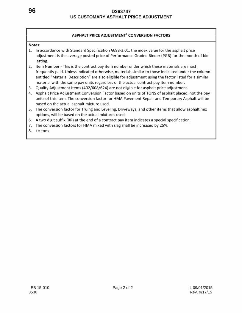
US CUSTOMARY ASPHALT PRICE ADJUSTMENT
EB 15-010 Page 2 of 2 L 09/01/2015 3530 Rev. 9/17/15
ASPHALT PRICE ADJUSTMENT1 CONVERSION FACTORS
Notes: 1. In accordance with Standard Specification §698-3.01, the index value for the asphalt price
adjustment is the average posted price of Performance Graded Binder (PGB) for the month of bid letting.
2. Item Number - This is the contract pay item number under which these materials are most frequently paid. Unless indicated otherwise, materials similar to those indicated under the column entitled “Material Description” are also eligible for adjustment using the factor listed for a similar material with the same pay units regardless of the actual contract pay item number.
3. Quality Adjustment Items (402/608/624) are not eligible for asphalt price adjustment. 4. Asphalt Price Adjustment Conversion Factor based on units of TONS of asphalt placed, not the pay
units of this item. The conversion factor for HMA Pavement Repair and Temporary Asphalt will be based on the actual asphalt mixture used.
5. The conversion factor for Truing and Leveling, Driveways, and other items that allow asphalt mix options, will be based on the actual mixtures used.
6. A two digit suffix (RR) at the end of a contract pay item indicates a special specification. 7. The conversion factors for HMA mixed with slag shall be increased by 25%. 8. t = tons
D26374796

Page 1 of 1
SPECIAL NOTE 1
RESTRICTED HIGHWAY
Pursuant to Section 104A of the Highway Law, highways where work is to be performed underthis contract will be designated Restricted Highways.
The Contractor shall be responsible for meeting the requirements of Subsection 619-1.02 of theStandard Specifications, which shall include patrolling the contract site daily and removing fromthe project site all construction debris that would present a hazard to the traveling public. The costof this work will be included in the price bid for Item 619.01.
Highway Laws 1936, Chapter 25, of the Consolidated Laws
Article V. Section 104-a. Designating as restricted highways under construction or reconstruction
The commissioner of transportation shall have the power to designate any highway underconstruction or reconstruction under the supervision of the commissioner of transportation, thecounty superintendent of highways of a street, highway or road under construction orreconstruction under his supervision, and the town superintendent of highways of a street, highwayor road under construction or reconstruction under the supervision of the town superintendent, as arestricted highway, maintaining traffic thereon, subject to the provisions of article thirty-seven ofthe vehicle and traffic law.
(Added L. 1960, c. 647, section 1; amended L. 1964, c. 479, section 1; L. 1970, c. 63.)
D263747 97

Page 1 of 1
SPECIAL NOTE 2
NOISE CONTROL
The Contractor should be aware that Title 15 of the Rules of the City of New York was amended07/01/07 by adding a new Chapter 28, CITYWIDE CONSTRUCTION NOISE MITIGATION.The details and exact text of this new rule can be found online athttp://nyc.gov/html/dep/html/air_and_noise/index.shtml
In addition to compliance with Procedures for Abatement of Highway Traffic Noise andConstruction Noise (23CFR Part 772), the Contractor shall use and implement all reasonableefforts to accommodate the spirit and intent of Chapter 28 of the City Rules by planning andcarrying out the work on this Project to ensure that the noise from construction equipment andactivities is kept to a minimum. These efforts to accommodate the spirit and intent of Chapter 28shall be submitted by the Contractor, in writing, in the form of a Construction Noise MitigationPlan, to the Engineer for approval. No City permit pursuant to Chapter 28 is required.
The Contractor shall provide the Engineer with two noise meters meeting the requirements of anintegrating sound level meter that is in compliance with the criteria for a Type 1 (Precision) orType 2 (General Purpose) Sound Level Meter as defined in the current revision of ANSIStandard S1.4. Two acoustic calibrators of the type recommended by the meter manufacturershall also be provided.
If additional noise mitigation is required due to complaints; or if adherence to the ConstructionNoise Mitigation Plan can not be substantially complied with, an Alternative Construction NoiseMitigation Plan shall be prepared by the Contractor, in writing, and submitted to the Engineer forapproval. An approved Alternative Construction Noise Mitigation Plan must be fullyimplemented by the Contractor within five (5) business days after the Engineer’s approval.
Should the Contractor fail to implement the noise abatement operations and conditions of theapproved Construction Noise Mitigation Plan, or any approved Alternative Construction NoiseMitigation Plan within five (5) business days of approval thereof, the Engineer shall have theauthority to suspend all work until such time as the Engineer deems that the Contractor hascomplied with the requirements.
The cost of complying with this Mitigation Plan shall be incorporated into the prices bid for theappropriate pay items.
D26374798

Page 1 of 1
SPECIAL NOTE 3
RIGHT- OF- WAY / EASEMENT
Work in this contract is to be performed within the existing right-of-ways, (including maintenanceeasements) of the various roadways, except for construction of the pedestrian bridge (BIN 2269470)where access to park will require the construction permit (included in the contract) issued by the NewYork City Department of Parks & Recreation (NYCDPR).
D263747 99

SPECIAL NOTE 4Technical Requirements for
Item 637.34 – Office Technology Supplies
1 of 1
The following office technology supplies shall be provided as part of the initial setup of the Engineer’sOffice (additional supplies will be required to be provided over the duration of the construction contract):
[ Notes: If a specification is followed by "(minimum)" then the stated requirement or better isacceptable. Otherwise, only the stated requirement is acceptable. For accessories proceeded by "(*)",the Contractor shall replenish these items as required by the Engineer and be of a type, size, quality,and capacity acceptable to the Engineer. These items shall remain the property of the State. ]
Removable Storage Media(*) optical discs as needed(*) Data media storage containers as follows:
2 containers for 50 CDs, with locking capability (minimum)
Data Storage Devices(*) USB flash drives as needed(*) external hard disk drives as needed
Paper Supplies(*) 5000 sheets of 8 ½" x 11", 20# weight, paper suitable for printers and copiers (minimum)(*) 5000 sheets of 11" x 17", 20# weight, paper suitable for printers and copiers (minimum)(*) 200 sheets of 8 ½" x 11", photo quality, printer paper
[ Notes: If a specification is followed by "(minimum)" then the stated requirement or better is acceptable.Otherwise, only the stated requirement is acceptable. For accessories proceeded by "(*)", the Contractorshall replenish these items, as required by the Engineer and be of a type, size, quality, and capacityacceptable to the Engineer. These items shall remain the property of the State. ]
D263747100

Page 1 of 1
SPECIAL NOTE 5
STOCKPILE SITE
The Contractor is advised that if during the course of this contract, it is necessary to stockpile anyconstruction material which in the opinion of the Engineer, may be offensive in nature to sensitivereceptors . (i.e. homes, public places, hospitals, or schools) because of appearance, odor, potentialfor airborne disbursement or hazardous in nature, the Contractor must obtain permission from theEngineer prior to placing the stockpile. As a guideline, no such stockpiling is permitted within 200feet of any sensitive receptor.
Furthermore, the Contractor should also keep in mind that:The stockpile site shall not be used for storing/dumping debris from Contractor’s other projects.
New York City Department of Sanitation and Department of Transportation must be contactedfor issuance of a permit on any project if the Contractor wants to place stockpile materials onhighway Right-Of-Ways other than New State Department of Transportation highway Right-Of-Ways.
D263747 101

1 of 1
SPECIAL NOTES 6
DRAINAGE STRUCTURES PROTECTION REQUIREMENTS.
The inlet filter sediment control for existing catch basins (pay item 209.2301) shall beinstalled before the construction work starts. The Contractor shall take the necessaryprecautions to prevent debris resulting from his operations being collected in catchbasins. In the event the Contractor's operation damages or allows debris into thedrainage system, the Contractor shall, at its own expense, immediately repair, restoreand clean the drainage system as directed by the Engineer.
D263747102

Page 1 of 1
SPECIAL NOTE 7
RAP PG Binder ContributionsTop Course Items 402.125103
When greater than 10% of Recycled asphalt pavement (RAP) is utilized in the production of hotmix asphalt (HMA)Top course, only 75% of the AC content of the RAP will be utilized in thefinal mix design calculation for the optimum asphalt content. The mixture design will beformulated such that all properties are within the criteria specified in the latest Material method5.16. The total asphalt content of virgin binder the accepted RAP asphalt contribution shall notbe less the minimum asphalt content of the mix design during production.
No additional payment will be made for the above requirement. The contractor shall bid TopCourse Item 402.125103 accordingly.
D263747 103

D263747104

3750 Per DQAB
L05/07/09 Page 1 of 1
SPECIAL SPECIFICATIONS NOTE: This form was developed for repetitive use throughout all contract proposals and may identify items not applicable to this specific project.
D263747 105

ITEM 203.02990006 - PAVEMENT EXCAVATION
Page 1 of 1 10 January 07
DESCRIPTION: Under this item, the Contractor shall remove and dispose of existing cement concrete pavement or asphalt overlaid cement concrete pavement as indicated in the plans or as ordered by the Engineer. MATERIALS: Not specified. CONSTRUCTION DETAILS: The Contractor shall carefully line cut the perimeter of concrete pavement to be removed so as to form boundaries to the removal. METHOD OF MEASUREMENT: The quantity to be paid for under this item shall be the number of square feet of cement concrete pavement or asphalt overlaid concrete pavement removed and disposed of as shown on the Plans or ordered by the Engineer. BASIS OF PAYMENT: The unit price bid per square foot for this item shall include the cost of furnishing all labor, materials and equipment necessary to remove and dispose of concrete pavement, mesh reinforcement, transverse joints and longitudinal ties including all required line cutting. Payment shall be the same regardless of whether the entire thickness of pavement is removed or simply the top surface of pavement is removed to provide a transition for resurfacing.
D263747106

ITEM 203.03950017- EXPANDED POLYSTYRENE FILL
1 of 3 12/22/94 12/31/07
DESCRIPTION Furnish and install Expanded Polystyrene fill (EPS) as shown in the contract documents and as directed by the Engineer. MATERIALS General Furnish EPS blocks of the dimensions shown in the contract documents or as approved by the Engineer. EPS is typically supplied as right rectangular prismoid blocks with nominal dimensions of 2 ft x 4 ft x 8 ft. Blocks shall be smooth and flat on all surfaces and have a dimensional tolerance of ±0.5%. Blocks shall be manufactured using a modified resin that contains a fire retardant additive. Blocks shall be seasoned by storing them at the manufacturer’s facility in normal ambient room temperature for a minimum of 72 hours after being released from the mold. Blocks shall meet the following physical requirements after seasoning:
MINIMUM PHYSICAL PROPERTIES
ASTM D1622 Density 1.25 lbs/ft3 ASTM D1621 Compressive Strength: at 1% deformation 5.8 psi at 10% deformation 16.0 psi ASTM C203 Flexural Strength 30.0 psi ASTM D2863 Flammability (Oxygen Index) 24.0 %
The following reference standards shall apply in whole or in part to material supplied under this specification:
APPLICABLE STANDARDS
ASTM D6817 Standard Specification for Rigid Cellular Polystyrene Geofoam ASTM C390 Criteria for Sampling and Acceptance of Preformed Thermal
Insulation Lots The EPS blocks shall be produced by a manufacturer with an in-place quality control program which is monitored and certified by an accredited, independent third-party testing organization. Submittals A minimum of 20 business days prior to beginning work, submit two copies of certified third-party test reports to the Engineer for approval by the Deputy Chief Engineer for Technical Services (DCETS), showing that at least two separately molded EPS blocks, representative of those which will be supplied, conform to the physical properties and standards listed above. The date of manufacture of the tested EPS blocks shall be no more than 6 months prior to the date of the submittal. Test specimen selection and preparation shall be done in accordance with the relevant ASTM standard and Geotechnical Test Procedure GTP-7. The publication is available upon request to the Regional Director or the Director of the Geotechnical Engineering Bureau.
D263747 107

ITEM 203.03950017- EXPANDED POLYSTYRENE FILL
2 of 3 12/22/94 12/31/07
Submit detailed manufacturing records for the tested blocks which clearly state, in part, the percentage, type (in-plant or post-consumer), and original density of any recycled EPS material (regrind) used in the molding process. Basis of Acceptance Each EPS block shall be labeled with the manufacturer’s name, product type, lot number, date of manufacture and weight (as measured after seasoning and trimming). Unlabeled blocks will be rejected. The Contractor shall supply detailed manufacturing records of individual blocks if requested by the Engineer. The Engineer will perform on-site density tests by weighing and measuring one block randomly chosen from each truckload or 2500± cubic feet of EPS delivered to the project site. The Contractor shall provide a calibrated scale accurate to within 0.1 lbs and with sufficient capacity for this purpose. Blocks shall be kept clean and dry prior to weighing. If any block does not meet the minimum density requirement, the sampled truckload or 2500± cubic foot batch will be rejected by the Engineer. EPS blocks that do not meet tolerances, or have side area surface damage of 20% or more or volume damage of 1% or more will be rejected. The State reserves the right to take random samples from the project site (not to exceed 1 block per 10,000 cubic feet) for additional quality assurance testing. If testing yields unsatisfactory results the Contractor may be directed to remove and replace potentially defective EPS blocks at no additional cost to the State. CONSTRUCTION DETAILS General Exercise care to prevent damage to the EPS during delivery, storage and construction. Protect the EPS blocks from (1) Organic solvents such as acetone, benzene, and paint thinner; (2) Petroleum based solvents such as gasoline and diesel fuel; (3) Open flames and (4) Prolonged exposure to sunlight (more than 30 days). Provide a system of temporary weights or tie downs, approved by the Engineer, to anchor the EPS blocks if there is wind gust or flooding potential. Do not drive or operate heavy machinery or place concentrated loads directly on the EPS blocks. EPS blocks damaged due to the Contractor’s operations will be removed and replaced at no additional cost to the State. Installation Grade the leveling course within a tolerance of 0.5 inches in 10 feet. Place the EPS blocks as indicated in the contract documents. Fit blocks tight and flush against adjacent blocks on all sides. Avoid continuous vertical joints by laying blocks in a running bond pattern and orienting the long axis of the blocks in each successive layer perpendicular to the long axis of the blocks in the previous layer.
D263747108

ITEM 203.03950017- EXPANDED POLYSTYRENE FILL
3 of 3 12/22/94 12/31/07
Trim the EPS blocks in the field where necessary with a portable hot wire device supplied by the manufacturer, or a handsaw, or an alternative cutting method approved by the Engineer. METHOD OF MEASUREMENT The quantity of Expanded Polystyrene fill is the number of cubic feet satisfactorily installed as measured in its final position. BASIS OF PAYMENT The unit price per cubic foot shall include the cost of labor, materials, incidentals and equipment necessary to satisfactorily complete the work.
D263747 109

ITEM 203.30XX0063 - EXCAVATION AND DISPOSAL OF ROCK, EMERGENCY STANDBY
10/24/96
DESCRIPTION: This work shall consist of excavation and disposal of rock required pursuant to the implementation of an Emergency Stand-by Contract. This item of work will be used only in the instance where work of an emergency nature is needed and will include only that portion of the excavation deemed by the Geotechnical Engineering Bureau to be firm rock, in its natural position, that in the opinion of the State, can not be practically excavated by mechanical methods, and will require pre-splitting under the provisions of Section 203-3.05. MATERIALS: Not applicable. CONSTRUCTION DETAILS: Sections 203-3.01 and 203-3.05 shall apply. METHOD OF MEASUREMENT: The provisions of Section 203-4.01 and 203-4.03 shall apply. In addition, only that portion of excavation consisting of rock shall be included in the computation for this work. Excavation of soil, boulders, previously fallen ledge, boulders or ledge that have been pulled off a slope, loose rock, overburden, concrete, hardpan, or rock that could be mechanically excavated (ripped) in the opinion of the State (as determined by the Geotechnical Engineering Bureau) shall not be included in the computation of this work. No portion of a slope excavated to a slope flatter than one vertical on one horizontal shall be included in this work. Work done pursuant to Section 206 shall not be included in the computation of this work. The State may, at its option, compute the quantity to be paid by weighing the rock (as defined in the above paragraph) and converting the weight to equivalent volume in cubic meters based on the specific gravity of the rock excavated. In such case suitable truck scales shall be provided by the contractor. BASIS OF PAYMENT: All provisions of Section 203-5.01 shall apply. In addition, the unit price bid shall include the cost of furnishing and maintaining truck scales. Payment will be made under: ITEM NO. ITEM DESCRIPTION PAY UNIT 203.30010063 Excavation and Disposal of Rock, Emergency Standby Contract Work, Quantity Range 1 (0 to 130) Cubic Yard 203.30020063 Excavation and Disposal of Rock, Emergency Standby Contract Work, Quantity Range 2 (131 to 650) Cubic Yard 203.30030063 Excavation and Disposal of Rock, Emergency Standby Contract Work, Quantity Range 3 (651 to 1300) Cubic Yard
D263747110

ITEM 502.01010010 – PERVIOUS PORTLAND CEMENT CONCRETE
PAGE 1 of 4 October 11, 2011
DESCRIPTION: Furnish and place non-reinforced pervious Portland cement concrete in accordance with the plans and specifications. Common applications include, but not limited to, parking lots, shoulders, bicycle paths, sidewalks and driveways. MATERIALS: Pervious Portland cement concrete shall be manufactured in accordance with the requirements of §501-2, with the following modifications: Design a pervious Portland cement concrete mixture as specified in this document. Produce a homogeneous mixture of cement, pozzolan (fly ash or GGBFS), coarse aggregate, set retarding water reducing admixture, water reducing admixture, viscosity modifying admixture (VMA) and water.
Coarse aggregate gradation shall meet the requirements of size 1 or 1A in table 703-4 of the Department’s Standard Specifications, Section 703-AGGREGATES. Aggregate/cement ratio shall be in the range of 4:1 to 4.5:1.
Use Type I, II or I/II cement. Cementitous content shall be a minimum of 520 lb/yd³ for size 1 aggregate, and a minimum of 580 lb/ yd³ for size 1A aggregate. Water/cementitious ratio shall be in the range of 0.27 – 0.34.
At least one (1) week prior to placement of the test panel, provide the Regional Materials Engineer with the following:
1. List of all materials and source numbers. 2. Proposed mix design batch weights, including design unit weight. 3. Proposed production facility and location.
CONSTUCTION DETAILS: All the provisions of §501-3 shall apply with the following modifications: The Contractor shall provide a minimum of one National Ready Mix Concrete Association (NRMCA) Certified Pervious Concrete Technician at the placement site.
Mix the concrete in approved transit mix trucks. Load trucks to a maximum of 80% of the rated mixer capacity.
Thoroughly wet the entire subbase surface for a minimum of 2 hours immediately prior to placement. Remove all standing water prior to placement.
The NRMCA Certified Technician shall check each truck for uniformity during discharge. Mix water shall be such that the cement paste displays a “wet metallic sheen” without causing the
D263747 111

ITEM 502.01010010 – PERVIOUS PORTLAND CEMENT CONCRETE
PAGE 2 of 4 October 11, 2011
paste to flow from the aggregate. Additions of water to the mix, as directed by the Certified Technician, shall be followed by 20 mixing revolutions.
The concrete shall be deposited as close to its final position as practicable and such that fresh concrete enters the mass of previously placed concrete. The practice of discharging onto subbase and pulling or shoveling to final placement is not allowed.
Unless otherwise approved by the Engineer in writing, the Contractor shall provide mechanical equipment of either slipform or form riding with a following compactive unit that will provide a minimum of 10 psi vertical force. The pervious concrete pavement will be placed to the required cross section and shall not deviate more than +/- ¼ inch in 10 feet from profile grade.
Preferred method of strike off and compaction is the use of a form riding roller screed (i.e. NRMCA “One step method”). If allowed by the Engineer, the NRMCA “two step method” may be employed. If the two step method is used, strike off the concrete to approximately 3/8 in. to ¾ in. above the forms to allow for compaction. After strike off, compact the concrete to the height of the forms. Compaction shall be accomplished by rolling over the concrete with a steel roller, compacting the concrete to the height of the forms. Concrete shall be covered with minimum 6 mil plastic prior to rolling to prevent aggregate pull outs. Compaction shall be completed within 15 minutes of placement. Edges near forms shall be compacted using a 1 ft. by 1 ft. steel tamp, a float, or other similar device to prevent raveling of the edges. If vibration, internal or surface applied, is used, it shall be shut immediately when forward progress is halted for any reason.
After mechanical or other approved strike-off and compaction operation, no other finishing operation will be allowed. The Contractor will be restricted to pavement placement widths of a maximum of fifteen (15’) feet unless the Contractor can demonstrate competence to provide pavement placement widths greater than the maximum specified, to the satisfaction of the Engineer. Curing procedures shall begin within 15 minutes after placement. The pavement surface shall be covered with polyethylene curing covers meeting §711-04, or other pre-approved covering material. Overlap curing covers a minimum of 18 inches. Prior to covering, a fog or light mist shall be sprayed above the surface. The cover shall overlap all exposed edges and shall be fully secured throughout the curing period (without using dirt) to prevent dislocation due to winds or adjacent traffic conditions. The polyethylene covering shall remain on the surface for the full duration of the cure time. Supply form insulating materials when the air temperature is expected to fall below 40ºF at any time during the curing period.
Cure Time: a. Minimum of 7 days. b. No truck traffic shall be allowed for 10 days (no passenger car/light trucks
for 7 days).
D263747112

ITEM 502.01010010 – PERVIOUS PORTLAND CEMENT CONCRETE
PAGE 3 of 4 October 11, 2011
Jointing: Control (contraction) joints shall be installed at maximum 20-foot intervals. They shall be installed at a depth of least 1/4 the thickness of the pavement. It is recommended that these joints be installed in the plastic concrete with a rolling joint tool. Saw cut joints, if used, should be installed as soon as the pavement has hardened sufficiently to prevent raveling and uncontrolled cracking (normally immediately after curing). Transverse construction joints shall be installed whenever placing is suspended a sufficient length of time that concrete may begin to harden. In order to assure aggregate bond at construction joints, a bonding agent suitable for bonding fresh concrete shall be brushed, rolled, or sprayed on the existing pavement surface edge. Isolation (expansion) joints will not be used except when pavement is abutting slabs or other adjoining structures. Testing, Inspection, and Acceptance
A. Test panel(s): At least one week prior to use, the Contractor shall place, joint, and cure a test panel, a minimum of 100 sq. ft. at the required project thickness, designed in-place unit weight, and finish. The test panel will be constructed at a location designated by the Engineer and will remain in place for the duration of the project to be used as a reference for acceptance of the pavement surface.
1. Satisfactory performance of the test panels will be determined by:
a) Void Structure: 15% minimum; 25% maximum as per ASTM C1688. b) Unit weight (Density): Unit weight shall be within 5 lb/ft³ of the
design unit weight as per ASTM C1688. c) Infiltration Rate: Infiltration rate shall be a minimum of 100 in./hr as
per ASTM C1701. Perform this test after 7 day cure. d) Compacted Thickness: Core the test panel at a minimum of 7 days
and determine the compacted thickness as per ASTM C42. Compacted thickness shall be within ¼" of the specified thickness.
2. If the test panel does not meet performance criteria, it shall be removed and
redone at the Contractor’s expense, and the failed test panel disposed of in an appropriate manner.
3. The test panel will not be incorporated into the work, and will be removed when
ordered by the Engineer.
D263747 113

ITEM 502.01010010 – PERVIOUS PORTLAND CEMENT CONCRETE
PAGE 4 of 4 October 11, 2011
B. Testing:
During production, the following shall be conducted at the Contractor’s expense:
1. A minimum of one test for each day’s placement of pervious concrete in accordance with ASTM C 1688 to verify unit weight and percent void content. Unit weight shall be within 5 lb/ft³ of the design unit weight.
2. In a slipform paving operation, determine plastic thickness according to §502-
3.08. Perform this test at the frequency indicated in the §502-3.08, but at a minimum of twice per day. Fixed form thickness shall be determined by measuring from grade to top of forms prior to paving. Thickness shall be within ¼" of the specified thickness.
3. Infiltration Rate: Test as per ASTM C1701 after 7 day cure at a minimum of three locations chosen by the Engineer. Infiltration rate shall be a minimum of 100 in./hr.
Should any of these test results fall outside of the specified limits, the concrete shall be removed, replaced, and retested at no additional cost.
METHOD OF MEASUREMENT: This work will be measured as the number of cubic yards of pervious Portland cement concrete satisfactorily furnished and installed in accordance with the plans, specifications, and orders of the Engineer. BASIS OF PAYMENT: The unit price bid per cubic yard shall include the cost of all labor, materials, and equipment necessary to satisfactorily complete the work, including saw cutting, and providing a test panel(s). The cost of any necessary excavation and subbase course will be paid for under their appropriate items.
D263747114

ITEM 502.33010018 - DRILL AND ANCHOR LONGITUDINAL JOINT TIES FOR FULL-DEPTH PORTLAND CEMENT CONCRETE PAVEMENT REPAIRS
1 of 2 EI 03-012 L 09/11/03
DESCRIPTION. Drill holes and anchor longitudinal joint ties into concrete faces that will become longitudinal joints. MATERIALS AND EQUIPMENT. Longitudinal Joint Ties. Use 1 piece drop in type longitudinal joint ties depicted in the M502 Standard Sheet, Longitudinal Joint Ties, except substitute 28 inch long ties for 36 inch long ties. Use an epoxy coating appearing on the Approved List for “Epoxy Coatings for Longitudinal Joint Ties” or “Epoxy Coatings for Steel Reinforcing Bars” that is applied by an applicator appearing on the Approved List for “Applicators for Steel Reinforcing Bars”. At least 7 days prior to drilling holes, provide the Engineer:
• Material certification from the rolling mill as to the type and grade of steel used. • The brand of epoxy coating and the name and address of the Manufacturer. • The name and address of the epoxy coating applicator. • Material certification from the epoxy coating applicator that the bars have been coated, tested,
and meet the requirements of §705-14, Longitudinal Joint Ties. The Department may perform supplementary sampling and testing of the ties to ensure conformance with §705-14. Anchoring Material and Dispensing Equipment. Use a pourable, 2 component, 100% solids structural epoxy meeting §701-07, Anchoring Materials - Chemically Curing, dispensed:
• From side-by-side cartridges by manual or pneumatically powered injection guns. • Through a static nozzle that homogeneously mixes the material without any hand mixing.
Drills. Use hydraulic gang drills with a minimum of 2 independently powered and driven drills. Use tungsten carbide drill bits. Control the forward and reverse travel of the drills by mechanically applied pressure. Mount the drill on a suitable piece of equipment such that it is quickly transported and positioned. Rest and reference the drill rig frame on and to the pavement surface such that the drilled holes are cylindrical, perpendicular to the surface being drilled, and repeatable in terms of position and alignment on the surface being drilled. When allowed by the Engineer, hand-held drills may be used if the drill rig discussed above can not be positioned without being in conflict with the contracts maintenance and protection of traffic plan. CONSTRUCTION DETAILS. Drilling Holes. Drill holes such that:
• The end ties in a slab are placed 12 – 15 inches from the transverse joints. • The ties between the end ties are placed 24 inches apart, maximum. • 10 inches of tie is embedded in the existing concrete and 18 inches of tie protrudes from the
drilled concrete face. • The hole diameters are in accordance with the anchoring material Manufacturer’s written
recommendations. Provide those recommendations to the Engineer before drilling any holes. Extend the full depth repair boundaries as indicated in the contract documents if drilling cracks or damages the pavement to remain in place. Replace worn bits when necessary to ensure the proper hole diameter is drilled.
D263747 115

ITEM 502.33010018 - DRILL AND ANCHOR LONGITUDINAL JOINT TIES FOR FULL-DEPTH PORTLAND CEMENT CONCRETE PAVEMENT REPAIRS
2 of 2 EI 03-012 L 09/11/03
Cleaning Holes. Follow the anchoring material Manufacturer’s written recommendations for cleaning the holes. Provide those recommendations to the Engineer. As a minimum, clean the drilled holes with oil-free and moisture-free compressed air. The Engineer will check the compressed air stream purity with a clean white cloth. Use a compressor that delivers air at a minimum of 120 ft3 per minute and develops a minimum nozzle pressure of 90 PSI. Insert the nozzle to the back of the hole to force out all dust and debris. Tie Installation. When using new cartridges of anchoring material, ensure that the initial material exiting the nozzle appears uniformly mixed. If it is not uniformly mixed, waste the material until uniformly mixed material extrudes. Place the anchoring material at the back of the hole using a nozzle of sufficient length. Push the tie into the hole while twisting such that the air pocket within the hole is heard to burst and the anchoring material is evenly distributed around the tie. Use sufficient amounts of anchoring material such that it slightly extrudes out the hole as the tie is inserted. METHOD OF MEASUREMENT. The work will be measured for payment as the number of longitudinal joint ties satisfactorily anchored. BASIS OF PAYMENT. Include the cost of all labor, material, and equipment necessary to satisfactorily perform the work in the unit price bid for Drill and Anchor Longitudinal Joint Ties for Full-Depth PCC Pavement Repairs. No additional payment will be made for extra work required to repair damage to the adjacent pavement that occurred during drilling.
D263747116

ITEM 502.35010018 - PORTLAND CEMENT TREATED PERMEABLE BASE ITEM 502.36RC0018 - PORTLAND CEMENT CONCRETE (PCC) PLACEMENT FOR FULL-DEPTH PAVEMENT REPAIRS ITEM 502.37010018 - TRANSVERSE JOINTS ITEM 502.38010018 - LONGITUDINAL JOINTS
EI 03-012 Page 1 of 6 L 09/11/03
DESCRIPTION. Place Class C, Class F, or High-Early-Strength (HES) PCC as indicated in the contract documents in a previously prepared full-depth repair area. MATERIALS AND EQUIPMENT. Portland Cement Concrete (Class C and Class F) ............ ............ ............ ............ ............ ............ 501 High-Early-Strength (HES) Concrete ..... ............ ............ ............ ............ ............ ............ ............ 502-2.02 Portland Cement Treated Permeable Base ........... ............ ............ ............ ............ ............ ............ 502-2.03 Longitudinal Joint Ties . ............ ............ ............ ............ ............ ............ ............ ............ ............ . 705-14 Transverse Joint Supports .......... ............ ............ ............ ............ ............ ............ ............ ............ . 705-15 Wire Fabric for Concrete Reinforcement ............ ............ ............ ............ ............ ............ ............ 709-02 Epoxy-Coated Bar Reinforcement, Grade 60 ...... ............ ............ ............ ............ ............ ............ . 709-04 Quilted Covers (for Curing) ....... ............ ............ ............ ............ ............ ............ ............ ............ . 711-02 Plastic Coated Fiber Blankets (for Curing) .......... ............ ............ ............ ............ ............ ............ . 711-03 Polyethylene Curing Covers (White Opaque) ..... ............ ............ ............ ............ ............ ............ . 711-04 Membrane Curing Compound ... ............ ............ ............ ............ ............ ............ ............ ............ . 711-05 Form Insulating Materials for Winter Concreting ............ ............ ............ ............ ............ ............ 711-07 Water ............ ............ ............ ............ ............ ............ ............ ............ ............ ............ ............ . 712-01 HES concrete mix design and all details related to HES concrete production and discharge must be approved by the Regional Materials Engineer before placement. Transit Mix HES Concrete. Accelerating admixtures may be batched into the concrete at the plant in accordance with '501-2.03F, Admixture Dispensing Systems, or added at the site depending on the amount of acceleration required and the haul time. When adding accelerating admixtures at the site, equip truck mixers with an air pressurized tank that: $ Contains the correct volume of admixture (for the volume of concrete in the truck) dispensed
through the plant=s Admixture Dispensing System. $ Discharges the required admixture quantity into the truck mixer drum in less than 1 minute. $ Has a clear plastic tank output hose that leads into the truck mixer drum. $ Has a properly working relief valve. Twice daily, or more frequently if weather conditions change significantly as determined by the Engineer, determine the fine and coarse aggregate moisture contents. Compute the corresponding water added to the concrete in the truck from aggregate moisture. Subtract that quantity, as well as the water portion of the admixture in the tank and water added at the plant, from the design water for the truck. Submit these calculations to the NYSDOT plant inspector for approval. Upon approval, write the maximum volume of water to be added to the truck at the site on the delivery ticket. Upon arrival at the site, provide the delivery ticket to the Engineer. Discharge the accelerating admixture into the truck mixer drum during or after any water additions at the site. Do not add more water than the maximum volume indicated on the delivery ticket. Add all of the
D263747 117

ITEM 502.35010018 - PORTLAND CEMENT TREATED PERMEABLE BASE ITEM 502.36RC0018 - PORTLAND CEMENT CONCRETE (PCC) PLACEMENT FOR FULL-DEPTH PAVEMENT REPAIRS ITEM 502.37010018 - TRANSVERSE JOINTS ITEM 502.38010018 - LONGITUDINAL JOINTS
EI 03-012 Page 2 of 6 L 09/11/03
accelerating admixture in 1 uninterrupted operation in 1 minute or less. Apply a maximum of 200 total mixing revolutions before discharge. Truck Mix HES Concrete. Add the accelerating admixture and water at the site. Equip trucks with an air pressurized tank for accelerating admixtures as described above in Transit Mix HES Concrete and an in-line water flow meter that: $ Resets easily to "0". $ Is mounted to allow easy reading. $ Withstands water temperatures up to 200EF. $ Is equipped with air strainers capable of removing entrapped air within the system. $ Has a batching delivery tolerance of 1% by weight or volume. $ Has a manufacturer’s certified flow rate capacity of 70 gpm. $ Has a minimum actual flow rate of 50 gpm. The Regional Materials Engineer will measure the actual flow rate and inspect the flow meter prior to use. Do not place any concrete without the Regional Materials Engineer=s approval. Twice daily, or more frequently if weather conditions change significantly as determined by the Engineer, determine the fine and coarse aggregate moisture contents. Compute the corresponding water added to the concrete in the truck from aggregate moisture. Subtract that quantity, as well as the water portion of the admixture in the tank, from the design water for the truck. Submit these calculations to the NYSDOT plant inspector for approval. Upon approval, write the exact volume of water to be added to the truck at the site on the delivery ticket. Upon arrival at the site, provide the delivery ticket to the Engineer. Before adding water into the truck mixer, execute twenty dry revolutions at 12 to 18 rpm and reset the flow meter to 0. Add water in 1 uninterrupted operation. No water is to be removed from the truck mixer for any purpose while water is being added to the drum. After the required water designated on the delivery ticket has been added to the concrete in the truck, add all the accelerating admixture in 1 uninterrupted operation in 1 minute or less. Apply a maximum of 200 mixing revolutions before discharge. Use equipment meeting: Forms ............ ............ ............ ............ ............ ............ ............ ............ ............ ............ '502-2.04B1 Paving Irregular Areas .. ............ ............ ............ ............ ............ ............ ............ ............ '502-2.04B3 Vibrators .......... ............ ............ ............ ............ ............ ............ ............ ............ ............ '502-2.04C Permeable Base Paving Equipment ........ ............ ............ ............ ............ ............ ............ '502-2.04D Saw Cutting Equipment ............ ............ ............ ............ ............ ............ ............ ............ '502-2.04E Curing Compound Applicators .. ............ ............ ............ ............ ............ ............ ............ '502-2.04F CONSTRUCTION DETAILS. Apply the following from Section 502, Portland Cement Concrete Pavement, as modified herein:
D263747118

ITEM 502.35010018 - PORTLAND CEMENT TREATED PERMEABLE BASE ITEM 502.36RC0018 - PORTLAND CEMENT CONCRETE (PCC) PLACEMENT FOR FULL-DEPTH PAVEMENT REPAIRS ITEM 502.37010018 - TRANSVERSE JOINTS ITEM 502.38010018 - LONGITUDINAL JOINTS
EI 03-012 Page 3 of 6 L 09/11/03
Weather Limitations ...... ............ ............ ............ ............ ............ ............ ............ ............ ............ '502-3.01 Portland Cement Treated Permeable Base ........... ............ ............ ............ ............ ............ ............ '502-3.03
Use permeable base if the pavement being repaired was constructed with permeable base or if shown in the contract documents. Place permeable base 4 inches thick. Apply fixed form paving requirements.
Fixed Form Paving ........ ............ ............ ............ ............ ............ ............ ............ ............ ............ '502-3.05 Consider full-depth repairs to be irregular areas.
Joint Construction ......... ............ ............ ............ ............ ............ ............ ............ ............ ............ '502-3.06 Apply a bond breaker, such as form oil, to untied longitudinal joints immediately before placing concrete.
Finishing .......... ............ ............ ............ ............ ............ ............ ............ ............ ............ ............ '502-3.09 Finish short repairs (those less than the length of the finishing equipment) transversely.
Texturing .......... ............ ............ ............ ............ ............ ............ ............ ............ ............ ............ '502-3.10 Do not texture the plastic concrete if it will be diamond ground. The Engineer may require longitudinal astroturf drag if that was the original pavement texture.
Curing ............ ............ ............ ............ ............ ............ ............ ............ ............ ............ ............ '502-3.11 Pavement Protection ..... ............ ............ ............ ............ ............ ............ ............ ............ ............ '502-3.13 Damaged or Defective Concrete ............ ............ ............ ............ ............ ............ ............ ............ '502-3.14 Hardened Surface Test .. ............ ............ ............ ............ ............ ............ ............ ............ ............ '502-3.15
If the pavement is to be diamond ground, the maximum deviation is 3/8 inch in 10 feet. If the pavement will not be diamond ground, the maximum deviation is 1/8 inch in 10 feet.
Opening to Traffic ......... ............ ............ ............ ............ ............ ............ ............ ............ ............ '502-3.18 When determining concrete strength for opening to traffic, apply the following rather than '502-3.18C, Project Strength Determination:
Project Strength Determination. Provide an ACI Certified Concrete Field Testing Technician, Grade I, or higher, to cast all cylinders. Unless otherwise noted in the contract documents, use an agency accredited by the AASHTO Accreditation Program (AAP) in the field of construction materials testing of portland cement concrete to perform compressive strength testing. Cast and test in the presence of the Engineer, or the Engineer=s representative. Provide acceptable proof of ACI Certification and AASHTO Accreditation to the Engineer before placing any concrete. The Engineer, or the Engineer=s representative, will complete the Concrete Cylinder Report as cylinders are cast and tested.
Cast a minimum of 3 cylinder pairs (6 total) from each scheduled placement operation in accordance with Materials Method 9.2, Field Inspection of Portland Cement Concrete. Cast each pair from different delivery trucks with 1 of the 3 pairs cast from the last truck of the operation. Develop an Engineer-approved marking system that allows a cylinder to be readily associated with the corresponding placement location and placement time. Mark the cylinders and place them adjacent to the pavement under similar curing conditions. Determine the concrete compressive strength in accordance with ASTM C39, Standard Test Method for Compressive
D263747 119

ITEM 502.35010018 - PORTLAND CEMENT TREATED PERMEABLE BASE ITEM 502.36RC0018 - PORTLAND CEMENT CONCRETE (PCC) PLACEMENT FOR FULL-DEPTH PAVEMENT REPAIRS ITEM 502.37010018 - TRANSVERSE JOINTS ITEM 502.38010018 - LONGITUDINAL JOINTS
EI 03-012 Page 4 of 6 L 09/11/03
Strength of Cylindrical Concrete Specimens. Test all cylinder pairs at the same time relative to when they were cast. The testing time must be within the time frame needed to open the last concrete placed in the operation to traffic. The placement may be opened to traffic if all the following apply:
$ Average compressive strength of all cylinder pairs exceed 2500 PSI. $ Average compressive strength of each cylinder pair exceeds 2000 PSI. $ Appropriate time frame has elapsed for the entire area to be opened.
If these conditions are not met, test 3 additional cylinder pairs at a later time, provided the appropriate number of additional cylinders were cast and the placement has not been opened to traffic. If the above conditions are not met after additional testing, or, if the required number of additional cylinders were not cast, open the placement to traffic after 5 days, or when directed by the Engineer, provided this time frame is not in conflict with the work zone closure time restrictions stipulated in the contract documents. If the placement is opened to traffic (in accordance with the work zone closure time restrictions stipulated in the contract documents) before it has achieved the required strength, the placement will be considered Damaged or Defective Concrete and will be replaced at no additional cost to the State.
Contract testing for 28 day compressive strength is not required. If subsequent trial batches are required, the Engineer may waive the 28 day compressive strength testing.
METHOD OF MEASUREMENT.
Portland Cement Treated Permeable Base. The work will be measured for payment as the number of cubic yards of permeable base satisfactorily placed, measured to the nearest 0.1 yard3, based on the Engineer-approved repair area marked on the pavement prior to repair and the thickness of permeable base placed. Portland Cement Concrete, Unreinforced, All Classes. The work will be measured for payment as the number of cubic yards of concrete satisfactorily placed, measured to nearest 0.1 yard 3, based on the Engineer-approved repair area marked on the pavement prior to repair and the thickness of concrete placed. Deductions, and separate payment, will be made for catch basins, manholes, or other similar pavement obstructions requiring either mesh reinforced or heavily reinforced placements. Portland Cement Concrete, Mesh or Heavily Reinforced, All Classes. The work will be measured for payment as the number of cubic yards of concrete satisfactorily placed, measured to the nearest 0.1 yard 3, based on the Engineer-approved repair area marked on the pavement prior to repair and the thickness of concrete placed. No deductions will be made for drainage and utility structures or other similar pavement obstructions being isolated from the surrounding pavement. Transverse Joints. The work will be measured for payment as the number of feet of transverse joints satisfactorily constructed within the repair boundary, measured to the nearest 0.1 foot. Separate
D263747120

ITEM 502.35010018 - PORTLAND CEMENT TREATED PERMEABLE BASE ITEM 502.36RC0018 - PORTLAND CEMENT CONCRETE (PCC) PLACEMENT FOR FULL-DEPTH PAVEMENT REPAIRS ITEM 502.37010018 - TRANSVERSE JOINTS ITEM 502.38010018 - LONGITUDINAL JOINTS
EI 03-012 Page 5 of 6 L 09/11/03
measurement will be made for transverse joints that define the repair boundary and drilling and anchoring dowels into those joints. Constructing Longitudinal Joints. The work will be measured for payment as the number of feet of longitudinal joints satisfactorily constructed within the repair boundary, measured to the nearest 0.1 foot. Separate measurement will be made for longitudinal joints that define the repair boundary and drilling and anchoring longitudinal joint ties in those joints. BASIS OF PAYMENT. Portland Cement Treated Permeable Base. Include the cost of all labor, material, and equipment necessary to satisfactorily perform the work in the unit price bid for Portland Cement Treated Permeable Base. No additional payment will be made for extra work required to repair damage to the adjacent permeable base or pavement that occurred during any operation. Additional payment will be made if the original repair area did not completely extend into sound concrete. Portland Cement Concrete, Unreinforced, All Classes. Include the cost of all labor, material, and equipment necessary to satisfactorily perform the work in the unit price bid for Portland Cement Concrete, Unreinforced, All Classes. No additional payment will be made for Contractor-requested HES concrete mixes or extra work required to repair damage to the adjacent pavement that occurred during any operation. Additional payment will be made if the original repair area did not completely extend into sound concrete. Portland Cement Concrete, Mesh or Heavily Reinforced, All Classes. Include the cost of all labor, material, and equipment necessary to satisfactorily perform the work in the unit price bid for Portland Cement Concrete, Mesh or Heavily Reinforced, All Classes. No additional payment will be made for Contractor-requested HES concrete mixes or extra work required to repair damage to the adjacent pavement that occurred during any operation. Additional payment will be made if the original repair area did not completely extend into sound concrete. Transverse Joints. Include the cost of all labor, material, equipment, and labor necessary to satisfactorily perform the work in the unit price bid for Transverse Joints. Separate payment will be made for constructing transverse joints that define the repair boundary and drilling and anchoring dowels into those joints. Separate payment will be made for joint sealing or joint filling. Longitudinal Joints. Include the cost of all labor, material, and equipment necessary to satisfactorily perform the work in the unit price bid for Longitudinal Joints. Separate payment will be made for constructing longitudinal joints that define the repair boundary and drilling and anchoring ties into those joints. Separate payment will be made for joint sealing or joint filling.
D263747 121

ITEM 502.35010018 - PORTLAND CEMENT TREATED PERMEABLE BASE ITEM 502.36RC0018 - PORTLAND CEMENT CONCRETE (PCC) PLACEMENT FOR FULL-DEPTH PAVEMENT REPAIRS ITEM 502.37010018 - TRANSVERSE JOINTS ITEM 502.38010018 - LONGITUDINAL JOINTS
EI 03-012 Page 6 of 6 L 09/11/03
Payment Will Be Made Under: Item No. Item Pay Unit 502.35010018 Portland Cement Treated Permeable Base Cubic Yard 502.36RC0018 Portland Cement Concrete (PCC) Placement for Full-Depth Repair Cubic Yard
R - Reinforcement C - Concrete Class 0 - Unreinforced 1 - Class C 1 - Isolated, Mesh Reinforced 2 - Class F 2 - Isolated, Heavily Reinforced 3 - HES
502.37010018 Transverse Joints Foot 502.38010018 Longitudinal Joints Foot
D263747122

ITEM 520.05000010 - SAW CUTTING PORTLAND CEMENT CONCRETE AND COMPOSITE PAVEMENTS
1 of 1 08/15/08E 12/14/90
2/1/96 M
DESCRIPTION. This work shall consist of saw cutting existing reinforced or unreinforced portland cement concrete, including portland cement concrete pavement and sidewalk, and composite pavement (asphalt concrete on reinforced or unreinforced portland cement concrete), at the locations indicated on the plans or where directed by the Engineer. MATERIALS. All equipment proposed for this work shall be subject to approval by the Engineer prior to actual use. Rotary rock saws shall not be used for cuts under this item. CONSTRUCTION DETAILS. Saw cutting shall be along a neat line as indicated on the plans or where directed by the Engineer. The cuts shall be neat and true with no shatter. Saw cuts shall be made to the depth (s) indicated on the plans and as stated below. When removing composite pavement the Contractor shall saw cut the existing pavement for the full depth of the concrete pavement. The total saw cut depth will be more, depending on the thickness of the asphalt. At the Contractor’s option, the asphalt concrete may first be saw cut and removed before making a second cut through the portland cement concrete. Any damage to material not indicated for removal, caused by the Contractor’s operations, shall be repaired by the Contractor. All repair shall be done in a manner satisfactory to the Engineer. METHOD OF MEASUREMENT. This work will be measured by the number of linear feet of saw cutting done. No allowance will be made for saw cuts of different depths. Saw cutting which is done for the Contractor’s convenience will not be measured for payment under this item. BASIS OF PAYMENT. The unit price bid per linear foot of saw cutting shall include the cost of all labor, materials, and equipment necessary to complete the work. Only one payment will be made for saw cutting when removing composite pavement regardless of the method chosen. The cost of saw cutting the asphalt concrete in the composite pavement is included in this item. No payment will be made for this saw cutting under the item for saw cutting asphalt concrete. Any repairs made necessary by the Contractor’s operations shall be done to the satisfaction of the Engineer at no additional cost to the State
D263747 123

ITEM 555.72940001 - ARCHITECTURAL TREATMENT - VERTICAL CONCRETE SURFACES
Page 1 of 2 Revised 11/26/97
DESCRIPTION: This work shall consist of architecturally treating the vertical surface(s) of concrete retaining walls, structures, wing walls, or other similar vertical surfaces with a designated pattern(s) and texture(s). All work shall be in accordance with these specifications in and reasonably close conformity to the lines, grades and patterns shown on the plans. MATERIALS: Any commercially produced formliner meeting the requirements of this subsection will be acceptable. Polystyrene formliners are for one-time usage only and shall be allowed only if the formwork will not be reused. The formliners shall: 1. Produce the pattern required by the plans. 2. Be composed of a material(s) that will not bond to concrete. 3. Be attachable to standard plywood, or steel, concrete forms, such that no distortion, or stray markings, occur within the concrete surfaces. Formliners will be acceptable at the work site upon written certification that the requirements of this subsection have been met. Cast-in-place concrete - Class A or as shown in the contract documents shall meet the requirements of Section 501, Portland Cement Concrete - General. Releasing Agents. If the formliner manufacturer requires the use of an agent to facilitate the release of the formliner panel from the concrete, or when its use is specified on the plans, such agent shall be non-staining and evenly spread over the entire linear surface. Formwork shall also be treated as needed. Caulking Compound. When a caulking compound is required to seal any necessary concrete joints in the imprinted surface, such caulking compounds shall meet the material requirements of Subsection 705-06 of the Standard Specifications, Caulking Compound for Structures. CONSTRUCTION DETAILS: Special care shall be taken after installation to ensure that all formliner surfaces are thoroughly clean of all stray material of any nature. No concrete shall be placed prior to the Engineer's inspection and approval of formliner surfaces. Approximately 5/64” of the formliner panel shall overlap on either side of the formwork panel so that when the formwork sections are forced together, the formliners compress at the edges to form a tight joint. Joints between panels shall be sealed, taped or fused to form a watertight seam, according to the manufacturer's instructions. Unless specified on the plans, texturing is not required on surfaces which will be below finished grade. Plastic snap tie cones are to be of the non-leaking type. Metal form ties are not to be placed closer than 1 1/2” to the interior surface.
D263747124

ITEM 555.72940001 - ARCHITECTURAL TREATMENT - VERTICAL CONCRETE SURFACES
Page 2 of 2 Revised 11/26/97
Concrete shall be placed in accordance with Section 555, Structural Concrete Construction joints shall extend to the full depth of the concrete at the locations shown on the plans. When construction joints are needed but are not shown on the plans, the Contractor and the Engineer shall agree on the proper locations of such joints so as to not distract from the appearance of the imprinted pattern and to minimize the possibilities of cracking. After formwork removal the Engineer will inspect architecturally patterned concrete surfaces. All such surfaces which do not exhibit the required architectural pattern shall be repaired in a manner satisfactory to the Engineer at no cost to the State. The repair shall match the concrete surface. Concrete repair material, if used, shall meet the requirements of Subsection 701-04, Concrete Repair Material of the Standard Specifications. METHOD OF MEASUREMENT: Architecturally treated vertical concrete surfaces shall be measured by the number of square feet of concrete treated to the satisfaction of the Engineer. The quantity shall be as computed from payment lines shown on the plans or as established by the Engineer in writing. Measurement will be taken as the vertical plane projection of the treated location. No measurement will be taken of actual concrete surfaces. BASIS OF PAYMENT: The unit price bid per square foot shall include the cost of the formliners, the concrete needed to fill the formliner, releasing agents, caulking compounds, patch mix, and all other materials, equipment and labor necessary to complete the work as specified.
D263747 125

ITEM 555.80010001 - CRACK SEALING BY EPOXY INJECTION (PREVENTION) ITEM 555.80020001 - CRACK REPAIR BY EPOXY INJECTION (RESTORATION)
1 of 4 December 3, 1999
DESCRIPTION: Install injection ports, seal the crack opening, inject the crack with epoxy (full depth for restoration work, or as deep as conditions allow for prevention work), and restore the sealed surface to a flush condition in areas visible to the public. Perform the work at locations indicated on the contract plans or where directed by the Engineer. PREVENTION - use in contaminated, cracked concrete areas to prevent movement and protect reinforcing. RESTORATION - use in uncontaminated cracked concrete areas to restore structural integrity. Take verification cores for payment. Have an experienced epoxy manufacturer representative present until the work is acceptable to the Engineer. MATERIAL REQUIREMENTS: 1. Crack Sealant - epoxy paste that completely cures in 4 hours or less and retains the injected
epoxy. Any other type of crack sealant is subject to a project demonstration and approval by the Engineer.
2. Low Viscosity Injection Epoxy - Manufacturer certified to meet ASTM C881, Type I or IV,
Grade 1, Class B or C (as temperature conditions require.) 3. Vertical & Overhead Patching Material (Approved List) - (for ITEM 555.80020001) §701-08 INJECTION EQUIPMENT: Use equipment in good working order, as approved by the Engineer, with the following features: • Separate feed lines to the mixing chamber • Automatic mixing and metering pump • Ability to thoroughly mix the epoxy components in the mixing chamber • Operator control of the epoxy flow from the mixing chamber • Clean, legible, accurate pressure gauges easily viewable by the operator • Ability to provide an uninterrupted pressure head to continually force epoxy into the cracks • Injection pressure from 0 to at least 200 PSI • Capable of metering each epoxy component to within 3.0% of the epoxy manufacturer's mix
ratio Un-reacted epoxy components may be stored overnight in separate reservoirs and feed lines. Before starting the work, demonstrate to the Engineer the ability of the equipment to meter and mix epoxy components to the required mix ratio. Ratio accuracy may be determined by simultaneously metering each component into separate, clean, accurately graduated, volumetric containers, or another procedure approved by the Engineer. Also, activate the automatic mixing and metering pump, mix a small amount of injection epoxy, and waste it into a disposable container. The Engineer will observe this trial operation and be satisfied the equipment is working properly, and the epoxy is mixed with no streaks. CONSTRUCTION DETAILS:
D263747126

ITEM 555.80010001 - CRACK SEALING BY EPOXY INJECTION (PREVENTION) ITEM 555.80020001 - CRACK REPAIR BY EPOXY INJECTION (RESTORATION)
2 of 4 December 3, 1999
1. Crack and Surface Preparation. Remove all debris or contaminants accessible within the
cracks by using hand tools, water blasting or oil-free high pressure air blasting, vacuuming, or other methods suitable to the Engineer. Epoxy resin will not penetrate: compacted, water or oil soaked debris. Allow free moisture within the crack to be absorbed before injecting epoxy. Remove all materials, including moisture, from the surface adjacent to the crack which might interfere with bonding of the crack sealant.
2. Injection Port Installation. Attach injection ports to the prepared surface by placing them
onto (surface adapters) or into the cracks (socket ports) and affixing with crack sealant. Larger cracks may be ported by inserting an anchored tube into the crack.
Use positive connection port designs to connect injection equipment to the ports. Other injection port designs and attachment methods, where worker fatigue would not be a problem, require approval by the Engineer.
Use the following general guidelines for spacing injection ports when cracks are uniform in width through the structure. For cracks that get tighter with depth, double this spacing. Intermediate ports may be placed for observation. To permit maximum flow into the void, position ports on the wider crack sections and at intersections, rather than at an exact spacing.
If these guidelines cannot be followed, use port locations approved by the Engineer. Port spacing may be modified by the Engineer as experience is gained, or when cores are taken to determine penetration.
FOR CRACKS COMPLETELY THROUGH A MEMBER A. Cracks accessible from one side - space the ports not less than the thickness of the
member.
B. Cracks accessible from both sides - space the ports not less than twice the thickness of the member and stagger them relative to the ports on the opposite side. Make the stagger between ports (on opposite sides of the member) at least the thickness of the member.
Place the endmost ports at the ends of the crack so as to insure complete filling of the crack.
FOR MULTIPLE CRACKS ALL OVER A MEMBER. Space the ports as far apart as practical, but not less than 8” from one another. An 8” spacing presumes a 4” penetration in each direction, if the adjacent ports are not plugged when epoxy reaches them. For fine cracks that taper to an end, place the endmost ports about 4” from the end.
3. Crack Seal. After port installation, seal the crack opening with crack sealant, being careful not to plug the injection ports. Allow the crack sealant to cure completely before injecting epoxy.
Apply crack sealant only when surface and ambient temperatures are above 50º F.
D263747 127

ITEM 555.80010001 - CRACK SEALING BY EPOXY INJECTION (PREVENTION) ITEM 555.80020001 - CRACK REPAIR BY EPOXY INJECTION (RESTORATION)
3 of 4 December 3, 1999
4. Port Flushing. Prior to any epoxy injection, flush critical ports with oil-free compressed air to verify that air exits from all the installed ports, dry the cracks, and check for leaks.
5. Epoxy Injection. Perform epoxy injection only when the surface and ambient temperatures
are above 45º F and are not expected to fall below 45º F during the next 24 hours.
UNIFORM WIDTH CRACKS - start toward the middle of a horizontal crack and work outward, or the lowest point of a sloping or vertical crack and work upward.
VARIABLE WIDTH CRACKS - start at the widest points of all types of cracks and work outward. Secure the feed line to the first port. Initiate and continue flow until epoxy exits from the adjacent port. (Plug observation ports and continue through the same port to achieve maximum penetration.) Temporarily stop the injection process, remove the feed line, and seal the port. Attach the feed line to the adjacent port and repeat this procedure along the crack until the last port is sealed.
Generally, use higher pressures when injecting narrow deep cracks, medium to low for wider cracks, and lowest pressures when injecting a delaminated area or an area susceptible to lifting. Low pressure applied for a longer duration is often more effective than high pressure applied for a shorter duration.
Replenish the epoxy supply in the mixing equipment before it is exhausted. Thoroughly stir each epoxy component both before and after adding it to its respective component in the mixing equipment. Exercise care to assure a continuous injection operation.
Allow the epoxy to fully cure prior to performing subsequent work in the repaired area.
In the event of leakage from a crack, stop the injection process until the leak is sealed. When any work stoppage exceeds 15 minutes, clean the mixing chamber and flush the line that carries mixed epoxy. Flush with a suitable solvent, followed by air.
6. For ITEM 555.80020001 CRACK REPAIR BY EPOXY INJECTION (RESTORATION),
take cores ranging in diameter from 1 to 4”, as approved by the Engineer, to verify full penetration by epoxy and its cure. Take a representative core from each structural element, or one from every 100 feet of crack repaired, whichever is greater, at locations approved by the Engineer. The Engineer will retain the cores and determine if they are acceptable for payment. Patch the holes with Vertical & Overhead Patching Material.
More than one core may be necessary to obtain an acceptable sample from cracks that diverge below the surface. (To avoid cutting reinforcing, the core drill may be angled to intercept a crack behind the reinforcing.)
7. Clean Up. In all areas visible to the public, as determined by the Engineer, remove spillage,
the ports and crack sealant until flush with the adjacent surface. Remove stains and repair any damage to the satisfaction of the Engineer at no additional cost.
D263747128

ITEM 555.80010001 - CRACK SEALING BY EPOXY INJECTION (PREVENTION) ITEM 555.80020001 - CRACK REPAIR BY EPOXY INJECTION (RESTORATION)
4 of 4 December 3, 1999
METHOD OF MEASUREMENT: The Engineer will measure the work as the number of linear feet of crack sealed or repaired, as specified. BASIS OF PAYMENT: Include the cost of all labor, materials, and equipment necessary to complete the work in the unit price bid per linear foot. For ITEM 555.80020001 CRACK REPAIR BY EPOXY INJECTION (RESTORATION), also include the cost of coring and repairing the core holes. For ITEM 555.80010001 CRACK SEALING BY EPOXY INJECTION (PREVENTION), the Engineer will authorize payment after the measured length of crack has been sealed and the surface cleaned. For ITEM 555.80020001 CRACK REPAIR BY EPOXY INJECTION (RESTORATION), the Engineer will authorize payment after the measured length of crack has been repaired as verified by cores, the core holes patched and the surface cleaned.
D263747 129

ITEM 559.01000011 - PAINTING CONCRETE SURFACES
Page 1 of 3 Aug 2010
DESCRIPTION: The work shall consist of furnishing and applying paint on concrete surfaces in conformance with the details shown on the Contract Drawings, and where directed by the Engineer. MATERIALS: Any of the three following products may be used for the high build, waterborne acrylic, weatherproof coating:
1. W.B. Tneme-Crete 180, as manufactured by Tnemec Co., Inc.
2. Hydrocide Flexcoat, as manufactured by Sonneborn Building Products.
3. Sikagard ElastoColor, as manufactured by Sika Corporation. CONSTRUCTION DETAILS: Apply water-based paints only when the temperature of surfaces to be painted and surrounding air temperatures are between 50 and 90 degrees F. Do not apply paint in snow, rain, fog, or mist; or when the relative humidity exceeds 85 percent [ 80 percent for Sikagard Elastocolor ]; or at temperatures less than 5 degrees F above the dew point; or to damp or wet surfaces. Painting may continue during inclement weather if surfaces and areas to be painted are enclosed and heated within temperature limits specified by manufacturer during application and drying periods. Apply paint according to manufacturer’s written instructions. Use applicators and techniques best suited for substrate and type of material being applied. Do not paint over dirt, rust, scale, grease, moisture, scuffed surfaces, or conditions detrimental to formation of a durable paint film. Provide finish coats that are compatible with primers used. Scheduling Painting: Apply first coat to surfaces that have been cleaned, pretreated, or otherwise prepared for painting as soon as practicable after preparation and before subsequent surface deterioration.
D263747130

ITEM 559.01000011 - PAINTING CONCRETE SURFACES
Page 2 of 3 Aug 2010
The number of coats and the film thickness required are the same regardless of application method. Do not apply succeeding coats until the previous coat has cured as recommended by the manufacturer. If sanding is required to produce a smooth, even surface according to manufacturer’s written instructions, sand between applications. If undercoats, stains, or other conditions show through final coat of paint, apply additional coats until paint film is of uniform finish, color, and appearance. Give special attention to ensure edges, corners, crevices, welds, and exposed fasteners receive a dry film thickness equivalent to that of flat surfaces. Allow sufficient time between successive coats to permit proper drying. Do not recoat surfaces until paint has dried to where it feels firm, does not deform or feel sticky under moderate thumb pressure, and where application of another coat of paint does not cause the undercoat to lift or lose adhesion. Application Procedures: Apply paints and coatings by brush, roller, spray, or other applicators according to manufacturer’s written instructions. Brushes: Use brushes best suited for the type of material applied. Use brush of appropriate size for the surface or item being painted. Rollers: Use rollers of carpet, velvet back, or high-pile sheep’s wool as recommended by the manufacturer for the material and texture required. Spray Equipment: Use airless spray equipment with orifice size as recommended by the manufacturer for the material and texture required. Spreading Rate / Minimum Coating Thickness [as per manufacturer’s Data Sheet]: Apply paint materials no thinner than manufacturer’s recommended spreading rate. Provide the total dry film thickness of the entire system as recommended by the manufacturer. Prime Coats: Before applying finish coats, apply a prime coat of material, as recommended by the manufacturer, to material that is required to be painted or finished and that has not been prime coated by others. Recoat primed and sealed surfaces where evidence of suction spots or unsealed areas in first coat appears, to ensure a finish coat with no burn through or other defects due to insufficient sealing. Completely cover surfaces as necessary to provide a smooth, opaque surface of uniform finish, color, appearance, and coverage. Cloudiness, spotting, holidays, laps, brush marks, runs, sags, ropiness, or other surface imperfections will not be acceptable.
D263747 131

ITEM 559.01000011 - PAINTING CONCRETE SURFACES
Page 3 of 3 Aug 2010
METHOD OF MEASUREMENT: Paint for Concrete Surfaces will be measured by the actual number of square feet painted to the nearest square foot of finished surface. BASIS OF PAYMENT: The unit price bid per square foot of painted concrete shall include all labor, material, equipment, surface preparation and all incidentals and appurtenances necessary to satisfactorily complete the work, including delivery, inspection and storage of spare concrete masonry paint. Payment will not be made for repairs to damaged areas caused by the Contractor’s operations. No payment will be made for painting concrete or work related thereto that has not been accepted by the Engineer or that has degraded due to the Contractor’s negligence, material failure, or improper storage of the material.
D263747132

ITEM 559.18960118 - PROTECTIVE SEALING OF STRUCTURAL CONCRETE ON NEW BRIDGE DECKS AND BRIDGE DECK OVERLAYS
1 of 2 July 2009
DESCRIPTION. Under this work the Contractor shall furnish and apply, in accordance with this specification, a protective sealer to concrete surfaces, at locations indicated on the plans or where directed by the Engineer. MATERIALS. The protective sealer used on new concrete bridge decks shall be one appearing on the Department's Approved List, which does not contain an aqueous solvent/carrier and shall meet the requirements of the following subsection: 717-03 - Penetrating Type Protective Sealers CONSTRUCTION DETAILS. A. General. The Contractor shall provide the Engineer with the sealer manufacturer's written instructions for application and use, at least five (5) working days before the start of work. Only one (1) brand and specific type of sealer will be allowed for use on each deck. B. Surface Preparation. All concrete bridge decks shall air dry for twenty-four (24) hours
after the time of completion of saw cut grooving. If the concrete is subjected to rain or moisture from other project operations, the drying period shall be extended twenty-four (24) hours from the time that the concrete has stopped being wetted. All required surface texturing, saw cut grooving, barriers, parapets, sidewalks and safetywalks shall be completed, before the surface is cleaned. After the drying period has ended, the concrete surface shall be cleaned by vacuum methods, to remove loose particles.
After cleaning, no laitance, standing water, oil, dirt or other foreign particles shall be present, which may prevent penetration of the sealer. All surface preparation work shall be completed and approved by the Engineer before sealer application can commence.
C. Weather Limitations. Sealer materials shall not be applied during wet weather
conditions or when adverse weather conditions are anticipated within twelve (12) hours of the completion of sealer application. Ambient and surface temperatures, during application, and until the sealed concrete is dry to the touch, shall be a minimum of 40oF. Application by spray methods will not be permitted during windy conditions, if in the opinion of the Engineer, unsatisfactory results will be obtained.
D. Sealer Application. The protective sealer shall be used as supplied by the Manufacturer
without thinning or alteration. Equipment for sealer application shall be clean of foreign materials and approved by the Engineer before use. The sealer shall be applied by brushing, spraying or rolling, as recommended by the Manufacturer. A minimum of two (2) coats of the sealer shall be applied to achieve uniform coverage. The total quantity of sealer applied by all coats shall be equal to the quantity required at the application rate specified in the Approved List. The second and each additional coat shall be applied perpendicular to the previous coat. Care shall be taken when applying
D263747 133

ITEM 559.18960118 - PROTECTIVE SEALING OF STRUCTURAL CONCRETE ON NEW BRIDGE DECKS AND BRIDGE DECK OVERLAYS
2 of 2 July 2009
each coat, such that running or puddling does not occur. Each coat shall be allowed to dry for a minimum of two (2) hours before the next coat is applied. The final coat shall be allowed to dry according to the Manufacturer's instructions, before the removal of maintenance and protection of traffic.
METHOD OF MEASUREMENT. The work will be measured as the number of square feet of concrete sealed. BASIS OF PAYMENT. The unit price bid per square feet shall include the cost of furnishing all labor, materials, and equipment necessary to satisfactorily complete the work.
D263747134

ITEM 559.90030011 - FIELD APPLIED PERMANENT GRAFFITI-RESISTANT COATING ITEM 559.90040011 - FIELD APPLIED SACRIFICIAL WAX GRAFFITI-RESISTANT COATING
Page 1 of 4 Rev. 7/2004 USC 7/2009
DESCRIPTION Under this Item, the Contractor shall furnish and apply Graffiti Resistant Coating to exterior stone, brick, block, concrete, wood, or metal surfaces in accordance with O.S.H.A. Guidelines, Manufacturers Recommendations and the Plans, Specifications and directions of the Engineer. MATERIALS Contractor shall apply Graffiti Resistant Coatings from one of the three (3) categories listed below, depending upon the type of substrate: A. For wood (unpainted) and metal surfaces (unpainted), the Contractor shall apply Graffiti Solution System (G.S.S) as manufactured by American Polymer Corp., Sandy, Utah 84070 (800) 676-5963; local distributor: Kenseal. (718) 937-5490; or ARMAGLAZE 9000 System aliphatic urethane as manufactured by Aquarius Coatings Inc., 7700 Pine Valley Drive, Unit 206, Woodbridge, Ont. L4L 2X4 (800) 561-6750; GCP 1000, by Genesis Coatings, 2780 La Mirada Drive, Suite B, Vista, CA 92083, (800) 533-4273; EN 324 & EN 325 by ENVIRO-NORTHEAST SALES CORP., P.O.Box 975, Highland Lakes, N.J. 07422; (973) 764-4303, Contact Person -Ed Talmo; or approved equal. B. For new and unpainted masonry and concrete, the Contractor shall apply Professional Water Sealant (P.W.S) Coatings, as manufactured by Professional Products of Kansas, Inc., Wichita, KA 67216; (800) 676-7346 Local Representatives: ENVIRO-NORTHEAST SALES CORP., P.O.Box 975, Highland Lakes, N.J. 07422; (973) 764-4303, Contact Person -Ed Talmo; Dumond Anti Graffitiant, by Dumond Chemical, Inc., 1501 Broadway, N.Y., N.Y., 10036 (212) 869- 6350; GCP 1000, by Genesis Coatings, 2780 La Mirada Drive, Suite B, Vista, CA 92083, (800) 533-4273; or approved equal. C. For stained concrete –Unless otherwise directed by the Engineer, the Contractor shall apply a sacrificial wax coating; ENVIRO-SHEILD, as manufactured by ENVIRO-NORTHEAST SALES CORP., P.O.Box 975, Highland Lakes, N.J. 07422; (973) 764-4303, Contact Person -Ed Talmo; or SC-101 Sacrificial Graffiti Barrier Coating, by Dumond Chemical, Inc., 1501 Broadway, N.Y., N.Y., 10036 (212) 869-6350; G-PRO, as manufactured by Great Barrier Systems, 6951 N. Ridge Chicago, Illinois 60645, (773) 761-1677; Graffiti Melt Coating, by Genesis Coatings, 2780 La Mirada Drive, Suite B, Vista, CA 92083, (800) 533-4273; or approved equal. PRODUCTS: A. "G.S.S." COATINGS: Note: This Coating shall be applied to surfaces listed under A above. No previously painted surfaces shall receive this coating. 1. a. G.S.S.-Barrier, Standard: Sealer product; standard undercoat-not high solids version. This Standard Version shall be used with Clear Overcoat for coating wood. [* For Steel and Aluminum Surfaces, in lieu of G.S.S.-Barrier, use a water-borne urethane primer, such as Bond-Plex, as manufactured by Sherwin Williams Company (718) 426-8813.] 1. b. G.S.S.-Barrier, High Solids: Shall be used with Pigmented Topcoat. The High Solids Version is not recommended for use with clear top coating. High Solids barrier consists of a one component, acrylic copolymer coating. 2. a. G.S.S.-10 Clear Coating (Low V.O.C.): Anti-Graffiti product; overcoat. G.S.S.-10 consists of a polymer composition; two (2) component resin and catalyst system. It is a non-sacrificial permanent coating, with flat/matte finish. G.S.S.-10 Part A is premeasured for use with Part B. 2. b. G.S.S.- Pigmented Coating: Anti-Graffiti product; topcoat. Two (2) component
D263747 135

ITEM 559.90030011 - FIELD APPLIED PERMANENT GRAFFITI-RESISTANT COATING ITEM 559.90040011 - FIELD APPLIED SACRIFICIAL WAX GRAFFITI-RESISTANT COATING
Page 2 of 4 Rev. 7/2004 USC 7/2009
polyurethane, nonsacrificial, protective coating. Color shall be selected from either the manufacturers standard color guide, or Sherwin Williams Industrial and Marine Coatings; System 4000 color chart. Finish shall be flat/matte (not gloss) unless otherwise noted. [Pigmented coating shall be used in lieu of clear coating when directed by the Engineer.] B. "P.W.S." COATINGS: Note: This Coating shall be applied to surfaces listed under B above. 1. Professional Water Sealant (PWS) Low V.O.C: Anti-graffiti protectant. Professional Water Sealant consists of a penetrating, permanent weatherproofing treatment; one component sealant, clear with flat/matte finish, formulated using Silicone Rubber (RTV). C. For stained concrete -the Contractor shall apply a sacrificial wax coating as listed in C above, unless directed otherwise by the Engineer. CONSTRUCTION DETAILS Thirty (30) days prior to the start of this work, the Contractor shall submit a work schedule, for this work, to the Engineer. The contractor shall keep the top coating surface graffiti free until the coating is cured. Quality Assurance Graffiti Resistant Coating shall be applied only by an installer trained by the manufacturer of each respective product. A training session will be provided on site by a factory representative. PRODUCT DELIVERY, STORAGE, AND HANDLING: A. Contractor shall deliver materials in sufficient quantity to allow for continuity of work. Protect all materials, and equipment, during transit, delivery, storage, and handling to prevent damage and deterioration. B. Avoid fire; open flame and sparks. Container contents, even when empty, may ignite explosively when exposed to heat, welding, cutting torch, pilot lights and other flames and ignition sources at locations distant from the material storage and handling point. C. Avoid inhalation; ingestion; skin contact; and eye contact. D. Protect shrubs, plants and grass, during application. Avoid wind drift which may injure passersby or damage vehicles and adjacent properties. E. For additional cautions, human health data and protective equipment to be used (including respiratory), refer to Material Safety Data Sheets. F. Containers shall be kept closed when not in use. G. Dispose of excess, waste materials and empty containers in accordance with all local, state and federal regulations. Empty containers may be classified as hazardous; they retain product residues such as vapor, liquid or solid. Do not transfer contents into other containers for storage. H. Contractor shall implement any additional requirements as per manufacturer’s recommendations. SURFACE PREPARATION: Surfaces shall be thoroughly dry, cleaned and free of dust, surface dirt, oil, grease and other contaminants that might prevent penetration of the coatings. Newly constructed surfaces, repointed surfaces and
D263747136

ITEM 559.90030011 - FIELD APPLIED PERMANENT GRAFFITI-RESISTANT COATING ITEM 559.90040011 - FIELD APPLIED SACRIFICIAL WAX GRAFFITI-RESISTANT COATING
Page 3 of 4 Rev. 7/2004 USC 7/2009
concrete shall be cured for at least 28 days before application. Glossy, glazed and slick troweled surfaces should be lightly etched or abraded before application of coatings. Surface defects, voids, joints or cracks must be properly sealed or filled, allowing any patching compounds to be completely cured before application. Cleaning may be accomplished by high pressure washing, sand blasting or chemical cleaning, as determined by the Engineer. When chemicals are used, they should be removed by high pressure water cleaning before application of the sealant. Use of raw acids shall not be permitted. Allow cleaned surfaces to dry completely. A test must always be made prior to application using the same cleaning and application procedures as to be used on the project. This test area shall remain available to be inspected by the Engineer. Contractor shall implement any additional requirements as per manufacturer’s recommendations. APPLICATION PROCEDURES: as per manufacturer’s recommendations CLEAN-UP INSTRUCTIONS: as per manufacturer’s recommendations CURE TIME REQUIRED PRIOR TO REMOVER USE: as per manufacturer’s recommendations The quantity of graffiti resistant coating to be paid for under this item will be the number of square meters of surfaces prepared, coated, and cured, in accordance with the Contract Drawings, Specifications and directions of the Engineer. BASIS OF PAYMENT The price per square meter shall include the cost of all labor, materials, equipment and incidental expenses necessary to furnish and install graffiti resistant coatings, including surface preparation, application, and proper curing of coating and protection of the surfaces from graffiti tagging until the coating is fully cured, all in accordance with the Plans, Specifications, and directions of the Engineer. No additional payment will be made for surface preparation cleaning by high pressure washing, sand blasting, or chemical cleaning as determined by the Engineer. Pre-existing graffiti shall be removed under separate pay items. The Contractor is responsible for the protection of the traveling public and the protection of trees and vegetation at no additional cost to the State.
D263747 137

ITEM 559.90030011 - FIELD APPLIED PERMANENT GRAFFITI-RESISTANT COATING ITEM 559.90040011 - FIELD APPLIED SACRIFICIAL WAX GRAFFITI-RESISTANT COATING
Page 4 of 4 Rev. 7/2004 USC 7/2009
The training session provided on site by a factory representative will be at no additional cost to the State. Item No. Item Pay Unit 559.90030011 Field Applied Permanent Graffiti-Resistant Coating Square Feet 559.90040011 Field Applied Sacrificial Wax Graffiti-Resistant Coating Square Feet
D263747138

ITEM 560.80010011-REMOVE BRICK FACING DESCRIPTION: Under this item, the Contractor shall remove existing brick facing from portions of existing walls where indicated on the plans or where directed by the Engineer. MATERIALS: (Not Specified). CONSTRUCTION DETAILS : The Contractor shall remove existing brick facing at the location shown on the plans or where directed by the Engineer, in a careful manner so as not to damage the existing structure or brick facing that is to remain. If required, this removal shall be performed in such a manner that the existing brick facing that is to remain will have a resultant saw-tooth type pattern to which new brick facing can be joined. The removal of the existing brick facing shall include any mortar backing. After removal of the existing brick facing, the Contractor is to clean the existing anchor slots in a manner approved by the Engineer. All material removed under this item shall be properly disposed of the Contractor, off the Contract site. Hand held chipping hammers or any other equipment approved by the Engineer may be used. After cleaning, the surface shall be air blown or vacuum cleaned. METHOD OF MEASUREMENT: Removal of brick facing will be measured by the actual number of square feet of existing brick facing removed as indicated on the plans or as directed by the Engineer. BASIS OF PAYMENT: The unit price bid per square foot shall include the cost of furnishing all labor, materials, and equipment necessary to remove and dispose of existing brick facing, off the site, including its mortar backing and the cleaning of existing anchor slots.
Page 1 of 1 USC 1/13/11
D263747 139

ITEM 560.80800011 - REHABILITATE BRICK FACING
1 of 2 USC 1/13/11
DESCRIPTION Remove loose and/or damaged brick; clean the anchor dovetail slots, in-place brick and concrete surfaces; install anchors; furnish brick, and mortar the brick in place to reconstruct the damaged area to blend in with the surrounding brick wall where indicated on the plans. The precise location of the work will be determined by the Engineer in the field. MATERIALS A. Brick - new, uniform in quality and Manufacturer certified to meet ASTM C216, Grade SW. The
type (FBS, FBX or FBA) depends on the brick previously used.
Submit samples that match the existing brick facing for color range, size, texture and pattern for the Engineer's approval prior to use.
B. Anchors - stainless steel, dovetail anchors meeting ASTM A240 (previously A167). C. Masonry Mortar, Type S ..................................................................................................... '705-21 CONSTRUCTION DETAILS Remove all loose and damaged brick, including all mortar bedding and backing material, as indicated on the plans or ordered by the Engineer, in a manner so as to not damage dovetail slots or brick facing to remain in place. Repair or replace all damage areas resulting from removal operations, at no additional cost, to the satisfaction of the Engineer. Clean the surfaces of dovetail slots, and in-place bricks and concrete of all substances which will interfere with bonding. The cleaning methods will be subject to approval by the Engineer. Follow the cleaning operations with compressed air jetting or vacuum cleaning to ensure removal of all loose particles. Remove all materials and debris resulting from surface preparation prior to proceeding with the rehabilitation work. To determine if bricks need wetting prior to use, perform the following test in the presence of the Engineer: 1. With a wax pencil, draw a 1 inch circle (use a quarter as a guide) on a face which will be in contact
with mortar. 2. With a medicine dropper, rapidly place 20 drops of water inside the circle. 3. Note the time required for the water to be absorbed. 4. If the time exceeds 12 minutes from the first drop of water, no wetting is needed. 5. If the time is less than 12 minutes, wetting is required. If wetting is deemed necessary by the Engineer, immerse the bricks in water for a few hours and use the next
D263747140

ITEM 560.80800011 - REHABILITATE BRICK FACING
2 of 2 USC 1/13/11
day when they are surface dry. Hand dipping of brick in water prior to use will not be allowed. Install each new brick in mortar so as to form a full bed, with end and side joints in one operation in a neat, true to line and grade manner. Secure the brick facing to the wall with stainless steel, crimped anchors placed in dovetail anchor slots at a maximum vertical spacing of 1 foot, or as approved by the Engineer. Completely fill the space between the brick facing and the wall with mortar, and finish the joints with a pointing tool that recreates the original joint shape. Avoid recessed joints that hold water. Protect uncompleted work with waterproof coverings at the close of each day, when work ceases for any reason, and at any other time damage is likely. Use weighted, secure coverings that overhang the work by 2 feet or more on all sides, as approved by the Engineer. Protect the completed masonry from drying and keep damp for a period of at least 3 days. After completion of brick laying or other adjacent work likely to soil the masonry, thoroughly clean the masonry wall from joint to joint (construction joint to construction or expansion joint), or as determined by the Engineer. First, brush the dry wall with stiff fiber bristles to remove all loose contaminants likely to stain the wall. Then, thoroughly wet the wall and apply a masonry cleaner approved by the Engineer. Rewash and rinse the wall with clean water after application of the cleaner to remove all dirt, dust, mortar and stains. Always start the cleaning operation at the top and proceed downward. Install the brick facing only when the ambient and all brick temperatures are 41o F or more. If these temperatures are expected to be less than 41o F, use heating or insulating procedures, approved by the Engineer, for at least the first 24 hours after installation. If the ambient air temperature exceeds 90EF, spread the mortar bed less than 5 feet ahead, and set the bricks within 1 minute. METHOD OF MEASUREMENT The Engineer will measure the work as the number of square feet of rehabilitated brick facing. BASIS OF PAYMENT Include the cost of furnishing all labor, materials and equipment necessary to complete the work in the unit bid price per square foot for rehabilitating the brick facing. Progress payments will be made, at the unit bid price, for 75% of the quantity placed as approved by the Engineer. The balance will be paid after cleaning the brick facing.
D263747 141

ITEM 564.02010211 - BRIDGE HANGER ASSEMBLIES
Page 1 of 7 Rev. 02. 28, 2018
DESCRIPTION: This work shall include fabricating, transporting and erecting bridge hanger assemblies as shown on the plans and in accordance with the provisions of the Contract Documents. Each hanger assembly shall include the two structural strands and the associated sockets, threaded anchor rods, pins, nuts, washers, pivot plates, pin caps and appurtenances, and all field adjustments to hanger tension and roadway profile grade required or ordered. The Contractor's attention is directed to §106-01, Source of Supply and Quality Requirements, with regard to advising the Region and the Deputy Chief Engineer Structures (DCES) of the sources of proposed materials. The manufacturer/contractor shall contact the Department to request inspection as soon as the contract is awarded. No work shall commence prior to distribution of approved drawings as per section 202.5 of the Steel Construction Manual. For assemblies manufactured under this specification, inspection and rescheduling issues should be requested 5 working days prior to the commencement of work. Fabrication done without approved drawings or state inspection will be rejected. MATERIALS: The materials for this work and fabrication shall be in strict conformance with the New York State Steel Construction Manual (SCM), and the following subsections of §700 – Materials of the Standard Specifications: Paint as specified 708 High Strength Bolts, Nuts, and Washers 715-14 Painting Procedures 740 Painting Galvanizing Surfaces 740-03 All specified Galvanized items shall meet the requirements of (ASTM A 153), and minimum thickness shall be 4 mils. A. Structural Strand: The structural strand shall be an arrangement of wires laid helically around a
center wire to produce a symmetrical cross-section. The structural strand shall meet the requirements of ASTM A586 and shall be provided with a Class A weight zinc-coated inner wires and Class C weight zinc-coated outer wires. The structural strands shall be pre-stretched under a tension not to exceed 55% of the breaking strength shown in the table below. After pre-stretching, the minimum Modulus of Elasticity, E, shall be as specified in the table below.
Nominal Strand
Diameter (in)
Breaking Strength
(Tons)
Modulus of Elasticity
(ksi)
1”
57.9
24,000
The manufacturer’s quality procedures plan and manual shall be subject to approval by the Department.
Certified copies of the results of the tests conducted by the manufacturer shall be furnished to the DCES. in accordance with the requirements of §715-01, Structural Steel.
B. Cast Sockets and Socket Pins: The cast sockets and socket pins shall be supplied by the Contractor. The sockets and pins shall be designed to develop the minimum required ultimate strength of the structural
D263747142
ITEM 564.02010211 - BRIDGE HANGER ASSEMBLIES
Page 2 of 7 Rev. 02. 28, 2018
strand without suffering stresses beyond the yield point of the socket steel or measurable creep of the zinc filler under load. Open strand socket castings shall be cast steel conforming to the requirements of 715-02 of the Standard Specifications except that the material shall be (ASTM A 148, Grade 105-85) with Supplementary Requirement S9. One specimen per heat shall be Charpy V-notch impact tested with the documented results submitted to the DCES minimum CVN value shall be 15 ft-lbs @-400 F. Socket pin material shall at a minimum meet the requirements of (A 668) Class F and may be machined from forged stock. Galvanizing shall meet the requirements of (ASTM A 153) with a minimum thickness of 4 mils. All socket pins shall be furnished with a recessed hexagonal nut and stainless steel cotter pin. Any material alterations or substitutions must be approved by the DCES. prior to fabrication.
The manufacturer’s quality procedures plan and manual shall be subject to approval by the Department.
Certified copies of the results of the tests conducted by the manufacturer shall be furnished to the DCES. in accordance with the requirements of §715-01, Structural Steel.
C. Pivot Pins: Pins material shall at a minimum meet the requirements of (A 668) Class F Galvanized, and the galvanizing shall meet the requirements of (ASTM A 153) with a minimum thickness of 4 mils. Any material alterations or substitutions must be approved by the DCES. prior to fabrication. Pivot pins shall be furnished by the socket supplier.
Certified copies of the results of the tests conducted by the manufacturer shall be furnished to the DCES. in accordance with the requirements of §715-01, Structural Steel.
E. Pivot Plates, Washer Plates, Pin Caps and Socket Spacers: Plates, spacers and pin caps shall
conform to ASTM A709, Grade 50 galvanized, and the galvanizing shall meet the requirements of (ASTM A 153) with a minimum thickness of 4 mils. Pivot plates and pin caps shall be furnished by the socket supplier.
F. Neoprene Spacers: Neoprene spacers shall be furnished to the dimensions shown on the plans and
shall conform to §728-03 of the Standard Specifications. CONSTRUCTION DETAILS: This work, including fabrication, transportation, and erection shall be in accordance with the provisions of the SCM. Shop drawings shall be prepared, approved, and distributed in accordance with the requirements of the SCM. A. Testing of Strand Wire:
Prior to fabrication, the zinc-coated steel wire used in the manufacture of the structural strand shall be tested, in the presence of the DCES or authorized representative, for physical properties in accordance with paragraph 5 of ASTM A 586 and the following:
1. The test for tensile strength shall be made on samples of not less than 10 percent of the coils of any lot of zinc-coated wire. If tests of any of these coils fail to meet the requirements, the DCES may require that all coils of such lot be tested and shall reject all individual coils which do not meet the requirements for tensile strength.
2. The test for stress at 0.7 percent extension shall be made on samples of not less than 10 percent of
the coils of any lot of zinc-coated wire. If tests of any of these coils fail to meet the requirements,
D263747 143

ITEM 564.02010211 - BRIDGE HANGER ASSEMBLIES
Page 3 of 7 Rev. 02. 28, 2018
the DCES may require that all coils of such lot be tested and shall reject all individual coils which do not meet the requirements for stress.
3. Tests for zinc coating (weight and adherence) shall be made on samples of not less than 5 percent
of the coils of any lot of zinc-coated wire. If tests of any of these coils fail to meet the requirements, the DCES may require that all coils of such lot be tested. Unless at least 80 percent of the coils pass the test, the entire lot shall be rejected. Any coil failing to meet the requirements shall be rejected.
B. Fabrication of Structural Strand: The strand shall be manufactured to meet or exceed the strength requirements specified herein. Documentation of compliance with these requirements and the make-up of the wires in the strand shall be submitted to the DCES.
1. The strand shall be manufactured on machines of sufficient size to ensure good workmanship and shall be fabricated in the greatest length possible. Once the manufacture of the strand has been started, no changes shall be made as to the grade of wire, construction or lay of the strand, or other factors that would affect the uniformity of the finished product. Straightening of bent wires shall not be permitted. Any kinked or damaged strands shall be rejected.
2. All strands shall be pre-stretched by stressing each strand with a load equal to 55 percent of the
breaking strength in straight tension. The load shall be maintained and/or repeated until the strand reaches a stable condition and shows a well-defined and uniform elastic stretch and recovery under stressing.
3. The modulus of elasticity of each pre-stretched length of strand shall be determined in accordance
with ASTM A 586. This information shall be submitted to the DCES.
4. The strand shall be measured in the shop for the various hanger lengths while under tension equal to one-half of the full dead load as shown on the plans and cut for use in the hangers. When cutting the strand an allowance shall be made for obtaining test specimens for strand and socket testing as specified in section C.
5. At the time the strands are measured, a continuous paint stripe shall be made on one side of the
strand for its entire length to assure correct alignment of the strands during erection.
6. Strand identification marks shall be provided in order to facilitate erection. Each strand shall have a legible waterproof tag firmly attached to it giving the fabricated length and the location where it is to be installed on the bridge.
7. Strands shall be properly coiled or rolled on reels in such a manner so that no permanent
deformation of wires in the strand will occur. Strands shall be stored in a well-protected location. Handling, transporting and storing of strands shall be in accordance with the AISI Wire Rope User’s Manual. Any strands or sockets damaged by handling, transporting or storing shall be replaced by the Contractor at no cost to the State.
C. Testing of Structural Strand: From each pre-stretched length of the strand, one piece not less than (100”) long shall be cut and tested, in the presence of the DCES, to demonstrate the strength of the strand and sockets as specified in paragraph 9 of ASTM A 586. The ends of the test pieces shall be socketed with sockets selected at random from those
D263747144

ITEM 564.02010211 - BRIDGE HANGER ASSEMBLIES
Page 4 of 7 Rev. 02. 28, 2018
that are to be used in filling the order. The material and method of socketing shall be the same for both the test pieces and the production strand. Sockets shall be attached to the jaws of the testing machine in such a manner that stresses in the socket will reproduce those expected when the socket is installed in the bridge (i.e. pins at the lower socket and anchor rods at the upper socket). Positive means shall be provided to assure that the strand does not twist after pre-stretching and that the upper and lower sockets are kept free from rotating with respect to each other. The first six test pieces and any others directed by the DCES shall be stressed to destruction in a suitable testing machine. All pieces shall be tested to not less than the minimum specified breaking strength. The sockets in every instance shall be of sufficient strength to produce failure in the strand material. If, after six or more tests of pre-stretched strands have been made, the DCES finds that the strength and elasticity have sufficient uniformity, the DCES may direct that the testing be reduced to two pieces, one from each end of each manufactured length of strand instead of one from each pre-stretched length. The sockets used for these tests shall not be used in the bridge.
1. If a socket should break during the strand testing specified above, two additional sockets shall be selected and attached to strand and the test repeated. This testing shall continue until the DCES is satisfied with the socket reliability, at which point the lot shall be accepted. If 10 percent or more of all the sockets tested break at a load less than the specified minimum breaking strength, the entire lot shall be rejected and new ones, of greater resistance, shall be furnished.
D. Socket Finishing: Sockets shall be neatly finished to the exact dimensions shown on the approved shop drawings. Each socket shall be visually examined for defects. Defects judged to be unacceptable by the DCES shall be repaired to the satisfaction of the DCES, or the socket shall be replaced by a new casting. The DCES shall be the sole judge as to the reparability of a socket. To determine the type and amount of repair, where repairs are required, the Contractor shall perform such additional non-destructive tests at each unacceptable defect as the DCES may consider necessary. Such tests may be radiograph, ultrasonic, magnetic particle, or liquid penetrant as the DCES may direct or approve and shall be at the sole expense of the Contractor. Weld preparation shall be examined by magnetic particle or liquid penetrant methods in accordance with (ASTM A 781, S5). Repaired areas shall be retested using magnetic particle or liquid penetrant methods as directed or approved. At the DCES’s option, large repairs may require heat treatment in accordance with (ASTM A 148) requirements. The DCES shall be the sole judge as to the suitability of a repaired socket.
1. Socket manufacturer shall supply each strand socket drawing along with calculations for each socket. Only cast strand sockets designed for strand shall be supplied.
2. Socket manufacturer and steel fabricator shall review each other’s drawings ensuring that all pin
and jaw dimensions meet. It is suggested that the socket manufacturer supply one each type cast open strand socket pin to steel fabricator for final fabrication.
3. Holes for socket pins shall be line-bored to final dimensions.
4. After fabrication, it shall be demonstrated that the nuts, when turned by hand, move freely on the
threads of the anchor rods for the Type 6 anchor sockets. E. Socket Installation: The sockets shall be attached to the strands in accordance with the procedures submitted to the DCES prior to socketing.
1. Sockets shall be attached to the structural strand at 20% of the minimum breaking strength of each
D263747 145

ITEM 564.02010211 - BRIDGE HANGER ASSEMBLIES
Page 5 of 7 Rev. 02. 28, 2018
diameter strand.
2. The wires of a strand, after being splayed in preparation for socketing, shall be cleaned of grease and other impurities by a carefully controlled process that will assure no harm is done to the wire galvanizing coating. After socketing, the strand wires adjacent to the socket shall be relubricated.
3. The basket of the socket shall be preheated to expel moisture and to prevent the molten zinc from
congealing before it has completely filled the narrow lower end of the basket. Strands shall be rejected if the socketing procedure results in bare wires within the socket.
4. The zinc used to attach the sockets to the strand shall comply with ASTM B 6, High Grade, or
better. The molten zinc shall be placed at the lowest practical temperature, usually within the range of 496�C (925�F) to 524�C (975�F) and never over 538�C (1000�F), so as to minimize the effect of heat on the strands. The zinc temperature at the time of pouring shall be recorded for each socket and submitted to the DCES. Filling of the socket with molten zinc shall be performed in one continuous operation.
5. Care shall be taken to ensure socket and strand alignment and that the lengths of the hanger after
socketing are correct. A tabulation of shop-measured lengths of each hanger shall be submitted to the DCES for use in erecting the hangers.
F. Pivot Plates, Pivot Pins, and Pin Caps: Fabrication of pivot plates, pins, and pin caps shall conform to §564-3 of the Standard Specifications. Pivot plates and pin caps shall be galvanized, and the galvanizing shall meet the requirements of (ASTM A 153) with a minimum thickness of 4 mils. G. Delivery to Job Site: The hanger assemblies shall be inspected and approved for shipping by the DCES. The hanger assemblies shall be transported to the job site in a manner such that no permanent deformation of the bridge strand wires occurs. Any bridge hanger assembly damaged by handling, transporting or storing, shall be replaced by the Contractor at no cost to the State. H. Hanger Erection: Subcontractor Qualifications Hanger installation, stressing, and adjustments shall be supervised by the hanger supplier. The supervisor shall be on site full time during all such operations. The supervisor shall have previous experience with strand-by-strand installation of hangers/stay cables of similar or larger size on at least two other projects within the previous five years. The Contractor shall submit qualification for all subcontractors and supervisors and a quality procedures manual to the DCES for review. Hangers shall be erected with sockets in the same relative position to each other as existed when strands were measured and with paint stripe in a straight line. Each strand in a two-strand hanger shall be equally stressed. Extreme care shall be taken to prevent twisting of the strands during erection and field adjustments to hanger tension and roadway profile grade in accordance with the following:
1. Field adjustments to hanger tension and roadway profile grade shall be made underfloor system framing dead load and again under full dead load. Each strand in a two-strand hanger shall be tensioned to one-half of the hanger force shown on the plans and shall be equally stressed (+/- 5%).
D263747146

ITEM 564.02010211 - BRIDGE HANGER ASSEMBLIES
Page 6 of 7 Rev. 02. 28, 2018
Strands shall be tensioned simultaneously using calibrated jacks in accordance with the approved jacking procedure.
2. The Contractor shall submit a written hanger installation procedure to the DCES for approval.
The Contractor shall submit to the DCES the complete method of erecting and tensioning the hanger assemblies in accordance with Section 204 of SCM.
I. Painting All ferrous metal surfaces, other than stainless steel and hot dipped galvanized surfaces of the hanger cable system, shall be painted with approved paint system. Finish coat color shall be the color of the arch span. Bearing plates, guide pipes, and tower deviation pipes shall be galvanized in accordance with ASTM M 111M (ASTM A123M), Standard Specification for Zinc (Hot-Dip Galvanized) Coating on Iron and Steel Products, six kilograms per square meter.
K. Handling The Contractor shall develop procedures to assure that hanger cable components will not be damaged during handling. Hangers shall be protected from corrosives, heat, abrasion and other harmful effects throughout the fabrication and installation. Spreader bars and slings or other appropriate devices shall be used to handle all cables. The minimum bending radius for all such cables during handling shall be 25 times the diameter of the cable sheath. Slings or similar devices shall be positioned on the cable to carry both the anchor and adjacent cable in a tangent position, preventing bending of the cable at the anchor. Slings and spreader devices shall be padded to prevent damage to the cable sheath. All damage to hangers or components thereof shall be evaluated by the Department and remedied prior to installation of the cable. Damaged strand shall be replaced. Damage to non-load carrying components shall be repaired to the Engineer's satisfaction prior to the installation of the hangers. Repair procedures shall be submitted for review and approval prior to the commencement of work.
L. Working Drawings All working drawings shall be in accordance with the provisions of section 2 of the SCM.
1) Shop Drawings The contractor shall prepare and submit shop drawings in accordance with Section 202. Shop Drawings in the SCM. The Contractor shall submit copies of the detailed shop drawings to the DCES for approval.
2) Erection Drawings The contractor shall prepare and submit erection drawings in accordance with Section 204. Erection Drawings in the SCM. The Contractor shall submit drawings illustrating fully their proposed method of hanger erection and installation. It is intended that the hangers are prefabricated and installed as one system. Erection drawings shall show details of all lifting and handling devices, and attachments to the hangers: the sequence of erection, location, and capacities of lifting equipment as well as the location of lifting points on the hangers, and weights of the hangers. The plan and drawings shall be complete in detail for all anticipated phases and conditions during hanger installation. Design calculations, sealed by a Professional Engineer registered in the State of New York, shall be submitted by the Contractor to the DCES for approval which will demonstrate compliance with the PTI Recommendations and these specifications.
D263747 147

ITEM 564.02010211 - BRIDGE HANGER ASSEMBLIES
Page 7 of 7 Rev. 02. 28, 2018
M. Certificate of Compliance: The Contractor shall submit records of all tests results and Certificates of Compliance to the DCES indicating that all materials, testing and fabrication of the hanger assemblies and dampening devices meet the requirements specified herein. METHOD OF MEASUREMENT:
Lump Sum. The provisions of §564-4.01 of the Standard Specifications concerning castings, forgings, fasteners, cable and other metal parts shall apply. BASIS OF PAYMENT: The price bid shall include the cost of testing, fabricating, transporting and installing bridge hanger assemblies as shown on the plans, and all field adjustments to hanger tension and roadway profile grade required or ordered.
A. Progress Payments – Lump Sum: These shall be calculated by multiplying the lump sum price bid less 20% by the ratio which represents the bridge hanger assemblies erected during the payment period in question less any partial payments made for the hanger assemblies erected. The ratio will be computed by dividing number of the erected bridge hanger assemblies by the Total Quantity of bridge hanger assemblies (i.e. 57 bridge hanger assemblies). The remaining 20% will be paid upon final adjustment and acceptance of all hangers as specified under Construction Details §H, Hanger Erection (refer to §109-03). Progress Payment Formula:
((LS Price Bid-20%) X (x/y)) – z
x – No. of Hangers Assemblies Installed/payment period y – Total no. of Hanger Assemblies z – Partial payment (if any) made on x Hanger Assemblies Installed in the payment period
If the Contractor elects, provisions of §109-04, Partial Payments shall apply. Partial payment for material shall be deducted prior to making progress payments as stated above. Payment Will be made under: Item Number ITEM Pay Unit 564.02010211 Bridge Hanger Assemblies Lump Sum
D263747148

ITEM 568.11010011 – STEEL ROD SAFETY RAILING
ITEM 568.12010011 – HANDRAIL
Page 1 of 4 May 2017
DESCRIPTION
This work shall consist of furnishing and installing steel rod safety railing and/or handrail as
described in and at the location(s) shown in the contract documents and as directed by the
Engineer.
MATERIALS
The following sections of the standard specifications shall apply:
Stainless Steel Connecting Products 715-16
Galvanized Coatings and Repair Methods 719-01
Epoxy Polysulfide Grout 721-03
The following ASTM specifications shall apply:
Standard Specification for Chromium and Chromium-Nickel A240
Stainless Steel Plate, Sheet and Strip for Pressure Vessels
and General Applications
Standard Specification for Steel Bars, Carbon, Merchant A575
Quality, M-Grades
Standard Specification for Annealed or Cold-Worked Austenitic A666
Stainless Steel Sheet, Strip, Plate and Flat Bar
Standard Specification for Stainless Steel Nuts F594
The materials for this work shall meet the requirements of the New York State Steel
Construction Manual.
A. Steel Top Rail, Posts, Rod Panels & Components: The rails, posts, rod panels and
connection sleeves shall be steel ASTM A575, grade M 1020 galvanized to meet the
requirements of §719-01, Type I and have dimensions as specified in the contract
drawings. All galvanized fence and handrail components will be fabricated and
assembled as much as possible and all surfaces hot dipped galvanized (per §719-01) in
the shop before installation at site.
Embedded posts shall be stainless steel bars and meet the requirements of ASTM A666,
Type 316.
B. Hardware: Type and dimensions of all bolts, nuts, and washers shall be as indicated in the
contract documents and conform to §723-60. All bolts and nuts shall be tamper-proof,
unless noted otherwise. All tools and registrations for tamper-proof hardware shall be
D263747 149

ITEM 568.11010011 – STEEL ROD SAFETY RAILING
ITEM 568.12010011 – HANDRAIL
Page 2 of 4 May 2017
provided to the owner. Nuts shall meet the requirements of ASTM F594. Washers shall
meet the requirements of ASTM A240.
Anchor bolts shall meet the requirements of §723-60and shall be stainless steel 300 series
alloy. Anchor bolts shall meet the requirements of ASTM F 593.
C. Grout: Epoxy Polysulfide Grout to conform to §721-03. Grout color shall match
surrounding pavement, curb, or wall.
D. Fabrication:
The railing and handrail shall be fabricated to the dimensions and configurations
shown in the contract documents.
All mounting surfaces and rail alignments shall be measured and verified in the field
before fabrication begins.
Assemble railings in the shop to greatest extent possible to minimize field splicing
and assembly.
Fabrication and welding shall comply with NYSDOT Steel Construction Manual.
At exposed connections, finish exposed surfaces smooth and blended so no roughness
shows after finishing and welded surface matches contours of adjoining surfaces.
Fabricate anchorage devices capable of withstanding loads imposed by railings.
Shear and punch metals cleanly and accurately.
Remove burrs from exposed cut edges. Ease exposed edges to a radius of
approximately 1mm, unless otherwise indicated.
E. Finishing: All rail post components, (except stainless steel anchors and embedded posts),
shall be assembled as much as possible in the shop and hot dipped galvanized (per §719-
01) as one component before being transported to the site for installation.
CONSTRUCTION DETAILS
The following sections of the standard specifications shall apply:
Bridge Railing 568-3
Anchoring:
Embedded post or anchor bolts shall be anchored to surface(s) indicated in the contract drawings.
Unless otherwise specified, holes for the embedded posts shall be core drilled to the size and
depth to accept posts and as indicated on the contract drawings.
Holes for the embedded posts shall be surface dry and shall have had all foreign and loose
material removed immediately prior to grout placement.
D263747150
ITEM 568.11010011 – STEEL ROD SAFETY RAILING
ITEM 568.12010011 – HANDRAIL
Page 3 of 4 May 2017
Epoxy Grout shall be mixed and placed in strict accordance with the manufacturer’s
instructions. No grout shall be placed at a temperature below that recommended by the grout
manufacturer.
Prior to embedded post placement in the grouted hole, all material which might interfere with
bond between embedded post and the grout shall have been removed. This includes, but is
not limited to: moisture, grease, dirt, mill scale and rust.
The embedded post shall be inserted full depth into the hole and shall be manipulated to
ensure complete coverage by the grout.
After insertion of the post, all excess grout shall be struck-off flush with the coping face.
Should the grout fail to fill the hole after embedded post insertion, additional grout shall be
added to the hole to allow a flush strike-off.
Installation:
All railing shall be erected in accordance with approved shop drawings. Posts shall be set
perpendicular or plumb, according to the contract drawings within a tolerance of 0.08inch (2mm) in 1
yard.
Do not weld, cut or abrade surfaces of railing components that have been coated or finished after
fabrication and that are intended for field connection by mechanical or other means without further
cutting or fitting. Align rails so variations from level for horizontal or from parallel with wall slope
do not exceed ¼” in 10’-0”. Adjust railings before anchoring to ensure matching alignment at
abutting joints. Space posts at intervals indicated, but not less than that required by structural loads.
Railing posts shall be bolted to embed posts for securing railing and for properly transferring loads to
in-place construction.
Touch-up & Repair will be required for minor damage at bolted connections, and at abrasions
sustained during transportation and installation. The Contractor shall apply organic zinc repair paint
to damaged galvanized surfaces. Thickness of repair paint shall be not less than that required by
ASTM A123. The Contractor shall repair damaged surfaces in accordance with the manufacturer’s
recommendations. The repair shall not visible from a distance of 6’-0”.
Submittals:
Material Certifications: For each component, submit product data indicating they meet ASTM
standards referred under “materials” above.
Shop Drawings: Shop drawings shall be submitted for review and approval. Prepare shop
drawings in accordance with NYS Steel Construction Manual §203. Show fabrication and
installation of steel rod safety railing and handrails. Include plans, elevations, sections,
component details, and attachments to other work.
D263747 151

ITEM 568.11010011 – STEEL ROD SAFETY RAILING
ITEM 568.12010011 – HANDRAIL
Page 4 of 4 May 2017
Samples: Submit assembled sample of railing system, made from full-size components,
including top rail, post, and cables. Show method of finishing members at intersections. Sample
need not be full height.
METHOD OF MEASUREMENT
This work will be measured as the number of linear feet, measured along the centerline of the top
rail, of steel rod railing or handrails furnished and installed.
BASIS OF PAYMENT
The unit price bid per linear foot, measured along the centerline of the top rail, of steel rod safety
railing and/or handrail furnished and installed shall include the cost of all labor, materials and
equipment necessary to satisfactorily complete the work.
Payment will be made under the following payment items:
Item Description Unit
568.11010011 Steel Rod Safety Railing LF
568.12010011 Handrail LF
D263747152

ITEM 595.98200018 – SPRAY-APPLIED WATERPROOFING MEMBRANE
Page 1 of 2 Rev. May, 2017
DESCRIPTIONThe contractor shall furnish and install a spray-applied, waterproofing membrane in accordance with thecontract documents, approved Material Detail Sheets (MDS), and as directed by the Engineer. Allsurface preparation and quality-control testing of substrates and the applied membrane are included.
MATERIALSThe spray-applied, waterproofing membrane shall meet the requirements of §717-02 and ASTM C1305/
C1305M - 16 Crack Bridging Ability of Liquid-Applied Waterproofing Membrane.
CONSTRUCTION DETAILSGeneral. The contractor shall arrange for the membrane manufacturer to have a competent technical representativewith necessary equipment to perform the quality-control testing at the job site during all phases ofpreparation and installation. The technical representative shall present all quality-control testing equipment tothe Engineer to verify calibration dates and demonstrate their competency to perform quality-control testing.
The contractor shall submit Safety Data Sheets (SDS) and approved MDS prepared by the membranemanufacturer to the Engineer a minimum of two weeks prior to the scheduled commencement of work. Thecontractor shall protect personnel exposed to primers and membranes in accordance with SDS and store allcomponents of the membrane, including broadcast aggregates, at the job site in accordance with approvedMDS.
The contractor shall use tarpaulin or other suitable masking to protect traffic, the surrounding environmentand adjacent features from over spraying.
Membrane Application and Quality-Control Testing.
Substrate Preparation. All surfaces that are to receive the membrane shall be prepared in accordance with theapproved (MDS). The contractor shall blast clean all surfaces as a minimum and remove residual matter usingbrooms and oil/moisture-free compressed air.
Substrate Moisture Content and Temperature. The contractor shall measure the surface moisture content(≤5% reading is required using a moisture meter) and temperature before applying the primer and membrane.The surface moisture content and temperature shall be within allowable tolerances as stated in the approvedMDS. The contractor shall perform one test for every two thousand square feet of area as specified in the contractdocuments or a minimum of three tests.
Substrate Cohesion/Primer Adhesion. After the substrate has been prepared, the contractor shall test thecohesion of the substrate and the adhesion of the primer to the substrate in accordance with ASTM D4541 –Pull-Off Strength of Coatings Using Portable Adhesion Testers. The contractor shall conduct tests after theprimer has sufficiently cured as determined by the technical representative. One test shall be performed for everytwo thousand square feet of prepared substrate area and at locations where deficient adhesion is suspected by theEngineer or a minimum of three tests. Required minimum adhesion strengths shall be 300 psi for each test on steelor 150 psi on Portland Cement Concrete substrates before applying primer to the remaining surface area.
Primer Application. The contractor shall apply primer to the substrate surface area at a rate specified in theapproved MDS.
Membrane Application. The contractor shall apply each course of the membrane at a rate specified in theapproved MDS. The membrane shall be applied in one or two coats to a minimum total thickness of 80 mils.
D263747 153

ITEM 595.98200018 – SPRAY-APPLIED WATERPROOFING MEMBRANE
Page 2 of 2 Rev. May, 2017
Membrane Thickness. The contractor shall measure the wet-film thickness of each course of membrane using astandard comb-type thickness gauge or measure the dry-film thickness of each course of membrane using adry-film thickness gauge for nonferrous substrates.
One measurement for every one hundred square feet of membrane shall be done. The measured thickness of eachcourse of the membrane and the entire thickness of the finished membrane shall be greater than or equal to 80 mils.
Membrane Pin Holes. Following the application and cure of the primer and membrane, the membrane shall bevisually inspected for pinholes and integrity. Any defects shall be repaired as per the manufacturerrecommendation.
Membrane Adhesion. The contractor shall test the adhesion of the membrane to the substrate in accordance withASTM D4541 – Pull-Off Strength of Coatings Using Portable Adhesion Testers. One test shall be conducted forevery two thousand square feet of membrane applied, and at locations where deficient adhesion is suspected bythe Engineer or a minimum of three tests. The minimum adhesion strengths shall be 300 psi for each test on steelor 150 psi on Portland Cement Concrete substrates.
The contractor shall repair and correct any deficiencies in the membrane and substrate noted duringquality-control testing as recommended by the manufacturer’s representative at no additional cost to the State.
Binder Aggregate Application. When cold-applied, wearing-surface overlays are specified, or additional shearresistance between the membrane and the wearing surface is desirable, the contractor shall broadcast an aggregatebinder onto the membrane in accordance with the approved MDS.
The aggregate binder shall be applied to the membrane before the membrane cures and as specified in theapproved MDS. The aggregate and membrane shall be fully integrated after the aggregate has been applied andthe membrane has cured. Loose aggregate shall be removed with brooms or oil/moisture-free compressedair before applying the tack coat.
Tack Coat Application. The contractor shall apply a tack coat to the finished membrane as specified in the MDSprior to overlaying the membrane with a wearing surface.
METHOD OF MEASUREMENTThis work will be measured as the number of square feet of spray-applied, waterproofing membranesatisfactorily furnished and installed as shown on the contract plans or ordered by the Engineer.
BASIS OF PAYMENTThe unit price bid shall include the cost of furnishing all labor, materials, and equipment necessary tosatisfactorily complete the work.
D263747154

ITEM 603.95120011 – DUCTILE IRON PIPE ON CRUSHED STONE BEDDING, 12 IN DIA (NYC) ITEM 603.95160011 – DUCTILE IRON PIPE ON CRUSHED STONE BEDDING, 16 IN DIA (NYC) ITEM 603.95180011 – DUCTILE IRON PIPE ON CRUSHED STONE BEDDING, 18 IN DIA (NYC) ITEM 603.95200011 – DUCTILE IRON PIPE ON CRUSHED STONE BEDDING, 20 IN DIA (NYC) ITEM 603.95240011 – DUCTILE IRON PIPE ON CRUSHED STONE BEDDING, 24 IN DIA (NYC)
Page 1 of 2 Rev. 5/09/17
DESCRIPTION
This work shall consist of the construction of ductile iron pipe storm drains in accordance with this
specification and the contract plans.
MATERIALS
Ductile iron pipe shall be Class 56 unless otherwise indicated and meet the requirements of ANSI
A21.51. Pipe shall be centrifugally cast Ductile Iron Pipe, 60-42-10 grade cement lined in accordance
with ANSI A21.51. Laying lengths shall not exceed twenty (20) feet. All inside surfaces of ductile, iron
pipes shall be cement lined in accordance with ANSI specification A21.4. All outside surfaces of ductile
iron pipe shall be shop-coated with an approved bituminous enamel applied hot in conformity with
AWWA specification 203.
Joints shall be of the restrained push-on type and shall be in accordance with ANSI specification A21.11.
The joint shall provide a positive axial lock between the two pipe segments joined. For each bell, there
shall be furnished a rubber gasket. Restrained push-on joints shall be the TRFlex Joint of U.S. Pipe and
Foundry Company, the Flex Ring Joint of the American Cast Iron Company, the Snap Lok Joint of
Amstead Industries or approved equal.
Ductile Iron Pipe shall be accepted on the basis of the Manufacturer’s certification that the material
conforms to the requirements of this specification. The certification shall accompany the material
delivered to the job site.
Broken stone shall be hard, unweathered stone uniformly graded from ¼ inch to 3/4 inch diameter and
shall conform to the requirements of Subsection 703-02 of the Standard Specifications (USC Edition).
CONSTRUCTION DETAILS
Pipe shall be laid on a bed of compacted stone for the full trench width to the limits shown on the details
of the drawings. Pipe joints shall be restrained push-on type and shall be installed in accordance with the
manufacturer’s instructions for assembling pipe. All other requirements of Subsection 603-3
“Construction Details” of the Standard Specifications (USC Edition) shall apply.
METHOD OF MEASUREMENT
The quantities of Ductile Iron Pipe on Crushed Stone Bedding to be measured for payment shall be the
number of linear feet of each sized measured horizontally along the center line of sewer from inside face
of manhole to inside face of manhole.
D263747 155

ITEM 603.95120011 – DUCTILE IRON PIPE ON CRUSHED STONE BEDDING, 12 IN DIA (NYC) ITEM 603.95160011 – DUCTILE IRON PIPE ON CRUSHED STONE BEDDING, 16 IN DIA (NYC) ITEM 603.95180011 – DUCTILE IRON PIPE ON CRUSHED STONE BEDDING, 18 IN DIA (NYC) ITEM 603.95200011 – DUCTILE IRON PIPE ON CRUSHED STONE BEDDING, 20 IN DIA (NYC) ITEM 603.95240011 – DUCTILE IRON PIPE ON CRUSHED STONE BEDDING, 24 IN DIA (NYC)
Page 2 of 2 Rev. 5/09/17
BASIS OF PAYMENT
The requirements of Subsection 603-5 “Basis of Payment” of the Standard Specifications (USC Edition)
shall apply. The broken stone bedding shall be paid for separately under Item 623.13 Crushed Stone.
D263747156

ITEM 603.98100402 - SMOOTH INTERIOR PERFORATED CORRUGATED POLYETHYLENE UNDERDRAIN PIPE – 4 INCH ITEM 603.98100602 - SMOOTH INTERIOR PERFORATED CORRUGATED POLYETHYLENE UNDERDRAIN PIPE – 6 INCH
Revised 2/23/2004
Page 1 of 2
DESCRIPTION The work shall consist of furnishing and installing Smooth Interior Perforated Corrugated Polyethylene Underdrain Pipe for drainage in accordance with this specification, the contract plans and Standard Sheet entitled “Installation Details For Corrugated Metal and Structural Plate Pipe and Pipe-Arches”. MATERIALS The Smooth Interior Perforated Corrugated Polyethylene Underdrain Pipe shall conform to the requirements of Subsection 706-12, Smooth Interior Corrugated Polyethylene Pipe, of the Standard Specifications. Underdrain filter materials shall consist of screened gravel, crushed stone, crushed gravel, or crushed slag meeting the requirements of Section 605-2.02 Granular Filter Materials. End Sections. End sections shall be galvanized steel conforming to Subsection 707-10, Galvanized Steel End Sections, of the Standard Specifications. Metal end sections used with polyethylene pipe shall be sized as follows: 4 inch pipe: No standard galvanized steel end sections available 6 inch pipe: PE Pipe I.D. 6 inch, Wall Thickness 1/2 inch, O.D. 7 inch Material shall be supplied by a supplier from the approved list. CONSTRUCTION DETAILS The construction details of §605 shall apply. In addition: Excavation. The requirements specified in §206, Trench, Culvert and Structure Excavation, that apply to culverts and storm drains shall govern, except as modified herein. Width of excavation at trench bottom shall be measured as the nominal outside diameter of the pipe plus 12 inch (for 6 inch pipe) or 8 inch (for 4 inch pipe) or as shown on the plans. Laying Pipe. All pipe shall be laid in reasonably close conformity to line and grade and shall have a full, firm and even bearing at each joint and along the entire length of pipe. Joint misalignment shall not result in offsets, in the interior smooth liner, greater than 1/4 inch. Pipe laying shall begin at the downstream end and progress upstream or as ordered by the Engineer. Any single run of pipe, excluding end sections, shall consist wholly of the same type material unless otherwise directed by the Engineer. In a closed drainage application, the upgrade end of a run need not be capped. End caps shall be used when deemed necessary by the Engineer. Handling and Assembly of Pipe. All pipe shall be handled, stored and assembled in accordance with the Approved Materials Details except as modified on the plans or by the Engineer’s written order. Two copies of Materials Details shall be provided by the supplier through the Contractor to the Engineer at
D263747 157

ITEM 603.98100402 - SMOOTH INTERIOR PERFORATED CORRUGATED POLYETHYLENE UNDERDRAIN PIPE – 4 INCH ITEM 603.98100602 - SMOOTH INTERIOR PERFORATED CORRUGATED POLYETHYLENE UNDERDRAIN PIPE – 6 INCH
Page 2 of 2 Revised 2/23/2004
least 10 days prior to shipment of the product to the job site. Joint assembly shall be made with manufactured ends. Field cuts shall be permitted only at the terminal ends and shall result in a minimum pipe length of 3 feet. Joint assemblies shall provide separations no greater than 1/2 inch between adjoining sections of pipe. Lateral connections shall be made with appropriate fittings, supplied by the pipe manufacturer and approved by the Engineer. For basin connections, installations shall be in accordance with the standard sheet entitled “Drainage Structure Details” except that the pipe end shall protrude 2 inches into the basin interior to provide for a 45° battered grout seal. The battered grout seal shall be applied to both interior and exterior faces of the basin. Bedding and Backfilling Pipe. When using Smooth Interior Perforated Corrugated Polyethylene Underdrain pipe, the type of materials to be used in bedding and backfilling shall conform to the provisions of Section 605, Underdrains. Installation shall be in accordance with the Standard Sheet titled “Installation Details for Corrugated Metal and Structural Plate Pipe and Pipe-Arches” and as modified in this specification. The pipe after installation shall have a maximum deflection of 5% of its nominal inside diameter. The Engineer may order the Contractor to perform mandrel testing to determine the 5% specification compliance. Damage. Pipe that is damaged or disturbed through any cause occurring prior to acceptance of the contract, shall be replaced or realigned as directed by the Engineer at the Contractor’s expense. Pipe that is defective from any cause, including damage caused by handling, will be unacceptable for installation and will be replaced as directed by the Engineer at no cost to the State. Pipe with damaged ends may be incorporated into the work at terminal locations and only if the damaged portion is totally removed by the field cut. Repair or replacement of pipe that is disturbed, damaged, or misaligned shall provide the same product as a new pipe installation, as determined by the Engineer. METHOD OF MEASUREMENT The provisions of §605-4 Method of Measurement shall apply. BASIS OF PAYMENT End sections, excavation, granular fill and backfill will be paid for separately under their appropriate items in §203 and §206 as applicable. Payment will be made under:
Item 603.98100402 M Smooth Interior Perforated Corrugated Polyethylene Underdrain Pipe, 4 inch Diameter
Item 603.98100602 M Smooth Interior Perforated Corrugated Polyethylene Underdrain Pipe, 6 inch Diameter
D263747158

Page 1 07/19/11
ITEM 604.07260011 – CONNECTION TO EXISTING DRAINAGE FACILITIES
Description:
Under this item, the Contractor shall remove portions of existing drainage facilities and connect new drainage facilities thereto at the locations shown on the plans as ordered by the Engineer.
Materials:
Concrete Class A Section 501 Concrete Grouting Material Section 701-05 Bar Reinforcement Grade 60 Section 709-01
Construction Details:
The work under this item provides for connecting new pipe lines to existing pipe lines or structures. The Contractor shall maintain the existing pipe lines and structures in continuous service as required and/or directed by the Engineer.
The Contractor shall perform all excavation and backfill and dispose of all excess materials as required to complete the work. Backfilling shall be compacted in conformance with Section 203 of the Standard Specifications.
When connecting to the existing pipe line or structures, the existing facility shall be broken into and reinforcement cut back only as needed to accommodate the new pipe as indicated on the plans. The new pipe shall be set to required grade and the existing pipe wall shall be repaired and patched as required to provide a secure and waterproof connection. Ends of the new pipe projecting into the existing drainage facility shall be neatly cut off and trimmed flush with the inside face of the structure.
Method of Measurement:
The quantity to be paid for shall be the actual number of connections made in conformance with the plans and specifications and the orders of the Engineer.
Basis of Payment:
Payment will be made at the unit price bid for each connection which shall include the cost of all materials, labor and equipment necessary to complete the work except excavation and backfill which will be paid under Trench and Culvert Excavation Item 206.02 and the new pipe which shall be paid under the appropriate pipe item.
D263747 159

ITEM 604.5102nn15 - STORMWATER TREATMENT SYSTEM (SWTS)
Page 1 of 3 Revised 7/16/08 Revised 12/01/2017
DESCRIPTION:
This work shall consist of designing, furnishing and installing a Stormwater Treatment System (SWTS) in accordance with this specification, as shown in the contract documents and as directed by the Engineer. The system shall also be routinely inspected, cleaned, and maintained for the duration of the contract. MATERIALS: All precast concrete elements shall meet the requirements of Section 704-03 - Precast Concrete - General, of the Standard Specifications except the concrete shall have a minimum compressive strength of 5000 psi (35 Mpa) at 28 days, unless otherwise noted on the approved fabrication drawing. Precast units shall be fabricated at facilities approved by the Department. Manhole frames and covers shall comply with the requirements of Section 655 – Frames, Grates and Covers. The stormwater treatment system components, inserted or cast into precast concrete units, shall be one of the following: Vortechs™ as manufactured by CONTECH Construction Products Inc.
9025 Centre Pointe Drive, suite 400 West Chester, OH 45069 1-800-925-5240
Downstream Defender™ as manufactured by Hydro International 94 Hutchins Drive Portland, ME 04102 Phone (207) 756-6212 Stormvault™ as manufactured by CONTECH Construction Products Inc.
9025 Centre Pointe Drive, suite 400 West Chester, OH 45069 1-800-925-5240
Or an approved equal. The contractor shall provide the manufacturer’s standard sheets, installation details, and operations and maintenance manuals to the Engineer ten days prior to the installation. Units shall be designed to withstand an MS-18 highway loading. Design calculations and fabricator working drawings shall be stamped by a Professional Engineer licensed and registered to practice in New York State. Fabricator working drawings, prepared in accordance with the requirements of Section 704-03, Precast Concrete - General, of the Standard Specifications, shall be supplied to the Materials Bureau for approval prior to fabrication of the precast concrete units. The structure(s) must meet the following performance specifications: (1) the manufacturer must document a sediment removal efficiency of 80% for all particles entering the structure (as determined by third party independent scientific study) at the flow rate associated with the Water Quality Volume as indicated in the contract documents; (2) the manufacturer shall determine the
D263747160

ITEM 604.5102nn15 - STORMWATER TREATMENT SYSTEM (SWTS)
Page 2 of 3 Revised 7/16/08 Revised 12/01/2017
rise in Hydraulic Grade Line (HGL) of the drainage system upstream of the SWTS. This shall consist of a stage-discharge table indicating the water surface elevation at the entrance of the SWTS for the full range of flows that may pass through the system. Documentation of these performance standards must be submitted to the Engineer. Sizing of the unit shall be determined by the manufacturer based on the maximum flow rate through the structure (i.e. the flow associated with water quality volume for 10-year, 24-hour storm event) as indicated in the contract documents and shown in Table 1. If units can not pass the 10-year, 24-hour storm event, the SWTS shall be installed off of the main drainage system (off-line installation). The configuration of the unit with respect to the drainage system (on-line vs. off-line) shall be as shown in the contract documents. Inlet, bypass, and outlet pipe diameters will be as required by the manufacturer and/or as indicated on the plans. All pipe sizes and invert elevations determined by the manufacturer shall be verified by the contractor prior to installation of pipes at the unit.
Table 1
Item Number Maximum Flow
Capacity (cfs)/(l/s)
604.51020115 1.6 (45) 604. 51020215 2.8 (80) 604. 51020315 4.5 (125) 604. 51020415 6.0 (170) 604. 51020515 8.5 (240) 604. 51020615 11.0 (315) 604. 51020715 14.0 (400) 604. 51020815 17.5 (495) 604. 51020915 25.0 (710)
CONSTRUCTION DETAILS: The contractor shall follow the procedures established by the manufacturer for installation and field testing. The contractor shall be responsible for cleaning the system when needed, maintaining performance / efficiency, and keeping a record of maintenance inspections for the duration of the contract. If the system is not functioning as outlined in the Operation and Maintenance Manual for the system, then the contractor, with the Engineer’s approval, shall take the necessary steps to diagnose and correct problems at no additional cost to the State. Final approval of the installation will be made by the Engineer verifying that the system has been installed, field tested and functioning as outlined in the Operation & Maintenance Manual for the system.
D263747 161

ITEM 604.5102nn15 - STORMWATER TREATMENT SYSTEM (SWTS)
Page 3 of 3 Revised 7/16/08 Revised 12/01/2017
METHOD OF MEASUREMENT: This work will be measured as the number of Stormwater Treatment Systems installed in accordance with this specification, and approved by the Engineer. BASIS OF PAYMENT: The unit price bid for each Stormwater Treatment System shall include the cost of all labor, materials, equipment necessary to complete the work, including manhole frames and covers; all necessary excavation, backfill, sheeting; and necessary maintenance for the duration of the contract. The cost of the outlet/inlet pipes will be paid for under their respective items. Seventy-five percent of the price bid for this item will be paid upon satisfactory installation of the SWTS units. The remaining percentage will be paid after the SWTS is satisfactorily cleaned at the completion of the contract.
D263747162

ITEM 605.97000017 - INSTALLING WEEP HOLE(S) IN EXISTING WALL
Page 1 of 1 01/04/00 08/09/10 09/01/05
DESCRIPTION The work shall consist of coring holes through an existing wall and installing weep pipes at locations shown on the plans or established by the Engineer. MATERIALS Provide Schedule 40 Polyvinyl Chloride (PVC) pipe or as approved by the Engineer. Provide Geotextile Drainage conforming to the requirements of §737-01 C. Geotextile Drainage. Provide Portland Cement conforming to the requirements of §701-01 Portland Cement, Type 1 or Type 2. Provide water conforming to §712-01 Water. CONSTRUCTION DETAILS Core hole(s) through the wall at the location(s) shown on the contract plans or as directed by the Engineer. Wrap Geotextile around one end of the pipe and glue to the outside of the pipe with a minimum 6 inch overlap. Place Geotextile wrapped end of the pipe through the cored hole and into the backfill to the depth shown on the plans or as directed by the Engineer. Grout the annular space between the pipe and cored wall. METHOD OF MEASUREMENT This work will be measured as the number of feet of pipe placed, measured from the face of the wall to the backfill end of the pipe. BASIS OF PAYMENT The unit price bid shall include the cost of furnishing all labor materials and equipment necessary to satisfactorily complete the work. Payment will be made under:
Item No. Item Pay Unit 605.97000017 Installing Weep Hole(s) in Existing Wall Feet
D263747 163

ITEM 606.31090011 - LOW PROFILE CONCRETE BARRIER
Page 1 of 1
Rev. May 2018
Description: Under this item, the Contractor shall construct and place precast low profile concrete barriers and component parts of the type and sizes illustrated on the plans at the locations shown in accordance with these specifications, and as directed by the Engineer. Materials: Materials shall meet the following requirements:
Concrete: Section 501 "Portland Cement Concrete - General" Portland Cement 701-01 Concrete Grouting Materials 701-05 Premoulded Resilient Joint Filler 705-07 Epoxy Coated Bar Reinforcement 709-04 Anchor Bolts 723-60
Construction Details: Precast Concrete Barrier. The requirements of Subsection 606-3.05 and Sections 704-03 and 704-05 of the Standard Specifications shall apply Method of Measurement: The requirements of Subsection 606-4.03 Concrete Barrier and Terminal Sections of the Standard Specifications shall apply. Basis of Payment: The requirements of Subsection 606-5.01 "Basis of Payment" of the Standard Specifications shall apply.
D263747164

ITEM 606.90000011 - CONCRETE MEDIAN BARRIER TRANSITION (CAST IN PLACE)
7/13/01
Rev 10/17/02 Page 1 of 1
DESCRIPTION : This work shall consist of the replacement of the concrete median barrier removed for the construction of overhead sign structure as shown on the plans.
MATERIALS: Materials shall conform to the applicable provisions of Section 606-2. Premoulded Resilient Joint Filler shall conform to Section 705-07. CONSTRUCTION DETAILS: Construction details shall conform to the applicable provisions of Section 606-3. METHOD OF MEASUREMENT: The quantity of concrete median barrier transition measured for payment will be the number of meters placed in accordance with the plans and specifications, measured along the axis of the barrier and between its extreme outer limits. BASIS OF PAYMENT: The unit price bid per foot for the above work shall include the cost of all labor, equipment and material necessary to complete the work, including the cost of premoulded joint filler and any repairs required to the existing barrier. Payment will be made under: Item No. Item Pay Unit 606.90000011 Concrete Median Barrier Transition (Cast in Place) Linear Foot
D263747 165

ITEM 607.21000011 - REMOVE AND DISPOSE OF CHAIN LINK FENCE ITEM 607.22000011 - REMOVE AND DISPOSE OF EXISTING FENCE POST
WITH ATTACHED ANCHOR PLATE ITEM 607.23000011 - REMOVE EXISTING GALVANIZED STEEL DOUBLE LEAF
CHAIN LINK FENCE GATE WITH POSTS (16 FEET HIGH X 13.5 FEET WIDE)
Page 1 of 1 Rev. 8/07/1995 USC 3/10/2009
Description: The Contractor shall remove and dispose of chain link fence, fence posts with attached anchor plate, and fence gates in accordance with the plans, specifications and orders of the Engineer. Materials: None specified. Construction Details: The Contractor shall remove the existing chain link fence, fence posts with attached anchor plates, and fence gates as indicated in the plans and remove them from the site of work in a manner approved by the Engineer. Method of Measurement: A. Removal and Disposal of Chain Link Fence - The quantity to be paid for will be the
number of linear feet of chain link fencing removed and disposed of regardless of height, measured along the top of the fencing, in accordance with the plans and as ordered by the Engineer.
B. Removal and Disposal of Fence Posts with attached anchor Plates and Fence Gates -
The quantity to be paid for will be the number of each removed and disposed of in accordance with the plans and as ordered by the Engineer.
Basis of Payment: A. Removal and Disposal of Chain Link Fence - The unit price bid per linear feet for the
removing and disposing of the chain link fence shall include the cost of furnishing all labor, equipment and materials necessary to complete the work.
B. Removal and Disposal of Fence Posts with attached Anchor Plate and Fence Gates -
The unit price bid for each fence gate shall include the cost of furnishing all labor, equipment and materials necessary to complete the work of removing and disposing them. Anchor bolts shall not be removed. Any damage caused by the Contractor=s operation to the existing fencing and, appurtenances to remain and/or the surrounding areas shall be repaired/replaced by the Contractor as ordered by the Engineer, at no cost to the State.
D263747166

ITEM 607.41010010 - TEMPORARY PLASTIC BARRIER FENCE
Page 1 of 2 May, 2012
DESCRIPTION This work shall consist of furnishing, installing, and maintaining Temporary Plastic Barrier Fences of the type and at the locations shown in the plans or where directed by the Engineer. MATERIALS Materials for Temporary Plastic Barrier Fences shall meet the following requirements: • Fence: High-density polyethylene mesh, ultraviolet-stabilized min. 2 years; minimum height
4.0 feet. Color: high-visibility orange or green. When used to protect trees or other vegetation, color shall be high-visibility orange.
• Posts: Rigid metal or wood posts, minimum length 6.0 feet. • Ties: Steel wire, #14 gauge or nylon cable ties. • Warning signs: Sheet metal, plastic or other rigid, waterproof material, 1.5 feet by 2.0 feet
with 4 inch black letters on a white background. Text shall be: "Protected Site - Keep Out" unless otherwise specified.
CONSTRUCTION DETAILS Fences shall be erected prior to moving construction equipment onto any area designated for protection. The line of fences as indicated on the plans shall be staked or marked out on the ground by the Contractor and approved by the Engineer before any fence is installed. Where used for protection of individual trees, fence shall be placed at the drip line (extent of canopy). If not possible, placement shall be as close to the drip line as possible and in no case less than 5.0 feet away from the tree trunk. On approval of the stakeout, posts shall be securely driven on 6.0 foot-maximum centers, normal to the ground, to a depth 1/3 of the total post length. Plastic barrier fence shall be placed along the side of all posts. Ends of fencing segments shall overlap a distance of at least one half the fence height. Fencing shall be secured to posts with wire or cable ties at top, middle and bottom of post. Fastener shall be tight enough to prevent the fencing from slipping down. Overlaps shall also be securely fastened. Barrier fence which is not orange in color shall be flagged at 6.0 foot intervals with red or orange florescent tape. Warning signs shall be mounted on the fence at no more than 100 foot intervals. Maintenance shall commence immediately after erection of the fence and continue until one week prior to acceptance of the contract, and shall consist of: replacing damaged post(s) and fencing; re-fastening and tightening fencing; and restoring fence to its intended height. Fencing used for tree or other vegetation protection shall not be temporarily removed to allow equipment access over a protected area, except as required for items of work specifically shown on the plans and approved by the Engineer in writing.
D263747 167

ITEM 607.41010010 - TEMPORARY PLASTIC BARRIER FENCE
Page 2 of 2 May, 2012
METHOD OF MEASUREMENT The quantity to be measured for payment will be the number of feet of Temporary Plastic Barrier Fence erected, measured along the top, to the nearest whole foot. BASIS OF PAYMENT The unit price bid shall include the cost of all labor, materials and equipment necessary to satisfactorily complete the work. Relocation of a fence from one location to another as directed by the Engineer shall be considered as a new location and will be separately paid. Seventy percent (70%) of the price bid will be paid after satisfactory installation of the fence. The remaining Thirty percent (30%) will be paid after complete removal of the fence.
D263747168

ITEM 607.45XX0011 – ORNAMENTAL STEEL MESH FENCE ITEM 607.46XXYY11 – ORNAMENTAL STEEL MESH GATE ITEM 607.47000011 – PRIVACY SLATS
Page 1 of 5 7/16/2008 Rev.10/15/2009 USC 2/17/11
DESCRIPTION
This work consists of furnishing and installing steel mesh fence and gates and privacy slats as shown in the contract documents or as directed by the Engineer.
MATERIALS
A. MANUFACTURERS:
Omega Architectural Fence Metalco Amego Prism 3-D Fence System Omega II Fence Systems Steel Fence System Payne Fence Products 1735 St-Elzear West Atlantis Products, Inc. 3309 SW Interstate 45 Laval, QC, Canada H7L 3N6 8185 S. Cass Ave Ennis, TX 75119 Tel: 800-836-6342 Darien, IL 60561 Tel: 972-878-7000 Fax: 450-681-5318 Tel: 630-971-9680 Fax: 972-878-4703 www.omegafence.com Fax: 630-971-9860 www.paynefence.com www.fence-system.com
or equal as approved by the Regional Landscape Architect.
All materials shall be delivered to the site along with sufficient documentation indicating compliance with the requirements of the Department of Transportation, Federal Highway Administration Rules and Regulations, Section 165, Domestic Origin, (Buy America). Acceptable documentation may include mill certificates that verify the US origin of all steel products. The Engineer may reject all material, at no cost to the State, if it is not clear that all materials are in compliance with Buy America.
B. FENCE AND GATE:
a. Product: Model “Omega Architectural” Fence and Accessories
b. Steel Mesh Fence Panels: i. The wire mesh fence panels shall be welded by resistance welding per ASTM
A185 using 0.19 inch pre-galvanized steel wire, welded at each crossing to form rectangles of 2 inch by 6 inch. The cold rolled wire shall have a tensile strength of at least 75 ksi and a 2,170 1b breaking strength.
ii. Galvanized Before Welding: Applied on wire, 0.03 lb/ sqft zinc coating conforming to the ASTM A641.
iii. One end of the vertical wires of the panel shall exceed 1 inch from the last or first horizontal wire thereby creating a spiked top or bottom depending of its position when installed. The other end is cut flush. A 4 mil polyester powder coating is applied on the mesh panel after fabrication.
iv. A 4 mil polyester powder coating shall be applied on the mesh.
c. Gate Frames for swing gates shall be made in accordance with ASTM F900 using galvanized square steel tube 2 inch by 2inch vertical and horizontal parts shall be welded at intersections to create a rigid frame.
d. Fence posts shall be square posts, cold rolled from 1008 grade steel and meet ASTM
D263747 169

ITEM 607.45XX0011 – ORNAMENTAL STEEL MESH FENCE ITEM 607.46XXYY11 – ORNAMENTAL STEEL MESH GATE ITEM 607.47000011 – PRIVACY SLATS
Page 2 of 5 7/16/2008 Rev.10/15/2009 USC 2/17/11
513 and ASTM A787-01, G90 zinc coating (galvalume process). Provide post wall thickness and size as specified in the contract plans.
e. Gate Posts shall be shall be produced per ASTM A787, G90 with a zinc coating (galvalume process) of 5.5 lb/sqft on steel square sections in conformity to ASTM B-6. The steel shall meet the requirements of structural quality steel with a 45 ksi tensile strength.
f. Universal Post Bracket attachment kit for standard fence shall include 0.1 inch steel collar and wire retaining plate 0.25 inch by 1 inch, nut, washer and carriage bolt 0.31 inch by 1.25 inch - all galvanized steel. For 90 degree turn, use the same bracket. For different angles, use the "Universal angle brackets"
g. Post Caps shall be aluminum for the 2 inch by 2 inch square post and galvanized steel for other square posts. Polyester coating shall match post where specified.
h. The Special Panel Fitting, enabling a panel to be fastened to any vertical or horizontal surface, such as a steel, concrete beam or a wood post, shall be hot dip galvanized and provided as required.
i. Gate Hardware shall be in conformity with ASTM F900 for hinges, latch, drop rods, shall be hot-dip galvanized steel, and sized to assure proper gate operation. Non moving parts shall be powder coated.
i. Hinge shall be structurally designed to support all gates without deformation during opening and closing.
ii. Latch shall be clamp-on gravity system that is self latching. iii. Gate Keeper for Double Leafed Models shall consist of mechanical device
with gravity-lock system that fasten each gate leaf when in full open position. iv. Double Gates Hardware shall consist of one drop bar to secure in closed
position one of the gate leaves complete, with stop pipe to engage the center drop rod. And one self-locking device with padlock eyes as an integral part of latch.
C. FINISHES:
a. Zinc Coating: i. Galvanized After Welding (GAW): The wire meshes shall be coated with
0.075 lb/sqft zinc in conformity with “ASTM A123/A123M Standard Specification for Zinc (Hot Dip Galvanized) Coating on Iron and Steel Products”.
ii. Galvanized Before Welding (GBW): The wire mesh shall be coated with 0.03 lb/sqft zinc in conformity with “ASTM A641 Standard Specification for Zinc-Coated (Galvanized) Carbon Steel Wire”.
iii. The fence posts, the swing gate frame and posts shall be zinc coated (galvalume process) with 0.055 lb/sqft per “ASTM A787-01 Standard Specification for Electric-Resistance-Welded Metallic-Coated Carbon Steel Mechanical Tubing”.
b. Polyester coating shall be minimum 4 mils applied by an electrostatic method.
D263747170
ITEM 607.45XX0011 – ORNAMENTAL STEEL MESH FENCE ITEM 607.46XXYY11 – ORNAMENTAL STEEL MESH GATE ITEM 607.47000011 – PRIVACY SLATS
Page 3 of 5 7/16/2008 Rev.10/15/2009 USC 2/17/11
Coating shall cover all surfaces of the wire and post sections. Coating shall be capable of withstanding the following tests:
i. Mechanical adhesion test per ASTMD 3359 - Method B. ii. Shock resistance tests per ASTM D 2794.
iii. Salt spray testing with a minimum of 1,000 hrs without red rust appearance, per ASTM B 117.
iv. Humidity resistance in a weather meter chamber per ASTM D 2247. v. Color: As selected by Architect from manufacturer's available finishes and
colors.
D. HARDWARE AND ACCESSORIES:
a. Anchor bolts embedded or grouted in concrete for securing fence post base plates shall meet the requirements of NYSDOT Standard Specification Section 723-60. Nuts and washers shall meet the requirements of ASTM A325M. Anchor bolts, nuts, and washers shall be galvanized in accordance with NYSDOT Standard Specification Section 719-01, Galvanized Coatings and Repair Methods, Type II.
b. Grout for anchor bolts shall conform to the requirements of NYSDOT Standard Specification Section 701-05 or 701-07.
c. Drilling and grouting shall be performed in accordance with NYSDOT Standard Specification Section 586.
d. Base plates shall be A36M steel minimum and hot-dip galvanized according to NYSDOT Standard Specifications Section 719-01, Type I.
e. Precast inserts shall meet the material requirements given in NYSDOT Standard Specification Section 704-03, Precast Concrete – General, and shall be coordinated with the precast concrete manufacturer.
f. All other connecting pieces and other accessories shall be hot-dip galvanized and conform to NYSDOT Standard Specifications Section 719-01, Galvanized Coatings and Repair Methods, Type I.
E. PRIVACY SLATS:
Privacy slats shall be composed of extruded high density polyethylene (HDPE) containing color pigment and ultra violet inhibitors. Color shall be as specified in the contract plans.
CONSTRUCTION DETAILS
All work, including, but not limited to fabrications, inspection, and transportation of steel mesh fence shall be done in accordance with provisions of the New York State Steel Construction Manual.
D263747 171

ITEM 607.45XX0011 – ORNAMENTAL STEEL MESH FENCE ITEM 607.46XXYY11 – ORNAMENTAL STEEL MESH GATE ITEM 607.47000011 – PRIVACY SLATS
Page 4 of 5 7/16/2008 Rev.10/15/2009 USC 2/17/11
A. SUBMITTALS:
a. Product Data: Material descriptions, construction details, dimensions of individual components and profiles, and finishes for the following:
i. Fence and gate posts, rails, and fittings. ii. Gates and hardware.
b. Shop Drawings: i. Show locations of fence, each gate, posts, rails, and details of gate swing, or
other operation, hardware, and accessories. ii. Indicate materials, dimensions, sizes, weights, and finishes of components.
iii. Include plans, elevations, sections, gate swing and other required installation and operational clearances, and details of post anchorage, attachment and bracing.
iv. Installation procedures and instructions describing details for a typical fence and gates.
c. Selection Samples: For each finish product specified, two complete sets of color chips representing manufacturer's full range of available colors and patterns.
d. Verification Samples: For each finish product specified, two samples, minimum size 6 inches square, representing actual product, color, and patterns.
e. Qualification Data: For firms and persons specified in "Quality Assurance" article to demonstrate their capabilities and experience. Include lists of completed projects with project names and addresses, names and addresses of architects and owners, and other information specified.
B. QUALITY ASSURANCE
Installer Qualifications: An experienced installer who has completed fences and gates similar in material, design, and extent to those indicated for this Project and whose work has resulted in construction with a record of successful in-service performance.
C. DELIVERY, STORAGE, AND HANDLING.
Store products in manufacturer’s tagged and unopened packaging until ready for installation.
D. INSTALLATION
a. Work shall proceed in accordance with the manufacturer’s instructions and in accordance with the contract plans.
b. Privacy Slats shall be installed at locations shown in the contract plans. Installation of slats shall be coordinated with fence manufacturer.
METHOD OF MEASUREMENT
ORNAMENTAL STEEL MESH FENCE
D263747172

ITEM 607.45XX0011 – ORNAMENTAL STEEL MESH FENCE ITEM 607.46XXYY11 – ORNAMENTAL STEEL MESH GATE ITEM 607.47000011 – PRIVACY SLATS
Page 5 of 5 7/16/2008 Rev.10/15/2009 USC 2/17/11
This work will be measured as the number of feet of ORNAMENTAL STEEL MESH FENCE satisfactorily furnished and installed, measured along the top of the fence from center to center of the end posts.
ORNAMENTAL STEEL MESH GATE
This work will be measured as the number of ORNAMENTAL STEEL MESH GATE satisfactorily furnished and installed.
PRIVACY SLATS
This work will be measured as the number of Square Feet of PRIVACY SLATS satisfactorily furnished and installed.
BASIS OF PAYMENT
The unit price bid shall include the cost of furnishing all labor, materials, and equipment necessary to satisfactorily complete the work.
Concrete, reinforcement, excavation, and fill for post foundations shall be paid for under separate items.
Payment will be made under: Item No. Item Pay Unit 607.45120011 Ornamental Steel Mesh Fence, 4 ft high Ft 607.45150011 Ornamental Steel Mesh Fence, 5 ft high Ft 607.45240011 Ornamental Steel Mesh Fence, 8 ft high Ft 607.46121211 Single Ornamental Steel Mesh Gate, 4 ft high, 4 ft opening EA 607.46151211 Single Ornamental Steel Mesh Gate, 5ft high, 4ft opening EA 607.46153111 Double Ornamental Steel Mesh Gate, 5 ft high, 10 ft opening EA 607.46242411 Single Ornamental Steel Mesh Gate, 8 ft high, 8 ft opening EA 607.46244911 Double Ornamental Steel Mesh Gate, 8 ft high, 16 ft opening EA 607.46245511 Double Ornamental Steel Mesh Gate, 8 foot high, 18 ft opening EA 607.47000011 Privacy Slats Sq Ft
D263747 173
ITEM 607.81020004 – VEHICLE BARRIER GATE
Page 1 of 1
DESCRIPTION: Under this item the Contractor shall furnish and install vehicle barrier gates at the location shown on the plans in accordance with the plans, details, and specifications. MATERIALS: Steel pipe and fittings shall be of the type and size shown on the plans and shall meet the requirements of Section 710-10 Steel and Iron Posts, Rails, Braces, and Fittings for Chain-Link Fence. Wood posts, shall meet the requirements of Section 710-13, Wood Posts. Concrete for bases shall be Class A conforming to the requirements of Section 510 Portland Cement Concrete, General, except that the requirements for automated batching shall not apply. CONSTRUCTION DETAILS: The vehicle barrier shall be installed according to the plans and details and as ordered by the engineer. Shop drawings indicating details of all connections and locking mechanisms shall be prepared by the Contractor and approved by the engineer prior to installation of the gate. Any galvanizing damaged in the field prior to and during erection of the vehicle barrier shall be repaired in accordance with the requirements of Section 719-01 Galvanized Coatings and Repair Methods. Where required, each gate shall be supplied with a weatherproof lock and three keys of the type specified on the plans or as approved by the engineer. METHOD OF MEASUREMENT: The quantity to be paid for will be measured as the number of gates furnished and installed in accordance with the plans, details, and specifications. BASIS OF PAYMENT: The unit price bid shall include the cost of all labor, materials, and equipment necessary to complete the work as specified; including wood posts, excavation for posts and footings, and concrete footings. October 2011
D263747174

ITEM 607.98010111 - TEMPORARY CHAIN-LINK FENCE
USC 4/6/09 Rev. 1/14/02
12/18/95 Page 1 of 5
DESCRIPTION: This work shall consist of furnishing, erecting, moving and removing chain link fencing and metal gates of the size and type shown on top of the temporary concrete barriers, and in sidewalk and roadway areas at the locations as shown on the plans and where directed by the Engineer. Fence Types: The types of the fences to be used may be one of the following:
Galvanized Steel Chain-Link Fencing on Steel Frame Vinyl Coated Steel Chain-Link Fencing on Steel Frame Vinyl Coated Steel Chain-Link Fencing on Plastic Coated Frame Fence Gates
MATERIALS : Materials shall conform to the requirements specified in the following subsections of Section 700-Materials:
Galvanized Steel Fence Fabric 710-02 Vinyl Coated Steel Fence Fabric 710-03
Steel and Iron Posts, Rails, Braces 710-10 and Fittings for Chain- Link Fence Plastic Coated Posts, Rails, Braces 710-12 and Fittings for Chain-Link Fence
Fence Gates: Gate frames shall be composed of tubing braced with rods, bars or angles and filled with wire mesh, meeting the requirements of the Specifications for the type of fencing with which the gate is to be used, all as detailed on the Plans or Standard Sheets. Portland Cement Concrete for Basis: Portland cement concrete used for basis shall be Class A or C, conforming to the requirements of Section 501, Portland Concrete-General, except that requirements for automated batching shall not apply. CONSTRUCTION DETAILS: General: The Contractor shall install fence posts on the concrete barrier in 1 ½ inch diameter, 12 inch deep drilled or formed holes near each end of each section of barrier. In addition, if the
D263747 175

ITEM 607.98010111 - TEMPORARY CHAIN-LINK FENCE
USC 4/6/09 Rev. 1/14/02
12/18/95 Page 2 of 5
concrete barrier is furnished in lengths exceeding 10 feet, it will be necessary for the Contractor to provide an additional hole at the center of the section to permit the installation of an intermediate post. Line posts and corner and end posts on grade shall be installed in accordance with Standard Sheet 607-10 and 607-11 and gate posts shall be installed in accordance with Standard Sheet 607-12 Heights of the posts and fencing shall conform to the dimensions shown on the Plans. The Contractor shall perform such clearing and grubbing as may be necessary to construct the fence to the required grade and alignment. At locations where breaks in a run of fencing are required, or at interactions with existing fences, appropriate adjustments in post spacing shall be made to conform to the requirement for the type of closure indicated. When the Plans require that the posts, braces, or anchors be embedded in concrete, the Contractor shall install temporary guys or braces, as may be required to hold the posts in proper position until such time as the concrete has set sufficiently to hold the posts. Unless otherwise permitted, no materials shall be installed on posts or strain placed on guys or bracing set in concrete until seven days elapsed from time of placing the concrete. All posts shall be set vertically and to the required grade and alignment. Cutting of the tops of the posts will be allowed only with the approval of the Engineer and under conditions specified by the Engineer . Fence fabric of the size and type required shall be firmly attached to the posts and braces in the manner indicated. All fence fabric shall be stretched taut and installed to the required elevations. At each location where an electric transmission, distribution or secondary line crosses any of the types of fences covered by these Specifications, the Contractor shall furnish and install a ground conforming to the requirements of Subsection 9 of the National Electric Safety Code. Fence shall generally follow the contour of the ground, with the bottom of fence fabric no less than 2 inch nor more than 6 inch from the ground surface. Grading shall be performed where necessary to provide a neat appearance. Line posts shall be spaced equidistant in the fence line at the spacing shown on the Plans, Standard Sheets or as directed by the Engineer. End, corner, and intermediate posts shall be placed at the locations indicated on the Plans, Standard Sheets or where directed by the Engineer, and shall be braced as shown on the Plans and Standard Sheets. When chain-link fence is on a long curve, intermediate posts shall be evenly spaced so that the strain of the fence will not bend the line posts.
D263747176

ITEM 607.98010111 - TEMPORARY CHAIN-LINK FENCE
USC 4/6/09 Rev. 1/14/02
12/18/95 Page 3 of 5
All end, corner, and intermediate posts shall be set plumb in concrete bases of the depth and diameter shown on the Plans or Standard Sheets. The Contractor shall have the option of setting the line posts in concrete bases or using methods of driving and anchoring specified by the fence manufacturer and approved by the Engineer. The concrete bases shall be rough cast in the ground around the posts. The top surface shall be domed to shed water and provide a neat appearance when completed. Extensions of up to 45 minutes for the allowed time for pouring the concrete will be permitted. Chain Link Fencing With Top Rail: Posts shall be set so they are equidistant with a maximum of 10 foot centers. All top rails shall pass through the base of the post caps and shall form a continuous brace from end to end of each stretch of fence. Top rail lengths shall be joined with sleeve couplings with expansion sleeves provided at 100 foot intervals. Top rails shall be securely fastened to end posts by means of approved rail end connectors . Horizontal braces shall be provided at all intermediate posts, midway between the top rail and ground as shown on the Plans or Standard Sheets. Diagonal truss rods shall be installed with the horizontal braces as indicated in the Plans or Standard Sheets. Fence fabric shall be installed approximately 2 inch above the ground level and securely fastened along the bottom and to all braces, top rails, line and pull posts, at the intervals indicated on the Standard Sheets by approved methods. The fabric shall be secured to all end, corner, and gate posts with stretcher bars fastened to the posts, with stretcher bands spaced at a maximum of 14 inch and in a manner permitting adjustment of the fabric tension. If the Contractor elects the option of using pieces, roll-formed sections, the fence fabric shall be integrally woven into the fabric loops on the end, corner, pull and gate posts. The fabric shall be attached to the end, corner and line posts as shown on the Standard Sheets.
Chain Link Fencing With Top Tension Wire:
The construction details specified in Chain-Link Fencing with top Rail shall apply with the following modifications: A. Top tension wire shall be installed as shown on the Plans Standard Sheets, or as directed, by the Engineer. B. All posts shall be spaced equidistant in the fence line on a maximum of 8 foot centers,
D263747 177
ITEM 607.98010111 - TEMPORARY CHAIN-LINK FENCE
USC 4/6/09 Rev. 1/14/02
12/18/95 Page 4 of 5
except that a10 foot spacing will be permitted on concrete barriers.
C. Additional pull posts shall be placed at locations indicated on the Plans or Standard Sheets. Brace assemblies shall be installed at each intermediate post as indicated on the Plans or Standard Sheets. Vinyl Coated Chain-link Fencing on Plastic Coated Frame: The construction details specified on Chain-Link Fencing with Top Rail or Chain-Link Fencing with Top Tension Wire shall apply with the following addition: If any of the resin clad material specified under item has the protective resin coating is damaged so its effectiveness to prevent corrosion of the base material is impaired, the Contractor shall repair such parts by applying one coat of an approved compound of color to match original material. Fence Gates: The Contractor shall construct metal fence gates of the type and size as indicated on the Plans or Standard Sheets, and in the location shown on ordered by the Engineer. Upon removal, fence gates shall become the property of the Contractor and shall be removed by it from the project site. METHOD OF MEASUREMENT: This work will be measured as the number of linear feet of the chain-link fencing installed as measured along the top of fencing, including gates, center to center of end posts. BASIS OF PAYMENT: The unit price bid per linear feet for temporary chain-link fencing shall include the cost of all labor, materials, tools and equipment necessary to satisfactorily install the fencing , and gates and to subsequently remove them, and shall include all necessary clearing, grubbing, excavation and disposal, fill, concrete, anchoring, posts, hardware, fencing, gates, gate posts, locks, bracing, drilling or forming holes in concrete barriers as necessary, repair of material damaged by the Contractor=s operations and all other materials. Upon completion of construction, all materials installed under this item shall become the property of the Contractor and shall be removed by the Contractor from the site of work. After placement, payment will be made for ninety (90) percent of the quantity of chain-link fencing and gates furnished and erected in accordance with contract requirements. The
D263747178

ITEM 607.98010111 - TEMPORARY CHAIN-LINK FENCE
USC 4/6/09 Rev. 1/14/02
12/18/95 Page 5 of 5
remaining will be paid upon removal.
D263747 179

ITEM 608.13000039 – PRECAST CONCRETE PERMEABLE PAVERS FOR
SIDEWALKS, DRIVEWAYS AND BICYCLE PATHS
Page 1 of 2 October 2016
DESCRIPTION
This work shall consist of furnishing and installing precast concrete permeable pavers at the
locations and configurations as shown in the contract documents, in accordance with the
manufacturer’s specifications, and as approved by the Engineer.
MATERIALS
The following sections of the standard specifications shall apply:
Sidewalks, Driveways, Bicycle Paths and Vegetation Control Strips 608-2
Precast Concrete Street Pavers- 704-23
with the following modifications:
Setting Bed Material requirements shall be that of §703-02 Coarse Aggregate; Material
Requirements C – Screened Gravel (703-0203), size 1A.
Base materials shall meet the requirements of §703-02, Coarse Aggregate, Material
Requirements A – Crushed Stone (703-0201), OR B – Crushed Gravel (703-0202), size
designation #2.
Subbase materials shall meet the requirements of §703-02, Coarse Aggregate, Material
Requirements A Crushed Stone (703-0201), OR B - Crushed Gravel (703-0202), size
designation #4A.
Precast Concrete Street Pavers shall meet the requirements of §704-23 and as described in
the contract documents.
Paver edge restraint shall be specified in the contract documents.
CONSTRUCTION DETAILS
The following sections of the standard specification shall apply:
Sidewalks, Driveways, Bicycle Paths and Vegetation Control Strips 608-3
with the following modifications:
Subbase and setting bed thicknesses shall be as specified in the contract documents.
After the pavers are in place the setting bed material shall be swept over the pavers until the
joints are completely filled. Joints shall be spaced as indicated in contract documents.
Submittals
A representative sample of the color blend to be used shall be submitted for approval prior to
ordering materials for the job or beginning of work.
D263747180

ITEM 608.13000039 – PRECAST CONCRETE PERMEABLE PAVERS FOR
SIDEWALKS, DRIVEWAYS AND BICYCLE PATHS
Page 2 of 2 October 2016
METHOD OF MEASUREMENT
This work will be measured by the number of square yards, measured in the field to the
nearest 0.1 square yard, of precast concrete permeable pavers furnished and installed.
BASIS OF PAYMENT
The unit bid price per square yard of precast concrete permeable paver furnished and
installed shall include the cost of all labor, equipment and material necessary to satisfactorily
complete the work.
Geotextile Drainage and edge restraint to be paid for under separate payment item.
D263747 181

ITEM 609.15100002 - STEEL LANDSCAPE EDGING
Page 1 of 1 November, 2017
DESCRIPTION This work shall consist of furnishing and installing steel landscape edging in accordance with the contract documents and as directed by the Engineer. MATERIALS The following ASTM specifications shall apply:
Standard Specification for Carbon Structural Steel ASTM A36 Edging: Steel landscape edging shall be made of hot-rolled milled steel to conform with ASTM A36 or better and of a thickness and width as defined in the contract documents. Stakes: Steel stakes shall be made of the same material as the edging and be tapered. Stake length shall be defined in the contract documents. Finish: Steel landscape edging and stakes shall be powder coated. Unless otherwise stated in the contract documents, the paint color shall be Federal Color Chart 595B, Green 14036. CONSTRUCTION DETAILS Refer to the contract documents for steel landscape edging height and location. Landscape edging bends and curves shall be smooth and uniform. When the field bending is not practical, bends and curves may be shop formed. Field splices in steel landscape edging shall be made as per manufacturer recommendations. Any cuts shall be ground smooth and field painted to match the steel landscape edging. Stakes shall be placed through punch slots (stake pockets) along the edging’s length at intervals suggested by the manufacturer. METHOD OF MEASUREMENT This work will be measured as the number of linear feet, of steel landscape edging furnished and installed. Overlapping lengths required for field splices are not included. BASIS OF PAYMENT The unit price bid per linear foot of steel landscape edging shall include the cost of all labor, materials, and equipment necessary to satisfactorily complete the work.
D263747182

ITEM 609.26020111 – CONCRETE CURB, STEEL FACED (NYC), TYPE D
12/4/09 E 11/27/98 Page 1 of 2
DESCRIPTION: Under this item the Contractor shall construct concrete curb with steel facing as illustrated on the plans, in accordance with these specifications, at the locations shown on the plans or as ordered by the Engineer. MATERIALS 1. The material requirements of Section 609 “Curb and Curb & Gutter” of the Standard
Specifications shall apply. The material requirements, mix preparations and manufacturing of concrete shall comply with the Standard Specification for Class A concrete in Section 501, “Portland Cement Concrete - General”.
2. Structural steel shall conform to the requirements of ASTM Designation A283, Grade A, and
shall meet the requirement of the “New York Steel Construction Manual”. 3. Epoxy Primer, Epoxy Intermediate Coat and Polyurethane Topcoat shall meet the requirements of
Item 572.01nnnn Structural Steel Painting, Shop Applied. The Polyurethane Topcoat shall be light gray in color such that a prepared chip shall be a reasonable visual match to Munsell Book Notation 10B 6/1. Viewing shall be done North Standard Daylight.
CONSTRUCTION DETAILS: Fabrication and construction details comply with the detail and notes on the New York City Department of Highways standard drawing H-1010 “Steel Faced Curb . . . Type D”, as applicable with these specifications, and in accordance with the following: A. Concrete Curb 1. Sub-section 609-3.04 “A. Conventionally Formed Curb and Curb & Gutter” of the
Standard Specifications for construction of concrete curb shall apply except as modified by this specification.
2. Expansion joints for curb section shall be 9/32 inch wide and filled with Premoulded
Bituminous Joint Filler. An expansion joint of 3/4 inch thick Premoulded Bituminous Joint filler shall be provided in the curb on each side of drainage structures.
3. All the provisions of Section 609 pertaining to “Curb and Curb & Gutter” shall apply. B. Steel Facing 1. Fabrication of the steel facing shall conform to the requirements of Subsections 564-3
“Construction Details” of the Standard Specifications. 2. All surfaces of completed steel facing including anchors, fastening, etc., shall be
thoroughly cleaned of all rust, oil, grease or foreign matter in accordance with Item 572.01nnnn Structural Steel Paint, Shop Applied. All surfaces of steel facing to be exposed after installation shall be painted in accordance with and meet the requirements of items 574.02nnnn and 574.03nnnn.
D263747 183

ITEM 609.26020111 – CONCRETE CURB, STEEL FACED (NYC), TYPE D
12/4/09 E 11/27/98 Page 2 of 2
3. Curved steel facing shall be bent to radii designated on the plans, with tangent 36 inch lengths provided in the end sections that will incorporate the point of curvature and point of tangency of the curb radius.
4. Special steel facing for drop curbs, splays, etc., shall be constructed as indicated on the
New York City Highway Drawing H-1015 “Steel Faced Drop Curb (Driveways)”. METHOD OF MEASUREMENT Measurement will be taken as the number of linear feet of steel faced concrete curb furnished and installed where shown on the plans as ordered by the Engineer. BASIS OF PAYMENT The unit price bid per linear feet shall include the cost of furnishing all labor, materials, equipment, excavation to bed the curb, and backfill, except where select backfill is called for, necessary to satisfactorily complete the work. Cleaning and painting of steel facing shall be included in the unit price bid.
D263747184

ITEM 610.14000011 – STRUCTURAL SOIL MIX
Page 1 of 2 August 3, 2012
DESCRIPTION Under this item the Contractor shall furnish and place Structural Soil Mix in accordance with the contract documents and as directed by the Engineer. MATERIALS Structural Soil Mix shall be a mixture of crushed stone, clay loam, hydrogel and amendments meeting the requirements of “CU Structural Soil®” patented by Cornell University (Patent #5,849,069) also known as “CU SoilTM” The material shall be obtained from a Producer sub-licensed by Amereq, the exclusive Licensee of Cornell University for CU-Structural Soil®. Proof of such sub-licensing shall be submitted to the Engineer along with a sample of the finished mix, prior to delivery to the site. A list of sub-licensed Producers can be obtained from:
Amereq Inc. “CU SoilTM” Division 19 Squadron Blvd. New City, New York 10956, phone: (800) 832-8788 ext. 11 contact: [email protected]
Water: Shall comply with Standard Specifications Section 712-01. CONSTRUCTION DETAILS Mixing and Quality Control Testing: All Structural Soil components, including any organic material, water, or other amendments necessary to meet the requirements of CU-Structural Soil®
shall be mixed by a licensed Producer at that Producer’s yard prior to delivery. No mixing shall be done at the project site. Sufficient time must be allowed prior to delivery for the Producer’s internal quality control, independent laboratory testing, analysis and (if necessary) amendment of the mix. Delivery, Storage and Handling: The Contractor shall arrange for delivery of the Structural Soil Mix to the site, either by the Producer, or the Contractor’s own forces. The Contractor shall ensure that the delivered Mix is received from the Producer at or near optimum compaction moisture content as determined by AASHTO T-99 (ASTM D698) and shall protect the Mix from drying out or from excess moisture until placed. The Mix shall also be protected from contamination by toxic materials, trash, debris, water containing cement, clay, silt or materials that will alter the particle size distribution. Structural Soil Mix shall not be transported when rain is expected. If not placed the day of delivery, it shall be stored and protected from excess water absorption and/or potential erosion. The Engineer shall obtain and furnish to the EIC, a ticket ensuring that the delivered Structural Soil Mix was obtained from and mixed by a licensed Producer. The delivered Structural Soil Mix should also be compared to the original sample to ensure consistency.
D263747 185

ITEM 610.14000011 – STRUCTURAL SOIL MIX
Page 2 of 2 August 3, 2012
Placement: The Contractor shall notify the Engineer of any subsurface conditions which may affect the Contractor’s ability to install the Structural Soil Mix. If subsurface drain lines are included, they shall be installed prior to placement of the mix. The Mix shall not be worked when frozen, excessively wet, or under otherwise unsatisfactory conditions nor shall it be placed on frozen, wet or muddy sites. The Mix must not be excessively or incorrectly handled to the point of separation of the clay loam soil from the crushed stones. Structural Soil Mix shall be placed in 6 inch lifts, each compacted to at least 95% Proctor Density. If compaction moisture content exceeds the optimum per AASHTO T 99 (ASTM D 698), delay compaction and protect Mix until sufficiently dry to compact. METHOD OF MEASUREMENT The quantity to be measured for payment will be in cubic yards to the nearest cubic yard of Structural Soil Mix installed. BASIS OF PAYMENT The unit bid price shall include the cost of all labor, materials and equipment necessary to complete the work satisfactorily.
Payment will be made under: ITEM NO. ITEM PAY UNIT 610.14000011 Structural Soil Mix Cubic Yard
D263747186

ITEM 611.19010024 - POST-PLANTING CARE WITH REPLACEMENT - MAJOR DECIDUOUS TREES ITEM 611.19020024 - POST-PLANTING CARE WITH REPLACEMENT - MINOR DECIDUOUS TREES ITEM 611.19030024 - POST-PLANTING CARE WITH REPLACEMENT - CONIFEROUS TREES ITEM 611.19040024 - POST-PLANTING CARE WITH REPLACEMENT - DECIDUOUS SHRUBS ITEM 611.19050024 - POST-PLANTING CARE WITH REPLACEMENT - EVERGREEN SHRUBS ITEM 611.19060024 - POST-PLANTING CARE WITH REPLACEMENT– VINES, GROUNDCOVERS ITEM 611.19070024 - POST-PLANTING CARE WITH REPLACEMENT - HERBACEOUS PLANTS
EI 12-001 – Statewide Special Spec. Page 1 of 2 USC L 09/06/2012
DESCRIPTION This work consists of the care of newly planted and transplanted trees, shrubs, vines, groundcovers and other plants and replacement of plants in kind and as necessary, in accordance with the contract documents and as directed by the Engineer. MATERIALS Materials shall meet the requirements of the following subsections of Section 700 Materials and Manufacturing.
Water 712-01 Topsoil 713-01 Mulch for Landscape Bedding 713-05 Trees, Shrubs and Vines 713-06 Materials for the Protection of Plants 713-08
Pesticides 713-13 CONSTRUCTION Post-Planting Care. The Contractor shall perform all work as specified under Standard Specification section 611-3.05 Post-Planting Care. Replacement Planting. Plants that die, become diseased or badly impaired during Post-Planting Care shall be removed and replaced in kind once with new, healthy plant material, in the same location as the initial planting. Replacement planting shall occur within the planting seasons shown in Standard Specification Table 611-1. For any plants replaced during the Post-Planting Care period, Post-Planting Care shall continue to the end of the period. Replacement plants shall be planted, maintained and accepted per Standard Specification Section 611-3.01. Planting soil used in the initial planting shall be reused for replacement plants and shall be supplemented with topsoil at no additional cost if additional material is needed to meet grade and surface finish. Watering shall accompany backfilling, at no additional cost. No replacement tree shall be staked, guyed or anchored.
D263747 187

ITEM 611.19010024 - POST-PLANTING CARE WITH REPLACEMENT - MAJOR DECIDUOUS TREES ITEM 611.19020024 - POST-PLANTING CARE WITH REPLACEMENT - MINOR DECIDUOUS TREES ITEM 611.19030024 - POST-PLANTING CARE WITH REPLACEMENT - CONIFEROUS TREES ITEM 611.19040024 - POST-PLANTING CARE WITH REPLACEMENT - DECIDUOUS SHRUBS ITEM 611.19050024 - POST-PLANTING CARE WITH REPLACEMENT - EVERGREEN SHRUBS ITEM 611.19060024 - POST-PLANTING CARE WITH REPLACEMENT– VINES, GROUNDCOVERS ITEM 611.19070024 - POST-PLANTING CARE WITH REPLACEMENT - HERBACEOUS PLANTS
EI 12-001 – Statewide Special Spec. Page 2 of 2 USC L 09/06/2012
METHOD OF MEASUREMENT. The quantity to be measured for payment will be the number of plants of each type cared for and, if necessary, replaced in kind. BASIS OF PAYMENT. The unit price bid shall include the cost of all labor, materials, and equipment necessary to satisfactorily complete the work. Payment will be made under: Item No. Item Pay Unit 611.19010024 Post Planting Care with Replacement - Major Deciduous Trees Each 611.19020024 Post Planting Care with Replacement - Minor Deciduous Trees Each 611.19030024 Post Planting Care with Replacement - Coniferous Trees Each 611.19040024 Post Planting Care with Replacement - Deciduous Shrubs Each 611.19050024 Post Planting Care with Replacement - Evergreen Shrubs Each 611.19060024 Post Planting Care with Replacement– Vines, Groundcovers Each 611.19070024 Post Planting Care with Replacement - Herbaceous Plants Each
D263747188

ITEM 615.0101NN10 – LITTER (TRASH) RECEPTACLE
Page 1 of 1 September 2012
DESCRIPTION The work shall consist of furnishing and installing litter (trash) receptacles in accordance with the contract documents and as directed by the Engineer. MATERIALS The materials for this work shall conform to the requirements listed here and in the contract documents, unless otherwise approved. Litter (trash) receptacles shall be as manufactured by the Manufacturers listed in the contract documents or approved equals. Litter (trash) receptacles that are received chipped, scratched, bent, dented or damaged in any way will not be accepted and shall be removed and replaced with new containers or parts which are free from all defects. CONSTRUCTION DETAILS Prior to ordering litter (trash) receptacles, the Contractor shall submit catalog cuts and/or shop drawings along with color samples for approval and shall verify the quantity and location of each type of litter receptacle with the Engineer. Litter (trash) receptacles shall be installed in the positions and manner shown on the plans, according to the Manufacturer's instructions, and as approved by the Engineer. METHOD OF MEASUREMENT This work will be measured as the number of litter (trash) receptacles installed in accordance with the contract documents and as directed by the Engineer. BASIS OF PAYMENT The unit bid price for each litter (trash) receptacle shall include the cost of furnishing all equipment, hardware, materials and labor necessary to complete the work. Payment will be made under Item Description Pay Unit 615.01010110 Litter (Trash) Receptacle Type 1 Each 615.01010210 Litter (Trash) Receptacle Type 2 Each 615.01010310 Litter (Trash) Receptacle Type 3 Each 615.01010410 Litter (Trash) Receptacle Type 4 Each 615.01010510 Litter (Trash) Receptacle Type 5 Each
D263747 189

ITEM 615.08XXNN39 – WORLD’S FAIR BENCH – RPL SLATS - NYCDPR
Page 1 of 9 July 2016
DESCRIPTION This work includes furnishing and installing World’s Fair Bench – RPL Slats in accordance with
the contract documents and as directed by the Engineer.
MATERIALS The following sections of the standard specifications shall apply:
High Strength Bolts, Nuts And Washers 715-14
Galvanized Coatings and Repair Methods 719-01
The following ASTM Specifications shall apply:
Standard Specifications for Ductile Iron Castings ASTM A536
Standard Specifications for Polyethylene Plastics Extrusion ASTM D1248
Materials for Wire and Cable
Standard Test Methods for Measuring Adhesion by Tape Test ASTM D3359
Standard Test Method for Compressive Properties of Plastic ASTM D6108
Lumber and Shapes
Standard Test Methods for Flexural Properties of Unreinforced ASTM D6109
and Reinforced Plastic Lumber and Related Products
Standard Test Method for Bulk Density and Specific Gravity ASTM D6111
of Plastic Lumber and Shapes by Displacement
Standard Test Methods for Compressive and Flexural Creep ASTM D6112
and Creep Rupture of Plastic Lumber and Shapes
Standard Test Methods for Mechanical Fasteners in Plastic ASTM D6117
Lumber and Shapes
Standard Test Method for Determination of the Linear ASTM D6341
Coefficient of Thermal Expansion of Plastic Lumber and
Plastic Lumber Shapes Between -30 and 140 ⁰F (-34.4 and 60⁰C)
Standard Test Method for Surface Burning Characteristics ASTM E84
of Building Materials
D263747190

ITEM 615.08XXNN39 – WORLD’S FAIR BENCH – RPL SLATS - NYCDPR
Page 2 of 9 July 2016
1964 World Fair Benches shall be from one of the following manufacturers:
No. 6733A, 6733, 6731A or 6731 “1964 World’s Fair Bench”
Manufactured by Manufactured by
Kenneth Lynch & Sons, Kevin G. Lindelow Quality Site Furnishings
114 Willenbrock Road 1352 NJ-12
Oxford, CT 06478 Frenchtown, NJ 08825
203-264-2831 908-996-7575
www.klynchandsons.com
#64-WF-RPL
Manufactured by
All City Play Equipment, Inc.
135 58th Street
Brooklyn, NY 11220
888-258-9600
www.allcityproducts.com
or equal as approved by Engineer.
Type “A” Worlds Fair Bench shall be from one of the following manufacturers:
No. 6737 or 6736 “Liberty Bench”
as manufactured by as manufactured by
Kenneth Lynch & Sons, Kevin G. Lindelow Quality Site Furnishings
114 Willenbrock Road 1352 NJ-12
Oxford, CT 06478 Frenchtown, NJ 08825
203-264-2831 908-996-7575
www.klynchandsons.com
World’s Fair Bench
as manufactured by
All City Play Equipment, Inc.
135 58th Street
Brooklyn, NY 11220
888-258-9600
www.allcityproducts.com
or equal as approved by the Engineer
D263747 191

ITEM 615.08XXNN39 – WORLD’S FAIR BENCH – RPL SLATS - NYCDPR
Page 3 of 9 July 2016
Standards: Bench standards shall be of cast ductile iron. The tensile strength shall meet a
minimum of 65,000 psi, in accordance with ASTM A536, Grade 65-45-12. Standards shall be:
1964 World’s Fair Bench - hot dipped galvanized, painted or powdercoated.as noted in
the contract documents,
Type ‘A’ Bench – painted or powdercoated as noted in the contract documents.
Steel Supports:
1964 World’s Fair Bench - Steel supports for recycled plastic lumber shall be hot-rolled
carbon steel flat bars and channels of the sizes indicated in the contract documents and
secure to the plastic slats with vandal resistant screws. All steel supports shall be either
hot dipped galvanized, painted or powdercoated as noted in the contract documents.
“Type A” Bench – Steel back supports, steel supports and cross bars shall be steel bar
and channel of sizes as indicated in the contract documents, formed to the curve of the
back and seat and secured to the recycled plastic slats with vandal-resistant stainless steel
screws.
Finishes for Cast Ductile Iron Standards: The Contractor shall supply either hot dipped
galvanized, powder coated or painted bench standards as noted in the contract documents. The
types of finishes are outlined below:
1. Hot Dipped Galvanized (1964 World’s Fair Bench only): All surfaces of the cast iron bench
standards, bars and brace rods shall be hot dipped galvanized in accordance with ASTM
A153. Any resulting dimples or sharp points shall be ground smooth.
2. Powder Coating (1964 World’s Fair Bench or ‘Type A’ Worlds Fair Bench): All surfaces of
the cast iron bench standards, bars and brace rods shall be powder coated with a polyester
thermosetting powder coating such as manufactured by:
Tiger Drylac Spraylat Corporation
1090 Commons Blvd. 143 Sparks Ave.
Reading, PA 19605 Pelham, NY 10803
800-243-8148 914-438-1600
www.tiger-coatings.us www.spraylat.com
Alesta Powder Coatings
Manufactured by
DuPont Coating Solutions
1007 Market Street.
Wilmington, DE 19898
www2.dupont.com/Powder/en-us
or equal as approved by Engineer.
D263747192

ITEM 615.08XXNN39 – WORLD’S FAIR BENCH – RPL SLATS - NYCDPR
Page 4 of 9 July 2016
Color of the finish coat shall be:
1964 World’s Fair Bench - RAL 9007 Grey Aluminum semi-gloss or Federal Standard
Color 16251.
‘Type A’ Bench – Gloss Black
or as specified in the contract documents. Powder coating shall be applied to the metal in such a
manner that the coating will not peel off. Ensure surfaces to be coated are clean and dry and free
of grease, dust, rust, etc. All surfaces shall first receive phosphating and chromatizing treatments
to improve the adhesion of the surface coating.
Powder coating shall be applied at a film thickness of 3 to 4 mils by electrostatic spray process
and bake finished per the manufacturer’s directions. It shall be applied without voids, tears or
cuts that reveal the substrate and shall thoroughly adhere to the metal without peeling when
scratched with a pick device or knife blade point. Nuts, washers and ends of all bolts shall be
painted with touch-up paint as described below.
Touch-up and Repair: For minor damage caused by installation or transportation, touch-up
finish in conformance with manufacturer’s recommendations. Provide touch-up such that
repair is not visible from a distance of six feet (6’).
Laboratory Test For TGIC-Polyester Powder Coat: Upon request, a sample TGIC-Polyester
powder coated bench standard shall be laboratory tested for bonding of the powder coating to
the metal. Test shall be the Cross Hatch test per ASTM D3359, Method B. Failure to
satisfactorily pass this test shall be a basis for rejection.
3. Painting(1964 World’s Fair Bench or ‘Type A’ Worlds Fair Bench): All metal surfaces of
the cast iron bench, including standards, hardware, bars and brace rods, shall receive three (3)
coats of shop applied paint. All coats of paint used shall be produced by the same
manufacturer. Selection of undercoat colors is left to the discretion of the Contractor except
that each single paint coat shall be a color different from the others and shall be approved.
Immediately prior to painting, all surfaces shall be thoroughly clean. All surfaces that are rust
free shall be cleaned in accordance with SP-1, Solvent Cleaning. Cleaning shall be performed
with a solvent such as mineral spirits, xylol, or turpentine to remove all dirt, grease, and foreign
matter. Surfaces that show evidence of scale and rust shall be cleaned in accordance with SP-2,
Hand Tool Cleaning, a method generally confined to wirebrushing, sandpaper, hand scrapers, or
hand impact tools, or SP-3, Power Tool Cleaning, a method generally confined to power
wirebrushes, impact tools, power sanders, and grinders in order to achieve a sound substrate.
After the standards have been cleaned and prepared, they shall be painted as follows:
D263747 193

ITEM 615.08XXNN39 – WORLD’S FAIR BENCH – RPL SLATS - NYCDPR
Page 5 of 9 July 2016
First Coat: Primer shall be a phenolic alkyd flat finish coating having a dry film thickness of 2
mils. Paint requires one (1) to two (2) hours drying time before recoating. Primer shall be from
one of the following manufacturers:
Universal Metal Primer M07, White Kem Bond HS Metal Primer, B50NZ3, Red
Oxide
as manufactured by Benjamin Moore as manufactured by Sherwin Williams
Company
51 Chestnut Ridge Road 62-16 34th Ave
Montvale, NJ 07645 Woodside, NY
201 – 573- 9600 718-426-8813
www.benjaminmoore.com www.sherwin-williams.com
or equal as approved by Engineer
Second Coat: Primer shall be a Primer be a D.T.M.( Direct to Metal) Alkyd semi gloss. The
coating is a modified alkyd having a dry film thickness of 2 mils for each coat. Paint requires
eight (8) hours drying time before recoating. The paint shall be from one of the following
manufacturers:
D.T.M. Alkyd Semi-Gloss Kem Bond HS Metal Primer, B50NZ3, Red Oxide
As manufactured by Benjamin Moore As manufactured by Sherwin Williams Company
51 Chestnut Ridge Road 62-16 34th Ave
Montvale, NJ 07645 Woodside, NY
201 – 573- 9600 718-426-8813
www.benjaminmoore.com www.sherwin-williams.com
or equal as approved by Engineer
Third Coat: Shall be a D.T.M.( Direct to Metal) Alkyd semi gloss. The
coating is a modified alkyd having a dry film thickness of 2 mils for each coat. Paint requires
eight (8) hours drying time before recoating. The paint shall be from one of the following
manufacturers:
D.T.M. Alkyd Semi-Gloss Steel Master 9500 Silicone Alkyd, Black
As manufactured by Benjamin Moore As manufactured by Sherwin Williams Company
51 Chestnut Ridge Road 62-16 34th Ave
Montvale, NJ 07645 Woodside, NY
201 – 573- 9600 718-426-8813
www.benjaminmoore.com www.sherwin-williams.com
or equal as approved by Engineer.
D263747194

ITEM 615.08XXNN39 – WORLD’S FAIR BENCH – RPL SLATS - NYCDPR
Page 6 of 9 July 2016
All three (3) coats shall be shop painted. All paints shall be applied when the ambient air
temperature is forty-five (45) degrees F and rising and when surfaces to be painted are moisture
free. No painting will be allowed below the minimum ambient air temperature. In addition, no
painting will be allowed below the temperature at which moisture will condense on surfaces.
Bench Slats – Recycled Plastic Lumber (RPL): All slats for benches shall be fabricated from a
minimum ninety percent (90%) post consumer recycled plastic, The RPL dimensions shall be as
indicated in the contract documents. Recycled plastic lumber shall be manufactured by:
Selectforce
Bedford Technology, LLC
PolyTuf
Tangent Technologies, LLC
2424 Armour Rd. 1001 W. Sullivan Rd.
Worthington, MN 56187 Aurora, IL 60506
507-372-5558 630-264-1110
www.plasticboards.com
www.tangentusa.com
or equal as approved by the Engineer.
Color to be Cedar or Weathered Wood unless otherwise indicated in the contract documents.
Recycled plastic lumber slats shall comply with or be tested in accordance with provisions of the
following ASTM specifications:
ASTM D6108
ASTM D6109
ASTM D6111
ASTM D6112
ASTM D6117
ASTM D1248
RPL shall be fabricated from recycled High Density Polyethylene (HDPE) and recycled Low
Density Polyethylene (LDPE). HDPE resins shall meet the requirements of ASTM D1248 for
Type II, III or IV (high density), Grade G7. Lumber shall contain no toxic materials, but shall
contain UV-inhibited pigments. Recycled plastic lumber shall not absorb moisture, corrode, rot,
warp, splinter, or crack and shall not contain fiberglass or any material that will be irritating in
contact with skin Composition and mechanical properties shall be as follows:
Minimum Recycled Content 90%
Minimum High Density Polyethylene 70%
Maximum Percentage of Materials other than Polyolefins 5%
Minimum Specific Gravity (ASTM D6111-09) 0.02 lbs-in3
Minimum Flexural Modulus (ASTM D6109) 85,000 psi
D263747 195

ITEM 615.08XXNN39 – WORLD’S FAIR BENCH – RPL SLATS - NYCDPR
Page 7 of 9 July 2016
Minimum Nail Pull-out Strength (ASTM D6117) 700 lbs
Flame Spread, Class C or better, tested in accordance with ASTM E84.
Coefficient of Thermal Expansion (ASTM D6341), in the range of 14 degrees F 86 degrees F,
shall not exceed 70 x 10-6/°F.
The State reserves the right to independently test samples of slats from the job site. Upon
request, random samples must be supplied to the State for identification. Should the slats
provided on the job site not be as previously approved, the Contractor shall replace all the
incorrect slat lumber at no extra cost to the State.
Additional RPL requirements for Type A benches: Recycled plastic lumber slats shall be
internally reinforced or externally supported with additional steel bar and channel supports. The
Contractor shall submit shop drawings showing all external supports if non-reinforced plastic
lumber is used. Both types (internally reinforced and externally supported) of RPL shall comply
with and be tested in accordance with the provisions listed above.
Reinforced plastic slats shall be precision machined to receive the internal steel support bars and
allow expansion and contraction of the slats. The slats with supports on minimum forty-six inch
(46”) centers and a one-and-one-half inch by one quarter inch (1-½” X ¼”) steel support strap
midway between the legs, shall be capable of bearing a five hundred pound (500 lb) load for a
minimum twenty four hours with a maximum deflection of one-quarter inch (¼”) with the
weight in place and one-sixteenth inch (1/16”) with the weight removed. As-equal submittals will
require test data confirming this tolerance.
The different coefficients of expansion require sufficient play in the slot and spacing of fasteners
to prevent cracking and splitting. Internal steel reinforcement bars shall be made of A36 electric
furnace mild steel from recycled steel scrap. Steel dimension shall be one-quarter inch by one
inch (¼” X 1”), secured with stainless steel set screws, countersunk with the resulting cavity
filled with recycled plastic plugs.
The steel bars shall be hot-dipped galvanized and powdercoated to match the color of the
recycled plastic lumber slats.
Hardware:
Type A and 1964 Bench: Bolts, locknuts, and washers used to secure slats to standards shall be
stainless steel. Bolt or wood screw used for mid section steel support strap (RPL only) shall be a
vandal resistant type, either stainless steel or hot-dipped galvanized. Type and dimensions of all
bolts, nuts, and washers shall be as indicated in the contract documents. Anchor bolts used to
secure the benches to pavements may be either stainless steel or hot-dipped galvanized steel.
Bolts for securing slats shall be provided with nylon lock nuts so as to render the connection
vandal resistant.
D263747196

ITEM 615.08XXNN39 – WORLD’S FAIR BENCH – RPL SLATS - NYCDPR
Page 8 of 9 July 2016
Type A Bench: Steel support straps shall be secured with 3/8” hot-dipped galvanized or stainless
steel screws with vandal resistant heads.
CONSTRUCTION DETAILS Assembly and Installation: Benches shall be assembled before being installed. Refer to the
contract documents for the installation location. After assembly, benches shall be surface-
mounted in their final position and secured in place, as indicated in the contract documents and
as per manufacturer’s instructions.
Fabrication Tolerances (Type A and 1964): Ends shall be smooth with clean cuts, cross-sections
shall not have voids greater than 1/2" dia. Voids of 1/2" dia. or less shall be filled with a
matching color of silicone caulk, as per manufacturer’s specifications. All edges shall be eased.
Maximum variation from flat surface across section shall be 1/8".
Delivery and Storage (Type A and 1964): Keep materials protected at all times against exposure
to extreme heat or impact. All material shall be bundled and fully supported during shipping and
storage to prevent creep. Any lumber that is damaged or excessively scratched will be rejected
and replaced with new. All slat material must be straight and true when bolted to the standards.
Touch-up and Repair: For minor damage caused by installation or transportation, touch-up finish
in conformance with manufacturer’s recommendations. Provide touch-up such that repair is not
visible from a distance of six feet (6’).
Submittals:
1. Shop Drawings - The Contractor shall submit Shop Drawings when required.
2. Foundry Certificates - Certifying Ductile Iron used in bench standards shall be submitted.
The certificate shall be on foundry letterhead, dated and signed by the manufacturer with the
Contract No.,
Contractor name, and
Class of Ductile Iron
provided.
3. Sample - The Contractor shall submit a twelve inch (12”) sample of the recycled plastic
lumber slat for surface and color approval. Required test results shall be submitted for
unreinforced recycled plastic lumber slats.
4. Paint Submission - A written request for any paint substitution must be submitted. The
Contractor shall submit manufacturer's data sheets and installation instructions for approval
of any proposed as-equal product no less than two (2) weeks prior to application.
METHOD OF MEASUREMENT This work will be measured as the number of feet, measured in place along the front slat, of
World’s Fair Bench – RPL Slats, furnished and installed.
D263747 197

ITEM 615.08XXNN39 – WORLD’S FAIR BENCH – RPL SLATS - NYCDPR
Page 9 of 9 July 2016
BASIS OF PAYMENT The unit price bid per linear foot of World’s Fair Bench – RPL Slats shall include the cost of all
labor, materials, and equipment necessary to satisfactorily complete the work.
Excavation and concrete for footings or concrete slab shall be paid for separately under their
respective items.
Payment will be made under:
Item Description Unit
615.08010139 Type ‘A’ World’s Fair Bench – RPL Slats - NYCDPR Linear Foot
615.08010239 Type ‘A’ Backless World’s Fair Bench – RPL Slats - NYCDPR Linear Foot
615.08020139 1964 World’s Fair Bench – RPL Slats – (Backless and Armless)
- NYCDPR
Linear Foot
615.08020239 1964 World’s Fair Bench – RPL Slats – with Back and Arms-
NYCDPR
Linear Foot
615.08020339 1964 World’s Fair Bench – RPL Slats – with Back (Armless) -
NYCDPR
Linear Foot
615.08020439 1964 World’s Fair Bench – RPL Slats – with Arms (Backless) -
NYCDPR
Linear Foot
D263747198

ITEM 615.27XX0010 - BICYCLE RACK (DESIGN CAPACITY XX BICYCLES)
Page 1 of 1 05/22/2012
DESCRIPTION: This work shall consist of furnishing and installing bicycle racks in accordance with the plans and specifications or as directed by the Engineer. MATERIALS: The bicycle rack shall be constructed of ASTM F1083 schedule 40 steel pipe or approved equal. The Contractor shall submit shop drawings and/or catalog cuts to the Engineer for review and approval prior to the installation of the bicycle rack. Drawings shall show clearly all materials, finishes, and connecting methods. Class A concrete shall be used for the footing. CONSTRUCTION DETAILS: Bicycle racks shall be constructed in accordance with this specification, the contract documents, and as directed by Engineer. Each bicycle rack shall be permanently installed on the surface by embedding the bottom portion of the galvanized steel frame, or an extension of the frame, into concrete or by installing a surface flange mount as recommended by the manufacturer. Assembly of bicycle rack components shall be performed in strict accordance with manufacturer’s recommendations for installation if applicable. All work shall be free of blemishes or defects, which can affect durability, strength, safety or appearance. Bicycle racks or parts that are received chipped, scratched, bent, dented, stained, or damaged or are damaged during installation as determined by the Engineer will not be accepted and shall be removed immediately from the project site and replaced with new bicycle racks or parts, which are free from all defects. The contractor shall set the bicycle rack plumb to the height indicated in the contract documents or as directed by the Engineer. The contractor shall protect all parts of the bicycle rack and maintain it in an undamaged condition until completion and acceptance of the contract. Any sections damaged at any time prior to final acceptance shall be repaired or replaced at the contractor’s expense. All sidewalk restoration and excavation shall be included in the price bid for this item. METHOD OF MEASUREMENTS: This work will be measured as the number of bicycle racks satisfactorily furnished and installed at the locations shown on the plans or ordered by the Engineer. BASIS OF PAYMENT: The unit price bid for each bicycle rack shall include the cost of furnishing all labor, materials and equipment necessary to complete the work, including sidewalk restoration where necessary.
D263747 199

ITEM 615.33XX0011 - TEMPORARY WOODEN TREE GUARD - NYCDPR
Page 1 of 3 July 2, 2012
Revised February 2016
DESCRIPTION
This work shall consist of furnishing, installing, maintaining and removing temporary wooden
tree guards around existing trees in accordance with the contract documents and as directed by
the Engineer.
Definition: Temporary wooden tree guard with (or without) tree wrap is intended to protect
individual trees. Temporary wooden tree guard for groves shall enclose a group (or grove) of several trees.
MATERIALS
The following sections of the standard specifications shall apply:
Timber and Lumber 594-2
Bar Reinforcement, Grade 60 709-01
Epoxy-Coated Bar Reinforcement 709-04
Tree Guard: Lumber shall be Yellow Pine, Douglas Fir or Spruce. In addition to the
requirements found in §712-13, lumber shall be free of cracks, deformities and bark. No paint will be required.
Hardware: Galvanized or stainless steel screws.
Tree Wrap: “Snow fencing” composed of High Density Polyethylene (HDPE) mesh.
Line Post/Stake: Line post/Stake shall be No. 4 rebar. Rebars shall be uncoated conforming to §709-01 or can be epoxy coated conforming to §709-04.
CONSTRUCTION DETAILS
General: Temporary wooden tree guards shall be furnished and installed before commencing work on the site.
When directed, branches of existing trees shall be tied up to prevent tree injury during construction.
If temporary wooden tree guards or wrap are damaged before the authorized removal, they shall
be immediately repaired, or replaced by a new temporary wooden tree guard or wrap at no additional expense.
Tree Wrap: When indicated for use in the contract documents,
The tree wrap shall be carefully wrapped around the trunk of the tree above the root flare and
secured with steel or aluminum tie wire. Tree wrap shall be installed prior to the installation of the tree guards.
D263747200

ITEM 615.33XX0011 - TEMPORARY WOODEN TREE GUARD - NYCDPR
Page 2 of 3 July 2, 2012
Revised February 2016
Temporary Wooden Tree Guards: Temporary wooden tree guards shall be installed at the locations shown in the contract drawings.
Posts for temporary wooden tree guards for individual trees shall be installed at the corners of the
square enclosure as shown in the contract documents.
Posts for temporary wooden tree guards for groves shall be installed every eight feet on center
(approximately), unless otherwise noted in the contract documents. Temporary wooden tree
guards shall be installed with line post/stakes securely attached with galvanized or stainless steel screws to the wooden posts and driven 18” into the ground, without damage to existing trees.
Temporary wooden tree guards and wrap shall remain in place and not be moved or removed
until,
written permission is granted, AND
all work which might cause damage or defacement has been completed.
Upon completion of the work, the Contractor shall remove and dispose of all temporary wooden
tree guards and tree wrap.
METHOD OF MEASUREMENT Temporary Wooden Tree Guard With and/or Without Tree Wrap: The work will be
measured as the number of each wooden tree guard with and/or without wrap furnished, installed, maintained and removed.
Temporary Wooden Tree Guard For Groves: The work will be measured as the number of
linear feet to the nearest whole linear foot of temporary wooden tree guard for groves furnished,
installed, maintained and removed. Linear feet will be measured along the top edge of the temporary wooden tree guard.
BASIS OF PAYMENT
Temporary Wooden Tree Guard With and/or Without Tree Wrap The unit bid price for
each temporary wooden tree guard with and/or without wrap shall include the cost of all labor,
materials and equipment necessary to satisfactorily complete the work. Tying of tree branches, as directed, is included in the cost of work.
Temporary Wooden Tree Guard For Groves: The unit bid price for each temporary wooden
tree guard for groves shall include the cost of all labor, materials and equipment necessary to
satisfactorily complete the work. Tying of tree branches, as directed, is included in the cost of
work.
D263747 201

ITEM 615.33XX0011 - TEMPORARY WOODEN TREE GUARD - NYCDPR
Page 3 of 3 July 2, 2012
Revised February 2016
Progress Payments: Progress payments shall be made at the unit price bid for 75 percent of the
quantity of temporary wooden tree guard with and/or without tree wrap and temporary wooden tree guard for groves installed. The remaining 25 percent will be paid upon final removal.
The work will be paid under the following payment items:
Item Number Description Units
615.33010011 Temporary Wooden Tree Guard without Tree Wrap – NYCDPR EA
615.33020011 Temporary Wooden Tree Guard with Tree Wrap – NYCDPR EA
615.33030011 Temporary Wooden Tree Guard for Groves LF
D263747202

ITEM 615.9900XX10 - PLANTERS
Page 1 of 1 Rev. October, 2012
Description The Contractor shall furnish and install planter(s) as shown in the contract documents and as directed by the Engineer. Materials The type, including size, shape, finish and color, and quantity of the planter(s) shall be as specified in the contract documents. Connecting Hardware - All hardware shall be as supplied or recommended by the manufacturer and as specified in the contract documents. The Contractor shall verify the type, quantity, location and installation method for each planter prior to ordering. Construction Details The planter(s) shall be installed in the locations indicated in the contract documents, in accordance with the manufacturer’s instructions. Method of Measurement The work will be measured as the number, of each planter satisfactorily installed. Basis of Payment The unit price bid for each planter shall include the cost of all labor, materials and equipment necessary to satisfactorily complete the work. Payment will be made under:
Item Description 615.99000110 Planters, Type 01 615.99000210 Planters, Type 02 615.99000310 Planters, Type 03 615.99000410 Planters, Type 04 615.99000510 Planters, Type 05
D263747 203

ITEM 615.9906XX04 – LANDSCAPE BOULDERS
Page 1 of 2 June, 2013
DESCRIPTION The work shall consist of furnishing and installing landscape boulders in accordance with the contract documents and as directed by the Engineer. MATERIALS The boulder and bedding material shall be described in the contract documents in a special note entitled “Landscape Boulders”. Submittals The Contractor shal1 submit two (2) samples of the proposed landscape boulder for approval prior to delivery. Samples shall be large enough to convey the boulder appearance, including texture and color, but no larger than 20 pounds. CONSTRUCTION DETAILS The Engineer shall be notified two weeks before the boulders are delivered to the construction site. The Contractor shall stockpile the materials at an approved location. The boulders shall be approved prior to placement. The Contractor shall notify the Engineer when the boulder placement site is complete and ready for boulder placement. The contractor shall mark out the location of boulders in the field for approval, based on the contract documents and as directed by the Engineer. After the arrangement of boulders is approved, the Contractor shall set the boulders in place and backfill around them with specified bedding material as shown in the contract documents. The placed boulders shall be clean, free from marks or scars caused by construction equipment and in a stable position that prevents future removal or displacement. METHOD OF MEASUREMENT The work will be measured as the number of each boulder installed in accordance with the contract documents. BASIS OF PAYMENT The unit price bid for each landscape boulder shall include the cost of all labor, material, and equipment necessary to satisfactorily complete the work. Payment will not be made for repairs to damaged areas caused by the Contractor’s operations. No payment will be made for installing landscape boulders or work related thereto that have not been pre-approved or that have degraded due to the Contractor’s negligence, material failure, or improper storage of the material.
D263747204

ITEM 615.9906XX04 – LANDSCAPE BOULDERS
Page 2 of 2 June, 2013
Payment will be made under the following: ITEM DESCRIPTION Pay Unit615.99060104 Landscape Boulders, Type 1 EACH615.99060204 Landscape Boulders, Type 2 EACH615.99060304 Landscape Boulders, Type 3 EACH615.99060404 Landscape Boulders, Type 4 EACH
D263747 205

ITEM 619.22970011 - TRAFFIC ENFORCEMENT AGENTS
Page 1 of 2 01/08 USC 02/04/2009
DESCRIPTION Under the item, professionally trained Traffic Enforcement Agents (TEAs) from the Police Department shall be provided in order to properly maintain the flow of traffic in the vicinity of the construction site, as specified in the contract documents and as determined and ordered by the Engineer. A boiler plate of formal agreement, as developed during the design phase of the project in consultation with the NYPD shall be executed by the Contractor as a final agreement with the Traffic Control Division/Office of Construction Mitigation and Coordination-Streets (OCMC) following the award of the contract, as provided in the special provisions. MATERIALS The contractor shall arrange for TEAs to be provided by the NYPD with a uniform readily identifiable to the traveling public. Each TEA will be equipped with all items, to be provided by NYPD, necessary to carry out their assigned duties. CONSTRUCTION DETAILS The TEAs will be deployed to provide adequate traffic control throughout the construction site . The location, hours and days to be worked by the TEAs shall be according to contract plans or as evaluated and determined by the Engineer in Charge before the start of the contract. METHOD OF MEASUREMENT The dollars-cents sum shown in the bid proposal for this item shall be considered the price bid including equipment & uniform cost although actual payment will be based on the work performed. The dollars-cents sum is not to be altered in any manner. It is agreed that all work shall be based on the actual number of hours that each TEA performs at a post in addition to travel time. Travel time will not exceed two hours per day. For every four TEAs on duty there shall be one relief TEA. Relief TEAs are required to provide coverage for regularly posted TEAs during their staggered lunch or dinner period and breaks. They shall be paid for actual relief hours at the same rate as the agents they are relieving that day. Total estimated costs shall include the actual cost of fringe/leave benefits for each TEA and Supervisor. The hours of supervisory personnel will be based on a percentage basis of man-hours worked by TEAs including travel time. Supervision will consist of level I, level II, and level III supervisors. Payment will be made based on work as follows: level I at 12.5%, level II at 2.5%, and level III at 1.33% of all hours worked by TEAs. Supervisory personnel hours are not subject to audit. The hourly rate paid shall be the actual yearly salary, divided by the normal hours paid, including leave and holiday hours for TEAs. Those TEAs working overtime, including
D263747206

ITEM 619.22970011 - TRAFFIC ENFORCEMENT AGENTS
Page 2 of 2 01/08 USC 02/04/2009
weekends and holidays will be paid one and a half times their regularly hourly rate. Those TEAs starting work prior to 8:00AM and/or working beyond 6:00PM shall be entitled to a 10% night shift differential. An additional 5% of the total hours (TEA man hours worked including travel time and supervision hours) will be allowed for bookkeeping services in processing TEA time sheets. BASIS OF PAYMENT The contract price for this item shall be a dollars-cents price for the work performed under this item and shall be equal to the sum total of all vouchers submitted to the Contractor by the New York City Police Department (NYPD), as approved by the Engineer, for payment by the Contractor for the cost incurred in providing Traffic Enforcement Agents. Each TEA will be required on a daily basis to sign a time sheet showing date, time and the hours worked at each assigned location. These time sheets along with the report which shall contain the name of the agent, badge number and in-out will be submitted to the Engineer, on a daily basis, for verification. Payment under this item, will not be made until the Contractor has furnished satisfactory evidence (check etc.) to the Engineer that he has reimbursed the Police Department for said costs in providing Traffic Enforcement Agents. The total estimated cost of this item is the “dollars-cents” amount shown for this item in the Bid Schedule. No guarantee is given that the actual dollars-cents cost for this item will in fact be the “dollars-cents” amount. The “dollars-cents” amount is included in the total bid solely to insure that sufficient monies will be available to pay the Contractor for these services. The Contractor shall maintain separate books of accounts and shall not charge any portion of the cost of Traffic Enforcement services to another part of the work. The voucher for the payment shall be submitted to the Engineer for approval on a monthly basis and shall include the signed copies of the daily summary time sheet. Payment for this item shall be on a monthly basis upon submission of voucher to be verified by the Engineer. Payment to NYPD shall be prompt & should be treated separately from the payment made to subcontractors. The “dollars-cents” is for bidding purposes only and shall not be varied in the bid. The contractor will be paid for the actual amount paid to NYPD and a 5% overhead as an administrative fee regardless of the dollars-cents, which may be more or less than the dollars-cents amount.
D263747 207
ITEM 619.60700011 - CHAIN LINK FENCING ON TEMPORARY CONCRETE BARRIER 5 FEET HIGH
5/14/07 U.S. Customary 5/2011
Page 1 of 1
DESCRIPTION This work shall consist of the construction and removal of 5’ high chain-link fencing with top tension wire on top of the temporary concrete barrier or at locations as shown on the plans in accordance with the contract documents. MATERIALS Materials shall conform to §607-2 of the Standard Specifications. Used material in good condition may be used. CONSTRUCTION DETAILS Construction details shall conform to §607-3 of the Standard Specifications, Standard Drawing 607-05 and as shown on the plans. Upon removal, the chain-link fence shall become the property of the Contractor and shall be removed from the contract site. METHOD OF MEASUREMENT The quantity to be measured for payment will be in feet of chain-link fencing measured to the nearest inch, along the top of the fencing, center to center of end posts. BASIS OF PAYMENT No separate payment will be made for relocating chain-link fencing on top of temporary concrete barriers that are relocated in accordance with the work zone traffic control plans. The unit price bid per meter shall include the cost of all labor, materials, tools, and equipment necessary to satisfactorily complete the work.
D263747208

ITEM 637.31XX0020 – INSPECTION VEHICLES (MAXIMUM BID)
Page 1 of 2 Rev. Oct. 2015
DESCRIPTION This work shall consist of providing and maintaining motor vehicle(s) for exclusive use by the Engineer and the Inspection Staff. MATERIALS The vehicles(s) provided shall not be over 4 years old or have over 50,000 miles on the odometer as of the delivery date. The vehicle(s) shall be properly registered and be provided with an owner’s policy of liability insurance in conformance with §107-06B. Insurance Requirements. The vehicles shall be in safe and serviceable operating condition with automatic transmissions and air conditioning. A. Compact Sedan. The Contractor shall provide a Ford Focus or similar compact sedan. B. Midsize/Intermediate SUV. The Contractor shall provide a Jeep Patriot or similar midsize/intermediate SUV. The SUV shall have all-wheel, or 4-wheel drive capability. C. Small/Standard Pickup Truck. The Contractor shall provide a Chevrolet Colorado or similar small/standard pickup truck. The pickup truck shall have 4-wheel drive capability. CONSTRUCTION DETAILS Prior to the start of any contract work, the Contractor shall make the inspection vehicle(s) available for inspection by the Engineer. The Contractor shall make arrangements for delivery to the site on a date agreed to by the Engineer. If more than one vehicle is required, the number required will be shown in a Special Note entitled Contractor Supplied Inspection Vehicles. Inspection vehicles will be operated by Department and consultant inspection staff possessing a valid driver’s license as authorized by the Engineer and for official State business purposes only. The vehicle operator is personally liable for any traffic infractions, including parking tickets, or EZ Pass violations. The Contractor shall provide all proper and scheduled maintenance (oil changes, tires) to keep the vehicle(s) in safe and serviceable operating condition and undertake all repairs as required, including repairs arising from vandalism, accidents or other damages. If a vehicle becomes unavailable for any reason or requires maintenance or repairs which cannot be completed on the same day, a comparable replacement vehicle shall be provided while the vehicle is out of service. The Department will provide fuel and EZ Pass for the vehicle(s). METHOD OF MEASUREMENT Each inspection vehicle will be measured for payment on a monthly basis, measured to the nearest 0.25 months. BASIS OF PAYMENT The unit price bid per month shall include all costs in connection with furnishing properly registered vehicle(s), maintaining and repairing the vehicles as required and providing an owner’s policy of liability insurance for the vehicles in conformance with §107-06B. Insurance Requirements. A deduction of 1/30 of a month will be made for each 24-hour period, or portion thereof, during which the vehicle is unavailable to the Engineer, regardless of the reason for the vehicle's unavailability. Payment may be terminated on a specified date prior to contract final acceptance by written notification from the Engineer that a vehicle will no longer be required.
D263747 209

ITEM 637.31XX0020 – INSPECTION VEHICLES (MAXIMUM BID)
Page 2 of 2 Rev. Oct. 2015
Payment will be made under: Item Description Unit 637.31010020 Inspection Vehicles, Compact Sedan Month 637.31020020 Inspection Vehicles, Midsize/Intermediate SUV Month 637.31030020 Inspection Vehicles, Small/Standard Pickup Truck Month MAXIMUM BID ITEM The maximum bid allowed per vehicle(s) per month shall be that shown in the proposal. The Contractor may bid less than the maximum bid, but any bid exceeding the maximum bid will be disregarded and changed to the amount shown in the proposal.
D263747210

ITEM 639.2X010011 – CPM (CRITICAL PATH METHOD) PROGRESS SCHEDULE - Type 2
Page 1 of 30 8/15/2014
DESCRIPTION This work shall consist of preparing, maintaining and submitting a Progress Schedule using the Critical Path Method on Oracle-Primavera P6 software which demonstrates complete fulfillment of all work shown in the contract documents. All work to prepare and maintain the CPM Progress Schedule shall be performed using the scheduling software application provided by the Department on network servers and accessed through the Internet with Department provided user accounts. The Contractor shall regularly revise and update the Progress Schedule, and use it in planning, coordinating and performing all work. Schedule activities shall accurately depict the entire scope of work to be performed to complete the project including, but not limited to, all work to be performed by the Contractor, subcontractors, fabricators, suppliers, consultants, the Department, and others, contributing to the project. DEFINITIONS
Activity - A discrete, identifiable task or event that usually has an expected duration, has a definable Start Date and/or Finish Date, and can be used to plan, schedule, and monitor a project.
Activity, Controlling - The first incomplete activity on the critical path.
Activity, Critical - An activity on the critical path.
Actual Start date- At the activity level, the Actual Start date represents the point in time that meaningful work actually started on an activity.
Actual Finish date - At the activity level, the Actual Finish date represents the point in time that work actually ended on an activity (Note: in some applications areas, the activity is considered “finished” when work is “substantially complete.”)
Backward Pass – Calculation of the late start and late finish dates for each activity, based on the start or finish dates of successor activities as well as the duration of the activity itself. It is also known as the second pass.
Baseline Progress Schedule @ Award- The Progress Schedule submitted by the Contractor and accepted by the Department that shows the plan to complete the construction contract work. The Baseline Progress Schedule @ Award represents the Contractor’s plan at the time of Contract Award for completing the project.
Bid Date – The date the contract is let and there is an announcement by the Department of an apparent low bidder.
Completion Date, Contract - The date specified in Article 1 of the Contract for completion of the project or a revised date resulting from properly executed time extensions.
Anticipated Completion Date - The date forecasted by the Progress Schedule for the completion of the contract work.
Constraint - A schedule restriction imposed on the Start or Finish date(s) of an activity that modifies or overrides an activity’s relationships.
Contemporaneous Period Analysis Method – A technique for evaluating schedule delays or time savings. The analysis period for the purpose of these provisions shall be the period covered in each regular progress update to the schedule, as they coincide with contract payments to the Contractor.
Contractor’s First Day of Work - The day of the Contractor’s first day of physical work within the highway Right-of-Way.
Contractor’s Last Day of Work - The Contractor’s last day of physical work in the field, and the Contractor has demobilized (no longer has any presence within the highway right-of-way). Contractor Work Day - A calendar day scheduled for active prosecution of the work.
D263747 211

ITEM 639.2X010011 – CPM (CRITICAL PATH METHOD) PROGRESS SCHEDULE - Type 2
Page 2 of 30 8/15/2014
Critical Path – In the Progress Schedule the critical activities shall be those activities being on the longest path. In a project network diagram, it is the series of activities which determines the earliest completion of the project.
Critical Delay - An event, action, or other factor that delays the critical path of the Progress Schedule and extends the time needed for completion of the construction project.
Critical Path Method (CPM) – A network analysis technique used to predict project duration by analyzing which sequence of activities (which path) has the least amount of scheduling flexibility (the least amount of float). A scheduling technique utilizing activities, durations, and interrelationships/dependencies (logic), such that all activities are interrelated with logic ties from the beginning of the project to the completion of the project. Early dates are calculated by means of a forward pass using a specified start date. Late dates are calculated by means of a backward pass starting from a specified completion date (usually the forward pass’s calculated project early finish date).
Data Date – The date entered in the Project Details, in the Dates tab, which is used as the starting point to calculate the schedule. Everything occurring earlier than the data date is "as-built" and everything on or after the data date is "planned." Deliverable – Any measurable, tangible, verifiable outcome, result, or item that must be produced to complete a project or part of a project. Often used more narrowly in reference to an external deliverable, which is a deliverable that is subject to approval by the Department.
Draft Baseline Progress Schedule – An optional schedule submission that reflects an outline of the schedule format and content proposed by the Contractor’s Project Scheduler to comply with the schedule provisions in the contract to solicit early comments by the Engineer, prior to the submittal of complete Baseline Progress Schedule @ Award.
Duration, Original - The original estimated number of working days (not including holidays or other non-working periods) in which the work task associated with the activity is expected to be performed. (The number of calendar days may be different based on the calendar assigned to the activity.) For certain activities such as concrete curing, or others approved by the Engineer, the calendar shall reflect no non-working days.
Duration, Remaining - The estimated time, expressed in working days (not including holidays or other non-working periods), needed to complete an activity that has started but has not finished.
Early Completion Schedule - A progress schedule will be considered an early completion schedule when the schedule submitted by the Contractor indicates a completion date that is earlier than the specified contract completion date, or the Finish date of any interim Milestone work activity is earlier than the date specified in the contract. This includes, but is not limited to, B-Clock activities, activities subject to Incentive/Disincentive provisions, and/or specific Liquidated Damages provisions, and Lane Rental activities.
Enterprise Project Management Database (EPMD) – The Department’s database of construction project Progress Schedules.
Final Baseline Progress Schedule @ Award - The original plan against which the Contractor’s progress is measured. The Final Baseline Progress Schedule @ Award represents the original plan at the award of the contract, of what is expected to happen. Once the Final Baseline Progress Schedule @ Award is accepted by the Engineer it is saved and used as a basis to compare against Progress Schedules Updates.
Float Suppression - Utilization of zero free float constraints which allows an activity to start as late as possible by using all of its’ available free float. This technique allows activities to appear more critical than if the activity's total float was based on early dates. Assigning zero free float prevents true sharing of total float between Department and the Contractor. Utilization of overly generous activity durations and overly restrictive calendar non-working periods are also considered to cause float suppression.
D263747212

ITEM 639.2X010011 – CPM (CRITICAL PATH METHOD) PROGRESS SCHEDULE - Type 2
Page 3 of 30 8/15/2014
Float, Free - The amount an activity can slip without delaying the immediate successor activities. Free Float is the property of an activity and not the network path.
Float, Total - The amount of time an activity (or chain of activities) can be delayed from its early start without delaying the contract completion date. Float is a mathematical calculation and can change as the project progresses and changes are made to the project plan. Total Float is calculated and reported for each activity in a network, however, Total Float is an attribute of a network path and not associated with any one specific activity along that path.
Fragnet – A subdivision of a project network diagram usually representing some portion of the project.
Global data – Data classified by Oracle-Primavera software as Global, including Project Codes, Global Activity Codes, Global Calendars, Resource Calendars, Global Filters, Resources, Global Reports, User Defined Fields and Unit of Measure.
Key Plans - Key Plans are graphic representations made by the Contractor’s Project Scheduler on paper copies of the appropriate contract plan sheets that reflect the Contractor’s planned breakdown of the project for scheduling purposes to efficiently communicate the Contractor’s activity coding scheme to State scheduling staff. The key plans prepared by the Contractor shall clearly define the boundaries of the work for each designated Area, the operations contained in various Stages of work, and work in the Work Zone Traffic Control (WZTC) Phases. The alphanumeric codes on the key plans shall match the code values for the activity code "Area", “Stage”, and “WZTC Phase” in the Progress Schedule.
Longest Path - The sequence of activities through the Progress Schedule network that establishes the Scheduled Completion Date
Look-Ahead Schedule – A three week time segment generated from the accepted Progress Schedule that shows the actual work progressed during the previous one week and forecasts the work planned for next two week period following the Data Date, and includes any major materials to be delivered and any lane closings or anticipated shifts in WZTC.
Milestone – An activity with zero duration that typically represents a significant event, usually the beginning and end of the project, milestones set forth in the contract proposal, construction stages, a major work package, or the contract interim time-related clauses.
Narrative Report - A descriptive report submitted with each Progress Schedule. The required contents of this report are set forth in this specification.
Open End - The condition that exists when an activity has either no predecessor or no successor, or when an activity’s only predecessor relationship is a finish-to-finish relationship or only successor relationship is a start-to-start relationship.
Predecessor - An activity that is defined by Schedule logic to precede another activity. A predecessor may control the Start Date or Finish Date of its successor.
Progress Schedule – A general Oracle-Primavera P6 Schedule as defined by this Specification.
Progress Schedule Update – Changes to the Progress Schedule that reflect the status of activities that have commenced or have been completed, including the following items: (a) Actual Start date and or Actual Finish date as appropriate; (b) Remaining Duration for activities commenced and not complete; and (c) Suspend or Resume dates for activities commenced and not complete.
Progress Schedule Revision – Revisions to the Progress Schedule ensure it accurately reflects the current means and methods of how the project is anticipated to progress, including modifications made to any of the following items: (a) changes in logic connections between activities; (b) changes in constraints; (c) changes to activity descriptions; (d) activity additions or deletions; (e) changes in activity code assignments; (f) changes in activity Productivity Rates; and (g) changes in calendar assignments.
Project Scheduler – The person that is responsible for developing and maintaining the Progress Schedule.
D263747 213

ITEM 639.2X010011 – CPM (CRITICAL PATH METHOD) PROGRESS SCHEDULE - Type 2
Page 4 of 30 8/15/2014
Projects Planned Start Date – The date entered in the Project Details, in the Dates tab, that reflects the Contractor’s planned start of work (based on contract requirements, and reasonable expectation for a Notice to Proceed) at the time the bid was submitted to the Department.
Projects Must Finish By Date – A date constraint entered in the Project Details, in the Dates tab, that reflects the Contract Completion Date set in the Contract Documents or through a formal contract extension of time.
Recovery Schedule – A schedule depicting the plan for recovery of significant time lost on the project. This separate CPM schedule submission shall provide the resolution and include appropriate changes in network logic, calendar adjustments, or resource assignments.
Relationships - The interdependence among activities. Relationships link an activity to its predecessors and successors. Relationships are defined as:
Finish to Start - The successor activity can start only when the current activity finishes. Finish to Finish – The finish of the successor activity depends on the finish of the current activity. Start to Start – The start of the successor activity depends on the start of the current activity. Start to Finish – The successor activity cannot finish until the current activity starts.
Resources, Contract Pay Item – Contract Pay Item resources shall be identified as a Material resource type. When required, Contract Pay Item resources are developed for each Pay Item in the contract, with the Resource ID matching the contract Pay Item and the Resource Name matching the description of the contract Pay Item.
Resources, Equipment – Equipment resources shall be identified as a Nonlabor resource type. A unique identifier shall be used in the Resource Name or Resource Notes to distinguish this piece of equipment from a similar make and model of equipment used on the project.
Resources, Labor – Labor resources shall be identified as a Labor resource type. Labor Resources shall identify resources that encompass direct labor at the Crew level.
Scheduling/Leveling Report – The report generated by the software application when a user “Schedules” the project. It documents the settings used when scheduling the project, along with project statistics, errors/warnings, scheduling/leveling results, exceptions, etc.
State Business Days – Monday through Friday, with the exception of State Holidays. Days scheduled for the active prosecution of work activities by State staff or the State’s representatives.
Substantial Completion - the day, determined by the Engineer, when all of the following have occurred: 1. The public (including vehicles and pedestrians) has full and unrestricted use and benefit of the
facilities both from the operational and safety standpoint, and 2. All safety features are installed and fully functional, including, but not limited to, illumination,
signing, striping, barrier, guard rail, impact attenuators, delineators, and all other safety appurtenances, and
3. Only minor incidental work, replacement of temporary substitute facilities or correction or repair remains for the Physical Completion of the Contract, and
4. The Contractor and Engineer mutually agree that all work remaining will be performed with short term lane closures to minimize delays, disruption, or impediment to the traveling public. No overnight lanes closures will be allowed.
Successor - An activity that is defined by Schedule logic to succeed another activity. The Start Date or Finish Date of a successor may be controlled by its predecessor.
Time Impact Analysis - A technique to demonstrate the comparison of a time impact of a Progress Schedule revision prior to a change in the Contract work, against the current accepted Progress Schedule. It is also known as a “What-If” analysis.
Weekly Status Report – The report generated weekly from the updated Progress Schedule in an electronic Adobe Acrobat PDF format that reflects a Data Date for that Progress Schedule Update period. The report
D263747214

ITEM 639.2X010011 – CPM (CRITICAL PATH METHOD) PROGRESS SCHEDULE - Type 2
Page 5 of 30 8/15/2014
shall be formatted to fit ANSI Size D paper (610 mm x 914 mm) (24 inch x 36 inch), listing all work activities from the data date to contract completion, using the NYSDOT Status Report Layout, sorted by Early Start Date, Total Float in increasing order, showing the Activity ID, Activity Description, Original Duration, Remaining Duration, Total Float, Early Start date, Early Finish date, Start date, Finish date and Calendar ID.
Work Breakdown Structure (WBS) - A deliverable-oriented grouping of project elements, which organizes and defines the total scope of the project. Each descending level represents an increasingly detailed definition of project components or work packages.
Work Days – A calendar day (Monday through Friday) on which State offices are open to the public for business. State recognized public holidays are not work days. Days scheduled for the active prosecution of work activities by State staff or the State’s representatives. (State Business Day calendar)
New York State Holidays New Years Day January 1
Martin Luther King Day 3rd Monday in January President’s Day 3rd Monday in February Memorial Day Last Monday in May
Independence Day July 4th Labor Day 1st Monday in September
Columbus Day 2nd Monday in October Veteran’s Day November 11th
Thanksgiving Day 4th Thursday in November Christmas Day December 25th
If the holiday occurs on a Saturday, it will be observed the Friday before. If the holiday occurs on a Sunday, it will be observed the Monday after.
Work Package - A deliverable at the lowest level of the work breakdown structure. A work package contains activities. MATERIALS None Specified.
CONSTRUCTION DETAILS
A. General. In addition to the attributes of the Progress Schedule provisions as set forth in §108-01, the Contractor shall prepare, furnish, and maintain a computer-generated Progress Schedule using the Critical Path Method (CPM) utilizing Oracle-Primavera scheduling software on the Department’s network servers. The CPM Progress Schedule shall be prepared based on the principles defined by the latest issue of the Construction Planning & Scheduling Manual published by the Associated General Contractors of America, except where superseded by the contract documents such as the CPM Special Notes and this specification.
The Contractor and the Department shall use the Progress Schedule to manage the work, including but not limited to the activities of subcontractors, fabricators, the Department, other involved State agencies and authorities, other entities such as utilities and municipalities, and all other relevant parties involved with the project.
No work other than installation of the Engineer’s Field Office, mobilization, procurement and administrative activities, installation of construction signs, installation of erosion and pollution protection, clearing and grubbing, field measurements, and survey and stakeout will be permitted to start until the Baseline Progress Schedule @ Award has been submitted to the Engineer, and the Engineer determines there are no deficiencies consistent with those identified in paragraph I.1 Immediate Rejection of Progress Schedule Submissions. .
The purpose of the Progress Schedule, and scheduling provisions in the contract, shall be to:
D263747 215

ITEM 639.2X010011 – CPM (CRITICAL PATH METHOD) PROGRESS SCHEDULE - Type 2
Page 6 of 30 8/15/2014
a) Ensure that the Contractor and the Department have a detailed plan and resources to complete the project in accordance with contract time requirements;
b) Provide a means of monitoring the progress of work; c) Aid in communication and coordination of activities among all affected parties; d) Analyze the effect of changed conditions on any milestone dates or on the contract completion date; e) Analyze the effect of change orders for extra work or deductions, and unanticipated delays, on the
contract completion date; f) Establish a standard methodology for time adjustment analysis based on the principles of the Critical
Path Method of scheduling, to analyze delays and resolve construction disputes concerning time; g) Determine appropriate extensions or reductions of Contract Time.
In scheduling and executing the work, the Contractor shall:
a) Sequence the work commensurate with the Contractor’s abilities, resources and the contract documents. The scheduling of activities is the responsibility of the Contractor.
b) Ensure that Progress Schedules prepared by the Project Scheduler for submission to the Department are in compliance with the Contract. The intent should be that Schedule submissions and accompanying Narratives are timely, complete, accurate, and in compliance with the Contract.
c) Communicate all Contract changes, and decisions or actions taken by the Contractor and all subcontractors, fabricators, etc, that effect the Progress Schedule to the Project Scheduler in a timely manner to allow appropriate development, maintenance, and update of the Progress Schedule.
d) Include all work contained in the Contract and all work directed in writing by the Engineer. Work activities directed by the Engineer to be added to the Contract shall be included in the next Monthly Progress Schedule submission.
e) Assure that Progress Schedule Updates reflect the actual dates that work activities started and completed in the field.
f) Break a schedule activity into multiple activities to reflect a discontinuity in the work if a work activity is suspended in the field and restarted at a later date, and the break between when the work was suspended to when it was resumed is significant compared to the original activity duration.
g) Ensure the Progress Schedule contains all work constraints and Milestones defined in the Contract. h) Schedule the work using such procedures and staging or phasing as required by the Contract. Work
designated as part of separate stages may be performed concurrently with other stages where allowed by the Contract or where approved by the Department.
Failure by the Contractor to include any element of work required by the Contract in the accepted
progress schedule does not relieve the Contractor from its responsibility to perform such work. Should the Contractor choose to show activities in the schedule that reflects their plan of work prior to the
contract award, the Department does not incur any liability and such work being performed between the letting date and the contract award date shall be considered at risk work.
Errors or omissions on schedules shall not relieve the Contractor from finishing all work within the time limit specified for completion of the contract.
B. Project Scheduler. The Contractor shall designate an individual, entitled the Project Scheduler, who will develop and maintain the construction progress schedule. The Project Scheduler shall be present at the Preconstruction Schedule Meeting, prepared to discuss, in detail, the proposed sequence of work and methods of operation, and how that information will be communicated through the Progress Schedule. The Project Scheduler shall attend all meetings, or receive meeting minutes that outline schedule related issues of those meetings, which may affect the CPM schedule, including but not limited to those between the Contractor and their Subcontractors and between the Contractor and the Department. The Project Scheduler shall be knowledgeable of the status of all aspects of the work throughout the length of the Contract, including but not limited to: original contract work, additional work, new work, and changed conditions of work.
C. Scheduling Software. The State will provide Oracle-Primavera P6 software and computer system for use by the Engineer to review the schedules submitted by the Contractor. The Department has installed
D263747216

ITEM 639.2X010011 – CPM (CRITICAL PATH METHOD) PROGRESS SCHEDULE - Type 2
Page 7 of 30 8/15/2014
Oracle-Primavera P6 software on internet accessible servers for use by the Department’s construction inspection staff. Appropriate Department personnel, Consultants, and Contractors will also have access to these schedules on the Department’s Enterprise Project Management Database (EPMD). The Department will determine the location to store the project schedule files on the EPMD, and will provide the Contractor the naming convention for all progress schedule submissions. The Contractor shall develop, update, and revise the Progress Schedules using the Department provided Oracle-Primavera P6 software application and the Contractor shall store all Progress Schedule files on the Department’s EPMD.
C.1 User Access. The Contractor shall submit completed and signed Request for Access Forms to the Engineer for each proposed Primavera user to obtain the User ID’s and Passwords for access to software and data on the Department’s network servers. The form can be downloaded from the following web page https://www.dot.ny.gov/main/business-center/contractors/construction-division/primavera. These forms may submitted any time after the contract letting date and announcement by the Department that the Contractor is the apparent low bidder. The Department will process these requests and should generally provide the User ID’s and Passwords within two weeks of receipt by the Engineer. Upon approval by the Construction Supervisor and the Office of Construction, required User ID’s and passwords will be provided to the Contractor (for the Project Scheduler plus one other person) to obtain secure Internet access to the Oracle-Primavera software and project schedule data. If the contract is not awarded to this firm, the firms access to this project will be removed. Department provided User Id’s and Passwords are assigned to specific individuals and shall not be shared with any other users.
C.2 User Security Privileges. User security privileges within the Oracle-Primavera database will be created and maintained by the Department. The Department will be the sole entity to modify the Enterprise Project Structure (EPS), the Organizational Breakdown Structure (OBS), Project Codes, Global Activity Codes, Global Calendars, User Defined Fields, Security Profiles, Admin Categories and Preferences. The Contractor’s users will generally have the security privileges to create and edit activities, project calendars, project resources, project activity codes, as well as schedule and summarize the project.
Project schedules are developed from the Contractor’s knowledge of the project, and the means and methods represented in those schedules are based on the Contractor’s understanding of the contract documents, and the Contractor’s past experience, which are unique to the Contractor. Schedule activity data and logic are therefore the intellectual property of the Contractor and will not be made available to other Contractors. All other schedule data, and all Enterprise data residing on the network servers, are the sole property of the Department.
The Contractor will be the sole entity allowed to physically modify the following data within the progress schedule: activity IDs; activity descriptions; activity durations; relationships between activities; successors and predecessors, actual start and actual finish dates of activities; planned start and planned finish dates of activities; and activity resources (with the exception that activities assigned resources labeled to reflect Department personnel may be changed to reflect specific individuals, or job roles, within the Department).
The Department may modify certain data associated with the progress schedule to ensure conformance to the Department’s Enterprise Project Management standard schedule format. This means that the Department may: create additional layouts, filters and reports; create and edit additional user defined custom data fields; assign Project Codes; add and assign additional project Activity Codes; add and assign additional Cost Account Codes; add and assign additional Resource Codes; enter data in Notebook tabs; modify calendar ID’s (although not the calendar itself); etc; that do not alter the established activities or schedule logic of the Contractor. The Engineer shall communicate to the Project Scheduler the types and scope of changes planned to be made to the progress schedules prior to the implementation of those changes. The Contractor shall not delete or modify any schedule data entered by the Department without prior approval by the Engineer. The schedule data added by the Department shall be incorporated into future schedule submissions of the Contractor.
The Department may make copies of the Contractor’s progress schedules to perform what-if type analysis, which may involve any type of modification to those copies of the schedules.
D263747 217

ITEM 639.2X010011 – CPM (CRITICAL PATH METHOD) PROGRESS SCHEDULE - Type 2
Page 8 of 30 8/15/2014
C.3 Software availability. Oracle-Primavera software and schedule data on the Department’s EPMD will generally be available for the Contractor’s use at all times unless system maintenance (e.g. backups, upgrades, etc) is being performed. System maintenance will generally be conducted over short time periods between the hours of 10 PM – 6AM, Monday - Friday and on weekends. The Department does perform regular backup of data contained in the EPMD, and will make every effort to restore the latest historical copy of schedule submissions in the event of any data failure of the EPMD. The Contractor shall also be responsible for exporting copies of project progress schedules, recovery schedules, TIA schedules, after data modifications have been made as their backup of these submissions. In the event a Contractor’s authorized user cannot access the software from 6AM to 10PM Monday through Friday, the Contractor shall provide written notification to the Engineer.
C.4 Schedule Templates. The Department will provide the Contractor either a project specific Suggested Preliminary Construction Schedule or a project schedule template for the Contractor’s use in developing their CPM Progress Schedule.
C.5 Importing/Exporting Schedules. Contractor’s users will have the security privileges to “Export” their progress schedule files from the central P6 database to a computer. However, the Department will not allow any user to “Import” or accept Progress Schedule files from any other computer system back into the Department’s EPMD.
D. Meetings. D.1. Preconstruction Schedule Meeting. The Contractor shall contact the Regional Construction
Engineer after notification they are the apparent low bidder, but no later than two (2) Work Days following notification of contract award to schedule a Preconstruction Schedule Meeting. The purpose of this meeting will be to discuss essential matters pertaining to the satisfactory scheduling of project activities, and to resolve any known questions regarding interpretation of the contract requirements for this work.
The Project Scheduler shall be prepared to discuss the following: a) The proposed hierarchal Work Breakdown Structure (WBS) for the Progress Schedules. The
Project Scheduler shall provide a paper copy at the meeting. b) The proposed project calendars. c) The proposed project activity codes and various code values for each activity code. The Project
Scheduler shall provide a paper copy at the meeting. d) The specifics of any contract Time-Related Clauses (A+B Bidding, Incentive/Disincentive,
Liquidated Damages, Lane Rental, etc.); e) The Contractor’s schedule methodology to be employed, proposed work sequence and any
proposed deviations from the contract plans with respect to Staging or Work Zone Traffic Control phasing.
f) The Key Plans shall be provided at the meeting. g) The factors that the Contractor determines to control the completion of the project and any
milestone activity completion dates contained therein. h) The Project Scheduler shall provide an outline for the content of the Narrative report for future
Progress Schedule submissions. i) Schedule submission protocol for Progress Schedule submissions.
The Contractor shall submit to the Engineer for review, a minimum of five Work Days prior to the Preconstruction Schedule Meeting, the following: a copy of the Key Plans, a print out of the proposed Work Breakdown Structure, a print out of each of the proposed project Calendars showing the Work Days versus non-work days and hours per day, and a list of the Code Values for each Project Activity Code proposed to be used in the schedules. The Engineer will be available to answer questions regarding scheduling, including: the availability of Department supplied electronic file(s) containing sample project schedule information, sample
D263747218

ITEM 639.2X010011 – CPM (CRITICAL PATH METHOD) PROGRESS SCHEDULE - Type 2
Page 9 of 30 8/15/2014
progress schedule narratives, Special Notes for CPM Scheduling, and required standard format for CPM Progress Schedules for contract work. The Contractor shall schedule meetings as necessary with the Engineer to discuss schedule development and resolve schedule issues, until the Final Baseline Progress Schedule @ Award is accepted by the Engineer.
D.2. Progress Meetings. One topic of the regular progress meetings held by the Engineer and attended by the Contractor shall be a review of the Weekly Status Report generated from the Progress Schedule. The Contractor shall be represented by the Field Superintendent and Project Scheduler. The Project Scheduler shall bring a copy of the printed plot of the current Weekly Status Report to the progress meeting, the report shall show the current anticipated schedule for all remaining work with the critical path activities highlighted. a) The review of the Status Report serves as the forum to discuss project progress and delays,
suggested remedies, necessary Progress Schedule revisions, coordination requirements, change orders, potential Contractor time extension requests, and other relevant issues. If contract work is falling behind the Progress Schedule, the responsible party (i.e.- Contractor or Department) shall be ready to discuss what measures it will take in the next thirty (30) days to put the work back on schedule so as to meet the contract Completion Date specified in the contract.
b) Items of discussion will include, but are not limited to: project progress; schedule progress; near term and long-term schedule issues, including RFIs, Shop Drawing submittals, permit work, utility relocations, mitigation work; project issues and risks; proposed solutions; and any relevant technical issues that are schedule related.
c) At the meeting the Project Scheduler shall compile an action item list that describes who is responsible for existing or pending issues and the date by which the issue needs to be resolved to avoid delays. The Contractor shall forward a copy of the action item list to the Engineer within 2 business days following the meeting.
E. Progress Schedule Submissions:
E.1. Draft Baseline Schedule. The Contractor is encouraged, but not required, to submit a Draft Baseline Progress Schedule that demonstrates a sample of how the Project Scheduler’s proposed alphanumeric coding structure and the activity identification system for labeling work activities in the CPM progress schedule will conform to the detailed requirements of this specification.
This submittal may be made anytime following notice to the Contractor that they are the apparent low bidder on the contract.
Critical items for this review should include but are not limited to: the proposed WBS for subsequent progress schedules; the proposed project Calendars; project Planned Start date; project Must Finish By date; major milestone activities (e.g. - Award, Notice to Proceed, Contractor’s First Day of Work, Contractor’s Last day of Work, Anticipated Completion Date); and between fifty to one hundred summary activities for the major work deliverables of the contract (e.g. - pave EB from STA x to STA y, construct roundabout 1, construct bridge xyz, etc) that have assigned Activity Ids, Activity Descriptions, Activity Durations, Predecessors, Successors, and Activity Relationships. These summary activities will be broken down into, or supplemented with, individual work activities for the baseline submission.
If any Crew resources are included, the composition of the staffing (the number and titles of the various staff) shall be listed in the Notes tab of the Crew resource, and the composition of the crews shall be included in the narrative. To the extent practicable, the Draft Baseline Progress Schedule should include administrative and procurement activities to be accomplished during the contract; planned submittal, review, and approval dates for shop drawings, working drawings, fabrication drawings, and contractor supplied plans, procedures, and specifications.
Any submission of a Draft Baseline Progress Schedule should be accompanied by a written Narrative that provides details of the Calendar assignments of Working Days versus non-work days, outlines the sequence of planned operations to complete the project work, and provides the proposed Activity Codes and Code values to be assigned to activities in future submissions of project progress schedules.
D263747 219

ITEM 639.2X010011 – CPM (CRITICAL PATH METHOD) PROGRESS SCHEDULE - Type 2
Page 10 of 30 8/15/2014
The review and comment by the Engineer of the sample schedule should assist the Project Scheduler in assuring the first submittal of the Baseline Progress Schedule @ Award will be in general conformance with the requirements of the specification and other contract requirements, and that major rework of the Baseline Progress Schedule @ Award will not be required. The Engineer will review the logic diagram, coding structure, activity identification system, and Narrative; and provide comments for required changes by the Project Scheduler for implementation in the submission of the Baseline Progress Schedule @ Award. The Engineer will provide written comments on major deficiencies within five (5) Work Days of receipt. The Department reviews Draft Baseline Progress Schedules solely for format, and will not consider any submission of a Draft Baseline Progress Schedule for approval as an Early Completion Schedule.
E.2. Baseline Progress Schedule @ Award – Within ten Work Days of receipt of the contract award the Contractor shall prepare and submit a Baseline Progress Schedule that meets the following requirements: a) The schedule shall accurately reflect the proposed approach to accomplish the work outlined in the
Contract documents and conforms to all requirements of this specification. b) The schedule shall define a complete logical plan that can realistically be accomplished, to execute
the work defined in the Contract. c) The schedule shall comply with the work constraints and milestones defined in the Contract as well as
all other contractual terms and conditions. The schedule shall be consistent in all respects with the specific interim Time-Related Contract Provisions, and any order of work requirements of the contract documents. The schedule shall meet all interim milestone dates and the contractor’s Anticipated Completion Date shall not extend beyond the contract completion date. This submission shall reflect the Contractor’s plan at the time of contract award, and prior to the start of any work.
d) Float. No negative float is allowed in the Baseline Progress Schedule @ Award submission. e) Data Date. The contract Award Date shall be entered as the Data Date. If the Contractor submits a
Baseline Progress Schedule @ Bid submission, the Data date shall be the date of the schedule submission to the Engineer and not prior to the bid date. Time shall be the end of the work day.
f) Activity Codes. The Progress Schedule shall have assigned, to the maximum extent practicable, the Global Activity Codes (DOT GLOBAL) identified in the Department’s Primavera enterprise solution. Including, but not limited to Responsible Party, Stage and Type of Work. The Contractor shall also use a Project Level activity code named “Subcontractor” with code values identifying each of the approved subcontractors working on relevant activities.
g) Project Level Layouts & Filters. Any “Layouts”, “Filters” and “Report” formats that the Contractor develops for the various Progress Schedules submissions to the Engineer shall be saved and made available to all other users of the project schedule with a name that includes the contract D#. The Contractor shall assign appropriate Activity Codes and provide custom Layouts, Filters, and/or report formats necessary to allow the Engineer to generate a report from the each Progress Schedule submission of all submittals required under the contract (i.e., shop drawings, required permits, erection/demolition plans, etc). The list shall show scheduled submission date, review date, and acceptance date for each submittal and identify the earliest activity affected by each of these submittals. This list shall be generated from each Progress Schedule submission until all such activities are completed.
h) Schedule Submission i) Within the timeframe indicated in Table 1 column 1, the Contractor shall send an email to the
Engineer and Area Construction Supervisor, with copy to [email protected] notifying them the schedule is ready for review.
TABLE 1 (in Work Days) Timeframe from receipt of Notice of
Award to Submission of complete Baseline Schedule. (Column 1)
Timeframe for Engineer’s Review
(Column 2)
Timeframe from Notice of Award to acceptance by the Engineer not
to exceed (Column 3)
D263747220

ITEM 639.2X010011 – CPM (CRITICAL PATH METHOD) PROGRESS SCHEDULE - Type 2
Page 11 of 30 8/15/2014
ii) The Engineer will review the schedule and return it, accept it with comments, or reject it within the timeframes indicated in Table 1 column 2, following the date of receipt of the Contractor’s submission.
iii) If the schedule is returned with comments, the Contractor shall address all comments and revise the schedule as necessary. The Contractor shall complete the Final Baseline Progress Schedule @ Award and obtain the acceptance of the Engineer within the timeframe required in Table 1 column 3.
iv) If the schedule is accepted without any comments by the Engineer, the Contractor shall copy the schedule and rename it for submission as the Final Baseline Progress Schedule @ Award.
v) In no way does the Baseline Progress Schedule modify the contract documents.
E.3. Final Baseline Progress Schedule @ Award a) If the Baseline Progress Schedule @ Award is returned to the Contractor with comments, the
Contractor shall make a copy of the schedule and rename it as the Final Baseline Progress Schedule @ Award with comments addressed and revisions made as necessary. The Contractor shall complete the Final Baseline Progress Schedule @ Award and obtain acceptance of the Engineer within the timeframe required in column 3 of Table1, or within one week of the Contractor’s receipt of the final comments by the Engineer, whichever is sooner.
b) The Engineer shall review the schedule and return it, accepted or with comments, within 5 Work Days following the date of receipt of the Contractor’s submission.
c) The Final Baseline Progress Schedule @ Award must be “accepted” or “accepted as noted” by the Engineer prior to the Department evaluating any Contractor disputes associated with time impacts. This does not preclude the Contractor from submitting a dispute while the schedule is being reviewed for acceptance.
E.4. Progress Schedule Updates and Weekly Status Reports: a) The Contractor shall perform a Progress Schedule Update, on a minimum, at the end of each week. b) The Contractor shall generate a Weekly Status Report at the end each work week after performing the
Progress Schedule Update and Scheduling the project with a Data Date of day the schedule was updated, and submit it to the Engineer by the beginning of business each Monday. The Weekly Status Report shall be generated using the activity Layout named Weekly Status Report, with activities grouped by the WBS, sorted by Finish Date. The Gantt Chart shall clearly indicate the project critical (longest) path. Graphical representations shall be shown at a suitable scale to be legible and readable.
c) During any time periods within the contract that special time-related contract provisions are in effect, including B-Clock periods or Incentive/Disincentive Periods, the Engineer may require more frequent Progress Schedule Updates and/or Progress Schedule Status Reports.
E.5. Monthly, Bi-Weekly, or Weekly Progress Schedule Submissions. a) First Progress Schedule Submission – Within three Work Days following acceptance of the Final
Baseline Progress Schedule @ Award the Contractor shall perform a Progress Schedule Update to reflect the status of all activities where work was performed in the time period between the start of work and acceptance of the Final Baseline Progress Schedule @ Award. This shall include actual dates entered in the Actual Start and Actual Finish columns, and percentage of work complete for uncompleted activities, in addition the Contractor shall incorporate any Progress Schedule Revisions that reflect any changes in how future work activities are to be completed.
10 10 40
D263747 221

ITEM 639.2X010011 – CPM (CRITICAL PATH METHOD) PROGRESS SCHEDULE - Type 2
Page 12 of 30 8/15/2014
b) Subsequent Progress Schedule Submissions – The Contractor shall prepare and submit subsequent Progress Schedule submissions on a regular basis based on the schedule type determined in the pay item in the contract. Type 2A. Monthly Progress Schedules Type 2B. Bi-Weekly Progress Schedules Type 2C. Weekly Progress Schedules The Contractor shall submit a copy of the current Progress Schedule that includes all Progress Schedule Revisions and Progress Schedule Updates to reflect the actual and planned prosecution and progress of the contract work. Progress Schedule Updates shall reflect the status of activities that have commenced or have been completed, including the following items: (a) actual dates in activity Actual Start and Actual Finish columns as appropriate; (b) actual Remaining Duration for activities commenced and not complete; and (c) actual activity Suspend or Resume dates for activities commenced and not complete. Progress Schedule Revisions reflect modifications made to activities in the current project baseline schedule in any of the following items: (a) activity Original Duration; (b) changes in logic connections between activities; (c) changes in Constraints; (d) changes to Activity Descriptions; (e) activity additions or deletions; (f) changes in Activity Code assignments; (g) changes in Calendar assignments, and Work Days; (h) Productivity Rates; (i) a list of Notebook Topic additions and changes . All "Out of Sequence" activities noted in the scheduling log shall be corrected to reflect the current construction operations.
c) For any contract time extension requests the Contractor shall include: a Time Impact Analysis (TIA) for any changes to the schedule for future work for such issues as Added Work, VECP, or Changed Conditions; and a Delay Analysis that documents all delays from the Contract Award to the current date that is based on critical path delays that occurred when comparing subsequent Monthly/Bi-Weekly or Weekly Progress Schedule submissions and the supporting delay documentation in the Progress Schedule Narratives.
E.6. As-Built Progress Schedule. The Contractor shall submit the As-Built Progress Schedule with Actual Start and Actual Finish dates for all activities, within ten (10) Work Days following final acceptance of work by the Regional Director.
E.7. Look-Ahead Schedule. Except during winter shutdown periods the Contractor shall prepare a Look-ahead Schedule as either a plotted report from the current progress schedule, or as a narrative report, and provide it to the EIC on a weekly basis, or if approved by the Engineer on a mutually agreed upon interval The Look-ahead schedule shall include all work activities planned for the next two week period, and include all work activities progressed in the previous one week period, and should also show: anticipated lane closures, road closures and detours, environmental issues, and utility issues. The Engineer will provide the Project Scheduler with guidelines for determining the begin dates and end dates for the one or two week reporting periods, along with the how the plotted schedule report or narrative report shall be formatted. The Department generally uses this Look-ahead schedule to facilitate communication with other Federal or State agencies, local municipalities, utility companies, railroads, emergency service providers, public news media and other affected parties.
F. Detailed Progress Schedule Requirements. F.1. Baseline Progress Schedule. As a minimum, the Contractor shall address the following:
a) Defining Project details and defaults – Within the Dates tab, the “Planned Start” shall be the Letting Date, the “Data Date” shall be the date of Contract Award, the “Must Finish By” date shall be the contract Completion Date. Within the Settings tab, define the Critical Activities as the “Longest Path”. The Project Scheduler role does not have security privileges to change this data in the project Details tab, however they have the ability through the “Schedule” function. Any requests for changes to other data with the Project Details needs to be forwarded by email to [email protected]; include in your request the contract Dnumber and the ProjectID.
D263747222

ITEM 639.2X010011 – CPM (CRITICAL PATH METHOD) PROGRESS SCHEDULE - Type 2
Page 13 of 30 8/15/2014
b) Sufficient activities shall be included to assure that there is adequate planning for the entire project. The appropriate number of activities will be largely dependent upon the nature, size, and complexity of the project. In addition to all site construction activities, network activities shall include: activities necessary to depict the procurement/submittal process including shop drawings and sample submittals; the fabrication and delivery of key and long-lead procurement elements; testing of materials, plants, and equipment; settlement or surcharge periods activities; sampling and testing period activities; cure periods; activities related to temporary structures or systems; activities assigned to subcontractors, fabricators, or suppliers; erection and removal of falsework and shoring; major traffic stage switches; activities assigned to the Department and other involved State agencies and authorities, including final inspection; activities to perform punch list work; and activities assigned to other entities such as utilities, municipalities, County government/agencies, and other adjacent contractors. The schedule shall indicate intended submittal dates, and depict the review and approval periods as defined in the Contract Documents for Department review.
c) The following Activity ID’s and Activity Descriptions exactly as shown in Table 2 shall be incorporated into all Progress Schedules:
TABLE 2
Activity ID Activity Description Duration
(Min) Predecessor Logic
Tie ResponsibleParty
M00001 Contract Letting Date 0 - Start Milestone ---- ---- NYSDOT 00020 Contract Award Process 45 Calendar Days M00001 SS NYSDOT
C00005 Preconstruction Schedule Meeting 1 Work Day M00001 SS NYSDOT
C00011 Prepare & Submit DMWBE Goals Minimum 1 Contractor Work Day M00001 SS Contractor
C00015 DMWBE Utilization Approved 15 Work Days C000011 FS NYSDOT
C00030 Submit Proof of Insurance 1 Contractor Work Day M00001 SS Contractor
M00025 Contract Award Date 0 - Finish Milestone 00020, C00015
FF NYSDOT
C00010 Preconstruction Meeting 1 Work Day M00001 SS NYSDOT
C00035 Notification to Proceed 5 Work Days M00025, C00030
FS NYSDOT
C00040 Prepare/Submit Safety & Health Plan Minimum 1 Work Day M00001 SS Contractor
C00045 Approve Safety & Health Plan 20 Work Days C00040 FS NYSDOT
M00050 Contractor’s First Day of Work 0 - Start Milestone C00035, C00045
FS Contractor
C00055 Set Up Engineer’s Field Office 20 Contractor Work Days C00035 FS Contractor
C00060 Prepare & Submit Baseline Progress Schedule @ Award
10 Work Days from Notice of Award C00005 FS Contractor
C00065 Review Baseline Progress Schedule @ Award
10 Work Days C00060, M00025
FS NYSDOT
C00070 Accept Baseline Progress Schedule @ Award
1 State Business Days (see Note 1)
C00065 FS NYSDOT
C00075 Mobilization 20 Contractor Work Days M00050 SS Contractor
D263747 223

ITEM 639.2X010011 – CPM (CRITICAL PATH METHOD) PROGRESS SCHEDULE - Type 2
Page 14 of 30 8/15/2014
TABLE 2
Activity ID Activity Description Duration
(Min) Predecessor Logic
Tie ResponsibleParty
M00100 Field Work Begins 0 - Start Milestone M00050, C00055, C00060
Contractor
M00900 Substantial Completion 0 - Finish Milestone See definition
FF Contractor
C09010 Other Agency Inspection 20 Work Days M00900 FS Others
C09020 NYSDOT Final Inspection 20 Work Days M00900 FS NYSDOT
C09030 Punchlist Work 20 Contractor Work Days C09020 FS Contractor
M00950 Contractor’s Last Day of Work 0 - Finish Milestone C09030 FF Contractor
M00999 Anticipated Completion Date 0 - Finish Milestone M00950 FF Contractor
C09040 Demobilization 10 Contractor Work Days C09020 FS Contractor
M00925 Regional Recommendation for Final Acceptance
0 - Finish Milestone C09040 FF NYSDOT
M09999 Final Acceptance by the DCEC 0 - Finish Milestone M00925 FF NYSDOT
M99999 Final Agreement 0 - Finish Milestone M09999 FF NYSDOT
M99998 Final Payment 0 - Finish Milestone M99999 FF NYSDOT
Note 1 – Acceptance Date shall not exceed 40 Work Days from Notice of Award.
The Logic Tie shown shall be used as a relationship to the predecessor activities contained in the column named Follows.
d) Work Breakdown Structure (WBS) - A multi level hierarchal WBS shall be incorporated that provides a deliverable-oriented grouping of activities and defines the total scope of the project. The Contractor shall develop a detailed project specific WBS for the Engineer’s review and approval. The Engineer shall make the final determination on the number of levels of the WBS, and how the activities shall be grouped to represent the deliverables of the project.
For all projects the first two levels (nodes) of the WBS shall be labeled as follows: Level 1 - is the project level; and shall have the project name. Level 2 - shall have three nodes; “PRECONSTRUCTION”, “CONSTRUCTION”, and “POST
CONSTRUCTION”; Level 3- under “PRE-CONSTRUCTION”, shall include at least three nodes “GENERAL
SUBMITTALS”, “SHOP DRAWINGS”; and “PROCUREMENT/FABRICATION/DELIVERY”.
Level 3- under “CONSTRUCTION”; shall have three nodes “PRE-CONSTRUCTION”, “CONSTRUCTION OPERATIONS”, and “POST CONSTRUCTION/CLOSEOUT”;
Under the “CONSTRUCTION OPERATIONS” node, the grouping of activities may vary depending on the scope and nature of the project work. The Contractor shall coordinate with the Engineer to determine the best way to represent (group activities) the project deliverables (i.e. Bridge, Roundabout, Highway segment, Interchange, Intersection, etc) and the various Stages or Phases of work. The Engineer may require sub nodes for AREA (geographic area within the project limits), STAGE, or for a bridge project SUBSTRUCTURE, SUPERSTRUCTURE, and DECK .
D263747224

ITEM 639.2X010011 – CPM (CRITICAL PATH METHOD) PROGRESS SCHEDULE - Type 2
Page 15 of 30 8/15/2014
Generally Level 4 would be by geographic area within the project limits, Level 5 would be by highway feature (bridge, highway segment, intersection), Level 6 the highway features should be broken into their components (a bridge into components such as Piles, Substructure, Superstructure), and a highway segment into components such as pavement, drainage, earthwork, lighting, traffic signals, etc.
An example Work Breakdown Structure is shown below in Figure 1
FIGURE 1
e) Activity ID - Include a unique identification number for each activity. Activity ID numbers shall not be changed, or reassigned for the duration of the contract. Task type Activity IDs shall be prefixed by a “C”. Milestone type activities shall be prefixed by an “M”. .
f) Activity Name - Clearly and uniquely define each activity name with a description of the work that is readily identifiable to inspection staff and the progress of each activity can be measured. Each Activity shall have a narrative description consisting at a minimum of a verb or work function (i.e.
D263747 225

ITEM 639.2X010011 – CPM (CRITICAL PATH METHOD) PROGRESS SCHEDULE - Type 2
Page 16 of 30 8/15/2014
form, pour, excavate, etc), an object (i.e. slab, footing, wall, etc), and a location (i.e. STA, bridge or retaining wall number, street, etc). The work related to each Activity shall be limited to one Area of the contract, one Stage of the contract, one WZTC Phase of the contract, and one Responsible Party of the contract. The Activity Name shall not be changed for the duration of the contract without approval of the Engineer.
g) Milestone Activities - Include activities for all contract milestones that define significant contractual events such as Contract Award, Notice to Proceed, Contractor Start Work, Substantial Completion, Physical Completion, Contract Completion, and coordination points with outside entities such as utilities, State agencies, Authorities, municipalities, Time-Related Contract Provisions, etc.
• The Contract Award milestone shall have a primary constraint of “Finish On” and the date of Contract signature by the State Comptroller,
• The Contract Completion milestone shall have a primary constraint of “Finish on or before” and the contract Completion Date.
• The Contractor Start Work” Start milestone activity, that will eventually reflect the actual date the Contractor started work authorized under the contract.
h) Activity Durations – Define the Original Duration of each activity in units of whole work days, except for activities of less than one day duration which should be shown in units of tenths of a day. Except submittal/procurement activities, durations shall not exceed 15 work days unless approved by the Engineer. Durations for Department submittal reviews shall meet the requirements set forth in the contract documents. If requested by the Engineer, the Contractor shall justify the reasonableness of planned activity time durations. Task Dependent activities shall not have a zero duration.
i) Activity Relationships - Clearly assign predecessors and successors relationships to each activity, and assign appropriate logic ties between activities (Finish to Start, Start to Start, Finish to Finish, etc). Do not have any open ended activities, with the exception of the first activity and last activity in the schedule. An activity may only appear once as a predecessor or successor to another specific activity, but may be assigned as a predecessor or successor to many different activities. Do not include inappropriate logic ties with Milestone activities (For a finish milestone activity: a predecessor shall only be assigned a Finish to Finish logic tie, a successor shall only be assigned a Finish to Start or Finish to Finish logic tie. For a start milestone: a predecessor shall only be assigned a Finish to Start or Start to Start logic tie, a successor shall only be assigned with a Start to Start logic tie). Lag time may not exceed 10 days. The Contractor shall not use negative Lag times.
j) The Contractor shall assign the “Contract Award Date” activity as a predecessor to all Review and Approval type activities to be performed by Department staff.
k) Activity Constraint Dates – The Contractor shall not have any constrained activities, with the exception of contractual dates, unless the Engineer accepts such constraints in writing. Milestone activities shall be included for the Contract Award which shall have a primary constraint of “Finish On” and the date of contract signature by the State Comptroller, and for the Anticipated Contract Completion which shall have a primary constraint of “Finish on or before” and the contract completion date indicated in the contract documents. Only contractual/owner-designated constraints are allowed unless specifically authorized by this specification or the Engineer. . If used, only Constraints of type, “Finish on or Before”, ‘Start on or After”, or when deemed appropriate by the Engineer “As-Late-As-Possible” are acceptable
l) Activity Dates – With the exception of contract Milestone dates, “Actual Start” and “Actual Finish” dates and “Planned Start” and “Planned Finish” dates, activity dates shall be calculated by the project scheduler tool within the Oracle-Primavera software. No Actual Start or Actual Finish dates shall be entered in the Baseline Progress Schedule @ Award, with the exception of activities that were completed prior to the Contract Award.
m) Calendars - Use clearly defined calendars that account for expected seasonal weather conditions (including winter shutdown periods) and environmental permit requirements, for the planning and scheduling of activities. Do not incorporate an activity with a description of “Winter Shutdown” that requires constraints. Provide the working days per week, non-working holidays. Also provide the
D263747226
ITEM 639.2X010011 – CPM (CRITICAL PATH METHOD) PROGRESS SCHEDULE - Type 2
Page 17 of 30 8/15/2014
number of shifts per day, and the number of hours per shift by using the Calendar feature, called “Time Periods” in the P6 software. Incorporate any seasonal restrictions to the work within calendars assigned to activities.
● Global calendars used in the progress schedule shall be those established by the Department. There are only two Global Calendars developed and maintained by the Department for use by Contractor’s, they are the following:
• NYSDOT Milestone/Curing 365 Day / 8 hour • State Business Days, 5 Day Work Week w/State Holidays, Field
All milestone activities in the schedule shall be assigned the standard Global calendar named ‘NYSDOT Milestone/Curing 365 Day / 8 hour”, this calendar should also be assigned to any activities for concrete curing. Activities for shop drawing reviews and other approvals by Department personnel shall be assigned the Department’s standard Global – “State Business Day, 5 Day Work Week w/State Holidays, Field” Calendar that reflects all holidays observed by the State.
Changes desired for these calendars shall be forwarded by email to [email protected], and if appropriate these changes will be performed by the Office of Construction system admin staff. This will be accomplished by making a copy of the existing Global calendar, and then the new calendar will be renamed and modified as necessary.
● Calendars related to specific resources (i.e., Crane, Bidwell, Asphalt Paver) shall be established as Project level Calendars (not Resource calendars), with the Calendar name clearly identifying the resource.
● All other calendars developed by a Contractor shall be established as Project Calendars, with the calendar name including the contract D# and describing the function (i.e., D260000 - Asphalt Calendar, D260000 - Concrete Calendar, D260000 - Landscape Calendar, D260000 - Painting Calendar, D260000 – Contractor’s 5 Day/8 Hour Workweek). All work activities of the Contractor shall be assigned to Project Calendars.
● The Baseline Progress Schedule can not include a calendar that reflects any workers working more than 8 hours in any one calendar day or more than 5 days in any one week. (§102-10 LABOR AND EMPLOYMENT) Following the contract award the Contractor can add additional calendars in their next Monthly Progress Schedule submission based on an approved overtime dispensation.
n) Clearly define significant interaction points between the Contractor, the Department, and other entities including but not limited to: Federal, State and local agencies/authorities; and utilities. All activities of the Department, utility companies, adjacent contracts, and other entities that affect progress and influence any contract required dates including durations shall be shown in the schedule. This includes dates related to all Permits or Agreements. The schedule shall give special consideration to sensitive areas such as road closures and parklands and shall indicate any time frames when work is restricted in these sensitive areas as outlined in the permits issued by the regulatory agencies, and provided in the contract documents.
o) Activity Resources – It shall be the Contractor’s responsibility to assure the activity logic in the schedule properly reflects their resource limitations. An activity shall not involve multiple crews comprised of the Contractor and a subcontractor, or multiple subcontractors.
The level of resource loading of the schedule shall dependant on the schedule Type. Type 2A. Monthly Progress Schedules - The Contractor will generally not be required to develop Labor resources, Equipment resources or Contract Pay Item resources in the Resource Dictionary, or assign them to schedule activities. Type 2B. Bi-Weekly Progress Schedules - The Contractor shall develop crew level Labor resources, along with Equipment resources in the Resource Dictionary, and assign them to schedule activities. Equipment resources for major or specialty equipment such as tower cranes, piledrivers, barges, asphalt pavers, concrete pavers, dozers, front end loaders, backhoes, rollers,
D263747 227

ITEM 639.2X010011 – CPM (CRITICAL PATH METHOD) PROGRESS SCHEDULE - Type 2
Page 18 of 30 8/15/2014
excavators, graders, long line striping truck or other equipment that cannot be rented easily shall be assigned to schedule activities. Type 2C. Weekly Progress Schedules - The Contractor shall develop Labor resources, Equipment resources and contract Pay Item resources in the Resource Dictionary. The Contractor shall define labor resources for the project that comprise the various labor classifications (i.e. – Tower Crane Operator, Operator, Labor Foreman, Laborer, Carpenter, Teamster, Dock Builder, Iron Worker, Painter…), and these resources shall be assigned to schedule activities. Equipment resources for major or specialty equipment such as tower cranes, piledrivers, barges, asphalt pavers, concrete pavers, dozers, front end loaders, backhoes, rollers, excavators, graders, long line striping truck or other equipment that cannot be rented easily shall be assigned to schedule activities. The Department shall provide a resource library of Global Pay Item resources for all standard pay items contained in the Standard Specifications, and the Contractor shall develop pay item resources for any pay items for Special Specifications in the contract. For each activity in the Progress Schedule the Contractor shall assign the appropriate pay item resources, and within the resource details enter the appropriate quantity for each pay item. The Baseline Progress Schedule at Award shall include resource loading for the first ninety (90) days of anticipated contract field (non administrative) work. The remaining activities will require pay item resource assignments as required under paragraph F.2.c. The resource allocations shall be shown to a level of detail that facilitates report generation based on labor classifications and equipment classes for the Contractor and subcontractors. The Contractor shall optimize and level labor to reflect a reasonable plan for accomplishing the work of the contract and to assure that resources are not duplicated in concurrent activities. The time-scaled resource histograms shall show labor classifications and equipment classes to be utilized on the contract.
p) Production Rates – The Contractor shall enter the quantity of the major item of work for each non administrative activity in the schedule into the field labeled “PR Quantity”, the Unit of Measure for that major item in the field labeled “PR Unit”, the anticipated production rate of the equipment and labor resources for that activity of work in the field labeled “Production Rate / Day”, and the associated duration for that work in the field labeled “PR Duration”. These are all Activity level UDF fields, and can be found in the activity Layout named Contractor Production Rates.
q) Activity Codes – The Contractor shall include a well-defined activity coding structure that allows project activities to be sorted and filtered. Activity Codes shall include, but not be limited to: Responsible Party; Stage; Area of Work; Type of Work; Subcontractor; and additionally as required by the Engineer to meet the needs of the specific contract work to facilitate the use and analysis of the schedule.
● No Global Activity Codes shall be incorporated in any progress schedule submission to the Engineer except those established by the Department.
● The Global activity codes established by the Department shall be used to the maximum extent practicable. The Contractor shall assign the appropriate activity code values to each activity in the progress schedule for the following Global Activity Codes that are in the Department’s enterprise database:
1) RESPONSIBLE PARTY (DOT GLOBAL) 2) STAGE (DOT GLOBAL) 3) AREA (DOT GLOBAL) 4) TYPE OF WORK (DOT GLOBAL) 5) CHANGED (ADDED/DELETED) WORK (DOT GLOBAL) 6) TIME Related Clauses (DOT GLOBAL) 7) DELAY (DOT GLOBAL)
● Additional Activity Codes developed for specific projects shall be established as Project Activity Codes. As a minimum this shall include the following:
1) SUBCONTRACTOR
D263747228

ITEM 639.2X010011 – CPM (CRITICAL PATH METHOD) PROGRESS SCHEDULE - Type 2
Page 19 of 30 8/15/2014
r) Activity Code Values – Each Activity Code shall be broken down into various Activity Code Values that are then assigned to activities. For example, the Activity Code “Stage” shall include a hierarchal arrangement of Activity Code Values as shown below in Figure 2:
FIGURE 2
s) Activity Code Assignments - For each activity, within the activity details the Contractor shall assign Activity Code values to identify the “Responsible Party” (i.e. – Contractor, NYSDOT, Utility Co, Municipality) for the work to be performed (one and only one responsible party shall be assigned to each activity), the “Stage” of the contract for the work that will be performed, the “Area” where the work is to be performed, the “WZTC Phase”, and the Type of Work (i.e. - Procurement, Paving, Embankment, Excavation, Electrical, Signing, etc). For activities included in work governed by time-related contract provisions, the appropriate “Time Related” activity code shall be utilized. For activities included in work added and/or changed within an Order-On-Contract, the appropriate
D263747 229

ITEM 639.2X010011 – CPM (CRITICAL PATH METHOD) PROGRESS SCHEDULE - Type 2
Page 20 of 30 8/15/2014
“Added/Changed Work” code shall be utilized. For all work activities performed by the Contractor or subcontractors/fabricators/suppliers, “Contactor” shall be designated as the Responsible Party
t) Interim Milestone Dates with Liquidated Damages and Special Time-Related Contract Provisions (i.e. – A+B Bidding, Incentive/Disincentive provisions, Lane Rental) – Each time-related contract provision in the contract shall be represented in the progress schedule by having a start and finish milestone, with appropriate predecessors and successors assigned to all schedule activities considered part of that time-related contract provision work including the start and finish milestone activities. In addition, the Start milestone for the time-related contract work shall have predecessors and/or date constraints assigned that include those defined in the contract documents, and the Finish milestone for the time-related contract work shall have successors and/or date constraints assigned that include those defined in the contract documents. All schedule activities associated with each specific time-related contract provision shall be assigned to a separate node within the project WBS and the WBS node description shall be labeled accordingly, in addition these activities shall be assigned the appropriate Time-Related Clauses (DOT GLOBAL) activity code value. A Level Of Effort activity shall be used for each time related contract provision (i.e - “Incentive 1 Duration” or “B Clock 1 Duration”), this activity shall have the Start Milestone as a predecessor with a SS relationship and the Finish Milestone as a successor with a FF relationship and the duration of this activity shall be calculated when the project is scheduled.
u) List of Submittals – The Contractor shall submit with the Progress Schedule a list of all Submittals (i.e. - Shop Drawings, required permits, Erection/Demolition plans, Heath and Safety Plan, etc.) generated from the Baseline Progress Schedule for review and approval by the Engineer. The Contractor shall use a Filter to limit the schedule activities shown in the report to only the prepare/submit, and review/approve activities related to submittals. For construction contracts that utilize Oracle-Primavera Contract Manager, Shop Drawing submittal activities in the Progress Schedule shall be at the Submittal Package level. The report shall be in Adobe PDF format and transmitted to the Engineer by email.
F.2. Weekly/Bi-Weekly/Monthly Progress Schedules. In addition to the detailed schedule
requirements for the submission of the Baseline Progress Schedule @ Award, the Contractor shall complete the following additional requirements for these regular Progress Schedule submissions: a) Activity Status -
i) Durations – the Original Duration shall not be changed without prior written justification by the Contractor, and written approval by the EIC. The Contractor shall edit the Remaining Duration to reflect progress made on work activities, and shall not use Duration % . If a proposed change to Original Duration is due to additional or changed work to the contract the Contractor shall instead add an activity to reflect this additional work, and assign the appropriate Activity Code. The Contractor shall not use zero durations for Task Dependant activities.
ii) Started and Finished dates – for each activity where work was begun during the Weekly/Bi-weekly or Monthly reporting period, the Contractor shall check the box adjacent to Started and enter the date the work began. For each activity where work was completed during the Weekly/Bi-weekly or Monthly reporting period, the Contractor shall check the box adjacent to Finished and enter the date the work was completed.
iii) Suspended work – The first time that work has been suspended on a schedule activity, the Contractor shall enter the Suspend and Resume fields within the Project Details under the Status tab. For any subsequent suspensions of work to that activity the Contractor shall break that activity into two or more activities to accurately reflect the suspension and resumption of work dates in the field, and to more accurately reflect the relationship to other work activities.
b) Calendars – To change a project calendar for activities scheduled in the future, the Contractor shall copy the calendar and use a revised name that includes a reference to which Update the change was incorporated (i.e. - D260000 - Concrete Calendar should be revised to D260000 – 2 - Concrete
D263747230

ITEM 639.2X010011 – CPM (CRITICAL PATH METHOD) PROGRESS SCHEDULE - Type 2
Page 21 of 30 8/15/2014
Calendar to reflect the 2nd Monthly Update when the change was made to the calendar). The reason for the change in the calendar shall be documented in the Narrative.
c) Resources – Type 2C. Weekly Progress Schedules – For each of the first four Weekly Progress Schedule submissions the Contractor shall assign as a minimum an additional month of Labor, Equipment and Pay Item resources for anticipated contract field work. For each subsequent month of the contract the Contractor’s Progress Schedule submission shall include labor, equipment and pay item resources for an additional year of anticipated contract work until all activities in the schedule have resources defined. Until such time that all activities are resource loaded, for any activity that resource limitations are affecting the prosecution of work, as determined by the Engineer, labor and equipment resources shall be entered in the schedule by the Contractor. When the resource assignments are complete for all schedule activities, the Engineer will compare pay item quantities in the schedule with pay item quantities in the Engineer’s estimate to determine if all contract work is represented in the Contractor’s schedule.
d) Notebook Tab – i) Delays - For any activities on the critical path that are delayed during this monthly reporting
period, the Contractor shall enter the dates the activity was delayed and the reason for such delay in the Notebook tab of that activity.
ii) Activity Changes – For any changes to activity logic, calendar assignments, suspended work, added or revised lag periods or constraints the Contractor shall document the change and reason in a Notebook Topic for that activity by assigning the appropriate “Progress Submission # Revision” and describing the changes.
e) Production Rates – For all non administrative that have shifted onto the critical path, or now have less than 20 days of Total Float, the Contractor shall enter the Production Rate information required in paragraph F.1.p. For any activities where the work to be performed is similar in nature to work already performed on the same project and that the Production Rate for the work to be performed is different than the actual Production Rate for work already performed the Engineer may require the Contractor to adjust the Duration for the work to be performed to reflect the more appropriate Production Rate.
f) Deleted work – If work has been deleted the corresponding work activities in the schedule shall be deleted. The Contractor shall not just zero the activity duration since the calendar assigned to the zero duration activity shall still affect the logic of future work activities.
g) The Project Scheduler can modify the project’s Data Date through the Schedule tool. h) The Contractor shall complete the following additional requirements based on the governing
schedule type for the specific construction contract. Type 2A. Monthly Progress Schedules
i) Data Date - the “Data Date” shall be the date the Project Scheduler last edits the schedule prior to submission to the Engineer (generally the last working day of the month).
ii) Submission frequency. The Contractor shall submit the schedule file and Narrative Report to the Engineer monthly. The schedule submission to the Engineer shall be made within three (3) Work Days of the last day of the month, whether or not the Engineer has accepted the previous Progress Schedule submission.
Type 2B. Bi-Weekly Progress Schedules i) Data Date - the “Data Date” shall be the date the Project Scheduler last edits the schedule prior to
submission to the Engineer (generally the 1st working day of the month, and the 16th day of the month).
ii) Submission frequency. The Contractor shall submit the schedule file and Narrative Report to the Engineer bi-weekly. The schedule submission to the Engineer shall be made by COB on the 2nd day of the month, and the 17th day of the month, whether or not the Engineer has accepted the previous Progress Schedule submission.
Type 2C. Weekly Progress Schedules
D263747 231

ITEM 639.2X010011 – CPM (CRITICAL PATH METHOD) PROGRESS SCHEDULE - Type 2
Page 22 of 30 8/15/2014
i) Data Date - the “Data Date” shall be the date the Project Scheduler last edits the schedule prior to submission to the Engineer (generally the last working day of the week (Saturday).
ii) Submission frequency. The Contractor shall submit the schedule file and Narrative Report to the Engineer weekly. The schedule submission to the Engineer shall be made by BOB on Monday of each week, whether or not the Engineer has accepted the previous Progress Schedule submission.
G. Detailed Narrative Requirements: G.1. For the Baseline Progress Schedule. The Contractor shall include a narrative in Microsoft
Word and/or Adobe Acrobat format that includes the following topics and attachments: a) Contract Identification. Include the contract D number, project name, project location, and name
of Prime Contractor. b) Key milestone dates. Include the actual contract Award Date, original and adjusted contract
Completion Date, Substantial Completion Date, and anticipated completion of all project work. Also include any contract Interim Milestone dates (I/D, B-Clock, LD, etc), and scheduled Start and Finish dates for those Milestone activities.
c) General approach. Describe the Contractor’s general approach to construct the Work outlined in the baseline schedule. Address the reasons for the sequencing of work and describe any resource limitations, potential conflicts, and other salient items that may affect the schedule and how they may be resolved.
d) Key Plans. If not provided in the contract plans, or if modified by the Contractor, provide copies of the appropriate contract plan sheets marked up to correlate values on the contract plans (for Area of Work, Stage of Work, and WZTC Phase) to the Contractor’s planned breakdown of the project (ie- Activity Codes, Activity Descriptions) for scheduling purposes.
e) Logic Justifications. The justification(s) for each activity with a duration exceeding 15 working days. The justification(s) for Contractor imposed activity constraints proposed in the schedule. The reason for any lags assigned to any activities.
f) Calendars. Include a list of calendars which have been incorporated in the schedule, and for each calendar the general reason for it’s use in the schedule.
g) Critical Path issues. A brief discussion of the critical path shown in Appendix 2, highlighting any potential challenges that are foreseen associated with the critical path work.
h) Coordination issues. Outline any anticipated coordination issues related to work activities by other entities that require additional information from, or action by, the Engineer.
i) APPENDIX 1 – Scheduling/Leveling Report. This appendix in Adobe Acrobat PDF file format, formatted to fit standard ANSI Size A (Letter) size paper (8.5 inch x 12 inch) (215 mm x 279 mm) paper, printed with portrait orientation, shall be included with the narrative as a separate file. A complete Scheduling/Leveling Report (SCHEDLOG.TXT file generated by the Department’s Oracle-Primavera scheduling software application) which includes the Schedule Settings, Statistics, Errors, Warnings, Scheduling/Leveling Results, Exceptions, Activities with unsatisfied constraints, Activities with unsatisfied relationships, and Activities with external dates. The statistics shall include, # of Activities, # of Activities Not Started, # of Activities In Progress, # of Activities Completed, # of Activity Relationships, and # of Activities with Constraints. Total number of activities on the critical path, percent complete, activities without predecessors, activities without successors, and activities out of sequence.
j) APPENDIX 2 – Progress Schedule plot. This appendix in Adobe Acrobat PDF file format, formatted to fit ANSI Size B (Ledger) paper (11 inch x 17 inch) (279 mm x 431 mm) paper, printed with Landscape orientation, shall be included with the narrative as a separate file. Appendix 2 to the narrative shall be an electronic schedule plot (Adobe Acrobat format) using the Global Layout named “Baseline Schedule submission”, with activities sorted by Start Date in ascending order, Grouping of activities by WBS, and only the “Longest Path” filter applied. This plot shall provide a clear critical path from the Data Date to the last activity in the schedule.
D263747232

ITEM 639.2X010011 – CPM (CRITICAL PATH METHOD) PROGRESS SCHEDULE - Type 2
Page 23 of 30 8/15/2014
Graphical representations shall be shown at a suitable scale to be legible and readable. G.2. For the Weekly/Bi-Weekly/Monthly Progress Schedule. For each Progress Schedule
submission, the Contractor shall submit a revised narrative in Microsoft Word or Adobe Acrobat format that includes (but is not limited to) the information from paragraph G.1, and the following additional topics: k) Project Progress. Discuss the progress that was made during the current reporting period, and
document any Total Float gained or recovered during the period. For major work items describe the differences between the actual work performed and the work planned for the period as represented in the preceding Progress Schedule submission, including explanations for the deviations.
l) Suspended Work. For all suspended work activities that could otherwise logically be progressed, identify the responsible party prohibiting the progression of the work, as well as the detailed reasons why.
m) Project Delays. Discuss any delays experienced during the current reporting period. Quantify any relative change in Total Float for the project since the last Progress Schedule submission. For each activity on the critical path (include Activity ID’s and Activity Descriptions) where work was delayed during the reporting period, provide the following detailed information including:
• the extent in days (negative float) of the delay, and events that caused the delay. • the party(s) responsible for the delay event(s). • the other activities in the construction schedule affected by the events. • the reasonable steps needed to minimize the impact of the delay, and which party needs to
take the action(s). The Contractor is reminded of the requirements of Notice & Recordkeeping as found in §104-06 of the contract specifications and as they relate to Disputed Work. The Contractor shall include a copy of any notice provided to the Engineer for any time-related delay dispute as part of their narrative.
n) Project Issues. List any other problems experienced during this Progress Schedule submission period, the party responsible for the problems, and the Contractor’s intentions to resolve the issue(s).
o) Schedule changes. i) List of all added or deleted activities included in this Progress Schedule submission, and the
reason(s) for and the impact(s) of such changes. ii) List all changes in activity Original Durations, the justification for such change(s), and the
impact(s) of such changes. iii) List all changes in relationships between activities included in this Progress Schedule
submission, and the reason(s) for and the impact(s) of such changes. iv) List any addition or deletion of activity or project constraints, and the reason(s) for and the
impact(s) of such changes. v) List all changes to the project calendars, and the reason(s) for and the impact(s) of such
changes. p) List all activities for procurement of long lead time materials that are behind schedule and the
reason(s) why. q) Description of any changes to the critical path since the last Progress Schedule submission and the
impacts of such changes. r) The major work elements, as defined in the WBS, to be accomplished during the next monthly work
period. s) Any potential problems that are anticipated for the next monthly work period and the proposed
solutions to such problems. Identify potential problems or risks that either the Department or Contractor may be potentially responsible for. Explain what action the responsible party (i.e. - Department or Contractor) needs to take and the date by which time the action needs to taken to avoid the problem.
t) Any planned acceleration of activities that the Contractor anticipates to undertake within the next monthly work period that either the Department directed, or that the Contractor believes is necessary.
D263747 233

ITEM 639.2X010011 – CPM (CRITICAL PATH METHOD) PROGRESS SCHEDULE - Type 2
Page 24 of 30 8/15/2014
u) The following appendix in Adobe Acrobat PDF file format, formatted to fit ANSI Size E paper (34 inch x 44 inch) (863 mm x 1117 mm) paper, printed with Landscape orientation, shall be included with the narrative as a separate file.
● APPENDIX 3 – A listing of all work activities as of the data date, using the NYSDOT Appendix 1 activity layout, sorted by Finish date, Total Float in increasing order, showing the Activity ID, Activity Name, Original Duration, Remaining Duration, Actual Duration, Total Float, Early Start date, Start date, Finish date, Late Finish date, and Calendar ID. The grouping of activities shall be by WBS. The Gantt Chart shall clearly indicate all activities in the schedule. Graphical representations shall be shown at a suitable scale to be legible and readable.
● APPENDIX 4 – A listing of work activities filtered by NoteBook Topics assigned as of the data date, sorted by Finish date and Total Float in increasing order, showing the Activity ID, Activity Name, and Notebook Topic. The grouping of activities shall be by WBS.
H. Schedule Submission Methodology. Progress Schedule submissions will only be considered complete when all documents and data have been provided to the Engineer. H.1. When preparing a formal submission of the progress schedule, the Contractor shall make a copy of the
current Progress Schedule and name it according to the file naming convention provided by the Department in Table 3.
H.2. File Naming Convention. The schedule filename shall conform to the requirements of Table 3. Type 2A. Monthly Progress Schedules
TABLE 3A – Schedule Filename convention Progress Schedules 1st Version 2nd Version 3rd Version Draft Baseline Progress Schedule D26####-1DB D26####-2DB D26####-3DB Baseline Progress Schedule @ Award D26####-1BPS D26####-2BPS D26####-3BPS Final Baseline Progress Schedule @ Award D26####-1FB D26####-2FB D26####-3FB Monthly Progress Schedule Submission #1 D26####-1SU01 D26####-2SU01 D26####-3SU01 Monthly Progress Schedule Submission #2 D26####-1SU02 D26####-2SU02 D26####-3SU02 Monthly Progress Schedule Submission #3 D26####-1SU03 D26####-2SU03 D26####-3SU03 Monthly Progress Schedule Submission #4 D26####-1SU04 D26####-2SU04 D26####-3SU04 As-Built Progress Schedule (Last Progress Schedule) D26####-1AB D26####-2AB D26####-3AB 1st Time Impact Analysis D26####-1TIA1 D26####-2TIA1 D26####-3TIA1 1st Recovery Schedule D26####-1RS1 D26####-2RS1 D26####-3RS1
Type 2B. Bi-Weekly Progress Schedules TABLE 3B – Schedule Filename convention
Progress Schedules 1st Version 2nd Version 3rd Version Draft Baseline Progress Schedule D26####-1DB D26####-2DB D26####-3DB Baseline Progress Schedule @ Award D26####-1BPS D26####-2BPS D26####-3BPS Final Baseline Progress Schedule @ Award D26####-1FB D26####-2FB D26####-3FB Month 1Bi-Weekly Progress Schedule Submission #1A D26####-1SU1A D26####-2SU1A D26####-3SU1A Month 1Bi-Weekly Progress Schedule Submission #1B D26####-1SU1B D26####-2SU1B D26####-3SU1B Month 2Bi-Weekly Progress Schedule Submission #2A D26####-1SU2A D26####-2SU2A D26####-3SU2A Month 2Bi-Weekly Progress Schedule Submission #2B D26####-1SU2B D26####-2SU2B D26####-3SU2B As-Built Progress Schedule (Last Progress Schedule) D26####-1AB D26####-2AB D26####-3AB
D263747234

ITEM 639.2X010011 – CPM (CRITICAL PATH METHOD) PROGRESS SCHEDULE - Type 2
Page 25 of 30 8/15/2014
1st Time Impact Analysis D26####-1TIA1 D26####-2TIA1 D26####-3TIA1 1st Recovery Schedule D26####-1RS1 D26####-2RS1 D26####-3RS1
Type 2C. Weekly Progress Schedules TABLE 3C – Schedule Filename convention
Progress Schedules 1st Version 2nd Version 3rd Version Draft Baseline Progress Schedule D26####-1DB D26####-2DB D26####-3DB Baseline Progress Schedule @ Award D26####-1BPS D26####-2BPS D26####-3BPS Final Baseline Progress Schedule @ Award D26####-1FB D26####-2FB D26####-3FB Month 1Weekly Progress Schedule Submission #1A D26####-1SU1A D26####-2SU1A D26####-3SU1A Month 1Weekly Progress Schedule Submission #1B D26####-1SU1B D26####-2SU1B D26####-3SU1B Month 1Weekly Progress Schedule Submission #1C D26####-1SU1C D26####-2SU1C D26####-3SU1C Month 1Weekly Progress Schedule Submission #1D D26####-1SU1D D26####-2SU1D D26####-3SU1D Month 2Weekly Progress Schedule Submission #2A D26####-1SU2A D26####-2SU2A D26####-3SU2A Month 2Weekly Progress Schedule Submission #2B D26####-1SU2B D26####-2SU2B D26####-3SU2B Month 2Weekly Progress Schedule Submission #2C D26####-1SU2C D26####-2SU2C D26####-3SU2C Month 2Weekly Progress Schedule Submission #2D D26####-1SU2D D26####-2SU2D D26####-3SU2D As-Built Progress Schedule (Last Progress Schedule) D26####-1AB D26####-2AB D26####-3AB 1st Time Impact Analysis D26####-1TIA1 D26####-2TIA1 D26####-3TIA1 1st Recovery Schedule D26####-1RS1 D26####-2RS1 D26####-3RS1
The Project Scheduler can change the Project ID and Name through the WBS at the top node, as they do not have privileges to edit data through the Project Details tab.
H.3.Schedule the project. Immediately prior to submitting the schedule the Project Scheduler shall “Schedule” the project using the Scheduling Options shown below and in Figure 3, unless approval to vary from these settings is given by the Engineer. The Project Scheduler shall use the same Scheduling Options for all Progress Schedule submittals for the duration of the contract.
FIGURE 3
D263747 235

ITEM 639.2X010011 – CPM (CRITICAL PATH METHOD) PROGRESS SCHEDULE - Type 2
Page 26 of 30 8/15/2014
When entering the Data Date, the Contractor shall use the Date they last modified the schedule and the time entered shall be the end of the work day (generally 5pm) indicated on the project’s default calendar.
H.4. Schedule Submission Delivery. The Contractor shall submit the schedule to the Engineer electronically for review and acceptance. The Contractor’s submission shall be documented by an E-mail to the Engineer, with a copy to [email protected] and all appropriate project participants, that the project schedule on the network is ready for review. The Contractor’s E-mail to the Engineer shall also consist of the following:
i) The subject of the E-mail shall include the Region #, contract D number, the Project Name, the Progress Schedule’s ProjectID, and construction company name. (i.e. – Region 8, D260000, Rehabilitation of Main Street viaduct, D260000-01SU2, ABC Contractors)
ii) The E-mail message shall include the name of the EIC, the current anticipated Finish date of the last activity in the project schedule, a statement as to how that date compares to the current Contract Completion Date, and the name of the Area Construction Supervisor.
iii) Electronic files of all Narrative Reports and required attachments associated with the schedule shall be submitted by the Contractor in Adobe Acrobat format.
I. Progress Schedule Review and Analysis:
I.1. Immediate Rejection of Progress Schedule Submissions. The following deficiencies in a Contractor’s progress schedule submission shall be grounds for the immediate rejection by the EIC, without further review, analysis and/or comments.
a) Failure of the Project Scheduler to “schedule” the project, as of the data date. b) Failure to attach a copy of the complete Scheduling/Leveling Report (SCHEDLOG.TXT file
generated by the Department’s Oracle-Primavera software application). c) Any activities without predecessors, or activities without successors, appearing in the
Scheduling/Leveling Report with the exception of the first and last activity in the schedule. d) Any activity constraints appearing in the Scheduling/Leveling Report that have not been
approved in writing by the EIC, or that are not specifically allowed by this specification. e) Any Activities with Actual Dates > Data Date appearing in the Scheduling/Leveling Report. f) Any Milestone Activities with invalid relationships appearing in the Scheduling/Leveling Report. g) Failure to have a clearly defined Critical Path from the Data Date to the last activity in the
schedule, using the Longest Path method. This would reflect logic errors in the project schedule. h) Failure to attach the schedule Narrative and required appendices. i) Repeated failure to correct “Out-Of-Sequence” activities.
If any of these deficiencies are found, the Contractor’s submission shall be considered deficient, and Engineer will notify the Contractor immediately by return E-mail of the rejection of the schedule submittal.
I.2. Schedule Analysis Method. Events, actions, and progress that cause delays or gains to the Progress Schedule will be analyzed solely
by the "Contemporaneous Period Analysis" method.
I.3. Department Review and Acceptance of Progress Schedules. The Engineer will review the Monthly Progress Schedule submissions and will prepare a written response (Progress Schedule Review Report) to the Contractor’s submission within five (5) Work Days following receipt of the Contractor’s complete schedule submission. The Engineer will either “accept” the schedule, “accept as noted”, or “reject” the schedule for re-submittal by the Contractor.
If the Progress Schedule submission is not in compliance with contract requirements, the Engineer may reject the submittal and shall forward any comments and requests for schedule revisions to the Project Scheduler by email, with a copy to the Contractor and to [email protected]. The Project Scheduler shall address all comments in writing and/or make the requested revisions, and resubmit the revised schedule within three (3) State Business days of the Engineer’s reply. If the
D263747236

ITEM 639.2X010011 – CPM (CRITICAL PATH METHOD) PROGRESS SCHEDULE - Type 2
Page 27 of 30 8/15/2014
Engineer determines the revised submission still does not meet the contract requirements, any further revisions required thereafter shall also be submitted for acceptance within (3) Work Days of the request for revisions by the Engineer.
For schedules that are “accepted as noted” the Engineer shall forward any comments, or requests for revisions, to the Contractor by email, with a copy to the [email protected]. The Project Scheduler shall address all comments in writing and/or make the requested revisions as part of the next scheduled Progress Schedule submission.
The Project Scheduler shall make adjustments to the Progress Schedule in accordance with the Engineer’s comments and resubmit copies for review consistent with the requirements of this section.
The Engineer, by accepting the progress Schedule, does not agree that the Progress Schedule is reasonable or that by following the Progress Schedule the Contractor can complete the work in a timely manner. If, after a Progress Schedule has been accepted by the Engineer, either the Contractor or the Engineer discover that any aspect of the Schedule is on error, or something significant has been omitted, the Contractor shall correct the Progress Schedule in the next Progress Schedule submission and describe this revision in the Narrative report.
Acceptance of progress schedules by the Engineer shall not be construed to imply approval of any particular construction methods or sequence of construction or to relieve the Contractor from its responsibility to provide sufficient materials, equipment and labor to guarantee the completion of the contract in accordance with the contract documents.
Acceptance of the progress schedule by the Engineer does not attest to the validity of assumptions, activities, relationships, sequences, resource allocations, or any other aspect of the progress schedule. Within the contractual constraints, the Contractor is solely responsible for the planning and execution of the work.
Acceptance of the progress schedule by the Engineer shall not be construed to modify or amend the contract agreement or the date of completion therein. Completion dates can only be modified or amended by standard contractual means, through an official HC-250b Request For Extension of Completion Date.
If any resources are included in the Progress Schedule, it is not intended that the Engineer, by accepting the schedule should use the Contractor’s resource data for anything other than determining the reasonableness of achieving the Contractor’s production rates. Resources included with the accepted CPM schedule shall not be misconstrued as a cost benchmark for the performance of planned or actual work.
Once the progress schedule has been accepted, the Contractor shall not deviate from it without first notifying the Engineer in writing.
Upon receipt from the Contractor of the corrected schedule, a new review period by the Engineer of five (5) Work Days will begin.
J. Changes to Progress Schedule due to Added/Deleted/Changed Work:
J.1. Changes to the contract. In the event a notice of a change to the contract is received, the appropriate changes to the progress schedule shall be made, as necessary, to incorporate the anticipated added/deleted/changed work and the Contractor shall notify the Engineer in writing within 10 (ten) calendar days if there is any effect of such change to the schedule. Change to the contract includes, but is not limited to, Extra Work, Change Orders, Suspensions of Work Directed by the Engineer, Changed Condition, and Value Engineering Change Proposals. Added, deleted and/or extra work associated with Change Orders shall be reflected in the next Monthly Progress Schedule Submission in anticipation of and prior to the date in which the work physically takes place without regard to the dates when the actual Change Order was approved. The effect of the change to the contract on the projects Critical Path shall be stated. Extra work or additional work that does not affect the controlling operation on the critical path will not be considered as the basis for a time extension. All schedule activities effected by added, deleted or changed work that is included in a signed Order-On-Contract, Field Change Order, or Authorization of Extra Work (with the exception of minor quantity changes that do not impact contract milestones), or work activities performed by the Contractor at risk in anticipation of such Department approval, shall be
D263747 237

ITEM 639.2X010011 – CPM (CRITICAL PATH METHOD) PROGRESS SCHEDULE - Type 2
Page 28 of 30 8/15/2014
assigned the appropriate Activity Code (Added/Changed Work) and Code Value (sequentially numbered) to denote which “Changed Contract Work” order number correlates to those activities of work.
J.2. Time Impact Analysis. For each request of an adjustment of contract time due to an anticipated change to future work in the Progress Schedule, when the Contractor or Engineer consider that an anticipated or approved change to the contract may impact the critical path and contract progress by more than a calendar month, the Contractor shall submit a Time Impact Analysis (TIA). The TIA shall be submitted as part of any Order on Contract (Change Order) and/or VECP if the critical path changes by more than a calendar month. The TIA shall be based on a revised Progress Schedule and shall be submitted as an electronic file (using Microsoft Word for the narrative) containing: a) The TIA shall illustrate the impacts of each change or delay on the current scheduled completion date
or internal milestone, as appropriate. b) The analysis shall use the accepted Monthly Progress Schedule that has a data date closest to and
prior to the event as the “Current Baseline”, this shall then be compared against the “What-if Project Plan Baseline” for the purpose of the TIA.
c) If the Engineer determines that the accepted schedule used does not appropriately represent the conditions prior to the event, the accepted schedule shall be updated to the day before the event being analyzed.
d) The TIA shall include an impacted schedule (“What-if Project Plan Baseline”) developed from incorporating the actual or anticipated event into the accepted schedule by adding or deleting activities, or by changing durations or logic of existing activities.
e) If the impact schedule shows that incorporating the event negatively modifies the critical path and scheduled completion date of the accepted schedule, and the Engineer accepts the impacted schedule, the difference between scheduled completion dates of the two schedules shall be equal to the proposed adjustment of contract time.
f) The Engineer may construct and utilize an appropriate project schedule or use another recognized method to determine adjustments in contract time until the Contractor provides the TIA.
g) The Contractor shall submit a TIA within fifteen (15) State Business Days of receiving a written request for a TIA from the Engineer.
h) The Contractor shall allow the Engineer ten (10) Work Days after receipt to accept or reject the submitted TIA. All accepted TIA schedule changes shall be included in the next Monthly Progress Schedule submission.
i) If a TIA submitted by the Contractor is rejected by the Engineer, the Contractor shall meet with the Engineer to discuss and resolve issues related to the TIA. If agreement is not reached, the Contractor will give notice in conformance with §104-06 Notice & Recordkeeping, and submit in accordance within the provisions in §105-14.E "Required Content of Dispute Submissions".
j) The Contractor shall only show actual as-built work, not unapproved changes related to the TIA, in subsequent Monthly Progress Schedules submissions. If agreement is reached at a later date, approved TIA schedule changes shall be included in the next Monthly Progress Schedule submission.
k) Request for a contract time extension will not be processed until the receipt and approval of a Time Impact Analysis.
K. Failure to Submit Progress Schedules and/or Recovery Schedules: K.1.No progress payment for this item of work shall be made until the progress schedule is “accepted” or
“accepted as noted” by the Engineer. K.2.If the Contractor’s Progress Schedule submission is rejected due to any deficiency noted in paragraph
I.1(a) through (i), it shall be considered an incomplete submission and therefore substantially deficient. K.3.If the Contractor’s revised Progress Schedule submission does not address the written comments
provided by the Engineer, and does not include a written explanation with a reasonable rational for not addressing those comments, the submission shall be considered deficient.
K.4. If the Contractor fails to submit a CPM Progress Schedule conforming to the provisions required under this specification, to the degree that such failure is deemed by the Regional Construction Engineer to
D263747238

ITEM 639.2X010011 – CPM (CRITICAL PATH METHOD) PROGRESS SCHEDULE - Type 2
Page 29 of 30 8/15/2014
adversely affect the management of the project and/or the administration of the construction contract, liquidated damages will be assessed as determined under Basis of Payment.
L. Recovery Schedule L.1 If the latest completion time for any work on the current Progress Schedule results in an activity being
delayed ten percent or more of the time beyond the required Contract duration or any specified Milestone duration, as adjusted if appropriate, the Engineer may require the Contractor to submit a Recovery Schedule and written description of the plan to recover all lost time and maintain the required Completion Date or specified Interim Milestone Date(s).
L.2. With the Recovery Schedule the Contractor shall submit a narrative that identifies where additional labor and/or equipment resources will be allocated. Alternately, the Contractor may elect to provide the makeup of their Crew resources in the narrative, and assign those Crew resources to the appropriate activities in the Progress Schedule. The makeup of the Crew shall include the various Labor classes and equipment that comprise the Crew along with the quantity of each labor class and type of equipment. Equipment resources shall be shown for major or specialty equipment such as tower cranes, piledrivers, barges, asphalt pavers, concrete pavers, dozers, front end loaders, backhoes, rollers, excavators, graders, long line striping truck or other equipment that cannot be rented easily. Either of these alternatives may be supplemented with a request for a Contract Time Extension. The Contractor shall provide a reasonable plan for accomplishing the work of the contract within the current completion date, or to the requested contract extension date. The Engineer will use the Recovery Schedule to evaluate time extensions, with or without charges.
M. Submission of progress schedules with projected Early Completion date(s): The Contractor may indicate a projected early completion date on any progress schedule submission. If the Contractor desires reimbursement for delay damages caused by the Department in accordance with §109-05D Time Related Dispute Compensation, related to an early completion date, the Contractor shall be required to gain approval of a change to the contract completion date via a VECP in accordance with §104-10 Value Engineering Change Proposals of the Standard Specifications. If the VECP is approved by the Department, and the contract completion date is revised to the Early Completion date via Change Order, then Standard Specification §108-03 will be superseded by the following: “If the Contractor fails to complete all contract work by the revised contract completion date,
the Department may assess Engineering Charges but not Liquidated Damages for each calendar day that work on the project remains incomplete due to Contractor responsible delays, for the period of time after the revised contract completion date to the original contract completion date.
The Department may further assess both Engineering Charges and Liquidated Damages, for each calendar day that work on the project remains incomplete due to Contractor responsible delays, for the period of time after the original contract completion date.”
Furthermore, the Contractor waives its rights to compensation under §109-05D Time Related Dispute Compensation of the Standard Specifications for the period of time between the revised early contract completion date and the original contract completion date, regardless of the cause(s) for delay, by any party, if the Contractor has not submitted and received Department approval for a VECP Early Completion date change.
N. Float During the course of contract execution, Total Float generated due to the efficiencies of either party (State or Contractor) will be considered project Float that is not for the sole use of the party generating the float; rather it is a shared commodity to be reasonably used by either party. Any party assigned activity responsibility within the schedule has the full use of the project Float until it is depleted.
METHOD OF MEASUREMENT:
D263747 239

ITEM 639.2X010011 – CPM (CRITICAL PATH METHOD) PROGRESS SCHEDULE - Type 2
Page 30 of 30 8/15/2014
The quantity shall be measured for payment on a Lump Sum basis. The minimum lump sum bid for this item shall be the unit price shown in the itemized proposal. Failure of the Contractor to bid at least the minimum amount will result in the Department adjusting the Contractor’s bid to include the minimum bid amount for this item.
BASIS OF PAYMENT: The lump sum price bid for CPM Progress Schedules shall include all labor, material, and equipment necessary to satisfactorily complete the work.
Progress payments will be made at 25 percent of the lump sum price bid upon acceptance of the Final Baseline Progress Schedule @ Award and the List of Submittals. 70 percent will be paid in subsequent contract payments, in proportion to the number of months remaining in the original contract duration, less any non-payment for substantial deficiencies. The remaining 5 percent will be paid upon acceptance of the As-Built Progress Schedule.
A. Non-Payment. No payment will be made for any Progress Schedule submitted more than twenty-one calendar days late. For each calendar day during which there are substantial deficiencies with the Progress Schedule no payment will be made. The amount of such non-payment will be 1/30th of the Monthly Payment Amount multiplied by the number of days there are substantial deficiencies.
B. Liquidated Damages. Liquidated damages will be assessed for each subsequent calendar day or part thereof that a cited deficiency resulting in non-payment is not corrected or is permitted to recur. Liquidated damages will be assessed at the rate equal to 1/10th of the Monthly Payment Amount.
If an extension of time without the assessment of engineering charges and/or liquidated damages is approved, additional payment for CPM Progress Schedules will be made for each month the contract is extended.
If an extension of time with the assessment of engineering charges and/or liquidated damages is approved, no additional payment will be made for CPM Progress Schedules.
Payment will be made under: Item No. Item Pay Unit 639.21010011 CPM (Critical Path Method) Progress Schedule – Type 2A LS 639.22010011 CPM (Critical Path Method) Progress Schedule – Type 2B LS 639.23010011 CPM (Critical Path Method) Progress Schedule – Type 2C LS
D263747240

ITEM 645.21010011 - LED SPEED DISPLAY SIGN (NEW YORK CITY)
PAGE 1 of 4 5/20/2015
DESCRIPTION
This work shall consist of furnishing and installing LED Speed Display Sign and their
associated power supplies in accordance with the contract documents and as directed by the
Engineer.
MATERIALS
Display: The display shall consist of an LED, two-digit speed display and static word sign with
the legend “YOUR SPEED IS”.
a. LED Display Panels: The LED display panels shall be a minimum of 14 inches in height.
Display panels shall be one hundred percent (100%) solid state with no moving parts of
switches, shall be identical, mutually interchangeable, and replaceable without the
necessity of field hardware or programming modifications. Each panel shall contain the
driver circuitry necessary to operate its associated LED’s; there shall be no separate
driver boards between the display panels and the central processing unit (CPU). The
LEDs luminous intensity shall be controlled automatically to optimize lighting intensity
for daytime, nighttime and adverse weather conditions. The LED display shall provide
for a minimum legibility distance of six hundred feet (600’).
b. Pixels: individual pixels shall consist of two (2) pairs of LED’s. The LED’s shall be 17
ITE amber (590 nm) ultra bright, based upon AllnGaP technology, shall be rated for
100,000 hours of operation, and shall have an operating temperature range of -22 F to
+160 F.
c. Display Power Supply: The display power supply shall be a 110 VAC input/ 12 DC
output power supply sufficient to operate the CPU and LED display during conditions of
both daylight and darkness. The display power supply shall be suitably regulated and
temperature stable, fully operational in conditions of 0-95% relative humidity, non-
condensing, and in the temperature range of –30 F to +160 F.
Power Source: The power for the sign shall be 110 VAC provided by the customer and wired
into the terminal block located within the weatherproof junction box on the sign case. The
weatherproof junction box shall contain the terminal strip and a ten ampere (10 amp) breaker for
the 110 VAC power supply for the sign. Wiring shall be in accordance with the wiring diagram
provided with each unit.
Central Processing Unit: The CPU shall consist of a single printed circuit board which shall
contain all of the operational parameters of the speed display system. The CPU shall be a 100%
solid state, conformally coated unit with no moving parts or switches. The CPU shall be
operable in 0-95% non-condensing humidity conditions at temperatures ranging from –30 F to
+160 F. The CPU shall be capable of retaining the operational parameters for the sign in the
event of an interruption of power to the sign, and shall return the sign to fully operational status
when power is restored.
D263747 241

ITEM 645.21010011 - LED SPEED DISPLAY SIGN (NEW YORK CITY)
PAGE 2 of 4 5/20/2015
The unit shall be capable of recording and storing vehicle and speed data by date and time of day
which can be accessed locally via a laptop and/or remotely via cell phone. Basic information
should include total vehicles and their recorded speeds (in daily and/or hourly increments),
average speeds and the number of vehicles exceeding the legal speed limit.
Radar Transducer: The radar unit shall be low power, “K” band standard traffic radar
operating in an “approach only” mode such that only speeds of vehicles approaching the sign and
exceeding the lower practical limit of ten miles per hour (10 MPH) will be displayed. The unit
shall not record false speeds due to opposite direction traffic. The unit shall operate at voltages
between 8.0 and 16.0 VDC, and shall be capable of measuring vehicular speeds between ten
miles per hour (10 MPH) and ninety-nine miles per hour (99 mph) within one mile per hour (1
mph). The radar shall have an effective range of at least six hundred feet (600’) and shall be
unaffected by normal radio frequency transmissions. The radar unit should be easily accessible
for alignment in the field and to facilitate maintenance.
Sign Case: The sign case shall have a six inch by thirty-six inch (6”X36”) static word sign with
the legend “YOUR SPEED IS” screened on high-intensity retroreflective sheeting installed by
the contractor. The sign case shall be weatherproof and of seamless, molded, cross-linked
polyethylene construction, welded aluminum, or approved equal. The front of the display shall
be covered with a clear, transparent, matte finished polycarbonate lens two hundred and thirty-
six thousandths of an inch (0.236”) in thickness (or approved equal). The lens shall be suitably
stabilized to resist degradation due to exposure to ultraviolet radiation, and shall be silk screened
on the front surface with a flat black ink to increase contrast, enhance legibility, and reduce
specular glare from solar illumination and/or vehicle head lamps (or approved equal). The lens
shall exhibit a nominal glare index of ninety-three percent (93%) (or approved equal). The sign
case shall contain all of the electronic and radar components necessary for the operation of the
speed display sign.
a. Sign Case Assembly: The sign case assembly shall consist of the sign case and necessary
brackets to facilitate the mounting of the assembly by means of “U” bolts (or approved
equal) on the shaft of a pole or on a cantilevered mast arm above a roadway. The
contractor shall supply details to mount the sign on the mast arm of the type M-2 pole
used in New York City and calculate the effects of the weight and wind load of the sign
case on the mast arm. The maximum weight of the assembly shall not exceed eighty
pounds (80 lb.). The sign case assembly shall be delivered as a unit with all necessary
mounting brackets so that installation requires only supplying 110 VAC service to the
weatherproof junction box.
b. Training/Installation: The contractor shall provide training to the Department on
procedures required to program the units, properly install and align the units (to insure
that recorded speeds are accurate) and in the use of the data collection features.
The contractor shall insure the range and directionality of the radar results in accurate
speed recordings.
D263747242

ITEM 645.21010011 - LED SPEED DISPLAY SIGN (NEW YORK CITY)
PAGE 3 of 4 5/20/2015
Tests: The State may employ any organization it may deem qualified to perform any test
required to determine compliance of the Contractor’s product with this specification. The costs
of such tests are to be borne by the successful bidder.
Programming and Software: A copy of any software needed for programming or maintenance
shall be supplied one copy per ten units in CD electronic format. If any programming tool or
devise (programmer) is needed except for standard windows laptop PC. It shall also be supplied
in the same quantities as software.
The operator must be able to choose the maximum speed that can be displayed (as a deterrent to
those who mischievously attempt to have their excessive speed displayed). The display must
blank out at or above this preset speed.
Communications:
1. All display communication and programming functions shall be available remotely from
a central office location using Microsoft Windows-based Central Office™ software on a
PC with Windows 7 operating systems.
2. Software shall allow user-defined groups of displays that will upload schedules to all
displays in the group with one command.
3. Central Office must support the following communication links:
a. The agency’s TCP-IP LAN connection and router network, using an optional
TCP/IP Adapter in the sign.
b. Cellular modem, using optional CDMA cellular modem in the sign and
commercial cellular data service via internet-based device addressing.
c. RS-232 serial data connection using devices that may be in use or selected for use
by the Agency, such as radio-frequency links.
4. In addition to the above methods, the sign shall have the capability of local Bluetooth™
communications to enable field connection for analysis, repair, or programming without
relying on the above connection methods.
CONSTRUCTION DETAILS
The LED Speed Display Sign shall be pole mounted at a vertical mounting height and at a lateral
clearance from the edge of shoulder or travel lane (or behind the deflection zone of existing guide
rail) as specified on Standard Sheet 645-03 – Positioning of Traffic Signs. The Contractor shall
orient the fixtures in such a manner as to optimize viewing and detection angles using the
manufactures recommendations for installation instructions.
Electrical and communication cables shall be run in separate conduits.
The Contractor shall submit to the Engineer detailed specifications, parts lists, instruction sheets,
and wiring diagrams for the equipment to be installed, and shall submit for approval shop
drawings.
D263747 243
ITEM 645.21010011 - LED SPEED DISPLAY SIGN (NEW YORK CITY)
PAGE 4 of 4 5/20/2015
METHOD OF MEASUREMENT
The work will be measured as the number of LED Speed Display Signs furnished and
installed in accordance with the plans, specifications and as directed by the Engineer.
BASIS OF PAYMENT
The unit price bid for this item shall include the cost of furnishing of all labor, materials,
tools, equipments, hardware, electrical connections and incidentals as necessary for installation of
LED Signs. The cost of the pedestal poles, breakaway transformer bases, excavation, and concrete
foundations for the poles will be paid for under their respective items.
D263747244

ITEM 660.09010011 - CONCRETE ROADWAY BOX, TYPE 1812 (DIVISION OF STREET LIGHTING ITEM 660.09020011 - CONCRETE ROADWAY BOX, TYPE 2418 (DIVISION OF STREET LIGHTING ITEM 660.09030011 - CONCRETE ROADWAY BOX, TYPE 3018 (DIVISION OF STREET LIGHTING ITEM 660.09040011 - CONCRETE ROADWAY BOX, TYPE 3618 (DIVISION OF STREET LIGHTING ITEM 660.09050011 - CONCRETE ROADWAY BOX, TYPE 3624 (DIVISION OF STREET LIGHTING ITEM 660.09060011 - CONCRETE ROADWAY BOX, TYPE 4824 (DIVISION OF STREET LIGHTING
3/27/10 PAGE 1 OF 1
DESCRIPTION: Under this work, where shown on the plans or where directed by the Engineer, the Contractor shall construct concrete roadway boxes of the type called for on the plans. MATERIALS: The various components of the roadway boxes shall be as specified in the "General Specifications for Street lighting Facilities" contained in the publication "City of New York SPECIFICATIONS-Compiled 1970 for Use with State of New York Department of Transportation Construction Contracts" and Bureau of Electric Control Standard Drawings J-3179-B and H-5019, except that concrete shall be Class A meeting the requirements of section 501, "Portland Cement Concrete - General," of the Standard Specifications (US Customary Edition). If unit is Precast, the unit shall meet the requirements of 723-45 APrecast Reinforced Concrete Foundations and Pullboxes@. CONSTRUCTION DETAILS: The roadway boxes shall be constructed in accordance with the plans, the "General Specifications for Street Lighting Facilities", and Bureau of Electric Control Standard Drawings J-3179-B and H-5019. Excavation and backfill shall conform to Section 206 "Trench, Culvert and Structure Excavation" of the Standard Specifications (US Customary Edition). METHOD OF MEASUREMENT: This work shall be measured by the number of concrete roadway boxes of each type completed as specified. BASIS OF PAYMENT: The unit price bid per roadway box shall include the cost of all excavation, backfill, concrete, frames, covers, reinforcement, broken stone, grounding rods and wires where required, labor, equipment, and all other materials necessary to complete the work.
D263747 245

Item 661.06090111 -Temporary Overhead Wiring, No. 6 AWG Polyethylene covered (Bureau of Gas and Electricity) Item 661.06100111 -Temporary Overhead Wiring, No. 4 AWG Polyethylene covered (Bureau of Gas and Electricity) Item 661.06110111 - Temporary Overhead Wiring, No 2 AWG Polyethylene covered (Bureau of Gas and Electricity)
07/17/02 Page 1 of 2 USC 12/11/12
Description: Under this work, where shown in the plans, or where directed by the Engineer, the Contractor shall furnish, install, and maintain temporary overhead wiring of the size or sizes indicated.
These items, together with the appropriate item or items for temporary light poles and/or pylons, constitute the complete temporary lighting system to be initially installed and maintained by the Contractor, in accordance with Subsection 9, “Temporary Roadway Lighting”, of the “General Specifications for Street Lighting Facilities”, contained in the publication, “City of New York SPECIFICATIONS - Compiled 1970 for Use with State of New York Department of Transportation Construction Contracts”.
Materials: Insulated wire furnished under these items shall comply with ANSI Standard C8.35, “Specifications for Weather-Resistant Wire and Cable-Polyethylene Type”.
Conductors shall be stranded, and shall be of either copper or aluminum (at the Contractor’s option), in compliance with either paragraph 2.1 or 2.4 of ANSI Standard C8.35. Wire sizes in the plans are for copper conductors. Where aluminum conductors are substituted, the gage shall be adjusted as given in the table below to provide ampacity equivalent to or greater than that of the size of copper conductor specified:
Conductor Size
Copper Aluminum Equivalent
#6 AWG #4 AWG #4 AWG #2 AWG #2 AWG #1/0 AWG
Construction Details: Overhead wiring shall be installed and maintained in accordance with the “General Specifications for Street Lighting Facilities” and Subsection 9, “Temporary Roadway Lighting” therein.
Method of Measurement: This work will be measured by the total number of feet of current carrying conductor, including the number of feet of neutral wire required by the plans and/or specifications, which is furnished and installed at locations shown in the plans or ordered by the
D263747246

Item 661.0609010111 -Temporary Overhead Wiring, No. 6 AWG Polyethylene covered (Bureau of Gas and Electricity) Item 661.0610010111 -Temporary Overhead Wiring, No. 4 AWG Polyethylene covered (Bureau of Gas and Electricity) Item 661.0611010111 - Temporary Overhead Wiring, No 2 AWG Polyethylene covered (Bureau of Gas and Electricity)
07/17/02 Page 2 of 2 USC 12/11/12
Engineer. The quantity to be paid for will not exceed the maximum number of feet of temporary overhead wire (including wire relocated under its respective item) required to be in service at any one time.
Measurement will be center-to-center of poles, without compensation for sags, wrap-arounds or overhead service feeders; multiplied by the number of wires used.
Basis of Payment: The unit price bid per feet for furnishing and installing temporary overhead wiring shall include the cost of furnishing, installing, and connecting the wire; furnishing and installing the secondary racks, insulators, and all incidentals necessary to complete the work, and maintaining the wiring system while in operation, in accordance with Subsection 9, “Temporary Roadway Lighting”.
No additional payment will be made for the use of a conductor larger than that specified in the plans, including the larger aluminum equivalent conductors required to meet the ampacity requirements. The cost of such larger sizes shall be included in the price bid for this item.
Relocation and final removal of temporary overhead wiring will be paid for under their respective items. Also, the installation, maintenance, relocation, and final removal of temporary lighting poles and/or pylons will be paid for under the appropriate items for Temporary Light Pols and/or Pylons.
Payment for these items, the items for relocating (if applicable) and removing temporary overhead wiring, and the items for furnishing and installing, maintaining, relocating, and removing temporary light poles and/or pylons, constitute total payment for the temporary roadway lighting system installed, maintained, and removed as specified under Subsection 9, “Temporary Roadway Lighting.”
D263747 247

ITEM 661.08040011 - REMOVE TEMPORARY OVERHEAD WIRING
1 of 1 8/2012
DESCRIPTION: Under this item the Contractor shall remove temporary overhead wiring used in the temporary illumination of roadways. This item, together with the applicable item for removal of temporary light poles and/or pylons, constitutes the final removal of all or parts of the temporary lighting system, in accordance with Subsection 9, "Temporary Roadway Lighting", of the "General Specifications for Street Lighting Facilities", contained in the publication. “City of New York Specification-Compiled 1970 for Use with State of New York Department of Transportation Construction Contracts" MATERIALS: (Not Specified). CONSTRUCTION DETAILS: Upon completion and approval of the permanent roadway lighting system, or when ordered by the Engineer, the Contractor shall remove all temporary overhead wiring not required to remain in place, and dispose of such wiring away from the contract site, in accordance with the "General Specifications for Street Lighting Facilities" and Subsection 9, "Temporary Roadway Lighting" therein. METHOD OF MEASUREMENT: The quantity to be paid for under this item will be the total number of feet of current carrying conductor, regardless of size, and including the number of feet of neutral wire required by the plans and/or specifications, which is removed as prescribed. BASIS OF PAYMENT: The unit price bid per foot for removing temporary overhead wiring shall include the cost of removing the wiring, secondary racks and insulators and other appurtenant equipment; all other labor, materials, equipment and incidentals necessary to complete the work; and disposing of same. Removal of temporary overhead wiring of all sizes will be paid for under this item. Payment for this item, the item for furnishing and installing, and relocating (if applicable) temporary overhead wiring, and the items for furnishing and installing, maintaining, relocating, and removing temporary light poles and/or pylons, constitute total payment for the temporary roadway lighting system installed, maintained and removed as specified under Subsection 9, "Temporary Roadway Lighting".
D263747248

ITEM 661.21010011 - TEMPORARY LIGHT POLE OR PYLON
1 of 2 M 11/11/96
DESCRIPTION: Under this item, where shown in the plans, or where directed by the Engineer, the Contractor shall furnish, install, and maintain wood poles and/or sheet metal pylons for the temporary illumination of roadways during the progress of work. The work under this item shall include installation and maintenance of luminaires and all other equipment required to make the electrical installation on the poles and/or pylons complete and operative. This item, together with the appropriate item or items for temporary overhead wiring, constitutes the complete temporary lighting system to be initially installed and maintained by 1the Contractor, in accordance with Subsection 9, 'Temporary Roadway Lighting", of the ''General Specifications for Street Lighting Facilities", contained in the publication "City of New York Specficaions - compiled 1970 for the use with State of New York Department of Transportation Construction Contracts". MATERIALS: Poles when installed, shall be as shown in the plans. The various components of the sheet metal pylons, when installed, shall be as specified on Bureau of Gas and Electricity Standard Drawing F-5005. The feeder cables shall be as specified in the “General Specifications for Street Lighting Facilities", contained in the publication ''City of New York SPECIFICATIONS – Compiled 1970 for the use with State of New York Department of Transportation Construction Contracts". CONSTRUCTION DETAILS: The lengths of poles to be erected shall be shown in the plans. Sheet metal pylons shall be constructed as shown on Bureau of Gas and Electricity Standard Drawing F-5005. Luminaires and brackets will be supplied for use on the poles or pylons by the Bureau of Gas and Electricity. The Contractor shall obtain these luminaires at a designated Department store yard and transport them to the site of wok for attachment to the poles and/or pylons. After installing the pole assembly with luminaire, the Contractor shall furnish, install and connect the fixture lead, furnish and install cabinets with time switches, cutouts, conduits and cables, where necessary, furnish and install all lamps and all service feeders required, and perform all other work necessary to make the electrical installation on the pole or pylon complete and operative. All temporary poles and/or pylons, including all appurtenant equipment and service feeders, shall be installed and maintained in accordance with the "General Specifications for Street Lighting Facilities'" and Subsection 9, “Temporary Roadway Lighting" therein. METHOD OF MEASUREMENT: The work shall be measured by the number of temporary light poles, and/or sheet metal pylons, with all appurtenance equipment, furnished, installed and. maintained as prescribed.
D263747 249

ITEM 661.21010011 - TEMPORARY LIGHT POLE OR PYLON
2 of 2 M 11/11/96
BASIS OF PAYMENT: The unit price bid for this item shall include the cost of furnishing and installing the poles and/or pylons, transporting and installing the luminaires furnished by the Bureau of Gas and Electricity, and performing all work described above as necessary to make the electrical installation on the poles and/or pylons complete and operative, in accordance with Subsection 9, "Temporary Roadway Lighting". The unit price bid for this item shall also include the cost of maintaining the poles and/or pylons and all appurtenant equipment until the time of their removal, also in accordance with Subsection 9, "Temporary Roadway Lighting". Payment for this item, the items for relocating (if applicable) and removing temporary light poles and/or pylons, and the items for furnishing and installing, maintaining, relocating and removing temporary overhead wiring, constitute total payment for the temporary roadway lighting system installed, maintained and removed as specified under Subsection 9, ''Temporary Roadway Lighting".
D263747250

ITEM 670.009XXX11 – LED UNDERDECK LUMINAIRE
Page 1 of 1 7/18/2013
DESCRIPTION
This work shall consist of furnishing and installing LED underdeck luminaire in accordance with the contract documents and as directed by the Engineer.
MATERIALS
Materials shall conform to the current requirements of the “Specifications No. 464, Specifications for LED Underdeck Luminiaire” contained in the publication of “City of New York, Department of Transportation, Bureau of Traffic, Division of Street Lighting”. The luminaire shall be of Lighting Emitting Diode (LED) type multi bars designed for underdeck mounting. The luminaire housing shall be cast aluminum. The luminaire shall be equipped with a built-in power driver. The power driver shall be 120-277 Volt, 50/60Hz Class 1 or Class 2 LED driver. The luminaire shall be UL listed and IP 66 classified enclosure and pass 3G vibration test.
CONSTRUCTION DETAILS
The provisions of §670-3 shall apply
METHOD OF MEASUREMENT
This work will be measured as the number of LED underdeck luminaires satisfactorily furnished and installed.
BASIS OF PAYMENT
The unit price bid shall include the cost of furnishing all labor, materials, and equipment necessary to satisfactorily complete the work.
Payment will be made under: Item Description Pay Unit 670.009XXX11 LED Underdeck Luminaire Each
XXX – denotes wattage of luminaire
D263747 251

ITEM 670.10580011 - FURNISH HOT DIPPED, GALV. STEEL LAMPPOST W/ 8 FT ARM (WITH TRANSFORMER BASE) ITEM 670.10580211 - FURNISH AND INSTALL HOT DIPPED, GALV. STEEL
2 FT ARM ONLY ITEM 670.10580811 - FURNISH AND INSTALL HOT DIPPED, GALV. STEEL
8 FT ARM ONLY
Page 1 of 1 Rev. 04/13/2018
DESCRIPTION This work shall consist of furnishing and installing hot dipped, galvanized steel lamppost consisting of 25 ft shaft, 8 ft arm and transformer base at the locations indicated on the contract documents and as directed by the Engineer.
All provisions of Section 670 shall apply to this specification except as modified below:
MATERIALS Steel shaft shall be round and shall be 7 gauge steel. All steel used in the lamppost shall meet the requirements of ASTM A36 and shall be galvanized in conformance with NYSDOT standard Specification Section 719-01. For Hardware materials shall be in accordance with Specification Number 100, Hot Dipped Galvanized Steel Lamppost, of the City of New York, Department of Transportation, Bureau of Traffic, Division of Street Lighting Specifications and Standard Drawings H-3722 (sheet numbers 3A, 4A, and 5A), J-3722 (sheet number 8), E-3768, G-3799 and NYSDOT Standard Specification 715-14. CONSTRUCTION DETAILS The lamp post shall be fabricated as shown on City of New York, Department of Transportation, Bureau of Traffic Specification No.100 - specification for hot dipped galvanized steel lamppost Standard Drawings H-3722 (sheet numbers 3A, 4A, and 5A), J-3722 (sheet number 8), E-3768, and G-3799. METHOD OF MEASUREMENT This work will be measured as the number of hot dipped, galvanized steel lamppost assemblies and galvanized steel arms satisfactorily furnished and installed. BASIS OF PAYMENT The unit price bid shall include the cost of furnishing all labor, materials, and equipment necessary to satisfactorily complete the work.
D263747252

ITEM 670.11250111 - Aluminum Lamppost Consisting of 25 ft Shaft and 4 ft Bracket Arm w/o Transformer Base. ITEM 670.11250211 - Aluminum Lamppost Consisting of 25 ft Shaft and 4 ft Bracket Arm with Transformer Base. ITEM 670.11250511 - Aluminum Lamppost Consisting of 25 ft Shaft and 8 ft Arm w/o Transformer Base. ITEM 670.11250611 - Aluminum Lamppost Consisting of 25 ft Shaft and 8 ft Arm with Transformer Base. ITEM 670.11250711 - Aluminum Lamppost Consisting of 25 ft Shaft and 12 ft Arm w/o Transformer Base. ITEM 670.11250811 - Aluminum Lamppost Consisting of 25 ft Shaft and 12 ft Arm with Transformer Base. ITEM 670.11251111 - Aluminum Lamppost Consisting of 25 ft Shaft and 8 ft Twin Arm w/o Transformer Base. ITEM 670.11251211 - Aluminum Lamppost Consisting of 25 ft Shaft and 8 ft Twin Arm with Transformer Base ITEM 670.11251311 - Aluminum Lamppost Consisting of 25 ft Shaft and 12 ft Twin Arm w/o Transformer Base ITEM 670.11251411 - Aluminum Lamppost Consisting of 25 ft Shaft and 12 ft Twin Arm with Transformer Base. ITEM 670.11251711 - Aluminum Lamppost Consisting of 25 ft Shaft and (15 & 8 ft) Arms w/o Transformer Base. ITEM 670.11251811 - Aluminum Lamppost Consisting of 25 ft Shaft and (15 & 8 ft) Arms with Transformer Base. ITEM 670.11251911 - Aluminum Lamppost Consisting of 25 ft Shaft with no Arms and w/o Transformer Base. ITEM 670.11252011 - Aluminum Lamppost Consisting of 25 ft Shaft with no Arms and with Transformer Base
PAGE 1 of 6 Rev. 1/9/13
The provisions of the Standard Specifications (Metric Edition) Section 670 HIGHWAY LIGHTING SYSTEM shall apply with the following additions and modifications:
DESCRIPTION This work shall consist of furnishing and installing aluminum lampposts consisting of 25 ft shaft and the arm lengths indicated, with or without transformer bases, at the locations on the plans in accordance with the specifications, and as ordered by the Engineer. MATERIALS The various components of the lamppost assembly shall conform to the requirements of the most current NYCDOT Division of Street Lighting specifications and standard d rawings, and as specified
D263747 253

ITEM – SEE TOP PAGE – RANGE 11670.11250111 - 11670.11252011 (Continued)
PAGE 2 of 6 Rev. 1/9/13
on the plans. Lampposts shall consist of truss type mast arm shaft with shoe base welded on and demountable arm(s), together with all necessary appurtenant parts. When installed on a 17" high transformer base, mounting height shall be approximately 30 ft, measured vertically from roadway surface to center of luminaire end of arm. All nuts, bolts and washers used in lamppost shall be furnished under this item and shall be stainless steel, 300 series 18-8, except as noted. Where cable passes through a hole or along a surface at any point in lamppost, such hole and /or surface shall be deburred and free of any sharp edges or protuberances that may in any manner damage passing cable. All welding shall be performed by the inert gas shielded arc method and all welds shall be free from cracks and porosity. Shaft shall be one-piece, seamless, round, spun aluminum. The wall thickness shall be 3/16 inch with a negative tolerance of 10%. It shall measure 8 inch O.D. at base and 4 2 inch O.D. at top, and shall be approximately 25 ft long. Lower section for the first 5 ft (minimum) to 8 ft (maximum) shall be straight of constant diameter. Upper section for approximately 8 inches shall be straight of constant diameter. Shaft shall have a continuous and uniform taper between lower straight section and upper straight section of shaft. The material used shall be aluminum alloy 6063-T6 which alloy shall conform to the physical and mechanical property specifications as set forth or equal thereto in all respects, and shaft shall be full length heat-treated after welding on the shoe base to provide the T-6 temper. Where heat treatment, cold work artificial aging, and/or stabilization is required to accomplish the physical and mechanical improvement of the alloy, same shall be determined and applied by lamppost manufacturer so as to meet test requirements prescribed hereafter. Top of each shaft shall be equipped with cast aluminum removable pole cap held securely in place by means of three stainless steel 1/4 inch X 3/8 inch long Allen head cup point set screws installed in place in cap. Caps shall be boxed and shipped separately from shafts. All shafts furnished shall be capable of having a truss type mast arm mounted on them. Tolerances on shaft as regards twist, straightness, length, contour, and cross sectional dimension shall be standard tolerances except as noted. Shaft shall be provided with satin finish accomplished by mechanical rotary grinding. All materials shall be cleaned and free from dents and unsightly scratches. No surface preparation or painting of any type shall be required at time of installation.
D263747254

ITEM – SEE TOP PAGE – RANGE 11670.11250111 - 11670.11252011 (Continued)
PAGE 3 of 6 Rev. 1/9/13
Each shaft shall be spirally wrapped with protective paper secured in place with tape and shall be equipped with a ripcord for quick, easy unwrapping. All small parts shall be boxed. Shoe base shall be a one-piece permanent mold casting, aluminum alloy 356-T6. It shall be approximately 12 inches square at bottom with a height of approximately 3 2 inches. It shall be provided with four (4) 1 1/4 inch X 1 3/4 inch slots to receive 1 inch diameter bolts placed on 11 to 12 inch diameter bolt circle. Shoe base shall be joined to shaft by means of complete circumferential welds, externally at top of shoe base and internally at bottom of shaft. Shoe base shall be so positioned that installed arm shall point in direction perpendicular to side of shoe base. Four (4) 1 inch X 4 inch long H.D. Galvanized steel hexagon head machine bolts with bearing plates or oversize washers, lock washers, and hexagon nuts, all H.D. Galvanized steel, shall be supplied to attach shoe base to transformer base where indicated. The mast arm shall be truss type and unswept in design. Complete mast arm assembly shall be detachable from shaft. Both upper and lower members of mast arm shall be of oval cross section, tapering from the shaft over half the length of the arm, and continuing with a circular cross-section of 2 3/8 inch outer diameter to the luminaire end of arm. When installed on the shaft, mast arm shall have a rise measured from the wire way grommet in shaft to the center of luminaire end of arm to achieve a mounting height of approximately 30 ft above the roadway, and a reach of 4 ft to 15 ft as specified. Luminaire end of arm shall have an outer diameter of 2 3/8 inches, plus 0" minus 2 inch for a distance of 7 inches minimum and an upward tilt of between 3 and 5 degrees measured from the horizontal. Luminaire end of arm shall have no sharp edges. No castings shall be allowed for the arm or arm attachment. Wiring of the attachment shall be through a rubber grommet in a 1 1/4 inch diameter hole. Approximately 30 inches from shaft end of arm, a strut shall be installed between upper and lower members. The strut shall be a 11/4 inches x 1/4 inch pipe strut, or an extruded oval cylinder or equal, of 6061 aluminum alloy. Upper member, lower member, and strut shall be welded together to form an integral unit. An intermediate connector may be used between upper and lower members when welding them together. Internal diameters, bends, and joints shall be designed to permit easy wiring. Open end of lower member shall be capped. Upper member shall be formed of 3 inch outer diameter x 1/8 inch wall, aluminum alloy 6063-T6. Shaft end shall have a cross-section of 32 inches X 23/8 inches attached to shaft by means of 1/4 inch thick attachment plate welded to end of arm. Attachment plate shall be of aluminum alloy 6061-T6 or alloy 6005-T5.
D263747 255

ITEM – SEE TOP PAGE – RANGE 11670.11250111 - 11670.11252011 (Continued)
PAGE 4 of 6 Rev. 1/9/13
In lieu of bolting to shaft the upper member may be clamped to shaft. Clamping device shall consist of two (2) halves each of approximately 5/16 inch thickness, the upper support clamp and the upper support clamp back, and shall be of aluminum alloy 6063-T6 or 6005-T5. Upper member shall be welded to the support clamp, which shall have an approximately 12 inches diameter wireway hole with smooth edges. The two halves of clamping device shall be bolted together by means of four (4) 2 inch X 1½ inch long hexagon head bolts, with lock washers and hexagon nuts, all stainless steel. When mounted on shaft, clamping device shall fit evenly against outer surface of shaft and shall securely attach the upper member to the shaft with grommeted hole in shaft aligned with the wireway hole in support clamp. Lower member shall be formed of 3 2 inch outer diameter x 1/8 wall, aluminum alloy 6063-T6. Shaft end shall have a cross-section of 4 inches x 2 3/8 inches approximately, with long axis vertical. Whether the upper member is bolted or clamped to the shaft, in either case the lower member shall be attached to the shaft by a clamping device. The clamping device shall consist of two (2) halves each of approximately 5/16 inch thickness, lower support clamp and the lower support clamp back, and shall be of aluminum alloy 6063-T6 or 6005-T5. Lower member shall be welded to the support clamp. The two (2) halves of the clamping device shall be bolted together by means of four (4) 1 2 inch hexagon head bolts with lock washers and hexagon nuts, all stainless steel. When mounted on shaft, clamping device shall fit evenly against outer surface of shaft and shall securely attach lower member to shaft. On exterior surface of arm attachment plate and on side of shoe base, 2 inch below top edge, the following shall be stamped or cast: 2 inch NEWYORKCITY 1/4 inch 1/4 inch YEAR 3/16 inch MANUFACTURER=SNAME 3/16 inch Where indicated the transformer base shall be cast of aluminum alloy 356-T6, with a hinged access door of aluminum alloy 43 of 356. The transformer base shall meet the requirements of '723-15 BREAKAWAY TRANSFORMER BASE (ALUMINUM), plus the following NYC requirements: Four (4) hot dipped galvanized steel hold -down cleats or washers, for fastening transformer base to foundation, shall be furnished with each transformer base. The top of transformer base shall be designed to be bolted to shoe base of shaft, and shall accept 1 inch bolts on a 10½ inch to 12 inch diameter bolt circle.
D263747256

ITEM – SEE TOP PAGE – RANGE 11670.11250111 - 11670.11252011 (Continued)
PAGE 5 of 6 Rev. 1/9/13
Transformer base shall be so designed as to minimize the possibility of hooking or snagging an impacting vehicle. Contractor shall certify that the transformer base shall conform to the latest frangibility requirement at time of bid specified by the Federal Highway Administration. A set of six 1/16 inch u-shaped aluminum or hot-dipped galvanized steel shims of proper dimension to fit around anchor bolts shall be furnished with each transformer base. On side of base opposite from door, 2 inch below top edge, the following shall be stamped or cast: 2 inch NEW YORK CITY 1/4 inch 1/4 inch YEAR 3/16 inch _ 3/16 inch MANUFACTURER=S NAME Finish of all castings shall be as cast, except as required to adequately clean them. Where the pole is mounted on a structure subject to vibration, a vibration damper and pad shall be required. The damper shall be installed in conformance with the NYCDOT Division of Street Lighting Standard Drawing J-5281M. The damper shall have a minimum weight of 15 lbs and may be externally mounted if explicitly requested by the Engineer. CONSTRUCTION DETAILS Aluminum lampposts shall be installed in conformance with the requirements of the most current NYCDOT Division of Street Lighting Specifications and Standard Drawings, except as modified on the plans and in these specifications. METHOD OF MEASUREMENT This work will be measured as the number of aluminum lamppost assemblies furnished and installed in accordance with the plans, specifications and directions of the Engineer. BASIS OF PAYMENT The unit price bid shall cover the cost of furnishing and installing the lamppost assembly, (bracket arm(s), and transformer base as indicated) including identification tags, conductor and incidental electrical parts required to connect from the service box (or service cables) to luminaire, and all labor, equipment and materials necessary to complete the work except that luminaires, foundations
D263747 257

ITEM – SEE TOP PAGE – RANGE 11670.11250111 - 11670.11252011 (Continued)
PAGE 6 of 6 Rev. 1/9/13
and service conduit will be paid for under their respective items.
D263747258

ITEM 670.40280011 - REFURBISH AND MODIFY EXISTING ELECTRICAL CONTROL CABINET
Page 1 of 2 07/23/2013
DESCRIPTION Work under this item shall consist of refurbishing and modifying the existing control cabinet to make operational at the locations indicated on the plans in accordance with these specifications and as ordered by the Engineer MATERIALS The various components of the control cabinets shall be as specified on Bureau of Gas and Electricity Standard Drawing H-5222A and in conformance with the "General Specifications for Street Lighting Facilities" contained in the publication "City of New York SPECIFICATIONS - Compiled 1992 for use with State of New York Department of Transportation Construction Contracts". The components to be installed in the cabinet are listed and shown on the contract plans CONSTRUCTION DETAILS: The existing electrical control cabinet shall be cleaned with a wire brush, painted with one coat of Dull Orange Primer (798-03) followed by one coat of Sage Green Paint (708-11). New locks shall be installed with two keys in accordance with NYC BG&E requirements. All existing wiring and equipment shall be replaced. Existing service conductors are to be replaced in kind by the utility company and reconnected to the new equipment in the cabinet. Feeder cables for existing lighting circuits shall be run to the junction boxes as shown on the plans and reconnected to existing lighting systems that are beyond the actual bridge (generally along the adjacent highways) and made operational. The cables shall be removed and replaced under the appropriate item of the Contract. Asbestos: Removal of asbestos covered cables and equipment containing asbestos shall follow the rules listed under Section 150- conductors in the "General Specifications for Street Lighting Facilities". The refurbishing and modification of the existing control cabinet equipment shall be accomplished while maintaining the existing lighting systems operational at all times in accordance with the requirements for scheduling the various stages of construction. Any work performed within the boundaries of New York City shall also be in accordance with the "General Specifications for Street Lighting Facilities" contained in the latest publication of "City of New York SPECIFICATIONS For Use with State of New York Department of
D263747 259

ITEM 670.40280011 - REFURBISH AND MODIFY EXISTING ELECTRICAL CONTROL CABINET
Page 2 of 2 07/23/2013
Transportation Construction Contracts." Differences in standards or code requirements shall be resolved as determined by the Engineer.
METHOD OF MEASUREMENT: This work shall be measured for payment by the number of existing electric control cabinets refurbished and modified in accordance with the plans and specifications. BASIS OF PAYMENT: The unit price bid for refurbishing and modifying the existing control cabinet shall include the cost of all labor, materials and equipment necessary to complete the work.
D263747260

ITEM 670.41090611 – GALVANIZED STEEL NEMA-4 TYPE JUNCTION BOX SURFACE MOUNTED 6 IN x 6 IN x 4 IN ITEM 670.41090711 – GALVANIZED STEEL NEMA-4 TYPE JUNCTION BOX SURFACE MOUNTED 24 IN x 20 IN x 8 IN ITEM 670.41090811 – GALVANIZED STEEL NEMA-4 TYPE JUNCTION BOX SURFACE MOUNTED 16 IN x 12 IN x 6 IN ITEM 670.41090911 – GALVANIZED STEEL NEMA-4 TYPE JUNCTION BOX SURFACE MOUNTED 12 IN x 12 IN x 8 IN ITEM 670.41091011 – GALVANIZED STEEL NEMA-4 TYPE JUNCTION BOX SURFACE MOUNTED 24 IN x 18 IN x 10 IN ITEM 670.41091111 – GALVANIZED STEEL NEMA-4 TYPE JUNCTION BOX SURFACE MOUNTED 12 IN x 12 IN x 6 IN ITEM 670.41091211 – GALVANIZED STEEL NEMA-4 TYPE JUNCTION BOX SURFACE MOUNTED 18 IN x 12 IN x 10 IN ITEM 670-41091311 – GALVANIZED STEEL NEMA-4 TYPE JUNCTION BOX SURFACE MOUNTED 20 IN x 24 IN x 8 IN ITEM 670.41091411 – GALVANIZED STEEL NEMA-4 TYPE JUNCTION BOX SURFACE MOUNTED 10 IN x 10 IN x 8 IN ITEM 670.41091511 – GALVANIZED STEEL NEMA-4 TYPE JUNCTION BOX
SURFACE MOUNTED 8 IN x 8 IN x 6 IN
Page 1 of 2 USC 6/9/10
DESCRIPTION: Under this item the Contractor shall furnish galvanized steel junction boxes for the purpose of providing conduit junction points and splices for branch circuit wiring MATERIALS: Boxes shall be hot dipped galvanized steel (min. #12 gauge), NEMA-4 Type. Box shall be furnished with hinged gasketed cover and positive locking latch. All electrical equipment shall conform to UL and NEMA requirements. CONSTRUCTION DETAILS: Contractor shall drill box to receive conduits. Contractor shall attach box to structure with approved supports. Any work performed within the boundaries of New York City shall also be in accordance with the “General Specifications for Street Lighting Facilities” contained in the latest publication of “City of New York SPECIFICATIONS For Use With State of New York Department of Transportation Construction Contracts.” Differences in standards or code requirements shall be resolved as determined by the Engineer.
D263747 261

ITEM 670.41090611 – GALVANIZED STEEL NEMA-4 TYPE JUNCTION BOX SURFACE MOUNTED 6 IN x 6 IN x 4 IN ITEM 670.41090711 – GALVANIZED STEEL NEMA-4 TYPE JUNCTION BOX SURFACE MOUNTED 24 IN x 20 IN x 8 IN ITEM 670.41090811 – GALVANIZED STEEL NEMA-4 TYPE JUNCTION BOX SURFACE MOUNTED 16 IN x 12 IN x 6 IN ITEM 670.41090911 – GALVANIZED STEEL NEMA-4 TYPE JUNCTION BOX SURFACE MOUNTED 12 IN x 12 IN x 8 IN ITEM 670.41091011 – GALVANIZED STEEL NEMA-4 TYPE JUNCTION BOX SURFACE MOUNTED 24 IN x 18 IN x 10 IN ITEM 670.41091111 – GALVANIZED STEEL NEMA-4 TYPE JUNCTION BOX SURFACE MOUNTED 12 IN x 12 IN x 6 IN ITEM 670.41091211 – GALVANIZED STEEL NEMA-4 TYPE JUNCTION BOX SURFACE MOUNTED 18 IN x 12 IN x 10 IN ITEM 670-41091311 – GALVANIZED STEEL NEMA-4 TYPE JUNCTION BOX SURFACE MOUNTED 20 IN x 24 IN x 8 IN ITEM 670.41091411 – GALVANIZED STEEL NEMA-4 TYPE JUNCTION BOX SURFACE MOUNTED 10 IN x 10 IN x 8 IN ITEM 670.41091511 – GALVANIZED STEEL NEMA-4 TYPE JUNCTION BOX
SURFACE MOUNTED 8 IN x 8 IN x 6 IN
Page 2 of 2 USC 6/9/10
METHOD OF MEASUREMENT: The quantity to be paid for under this item will be the number of complete junction boxes installed. BASIS OF PAYMENT: The unit price bid shall cover the cost of the junction boxes including electrical components, hardware, incidentals, labor, equipment and all other materials necessary to complete the work.
D263747262

ITEM 670.51830039 – POLE WITH TRANSFORMER BASE AND POST MOUNTED
LUMINAIRE, LED 71 WATT (FLUSHING MEADOWS PARK
LUMINAIRE)
Page 1 of 2 July 2016
DESCRIPTION This work shall consist of furnishing and installing of a Flushing Meadows Light Pole with Transformer Base and Post Mounted Light-Emitting Diode (LED) Luminaire, in accordance with the contract documents and as directed by the Engineer.
MATERIALS All materials shall conform to the requirements of the latest edition of the “General Specifications for Street Lighting Facilities,” City of New York Department of Transportation, Bureau of Traffic; Street Lighting Division (NYCL): Specification # 474 except as modified the contract documents. The luminaire shall be 70 watt LED equipped with a built in power driver and shall be designed for operation on a 120 volt, 60 Hz, with LED amperage 1000 Ma maximum as manufactured by:
L20LED-72 72w LED/120-277v
MagniFlood Inc. 7200 New Horizons Blvd.
North Amityville, NY 11701 631-226-1000
SFM-LED
71w LED/120-277v
Sentry Electric 185 Buffalo Avenue,
Freeport, NY 11520 516-379-4660 [email protected]
or equal as approved by Engineer and NYCL. NYCL has the right to supersede contract documents pertaining to the wattage of the
luminaire and type of the ballast. NYCL must be contracted prior to ordering luminaires
and ballasts for the project. Luminaire – For details see NYCL Standard Drawing H-5305.
Identification Numbers – The inscription “Property of New York City” shall appear on the
inside of the housing for the luminaires in a convenient location in letters approximately ½ inch
high, also it shall have the manufacture name and date manufactured. Identification of Wattage - On the housing of the luminaire there shall be identification
permanently attached to allow for identification of the wattage. The means shall conform to
ANSI C136.15-2011, be visible to an observer standing at street level under the install luminaire.
D263747 263

ITEM 670.51830039 – POLE WITH TRANSFORMER BASE AND POST MOUNTED
LUMINAIRE, LED 71 WATT (FLUSHING MEADOWS PARK
LUMINAIRE)
Page 2 of 2 July 2016
Identification means shall consist of a black number on a white colored square as per IEDNA standards.
Anatomy of the Facts Label:
Label shall be included in the fixture; it shall have light output lumens, watts,
lumens/watt (Efficacy), color rendering index (CRI), correlated color temperature (CCT) and IESNA LM-79-2008.
Pole – The pole shall be 12 feet long tapered high-tensile carbon steel tubing as shown on
NYCL Standard Drawing H-5305.
Base – The base shall be a one piece round cast iron base with cast-in anchor plate as shown on
NYCL Standard Drawing H-5305. Finish - The electrostatically applied powder coat paint finish must meet the requirements set
forth in NYC Lighting Specification # 474.
Foundation and Anchor Bolts – For details see NYCL Standard Drawing E-3884. The Contractor shall submit to the Engineer all shop drawings and cut sheets pertaining to the construction and installation of the lighting fixture, pole and base for approval. The Contractor shall not order materials until the shop drawings are approved by the Engineer and NYC Lighting.
CONSTRUCTION DETAILS All preparation, testing and installation of the lighting fixture, pole and base shall
conform to the requirements of the latest edition of NYC Lighting’s “General Specifications for Street Lighting Facilities”, and will be subject to final inspection by
NYC Lighting. The Contractor shall meet all requirements determined by NYC Lighting
at no additional cost to the State.
METHOD OF MEASUREMENT Pole (Flushing Meadows) with Transformer Base and Post Mounted 70 watt LED Luminaire, will be measured as the number of complete units satisfactorily furnished and installed in accordance with the plans, specifications or as directed by the Engineer.
BASIS OF PAYMENT The unit price bid shall include the cost of furnishing all labor, materials, and equipment necessary to satisfactorily complete the work.
D263747264

ITEM 670.75XX0011 - GROUND WIRE AWG
12/07/00
Rev 5/01/03 page 1 of 1 Rev 04/24/13
DESCRIPTION:
This work shall consist of furnishing and installing ground wires of the sizes shown and at the locations indicated on the plans or where directed by the Engineer.
MATERIALS:
The bare conductor and any other materials required, shall conform to the requirements of Section 723-75 of the Standard Specifications with the additional requirements that the conductors shall be of the size indicated in the plans and shall consist of 7 strands for cable size less than 1/0 and 19 strands for size 1/0 or greater of soft-drawn bare copper wire complying with ASTM B-3 and ASTM B-8. The ground wire shall be Underwriter=s Laboratory approved.
CONSTRUCTION DETAILS:
The Contractor shall furnish, install and test the conductors in conformance to Section 670 of the Standard Specifications, except that only Method No. 2 for splicing shall be used.
METHOD OF MEASUREMENT:
Ground wire will be measured for payment by the number of linear feet of ground wire of each size actually installed in accordance with the plans and specifications or as directed by the Engineer.
BASIS OF PAYMENT:
The unit price bid per linear foot shall include the cost of furnishing all labor, materials and equipment to satisfactorily complete the work.
XX = Ground wire AWG gage as per the following table:
XX = 02 04 05 06 07 08 10 20 30 40
GAGE 2 4 6 8 10 12 1/0 2/0 3/0 4/0
D263747 265

ITEM 670.81200010 - REMOVE AND DISPOSE EXISTING UNDERPASSLUMINAIRES
12/23/08E Page 1 of 1 Nov. 1995Oct. 1998 M
DESCRIPTION
Under this item the Contractor shall remove and dispose of underpass luminaires and associatedconduit, wiring and junction boxes, from the locations indicated on the plans, or where orderedby the Engineer.
MATERIALS
None specified.
CONSTRUCTION DETAILS
A list of all equipment the Contractor intends to use for the removal of the luminaires shall besubmitted to the Engineer in charge for approval before any work is started.
Luminaires, including mounting assemblies, conduit, wiring, boxes, etc., shall be completelyremoved from the underpass, back to a point 1 ft below grade or flush with bridge wall in a neatand workman like manner. All removed material shall be taken from the Contract site anddisposed of by the Contractor. All surfaces shall be neatly restored to the satisfaction of theEngineer.
METHOD OF MEASUREMENT
The quantity to be paid for under this item will be the number of complete underpass luminairesremoved and disposed of.
BASIS OF PAYMENT
The unit price bid shall cover the cost of removing and disposing the underpass luminaires,including conductor, conduit electrical components, hardware, surface restoration, incidentals,labor, equipment and all other materials necessary to complete the work.
D263747266

ITEM 670.91010011 - REMOVE AND DISPOSE EXISTING BRACKET ARM AND LUMINAIRE
9/13/11 E Page 1 of 1 8/13/99
DESCRIPTION: This work shall consist of dismantling, removing and disposing the existing bracket arms and luminaries from existing poles as shown on the plans and as directed by the Engineer. MATERIALS: Not specified. CONSTRUCTION DETAILS: The contractor shall disconnect and cover power leads to the existing luminaries in a workmanlike manner and remove the existing luminaries and bracket arms from the poles to satisfaction of the Engineer. All parts of the dismantled and removed bracket arms and luminaries under this item shall be disposed of by the contractor as directed by the Engineer. METHOD OF MEASUREMENT: This work will be measured as the number of existing bracket arms and luminaries removed and disposed of, in accordance with the plans and/or as directed by the Engineer. BASIS OF PAYMENT: The unit price bid for each shall include all labor, materials and equipment necessary to complete the work.
D263747 267
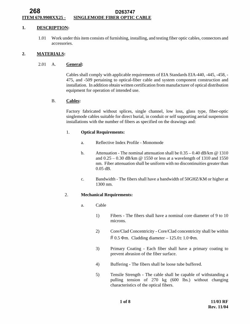
ITEM 670.9908XX25 - SINGLEMODE FIBER OPTIC CABLE
11/03 RF Rev. 11/04
1 of 8
1. DESCRIPTION:
1.01 Work under this item consists of furnishing, installing, and testing fiber optic cables, connectors and accessories.
2. MATERIALS:
2.01 A. General:
Cables shall comply with applicable requirements of EIA Standards EIA-440, -445, -458, -475, and -509 pertaining to optical-fiber cable and system component construction and installation. In addition obtain written certification from manufacturer of optical distribution equipment for operation of intended use.
B. Cables:
Factory fabricated without splices, single channel, low loss, glass type, fiber-optic singlemode cables suitable for direct burial, in conduit or self supporting aerial suspension installations with the number of fibers as specified on the drawings and:
1. Optical Requirements:
a. Reflective Index Profile - Monomode
b. Attenuation - The nominal attenuation shall be 0.35 – 0.40 dB/km @ 1310
and 0.25 – 0.30 dB/km @ 1550 or less at a wavelength of 1310 and 1550 nm. Fiber attenuation shall be uniform with no discontinuities greater than 0.05 dB.
c. Bandwidth - The fibers shall have a bandwidth of 50GHZ/KM or higher at
1300 nm.
2. Mechanical Requirements:
a. Cable
1) Fibers - The fibers shall have a nominal core diameter of 9 to 10 microns.
2) Core/Clad Concentricity - Core/Clad concentricity shall be within
0.5 m. Cladding diameter – 125.0± 1.0 m.
3) Primary Coating - Each fiber shall have a primary coating to prevent abrasion of the fiber surface.
4) Buffering - The fibers shall be loose tube buffered.
5) Tensile Strength - The cable shall be capable of withstanding a
pulling tension of 270 kg (600 lbs.) without changing characteristics of the optical fibers.
D263747268
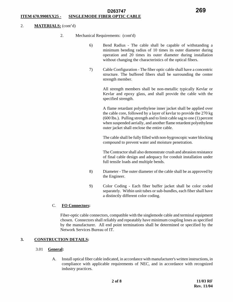
ITEM 670.9908XX25 - SINGLEMODE FIBER OPTIC CABLE
11/03 RF Rev. 11/04
2 of 8
2. MATERIALS: (cont’d)
2. Mechanical Requirements: (cont'd)
6) Bend Radius - The cable shall be capable of withstanding a minimum bending radius of 10 times its outer diameter during operation and 20 times its outer diameter during installation without changing the characteristics of the optical fibers.
7) Cable Configuration - The fiber optic cable shall have a concentric
structure. The buffered fibers shall be surrounding the center strength member.
All strength members shall be non-metallic typically Kevlar or Kevlar and epoxy glass, and shall provide the cable with the specified strength.
A flame retardant polyethylene inner jacket shall be applied over the cable core, followed by a layer of kevlar to provide the 270 kg (600 lbs.). Pulling strength and to limit cable sag to one (1) percent when suspended aerially, and another flame retardent polyethylene outer jacket shall enclose the entire cable.
The cable shall be fully filled with non-hygroscopic water blocking compound to prevent water and moisture penetration.
The Contractor shall also demonstrate crush and abrasion resistance of final cable design and adequacy for conduit installation under full tensile loads and multiple bends.
8) Diameter - The outer diameter of the cable shall be as approved by
the Engineer.
9) Color Coding - Each fiber buffer jacket shall be color coded separately. Within unit tubes or sub-bundles, each fiber shall have a distinctly different color coding.
C. FO Connectors:
Fiber-optic cable connectors, compatible with the singlemode cable and terminal equipment chosen. Connectors shall reliably and repeatably have minimum coupling loses as specified by the manufacturer. All end point terminations shall be determined or specified by the Network Services Bureau of IT.
3. CONSTRUCTION DETAILS:
3.01 General:
A. Install optical fiber cable indicated, in accordance with manufacturer's written instructions, in compliance with applicable requirements of NEC, and in accordance with recognized industry practices.
D263747 269

ITEM 670.9908XX25 - SINGLEMODE FIBER OPTIC CABLE
11/03 RF Rev. 11/04
3 of 8
3. CONSTRUCTION DETAILS: (cont’d)
3.01 General: (cont’d)
B. Coordinate optical fiber cable installation work, including electrical raceway and equipment installation work, as necessary to properly interface with other work.
C. Pull conductors simultaneously where more than one is being installed in same raceway. Use
pulling compound or lubricant where necessary; compound used must not deteriorate conductor or insulation. Use pulling means, which will not apply tension on the fibers and which will not damage conductors or raceway. Do not install conductors in raceway until all work which may cause damage has been completed.
D. No splices are allowed unless specifically directed by Contract drawings.
E. Fiber optic cable installation shall be done by a minimum of two cable manufacturer certified
individuals. A list of certified employees shall be submitted and no fiber optic cable installation shall be conducted without at least two people on that list being present at all times.
F. Fiber optic connectorization, splicing, preparation and testing shall be done by a "hands on"
certified individual in each of the respective areas. A list of such individuals shall be submitted to the Owner's Representative and only those people on this list shall be allowed to perform the above mentioned tasks.
G. All fiber connectors and splices shall be in approved enclosures.
3.02 EXPERIENCE REQUIREMENTS:
A. Personnel involved in the installation, splicing and testing of the fiber optic cable shall meet
the following requirements:
1. Three (3) years experience in the installation of fiber optic cables, including splicing, terminating and testing singlemode fibers.
2. Two (2) installed systems where fiber optic cables are installed in outdoor conduits
and the systems are in continuous satisfactory operation for at least two (2) years. The Conductor shall submit as proof, photographs or other supporting documents, and the names, addresses and telephone numbers of the operating personnel who can be contacted regarding the fiber optic system.
One (1) fiber optic cable system (which may be one of the two in the preceding paragraph) which the Contractor can arrange for demonstration to Thruway representatives and the Engineer.
3. Splicers shall have been trained and experienced on the specific splicing equipment
to be used. Proof of this training must be supplied to the Engineer upon request.
D263747270

ITEM 670.9908XX25 - SINGLEMODE FIBER OPTIC CABLE
11/03 RF Rev. 11/04
4 of 8
3. CONSTRUCTION DETAILS: (cont'd)
3.03 CABLE INSTALLATION:
A. Cables shall be pulled in conduit and trays with a steady pull without jerking. The cable pull shall be stopped and sources of hang-up found and corrected prior to continuing pulling cables. Maximum pulling force shall not exceed 270 kg (600 lbs.) tension or the manufacturer's recommendation, whichever is less.
B. Cables shall be run as straight as possible with smooth bends; sharp bends, exceeding
manufacturers recommended minimum bend radius and kinking of the cables are prohibited.
C. Any cables which have been kinked or bent beyond minimum bending radius shall be replaced at Contractor's expense.
D. Open ends of cables shall be capped to prevent moisture from entering the cables during
construction.
E. All interior cable runs shall be contained in conduit or cable tray unless otherwise specified on the Drawings.
F. No more than 270º composed of a maximum of three (3) 90º bends or per manufacturer�s
recommendation shall be allowed in any one cable pull.
G. The cable’s maximum tensile rating shall not be exceeded during pull. Rating shall be as specified in “A” above by manufacturer's date sheet.
H. Any non-hand pulls shall be monitored using a tension scale. Machine pull set ups shall be
submitted for approval on a case basis.
I. All cable pulls shall use split mesh grips and a swivel. If multiple cables are being pulled at once ensure tensile load is applied equally to all cables.
J. Fiber optic cables' outer sheath shall be stripped using cable's ripcord or factory approved
adjustable diameter sheath (ring) stripper, hook blade knife and sheath ripper.
K. Stressed pulling ends of fiber cables shall be removed prior to connectorization.
L. All aerial cable runs shall be lashed to a messenger cable or other conduit in accordance with manufacturer's recommendation.
3.04 INSTALLATION OF CONNECTORS, ACCESSORIES:
A. Fiber optic connectors, splices, pigtail modules, etc., shall be installed by qualified personnel
in strict accordance to the manufacturer's recommended methods using recommended tools: cleaver, wipes, polisher, sandpapers, crimper, strippers, scissors, epoxy, cleaner, polishing pad and plate, curing oven, inspection microscope etc. If proper equipment is not available work shall not be allowed to continue. If improper equipment is found to have been used or used improperly, the NYSTA may require all work affected to be removed and/or redone at Contractor's expense.
D263747 271

ITEM 670.9908XX25 - SINGLEMODE FIBER OPTIC CABLE
11/03 RF Rev. 11/04
5 of 8
3. CONSTRUCTION DETAILS: (cont’d)
3.04 INSTALLATION OF CONNECTORS, ACCESSORIES: (cont’d)
B. Work surfaces shall be sterilized with alcohol and dried with canned air prior to work.
C. The Contractor shall collect broken or cleaved fiber on the back side of black electrical tape immediately after breakage or cleavage.
D. All connectors shall be cleaned and polished before connection to hardware. Cleaning shall
consist of manufacturers specifications and a minimum of isopropyl alcohol and lens grade tissues.
E. Cleaving shall be done using a universal cleaver that can consistently deliver a high quality
(less than 1.2º angle typical) cleaves in the field on both single and multimode fiber.
F. The NYSTA shall be allowed to inspect finished connectors using installers microscope upon timely requests.
3.05 SPLICING REQUIREMENTS:
A. All optical fibers shall be spliced to provide continuous runs. Splices shall be allowed only
in equipment cabinets, manholes or in pull boxes (only as allowed by NYSTA Network Services).
B. All splices shall use the fusion technique. Fusion splicing equipment shall be provided by
the Contractor and shall be cleaned, calibrated and specifically adjusted to the fiber and environmental conditions at the start of each shift. Splice enclosures, tools and procedures, shall be approved by the cable manufacturer as being compatible with the cable type being delivered.
C. Each spliced fiber shall be packaged in a protective sleeving or housing. Bare fibers shall be
completely re-coated with a protective RTV, gel or similar substance, prior to application of the sleeve or housing, so as to protect the fiber from scoring, dirt or microbending.
D. Rack mounted organizer trays shall be used to hold the spliced fibers, with each fiber neatly
secured to the tray.
E. Splice loss shall not exceed 0.2 dB. If a splice is measured to exceed 0.2 dB during the splicing process it shall be remade, to a maximum of three (3) attempts, or until its loss falls below 0.2 dB. Each attempt shall be recorded for purposes of acceptance.
F. All splice losses shall be recorded in tabular form and submitted to the Engineer for
approval. An optical time domain reflectometer (OTDR) shall be used to record splice loss, chart recordings of the "signature" shall be submitted with the splice data with a record of all OTDR settings and the OTDR locations written on the trace.
D263747272

ITEM 670.9908XX25 - SINGLEMODE FIBER OPTIC CABLE
11/03 RF Rev. 11/04
6 of 8
3. CONSTRUCTION DETAILS: (cont’d)
3.06 FIELD QUALITY CONTROL:
A. General:
1. The NYSTA reserves the right to inspect wiring centers, connections, splices, etc., to ensure the Contractor is complying to standards.
2. Personnel performing tests on fiber optic cables shall be "hands on" course certified
in using an OTDR on connectorized and unconnectorized fiber optic cables. Only personnel on the Fiber Certified Employee List submitted to the Owner's Representative may conduct tests.
3. All tests shall be witnessed by NYSTA.
4. The Contractor shall notify NYSTA in writing ten (10) working days prior to testing
date.
B. Testing of Fiber Optic Cables:
1. Factory Testing: The Contractor shall submit four (4) copies of the factory OTDR test results of each cable provided. The manufacturer's test results shall indicate fiber's total dB loss and its total length. The Contractor shall not accept fibers with factory test results that exceed manufacturer's published maximum loss.
2. Pre-installation Testing: The Contractor shall test the cable while on the spool the
day it arrives at the site. The cables shall be tested using an Optical Time Domain Reflectometer (OTDR) with no internal memory, designed for singlemode fiber at transmissions wavelength of 1310 and 1550 nm. The OTDR shall be portable, menu drive, rapid display updating, and have a built-in printer, parameter storage, real time analog output and display distance (M/FC), and absolute attenuation (dB/m, dB/F). The fibers shall be tested using an index matching gel filled lab splice or an XYZ alignment mechanism made specifically for coupling of bare fibers. The unit shall be used in strict accordance with the OTDR manufacturer's recommended test procedures.
The Contractor shall record and submit test results as follows:
a. The strip chart (x-y) printout of OTDR tests shall have the cable number
being tested, all OTDR settings, attenuation (dB), cable length, and the operator's signature. The Contractor shall submit tests results on 8.5" x 11" paper for approval.
3. Post Installation Testing: The total fiber run (connectors, splices and fiber) shall be
tested once the system is completely connected to interconnect centers. The test shall use an OTDR (same as specified in above) and the results shall be recorded and submitted as specified above. The fiber run shall be tested at 1310 and 1550 nm wavelength and in strict accordance with the manufacturer's recommended test procedures.
D263747 273
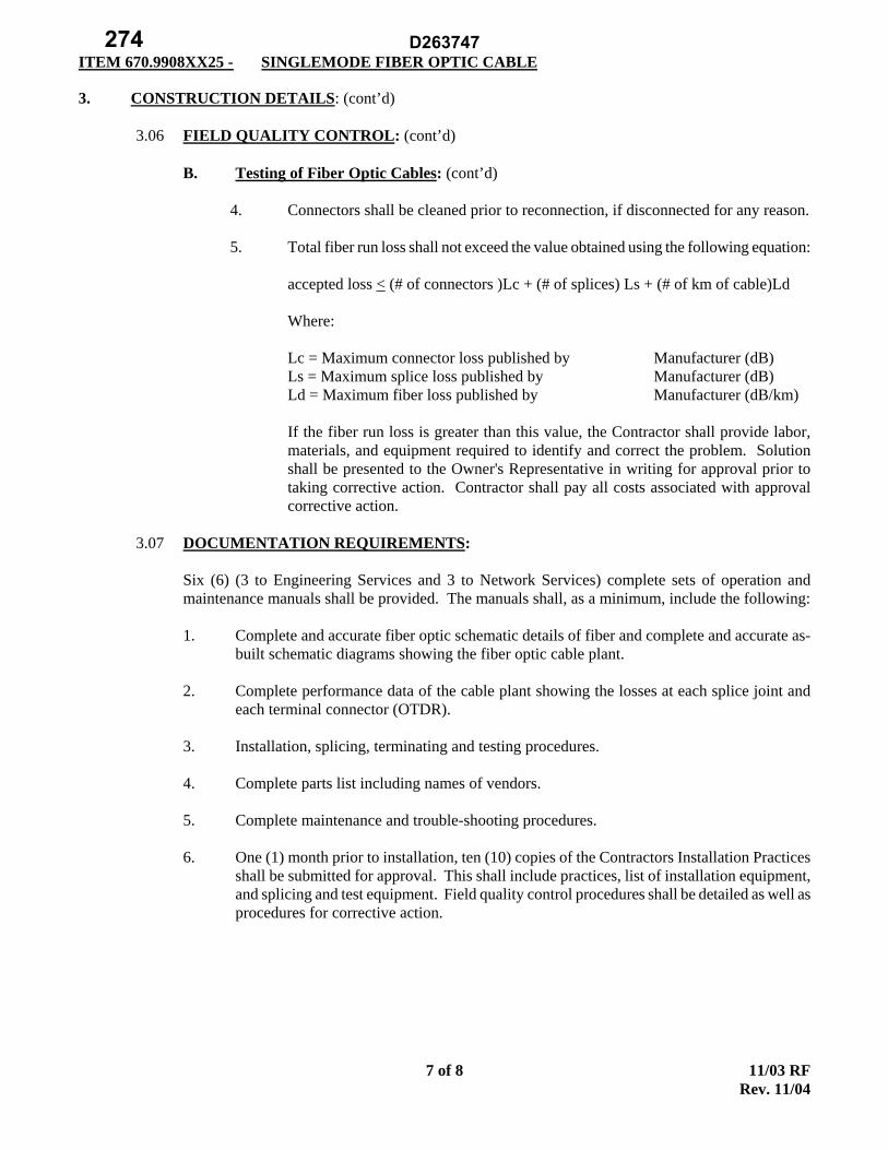
ITEM 670.9908XX25 - SINGLEMODE FIBER OPTIC CABLE
11/03 RF Rev. 11/04
7 of 8
3. CONSTRUCTION DETAILS: (cont’d)
3.06 FIELD QUALITY CONTROL: (cont’d)
B. Testing of Fiber Optic Cables: (cont’d)
4. Connectors shall be cleaned prior to reconnection, if disconnected for any reason.
5. Total fiber run loss shall not exceed the value obtained using the following equation:
accepted loss < (# of connectors )Lc + (# of splices) Ls + (# of km of cable)Ld
Where:
Lc = Maximum connector loss published by Manufacturer (dB) Ls = Maximum splice loss published by Manufacturer (dB)
Ld = Maximum fiber loss published by Manufacturer (dB/km)
If the fiber run loss is greater than this value, the Contractor shall provide labor, materials, and equipment required to identify and correct the problem. Solution shall be presented to the Owner's Representative in writing for approval prior to taking corrective action. Contractor shall pay all costs associated with approval corrective action.
3.07 DOCUMENTATION REQUIREMENTS:
Six (6) (3 to Engineering Services and 3 to Network Services) complete sets of operation and maintenance manuals shall be provided. The manuals shall, as a minimum, include the following:
1. Complete and accurate fiber optic schematic details of fiber and complete and accurate as-
built schematic diagrams showing the fiber optic cable plant.
2. Complete performance data of the cable plant showing the losses at each splice joint and each terminal connector (OTDR).
3. Installation, splicing, terminating and testing procedures.
4. Complete parts list including names of vendors.
5. Complete maintenance and trouble-shooting procedures.
6. One (1) month prior to installation, ten (10) copies of the Contractors Installation Practices
shall be submitted for approval. This shall include practices, list of installation equipment, and splicing and test equipment. Field quality control procedures shall be detailed as well as procedures for corrective action.
D263747274

ITEM 670.9908XX25 - SINGLEMODE FIBER OPTIC CABLE
11/03 RF Rev. 11/04
8 of 8
3. CONSTRUCTION DETAILS: (cont’d)
3.08 CABLE IDENTIFICATION:
Fiber optic cables shall be labeled with cable markers specified herein at locations specified below:
a. Fiber optic cables installed aerially, exposed or in tray shall be labeled every 4.5 meters (15 feet).
b. Each individual subcable fiber shall be labeled one inch from connector. (Use label as
specified herein.)
c. At pull boxes and fiber distribution panels. 4. METHOD OF MEASUREMENT:
4.01 Payment will be made for items at a unit of meters (linear feet). 5. BASIS OF PAYMENT:
5.01 The unit price bid for each meter (linear foot) of fiber cable shall include the cost of furnishing all labor, equipment, and material necessary for a complete fiber optic link.
ITEM NO. DESCRIPTION PAY UNIT 670.99080425 SINGLEMODE FIBER OPTIC CABLE - FIBER 4 M/LF 670.99080625 SINGLEMODE FIBER OPTIC CABLE - FIBER 6 M/LF 670.99081225 SINGLEMODE FIBER OPTIC CABLE - FIBER 12 M/LF
670.99082025 SINGLEMODE FIBER OPTIC CABLE – FIBER 20 M/LF
D263747 275

ITEM 680.50005011 - FOUNDATION FOR TRAFFIC STANDARD TYPE M-2-5S (NEW YORK CITY)
ITEM 680.50010011 - FOUNDATION FOR TRAFFIC STANDARD TYPE M-l (NEW YORK CITY)
ITEM 680.50020011 -FOUNDATION FOR TRAFFIC STANDARD TYPE M-I-S (NEW YORK CITY)
ITEM 680.50030011 -FOUNDATION FOR TRAFFIC STANDARD TYPE M-2-2T (NEW YORK CITY)
ITEM 680.50040011 -FOUNDATION FOR TRAFFIC STANDARD TYPE M-2-3T (NEW YORK CITY)
ITEM 680.50050011 - FOUNDATION FOR TRAFFIC STANDARD TYPE M-2-ST (NEW YORK CITY)
ITEM 680.50060011 - FOUNDATION FOR TRAFFIC STANDARD TYPE S-I-A (NEW YORK CITY)
ITEM 680.50070011- FOUNDATION FOR TRAFFIC STANDARD TYPE T-I-A (NEW YORK CITY)
1 of 1 E 08/09/2012
DESCRIPTION:
Under this work, where shown on the plans or where directed by the Engineer, the Contractor shall
construct foundations for traffic standards of the type called for on the plans.
MATERIALS:
Materials shall be as specified in the "General Specifications for Traffic Light Facilities" contained in the
publication "City of New York SPECIFICATIONS - Compiled 1970 for Use with State of New York
Department of Transportation Construction Contracts" and as indicated on the following Department of
Traffic Standard Drawings:
Foundation Type Standard Drawing
M-I-S LB-lll
M-2-2T, M-2-3T, M-2-ST, LB-I028-S
S-l-A, T-I-A LG-170-S
M-2-5S LB-I028-S
Concrete shall be Class A meeting the requirements of Section 501, "Portland Cement Concrete - General",
of the Standard Specifications. Anchor bolts and couplings shall conform to Department of Traffic Standard
Drawing LG-I04-S.
CONSTRUCTION DETAILS:
The foundations shall be constructed in accordance with the plans, the "General Specifications for Traffic
Light Facilities" and Department of Traffic Standard Drawings LB-lll , LB-l 028-S, LG-1 70-S, LG-62-S,
LG-97 -S and LG-169-S . Excavation and backfill shall conform to Section 206, "Trench, Culvert and
Structure Excavation".
METHOD OF MEASUREMENT:
The quantity to be paid for will be the number of traffic standard foundations of each type completed as
specified.
BASIS OF PAYMENT:
The unit price bid per foundation shall include the cost of all excavation, backfill, concrete, reinforcement,
conduit elbows and caps, precast concrete slabs, anchor bolts and couplings, labor, equipment, and all other
materials necessary to complete the work.
D263747276

ITEM 680.58801008 WIRELESS VEHICLE DETECTION SYSTEM REPEATER-(LONG LIFE)
ITEM 680.58802008 WIRELESS VEHICLE DETECTION SYSTEM FREEWAY SENSOR
ITEM 680.58803008 WIRELESS VEHICLE DETECTION SYSTEM INTERSECTION SENSOR
ITEM 680.58804008 WIRELESS VEHICLE DETECTION SYSTEM CONTACT CLOSURE
INTERFACE (APCC)
ITEM 680.58805008 WIRELESS VEHICLE DETECTION SYSTEM EXTENSION CONTACT
CLOSURE CARD
ITEM 680.58806008 WIRELESS VEHICLE DETECTION SYSTEM ISOLATOR MODULE (ISO)
ITEM 680.58807008 WIRELESS VEHICLE DETECTION SYSTEM SERIAL PORT PROTOCOL
DIGITAL RADIO (SPP)
ITEM 680.58808008 WIRELESS VEHICLE DETECTION CONTACT CLOSURE INTERFACE
(APCCM-E) WITH ETHERNET COMMUNICATIONS
Page 1 of 6 4/15/2013
Rev. 4/8/2014
Rev. 6/15/2014
Rev. 11/16/2015
DESCRIPTION
Under these items the contractor shall furnish and install a wireless, battery‐powered magnetometer vehicle
detection system as shown in the contract documents or where directed by the engineer.
The wireless, battery‐powered magnetometer vehicle detection system shall consist of one or more of the
following:
Battery‐powered sensors installed in‐pavement in each traffic lane (paid under its respective item).
Access Point Contact Closure (APCC) Card to interface between a standard 170/2070 controller using
contact closure signals.
Access Point Contact Closure (APCCM-E) Card to interface to a central control system using Ethernet
and TCP/IP networking.
Serial Port Protocol Digital Radio (SPP) mounted on the side of the roadway, serving as the communications hub for the installation. Multiple SPPs may be employed per installation.
Optional wireless repeaters mounted on the side of the roadway, serving to extend the radio range of an
APCC. Contact Closure Extension cards to support the interface between an APCC and a standard
170/2070 controller using contact closure signals (paid under its respective item)
Isolation Module for each SPP
Software to control and configure the sensors, APCCs and repeaters
Software to store and retrieve detection data
Communications between the sensors and the SPP or repeater and between the repeater and SPP shall be via
radio. For traffic signal applications, detection data shall be relayed from each SPP to a local 170/2070
controller for real‐time vehicle presence detection using contact closure signals. If an APCCM-E is specified in
the contract documents, data shall be relayed from each APCCM-E to a central software system or central
server over standard IP (Internet Protocol) networks. NYSDOT shall provide the contractor with network
configuration information necessary for the configuration of each APCCM-E.
MATERIALS
All sensor components shall be contained within a single housing. The sensor housing shall conform to
NEMA Type 6P and IEC IP68 standards. All SPP components shall be contained within a single housing. The
SPP housing shall conform to NEMA Type 4X and IEC IP67 standards. All repeater components shall be
contained within a single housing. The repeater housing shall conform to NEMA Type 4X and IEC IP67
standards.
The sensor components shall be fully encapsulated within the housing to prevent moisture from degrading the
D263747 277

ITEM 680.58801008 WIRELESS VEHICLE DETECTION SYSTEM REPEATER-(LONG LIFE)
ITEM 680.58802008 WIRELESS VEHICLE DETECTION SYSTEM FREEWAY SENSOR
ITEM 680.58803008 WIRELESS VEHICLE DETECTION SYSTEM INTERSECTION SENSOR
ITEM 680.58804008 WIRELESS VEHICLE DETECTION SYSTEM CONTACT CLOSURE
INTERFACE (APCC)
ITEM 680.58805008 WIRELESS VEHICLE DETECTION SYSTEM EXTENSION CONTACT
CLOSURE CARD
ITEM 680.58806008 WIRELESS VEHICLE DETECTION SYSTEM ISOLATOR MODULE (ISO)
ITEM 680.58807008 WIRELESS VEHICLE DETECTION SYSTEM SERIAL PORT PROTOCOL
DIGITAL RADIO (SPP)
ITEM 680.58808008 WIRELESS VEHICLE DETECTION CONTACT CLOSURE INTERFACE
(APCCM-E) WITH ETHERNET COMMUNICATIONS
Page 2 of 6 4/15/2013
Rev. 4/8/2014
Rev. 6/15/2014
Rev. 11/16/2015
components. The sensor housing shall be capable of being installed in a 4” diameter hole approximately 2 ¼”
deep. An SPP shall be no larger than 12” H x 8” W x 4”D. A repeater shall be no larger than 5”H x 4”W x 4”D.
An SPP and a repeater shall weigh no more than 4 pounds (1.8 kg) each. An SPP shall support at least 48
sensors. A repeater shall support at least 10 sensors.
The sensor, SPP/APCC, ISO and the repeater shall operate at temperatures from -37 F to +176 F. A sensor shall
be battery-powered with an average lifetime of ten (10) years when the sensor is configured for and operating
under normal traffic conditions. The long life repeater shall be battery- powered, have a life expectancy a
minimum of 7 years and the battery shall be field replaceable. An APCC shall be factory-configurable to
support at least two (2) different power options:
• Power shall be supplied via an isolated nominal 48 VDC (36-58 VDC) input, consuming a
maximum of 3W and providing 1500 V isolation and 5 kV surge protection
• Power shall be supplied via a non-isolated nominal 12 VDC (10-15 VDC) input, consuming a
maximum of 2W
Each sensor shall detect a vehicle by magnetometer-type detection by measuring changes in the earth’s
magnetic field near the sensor as caused by a stopped or passing vehicle. The sensor shall sample the earth’s
magnetic field at a rate of 128 Hz and shall communicate time-stamped ON and OFF vehicle detection
events. As an option, the sensor shall provide a mode where the complete X-Y-Z magnetic signatures of detected
vehicles are transmitted as data. In the event of a detector lock, each sensor shall automatically recalibrate. Each
sensor shall communicate by radio to a nearby SPP/APCC or repeater. Each sensor shall transmit its detection
data within 150 ms of a detected event. Each sensor shall automatically re-transmit a detected event if no
acknowledgement is received from the access point. Each sensor may stop retransmission after 8 attempts.
After losing radio contact because of stopped vehicles over or near the sensor, each sensor shall be capable of
re- establishing the radio link with its supporting access point or receiver in less than 2 seconds. Each sensor
shall transmit a unique identifying code and shall respond within 100 seconds when the access point is
powered on. When no APCC or repeater is present or powered on, the sensors shall not be required to detect
vehicles.
The radio links between each sensor and SPP/APCC or repeater and between each repeater and SPP/APCC
shall conform to the following requirements: The physical layer of the radio links between each sensor and
SPP/APCC or repeater and between each repeater and SPP/APCC shall conform to published standards. The
center frequencies, bandwidths, and transmit power levels of the radio links shall allow operation in an
unlicensed frequency band. Frequency channels shall be employed by the sensors, SPP/APCC, and repeaters to
avoid interference with other devices operating in the unlicensed band. The frequency channels shall be user-
configurable and at least 16 frequency channels shall be supported. The link budget (transmit power plus transmit
antenna gain plus receive antenna gain minus receive sensitivity, where receive sensitivity shall assume a 1%
packet error rate) for all radio links shall be 93 dB or greater.
D263747278

ITEM 680.58801008 WIRELESS VEHICLE DETECTION SYSTEM REPEATER-(LONG LIFE)
ITEM 680.58802008 WIRELESS VEHICLE DETECTION SYSTEM FREEWAY SENSOR
ITEM 680.58803008 WIRELESS VEHICLE DETECTION SYSTEM INTERSECTION SENSOR
ITEM 680.58804008 WIRELESS VEHICLE DETECTION SYSTEM CONTACT CLOSURE
INTERFACE (APCC)
ITEM 680.58805008 WIRELESS VEHICLE DETECTION SYSTEM EXTENSION CONTACT
CLOSURE CARD
ITEM 680.58806008 WIRELESS VEHICLE DETECTION SYSTEM ISOLATOR MODULE (ISO)
ITEM 680.58807008 WIRELESS VEHICLE DETECTION SYSTEM SERIAL PORT PROTOCOL
DIGITAL RADIO (SPP)
ITEM 680.58808008 WIRELESS VEHICLE DETECTION CONTACT CLOSURE INTERFACE
(APCCM-E) WITH ETHERNET COMMUNICATIONS
Page 3 of 6 4/15/2013
Rev. 4/8/2014
Rev. 6/15/2014
Rev. 11/16/2015
Each sensor in an installation shall be capable of being individually configured with its own sensitivity level. A
single sensor shall be capable of being configured with a sensitivity level that approximates the detection zone of
a standard 6’ x 6’ inductive loop. Each sensor shall be capable of being configured with relatively higher or lower
sensitivity levels as may be required to detect bicycles or motorcycles. Up to two sensors properly configured
shall be capable of detecting motorcycles in a standard traffic lane and bicycles in a designated bicycle lane.
An SPP/APCC shall support the relay of sensor detection data through several interfaces as required by the
application. Detection data shall be communicated to a standard roadside 170/2070 controller via APCC card
capable of being installed in standard contact closure input shelves. As an option, detection data shall be
communicated over TCP/IP via an integrated 10 Base-T and 100 Base-T Ethernet interface. As an option,
detection data shall be communicated as IP data over GSM-based cellular data services via an integrated GPRS
cellular modem. As an option, detection data shall be communicated as IP data over CDMA-based cellular data
services via an integrated 1xRTT and EVDO/LTE cellular modem. The APCC shall be capable of
simultaneously communicating detection data via the contact closure interface, optional Ethernet
interface, and optional cellular data modem interface.
Each sensor, APCC, and repeater shall be capable of accepting software and firmware upgrades.
The wireless battery-powered magnetometer vehicle detection system shall provide software operating on
conventional notebook/portable PCs to support configuration of a sensor, APCC, repeater and store & retrieve
detection data.
Each Access Point Contact Closure Interface APCC card shall provide detector data as contact closure signals to
the 170/2070 controller. An APCC card shall directly plug in to standard 170/2070 input files or NEMA detector
racks. Additional Extension Contact Closure cards shall provide up to 256 channels of detection data from a
single APCC’s supported sensors, where each channel comprises an optically isolated contact closure relay and,
if configured for TS2 operation, an additional contact closure relay to indicate the channel status. Each
Extension Contact Closure card shall be configurable by providing contact closure signals in either presence or
pulse mode with up to 31 seconds of delay timing and 7.5 seconds of extension (carryover) timing. The
Extension Contact Closure card front panel shall provide status LEDs to monitor detection channel status, line
quality and fault monitor. The Extension Contact Closure card front panel shall provide switches to select and
configure presence or pulse mode, delay timing and extension timing. An Extension Contact Closure card shall
be powered by the 170/2070 controller backplane via an 11-26 VDC input. Contact closure cards shall be
powered from input file assembly rack or detector rack, not from controller back panel. An Extension Contact
Closure card shall be surge protected to GR-1089 standards. An Extension Contact Closure card shall operate at
Temperatures from -37 F to +176 F.
An Extension Contact Closure card shall operate in humidity up to 95% (non- condensing).
The APCCME shall have all the features and functions of the APCC in addition to the following when polled by
a Central management Software Application.
D263747 279

ITEM 680.58801008 WIRELESS VEHICLE DETECTION SYSTEM REPEATER-(LONG LIFE)
ITEM 680.58802008 WIRELESS VEHICLE DETECTION SYSTEM FREEWAY SENSOR
ITEM 680.58803008 WIRELESS VEHICLE DETECTION SYSTEM INTERSECTION SENSOR
ITEM 680.58804008 WIRELESS VEHICLE DETECTION SYSTEM CONTACT CLOSURE
INTERFACE (APCC)
ITEM 680.58805008 WIRELESS VEHICLE DETECTION SYSTEM EXTENSION CONTACT
CLOSURE CARD
ITEM 680.58806008 WIRELESS VEHICLE DETECTION SYSTEM ISOLATOR MODULE (ISO)
ITEM 680.58807008 WIRELESS VEHICLE DETECTION SYSTEM SERIAL PORT PROTOCOL
DIGITAL RADIO (SPP)
ITEM 680.58808008 WIRELESS VEHICLE DETECTION CONTACT CLOSURE INTERFACE
(APCCM-E) WITH ETHERNET COMMUNICATIONS
Page 4 of 6 4/15/2013
Rev. 4/8/2014
Rev. 6/15/2014
Rev. 11/16/2015
If detection data is relayed to a central software system or central server, each installation of the Wireless
Battery-Powered Magnetometer Vehicle Detection System shall provide the following measurements, as
required by the application:
Vehicle volume (count) per lane over a specified time interval
Lane occupancy (percent) over a specified time interval
Vehicle speed (mph or kph) when more than one sensor is deployed in a lane
Per-vehicle speed
Median speed over a specified time interval
Mean speed over a specified time interval
Distribution of speeds over a specified time interval, with a resolution of 1 mph / 2 kph
Vehicle classification when more than one sensor is deployed in a lane
Per-vehicle length
Report distribution of vehicle lengths over a specified time interval, with a resolution of 1 foot /
0.5 meters
The time interval for measurements shall be selectable, including at least the following intervals:
30 seconds
1 minute
5 minutes
6 minutes
15 minutes
1 hour
24 hours
Silicone sealant used to secure and cover the sensor in the cored hole in the pavement shall conform to the
provisions of §705-05, Silicone Joint Sealants for Pavements.
CONSTRUCTION DETAILS
Each sensor shall be installed in the roadway at the locations shown on the contract drawings or as ordered by
the engineer. The roadway shall be core drilled to provide a 4” diameter hole, 2.25” deep. A small layer of
silicone sealant shall be applied to cover the bottom of the hole. The sensor shall then be placed on top of this
layer in the correct orientation as clearly marked on the sensor. The sensor shall be fully encapsulated with the
D263747280

ITEM 680.58801008 WIRELESS VEHICLE DETECTION SYSTEM REPEATER-(LONG LIFE)
ITEM 680.58802008 WIRELESS VEHICLE DETECTION SYSTEM FREEWAY SENSOR
ITEM 680.58803008 WIRELESS VEHICLE DETECTION SYSTEM INTERSECTION SENSOR
ITEM 680.58804008 WIRELESS VEHICLE DETECTION SYSTEM CONTACT CLOSURE
INTERFACE (APCC)
ITEM 680.58805008 WIRELESS VEHICLE DETECTION SYSTEM EXTENSION CONTACT
CLOSURE CARD
ITEM 680.58806008 WIRELESS VEHICLE DETECTION SYSTEM ISOLATOR MODULE (ISO)
ITEM 680.58807008 WIRELESS VEHICLE DETECTION SYSTEM SERIAL PORT PROTOCOL
DIGITAL RADIO (SPP)
ITEM 680.58808008 WIRELESS VEHICLE DETECTION CONTACT CLOSURE INTERFACE
(APCCM-E) WITH ETHERNET COMMUNICATIONS
Page 5 of 6 4/15/2013
Rev. 4/8/2014
Rev. 6/15/2014
Rev. 11/16/2015
silicone sealant to the lip of the cored hole.
The maximum distance between a sensor installed in the roadway and an SPP or a repeater with a clear
line-of-sight between devices shall be at least 150’ for an access point or repeater installed 24’ above the
roadway, at least 100’ for an APCC or repeater installed 18’ above the roadway and at least 75’ for an APCC
or repeater installed 12’ above the roadway. The maximum distance between an APCC and a repeater shall
be at least 750’ when both units are installed 18’ above the roadway and with a clear line-of-sight between devices.
The SPP Digital Radio can be wired up to 2000’ from the APCC. Up to 2 SPP’s can be wired to an APCC.
Each SPP requires an ISO for proper operation. The ethernet cable shall be provided in the appropriate length as
indicated on the plans. There will be no separate payment for this cable.
Each installation of the wireless battery-powered magnetometer vehicle detection system shall consist of one or
more sensors installed in each traffic lane where presence detection is required, avoiding sources of magnetic
noise such as underground power cables, overhead high tension power cables, light rail or subway tracks, and
power generation stations and sub-stations. The sensors shall be located as specified by the contract drawings,
with each sensor’s supporting access point or receiver installed no farther than the maximum range indicated
above.
The contractor shall not damage the sensors and other equipment during construction. The sensors shall be
removed and installed during various phases and sub-phases in accordance with the contract drawings. Core
holes left in the pavement upon removal of sensors shall be filled with asphalt cold patch by the contractor at
no additional cost to the State. The contractor shall ensure that the wireless battery- powered magnetometer
vehicle detection system operates according to specification during all phases and sub-phases of construction.
All equipment shall become the property of NYSDOT upon project completion.
D263747 281

Page 6 of 6 4/15/2013
Rev. 4/8/2014
Rev. 6/15/2014
Rev. 11/16/2015
ITEM 680.58801008 WIRELESS VEHICLE DETECTION SYSTEM REPEATER-(LONG LIFE)
ITEM 680.58802008 WIRELESS VEHICLE DETECTION SYSTEM FREEWAY SENSOR
ITEM 680.58803008 WIRELESS VEHICLE DETECTION SYSTEM INTERSECTION SENSOR
ITEM 680.58804008 WIRELESS VEHICLE DETECTION SYSTEM CONTACT CLOSURE
INTERFACE (APCC)
ITEM 680.58805008 WIRELESS VEHICLE DETECTION SYSTEM EXTENSION CONTACT
CLOSURE CARD
ITEM 680.58806008 WIRELESS VEHICLE DETECTION SYSTEM ISOLATOR MODULE (ISO)
ITEM 680.58807008 WIRELESS VEHICLE DETECTION SYSTEM SERIAL PORT PROTOCOL
DIGITAL RADIO (SPP)
ITEM 680.58808008 WIRELESS VEHICLE DETECTION CONTACT CLOSURE INTERFACE
(APCCM-E) WITH ETHERNET COMMUNICATIONS
METHOD OF MEASUREMENT
The wireless, battery‐powered magnetometer vehicle detection system will be measured as the number of units
satisfactorily installed in accordance with the contract documents.
At a minimum, the wireless, battery‐powered magnetometer vehicle detection system requires:
(1) Access Point Contact Closure Interface Card (APCC); paid under its respective item
-- OR –
(1) Access Point Contact Closure Interface Card with Ethernet (APCCM-E); paid under its respective item
(1) Serial Port Protocol Digital Radio (SPP) and Ethernet cable as required; paid under its respective
item
(1) Isolation Module (ISO); paid under its respective item
Intersection sensors, Freeway sensors, Long Life Repeaters and Extension Contact Closure Cards will be specified on the plans and will be paid under their respective items.
BASIS OF PAYMENT
The unit price bid for furnishing and installing each item shall include the cost of furnishing all labor, materials,
equipment, tools and all necessary tests to satisfactorily complete the work in accordance with the contract
documents.
D263747282

ITEM 680.58801108 - WIRELESS VEHICLE DETECTION SYSTEM PAVEMENT
SENSOR
ITEM 680.58801208 - WIRELESS VEHICLE DETECTION BASE STATION
ITEM 680.58801308 - WIRELESS VEHICLE DETECTION ACCESS POINT
ITEM 680.58801408 - WIRELESS VEHICLE DETECTION SYSTEM CONTACT
CLOSURE CARD
Page 1 of 6 3-28-2017
DESCRIPTION:
Under these items the contractor shall furnish and install a wireless, battery‐powered
magnetometer vehicle detection system as shown in the contract documents or where directed by
the Engineer.
The wireless, battery‐powered magnetometer vehicle detection system shall consist of the
following equipment:
Battery‐powered sensors installed in‐pavement in each traffic lane as indicated in the
Contract Documents
System radios (including repeaters, if required) that communicate wirelessly with the
sensors and provide detection information to the processing unit.
A base station unit capable of interpreting the information provided by the sensors.
Software to control and configure the detectors, base station units and access points.
A SDLC interface to provide a communication interface between a base station unit and a
standard 2070 controller.
Communications between the detectors and the access point shall be via radio. When only one
access point is used, it shall be hard-wired to the base station. When two access points are used
in one site, the access point with the weakest signal shall be hard-wired to the base station,
except when the cable routing distance is greater than 950 ft. For traffic signal applications,
detection data shall be relayed from each sensor to a local 2070 controller for real‐time vehicle
presence detection using SDLC interfaces. If a network interfaced base station unit is specified in
the contract documents, data shall be broadcast from each base station unit to a central software
system or central server over standard TCP/IP (Internet Protocol) networks. NYSDOT shall
provide the contractor with network configuration information necessary for the configuration of
each networked base station unit.
MATERIALS:
PAVEMENT SENSOR
All detector components shall be contained within a single housing. The sensor housing
shall conform to NEMA Type 6P and IEC IP68 standards.
Detectors should communicate at an Ultra High Frequency, increasing the range and
battery life of the sensor device.
The detector housing shall be capable of being installed in a 4.5” diameter hole.
The detector components shall be fully encapsulated within clamshell housing to prevent
moisture from degrading the components.
The detector shall operate at temperatures from -35° F to +176° F.
D263747 283

ITEM 680.58801108 - WIRELESS VEHICLE DETECTION SYSTEM PAVEMENT
SENSOR
ITEM 680.58801208 - WIRELESS VEHICLE DETECTION BASE STATION
ITEM 680.58801308 - WIRELESS VEHICLE DETECTION ACCESS POINT
ITEM 680.58801408 - WIRELESS VEHICLE DETECTION SYSTEM CONTACT
CLOSURE CARD
Page 2 of 6 3-28-2017
A detector shall be battery-powered with a minimum lifetime of eight (8) years when the
detector is configured for, and operating under normal traffic conditions.
Each detector shall detect a vehicle by magnetometer detection by measuring changes in
the earth’s magnetic field near the sensor as caused by a stopped or passing vehicle. The
sensor shall have a three (3) axis magnetometer with dual sensors in the Z-axis to
improve capture accuracy.
The detector shall be capable of operating in three (3) detection modes: count, presence
and speed.
The detector shall be capable of wirelessly accepting software and firmware upgrades.
In the event of a detector lock, “memory on”, each detector shall automatically
recalibrate.
Each detector shall transmit its detection data within 150ms of a detected event.
Each detector shall automatically re-transmit a detected event if no acknowledgement is
received from the base station unit. Each detector may stop retransmission after 8
attempts.
After losing radio contact because of stopped vehicles over or near the detector, each
detector shall be capable of re-establishing the radio link with its supporting access point
or receiver in less than 2 seconds.
Each detector shall transmit a unique identifying code and shall respond within 100
seconds when the base station unit is powered on.
When no base station unit is present or powered on, the detector shall not be required to
detect vehicles.
Each detector in an installation shall be capable of being individually configured with its
own sensitivity level. A single detector shall be capable of being configured with a
sensitivity level that approximates the detection zone of a standard 6’ x 6’ inductive loop.
o Each detector shall be capable of being configured with relatively higher or lower
sensitivity levels as may be required to detect bicycles or motorcycles.
o Each pavement sensor is only required to be capable of reporting vehicle
presence.
o Up to two detectors properly configured shall be capable of detecting motorcycles
in a standard traffic lane and bicycles in a designated bicycle lane.
The detector shall be supplied with sufficient two part epoxy resin to secure and cover the
sensor inside the cored hole in the pavement where it will be installed.
BASE STATION UNITS
The base station shall be capable of being installed in shelf mount within the cabinet.
The base station shall be capable of being installed in card mount within the cabinet.
Each base station unit shall be capable of operation at temperatures from -35° F to
+176°F.
D263747284

ITEM 680.58801108 - WIRELESS VEHICLE DETECTION SYSTEM PAVEMENT
SENSOR
ITEM 680.58801208 - WIRELESS VEHICLE DETECTION BASE STATION
ITEM 680.58801308 - WIRELESS VEHICLE DETECTION ACCESS POINT
ITEM 680.58801408 - WIRELESS VEHICLE DETECTION SYSTEM CONTACT
CLOSURE CARD
Page 3 of 6 3-28-2017
The base station unit shall include, or make available via the Internet at no extra charge,
an interface specification or application programming interface that will allow for
retrieval of traffic data from the base station unit over a TCP/IP Ethernet connection.
The base station unit shall consist of, at a minimum, the base station, SDLC interface,
software, and all ancillary equipment needed for a complete installation.
ACCESS POINTS
The access points shall operate at temperatures from -35° F to +176° F.
The access points shall be FCC Part 15 compliant and shall not interfere with public
safety radio bands or other radio services.
A detection access point shall be no larger than 8” H x 8” W x 8”D. The access point
shall not weigh more than 4 pounds (1.8 kg)
All access point components shall be contained within a single housing. The access point
housing shall conform to NEMA Type 4X and IEC IP67 standards
The access point shall support communications with at least 48 sensors.
The access point shall reliably communicate with all in-pavement detectors within 500
feet, without the use of repeaters.
Additional range may be provided through the use of repeaters. If repeaters are required,
all repeater components shall be included in this item, including poles, foundations,
mounting hardware, and any other items required for a complete installation. There is no
separate payment for repeater equipment.
The access point shall be able to support up to three (3) radios directly connected to it.
The access point shall be able to communicate with the base station with a fixed cable, a
wireless connection or both simultaneously.
The access point shall also be able to accept RF splitters being used on up to two (2) of
the connected radios to allow for up to five (5) radios per access point.
Each access point shall include all antennas, mounting devices, cabling, surge protection
and RF splitters, needed to a complete installation. There is no separate payment for this
equipment.
Each access point must be supplied with any electrical isolation equipment necessary for
protection from electrical surges in the power supply. There is no separate payment for
this equipment.
Each access point must be supplied with any cabling necessary for its operation. There is
no separate payment for this equipment.
The access point shall be capable of accepting firmware upgrades.
The radio links between each sensor and each access point shall conform to the following
requirements:
o The physical layer of the radio links between each sensor and access point shall
conform to published standards.
D263747 285

ITEM 680.58801108 - WIRELESS VEHICLE DETECTION SYSTEM PAVEMENT
SENSOR
ITEM 680.58801208 - WIRELESS VEHICLE DETECTION BASE STATION
ITEM 680.58801308 - WIRELESS VEHICLE DETECTION ACCESS POINT
ITEM 680.58801408 - WIRELESS VEHICLE DETECTION SYSTEM CONTACT
CLOSURE CARD
Page 4 of 6 3-28-2017
o The center frequencies, bandwidths, and transmit power levels of the radio links
shall allow operation in an unlicensed frequency band for Detector Wireless links.
o Frequency channels shall be employed by the sensors and system radio to avoid
interference with other devices operating in the unlicensed band. The frequency
channels shall be user-configurable and at least 16 frequency channels shall be
supported.
VEHICLE DETECTION APPLICATIONS
This application uses the wireless magnetometer system as vehicle detection for signalized
intersection control, as well as other applications where the wireless magnetometer system data
is being subsequently processed or communicated by a 2070 controller. These applications
require the card mount form factor.
Detection data shall be communicated to a standard roadside 2070 controller via a base
station unit expansion card capable of being installed in standard 33X input file
assemblies, with a SDLC cable
If expansion cards are to be installed within the detector input rack of the cabinet. The
cards shall have a minimum of four (4) optically isolated outputs per card.
Rack mount processing units shall include an Ethernet interface for communicating
directly via a wired TCP/IP network. This shall include a minimum 3 foot (1 meter) long
EIA/TIA 568B RJ45 terminated category 6 network cable.
The base station unit shall be capable of simultaneously communicating detection data
via the contact closure interface and Ethernet interface.
Contact closure card shall operate at Temperatures from -35 F to +176 F.
Each installed contact closure card shall provide an additional minimum of 4 channels of
detection data to the input file and 2070 controller.
Each contact closure card shall be configurable to provide contact closure signals in
either presence or pulse mode
The contact closure card front panel shall provide status LEDs to monitor detection
channel status, line quality and fault monitor.
The contact closure card front panel shall provide means to select and configure presence
or pulse mode, delay timing and extension timing.
Contact closure cards shall be powered from input file assembly rack or detector rack, not
from controller back panel.
Contact closure cards shall be surge protected to GR-1089 standards.
Contact closure cards shall operate in humidity up to 95% (non- condensing).
D263747286

ITEM 680.58801108 - WIRELESS VEHICLE DETECTION SYSTEM PAVEMENT
SENSOR
ITEM 680.58801208 - WIRELESS VEHICLE DETECTION BASE STATION
ITEM 680.58801308 - WIRELESS VEHICLE DETECTION ACCESS POINT
ITEM 680.58801408 - WIRELESS VEHICLE DETECTION SYSTEM CONTACT
CLOSURE CARD
Page 5 of 6 3-28-2017
CONSTRUCTION DETAILS:
All construction shall conform to Section 680-3.01 of the Standard Specifications.
The contractor shall not damage the components of the wireless vehicle detection system
during construction.
The contractor shall ensure that the wireless vehicle detection system operates according
to manufacturer specification during all phases and sub-phases of construction.
All equipment shall become the property of NYSDOT upon project completion.
PAVEMENT SENSORS
The roadway shall be core drilled to provide a 4.5” diameter hole at the location and to
the depth indicated in the contract plans or as directed by the Engineer. All debris from
the drilling process shall be removed cored hole to provide a clean surface to mount the
sensor.
A layer of two part epoxy shall be applied to cover the bottom of the hole. The detector,
within a protective shell (if offered by the manufacture), shall then be placed on top of
this layer in the correct orientation as marked on the detector. The upper edge of the
sensor should be a minimum distance of 3/8” from the road surface. The detector shall
then be fully encapsulated with the two part epoxy to the lip of the cored hole. The depth
of detector placement and distance to the access point shall not exceed the link tolerances
specified by the manufacturer for consistent, accurate reception of detector data at the
base station unit.
All detector protection, such as clamshell covers and two part epoxy resin necessary for
operation of the access points shall be included in the item for the access point. There is
no separate payment for this equipment.
BASE STATION UNITS
Rack mounted base station units, and if required by the contract documents, additional
Contact Closure cards, shall be inserted into the input file assembly for the site. Specific
ordering of cards and associated detection contact closures may be stipulated in the
contract documents or as directed by the engineer.
Shelf mounted base station units shall be placed on an equipment shelf provided within
the cabinet at the site.
Shelf mounted units in cabinets provided with standard 120V 60Hz line electricity shall
be connected to power using a standard power receptacle provided within the cabinet
unless otherwise directed by the contract documents or the engineer.
Shelf mounted units in cabinets provided with 12VDC electricity shall be connected to
power according to manufacturer instructions, unless otherwise directed by the contract
documents or the engineer.
D263747 287

ITEM 680.58801108 - WIRELESS VEHICLE DETECTION SYSTEM PAVEMENT
SENSOR
ITEM 680.58801208 - WIRELESS VEHICLE DETECTION BASE STATION
ITEM 680.58801308 - WIRELESS VEHICLE DETECTION ACCESS POINT
ITEM 680.58801408 - WIRELESS VEHICLE DETECTION SYSTEM CONTACT
CLOSURE CARD
Page 6 of 6 3-28-2017
Ethernet communications cables shall be connected to network interfaces as shown in the
contract documents or as directed by the engineer.
All cabling and electrical isolation necessary for operation of the base station unit shall be
included in the item for the base station unit. There is no separate payment for this
equipment.
ACCESS POINTS (RADIOS)
System access points are to be installed according to the contract documents and subject
to the following stipulations;
o Access points shall be placed within a clear line-of-sight to the detectors, the unit
in question is intended to receive traffic data from.
o The height of placement of access points and distance to the detectors shall not
exceed the link tolerances specified by the manufacturer for consistent, accurate
reception of detector data at the base station unit.
All cabling and electrical isolation (such as surge protection for the Ethernet cable)
necessary for operation of the access points shall be included in the item for the access
point. There is no separate payment for this equipment.
If repeaters or additional equipment are required to provide constant communications
with detectors, they shall be included within these items with no separate payment
required. Any additional equipment shall be installed as shown on Contract Documents
or as ordered by the Engineer.
METHOD OF MEASUREMENT:
This work will be measured by the number of successfully installed radios, detectors, processing
units, or contact closure cards installed as part of the wireless, battery‐powered magnetometer
vehicle detection system, per site, as defined by the contract documents and the Engineer.
BASIS OF PAYMENT:
The unit price bid for furnishing and installing each item shall include the cost of furnishing all
labor, materials, equipment, tools and all necessary tests to satisfactorily complete the work in
accordance with the contract documents.
D263747288

ITEM 680.77000010 - MODIFY TRAFFIC SIGNAL EQUIPMENTITEM 680.79000010 - REMOVE TRAFFIC SIGNAL EQUIPMENT
12/24/08E 11/791/86
3/15/96 MPage 1 of 1
DESCRIPTION.This work shall consist of modifying existing traffic signal equipment and removing existingtraffic signal equipment, in accordance with the plans, specifications, or directions of theEngineer.
MATERIALS.When the existing system is to be modified, the existing material shall be reused in the revisedsystem, removed, salvaged, or disposed of as shown on the plans, as specified in the specialprovisions, or as directed by the Engineer.
New material required shall conform to the requirements of Subsection 680-2 of the StandardSpecifications.
CONSTRUCTION DETAILS.Where shown on the Contract Plans or directed by the Engineer, existing traffic signal equipmentshall be either modified or removed and disposed of as specified in the Contract Documents.
The requirements of Subsections 680-3.01, 680-3.03, 680-3.04, 680-3.06, 680-3.07, 680-3.08,680-3.09, 680-3.10, 680-3.12, 680-3.14, 680-3.16, 680-3.22, 680-3.30, and 680-3.32, asapplicable, shall apply.
Care shall be exercised in removing and salvaging electrical equipment so that it will remain inits original form and existing condition wherever possible. The Contractor will be required toreplace, at his expense, any traffic signal equipment which is determined by the Engineer to havebeen damaged or destroyed by reason of the Contractor’s operations.
Existing material required to be modified and found to be unsatisfactory by the Engineer shall bereplaced by new material and the cost therefor will be paid for as extra work.
METHOD OF MEASUREMENT.The items will be measured for payment on a lump sum basis for the work completed inaccordance with the Contract Documents and as directed by the Engineer.
BASIS OF PAYMENT.The lump sum price bid shall include the cost of furnishing all labor, materials, tools, equipment,safety requirements as determined by U.S. Department of Labor’s Occupational Safety and Health Standards, and incidentals necessary to complete the work including excavation, backfill,concrete, and restoration of surfaces.
Monthly payments will be made in proportion to the amount of work done under each item asdetermined by the Engineer.
D263747 289

ITEM 680.77XXXX05 - MODIFY TRAFFIC SIGNAL INSTALLATION ITEM 680.79XXXX05 - REMOVE TRAFFIC SIGNAL INSTALLATION ITEM 680.50XXXX05 - ALTER ELEVATION OF POLE FOUNDATION ITEM 680.50500005 - REMOVE POLE FOUNDATION ITEM 680.51XXXX05 - ALTER ELEVATION OF PULL BOXES ITEM 680.90000005 - RESET POLE
7/96
DESCRIPTION: This work shall consist of modifying, removing, storing and/or disposing, reinstalling, refurbishing or replacing of elements of a traffic signal system in accordance with the contract documents and/or directions of the Engineer. Where not specifically covered in the contract documents the work shall be in accordance with the latest national, local and industrial standards or codes which are usually applied to such work and the requirements of the maintaining agency. MATERIALS: When an existing system is to be altered, modified or relocated, the existing material shall be reused in the revised system, removed, salvaged or disposed of as shown in the contract documents, as specified in the special provisions or as directed by the Engineer. When new materials must be provided under the modification work they shall conform to the requirements of Standard Specifications Section 680-2, Materials whenever applicable. Materials not specified in Section 680-2 shall match the existing system as nearly as possible and meet the requirements of the owning agency. CONSTRUCTION DETAILS: The applicable provisions of Standard Specifications Section 680-3, Construction Details shall be complied with, in addition to the following: Removing and Salvaging Care shall be exercised in removing signal and electrical equipment and any appurtenances attached to them so that elements to remain or be salvaged will not be damaged. The Contractor will be required to replace or repair, to the satisfaction of the Engineer, any equipment damaged, destroyed or lost by the Contractor's operations or negligence as determined by the Engineer. Existing equipment or material intended to be reused and found to be missing or unsatisfactory, through no fault of the Contractor, shall be properly replaced by the Contractor, using equipment or material supplied by the owning agency or under other items. All equipment or materials specified for removal but not intended to be incorporated in the work shall be removed and disposed of as specified in the contract documents. The owners of appurtenances attached to signal equipment (e.g. street lighting) must be given adequate notification to allow sufficient time for them to remove or maintain their work Alter Elevation of Pole Foundation or Pull Boxes When adjustments to existing pole foundations and pull boxes are specified, the poles or frames and covers shall be removed and the foundation (anchor bolts, conduits, ground wires, conductor cables, etc.) or walls reconstructed as required in the contract documents.
D263747290

ITEM 680.77XXXX05 - MODIFY TRAFFIC SIGNAL INSTALLATION ITEM 680.79XXXX05 - REMOVE TRAFFIC SIGNAL INSTALLATION ITEM 680.50XXXX05 - ALTER ELEVATION OF POLE FOUNDATION ITEM 680.50500005 - REMOVE POLE FOUNDATION ITEM 680.51XXXX05 - ALTER ELEVATION OF PULL BOXES ITEM 680.90000005 - RESET POLE
7/96
Remove Pole Foundations Support poles are to be removed in their entirety to permit reuse by the owner. Anchor base poles shall be removed from the foundation and the foundation shall be cut one foot below final grade surface or subgrade, whichever is lower, unless the foundation interferes with the construction and will have to be removed in order to complete the work. Embedded poles shall be removed in their entirety (including all foundation materials from around the pole) unless it is determined by the Engineer that such removal will cause damage to existing underground facilities. If the Engineer orders the Contractor in writing to leave an embedded pole foundation in place, the pole and foundation shall be cut one foot below finished grade or subgrade, whichever is lower. Holes All holes resulting from this work shall be backfilled with suitable material and if so specified the disturbed areas restored to match the adjacent surface as approved by the Engineer. METHOD OF MEASUREMENT: Each The following items will be measured for payment as the number of each operation completed in accordance with the contract documents to the satisfaction of the Engineer. 680.50XXXX05 - Alter Elevation of Pole Foundation 680.51XXXX05 - Alter Elevation of Pull Boxes 680.90000005 – Reset Pole Foot The following item will be measured for payment as the number of feet of pole foundation removed measured (to the nearest one half foot) from the top of anchor bolts, for anchor base poles, and the top of concrete, for embedded poles, to the depth of removal. 680.50500005 - Remove Pole Foundation. Each Location The quantity for each location includes all the work described in the contract documents for each serialized pay item. The following items will be measured for payment as the number of locations completed in accordance with the contract documents to the satisfaction of the Engineer. 680.77XXXX05 - Modify Traffic Signal Installation 680.79XXXX05 - Remove Traffic Signal Installation BASIS OF PAYMENT: The requirements of Standard Specifications Section 680-5.01, General shall apply with the following additional provisions:
D263747 291

ITEM 680.77XXXX05 - MODIFY TRAFFIC SIGNAL INSTALLATION ITEM 680.79XXXX05 - REMOVE TRAFFIC SIGNAL INSTALLATION ITEM 680.50XXXX05 - ALTER ELEVATION OF POLE FOUNDATION ITEM 680.50500005 - REMOVE POLE FOUNDATION ITEM 680.51XXXX05 - ALTER ELEVATION OF PULL BOXES ITEM 680.90000005 - RESET POLE
7/96
Modify Traffic Signal Installation The unit bid per location shall include all costs for grounding and the repairing or replacing of equipment damaged, destroyed or lost by the Contractor's operations or negligence. Installation of replacement equipment and materials supplied by the owning agency is also included unless provided for under other items. Progress payments for each location will be made in the following manner: Sixty-five percent of the bid price of each location modified will be paid after it is completed and ready for testing. Twenty-five percent of the bid price will be paid after satisfactory completion of all tests required by these specifications, including the function test for ten days of continuous satisfactory operation of the traffic signal system at each location. The remaining ten percent will be paid when all the traffic signals in the contract are functioning to the satisfaction of the Engineer. Remove Traffic Signal Installation The unit price bid for each location removed shall include the cost for removing, storing and/or disposing as indicated in the contract documents. Progress payments for each location removed will be made in the following manner: Sixty-five percent will be paid when the elements to be removed are taken down. Twenty percent will be paid when the elements are disposed of off the job site or salvaged by the owning agency. The remaining fifteen percent will be paid when the location is restored to the satisfaction of the Engineer. Alter Elevation of Pull Boxes and Pole Foundations The unit price bid for each alteration operation as specified in the contract documents shall include all costs for excavation, backfill, removing and/or cutting off concrete, reinforcing or anchor bolts, furnishing and installing concrete, bonding compounds, reinforcing bars, anchor bolt extensions and necessary drilling and grouting, removing, storing or resetting frames and grates and restoration of the site as specified. Removing and resetting poles made necessary by this work shall be paid for under their respective items. Remove Pole Foundations The unit price bid per foot of pole foundation removed shall include all costs for excavation and disposal, backfill, removing and/or cutting off reinforcing or anchor bolts and restoring the site if specified in the contract documents.
D263747292

ITEM 680.77XXXX05 - MODIFY TRAFFIC SIGNAL INSTALLATION ITEM 680.79XXXX05 - REMOVE TRAFFIC SIGNAL INSTALLATION ITEM 680.50XXXX05 - ALTER ELEVATION OF POLE FOUNDATION ITEM 680.50500005 - REMOVE POLE FOUNDATION ITEM 680.51XXXX05 - ALTER ELEVATION OF PULL BOXES ITEM 680.90000005 - RESET POLE
7/96
Reset Pole The unit price bid for each pole reset shall include the cost for refurbishing, handling, erecting (including signs, push buttons, street lighting and other appurtenances if attached), furnishing anchor bolts (installed under another item) if required, field galvanizing, drag wires, conductor cable connection, grounding and incidental connecting hardware as specified. Removing the pole will be paid for under the item for Remove Traffic Signal Installation. Payment will be made under: ITEM NO. ITEM DESCRIPTION PAY UNIT 680.77XXXX05 Modify Traffic Signal Installation
Location ______ Each Location
680.79XXXX05 Remove Traffic Signal Installation Location ______
Each Location
680.50000105 Alter Elevation of Pole Foundations Type 1 Each
680.50000205 Alter Elevation of Pole Foundations Type 2 Each
680.50000305 Alter Elevation of Pole Foundations Type 3 Each
680.50500005 Remove Pole Foundations Foot 680.51000105 Alter Elevation of Pull Boxes
Type 1 Each 680.51000205 Alter Elevation of Pull Boxes
Type 2 Each 680.51000305 Alter Elevation of Pull Boxes
Type 3 Each 680.90000005 Reset Pole Each
D263747 293

ITEM 680.80020039 - FURNISH AND INSTALL NEW YORK CITY ASTC-12
CONTROLLER WITH CABINET
Page 1 of 2 11/15/2014
DESCRIPTION
This work shall consist of furnishing and installing a new twelve channel Advanced Solid-State
Traffic Controller (ASTC-12), with cabinet, in accordance with the contract documents, Current
version of New York City Department of Transportation Advanced Solid-State Traffic
Controller Procurement Specifications, and as directed by the Engineer.
MATERIALS
The controllers and cabinets shall meet all material, installation, testing, documentation, software
and other requirements as set forth in the New York City Department of Transportation
Specifications for furnishing all labor and material necessary and required for the installation or
removal of electrical traffic signal equipment to control traffic in the City of New York.
Controller and cabinet shall conform to NYCDOT ASTC-12 Specifications. The ASTC-12
cabinet is larger than the commonly used ASCT-6 cabinet. A summary of the major elements of
the larger ASTC-12 cabinet is listed below.
• A larger version of the input file is used with 10 Slots for card and slots for 2 BIU’s.
• Two BIU’s are required: both will be mounted in the input file with a cross connect
between the input file and the output file.
• The number of load switches has been expanded from 6 to 12.
• The number of flash transfer relays has been expanded from 2 to 6.
• The field terminal blocks have been increased to handle the added input circuits and load
switches.
• The cabinet is larger and more closely resembles the 330 cabinet.
• A configuration connector has been added so that Load Switches 9-12 can support any
combination of circuits from 6 PED circuits to 4 three circuit signal heads.
• An auxiliary cabinet support connector has been added so that 4 more load switches can
be added to the intersection and properly wired to the Conflict Monitor.
• Pole-mounted cabinet fabricated from 0.187 inch aluminum
CONSTRUCTION DETAILS
The requirements of Section 680-3 of the Standard Specification shall apply.
The Contractor shall install the ASTC-12 controllers and all related hardware including cabinets
at the locations specified on the plans.
D263747294

ITEM 680.80020039 - FURNISH AND INSTALL NEW YORK CITY ASTC-12
CONTROLLER WITH CABINET
Page 2 of 2 11/15/2014
The Contractor shall program each installed controller with a unique address, in accordance with
the contract documents and as directed by the Engineer.
The Contractor shall furnish and install the software and signal timings in accordance with New
York City Department of Transportation requirements.
The Contractor shall arrange with the utility company and the Engineer to have power connected
to the controller and shall pay for the power until the project is complete and the signal is turned
over to the New York City Department of Transportation. The exact location of the power feed
shall be determined by the Engineer.
The Contractor shall be responsible for the continued operation and maintenance of the
controller and signal equipment until the signal is turned over to the New York City Department
of Transportation.
METHOD OF MEASUREMENT
This work will be measured as the number of each new Furnished and Installed (ASTC-12)
Controller with Cabinet satisfactorily furnished and installed in accordance with the contract
documents or as directed by the Engineer.
BASIS OF PAYMENT
The unit price bid for each ASTC-12 Controller with cabinet shall include the cost of furnishing
all labor, materials, and equipment necessary to satisfactorily complete the work for acceptance
by the New York City Department of Transportation.
D263747 295

ITEM 680.80720011 - FURNISH AND INSTALL TRAFFIC SIGN POLE TYPE S-1-A (NYC)
Page 1 of 1 08/06/2012
Description: Under this item the Contractor shall furnish and install traffic signal poles type S-1-A at the traffic locations shown in the Contract drawings and in conformance with New York City Traffic Standards. The Standard Specifications for Item “Traffic Signal Pole-Post Top Mount”, shall apply except for the following modifications: Materials: Traffic Signal Poles shall meet the requirements of Subsection 724-03, “Traffic Signal Poles,” of Standard Specifications (Metric Edition). Construction Details: The poles shall be fabricated in accordance with the plans. New York City Department of Traffic Standard Drawings. LC-343-S and in conformance with the “General Specifications for Traffic Light Facilities” contained in the publication “City of New York SPECIFICATIONS –Compiled 1970 for Use with State of New York Department of Transportation Construction Contracts.” The poles shall be installed in accordance with the Contract Drawings and N.Y.C. Standard Traffic Drawings. Installation shall be in accordance with the “General Specifications for Traffic Light facilities contained in the publication “City of New York SPECIFICATIONS – Compiled 1970 for Use with State of New York Department of Transportation Construction Contracts.” The letters “N.Y.C.”, the year of the manufacture, the manufacturer’s name or symbol, and the word “TRAFFIC” shall be legibly stamped into the side of the transformer base, centered just over the door opening. Method of Measurement: The quantity to be paid under this item will be the number of Traffic Signal Poles furnished and installed in accordance with the plans, specifications and instructions of the Engineer. Basis of Payment: The unit price for this item shall include the cost of labor, cost of furnishing all materials, pertinent hardware, equipment, materials and wiring harness and attachments necessary to complete the work except that anchor bolt installation is included in the cost of the foundation.
D263747296

ITEM 680.81000111 - FURNISH AND INSTALL LED TRAFFIC SIGNAL MODULE 12 INCH, RED BICYCLE
ITEM 680.81000211 - FURNISH AND INSTALL LED TRAFFIC SIGNAL MODULE 12 INCH, YELLOW BICYCLE
ITEM 680.81000311 - FURNISH AND INSTALL LED TRAFFIC SIGNAL MODULE 12 INCH, GREEN BICYCLE
Page 1 of 1 03/08/2018
DESCRIPTION This work shall consist of furnishing and installing Led Traffic Signal Module 12 inch Red, Yellow and Green Bicycle at the location indicated on the contract documents and as directed by the Engineer. All provisions of Section 680 shall apply to this specification except as modified below:
MATERIALS
Hardware materials shall be in accordance with Specification Number 7B, NYCDOT Specification for LED Vehicle Traffic Signal, of the “City of New York Department of Transportation Systems Engineering” Specifications and Standard Drawing No SE-028. CONSTRUCTION DETAILS All preparation, testing and installation shall be in accordance with Specification Number 7B, NYCDOT Specification for LED Vehicle Traffic Signal, of the “City of New York Department of Transportation Systems Engineering” Specifications and Standard Drawing No SE-028. The Contractor shall meet all requirements determined by NYCDOT at no additional cost to the State. METHOD OF MEASUREMENT This work will be measured by the number of each LED Traffic Signal Modules, furnished and installed, in accordance with the contract documents or as directed by the Engineer. BASIS OF PAYMENT The unit price bid to furnish and install the LED Traffic Signal Module shall include the cost of tools, equipment, labor, transportation, and handling necessary to complete this work including all tests to the satisfaction of the Engineer.
D263747 297

ITEM 680.81320010 - LED PEDESTRIAN SIGNAL WITH COUNTDOWN TIMER
16”X18”
E 11/21/12 Page 1 of 3 7/9/2010
DESCRIPTION This work shall consist of furnishing and installing LED Pedestrian Signal with Countdown Timer in accordance with the contract documents and as directed by the Engineer. MATERIALS The pedestrian signal shall be a single unit housing for both the symbol messages and the countdown pedestrian signal from the Qualified Product List It shall be designed to illuminate the alternate symbol message “WALKING PERSON”/“UPRAISED HAND,” and “COUNTDOWN TIMER.”
The pedestrian signal housing shall be a one piece corrosion resistant aluminum alloy die casting complete with integrally cast top, bottom, sides, and back, or polished sheet aluminum.
The pedestrian signal housing shall have two (2) coats of State Green finish over a prime coat, baked after application.
Four integrally cast hinge lugs, two at the top and two at the bottom, shall be provided for the operation of a swing-down door. A mounting hole shall be provided in the top and bottom of the housing for standard pipe as indicated in the standard drawings. The mounting holes shall be reinforced with an integral casting. The door frame shall be a one piece corrosion resistant aluminum alloy die casting, complete with cast hinge lugs and latch lugs. Latching or unlatching of the door shall require no tools. The housing shall be dust proof, weather proof, and corrosion resistant. The housing shall provide for easy access and replacement of all components. Each signal shall be provided with a visor approximately 8 inches in depth. LED Countdown Pedestrian Module - Basic Requirements.
The LED Countdown Pedestrian Module shall be a single, self-contained device (16” High x 18” Wide), not requiring on-site assembly for installation into existing traffic signal housings. The LED Countdown Pedestrian Module shall consist of a double overlay message combining the graphic symbols of a “WALKING PERSON” and “UPRAISED HAND,” and two seven segment digits for the “COUNTDOWN TIMER.” In the graphic symbols, the LEDs shall be arranged in a manner to form a solid icon symbol When not energized, the symbols and countdown timer shall be dark with no phantom image regardless of solar intensity or alignment.
Countdown Functionality.
The countdown timer display shall start only at the beginning of the pedestrian change interval.
D263747298

ITEM 680.81320010 - LED PEDESTRIAN SIGNAL WITH COUNTDOWN TIMER
16”X18”
E 11/21/12 Page 2 of 3 7/9/2010
After the countdown timer displays zero, the display shall remain dark until the beginning of the next countdown. The countdown timer shall display the number of seconds remaining until the termination of the pedestrian change interval. The countdown timer shall be able to follow the controller through any NEMA defined operations. The countdown timer display remains synchronized with the signal indications and always reaches zero at the same time as the flashing hand. The countdown module shall prevent any possible conflicts between the “WALKING PERSON”/“UPRAISED HAND” signal indications and the time display. It shall be impossible for the display to countdown during a solid hand indicator.
CONSTRUCTION DETAILS The LED Countdown Pedestrian Module shall not require special tools for installation. Module Identification. Each LED Countdown Pedestrian Module shall have the manufacturer’s name, trademark, model number, serial number, date of manufacture, and lot number as identification permanently marked on the back of the module. The following operating characteristics shall be permanently marked on the back of the module: rated voltage and rated power in Watts and Volt-Ampere.
Documentation Requirements. Each LED Countdown Pedestrian Module unit shall be provided with a complete and accurate installation wiring guide. The complete name, address, and telephone number for the representative, manufacturer, or distributor for warranty repair shall be provided.
Warranty. The LED Countdown Pedestrian Module shall be warranted against any failure due to workmanship, material defects or intensity within the first 60 months of field operation. The LED Countdown Pedestrian Module shall meet or exceed minimum intensity values during the 60 months of field operation. The manufacturer shall provide a written warranty against defects in materials, workmanship and luminous intensity for LED Countdown Pedestrian Module for a period of 60 months after installation of LED Countdown Pedestrian Module. Replacement LED Countdown Pedestrian Module shall be provided within five(5) days after receipt of failed LED signal modules at no cost except the cost of shipping the failed modules.
Installation. The pedestrian signal shall be installed on steel, wood, or aluminum poles.
D263747 299

ITEM 680.81320010 - LED PEDESTRIAN SIGNAL WITH COUNTDOWN TIMER
16”X18”
E 11/21/12 Page 3 of 3 7/9/2010
Post Top Mount. The lower supporting assembly of the pedestrian signal shall consist of an aluminum slipfitter assembly with an approved locking device. A close nipple with locknuts or equivalent shall be utilized to secure the slipfitter to the pedestrian signal. The top of the signal face shall be sealed with a threaded cap assembly. When two or more signals are installed on a pedestal, an approved bracket assembly shall be utilized for the top and bottom of the signals and secured to the slipfitter.
The bracket shall have as many arms as the number of signal faces to be installed.
A locking device which shall firmly and positively hold the signal face in the required alignment, shall be furnished and installed.
Shaft Mount. The upper and lower support assembly shall consist of two cast aluminum pole mounting brackets. The pole mounting brackets shall be cast with a threaded hub to receive a pipe and two guides for stainless steel bands.
The bracket shall be secured to the pole with stainless steel bands, steel conduit and elbows shall be used to secure the top and bottom of the pedestrian signal to the brackets. Steel lock nuts shall be installed on all conduits at the juncture of the conduit, bracket or elbow.
Locking devices which shall firmly and positively hold the signal head in the required alignment, shall be furnished and installed. The pedestrian signal shall be installed and aligned in accordance with the plans, or as ordered by the Engineer.
The electrical cable for the pedestrian signal shall be installed under the appropriate item as indicated on the plans. The electrical cable for the pedestrian signal shall be brought in through the bracket assembly and conduit, and connected to the proper terminal block within the signal housing. When the pedestrian signal is mounted on the side of a pole, the lower portion of the pedestrian signal including hardware, shall provide a vertical clearance of 8 feet.
METHOD OF MEASUREMENT This work will be measured as the number of LED Pedestrian Signal with Countdown Timer satisfactorily furnished and installed. BASIS OF PAYMENT The unit price shall include the cost of furnishing all labor, materials, and equipment necessary to satisfactorily complete the work.
D263747300

ITEM 680.81802011 - FURNISH 3 SECTIQN TRAFFIC SIGNAL LENS, 8 INCH LENS (NYC) ITEM 680.81812011 - FURNISH 3 SECTION TRAFFIC SIGNAL LENS, 12 INCH LENS (NYC) ITEM 680.81822011 - INSTALL 3 SECTION TRAFFIC SIGNAL LENS, 8 INCH AND 12 INCH (NYC)
1 of 6 E 08/09/2012
DESCRIPTION: Under this item, the Contractor shall furnish and install new traffic signal lens, and remove, modify, and install existing traffic signal lens, including the appropriate assemblies and fittings, all in accordance with the plans, the specifications and the directions of the Engineer.
DEFINITIONS OF TERMS USED HEREIN
Signal Head - An assembly containing one or more signal faces which may be designated accordingly as one-way. two-way, etc. One-way Signal - An assembly of three "Signal Sections" presenting one "Signal Face". Signal Face - That part of a "Signal Head'· provided for controlling traffic in a single direction. Signal Section - That part of a "Signal Face" providing a single "Signal Indication” complete with its own separate unitized housing, visor and optical system. Signal Indication - The lighted signal message, consisting of a uniformly colored Red, Yellow, or Green Lens. Lens - That part of the "Optical Unit" which redirects the light coming from the lamp and its reflector. Optical Unit - An assembly of redirecting cover glass or lens, reflector and lamp socket with the necessary supporting parts to be used for providing a single "Signal Indication". Visor - That part of the "Signal Section" placed around the outside periphery of the "Lens" for the purpose of shielding the "Lens" and optical system. MATERIALS: Housing: The signal action housing shall consist of three (3) complete independent sections completely waterproof, one for each optical system, which can be fastened together with common hand tools, such as screwdriver or wrench, to form a rigid weather tight assembly with one signal face. The top of bottom of the housing for each section shall be die cast integrally with the sides forming a complete and independent unit. Aluminum alloy number 13 or approved equal, which meets the requirements of AS.T.M. Designation B-85, shall be used for the housing. All castings shall be free of voids, fins, burrs, dents, cracks and sharp ridges. The top and bottom of the housing shall have an opening 2 inches in diameter to permit entrance of 3 inches brackets. There shall be no other opening in the top or bottom of the housing. The top of each section shall have 72 evenly spaced protruding serrations integrally cast around the pipe opening. The bottom of each section shall have 72 evenly spaced recessed serrations integrally cast around the pipe opening. The top and bottom serrations shall match and conform to the New York City Department of Traffic Standard Drawings LB-634-S and LB-635-S. A neoprene gasket shall be provided for the top of
D263747 301

ITEM 680.81802011 - FURNISH 3 SECTIQN TRAFFIC SIGNAL LENS, 8 INCH LENS (NYC) ITEM 680.81812011 - FURNISH 3 SECTION TRAFFIC SIGNAL LENS, 12 INCH LENS (NYC) ITEM 680.81822011 - INSTALL 3 SECTION TRAFFIC SIGNAL LENS, 8 INCH AND 12 INCH (NYC)
2 of 6 E 08/09/2012
each signal section to provide a watertight seal between each section and also between the signal face and the bracket fittings. Individual signal sections shall be fastened together one above the other by means of an approved cadmium plated coupler. The coupler shall provide sufficient space for the entrance of two (2) cables, each with the diameter of 0.75 inches. This coupler shall rigidly hold the sections in place with the matching or meshing of the top and bottom serrations and permit rotation of one section with respect to another when required. The use of tie rods will not be acceptable. Two (2) hinge lugs, for mounting the door, shall be cast integrally with the side of the housing at the left side of the door. Two (2) lugs shall be cast integrally with the side of the housing, at the center of the right side of the door, to accommodate an eye-bolt latch with a wing nut-and plain washer, all stainless steel. The hinge pins for the door and latch shall be of stainless steel. The end of the threaded portion of the eye-bolt shall be slightly upset, after t he washer and wing nut are added, to prevent their loss. Housing Door: The housing door of each section shall also be die cast of the same alloy as the housing. A gasket groove shall accommodate a weatherproof neoprene gasket, which, when the door is closed shall seal against a raised bead on the housing making a positive weatherproof and dustproof seal. A raised collar shall be cast integrally with the door around the periphery of the lens opening, on the outside of the door. This collar shall be designed to fit up into the visor in such a way as to prevent any perceptible filtration of light between the door and the attached visor. The minimum height of the raised collar shall be 0.15 inches. The hinge tugs shall be cast integrally with the door. It shall be possible to completely invert the signal head, rearrange the lenses, and provide reverse door swing whenever conditions require. A lug with an open-end slot shall be cast integrally with the right side of the door, at the center, which will provide bearing surface for the wing nut on the eye-bolt latch. The door shall also contain four M5 coarse thread capped holes equally spaced and straddling the vertical centerline, through bosses on the door. These holes will accommodate visor dip connection on the outside and lens clip connections on the inside of the door. The fastening screws shall be the Truss Type of stainless steel. (See Drawing LG-127 -S). Visors: Each section shall be provided with a removable visor of Number 16 American gauge aluminum sheeting. The aluminum used shall be non-heat treatable alloy 3003-H 14, or approved equal. The clip angles shall be of the same gauge and alloy as the visor. The visor shall be manufactured according to New York City Department of Traffic Standard Drawing LG-127-S, where applicable. The visor shall be securely fastened to the door, over the raised collar, to prevent any perceptible filtration of signal light around the connection of the visor. The fastening screws for the visor shall be M5 coarse thread Truss Type of stainless steel.
D263747302

ITEM 680.81802011 - FURNISH 3 SECTIQN TRAFFIC SIGNAL LENS, 8 INCH LENS (NYC) ITEM 680.81812011 - FURNISH 3 SECTION TRAFFIC SIGNAL LENS, 12 INCH LENS (NYC) ITEM 680.81822011 - INSTALL 3 SECTION TRAFFIC SIGNAL LENS, 8 INCH AND 12 INCH (NYC)
3 of 6 E 08/09/2012
The visor, when mounted, shall have a seven degree downward slope from a horizontal projection perpendicular to the door. Lens: The lens shall be standard, prismed Red, Yellow or Green. The lens shall conform to the specification of the Institute of Traffic Engineers Standard (LT.E. Technical Report No. I) and American Standards Association, D 10.1-1958 UDC 656.054/-.057 where applicable; and shall bear a label verifying this conformance. The lens shall be a circular convex lens. The lens shall be the best quality glass for the purpose, free from all chips, wrinkles and shall be annealed to relieve internal stresses. The gasketed lens shall be secured firmly to the door with four (4) equally spaced lens clips. The lens clips and gasket shall be designed so that the lens may be easily rotated, or completely removed, without removing the lens clips or the associated screws. Reflector: The reflector shall be of one-piece best quality, clear glass, reasonably free from bubbles or ripples with an opening in the back for the lamp socket; and shall have its back surface silvered by chemical deposition to such a thickness that the filament of a lighted 100-watt incandescent traffic signal lamp is invisible through the silver layer. The reflector backing shall consist of a homogeneous coating of metallic silver, evenly applied. It shall be so applied that no foreign substance remains between it and the glass, and it shall adhere so closely to the glass that the admission of any foreign substance (solid, liquid, or gas) shall be prevented. Over the reflective backing there shall be applied electronically a cost of metallic copper, at least 0.00106 inches thick at the minimum point, to reinforce and protect the silver from the admission of vapors or oxidizing agents. The copper shall extend over the edge of the mirror at least one-fourth (1/4) of the thickness of the glass. There shall be applied over the copper backing a hard surface, heat-resistant paint. All reflectors shall conform to the standards of the Institute of Traffic Engineers (I.T,E. Technical Report No.1). Reflector Holder: The reflector holder shall be designed to assure maintenance of proper relationship of the reflector with respect to the lens under normal operating conditions. This relationship shall he maintained after opening and closing the door of the section for maintenance functions The reflector holder shall be pivoted on the inside of the signal section housing to swing easily in the same direction as the door, for access to the inside of the section and the rear of the lamp holder and reflector. It shall be held closed with a spring latch and may be completely disassembled without the usc of any tools. Lamp Holder: The lamp holder shall have a heat, moisture, and weatherproof molded phenolic housing; and shall be designed to accommodate 40 to 150 watt standard A-21 traffic signal lamps. The tamp holder shall be the pre-focused type so that, when an A-21 traffic signal lamp is installed in a signal the filament shall be automatically positioned at the focal point of the reflector and an accurate focus will also be obtained. The lamp holder shall be designed so that it can be easily rotated and positively positioned so as to provide proper lamp filament orientation without affecting the lamp focus.
D263747 303

ITEM 680.81802011 - FURNISH 3 SECTIQN TRAFFIC SIGNAL LENS, 8 INCH LENS (NYC) ITEM 680.81812011 - FURNISH 3 SECTION TRAFFIC SIGNAL LENS, 12 INCH LENS (NYC) ITEM 680.81822011 - INSTALL 3 SECTION TRAFFIC SIGNAL LENS, 8 INCH AND 12 INCH (NYC)
4 of 6 E 08/09/2012
Adjustment and removal of the lamp holder and reflector shall be possible without the use of any tools. The center contact shall retain its spring action and shall not twist or turn when the lamp is installed. The threaded sleeve, or shell, shall have a lamp grip sufficient to prevent the lamp from working loose due to vibration. It shall be securely fastened to the housing so that it will not become loose, break out, or turn when replacing lamp. Lamp Socket: The lamp sockets shall be wired with Number 16 B & S gauge stranded wire per MIL-W-76A Specifications. An eight-point terminal block with pressure type terminals, Marathon Electric No. 1008 or approved equal, shall be mounted vertically in the center section of the three (3) section signal and wired to the lamp sockets. A white lead shall be connected to the threaded sleeves of the sockets for the common connections (ground side of power) and a black lead shall be connected to the center contact of each lamp socket. Door Gasket: A neoprene hollow cored door gasket shall provide positive seal between the door and signal housing. Lens Gasket: A special slotted air cored neoprene lens gasket shall provide positive seals between the lens and the signal door and between the lens and the reflector holder. It shall be an unbroken circular gasket with a "U” shaped cross section. Reflector Gasket: A neoprene “J” section reflector gasket shall provide a cushion and positive seal between the reflector and reflector holder. Lamp Holder Gasket: A neoprene gasket shall provide a cushion and positive seal between the reflector and the flange of the lamp socket. Painting: All metal surfaces of the signal head, including both sides of all visors, shall be first cleaned of all foreign deposits, oil and grease, and then neutralized for priming. This shall be followed by immersion from 25 to 35 seconds in a phosphate coating solution (Bondrite #723 or equal) as per MIL-C-5541A Government Specification; next clear water rinse followed by immersion in a scaling, neutralizing solution Parolene #3 or approved equal; then oven-dried in preparation for paint. Over the prime coat shall be added two (2) coats of best quality alkyd urea type oven-baked enamel and shall meet or exceed the salt spray and weather-mometer requirements of Federal Specification TT-P-1416. On all but the inside surfaces of the visors, the two (2) final coats shall be the color specified on the plans. The insides of all visors shall be painted two (2) coa.ts of flat black enamel. All separate parts shall be painted before assembly; each coat shall be baked on l\cparately. The stainless steel latching devices shall not be painted. No painting or preparation shall be started before notifying the Engineer and allowing him ample time and opportunity to inspect the product. Lamp: The lamp for illumination of a 203 nun lens shall be clear, 130 volts AC not less than 60 watts nominal, 665 rated initial lumen output, with a rated life of 8,000 hours. The lamp for illumination of a 12 inches lens shall be clear, 130 volts AC, not less than 150 watts nominal. 1950 rated initial lumen output, with a rated life of 6,000 hours. Lamps and the intensity of distribution of light of each illuminated signal lens shal1 conform to the
D263747304

ITEM 680.81802011 - FURNISH 3 SECTIQN TRAFFIC SIGNAL LENS, 8 INCH LENS (NYC) ITEM 680.81812011 - FURNISH 3 SECTION TRAFFIC SIGNAL LENS, 12 INCH LENS (NYC) ITEM 680.81822011 - INSTALL 3 SECTION TRAFFIC SIGNAL LENS, 8 INCH AND 12 INCH (NYC)
5 of 6 E 08/09/2012
requirements of "Standard of Adjustable Face Vehicle Traffic Control Heads" and "Standards for Traffic Signal Lamps" published by the Institute of Traffic Engineers. Samples: Two (2) complete pre-production samples of the traffic signals including one (1) uncolored lens, shall be delivered by the Contractor to the job site for inspection and testing by a New York City Department of Traffic representative, thirty (30) calendar days prior to their anticipated installation on the job, At the same time, the Contractor shall also submit six (6) complete sets of shop drawings, for approval. The manufacturer shall submit a certification that the traffic signals are in compliance with the specification requirements. Construction Details: The signal lens shall operate on a 120 volt, 60 Hz alternative current. All signal indications for each signal face shall be in a straight line and assembled for vertical operation. POSITION SIGNAL INDICATION
1 Red 2 Yellow 3 Green
The three (3) section signal lens shall be assembled into signal heads consisting of one-way, two-way, three-way, four-way or five-way assemblies and mounted on mast arms, top of posts or on pole shafts, as shown on the plans and where directed by the Engineer. The mounting and assembly of the traffic heads shall conform to the following New York City Department of Traffic Standard Drawings: LB-636-S, LB-639-S, LC-24, LC-34, LG-127-S, LG-133-S, LG-158-S, LG-167-S, LGl68-S and LG-187-S. The lighted signal shall be clearly illuminated, without spots or shadows, over its entire surface when viewed from the usual angles encountered in service. The optical unit and visor shall be designed as a whole so as to eliminate the return of outside rays entering the unit from above the horizontal (known as sun phantom). The optical unit shall be so designed and assembled that no light can escape from one indication to another. Guarantee: All materials furnished and installed under these specifications shall be guaranteed for a period of six months from the date of completion of this contract. During the term of the guarantee, the Contractor shall repair or replace, free from all expense to the City, including delivery and shipping charges, any deficiencies due to faulty material or workmanship. METHOD OF MEASUREMENT: The quantity to be paid for under these items shall be the number of assembled three section traffic signal lens, of the sizes specified, furnished and/or installed. BASIS OF PAYMENT: The unit prices bid shall include the costs of furnishing all materials, equipment and incidentals necessary to complete the work, including performing all tests to the satisfaction of the Engineer, and as follows: For the items "Furnish 3 Section Traffic Signal Lens, 8 inches Lens (New York City)" and “Furnish 3 Section Traffic Signal Faces, 12 inches Lens (New York City)", the unit price bid shall include an assembled three section signal face, internal wiring, wiring from signal head to disconnect hanger, balance adjustor, visors, lamps and incidental fittings, as required.
D263747 305

ITEM 680.81802011 - FURNISH 3 SECTIQN TRAFFIC SIGNAL LENS, 8 INCH LENS (NYC) ITEM 680.81812011 - FURNISH 3 SECTION TRAFFIC SIGNAL LENS, 12 INCH LENS (NYC) ITEM 680.81822011 - INSTALL 3 SECTION TRAFFIC SIGNAL LENS, 8 INCH AND 12 INCH (NYC)
6 of 6 E 08/09/2012
For the item "Install 3 Section Traffic Signal Faces, 8 inches and 12 inches Lens (New York City)". The unit price bid shall include the cost of installing new or reused traffic signal faces and the furnishing, modification and installation of new or reused hardware, mounting fittings and assemblies as required.
D263747306

ITEM 680.82050011 – FURNISH AND INSTALL 20 FT SINGLE MAST ARM ASSEMBLY (NYC)
1 of 1 07/31/2013
DESCRIPTION Under this item the Contractor shall furnish and install 20 feet single mast arms in accordance with the Standard Specifications for Item 680.62XXYY “Traffic Signal Pole-Mast Arm” except for the following modifications: MATERIALS All screw, bolts, nuts, washers and other fastening hardware shall be series 300 stainless steel, unless otherwise noted. All low alloy, high strength steel shall be Corten, Mayari-R, Hi-Steel, Yoloy E-HSX, N-A-X or an approved equal, as per ASTM Specifications A-242 with a minimum yield point of 45 ksi and a minimum tensile strength of 65 ksi. All other structural steel shall be open hearth, hot-rolled, mild carbon steel as per ASTM Specifications A-36 with a minimum yield point of 33 ksi and a minimum tensile strength of 60 ksi. CONSTRUCTION DETAILS The mast arms, tie rods and cross arms shall be fabricated and installed in accordance with the plans, New York City Department of Traffic Standard Drawings, LC-302, LC-303, LC-304 and LC-305 and in conformance with the “General Specifications for Traffic Light Facilities” contained in the publication “City of New York Specifications – Compiled 1970 for Use with State of New York Department of Transportation Construction Contracts”. All threading on aluminum and stainless steel pipe shall be Standard National Pipe Straight Machine Thread (NPSM), with the outside ends slightly chamfered. METHOD OF MEASUREMENT This work and item shall be measured as the number of 20 feet mast arms furnished and installed in accordance with the Contract Documents and as ordered by the Engineer. BASIS OF PAYMENT The unit price bid shall include the cost of labor, tools, equipment, materials, hardware and incidentals to complete this item of work including any necessary attachment hardware and field galvanizing to the satisfaction of the Engineer.
D263747 307

ITEM 680.82290010 - ADA COMPLIANT PEDESTRIAN PUSHBUTTON WITH
LATCHING LED INDICATION – WITH POST
ITEM 680.82300010 - ADA COMPLIANT PEDESTRIAN PUSHBUTTON WITH
LATCHING LED INDICATION
Page 1 of 2 REV 02/20/15
1.0 DESCRIPTION
The work shall consist of furnishing and installing an ADA compliant pedestrian pushbutton with
internal light activation in accordance with all applicable NYSDOT standard sheets and
specifications and in accordance with the contract documents. The internal LED shall activate
only during non-walk phases and remain lit until the beginning of the “Walk” phase.
2.0 GENERAL REQUIREMENTS
2.1 When the pushbutton is activated, the internal LED shall light and remain lit until the
“Walk” cycle begins.
2.2 An audible “beep” shall also be activated in conjunction with the lighting of the LED.
3.0 FUNCTIONAL REQUIREMENTS
3.1 The pushbutton requires a separate frame for mounting to a pole, as well as a control unit
which installs in the intersection’s traffic control cabinet.
3.2 The pushbutton unit shall be ADA compliant.
3.3 The pushbutton shall operate with a maximum force of 3 lbs.
3.4 An internal LED shall be included which will light only during “Non-Walk” phases and
remain lit until the beginning of the “Walk” phase.
4.0 MECHANICAL CONSTRUCTION REQUIREMENTS
4.1 The pushbutton body shall be powder-coated (dark green) aluminum construction.
4.2 The pushbutton shall be 2” in diameter, and of 316 stainless steel construction.
4.3 The switch shall be piezo-driven, and solid-state.
4.4 The pushbutton shall be highly vandal-resistant.
4.5 The pushbutton mounting frame shall be powder-coated (dark green) aluminum
construction and have an integral sign frame (for 9” x 15” sign).
4.6 The push button sign shall be 9” x 15” with hole grommets (to match mounting holes in
frame, above) and provide instructions for pedestrian crossing.
5.0 ENVIRONMENTAL OPERATIONS
The pushbutton shall be capable of continuous operation over a temperature range of -30 degrees
F to 165 degrees F (-34 degrees C to 74 degrees C).
POST – Post installed shall be in accordance with the standard sheet for Pedestrian Signal
Details.
6.0 CONSTRUCTION DETAILS
The pushbutton assembly shall be installed and constructed in accordance with this specification
and the details specified on the standard sheets. The pushbutton housing and sign bracket (for 9”
x 15”
D263747308

ITEM 680.82290010 - ADA COMPLIANT PEDESTRIAN PUSHBUTTON WITH
LATCHING LED INDICATION – WITH POST
ITEM 680.82300010 - ADA COMPLIANT PEDESTRIAN PUSHBUTTON WITH
LATCHING LED INDICATION
Page 2 of 2 REV 02/20/15
sign, included) shall be an assembly and installed using the vertical height from the ground to the
push button as shown in the standard sheets. The pushbutton assembly shall be installed on either
an existing pole, newly installed signal pole, or on its own post and footing as specified on the
plans. All mounting hardware shall be included for complete installation of pushbutton/sign
assembly.
The orientation shall be convenient to pedestrians intending to cross the street controlled by the
pushbutton at the marked or obvious crosswalk.
The post and sign shall be installed in accordance with the details specified on the standard sheet.
7.0 METHOD OF MEASUREMENT
7.1 The ADA compliant pedestrian pushbutton will be measured for payment by the number
of pedestrian pushbutton assemblies, as specified, that are satisfactorily
installed. Also included shall be one pushbutton frame (for mounting to a signal pole)
per pushbutton and one control unit (which installs in the existing traffic control cabinet)
per intersection.
8.0 BASIS OF PAYMENT
The unit price bid for each pedestrian pushbutton assembly shall include the cost of furnishing all
labor, material, tools, and equipment required to complete the installation, and to make the unit
fully operational.
Where the pushbutton and sign assembly is installed on its own post, the unit price bid shall also
include the cost of post, sawcutting, excavation, backfill, concrete, restoration of surfaces, and
conduit bend and fittings.
D263747 309

ITEM 680.82310011 – FURNISH AND INSTALL TRAFFIC SIGNAL POLE TYPE M-2A(NYC)
1 of 2 07/31/2013
DESCRIPTION Under this item the Contractor shall furnish and install traffic signal pole type M-2A at the locations shown in the Contract drawings and in conformance with New York City Traffic Standards. The Standard Specifications for Item 680.62XXYY “Traffic Signal Pole-Mast Arm”, shall apply except for the following modifications: MATERIALS All screws, bolts, nuts, washers and other fastening hardware shall be series 300 stainless steel, unless otherwise noted. The bolts and nuts for connecting the anchor base to the transformer base shall be low carbon steel, as per ASTM Specifications A-307. All low alloy, high strength steel shall be Corten, Mayari-R, Hi-Steel, Yoloy E-HSX, N-A-X or an approved equal, as per ASTM Specifications A-242 with minimum yield point of 45 ksi and a minimum tensile strength of 65 ksi. All other structural steel shall be open heart, hot-rolled, mild carbon steel as per ASTM Specifications A-36 with a minimum yield point of 33 ksi and a minimum tensile strength of 60 ksi unless otherwise noted. The bolt covers “N2a” (detailed on NYC Department of Traffic Standard Drawings LC-307) shall be sand gray cast iron according to ASTM Specifications A-48. CONSTRUCTION DETAILS The pole shall be fabricated in accordance with the plans, NYC Department of Traffic Standard Drawings LC-302, LC-303, LC-306 and LC-307, and in conformance with the “General Specifications for Traffic Light Facilities” contained in the publication “City of New York Specifications – Compiled 1970 for Use with state of New York Department of Transportation Construction Contracts”. The poles shall be installed in accordance with the Contract Drawings and NYC Standard Traffic Drawings. Installation shall be in accordance with the “General Specifications for Traffic Light Facilities” contained in the publication “City of New York Specifications – Compiled 1970 for Use with state of New York Department of Transportation Construction Contracts”. All threading on aluminum and stainless steel pipe shall be Standard National Pipe Straight Machine Thread (NPSM), with the outside ends slightly chamfered. The letters “N.Y.C.”, the year of the manufacture, the manufacturer’s name or symbol, and the word “TRAFFIC”, shall be legibly stamped into the side of the transformer base, centered just over the door opening. METHOD OF MEASUREMENT The quantity to be paid under this item will be the number of Traffic Signal Poles furnished and installed in accordance with the plans, specifications and instruction of the Engineer.
D263747310

ITEM 680.82310011 – FURNISH AND INSTALL TRAFFIC SIGNAL POLE TYPE M-2A(NYC)
2 of 2 07/31/2013
BASIS OF PAYMENT The unit price bid shall include the cost of labor, cost of furnishing all materials, pertinent hardware, equipment, materials and wiring harness and attachments necessary to complete the work except that anchor bolt installation is included in the cost of the foundation.
D263747 311

ITEM 680.83020011 – TRAFFIC DEPARTMENT CONDUIT, HOT DIPPED GALVANIZED STEEL PIPE(NEW YORK CITY)-2 NPS
ITEM 680.83030011 - TRAFFIC DEPARTMENT CONDUIT, HOT DIPPED GALVANIZED STEEL PIPE(NEW YORK CITY)-3 NPS
1 of 1 07/31/2013
DESCRIPTION Under this item the Contractor shall furnish and place hot dipped galvanized steel conduit at the locations shown on the plans or where ordered by the Engineer. MATERIALS Conduit, coatings, fittings, supports and appurtenances shall conform to the requirements of the “General Specifications for Traffic Light Facilities” contained in the publication “City of New York Department of Transportation Construction Contracts.” CONSTRUCTION DETAILS Preparation, testing and installation of conduit and appurtenances shall conform to the requirements of the “General Specifications for Traffic Light Facilities”. All excavation shall conform to Section 206, “Trench, Culvert and Structure Excavation”, of the Standard Specifications. METHOD OF MEASUREMENT The quantity to be paid for will be the number of linear feet of hot dipped galvanized steel conduit furnished and placed, measured along the axis of the conduit in its final position. BASIS OF PAYMENT The unit price bid per linear foot shall include the cost of the conduit, fittings and supports, galvanized steel wire where required, all materials necessary to meet the requirements of the “General Specifications for Traffic Light Facilities”, labor, equipment and all other material necessary to complete the work, except that excavation, backfill and restoration of sidewalk and pavement courses will be paid for under Item 206.03 “Conduit Excavation and Backfill”.
D263747312

ITEM 680.83080011 - SHAFT EXTENSION AND STREET LIGHT LUMINAIRE SUPPORT ARM ON M-2A TYPE TRAFFIC SIGNAL POLE (NEW YORK CITY)
1 of 1 8/22/95
USC 2/10/09
Description: Under this item, the Contractor shall furnish and install one Shaft Extension and one Street Light Luminaire Support Arm on an M-2A Type Traffic Signal Pole where indicated on the plans or ordered by the Engineer. Materials: Materials shall comply with the applicable standards of the New York City Bureau of Gas & Electricity and as specified on New York City Bureau of Gas & Electricity Standard Drawings H-5159 and J-3951. The material used in the shaft extension shall match that of the M-2A pole on which it is installed. Construction Details: The shaft extension and luminaire support arm shall be fabricated and installed in accordance with the plans, New York City Bureau of Gas & Electricity Standard Drawings, H-5159 and J-3951 and in conformance with the "General Specifications for Street Lighting Facilities" contained in the publication "City of New York SPECIFICATIONS - Compiled 1970 for Use with State of New York Department of Transportation Construction Contracts." The exposed surfaces of the shaft extension and luminaire support arm assembly shall be painted according to Section 657 of the NYSDOT Standard Specifications. All galvanized items shall be treated as new galvanizing. Method of Measurement: The work will be measured by the actual number of shaft extensions and luminaire support arms installed as a set in accordance with the contract documents or as directed by the Engineer. Basis of Payment: The unit price bid for this item shall include the furnishing of all labor, materials, tools, equipment, hardware and electrical connections, installed in place and performing all tests as required to the satisfaction of the Engineer. Painting will be paid for under the Painting Newly Galvanized Surfaces item.
D263747 313

ITEM 680.83080211 - SHAFT EXTENSION & TWIN STREET LIGHT ARMS FOR M-2A
TRAFFIC SIGNAL POLE (NYC)
Page 1 of 1 11/20/95
USC 11/23/15
Description:
Under this item, the Contractor shall furnish and install shaft extensions with twin street light
luminaire support arms on top of Type M-2A traffic signal poles where indicated on the plans or
ordered by the Engineer.
Materials:
Materials shall comply with the applicable NYCDOT Systems Engineering Specifications, Division
of Street Lighting Specifications and as shown on the NYCDOT - Division of Street Lighting
Standard Drawings H-5260 and H-5268-A. The material used in the shaft extension shall match
that of the M-2A traffic signal pole on which it is installed.
Construction Details:
The shaft extension and luminaire support arms shall be fabricated and installed in accordance with
the plans, NYCDOT- Division of Street Lighting Standard Drawings, H-5260 and H-5268-A. All
work shall be performed in accordance to Section 670-3 of the NYSDOT Standard Specifications
The exposed surfaces of the shaft extension and luminaire support arm assembly shall be painted
according to Section 657 of the NYSDOT Standard Specifications. All galvanized items shall be
treated as new galvanizing.
Method of Measurement:
The work will be measured by the actual number of shaft extensions and luminaire support arms
installed as a set in accordance with the contract documents or as directed by the Engineer.
Basis of Payment:
The unit price bid for this item shall include the furnishing of all labor, materials, tools, equipment,
hardware and electrical connections, installed in place and performing all tests as required to the
satisfaction of the Engineer. Painting will be paid for under the Painting Traffic Signal Pole Item.
D263747314

ITEM 680.83720011 – FURNISH AND INSTALL 5 FT EXTENSION ARMS FOR 20 FT MAST ARM(NYC)
1 of 1 07/31/2013
DESCRIPTION Under this item the Contractor shall furnish and install mast arm extensions for mast arms. MATERIALS All screws, bolts, nuts, washers and other fastening hardware shall be series 300 stainless steel, unless otherwise noted. The materials shall be in accordance with the New York City Department of Traffic Standard Drawings, LB-1354-S and in accordance with the “General Specifications for Traffic Light Facilities” contained in the publication “City of New York Specifications – Complied 1970 for Use with State of New York Department of Transportation Construction Contracts”. All low alloy, high strength steel shall be Corten, Mayari-R, Hi-Steel, Yoloy E-HSX, N-A-X or an approved equal, as per ASTM Specification A-242 with a minimum yield point of 45 ksi and a minimum tensile strength of 65 ksi unless otherwise noted. CONSTRUCTION DETAILS The extension arms shall be fabricated and installed in accordance with Standard Drawing LB-1354-S and the “General Specifications for Traffic Light Facilities” contained in the publication “City of New York Specifications – Complied 1970 for Use with State of New York Department of Transportation Construction Contracts”. METHOD OF MEASUREMENT The item shall be measured as the number of mast arm extensions furnished and installed in accordance with the Contract Documents and as ordered by the Engineer. BASIS OF PAYMENT The unit price bid shall include the furnishing of all labor, materials, tools, equipment and incidentals required to complete this item of work, including any necessary field galvanizing, to the satisfaction of the Engineer.
D263747 315

ITEM 680.96050304 - SPLICE, FIBER OPTIC CABLE
1 of 3 7/18/00 Rev. 12/6/00
DESCRIPTION This work consists of fusion splicing of optical fiber to optical fiber in cables located in splice/pull boxes, cross connect cabinets, within buildings and the environmental encasing of the splices at locations as shown on the Plans and as directed by the Engineer. This item covers all splicing performed at a single location, regardless of the number of fibers spliced. MATERIALS Splice Enclosure The splice enclosure shall be air tight, water tight, corrosion resistant and re-enterable. The splice enclosure shall be manufacturer certified for outside plant, direct burial installation, underground and installation in splice/pull boxes. The splice enclosure shall have sufficient capacity for 192 single fusion splices. The splice enclosure shall not exceed 30 inches in length. The splice enclosure shall have the capacity to accommodate four cables and field expandable to accept eight cables. Splice trays shall be installed in each splice enclosure for holding, protecting and organizing the optical fiber. Splice trays shall provide sufficient space for coiling of optical fibers to prevent micro bending and have the capability to pass express fibers through the splice enclosure. The splice tray shall provide protection for the bare fusion splice of an optical fiber. Splice enclosure kits must provide for a means to ground the fiber optic cable shield with waterproof isolation. Shield bonding connectors shall be as specified by the cable manufacturer. Shield bonding conductors shall be equivalent to a 6-gage single conductor cable and of a bimetallic design to prevent corrosion. Grounding conductors shall be solid, bare, copper wire equivalent to a 6 gage conductor. Wall mounting brackets shall be provided for splice enclosures mounted within buildings. Hook-and-eye assemblies shall be provided to suspend splice enclosures vertically in pull boxes. Identification Labels, Tags and Marking Tape Fiber optic cable identification labels shall be non-conductive, non-corrosive, chemical resistant water-resistant tag and legend and attached with self-locking cable ties or an approved fastening method. Equipment drop cables, route makers/ fiber count identification labels – black legend with yellow background, minimum size of the legend shall be 5/16 inches wide x ½ inches high. Fiber optic cable tags – shall have a permanent embossed legend “ CAUTION NYSDOT FIBER
D263747316

ITEM 680.96050304 - SPLICE, FIBER OPTIC CABLE
2 of 3 7/18/00 Rev. 12/6/00
OPTIC CABLE” or, for the Monroe County cable, “CAUTION MONROE COUNTY PURE WATERS FIBER OPTIC CABLE 760-7600” – black legend with orange background, minimum size of the tag shall be 3 3/4 inches wide x 2 ½ inches high. Marking tape shall be a color vinyl tape that will resist moisture, alkalis, acids commonly found in the splice/pull box environment. The required colors for the tape are as shown on the Plans. CONSTRUCTION DETAILS All fiber optic cablecrafts persons (splicers) to perform the optical fiber splicing for this Contract shall have an industry recognized certification and with at least two years experience in fusion splicing of optical fiber. The names of the splicers with documentation indicating they meet the above requirement will be submitted to the Engineer for approval. Required optical fiber splicing shall be as shown on the Plans and as directed by the Engineer. All optical fiber splices shall only be the fusion type. Mechanical splices shall not be permitted. The cable manufacture’s recommendations concerning bending radius shall be observed for the fiber optic cable, buffer tubes and optical fiber. The Contractor shall furnish all manufacturers’ specifications to the Engineer prior to beginning the fiber optic cable splicing operation. The handling preparation of the fiber optic cable for splicing shall be in accordance with cable and splice enclosure manufacture’s recommendation and Rural Utilities Service (RUS) Bulletin 1753F-401 (PC-2). A single splice tray shall be used for no more than the maximum number of optical fiber splices as specified by the manufacturer. Sufficient splice trays shall be provided with each splice enclosure to accommodate the required splices. The placement of the bare optical fiber in the splice tray shall be such that there is no discernible tensile force on the optical fiber. Optical fiber splices shall be made in areas where temperature, humidity and cleanliness can be controlled. The optical fiber splices shall be encased in a splice enclosure at all locations identified on the Plans and as directed by the Engineer. For splices in pull boxes, all cables must enter the same end of the enclosure. Bonding and grounding will be in accordance with the splice enclosure manufacturer’s recommendations. All connections to ground rods will be accomplished by an exothermic welding process and in accordance with manufacturer’s instructions. To insure the quality of the optical fiber splices the fusion splicing machine(s) to be used in this Contract shall automatically control the fusion and fiber positioning processes. The fusion splicing machine shall be maintained in accordance with the manufacture’s recommendations.
D263747 317

ITEM 680.96050304 - SPLICE, FIBER OPTIC CABLE
3 of 3 7/18/00 Rev. 12/6/00
Once all splicing and the installation of the splice enclosure has been accomplished the splice enclosure shall be mounted using the mounting brackets (in buildings) or hook-and-eye assembly (in pull boxes). All excess cable will be neatly coiled. All cables will be identified, tagged and marked with color tape as shown on the Plans and as directed by the Engineer. System Acceptance Testing of the fusion splicing will be accomplished in other sections of these Specifications, the minimum acceptance criteria for fusion splicing of optical fiber shall be:
Splice loss: # 0.1dB Return loss: $ 40 dB
Testing and documentation shall be as specified in these Contract documents. METHODS OF MEASUREMENT Fiber Optic Cable – Splice will be measured for payment as each location shown on the plans where splicing is performed, and any other location where the Engineer directs splicing to be performed. BASIS OF PAYMENT The unit bid price for each Fiber Optic Cable – Splice shall include the cost of furnishing all labor, tools, materials, equipment and incidentals as necessary to complete the work. The cost for identification labels, tags, marking tape, splice enclosures, splice trays, mounting hardware, and all other incidental equipment is to be included in the unit bid price. If the Contractor splices at additional locations for his own convenience, the splicing shall be in accordance with this specification but no additional payment will be made. Testing and documentation will be paid under a separate bid item. Progress payment will be made as follows: Fifty percent (50%) of the bid price for each item will be paid when all splices at the location have passed their tests. Twenty percent (20%) of the bid price for each item shall be paid when all fiber segments involved in the cable splice have passed their segment tests. Twenty percent (20%) of the bid price for each item will be paid upon successful completion of the System Acceptance Test. Ten percent (10%) of the bid price for each item will be paid upon successful completion of the Final Acceptance Test.
D263747318

ITEM 680.99470025 RELOCATING CCTV CAMERAS AND EQUIPMENT
08/17 BMM 1 of 2
1. DESCRIPTION:
1.01 Under this work the Contractor shall relocate CCTV cameras and related equipment in accordance with the Plans, and Specifications or as approved by the Engineer.
2. MATERIALS:
2.01 New connection wiring will be required from the camera to the control cabinet. The wiring shall be Cat 5e cable, conforming to Item 683.10010001 – Furnish and Install Category 5E Outside Plant Cable. Two lengths of cable shall be run to provide for a spare.
2.02 Attachment hardware shall be galvanized. 3. CONSTRUCTION DETAILS:
3.01 The existing system shall include the camera; equipment cabinet and any other cabinets attached to the pole.
3.02 All components shall be carefully removed to avoid damage to the components and connections.
3.03 Connections from the camera to the control cabinet shall be done with connectors identical to the
existing connectors.
3.04 New ground rods shall be installed and the system grounded in accordance with applicable codes.
3.05 All cable connections shall be weatherproofed with an approved weatherproofing mastic and electrical tape (Scotch 33 or approved equivalent).
3.06 The cameras and equipment shall be detached from the existing pole and re-attached at the new
pole location. The relocation shall be accomplished in a continuous operation to minimize the down time of the camera.
3.07 The Contractor shall give the Engineer a one- (1) week minimum notice prior to the relocation.
3.08 The system shall be tested as follows:
A. The final site acceptance test shall, at a minimum, exercise functional operation of each unit of equipment under this Contract with existing equipment as an integrated system. The test shall also demonstrate the operations of the existing equipment in the integrated system. The test shall include a fourteen (14) day period of normal operations, which includes acceptable picture quality and all control features without any failure of equipment supplied by the Contractor. The Engineer shall review all site operations and will make the final decision on failure or acceptance.
B. In the event of a failure in any of the Contractor supplied equipment, the 14-day test
period shall be restarted. In the event of a failure of any equipment installed by others, the test shall be suspended until the Authority makes the necessary repairs and then the test shall be resumed for the continuation of the 14-day period.
D263747 319

ITEM 680.99470025 RELOCATING CCTV CAMERAS AND EQUIPMENT
08/17 BMM 2 of 2
3. CONSTRUCTION DETAILS: (cont’d)
C. Test Procedure: The Contractor shall provide all test procedures and data forms for the Engineer’s approval. The test procedures shall include the sequence of conducting the tests. The test procedures shall have the Engineer’s approval prior to submission of equipment for tests.
D. The Contractor shall furnish data forms containing all of the data taken, as well as quantitative
results for all tests. An authorized representative of the Contractor shall sign the data forms. At least one copy of the data forms shall be sent to the Engineer.
4. METHOD OF MEASUREMENT:
4.01 The work shall be measured as the number of complete site installations as shown on the Plans or as directed by the Engineer.
5. BASIS OF PAYMENT:
5.01 The unit price bid for this item shall include the cost to relocate all of the system components from the existing pole or structure to the new pole or structure. The cost shall also include all strapping and necessary connectors (if the existing cannot be reused) to remount the system in accordance with the plans and as ordered by the Engineer. The camera pole, control cabinet and electrical service, if required, shall be paid for under separate items.
D263747320

ITEM 691.03000020 – TRAINING REQUIREMENTS
EI 06-018 Page 1 of 8 USC 03/9/2009
DESCRIPTION This item of work shall consist of the meaningful and effective training of one or more apprentices/trainees leading to their qualification as journeyworkers in trades for the highway construction industry. The statutory authority for training requirements is described in §102-11 Equal Employment Opportunity Requirements. This specification establishes the specific requirements for a Contractor to provide training pursuant to 23 CFR 230.111 as part of Equal Employment Opportunity responsibilities. This specification, with referenced Standard Specifications, constitutes “Training Special Provisions” (TSP) pursuant to 23 CFR 230.111. The TSP supercedes any conflicting portions of Form FHWA 1273 Required Contract Provisions, Federal Aid Construction Contracts found in contract proposals.
MATERIALS None Specified.
CONSTRUCTION DETAILS
GENERAL. The objective of these training requirements is to provide training opportunities to minorities, women and disadvantaged persons for the following reasons:
1. To address the current under-representation of minorities and women in skilled trades, and; 2. To maintain a pool of qualified minorities, women and disadvantaged persons to compete for
those journeyworker positions which are created as others leave the workforce. Disadvantaged means a person who is either a) a member of a family that receives public assistance, or b) a member of a family whose income during the previous six (6) months, on an annualized basis, was such that the family qualified for public assistance, or whose income was at or below either the poverty level or 70% of the lower living standard income (LLSI) level for the person’s county of residence.
The Contractor shall make every effort to recruit and hire minority, women and disadvantaged apprentices/trainees to the extent that such persons are available within a reasonable area of recruitment. Such training commitment is not intended to, and shall not be used to, discriminate against any applicant for training, whether a member of a minority group or not. Apprentices/trainees shall be employed and offered meaningful and effective training opportunities. Meaningful and effective training is defined as occurring when contract work provides a realistic and practical opportunity of reasonable duration for the apprentice/trainee to complete elements of the apprenticeship/OJT program in order to achieve journeyworker status.
TRAINING PROGRAMS. In accordance with §102-10D Training, an apprentice is defined as an individual who is enrolled in an apprenticeship training program that is registered with the NYS Department of Labor, and a trainee is defined as an individual who is enrolled in an On-the-Job Training (OJT) program that is approved by the Federal Highway Administration (FHWA). NYSDOT administers the trainee training programs.
Although the terms apprentices and trainees are generally used interchangeably in this specification, in Regions 1, 2, 3, 4, 5, 8, 10 and 11, the Department will only approve the use of apprentices and apprenticeship training programs, where available, in fulfillment of these requirements. In Regions 6, 7 and 9, the Department will approve the use of either apprenticeship or FHWA approved OJT trainee programs.
Prospective bidders can obtain additional information about apprentice programs from the Director of Apprenticeship Training Programs, NYS Department of Labor, State Office Building Campus, Building 12, Rm 436, Albany, NY 12240 ; (518) 457-6820; fax (518) 457-7154; [email protected].
D263747 321

ITEM 691.03000020 – TRAINING REQUIREMENTS
EI 06-018 Page 2 of 8 USC 03/9/2009
Approval to use a training program shall be obtained from the Department prior to commencing work involving the trade(s) covered by the program.
APPRENTICES/TRAINEES. Recruitment. The Contractor shall decide who is hired as an apprentice/trainee. Such apprentice/trainee shall be enrolled in a registered apprenticeship or OJT program approved by the Department and satisfy the requirements under Work History.
Prior to engaging in the recruitment of new apprentice/trainees, the Contractor shall employ apprentices/trainees who are partially trained, if available, in order to facilitate completion of their apprenticeship/OJT program. Training and upgrading of minorities and women toward journeyworker status is a primary objective of the TSP requirements.
The Contractor shall make every effort to enroll minority and women apprentice/trainees (e.g., by conducting systematic and direct recruitment through public and private sources likely to yield minority and women apprentice/trainees, such as the Department’s OJT supportive services program) to the extent that such persons are available within a reasonable area of recruitment. The Contractor will be responsible for demonstrating the steps that have been taken in pursuance thereof, prior to a determination as to whether the Contractor is in compliance with the TSP requirements.
Work History. The Contractor shall not propose or use any person under this item if such person has successfully completed a training program providing journeyworker status in the same trade or work classification as will be used for training under this contract. The Contractor shall not use or propose a person who has been gainfully employed as a journeyworker in that trade by virtue of informal on-the-job training or otherwise. The Contractor shall ascertain, before training a person and before requesting payment therefore, whether the person qualifies. The Contractor shall include appropriate questions on employee application forms and shall check the personal references of an applicant for a position in order to ensure that the person is qualified for training. The Contractor shall maintain records of these findings and provide them to the Department upon request.
Termination. An apprentice/trainee may be terminated at any time during training for: excessive absenteeism; lack of punctuality; accident-proneness; lack of interest; poor attitude; and continued failure to behave in a business-like manner. However, termination will not occur without: 1. Documented counseling by the Contractor's Trainer about the reason(s) for termination; and 2. Documented efforts by the Contractor's Trainer to resolve the problem; and 3. Documented notification to the Engineer and Regional Compliance Specialist about the problem; and 4. Written notification of intent to terminate to the Engineer and the Regional Compliance Specialist
stating the reason(s) therefore; and 5. An opportunity for Department representatives to discuss the impending termination with the
Contractor in order to ensure compliance with Steps 1 through 4 above. REQUIRED TRAINING EFFORT.
CHART A NUMBER OF APPRENTICE/TRAINEE FTEs REQUIRED
Contract Bid Amount AA Component RGN Component Total (AA + RGN) < $15M 1 1 2
$15M to < $30M 2 2 4 ≥ $30M 3 3 6
D263747322

ITEM 691.03000020 – TRAINING REQUIREMENTS
EI 06-018 Page 3 of 8 USC 03/9/2009
Full-Time Equivalents (FTEs). The number of apprentice/trainee full-time equivalents (FTEs) the Contractor is required to train is identified in Chart A. For the purposes of this specification, FTEs are used to designate the desired and expected level of training effort, in terms of full-time workers employed for the duration of the contract. Although the value of one FTE is not fixed, a general estimation of expected effort is approximately 1,000+ hours of work per construction season for upstate Regions and 2,000+ hours of work per construction season for downstate Regions. One FTE could be achieved with one individual working for the contract duration or with multiple individuals working full-time on a daily basis for portions of the contract duration so long as they are collectively employed for the equivalent amount of time as one full-time employee working for the entire duration of the contract. Accordingly, the Contractor may propose a different number of trainees/apprentices and a different duration of their training activities to achieve the required number of FTEs, but the proposal is subject to the approval of the Department. Affirmative Action (AA) Component. The affirmative action (AA) component identifies locations and trades with programmatic under-representation of minorities and/or females as journeyworkers. The Contractor shall provide the appropriate number of apprentices/trainees FTEs to fulfill the affirmative action (AA) requirements of this specification in the specified trade(s) and classification(s) (minority or female). The number of AA apprentice/trainee FTEs required are identified in Chart A and the required trade/classification targets for each NYSDOT Region are identified in Chart B.
CHART B AFFIRMATIVE ACTION TARGETS
TRADE NYSDOT REGION 1 1 2 3 4 5 6 7 8 9 10 11
Laborer (Female) Laborer (Minority)
Equip. Operator (Female) Equip. Operator (Minority)
Iron Worker (Female) Iron Worker (Minority) Carpenter (Female) Carpenter (Minority)
Mason (Female) Mason (Minority) Painter (Female) Painter (Minority)
Electrician (Female) Electrician (Minority)
Race/Gender Neutral (RGN) Component. The Contractor shall also provide the appropriate number of apprentices/trainees FTEs to fulfill the race/gender neutral (RGN) requirements in accordance with Chart A. The RGN component allows the Contractor to hire apprentices without imposed race, gender or specific trade requirements. Training shall be provided to anyone (minorities/non-minorities, males/females, and disadvantaged/non-disadvantaged persons) at the Contractor’s discretion.
D263747 323

ITEM 691.03000020 – TRAINING REQUIREMENTS
EI 06-018 Page 4 of 8 USC 03/9/2009
Although trades are not designated for the RGN apprentices/trainees, training should be provided in the construction trades rather than in clerical/administrative positions. Training is permissible, by Department authorized exception only, in lower level management positions such as office engineers, estimators, timekeepers, etc., where the training is oriented toward construction applications. On a voluntary basis, the Contractor has the option to help address areas with programmatic under-representations, by hiring the RGN apprentices/trainees to the designated areas outlined in Chart B – Affirmative Action Targets. Implementation and Distribution. The number of apprentices/trainees FTEs shall be distributed among the trades based upon the AA component requirements, maximum opportunity for work, required journeyworker/apprentice ratios outlined in the prevailing wage rate schedule, distribution of multiple persons among multiple trades, the Contractor’s needs and the availability of apprentices/trainees within a reasonable area of recruitment. When multiple apprentices/trainees are required, effort shall be made to hire apprentices/trainees whom are at a variety of different stages in their training programs (first year, third year, etc.) Where feasible, 25 percent of apprentices/trainees shall be in their first year of apprenticeship or training. The Contractor may allow apprentices/trainees to be trained by a subcontractor. However, the Contractor retains the primary responsibility to meet the TSP requirements and compensation is the same.
Compliance. A Contractor will have fulfilled the primary responsibilities under this Training Special Provision if acceptable training is provided to the number of apprentice/trainee FTEs specified or good faith efforts to attempt to provide the required training is demonstrated consistently throughout the duration of the contract. Training Coordinator. The Contractor shall designate one individual who will function as the training coordinator and act as the contact person for training related concerns. The training coordinator should be someone that has regular dealings and familiarity with the actual training direction and guidance being provided. As conditions and apprentices/trainees may change throughout the duration of the contract, notify the Department if at any point a new training coordinator is designated. TSP PROCESS. Prior to Letting. Bidders are advised that there are a number of procedural steps in the approval of a training (apprenticeship or OJT) program, including preparation of an application, review, and resolution of questions and comments. Approval of a training program is not guaranteed, and may take 30 to 60 days. It is highly recommended to have an approved apprenticeship or OJT trainee program prior to bidding. Within 7 Days After Letting. As a requirement of the contract award process, the apparent low bidder shall submit a TSP Letter to the Department within 7 work days after letting, signed and dated by an authorized company officer. A recommended form, which includes the mailing address, for the TSP Letter is available from the Department’s website at: https://www.nysdot.gov/main/business-center/contractors/construction-division/forms-manuals-computer-applications-general-information/civil-rights The minimum content requirements for the TSP Letter include:
• A statement acknowledging the TSP requirements and a pledge to make every effort to meet them • Recognition of the number of apprentices required under the AA component, under the RGN
component, and the total • Recognition of the Region–specific affirmative action apprentice/trainee targets by trade and
D263747324

ITEM 691.03000020 – TRAINING REQUIREMENTS
EI 06-018 Page 5 of 8 USC 03/9/2009
candidate classification (ex., female equipment operators, minority electricians, etc.) • Identification of how the TSP requirements will be met (ex., union-sponsored apprentice
program, contractor-sponsored apprentice program or OJT program) • Status of program/application (if pending, attach a copy of the letter from NYSDOL verifying
receipt of the application, for Department verification and consultation with NYSDOL.) • Contact information: contact person, telephone number, E-mail address and mailing address.
At the Pre-Construction Meeting. The Contractor shall submit a conceptual plan for how they will fulfill the training requirements on the contract. They shall identify anticipated contract work suitable for apprentices/trainees, any timeline/scheduling issues, anticipated sources for apprentices/trainees, steps taken to date to comply with the training requirements, and how they will address the development of a training plan for each apprentice/trainee. Within 90 Days of Award. The Contractor shall submit a formalized training plan for each of the apprentices/trainees. All coordination with the Engineer and the Regional Compliance Specialist (RCS) regarding the training plan should be completed at this point. The training plan may be adjusted throughout the duration of the contract as necessary. Written requests to submit the plan, or portions of the plan, at a specified latter date will be considered depending on the reason for the request. The cost estimate shall be submitted within 90 calendar days of the contract award date regardless of whether or not the training plan is allowed to be submitted at a latter date. The minimum content requirements for the training plan(s) include:
• Name of the apprentice/trainee, trade, starting level (i.e., year of apprenticeship) and which TSP requirement (AA or RGN) the candidate is fulfilling.
• Apprentice/trainee projected start date, projected end date and the reason for ending the training (e.g., training program completed, no remaining training opportunities, contract completion, etc.).
• An outline of the training program requirements the candidate has already completed and the requirements which the candidate still has left to complete. Provide the associated number of hours for each requirement. List classroom and on-site training requirements separately.
• Total number of on-site (non-classroom) hours left to complete the training program. • Projection of the hours and components of the remaining training program requirements which
the candidate will be able to accomplish on the contract. • A cost estimate for compensation which shows how the amount was calculated. • Any known outside factors that might affect the training plan, such as if the apprentice/trainee
will be working on other contracts or there may be time constraints of the apprentice (ex., planned future reassignment, leave to attending school, moving/relocating, etc.).
• Copies of the NYSDOL Form AT 14 (blue book), or acceptable equivalent, for each apprentice shall be made available.
• A copy of NYSDOL form AT 401 – Apprenticeship Agreement/Documentation Form. Monthly Training Progress Report. The Contractor shall submit Form AAP 26 - Monthly Training Progress Report whenever an apprentice/trainee employed pursuant to this item begins work on a contract and monthly thereafter. In addition to each Monthly Training Progress Report, the Contractor shall provide the Engineer a summary of hours required to complete the various work elements of the training program, hours completed this period, and hours completed to date. This summary shall be provided in sufficient detail to allow the Engineer to determine whether the hours in the previous period are qualified hours under this pay item.
D263747 325

ITEM 691.03000020 – TRAINING REQUIREMENTS
EI 06-018 Page 6 of 8 USC 03/9/2009
Periodic Auditing / End of Service. Periodically copies of the training program and the NYSDOL Form AT 14 (blue book) may be required for auditing purposes and verification of the training. Whenever an apprentice/trainee ceases to be employed on a contract, a copy of their NYSDOL Form AT 14 (blue book) shall be provided. WAIVER REQUEST. A request for a waiver of all or a portion of the TSP requirements may be submitted based on unusual circumstances which make the TSP requirements impractical or unduly burdensome to complete. The TSP requirements may be reduced or completely waived if the Contractor can clearly present a case for the TSP waiver (ex., no reasonable training opportunities will exist, lack of available apprentices/trainees, lack of available work for apprentices/trainees based on apprentice-to-journeyworker ratio restrictions). A TSP waiver request may be submitted at any point in the process after the contract letting date. TSP waiver requests made within 7 work days after contract letting may be submitted in lieu of the TSP Letter. The TSP waiver request should provide a detailed explanation for the request, steps taken to try to comply, and contact person information (name, telephone number, E-mail address). If the TSP waiver request is for elimination of all apprentice/trainee requirements and the TSP waiver is approved, no further TSP submissions are required. If the TSP waiver request is for a reduction or an alteration to the requirements and it is approved the Contractor shall submit a TSP Letter with the authorized revisions within 3 work days of notification of the TSP waiver request being approved. In the event that a TSP waiver request is not approved, the Contractor shall submit a TSP Letter within 3 work days of notification of the TSP waiver request being declined. The pre-award review of the TSP waiver request will focus on the apparent low bidder’s good faith efforts to comply with these requirements, and will not eliminate the detailed review process of the contractor’s workforce planning efforts and TSP compliance efforts after contract award. TSP waivers are not necessarily permanent, particularly if based on available workforce reasons. Throughout the contract duration, the Contractor shall continue to try to meet the original requirements under this pay item. Whenever there are changes in the construction schedule, scope of work, availability of apprentices/trainees, or any other factor that might affect the ability to hire apprentices/trainees to reasonable training opportunities, any TSP waivers shall be reevaluated. The Contractor is required to bring any such factors to the attention of the Department in a timely manner. TRAINING DURATION. Start-Up. An apprentice/trainee shall begin training as soon as feasible in trade related work and remain on the contract as long as training opportunities exist in the trade, until completion of the training program or until completion of the contract. After approval of an apprentice/trainee, the individual shall be employed in the designated trade in accordance with the currently approved Form AAP 35 Workforce Participation Plan to the extent that training opportunities exist in the contract work. At the time an apprentice/trainee reports to the Contractor for training under this item, the Training Coordinator shall notify the Engineer to ensure that appropriate records are kept.
D263747326

ITEM 691.03000020 – TRAINING REQUIREMENTS
EI 06-018 Page 7 of 8 USC 03/9/2009
Throughout Contract Duration. The Contractor is expected to provide maximum opportunity to the apprentice/trainee for completion of their apprenticeship/OJT program. The Contractor shall monitor the apprentice/trainee's progress, paying particular attention to completion of work elements within the training program. When a work element of the training program is completed, the Contractor shall rotate the apprentice/trainee to other work processes to the extent that training opportunities exist. Should no such training opportunities exist, the apprentice/trainee may continue to work as long as there is work. However any work not in the training program or beyond the number of hours indicated in the training program for each work element will not qualify for payment under this pay item. This continued work will not make the apprentice/trainee ineligible for continued future training in the trade. Retention. The Contractor is expected to retain, as a journeyworker, an apprentice/trainee that completes their training program and attains journeyworker status prior to contract completion, provided there is contract work remaining. Continued work by a journeyworker will not qualify for payment under this item. Maintaining Compliance with the FTE Requirement. The Contactor is responsible for maintaining compliance with the required number of apprentice/trainee FTEs for the duration of the contract. If the number of employed TSP apprentice/trainee FTEs falls below the required number (e.g., apprentice/trainee attains journeyworker status, leave the contract, etc.) and there are substantial training opportunities remaining, the Contractor is required to make every effort to recruit and hire additional apprentices/trainees. Although, consideration to waive the remaining training requirements will be given when there is limited contract work remaining or when, due to the retention of TSP apprentices/trainees who have reached journeyworker status, available employment opportunities are limited. If at any point during the contract the amount of training being accomplished is significantly below the projected amount stated in the training plan(s), the Contractor is required to adjust their training efforts such that the approved number of hours of training in the training plan(s) is achieved by contract completion. COMPENSATION. This specification provides for partial compensation to the contractor towards the cost of managing and operating the training program(s). Compensation is not intended as reimbursement towards the apprentices’ wages, but rather as general compensation for administrating the training program along with the loss of productivity on the behalf of the journeyworker(s) providing the training, guidance and supervision. A combined negotiated amount for partial compensation of all the TSP apprenticeship/OJT programs will be added to the contract by order-on-contract. During the contract duration, revisions to the training plan(s) can be submitted. If a revised training plan, including the cost estimate, is approved then the previously negotiated amount can be adjusted by order-on-contract. The Contractor shall attach to each Form AAP 26 Monthly Training Progress Report, a monthly summary of hours of qualifying training for each apprentice/trainee that shows the number of hours trained each day of the progress period by training program work element. Only training hours verified and approved of by the Engineer or his designee will be considered as qualifying training. Any hours of work performed which are not in the training program or are beyond the number of hours indicated for each work element in the training program will not qualify for payment under this pay item. Off-site training or training performed at other work sites does not qualify for compensation. Classroom training hours do not qualify for compensation.
D263747 327

ITEM 691.03000020 – TRAINING REQUIREMENTS
EI 06-018 Page 8 of 8 USC 03/9/2009
The total verified hours of training provided during the month will be used to determine the monthly payment due. Regardless of the amount approved for the pay item, payments will be made only for the number qualifying hours of training accomplished. Payment for training under the affirmative action component of this specification is contingent upon the Contractor fulfilling or demonstrating satisfactory good faith efforts to fulfill the corresponding equal employment opportunity (EEO) goals in accordance with §102-11 Equal Employment Opportunity Requirements. [Example Situation #1 - For contracts with a minority EEO goal and a female EEO goal: If achieve the minority EEO goal but not the female EEO goal, then compensation may still be allowed for a minority TSP AA apprentice/trainee but not for a female TSP AA apprentice/trainee. Example Situation #2 - For contracts with trade specific minority/female EEO goals (i.e., applicable in New York City): If achieve the minority equipment operator EEO goal but not the minority iron worker EEO goal, then compensation may still be allowed for a minority equipment operator TSP AA apprentice/trainee but not for a minority iron worker TSP AA apprentice/trainee.] Any apprentices/trainees hired towards attempting to attain fulfillment of the EEO goals do not qualify for payment under this specification nor are they considered as TSP apprentices/trainees (i.e., still required to hire additional apprentices/trainees under this specification’s requirements). Payment for training under the race/gender neutral component of this specification is contingent upon the Contractor fulfilling or demonstrating satisfactory good faith efforts to fulfill all of the equal employment opportunity (EEO) goals in accordance with §102-11 Equal Employment Opportunity Requirements and fulfilling or demonstrating satisfactory good faith efforts to fulfill the affirmative action component. METHOD OF MEASUREMENT This work will be measured on a Dollars-Cents basis. The amount shown in the proposal is not to be altered in any manner by the bidder. Should the bidder alter the amount shown, the altered figure will be disregarded, and the original price will be used to determine the total amount bid.
BASIS OF PAYMENT Compensation towards the training program for each apprentice/trainee will be made as such:
= (0.35) x (Base Journeyworker Prevailing Wage Rate) x (Hours of Qualifying Training Accomplished)
No adjustments to the base rate shall be allowed, such as for: fringes/supplemental benefits, premium rates (overtime, holiday, etc.), worker’s compensation insurance, FICA, state or federal unemployment insurance, commercial general liability (CGL) insurance, etc. When determining compensation, use the prevailing wage rate that was current at the time the training was provided. Qualified training time will include only verified training properly completed and accounted for, including only those hours the apprentice/trainee is actually receiving on-site training in the work elements included in his/her approved apprenticeship/OJT program. Off-site or related classroom training will not be considered as qualifying training time under this item.
D263747328

4000 Page 1 of 1 Per DQAB
L05/07/09
PREVAILING WAGE RATES NOTE: This form was developed for repetitive use throughout all contract proposals and may identify items not applicable to this specific project.
D263747 329

General Decision Number: NY180003 04/20/2018 NY3
Superseded General Decision Number: NY20170003
State: New York
Construction Types: Building, Heavy, Highway and Residential
Counties: Bronx, Kings, New York, Queens and Richmond Counties in New York.
BUILDING & RESIDENTIAL CONSTRUCTION PROJECTS (includes single family homes and apartments up to and including 4 stories), HEAVY AND HIGHWAY CONSTRUCTION PROJECTS
Note: Under Executive Order (EO) 13658, an hourly minimum wage of $10.35 for calendar year 2018 applies to all contracts subject to the Davis-Bacon Act for which the contract is awarded (and any solicitation was issued) on or after January 1, 2015. If this contract is covered by the EO, the contractor must pay all workers in any classification listed on this wage determination at least $10.35 per hour (or the applicable wage rate listed on this wage determination, if it is higher) for all hours spent performing on the contract in calendar year 2018. The EO minimum wage rate will be adjusted annually. Please note that this EO applies to the above-mentioned types of contracts entered into by the federal government that are subject to the Davis-Bacon Act itself, but it does not apply to contracts subject only to the Davis-Bacon Related Acts, including those set forth at 29 CFR 5.1(a)(2)-(60). Additional information on contractor requirements and worker protections under the EO is available at www.dol.gov/whd/govcontracts.
Modification Number Publication Date 0 01/05/2018 1 01/12/2018 2 01/19/2018 3 02/09/2018 4 02/16/2018 5 04/06/2018 6 04/20/2018
* ASBE0012-001 01/01/2018
Rates Fringes
Asbestos Workers/Insulator Includes application of all insulating materials, protective coverings, coatings and finishes to all types of mechanical systems.....................$ 70.47 35.25 HAZARDOUS MATERIAL HANDLER.......$ 39.00 12.75 ---------------------------------------------------------------- BOIL0005-001 01/01/2017
Page 1 of 16https://www.wdol.gov/wdol/scafiles/davisbacon/ny3.dvb
D263747330

Rates Fringes
BOILERMAKER......................$ 55.23 33%+24.12+a
FOOTNOTE:
a. PAID HOLIDAYS: New Year's Day, Thanksgiving Day, Memorial Day, Independence Day, Labor Day and Good Friday, Friday after Thanksgiving, Christmas Eve Day and New Year's Eve
---------------------------------------------------------------- BRNY0001-001 07/01/2017
Rates Fringes
BRICKLAYER.......................$ 60.18 26.84 MASON - STONE....................$ 62.67 30.59 ---------------------------------------------------------------- BRNY0001-002 07/01/2017
Rates Fringes
Pointer, cleaner and caulker.....$ 52.62 26.12 ---------------------------------------------------------------- BRNY0004-001 01/01/2018
Rates Fringes
MARBLE MASON.....................$ 58.53 36.22 ---------------------------------------------------------------- BRNY0007-001 07/01/2017
Rates Fringes
TERRAZZO FINISHER................$ 53.03 34.26 TERRAZZO WORKER/SETTER...........$ 54.63 34.28 ---------------------------------------------------------------- BRNY0020-001 01/01/2018
Rates Fringes
MARBLE FINISHER..................$ 46.66 34.03 ---------------------------------------------------------------- BRNY0024-001 01/01/2018
Rates Fringes
BRICKLAYER MARBLE POLISHERS............$ 40.89 26.69 ---------------------------------------------------------------- BRNY0052-001 06/05/2017
Rates Fringes
Tile Layer.......................$ 49.97 26.96 ---------------------------------------------------------------- BRNY0088-001 12/07/2015
Rates Fringes
Page 2 of 16https://www.wdol.gov/wdol/scafiles/davisbacon/ny3.dvb
D263747 331

TILE FINISHER....................$ 42.42 29.13 ---------------------------------------------------------------- CARP0001-009 07/01/2016
Rates Fringes
CARPENTER Carpenters..................$ 52.50 45.58 Soft Floor Layers...........$ 50.50 45.18 ---------------------------------------------------------------- CARP0740-001 08/01/2017
Rates Fringes
MILLWRIGHT.......................$ 52.10 52.21 ---------------------------------------------------------------- CARP1556-006 07/01/2017
Rates Fringes
Dock Builder & Piledrivermen DOCKBUILDERS................$ 52.63 48.96 ---------------------------------------------------------------- CARP1556-007 07/01/2017
Rates Fringes
Diver Tender.....................$ 47.34 48.96 Diver............................$ 66.66 48.96 ---------------------------------------------------------------- CARP1556-011 07/01/2017
Rates Fringes
Carpenters: TIMBERMEN...................$ 48.00 48.46 ---------------------------------------------------------------- ELEC0003-001 05/10/2017
Rates Fringes
ELECTRICIAN Electricians................$ 56.00 70.718%+14.75+a Jobbing, and maintenance and repair work.............$ 28.50 51.243%+7.50+a
PAID HOLIDAYS:
a. New Years Day, Martin Luther King, Jr.'s Birthday, Washington's Birthday, Memorial Day, Independence Day, Labor Day, Columbus Day, Election Day, Thanksgiving Day, the day after Thanksgiving Day, and Christmas Day
---------------------------------------------------------------- ELEC1049-001 04/02/2017
QUEENS COUNTY
Rates Fringes
Page 3 of 16https://www.wdol.gov/wdol/scafiles/davisbacon/ny3.dvb
D263747332
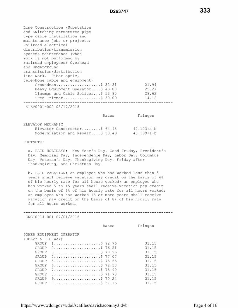
Line Construction (Substation and Switching structures pipe type cable installation and maintenance jobs or projects; Railroad electrical distribution/transmission systems maintenance (when work is not performed by railroad employees) Overhead and Underground transmission/distribution line work. Fiber optic, telephone cable and equipment) Groundman...................$ 32.31 21.94 Heavy Equipment Operator....$ 43.08 25.27 Lineman and Cable Splicer...$ 53.85 28.62 Tree Trimmer................$ 30.09 14.12 ---------------------------------------------------------------- ELEV0001-002 03/17/2018
Rates Fringes
ELEVATOR MECHANIC Elevator Constructor........$ 64.48 42.103+a+b Modernization and Repair....$ 50.49 40.399+a+b
FOOTNOTE:
a. PAID HOLIDAYS: New Year's Day, Good Friday, President's Day, Memorial Day, Independence Day, Labor Day, Columbus Day, Veteran's Day, Thanksgiving Day, Friday after Thanksgiving, and Christmas Day.
b. PAID VACATION: An employee who has worked less than 5 years shall recieve vacation pay credit on the basis of 4% of his hourly rate for all hours worked; an employee who has worked 5 to 15 years shall receive vacation pay credit on the basis of 6% of his hourly rate for all hours worked; an employee who has worked 15 or more years shall receive vacation pay credit on the basis of 8% of his hourly rate for all hours worked.
---------------------------------------------------------------- ENGI0014-001 07/01/2016
Rates Fringes
POWER EQUIPMENT OPERATOR (HEAVY & HIGHWAY) GROUP 1....................$ 92.76 31.15 GROUP 2....................$ 76.51 31.15 GROUP 3....................$ 78.96 31.15 GROUP 4....................$ 77.07 31.15 GROUP 5....................$ 75.55 31.15 GROUP 6....................$ 72.53 31.15 GROUP 7....................$ 73.90 31.15 GROUP 8....................$ 71.78 31.15 GROUP 9....................$ 70.24 31.15 GROUP 10....................$ 67.16 31.15
Page 4 of 16https://www.wdol.gov/wdol/scafiles/davisbacon/ny3.dvb
D263747 333

GROUP 11....................$ 62.73 31.15 GROUP 12....................$ 64.13 31.15 GROUP 13....................$ 64.63 31.15 GROUP 14....................$ 48.73 31.15 GROUP 15....................$ 45.27 31.15 POWER EQUIPMENT OPERATOR (PAVEMENT-HEAVY & HIGHWAY) Asphalt Plants..............$ 59.14 31.15+a Asphalt roller..............$ 69.91 31.15+a Asphalt spreader............$ 71.78 31.15+a POWER EQUIPMENT OPERATOR (STEEL ERECTION) Compressors, Welding Machines....................$ 45.34 31.15 Cranes, Hydraulic Cranes, 2 drum derricks, Forklifts, Boom Trucks......$ 76.43 31.15 Three drum derricks.........$ 79.54 31.15 POWER EQUIPMENT OPERATOR (UTILITY) Horizontal Boring Rig.......$ 68.25 31.15 Off shift compressors.......$ 56.70 31.15 Utility Compressors.........$ 44.98 31.15
POWER EQUIPMENT OPERATOR CLASSIFICATIONS
GROUP 1: Tower crane
GROUP 2: Rubber Tire Backhoes over 37,000 lbs, Track Backhoes, power shovel, Hydraulic clam shells, moles and machines of a similar type
GROUP 3: Mine hoists and crane, etc. used as mine hoists
GROUP 4: Gradalls, keystones, cranes (with digging buckets), bridge cranes, trenching machines, vermeer cutter and machines of a similar nature
GROUP 5: Piledrivers, derrick boats, tunnel shovels
GROUP 6: All drills, and machines of a similar nature
GROUP 7: Back filling machines, cranes, mucking machines, dual drum pavers
GROUP 8: Mixers (concrete w/loading attachments), concrete pavers, cableways, land derricks, power house (low pressure units), concrete pumps
GROUP 9: Concrete plants, well drilling machines, stone crushers double drum hoist, power house (other than above)
GROUP 10: Concrete mixers
GROUP 11: Elevators
GROUP 12: Concrete breaking machine, Hoists (single drum), load masters, locomotive and dinkies over 10 tons
GROUP 13: Vibratory console
Page 5 of 16https://www.wdol.gov/wdol/scafiles/davisbacon/ny3.dvb
D263747334

GROUP 14: Compressors (portable 3 or more in battery), tugger machine (caissons), well point pumps, chum drill
GROUP 15: Boilers, (high pressure, compressors (portable, single, or 2 in battery, not over 100' apart), pumps (river cofferdam and welding machines (except where arc is operated by members of local 15) push button machines, all engines irrespective of power (power pac) used to drive auxilliary equipment, air, hydraulic etc.
PREMIUMS ON CRANES (Crawler or Truck): 100' to 149' boom - add .50 150' to 249' boom - add .75 250' to 349' boom - add 1.00 350' to 450' boom - add 1.50
Premiums for Cranes on Steel Erection: 100' to 149' boom - add 1.75 150' to 249' boom - add 2.00 250' to 349' boom - add 2.25 350' to 450' boom - add 2.75 Tower crane - add 2.00
FOOTNOTE: a. Paid Holidays: New Year's Day; Lincoln's Birthday; Washington's Birthday; Memorial Day; Independence Day; Labor Day; Veterans Day; Columbus Day; Election Day; Thanksgiving Day; and Christmas Day; provided the employee works one day the payroll week in which the holiday occurs.
---------------------------------------------------------------- ENGI0014-002 07/01/2016
Rates Fringes
Power Equipment Operator BUILDING & RESIDENTIAL GROUP 1....................$ 71.85 31.15+a GROUP 2....................$ 76.12 31.15+a GROUP 3....................$ 69.39 31.15+a GROUP 4....................$ 63.12 31.15+a GROUP 5....................$ 47.26 31.15+a
POWER EQUIPMENT OPERATORS CLASSIFICATIONS
GROUP 1: Double drum
GROUP 2: Stone derrick, cranes, hydraulic cranes, boom trucks
GROUP 3: 4 pole Hoist, Single Drum Hoists
GROUP 4: Fork lift, house cars, plaster (platform machine), plaster bucket, concrete pump and all other equipment used for hoisting material
GROUP 5: Compressors, welding machines (cutting concrete work), paint spraying, sand blasting, pumps (with the exclusion of concrete pumps), house car (settlement basis
Page 6 of 16https://www.wdol.gov/wdol/scafiles/davisbacon/ny3.dvb
D263747 335

only), all engines irrespective of power (power pac) used to drive auxiliary equipment, air, hydraulic, etc., boilers
Premiums for Cranes: 100'-149' boom - add 1.75 150'-249' boom - add 2.00 250'-349' boom - add 2.25 350'-450' boom - add 2.75 Tower cranes add 2.00
FOOTNOTE: a. PAID HOLIDAYS: New Year's Day, Lincoln's Birthday, Memorial Day, Independence Day, Labor Day, Veteran's Day, Columbus Day, Election Day, Thanksgiving Day, and Christmas Day, provided the employee works one day in the payroll week in which the holiday occurs
---------------------------------------------------------------- ENGI0015-001 07/01/2016
Rates Fringes
POWER EQUIPMENT OPERATOR HEAVY AND HIGHWAY GROUP 1....................$ 65.94 32.95 GROUP 2....................$ 63.98 32.95 GROUP 3....................$ 60.69 32.95 GROUP 4....................$ 57.42 32.95 GROUP 5....................$ 39.70 32.95
POWER EQUIPMENT OPERATORS CLASSIFICATIONS
GROUP 1: Cherrypickers 20 tons and over and loaders (rubber-tired and/or tractor type with a manfufacturer's rated capacity of six cubic yards and over
GROUP 2: Rubber Tire Backhoes up to and including 37,000 lbs, Basin Machines, Groover, Mechanical Sweepers, Bobcat, Boom Truck, Barrier Transport (Barrier Mover) and machines of a similar nature, Boat Captains, Boat Operators, operation of Churn Drills and machines of a similar nature, Stetco Silent Hoist and machines of a similar nature, Vac-alls, Meyers Machines, John Beam and machines of a similar nature, Ross Carriers and Travel Lifts and machines of a similar nature, Bulldozers, Scrapers, and Turn-a Pulls, Tugger Hoist (used exclusively for handling excavated material), Tractors with attachments, Hyster and Roustabout Cranes, Cherrypickers, Austin Western, Grove and machines of a similar nature, Scoopmobiles, Monorails, Conveyors, Trenchers, Loaders- Rubber-tired and Tractor, Barber Greene, Eimco Loaders and Eimco Backhoes, Mighty Midget and similar breakers and tampers, Curb and Gutter Pavers and Motor Patrol, Motor Graders and all machines of a similar nature, Locomotives ten (10) tons or under, Mini-Max, Break-Tech and machines of a similar nature, Milling Machines, robotic and demolition machines and machines of a similar nature including Bobcat, Pile Rig Rubber-tired Excavator (37,000 lbs. and under), 2 man auger GROUP 3: Minor Equipment such as Tractors, Post Hole Diggers and Drivers, Ditch Witch (Walk Behind), Road Finishing
Page 7 of 16https://www.wdol.gov/wdol/scafiles/davisbacon/ny3.dvb
D263747336

Machines, Rollers (five (5) tons and under), Tugger Hoists, Dual Purpose Trucks, Fork Lifts and Dempsey Dumpsters
GROUP 4: Oilers for the following equipment: (all gasoline, electric, diesel, or air operated) gradalls and concrete pumps or similarly equipment manned by two-men
GROUP 5: Oilers for the following equipment: (all gasoline, electric, diesel, or air operated) shovels, cranes (draglines), backhoes, pavers, trenching machines, gunite machines, compressors (3 or more in battery)
Premiums for Cranes: 100'-149' boom - add 1.75 150'-249' boom - add 2.00 250'-349' boom - add 2.25 350'-450' boom - add 2.75 Tower cranes add 2.00
FOOTNOTE: a. PAID HOLIDAYS: New Year's Day, Lincoln's Birthday, Memorial Day, Independence Day, Labor Day, Veteran's Day, Columbus Day, Election Day, Thanksgiving Day, and Christmas Day, provided the employee works one day in the payroll week in which the holiday occurs
---------------------------------------------------------------- ENGI0015-002 07/01/2016
Rates Fringes
POWER EQUIPMENT OPERATOR BUILDING GROUP 1....................$ 65.94 32.95 GROUP 2....................$ 63.98 32.95 GROUP 3....................$ 57.42 32.95
POWER EQUIPMENT OPERATORS CLASSIFICATIONS GROUP 1: Oiler GROUP 2: Oilers on Crawler Cranes, Backhoes, Trenching machines, Gunite machines, Compressors (3 or more in Battery) GROUP 3: Gradalls: Concrete Pumps, Power Houses - All equipment in same is manned by two (2) men only, Driving Truck Cranes FOOTNOTE: a. PAID HOLIDAYS: New Year's Day, Lincoln's Birthday, Memorial Day, Independence Day, Labor Day, Veteran's Day, Columbus Day, Election Day, Thanksgiving Day, and Christmas Day, provided the employee works one day in the payroll week in which the holiday occurs
---------------------------------------------------------------- IRON0040-002 07/01/2017
BRONX, NEW YORK, RICHMOND
Rates Fringes
IRONWORKER, STRUCTURAL...........$ 50.05 72.53
Page 8 of 16https://www.wdol.gov/wdol/scafiles/davisbacon/ny3.dvb
D263747 337

---------------------------------------------------------------- IRON0046-003 07/01/2017
Rates Fringes
IRONWORKER METALLIC LATHERS AND REINFORCING IRONWORKERS.....$ 56.28 20.62 ---------------------------------------------------------------- IRON0197-001 07/01/2017
Rates Fringes
IRONWORKER STONE DERRICKMAN............$ 48.17 38.95 ---------------------------------------------------------------- IRON0361-002 07/01/2017
KINGS, QUEENS
Rates Fringes
Ironworkers: (STRUCTURAL)................$ 50.05 72.53 ---------------------------------------------------------------- IRON0580-001 01/01/2017
Rates Fringes
IRONWORKER, ORNAMENTAL...........$ 44.00 50.57 ---------------------------------------------------------------- LABO0006-001 07/01/2016
Rates Fringes
LABORER (Cement and Concrete Workers).........................$ 42.48 17.35 ---------------------------------------------------------------- LABO0029-001 07/01/2017
Rates Fringes
Laborers: Heavy Blasters (hydraulic trac drill).....................$ 47.15 35.49 Blasters...................$ 46.27 35.49 Hydraulic Trac Drill.......$ 41.29 35.49 Jackhammers, Chippers, Spaders, Concrete Breakers, All Other Pneumatic Tools, Walk Behind Self-Propelled Hydraulic Asphalt and Concrete Breaker...........$ 39.34 35.49 Powder Carriers............$ 35.17 35.49 ---------------------------------------------------------------- LABO0078-001 12/01/2016
Rates Fringes
Page 9 of 16https://www.wdol.gov/wdol/scafiles/davisbacon/ny3.dvb
D263747338

LABORERS BUILDING CONSTRUCTION ASBESTOS (Removal, Abatement, Encapsulation or Decontamination of asbestos); LEAD; & HAZARDOUS WASTE LABORERS (Hazardous Waste, Hazardous Materials, Biochemical and Mold Remediation, HVAC, Duct Cleaning, Re-spray Fireproofing, etc).........$ 36.00 16.15 ---------------------------------------------------------------- LABO0079-001 07/01/2017
Rates Fringes
Laborers Building Construction Common or General Laborer...$ 40.15 28.34 Demolition Laborers Tier A.....................$ 38.48 26.17 Tier B.....................$ 27.06 19.38 Mason Tenders...............$ 39.80 27.30
CLASSIFICATIONS
TIER A: Responsible for the removal of all interior petitions and structural petitions that can consist of sheet rock, block or masonry. Also, all structural slab openings for ducts, mechanical, shafts, elevators, slab openings and exterior walls where the building is not being completely demolitioned.
TIER B: Responsible for shoveling of debris into containers, pushing containers from the inside to the outside of the building.
---------------------------------------------------------------- LABO0147-001 07/01/2016
Rates Fringes
LABORERS (FREE AIR & TUNNEL).....$ 72.67 47.72
Maintenance Men, Inside Muck Lock Tenders, Pump Men, Electricians, Cement Finishers, Caulkers, Hydraulic Men, Shield Men, Monorail Operators, Motor Men, Conveyor Men, Powder Carriers, Pan Men, Riggers, Chuck Tenders, Track Men Painters, Nippers, Brakemen, Cable Men, Hose Men, Grout Men, Gravel Men, Form Workers, Concrete Workers, Tunnel Laborers, Mole Nipper (one (1) Mole Sipper per Working Shaft per Shift for up to and including Two (2) Moles
---------------------------------------------------------------- LABO0731-001 07/01/2016
Rates Fringes
Page 10 of 16https://www.wdol.gov/wdol/scafiles/davisbacon/ny3.dvb
D263747 339

LABORER Building, Heavy and Residential Construction LABORER: (Asbestos, Lead, Hazardous Waste Removal (including soil)/CEMENT/CONCRETE......$ 41.00 38.53 UTILITY LABORER............$ 40.85 38.53
Paid Holidays: Labor Day and Thanksgiving Day ---------------------------------------------------------------- LABO1010-001 07/01/2017
Rates Fringes
Laborers: HIGHWAY CONSTRUCTION Fence Installer & Repairer.$ 41.98 40.28 FORMSETTERS................$ 45.85 40.28 LABORERS...................$ 41.98 40.28 Landscape Planting & Maintenance................$ 41.98 40.28 Maintenance Safety Surface.$ 41.98 40.28 Slurry/Sealcoater/Play Equipment Installer........$ 41.98 40.28 Small Equipment Operator (Not Operating Engineer)...$ 41.98 40.28 Small Power Tools Operator.$ 41.98 40.28
FOOTNOTES:
a. PAID HOLIDAYS: Memorial Day, Fourth of July, Labor Day, Columbus Day, Election Day and Thanksgiving Day, provided the employee has worked one (1) day in the calendar week in which the said holiday occurs.
---------------------------------------------------------------- LABO1010-002 07/01/2017
Rates Fringes
Laborers-Asphalt Construction: Micro Paver.................$ 46.45 40.28 Raker.......................$ 45.85 40.28 Screedperson................$ 46.45 40.28 Shoveler (Production Paving Only)................$ 42.37 40.28 Small Equipment Operator (Asphalt)...................$ 42.37 40.28 ---------------------------------------------------------------- PAIN0009-001 05/01/2017
Rates Fringes
GLAZIER..........................$ 44.70 38.42 PAINTER Painters, Drywall Finishers, Lead Abatement Worker......................$ 44.10 27.02 Spray, Scaffold and
Page 11 of 16https://www.wdol.gov/wdol/scafiles/davisbacon/ny3.dvb
D263747340

Sandblasting................$ 47.10 27.02 ---------------------------------------------------------------- PAIN0806-001 10/01/2017
Rates Fringes
Painters: Structural Steel and Bridge.$ 49.50 38.93 ---------------------------------------------------------------- PAIN1974-001 12/28/2016
Rates Fringes
Painters: Drywall Tapers/Pointers.....$ 47.82 22.66 ---------------------------------------------------------------- PLAS0262-001 08/01/2017
Rates Fringes
PLASTERER........................$ 45.58 25.87 ---------------------------------------------------------------- PLAS0262-002 08/01/2017
KINGS AND QUEENS COUNTIES
Rates Fringes
PLASTERER........................$ 45.58 25.87 ---------------------------------------------------------------- PLAS0780-001 07/01/2017
Rates Fringes
CEMENT MASON/CONCRETE FINISHER...$ 50.97 39.56 ---------------------------------------------------------------- PLUM0001-001 07/01/2016
Rates Fringes
PLUMBER MECHANICAL EQUIPMENT AND SERVICE Any repair and/or replacement of the present plumbing system that does not change the existing roughing..........$ 39.92 14.41 PLUMBERS:...................$ 67.25 29.30 ---------------------------------------------------------------- PLUM0638-001 12/28/2016
Rates Fringes
PLUMBER SERVICE FITTERS.............$ 26.30 2.55 SPRINKLER FITTERS, STEAMFITTERS................$ 61.81 48.30
Service Fitter work shall consist of all repair, service and
Page 12 of 16https://www.wdol.gov/wdol/scafiles/davisbacon/ny3.dvb
D263747 341

maintenance work on domestic, commercial and industrial refrigeration, air conditioning and air cooling, stoker and oil burner apparatus and heating apparatus etc., including but not exclusively the charging, evacuation, leak testing and assembling for all machines for domestic, commercial and industrial refrigeration, air conditioning and heating apparatus. Also, work shall include adjusting, including capacity adjustments, checking and repairing or replacement of all controls and start up of all machines and repairing all defects that may develop on any system for domestic, commercial and industrial refrigeration and all air conditioning, air cooling, stoker and oil burner apparatus and heating apparatus regardless of size or type.
---------------------------------------------------------------- ROOF0008-003 07/01/2017
Rates Fringes
ROOFER...........................$ 41.50 32.37 ---------------------------------------------------------------- SHEE0028-002 07/31/2014
Rates Fringes
SHEET METAL WORKER BUILDING CONSTRUCTION.......$ 50.91 36.70 RESIDENTIAL CONSTRUCTION....$ 27.22 16.48 ---------------------------------------------------------------- TEAM0282-001 07/01/2017
Rates Fringes
TRUCK DRIVER Asphalt.....................$ 42.68 46.9025+a Euclids & Turnapulls........$ 42.78 46.9025+a High Rise...................$ 50.36 46.0925+a
FOOTNOTES:
PAID HOLIDAYS: New Year's Day, Presidents' Day, Memorial Day, Independence Day, Labor Day, Columbus Day, Election Day, Veterans' Day (Armistice Day), Thanksgiving Day, Day after Thanksgiving and Christmas Day. Employees working two (2) days in the calendar week in which a holiday falls are to be paid for such holiday, provided that they shape each remaining workday during such calendar week.
----------------------------------------------------------------
WELDERS - Receive rate prescribed for craft performing operation to which welding is incidental.
================================================================
Note: Executive Order (EO) 13706, Establishing Paid Sick Leave for Federal Contractors applies to all contracts subject to the Davis-Bacon Act for which the contract is awarded (and any solicitation was issued) on or after January 1, 2017. If this contract is covered by the EO, the contractor must provide
Page 13 of 16https://www.wdol.gov/wdol/scafiles/davisbacon/ny3.dvb
D263747342

employees with 1 hour of paid sick leave for every 30 hours they work, up to 56 hours of paid sick leave each year. Employees must be permitted to use paid sick leave for their own illness, injury or other health-related needs, including preventive care; to assist a family member (or person who is like family to the employee) who is ill, injured, or has other health-related needs, including preventive care; or for reasons resulting from, or to assist a family member (or person who is like family to the employee) who is a victim of, domestic violence, sexual assault, or stalking. Additional information on contractor requirements and worker protections under the EO is available at www.dol.gov/whd/govcontracts.
Unlisted classifications needed for work not included within the scope of the classifications listed may be added after award only as provided in the labor standards contract clauses (29CFR 5.5 (a) (1) (ii)).
----------------------------------------------------------------
The body of each wage determination lists the classification and wage rates that have been found to be prevailing for the cited type(s) of construction in the area covered by the wage determination. The classifications are listed in alphabetical order of "identifiers" that indicate whether the particular rate is a union rate (current union negotiated rate for local), a survey rate (weighted average rate) or a union average rate (weighted union average rate).
Union Rate Identifiers
A four letter classification abbreviation identifier enclosed in dotted lines beginning with characters other than "SU" or "UAVG" denotes that the union classification and rate were prevailing for that classification in the survey. Example: PLUM0198-005 07/01/2014. PLUM is an abbreviation identifier of the union which prevailed in the survey for this classification, which in this example would be Plumbers. 0198 indicates the local union number or district council number where applicable, i.e., Plumbers Local 0198. The next number, 005 in the example, is an internal number used in processing the wage determination. 07/01/2014 is the effective date of the most current negotiated rate, which in this example is July 1, 2014.
Union prevailing wage rates are updated to reflect all rate changes in the collective bargaining agreement (CBA) governing this classification and rate.
Survey Rate Identifiers
Classifications listed under the "SU" identifier indicate that no one rate prevailed for this classification in the survey and the published rate is derived by computing a weighted average rate based on all the rates reported in the survey for that classification. As this weighted average rate includes all rates reported in the survey, it may include both union and non-union rates. Example: SULA2012-007 5/13/2014. SU indicates
Page 14 of 16https://www.wdol.gov/wdol/scafiles/davisbacon/ny3.dvb
D263747 343

the rates are survey rates based on a weighted average calculation of rates and are not majority rates. LA indicates the State of Louisiana. 2012 is the year of survey on which these classifications and rates are based. The next number, 007 in the example, is an internal number used in producing the wage determination. 5/13/2014 indicates the survey completion date for the classifications and rates under that identifier.
Survey wage rates are not updated and remain in effect until a new survey is conducted.
Union Average Rate Identifiers
Classification(s) listed under the UAVG identifier indicate that no single majority rate prevailed for those classifications; however, 100% of the data reported for the classifications was union data. EXAMPLE: UAVG-OH-0010 08/29/2014. UAVG indicates that the rate is a weighted union average rate. OH indicates the state. The next number, 0010 in the example, is an internal number used in producing the wage determination. 08/29/2014 indicates the survey completion date for the classifications and rates under that identifier.
A UAVG rate will be updated once a year, usually in January of each year, to reflect a weighted average of the current negotiated/CBA rate of the union locals from which the rate is based.
----------------------------------------------------------------
WAGE DETERMINATION APPEALS PROCESS
1.) Has there been an initial decision in the matter? This can be:
* an existing published wage determination * a survey underlying a wage determination * a Wage and Hour Division letter setting forth a position on a wage determination matter * a conformance (additional classification and rate) ruling
On survey related matters, initial contact, including requests for summaries of surveys, should be with the Wage and Hour Regional Office for the area in which the survey was conducted because those Regional Offices have responsibility for the Davis-Bacon survey program. If the response from this initial contact is not satisfactory, then the process described in 2.) and 3.) should be followed.
With regard to any other matter not yet ripe for the formal process described here, initial contact should be with the Branch of Construction Wage Determinations. Write to:
Branch of Construction Wage Determinations Wage and Hour Division U.S. Department of Labor 200 Constitution Avenue, N.W. Washington, DC 20210
Page 15 of 16https://www.wdol.gov/wdol/scafiles/davisbacon/ny3.dvb
D263747344

2.) If the answer to the question in 1.) is yes, then an interested party (those affected by the action) can request review and reconsideration from the Wage and Hour Administrator (See 29 CFR Part 1.8 and 29 CFR Part 7). Write to:
Wage and Hour Administrator U.S. Department of Labor 200 Constitution Avenue, N.W. Washington, DC 20210
The request should be accompanied by a full statement of the interested party's position and by any information (wage payment data, project description, area practice material, etc.) that the requestor considers relevant to the issue.
3.) If the decision of the Administrator is not favorable, an interested party may appeal directly to the Administrative Review Board (formerly the Wage Appeals Board). Write to:
Administrative Review Board U.S. Department of Labor 200 Constitution Avenue, N.W. Washington, DC 20210
4.) All decisions by the Administrative Review Board are final.
================================================================
END OF GENERAL DECISION
Page 16 of 16https://www.wdol.gov/wdol/scafiles/davisbacon/ny3.dvb
D263747 345

STATE PREVAILING WAGE RATES
4025 Page 1 of 1 EB 06-035
L 01/06/11 9/15/11
The New York State Department of Labor (NYSDOL) has issued a project-specific
prevailing wage rate schedule for this Contract. The New York State Labor Law requires the
Contractor and all subcontractors to ensure that all workers employed in the performance of a
public work contract are paid not less than the prevailing wage rate and supplemental (fringe)
benefits in the locality where the work is performed.
The project-specific prevailing wage rate schedule, together with all updates and
amendments, is incorporated by reference in this Contract, and made a part hereof, as though
fully set forth herein. The schedule may be accessed by visiting the NYSDOL website,
navigating to the appropriate web page for prevailing wages, and entering the Prevailing Rate
Case Number (PRC#). The PRC# is found on NYSDOL Form PW-200, the following page in
this Contract Proposal. The project-specific prevailing wage rate schedule and all wage rate
amendments are annexed electronically through the following link:
www.labor.ny.gov
It is the obligation of the Contractor and all subcontractors to obtain all updated
prevailing wage rate schedules and to pay all workers in accordance with the periodic wage rate
schedule updates issued by the NYSDOL. Any changes or clarifications of labor classifications,
and information on the applicability of particular prevailing wage rates, must be obtained from
the Office of the Director of the Bureau of Public Work at the New York State Department of
Labor.
D263747346

������������������������ �������������� ��������������� ���������� ����������� ������������ ������!""�#�� ����!$�% &�'(�����)"�*��$�#+�,�+��"��� ��#��)"�*��$�#+��'!"$- !))$�.�#� �('"�����)"'/����"�(�"�#�����0'*�1����!#�2!��3"�*��$�#+�4�+��5� ��6!.0�"%3758&��� �0��#�� �+#����'����� ����!$�% &�('"�-'!"�)"'/���1�9��� ����!$��� ��((����*��("'.�:!$-�;<=>���"'!+��:!#��;<=?1��$$�!)���� @��'""����'# @�)' ���'#�����= ��0! �#� ���-�'(������.'#��@��#��(!�!"���')�� �'(������##!�$�����".�#���'#��"��*��$�0$��'#�����A�)�"�.�#�B �,�0 ������,,,1$�0'"1 ����1#-1! 1�����C)������3AD��')�� �'(-'!"� ����!$����#�0������ ���0-��#��"�#+�-'!"�� �+#���3758��������)"')�"�$'����'#�'#����,�0 ���1�E��� �����"� )'# �0�$��-�'(������'#�"����#+��+�#�-�'"��� ��+�#���'��##�F��#��.�G��)�"�@������������� ����!$�@��'����� )���(�����'# �('"���� �)"'/���@�,��#����� ���*�"�� ���('"�0�� ��#��H'"�'�('",�"�� ���� ����!$� ��'����� !��� (!$�0����"% &@��..������$-�!)'#�"����)�@��#�'"��"��'�# !"������)"')�"�)�-.�#��'(�,�+� 1�3$�� ��"�(�"��'�����IJ�#�"�$�3"'*� �'# �'(�K�, �5'*�"�#+�4'"G�" �'#�3!0$���4'"G5'#�"��� I�)"'*�����,������� � ����!$�@�('"����� )���(��������$ �"�$���#+��'�'���""� )'# �0�$���� �'(�����A�)�"�.�#��'(�:!"� �����'#1�C)'#��'.)$���'#�'"���#��$$���'#�'(���� �)"'/���@��#��"�����"�2!�"����#('".���'#��#��.��$����(�F���� �('".��'�����'((���� �',#��������0'��'.�'(���� �#'����@������(�$$�'!�������$���"'#��*�" �'#�*�������6LMANK�,�0 ���1� ��� ����� �O�������P� � ���������������� ��A����5'.)$����Q A����5�#��$$��Q�6�.��R�9��$��'(�7�)"� �#����*�Q��� ��3�'#�Q�%S=?&�TS>USS?V��D�FQ��%S=?&�T?SU=?><���41��*�"�$$�W�""�.�#�M�����N((����5�.)! @�X$�+1�=;@�7''.�=Y<@��$0�#-@�6L�=;;T<��,,,1$�0'"1 ����1#-1! 1�� �����34�;<< �����34� GZ$�0'"1 ����1#-1!
[\]_ �ab�cdefeg�hei_\e jek_lm�j_m]e\g�ceffnoone\_pqrstu�[jvwps��r[xh[ag�sy[z�{r|}�~pwupqrstu{ts�������tx��jt[s[xz[pq����pq������ r��_]d�_�q_m �����l�ed�������sml_�j_�d_ol_] ����������{jc� ����������xe�mlne\ ze\�{e�_�l�ws� s������{e�_�l�u��_ [l�d�r�_n]m\�}\�m\�_f_\l�{e�_�l�[l�d�r�_n]m\�}��_oom����������rb�b��������ef�zd��\_}��_oom��le�ceoo�ze\��}��_oom��a~pwcw{[xwuw}r��p_ �qe��cnl��ct~puw}r��ze\��ced\l�
D263747 347

���������������� �������������������������������������������������������������������� !"#�� $�#�%&'#�(�)&!*'+�$"#,�+"-.# +."#(� -/�(&!+"-.# +."#(�."�) 0�* !"#�#(1�$"#,�#(1�"#�2�+� -'+(��2)*"0�/�'-.���)�#3"#2 -+��"3� �)&!*'+�$"#,�+"-.# +.�-".�*�((�.� -�.���)#�4 '*'-5�# .��"3�$ 5�� -/�(&))*�2�-.(�63#'-5��!�-�3'.(7�'-�.��*"+ *'.0�$��#��.���$"#,�'(�)�#3"#2�/8�9��:������������ ��;��<�:���=���� �>�����������?�@�) #.2�-.�"3�A&#'(/'+.'"-�6B"-.# +.'-5�?5�-+07�'-+*&/�(� �(. .��/�) #.2�-.1� 5�-+01�!" #/�"#�+"22'(('"-C� �+"&-.01+'.01�."$-�"#�4'** 5�D� �(+�""*�/'(.#'+.1�!" #/�"3��/&+ .'"-�"#�!" #/�"3�+"")�# .'4���/&+ .'"- *�(�#4'+�(D� �(�$�#1�$ .�#1�3'#�1'2)#"4�2�-.� -/�".��#�/'(.#'+.�+"#)"# .'"-D� �)&!*'+�!�-�3'.�+"#)"# .'"-D� -/� �)&!*'+� &.�"#'.0� $ #/'-5� �)&!*'+�$"#,+"-.# +.8�����@�) #.2�-.�"3�A&#'(/'+.'"-�6B"-.# +.'-5�?5�-+07� $ #/'-5� �)&!*'+�$"#,�+"-.# +.�EFG��"!. '-� �H#�4 '*'-5�I .�G+��/&*��*'(.'-5�.����"&#*0�# .�(�"3�$ 5�(� -/�(&))*�2�-.(�/&��.���$"#,�#(�."�!���2)*"0�/�"-� �)&!*'+�$"#,�)#"J�+.8��'(�(+��/&*��2 0�!��"!. '-�/�!0�+"2)*�.'-5� -/�3"#$ #/'-5� �KI�%&�(.�3"#�$ 5�� -/�G&))*�2�-.�L-3"#2 .'"-K�3"#2�6HMNO7�."�.���P&#� &�"3�H&!*'+�M"#,8������H#�4 '*'-5�I .��G+��/&*��EFG��!��'-+*&/�/�'-�.���()�+'3'+ .'"-(�3"#�.���+"-.# +.�."!�� $ #/�/� -/�'(�/��2�/�) #.�"3�.���)&!*'+�$"#,�+"-.# +.8�F)"-�.��� $ #/'-5�"3�.���+"-.# +.1�.���* $�#�%&'#�(�.� .�.���@�) #.2�-.�"3�A&#'(/'+.'"-�6B"-.# +.'-5�?5�-+07�3&#-'(��.��3"**"$'-5�'-3"#2 .'"-�."�.���P&#� &C��.���- 2�� -/� //#�((�"3�.���+"-.# +."#1�.���/ .��.���+"-.# +.�$ (�*�.� -/�.�� ))#"Q'2 .��/"** #�4 *&��"3�.���+"-.# +.8��"�3 +'*'. .��+"2)*' -+��$'.��.�'(�)#"4'('"-�"3�.���� !"#�� $1� �+")0�"3�.��@�) #.2�-.R(�KS".'+��"3�B"-.# +.�?$ #/K�3"#2�6HM�TU7�'(�)#"4'/�/�$'.��.���"#'5'- *�H#�4 '*'-5�I .��G+��/&*�8�����@�) #.2�-.�"3�A&#'(/'+.'"-�6B"-.# +.'-5�?5�-+07�'(�#�%&'#�/�."�-".'30�.���P&#� &�"3�.���+"2)*�.'"-�"#�+ -+�** .'"-�"3 -0�)&!*'+�$"#,�)#"J�+.8������@�) #.2�-.R(�HM�VWW�3"#2�'(�)#"4'/�/�3"#�.� .�)&#)"(�8�P".��.���HM�TU� -/��HM�VWW�3"#2(� #�� 4 '* !*��3"#�+"2)*�.'"-�"-*'-�8��X����S"�* !"#�#1�$"#,�#1�"#�2�+� -'+�'-�.����2)*"0�"3� �+"-.# +."#�"#�(&!+"-.# +."#��-5 5�/�'-�.���)�#3"#2 -+��"3� -0�)&!*'+$"#,�)#"J�+.�(� **�!��)�#2'..�/�."�$"#,�2"#��.� -��'5�.��"&#(�'-� -0�/ 0�"#�2"#��.� -�3'4��/ 0(�'-� -0�$��,1��Q+�).�'-+ (�(�"3��Q.# "#/'- #0��2�#5�-+08������+"-.# +."#� -/�.���@�) #.2�-.�"3�A&#'(/'+.'"-�6B"-.# +.'-5�?5�-+07�2 0� ))*0�.".���P&#� &�"3�H&!*'+�M"#,�3"#� �/'()�-( .'"-�)�#2'..'-5�$"#,�#(�."�$"#,� //'.'"- *��"&#(�"#�/ 0(�)�#�$��,�"-� �) #.'+&* #)&!*'+�$"#,�)#"J�+.8����#�� #��4�#0�3�$��Q+�).'"-(�."�.�'(�#&*�8��B"2)*�.��'-3"#2 .'"-�#�5 #/'-5�.��(���Q+�).'"-(�'( 4 '* !*��"-�.���KY�@ 0�Z�TW�["&#�M"#,�G+��/&*�K�3"#2�6HM�NW8T78������������\�::��=���������$ 5�(� -/�(&))*�2�-.(�."�!��) '/� -/Z"#�)#"4'/�/�."�* !"#�#(1�$"#,�#(1� -/�2�+� -'+(��2)*"0�/�"-� �)&!*'+�$"#,)#"J�+.�(� **�!��-".�*�((�.� -�.�"(��*'(.�/�'-�.���+&##�-.�H#�4 '*'-5�I .��G+��/&*��3"#�.���*"+ *'.0�$��#��.���$"#,�'()�#3"#2�/8��L3� �)#'2��+"-.# +."#�"-� �)&!*'+�$"#,�)#"J�+.�� (�-".�!��-�)#"4'/�/�$'.�� �H#�4 '*'-5�I .��G+��/&*�1�.��+"-.# +."#�2&(.�-".'30�.���@�) #.2�-.�"3�A&#'(/'+.'"-�6B"-.# +.'-5�?5�-+07�$�"�'-�.&#-�2&(.�#�%&�(.� -�"#'5'- *�H#�4 '*'-5I .��G+��/&*��3"#2�.���P&#� &�"3�H&!*'+�M"#,8��I�%&�(.(�2 0�!��(&!2'..�/�!0C�2 '*�."�S]G@ �1�P&#� &�"3�H&!*'+�M"#,1G. .��33'+��P*/58�B 2)&(1�P*/58�TV1�I28�TNW1�?*! -01�S]�TVVYWD�_ Q�."�P&#� &�"3�H&!*'+�M"#,�6Ta7�YabTacWD�"#�*�+.#"-'+ **0� .�.���S]G@ ��$�!('.���$$$8* !"#8(. .�8-08&(8�F)"-�#�+�'4'-5�.���"#'5'- *�(+��/&*�1�.���@�) #.2�-.�"3�A&#'(/'+.'"-�6B"-.# +.'-5�?5�-+07�'(�IdeFLId@�."�)#"4'/�+"2)*�.��+")'�(�."� **�)#'2��+"-.# +."#(�$�"�'-�.&#-�EFG�1�!0�* $1�)#"4'/��+")'�(�"3� **� ))*'+ !*��+"&-.0�(+��/&*�(�."� +��(&!+"-.# +."#� -/�"!. '-�3#"2�� +��(&!+"-.# +."#1� -� 33'/ 4'.�+�#.'30'-5�(&+��(+��/&*�(�$�#��#�+�'4�/8�L3�.���"#'5'- *(+��/&*���Q)'#�/1�.���+"-.# +."#�2 0�"!. '-� �+")0�"3�.���-�$� --& *�/�.�#2'- .'"-�3#"2�.���S]G@ ��$�!('.�$$$8* !"#8(. .�8-08&(8�����B"22'(('"-�#�"3�� !"#�2 ,�(� -� --& *�/�.�#2'- .'"-�"3�.���)#�4 '*'-5�# .�(8����'(�/�.�#2'- .'"-�'(�'-��33�+.�3#"2A&*0�T(.�.�#"&5��A&-��NW.��"3�.���3"**"$'-5�0� #8������ --& *�/�.�#2'- .'"-�'(� 4 '* !*��"-�.���S]G@ ��$�!('.�$$$8* !"#8(. .�8-08&(8���f�����������f����9�������d4�#0�+"-.# +."#� -/�(&!+"-.# +."#�EFG��,��)�"#'5'- *�) 0#"**(�"#�.# -(+#').(�(&!(+#'!�/� -/� 33'#2�/� (�.#&��&-/�#)�- *.0�"3�)�#J��H 0#"**(�2&(.�!��2 '-. '-�/�3"#� .�*� (.�_'4��67�0� #(�3#"2�.���)#"J�+.R(�/ .��"3�+"2)*�.'"-8�G���G)". P'**�S".'+�8��?.� �2'-'2&21�) 0#"**(�2&(.�(�"$�.���3"**"$'-5�'-3"#2 .'"-�3"#�� +��)�#("-��2)*"0�/�"-� �)&!*'+�$"#,)#"J�+.C�S 2�1�?//#�((1�� (.�Y�@'5'.(�"3�G"+' *�G�+&#'.0�S&2!�#1�B* (('3'+ .'"-6(7�'-�$�'+��.���$"#,�#�$ (��2)*"0�/1["&#*0�$ 5��# .�6(7�) '/1�G&))*�2�-.(�) '/�"#�)#"4'/�/1� -/�@ '*0� -/�$��,*0�-&2!�#�"3��"&#(�$"#,�/�'-�� +�+* (('3'+ .'"-8�
D263747348

�������������� ����������������������������������������������������� ���������� ������������������������������������������������������������������������������������ ��� ����������� ��!"���� ������������������������������� ����������� ������ ��!"���� ������������������������������������������ �������������������������������������������������� �����#�� ����������������������������������������������� ��������������������� ������������������ ��������������������� ������$����������������������������%������ ���&�������������������������� ���������'"���� ��������&�������� ����������� ��������������������� ������������ ����������� �(������������� �(���)� ��������������������� ����������������������������� �(����������������������������������������� ������������������������� ��������(�������� �������*���������������������&����������������� �����������������������'"���� �� ������������������ ����������������+,-���������������������.�����/'""�"""�""���$�������������������������������������������������������������������0� �1�(2����������������������������������.������/+,�"""�""���� �������������������������������������(������������#��� �(�������������������������������������������� �������� ������������������ ������������������� ��� ���������������������������������������������������������������������������������������� �������)���������3����2������������������������������� �(������������ ��������� ������&����� ������������������������������������������������������� �������������������������������������������������4��2������++"5��������%����%� �������������������������� ���������� �(���#����������������������������������������������������������������������� ������&����� �������������������������������������������������������������������������������������������������������������������)���������3����2������������ ������ ��������������������������������� ����������������������������������������2���012�%����%� �����������4���2������++"5����67879:;<=8;><�>?�@97A=;B;<C�D=C7�=<E�FGHHB7:7<8�I=87�JHE=87K�LHHB;M=NB7�8>�LBB�O>G<8;7K����� ��������������������������������������������������������������������������� �'��� ������������������ �������������������������������� �����������������������������������(���������� ������������������������������ �����������������������������������������P��������������������� ���$��������������������� �������������� �(���������������������������������$�������������&�����������������������������������������������������������������������������������������������#�������� ���������������������������������� ��������������������������������012�Q% ������������������������������ ��������������������������������������������� �������������������������� �������������������� �'����R���� ������� ���������������������������������������� ����������������������������������������������������������������������������������������� ����������������������������������������������.��������������������������������������������������������������������������������� ���������� �'����������!"���������������������� �����������������������������������3�����������.������� �������������������������������������������Q0%1������� ������������������������������������������������������ ����������������������������� �'����������!"���������������D;8SS>BE;<C�>?�@=T:7<8K�R������������������������ ���������������������%������������������������������������������������������ ����������������������� ��������������������� ���������������������%������������������������� ������������������� ����������� ������������������� �(������������������ ������������������������������������������������������������ ������������������� ������������������������������������������������������� ������������������������������R��������U��������)������R�(������������������������������������������������ �(���#��������������� ���������������&����������������� �����������������������U���������������V���� �2�������++"5������+!,�+�������%����%� �������� �������������������������������������������������������������������� �������� ����������������� �(���������2�����������WX2������� �������������������� �������������� ��� ������������������������������������������������������������������������ �����U���������������������������� ������������ �������������������������������������������� ������������� �������� �������������� ������������������%���������� ������������������������������������������������������������������ ������ ������������������%������� ������������������������������������������������������������ ���������������������������������������%������������������������������������������������� ������������ � ���������������������������������%���������������� ���������������������������������������� ���������FG::=9T�>?�Y>8;M7�@>K8;<C�I7ZG;97:7<8K�������������)���������3����2��������������������������������������������������������������������������������� �(��#�������������������� �������������������������������������������������������������������� ������������������ ������������������������������[)3�\�$%$0]�3����Q*�R�]�2[���������������������������� ��+���������� �� ��+��������������[)������R�(�)�#���[����������������������������������������������������������� �������� �(����������������#��������
D263747 349

������������������� �������������� ���� �� ���� ���� �������������� ��������������� ���������������������� ���������������������������������������� ���� ������� ���� ������������� ������������������������������������������ �!��� �"������#��������� ��������������������������$��������������� �$�������� ������ � ���� ����$� ��������� ������������� �����%����� ���!��� �"������������������������ ������� ��� ��������& ������ ��' ���� ���#��������� ������������� ������������ �������� ��������������� �%������� ����#�����())*+,-./+0����������� ��������������� ������������ �������������� ��������������������� �������������������������������� ������� �����#������1��������������������� ����������� ���������� �� ������������������� ��� ���� ����������� �������������������� �������������������������������%������� ����#����� ��� ���������������2������ ��"��� ���������3 �������������� ������������ ������ ����������� ��������������������������������� ��������������������������� ������������������������� ��������� �� �����$������������������������� ����� �������4����������������������������� ����������������������������������� ����� %5#�#����#��$�3������6$� ���� �7789:$���;���������� ������� ������� ������������������������������� %������� ����#��������������������� ��������������� �����������������������������<�������� �����3�� ������������������������� ������� ��������� ������2��� ������� �������������������� ��������������� ���� ������ ����������� ������ ��������$��������� %5#�5������������������%������ ��=�3���� ���������1��� � �$� �����5�����������������$������>7$�3�� �$�����>77?8������<�@���� %5#�3���� ���������1��� � ��AB>6C�?BD9D>B?���3���;������������������� ������� ��������� ����� ��������������� ���������������� ������������� ������ ������;��������1��� ��� �������������� ������������� ��������������� ���������� ����������� ����������� %5#�3���� ��������1��� � ��3�� ���� ��������������������<������ �� �����3���� ���������1��� � ������������������3�� ���� �������� ����������������� �� ������ ��'���������� ��������������@���� ����������������������� ������������������� ��� ����������������� ������ ��������������� ���������������<���������$������@���� ������������ �������������$���� �������� ������$������������������������ ��� ��������������������������� ���� ������ ����� ������ ������E,-+*+0-�F,G�H+,FI-.+0�' �������� �������� �� �������� ����������� �=��������� �������� �J�9' �������������������������������������� �� ����������������������������� ����� �� �� ������ ��������� �������� �>?9���������� �� ��#��$������ ������������������� �������� ���������������������� ���������93������2� ����������������������$� �����@�����7BK������������������$�������� ��$�� ��� ������������L+MF*N+,-�3 ��� ������������� �������� �=����������������������� ���������������������� ��������������� ������������ ������������ ������������ �������$��� ������������� �������������������������������ABC���������� J�91��A7C������������� ��� ���������� ��� ���������� ��������� ������������� �������� �=������������������� �� ��� �����������@�AOC������������91��������� �������������� ��� ������� ������������������� ���������������������������������������������� ����P*.N.,FI�QF,/-.R,0����������� ��������2������ �������#���A3������6�������#����#��C������������ ���� ������������ ��������� �� ���������>B������$��������L.0/*.N.,F-.R,������������������ ����������� ����������������� ��������� ��� ����� �������$�����$������$���$� ��� ����� $���@$������������������������������� ������$����� ������� ��� ������ ����� �� ����������$������������ �������$������$���$����������$���@�� ��� ������ ��������� �������� ���� ������S� ������� ���������������������;��������� �������������������������������������������� ���������A�� �#����#��$�3������6$� ���� �7789�A�CC����� ������$����� ������$� ��� ������ ����� �� ����������$������ �� ���� ��$��������� �������� ������ ��������� ��������� ����� ��������$������$���$����������$���@$��� ��� ������ �A�� �#����#��$�3������6$� ���� �7789�A�C�C�
D263747350

������������� ������������������ ����������� ������������� ��������������������� ���� � ���������������������������������� �������� ������� ��������� �� ����� ��� �������� ����� ��� ������� �������������������������������������������������������������������� �������� ����� ����� ���������� ������ ��������������� ����� ��� � !"#������������$� �����%��#�� ���&&�'� �(�(�������� ��� �������������������� ����� ������ ���# � �������������� ����$���������������� ������������� ��������������������� ��������������������������)�� ������ ������ ��� ������������ ������� ���� �'��������� ������ ������ ����� ��� � !"#������������$� �����%��#�� ���&&�'� �(�(��*�����������������+�� � �� ���!���"��,�# � ���������� ��������� ����������������� �� �� ���������������������������� ������������� � �������� ����� ����������������� ���# � ��-������������������ ���./012034�5/672839:;/8�<������������� ��#�� ���=>&���� ���# � ��?���������� ����� ��� ������������ ������������������ ����������� ���� ��� ����� �������� ������������������������)��������� ���������������� ���!���"��,�# � ��@��,���A�B������ �������$��� ��� ������������������������������,��� ��� ���� ���������������������,���A�������� ������������������ �������������� ����������,������������������������ ������������������������� ����C��� �������������,���A�������� ��������������!���"��,# � ����D�������������������� �����������B'=���&� B�� ����� �����@��,���A�B������ ���<������(������� ����� ����������������� ����� ����������<��!���"��,�# � �������������������� �����E�� ����� '��'� � ����������� ����������������� �������������������������� ����C��� ����� �����,���A�������� �������������� ����� � �������������������� ������� ��������� ���F$���� �������� ��������������� ��� ������ ���� ��������� �� ������ ��� ������������,�������������� ������ ��� ��������������� ���������,���A�������� �������������������������������,�����!���"��,�# � ���*��������������������������,��A��������� ���������������������� ������� ����� ���� �� ����������������������� �������� ��������������� ���@��,���A�B������ ���G���������������������������� ���+���� ���H8267I/J628:�K83L098M2�*���������������������� ���� ��������� ���N�������� �<�������������� ����������������� ��� ���+���� ��� ���������������� ���!���"��,�# � ��-���� �� �����������
D263747 351

������������������� ������� ���������� ����������� �������������� ������ ��!��!����"� "#� �!#��$�%���&� '�"!(� �"�"!��($!�� ��������������)� ����� ���� ����� �*+,-� �������&��.�" ������� ��(� �� /00/1234/�562/�7/1/89/:�;<�=>>?�� ,@��������� ������A� BCDE�FGHI�JHEKLDMHE�GCH�NOMPDK�QRLS�TUVRLKHIHUG�WOUJ�XGCH�WOUJY�NQTWZ�[UJ�DGELHPH\[UKH�GR�]G[GH�[HUKDHE�[UJ�_OMPDK�MHUHVDG�KRL_RL[GDRUE�HU[HJ�DU�KRUEGLOKGDRU�RLLHKRUEGLOKGDRU�KRUGL[KGEY�I[DUGHU[UKH�[UJ�LH_[DLY�[UJ�[UUROUKHE�GCH�LHKHUGPaHU[KGHJDUKLH[EH�GR�GCH�_HLKHUG[H�RV�GCH�JRPP[L�\[POH�RV�EOKC�KRUGL[KGE�GC[G�IOEG�MH�JH_REDGHJ�DUGRGCH�WOUJb�BCDE�DGHI�[PER�JHEKLDMHE�GCH�LRPHE�RV�GCH�VRPPRcDU�HUGDGDHE�cDGC�LHE_HKG�GR�GCHWOUJd� a eHc�fRLS�]G[GH�gH_[LGIHUG�RV�h[MRL�XgihZYa BCH�iVVDKH�RV�GCH�]G[GH�RV�jRI_GLRPPHL�Xi]jZY�[UJa ]G[GH�[HUKDHE�[UJ�_OMPDK�MHUHVDG�KRL_RL[GDRUEb� k@����.���� ��� ������������ ����� ���A� gih�OEHE�GCH�WOUJ�GR�HUVRLKH�GCH�]G[GHlE�h[MRL�h[c�[E�DG�LHP[GHE�GR�KRUGL[KGE�VRLKRUEGLOKGDRU�RL�LHKRUEGLOKGDRUY�I[DUGHU[UKH�[UJ�LH_[DLY�[E�JHVDUHJ�DU�EOMJD\DEDRU�GcR�RV]HKGDRU�mmn�RV�GCH�h[MRL�h[cb�]G[GH�[HUKDHE�[UJ�_OMPDK�MHUHVDG�KRL_RL[GDRUE�_[LGDKD_[GDUDU�EOKC�KRUGL[KGE�[LH�LHoODLHJ�GR�I[SH�_[IHUGE�GR�GCH�WOUJb� jC[_GHL�pqq�RV�GCH�h[cE�RV�qrrp�X[E�[IHUJHJ�M�jC[_GHL�pqs�RV�GCH�h[cE�RV�qrrtYjC[_GHL�upp�RV�GCH�h[cE�RV�qrrrY�jC[_GHL�stu�RV�GCH�h[cE�RV�mnns�[UJ�jC[_GHL�vnt�RV�GCHh[cE�RV�mnnpZ�HEG[MPDECHJ�GCH�WOUJb� w@������������� ����� ��� ��� ����������A� BCH�WOUJ�DE�EO__RLGHJ�M�GL[UEVHLE�[UJ�JH_REDGE�M[EHJ�RU�GCH�\[POH�RV�KRUGL[KGE�VRLKRUEGLOKGDRU�[UJ�LHKRUEGLOKGDRUY�I[DUGHU[UKH�[UJ�LH_[DLY�[E�JHVDUHJ�DU�EOMJD\DEDRU�GcR�RV]HKGDRU�mmn�RV�GCH�h[MRL�h[cY�DUGR�cCDKC�[PP�]G[GH�[HUKDHE�[UJ�_OMPDK�MHUHVDG�KRL_RL[GDRUEHUGHLb� jC[_GHL�vnt�RV�GCH�h[cE�RV�mnnp�DUKLH[EHJ�GCH�[IROUG�LHoODLHJ�GR�MH�_LR\DJHJ�GR�GCDE�VOUJGR�bqn�RV�RUHa_HLKHUG�RV�GCH�GRG[P�KREG�RV�H[KC�EOKC�KRUGL[KGY�GR�MH�K[PKOP[GHJ�[G�GCH�GDIH[HUKDHE�RL�_OMPDK�MHUHVDG�KRL_RL[GDRUE�HUGHL�DUGR�[�UHc�KRUGL[KG�RL�DV�[�KRUGL[KG�DE�[IHUJHJbBCH�_LR\DEDRUE�RV�GCDE�MDPP�MHK[IH�HVVHKGD\H�xOOEG�mY�mnnpb
D263747352

������������������� ������� ���������� ����������� �������������� ������ ��!��!����"� "#� �!#��$�%���&� '�"!(� �"�"!��($!�� )*+�,-..�/012/3�32�4)5�26�7..�82693/:83-26;/0.730<�=>4>?�8263/7839�711/2@0<�<:/-6A�3B0C263BD�-68.:<-6A�8263/783�7C06<C0639D�76<�3B06�4)5�,-..�E-..�7A068-09�3B0�711/21/-730799099C063�C263B.FG�H6�7A068F�C7F�3B06�C7I0�7�<030/C-673-26�-J�76F�2J�3B0�E-..0<8263/7839�7/0�0K0C13�76<�92�6230�26�3B0�E-..�9:EC-330<�E78I�32�4)5G�L2/�76F�-6937680,B0/0�76�7A068F�-9�:69:/0�-J�7�8263/783�-9�2/�-9�623�0K0C13D�3B0F�876�87..�3B0�M:/07:�2JN:E.-8�O2/I�73�3B0�6:CE0/�6230<�E0.2,�J2/�7�<030/C-673-26G�N7FC063�EF�8B08I�2/�P2:/67.@2:8B0/�-9�<:0�32�4)5�,-3B-6�3B-/3F�<7F9�J/2C�3B0�<730�2J�3B0�E-..-6AG�4)5�,-..�@0/-JF�3B07C2:639�76<�J2/,7/<�3B0C�32�)*+�J2/�1/28099-6AG� L2/�3B290�8263/7839�,B-8B�7/0�623�711/2@0<�2/�7<C-6-930/0<�EF�3B0�+2C13/2..0/D�C263B.F/012/39�76<�17FC0639�J2/�<0129-3�-632�3B0�N:E.-8�O2/I�Q6J2/80C063�L:6<�C:93�E0�1/2@-<0<32�3B0�H<C-6-93/73-@0�L-67680�M:/07:�73�3B0�4)5�,-3B-6�RS�<7F9�2J�3B0�06<�2J�078B�C263B2/�26�7�17FC063�98B0<:.0�C:3:7..F�7A/00<�:126�,-3B�4)5G� T012/39�9B2:.<�82637-6�3B0�J2..2,-6A�-6J2/C73-26U� V W7C0�76<�E-..-6A�7<</099�2J�*3730�7A068F�2/�1:E.-8E060J-3�82/12/73-26XV *3730�7A068F�2/�1:E.-8�E060J-3�82/12/73-26�8263783�76<1B260�6:CE0/XV W7C0�76<�7<</099�2J�8263/7832/�/080-@-6A�3B0�7,7/<XV +263/783�6:CE0/�76<�0JJ083-@0�<7309XV +263/783�7C2:63�76<�NOQL�799099C063�8B7/A0�=-J8263/783�7C2:63�B79�E006�7C06<0<D�/0J.083�-68/0790�2/<08/0790�32�2/-A-67.�8263/783�76<�3B0�7<P:93C063�-6�3B0NOQL�8B7/A0?X�76<V M/-0J�<098/-13-26�2J�3B0�,2/I�32�E0�10/J2/C0<�:6<0/�078B8263/783G� +B08I9�76<�Y2:/67.�Z2:8B0/9D�17F7E.0�32�3B0�>W0,�[2/I�*3730�4017/3C063�2J�57E2/>9B2:.<�E0�9063�32U� 4017/3C063�2J�57E2/H<C-6-93/73-@0�L-67680�M:/07:;NOQL�\6-3M:-.<-6A�]D�T22C�__*3730�)JJ-80�+7C1:9H.E76FD�W[�] _S� H6F�a:093-269�/0A7/<-6A�E-..-6A�9B2:.<�E0�<-/0830<�32�W[*4)5b9�H<C-6-93/73-@0�L-67680M:/07:;NOQL�\6-3�73�=c]d?�_ce;R _�76<�76F�a:093-269�/0A7/<-6A�N:E.-8�O2/I�+263/78399B2:.<�E0�<-/0830<�32�3B0�M:/07:�2J�N:E.-8�O2/I�73�=c]d?�_ce;ccdfG
D263747 353

���������������� ����������������������������������� �!"��#��$%��!&'(!)�#!*+,-,./01234,0.,-5106,787403--,-490:,.4+8,.481518434,0.0/5314,;:<3118=:,1828.4-/0183;+;<3--,/,;34,0.0/>01?81;0.43,.87,.4+83443;+87@;+87:<80/A1863,<,.BC348-DE#�FF���'�����G4,-4+87:490/4+8H022,--,0.810/I3J014023?84+8510581;<3--,/,;34,0.0/>01?81-43?,.B,.403;;0:.4>+84+814+8>01?,-+83693.7+,B+>39KJ:,<7,.BK-8>813.7>3481K4:..8<>01?K0118-,78.4,3<K3.74023?83784812,.34,0.0/>3B8-3.7-:55<828.4-40J853,7015106,787DG4,-4+818-50.-,J,<,490/4+85:J<,;>01?;0.413;40140:-84+85105811348DG/4+818,-3=:8-4,0.0.4+8510581;<3--,/,;34,0.40J8:-87K5<83-8;3<<4+87,-41,;40//,;8<0;3487.8318-44+8510L8;4DM,-41,;40//,;8<0;34,0.-3.75+0.8.:2J81-318<,-487J8<0>DA1863,<,.BN3B8@;+87:<8-318,--:87-8531348<9/01OP8.813<H0.-41:;4,0.A10L8;4-O3.7OC8-,78.4,3<H0.-41:;4,0.A10L8;4-O0.3;0:.49QJ9Q;0:.49J3-,-DP8.813<H0.-41:;4,0.C348-355<940510L8;4--:;+3-RS:,<7,.B-KT8369UT,B+>39K3.7*:..8<3.7N3481U@8>811348-DC8-,78.4,3<H0.-41:;4,0.C348-B8.813<<9355<940;0.-41:;4,0.K18;0.-41:;4,0.K1853,1K3<48134,0.K017820<,4,0.0/0.8/32,<9K4>0/32,<9K10>+0:-,.BK0118.43<4958:.,4-,.48.787/0118-,78.4,3<:-8D@0281348-<,-487,.4+8C8-,78.4,3<H0.-41:;4,0.C348@;+87:<8+36836819<,2,487355<,;3J,<,49<,-4873<0.B>,4+4+81348DC348-/010;;:534,0.-01<0;34,0.-.04-+0>.0.4+818-,78.4,3<-;+87:<82:-4J80J43,.87/1024+8P8.813<H0.-41:;4,0.C348@;+87:<8DA<83-8;0.43;44+8<0;3<S:183:0/A:J<,;N01?0//,;8J8/018:-,.BC8-,78.4,3<C348@;+87:<8-K408.-:184+344+8510L8;42884-4+818=:,187;1,481,3D ��)V�#�)�WFA3,7T0<,739-318739-/01>+,;+3.8<,B,J<8825<098818;8,68-318B:<31739X-539KJ:4,-.0418=:,18740581/012>01?DG/3.825<0988>01?-0.3739<,-4873-353,7+0<,739K4+,-182:.8134,0.,-,.377,4,0.4053928.40/4+818=:,18751863,<,.B1348/014+8>01?3;4:3<<9581/01287DY"!����!Z432,.,2:2K3<<>01?581/012870.35:J<,;>01?510L8;4,.8[;8--0/8,B+4+0:1-,.3.90.87390120184+3./,68739-,.3.9>01?>88?,-06814,28DT0>8681K4+8-58;,/,;06814,2818=:,1828.4-/0183;+41378010;;:534,0.0.35:J<,;>01?510L8;42397,//81D@58;,/,;06814,2818=:,1828.4-/0183;+41378010;;:534,0.318;0.43,.87,.4+851863,<,.B1348-;+87:<8-D\6814,28+0<,739539,-4+85182,:25394+34,-18=:,187/01>01?581/012870.-58;,/,87+0<,739-DG4,-0.<918=:,187>+8184+8825<09883;4:3<<9581/012->01?0.-:;++0<,739-D*+8355<,;3J<8+0<,739-318<,-487:.781T\IGMZ]@R\ _C*G_D*+818=:,18713480/539/014+8-8;068187+0<,739-;3.J8/0:.7,.4+8\ _C*G_AZ]-8;4,0.<,-4,.B-/0183;+;<3--,/,;34,0.D&�aa#!�!���#b!�!���FA314,;:<313448.4,0.-+0:<7J8B,68.404+8-:55<828.43<J8.8/,418=:,1828.4-DG.20-4;3-8-4+853928.4015106,-,0.0/-:55<828.4-,-/0183;++0:1>01?87c.0487,.4+8-;+87:<83-XA81+0:1>01?87XdD@028;<3--,/,;34,0.-18=:,184+853928.4015106,-,0.0/-:55<828.4-/0183;++0:153,7c.0487,.4+8-;+87:<83-XA81+0:153,7XdK>+,;+18=:,18-:55<828.4-40J853,7015106,7873435182,:21348/015182,:2+0:1->01?87D@028;<3--,/,;34,0.-2393<-018=:,184+853928.4015106,-,0.0/-:55<828.4-/0153,7+0<,739-0.>+,;+.0>01?,-581/01287De��!'��"!f��!FN+8.90:186,8>4+8-;+87:<8/0135314,;:<310;;:534,0.K90:13448.4,0.-+0:<7J87,18;487404+87348-3J0684+8;0<:2.0/1348-D*+8-83184+87348-/01>+,;+3B,68.-840/1348-,-8//8;4,68D*+81348<,-487,-63<,7:.4,<4+8.8[48//8;4,681348;+3.B801:.4,<4+8.8>3..:3<784812,.34,0.>+,;+43?8-8//8;40.g:<9h0/83;+9831DZ<<;0.413;401-3.7-:J;0.413;401-31818=:,187405394+8;:118.451863,<,.B1348-0/>3B8-3.7-:55<828.4-DG/90:+3683.9=:8-4,0.-5<83-8;0.43;44+8S:183:0/A:J<,;N01?016,-,44+8i8>][email protected]/I3J01>8J-,48c>>>D<3J01D-4348D.9D:-d/01;:118.4>3B81348,./01234,0.D�aa�!���'!j������$%����F*+8/0<<0>,.B3184+83<<0>3J<8134,0-0/18B,-48187Z5518.4,;8-40g0:1.89Q>01?81-Dk018[325<8K4+8134,0hRhKhRl,.7,;348-4+83<<0>3J<8,.,4,3<134,0,-0.8Z5518.4,;8400.8g0:1.89>01?81D*+8g0:1.89>01?812:-4J8,.5<3;80.4+8510L8;4J8/0183.Z5518.4,;8,-3<<0>87D*+8.4+188377,4,0.3<g0:1.89>01?81-318.88787J8/0183-8;0.7Z5518.4,;8,-3<<0>87D*+8<3-4134,0185834-,.78/,.,48<9D*+818/018K4+1882018g0:1.89>01?81-2:-4J8518-8.4J8/01834+,17Z5518.4,;8;3.J8+,187K3.7-00.DA<83-8;3<<Z5518.4,;8*13,.,.BH8.413<\//,;834cmhndompQqnrs,/90:+3683.9=:8-4,0.-D *,4<8c*1378d C34,0S0,<8123?81cH0.-41:;4,0.d hRhKhRoS0,<8123?81c@+05d hRhKhRlH3158.481cS<7BDKTUTKA,<8M1,681tM0;?J:,<781d hRhKhRoH3158.481cC8-,78.4,3<d hRhKhRlA3B8ls
A1863,<,.BN3B8C348-/01sptshtrshpQsqtlstrshn A:J<,-+87J94+8i8>][email protected]/I3J01I3-4A:J<,-+870.Z51shrshn ACHi:2J81rshnssomqmD263747354

������������� ����������� �������������������� ���� ����������������� ���������� ������������������� ������� ������ ��������� ��������! "� �� #��$�� �����������#��$�� ������%��"���� ��������� �� ������%����&��'(� ������%�)��'����� ������*+������ �������+���"���,����-����� �������.��-�� �������,(��������#��$�� �������,)���$���/����� ��������-0��(�����01�� ���� ���������'�(������(�� �(�������&������$�������������-���������)��� ���������(������ �23.�!3�-+32���#�.45� ������--�����&�������6�&7��$,����5�)��������-��"��2������-+�"���#��$,�����--������)� �2��'8��!�"��0�67���%95� ������--����������� � :���)(���; /!<;2������-+�"���#��$=!�"��0 *�>=%*?=�?%% *�>=%>*=9�%92������-+�"���#��$=2��'(����� @9?=?��=>99* @9?=?��=>99%2������-+�"���#��$=2�--��� ?�@=>%?=?�*A ?�@=>%?=?@*92������-+�"���#��$= ��������0 *�@=��>=�A�* *�@=?A%=�*�>2������-+�"���#��$=6�&"��'( >%*=*@>=*�>? >%*=*@>=*���2������-+�"���#��$=6�&7��$���0 ���=A��=�%�A ���=??*=�*?A2������-+�"���#��$=+���(�'�� @��=@>?=%>>� @��=@>?=%A9�2������-+�"���#��$=.��(� ��� *>*=�*>=%*9* *>*=�*>=%?9>2������-+�"���#��$=,0���� � ��*=%�>=%9*@ ��*=%�>=%@?�2������-+�"���#��$=3���� ��*=?A�=���% ��*=?A�=�*�%2������-+�"���#��$=#(���+���� A�%=AA?=A*9? A�%=AA?=A*��2������-+�"���#��$=��������--��� *�>=%*?=**>A *�>=%>*=�>?9+�'���
+��������'#�'�.��� -��9?�9���9�?=9@��9��9�> +�"�� (��"0�(�6�&7��$,����5�)��������-��"���� �+�"�� (����!)�9��9�> +.�6��"���9�>99%*@*D263747 355

4200 Per DQAB
L05/07/09 Page 1 of 1
ESTIMATE OF QUANTITIES NOTE: This form was developed for repetitive use throughout all contract proposals and may identify items not applicable to this specific project.
D263747356

Quantity Sheet Summary
D263747Proposal ID:
Project ID: X73149
Project Description: Install Traffic Signal at I-895 and Urban Blvd. Construct Ped Bridge Over BronxRiver
Contractor:
QuantityDescription UnitItem ID
23,300.000CYUNCLASSIFIED EXCAVATION AND DISPOSAL203.02262,517.000SFPAVEMENT EXCAVATION203.02990006
5,600.000CYEMBANKMENT IN PLACE203.031,800.000CYSELECT GRANULAR FILL203.07
887.000CYSELECT STRUCTURE FILL203.2170.000CYSAND BACKFILL203.25
200.000CYEXCAVATION AND DISPOSAL OF ROCK, EMERGENCY STANDBYCONTRACTWORK, QUANTITY RANGE 2 (131 TO 650)
203.30020063
1.000LSSEGREGATION AND STORAGE OF CONTAMINATED SOIL205.0201100.000HOURFIELD ORGANIC VAPOR MONITORING OF CONTAMINATED SOIL205.03
2,000.000TONDISPOSAL OF CONTAMINATED NON-HAZARDOUS WASTE SOIL205.0502013,160.000CYSTRUCTURE EXCAVATION206.017,236.000CYTRENCH AND CULVERT EXCAVATION206.0201
12,255.000LFCONDUIT EXCAVATION AND BACKFILL INCLUDING SURFACERESTORATION
206.03
10.000EACHTEST PIT EXCAVATION206.0550.000SYGEOTEXTILE BEDDING207.20
4,677.000SYGEOTEXTILE SEPARATION207.2111,800.000SYGEOTEXTILE DRAINAGE207.22
75.000SYPREFABRICATED COMPOSITE STRUCTURAL DRAIN207.269,700.000LFSILT FENCE-TEMPORARY209.13
200.000LFTURBIDITY CURTAIN - TEMPORARY209.15011,725.000LFSEDIMENT FILTER LOG-TEMPORARY,12"209.2301
12,665.000CYSUBBASE COURSE, TYPE 1304.11149.000CYSUBBASE COURSE, TYPE 2304.12
15.000CYSUBBASE COURSE, TYPE 4304.14663.000QUPLANT PRODUCTION QUALITY ADJUSTMENT TO HMA ITEMS402.000013
1,501.000TONTRUE & LEVELING F9, SUPERPAVE HMA, 70 SERIESCOMPACTION
402.017903
2,897.000TON12.5 F1 TOP COURSE HMA, 50 SERIES COMPACTION402.1251034,855.000TON25 F9 BINDER COURSE HMA, 50 SERIES COMPACTION402.2559034,002.000TON37.5 F9 BASE COURSE HMA, 60 SERIES COMPACTION402.3769038,174.000GALDILUTED TACK COAT407.01025,739.000SYPRODUCTION COLD MILLING OF BITUMINOUS CONCRETE490.10
50.000CYPORTLAND CEMENT TREATED PERMEABLE BASE502.00016,577.000CYPCC PAVEMENT, UNREINFORCED, NONPROFILOGRAPHED,
CLASS C,FRICTION TYPE 1502.0011
2,298.000EACHDRILL AND ANCHOR LONGITUDINAL JOINT TIES FOR FULL-DEPTH PORTLAND CEMENT CONCRETE PAVEMENT REPAIRS
502.33010018
416.000LFTRANSVERSE JOINTS502.37010018
Page: 1 of 9D263747Proposal:
D263747 357

Quantity Sheet Summary
QuantityDescription UnitItem ID
9,627.000LFCONSTRUCTING TRANSVERSE JOINTS502.9120,289.000LFCONSTRUCTING LONGITUDINAL JOINTS502.9110
9,627.000LFSEALING TRANSVERSE JOINTS502.9220,289.000LFSEALING LONGITUDINAL JOINTS502.93
6,323.000LFSAW CUTTING PCC AND COMPOSITE PAVEMENT520.05000010515.000LFSTEEL H-PILES (HP 10X42)551.010042
4,200.000LFUNTREATED TIMBER PILES551.020000111.000LSFURNISHING EQUIPMENT FOR DRIVING PILES551.13
50,000.000SFTEMPORARY TIMBER SHEETING552.124,022.000SFTEMPORARY STEEL SHEETING552.134,154.000SFSHIELDS AND SHORING552.17
2.000EACHCOFFERDAMS (TYPE 1)553.01000150.000CYFOOTING CONCRETE CLASS A (NO CONCRETE CLASS
SUBSTITUTIONSPERMITTED,EXCEPT CLASS H WHEREFOOTING IS 3 FT THICK OR LESS
555.0104
485.000CYCONCRETE FOR STRUCTURES, CLASS A555.010564.000CYFOOTING CONCRETE, CLASS HP555.08
1,200.000CYCONCRETE FOR STRUCTURES, CLASS HP555.0920,075.000SFARCHITECTURAL TREATMENT - VERTICAL CONCRETE
SURFACES555.72940001
2,357.000LFCRACK SEALING BY EPOXY INJECTION (PREVENTION)555.80010001535.000SYEPOXY COATED STEEL FABRIC REINFORCEMENT556.0102
110,306.000LBEPOXY-COATED BAR REINFORCEMENT FOR STRUCTURES556.02029,275.000LBGALVANIZED BAR REINFORCEMENT FOR STRUCTURES556.02031,711.000EACHSTUD SHEAR CONNECTORS FOR BRIDGES556.03
370.000SYSUPERSTRUCTURE SLAB WITH INTEGRAL WEARING SURFACE- BOTTOMFORMWORK REQUIRED - TYPE 9 FRICTION
557.0109
370.000SYWINTER SURFACE TREATMENT - SUPERSTRUCTURE SLABSAND STRUCTURAL APPROACH SLABS
557.29
30.000SYSIDEWALKS AND SAFETY WALKS557.30340.000SYLONGITUDINAL SAWCUT GROOVING OF STRUCTURAL SLAB
SURFACE558.02
24,476.000SFPAINTING CONCRETE SURFACES559.010000113,324.000SFPROTECTIVE SEALING OF STRUCTURAL CONCRETE ON NEW
BRIDGEDECKS AND BRIDGE DECK OVERLAYS559.18960118
129.000SFFIELD APPLIED PERMANENT GRAFFITI-RESISTANT COATING559.90030011577.000SFDIMENSION STONE MASONRY560.01
4,320.000SFREMOVE BRICK FACING560.80010011140.000SFREHABILITATE BRICK FACING560.80800011
1.000LSSTRUCTURAL STEEL, TYPE 1564.05011.000LSSTRUCTURAL STEEL, TYPE 2564.05022.000EACHTYPE E.B. FIXED BEARING (OVER 225 KIPS)565.20252.000EACHTYPE E.B EXPANSION BEARING (OVER 225 KIPS)565.2035
39.000LFARMORLESS BRIDGE JOINT SYSTEM567.60380.000LFPEDESTRIAN AND BICYCLE RAILING (TWO-RAIL)568.81574.000LFSINGLE SLOPE (HALF SECTION) CONCRETE BRIDGE BARRIER569.04
13,200.000SFSTRUCTURAL STEEL PAINT SYSTEM: SHOP APPLIED572.010001161.000CYREMOVAL OF STRUCTURAL CONCRETE580.01
Page: 2 of 9D263747Proposal:
D263747358

Quantity Sheet Summary
QuantityDescription UnitItem ID
10.000CYREMOVAL OF STRUCTURAL CONCRETE- REPLACEMENT WITHCLASS ACONCRETE
582.05
4,000.000SFREMOVAL OF STRUCTURAL CONCRETE - REPLACEMENT WITHCLASSD CONCRETE
582.06
4,000.000SFREMOVAL OF STRUCTURAL CONCRETE - REPLACEMENT WITHVERTICALAND OVERHEAD PATCHING MATERIAL
582.07
6,400.000EACHDRILLING AND GROUTING BOLTS OR REINFORCEMENT BARS586.0201947.000LFBRIDGE RAILING REMOVAL AND DISPOSAL587.01110.000CFTIMBER AND LUMBER594.01
7,940.000SFSPRAY-APPLIED, WATERPROOFING MEMBRANE595.982000181,650.000LFREINFORCED CONCRETE PIPE CLASS IV, 15 INCH DIAMETER603.6102
860.000LFREINFORCED CONCRETE PIPE CLASS IV, 18 INCH DIAMETER603.6103400.000LFREINFORCED CONCRETE PIPE CLASS IV, 24 INCH DIAMETER603.6105
60.000LFREINFORCED CONCRETE PIPE CLASS IV, 30 INCH DIAMETER603.6107970.000LFDUCTILE IRON PIPE ON CRUSHED STONE BEDDING, 12 IN DIA
(NYC)603.95120011
20,674.000LFSMOOTH INTERIOR PERFORATED CORRUGATEDPOLYETHYLENEUNDERDRAIN PIPE - 4 INCH
603.98100402
10.000EACHALTERING DRAINAGE STRUCTURES, LEACHING BASINS ANDMANHOLES
604.070101
13.000EACHCONNECTION TO EXISTING DRAINAGE FACILITIES604.07260011480.000LFSPECIAL DRAINAGE STRUCTURE604.501001240.000LFSPECIAL DRAINAGE STRUCTURE604.501002
50.000LFSPECIAL DRAINAGE STRUCTURE604.50100340.000LFSPECIAL DRAINAGE STRUCTURE604.501004
1.000EACHSTORMWATER TREATMENT SYSTEM (SWTS) (MAXIMUM FLOWCAPACITYOF 12 GAL/SEC)
604.51020115
1,462.000CYUNDERDRAIN FILTER TYPE 1605.09015,612.000LFPERFORATED CORRUGATED POLYETHYLENE UNDERDRAIN
TUBING, 4 INCHDIAMETER605.1501
8,966.000LFLOW PROFILE CONCRETE BARRIER606.310900118,333.000LFREMOVING AND DISPOSING CORRUGATED BEAM GUIDE
RAILING606.71
3,890.000LFREMOVING AND DISPOSING CONCRETE BARRIER606.7516.000EACHREMOVING AND DISPOSING ANCHORAGE UNITS FOR
CORRUGATED BEAMGUIDE RAILING AND MEDIAN BARRIER606.7910
100.000LFCONCRETE MEDIAN BARRIER TRANSITION (CAST IN PLACE)606.900000113,371.000LFREMOVE AND DISPOSE OF CHAIN LINK FENCE607.210000111,505.000LFTEMPORARY PLASTIC BARRIER FENCE607.410100103,300.000LFORNAMENTAL STEEL MESH FENCE 4 FT HIGH607.45120011
1.000EACHVEHICLE BARRIER GATE607.8102000440.000LFTEMPORARY CHAIN-LINK FENCE607.98010111
1,010.000CYCONCRETE SIDEWALKS AND DRIVEWAYS608.010127.000TONHOT MIX ASPHALT (HMA) SIDEWALKS, DRIVEWAYS AND
BICYCLE PATHS,AND VEGETATION CONTROL STRIPS608.020102
335.000SYPRECAST CONCRETE BLOCK PAVED SIDEWALKS ANDDRIVEWAYS(GRANULAR MATERIAL SETTING BED)
608.12
60.000SYEMBEDDED DETECTABLE WARNING UNITS608.211,246.000LFCAST-IN-PLACE CONCRETE CURB TYPE M100609.04053,354.000LFSTEEL LANDSCAPE EDGING609.15100002
Page: 3 of 9D263747Proposal:
D263747 359

Quantity Sheet Summary
QuantityDescription UnitItem ID
7,140.000LFCONCRETE CURB, STEEL FACED (NYC) TYPE D609.260201111,248.000LFCONCRETE CURB (NEW YORK CITY) - TYPE E609.270000111,466.000LBMYCORRHIZAL FUNGI610.0701
622.000LBMOISTURE RETENTION ADDITIVE610.08195.000CYCOMPOST610.10569.000CYMULCH FOR PLANTING TYPE C - USDA-APHIS PROTOCOL
WOOD CHIPS610.1102
5,451.000CYTOPSOIL - LAWNS610.14033,021.000SYWILDFLOWER SEEDING610.17
270.000SYSODDING610.182,071.000MGALWATERING VEGETATION610.19
30.000EACHPLANTING - MAJOR DECIDUOUS TREES - 3 INCH CALIPERBALL& BURLAP, FIELD POTTED OR FIELD BOXED
611.0171
43.000EACHPLANTING - MAJOR DECIDUOUS TREES - 3 1/2 INCH CALIPERBALL& BURLAP, FIELD POTTED OR FIELD BOXED
611.0181
54.000EACHPLANTING - MAJOR DECIDUOUS TREES - 4 INCH CALIPERBALL& BURLAP, FIELD POTTED OR FIELD BOXED
611.0191
3.000EACHPLANTING - MINOR DECIDUOUS TREES - SIZE AS SPECIFIEDBALL& BURLAP, FIELD POTTED OR FIELD BOXED
611.0211
58.000EACHPLANTING - CONIFEROUS TREES - 8 FOOT HEIGHT BALL &BURLAP, FIELD POTTED OR FIELD BOXED
611.0381
8,488.000EACHPLANTING - DECIDUOUS SHRUBS - 2 FOOTHEIGHT/SPREADCONTAINER OR BOX GROWN
611.0442
355.000EACHPLANTING - EVERGREEN SHRUBS - 2 FOOT HEIGHT/SPREADCONTAINER OR BOX GROWN
611.0542
237.000EACHPLANTING - VINES, GROUNDCOVERS - NUMBER 1 CONTAINER- CONTAINER GROWN
611.0651
1,434.000EACHPLANTING - HERBACEOUS PLANTS - AS SPECIFIED BAREROOT
611.0712
5,291.000EACHPLANTING - HERBACEOUS PLANTS - NUMBER SP4 CONTAINER- CONTAINER GROWN
611.0721
6,329.000EACHPLANTING - HERBACEOUS PLANTS - NUMBER 1 CONTAINER -CONTAINER GROWN
611.0741
92.000EACHPORTABLE DRIP IRRIGATION SYSTEM611.17121.000EACHREMOVAL OF PORTABLE DRIP IRRIGATION SYSTEM611.18
4,341.000EACHPOST-PLANTING CARE611.19127.000EACHPOST PLANTING CARE WITH REPLACEMENT - MAJOR
DECIDUOUS TREES611.19010024
3.000EACHPOST PLANTING CARE WITH REPLACEMENT - MINORDECIDUOUS TREES
611.19020024
58.000EACHPOST PLANTING CARE WITH REPLACEMENT - CONIFEROUSTREES
611.19030024
8,488.000EACHPOST PLANTING CARE WITH REPLACEMENT - DECIDUOUSSHRUBS
611.19040024
355.000EACHPOST PLANTING CARE WITH REPLACEMENT - EVERGREENSHRUBS
611.19050024
237.000EACHPOST PLANTING CARE WITH REPLACEMENT - VINES,GROUNDCOVERS
611.19060024
11,620.000EACHPOST PLANTING CARE WITH REPLACEMENT - HERBACEOUSPLANTS
611.19070024
23.000EACHCARE OF TREES UP TO 12 INCHES DIAMETER AT BREASTHEIGHT - PRUNING
614.0411
11.000EACHCARE OF TREES OVER 12 TO 24 INCHES DIAMETER AT614.0421
Page: 4 of 9D263747Proposal:
D263747360

Quantity Sheet Summary
QuantityDescription UnitItem ID
BREAST HEIGHTPRUNING3.000EACHCARE OF TREES OVER 24 TO 36 INCHES DIAMETER AT
BREAST HEIGHTPRUNING614.0431
4.000EACHTREE REMOVAL OVER 4 INCHES TO 6 INCHES DIAMETERBREAST HEIGHT - STUMPS GRUBBED
614.060104
4.000EACHTREE REMOVAL OVER 6 INCHES TO 12 INCHES DIAMETERBREAST HEIGHT - STUMPS GRUBBED
614.060204
4.000EACHTREE REMOVAL OVER 18 INCHES TO 24 INCHES DIAMETERBREASTHEIGHT - STUMPS GRUBBED
614.060404
4.000EACHPRE-EXISTING STUMP REMOVAL UP TO 24 INCH DIAMETER AT6INCHES ABOVE GRADE
614.0701
4.000SYTREE ROOT ZONE TREATMENT (VERTICALMULCHING/AERATION)
614.08
3.000EACHBICYCLE RACK (DESIGN CAPACITY 6 BICYCLES)615.270600106.000EACHTEMPORARY WOODEN TREE GUARD WITHOUT TREE WRAP -
NYCDPR615.33010011
49.000EACHPLANTERS, TYPE 01615.9900011026.000EACHLANDSCAPE BOULDERS, TYPE 1615.9906010441.000EACHLANDSCAPE BOULDERS, TYPE 2615.9906020421.000EACHLANDSCAPE BOULDERS, TYPE 3615.9906030414.000EACHLANDSCAPE BOULDERS, TYPE 4615.99060404
1.000LSBASIC WORK ZONE TRAFFIC CONTROL619.01700.000EACHTYPE III CONSTRUCTION BARRICADE619.04
100,000.000LFREMOVE PAVEMENT MARKING STRIPES, EPOXY PAINT619.080102220.000EACHREMOVE PAVEMENT MARKING LETTERS OR SYMBOLS, EPOXY
PAINT619.080202
100,000.000LFINTERIM PAVEMENT MARKINGS, STRIPES (TRAFFIC PAINT)619.100101110.000EACHINTERIM PAVEMENT MARKINGS, SYMBOLS (TRAFFIC PAINT)619.100201110.000EACHINTERIM PAVEMENT MARKINGS, LETTERS (TRAFFIC PAINT)619.100301
4.000EACH(PVMS) STANDARD SIZE - FULL MATRIX (LED) NOOPTIONALEQUIPMENT SPECIFIED, CELLULARCOMMUNICATIONS
619.110512
37,100.000LFTEMPORARY CONCRETE BARRIER, (UNPINNED)619.1701800.000LFTEMPORARY CONCRETE BARRIER, (UNPINNED) WITH
WARNING LIGHTS619.1702
1,500.000LFTEMPORARY CONCRETE BARRIER, (PINNED)619.17035.000EACHTEMPORARY IMPACT ATTENUATOR - REDIRECTIVE (TEST
LEVEL 3)619.1803
50.000EACHTEMPORARY SAND BARREL MODULE619.21400,000.000DCTRAFFIC ENFORCEMENT AGENTS619.22970011
1.000LSNIGHTTIME OPERATIONS619.24650.000LFCHAIN LINK FENCING ON TEMPORARY CONCRETE BARRIER 5
FEET HIGH619.60700011
45.000CYSTONE FILLING (HEAVY)620.051,850.000LFCLEANING CLOSED DRAINAGE SYSTEMS621.03
20.000EACHCLEANING DRAINAGE STRUCTURES621.041,680.000CYCRUSHED STONE (IN-PLACE MEASURE)623.12
1.000LSSURVEY OPERATIONS625.0122.000EACHPERMANENT SURVEY MARKERS625.06
1.000MILEHIGHWAY PAVEMENT, MEDIAN & SHOULDER CLEANING633.03000111
Page: 5 of 9D263747Proposal:
D263747 361
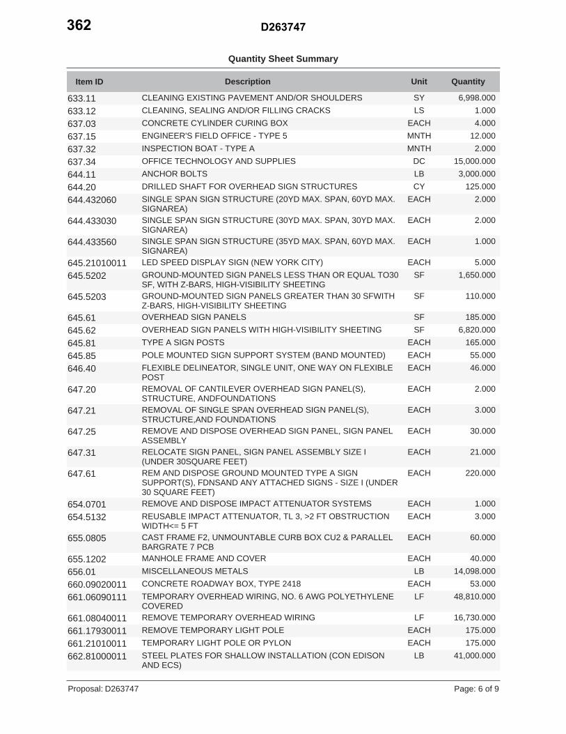
Quantity Sheet Summary
QuantityDescription UnitItem ID
6,998.000SYCLEANING EXISTING PAVEMENT AND/OR SHOULDERS633.111.000LSCLEANING, SEALING AND/OR FILLING CRACKS633.124.000EACHCONCRETE CYLINDER CURING BOX637.03
12.000MNTHENGINEER'S FIELD OFFICE - TYPE 5637.152.000MNTHINSPECTION BOAT - TYPE A637.32
15,000.000DCOFFICE TECHNOLOGY AND SUPPLIES637.343,000.000LBANCHOR BOLTS644.11
125.000CYDRILLED SHAFT FOR OVERHEAD SIGN STRUCTURES644.202.000EACHSINGLE SPAN SIGN STRUCTURE (20YD MAX. SPAN, 60YD MAX.
SIGNAREA)644.432060
2.000EACHSINGLE SPAN SIGN STRUCTURE (30YD MAX. SPAN, 30YD MAX.SIGNAREA)
644.433030
1.000EACHSINGLE SPAN SIGN STRUCTURE (35YD MAX. SPAN, 60YD MAX.SIGNAREA)
644.433560
5.000EACHLED SPEED DISPLAY SIGN (NEW YORK CITY)645.210100111,650.000SFGROUND-MOUNTED SIGN PANELS LESS THAN OR EQUAL TO30
SF, WITH Z-BARS, HIGH-VISIBILITY SHEETING645.5202
110.000SFGROUND-MOUNTED SIGN PANELS GREATER THAN 30 SFWITHZ-BARS, HIGH-VISIBILITY SHEETING
645.5203
185.000SFOVERHEAD SIGN PANELS645.616,820.000SFOVERHEAD SIGN PANELS WITH HIGH-VISIBILITY SHEETING645.62
165.000EACHTYPE A SIGN POSTS645.8155.000EACHPOLE MOUNTED SIGN SUPPORT SYSTEM (BAND MOUNTED)645.8546.000EACHFLEXIBLE DELINEATOR, SINGLE UNIT, ONE WAY ON FLEXIBLE
POST646.40
2.000EACHREMOVAL OF CANTILEVER OVERHEAD SIGN PANEL(S),STRUCTURE, ANDFOUNDATIONS
647.20
3.000EACHREMOVAL OF SINGLE SPAN OVERHEAD SIGN PANEL(S),STRUCTURE,AND FOUNDATIONS
647.21
30.000EACHREMOVE AND DISPOSE OVERHEAD SIGN PANEL, SIGN PANELASSEMBLY
647.25
21.000EACHRELOCATE SIGN PANEL, SIGN PANEL ASSEMBLY SIZE I(UNDER 30SQUARE FEET)
647.31
220.000EACHREM AND DISPOSE GROUND MOUNTED TYPE A SIGNSUPPORT(S), FDNSAND ANY ATTACHED SIGNS - SIZE I (UNDER30 SQUARE FEET)
647.61
1.000EACHREMOVE AND DISPOSE IMPACT ATTENUATOR SYSTEMS654.07013.000EACHREUSABLE IMPACT ATTENUATOR, TL 3, >2 FT OBSTRUCTION
WIDTH<= 5 FT654.5132
60.000EACHCAST FRAME F2, UNMOUNTABLE CURB BOX CU2 & PARALLELBARGRATE 7 PCB
655.0805
40.000EACHMANHOLE FRAME AND COVER655.120214,098.000LBMISCELLANEOUS METALS656.01
53.000EACHCONCRETE ROADWAY BOX, TYPE 2418660.0902001148,810.000LFTEMPORARY OVERHEAD WIRING, NO. 6 AWG POLYETHYLENE
COVERED661.06090111
16,730.000LFREMOVE TEMPORARY OVERHEAD WIRING661.08040011175.000EACHREMOVE TEMPORARY LIGHT POLE661.17930011175.000EACHTEMPORARY LIGHT POLE OR PYLON661.21010011
41,000.000LBSTEEL PLATES FOR SHALLOW INSTALLATION (CON EDISONAND ECS)
662.81000011
Page: 6 of 9D263747Proposal:
D263747362

Quantity Sheet Summary
QuantityDescription UnitItem ID
40.000LFDUCTILE IRON CEMENT LINED WATER PIPE, 6"663.0106450.000LFDUCTILE IRON CEMENT LINED WATER PIPE, 8"663.0108
4.000EACHDOUBLE DISK GATE VALVE & VALVE BOX, 6 "663.12062.000EACHDOUBLE DISK GATE VALVE & VALVE BOX, 8 "663.12084.000EACHHYDRANT663.13018.000EACHHYDRANT FENDER663.14
15.000EACHLED UNDERDECK LUMINAIRE 94 WATTAGE670.009094115.000EACHFOUNDATION FOR LIGHT STANDARDS, 12 FEET LONG670.0112
47.000EACHFOUNDATION FOR LIGHT STANDARDS, 25 FEET LONG670.01251.000EACHALUMINUM LAMPPOST CONSISTING OF 25 FEET SHAFT AND 8
FEETARM WITHOUT TRANSFORMER BASE670.11250511
1.000EACHALUMINUM SINGLE MEMBER BRACKET ARM, 8 FEET LONG670.12087,540.000LFGALVANIZED STEEL CONDUIT, 2"670.2003
310.000LFGALVANIZED STEEL CONDUIT, 3"670.20041,112.000LFGALVANIZED STEEL CONDUIT (1.5")670.2007
78.000LFFLEXIBLE CONDUIT, 3/4"670.25011.000EACHCAST IRON JUNCTION BOXES670.402.000EACHREFURBISH AND MODIFY EXISTING ELECTRICAL CONTROL
CABINET(DSL670.40280011
12.000EACHGALVANIZED STEEL NEMA - 4 TYPE JUNCTION BOX SURFACEMOUNTED,12 IN X 12 IN X 8 IN
670.41090911
3.000EACHGALVANIZED STEEL NEMA-4 TYPE JUNCTION BOX SURFACEMOUNTED,18 IN X 12 IN X 10 IN
670.41091211
5.000EACHPHOTOELECTRIC CONTROLS670.6038,425.000LFSINGLE CONDUCTOR CABLE, NUMBER 2 GAGE670.7002
3,530.000LFSINGLE CONDUCTOR CABLE, NUMBER 6 GAGE670.70046,310.000LFSINGLE CONDUCTOR CABLE, NUMBER 12 GAGE670.70073,080.000LFSINGLE CONDUCTOR CABLE, NUMBER 4/0 GAGE670.7040
10,000.000LFGROUND WIRE NUMBER 6 AWG670.750500112,095.000LFGROUND WIRE NUMBER 12 AWG670.75080011
64.000EACHREMOVE AND DISPOSE OF LAMPPOST ASSEMBLY670.818.000EACHREMOVE AND DISPOSE EXISTING UNDERPASS LUMINAIRES670.81200010
62.000EACHREMOVE LAMPPOST FOUNDATION670.8282.000EACHREMOVE AND DISPOSE EXISTING BRACKET ARM AND
LUMINAIRE670.91010011
120.000LFSINGLEMODE FIBER OPTIC CABLE - FIBER 6670.990806256.000CYPOLE EXCAVATION AND CONCRETE FOUNDATION680.5001
26.000EACHFOUNDATION FOR TRAFFIC STANDARD TYPE M-2-ST (NEWYORK CITY)
680.50050011
23.000EACHFOUNDATION FOR TRAFFIC STANDARD TYPE S-1-A (NEWYORK CITY)
680.50060011
3.000LFREMOVE POLE FOUNDATIONS680.505000056.000EACHPULLBOX-RECTANGULAR, 26 X 18 INCH,
REINFORCEDCONCRETE680.510501
1.000EACHWIRELESS VEHICLE DETECTION SYSTEM REPEATER - (LONGLIFE)
680.58801008
8.000EACHWIRELESS VEHICLE DETECTION SYSTEM PAVEMENT SENSOR680.588011082.000EACHWIRELESS VEHICLE DETECTION ACCESS POINT680.588013084.000EACHTRAFFIC SIGNAL POLE-POST TOP MOUNT 10 FEET MOUNTING680.6710
Page: 7 of 9D263747Proposal:
D263747 363

Quantity Sheet Summary
QuantityDescription UnitItem ID
HEIGHT3,125.000LFSIGNAL CABLE, 3 CONDUCTOR, 10 AWG680.7303105,890.000LFSIGNAL CABLE 13 CONDUCTORS, 14 AWG680.731314
1.000EACHREMOVE TRAFFIC SIGNAL INSTALLATION680.790000051.000LSREMOVE TRAFFIC SIGNAL EQUIPMENT680.79000010
16.000EACHFURNISH AND INSTALL TRAFFIC SIGNAL POLE TYPE S-1A(NYC)
680.80720011
24.000EACHTRAFFIC SIGNAL MODULE - 12 INCH, RED BALL, LED680.8101018.000EACHTRAFFIC SIGNAL MODULE - 12 INCH, RED ARROW, LED680.810102
22.000EACHTRAFFIC SIGNAL MODULE - 12 INCH, YELLOW BALL, LED680.8101038.000EACHTRAFFIC SIGNAL MODULE - 12 INCH, YELLOW ARROW, LED680.810104
22.000EACHTRAFFIC SIGNAL MODULE - 12 INCH, GREEN BALL, LED680.8101058.000EACHTRAFFIC SIGNAL MODULE - 12 INCH GREEN ARROW, LED680.810106
33.000EACHTRAFFIC SIGNAL BRACKET ASSEMBLY - 1 WAY680.81114.000EACHTRAFFIC SIGNAL BRACKET ASSEMBLY - 2 WAY680.8112
40.000EACHINSTALL LED PEDESTRIAN SIGNAL MODULE680.81310440.000EACHLED PEDESTRIAN SIGNAL WITH COUNTDOWN TIMER 16"X18"680.8132001040.000EACHPEDESTRIAN SIGNAL BRACKET MOUNT ASSEMBLY680.814140.000EACHFURNISH 3 SECTION TRAFFIC SIGNAL LENS, 12 INCH (NYC)680.8181201123.000EACHFURNISH AND INSTALL 20 FT SINGLE MAST ARM ASSEMBLY
(NYC)680.82050011
3.000EACHFLASHING BEACON SIGN ASSEMBLY680.822032.000EACHADA COMPLIANT PEDESTRIAN PUSHBUTTON WITH LATCHING
LED INDICATION680.82300010
25.000EACHFURNISH AND INSTALL TRAFFIC SIGNAL POLE TYPE M-2A(NYC)
680.82310011
1,915.000LFTRAFFIC DEPARTMENT CONDUIT, HOT DIPPED GALVANIZEDSTEELPIPE (NEW YORK CITY) 2 INCH DIAMETER
680.83020011
7.000EACHSHAFT EXTENSION AND SINGLE STREET LIGHTLUMINAIRESUPPORT ARM FOR M-2A TYPE TRAFFIC SIGNALPOLE (NYC)
680.83080011
8.000EACHSHAFT EXTENSION AND TWIN STREET LIGHT ARMS FOR M-2ATRAFFICSIGNAL POLE (NYC)
680.83080211
5.000EACHFURNISH AND INSTALL 5 FT EXTENSION ARM FOR 20 FT MASTARM(NYC)
680.83720011
1.000EACHRESET POLE680.900000051.000EACHSPLICE, FIBER OPTIC CABLE680.96050304
350,000.000LFWHITE EPOXY REFLECTORIZED PAVEMENT STRIPES - 20 MILS685.11140,000.000LFYELLOW EPOXY REFLECTORIZED PAVEMENT STRIPES - 20
MILS685.12
110.000EACHWHITE EPOXY REFLECTORIZED PAVEMENT LETTERS - 20 MILS685.13110.000EACHWHITE EPOXY REFLECTORIZED PAVEMENT SYMBOLS - 20
MILS685.14
378,000.000DCTRAINING REQUIREMENTS691.030000201.000LSSUPPORT AND MAINTAIN EXISTING UTILITY CONDUITS AND/OR
CABLES- OFF STRUCTURE695.33130105
1,990,000.000DCFIELD CHANGE PAYMENT697.03100.000DCASPHALT PRICE ADJUSTMENT698.04100.000DCFUEL PRICE ADJUSTMENT698.05100.000DCSTEEL/IRON PRICE ADJUSTMENT698.06
Page: 8 of 9D263747Proposal:
D263747364

Quantity Sheet Summary
QuantityDescription UnitItem ID
1.000LSMOBILIZATION699.040001
Page: 9 of 9D263747Proposal:
D263747 365

0775 Page 1 of 1 L09/03/09
THIS PAGE
INTENTIONALLY LEFT BLANK
D263747366